control of ripple eliminators to improve the power quality...
TRANSCRIPT

Received March 26, 2016, accepted April 16, 2016, date of publication May 2, 2016, date of current version May 23, 2016.
Digital Object Identifier 10.1109/ACCESS.2016.2561269
Control of Ripple Eliminators to Improve thePower Quality of DC Systems and Reducethe Usage of Electrolytic CapacitorsQING-CHANG ZHONG1,2, (Senior Member, IEEE), WEN-LONG MING2,XIN CAO3, (Member, IEEE), AND MIROSLAV KRSTIC4, (Fellow, IEEE)1Department of Electrical and Computer Engineering, Illinois Institute of Technology, Chicago, IL 60616, USA2Department of Automatic Control and Systems Engineering, The University of Sheffield, Sheffield S1 3JD, U.K.3Jiangsu Key Laboratory of New Energy Generation and Power Conversion, Nanjing University of Aeronautics and Astronautics, Nanjing 210016, China4Department of Mechanical and Aerospace Engineering, University of California at San Diego, San Diego, CA 92093-0411, USA
Corresponding author: Q.-C. Zhong ([email protected]).
This work was supported by the Engineering and Physical Sciences Research Council, U.K., under Grant EP/J001333/2.
ABSTRACT The problem of voltage/current ripples has become a primary power quality issue fordc systems, which could seriously degrade the performance on both the source side and the load side and leadto reliability concerns. In this paper, a single-phase Pulse width modulation-controlled rectifier is taken asan example to investigate how active control strategies can improve the power quality of dc systems, reducevoltage ripples, and, at the same time, reduce the usage of electrolytic capacitors. The concept of ripple elim-inators recently proposed in the literature is further developed, and the ratio of capacitance reduction is quan-tified.With such ripple eliminators, this power quality problem is formulated as a control problem to activelydivert the ripple current on the dc bus. The main focus of this paper is to investigate how advanced controlstrategies could improve the performance of ripple eliminators. An advanced controller on the basis of therepetitive control is proposed for one possible implementation of ripple eliminators in the continuous currentmode (CCM). Experimental results are presented to verify the effectiveness of the strategy with comparisonto another ripple eliminator operated in the discontinuous current mode. It has been shown that the proposedinstantaneous ripple-current diversion in CCM leads to a nearly fourfold improvement of performance.
INDEX TERMS Instantaneous diversion of ripple currents, CCM, DCM, ripple eliminators, voltage ripples,repetitive control, reliability, electrolytic capacitors.
I. INTRODUCTIONProliferated renewable energy systems greatly promote thedevelopment of DC distributed power system, which enjoysflexible system configurations, high efficiency, and high den-sity power delivery capability [2]. In such DC systems, ripplepower is often not a major concern because a DC currentis constant and there is not an issue of phase differencesbetween voltages and currents. However, in many applica-tions like hybrid electrical vehicles and wind power systems,rectifiers and inverters are commonly used and DC voltagesare not ideal but have a significant amount of harmoniccomponents [3]. Because of the harmonic components in thevoltages and the resulting ripple currents, ripple power hasbecome a major power quality issue in DC systems. For sys-tems powered by photovoltaic panels, batteries and fuel cells,large ripple currents and ripple voltages could considerablyreduce the lifetime and long-term reliability of photovoltaic
panels, batteries and fuel cells [3]–[6]. During the chargingmode of a battery, an external voltage with large ripplescould lead to an immoderate chemical reaction. During thedischarging mode, ripple currents drawn from a fuel cell candegrade the system efficiency significantly and even make itunstable [7]. Generally, current ripples should be maintainedless than 10% of the rated current for batteries [8]. In order toreduce the ripple current and smooth the external voltage onbatteries and fuel cells, bulky capacitors or ultracapacitors areoften connected in parallel with them [9]. Large electrolyticcapacitors are also often needed to level and smooth theDC-bus voltage of inverters and rectifiers [10]. For volume-critical and/or weight-critical applications, such as electricalvehicles [8] and aircraft power systems [10], the volume andweight of electrolytic capacitors could be a serious problem.
Because of limited lifetime of electrolytic capacitors,they are one of the most vulnerable components in power
VOLUME 4, 20162169-3536 2016 IEEE. Translations and content mining are permitted for academic research only.
Personal use is also permitted, but republication/redistribution requires IEEE permission.See http://www.ieee.org/publications_standards/publications/rights/index.html for more information.
2177
Q.-C. Zhong et al.: Control of Ripple Eliminators
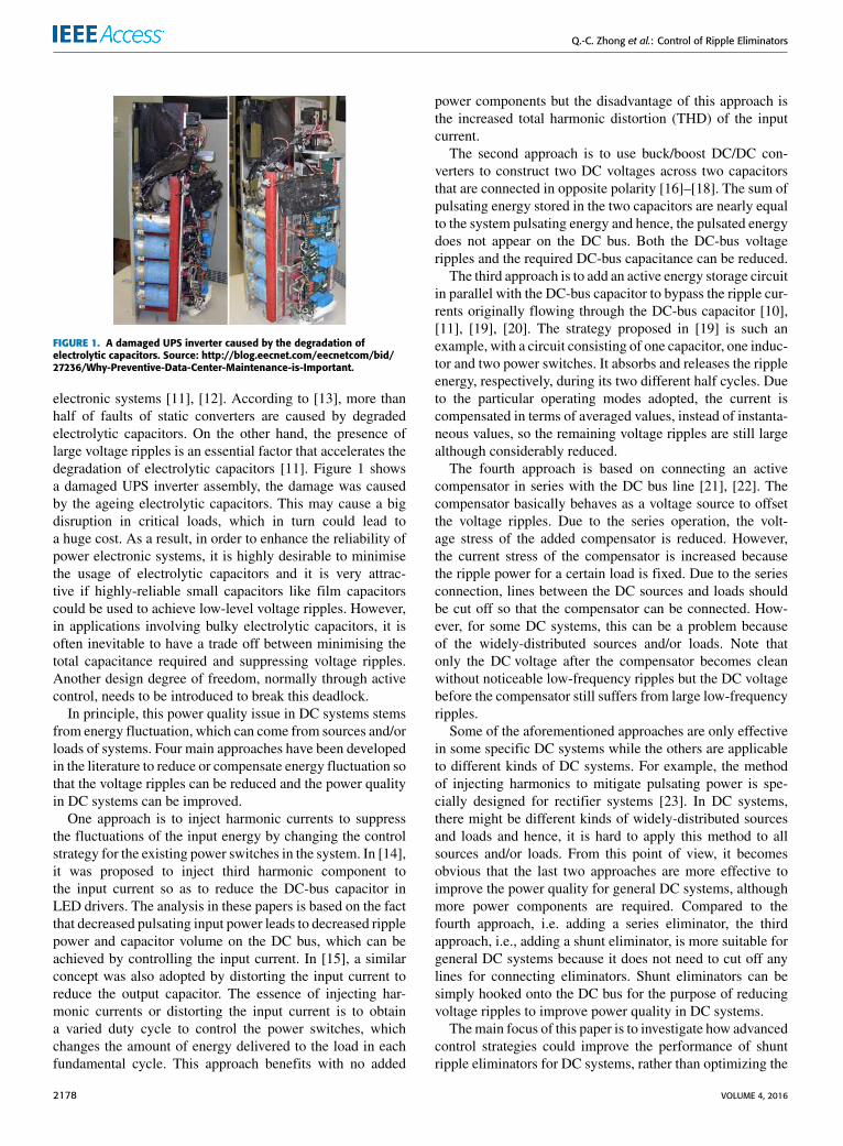
FIGURE 1. A damaged UPS inverter caused by the degradation ofelectrolytic capacitors. Source: http://blog.eecnet.com/eecnetcom/bid/27236/Why-Preventive-Data-Center-Maintenance-is-Important.
electronic systems [11], [12]. According to [13], more thanhalf of faults of static converters are caused by degradedelectrolytic capacitors. On the other hand, the presence oflarge voltage ripples is an essential factor that accelerates thedegradation of electrolytic capacitors [11]. Figure 1 showsa damaged UPS inverter assembly, the damage was causedby the ageing electrolytic capacitors. This may cause a bigdisruption in critical loads, which in turn could lead toa huge cost. As a result, in order to enhance the reliability ofpower electronic systems, it is highly desirable to minimisethe usage of electrolytic capacitors and it is very attrac-tive if highly-reliable small capacitors like film capacitorscould be used to achieve low-level voltage ripples. However,in applications involving bulky electrolytic capacitors, it isoften inevitable to have a trade off between minimising thetotal capacitance required and suppressing voltage ripples.Another design degree of freedom, normally through activecontrol, needs to be introduced to break this deadlock.
In principle, this power quality issue in DC systems stemsfrom energy fluctuation, which can come from sources and/orloads of systems. Four main approaches have been developedin the literature to reduce or compensate energy fluctuation sothat the voltage ripples can be reduced and the power qualityin DC systems can be improved.
One approach is to inject harmonic currents to suppressthe fluctuations of the input energy by changing the controlstrategy for the existing power switches in the system. In [14],it was proposed to inject third harmonic component tothe input current so as to reduce the DC-bus capacitor inLED drivers. The analysis in these papers is based on the factthat decreased pulsating input power leads to decreased ripplepower and capacitor volume on the DC bus, which can beachieved by controlling the input current. In [15], a similarconcept was also adopted by distorting the input current toreduce the output capacitor. The essence of injecting har-monic currents or distorting the input current is to obtaina varied duty cycle to control the power switches, whichchanges the amount of energy delivered to the load in eachfundamental cycle. This approach benefits with no added
power components but the disadvantage of this approach isthe increased total harmonic distortion (THD) of the inputcurrent.
The second approach is to use buck/boost DC/DC con-verters to construct two DC voltages across two capacitorsthat are connected in opposite polarity [16]–[18]. The sum ofpulsating energy stored in the two capacitors are nearly equalto the system pulsating energy and hence, the pulsated energydoes not appear on the DC bus. Both the DC-bus voltageripples and the required DC-bus capacitance can be reduced.
The third approach is to add an active energy storage circuitin parallel with the DC-bus capacitor to bypass the ripple cur-rents originally flowing through the DC-bus capacitor [10],[11], [19], [20]. The strategy proposed in [19] is such anexample, with a circuit consisting of one capacitor, one induc-tor and two power switches. It absorbs and releases the rippleenergy, respectively, during its two different half cycles. Dueto the particular operating modes adopted, the current iscompensated in terms of averaged values, instead of instanta-neous values, so the remaining voltage ripples are still largealthough considerably reduced.
The fourth approach is based on connecting an activecompensator in series with the DC bus line [21], [22]. Thecompensator basically behaves as a voltage source to offsetthe voltage ripples. Due to the series operation, the volt-age stress of the added compensator is reduced. However,the current stress of the compensator is increased becausethe ripple power for a certain load is fixed. Due to the seriesconnection, lines between the DC sources and loads shouldbe cut off so that the compensator can be connected. How-ever, for some DC systems, this can be a problem becauseof the widely-distributed sources and/or loads. Note thatonly the DC voltage after the compensator becomes cleanwithout noticeable low-frequency ripples but the DC voltagebefore the compensator still suffers from large low-frequencyripples.
Some of the aforementioned approaches are only effectivein some specific DC systems while the others are applicableto different kinds of DC systems. For example, the methodof injecting harmonics to mitigate pulsating power is spe-cially designed for rectifier systems [23]. In DC systems,there might be different kinds of widely-distributed sourcesand loads and hence, it is hard to apply this method to allsources and/or loads. From this point of view, it becomesobvious that the last two approaches are more effective toimprove the power quality for general DC systems, althoughmore power components are required. Compared to thefourth approach, i.e. adding a series eliminator, the thirdapproach, i.e., adding a shunt eliminator, is more suitable forgeneral DC systems because it does not need to cut off anylines for connecting eliminators. Shunt eliminators can besimply hooked onto the DC bus for the purpose of reducingvoltage ripples to improve power quality in DC systems.
Themain focus of this paper is to investigate how advancedcontrol strategies could improve the performance of shuntripple eliminators for DC systems, rather than optimizing the
2178 VOLUME 4, 2016

Q.-C. Zhong et al.: Control of Ripple Eliminators
system performance through topological design. It is foundthat the capability of diverting the ripple current away fromthe DC bus is the key for improving the performance. Hence,it is important to adopt a control strategy that is able totrack periodic signals and the repetitive control strategy [24]is then applied to achieve instantaneous current tracking ata fixed switching frequency. Furthermore, it is preferred tooperating the shunt ripple eliminator in the continuous cur-rent mode (CCM) rather than in the discontinuous currentmode (DCM) because the current tracking is instantaneousin CCM but is in the average sense in DCM. Because theripple current is diverted instantaneously in CCM, the voltageripples can be reduced considerably. The boost topologyin [25], where a flicker-free AC–DC LED driver with a fly-back PFC converter was designed and the strategy, is takenas an example, because of its high efficiency compared tobuck-type topologies [26], to demonstrate the performanceimprovement by designing a suitable controller. This topol-ogy was also investigated in the conference version [1] of thispaper and also in [27] and [28]. It is a bidirectional boostconverter that is able to divert the ripple current instanta-neously. The voltage of the auxiliary capacitor is higher thanthe DC-bus voltage, which helps improve the efficiency per-formance [26], the current tracking performance and reducethe required capacitance to achieve the same performance.Compared to the conference version [1] of this paper, the newcontributions of this paper include 1) analysing and revealinghow active control strategies can help reduce voltage ripplesand reduce total capacitance, which paves a way to designhigh performance controllers for different types of rippleeliminators; 2) quantifying the level of capacitance reduc-tion, which is independent from applications and topologies;3) optimizing the controller for ripple eliminators in whichonly one instead of two repetitive controllers are now requiredwithout affecting the system performance; 4) experimentallyverifying the performance of the active control strategies.
The following parts of this paper are presented as fol-lows. In Section II, a single-phase H-bridge Pulse widthmodulation (PWM) rectifier is taken as an example to anal-yse the ripple energy and ripple voltage in a DC system.In Section III, the concept of ripple eliminators is furtherdeveloped and the level of reduction of capacitance is quan-tified. In Section IV, the operation principle of the rippleeliminator under investigation is discussed and in Section Vthe controller of the ripple eliminator is developed basedon repetitive control. Experimental results with comparisonto a ripple eliminator reported in the literature are pro-vided in Section VI. At the end, conclusions are madein Section VII.
II. ANALYSIS OF RIPPLE ENERGY AND RIPPLE VOLTAGEIn order to facilitate the analysis in this paper, a single-phaseH-bridge PWM-controlled rectifier as shown in Figure 2 isused as an example, with all the components assumed tobe ideal to simplify the analysis in the sequel. Most of thefindings can be easily applied to other applications.
FIGURE 2. Single-phase H-bridge PWM-controlled rectifier.
If the input current of the rectifier is regulated to be sinu-soidal as is =
√2Is sin(ωt) and in phase with the input
voltage vs =√2Vs sin(ωt), then the input power is
ps = vsis = VsIs − VsIs cos(2ωt), (1)
where Vs and Is are the RMS values of the input voltageand current, respectively, and ω is the angular line frequency.Note that the power drawn from the AC source consistsof a constant VsIs and a second-order ripple component−VsIs cos(2ωt).
In order to analyse the voltage ripples of the DC bus, the netchange of the energy stored in the DC-bus capacitor overa charging period (i.e. a quarter cycle of the supply), calledthe ripple energy, can be calculated as [10]
Er =VsIsω. (2)
As demonstrated in [10], the voltage ripple (peak-peak) onthe capacitor C can be given as
4VDC ≈Er
CVDC0(3)
where VDC0 is the average value of the voltage VDC . It is clearthat, when increasing the capacitor C , the DC-bus voltageripple is decreased but this increases the weight, volume andcost of the system and decreases the reliability of the system,which should be avoided if possible.
III. RIPPLE ELIMINATORS AND THE LEVELOF CAPACITANCE REDUCTIONIn order to break the deadlock between minimising therequired capacitors and reducing voltage ripples, anotherdesign degree of freedom, called the ripple eliminator [19],can be introduced to replace the bulky DC-bus capacitor,as shown in Figure 3. The basic idea is to introduce anauxiliary capacitor Ca in the ripple eliminator so that theripples on the DC bus can be transferred onto Ca. The voltageVa across the auxiliary capacitor Ca is allowed to vary withina wide range with a large ripple 4Va. This concept can beregarded as the general form of the strategies proposed in theliterature, (e.g., [10], [25]).
Since the ripple eliminator is operated to divert the rippleenergy on the DC bus to the auxiliary capacitor, there is noneed to use a large electrolytic capacitor on the DC bus and
VOLUME 4, 2016 2179

Q.-C. Zhong et al.: Control of Ripple Eliminators
FIGURE 3. The concept of ripple eliminators.
the ripple energy on the auxiliary capacitor should be thesame as the DC-bus ripple energy in the ideal case. Applying(3) to the auxiliary capacitor, there is
Ca ≈Er
4VaVa0, (4)
where 4Va and Va0 are the peak-peak and average voltagesof the auxiliary capacitor. Note that the ripple energy Er isdetermined by theDC bus and not affected by the added rippleeliminator. Note also that the auxiliary capacitor is designedto allow large voltage ripples. Assume the ripple voltage ratioof the auxiliary capacitor is
ra =4VaVa0
. (5)
Then (4) can be re-written as
Ca ≈ErraV 2
a0
. (6)
It is clear that for the same ripple ratio ra, the capacitance is ininverse proportion to the square of the voltage across it, whichmeans the auxiliary capacitance can be significantly reducedvia increasing its operating voltage.
If the same ripple energy Er needs to be taken care of bya DC-bus capacitor C , as shown in Figure 2, then, accordingto (3), the voltage ripple ratio r of the DC bus is about
r ≈Er
CV 2DC0
. (7)
This means the auxiliary capacitor needed can be reduced to
Ca ≈rra(VDC0Va0
)2C (8)
by a factor of
Rd =rar(Va0VDC0
)2 =1VaVa0
1VDCVDC0. (9)
The capacitanceCa can be reduced by 1) allowing the voltageripple ratio higher than that of the original DC bus, 2) adopt-ing an operating voltage Va0 higher than VDC0 for Ca. Thetopology in [10] adopts a higher voltage ripple ratio and thestrategy in [19] adopts both.
Here is a numerical example. If the auxiliary capacitorvoltage is chosen four times of the DC-bus voltage then
the maximum allowable ripple voltage ratio of the auxiliarycapacitor is ra = 75%. Moreover, if the allowed ripple ratioof the original DC-bus voltage is r = 5%, then the auxiliarycapacitor can be reduced by a factor of Rd = 75%
5% ×42= 240.
Hence, it is not a problem to reduce the level of the totalcapacitance required by a factor of 100.
Note that (9) is independent of applications. It sets thebasic guidelines for designing different ripple eliminators.Some other guidelines include: 1) a ripple eliminator needsto be able to provide bi-directional current path so that theripple current can flow through; 2) the remaining level ofDC-bus voltage ripples is determined by the performanceof the ripple eliminator so the ripple eliminator needs to becontrolled properly; 3) The hold-up time requirement [21],voltage stress and current stress should be considered tochoose suitable capacitors. If the maximum voltage of thecapacitor is determined, then increased capacitance meanslonger hold-up time and lower current stress, which are pre-ferred in some applications [12]. As a result, there are severaltrade-offs that should be considered together when choosingthe capacitors for certain applications. If all the ripple currentin i is bypassed through the ripple eliminator then the DC-buscapacitor C ′ only needs to take care of the switching ripplesand hence small capacitors can be used.
FIGURE 4. The ripple eliminator under investigation.
IV. THE RIPPLE ELIMINATOR UNDER INVESTIGATIONA. OPERATION PRINCIPLES OF THE RIPPLE ELIMINATORIn this paper, a practical implementation of the ripple elim-inator concept to be studied is shown in the dashed boxof Figure 4, which is actually a bi-directional boost-buckconverter. It can also be regarded as one phase of an inverterwith the DC bus provided by the auxiliary capacitor Ca soit is able to divert a bidirectional current ir away from theDC bus. This topology was studied in [25], where a flicker-free LED driver with a flyback PFC converter was designedand the strategy about how to remove the ripple energythrough tracking the ripple current generated by the flybackconverter was analysed in detail, and in [27] and [28], wherean active filter for grid-tied PV applications was developed toreduce the low frequency current drawn from PV panels.
In order to track the ripple current, switches Q1 and Q2can be controlled in two different switching modes. One isonly to control Q2 (Q1, resp.) in the positive (negative, resp.)
2180 VOLUME 4, 2016

Q.-C. Zhong et al.: Control of Ripple Eliminators
half cycle of the ripple current, which corresponds to thecharging (discharging) mode. In the charging mode, Q2 iscontrolled by a PWM signal and Q1 is always OFF, whichprovides the path for the positive half cycle of the ripplecurrent ir , and hence, the ripple eliminator is operated asa boost converter. In the discharging mode, Q2 is alwaysOFF and Q1 is controlled by a PWM signal, which providesthe path for the negative half cycle of the ripple current ir ,and the circuit is operated as a buck converter. Therefore,the direction of the current flowing through the auxiliaryinductor can only be negative or positive in one switchingperiod.
Another switching mode is to control the two switchescomplementarily. That means switches Q1 and Q2 are con-trolled by two inverse PWM signals to track the ripple currentand the voltage across the auxiliary inductor can be VDCand VDC − Va depending on the ON-OFF combinations ofthese two switches. In one PWM period, if Q1 is ON, Q2 iscontrolled by an inverse signal to keep OFF and vice versa.Different from the previous operation mode, the inductorcurrent can be positive or negative even during one switchingperiod. This is a very good feature because the current can betracked very well no matter at zero-crossing points or at largecurrent ripple conditions. In the previous mode, the sharpturn at the zero-crossing points causes high harmonic content,which is hard for the controller to track. Since the final controlobjective is to reduce DC-bus voltage ripples, it does not mat-ter if the auxiliary current ripple is slightly large because ofthe high switching frequency. With the same system parame-ters, large ripple means a small inductor is needed, which canreduce the size of the ripple eliminator. In this paper, in orderto fully use the ripple eliminator under different workingconditions, Q1 and Q2 are operated complementarily to trackthe ripple current.
B. SELECTION OF THE AUXILIARY INDUCTORApart from the auxiliary capacitorCa, there is another passivecomponent, i.e., the auxiliary inductor La, that affects theperformance of the ripple eliminator. In this subsection, howto select the La is discussed.
Here, the duty cycle and the PWM period time are denotedas dr and Tr , respectively. As two switches Q1 and Q2 areoperated complementarily, the ON time of Q2 is drTr andthe ON time of Q1 is (1 − dr )Tr in one PWM period. Sincethe PWM frequency is much higher than the line frequency,it can be assumed that the current increased (to withstandthe positive voltage VDC ) and decreased (to withstand thenegative voltage VDC − Va) in these two modes are the samein the steady state. In other words, the current ripple 4ir is
4ir =VDCLa
drTr = −VDC − Va
La(1− dr )Tr . (10)
Therefore, the duty cycle dr can be obtained as
dr = 1−VDCVa
. (11)
The substitution of (11) into (10) leads to
La4irVDC
= (1−VDCVa
)Tr , (12)
which can be re-written as
frLa4ir = VDC (1−VDCVa
). (13)
As expected, the product of the switching frequency fr ,the inductance La and the current ripple 4ir is a constant,which is determined by the DC-bus voltage and the auxiliaryvoltage. The auxiliary inductor current mainly includes thecurrent ripple1ir and the ripple current to be injected into theDC-bus. Hence, the role of the DC-bus capacitor is to filterout this high frequency current ripple 4ir , which could beachieved by a small capacitor.
In this case, the amplitude of the current ripple 1ir is nota major concern. As long as the low frequency componentof the inductor current is equal to the second-order harmoniccurrent on the DC bus, the ripple voltage on the DC bus can beeffectively eliminated. The high frequency part of ir , whichis 1ir , can be large in order to reduce the inductance of La.However, a large 1ir leads to a large current peak for theinductor and also aggravate the filtering burden of the capac-itor C . Therefore, there is a trade off between La and 4ir .In this work, in order to ensure the inductor is operated inthe critical continuous current mode, the amplitude of 4ir isdesigned to satisfy
1ir ≤ 2Irm, (14)
where Irm is the peak value of ir . Considering (12), theauxiliary inductance should be selected to satisfy
La ≥(1− VDC
Va)VDC
2Irmfr. (15)
On the other hand, the rising rate of the auxiliary inductorcurrent should be greater than the maximum rising rate of thereference ripple current which appears at the zero-crossingpoint. If the reference ripple current is expressed as
ir = Irm sin(2ωt), (16)
then the maximum rising rate of ir can be obtained as
dirdt|t=0= 2ωIrm = 4π fIrm. (17)
Accordingly, there exist
VDCLa≥ 4π fIrm, (18)
andVa − VDC
La≥ 4π fIrm. (19)
Combining the above two equations, then
La ≤ min(
VDC4π fIrm
,Va − VDC4π fIrm
). (20)
VOLUME 4, 2016 2181

Q.-C. Zhong et al.: Control of Ripple Eliminators
Combining it with (15), there is
(1− VDCVa
)VDC
2Irmfr≤ La ≤ min
(VDC4π fIrm
,Va − VDC4π fIrm
),
(21)
i.e.,
1−1VaVDC
≤2IrmfrLaVDC
≤ min
(12π·frf,
VaVDC− 1
2π·frf
),
(22)
where IrmfrLa reflects the voltage dropped on La caused byIrm at the switching frequency fr . This relationship is shown inFigure 5 and can be used to determine La. Note that La can bereduced via increasing fr . Moreover, when Irm is increased,La can be reduced.
FIGURE 5. Selection of 2Irmfr LaVDC
: between the two surfaces.
V. CONTROL OF THE RIPPLE ELIMINATORA. FORMULATION OF THE CONTROL PROBLEMAs discussed before, the DC voltage ripple is caused bythe pulsating input energy. After the ripple eliminator isintroduced to divert the ripple current from the capacitor C ,the DC-bus voltage then becomes ripple free, apart fromswitching ripples, and equal to the DC-bus voltage. Hence,the current to be diverted should be
ir = −VsIsVDC0
cos(2ωt), (23)
which is a second-order harmonic current. Note that the cur-rent ir could be different for other DC systems but it does notaffect the analysis above. The control objective of the rippleeliminator is then to instantaneously divert ir in (23) awayfrom the DC bus through the ripple eliminator so that the
current flows through the load does not contain ripples otherthan switching ripples. In other words, the control problem isto instantaneously track the ripple current ir that correspondsto the ripple power via controlling Q1 and Q2.Tracking the ir can be achieved in terms of either averaged
values or instantaneous values, which corresponds to theDCM or CCM operation of the ripple eliminator. Of course,the current tracking performance in CCM is better than that inDCM. Hence, the CCM operation is preferred. On the otherhand, the inductor will have a relatively large size in orderto keep the ripple current continuous. This can be mitigatedif the ripple eliminator can be operated at high switchingfrequencies. For example, if MOSFETs instead of IGBTs areused to construct the eliminator, then the switching frequencycan be very high, e.g., at 200 kHz, so that only a smallinductor is needed. When it is operated in DCM, the inductorcan be smaller but the maximum current flowing through theswitches is much higher in DCM than that in CCM becauseof the average tracking. High current means high cost forswitches.
In this paper, the CCM operation is chosen because ofits high performance for current tracking. The ripple currenttracking can be achieved in two steps: 1) to generate a refer-ence ripple current and 2) to track the reference ripple current.Moreover, in order to make sure that the current tracking canbe achieved properly, the voltage across the auxiliary capac-itor Ca should be regulated as well. The proposed overallcontrol strategy is shown in Figure 6, which is explained indetail in the following subsections.
FIGURE 6. Control strategy for the ripple eliminator.
B. REGULATION OF THE AUXILIARY CAPACITOR VOLTAGEThe operation of the ripple eliminator relies on a properlyregulated the voltage across the auxiliary capacitor, whichis designed to allow a significant amount of ripples. Forthe purpose of maintaining the average DC component ata certain value, a low-pass filter can be adopted to removeripples. Here, the following low-pass filter
H (s) =1− e−τ s/2
τ s/2, (24)
inwhich τ is chosen as the system fundamental period, is usedto filter out other components so that the average value of thevoltage can be extracted for control. Once the average voltageis obtained, it can be easily regulated at a given value V ∗a by
2182 VOLUME 4, 2016

Q.-C. Zhong et al.: Control of Ripple Eliminators
using a PI controller, as shown in Figure 6, via charging ordischarging the ripple eliminator. It is also possible to designthe controller to regulate the maximum or minimum value ofthe voltage, as reported in [19].
C. GENERATION OF THE REFERENCE RIPPLE CURRENT i∗rThe second-order harmonic current of the current i betweenthe rectifier and the ripple eliminator can be extracted byusing the following resonant filter
KR(s) =Kh2ξhωs
s2 + 2ξhωs+ (hω)2(25)
tuned at the second harmonic frequency with ξ = 0.01,h = 2, and ω = 2π f . If the harmonic current has com-ponents at other frequencies, then KR(s) can be designedto include the corresponding term. For example, if there isa 3rd-order harmonic current, then KR(s) can include a termwith h = 3. The extracted current can be added to the outputof the PI controller that regulates the auxiliary capacitorvoltage to form the reference ripple current i∗r ; see Figure 6.
D. DESIGN OF A CURRENT CONTROLLER TO TRACK THESECOND-ORDER RIPPLE CURRENTAs explained before, the control problem is essentially a cur-rent tracking problem. Since the reference ripple currentis periodic, the repetitive control strategy [29], [30] canbe adopted to achieve excellent tracking performance witha fixed switching frequency, as shown in Figure 6.
FIGURE 7. The repetitive controller.
A repetitive controller contains an internal model, whichis a local positive feedback loop involving a delay term anda low-pass filter, as shown in Figure 7. It introduces high gainsat the fundamental and all harmonic frequencies of interestand hence, it is able to eliminate periodic errors [31], accord-ing to the internal model principle [32]. From the controllersdesigned with advanced control algorithms, e.g., the onesin [30], the controllers that work with the repetitive controlstrategy can be very simple. In this paper, since the problemis a current tracking problem, the proportional controller Krcascaded with the internal model obtained in [29] and [30]with theH∞ control strategy, as shown in Figure 7, is adopted.Here, ie = i∗r − ir is the current tracking error.Based on the analysis in [30] and [33], τd is selected as
τd =τ
2−
1ωi= 0.0099 s (26)
for ωi = 10000 rad/sec and τ = 1f = 0.02 s. The propor-
tional gain can be determined by following the procedures of
H∞ control design proposed in [29] and [30] or simply bytuning with trial-and-error.
TABLE 1. System parameters.
VI. EXPERIMENTAL VALIDATIONIn order to verify the proposed control method, a test rig thatconsists of a 1.1 kW single-phase PWM-controlled rectifierand three kinds of ripple eliminators was built. The systemparameters are summarized in Table 1. In this study, the ripplevoltage ratio is selected below 10% for all the auxiliarycapacitor voltage references from 500 V to 700 V. Accordingto (6), Ca should be around 160 µF and is chosen asCa = 165µF. Of course, this ratio could be greater than 10%in order to further decrease the capacitance needed as long asthe auxiliary capacitor voltage is higher than the DC-bus volt-age to guarantee the successful operation of the eliminator.
FIGURE 8. Controller for a single-phase PWM-controlled rectifier.
A. CONTROL OF THE SINGLE-PHASEPWM-CONTROLLED RECTIFIERThe PWM rectifier is adopted as an example for generatingvoltage/current ripples in a DC system. It is controlled todraw a clean sinusoidal current from the source that is inphase with the voltage source. This can be achieved withthe controller shown in Figure 8, which mainly consists ofthree parts: 1) a synchronisation unit to generate a cleansinusoidal current signal that is in phase with the source sothat the reactive power drawn from the supply is controlledto be zero; 2) a PI voltage controller that maintains thevoltage VDC according to the DC-bus reference voltage V ∗DCto generate the right amplitude for the current reference; and3) a current controller to track the reference current thatis formed according to the PI voltage controller and thesynchronisation signal. Here, the sinusoid-tracking algo-rithm (STA) [34] is adopted to provide the phase information
VOLUME 4, 2016 2183

Q.-C. Zhong et al.: Control of Ripple Eliminators
sinωt for the input current, as shown in Figure 8. In orderto obtain the DC component of the DC-bus voltage, the holdfilter (24) is adopted to remove the voltage ripples. This isable to reduce the ripple component in the reference current,which helps improve the power quality of the current drawnfrom the voltage source.
Since the reference current is periodic, the repetitive con-troller designed for the ripple eliminator can also be adoptedto track the reference current, as shown in Figure 8.
FIGURE 9. Experimental results when the ripple eliminator was notactivated: DC-bus voltage VDC , input voltage vs and input current is.
B. VALIDATION1) WITHOUT THE RIPPLE ELIMINATORFigure 9 shows the experimental results of the single-phasePWM-controlled rectifier without the ripple eliminator. Theinput current was well regulated to be in phase with the sourcevoltage to achieve the unity power factor. However, the rippleof the VDC is around 90 V, which is often not acceptable inpractice.
2) WITH THE RIPPLE ELIMINATOR ACTIVATEDFigure 10 shows the results with the ripple eliminator acti-vated. In order to investigate how the voltage Va affects thereduction of the voltage ripple, different levels of the Va at500 V, 600 V and 700 V were tested. Generally, it can beseen that the DC-bus voltage ripple was significantly reducedfor all these three voltages. The performance is improvedwhen the auxiliary capacitor voltage is increased becausethe inductor current tracking performance is improved whenthe auxiliary capacitor voltage increases. The DC-bus volt-age ripple is around 2.5 V when the auxiliary capacitorvoltage is 600 V and 700 V, which represents 36 times ofimprovement. Moreover, the voltage ripple on the auxiliarycapacitor decreased with the increase of its DC voltage. Thecorresponding voltage ripples 1VDC and 1Va are shownin Figure 11. Based on the analysis in Section III, the productof4Va and Va0 should be a constant if the auxiliary capacitoris not changed. Indeed, the product is equal to about 25000for the three different voltages 500 V, 600 V or 700 V.Moreover, the current ripple of the auxiliary inductor shownin Figure 10(b) crosses zero in most of PWM cycles.
FIGURE 10. Experimental results with different auxiliary capacitorvoltages: (a) V ∗a = 700 V. (b) V ∗a = 600 V. (c) V ∗a = 500 V.
The high-frequency current ripples of the auxiliary-inductor current increased along with the increase of theauxiliary-capacitor voltage. Figure 12 shows the theoreticaland experimental results of the auxiliary-inductor currentripples1ir . It can be seen that the experimental results matchthe calculated values well.
3) DYNAMIC PERFORMANCEThe dynamic performance of the ripple eliminator was tested.As shown in Figure 13(a), the voltage ripple was almost
2184 VOLUME 4, 2016

Q.-C. Zhong et al.: Control of Ripple Eliminators
FIGURE 11. Voltage ripples on the DC bus (1VDC ) and the capacitor Ca(1Va) of the proposed ripple eliminator tested over a wide range of Va0.
FIGURE 12. Current ripples 1ir on the inductor La over a wide rangeof Va0.
FIGURE 13. Dynamic performance of the proposed ripple eliminator(V ∗a0 = 600 V): (a) Start-up. (b) Stop.
removed from the DC-bus voltage after the eliminator wasactivated for about seven line cycles. When the ripple elim-inator was deactivated, the ripples of the DC-bus voltage
FIGURE 14. The DCM ripple eliminator studied in [19]: (a) topology;(b) experimental results with V ∗amin = 300 V.
immediately went back to about 90 V, as shownin Figure 13(b).
4) COMPARISON WITH THE DCM RIPPLEELIMINATOR IN [19]The experimental results for the ripple eliminator reportedin [19], as shown in Figure 14(a), are presented for compar-ison. The only difference in this topology is that the powerswitch Q2 is swapped with the inductor La and the directionof the switchQ1 is reversed. This makes the ripple eliminatoreither a buck or a boost converter and hence, both Va < VDCand Va > VDC can be achieved.
The inductor La is changed to 0.55 mH so that the elim-inator can be operated in DCM as studied in [19] and theload is slightly lighter, 1 kW instead of 1.1 kW. The otherparameters of the system are the same as given in Table 1.The experimental results are shown in Figure 14(b) when theminimum of the auxiliary voltage was regulated at 300 V. TheDC-bus voltage ripple is about 9 V, which is almost 4 timesof 2.5 V shown in Figure 10(b) and 10(c) obtained with theproposed control strategy. The investigated eliminator canremovemore than 97% of the voltage ripples from the DC busbut the DCM one shown in Figure 14(a) can only eliminateabout 90% of the voltage ripples.Moreover, the voltage rippleof the auxiliary capacitor Ca increased to about 60 V becauseof the lower average voltage. It is also worth noting thatthe peak value of the compensation ripple current ir nearlyreached 30A, which is about 7 times of the peak currentobtained in this paper.
VII. CONCLUSIONSThe concept of ripple eliminators has been further developedto improve the power quality and reduce the voltage ripples
VOLUME 4, 2016 2185

Q.-C. Zhong et al.: Control of Ripple Eliminators
in DC systems and, at the same time, reduce the capacitanceneeded and the usage of electrolytic capacitors. After derivingthe reduction ratio of the capacitance required, the focus ofthis paper is on the design of an advanced control strategyso that the ripple current can be instantaneously compen-sated. Compared to [19] and some other related researchin the literature, this paper has the following unique con-tributions: 1) It has been revealed that the capability of ofinstantly diverting the ripple current away from the DC busis the key to improve the performance. As a result, rippleeliminators that can be operated in CCM to instantaneouslydivert ripple currents are preferred; 2) the repetitive controlstrategy is proposed to control one exemplar ripple elim-inator, with the ripple energy provided by a single-phasePWM-controlled rectifier. It instantaneously compensates theripple current on the DC bus so that the voltage rippleson the DC bus can be significantly reduced. Experimentalresults have demonstrated that the proposed strategy is validand offers several times of performance improvement withcomparison to a DCM ripple eliminator reported in [19].It has been confirmed that it is important to operate rippleeliminators in CCM to instantaneously track the ripple cur-rent so that the DC-bus voltage ripples can be minimised tothe greatest extent.
ACKNOWLEDGMENTSome preliminary results of this paper were presented atthe 38th Annual Conference on IEEE Industrial ElectronicsSociety, Montreal, QC, Canada, Oct. 2012.
REFERENCES[1] Q.-C. Zhong, W.-L. Ming, X. Cao, and M. Krstic, ‘‘Reduction of
DC-bus voltage ripples and capacitors for single-phase PWM-controlledrectifiers,’’ in Proc. 38th Annu. Conf. IEEE Ind. Electron. Soc. (IECON),Oct. 2012, pp. 708–713.
[2] A. A. Hamad, H. E. Farag, and E. F. El-Saadany, ‘‘A novel multiagentcontrol scheme for voltage regulation in DC distribution systems,’’ IEEETrans. Sustainable Energy, vol. 6, no. 2, pp. 534–545, Apr. 2015.
[3] Y. Sun, Y. Liu, M. Su, W. Xiong, and J. Yang, ‘‘Review of active powerdecoupling topologies in single-phase systems,’’ IEEE Trans. Power Elec-tron., vol. 31, no. 7, pp. 4778–4794, Jul. 2016.
[4] Y. Du, D. D.-C. Lu, G. M. L. Chu, and W. Xiao, ‘‘Closed-form solutionof time-varying model and its applications for output current harmonicsin two-stage PV inverter,’’ IEEE Trans. Sustainable Energy, vol. 6, no. 1,pp. 142–150, Jan. 2015.
[5] B. Karanayil, V. G. Agelidis, and J. Pou, ‘‘Performance evaluation ofthree-phase grid-connected photovoltaic inverters using electrolytic orpolypropylene film capacitors,’’ IEEE Trans. Sustainable Energy, vol. 5,no. 4, pp. 1297–1306, Oct. 2014.
[6] Y. Hu, W. Cao, S. J. Finney, W. Xiao, F. Zhang, and S. F. McLoone, ‘‘Newmodular structure DC–DC converter without electrolytic capacitors forrenewable energy applications,’’ IEEE Trans. Sustainable Energy, vol. 5,no. 4, pp. 1184–1192, Oct. 2014.
[7] C. Liu and J.-S. Lai, ‘‘Low frequency current ripple reduction techniquewith active control in a fuel cell power system with inverter load,’’ IEEETrans. Power Electron., vol. 22, no. 4, pp. 1429–1436, Jul. 2007.
[8] H. Wen, W. Xiao, X. Wen, and P. Armstrong, ‘‘Analysis and evaluation ofDC-link capacitors for high-power-density electric vehicle drive systems,’’IEEE Trans. Veh. Technol., vol. 61, no. 7, pp. 2950–2964, Sep. 2012.
[9] W. Choi, J.W. Howze, and P. Enjeti, ‘‘Development of an equivalent circuitmodel of a fuel cell to evaluate the effects of inverter ripple current,’’J. Power Sour., vol. 158, no. 2, pp. 1324–1332, Aug. 2006.
[10] R. Wang et al., ‘‘A high power density single-phase PWM rectifier withactive ripple energy storage,’’ IEEE Trans. Power Electron., vol. 26, no. 5,pp. 1430–1443, May 2011.
[11] P. T. Krein, R. S. Balog, and M. Mirjafari, ‘‘Minimum energy andcapacitance requirements for single-phase inverters and rectifiers using aripple port,’’ IEEE Trans. Power Electron., vol. 27, no. 11, pp. 4690–4698,Nov. 2012.
[12] W.-L. Ming, Q.-C. Zhong, and X. Zhang, ‘‘A single-phase four-switchrectifier with significantly reduced capacitance,’’ IEEE Trans. Power Elec-tron., vol. 31, no. 2, pp. 1618–1632, Feb. 2016.
[13] P. Venet, A. Lahyani, G. Grellet, and A. Ah-Jaco, ‘‘Influence of agingon electrolytic capacitors function in static converters: Fault predictionmethod,’’ Eur. Phys. J. Appl. Phys., vol. 5, no. 1, pp. 71–83, 1999.
[14] L. Gu, X. Ruan, M. Xu, and K. Yao, ‘‘Means of eliminating electrolyticcapacitor inAC/DC power supplies for LED lightings,’’ IEEETrans. PowerElectron., vol. 24, no. 5, pp. 1399–1408, May 2009.
[15] D. G. Lamar, J. Sebastian, M. Arias, and A. Fernandez, ‘‘On the limit of theoutput capacitor reduction in power-factor correctors by distorting the lineinput current,’’ IEEE Trans. Power Electron., vol. 27, no. 3, pp. 1168–1176,Mar. 2012.
[16] S. Li, G.-R. Zhu, S.-C. Tan, and S. Y. Hui, ‘‘Direct ac/dc rectifier with mit-igated low-frequency ripple through inductor-current waveform control,’’IEEE Trans. Power Electron., vol. 30, no. 8, pp. 4336–4348, Aug. 2015.
[17] Y. Tang, W. Yao, P. C. Loh, and F. Blaabjerg, ‘‘Highly reliable trans-formerless photovoltaic inverters with leakage current and pulsating powerelimination,’’ IEEE Trans. Ind. Electron., vol. 63, no. 2, pp. 1016–1026,Feb. 2016.
[18] W. Cai, L. Jiang, B. Liu, S. Duan, andC. Zou, ‘‘A power decouplingmethodbased on four-switch three-port DC/DC/AC converter in DC microgrid,’’IEEE Trans. Ind. Appl., vol. 51, no. 1, pp. 336–343, Jan./Feb. 2015.
[19] X. Cao, Q.-C. Zhong, and W.-L. Ming, ‘‘Ripple eliminator to smooth DC-bus voltage and reduce the total capacitance required,’’ IEEE Trans. Ind.Electron., vol. 62, no. 4, pp. 2224–2235, Apr. 2015.
[20] Z. Qin, Y. Tang, P. C. Loh, and F. Blaabjerg, ‘‘Benchmark of AC and DCactive power decoupling circuits for second-order harmonic mitigation inkilowatt-scale single-phase inverters,’’ IEEE J. Emerg. Sel. Topics PowerElectron., vol. 4, no. 1, pp. 15–25, Mar. 2016.
[21] H. Wang, H. S.-H. Chung, and W. Liu, ‘‘Use of a series voltage com-pensator for reduction of the dc-link capacitance in a capacitor-supportedsystem,’’ IEEE Trans. Power Electron., vol. 29, no. 3, pp. 1163–1175,Mar. 2014.
[22] W. Liu, K. Wang, H. S.-H. Chung, and S. T.-H. Chuang, ‘‘Modeling anddesign of series voltage compensator for reduction of DC-link capacitancein grid-tie solar inverter,’’ IEEE Trans. Power Electron., vol. 30, no. 5,pp. 2534–2548, May 2015.
[23] B. Wang, X. Ruan, K. Yao, and M. Xu, ‘‘A method of reducingthe peak-to-average ratio of LED current for electrolytic capacitor-less AC–DC drivers,’’ IEEE Trans. Power Electron., vol. 25, no. 3,pp. 592–601, Mar. 2010.
[24] Q.-C. Zhong and T. Hornik, ‘‘Cascaded current–voltage control to improvethe power quality for a grid-connected inverter with a local load,’’ IEEETrans. Ind. Electron., vol. 60, no. 4, pp. 1344–1355, Apr. 2013.
[25] S. Wang, X. Ruan, K. Yao, S.-C. Tan, Y. Yang, and Z. Ye, ‘‘A flicker-free electrolytic capacitor-less AC–DC LED driver,’’ IEEE Trans. PowerElectron., vol. 27, no. 11, pp. 4540–4548, Nov. 2012.
[26] J.-J. Lin, S.-Y. Huang, P.-T. Cheng, and T. Shimizu, ‘‘Analysis and com-parison of power decoupling circuits for single-phase DC/AC converters,’’in Proc. Int. Conf. Intell. Green Building Smart Grid (IGBSG), Apr. 2014,pp. 1–4.
[27] A. C. Kyritsis, N. P. Papanikolaou, and E. C. Tatakis, ‘‘A novel parallelactive filter for current pulsation smoothing on single stage grid-connectedAC-PV modules,’’ in Proc. Eur. Conf. Power Electron. Appl., Sep. 2007,pp. 1–10.
[28] A. C. Kyritsis, N. P. Papanikolaou, and E. C. Tatakis, ‘‘Enhanced currentpulsation smoothing parallel active filter for single stage grid-connectedAC-PV modules,’’ in Proc. 13th Power Electron. Motion ControlConf. (EPE-PEMC), Sep. 2008, pp. 1287–1292.
[29] Q.-C. Zhong and T. Hornik, Control of Power Inverters in RenewableEnergy and Smart Grid Integration. New York, NY, USA: Wiley, 2013.
[30] T. Hornik and Q.-C. Zhong, ‘‘A current-control strategy for voltage-sourceinverters in microgrids based on H∞ and repetitive control,’’ IEEE Trans.Power Electron., vol. 26, no. 3, pp. 943–952, Mar. 2011.
2186 VOLUME 4, 2016

Q.-C. Zhong et al.: Control of Ripple Eliminators
[31] S. Hara, Y. Yamamoto, T. Omata, and M. Nakano, ‘‘Repetitive controlsystem: A new type servo system for periodic exogenous signals,’’ IEEETrans. Autom. Control, vol. 33, no. 7, pp. 659–668, Jul. 1988.
[32] B. A. Francis andW.M.Wonham, ‘‘The internal model principle for linearmultivariable regulators,’’ Appl. Math. Optim., vol. 2, no. 2, pp. 170–194,Jun. 1975.
[33] G. Weiss and M. Häfele, ‘‘Repetitive control of MIMO systems using H∞
design,’’ Automatica, vol. 35, no. 7, pp. 1185–1199, Jul. 1999.[34] A. K. Ziarani and A. Konrad, ‘‘A method of extraction of nonstationary
sinusoids,’’ Signal Process., vol. 84, no. 8, pp. 1323–1346, Aug. 2004.
QING-CHANG ZHONG (M’04–SM’04) receivedthe Ph.D. degree in control and power engineer-ing from Imperial College London, U.K., in 2004(awarded the Best Doctoral Thesis Prize) andthe Ph.D. degree in control theory and engineer-ing from Shanghai Jiao Tong University, China,in 2000.
He holds the Max McGraw Endowed ChairProfessor in Energy and Power Engineering withthe Department of Electrical and Computer Engi-
neering, Illinois Institute of Technology, Chicago, USA. He is a Distin-guished Lecturer of the IEEE Power Electronics Society and the IEEEControl Systems Society. He is a fellow of the Institution of Engineeringand Technology and the Vice Chair of the IFAC TC of Power and EnergySystems, and was a Senior Research Fellow of the Royal Academy ofEngineering, U.K. (2009-2010) and the U.K. Representative to the Euro-pean Control Association (2013-2015). He serves as an Associate Editor ofthe IEEE TRANSACTIONS ON AUTOMATIC CONTROL/TRANSACTIONS ON INDUSTRIALELECTRONICS/TRANSACTIONS ON POWER ELECTRONICS/TRANSACTIONS ON CONTROL
SYSTEMS TECHNOLOGY /ACCESS/JOURNAL OF EMERGING AND SELECTED TOPICS
IN POWER ELECTRONICS. He has co-authored three research monographs,including Control of Power Inverters in Renewable Energy and Smart GridIntegration (Wiley-IEEE Press, 2013) and Robust Control of Time-delaySystems (Springer, 2006), and proposed the architecture for next-generationsmart grids to unify the interface of all players with the grid through thesynchronization mechanism of conventional synchronous machines. Hisresearch focuses on advanced control theory and its applications to varioussectors, including power and energy engineering, chemical engineering, andmechatronics.
WEN-LONG MING received the B.Eng. andM.Eng. degrees in automation from ShandongUniversity, Jinan, China, in 2007 and 2010, respec-tively, and the Ph.D. degree in automatic controland systems engineering from the University ofSheffield, Sheffield, U.K., in 2015.
He was with the Center for Power Electron-ics Systems, Virginia Tech, Blacksburg, USA,in 2012, as an Academic Visiting Scholar. He has(co-)authored more than 30 papers in leading jour-
nals or refereed IEEE conferences and a research monograph entitledAdvanced Power Electronic Converters with Reduced Capacitance, Ripplesand Common-mode Voltages, which is scheduled for publication by Wiley-IEEE Press in 2016. His research interests focus on smart grids, advancedcontrol of power electronic converters, technologies to reduce passivecomponents in power converters, traction power systems, transformerlessPV inverters, and neutral line provision in power electronic systems.
XIN CAO (M’12) received the B.Eng., M.Eng.,and Ph.D. degrees in electrical engineering fromthe Nanjing University of Aeronautics and Astro-nautics, Nanjing, China, in 2003, 2006, and 2010,respectively. Since 2011, he has beenwith theNan-jing University of Aeronautics and Astronautics.
He was a Research Associate with the Depart-ment of Aeronautical and Automotive Engi-neering, Loughborough University, U.K., from2011 to 2012. His current research focuses on
distributed generation and renewable energy, electric vehicles, switchedreluctance motors, and magnetically levitated bearingless motors.
MIROSLAV KRSTIC (S’92–M’95–SM’99–F’02)holds the Alspach Endowed Chair and is theFounding Director of the Cymer Center for Con-trol Systems and Dynamics at UC San Diego.He also serves as an Associate Vice Chancellor forResearch at UCSD. As a Graduate Student, he wonthe UC Santa Barbara Best Dissertation Awardand student best paper awards at CDC and ACC.He is a fellow of IFAC, ASME, and IET (U.K.),and a Distinguished Visiting Fellow of the Royal
Academy of Engineering. He has received the PECASE, NSF Career, andONR Young Investigator awards, the Axelby and Schuck paper prizes, theChestnut textbook prize, and the first UCSD Research Award given to anengineer. He has held the Springer Visiting Professorship at UC Berkeley.He serves as a Senior Editor of the IEEE TRANSACTIONS ON AUTOMATIC
CONTROL and AUTOMATICA, an Editor of two Springer book series, and hasserved as the Vice President for Technical Activities of the IEEE ControlSystems Society and the Chair of the IEEE CSS Fellow Committee. He hasco-authored ten books on adaptive, nonlinear, and stochastic control,extremum seeking, control of PDE systems, including turbulent flows, andcontrol of delay systems.
VOLUME 4, 2016 2187