control architecture for an orthopedic surgical robotic ... · pdf filecomputed torque control...
TRANSCRIPT

Abstract—Recent research in orthopedic surgeries indicates
that computer-assisted robotic systems have shown that robots
can improve the precision and accuracy of the surgery which in
turn leads to better long-term outcomes. An orthopedic surgical
robotic system called OrthoRoby which will be used in bone
cutting operations has been developed. A control architecture is
designed for OrthoRoby to complete bone cutting operations in
a desired and safe manner. Experimental tests are performed to
demonstrate the efficacy of the proposed control architecture.
Index Terms—orthopedic surgical robot, control architecture
I. INTRODUCTION
Orthopedic surgery is one of the most common operations
in hospitals. Most of the bone related orthopedic surgeries are
performed to straighten bone deformities, to extend bone
length, and to remove bone regions inflicted on by tumors
and infections. Current manual surgical techniques often
result in inaccurate placing and balancing of hip
replacements, knee components, or soft-tissues. In recent
years, computer-assisted robotic systems are developed for
orthopedic surgeries, which improve the precision and
accuracy of the surgery and in turn lead to better long-term
outcomes.
Various orthopedic surgery robotic systems have been
developed to perform the orthopedic surgeries. Some of
these robotic systems use serial manipulators and some of
them use parallel manipulators. Robodoc [1], Caspar,
Acrobot [2], Arthrobot [3] and [4] are well known
orthopedic surgical robots that belong to the serial
manipulators with large workspace which are somewhat
heavy and suffer from low stiffness and accuracy, and
possess low nominal load/weight ratio. Parallel robots are
also used for orthopedic surgery robots, which have
specific advantages over serial robots such as better
stiffness and precise positioning capability. Parallel
manipulators are closed kinematic structures that hold
requisite rigidity to yield a high payload to self-weight
ratio. MARS is one of the well-known patient-mounted
parallel robot [5], [6]. Similar to the MARS miniature
orthopedic robot, MBARS [7] robot employs a parallel
platform architecture. MBARS has been used for
machining the femur to allow a patella implant to be
positioned [7], [8]. Compact robot system for image-guided
orthopedic surgery (CRIGOS) is another parallel robot
developed for planning of surgical interventions and for
supervision of the robotic device [9]. Additionally, Orthdoc
Y. Guven is with the Electrical and Electronics Engineering Department,
Yeditepe University, Istanbul 34755 TURKEY (e-mail:
[email protected]). D. Erol Barkana is with the Electrical and Electronics Engineering
Department, Yeditepe University, Istanbul 34755 TURKEY (e-mail:
[email protected], [email protected]).
[10] and NonaPod [11] use parallel manipulators for
orthopedic surgery. Hybrid bone-attached robot (HyBAR)
has also been developed with a parallel and serial hybrid
kinematic configuration for joint arthroplasty [12]. Parallel
manipulators are preferred for orthopedic surgeries because
they provide advantages in medical robotics such as small
accumulated positioning errors and high stiffness [13]. On
the other hand, Praxiteles is another patient-mounted
surgical robot which comprised of 2 motorized degrees of
freedom (DoF) whose axes of rotation are arranged in
parallel, and are precisely aligned to the implant cutting
planes with a 2 DoF adjustment mechanism [14]. In our
previous work an orthopedic surgery robot called
OrthoRoby, which consists of a parallel robot and a cutting
tool, has been developed [15],[16].
In this work, control architecture is designed for
OrthoRoby to complete bone cutting operations in a desired
and safe manner. The control architecture is responsible to
monitor the possible events that may happen during the
operation, to detect the surgeons cutting trajectory decision
and to complete the operation in a desired manner.
Control architecture of OrthoRoby is presented in
Section II. Results of the experiments that are performed to
demonstrate the efficacy of the proposed control
architecture are given in Section III. Conclusion and
possible directions for future work are given in Section IV.
II. CONTROL ARCHITECTURE
The control architecture that is developed for orthopedic
surgical robotic system OrthoRoby is shown in Fig.1. The
control architecture is used to track a desired bone cutting
trajectory in a desired and safe manner. The control
architecture consists of OrthoRoby robotic system, user
interface, camera, a high-level controller and a low-level
controller.
Fig.1. Control Architecture of OrthoRoby for Orthopedic Surgery
A. OrthoRoby
OrthoRoby is developed considering the well known
parallel robot Stewart platform. Stewart platform has a
moving platform connected to the base platform by linear
actuators called legs. Each leg is connected to the moving
platform and the base platform by spherical joints,
universal joints and revolute joints. In our previous work a
6-6 spherical-prismatic-spherical (SPS) Stewart platform is
selected for OrthoRoby as like as MARS and CRIGOS robots
[15], [16]. OrthoRoby parallel robot consists of two circular
Control Architecture for an Orthopedic Surgical
Robotic System OrthoRoby
Yasin Guven and Duygun Erol Barkana
Proceedings of the World Congress on Engineering and Computer Science 2010 Vol I WCECS 2010, October 20-22, 2010, San Francisco, USA
ISBN: 978-988-17012-0-6 ISSN: 2078-0958 (Print); ISSN: 2078-0966 (Online)
WCECS 2010
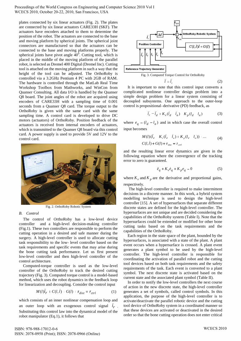
plates connected by six linear actuators (Fig. 2). The plates
are connected by six linear actuators CARE33H (SKF). The
actuators have encoders attached to them to determine the
position of the robot. The actuators are connected to the base
and moving platform by spherical joints. The spherical joint
connectors are manufactured so that the actuators can be
connected to the base and moving platforms properly. The
spherical joints have pivot angle 400. Cutting tool, which is
placed in the middle of the moving platform of the parallel
robot, is selected as Dremel 400 Digital (Dremel Inc). Cutting
tool is attached on the moving platform in such a way that the
height of the tool can be adjusted. The OrthoRoby is
controlled via a 3.2GHz Pentium 4 PC with 2GB of RAM.
The hardware is controlled through the MatLab Real Time
Workshop Toolbox from Mathworks, and WinCon from
Quanser Consulting. All data I/O is handled by the Quanser
Q8 board. The joint angles of the robot are acquired using
encoders of CARE33H with a sampling time of 0.001
seconds from a Quanser Q8 card. The torque output to the
OrthoRoby is given with the same card with the same
sampling time. A control card is developed to drive DC
motors (actuators) of OrthoRoby. Position feedback of the
actuators is received from internal encoders of actuators,
which is transmitted to the Quanser Q8 board via this control
card. A power supply is used to provide 5V and 12V to the
control card.
Fig. 2. OrthoRoby Robotic System
B. Control
The control of OrthoRoby has a low-level device
controller and a high-level decision-making controller
(Fig.1). These two controllers are responsible to perform the
cutting operation in a desired and safe manner during the
surgery. A high-level controller is used to allocate cutting
task responsibility to the low- level controller based on the
task requirements and specific events that may arise during
the bone cutting task performance. Let us first present
low-level controller and then high-level controller of the
control architecture.
Computed-torque controller is used as the low-level
controller of the OrthoRoby to track the desired cutting
trajectory (Fig. 3). Computed torque control is a model-based
method, which uses the robot dynamics in the feedback loop
for linearization and decoupling. Consider the control input
ctrldistlGllCrllM )(),()( (1)
which consists of an inner nonlinear compensation loop and
an outer loop with an exogenous control signal rl .
Substituting this control law into the dynamical model of the
robot manipulator (Eq.1), it follows that
Fig. 3. Computed Torque Control for OrthoRoby
rll (2)
It is important to note that this control input converts a
complicated nonlinear controller design problem into a
simple design problem for a linear system consisting of
decoupled subsystems. One approach to the outer-loop
control is propositional–derivative (PD) feedback, as
)()( adpadvdr llKllKll (3)
where )( adq lle and in which case the overall control
input becomes
ctrldist
adpadvd
lGllC
llKllKllM
)(),(
...))()(()(
(4)
and the resulting linear error dynamics are given in the
following equation where the convergence of the tracking
error to zero is guaranteed.
0qpqvq eKeKe (5)
where vK and pK are the derivative and proportional gains,
respectively. The high-level controller is required to make intermittent
decisions in a discrete manner. In this work, a hybrid system
modelling technique is used to design the high-level
controller [15]. A set of hypersurfaces that separate different
discrete states are defined for the high-level controller. The
hypersurfaces are not unique and are decided considering the
capabilities of the OrthoRoby system (Table I). Note that the
hypersurfaces could be extended or modified for other bone
cutting tasks based on the task requirements and the
capabilities of the OrthoRoby.
Each region in the state space of the plant, bounded by the
hypersurfaces, is associated with a state of the plant. A plant
event occurs when a hypersurface is crossed. A plant event
generates a plant symbol to be used by the high-level
controller. The high-level controller is responsible for
coordinating the activation of parallel robot and the cutting
tool devices based on both task requirements and the safety
requirements of the task. Each event is converted to a plant
symbol. The next discrete state is activated based on the
current state and the associated plant symbol (Table II).
In order to notify the low-level controllers the next course
of action in the new discrete state, the high-level controller
generates a set of symbols, called control symbols. In this
application, the purpose of the high-level controller is to
activate/deactivate the parallel robotic device and the cutting
tool device of OrthoRoby system in a coordinated manner so
that these devices are activated or deactivated in the desired
order so that the bone cutting operation does not enter critical
Proceedings of the World Congress on Engineering and Computer Science 2010 Vol I WCECS 2010, October 20-22, 2010, San Francisco, USA
ISBN: 978-988-17012-0-6 ISSN: 2078-0958 (Print); ISSN: 2078-0966 (Online)
WCECS 2010
regions of the state space in order to ensure safety. When new
control actions are required for a bone cutting operation, new
control states can easily be included in the set of the states.
The transition function uses the current control state and the
plant symbol to determine the next control action that is
required to update the bone cutting operation. The high-level
controller generates a control symbol which is unique for
each state. The low-level assistive controller cannot interpret
the control symbols directly. Thus the interface converts the
control symbols into continuous outputs, which are called
plant inputs. The plant inputs are then sent to the low-level
controllers to modify the bone cutting operation. Table III
and Table IV present control states and control symbols,
respectively. To our knowledge, such an intelligent control
mechanism has not been explored before for orthopedic
surgical robotic systems. Table I: Hypersurfaces
(sb==1)
start button (sb) is a binary
value, which will be 1
when it is pressed and 0
when it is released.
x and xt are the parallel
robot position and the
bone's position,
respectively, is a value
used to determine if the
parallel robot is close
enough to the bone.
cto (cutting tool on) is a
binary value, which will be
1 when it is pressed and 0
when it is released. and
are the cutting tool
depth and the depth in the
bone, respectively. is a
value used to determine if
the cutting tool is close
enough to the desired depth
in the bone.
and are the parallel
robot position and the
initial position of the task,
respectively, is a value
used to determine if the
robot is close enough to the
initial position.
and represent the set
of lower and upper limits of
the parallel robots legs,
respectively and l is the set
of actual leg lengths.
and are the torque
applied to the actuators of
the parallel robot device
and the threshold value,
respectively.
Emergency button (eb) and
pause button (pb) are
binary values, which will
be 1 when it is pressed and
0 when it is released.
C. Camera
Two Logitech C600 HD webcam with fixed focus
cameras, which are labeled as C1 and C2, are added to the
control architecture to measure the depth of cutting and to
detect if OrthoRoby is close enough to the bone during the
Table II: Plant Symbols
The parallel robot approaches towards the bone, which is
generated when h1 is crossed.
The parallel robot reaches the bone, which is generated when
h2 is crossed.
The cutting tool reaches the desired cutting depth, which is
generated when h3 is crossed.
Parallel robot goes back to starting position, which is
generated when h4 is crossed.
Safety related issues happened such as the parallel robot leg
lengths are out of limits, or the parallel robot applied force is
above its threshold (when h5 is crossed), or emergency
button is pressed (when h6 is crossed), or surgeon pressed
pause button (when h7 is crossed)
The surgent releases the pause buton, which is generated
when h8 is crossed
If the surgent presses pause button when the parallel robot is
approaching towards the bone, then plant symbol is
generated. Similarly if the surgent presses pause button when
the bone cutting tool is on, then the plant symbol is
generated. If the surgent presses pause button when robot is
returning back to original position, then the plant symbol
is generated.
Table III: Control States
The parallel robot device alone is active to move towards the
bone.
The parallel robot device alone is active to move back to the
starting position.
Both the parallel robot device and the cutting tool device are
active.
Both the parallel robot device and the cutting tool device are
idle.
Memory state after surgeon says "stop" while is active and
m = 1, 2.
Continue state when the surgeon wants to continue with the
task while (where m = 1, 2) is active.
Table IV: Control Symbols
Drive parallel robot device to perform primitive motion to
move towards the bone.
Drive, parallel robot device to perform primitive motion to
move back to the starting position
Drive cutting tool device to cut the bone.
Make the parallel robot and cutting tool devices idle.
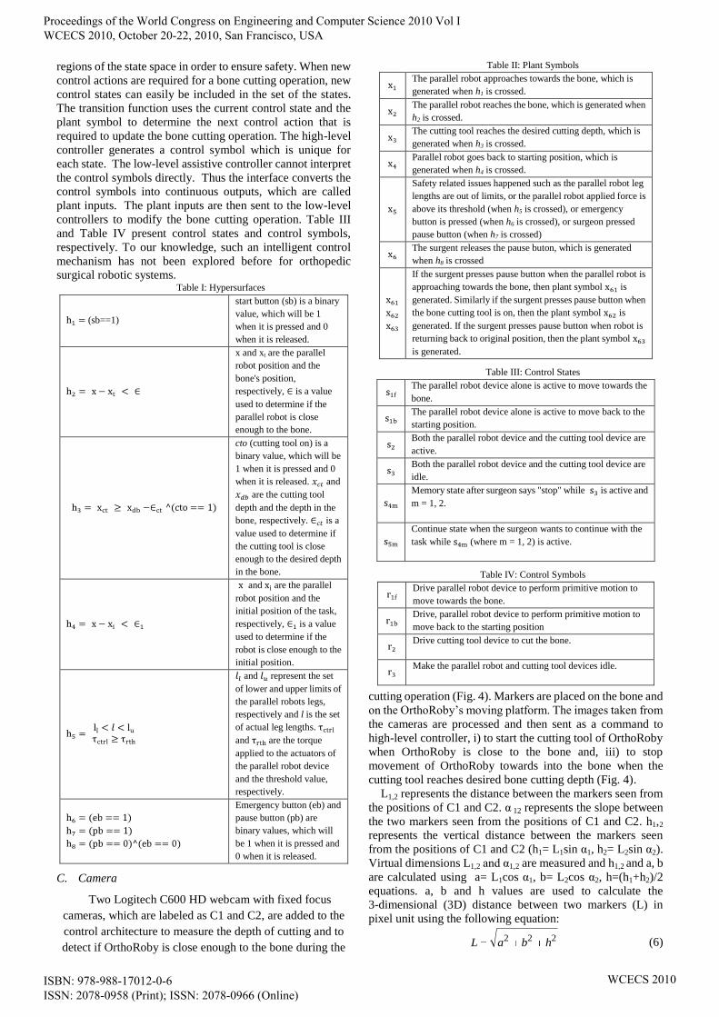
cutting operation (Fig. 4). Markers are placed on the bone and
on the OrthoRoby’s moving platform. The images taken from
the cameras are processed and then sent as a command to
high-level controller, i) to start the cutting tool of OrthoRoby
when OrthoRoby is close to the bone and, iii) to stop
movement of OrthoRoby towards into the bone when the
cutting tool reaches desired bone cutting depth (Fig. 4).
L1,2 represents the distance between the markers seen from
the positions of C1 and C2. α 12 represents the slope between
the two markers seen from the positions of C1 and C2. h1,2
represents the vertical distance between the markers seen
from the positions of C1 and C2 (h1= L1sin α1, h2= L2sin α2).
Virtual dimensions L1,2 and α1,2 are measured and h1,2 and a, b
are calculated using a= L1cos α1, b= L2cos α2, h=(h1+h2)/2
equations. a, b and h values are used to calculate the
3-dimensional (3D) distance between two markers (L) in
pixel unit using the following equation:
222 hbaL (6)
Proceedings of the World Congress on Engineering and Computer Science 2010 Vol I WCECS 2010, October 20-22, 2010, San Francisco, USA
ISBN: 978-988-17012-0-6 ISSN: 2078-0958 (Print); ISSN: 2078-0966 (Online)
WCECS 2010
where L is known to be 8.1 cm, so it will be possible to find
the cm equivalent of each pixel in images. If pixel width is
known in cm unit, it will be possible to measure the distance
of the cutting tool movement inside the bone [17].
Fig. 4. Camera Interface
D. Medical User Interface (MUI)
The necessity of obtaining accurate results for posterior
validation with experimental values implied an adequate
modeling of the bone structure in terms of 3D modeling. The
initial step concerning the bone anthropometrical definition is
a Computer-Tomography (CT) scan of the femur region of
patients in a Philips® Brilliance CT equipment. The
geometric models are obtained from 3D reconstruction of CT
images of the patients which are taken from Yeditepe
University Hospital. The CT images are taken with intervals
of 1 mm in the neutral position. These images are transferred
to user interface. Surgeon decides bone cutting trajectory
after processing patient’s CT images by using the functions
of user interface. The decision is transferred to OrthoRoby
via high-level controller. The details of MUI is given in [17].
III. RESULTS
A. Experimental-Setup
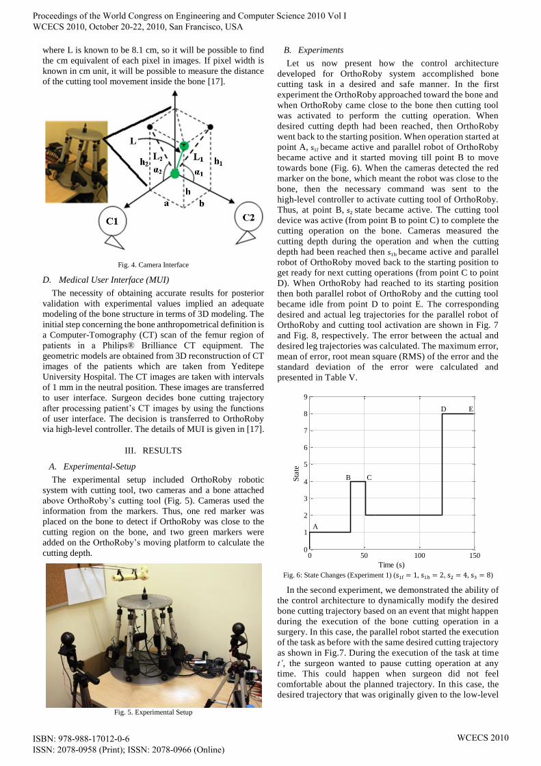
The experimental setup included OrthoRoby robotic
system with cutting tool, two cameras and a bone attached
above OrthoRoby’s cutting tool (Fig. 5). Cameras used the
information from the markers. Thus, one red marker was
placed on the bone to detect if OrthoRoby was close to the
cutting region on the bone, and two green markers were
added on the OrthoRoby’s moving platform to calculate the
cutting depth.
Fig. 5. Experimental Setup
B. Experiments
Let us now present how the control architecture
developed for OrthoRoby system accomplished bone
cutting task in a desired and safe manner. In the first
experiment the OrthoRoby approached toward the bone and
when OrthoRoby came close to the bone then cutting tool
was activated to perform the cutting operation. When
desired cutting depth had been reached, then OrthoRoby
went back to the starting position. When operation started at
point A, became active and parallel robot of OrthoRoby
became active and it started moving till point B to move
towards bone (Fig. 6). When the cameras detected the red
marker on the bone, which meant the robot was close to the
bone, then the necessary command was sent to the
high-level controller to activate cutting tool of OrthoRoby.
Thus, at point B, state became active. The cutting tool
device was active (from point B to point C) to complete the
cutting operation on the bone. Cameras measured the
cutting depth during the operation and when the cutting
depth had been reached then became active and parallel
robot of OrthoRoby moved back to the starting position to
get ready for next cutting operations (from point C to point
D). When OrthoRoby had reached to its starting position
then both parallel robot of OrthoRoby and the cutting tool
became idle from point D to point E. The corresponding
desired and actual leg trajectories for the parallel robot of
OrthoRoby and cutting tool activation are shown in Fig. 7
and Fig. 8, respectively. The error between the actual and
desired leg trajectories was calculated. The maximum error,
mean of error, root mean square (RMS) of the error and the
standard deviation of the error were calculated and
presented in Table V.
Fig. 6: State Changes (Experiment 1) ( , , , )
In the second experiment, we demonstrated the ability of
the control architecture to dynamically modify the desired
bone cutting trajectory based on an event that might happen
during the execution of the bone cutting operation in a
surgery. In this case, the parallel robot started the execution
of the task as before with the same desired cutting trajectory
as shown in Fig.7. During the execution of the task at time
t’, the surgeon wanted to pause cutting operation at any
time. This could happen when surgeon did not feel
comfortable about the planned trajectory. In this case, the
desired trajectory that was originally given to the low-level
0 50 100 1500
1
2
3
4
5
6
7
8
9
Time (s)
Sta
te
A
B C
D E
Proceedings of the World Congress on Engineering and Computer Science 2010 Vol I WCECS 2010, October 20-22, 2010, San Francisco, USA
ISBN: 978-988-17012-0-6 ISSN: 2078-0958 (Print); ISSN: 2078-0966 (Online)
WCECS 2010
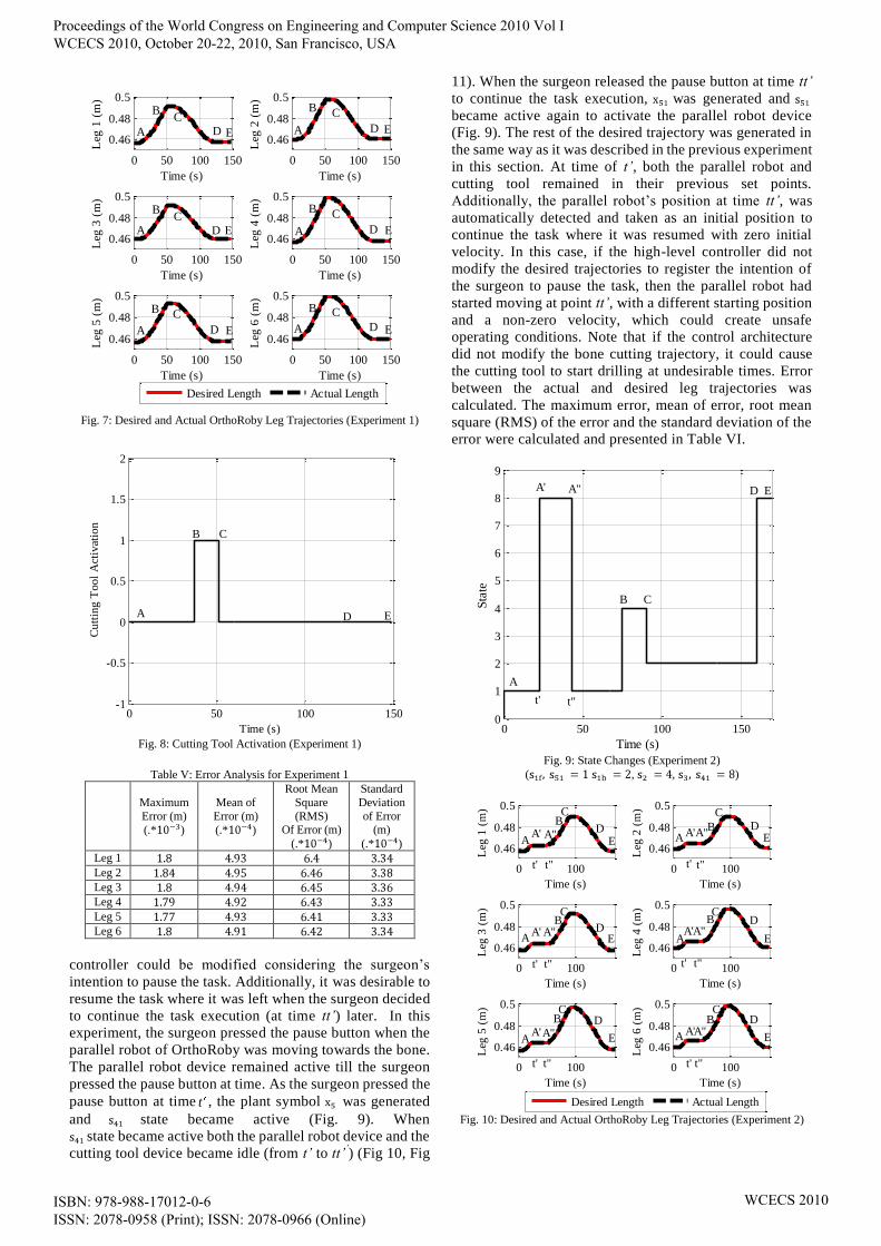
Fig. 7: Desired and Actual OrthoRoby Leg Trajectories (Experiment 1)
Fig. 8: Cutting Tool Activation (Experiment 1)
Table V: Error Analysis for Experiment 1
Maximum
Error (m)
(.* )
Mean of
Error (m)
(.* )
Root Mean
Square
(RMS) Of Error (m)
(.* )
Standard
Deviation
of Error (m)
(.* )
Leg 1
Leg 2
Leg 3
Leg 4
Leg 5
Leg 6
controller could be modified considering the surgeon’s
intention to pause the task. Additionally, it was desirable to
resume the task where it was left when the surgeon decided
to continue the task execution (at time tt’) later. In this
experiment, the surgeon pressed the pause button when the
parallel robot of OrthoRoby was moving towards the bone.
The parallel robot device remained active till the surgeon
pressed the pause button at time. As the surgeon pressed the
pause button at time t , the plant symbol was generated
and state became active (Fig. 9). When
state became active both the parallel robot device and the
cutting tool device became idle (from t’ to tt’’) (Fig 10, Fig
11). When the surgeon released the pause button at time tt’
to continue the task execution, was generated and
became active again to activate the parallel robot device
(Fig. 9). The rest of the desired trajectory was generated in
the same way as it was described in the previous experiment
in this section. At time of t’, both the parallel robot and
cutting tool remained in their previous set points.
Additionally, the parallel robot’s position at time tt’, was
automatically detected and taken as an initial position to
continue the task where it was resumed with zero initial
velocity. In this case, if the high-level controller did not
modify the desired trajectories to register the intention of
the surgeon to pause the task, then the parallel robot had
started moving at point tt’, with a different starting position
and a non-zero velocity, which could create unsafe
operating conditions. Note that if the control architecture
did not modify the bone cutting trajectory, it could cause
the cutting tool to start drilling at undesirable times. Error
between the actual and desired leg trajectories was
calculated. The maximum error, mean of error, root mean
square (RMS) of the error and the standard deviation of the
error were calculated and presented in Table VI.
Fig. 9: State Changes (Experiment 2)
( , , )
Fig. 10: Desired and Actual OrthoRoby Leg Trajectories (Experiment 2)
0 50 100 150
0.46
0.48
0.5
Time (s)
Leg
1 (
m)
0 50 100 150
0.46
0.48
0.5
Time (s)
Leg
3 (
m)
0 50 100 150
0.46
0.48
0.5
Time (s)
Leg
5 (
m)
0 50 100 150
0.46
0.48
0.5
Time (s)
Leg
2 (
m)
0 50 100 150
0.46
0.48
0.5
Time (s)
Leg
4 (
m)
0 50 100 150
0.46
0.48
0.5
Time (s)
Leg
6 (
m)
Desired Length Actual Length
A
A
A
A
A
A
B
B
B
B
B
BC
C
C C
C
C
D
E E
E
E
ED
ED
DD
D
0 50 100 150-1
-0.5
0
0.5
1
1.5
2
Time (s)
Cu
ttin
g T
oo
l A
ctiv
atio
n
A
CB
D E
0 50 100 1500
1
2
3
4
5
6
7
8
9
Time (s)
Sta
teED
B C
A' A"
A
t' t"
0 100
0.46
0.48
0.5
Time (s)
Leg
1 (
m)
0 100
0.46
0.48
0.5
Time (s)
Leg
3 (
m)
0 100
0.46
0.48
0.5
Time (s)
Leg
5 (
m)
0 100
0.46
0.48
0.5
Time (s)
Leg
2 (
m)
0 100
0.46
0.48
0.5
Time (s)
Leg
4 (
m)
0 100
0.46
0.48
0.5
Time (s)
Leg
6 (
m)
Desired Length Actual Length
E
E
E
EE
D
DD
D
D
D
A
A
A
A
A
B
C
C
CB
CB B
E
CB
CB
AA' A"
A' A"
A'A" A"A'
A'A"
A"A'
t'
t'
t"
t"
t' t"
t' t"
t"t'
t"t'
Proceedings of the World Congress on Engineering and Computer Science 2010 Vol I WCECS 2010, October 20-22, 2010, San Francisco, USA
ISBN: 978-988-17012-0-6 ISSN: 2078-0958 (Print); ISSN: 2078-0966 (Online)
WCECS 2010
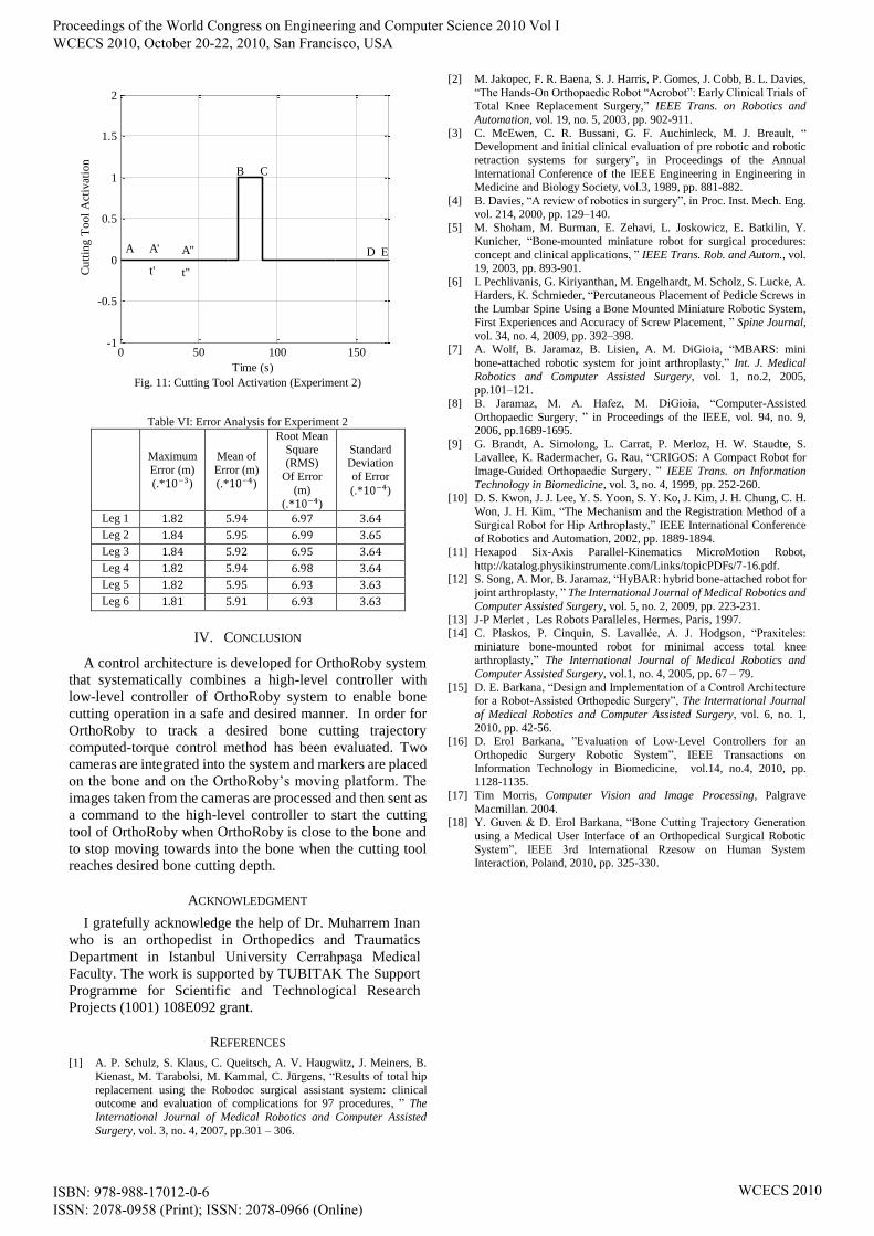
Fig. 11: Cutting Tool Activation (Experiment 2)
Table VI: Error Analysis for Experiment 2
Maximum
Error (m)
(.* )
Mean of
Error (m)
(.* )
Root Mean
Square (RMS)
Of Error
(m)
(.* )
Standard Deviation
of Error
(.* )
Leg 1
Leg 2
Leg 3
Leg 4
Leg 5
Leg 6
IV. CONCLUSION
A control architecture is developed for OrthoRoby system
that systematically combines a high-level controller with
low-level controller of OrthoRoby system to enable bone
cutting operation in a safe and desired manner. In order for
OrthoRoby to track a desired bone cutting trajectory
computed-torque control method has been evaluated. Two
cameras are integrated into the system and markers are placed
on the bone and on the OrthoRoby’s moving platform. The
images taken from the cameras are processed and then sent as
a command to the high-level controller to start the cutting
tool of OrthoRoby when OrthoRoby is close to the bone and
to stop moving towards into the bone when the cutting tool
reaches desired bone cutting depth.
ACKNOWLEDGMENT
I gratefully acknowledge the help of Dr. Muharrem Inan
who is an orthopedist in Orthopedics and Traumatics
Department in Istanbul University Cerrahpaşa Medical
Faculty. The work is supported by TUBITAK The Support
Programme for Scientific and Technological Research
Projects (1001) 108E092 grant.
REFERENCES
[1] A. P. Schulz, S. Klaus, C. Queitsch, A. V. Haugwitz, J. Meiners, B.
Kienast, M. Tarabolsi, M. Kammal, C. Jürgens, “Results of total hip
replacement using the Robodoc surgical assistant system: clinical outcome and evaluation of complications for 97 procedures, ” The
International Journal of Medical Robotics and Computer Assisted
Surgery, vol. 3, no. 4, 2007, pp.301 – 306.
[2] M. Jakopec, F. R. Baena, S. J. Harris, P. Gomes, J. Cobb, B. L. Davies,
“The Hands-On Orthopaedic Robot “Acrobot”: Early Clinical Trials of Total Knee Replacement Surgery,” IEEE Trans. on Robotics and
Automation, vol. 19, no. 5, 2003, pp. 902-911.
[3] C. McEwen, C. R. Bussani, G. F. Auchinleck, M. J. Breault, “ Development and initial clinical evaluation of pre robotic and robotic
retraction systems for surgery”, in Proceedings of the Annual
International Conference of the IEEE Engineering in Engineering in Medicine and Biology Society, vol.3, 1989, pp. 881-882.
[4] B. Davies, “A review of robotics in surgery”, in Proc. Inst. Mech. Eng.
vol. 214, 2000, pp. 129–140. [5] M. Shoham, M. Burman, E. Zehavi, L. Joskowicz, E. Batkilin, Y.
Kunicher, “Bone-mounted miniature robot for surgical procedures:
concept and clinical applications, ” IEEE Trans. Rob. and Autom., vol. 19, 2003, pp. 893-901.
[6] I. Pechlivanis, G. Kiriyanthan, M. Engelhardt, M. Scholz, S. Lucke, A.
Harders, K. Schmieder, “Percutaneous Placement of Pedicle Screws in the Lumbar Spine Using a Bone Mounted Miniature Robotic System,
First Experiences and Accuracy of Screw Placement, ” Spine Journal,
vol. 34, no. 4, 2009, pp. 392–398. [7] A. Wolf, B. Jaramaz, B. Lisien, A. M. DiGioia, “MBARS: mini
bone-attached robotic system for joint arthroplasty,” Int. J. Medical
Robotics and Computer Assisted Surgery, vol. 1, no.2, 2005,
pp.101–121.
[8] B. Jaramaz, M. A. Hafez, M. DiGioia, “Computer-Assisted
Orthopaedic Surgery, ” in Proceedings of the IEEE, vol. 94, no. 9, 2006, pp.1689-1695.
[9] G. Brandt, A. Simolong, L. Carrat, P. Merloz, H. W. Staudte, S. Lavallee, K. Radermacher, G. Rau, “CRIGOS: A Compact Robot for
Image-Guided Orthopaedic Surgery, ” IEEE Trans. on Information
Technology in Biomedicine, vol. 3, no. 4, 1999, pp. 252-260. [10] D. S. Kwon, J. J. Lee, Y. S. Yoon, S. Y. Ko, J. Kim, J. H. Chung, C. H.
Won, J. H. Kim, “The Mechanism and the Registration Method of a
Surgical Robot for Hip Arthroplasty,” IEEE International Conference of Robotics and Automation, 2002, pp. 1889-1894.
[11] Hexapod Six-Axis Parallel-Kinematics MicroMotion Robot,
http://katalog.physikinstrumente.com/Links/topicPDFs/7-16.pdf. [12] S. Song, A. Mor, B. Jaramaz, “HyBAR: hybrid bone-attached robot for
joint arthroplasty, ” The International Journal of Medical Robotics and
Computer Assisted Surgery, vol. 5, no. 2, 2009, pp. 223-231. [13] J-P Merlet , Les Robots Paralleles, Hermes, Paris, 1997.
[14] C. Plaskos, P. Cinquin, S. Lavallée, A. J. Hodgson, “Praxiteles:
miniature bone-mounted robot for minimal access total knee
arthroplasty,” The International Journal of Medical Robotics and
Computer Assisted Surgery, vol.1, no. 4, 2005, pp. 67 – 79.
[15] D. E. Barkana, “Design and Implementation of a Control Architecture for a Robot-Assisted Orthopedic Surgery”, The International Journal
of Medical Robotics and Computer Assisted Surgery, vol. 6, no. 1,
2010, pp. 42-56. [16] D. Erol Barkana, ”Evaluation of Low-Level Controllers for an
Orthopedic Surgery Robotic System”, IEEE Transactions on
Information Technology in Biomedicine, vol.14, no.4, 2010, pp. 1128-1135.
[17] Tim Morris, Computer Vision and Image Processing, Palgrave
Macmillan. 2004. [18] Y. Guven & D. Erol Barkana, “Bone Cutting Trajectory Generation
using a Medical User Interface of an Orthopedical Surgical Robotic
System”, IEEE 3rd International Rzesow on Human System Interaction, Poland, 2010, pp. 325-330.
0 50 100 150-1
-0.5
0
0.5
1
1.5
2
Time (s)
Cu
ttin
g T
oo
l A
ctiv
atio
n
A A' A"
t' t"
D
B C
E
Proceedings of the World Congress on Engineering and Computer Science 2010 Vol I WCECS 2010, October 20-22, 2010, San Francisco, USA
ISBN: 978-988-17012-0-6 ISSN: 2078-0958 (Print); ISSN: 2078-0966 (Online)
WCECS 2010