continuously transposed cable - essex · pdf fileb width of bare wire e nominal increase due...
TRANSCRIPT

Product Information
Continuously Transposed Cable
© Essex Revision 2013-01

Product Information CTC 2013-01; Page 2 of 13
© Essex
1 Inhaltsverzeichnis2 Introduction ...................................................................................................................3
3 Quality...........................................................................................................................3
4 Technical restrictions ....................................................................................................3
4.1 Overview ................................................................................................................3
4.2 Conductor...............................................................................................................4
4.2.1 Materials.....................................................................................................................................4
4.2.2 Mechanical characteristics of conductor ...................................................................................4
4.2.3 Sizes ............................................................................................................................................5
4.3 Enamelled strand....................................................................................................5
4.3.1 Strand Insolation ........................................................................................................................5
4.3.2 Thickness of enamel ...................................................................................................................5
4.3.3 Epoxy bond coat .........................................................................................................................5
4.4 Continuously transposed cable ..............................................................................6
4.4.1 Transposition..............................................................................................................................6
4.4.2 Size calculation ...........................................................................................................................6
4.4.3 Determination of size .................................................................................................................7
4.5 Cable Insulation......................................................................................................7
4.5.1 Cellulose insulation ....................................................................................................................7
4.5.2 Thickness and width of paper ....................................................................................................8
4.5.3 Minimum number of paper layers .............................................................................................8
4.5.4 Tolerance of insulation...............................................................................................................9
4.5.5 Arrangement of layers................................................................................................................9
4.5.6 Inter column separator...............................................................................................................9
4.5.7 Special insulation........................................................................................................................9
4.5.8 Special solutions for low voltage winding ..................................................................................9
5 Test certificate.............................................................................................................10
6 Packaging ...................................................................................................................11
6.1 Drum types ...........................................................................................................11
6.2 Storage and transport condition ...........................................................................12
7 Ordering specification .................................................................................................12
8 Marking .......................................................................................................................12
9 Appendix: order specification form...........................................................................9-13
9.1.1 ..................................................................................................................................................... 9-13
9.1.2 ..................................................................................................................................................... 9-13
Product Information CTC 2013-01; Page 3 of 13
© Essex
2 Introduction
Continuously transposed cables are used in power transformers. They offer decisiveadvantages in the design of transformers compared to the conventional paper-insulated solidconductors:
shorted winding time during the production of power transformers
increased space factor resulting in decreased size and costs of transformer
reduced electrical losses
A large selection of various materials for insulation and special covering of continuouslytransposed cables is available.
Furthermore, the patented manufacturing process of Essex offers additional specificadvantages:
precise transposition enabling limited tolerance in measuring
extreme flexibility through short pitches
excellent windability and simple handling
no necessity of paper insulation because of high stability
This Product Information provides general technical information on continuously transposedcable made of high conductivity enamelled copper or copper silver alloy strip made up of oddor even number of 5 to 84 individual strips for use in transformer winding.
Please contact us for any special request you may have.
3 Quality
Continuously transposed cables are used in electrical machines at very high cost per unit.For this reason the quality is strictly controlled during the entire production, e.g.:
Bare wire drawing continuous monitoring of dimensionssurface conditiongeometry
Enamelling dielectricssurface condition
Transposing accuracy of transpositionsinsulation between strands
The process-oriented quality system of Essex is based on ISO 9001 and ISO TS 16949
4 Technical restrictions
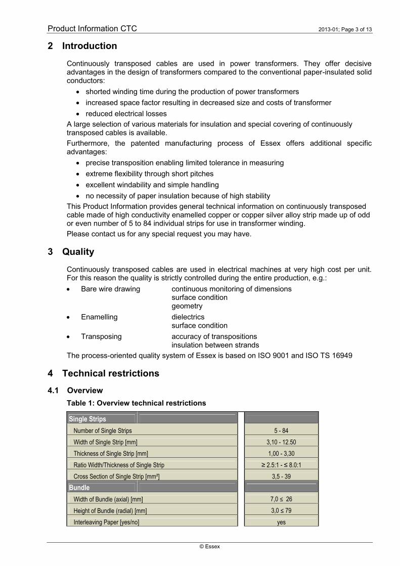
4.1 Overview
Table 1: Overview technical restrictions
Single Strips
Number of Single Strips 5 - 84
Width of Single Strip [mm] 3,10 - 12.50
Thickness of Single Strip [mm] 1,00 - 3,30
Ratio Width/Thickness of Single Strip ≥ 2.5:1 - ≤ 8.0:1
Cross Section of Single Strip [mm²] 3,5 - 39
Bundle
Width of Bundle (axial) [mm] 7,0 ≤ 26
Height of Bundle (radial) [mm] 3,0 ≤ 79
Interleaving Paper [yes/no] yes

Product Information CTC 2013-01; Page 4 of 13
© Essex
Ratio Height/Width of Bundle ≥ 1:3 - ≤ 8:1
Transposing Factor 5 - 14
Min. Transposing pitch length [mm] 25
Mechanical Properties
Proof stress (Rp 0.2) - Soft annealed [N/mm²] 80 - 120
Proof stress (Rp 0.2) - Mechanical hardened [N/mm²] 120 - 220
Proof stress (Rp 0.2) - silver alloyed [N/mm²] 220 - 350
Restrictions
Proof Stress
170 N/mm² < Rp 0.2 <220 N/mm²
Width of Single Strip [mm] 3,10 - 12.50
Thickness of Single Strip [mm] 1,00 - 3,30
Cross Section of Single Strip [mm²] 3,5 ≤ 39
220 N/mm² < Rp 0.2 <280 N/mm²
Width of Single Strip [mm] 3,10 - 12.50
Thickness of Single Strip [mm] 1,00 - 2,80Max. Cross Section of Single Strip[mm²] 3,5 ≤ 30
Transposing Factors < 7
Width of Single Strip [mm] 3,10 - 10,00
Thickness of Single Strip [mm] 1,00 - 2,00
Proof Stress (Rp 0.2) [N/mm²] 80 - 200
Other dimensions on request !
4.2 Conductor
4.2.1 Materials
Table 2: Conductor material
4.2.2 Mechanical characteristics of conductor
The mechanical characteristics of conductor are adjusted to the customer specification atRp0,1 or Rp0,2.
type description norm purity conductivity @
20°C*
specific resis-
tance @ 20 °C*
remarks
Cu-ETP1 high conductivity
copper
EN 1977 Cu min 99,99 % > 58,58 MS/m < 0,01707 µW m
Cu-OF1 oxygen free copper EN 1977 Cu min 99,99 % > 58,58 MS/m < 0,01707 µW m copper with high conductivity and
resitance against hydrogen
embrittlement
CuAg0,04 silver alloyed copper EN 1977 Ag: 0,03 - 0,05 % > 58,00 MS/m < 0,01724 µW m material for high yield points up to
380 Mpa
CuAg0,10 silver alloyed copper EN 1977 Ag: 0,08 - 0,12 % > 58,00 MS/m < 0,01724 µW m material for high yield points up to
380 Mpa
type description norm purity conductivity @
20°C*
remarks
EN AW 1370 Aluminium for
electrical application
DIN EN 573-3 Al min 99,70 % > 36,7 MS/m < 0,02725 µW m
Copper
Aluminium
Product Information CTC 2013-01; Page 5 of 13
© Essex
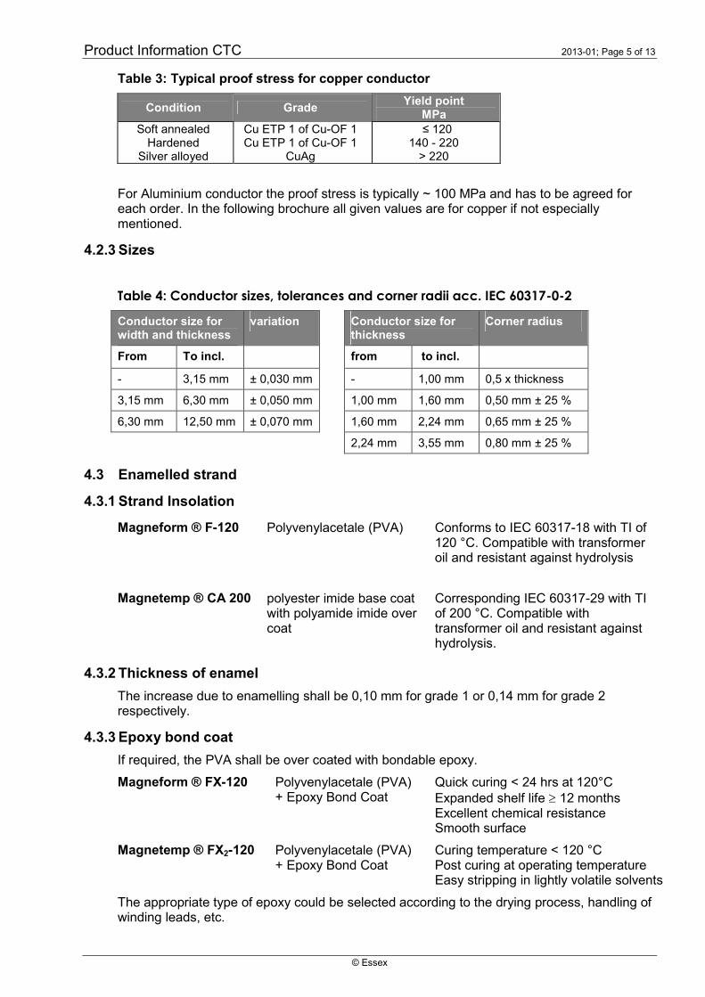
Table 3: Typical proof stress for copper conductor
Condition GradeYield point
MPaSoft annealed
HardenedSilver alloyed
Cu ETP 1 of Cu-OF 1Cu ETP 1 of Cu-OF 1
CuAg
≤ 120140 - 220
> 220
For Aluminium conductor the proof stress is typically ~ 100 MPa and has to be agreed foreach order. In the following brochure all given values are for copper if not especiallymentioned.
4.2.3 Sizes
Table 4: Conductor sizes, tolerances and corner radii acc. IEC 60317-0-2
Conductor size forwidth and thickness
variation Conductor size forthickness
Corner radius
From To incl. from to incl.
- 3,15 mm ± 0,030 mm - 1,00 mm 0,5 x thickness
3,15 mm 6,30 mm ± 0,050 mm 1,00 mm 1,60 mm 0,50 mm ± 25 %
6,30 mm 12,50 mm ± 0,070 mm 1,60 mm 2,24 mm 0,65 mm ± 25 %
2,24 mm 3,55 mm 0,80 mm ± 25 %
4.3 Enamelled strand
4.3.1 Strand Insolation
Magneform ® F-120 Polyvenylacetale (PVA) Conforms to IEC 60317-18 with TI of120 °C. Compatible with transformeroil and resistant against hydrolysis
Magnetemp ® CA 200 polyester imide base coatwith polyamide imide overcoat
Corresponding IEC 60317-29 with TIof 200 °C. Compatible withtransformer oil and resistant againsthydrolysis.
4.3.2 Thickness of enamel
The increase due to enamelling shall be 0,10 mm for grade 1 or 0,14 mm for grade 2respectively.
4.3.3 Epoxy bond coat
If required, the PVA shall be over coated with bondable epoxy.
Magneform ® FX-120 Polyvenylacetale (PVA)+ Epoxy Bond Coat
Quick curing < 24 hrs at 120°CExpanded shelf life 12 monthsExcellent chemical resistanceSmooth surface
Magnetemp ® FX2-120 Polyvenylacetale (PVA)+ Epoxy Bond Coat
Curing temperature < 120 °CPost curing at operating temperatureEasy stripping in lightly volatile solvents
The appropriate type of epoxy could be selected according to the drying process, handling ofwinding leads, etc.

Product Information CTC 2013-01; Page 6 of 13
© Essex
Enamelling of epoxy can be done by different methods, either concentrically with an increaseof 0,05 mm or as Radial Bond. For Radial Bond the size will increase axially by 0,01 mm and0,05 mm in radial direction.
Please contact us for any further request you may have.
4.4 Continuously transposed cable
The majority of continuously transposed cables consist of an uneven number of individualstrands due to geometrical advantages in the manufacturing of transformer windings. Even-numbered continuously transposed cables are produced at Essex as well. Twin- or triple-continuously transposed cables made by Essex, can reduce winding time in certainapplications, where large section conductors are needed.
Our patented manufacturing equipment allows maximum stack size axially 26 mm andradially 79 mm prior to paper covering. Because of easy windability the radial dimensionshould not exceed 6 times of the axial size
Each CTC is supplied with electrically continuous strands for the entire length of the cable onthe drum.
Prior to shipment the insulation of strips is tested. Electrical failures between each and everystrand are not permitted. All CTC are delivered without shorts.
4.4.1 Transposition
In one turn on the smallest winding diameter allstrands change their position at least once. Thepitch P may be shorter than calculated:
PD
n
Part of the pitch is the crank length (c) which is thearea of bending.
For geometric reasons the pitch can not bechosen at random. The transposing factorconsiders the width of the individual conductor.The transposing factor (FT) should not be lessthan 5:
nb
DFT
The applicable maximum transposition factor in individual cases will be set to ensuremechanical stability of the CTC during processing.
4.4.2 Size calculation
Nominal axial width is calculated as
ZIEbBA )(*2
The radial dimension of odd numbered CTC is calculated as ZEan
HR
2
1
or for CTC with an even number of strands
ZEan
HR
2
2.
Where n Number of stripsa Thickness of bare wireb Width of bare wireE Nominal increase due to enamelI Inter column separator, if specified in order 0.10 mmZ Nominal paper insulation
Figure 2: CTC Section
Figure 1: Crank length and pitch

Product Information CTC 2013-01; Page 7 of 13
© Essex
4.4.3 Determination of size
Measurement of size of CTC is done on straight specimen of approximately 40 cmlength with free ends under a pressure of 100 N/cm².
Table 5: Radial tolerances
Transposing factor FT ≥ 7thickness of strand ≤ 2,00 mm oryield point Rp0,2 ≤ 170 MPa
Transposing factor FT ≥ 5thickness of strand > 2,00 mm oryield point 170 MPa < Rp0,2 ≤ 220 MPa
No. of strands Tolerance No. of strands Tolerance
≤ 21 - 0,10 / +0,20 mm ≤ 21 - 0,10 / +0,30 mm
≤ 35 - 0,15 / + 0,30 mm ≤ 35 - 0,15 / + 0,50 mm
≤ 55 - 0,20 / + 0,80 mm ≤ 55 - 0,20 / + 1,30 mm
> 55 - 0,50 / + 1,10 mm > 55 - 0,50 / + 1,40 mm
Table 6: Axial tolerances
Size Tolerance
All sizes - 0,10 / + 0,05 mm
In case of transposing factors FT < 5 or yield point Rp0,2 > 220 MPa please contactESSEX for technical support.
4.5 Cable Insulation
Table 7: Overview of typical wrapping materials
Wrapping Material Special Feature, application
Kraft 5A2-1H1, general purpose with high purityKraft, calendared 5A4-1M2, high density and dielectric strengthKraft, thermally upgraded 5A2-1M2, high thermal propertiesKraft, thermally upgraded, calendared 5A4-1M1, high density, thermal and dielectric characteristicsCalandered, upgraded, creped Outer layers with very high mechanical strengthKraft, Epoxy coated Bondable outer layersKraft, Epoxy coated, upgraded Bondable outer layersAramide Very high thermal resistance, for traction transformersAramide, Epoxy coated Bondable outer layers, for traction transformersPerforated paper CTC with improved cooling of LV windingsGlass fabric tape External protection for cast resin transformers
4.5.1 Cellulose insulation
For the insulation of CTC designed for use in oil immersed transformers only insulating papercorresponding to IEC 554-3-5 is used. Available grades of cellulose paper are describedbelow.
High density crepe papers are often recommended as outermost layers to improvemechanical strength of the insulation. Crepe papers are thermally upgraded.

Product Information CTC 2013-01; Page 8 of 13
© Essex
Table 8: Cellulose Papers acc. IEC 554-3-5
Standard Kraft CalanderedKraft
Upgraded Upgradedcalendared
5A2-1H1 5A4-1M2 5A2-1M2 5A4-1M1Colour natural brown natural brown green greenAir permeability m/Pa*s 0,5 -1,0 0,1 - 0,2 0,1 - 0,2 0,05 - 0,1Air resistance Guerley
s128 – 255 640 – 1279 640 – 1279 1280 – 2560
Thickness mm 0,065 to 0,100 0,065 to 0,105 0,065 to 0,105 0,065 to 0,105Density g/cm³ 0,80+/-0,05 1,00 +/- 0,05 0,80 +/- 0,05 1,00 +/- 0,05Tensile index MD Nm/g > 93 > 93 > 93 > 93
CD > 34 > 35 > 35 > 35Elongation MD % > 2 > 2 > 2 > 2
CD > 4 > 4 > 4 > 4Ash content % < 0,5 < 0,5 < 0,5 < 0,5pH 6,0 - 8,0 6,0 - 8,0 6,0 - 8,0 6,0 - 8,0Conductivity mS/m < 4 < 4 < 4 < 4Capillary rise mm > 5 > 5 > 5 > 5Dielectric in air kV/mm > 7 > 8 > 7 > 7Dielectric in oil kV/mm >40 >60 >50 >60Nitrogen content % - - 1,1-2,6 1,1-2,6Degree of polymerisation >1000 >1000 >1100 >1100
Table 9: Crepe Papers, thermally Upgraded High Density, typical properties
Dennison22 HCC
Dennison32 HCC
Cindus42 HCF
CottrellK 125 TU
Air permeability Guerley s 750 750 >800 n.a.Thickness mm 0,076 0,076 0,076 0,127Density g/cm³ 1,02 1,04 1,12 1,05-1,25Tensile strength MD N/mm > 5 > 5 > 7 > 6Elongation MD % >15 >15 >15 >15Ash content % <1 <1 <1 0,75pH 7,50 7,50 6,5-7,5 n.a.Conductivity mS/m <4 <4 <250 n.a.Nitrogen content % 1.3-2.5 1.3-2.5 1,3-2,6 1,3-2,6Dielectric in air kV/mm > 10 > 9 > 9 > 12Dielectric in oil kV/mm 74 68 74 n.a.Degree of polymerisation >1200 >1200 ~1200 n.a.
4.5.2 Thickness and width of paper
The preferred width of paper is between 15 mm and 30 mm, its thickness between 65 mand 105 m. Thicker papers are applied as outer layers.
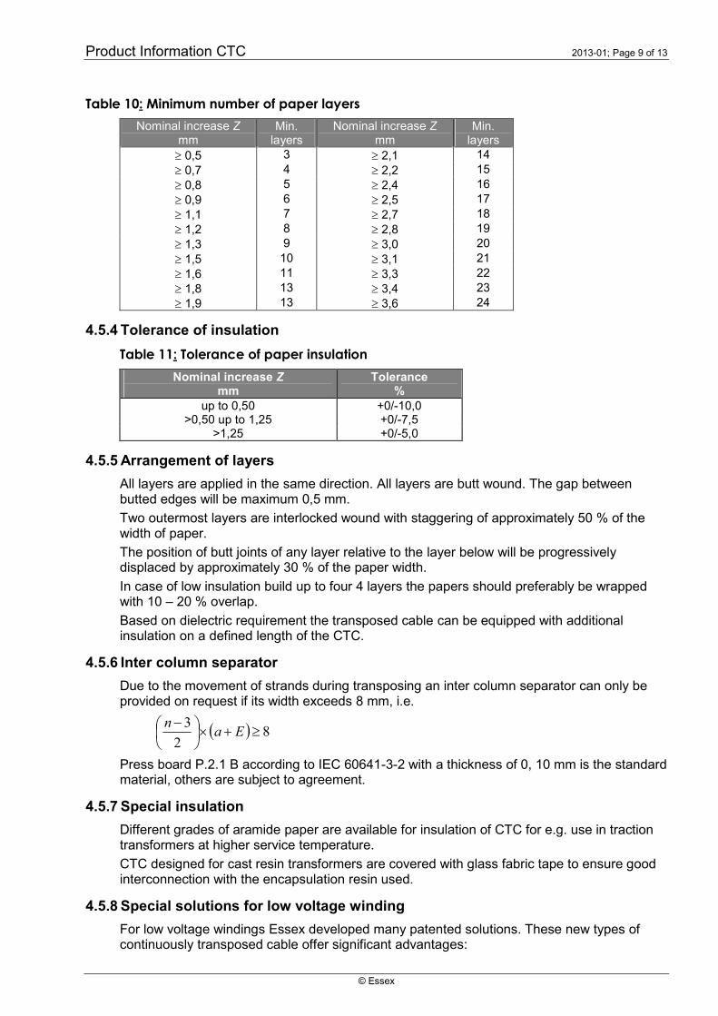
4.5.3 Minimum number of paper layers
A minimum number of layers will be applied according to Table 8.
Product Information CTC 2013-01; Page 9 of 13
© Essex
Table 10: Minimum number of paper layers
Nominal increase Zmm
Min.layers
Nominal increase Zmm
Min.layers
0,5 3 2,1 14
0,7 4 2,2 15
0,8 5 2,4 16
0,9 6 2,5 17
1,1 7 2,7 18
1,2 8 2,8 19
1,3 9 3,0 20
1,5 10 3,1 21
1,6 11 3,3 22
1,8 13 3,4 23
1,9 13 3,6 24
4.5.4 Tolerance of insulation
Table 11: Tolerance of paper insulation
Nominal increase Zmm
Tolerance%
up to 0,50 +0/-10,0>0,50 up to 1,25 +0/-7,5
>1,25 +0/-5,0
4.5.5 Arrangement of layers
All layers are applied in the same direction. All layers are butt wound. The gap betweenbutted edges will be maximum 0,5 mm.
Two outermost layers are interlocked wound with staggering of approximately 50 % of thewidth of paper.
The position of butt joints of any layer relative to the layer below will be progressivelydisplaced by approximately 30 % of the paper width.
In case of low insulation build up to four 4 layers the papers should preferably be wrappedwith 10 – 20 % overlap.
Based on dielectric requirement the transposed cable can be equipped with additionalinsulation on a defined length of the CTC.
4.5.6 Inter column separator
Due to the movement of strands during transposing an inter column separator can only beprovided on request if its width exceeds 8 mm, i.e.
82
3
Ea
n
Press board P.2.1 B according to IEC 60641-3-2 with a thickness of 0, 10 mm is the standardmaterial, others are subject to agreement.
4.5.7 Special insulation
Different grades of aramide paper are available for insulation of CTC for e.g. use in tractiontransformers at higher service temperature.
CTC designed for cast resin transformers are covered with glass fabric tape to ensure goodinterconnection with the encapsulation resin used.
4.5.8 Special solutions for low voltage winding
For low voltage windings Essex developed many patented solutions. These new types ofcontinuously transposed cable offer significant advantages:
Product Information CTC 2013-01; Page 10 of 13
© Essex
No bulging of paper insulation, oil pockets are avoided Improved heat dissipation allows reduction of oil ducts and results in better space
factor
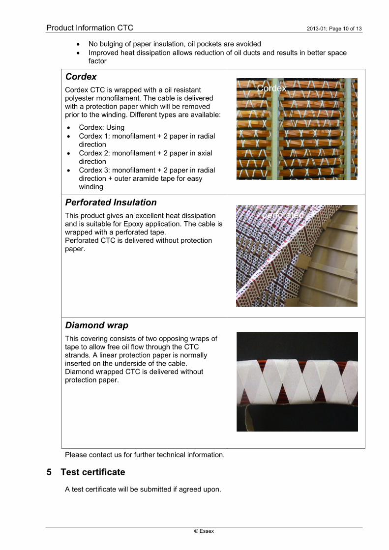
Cordex
Cordex CTC is wrapped with a oil resistantpolyester monofilament. The cable is deliveredwith a protection paper which will be removedprior to the winding. Different types are available:
Cordex: Using Cordex 1: monofilament + 2 paper in radial
direction Cordex 2: monofilament + 2 paper in axial
direction Cordex 3: monofilament + 2 paper in radial
direction + outer aramide tape for easywinding
Perforated Insulation
This product gives an excellent heat dissipationand is suitable for Epoxy application. The cable iswrapped with a perforated tape.Perforated CTC is delivered without protectionpaper.
Diamond wrap
This covering consists of two opposing wraps oftape to allow free oil flow through the CTCstrands. A linear protection paper is normallyinserted on the underside of the cable.Diamond wrapped CTC is delivered withoutprotection paper.
Please contact us for further technical information.
5 Test certificate
A test certificate will be submitted if agreed upon.
perforated
Cordex

Product Information CTC 2013-01; Page 11 of 13
© Essex
6 Packaging
6.1 Drum types
The continuously transposed cable shall be wound on wooden drum according to DIN 46391with metal inserts for the centre bore. The drum shall comply with the dimensions given inTable 12.
Suitable protection on the outside layer of the cable shall prevent from moisture and foreignmatter during storage and transport. An overall protection shall be obtained by woodenbattens. Flanges and partitions shall be smooth and not cause any damage to the conductorduring winding operation.
One or multiple length of cable per drum may be ordered. When multiple lengths per drumare required each length shall be wound into different compartments. When quantities ordesign on any partition differ length wise they shall be supplied as per Figure 3. In such casethe width may differ from sizes given in table 10.
The conductor ends shall be arranged that an electrical test between strips can be carriedout without unwinding. It should be noted that the ends of each length of the cable must besuitably insulated for this test and adequately protected for transport.
The finished conductor shall be lightly and evenly wound without twist on the drum.
d3 d1d2
b1
b2
Figure 3: Drum dimension Figure 4: Arrangement on drum
Table 12: Standard Drums for delivery of CTC (*)
Flange Core Width Traversing Centre bore Volume (**) Max. grossd1 d2 b1 b2 d3 65% weight
mm mm mm mm mm dm³ kg, ca.
1000 800 630 530 82 97 5751000 800 830 730 82 134 8001000 800 1050 930 82 171 1050
1250 900 630 500 82 192 12001250 900 830 700 82 269 16501250 900 1050 900 82 346 2150
1400 900 630 500 82 294 18001400 900 830 700 82 411 25001400 900 1050 900 82 528 3200
1600 1000 630 500 82 398 23001600 1000 830 700 82 557 32501600 1000 1050 900 82 717 4400
(*) Other types are subject to agreement.
(**) By experience it may be suggested to calculate the filling from 65 % usable volume ofthe geometrical space.

Product Information CTC 2013-01; Page 12 of 13
© Essex
6.2 Storage and transport condition
All reels have to be transported and stored only with horizontal axis. Care should be taken toensure that all loads are secured and unable to move during transportation. Forklifts have tobe used carefully not to destroy the flanges of the reel and the protection paper.
The storage temperature should not exceed 50 °C for a longer time, especially when the wireis coated with Epoxy bond coat. High humidity, condensate water or aggressive agentsshould be avoided.
Recommended conditions are between 15 - 25 °C at 60 % humidity and no direct solarradiation. Under these conditions the shelf life of Epoxy coated CTC is 6 month.
7 Ordering specification
Following details to be furnished in Purchase Order
Conductor size Number of strands Nominal insulation increase due to paper covering Inter column separator, if applicable Smallest winding diameter of transformer coil Length per drum and compartment Number of drum Approximate total weight of cable Number and issue of this Product Information
Enclosed order form contains all relevant information. We recommend using it for yourenquiries, requests or orders.
8 Marking
Each drum is to be clearly marked clearly with following information
Supplier’s name
Number and size of strands
Drum number
Gross weight
Length of cable
9 Appendix: order specification form
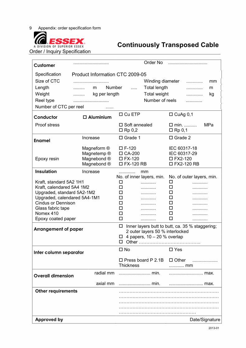
Continuously Transposed CableOrder / Inquiry Specification
Customer............................ Order No ...............................
Specification Product Information CTC 2009-05
Size of CTC ............................ Winding diameter ............. mm
Length ......... m Number ..... Total length ............. m
Weight ......... kg per length Total weight ............. kg
Reel type ............................ Number of reels .............
Number of CTC per reel ......
Conductor Aluminium Cu ETP CuAg 0,1
Proof stress Soft annealed min. .......... MPa Rp 0,2 Rp 0,1
EnamelIncrease Grade 1 Grade 2
Magneform ® F-120 IEC 60317-18Magnetemp ® CA-200 IEC 60317-29
Epoxy resin Magnebond ® FX-120 FX2-120Magnebond ® FX-120 RB FX2-120 RB
Insulation Increase ............. mmNo. of inner layers, min. No. of outer layers, min.
Kraft, standard 5A2 1H1 ............ ............Kraft, calendared 5A4 1M2 ............ ............Upgraded, standard 5A2-1M2 ............ ............Upgraded, calendared 5A4-1M1 ............ ............Cindus or Dennison ............ ............Glass fabric tape ............ ............Nomex 410 ............ ............Epoxy coated paper ............ ............
Arrangement of paper Inner layers butt to butt, ca. 35 % staggering;
2 outer layers 50 % interlocked 4 papers, 10 – 20 % overlap Other …………………………………..
Inter column separator No Yes
Press board P 2.1B Other ....................Thickness ............ mm
Overall dimensionradial mm ......................... min. ........................... max.
axial mm ......................... min. ........................... max.
Other requirements ………………………………………………………………………………………………………………………………………………………………………………………………………………………………………………………………………………………
Approved by Date/Signature
2013-01