continuous-flow grain dryer - allied grain · pdf file4 introduction in the neco dryer, warm...
TRANSCRIPT

1
YOUR SAFETY IS INVOLVED!
7713390
ATTENTIONPay close attention when you see this triangular symbol.
It will be throughout this manual and on decals.
Obey the Dangers, Warnings and Cautions.
READ AND UNDERSTAND THIS MANUAL BEFORE OPERATING DRYER.
CONTINUOUS-FLOW
Owner's and Operator's Manual
May 2008 Printing
9364 North 45th StreetOmaha, Nebraska 68112
www.necousa.com
GRAIN DRYER
Nebraska Engineering Co.A Division of GLOBAL Industries, Inc.
NECO
CE Version

2
GENERAL STATEMENT
WATCH FOR THIS SYMBOL! IT POINTS OUTIMPORTANT SAFETY PRECAUTIONS. IT MEANS,
“ATTENTION! - BECOME ALERT! YOUR SAFETY IS INVOLVED”.
Occupational safety is of prime concern to NECO. This Owner’s and Operator’s Manual was written with thesafety of the operator and others who come in contact with the equipment as our prime concern. It is yourresponsibility as an owner, operator, or supervisor to know what specific requirements, precautions, andwork hazards exist and to make these known to all other personnel working with the equipment or in the area,so that they too may take any necessary safety precautions that may be required. Failure to read thisOwner’s & Operators Manual and its’ safety instructions is a misuse of the equipment.
TO THE OWNER
We at NECO are continually testing and improving our products to give you the most efficient and economicalgrain handling equipment available. However, when improvements on our equipment are made, we cannotbe responsible for upgrading or changing units sold previously. The NECO equipment that you have justpurchased will give years of dependable service when properly maintained. your work load will be lightenedand valuable time will be saved. Congratulations on a wise investment and an astute brand choice . . .Welcome to the growing number of satisfied NECO equipment owners.
LIMITED WARRANTY
For a period of one (1) year after shipment of goods by Buyer to its’ customer, NECO will supply, free ofcharge, F.O.B. NECO’s factory, Omaha, Nebraska, replacement parts for parts which prove defective inworkmanship or material. Defective parts must be returned freight prepaid to the NECO Factory in Omaha,Nebraska. Prior to returning goods, NECO requires that a return form be obtained from NECO.
This limited warranty does not extend to parts designed to wear in normal operation and be replaced periodi-cally; or to damage caused by negligence, accident, abuse or improper installation or operation.
GOODS NOT MANUFACTURED BY NECO CARRY ONLY THE MANUFACTURER’S WARRANTY.
THIS UNDERTAKING IS IN LIEU OF ALL OTHER WARRANTIES, EXPRESS OR IMPLIED, INCLUDINGMERCHANTABILITY AND FITNESS FOR PARTICULAR PURPOSE.
FAILURE TO FOLLOW THE INSTRUCTIONS CONTAINED IN THIS MANUAL AND THE ITEMS LISTEDBELOW WILL RESULT IN THE VOIDING OF THIS LIMITED WARRANTY.
1. Improper assembly.2. Improper installation (power and wiring included)3. Unauthorized alterations of goods.4. Goods operated when obviously in need of repair.5. Use of unauthorized repair parts.6. Irresponsible operation by children or uninstructed personnel7. Used to handle materials other than free flowing, non-abrasive and dry materials as intended.8. Damaged through abusive use or accident.
LIMITATION OF LIABILITY
BUYER AGREES THAT IN NO EVENT SHALL NECO HAVE LIABILITY FOR DIRECT DAMAGES IN EX-CESS OF THE CONTRACT PRICE OF THE GOODS IN RESPECT OF WHICH CLAIM IS MADE ANDBUYER FURTHER AGREES THAT IN NO EVENT SHALL NECO ON ANY CLAIM OF ANY KIND, HAVELIABILITY FOR LOSS OF USE, LOSS OF PROFITS OR FOR ANY INDIRECT, INCIDENTAL, OR CONSE-QUENTIAL DAMAGES.

3
TABLE OF CONTENTS
INTRODUCTION .......................................................................................................................4COMPONENT CERTIFICATIONS .............................................................................................5SAFETY PROCEDURES ..........................................................................................................6TOWING A DRYER ....................................................................................................................8DRYER SETUP
TOP GARNER & LEVEL ASSEMBLY (16' Grain Dryers) ...........................................10TOP GARNER & LEVEL ASSEMBLY (24' Grain Dryers) ...........................................13HIGH-CAPACITY 10" LEVEL AUGER ASSEMBLY .....................................................16FUEL SUPPLY..............................................................................................................19ELECTRIC POWER......................................................................................................27
DRYER CONTROL PANEL .....................................................................................................28BURNER MONITORS .............................................................................................................32GRAIN LEVEL MONITORS .....................................................................................................33OPERATIONAL ADJUSTMENTS ...........................................................................................34FILLING THE DRYER..............................................................................................................36START-UP PROCEDURE .......................................................................................................37OPERATION ............................................................................................................................38EMPTYING THE DRYER .........................................................................................................43MAINTENANCE.......................................................................................................................45
APPENDIXGRAIN DRYING TERMS AND DEFINITIONS .........................................................................47TROUBLESHOOTING GUIDE ................................................................................................51REPLACEMENT PARTS ........................................................................................................59

4
INTRODUCTION
In the NECO dryer, warm dry air is forced through the grain mass by the blower. This air warmsthe grain mass and causes moisture on the outside of the kernel to evaporate into the air which, inturn, is exhausted to the atmosphere. When the moisture is removed from the surface of thekernel by evaporation, moisture trapped inside the kernel slowly migrates to the outside and isabsorbed by the warm air. Thus, chain reaction takes place — warm air evaporates surfacemoisture which, in turn, causes moisture from inside the kernel to travel to the surface. Hot air isused not only because it holds much more moisture, but more importantly, it increases the vaporpressure of the moisture in the kernel and drives the moisture out from the interior of the kernel.The higher the surface temperature which can be achieved without damage to the interior of thekernel, the more quickly internal moisture will migrate to the surface for evaporation. The kernelwill dry more quickly, therefore allowing greater capacity in the drying system. This process takesmoisture out of the grain, but it takes one more step before the grain is ready for the bin.
The warm air leaves the grain dry, but at a temperature which is too high for storing. The bottomlayer or two (depending on the divider door location) of ducts are cooling ducts. Cool air is forcedthrough the grain mass to bring it down to storage temperature, usually about 30 degrees F. aboveoutside air temperature.
The drying process dictates that water is removed from the surface of the seed. Since mostmoisture testers test surface moisture, it seems logical that the moisture content of the grain willtest lower right after drying than it will a day later when the moisture inside the kernel has had achance to become even throughout the kernel. This does in fact take place — the phenomena isknown as “moisture rebound.” For this reason, it is advisable to dry the grain to about 1 percentless moisture content than the suggested storage moisture contents. (For additional information,see the section on “Moisture Rebound” under Operational tips.)
It is the responsibility of the owner of the machine to see that all persons involved with the dryerare knowledgeable in the operation of the machine. Read and understand this manual beforeoperating dryer.
SERIAL NUMBER
The serial number of your NECO dryer is located on the inside door of the main control panel.(The serial number should be quoted in any correspondence with the factory.)

5
COMPONENT CERTIFICATIONS
Component Manufacturer Catalog Number Certification CSA File / Standard #
Wire (Harmonized) Alpha 16-2 AWG stranded CSA, UL, CEBECHTOLD <] VDE [> <] HAR [> HO7V2-K (size)mm (size) AWG E220830 (UL) MTW OR UR AWM 1015 VW-1 CSA TEW 105C 600V FT1 CE
Wire (Harmonized) Lapp Kabel 16-4/0 AWG stranded CSA, UL, CELAPP KABEL <] VDE [> <] HAR [> HO7V2-K (size)mm (size) AWG (UL) 1063 MTW OR UR AWM 1015 VW-1 CSA TEW 105C 600V FT1 CE
Wire (Harmonized) SAB 16-2 AWG stranded CSA, UL, CE<] VDE [> <] HAR [> HO7V2-K (size)mm (size) AWG UR AWM Style 1015/10519 105C 600V VW1 CSA Type TEW 105C 600V FT1 CE
Relay IDEC RH2B-U CSA, UR, TUV LR35144Relay Base IDEC SH2B-05 CSA, UR, TUV LR84913Timer IDEC RTE-P1AF20 cULus, TUV, CE E66043Timer Base IDEC SR2P-05 CSA, UR, TUV LR84913
Fuses Bussmann FNW series CSA, UL Class 1422-01, File 53787Fuses Bussmann AGC series CSA, UL Class 1422-01, File 53787Fuse Blocks Bussmann BM series CSA, UR, CE Class 6225-01, File 47235Distribution Blocks Bussmann 163 series CSA, UR, CE LR15364
Enclosures Hoffman Concept series CUL, UL, VDE LR42186, Type 12Enclosures Hoffman CH series CSA, UL LL42184, Type 12Wiring Duct Iboco T1 series CSA, UR, CE LR40464-5Terminal Blocks & accessories Wago 2002 series CSA, UR, CCA-KEMA E45172
Contactors & accessories Square D LC1D series CSA, UL, CE LR43364 Class 3211 04Motor protectors Telemecanique GV2 & GV3 series CSA, UL, CE Class 3211-05, File LR81630Operator switches & lights Telemecanique XB4 series CSA, UL, CE Class 3211-03, File LR44087Transformers Square D 9070 series CSA, UL, cULus, CE LR37055
Burner Controllers Honeywell 7800 series CSA, UL, FM LR95329-3Spark Generator Honeywell Q624A 1014 CSA, UR LR1620Air switch BEC Controls R76-C1-GD-14 none noneBin Level Switch Binmaster BM-45-FHT none none
Limit Switch Honeywell BZV6 series CSA, UR LR41372Insertion Thermostat Honeywell T675A 1102 CSA, UL E4436Mini-Peeper Honeywell C7027A 1031 CSA, UL LR95329-1Modulator Motor Honeywell MC728C 1059 CSA, ULTemp Monitor IMC Model 731 none noneValves Asco 8215 series CSA, ULValves Asco 8262 series CSA, UL
Conduit boxes PVC Scepter JB series CSA, UL C22.2 No.85Conduit boxes PVC Carlon E987R CSA, ULConduit bodies Crouse-Hinds Form 7 series CSA, UL C22.2 No.18Conduit sealing rings Crouse-Hinds SG series CSA, UL C22.2Conduit EMT various EMT series UL 797
Conduit Liquid-Tite various Type UL none noneConduit hangers Bridgeport 21** series CSA, UL LR39354Conduit compression couplings Bridgeport 26*-DC series CSA, UL LR39354Conduit pull elbow Bridgeport 8*-DC series cULus E20534Conduit compression connectors Bridgeport 25*-DC2 series CSA, UL LR39354Conduit nipples Bridgeport 11** & 11**-DC series CSA, UL LR39354Conduit bodies Bridgeport LB, LR, LL, T series CSA, UL E11077Two screw strap type connector Bridgeport 660-DC2 CSA, UL LR39354
Cord Grip Hubbell SHC series CSA, ULWire terminals (crimp on) Thomas&Betts Sta-Kon series CSA, UL E9809Compression connectors Thomas&Betts MRO color-keyed series CSA, ULConduit bodies Thomas&Betts Series 35 cULusLiquid tight metal conduit fittings Thomas&Betts -- CSA, UL
Ground Lugs Burndy KA-U series CSA, ULGround Lugs ILSCO TA-1 series CSA, ULWire connectors Ideal Wing-nut series CSA, ULWire connectors Ideal Wire-nut series CSA, UL

6
SAFETY PROCEDURES
The signs that are included in this Operator’s Manual are designed to make you aware of safetyprocedures and possible hazards that could occur. It is recommended that all signs on yourNECO Grain Dryer be read, understood, and followed for the safe operation of your Dryer.
SOME WARNING AND DANGER SIGNS THAT ANY OPERATOR MUST BE AWARE OF TOAVOID INJURY ARE:
DO NOT ALLOW CLOTHING NEAR BLOWER FAN OF DRYER AS SUCTION MAYOCCUR, PULLING CLOTHES INTO FAN AND CAUSING INJURY.
DO NOT OPEN REAR DOOR OF DRYER WHILE IN OPERATION.
DO NOT DRIVE OVER PROPANE HOSE OR DAMAGE HOSE.
DO NOT CLIMB ON LADDER WHILE MACHINE IS RUNNING. DO NOT STANDON TOP OF THE MACHINE WHILE IT IS IN OPERATION TO AVOID INJURYFROM ROTATING PARTS.
KEEP ALL SHIELDS IN PLACE.
IN CASE OF FIRE IN THE GRAIN - STOP THE BLOWER TO LIMIT THE OXYGENSUPPLY.
DO NOT LEAVE DRYER UNATTENDED FOR LONG PERIODS OF TIME WHILEIN OPERATION.
DO NOT ALLOW UNTRAINED PERSONNEL, VISITORS, AND ESPECIALLYCHILDREN NEAR THE MACHINE WHILE IN OPERATION TO AVOID INJURY.
BE CERTAIN TO GUARD INTAKES OF AUGERS USED IN CONJUNCTION WITHTHE DRYER TO AVOID INJURY TO LIMBS.

7
STOP THE BLOWER IMMEDIATELY IF YOU SUSPECT THAT ANYTHING ISWRONG WITH THE GRAIN DRYER. SYMPTOMS OF A PROBLEM MAY IN-CLUDE: EXCESSIVE VIBRATION, SMOKE EMISSION FROM THE DRYER,UNUSUAL OR LOUD NOISES AND SQUEAKS.
BEWARE OF POWER LINES. THIS DRYER IS NOT INSULATED. KEEP ATLEAST 3 METERS AWAY FROM OVERHEAD ELECTRICAL WIRES. ELECTRO-CUTION CAN OCCUR WITHOUT DIRECT CONTACT.
READ ALL DECALS AND OPERATOR’S MANUAL CAREFULLY BEFORE THESTART-UP OF THIS DRYER AND FOLLOW ALL SAFETY SUGGESTIONS. FAIL-URE TO DO SO MAY RESULT IN SERIOUS PERSONAL INJURY OR DEATH.
The NECO Grain Dryer has been Engineered and factory-tested with the safety of theoperator in mind. Be sure all persons who may go near it are properly instructed.
It is the obligation of the purchaser to ensure that each successive operator or owner(and visitors) be instructed in the proper use and potential hazards of this dryer to avoidpersonal injury or property damage.

8
TOWING A DRYERThings Required
1. Suitable towing vehicle.Minimum 3/4 ton truck for a 16' dryer and a 1 ton for 24' dryer. Check with D.O.T.
for acceptability of vehicle, as this may vary state to state.Good brakes on vehicle, grain dryers do not have brakes on them.Hitch capable of towing weight of dryer, a D1680 weighs approximately 4400 kg.
2. Good traveling conditions.Dryer has a very large amount of surface area, winds above 16 kph may make
towing a dryer dangerous.Icy roads and falling snow may make stopping with a dryer impossible.Soft and muddy rural roads could present a problem with the weight of the dryer.If the dryer has been towed on salty roads it would be wise to wash down dryerthoroughly and as soon as possible, as the salt has a very adverse affect ongalvanized steel.
3. Tail lights for the back of the dryer with matching plug for towing
vehicle.
4. Four red flags for dryer, two for the front and two for the back.
5. Wide Load signs, and any permits needed for towing a vehiclethat is 2.96m wide.
6. Familiarity of route.Plan out your trip ahead of time paying particular attention to low clearance bridgesand tunnels.
7. Tools.A torque wrench, drive extension, and 13/16" socket will be needed for checkingand retightening the lug bolts. The lug bolts should be checked after the firstcouple of miles, and every 80 km afterwards. It would also be wise to have asmall wrench set 3/4" and smaller, screw drivers, 5 ton jack, and tape alongfor the trip.When towing a dryer it is best to keep the full width of the dryer tires on the road,
it 's been determined that if tires are allowed to run on the edge of the roadthat they are more likely to fail.

9
8. Spare tire for dryer and tow vehicle.The dryer uses a standard 15"x8" - 6 hole implement rim with a 31 x10.5R15 radial implement retread tire. This is equivilent to a 11L-15standard implement tire.
9. Allow plenty of time to tow dryer.We recommend towing a dryer no faster than 75 kph.
10. Safety chain.Laws require safety chain from dryer to tow vehicle.

10
DRYER SETUPTOP GARNER AND LEVEL AUGER ASSEMBLY
Hardware Location - 16' Grain Dryers
Figure 9.

11
TOP GARNER AND LEVEL AUGER ASSEMBLY
Description
3/8" x 1-1/4" Carriage Bolts3/8" Lockwashers3/8" Nuts
1/4" x 1" Carriage Bolts1/4" Flatwashers1/4" Lockwashers1/4" Nuts
1/4" x 3/4" Bolts1/4" Flatwashers1/4" Flanged Washer Nuts
1/4" x 1" Carriage Bolts1/4" Flatwashers1/4" Lockwashers1/4" Nuts
1/2" x 1" Bolts1/2" Flatwashers1/2" Flanged Washer Nuts
1/2" x 1" Bolts1/2" Flatwashers1/2" Flanged Washer Nuts
1/4" x 3/4" Bolts1/4" Flatwashers1/4" Flanged Washer Nuts
1/2" x 1" Bolts1/2" Flatwashers1/2" Flanged Washer Nuts
1/2" x 1" Bolts1/2" Flatwashers1/2" Flanged Washer Nuts
3/8" x 1" Bolts3/8" Lockwashers3/8" Nuts
Location
Plenum Ridge Support Brack-ets (3) to Top Body Section
Garner Sides to Garner Ends
Plenum Ridge to PlenumRidge and Support Angles
Support Bar for Garner Sides
Level Auger Support Angle toGarner End
Level Auger Support Channelto Support Angle
Side Skirts to Splice Angles
Hanger Bearing SupportBrackets to Side Skirts
Side Skirts to Level AugerSupport Channels
Level Auger Bearing (DriveEnd) and Flangettes to LevelAuger Channel
continued next page
Ref.
A
B
C
D
E
F
G
H
I
J
Part No.
003014003178003148
001297003190003176003145
003038003190003160
001297003190003176003145
003072003193
2702051
003072003193
2702051
003038003190003160
003072003193
2702051
003072003193
2702051
003057003178003148
Qty.
121212
24242424
303030
2222
161616
121212
121212
242424
888
222
Hardware Location - 16' Grain DryersTable 1A.

12
TOP GARNER AND LEVEL AUGER ASSEMBLY
Ref.
K
L
M
N
O
P
Q
R
S
T
U
V
Part No.
003057003178003148
003075003193
2702051
003075003172
003075003172
003074003193
2702051
003348003203003152
003046003191003177003147
003464003468
003292
0030722702051
003038003160
003038003190003160
Location
Level Auger Bearing (IdlerEnd) and Flangettes to LevelAuger Channel
Hanger Bearing Halves toLevel Auger
Idler Shaft to Level Auger
Drive Shaft to Level Auger
Hanger Bearing to SupportBracket
Motor Mount Base Plate toCover Plate and Side Skirts
Level Auger Motor to MotorMount Pivot Plate
Motor Mount Pivot Plate toMotor Mount Base Plate
Drive Shaft to Driven Pulley
Switch Angles & Channel toLevel Auger Channel
Level Auger Covers to SideSkirts
Garner Sides toBody Section
Description
3/8" x 1" Bolts3/8" Lockwashers3/8" Nuts
1/2" x 2" Bolts1/2" Flatwashers1/2" Flanged Washer Nuts
1/2" x 2" Bolts1/2" Lock Nuts
1/2" x 2" Bolts1/2" Lock Nuts
1/2" x 1-1/2" Bolts1/2" Flatwashers1/2" Flanged Washer Nuts
3/4" x 6" Threaded Rods3/4" Flatwashers3/4" Nuts
5/16" x 1" Bolts5/16" Flatwashers5/16" Lockwashers5/16" Nuts
5/16" x 2-1/2" Carriage Bolts5/16" Wing Nuts
1/4" x 1/4" x 2" Key
1/2" x 1" Bolts1/2" Flanged Washer Nuts
1/4" x 3/4" Bolts1/4" Flanged Washer Nuts
1/4" x 3/4" Bolts1/4" Flatwashers1/4" Flanged Washer Nuts
Qty.
222
222
22
22
222
48
16
4844
22
1
44
1818
303030
Hardware Location - 16' Grain Dryers, continued
Table 1B.

13
TOP GARNER AND LEVEL AUGER ASSEMBLYHardware Location - 24' Grain Dryers
Figure 10.

14
TOP GARNER AND LEVEL AUGER ASSEMBLY
Description
3/8" x 1-1/4" Carriage Bolts3/8" Lockwashers3/8" Nuts
1/4" x 1" Carriage Bolts1/4" Flatwashers1/4" Lockwashers1/4" Nuts
1/4" x 3/4" Bolts1/4" Flatwashers1/4" Flanged Washer Nuts
1/4" x 1" Carriage Bolts1/4" Flatwashers1/4" Lockwashers1/4" Nuts
1/2" x 1" Bolts1/2" Flatwashers1/2" Flanged Washer Nuts
1/2" x 1" Bolts1/2" Flatwashers1/2" Flanged Washer Nuts
1/4" x 3/4" Bolts1/4" Flatwashers1/4" Flanged Washer Nuts
1/2" x 1" Bolts1/2" Flatwashers1/2" Flanged Washer Nuts
1/2" x 1" Bolts1/2" Flatwashers1/2" Flanged Washer Nuts
3/8" x 1" Bolts3/8" Lockwashers3/8" Nuts
Location
Plenum Ridge Support Brack-ets (3) to Top Body Section
Garner Sides to Garner Ends
Plenum Ridge to PlenumRidge and Support Angles
Support Bar for Garner Sides
Level Auger Support Angle toGarner End
Level Auger Support Channelto Support Angle
Side Skirts to Splice Angles
Hanger Bearing SupportBrackets to Side Skirts
Side Skirts to Level AugerSupport Channels
Level Auger Bearing (DriveEnd) and Flangettes to LevelAuger Channel
continued next page
Ref.
A
B
C
D
E
F
G
H
I
J
Part No.
003014003178003148
001297003190003176003145
003038003190003160
001297003190003176003145
003072003193
2702051
003072003193
2702051
003038003190003160
003072003193
2702051
003072003193
2702051
003057003178003148
Qty.
202020
24242424
454545
4444
161616
121212
242424
404040
888
222
Hardware Location - 24' Grain Dryers
Table 2A.

15
TOP GARNER AND LEVEL AUGER ASSEMBLY
Ref.
K
L
M
N
O
P
Q
R
S
T
U
V
Part No.
003057003178003148
003075003193
2702051
003075003172
003075003172
003074003193
2702051
003348003203003152
003046003191003177003147
003464003468
003292
0030722702051
003038003160
003038003190003160
Location
Level Auger Bearing (IdlerEnd) and Flangettes to LevelAuger Channel
Hanger Bearing Halves toLevel Auger
Idler Shaft to Level Auger
Drive Shaft to Level Auger
Hanger Bearing to SupportBracket
Motor Mount Base Plate toCover Plate and Side Skirts
Level Auger Motor to MotorMount Pivot Plate
Motor Mount Pivot Plate toMotor Mount Base Plate
Drive Shaft to Driven Pulley
Switch Angles & Channel toLevel Auger Channel
Level Auger Covers to SideSkirts
Garner Sides toBody Section
Description
3/8" x 1" Bolts3/8" Lockwashers3/8" Nuts
1/2" x 2" Bolts1/2" Flatwashers1/2" Flanged Washer Nuts
1/2" x 2" Bolts1/2" Lock Nuts
1/2" x 2" Bolts1/2" Lock Nuts
1/2" x 1-1/2" Bolts1/2" Flatwashers1/2" Flanged Washer Nuts
3/4" x 6" Threaded Rods3/4" Flatwashers3/4" Nuts
5/16" x 1" Bolts5/16" Flatwashers5/16" Lockwashers5/16" Nuts
5/16" x 2-1/2" Carriage Bolts5/16" Wing Nuts
1/4" x 1/4" x 2" Key
1/2" x 1" Bolts1/2" Flanged Washer Nuts
1/4" x 3/4" Bolts1/4" Flanged Washer Nuts
1/4" x 3/4" Bolts1/4" Flatwashers1/4" Flanged Washer Nuts
Qty.
222
444
22
22
444
48
16
4844
22
1
44
2828
454545
Hardware Location - 24' Grain Dryers, continued
Table 2B.

16
HIGH CAPACITY 10" LEVEL AUGER ASSEMBLYHardware Location - 24' Grain Dryers
Figure 11.

17
Description
3/8" x 1-1/4" Carriage Bolts3/8" Lockwashers3/8" Nuts
1/4" x 1" Carriage Bolts1/4" Flatwashers1/4" Lockwashers1/4" Nuts
1/4" x 3/4" Bolts1/4" Flatwashers1/4" Flanged Washer Nuts
1/4" x 1" Carriage Bolts1/4" Flatwashers1/4" Lockwashers1/4" Nuts
1/2" x 1" Bolts1/2" Flatwashers1/2" Flanged Washer Nuts
1/2" x 1" Bolts1/2" Flatwashers1/2" Flanged Washer Nuts
1/4" x 3/4" Bolts1/4" Flatwashers1/4" Flanged Washer Nuts
1/2" x 1" Bolts1/2" Flatwashers1/2" Flanged Washer Nuts
1/2" x 1" Bolts1/2" Flatwashers1/2" Flanged Washer Nuts
3/8" x 1" Bolts3/8" Lockwashers3/8" Nuts
3/8" x 1" Bolts3/8" Lockwashers3/8" Nuts
Location
Plenum Ridge Support Brack-ets (3) to Top Body Section
Garner Sides to Garner Ends
Plenum Ridge to Plenum Ridgeand Support Angles
Support Bar for Garner Sides
Level Auger Support Angle toGarner End
Level Auger Support Channel toSupport Angle
Side Skirts to Splice Angles
Hanger Bearing Support Brack-ets to Side Skirts
Side Skirts to Level AugerSupport Channels
Level Auger Bearing (Drive End)and Flangettes to Level AugerChannel
Level Auger Bearing (Idler End)and Flangettes to Level AugerChannel
continued next page
Ref.
A
B
C
D
E
F
G
H
I
J
K
Part No.
003014003178003148
001297003190003176003145
003038003190003160
001297003190003176003145
0030720031932702051
0030720031932702051
003038003190003160
0030720031932702051
0030720031932702051
003057003178003148
003057003178003148
Qty.
202020
24242424
454545
4444
161616
121212
242424
404040
888
222
222
Hardware Location - 24' Grain DryersHIGH CAPACITY 10" LEVEL AUGER ASSEMBLY
Table 3A.

18
Ref.
L
M
N
O
P
Q
R
S
T
U
V
W
X
Y
Part No.
0030750031932702051
003075003172
003075003172
0030740031932702051
003348003203003152
003046003191003177003147
003464003468
003292
0030722702051
003038003160
003038003190003160
0030750031932702051
0030762702051
003075003172
Location
2" Hanger Bearing Halves toLevel Auger
Idler Shaft to Level Auger
Drive Shaft to Level Auger
Hanger Bearing to SupportBracket
Motor Mount Base Plate toCover Plate and Side Skirts
Level Auger Motor to MotorMount Pivot Plate
Motor Mount Pivot Plate toMotor Mount Base Plate
Drive Shaft to Driven Pulley
Switch Angles to Channel
Level Auger Covers to SideSkirts
Garner Sides toBody Section
1 1/2" Hanger Bearing Halves toConnecting Shaft
Channel through spacer toLevel Auger Channel
Connecting Shaft to Level Auger
Description
1/2" x 2" Bolts1/2" Flatwashers1/2" Flanged Washer Nuts
1/2" x 2" Bolts1/2" Lock Nuts
1/2" x 2" Bolts1/2" Lock Nuts
1/2" x 1-1/2" Bolts1/2" Flatwashers1/2" Flanged Washer Nuts
3/4" x 6" Threaded Rods3/4" Flatwashers3/4" Nuts
5/16" x 1" Bolts5/16" Flatwashers5/16" Lockwashers5/16" Nuts
5/16" x 2-1/2" Carriage Bolts5/16" Wing Nuts
1/4" x 1/4" x 2" Key
1/2" x 1" Bolts1/2" Flanged Washer Nuts
1/4" x 3/4" Bolts1/4" Flanged Washer Nuts
1/4" x 3/4" Bolts1/4" Flatwashers1/4" Flanged Washer Nuts
1/2" x 2" Bolts1/2" Flatwashers1/2" Flanged Washer Nuts
1/2" x 2 1/2" Bolts1/2" Flanged Washer Nuts
1/2" x 2" Bolts1/2" Lock Nuts
Qty.
666
22
22
101010
4816
4844
22
1
22
2828
454545
444
22
88
Hardware Location - 24' Grain Dryers, continuedHIGH CAPACITY 10" LEVEL AUGER ASSEMBLY
Table 3B.
19
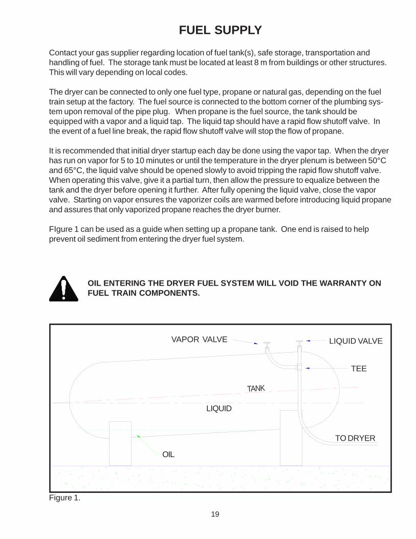
FUEL SUPPLY
Contact your gas supplier regarding location of fuel tank(s), safe storage, transportation andhandling of fuel. The storage tank must be located at least 8 m from buildings or other structures.This will vary depending on local codes.
The dryer can be connected to only one fuel type, propane or natural gas, depending on the fueltrain setup at the factory. The fuel source is connected to the bottom corner of the plumbing sys-tem upon removal of the pipe plug. When propane is the fuel source, the tank should beequipped with a vapor and a liquid tap. The liquid tap should have a rapid flow shutoff valve. Inthe event of a fuel line break, the rapid flow shutoff valve will stop the flow of propane.
It is recommended that initial dryer startup each day be done using the vapor tap. When the dryerhas run on vapor for 5 to 10 minutes or until the temperature in the dryer plenum is between 50°Cand 65°C, the liquid valve should be opened slowly to avoid tripping the rapid flow shutoff valve.When operating this valve, give it a partial turn, then allow the pressure to equalize between thetank and the dryer before opening it further. After fully opening the liquid valve, close the vaporvalve. Starting on vapor ensures the vaporizer coils are warmed before introducing liquid propaneand assures that only vaporized propane reaches the dryer burner.
FIgure 1 can be used as a guide when setting up a propane tank. One end is raised to helpprevent oil sediment from entering the dryer fuel system.
OIL ENTERING THE DRYER FUEL SYSTEM WILL VOID THE WARRANTY ONFUEL TRAIN COMPONENTS.
TO DRYER
LIQUID VALVE
TEE
VAPOR VALVE
TANK
LIQUID
OIL
Figure 1.
20
Extreme caution must be used if tank(s) for anhydrous ammonia are used for LP gasfuel to your dryer. If tank(s) are not properly purged, fuel train components may bedamaged by anhydrous ammonia. Check with your LP gas supplier for specific purg-ing procedure. Fuel train components damaged by anhydrous ammonia are notcovered under warranty.
CAUTION
EXTREME CARE MUST BE EXERCISED WHEN DOING THIS. NEVER USE ANOPEN FLAME DIRECTLY ON THE TANK.
When operating propane fueled dryers in very cold weather, the dryer may not be able to obtainsufficient fuel to reach desired operating temperature. This is due to the very low propane vaporpressure at cold temperatures. To overcome this situation, the tank can be warmed. This can beaccomplished by using an electric warming blanket that is approved for such a purpose.
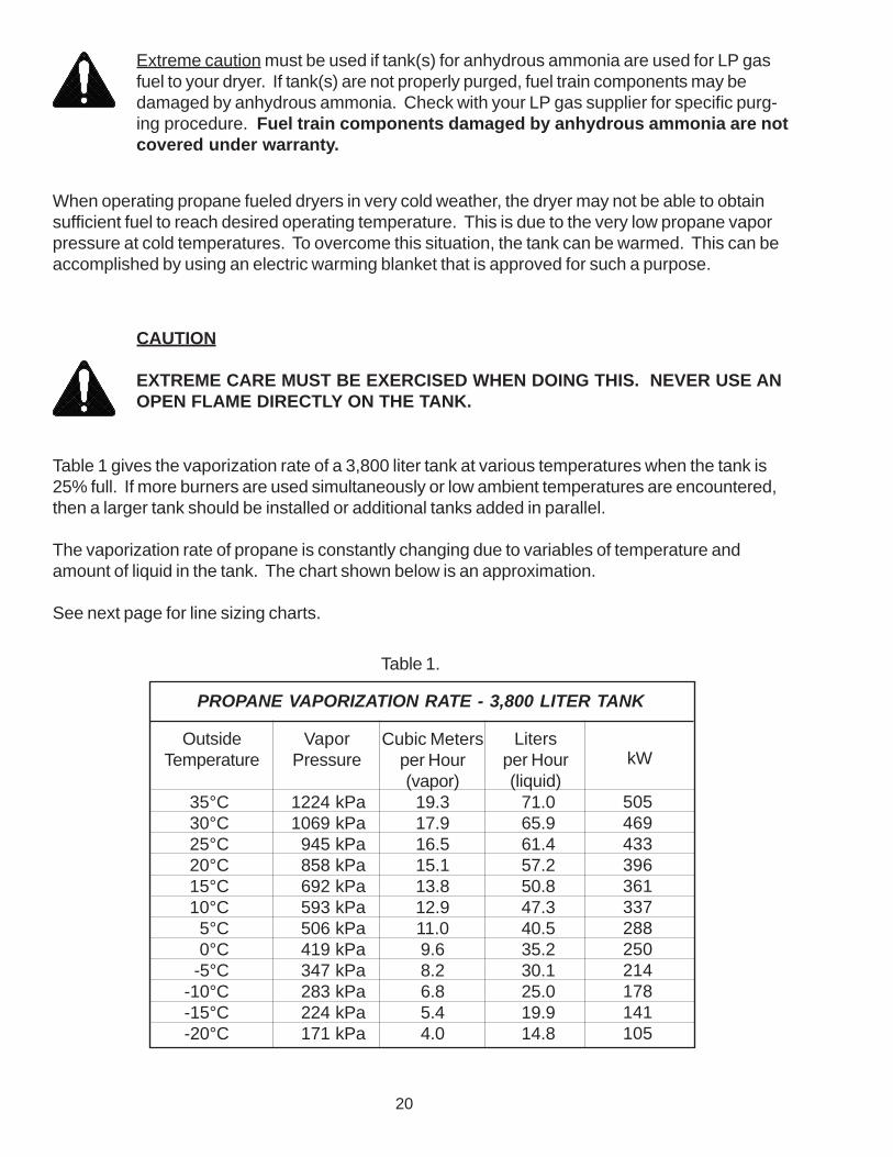
Table 1 gives the vaporization rate of a 3,800 liter tank at various temperatures when the tank is25% full. If more burners are used simultaneously or low ambient temperatures are encountered,then a larger tank should be installed or additional tanks added in parallel.
The vaporization rate of propane is constantly changing due to variables of temperature andamount of liquid in the tank. The chart shown below is an approximation.
See next page for line sizing charts.
VaporPressure
1224 kPa1069 kPa
945 kPa858 kPa692 kPa593 kPa506 kPa419 kPa347 kPa283 kPa224 kPa171 kPa
Cubic Metersper Hour(vapor)
19.317.916.515.113.812.911.09.68.26.85.44.0
Litersper Hour(liquid)
71.065.961.457.250.847.340.535.230.125.019.914.8
OutsideTemperature
35°C30°C25°C20°C15°C10°C
5°C0°C
-5°C-10°C-15°C-20°C
kW
505469433396361337288250214178141105
PROPANE VAPORIZATION RATE - 3,800 LITER TANK
Table 1.

21
LINE SIZING CHART FOR LP-GAS VAPOR
kW m3/min3/8"O.D.
1/2"O.D.
5/8"O.D.
FLOW RATE COPPER TUBING
3/8" 1/2" 3/4" 1" 1-1/4" 1-1/2" 2"
SCHEDULE 40 PIPE
29445988
120150290440590730880
11701470176020502340
1.11.72.33.44.55.7
11.317.022.728.334.045.356.668.079.390.6
592716853
874124175
825516853
784530943
912513854
101493020149543
936146272013108
1029765473528
1371007558
321247191
LINE LENGTH IN METERS
Use Table 2 as a guide for sizing the line for vapor between the LP tank and the dryer so as toallow a pressure drop of 7 kPa.
Use Table 3 as a guide for sizing the line for liquid propane between the LP tank and the dryer soas to allow a pressure drop of 7 kPa.
kW l/hr3/8"O.D.
1/2"O.D.
5/8"O.D.
FLOW RATE COPPER TUBING - TYPE K
1/4" 3/8" 1/2" 3/4" 1" 1-1/4"
SCHEDULE 80 PIPE
268536
107216092145268137534826536275078043
3876
151227303379530681757
10601136
1002563
401100251164
430108482517954
2225514632
251622816105
22710157361911954
2241437344361816
2481501226254 239
LINE LENGTH IN METERS
LINE SIZING CHART FOR LP-GAS LIQUID
Table 2.
Table 3.
22
UP (Open Position)
DOWN (Closed Position)
QUICK SHUTOFF VALVE
TOP VIEW
TOP
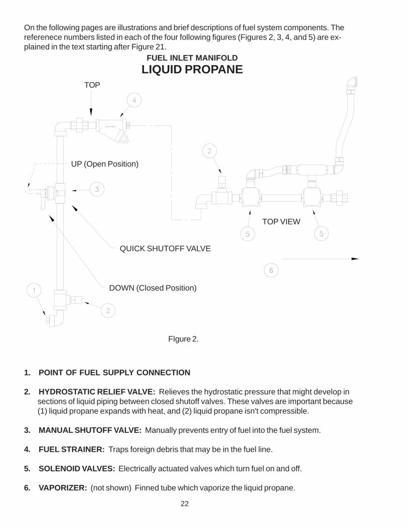
FUEL INLET MANIFOLD
LIQUID PROPANE
On the following pages are illustrations and brief descriptions of fuel system components. Thereferenece numbers listed in each of the four following figures (Figures 2, 3, 4, and 5) are ex-plained in the text starting after Figure 21.
1. POINT OF FUEL SUPPLY CONNECTION
2. HYDROSTATIC RELIEF VALVE: Relieves the hydrostatic pressure that might develop insections of liquid piping between closed shutoff valves. These valves are important because(1) liquid propane expands with heat, and (2) liquid propane isn't compressible.
3. MANUAL SHUTOFF VALVE: Manually prevents entry of fuel into the fuel system.
4. FUEL STRAINER: Traps foreign debris that may be in the fuel line.
5. SOLENOID VALVES: Electrically actuated valves which turn fuel on and off.
6. VAPORIZER: (not shown) Finned tube which vaporize the liquid propane.
FIgure 2.
23
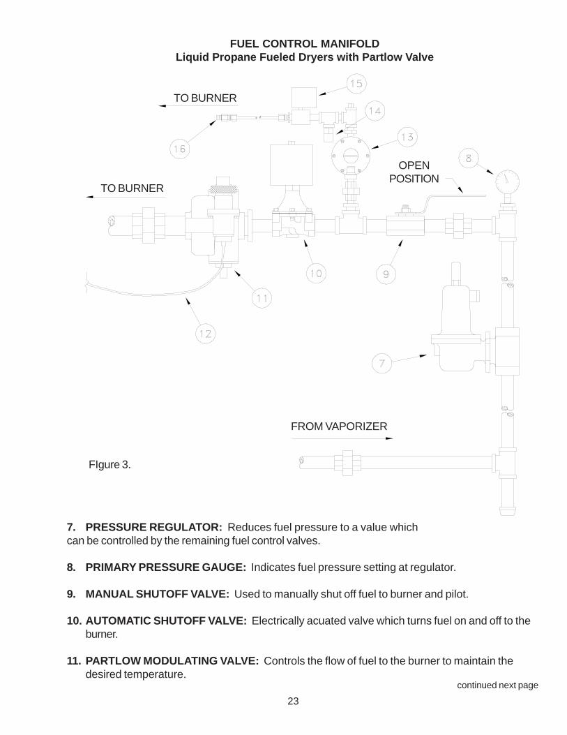
FUEL CONTROL MANIFOLDLiquid Propane Fueled Dryers with Partlow Valve
TO BURNER
TO BURNER
FROM VAPORIZER
OPENPOSITION
continued next page
7. PRESSURE REGULATOR: Reduces fuel pressure to a value whichcan be controlled by the remaining fuel control valves.
8. PRIMARY PRESSURE GAUGE: Indicates fuel pressure setting at regulator.
9. MANUAL SHUTOFF VALVE: Used to manually shut off fuel to burner and pilot.
10. AUTOMATIC SHUTOFF VALVE: Electrically acuated valve which turns fuel on and off to theburner.
11. PARTLOW MODULATING VALVE: Controls the flow of fuel to the burner to maintain thedesired temperature.
FIgure 3.

24
12. CAPILLARY TUBE FOR PARTLOW VALVE: Measures the plenum air temperature andcontrols the Partlow valve as required.
13. PRESSURE REGULATOR: Further reduces fuel pressure to a value which is useable forpilot purposes.
14. HYDROSTATIC RELIEF VALVE: Used to relieve any excess fuel pressure the may occur inthe pilot line.
15. AUTOMATIC SHUTOFF VALVE: Electrically actuated valve which turns fuel on and off to theburner pilot.
16. PILOT ORIFICE: A fitting with a small hole in the end which controls the volume of fuel deliv-ered to the burner pilot.
17. MODULATING MOTOR: Operates the Flow-Control Valve after receiving input from theWatlow Temperature Controller.
continued next page
FUEL CONTROL MANIFOLDLiquid Propane Fueled Dryers with Electronic Controls
SERIES 988
091901
PROCESS
L4L3L2L1
%OUT
DEV
MANAUTO
DISPLAY
MODE
WATLOW
TO BURNER
FIgure 4.

25
FUEL CONTROL INLET & MANIFOLD
NATURAL GAS
When using natural gas, the gas company will install a regulator which should be capable ofproducing 20 to 70 kPa under flow. The regulator should be located at or near the dryer to reducethe size of the supply line. Consult your natural gas representative for pressure available andassistance in the installation.
TO BURNER ELBOW FORSINGLE ORTOP BURNERS
BASICPARTLOW
VALVE
TO WATLOW CONTROLLEROR PLC TEMP CARD
OPTIONALELECTRIC
MODULATING CONTROL VALVE
12
11
10
FIgure 5.

26
MANUAL SHUTOFF VALVE: Manually prevents entry of fuel into the fuel system.
PRESSURE REDUCING REGULATOR: Reduces fuel pressure to a value which can becontrolled by the remaining fuel control valves.
PRIMARY PRESSURE GAUGE: Indicates fuel pressure setting at regulator.
MAIN SOLENOID VALVE: Electrically activated valve which turns fuel on and off to mainburner.
PARTLOW MODULATING VALVE: Controls the flow of fuel to the burner to maintain thedesired temperature.
CAPILLARY TUBE FOR PARTLOW VALVE: Measures the plenum air temperature andcontrols the Partlow valve as required.
PRESSURE REGULATOR: Further reduces fuel pressure to a value which is useable forpilot purposes.
PILOT SOLENOID VALVE: Electrically actuated valve which turns fuel on and off to theburner pilot.
PILOT ORIFICE: A fitting with a small hole in the end which controls the volume of fuel deliv-ered to the burner pilot.
MODULATING MOTOR: Operates the Flow-Control Valve after receiving input from theWatlow Temperature Controller or PLC Temp Card.
LINKAGE: Operates Flow-Control Valve.
FLOW-CONTROL VALVE: Controls the amount of fuel the burner receives. Designed forthrottling service and is not intended for tight shutoff.
MANUAL SHUT OFF VALVE WITH PLUGGED TEST PORT: Used to manually shutoff fuelto main burner.
1.
2.
3.
4.
5.
6.
7.
8.
9.
10.
11.
12.
13.

27
ELECTRIC POWER
Most of the wiring has been completed at the factory. There are however, a few wiring tasks thatmust be completed before you are ready to operate. A qualified electrician will be required tocomplete the wiring.
A main disconnect switch for the electrical power to the dryer must be supplied by thecustomer. This disconnect switch should be sized and installed by a certified electrician.
Copper wire of the appropriate size will have to be run between the main disconnect switch andthe distribution block located in the dryer panel. Wire size will be based on ampacity and distancefrom the main disconnect to the dryer. The serial number decal inside the panel lists the ampacityof the disconnect required by each dryer.

28
DRYER CONTROL PANEL
The control panel installed on your dryer will perform several functions automatically so that you donot have to constantly monitor the dryer. However, it is advisable to never leave the dryer unat-tended for long periods of time. The control panel will provide the following functions; fill the dryerautomatically, stop the dryer in case of auger failure, fuel failure, when wet bin is empty or dry binis full and will shut down machine in case of blower failure.
SELECTOR SWITCHES
Figure 6 shows the selector switches on the front panelof the dryer. These switches allow you tochoose the operating function of the panel.
Figure 6.
OPERATING INSTRUCTIONSREAD AND UNDERSTAND OPERATING PROCEDURE INOWNER’S MANUAL BEFORE OPERATING DRYER.

29
“FILLING” Switch
This switch controls the filling and leveling auger motors. The “TEST” position bypasses all controldevices and will start these motors no matter what the dryer grain level.
WARNING: DO NOT LEAVE THE FILLING SWITCH IN THE “TEST”POSITION. THE FILLING AUGER WILL NOT STOP WHEN THEDRYER IS FULL AND GRAIN SPILLAGE COULD OCCUR.
The “AUTO” position is selected when the dryer is to be filled automatically. When the grain levelreaches the filling bin level switch, the leveling auger and fill auger will stop. The “LOW DRYER”and “WET EMPTY” switches are also included in the circuit so that incorrect grain levels will stopthe filling system from operating. NOTE: THE OVERLOAD RELAYS FOR THESE MOTORSARE INTERLOCKED IN SUCH A WAY THAT IF ONE MOTOR OVERLOADS, THE OTHER WILLALSO STOP.
“DISCHARGE” Switch
In the “AUTO” or "EMPTY" position, the dryer will discharge grain automatically. If the “DIS-CHARGE PLUGGED” switch or the “DRY FULL” switch detect grain, the unloading system willstop. When in "AUTO" position the unloading system will also stop if the burner stops for anyreason. NOTE: THE OVERLOAD RELAYS FOR THESE MOTORS ARE INTERLOCKED INSUCH A WAY THAT IF ONE MOTOR OVERLOADS, THE OTHER WILL ALSO STOP.
A
B
“BLOWER” Switch
When this switch is in the off position, turn to the start position and hold until the blower starts.When released, this switch will spring and return to the run position. If any of the safety interlocksdetect an abnormal situation or grain activates the discharge plugged switch, the burners, blowersand discharge unit will shut down. The only time the blowers will continue to run after the burnersare shut down is due to either the lack of grain against the low grain switch which is mounted onthe top body section or when the wet holding bin becomes empty or the dry grain bin becomes full.In these cases, the burners and discharge will stop but the blowers will continue to operate until theoff delay timer (4TR) times out. 4TR is adjustable from 0 to 100 minutes. This timer is present inthe case where wet grain is no longer available to the dryer, the blowers will then continue runningfor a length of time predetermined by the operator to cool grain left in the dryer.
Dryers with multiple blowers have only one blower switch. To prevent an overload of the powersource during the motor start-up, there is a time lag between the start-up of the first blower andeach subsequent blower. These time delays are incorporated into the motor starters.
“FUEL SYSTEM” Switch
The “MANUAL” position of this switch bypasses some of the control devices in the system. Forexample, if the wet surge bin were to become empty, the fuel system would not turn off. If however,the blower would stop, the fuel system would immediately be turned off. The “MANUAL” positionis used for batch drying. The dryer should not be left unattended when the fuel system is in the“MANUAL” position.
C
D

30
In the “AUTO” position, the fuel is tied in to all safety control devices. In case of auger failure ordepletion of grain supply, the fuel system will shut off as well as the rest of the dryer (except theblower). Also, if the “HIGH LIMIT” or “STATIC PRESSURE” switch detects a problem, the burnerwill be stopped.
“FUNCTION” Switch
This switch is installed to accommodate some special situations that arise when drying. The"INTERLOCK” position is the normal operating position. All control devices are in the circuit whenthis switch is in the "INTERLOCK" position and the dryer will run on automatic. The “START”position bypasses some of the control devices and is only used when starting the dryer. When the" BURNER ON” lamp is illuminated, the “FUNCTION” switch must be moved to the “INTERLOCK”position before timer 1TR times out.
E
The feedrolls and discharge augers will not start until the FUNCTION switch is in theINTERLOCK position. This switch must be turned to INTERLOCK within 30 sec-onds after the green BURNER ON lamp is illuminated. If more than 30 secondspasses (timer 1TR controls this amount of time delay), the dryer will shut down theburner(s). The dryer will then restart after purging and run through this cycle again andkeep doing this until the FUNCTION switch is turned to the INTERLOCK position. Withthe burner(s) on, grain will not move through the dryer until the FUNCTION switch ismoved to the INTERLOCK position. Failure to move the FUNCTION switch to theINTERLOCK position will cause the dryer to cycle on and off and may cause over-dryingof grain or possible fire.
The “FILL/EMPTY” position is used when filling or emptying the dryer. For example, let’s say youwish to initially fill the dryer. With the “FILLING” switch in “AUTO”, the augers would not operate ifthe FUNCTION switch is in anything other than "FILL/EMPTY" because the “LOW DRYER” switchwould not have had any grain against it. The system would see a problem and prevent the fillingauger from starting. Moving the switch to the “FILL/EMPTY” position removes the “LOW DRYER”switch from the circuit allowing filling to take place. When the dryer is full, the filling system willautomatically stop. A similar situation occurs when trying to completely empty the dryer.
“BURNER” Switch(only present on dryers with multiple burners)
Whether the dryer is going to use all heat or heat and cool will determine how many of the burnersneed to be lighted. On a dryer with two burners, the switch will be marked: 1 and 1,2. On a dryerwith three burners, the switch will be marked: 1 and 1,2 and 1,2,3. 1 is always the top burner, 2 isalways the next burner down from the top and 3 is always the bottom burner if it is present. If allheat is desired, then the selector switch would be turned on to the position marked 1,2,3. If heatand cool is desired, the selector switch would be set to the position marked 1,2.

31
“LOW DRYER” and “WET EMPTY” Lamps
Indicates that grain level is low or the wet surge bin is empty respectively. In either case, the fillingwill stop. If the fuel system and discharge switches are in the “AUTO” position, they will also stop.
“DISCHARGE PLUGGED” and “DRY FULL” Lamps
Indicates that the discharge is plugged or dry grain bin is full respectively. In either case, thedischarge system will stop. If the fuel system is in “AUTO” position, it will also stop.
“POWER” Lamp
Indicates that the dryer control panel is energized.
“IGNITION” Lamp
Indicates that an ignition attempt is prevented when either the high limit or operating limit switchesare tripped, the static pressure switch indicates insufficient pressure, or the flame safeguard relayhas tripped. An ignition attempt will only be made for a maximum of 10 seconds.
“BURNER ON” Lamp
Indicates that an ignition attempt was successful and that the scanner is detecting a proper flamesignal. The discharge system will now start automatically if the discharge switch is in “AUTO”position. When the " BURNER ON” lamp is illuminated, the “FUNCTION” switch is moved to the“INTERLOCK” position.
“LOW STATIC PRESSURE” Lamp
Indicates insufficient status pressure in the dryer. An ignition attempt will not be made until thecause of the problem is corrected.
“LIMITS EXCEEDED” Lamp
Indicates that either the high limit or operating limit switch has been tripped. An ignition attemptwill not be made. Both limits are reset by pressing the high limit reset button.
“BURNER RESET REQUIRED” Lamp
Indicates that an ignition attempt has been unsuccessful. Another attempt will not be made untilthe burner is reset by pressing the burner reset button.
F
H
I
J
G
L
M
K
INDICATOR LIGHTS
There are a number of indicator lights on the control panel (fig. 05) which indicate the status ofvarious controls and monitors. Below is a description of each lamp and its function. (Replacement bulbs are available, part number for bulbs is 044609).

32
BURNER MONITORS
There are a number of monitors and safety devices which supervise and control burner operation.They are as follows:
“HIGH TEMPERATURE LIMIT SWITCH”
This device will stop the burner if the actual plenum temperature exceeds the setting on the de-vice. The switch itself is located in the burner interlock control box and can be set from 160° to260°F. A sensing element in the dryer plenum is located in the upper flow of heated air 8 to 10feet away from the burner. It is normally set at 30° to 40° F above the drying temperature.
“STATIC PRESSURE SWITCH”
This switch monitors the static pressure produced by the blower. If a loss of static pressure isdetected (blower stops), it will shut down the dryer. The device is located in the burner interlockbox and has a copper tube extending into the upper dryer plenum where it senses the pressure.
“SCANNER”
This device is an ultraviolet flame sensor ( mini-peeper ) and detects when the burner is operating.It will turn off the fuel supply when a loss of flame is detected.
“FLAME SAFEGUARD CONTROL”
This device is the overall burner controller. It monitors the status of the static pressure switch, highlimit switch and scanner and decides when it is safe to operate the burner. It directly controls theoperation of the fuel valves and ignition transformer. The device is located in the main dryercontrol box.
“TEMPERATURE MODULATING VALVE”
This device controls the amount of fuel reaching the burner unit thus controlling the temperature ofthe dryer plenum. When set at a desired level, it keeps the plenum temperature constant over awide range of conditions. It has a sensor which is located in the plenum of the dryer to detecttemperature. The temperature setting is controlled by the knob located in the top of the valve.Turning it counter-clockwise increases the temperature, while clockwise decreases it. The actualtemperature is indicated on the thermometer next to the valve. The thermostat on the valve hasbeen calibrated to the thermometer at the factory. If recalibration of the valve becomes necessary,first let dryer warm up for 15 minutes and then simply loosen the allen screw at the top of the valve,set the knob to correspond with the thermometer and retighten the allen screw.
33
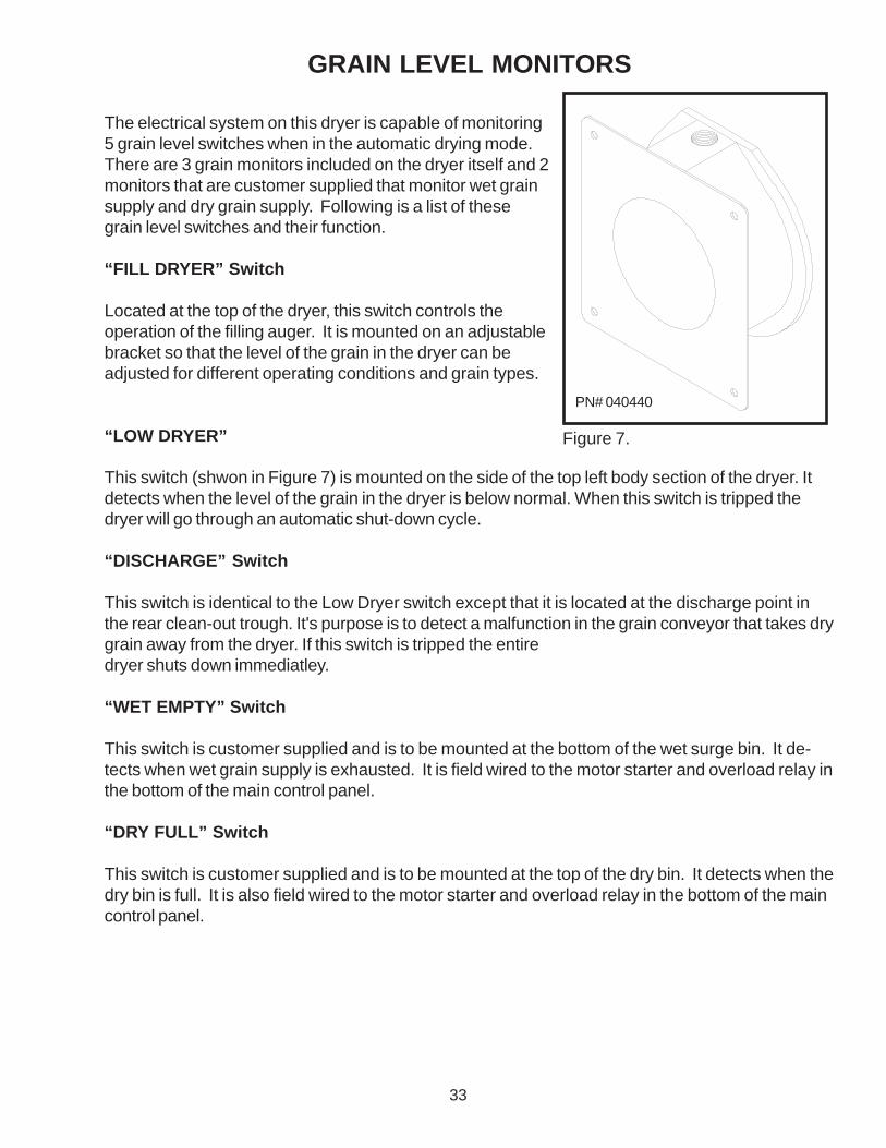
GRAIN LEVEL MONITORS
The electrical system on this dryer is capable of monitoring5 grain level switches when in the automatic drying mode.There are 3 grain monitors included on the dryer itself and 2monitors that are customer supplied that monitor wet grainsupply and dry grain supply. Following is a list of thesegrain level switches and their function.
“FILL DRYER” Switch
Located at the top of the dryer, this switch controls theoperation of the filling auger. It is mounted on an adjustablebracket so that the level of the grain in the dryer can beadjusted for different operating conditions and grain types.
“LOW DRYER”
This switch (shwon in Figure 7) is mounted on the side of the top left body section of the dryer. Itdetects when the level of the grain in the dryer is below normal. When this switch is tripped thedryer will go through an automatic shut-down cycle.
“DISCHARGE” Switch
This switch is identical to the Low Dryer switch except that it is located at the discharge point inthe rear clean-out trough. It's purpose is to detect a malfunction in the grain conveyor that takes drygrain away from the dryer. If this switch is tripped the entiredryer shuts down immediatley.
“WET EMPTY” Switch
This switch is customer supplied and is to be mounted at the bottom of the wet surge bin. It de-tects when wet grain supply is exhausted. It is field wired to the motor starter and overload relay inthe bottom of the main control panel.
“DRY FULL” Switch
This switch is customer supplied and is to be mounted at the top of the dry bin. It detects when thedry bin is full. It is also field wired to the motor starter and overload relay in the bottom of the maincontrol panel.
Figure 7.
PN# 040440

34
OPERATIONAL ADJUSTMENTS
PLENUM DIVIDER DOOR POSITION12' and 16' Dryers
Figure 8 shows how the divider doors should normally bein the lower position, giving one layer of cooling. If thegrain coming out of the machine is too warm with the doorsin this position and the flap at the front fully lowered, thedoors should be placed in the upper position. Normally,placing the divider door in the upper position would onlyoccur in low moisture removal and when drying on warmdays. Note: Not all dryers are equipped with theoptional cooling floors.
HEAT PLENUM
DIVIDER DOOR
COOLING PLENUM
1
2
3
FLAP POSITION - AIR DIVIDERS
The flap position is one of the fine tuning adjustments which determines the amount of cooling airthat reaches the grain (see Figure 9). On all dryers, the air divider flap is directly in line with thehandle on the outside of the fan connection housing so one has a visual check on the actual posi-tion of the flap. The lower the flap handle is on the slotted adjusting arm, the morecooling air is allowed through to the bottom for cooling.
When initially starting the dryer on a batch ofgrain or when drying without any cooling (allheat), the divider doors can be opened toallow heated air to reach all of the dryer. Thecooling flap should be completely raisedwhen doing this so that all of the air is heatedby the burner.
The drying of the first batch of grain is donemore efficiently by recirculating it back intothe dryer to maintain a continuous flow. Thiscan be done by putting it back on the truck,putting it back into the wet holding bin, or byusing a portable auger and putting it directlyinto the top of the dryer.
HEATED AIR
COOL AIR
BLOWERFLAPHANDLE
LOCKINGARM
12' and 16' Dryers
Figure 8.
Figure 9.

35
The function of the pressure regulator (shown in Figure 10) is to supply a constant pressure ofpropane to the temperature modulating valve on the dryer. Under normal operation, the pressureon the regulator gauge can be set between 3 an 8 psi.
It is best to have the pressure regulator set just high enough to maintain operating temperature.This allows the modulating valve to hold a more even temperature. It may also be necessary toincrease the pressure as the weather gets colder, as the higher pressure is needed to hold oper-ating temperature.
NOTE: It is normal for the pressure on the regulator gauge to rise on shut-down. The reason forthis is that the regulator gauge is on the vaporizer loop between two solenoid valves. When thevalves close, the vaporizer is still warming the propane and it is expanding, causing the pressureto rise. Should this pressure become too great, there are pressure relief valves in this loop torelieve any extreme pressure before any damages could occur.
ADJUSTMENTSCREW
PRESSURE REGULATOR
PRESSURE GAUGE
PRESSUREREGULATOR
FROM VAPORIZER
TO BURNER
LIQUID PROPANEMODELS
NATURAL GASMODELS
○
○
○
○
○
○
○
○
○
○
○
○
○
○
○
○
○
○
○
○
○
○
○
○
○
○
○
○
○
○
○
○
○
○
○
○
○
○
○
○
○
○
○
○
○
○
○
○
○
○
Figure 10.

36
FUNCTION switch in FILL/EMPTY position.
FILLING switch in AUTO position.
All other switches in OFF position.
The dryer will now fill automatically. DO NOT attempt to fill dryer in the TEST position. All grainlevel switches are excluded from the circuit and the augers will not stop even when the dryer is full.
CAUTION: BE SURE THAT THE CLEANOUT DOORS ARE COMPLETELYCLOSED BEFORE FILLING. Use your hand to assist the door closing if neces-sary. The OUTSIDE door closes first, see Figure 11.
ALL SHIELDS MUST BE FIRMLY IN PLACE.
ALL BELTS, SHAFTS AND AUGERS ARE TO BECOVERED.
BLOCK WHEELS ON PORTABLE FUEL TANKSIF USED.
KEEP AREA CLEAN TO PREVENT TRIPPING.
FILLING THE DRYER
Figure 11.
NOTE: ALWAYS INVESTIGATE THE CAUSE OF A TRIPPED CIRCUIT BREAKER OROVERLOAD RELAY BEFORE RESUMING OPERATIONS.
If the filling system stops before the dryer is full:
Check motor circuit breakers.
Check motor overload relays.
Check control circuit breakers.
If the filling system fails to start:
Check motor circuit breakers.
Check the motor overload relays.
Check main power switch.
Check control circuit breakers.
Check control panel switch positions.

37
START-UP PROCEDURE
Fill dryer according to FILL INSTRUCTIONS. Before ignition can take place, the dryer mustbe full or all ducts above the grain level must be closed off to allow at least 1" of staticpressure in the dryer with the blower operating.
On propane fueled dryers, open vapor valve on propane tank.
Open all manual gas valves on dryer.
Adjust pressure regulator to approximately one - half of normal operating pressure.
Set temperature controller to 30°C over ambient.
Set the following switches to:
FUNCTION switch in START position.
FILL switch in AUTO position.
BLOWER switch to Momentary Start (for less than 1 sec.) and then to ON position.
DISCHARGE switch in AUTO position.
FUEL SYSTEM switch in AUTO position. (After blower is running)
The burner circuits will now be energized. There will be a 30 second delay before an ignitionattempt is made. The illumination of the IGNITION lamps will signal the start of an ignition attempt.The fuel valves will open and the ignition transformer will be energized. When the burners igniteand the scanner has verified that flame exists, the green BURNER ON operating lampswill be illuminated. The FUNCTION switch must now be put in the INTERLOCK position.The feedrolls and discharge augers will not start until the FUNCTION switch is in the INTERLOCKposition. This switch must be turned to the INTERLOCK within 30 seconds after thegreen BURNER ON lamp is illuminated. If more than 30 seconds passes (timer 1TR controlsthis amount of time delay), the dryer will shut down the burner(s). The dryer will then restart afterpurging and run through this cycle again and keep doing this until the FUNCTION switch is turnedto the INTERLOCK position. With the burner(s) on, grain will not move through the dryer until theFUNCTION switch is moved to the INTERLOCK position. Failure to move the FUNCTION switchto the INTERLOCK position will cause the dryer to cycle on and off and may cause over-drying ofgrain or possible fire.
The discharge rate of the grain is adjusted to the appropriate level with the Electronic MoistureController, refer to the instructions listed in this manual.
For propane fueled dryers, allow the dryer to warm up for 5 - 10 minutes then slowly open theliquid valve on the propane tank. Shut off the vapor valve at the propane tank.
Set regulator to normal operating pressure.
Slowly bring the dryer up to the desired operating temperature.

38
OPERATIONOPERATING TIPS FOR MAXIMUM CAPACITY
BLOWER SPEED
The blower on the dryer was designed for distinctive characteristics. When operated at normalspeed, the blower will put out enough air to do an adequate job of drying. If you increase thespeed of the blower it will put out a significantly larger volume of air. Our recommendation is that aperson can increase the speed of the blower until the air starts to lift kernels of grain out of theducts, then run at a speed just lower than this. On rapeseed it may be 540 RPM, where as inbarley and wheat it may be as high as 600 or 650 RPM. These speeds can be accomplished bychanging motor pulleys: 6.8 = 538 RPM, 7.4 = 586 RPM, 8.0 = 634 RPM.
CAUTION: Do not exceed a blower speed of 650 RPM.
In certain cases where grain is being blown out of one or two ducts for no apparent reason, thecause may be trash that has piled up in corners of the machine as it moves along by a duct, itallows more air to flow at that particular point. The thin layer of grain which covers the trash maybe picked up and blown out. This may be more noticeable in flax and rapeseed. Try to raise orlower the leveling auger or the bin fill switch to allow the trash to pile up at the end of the machine.
CAUTION: Never go on top of dryer while operating to avoid injury by movingparts.
It is desirable to clean the wet grain if convenient before drying. Combines should be adjusted toprovide the cleanest sample.
TEMPERATURE RECOMMENDATIONS
In making temperature recommendations it is NECO’s firm belief that as long as the grain's abilityto germinate is not affected by drying, then there is no damage to the milling, malting, feeding orprotein quality of the grain.
A simple check to see what maximum temperature a person can operate at is when the machineis operating in the batch or stationary mode. We suggest that people do not exceed the maximumtemperature that swaths might get on a hot day, unless the grain is for feed. We have recordedswath temperature in excess of 55°C, therefore, in absence of other technical date, we suggestthat farmers use this as a maximum and suggest if the grain is quite damp, that a little be movedthough the dryer to avoid any over drying and allowing the grain to mix.
To avoid tripping the "High Temperature Limit" switch, limit the drying temperature to 230° F.
To determine correct kernel temperature, take a sample from a duct at the lower part of the heat-ing section. Put into an insulated (covered) container, with a thermometer directly in the grain.After 10 minutes record the temperature reading. Putting a thermometer directly in the dryer onlygives the temperature of the air between the kernels and not the correct temperature of kernelswhich is required.

39
RECOMMENDED MAXIMUM TEMPERATURES IN THE NECO DRYER
SPECIFIC CROPS
Rapeseed: In the NECO dryer, rapeseed is as trouble free as any other crop to dry. Thescreenless design is the major reason for this. There are several things to watch for however. Inrapeseed containing pods it is advisable to clean out the machine after every days’ operation toprevent trash build up and plugging in the machine. Also, the temperature must be watchedcarefully. Combustion is known to have occurred in rapeseed when the seed temperature reachedabout 70°C. It is possible for this to happen in plugged areas of the machine.
Empty the machine daily to ensure that it is not plugged with trash. Wind can cause trash toaccumulate in one area.
Flaxseed: Because of the shape of flaxseed, the same conditions exist with flaxseed as withrapeseed. Flax is one of the most difficult crops to force air though. Therefore, by keeping itmoving it will stay loose and more air will pass through. Flaxseed also has the characteristic that itwill tend to stick together and to the walls of the machine if it is not kept moving at all
Table 4.
CAUTION: The temperatures Table 4 must be used with care. In cases where the grainhas a lot of trash, when drying high moisture grain, or is immature or frozen, drying at theabove temperatures may not be possible. In cases where there is blocking in themachine due to trash, it is possible for this material to become subject to sponta-neous combustion. In this case and in any case where a person may see smokecoming from the machine, the blower should be stopped immediately. The mate-rial will generally smother itself in a few minutes. As insurance, a person may want toopen the back door and check that the material has been extinguished.
Under normal circumstances, always cool the grain when stopping the machine to avoidpossible combustion which can occur in any grain.
FEED COMMERCIAL SEED
Continuous-Flow
Batch
Continuous-Flow
Batch
BARLEY, OATS,WHEAT, CORN
RAPESEED andFLAXSEED
°F
200+
160
-
-
°C
93+
71
-
-
°F
180 - 200
140 - 160
150 - 170
130 - 140
°C
82 - 93
60 - 71
66 - 77
54 - 60
°F
160
130
130 - 140
110
°C
71
71
54 - 60
43

40
times. The blower speed may have to be lowered or the duct shut-off slides closed in order toprevent it from being lifted out of the ducts.
Barley, Wheat and Oats: These crops dry relatively trouble free. One must be sure to clean themachine out after every couple of days operation in order to clean any possible trash blockages.
Specialty Crops: Feel free to contact a factory representative.
“MOISTURE REBOUND”
Moisture rebound can be defined as the equalization of moisture within a kernel after being rapidlydried. Since moisture is removed from the outer part of the kernel first, the inside is at a highermoisture content. Rebound is just this evening out. This can occur on a hot day in the field as wellas in the bin.
Moisture rebound is a consideration that should be checked and allowed for under normal dryingoperations. The amount of moisture rebound encountered will vary depending upon the amount ofmoisture removed, and how fast the moisture is removed.
By taking a sample of grain which has just been dried, placing it in a tightly sealed container forover night and then re-checking the moisture content again the next morning, you will be able todetermine amount of moisture rebound and how much you will have to “overdry” the grain in orderto compensate “moisture bound”.
OPERATION IN ADVERSE WEATHER
Most operators, when drying, hope that all of their drying can be done early in the fall when theweather is warm and sunny. Unfortunately, this does not always happen.
The factor which has the most influence on drying is the temperature of the outside air which isused to heat the grain. It does not effect the capacity of the machine, however, it will increase thefuel costs of drying. The second factor which will influence operating is the temperature of thegrain which is to be dried. In this case, both fuel consumption is increased and the capacity of thedryer is reduced because the grain must be heated more than in warm weather drying.
Drying in rainy weather does effect the operation of the machine. However, the problem is not assevere as some people may think. The amount rain water that would enter the dryer is signifi-cantly less than the amount of internal moisture the dryer is capable of removing from the grain.One can expect a decrease in capacity of about 10-15% if the dryer is operated in the rain.

41
DURING OPERATION
The following conditions will result in an automatic shut down.
Wet bin out of grain; indicated by WET EMPTY lamp.
Low grain in dryer; indicated by LOW DRYER lamp. If this occurs, following are the most prob-able causes:
•Motor circuit breakers on filling/leveling motors.
•Overloaded filling/leveling motors.
•A mechanical malfunction in the filling auger.
Discharge plugged; indicated by the DISCHARGE PLUGGED lamp. If this occurs, following arethe most probable causes.
•Dry auger mechanical malfunction.
•Dry auger motor circuit breaker tripped.
Dry bin is full; indicated by DRY FULL lamp.
Dry auger or discharge motor overloaded; no indicating lamps indicate this condition. Can checkthis by resetting dry auger and discharge motor overloads or trying discharge system on empty.
Fuel supply being interrupted; no direct indication lamps indicate this condition. Pressure onprimary pressure gauge will be at zero.
Excess temperature condition; when FUNCTION switch is in the INTERLOCK position, the HIGHLIMIT lamp will come on. If the plenum temperature exceeded the setting on either the high limitswitch or the operating limit, the circuit will be tripped. Push the HIGH LIMIT RESET button toreset.
Low static pressure; when FUNCTION switch is in the INTERLOCK position, the LOW STATICPRESSURE lamp will be illuminated. NOTE: IF THE PROBLEM IS INTERMITTENT, THE LAMPMAY NOT ILLUMINATE. YOU WILL HAVE TO MAKE AN IGNITION ATTEMPT WHILE WATCH-ING FOR A FLICKER IN THE LAMP.
Blower motor overload; will result in a low static pressure condition indicated as describedabove.

42
If the burner(s) will not ignite, the following should be checked.
FUNCTION switch should be in START.
If any RED indicating lamp is on, investigate the problem.
If the ignition lamp illuminates for 10 seconds but the burner(s) never lights, check fuel supply andthe gap between the electrode and the burner.
If the IGNITION lamp is illuminated for 10 seconds and the burner ignites but goes out at the sametime as the IGNITION lamp, the scanner may be defective or the sight pipe is plugged with debris.
DRYING THE LAST BATCH
When drying the last batch of grain, whether for periodic clean out, to change grains or the grainsource has become exhausted, the grain remaining in the dryer can be dried by recirculating thegrain or by “Batch Drying”. On continuous flow, the grain is dried evenly from all sides as it movesdownward in the dryer. The grain is dried faster and more efficiently than as a batch. In caseswhere a batch must be dried, it is best done by recirculating some of the grain, allowing the grainto dry. With some types of grain it is necessary to dry more evenly, but also to reduce the dryingtime. In some cases, it may be almost impossible to dry without moving the grain a little, espe-cially with flax, rapeseed and other small grains.
The NECO dryer is capable of being operated as a batch dryer; however when the dryer is usedin this method, it is susceptible to the same problems as a recirculation batch dryer.
Since the grain is not moving during batch drying, the drying temperature should belowered to avoid overheating some of the grain. See the following pages for recom-mended maximum temperatures in NECO dryer.
CAUTION: Never leave the dryer unattended when operating in manual position.
Test grain samples from several areas of the dryer and average them until the average grainmoisture is acceptable. Turn the fuel switch off and allow the blower to continue until the grain hascooled to within 20°F of ambient temperature or 40°F. To empty the dryer, see next page.
CAUTION: To avoid injury, DO NOT open rear door while the blower is operating.
Excessive fuel pressure may blow out pilot upon ignition, reduce fuel pressure to 3 to 5 psi retryignition.

43
EMPTYING THE DRYER
FUNCTION switch in FILL/EMPTY position.
DISCHARGE switch in EMPTY position.
All other switches in OFF position.
The dryer will now empty out completely. The DISCHARGE PLUGGED switch is included in thecircuit when the DISCHARGE switch is in the EMPTY position.
NEVER ATTEMPT TO UNPLUG EQUIPMENT WHILE THERE IS APOSSIBILITY OF SOMEONE ELSE RESETTING DISCHARGE.
Check control circuit breakers.If the unloading system stops before dryer isempty:
Check the DRY/FULL and the DISCHARGElamps. If either is illuminated, the dischargesystem will not operate.
Check motor circuit breakers.
Check motor overloads relays.
Check control circuit breakers.
If the unloading system fails to start:
Check the control panel switch positions.
Check the DRY/FULL and the DISCHARGElamps. If either is illuminated, the dischargesystems will not operate.
Check motor circuit breakers.
Check the overload relays.
Check that main power switch is on.
SHUT DOWN PROCEDURE
Turn off the fuel supply at its source. (Propane tank or gas valve furthest away from dryer).
Allow the burner(s) to operate until all fuel in the lines has been consumed.
Close the quick shut-off valves.
Turn off all switches except the blower switch(es).
Allow blower(s) to operate for sufficient time to cool grain. Usually 15 - 20 minutes is adequate.
Turn off blower(s).
Turn off main power supply.
NOTE: ALWAYS INVESTIGATE THE CAUSE OF A TRIPPED CIRCUIT BREAKER OROVERLOAD RELAY AND RECTIFY BEFORE CONTINUING OPERATIONS.

44
DRYER CLEANOUT AND STORAGE
Upon completion of drying on variety of grain or at the end of the season, the dryer should becompletely cleaned out. This can be done simply in the NECO dryer by swinging open the cleanout door handles. This allows the trough under the augers and meters to fall open. By openingand closing them rapidly it will knock any lodged kernels free. Then by turning the dischargeswitch on it will rotate the meters allowing the kernels to fall off the top of them. The rear clean outtrough can be opened to clean the rear auger. The machine should now be completely free of anygrain.
CAUTION: TO AVOID INJURY TO LIMBS, DO NOT LOWER REAR TROUGHWHILE MACHINE IS RUNNING.
For storage, these doors should be left open so that rain may fall through. This eliminates grainrotting, sprouting, rusting of the machine and the need for a roof. To reclose them, a person mayhave to assist the outside door with their hands.
The belts should be loosened and removed. They should be stored in a dark place.
The chains should be removed and lubricated, then stored in an air tight container.
Any scratches should be painted to preserve the appearance of the machine.
45
MAINTENANCE
LUBRICATION
The NECO dryer has a very minimum number of moving parts and therefore lubrication is at aminimum as well. All the bearings are sealed to minimize lubrication requirements. Below is aschedule of necessary lubrication.
BEARING OR PART PERIOD (or hours in use)
Gearbox, Cross Auger - 80/90 Gear Oil 1/2 Full . . . . . . . . . . . . . . . . . . Check Weekly (100 hrs.)
Fan Shaft Bearings . . . . . . . . . . . . . . . . . . . . . . . . . . . . . . . . . . . . . . . . . . . . . . Weekly (100 hrs.)
Rear Cross Auger Bearings . . . . . . . . . . . . . . . . . . . . . . . . . . . . . . . . . . . . . . . Weekly (100 hrs.)
Sealed Meter and Auger Bearings . . . . . . . . . . . . . . . . . . . . . . . . . . . . . . . . . . . Oil (Seasonally)
Roller Chains for Metering rolls and Discharge Augers . . . . . . . . . . . . . . . . Oil Weekly (100 hrs.)
CAUTION: DO NOT go near shafts or any augers or any moving part if themachine is running. DO NOT go up the ladder if the machine is running.
NOTE: Clean the plenum daily or when trash accumulates and before storage or over winter.Always leave the cleanout doors open when dryer is not in use to allow rain, etc. to pass through.
NOTE: On greaseable sealed bearings, DO NOT OVER GREASE. Over greasing will force outthe seals causing contamination and rapid bearing wear from dust.
GAS PORTS
Conduct initial inspection within the first month after commissioning. Visually check the gas portsof new burner assemblies for any piping scale or debris. Use a pin vise and a #47 drill bit toremove any blockages (do not use an electric drill).
Annual inspections are normally adequate once the initial piping debris is removed. The operat-ing conditions of the burner will determine how frequently maintenance is actually required.
SOLENOID VALVES
All solenoid valves should be cleaned periodically. The time between cleanings will vary depend-ing on the medium and service conditions. In general, if the voltage to the coil is correct, sluggishvalve operation, excessive noise, or leakage will indicate that cleaning is required. In the extremecase, faulty valve operation will occur and the valve may fail to open or close. See the additionalinstructions located at the end of this manual for the correct cleaning procedure.

46
This page is left blank intentionally.

47
APPENDIX
GRAIN DRYING TERMS &DEFINITIONS
The following terms are more commonly used in grain drying. You will find these helpful in gaininga thorough understanding of grain drying.
Aeration: The moving of air through stored grain at low air-flow rates generally between 0.2 and1.1 CFM per bu. for purposes of cooling and ventilating the grain.
Air Pressure Switch: (Static Pressure Switch) A switch controlled by the air pressure in theplenum chamber. Should air pressure be relieved, this switch breaks contact and stops the flow ofelectrical current to the solenoid valve, thus shutting off the fuel supply to the heating unit.
Air Velocity: The speed of air flow in feet per minute through a given cross sectional area. Thisis determined by dividing the quantity of air flow in cu. feet per minute by the cross sectional areaof the air passage.
Ambient Temperature: Outside air or atmospheric temperature.
Automatic Temperature Control: A mechanical device located in the fuel system of the heatunit which controls the fuel flow at the burner orifice to maintain constant temperature.
B.T.U. (British Thermal Unit): A measure of quantity of heat. (One B.T.U. will raise the tempera-ture of one pound of water 1 degree Fahrenheit.)
B.T.U. per hr.: A common standard by which a heating unit is rate. ( A heating unit is usuallyrated at its maximum output. It is also written B.T.U.H.)
Bushel: One bushel equals 1.2 cu. ft. for purposes of calculations.
C.F.M. (cubic ft. per minute): Fans are rated at so many C.F.M. at a given R.P.M. workingagainst a determined static pressure. Fan design determines at what R.P.M. and in what staticpressure range the fan will operate most efficiently.
Continuous Heated Air Drying: Relatively shallow columns of grain flow down through the dryercontinuously with air passing through.
Cooling Cycle: (Common to Batch Type Dryer) The period of time that grain in the tank issubjected to air movement by the fan without the burner being lighted. Grain should be cooled

48
down to within 20 to 30 degrees F. of ambient temperature or 40 degrees F. after being dried withsupplemental heat, whichever is warmer.
Drying Period: The period of time the grain is subjected to drying air. The length of the dryingperiod will be determined by these factors: (1) kind of grain being dried; (2) moisture content ofthe grain; (3) moisture content desired in the finished grain; (4) air flow per bushel; (5) cleanlinessof grain in the dryer.
Drying Front: Point at which air traveling through the grain reaches the equilibrium moisturecontent of the grain and cannot pick up any more moisture.
Drying Zone: A layer of grain in which moisture content is being reduced at any given timeduring the drying process and includes the drying front.
Exhausted Air: The air leaving the grain after having absorbed as much moisture as possible.
Heat of Vaporization: It takes 1060 B.T.U.’s to evaporate 1 pound of water (theoretically).
Heated Air Drying: The drying which is done with high air-flow rates along with high dryingtemperatures at 100 degrees to 160 degrees F. This type of drying is used in batch, recirculatingcontinuous flow, truck, and big batch dryer.
High Temperature Limit Switch: A safety switch is actuated when the heat-sensing elementexceeds the control dial setting. This switch will break contact and disrupt the flow of electricalcurrent.
L.P. Gas: A petroleum product normally stored and transported as a liquid under pressure. Boil-ing point is (-44 degrees F) and, therefore, has little vapor pressure at very cold temperatures.
Linkage: Operates Flow-Control Valve.
Flow-Control Valve: Controls the amount of fuel the burner receives. Designed for throttlingservice and is not intended for tight shutoff.
Temperature Controller: Sends a signal to Modulating Motor which operates the Flow-ControlValve regulating dryer plenum temperature.
Thermocoupler Sensor: Senses plenum temperature and sends a signal to TemperatureController.
Manometer: A “U” shaped transparent tube partially filled with liquid (water) of a definite specificgravity. One end of the tube is connected to the plenum chamber, while the other end is vented toatmospheric pressure. In measuring the difference between plenum pressure and atmosphericpressure we arrive at the static pressure. This is the difference, in inches, between the heights ofthe two water columns.
Moisture Content: The moisture content of a material is measured by dividing the weight of thewater which it contains by the total weight of the material and water.

49
Moisture Rebound: When moisture is removed from kernels of grain very rapidly, it will beremoved from the surface faster than the interior of the kernel. After this grain is allowed to sit fora period of time, the moisture will even out within the kernel. This phenomena, when observed ona moisture meter, shows the grain testing drier than it actually is when taken from the dryer.
Natural Air Drying: Drying with low air flow of 3 to 15 C.F.M. per bu. and no heat, or just a littleheat to bring the humidity of the air to the desired level to give dryness wanted in the dried grain.This drying is associated with multiple-layer drying, in-storage grain drying and bin or buildingdrying.
Plenum: An enclosed volume of moving air under greater pressure than the surrounding con-tainer. Size and shape of the plenum area has a direct effect on fan performance and air distribu-tion. In a dryer, the air entering this area is heated.
Point of Equilibrium: The point at which grain and the surrounding air are in equilibrium in vaporpressure. Under these conditions, no transfer of moisture will take place.
Pressure Regulator: A mechanical unit which, through use of diaphragm, spring and valve,reduces a high fluctuating pressure to a lower steady pressure.
PSI (pounds per square inch): A unit to measure the intensity of pressure.
Relative Humidity: A measure of the moisture content of the air relative to fully saturated air.
Relief Valve: A valve which protects the fuel system against excessive pressures.
R.P.M. (revolutions per minute): The common method of expressing the speed of rotatingparts.
Solenoid Valve: A valve which is normally closed and opened by electro-magnetic pull on thesolenoid plunger as current passes throughout the solenoid coil.
Static Pressure: A measure of the air pressure in the plenum chamber. (Usually expressed ininches of water column.) Small kernel grains (such as rapeseed and flax and feed grains packclose together and offer greater resistance to air movement than corn, thus causing higher staticpressures to develop and, consequently, a lower fan volume flow).
Temperature Rise: The difference between ambient temperature and plenum temperature isreferred to as the temperature rise. A thermometer is provided to register temperature rise insome dryers.

50
This page is left blank intentionally.

51
TROUBLESHOOTINGGUIDE

52
Will
not
FIL
L in
AU
TO
Blo
wer
will
not
sta
rt
PO
WE
R la
mp
not i
llum
inat
ed.
PO
WE
R la
mp
illum
inat
ed.
The
re a
re tw
o la
mps
on
the
timer
itsel
f. T
he b
otto
m la
mp
indi
cate
s th
atth
e tim
er is
tim
ing
out.
Bot
h la
mps
on
indi
cate
that
the
timer
has
tim
ed o
ut.
Lam
ps o
n tim
er a
re n
ot il
lum
inat
ed.
5TR
tim
er n
ot ti
min
g.
Bot
h la
mps
on
timer
are
illu
min
ated
,bu
t mot
or d
oes
not s
tart
.
Wet
bin
em
pty
light
on
and
a lo
w b
inle
vel s
witc
h in
stal
led.
Wet
bin
em
pty
light
on
and
low
bin
leve
l sw
itch
not i
nsta
lled.
PO
WE
R la
mp
not i
llum
inat
ed.
Circ
uit b
reak
er in
pan
el h
as tr
ippe
d.
Ove
rload
on
blow
er m
otor
con
tact
ortr
ippe
d.
Is th
e D
isch
arge
Plu
gged
lam
p on
.
No
pow
er to
the
drye
r
Are
you
wai
ting
long
eno
ugh
for d
elay
on ti
mer
(5T
R) t
o en
ergi
ze.
Leve
l aug
er s
witc
h on
top
of d
ryer
stuc
k in
the
full
posi
tion.
Mot
or o
verlo
ad(s
) hav
e tr
ippe
d.
Low
gra
in in
Wet
hol
ding
bin
.
Loos
e or
mis
sing
jum
per w
ire o
nte
rmin
als
7 to
term
inal
9.
No
pow
er to
the
drye
r.
Som
eone
had
turn
ed b
reak
er o
ff or
som
ethi
ng h
as c
ause
d it
to tr
ip.
Blo
wer
mot
or o
verlo
ad.
Gra
in is
aga
inst
the
Dis
char
geP
lugg
ed s
witc
h.
Tur
n on
pow
er to
the
drye
r
Wai
t for
on-
dela
y tim
er to
tim
e ou
t. 5t
rtim
er d
elay
s th
e st
art o
f the
fill
auge
rco
ntac
tor.
Thi
s is
nor
mal
ly s
et fo
r 10
seco
nds.
Uns
tick
switc
h an
d co
rrec
t if n
eces
-sa
ry.
Res
et W
et A
uger
(2M
) and
Lev
elA
uger
(4M
) ove
rload
rela
ys
Fill
with
gra
in.
Tig
hten
or i
nsta
ll ju
mpe
r wire
from
term
inal
7 to
term
inal
9.
Tur
n on
pow
er to
the
drye
r.
Tur
n br
eake
r bac
k on
. If
circ
uit
brea
ker c
ontin
ues
to tr
ip, t
hen
dete
r-m
ine
the
reas
on fo
r trip
ping
(sho
rted
wire
, etc
.)
Res
et o
velo
ad re
lay.
Che
ck a
mpe
rage
of b
low
er m
otor
lead
s. B
low
er m
otor
will
pul
l the
mos
t am
ps w
hen
drye
rco
olin
g fla
p is
ope
n. If
mot
or is
pul
ling
mor
e th
at th
e na
mep
late
ratin
g, c
heck
for l
oose
con
nect
ions
. If c
onne
ctio
nsar
e tig
ht, t
hen
a sm
alle
r m
otor
pul
ley
will
nee
d to
be
inst
alle
d.
Rem
ove
grai
n fr
om s
witc
h an
d/or
rese
ton
pan
el.
PR
OB
LE
MC
HE
CK
OU
TP
OS
SIB
LE
CA
US
EP
OS
SIB
LE
SO
LU
TIO
N
TR
OU
BL
E S
HO
OT
ING
GU
IDE

53
Blo
wer
will
not
sta
rt.
Blo
wer
sta
rts
on m
omen
tary
and
stop
s w
hen
switc
h is
rel
ease
d.
Blo
wer
sta
rts
and
then
shu
tsdo
wn.
Doe
s th
e Lo
w S
tatic
pre
ssur
e la
mp
com
e on
.
Is th
e Li
mits
Exc
eede
d la
mp
on.
Che
ck p
rope
r lin
e vo
ltage
bet
wee
n H
1- H
4 (2
30 v
olt)
and
bet
wee
n X
1 - X
2(1
20 v
olt)
.
The
Low
Dry
er la
mp
is il
lum
inat
ed.
Gra
in is
abo
ve th
e sw
itch,
but
the
Low
Dry
er la
mp
is o
n.
Aux
illia
ry s
witc
h (5
OL)
on
blow
erco
ntac
tor n
ot a
llow
ing
curr
ent t
o pa
ss.
4TR
tim
er n
ot p
lugg
ed in
.
Low
Sta
tic p
ress
ure
lam
p co
mes
on
whe
n fu
el s
witc
h is
turn
ed to
aut
o.
The
Fue
l sw
itch
is in
the
auto
or
man
ual p
ositi
on.
A h
igh
tem
pera
ture
lim
it co
nditi
on h
assh
ut d
own
the
drye
r
Con
trol
tran
sfor
mer
prim
ary
fuse
s(2
FU
& 3
FU
) or 1
FU
sec
onda
ry fu
seha
s bl
own.
Gra
in is
bel
ow th
e lo
w d
ryer
sw
itch
onth
e si
de o
f the
dry
er.
The
Low
Dry
er s
witc
h ha
s st
uck.
Loos
e w
ire o
n au
xilli
ary
switc
h.D
irt o
r gra
in p
artic
al in
terf
erei
ng w
ithco
nta
cts.
Tim
er h
as b
ecom
e lo
ose.
Air
switc
h is
not
adj
uste
d co
rrec
tly.
Tur
n F
uel s
witc
h of
f and
rese
t Low
Sta
tic p
ress
ure
on p
anel
. D
o no
t tur
nth
e fu
el o
n un
til th
e bl
ower
has
pres
suriz
ed th
e pl
enum
.
Che
ck d
ryer
for r
easo
n of
hig
h te
m-
pera
ture
lim
it. C
heck
set
ting
of h
igh
limit
switc
h. R
eset
hig
h lim
it on
pan
el.
If no
vol
tage
read
ing
betw
een
H1
- H4
(230
vol
t) th
en 2
FU
and
/or 3
FU
fuse
has
blow
n. R
epla
ce b
low
n fu
se. I
f no
volta
ge b
etw
een
X1
- X2
(120
vol
t) th
entr
ansf
orm
er m
ay b
e ba
d. R
epla
cetr
ansf
orm
er. I
f the
re is
vol
tage
acr
oss
X1
- X2,
then
che
ck a
cros
s 1F
U fu
se.
If no
vol
tage
acr
oss
1FU
, the
n fu
seha
s bl
own.
Rep
lace
fuse
.
Gra
in m
ust b
e ab
ove
this
sw
itch
for
the
blow
er to
run.
Try
ing
to s
tart
the
blow
er m
ay c
ause
the
grai
n to
shi
ft an
d se
ttle
agai
nst t
helo
w d
ryer
sw
itch,
fixi
ng th
e pr
oble
m.
Gai
n ac
cess
to th
e sw
itch
and
tap
ondi
aphr
am to
uns
tick
switc
h.
Tig
hten
wire
s.In
spec
t and
cle
an.
Mak
e su
re ti
mer
is s
ecur
ely
inse
rted
into
bas
e.
Loos
en la
rge
nut o
n to
p of
air
switc
han
d ba
ck th
e th
read
ed c
olla
r out
of t
hesw
itch
¼ tu
rn.
PR
OB
LE
MC
HE
CK
OU
TP
OS
SIB
LE
CA
US
EP
OS
SIB
LE
SO
LU
TIO
N

54
Blo
wer
runs
and
then
shu
ts d
own.
Dry
er d
oes
not t
ry fo
r ign
ition
.
Blo
wer
is ru
nnin
g an
d ig
nitio
n lig
htco
mes
on,
but
pilo
t doe
s no
t lig
ht.
Blo
wer
mot
or p
ullin
g to
o m
any
amps
.
Blo
wer
mot
or a
mp
read
ings
with
inlim
its.
Che
ck p
ositi
ons
of s
witc
hes
Che
ck fo
r loo
se re
lays
.
The
pow
er L
ED
on
the
Hon
eyw
ell
Fla
me
Saf
egua
rd is
not
lit.
The
pow
er L
ED
on
the
Hon
eyw
ell
Fla
me
Saf
egua
rd is
lit.
Lack
of f
uel
Ove
rload
rela
y m
ay b
e tr
ippi
ng.
Hea
ter
strip
s m
ay b
e th
e w
rong
siz
e.
Fue
l sw
itch
not t
urne
d to
aut
o.
Fun
ctio
n sw
itch
not i
n S
tart
pos
ition
.
"F"
rela
y no
t plu
gged
in.
Hon
eyw
ell m
ay n
eed
to b
e re
set
Bur
ner r
eset
rod
not a
djus
ted
cor-
rect
ly a
nd p
ushi
ng re
set b
utto
n on
Hon
eyw
ell F
lam
e S
afeg
uard
.
Tim
er c
ard
in H
oney
wel
l bad
or
mis
sing
.
Has
fuel
bee
n tu
rned
on
at th
e su
pply
.
Are
man
ual s
huto
ff va
lves
ope
n on
the
drye
r.
The
re m
ay b
e ai
r in
the
fuel
line
.
Che
ck a
mpe
rage
of b
low
er m
otor
lead
s. B
low
er m
otor
will
pul
l the
mos
tam
ps w
hen
drye
r coo
ling
flap
is o
pen.
If m
otor
is p
ullin
g m
ore
that
the
nam
epla
te ra
ting,
che
ck fo
r loo
seco
nnec
tions
. If c
onne
ctio
ns a
re ti
ght
then
a s
mal
ler m
otor
pul
ley
will
nee
dto
be
inst
alle
d.
Inst
all c
orre
ct h
eate
r str
ips.
Tur
n fu
el s
witc
h to
aut
o po
sitio
n.
Tur
n F
unct
ion
switc
h to
sta
rt p
ositi
on.
Mak
e su
re "
F"
rela
y is
sec
urel
yin
sert
ed in
to b
ase.
Pus
h re
set b
utto
n on
cov
er o
fH
oney
wel
l Fla
me
Saf
guar
d.
Adj
ust o
r sho
rten
rod
to p
rope
r len
gth.
Rep
lace
or s
ecur
e tim
er c
ard
Tur
n on
fuel
at t
he s
uppl
y.
Ope
n m
anua
l shu
toff
ball
valv
es o
ndr
yer f
uel l
ine.
Let d
ryer
cyc
le s
ever
al ti
mes
to p
urge
air
from
sys
tem
.
PR
OB
LE
MC
HE
CK
OU
TP
OS
SIB
LE
CA
US
EP
OS
SIB
LE
SO
LU
TIO
N
TR
OU
BL
E S
HO
OT
ING
GU
IDE

55
Blo
wer
is ru
nnin
g an
d ig
nitio
n lig
htco
mes
on,
but
pilo
t doe
s no
t lig
ht.
Lack
of f
uel
Lack
of i
gniti
on.
Liqu
id s
olen
oid
valv
es n
ot o
peni
ng.
Pilo
t sol
enoi
d va
lve
not o
peni
ng.
Not
eno
ugh
fuel
pre
ssur
e.
Too
muc
h fu
el p
ress
ure.
Igni
tor p
lug
dirt
y an
d/or
gap
not
set
corr
ectly
.
Igni
tion
tran
sfor
mer
not
wor
king
.
Whe
n th
e fu
el s
witc
h is
mov
ed to
the
auto
pos
ition
, the
liqu
id s
olen
oid
valv
es s
houl
d cl
ick
(LP
uni
ts).
Pla
ceyo
ur h
and
on th
e so
leno
ids
to c
heck
for
the
clic
k. Y
ou s
houl
d be
abl
e to
read
pre
ssur
e on
the
fuel
gua
ge a
bove
the
sole
noid
s at
this
tim
e. If
not
,ch
eck
to s
ee th
at th
ere
is p
ower
toth
e liq
uid
sole
noid
term
inal
s in
the
pane
l. If
ther
e is
and
all
conn
ectio
nsar
e go
od, r
epla
ce s
olen
oid(
s).
30 s
econ
ds a
fter
the
fuel
sw
itch
ism
oved
to th
e au
to p
ositi
on, t
he p
ilot
sole
noid
val
ve s
houl
d op
en.
Che
ck fo
rth
is b
y pl
acin
g yo
ur h
and
on th
eso
leno
id to
see
if it
clic
ks. I
f it d
oes
not
clic
k, c
heck
to
see
that
the
re is
pow
er to
the
liqui
d so
leno
id te
rmin
als
in th
e pa
nel.
If th
ere
is p
ower
and
all
conn
ectio
ns a
re g
ood,
repl
ace
sole
noid
.
Adj
ust r
egul
ator
.
Adj
ust r
egul
ator
.
Cle
an p
lug
and
adju
st g
ap to
3/1
6"
Look
ing
thro
ugh
the
view
win
dow
on
the
rear
of t
he d
ryer
, che
ck to
see
ifth
ere
is a
spa
rk.
Che
ck to
see
that
ther
e is
pow
er to
the
tran
sfor
mer
term
inal
s in
the
pane
l. If
ther
e is
pow
er a
nd a
ll co
nnec
tions
are
goo
d,re
plac
e tr
ansf
orm
er.
PR
OB
LE
MC
HE
CK
OU
TP
OS
SIB
LE
CA
US
EP
OS
SIB
LE
SO
LU
TIO
N

56
Blo
wer
is ru
nnin
g an
d pi
lot i
sbu
rnin
g, b
ut b
urne
r doe
s no
t lig
ht.
Blo
wer
is ru
nnin
g an
d bu
rner
ison
, but
bur
ner g
oes
out w
hen
turn
ing
func
tion
switc
h fr
omS
TAR
T to
INT
ER
LOC
K.
Dry
er is
runn
ing
fine
for a
nes
tabl
ishe
d tim
e, b
ut th
en lo
ses
burn
er.
Dry
er is
runn
ing
fine
for a
nes
tabl
ishe
d tim
e, b
ut th
en lo
ses
burn
er.
(Equ
iped
with
dry
full
switc
h)
Bur
ner i
ndic
ator
ligh
t doe
s no
t com
e
Pos
ition
of s
witc
hes
on p
anel
.
Sw
itche
s O
.K.
still
shu
ts d
own
Blo
wer
is s
till r
unni
ng.
Blo
wer
is s
till r
unni
ng, L
ow d
ryer
lam
pis
on.
Blo
wer
is s
till r
unni
ng, D
ry b
in fu
llla
mp
is o
n.on
.
Min
i-pee
per (
Fire
eye
) not
see
ing
flam
e.
Mai
n fu
el s
olen
oid
not e
nerg
izin
g
Dis
char
ge s
witc
h no
t in
AU
TO
.
Dis
char
ge c
onta
ctor
(s) o
verlo
adtr
ippe
d (1
M &
3M
)
Con
tact
or 1
M a
uxill
ary
switc
h no
tcl
osin
g. (
On
side
of c
onta
ctor
)
Min
i-pee
per l
osin
g si
ght o
f fla
me.
Low
dry
er s
witc
h, D
ryer
has
run
out o
fgr
ain
to d
ry a
nd is
tim
ing
out t
o sh
utdo
wn.
Gra
in b
in is
full
and
drye
r is
tim
ing
out
to s
hut d
own.
Cle
an o
r rep
lace
min
i-pee
per a
sne
eded
.
Che
ck w
ire c
onne
ctio
ns a
t jun
ctio
nbo
x an
d at
term
inal
str
ip in
mai
n pa
nel
Term
inal
#45
( #7
0, #
90 fo
r mul
tiple
burn
ers)
. If c
onne
ctio
ns a
re g
ood
chec
k th
at s
olen
iod
clic
ks if
not
dete
rmin
e th
at p
ower
is g
ettin
g to
sole
noid
, if s
o re
plac
e so
leno
id.
Dis
char
ge s
witc
h ne
eds
to b
e in
AU
TO
or
drye
r w
ill ti
me
out a
nd s
hut
dow
n.
Res
et o
verlo
ad
Adj
ust o
r re
plac
e sw
itch
as n
eces
-sa
ry.
Cle
an m
ini-p
eepe
r and
che
ck fo
rob
stru
ctio
ns in
to b
urne
r.
Add
mor
e gr
ain
to d
ryer
to c
ontin
uedr
ying
.
Che
ck o
ut lo
w d
ryer
sw
itch
for
poss
ible
obs
truc
tions
and
dam
age,
repl
ace
switc
h if
nece
ssar
y.
Mor
e st
orag
e is
nee
ded
for d
ryer
.
PR
OB
LE
MC
HE
CK
OU
TP
OS
SIB
LE
CA
US
EP
OS
SIB
LE
SO
LU
TIO
N
TR
OU
BL
E S
HO
OT
ING
GU
IDE

57
PR
OB
LE
MC
HE
CK
OU
TP
OS
SIB
LE
CA
US
EP
OS
SIB
LE
SO
LU
TIO
N
Dry
er is
runn
ing
fine
for a
nes
tabl
ishe
d tim
e, b
ut th
en s
huts
dow
n.
Low
dry
er la
mp
is o
n.
Low
sta
tic p
ress
ure
rese
t but
ton
illum
inat
ed.
Hig
h lim
it re
set b
utto
n ill
umin
ated
.
Hig
h lim
it re
set b
utto
n ill
umin
ated
,ha
ppen
s as
sho
rtly
as
burn
er is
on
for
a fe
w m
inut
es.
Dry
er ra
n ou
t of g
rain
and
has
gon
eth
roug
h au
tom
atic
shu
tdow
n.
The
set
ting
on th
e 5T
R ti
mer
is to
hig
han
d th
e dr
yer i
s ru
nnig
out
of g
rain
befo
re it
can
be
repl
enis
hed
with
wet
grai
n.
On
very
win
dy d
ays
it is
pos
sibl
e th
atth
e w
ind
cont
inuo
usly
trip
s ou
t the
fill
switc
h to
the
leve
l aug
er, t
here
bysh
utin
g of
f the
sup
ply
of g
rain
bef
ore
drye
r is
full.
Air
switc
h ha
s de
tect
ed lo
w s
taic
pres
sure
in th
e pl
enum
.
Ple
num
tem
pera
ture
has
reac
hed
the
setti
ng fo
r hi
gh li
mit.
Fue
l pre
ssur
e m
ay b
e se
t to
high
or
ther
e is
a v
ery
larg
e di
ffere
nce
inte
mpe
ratu
re s
ettin
g an
d am
bien
t.
Dry
er n
eeds
a n
ew s
uppl
y of
gra
in a
ndre
star
ted.
Adj
ust 5
TR
tim
er to
low
er s
ettin
g, b
utto
muc
h to
whe
re th
e le
vel a
uger
istu
rnin
g on
and
off
mor
e th
an n
eede
d.
If po
ssib
le, t
ry b
lock
ing
off w
ind
soth
at it
is n
ot d
irect
ly b
low
ing
onsw
itch,
and
adj
ust 5
TR
tim
er to
Zer
oso
that
ther
e is
no
time
dela
y on
fillin
g. R
emem
ber t
o re
set
5TR
whe
nw
eath
er c
lear
s.
Che
ck th
at n
othi
ng is
blo
ckin
g th
e ai
rtu
be in
side
the
plen
um, a
nd th
at th
eai
r tub
e is
faci
ng th
e bl
ower
. Pus
hre
set b
utto
n an
d re
star
t dry
er. I
fpr
oble
m p
ersi
sts
the
air
switc
h m
ayne
ed a
djus
tmen
t.
Che
ck h
igh
limit
setti
ng w
ith te
mpe
ra-
ture
set
ting
the
drye
r is
ope
ratin
g at
.T
he h
igh
limit
cont
rolle
r is
not
a r
eal
prec
ise
inst
rum
ent,
ther
efor
e te
mpe
ra-
ture
set
at m
ay b
e of
f as
muc
h as
ten
degr
ees.
Adj
ust h
igh
limit
if ne
cess
ary
push
rese
t but
ton
and
rest
art d
ryer
.W
atch
the
drye
r run
for a
whi
le a
ndde
term
ine
that
eve
ryth
ing
is s
afe.
Bac
k of
f fue
l pre
ssur
e, o
r bac
k of
fte
mpe
ratu
re s
ettin
g un
til b
urne
r is
on,
grad
ually
incr
ease
to d
esire
d te
mpe
ra-
ture

58
Dry
er is
runn
ing
fine
for a
nes
tabl
ishe
d tim
e, b
ut th
en s
huts
dow
n.
Dry
er is
runn
ing,
all
func
tion
switc
hes
are
in p
rope
r pos
ition
,bu
t gra
in w
ill n
ot m
eter
out
.
Plu
gged
dis
char
ge re
set b
utto
nill
umin
ated
.
Is th
ere
pow
er to
the
moi
stur
e co
ntro
l-le
r.( A
re a
ny o
f the
red
ligh
ts o
n in
side
the
moi
stur
e co
ntro
ller b
ox.)
The
re's
pow
er to
the
moi
stur
e co
ntro
l-le
r, bu
t mot
or is
not
turn
ing
met
erin
gro
lls.
Plu
gged
dis
char
ge s
witc
h ha
s be
entr
ippe
d at
rear
cro
ss a
uger
.
Is 3
M-A
aux
illar
y co
ntac
tor
switc
hcl
osin
g.
Is p
ower
sw
itch
ON
insi
de m
oist
ure
cont
rolle
r box
.
Plu
g in
at b
otto
m o
f moi
stur
e co
ntro
l-le
r ful
ly c
onne
cted
.
Blo
wn
fuse
on
moi
stur
e co
ntro
ller
pane
l.
If m
oist
ure
cont
olle
r is
in m
anua
lm
ode,
and
spe
ed d
ial i
s se
t at v
ery
low
set
ting.
Che
ck d
rive
belts
for p
rope
r ten
sion
and
driv
e ch
ains
for r
ear c
ross
aug
erar
e on
and
adj
uste
d. M
ake
sure
pow
eris
off
and
unpl
ug a
uger
. Pus
h re
set
butto
n an
d re
star
t dry
er.
Cle
an a
nd a
djus
t or i
f nec
essa
ryre
plac
e au
xilla
ry s
witc
h.
Tur
n on
sw
itch.
Pus
h pl
ug in
com
plet
ely
on.
Rep
lace
fuse
with
pro
per a
mpe
rage
ratin
g.
Mom
enta
rily
incr
ease
spe
ed d
ial t
ow
here
the
met
erin
g ro
lls tu
rn a
cou
ple
of re
volu
tions
and
retu
rn to
pre
viou
sse
tting
.
PR
OB
LE
MC
HE
CK
OU
TP
OS
SIB
LE
CA
US
EP
OS
SIB
LE
SO
LU
TIO
N
TR
OU
BL
E S
HO
OT
ING
GU
IDE
59
REPLACEMENT PARTS

60
16' U
NL
OA
D A
UG
ER
/ C
LE
AN
OU
T D
OO
RR
epla
cem
ent P
arts
Figure 19.

61
RE
F.
QT
Y.
PA
RT
NO
.D
ES
CR
IPT
ION
12
7712
705
CLE
AN
OU
T D
OO
R H
AN
DLE
RIG
HT
NO
T S
HO
WN
277
1272
3C
LEA
NO
UT
DO
OR
HA
ND
LE L
EF
T2
877
1272
6C
AB
LE S
WIV
EL
CLE
AN
OU
T D
OO
R H
AN
DLE
38
7712
689
1/2"
PU
SH
CA
P4
1600
2078
3/16
" C
AB
LE C
LAM
P5
477
1273
1C
AB
LE A
SS
EM
BLY
WIT
H S
TOP
59"
477
1273
6C
AB
LE A
SS
EM
BLY
WIT
H S
TOP
66"
68
7612
441
CLE
AN
OU
T D
OO
R E
ND
PIN
78
0447
74C
LEA
NO
UT
DO
OR
INN
ER
CLO
SU
RE
88
0442
09C
LEA
NO
UT
DO
OR
OU
TER
CLO
SU
RE
94
0443
26O
UTE
R C
LEA
NO
UT
DO
OR
WE
LDM
EN
T10
404
4325
INN
ER
CLE
AN
OU
T D
OO
R W
ELD
ME
NT
114
7612
442
CE
NTE
R C
LEA
NO
UT
DO
OR
PIN
124
0446
43R
EA
R M
ETE
RIN
G R
OLL
SH
AF
T13
104
4673
RE
AR
DR
IVE
SH
AF
T C
LEA
NO
UT
AU
GE
RN
OT
SH
OW
N1
0446
46R
EA
R ID
LER
SH
AF
T C
LEA
NO
UT
AU
GE
R14
204
4638
RE
AR
UN
LOA
D A
UG
ER
158
0446
41E
XTR
UD
ED
ALU
MIN
UM
ME
TER
ING
RO
LL16
404
4642
CE
NTE
R M
ETE
RIN
G R
OLL
SH
AF
T17
3203
5116
BE
AR
ING
HO
LDE
R F
LAN
GE
TTE
1812
0367
841-
1/8"
WO
OD
BE
AR
ING
194
0446
47H
AN
GE
R B
EA
RIN
G H
OLD
ER
HA
LF20
204
4171
CE
NTE
R C
ON
NE
CTI
NG
SH
AF
T A
UG
ER
212
0352
971-
1/4"
SP
LIT
WO
OD
BE
AR
ING
222
0449
79F
RO
NT
UN
LOA
D A
UG
ER
2316
0030
761/
2" X
2-1
/2"
ZIN
C B
OLT
244
0446
44F
RO
NT
ME
TER
ING
RO
LL D
RIV
E S
HA
FT
252
0449
53C
LEA
NO
UT
AU
GE
R D
RIV
E S
HA
FT
261
0449
75B
OLT
-ON
HIT
CH
WE
LDM
EN
T27
134
1101
1JA
CK
28
177
1256
3H
ITC
H C
LEV
IS P
IN29
128
0025
1H
ITC
H C
LEV
IS30
117
0026
01/
4" X
2"
CO
TTE
R P
IN31
1676
1246
03/
8" L
BO
LT Z
INC
PLA
TED
321
0443
2416
' FR
AM
E W
ELD
ME
NT
16' U
NL
OA
D A
UG
ER
/ C
LE
AN
OU
T D
OO
RR
epla
cem
ent P
arts

62
DIS
CH
AR
GE
DR
IVE
SR
epla
cem
ent P
arts
Figure 20.

63
RE
F.
QT
Y.
PA
RT
NO
.D
ES
CR
IPT
ION
14
0446
22S
PR
OC
KE
T R
C50
33 1
-1/8
" B
OR
E2
3203
5116
BE
AR
ING
HO
LDE
R F
LAN
GE
TTE
312
0367
841-
1/8"
WO
OD
BE
AR
ING
44
0446
44F
RO
NT
ME
TER
ING
RO
LL D
RIV
E S
HA
FT
51
0449
37R
.H.
DIS
CH
AR
GE
DR
IVE
SH
IELD
61
0404
38 B
X150
NO
TCH
ED
BE
LT7
303
6190
1-1/
4" P
ULL
EY
BU
SH
ING
82
0404
36B
K8.
0 B
RO
WN
ING
PU
LLE
Y9
404
4756
1-1/
4" B
EA
RIN
G IN
SE
RT
FA
FN
IR10
204
4953
CLE
AN
OU
T A
UG
ER
DR
IVE
SH
AF
T11
17'
0021
16#
50 R
OLL
ER
CH
AIN
121
1596
700
1/2"
X 5
" B
OLT
ZIN
C13
104
0102
UH
MW
CH
AIN
IDLE
R 2
"RD
141
0445
2190
V 1
/8H
P G
EA
RM
OTO
R15
104
4576
90V
MO
TOR
MO
UN
T B
RA
CK
ET
WE
LDM
EN
T16
104
4623
SP
RO
CK
ET
50B
10 5
/8"
BO
RE
173
0367
14S
PR
OC
KE
T ID
LER
501
3 1/
2" B
OR
E18
104
0425
BE
LT T
EN
SIO
NE
R P
IVO
T P
LATE
191
0404
28B
ELT
TE
NS
ION
ER
PIV
OT
SP
AC
ER
201
0030
781/
2" X
3-1
/2"
BO
LT Z
INC
211
0364
82P
ULL
EY
5"
FLA
T ID
LER
1/2
" B
OR
E22
102
5259
BE
LT T
EN
SIO
NE
R T
HR
EA
DE
D R
OD
231
0250
64B
ELT
TE
NS
ION
ER
EXP
AN
SIO
N S
PR
ING
241
0449
38L.
H.D
ISC
HA
RG
E D
RIV
E S
HIE
LD25
121
0208
2P
ULL
EY
BK
150
1GR
. B
RO
WN
ING
261
0447
51IN
SID
E S
PR
OC
KE
T A
DJU
STM
EN
T B
RA
CK
ET
271
0446
54O
UTS
IDE
SP
RO
CK
ET
AD
J. B
RA
CK
ET
2812
0032
181/
4" x
2"
RO
LL P
IN
DIS
CH
AR
GE
DR
IVE
SR
epla
cem
ent P
arts
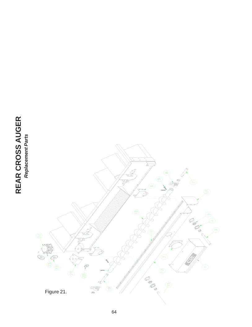
64
RE
AR
CR
OS
S A
UG
ER
Rep
lace
men
t Par
ts
Figure 21.

65
RE
F.
QT
Y.
PA
RT
NO
.D
ES
CR
IPT
ION
12
0449
42R
EA
R C
RO
SS
AU
GE
R G
UA
RD
AS
SE
MB
LY2
104
0440
PLU
GG
ED
DIS
CH
AR
GE
SW
ITC
H3
104
4646
RE
AR
IDLE
R S
HA
FT
CLE
AN
OU
T A
UG
ER
432
0351
16B
EA
RIN
G H
OLD
ER
FLA
NG
ETT
E5
404
4756
1-1/
4" B
EA
RIN
G IN
SE
RT
FA
FN
IR6
276
1013
0R
EA
R C
LEA
NO
UT
BE
AR
ING
BR
AC
KE
T7
104
4652
RE
AR
CR
OS
S A
UG
ER
IDLE
R S
HA
FT
82
0447
571-
1/4"
PIL
LOW
BLO
CK
BE
AR
ING
916
0030
761/
2" X
2-1
/2"
ZIN
C B
OLT
101
0446
50R
EA
R C
RO
SS
AU
GE
R1
0441
11R
EA
R C
RO
SS
AU
GE
R C
EN
TER
DIS
CH
AR
GE
111
0400
097
RE
AR
TR
OU
GH
HIN
GE
121
0446
28C
RO
SS
AU
GE
R T
RO
UG
H L
EF
T H
AN
D1
0446
29C
RO
SS
AU
GE
R T
RO
UG
H R
IGH
T H
AN
D1
0446
30C
RO
SS
AU
GE
R T
RO
UG
H C
EN
TER
DIS
.13
6'00
2116
# 50
RO
LLE
R C
HA
IN14
203
6495
SP
RO
CK
ET
RC
5020
1-1
/4"
BO
RE
151
0446
73R
EA
R D
RIV
E S
HA
FT
CLE
AN
OU
T A
UG
ER
162
0032
901/
4" X
1-1
/4"
KE
Y17
104
4632
CR
OS
S A
UG
ER
TR
OU
GH
EN
D P
LATE
R.H
.18
104
4631
CR
OS
S A
UG
ER
TR
OU
GH
EN
D P
LATE
L.H
.19
104
4651
RE
AR
CR
OS
S A
UG
ER
DR
IVE
SH
AF
T20
303
6714
SP
RO
CK
ET
IDLE
R 5
013
1/2"
BO
RE
211
0442
11G
EA
RB
OX
CH
AIN
TIG
HTN
ER
BR
AC
KE
T22
203
6707
SP
RO
CK
ET
RC
5020
1"
BO
RE
232
0032
881/
4" X
1"
KE
Y24
101
0078
GE
AR
BO
X A
SS
EM
BLY
RE
AR
CR
OS
S A
UG
ER
Rep
lace
men
t Par
ts

66
BL
OW
ER
DR
IVE
CO
MP
ON
EN
TS
Rep
lace
men
t Par
ts
Figure 22.

67
RE
F.
QT
Y.
PA
RT
NO
.D
ES
CR
IPT
ION
11
0449
66B
LOW
ER
SH
IELD
AS
SY
, RIG
HT
HA
ND
22
0358
05B
ELT
BX
95 N
OT
CH
ED
203
5598
BE
LT B
X93
NO
TC
HE
D2
0446
02B
ELT
BX
97 N
OT
CH
ED
32
7612
580
MO
UN
TIN
G B
RA
CK
ET
, BLO
WE
R B
EA
RIN
G4
VA
RIE
S04
5056
BLO
WE
R B
EA
RIN
G S
HIM
PLA
TE
51
0357
65P
ULL
EY
18.
4 X
2G
R S
K6
112
6009
8P
ULL
EY
BU
SH
ING
2-3
/16"
SK
104
0485
PU
LLE
Y B
US
HIN
G 1
-11/
16"
SK
72
0447
72B
EA
RIN
G 2
-3/1
6" P
ILLO
W B
LOC
K F
AF
NIR
204
4758
BE
AR
ING
1-1
1/1
6" P
ILLO
W B
LOC
K F
AF
NIR
81
0447
71B
LOW
ER
SH
AF
T 2
-3/1
6" X
45-
1/2"
104
0482
BLO
WE
R S
HA
FT
1-1
1/16
" X
47-
1/2"
91
N/A
KE
Y S
UP
PLI
ED
WIT
H P
ULL
EY
BU
SH
ING
101
0033
79K
EY
1/2
" X
1/2
" X
6"
111
0404
39B
LOW
ER
WH
EE
L A
30-2
7H X
2.1
88"
BO
RE
104
4688
BLO
WE
R W
HL
& H
SG
A27
-27H
1.6
88 B
OR
E12
123
0201
1H
OU
SIN
G &
CU
TO
FF
A30
-27H
GA
LVA
NIZ
ED
131
0449
52B
LOW
ER
SH
IELD
AS
SY
, LE
FT
HA
ND
141
0445
04M
OT
OR
MO
UN
T P
LAT
E B
LOW
ER
151
2102
041
PU
LLE
Y 5
.8 X
2G
R S
DS
103
8673
PU
LLE
Y 5
.6 X
2G
R S
DS
104
5037
PU
LLE
Y 5
.4 X
2G
R S
DS
161
0447
69P
ULL
EY
BU
SH
ING
1-7
/8"
SD
S1
1260
101
PU
LLE
Y B
US
HIN
G 1
-5/8
" S
DS
171
7710
280
MO
TO
R 2
0HP
1P
H 2
30V
BA
LDO
R1
0053
75M
OT
OR
20H
P 3
PH
230
& 4
60V
BA
LDO
R1
F04
823
7M
OT
OR
25H
P 3
PH
230
& 4
60V
BA
LDO
R1
0053
69M
OT
OR
15H
P 1
PH
230
V B
ALD
OR
100
5374
MO
TO
R 1
5HP
3P
H 2
30 &
460
V B
ALD
OR
182
0449
50B
LOW
ER
SH
IELD
BR
AC
KE
T W
ELD
ME
NT
BL
OW
ER
DR
IVE
CO
MP
ON
EN
TS
Rep
lace
men
t Par
ts

68
SERV
ICE
VALUE
QUALITY
a Division of GLOBAL Industries, Inc.9364 North 45th Street
Omaha, Nebraska 68112www.necousa.com
Manufactured by