context plus final singles - pdf.xportsales.co.uk 11.… · 5005 contextplus brochure...
TRANSCRIPT

Context Plus Fire Catalogue
Analogue Addressable Fire Alarm Equipment
Conventional Fire Alarm Equipment
ContextContextContextPlus
5005 ContextPlus Brochure 270411_Context plus final singles 10/05/2011 08:48 Page 1

ContextContextContextPlus
INTRODUCING THE
RANGE OF ANALOGUE ADDRESSABLE FIRE ALARM EQUIPMENT
CONTEXT PLUS LIMITED175 Mauldeth Road, Manchester M14 6SG, England
Tel: +44 161 257 2541. Fax: +44 161 225 8817.
E-mail: [email protected] Website: www.xportsales.com
The primary purpose of a fire alarm system is to provide an early warning of a fire so that peoplecan be evacuated and action taken to stop the fire as soon as possible – all to a predetermined plan.
Context Plus Analogue Addressable Fire Alarm Equipment
Unlike conventional fire alarm systems, Context Plus analogue addressable systems use ‘intelligent’detectors, sounders and call points that communicate constantly with the control panel, reporting avast amount of data almost ‘invisibly’. This sophisticated communication system allows a degree ofcontrol and reporting unattainable with conventional systems. Very accurate control and monitoringof many parameters is easily achievable, without the need for expensive and complex wiringschemes.
One of the main advantages of an analogue system over a four wire conventional system is that atotal of 126 addressable detection and output devices can be wired in a single loop configuration.
Key features of the Context Plus range of analogue addressable fire alarm equipment include:
• A wide choice of fire alarm control panels (including the XFP range of 1-2 loop panels, the IFP range of 2-8 loop touchscreen-controlled panels and the FirePlus range of 4-32 loop panels)
• A powerful panel networking facility
• Digital protocol for error-free transmission
• A choice of DIL switch or ‘XPERT’ card addressed smoke and heat detectors
• A wide range of sounders, beacons and sounder/beacons
• The ability to carry out many additional functions (switch monitoring, etc) via a comprehensive range of compatible interface units.
Context Plus Conventional Fire Alarm Equipment
Context Plus Limited also offers a range of conventional fire alarm equipment including 1-28 zoneconventional fire panels, wired and wireless conventional smoke and heat detectors, automaticextinguisher panels, power supplies and more.
5005 ContextPlus Brochure 270411_Context plus final singles 10/05/2011 08:48 Page 2
ContextContextContextPlus
Fire alarm system design is beyond the scope of this document.
Contact the Fire Officer concerned with the property at an early stage in case he or she has any special requirements andalways read the installation instructions provided with each Context Plus device.
We strongly recommend that a suitably qualified and competent person is consulted in connection with the design of thefire alarm system and that the system is commissioned and serviced in accordance with the laid down specification andnational standards.
Errors and omissions excepted.
No responsibility can be accepted by the manufacturer or distributors of this range of equipment for any errors or omissionsor for any misinterpretation of any information published in this brochure.
We reserve the right to alter product specifications at our discretion and without prior notice.
CONTEXT PLUS ADDRESSABLE CONTROL & INDICATING EQUIPMENT
XFP 1 to 2 Loop Networkable Analogue Addressable Fire Panels ......................................................................................4
IFP 2 to 8 Loop Networkable Analogue Addressable Fire Panels ........................................................................................7
Fireplus 4 to 32 Loop Networkable Analogue Addressable Fire Panels ..............................................................................9
CONTEXT PLUS ADDRESSABLE DETECTION DEVICES
Choosing a Context Plus detector & notes on short circuit isolation ................................................................................11Ionisation Smoke Detectors (Xpert card style) ....................................................................................................................13Optical Smoke Detectors (Xpert card style) ........................................................................................................................14Temperature/Heat Detectors (Xpert card style) ..................................................................................................................15Multisensors (Xpert card style)..............................................................................................................................................16Mounting Bases & Isolators (Xpert card style) ....................................................................................................................17Optical Detectors (DIL switch style) ......................................................................................................................................19Temperature/Heat Detectors (DIL switch style)....................................................................................................................20Mounting Bases (DIL switch style) ........................................................................................................................................21Manual Call Points ................................................................................................................................................................22Specialist Detectors (flame, beam, etc) ................................................................................................................................23
CONTEXT PLUS ADDRESSABLE INDICATING DEVICES
Addressable Beacons, Sounders and Sounder/Beacons ......................................................................................................25
CONTEXT PLUS ADDRESSABLE MODULES
Switch Monitors ....................................................................................................................................................................28Input/Output Units, 3 Channel I/O Units, Mains I/O units, Output Units ..........................................................................29Zone Monitor with Isolator...................................................................................................................................................30Sounder Control Unit with Isolator ......................................................................................................................................31Hush Buttons ..........................................................................................................................................................................32
CONTEXT PLUS VOICE ALARM & FIRE TELEPHONE EQUIPMENT
The AVAC Voice Alarm System..............................................................................................................................................33The SigTEL Fire / Telephone Disabled Refuge System ........................................................................................................35
CONTEXT PLUS CONVENTIONAL FIRE ALARM EQUIPMENT
Conventional Detectors ........................................................................................................................................................36Conventional Fire Accessories (Call Points, Bells and Sounders) ........................................................................................37Conventional Fire Panels ......................................................................................................................................................38Wireless Detectors and Ancillaries........................................................................................................................................40Power supplies .......................................................................................................................................................................42
CONTEXT PLUS FIRE PERFORMANCE CABLE
Standard Fire Performance Cable ........................................................................................................................................43
5005 ContextPlus Brochure 270411_Context plus final singles 10/05/2011 08:49 Page 3

Key Features
4Third-party certified to EN54 parts 2 and 4 by the LPCB.
4Full compatibility with the Context Plus range of smoke and heat
detectors, call points, sounders and control modules.
4Three access levels - 1 (general), 2 (authorised user) and 3 (engineer)
4Combined keypad/keyswitch entry to access levels 2 and 3
4The ability to interconnect up to eight XFP main panels (any variant)
plus an additional four XFP repeater panels per main onto a two wire
RS485 network.
4Two independently programmable conventional sounder circuits.
4Two programmable inputs.
4A fault output relay and three programmable relay outputs with voltage
free changeover contacts.
4Three zone dependency functions (A, B & C to EN54-2 Clause 7.12)
4A day/night (building occupied/unoccupied) function.
4An investigation delay period function.
4 Individual sensitivity settings for each device.
4A phased evacuation and delays to outputs facility (to EN54-2 Clause 7.11)
4An alarm counter that records the number of times the panel has been
in an alarm state (to EN54-2 Clause 7.13).
4Powerful short circuit protected loop drivers, capable of supporting up
to 40 loop powered 10mA sounders per loop.
4An integral EN54 switch mode PSU rated @ 185-260V a.c. 50/60Hz (3A
on 32 zone panel, 1.4A on 16 zone panel).
4Adjustable contamination levels.
4Earth fault monitoring.
4Push button access code or keyswitch entry to Access Levels 2 and 3
(depending on model purchased).
4An easy to read, 80 character back-lit display.
440 characters of custom text per device.
4999 event monitoring.
4Comprehensive test facilities (to EN54-2 Clause 10) and a wide range of
maintenance and commissioning functions including auto-learn loops,
monitor a point, test outputs, one man walk test and loop continuity test).
4An intuitive Windows based upload-download PC program that allows
the system to be programmed quickly and easily.
Fully approved to EN54 parts 2 & 4 by
the Loss Prevention Certification
Board, the XFP Range of networkable
analogue addressable fire alarm
control panels offers high performance
at a competitive price. Available in
two different versions (a cost-effective
single loop 16 zone panel supplied in a
plastic enclosure and a robust 1 or 2
loop 32 zone metal panel), the range
offers an array of user and installer-
friendly features.
XFP Single Loop 16 Zone Panel
WHY LPCB?The LPCB stamp of approval is recognised worldwide and
demonstrates that the XFP has been tested and certified
as being compliant with EN54 parts 2 and 4 by the Loss
Prevention Certification Board. LPCB Ref. 176b
XFP 1 or 2 Loop 32 Zone Panel
XFP 1-2 LOOP NETWORKABLE ANALOGUEADDRESSABLE FIRE PANELS
0832176b
4
5005 ContextPlus Brochure 270411_Context plus final singles 10/05/2011 08:49 Page 4

5
A TYPICAL XFP ANALOGUE ADDRESSABLE LOOP / XFP NETWORKING DETAILS
EOL
EOLc c
Sounder control unit with Isolator
Switch Monitor with Isolator
Zone Monitor with Isolator
Input Output Unit with Isolator
Fire OutputFault Input
Ancillary function
Programmable input 1Programmable input 2
Conventional Sounder Circuit 1Conventional Sounder Circuit 2
Relay output 1Relay output 2Relay output 3
Fault output+24V output
Externally powered conventional sounders
EOL
Conventional detectors and manual call points
EOL
Local24VPSU
Detector c/w Mounting Base
ManualCall Point
Loop PoweredSounder
Detector c/w Isolating Base
Loop PoweredBeacon
c c c
c c c
Important: Isolators should be installed at intervals not exceeding 20 devices and at the building's structural fire barriers/zonal boundaries.
Conventional detectors, manual call points and sounders
Hush button with Isolator c c
XFP ORDER CODES
XFP REPEATERS*
XFP510-16 XFP Networkable repeater panel, 16 zonesKeypad/keyswitch entry, c/w psu, plastic enclosure
XFP510-32 XFP Networkable repeater panel, 32 zones Keypad/keyswitch entry, c/w psu, metal enclosure
XFP BEZELS & ENCLOSURES
AFP385 Flush mount bezel (for XFP 32 zone main & repeater panels)
BF359/3S Stainless steel glazed enclosure for XFP 32 zone panels, requires BF359/3CL or BF359/3SL lock kit
BF359/3CL Cam lock kit for BF359/3S enclosure
BF359/3SL Electromagnetic solenoid lock kit for BF359/3S enclosure
Note XFP 16 zone panels can be semi-flush mounted without the need for a bezel
XFP PROGRAMMING SOFTWARE*
XFP507 XFP Upload download software kit (all protocols)Windows 98, 2000, XP. Includes programming lead
SAF7070000 2m Programming lead ONLY
XFP PRINTER KITS*
AFP709 XFP off-board printer kit
* Repeaters, bezels, network communication cards, programming softwareand printer kits are not included within the scope of the XFP’s LPCB approval
XFP SINGLE LOOP 16 ZONE FIRE PANELS - LPCB approved to EN54-2/4Communication protocol = Apollo XP95/DiscoveryXFP501E/CON XFP Networkable single loop 16 zone panel
Keypad/keyswitch entry, c/w 1.4A psu, plastic enclosure
XFP 1 LOOP 32 ZONE FIRE PANELS - LPCB approved to EN54-2/4Communication protocol = Apollo XP95/DiscoveryXFP501/CON XFP Networkable one loop 32 zone panel
Keypad/keyswitch entry, c/w 3A psu, metal enclosure
XFP 2 LOOP 32 ZONE FIRE PANELS - LPCB approved to EN54-2/4Communication protocol = Apollo XP95/DiscoveryXFP502/CON XFP Networkable two loop 32 zone panel
Keypad/keyswitch entry, c/w 3A psu, metal enclosure
XFP NETWORK COMMUNICATION CARDS*
CFP761 XFP network communication card for XFP 16 zone main panels
AFP711 XFP network communication card for XFP 32 zone main panels
(One network communication card is required per networked main panel. Note thatrepeater panels are supplied with a network communication card already fitted).
KEY FEATURES OF THE XFP’S NETWORK PROTOCOL
The XFP’s network protocol allows the interconnectionof up to eight XFP main panels (any mix) over a two-wire RS485 network. Alternatively, the network canbe used to connect up to eight XFP repeaters to oneXFP main panel. It is not possible to mix XFP mainpanels and repeaters on the same network.
Key features of the XFP’s network protocol whenused for interconnecting XFP main panels:
4 Allows the interconnection of up to eight XFP main panels (any mix of single loop 16 zone XFPs and 1 and 2 loop 32 zone XFPs)
4 Up to 1 km of cable may be fitted to an XFP main panel network.
4 Each networked XFP main panel can be programmed to accept Fires, Faults and Control actions such as Silence Alarm Sounders and Control Panel Reset from other main panels. They will also Accept Disablement commands for zones, sounders and output sets from other main panels.
4 All panels monitor all other panels for network wiring faults.
4 Fires on remote panels are displayed on local panelsincluding the point description of the alarm’s origin.
4 Faults on remote panels are displayed on local panelsincluding the point description of detectors.
4 Cause and effects can be programmed into local panels dependent on which remote panel is in alarm.
4 The network supports the programming of site datainto remote panels from a PC at a local panel.
4 Time and date is common to all panels throughoutthe network.
4 All networked main panels require a network communication card
Key features of the XFP’s network protocol whenused for connecting XFP repeaters
4 Allows the connection of up to eight XFP repeaters to one non-networked main panel. The XFP main panel must have a network communication card fitted.
4 Up to 500m of cable may be fitted to an XFP repeater network.
4 Each XFP repeater offers all the functions and controls of an XFP main panel.
Below is a diagram of a typical Context Plus analogue addressable loop fitted with a selection of detectors, looppowered sounders, modules and isolators, all connected to an XFP single loop 16 zone panel. The diagram alsoillustrates how a series of XFP main panels can be networked using the range’s powerful RS485 network.
This diagram is provided for illustration purposes only and you should always refer to the relevant XFP panel/device instructions as appropriatebefore installation. Note that the descriptions and availability of the devices shown may not be applicable to all manufacturer’s protocols.
ContextContextContextPlus
XFP 1-2 LOOP NETWORKABLE ANALOGUEADDRESSABLE FIRE PANELS
5005 ContextPlus Brochure 270411_Context plus final singles 10/05/2011 08:49 Page 5
6
XFP Technical Specifications
Mains supply 230V a.c. ± 10% 50/60Hz. Max current 350mA 230V a.± 10% 50/60Hz. Max current 680mAInternal power supply 27V d.c Nominal 27V d.c NominalTotal output current limited to 1.4A @ 230V a.c. 3A @ 230 V a.c.Supply and battery charger monitored for failure Yes YesBatteries monitored for disconnection and failure Yes YesBatteries protected against deep discharge Yes YesMax. battery size and type 3.2 Ahr VRLA 7.0 Ahr VRLASpecified batteries for LPCB approved systems 2 x Yuasa NP3.2-12 2 x Yuasa NP7-12
Quiescent current drain (1 loop unloaded) < 50mA < 80mAQuiescent current drain (2 loop unloaded) not applicable <100mAEarth fault monitoring Yes (any conductor) Yes (any conductor)
Temperature compensated charging Yes YesNumber of loop drivers 1 1 (XFP501/CON)
2 (XFP502/CON)Line monitored for open and short circuit faults Yes YesOnboard loop isolators with LED indication when active Yes YesAuto-polling from each loop end Yes YesMax. loop output current 500mA (Voltage: 25V min, 34V max) 500mA (Voltage: 25V min, 34V max)Max. number of addressable devices per loop 126 126Max. number of loop powered sounders per loop @ 10mA 40 40Number of programmable sounder groups 16 16
Number of programmable output sets 16 16Number of programmable circuits 2 2End of line resistor value 6800 Ω 5% Tol. 0.25 W 6800 Ω 5% Tol. 0.25 WLine monitored for open and short circuit faults Yes YesOutputs fused at 400mA 400mA
Max. number of sounders @ 20mA 40 80Type Relay voltage free single pole changeoverMax switching current 1AMax switching voltage 30 V d.cRelay 1 Programmed from cause and effectRelay 2 Programmed from cause and effectRelay 3 Programmed from cause and effectFault Active when no faults are present
‘24V’ Aux Power Output 19.5V min, 28V max. Max current 100mA. Protected by resettable overload circuitInput 1 Connect to 0V to trigger. Max input voltage 27V d.c. (non-latching). Programmable from cause and effect.
Input 2 Connect to 0V to trigger. Max input voltage 27V d.c (non-latching). Programmable from cause and effect.Mains Fuse 1A HRC Ceramic 20mm 1A HRC Ceramic 20mm
Battery Fuse - limits the current drawn from the battery 1.6A F 20mm 3.15A F 20mmControl buttons Silence, Reset, Resound, Investigate; More Information; Menu Event scrolling and menu access buttons Up (1); Down (2); Accept (3); Abort (4)Liquid Crystal Display Two lines x 40 characters, backlit Number of Zonal LED indicators 16 32Other LED indicators General Fire, System Energised; Pre-Alarm; Remote Output Activated; Menus Accessed; Disablement;
ONE OR TWO LOOP 32 ZONE XFP PANELSXFP501/CON XFP502/CON
Test; Remote Output Disabled; Silenced; General Fault; System Fault; Approx. dimensions of back box (W x H x D) 380 x 235 x 77mm (plastic). Includes ‘lip’. 410 x 250 x 80mm (metal)Approx. dimensions of lid (W x H x D) 380 x 235 x 16mm (plastic) 439 x 274 x 7mm (metal)
Approx. weight (without batteries) 1.9Kg 4.5kgType of cable Fire resistant screened cable, minimum size 1mm2
Max. cable length per loop 1kmConnector blocks Plug-on type, largest acceptable conductor size 1.5mm2
Max. allowable loop impedance (each conductor) 20 Ω
Max. cable capacitance .27µFConnection Via CFP761 network driver card fitted at Via AFP711 network driver card fitted at
main panel main panelMax. no. of main panels per network 8 8Max. no of repeaters per non-networked main panel 8 8
Max. cable length per network 1km (main panel network); 500m (repeater network) 1km (main panel network); 500m (repeater network)PC connection Via main panel RS232 molex connector (lead supplied in XFP507 upload/download software kit)
SINGLE LOOP 16 ZONE XFP PANELSXFP501E/CON
Power Supply Specification
Loop Driver Specification
Conventional Sounder Circuit Specification
Auxiliary Outputs
Auxiliary Inputs
Fuses (to IEC - EN60127 Pt2)
Panel Indicators and Controls
Physical Dimensions
Cabling Requirements
Network Specification
PC/Printer Interface
The components are selected to operate within their specification when the environmental conditions outside the enclosure comply with class 3k5 of IEC 721-3-3 : 1978.Temperature range:- -5 to +40oC. Maximum relative humidity: 95%
Operating conditions
XFP 1-2 LOOP NETWORKABLE ANALOGUEADDRESSABLE FIRE PANELS
5005 ContextPlus Brochure 270411_Context plus final singles 10/05/2011 08:49 Page 6

Introducing the new IFP Range of
intelligent touchscreen-controlled
2-8 loop fire panels from Context Plus -
due for release Quarter 4, 2011
Preliminary Features4 Designed to comply with the latest versions of EN54 parts 2, 4 and 13
4 Communication protocol - Apollo XP95/Discovery
4 Three cabinet sizes - standard (2 or 4 loops), medium (2, 4, 6 or 8 loops) and large (2, 4, 6 or 8 loops)
4 3A or 5A full EN54-4/A2 PSU and battery charger included
4 Onboard mini-USB connection to connect a PC running programming software
4 Two RS 232 ports - one dedicated to a 40 column thermal printer (optional), one for ancillary devices such as ESPA protocol alphanumeric pagers / DECT telephone systems
4 4.3 inch, 472 x 248 pixel, 24 Bit, 16 M colour, resistive LCD touchscreen (larger touchscreen available to special order)
4 40 characters of custom text per device
4 Separate distinct LEDs for mandatory EN54 indications plus programmable LEDs
4 Real time clock with built in and automatic daylight saving time/backup PSU
4 Standard upload download software includes facility to upload company logos - even from a simple .jpg file from a camera
4 Secure fault tolerant network as standard (needs separate network driver PCB)
4 Full on-screen QWERTY keyboard
4 Day/night sensitivity
4 Three access levels - general, authorised user and engineer
4 Four programmable 1A sounder circuits (3A max total)
4 Directly connects to DIN standard fireman’s Interface (IFAM-FAT/FBF).Interface for Keybox units and ATU.
4 Up to 200 separate LEDs per panel, programmable as Fire Zonal LEDs or other
4 Up to 64 eight loop peer to peer panel network capacity (max. distance between each ‘node’ = 1KM)
4 Fault tolerant network drivers (Hi-Net)
4 Flush and surface ‘Compact Controllers’
4 Up to 10,000 programmable and indicatable system zones
4 Greater than 100,000 addressable device system capacity
4 20,000 event memory of all fire and fault and system events - all filterable
4 Selectable Language
4 ‘Slide In’ label system on custom moulded bezels for customizable language labels/custom description of zones and programmable LEDs. Common word processortemplates available with software
4 Isolated internal/external RS485 peripheral bus for connection of ancillary peripheral PCBs (15 PCBs max per panel)
4 Up to 16 GB (2 GB as standard) internal SD card memory (removable micro SD card). SD card can be programmed off site if required
4 Dedicated port for Ethernet connection (requires plug on TCP/IP PCB) to allow for Internet control and monitoring
4 Onboard printer option
4 Modular Construction
4 Up to 18 Ah batteries in standard cabinet, up to 38 Ah in larger cabinets
Panel appearance and specifications subject to confirmation and/or change without prior notice.Please contact our sales desk for an up-to-date list of panel features, part numbers and release dates.
ContextContextContextPlus
IFP 2 TO 4 LOOP PANEL(STANDARD CABINET)
IFP 2-8 LOOP NETWORKABLE ANALOGUEADDRESSABLE FIRE PANELS
7
IFP 2, 4, 6, 8 LOOP PANEL(MEDIUM CABINET)
IFP COMPACT CONTROLLER
5005 ContextPlus Brochure 270411_Context plus final singles 10/05/2011 08:49 Page 7

8
PROCESSOR TECHNOLOGY Dual processor, flash based.
POWER SUPPLY 230v 50-60Hz 5A EN 54-4/A2 inc temperature compensated charger.1 x 24V 0.5A Aux PSU output.
MEMORY 512 Mb onboard flash – firmware.16 Mb DRAM.2Gb removable on board micro SD card (16Gb max).
DISPLAY 4.3 inch, 472 x 248 pixel, 24 Bit, 16 M colour, resistive LCD touch screen (larger sizes available to special order)
EXTRA INDICATION - MAIN DISPLAY CARD 16 Programmable main panel mounted LEDs (1 Green, 3 Red and 13 Yellow). These are the EN 54 Mandatory LEDs + a minimum of 6 user definable & programmable.
CONTROLS Multiple controls via virtual touch screen buttons. User definable & programmable options.Multiple panel mounted keyswitch/ordinary switches panel mounted and programmable(needs extra serial I/O card).
ON BOARD I/O 4 x Programmable 1A sounder circuits (3A max. total) – Monitored3 x Programmable relays volt free outputs.2 x Programmable on board monitored inputs.1 x Earth fault monitor.
PANEL CAPACITY 2 or 4 loops in standard cabinet2, 4, 6 or 8 loops in medium or large size cabinets.
COMMUNICATION BUSES 2-8 Proprietary protocol loop drivers. Available as 2-loop PCBs.1 x RS232 dedicated to onboard printer (optional).1 x RS232 for connection of e.g. Alphanumeric Paging Transmitter (including ESPA) or DECT Phones. 1 x Serial I/O bus (for panel mounted auxiliary LEDs, switches etc).1 x RS485 A-Bus. Peripheral bus to peripheral PCBs (e.g. relay drivers, I/O PCBs, Aux Sounder PCBs, Conventional zone PCBs, mimic drivers etc).Max 15 per panel.1 x RS485 Fault tolerant network driver output (needs isolated fault tolerant network PCB).1 x RS485 (needs TCP/IP plug on PCB for connection to LAN and Internet).1 x RS485 Fireman’s interface connection (needs proprietary driver PCB e.g. IFAM).
SERIAL ANCILLARY CARDS (EXTRA) 20-zone Indication Module, name slots & space for 5 switches* & 10 LEDs.• Max 3 Indication/Switch Modules 20-zone Indication Module, name slots, printer* & space for 2 switches* & 4 LEDs.
per control module. 40-zone Indication Module with name slots.• Two modules per enclosure window. 40-zone Indication Module with space for 5 switches* & 10 LEDs.
40-zone Indication Module with printer* & space for 2 switches* & 4 LEDs.100-zone Indication Module, numbered 1-100.100-zone Indication Module, numbered 101-200.Blank Module.* Key switches and Push buttons extra.
A-BUS PERIPHERAL PCBS 4 relay PCB (half-size).• Connect to Main 2-Loop PCB or 8 relay PCB.
Hi-Net+ PCB. 8 I/O PCB (half-size).• Cabling is 2 core + screen plus 2-core 16 I/O PCB.
for power supply, which may be local. 4 Sounder PCB with PSU monitoring - 4 x 1A 6K8 monitored sounder circuits (3A limit).• Up to 15 per Network PCB per A bus. 4 zone PCB (conv) with 2 sounder circuits & PSU monitoring - 2 x 1A 6K8 monitored sounder circuits.• Powered from Main 2-Loop PCB Mimic Interface PCB (will use light guides).
or other EN 54-4 PSUs. German key box interface PCB.• Normally only used within the cabinet(s) IFAM FAT/FBF PCB German fireman’s panel (Does not connect to Hi-Net).
but may be extended up to 1 km for non EN 54-2 functions.
CABINETS (W X H X D mm)
STANDARDS COMPLIANCE EN 54-2/4
IFP 2-8 LOOP NETWORKABLE ANALOGUEADDRESSABLE FIRE PANELS
All of the above preliminary features are subject to confirmation and/or change without prior notice. Please contact our sales desk for an up-to-datelist of panel features, part numbers and release dates.
200 450200
960
200 450200
720
200 450200
462
Standard (2-4 loop)(18AHr Batteries)
Large (2-4-6-8 loop)(12-38AHr Batteries)
Medium (2-4-6-8 loop)(7-18AHr Batteries)
CompactController
214214
178178
5005 ContextPlus Brochure 270411_Context plus final singles 10/05/2011 08:50 Page 8

Key Features:-Introducing the FirePlus range of
feature-rich 4 to 32 loop networkable
analogue addressable fire alarm
panels.
Options such as single point network
programming, remote diagnostics
via modem and a powerful
‘Smartgraphics’ package, combine to
make FirePlus one of the most flexible
networkable fire panels in the world.
• Communication protocol = Apollo XP95/Discovery • Designed to comply with EN54-2/4 and
Australian standard AS 4428.1 • Front panel & laptop programmable • Self learn • Modem connection capability • Remote upload/download of software • Remote interrogation of system • Password protection • Day/night sensitivity settings • Event log • Network capabilities • Operation of all inputs/outputs via keypad • Brigade output interrogation • Pre-alarm level available
• Digital voltage readout • Readout of detector analogue count • Printer connection capability • Service information displayed on LCD • S.P.O.T. - Single Person Operation Test • Modular expansion capabilities • Graphics display and control capabilities • Max no. of repeaters = 30 • Display provides 8 lines of up to 40 characters• 34 characters of custom text per device• Three access levels• System programmable via front panel or PC• Mod bus or ASCII output for connection to
optional BMS, paging or graphic system• 200 events in the fire event log
ContextContextContextPlus
FirePlus SP1M Panel
FirePlus SP8 Panel
FIREPLUS 4-32 LOOP NETWORKABLE ANALOGUEADDRESSABLE FIRE PANELS
9
OverviewThe heart of each FirePlus panel comprises two boards collectively known as the Controller.The boards are the Main Board and the CPU Board. Combining these two boards with afront panel forms the basis for a FirePlus FACP. A single FirePlus Controller has the capacityto interface to four (4) Slave CPU’s. Each of these Slave CPU’s can interface to a 16 ZoneConventional Termination Board, a Loop Termination Board and or Input/Output Boards. The Main Board includes the first Slave CPU and the provision for the plug in mounting ofup to three additional Slave CPU’s. Each Slave CPU has the same software installed and themanner in which they operate is automatically determined by the type of termination orinterface board connection.
Keypad Features Using the keypad and the LCD display the status of the system can be displayed. Users canallocate descriptions to inputs and outputs, identify inputs and outputs by their location andconduct pre-commissioning tests using the unique input / output testing feature. Other keyfeatures include adding, deleting or editing devices, displaying the status of the brigadeoutput, day / night sensitivities, changing of brigade functions, displaying the status ofdevices and the event log.
Self Learn The ability to self-learn devices connected on each analogue loop and downloadingconfiguration information of these devices, is incorporated in the FirePlus. FirePlus also takesthis feature of self learn one step further as it has the ability to automatically configuresystem hardware. With the latest software enhancements FirePlus now treats each input ofa multi-input device as a unique entity although only one address is required. The FirePlususes special ‘sub-addressing’ techniques that allows each input to be zoned and have adescriptor assigned separately.
Serial Interfacing The FirePlus has 2 internal serial bus that provide the interfacing to (1) the Brigade PSUMonitor Board and if required up to eight Sounder Boards; and (2) ancillary boards for thecontrol and or monitoring of field plant and equipment.
Networking a System Where system design exceeds the capacity of one SP series FirePlus then other FirePluspanels can be networked together to provide an expanded system with a maximum of 100loops or 1000 zones.
Networking Features • A Master / Slave (Main/Sub) FACP arrangement • A true Peer to Peer System • Use of Data Gathering Panels (DGP’s) • SmartTerminal Repeater Panels • SmartGraphics
SmartGraphics The Graphics system transforms the FirePlus into a powerful, flexible and integratedgraphics based fire and or building management system.
Config Manager Software ConfigManager is a Windows based software programming package used to configure theFirePlus operational characteristics to the functional design of an installation.
LineManager Line Manager is a software tool for local or remote upload and/or download of software;establish the status of devices, interrogate the FirePlus; download single events from theevent log file.
5005 ContextPlus Brochure 270411_Context plus final singles 10/05/2011 08:50 Page 9

10
Front Panel Layout & Controls
SOUNDER SILENCE: Silences any bells or soundersconnected to the fire panel that have been activated by anAlarm or Evacuate
EVACUATE: Activates the Sounders and Bells.
PREVIOUS: Scrolls backwards through displayed alarms,faults or disables.
NEXT: Scrolls forwards through displayed alarms, faults ordisables.
BUZZER SILENCE: Silences the panel buzzer
RESET: Resets the panel by clearing any recognised alarms.Uncleared faults or disabled devices will continue to show.
SOUNDER DISABLE: Disable Sounders & Bells until released
DEVICE DISABLE/ENABLE: Disables selected detectors,devices or zones.
F.W.R.E FAULT/DISABLE: Disables the FWRE relay on theBrigade PSU Monitor Board.
F.A.R.E FAULT/DISABLE: Disables the FARE relay on theBrigade PSU Monitor Board.
OUTPUT DELAY ACTIVE: Activates the delay of an Alarmoutput (AIF).
LOOP: Allows selection of the loop to be accessed.
DEVICE: Allows selection of the device to be accessed.
ZONE: Allows selection of the zone to be accessed.
DISPLAY: Displays the state of the device/s selected.
1 ABC, 2 DEF, 3 GHI, etc: The Alphanumeric characters areused to edit text and/or for the selection of componentson the system.
TO: Allows access to a range of devices. Eg. 1 TO 8
ENTER: Confirms the entry of data onto the system.
CANCEL ENTRY: Deletes data or returns to the previouslydisplayed menu.
Moves the cursor back and forth when entering data in a field.
Used to move between fields when entering data.
MENU - Displays the main menu on the LCD.
FUNCTION - Displays the function menu on the LCD.
SP4 AS4428 Range (SP1M)Expandable upto 4 loops, 32 Zone LEDS PSU rated at 2.6 amps3 alarm circuits; Enclosure dimensions 500H x 400W x 140DSP1M 4 loop panel (formerly SP4 112-0027) 8580-4200SP1M 4 loop panel & printer .(formerly SP4 112-0027/P) 8580-4300
SP4 Range (SP1M)Expandable from 5 loops to 8 loops, 32 zone LEDS PSU ratedat 5.6 amps 3 alarm circuits; Enclosure dimensions 500H x400W x 140D; 64 zone LEDS available on SP4 (SP1M) panels 5loops and above; Note: An SP1M ancillary cabinet (850-9003)may be required for standby batteries SP1M Five Loop panel 8580-5200SP1M Six Loop panel 8580-6200SP1M Seven Loop panel 8580-7200SP1M Eight Loop panel 8580-8200
SP8 AS4428 RangeExpandable upto 8 loops, 64 Zone LEDS, PSU rated at 5.6 amps,3 alarm circuits; Enclosure dimensions 840H x 515W x 140DSP8 Four loop panel (formerly 112-0032) 8580-4700SP8 Five loop panel (formerly 112-0033) 8580-5700SP8 Six loop panel (formerly 112-0034) 8580-6700SP8 Seven loop panel (formerly 112-0035) 8580-7700SP8 Eight loop panel (formerly 112-0036) 8580-8700
SP16 AS4428 RangeExpandable upto 16 loops, 64 Zone LEDS, PSU rated at 5.6 amps,3 alarm circuits; Enclosure Dimensions 1200H x 625W x 240DSP16 Nine loop panel (formerly SP16-09) 8580-9809SP16 Ten loop panel (formerly SP16-10_ 8580-9810SP16 Eleven loop panel (formerly SP16-11) 8580-9811
Part numbers
SP16 Twelve loop panel (formerly SP16-12) 580-9812SP16 Thirteen loop panel (formerly SP16-13) 8580-9813SP16 Fourteen loop panel (formerly SP16-14) 8580-9814SP16 Fifteen loop panel (formerly SP16-15) 8580-9815SP16 Sixteen loop panel (formerly SP16-16) 8580-9816
Internal accessories for Fireplus8 x 3A Serial Relay output kit 159-0072Panel Printer SP1M, SP8, SP16 (Formerly 159-0016) 159-0110Network interface board, V6 (Formally 159-0053) 159-0223Modbus Com Card, CIC (controller interface card) 159-00544 plus 4 bell monitor board 159-00698 way bell monitor board 159-0071Paper for 159-0110, 10 rolls (Formally 326-0008) MIS198132 zone LED Alarm & Fault Indicator board 159-0075
FireFinder bezels, cabinets and ancillariesSP8 Flush mount bezel 158-0033SP1M/SP1X Flush mount bezel ENC1798-F
FireFinder Smart Graphics and SoftwareSmart Graphics Windows based graphics package 159-0073 (includes dongle) - requires Modbus Card 159-0054FireFinder laptop comms cable 322-0008FireFinder laptop comms cable & USB adaptor 1150ConfigManager Program kit, dongle & USB adaptor 1151
FireFinder Repeaters and mimicsLCD SmartTerminal repeater* - without PSU 4380-0001LCD SmartTerminal repeater* - with 2 Amp PSU 4380-0002LCD SmartTerminal Slim Line repeater* - no PSU 4380-0003*Requires driver PCB 159-0129 in the control panel)LCD repeater driver PCB 159-0129
FirePlus SP1M Panel
FirePlus SP8 Panel
FIREPLUS 4-32 LOOP NETWORKABLE ANALOGUEADDRESSABLE FIRE PANELS
5005 ContextPlus Brochure 270411_Context plus final singles 10/05/2011 08:50 Page 10

11
information that allows an alarm to be raised even when the device isnot itself being interrogated. Message error checking is also provided.
Context Plus detectors provide an alarm facility that automatically putsan alarm code on the data stream and reports its address when thepre-set EN54 thresholds are exceeded. The devices provide greatflexibility in system design with the control equipment determining thecharacteristics of the system.
All Context Plus detectors are designed to be connected to a two wireloop circuit carrying both data and a 17V to 28V dc supply. Thedetectors are connected to the incoming and outgoing supply viaterminals L1 and L2 in the mounting base. A remote LED indicatorrequiring not more than 4mA at 5V may be connected between +Rand -R terminals. An earth connection terminal is also provided.
The Context Plus range now includes two distinct ranges of detectors,our XPERT Card addressed range and our DIL switch addressed range.(Our DIL Switch range includes optical and temperature detectors only).
APPROVALS
Context Plus addressable detectors comply with EN54-5: 2001 (heat) andEN54-7: 2001 (smoke). Detectors also comply with EMC Directive2004/108/EC and are CE marked. Each detector type is designed to beapproved by approval and regulatory bodies worldwide, including theLPCB in the UK.
Your choice of detector(s) from the Context Plus range should alwaysfollow the well established principles of system design. That is, theoptimum detector type will depend on the type of fire risk and fireload, and the type of environment in which the detector is sited.
For general use, smoke detectors (ionisation, optical or multisensor)are recommended since these give the highest level of protection. It isgenerally accepted that ionisation types have a high sensitivity toflaming fires whereas optical types have high sensitivity tosmouldering fires. These general principles apply to all Context Plusdetectors although the availability of a multisensor offers more choiceto the system designer. The multisensor is basically an optical smokedetector combined with a heat detector. It therefore responds well tosmoke from smouldering fires and its temperature sensitivity allows itto give a response to fast burning (flaming) fires, which is similar tothat of an ionisation detector. The multisensor can therefore be usedas an alternative to an ionisation detector.
Where the environment is smoky or dirty under normal conditions, aheat detector may be more appropriate. It must be recognised,however, that any heat detector will respond only when the fire iswell established and generating a high heat output.
Each Context Plus device responds to interrogation and commandfrom central Context Plus control equipment. It communicates to thepanel information on status, command bits, type, location, and other
Ionisation Optical Temp. (Heat) MultisensorOverheating/thermal combustion Poor Very Good Very Poor Very GoodSmouldering/glowing combustion Moderate/Good Good Very Poor GoodFlaming combustion Very Good Good Poor GoodFlaming with high heat output Very Good Good Moderate/Good Very GoodFlaming - clean burning Poor Very Poor Moderate/Good Moderate/Good
Context Plus XP95 Device Response
THE REQUIREMENT FOR ISOLATIONAnalogue addressable fire detection systems are usually designed asloops, with the connecting wires starting and finishing at the controlpanel. Detectors and interfaces are connected at intervals along thecables. Depending on local regulations, manual call points and soundersare connected either to the same loop or to other, dedicated loops. Spursmay be connected at any point of the loop, either directly from the loopwires or from an interface such as a Zone Monitor.
Short circuits do not occur very often but, when they do, theconsequences can be serious, possibly making the affected loop entirelyinoperative. It is for this reason that isolating circuits have been designedand incorporated into various devices that are connected to the loop.The purpose of these isolating circuits is to protect the loop in the eventof a short circuit by disconnecting the part of the loop where the shortcircuit has occurred. When the short circuit fault has been rectified, theisolating circuitry reconnects the affected section of the loop. Normallyan isolator should be included on every wiring transition between zones,thus ensuring that a single short circuit fault only affects one zone only orpart thereof.
FEATURES OF ISOLATING CIRCUITSIsolating circuits are delivered as stand-alone isolators with their ownmounting bases or as printed circuit boards in a version of the detectormounting bases known as ‘isolating bases’. Isolating circuits are also fitted
to interfaces such as Input/Output Units or Sounder Control Units. Theyare polarity sensitive, normally switch the negative line of the loop andallow the connection of between one and twenty detectors or theequivalent load between isolators. Detectors fitted to isolating bases andinterfaces with built-in isolating circuits remain operative when anadjacent loop section is in the isolated state.
OPERATING PRINCIPLESUnder normal operating conditions the isolating circuit provides a lowresistance of 0.2Ω or lower in either direction. If the loop voltage falls to14±0.4V the isolator will switch from the closed state to the open state inorder to isolate the loop ‘in’ and ‘out’ lines. The isolated section is testedevery four seconds with a current pulse and is automatically re-connectedwhen the load resistance is 175Ω or greater. The current pulses are drawnfrom the loop and it is important for correct operation of the system thatthe pulse load be included in the loop calculation made for any system.
LOAD CALCULATIONUp to 20 detectors or the equivalent load may be connected betweentwo isolating circuits. Interfaces and sounders are counted as onedetector for every milliampere of switch-on surge current. Interfaces withintegral isolation can be powered from either side of the isolator. Theswitch-on surge current is counted as one detector for every milliampereof switch-on surge current and must be included with the calculation foreach of the adjacent sections of the loop. Context Plus offers a softwareprogram with which the viability of a design can be checked. For a copyof the program, entitled LoopCalc, contact our sales desk.
ContextContextContextPlusCHOOSING A CONTEXT PLUS DETECTOR
NOTES ON SHORT-CIRCUIT ISOLATION
5005 ContextPlus Brochure 270411_Context plus final singles 10/05/2011 08:50 Page 11

CONTEXT PLUS‘XPERT’ CARD ADDRESSED
DETECTORS & BASES
Our XPERT Card addressed detectors utilise a unique addressing methodwhere the address is held in the base and not the detector head. Thismeans the address remains the same regardless of how many times adetector is replaced and allows different types of detecting heads to beswapped without the need for reprogramming.The XPERT card is a plastic, coded card containing seven 'pips'.The address is set by removing the 'pips' with a screwdriver and inserting thecard into the side of the base. When the detector head is rotated into the base,the remaining 'pips' on the card operate the address buttons on the base of thedetector and the address is read by the detector electronics.
12
5005 ContextPlus Brochure 270411_Context plus final singles 10/05/2011 08:51 Page 12

13
Ionisation Smoke Detector, XPERT style, 55000-500IMC
The Context Plus XP95 ionisation smoke detector has a moulded self-extinguishing white polycarbonate case with wind resistant smokeinlets. Stainless steel wiper contacts connect the detector to theterminals in the mounting base. Inside the detector case is a printed circuit board thathas the ionisation chamber mounted on one side and the address capture, signalprocessing and communications electronics on the other.
The ionisation chamber system is an inner reference chamber contained inside anouter smoke chamber. The outer smoke chamber has smoke inlet apertures thatare fitted with an insect resistant mesh.
The radioactive source holder and the outer smoke chamber are the positive andnegative electrodes respectively. An Americium 241 radioactive source mounted withinthe inner reference chamber irradiates the air in both chambers to produce positiveand negative ions. On applying a voltage across these electrodes an electric field isformed. The ions are attracted to the electrode of the opposite sign, some ions collideand recombine, but the net result is that a small electric current flows between theelectrodes. At the junction between the reference and smoke chambers is the sensingelectrode that is used to convert variations in the chamber currents into a voltage.When smoke particles enter the ionisation chamber, ions become attached to themwith the result that the current flowing through the chamber decreases. This effect isgreater in the smoke chamber than in the reference chamber and the imbalancecauses the sensing electrode to go more positive.
Sectional view - Ionisation Smoke Detector
Specifications are typical and given at 23°C& 50% relative humidity unless stated.
Communication protocol: ApolloXP95 pulse 5-9V
Detector Type: Products ofcombustion (smoke)
Detection Principle: IonisationChamber
Chamber Configuration:Twin compensating chambers usingone single sided ionising radiationsource
Radioactive Isotope: Americium 241
Activity: 33.3k Becquerels, 0.9µCurie
Sampling Frequency: Continuous
Supply Wiring: Two wire supply,polarity insensitive
Terminal Functions:L1&L2 supply in and out
connections (polarityinsensitive)
+R remote indicator positive connection (internal 2.2kΩresistance to supply +ve)
-R remote indicator negative connection (internal 2.2kΩ resistance to supply - ve)
Supply Voltage: 17 to 28 Volts dc
Modulation Voltage at Detector: 5to 9 Volts peak to peak.
Quiescent Current: 280µA average,500µA peak
Power-up Surge Current: 1mA
Duration of Power-up SurgeCurrent: 0.3 seconds
Maximum Power-up Time:4 seconds for communications(measured from application ofpower and protocol); 10 secondsto exceed 10 counts; 15 secondsfor stable clean air value
Storage Temp: -30°C to +80°C
Operating Temp: -20°C to +70°C
Clean Air Analogue Value:25±7 counts
Alarm Level 55 Counts:EN54 y value of 0.7
Alarm Indicator:Red light emitting diode (LED)
Alarm LED Current: 2mA
Remote LED Current: 4mA at 5V(measured across remote load)
Type Code: (210 43) 011 00
Sensitivity: Nominal threshold yvalue of 0.7 to EN54 Pt 7 2001; (BS5445 Pt 7 2001)
Guaranteed Temperature Range(no condensation or icing): -20°Cto +60°C
Humidity (No condensation or icing):0% to 95% relative humidity
Wind Speed: 10m/s maximum
Atmospheric Pressure:Automatic compensation by dualchambers to maintain sensitivity upto a height of 2000m above sealevel
Vibration, Impact & Shock: To EN54Pt 7 1984 (BS5445 Pt 7 2001)
IP Rating: 23D
Dimensions: (diameter x height)Detector: 100mm x 42mm Detector in Base: 100mm x 50mm
Weights: Detector: 105g; Detectorin Base: 161g
Materials: Detector Housing:White polycarbonate V-0 rated toUL 94; Terminals: Stainless Steel
The Context Plus ionisation detector,like all ionisation detectors, has somesensitivity to air movement (wind).The extent to which the analoguevalue will change depends on thewind speed and on the orientation ofthe detector relative to the winddirection. Relatively small changes inwind direction can cause significantchanges in analogue value.
Technical Data
DEVICE RESPONSE
Type: Flaming combustion
Response: Very good
Type: Flaming with high heat output
Response: Very good
Type: Smouldering/glowing combustion
Response: Moderate/Good
Type: Overheating/thermal combustion
Response: Poor
Type: Flaming - clean burning
Response: Poor
ContextContextContextPlus
Part Number 55000-500IMC
XPERT CARD ADDRESSEDIONISATION SMOKE DETECTOR
0832010q
5005 ContextPlus Brochure 270411_Context plus final singles 10/05/2011 08:51 Page 13

14
Technical Data
Specifications are typical and given at 23°Cand 50% relative humidity unless stated.
Communication protocol: ApolloXP95 pulse 5-9V
Detector Type: Products ofcombustion (smoke) detector
Detection Principles: Photo-electricdetection of light scattered in aforward direction by smoke particles
Chamber Configuration: Horizontaloptical bench housing an infraredemitter and sensor arranged radiallyto detect scattered light
Sensor: Silicon PIN photo-diode
Emitter: GaAs Infra-red lightemitting diode
Sampling Frequency: 1 second
Supply Wiring: Two wire supply,polarity insensitive
Terminal Functions:
L1&L2 supply in and outconnections (polarityinsensitive)
+R remote indicator positive connection (internal 2.2kΩ resistance to supply +ve)
-R remote indicator negative connection (internal 2.2kΩ resistance to supply - ve)
Supply Voltage: 17 to 28 Volts dc
Quiescent Current: 340µA average,600µA peak
Power-up Surge Current: 1mA
Duration of Power-up SurgeCurrent: 0.3 seconds
Maximum Power-up Time:4 seconds for communications(measured from application ofpower and protocol) 10 secondsto exceed 10 counts 35 secondsfor stable clean air value
Storage Temp: -30°C to +80°C
Operating Temp: -20°C to +60°C
Alarm Level Analogue Value: 55
Clean Air Analogue Value: 25±7counts
Alarm Indicator: Clear lightemitting diode (LED) emitting redlight
Alarm LED Current: 4mA
Remote LED Current: 4mA at 5V(measured across remote load)
Type Code: (210 43) 101 00
Sensitivity: Nominal threshold of2.4% light grey smokeobscuration per metre
Guaranteed Temperature Range(No condensation or icing): -20°Cto +60°C
Humidity (No condensation oricing): 0% to 95% relative humidity
Wind Speed: Unaffected by wind
Atmospheric Pressure: Unaffected
Vibration, Impact & Shock: To EN54Pt 7 2001 (BS5445 Pt 7 2001)
IP Rating: 43
Dimensions: (diameter x height)Detector: 100mm x 42mm Detector in Base: 100mm x 50mm
Weights: Detector: 105g Detectorin Base: 157g
Materials: Detector Housing:White polycarbonate V-0 rated toUL 94 Terminals: Stainless Steel
Optical Smoke Detector, XPERT style, 55000-600IMC
The Context Plus XP95 optical detector uses the same outercase as the ionisation smoke detector and is distinguished bythe indicator LED which is clear in standby and red in alarm.Within the case is a printed circuit board which, on one side, has the light prooflabyrinth chamber with integral gauze surrounding the optical measuring systemand, on the other, the address capture, signal processing and communicationselectronics.
An infrared light emitting diode within its collimator is arranged at an obtuseangle to the photo-diode. The photo-diode has an integral daylight-blockingfilter.
The IR LED emits a burst of collimated light every second. In clear air the photo-diode receives no light directly from the IR LED because of the angulararrangement and the dual mask. When smoke enters the chamber it scattersphotons from the emitter IR LED onto the photo-diode in an amount related tothe smoke characteristics and density.
Top section view - Optical Smoke Detector
DEVICE RESPONSE
Type: Overheating/thermal combustion
Response: Very good
Type: Smouldering/glowing combustion
Response: Good
Type: Flaming combustion
Response: Good
Type: Flaming with high heat output
Response: Good
Type: Flaming - clean burning
Response: Very poor
Part Number 55000-600IMC
XPERT CARD ADDRESSEDOPTICAL SMOKE DETECTOR
0832010q
5005 ContextPlus Brochure 270411_Context plus final singles 10/05/2011 08:51 Page 14

15
Technical DataStandard temperature detectorDetector Part No 55000-400 IMC
Specifications are typical and given at 23°Cand 50% relative humidity unless stated.
Communication protocol: ApolloXP95 pulse 5-9V
Detector Type: Fixed TemperatureHeat Detector (software algorithmmay be used for Grade 1 response)
Detector Principle: Linearapproximation over temperaturerange 25°C to 90°C
Sensor: Single NTC Thermistor
Sampling Frequency: Continuous
Supply Wiring: Two wire supply,polarity insensitive
Terminal Functions:
L1&L2 supply in and out connections (polarity insensitive)
+R remote indicator positive connection (internal 2.2kΩ)resistance to supply +ve)
-R remote indicator negative connection (internal 2.2kΩ resistance to supply - ve)
Supply Voltage: 17 to 28 Volts dc
Modulation Voltage at Detector: 5to 9 Volts peak to peak
Quiescent Current: 250µA average,500µA peak
Power-up Surge Current: 1mA
Duration of Power-up SurgeCurrent: 0.3 seconds
Maximum Power-up Time: 4 secs
Storage Temp: -30°C to +80°C
Operating Temp: -20°C to +70°C
Analogue Value at 25°C 25± 5counts
Alarm Level 55 Counts: 55°C
Alarm Indicator: Red lightemitting diode (LED)
Alarm LED Current: 2mA
Remote LED Current: 4mA at 5V(measured across remote load)
Type Code: (210 43) 110 00
Sensitivity: 25°C to 90°C:1°C/Count. -20°C returns 8 counts
Guaranteed Temp. Range (Nocondensation or icing): -20°C to+70°C
Humidity (No condensation): 0%to 95% relative humidity
Wind Speed: Unaffected in fixedtemperature use
Atmospheric Pressure:Unaffected
Vibration, Impact & Shock: ToEN54 Pt 5 2001 (BS5445 Pt 5 2001)
IP Rating: 53
Dimensions: (diameter x height)
Detector: 100mm x 42mmDetector in Base: 100mm x 50mm
Weights: Detector: 105g; Detectorin Base: 157g
Materials: Detector Housing: Whitepolycarbonate V-0 rated to UL 94;Terminals: Stainless Steel
_________________________________
High Temperature DetectorDetector Part No: 55000-401 IMC
Specifications are the same as thosefor the standard temperaturedetector described above, apartfrom the following points:
Detector Type: Fixed Temperature
Detector Principles: Linearapproximation designed to give 25counts at 25°C and 55 counts at90°C
Guaranteed Temp. Range (Nocondensation or icing): -20°C to+120°C
Sensitivity: 25°C to 90°C: 2.17°C /Count -20°C returns 20 counts
Standard Temperature Detector, XPERT style, 55000-400IMCHigh Temperature Detector, XPERT style, 55000-401IMC
Context Plus XP95 temperature (heat) detectors have acommon profile with ionisation and optical smoke detectorsbut have a low air flow resistance case made of self-extinguishing whitepolycarbonate. They monitor temperature by using a single thermistor networkwhich provides a voltage output proportional to the external air temperature.
The response to temperature increases of the standard temperature detector(part no: 55000-400IMC) enables the detector to be utilised as an EN54 Grade 2 heatdetector.
To provide a device for use in ambient temperatures of up to 55°C, a hightemperature detector (part no: 55000-401IMC) is also available. This has similarcharacteristics to the standard temperature detector at 25°C but reaches a 55count (alarm) at 90°C.
Sectional view - Temperature (Heat) Detector
DEVICE RESPONSE
Type: Flaming with high heat output
Response: Moderate/good
Type: Flaming - clean burning
Response: Moderate/good
Type: Flaming combustion
Response: Poor
Type: Overheating/thermal combustion
Response: Very poor
Type: Smouldering/glowing combustion
Response: Very poor
ContextContextContextPlus
Part Number 55000-400IMCStandard Temperature Detector
Part Number 55000-401IMCHigh Temperature Detector
XPERT CARD ADDRESSEDTEMPERATURE DETECTORS
0832010p
5005 ContextPlus Brochure 270411_Context plus final singles 10/05/2011 08:51 Page 15

16
Technical DataSpecifications are typical and given at 23°Cand 50% relative humidity unless stated.
Communication protocol: ApolloXP95 pulse 5-9V
Detector type/principle:
Smoke: Photoelectric detection oflight scattered by smoke particles
Heat: Temperature sensitiveresistance
Type code:
Bits: (2 1 0 4 3) 1 0 1 1 1
Supply wiring: Two-wire supply,polarity insensitive
Terminal functions: L1&L2supply in and out connections(polarity insensitive)
+R remote indicator positive connection (internal 2.2kΩ resistance to positive remote indicator negative connection)
-R remote indicator negative connection (internal 2.2kΩ resistance to negative)
Operating voltage: 17-28V DC
Communications protocol: 5-9Vpeak to peak
Quiescent current: 500µA average750µA peak
Power-up surge current: 1mA
Maximum power-up time: 10s
Alarm LED current: 3.5mA
Remote LED current: 4mA at 5V(measured across remote load)
Clean air analogue value:23 +4/-0
Alarm level analogue value: 55
Alarm indicator: 2 colourless LightEmitting Diodes (LEDs); illuminated
red in alarm, optional remote LED
Temperature range:
Max. continuous operating:+60°C
Min. continuous operating: 0°C
Min. operating (no condensation /icing):-20°C
Storage: -30°C to +80°C
Humidity (No condensation): 0 to 95% relative humidity
Effect of temperature on opticaldetector: Less than 15% change insensitivity over rated range. Slowchanges in ambient conditions willautomatically be compensatedand will not affect sensitivity
Effect of atmospheric pressure onoptical sensor: None
Effect of wind on optical sensor:None
Vibration, Impact and Shock: ToprEN54-7
IP rating: 43
Dimensions: 100mm diameter;50mm height; 58mm (in base)
Weight: Detector:105g; Detector in base:160g
Materials: Housing: Whitepolycarbonate V-0 rated to UL94;Terminals: Nickel plated s/steel
Smoke element only:
Chamber configuration:
Horizontal optical bench housinginfrared emitter and sensor,arranged radially to detect forwardscattered light
Sensor: Silicon PIN photo-diode
Emitter: GaAlAs infra-red lightemitting diode
Sampling frequency: 1 per sec
WARNING: If the control panelincorporates a drift compensationalgorithm, this should be disabledwhen polling the Context PlusMultisensor detector.
Multisensor Detector, XPERT style, 55000-885IMC
The Context Plus XP95 multisensor detector contains anoptical smoke sensor and a thermistor temperaturesensor whose outputs are combined to give the finalanalogue value.
The multisensor construction is similar to that of the optical detector but uses a differentlid and optical mouldings to accommodate the thermistor temperature sensor. Thesectional view (below) shows the arrangement of the optical chamber and thermistor.
The signals from the optical smoke sensing element and the temperature sensorare independent, and represent the smoke level and the air temperaturerespectively in the vicinity of the detector. The detector’s microcontroller processesthe two signals. The temperature signal processing extracts only rate of riseinformation for combination with the optical signal. The detector will notrespond to a slow temperature increase - even if the temperature reaches a highlevel. A large sudden change in temperature can, however, cause an alarm withoutthe presence of smoke, if sustained for 20 seconds.
The processing algorithms in the multisensor incorporate drift compensation. Thecontrol panel must not have a drift compensation algorithm enabled.
The sensitivity of the detector is considered the optimum for most generalapplications since it offers good response to both smouldering and flaming fires.
Note: In situ testing of the multisensor should be carried out as for smoke detectors.
Sectional view - Multisensor Detector
DEVICE RESPONSE
Type: Overheating/thermal combustion
Response: Very good
Type: Flaming with high heat output
Response: Very good
Type: Smouldering/glowing combustion
Response: Good
Type: Flaming combustion
Response: Good
Type: Flaming - clean burning
Response: Moderate/good
Part Number 55000-885IMC
XPERT CARD ADDRESSEDMULTISENSOR DETECTOR
VdSG2990800832010m
5005 ContextPlus Brochure 270411_Context plus final singles 10/05/2011 08:51 Page 16

17
Intelligent Mounting Base, XPERT style, 45681-210IMCAccepts all Context Plus Xpert card stlyle smoke and heat detectors. It is a zero insertion forcebase with dual finger receptacles of stainless steel into which the detector terminals slide.Cable connections of up to 2.5mm diameter are made via captive cable clamps.Includes four double terminals (L1 = - line IN and OUT; L2 = + line IN and OUT; +R = remoteLED positive supply; -R = remote LED negative supply) and one isolated single terminal thatcan be used to provide continuity of an earth or shield.XPERT cards, are supplied with all bases. Consult the coding guide to determine which pips are tobe removed. Pre-printed and pre-punched address cards that save time and increase accuracyduring commissioning are available in sets (part number: 45682-127).The base has a ‘one way only’ fit and detectors can be locked into the base by a grub screwwith the aid of a 1.5mm hexagonal driver.
20D Isolating Base, XPERT style, 45681-321IMC or 45681-284IMC
The Context Plus XP95 20D isolating base senses and isolatesshort circuit faults on loops and spurs. The base is looppowered, polarity sensitive and accepts the XPERT card to setthe associated device address.
In short circuit conditions, the integral yellow LED is illuminated. The detector associated withthe base remains active under short circuit conditions. Power and signals to the affectedsection are restored automatically when the fault is cleared. Under normal operatingconditions, a low impedance is present between the – IN and – OUT terminals of the base, sothat power and signals pass to the next base in the line.
If a short circuit or abnormally low impedance occurs, the fall in voltage is sensed and the baseisolates the negative supply in the direction of the fault.
In applications where it is not necessary to use an isolating base for each detector, up totwenty devices (detectors and interfaces) may be installed between isolating bases, providedthat their total switch-on surge current does not exceed 20mA.
Circuits may include spurs, which should be connected between the spare –OUT terminal andthe base L1 terminal. Spurs connected in this way appear directly across the loop on theoutput side of the isolating base. Short-circuit faults on the spur therefore short circuit theloop and vice versa. The effect of such short circuits must be taken into account in the systemdesign and may require the use of extra isolating bases.
Technical DataDevice Part No: 45681-321IMC or 45681-284IMCMaximum Loop Operating Voltage: 28V DC plus 9V protocol pulsesMinimum Normal Loop Operating Voltage: 17V DCPower-up time: >10mSIsolation time, 2Ω load at 28V: 20µsIsolation Voltage: 14VIsolation Indicator: Yellow LED, lit continually inisolation conditionCurrent Consumption at 18V: 23µACurrent Consumption at 28V: 43µA
Current Consumption at 18V & adjacent sectorisolated: 4mAMaximum Line CurrentNon-isolating continuous: 1.0A; Transition into isolation: 3.0AOn Resistance: <0.2ΩDevice Reset Resistance: 300ΩOperating Temperature: -20°C to +60°CStorage Temperature: -30°C to +80°CRelative Humidity (no condensation/icing): 0% to 95%Dimensions: 100mm (diam) x 24mm (H); Weight: 100g
ContextContextContextPlus
Part Number 45681-210IMC
Part Number 45681-321IMCor 45681-284IMC
XPERT CARD MOUNTING BASES & ISOLATORS
VdSG2990820832010aa
BF318 Remote LED IndicatorThe BF318 is a high quality LED indicator specifically designed for use in fire alarmsystems. It incorporates a high-intensity wide-angle red LED which is clearly visible fromthe front of the plate when active. Its primary use is to indicate the activation ofhidden or out-of-sight fire detectors. The front label includes a white 'write on' panelallowing installers to add their own personalised text such as equipment locations. Theunit will fit on 16mm deep flush or surface mount back boxes. If connecting the BF318to a smoke or heat detector, always refer to the detector manufacturers' instructionsprior to installation to verify the connections. As the detector head's outputs willalready be current limited, to ensure maximum brightness and visibility they should beconnected directly to the Remote LED via its ‘OV’ and ‘LED only’ terminals.
TECHNICAL SPECIFICATIONCurrent rating using '0V' & 'LED only' terminals: This is dependent on the type/make of detector used.Current rating using 'OV' & '+30V Max' terminals: 10mA @ 30V d.c. (Max); 1.3mA @ 6V d.c. (Min).
BF318 Remote LED Indicator
5005 ContextPlus Brochure 270411_Context plus final singles 10/05/2011 08:51 Page 17

CONTEXT PLUSDIL SWITCH ADDRESSED
DETECTORS & BASES
Our DIL switch addressed range of optical and heat (temperature)detectors are manufactured in the UK and approved to the relevantstandards by the LPCB. Their addresses are set using a DIL switchlocated on their underside using a small screwdriver or similar tool(see right).
The address should be written on the label for reference purposesand then sealed. The detectors use the same protocol as ourContextPlus XPERT card detectors (Apollo XP95 protocol, pulses 5-9V)and are fully compatible with our entire range of ContextPlusaddressable control equipment.
18
5005 ContextPlus Brochure 270411_Context plus final singles 10/05/2011 08:52 Page 18

19
Technical Data
Detector Part No 55000-665IMC
Base Part No: 45681-200
Specifications are typical and given at 23°Cand 50% relative humidity unless stated.
Communication protocol: ApolloXP95 pulse 5-9V
Address range: 1 to 126
Detector Type: Products ofcombustion (smoke) detector
Detection Principles: Photo-electricdetection of light scattered in aforward direction by smoke particles
Chamber Configuration: Horizontaloptical bench housing an infraredemitter and sensor arranged radiallyto detect scattered light
Sensor: Silicon PIN photo-diode
Emitter: GaAIAs Infra-red lightemitting diode
Sampling Frequency: 1 second
Supply Wiring: Two wire supply,polarity insensitive
Terminal Functions:Supply positive and negative in andout connections (polarity sensitive).Remote indicator connection to LEDdriver base
Supply Voltage: 17 to 28 Volts dc
Quiescent Current: 340µA
Duration of Power-up SurgeCurrent: 1 second
Maximum Power-up Time:4 seconds for communications(measured from application ofpower and protocol) 10 seconds to
exceed 10 counts 35 seconds forstable clean air value
Storage Temp: -30°C to +80°C
Operating Temp: -20°C to +60°C
Alarm Level Analogue Value: 55
Clean Air Analogue Value: 25±7counts
Alarm Indicator: Red Light EmittingDiode (LED)
Alarm LED Current: 2mA
Remote LED Current: 4mA at 5V(measured across remote load)
Type Code: (210 43) 101 00
Sensitivity: Nominal threshold of2.4% light grey smoke obscurationper metre
Humidity (No condensation oricing): 0% to 95% relative humidity
Wind Speed: Unaffected by wind
Atmospheric Pressure: unaffected
Vibration, Impact & Shock: ToEN54–7:2001 CE marked.
IP Rating: 43
Dimensions: (diameter x height)Detector: 100mm x 39mm Detector in Base: 100mm x 47mm
Weights: Detector: 100g Detectorin Base: 157g
Materials: Detector Housing:White polycarbonate V-0 rated toUL 94 Terminals: Stainless Steel
Optical Smoke Detector, DIL style, 55000-665IMC
Our DIL Switch Addressed (DSA) Context Plus optical detectorhas a moulded self extinguishing white polycarbonate casedesigned to allow free entry of smoke while minimising theeffects of dust contamination. Stainless steel wiper contacts connect the detectorto the terminals in the mounting base. Within the case is a printed circuit boardwhich on one side has the light proof labyrinth chamber with integral gauzesurrounding the optical measuring system. The other side has the address capture,signal processing and communications electronics. An infra-red light emittingdiode (IR LED) within the optical chamber is arranged at an obtuse angle to aphotodiode. The photo-diode has an integral daylight-blocking filter. The IR LEDemits a burst of collimated light every second. In clear air the photo-diodereceives no light directly from the IR LED. When smoke enters the chamber itscatters light from the IR LED onto the photodiode in an amount related to thesmoke characteristics and density. The photodiode signal is processed by theoptical ASIC and passed to the A/D converter on the communications ASIC readyfor transmission when the device is interrogated.
The address of the DSA Context Plus detectors is set using the DIL switch locatedon the underside of the device. All segments are set to 0 (ON) or 1 (OFF), using asmall screwdriver or similar tool. The address should be written on the label andthe rear of the detector sealed.
Photo Diode
PCB Cover
Case Moulding
Infra-Red LED
Optical Chamber
Top section view - Optical Smoke Detector
DEVICE RESPONSE
Type: Overheating/thermal combustion
Response: Very good
Type: Smouldering/glowing combustion
Response: Good
Type: Flaming combustion
Response: Good
Type: Flaming with high heat output
Response: Good
Type: Flaming - clean burning
Response: Very poor
ContextContextContextPlus
Part Number 55000-665IMC
DIL SWITCH ADDRESSEDOPTICAL SMOKE DETECTOR
0832010u/02
5005 ContextPlus Brochure 270411_Context plus final singles 10/05/2011 08:52 Page 19

20
Technical DataStandard temperature detectorDetector Part No 55000-465IMC
Base Part No 45681-200
Specifications are typical and given at 23°Cand 50% relative humidity unless stated.
Communication protocol: ApolloXP95 pulse 5-9V
Address range: 1 to 126
Detector Type: Fixed TemperatureHeat
Detector Principle: Temperaturesensitive resistance
Sensor: Single NTC Thermistor
Sampling Frequency: Continuous
Supply Wiring: Two wire supply,polarity insensitive
Terminal Functions:Supply positive and negative in andout connections (polarity sensitive);remote indicator connection to LEDdriver base
Supply Voltage: 17 to 28 Volts dc
Quiescent Current: 300µA @ 24V
Power-up Surge Current: 1mA
Duration of Power-up SurgeCurrent: 1 second
Maximum Power-up Time: 4 secs
Storage Temp: -30°C to +80°C
Min Continuous OperatingTemperature: -0°CApplication Temperature: ClassEN54–5:2001 A2S typical 25°C, max50°C
Static Response Temperature °C: Min54 Type 58 Max 62
Alarm Level Analogue Value: 55
Alarm Indicator: Red Light EmittingDiode (LED)
Alarm LED Current: 2mA
Type Code: (210 43) 110 00
Sensitivity: 25°C to 90°C:1°C/Count ; -20°C returns 8 counts
Humidity: (No condensation oricing) 0% to 95% relative humidity
Wind Speed: Unaffected
Atmospheric Pressure: Unaffected
Vibration, Impact & Shock: ToEN54-5:2000 marked.
IP Rating: 53
Dimensions: (diameter x height)Detector: 100mm x 39mmDetector in Base: 100mm x 47mm
Weights: Detector: 100g; Detectorin Base: 157g
Materials: Detector Housing:White polycarbonate V-0 rated toUL 94; Terminals: Stainless Steel
High Temperature DetectorDetector Part No: 55000-475IMC
Base Part No 45681-200
Specifications are the same as thosefor the standard temperaturedetector described above, apartfrom the following points:
Detector Principle: Temperaturesensitive resistance. Linearapproximation designed to give 26counts at 25°C and 55 counts at90°CType Code: (210 43) 110 01
Application Temperature:
Class EN54–5:2001 CS typical 55°C,max 80°C
Static Response Temperature °C: Min84 Type 90 Max 96
Sensitivity: 25°C to 90°C:
2·17°C/Count -20°C returns 20 counts
Standard Temperature Detector, DIL style, 55000-465IMCHigh Temperature Detector, DIL style, 55000-475IMC
Our DIL Switch Addressed (DSA) Context Plustemperature detectors have a low air flow resistancecase made of self-extinguishing white polycarbonate. The devices monitortemperature by using a single thermistor network which provides a voltage outputproportional to the external air temperature.
The response to heat increases of the standard temperature detector enables thedetector to be utilised as an EN54–5:2000 A2S heat detector, which is equivalent toan EN54–5:1984 Grade 2 detector. A high temperature detector, which has similarcharacteristics at 25°C but reaches a 55 count at 90°C, is available for use in normalambient temperatures of up to 55°C. This detector meets the requirements for aCS detector in EN54–5:2000.
The address of DSA Context Plus temperature detectors is set using the DIL switchlocated on the underside of the device. All segments are set to 0 (ON) or 1 (OFF),using a small screwdriver or similar tool. The address should be written on thelabel and the rear of the detector sealed.
Lid Moulding
Case Moulding
PCB
Thermistor Bead
Sectional view - Temperature (Heat) Detector
DEVICE RESPONSE
Type: Flaming with high heat output
Response: Moderate/good
Type: Flaming - clean burning
Response: Moderate/good
Type: Flaming combustion
Response: Poor
Type: Overheating/thermal combustion
Response: Very poor
Type: Smouldering/glowing combustion
Response: Very poor
Part Number 55000-465IMCStandard Temperature Detector
Part Number 55000-475IMCHigh Temperature Detector
DIL SWITCH ADDRESSEDTEMPERATURE DETECTOR
0832010u/05010u/04
5005 ContextPlus Brochure 270411_Context plus final singles 10/05/2011 08:52 Page 20

21
Context Plus Common Base, 45681-200IMCThe Context Plus Common Base is designed to accept DIL switch addressed smoke Optical andTemperature detectors. Polarity must be observed as indicated. A self adhesive label is providedwith each base to mark the detector address. This base will not support remote LED indication.
Context Plus Negative Switching Isolating Base, 45681-505IMCDesigned to sense and isolate short-circuits on Context Plus loops, theContext Plus Negative Switching Isolating base can be used in place ofstandard bases. Under normal operating conditions the isolating circuitprovides a low resistance of 0.2 ohm in either direction. If the loopvoltage falls to 14±0.4V the isolator will switch from the closed state to the open state in orderto isolate the loop ‘in’ and ‘out’ lines. The isolated section is tested every four seconds and isautomatically re- connected when the load resistance is 175 or greater. Up to 20 detectors orthe equivalent load may be connected between two isolating circuits. Interfaces and soundersare counted as one detector for every milliampere of switch-on surge current. Isolating bases areloop powered and polarity sensitive and can be damaged if connected in reverse polarity. It isimportant to note the polarity is indicated at the wiring terminal. All wiring terminals will acceptsolid or stranded cables up to 2.5mm2. A Yellow LED illuminates if a short-circuit is detected eitherside of the isolator. Complies with EN54-17 (2005). This base will not support remote LED indication
Technical DataNegative switching Isolator BaseBase Part No 45681-505IMCMin. loop operating voltage in normal conditions: 17V dc Maximum loop operating voltage: 28V dc Minimum protocol pulse: 5V Power-up time: <10ms Operating current (quiescent): 23uA @ 18V; 35uA @ 24V; 43uA @ 28VOperating current (isolated):4mA @ 18V; 5.4mA @ 24V; 6.4mA @ 28V; Maximum loop current: 1A continuous; 3A short-circuit switching Maximum load: 20 XP95 detectors or equivalent
Maximum 'on' resistance: 0.2 OhmIsolation indication: yellow LED Isolation voltage (isolator open): 14±0.4V Reconnection voltage:15.8±0.4V Reconnection resistance: 75 Isolation time: 50 s Operating humidity: 0–95%RH non-condensing Operating temperature: –20 to +60°C Storage temperature: –30 to +80°C Design environment: indoor use only
Context Plus Addressable Relay Base, 45681-504IMCOur Addressable Relay Base features a set of volt-free, form C (change-over) contactscontrolled and powered by the remote output of a detector. Low power operation and highmaximum operating frequency are achieved by using a latching relay coupled to an efficientdrive circuit Warning: This base must not be connected to the mains supply. The maximumvoltage applied to the relay contact terminals must not exceed the Extra Low Voltage limits of50V ac and 75V dc. It is important to recognise that the relay cannot be controlled unless thebase is fitted with a fully functional Context Plus DIL switch addressed detector. Removal ofthe detector or disconnection of its supply will cause an energised relay to reset. Under nocircumstances connect an LED or any other device to the base terminals marked -R r.
Technical DataAddresssable Relay Base: Part No 45681-504IMCEnvironment: Indoor, non-icing, non-condensing Temp Range: –30 to +70oC storage; –20 to +70oC operating Humidity: 0 TO 95% RH Base Material: White Polycarbonate V-O to UL94 Supply Voltage: 17 to 28V dc (polarised)
Supply Current: <1.0mA RELAY RATINGS Max switching power: 30W, 50VA Max switching current: 1A (resistive load) Max switching voltage: 50V AC, 75V dc Drop out voltage: <14V dc
ContextContextContextPlus
Part Number 45681-200IMC
Part Number 45681-505IMC
Part Number 45681-504IMC
DIL SWITCH MOUNTING BASES & ISOLATORS
0832010up/01
Technical DataDevice Part No: 55000-720Min. loop operating voltage in normal conditions: 17V DCMaximum loop operating voltage: 28V DCMinimum protocol pulse: 5VPower-up time: <10msQuiescent current: 18V = 23µA; 24V = 35µA; 28V = 43µACurrent in isolated state: 18V = 4.0mA; 24V = 5.4mA; 28V = 6.4mAMax. loop current: 1A continuous; 3A short-circuit switchingMax. load : 20 Context Plus XP95 detectors or equivalent
Stand alone Isolator, 55000-720; Isolator Base, 45681-211
Designed to be placed at intervals on the loop to ensure that,in the case of a short-circuit, only the section between theisolators is affected. When the short-circuit is removed, theisolators automatically restore power and data to the isolated section. The equivalent of up to20 smoke detectors may be installed between isolators. 20mA start up current.
Maximum ‘on’ resistance: 0.2ΩIsolation indication: Yellow LEDIsolation voltage (isolator opens): 14±0.4VReconnection voltage: 15.8±0.4VReconnection resistance: 175ΩIsolation time: 50µsOperating humidity: 0–95%RH non-condensingOperating temperature: –20 to +60°CStorage temperature: –30 to +80°C
Part Number 55000-720
VdSG2990830832010aa
5005 ContextPlus Brochure 270411_Context plus final singles 10/05/2011 08:52 Page 21

22
Technical DataCommunication protocol: ApolloXP95 pulse 5-9V
Call Point Type: Deformableelement
Call Point Principle: Operation of aswitch
Alarm Indicator: Red Light EmittingDiode (LED)
Fault Indicator: Amber/yellow LightEmitting Diode (LED)
Type Code:(2 1 0 4 3) 1 1 1 1 1
Supply Wiring: Two-wire supply,polarity insensitive
Loop connections L1/L2: Terminalblock
Operating Voltage: 17V-28V dc
Communication Protocol: 5V-9Vpeak to peak
Quiescent Current: 100µA
Power-up Surge Current: 1mA
Maximum Power-up Time: 1 sec
Alarm Current, LED illuminated:4mA
Normal Analogue Value: 16
Alarm State Value: 64
Temperature Range:
Max. continuous operating: +60°C
Min. continuous operating: 0°C
Min. operating (nocondensation/icing): -20°C
Storage: -30°C to +80°C
Humidity: (No condensation) 0 to 95% relative humidity
Compliance standard:EN54-11:2001 and EN54-17:2005(isolated version)
EMC directive 2004/108/EC
IP Rating of indoor version: 24.
IP Rating of waterproof version: 67
Dimensions of indoor version:93mm x 89mm x 59.9mm
Dimensions of waterproof version:93mm x 97.5mm x 71mm. Cablegland size = M20
Materials: Housing: Red self-coloured Polycarbonate/ABS.
Manual Call Point with isolator, 55100-908IMC
The Context Plus XP95 Manual Call Point is intended for indoorapplications and incorporates a short circuit isolator which willensure its operation in the event of a short circuit fault on theloop.
The Call Point is surface mountable and has an easily resettable element rather thana break glass. It also features a unique ‘Plug and Play’ installation concept designedspecifically to reduce installation time. The call point utilises a terminal block, whereall installation cabling is terminated.
Its address is set at the commissioning stage by means of a seven-segment DIL switch.A single bi-coloured alarm LED is provided which is controlled independently of thecall point by the control panel. The LED is illuminated red when the call point hasbeen activated and amber/yellow to indicate a short circuit.
Once activated, the Call Point can be reset by inserting the test key into the bottomof the unit until the key clicks into position, next remove the test key and push thefront cover up until it clicks home.
Waterproof Manual Call Point with isolator, 58100-951The Context Plus Waterproof Manual Call Point has an IP67rating and is intended for outdoor applications or areas wherewater and dirt are a problem. It incorporates a short circuitisolator which will ensure its operation in the event of a shortcircuit fault on the loop.
The Call Point is surface mountable and has an easily resettable element rather thana break glass. It also features a unique ‘Plug and Play’ installation concept designedspecifically to reduce installation time. The call point utilises a terminal block, whereall installation cabling is terminated.
Its address is set at the commissioning stage by means of a seven-segment DIL switch.A single bi-coloured alarm LED is provided which is controlled independently of thecall point by the control panel. The LED is illuminated red when the call point hasbeen activated and amber/yellow to indicate a short circuit.
Once activated, the Call Point can be reset by inserting the test key into the bottomof the unit until the key clicks into position, next remove the test key and push thefront cover up until it clicks home.
A version without an isolator (58100-950) is also available.
Part Number 55100-908IMC
Part Number 58100-951
MANUAL CALL POINTS
0832010w/01
0832010w/06
5005 ContextPlus Brochure 270411_Context plus final singles 10/05/2011 08:52 Page 22

23
Intelligent Dual IR2 Flame Detector, 55000-280Designed for use in areas where flaming fires may be expected. The detector hastwo sensors which respond to different IR wavelengths to discriminate betweenflames and spurious sources of radiation. Applications include aircraft hangars,coal handling and paper manufacturing plants and woodworking environments.
• Sensitive to flickering IR radiation • Detects through films of oil, dust, water and ice • Responds to flickering flames, including those invisible to the naked eye • Remote optical self-test function • 90° field of view and up to 40m coverage • Optional mounting bracket (two-axis adjustable) and weather shield also available
Intelligent IR2 Flame Detector, order code 55000-280 Intelligent Flameproof IR2, order code 55000-295 Flame Detector Bracket, order code 29600-203 Flame Detector Weather Shield, order code 29600-206
Intelligent Triple IR3 Flame Detector, 55000-020Designed to protect areas where open flaming fires may be expected. It issensitive to low-frequency, flickering infra-red radiation emitted by flames duringcombustion.
• Loop-powered • Sensitive to flickering IR radiation • Detects through films of oil, dust, water and ice • Responds to flickering flames, including those invisible to the naked eye • False alarms due to lighting or flickering sunlight are minimised • Optional mounting bracket (two-axis adjustable) and weather shield also available
Intelligent IR3 Flame Detector, order code 55000-020 Intelligent Flameproof IR3 Flame, order code 55000-021 Flame Detector Bracket, order code 29600-203 Flame Detector Weather Shield, order code 29600-206
Intelligent Base Mounted UV Flame Detector, 55000-022Designed to protect internal areas where open fires may be expected.The detector has a single UV sensor with a narrow spectral response inorder to discriminate between flames and most spurious sources ofradiation. Complies with EN54-10 (2002).
• Responds to stationary flames with no flicker • Sensitive to UV radiation emitted by flames during combustion • Compact flame detector which can fit into Context Plus XP95 bases
Intelligent Base Mounted UV Flame Detector, order code 55000-022 Base Mounted Flame Detector Bracket, order code 29600-458
Intelligent Base Mounted UV IR2 Flame Detector, 55000-023Designed to protect areas where open flaming fires may be expected.The detector has a UV and dual IR sensors responding to differentwavelengths in order to discriminate between flames and spurioussources of radiation. Complies with EN54-10 (2002).
• Responds to stationary flames with no flicker • Sensitive to UV and low-frequency flickering IR radiation emitted by flames during combustion • Compact flame detector which can fit into Context Plus XP95 bases • False alarms due to electrical discharges from lightning or arc welding, etc., are minimised
Intelligent Base Mounted UV IR2 Flame Detector 55000-023 Base Mounted Flame Detector Bracket 29600-458
Intelligent Base Mounted IR3 Flame Detector, 55000-024Designed to protect areas where open flaming fires may be expected.The detector has three IR sensors that respond to different IRwavelengths in order to discriminate between flames and spurioussources of radiation. Complies with EN54-10 (2002).
• Responds to stationary flames with no flicker • Sensitive to low-frequency flickering IR radiation emitted by flames during combustion. • Compact flame detector which can fit into Context Plus XP95 bases • False alarms due to factors such as flickering sunlight are avoided by a combination of filters
and signal processing techniques.• EN54-10 (2002) compliant
Intelligent Base Mounted IR3 Flame Detector 55000-024 Base Mounted Flame Detector Bracket 29600-458
ContextContextContextPlus
Part Number 55000-280
Part Number 55000-020
Part Number 55000-022
Part Number 55000-023
Part Number 55000-024
SPECIALIST DETECTORS
0832010an
0832
0832
0832010an
0832010an
5005 ContextPlus Brochure 270411_Context plus final singles 10/05/2011 08:52 Page 23

24
Intelligent Reflective Beam Detector, 55000-268The Intelligent Reflective Beam Detector differs from a traditionalbeam detector in that it is a single unit which houses a transmitter, areceiver and the control electronics. The beam detector is availablein two versions: a single reflector model for distances of 5-50m and a four-reflector unit for distances of 50-100m.
• Loop-powered • Incorporates a short-circuit isolator • Automatic drift compensation • Automatic reset following alarm or fault condition • Surface/flush back box also available for easy first fix
Intelligent Reflective Beam Detector 5-50m 55000-268 Intelligent Reflective Beam Detector 50-100m 55000-273 Reflective Beam Detector Backbox 29600-241
Intelligent Duct Smoke Detector, 53546-022Provides early detection of smoke in the air moving through heating and ventilation(HVAC) ducts in commercial and industrial premises. Its purpose is to prevent the re-circulation of smoke from an area on fire to areas unaffected by the fire.
• Operates in air speeds of 0.5m/s to 20m/s • Transparent cover to view detector head LED • Integral smoke test port
Intelligent Duct Smoke Detector 53546-022 300-750mm Extension Tube, 53541-170 750-1500mm Extension Tube, 53541-171 1500-3000mm Extension Tube, 53541-172
Carbon Monoxide Detector, 58000-300Our carbon monoxide (CO) detector is good at detecting deep-seated fires. Please notehowever that CO detectors do not detect smoke particles or heat and are not designedas universal replacements for smoke detectors.
• Enhanced detection capability• Early response to hot fires• Ideal for smoldering fires• Less susceptible to false alarms caused by steam than smoke alarms• Five response modes
Part Number 55000-268
Part Number 53546-022
SPECIALIST DETECTORS
0786
VdSG07065
Part Number 58000-300
5005 ContextPlus Brochure 270411_Context plus final singles 10/05/2011 08:53 Page 24

25
ContextContextContextPlusSOUNDERS, BEACONS & SOUNDER/BEACONS
Addressable Sounder Beacon Base, BF330CTBAn attractively-designed, highly efficient and easy to install addressablesounder/beacon base offering low current consumption, high sound output, ultra-bright light, 7 volume levels and 15 selectable tone pairs.
• Includes a built-in flashing multi-LED beacon and short-circuit loop isolator
• DIL switch addressable
• Designed for use as part of a sounder/beacon/detector base combination - requires a separately available smoke/heat detector and detector base (spur wires provided)
• Can also be used as a stand-alone unit - requires a separately available lockable white cap, part no. BF330CTLIDW or red cap, part no. BF330CTLIDR)
• 92dB(A) sound output @ 1m
• 700uA quiescent current
• 8mA typical alarm current @24V (beacon lit and sounder at max. volume)
• 15 selectable industry-standard tone pairs and 7 volume levels (selectable at panel)
• Group addressing facility allows multiple sounders to be operated simultaneously (programmable at panel)
• Beacon and Sounder can be set to operate independently of each other
• Large cable entry hole (located away from fixing points) for ease of installation
• Fixing points arranged to fit all popular electrical accessory boxes and conduit
• Visual indication of short circuit faults via a yellow LED (illuminates if a short circuit fault appears between the sounder/beacon and a neighbouring device)
• IP21D rated (with cap or detector fitted)
• Designed to comply with EN54-3 (2001) and EN54-23 (2010)
• Suitable for use with all Context Plus detector/base combinations
Addressable Base Sounder, BF330CTAn attractively-designed base sounder offering low current consumption, highsound output, 7 volume levels and 15 selectable tone pairs.
• Includes a short-circuit loop isolator
• DIL switch addressable
• Designed for use as part of a sounder/detector base combination - requires a separately available smoke/heat detector and detector base (spur wires provided)
• Can also be used as a stand-alone unit - requires a separately available lockable white cap, part no. BF330CTLIDW or red cap, part no. BF330CTLIDR)
• 92dB(A) sound output @ 1m
• 700uA quiescent current
• 5.5mA typical alarm current @24V
• 15 selectable industry-standard tone pairs and 7 volume levels (selectable at panel)
• Group addressing facility allows multiple sounders to be operated simultaneously (programmable at panel)
• Large cable entry hole (located away from fixing points) for ease of installation
• Fixing points arranged to fit all popular electrical accessory boxes and conduit
• Visual indication of short circuit faults via a yellow LED (illuminates if a short circuit fault appears between the sounder/beacon and a neighbouring device)
• IP21D rated (with cap or detector fitted)
• Designed to comply with EN54-3 (2001)
• Suitable for use with all Context Plus detector/base combinations
Part Number BF330CTB(pictured with BF330CTLIDW cap)
Part Number BF330CT(pictured with BF330CTLIDW cap)
5005 ContextPlus Brochure 270411_Context plus final singles 10/05/2011 08:53 Page 25

26
SOUNDERS, BEACONS & SOUNDER/BEACONS
Addressable Wall Sounder, shallow version, BF330CTSR (formerly BF330CASR)
Addressable Wall Sounder, deep version, BF330CTDR (formerly BF330CADR)
An attractively-designed wall sounder offering low current consumption, highsound output, 7 volume levels and 15 selectable tone pairs.
• Includes a built-in short-circuit loop isolator
• DIP switch addressable • Excellent lateral sound distribution • 92dB(A) sound output @ 1m • 700μA quiescent current • 5.5mA typical alarm current @24V (sounder at max. volume) • 15 selectable industry-standard tone pairs and 7 volume levels (selectable at panel) • Group addressing facility allows multiple sounders to be operated simultaneously
(programmable at panel) • Locking system offers full compliance with BS5839 Part 1 2002 Clause 12.2.2• IP43 rated shallow base has a wide access hole for cable entry; IP65 rated deep
base allows wiring access through top and side • Designed to comply with EN54-3 (2001)• Dimensions: 94mm diameter x 83mm (BF330CTSR); 94mm diameter x 101mm (BF330CTDR)• White versions also available
Addressable Sounder/Beacon, shallow version, BF333CTSR (formerly BF333CASR)
Addressable Sounder/Beacon, deep version, BF333CTDR (formerly BF333CADR)
An attractively-designed, highly efficient and easy to install addressablesounder/beacon base offering low current consumption, high sound output, ultra-bright light, 7 volume levels and 15 selectable tone pairs.
• Includes a built-in short-circuit loop isolator • DIP switch addressable • Excellent lateral sound distribution • 92dB(A) sound output @ 1m • 700μA quiescent current • 8mA typical alarm current @24V (beacon lit and sounder at max. volume) • 15 selectable industry-standard tone pairs and 7 volume levels (selectable at panel) • Group addressing facility allows multiple sounders to be operated simultaneously
(programmable at panel) • Locking system offers full compliance with BS5839 Part 1 2002 Clause 12.2.2 • Beacon and Sounder can be set to operate independently of each other • IP43 rated shallow base has a wide access hole for cable entry; IP65 rated deep
base allows wiring access through top and side • Designed to comply with EN54-3 (2001) and EN54-23 (2010) • Dimensions: 94mm diameter x 89mm (BF333CTSR); 94mm diameter x 106mm (BF333CTDR)• White versions also available
Addressable Wall Beacon Only, shallow version, BF340CTSR (formerly BF340CASR)
Addressable Wall Beacon Only, deep version, BF340CTDR (formerly BF340CADR)
Utilises the latest developments in surface mount LED technology to provide a cost-effective beacon that is big on visibility but low on current consumption.
• Includes a built-in short-circuit loop isolator • Attractive low profile design • DIP switch addressable • 700μA quiescent current • 3.5mA typical alarm current @24V • Group addressing facility allows multiple sounders to be operated simultaneously
(programmable at panel) • Locking system offers full compliance with BS5839 Part 1 2002 Clause 12.2.2 • IP43 rated shallow and IP65 rated deep base versions available.• Dimensions: 94mm diameter x 61mm (BF340CTSR); 94mm diameter x 78mm (BF340CTDR)• Designed to comply with EN54-3 (2001) and EN54-23 (2010)
Part Number BF330CTSR (shallow)BF330CTDR (deep)
Part Number BF333CTSR (shallow)BF333CTDR (deep)
Part Number BF340CTSR (shallow)BF340CTDR (deep)
5005 ContextPlus Brochure 270411_Context plus final singles 10/05/2011 08:53 Page 26
27
ContextContextContextPlusSOUNDERS, BEACONS & SOUNDER/BEACONS
Intelligent Open Area sounder, 55000-001The Intelligent Open-Area Sounder is designed for use in openareas and includes the following features
• Loop-powered • Self-test fault monitoring • Choice of tones• IP65 rated• Group addressing and synchronisation of alarm• Comes with an isolating base as standard• Output is 100dB(A) at 90o• Complies with EN54-3 (2001)
Intelligent Open Area beacon, red lens 55000-009The Intelligent Open-Area Beacon is designed for use in situations where there is a riskthat sounders will not be heard. It is weatherproof, can be used outside and includesthe following features. A version with a clear lens is also available (55000-010)
• Loop-powered • Self-test fault monitoring • IP65 rated• Group addressing and synchronisation of alarm• Comes with an isolating base as standard• Complies with EN54-3 (2001)
Intelligent Open Area sounder beacon, red lens, 55000-005The Intelligent Open-Area Sounder Beacon is designed for use inopen areas and includes the following features. A version with aclear lens is also available (55000-006)
• Loop-powered • Gives two functions at one point• Self-test fault monitoring • Choice of tones• IP65 rated• Group addressing and synchronisation of alarm• Comes with an isolating base as standard• Complies with EN54-3 (2001)
Integrated Base Sounder, 45681-278The Integrated Base Sounder comprises a base sounder with integralmounting base which is suitable for use only with our XPERT-card addresseddetectors or as a stand-alone unit if using our 45681-292 cap. A version isalso available with a built-in isolator (45681-277).
• Loop-powered • Two tone ranges• Synchronisation of Alert and Evacuate tones• Integrated base • Individual and group addressing • Unique acoustic self-test• Complies with EN54-3 (2001)
Ancillary Base Sounder, 45681-276The Ancillary Base Sounder is a local-area sounder designed for indoor use.Suitable for use only with our XPERT-card addressed detectors.
• Guaranteed sound output of 85db(A) at 1 metre• Current consumption only 3mA• Loop powered• Responds to signals from the associated detector - does not have an address of its own• Adjustable volume control
Part Number 55000-001
Part Number 55000-009
Part Number 55000-005
Part Number 45681-278
Part Number 45681-276
0832010ak
0832010ak
0832
0832
5005 ContextPlus Brochure 270411_Context plus final singles 10/05/2011 08:53 Page 27
28
Technical Data
Switch Monitor with Isolator, 55000-843IMC
The Context Plus XP95 Switch Monitor is designed tomonitor the state of one or more single pole, volt-freecontacts connected on a single pair of cables and to reportthe status to Context Plus compatible control equipment.
FEATURES
The Switch Monitor provides four input states to the control equipment: ‘Normal’, ‘Fault’,‘Pre-alarm’ and ‘Alarm’. The Switch Monitor has a red LED to indicate an alarm and twoyellow LEDs to indicate a switch input wiring fault or a loop short-circuit wiring fault.
The Switch Monitor is fitted with a bi-directional short-circuit isolator and will beunaffected by a single short-circuit on either loop input or output.
ELECTRICAL CONSIDERATIONS
The Switch Monitor is loop powered and operates at 17–28V DC with protocol voltagepulses of 5–9V. It is designed to accept a maximum line resistance of 50Ω. The end-of-line resistor required is 20kΩ.
MECHANICAL CONSTRUCTION
The Switch Monitor is supplied with a back box for surface mounting and is intended forindoor use only.
Three LEDs, one red and two yellow, are visible through the front cover of the enclosure.
The red LED can be illuminated under CIE control in the event of an alarm being detected.
One yellow LED is illuminated in the event of a fault condition being detected in themonitoring circuit and cannot be controlled by the CIE.
The other LED is illuminated whenever the built-in isolator has sensed a short-circuitloop fault.
Minimum loop operating voltage in normalconditions: 17V DC
Maximum loop operating voltage: 28V DC
Maximum current consumption at 24V:
Switch-on surge, max 150ms: 3.5mA
Quiescent, 20kΩ EOL fitted: 1.25mA
LED off, switch input closed: 1.5mA
LED on, switch input closed: 3.5mA
LED on, switch input s/c: 3.6mA
Maximum continuous current: 1A
Maximum switching current: 3A
On resistance: 0.2Ω
Switch input monitoring voltage: 9–11V DC
Maximum cable resistance: 50ΩOperating temperature: –20°C to +70°C
Humidity (no condensation): 0–95%RH
Shock, vibration and impact: to GEI 1-052
IP rating: 54
Radiated and conducted RF emissions to: BS EN50081-1 & 2
Radiated and conducted RF immunity to: BS EN50130-4
Dimensions of switch Monitor (surface mount):150 x 90 x 48mm
Weight: 240g
Mini-Switch Monitor with isolator, 55000-760
Our new Context Plus Mini Switch Monitor is aninterface within an entirely new housing which is idealfor use in areas where space is limited. Its compactdesign allows the unit to be fitted onto a standard 35mm DIN-Rail (using a twist-clickmotion) or to be mounted within an enclosure, for example a manual call point. It isdesigned to monitor the state of one or more single pole, volt-free contacts connectedon a single pair of cables and to report the status to Context Plus compatibleaddressable control equipment. The unit includes three coloured status LEDs.
Part Number 55000-843IMC
Part Number 55000-760
SWITCH MONITORS
VdSG2010330832010ah
VdSG2010340832010ah
5005 ContextPlus Brochure 270411_Context plus final singles 10/05/2011 08:53 Page 28

29
Technical Data
Input/output unit with isolator, 55000-847IMC
The Context Plus XP95 input/output unit provides twovoltage-free, single pole, change-over relay outputs, asingle monitored switch input and an unmonitored,non-polarised opto-coupled input.FEATURESCompliant with EN54-17 & 18 (2005), the Input/Output Unit supervises one ormore normally-open switches connected to a single pair of cables.
It is set to return an analogue value of 4 in the event of an open or short-circuitfault and 16 during normal operation. The status of the inputs is reported bymeans of two input bits. The change-over contacts are operated by an output bit.
The Input/Output unit is fitted with a bi-directional short-circuit isolator and willbe unaffected by loop short-circuits on either loop input or output.
ELECTRICAL CONSIDERATIONSThe unit operates at 17-28V DC with protocol voltage pulses of 5-9V. No electricalsupply greater than 50V AC rms or 75V DC should be connected to any terminal.
Designed for indoor use only it includes four LEDs, two red and two yellow,which are visible through the front cover of the enclosure. One red LED isilluminated to indicate that the relay is set. The second red LED is illuminated toindicate that the switch input is closed. One yellow LED is illuminated whenever afault condition (open or short circuit) has been detected. The other LED isilluminated whenever the built-in isolator has sensed a short-circuit loop fault.
The enclosure is moulded from white self-extinguishing polycarbonate.
Minimum loop operating voltage in normalconditions: 17V DCMaximum loop operating voltage: 28V DCMax. current consumption at 24V DC no protocol
Switch-on surge, max 150ms: 3.5mAQuiescent, 20kΩ EOL fitted: 1.25mASwitch input closed ‘switch closed’ LED on: 2.5mASwitch input closed (LED disabled): 1.5mAAny other condition (max 2 LEDs on): 3.5mARelay operated: 2mA
Switch input monitoring voltage (open-circuitcondition): 9–11V DCMaximum cable resistance: 50ΩOpto-coupled input
Maximum voltage: 35V DCImpedance: 10kΩ
Relay output contact rating at 30V AC or DC(inductive or resistive): 1ARelay output wetting current at 10mV DC: 10µAOn resistance 0.2ΩMaximum continuous current: 1A Maximum switching current: 3A Maximum load: 20 Context Plus detectorsOperating temperature: –20°C to +70°CHumidity (no condensation) : 0–95% RHShock, vibration and impact: to GEI 1-052IP rating: 54Radiated and conducted RF emissions to: BS EN 50081-–1 & 2Radiated and conducted RF immunity to: BS EN 50130–4Dimensions of Input/Output Unit (surface mount):150 x 90 x 48mm; Weight: 240g
Also available:
Three Channel Input/Output Unit, order code 55000-588
Provides three voltage-free, single pole, change-overrelay outputs and three monitored switch inputs.Supervises one or more normally-open switches on eachof the three inputs. Capable of switching up to 30V at 1A on each of the threeoutputs
Mains Switching Input/Output Unit, order code 55000-875Provides a voltage-free, single pole change-over relay output and amonitored switch input. Supervises one or more normally-openswitches connected to a single pair of cables. Capable of switching250V AC at up to 5A
Output Unit, order code 55000-849 Provides a voltage-free single pole, change-over relayoutput. It is a simplified version of the Input/Outputunit without circuitry for monitoring inputs. Capableof switching up to 30V at 1A
ContextContextContextPlus
Part Number 55000-847IMC
INPUT/OUTPUT UNIT WITH ISOLATOR
VdSG2010320832010ah
VdSG2010520832010ah
0832010ag
VdSG2010320832010ah
5005 ContextPlus Brochure 270411_Context plus final singles 10/05/2011 08:53 Page 29

30
Technical Data
Zone Monitor with Isolator, order code 55000-845IMC
The Context Plus XP95 Zone Monitor powers andcontrols the operation of a zone of up to 20 Series 65conventional fire detectors from a loop of ContextPlus analogue addressable detectors and interfaces.
FEATURES
The Zone Monitor is factory preset to return an analogue value of 16 when alldetectors on the zone are in quiescent state and 64 when a detector changes to thealarm state. The Zone Monitor latches in the alarm state.
5.1kΩ end-of-line resistor is fitted to detector cables for open- and short-circuitfaults. Alternatively, an active end-of-line monitor may be used in conjunction withdiode bases and a capacitor of up to 50µF fitted at the Zone Monitor wiringterminals.
In either case an analogue value of 4 is transmitted during open- or short-circuitfaults. The Zone Monitor is fitted with a bi-directional short circuit isolator and willbe unaffected by loop short circuits on either the loop input or loop output.
ELECTRICAL CONSIDERATIONS
The Zone Monitor is loop powered and operates at 17–28V DC with protocolpulses of 5–9V.
MECHANICAL CONSTRUCTION
The Zone Monitor is supplied with a backbox for surface mounting, and is alsoavailable without the backbox for flush mounting. Both versions are for indoor useonly.
Two LEDs, one red and one yellow, are visible through the front cover of the enclosure.
The red LED is illuminated to indicate that a fire alarm condition has beendetected on the zone wiring.
The yellow LED is illuminated whenever the built-in isolator has sensed a shortcircuit loop fault.
Context Plus line voltage: 17V-28V DC
Zone voltage (loop voltage ≥22V): 19V±1V
Zone voltage (loop voltage <22V): Loop voltage -1.5V
Maximum current consumption at 24V (5.1KΩ EOL):
Switch-on surge, max 150ms: 3.5mA
Quiescent: 4mA + detector load
Alarm: 11mA (19mA when increased current enabled)
Short circuit: 11mA
End of line resistor value: 5.1KΩ ± 5% 1/3W
Stabilisation time on power up: 4 seconds
Maximum capacitor on zone terminals: 5µF
Operating temperature: –20°C to +70°C
Humidity (no condensation): 0–95%RH
Shock, vibration and impact: to GEI 1-052
IP rating: 54
Radiated and conducted RF emissions to:BS EN50081-1 & 2
Radiated and conducted RF immunity to:BS EN50130-4
Dimensions of Zone Monitor (surface mount): 150 x 90 x 48mm
Weight: 230g
NOTES ON USE1. Zone voltage is regulated to 19 ± 1V for any loop voltage greater than 22V. If the loopvoltage falls below 22V, the zone voltage is approximately 1.5V below the loop voltage. It isimportant to ensure that under worst-case conditions, the zone voltage is above theminimum operating voltage for the conventional detectors.
2. Alarm conditions are latched internally by the Zone Monitor. It is therefore necessary toreset the alarm even if non-latching conventional detectors are used.
3. Manual call points can be located at any point in the zone wiring if active end-of-linemonitoring with diode detector bases is used. If a 5.1kΩ resistor is used for monitoring,manual call points must be connected between the Zone Monitor and the first detector.
Part Number 55000-845IMC
ZONE MONITOR WITH ISOLATOR
VdSG200520832010ah
5005 ContextPlus Brochure 270411_Context plus final singles 10/05/2011 08:53 Page 30

31
Technical Data
Sounder control unit with isolator, 55000-852IMC
The Context Plus XP95 Sounder Control Unit is usedto control the operation of a zone of externallypowered sounders and to report their status toContext Plus-compatible control equipment.
FEATURESThe Sounder Control Unit allows sounders to be operated continuously or pulsed,1 second on, 1 second off. Sounders may be operated individually or in groupsand, whichever address mode has been applied, may be synchronised when inpulsed operation.
An opto-coupled input is provided to monitor the state of the external power supply.
In normal operation the Sounder Control Unit returns a pre-set analogue value of16, but in the event of an open or short-circuit fault or of a fault in the externalpower supply, the unit returns a pre-set analogue value of 4.
The Sounder Control Unit is fitted with a bi-directional short-circuit isolator and willbe unaffected by loop short-circuits on either loop input or output.
ELECTRICAL CONSIDERATIONSThe Sounder Control Unit is line powered and operates at 17–28V DC. It requiresa local power supply of 9–32V DC to power the external load, which may be up to1.25A. A polarising diode is required with each alarm device, as sounders areoperated by voltage reversal, provided by a double-pole change-over relay. Thesounder circuit is protected by a miniature (TR5) fuse rated at 1A.
ADDRESSING
The Sounder Control Unit responds to its own individual address set with a 7-segment DIL switch. It also responds both to a group address, set by means of a4-segment DIL switch, and to a pulsed-mode synchronisation address which isembedded in the unit.
Addresses 1 to 111 are used exclusively for individual addresses (if “0” is selectedon the DIL switch, the Sounder Control Unit will return a pre-set analogue valueof 4 to signal a fault); addresses 112 to 126 are used for group addressing, whilethe synchronisation address, to which all units respond, is “0”. Any SounderControl Unit on a loop may be freely assigned to a group. The address for anygroup must be chosen from the range 112–126.
Addresses 112 to 126 may be used as individual addresses but only if the4-segment DIL switch is set to 127 – group addressing is then disabled. If the4-segment DIL switch were set to any number other than 127, a pre-set analoguevalue of 4 would be transmitted to indicate a fault.
Minimum loop operating voltage in normalconditions : 17V DC
Maximum loop operating voltage: 28V DC
Sounder Control Data
Current consumption, loop, at 24V:
Switch-on surge, max 100ms: 2.6mA
Quiescent, 10kΩ EOL fitted : 1.95mA
Sounders operated: 1.7mA
Fault (yellow LED on): 3.6mA
Sounder line short circuit: 2.8mA
Current consumption, external supply:
Relay off: 1mA at 9V; 3mA at 32V
Sounders and red LED on: 44mA at 9V (+ sounderload); 47mA at 32V (+ sounder load)
Sounder output monitoring voltage (open-circuitcondition): 9–11V DC
Maximum sounder circuit voltage: 32V DC
Maximum sounder circuit current (inductive orresistive): 1A at 30V DC
On resistance: 0.2ΩMaximum continuous current: 1A
Maximum switching current: 3A
Maximum load: 20 Context Plus detectors
Operating temperature: –20°C to +70°C
Humidity (no condensation) : 0–95%RH
Shock, vibration and impact: to GEI 1– 052
IP rating: 54
Radiated and conducted RF emissions to:BS EN 50081-–1 & 2
Radiated and conducted RF immunity to:BS EN 50130–4
Dimensions of Sounder Control Unit (surfacemount): 150 x 90 x 48mm
Weight: 240g
MECHANICAL CONSTRUCTION
The Sounder Control Unit is normally
supplied with a backbox for surface
mounting. It is also available without the
backbox for flush mounting. The
mouldings are made from polycarbonate
material. Both versions are for indoor
use only.
Three LEDs, one red, two yellow, are
visible through the front cover of the
enclosure. The red one pulses or is
illuminated continuously to indicate that
the sounders are, respectively, pulsed or
switched on continuously.
One yellow LED is illuminated whenever
a fault has been detected. The other LED
is illuminated whenever the built-in
isolator has sensed a short-circuit loop
fault.
FAULT MONITORING
In addition to the monitoring of open
and short circuit faults on the sounder
wiring, the Unit has a facility to monitor
the presence and polarity of the external
PSU. This is achieved by a fault
monitoring circuit which also includes an
input to monitor a volt-free contact (such
as a fault relay in the external PSU). A
three-way terminal block is provided for
connection of normally-open or
normally-closed fault contacts to this
fault input. Note that a wire link must
be fitted between the ‘COM’ and ‘N/C’
terminals if the fault input is not used or
if a normally-open contact is monitored.
ContextContextContextPlus
Part Number 55000-852IMC
SOUNDER CONTROL UNIT WITH ISOLATOR
VdSG2010950832010ah
5005 ContextPlus Brochure 270411_Context plus final singles 10/05/2011 08:53 Page 31
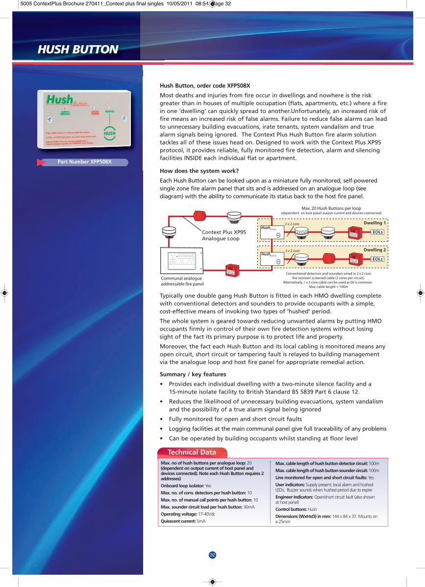
32
Hush Button, order code XFP508X
Most deaths and injuries from fire occur in dwellings and nowhere is the riskgreater than in houses of multiple occupation (flats, apartments, etc.) where a firein one ‘dwelling’ can quickly spread to another.Unfortunately, an increased risk offire means an increased risk of false alarms. Failure to reduce false alarms can leadto unnecessary building evacuations, irate tenants, system vandalism and truealarm signals being ignored. The Context Plus Hush Button fire alarm solutiontackles all of these issues head on. Designed to work with the Context Plus XP95protocol, it provides reliable, fully monitored fire detection, alarm and silencingfacilities INSIDE each individual flat or apartment.
How does the system work?
Each Hush Button can be looked upon as a miniature fully monitored, self-poweredsingle zone fire alarm panel that sits and is addressed on an analogue loop (seediagram) with the ability to communicate its status back to the host fire panel.
Typically one double gang Hush Button is fitted in each HMO dwelling completewith conventional detectors and sounders to provide occupants with a simple,cost-effective means of invoking two types of ‘hushed’ period.
The whole system is geared towards reducing unwanted alarms by putting HMOoccupants firmly in control of their own fire detection systems without losingsight of the fact its primary purpose is to protect life and property.
Moreover, the fact each Hush Button and its local cabling is monitored means anyopen circuit, short circuit or tampering fault is relayed to building managementvia the analogue loop and host fire panel for appropriate remedial action.
Summary / key features
• Provides each individual dwelling with a two-minute silence facility and a 15-minute isolate facility to British Standard BS 5839 Part 6 clause 12.
• Reduces the likelihood of unnecessary building evacuations, system vandalism and the possibility of a true alarm signal being ignored
• Fully monitored for open and short circuit faults
• Logging facilities at the main communal panel give full traceability of any problems
• Can be operated by building occupants whilst standing at floor level
HushButton
HUSH
HushButton
HUSHEOLs
EOLs
Dwelling 1
Dwelling 2
Max. 20 Hush Buttons per loop (dependent on host panel output current and devices connected)
Communal analogueaddressable fire panel
Conventional detectors and sounders wired in 2 x 2 corefire resistant screened cable (2 cores per circuit).
Alternatively, 1 x 3 core cable can be used as 0V is common. Max. cable length = 100m
2 x 2 core
2 x 2 core
Apollo XP95 or Hochiki ESP
Analogue loop
Context Plus XP95Analogue Loop
Technical DataMax. no of hush buttons per analogue loop: 20(dependent on output current of host panel anddevices connected). Note each Hush Button requires 2addresses)
Onboard loop isolator: Yes
Max. no. of conv. detectors per hush button: 10
Max. no. of manual call points per hush button: 10
Max. sounder circuit load per hush button: 30mA
Operating voltage: 17-40Vdc
Quiescent current: 5mA
Max. cable length of hush button detector circuit: 100m
Max. cable length of hush button sounder circuit: 100m
Line monitored for open and short circuit faults: Yes
User indicators: Supply present; local alarm and hushedLEDs; Buzzer sounds when hushed period due to expire
Engineer Indicators: Open/short circuit fault (also shownat host panel)
Control buttons: Hush
Dimensions (WxHxD) in mm: 144 x 84 x 37. Mounts ona 25mm
Part Number XFP508X
HUSH BUTTON
5005 ContextPlus Brochure 270411_Context plus final singles 10/05/2011 08:54 Page 32
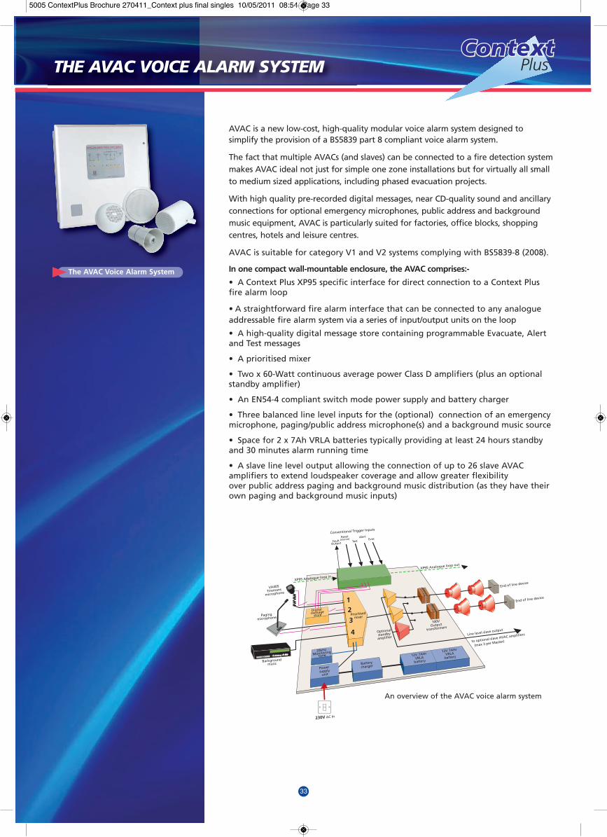
33
AVAC is a new low-cost, high-quality modular voice alarm system designed tosimplify the provision of a BS5839 part 8 compliant voice alarm system.
The fact that multiple AVACs (and slaves) can be connected to a fire detection systemmakes AVAC ideal not just for simple one zone installations but for virtually all smallto medium sized applications, including phased evacuation projects.
With high quality pre-recorded digital messages, near CD-quality sound and ancillaryconnections for optional emergency microphones, public address and backgroundmusic equipment, AVAC is particularly suited for factories, office blocks, shoppingcentres, hotels and leisure centres.
AVAC is suitable for category V1 and V2 systems complying with BS5839-8 (2008).
In one compact wall-mountable enclosure, the AVAC comprises:-
• A Context Plus XP95 specific interface for direct connection to a Context Plusfire alarm loop
• A straightforward fire alarm interface that can be connected to any analogueaddressable fire alarm system via a series of input/output units on the loop
• A high-quality digital message store containing programmable Evacuate, Alertand Test messages
• A prioritised mixer
• Two x 60-Watt continuous average power Class D amplifiers (plus an optionalstandby amplifier)
• An EN54-4 compliant switch mode power supply and battery charger
• Three balanced line level inputs for the (optional) connection of an emergencymicrophone, paging/public address microphone(s) and a background music source
• Space for 2 x 7Ah VRLA batteries typically providing at least 24 hours standbyand 30 minutes alarm running time
• A slave line level output allowing the connection of up to 26 slave AVACamplifiers to extend loudspeaker coverage and allow greater flexibility over public address paging and background music distribution (as they have theirown paging and background music inputs)
12
3
4 Optionalstandbyamplifier
Prioritisedmixer
Digital message
store
100VOutput
transformers
20kHz
Batterycharger
12V 7AHrVRLA
battery
12V 7AHrVRLA
batteryMonitoring
tone
VA405Firemans
microphone
Pagingmicrophone
230V AC In
Line level slave output
XP95 Analogue loop out
End of line device
End of line device
FaultOutput
Reset(silence)
TestAlert
Evac
XP95 Analogue loop in
to optional slave AVAC amplifiers
(max 3 per Master)
Conventional Trigger Inputs
Backgroundmusic
CD
fuse
Powersupply
unit
An overview of the AVAC voice alarm system
ContextContextContextPlus
The AVAC Voice Alarm System
THE AVAC VOICE ALARM SYSTEM
5005 ContextPlus Brochure 270411_Context plus final singles 10/05/2011 08:54 Page 33

34
OPERATION The principal function of AVAC is to generate clear voicemessages to alert people to the presence of fire, normallyunder the control of a fire detection system. When AVACreceives a message trigger from the fire detection system, itresponds by playing an appropriate message (Evacuate, Alertor Test) from its digital message store. This message isamplified and broadcast around the site via the system’sloudspeakers. Three balanced line-level audio inputs are alsoprovided for the connection of optional equipment such as anemergency microphone (to allow live directive announcementsby the emergency services), public address paging equipmentand a background music (BGM) source such as a CD player orradio tuner. The level of all four audio channels (digitalmessage store, emergency mic., paging and BGM) can be setusing four internal level controls. If multiple inputs and/ordigital message triggers are active at the same time, AVAC’sprioritized mixer ensures that only the most urgent audiosignal is broadcast, as indicated below:-
Priority Description1 Emergency microphone 2 Evacuate, Alert or Test message
(Evacuate overrides Alert, Alert overrides Test) 3 Paging / public address microphone(s) 4 Background music source(s)
AVAC’S FIRE ALARM INTERFACEThe host fire detection system can be connected to AVAC viathree polarized, opto-isolated trigger inputs. These inputs aredesigned to control AVAC’s digital message store and willactivate when a steady voltage of 24V DC is applied to them.
All inputs are prioritized according to the type of messagesthey trigger. AVAC can also be connected directly to any Apolloprotocol XP95, Discovery or Xplorer analogue addressable firealarm loop via its LOOP input. When connected in this way,AVAC emulates an Apollo sounder control module and must beaddressed as such. Once addressed, AVAC responds to a firepanel’s commands by activating its Evacuate message when itreceives a continuous sounders command and its Alert messagewhen it receives an intermittent sounders command. It alsoreports any fault conditions back to the analogue loop as ageneral fault allowing the fire detection system to annunciatethe fault location accordingly.
MONITORING In order to comply with current life safety standards, AVAC’sloudspeaker lines, PSU, batteries, emergency microphone anddigital message store are all monitored for short circuits, opencircuits, earth faults, discharge, disconnection and datacorruption as appropriate. Non-critical inputs such as publicaddress paging and background music are not monitored and,in the event of Mains failure, are automatically cut off toconserve battery life. This contributes to AVAC’s efficientstandby time - typically 24 hours (plus 30 minutes runningtime) using 2 x 7 Ah VRLA batteries. Provided the system iswired as recommended, an AVAC fault condition will bereported as a sounder fault on the fire detection system, withmore detailed fault indication provided on the front of AVAC.
DIGITAL MESSAGE SELECTIONAVAC’s digital messages are stored in MP3 format on a monitored,non-volatile memory card. The content of these can be adjustedto suit the application using a series of internal links. Forexample, the Evacuate message can be configured to state that‘a situation has arisen’ or ‘a fire has been reported’ and to warnpeople - if appropriate - not to use the building’s lifts.
AMPLIFIER AND LOUDSPEAKER CIRCUITS AVAC is supplied with a minimum of two separate 60-Wattcontinuous average power Class D amplifiers. These are designedto drive AVAC’s two loudspeaker circuits, each of which willaccommodate up to 60 Watts of loudspeaker load (although 50Watts is recommended to allow for system changes), through100V line transformers, which step up the voltage for distributionaround the site. An end-of-line device must be connected acrossthe terminals of the last loudspeaker on each circuit and bothcircuits must be calibrated at commissioning using AVAC’scalibrate button to ensure correct monitoring. Some AVACsfeature an additional standby amplifier that will switch in ifeither of AVAC’s regular amplifiers fail, a requirement of somelife safety voice alarm specifications.
MULTIPLE AVACs AND SLAVE AMPLIFIERSThere is no limit to the number of master AVACs that can beused per system but the VA405 emergency microphone can bedaisychained to a maximum of 26 master AVACs. For systemsrequiring more than one emergency microphone, up to fourVA407 emergency microphones can be connected to a system.However this will reduce the number of AVAC masters that canbe interlinked to 20 (for systems with two VA407s), 10 (forsystems with three VA407s) and 6 (for systems with fourVA407s).
To increase audio coverage in large areas, up to 26 slaveAVACs can be connected to one master AVAC. Slave AVACsrepeat all emergency microphone and digital messagebroadcasts that are made at the master. They also featuretheir own paging and background music inputs meaninglocalized paging and background music can be easilyimplemented, a particularly useful feature for tenanted officeblock applications, etc.
fuse
ProtocolSpecificRelay
Module
Loudspeakers
Emergency Mic.2 x 4 com & E (screened)
1.5m2. 1000m max.
EOLDin Speaker
EOLDin Speaker
2 com & E (screened)1.5m2. 500m max. (at 50W)
2 com & E (screened)1.5m2. 500m max. (at 50W)
MainsDetection
Loop
Emergency Mic.
Allow for 1 x 4 com & E (screened) 1.5m2 / 500m for emergency fire mic.
Allow for 1 x 4 com & E (screened) 1.5m2 / 500m for emergency fire mic.
MasterAVAC
SlaveAVAC
SlaveAVAC
Emergency Mic.2 x 4 com & E (screened) 1.5m2
AVAC
AVAC
AVAC
AVAC
FirePanel
I/O
I/O
I/O
I/OTHIRDFLOOR
SECONDFLOOR
FIRSTFLOOR
GROUNDFLOOR
THE AVAC VOICE ALARM SYSTEM
5005 ContextPlus Brochure 270411_Context plus final singles 10/05/2011 08:54 Page 34
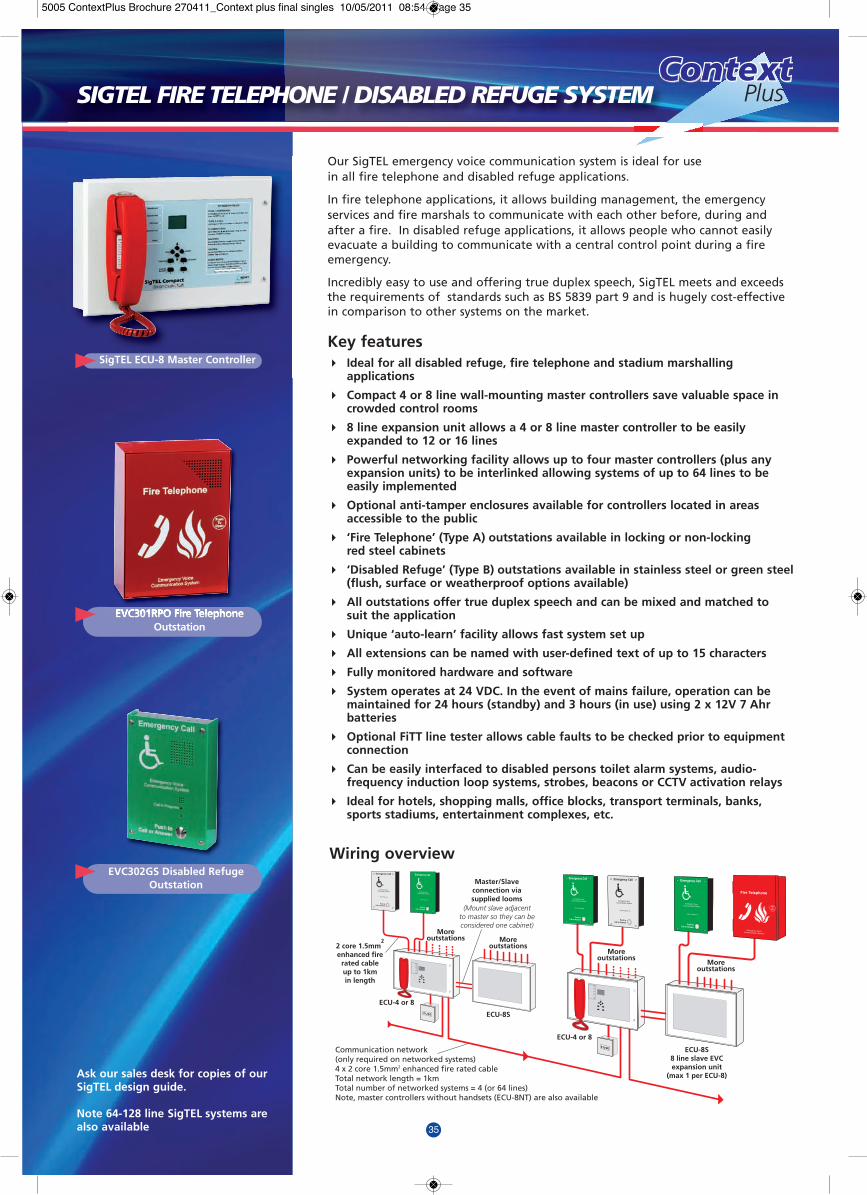
35
Our SigTEL emergency voice communication system is ideal for usein all fire telephone and disabled refuge applications.
In fire telephone applications, it allows building management, the emergencyservices and fire marshals to communicate with each other before, during andafter a fire. In disabled refuge applications, it allows people who cannot easilyevacuate a building to communicate with a central control point during a fireemergency.
Incredibly easy to use and offering true duplex speech, SigTEL meets and exceedsthe requirements of standards such as BS 5839 part 9 and is hugely cost-effectivein comparison to other systems on the market.
Key features4 Ideal for all disabled refuge, fire telephone and stadium marshalling
applications
4 Compact 4 or 8 line wall-mounting master controllers save valuable space in crowded control rooms
4 8 line expansion unit allows a 4 or 8 line master controller to be easily expanded to 12 or 16 lines
4 Powerful networking facility allows up to four master controllers (plus any expansion units) to be interlinked allowing systems of up to 64 lines to beeasily implemented
4 Optional anti-tamper enclosures available for controllers located in areas accessible to the public
4 ‘Fire Telephone’ (Type A) outstations available in locking or non-lockingred steel cabinets
4 ‘Disabled Refuge’ (Type B) outstations available in stainless steel or green steel(flush, surface or weatherproof options available)
4 All outstations offer true duplex speech and can be mixed and matched to suit the application
4 Unique ‘auto-learn’ facility allows fast system set up
4 All extensions can be named with user-defined text of up to 15 characters
4 Fully monitored hardware and software
4 System operates at 24 VDC. In the event of mains failure, operation can be maintained for 24 hours (standby) and 3 hours (in use) using 2 x 12V 7 Ahr batteries
4 Optional FiTT line tester allows cable faults to be checked prior to equipment connection
4 Can be easily interfaced to disabled persons toilet alarm systems, audio-frequency induction loop systems, strobes, beacons or CCTV activation relays
4 Ideal for hotels, shopping malls, office blocks, transport terminals, banks, sports stadiums, entertainment complexes, etc.
Ask our sales desk for copies of ourSigTEL design guide.
Note 64-128 line SigTEL systems arealso available
ContextContextContextPlus
SigTEL ECU-8 Master Controller
EVC302GS Disabled RefugeOutstation
EVC301RPO Fire TelephoneOutstation
SIGTEL FIRE TELEPHONE / DISABLED REFUGE SYSTEM
FUSE
FUSE
Master/Slaveconnection viasupplied looms
(Mount slave adjacentto master so they can beconsidered one cabinet)
ECU-8S8 line slave EVCexpansion unit
(max 1 per ECU-8)
ECU-8S
ECU-4 or 8
ECU-4 or 8
Communication network(only required on networked systems)4 x 2 core 1.5mm2 enhanced fire rated cableTotal network length = 1kmTotal number of networked systems = 4 (or 64 lines)Note, master controllers without handsets (ECU-8NT) are also available
2 core 1.5mm2
enhanced firerated cableup to 1kmin length
Moreoutstations More
outstationsMore
outstationsMore
outstations
Wiring overview
5005 ContextPlus Brochure 270411_Context plus final singles 10/05/2011 08:54 Page 35

36
Our Context Plus Series 65A range of conventional fire detectors incorporates well-proven sensing technologie including an IC based on that used in our Context Plus XP95analogue addressable detectors. The range consists of ionization, integrating ionizationand photo-electric smoke detectors, two grades of thermal detector and a standard base.Each type of detector has an LED which flashes continuously in stand-by mode. The range is tested and approved to the following standards: UL268-smoke detectors (file S24127) and UL521-thermal detectors (file S24128).
Context Plus Ionization Smoke Detector, 55000-226IMC
The sensing part of the detector consists of two chambers - an open outerchamber and a semi-sealed reference chamber within. Mounted in thereference chamber is a low activity radioactive foil of Americium 241 whichenables current to flow between the inner and outer chambers when the detector ispowered up. As smoke enters the detector, it causes a reduction of the current flow inthe outer chamber and hence an increase in voltage measured at the junction betweenthe two chambers. The voltage increase is monitored by the electronic circuitry whichtriggers the detector into the alarm state at a preset threshold. An externally visible redLED lights up when in alarm. IP rating = IP23D
Features: Flashing LED; Alarm indication: Red LED; Supply voltage: 9 to 33V Average stand-by current at 24V: 45uA; Average stand-by current at 9V: 21uA Alarm current at 24V: 52mA; Alarm current at 9V: 17mA Ambient temperature: 32 to 158°F; Max wind continuous: 2,000ft/min Remote output (R-) characteristics: Current sink to -ve line, limited to 17mA. Note: when using aremote indicator a current-limiting series resistor may be required.
Context Plus Photo-electric Smoke Detector, 55000-326IMC
Photo-electric smoke detectors incorporate a pulsing LED located in achamber within the housing of the detector. The chamber is designedto exclude light from any external source. At an angle to the LED is aphoto-diode which normally does not register the column of light emitted by the LED.In the event of smoke from a fire entering the chamber, the light pulse from the LEDwill be scattered and hence registered by the photo-diode. If the photo-diode “sees”smoke on the two following pulses, the detector changes into the alarm state and theindicator LED lights up. IP rating = IP23D
Features: Flashing LED; Alarm indication: Clear LED, Red in alarm; Supply voltage: 9 to 33V Average stand-by current at 24V: 45uA; Average stand-by current at 9V: 40uA Alarm current at 24V: 52mA; Alarm current at 9V: 17mA Ambient temperature: 32 to 100°F; Max wind continuous: not affected Remote output (R-) characteristics: Current sink to -ve line, limited to 17mA. Note: when using aremote indicator a current-limiting series resistor may be required.
Context Plus Thermal Detector, Ordinary, 55000-139IMC
Context Plus Thermal Detector, Intermediate, 55000-145IMC
Thermal detectors operate by using a matched pair of thermistors tosense heat. One thermistor is exposed to the ambient temperature,the other is sealed. In normal conditions the two thermistors register similartemperatures, but, on the development of a fire, the temperature recorded by theexposed thermistor will increase rapidly, resulting in an imbalance, causing the detectorto change into the alarm state. Rate-of-rise detectors are designed to detect a fire asthe temperature increases, but they also have a fixed upper limit at which the detectorwill go into alarm if the rate of temperature increase has been too slow to trigger thedetector earlier. Externally, the thermal detectors have wide openings to thesurrounding atmosphere to allow good movement of air around the externalthermistor. IP rating = IP23D
Features: Flashing LED; Alarm indication: Red LED; Supply voltage: 9 to 33V 9 to 33V Average stand-by current at 24V: 55uA; Average stand-by current at 9V: 50uA Alarm current at 24V: 52mA; Alarm current at 9V: 17mA Ambient temperature: 32 to 100°F; Max wind continuous: not affected Remote output (R-) : Current sink to -ve line, limited to 17mA. Note: when using a remoteindicator a current-limiting series resistor may be required. Alarm upper limit: 135oF for 55000-139IMC; 200oF for 55000-145IMC
Context Plus Base, 45681-200IMC
Designed to enable detectors to be plugged in without any need forforce - particularly useful when fitting to suspended ceilings. As wellas being lockable it contains no electronic parts which could bedamaged during installation.
Supply voltage: 9 to 33V; Normal operating temp (no condensation or icing): 32 to 100°F
55000-226IMC
55000-326IMC
55000-139 / 55000-145IMC
45681-200IMC
CONVENTIONAL DETECTORS
LISTED LISTED
LISTED LISTED
LISTED LISTED
LISTED
5005 ContextPlus Brochure 270411_Context plus final singles 10/05/2011 08:54 Page 36

37
ContextContextContextPlus
RESETTABLE CONVENTIONAL FIRE ALARM CALL POINT, BF370MERThe BF370MER’s simple ‘RESET’ mechanism comprises tough ABS plastic elements thatsimulate break glass activation. It is instantly reusable without the environmentalhazard caused by fragments of broken glass making it ideal for use in food processingplants, schools, shopping malls and other high traffic areas. Finished in red, the unit isflush or surface mountable and has alternate terminals for open and closed circuits.When wired for open circuit operation, the circuit closes instantly when activated.
The BF370MER also meets the requirements of BS5839 Part 2 and EN54 Part 11.
• Double terminal wire connectors for independent input and output connections
• No glass elements to break, lose or incorrectly fit when installing.
• Complete functional test with every activation.
• Preopened conduit entries from top, bottom and the back
Options include a transparent polycarbonate lift-up protection cover and differentcasing colours. Specific languages or custom imprints also available on request.
Size (H x W x D): 88 x 88 x 53 mm (Surface Mount) 88 x 88 x 20 mm (Flush Mount) Net/Gross Weight: 160/184g. Connections: Terminal, max 2.5mm2 cableCurrent Ratings : 12/24V DC 10A; 48V DC 3A; 250V AC 10A; IP rating = IP24D
MOTOR DRIVEN CONVENTIONAL DOME BELL, BF336DThe BF336D 24V 6”(150mm) bell is designed to meet the special requirements of firealarm systems where low power consumption and high sound output is essential. Theunit’s heavy duty micro-motor with built-in varistor suppression ensures reliability andlong life. Designed to meet the requirements of EN54-3:2001.
• Interchangeable base suitable for surface mounting
• Zero standby current and low current consumption
• Louder mechanical Resonant Tone
Amps = 0.03A; Decibel rating at 1m = 95dB; Weight = 812g; IP rating = IP23
CONVENTIONAL 4 TONE SPATIAL SOUNDER, BF334C/4103RDesigned for areas where low current consumption relative to sound output isrequired, our conventional spatial sounder requires only 11mA @ 24V d.c to provide anoutput of 103 dBa @ 1 metre. With an operating frequency of 800 to 1000Hz, itprovides sound within the frequency range specified by BS5839. Tones are available byselecting either warble, sweep or pips via the jumper fitted to the sounder’s PCB. Byusing three wires, a second stage alarm may be switched so that the continuous toneoverrides the selected tone.
Output @ 1 metre 24Vdc: 103dBa; Current @ 24V dc: c.11mA Voltage Range: 8-35V dc; Number of Tones: 4; Volume control: -30dBa; IP Rating: IP65 Temperature Range: -20°Cto + 70°C; Weight (per unit unpacked): 200g Approx.dimensions 105mm diameter x 85mm deep
ELECTRONIC SOUNDER, BF330ERThe BF330ER is a versatile and compact electronic sounder ideal for fire, securityand hazard warning applications. Flush or surface mountable, it is IP54 rated anddesigned to meet the requirements of BS5839-1.Operating Current: Max 35mA at 24V DC; Operating Voltage: 12V–24V DC Operating Frequency 2.5KHz ±30%; Sound Output Level 100± 3db at 24V DC (@1m) Operating Temperature -10oC min to +60oC max; Approximate Weight: 144g Protection Classification: IP 54; Terminal Capacity: 2 x 1.5mm2 ConductorsDimensions: (H x W x D) 88 x 88 x 43 mm (75mm with base)
--------------------------------------------- Also available ---------------------------------------------
BF370MER
BF336D
BF334C/4103R
CONVENTIONAL FIRE ALARM ACCESSORIES
BF330ER32 TONE SPATIAL SOUNDERSShallow (BF330CSR) and deep(BF330CDR versions available
32 TONE SPATIAL SOUNDER/BEACONSShallow (BF333CSR) and deep(BF333CDR) versions available
XENON BEACONS1W (BF340C/1), 2W (BF340/2) &
5W (BF340C/5) versions available
5005 ContextPlus Brochure 270411_Context plus final singles 10/05/2011 08:54 Page 37

38
CFP 2-8 Zone Conventional Fire Panel to EN54-2/4
• LPCB approved to the latest versions of EN54 Parts 2 and 4 (Amendment 2)
• Keyswitch or keypad entry to a wide range of engineering functions including zone test, zone delay, coincidence and non-latching zones
• Two on-board relays (Fire and Fault) and two open-collector outputs (Remote & Reset)
• Available with 2, 4 or 8 zone circuits
• Four conventional sounder circuits
• ‘Class Change’ and Alert inputs
• Attractive flush or surface mountable plastic lid and enclosure
• Integral 1.5A EN54-4/A2 switch mode PSU
• Ancillary connections provided for up to eight two-wire repeaters (one CFP761 network driver card required per system) & optional relay boards.
• Space available for two x 12V 3.3Ah VRLA batteries
• Fully compatible with the Context Plus UL-listed Series 65A range of conventional detectors and with the Ei range of wireless detectors and ancillaries.
• Economy version also available - contact our sales desk for details
CONVENTIONAL FIRE PANELS
CFP RANGE
176a
FP 1-14 Zone Conventional Fire Panel to BS5839-4
• Fully compliant with BS 5839 Part 4
• Lift-off lid for easy first fix and maintenance
• Two conventional sounder circuits.
• Built-in 24V power supply and battery charger
• Optional head removal monitoring facility
• Separate indicators for open and short circuit fault, sounder fault and battery/power supply fault
• Non-latching ‘class change’ sounder input, latching fire and non-latching fault outputs (availablevia optional expansion loom)
• Fault buzzer mute facility
• Space available for the rated capacity of VRLA batteries
• Short circuit = fire facility (pre-1980 BS, no resistors in call points), selectable on a zone by zone basis - ideal for retro-installations
• One man walk test and zone isolate facility (not on EFP1)
• Ancillary connections for repeater panels and other add-ons including fault relay modules,fire relay modules, sounder delay relay modules, sounder extender kits, etc (not on EFP1)
• Fully compatible with the Context Plus UL-listed Series 65A range of conventional detectors and with the Ei range of wireless detectors and ancillaries.
FP RANGE
Technical Data
Technical Data
MAINS SUPPLY VOLTAGE: 230 Va.c. ±10% 50/60HzTOTAL OUTPUT CURRENT LIMITED TO: 400mA (EFP1); 800mA (FP2/2E); 1.4A (FP4/6/8E); 3A (FP8/10/12/14)NUMBER OF ZONE CIRCUITS: 1, 2, 4, 6, 8, 10, 12 or 14MAX. NUMBER OF SMOKE DETECTORS PER ZONE: 20MAX. NUMBER OF MANUAL CALL POINTS PER ZONE: No LimitNUMBER OF SOUNDER CIRCUITS: 2MAX. NO OF BELLS @ 25 mA: 16 (EFP1); 32 (FP2/2E); 56 (FP4/6/8E); 120 (FP8/10/12/14)MAX. NO OF ELECTRONIC SOUNDERS @ 20 mA: 20 (EFP1); 40 (FP2/2E); 70 (FP4/6/8E); 150 (FP8/10/12/14)SOUNDER OUTPUTS EACH FUSED AT: 400mA (EFP1); 1A (FP2/2E/4/6/8E); 1.6A (FP8/10/12/14)ENCLOSURE (WxHxD): 271x200x70 (EFP1); 322x267x92 (FP2/2E); 405x267x92 (FP4/6/8E); 521x334x140 (FP8/10/12/14)WEIGHT (WITHOUT BATTERIES): 2.3KG (EFP1); 4.3KG (FP2/2E); 5KG (FP4/6/8E); 9.2KG (FP8/10/12/14)
MAINS SUPPLY VOLTAGE: 230 Va.c. ±10% 50/60HzTOTAL OUTPUT CURRENT LIMITED TO: 1.5ANUMBER OF ZONE CIRCUITS: 2, 4 or 8MAX. NUMBER OF SMOKE DETECTORS PER ZONE: 25MAX. NUMBER OF COMBINED DETECTORS & MANUAL CALL POINTS PER ZONE: 32NUMBER OF SOUNDER CIRCUITS: 4MAX. NO OF BELLS @ 25 mA: 32MAX. NO OF ELECTRONIC SOUNDERS @ 20 mA: 40SOUNDER CIRCUIT FUSES (1 PER CIRCUIT) : 200mA min hold current, 400mA max trip current, 50mA when trippedENCLOSURE (WxHxD): 380 x 235 x 96mm approxWEIGHT (WITHOUT BATTERIES): 1.75KG
5005 ContextPlus Brochure 270411_Context plus final singles 10/05/2011 08:55 Page 38

ContextContextContextPlusCONVENTIONAL FIRE PANELS
39
MFP 4-28 Zone Conventional Fire Panel to BS5839-4
• Fully compliant with BS 5839 Part 4
• Robust metal lid and metal back box with heavy-duty base connections
• Four sounder circuits and head out (detector removed) fault indication provided as standard
• Expandable from 4 to 28 zones in 4 zone steps
• End of line units included (one per zone)
• Separate indication of open circuit, short circuit, head out, sounder and battery/PSU faults
• Non-latching ‘class change’ sounder input, latching fire & non-latching fault outputs (via MFPX loom)
• Fault buzzer mute facility
• Short circuit = fire facility (pre-1980 BS,no resistors in call points), selectable on a zone by zone basis for retro-installations
• Non-latching zones facility for cross connection to other panels
• Wide range of engineer facilities including one man detector test, sounder walk test, sounder isolate, sounder delay and auxiliary isolate
• Up to eight two-wire repeaters with full external control (except isolate) per system (requires oneFF596T Repeater Transmitter PCB fitted at the main panel).
• Fully compatible with the Context Plus UL-listed Series 65A range of conventional detectors and with the Ei range of wireless detectors and ancillaries.
MFP RANGE
Technical Data
EP203 Extinguisher Panel to EN12094-1 & EN54-2/4
• LPCB approved to EN12094 part 1 and EN54 parts 2 and 4
• Functions as a standard three zone conventional fire panel with additional circuitry for controlling the release of fire-suppressing gas into protected areas
• Unique 128 x 64 pixel graphical display facilitates straightforward system programming
• Any combination of activated zones can be programmed to automatically start the panel’s extinguishant release sequence
• Includes a pull-down front-panel manual release button and two keyswitches for accessing the panel’s functions and toggling between auto/manual mode
• Three conventional sounder circuits (two x 1st stage, one x 2nd stage)
• Powerful 3A EN54-4 compliant switch mode PSU
• Wide range of monitored inputs and auxiliaryoutputs
• Abort and hold inputs allow the panel’s release sequence to be cancelled or suspended at any time
• Time-stamped event log
• RS485 connections for up to eight EP210 remote status units.
• Optional EP211 economy status units, EP212 relay expansion boards, EP215 abort/hold buttons and BF372 extinguishant release call points also available.
• Ideal for use in computer rooms, telecommunication centres, archive storage areas, etc..
Technical Data
EP203
176c
MAINS SUPPLY VOLTAGE: 230 Va.c. ±10% 50/60HzTOTAL OUTPUT CURRENT LIMITED TO: 1.4 A (MFP 4-12), 3A (MFP16-28)NUMBER OF ZONE CIRCUITS: 4, 8, 12, 16, 20, 24 or 28MAX. NO OF SMOKE DETECTORS PER ZONE: 20MAX. NO OF MANUAL CALL POINTS PER ZONE: No LimitNUMBER OF SOUNDER CIRCUITS: 4MAX. NO OF BELLS @ 25 mA: 56 (MFP 4-12); 120 (MFP16-28)MAX. NO OF ELECTRONIC SOUNDERS @ 20 mA: 70 (MFP 4-12); 150 (MFP16-28)SOUNDER OUTPUTS EACH FUSED AT: 1A (MFP 4-12); 1.6A (MFP16-28)ENCLOSURE (W x H x D): 405x267x29mm (MFP 4-12); 521x334x140 (MFP16-28)WEIGHT (WITHOUT BATTERIES): 5KG (MFP 4-12); 9.5KG (MFP16-28)
MAINS SUPPLY VOLTAGE: 230 Va.c. ±10% 50/60HzTOTAL OUTPUT CURRENT LIMITED TO: 3ANUMBER OF ZONE CIRCUITS: 3MAX. NO OF SMOKE DETECTORS PER ZONE: 20MAX. NUMBER OF COMBINED DETECTORS & MANUAL CALL POINTS PER ZONE: 32NUMBER OF SOUNDER CIRCUITS: 3 (two x 1st stage, one x 2nd stage)MAX. NO OF ELECTRONIC SOUNDERS @ 20 mA: 10SOUNDER OUTPUTS EACH FUSED AT: 200mAAUXILIARY OUTPUTS: 6 (Fire, Local Fire, Extract Fan, 1st Stage, 2nd Stage, Fault)EXTINGUISHANT RELEASE OUTPUTS: Exting. release, release time delay, release duration, flooding time, output EOLMONITORED INPUTS: 6 (Manual release, flow switch, low pressure, mode, hold, abort)ENCLOSURE (W x H x D): Back box = 439 x 276 x 70; Lid = 467 x 293 x 29mm; WEIGHT: 4.65KG
5005 ContextPlus Brochure 270411_Context plus final singles 10/05/2011 08:55 Page 39

40
Our Ei range of RadioLINK wireless conventional detectors are BSI kitemarked /VDS approved to BS EN14604:2005.
All devices have built-in circuitry to aid suppression of voltage transients and RFinterference (devices operate at RF frequency 868,499MHz).
Wireless zones - why?
• Eliminates expensive cable for detectors and sounders
• Difficult or impossible to run cable
• Hard to reach voids
• Listed and protected buildings
• Renovations and refurbishments
• Integrated detectors and sounders
• Up to 12 x RF alarms and 8 x ancillaries (e.g. MCP) per zone
• Multi-repeater and multi-path robust connectivity
RadioLINK Wireless Professional Battery Powered Smoke Alarms (Ei605 Series)
• Smoke Alarm - Optical Sensor • RadioLINK interconnect & remote control • Loud Alarm - 85dB (A) at 3 metres• Large Test & Hush Button • Easy Installation with twist-on base • Model Ei605WRF - Replaceable Battery • Model Ei605TYWRF - 10 Year Lithium Battery • Certified to VdS EN 14604:2005 • 5 Year Guarantee
RadioLINK Wireless Professional Battery Powered Heat Alarms (Ei603 Series)
• Heat Alarm - Type A1 Sensor • RadioLINK interconnect & remote control • Loud Alarm - 85dB (A) at 3 metres • Large Test Button • Easy Installation with twist-on base • Model Ei603CRF - Replaceable Battery • Model Ei603TYCRF - 10 Year LithiumBattery • Certified to BS 5446-2:2003 • 5 Year Guarantee
RadioLINK Wireless Interface Module to conventional fire panel (Ei413)
• RadioLINK Interface Module to conventional fire panels • Signals to panel - Fire Alarm - Low battery fault - Smoke chamber fault • 10 - 30V power from panel • Works with Ei Electronics 600 Series RadioLINK Alarms & Accessories • Contact input from panel to sound all alarms in zone • 1 x Ei413 required for each Wireless Zone • 5 Year Guarantee
RadioLINK Wireless Manual Call Point (Ei407)
• Wall mounted Manual Call Point • Fully resettable • Powered by 10 Year Battery • Triggers all wireless alarms in the selected zone • Triggers the Ei413 interface module to alert panel • 5 Year Guarantee
Ei605 Series
Ei603 Series
Ei413
Ei407
WIRELESS CONVENTIONAL DETECTORS & ANCILLARIES
5005 ContextPlus Brochure 270411_Context plus final singles 10/05/2011 08:55 Page 40

41
ContextContextContextPlus
RadioLINK Wireless Remote Control Switches (Ei411H / Ei410)
• Ei411H - 10 Year Lithium Battery • Ei410 - Replaceable Lithium Battery • Test Button - sounds all wireless alarms in the selected zone • Locate Button - indentifies which alarm has triggered the zone • Hush Button - silences all alarms in the zone for a period of 10 minutes • Memory - records previous alarm conditions • 5 Year Guarantee
RadioLINK Wireless Relay Modules (Ei428 / Ei408)
• Mains powered relay output module • Triggered by RadioLINK fire signal • NO /NC voltage free contact outputs • Activates external circuit,e.g. strobes, sirens, magnetic door holders, etc • Mains powered switched input module • Triggered by voltage free contact inputs • Transmits RadioLINK fire signal to activate smoke alarm sounders
Ei411H
Ei410
Ei428
Ei408
Typical mixed wireless & hard wired conventional panel system
WIRELESS CONVENTIONAL DETECTORS & ANCILLARIES
5005 ContextPlus Brochure 270411_Context plus final singles 10/05/2011 08:55 Page 41
42
12V 2A EN54-4 Switch Mode PowerSupply
BF360-12
24V 5A EN54-4 Switch Mode Power SupplyBF362-5
24V 1.5A EN54-4 Switch Mode Power SupplyBF362-1
24V 3A EN54-4 Switch Mode Power SupplyBF362-3
Introducing our new range of continuously rated third-party approved EN54-4/A2switch-mode power supplies - ideal for powering beam detectors, auto dial units,aspirating smoke detectors, fail secure door systems, digital communicators,auxiliary sounder systems and more.
Five versions are available - a 12V 2A model (with optional STU mounting platefor use in auto-dial applications) and four 24V supplies rated at 1.5A (twovariants), 3A and 5A. All models offer low current consumption, a single pole voltfree relay and link-selectable battery charging capacity.
Key features of our EN54-4 power supply range
• Third-party approved to EN54-4/A2:2006 by the VdS or LPCB• Low current consumption• Deep discharge battery protection and EN54 compliant flagging of battery
impedance faults• Single-pole volt-free changeover relay that switches for any fault condition• Three LED indicators - supply present, general fault and auxiliary fault (for
optional connection to third-party equipment)• Link selectable battery charging capacity• Optional STU mounting plate (for 12V 2A model only)• Optional high-temperature output activates when internal box temperature
reaches 55oC, for connection to ventilation fans, etc.• Chassis only power supplies available for OEMs• Power supplies with a higher battery charging capacity available to special
order (minimum quantities apply).
Order codes and descriptions
BF360-12 12V 2A PSU
BF362-1 24V 1.5A PSU
BF360-24 24V 1.5A PSU
BF362-3 24V 3A PSU
BF362-5 24V 5A PSU
24V POWER SUPPLIES
VdS0786
VdS0786
VdS
PENDING
VdS0786
0786
Max. physical battery size: 2 x 12V 19 Ah
Standard battery charging capacity: 2.5 Ah to 19 Ah
Output option A: 1A DC current, 0.5A charge current
Output option B: 0.5A DC current, 1A charge current
Enclosure size (WxHxD): 404 x 404 x 110mm
Physical attributes: Metal lid and base
24V 1.5A EN54-4 Switch Mode Power Supply
Max. physical battery size: 2 x 12V 3 Ah
Standard battery charging capacity: 2 Ah to 12 Ah
Output option A: 1.3A DC current, 0.2A charge current
Output option B: 0.8A DC current, 0.7A charge current
Enclosure size (WxHxD): 380 x 235 x 96mm
Physical attributes: Plastic lid and base
BF360-24
Max. physical battery size: 2 x 12V 12 Ah
Standard battery charging capacity: 7 Ah to 12 Ah
Output: 2.3A DC current, 0.7A charge current
Enclosure size (WxHxD): 404 x 404 x 110mm
Physical attributes: Metal lid and base
Max. physical battery size: 2 x 12V 18 Ah
Standard battery charging capacity: 7 Ah to 18 Ah
Output: 4A DC current, 1A charge current
Enclosure size (WxHxD): 404 x 404 x 110mm
Physical attributes: Metal lid and base
Max. physical battery size (with STU plate): 1 x 12V 3 Ah
Max. physical battery size (no STU plate): 1 x 12V 7 Ah
Standard battery charging capacity: 2 Ah to 12 Ah
Output option A: 1.8A DC current, 0.2A charge current
Output option B: 1.3A DC current, 0.7A charge current
Enclosure size (WxHxD): 380 x 235 x 96mm
Physical attributes: Plastic lid and base
G208156
G209196
G209197
G208155
PENDING
5005 ContextPlus Brochure 270411_Context plus final singles 10/05/2011 08:56 Page 42

43
Context Plus 'Standard' Fire Performance
Cable has been independently tested and
approved by the LPCB to meet BS 5839-
1:2002+A2:2008 Clause 26.2d Standard,
BS EN 50200:2006+Annex E 30 minutes,
and BS EN 50200:2006 PH120 - under fire
conditions.
Materials and processes are recorded
and tracked throughout manufacture to
ensure consistent reliability and quality.
Cable cores are twisted during
manufacture to provide the highest
level of data protection, ideal for long
cable runs and analogue addressable
fire systems.
• Manufactured in the United Kingdom with a ten year warranty.
• Low Smoke Zero Halogen emissions under fire conditions.
• Easy to install and superb working flexibility
• Reduced installation time and costs
• All in one - easy to strip outer sheath
• No separate foil or additional fibre wraps
• No mica tape on conductors
• No additional core separators to remove
• Available in a variety of multi-core combinations all with CPC (circuit protection conductor)
• 100m, 200m and 500m reels (other special lengths available to order)
• Approved to meet a 3 hours only fire duration at 950°C & 2 hours fire and mechanical shock duration at 830°C.
• Retains continuity for 30 mins under fire conditions at 830°C including 15 mins under fire & water conditions and with a mechanical shock applied every 5 minutesduring the full 30 minute test.
• Approved and Certified to meetBS 5839-1:2002+A2:2008 - ‘Standard’ Fire CableBS EN 50200:2006+Annex E 30 mins - Fire Resistance Standard BS EN 50200:2006 PH120 - Fire Resistance StandardBS 7629-1:2008 - Fire Resistance StandardBS 6387:1994 Clause 11 CWZ - Fire Resistance StandardBS EN 50267-2-1:1999 - Halogen Emission StandardBS EN 61034-2:2005 - Low Smoke Standard
• Also suitable forEmergency Lighting Standard - BS 5266-1:2005Voice Alarm Systems Standard - BS 5839-8:2008Voice Communication Standard - BS 5839-9:2003(Risk Assessment May Demand Mechanical Protection)
PART NUMBERS2 Cores 3 Cores 4 Cores
Red1.0mm2 FPS-210ER FPS-310ER FPS-410ER1.5mm2 FPS-215ER FPS-315ER FPS-415ER2.5mm2 FPS-225ER FPS-325ER FPS-425ER4.0mm2 FPS-S240ER
White1.0mm2 FPS-210EW FPS-310EW FPS-410EW1.5mm2 FPS-215EW FPS-315EW FPS-415EW2.5mm2 FPS-225EW FPS-325EW FPS-425EW4.0mm2 FPS-S240EW
Black1.5mm2 FPS-215EBK FPS-415BK2.5mm2 FPS-225EBK
*All above are solid core except FPS-S240ER which is stranded.
Technical Data
Recommended metal clip spacing: 300mm Horizontal or400mm VerticalMinimum installation Temperature: 0°CMaximum installation Temperature: 70°COperating Temperature: Min -40°C to Max +90°C. The cable should not be flexed or bent when either thecable or operating temperature is outside the recommendedinstallation temperatures.Minimum Bend Radius: 6 x DiameterPlastic clips or ties must not be used as the sole means ofsupport for fire cable.MaterialsCPC (Earth): Tinned Annealed Copper Conductors: Plain Annealed CopperCore Installation: Fire Resistant SiliconeScreening: Aluminium FoilOuter Sheath: Low Smoke Halogen Free Thermoplastic Working Voltage: Core to Core: = 500V; Coreto CPC = 300VOuter Sheath Colours: Red, White or BlackNumber of Cores: 2, 3 & 4 CoreInner Cores CSA: 1.0, 1.5, 2.5 & 4.0mm CSA
Resistance:1.0mm CSA:18.1 Ohms / 1Km 1.5mm CSA: 12.1 Ohms / 1Km2.5mm CSA: 7.41 Ohms / 1Km 4.0mm CSA: 4.61 Ohms / 1KmCurrent rating:1.0mm Cable clipped (DC or single phase AC) = 15A1.5mm Cable clipped (DC or single phase AC) = 19.5A2.5mm Cable clipped (DC or single phase AC) = 27A4.0mm Cable clipped (DC or single phase AC) = 36A1.0mm Enclosed (DC or single phase AC) = 13A1.5mm Enclosed (DC or single phase AC) = 16.5A2.5mm Enclosed (DC or single phase AC) = 23A4.0mm Enclosed (DC or single phase AC) = 30ARatings listed are at 30oC, refer to BS7671/EE wiring refs forde-rating factor
Context Plus Standard Fire Cable
FIRE ALARM ANCILLARIES
STANDARD FIRE PERFORMANCE CABLEContextContextContext
Plus
Certificate No.
682a-(cl-3)
5005 ContextPlus Brochure 270411_Context plus final singles 10/05/2011 08:56 Page 43

ContextContextContextPlus
CONTEXT PLUS LIMITED175 Mauldeth Road, Manchester M14 6SG, England
Tel: +44 161 257 2541. Fax: +44 161 225 8817. E-mail: [email protected] Website: www.xportsales.com
5005 ContextPlus Brochure 270411_Context plus final singles 10/05/2011 08:56 Page 44