contents of appendix b - sandiegocounty.gov · contents of appendix b ... monitoring well(s) for an...
TRANSCRIPT
APPENDIX B: MONITORING WELL/BORING PERMIT AND STANDARDS
SAM Manual 7.1.2010 Page B-1
Appendix B Monitoring Well/Boring
Permit and Standards
CONTENTS OF APPENDIX B
I. Guideline for Completing Monitoring Well Permit Applications II. San Diego County Monitoring Well and Boring Construction Standards

APPENDIX B: MONITORING WELL/BORING PERMIT AND STANDARDS
Page B-2 7.1.2010 SAM Manual
I. GUIDELINE FOR COMPLETING MONITORING WELL PERMIT APPLICATIONS
INSTRUCTIONS FOR COMPLETING MONITORING WELL PERMIT APPLICATIONS
Submit one (1) original application package, including plan drawings with the required fee to the
Monitoring Well Permit Desk, Department of Environmental Health, Site Assessment and Mitigation
Program (SAM) at 5500 Overland Avenue, Suite 210, San Diego, CA 92123 or mail the application
package to P. O. Box 129261, San Diego, CA 92112-9261. All accompanying documentation must be
included in each application package. Information in addition to that presented in the application package
may be needed in order to obtain final approval. Any application that is missing information or
documents may be returned to the submitter as incomplete. Allow seven to ten business days for
processing. Checks should be made payable to the County of San Diego. The applications and
associated forms can be found at:
http://www.sdcounty.ca.gov/deh/water/sam_monitoring_well_page.html
PLEASE PROVIDE ALL INFORMATION AS REQUIRED ON THE APPLICATION FORM
A. Responsible Party: the person, persons or company who has or who causes to have constructed,
repaired, reconstructed, maintained and /or destroyed, the proposed borings and/or wells.
B. Site Assessment Project: If there is a Site Assessment and Mitigation (SAM) case (open or
closed), please provide the lead agency and regulatory case number. EXAMPLE: H00011-002.
C. Consulting Firm: Well design, logging and construction must be supervised by a Geologist,
Engineering Geologist or Civil Engineer who is licensed by the State of California.
D. Drilling Company: Well driller must have an active C-57 License.
E. Proposed Scope of Work: Provide all requested data concerning the proposed
construction/destruction of wells and/or drilling of borings. Be sure that the licensed professional
and the authorized person for the drilling company have both signed the application.
F. Site Location: Space is provided on the application for more than one site. If your application
includes more than one parcel, the sites must be adjacent to one another or located within the
same block. If not, a separate application may be required. If you are in doubt, please contact the
Monitoring Well Permit desk. Please provide the correct Assessor’s Parcel Number(s). Identify
each parcel on the accompanying site map and provide accurate property owner information.
You can verify the parcel number by accessing the Internet SANGIS site at:
http://files.sangis.org/interactive/viewer/viewer.asp
or by calling the Assessor’s Office at (619) 236-3771. If the property in question is undeveloped
or otherwise difficult to identify, the Mapping Division of the Assessor’s office may be able to
assist you. Their phone number is (619) 531-5588. In addition, if the work is to be done in the
public right-of-way or other location that has no assessor’s parcel identification, use the APN of
the adjacent property closest to your proposed drilling location.
APPENDIX B: MONITORING WELL/BORING PERMIT AND STANDARDS
SAM Manual 7.1.2010 Page B-3
Military Sites: Some bases are divided into “areas”. Since the bases are so large, please include
only one “area” per application in addition to the parcel number. If you are in doubt about how a
military site is designated, please check first with your military contact person. If it is still not
clear how to proceed, call our office and we will assist you.
G. Fees: Please use the fee table included in the application to compute the appropriate fees for your
project.
If you are in doubt, please visit the Monitoring Well Website:
http://www.sdcounty.ca.gov/deh/water/sam_monitoring_well_page.html
or contact the Monitoring Well Permit Desk at (858) 505-6688 for assistance.
H. Questions: Provide full and accurate answers to all applicable questions. For well destructions,
complete only Question #1 and provide applicable supporting documents including requests for
variances.
ADDITIONAL SUPPORTING DOCUMENTS:
Site Maps: All applications must include a site map giving location of property lines, existing improvements such as structures, underground tanks, underground utilities, underground piping, and the existing and proposed wells and borings. Please be sure the site map also shows the streets bounding your site property. Sometimes you can do it all with just one map and other times it may require one site-specific map and one more general area map. If you are in doubt, ask yourself: “If I were unfamiliar with this site/area, would I be able to locate the property and the wells using this map?” Encroachment and Traffic Control Permits: If your proposed work will be located in a public right-of-way that requires permits from the city or County in which the work is being done, you must include a copy of the permit or the application for the encroachment/traffic control permit in your application package. Property Owner Consent (POC): This document, completed and signed by the property owner
1,
must accompany all applications except work proposed for on-site open LOP/SAM cases, Military property or Caltrans property:1
1 The property owner may be an individual, several individuals or a company/corporation. If not a private
individual(s), the signer must be an officer of the company. A “manager” may not sign for the property owner
unless DEH receives written verification that the property owner has authorized this person to sign on his/or her
behalf.
APPENDIX B: MONITORING WELL/BORING PERMIT AND STANDARDS
Page B-4 7.1.2010 SAM Manual
II. SAN DIEGO COUNTY MONITORING WELL AND BORING CONSTRUCTION STANDARDS
Monitoring wells are normally constructed in conjunction with on-site corrective action, namely site
investigation or remediation activities, or with water resource investigations. Proper design and
construction of groundwater and vadose wells are essential for the acquisition of reliable subsurface
data and representative samples as well as for protection of the groundwater aquifer. In such design
and construction, site-specific geological, hydrogeological, physical, and geochemical conditions
should be considered. It may even be appropriate to develop a conceptual hydrogeological model,
prior to well design and construction, particularly for sites with relatively complex environments.
Groundwater or vadose well installation should be properly planned with the drilling activities,
monitoring well construction materials, well specifications, and installation procedures addressed
prior to the initiation of field work. Monitoring wells should be constructed as designed, except in
situations where subsurface conditions warrant modifications, which should be clearly documented.
There are numerous publications that provide guidance for the design and construction of wells. This
type of detail is beyond the scope of this manual. Please refer to Appendix I for several references on
this subject.
A. General Considerations
1. Site
a. Monitoring well(s) for an initial site assessment should be located reasonably close to the
known or suspected spill/leak or in areas know to be contaminated.
b. Generally, the well(s) should be located in the down-gradient direction, based on known
or reasonably assumed conditions at the site. For complete site assessment, the
monitoring well network should be capable of evaluating the groundwater gradient,
extent of the contamination, and background conditions.
c. It may be feasible to use an in situ sampling device to sample groundwater and assist in
determining the placement of groundwater monitoring wells.
2. Equipment and Materials
a. Drilling - The selection of an appropriate drilling method for constructing monitoring
wells should be based on minimizing both the disturbance of penetrated geologic
materials and the possibility of aquifer contamination by the introduction of air, fluids,
muds, and contaminated soil. Where possible, the drilling method selected should allow
detection of the saturated zones encountered during drilling.
(1) Wherever possible, drilling should be accomplished with a hollow-stem, continuous
flight auger drill rig. Other types of drilling methods may be used if conditions
warrant and are approved by DEH or the lead agency.
(2) No drilling fluids are to be used unless approved by DEH prior to drilling. Drilling
fluid additives (if approved) should be limited to inorganic, non-hazardous materials
that will not mask or alter the constituents being monitored. Use of all additives must
be indicated on the boring log as to depth, quantity and type. Representative samples
APPENDIX B: MONITORING WELL/BORING PERMIT AND STANDARDS
SAM Manual 7.1.2010 Page B-5
of the additive should be retained for a period of 90 days and analyzed in the event
contamination is identified.
b. Inspections, Maintenance, and Materials
(1) Drill rigs should be inspected prior to drilling to ensure that the rig is free of
hydraulic oil and fuel leaks.
(2) Prior to drilling, the drill rig and equipment should be cleaned by an appropriate
method to ensure that a contaminant is not introduced by drilling. The equipment
should be cleaned between boreholes to prevent cross contamination.
(3) Prior to installation, well casings, casing fittings, screen, and all other components to
be installed in the well should be thoroughly cleaned by an appropriate method. Well
materials that are cleaned and wrapped by the factory are acceptable. Care should be
taken to not contaminate the casing during installation.
c. Well Materials
(1) Soil sampling equipment, drilling equipment and materials used to construct a well
should be compatible with the constituents being investigated, and should not donate
to, capture, mask, or alter the constituents to be analyzed.
(2) The materials should be of sufficient durability to withstand deterioration by the
suspected contaminants.
(3) The well screen should be commercially manufactured, corrosion resistant, and have
sufficient column and collapse strength.
(4) Representative samples of all imported materials used for filter pack, annular seal,
and bentonite seals should be retained for a period of 90 days. At the request of DEH
or the lead agency, an evaluation of compatibility may be required.
d. Soil Descriptions/Sampling
(1) All soil and/or fill encountered during drilling shall be described in detail according
to the Unified Soil Classification System.
(2) Rocks or geologic formations should be described by an appropriate rock
classification system.
(3) A Professional Geologist, Registered Civil Engineer, or Certified Engineering
Geologist, who is licensed or certified by the State of California, must log all soils
and rock materials. A trained and experienced technician working under the direct
supervision and review of one of the aforementioned professionals shall be deemed
qualified, provided the aforementioned professional assumes responsibility for the
accuracy and completeness of the logs.
APPENDIX B: MONITORING WELL/BORING PERMIT AND STANDARDS
Page B-6 7.1.2010 SAM Manual
B. Standards
1. Well Construction
a. Vadose and groundwater wells must be designed by a Professional Geologist, Registered
Civil Engineer, or Certified Engineering Geologist.
b. The well identification number and well type should be permanently affixed to the
exterior of the well security structure.
c. Well casing should be flush-threaded. Use of organic solvents or cements is not
acceptable. All well casing should have a bottom cap or plug.
d. Monitoring well casing diameter should not be less than 2 inches or greater than 6 inches,
unless specifically approved by DEH.
e. The casing must extend a minimum of three inches above the interior concrete seal.
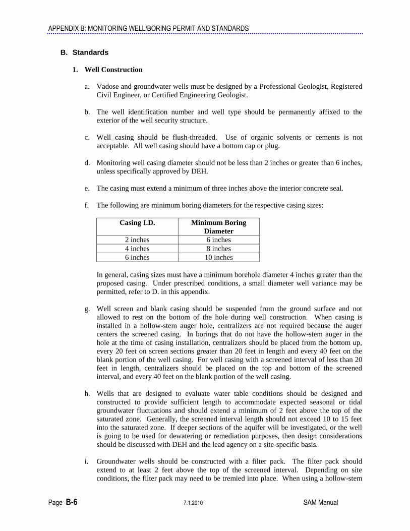
f. The following are minimum boring diameters for the respective casing sizes:
Casing I.D. Minimum Boring
Diameter
2 inches 6 inches
4 inches 8 inches
6 inches 10 inches
In general, casing sizes must have a minimum borehole diameter 4 inches greater than the
proposed casing. Under prescribed conditions, a small diameter well variance may be
permitted, refer to D. in this appendix.
g. Well screen and blank casing should be suspended from the ground surface and not
allowed to rest on the bottom of the hole during well construction. When casing is
installed in a hollow-stem auger hole, centralizers are not required because the auger
centers the screened casing. In borings that do not have the hollow-stem auger in the
hole at the time of casing installation, centralizers should be placed from the bottom up,
every 20 feet on screen sections greater than 20 feet in length and every 40 feet on the
blank portion of the well casing. For well casing with a screened interval of less than 20
feet in length, centralizers should be placed on the top and bottom of the screened
interval, and every 40 feet on the blank portion of the well casing.
h. Wells that are designed to evaluate water table conditions should be designed and
constructed to provide sufficient length to accommodate expected seasonal or tidal
groundwater fluctuations and should extend a minimum of 2 feet above the top of the
saturated zone. Generally, the screened interval length should not exceed 10 to 15 feet
into the saturated zone. If deeper sections of the aquifer will be investigated, or the well
is going to be used for dewatering or remediation purposes, then design considerations
should be discussed with DEH and the lead agency on a site-specific basis.
i. Groundwater wells should be constructed with a filter pack. The filter pack should
extend to at least 2 feet above the top of the screened interval. Depending on site
conditions, the filter pack may need to be tremied into place. When using a hollow-stem

APPENDIX B: MONITORING WELL/BORING PERMIT AND STANDARDS
SAM Manual 7.1.2010 Page B-7
auger the augers may be used as a tremie. Care should be taken to prevent bridging of
the filter pack during placement.
j. Groundwater wells being constructed in crystalline rock may be constructed as an open
hole in the interval that is to be monitored. This type of construction will be evaluated on
a case-by-case basis.
k. Sieve analyses performed on the actual aquifer formation material will allow for design
of an effective filter pack and screen size. During initial drilling, formation material
should be retained and sieve analyses performed to develop a proper well design.
l. Following placement of the filter pack and prior to placement of the bentonite transition
seal, the well should be surged to ensure that the filter pack level has stabilized.
m. A minimum 3-foot-thick bentonite transition seal should be placed directly on top of the
filter pack. Depending on site conditions, the bentonite may have to be tremied into
place to prevent bridging when being placed. The bentonite seal should be placed and
hydrated in accordance with manufacturer's specifications.
n. The depth of the annular seal should be in accordance with California Department of
Water Resources Bulletins 74-81 and 74-90. For those cases where the annular seal is
less than 20 feet in length, a variance must be reviewed and approved by DEH prior to
construction.
o. The annular space from the top of the bentonite transition seal to the base of the surface
seal shall be filled with either a cement, a cement-bentonite, or bentonite grout. The
grout seal shall be an approved sealing material as specified in California Department of
Water Resources Bulletins 74-81 and 74-90, and should be placed by using the tremie
method.
p. The surface seal shall consist of concrete able to withstand the maximum anticipated load
without cracking or deteriorating. The concrete should meet Class A specifications,
which meet a minimum 4,000-pound compressive strength.
q. All wells must be constructed at the ground surface meeting the following criteria:
(1) The surface completion of the security structure must use structural rated concrete
that meets or exceeds the structural loads anticipated for the site.
(2) The security structure must be able to be properly secured to prevent access by
unauthorized persons and vandalism.
(3) Positive surface drainage away from the security structure must be provided to
prevent water from entering the well vault.
(4) The security structure must be designed for a monitoring well. Irrigation boxes are
not acceptable. The casing must be fitted with a water-tight locking well cap. The
use of a slip cap is not acceptable.

APPENDIX B: MONITORING WELL/BORING PERMIT AND STANDARDS
Page B-8 7.1.2010 SAM Manual
r. Figure B-1
The well head is completed below the surface grade in a vault. The following diagram
provides minimum design standards for surface completion of a flush-grade well head
security vault. This type of surface construction is only applicable in traffic areas, paved
areas, and/or where the well will cause a safety problem. In traffic areas and sidewalks,
the vertical well profile must not exceed 1/2 inch to minimize physical hazards and
maintain a smooth, travelable surface. These wells must be constructed in an area where
the wells will not become flooded or damaged. Drainage around the well must be
maintained so that no ponding of water will occur around the well head. The security
vault must be a traffic-rated, water tight, locking structure that can withstand the
maximum traffic loads anticipated for the site. The surface seal must be extended a
minimum of 12 inches around the perimeter of the security vault and extend a minimum
36” below ground surface. Any variation in these construction standards must be
approved by DEH.

APPENDIX B: MONITORING WELL/BORING PERMIT AND STANDARDS
SAM Manual 7.1.2010 Page B-9
s. Figure B-2
The well head is completed above the surface grade. The following diagram provides the
minimum design standards for an above-grade surface completion of a well. This type of
surface construction is required in all areas unless the well is located in traffic areas,
paved areas, and/or where the well will cause a safety problem. The well pad must be
designed and constructed so that it will have proper drainage away from the steel
conductor casing. Drainage around the well must be maintained so that no ponding of
water will occur around the well head. Protective steel posts may be required around the
well to provide protection to the well structure. The surface seal must be extended a
minimum of 24 inches around the perimeter of the protective steel casing and extend a
minimum of 36” below surface grade. Any variation in these construction standards must
be approved by DEH.
The well head is completed below the surface grade in a vault. The following diagram
provides minimum design standards for surface completion of a flush-grade well head
security vault in a public roadway. These wells must be constructed in an area where the

APPENDIX B: MONITORING WELL/BORING PERMIT AND STANDARDS
Page B-10 7.1.2010 SAM Manual
wells will not become flooded or damaged. Drainage around the well must be
maintained so that no ponding of water will occur around the well head. The security
vault must be a traffic-rated, water tight, locking structure that can withstand the
maximum traffic loads anticipated for the site. The surface seal must be extended a
minimum of 12 inches around the perimeter of the security vault and extend a minimum
36” below ground surface. Any variation in these construction standards must be
approved by DEH.
t. A properly licensed professional should survey the top of the well casing to an accurate
datum.
u. Special considerations for vadose wells
(1) Design
(a) Vadose well(s) may be designed for monitoring or remedial action purposes.
(b) Vadose well(s) for monitoring purposes should be designed to detect the
substances being monitored.
(c) The well(s) should be designed to reduce the potential for cross contamination.
(2) Construction - Vadose well(s) shall be constructed with a well seal. The depth of the
well seal will be approved by DEH on a case-by-case basis.

APPENDIX B: MONITORING WELL/BORING PERMIT AND STANDARDS
SAM Manual 7.1.2010 Page B-11
2. Destruction of Wells and Exploratory Borings
a. Groundwater and Vadose Wells - A monitoring well shall be destroyed by removing all material within the original borehole, including the casing, filter pack, and annular seal, and filling the remaining borehole from the bottom of the borehole to the ground surface with an approved sealing material as specified in Bulletin 74-90.
b. Temporary wells can be permitted as borings but must be destroyed within 72 hours of
construction. This allows for proper well development and sampling. A temporary well shall be destroyed by removing all material within the original borehole, including the casing, filter pack, and annular seal, with the remaining borehole being completely filled from the bottom of the borehole to the ground surface with an approved sealing material as specified in Bulletin 74-90.
c. Exploratory Borings - All exploratory borings, including direct push borings, shall be
sealed from the bottom of the boring to the ground surface with an approved sealing material as specified in California Department of Water Resources Bulletins 74-81 and 74-90. Placement of any sealing material at a depth greater than 30 feet must be done using the tremie method.
d. Any proposed destruction variance, including pressure grouting or the filling of large
diameter borings (>12 inches), must be submitted with the original application accompanied by a detailed description.
C. Procedures
1. Variances
Due to special site-specific geologic and hydrogeologic conditions, DEH may allow variances to the design of a groundwater or vadose monitoring well(s). This variance will be reviewed on a case-by-case basis and must be approved by DEH prior to construction of the well(s). Refer to D of this appendix for the Small Diameter Well Variance guideline.
2. Reporting, Notifications, and Inspections
a. A representative of DEH will, on a case-by-case basis, observe the installation of
wells/borings. DEH requires a minimum notice of 48 hours prior to drilling.
b. Well owners are required to maintain their well(s) in good condition. All permitted wells will be inspected. The well owner will be notified of deficiencies and instructed to make associated repairs.
c. Reports concerning the construction, alteration, or destruction of vadose and groundwater
wells and borings shall be filed with DEH within 60 days of completion. See Section 5.II.E.3 for reporting requirements.
D. Small Diameter Well Variance Guideline
1. Introduction
In recent years, direct push technology (DPT) has been used to investigate both soil and groundwater contamination. Technological advances have resulted in the ability to install small diameter groundwater monitoring wells using direct push technology. Published studies indicate that contaminant concentration data from direct push wells compare
APPENDIX B: MONITORING WELL/BORING PERMIT AND STANDARDS
Page B-12 7.1.2010 SAM Manual
favorably to data from traditional drilled wells (Kram, et. al., 2001; BP and EPA Region 4, May, 2002). Direct push wells cost less than drilled wells, minimize or eliminate soil cuttings, and expose the workers to less chemical exposure during installation. Due to the convenience and the cost savings of using this technology, there has been increasing demand to use this method to install permanent small diameter wells. In addition, this guideline will allow, in certain circumstances, a small diameter well to be installed in an open hole.
Pursuant to the current State of California Well Standards (Department of Water Resources, DWR, Bulletins 74-81 and 74-90), groundwater wells shall have a minimum annular space of two inches around the well casing and screen. The intent of the Standards to specify a minimum annular space is to minimize the potential of bridging during placement of the sand pack and seals and to increase the potential of a properly placed annular seal. Small diameter wells cannot meet these prescribed construction standards because of the insufficient annular space created by the small diameter of the borehole. However, DEH has the authority to approve variance to the standards if the well design meets the intent of the State Well Standards. Therefore, DEH has established these guidelines to allow a variance for the construction of permanent small diameter wells having effective sand packs and annular seals following the intent of the Bulletins. Please be reminded that screen slot size and sand pack selection should follow the guidelines provided in Appendix B II. B.
Please be aware that nothing in this guideline relieves the driller and/or the registered professional from their responsibility for:
Properly installing the well in accordance with applicable state and local regulations and guidelines.
Preventing the well from being a potential environmental threat to water quality.
Assuring that the well will be designed and constructed to yield representative samples, usable hydrologic data, and have a useful lifetime.
DEH, under its well permitting authority, reserves the right to modify or deny any variance.
2. General Considerations
a. Definition of Small Diameter Well
A “small diameter well” for the purpose of this document is a well with a borehole diameter of less than 6 inches and an annular space around the casing of less than 2 inches that cannot be constructed using conventional drilling methods.
The “small diameter well” must have an annular space of sufficient size to allow verifiable emplacement of sealing materials. This variance guideline does not apply to other well geometries.
b. San Diego County Well and Boring Standards
The installation of small diameter wells shall follow all sections of the San Diego County
Well and Boring Construction Standards in Appendix B II. B. except for specific
variances allowed in this guideline. Unless otherwise specified in this section, all

APPENDIX B: MONITORING WELL/BORING PERMIT AND STANDARDS
SAM Manual 7.1.2010 Page B-13
standards listed in the California Department of Water Resources Bulletins 74-81 and 74-
90 will apply to small diameter wells.
A small diameter well is a “variation from the methods and or procedures presented in
the requirements for the construction of Vadose and Ground Water Monitoring Wells
(Current SAM Manual Requirements)” and, therefore, must be identified as such in
answering Question 9 of the Permit Application for Ground Water and Vadose
Monitoring Wells, Exploratory or Test Borings.
The purpose of this guideline is to help qualified professionals propose an acceptable
construction of a small diameter well.
c. Site Selection
The ability to install small diameter wells depends on having favorable geologic and
hydrologic conditions at the site. Additionally, this guideline specifies conditions where
these technologies are permitted.
The subsurface geology and water table elevation at the site shall be sufficiently
understood to allow the proper choice of a filter pack and selection of a screened interval
before a small diameter well is constructed.
The subsurface geology must be verified by continuous logging during the installation of
small diameter wells.
d. Well Design
Only professionals having the qualifications listed in Appendix B II. B. may design small
diameter wells. The professional should review available well and boring logs for the
site and immediate vicinity along with sample data to design the well. Design the wells
in accordance with the standards in Appendix B II. B. Do not use pre-packed bentonite
seals for transition or annular seals above the water level in the borehole because the
proper expansion of the seal cannot be assured in unsaturated conditions.

APPENDIX B: MONITORING WELL/BORING PERMIT AND STANDARDS
Page B-14 7.1.2010 SAM Manual
Figure B-3 Example Small Diameter Well

APPENDIX B: MONITORING WELL/BORING PERMIT AND STANDARDS
SAM Manual 7.1.2010 Page B-15
e. Overview of DPT Well Installation
A DPT rig is a hydraulically powered machine that utilizes static force and hydraulic
rams and/or percussion to advance small diameter sampling tools into the subsurface for
making in-situ measurements or collecting soil core, soil gas, or groundwater samples.
The DPT rig pushes tools into the ground using rods with a typical outside diameter of
approximately two inches.
The components of a DPT well consist of the following:
An expendable conical push point that the anchors the well.
A bottom cap or plug.
A length of manufactured well screen with attached filter pack, also known as a
“prepacked well screen.”
Material to support a bentonite transition seal above the prepacked screen, such
as a manufactured annular bridge attached to the well casing, or sand tremied into
the annular space surrounding the prepacked screen, or collapse of natural
formational material.
A bentonite transition seal that prevents liquid grout from reaching the screened
interval.
Riser pipe.
Properly installed annular seal materials.
Standard surface seal and wellhead protection.
If a portion of the annular seal is constructed below water level in the hole,
prepacked bentonite seals are used for both the transition seal and the annular
seal below water level in the hole.
For well construction, the push rods are advanced to the correct depth, then the prepacked
well screen, optional annular bridge, prepacked bentonite seal (if appropriate), and riser
pipe are assembled and lowered through the inside of the push rods.
The bottom of the well assembly is attached to an expendable anchor point that becomes
the bottom cap of the well. After the well assembly is anchored, the push rods are
retracted. As the rods are retracted above the prepacked screen, either natural formation
collapses around the screen or (if no annular bridge or prepacked bentonite sleeve is
used) sand of the appropriate size is poured through the rod annulus to a level six inches
above the screen.
A bentonite transition seal six inches in thickness is placed above the filter pack to
prevent grout from penetrating into the screened interval. Grout conforming to the
requirements in Appendix B II. B. is then installed in the annulus to form an annular seal.
These procedures are presented in more detail in the following sections.
Once the well is set, the surface seal and well head completion is constructed in
accordance with SAM Manual Appendix B II. B.
APPENDIX B: MONITORING WELL/BORING PERMIT AND STANDARDS
Page B-16 7.1.2010 SAM Manual
f. Overview of Open Hole Construction of Small Diameter Wells
Open hole construction is performed in small diameter boreholes created by equipment
other than hollow-stem auger or DPT. For San Diego County, open hole construction is
limited to wells no greater that 20 feet in depth from the ground surface. The walls of the
borehole must be stable when unsupported.
All requirements in Appendix B II. B regarding the design and construction of
groundwater monitoring wells apply to small diameter wells constructed in open holes,
except for the characteristics unique to small diameter wells and techniques unique to
open hole construction specified in this guideline.
Once the open borehole has been excavated, the well materials, consisting of a bottom
cap, well screen, riser pipe, and centralizers, are assembled and lowered into the hole.
Centralizers are required at the bottom, top, and at an appropriate location in the center of
the well assembly.
Appropriate materials are then poured into the borehole to form the sand pack, transition
seal, and annular seal, in accordance with San Diego County Standards for well
construction in Appendix B II. B. In addition, as materials are added, the filling of the
hole is monitored using a rigid device to measure the depth to the top of the material. If
the measurements indicate bridging or other conditions that could create voids, corrective
action is taken before adding more material. These procedures are presented in more
detail in the following sections.
Once the well is set, the surface seal and well head completion is constructed in
accordance with SAM Manual Appendix B II. B.
g. General Equipment and Materials
(1) Equipment
DPT equipment is manufactured by several companies and sold under various names.
Similarly, there are a wide variety of small-diameter solid-stem auger and hand auger
rigs available. Any of these rigs are suitable for the installation of small diameter
wells. The equipment must be inspected and maintained in accordance with the
requirements in Appendix B II. B. The operator of any of this equipment must meet
the requirements for “Drilling Company” in Appendix B II. B.
A grout pump is required to install annular seals.
(2) Permits
An approved Groundwater Monitoring Well permit is needed prior to installation of
the wells. A well construction diagram must be submitted for any permit application
for a small diameter well. In the appropriate area on the permit application, identify
that the proposed well will be a small-diameter well and, if applicable, identify if the
well will be constructed in an open hole. Identify the type of equipment to be used
(DPT, solid-stem auger, or hand auger). Identify any other proposed variances from
the well standards or these guidelines. More information regarding how to complete
APPENDIX B: MONITORING WELL/BORING PERMIT AND STANDARDS
SAM Manual 7.1.2010 Page B-17
the Groundwater Monitoring Well permit application is presented in Appendix B II.
B.
(3) Well Materials
At a minimum, the following well materials are needed at the site to properly
construct a DPT small diameter well:
Pre-packed screen;
Expendable drive/anchor point;
Bottom cap or plug;
PVC riser with 0-rings or a SAM-approved alternative between the riser pipe
sections;
PVC top cap;
Well cover (aboveground or flush-mount);
Annular bridge or sand, 20/40 grade or as appropriate for the lithology;
Granular bentonite (passing #8 mesh);
High-solids bentonite grout;
Portland cement;
Type I concrete mix (premixed cement and aggregate);
A rigid measuring device that will fit down the small annular space;
Clean water;
Decontamination equipment for all down-hole rods and equipment.
All well materials must conform to the other requirements listed in Appendix B II. B.
h. Soil Description/Sampling
Soil descriptions, soil sampling, and documentation of depth to groundwater, must be
performed in accordance with Appendix B IV. B. Because DPT does not inherently
produce materials that can be logged, such as soil cuttings, the subsurface geology by
continuous logging technique such as continuous coring or Cone Penetrometer Test
(CPT). If CPT data is used, soil classification (using a referenced CPT classification
system) must be provided as well as the raw strain gauge data. Depending on the level of
information available, the degree of verifiability needed may be reduced on a case-by-
case basis with a variance issued by DEH.
The geology and water table shall be depicted on a well log and submitted with the well
log report in accordance with the requirements of the well permit. The source of the
geologic data (continuous coring, CPT, etc.) shall be clearly stated on the well log.
APPENDIX B: MONITORING WELL/BORING PERMIT AND STANDARDS
Page B-18 7.1.2010 SAM Manual
i. Well Destruction
All failed or unsuccessful small-diameter well installations must be destroyed according
to California Standards within 24 hours of construction. Small diameter wells shall be
destroyed in the same manner as any groundwater or vadose well.
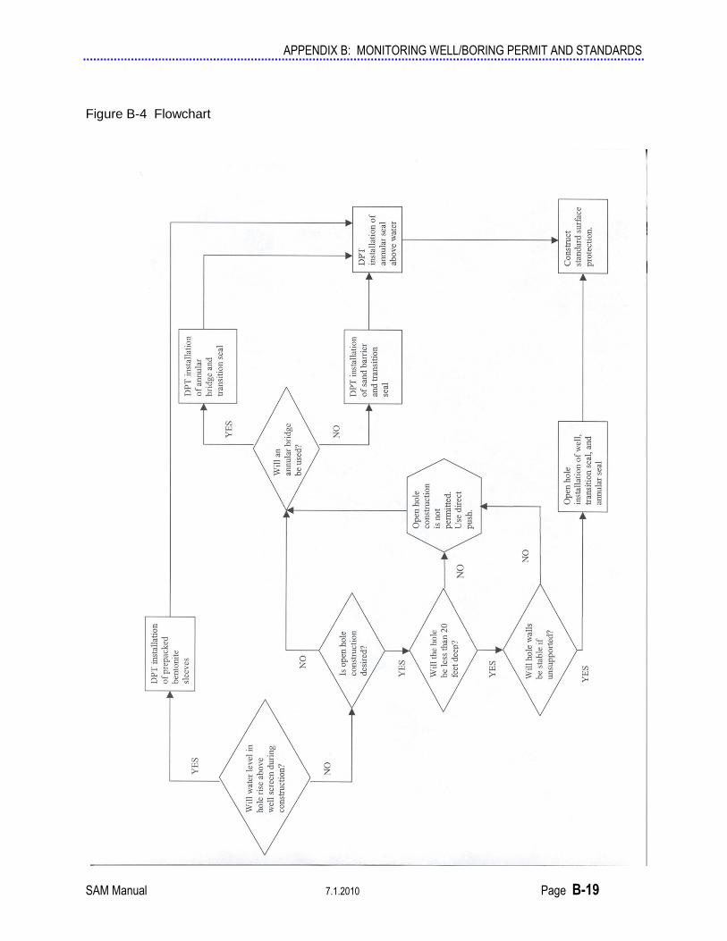
3. Small Diameter Well Construction Guidelines
This section presents five separate procedures for use in the construction of small diameter
wells:
The flowchart in Figure B-4 guides the decision of which procedure(s) are appropriate for the
proposed well installation. Note that information about the subsurface is required in order to
decide which procedures to use.
Information regarding the depth to water at the site must be known. Not only is this
information required (as with any well) to properly design the well in accordance with the
requirements of Appendix B II. B., this information is also needed to plan the special
materials needed and procedures to be followed for a small diameter well. For example, if
water level in the borehole rises completely above the screened interval during construction,
and therefore sealing materials need to be installed below water in the borehole, prepacked
bentonite sleeves should be used to seal the interval below water level in the borehole.
Also, if open hole construction is desired, the geologic materials must be of a type not given
to caving, sloughing, expansion, heaving, flowing, or other characteristics that would cause
closure or in-filling of an open borehole. The project site and subsurface geologic conditions
must be evaluated by a qualified professional, and a certification be made that the site
geologic conditions are suitable for open-hole construction of wells. Accompanying the
application for a permit, a summary of the evaluation must be included to justify the use of
this method.
APPENDIX B: MONITORING WELL/BORING PERMIT AND STANDARDS
SAM Manual 7.1.2010 Page B-19
Figure B-4 Flowchart
APPENDIX B: MONITORING WELL/BORING PERMIT AND STANDARDS
Page B-20 7.1.2010 SAM Manual
The following are details for the five procedures presented in the flow chart (Figure B-4).
a. DPT installation of sand barrier and transition seal.
Overview
Shall be constructed with a prepacked well screen that is designed to span the water
table.
Shall have a sand barrier filling the annular space adjacent to the prepacked well
screen and extending to six inches above the top of the screened interval. The
purpose of the sand barrier is to prevent transition seal materials from reaching the
depth of the screened interval.
Shall have a transition seal six inches thick composed of properly hydrated granular
bentonite used in accordance with manufacturer’s specifications. The purpose of the
transition seal is to prevent annular sealing materials from reaching the screened
interval.
The annular space from the top of the bentonite transition seal to the base of the
surface seal shall be filled using the procedure for “DPT installation of annular seal
above water level in well” below. A surface seal and well head shall be completed in
accordance with Appendix B II. B.
As with all well construction, all quantities of sealing materials used shall be
measured in units of volume and reported in the well log report.
Procedure for Anchoring Well Assembly
An expendable anchor point is driven to depth on the end of the push rods. A prepacked
well screen assembly is inserted into the inside of the rod with sections of PVC riser pipe.
The screens and riser pipe are attached to the anchor point to stabilize the assembly for
installation.
Affix the expendable drive point to the bottom push rod and advance the push rods to
the designed maximum depth of the well.
Lower capped or plugged prepacked well screen down the push rod with the
appropriate end pointing down, per manufacturer’s instructions. Add pre-packed
well screen sections as needed to achieve the designed screened interval.
Attach sections of PVC Riser to the top of the screen assembly. Continue to add riser
sections until the assembly hits the expendable drive point at bottom of rods. At least
one foot of riser should extend past the top push rod. Plug the top riser to ensure that
the inside of the well stays clean during construction.
Attach the well assembly firmly to the expendable drive point in accordance with the
manufacturer’s instructions, ensuring that the bottom end of the screen is sealed.
Gently pull up on the riser to ensure that the well assembly is firmly attached to the
anchor.
APPENDIX B: MONITORING WELL/BORING PERMIT AND STANDARDS
SAM Manual 7.1.2010 Page B-21
Begin retracting the push rods. While pulling the rods, observe whether the PVC
risers stay in place or move up with the rods.
If the PVC risers move up with the rod string, the well is not anchored. Stop and take
corrective action. First, check to be sure the pre-packed screen is still attached to the
expendable drive point. Next, use precautionary measures to safely hold the PVC
risers in place while pulling up the rods. An additional section of PVC riser may be
helpful. Once the push rods have cleared the anchor point and part of the screen, the
screen and riser assembly should stop rising with the rods.
If the PVC risers stay in place, the well is successfully anchored. Continue retracting
the rods so that the bottom of the rods are no more than two feet above the top of the
planned six-inch transition seal interval.
Procedure for Installing the Sand Barrier
The natural formation will sometimes collapse around and above the well screens as the
push rod string is withdrawn. The collapse above the screens provides effective support
for the transition seal. If the formation does not collapse, a sand barrier must be placed
from the surface. This portion of the well installation procedure is important because an
inadequate barrier will allow transition seal bentonite and perhaps grout to reach the well
screens. Non-representative samples and retarded groundwater flow into the well result
from bentonite or grout in the screened interval.
Using a water level sounder or flat tape measure, determine the depth from the top of the
PVC riser to the bottom of the annulus between the riser and push rods. Two scenarios
are possible:
Measured depth is 2 to 3 feet less than riser length. This indicates that unstable
conditions have resulted in formation collapse. A natural base for the transition seal
was formed as material collapsed around the PVC riser when the probe rods were
retracted. This commonly occurs in non-cohesive sands. A sand barrier cannot be
installed due to the collapse of the formation. Proceed to the next section on
installing the bentonite transition seal.
Measured depth is equal to or greater than riser length. This indicates that stable
conditions are present. The probe hole has remained open and void space exists
between the riser (and possibly the screen) and formation material. Clean sand must
be placed down hole to provide a suitable grout barrier.
Begin slowly pouring 20/40-grade (or as appropriate for the lithology) sand pack down
the annulus between the PVC riser and push rod string. Measure and record the volume
of sand added.
Measure the annulus depth while adding sand. The sand may not fall all the way past the
screens due to the tight annulus and possible water intrusion. This is acceptable, since
the pre-packed screens do not require the addition of sand. It is, however, important that
support for the transition seal is provided above the screens.
Add sand until it extends six inches above the screen section.
APPENDIX B: MONITORING WELL/BORING PERMIT AND STANDARDS
Page B-22 7.1.2010 SAM Manual
Sand may bridge within the annulus between the risers and push rods and consequently
fail to reach total depth. Wet probe rods contribute to sand bridging. If no bridging has
occurred, proceed to the next step.
In case of a sand bridge above the screens, insert a clean rigid device into the well
annulus to break up the sand. Simultaneously retracting the push rods usually helps.
Check annulus depth again. If sand is no longer bridged, proceed to the next step.
If the sand bridge cannot be broken up with a rigid device, inject a small amount of clean
water into the annulus. This is accomplished using grout machine and tubing. Insert the
tubing down the well annulus until the sand bridge is contacted. Attach the tubing to the
grout machine and pump up to one gallon of clean water while moving the tubing up and
down. The jetting action of the water will loosen and remove the sand bridge. Check
annulus depth again. The distance should be 2 to 3 feet less than the riser length.
In general, avoid any procedure that will cause the inside of the push rods to get wet.
Moisture inside the push rods will greatly increase the chance of bentonite bridging in the
rod annulus when the transition seal is installed.
Procedure for Installing Bentonite Transition Seal
Bentonite clay, when properly placed, prevents liquid grout and contaminants from
moving down the annular space into the well screen. The seal is formed by placing
granular bentonite into the annulus by gravity and hydrating in accordance with the
manufacturer’s instructions or by injecting high-solids bentonite slurry directly above the
sand barrier. Bentonite chips should not be used. The bentonite transition seal must
extend at least six inches above the sand pack.
Stable Formation - Granular bentonite is recommended if the following conditions are
met:
Formation remained open when probe rods were retracted.
Bridging was not encountered while installing the sand pack and grout barrier.
The following procedure should be used:
o Withdraw the probe rod string another 3 to 4 feet. Ensure that the PVC riser
does not rise with rods.
o Measure the depth from the top of the riser to the bottom of the annulus. Pour
granular bentonite between the probe rods and PVC riser as was done with the
sand, measuring as the bentonite is added. Add bentonite to form a six-inch
transition seal.
Verify the thickness of the transition seal by measure the depth from the top of the riser
to the bottom of the annulus. The distance should now equal the installed riser length
minus the minimum six inches of sand pack and six inches of bentonite seal. As was
stated with the sand pack, if the measured depth is significantly less than expected, the
bentonite has more than likely bridged somewhere along the rod string. A procedure
similar to that identified for bridged sand may be used to dislodge the granular bentonite.
APPENDIX B: MONITORING WELL/BORING PERMIT AND STANDARDS
SAM Manual 7.1.2010 Page B-23
Once it has been determined that the bentonite seal is properly placed, use the grout pump
and grout tube to pump sufficient water to the bentonite to hydrate it according to the
manufacture’s instructions.
Unstable Formation - A grout machine is required. The pump must be able to supply
high-solids bentonite slurry under sufficient pressure to displace collapsing soil.
The high-solids bentonite grout (20 to 25 percent by dry weight) must be used and placed
by using a grouting machine.
The grout must be delivered to the bottom of the annulus between the probe rods and well
riser through a grouting tube.
While pumping the bentonite grout slowly pull the rod string approximately 3 feet. This
procedure will place bentonite in the void left by the retracted rods before it is filled by
the collapsing formation.
During this procedure measure the annulus depth to ensure that the bentonite was
delivered.
Follow procedure for “DPT installation of annular seal above water level in well” below,
and then construct surface completion in accordance with Appendix B II. B.
b. DPT installation of annular bridge and transition seal.
Overview
The well shall be constructed with a prepacked well screen that is designed to span the
water table.
The well shall have a manufactured device in the well assembly designed to bridge
the annular space and prevent transition seal materials from reaching the well screen
(i.e. an “annular bridge”). The annular bridge must meet all requirements in the
General Considerations for Well Materials in Appendix B II. B.
The well shall have a transition seal six inches thick composed of properly hydrated
granular bentonite used in accordance with manufacturer’s specifications. The
purpose of the transition seal is to prevent annular sealing materials from reaching the
screened interval.
The annular space from the top of the bentonite transition seal to the base of the
surface seal shall be filled using the procedure for “DPT installation of annular seal
above water level in well” below. A surface seal and well head shall be completed in
accordance with Appendix B II. B.
As with all well construction, all quantities of sealing materials used shall be
measured in units of volume and reported in the well log report.
APPENDIX B: MONITORING WELL/BORING PERMIT AND STANDARDS
Page B-24 7.1.2010 SAM Manual
Procedure for Anchoring Well Assembly
Affix the expendable drive point to the bottom push rod and advance the push rods to the designed maximum depth of the well.
Lower capped or plugged prepacked screen down the push rod with the appropriate end pointing down, per manufacturer’s instructions. Add screen sections as needed to achieve the designed screened interval.
Thread annular bridge onto the top of the pre-packed screen.
Thread the riser pipe to the top of the annular bridge.
Lower well assembly into push rods until the annular bridge is approximately three feet into the push rods.
Calculate the volume of granular bentonite that is needed to fill the annular space between the borehole wall and the riser pipe for six vertical inches. Measure the granular bentonite into the annular space between the riser pipe and the push rod so that it rests on top of the annular bridge. Note that the insides of the push rods need to be dry for this method to succeed.
While holding the grout tube to well casing, push the riser pipe and grout tube down the push rod, adding riser pipe until screen hits the expendable drive point at bottom of rod string. At least one foot of riser should extend past the top push rod. Plug the top riser to ensure that the inside of the well stays clean during construction.
Release the grout tube and attach the well assembly firmly to the expendable drive point in accordance with the manufacturer’s instructions, ensuring that the bottom end of the screen is sealed. Gently pull up on the riser to ensure that the well assembly and anchor are firmly attached.
Begin retracting the push rods. While pulling the rods, observe whether the PVC risers stay in place or move up with the rods. If the PVC risers move up with the rod string, the well is not anchored. Stop and take corrective action. First, check to be sure the pre-packed screen is still attached to the expendable drive point. Next, use precautionary measures to safely hold the PVC risers in place while pulling up the rods. An additional section of PVC riser may be helpful. Once the push rods have cleared the annular bridge, the screen and riser assembly should stop rising with the rods.
If the PVC risers stay in place, the well is successfully anchored. Continue retracting the rods so that the bottom of the rod string rod is just above the end of the grout tube. The length of retraction equals the total length of screen + the length of the annular bridge + the thickness of the bentonite + the distance between the bentonite and the bottom of the grout tube.
Use the grout pump and grout tube to pump sufficient water to the bentonite to hydrate it according to the manufacture’s instructions. Wait for the bentonite to absorb enough water to form a barrier to liquid grout.
Follow procedure for “DPT installation of annular seal above water level in well” below, and then construct surface completion in accordance with Appendix B II. B.

APPENDIX B: MONITORING WELL/BORING PERMIT AND STANDARDS
SAM Manual 7.1.2010 Page B-25
c. DPT installation of wells using prepacked bentonite sleeves below water level in the
borehole.
Overview
The well shall be constructed with a prepacked well screen.
The well shall be constructed with properly installed prepacked bentonite seals for all
riser pipe installed beneath the water level in the borehole at the time of installation.
When the well assembly is anchored, the prepacked seals are submerged under water.
The prepacked seals are allowed to hydrate in accordance with the manufacturer’s
instructions.
The annular space above water level in the borehole, from the top of the prepacked
bentonite seal to the base of the surface seal, shall be filled using the procedure for
“DPT installation of annular seal above water level in well” below (#4). A surface
seal and well head shall be completed in accordance with Appendix B II. B.
As with all well construction, all quantities of sealing materials used shall be
measured in units of volume and reported in the well log report.
Procedure for Anchoring Well Assembly
Affix the expendable drive point to the bottom push rod and advance the push rods to
the designed maximum depth of the well.
Lower capped or plugged pre-packed screen down the push rod with the appropriate
end pointing down, per manufacturer’s instructions. Add screen sections as needed to
achieve the designed screened interval.
Thread annular bridge onto the top of the pre-packed screen.
Thread the prepacked bentonite sleeve to top of screen.
Lower the well screen and seal into the push rods. Add additional pre-packed
bentonite seals so that pre-packed seals will seal all of the annular space below the
water level in the borehole. The pre-packed seals will function as an annular seal
below the water table and as a transition seal/grout barrier for the annular seal
installed above the water table.
Do not use pre-packed seals above the water table because the proper expansion of
the seal cannot be assured in unsaturated conditions. Add PVC riser pipe above the
prepacked bentonite sleeves. Continue to add riser sections until the assembly hits the
expendable drive point at bottom of rod string. At least one foot of riser should
extend past the top push rod. Plug the top riser to ensure that the inside of the well
stays clean during construction.
Attach the well assembly firmly to the expendable drive point in accordance with the
manufacturer’s instructions, ensuring that the bottom end of the screen is sealed. Gently pull up on the riser to ensure that the well assembly and anchor are firmly attached.

APPENDIX B: MONITORING WELL/BORING PERMIT AND STANDARDS
Page B-26 7.1.2010 SAM Manual
Retract the push rods so that the bottom push rod is approximately one foot above the
top prepacked bentonite sleeve. Work quickly so that the sleeves do not swell inside the push rods and come up with the rod string. If the prepacked bentonite sleeves come up with the rod string, the well installation has failed and must be immediately destroyed and sealed by tremie grouting.
Allow the prepacked bentonite seals to hydrate in accordance with manufacturer’s
instructions before proceeding with the next steps. This can take anywhere from minutes to several hours depending on the product used.
Follow procedure for “DPT installation of annular seal above water level in well”
below, and then construct surface completion in accordance with Appendix B II. B.
d. DPT installation of annular seal above water level in well.
The annular space from the top of the bentonite transition seal to the base of the surface seal shall be filled using approved sealing materials and methods as specified in Appendix B II. B.
Calculate the amount of grout expected for each foot of annulus that will be filled.
Mix an appropriate amount of grout material and place it in the hopper on the grouting machine.
Position the grout tube just above the bentonite transition seal.
Retract two push rods (approximately six feet total length) while simultaneously
pumping grout. Hold the grout tube down while retracting the rods. When pausing rod retraction to remove a rod, stop the grout pump to prevent flooding rods with grout.
Continue retracting the push rods while simultaneously pumping grout until rods are
out of ground. Stop the grout pump at each rod break and pull approximately one push-rod length of grout tube out of the hole or hold tube while retracting rods so that tube comes up with rods.
Pull grout tube from hole until the end is above ground surface, pumping grout as
needed to keep hole full. When level of grout in hole stabilizes, put end of grout tube in bucket and pump clear
water through until clear water runs into the bucket. Shut off grout pump.
Pull the remaining grout tube through the push rods.
Cut or unthread casing approximately 6 inches above ground surface and remove excess casing. Cap well temporarily with slip cap.
Construct a standard well surface completion in accordance with the specifications in
Appendix B IV. B. of the SAM manual. Note that curing concrete can potentially generate enough heat to melt the riser pipe. Consider protecting the riser pipe from the curing concrete with a PVC conductor casing. The annular space between the riser pipe and conductor casing must be sealed with annular sealing material.
APPENDIX B: MONITORING WELL/BORING PERMIT AND STANDARDS
SAM Manual 7.1.2010 Page B-27
e. Open hole installation of well, transition seal, and annular seal.
Overview
This section provides criteria to be used for open-hole construction of groundwater
monitoring wells in small-diameter soil borings. An open hole for the purpose of this
guideline is a hole less than 20 feet deep with hole walls that will be stable if
unsupported. Open-hole construction of wells in small diameter borings will be limited to
borings and wells no greater than 20 feet in depth from the ground surface. The proper
placement of the well casing and annular materials (sand pack, well seal, etc.) and an
appropriate method of verifying the placement is a requirement of this method of well
construction. Centralizers must be used at the bottom, top, and at an appropriate location
in the middle of the well assembly. Following are criteria to be used for open-hole
construction of wells in small diameter borings.
Subsurface Geologic Conditions
Because the borehole must remain open during construction of the well, geologic
materials must be of a type not given to caving, sloughing, expansion, heaving, flowing,
or other characteristics that would cause closure or in-filling of an open borehole. The
project site and subsurface geologic conditions must be evaluated by the qualified
professional (as specified in Appendix B IV. B.), and a certification be made that the site
geologic conditions are suitable for open-hole construction of wells. Accompanying the
application for a permit, a summary of the evaluation must be included to justify the use
of this method.
Well Construction
With the exception of provision of a 2-inch annular space between the well casing and
boring walls, wells constructed in small-diameter borings must meet the requirements of
the State well standards and the SAM Program regarding the following:
Placement and location of well screen relative to the water table;
Placement of annular materials including sand filter pack, bentonite well seal, and
surface seal;
Construction of well surface completion; and
Well development.
In addition to these requirements, centralizers are required at the bottom, top, and at an
appropriate location in the center of the well assembly.
Verification of Well Construction
During placement of annular materials during typical well construction, depth to annular
materials (sand filter pack, bentonite seal, grout backfill) is monitored or “tagged” usually
with a weighted measuring tape or similar devise. The small annular space in wells
constructed in small-diameter borings would not allow the use of similar methods for
measuring the depth of emplacement of the annular materials. A rigid measuring device
APPENDIX B: MONITORING WELL/BORING PERMIT AND STANDARDS
Page B-28 7.1.2010 SAM Manual
must be used for such measurements during well construction in small-diameter borings.
The rigid device must not collapse or bend during the process of obtaining measurements,
must be long enough to reach to the bottom of the borehole, and must be small enough to
be inserted in the annular space between the well casing and borehole walls.
APPENDIX B: MONITORING WELL/BORING PERMIT AND STANDARDS
SAM Manual 7.1.2010 Page B-29
Definitions
Annular Bridge – A manufactured device designed to provide a bridge above the screened interval to
prevent granular bentonite from reaching the screened interval during transition seal emplacement. This is
a small device made of an expanding material such as foam.
Annular Space – The void space between an outer cylinder (such as a borehole wall or a push rod) and an
inner cylinder (such as a well screen or riser pipe).
DEH – The County of San Diego, Department of Environmental Health.
DPT – Direct Push Technology. Equipment that drives tools into the ground without augering a borehole.
Expendable drive point – A sacrificial metal conical tip that is left in the ground to act as an anchor point
and bottom cap for a direct-push well.
ID – Inside diameter; the diameter of a pipe or rod as measured from the inside edges.
OD – Outside diameter; the diameter of a pipe or rod as measured from the outside edges.
Prepacked bentonite seal – A commercially manufactured annular seal consisting of PVC riser pipe
wrapped with material that temporarily encloses bentonite. The prepacked seal is designed to be installed
through DPT push rods. When the rods are withdrawn and the seal comes in contact with groundwater, the
bentonite expands, rupturing the enclosing material and filling the annular space between the riser pipe
and the borehole wall. The prepacked bentonite seal must be certified by the manufacturer to completely
seal the annular space created by the outside diameter of the push rods. Prepacked bentonite seals must be
allowed to hydrate in accordance with manufacturer’s specifications before an annular seal is installed in
the unsaturated zone. Prepacked bentonite seals are not to be used above the water table.
Prepacked well screen – A commercially manufactured well intake device consisting of slotted PVC pipe
wrapped with a sandwich of screen holding a layer of appropriately sized silica sand.
PVC – Polyvinyl chloride.
SAM – The County of San Diego, Department of Environmental Health, Site Assessment and Mitigation
Program.
Schedule 40 -- Pipe manufactured to meet ASTM D1785 Schedule 40 specifications.
Small Diameter Well - A “small diameter well” for the purpose of this document is a well with a
borehole diameter of less than 6 inches and an annular space around the casing of less than 2 inches that
cannot be constructed using conventional drilling methods.
Well riser pipe - The non-perforated pipe inserted into the well borehole that connects the well screen
with the ground surface.
References
ASTM International D: 6724-01, 2001. Standard Guide for Installation of Direct Push Ground Water
Monitoring Wells.
ASTM International D: 6725-01, 2001. Standard Practice for Direct Push Installation of Prepacked Screen
Monitoring Wells in Unconsolidated Aquifers.

APPENDIX B: MONITORING WELL/BORING PERMIT AND STANDARDS
Page B-30 7.1.2010 SAM Manual
BP Corporation North America Inc. and The Underground Storage Tank Programs of U.S. Environmental
Protection Agency Regions 4, Atlanta GA and Region 5, Chicago, IL, May 1, 2002. Monitoring Well
Comparison Study: An Evaluation of Direct-Push Versus Conventional Monitoring Wells.
California Department of Water Resources, 1991. Bulletin 74-90 (Supplement to 74-81), California Well
Standards, Water wells, Monitoring wells, Cathodic protection wells.
County of San Diego, Department of Environmental Health, Land & Water Quality Division, Site
Assessment and Mitigation Program (SD DEH), 2002. Site Assessment and Mitigation Manual.
Kram, M; Lorenzana, D; Michaelsen, J; and Lory, E; January, 2001. Performance Comparison: Direct-
Push Wells Versus Drilled Wells. Naval Facilities Engineering Service Center Technical Report TR-2120-
ENV.