contents i switchboards— low voltagepub/@electrical/documents/conte… · 21.0-2 for more...
TRANSCRIPT

CA08104001E For more information, visit: www.eaton.com/consultants
April 2018
Contents
Switchboards—Low Voltage 21.0-1Sheet 21
i
ii
1
2
3
4
5
6
7
8
9
10
11
12
13
14
15
16
17
18
19
20
21
001
Sw
itch
bo
ard
s—
Lo
w V
olt
ag
e Switchboards—Low Voltage
General Description . . . . . . . . . . . . . . . . . . . . . . . . . . . . . . . . . . . . . . . . . . . 21.0-2
Power Xpert Release Trip Unit . . . . . . . . . . . . . . . . . . . . . . . . . . . . . . . . 21.0-5
Metering Devices . . . . . . . . . . . . . . . . . . . . . . . . . . . . . . . . . . . . . . . . . . 21.0-6
Surge Protective Devices . . . . . . . . . . . . . . . . . . . . . . . . . . . . . . . . . . . . 21.0-7
Pow-R-Line C Front- or Rear-Access, Group-Mounted Feeders . . . . . . . . . 21.0-8
Pow-R-Line C Front-Access, Group-Mounted Feeders. . . . . . . . . . . . . . . . 21.0-9
Pow-R-Line, Drawout Molded Case Circuit Breaker Switchboard . . . . . . . 21.0-10
Pow-R-Line i, Compartmentalized Feeders . . . . . . . . . . . . . . . . . . . . . . . . 21.0-11
Circuit Breakers and Fusible Switch Technical Data. . . . . . . . . . . . . . . 21.0-14
Pow-R-Line C Front-Access, Group-Mounted Feeders . . . . . . . . . . . . . . . . . . 21.1-1
Pow-R-Line C Rear-Access, Group-Mounted Feeders and Pow-R-Line i . . . . . 21.2-1
Pow-R-Line i, Compartmentalized Feeders, Rear-Access . . . . . . . . . . . . . . . 21.3-1
Outdoor Enclosures . . . . . . . . . . . . . . . . . . . . . . . . . . . . . . . . . . . . . . . . . . . . . 21.4-1
Metal-Enclosed Drawout Switchboards—Low Voltage
Features—General . . . . . . . . . . . . . . . . . . . . . . . . . . . . . . . . . . . . . . . . . . . . . 21.5-1
Magnum SB Breaker Ratings . . . . . . . . . . . . . . . . . . . . . . . . . . . . . . . . . . . . . 21.5-2
Layout and Breaker Weights. . . . . . . . . . . . . . . . . . . . . . . . . . . . . . . . . . . . . . 21.5-3
Integrated Facility System Switchboards
General Description . . . . . . . . . . . . . . . . . . . . . . . . . . . . . . . . . . . . . . . . . . . . 21.6-1
Layout Dimensions. . . . . . . . . . . . . . . . . . . . . . . . . . . . . . . . . . . . . . . . . . . . . 21.6-2
Generator Quick Connect Switchboard . . . . . . . . . . . . . . . . . . . . . . . . . . . . . 21.7-1
Roll-up Generator Termination Boxes . . . . . . . . . . . . . . . . . . . . . . . . . . . . . . . 21.8-1
Multipoint Submetering . . . . . . . . . . . . . . . . . . . . . . . . . . . . . . . . . . . . . . . . . . 21.9-1
Commercial Metering Switchboards
General Description . . . . . . . . . . . . . . . . . . . . . . . . . . . . . . . . . . . . . . . . . . . . 21.10-1
Layout Dimensions. . . . . . . . . . . . . . . . . . . . . . . . . . . . . . . . . . . . . . . . . . . . . 21.10-9
Instant Switchboards . . . . . . . . . . . . . . . . . . . . . . . . . . . . . . . . . . . . . . . . . . . . 21.11-1
Specifications:
See Eaton’s Product Specification Guide, available on CD or on the Web.CSI Format:. . . . . . . . . . . . . . . . . . . . . . . . . . . . . 1995 2010
Type 1 Pow-R-Line C Front-Access—Group-Mounted Feeders . . . . . . . . . . . . Section 16429 Section 26 24 13.11
Pow-R-Line i—Compartmentalized Feeders . . . . . . . . . Section 16428 Section 26 24 13.13
Integrated Facility System Switchboard. . . . . . . . . . . . . . . . . . . . . . Section 16433 Section 26 24 13.21
Commercial Metering Switchboard . . . . . Section 16431 Section 26 24 13.17
Instant Switchboards . . . . . . . . . . . . . . . . Section 16435 Section 26 24 13.19
Power Distribution Units . . . . . . . . . . . . . Section 16474 Section 26 26 00
Circuit Breakers and Fusible Switches—LV. . . . . . . . . . . . . . . . . . . . . Section 16475 Section 26 28 11
Generator Quick Connect Switchboard. . . . . . . . . . . . . . . . . . . . . . Section 16429C Section 26 23 00.15
Roll-up Generator Termination Boxes . . . . . . . . . . . . . . . . . . . . . . . . . . Section 16429R Section 26 24 13.37

21.0-2
For more information, visit: www.eaton.com/consultants CA08104001E
April 2018
Switchboards—Low Voltage
Sheet 21
i
ii
1
2
3
4
5
6
7
8
9
10
11
12
13
14
15
16
17
18
19
20
21
General Description002
Application Considerations and DefinitionsEaton’s Pow-R-Line® family of distribution switchboards incorporates new design concepts that fit the ever-increasing need for applications on high short circuit systems, while retaining maximum flexibility, safety and convenience throughout the line.
Front AccessFront-access switchboards align at the rear, enabling them to be placed against a wall (Type Pow-R-Line C™ front accessible). If the main section is deeper than others, due to physical size of the main device, the necessary offset in lineup will occur in front, and the main section will be accessible from the side as well as from the front. Eaton also offers front accessible switchboards that align at the front and rear.
Rear AccessRear-access switchboards align at the front and the rear. Bus maintenance and cable entry and exit require rear access. There are two types of rear accessible switchboards. Both types use the same incoming utility and/or main structures. The first type uses group-mounted feeder devices with panel construction (Type Pow-R-Line C rear accessible). The second type uses individually compartmentalized feeder devices with load side insulated bus bar extensions (Type Pow-R-Line i).
Individually Mounted Larger overcurrent protective devices (OCPD) may be individually mounted. In most cases, this means that the OCPD is mounted vertically in the switchboard and is connected via bus bar. All insulated case circuit breakers, power air circuit breakers and bolted pressure contact switches are individually mounted. Molded case circuit breakers 600 A and above may be individually mounted when used as a main or as a feeder device feeding other OCPD within a section or adjacent sections.
Compartmentalized Feeder and Branch Devices Compartmentalized molded case circuit breakers and fusible switches provide additional isolation. Individually mounted molded case circuit breakers and fusible switches through 1200 A are available in a compartmentalized, rear-access,
rear-connected switchboard. See Pow-R-Line i switchboards in this section for details.
Standard Switchboard HeightStandard Pow-R-Line switchboard height is 90.00 inches (2286.0 mm). Contact Eaton for special heights.
Group MountingGroup-mounted circuit protective devices are an assembly of units mounted on a panelboard type chassis. Units may be molded-case breakers, fusible switches, customer metering and surge protective devices.
A main molded case breaker or main fusible switch, within the sizes listed for panelboard design, can be included in the panel-mounted assembly in lieu of a separate, individually mounted unit.
Space Only for Future Devices Group-Mounted ConstructionWhere space only for future circuit protective devices is required, the proper space and a blank filler plate will be supplied. Connections and mounting hardware are not included.
Provision for Future DevicesWhere provisions for future circuit protective devices are required, space for the device, corresponding vertical bus, device connectors and the necessary mounting hardware will be supplied.
Bus Bar SystemStandard bus in the switchboards is tin-plated aluminum. Copper, silver-plated copper or tin-plated copper are also available.
Main bus and sub-main buses meet UL® and NEMA® standards for temperature rise on all Pow-R-Line switchboards. Special density rated bus is available.
Overcurrent DevicesTo properly select and size overcurrent devices for use in a switchboard, the allowable temperature rise must be taken into account as to its effect on the tripping characteristics of the devices in question per UL 891.
Accordingly, the NEC® requires overcurrent devices to be rated not less than 125% of the continuous load they are protecting. To comply with this, an 80% derating factor must be used with all overcurrent devices such as molded case
breakers and FDPW fusible switches unless they are tested and listed for application at 100% of the rating. All Magnum type breakers and bolted pressure switches are 100% rated.
Short-Circuit RatingStandard bus and connectors on all switchboards are rated for use on systems capable of producing up to 65,000 A rms symmetrical short-circuit current at the incoming terminals.
Increased bus short-circuit ratings equal to that of connected switchboard devices, up to 200,000 A rms symmetrical, are available in most Pow-R-Line C switchboards when approved main devices are installed. UL labeled switchboard sections are marked with their applicable short-circuit rating.
When air power circuit breakers are used as feeder devices in a switchboard, these devices may experience up to a 30-cycle (1/2 second) delay if the instantaneous setting is turned off. Eaton has qualified our low voltage switchboards when air power circuit breakers are used as feeders (and mains) to 30 cycles. This rating is not recognized under the UL 891 standard. However, Eaton has witness tested the structure bussing with a qualified National Recognized Testing Laboratory (NRTL) at 30 cycles (1/2 second) up to 100 kAIC symmetrical.
Provision for Busway Entrance and ExitBusway connections to switchboard sections include cutout and drilling in the top of the switchboard with riser connections from the switchboard device or bus, up to the point where the bus duct enters the switchboard. No connections are furnished external to the switchboard.
In all transactions involving busway attached to switchboards, it is essential that information regarding orientation of the busway with respect to the front of the switchboard be supplied to the coordinating assembly plant.
On Pow-R-Line C switchboards, a solid bus bar is used to connect the bus duct to the individually mounted main device, main or sub-main switchboard bus, or vertical main bus of panel-mounted circuit protective device panels. Busway fed by group-mounted branch devices are cable connected.
Aluminum riser connections are standard. Copper- or silver-plated copper is available as an option.

CA08104001E For more information, visit: www.eaton.com/consultants
21.0-3April 2018
Switchboards—Low Voltage
Sheet 21
i
ii
1
2
3
4
5
6
7
8
9
10
11
12
13
14
15
16
17
18
19
20
21
General Description003
TransitionsTransition structures are required for connecting switchboards to the secondary of power center transformer (fluid filled), motor control centers, and for other special switchboard configurations such as “L” or “U” shaped lineups. In some applications, an extra structure complete with connections is required; in others, where switchboard depth and space permit, only the connection conductors are required. Refer to Eaton for these applications.
Auxiliary Structures These are normally mounted adjacent to service structures or distribution structures, and used where incoming service or feeder conductors require additional space or facilities not included in the standard switchboard, such as:
1. Mounted adjacent to a topconnected service structure and used as a cable pull structure where service conductors are brought in underground. Auxiliary structures are the same depth and height as the service structure, and are wide enough to accommodate the incoming cables.
2. Mounted adjacent to a service structure and used as a bus transition compartment for running riser bus from the load-side of the service structure up to top outgoing bus duct connection when distribution structures are not required. Auxiliary structures are the same depth and height as service structures.
In addition to the above applications, auxiliary structures may be mounted adjacent to a distribution structure and used as a structure for lighting panel or other device that may be cable-connected to a branch circuit device in the distribution structure. Dimensions are compatible with the arrangements required.
Switchboards Used as Service EquipmentService equipment is the electrical equipment that constitutes the main control and means of power cutoff the electric service (normally Power Company supply) brought into the building.
Where switchboards are to be used as service equipment, certain NEC and UL requirements apply that necessitate modifications not normally supplied in switchboards.
The following is a summary of the requirements that are pertinent to the application of a switchboard for service equipment:
A. A switchboard with main lugsonly (no main disconnect) must be designed so that all circuits in the switchboard can be disconnected from the supply source by the operation of no more than six operating handles (breaker or switch).
Switchboard equipped with main disconnect devices are not subject to the above six disconnect limitation, as the entire board can be de-energized with the main disconnect device.
Ground fault protection of equipment must be provided for solidly grounded wye electrical services of more than 150 V to ground, but not exceeding 600 V phase-to-phase for each service disconnecting means rated 1000 A or more.
B. For testing purposes, means are also required to disconnect the switchboard neutral bus from the grounded service neutral conductor (single-phase, three-wire; and three-phase, four-wire systems). To comply with this requirement, a removable link (solid bar) is provided in the switchboard neutral bus. This link is generally located near the point where the main feeders enter the switch-board or in the area of the main disconnect device where one is provided.
To further comply with NEC and UL requirements, a separate bonding strap is connected from the neutral bus to the switchboard frame. This bonding connection is located on the line side of the removable neutral link, maintaining a service ground to the switchboard frame when the test link is removed. See Figure 21.0-1.
Figure 21.0-1. Neutral Link
UL labeling will clearly indicate service equipment listed switchboards.
Ø1 Ø2 Ø3 N
N
Ø1
Ø2
Ø3
To StationGround
NeutralLink
BondingStrap
EquipmentGround Bus
Switchboard Frame

21.0-4
For more information, visit: www.eaton.com/consultants CA08104001E
April 2018
Switchboards—Low Voltage
Sheet 21
i
ii
1
2
3
4
5
6
7
8
9
10
11
12
13
14
15
16
17
18
19
20
21
General Description004
Underwriters Laboratories Requirements and LabelingThe basic requirement for obtaining a UL label on a switchboard, is that all the component devices (breakers, switches, and so on) in the switchboard assembly are UL listed. In addition, the switchboard must comply with all applicable provisions of UL 891.
Today’s modern electrical systems require that switchboards offer a wide selection of electrical devices, many of which do not fall within the scope of UL listed devices. Therefore, the conditions under which a switchboard may be labeled are limited.
Listed below are several important guidelines for consideration when aUL label is specified:
1. UL nameplates, where applicable, are supplied for each vertical structure rather than one common nameplate for the complete switchboard lineup. Where all of the component devices in the switchboard are UL listed and all applicable provisions of UL 891 are met, each of the switchboard sections may be labeled.
2. Individual vertical structures of a switchboard may be labeled where they comply with UL requirements, although other vertical structures in the same switchboard lineup may not meet the UL standards, and will not be labeled.
3. All Pow-R-Line C switchboards are UL labeled when all mounted devices are UL listed.
Alternate Power Source CapabilitiesMultiple solutions are available to accommodate alternate power sources available. Due to the large number of customer and system requirements, details are not provided in this guide. Eaton offers solutions that include main-main configuration and main-tie-main configurations. Automatic transfer equipment, including UL 1008 listed transfer switches and other automatic transfer schemes, are available.
Automatic Transfer EquipmentFor continuity of service, automatic transfer equipment between two incoming sources may be required. This equipment transfers the load upon failure of the normal (or preferred) source to the standby (or alternate) source. Upon restoration of the normal source, the load is automatically transferred back to it. To accomplish this, electrically operated main protective devices (and bus tie devices, if required) must be employed. Additional relays also are required to detect source voltage failure and to transfer control power, when required. A manual selector switch is usually provided to select the mode of operation—automatic or manual transfer.
Seismic Qualification
Refer to Tab 1 for information on seismic qualification for this and other Eaton products.

CA08104001E For more information, visit: www.eaton.com/consultants
21.0-5April 2018
Switchboards—Low Voltage
Sheet 21
i
ii
1
2
3
4
5
6
7
8
9
10
11
12
13
14
15
16
17
18
19
20
21
General Description—OPTIM Trip Units005
Power Xpert Release Trip Unit
Power Xpert Release Trip Unit
DescriptionEaton’s Power Xpert Release(PXR) trip units are programmable communicating microprocessor-based low-voltage electronic trip unit systems for Eaton insulated case circuit breakers. PXR trip units are available in two models: PXR20 and PXR25.
The PXR electronic trip units provide an enhanced and easy-to-use interface that enables end users and maintenance engineers to more easily change set points, test and configure circuit breakers, and review energy and power information. Also, the Power Xpert Protection Manager software provides the capability of secondary injection tests and reports on-demand without the need of expensive test kits.
Standards and CertificationsThe PXR trip units are listed by Underwriters Laboratories (UL) and Canadian Standards Association (CSA) for use in Series NRX™ NF and Series NRX RF circuit breakers. All PXR units have also passed the IEC 60947-2 test program that includes EMC testing. All trip units meet the low-voltage and EMC directives and carry the CE mark.
Features
Table 21.0-1. Power Xpert FeaturesTrip Unit PXR 20 PXR 25
Diagnostics and Indication FeaturesTrip Log 10 trip events
200 summaryAdditional storage available via CAM module
Alarm log 10 alarm events—through COMWaveform capture One waveform event captured in ETUDisplay LCD dot matrixLEDs ETU Status Instantaneous trip
Long trip Ground tripShort trip ARMS status
Power for cause of trip LEDs Control power or batteryBattery Indication Display (no PTT)Maintenance/wellness health and diagnostics
ETU temp. and max. Operating (run) timeTrip count Health bar (algorithm)Ops count / last date
PXR Metering, Communications and Other FeaturesMetering—current Yes
Phase, Neutral, Ground, min., max., demand, peakMetering—voltage No Yes
L-L, L-N, avg. min., max.,Frequency, min., max.
Metering—power No YeskW, kVA, kvarDemand-kW, kVA, kvarPeak Demands
Metering—Energy No YeskWh-fwd, rev, net, totkvarh-lead, lag, net, tot
Metering—PF apparent No Yesmin., max.
Communications Modbus RTU optionalCAM modules opt.
Modbus RTU nativeCAM modules opt.
Testing method PC via USB portInternal Secondary injection test circuit
Relay outputs—alarms or trips 3QR code—support information YesPassword—setting menu and test YesRoHS Yes
Protection FeaturesOrdering options LSI, LSIG/ANumber of sensors 1 Sensor—NF
1 Sensor—RFSensor (rating) plug (In) No plug
Programmable In (21)Slopes It, I2t, I2t
IEEE—MI, VI, EISystem frequency 50 / 60 HzLong delay pickup (Ir) 0.4 –1.0 x (In)(10)Long delay time I2T at 6x (Ir) 0.5–24 s (10)Long delay thermal memory Yes—Program disableShort delay pickup 1.5–10 x (In)(10)Short delay time I2t at 8x (Ir) 0.1, 0.3, 0.4, 0.5 sShort delay time flat 0.0, 0.1, 0.2, 0.3, 0.4, 0.5 sInstantaneous pickup 2–15 x (In)(10)Ground (earth) fault pickup Trip: 0.2–1.0 x (In)(5)
Alarm: 0.2–1.0 x (In)(4)Off
Ground (earth) fault time I2t at 0.625 x (In) 0.1, 0.2, 0.3, 0.4, 0.5 s
Ground (earth) fault time flat 0.1, 0.2, 0.3, 0.4, 0.5 sZSI, short delay and ground Programmable
Display indicationNeutral protection Yes
Off, 60, 100%ARMS—arc flash—mode/settings Optional—on or off/remote
5 settings (x In)

21.0-6
For more information, visit: www.eaton.com/consultants CA08104001E
April 2018
Switchboards—Low Voltage
Sheet 21
i
ii
1
2
3
4
5
6
7
8
9
10
11
12
13
14
15
16
17
18
19
20
21
General Description—Metering Devices006
Power Xpert Meters 2000
Power Xpert Meters 2000
The Power Xpert 2250 MeterThis meter provides all the core functions for monitoring power consumption and power quality, Ethernet connectivity and onboard gateway card limits. This unit uses D/A technology to sample circuits at 400 samples per cycle for extremely accurate measurement of power factor and energy consumption. In addition, the meter has 256 MB for logging meter data.
The Power Xpert 2260 MeterThis meter adds the ability to monitor total harmonic distortion and the ability to set onboard meter limits. The meter also will illuminate LEDs on the faceplate, indicating that a limit has been exceeded and provides 512 MB for data logging.
The Power Xpert 2270 MeterThis meter adds the ability to monitor individual harmonics and visualize waveforms on your desktop using the embedded Web server and raises the storage to 768 MB for data logging.
Meter series benefits include:
■ Fully understand your facility’s power quality
■ Detailed event information; pinpoint the root causes of problems—or prevent them from occurring
■ Measure, trend and analyze power via information through onboard Web and comma separated values (CSV) exporting capabilities
■ Up to 768 MB of storage; typically 15 years of storage capability depending on the meter model and frequency of events
■ Local or remote configuration
Power Xpert Meter 4000/6000/8000
Power Xpert Meter 4000/6000/8000■ The Power Xpert Meter 4000/6000/
8000 series is an Internet-enabled (including a built-in Web server), power quality and energy meter with comprehensive power and energy measurement, and integrated quality analysis. These meters allow you to use a standard Web browser to surf the meter and visualize a waveform and analyze trends
■ Accurate detection of fast transients ■ Early warning of impending
problems ■ At-a-glance view of power quality ■ Reduces power monitoring cost ■ Supports continuous, non-
disruptive monitoring ■ Accessible via the Ethernet ■ Uses industry-standard
communication protocols
IQ 130/140/150
IQ 130/140/150Providing the first line of defense against costly power problems, Eaton’s IQ 100 electronic power meters can perform the work of an entire wall of legacy metering equipment using today’s technology.
■ 24-bit AD converters that sample at more than 400 samples per cycle
■ Meet ANSI C12.20 standards for accuracy of 0.5 percent
■ Confidently used for primary revenue metering and submetering applications
■ Direct-reading metered values such as watts, watt demand, watthours, voltage amperes (VA), VA-hours, VARs, VARhours and power factor
■ Also available in Eaton's enclosed meter product

CA08104001E For more information, visit: www.eaton.com/consultants
21.0-7April 2018
Switchboards—Low Voltage
Sheet 21
i
ii
1
2
3
4
5
6
7
8
9
10
11
12
13
14
15
16
17
18
19
20
21
General Description—Metering Devices007
IQ 250/260
IQ 250/260The IQ 250 and IQ 260 electronic meters provide capabilities you wouldn’t normally expect in an affordable, ultra-compact meter—such as fast sampling rate and accurate metering for a full range of power attributes. Built-in slots allow for future upgrades.
■ Comprehensive metering ■ High-end accuracy ■ Self-test capability to validate
accuracy ■ Large, easy-to-read display ■ Local or remote configuration ■ Industry-standard communication
protocols ■ Mix-and-match input/output options ■ Integration with Eaton’s Power Xpert
Architecture ■ Field-upgradeable
Note: For full technical information, see Tab 3.
For information on other available power meters, visit www.eaton.com/meters.
Power Xpert Gateway
Power Xpert Gateway Eaton’s Power Xpert Gateway (PXG) bridges the IT and facilities management worlds by bringing disparate panelboards, switchboards and other power equipment onto the network. The PXG takes the complexity out of connecting power equipment to the network. The Web-enabled PXG is an out-of-the-box device that can support up to 96 devices, translate most industrial communication protocols, and offer user-selectable events and real-time trending. It also features e-mail notification of events, waveform capture and data/event logging—all with no special software. Adding basic meters or the utility’s meter, the PXG assists in tracking energy usage. The PXG recognizes the interdependence of IT systems and power systems, and delivers what organizations need to bring these worlds together for seamless, end-to-end system reliability.
The PXG consolidates data available breakers, meters, motor controllers and protective relays, and presents the information in a variety of ways (a Web browser being the most widely used method). The PXG is a stand-alone solution. As needs change and grow, the PXG can be integrated through Power Xpert Software into a broader solution that encompasses other intelligent hardware and can integrate with third-party network management systems (NMS) or building management systems (BMS) for system-wide monitoring and reporting of power and IT.
For detailed information, please refer to Tab 2.
Integrated Surge Protective Devices
Integrated Surge Protective Devices Eaton integrates our industry-leading surge protective devices (SPD) in to switchboards. Lead length is kept to a minimum to maximize SPD performance. SPD units are available with ratings up through 400k, and are UL listed and labeled to UL 1449 3rd Edition.
All switchboards with integrated SPD units are connected to a lineside overcurrent protective device for disconnecting means. When applied on the lineside of a service entrance main, the disconnecting means does not count as a service disconnect per National Electrical Code Article 230.71[A].
For complete SPD product description, application and ratings, refer to Tab 34.

21.0-8
For more information, visit: www.eaton.com/consultants CA08104001E
April 2018
Switchboards—Low Voltage
Sheet 21
i
ii
1
2
3
4
5
6
7
8
9
10
11
12
13
14
15
16
17
18
19
20
21
Pow-R-Line C SwitchboardsGeneral Description—Pow-R-Line C, Front- or Rear-Access, Group-Mounted Feeders
008
Pow-R-Line C SwitchboardsMeets NEMA Standard PB-2 and UL 891.
Construction Details■ 6000 A main bus maximum■ Front accessible—main sections
front- and/or side-access■ Front- and rear-access; main
sections front- and/or side-access■ Feeder devices group-mounted■ Sections rear-aligned or front- and
rear-aligned
Main Devices, Individually Mounted■ Molded case circuit breakers,
400–2500 A, fixed-mounted■ Insulated case circuit breakers,
Magnum SB, 800–5000 A, fixed and drawout
■ Air power circuit breakers, Magnum™ DS, 800–5000 A, fixed or drawout
■ Air power circuit breakers with current limiting fuses, Magnum DSL, 800–5000 A
■ Bolted pressure switches, 800–5000 A, fixed
■ Insulated case circuit breakers, Series NRX NF, 800–1200 A, fixed and drawout
■ Insulated case circuit breakers, Series NRX RF, 800–3000 A, fixed and drawout
■ Fusible switches, 400–1200 A, fixed
Feeder Devices, Group-Mounted■ Bolt-on molded case circuit
breakers, 15–1200 A■ Drawout molded case circuit
breakers, 70–1200 A■ Fusible switches, 30–1200 A
Pow-R-Line C Switchboard
Feeder Devices,Individually Mounted■ Molded case circuit breakers,
800–2500 A, fixed■ Insulated case circuit breakers,
Magnum SB, 800–5000 A, fixed and drawout
■ Air power circuit breakers, DS and Magnum DS, 800–4000 A, fixed and drawout
■ Insulated case circuit breakers, Series NRX NF, 800–1200 A, fixed and drawout
■ Insulated case circuit breakers, Series NRX RF, 800–3000 A, fixed and drawout
■ Bolted pressure switches, 800–1600 A, fixed
Selective CoordinationSelectively coordinated systems dictated by code and customer mandates may be achieved with Eaton switchboards to either 0.1 or 0.01 seconds as mandated by codes and/or customers. Refer to Tab 1, Section 1.4 for additional details.
Note: For selection and layout guidelines, please reference Page 21.1-1.
For a complete product specification in CSI format, see Eaton’s Product Specification Guide. . . . . . . . . . . . . . Section 16429

CA08104001E For more information, visit: www.eaton.com/consultants
21.0-9April 2018
Switchboards—Low Voltage
Sheet 21
i
ii
1
2
3
4
5
6
7
8
9
10
11
12
13
14
15
16
17
18
19
20
21
Pow-R-Line C SwitchboardsGeneral Description—Pow-R-Line C, Front-Access, Group-Mounted Feeders
009
Features■ Eaton’s circuit breaker ratings up to
200 kAIC■ Trip units that integrate Eaton’s
Arcflash Reduction Maintenance System™ reduces potential arc flash available
■ Integral ground fault protection available in electronic trip units from 15–5000 A
■ Electronic trip units that integrate zone selective interlocking capabilities available in molded case, insulated case and air power circuit breaker
■ Available with circuit breakers and fusible switches on the same chassis
The Single Chassis Design Provides Device Flexibility
■ UL listed and labeled. Meets NEC and NEMA standards
■ Eaton microprocessor-based metering devices are standard when metering is specified. Conventional metering is available. IQ and Power Xpert devices can provide a communications capability. See Tab 3
■ Optional integral surge protective device (SPD) is available in Pow-R-Line C switchboards, when specified. See Tab 34
■ Aluminum, copper or silver-plated copper bus
■ A full range of device modifications is available
■ Available in NEMA Type 1 and 3R enclosures, UL listed
Modifications■ Ground fault protection on mains
and distribution devices■ Coordination with other Eaton
divisions for busway and transformer connections
Type 1 Pow-R-Line C Features
a Customer metering.b Utility metering compartment.c Surge protective device.d Main breaker (Magnum SB).e Cable pull and termination space.
f 250 A frame single mount.g 600 A frame single mount.h 250 A frame dual mount.i 600 A frame dual mount.
Table 21.0-2. Pow-R-Line C Group-Mounted SwitchboardsVoltage: 240–480–600 Vac, 250 VdcMains: 400–6000 A
1 5000 A bolted pressure switches are not UL listed.2 Third-party witness tested at 30 cycles.
de
ba
c
h
g
f
i
Main Device
Type
Amperes Short-Circuit
Symmetrical Rating (kA)
Molded case circuit breakersInsulated case circuit breakers, Magnum SBInsulated case circuit breakers, Series NRX NFInsulated case circuit breakers, Series NRX RFAir power circuit breakers, Magnum DSAir power circuit breakers with CL fuses, DSL
400–2500800–5000800–1200800–3000
800–5000
14–20030–10065–8565–100
200
Bolted pressure switchesFusible switchesMain lugs only
800–5000 1400–1200400–6000
200200Rating determined by overcurrent protective device
Feeder Device
Type
Amperes Short-Circuit
Rating (kA)
Bolt-on, fixed-mounted molded case circuit breakersDrawout, molded case circuit breakersFusible switchesStacked—main with branch devices
15–250070–60030–1200
400–2500
10–20010–200
20018–200
Magnum SB up to two highMagnum DS up to two high 2
800–2000800–2000
30–10030–100
Series NRX NF up to two high and quad stackSeries NRX RF up to two high
800–1200800–3000
65–8565–100
21.0-10
For more information, visit: www.eaton.com/consultants CA08104001E
April 2018
Switchboards—Low Voltage
Sheet 21
i
ii
1
2
3
4
5
6
7
8
9
10
11
12
13
14
15
16
17
18
19
20
21
General Description—Pow-R-Line, Drawout Molded Case Circuit Breaker Switchboard010
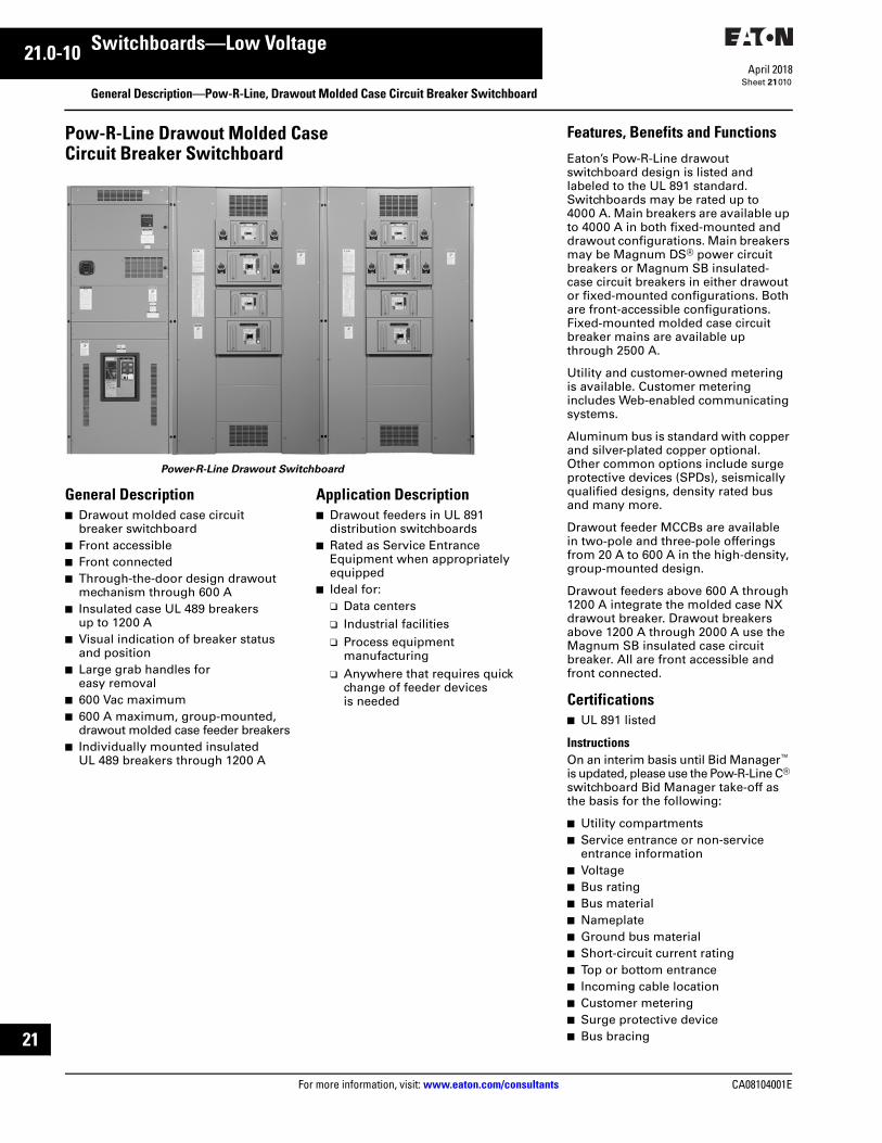
Pow-R-Line Drawout Molded Case Circuit Breaker Switchboard
Power-R-Line Drawout Switchboard
General Description■ Drawout molded case circuit
breaker switchboard■ Front accessible■ Front connected■ Through-the-door design drawout
mechanism through 600 A■ Insulated case UL 489 breakers
up to 1200 A■ Visual indication of breaker status
and position■ Large grab handles for
easy removal■ 600 Vac maximum■ 600 A maximum, group-mounted,
drawout molded case feeder breakers■ Individually mounted insulated
UL 489 breakers through 1200 A
Application Description■ Drawout feeders in UL 891
distribution switchboards■ Rated as Service Entrance
Equipment when appropriately equipped
■ Ideal for:❑ Data centers❑ Industrial facilities❑ Process equipment
manufacturing ❑ Anywhere that requires quick
change of feeder devices is needed
Features, Benefits and Functions
Eaton’s Pow-R-Line drawout switchboard design is listed and labeled to the UL 891 standard. Switchboards may be rated up to 4000 A. Main breakers are available up to 4000 A in both fixed-mounted and drawout configurations. Main breakers may be Magnum DS® power circuit breakers or Magnum SB insulated- case circuit breakers in either drawout or fixed-mounted configurations. Both are front-accessible configurations. Fixed-mounted molded case circuit breaker mains are available up through 2500 A.
Utility and customer-owned metering is available. Customer metering includes Web-enabled communicating systems.
Aluminum bus is standard with copper and silver-plated copper optional. Other common options include surge protective devices (SPDs), seismically qualified designs, density rated bus and many more.
Drawout feeder MCCBs are available in two-pole and three-pole offerings from 20 A to 600 A in the high-density, group-mounted design.
Drawout feeders above 600 A through 1200 A integrate the molded case NX drawout breaker. Drawout breakers above 1200 A through 2000 A use the Magnum SB insulated case circuit breaker. All are front accessible and front connected.
Certifications■ UL 891 listed
InstructionsOn an interim basis until Bid Manager™ is updated, please use the Pow-R-Line C® switchboard Bid Manager take-off as the basis for the following:
■ Utility compartments■ Service entrance or non-service
entrance information■ Voltage■ Bus rating■ Bus material■ Nameplate■ Ground bus material■ Short-circuit current rating■ Top or bottom entrance■ Incoming cable location■ Customer metering■ Surge protective device■ Bus bracing

CA08104001E For more information, visit: www.eaton.com/consultants
21.0-11April 2018
Switchboards—Low Voltage
Sheet 21
i
ii
1
2
3
4
5
6
7
8
9
10
11
12
13
14
15
16
17
18
19
20
21
General Description—Pow-R-Line i, Rear-Access, Compartmentalized Feeders011
Pow-R-Line® i SwitchboardsMeets NEMA Standard PB-2 and UL 891.
Construction Details■ 4000 A main bus maximum■ Front and rear accessible—
main and distribution sections■ Feeder devices individually
compartmentalized■ Sections front and rear aligned■ Designed for mounting with code
clearance to a wall
Main Devices, Individually Mounted■ Molded case circuit breakers,
400–2500 A, fixed or drawout■ Insulated case circuit breakers,
Series NRX NF, 800–1200 A, fixed and drawout
■ Insulated case circuit breakers, Series NRX RF, 800–3000 A, fixed and drawout
■ Insulated case circuit breakers, Magnum SB, 800–4000 A
■ Air power circuit breakers, Magnum DS, 800–4000 A, fixed or drawout
■ Air power circuit breakers with current limiting fuses, Magnum DSL, 800–4000 A
■ Bolted pressure switches, 800–4000 A, fixed
■ Fusible switches, 400–1200 A, fixed
Feeder Devices■ Molded case circuit breakers,
15–1200 A are compartmentalized■ Molded case circuit breakers above
1200 A are not compartmentalized■ Fusible switches, 100–1200 A■ Insulated case circuit breakers,
Magnum SB, 800–4000 A■ Air power circuit breakers,
Magnum DS, 800–2000 A■ Bolted pressure switches,
800–2500 A■ Insulated case circuit breakers,
Series NRX NF, 800–1200 A, fixed and drawout
■ Insulated case circuit breakers, Series NRX RF, 800–3000 A, fixedand drawout
■ Trip units that integrate Eaton’s Arcflash Reduction Maintenance System to reduce potential arc flash
■ Integral ground fault protection available in electronic trip units from 15–5000 A
■ Electronic trip units that integrate zone selective interlocking capabilities available in molded case, insulated case and air power circuit breaker
Note: For selection and layout guidelines, please reference Page 21.3-1.
Pow-R-Line i Switchboard
For a complete product specification in CSI format, see Eaton’s Product Specification Guide. . . . . . . . . . . . . . Section 16428

21.0-12
For more information, visit: www.eaton.com/consultants CA08104001E
April 2018
Switchboards—Low Voltage
Sheet 21
i
ii
1
2
3
4
5
6
7
8
9
10
11
12
13
14
15
16
17
18
19
20
21
General Description—Pow-R-Line i, Rear-Access, Compartmentalized Feeders012
Pow-R-Line i Construction Features
Distribution Section—Front View
a Glass polyester circuit breaker compartment.
b Insulated copper load side runbacks.
c Full length barrier isolating the cable compartment.
d Horizontal cross bus.
e Tandem mounted circuit breakers through 400 A.
f Isolating bus compartment.
Distribution Section—Rear View
g Available zero sequence ground fault.
h Angled neutral connections.
i A, B, C phase connections.
j Anti-turn lugs.
k Movable cable support.
l Generous conduit space.
a
b
e
g f
d
h
i
j
k
l
d
c

CA08104001E For more information, visit: www.eaton.com/consultants
21.0-13April 2018
Switchboards—Low Voltage
Sheet 21
i
ii
1
2
3
4
5
6
7
8
9
10
11
12
13
14
15
16
17
18
19
20
21
General Description—Pow-R-Line i, Rear-Access, Compartmentalized Feeders013
Pow-R-Line i Switchboards...Greater Flexibility and Increased Safety FeaturesEaton’s Pow-R-Line i Switchboards are engineered in a new compartmentalized design for applications where a greater degree of safety is required. A wide variety of configurations is possible, including utility metering, customer metering, main devices, branch devices, accessories and enclosures.
Significant safety features include:
■ Individual compartments for branch devices—glass polyester for circuit breakers and steel for fusible switches. These compartments help eliminate possible contact with the main bus and reduce fault propagation
■ Three-section construction with each section barriered from the other❑ Device section. Each device is
mounted in its own compartment❑ Bus bar section. Contains both
horizontal and vertical buses❑ Rear cable compartment.
Completely isolated from the bus bars
■ Insulated copper runback. Power is taken from the protective device by the insulated copper runback through a standard full height glass polyester barrier to the rear cable compartment. This design virtually eliminates the possibility of accidental contact with the main buses during installation or maintenance
A Wide Selection of Main and Branch DevicesMain devices are available from 400–4000 A and can include molded case circuit breakers, Magnum SB and DS breakers, and fusible switches or bolted pressure switches. Main buses are rated up to 4000 A.
Ground fault test panels can be mounted in compartments with the circuit breakers for convenience and space savings.
Branch circuit breakers range from 150–1200 A frames. Branch fusible switches are available from 100–1200 A frames.
Short-circuit ratings up to 200,000 A are UL listed.
Pow-R-Line i switchboards are UL listed and meet all applicable requirements of NEMA and NEC. They are rear-accessible and front- and rear-aligned.
The Magnum DS breaker includes the Digitrip™ RMS trip unit that provides circuit protection, information and testing functions, and true rms sensing.
Pow-R-Line i switchboards can help to provide for future distribution system requirements by including empty compartments for branch circuit breakers and fusible switches. (Circuit breaker provisions shown.)
Space-Saving Ground Fault Test PanelsPow-R-Line i switchboards can accommodate either integral or zero sequence types of ground fault protection. Depending on the specific application, a test panel can be mounted in the circuit breaker compartment, which may eliminate the need for an auxiliary structure.
Provisions for the FutureFuture expansion provisions include line side connectors, load side runbacks, terminals, and glass polyester compartments and covers (for circuit breakers).
Customer MeteringEaton microprocessor-based metering devices are standard when customer metering is specified. Conventional metering is available.IQ and Power Xpert devices can provide communications capabilities. See Tab 3.

21.0-14
For more information, visit: www.eaton.com/consultants CA08104001E
April 2018
Switchboards—Low Voltage
Sheet 21
i
ii
1
2
3
4
5
6
7
8
9
10
11
12
13
14
15
16
17
18
19
20
21
Technical DataCircuit Breaker and Fusible Switch Technical Data
014
Table 21.0-3. Molded Case Circuit Breakers
1 N.I.T. is non-interchangeable trip unit. I.T. is interchangeable trip unit.
2 Two-pole circuit breaker, or two poles of three-pole circuit breaker at 250 Vdc.
3 For use on dc systems only.
4 For use with drawout feeder device only.5 Electronic trip unit adjustable from
20 to 250 A.6 100% rated.
7 Not available in Pow-R-Line i switchboards.8 Available in bolt-on fixed mount or drawout
feeder device.9 Individually, vertically mounted.
Circuit
Breaker
Type
Continuous
Ampere
Rating
at 40 ºC
No. of
Poles
Voltage Trip
Type 1UL Listed Interrupting Ratings rms Symmetrical Amperes
AC DC ac Ratings Volts dc Ratings Volts 2
120 120/240 240 277 480 600 125 250 125/250 600
EDBEDSEDEDHEDC
100–225100–225100–225100–225100–225
2, 32, 32, 32, 32, 3
240240240240240
125125125125125
N.I.T.N.I.T.N.I.T.N.I.T.N.I.T.
—————
—————
224265
100200
—————
—————
—————
1010101010
—————
—————
—————
EHDEHDHFDDC 3FDBFDB
15–10015–10015–15015–22515–225
12, 32, 32, 34
277480—600600
125250600250250
N.I.T.N.I.T.N.I.T.N.I.T.N.I.T.
—————
—————
—18
—1818
14————
—14
—1414
———1414
10—42——
—10421010
—————
——35——
FD, FDEFD, FDEFD, FDEHFD, HFDEHFD, HFDE
15–22515–22515–22515–22515–225
12, 3412, 3
277600600277600
125250250125250
N.I.T.N.I.T.N.I.T.N.I.T.N.I.T.
—————
—————
—6565
—100
35——65—
—3535
—65
—1818—25
10——10—
—1010—22
—————
—————
HFD, HFDEFDC, FDCEFDC, FDCEJDHJD
15–22515–22515–22570–25070–250
42, 342, 32, 3
600600600600600
250250250250250
N.I.T.N.I.T.N.I.T.I.T.I.T.
—————
—————
10020020065
100
—————
651001003565
2535351825
—————
2222221022
—————
—————
JDCHJDDC 3JGS 4JGH 4JGC 4
70–25070–25070–25070–25070–250
2, 32, 32, 32, 32, 3
600—600600600
250600250250250
I.T.I.T.I.T.I.T.I.T.
—————
—————
200—65
100200
—————
100—3565
100
35—253550
—42———
2242———
—————
—35———
DKKDCKD 6HKDCHKD 6
250–40070–40070–40070–40070–400
2, 32, 332, 33
240600600600600
250250250250250
N.I.T.I.T.I.T.I.T.I.T.
—————
—————
656565
100100
—————
—35356565
—25253535
—————
1010102222
—————
—————
KDCHKDDC 3LHH 7NHHLGE 7
70–400100–400125–400150–350300–600
2, 32, 32, 332, 3
600—600600600
250600250—250
I.T.I.T.I.T.--I.T.
—————
—————
200—10010065
—————
100—656535
50—353525
—42——10
224242—22
—————
—35———
LGH 78
LGC 78
LGU 7LDCLD 6
300–600250–600250–600300–600300–600
2, 32, 32, 32, 33
600600600600600
250250250250250
I.T.I.T.I.T.I.T.I.T.
—————
—————
1002002006565
—————
651001503535
3550652525
10————
2242502222
—————
—————
HLDCHLD 6LDCCLDC 6HLDDC 3
300–600300–600300–600300–600300–600
2, 332, 332, 3
600600600600—
250250250250600
I.T.I.T.I.T.I.T.I.T.
—————
—————
100100200200—
—————
6565
100100—
35355050—
————42
2525252542
—————
—————
MDL 7CMDL 67
HMDL 7CHMDL 67
HMDLDC 3
400–800400–800400–800400–800300–800
2, 332, 332, 3
600600600600—
250———600
N.I.T.N.I.T.N.I.T.N.I.T.I.T.
—————
—————
6565
100100—
—————
50506565
—
25253535—
————42
2222252542
—————
—————
NGCNG 6NGHCNGH 6NGC
600–1200600–1200600–1200600–1200600–1200
2, 332, 332, 3
600600600600600
—————
N.I.T.N.I.T.N.I.T.N.I.T.N.I.T.
—————
—————
6565
100100200
—————
50506565
100
2525353550
—————
—————
—————
—————
CNGC 6NBDC 3RG 1600CRG 1600 6RG 2000
600–1200700–1200800–1600800–1600
1000–2000
32, 3333
600—600600600
—600———
N.I.T.I.T.N.I.T.N.I.T.N.I.T.
—————
—————
200—125125125
—————
100—656565
50—505050
—42———
—42———
—————
—50———
CRG 2000 6RG 2500RGC 1600CRGC 1600 6RGC 2000
1000–20001000–2500800–1600800–1600
1000–2000
33333
600600600600600
—————
N.I.T.N.I.T.N.I.T.N.I.T.N.I.T.
—————
—————
125200200200200
—————
65100100100100
6565656565
—————
—————
—————
—————
CRGC 2000 6RGC 2500RGC 39
1000–20001000–25001600–2000
332, 3
600600—
——600
N.I.T.N.I.T.I.T.
———
———
200200—
———
100100—
6565—
——42
——65
———
——65

CA08104001E For more information, visit: www.eaton.com/consultants
21.0-15April 2018
Switchboards—Low Voltage
Sheet 21
i
ii
1
2
3
4
5
6
7
8
9
10
11
12
13
14
15
16
17
18
19
20
21
Technical DataCircuit Breaker and Fusible Switch Technical Data
015
Table 21.0-4. Magnum SB Insulated Case Circuit Breaker Interrupting Ratings 1
1 Fixed internal instantaneous trip set at approximately 18 x In symmetrical.
Table 21.0-5. Series NRX RF Insulated Case Circuit Breaker Interrupting Ratings
Table 21.0-6. Magnum DS Power Breaker Interrupting Ratings
2 Also ratings without instantaneous trip.
Circuit
Breaker
Type
Frame
Amperes
Trip Unit Current
Sensor and Rating
Plug Ranges
Ratings rms Symmetrical Amperes (kAIC)
Interrupting Ratings
208/240 Vac 480 Vac 600 Vac
SBS-608SBS-C08SBS-612
800800
1200
200–800200–800200–1200
6510065
6510065
658565
SBS-C12SBS-616SBS-C16
120016001600
200–1200200–1600200–1600
10065
100
10065
100
856585
SBS-620SBS-C20SBS-625
200020002500
200–2000200–2000200–2500
6510065
6510065
658565
SBS-C25SBS-630SBS-C30
250030003000
200–2500200–3000200–3000
10065
100
10065
100
856585
SBS-840SBS-C40SBS-850SBS-C50
4000400050005000
2000–40002000–40002500–50002500–5000
6510065
100
6510065
100
65856585
Circuit
Breaker
Type
Frame
Amperes
Trip Unit Current
Sensor Ranges
Ratings rms Symmetrical Amperes (kAIC)
Interrupting Ratings
208/240 Vac 480 Vac
NRX-RF PXR 20/25NRX-RF PXR 20/25NRX-RF PXR 20/25NRX-RF PXR 20/25
800120016002000
800800–1200800–1600800–2000
100100100100
65656565
NRX-RF PXR 20/25NRX-RF PXR 20/25NRX-NF PXR 20/25NRX-NF PXR 20/25
25003000800
1200
800–2500800–3000200–800200–1200
1001008585
65656565
Circuit
Breaker
Type
Frame
Amperes
Ratings rms Symmetrical Amperes (kAIC)
Interrupting Ratings Short-Time Rating 2
208/240 V 480 V 600 V 208/240 V 480 V 600 V
MDS-408MDS-608MDS-808
800800800
426585
426585
426585
426585
426585
426585
MDS-C08MDS-616MDS-816
80016001600
1006585
1006585
1006585
856585
856585
856585
MDS-C16MDS-620MDS-820
160020002000
1006585
1006585
1006585
856585
856585
856585
MDS-C20MDS-632MDS-832
200030003000
1006585
1006585
1006585
856585
856585
856585
MDS-C32MDS-840MDS-C40
300040004000
100130130
10085
100
10085
100
8585
100
8585
100
8585
100
MDS-850MDS-C50
40005000
130130
85100
85100
85100
85100
85100

21.0-16
For more information, visit: www.eaton.com/consultants CA08104001E
April 2018
Switchboards—Low Voltage
Sheet 21
i
ii
1
2
3
4
5
6
7
8
9
10
11
12
13
14
15
16
17
18
19
20
21
Technical DataCircuit Breaker and Fusible Switch Technical Data
016
Table 21.0-7. Current Limit-R Current Limiting Circuit Breakers—Non-Fused Type
3 N.I.T. is non-interchangeable trip unit and I.T. is interchangeable trip unit.4 Two-pole circuit breaker, or two poles of three-pole circuit breaker at 250 Vdc.5 Not defined in W-C-375b.
Table 21.0-8. TRI-PAC Current Limiting Circuit Breakers—Fused Type
6 N.I.T. is non-interchangeable trip unit and I.T. is interchangeable trip unit.7 Two-pole circuit breaker, or two poles of three-pole circuit breaker at 250 Vdc.
Table 21.0-9. Electrical Characteristics of Fusible Switches
1 5000 A bolted pressure contact switch is not UL listed.
Table 21.0-10. Standard Switchboard Terminals Standard Main Breaker, Branch Breaker, Main Switch or Branch Switch Terminals
2 100% rated breaker.Note: All terminal sizes are based on wire ampacities corresponding to those shown in NEC Table 310.16 under the 75 °C insulation columns (75 °C wire). The use of smaller size (in circular mills), regardless of insulation temperature rating is not permitted without voiding UL labels on devices and equipment.Note: For other terminals available on some ratings of molded case circuit breakers and fusible switches, refer to Tab 27.
Circuit
Breaker
Type
Cont.
Ampere
Rating
at 40 °C
No. of
Poles
Voltage Trip
Type3
Federal
Spec.
W-C-375b
UL Listed Interrupting Ratings rms Symmetrical Amperes
AC DC AC Ratings Volts DC 4
120 120/240 240 277 480 600 125 250 125/250
FCLLCL
15–100125–400
2, 32, 3
480600
——
N.I.T.N.I.T.
5
5 — —
——
200,000200,000
——
150,000200,000
—100,000
——
——
——
Circuit
Breaker
Type
Cont.
Ampere
Rating
at 40 °C
No. of
Poles
Voltage Trip
Type6
Federal
Spec.
W-C-375b
UL Listed Interrupting Ratings rms Symmetrical Amperes
AC DC AC Ratings Volts DC 7
120 120/240 240 277 480 600 125 250 125/250
FBLA
15–10070–400
2, 32, 3
600600
250250
N.I.T.I.T.
16a, 16b, 17a, 26a16a, 16b, 17a, 26a
——
——
200,000200,000
——
200,000200,000
200,000200,000
——
——
100,000100,000
NBPB
300–800600–1600
2, 32, 3
600600
250250
I.T.I.T.
16b, 17a, 26a17a, 26a
——
——
200,000200,000
——
200,000200,000
200,000200,000
——
——
100,000100,000
Device
Type
System
Voltage
Ampere
Rating
Interrupting Capacities kA
Symmetrical Amperes
Fusibleswitch
240or600
30–600300–120030–600
800, 1200
200 kAIC with Class R Fuses200 kAIC with Class T Fuses200 kAIC with Class R and J Fuses200 kAIC with Class L Fuses
Boltedpressureswitch
240or480
800, 1200, 1600 2000, 2500, 3000,4000, 5000 1
200 kAIC with Class L Fuses200 kAIC with Class L Fuses200 kAIC with Class L Fuses
Type
Breaker
Ampere
Rating
Wire Size
Ranges
EDB, EDS, ED, EDH, EDC 100–225 # 4–#4/0 or # 6–300 kcmil
EHD, FDB, FD, HFD, FDC, FDE, HFDE, FDCE
15–100125–225
#14–#1/0# 4–#4/0 or #6–300 kcmil
FCL 15–100 #14–#1/0
JD, HJD, JDC, JGS, JGH, JGC 70–250 # 4–350 kcmil
DK 250–350400
(1) 25–500 kcmil(2) 3/0–250 kcmil or(1) 3/0–500 kcmil
KD, HKD, KDC, CKD 2, CHKD 2 100–225250–350400
(1) #3–350 kcmil(1) 250–500 kcmil(2) 3/0–250 kcmil(1) 3/0–500 kcmil
LGE, LGH, LD, HLD, LDC, CLD 2, CHLD 2, CLDC 2,LHH, LGC, LGUNHH
300–500600
150–350
(2) 250–350 kcmil(2) 400–500 kcmil
(1) #2–600 kcmil
MDL, CMDL 2, HMDL, CHMDL 400–600700–800
(2) #1–500 kcmil(3) 3/0–400 kcmil(2) 500–750 kcmil
NG, NGH, NGC, NG 2, NGH 2, NGC 2
600–10001200
(3) 3/0–400 kcmil(4) 4/0–500 kcmil
LCL 125–225250–400
(1) #6–350 kcmil(1) #4–250 kcmil and(1) 3/0–600 kcmil
FB-P 15–100 #14–1/0
LA-P 70–225250–400
(1) #6–350 kcmil(1) #4–250 kcmil and(1) 3/0–600 kcmil
NB-P 350–700800
(2) #1–500 kcmil(3) 3/0–400 kcmil

CA08104001E For more information, visit: www.eaton.com/consultants
21.0-17April 2018
Switchboards—Low Voltage
Sheet 21
i
ii
1
2
3
4
5
6
7
8
9
10
11
12
13
14
15
16
17
18
19
20
21
Technical DataCircuit Breaker and Fusible Switch Technical Data
017
Cable Ranges for Standard Secondary Device TerminalsWire and cable terminals supplied on switchboard mounted devices for making up incoming or outgoing cable connections are of the mechanical screw clamp pressure type. All standard terminals are suitable for use with either aluminum or copper cable except as noted in the table. Panel mounted devices use the standard terminal provided with that device.
Table 21.0-11. Fusible Switches
Table 21.0-12. Standard Mechanical Incoming Terminal Ranges for Main Lugs Only and Main Devices Including Circuit Breakers and Fusible Devices
Table 21.0-13. Range Taking Compression Main Terminals
3 Compression terminations will take a range of conductors and include 500, 600, 700 and 750 kcmil.
Ampere Rating Wire Size Ranges
30, 60, 100200
#14–1/0#4–300 kcmil
400 250–750 kcmil or(2) 3/0–250 kcmil
600 (2) #4–600 kcmil or(4) 3/0–250 kcmil
800 (3) 250–750 kcmil or(6) 3/0–250 kcmil
1200 (4) 250–750 kcmil or(8) 3/0–250 kcmil
Ampere Rating Cable Range
400600800
(2) #2–500 kcmil(2) #2–500 kcmil(3) #2–500 kcmil
100012001600
(4) #2–500 kcmil(4) #2–500 kcmil(5) #2–500 kcmil
200025003000
(6) #2–500 kcmil(7) #2–500 kcmil(10) #2–500 kcmil
Main
Ampere
Number of Conductors and Wire Range Per Phase
Aluminum Conductors Copper Conductors
1200160020002500
(4) 500–750 kcmil(5) 500–750 kcmil(6) 500–750 kcmil(7) 500–750 kcmil
(3) 500–750 kcmil(4) 500–750 kcmil(4) 500–750 kcmil(6) 500–750 kcmil
300040005000
(8) 500–750 kcmil(11) 500–750 kcmil(13) 500–750 kcmil
(7) 500–750 kcmil(9) 500–750 kcmil(11) 500–750 kcmil

21.0-18
For more information, visit: www.eaton.com/consultants CA08104001E
April 2018
Switchboards—Low Voltage
Sheet 21
i
ii
1
2
3
4
5
6
7
8
9
10
11
12
13
14
15
16
17
18
19
20
21
018
This page intentionally left blank.

CA08104001E For more information, visit: www.eaton.com/consultants
21.1-1April 2018
Switchboards—Low Voltage
Sheet 21
i
ii
1
2
3
4
5
6
7
8
9
10
11
12
13
14
15
16
17
18
19
20
21
Pow-R-Line CLayout and Dimensions
019
Layout Guide for Pow-R-Line C, Front-Access, Group-Mounted Feeders
PRLC Switchboard—Front-Access
Drawings Drawings and data on the following pages reflect dimensions for worst case switchboard designs. Smaller switchboard dimensions may be available. Both preliminary and as-built approval drawings are available from Eaton. These drawings reflect the actual switchboard configured, and include height, width and depth dimensions.
Building Information ModelIn addition, a building information model (BIM) 3D compatible drawing is available for all configured to order switchboards.
A BIM is a three-dimensional digital representation of a facility’s physical and functional characteristics. It serves as a shared knowledge resource for information about a facility and forms a reliable basis for decisions throughout its life-cycle.
Eaton offers 3D BIM compatible models to support a variety of MEP software, including Autodesk AutoCAD MEP, Revit MEP and NavisWorks, Bentley Building Electrical Systems, Graphisoft ArchiCAD MEP Modeler, Nemetschek N.A. VectorWorks, and others.
Table 21.1-1. Front-Access Group-Mounted Feeders Pow-R-Line C
1 Because utility compartment dimensions are the minimum required by utility, check “no metering” main device widths and use the larger width of either the main device or utility metering compartment.
2 Feeders are individually mounted, not compartmentalized.
Table 21.1-2. Rear-Access Group-Mounted Feeders Pow-R-Line C
3 Because utility compartment dimensions are the minimum required by utility, check “no metering” main device widths and use the larger width of either the main device or utility metering compartment.
4 Feeders are individually mounted, not compartmentalized.
Table 21.1-3. Rear-Access Compartmentalized Feeders Pow-R-Line i
5 Because utility compartment dimensions are the minimum required by utility, check “no metering” main device widths and use the larger width of either the main device or utility metering compartment.
6 Feeders are individually mounted, not compartmentalized.
Steps Description Page
Step 1 1 Layout incoming main section (with or without main device) as follows:Special Utility Metering CompartmentWest Coast Utility Metering CompartmentStandard NEMA® Utility Metering CompartmentCustomer Only Metering CompartmentNo Metering Compartment
21.1-2
21.1-6
21.1-8
21.1-9
21.1-9
Step 2 Layout Feeder Devices in Distribution SectionsPow-R-Line C
Group-Mounted Type Bolt-on Fixed or DrawoutIndividually Mounted Type 2Outdoor Enclosures
21.1-11
21.1-15
21.4-1
Step 3 Technical data, e.g., interrupting ratings, terminal size. 21.0-14
Step 4 Specification Data For a complete product specification in CSI format, see Eaton’s Product Specification Guide, Section 16429.
Steps Description Page
Step 1 3 Layout incoming main section (with or without main device) as follows:Special Utility Metering CompartmentWest Coast Utility Metering CompartmentStandard NEMA® Utility Metering CompartmentCustomer Only Metering CompartmentNo Metering Compartment
21.2-3
21.2-5
21.2-7
21.2-8
21.2-8
Step 2 Layout Feeder Devices in Distribution SectionsPow-R-Line C
Group-Mounted TypeIndividually Mounted Type 4Outdoor Enclosures
21.2-12
21.1-15
21.4-1
Step 3 Technical data, e.g., interrupting ratings, terminal size. 21.0-14
Step 4 Specification Data For a complete product specification in CSI format, see Eaton’s Product Specification Guide, Section 16429.
Steps Description Page
Step 1 5 Layout incoming main section (with or without main device) as follows:Special Utility Metering CompartmentWest Coast Utility Metering CompartmentStandard NEMA® Utility Metering CompartmentCustomer Only Metering CompartmentNo Metering Compartment
21.2-3
21.2-5
21.2-7
21.2-8
21.2-8
Step 2 Layout Feeder Devices in Distribution SectionsPow-R-Line C
Compartmentalized TypeIndividually Mounted Type 6Outdoor Enclosures
21.3-1
21.1-15
21.4-1
Step 3 Technical data, e.g., interrupting ratings, terminal size. 21.0-14
Step 4 Specification Data For a complete product specification in CSI format, see Eaton’s Product Specification Guide, Section 16429.

21.1-2
For more information, visit: www.eaton.com/consultants CA08104001E
April 2018
Switchboards—Low Voltage
Sheet 21
i
ii
1
2
3
4
5
6
7
8
9
10
11
12
13
14
15
16
17
18
19
20
21
Switchboard Layout DataLayout Dimensions—Pow-R-Line C, Front-Access
020
Incoming Utility Compartments and/or Main Devices
Figure 21.1-1. Incoming Utility Compartment—Dimensions in Inches (mm)1 Cold Sequence: 3000 or 4000 A main device must be mounted in separate structure. Refer to Page 21.1-9, Layouts 1 and 2 in Figure 21.1-5.
The utility compartment will then be housed in the second structure. Branch devices or customer metering can then be mounted in remaining half of utility compartment structure.
2 Clear area assumes no floor channels used under bottom frame.
Table 21.1-4. Dimensions for Figure 21.1-1 Layouts—Dimensions in Inches (mm)
3 For BG&E, the utility compartment is mounted in the bottom for Layout 1 and top for Layout 2. For bottom feed (Layout 1); up to 2500 A, the main is mounted in top. For 3000 and 4000 A bottom feed, the main is in a separate structure. For top feed (Layout 2), maximum amperes is 4000 A and the main is mounted in the bottom.
4 Cold Sequence: 3000 or 4000 A main device must be mounted in separate structure. Refer to Page 21.1-9, Layouts 1 and 2 in Figure 21.1-5. The utility compartment will then be housed in the second structure. Branch devices or customer metering can then be mounted in remaining half of utility compartment structure.
5 For special applications approved by the utility.6 Dimensions are the same as standard NEMA utility compartments, refer to Figure 21.1-4.7 Only required for 750 kcmil incoming cables.Note: “W” or “D” of structure is determined by the dimensions of the utility compartment or main device—whichever is greater. For main device dimensions, see Figure 21.1-5. N/A = Not Applicable.Dimensions for estimating purposes only.
Power CompanyCompartmentsAmpere Ratings
MeteringSequence
Front-Access
Layout 1 Layout 2 Layout 3 Layout 4 Top-MountedPull Box
PullSection
Width (W) Depth (D) Depth (D) Depth (D) Depth (D) Height (H) Width (W1)
Atlantic City Electric Hot Bottom Top
80012001600–20002500–4000
36 (914.4)36 (914.4)45 (1143.0)45 (1143.0)
30 (762.0)30 (762.0)36 (914.4)36 (914.4)
30 (762.0)30 (762.0)36 (914.4)36 (914.4)
30 (762.0)30 (762.0)36 (914.4)36 (914.4)
30 (762.0)30 (762.0)36 (914.4)36 (914.4)
N/AN/AN/AN/A
N/AN/AN/AN/A
30 (762.0)30 (762.0)30 (762.0)30 (762.0)
BGE (Baltimore Gas and Electric) 3 Hot
8001200–25003000–4000
36 (914.4)/36 (914.4)/45 (1143.0) 3
36 (914.4)36 (914.4)36 (914.4) 3
36 (914.4)/36 (914.4)/36 (914.4) 3
N/AN/AN/A
N/AN/AN/A
N/AN/AN/A
N/AN/AN/A
NSTAR (Boston Edison, Cambridge Electric, Commonwealth Electric)
Cold
800–16002000–25003000–4000
36 (914.4)36 (914.4)45 (1143.0) 4
N/AN/AN/A
N/AN/AN/A
N/AN/AN/A
30 (762.0)36 (914.4)36 (914.4) 4
18 (457.2)24 (609.6)N/A 4
30 (762.0)30 (762.0)N/A
CH Energy Group(Central Hudson Gas and Electric)
Hot 5/Cold 6 6 6 6 6 N/A 6
Central Vermont Public Service Hot 6 6 6 6 6 N/A 6
Cinergy/CG&E(Cincinnati Gas and Electric)
Hot Bottom Top
8001200–20002500–4000
36 (914.4)45 (1143.0)45 (1143.0)
30 (762.0)36 (914.4)36 (914.4)
30 (762.0)36 (914.4)36 (914.4)
30 (762.0)36 (914.4)36 (914.4)
30 (762.0)36 (914.4)36 (914.4)
N/AN/AN/A
N/AN/AN/A
30 (762.0)30 (762.0)30 (762.0)
Exelon/ComEd (Commonwealth Edison)
Hot Bottom Top
400–10001200–20002500–4000
36 (914.4)36 (914.4)36 (914.4)
30 (762.0)36 (914.4)36 (914.4)
30 (762.0)36 (914.4)36 (914.4)
30 (762.0)36 (914.4)36 (914.4)
30 (762.0)36 (914.4)36 (914.4)
N/AN/AN/A
12 (304.8) 718 (457.2)24 (609.6)
30 (762.0)30 (762.0)30 (762.0)
W or W1
ClearArea
2.50(63.5)
DBlank
UtilityCompartmentHot Sequence
WD
BlankPull
Section
UtilityCompartmentHot Sequence
WD
PullSection
UtilityCompartmentHot Sequence
Main
WD
W1
HPull Box
PullSection
Main2500AmpMax.
WD
W1
HPull Box
UtilityCompartment
ColdSequence
2.50(63.5)
3.00(76.2)
3.00(76.2)
��
Layout 1 Layout 2 Layout 3 Layout 4 (Cold Sequence)
Floor Plan
Layouts 1, 3 and 4
Pull Section Only
Bottom Feed Top Feed Bottom or Top Feed Bottom or Top Feed

CA08104001E For more information, visit: www.eaton.com/consultants
21.1-3April 2018
Switchboards—Low Voltage
Sheet 21
i
ii
1
2
3
4
5
6
7
8
9
10
11
12
13
14
15
16
17
18
19
20
21
Switchboard Layout DataLayout Dimensions—Pow-R-Line C, Front-Access, Group-Mounted Feeders
021
Table 21.1-4. Dimensions for Figure 21.1-1 Layouts—Dimensions in Inches (mm) (Continued)
1 For special applications approved by the utility.2 Dimensions are the same as standard NEMA utility compartments, refer to Page 21.1-8.c Cold Sequence: 3000 or 4000 A main device must be mounted in separate structure. Refer to Page 21.1-9, Layouts 1 and 2 in Figure 21.1-5.
The utility compartment will then be housed in the second structure. Branch devices or customer metering can then be mounted in remaining half of utility compartment structure.
Note: “W” or “D” of structure is determined by the dimensions of the utility compartment or main device—whichever is greater. For main device dimensions, see Page 21.1-9. N/A = Not Applicable.
Power Company
Compartments
Ampere Ratings
Metering
Sequence
Front-Access
Layout 1 Layout 2 Layout 3 Layout 4 Top-Mounted
Pull Box
Pull
Section
Width (W) Depth (D) Depth (D) Depth (D) Depth (D) Height (H) Width (W1)
Connecticut Light and Power
(Northeast Utilities)
Hot 1/Cold
800–12001600–20002500–4000
2
36 (914.4)36 (914.4)45 (1143.0)
2
30 (762.0)36 (914.4)
2
30 (762.0)36 (914.4)
2
30 (762.0)36 (914.4)
2
30 (762.0)36 (914.4) 3
N/A18 (457.2)24 (609.6) 3
2
30 (762.0)30 (762.0)
ConEdison
(Consolidated Edison)
Hot Bottom Top
800–1200 (Spec. 298)
1200–2000 (Spec. 377)2500–4000 (Spec. 377)
38 (965.2)
45 (1143.0)45 (1143.0)
24 (609.6)
36 (914.4)36 (914.4)
24 (609.6) 3
36 (914.4) 336 (914.4) 3
24 (609.6)
48 (1219.2)48 (1219.2)
24 (609.6)
48 (1219.2)48 (1219.2)
N/A
N/AN/A
12 (304.8)Fig. 318 (457.2)24 (609.6)
30 (762.0)
30 (762.0)30 (762.0)
DTE Energy (Detroit Edison) Hot Bottom Top800
1200–250003000–4000
36 (914.4)36 (914.4)45 (1143.0)
30 (762.0)30 (762.0)36 (914.4)
30 (762.0)30 (762.0)36 (914.4)
30 (762.0)30 (762.0)36 (914.4)
30 (762.0)30 (762.0)36 (914.4)
N/AN/AN/A
N/AN/AN/A
30 (762.0)30 (762.0)30 (762.0)
Florida Power and Light Hot 2 2 2 2 2 2 N/A 2
Georgia Power Co. Hot 2 2 2 2 2 2 N/A 2
IPL (Indianapolis Power Co.) Hot/Cold 1 Bottom Top800
1200–25003000–4000
36 (914.4)36 (914.4)36 (914.4)
36 (914.4)36 (914.4)36 (914.4)
36 (914.4)36 (914.4)36 (914.4)
36 (914.4)36 (914.4)36 (914.4)
36 (914.4)36 (914.4)36 (914.4)
36 (914.4)36 (914.4)36 (914.4) 3
12 (304.8)18 (457.2)24 (609.6) 3
30 (762.0)30 (762.0)30 (762.0)
Jersey Central Power (First Energy) Hot 1/Cold Bottom Top800
1200–20002500–4000
45 (1143.0)45 (1143.0)45 (1143.0)
36 (914.4)36 (914.4)36 (914.4)
36 (914.4)36 (914.4)36 (914.4)
36 (914.4)36 (914.4)36 (914.4)
36 (914.4)36 (914.4)36 (914.4)
36 (914.4)36 (914.4)36 (914.4)
N/A18 (457.2)24 (609.6)
30 (762.0)30 (762.0)30 (762.0)
Kansas City Power and Light Hot 2 2 2 2 2 N/A 2
PSEGLI (Public Service Electric-
Long Island)
Hot Bottom Top
800–12001600–20002500–4000
38 (965.2)45 (1143.0)45 (1143.0)
24 (609.6)36 (914.4)36 (914.4)
24 (609.6)36 (914.4)36 (914.4)
24 (609.6)36 (914.4)36 (914.4)
24 (609.6)36 (914.4)36 (914.4)
N/AN/AN/A
12 (304.8)18 (457.2)24 (609.6)
30 (762.0)30 (762.0)30 (762.0)
LG&E Energy
(Louisville Gas and Electric)
Hot Bottom Top
8001200–20002500–4000
36 (914.4)45 (1143.0)45 (1143.0)
36 (914.4)36 (914.4)36 (914.4)
36 (914.4)36 (914.4)36 (914.4)
36 (914.4)36 (914.4)36 (914.4)
36 (914.4)36 (914.4)36 (914.4)
N/AN/AN/A
12 (304.8)18 (457.2)24 (609.6)
30 (762.0)30 (762.0)30 (762.0)
Madison Gas and Electric Cold Bottom Top800–1200
1600–20002500–4000
36 (914.4)36 (914.4)45 (1143.0)
30 (762.0)30 (762.0)36 (914.4)
30 (762.0)30 (762.0)36 (914.4)
30 (762.0)30 (762.0)36 (914.4)
30 (762.0)30 (762.0)36 (914.4)
30 (762.0)30 (762.0)36 (914.4) 3
12 (304.8)18 (457.2)24 (609.6) 3
30 (762.0)30 (762.0)30 (762.0) 3
Massachusetts Electric
(National Grid)
Hot Bottom Top
8001200–20002500–4000
2
36 (914.4)36 (914.4)
2
30 (762.0)30 (762.0)
2
30 (762.0)30 (762.0)
2
30 (762.0)30 (762.0)
2
30 (762.0)30 (762.0)
N/AN/AN/A
N/AN/AN/A
2
30 (762.0)30 (762.0)
Metropolitan Edison (First Energy) Hot 2 2 2 2 2 N/A 2
Monongahela Power Hot 2 2 2 2 2 2 N/A 2
Naperville Hot 2 2 2 2 2 N/A 2
Narragansett (National Grid) Hot Bottom Top800
1200–20002500–4000
2
36 (914.4)36 (914.4)45 (1143.0)
2
30 (762.0)36 (914.4)
2
30 (762.0)36 (914.4)
2
30 (762.0)36 (914.4)
2
30 (762.0)36 (914.4)
N/AN/AN/A
N/AN/AN/A
2
30 (762.0)30 (762.0)
Dimensions for estimating purposes only.

21.1-4
For more information, visit: www.eaton.com/consultants CA08104001E
April 2018
Switchboards—Low Voltage
Sheet 21
i
ii
1
2
3
4
5
6
7
8
9
10
11
12
13
14
15
16
17
18
19
20
21
Switchboard Layout DataLayout Dimensions—Pow-R-Line C, Front -Access
022
Figure 21.1-2. Incoming Utility Compartment and/or Main Devices—Dimensions in Inches (mm)1 Cold Sequence: 3000 or 4000 A main device must be mounted in separate structure. Refer to Page 21.1-9, Layouts 1 and 2 in Figure 21.1-5.
The utility compartment will then be housed in the second structure. Branch devices or customer metering can then be mounted in remaining half of utility compartment structure.
2 Clear area assumes no floor channels used under bottom frame.
Table 21.1-5. Dimensions for Figure 21.1-2 Layouts—Dimensions in Inches (mm)
3 Cold Sequence: 3000 or 4000 A main device must be mounted in separate structure. Refer to Page 21.1-9, Layouts 1 and 2 in Figure 21.1-5. The utility compartment will then be housed in the second structure. Branch devices or customer metering can then be mounted in remaining half of utility compartment structure.
4 Dimensions are the same as standard NEMA utility compartments, refer to Page 21.1-8.5 For special applications approved by the utility.6 For limiter lugs or more than six (6) mechanical lugs per phase, use Layout 3.7 For limiter lugs or more than six (6) mechanical lugs per phase, a 12-inch (304.8 mm) pull box is required.8 For bottom incoming, front accessible applications only, 45-inch (1143.0 mm) wide pull section required.Note: “W” or “D” of structure is determined by the dimensions of the utility compartment or main device—whichever is greater. For main device dimensions, see Page 21.1-9. N/A = Not Applicable.Dimensions for estimating purposes only.
Power Company
Compartments
Ampere Ratings
Metering
Sequence
Front-Access
Layout 1 Layout 2 Layout 3 Layout 4 Top-Mounted
Pull Box
Pull
Section
Width (W) Depth (D) Depth (D) Depth (D) Depth (D) Height (H) Width (W1)
New York State
Electric and Gas
Cold Bottom Top
800–12001600–20002500–4000
36 (914.4)36 (914.4)36 (914.4)
N/AN/AN/A
N/AN/AN/A
N/AN/AN/A
N/AN/AN/A
36 (914.4)36 (914.4)36 (914.4) 3
12 (304.8)18 (457.2)24 (609.6) 3
30 (762.0)30 (762.0)30 (762.0) 3
Niagara Mohawk
(National Grid)
Cold Bottom Top
800–12001600–20002500–4000
36 (914.4)36 (914.4)36 (914.4)
N/AN/AN/A
N/AN/AN/A
N/AN/AN/A
N/AN/AN/A
4
30 (762.0)30 (762.0) 3
N/A18 (457.2)24 (609.6) 3
4
30 (762.0)30 (762.0) 3
Northeast Utilities Hot 5/Cold Bottom Top
800–12001600–20002500–4000
4
36 (914.4)36 (914.4)
4
30 (762.0)36 (914.4)
4
30 (762.0)36 (914.4)
4
30 (762.0)36 (914.4)
4
30 (762.0)36 (914.4)
4
30 (762.0)36 (914.4) 3
N/A18 (457.2)24 (609.6) 3
30 (762.0)30 (762.0)30 (762.0)
XCEL
(Northern States Power)
Hot 5/Cold Bottom Top
800–12001600–25003000–4000
36 (914.4)36 (914.4)45 (1143.0)
30 (762.0)30 (762.0)36 (914.4)
30 (762.0)30 (762.0)36 (914.4)
30 (762.0)30 (762.0)36 (914.4)
30 (762.0)30 (762.0)36 (914.4)
N/AN/A
12 (304.8)12 (304.8)
30 (762.0)30 (762.0)
Orange and Rockland Hot 4 4 4 4 4 N/A 4
PPL (Pennsylvania Power
and Light)
Hot Bottom Top
800–4000 480Y/277 V800–4000 208Y/120 V
45 (1143.0)45 (1143.0)
48 (1219.2) 636 (914.4) 6
48 (1219.2) 736 (914.4) 7
48 (1219.2) 67
36 (914.4) 67N/AN/A
N/AN/A
12 (304.8) 712 (304.8) 7
45 (1143.0) 68
45 (1143.0) 68
Bottom Feed Top Feed Bottom or Top Feed Bottom or Top Feed
Layout 1 Layout 2 Layout 3 Layout 4
(Cold Sequence)
W or W1
ClearAreaD
Blank
UtilityCompartmentHot Sequence
WD
BlankPull
Section
UtilityCompartmentHot Sequence
WD
PullSection
UtilityCompartmentHot Sequence
Main
WD
W1
HPull Box
PullSection
Main2500AMax.
WD
W1
HPull Box
UtilityCompartment
ColdSequence
2.50(63.5)
2.50(63.5)
3.00(76.2)
3.00(76.2)
��
Floor Plan
Layouts 1, 3 and 4
Pull Section Only

CA08104001E For more information, visit: www.eaton.com/consultants
21.1-5April 2018
Switchboards—Low Voltage
Sheet 21
i
ii
1
2
3
4
5
6
7
8
9
10
11
12
13
14
15
16
17
18
19
20
21
Switchboard Layout DataLayout Dimensions—Pow-R-Line C, Front-Access
023
Table 21.1-5. Dimensions for Figure 21.1-2 Layouts—Dimensions in Inches (mm) (Continued)
1 Dimensions are the same as standard NEMA utility compartments, refer to Page 21.1-8.
2 Only required for 750 kcmil incoming cables.c For special applications approved by the utility.Note: “W” or “D” of structure is determined by the dimensions of the utility compartment or main device—whichever is greater. For main device dimensions, see Page 21.1-9. N/A = Not Applicable.
Note: The following utilities have standardized on the National Electrical Manufacturers Association (NEMA) utility metering compartment standard. Refer to Page 21.1-8 for specific sizing and requirements.American Electric Power, Central Hudson Gas and Electric, Central Vermont, Consumers Power Company, Delmarva Power and Light, Georgia Power Company, Kansas City Power and Light, Orange And Rockland, Philadelphia Electric Company, Allegheny Power, Toledo Edison, Union Electric, Columbus Southern Power, Pennsylvania Electric Co. and Southern Maryland Electric Coop.
Power Company
Compartments
Ampere Ratings
Metering
Sequence
Front-Access
Layout 1 Layout 2 Layout 3 Layout 4 Top-Mounted
Pull Box
Pull
Section
Width (W) Depth (D) Depth (D) Depth (D) Depth (D) Height (H) Width (W1)
Exelon/PECO
(Philadelphia Electric Company)
Hot 1 1 1 1 1 N/A N/A 1
800–200025003000–4000
36 (914.4)36 (914.4)45 (1143.0)
30 (762.0)36 (914.4)36 (914.4)
30 (762.0)36 (914.4)36 (914.4)
N/AN/AN/A
N/AN/AN/A
N/AN/AN/A
N/AN/AN/A
N/AN/AN/A
PEPCO
(Potomac Electric Power Co.)
Hot Bottom Top
800–20002500–4000800–3000
4000
36 (914.4)36 (914.4)36 (914.4)36 (914.4)
30 (762.0)36 (914.4)N/AN/A
N/AN/A36 (914.4)48 (1219.2)
N/AN/AN/AN/A
N/AN/AN/AN/A
N/AN/AN/AN/A
N/AN/AN/AN/A
N/AN/AN/AN/A
XCEL Energy of Colorado Hot Bottom Top
800–12001600–25003000–4000
1
36 (914.4)45 (1143.0)
1
30 (762.0)36 (914.4)
1
30 (762.0)36 (914.4)
1
30 (762.0)36 (914.4)
1
30 (762.0)36 (914.4)
N/AN/AN/A
N/A12 (304.8) 212 (304.8) 2
30 (762.0)30 (762.0)30 (762.0)
PSEG-New Jersey
(Public Service Electric and Gas)
Hot Bottom Top
8001200–16002000–4000
36 (914.4)45 (1143.0)45 (1143.0)
30 (762.0)36 (914.4)36 (914.4)
30 (762.0)36 (914.4)36 (914.4)
30 (762.0)36 (914.4)36 (914.4)
30 (762.0)36 (914.4)36 (914.4)
N/AN/AN/A
N/A18 (457.2)24 (609.6)
30 (762.0)30 (762.0)30 (762.0)
Public Service of New Hampshire Hot/Cold c 1 1 1 1 1 N/A 1
First Energy Toledo Edison Cold 1 1 1 1 1 N/A 1
Ameren
(Union Electric)
Hot
800–4000 1 1 1 1 1 N/A 1 1
Dominion
(Virginia Power Company)
Hot Bottom Top
800–12001600–20002500–4000
36 (914.4)45 (1143.0)45 (1143.0)
30 (762.0)30 (762.0)36 (914.4)
30 (762.0)30 (762.0)36 (914.4)
30 (762.0)30 (762.0)36 (914.4)
30 (762.0)30 (762.0)36 (914.4)
N/AN/AN/A
18 (457.2)24 (609.6)30 (762.0)
30 (762.0)30 (762.0)30 (762.0)
We Energies
(Wisconsin Electric Power Co.)
Hot Bottom Top
800–12001600–20002500–30004000
36 (914.4)36 (914.4)36 (914.4)45 (1143.0)
30 (762.0)36 (914.4)36 (914.4)36 (914.4)
30 (762.0)36 (914.4)36 (914.4)36 (914.4)
30 (762.0)36 (914.4)36 (914.4)36 (914.4)
30 (762.0)36 (914.4)36 (914.4)36 (914.4)
N/AN/AN/AN/A
12 (304.8)18 (457.2)30 (762.0)30 (762.0)
30 (762.0)30 (762.0)30 (762.0)30 (762.0)
Alliant Energy
(Wisconsin Power and Light)
Hot Bottom Top
800–12001600–20002500–3000
36 (914.4)36 (914.4)45 (1143.0)
36 (914.4)36 (914.4)36 (914.4)
36 (914.4)36 (914.4)36 (914.4)
36 (914.4)36 (914.4)36 (914.4)
36 (914.4)36 (914.4)36 (914.4)
N/AN/AN/A
18 (457.2)24 (609.6)30 (762.0)
30 (762.0)30 (762.0)30 (762.0)
Wisconsin Public Service Corp. Hot Bottom Top
1000–4000 45 (1143.0) 30 (762.0) 30 (762.0) N/A N/A N/A N/A N/A
Dimensions for estimating purposes only.

21.1-6
For more information, visit: www.eaton.com/consultants CA08104001E
April 2018
Switchboards—Low Voltage
Sheet 21
i
ii
1
2
3
4
5
6
7
8
9
10
11
12
13
14
15
16
17
18
19
20
21
Switchboard Layout DataLayout Dimensions—Pow-R-Line C, Front-Access
024
Main Structures—Incoming West Coast Utility Compartments and/or Main Devices
Figure 21.1-3. West Coast Utility Compartment Layouts—Dimensions in Inches (mm)1 Clear area assumes no floor channels used under bottom frame.
Table 21.1-6. Dimensions for Figure 21.1-3 Layouts—Dimensions in Inches (mm)
2 Refer to Eaton.Note: “W” or “D” of structure is determined by the dimensions of the utility compartment or main device—whichever is greater. For main device dimensions, see Page 21.1-9. N/R = Not Required.
Power Company
Compartments
Ampere Ratings
Front-Access
Layout 1 Layout 2 (Top Feed)
Top-Mounted Pull Box
(Bottom Feed)
Pull Section
Width (W) Depth (D) Width (W) Depth (D) Height (H) Width (W1)
West Coast UtilitiesE.U.S.E.R.C. 400–80010001200
36 (914.4)36 (914.4)38 (965.2)
24 (609.6)24 (609.6)30 (762.0)
36 (914.4)36 (914.4)38 (965.2)
24 (609.6)24 (609.6)30 (762.0)
N/R30 (762.0)36 (914.4)
30 (762.0)36 (914.4)36 (914.4)
160020002500
45 (1143.0)45 (1143.0)51 (1295.4)
30 (762.0)30 (762.0)36 (914.4)
38 (965.2)38 (965.2)38 (965.2)
30 (762.0)30 (762.0)30 (762.0)
36 (914.4)36 (914.4)36 (914.4)
45 (1143.0)45 (1143.0)51 (1295.4)
30004000
51 (1295.4)51 (1295.4)
36 (914.4)36 (914.4)
38 (965.2)51 (1295.4)
30 (762.0)36 (914.4)
36 (914.4)36 (914.4)
51 (1295.4)51 (1295.4)
Southern California Edison (S.C.E.)400600–800
1000
36 (914.4)36 (914.4)36 (914.4)
24 (609.6)24 (609.6)24 (609.6)
36 (914.4)36 (914.4)36 (914.4)
24 (609.6)24 (609.6)24 (609.6)
N/RN/R30 (762.0)
30 (762.0)30 (762.0)36 (914.4)
120016002000
38 (965.2)45 (1143.0)45 (1143.0)
30 (762.0)30 (762.0)30 (762.0)
38 (965.2)38 (965.2)38 (965.2)
30 (762.0)30 (762.0)30 (762.0)
36 (914.4)36 (914.4)36 (914.4)
36 (914.4)45 (1143.0)45 (1143.0)
250030004000
———
———
38 (965.2)38 (965.2)51 (1295.4)
30 (762.0)30 (762.0)36 (914.4)
36 (914.4)36 (914.4)36 (914.4)
51 (1295.4)51 (1295.4)51 (1295.4)
Los Angeles Department of Water and Power (L.A.D.W.P.)400600–800
1000
36 (914.4)36 (914.4)36 (914.4)
24 (609.6)24 (609.6)24 (609.6)
36 (914.4)36 (914.4)36 (914.4)
24 (609.6)24 (609.6)24 (609.6)
2
2
2
30 (762.0)30 (762.0)36 (914.4)
120016002000
38 (965.2)45 (1143.0)45 (1143.0)
30 (762.0)30 (762.0)30 (762.0)
38 (965.2)38 (965.2)38 (965.2)
30 (762.0)30 (762.0)30 (762.0)
2
2
2
36 (914.4)45 (1143.0)45 (1143.0)
250030004000
———
———
38 (965.2)38 (965.2)51 (1295.4)
30 (762.0)30 (762.0)36 (914.4)
2
2
2
51 (1295.4)51 (1295.4)51 (1295.4)
Dimensions for estimating purposes only.
W
ClearAreaD
Blank
UtilityCompartmentHot Sequence
WD
PullSection
UtilityCompartmentHot Sequence
Main
WD
W1
HPull Box
W1
ClearArea
W
D
2.50(63.5)
2.50(63.5)
3.00(76.2)
3.00(76.2)
2.50(63.5)
2.50(63.5)
� �
� �
Bottom Feed Bottom or Top Feed
Layout 1 Layout 2
Floor Plan
Layout 1
Floor Plan
Layout 2

CA08104001E For more information, visit: www.eaton.com/consultants
21.1-7April 2018
Switchboards—Low Voltage
Sheet 21
i
ii
1
2
3
4
5
6
7
8
9
10
11
12
13
14
15
16
17
18
19
20
21
Switchboard Layout DataLayout Dimensions—Pow-R-Line C, Front-Access
025
Table 21.1-6. Dimensions for Figure 21.1-3 Layouts—Dimensions in Inches (mm) (Continued)
Note: “W” or “D” of structure is determined by the dimensions of the utility compartment or main device—whichever is greater. For main device dimensions, see Page 21.1-9. N/R = Not Required.
Power Company
Compartments
Ampere Ratings
Front-Access
Layout 1 Layout 2 (Top Feed)
Top-Mounted Pull Box
(Bottom Feed)
Pull Section
Width (W) Depth (D) Width (W) Depth (D) Height (H) Width (W1)
West Coast UtilitiesPacific Gas and Electric (P.G. and E.)
400–80010001200
36 (914.4)36 (914.4)38 (965.2)
24 (609.6)24 (609.6)30 (762.0)
36 (914.4)36 (914.4)38 (965.2)
24 (609.6)24 (609.6)30 (762.0)
N/R30 (762.0)36 (914.4)
30 (762.0)36 (914.4)36 (914.4)
160020002500
45 (1143.0)45 (1143.0)—
30 (762.0)30 (762.0)—
38 (965.2)38 (965.2)38 (965.2))
30 (762.0)30 (762.0)36 (914.4)
36 (914.4)36 (914.4)36 (914.4)
45 (1143.0)45 (1143.0)51 (1295.4)
30004000
——
——
45 (1143.0)51 (1295.4)
30 (762.0)36 (914.4)
36 (914.4)36 (914.4)
51 (1295.4)51 (1295.4)
San Diego Gas and Electric (S.D.G. and E.)400–800
10001200
36 (914.4)36 (914.4)38 (965.2)
24 (609.6)24 (609.6)30 (762.0)
36 (914.4)36 (914.4)38 (965.2)
24 (609.6)24 (609.6)30 (762.0)
30 (762.0)30 (762.0)36 (914.4)
30 (762.0)36 (914.4)36 (914.4)
1600–2000 (Copper)1600 (Aluminum)2000 (Aluminum)
45 (1143.0)45 (1143.0)45 (1143.0)
30 (762.0)30 (762.0)30 (762.0)
38 (965.2)38 (965.2)38 (965.2)
30 (762.0)30 (762.0)30 (762.0)
36 (914.4)36 (914.4)36 (914.4)
45 (1143.0)45 (1143.0)45 (1143.0)
250030004000
———
———
38 (965.2)38 (965.2)51 (1295.4)
30 (762.0)30 (762.0)36 (914.4)
36 (914.4)36 (914.4)36 (914.4)
51 (1295.4)51 (1295.4)54 (1371.6)
Dimensions for estimating purposes only.

21.1-8
For more information, visit: www.eaton.com/consultants CA08104001E
April 2018
Switchboards—Low Voltage
Sheet 21
i
ii
1
2
3
4
5
6
7
8
9
10
11
12
13
14
15
16
17
18
19
20
21
Switchboard Layout DataLayout Dimensions—Pow-R-Line C, Front-Access
026
Main Structure—Incoming Standard (NEMA) Utility Compartments and/or Main Device
Figure 21.1-4. NEMA Utility Compartment Layouts—Dimensions in Inches (mm)1 Rigid bus extension into Pull Section is required above 2000 A.2 Clear area assumes no floor channels used under bottom frame.3 IQ meter mounted to disconnect door as an alternate location. (When K, L, M, N and R fixed-mounted frames and fixed-mounted power
circuit breakers are used.)
Table 21.1-7. Main Device Structure Size for Figure 21.1-4 Layouts
Dimensions for estimating purposes only. For metric conversion: inches x 25.4 = mm.
W1
ClearArea
¡D
W
ClearAreaD
Optional GFP
UtilityCompartmentHot Sequence
Main
WD
l
Optional GFP
Main
WD
OptionalCustomerMetering
UtilityCompartment
ColdSequence
¬
Optional GFP
PullSection
UtilityCompartmentHot Sequence
Main
WD
l
¿
90.00(2286.0)
Optional GFP
Main
WD
W1
OptionalCustomerMetering
UtilityCompartment
ColdSequence
PullSection
¿ ¬
2.50(63.5)
2.50(63.5)
3.00(76.2)
3.00(76.2)
2.50(63.5)
2.50(63.5)
3.00(76.2)
3.00(76.2)
90.00(2286.0)
W1
Bottom Entrance Top Entrance Bottom Entrance Top Entrance
Floor Plan,
Pull Section
Hot Sequence Utility Cold Sequence Utility
Top Plan,
Main SectionLayout 1 Layout 2 Layout 3 Layout 4
Note: Dimensions for Figure 21.1-4.
Note: Refer to Pages 21.1-2 to 21.1-4 for dimensions on special utility CT compartments.
Main
Device
Max.
Amp.
Rating
Width
(W)
Depth
(D)
Pull
Section
Width
(W1)
Fixed-Mounted Devices
Molded Case BreakersAvailable with Optional Integral GFPKD, HKD, KDCLGS, LGH, LGC, LGULD, HLD, LDCMDL, HMDLNG, NGH, NGC
400600
600800
1200
3636
363636
3030
303030
3030
303030
RG, RGCRGRG
160020002500
363636
303030
303030
100% Rated Molded Case BreakersAvailable with Optional Integral GFPCKD, CHKDCLD, HCLD, CLDC
400600
3636
3030
3030
CMDL, CHMDLNG, NGH, NGC
8001200
3636
3030
3030
RG, RGCRG, RGC
16002000
3636
3030
3030
TRI-PAC Fuse Type Current Limiting BreakersLA-PNB-PPB-P
400800
1600
363636
303030
303030
Note: See Pages 21.1-11 to 21.1-14 for layout of distribution sections. See Pages 21.4-1 and 21.4-2 for outdoor rainproof enclosures. Top-mounted pull boxes are available with heights of 12.00, 18.00, 24.00 and 30.00 inches (304.8, 457.2, 609.6 and 762.0 mm).
Main
Device
Max.
Amp.
Rating
Width
(W)
Depth
(D)
Pull
Section
Width
(W1)
Fixed-Mounted Devices
100% Rated Insulated Case Circuit BreakersAvailable with Optional Integral GFPMagnum SB, DS 4
8001600200030004000
3636364545
3030303036
3030303030
100% Rated Power Circuit BreakersAvailable with Optional Integral GFPMagnum DS 800
1600200030004000
3636364545
3030303636
3030303030
Fusible Switches400600800
1200
400600800
1200
36363636
30303030
30303030
100% Rated Electric Trip Bolted Pressure SwitchesAvailable with Optional GFPCBC-800CBC-1200CBC-1600CBC-2000CBC-2500CBC-3000CBC-4000
800120016002000250030004000
36363636454545
30303030363636
30303030303030
4 Magnum DS power circuit breakers used as feeder devices have been qualified by Eaton and third-party witness tested for 30-cycle withstand. 30-cycle withstand is not recognized by UL 891.
Main
Device
Max.
Amp.
Rating
Width
(W)
Depth
(D)
Pull
Section
Width
(W1)
Fixed-Mounted Devices
100% Rated Manual Bolted Pressure SwitchesNot Available with Ground Fault ProtectionQA-800QA-1200QA-1600QA-2000QA-2500QA-3000QA-4000
800120016002000250030004000
36363636454545
30303030363636
30303030303030
Drawout-Mounted Devices
100% Rated Insulated Case Circuit Breakers Available with Optional Integral GFPMagnum SB,DS 4
8001600200030004000
3636364545
4848484848
3030303030
100% Rated Power Circuit Breakers Available with Optional Integral GFPMagnum SB,DS 4
8001600200030004000
3636364545
4848484848
3030303030

CA08104001E For more information, visit: www.eaton.com/consultants
21.1-9April 2018
Switchboards—Low Voltage
Sheet 21
i
ii
1
2
3
4
5
6
7
8
9
10
11
12
13
14
15
16
17
18
19
20
21
Switchboard Layout DataLayout Dimensions—Pow-R-Line C, Front-Access, Group-Mounted Top Feed
027
Incoming Structure—With Customer Metering and/or Main Device
Figure 21.1-5. Main Structure Layouts—Dimensions in Inches (mm)1 Clear area assumes no floor channels used under bottom frame.2 Customer metering with IQ meter requires 30.00-inch (762.0 mm) minimum width.3 Not available with bottom fed TRI-PACT breaker.
Table 21.1-8. Main Device Structure Size for Figure 21.1-5 Layouts
Dimensions for estimating purposes only. For metric conversion: inches x 25.4 = mm.
Clear Area
W
ClearArea
¿D
Optional GFP
Main
WD
OptionalCustomer
Metering ¡
4000AMax.
Optional GFP
2500AMax.
22XDist.
Classis
Main
ll
24.00 (609.6)Min.
Optional GFP
2500AMax.
36.00(914.4)Min.
PullSection
22XDist.
Classis
Main
ll
Optional GFP
Main
WD
l
OptionalCustomer
Metering ¡
90.00(2286.0)
Optional GFP
Main
WD
l
OptionalCustomer
Metering
2.50(63.5)
2.50(63.5) 3.00
(76.2)3.00
(76.2)3.00
(76.2)3.00
(76.2)
12.00(304.8)
24.00 (609.6)Min.36.00
(914.4)Min.
¡
� �
Top Entrance Top-
Mounted Main with
Distribution Chassis
Bottom Entrance
Mid-Mounted Main
Load Cross Bus
Top Entrance
Bottom-Mounted
Main Load Cross Bus
Bottom Entrance Top-
Mounted Main with
Distribution Chassis
Top or Bottom
Entry Mid-Mounted
Main Cable Exit
Floor or Top Plan Floor Plan
Layout 1 Layout 2 Layout 3 Layout 4
Layouts 3 & 4
Layout 5(Fixed-MountedDevices Only)
Layouts 1 & 2
Ampere
Rating
Dimensions in
Inches (mm)
Width Height
Pull SectionMinimum Dimensions
400–8001200–20002500
30 (762.0)30 (762.0)30 (762.0)
———
Top Pull BoxMinimum Dimensions
400–8001200–20002500
———
12 (304.8)18 (457.2)24 (609.6)
Note: See Pages 21.1-11 to 21.1-14 for layout of distribution sections. See Pages 21.4-1 and 21.4-2 for outdoor rainproof enclosures.Note: Top-mounted pull boxes are available with heights of 12.00, 18.00, 24.00 and 30.00 inches (304.8, 457.2, 609.6 and 762.0 mm).
Main
Device
Max.
Amp.
Rating
Width (W) Depth
(D)Zero
Seq.
GFP
No GFP
or With
Integral
GFP
Fixed-Mounted Devices
Molded Case BreakersAvailable with Optional Integral GFPKD, HKD, KDCLGS, LGH, LGC, LGULD, HLD, LDCMDL, HMDLNG, NGH
400600600600800
1200
303030303030
303030303030
242424242424
RG, RGCRG, RGC RG, RGC
160020002500
303030
303030
303030
100% Rated Molded Case BreakersAvailable with Optional Integral GFPCKD, CHKDCLD, HCLD, CLDC
400600600
303030
303030
181818
CMDL,CHMLNG, NGHNGC
80012001200
303030
303030
242424
RG, RGCRG, RGC
16002000
3636
3030
3030
TRI-PAC Fuse Type Current Limiting BreakersLA-PNB-PPB-P
400800
1600
303030
262626
181824
Note: Dimensions for Layouts 1, 2 and 5—shown above. Dimensions for Layouts 3 and 4—use larger allowable dimension of main (shown above) or distribution mounted devices (see Pages 21.1-9 to 21.1-15).
Main
Device
Max.
Amp.
Rating
Width
(W)
Depth
(D)
Fixed-Mounted Devices
100% Rated Insulated Case Circuit Breakers Available with Optional Integral GFPMagnum SB, DS 7
80016002000300040005000
363636363645
303030303636
100% Rated Power Circuit Breakers Available with Optional Integral GFPMagnum DSX 800
16002000300040005000
363636454545
303030303648
Fusible Switches400600800
1200
400600800
1200
30303030
18181818
100% Rated Electric Trip Bolted Pressure Switches Available with Optional GFP 4
CBC-800CBC-1200CBC-1600CBC-2000CBC-2500CBC-3000CBC-4000
800120016002000250030004000
36363636454545
30303030363636
CBC-5000 5 5000 6
4 Bottom feed switch structure depth per Figure 1 is 36.00-inch (914.4 mm) minimum.
5 Not UL listed.6 Refer to Eaton.7 Magnum DS power circuit breakers used
as feeder devices have been qualified by Eaton and third-party witness tested for 30-cycle withstand. 30-cycle withstand is not recognized by UL 891.
MainDevice
Max.Amp.Rating
Width(W)
Depth(D)
Fixed-Mounted Devices
100% Rated Manual Bolted Pressure Switches Not Available with Ground Fault Protection 4
QA-800QA-1200QA-1600QA-2000QA-2500QA-3000QA-4000
800120016002000250030004000
30303030364545
30303030303636
QA-5000 5 5000 6
Drawout-Mounted Devices
100% Rated Insulated Case Circuit BreakersAvailable with Optional Integral GFPMagnum SB, DS 7
80016002000300040005000
363636364545
484848484848
100% Rated Power Circuit BreakersAvailable with Optional Integral GFPMagnum DSX 800
16002000300040005000
363636454545
484848484848

21.1-10
For more information, visit: www.eaton.com/consultants CA08104001E
April 2018
Switchboards—Low Voltage
Sheet 21
i
ii
1
2
3
4
5
6
7
8
9
10
11
12
13
14
15
16
17
18
19
20
21
Switchboard Layout DataLayout Dimensions—Pow-R-Line C, Front-Access, Individually Mounted
028
Individually Mounted Distribution Devices
Figure 21.1-6. Individually Mounted Distribution Layouts1 Clear area assumes no floor channels used under front or rear frame members.Note: Individually mounted distribution devices are not compartmentalized.
Table 21.1-9. Stacked Individually Mounted Distribution Structure Sizes for Figure 21.1-6 Layout 1 Only—Dimensions in Inches (mm) 2
2 Structure size to be determined by device requiring the largest structure width and depth.
3 Magnum DS power circuit breakers used as feeder devices have been qualified by Eaton and third-party witness tested for 30-cycle withstand. 30-cycle withstand is not recognized by UL 891.
Table 21.1-10. Top Feeder with Group-Mounted Distribution Chassis (Layout 2 Only)—Dimensions in Inches (mm)
Note: Top-mounted pull boxes are available with heights of 12.00, 18.00, 24.00 and 30.00 inches (304.8, 457.2, 609.6 and 762.0 mm).
DW
Optional GFP
●
W(Front)
D
CC
DW
2.50(63.5)
3.00(76.2)
2.50(63.5) 3.00
(76.2)
ClearArea
Optional GFP
2500AMax.
22XDist.
Classis
Feeder
●●
D36.00(914.4)Min.
Floor Plan
Layout 2Layout 1
Note: Switchboards designed using these distribution structures require front access for cable terminations.
Top-Mounted Feeder with
Distribution Chassis
Feeder
Device
Max.
Amp.
Rating
Zero Sequence
GFP
No GFP or with
Integral GFP
Minimum
Cable
Space
CCMinimum Minimum
Width
(W)
Depth
(D)
Width
(W)
Depth
(D)
Fixed-Mounted Devices
Molded Case BreakersRG, RGCRG, RGCRG, RGC
160020002500
45 (1143.0)45 (1143.0)45 (1143.0)
36 (914.4)36 (914.4)36 (914.4)
45 (1143.0)45 (1143.0)45 (1143.0)
36 (914.4)36 (914.4)36 (914.4)
12 (304.8)12 (304.8)12 (304.8)
100% Rated Power Circuit BreakerMagnumDS 3, SB, DSX
80016002000
45 (1143.0)45 (1143.0)45 (1143.0)
36 (914.4)36 (914.4)36 (914.4)
45 (1143.0)45 (1143.0)45 (1143.0)
36 (914.4)36 (914.4)36 (914.4)
12 (304.8)12 (304.8)12 (304.8)
Dimensions for estimating purposes only.
Feeder
Device
Maximum
Ampere Rating
Width
(W)
Depth
(D)
RG, RGCMagnum SBMagnum DS 3Manually Operated BoltedPressure Contact Switch
2500250025002500
36 (914.4)36 (914.4)36 (914.4)36 (914.4)
30 (762.0)30 (762.0)30 (762.0)30 (762.0)

CA08104001E For more information, visit: www.eaton.com/consultants
21.1-11April 2018
Switchboards—Low Voltage
Sheet 21
i
ii
1
2
3
4
5
6
7
8
9
10
11
12
13
14
15
16
17
18
19
20
21
Switchboard Layout DataLayout Dimensions—Pow-R-Line C, Front-Access, Group-Mounted Feeders
029
Distribution Sections—Group-Mounted Devices
Figure 21.1-7. Distribution Section Layouts—Dimensions in Inches (mm)1 Clear area assumes no floor channels used under bottom frame.2 For panels rated above 2000 A, minimum depth is 24.00 inches (609.6 mm).3 Busway connection can be either incoming service or exiting load from a feeder breaker. Increased depth will be required.
Main Lug Distribution SizingMost switchboard layouts feed the distribution section(s) from adjacent main breaker sections; however, a single distribution section may have a set of incoming main lugs only.
Main lugs may be positioned in two ways.
1. Main lugs on distribution panel using space requirements in Table 21.1-11.
2. With a bussed auxiliary structure for incoming cable per Figure 21.1-8.
Table 21.1-11. Main Lug Only Space Requirements—Dimensions in Inches (mm)
4 For compression lugs, use #250–750 kcmil lug dimensions.
5 Dimensions shown are for top entry on 38X Chassis only. For bottom entry, use 50X Chassis space requirements.
Figure 21.1-8. Section Plan View
For 3000–4000 A: Incoming cable or busway enters top or bottom of pull section, terminating in cross bus extension. For pull section dimensions, refer to Page 21.1-8.
90.00(2286.0)
24.00 (609.6)36, 45
(914.4, 1143.0)
22XDeviceSpace
OptionalCustomerMetering
orBlank
18.00 (457.2)
38XVerticalPanelSpace
forDevices
Busway ¬Connection
50XVerticalPanelSpace
forDevices
D ClearArea¿
W(Front)
2.50(63.5)
2.50(63.5) 3.00
(76.2)3.00
(76.2)
90.00(2286.0)
36, 45(914.4, 1143.0)
18.00 (457.2) �
90.00(2286.0)
36, 45(914.4, 1143.0)
�
Note: See Distribution Layout Guides for structure width and for feeder device “X” requirements on Pages 21.1-12 and 21.1-14.
Layout 1
Maximum 2000 Amperes
CT Compartment
Combination Section
Layout 2
Busway Connection
Layout 3
Full Distribution Section
Floor Plan
Dimensions for estimating purposes only.
Amperes Lug 4
Range
(kcmil)
”X“ Space Required
50X
Chassis
38X
Chassis 5
400 & 600
2–#2–5002–#250–750
10 (254.0)16 (406.4)
10 (254.0)10 (254.0)
800 3–#2–5003–#250–750
10 (254.0)16 (406.4)
10 (254.0)10 (254.0)
1200 4–#2–5004–#250–750
12 (304.8)16 (406.4)
12 (304.8)12 (304.8)
1600 5–#2–5005–#250–750
12 (304.8)16 (406.4)
12 (304.8)12 (304.8)
2000 6–#2–5006–#250–750
12 (304.8)16 (406.4)
12 (304.8)12 (304.8)
WallCross Bus
PNL’BD PNL’BDIncomingConduits
W W
18.00(457.2)
PullSection
Top Section View

21.1-12
For more information, visit: www.eaton.com/consultants CA08104001E
April 2018
Switchboards—Low Voltage
Sheet 21
i
ii
1
2
3
4
5
6
7
8
9
10
11
12
13
14
15
16
17
18
19
20
21
Switchboard Layout DataLayout Dimensions—Pow-R-Line C, Front-Access, Group-Mounted Feeders
030
Distribution Layout Guide—Molded Case Breakers
Figure 21.1-9. Circuit Breaker “X” Space Requirements—Dimensions in Inches (mm)1 Preferred location of SPD is mounted at the top of first distribution section. See Tab 34 for further information.2 100% rated breakers.3 For use on direct current (DC) systems only.Note: For breaker interrupting rating and terminal data, see Tab 26.
36-in
ch (9
14.4
mm
) Wid
e S
truc
ture
1X
2X
1P 1P
2P 2P
3P 3P
2P 2P
3P 3P
2 or 3P
Filler
Surge Protective DeviceSPD
2 or 3P
2 or 3P
Load
2 or 3P 2 or 3P
2 or 3P 2 or 3P
2 or 3P
2 or 3P
2 or 3P 2 or 3P
2 or 3P
Breaker may be used as main.
45-in
ch (1
143.
0 m
m)
Wid
e S
truc
ture
1X
11X
3X
2X
3X
3X
4X
6X
3X
3X
6X
6X
4X
6X
CustomerMetering
3PEarth Leakage
7Xor10X
4X
FrameMaximumAmperes
600
1200
400
225
250
400
400
100
250
800
1200
Breaker to FusibleTransition, All Widths
Surge Protective Device SPD7X through 200 kA10X at 250–400 kA
EHD
FDB, FD, HFD, FDHFDDC
C, FDE, HFDE, FDCE,
EDB, EDS, ED, EDH,EDC, FD, HFD, FDC, FDE, HFDE, FDCE
JD, HJD, JDC, HJDDC
DK, KD, HKD, LHHKDC, CKD , CHKD , HKDDC
LD, HLD, LDC,CLD , CHLD , CLDC
FB-P
JD, HJD, JDC
NHH, LA-P
MDL, HMDL,CMDL , CHMDL
NG, NGH, NGC
DK, KD,HKD, KDC
NB-P
NG , NGH , NGC
Customer Metering
ELKD, ELHKD, ELKDC
100
150
400
800
2 or 3P 4X 600 LGE, LGH, LGC, LGU
, HLDDC
, HMDLDC
, NBDC
1X = 1-3/8 inches(34.9 mm)

CA08104001E For more information, visit: www.eaton.com/consultants
21.1-13April 2018
Switchboards—Low Voltage
Sheet 21
i
ii
1
2
3
4
5
6
7
8
9
10
11
12
13
14
15
16
17
18
19
20
21
Switchboard Layout DataLayout Dimensions—Pow-R-Line C, Front-Access, Group-Mounted Feeders
031
Distribution Layout Guide—Group-Mounted Drawout
Figure 21.1-10. Circuit Breaker “X” Space Requirements—Dimensions in Inches (mm)1 Preferred location of SPD is mounted at the top of first distribution section. See Tab 34 for further information.Note: Determine the structure width by the group-mounted drawout MCCB feeder devices above. The width of the structure is determined by the maximum structure size shown for each device.
7X
or
10X
7X
9X
7X
9X
2 or 3PSingle Drawout
Feeder
2 or 3PSingle Drawout
Feeder
2 or 3PDual Drawout
Feeder
2 or 3PDual Drawout
Feeder
3PDual Drawout
Feeder
3PDual Drawout
Feeder
JGS, JGH, JGC
250AMax.
600AMax.
Surge Protective Device (includes behind the deadfront disconnect)7X through 200 kA10X 250 kA through 400 kA
JGS, JGH, JGC
LGS, LGH, LGC
250AMax.
45
-In
ch (
114
3.0
mm
)W
ide
Str
uctu
re5
1-I
nch
(12
95
.4 m
m)
Wid
e S
tru
ctu
re
36
-In
ch (
914
.4 m
m) W
ide
Min
imu
m S
tru
ctu
re
600AMax.
11XCustomerMetering
Customer Metering
Surge ProtectiveDevice (SPD)
LGS, LGH, LGC
1X = 1-3/8 inches(34.9 mm)

21.1-14
For more information, visit: www.eaton.com/consultants CA08104001E
April 2018
Switchboards—Low Voltage
Sheet 21
i
ii
1
2
3
4
5
6
7
8
9
10
11
12
13
14
15
16
17
18
19
20
21
Switchboard Layout DataLayout Dimensions—Pow-R-Line C, Front-Access, Group-Mounted Feeders
032
Distribution Layout Guide—Fusible Switches
Figure 21.1-11. Fusible Switch “X” Space Requirements—Dimensions in Inches (mm) 1 Preferred location of SPD is mounted at the top of first distribution section. See Tab 34 for further information.2 Twin 200 A switches requires the use of “J” or “T” fuses at 480 V.Note: Ground fault applications for 800 and 1200 A switches require a shunt trip.
Fusible to BreakerTransition, All Widths
100A250V Max.
s
l
l
s
s
l
l
s
s
100A 250V Max.
60A 60A
30A 30A
100 A
200A Main or Branch
100A 100A
400A Branch
600A Branch
400A Main or Branch
800A Branch Only
600AMain or Branch
1200A Branch Only
200A 200A
1X
4X
4X
4X
5X
6X
5X
9X
11X
6X
9X
11X
11X
15X (16X with Shunt Trip)
(16X with Shunt Trip)
s
Surge Protective Device(SPD)
Customer Metering11XCustomer Metering
Surge Protective Device (SPD)7X up to 200 kA10X at 250–400 kA
¿7X or 10X
s Fusible switch may be used as horizontally main.
l 400 and 600A horizontally mounted feeder switches in 36- or 45-inch (914.4 or 1143.0 mm) wide structure. 400 and 600A horizontally mounted main switches only in 45-inch (1143.0 mm) wide structure.
36-in
ch (9
14.4
mm
) wid
e S
truc
ture
45-in
ch (1
143.
0 m
m) w
ide
Str
uctu
re
¡ ¡
(11X with Shunt Trip)
(11X with Shunt Trip)
1X = 1-3/8 inches(34.9 mm)

CA08104001E For more information, visit: www.eaton.com/consultants
21.1-15April 2018
Switchboards—Low Voltage
Sheet 21
i
ii
1
2
3
4
5
6
7
8
9
10
11
12
13
14
15
16
17
18
19
20
21
Switchboard Layout DataLayout Dimensions—Pow-R-Line C, Front-Access, Group-Mounted Feeders
033
Individually Mounted Feeder Devices
Figure 21.1-12. Individually Mounted Feeder Layout—Dimensions in Inches (mm)1 Verify acceptance with code authorities.2 Clear area assumes no floor channels used under front or rear frame members.3 Clearance from walls (on boards that are not rear accessible) should be a minimum of 0.50-inch (12.7 mm) for indoor boards.
For boards used in outdoor or wet locations the clearance should be no less than 6.00 inches (152.4 mm).Note: Top-mounted pull boxes are available with heights of 12.00, 18.00, 24.00 and 30.00 inches (304.8, 457.2, 609.6 and 762.0 mm).
Table 21.1-12. Dimensions for Figure 21.1-12 Layout—Dimensions in Inches (mm)Feeder
Device
Maximum
Ampere
Rating
Zero Sequence GFP No GFP or with Integral GFP
Minimum Minimum
Width (W) Depth (D) Width (W) Depth (D)
Fixed-Mounted Devices
100% Rated Electric Trip Bolted Pressure SwitchesCBC-800CBC-1200CBC-1600
80012001600
51 (1295.4)51 (1295.4)51 (1295.4)
36 (914.4)36 (914.4)36 (914.4)
51 (1295.4)51 (1295.4)51 (1295.4)
36 (914.4)36 (914.4)36 (914.4)
100% Rated Manual Bolted Pressure SwitchesNot Available with Ground Fault ProtectionQA-800QA-1200QA-1600
80012001600
———
———
51 (1295.4)51 (1295.4)51 (1295.4)
36 (914.4)36 (914.4)36 (914.4)
DW
Optional GFP
36.00(914.4)
Rear of Switchboard
¿
ClearArea
¡
ClearArea
¡
¬
3.00(76.2)
19.50(495.3)
3.00(76.2)
8.50(215.9)
12.00(304.8)
12.00(304.8)
51.00(1295.4)
Layout 1Floor Plan
Dimensions for estimating purposes only.

21.1-16
For more information, visit: www.eaton.com/consultants CA08104001E
April 2018
Switchboards—Low Voltage
Sheet 21
i
ii
1
2
3
4
5
6
7
8
9
10
11
12
13
14
15
16
17
18
19
20
21
034
This page intentionally left blank.

CA08104001E For more information, visit: www.eaton.com/consultants
21.2-1April 2018
Switchboards—Low Voltage
Sheet 21
i
ii
1
2
3
4
5
6
7
8
9
10
11
12
13
14
15
16
17
18
19
20
21
Switchboard Layout DataLayout Dimensions—Pow-R-Line C, Rear-Access, Group-Mounted Feeders and Pow-R-Line i
035
Incoming Utility Compartments and/or Main Devices
Figure 21.2-1. Utility Compartment Layouts—Dimensions in Inches (mm)1 Cold Sequence: 3000 or 4000 A main device must be mounted in separate structure. Refer to Page 21.2-8, Layouts 1 and 2 in Figure 21.2-5.
The utility compartment will then be housed in the second structure. Branch devices or customer metering can then be mounted in remaining half of utility compartment structure.
2 Clear area assumes no floor channels used under bottom frame.3 If floor channels are present, this dimension is 6.00 (152.4).
Table 21.2-1. Dimensions for Figure 21.2-1 Layouts—Dimensions in Inches (mm)
4 For special applications approved by the utility.5 Refer to Eaton.6 For BG&E, the utility compartment is mounted in the bottom for Layout 1 and top for Layout 2. For bottom feed (Layout 1); up to 2500 A, the main is
mounted in top. For 3000 and 4000 A bottom feed, the main is in a separate structure. For top feed (Layout 2), maximum amperes is 4000 A and the main is mounted in the bottom.
7 Cold Sequence: 3000 or 4000 A main device must be mounted in separate structure. Refer to Page 21.2-8, Layouts 1 and 2 in Figure 21.2-5. The utility compartment will then be housed in the second structure. Branch devices or customer metering can then be mounted in remaining half of utility compartment structure.
8 Dimensions are the same as standard NEMA utility compartments, refer to Page 21.2-7.Note: “W” or “D” of structure is determined by the dimensions of the utility compartment or main device—whichever is greater. For main device dimensions, see Page 21.2-8. N/A = Not Applicable.
Power CompanyCompartmentsAmpere Ratings
MeteringSequence
Rear-Access
Layout 1 Layout 2 Layout 3 Layout 4
Width (W) Depth (D) Depth (D) Depth (D) CC Depth (D) CC
Atlantic City Electric Hot
80012001600–20002500–4000
36 (914.4)36 (914.4)45 (1143.0)45 (1143.0)
36 (914.4)48 (1219.2)48 (1219.2)48 (1219.2)
36 (914.4)48 (1219.2)48 (1219.2)48 (1219.2)
36 (914.4)48 (1219.2)48 (1219.2)48 (1219.2)
6 (152.4)6 (152.4)
12 (304.8)12 (304.8)
N/AN/AN/AN/A
————
BGE (Baltimore Gas and Electric) 4 Hot
8001200–25003000–4000
36 (914.4)/36 (914.4)/45 (1143.0) 6
36 (914.4)/36 (914.4)/36 (914.4) 6
36 (914.4)/36 (914.4)/36 (914.4) 6
555
555
N/AN/AN/A
———
NSTAR (Boston Edison, Cambridge Electric, Commonwealth Electric)
Cold
800–16002000–25003000–4000
36 (914.4)36 (914.4)45 (1143.0) 7
N/AN/AN/A
N/AN/AN/A
N/AN/AN/A
———
48 (1219.2)48 (1219.2)48 (1219.2)
18 (457.2)12 (304.8)12 (304.8) 7
CH Energy Group(Central Hudson Gas and Electric)
Hot 4/Cold 8 8 8 8 8 N/A —
Central Vermont Public Service Hot 8 8 8 8 8 N/A N/A
Cinergy/CG&E(Cincinnati Gas and Electric)
Hot
8001200–20002500–4000
36 (914.4)45 (1143.0)45 (1143.0)
30 (762.0)36 (914.4)36 (914.4)
30 (762.0)36 (914.4)36 (914.4)
36 (914.4)48 (1219.2)48 (1219.2)
6 (152.4)12 (304.8)12 (304.8)
N/AN/AN/A
———
Exelon/ComEd(Commonwealth Edison)
Hot
400–10001200–20002500–4000
36 (914.4)36 (914.4)36 (914.4)
36 (914.4)48 (1219.2)48 (1219.2)
36 (914.4)48 (1219.2)48 (1219.2)
36 (914.4)48 (1219.2)48 (1219.2)
6 (152.4)12 (304.8)12 (304.8)
N/AN/AN/A
———
Dimensions for estimating purposes only.
W
ClearAreaD
Blank
UtilityCompartmentHot Sequence
WD
Blank
UtilityCompartmentHot Sequence
WD
Main
WD
UtilityCompartmentHot Sequence
Main2500AmpMax.
WD
UtilityCompartment
ColdSequence
W
CCClear Area
2.50(63.5)
2.50(63.5) 3.00
(76.2)3.00
(76.2)
3.00(76.2)
3.00(76.2)
� �
�
� �
Bottom Feed Top Feed Bottom or Top Feed Bottom or Top Feed
Layout 1 Layout 2 Layout 3 Layout 4
Cold Sequence)
Floor Plan
Layouts 3 and 4Floor Plan
Layout 1
Note: Switchboards designed using these main structures require rear access for cable terminations. Refer to NEC Article 110-26 for requirements.
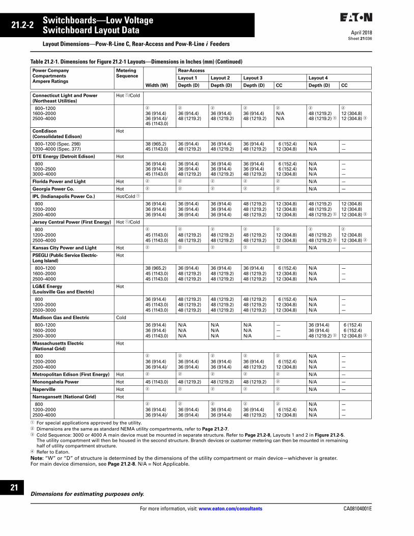
21.2-2
For more information, visit: www.eaton.com/consultants CA08104001E
April 2018
Switchboards—Low Voltage
Sheet 21
i
ii
1
2
3
4
5
6
7
8
9
10
11
12
13
14
15
16
17
18
19
20
21
Switchboard Layout DataLayout Dimensions—Pow-R-Line C, Rear-Access and Pow-R-Line i Feeders
036
Table 21.2-1. Dimensions for Figure 21.2-1 Layouts—Dimensions in Inches (mm) (Continued)
1 For special applications approved by the utility.2 Dimensions are the same as standard NEMA utility compartments, refer to Page 21.2-7.3 Cold Sequence: 3000 or 4000 A main device must be mounted in separate structure. Refer to Page 21.2-8, Layouts 1 and 2 in Figure 21.2-5.
The utility compartment will then be housed in the second structure. Branch devices or customer metering can then be mounted in remaining half of utility compartment structure.
4 Refer to Eaton.Note: “W” or “D” of structure is determined by the dimensions of the utility compartment or main device—whichever is greater. For main device dimension, see Page 21.2-8. N/A = Not Applicable.
Power Company
Compartments
Ampere Ratings
Metering
Sequence
Rear-Access
Layout 1 Layout 2 Layout 3 Layout 4
Width (W) Depth (D) Depth (D) Depth (D) CC Depth (D) CC
Connecticut Light and Power
(Northeast Utilities)
Hot 1/Cold
800–12001600–20002500–4000
2
36 (914.4)36 (914.4)/45 (1143.0)
2
36 (914.4)48 (1219.2)
2
36 (914.4)48 (1219.2)
2
36 (914.4)48 (1219.2)
2
N/AN/A
2
48 (1219.2)48 (1219.2) 3
2
12 (304.8)12 (304.8) 3
ConEdison
(Consolidated Edison)
Hot
800–1200 (Spec. 298)1200–4000 (Spec. 377)
38 (965.2)45 (1143.0)
36 (914.4)48 (1219.2)
36 (914.4)48 (1219.2)
36 (914.4)48 (1219.2)
6 (152.4)12 (304.8)
N/AN/A
——
DTE Energy (Detroit Edison) Hot
8001200–25003000–4000
36 (914.4)36 (914.4)45 (1143.0)
36 (914.4)36 (914.4)48 (1219.2)
36 (914.4)36 (914.4)48 (1219.2)
36 (914.4)36 (914.4)48 (1219.2)
6 (152.4)6 (152.4)
12 (304.8)
N/AN/AN/A
———
Florida Power and Light Hot 2 2 2 2 2 N/A —
Georgia Power Co. Hot 2 2 2 2 2 N/A —
IPL (Indianapolis Power Co.) Hot/Cold 1
8001200–20002500–4000
36 (914.4)36 (914.4)36 (914.4)
36 (914.4)36 (914.4)36 (914.4)
36 (914.4)36 (914.4)36 (914.4)
48 (1219.2)48 (1219.2)48 (1219.2)
12 (304.8)12 (304.8)12 (304.8)
48 (1219.2)48 (1219.2)48 (1219.2) 3
12 (304.8)12 (304.8)12 (304.8) 3
Jersey Central Power (First Energy) Hot 1/Cold
8001200–20002500–4000
2
45 (1143.0)45 (1143.0)
2
48 (1219.2)48 (1219.2)
2
48 (1219.2)48 (1219.2)
2
48 (1219.2)48 (1219.2)
2
12 (304.8)12 (304.8)
2
48 (1219.2)48 (1219.2) 3
2
12 (304.8)12 (304.8) 3
Kansas City Power and Light Hot 2 2 2 2 2 N/A —
PSEGLI (Public Service Electric-
Long Island)
Hot
800–12001600–20002500–4000
38 (965.2)45 (1143.0)45 (1143.0)
36 (914.4)48 (1219.2)48 (1219.2)
36 (914.4)48 (1219.2)48 (1219.2)
36 (914.4)48 (1219.2)48 (1219.2)
6 (152.4)12 (304.8)12 (304.8)
N/AN/AN/A
———
LG&E Energy
(Louisville Gas and Electric)
Hot
8001200–20002500–3000
36 (914.4)45 (1143.0)45 (1143.0)
48 (1219.2)48 (1219.2)48 (1219.2)
48 (1219.2)48 (1219.2)48 (1219.2)
48 (1219.2)48 (1219.2)48 (1219.2)
6 (152.4)12 (304.8)12 (304.8)
N/AN/AN/A
———
Madison Gas and Electric Cold
800–12001600–20002500–3000
36 (914.4)36 (914.4)45 (1143.0)
N/AN/AN/A
N/AN/AN/A
N/AN/AN/A
———
36 (914.4)36 (914.4)48 (1219.2) 3
6 (152.4) 6 (152.4)12 (304.8) 3
Massachusetts Electric
(National Grid)
Hot
8001200–20002500–4000
2
36 (914.4)36 (914.4)/
2
36 (914.4)36 (914.4)
2
36 (914.4)36 (914.4)
2
36 (914.4)48 (1219.2)
2
6 (152.4)12 (304.8)
N/AN/AN/A
———
Metropolitan Edison (First Energy) Hot 2 2 2 2 2 N/A —
Monongahela Power Hot 45 (1143.0) 48 (1219.2) 48 (1219.2) 48 (1219.2) 2 N/A —
Naperville Hot 2 2 2 2 2 N/A —
Narragansett (National Grid) Hot
8001200–20002500–4000
2
36 (914.4)36 (914.4)/
2
36 (914.4)36 (914.4)
2
36 (914.4)36 (914.4)
2
36 (914.4)48 (1219.2)
2
6 (152.4)12 (304.8)
N/AN/AN/A
———
Dimensions for estimating purposes only.

CA08104001E For more information, visit: www.eaton.com/consultants
21.2-3April 2018
Switchboards—Low Voltage
Sheet 21
i
ii
1
2
3
4
5
6
7
8
9
10
11
12
13
14
15
16
17
18
19
20
21
Switchboard Layout DataLayout Dimensions—Pow-R-Line C, Rear-Access, Group-Mounted Feeders and Pow-R-Line i
037
Incoming Utility Compartments and/or Main Devices (Continued)
Figure 21.2-2. Utility Compartment Layouts—Dimensions in Inches (mm)1 Dimensions are the same as standard NEMA utility compartments, refer to Page 21.2-7.2 Clear area assumes no floor channels used under bottom frame.3 If floor channels are present, this dimension is 6.00 (152.4).
Table 21.2-1. Dimensions for Figure 21.2-2 Layouts—Dimensions in Inches (mm) (Continued)
4 Cold Sequence: 3000 or 4000 A main device must be mounted in separate structure. Refer to Page 21.2-8, Layouts 1 and 2 in Figure 21.2-5. The utility compartment will then be housed in the second structure. Branch devices or customer metering can then be mounted in remaining half of utility compartment structure.
5 Dimensions are the same as standard NEMA utility compartments, refer to Page 21.2-7.6 For special applications approved by the utility.7 Refer to Eaton.8 For limiter lugs or more than six mechanical lugs per phase, a separate pull section is required.9 For limiter lugs or more than six mechanical lugs per phase, a 12.00-inch (304.8 mm) pull box is required.Note: “W” or “D” of structure is determined by the dimensions of the utility compartment or main device—whichever is greater. For main device dimensions, see Page 21.2-8. N/A = Not Applicable.
Power Company
Compartments
Ampere Ratings
Metering
Sequence
Rear-Access
Layout 1 Layout 2 Layout 3 Layout 4
Width (W) Depth (D) Depth (D) Depth (D) CC Depth (D) CC
New York State Electric and Gas Cold
800–12001600–20002500–4000
36 (914.4)36 (914.4)36 (914.4)
N/AN/AN/A
N/AN/AN/A
N/AN/AN/A
———
36 (914.4)48 (1219.2)48 (1219.2) 4
6 (152.4)6 (152.4)6 (152.4) 4
Niagara Mohawk (National Grid) Cold
800–12001600–20002500–4000
5
36 (914.4)36 (914.4)
N/AN/AN/A
N/AN/AN/A
N/AN/AN/A
———
5
36 (914.4)36 (914.4) 4
5
6 (152.4)6 (152.4) 4
Northeast Utilities Hot 6/Cold
800–12001600–20002500–4000
5
36 (914.4)36 (914.4)
5
36 (914.4)48 (1219.2)
5
36 (914.4)48 (1219.2)
5
48 (1219.2)48 (1219.2)
5
12 (304.8)12 (304.8)
5
48 (1219.2)48 (1219.2) 4
5
12 (304.8)12 (304.8) 4
XCEL (Northern States Power) Hot
800–12001600–25003000–4000
36 (914.4)36 (914.4)45 (1143.0)
36 (914.4)36 (914.4)48 (1219.2)
——36 (914.4)
36 (914.4)36 (914.4)48 (1219.2)
6 (152.4)6 (152.4)
12 (304.8)
N/AN/AN/A
———
Orange and Rockland Hot 5 5 5 5 5 N/A —
PPL (Pennsylvania Power and Light) Hot
800–4000 7 45 (1143.0) 48 (1219.2) 8 48 (1219.2) 9 54 (1371.6) 6 (152.4) N/A —
Exelon/PECO
(Philadelphia Electric Company)
Hot 5 5 5 5 5 N/A —
Dimensions for estimating purposes only.
Bottom Feed Top Feed Bottom or Top Feed Bottom or Top Feed
Layout 1 Layout 2 Layout 3 Layout 4
(Cold Sequence)
Blank
WD
Blank
WD
Main
WD
Main2500AmpMax.
WD
UtilityCompartment
ColdSequence
UtilityCompartmentHot Sequence
UtilityCompartmentHot Sequence
UtilityCompartmentHot Sequence
W
ClearAreaD
W
CCClear Area
2.50(63.5)
2.50(63.5)
3.00(76.2)
3.00(76.2)
3.00(76.2)
3.00(76.2)
� �
�
� �
Floor Plan
Layout 1
Floor Plan
Layouts 3 and 4
Note: Switchboards designed using these main structures require rear access for cable terminations. Refer to NEC Article 110-26 for requirements.

21.2-4
For more information, visit: www.eaton.com/consultants CA08104001E
April 2018
Switchboards—Low Voltage
Sheet 21
i
ii
1
2
3
4
5
6
7
8
9
10
11
12
13
14
15
16
17
18
19
20
21
Switchboard Layout DataLayout Dimensions—Pow-R-Line C, Rear-Access, Group-Mounted Feeders and Pow-R-Line i
038
Table 21.2-1. Dimensions for Figure 21.2-2 Layouts—Dimensions in Inches (mm) (Continued)
1 Dimensions are the same as standard NEMA utility compartments, refer to Page 21.2-7.2 For special applications approved by the utility.Note: “W” or “D” of structure is determined by the dimensions of the utility compartment or main device—whichever is greater. For main device dimensions, see Page 21.2-8. N/A = Not Applicable.Note: The following utilities have standardized on the National Electrical Manufacturers Association (NEMA) utility metering compartment standard. Refer to Page 21.1-8 for specific sizing and requirements. American Electric Power, Central Hudson Gas and Electric, Central Vermont, Consumers Power Company, Delmarva Power and Light, Georgia Power Company, Kansas City Power And Light, Orange and Rockland, Philadelphia Electric Company, Allegheny Power, Toledo Edison, Union Electric, Columbus Southern Power, Pennsylvania Electric Co. and Southern Maryland Electric Coop.
Power Company
Compartments
Ampere Ratings
Metering
Sequence
Rear-Access
Layout 1 Layout 2 Layout 3 Layout 4
Width (W) Depth (D) Depth (D) Depth (D) CC Depth (D) CC
PEPCO
(Potomac Electric Power Company)
Hot
800–20002500–4000800–3000
4000
36 (914.4)36 (914.4)36 (914.4)36 (914.4)
30 (762.0)36 (914.4)N/AN/A
N/AN/A36 (914.4)48 (1219.2)
N/AN/AN/AN/A
————
N/AN/AN/AN/A
————
XCEL Energy of Colorado Hot
8001200–25003000–4000
1
36 (914.4)45 (1143.0)
1
36 (914.4)48 (1219.2)
1
36 (914.4)48 (1219.2)
1
36 (914.4)48 (1219.2)
1
6 (152.4)12 (304.8)
N/AN/AN/A
———
PSEG
(Public Service Electric and Gas)
Hot
8001200–200025003000–4000
36 (914.4)45 (1143.0)45 (1143.0)45 (1143.0)
36 (914.4)48 (1219.2)48 (1219.2)48 (1219.2)
36 (914.4)48 (1219.2)48 (1219.2)48 (1219.2)
36 (914.4)48 (1219.2)48 (1219.2)48 (1219.2)
6 (152.4)12 (304.8)12 (304.8)12 (304.8)
N/AN/AN/AN/A
————
Public Service of New Hampshire Hot/Cold 2 1 1 1 1 1 N/A —
First Energy Toledo Edison Cold 1 1 1 1 1 N/A —
Ameren
(Union Electric)
Hot
800–4000 1 1 1 1 1 N/A N/A
Dominion
(Virginia Power Company)
Hot
800–12001600–20002500–4000
36 (914.4)45 (1143.0)45 (1143.0)
36 (914.4)36 (914.4)48 (1219.2)
36 (914.4)36 (914.4)48 (1219.2)
36 (914.4)48 (1219.2)48 (1219.2)
6 (152.4)12 (304.8)12 (304.8)
N/AN/AN/A
———
We Energies
(Wisconsin Electric Power Co.)
Hot
800–12001600–30004000
36 (914.4)36 (914.4)45 (1143.0)
36 (914.4)48 (1219.2)48 (1219.2)
36 (914.4)48 (1219.2)48 (1219.2)
36 (914.4)48 (1219.2)48 (1219.2)
6 (152.4)12 (304.8)12 (304.8)
N/AN/AN/A
———
Alliant Energy
(Wisconsin Power and Light)
Hot
800–12001600–20002500–3000
36 (914.4)36 (914.4)45 (1143.0)
36 (914.4)48 (1219.2)48 (1219.2)
36 (914.4)48 (1219.2)48 (1219.2)
48 (1219.2)48 (1219.2)48 (1219.2)
12 (304.8)12 (304.8)12 (304.8)
N/AN/AN/A
———
Wisconsin Public Service Corp. Hot
1000–4000 45 (1143.0) 36 (914.4) 36 (914.4) N/A — N/A —
Dimensions for estimating purposes only.

CA08104001E For more information, visit: www.eaton.com/consultants
21.2-5April 2018
Switchboards—Low Voltage
Sheet 21
i
ii
1
2
3
4
5
6
7
8
9
10
11
12
13
14
15
16
17
18
19
20
21
Switchboard Layout DataLayout Dimensions—Pow-R-Line C, Rear-Access, Group-Mounted Feeders and Pow-R-Line i
039
Incoming West Coast Utility CT Compartments and/or Main Devices
Figure 21.2-3. West Coast Utility Layouts—Dimensions in Inches (mm)1 Clear area assumes no floor channels used under bottom frame.2 If floor channels are present, this dimension is 6.00 (152.4).
Table 21.2-2. Dimensions for Figure 21.2-3 Layouts—Dimensions in Inches (mm)
3 Refer to Eaton.Note: “W” or “D” of structure is determined by the dimensions of the utility compartment or main device—whichever is greater. For main device dimensions, see Page 21.2-8. N/R = Not Required.
Power Company
Compartments
Ampere Ratings
Front- and Rear-Access
Layout 1 Layout 2 (Top Feed)
Top-Mounted Pull Box
(Bottom Feed)
Pull Section
Width (W) Depth (D) Width (W) Depth (D) Height (H) Width (W1)
West Coast UtilitiesE.U.S.E.R.C.
400–80010001200
36 (914.4)36 (914.4)38 (965.2)
24 (609.6)24 (609.6)30 (762.0)
36 (914.4)36 (914.4)38 (965.2)
24 (609.6)24 (609.6)30 (762.0)
N/R30 (762.0)36 (914.4)
30 (762.0)36 (914.4)36 (914.4)
160020002500
45 (1143.0)45 (1143.0)51 (1295.4)
30 (762.0)30 (762.0)36 (914.4)
38 (965.2)38 (965.2)38 (965.2)
30 (762.0)30 (762.0)30 (762.0)
36 (914.4)36 (914.4)36 (914.4)
45 (1143.0)45 (1143.0)51 (1295.4)
30004000
51 (1295.4)51 (1295.4)
36 (914.4)36 (914.4)
38 (965.2)51 (1295.4)
30 (762.0)36 (914.4)
36 (914.4)36 (914.4)
51 (1295.4)51 (1295.4)
Southern California Edison (S.C.E.)400600–800
1000
36 (914.4)36 (914.4)36 (914.4)
24 (609.6)24 (609.6)24 (609.6)
36 (914.4)36 (914.4)36 (914.4)
24 (609.6)24 (609.6)24 (609.6)
N/RN/R30 (762.0)
30 (762.0)30 (762.0)36 (914.4)
120016002000
38 (965.2)45 (1143.0)45 (1143.0)
30 (762.0)30 (762.0)30 (762.0)
38 (965.2)38 (965.2)38 (965.2)
30 (762.0)30 (762.0)30 (762.0)
36 (914.4)36 (914.4)36 (914.4)
36 (914.4)45 (1143.0)45 (1143.0)
250030004000
———
———
38 (965.2)38 (965.2)51 (1295.4)
30 (762.0)30 (762.0)36 (914.4)
36 (914.4)36 (914.4)36 (914.4)
51 (1295.4)51 (1295.4)51 (1295.4)
Los Angeles Department of Water and Power (L.A.D.W.P.)400600–800
1000
36 (914.4)36 (914.4)36 (914.4)
24 (609.6)24 (609.6)24 (609.6)
36 (914.4)36 (914.4)36 (914.4)
24 (609.6)24 (609.6)24 (609.6)
3
3
3
30 (762.0)30 (762.0)36 (914.4)
120016002000
38 (965.2)45 (1143.0)45 (1143.0)
30 (762.0)30 (762.0)30 (762.0)
38 (965.2)38 (965.2)38 (965.2)
30 (762.0)30 (762.0)30 (762.0)
3
3
3
36 (914.4)45 (1143.0)45 (1143.0)
250030004000
———
———
38 (965.2)38 (965.2)51 (1295.4)
30 (762.0)30 (762.0)36 (914.4)
3
3
3
51 (1295.4)51 (1295.4)51 (1295.4)
W
ClearAreaD
Blank
UtilityCompartmentHot Sequence
WD
PullSection
UtilityCompartmentHot Sequence
Main
WD
W1
HPull Box
W1
ClearArea
W
D
2.50(63.5)
2.50(63.5)
3.00(76.2)
3.00(76.2)
2.50(63.5)
2.50(63.5)
� �
� �
Bottom Feed Bottom or Top Feed
Layout 1 Layout 2
Floor Plan
Layout 1
Floor Plan
Layout 2
Note: Switchboards designed using these main structures require rear access for cable terminations. Refer to NEC Article 110-26 for requirements.
Dimensions for estimating purposes only.

21.2-6
For more information, visit: www.eaton.com/consultants CA08104001E
April 2018
Switchboards—Low Voltage
Sheet 21
i
ii
1
2
3
4
5
6
7
8
9
10
11
12
13
14
15
16
17
18
19
20
21
Switchboard Layout DataLayout Dimensions—Pow-R-Line C, Rear-Access, Group-Mounted Feeders and Pow-R-Line i
040
Table 21.2-2. Dimensions for Figure 21.2-3 Layouts—Dimensions in Inches (mm) (Continued)
Note: “W” or “D” of structure is determined by the dimensions of the utility compartment or main device—whichever is greater. For main device dimensions, see Page 21.2-8. N/R = Not Required.
Power Company
Compartments
Ampere Ratings
Front- and Rear-Access
Layout 1 Layout 2 (Top Feed)
Top-Mounted Pull Box
(Bottom Feed)
Pull Section
Width (W) Depth (D) Width (W) Depth (D) Height (H) Width (W1)
West Coast UtilitiesPacific Gas and Electric (P.G. and E.)
400–80010001200
36 (914.4)36 (914.4)38 (965.2)
24 (609.6)24 (609.6)30 (762.0)
36 (914.4)36 (914.4)38 (965.2)
24 (609.6)24 (609.6)30 (762.0)
N/R30 (762.0)36 (914.4)
30 (762.0)36 (914.4)36 (914.4)
160020002500
45 (1143.0)45 (1143.0)—
30 (762.0)30 (762.0)—
38 (965.2)38 (965.2)38 (965.2)
30 (762.0)30 (762.0)36 (914.4)
36 (914.4)36 (914.4)36 (914.4)
45 (1143.0)45 (1143.0)51 (1295.4)
30004000
——
——
38 (965.2)51 (1295.4)
36 (914.4)36 (914.4)
36 (914.4)36 (914.4)
51 (1295.4)51 (1295.4)
San Diego Gas and Electric (S.D.G. and E.)400–800
10001200
36 (914.4)36 (914.4)38 (965.2)
24 (609.6)24 (609.6)30 (762.0)
36 (914.4)36 (914.4)38 (965.2)
24 (609.6)24 (609.6)30 (762.0)
N/R30 (762.0)36 (914.4)
30 (762.0)36 (914.4)36 (914.4)
160020002500
45 (1143.0)45 (1143.0)—
30 (762.0)30 (762.0)—
38 (965.2)38 (965.2)38 (965.2)
30 (762.0)30 (762.0)30 (762.0)
36 (914.4)36 (914.4)36 (914.4)
45 (1143.0)45 (1143.0)51 (1295.4)
30004000
——
——
38 (965.2)51 (1295.4)
30 (762.0)36 (914.4)
36 (914.4)36 (914.4)
51 (1295.4)51 (1295.4)
Dimensions for estimating purposes only.

CA08104001E For more information, visit: www.eaton.com/consultants
21.2-7April 2018
Switchboards—Low Voltage
Sheet 21
i
ii
1
2
3
4
5
6
7
8
9
10
11
12
13
14
15
16
17
18
19
20
21
Switchboard Layout DataLayout Dimensions—Pow-R-Line C, Rear-Access, Group-Mounted Feeders and Pow-R-Line i
041
Incoming Standard (NEMA) Utility CT Compartment and/or Main Device
Figure 21.2-4. NEMA Utility Compartment Layouts—Dimensions in Inches (mm)1 Clear area assumes no floor channels used under front or rear frame members.2 IQ meter can be mounted to disconnect door as an alternate location for molded case circuit breakers and fixed-mounted power circuit breakers.
Table 21.2-3. Main Device Structure Size for Figure 21.2-4 Layouts
Dimensions for estimating purposes only. For metric conversion: inches x 25.4 = mm.
Cold Sequence UtilityHot Sequence Utility
Optional GFP
UtilityCompartmentHot Sequence
Main
WD
l
Optional GFP
UtilityCompartmentHot Sequence
Main
WD
l
Optional GFP
Main ¡
WD
Optional GFP
WD
UtilityCompartment
ColdSequence
UtilityCompartment
ColdSequence
Main ¡W
(Front)
D
Clear Area¿ CC
OptionalCustomerMetering
OptionalCustomerMetering
2.50(63.5)
3.00(76.2)
90.00(2286.0)
90.00(2286.0)
2.50(63.5) 3.00
(76.2)
Layout 1 Layout 2 Layout 3 Layout 4
Top Entrance Bottom EntranceFloor PlanTop Feed Bottom Feed
Note: Switchboards designed using these main structures require rear access for cable terminations. Refer to NEC Article 110-26 for requirements.
Note: Refer to Pages 21.1-15 to 21.6-6 for dimensions on special utility CT compartments.Note: See Pages 21.2-12 to 21.2-15 for layout of distribution sections. See Pages 21.4-1 and 21.4-2 for outdoor rainproof enclosures.
Main
Device
Max.
Amp.
Rating
Width
(W)
Depth
(D)
Min.
Cable
Space
CC
Fixed-Mounted Devices
Molded Case Breakers AvailableWith Optional Integral GFPKD, HKD, KDCLGS, LGH, LGC, LGULD, HLD, LDCMDL, HMDL
400600
600800
3636
3636
4848
4848
1212
1212
NG, NGH NGC
12002000
3636
4848
1212
RG, RGC 2500 36 48 12
100% Rated Molded Case BreakersAvailable with Optional Integral GFPCKD, CHKDCLD, HCLD, CLDC
400600600
363636
484848
121212
CMDL, CHMDLNG, NGH NGC
80012001200
363636
484848
121212
RG, RGCRG, RGC
16002000
3636
4848
1212
TRI-PAC Fuse Type Current Limiting BreakersLA-PNB-PPB-P
400800
1600
363636
484848
121212
Note: Top-mounted pull boxes are available with heights of 12.00, 18.00, 24.00 and 30.00 inches (304.8, 457.2, 609.6 and 762.0 mm).
Main
Device
Max.
Amp.
Rating
Width
(W)
Depth
(D)
Min.
Cable
Space
CC
Fixed-Mounted Devices
100% Rated Insulated Case Circuit BreakersAvailable with Optional Integral GFPMagnum SB, DS 4
800160020003000 34000 3
3636364545
4848484848
1212121212
100% Rated Power Circuit BreakersAvailable with Optional Integral GFPMagnum DSX
800160020003000 34000 3
3636364545
4848484848
1212121212
Fusible Switches400600800
1200
400600800
1200
36363636
48484848
12121212
100% Rated Electric Trip Bolted Pressure SwitchesAvailable with Optional GFPCBC-800CBC-1200CBC-1600CBC-2000CBC-2500CBC-3000CBC-4000
80012001600200025003000 34000 3
36363636454545
48484848484848
12121212121212
3 Layout 1.4 Magnum DS power circuit breakers used
as feeder devices have been qualified by Eaton and third-party witness tested for 30-cycle withstand. 30-cycle withstand is not recognized by UL 891.
Main
Device
Max.
Amp.
Rating
Width
(W)
Depth
(D)
Min.
Cable
Space
CC
Fixed-Mounted Devices
100% Rated Manual Bolted Pressure SwitchesNot Available with Ground Fault ProtectionQA-800QA-1200QA-1600QA-2000QA-2500QA-3000QA-4000
80012001600200025003000 34000 3
36363636454545
48484848484848
12121212121212
Drawout-Mounted Devices
100% Rated Insulated Case Circuit Breakers Available with Optional Integral GFPMagnum SB, DS 4
800160020003000 34000 3
3636364545
5454546666
6 6 61818
100% Rated Power Circuit Breakers Available with Optional Integral GFPMagnum DSX
800160020003000 34000 3
3636364545
5454546666
6 6 61818

21.2-8
For more information, visit: www.eaton.com/consultants CA08104001E
April 2018
Switchboards—Low Voltage
Sheet 21
i
ii
1
2
3
4
5
6
7
8
9
10
11
12
13
14
15
16
17
18
19
20
21
Switchboard Layout DataLayout Dimensions—Pow-R-Line C, Rear-Access and Group-Mounted Feeders
042
Main Structure—With Customer Metering and/or Main Device
Figure 21.2-5. Main Section Layouts—Dimensions in Inches (mm)1 Customer metering with IQ Meter requires
30.00-inch (762.0 mm) minimum width.2 Not available with bottom fed TRI-PAC
breaker.3 Clear area assumes no floor channels used
under front or rear frame members.
Table 21.2-4. Main Device Structure Size for Figure 21.2-5 Layouts
Optional G, F, P
Main
WD
OptionalCustomer
Metering �
4000AMax.
�
Optional GFP
Main
WD
l
90.00(2286.0)
Optional GFP
Main
WD
l
D
Clear Area� CC
W(Front)
48 (1219.2)Min.36 (914.4)
Min.
Optional GFP
Main2500AMax.
FeederDevice
2500A Max.
ll
l
D
22XDist.
Classis
Optional GFP
Main2500AMax.
ll
2.50(63.5)
3.00(76.2)
36 (914.4)Min.
OptionalCustomer
Metering �
OptionalCustomer
Metering �
2.50(63.5) 3.00
(76.2)
Top or Bottom
Entrance Top Mounted
Main Bottom
Mounted Feeder
Top Entrance
Bottom Mounted
Main Load
Cross Bus
Bottom Entrance
Bottom Mounted
Main Load
Cross Bus
Top or Bottom
Entrance Top
Mounted Main with
Distribution Chassis
Top or Bottom
Entrance
Mid Mounted
Main Cable Exit
Floor Plan
Layout 1 Layout 2 Layout 3 Layout 4 Layout 5
Note: Switchboards designed using these main structures require rear access for cable terminations. Refer to NEC Article 110-26 for requirements.
Dimensions for estimating purposes only. For metric conversion: inches x 25.4 = mm.
Main
Device
Max
Amp
Rat-
ing
Min. Width
(W)
Min.
Depth
(D)
Min.
Cable
Space
CCZero
Seq.
GFP
Inte-
gral
GFP
or W/
No
GFP
Fixed-Mounted Devices
Molded Case BreakersAvailable with Optional Integral GFPKD, HKD,KDCLGS, LGH, LGC, LGU
400
600
30
30
26 30
30
12
12
LD, HLD,LDC
600 30 26 30 12
MDL, HMDL 800 30 26 30 12NG, NGH, NGC
1200 30 26 30 12
RG, RGCRG, RGCRG, RGC
160020002500
363636
262626
484848
181818
100% Rated Molded Case BreakersAvailable with Optional Integral GFPCKD, CHKD 400 30 26 30 12CLD, HCLD,CLDC
600 30 26 30 12
CMDL,CHMDL
800 30 26 30 12
NG, NGH 1200 30 26 30 12RG, RGC, NGCRG, RGC
16002000
3030
2626
4848
1818
TRI-PAC Fuse Type Current Limiting BreakersLA-PNB-PPB-P
400 8001600
303030
262626
303036
121218
Note: See Pages 21.2-12 to 21.2-15 for layout of distribution sections. See Pages 21.4-1 and 21.4-2 for outdoor rainproof enclosures.Note: Top-mounted pull boxes are available with heights of 12.00, 18.00, 24.00 and 30.00 inches (304.8, 457.2, 609.6 and 762.0 mm).
Main
Device
Max.
Amp.
Rating
Min.
Width
(W)
Min.
Depth
(D)
Min.
Cable
Space
CC
Fixed-Mounted Devices
100% Rated Insulated Case Circuit BreakersAvailable with Optional Integral GFPMagnum DS, SB 7
80016002000300040005000
363636363645
364848484848
618181812—
100% Rated Power Circuit BreakersAvailable with Optional Integral GFPMagnum DSX
80016002000300040005000
363636454545
364848484848
618181812—
Fusible Switches400600800
1200
400600800
1200
30303030
30303030
12121212
100% Rated Electric Trip Bolted Pressure SwitchesAvailable with Optional GFPCBC-800CBC-1200CBC-1600CBC-2000CBC-2500CBC-3000CBC-4000
800120016002000250030004000
36363636454545
36 536 536 536 5484848
12121212181812
CBC-5000 6 5000 Refer to Eaton
4 Refer to Eaton.5 Bottom feed switch structure is 48.00 inches
(1219.2 mm) minimum.6 Not UL listed.7 Magnum DS power circuit breakers used
as feeder devices have been qualified by Eaton and third-party witness tested for 30-cycle withstand. 30-cycle withstand is not recognized by UL 891.
Main
Device
Max.
Amp.
Rating
Min.
Width
(W)
Min.
Depth
(D)
Min.
Cable
Space
CC
Fixed-Mounted Devices
100% Rated Manual Bolted Pressure SwitchesNot Available with Ground Fault ProtectionQA-800QA-1200QA-1600QA-2000QA-2500QA-3000QA-4000
800120016002000250030004000
30303030364545
36363636484848
12121212181812
QA-5000 6 5000 Refer to Eaton
Drawout-Mounted Devices
100% Rated Insulated Case Circuit BreakersAvailable with Optional Integral GFPMagnum DS, SB 7
80016002000300040005000
363636363645
5454546666—
666
1818—
100% Rated Power Circuit BreakersAvailable with Optional Integral GFPMagnum DSX
80016002000300040005000
363636454545
5454546666—
666
1818—

CA08104001E For more information, visit: www.eaton.com/consultants
21.2-9April 2018
Switchboards—Low Voltage
Sheet 21
i
ii
1
2
3
4
5
6
7
8
9
10
11
12
13
14
15
16
17
18
19
20
21
Switchboard Layout DataLayout Dimensions—Rear-Access, Group-Mounted Feeders and Pow-R-Line i
043
Main Structure—With Customer Metering and/or Main Device
Figure 21.2-6. Main Section Layouts—Dimensions in Inches (mm)1 Customer metering with IQ Meter requires
30.00-inch (762.0 mm) minimum width.2 Not available with bottom fed TRI-PAC
breaker.3 Clear area assumes no floor channels used
under front or rear frame members.
Table 21.2-5. Main Device Structure Size for Figure 21.2-5 Layouts
Optional G, F, P
Main
WD
OptionalCustomer
Metering �
4000AMax.
�
Optional GFP
Main
WD
l
90.00(2286.0)
Optional GFP
Main
WD
l
D
Clear Area� CC
W(Front)
48 (1219.2)Min.36 (914.4)
Min.
Optional GFP
Main2500AMax.
FeederDevice
2500A Max.
ll
l
D
22XDist.
Classis
Optional GFP
Main2500AMax.
ll
2.50(63.5)
3.00(76.2)
36 (914.4)Min.
OptionalCustomer
Metering �
OptionalCustomer
Metering �
2.50(63.5) 3.00
(76.2)
Top or Bottom
Entrance Top Mounted
Main Bottom
Mounted Feeder
Top Entrance
Bottom Mounted
Main Load
Cross Bus
Bottom Entrance
Bottom Mounted
Main Load
Cross Bus
Top or Bottom
Entrance Top
Mounted Main with
Distribution Chassis
Top or Bottom
Entrance
Mid Mounted
Main Cable Exit
Floor Plan
Layout 1 Layout 2 Layout 3 Layout 4 Layout 5
Note: Switchboards designed using these main structures require rear access for cable terminations. Refer to NEC Article 110-26 for requirements.
Dimensions for estimating purposes only. For metric conversion: inches x 25.4 = mm.
Main
Device
Max
Amp
Rat-
ing
Min. Width
(W)
Min.
Depth
(D)
Min.
Cable
Space
CCZero
Seq.
GFP
Inte-
gral
GFP
or W/
No
GFP
Fixed-Mounted Devices
Molded Case BreakersAvailable with Optional Integral GFPKD, HKD,KDCLGS, LGH, LGC, LGU
400
600
30
30
26 48
48
30
30
LD, HLD,LDC
600 30 26 48 30
MDL, HMDL 800 30 26 48 30NG, NGH 1200 30 26 48 30RG, RGCRG, RGCRG, RGC
160020002500
363636
262626
484848
181818
100% Rated Molded Case BreakersAvailable with Optional Integral GFPCKD, CHKD 400 30 26 48 30CLD, HCLD,CLDC
600 30 26 48 30
CMDL,CHMDL
800 30 26 48 30
NG, NGH 1200 30 26 30 12RG, RGCRG, RGC
16002000
3030
2626
4848
1818
TRI-PAC Fuse Type Current Limiting BreakersLA-PNB-PPB-P
400 8001600
303030
262626
303036
121218
Note: See Pages 21.2-12 to 21.2-15 for layout of distribution sections. See Pages 21.4-1 and 21.4-2 for outdoor rainproof enclosures.Note: Top-mounted pull boxes are available with heights of 12.00, 18.00, 24.00 and 30.00 inches (304.8, 457.2, 609.6 and 762.0 mm).
Main
Device
Max.
Amp.
Rating
Min.
Width
(W)
Min.
Depth
(D)
Min.
Cable
Space
CC
Fixed-Mounted Devices
100% Rated Insulated Case Circuit BreakersAvailable with Optional Integral GFPMagnum DS, SB
80016002000300040005000
363636363645
484848484848
1818181812—
100% Rated Power Circuit BreakersAvailable with Optional Integral GFPMagnum DSX
80016002000300040005000
363636454545
484848484848
1818181812—
Fusible Switches400600800
1200
400600800
1200
30303030
48484848
30303030
100% Rated Electric Trip Bolted Pressure SwitchesAvailable with Optional GFPCBC-800CBC-1200CBC-1600CBC-2000CBC-2500CBC-3000CBC-4000
800120016002000250030004000
36363636454545
48 548 548 548 5484848
24242424121212
CBC-5000 6 5000 Refer to Eaton
4 Refer to Eaton.5 Bottom feed switch structure is 48.00 inches
(1219.2 mm) minimum.6 Not UL listed.7 Magnum DS power circuit breakers used
as feeder devices have been qualified by Eaton and third-party witness tested for 30-cycle withstand. 30-cycle withstand is not recognized by UL 891.
Main
Device
Max.
Amp.
Rating
Min.
Width
(W)
Min.
Depth
(D)
Min.
Cable
Space
CC
Fixed-Mounted Devices
100% Rated Manual Bolted Pressure SwitchesNot Available with Ground Fault ProtectionQA-800QA-1200QA-1600QA-2000QA-2500QA-3000QA-4000
800120016002000250030004000
30303030364545
48484848484848
24242424121212
QA-5000 6 5000 Refer to Eaton
Drawout-Mounted Devices
100% Rated Insulated Case Circuit BreakersAvailable with Optional Integral GFPMagnum DS, SB 7
80016002000300040005000
363636363645
5454546666—
666
1818—
100% Rated Power Circuit BreakersAvailable with Optional Integral GFPMagnum DSX
80016002000300040005000
363636454545
5454546666—
666
1818—

21.2-10
For more information, visit: www.eaton.com/consultants CA08104001E
April 2018
Switchboards—Low Voltage
Sheet 21
i
ii
1
2
3
4
5
6
7
8
9
10
11
12
13
14
15
16
17
18
19
20
21
Switchboard Layout DataLayout Dimensions—Pow-R-Line C, Rear-Access, Group-Mounted Feeders
044
Individually Mounted Feeder Devices
Figure 21.2-7. Individually Mounted Feeder Layouts—Dimensions in Inches (mm)1 When using top-mounted (bottom feed) inverted bolted switches, verify acceptance with code authorities.2 For Layout 2, width will be 36.00 or 45.00 inches (914.4 or 1143.0 mm) depending on size of panel mounting devices. Refer to Page 21.2-12.
Table 21.2-6. Stacked Distribution Structure Sizes for Figure 21.2-7 Layouts 1 and 2—Dimensions in Inches (mm) 3
3 Structure size determined by device requiring largest width and depth.4 Magnum DS power circuit breakers used as feeder devices have
been qualified by Eaton and third-party witness tested for 30-cycle withstand. 30-cycle withstand is not recognized by UL 891.
Table 21.2-7. Stacked Distribution Structure Sizes for Figure 21.2-7 Layout 3 Only—Dimensions in Inches (mm)
5 Magnum DS power circuit breakers used as feeder devices have been qualified by Eaton and third-party witness tested for 30-cycle withstand. 30-cycle withstand is not recognized by UL 891.
Note: See Pages 21.2-12 to 21.2-15 for layout of distribution sections.See Pages 21.4-1 and 21.4-2 for outdoor rainproof enclosures.Note: Top-mounted pull boxes are available with heights of 12, 18, 24 and 30 inches (304.8, 457.2, 609.6 and 762.0 mm).
D36, 45
(914.4, 1143.0)
22XPanelSpace
Optional GFP
l
l
l
DW
Optional GFP
l
DW
W(Front)
D
CCClear Area�
�
2.50(63.5)
3.00(76.2)
2.50(63.5)
3.00(76.2)
Layout 1 Layout 2 Layout 3
Floor Plan
Note: Switchboards designed using these distribution structures require rear access for cable terminations. Refer to NEC Article 110-26 for requirements.
Feeder
Device
Max.
Amp.
Rating
Zero Sequence
GFP
No GFP or with
Integral GFP
Minimum
Cable
Space
CCMinimum Minimum
Width
(W)
Depth
(D)
Width
(W)
Depth
(D)
Fixed-Mounted Devices
Molded Case BreakersRG, RGCRG, RGCRG, RGC
160020002500
30 (762.0)30 (762.0)30 (762.0)
48 (1219.2)48 (1219.2)54 (1371.6)
26 (660.4)26 (660.4)26 (660.4)
48 (1219.2)48 (1219.2)48 (1219.2)
12 (304.8)12 (304.8)12 (304.8)
100% Rated Insulated Case Circuit Breakers Available with Optional Integral GFPMagnumSB, DS 4
80016002000
36 (914.4)36 (914.4)36 (914.4)
48 (1219.2)48 (1219.2)48 (1219.2)
36 (914.4)36 (914.4)36 (914.4)
48 (1219.2)48 (1219.2)48 (1219.2)
18 (457.2)18 (457.2)18 (457.2)
100% Rated Insulated Case Circuit Breakers Available with Optional Integral GFPMagnumDSX
80016002000
36 (914.4)36 (914.4)36 (914.4)
48 (1219.2)48 (1219.2)48 (1219.2)
36 (914.4)36 (914.4)36 (914.4)
48 (1219.2)48 (1219.2)48 (1219.2)
18 (457.2)18 (457.2)18 (457.2)
100% Rated Electric Trip Bolted Pressure SwitchesCBC-800CBC-1200CBC-1600CBC-2000CBC-2500
8001200160020002500
36 (914.4)36 (914.4)36 (914.4)36 (914.4)45 (1143.0)
48 (1219.2)48 (1219.2)48 (1219.2)48 (1219.2)48 (1219.2)
36 (914.4)36 (914.4)36 (914.4)36 (914.4)36 (914.4)
48 (1219.2)48 (1219.2)48 (1219.2)48 (1219.2)48 (1219.2)
12 (304.8)12 (304.8)12 (304.8)12 (304.8)12 (304.8)
100% Rated Manual Bolted Pressure SwitchesNot Available with Ground Fault ProtectionQA-800QA-1200QA-1600QA-2000QA-2500
8001200160020002500
—————
—————
30 (762.0)30 (762.0)30 (762.0)30 (762.0)36 (914.4)
48 (1219.2)48 (1219.2)48 (1219.2)48 (1219.2)48 (1219.2)
12 (304.8)12 (304.8)12 (304.8)12 (304.8)12 (304.8)
Dimensions for estimating purposes only.
Feeder
Device
Maximum
Ampere
Rating
No GFP or with
Integral GFP
Minimum
Cable
Space
CCMinimum
Width
(W)
Depth
(D)
Fixed-Mounted Devices
100% Rated Insulated Case Circuit Breakers Available with Optional Integral GFPMagnum SB, DS 4 800 36 (914.4) 36 (914.4) 6 (152.4)
100% Rated Insulated Case Circuit Breakers Available with Optional Integral GFPMagnum DSX 800 36 (914.4) 36 (914.4) 6 (152.4)
100% Rated Manual Bolted Pressure SwitchesNot Available with Ground Fault ProtectionQA-800 800 30 (762.0) 48 (1219.2) 12 (304.8)

CA08104001E For more information, visit: www.eaton.com/consultants
21.2-11April 2018
Switchboards—Low Voltage
Sheet 21
i
ii
1
2
3
4
5
6
7
8
9
10
11
12
13
14
15
16
17
18
19
20
21
Switchboard Layout DataLayout Dimensions—Rear-Access, Group-Mounted Feeders and Pow-R-Line i
045
Individually Mounted Feeder Devices
Figure 21.2-8. Individually Mounted Feeder Layouts—Dimensions in Inches (mm)1 When using top-mounted (bottom feed) inverted bolted switches, verify acceptance with code authorities.2 For Layout 2, width will be 36.00 or 45.00 inches (914.4 or 1143.0 mm) depending on size of panel mounting devices. Refer to Page 21.2-12.
Table 21.2-8. Stacked Distribution Structure Sizes for Figure 21.2-7 Layouts 1 and 2—Dimensions in Inches (mm) 3
3 Structure size determined by device requiring largest width and depth.4 Magnum DS power circuit breakers used as feeder devices have
been qualified by Eaton and third-party witness tested for 30-cycle withstand. 30-cycle withstand is not recognized by UL 891.
Table 21.2-9. Stacked Distribution Structure Sizes for Figure 21.2-7 Layout 3 Only—Dimensions in Inches (mm)
5 Magnum DS power circuit breakers used as feeder devices have been qualified by Eaton and third-party witness tested for 30-cycle withstand. 30-cycle withstand is not recognized by UL 891.
Note: See Pages 21.2-12 to 21.2-15 for layout of distribution sections.See Pages 21.4-1 and 21.4-2 for outdoor rainproof enclosures.Note: Top-mounted pull boxes are available with heights of 12, 18, 24 and 30 inches (304.8, 457.2, 609.6 and 762.0 mm).
D36, 45
(914.4, 1143.0)
22XPanelSpace
Optional GFP
l
l
l
DW
Optional GFP
l
DW
W(Front)
D
CCClear Area�
�
2.50(63.5)
3.00(76.2)
2.50(63.5)
3.00(76.2)
Layout 1 Layout 2 Layout 3
Floor Plan
Note: Switchboards designed using these distribution structures require rear access for cable terminations. Refer to NEC Article 110-26 for requirements.
Feeder
Device
Max.
Amp.
Rating
Zero Sequence
GFP
No GFP or with
Integral GFP
Minimum
Cable
Space
CCMinimum Minimum
Width
(W)
Depth
(D)
Width
(W)
Depth
(D)
Fixed-Mounted Devices
Molded Case BreakersRGRGRG
160020002500
30 (762.0)30 (762.0)30 (762.0)
48 (1219.2)48 (1219.2)54 (1371.6)
26 (660.4)26 (660.4)26 (660.4)
48 (1219.2)48 (1219.2)48 (1219.2)
12 (304.8)12 (304.8)12 (304.8)
100% Rated Insulated Case Circuit Breakers AvailableMagnumSB
80016002000
30 (762.0)30 (762.0)30 (762.0)
48 (1219.2)48 (1219.2)48 (1219.2)
26 (660.4)26 (660.4)26 (660.4)
48 (1219.2)48 (1219.2)48 (1219.2)
12 (304.8)12 (304.8)12 (304.8)
100% Rated Power Circuit BreakerMagnumDS 4
80016002000
30 (762.0)30 (762.0)30 (762.0)
48 (1219.2)48 (1219.2)48 (1219.2)
26 (660.4)26 (660.4)26 (660.4)
48 (1219.2)48 (1219.2)48 (1219.2)
12 (304.8)12 (304.8)12 (304.8)
100% Rated Electric Trip Bolted Pressure SwitchesCBC-800CBC-1200CBC-1600CBC-2000CBC-2500
8001200160020002500
36 (914.4)36 (914.4)36 (914.4)36 (914.4)45 (1143.0)
48 (1219.2)48 (1219.2)48 (1219.2)48 (1219.2)48 (1219.2)
36 (914.4)36 (914.4)36 (914.4)36 (914.4)36 (914.4)
48 (1219.2)48 (1219.2)48 (1219.2)48 (1219.2)48 (1219.2)
12 (304.8)12 (304.8)12 (304.8)12 (304.8)12 (304.8)
100% Rated Manual Bolted Pressure SwitchesNot Available with Ground Fault ProtectionQA-800QA-1200QA-1600QA-2000QA-2500
8001200160020002500
—————
—————
30 (762.0)30 (762.0)30 (762.0)30 (762.0)36 (914.4)
48 (1219.2)48 (1219.2)48 (1219.2)48 (1219.2)48 (1219.2)
12 (304.8)12 (304.8)12 (304.8)12 (304.8)12 (304.8)
Dimensions for estimating purposes only.
Feeder
Device
Maximum
Ampere
Rating
No GFP or with
Integral GFP
Minimum
Cable
Space
CCMinimum
Width
(W)
Depth
(D)
Fixed-Mounted Devices
100% Rated Insulated Case Circuit Breakers Available with Optional Integral GFPMagnum SB 800 30 (762.0) 48 (1219.2) 12 (304.8)
100% Rated Insulated Case Circuit Breakers Available with Optional Integral GFPMagnum DS 4 800 30 (762.0) 48 (1219.2) 12 (304.8)
100% Rated Manual Bolted Pressure SwitchesNot Available with Ground Fault ProtectionQA-800 800 30 (762.0) 48 (1219.2) 12 (304.8)

21.2-12
For more information, visit: www.eaton.com/consultants CA08104001E
April 2018
Switchboards—Low Voltage
Sheet 21
i
ii
1
2
3
4
5
6
7
8
9
10
11
12
13
14
15
16
17
18
19
20
21
Switchboard Layout DataLayout Dimensions—Pow-R-Line C, Rear-Access, Group-Mounted Feeders
046
Distribution Sections—Group-Mounted Devices
Figure 21.2-9. Distribution Section Layout—Dimensions in Inches (mm)1 Busway connection can be either incoming service to structure or exiting load from a feeder breaker. Increased depth will be required.2 For panels rated above 2000 A, minimum depth is 24.00 inches (609.6 mm).3 Clear area assumes no floor channels used under bottom frame.
Table 21.2-10. Pow-R-Line C
36.00 (914.4)Minimum
22XDeviceSpace
UtilityCompartment
orBlank
38XVerticalPanelSpace
forDevices
Busway �Connection
90.00(2286.0)
30.00 (762.0) �Minimum
36, 45(914.4, 1143.0)
50XVerticalPanelSpace
forDevices
D ClearArea�
W(Front)
2.50(63.5)
2.50(63.5)
3.00(76.2)
3.00(76.2)
90.00(2286.0)
90.00(2286.0)
30.00 (762.0) �Minimum 36, 45
(914.4, 1143.0)36, 45
(914.4, 1143.0)
CC
See Distribution Layout Guides for structure width and for feeder device “X” requirements on Pages 21.2-14 and 21.2-15.
Layout 1
Maximum 2000 Amperes
CT Compartment
Combination Section
Layout 2
Busway Connection
Layout 3
Full Distribution Section
Floor Plan
Minimum
Depth D)
2000 A or Less Above 2000 A
Minimum
Cable
Space
CC
Minimum
Cable
Space
CC
30 (762.0)36 (914.4)48 (1219.2)54 (1371.6)66 (1676.4)
10 (254.0)16 (406.4)28 (711.2)34 (863.6)46 (1168.4)
4 (101.6)10 (254.0)22 (558.8)28 (711.2)40 (1016.0)
Dimensions for estimating purposes only.

CA08104001E For more information, visit: www.eaton.com/consultants
21.2-13April 2018
Switchboards—Low Voltage
Sheet 21
i
ii
1
2
3
4
5
6
7
8
9
10
11
12
13
14
15
16
17
18
19
20
21
Switchboard Layout DataLayout Dimensions—Pow-R-Line i, Rear-Access and Group-Mounted Feeders
047
Distribution Sections—Group-Mounted Devices
Figure 21.2-10. Distribution Section Layout—Dimensions in Inches (mm)1 Busway connection can be either incoming service to structure or exiting load from a feeder breaker. Increased depth will be required.2 For panels rated above 2000 A, minimum depth is 24.00 inches (609.6 mm).3 Clear area assumes no floor channels used under bottom frame.
Table 21.2-11. Pow-R-Line i
48.00 (1219.2)Minimum
22XDeviceSpace
UtilityCompartment
orBlank
38XVerticalPanelSpace
forDevices
Busway �Connection
90.00(2286.0)
48.00 (1219.2)Minimum
36, 45(914.4, 1143.0)
50XVerticalPanelSpace
forDevices
D Clear Area�
W(Front)
2.50(63.5)
2.50(63.5)
3.00(76.2)
3.00(76.2)
90.00(2286.0)
90.00(2286.0)
48.00 (1219.2)Minimum36, 45
(914.4, 1143.0)36, 45
(914.4, 1143.0)
CC
See Distribution Layout Guides for structure width and for feeder device “X” requirements on Pages 21.2-14 and 21.2-15.
Layout 1
Maximum 2000 Amperes
CT Compartment
Combination Section
Layout 2
Busway Connection
Layout 3
Full Distribution Section
Floor Plan
Minimum Depth D) 4000 A Maximum
Minimum Cable
Space CC
48 (1219.2)54 (1371.6)66 (1676.4)
18 (457.2)54 (1371.6)66 (1676.4)
Dimensions for estimating purposes only.

21.2-14
For more information, visit: www.eaton.com/consultants CA08104001E
April 2018
Switchboards—Low Voltage
Sheet 21
i
ii
1
2
3
4
5
6
7
8
9
10
11
12
13
14
15
16
17
18
19
20
21
Switchboard Layout DataLayout Dimensions—Pow-R-Line C, Rear-Access, Group-Mounted Feeders
048
Distribution Layout Guide—Molded Case Breakers
Figure 21.2-11. Circuit Breaker “X” Space Requirement—Dimensions in Inches (mm)1 Preferred location of SPD is mounted at top of first distribution section.2 100% rated breakers.3 For use on direct current (DC) systems only.Note: For breaker interrupting ratings and terminal data, see Tab 26.
36-in
ch (9
14.4
mm
) Wid
e S
truc
ture
1X
2X
1P 1P
2P 2P
3P 3P
2P 2P
3P 3P
2 or 3P
Filler
Surge Protective DeviceSPD
2 or 3P
2 or 3P
Load
2 or 3P 2 or 3P
2 or 3P 2 or 3P
2 or 3P
2 or 3P
2 or 3P 2 or 3P
2 or 3P
Breaker may be used as main.
45-in
ch (1
143.
0 m
m)
Wid
e S
truc
ture
1X
11X
3X
2X
3X
3X
6X
3X
3X
6X
6X
4X
6X
CustomerMetering
7Xor10X
4X
FrameMaximumAmperes
600
1200
400
225
250
400
100
250
800
1200
Breaker to FusibleTransition, All Widths
Surge Protective Device SPD7X through 200 kA10X at 250–400 kA
EHD
FDB, FD, HFD, FDC, FDE, HFDE, FDCE,
EDB, EDS, ED, EDH,EDC, FD, HFD, FDC, FDE, HFDE, FDCE
JD, HJD, JDC, HJDDC
DK, KD, HKD, LHHKDC, CKD , CHKD , HKDDC
LD, HLD, LDC,CLD , CHLD , CLDC
FB-P
JD, HJD, JDC
LA-P, NHH
MDL, HMDL,CMDL , CHMDL
ND, HND,NDC
DK, KD,HKD, KDC
NB-P
NG , NGH , NGC
Customer Metering
100
150
400
800
2 or 3P 4X 600 LGE, LGH, LGC, LGU
, HLDDC
, HMDLDC
, NBDC
HFDDC
1X = 1-3/8 inches(39.4 mm)
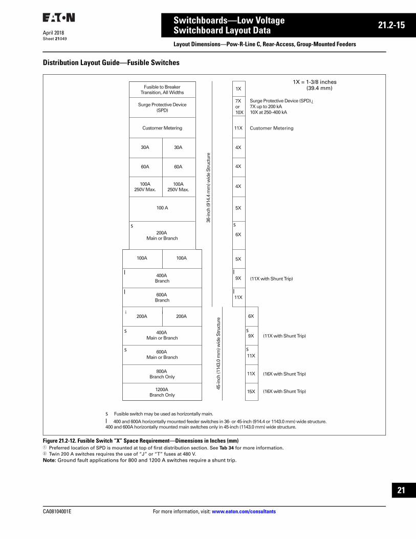
CA08104001E For more information, visit: www.eaton.com/consultants
21.2-15April 2018
Switchboards—Low Voltage
Sheet 21
i
ii
1
2
3
4
5
6
7
8
9
10
11
12
13
14
15
16
17
18
19
20
21
Switchboard Layout DataLayout Dimensions—Pow-R-Line C, Rear-Access, Group-Mounted Feeders
049
Distribution Layout Guide—Fusible Switches
Figure 21.2-12. Fusible Switch “X” Space Requirement—Dimensions in Inches (mm) 1 Preferred location of SPD is mounted at top of first distribution section. See Tab 34 for more information.2 Twin 200 A switches requires the use of “J” or “T” fuses at 480 V.Note: Ground fault applications for 800 and 1200 A switches require a shunt trip.
Fusible to BreakerTransition, All Widths
100A250V Max.
s
l
l
s
s
l
l
s
s
100A 250V Max.
60A 60A
30A 30A
100 A
200A Main or Branch
100A 100A
400A Branch
600A Branch
400A Main or Branch
800A Branch Only
600AMain or Branch
1200A Branch Only
200A 200A
1X
4X
4X
4X
5X
6X
5X
9X
11X
6X
9X
11X
11X
15X (16X with Shunt Trip)
(16X with Shunt Trip)
s
Surge Protective Device(SPD)
Customer Metering11XCustomer Metering
Surge Protective Device (SPD)7X up to 200 kA10X at 250–400 kA
¿7X or 10X
s Fusible switch may be used as horizontally main.
l 400 and 600A horizontally mounted feeder switches in 36- or 45-inch (914.4 or 1143.0 mm) wide structure. 400 and 600A horizontally mounted main switches only in 45-inch (1143.0 mm) wide structure.
36-in
ch (9
14.4
mm
) wid
e S
truc
ture
45-in
ch (1
143.
0 m
m) w
ide
Str
uctu
re
¡ ¡
(11X with Shunt Trip)
(11X with Shunt Trip)
1X = 1-3/8 inches(39.4 mm)

21.2-16
For more information, visit: www.eaton.com/consultants CA08104001E
April 2018
Switchboards—Low Voltage
Sheet 21
i
ii
1
2
3
4
5
6
7
8
9
10
11
12
13
14
15
16
17
18
19
20
21
050
This page intentionally left blank.

CA08104001E For more information, visit: www.eaton.com/consultants
21.3-1April 2018
Switchboards—Low Voltage
Sheet 21
i
ii
1
2
3
4
5
6
7
8
9
10
11
12
13
14
15
16
17
18
19
20
21
Switchboard Layout DataLayout Dimensions—Pow-R-Line i, Rear-Access, Compartmentalized Feeders
051
Distribution Layout Guide—Circuit Breakers
Figure 21.3-1. Individually Compartmentalized Feeder Layout 36.00-Inch (914.4 mm) Wide Section 50X Structure Only (4000 A Maximum)1 Unused bus space to be located in Zone A when possible.2 For breakers with OPTIM trip units, the compartment height is 8X.
A Zone225A FD Family (T win Only)
250A JD FamilyOR
400A KD FamilyOR
600–1200A LD, MDL, NDFamilies
Zone A 25X
16X
9X
50X
Zone B
B Zone LimitedDue to Cross Bus
Zone C
B Zone600–1200A LD, MDL, ND
Families
C Zone225A FD Family (T win Only)
250A JD FamilyOR
400A KD FamilyOR
600–1200A LD, MDL, NDFamilies
X Space Determines Amount ofBreakers Allowed in Zone
Frame Types can be Mixed withinZones Specified
2P OR 3P
LOA
D
LIN
E
4XFD, HFD, FDC (225A Twin Only) JD, HJD, JDC (Twin and Single)
2P OR 3P
LOA
D
LIN
E
5X
KD, HKD, KDC400A (Twin and Single)Zero Sequence Ground Fault Compartmentalized
2P OR 3P
LOA
D
LIN
E7X
8X(OPTIM)
LD, HLD, LDC, LCL, LA-P, MDL, HMDL, NG, NGH,NGC, NB-P 600–1200A (Single Only)

21.3-2
For more information, visit: www.eaton.com/consultants CA08104001E
April 2018
Switchboards—Low Voltage
Sheet 21
i
ii
1
2
3
4
5
6
7
8
9
10
11
12
13
14
15
16
17
18
19
20
21
Switchboard Layout DataLayout Dimensions—Pow-R-Line i, Rear-Access, Compartmentalized Feeders
052
Distribution Layout Guide—Fusible Switches
Figure 21.3-2. Individually Compartmentalized Feeder Layout 36.00-Inch (914.4 mm) Wide Section 50X Structure Only (4000 A Maximum) 1 Unused bus space to be located in Zone A when possible.
Zone A 25X
16X
9X
50X
¿
Zone B
¿
B Zone LimitedDue to Cross Bus
¿
Zone C
A Zone100–1200A Fusible Switch
B Zone400–1200A Fusible Switch
C Zone100–200A Fusible Switch
X Space DeterminesAmount of SwitchesAllowed in Zone
Switch Types can be Mixedwithin Zones Specified
200A Branch6X
240V, 600V, 250 Vdc Fusible Switch
400A Branch
9X
240V, 600V, 250 Vdc Fusible Switch
600/800A Branch
11X
240V, 600V Fusible Switch
1200A Branch
15X
240V, 600V Fusible Switch
100A Branch5X
240V, 600V, 250 Vdc Fusible Switch

CA08104001E For more information, visit: www.eaton.com/consultants
21.4-1April 2018
Switchboards—Low Voltage
Sheet 21
i
ii
1
2
3
4
5
6
7
8
9
10
11
12
13
14
15
16
17
18
19
20
21
Switchboard Layout DataOutdoor Enclosures
053
Non-Walk-in with Flat Roof
Figure 21.4-1. Front-Access—Non-Walk-In with Flat Roof—Dimensions in Inches (mm)1 Standard busway entry/exit location, 36.00-inch (914.4 mm) deep minimum.2 20.00-inch (508.0 mm) wide structure always required when throat connecting to other equipment. Standard transformer throat connection,
48.00-inch (1219.2 mm) deep structure only.
Table 21.4-1. Switchboard Depths—Dimensions in Inches (mm) Table 21.4-2. Transformer Throat Location—Dimensions in Inches (mm)
Enclosure Depth
Switchboard StructureDepth
Front ofPRL C InnerStructure
44.00(1117.6)
22.00(558.8)
20.00(508.0)
2.13(54.0)
4.5(114.3)
1.25(31.8)
StructureWidth
“A”to
Floor
5.00(127.0)
90.7(2303.8)
2.15(54.6)
�
12.81(325.4)
17.37(441.2)
�
20.00(508.0)
Transition �Structure Width
��
Switchboard Indoor
Structure Depth
Non-Walk-in
Enclosure Depth
24 (609.6)—not available for transformer connection30 (762.0)—not available for transformer connection36 (914.4)—not available for transformer connection48 (1219.2)—minimum for transformer connection
37 (939.8)43 (1092.2)49 (1244.6)61 (1549.4)
Dimensions for estimating purposes only.
Transformer Dimension “A”
0–2500 kVA2501–5000 kVA
55 (1397.0)61 (1549.4)

21.4-2
For more information, visit: www.eaton.com/consultants CA08104001E
April 2018
Switchboards—Low Voltage
Sheet 21
i
ii
1
2
3
4
5
6
7
8
9
10
11
12
13
14
15
16
17
18
19
20
21
Switchboard Layout DataOutdoor Enclosures
054
Non-Walk-in with Sloped Roof
Figure 21.4-2. Front-Access—Non-Walk-In with Sloped Roof—Dimensions in Inches (mm)1 20.00-inch (508.0 mm) wide structure always required when throat connecting to other equipment. Standard transformer throat connection,
48.00-inch (1219.2 mm) deep structure minimum.
Table 21.4-3. Switchboard Depths—Dimensions in Inches (mm) Table 21.4-4. Transformer Throat Location—Dimensions in Inches (mm)
0.13(3.2)
End TrimEnclosure Depth
Switchboard StructureDepth
Front ofPRL C InnerStructure
44.00(1117.6)
StructureWidth
“A”to
Floor
20.00(508.0)
5.00(127.0)
12.81(325.4)
2.13(54.0)
4.50(114.3)
22.00(558.8)
92.95(2360.8)
2.25(57.2)
20.00(508.0)
Transition ¿Structure Width
0.13(3.2)
End Trim
� �
Switchboard Indoor
Structure Depth
Non-Walk-in
Enclosure Depth
24 (609.6)—not available for transformer connection30 (762.0)—not available for transformer connection36 (914.4)—not available for transformer connection48 (1219.2)—minimum for transformer connection54 (1371.6)66 (1676.4)
37 (939.8)43 (1092.2)49 (1244.6)61 (1549.4)67 (1701.8)79 (2006.6)
Dimensions for estimating purposes only.
Transformer Dimension “A”
0–2500 kVA2501–5000 kVA
55 (1397.0)61 (1549.4)

CA08104001E For more information, visit: www.eaton.com/consultants
21.5-1April 2018
Switchboards—Low Voltage
Sheet 21
i
ii
1
2
3
4
5
6
7
8
9
10
11
12
13
14
15
16
17
18
19
20
21
Metal-Enclosed Drawout—Magnum SBGeneral Description
055
Drawout Magnum SB SwitchboardEaton’s drawout Magnum SB switchboard has been designed for the power user that desires the configurations and features of low voltage switchgear, but does not require the full selectivity and robust-ness that low voltage metal-enclosed switchgear provides.
The drawout Magnum SB switchboard is designed and built using many of the same techniques and parts of the Magnum DS switchgear platform. The design has been optimized forthe differences between the UL 891 standard and the more rigorous UL 1558 standard.
Refer to Tab 20, Section 20.1 Magnum DS switchgear structure features, ratings and layout guides. Differences in these ratings are covered on the following pages.
Magnum SB is a low voltage insulated case circuit breaker family designed for the performance and economic requirements of UL 891 switchboards.
■ Magnum SB insulated case circuit breakers have interruption ratings up to 100 kA at 635 Vac with continuous current ratings up to 6000 A
■ Magnum SB insulated case circuit breakers have lighter-duty short time withstand ratings and fixed internal instantaneous trips on most ratings, which is characteristic of UL 489 molded case breakers com-monly used in UL 891 switchboards. This provides for greater economy and excellent coordination and selectivity for most commercial applications
■ Fixed internal instantaneous trips on all SB insulated case circuit breakers rated 3200 A and below will provide an extra safety factor by reducing the energy let-through to downstream circuits at the maximum instantaneous trip point and facilitate feeder circuit breaker protection in UL 891 switchboards with 3-cycle bus bracing
■ Magnum SBSE current limiting power circuit breakers have 150 kA interrupting ratings at 480 Vac with continuous current ratings up to 5000 A. The short-time withstand rating is 30 kA for standard frame and 50 kA for double frame breakers
Magnum SB Switchboard
Magnum SB breakers meet or exceed the applicable ANSI, NEMA, UL and CSA standards, including:
■ ANSI C37.13 (low voltage AC power circuit breakers used in enclosures)
■ ANSI C37.16 (preferred ratings, related requirements and application recommendations for low voltage power circuit breakers and AC power circuit breakers)
■ ANSI C37.17 (trip devices for AC and general purpose DC low voltage power circuit breakers)
■ ANSI C37.50 (test procedures for low voltage AC power circuit breakers used in enclosures)
■ UL 1066 (standard for low voltage AC and DC power circuit breakers used in enclosures)
Drawout Magnum SB switchboards conform to the following standards:
■ CSA■ UL Standard 891■ American Bureau of Shipping (ABS)■ Built in an ISO® certified facility
Maximum ratings for Magnum SB switchboards are 600 Vac, 10,000 A continuous cross bus and 200 kA short-circuit capacity.

21.5-2
For more information, visit: www.eaton.com/consultants CA08104001E
April 2018
Switchboards—Low Voltage
Sheet 21
i
ii
1
2
3
4
5
6
7
8
9
10
11
12
13
14
15
16
17
18
19
20
21
Metal-Enclosed Drawout—Magnum SBTechnical Data
056
Magnum SB Switchboard Class UL 1066 Insulated Case
Magnum SB Low Voltage Insulated Case Circuit Breaker Family UL Rated for Switchboard Applications
Table 21.5-1. Magnum SB Switchboard Class Insulated Case Low Voltage Air Circuit Breakers
1 Interrupting ratings shown based on breaker equipped with integral Digitrip RMS Trip Unit. Interruption ratings for non-automatic breakers are equal to the published short-time withstand rating. These interruption ratings are based on the standard duty cycle consisting of an open operation, a 15-second interval and a close-open operation, in succession, with delayed tripping in case of short-delay devices.
The standard duty cycle for short-time rat-ings consists of maintaining the rated cur-rent for two periods of 1/2 seconds each, with a 15-second interval of zero current between the two periods.
2 Fixed internal instantaneous trip set at approximately 18 x In symmetrical will be phased into the product.
3 Product to be tested. Contact Eaton for product rating.
4 Magnum SBSE Current Limiting Power Circuit Breaker with fast opening contacts.
5 Breaker applied in a tested fan-cooled enclosure.
Note: Magnum SB is UL 1066 listed.
Frame
Amperes
Breaker Type
Catalog
Position 1–6
Frame
Type
rms Symmetrical Current Ratings kA 50/60 Hz 1 Available Current Sensor and
Rating Plugs for Digitrip
RMS Trip Unit (Establishes
Breaker In Rating)
Interrupting
at 254 Vac
Interrupting
at 508 Vac
Interrupting
at 635 Vac
Short-Time
Withstand Rating
Fixed Internal
Instantaneous Trip
800 SBN-508SBN-608SBN-C08
NarrowNarrowNarrow
5065100
5065100
354265
202020
22
18 x In
200, 250, 300, 400, 600, 800
SBS-608SBS-C08SBS-E08 4
StandardStandardStandard
65100200
65100150
65853
202030
22
30
1200 SBN-512SBN-612SBN-C12
NarrowNarrowNarrow
5065100
5065100
354265
252525
22
18 x In
200, 250, 300, 400, 600, 800, 1000, 1200
SBS-612SBS-C12SBS-E12 4
StandardStandardStandard
65100200
65100150
65853
252530
22
30
1600 SBN-516SBN-616SBN-C16
NarrowNarrowNarrow
5065100
5065100
354265
303030
22
18 x In
200, 250, 300, 400, 600, 800, 1000, 1200, 1600
SBS-616SBS-C16SBS-E16 4
StandardStandardStandard
65100200
65100150
65853
303030
22
30
2000 SBN-620SBN-C20
NarrowNarrow
65100
65100
6565
3535
2
18 x In200, 250, 300, 400, 600, 800, 1000, 1200, 1600, 2000
SBS-620SBS-C20SBS-E20 4
StandardStandardStandard
65100200
65100150
65853
353530
22
30
2500 SBS-625SBS-C25
StandardStandard
65100
65100
6585
4545
22
200, 250, 300, 400, 600, 800, 1000, 1200, 1600, 2000, 2500
SBS-E25 4 Double 200 150 3 50 50
3000 SBS-630SBS-C30
StandardStandard
65100
65100
6585
5050
22
200, 250, 300, 400, 600, 800, 1000, 1200, 1600, 2000, 2500, 3000SBS-E30 4 Double 200 150 3 50 50
4000 SBS-840SBS-C40SBS-E40 4
DoubleDoubleDouble
85100200
85100150
851003
8510050
——50
2000, 2500, 3000, 4000
5000 SBS-850SBS-C50SBS-E50 45
DoubleDoubleDouble
85100200
85100150
851003
8510050
——50
2500, 3000, 4000, 5000
6000 SBS-C60 5 Double 100 100 100 100 — 3000, 4000, 5000, 6000

CA08104001E For more information, visit: www.eaton.com/consultants
21.5-3April 2018
Switchboards—Low Voltage
Sheet 21
i
ii
1
2
3
4
5
6
7
8
9
10
11
12
13
14
15
16
17
18
19
20
21
Metal-Enclosed Drawout—Magnum SBLayout Guide
057
Layout Guide—Drawout Magnum SB Rear-Access SwitchboardTable 21.5-2. Layout Guide
Figure 21.5-1. Breaker Structures
Figure 21.5-2. Main-Tie-Main Typical Layouts
Rear-Connected Switchgear
Breaker Type Ampacity Available Structure Widths—Allowable Breaker Placements—Inches (mm)
<=100 kAIC 150 kAIC 18 (457.2) 22 (558.8) 30 (762.0) 44 (117.6)
Narrow (SBN) 800–2000SBN5-SBN6-SBNC-
— Feeder—A, B, C, DTie—BMain—B, C, D
Feeder—A, B, C, DMain—B, C, DTie—B, C
— Feeder—A, B, C, D, E, F, G, H
Standard (SBS) 800–2000SBS6-SBSC-
800–1600SBSE
— Feeder—A, B, C, DTie—B, CMain—B, C, D
Feeder—A, B, C, DTie—B or CMain—B, C, D
Feeder—A, B, C, D, E, F, G, H
Standard (SBS) 2500–3000SBS6-SBSC-
2000SBSE
— Feeder—B, C, DTie—B, CMain—B, C, D
Feeder —B, C, DTie—B, CMain—B, C, D
Feeder—contact Eaton
Double (SBS) 4000–5000SBS8-SBSC-
3200–4000SBSE
— — — Feeder—B/F or C/G or D/HTie—B/F, C/GMain—B/F, C/G, D/H
Double w/ Fans (SBS) 6000SBSC-
5000SBSE
— — — Feeder—BC/FG or CD/GHTie—BC/FG, CD/GHMain—BC/FG, CD/GH
Instrument compartment (SPD, HRG,metering, controls, panelboard, etc.)
— — All positions All positions All positions All positions
18 22 30 44
A
B
C
D
E
F
G
H
A A
B B
C C
D D
A
B
C
D
Metering
MainSBS-6303000A
SPD
FeederSBN-608
800A
FeederSBN-608
800A
FeederSBN-608
800A
FeederSBN-608
800A
FeederSBN-608
800A
FeederSBN-608
800A
FeederSBN-608
800A
TieSBS-6303000A
FeederSBN-608
800A
FeederSBN-608
800A
FeederSBN-608
800A
FeederSBN-608
800A
FeederSBN-608
800A
MainSBS-6303000A
Metering
SPD
A
B
C
D
22 18 22 2218
Metering MeteringSPD SPD
FeederSBS-608
800A
FeederSBS-608
800A
FeederSBS-608
800A
FeederSBS-608
800A
FeederSBS-608
800A
FeederSBS-608
800A
FeederSBS-608
800A
MainMBS-840
4000A
MainSBS-8404000A
TieMBS-840
4000A
FeederSBS-6161600A
FeederSBS-6161600A
FeederSBS-6161600A
FeederSBS-6161600A
FeederSBS-6161600A
FeederSBS-6161600A
FeederSBS-608
800A
A/E
B/F
C/G
D/H
44 44 44
Using Narrow and Standard Breakers Using Standard and Double Breakers

21.5-4
For more information, visit: www.eaton.com/consultants CA08104001E
April 2018
Switchboards—Low Voltage
Sheet 21
i
ii
1
2
3
4
5
6
7
8
9
10
11
12
13
14
15
16
17
18
19
20
21
Metal-Enclosed Drawout—Magnum SBLayout Guide
058
Layout Guide—Drawout Magnum SB Front-Access SwitchboardTable 21.5-3. Layout Guide
Figure 21.5-3. Breaker Structures
Figure 21.5-4. Front-Access Main Sections
Front-Connected Switchgear
Breaker Type Ampacity Available
<=100 kAIC
Structure Widths—Inches (mm)
18 + X (457.2 + X) 22 + X (558.8 + X) 44 + X (1117.6 + X)
Narrow (SBN) 800–2000SBN5-SBN6-SBNC-
Feeder—A, B, C, DTie—BMain—B, C, D
Feeder—A, B, C, DTie—B, CMain—B, C, D
—
Standard (SBS) 800–3000SBS6-SBSC-
— Feeder—BTie—BMain—B
—
Double (SBS) 4000–5000SBS8-SBSC-
— — Feeder—B/FTie—B/FMain—B/F
Double w/ Fans (SBS) 6000SBSC-
— — Feeder—BC/EFTie—BC/EFMain —BC/EF
Instrument compartment (SPD, HRG,metering, controls, panelboard, etc.)
— All positions All positions All positions
Cable Compartment
Cable Compartment
Cable Compartment
18 "x" "x" "x"22 44
A
B
C
D
E
F
G
H
A A
B B
C C
D D
Note:
18" Breaker Sections:Cable Compartment can ONLY be on the right.
22" and 44" Breaker Sections:Cable Compartment can be on the right or left.
Shipping splits are not allowed between 18" Breaker structure and its cable compartment.
Shipping splits must be adjacent to a cable compartment.
22 (558.8) 44 (1117.6)
Cable Compartment —Top Entry
Main Breaker
Instrumentor SPD
Cable Compartment —Top Entry
Main Breaker 5 kA
Instrumentor SPD
Blank
44 (1117.6)
Cable Compartment —Top Entry
6 kA Main Breaker
Fans
22 (558.8) 44 (1117.6)
Instrumentor SPD
Instrumentor SPD
Main Breaker
Cable Compartment —Bottom Entry
Main Breaker 5 kA
Cable Compartment —Bottom Entry
Blank

CA08104001E For more information, visit: www.eaton.com/consultants
21.5-5April 2018
Switchboards—Low Voltage
Sheet 21
i
ii
1
2
3
4
5
6
7
8
9
10
11
12
13
14
15
16
17
18
19
20
21
Metal-Enclosed Drawout—Magnum SBLayout Guide
059
Figure 21.5-5. Standard and Narrow Breakers—Typical Main-Tie-Main Layout
Magnum SB Rear-Accessible Switchboard with NRX Feeders
Figure 21.5-6. Typical Structure and Breaker Arrangements (Continued)—Magnum SB Mains and Ties, and Series NRX Feeder Breakers—Dimensions in Inches (mm) Notes: Breaker and cell utilization should keep load amperes below rating of MAIN due to vertical bus limitations.
Cable used in the conduit areas are limited to 75 °C ampacity values per the NEC for ampacity calculations.Any cell not used as a feeder breaker may be a blank, or a feeder breaker provision for future breakers, or SPD surge.
Feeder1200
A
Feeder1200
E
Blank orInstrument
A
Feeder800
A
Feeder800
E
Feeder1200
A
Feeder1200
EFeeder1200
B
Feeder1200
F
Main800
160020003000
B
Main800
160020003000
B
Feeder1200
B
Feeder1200
FFeeder1200
C
Feeder1200
G
Feeder1200
C
Feeder1200
G
Feeder1200
C
Feeder1200
G
Tie 800160020003000
CFeeder1200
D
Feeder1200
H
Feeder1200
D
Feeder1200
H
Feeder1200
D
Feeder1200
H
Feeder1200
D
Feeder1200
H24.00 (609.6)
Arrangement 28
24.00 (609.6)Arrangement 29
24.00 (609.6)Arrangement 30
24.00 (609.6)Arrangement 31
Blank orInstrument
or SPD
A
Blank orInstrument
or SPD
ABlank or
Instrument
B
Blank orInstrument
BMain
800160020003000
C
Feeder1200
C
Feeder1200
GFeeder1200
D
Feeder1200
H
Feeder1200
D
Feeder1200
H24.00 (609.6)
Arrangement 32
24.00 (609.6)Arrangement 33
Cable Compart-
ment
Main SBS-630
3000A
Feeder SBN-608
800A
Feeder SBN-608
800A
Feeder SBN-608
800AFeeder
SBN-608800A
Cable Compart-
ment
Metering
Tie SBS-630
3000A
Feeder SBN-608
800AFeeder
SBN-608800A
Feeder SBN-608
800AFeeder
SBN-608800A
Cable Compart-
ment
Main SBS-630
3000A
Cable Compart-
ment
22 22 18 18 22 22 2218

21.5-6
For more information, visit: www.eaton.com/consultants CA08104001E
April 2018
Switchboards—Low Voltage
Sheet 21
i
ii
1
2
3
4
5
6
7
8
9
10
11
12
13
14
15
16
17
18
19
20
21
Metal-Enclosed Drawout—Magnum SBLayout Guide
060
Layout Guide—Magnum SB Front-Accessible Switchboard with NRX Feeders
Figure 21.5-7. Typical Structure and Breaker Arrangements—Series NRX and Magnum SB BreakersNotes: Breaker and cell utilization should keep load amperes below rating of MAIN due to vertical bus limitations.
Cable used in the conduit areas are limited to 75 °C ampacity values per the NEC for ampacity calculations.Any cell not used as a feeder breaker may be a blank, or a feeder breaker provision for future breakers, or SPD surge.Cable compartment must be at least as wide as the breaker compartment.Cable sections must be on the right-hand side of the breaker sections when facing the front.
Figure 21.5-8. Floor Plans and Available Conduit Space in Inches (mm)—Front-Access Structures
CableCompartment
Arrangement 1 Arrangement 2
24.00(609.6)
24.00 (609.6)30.00 (762.0)
44.00 (1117.6)
CableCompartment
24.00(609.6)
24.00 (609.6)30.00 (762.0)44.00 (1117.6)
CableCompartment
24.00(609.6)
24.00 (609.6)30.00 (762.0)
44.00 (1117.6)
CableCompartment
24.00(609.6)
24.00 (609.6)30.00 (762.0)44.00 (1117.6)
CableCompartment
24.00(609.6)
24.00 (609.6)30.00 (762.0)44.00 (1117.6)
A
Feeder1200
Feeder1200
Feeder1200
Feeder1200
Feeder1200
Feeder1200
Feeder1200
E
Instr.
A
Instr.
E
B F
Main 8001600 2000 3000
B F
C G
D
NRX1200
H
Arrangement 3 Arrangement 4 Arrangement 5
A E
B F
Tie 8001600 2000 3000
C G
Feeder 8001600 2000 3000
C G
D H
A E
D H
Instr.
A
Instr.
E
D H
C G
C G
D H
Tie 8001600 2000 3000
B F
Main 8001600 2000 3000
B F
Feeder1200
Feeder1200
Feeder1200
Feeder1200
Feeder1200
Feeder1200
Feeder1200
Feeder1200
Feeder1200
Feeder1200
Feeder1200
Feeder1200
Feeder1200
Feeder1200
Feeder1200
Feeder1200
Feeder1200
Feeder1200
Bus Bus
24.00(609.6)
48.00(1219.2)
24.00(609.6)
20.50(520.7)
40.20(1021.1)
20.00(508.0)
17.50(444.5)
Breakers CableConduit
Area
Bus Bus
24.00(609.6)
54.00(1371.6)
30.00(762.0)
26.50(673.1)
Breakers CableConduit
Area
Front
Bus Bus
24.00(609.6)
68.00(1727.2)
44.00(1117.6)
40.50(1028.7)
Breakers CableConduit
Area
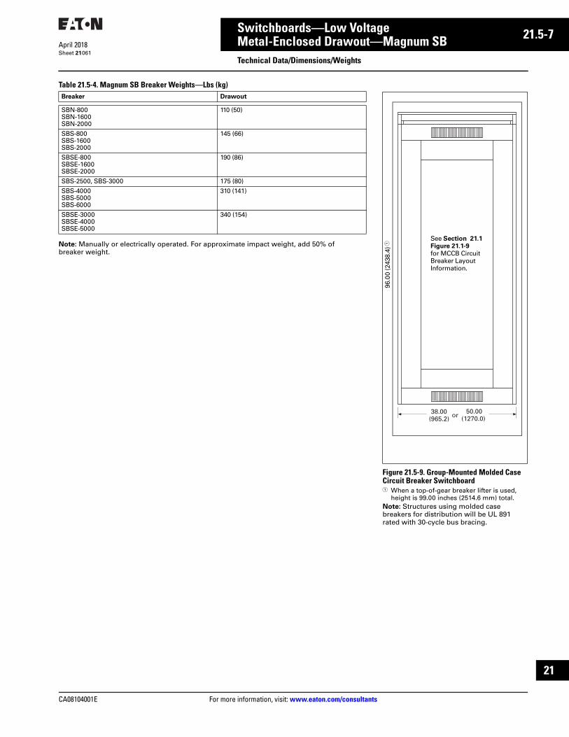
CA08104001E For more information, visit: www.eaton.com/consultants
21.5-7April 2018
Switchboards—Low Voltage
Sheet 21
i
ii
1
2
3
4
5
6
7
8
9
10
11
12
13
14
15
16
17
18
19
20
21
Metal-Enclosed Drawout—Magnum SBTechnical Data/Dimensions/Weights
061
Table 21.5-4. Magnum SB Breaker Weights—Lbs (kg)
Note: Manually or electrically operated. For approximate impact weight, add 50% of breaker weight.
Breaker Drawout
SBN-800SBN-1600SBN-2000
110 (50)
SBS-800SBS-1600SBS-2000
145 (66)
SBSE-800SBSE-1600SBSE-2000
190 (86)
SBS-2500, SBS-3000 175 (80)
SBS-4000SBS-5000SBS-6000
310 (141)
SBSE-3000SBSE-4000SBSE-5000
340 (154)
Figure 21.5-9. Group-Mounted Molded Case Circuit Breaker Switchboard1 When a top-of-gear breaker lifter is used,
height is 99.00 inches (2514.6 mm) total.Note: Structures using molded case breakers for distribution will be UL 891 rated with 30-cycle bus bracing.
96.0
0 (2
438.
4) 1
38.00(965.2)
50.00(1270.0)or
See Section 21.1 Figure 21.1-9 for MCCB Circuit Breaker Layout Information.
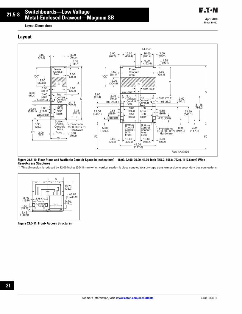
21.5-8
For more information, visit: www.eaton.com/consultants CA08104001E
April 2018
Switchboards—Low Voltage
Sheet 21
i
ii
1
2
3
4
5
6
7
8
9
10
11
12
13
14
15
16
17
18
19
20
21
Metal-Enclosed Drawout—Magnum SBLayout Dimensions
062
Layout
Figure 21.5-10. Floor Plans and Available Conduit Space in Inches (mm)—18.00, 22.00, 30.00, 44.00-Inch (457.2, 558.8, 762.0, 1117.6 mm) Wide Rear-Access Structures1 This dimension is reduced by 12.00 inches (304.8 mm) when vertical section is close coupled to a dry-type transformer due to secondary bus connections.
Figure 21.5-11. Front- Access Structures
PowerConduitArea
TopControlConduitArea
BottomControlConduitArea
31.18(792.0)
8.38(212.9)
A
D
1.50(38.1)
12.00(304.8)
“CC”
16.00(406.4)
3.00(76.2)
1.38(35.1)
3.00(76.2)
1.03 (26.2)
3.60(91.4)
FrontFC
3.00(76.2)
3.00(76.2)
21.50(546.1)
3.50 (88.9)
0.65(16.5)
3.60(91.4)3.50(88.9)
5.38(136.7)
ControTop
lConduitArea
3.60(91.4)
3.00(76.2)
6.00(152.4)
16.00(406.4)
16.00(406.4)
16.00(406.4)
1.50(38.1)
3.00 (76.2)6.00 (152.4)
3.00 (76.2)1.03 (26.2)
3.60(94.4)
3.50(88.9) 4.25 (108.0)
0.65(16.5)
21.50(546.1)
44.00(1117.6)
FC
4.63(117.6)
BottomControlConduitAreaFront
Provisions for 0.50 (12.7)
Hardware
44-Inch
Ref: 4A37896
PowerConduitArea 1.50
(38.1)
TopControlConduitArea
3.00(76.2)
31.18(792.0)
3.38(85.9)
A
D
1.50(38.1)
12.00(304.8)
“CC”
3.00(76.2)
3.00(76.2)
1.38(35.1)
3.00(76.2)
1.03 (26.2)
3.60(91.4)
FrontFC
W
3.00(76.2)
3.00(76.2)
21.50(546.1)
3.50 (88.9)
0.65(16.5)
3.60(91.4)3.50
(88.9)
5.38(136.7)
Provision for 0.50 (12.7)
Hardware
Bottom Control Conduit
Area
11
CC
17.52(445.0)
40.20(1021.0)
18.73(475.7)
W
Control Conduit
Areas
2.75 (70.0)0.65(16.5)
3.50(88.9)
5.42(138.0)

CA08104001E For more information, visit: www.eaton.com/consultants
21.5-9April 2018
Switchboards—Low Voltage
Sheet 21
i
ii
1
2
3
4
5
6
7
8
9
10
11
12
13
14
15
16
17
18
19
20
21
Metal-Enclosed Drawout—Magnum SBLayout Dimensions
063
Table 21.5-5. Rear-Access Structure Dimensions in Inches (mm)
Table 21.5-6. Front-Access Structure Dimensions in Inches (mm)
W D A CC Recommended Number
3.50 Inch (88.9 mm) 4.00 Inch (101.6 mm)
18.00 (457.2) 54.00 (1371.6)60.00 (1524.0)66.00 (1676.4)72.00 (1828.8)78.00 (1981.2)84.00 (2133.6)90.00 (2286.0)
18.00 (457.2)24.00 (609.6)30.00 (762.0)36.00 (914.4)42.00 (1066.8)48.00 (1219.2)54.00 (1371.6)
7.30 (185.4)13.30 (337.8)19.30 (490.2)25.30 (642.6)31.30 (795.0)37.30 (947.4)43.30 (1099.8)
2468
121416
2468
101216
22.00 (558.8) 54.00 (1371.6)60.00 (1524.0)66.00 (1676.4)72.00 (1828.8)78.00 (1981.2)84.00 (2133.6)90.00 (2286.0)
18.00 (457.2)24.00 (609.6)30.00 (762.0)36.00 (914.4)42.00 (1066.8)48.00 (1219.2)54.00 (1371.6)
7.30 (185.4)13.30 (337.8)19.30 (490.2)25.30 (642.6)31.30 (795.0)37.30 (947.4)43.30 (1099.8)
369
12151821
369
12151821
24.00 (609.6) 60.00 (1524.0)66.00 (1676.4)72.00 (1828.8)78.00 (1981.2)84.00 (2133.6)90.00 (2286.0)
24.00 (609.6)30.00 (762.0)36.00 (914.4)42.00 (1066.8)48.00 (1219.2)54.00 (1371.6)
9.08 (230.6)15.08 (383.0)21.08 (535.4)27.08 (687.8)33.08 (840.2)39.08 (992.6)
59
12151821
58
12151821
30.00 (762.0) 54.00 (1371.6)60.00 (1524.0)66.00 (1676.4)72.00 (1828.8)78.00 (1981.2)84.00 (2133.6)90.00 (2286.0)
18.00 (457.2)24.00 (609.6)30.00 (762.0)36.00 (914.4)42.00 (1066.8)48.00 (1219.2)54.00 (1371.6)
7.30 (185.4)13.30 (337.8)19.30 (490.2)25.30 (642.6)31.30 (795.0)37.30 (947.4)43.30 (1099.8)
48
1216202428
48
1216202428
44.00 (1117.6) 54.00 (1371.6)60.00 (1524.0)66.00 (1676.4)72.00 (1828.8)78.00 (1981.2)84.00 (2133.6)90.00 (2286.0)
18.00 (457.2)24.00 (609.6)30.00 (762.0)36.00 (914.4)42.00 (1066.8)48.00 (1219.2)54.00 (1371.6)
7.30 (185.4)13.30 (337.8)19.30 (490.2)25.30 (642.6)31.30 (795.0)37.30 (947.4)43.30 (1099.8)
7142128354249
7142128354249
60.00 (1524.0) 54.00 (1371.6)60.00 (1524.0)66.00 (1676.4)72.00 (1828.8)78.00 (1981.2)84.00 (2133.6)90.00 (2286.0)
18.00 (457.2)24.00 (609.6)30.00 (762.0)36.00 (914.4)42.00 (1066.8)48.00 (1219.2)54.00 (1371.6)
7.30 (185.4)13.30 (337.8)19.30 (490.2)25.30 (642.6)31.30 (795.0)37.30 (947.4)43.30 (1099.8)
8162432404856
8162432404856
W CC Recommended Number
3.50 Inch (88.9 mm) 4.00 Inch (101.6 mm)
18.00 (457.2)22.00 (558.8)30.00 (762.0)44.00 (1117.6)
13.89 (352.8)17.89 454.4)25.89 (657.6)39.89 (1013.2)
68
1116
68
1116

21.5-10
For more information, visit: www.eaton.com/consultants CA08104001E
April 2018
Switchboards—Low Voltage
Sheet 21
i
ii
1
2
3
4
5
6
7
8
9
10
11
12
13
14
15
16
17
18
19
20
21
Metal-Enclosed Drawout—Magnum SBLayout Dimensions
064
Layout—Outdoor Walk-in Switchboard
Figure 21.5-12. Outdoor Walk-in Enclosure Dimensions in Inches (mm)1 46.63 (1184.4) = 55.00-inch (1397.0 mm) throat (44.00-inch [1117.6 mm] wide transition box); 52.63 (1336.8) = 61.00-inch (1549.4 mm) throat
(44.00-inch [1117.6 mm] wide transition box).2 18.70 (475.0) = 44.00-inch (1117.6 mm) wide transition box.3 0.75-inch (19.1 mm) hardware recommended in all tie down locations.
Control WireOpening
20.00(508.0)
20.00(508.0)
25.31(642.9)
2.50(63.5)
17.13(435.1)
4.00(101.6)
40.94(1039.9)Opening
Foundation Tie Down(for Seismic Only) �
Lifting Angle �
3.06(77.7)
18.94(481.1)
Opening
3.06(77.7)
3.06(77.7)
26.94(684.3)
Opening
2.00(50.8)
22.00(558.8)
Unit
44.00(1117.6)
Unit
30.00(762.0)
Unit
3.93(99.8)
1.50(38.1)
48.87(1241.3)Bottom
ConduitSpace
3.50 x 3.50(88.9 x 88.9)
Control WireOpening3.50 x 3.50
(88.9 x 88.9)
45.66(1159.8)
5.03(127.8)
‘B’
StructureWidth
16.81(427.0
18.44(468.4)
0.95(24.1)
A
Rear of BaseRoof
0.95(24.1)
45.35
(1151.9) 50.00
(1270.0)
25.00
(635.0)
25.35(644.0)
39.35(999.5)
33.35(847.1)
44.00
(1117.6)
30.00
(762.0)38.00
(965.2)22.00
(558.8)
15.00(381.0)19.00
(482.6)
0.95(24.1)
Bus Duct Chimney & Cover
B
A
17.35(440.7)
StructureWidth
22.00(558.8)
‘B’
11.00(279.4)
‘C’
25.52(648.2)
109.03(2769.4)to Floor
Rear ofInnerStructure
‘C’ 0.95(24.1)
CL
CL
B
13.35(339.1)
9.00(228.6)
18.00(457.2)
41.38(1051.1)
�
22.00(558.8)
37.50(952.5)
19.70(500.4)
�
Switchgear Throat(Shipped Disassembled)
Transition Box(Shipped Attached)
45.00(1143.0)
(Overall Shipping Width)Unit Widths
30.00(762.0)
44.00(1117.6)22.00
(558.8)
15.50(393.7)
8.00(203.2)
TransformerFlange
5.00(127.0)
26.97(685.0)
42.00(1066.8)(Clear Width)
20.74(526.8)30.89
(784.6)
36.00(914.4)
Switchgear Throat(Shipped Disassembled)
O.S. of Outdoor End Sheet
22.00(558.8)
ThroatOpening& TXF
14.00(355.6)
72.00(1828.8)
SwitchgearDepth
SeeFigure 1
22" Width = 21.4 to Rear Frame (543.6)30" Width = 29.4 to Rear Frame (746.8)38" Width = 37.4 to Rear Frame (950.0)50" Width = 49.4 to Rear Frame (1254.8)55" Width = 54.4 to Rear Frame (1381.8)
‘A’
‘A’
Outdoor Roof Sheet
CL
Transformer Flange
CLCL
33.45(849.6)39.66
(1007.4)
33.45(849.6)
Front of OutdoorBase
Door SwingDoorSwing
18" Width = 17.4 to Rear Frame (441.9)
30.21(767.3)
(OpeningWidth)
28.59(726.2)
(From Base)
119.98(3047.5)
Overall Depth
117.08(2973.8)(Base)
26.00(660.4)
Bus Opening (From Base)
105.06(2668.5)
109.03(2769.4)
18.44(468.4)
51.23(1301.2)
See Figure 1 Above for Bus Duct Orientation Info.
4.00(101.6)
111.48(2831.6)OverallHeight
2.00(50.8)
CL
CL
3.89(98.8)
33.45(849.6)(DoorWidth)
5.75(146.1)
5.75(146.1)
0.61(15.5)
43.38(1101.9)
(Aisle Width)
2.30(58.4)
Weights of Outdoor Structures
(without breakers)
Weight
Structure Lbs (kg)
End Trims One set per lineup) 1500 (681)18.00-inch (457.2) wide breaker structure 2500 (1135)22.00-inch (558.8 mm) wide breaker structure 2600 (1180)30.00-inch (762.0 mm) wide breaker structure 2700 (1226)44.00-inch (1117.6 mm) wide breaker structure 5200 (2361)22.00-inch (558.8 mm) wide auxiliary structure 2300 (1044)22.00-inch (558.8 mm) wide transition structure 2300 (1044)38.00-inch (965.2 mm) wide utility structure 2700 (1226)50.00-inch (1270.0 mm) wide utility structure 3200 (1453)Transformer throat 150 (68)
Reference Drawing: 9255C25
Floor Plan
Side View Top View
Front View
Top View
Section B-B
Section A-A
Figure 1

CA08104001E For more information, visit: www.eaton.com/consultants
21.5-11April 2018
Switchboards—Low Voltage
Sheet 21
i
ii
1
2
3
4
5
6
7
8
9
10
11
12
13
14
15
16
17
18
19
20
21
Metal-Enclosed Drawout—Magnum SBLayout Dimensions
065
Layout—Outdoor Non-Walk-in Switchboard
Figure 21.5-13. Outdoor Non-Walk-in Enclosure Dimensions in Inches (mm)1 0.75-inch (19.1 mm) hardware recommended in all tie down locations.2 18.70 (475.0) = 4.004-inch (1117.6 mm) wide transition box.Note: 46.63 (1184.4) = 55.00-inch (1397.0 mm) throat (44.00-inch [1117.6 mm] wide transition box); 52.63 (1336.8) = 61.00-inch (1549.4 mm) throat (44.00-inch [1117.6 mm] wide transition box).
‘B’
StructureWidth
16.85(428.0
18.44(468.4)
0.95(24.1)
A
Rear of BaseRoof
0.95(24.1)
45.35
(1151.9) 50.00
(1270.0)
25.00
(635.0)
25.35(644.0)
39.35(999.5)
33.35(847.1)
44.00
(1117.6)
30.00
(762.0)38.00
(965.2)22.00
(558.8)
15.00(381.0)19.00
(482.6)
0.95(24.1)
Bus Duct Chimney & Cover
B
A
17.35(440.7)
StructureWidth
22.00(558.8)
‘B’
11.00(279.4)
‘C’
25.52(648.2)
109.03(2769.4)to Floor
Rear ofInnerStructure
‘C’ 0.95(24.1)
CL
CL
B
18.00(457.2)
13.35(339.1)
9.00(228.6)
20.00(508.0)
25.44(646.2)
2.50(63.5)
17.13(435.1)
4.00(101.6)
40.94(1039.9)Opening
Foundation Tie Down(for Seismic Only) �
Lifting Angle �
3.06(77.7)
18.94(481.1)
Opening
3.06(77.7)
3.06(77.7)
26.94(684.3)
Opening
20.00(508.0)
2.00(50.8)
22.00(558.8)
Unit
44.00(1117.6)
Unit
30.00(762.0)
Unit
3.93(99.8)
1.50(38.1)
17.83(452.9)Bottom
ConduitSpace
3.50 x 3.50(88.9 x 88.9)
Control WireOpening
20.10(510.5)30.23
(767.8)26.97
(685.0)
36.00(914.4)
Switchgear Throat(Shipped Disassembled)
O.S. of Outdoor End Sheet
22.00(558.8)
ThroatOpening& TXF
1.60(40.6)14.00
(355.6)
72.00(1828.8)
SwitchgearDepth
SeeFigure 1
7.51(190.8)
Work Space
22" Width = 21.4 to Rear Frame (543.6)30" Width = 29.4 to Rear Frame (746.8)38" Width = 37.4 to Rear Frame (950.0)50" Width = 49.4 to Rear Frame (1254.8)55" Width = 54.4 to Rear Frame (1381.8)
‘A’
‘A’
Outdoor Roof Sheet 1.65
(41.9)
CL
Transformer Flange
CL
CL
Indoor Gear Rear of Base
Outdoor Base
41.38(1051.1)
�
22.00(558.8)
37.50(952.5)
19.70(500.4)
�
Switchgear Throat(Shipped Disassembled)
Transition Box(Shipped Attached)
45.00(1143.0)
(Overall Shipping Width)Unit Widths
30.00(762.0)
44.00(1117.6)22.00
(558.8)
15.50(393.7)
8.00(203.2)
TransformerFlange
28.58(725.9)
(From Base)
88.02(2235.7)
Overall Depth
86.04(2185.4)(Base)
26.00(660.4)
Bus Opening (From Base)
105.08(2669.0)
109.05(2769.9)
18.44(468.4)
51.23(1301.2)
See Figure 1 Above for Bus Duct Orientation Info.
4.00(101.6)
109.79(2788.7)OverallHeight
2.00(50.8)
CL
CL
3.89(98.8)
Weights of Outdoor Structures
(without breakers)
Weight
Structure Lbs (kg)
End Trims One set per lineup) 1500 (681)18.00-inch (457.2 mm) wide breaker structure 2400 (1090)22.00-inch (558.8 mm) wide breaker structure 2600 (1180)30.00-inch (762.0 mm) wide breaker structure 2700 (1226)44.00-inch (1117.6 mm) wide breaker structure 5200 (2361)22.00-inch (558.8 mm) wide auxiliary structure 2300 (1044)22.00-inch (558.8 mm) wide transition structure 2300 (1044)38.00-inch (965.2 mm) wide utility structure 2700 (1226)50.00-inch (1270.0 mm) wide utility structure 3200 (1453)Transformer throat 150 (68)
Reference Drawing: 9255C35
Floor Plan
Top View
Section B-B
Section A-A
Figure 1
Side View Top View
Front View

21.5-12
For more information, visit: www.eaton.com/consultants CA08104001E
April 2018
Switchboards—Low Voltage
Sheet 21
i
ii
1
2
3
4
5
6
7
8
9
10
11
12
13
14
15
16
17
18
19
20
21
066
This page intentionally left blank.

CA08104001E For more information, visit: www.eaton.com/consultants
21.6-1April 2018
Switchboards—Low Voltage
Sheet 21
i
ii
1
2
3
4
5
6
7
8
9
10
11
12
13
14
15
16
17
18
19
20
21
Integrated Facility System SwitchboardsGeneral Description
067
Integrated Facility System Switchboards
Integrated Facility System Switchboards
General DescriptionEaton’s Integrated Facility System Switchboard product is a simple concept. This technology integrates standard panelboards, dry-type distribution transformers, contactors and other electrical equipment into free-standing, front-access switchboards.
Integrated Facility System Switchboard Benefits■ Space savings up to 50% or more■ Factory wired and pre-tested■ Assembled and ready to install■ Significantly reduces installation
time and materials■ Significantly reduces materials
associated with panel installation■ Frees up additional space at no
charge to the owner■ Installed cost is typically less than
with traditional products■ Sustainability and LEED® compliant
Available Options■ Automatic transfer switches■ UPS (Uninterrupted Power Supplies)■ SPD (surge protective devices)■ HVAC control■ Lighting control■ Power factor correction■ Metering■ Generator Quick Connect■ Customer metering■ Lighting power reduction products
Standards■ Meets NEMA Standard PB-2 and
UL 891■ Used with Type 1 Pow-R-Line C
switchboard sections■ Select main, branch feeder,
customer and utility metering from Section 21.1
■ Factory wired panelboards and dry-type distribution transformers meet NEMA Standard PB-2, UL 891 and the National Electrical Code
Integrated Facility System Switchboard Sections and Selection■ From the following pages select the
appropriate section “Type”■ Select from panelboards, blank steel
backpans and dry-type distribution transformers by “cell”
■ Layout IFS sections near standard distribution sections
■ Indicate on drawings and one-line diagrams the connections from feeder devices to the appropriate cell
Figure 21.6-1. Traditional Electrical Room—Plan View
Figure 21.6-2. IFS Electrical Room—Plan View
Figure 21.6-3. Optimized IFS Layout—Front View
Panel L1 Panel L2
Panel P3 Panel P2 Panel P1Telephone
MainSwitchboard
Transformer
Telephone
Integrated Facility SystemSwitchboard Solution
IFSSwitchboard
UtilityMeteringSection
Main RDBreaker
CustomerMetering,
SPD
FeederBreakerSection
Dry-TypeDist.
X-Former
P1
P2
P3 L1
L2
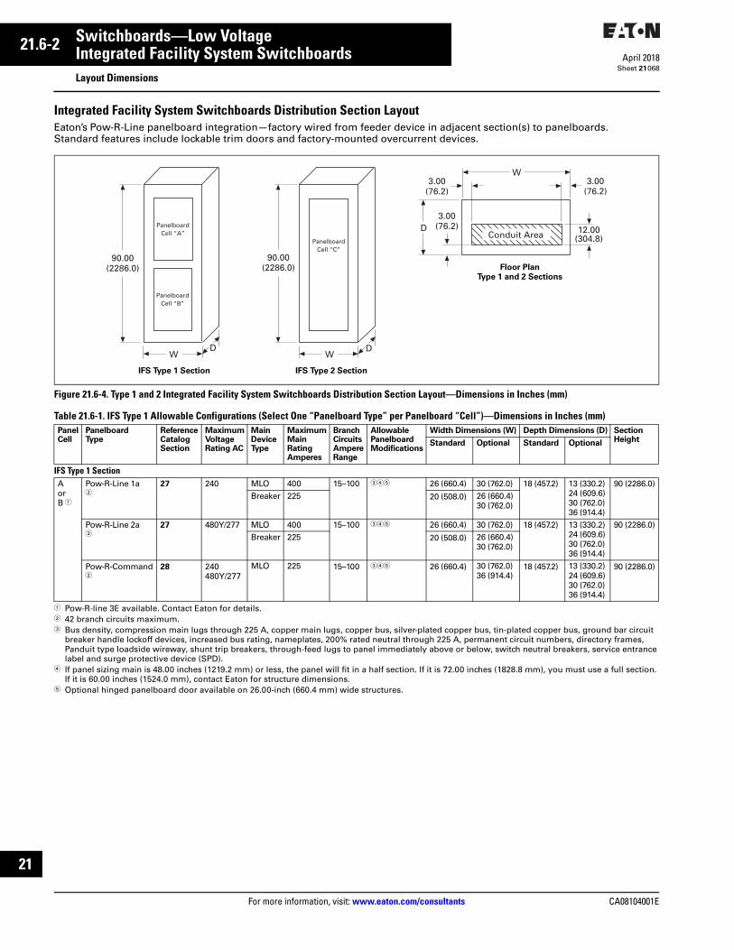
21.6-2
For more information, visit: www.eaton.com/consultants CA08104001E
April 2018
Switchboards—Low Voltage
Sheet 21
i
ii
1
2
3
4
5
6
7
8
9
10
11
12
13
14
15
16
17
18
19
20
21
Integrated Facility System SwitchboardsLayout Dimensions
068
Integrated Facility System Switchboards Distribution Section LayoutEaton’s Pow-R-Line panelboard integration—factory wired from feeder device in adjacent section(s) to panelboards. Standard features include lockable trim doors and factory-mounted overcurrent devices.
Figure 21.6-4. Type 1 and 2 Integrated Facility System Switchboards Distribution Section Layout—Dimensions in Inches (mm)
Table 21.6-1. IFS Type 1 Allowable Configurations (Select One “Panelboard Type” per Panelboard “Cell”)—Dimensions in Inches (mm)
1 Pow-R-line 3E available. Contact Eaton for details.2 42 branch circuits maximum.3 Bus density, compression main lugs through 225 A, copper main lugs, copper bus, silver-plated copper bus, tin-plated copper bus, ground bar circuit
breaker handle lockoff devices, increased bus rating, nameplates, 200% rated neutral through 225 A, permanent circuit numbers, directory frames, Panduit type loadside wireway, shunt trip breakers, through-feed lugs to panel immediately above or below, switch neutral breakers, service entrance label and surge protective device (SPD).
4 If panel sizing main is 48.00 inches (1219.2 mm) or less, the panel will fit in a half section. If it is 72.00 inches (1828.8 mm), you must use a full section. If it is 60.00 inches (1524.0 mm), contact Eaton for structure dimensions.
5 Optional hinged panelboard door available on 26.00-inch (660.4 mm) wide structures.
PanelCell
PanelboardType
ReferenceCatalog Section
MaximumVoltageRating AC
MainDeviceType
MaximumMainRatingAmperes
BranchCircuitsAmpereRange
AllowablePanelboardModifications
Width Dimensions (W) Depth Dimensions (D) SectionHeightStandard Optional Standard Optional
IFS Type 1 SectionAorB 1
Pow-R-Line 1a2
27 240 MLO 400 15–100 345 26 (660.4) 30 (762.0) 18 (457.2) 13 (330.2)24 (609.6)30 (762.0)36 (914.4)
90 (2286.0)Breaker 225 20 (508.0) 26 (660.4)
30 (762.0)
Pow-R-Line 2a2
27 480Y/277 MLO 400 15–100 345 26 (660.4) 30 (762.0) 18 (457.2) 13 (330.2)24 (609.6)30 (762.0)36 (914.4)
90 (2286.0)Breaker 225 20 (508.0) 26 (660.4)
30 (762.0)
Pow-R-Command2
28 240480Y/277
MLO 225 15–100 345 26 (660.4) 30 (762.0)36 (914.4)
18 (457.2) 13 (330.2)24 (609.6)30 (762.0)36 (914.4)
90 (2286.0)
WD
90.00(2286.0)
PanelboardCell “A”
PanelboardCell “B”
WD
90.00(2286.0)
PanelboardCell “C”
D
W3.00
(76.2)3.00
(76.2)
3.00(76.2) 12.00
(304.8)Conduit Area
IFS Type 1 Section IFS Type 2 Section
Floor Plan
Type 1 and 2 Sections

CA08104001E For more information, visit: www.eaton.com/consultants
21.6-3April 2018
Switchboards—Low Voltage
Sheet 21
i
ii
1
2
3
4
5
6
7
8
9
10
11
12
13
14
15
16
17
18
19
20
21
Integrated Facility System SwitchboardsLayout Dimensions
069
Table 21.6-1. IFS Type 2 Allowable Configurations (Select One “Panelboard Type” per Panelboard “Cell”)—Dimensions in Inches (mm) (Continued)
1 Pow-R-Line 3E available. Contact Eaton for details.2 42 branch circuits maximum.3 Bus density, compression main lugs through 225 A, copper main lugs, copper bus, silver-plated copper bus, tin-plated copper bus, ground bar circuit
breaker handle lockoff devices, increased bus rating, nameplates, 200% rated neutral through 225 A, permanent circuit numbers, directory frames, Panduit type loadside wireway, shunt trip breakers, through-feed lugs to panel immediately above or below, switch neutral breakers, service equipment label and surge protective device (SPD).
4 If panel sizing with non-interchange main is 48.00 inches (1219.2 mm) or less, the panel will fit in a half section. If it is 72.00 inches (1828.8 mm), you must use a full section. If it is 60.00 inches (1524.0 mm), contact Eaton for cell height.
PanelCell
PanelboardType
ReferenceCatalogSection
MaximumVoltageRating AC
MainDeviceType
MaximumMainRatingAmperes
BranchCircuitsAmpereRange
AllowablePanelboardModifications
Width Dimensions (W) Depth Dimensions (D) SectionHeightStandard Optional Standard Optional
IFS Type 2 SectionC 1 Pow-R-Line 1a
227 240 Breaker 400 15–100 34 26 (660.4) 30 (762.0) 18 (457.2) 13 (330.2)
24 (609.6)30 (762.0)36 (914.4)
90 (2286.0)
Pow-R-Line 2a2
27 480Y/277 Breaker 400 15–100 34 26 (660.4) 30 (762.0) 18 (457.2) 13 (330.2)24 (609.6)30 (762.0)36 (914.4)
90 (2286.0)
Pow-R-Command2
28 480Y/277 MLO 400 15–100 34 26 (660.4) 30 (762.0)36 (914.4)
18 (457.2) 13 (330.2)24 (609.6)30 (762.0)36 (914.4)
90 (2286.0)Breaker 225
Pow-R-Line 3a 27 480Y/277 MLO 600 15–225 34 26 (660.4) 30 (762.0)36 (914.4)
18 (457.2) 13 (330.2)24 (609.6)30 (762.0)36 (914.4)
90 (2286.0)Breaker 600
MLO 800 15–225 34 30 (762.0) 36 (914.4) 18 (457.2) 13 (330.2)24 (609.6)30 (762.0)36 (914.4)
90 (2286.0)

21.6-4
For more information, visit: www.eaton.com/consultants CA08104001E
April 2018
Switchboards—Low Voltage
Sheet 21
i
ii
1
2
3
4
5
6
7
8
9
10
11
12
13
14
15
16
17
18
19
20
21
Integrated Facility System SwitchboardsLayout Dimensions
070
Integrated Facility System Switchboards Distribution Section LayoutEaton’s Pow-R-Line panelboard and transformer integration—factory wired from feeder device in adjacent sections. Standard features include lockable trim doors and factory-mounted overcurrent devices.
Figure 21.6-5. Type 3 and 4 Integrated Facility System Switchboards Distribution Section Layout—Dimensions in Inches (mm)
Table 21.6-2. IFS Type 3 and 4 Allowable Configurations (Select One “Panelboard Type” per Panelboard “Cell”)—Dimensions in Inches (mm)
1 Pow-R-Line 3E panelboard available. Contact Eaton for details.2 42 branch circuits maximum.3 Possible uses: HVAC, dimming and contactors. Contact Eaton for details.4 Bus density, compression main lugs through 225 A, copper main lugs, copper bus, silver-plated copper bus, tin-plated copper bus, ground bar circuit
breaker handle lockoff devices, increased bus rating, nameplates, 200% rated neutral through 225 A, permanent circuit numbers, directory frames, Panduit type loadside wireway, shunt trip breakers, through-feed lugs to panel immediately above or below, switch neutral breakers, service equipment label and surge protective device (SPD).
5 If panel sizing is 48.00 inches (1219.2 mm) or less, the panel will fit in a half section. If it is 72.00 inches (1828.8 mm), you must use a full section. If it is 60.00 inches (1524.0 mm), contact Eaton for cell height.
6 Optional hinged panelboard door available on 26.00-inch (660.4 mm) wide structures.7 Galvanized steel backpan provided for customer specified equipment. Contact Eaton for requirements and details.
PanelCell
PanelboardType
ReferenceCatalogSection
MaximumVoltageRating AC
MainDeviceType
MaximumMainRatingAmperes
Branch CircuitsAmpereRange
AllowablePanelboardModifications
Width Dimensions (W) Depth Dimensions (D) SectionHeight
Standard Optional Standard Optional
IFS Type 3 Section DorE 1
Pow-R-Line 1a2
27 240 MLO 400 15–100 2456 26 (660.4) 30 (762.0) 18 (457.2) 13 (330.2)24 (609.6)30 (762.0)36 (914.4)
90 (2286.0)
Breaker 225 20 (508.0) 26 (660.4)30 (762.0)
Pow-R-Line 2a2
27 480Y/277 MLO 400 15–100 2456 26 (660.4) 30 (762.0) 18 (457.2) 13 (330.2)24 (609.6)30 (762.0)36 (914.4)
90 (2286.0)
Breaker 225 20 (508.0) 26 (660.4)30 (762.0)
Blank SteelBackpan3
— — None — — 7 20 (508.0) 30 (762.0) 18 (457.2) 13 (330.2)24 (609.6)30 (762.0)36 (914.4)
90 (2286.0)
26 (660.4)30 (762.0)
IFS Type 4 Section F Blank Steel
Backpan 3— — None — — 7 20 (508.0) 26 (660.4)
30 (762.0)18 (457.2) 13 (330.2)
24 (609.6)30 (762.0)36 (914.4)
90 (2286.0)
WD
90.00(2286.0)
Cell “D”
Cell “E”
WD
90.00(2286.0)
Cell “F”
D
W3.00
(76.2)3.00
(76.2)
3.00(76.2) 12.00
(304.8)Conduit Area
D
W3.00
(76.2)3.00
(76.2)
3.00(76.2) 3.00
(76.2)Conduit Area
IFS Type 3 Section IFS Type 4 Section
Floor Plan
Type 3 and 4 Sections
Floor Plan
Type 4 Sections with Blank Steel Backpan Only

CA08104001E For more information, visit: www.eaton.com/consultants
21.6-5April 2018
Switchboards—Low Voltage
Sheet 21
i
ii
1
2
3
4
5
6
7
8
9
10
11
12
13
14
15
16
17
18
19
20
21
Integrated Facility System SwitchboardsLayout Dimensions
071
Integrated Facility System Switchboards Distribution Section LayoutEaton’s Pow-R-Line panelboard and transformer integration—factory wired from feeder device in adjacent sections. Standard features include lockable trim doors and factory-mounted overcurrent devices.
Figure 21.6-6. Type 5 and 6 Integrated Facility System Switchboards Distribution Section Layout—Dimensions in Inches (mm)
Table 21.6-3. IFS Type 5 Allowable Configurations (Select One “Panelboard Type” per Panelboard “Cell”)—Dimensions in Inches (mm)
1 Pow-R-Line 3E panelboard available. Contact Eaton for details.2 42 branch circuits maximum.3 Galvanized steel backpan provided for customer specified equipment. Contact Eaton for requirements and details.4 Bus density, compression main lugs through 225 A, copper main lugs, copper bus, silver-plated copper bus, tin-plated copper bus, ground bar circuit
breaker handle lockoff devices, increased bus rating, nameplates, 200% rated neutral through 225 A, permanent circuit numbers, directory frames, Panduit type loadside wireway, shunt trip breakers, through-feed lugs to panel immediately above or below, switch neutral breakers, hinged panelboard door on 26.00-inch (660.4 mm) wide sections, service entrance label and surge protective device (SPD).
Note: Select one “Panelboard Type” or one “Blank Steel Backpan” and either one “Transformer” or one “Blank Space” per “Cell.“
Table 21.6-4. IFS Type 5 and 6 General Purpose Dry-Type Distribution Transformers—Dimensions in Inches (mm)
5 Copper windings, 115 ºC, 80 ºC, K-Factor, low sound are available options but may change dimensions.6 Either one F-Frame or K-Frame circuit breaker can be included in any transformer section to be used as a disconnect.7 Galvanized steel backpan provided for customer specified equipment. Contact Eaton for requirements and details.8 Contact Eaton for other Temperature Rise Transformers and Specials.Note: 480:208Y/120 Vac three-phase or 480:120/240 Vac single-phase.
PanelCell
Panelboard Type
ReferenceCatalogSection
MaximumVoltageRating AC
MainDevice Type
MaximumMainRatingAmperes
Branch CircuitsAmpereRange
AllowablePanelboardModifications
Width Dimensions (W) Depth Dimensions (D) SectionHeight
Standard Optional Standard Optional
IFS Type 5 SectionG 1 Pow-R-Line 1a
227 240 MLO 400 15–100 4 26 (660.4) 30 (762.0) 24 (609.6) 30 (762.0)
36 (914.4)90 (2286.0)
Breaker 225Pow-R-Line 2a2
27 480Y/277 MLO 400 15–100 4 26 (660.4) 30 (762.0) 24 (609.6) 30 (762.0)36 (914.4)
90 (2286.0)Breaker 225
Blank SteelBackpan 3
— — None — — 3 26 (660.4) 30 (762.0) 24 (609.6) 30 (762.0)36 (914.4)
90 (2286.0)
Pow-R-Command 2
28 240, 480Y/277
MLO 225 15–100 34 26 (660.4) 30 (762.0)36 (914.4)
24 (609.6) 30 (762.0)36 (914.4)
90 (2286.0)
PanelCell
PanelboardType
Reference CatalogSection
Temper-atureRise
Windings kVARange
Full Cap Taps AllowableModifications
Width Dimensions (W)
Depth Dimensions (D)
SectionHeight
FCAN FCBN Standard Optional Standard Optional
IFS Type 5 SectionH 56 DT-3
Transformer7
TP1, 480: 208Y/120 Vac
19 150ºC Only 8
Aluminum 15–45 4–2.5% 2–2.5% 5 26 (660.4) 30 (762.0) 24 (609.6) 30 (762.0)36 (914.4)
90 (2286.0)75 4–2.5% 2–2.5% 5 30 (762.0) N/A112.5 4–2.5% 2–2.5% 5 36 (914.4) N/A 30 (762.0) 36 (914.4) 90 (2286.0)150 4–2.5% 2–2.5% 5 36 (914.4) N/A 30 (762.0) 36 (914.4) 90 (2286.0)
Blank SteelBackpan 7
— — None — — 5 26 (660.4) 30 (762.0) 24 (609.6) 30 (762.0)36 (914.4)
90 (2286.0)
IFS Type 6 SectionI 6 DT-3
TransformerTP1, 480: 208Y/120 Vac
19 150ºC 8 Aluminum 225 4–2.5% 2–2.5% 5 36 (914.4) N/A 30 (762.0) N/A 90 (2286.0)300 4–2.5% 2–2.5% 5 45 (1143.0) N/A 36 (914.4)
WD
90.00(2286.0)
Cell “I”
D
W3.00
(76.2)3.00
(76.2)
3.00(76.2) 3.00
(76.2)
WD
90.00(2286.0)
Cell “G”
Cell “H”
IFS Type 5 Section
Floor Plan Type 5 Section
with Blank Space in Cell “H”
No Bottom Entry Conduit
Space with Transformer
in Cell “H” or “I” (Type 5 or 6)IFS Type 6 Section

21.6-6
For more information, visit: www.eaton.com/consultants CA08104001E
April 2018
Switchboards—Low Voltage
Sheet 21
i
ii
1
2
3
4
5
6
7
8
9
10
11
12
13
14
15
16
17
18
19
20
21
Integrated Facility System SwitchboardsLayout Dimensions
072
Integrated Facility System Switchboards Distribution Section LayoutEaton’s Pow-R-Line panelboard integration—factory wired from feeder device in adjacent section(s) to Panelboard Cell “J.“ Distribution Chassis in Cell “K” may be field wired or wired from an adjacent section. Standard features include lockable trim doors and factory-mounted overcurrent devices.
Figure 21.6-7. Type 7 and 8 Integrated Facility System Switchboards Distribution Section Layout—Dimensions in Inches (mm)
Table 21.6-5. IFS Type 7 and 8 Sections Allowable Configurations (Select One “Panelboard Type” per Panelboard “Cell”)—Dimensions in Inches (mm)
1 42 branch circuits maximum.2 Bus density, compression main lugs through 225 A, copper main lugs, copper bus, silver-plated copper bus, tin-plated copper bus, ground bar circuit
breaker handle lockoff devices, increased bus rating, nameplates, 200% rated neutral through 225 A, permanent circuit numbers, directory frames, Panduit type loadside wireway, shunt trip breakers, through-feed lugs, switch neutral breakers, hinged panelboard door on 26.00-inch (660.4 mm) wide sections, service entrance label and surge protective device (SPD).
3 If panel sizing main is 48.00 inches (1219.2 mm) or less, the panel will fit in a half section. If it is 72.00 inches (1828.8 mm), you must use a full section. If it is 60.00 inches (1524.0 mm), contact Eaton to see if it will fit.
4 Reference Page 21.1-11 for selection criteria.5 Pow-R-Line 3E available. Contact Eaton for details.
Panel
Cell
Panelboard
Type
Reference
Catalog
Section
Maximum
Voltage
Rating AC
Main
Device
Type
Maximum
Main
Rating
Amperes
Branch
Circuits
Ampere
Range
Allowable
Panelboard
Modifications
Width Dimensions (W) Depth Dimensions (D) Section
HeightStandard Optional Standard Optional
IFS Types 7 and 8 SectionsJ 5 Pow-R-Line 1a
127 240 MLO 400 15–100 23 26 (660.4) 30 (762.0)
36 (914.4)18 (457.2) 13 (330.2)
24 (609.6)30 (762.0)36 (914.4)
90 (2286.0)
Breaker 225
Pow-R-Line 2a1
27 480Y/277 MLO 400 15–100 23 26 (660.4) 30 (762.0)36 (914.4)
18 (457.2) 13 (330.2)24 (609.6)30 (762.0)36 (914.4)
90 (2286.0)
Breaker 225
Pow-R-Command 1
28 240,480Y/277
MLO 225 15–100 23 26 (660.4) 30 (762.0)36 (914.4)
18 (457.2) 13 (330.2)24 (609.6)30 (762.0)36 (914.4)
90 (2286.0)
K Pow-R-Line CSwitchboardChassis 1
— 480Y/277 MLO 800 15–600 4 26 (660.4) 36 (914.4)30 (762.0)
18 (457.2) 13 (330.2)24 (609.6)30 (762.0)36 (914.4)
90 (2286.0)
Breaker 600
MLO orBreaker
1200 15–600 4 36 (914.4) 45 (1143.0) 18 (457.2) 13 (330.2)24 (609.6)30 (762.0)36 (914.4)
90 (2286.0)
WD
90.00(2286.0)
Cell “J”
WD
90.00(2286.0)
Cell “J”22X
DistributionChassisCell “K”
22X Distribution
ChassisCell “K”
D
W3.00
(76.2)3.00
(76.2)
3.00(76.2) 12.00
(304.8)Conduit Area
IFS Type 7 Section IFS Type 8 Section
Floor Plan
Type 7 and 8 Sections

CA08104001E For more information, visit: www.eaton.com/consultants
21.6-7April 2018
Switchboards—Low Voltage
Sheet 21
i
ii
1
2
3
4
5
6
7
8
9
10
11
12
13
14
15
16
17
18
19
20
21
Integrated Facility System SwitchboardsLayout Dimensions
073
Integrated Facility System Switchboards Distribution Section LayoutEaton’s Pow-R-Line panelboard integration—factory wired from feeder device in adjacent section(s). Standard features include lockable trim doors and factory-mounted overcurrent devices.
Figure 21.6-8. Type 9 Integrated Facility System Switchboards Distribution Section Layout—Dimensions in Inches (mm)
Table 21.6-6. IFS Type 9 Section Panelboard Over Dry-Type Transformer (Select One “Panelboard Type” per Panelboard “Cell”)—Dimensions in Inches (mm)
1 Pow-R-Line 3E panelboard available. Contact Eaton for details.2 42 branch circuits maximum.3 Bus density, compression main lugs through 225 A, copper main lugs, copper bus, silver-plated copper bus, tin-plated copper bus, ground bar circuit
breaker handle lockoff devices, increased bus rating, nameplates, 200% rated neutral through 100 A, permanent circuit numbers, directory frames, Panduit type loadside wireway, shunt trip breakers, through-feed lugs, switch neutral breakers.
Table 21.6-7. IFS Type 9 Section General Purpose Dry-Type Distribution Transformers—Dimensions in Inches (mm)
4 Contact Eaton for other Temperature Rise Transformers and Specials.5 Copper windings, 115 ºC, 80 ºC, K-Factor, and low sound TP-1 are available options but may change dimensions.
Panel
Cell
Panelboard
Type
Reference
Catalog
Section
Maximum
Voltage
Rating AC
Main
Device
Type
Maximum
Main
Rating
Amperes
Branch
Circuits
Ampere
Range
Allowable
Panelboard
Modifications
Width Dimensions (W) Depth Dimensions (D) Section
HeightStandard Optional Standard Optional
IFS Type 9 SectionL 1 Pow-R-Line 1a
227 240 MLO 225 15–100 3 36 (914.4) 45 (1143.0) 24 (609.6) 30 (762.0)
36 (914.4)90 (2286.0)
Breaker 400 45 (1143.0) —
Pow-R-Line 2a2
27 480Y/277 MLO 225 15–100 3 36 (914.4) 45 (1143.0) 24 (609.6) 30 (762.0)36 (914.4)
90 (2286.0)
Breaker 400 45 (1143.0) —
Pow-R-Command 2
27 240,480Y/277
MLO 225 15–100 3 26 (660.4) 30 (762.0)36 (914.4)
18 (457.2) 13 (330.2)24 (609.6)30 (762.0)36 (914.4)
90 (2286.0)
PanelCell
TransformerType
Reference CatalogSection
Temper-atureRise
Windings kVARange
Full Cap Taps AllowableModifications
Width Dimensions (W) Depth Dimensions (D) SectionHeight
FCAN FCBN Standard Optional Standard Optional
IFS Type 9 SectionM DT-3
TransformerTP-1480: 208Y/120 Vac
19 150ºCOnly 4
Aluminum 15–75 4–2.5% 2–2.5% 5 36 (914.4) 45 (1143.0) 24 (609.6) 30 (762.0)36 (914.4)
90 (2286.0)
112.5 4–2.5% 2–2.5% 5 36 (914.4) 45 (1143.0) 36 (914.4) — 90 (2286.0)
Cell“L” D
W
Cell“L”
Cell “M”
IFS Type 9 Section
Floor Plan Type 9 Section
There is no Bottom Entry
Conduit Space with
Transformer in Cell “M”

21.6-8
For more information, visit: www.eaton.com/consultants CA08104001E
April 2018
Switchboards—Low Voltage
Sheet 21
i
ii
1
2
3
4
5
6
7
8
9
10
11
12
13
14
15
16
17
18
19
20
21
Integrated Facility System SwitchboardsLayout Dimensions
074
Integrated Facility System Switchboards Distribution Section LayoutEaton’s Pow-R-Line panelboard integration—factory wired from feeder device in adjacent section(s) to Panelboard Cell “J.” Distribution Chassis in Cell “K” may be field wired or wired from an adjacent section. Standard features include lockable trim doors and factory-mounted overcurrent devices.
Figure 21.6-9. Type 10 and 11 Integrated Facility System Switchboards Distribution Section Layout—Dimensions in Inches (mm)
Table 21.6-8. IFS Type 10 and 11 Sections Allowable Configurations (Select One “Panelboard Type” per Panelboard “Cell”)—Dimensions in Inches (mm)
1 Pow-R-Line 3E available. Contact Eaton when applicable.2 42 branch circuits maximum.3 Bus density, compression main lugs through 225 A, copper main lugs, copper bus, silver-plated copper bus, tin-plated copper bus, ground bar circuit
breaker handle lockoff devices, increased bus rating, nameplates, 200% rated neutral through 225 A, permanent circuit numbers, directory frames, Panduit type loadside wireway, shunt trip breakers, through-feed lugs, switch neutral breakers, hinged trim, service entrance label and surge protective device (SPD).
4 If panel sizing is 48.00 inches (1219.2 mm) or less, the panel will fit in a half section. If it is 72.00 inches (1828.8 mm), you must use a full section. If it is 60.00 inches (1524.0 mm), contact Eaton to see if it will fit.
5 See Page Page 21.1-11 reference information in Tab 21.
Panel
Cell
Panelboard
Type
Reference
Catalog
Section
Maximum
Voltage
Rating AC
Main
Device
Type
Maximum
Main
Rating
Amperes
Branch
Circuits
Ampere
Range
Allowable
Panelboard
Modifications
Width Dimensions (W) Depth Dimensions (D) Section
HeightStandard Optional Standard Optional
IFS Types 10 and 11 SectionsN 1 Pow-R-Line 1a
227 240 MLO 400 15–100 34 45 (1143.0) — 18 (457.2) 13 (330.2)
24 (609.6)30 (762.0)36 (914.4)
90 (2286.0)
Breaker 225 36 (914.4) 45 (1143.0)
Pow-R-Line 2a2
27 480Y/277 MLO 400 15–100 34 45 (1143.0) — 18 (457.2) 13 (330.2)24 (609.6)30 (762.0)36 (914.4)
90 (2286.0)
Breaker 225 36 (914.4) 45 (1143.0)
Pow-R-Command 2
28 240,480Y/277
MLO 225 15–100 34 45 (1143.0) 36 (914.4) 18 (457.2) 13 (330.2)24 (609.6)30 (762.0)36 (914.4)
90 (2286.0)
O Pow-R-Line CSwitchboardChassis
— 480Y/277 MLO 800 15–600 5 36 (914.4) 45 (1143.0) 18 (457.2) 13 (330.2)24 (609.6)30 (762.0)36 (914.4)
90 (2286.0)
Breaker 600
MLO orBreaker
1200 15–600 5 36 (914.4) 45 (1143.0) 18 (457.2) 13 (330.2)24 (609.6)30 (762.0)36 (914.4)
90 (2286.0)
WD
90.00(2286.0)
WD
90.00(2286.0)
22X Distribution
ChassisCell “O”
22X Distribution
ChassisCell “O”
D
W3.00
(76.2)3.00
(76.2)
3.00(76.2) 12.00
(304.8)Conduit Area
Cell“N”
Cell“N”
Cell“N”
Cell“N”
IFS Type 10 Section IFS Type 11 Section
Floor Plan
Type 10 and 11 Sections

CA08104001E For more information, visit: www.eaton.com/consultants
21.6-9April 2018
Switchboards—Low Voltage
Sheet 21
i
ii
1
2
3
4
5
6
7
8
9
10
11
12
13
14
15
16
17
18
19
20
21
Integrated Facility System SwitchboardsLayout Dimensions
075
Integrated Facility System Switchboards Distribution Section LayoutEaton’s Pow-R-Line panelboard integration—factory wired from feeder device in adjacent section(s). Standard features include lockable trim doors and factory-mounted overcurrent devices.
Figure 21.6-10. Type 12 Integrated Facility System Switchboards Distribution Section Layout—Dimensions in Inches (mm)
Table 21.6-9. IFS Type 12 Section Allowable Configurations (Select One “Panelboard Type” per Panelboard “Cell”)—Dimensions in Inches (mm)
1 Pow-R-Line 3E available. Reference Section 27. Contact Eaton when applicable.2 42 branch circuits maximum.3 Bus density, compression main lugs through 225 A, copper main lugs, copper bus, silver-plated copper bus, tin-plated copper bus, ground bar circuit
breaker handle lockoff devices, increased bus rating, nameplates, 200% rated neutral through 225 A, permanent circuit numbers, directory frames, Panduit type loadside wireway, shunt trip breakers, through-feed lugs, switch neutral breakers, hinged trim, service entrance label and surge protective device (SPD).
4 If panel sizing is 48.00 inches (1219.2 mm) or less, the panel will fit in a half section. If it is 72.00 inches (1828.8 mm), you must use a full section. If it is 60.00 inches (1524.0 mm), contact Eaton for structure dimensions.
5 If any single-phase is selected as 400 A or PRC, section minimum width is 45.00 inches (1143.0 mm).
Panel
Cell
Panelboard
Type
Reference
Catalog
Section
Maximum
Voltage
Rating AC
Main
Device
Type
Maximum
Main
Rating
Amperes
Branch
Circuits
Ampere
Range
Allowable
Panelboard
Modifications
Width Dimensions (W) Depth Dimensions (D) Section
HeightStandard Optional Standard Optional
IFS Types 12 SectionP 1 Pow-R-Line 1a
227 240 MLO 400 15–100 345 45 (1143.0) — 18 (457.2) 13 (330.2)
24 (609.6)30 (762.0)36 (914.4)
90 (2286.0)
Breaker 225 36 (914.4) 45 (1143.0)
Pow-R-Line 2a2
27 480Y/277 MLO 400 15–100 345 45 (1143.0) — 18 (457.2) 13 (330.2)24 (609.6)30 (762.0)36 (914.4)
90 (2286.0)
Breaker 225 36 (914.4) 45 (1143.0)
Pow-R-Command 2
28 240,480Y/277
MLO 225 15–100 345 45 (1143.0) 36 (914.4) 18 (457.2) 13 (330.2)24 (609.6)30 (762.0)36 (914.4)
90 (2286.0)
Cell“P”
Cell“P”
Cell“P”
Cell“P”
D
W3.00
(76.2)3.00
(76.2)
3.00(76.2) 12.00
(304.8)Conduit Area
IFS Type 12 Section
Floor Plan
Type 12 Section
21.6-10
For more information, visit: www.eaton.com/consultants CA08104001E
April 2018
Switchboards—Low Voltage
Sheet 21
i
ii
1
2
3
4
5
6
7
8
9
10
11
12
13
14
15
16
17
18
19
20
21
076
This page intentionally left blank.

CA08104001E For more information, visit: www.eaton.com/consultants
21.7-1April 2018
Switchboards—Low Voltage
Sheet 21
i
ii
1
2
3
4
5
6
7
8
9
10
11
12
13
14
15
16
17
18
19
20
21
Generator Quick Connect SwitchboardGeneral Description
077
Generator Quick Connect Switchboard
Generator Quick Connect Switchboard Section
General DescriptionEaton’s Generator Quick Connect switchboard is an engineered switchboard assembly designed to allow easy and quick connection of a standby generator to your facility’s service entrance switchboard.
Through inclusion of cam-type receptacles, standard mechanical lugs, a dedicated generator service disconnect and a key interlock transfer scheme, a facility can quickly be switched to generator power. By including the Generator Quick Connect switchboard, a facility can be on backup power without waiting on the utility to disconnect service.
Product Benefits■ Decrease utility dependency:
In power outages, especially those that are widespread, the utility company may take hours before they are available to disconnect service from a facility. By use of the Generator Quick Connect switchboard, a facility is equipped with a means that allows switching between utility feed and a generator feed, without waiting for the utility to disconnect service
■ Decrease chance of spoilage: For those facilities that house perishable goods that require controlled environmental conditions such as refrigeration, prolonged power outages can cost hundreds of thousands of dollars in spoilage. By use of the Generator Quick Connect switchboard, a facility ensures that they can be back on sustained power before spoilage occurs, and without the necessity of calling in expensive specialty equipment. In addition to direct loss of product, the result of spoilage can have a negative affect on a facility’s insurance, which can result in additional long-term costs
■ Decrease chance of lost revenue: Without a constant supply of electricity, a facility’s revenue generation capability grinds to a halt. By use of the Generator Quick Connect switchboard, a facility’s operations can be sustained and downtime can be reduced
■ Decrease chance of liability: Among the risks to a facility during a power outage is the injury of patrons due to loss of lighting. By use of the Generator Quick Connect switchboard, a facility’s lighting can be sustained, allowing for the safety of patrons
■ Decrease chance of loss and damage: During a sustained power outage, a facility may become susceptible to loss due to theft, damage and other malicious acts. By use of the Generator Quick Connect Switchboard, a facility can better protect itself from these losses and damages.
■ Quick and readily available connection: In facilities that are not equipped for a backup generator, connection can demand field modification of existing switchboard structures, and/or even modification of the facility’s physical structure. By use of the Generator Quick Connect Switchboard, the time required for these connections can be greatly reduced.
Construction SpecificationsEaton’s Generator Quick Connect switchboard is built to UL 891 listed Pow-R-Line C switchboard standards. As such, the sizing rules of standard switchboards apply, and all modifications for Pow-R-Line C switchboards are available.
For sizing information and available modifications, consult Eaton.

21.7-2
For more information, visit: www.eaton.com/consultants CA08104001E
April 2018
Switchboards—Low Voltage
Sheet 21
i
ii
1
2
3
4
5
6
7
8
9
10
11
12
13
14
15
16
17
18
19
20
21
Generator Quick Connect SwitchboardGeneral Description
078
Application DescriptionAs the Generator Quick Connect switchboard is based on the brand Pow-R-Line C switchboard, it can be applied in both new and retrofit applications.
Significant Components and AssembliesThe Generator Quick Connect switchboard is based on the Pow-R-Line C switchboard construction. However, as part of the larger assembly, there are several sub-assemblies that provide greater function and benefit to facilities. These components are described in the following and are illustrated in the photos to the right.
■ Generator disconnect: The generator service disconnect is a UL listed circuit breaker with a key interlock in combination with one mounted on the main service disconnect. It can include ground fault protection, shunt trips, alarms, single-phase protection and auxiliary contacts
■ Cam-type receptacle sub-assembly: This sub-assembly is designed to work with the quick connects that are commonly found on portable generator cables. This sub-assembly additionally includes color coding to industry standards for proper and easy phase identification, assuming proper installation
■ Permanent operation instructions: Affixed to each Generator Quick Connect switchboard is a set of simple instructions for operation. With these instructions, any generator technicians can operate the mechanisms included in the assembly
■ Standard mechanical lugs: In addition to the cam-type receptacles, a set of standard mechanical lugs is provided with the Generator Quick Connect switchboard to allow an alternate method of connecting generator cables
■ Bus connection sub-assembly: All connection methods described previously are connected together using only factory stamped and bent bus. Bus connection, as opposed to cable, provides a more robust and smaller construction
Table 21.7-1. Generator Quick Connect Dimensions and kW Ratings (Rated up to 480 V) 1
1 65 kAIC standard bus bracing.2 Type 3R enclosures shall be equipped with a 13.00-inch (330.2 mm) front structure extension.3 Calculated using the following: kW (max.) = [(V*A*1.73*PF)/1000]*(Breaker Rating) with PF
(power factor) equalling 0.8.4 For applications above 3000 A, contact Eaton.
Significant Components an Assemblies (Typical)
Ampere
Rating2
Number of
Structures
Dimensions in Inches (mm) kW (Max.) Rating 4
80% Rated
Generator
Disconnect
Breaker
100% Rated
Generator
Disconnect
Breaker
Depth 3 Structure
Width
Total
Width
480 V 208 V 480 V 208 V
400 1 30.00(762.0)
30.00(762.0)
30.00(762.0)
213 92 266 115
600 1 30.00(762.0)
30.00(762.0)
30.00(762.0)
319 138 399 173
800 1 30.00(762.0)
30.00(762.0)
30.00(762.0)
425 184 531 230
1200 1 30.00(762.0)
30.00(762.0)
30.00(762.0)
638 276 797 345
1600 1 30.00(762.0)
30.00(762.0)
30.00(762.0)
850 368 1063 461
2000 1 30.00(762.0)
30.00(762.0)
30.00(762.0)
1063 461 1329 576
2500 2 30.00(762.0)
30.00 & 30.00(762.0 & 762.0)
60.00(1524.0)
1329 576 1661 720
3000 2 30.00(762.0)
30.00 & 30.00(914.4 & 914.4)
72.00(1828.8)
N/A N/A 1993 864
Cam-Type Receptacle Sub-AssemblyTypical (1200 A) Generator Quick Connect Switchboard

CA08104001E For more information, visit: www.eaton.com/consultants
21.8-1April 2018
Switchboards—Low Voltage
Sheet 21
i
ii
1
2
3
4
5
6
7
8
9
10
11
12
13
14
15
16
17
18
19
20
21
Roll-up Generator Termination BoxesGeneral Description
079
Construction and Application ConsiderationsEaton’s Roll-Up Generator Termina-tion Boxes (RUGTB) are designed as an intermediate termination cabinet between a temporary, portable, roll-up generator and the facility being served by the portable generator. The RUGTB is designed for permanent installation and is secured to a concrete pad with bolts.
The RUGTB includes line terminations for the temporary connection of the portable generator and permanent connections on the load side to the secondary disconnect in the facility which is interlocked with the main overcurrent device in a manner that ensures that only one, either the service main or the generator main, can be energized at any one time. The conductors and conduits must be sized and suitable for carrying the load ratings marked on the equipment per the National Electrical Code.
Standards and Ratings■ UL 1773—termination boxes■ 600 Vac maximum■ Ampere ratings: 800, 1200, 1600,
2000 and 2500■ Assembly short-circuit rating:
35,000 A rms symmetrical■ Marked “Suitable for use on the line
side of service equipment” per UL 1773
Standard Features■ Type 3R enclosure standard■ Line and load side mechanical alloy
set screw lugs■ Hinged bottom trap door for line
conductors■ 36.00-inch (914.4 mm) width
[45.00 inches (1143.0 mm) wide with 2 hole compression lugs]
Optional Features■ Compression lugs (line and load)
❑ 1 hole Anderson❑ 2 hole Burndy (requires
45.00-inch (1143.0 mm) wide enclosure)
■ Compression lug provisions line and load [0.50-inch (12.7 mm) bolt, 1.75-inch (44.5 mm) spacing]
■ Optional 45.00-inch (1143.0 mm) width
EnclosureThe enclosure is free-standing with feet on the bottom providing access to the cable connections for temporary roll-up generator terminations. The enclosure is made from code gauge steel and suitable for either outdoor or indoor installation (Type 3R construc-tion). The enclosure is powder coat painted ANSI 61 grey. Each enclosure houses line and load phase and neutral connections. Access is provided at the bottom of the enclosure for both the temporary connections to the roll-up generator and permanent connections to the facility’s generator overcurrent disconnecting means. The permanent connection section at the bottom of the enclosure contains a fixed mount-ing plate. The temporary generator connection to the RUGTB contains a cover that allows the enclosure to be sealed once the temporary connections have been removed.
The enclosure uses feet that raise the termination compartment off the finished grade by 18 inches. Enclosure feet have provisions for anchoring. Anchor bolts used to secure the RUGTB shall be encased in a concrete pad by the installer in a manner that is suitable as a permanent base for the RUGTB. A template for anchor bolt installation is available from the manufacturer.
The enclosure contains a sturdy, lockable, hinged door for access to the termination compartment by qualified personnel as described in NFPA 70E and the National Electrical Code.
Feeder conductor entry is provided in the bottom of the enclosure for the line side (generator). Removable bottom plate for connections to the line side (connection from the generator) is available on either the right or left side and must be specified on order. The permanent load connections (feeding generator disconnect inside the facility) may exit the enclosure either from the bottom or the back of the enclosure.
RUGTB Free-Standing Enclosure

21.8-2
For more information, visit: www.eaton.com/consultants CA08104001E
April 2018
Switchboards—Low Voltage
Sheet 21
i
ii
1
2
3
4
5
6
7
8
9
10
11
12
13
14
15
16
17
18
19
20
21
Roll-up Generator Termination BoxesGeneral Description
080
Technical Data
Figure 21.8-1. Bottom View Left Line (Generator) Connection
Figure 21.8-2. Front Bus Arrangement
Table 21.8-1. Roll-Up Generator Termination Box Available Lugs
1 Provisions only. Compression/crimp lugs supplied by installer.Note: Wire bending space provided based on the Roll-up Generator Termination Box size and number of conductors and meets requirements of UL and the National Electrical Code.
TerminationsAll Roll-up Generator Termination Boxes contain a termination/lug landing for three phases and neutral suitable for copper or aluminum conductors. Mechanical box lugs are supplied standard. The number and size of mechanical box lug connectors are determined by the ampacity of the RUGTB ordered. Optional lug offering includes a compression lug pad (compression lugs supplied by others).
Ampere
Rating
Available Line and Load Connections
Select One Line and One Load by Ampacity
Al/Cu Mechanical Lugs800 (3) 4/0–500 kcmil or
(2) 3/0–750 kcmil
1200 (4) 4/0–500 kcmil or(3) 3/0–750 kcmil
1600 (5) 4/0–500 kcmil or(4) 3/0–750 kcmil
2000 (6) 4/0–500 kcmil or(5) 3/0–750 kcmil
2500 (8) 4/0–500 kcmil or(7) 3/0–750 kcmil
2 Hole Cu Only Compression Lugs Brundy Only—Factory Installed800 (3) 350 kcmil or
(3) 400 kcmil
1200 (4) 500 kcmil or(4) 600 kcmil or(3) 750 kcmil
1600 (6) 500 kcmil or(5) 600 kcmil or(5) 750 kcmil
2000 (7) 500 kcmil or(6) 600 kcmil or(6) 750 kcmil
2500 (9) 500 kcmil or(8) 600 kcmil or(7) 750 kcmil
1 Hole Compression Provisions Only (Lugs Supplied by Others)800 3–provisions / phase
1200 4–provisions / phase
1600 5–provisions / phase
2000 6–provisions / phase
2500 7–provisions / phase
2 Hole Compression Provisions Only (Lugs Supplied by Others)800 3–provisions / phase
1200 4–provisions / phase
1600 5–provisions / phase
2000 6–provisions / phase
2500 7–provisions / phase

CA08104001E For more information, visit: www.eaton.com/consultants
21.9-1April 2018
Switchboards—Low Voltage
Sheet 21
i
ii
1
2
3
4
5
6
7
8
9
10
11
12
13
14
15
16
17
18
19
20
21
Multipoint SubmeteringPRL MPM / PRC7500 Multipoint Submetering
081
Power Xpert Multipoint Metering Switchboard
Power Xpert Multipoint Metering Switchboard
General DescriptionAllocation of energy consumption in a residential or commercial application is a tremendous task for a property owner, management firm or electrical energy manager. Eaton’s Power Xpert Multipoint Meter low-cost solution can assist in allocation or direct billing of consumed energy. The Power Xpert Multipoint Meter provides a cost-effective energy tabulation system for residential or commercial metering installations, including:
■ High-rise buildings■ Universities and campuses■ Office buildings■ Apartment and condominium
complexes ■ Shopping malls■ Airports
Eaton’s Power Xpert Multipoint Meter can provide accurate information of consumed energy for monthly involving statements. Using the Power Xpert Multipoint Meter for utility allocation maximizes revenue by effectively measuring, allocating and recovering utility expenditures. The Power Xpert Multipoint Meter solution can interface with a third-party utility allocation service and offers the following advantages:
■ Purchase energy at bulk rates while charging consumer rates
■ Capitalize on naturally variable tenant loads by purchasing energy at a lower coinciding load
■ Capture and allocate common area maintenance cost
■ Promote tenant retention with accurate and defensible billing
■ Eliminate subsidization of other tenants
Product DescriptionUsing Eaton’s Power Xpert Multipoint Metering Switchboard design, multiple tenant submetering has never been easier. The Power Xpert Multipoint Metering Switchboard combines the Power Xpert Multi-Point Meter and Eaton’s PRL4, PRLC or Integrated Facility System™ (IFS™) to provide a space-saving, cost-effective energy tabulation system for residential or commercial metering installations.
Application DescriptionWith energy cost on the rise, it is vital to proactively monitor and conserve electrical energy. Documentations of electrical energy usage can promote energy conservation for tenants or business departments. When the need for accurate energy consumption information for monthly tenant invoicing arises, use Eaton’s Power Xpert Multipoint Metering Switchboard solution.
Using the Power Xpert Multipoint Meter for utility allocation maximizes revenue by effectively measuring, allocating and recovering utility expenditures. The Power Xpert Multipoint Meter, using Eaton’s cost-allocation software or a third-party billing software, can generate single-rate or multi-rate billing.

21.9-2
For more information, visit: www.eaton.com/consultants CA08104001E
April 2018
Switchboards—Low Voltage
Sheet 21
i
ii
1
2
3
4
5
6
7
8
9
10
11
12
13
14
15
16
17
18
19
20
21
Multipoint SubmeteringPRL MPM / PRC7500 Multipoint Submetering
082
Features, Benefits and FunctionsThe Power Xpert Multipoint Metering Switchboard offers the property owner or the property management firm the ability to:
■ Capture and allocate common area maintenance cost
■ Promote tenant retention with accurate billing
■ Eliminate subsidization of other tenants
The Power Xpert Multipoint Meter’s space-saving design reduces the need for multi-metering equipment for each tenant. Additionally, the Power Xpert Multipoint Meter can monitor loads up to 5000A for energy billing or cost allocation. The meter is rated per ANSI C12.20 for revenue metering grade accuracy. With built-in communications capabilities, the Power Xpert Multipoint Meter can be connected to a local PC or network. The Power Xpert Multipoint Meter can connect to a third-party billing service to provide monthly energy consumption charges used by tenants. Additionally, unit status and communication activity are provided by a display on the metering compartment front panel.
The Power Xpert Multipoint Meter device can measure up to 60 total poles in any combination of single-, two- or three-pole breakers. The meters and current sensors are factory mounted with the current sensors factory wired to the meter inside the host structure. The meter monitors power and energy including instantaneous (kW), demand and cumulative (kWh) measurements for each load. The meter provides the following:
■ Interval energy data logging■ Time-of-use energy registers■ Coincident peak demand storage■ Schedule remote meter reading data
in non-volatile memory■ Measure bus voltage■ Factory-wired system■ Saves floor space■ Lower installed cost■ Network compatible■ Tenant sub-billing
Standards and Certifications■ UL listed
Product SelectionFor complete application and pricing information, contact your local Eaton sales office.
Options■ Energy Portal Module or Ethernet-
based communications plus Modbus® TCP and BACnet/IP
■ Pulse input module for WAGES inputs
■ Digital output module for programmable alarm functions

CA08104001E For more information, visit: www.eaton.com/consultants
21.9-3April 2018
Switchboards—Low Voltage
Sheet 21
i
ii
1
2
3
4
5
6
7
8
9
10
11
12
13
14
15
16
17
18
19
20
21
Multipoint SubmeteringPRL MPM / PRC7500 Multipoint Submetering
083
Layout Guide
Figure 21.9-3. PRL MPM / PRC7500 Layout Guide for Current Sensor and Current Transformer Sizing—Standard Pow-R-Line C Switchboard Construction Applies
Note: For all other breaker frames and amperages, consult factory for “X” space sizing.
Note: Consult Section 21.1 for Pow-R-Line C structure configuration.
Table 21.9-1. PRL MPM and PRC7500 Breaker Frames
Pow-R-Line MPM
4X – 2P6X – 3P
4X – 2P6X – 3P
5X
3X
3X
2X
11X
PRC7500
6X – 2P8X – 3P
6X – 2P8X – 3P
5X
4X
3X
2X
15XBucket for Meter(s)Maximum (1) PXMPM Meter
EHDFDBFD, HFD, FDC, FDE, HFDE, FDCETrip Range (15–125A)
ED, EDH, EDC,EDB, EDSTrip Range (150–225A)
DK, KDB, KDHKD, KDCTrip Range (70–400A)
Bucket for Meter(s)Maximum (2) MC-5 Meters
EHD (100A Max.)FDB (150A Max.)FD, HFD, FDC, FDE, HFDE, FDCE (225A Frame)
ED, EDH, EDC,EDB, EDS (225A Frame)Trip Range (150–200A)
DK, KDB, KD (400A Frame)HKD, KDC (400A)
2- & 3-Pole 2- & 3-Pole
2- or 3-Pole
3-Pole
2-Pole
3-Pole
2-Pole
3-Pole
2-Pole
3-Pole
2-Pole
Pow-R-Line MPMPXMPM Multipoint Meter
orPRC7500
MiniCloset-5
Reference Table 21.1-11 forMain Lugs Only and
Figure 21.1-9 for Main Breakers
Lin
e
Load
Breaker
Type
Maximum
Trip
Amperes
Number
of Poles
Current Sensor
(100 mA) I.D.
in Inches
Pow-R-Line MPM PRC7500
“X”
Space
Minimum Structure
Width in Inches (mm)
“X”
Space
Minimum Structure
Width in Inches (mm)
EHDEHD
100100
23
0.53 2X3X
36.00 (914.4) 2X3X
36.00 (914.4)
FDB, FD, HFD, FDCFDB, FD, HFD, FDC, FDE, HFDE, FDCE
125125
23
0.53 2X3X
36.00 (914.4) 4X5X
36.00 (914.4)
EDB, EDS, ED, EDH, EDC, FD, HFD, FDCEDB, EDS, ED, EDH, EDC, FD, HFD, FDC, FDE, HFDE, FDCE
225225
23
1.12 3X5X
36.00 (914.4) 4X5X
36.00 (914.4)
DK, KD, HKD, KDCDK, KD, HKD, KDC
400400
23
1.74 4X6X
Single36.00(914.4)
Twin51.00(1295.4)
6X8X
Single36.00(914.4)
Twin51.00(1295.4)

21.9-4
For more information, visit: www.eaton.com/consultants CA08104001E
April 2018
Switchboards—Low Voltage
Sheet 21
i
ii
1
2
3
4
5
6
7
8
9
10
11
12
13
14
15
16
17
18
19
20
21
084
This page intentionally left blank.

CA08104001E For more information, visit: www.eaton.com/consultants
21.10-1April 2018
Switchboards—Low Voltage
Sheet 21
i
ii
1
2
3
4
5
6
7
8
9
10
11
12
13
14
15
16
17
18
19
20
21
Commercial Metering SwitchboardsGeneral Description—Pow-R-Line C Types WWCMS (EUSERC Only) and WCMS
085
Construction and Application ConsiderationsEaton’s Pow-R-Line C commercial metering switchboards incorporate design concepts to fit the needs for reliable multiple circuit distribution and metering in commercial applications while retaining maximum standardization, safety and convenience.
Type WWCMS metering switchboards provide incoming service and tenant metering arrangements that comply with EUSERC utility requirements.
Type WCMS metering switchboards meet the standard requirements for service and tenant metering arrangements for all utility locations other than EUSERC service areas. Type WCMS may be either hot or cold sequenced.
EnclosureThe commercial metering switchboards are made up of one or more sections bolted together to form a 90.00-inch (2286.0 mm) high, freestanding, front-access grounded enclosure. Each section uses conventional distribution switchboard construction consisting of formed vertical posts and angle cross members for a rigid self-supporting framework to support the bussing, devices and covers. Code gauge steel covers for the rear, side and front are formed and sectionalized for easy removal and handling. Covers on all unmetered compartments are provided with sealing screws or studs.
All exterior surfaces are finished inside and out with a durable powder coat ANSI 61 light gray finish over a rust resistant primer.
The switchboards are available in NEMA Type 1 construction for indoor use or NEMA Type 3R for outdoor applications.
Bus Bar SystemThe standard main bus in the service section and the horizontal cross bus is tin-plated aluminum with ratings from 400–4000 A. Both copper and silver-plated copper bus are available as options.
Main bus and sub-main buses meet UL and NEMA standards for temperature rise on all metering switchboards. Special bus densities can be provided to meet specific needs.
Utility Approved Termination Compartment
Service and cross buses are supported by high-strength glass-reinforced polyester insulating supports. Splice connections between sections are easily made with bus tie links.
Ground bus is provided as standard on all switchboards.
Short-Circuit RatingStandard bus and connectors on all switchboards are rated for use on systems capable of producing up to 65,000 A rms symmetrical short-circuit current at the incoming terminals.
Increased bus short-circuit ratings equal to that of the connected switchboard devices, up to 200,000 A rms symmetrical, are available in all Pow-R-Line C switchboards. UL labeled switchboard sections are marked with their applicable short-circuit rating, taking into account the short-circuit capability of the power source to which they are to be connected.
TransitionsTransition structures are required for special switchboard configurations such as “L” or “U” shaped lineups. In some applications, an extra structure complete with connections is required; in others, where switchboard depth and space permit, only the connection conductors are required. (Refer to factory for these applications.)
Auxiliary StructuresThese are normally mounted adjacent to service structures or distribution structures and used where incoming service or feeder conductors require additional space or facilities not included in the standard switchboard, such as the following two applications.
1. Mounted adjacent to a top-connected service structure and used as a cable pull structure where service conductors are brought underground. Auxiliary structures are the same depth and height as the service structure and are wide enough to accommodate the incoming cables.
2. Mounted adjacent to a service structure and used as a bus transi-tion compartment for running riser bus from the line side of the service structure up to a top incoming busway connection. Auxiliary structures are the same depth and height as service structures.
Busway connections to switchboard sections include cutout and drilling in the top of the switchboard with riser connections from the switchboard device or bus, up to the point where the busway enters the switchboard.
In addition to the above applications, auxiliary structures may be mounted adjacent to a distribution structure and used to route feeder cables out the top of the lineup.

21.10-2
For more information, visit: www.eaton.com/consultants CA08104001E
April 2018
Switchboards—Low Voltage
Sheet 21
i
ii
1
2
3
4
5
6
7
8
9
10
11
12
13
14
15
16
17
18
19
20
21
Commercial Metering SwitchboardsGeneral Description—Pow-R-Line C Types WWCMS (EUSERC Only) and WCMS
086
Switchboards Used as Service EquipmentService equipment is the electrical equipment that constitutes the main control and means of power cutoff for the electric service (normally power company supply) brought into the building.
Where switchboards are to be used as service equipment, certain NEC and UL requirements apply that necessitate modifications not normally supplied in switchboards.
Following is a summary of the requirements that are pertinent to the ordering of a switchboard for service equipment:
A. A switchboard with main lugs only (no main disconnect) must be designed so that all circuits in the switchboard can be disconnected from the supply source by the operation of no more than six oper-ating handles (breaker or switch).
Switchboard equipped with main disconnect devices are not subject to the above six disconnect limita-tion, as the entire board can be de-energized with the main disconnect device.
Ground fault protection of equip-ment shall be provided for solidly grounded wye electrical services of more than 150 V to ground, but not exceeding 600 V phase-to-phase for each service disconnect-ing means rated 1000 A or more.
B. For testing purposes, means are also required to disconnect the switchboard neutral bus from the ground service neutral conductor (single-phase three-wire, three-phase four-wire systems). To comply with this requirement, a removable link (solid bar) is pro-vided in the switchboard neutral bus. This link is generally located near the point where the main feeders enter the switchboard or in the area of the main disconnect device where one is provided.
To further comply with NEC and UL requirements, a separate bonding strap is connected from the neutral bus to the switchboard frame. This bonding connection is located on the line side of the removable neutral link, maintain-ing a service ground to the switch-board frame when the test link is removed.
Where switchboards are to be used for service equipment, it should be clearly indicated in requests for quotations, and noted on the order.
Underwriters LaboratoriesRequirements and LabelingThe basic requirement for obtaining an Underwriters Laboratories label on a switchboard, is that all the compartment devices (breakers, switches, and the like) in the switchboard assembly are UL listed. In addition, the switchboard must comply with all applicable provisions of UL 891.
Today’s modern electrical systems require that switchboards offer a wide selection of electrical devices, many of which do not fall within the scope of UL listed devices. Therefore, the conditions under which a switchboard may be labeled are limited.
Listed below are several important guidelines for consideration when an Underwriters Laboratories label is specified:
1. Underwriters Laboratories nameplates, where applicable, are supplied for each vertical structure rather than one common nameplate for the complete switchboard lineup. Where all of the component devices in the switchboard are UL listed and all applicable provisions UL 891 are met, each of the vertical structures that make up the switchboard may be labeled.
2. Individual vertical structures of a switchboard may be labeled where they comply with Under-writers Laboratories requirements although other vertical structures in the same switchboard lineup may not meet the UL standards, and will not be labeled.
3. All Pow-R-Line C metering switchboards are UL labeled if all mounted devices are UL listed.
Incoming ServiceThe incoming service section is similar in design and arrangement to standard distribution switchboards. The incoming service can be located on either end of the lineup or in the center.
Main lugs only (400–4000 A) can be provided with an appropriate pull section for cable entry and termination. A variety of main service protective devices are also available. The standard devices include insulated case circuit breakers up to 4000 A, molded case circuit breakers (400–2500 A), fusible switches (400–1200 A) and bolted pressure switches (800–4000 A).
Ground fault protection is available to meet code requirements and a service entrance label can be provided when specified. Service sections can also include power company main service metering provisions, if required, and user instrumentation or monitoring devices.
Circuit BreakersCircuit breakers rated 800 A and below have thermal-magnetic trip devices with optional electronic trip units. Breakers 1200 A and larger have electronic trip units as standard. Optional electronic trip units are available rated 800 A, offering increased short-time function adjustability and integral ground fault protection.

CA08104001E For more information, visit: www.eaton.com/consultants
21.10-3April 2018
Switchboards—Low Voltage
Sheet 21
i
ii
1
2
3
4
5
6
7
8
9
10
11
12
13
14
15
16
17
18
19
20
21
Commercial Metering SwitchboardsGeneral Description—Pow-R-Line C Type WWCMS (EUSERC Only)
087
Fusible SwitchesThese switches incorporate a quick-make, quick-break mechanism housed in individual enclosures. The switches rated 400–1200 A are provided in single unit construction and applied as individually mounted main devices. Shunt trips are available for use with ground fault protection.
Switches rated 400 and 600 A are designed for use with Class R fuses. They can be provided with either Class J or T fuse provisions. The 800 and 1200 A units have provisions for Class L fuses.
Bolted Pressure SwitchesBolted pressure switches use a quick-acting stored energy mechanism with bolted pressure force on the contacts in the closed position.
Available in ratings of 800–4000 A, the switches can be provided as a manually operated device or with an electric trip mechanism for use with ground fault protection equipment.
All bolted pressure switches have provisions for Class L current limiting fuses. The units are 100% rated devices.
Tenant Metering Sections
Type WWCMS for EUSERC Service AreasTenant metering sections provide arrangements for grouping individual tenant feeder circuits rated 200 A or less. Each circuit consists of a utility approved meter socket and an appropriate disconnect device.
These sections contain chassis mounted, factory assembled and wired meter sockets and disconnects arranged for hot sequence metering (meter socket ahead of the tenant disconnect). The switchboards are shipped ready for connection of the tenant feeder cables and installation of the utility furnished watthour meter. Sealable covers are provided to comply with utility standard requirements.
The WWCMS hot sequence metering sections are constructed for bottom exit of the tenant feeder cables. If top exit of the cables is required, an optional rear barrier wireway can be provided in the back of the metering section or a load side cable pull section can be added to the lineup.
Meter SocketThe meter socket is a ring type device rated 200 A continuous for self-contained metering applications. The assembly includes a bypass test block in a fully bussed combination to meet EUSERC standard requirements.
DisconnectTenant disconnects can be molded case circuit breakers, fusible pullout devices (for Class T fuses) or fusible switches arranged for Class R fusing. Short-circuit ratings of the disconnect/meter socket assembly are established based on UL peak let-through currents using self-contained meter sockets.
Circuits Over 200 ARequirements for tenant metered circuits over 200 A can be met using separate sections with appropriate disconnect devices installed below a current transformer/metering compartment. The metering compartment constructed to EUSERC standards provides mounting provisions for the utility-furnished current transformers that can be connected to a transformer rated meter socket provided on the sealable compartment door.
Single disconnects can include molded case circuit breakers, fusible switches or bolted pressure switches. For multi-ple feeder applications, a 22X distribu-tion chassis with breakers or fusible switches can be provided in combina-tion with the metering compartment. The standard arrangement is for hot sequence metering.
Meter Socket Sealable Cover Arrangement
Assembly Includes Meter Socket and Test Block per EUSERC Requirements Prewired to Tenant Disconnect

21.10-4
For more information, visit: www.eaton.com/consultants CA08104001E
April 2018
Switchboards—Low Voltage
Sheet 21
i
ii
1
2
3
4
5
6
7
8
9
10
11
12
13
14
15
16
17
18
19
20
21
Commercial Metering SwitchboardsGeneral Description—Pow-R-Line C Type WCMS (Non-EUSERC)
088
Tenant Metering Sections
Type WCMSTenant metering sections provide arrangements for grouping individual tenant feeder circuits rated 200 A or less. Each circuit consists of a utility-approved meter socket and an appropriate disconnect device.
These sections contain factory assembled and wired meter sockets and disconnects that can be arranged for hot sequence metering (meter socket ahead of the tenant disconnect) or cold sequence metering (disconnect ahead of the meter socket). The switchboards are shipped ready for connection of the tenant feeder cables and installation of the utility-furnished watthour meter.
The WCMS metering sections are constructed for bottom exit of the tenant feeder cables. If top exit of the cables is required, an optional rear barriered wireway can be provided in the back of the metering section or a load side cable pull section can be added to the lineup.
Meter SocketThe meter socket is a ringless type device rated 200 A continuous for self-contained metering applications. All sockets include a manual lever bypass device. The standard meter socket is the heavy-duty Type HQ series. Type HB sockets are also available.
Each meter socket is provided with an individual screwless cover that includes a sealing bracket with provisions for barrel locks, sealing wire or sealing bands. Individual internal barriers are provided around each socket.
DisconnectTenant disconnects can be molded case circuit breakers, fusible pullout devices (for Class T fuses) or fusible switches arranged for Class R fusing. Short-circuit ratings of the disconnect/meter socket assembly are established based on UL peak let-through currents using self-contained meter sockets.
Circuits Over 200 ARequirements for tenant metered circuits over 200 A can be met using separate sections with appropriate disconnect devices installed in combination with a current transformer/metering compartment. The utility-approved metering compartment provides mounting
provisions for the utility or owner-furnished current transformers that can be connected to a transformer rated meter socket. The socket can optionally be provided on the switchboard or can be furnished and installed separately by others. Single disconnects can include molded case circuit breakers, fusible switches or bolted pressure switches, and can be arranged for hot or cold sequence metering. For multiple feeder applications, a 22X distribution chassis with breakers or fusible switches can be provided in combination with the metering compartment. The standard arrangement for multiple feedersis for hot sequence metering.
Two types of 400 A self-contained meter sockets are available. A single circuit 400 A (320 A continuous) rated self-contained meter socket with manual lever bypass is available with either a breaker or fusible switch tenant main. Also available is a 400 A continuous rated self-contained meter socket without bypass, which uses either a breaker or fusible switch tenant main.
Barriered Socket Construction with Manual Lever Bypass
Typical 200 A 7 Jaw Sockets with Manual Lever Bypass Connected to Circuit Breaker Disconnects in Hot Sequence Arrangement

CA08104001E For more information, visit: www.eaton.com/consultants
21.10-5April 2018
Switchboards—Low Voltage
Sheet 21
i
ii
1
2
3
4
5
6
7
8
9
10
11
12
13
14
15
16
17
18
19
20
21
Commercial Metering SwitchboardsGeneral Description—Pow-R-Line C Types WWCMS (EUSERC Only) and WCMS
089
Disconnect Selection and Ratings
Main and Large Feeder DisconnectsTable 21.10-1. Molded Case Circuit Breakers
Table 21.10-2. Bolted Pressure Switches
Table 21.10-3. Magnum SB Insulated Case Circuit Breaker—Main
Table 21.10-4. Fusible Switches
Meter Section Tenant Main DisconnectsTable 21.10-5. Molded Case Circuit Breakers
1 Short-circuit rating based on peak let-through of 30,000 A using self-contained meter sockets per UL 414. Standard device short- circuit rating applies when used with transformer rated sockets.
2 For use with 400 A self-contained socket in single section construction for Type WCMS lineups only.
Table 21.10-6. Fusible Pullout Devices
Table 21.10-7. Fusible Switches
Ampere
Rating
Breaker
Type
Interrupting Rating
rms Symmetrical Amperes
240 V 480 V
400 KD 65,000 35,000
HKD 100,000 65,000
KDC 200,000 100,000
600 LGE 65,000 35,000
LGH 100,000 65,000
LD 65,000 35,000
HLD 100,000 65,000
LDC, LGC 200,000 100,000
800 MDL 65,000 50,000
800–1200 NG 65,000 35,000
NGH 100,000 65,000
NGC 200,000 100,000
1600–2500 RG 125,000 65,000
Switch
Rating
Ampere
Fuse
UL
Class
Description Interrupting Rating
rms Symmetrical Amperes
800–4000 L CurrentLimiting
200,000
Ampere
Rating
Breaker
Type
Interrupting Rating
rms Symmetrical Amperes
240 V 480 V
80016002000
SBSBSB
65,00065,00065,000
65,00065,00065,000
30004000
SBSB
65,000130,000
65,00085,000
Switch
Rating
Ampere
Fuse
UL
Class
Description Interrupting Rating
rms Symmetrical Amperes
400–600 R CurrentLimiting
200,000
J 200,000
800–1200 L 200,000
Maximum
Voltage
Ampere
Rating
Breaker
Type
Short-Circuit Rating 1
rms Symmetrical Amperes
240 50–100 EHD 18,000
FD, FDE 25,000
HFD, HFDE 65,000
125–200 ED 65,000
400 KDC 2 50,000
480Y/277 70–100 EHD 14,000
70–200 HFD, HFDE 35,000
FDC 50,000
400 KDC 2 25,000
Switch
Rating
Ampere
Fuse
UL
Class
Description Interrupting Rating
rms Symmetrical Amperes
100 or 200 T CurrentLimiting
200,000
Switch
Rating
Ampere
Fuse
UL
Class
Description Interrupting Rating
rms Symmetrical Amperes
100 or 200 R CurrentLimiting
200,000

21.10-6
For more information, visit: www.eaton.com/consultants CA08104001E
April 2018
Switchboards—Low Voltage
Sheet 21
i
ii
1
2
3
4
5
6
7
8
9
10
11
12
13
14
15
16
17
18
19
20
21
Commercial Metering SwitchboardsGeneral Description—Pow-R-Line C Types WWCMS (EUSERC Only) and WCMS
090
Wire and Cable Terminals
Optional Rear Barriered Wireway for TenantMetering Sections Provides Access for Top Exit of Tenant Feeder Circuits
Standard Switchboard TerminalsWire and cable terminals supplied on switchboard mounted devices for making up incoming or outgoing cable connections are of the mechanical screw clamp pressure type.
All standard terminals are suitable for use with either aluminum or copper cable except as noted in the table. Panel-mounted devices use the terminal provided as standard for and furnished with that device.
All terminal sizes are based on wire ampacities corresponding to those shown in NEC Table 310.16 under the 75 °C insulation columns (75 °C wire). The use of smaller size (in circular mills) regardless of insulation temperature rating is not permitted without voiding UL labels on devices and equipment.
Table 21.10-8. Standard Incoming Terminals (MLO)
1 All terminal sizes are based on wire ampacities corresponding to those shown in NEC Table 310.16 under the 75 °C insulation columns (75 °C wire). The use of smaller size (in circular mils) regardless of insulation temperature rating is not permit-ted without voiding UL labels on devices and equipment.
Table 21.10-9. Molded Case Circuit Breakers
2 All terminal sizes are based on wire ampacities corresponding to those shown in NEC Table 310.16 under the 75 °C insulation columns (75 °C wire). The use of smaller size (in circular mils) regardless of insulation temperature rating is not permit-ted without voiding UL labels on devices and equipment.
Table 21.10-10. Magnum SB Insulated Case Circuit Breakers
3 All terminal sizes are based on wire ampacities corresponding to those shown in NEC Table 310.16 under the 75 °C insulation columns (75 °C wire). The use of smaller size (in circular mils) regardless of insulation temperature rating is not permit-ted without voiding UL labels on devices and equipment.
Table 21.10-11. Bolted Pressure Switches
4 All terminal sizes are based on wire ampacities corresponding to those shown in NEC Table 310.16 under the 75 °C insulation columns (75 °C wire). The use of smaller size (in circular mils) regardless of insulation temperature rating is not permit-ted without voiding UL labels on devices and equipment.
Table 21.10-12. Fusible Switches
5 All terminal sizes are based on wire ampacities corresponding to those shown in NEC Table 310.16 under the 75 °C insulation columns (75 °C wire). The use of smaller size (in circular mils) regardless of insulation temperature rating is not permitted without voiding UL labels on devices and equipment.
Ampere
Rating
Wire
Range 1
400600800
(2) #2-500 kcmil(2) #2-500 kcmil(3) #2-500 kcmil
120016002000
(4) #2-500 kcmil(5) #2-500 kcmil(6) #2-500 kcmil
250030004000
(7) #2-500 kcmil(8) #2-500 kcmil
(11) #2-500 kcmil
Breaker
Type
Ampere
Rating
Wire
Range 2
EDB, EDS, ED, EDH, EDC
125-225 #4-4/0 or#6-300 kcmil
EHD, FDB, FDEFD, HFD, HFDEFDC, FDCE
15-100125-225
#14-1/0#4-4/0 or#6-300 kcmil
KD, KDB, HKD, KDC
100-225250-350400
(1) #3-350 kcmil(1) 250-500 kcmil(2) 3/0-250 kcmilor(1) 3/0-500 kcmil
LGE, LGH, LD,HLD, LDC, LGC
300-500600
(2) 250-300 kcmil(2) 400-500 kcmil
MDL 400-600700-800
(2) #1-500 kcmil(2) 3/0-400 kcmil
NG, NGHNGC
800-10001200
(3) 3/0-400 kcmil(4) 4/0-500 kcmil
RG 160020002500
(5) #2-500 kcmil(6) #2-500 kcmil(7) #2-500 kcmil
Breaker
Type
Ampere
Rating
Wire
Range 3
SBSBSB
80016002000
(3) #2-500 kcmil(5) #2-500 kcmil(6) #2-500 kcmil
SBSB
30004000
(8) #2-500 kcmil(11) #2-500 kcmil
Ampere
Rating
Wire
Range 4
80012001600
(3) #2-500 kcmil(4) #2-500 kcmil(5) #2-500 kcmil
200025003000
(6) #2-500 kcmil(7) #2-500 kcmil(8) #2-500 kcmil
4000 (11) #2-500 kcmil
Ampere
Rating
Wire
Range 5
3060
100
#4-#1/0#4-#1/0#4-#1/0
200400600
#4-300 kcmil#4-600 kcmil(2) #4-600 kcmil
8001200
(3) #4-600 kcmil(4) #4-600 kcmil

CA08104001E For more information, visit: www.eaton.com/consultants
21.10-7April 2018
Switchboards—Low Voltage
Sheet 21
i
ii
1
2
3
4
5
6
7
8
9
10
11
12
13
14
15
16
17
18
19
20
21
Commercial Metering SwitchboardsGeneral Description—Pow-R-Line C Type WWCMS (EUSERC Only)
091
Main Switchboard Section—Layout and Dimensions in Inches (mm)Note: All sections are standard 90.00 inches (2286.0 mm) high. Add 13.00 inches (330.2 mm) to depth shown for NEMA Type 3R outdoor enclosure.
Table 21.10-13. Bussed Pull Sections (With Lug Landings)
1 If used with a main service section, depth will match the main device section.
Note: For main lug only applications.
Figure 21.10-1. Typical Conduit Area—Figures 21.10-2, 21.10-3 and 21.10-4
Table 21.10-14. Main Fusible Switch Service Sections
Table 21.10-15. Main Circuit Breaker Service Sections
Main Ampere
Rating
Figure 21.10-2
W D 1
400600800
30 (762.0) 24 (609.6)
1200 36 (914.4) 24 (609.6)
16002000
45 (1143.0) 30 (762.0)
25003000
51 (1295.4) 30 (762.0)
4000 51 (1295.4) 48 (1219.2)
W
D
3.00(76.2)
2.50(63.5)
2.50(63.5)
3.00(76.2)
Switch
Type
Ampere
Rating
Figure 21.10-3 Figure 21.10-4
W D W1 W D
FusibleSwitch
400600800
36 (914.4) 24 (609.6) 30 (762.0) 36 (914.4) 30 (762.0)
1200 36 (914.4) 24 (609.6) 36 (914.4) 36 (914.4) 36 (914.4)
BoltedPressureSwitch
800 36 (914.4) 30 (762.0) 30 (762.0) 36 (914.4) 36 (914.4)
1200 36 (914.4) 30 (762.0) 36 (914.4) 36 (914.4) 36 (914.4)
16002000
45 (1143.0) 30 (762.0) 45 (1143.0) 36 (914.4) 36 (914.4)
25003000
51 (1295.4) 36 (914.4) 51 (1295.4) 45 (1143.0) 36 (914.4)
4000 — — 51 (1295.4) 45 (1143.0) 48 (1219.2)
Breaker
Type
Ampere
Rating
Figure 21.10-3 Figure 21.10-4
W D W1 W D
KD, HKD, KDC
400 30 (762.0) 24 (609.6) 30 (762.0) 30 (762.0) 24 (609.6)
LGE, LGH, LGC, LD, HLD, LDC
600
MDL, ND 800
NG, NGH,NGC
1200 36 (914.4) 24 (609.6) 36 (914.4) 36 (914.4) 36 (914.4)
RG 16002000
45 (1143.0)45 (1143.0)
30 (762.0)30 (762.0)
45 (1143.0)45 (1143.0)
36 (914.4)36 (914.4)
36 (914.4)36 (914.4)
2500 51 (1295.4) 30 (762.0) 51 (1295.4) 36 (914.4) 36 (914.4)
Magnum SB 3000 51 (1295.4) 36 (914.4) 51 (1295.4) 45 (1143.0) 36 (914.4)
4000 51 (1295.4) 48 (1219.2) 51 (1295.4) 45 (1143.0) 48 (1219.2)
Figure 21.10-2. Main Lugs Only—Top or Bottom Feed
Figure 21.10-3. Main Device (Breaker or Switch)—Bottom Feed
Figure 21.10-4. Main Device (Breaker or Switch)—Top or Bottom Feed
WD
WD
WD
W1

21.10-8
For more information, visit: www.eaton.com/consultants CA08104001E
April 2018
Switchboards—Low Voltage
Sheet 21
i
ii
1
2
3
4
5
6
7
8
9
10
11
12
13
14
15
16
17
18
19
20
21
Commercial Metering SwitchboardsGeneral Description—Pow-R-Line C Type WWCMS (EUSERC Only)
092
Tenant Meter and Disconnect Sections—200 A Maximum CircuitHot sequence metering sections incorporating 200 A (maximum) continuous rated self-contained meter sockets with test bypass/disconnect block in combination with tenant main disconnect device.
Standard arrangement provides for bottom exit of cables. Top exit of cables will require addition of load side pull section or rear barriered wireway for each metering section.
Figure 21.10-5. Tenant Meter and Disconnect Configurations1 Depth will match main device section.2 3.00-inch (76.2 mm) additional clearance required by utility for clearance between meter and door posts for outdoor designs.
Double door without center post available for two sections side-by-side.
Figure 21.10-6. Typical Conduit Area Figure 21.10-7. Load Side Pull Section with Barriered Cross Bus3 Depth will match main device section.
Figure 21.10-8. Rear Barriered Wireway Metering Section Side View
Figure 21.10-9. Outdoor Floor Plans
Circuit Breaker or Fusible Pullout Disconnects Fusible Switch Disconnects
20.00 (508.0)Indoor
26.00 (660.4) Outdoor3 CircuitsMaximum
32.00 (812.8) Indoor
36.00 (914.4)Outdoor 6 CircuitsMaximum
� �
�
20.00 (508.0)Indoor
26.00 (660.4)Outdoor
2 Circuits Maximum 100A1 Circuit Maximum 200A
32.00 (812.8)Indoor
36.00 (914.4)Outdoor
4 Circuits Maximum 100A 3 Circuits Maximum 200A
36.00 (914.4)Indoor
36.00 (914.4)Outdoor
4 Circuits Maximum(3) 200A Circuits Maximum and
(1) 100A Circuit Maximum
� � �
W
D
3.00(76.2)
2.50(63.5)
2.50(63.5)
3.00(76.2)
BarrieredCross Bus
TenantFeederCables
20.00(508.0) �
Barrier
TenantFeederCables
3.00(76.2)
3.00(76.2)
3.00(76.2)
3.00(76.2)

CA08104001E For more information, visit: www.eaton.com/consultants
21.10-9April 2018
Switchboards—Low Voltage
Sheet 21
i
ii
1
2
3
4
5
6
7
8
9
10
11
12
13
14
15
16
17
18
19
20
21
Commercial Metering SwitchboardsLayout Dimensions—Pow-R-Line C Type WWCMS (EUSERC Only)
093
Main Switchboard Section—Layout and Dimensions in Inches (mm)Note: All sections are standard 90.00 inches (2286.0 mm) high. Add 13.00 inches (330.2 mm) to depth shown for NEMA Type 3R outdoor enclosure.
Table 21.10-16. Bussed Pull Sections
1 If used with a main service section, depth will match the main device section.
Note: For main lug only applications and installations requiring separate incoming pull section (top or bottom feed).
Table 21.10-17. Main Fusible Switch Service Sections
Table 21.10-18. Main Circuit Breaker Service Sections
Figure 21.10-10. Main Lug Only—Top or Bottom Feed
Figure 21.10-11. Main Device (Breaker or Switch)—Top Feed
Figure 21.10-12. Main Device (Breaker or Switch)—Bottom Feed
Figure 21.10-13. Typical Conduit Area—Figures 21.10-10, 21.10-11 and 21.10-12
Main Ampere
Rating
Figure 21.10-10
W D 1
800 or Less 20 (508.0) 30 (762.0)
1200–4000 30 (762.0) 30 (762.0)
Switch
Type
Ampere
Rating
Figure 21.10-11
or 21.10-12
W D
Fusibleswitch
400600800
1200
30 (762.0) 30 (762.0)
Boltedpressureswitch
800 30 (762.0) 30 (762.0)
120016002000
36 (914.4) 36 (914.4)
250030004000
45 (1143.0) 36 (914.4)
Breaker
Type
Ampere
Rating
Figure 21.10-11
or 21.10-12
W D
KD, HKD, KDC
400 30 (762.0) 30 (762.0)
LGE, LGH, LD, HLD, LDC, LGC
600
MDL, NG, NGH, NGC
8001200
RG 160020002500
WD
WD
WD
W
D
3.00(76.2)
2.50(63.5)
2.50(63.5)
3.00(76.2)
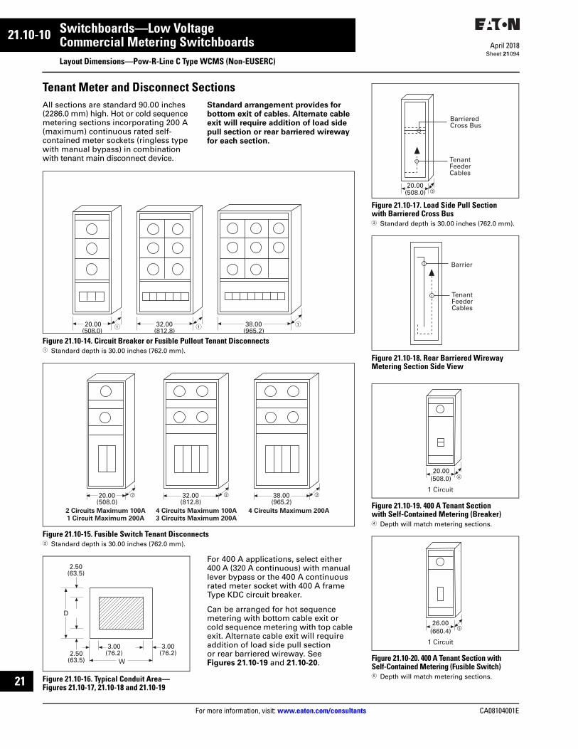
21.10-10
For more information, visit: www.eaton.com/consultants CA08104001E
April 2018
Switchboards—Low Voltage
Sheet 21
i
ii
1
2
3
4
5
6
7
8
9
10
11
12
13
14
15
16
17
18
19
20
21
Commercial Metering SwitchboardsLayout Dimensions—Pow-R-Line C Type WCMS (Non-EUSERC)
094
Tenant Meter and Disconnect SectionsAll sections are standard 90.00 inches (2286.0 mm) high. Hot or cold sequence metering sections incorporating 200 A (maximum) continuous rated self-contained meter sockets (ringless type with manual bypass) in combination with tenant main disconnect device.
Standard arrangement provides for bottom exit of cables. Alternate cable exit will require addition of load side pull section or rear barriered wireway for each section.
Figure 21.10-14. Circuit Breaker or Fusible Pullout Tenant Disconnects1 Standard depth is 30.00 inches (762.0 mm).
Figure 21.10-15. Fusible Switch Tenant Disconnects2 Standard depth is 30.00 inches (762.0 mm).
Figure 21.10-16. Typical Conduit Area—Figures 21.10-17, 21.10-18 and 21.10-19
For 400 A applications, select either 400 A (320 A continuous) with manual lever bypass or the 400 A continuous rated meter socket with 400 A frame Type KDC circuit breaker.
Can be arranged for hot sequence metering with bottom cable exit or cold sequence metering with top cable exit. Alternate cable exit will require addition of load side pull section or rear barriered wireway. See Figures 21.10-19 and 21.10-20.
20.00(508.0)
32.00(812.8)
38.00(965.2)
� � �
4 Circuits Maximum 200A 2 Circuits Maximum 100A1 Circuit Maximum 200A
� � �
4 Circuits Maximum 100A 3 Circuits Maximum 200A
20.00(508.0)
32.00(812.8)
38.00(965.2)
W
D
3.00(76.2)
2.50(63.5)
2.50(63.5)
3.00(76.2)
Figure 21.10-17. Load Side Pull Section with Barriered Cross Bus3 Standard depth is 30.00 inches (762.0 mm).
Figure 21.10-18. Rear Barriered Wireway Metering Section Side View
Figure 21.10-19. 400 A Tenant Sectionwith Self-Contained Metering (Breaker)4 Depth will match metering sections.
Figure 21.10-20. 400 A Tenant Section with Self-Contained Metering (Fusible Switch)5 Depth will match metering sections.
20.00(508.0)
BarrieredCross Bus
TenantFeederCables
�
Barrier
TenantFeederCables
20.00(508.0) �
1 Circuit
26.00(660.4) �
1 Circuit

CA08104001E For more information, visit: www.eaton.com/consultants
21.10-11April 2018
Switchboards—Low Voltage
Sheet 21
i
ii
1
2
3
4
5
6
7
8
9
10
11
12
13
14
15
16
17
18
19
20
21
Commercial Metering SwitchboardsLayout Dimensions—Pow-R-Line C Types WWCMS (EUSERC Only) and WCMS
095
All sections are standard 90.00 inches (2286.0 mm) high. Add 13.00 inches (330.2 mm) to depths shown for NEMA Type 3R outdoor enclosure. Add 9.00 inches (228.6 mm) for NEMA Type 3R on single section 36.00 inches (914.4 mm) wide only.
Tenant Sections Arranged for Transformer-Rated MeteringIncludes utility-approved metering compartment with provisions for mounting current transformers for metering circuits rated 400 A and above.
Disconnect device can be either a single fusible switch or circuit breaker arranged for hot or cold sequence.
A 22X chassis for installation of multiple disconnects on one metered circuit is also available for hot sequence metering.
Standard cable exit is at the bottom. For top cable exit, add wireway barrier.
Figure 21.10-21. Multiple Disconnects (22X Chassis—See Figures Below)1 Depth (D) will match depth of main
device section.Note: Refer to panel layout guides.
Figure 21.10-22. 22X Chassis Layout Guide—Fusible Switches
Switchboard Section—Layout and Dimensions
W
SingleDisconnect
or22X Chassis
30A 30A
60A
100A 240V Max.
100A 240V Max.
100A
200A
100A 100A
400A Branch
600A Branch
200A 200A
800A Branch
1200A Branch
36 in
ch (
914
.4 m
m)
Wid
eS
tru
ctu
re45
inch
(114
3.0
mm
) W
ide
Str
uct
ure
4X
4X
4X
5X
6X
5X
9X
11X
6X
11X
16X
Table 21.10-19. Single Tenant Disconnect Service Sections—Dimensions in Inches (mm)
2 Depth (D) will match depth of main device section.3 Also requires 20.00-inch (508.0 mm) wide pull section.
Figure 21.10-23. Typical Conduit Areas—Bottom Cable Exit
Figure 21.10-24. 22X Chassis Layout Guide—Circuit Breakers, 1X = 1.38 inches (34.9 mm)
Type
Disconnect
Ampere
Rating
Type WWCMS (EUSERC) Type WCMS
W D 2 W D 2
Fusible Switch—DisconnectFusibleswitch
400600800
36 (914.4) 24 (609.6) 36 (914.4) 30 (762.0)
1200 38 (965.2) 30 (762.0)
Boltedpressureswitch 3
800 36 (914.4) 30 (762.0)
12001600
38 (965.2) 30 (762.0)
Circuit Breaker—DisconnectKD, HKD, KDC 400 36 (914.4) 24 (609.6) 36 (914.4) 30 (762.0)
LD, HLD, LDC 600
MDL, NG 800
NG, NGH, NGC 3 1200 36 (914.4) 30 (762.0)
RG 3 1600
W
D
3.00(76.2)
2.50(63.5)
Single Disconnect
W
D 12.00(304.8)
22X Chassis
2.50(63.5)
3.00(76.2)
2.50(63.5)
3.00(76.2) 3.00
(76.2)
1P 1P2P 2P
2P 2P
3P 3P
3P 3P
2 or 3P
2 or 3P
2 or 3P
2 or 3P
2 or 3P 2 or 3P
36 in
ches
(914
.4 m
m) W
ide
Str
uctu
re
1X2X
3X
3X
3X
4X
6X
6X
2X
3X
225
225
250
400
600
250
800
1200
EHD,FDB, FD, FDEHFD, FDC, HFDE, FDCE
EDB, EDS,ED, EDH, EDC
JD, HJD,JDC
DK, KD,HKD, KDC
LD, HLD,LDC
JD, HJD,JDC
MDL
ND, HND,NDC
MaximumAmperes Frame
4X 600 LGE, LGH, LGC2 or 3P

21.10-12
For more information, visit: www.eaton.com/consultants CA08104001E
April 2018
Switchboards—Low Voltage
Sheet 21
i
ii
1
2
3
4
5
6
7
8
9
10
11
12
13
14
15
16
17
18
19
20
21
096
This page intentionally left blank.
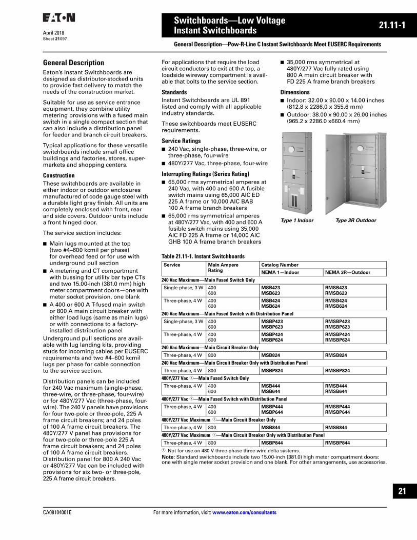
CA08104001E For more information, visit: www.eaton.com/consultants
21.11-1April 2018
Switchboards—Low Voltage
Sheet 21
i
ii
1
2
3
4
5
6
7
8
9
10
11
12
13
14
15
16
17
18
19
20
21
Instant SwitchboardsGeneral Description—Pow-R-Line C Instant Switchboards Meet EUSERC Requirements
097
General DescriptionEaton’s Instant Switchboards are designed as distributor-stocked units to provide fast delivery to match the needs of the construction market.
Suitable for use as service entrance equipment, they combine utility metering provisions with a fused main switch in a single compact section that can also include a distribution panel for feeder and branch circuit breakers.
Typical applications for these versatile switchboards include small office buildings and factories, stores, super-markets and shopping centers.
ConstructionThese switchboards are available in either indoor or outdoor enclosures manufactured of code gauge steel with a durable light gray finish. All units are completely enclosed with front, rear and side covers. Outdoor units include a front hinged door.
The service section includes:
■ Main lugs mounted at the top (two #4–600 kcmil per phase) for overhead feed or for use with underground pull section
■ A metering and CT compartment with bussing for utility bar type CTs and two 15.00-inch (381.0 mm) high meter compartment doors—one with meter socket provision, one blank
■ A 400 or 600 A T-fused main switch or 800 A main circuit breaker with either load lugs (same as main lugs) or with connections to a factory-installed distribution panel
Underground pull sections are avail-able with lug landing kits, providing studs for incoming cables per EUSERC requirements and two #4–600 kcmil lugs per phase for cable connection to the service section.
Distribution panels can be included for 240 Vac maximum (single-phase, three-wire, or three-phase, four-wire) or for 480Y/277 Vac (three-phase, four-wire). The 240 V panels have provisions for four two-pole or three-pole, 225 A frame circuit breakers; and 24 poles of 100 A frame circuit breakers. The 480Y/277 V panel has provisions for four two-pole or three-pole 225 A frame circuit breakers; and 24 poles of 100 A frame circuit breakers. Distribution panel for 800 A 240 Vac or 480Y/277 Vac can be included with provisions for six two- or three-pole, 225 A frame circuit breakers.
For applications that require the load circuit conductors to exit at the top, a loadside wireway compartment is avail-able that bolts to the service section.
StandardsInstant Switchboards are UL 891 listed and comply with all applicable industry standards.
These switchboards meet EUSERC requirements.
Service Ratings■ 240 Vac, single-phase, three-wire, or
three-phase, four-wire■ 480Y/277 Vac, three-phase, four-wire
Interrupting Ratings (Series Rating)■ 65,000 rms symmetrical amperes at
240 Vac, with 400 and 600 A fusible switch mains using 65,000 AIC ED 225 A frame or 10,000 AIC BAB 100 A frame branch breakers
■ 65,000 rms symmetrical amperes at 480Y/277 Vac, with 400 and 600 A fusible switch mains using 35,000 AIC FD 225 A frame or 14,000 AIC GHB 100 A frame branch breakers
■ 35,000 rms symmetrical at 480Y/277 Vac fully rated using 800 A main circuit breaker with FD 225 A frame branch breakers
Dimensions■ Indoor: 32.00 x 90.00 x 14.00 inches
(812.8 x 2286.0 x 355.6 mm)■ Outdoor: 38.00 x 90.00 x 26.00 inches
(965.2 x 2286.0 x660.4 mm)
Table 21.11-1. Instant Switchboards
1 Not for use on 480 V three-phase three-wire delta systems.Note: Standard switchboards include two 15.00-inch (381.0) high meter compartment doors: one with single meter socket provision and one blank. For other arrangements, use accessories.
Type 1 Indoor Type 3R Outdoor
Service Main Ampere
Rating
Catalog Number
NEMA 1—Indoor NEMA 3R—Outdoor
240 Vac Maximum—Main Fused Switch OnlySingle-phase, 3 W 400
600MSB423
MSB623
RMSB423
RMSB623
Three-phase, 4 W 400600
MSB424
MSB624
RMSB424
RMSB624
240 Vac Maximum—Main Fused Switch with Distribution PanelSingle-phase, 3 W 400
600MSBP423
MSBP623
RMSBP423
RMSBP623
Three-phase, 4 W 400600
MSBP424
MSBP624
RMSBP424
RMSBP624
240 Vac Maximum—Main Circuit Breaker OnlyThree-phase, 4 W 800 MSB824 RMSB824
240 Vac Maximum—Main Circuit Breaker Only with Distribution PanelThree-phase, 4 W 800 MSBP824 RMSBP824
480Y/277 Vac 1—Main Fused Switch OnlyThree-phase, 4 W 400
600MSB444
MSB644
RMSB444
RMSB644
480Y/277 Vac 1—Main Fused Switch with Distribution PanelThree-phase, 4 W 400
600MSBP444
MSBP644
RMSBP444
RMSBP644
480Y/277 Vac Maximum 1—Main Circuit Breaker OnlyThree-phase, 4 W 800 MSB844 RMSB844
480Y/277 Vac Maximum 1—Main Circuit Breaker Only with Distribution PanelThree-phase, 4 W 800 MSBP844 RMSBP844

21.11-2
For more information, visit: www.eaton.com/consultants CA08104001E
April 2018
Switchboards—Low Voltage
Sheet 21
i
ii
1
2
3
4
5
6
7
8
9
10
11
12
13
14
15
16
17
18
19
20
21
Instant SwitchboardsGeneral Description—Pow-R-Line C Instant Switchboards Meet EUSERC Requirements
098
Table 21.11-2. Meter Compartment Doors(Meter Sockets Not Included)
Table 21.11-3. Meter Sockets—For Field Installation (order separately)
Table 21.11-4. Loadside Wireway—Same Depth as Switchboard
Table 21.11-5. Underground Pull Sections
Note: Same depth as switchboard with provisions for lug landing kit.Note: If pull section is to be installed separate from service section, add side closer plates. Cat No. UGCP.
Table 21.11-6. Lug Landing Kits for Underground Pull Sections
Table 21.11-7. Distribution Breakers
Door Size
Inches (mm)
Drilling Catalog
Number
15.00 H x 32.00 W(381.0 x 812.2)
Blank1 socket
MD150
MD151
30.00 H x 32.00 W(762.0 x 812.2)
Blank2 socket
MD300
MD302
Number
of Jaws
Catalog
Number
456
M4
M5
M6
81315
M8
M13
M15
Section
Width
Inches (mm)
Catalog Number
NEMA 1—
Indoor
NEMA 3R—
Outdoor
12.00 (304.8) LSS12W RLSS12W
SectionWidthInches (mm)
Catalog Number
NEMA 1—Indoor
NEMA 3R—Outdoor
24.00 (609.6)30.00 (762.0)
UG24WUG30W
RUG24WRUG30W
MaximumAmpereRating
Service CatalogNumber
400 Single-phase, 3WThree-phase, 4W
LL4003LL4004
800 Single-phase, 3WThree-phase, 4W
LL8003LL8004
Ampere Rating
TypeBreaker
Poles
1P 2P 3P
240 Vac15–6070–100
125–225
BABBABED
X——
XXX
XXX
480Y/277 Vac15–10070–225
GHBFD
X—
XX
XX