contents erection - tradehouse
TRANSCRIPT

Contents Erection
Designation Identification No. of pages
Main assembly Drawing C1-00.00063000-00 1
Safety instruction 4509-02 1 General hints 4861-00 2
Site requirements 4503-00 1 Supply installation 4541-00 1
Stock area 4504-00 1 Delivery 4507-00 1
Delivery / Erection damage 4506-00 1 Pre-erection responsibility 4502-01 3
Pre-erection checks 4511-00 2 Faults 4555-00 1
Pre-erection on ground 4951-01 1 Bolt torques 4537-05 1
Torque thightening of 2¼” special structure bolt 5498-02 1 Erection guide 5611-00 6 Wire reeving 5610-00 1
Counterweight table 5585-00 1 Fitting of slewing bearing ring 2059-02 2
Tooth clearance for slewing bearing rings 2011-06 1 Torques for slewing bearing ring bolts 2266-10 1
Tests and Inspection after erection 5507-02 1

A ( 1 : 25 ) From rear (jib not shown) ( 1 : 25 )
1
1
2
2
3
3
4
4
5
5
6
6
7
7
8
8
9
9
10
10
11
11
12
12
A A
B B
C C
D D
E E
F F
G G
H H
SURFACE TREATMENT:
REPLACED BY:
REPLACES:
CHECK :
DRAWN :
DESIGN :
ORIGINATES FROM:
PHONE: +45 48 187400 FAX: +45 48 188807
KRØLL CRANES A/SDRAWING NO.:
ASSEMBLY DRAWING
SHEET NUMBER:
NORDKRANVEJ 2 3540 LYNGE DENMARK
CRANE TYPE
SCALE:
PROJ. QTY
SURFACE AREA:
m
3
TITLE:
m
2MATR.:
PARTS LIST:
DIM.:
TOTAL WEIGHT:
VOLUME:
E-mail: [email protected] Web: www.krollcranes.dk
150507 HK
150507 HK
150507 JL
K230F
1 : 100
50141 kg
K230F top crane assembly
C1-00.00063000-00
1 / 1
08-05-2015 10:02 R:\Tegning\K230F\Hovedsamling\63000 K230F-60m main assembly.idw
A
3203201Eurolift 2160 Hoist wire Ø12, 450mxxx09.168124508 5005001 Counterweight block 500 kgC2-72.000620217 26000200013 Counterweight block 2000 kgC2-72.000620206 5975971 Rear stays assemblyC2-09.000630045 503050301 Counterjib assemblyC1-04.000630034 10868108681 Jib assembly, 60 mC1-02.000630013 9829821 Top tower assemblyC1-04.000630052 584358431 Slewing/masthead assemblyC1-03.000630061
Total weightWeightPcsType/qualityLengthTitleDrawing/part no.Item
B
76
4
2
5
2 3
5
4
1
4.35
m
3625
12.9 m (tail radius)
1
61.94 m
1.45
m3.
42 m
3
60 m
1600
3625

Safety Erection
INF.REF. 4509-02 PAGE 1/2
SAFETY INSTRUCTIONS This instruction does not superseed any local regulations for the safety of work. Before erection and starting of the plant as well for the operation and maintenance, strictly follow the instruction manual. It is prohibited to remain under the suspended load or within the working radius of the slewing platform. The assembly area is to be made safe. When working in heights, a harness is to be worn and used. No loose parts on the suspended crane parts to be found. Wind load has a considerable influence on crane stability. Due to this crane assembly and climbing operations are only to be carried out up to wind speeds of 12.5 m/s equivalent to 45 km/t, and telescoping operation is only allowed up to 10 m/s (36km/t). Disregarding these warnings can cause serious damage, physical injuries or death. ASSEMBLY CONDITIONS Before assembly during unstable weather conditions, it is recommended to check the weather forecast to ensure that the assembly can be safely completed. Before commencing any assembly, remove any protection from machined or non-painted surfaces. Before beginning work, all assembly instructions should be studied in detail to avoid time and material losses, and not to endanger human life. Before using bolts and nuts, note any special requirements for bolt torque's during preassembly in the erection guide. The crane base foundation should be prepared, together with any other responsibilities of the Purchaser outside the contents of the crane order, i.e. counterweight blocks, etc. All concrete work carried out should have sufficient curing time before being put into use. For assembling the crane it is necessary to employ a mobile crane. Lifting height is dependent on the necessary or wanted height under hook of the tower crane. Details on the single weights and mounting heights, and of the required height under hook for the mobile crane are found in erection section. Differences in level on the site to mobile crane (mounting height) must be considered.

Safety Erection
INF.REF. 4509-02 PAGE 2/2
Before start of assembly, make sure that the ballast blocks available corresponds with the specification for weight and dimensions. If necessary they must be weighed again. All blocks are to be marked legibly with their actual weight. Before assembly the crane, parts are to be inspected by an expert (experienced erector) in order to ensure hight security and trouble-free erection. Level sections of i.e. jibs off the ground for preassembly. Use for example planks or sleepers. For guidance and advise of assembly procedures for tower cranes and for training of not yet sufficiently experienced personnel, KRØLL or representatives will upon request delegate specialists.

General hints Erection
INF.REF. 4861-00 PAGE 1/2
Tower cranes are to be erected or dismantled under experienced guidance always. The crane should be operated by experienced personnel only. Observe in particular the manufacturer’s instructions for operation and keep one set of these instructions always at site. WARNING! When erecting, observe all relevant accident prevention rules and be sure about particular local rules. Make safe erection area. During erection and maintenance operations a safety belt must be used and worn. Failure to observe this warning is dangerous and can lead to serious material damage as well as to physical injuries under certain circumstances resulting in death. Works on the electric systems may be carried out only by experienced electrician. We strongly recommend a detailed study of all erectional hints and instructions before the job is started, to avoid time- and material losses and to not endanger the life or health of human beings. Before start of erection, the erector in-charge has to make sure together with the engineer in-charge at site, that the ballast stones available correspond to the weight and dimensions of the Krøll regulations. If necessary, they must be weighed again. All stones are to be marked legibly with their actual weight. Before erection the crane components have to be inspected by an expert (experienced erector) in order to ensure highest security and trouble-free erection. Wind loads have a considerable influence on the stability of cranes. Therefore the wind force during erection must not exceed wind speed of 12.5 m/s corresponding to 45 km/h. To ensure a safe crane erection it is strongly recommended to inquire about the forecasts for the erection time from authorized or official weather stations, before erection is started. Deviations from the above instructions require a consultation of the manufacturer giving a detailed description of circumstances, as well as an approval by the local authorities. For crane erection without climbing equipment: Preassemble the necessary tower elements and type acc. to tower configuration (see Technical Data section 1) on the ground. Observe capacity of mobile crane. Place tower elements on the first tower element, pin and secure. For crane erection with climbing equipment: Place tower element acc. to tower configuration, but at least the number of tower elements as given for the basic erection, pin and secure (for further assembly see description of climbing device – separate manual).

General hints Erection
INF.REF. 4861-00 PAGE 2/2
The climbing frame is an erectional means only. It is not supposed to remain on the crane for normal operation. If frequent climbs are necessary for operational reasons, you must inquire the crane data for towers with climber from the manufacturer. A climber increases the wind attack area, the wheel pressures and other data, while the possible height under hook is slightly reduced.

Site requirements Erection
INF.REF. 4503-00 PAGE 1/1
The following points should be noted (and made available): • The receiving area for the shipment should be firm, well drained, and with
good access roads allowing for a turnround for articulated vehicles. • Timber blocks (e.g. rail ties) for the support of parts on delivery. • Tarpaulins (sheets) for covering parts (mainly electrical). • Mobile cranage for unloading. • Pre-assembly areas designated. • Crew shelter, office and tool storage facilities. • Electr. supply point for power tools, welding sets, etc. • Electr. supply point for floodlighting (if required). • Welding and cutting equipment in case of transport damage. • KRØLL CRANES A/S (or their agent's) personnel should be informed on
arrival of first-aid and telephone locations, together with any security arrangements made.
• Site access clearance should be obtained for them, together with any
other relevant information.

Supply installation Erection
INF.REF. 4541-00 PAGE 1/1
• If a trailing el. supply cable is fitted - to prevent wear a fine sand bed or leveled steel
plates should be laid between the tracks for the cable to be towed on. • The trailing cable will normally enter the crane structure on the track centre line. • A trailing cable is not recommended for curve running cranes. • If a cable drum is fitted, it's position is on the track centre line. For curve running
crane fit guides to the rail ties within the curve. • Portal cranes have a side mounted cable drum and guide roller fitted to lay the
cable adjacent to the track on the inside of one side. (Customer order should give any relevant information).
Combination cranes can be supplied with different hoist winch units within the same crane type. The dimensioning of main fuses and feeder cables depends on the winch equipment and not the crane type. It is important that the supply voltage is correct to ensure proper functioning of the crane. Note : KRØLL supply feeder cable to base of crane mast only, (whitout a connection box) or to the cable drum.

Stock area Erection
INF.REF. 4504-00 PAGE 1/1
The crane parts are delivered in packed units and cases (collie). • On unloading, use sling points indicated. Certain parts have sling eyes
welded on. • Support all material on timber blocks. • Consult the assembly drawing and lay parts out in the order of assembly,
especially the jib and counter jib sections. • Unpack parts consigned inside major structural sections before laying
them out in assembly order. In certain instances they can be ladders, platforms or railings belonging to the section they are packed into.
• Leave clear travelling roads and sub-assembly areas. • Cover motors and electrical equipment with sheets. • Plan the arrangement so that mobile carnage can operate from a near
stationary position or be moved in a straight line only. A study of the erection sequence will enable a final layout plan to be made.

Delivery Erection
INF.REF.4507-00 PAGE 1/1
• Check the delivery against the packing shipping list. • Do not open cases and leave contents - especially cardboard box
packings - exposed to the weather. • Remove tools, packed electronic equipment, instruction books, etc., to
secure, dry places. • NOTE: All damaged parts. • The normal KRØLL CRANES A/S colour scheme is red for the structure,
yellow for electrical panels, motors, trolleys and hook assemblies and the operator cabin.
Parts painted blue are for use on erection, and (according to purchase order)
may be returnable. • Check the bolt lists.

Delivery / Erection damage Erection
INF.REF. 4506-00 PAGE 1/1
This information applies both to transport and erection and in particular to all main structural members. • A check should be made as material is received and reports made of
apparent damage. • Consult sheets - 2029 Delivery servicing - 2017 Structure servicing - 2003 Electrodes - 2002 Steel quality • Further information may be found on any relevant drawings in the erection
or service manuals - or on any special requirement material forwarded in accordance with supply requirements.
• It should be noted that after repair, the damage area/component must be
checked and passed by an authorized and qualified inspector. A detailed record must be made and kept with the crane log book.
Main structural member repairs must not be subjected to final erection, until
a "Passed Inspection" notification in writing is given.

Pre-erection responsibilities Erection
INF.REF. 4502-00 PAGE 1/3
PRE-ERECTION RESPONSIBILITY OF THE PURCHASER IS AS FOLLOWS: A: 1) Counterweight blocks have been prepared and are on site. 2) Ballast blocks (when required) have been prepared and are
on site. 3) Test load blocks are weight-checked, marked and on site. 4) Crane base is prepared Bottom cross - Expendable base - Rail-mounted - 5) Crane main electr. supply point is installed in a position near
erection area. 6) Electr. supply point for power tools, welding set, etc. (if
required). 7) Electr. supply and floodlights (if required). 8) Tarpaulins for covering parts (mainly electr.) if delay between
delivery and erection. 9) Timber blocks for support of parts on delivery.
Information sheet Information sheet Information sheet NOTE: KRØLL main electr. installation is from the electr. panel out to all motors & control gear. Feeder cable size & length required is as ordered.
Pre-erection responsibilities Erection
INF.REF. 4502-00 PAGE 2/3
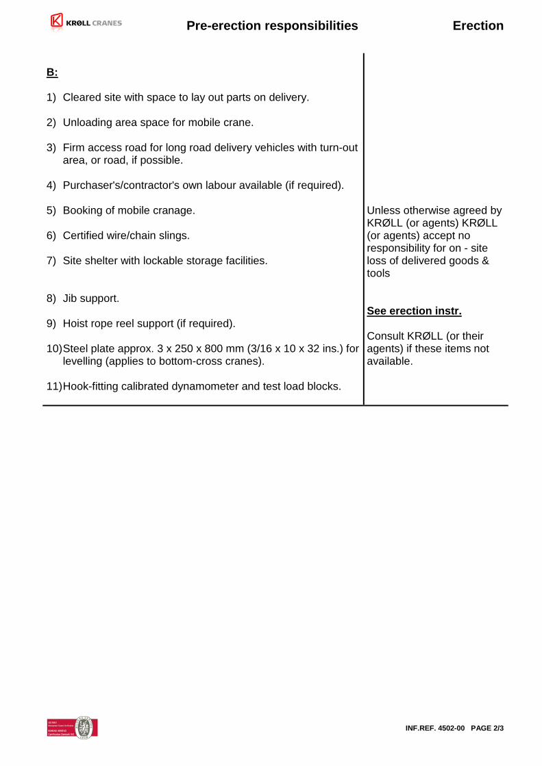
B: 1) Cleared site with space to lay out parts on delivery. 2) Unloading area space for mobile crane. 3) Firm access road for long road delivery vehicles with turn-out
area, or road, if possible. 4) Purchaser's/contractor's own labour available (if required). 5) Booking of mobile cranage. 6) Certified wire/chain slings. 7) Site shelter with lockable storage facilities. 8) Jib support. 9) Hoist rope reel support (if required). 10) Steel plate approx. 3 x 250 x 800 mm (3/16 x 10 x 32 ins.) for
levelling (applies to bottom-cross cranes). 11) Hook-fitting calibrated dynamometer and test load blocks.
Unless otherwise agreed by KRØLL (or agents) KRØLL (or agents) accept no responsibility for on - site loss of delivered goods & tools See erection instr. Consult KRØLL (or their agents) if these items not available.

Pre-erection responsibilities Erection
INF.REF. 4502-00 PAGE 3/3
C: 1) Tools 3-ton pull lift 20-ton hydr. jacks (2) Crowbars (2) Electr. drill 20 mm (3/4") cap. Hand wrench & die for anchor bolt threads (applies to
bottom-cross cranes). Wrenches & spanners up to 1 in. and 24 mm. Welding set } Gas cutting equipment } Disc grinding equipment } 2) Telephone/First-aid equipment. 3) Site access.
Consult KRØLL (or their agents) if these items will not be available These items should be instantly available, if required; (other-wise, consult KRØLL (or their agents)). KRØLL's (or agents') personnel should be informed on arrival at site of location points Site clearance permis-sion for KRØLL's (or their agents') personnel.
* THE CRANE TOOL BOX IS FOR MAINTAINING THE MACHINE AND DOES NOT PROVIDE FOR THE REQUIREMENTS ON AN ERECTION CREW.

Pre-erection checks Erection
INF.REF. 4511-00 PAGE 1/2
PRE-ERECTION CHECKS TO BE CARRIED OUT BY KRØLL'S (OR AGENT'S ) TECHN. ASSISTANT A: EXPENDABLE-BASE-MOUNTED CRANES Check - The foundation pad has had sufficient curing time. - Mast bolt diagonal centres. - With a level, the mast bolt block connection surfaces. - There is a min. of 400 mm (15¾") between underside of mast bolt block and the foundation top. B: BOTTOM-CROSS (B-X) MOUNTED CRANES Check - The foundation pad has had sufficient curing time. - Cast-in anchor bolt centres. - Cast-in anchor bolt height. - Clearance under the cross within the mast area. - Level of the base at anchor bolt position. - Packing plate available if required for levelling. - Hand wrench & die available for anchor bolt threads. C: RAIL-MOUNTED CRANES Check - Rail bed, bed drainage, sleeper type, sleeper quantity per meter (yard). - Source of rail bed calculation. - Rail joints (fish-plate, bolts, tools available), rail joint alignment & sleeper support. - Rail to sleeper fitting, rail head (on used rails), rail spacing tie rods. - Earthing arrangement, end buffers, electr. stop arrangement. - Position/installation of power cable pick-up. - Power cable bed (if trailing cable), provisions for power cable if curve- running. - Special instructions for position of bogie motors, cable, drum, access
ladder. - Number of ballast blocks on site, dimensions, quality, marked-up weight, total weight, quantity required.

Pre-erection checks Erection
INF.REF. 4511-00 PAGE 2/2
D: ALL CRANES Check - Pre-erection information complied with: - Weather conditions likely for the period of erection, site drainage, equipment protection. - Power supply, also whether to be drawn on by other equipment. - Counterweights on site, dimensions, quality, marked-up weight, total weight, quantity required. - Parts for transport damage. - Parts against packing lists. - Booking of adequate size mobile crane (hooks & slings). - Availability of contractor labour. - Required lubricants are on site. - Crane tool box on site. - Storage or transport defects/deficiencies of any supplied tool items (e.g. hydr. torque wrench). - Storage or transport defects/deficiencies of any climbing/telescoping equipment. - Storage or transport defects/deficiencies of any KRØLL (or agents) hired- out equipment (e.g. mech./hydr. erection equipment). - Electrical equipment for transport/storage damage. - Weather/storage deterioration of any items. - For long jib cranes, provision for wind ballasting. - Test loading equipment available. - Suspension ropes with shackles and sufficient capacity.
Faults Erection
INF.REF. 4555-00 PAGE 1/1
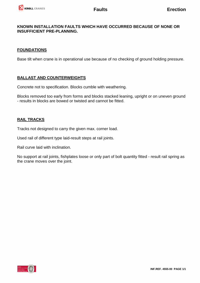
KNOWN INSTALLATION FAULTS WHICH HAVE OCCURRED BECAUSE OF NONE OR INSUFFICIENT PRE-PLANNING. FOUNDATIONS Base tilt when crane is in operational use because of no checking of ground holding pressure. BALLAST AND COUNTERWEIGHTS Concrete not to specification. Blocks cumble with weathering. Blocks removed too early from forms and blocks stacked leaning, upright or on uneven ground - results in blocks are bowed or twisted and cannot be fitted. RAIL TRACKS Tracks not designed to carry the given max. corner load. Used rail of different type laid-result steps at rail joints. Rail curve laid with inclination. No support at rail joints, fishplates loose or only part of bolt quantity fitted - result rail spring as the crane moves over the joint.

Pre-erection on the ground Erection
INF.REF. 4951-01 PAGE 1/1
Before beginning the work place solid wood or beams on the ground for the individual components to avoid sinking into the ground. • Slewing table and masthead. Consult the drawing in the assembly drawings
section. Machined contact faces on slewing bearing ring and mast head must be cleaned. After cleaning the contact faces should be lightly oiled.
• Use only the supplied spec. stud bolts, nuts and washers. Apply a thin coat of Molykote paste 1000 to the thread of the stud bolts.
• Support the slewing frame on the ground allow a space to the stud bolts. Fit all
the stud bolts with one nut and washer in the holes in the slewing frame. Fit the nut and washer as shown on the drawing.
• Lift the slewing frame vertical and carefully lower it into the slewing bearing inner
ring. The filler plug for the balls (which is located on the inner ring) should be positioned approx. 90 degr. from the boom centre line. Fit the stud bolts with washer and nut.
• Tighten all nuts lightly. • Tighten all inner ring stud bolts crosswise with the torque tool (which must be
well adjusted). Tight to 100% torque. • Grease then the slewing bearing ring in accordance with INFO. SHEET 4762
in the maintenance section.
Drivers cabin/platform. Consult the drawing in the assembly drawings section.
• Lift and mount the cabin to the support frame and make up railings and remaining equipment.

Bolt torques - General Service
INF.REF.4537-05 PAGE 1/1
BOLT TORQUES - NOT APPLICABLE TO SLEWING BEARING RING BOLTS
THREAD
QUALITY
TORQUE
NOTE
kpm Nm ft.lbs.
M10 8.8 4.8 48 35
M12 8.8 10.9
8 9.6
80 96
58 70
8.8 – BOLTS:
M14 8.8 12.5 125 90 Norm: DIN 931/933
M16 8.8 10.9
20 25
200 250
145 180
Finish: Bright zinc (fzb)
M18 8.8 27 270 195 Can be used direct from the packing.
M20 8.8 10.9
39 45
390 450
280 325
M22 8.8 10.9
51 65
510 650
360 470
M24 8.8 10.9
66 80
660 800
480 580
10.9 – BOLTS:
M27 8.8 10.9
98 125
980 1250
710 905
Norm: DIN 6914/6915/6916
M30 8.8 10.9
132 165
1350 1650
975 1195
Finish: Hot zinc (fzv)
M33 8.8 185 1850 1340 Nut Molykote-greased (MOS2)
M36 8.8 10.9
240 285
2400 2850
1735 2060
M39 8.8 310 3100 2240 M42 8.8 380 3800 2750 M45 8.8 475 4750 3435 Finish: Hot zinc (fsv) M45 10.9 664 6640 4800 Finish: Black, DIN 931 M45 10.9 475 4750 3435 Nut: RG-1100 grease, (KEMA) M48 8.8 570 5700 4025
5/8" UNC 8.8 21 210 145 3/4" UNC 8.8 34 340 245 7/8" UNC 8.8 52 520 370
1" UNC 8.8 75 750 545 1 1/4" UNC 8.8 87 870 630 1 1/2" UNC 8.8 152 1520 1090
2"-6 UN 9.9 300 3000 2170 2 1/4" UN 9.9 - - - See Inf. Ref. 5498
Torques for slewing bearing ring bolts: Info No. 2266

Special structure connection bolts Service
INF.REF. 5498-02 PAGE 1/1
Torque tightening of 2¼"x6UN special Krøll bolts The bolts are used for connecting main structural units (mast, jib and counterjib sections) Tightening procedure Always check the thread before use. Torque : 2950 Nm Grease : Molykote G-Rapid Plus paste, or Molykote 1000 • Apply G-Rapid Plus paste to
the thread of the bolt using a brush. Also apply paste to the contact face of the nut:
• Insert the bolt into the bolt hole. Fit the nut and hand-tighten. • Use a hydraulic torque wrench to tighten the nut to 2950 Nm. Checking procedure The preloading of the bolt can be checked (if found necessary) using the angle-of-rotation method. • Insert the bolt into the bolt hole. Fit the nut and hand-tighten. • Use an impact wrench and gentle strokes with a hammer to pre-tighten the nut. There will
be a significant sound when there is full contact between the bolt, the structural steel and the nut.
• Mark both the bolt (if the head is not locked during the torque tightening) and the nut. • Tighten the nut to 2950 Nm. • The nut should have turned approx. 115° relative to the bolt head. Re-use after dismantling • Clean bolt and nut for grease and dirt. • Check for damages and cracks. If any doubt – dispose the bolt or nut. • Check that bolt/nut fits smoothly. • Apply grease on damaged spots in the chrome plating for corrosion protection. • Do NOT re-use bolts or nuts older than 10 years.

ERECTION GUIDE K230F
SN 11596 & 11597 - Page 1 of 6 Inf. Ref. 5611-00
1. Masthead and slewing assembly Refer to drawings: C1-03.00063006, Slewing/masthead assembly C2-03.00063014, Driver’s Cabin assembly C3-64.00062154, Cabin rear platform
Slewing and masthead (without driver’s cabin) Total weight: 4.7 tons Slings: 4 x 2000 kg WLL The slewing table and mast head is supplied as a unit. Fit the side platform and railing and ladders The complete slewing and masthead unit can now be lifted and fitted to the crane mast
Driver’s cabin and platform Total weight: 1.2 tons Slings: 2 x 1000 kg WLL Fit the driver’s cabin to the slewing table
Fit and torque tighten all the mast corner bolts.

ERECTION GUIDE K230F
SN 11596 & 11597 - Page 2 of 6 Inf. Ref. 5611-00
2. Top Tower Refer to drawing: C1-04.00063005, Top tower assembly Lift and fit the top tower on the slewing unit Total weight: 1000 kg.
Slings: 3x500 kg WLL

ERECTION GUIDE K230F
SN 11596 & 11597 - Page 3 of 6 Inf. Ref. 5611-00
3. COUNTERJIB Refer to drawings: C1-04.00063003, Counterjib assembly
C2-09.00063004, Rear stays assembly
− Assemble the counter jib sections on the ground. Tighten all bolts to 100% torque. − Fit and position the rear stays on each side. Place the stays properly to allow easy
cotter bolt connections to the stays fitted to the top tower.
● Ensure that the necessary cotter bolts to connect the stays are placed on the counter
jib.
● Lift and fit the complete counter jib using the lifting eyes (Counter jib lifting angle is approx. 10 degrees). Make up the cotter bolt connections between the slewing frame and the counter jib.
Total lifting weight is approximately
5700 kg
Slings: 4 x 2.000 kg WLL

ERECTION GUIDE K230F
SN 11596 & 11597 - Page 4 of 6 Inf. Ref. 5611-00
● Pull – on each side – the stays using a tackle until the final stay connection can be
carried out.
● Let the mobile crane ease down the counter jib and check that the counter jib is
hanging properly in the stays BEFORE IT IS RELEASED FROM THE MOBILE CRANE HOOK.
NOTE: Counterweights are fitted according to the table in the separate sheet.
ERECTION GUIDE K230F
SN 11596 & 11597 - Page 5 of 6 Inf. Ref. 5611-00
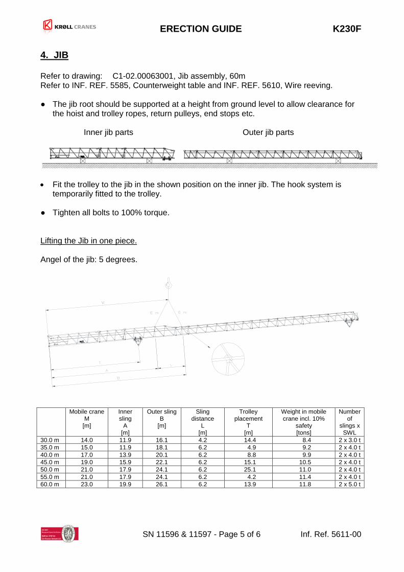
4. JIB Refer to drawing: C1-02.00063001, Jib assembly, 60m Refer to INF. REF. 5585, Counterweight table and INF. REF. 5610, Wire reeving.
● The jib root should be supported at a height from ground level to allow clearance for
the hoist and trolley ropes, return pulleys, end stops etc. Inner jib parts Outer jib parts
• Fit the trolley to the jib in the shown position on the inner jib. The hook system is
temporarily fitted to the trolley. ● Tighten all bolts to 100% torque. Lifting the Jib in one piece. Angel of the jib: 5 degrees.
Mobile crane
M [m]
Inner sling
A [m]
Outer sling B
[m]
Sling distance
L [m]
Trolley placement
T [m]
Weight in mobile crane incl. 10%
safety [tons]
Number of
slings x SWL
30.0 m 14.0 11.9 16.1 4.2 14.4 8.4 2 x 3.0 t 35.0 m 15.0 11.9 18.1 6.2 4.9 9.2 2 x 4.0 t 40.0 m 17.0 13.9 20.1 6.2 8.8 9.9 2 x 4.0 t 45.0 m 19.0 15.9 22.1 6.2 15.1 10.5 2 x 4.0 t 50.0 m 21.0 17.9 24.1 6.2 25.1 11.0 2 x 4.0 t 55.0 m 21.0 17.9 24.1 6.2 4.2 11.4 2 x 4.0 t 60.0 m 23.0 19.9 26.1 6.2 13.9 11.8 2 x 5.0 t

ERECTION GUIDE K230F
SN 11596 & 11597 - Page 6 of 6 Inf. Ref. 5611-00
● Make up the bolt connections between the top tower and the jib. ● Ease off the mobile crane and check that the jib is hanging properly BEFORE IT IS
RELEASED FROM THE MOBILE CRANE HOOK. ● Reeve the trolley rope. See the wire reeving diagrams. ● Reeve the hoist rope. See the wire reeving diagrams.
NOTE: Disconnect the electrical end stop shaft from the drum shaft.
5. FINAL STAGES ● Make up all electrical connections. Reconnect the height/depth stop drive on the hoist
motor.
● Carry out an inspection. Check connection bolts between units for 100% torque.
● Check the painting for erection damage.
● Check all motions and check the line part change-over system.
● The crane is now ready for operational check and adjustment. ● Before the crane is ready for takeover, inspect accoring to INF REF. 5507.

Wire Reeeving K230F
INF. REF. 5610-00
HOIST
TROLLEY

Counter weight table K230F
INF. REF. 5585-00
Blocks before jib
is mounted
Blocks after jib is mounted
Total blocks Total block mass
500 kg 2000 kg 2000 kg 500 kg 2000 kg
Jib length [m] [pcs] [pcs] [pcs] [pcs] [pcs] [kg]
30,0 0 4 5 0 9 18000 35,0 0 4 6 0 10 20000 40,0 0 4 7 0 11 22000 45,0 0 4 8 0 12 24000 50,0 1 4 8 1 12 24500 55,0 0 4 9 0 13 26000 60,0 1 4 9 1 13 26500
Blocks before jib is mounted: Are placed before the jib is mounted. Note: Not to be left on the crane over night. Blocks after jib is mounted: Are placed after the jib is mounted. For further information: See the erection guide.

Fitting / Exchange of slewing bearing rings Service
INF.REF. 2059-02 PAGE 1/2
1. Machined contact faces for slewing bearing rings on mast head and slewing frame must
be cleaned. The surface should be smooth, even and plain. Remove rust, paint, burrs at bolt holes, etc., using a steel brush, emery cloth or similar.
2. The contact faces should be lightly oiled after cleaning. 3. Remove paint, rust, burrs, etc., from the supporting surfaces of the bolt head and nut.
Note that the bolt heads/nuts must abut the supporting surfaces. 4. Do not fit used bolts. Only special bolts and lightly oiled nuts are to be used. Apply a thin
coat of Molykote Paste 1000 to the thread of the nuts before fitting. 5. Remove the protective coating (red or blue) from the contact faces of the slewing ring
using a solvent. Be careful when cleaning to prevent the solvent from entering the bearing.
6. Fit two eye bolts equally spaced on the inner ring bolt circle, lift the slewing ring and care-
fully lower it onto the machined contact face of the mat head. Fit the bolts with loose nuts. NOTE: - Each bolt is to be fitted with a washer both under the head and also under the
nut. 7. The contact faces of the mast head and slewing bearing ring must be checked for out-of-
flatness by inserting a feeler gauge between the mating surfaces both from outside and inside. The permissible out-of-flatness depends on the length of any unevenness; up to 200 mm length = 0.1 mm max., up to 500 mm length = 0.2 mm max. If the deviation exceed these values, the supporting surface must be machined to prevent distortion of the bearing when the bolts are tightened. If machining is not possible, then an air-hardening plastic grout should be used, see special information sheet.
8. Suspend the slewing frame on the hook so that it is vertical when lifted. Lift the slewing
frame and carefully lower it onto the slewing bearing inner ring. The filler plug for the balls (which is located on the inner ring) should be positioned approx. 90 deg. from the jib centre line. Turn the slewing frame until the teeth marked in green of the bearing are in mesh with the slewing pinion of one of the gearboxes. Fit the bolts with loose nuts.
NOTE: - Each bolt is to be fitted with washers both under the head and also under the nut.
9. Check out-of-flatness between slewing frame and slewing bearing ring as described in
para. 7. 10. Check tooth clearance at the point marked in green, see sheet 2011.
Fitting / Exchange of slewing bearing rings Service
INF.REF. 2059-02 PAGE 2/2
11. Tighten all nuts lightly. 12. Tighten all inner and outer ring bolts crosswise with the torque tool set (which must be
well-adjusted). For torque's, see sheet 2266. 13. Grease the slewing bearing ring in accordance with sheet 5413. On the first erection of a crane fitted with a new slewing bearing ring a test run with no load on the hook should be carried out by slewing the jib to the right/left for approx. 2 hrs. and checking the motors for uniform current consumption. Then, the crane should be test loaded followed by re-tightening of all bolts. The crane is now operational.

Tooth clearance for slewing bearing rings Service
INF.REF. 2011-06 PAGE 1/1
MODULE A = mm
8 and 10 14 and 16
0.6 - 1.0 0.8 - 1.4
B = mm
The tooth clearances given on this sheet ONLY apply to new slewing rings/rack segments and pinions. In all other cases, adjustment should be based on the distance from centre line slewing ring/segment to centre line pinion. Please consult KRØLL CRANES A/S for information.
8 10 14 16
approx. 17 22 29 34
When mounting/exchanging slewing bearing rings and gear units on the slewing assembly, the clearance in tooth mesh should be measured at the point on the slewing ring which is marked with a green spot. If the clearance at this point is correct, the tooth mesh will be correct over the full diameter. If the mark cannot be found, at least 4 checks at equidistant points should be taken. The tooth clearance for rack segments should be checked at 3 points, i.e. at the centre plus 0.5 m (20") from both ends. The tolerance given is the minimum. First, fit the slewing bearing ring on the slewing table/undercarriage of the crane, then check the tooth clearance for each slewing gear unit and, finally, tighten the slewing bolts. Tighten the bolts crosswise, first with 20%, then with 60% and finally with 100% of the max. torque. For mounting/exchange of slewing bearing rings, see info. sheet 2059.

Torques for slewing bearing ring bolts Service
INF.REF. 2011-06 PAGE 1/1
The bolts and nuts are supplied with a black finish and lightly oiled thread. A thin coat of Molykote Paste 1000 should be applied to the thread of the nuts before fitting.
CRANE TYPE
THREAD
GRADE
TORQUE REMARKS
kpm Nm ft.lbs. K-68 K-130F K-154/175 K-200D
K-200L K-300/320/333 K-400D K-420 / K-365L K-550 / K-500L
K-560 K-600 K-800
K-1000
*K-1000
K-1200 K-1400
K-1800 K-2500 K-3000/4000/5000
MK-2480 K-10000
M20
M24
M27
M30
M33
M36
M45
M60
10.9
10.9
10.9
10.9
10.9
10.9
10.9
54
93
140
185
258
330
634
1450
540
930
1400
1850
2580
3300
6340
14500
388
680
1030
1340
1870
2390
4677
10465
Ref FFCM drawing: A1-2600.165-A
* From S/N 1528 Applies to all slewing bearing rings supplied as a spare part.

General test / inspection after erection Erection
INF.REF.5507-02 PAGE 1/1
This test and inspection programme is Krølls requirements. It is not an official test for approval of the crane. The programme consists of inspection of parts, and control / adjustments of the control and indication systems. Some of the points can be inspected / verified during erection, i.e. correct torque of bolts, while most is to be checked after erection. Any point checked for repair should be accompanied by a specification of what needs to be repaired, where on the crane. N.A. Rep. OK
Steel Structure Inspection Dents, or bend members in any part of the steel structure. ☐ ☐ ☐ Other faults in structure (write here): ☐ ☐ ☐ Damage to paint, that needs repair. ☐ ☐ ☐ Correct torque of bolts in connections between structure parts. ☐ ☐ ☐ All access ways and workstation are undamaged. ☐ ☐ ☐
Motors and gears Check oil level on all gears. ☐ ☐ ☐ All wire connections are safe and sound. ☐ ☐ ☐ Slew ring greasing system is filled and in working order. ☐ ☐ ☐ Air- and drainholes are free and clean. ☐ ☐ ☐ Hoist gear and drum are correctly aligned. ☐ ☐ ☐
Wires Wires are free from damage. ☐ ☐ ☐
Trolley / Hook system Test of trolley system. ☐ ☐ ☐ Test of hook blocks including change of line part reeving. ☐ ☐ ☐
Control systems All control systems are in working order. ☐ ☐ ☐
Indication and warning systems All indication and warning systems are in working order. ☐ ☐ ☐
Other tests and inspections All lubrication points are undamaged. ☐ ☐ ☐ Test loading carried out acc. to Inf. Ref 2070. ☐ ☐ ☐