contents 3 project description 3 - ebrd
TRANSCRIPT

Amulsar Gold Mine Project Environmental and Social Impact Assessment, Chapter 3
ZT520088 May 2016
Version 10 Page i
CONTENTS 3 PROJECT DESCRIPTION ............................................................................................................ 3.2
3.1 Project Overview ........................................................................................................................ 3.2 3.2 Characteristics of the Ore and Barren Rock ............................................................................. 3.11
3.2.1 Barren Rock Mineralogy and Acid Rock Drainage (ARD) ................................................. 3.12 3.2.2 Schedule of NAG and PAG Waste .................................................................................... 3.13
3.3 Site Development and Phasing ................................................................................................ 3.13 3.4 Exploration ............................................................................................................................... 3.16 3.5 Early Works .............................................................................................................................. 3.16 3.6 Construction ............................................................................................................................. 3.16 3.7 Open Pit Mine .......................................................................................................................... 3.19
3.7.1 Site Layout and Development .......................................................................................... 3.19 3.7.2 Operations........................................................................................................................ 3.25
3.8 Barren Rock Storage Facility (BRSF) and Pit Backfill ................................................................ 3.28 3.8.1 Site Layout and Development .......................................................................................... 3.28 3.8.2 Construction and Commissioning .................................................................................... 3.32 3.8.3 Operations........................................................................................................................ 3.34
3.9 Crushing Plant .......................................................................................................................... 3.35 3.9.1 Site Layout ........................................................................................................................ 3.35 3.9.2 Operations........................................................................................................................ 3.36
3.10 Ore Conveyance and Heap Stacking ........................................................................................ 3.38 3.10.1 Site Layout ........................................................................................................................ 3.38 3.10.2 Operations........................................................................................................................ 3.39
3.11 Heap Leach Facility (HLF) ......................................................................................................... 3.40 3.11.1 Site Layout and Development .......................................................................................... 3.40 3.11.2 Construction and Commissioning .................................................................................... 3.46 3.11.3 Operations........................................................................................................................ 3.53 3.11.4 Summary of Design .......................................................................................................... 3.53
3.12 Adsorption-Desorption Recovery (ADR) Plant ......................................................................... 3.54 3.12.1 Site Layout ........................................................................................................................ 3.54 3.12.2 Construction ..................................................................................................................... 3.57 3.12.3 Operations........................................................................................................................ 3.57
3.13 Water Management ................................................................................................................. 3.59 3.13.1 Objectives ......................................................................................................................... 3.59 3.13.2 Site Wide Project Water Balance during Construction .................................................... 3.62 3.13.3 Site Wide Project Water Balance during Operation ........................................................ 3.63 3.13.4 Site Drainage .................................................................................................................... 3.68 3.13.5 BRSF Contact Water ......................................................................................................... 3.68 3.13.6 Heap Leach Facility Water Circulation ............................................................................. 3.69 3.13.7 Domestic Water Treatment ............................................................................................. 3.70 3.13.8 Firewater .......................................................................................................................... 3.71
3.14 Support Infrastructure and Activities....................................................................................... 3.71 3.14.1 Laboratories ..................................................................................................................... 3.72 3.14.2 Access and Haul Roads ..................................................................................................... 3.73 3.14.3 Electricity Supply .............................................................................................................. 3.75 3.14.4 Domestic and Industrial Solid Waste Handling ................................................................ 3.75 3.14.5 Reagent Storage and Handling ......................................................................................... 3.77

Amulsar Gold Mine Project Environmental and Social Impact Assessment, Chapter 3
ZT520088 May 2016
Version 10 Page ii
3.14.6 Transport Management ................................................................................................... 3.83 3.14.7 Fencing and security ........................................................................................................ 3.85
3.15 Labour and Services ................................................................................................................. 3.85 3.15.1 Workforce ........................................................................................................................ 3.85 3.15.2 Nationality of Workforce ................................................................................................. 3.87 3.15.3 Recruitment and Training ................................................................................................ 3.88 3.15.4 Housing and Accommodation .......................................................................................... 3.88
3.16 Land Take and Consumption of Raw Materials ....................................................................... 3.88 3.16.1 Land Take ......................................................................................................................... 3.88 3.16.2 Energy and Fuel ................................................................................................................ 3.89 3.16.3 Water ............................................................................................................................... 3.90 3.16.4 Construction Materials .................................................................................................... 3.91 3.16.5 Other Raw Materials and Requirements ......................................................................... 3.92
3.17 Closure and Decommissioning ................................................................................................. 3.92 TABLES Table 3.1: Distance from Various Aspects of the Mine and Infrastructure to Nearest Settlements and Other Environmental / Geographic Features (km) .................................................................................. 3.10 Table 3.2 In-Situ Volumes of Waste Type by Mining Period .................................................................... 3.13 Table 3.3: Mining Ore Production Rates: total of all pit stages ............................................................... 3.25 Table 3.4: Mass of Barren Rock and Ore to be Mined from each Amulsar Deposit ................................ 3.26 Table 3.5: Mining Equipment List ............................................................................................................ 3.27 Table 3.6: BRSF Schedule ......................................................................................................................... 3.32 Table 3.7: Crushing Plant Equipment Specifications ................................................................................ 3.37 Table 3.8: Amulsar Contact Water Storage capacity ............................................................................... 3.60 Table 3.10: Chemical and Reagent Types and Storage ............................................................................ 3.77 Table 3.11: Duty Roster for Amulsar Project Employees ......................................................................... 3.87 Table 3.12: Number of Employees at Amulsar Gold Mine by Department ............................................. 3.87 Table 3.13: Diesel Consumption .............................................................................................................. 3.89 Table 3.14: Electrical Consumption for Amulsar Project ......................................................................... 3.89 Table 3.15: Consumption or Raw Material Use ....................................................................................... 3.92 FIGURES Figure 3.1: Project Site Layout ................................................................................................................... 3.5 Figure 3.2: Preliminary life of mine schedule ............................................................................................ 3.8 Figure 3.3: Proposed Development Schedule .......................................................................................... 3.15 Figure 3.4: Ore and Barren Rock Production Rates ................................................................................. 3.20 Figure 3.5: Barren Rock Mining Rates and Destinations of Mined Barren Material................................ 3.21 Figure 3.6: Project Design Pit Development Year 1 ................................................................................. 3.22 Figure 3.7: Project Design Pit Development Year 4 ................................................................................. 3.23 Figure 3.8: Project Design Pit Development End of Mine Life (Year 9, Prior to Erato Backfill) ............... 3.24 Figure 3.9: BRSF – Phase 1, February 2016 .............................................................................................. 3.29 Figure 3.10: BRSF – Phase 2, February 2018 ............................................................................................ 3.30 Figure 3.11: BRSF – Phase 3, January 2021 .............................................................................................. 3.31 Figure 3.12: Isometric view of the Crushing and Screening Plant Layout looking southwest ................. 3.36 Figure 3.13 Truck Load-out Station and Fine Ore Stockpile .................................................................... 3.39 Figure 3.14: Phase 1 Leach Pad Layout and Ore Heap Plan ..................................................................... 3.42

Amulsar Gold Mine Project Environmental and Social Impact Assessment, Chapter 3
ZT520088 May 2016
Version 10 Page iii
Figure 3.15: Phases 1-2 Leach Pad Layout and Ore Heap Plan ................................................................ 3.43 Figure 3.16: Phases 1-3 Leach Pad Layout and Ore Heap Plan ................................................................ 3.44 Figure 3.17: Phases 1-4 Leach Pad Layout and Ore Heap Sections ......................................................... 3.45 Figure 3.18: Collection ponds details and sections .................................................................................. 3.47 Figure 3.19: Site Plan ADR Plant Area ...................................................................................................... 3.56 Figure 3.20: Operations Phase Water Balance Flow Chart ...................................................................... 3.64 Figure 3.21: Project Water Infrastructure ............................................................................................... 3.67 Figure 3.22: Truck Shop and Ancillary Buildings Layout .......................................................................... 3.80 Figure 3.23: Detail of Reagent and Acid Buildings at ADR Plant .............................................................. 3.81 Figure 3.24: Access Junctions to the Project............................................................................................ 3.84 Figure 3.25: Estimated accommodation requirements for non-local construction workforce ............... 3.86 APPENDICES Appendix 3.1: Amulsar Passive Treatment System (PTS) design basis


Amulsar Gold Mine Project Environmental and Social Impact Assessment, Chapter 3
ZT520088 May 2016
Version 10 Page 3.2
3 PROJECT DESCRIPTION
This chapter provides an overview of the Project components from construction through
operations, reclamation, closure and rehabilitation of the mine. The Project Overview
(Section 3.1) provides a brief summary of the Project’s overall development, operations and
closure activities. More detailed descriptions defining the construction, operation and
rehabilitation are considered in subsequent sections.
All descriptions of Project construction, operations and closure activities should be interpreted
as planned, and are subject to refinement as detailed design progress. However, the location and
design details of mine facilities and infrastructure, the proposed mining and processing methods
plus the mine waste management principles will not be subject to further change, without recourse to further interpretation in the ESIA. Where design features of the project components
are subject to refinement, as a consequence of detailed design and construction, it is anticipated
that these will not have further influence on either the predicted impacts or appropriateness of the mitigation and management plans proposed in the ESIA.
3.1 Project Overview
The Amulsar gold and silver deposits are located on the ridge peaks of Amulsar Mountain, in the Northern Zangezur mountain chain, with most of the mine infrastructure proposed on the west
side of the mountain at lower elevation. The mine will utilize conventional open pit mining
technology, with the extraction of gold and silver through a heap-leaching process followed by conventional recovery and smelting to Doré bullion.
The Project consists of the following main phases: • Exploration: This phase has been ongoing since 2006 and comprises of exploratory
surveys and techniques including surface mapping, exploration drilling, and analysis of
soil geochemistry, which has been used to define the geological resource to support a
future mine development. There will be continued and ongoing exploration at the site
during the mine construction and operation activities to identify possible additional ore.
• Construction: This phase will comprise the construction of the infrastructure required for
the operation of the mine, processing of ore and refining of precious metals, including ancillary infrastructure such as maintenance workshops and site offices. Currently, the
Amulsar Gold Mine Project Environmental and Social Impact Assessment, Chapter 3
ZT520088 May 2016
Version 10 Page 3.3
early works, pre-construction phase has been programmed to commence in during Q3,
2016.
• Operations: The operations will comprise of production of gold and silver (as Doré)
through the phased mining of ore and barren rock from the open pits together with the
processing of ore, and placement of barren rock in the storage facility.
Closure: The closure phase includes post operation activities, which comprises of the
reclamation of the open pits, BRSF, and the HLF. Topsoil stockpiles established during
construction will be used during site reclamation and closure. Infrastructure will be
dismantled and disturbed areas will be restored to grasslands or other habitats similar to
those currently present within the Project footprint.
The major Project components that will be developed during the construction and operation
phases comprises of the following (see also Figure 3.1):
• Open pits; • BRSF and Tigranes/Artavazdes pit backfill (barren rock repositories);
• Contained non hazardous landfill cell
• Crushing plant (consisting of primary and secondary crushers with intermediate
conveyors and screening plant); • Run-of-Mine (ROM), crushed ore, and low-grade ore stockpiles;
• Topsoil stockpiles;
• Haul roads and access roads; • Overland conveyor, crushed ore stockpile and truck load-out area;
• Heap Leach Facilities including:
• Heap leach pad (HLP);
• Solution collection pond, stormwater event ponds;
• Adsorption-Desorption Recovery (ADR) plant;
• Analytical and metallurgical laboratory;
• Reagent warehouses;
• Temporary hazardous waste storage facility, with potential for incineration;
• Subject to further detailed design the contained non hazardous landfill cell
may be constructed between the HLF and truck load out area;
• Passive water treatment system;
• Maintenance shop and parts warehouse; and

Amulsar Gold Mine Project Environmental and Social Impact Assessment, Chapter 3
ZT520088 May 2016
Version 10 Page 3.4
• ADR Plant offices.
• Sediment control ponds;
• Mine Fleet Truck Shop (maintenance workshops); • Mine Administration Offices;
• Domestic waste-water treatment facilities (bio-digesters, septic tanks and leach fields);
• Explosives magazines (two sites); and • A worker accommodation camp with space and infrastructure sized to accommodate
between 500 and 920 workers during the construction phase. For the operational phase
of the mine, the workforce that does not already live locally will be accommodated in a
combination of either the worker accommodation camp, and/or existing hotels and/or
apartment accommodations in Jermuk.
Figure 3.1 provides an overview of the Project layout.

Amulsar Gold Mine Project Environmental and Social Impact Assessment, Chapter 3
ZT520088 May 2016
Version 10 Page 3.5
Figure 3.1: Project Site Layout

Amulsar Gold Mine Project Environmental and Social Impact Assessment, Chapter 3
ZT520088 May 2016
Version 10 Page 3.6
Open Pits
Mining of the Amulsar deposit will use conventional open pit mining methods over the planned
10-year life of the mine. The Artavazdes and Tigranes areas will be mined in advance of the Erato
open pit, which requires further rock removal (pre-stripping) to expose the ore body. Barren rock,
with mineral values below the economic cut-off grade, from the Tigranes and Artavazdes deposits
will be stockpiled in the BRSF and the barren rock from the Erato area will be used to partially
backfill the Tigranes and Artavazdes pits during the later stages of the mine life to facilitate
reclamation and closure.
Crushing and Screening of Ore
The crushing and screening facility, and head-end of the overland conveyor will be located
approximately 2.7km north of the Erato pit. The mine maintenance workshops, mine administration offices and other smaller facilities will be located approximately 0.8km north of
the crushing facility.
Location and Design of BRSF (See Figure 3.9 to Figure 3.11)
Some of the barren rock at Amulsar has the potential to produce acid rock drainage (ARD) if it
comes into contact with air and water. Potentially acid generating (PAG) material will be segregated and encapsulated within the BRSF to mitigate formation of ARD and runoff.
The BRSF will be located on the north side of Amulsar Mountain, approximately 3.8km from
Tigranes pit and 2.6km north of Erato and will consist of a barren rock storage pad with a pond
at the toe to collect contact water.
The BRSF will be constructed with a low-permeability compacted clay liner consisting of re-
compacted subsoil. A layer of non-acid generating (NAG) barren rock will be placed over the
compacted soil liner. Any water emanating through the foundation of the BRSF will travel through this layer towards the toe of the facility to the BRSF Toe Pond (labeled PD-7 , Toe Pond – BRSF)
where it will be collected and piped to the Contact Water Ponds (labeled PD - 8A, HLF Pond #8
and PD - 8B, HLF Pond #8) at the HLF.
In addition to PAG, some low-grade ore will also be stored temporarily at the BRSF where it will
await processing at the end of mine life when higher grade ore is no longer available.

Amulsar Gold Mine Project Environmental and Social Impact Assessment, Chapter 3
ZT520088 May 2016
Version 10 Page 3.7
Location and Design of HLF (See Figure 3.14 to Figure 3.17)
The Heap Leach Facility is located approximately 6.8km to the west of the crushing plant.
Crushed ore will be transported approximately 5.6km on a covered, ground level, Overland
Conveyor from the crusher to the crushed ore stockpile at the truck load-out facility near the HLF.
Ore will be loaded into haul trucks at the western end of the conveyor for placement on the Heap
Leach Pad (HLP), constructed with the HLF, the crushed ore will be tipped in 8m lifts; to a
maximum nominal height of 120m above the HLP.
An access road / utility corridor will be constructed near the proposed conveyor route for
installation, maintenance and monitoring of the conveyor, as well as to access the crusher and
production infrastructure at the top of the mountain. Fibre-optic cable, water and power lines will also be located in this corridor to minimize land disturbance and provide easy access for
inspection and maintenance.
Closure and Rehabilitation
The closure and rehabilitation phase includes the reclamation of the open pits, BRSF, HLF, and
solution management ponds, as well as the dismantling of infrastructure and restoration of
disturbed areas back to grassland habitats similar to those currently in the area.
Preliminary Life of Mine Schedule through to Closure and Rehabilitation
The life of mine (LOM) and proposed reclamation, closure and rehabilitation (RCAR) schedule is
outlined in Figure 3.2.

Amulsar Gold Mine Project Environmental and Social Impact Assessment, Chapter 3
ZT520088 May 2016
Version 10 Page 3.8
Figure 3.2: Preliminary life of mine schedule

Amulsar Gold Mine Project Environmental and Social Impact Assessment, Chapter 3
ZT520088 May 2016
Version 10 Page 3.9
Mining and associated operations are anticipated to commence in Q1, 2018 following
construction of the haul roads, BRSF, mine processing and ancillary facilities together with the
HLF and associated infrastructure.
The Project components occupy 599 ha, which along with the area of land immediately adjacent
to the project footprint that is likely to be disturbed as a consequence of construction amounts
to 922ha of land as a combined total. There is an additional restricted area (either fenced for
safety reasons or temporarily restricted during blasting in the open pits) of 383ha. The
approximate distances from specific items of mine infrastructure to neighbouring settlements
and features are summarised in Table 3.1.
The following number of privately owned land plots are affected by the Project:
• HLF: 238 plots (Phase 1&2), of which 234 (98.3%) are acquired (4 expropriation); plus about 15 plots in Phase 3&4, acquisition of which is underway;
• A total of 40-42 plots within Phase 3 (15 in HLF) & 4 (26 under the Conveyor): as of April
25, out of this total number, 24 plots are acquired (60%);
• Overland conveyor from the crusher to the heap leach facility: approximately 23 plots, for
which livelihood surveys and land valuation have been completed in January 2016; and
• Access road and infrastructure platforms: approximately 20 plots used mainly for hay
cutting.
The Project design will incorporate the principles of ‘design for closure’ from the outset.
Progressive restoration will be carried out where possible. The budget for the closure plan will
be detailed to achieve long term sustainability to ensure the chemical and physical stability of
land post-closure, as well as providing viable and sustainable land uses.

Amulsar Gold Mine Project Environmental and Social Impact Assessment, Chapter 3
ZT520088 May 2016
Version 10 Page 3.10
Table 3.1: Distance from various aspects of the mine and infrastructure to nearest settlements and other environmental / geographic features (km)
Receptors Mine Infrastructure
Open pit Barren Rock
Storage Facility
Haul Road
at Pits
Haul Road
at HLF
Primary Crushing
plant
Facilities and
maintenance
Passive treatment
system
Non-hazardous
Landfill Site (BRSF)/(HLF)
Explosives storage
Overland Conveyor
Heap Leach Pad
ADR Plant
Collection Ponds
Tigranes Artavazdes Erato
Settlements
Jermuk 11.3 11.3 10.2 7.3 6.8 10.1 7.7 6.9 11.4 7.8 7.2 7.7 10.3 11.8 7.5
Kechut 7.9 7.9 6.9 4.1 3.4 6.4 4.3 3.5 8.0 4.7 4.4 4.2 6.6 8.3 4.3
Gndevaz 7.7 7.7 6.8 5.7 4.9 1.2 5.2 4.8 1.6 1.4 7.0 1.0 1.2 2.1 1.0
Saravan 5.0 5.0 5.0 5.7 4.9 2.2 5.6 6.0 3.3 2.5 7.5 2.8 2.0 2.7 2.8
Saralanj 3.9 3.9 4.5 5.8 4.4 4.4 5.9 6.4 5.5 4.6 7.5 4.8 4.2 4.9 5.0
Ughedzor 4.3 4.3 5.5 7.4 5.5 6.7 7.7 8.3 7.6 7.0 9.0 7.1 6.4 7.0 7.1
Gorayk 4.7 4.7 6.9 8.9 6.6 12.4 9.9 10.8 13.7 9.7 10.0 10.3 12.1 13.1 8.9
Main Rivers
Vorotan 1.8 1.8 2.0 2.2 2.2 8.7 3.7 4.3 10.6 2.5 2.4 4.0 8.5 10.3 2.7
Arpa 7.9 7.9 6.8 4.4 3.7 1.3 4.3 3.5 0.7 2.0 5.0 1.8 1.0 1.3 0.5
Darb 3.9 3.9 4.8 6.1 4.7 2.1 6.0 6.4 2.4 2.7 7.8 3.0 1.7 1.9 2.0
Reservoirs
Kechut 7.7 7.7 6.6 4.0 3.3 5.2 4.0 3.2 6.6 5.0 4.6 3.8 5.4 7.0 3.5
Spandaryan 7.6 7.6 9.7 11.5 9.4 15.5 12.7 13.5 16.8 12.2 12.4 13.0 15.1 17.2 11.5
Biological
Jermuk IBA 7.3 7.3 6.2 3.5 2.8 0.8 3.6 2.8 0.1 2.2 3.8 1.2 0.5 0.8 0.0
Gorayk IBA 0.8 0.8 3.0 5.1 2.6 8.4 6.0 6.8 9.8 5.9 6.3 6.3 8.1 9.2 5.0

Amulsar Gold Mine Project Environmental and Social Impact Assessment, Chapter 3
ZT520088 May 2016
Version 10 Page 3.11
The peak workforce to be employed during construction is estimated at approximately 1,300
people (see Figure 3.25). The total workforce during mine operations is estimated at 657
employees. The bulk of the operational workforce, approximately 85%, will be employed in the
mining and processing departments.
Upon closure, the number of people expected to be employed in monitoring and maintenance
activities is around 20.
The Project will source as many of its workers from the neighboring towns and villages as
possible; the majority of the remainder of the workers will be sourced nationally. Positions that
cannot be filled by Armenian Nationals will be staffed with suitably qualified expatriates on fixed-term contracts.
3.2 Characteristics of the Ore and Barren Rock 3.2.1 Characteristics of the orebody
The Amulsar project is a high sulphidation epthermal deposit hosted within a thick pile of volcanic
rocks which form part of the Tethyan magmatic arc/back arc system. The rock types are strongly
interleaved with mineralization associated with the subsequent deformation of this interleaved package. The deformation or alteration at Amulsar is characteristic of high sulphidation
epithermal systems, in which, fluids rich in magmatic volatiles migrate to elevated crustal
settings. These fluids are commonly highly oxidized and in the case of the Amulsar deposit the associated mineralisation is with iron oxides. These oxidized fluids were injected into faults,
fractures and other dilatant (semi liquid) structures during an deformation of the Earth’s crust
that created the areas around the Amulsar ridge.
The Amulsar deposit was likely developed within a volcanic edifice or cone with a protracted high
sulphidation fluid history that gradually developed into an epithermal level orogenic gold system.
Ore characteristics were established following core samples taken from the Tigranes, Artavasdes
and Erato deposits as part of the extensive site investigations. In general terms the ore found
within the Erato deposit areas is found deeper in the geological system where the ore is more
silicified and as such is much harder.
The ore characteristics for the three deposit area were defined following testing

Amulsar Gold Mine Project Environmental and Social Impact Assessment, Chapter 3
ZT520088 May 2016
Version 10 Page 3.12
• Artavazdes – Sample results contained massive silica breccia and highly
weathered/fractured samples containing firm to soft clay with some gravel within the clay
matrix;
• Triganes – Sample results contained massive silica breccia, faulted and iron oxide
volcanics, and porphyry; and • Erato – Sample results contained a mixture of massive silicates volcanics, vuggy silica
volcanics and massive volcanics.
Further details of the ore body, it’s exploration and characterisation of the measured gold and
silver resources are contained in Chapter 14 of the TS1.
3.2.2 Barren Rock Mineralogy and Acid Rock Drainage (ARD) There are three potential streams of barren rock in the mining schedule; these are Upper
Volcanics (VC) that do not meet cut-off grade, Lower Volcanics (LV) and Colluvium (C) (see
Chapter 4.6.2). The UV outcrop on Amulsar Mountain and on the eastern mountain flank; the LV
outcrop to the west of the mountain and occur underlying other units at lower elevations surrounding the mountain. The Lower Volcanics are extremely thick, outcropping from high
elevations on the west of Amulsar Mountain (above 2700 m asl) to below 1400 m asl in the gorge
of the Arpa River, indicating a total thickness of more than 1300 m.
The LV barren rock is potentially acid-generating (PAG). However, there is a wide range of
sulphide concentrations in the LV, and many LV samples do not produce moderate to severe acidic leachate (defined as a cell with leachate with pH<4.0 and sulphate concentrations >100
mg/L) despite long-term humidity cell testing (see Table 4.6.5 to Table 4.6.7). One important
property of Amulsar LV barren rock is that it shows resistance to the formation of ferric iron
oxidation conditions even when placed in a humidity cell. On-site kinetics, as exhibited at the
historic mine waste piles, suggests that ferric iron oxidation has not taken place despite decades
of reaction time (see Chapter 4.6.2).
In addition, the chemistry of the Amulsar ARD exhibits a low concentration of leachable metals,
when compared to other sources of ARD from similar operations from elsewhere in the world.
Metals leaching occurs in strongly acidic conditions (which, as mentioned above, are rare in these
1 NI 43-101 Technical Report -Amulsar Value Engineering and Optimization, Samuel Engineering, 2015

Amulsar Gold Mine Project Environmental and Social Impact Assessment, Chapter 3
ZT520088 May 2016
Version 10 Page 3.13
samples, see also Chapter 4.6.6). Overall, the Amulsar LV formation has been characterised as
PAG and it has the potential to degrade water quality by suppressing pH, and by possessing
elevated sulphate, iron, copper, selenium, or manganese concentrations.
3.2.3 Schedule of NAG and PAG Waste
For the life of the Project, it is envisaged that 60% of the barren rock generated will be non-acid
generating (NAG) VCs and colluvium, with 40% being PAG LVs. Based on the current Amulsar
lithology model, barren rock types were defined in the mining schedule by lithology. The volumes
of expected NAG and PAG barren rock are shown by mining period in Table 3.2.
Table 3.2 In-Situ volumes of waste type by mining period
Colluvium NAG Barren Rock (VC) PAG Barren Rock (LV) Period 000’s t 000’s t 000’s t
Year -1 26 699 259 Year 1 175 11,035 7,930 Year 2 373 16,214 7,246 Year 3 291 17,397 10,420 Year 4 438 12,381 11,027 Year 5 399 18,085 8,440 Year 6 18 18,980 2,733 Year 7 273 12,361 11,631 Year 8 318 15,453 17,304 Year 9 0 10,935 12,895
Year 10 0 2,714 635 Total 2,311 136,253 90,521
The NAG/PAG barren rock volumes have been coordinated with the scheduling of encapsulation at the BRSF.
3.3 Site Development and Phasing
The construction phase is planned to commence in 2016 and will follow a detailed programme
schedule for a duration of approximately 24 months from date of commencement. Early works
are due to start in June 2016.
The start date for full construction activities will be dependent on receipt of the revised Mining
Right, detailed engineering timelines, design institute approval of key pieces of infrastructure,
and securing Project financing. Work in some areas could be impacted if there are delays in

Amulsar Gold Mine Project Environmental and Social Impact Assessment, Chapter 3
ZT520088 May 2016
Version 10 Page 3.14
obtaining access to privately owned land. Construction will commence with initial support
infrastructure including access roads, water and electricity supply, and accommodations for
construction staff, and will accelerate as infrastructure allows.
The operational phase is planned to commence in late 2017. The nominal design production rate
for the Project is 10.5Mtpa of ore, with barren rock tonnages varying from year to year. Year 1
production will be less than the design capacity to allow for plant commissioning, start-up and
production ramp-up. The production rate of the first year is anticipated to be 60% to 70% of
nominal capacity.
The open pits, HLF, and BRSF will each be developed over the life of the mine in phases to reduce the initial capital outlay at a rate consistent with the projected rate of production. The phased
development designed for each of the Project components is described further in the following
sections.

Amulsar Gold Mine Project Environmental and Social Impact Assessment, Chapter 3
ZT520088 May 2016
Version 10 Page 3.15
Figure 3.3: Proposed Development Schedule

Amulsar Gold Mine Project Environmental and Social Impact Assessment, Chapter 3
ZT520088 May 2016
Version 10 Page 3.16
3.4 Exploration
In addition to the mine construction and operations, there will be continued and ongoing
exploration at the site. The ore body remains open at depth and to the north east and as such
additional drilling will be performed during the life of the Project to determine possible additional
resource / reserves. The exploration activities to be carried out will include exploration drilling,
surface sampling, geological mapping and geophysical investigations. Some of these activities
may cause surface disturbances, but these disturbances will be limited and managed using best
practices. Any disturbances will be reclaimed during the closure period as part of the overall mine
closure programme.
3.5 Early Works The Early Works phase for the Amulsar Project may include the following activities (commencing
Q3 2016):
i) Temporary water intake at the Arpa River for early construction activities mainly dust suppression and compaction on site 28;
ii) Pad construction at or around PL2 & PL8 to allow creation of access road, vehicles parking
and construction of offices;
iii) Tentatively in March relocation of irrigation pipeline (3 month project) at the bottom of site 28 (tie-in, install vales and install new pipe) and removal of the power line; and
iv) Initial archaeological clearances including excavations in areas within the HLF area.
The management of the contractors required for these early phase works will be in accordance with the Contractor Management Plan (see Appendix 8.26).
3.6 Construction
Earthwork will be a large component of construction and there are a number of requirements for
ground preparation and civil development that are relevant to the Project as a whole. These are
considered in this section.
Surface preparation activities, prior to commencement of start of bulk earthworks, are applicable
to all infrastructure development and will commence with clearing vegetation and the
mechanical removal of topsoil, where practicable. However, there are also areas that have been
defined as containing species-rich vegetation. Where practicable, prior to removal of soils from

Amulsar Gold Mine Project Environmental and Social Impact Assessment, Chapter 3
ZT520088 May 2016
Version 10 Page 3.17
these areas, a qualified ecological clerk of works will identify potential turves to be removed
along with the underlying top soil and translocate to donor sites.
In general, topsoil will be stockpiled in areas adjacent to extraction points to provide a barrier
between operational and non-operational land and be available for requirements of reclamation
(at the end of the construction period or for final closure). In certain instances, these stockpile
mounds will provide barriers to access and, therefore reduce the need for perimeter fencing.
Topsoil gathered from larger work areas will be placed in specific stockpiles to a height of 3m to
5m, and the sides graded so that vegetation growth is supported for the duration of the
operational phase. Where practical the outer slopes and top of soil mounds would be designed
as donor sites for the turves containing species rich vegetation. Topsoil stockpiled prior to construction would be retailed and used for reclamation. Where feasible the turves will be used
as ‘plugs’ in amongst seeded areas during restoration. The general location of topsoil stockpiles
are shown in Figure 3.1.
Due to the sloping nature of much of the terrain within the Project area, extensive cut and fill
(making use of excavated material) will be required to generate suitable profiles for construction
of the overland conveyor, haul roads and platform benches. Additional fill and construction materials will be sourced from granite and basalt quarries near the conveyor line, or from NAG
barren rock from the pits.
Geochemical characterization has revealed that some types of rock are not suitable for
construction (see Appendix 4.6.2 for details of the geochemical analysis). These rock types are
generally visually identifiable and will be avoided. Geochemical and structural characterization
of rock construction materials and rock foundation sites will be undertaken to confirm suitability
for use.
Initial earthworks would comprise leveling, compaction and construction of foundations. The
design criteria for foundation and buildings will conform to local building regulations in
augmented with Project specific design criteria. The standard building regulations comprise:
• Sanitary standards and regulations №2-III-2.1 “Hygiene requirements for locating, structure and operation of hotel facilities”;

Amulsar Gold Mine Project Environmental and Social Impact Assessment, Chapter 3
ZT520088 May 2016
Version 10 Page 3.18
• Sanitary standards and regulations №2.04.01.85 “Internal Water Supply and Sewage of
Buildings”;
• Sanitary standards and regulations №2.04.01-84 “Water Supply. External Networks and
Structures”;
• Sanitary standards and regulations №2.04.03-85 “Sewage. External Networks and
Structures”;
• Republic of Armenia Construction Standards №II-8.03-96 “Artificial and Natural Lighting”;
• Republic of Armenia Construction Standards №IV-12.02.02-2004 “Heating, Ventilation
and Air Conditioning”;
• Republic of Armenia Construction Standards №IV-21.01-2014 “Fire Safety of Buildings
and Structures”
During detailed design project specific criteria will also be used to refine and augment the
specification for project specific buildings.
Liner systems will be installed in the HLF with attention to construction quality assurance and
certification, discharge and erosion control measures. Details on the liner systems to be used for
the HLF are addressed in Section 3.11.
Additional details on proposed construction activities and designs for the Project infrastructure
that go beyond what is described above are presented in the following sections:
• BRSF and Tigranes/Artavazdes pit backfill barren depository (Section 3.6);
• HLF (Section 3.11);
• Project water supply (Section 3.13);
• Access and haul roads (Section 3.14.2);
• Electrical supply (Section 3.14.3); • Domestic and industrial solid and liquid waste facilities (Section 3.14.4);
• Reagent storage (Section 3.14.5); and
• Staff accommodation (Section 3.15.3).

Amulsar Gold Mine Project Environmental and Social Impact Assessment, Chapter 3
ZT520088 May 2016
Version 10 Page 3.19
3.7 Open Pit Mine
3.7.1 Site Layout and Development
Ore Bodies
The mine has been designed to develop the Tigranes, Artavazdes and Erato deposits. Two pits
will remain at the end of the Project life, one at the Erato deposit and another at the southeast
corner of the Tigranes/Artavazdes open pit.
The southeastern end of the Tigranes/Artavazdes pit hosts the part of the deposit known as
Arshak. Lateral resource extension has been identified in previous exploration activities in
Arshak, although the area has not been subject to the detailed resource assessment, undertaken
for Trigranes, Artavasdes and Erato2. The Arshak area also has biodiversity assets that are discussed in detail in Chapters 4.10 and 6.11. As a consequence of these assets, together with
the potential impact on biodiversity within the footprint of the Project, Arshak has been
designated as the biodiversity set-aside, to be maintained during the construction and operational phases of the Project. The management requirements for the set-aside are defined
in Appendices 8.20 and 8.21. The set-aside forms an integral part of the Project and will be
maintained until it can be demonstrated that it is no longer required and that the potential
impacts of affected critical habitats have been effectively mitigated. Consequently, further exploration and development of the potential ore body within Arshak does not form a part of the
Project considered in this chapter, or the TR3. Ongoing monitoring of biodiversity assets in the
set-aside will continue throughout the Project construction and operational phase (see Appendix 8.20).
If there is a change in the designation of biodiversity assets at Arshak, a complete and thorough
assessment of potential impacts would be undertaken, as part of a separate technical review
(including exploration) and ESIA, prior to any extension to the mining operations considered in
this chapter.
2 Ibid, 1 3 Ibid, 1

Amulsar Gold Mine Project Environmental and Social Impact Assessment, Chapter 3
ZT520088 May 2016
Version 10 Page 3.20
Mining Sequence
Ore will be mined from the open pits through a combination of blasting and excavation, and
hauled by truck to the crushing plant. The design production rate for ore from the open pits is
10.5Mtpa of heap leach feed.
The Tigranes and Artavazdes deposits will be developed first. As the footprint and depth of the
open pits increase, the Artavazdes and Tigranes pits will merge to form a single pit. During the
fourth year of production in the Artavazdes and Tigranes pits, mining will commence on the Erato
deposit. The ultimate design will be for two pits; however, three pits will operate concurrently at
certain stages during the life of the mine.
The majority of the ore will be fed directly from haul trucks into the primary crusher feed hoppers
at the crushing plant. A Run-of-Mine (ROM) stockpile will also be maintained close to the primary
crusher. Stockpiled ROM ore will be re-handled by a front-end loader and loaded into the feed hopper when ore is not available from the pits. Barren rock from Erato will be used for backfilling
the Tigranes and Artavazdes open pits, rather than being deposited in the BRSF. The development
of the open pits, by year of the Project development is shown in Figure 3.6 to Figure 3.8 and Table
3.3.
Figure 3.4: Ore and Barren Rock Production Rates

Amulsar Gold Mine Project Environmental and Social Impact Assessment, Chapter 3
ZT520088 May 2016
Version 10 Page 3.21
Figure 3.5: Barren Rock Mining Rates and Destinations of Mined Barren Material

Amulsar Gold Mine Project Environmental and Social Impact Assessment, Chapter 3
ZT520088 May 2016
Version 10 Page 3.22
Figure 3.6: Project Design Pit Development Year 1

Amulsar Gold Mine Project Environmental and Social Impact Assessment, Chapter 3
ZT520088 May 2016
Version 10 Page 3.23
Figure 3.7: Project Design Pit Development Year 4

Amulsar Gold Mine Project Environmental and Social Impact Assessment, Chapter 3
ZT520088 May 2016
Version 10 Page 3.24
Figure 3.8: Project Design Pit Development End of Mine Life (Year 9, Prior to Erato Backfill)
Amulsar Gold Mine Project Environmental and Social Impact Assessment, Chapter 3
ZT520088 May 2016
Version 10 Page 3.25
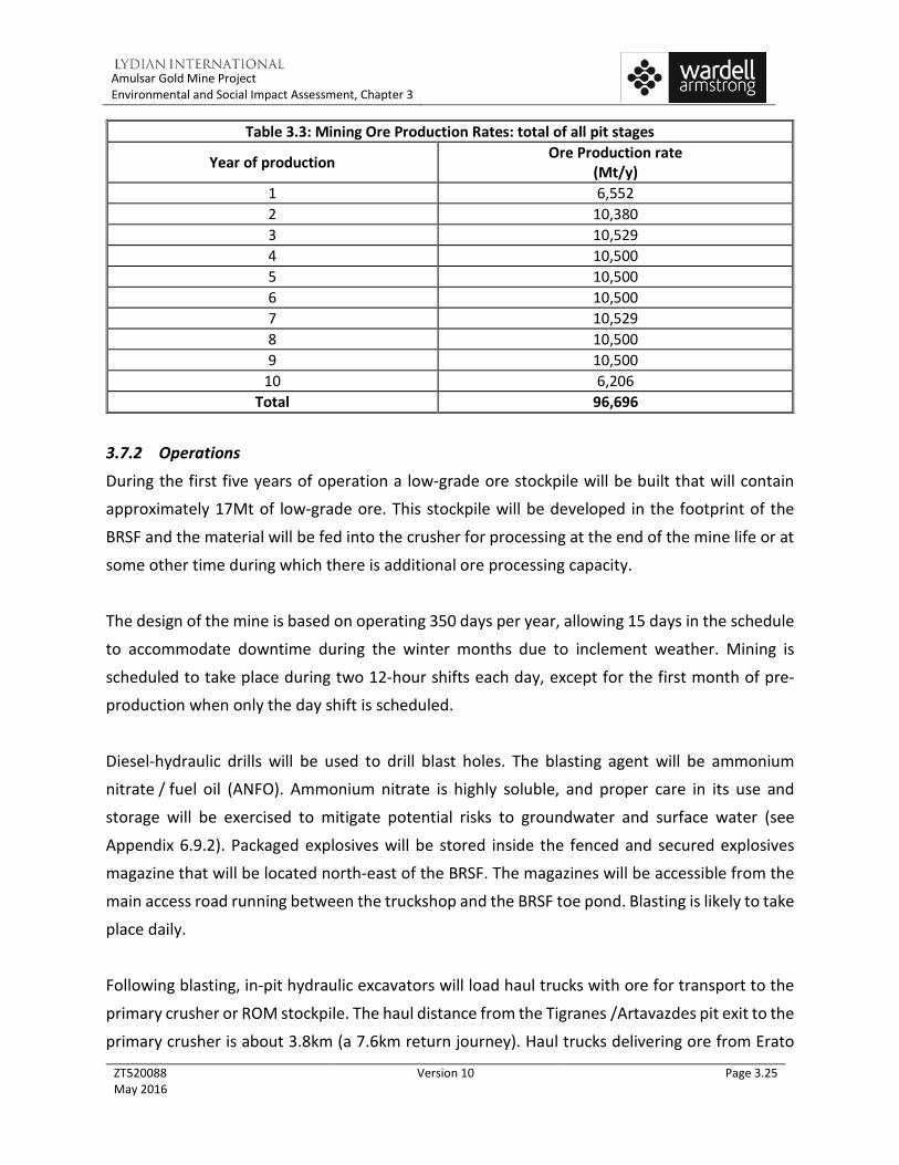
Table 3.3: Mining Ore Production Rates: total of all pit stages
Year of production Ore Production rate (Mt/y)
1 6,552 2 10,380 3 10,529 4 10,500 5 10,500 6 10,500 7 10,529 8 10,500 9 10,500
10 6,206 Total 96,696
3.7.2 Operations
During the first five years of operation a low-grade ore stockpile will be built that will contain approximately 17Mt of low-grade ore. This stockpile will be developed in the footprint of the
BRSF and the material will be fed into the crusher for processing at the end of the mine life or at
some other time during which there is additional ore processing capacity.
The design of the mine is based on operating 350 days per year, allowing 15 days in the schedule
to accommodate downtime during the winter months due to inclement weather. Mining is
scheduled to take place during two 12-hour shifts each day, except for the first month of pre-production when only the day shift is scheduled.
Diesel-hydraulic drills will be used to drill blast holes. The blasting agent will be ammonium
nitrate / fuel oil (ANFO). Ammonium nitrate is highly soluble, and proper care in its use and
storage will be exercised to mitigate potential risks to groundwater and surface water (see
Appendix 6.9.2). Packaged explosives will be stored inside the fenced and secured explosives
magazine that will be located north-east of the BRSF. The magazines will be accessible from the
main access road running between the truckshop and the BRSF toe pond. Blasting is likely to take
place daily.
Following blasting, in-pit hydraulic excavators will load haul trucks with ore for transport to the
primary crusher or ROM stockpile. The haul distance from the Tigranes /Artavazdes pit exit to the
primary crusher is about 3.8km (a 7.6km return journey). Haul trucks delivering ore from Erato

Amulsar Gold Mine Project Environmental and Social Impact Assessment, Chapter 3
ZT520088 May 2016
Version 10 Page 3.26
will travel approximately the same distance from pit exit to the crusher. The total distance
travelled will vary over time as the pit is developed.
Haul trucks will also haul barren rock to the BRSF, situated north of the pits. The BRSF will be
approximately 4.5km from the pit exits by haul road. Haul roads will be maintained by grading
and replacement of the surface wearing course during the summer months. During the winter
months, haul roads will be maintained by a combination of snow clearance and grit spreading.
During the peak operational period (approximately Year 4) there will be 20 haul trucks in use. It
is estimated that these haul trucks will make an average of 45 round trips per hour between the
pits and the BRSF, and approximately 10 round trips per hour between the pits and the primary crusher.
Beginning at the end of Year 4, some barren rock material from Erato will be backfilled into the Tigranes /Artavazdes pit, while concurrently transferring barren rock to the BRSF. In Year 6
barren rock ceases being transported to the BRSF and is only used to backfill the
Tigranes / Artavazdes pit. The distance travelled by haul vehicles to backfill the Tigranes /
Artavazdes pit will be approximately 1km (2km return trip).
The Tigranes / Artavazdes pit design will have a footprint of around 121.6hectares at the end of
its life of mine, while the Erato footprint will be approximately 59.4hectares. These areas are inclusive of all disturbed areas around the pit. The open pits will be developed in stages, with
pushbacks to enable deeper pit access to a maximum pit depth of approximately 310m, equating
to a final pit floor elevation of 2670m above sea level (masl) (these areas of the pit will be backfilled). The highest point on the rim of the pit at the end of production will be 2980masl.
A breakdown of waste and ore tonnes from each deposit is indicated in Table 3.4.
Table 3.4: Mass of Barren Rock and Ore to be Mined from each Amulsar Deposit Deposit Barren rock (Mt) Ore (Mt) Tigranes 69.0 22.1
Artavazdes 83.5 51.8 Erato 76.6 22.8 Total 229.1 96.7

Amulsar Gold Mine Project Environmental and Social Impact Assessment, Chapter 3
ZT520088 May 2016
Version 10 Page 3.27
Water trucks will be used to suppress dust generation from vehicle movements during dry
weather conditions. A network of portable pumps and HDPE piping will be utilised to pump any
water from the pits to the HLF Contact Water pond, to be used as “make up” water for the barren
leach solution going to the HLP.
A summary of the mobile plant required to operate the mine is provided in Table 3.5. Table 3.5: Mining Equipment List
Equipment Type Description Maximum
Number Units Required
Drills CAT 6240 Main blast hole drill rigs 4 CAT 5150C For perimeter blasting 1 Trucks CAT 789 Haul Truck; 180-190 tonne capacity 20 Excavators CAT 6050 For loading ore & barren rock into haul trucks 2 CAT 994 For loading ore and barren rock into haul vehicles 1 Ancillary Equipment CAT336DL Smaller excavator for earthworks and rock breaking 1 D10T Dozer Bulldozer (1 at BRSF, 2 in pit) 3
16M Grader Grader for road maintenance, Snow clearance 2 CAT 825 Roller Compactor For road maintenance 1 966 Loader (T/H) For drill and blast preparation; Roadworks 1 824 RTD Wheel dozer 2 930H IT Tool carrier at the truck shop 1 Water Truck Water truck for dust suppression 3 CAT 740 Fuel/Lube Truck For refuelling and maintaining equipment at site 1 Welding Truck For equipment maintenance 2 Mechanics Truck Mobile maintenance 3 ANFO Truck For loading explosives into blast holes 2 Stemming Truck For stemming blast holes 2 Light Vehicle Personnel Transport 8 Lighting Plant To provide light for working at night 6 Low Bed Truck / Transporter For moving heavy equipment long distance 1 30T crane Lifting 1 100T Crane Lifting 1 Ambulance / Fire Response Vehicle Emergency response 1

Amulsar Gold Mine Project Environmental and Social Impact Assessment, Chapter 3
ZT520088 May 2016
Version 10 Page 3.28
Table 3.5: Mining Equipment List
Equipment Type Description Maximum
Number Units Required
Forklift 12T Misc 2 ATV Misc 2
3.8 Barren Rock Storage Facility (BRSF) and Pit Backfill
3.8.1 Site Layout and Development
The BRSF will be located in a valley approximately 2km north of Erato and the mine pit area. The
site lies within the Kechut reservoir watershed zone, and the westernmost portion of the site is
within the Lake Sevan Immediate Impact Zone on the east side of the Spandaryan-Kechut tunnel.
The BRSF design capacity is approximately 190Mt. The schedule and quantity of barren rock going
to the BRSF is shown in Figure 3.5.
Development of the BRSF will take place in phases. The phased development is shown in Figure 3.9 to Figure 3.11 and Table 3.6, with stacking beginning on the southern side of the BRSF
footprint and developing towards the north as stacked benches are increased in height. The final
footprint of the BRSF will be approximately 181 hectares including ancillary infrastructure such
as the Toe Pond and other associated disturbed areas.
Beginning in Year 4, barren rock will also be placed in the Tigranes-Artavazdes pit as backfill. The
geometry of the pit naturally encapsulates PAG barren rock in the backfill. As soon as a BRSF or pit backfill surface reaches the planned end-of-mining configuration, it will be capped with an
evapotranspiration (ET) cover to limit the infiltration of water and the diffusion of oxygen.

Amulsar Gold Mine Project Environmental and Social Impact Assessment, Chapter 3
ZT520088 May 2016
Version 10 Page 3.29
Figure 3.9: BRSF – Phase 1, February 2016

Amulsar Gold Mine Project Environmental and Social Impact Assessment, Chapter 3
ZT520088 May 2016
Version 10 Page 3.30
Figure 3.10: BRSF – Phase 2, February 2018

Amulsar Gold Mine Project Environmental and Social Impact Assessment, Chapter 3
ZT520088 May 2016
Version 10 Page 3.31
Figure 3.11: BRSF – Phase 3, January 2021

Amulsar Gold Mine Project Environmental and Social Impact Assessment, Chapter 3
ZT520088 May 2016
Version 10 Page 3.32
Table 3.6: BRSF Schedule
Schedule for barren
rock Ye
ar -1
Year
1
Year
2
Year
3
Year
4
Year
5
Year
6
Year
7
Year
8
Year
9
Year
10
Total
(Mt)
BRSF 1.0 19.1 23.8 28.1 14.5 16.6 0.1 0.7 1.7 16.1 0.4 122.2
Backfill In-pit
- - - - 9.3 10.3 21.6 23.5 31.4 7.7 2.9 106.9
Total 1.0 19.1 23.8 28.1 23.8 26.9 21.7 24.3 33.1 23.8 3.3 229.1
3.8.2 Construction and Commissioning
The design of the BRSF includes features to ensure surface water is protected and that any groundwater that comes into contact with PAG barren rock drains via the Toe Pond to the HLF
Contact Water Pond via a gravity-flow pipe. The BRSF contact water line will be a buried, single-
wall HDPE pipe (460mm in diameter) and will traverse from the north-east side of the BRSF to the conveyor and then follow the line of the conveyor to the conveyor load-out facility and then
to the HLF pond; see Figure 3.1 for the alignment of the contact water pipeline. No discharge of
untreated contact water to surface (or ground) waters will occur during mining operations.
Not all of the barren rock that will be deposited in the BRSF is PAG. NAG material will be
selectively placed to encapsulate PAG material within the core of the BRSF where it will have limited contact with air and water.
Pit water is also expected to be impacted by ARD from oxidizing sulphides in the pit walls. Water
from pit dewatering activity will also be conveyed to the HLF Contact Water Pond for use as
process make-up water.
The design principles for constructing the BRSF are to prevent PAG barren rock from coming into
contact with water as much as possible, and to use NAG barren rock to serve as a contact buffer
between PAG material and the natural environment (see Section 3.2.3).
The steps involved in constructing the BRSF are as follows:

Amulsar Gold Mine Project Environmental and Social Impact Assessment, Chapter 3
ZT520088 May 2016
Version 10 Page 3.33
• Prior to construction, topsoil from within the footprint of the BRSF will be removed and
stored in a stockpile where it will be maintained until it is needed for concurrent final
reclamation (see topsoil stockpile location on Figure 3.1);
• Install diversion channels to ensure the natural runoff from the Amulsar Mountain is
routed around the BRSF to maintain this as natural (non-contact) surface water to drain
away naturally from the BRSF;
• The existing subsoil in the footprint of the BRSF will be compacted in place to act as a low-
conductivity soil liner. This soil liner will direct any water that comes into contact with the
barren rock to the Toe Pond;
• The BRSF will have three distinct drainage system elements:
• Primary drains in the large natural drainage channels,
• Secondary drains in secondary drainage channels,
• A NAG waste buffer zone 5m thick under the entirety of the BRSF;
• These three drainage systems will overlie the prepared low-conductivity soil liner. Groundwater seeps and springs emanating from beneath the BRSF will flow through the
drainage system to the Toe Pond. The drain system will be constructed from inert NAG
silicified mine waste that will be resistant to physical and chemical weathering;
• PAG waste will be placed in engineered cells that will be surrounded by NAG waste on all sides. As a result, the PAG waste will be in contact with neither the bottom soil liner nor
the atmosphere. Amulsar PAG waste consists of argillized rock and contains a significant
clay fraction. This clay fraction makes the PAG a low-permeability material. As a result, any water entering the body of the BRSF will flow preferentially through NAG barren rock
that will be placed around the PAG cells; and
• The BRSF cover will be an engineered ET cover specifically designed for the conditions
found at the site. The components of the cover include NAG waste placed on top of the
BRSF (see bullet above), which will provide a natural capillary break between the barren
rock and a layer of naturally-compacted clay that will act as a sponge that absorbs the
influx of water from the cover system. The cover will comprise topsoil to provide a
vegetative growth medium, which be restored in the first available growing season
following closure of that section of the BRSF.
Further details regarding water management design and activities related to the BRSF are
discussed in the Section on Water Management (Section 3.13).

Amulsar Gold Mine Project Environmental and Social Impact Assessment, Chapter 3
ZT520088 May 2016
Version 10 Page 3.34
3.8.3 Operations
The BRSF will be constructed in three phases over the life of mine. Haul trucks will transport
waste material from the pit to the BRSF, developing tip benches in lifts at an angle of repose of
approximately 37°. Lifts will be contoured following cessation of active dumping. The BRSF will
be progressively capped during operations with suitable cover soils and growth media and re-
vegetated with natural plants and grasses. Temporary ponds will be constructed at the toe of
Phase I and Phase II to capture mine-contact water that will flow to the Contact Water Pond.
Access to the BRSF and associated infrastructure will only be made via the mine haul road. For
safety reasons, non-mine vehicles will not be able to access active areas of the waste dump
without passing through security checkpoints.
The low grade stockpile will be temporarily stored within the footprint of the BRSF, as shown in
Figure 3.10 and Figure 3.11. As mining in the pits comes to an end, the material on the low grade stockpile will be transferred to the primary crusher. The closure of the BRSF prior to the end of
mining (after Year 6) will allow re-contouring of the surface and placement of the final cover
during the operations phase.
If the low grade stockpile is not processed at the end of the life of the mine due to economic
conditions at the time, the material that is left will be treated as NAG in a discrete cell in the
BRSF. Since the low-grade ore stockpile will be contained within the drainage basin of the BRSF, all leachate from this area will flow as contact water to the passive water treatment system.
The footprint of the BRSF will be contoured at closure, whether the low-grade material is
processed further or left in the BRSF. The top of the low-grade stockpile will be capped with the
same ET cover system as the rest of the BRSF.
Around Year 4, barren rock material from the Erato open pit will be placed into the
Tigranes/Artavazdes pits. Partial backfilling of the Erato open pit will occur towards the end of
the Project. Final surfaces of the Tigranes/Artavazdes backfill will be covered immediately after
they are no longer active.

Amulsar Gold Mine Project Environmental and Social Impact Assessment, Chapter 3
ZT520088 May 2016
Version 10 Page 3.35
3.9 Crushing Plant
Ore is processed through two stages of crushing to a target crush size of 100 percent passing
19 mm (P100 = 19 mm). The crusher unit operations include a primary jaw crusher, and secondary
cone crushing in closed circuit with triple deck multi slope screens. The crushed ore storage bin,
secondary crushing feed bin, and crushed ore stockpile provide crushing surge capacity for the
facility.
3.9.1 Site Layout
The crushing plant will be located on the western side of the ridge line situated to the west of
the BRSF. The mine haul road will lead directly to the primary crusher feed hopper. The crushing
plant will consist of two separate buildings or structures, interconnected by covered transfer
conveyors. The crushing plant will consist of:
• Primary and secondary crushing building;
• Crushed ore bin feed conveyor;
• Screening building;
• Screen oversized and product conveyors;
• Overland conveyor to transfer the ore to a crushed ore stockpile; and
• Truck load out bin for hauling the ore to the heap.
The crushing plant will be enclosed within a purpose-constructed building that has been designed
to reduce the potential for dust and sound emissions from the operation of the plant and to protect the operators during winter conditions.

Amulsar Gold Mine Project Environmental and Social Impact Assessment, Chapter 3
ZT520088 May 2016
Version 10 Page 3.36
Figure 3.12: Isometric view of the Crushing and Screening Plant Layout looking southwest
In addition to the crushing plant, a secondary electrical substation reducing power from 35kV to
6kV will be located between the primary and secondary crusher (see Figure 3.12)
3.9.2 Operations Run-of-mine (ROM) ore is transported to the primary crushing area by haul truck and dumped
onto two static grizzly feeders. Grizzly oversize is fed into the dump hopper, and undersize falls
to belt feeders and then onto the crusher discharge conveyor. A rock breaker will be available to service the crusher dump hopper. Ore exiting the dump hopper is conveyed to the primary
crusher grizzly feeder. Undersize joins the previously mentioned stream on the crusher discharge
conveyor, and oversize enters the primary jaw crusher. The crusher reduces the ore to nominally
80 percent passing 91 mm. Crushed ore drops to the crusher discharge conveyor, joining the
grizzly undersize material. The crusher discharge conveyor transfers the crushed ore to the
crushed ore bin feed conveyor for feed to the crushed ore storage bin.
The crushed ore storage bin will provide 1,600 tonnes of live storage. Ore is reclaimed from the bin via three (3) belt feeders. Each of the feeders will discharge onto a vibrating triple deck screen.
Screen undersize, at 100 percent passing 19 mm falls to the product conveyor for transfer to
overland conveying. Screen oversize, at 80 percent passing 70 mm falls to the vibrating screen

Amulsar Gold Mine Project Environmental and Social Impact Assessment, Chapter 3
ZT520088 May 2016
Version 10 Page 3.37
oversize conveyor for transfer to the secondary crushing feed conveyor. A crushed ore sampler
at the transfer point between the product conveyor and the overland conveyor will periodically
sample the product stream for analysis and metallurgical accounting.
The secondary crushing feed conveyor transfers ore to the secondary crushing feed bin with a
live capacity of 1,600 tonnes. Two belt feeders draw the material from the secondary crushing
feed bin to feed the two secondary crushers. The secondary crushing system is a parallel circuit
utilizing two cone crushers producing a product material of approximately 80 percent passing
35mm. The crushed product reports to the crusher discharge conveyor to join the primary
crushing circuit discharge for feed to the screening circuit.
The crushing area is equipped with an overhead bridge crane for maintenance and a dust
collection system to minimize fugitive dust at all transfer points.
The major equipment items in the crushing plant are listed in Table 3.7
Table 3.7: Crushing Plant Equipment Specifications
Equipment Name Number Comments Type
Primary Jaw Crusher 1 342 t/h (dry).
Crusher Setting: P80 91mm
Metso C-150
Coarse Ore Storage Bin 1 1600 tonne storage capacity Not specified
Secondary Vibrating Screen 3 Capacity: 1450 t/h
each Double deck, 3.65 m x 8.5 m
vibrating Secondary Crusher Feed
Bin 1 1600 tonne storage capacity Not specified
Secondary Cone Crusher 2 Capacity (each): 1341 t/h. Cone Crusher MP1250
Dust Control
The crusher building and the screening building are enclosed structures, and each building will
be fitted with a separate dust collection system.
Dust hoods will be placed over the conveyor transfer points and crusher feed points within the
crushing and screening buildings. A dust extraction system will draw the fugitive dust generated at these points to a dust collector with a fabric filter system.

Amulsar Gold Mine Project Environmental and Social Impact Assessment, Chapter 3
ZT520088 May 2016
Version 10 Page 3.38
The feed hopper of the primary crusher will not be enclosed, and will not have a dust hood fitted.
Fugitive dust generated here will be controlled by using raw-water sprays directly on the ore in
the dump hopper. Water for sprays will be sourced from the crusher area sediment pond.
During the winter months haul roads and surrounding surfaces would be generally frozen,
fugitive dust emissions would be controlled by regular grading of the haul road surface and
emissions would be insignificant because of the frozen surfaces which when thawed are likely to
be wet.
3.10 Ore Conveyance and Heap Stacking
3.10.1 Site Layout The product conveyor takes crushed ore from the screens to the north end of the screening
building. Crushed ore is transferred from the product conveyor to the overland conveyor, which
transports the ore west, down-grade 5.6km to the crushed ore stockpile and loadout area (see Figure 3.13). Thirty-tonne highway dump trucks will deliver the crushed ore from the loadout
area to the leach pad at a distance of between 0.3km and 2.0km depending on which phase of
the pad is operating.

Amulsar Gold Mine Project Environmental and Social Impact Assessment, Chapter 3
ZT520088 May 2016
Version 10 Page 3.39
Figure 3.13 Truck Load-out Station and Fine Ore Stockpile
3.10.2 Operations
Screen product from the product conveyor is sampled by the crushed ore sampler prior to transfer to the overland conveyor. The overland conveyor transports the crushed ore
approximately 5.6km down slope (700m elevation drop) to the crushed ore stockpile. The
overland conveyor will have a regenerative drive system that will generate approximately 3MW
of power that will be fed back into the electrical system.
The crushed ore stored at the crushed ore stockpile, live capacity of 5,000 tonnes, will be
reclaimed by three pan feeders underneath the stockpile which transfer the ore to the loadout
bin feed conveyor. Pebble lime is added to the crushed ore as it is conveyed to the loadout bin
by a screw feeder fed from a 200-tonne capacity lime silo. Lime will be metered to ensure proper
pH control for heap operation.
The loadout bin feed conveyor transfers the crushed product with lime to the 100-tonne loadout
bin. A full bin will stop the pan feeders and the loadout feed conveyor. The loadout bin is sized

Amulsar Gold Mine Project Environmental and Social Impact Assessment, Chapter 3
ZT520088 May 2016
Version 10 Page 3.40
to hold a volume of ore sufficient to fill three truck loads. Ore is discharged from the loadout bin
into the truck via clam shell gates. The crushed ore will then be hauled to the heap leach pad for
stacking and leaching.
Periodic clean-up of spillage from under the overland conveyor route will form part of a regular
maintenance programme.
3.11 Heap Leach Facility (HLF)
The heap leach process consists of stacking crushed ore on the leach pad in lifts and leaching
each lift to extract the gold and silver. Barren Leach Solution (BLS) containing dilute sodium
cyanide will be applied to the ore heap surface using a combination of drip emitters and sprinklers at a design application rate of 6L/hr/m2. The design leaching cycle of the ore heap is 60 days.
The solution will percolate through the ore to the drainage system above the pad liner, where it
will be collected in a network of perforated drain pipes embedded within a 0.6m minimum
thickness granular drainage layer above the liner.
As the cyanide solution percolates through the heap the gold (Au) and silver (Ag) metals are
dissolved into the cyanide solution (forming gold and silver cyanide ions). This solution is termed the pregnant leach solution (PLS) once it contains precious metals. The PLS drains by gravity from
the HLP in transfer pipes to the process pond. PLS collected in the process pond is pumped to the
ADR Plant to extract the gold and silver.
Metallurgical testwork on leachate from rinsed heap leach material shows that other minerals
within the heap will be stable.
3.11.1 Site Layout and Development
The HLF will be located at the western side of the Project, which is approximately 1km south of
the village of Gndevaz. Apart from one residence adjacent to the dairy farm located
approximately 600m north of the leach pad, this is the closest point of the HLF to any occupied
residential property. Development of the leach pad will take place in four phases over the life of
mine and is designed to accommodate a total of 104 Mt of stacked ore.

Amulsar Gold Mine Project Environmental and Social Impact Assessment, Chapter 3
ZT520088 May 2016
Version 10 Page 3.41
The leach pad will be constructed in four phases with approximate areas of 26 hectares, 20
hectares, 27 hectares and 42 hectares for Phases 1 to 4, respectively. The total of all Phases 1-4
pad area will be approximately 115 hectares. The fully stacked Phases 1-4 leach pad will have a
nominal capacity of 104Mt of ore and a nominal maximum heap height of 120m above the liner.
Incorporation of access and operational constraints (e.g. ramps within the heap) may slightly
reduce this capacity.
The ore heap on the leach pad is planned to be stacked in 8m thick, horizontal lifts. The heap
stage tonnages, number of lifts, elevations, and stacking schedules are described below.
The Phase 1 pad will accommodate approximately 9.3Mt, which will constitute the first four heap lifts to a nominal top surface elevation of 1664m, and will be stacked during the first year of
operations.
The Phase 2 pad expands the pad uphill to the east, by stacking an additional 20.7Mt in six
horizontal lifts above the Phase 1 heap level to a nominal top surface elevation of 1712m. The
Phase 2 heap is projected to be stacked through the end of Year 3 of operations.
The Phase 3 pad expands the pad further uphill to the east, by stacking approximately 31.4Mt in
seven additional lifts to a nominal top surface elevation of 1768m. The Phase 3 heap is projected
to be stacked through the end of Year 6 of operations.
The Phase 4 pad expands the pad further uphill to the east, by stacking 11 additional lifts to a
nominal top surface elevation of 1856m. Stacking of the Phase 4 heap will continue till the end
of Year 10 of operations to a final capacity of 104Mt.
The phased development of the leach pad and ore heap is illustrated in Figure 3.14 to Figure 3.17.

Amulsar Gold Mine Project Environmental and Social Impact Assessment, Chapter 3
ZT520088 May 2016
Version 10 Page 3.42
Figure 3.14: Phase 1 Leach Pad Layout and Ore Heap Plan

Amulsar Gold Mine Project Environmental and Social Impact Assessment, Chapter 3
ZT520088 May 2016
Version 10 Page 3.43
Figure 3.15: Phases 1-2 Leach Pad Layout and Ore Heap Plan

Amulsar Gold Mine Project Environmental and Social Impact Assessment, Chapter 3
ZT520088 May 2016
Version 10 Page 3.44
Figure 3.16: Phases 1-3 Leach Pad Layout and Ore Heap Plan

Amulsar Gold Mine Project Environmental and Social Impact Assessment, Chapter 3
ZT520088 May 2016
Version 10 Page 3.45
Figure 3.17: Phases 1-4 Leach Pad Layout and Ore Heap Sections
Amulsar Gold Mine Project Environmental and Social Impact Assessment, Chapter 3
ZT520088 May 2016
Version 10 Page 3.46
3.11.2 Construction and Commissioning
HLF construction will begin with site preparation, ensuring that the site is graded appropriately
and that suitable water drainage control structures are installed. The process pond and Storm
Pond 1 will be constructed during Phase 1 pad construction (see Figure 3.14), Storm Pond 2 will
be constructed during Phase 3 pad construction (See Figure 3.16) and Storm Pond 3 will be
constructed during Phase 4 pad construction (see Figure 3.17).
Throughout the HLF construction and operations, environmental protection measures will be
implemented. Addition detail on these elements of the HLF is discussed below.
Site Grading The HLF is located in a valley sloping to the southwest. The valley side slopes are 6% in the valley
bottom near the downgradient toe increasing to a maximum of 55% on the upper valley sides.
Site grading fill will be placed in the valley bottom in the leach pad downgradient toe area to
establish a toe bench with a 1% pad downhill grade to facilitate ore heap stability. In addition to
stability considerations, the toe bench provides a larger surface to stack and leach the first ore
heap lift on the Phase 1 pad. Earthwork grading for the Phase 1 pad will include cutting the northwest hillside to establish the underlying foundation surface for the line and construct a
gravity diversion channel drainage from the Phase 1 diversion pond; the excavated material will
be used for fill in the HLF construction. The Phase 1 diversion embankment and diversion channel will be constructed to the north and northwest of the Phase 1 pad, respectively, to divert storm
and snowmelt runoff from the north valley around the pad to the natural drainage downgradient
of the collection ponds. Cut and fill operations will also be performed to construct the collection
ponds downgradient of the leach pad.
Additional fill required for HLF construction (leach pad, process pond and storm ponds) will be
sourced from the contact water pond excavation and from nearby facility site grading cuts and
borrow sources outside the HLF limits.
It is anticipated that drilling and blasting will be required to excavate most of the basalt bedrock
in the Phase 1 pad northwest hillside site grading cut area.
Amulsar Gold Mine Project Environmental and Social Impact Assessment, Chapter 3
ZT520088 May 2016
Version 10 Page 3.47
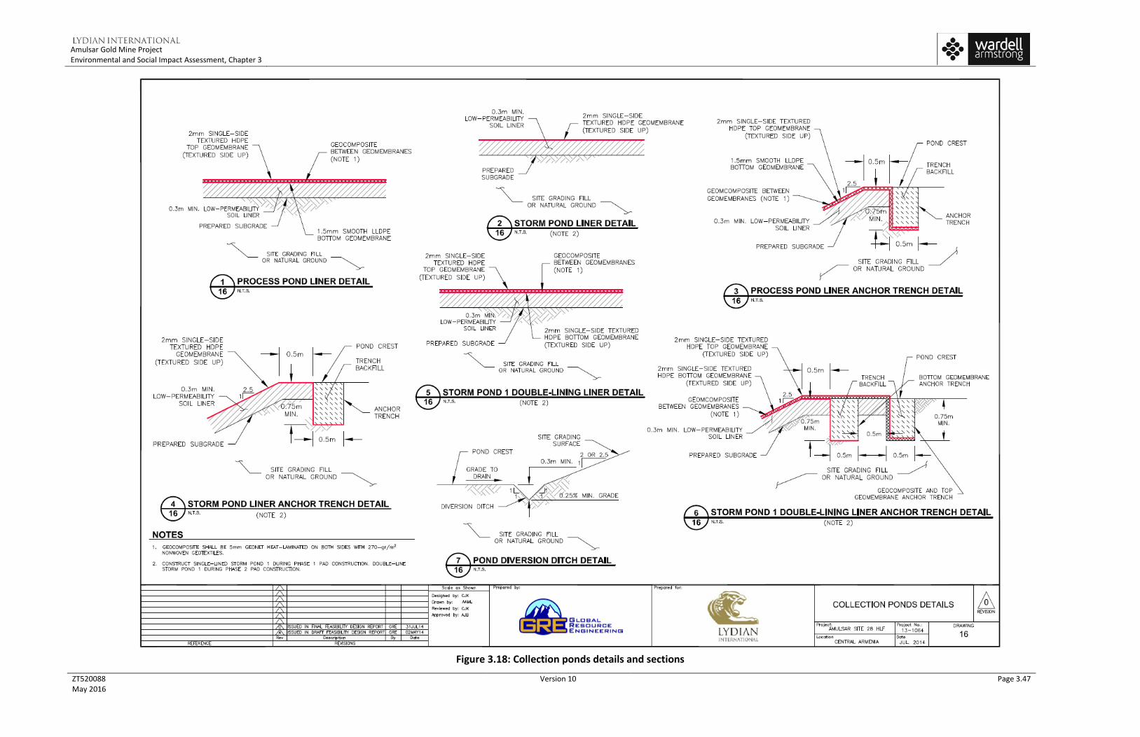
Figure 3.18: Collection ponds details and sections

Amulsar Gold Mine Project Environmental and Social Impact Assessment, Chapter 3
ZT520088 May 2016
Version 10 Page 3.48
Drainage Control
A diversion embankment and three diversion channels will be constructed upgradient of the HLF
phases to divert storm and snowmelt runoff from upstream catchments away from the pad and
collection ponds. In addition, the pad phase berms and access roads will be constructed to
capture storm and snowmelt runoff from upstream catchments and drain it away from the pad.
The diversion systems were designed with a minimum 0.3m freeboard depth.
Underdrains consisting of a network of drain trenches with pipes will be constructed at the
locations of existing drainages and seeps within the leach pad and collection pond footprints to
drain groundwater/subsurface seepage to a collection sump downgradient of the collection
ponds. The underdrains will discharge into a collection sump, where the discharge water quality will be monitored before being released or used in the process.
The leach pad will have a 1.5m high toe berm and 1m high perimeter berms to prevent applied solution and rainfall/snowmelt water within the pad from overflowing the pad. The solution and
storm flows will be collected by a drain pipe network constructed above the pad liner and routed
by gravity to the process pond.
Heap Leach Pad (HLP) The HLP will have a composite liner system consisting of a linear low-density polyethylene (LDPE)
geomembrane underlain by a 0.3m minimum thickness compacted low-permeability soil liner, or
geosynthetic clay liner (GCL) in areas steeper than 2.5H: 1V. The geomembrane will be 1.5mm (60mil) thick in the pad areas where the ultimate ore heap height is 60m or less, and 2mm (80-
mil) thick elsewhere. The geomembrane will be single-side textured with texturing at bottom (in
contact with the soil liner layer or the GCL) in the stability-critical area at the pad’s southwestern
edge, and smooth elsewhere.
A drain pipe solution collection network will be constructed above the pad liner and will be
embedded within a 0.6m minimum thickness liner cover drain fill layer, which will consist of free-
draining, hard and durable granular material. This granular material will consist mostly of low-
grade ore produced in the crushing plant. Solution, storm/snowmelt runoff and infiltration flows
collected by the drain pipe network will gravity-drain to the process pond.

Amulsar Gold Mine Project Environmental and Social Impact Assessment, Chapter 3
ZT520088 May 2016
Version 10 Page 3.49
A livestock-proof mesh fence with locking gates will be constructed around the perimeter of the
HLP to exclude wildlife. An additional purpose of the fence is for public safety and to deter
unauthorized access into the pad area.
The leach pad liner details are shown on Figure 3.19.
Collection Ponds
The HLF collection ponds will include the process pond, Storm Pond 1, Storm Pond 2 and Storm
Pond 3. The collection ponds were sized in accordance with the Project design criteria using the
results of the HLF water balance calculations. The process pond and Storm Pond 1 will be
constructed during Phase 1 pad construction, Storm Pond 2 will be constructed during Phase 3 pad construction and Storm Pond 3 will be constructed during Phase 4 pad construction.
Process solution and storm/snowmelt water flows within the leach pad will gravity-drain to the
pad’s lowest point and through a spillway to the process pond. A cascading spillway system will
be constructed between the process pond, Storm Pond 1, Storm Pond 2 and Storm Pond 3 for potential solution and storm/snowmelt runoff during pad operations. The storm ponds will be
configured to cascade downgradient starting with Storm Pond 1.
The process pond is designed to contain: • 8 hours of solution during normal operational flow;
• 24 hours of solution of emergency draindown flow from the ore heap in case of
operational shutdown due to pump failure or power loss;
• The maximum cumulative excess water volume predicted for the Phase 1 pad under typical wet year climatic conditions;
• The maximum cumulative excess water volume predicted for Phases 1-2 pad under
average year climatic conditions.
Storm Pond 1 is designed to contain:
• The maximum cumulative excess water volume predicted for Phases 1-2 pad under typical
wet year climatic conditions, less the excess water volume that can be stored in the process pond;

Amulsar Gold Mine Project Environmental and Social Impact Assessment, Chapter 3
ZT520088 May 2016
Version 10 Page 3.50
• The maximum cumulative excess water volume predicted for Phases 1-4 pad under
average year climatic conditions, less the excess water volume that can be stored in the
process pond.
Storm Pond 2 is designed to contain the maximum cumulative excess water volume predicted for
Phases 1-3 pad under typical wet year climatic conditions, less the sum of the Storm Pond 1
capacity and the excess water volume that can be stored in the process pond.
Storm Pond 3 is designed to contain the maximum cumulative excess water volume predicted for
Phases 1-4 pad under typical wet year climatic conditions, less the sum of Storm Pond 1 capacity,
Storm Pond 2 capacity and the excess water volume that can be stored in the process pond.
Standby pumps and an independent backup power supply system will be provided at the storm
ponds to evacuate the ponds during large storms and power outages, if needed to prevent pond
overflow into the natural drainage.
The process pond will have a composite double-geomembrane liner system comprised of top
(primary) and bottom (secondary) geomembranes, with an intermediate leak collection and
recovery system (LCRS) layer, and underlain by a 0.3m minimum thickness compacted low-permeability soil liner layer. The bottom geomembrane will be 1.5mm (60mil) smooth LLDPE, and
the top geomembrane will be 2mm (80mil) single-side textured high-density polyethylene (HDPE)
with texturing at top for traction. The LCRS between the two geomembranes will be a
transmissive geocomposite (drainage net) that is connected to the pond’s LCRS sump. The geocomposite will be 5mm (200mil) geonet heat-laminated on both sides with 270gr/m²
(8oz/yd2) nonwoven- geotextiles. Should a leak ever occur through the top geomembrane, it
would flow through the geocomposite to the LCRS sump, where it would be removed via a pump.
The design intent of the LCRS is to ensure that no hydraulic head occurs on the bottom
geomembrane, thereby removing any driving force required for seepage to occur through that
geomembrane.
Storm Pond 1 will initially have a single-geomembrane composite liner system consisting of 2mm
(80mil) single-side textured HDPE geomembrane with texturing at top for traction, underlain by
a 0.3m minimum thickness compacted low-permeability soil liner layer. The pond will be double-
geomembrane-lined and a LCRS geocomposite added between the geomembranes during Phase

Amulsar Gold Mine Project Environmental and Social Impact Assessment, Chapter 3
ZT520088 May 2016
Version 10 Page 3.51
3 pad construction. The added top geomembrane will be 2mm (80mil) single-side textured HDPE
with texturing at top for traction, and the geocomposite will be 5mm (200mil) geonet heat-
laminated on both sides with 270gr/m² (8oz/yd2) nonwoven geotextiles.
Storm Pond 2 and Storm Pond 3 will have a single-geomembrane composite liner system
consisting of 2mm (80mil) single-side textured HDPE geomembrane with texturing at top for
traction, underlain by a 0.3m minimum thickness compacted low-permeability soil liner layer.
A livestock-proof mesh fence with locking gates will be constructed around the perimeter of the
collection ponds to prevent wildlife from reaching the solutions in the ponds. The fence will also
preserve public safety by deterring unauthorized access.
The collection ponds liner details from the HLF 2014 feasibility design are shown on Figure 3.20.
Environmental Protection Measures
Environmental monitoring and protection features will be incorporated into the HLF construction
to minimize potential impacts on the surrounding environment, wildlife, surface water and groundwater. To summarise, these features will include:
1. Diversion systems to divert storm and snowmelt runoff from upstream catchments away from the HLP and collection ponds.
2. Underdrains beneath the HLP and collection pond footprints to drain
groundwater / subsurface seepage to a collection sump located downgradient of the ponds, where the underdrain discharge water quality will be monitored as required.
3. A composite liner system for the pad consisting of a geomembrane underlain by a
compacted low-permeability soil liner layer or GCL.
4. Process solution and storm/snowmelt water collection and drainage system above the
pad composite liner consisting of a network of drain pipes within a free-draining granular
medium layer designed to enhance solution collection and maintain a low hydraulic head
on the liner.
5. Placement of wear sheets beneath the large-diameter drain pipes within the pad to
reduce the potential for wear and damage to the pad geomembrane liner from pipe
movement.

Amulsar Gold Mine Project Environmental and Social Impact Assessment, Chapter 3
ZT520088 May 2016
Version 10 Page 3.52
6. A toe berm with a minimum height of 1.5m and perimeter berms with a minimum height
of 1m around the individual pad phases for solution and storm / snowmelt water
containment.
7. A 4m minimum offset between crests of the pad toe berm, perimeter berms and phase
berms and the ore heap toes to reduce the risk of solution release due to upset conditions
during operations.
8. Livestock-proof fencing around the pad to prevent access.
9. A process pond designed with sufficient capacity to contain the required solution during
normal operational flow and emergency draindown flow from the ore heap.
10. Storm ponds designed with sufficient capacity to contain storm/snowmelt overflows from
the HLF areas, sized based on HLF water balance calculations for typical wet year climatic conditions.
11. A composite double-geomembrane liner system for the process pond comprised of a top
(primary) geomembrane and a bottom (secondary) geomembrane, with an intermediate LCRS layer. The bottom geomembrane will be underlain by a compacted low-permeability
soil liner.
12. An initial composite single-geomembrane liner system for Storm Pond 1 consisting of a
geomembrane underlain by a compacted low-permeability soil liner. This storm pond will be double-geomembrane-lined and an intermediate LCRS layer will be added to its liner
system during Phase 3 pad construction to contain potential process solution overflow
from the process pond during Phases 3-4 pad operations. 13. A composite single-geomembrane liner system for Storm Pond 2 and Storm Pond 3
consisting of a geomembrane underlain by a compacted low-permeability soil liner.
14. Placement of wear sheets above the geomembrane liners of the collection ponds,
underneath pipes and in the corner sump areas, for geomembrane protection from pipe
movement and pumping operations.
15. Standby pumps and an independent backup power supply system at the storm ponds to
evacuate the ponds during large storms and power outages, if needed to prevent pond
overflow into the natural drainage.
16. Livestock-proof fencing around the collection ponds to prevent access.
17. Provision of floating "bird balls" to prevent birds drinking from cyanide containing
solutions in the collection ponds.

Amulsar Gold Mine Project Environmental and Social Impact Assessment, Chapter 3
ZT520088 May 2016
Version 10 Page 3.53
18. Monitoring wells around the HLF for monitoring groundwater quality during operations
and after closure.
3.11.3 Operations
The heaps will be stacked in roughly horizontal lifts of approximately 8m thickness each, with a
maximum ore thickness in any given area of 120m (approximately 15 lifts). Heap leaching consists
of applying barren leach solution, containing sodium cyanide, onto each lift. As the cyanide
solution percolates down through the heap the gold and silver will be leached from the ore into
the solution.
During winter, low temperatures at the Amulsar Project will present a need for measures to prevent the applied leach solution drip lines from freezing and disrupting the leaching and
solution processing cycle. Such measures may include one or more of the following:
• Heat-tracing and insulating the barren tank;
• Placing an ore heap cover layer above the drip emitter lines buried in typical 0.5m deep
ditches ripped with a dozer; and
• Frost protecting the process pond such as by placing floating plastic “bird balls" to reduce heat loss.
3.11.4 Summary of Design Feasibility-level engineering analyses were performed in 2014 for the feasibility design of the HLF
including the leach pad and collection ponds. Additional engineering analyses and designs were
performed in 2015 for the HLF, and the leach pad and collection pond designs were revised. The
leach pad will be constructed in four phases and the phased collection ponds will include the
process pond and Storm Pond 1 (Phase 1 pad construction), Storm Pond 2 (Phase 3 pad
construction), and Storm Pond 3 (Phase 4 pad construction). The main elements of the analysis
and design work and their results are outlined as follows:
• Geotechnical investigation at the HLF site comprised of test pits, boreholes and coreholes;
• Geotechnical laboratory testing on material samples collected from the HLF site, which resulted in geotechnical parameters used in the analysis and design activities;

Amulsar Gold Mine Project Environmental and Social Impact Assessment, Chapter 3
ZT520088 May 2016
Version 10 Page 3.54
• Processing of the available climate data that generated precipitation and evaporation
data used in the analysis and design activities;
• Designing diversion systems for storm runoff flows from catchments upstream of the HLP
and collection ponds;
• Developing the size, layout, grading plan, and phasing of the HLP and ore heap to
accommodate the required heap tonnage and stacking schedule, stability and drainage;
• Performing slope stability analyses for the leach pad and ore heap that resulted in
acceptable stability under static and seismic loading conditions; • Performing water balance calculations for the HLF that resulted in predictions of the
excess water volumes to be generated and makeup water volumes to be required;
• Developing the sizes, layouts, grading plans, and phasing of the collection ponds to accommodate the required solution storage and excess water volumes predicted by the
water balance calculations;
• Providing design details of the leach pad including underdrains; toe, perimeter and phase berms; embankments; liner systems; and drainage;
• Providing design details of the process and storm ponds including crests, embankments,
slopes, sumps, and liner systems;
• Calculating the material quantities and estimating the capital costs for the HLF phases; and
• Providing technical specifications for the leach pad and collection ponds.
3.12 Adsorption-Desorption Recovery (ADR) Plant
3.12.1 Site Layout
The process plant consists of an Adsorption, Desorption, Recovery (ADR) plant, refining, and
reagent makeup and delivery systems. The ADR plant will be located to the southwest of the
process pond at the toe of the HLF. The entire ADR plant area will be lined to contain spills and
any overflow from the plant, which will be routed to the process pond located just northwest of
the ADR plant platform.
The plant extracts precious metals from the PLS onto activated coconut carbon using carbon
columns in counter current. Once loaded with precious metals, the loaded carbon moves from
the columns into strip vessels where the metal is eluted from the carbon into solution at high
temperature and pressure. This eluate is then mixed with zinc powder (Merrill-Crowe circuit),

Amulsar Gold Mine Project Environmental and Social Impact Assessment, Chapter 3
ZT520088 May 2016
Version 10 Page 3.55
which causes gold and silver to precipitate from solution. Once the precious metals are
precipitated, the solution is filtered and the cake is dried, retorted to remove water and recover
any trace mercury, which is stored for resale as a by-product. The dried cake is mixed with flux
and smelted to produce doré bars. The doré bars are then shipped to a refinery for further
refining. The ADR circuit also reactivates the carbon through acid washing and a regeneration kiln
to maintain the carbon’s ability to adsorb metals in the carbon columns. Once reactivated, the
carbon is returned as fresh carbon to the carbon columns.
For details of reagent secondary containment measures at these facilities refer to Section 3.14.5.
The ADR plant configuration is shown on Figure 3.19.

Amulsar Gold Mine Project Environmental and Social Impact Assessment, Chapter 3
ZT520088 May 2016
Version 10 Page 3.56
Figure 3.19: Site Plan ADR Plant Area

Amulsar Gold Mine Project Environmental and Social Impact Assessment, Chapter 3
ZT520088 May 2016
Version 10 Page 3.57
3.12.2 Construction
The ADR plant design incorporates double containment systems such that any spills would be
contained or routed back to the HLP. This design philosophy ensures that solutions containing
cyanide are managed properly and does not allow for any discharges of cyanide into the
environment.
3.12.3 Operations
PLS is pumped from the process pond to the adsorption feed head tank. From there, the PLS
discharges to a single train of 5 carbon adsorption columns. These columns are used to adsorb
the metals from the solution. The PLS enters carbon column 1, flows through the CIC circuit,
finally discharging from carbon column 5 over a carbon safety screen to the barren solution tank.
The carbon columns are stepped down to allow solution to flow by gravity from one column to
the next. Because the pregnant solution is anticipated to come in at various flowrates, either due
to altering process condition or due to weather events, the carbon columns will be flared to allow
for different flowrates while maintaining up flow rates to keep carbon bed expansion at approximately 70 percent by volume.
Carbon is advanced counter-current, upstream, through the columns using a recessed impeller
pump. Loaded carbon from column 1 is pumped to either the elution column for desorption, or to the acid wash column. Fresh or reactivated coconut carbon is added to the last column
(number 5) in the CIC circuit. Each column has the capacity for roughly 4 tonnes of carbon. In-line
samplers are installed on the PLS line prior to addition to the CIC circuit, and also on the barren solution exiting the CIC train.
Metals are desorbed from the carbon using the Anglo-American Research Laboratories (AARL)
method, adapted so that the acid wash is either before or after the elution step. The acid will
remove inorganic contaminants, such as calcium, from the carbon surface. Hydrochloric acid is
used for acid washing of the carbon. Loaded carbon is pumped from the CIC circuit to the acid
wash tank which has a carbon capacity of 4 tonnes. A dilute acidic solution of roughly 2-5 percent
hydrochloric is recirculated though the carbon bed for a period of one to two hours.

Amulsar Gold Mine Project Environmental and Social Impact Assessment, Chapter 3
ZT520088 May 2016
Version 10 Page 3.58
Upon completion of the acid wash, the carbon is rinsed with water to ensure that acids and
chlorides do not enter the strip circuit. Once the cycle is complete, carbon is pumped to either
the elution column, carbon dewatering screen, or regeneration feed dewatering screen.
Neutralization is achieved through in-line injection using a dilute caustic solution comprised of
roughly 2-5 percent NaOH.
The acid wash area is equipped with a dedicated sump pump which returns solutions to the
carbon safety screen and on to the barren solution tank.
When reactivation is required, stripped carbon is pumped over the regeneration feed dewatering
screen to remove water and fine carbon which is generated during the ADR process. The screen
undersize (the transfer solution and fine carbon) flow to the carbon fines tank. The oversize
(larger than 12 mesh) is collected in a 4 tonne bin.
A screw feeder meters the carbon into a rotating reactivation kiln. Organic fouling is removed
from the carbon surfaces in a reducing atmosphere with high temperature steam at temperatures between 550 and 700°C. The kiln discharge is sealed under water by a seal pot to
prevent oxygen from entering the system. Carbon discharging the kiln is quenched in the carbon
quench tank and pumped to a carbon dewatering screen to remove carbon finer than 12 mesh. Fine carbon particulates report to the carbon fines tank. Reactivated carbon is returned to the
process or stored in the carbon dewatering tank.
Smelting operations are performed in a secure refinery. Access to the refinery is limited to
specific personnel, controlled by electronic and physical barriers, and is actively monitored.
The pregnant strip tank is designed to hold the pregnant eluate from 6 elution cycles or 3 days’
worth of eluate. Pregnant strip solution is pumped from the pregnant strip solution tank to the
Merrill-Crowe circuit. Zinc powder is added to the solution after the filter feed pump and before
the in-line zinc mixer. The precipitation of gold and silver is rapid and will have occurred before
the solution reaches the precipitation filter. The pregnant strip solution is pumped through two
plate and frame precipitation filters. Filtrate flows to the filtrate holding tank and eventually
recycled to the barren solution tank.

Amulsar Gold Mine Project Environmental and Social Impact Assessment, Chapter 3
ZT520088 May 2016
Version 10 Page 3.59
The filter cake is collected into retort pans and transferred by cart to the mercury retort area.
The mercury retort system is installed to remove water and capture any trace mercury that may
be present during the life of the mine. This retort package, designed by the supplier, recovers
mercury from the cake by gradually heating the cake to temperatures between 600 and 700°C.
The retort collects the mercury fumes in a distillation process and condenses them into a
collection flask.
Dry cake removed from the mercury retort is fluxed and smelted into doré bars using a direct
fired furnace. Off-gases are captured in a baghouse dust collection system where precious metal
dust is captured and returned to the system. The slag produced from smelting is crushed and
screened to recover any metal prill that may have become entrained with the slag. This prill is
then collected and saved for the next pour. The crushed slag is stored in the slag bin before shipping to off-site smelter. The doré is packaged and stored in a safe for off-site shipment.
3.13 Water Management
Water used by the Project will be classified according to the following:
• Fresh / potable water: Sourced from public supplies or treated on site to potable
standard;
• Process water: Held within / recovered from the HLF, for recycling back into the HLF;
• Construction water: Water used during the construction phase;
• Contact water: Water that has been used in the process or has come in contact with elements of the Project capable of producing an impact to water quality apart from
increased suspended solids; and
• Non-contact water: Water that comes in contact with facilities away from the open pits, BRSF, and HLP. Infrastructure includes the access road and the conveyor corridor.
3.13.1 Objectives
The main objectives of water management for the Project are to minimize water usage, recycle
and reuse wherever possible, and to ensure that if water discharges are required, they are of
suitable quality for release into the environment.
Table 3.8 outlines the contact water storage capacity for the Amulsar Project.

Amulsar Gold Mine Project Environmental and Social Impact Assessment, Chapter 3
ZT520088 May 2016
Version 10 Page 3.60
Table 3.8: Amulsar Contact Water Storage capacity
Pond Volume (m3) (ranges reflect phasing)
Truck shop storage 1000
BRSF toe pond (PD-7) 6,500 or 23,000
Contact water pond (PD-8) 200,000 - 1,280,000
Storm Ponds 1-4 42,000 - 630,000
The contact water containment ponds have been sized to accommodate the 100-year, 24 hour
storm event. They have also been sized to take account of high rates of rainfall in a prolonged
and significant wet year.
Protection of the Vorotan River and Lake Sevan is a key principle of the Project. This has been
achieved through site design, by siting chemical storage and mine processing facilities outside the Lake Sevan immediate impact zone. It should be noted that the open pits, BRSF and crushing
plant are not categorized as mineral processing operations as they do not require the use of
hazardous chemicals, therefore these operations can take place within the Lake Sevan Immediate Impact Zone.
Process water supply for the Project will be sourced from the Arpa River for operations. The proposed abstraction point is indicated on Figure 3.1. The pump station will pump water via a
~250mm diameter pipeline to two fresh water tanks at the ADR Plant. A secondary supply, from
any of the sedimentation ponds on Amulsar Mountain, will be used for dust suppression at the
pit, haul roads and the crusher area.
Cyanide solution will be circulated between the HLP, solution collection ponds, and ADR plant,
with no liquid discharge points (i.e. it is a ‘closed system’). The only water leaving the closed
circuit will be evaporative losses.
During the construction phase, water will be required for the worker accommodation camp, dust
suppression, earthwork/compaction and concrete production. As the project progresses, the
bulk of the construction water will be drawn from various sources from the three following
locations; i) Arpa River – both temporary and permanent draw and conveyance systems;

Amulsar Gold Mine Project Environmental and Social Impact Assessment, Chapter 3
ZT520088 May 2016
Version 10 Page 3.61
ii) Benik pond; and
iii) Existing and new ponds on site such as Dam D-1 (by the HLF), PD-14, and PD-15. PD-15
feeds into PD-14 along channel C-1. Water for PD-14 /15 would come from snow melt or
rain runoff. Similarly, PD12 will receive water from snow melt. The Dam D-1 is a water
diversion structure that captures water from upstream ground disturbances and acts as
sediment control, as well as protects the HLF pad during construction.
A summary of the water use and make up are shown in Table 3.9 (see Appendix 6.10.1 for the
detailed analysis of the site wide water balance).
Sediment control ponds will be built early in the construction schedule as part of the Surface Water Management Plan (SWMP) in order to manage the sediment coming from disturbed
surfaces. Table 3.9 shows the construction phase utilization.
Table 3.9 Construction-Phase Water Make up
Item Units Total Consumption
Water uses
Earthworks, construction and dust control m3/day 925
Temporary offices, facilities and worker accommodation
camp m3/day 115
Total 1058
Water requirements
Arpa River m3/day 690
Benk’s pond m3/day 110
Settlement ponds (PD13 & PD14 and behind dam DI) m3/days 258
Total 1058 m3/day
<12.3 l/s
Note: see Appendix 6.10.1 for detailed analysis
Potable water for site use will be supplied by bottled water to the various site facilities. Total
consumption of drinking water has been estimated at an additional 1.5 m3/day, additional
potable water will be used in several facilities for eyewash stations, safety showers and worker

Amulsar Gold Mine Project Environmental and Social Impact Assessment, Chapter 3
ZT520088 May 2016
Version 10 Page 3.62
showers. The potable water requirements will be trucked to site from potable water sources in
Jermuk area and stored in tanks for use during construction. With the progress of the
construction phase, the potable water may be sourced from public supplies or treated on site to
appropriate standards.
The Gndevaz Irrigation Channel currently being rehabilitated by Geoteam for the sole use of the
local community for irrigation and other purposes.
3.13.2 Site Wide Project Water Balance during Construction
The construction water demand will increase from the onset of the construction period to an
average of 12.3 l/s, (see Table 3.9), over the 2 year period of this phase. The site wide water balance (see Appendix 6.10.1) has been based on a constant water demand throughout the
construction period. Initially, water supply will be from the Arpa River, transported by truck to
areas of construction activity, while a new water pipeline and intake pong are constructed for the Project. The pipeline is expected to be installed in the early phase of construction during
Q2/Q3, 2016).
Water extraction from Benik’s pond is planned to commence during Q3, 2016 and will provide a steady extraction of 1.3 l/s during non-freezing months (approximately mid-April through mid-
November). Benik’s Pond will be equipped with a pump and piping system that will convey water
to a temporary storage tank located near the pits or near the BRSF. The water supply from Benik’s Pond is shown in Appendix 6.10.2.
The sediment ponds and dams will be constructed as early as practical to manage sediment
during construction and provide storage for construction water. The sediment ponds are planned
to be constructed and available to accept runoff during Q2 & 3, 2016. The runoff from the
construction areas will drain to the sediment ponds, which will be maintained for the duration of
the construction and operational phases. Once these ponds are available to collect and store
runoff, this source would provide a minimum of 3l/s, and extraction from the Arpa River will be
used to supplement the construction water demands, as required, but would not exceed an
abstraction rate of 8l/sec.

Amulsar Gold Mine Project Environmental and Social Impact Assessment, Chapter 3
ZT520088 May 2016
Version 10 Page 3.63
The volume of water that is available from sediment ponds and dams on site is dependent on the
drainage intercepted during snow melt, precipitation and surface run-off that drains to the
ponds. The predicted volume of snow melt and precipitation indicates that most of the water
required construction can be sourced from Benik’s Pond and the designed sediment ponds and
dams during the non-frozen months (see Appendix 6.10.1). During the winter period, the Arpa
River would provide the majority of the construction water demand. As the ponds will not be
constructed prior to the snowmelt in 2016, the volume of water available for construction during
Q3 & Q4 of 2016 will be dependent on drainage from rainfall and abstraction from the Arpa River.
3.13.3 Site Wide Project Water Balance during Operation
The operational risks arising from surface water runoff from active mine areas at the Amulsar Mine, mine-related discharges and abstractions are reported in the site wide water balance (see
Appendix 6.10.1). The water balance identifies net quantity of water passing into and from the
site, to evaluate the demand for makeup water from external sources and the volume of excess water generated during operations, to evaluate the water treatment rate, and to size various
ponds. The water balance covers the open pits, HLF, BRSF and other site facilities (crusher plant,
maintenance workshop and haul roads, see Figure 3.20). The site-wide surface water storage
includes HLF Storm Ponds; HLF process pond; BRSF toe pond and various sedimentation ponds (see Figure 3.21).

Amulsar Gold Mine Project Environmental and Social Impact Assessment, Chapter 3
ZT520088 May 2016
Version 10 Page 3.64
Figure 3.20: Operations Phase Water Balance Flow Chart

Amulsar Gold Mine Project Environmental and Social Impact Assessment, Chapter 3
ZT520088 April 2016
Version 10 Page 3.65
Non-Contact Water System
The non-contact water system is shown in Figure 3.20. Water is conveyed along haul road
between the pits and the crusher (RD-3) in a roadside channel. A secondary channel is located
along the existing access road to divert water away from the haul road cut slopes. The two
channels converge at a small stilling basin, PD-15, which is designed to dissipate the energy. PD-
15 will overflow to a channel that conveys non-contact water to a sediment pond located
southwest of the crusher, PD-14. This PD-14 sediment pond allows for solids to settle out of
suspension as well as to provide a primary source of dust suppression water supply for the roads
and crusher. The overflow from PD-14 is conveyed both overland and in pipe flows along the
conveyor corridor to sediment pond, PD-12. The 300mm pipeline is sized to convey flows up to
the 10-year peak event level; flows in excess of the 10-year peak will flow overland along the conveyor corridor.
PD-12 serves a dual function as an energy dissipator and a water source. PD-12 will be used for secondary dust suppression, discharge to a conveyance to the raw water pond (D-1), or discharge
to the Gndevaz Reservoir depending on the water balance needs of the mine. Pond D-1 is the
primary pond providing process make-up water. Excess water from D-1 will be discharged to the
environment.
The majority of water from the undisturbed drainage area that flows toward the access road (RD-
2 and RD-6) will be conveyed under the road in a series of culverts. The culverts will be placed at topographic low points along the road and will include good international industry practice (GIIP)
at the outlets to dissipate energy, minimize erosion, and allow for water to spread out into
overland flow in the natural topography.
Point source discharge to the environment will only occur at controlled locations where
monitoring can be performed. The point source discharge locations are from PD-12 and D-1.
Contingency measures, such as flocculation systems, may be warranted at point source discharge
locations to manage sediment to meet regulatory discharge requirements for suspended solids.
The runoff from the area between the pits, MP-1 and MP-2 will be managed with GIIP to provide
sheet flow to Benik’s pond, similar to the existing natural conditions. An active monitoring and
maintenance programme will be implemented to assess these areas for erosion and/or
channelized flow causing increased sediments in the runoff.

Amulsar Gold Mine Project Environmental and Social Impact Assessment, Chapter 3
ZT520088 April 2016
Version 10 Page 3.66
Contact Water System
The contact water is depicted starting at the top-left of Figure 3.20. Pit dewatering is
accomplished by pumping excess contact water from the pits where it is then conveyed along
RD-3 in a pipeline, around the crusher and along the conveyor corridor.
The BRSF contact water is collected in a toe sump (PD-7) and conveyed in a gravity pipeline to
the contact water pond located near the HLF (PD-8). The wash-bay water at the truck shop is also
considered contact water. It will be collected in a separate pond and treated if necessary (i.e. oil
skimmers). The contact water from the truck shop will be included in the contact water system
and used in dust suppression at the crusher facility or conveyed to the contact water pond
located near the HLF. Details on the water balance for the major facilities are provided Site-Wide Water Balance and Surface Water Management Plan (Appendix 6.10.1 & Appendix 8.13).
The Project will discharge no contact water up to Year 4 of operations. From Year 5 , excess contact water may be generated because the Phase 3 HLF increases contact water volumes
beyond the consumptive capacity of the HLF, and because the reduced solution application rate
decreases water loss in the HLF. The installation of evaporation sprays on the side slope of the
heap will be used to evaporate excess solution. The excess contact water not routed back to the HLP will be treated in a passive treatment system (PTS) (see Section 3.13.5).
Following closure, discharge from the HLF will continue to be treated in the same passive treatment system until it meets regulatory requirements.

Amulsar Gold Mine Project Environmental and Social Impact Assessment, Chapter 3
ZT520088 May 2016
Version 10 Page 3.67
Figure 3.21: Project Water Infrastructure

Amulsar Gold Mine Project Environmental and Social Impact Assessment, Chapter 3
ZT520088 May 2016
Version 10 Page 3.68
3.13.4 Site Drainage
As noted above, drainage from the site will be managed so as to separate non-contact and
contact water. Non-contact water that comes into contact with the Project facilities (roads,
crushing plants, power facilities, ADR plant away from cyanide, etc.) will be managed for
sediment and runoff control and routed to sediment ponds and ultimately to the natural drainage
system. All contact water (from the pits, BRSF and truckshop) will be routed to the Contact Water
System/Pond for consumption or, after Year 5, discharge following treatment.
All processing and storage areas will be protected by concrete slabs or liners as appropriate to
mitigate the risk of impact to the groundwater quality. Groundwater monitoring wells have been
installed around the site to facilitate monitoring so that in the unlikely event of a localised impact to groundwater, action can be taken to remediate the source. Additional monitoring wells will be
installed as required to properly monitor groundwater at key locations.
Groundwater modelling indicates that the pit floor will not intersect with the groundwater table,
and so there will be no water ingress to the pit via groundwater sources. However, snowmelt and
runoff water will collect in the open pits and will need to be pumped out in order for mining to
proceed. For the duration of operations, pit water will be pumped to the HLF Contact Water Pond.
3.13.5 BRSF Contact Water Seepage rates from the BRSF have been evaluated to predict the rate of seepage from the bottom
of the facility over time during the operations and post closure period. The predicted seepage
rate through the base of the BRSF will peak at slightly above 5l/s by the end of the fifth year of
mining and will rapidly reduce to approximately 2l/s and continue declining. All BRSF contact
water will be gathered in the toe pond and piped to the Contact Water Pond at the HLF, for use
as makeup water.
From Year 5, contact water in excess of the consumptive capacity of the HLF will be generated
because of increases contact water volumes associated with Phase 3 HLF and reduced water loss
in the HLF due to the reduced solution application rates. The excess contact water not routed
back through the heap leach, will be treated in a passive treatment (wetland) system (PTS) prior
to discharge. The PTS will be constructed to be fully operational by 2020 and prepared for

Amulsar Gold Mine Project Environmental and Social Impact Assessment, Chapter 3
ZT520088 May 2016
Version 10 Page 3.69
treatment of BRSF contact water in 2021. Testing of the process will commence during Q2, 2016
utilising the discharge from the mine portal, which will contain ARD-impacted water as a suitable
test surrogate for BRSF contact water. Initial feasibility will be comprise a series of on-site testing
cells to demonstrate, feasibility of the system. Based on the feasibility trials the detailed designs
of the PTS will be developed so that the system will be fully constructed, tested and operational
during 2020, in advance of the BRSF contact water treatment requirements.
The system will be designed to address, specifically, any ARD and is also referred to as a sulphate-
reducing bio-reactor (SRB). Within the SRB the following chemical processes will occur:
• Limestone within the SRB will raise the pH of the water;
• Organic matter within the SRB will support sulphate reducing micro-organisms; and • Wetland plants (e.g. reeds) will be naturally regenerating, will stabilise and bind any
dissolved metals and will provide additional polishing of the water quality.
The system will be a sustainable, long-term water treatment system, designed to meet Arpa
Category II discharge standards. It will operate by gravity and no pumping or addition of
chemicals,, other than limestone, will be required. Treated water will be released into infiltration
galleries constructed downstream of the PTS, or alternatively, directly to the Arpa river downstream of the Kechut Dam.
At closure, engineered ET covers have proven to be effective to reduce the amount of water flux into the BRSF in climatic conditions similar to those found at Amulsar. Therefore, water
emanating from the top of the BRSF will be minimised.
3.13.6 Heap Leach Facility Water Circulation
During the operational phase, the HLF will be operated as a closed circuit. There will be no
planned discharge from the facility during the operational phase when cyanide is applied to the
heap. However, water abstraction from the Arpa River will be required to make up water losses
from the contact water ponds due to evaporation and also in the wetting of the ore in the heap
leach.
Solution application on the HLP will be by a drip system. On occasion sprinklers may be used as
they can assist in getting better coverage of the slopes of the heap and can assist with water

Amulsar Gold Mine Project Environmental and Social Impact Assessment, Chapter 3
ZT520088 May 2016
Version 10 Page 3.70
management during the wetter months. The drip lines are perforated plastic tubes that will be
connected to a distribution line at appropriate intervals, typically 1m to 3m. The length of the
drip line is chosen so that the pressure drop through the line will give the desired flow rate
through the tube. Because the leach solution is flowing slowly out of the tube, evaporation is
limited. Additionally, the drip lines may be buried in the top of the heap; this will assist in reducing
freezing of pipes during the cold winter months.
In the case of major storm events after Phase 3 pad construction, pregnant leach solution may
overflow from the process pond to Storm Pond 1, which at that time will be double-
geomembrane lined with a leak collection and recovery system (LCRS), and has been designed to
accommodate such a storm event using typical wet year climatic conditions. As Storm Pond 1 is double-geomembrane lined with a LCRS, it will prevent any cyanide discharge from occurring.
Water that collects in Storm Pond 1 (via overflow or precipitation) will be pumped back to the
barren tank, and then on to the heap leach pad.
At the end of the life of mine the heap leach pad will be detoxified of cyanide. Detoxification
involves rinsing the pad and running a cyanide-destruction circuit until the leachate meets
cyanide standards. Once detoxification is complete, the pad will require approximately 12 months of active treatment to manage rinse water volumes. After the seepage from the HLF
reaches ~2l/s, it will be feasible to treat the water using a passive treatment system. For the post-
closure period, all seepage will pass through the HLF PTS. This passive system, which will be constructed on land adjacent to the BRSF PTS, will be designed to meet water quality guidelines.
The effluent from the passive treatment system may be discharged to the Arpa River or used for
land irrigation (see passive treatment system design report in Appendix 3.1).
3.13.7 Domestic Water Treatment
A sanitary sewer bio-digester or septic system will be installed to treat domestic water at the
following locations:
• Worker Accommodation camp;
• ADR Plant/administration buildings;
• Primary crusher and secondary crusher; and • Truck shop.

Amulsar Gold Mine Project Environmental and Social Impact Assessment, Chapter 3
ZT520088 May 2016
Version 10 Page 3.71
Bio-digesters, septic tanks and leach fields are assumed to be the preferred methods of sanitary
waste disposal for the Amulsar Project. At this stage the design is conceptual only and text book
examples were used for sizing a system such that a cost estimate could be made. Detailed survey
and geotechnical / percolation testing will be required at the detailed design stage.
3.13.8 Firewater
The main water supply tanks (one at the HLF process area and the other near the crushing plant)
will act as water storage for both process/fresh water and fire water. The tanks will be
constructed so that there are two outlets at different elevations to ensure that the water in the
top of the tank will act as the process/fresh water supply and the lower part of the tank will act
as the fire water reservoir. In this way even if the process water has been consumed, there is a reservoir of water that is adequate to meet the firefighting water requirements.
3.14 Support Infrastructure and Activities
The mine will have two administrative site offices where management will be based, one located
near the truckshop facilities, and the other located at the ADR plant. Non-production personnel such as finance, administration and community relations, and the mine operation manager,
production and environmental staff, will be based at the mine workshop site office, while the
metallurgical team will be based in the ADR plant offices (Figure 3.19).
The truckshop and mine maintenance facilities will be located northwest of the BRSF location
(Figure 3.1). The facilities include a mine fleet maintenance shop, a truck wash facility with water/oil separator, a tyre shop and warehouse. The mine infirmary and emergency response
will also be located in the mine facilities complex.
A vehicle refueling station with above-ground diesel and petroleum storage tanks located within
secondary containment will be located, along the haul road west of the BRSF and south of the
crushing plant.
Facilities near the HLF/ADR plant will include: • Plant operations environmental and analytical & metallurgical laboratory to run cyanide,
pH, elemental analysis and metallurgical testing;
• First-aid station;
• Security checkpoint buildings; and

Amulsar Gold Mine Project Environmental and Social Impact Assessment, Chapter 3
ZT520088 May 2016
Version 10 Page 3.72
• Reagents and chemical storage.
Other support facilities include (see Figure 3.1, Figure 3.18 and Figure 3.19):
• Accommodation facilities (hotels/apartments) located in Jermuk and other communities;
• Core storage and mine geological laboratory located in Gorayk; • Security checkpoints, four in total, one adjacent to the BRSF, one at the ADR plant, and
one for each main site access road;
• Explosives magazines, adjacent to BRSF; and • Main electrical substation.
A fibre-optic cable connection is available in the surrounding area. There is mobile phone signal coverage across most of the Project area.
3.14.1 Laboratories Operations
Geoteam currently operates a geological laboratory at Gorayk for preparation of geological
exploration core samples, and other geological test work. An analytical & metallurgical laboratory
for producing process measurement will be located in the ADR plant. The laboratory will also undertake routine environmental analysis, including sample preparation. All the detailed
environmental analytical requirements will be undertaken offsite at appropriately accredited
laboratory. The analytical laboratory at the ADR will run operational analysis of blasthole samples for grade control of mining operations, cyanide, gold in ADR solutions and pH of
solutions; the facility include sample preparation areas, fire assay facilities, an atomic absorption
spectrometer (AAS) for assaying ADR plant and elution solution samples, and facilities for other
metallurgical testing such as screen analyses. Coarse bottle roll and column leach tests will also
be made at the laboratory.
Appropriate ventilation and drainage systems will be incorporated into the design of the
laboratory buildings.

Amulsar Gold Mine Project Environmental and Social Impact Assessment, Chapter 3
ZT520088 May 2016
Version 10 Page 3.73
3.14.2 Access and Haul Roads
Site Layout
The Project is located to the north of the M-2 Highway from Yerevan. The main access route to
the site is via the H-42 that splits off from the M-2. Near Gndevaz, a turn-off to the east will allow
access to the HLF and ADR plant. Continuing north past Gndevaz and turning east at Kechut will
allow northern access to the crushing plant and pit, via the BRSF, during the site development
period. This access, using an existing gravel road, is temporary and will not be used as a main
access during mine operations.
The main mine access will be made from the existing community road that connects Gndevaz
and Saravan. This road will be upgraded between Gndevaz and the junction with the principle mine access road (RD-2). A second road that will access the truck load out facility will also start
at this junction.
An alternative access route to the site is via an existing gravel track that extends from Gorayk,
along the Vorotan River valley, to the BRSF. This road may be used during construction to
transport local workers, principally from Gorayk to the Project site. This road will be used
infrequently, and only for light vehicle traffic during operations.
The mine haul road (RD-3) will run between the open pits, mine maintenance facilities, crushing
plant and BRSF (see Figure 3.1).
Construction and Commissioning
Access roads on site will be upgraded to widths of up to 10m, and new roads connecting current
roads to new infrastructure will be constructed.
The surface of the access and haul roads will be capped with benign material. Haul roads, up to
30m wide, will be constructed between the open pits, mine facilities area, crushing plant, and
the BRSF.
Topsoil removed in advance of the construction of the light vehicle roads will be placed adjacent
to the access roads, where the ground is suitable for soil storage. The height of the storage
mounds will be approximately 3m. In addition, a buffer between the access road and the storage

Amulsar Gold Mine Project Environmental and Social Impact Assessment, Chapter 3
ZT520088 May 2016
Version 10 Page 3.74
mound will be required for drainage and this add a further up to 8m to the overall footprint of
the access roads in those locations. These topsoil stockpiles will be vegetated and maintained
throughout the operational phase. The soil mounds will also provide a barrier to define the
operational zone and can be used for restoration as a part of the mine closure plan. Where
appropriate, soil mounds will replace the need for fencing, alongside the light vehicle access road.
The layout of soil mounds and fencing will be determined in the final detailed mine design.
For the main haul roads, which will be excavated into the side of the hill, topsoil stockpiles will
be constructed at regular intervals and set back from the edge of the haul road to avoid risk of
compaction through trafficking and subsequent soil erosion, and reduce the level of
contamination from dispersion of dust from the haul road surface. Indicative position of the primary top soil mounds are shown on Figure 3.1.
The existing gravel road accessing the site from Kechut will be used during construction, and will then be closed off to limit access during operations.
Operations
During operations all personnel and goods destined for the mine office, HLF and the ADR plant will access site via a short road connecting with the main highway south of Gndevaz. Personnel
needing to access the mining areas will utilise the access road that runs from north of Gndevaz.
It is expected that during peak times approximately 47 vehicles (including buses and cars) will be on the road between the site and Jermuk and other local communities. Deliveries of other
chemicals and reagents during operations will utilize 20- to 40-tonne highway trucks. These will
include lime (3 trips per day), activated carbon (1 trip per month), sodium hydroxide (2 trip per
month), cyanide (once per month with a delivery of 3 vehicles), antiscalant (3 trips per month),
fuel (4 trips per day), general fleet maintenance (including other goods and services – 11 trips
per day) and delivery of food and consumables (4 trips per day).
The planned network of site roads within the Project will ensure that all facilities and operational
areas are accessible by appropriate vehicles. Traffic flow systems will be in place to ensure the
safety of drivers and other employees around the site.

Amulsar Gold Mine Project Environmental and Social Impact Assessment, Chapter 3
ZT520088 May 2016
Version 10 Page 3.75
3.14.3 Electricity Supply
Site Layout
The average electrical power demand of new facilities will be approximately 6.3MW, with a total
connected load of 12.7MW. During operations the overland conveyor will generate up to 3MW
of power due to the downhill run.
An existing 110kV power-line runs roughly north-south from a primary substation near the M-2
highway to the Jermuk substation; the line then continues south towards Gorayk. A new main
substation will be built for the Project next to this line close to the RD-3/RD-1 junction. The main
substation will step down the voltage to 35kV. The 35kV site distribution power lines will run
from the main substation to the area substations located adjacent to all facilities. An overhead 35kV power line will run along the conveyor route to the east from the main substation to the
area stations at the mine facilities and crushing plant. A second overhead 35kV line will follow
the conveyor route to the truck load out and ADR Plant.
The 35kV will be stepped down to 6kV at each area substation for distribution in each area. The
6kV lines will provide power to the mine maintenance facilities, crushers and transfer conveyors,
HLF, ADR plant, and Arpa River water supply pump station.
Construction
Power supply to mine buildings will require construction of new 35kV overhead power lines from the main substation to area substations around the site.
3.14.4 Domestic and Industrial Solid Waste Handling
Solid Waste
Barren rock is a solid waste that is managed as per the BRSF design (Section 3.8). At the end of
the life of the mine, the spent ore that remains on the heap leach pad is considered waste as all
precious minerals have been extracted from it. The heap leach pad and BRSF will be managed as
per the preliminary Mine Reclamation, Closure and Rehabilitation Plan (pMRCRP, Appendix 8.18).
A landfill will be constructed within the BRSF, area (see Figure 3.1). Subject to detailed design,
there is also the option that the non-hazardous landfill cell will be constructed in the HLF area.
The mine landfill(s) will accept non-hazardous industrial and domestic waste and the landfill

Amulsar Gold Mine Project Environmental and Social Impact Assessment, Chapter 3
ZT520088 May 2016
Version 10 Page 3.76
design, construction and operation will be in accordance to international best practice for solid
waste disposal as outlined in the World Bank Group General EHS Guidelines, EBRD / EU
requirements and other good international industry practice. The landfill design will incorporate
cells that are sized to be developed sequentially as the landfill increases in size. The open cell will
accept waste that will be compacted and closed off using a daily cover to seal the cell. When
landfilling within the cell is completed, the area will be sealed using an impermeable capping
layer.
The mine will also institute a waste sorting system so that recyclable materials will be sent to a
suitable recycling centre and any wastes not suitable for the site waste management facility will
be routed to an appropriate off-site waste management facility. An analysis of the materials that can be recycled or disposed of, will be sent to specialized facilities in Armenia to be undertaken
as part of the Waste Management Plan. The analysis will help in the sizing and design of the final
mine landfill facility.
Where waste cannot be recovered or reused, it will be treated, destroyed, and disposed of in an
environmentally sound manner. Cyanide containers will be washed before being returned to the
supplier for reuse. In the event of any cyanide spillage outside of containment areas, contaminated soil will be collected and placed on the heap leach pad.
During operations all domestic waste generated by the mine and mine accommodation in communities will be disposed of to the mine landfill site or for workers accommodated in
surrounding communities within the current landfill in the municipality of Jermuk.
Waste streams at the Project include:
• Mine process wastes (barren rock, spent process chemicals);
• Hazardous wastes (waste oils, chemical containers and medical wastes); • Industrial wastes (inert wastes such as plastic, glass and construction materials); and
• Domestic (organic) wastes (kitchen wastes, food and plant material, decomposable
refuse).
Wherever possible, the generation and disposal of hazardous material will be minimized to
decrease disposal costs, and any hazardous material that is intended for disposal will be

Amulsar Gold Mine Project Environmental and Social Impact Assessment, Chapter 3
ZT520088 May 2016
Version 10 Page 3.77
segregated from non-hazardous wastes and adequately contained in an impervious lined cell,
currently two sites have been selected (see Figure 3.1). The hazardous waste containment area
will be roofed, and all hazardous waste will be stored in clearly segregated areas within the
containment area until it can be safely removed from site, in compliance with the November 24,
2004, “Law of the Republic of Armenia on Waste”
Combustible hazardous materials such as used oils and greases will be disposed of under a chain
of custody document, or, alternatively, will be used as a feed source for heating and or
incineration. The use and installation of an incinerator will be reviewed during the construction
phase.
3.14.5 Reagent Storage and Handling
Site Layout
Reagents and chemicals will be stored within a convenient distance from the equipment or processes for which they are required; typical requirements have been summarised in Table 3.9.
Access roads will be put in place for delivery vehicles to reach each location where reagents are
needed.
Table 3.9: Chemical and Reagent Types and Storage Location Reagent Storage
Truck shop and warehouse (near BRSF) tank farm (within bunded and sealed
area)
30WT oil 50WT oil 90WT oil Used oil Grease
Anti-freeze Diesel fuel
Overland conveyor discharge building Pebble lime ADR plant Caustic soda (NaOH)
Sodium cyanide (NaCN) Activated carbon
Hydrochloric acid (HCl) Gold room fluxes; borax, silica, nitre (K2NO3), soda ash
Antiscalent Zinc
Diatomaceous Earth ADR plant yard (located within a bunded
and sealed area) Diesel fuel
HCl day tanks for carbon stripping Diesel day tanks for emergency generator
Explosives magazine Ammonium nitrate / fuel oil (ANFO)

Amulsar Gold Mine Project Environmental and Social Impact Assessment, Chapter 3
ZT520088 May 2016
Version 10 Page 3.78
In general all liquid process solutions and reagents for the Amulsar Project will be designed
utilizing secondary containment. The containment volume is designed to hold 110% of the largest
tank volume in each area. If additional spillage occurs in the ADR plant area the overflow will be
directed through piping by gravity to the leach pad containment area.
Fuel storage will be in vendor supplied storage tanks. The fuel storage tanks will be an
approximately 580,000 litre diesel tank and an approximately 50,000 litre gasoline tank. The
tanks will be installed in separate bunded containment areas, designed to catch any leaking oil,
overfilling or other spills from the fill area and associated piping. Tanks will be of standard steel
construction and surrounded by a berm or concrete curb so that a volume of 110% of the largest tank can be contained within the containment area. The containment area will be constructed of
concrete, or a geosynthetic liner will be deployed on the containment area for the tanks.
The fuel bay will be constructed so that fueling will take place on a concrete surfaced refueling
pad. The pad will be constructed so that drainage from the bund flows to a lined sump where
surface water can be tested for contamination, prior to discharge. When mobile equipment is
refueled in the field, standard operational procedures will be followed to prevent spills. These include using spill-proof disconnecting couplings (Wiggins style). If a spill should occur, any
contaminated material will be recovered and managed in accordance with the Emergency
Preparedness and Spill Response Plan (EPSRP, see Appendix 8.9). Oil storage will comply with the appropriate Armenian oil storage regulations.
In the ADR plant area, barren leach solution tanks will be located near the heap leach pad. The
Project will also provide secondary containment for all of the reagent-grade tanks that constitute
competent barriers to leakage. The secondary containment for mixing and storage tanks at the
ADR plant will be constructed from concrete. The reagent tank dimensions are relatively small as
noted below:
• Caustic mix/storage tank (1.5 m diameter by 1.8 m high);
• NaCN mix tank (2.5 m diameter by 2.8 m high); and • NaCN storage tank (2.9 m diameter by 3.2 m high).

Amulsar Gold Mine Project Environmental and Social Impact Assessment, Chapter 3
ZT520088 May 2016
Version 10 Page 3.79
The acid wash and stripping area will have adequate secondary containment to allow 110%
containment of both tanks. Hydrochloride acid storage will be separated from the cyanide
storage area so there is no possibility of cross contamination.
The locations of reagent storage are shown in Figure 3.22 and Figure 3.23. The pebble lime
storage location is within the truck loadout area the layout of which is shown in Figure 3.13.

Amulsar Gold Mine Project Environmental and Social Impact Assessment, Chapter 3
ZT520088 May 2016
Version 10 Page 3.80
Figure 3.22: Truck Shop and Ancillary Buildings Layout

Amulsar Gold Mine Project Environmental and Social Impact Assessment, Chapter 3
ZT520088 May 2016
Version 10 Page 3.81
Figure 3.23: Detail of Reagent and Acid Buildings at ADR Plant

Amulsar Gold Mine Project Environmental and Social Impact Assessment, Chapter 3
ZT520088 May 2016
Version 10 Page 3.82
Construction
Chemical storage compounds and mixing facilities will be constructed with impermeable surfaces
and sealed drainage systems to prevent spilt chemicals from entering the surrounding
environment.
Operations
The chemicals and reagents used in the extraction of ore from the HLF include NaCN, lime, NaOH
and HCl. The reagents and mixed solutions will be stored separately. Chemical storage and mixing
facilities will have sealed secondary containment features; spilled solutions will be collected and
pumped back into the respective process systems.
The bulk caustic handling facilities will produce a 25% concentration solution by adding NaOH
briquettes or flakes to fresh water.
In a separate process, NaCN will be added to a mix tank to obtain a 20% concentration. This
concentrated solution will be transferred to the NaCN storage tank and distributed to the
process.
A pump and line will deliver concentrated hydrochloric acid from carboys to the dilute acid tank.
The chemical mixing facilities will incorporate a safety shower for workers and a sump, in case of overflow or spillage.
Delivery and offloading of chemicals to the Project will also be controlled by documented
management procedures. Appropriate signage and Material Safety Data Sheets (MSDS) will be
used. Chemical-specific first aid training will be provided to nominated members of staff; at least
one of whom will be present at the chemical storage and mixing facilities at all times to ensure
that immediate assistance can be given to any injured worker prior to the arrival of the main site
medical team.
The use, transport, storage and handling of cyanide at the site will be controlled by the Cyanide
Management Plan (CMP) and procedures in accordance with the International Cyanide

Amulsar Gold Mine Project Environmental and Social Impact Assessment, Chapter 3
ZT520088 May 2016
Version 10 Page 3.83
Management Code (ICMC). Cyanide shipping containers will be returned to the supplier if
possible, but otherwise will be destroyed in accordance with procedures described in the CMP.
Waste oil will be returned to the oil supplier or burned in approved waste-oil furnaces for facility
heating.
3.14.6 Transport Management
Internationally sourced supplies, material and equipment will be shipped to the ports of Poti or
Batumi in Georgia, and transported through Georgia and Armenia to the Project. Airfreight
through the Zvartnots International Airport in Yerevan will be transported by road to the Project.
For domestic supplies of material, the majority will be transported by road from Yerevan, or directly from commercial suppliers such as lime from the Ararat Cement Plant. In the case of
cyanide shipments, receiving ports will be in Georgia (either Poti or Batumi) and transported by
road convoy. During unfavourable weather conditions, the shipment will be held at the port or other pre-designated staging areas until clearance has been agreed for the convoy.
All heavy goods vehicles (HGVs) deliveries to the Project would travel on the designated route
from the M-2 to the H-42, which connects the M-2 to Gndevaz and Jermuk (see Figure 3.24:).

Amulsar Gold Mine Project Environmental and Social Impact Assessment, Chapter 3
ZT520088 May 2016
Version 10 Page 3.84
Figure 3.24: Access Junctions to the Project

Amulsar Gold Mine Project Environmental and Social Impact Assessment, Chapter 3
ZT520088 May 2016
Version 10 Page 3.85
The Project will have two primary access junctions from the H-42 to the mine (Primary Access A
and B) and a secondary access (C) also from the H-42, see Figure 3.24.
Junction A is approximately 1.3km to the south of the Gndevaz junction on the H-42 and will
provide access to the HLF, ADR plant and associated operational area. The junction will be
designed for use during the construction of the HLF and then subsequently will become the main
access for these facilities during the operational phase. Junction B will be the access for all
materials, employees and visitors to the mine, reception and office facilities. A second junction
(C) will give access to the facilities located on the east side of the HLF. These junctions will be
secure and manned at all times.
Access point D is an existing gravel track to the north of the village of Kechut, which has been the
main access to the exploration camp for the Project’s exploration activities and will continue to
be an access during the construction phase.
All other existing gravel surfaced access roads that lead to the Project will be prohibited for access
by HGVs, but may be used for access by light vehicles.
3.14.7 Fencing and security
Project infrastructure will be fenced to provide security, using 1.8m high or 3.6m high chain link
or welded wire fencing, and to reduce access by livestock and wildlife, using stock proof and barbed wire fencing (see Figure 3.25). Additionally, haul roads and mine access roads will be
protected using a road berm to deter access by livestock and wildlife.
3.15 Labour and Services
3.15.1 Workforce
The total workforce during operation is estimated at 657 employees. The peak workforce during
construction could be as high as 1,300. Figure 3.25 estimates the accommodation requirements
for the construction workforce.

Amulsar Gold Mine Project Environmental and Social Impact Assessment, Chapter 3
ZT520088 May 2016
Version 10 Page 3.86
Figure 3.25: Estimated accommodation requirements for non-local construction workforce
Most of the bulk earthworks will be undertaken by local Armenian contractors. Assessment of local contractors in country has been undertaken, and a number of firms identified that have the
capability to complete this work. An assessment of HR and HESS requirements of selected
contractors would be undertaken in accordance with the Contractor Management Plan (see Appendix 8.26) and this work is ongoing, with particular emphasis on the early phase
construction contracts.
The heavy industrial nature of the facilities will require significant expatriate supervision during
construction. An international firm (or firms) will be awarded Engineering, Procurement, and
Construction Management contracts to complete the design and manage project construction. The appointed firm(s) will employ the bulk of the expatriates required for the construction of the
Project. A part of their mandate will be to maximize the employment of local personnel and to
utilise local sub-contractors where suitable skills exist. It is anticipated that approximately 30%
of the construction workforce will be from the local area.
Upon closure, about 20 workers will be employed in monitoring and maintenance activities of
the decommissioned plant. Salaries have been benchmarked against comparable operations in Armenia.

Amulsar Gold Mine Project Environmental and Social Impact Assessment, Chapter 3
ZT520088 May 2016
Version 10 Page 3.87
Depending on the nature of work and the origin of the employee, the duty roster for the Amulsar
Project during operations will be as shown in Table 3.10.
Table 3.10: Duty Roster for Amulsar Project Employees
Employee Type On duty Off duty
Armenian shift worker, 12 hour shifts 4 days 4 days
Armenian day workers, 8/9 hour shifts 5 days 2 days
Expatriates 6 weeks 2 weeks
Armenian employees have a shorter roster in order to adhere to local labour legislation
(maximum 48 hours in a working week).
Table 3.11 provides a summary of the approximate number of personnel required during operations in each department:
Table 3.11: Number of Employees at Amulsar Gold Mine by Department Department Number of Personnel
Mining 315 Processing 199
General and administration 133 Laboratory 10
Total 657 Nationality of Workforce
The Amulsar workforce is expected to be mainly Armenian Nationals. A large proportion of the
permanent workforce will be sourced from the local communities of Gorayk, Saravan, Gndevaz,
Kechut, and Jermuk; and from other communities within a 45km radius of the Project. However,
given the lack of extractive industries experience in these communities, it is expected that a
significant percentage of the highly skilled workforce, i.e. engineers, geologists, metallurgists,
and mechanical and electrical tradesmen with mining and processing experience, will need to be
recruited from Yerevan and other regional centres of the country. Positions that cannot be filled
by Armenians will be staffed with suitably qualified expatriates on fixed term contracts. It is
anticipated that within 3 – 5 years the local workforce will have gained sufficient experience and
competency to replace the majority of the expatriate job roles.

Amulsar Gold Mine Project Environmental and Social Impact Assessment, Chapter 3
ZT520088 May 2016
Version 10 Page 3.88
3.15.2 Recruitment and Training
Throughout the construction and operations phase of Amulsar, the company intends to develop
the following:
• Improvement of local skills to facilitate initiatives that benefit both Amulsar and the local
community;
• The development and dissemination of international best practices to the company and
contractor workforces; and
• Investment in local businesses to upgrade their ability and increase the amount of goods
and services sourced from local communities around the mine.
3.15.3 Housing and Accommodation
The construction workforce will be accommodated in the workers accommodation camp and in local hotels and apartments, as required.
During operations, non-local Armenians and expatriate employees will be accommodated in either the worker accommodation camp, and/or existing hotels and apartment accommodations
in Jermuk. The bulk of the workforce during operations, approximately 85%, will be employed in
the mining and processing departments.
3.16 Land Take and Consumption of Raw Materials 3.16.1 Land Take
The Project footprint is expected to amount to approximately 599 ha (excluding off-site
accommodation in Jermuk and the geological laboratory and core shed in Gorayk). This
constitutes the area that will be directly disturbed by placement of new infrastructure and
groundworks.
The additional restricted areas are those regions of land that are fenced or have physical barriers
to access, or will have controlled or restricted access due to safety concerns and the mine’s duty
of care to keep the public safe from harm. This region adds another 383 ha to the Project.

Amulsar Gold Mine Project Environmental and Social Impact Assessment, Chapter 3
ZT520088 May 2016
Version 10 Page 3.89
3.16.2 Energy and Fuel
The diesel and electrical energy requirements for the Project are summarised in Table 3.12 and
Table 3.13 respectively.
Table 3.12: Diesel Consumption Machine Type Average Monthly Fuel Consumption
Non- Road Vehicles (l of fuel) Load and Haul Excavators 212,337 Haul Trucks 638,786 Other Ancillary equipment 249,491 Drilling 73,192 Trim drilling 13,600 Dewatering 35,700 Total 1,223,106
Table 3.13: Electrical Consumption for Amulsar Project
Area Electrical Demand
(MW) Running
hours/year Total Power
(MW/yr) Fuel Storage 0.1 6816 681.6 Crushing & Screening 2 6816 13632 Overland Conveying* -0.9 6816 -6134.4
Stockpile Reclaim & Truck Loadout 0.3 6818 2045.4 Heap Leach 1.5 8349.6 12524.4 ADR Plant + Solution Management Pumping
2 8349.6 16699.2
Water Systems 1.3 8349.6 10854.48
Total 6.3
50302.68
* - Regenerative power system - connected power is 4.85 MW

Amulsar Gold Mine Project Environmental and Social Impact Assessment, Chapter 3
ZT520088 May 2016
Version 10 Page 3.90
3.16.3 Water
Consumption
During operations, the mine preferentially consumes contact water that has passed through
PD-8. However, the water balance predicts that additional make-up water will be required from
an external source during the early years of operation. For an average climate scenario, up to a
maximum of 250,000m3/yr water abstraction would be required from the Arpa River during the
first four years of operation (equivalent to a maximum abstract of 8l/sec). However, over the life
of the project the SWWB (see Appendix 6.10.2) predicts that taking account of dry year
547,000m3/yr make up water would be required for mine operations. During the operational
phase the abstraction from the Arpa River would continue to be up to a maximum of 8l/sec, with remaining make up water from contact water reuse.
Water consumption for dust suppression along haul roads and in crusher sprayers is expected to be approximately 466m3/day, but this water is sourced from on-site ponds and will only be
abstracted from external surface water resources during drier periods.
Discharge
In general, the Site-Wide Water Balance and Surface Water Management Plan model shows an excess of contact water after the construction of Phase 3 of the HLF under average climate
conditions. One method to reduce contact water is to increase evaporation through fog spray
emitters, sprinklers, or snow makers which is considered as part of the HLF water balance and operating recommendations for the HLF.
Incorporation of the HLF and BRSF water balance into the SWWB as stochastic modules to allow
daily time steps and to evaluate the cost benefit of various water management strategies was
made during the feasibility study; this analysis will be expanded during detailed engineering.
Non-contact water will be discharged from sediment ponds after water quality guidelines have
been met.
The SWMP has two controlled discharge locations for non-contact water to the environment,
downstream of PD-12 at the diversion structure and at D-1. Armenian Water Quality Standards
for discharge to the environment shall be met prior to discharge to natural watercourses. Due to fine clayey soils in the drainage area and low regulatory requirements for Total Suspended Solids,

Amulsar Gold Mine Project Environmental and Social Impact Assessment, Chapter 3
ZT520088 May 2016
Version 10 Page 3.91
flocculants may be required and will be used during high runoff events. Additional GIIP sediment
control measures, such as straw wattles, rock berms and in-line sediment traps or basins will be
used at localised source points to minimize solids prior to reaching the sediment control ponds.
The water balance model suggests that under average climate conditions, approximately
167,000m3 of contact water will need to be treated and discharged in year 5 of operations, rising
to 317,000m3 by Year 10.
Community water supplies
The residents of Gndevaz are supplied with drinking water from the Seven springs located 17km northeast of the village in the Vorotan valley, via a pair of underground, gravity-fed pipelines
(although one of these is understood not to be functional. The pipelines cross land north of the
BRSF (see Figure 3.21) and adjacent to the mine access road, that connects the BRSF to the mine facilities buildings and the HLF. The mine access road will cross the existing route of the drinking
water pipeline, therefore during construction works for the road, the pipe will be either protected
or relocated to maintain a continuation of the water supply.
The Arpa Gorge Irrigation Pipeline supplies Gndevaz and eight other communities with water
from the Kechut Reservoir. The underground pipe crosses the proposed HLF and is to be diverted
around the footprint before construction starts. Geoteam is currently planning this work in cooperation with the State Committee of Water Systems.
The Gndevaz Reservoir was designed to be supplied by the Gndevaz Channel, which has not
functioned for several years, although its restoration is currently in progress (by Geoteam). The
reservoir is currently supplied by snow-melt, and is used for agricultural irrigation downstream
of the dam. Supply of water to the reservoir will not be disrupted by the Project; there is provision
to supply excess non-contact water to the reservoir if required.
3.16.4 Construction Materials
Construction of all infrastructure across the Project requires the following materials:
• Concrete: approximately 10,000m3;
• Structural steel: approximately 2,500t; and

Amulsar Gold Mine Project Environmental and Social Impact Assessment, Chapter 3
ZT520088 May 2016
Version 10 Page 3.92
• Miscellaneous other items: gypsum plasterboard, communication cabling, paint and
primer, timber, melamine, ceramic tiles, rubber, geomembranes, LLDPE liners, corrosion
resistant piping, etc.
A breakdown of construction materials across project components and activities will be
developed and considered as part of the Project Execution Plan. It is planned to have laydown
areas mid-way along the overland conveyor route and in the general location of the ADR plant as
it is reasonably flat and has easy access from the highway. The laydown areas will be a temporary
use of land during the construction period and the areas used will be reinstated once
construction has been completed. The requirements for land acquisition and livelihood restoration activities, together with the details of landuse and rehabilitation within the laydown
areas will be available following the detailed construction design.
3.16.5 Other Raw Materials and Requirements
Table 3.14 provides a summary of some of the principal consumables that will be used for mining
operations and mineral processing.
Table 3.14: Consumption or Raw Material Use
Project Component/ Activity Item of use Consumption
Mining ANFO consumption Tyres, oil, lubricants 8,890t/y
Crushing and ore preparation
Crusher liners, rubber conveyor belts and belt-runners Lime
Replace when worn 32,232t/y
ADR Plant
Activated carbon Sodium cyanide briquettes Hydrochloric acid solution Sodium hydroxide solution Antiscalant Zinc
59.57t/y 1050.9t/y 530.91t/y 189.6t/y 43.3 t/y 1290 t/y
3.17 Closure and Decommissioning
The overall goal, in anticipation of closure, is to progressively rehabilitate areas that have been
worked so they are environmentally safe, and stable as soon as possible. Rehabilitation will be
carried out in accordance with the preliminary Mine Reclamation Closure and Rehabilitation Plan
(pMRCRP, Appendix 8.18). End land-use will be considered with reference to sustainable

Amulsar Gold Mine Project Environmental and Social Impact Assessment, Chapter 3
ZT520088 May 2016
Version 10 Page 3.93
livelihoods and current agricultural activities such as grazing, harvesting of plants, hay production
and other types of land use.
The pMRCRP outlines the processes for the decommissioning of the mine infrastructure and
facilities and the reclamation and rehabilitation of the land alongside measures to reduce the
socio-economic impacts of closure on the local communities. Closure planning is an integral
component of the Project ESIA. Through technical analysis and consultation, it identifies the most
appropriate post-mining land uses and closure-related objectives. Planning guides the transition
from operations to closure. In line with best practice, closure planning will be an ongoing matter
and the final closure plan will be completed at least two years prior to mine closure, and incorporating best practice as evidenced by mine closures elsewhere in the world.
The Closure Plan includes removing all surface structures, when no longer needed. The HLF and the BRSF will be re-profiled, to provide stable surfaces to reduce erosion, and covered with a cap
and vegetative cover, designed to limit infiltration into the waste and support re-establishment
of vegetation communities compatible with the post-mining land use, established and managed for an appropriate aftercare period.
The water emanating from the HLF and BRSF will be treated using a passive treatment system
and monitored and treated as required after closure until standards are met. The backfill within the pits will assist in reclamation and reduce the post-closure visual impact of the pits, reduce
the overall volume, footprint, and impact of the BRSF, and minimize the formation of pit lakes.
Rocky crags could be kept in the pit as potential alpine flora habitat and raptor nesting sites. The
pit rim will be made safe using a berm and then fenced on the outside to restrict access. The
footprint of the mine will be restored to the surrounding natural vegetation, with appropriate
revegetation research being conducted during the life of the mine. Appropriate engineering and
vegetation solutions will be implemented to reduce the potential for erosion.
There is the possibility of delivering alternative community uses for the mine facility buildings
after the mine life. Consideration of the socio-economic impacts of closure will be addressed in
advance, during the life of the mine, through the implementation of a range of community
engagement and development initiatives.

Amulsar Gold Mine Project Environmental and Social Impact Assessment, Chapter 3
ZT520088 May 2016
Version 10 Page 3.94
Closure planning and the development of a mine closure plan occur in stages:
• Stage 1: Compilation of a preliminary closure plan as part of the ESIA; • Stage 2: Implementation of monitoring and additional assessment as identified in the
preliminary closure plan and revising the plan on regular basis. Revisions should occur
whenever there is a significant change in either the Project or information base, leading
to the compilation of interim closure plans; • Stage 3: Execution of the engineering design of stated closure measures, based on
updated closure plans following significant changes to the Project or information base;
and • Stage 4: Finalisation of the closure plan, at least two years prior to the end of mine life,
taking account of previous work.
The following rehabilitation strategies and activities will be implemented:
• Haulage, stockpiling and monitoring of growth media and subsoil layers, to serve as a visual screen during construction and operation, and as a seed bank and to use for re-
vegetation at closure;
• Provision for collection of species, storage and reinstatement of vegetation communities
from and to areas during the entire length of the Project;
• Progressive rehabilitation of affected areas, where possible, throughout the mine life;
• Removal of temporary buildings and structures once their purpose has been fulfilled;
• Re-profiling and re-grading of the BRSF, HLF, access roads, haul roads and the open pit
areas, when no longer required as part of operations;
• Storage and removal of hazardous and domestic wastes;
• Engineering and revegetating slopes to provide erosion resistant and sustainable
landforms; and
• Revegetating disturbed areas for compatibility with the selected post-mining land use,
prioritizing native species and vegetation types that existed before the mining operation
began.
Areas on the pit boundaries may be left as rocky crags to provide raptor nesting sites and habitat
for the critically endangered plant species Potentilla porphyrantha population for which a net

Amulsar Gold Mine Project Environmental and Social Impact Assessment, Chapter 3
ZT520088 May 2016
Version 10 Page 3.95
gain in population must be demonstrated. Geoteam is working with specialist consultants to
assess further post-closure options.
The preliminary mine closure plan documents the guiding closure scenario as well as key closure
objectives based on available information for the planning stage of the Project. Post-closure care
and maintenance will continue until the environmental and post-mining land-use objectives have
been met. This is anticipated to be a minimum of 5 years, before the Project area can be
relinquished to the authorities.