containing national maintenance repair standards...
TRANSCRIPT

AIRFRAME DEPOT MAINTENANCEWORK REQUIREMENT
CONTAININGNATIONAL MAINTENANCE REPAIR STANDARDS
for
ARMY MODELS UH-60A, EH-60A, ANDUH-60L HELICOPTERSNSN 1520-01-035-0266NSN 1520-01-082-0686NSN 1520-01-298-4532
WARNING - This document contains technical data whose export is restricted by the Arms Export ControlAct (Title 22, U.S.C. Sec. 2751 et seq.) or the Export Administration Act of 1979, as amended, Title 50, U.S.C.,App. 2401 et seq. Violation of these export laws are subject to severe criminal penalties. Disseminate inaccordance with provisions of DoD Directive 5230.25.
DISTRIBUTION STATEMENT D: Distribution authorized to Department of Defense and DoD Contractors onlydue to Critical Technology effective as of 16 June 2003. Other requests for this document shall be referredto Commander, US Army Aviation and Missile Command, ATTN: SFAE-AV-UH/L, Redstone Arsenal, AL35898-5230.
DESTRUCTION NOTICE - Destroy by any method that will prevent disclosure of contents or reconstruction.
THIS PUBLICATION IS NOT AVAILABLE THROUGH THE AG PUBLICATIONS CENTERS. IT MUST BEOBTAINED FROM U. S. ARMY AVIATION AND MISSILE COMMAND, ATTN: AMSAM-MMC-LS-LPS, RED-STONE ARSENAL, AL 35898-5000.
DMWR 1-1520-237-3
US Army AviationAnd Missile Command
8 January 2004


WARNING
PRECAUTIONARY DATA
Personnel performing operations, procedures, and practices which are included or implied in this workrequirement shall observe the following warnings. Disregard of these warnings and precautionaryinformation can cause serious injury, death, or destruction of material.
CLEANING SOLVENTS
Cleaning solvents may be toxic. Use in well-ventilated areas. Avoid prolonged inhalation of fumes ordirect contact with skin. Do not use solvents near open flames or in areas where very high temperaturesprevail. Solvent with a flash point greater than 100°F (38°C) should be used. However solvents with aflash point lower than 100°F (38°C) may be specified. Consult the Material Safety Data Sheet (MDSD)for solvent flash point. Avoid breathing solvent vapor. Do operations involving cleaning solvent undera ventilated hood or in a well-ventilated work area. Wear a suitable mask when necessary. Avoidcontinuous contact with a solvent. Wear goggles, gloves, and apron to prevent irritation due toprolonged contact. Change clothing that has been saturated with solvent.
TOXIC MATERIALS
Before handing or using any consumable materials, read and observe the instructions on the materialcontainer. These warnings and precautionary data, if not strictly observed, may result in personnelinjury or loss of life. Recommended safety equipment will be used at all times.
COMPRESSED AIR
Compressed air shall not be used for cleaning purposes except where reduced to less than 15 psi andonly then with an effective chip guarding and personnel protection equipment. Do not direct compressedair near or directly against skin. When drying parts, do not use air under high pressure, or from a sourcenot having a moisture trap. Do not spin bearings with compressed air.
ELECTRICAL WIRING
Disconnect all electrical wiring before removing any part of aircraft.
DMWR 1-1520-237
a

Warnings, cautions, and notes are used to emphasize important and critical instructions and are used forthe following contions.
WARNING
Alerts personnel to operation, procedure, practice, etc, which, if not strictly observed, could result inpersonnel injury or loss of life.
CAUTION
Alerts personnel to operation, procedure, practice, etc, which, if not strictly observed, could result indamage to or destruction of equipment.
NOTE
Applies to operation, procedure, condition, etc, which is essential to highlight.
DMWR 1-1520-237
b

Insert latest changed pages; dispose of superseded pages in accordance with regulations.
NOTE: On a changed page, the portion of the text affected by the latest change is indicated by a vertical line inthe outer margin of the page Changes to illustrations are indicated by a vertical line next to the illustration title.Changes to wiring diagrams are indicated by shaded areas.
Dates of issue for original and changes pages are:
Original 0 . . . . . . . . . . . . . . . . . . . . . 8January 20048 January 2004
Total number of pages in this manual is 1,736 consisting of the following:
PageNo.
#Change
No.
Title . . . . . . . . . . . . . . . . . . . . . . . . . 0a - b . . . . . . . . . . . . . . . . . . . . . . . . . 0A . . . . . . . . . . . . . . . . . . . . . . . . . . . . 0B blank. . . . . . . . . . . . . . . . . . . . . . 0i - iii. . . . . . . . . . . . . . . . . . . . . . . . . 0iv blank. . . . . . . . . . . . . . . . . . . . . . 0E-1 - E-273. . . . . . . . . . . . . . . . . . 0E-274 blank. . . . . . . . . . . . . . . . . 0
DMWR 1-1520-237
LIST OF EFFECTIVE PAGES
# Zero in this column indicates an original page.
A/(B blank)

Airframe Depot Maintenance Work RequirementContaining National Maintenance Repair Standards
for
ARMY MODELS UH-60A, EH-60A, AND UH-60L HELICOPTERSNSN 1520-01-035-0266, NSN 1520-01-082-0686, NSN 1520-01-298-4532
REPORTING ERRORS AND RECOMMENDING IMPROVEMENTS
You can help improve this manual. If you find any mistakes or if you know of a way to improve theprocedures, please let us know. Mail your letter, DA Form 2028 (Recommended Changes toPublications and Blank Forms), or DA Form 2028-2 located in the back of this manual direct to:Commander, U.S. Army Aviation and Missile Command, ATTN: AMSAM-MMC-LS-LP, RedstoneArsenal, AL 35898-5000. A reply will be furnished to you. You may also send in your commentselectronically to our e-mail address: [email protected] or by fax 256-842-7546/DSN 788-7546.Instructions for sending an electronic 2028 may be found at the back of this manual immediatelypreceding the hard copy 2028.
DISTRIBUTION STATEMENT A: Approved for public release; distribution is unlimited.
TABLE OF CONTENTS
Chapter,Sectionand/or Group Task Page
Appendix E. MODIFICATIONS ............................................................................................................. E-1E-1 UH60A Re-capitalization Program...................................................................... E-1E-2 Installation of UH-609A to A9 Recapitalization Program (50-31).................... E-2E-3 Door Post Modification Kit (50-22).................................................................... E-20E-4 Hinge Access Modification Kit (50-35).............................................................. E-39E-5 Modification Kit (50-5)........................................................................................ E-44E-6 Station 379 Modification Kit (50-26).................................................................. E-65E-7 Upper Plating Modification Kit (50-16).............................................................. E-73E-8 BL 34.5 Modification Kit (50-7)......................................................................... E-88E-9 ESSS Doubler Modification Kit (50-15)............................................................. E-96E-10 TRDS Brackets Modification Kit (50-20)........................................................... E-105
*DMWR 1-1520-237
i

TABLE OF CONTENTS (Cont)
Chapter,Sectionand/or Group Task Page
E-11 Station 485 Modification Kit (50-34).................................................................. E-112E-12 Lower Aft Transition/Foam Liner Modification Kit (50-6) ............................... E-116E-13 Enclosure Modification Kit (50-21) .................................................................... E-143E-14 Support Shaft Modification Kit (50-9)................................................................ E-152E-15 Shear Deck Modification Kit (50-29) ................................................................. E-162E-16 Stringer/Frame Modification Kit (50-24) ............................................................ E-167E-17 Skin Doubler/Plate Installation Modification Kit (50-13) .................................. E-190E-18 Bulkhead Installation Modification Kit (50-17).................................................. E-202E-19 Tail Pylon, CRCT Doubler, Front Spar FT Modification Kit (50-8) ................ E-208E-20 Side Skin Modification Kit (50-10)..................................................................... E-231E-21 Aft Spar FT Modification Kit (50-25) ................................................................ E-240E-22 L/H R/H Firewall Modification Kit (50-19) ....................................................... E-253E-23 Cowl Assembly Modification Kit (50-33) .......................................................... E-261E-24 HIRSS Repair Kit (50-30) ................................................................................... E-267
*DMWR 1-1520-237
ii
TABLE OF CONTENTS (Cont)
Chapter,Sectionand/or Group Task Page
E-1 Re-capitalization Modification Kit E-15E-2 Door Post Modification Kit E-33E-3 Hinge Access Modification Kit E-42E-4 Modification Kit E-58E-5 Station 379 Modification Kit E-70E-6 Upper Plating Modification Kit E-81E-7 BL 34.5 Modification Kit E-93E-8 ESSS Doubler Modification Kit E-102E-9 Tail Rotor Drive Shaft Brackets Modification Kit E-110E-10 Station 485 Modification Kit E-114E-11 Lower Aft Transition Modification Kit E-129E-12 Foam Liner Modification Kit E-141E-13 Enclosure Modification Kit E-149E-14 Support Shaft Modification Kit E-158E-15 Support Shaft Modification Kit E-160E-16 Shear Deck Modification Kit E-165E-17 Stringer/Frame Modification Kit E-178E-18 Skin Doubler Modification Kit E-197E-19 Plate Installation Modification Kit E-199E-20 Bulkhead Installation Modification Kit E-206E-21 Tail Pylon Modification Kit E-221E-22 CRCT Doubler Modification Kit E-226E-23 Front Spar FT Modification Kit E-228E-24 Side Skin Modification Kit E-237E-25 Aft Spar Fitting Modification Kit E-250E-26 L/H Firewall Modification Kit E-257E-27 R/H Firewall Modification Kit E-259E-28 Cowl Assembly Modification Kit E-265E-29 HIRSS Repair Kit E-271
*DMWR 1-1520-237
iii/(iv blank)

APPENDIX E
MODIFICATIONS
E-1. UH60A RE-CAPITALIZATION PROGRAM.
The purpose of the UH-60A Re-capitalization Program is to extend the use of the U.S. Army owned UH-60A’s for ap-proximately ten additional years. The program will allow the aircraft to continue to be used until induction into the UH-60M Modernization Program. Approximately three hundred aircraft will be inducted into the re-capitalization program.
The airframe structural kits to be used in this program were developed based on review of the Government furnishedAircraft Corrosion Evaluation/Joint Aircraft Corrosion Evaluation/On Conditional Maintenance (ACE/JACE/OCM)data. The Sikorsky 9Crack Database9 as well as field service reports were also used to determine airframe componentsthat were problematic to the user community.
Several of the airfame kits are based on those previously used on other H-60 derivative aircraft such as the MH/HH-60G.Modifications were made as required to account for any structural differences between the parent aircraft and the UH-60A. In many cases, the structural kits for the re-capitalization program were also incorporated into production via ECPor production change orders. In these cases, the inducted aircraft will then be brought up close to the current UH-60Lconfiguration.
The kit description is broken down by aircraft structural component (cockpit, cabin, etc.). This was done because some ofthe components, namely the cockpit, tailcone and tail rotor pylon, will be reused when the aircraft is inducted into the UH-60 Modernization program. The strttctural kits for these areas are the same between the re-capitalization and themodernization programs. The item number shown for each kit was established from the first potential kit list shown in July2001. Some of the kits were subsequently deleted but the original item numbers were retained for historical purposes.
The weight and center of gravity data for each of the structural kits is included. This will allow the revised weight and bal-ance to be calculated for the aircraft inducted into the re-capitalization program.
DMWR 1-1520-237
E-1

E-2. INSTALLATION OF UH-60 9A TO A9 RECAPITALIZATION PROGRAM (50-31).
Subject: Installation of UH-60 9A to A9 Recapitalization Program, dated 31 March 2003
Purpose: The purpose of this Special Service Instructions (SSI) is to describe the modification and repair changes. Mate-rial information paragraph will be top kits and subkits only. Individual parts and parts disposition will not be listed. Stepby step modification instructions will only reference SSI instructions and Technical Manuals (TM).
Model: UH-60A
Description: The Recapitalization Program will modify areas of the UH-60A, Nose/Canopy, Cabin, Transition, TailCone, Pylon, Firewall, and Engine Cowls.
Drawings required for modification:
70000-03200, 70070-20167, 70070-20266, 70070-20465, 70070-20470, 70070-20488, 70070-20527,70070-20566, 70070-20568, 70070-20570, 70070-20572, 70070-20575, 70070-20577, 70070-20578, 70070-20581, 70070-20582, 70070-20583, 70070-20587, 70070-20588, 70070-20615, 70070-20617, 70070-20641,70070-30307, 70070-30308, 70070-95122, 70072-30000, 70083-20110, 70200-07050, 70201-06164, 70202-06051, 70203-03003, 70209-03012, 70209-03022, 70209-06056, 70211-01005, 70211-03001, 70211-03002,70211-03004, 70211-03005, 70211-03006, 70211-03007, 70211-03009, 70212-02307, 70212-03002, 70212-03003, 70212-05004, 70213-02101, 70213-02301, 70213-02501, 70213-03001, 70213-03002, 70213-03004,70217-01010, 70217-03001, 70219-03002, 70219-03011, 70304-02114, 70308-03611, 70400-03611, 70500-01053, 70553-07001, 70551-05140, 70551-03140, 70652-02150, 70551-03101, 70551-03102
References: (a) TM 1-1520-237-MTF, Technical Manual, Operator’s and Crew Member’s Check List
(b) TM 1-1520-237-23, Aviation Unit And Intermediate Maintenance For Army Models UH-60A, UH-60L, EH-60A, and UH-60Q Helicopters, Chapter 1, Aircraft General
(c) TM 1-1520-237-23, Aviation Unit And Intermediate Maintenance For Army Models UH-60A, UH-60L, EH-60A, and UH-60Q Helicopters, Chapter 2, Airframe
(d) TM 1-1520-237-23, Aviation Unit And Intermediate Maintenance For Army Models UH-60A, UH-60L, EH-60A, and UH-60Q Helicopters, Chapter 4, Engine Systems
(e) TM 1-1520-237-23, Aviation Unit And Intermediate Maintenance For Army Models UH-60A, UH-60L, EH-60A, and UH-60Q Helicopters, Chapter 5, Rotor System
(f) TM 1-1520-237-23, Aviation Unit And Intermediate Maintenance For Army Models UH-60A, UH-60L, EH-60A, and UH-60Q Helicopters, Chapter 6, Drive System
(g) TM 1-1520-237-23, Aviation Unit And Intermediate Maintenance For Army Models UH-60A, UH-60L, EH-60A, and UH-60Q Helicopters, Chapter 7, Pneudraulic System
(h) TM 1-1520-237-23, Aviation Unit And Intermediate Maintenance For Army Models UH-60A, UH-60L, EH-60A, and UH-60Q Helicopters, Chapter 8, Instrument Systems
(i) TM 1-1520-237-23, Aviation Unit And Intermediate Maintenance For Army Models UH-60A, UH-60L, EH-60A, and UH-60Q Helicopters, Chapter 9, Electrical System
(j) TM 1-1520-237-23, Aviation Unit And Intermediate Maintenance For Army Models UH-60A, UH-60L, EH-60A, and UH-60Q Helicopters, Chapter 10, Fuel System
DMWR 1-1520-237
E-2

(k) TM 1-1520-237-23, Aviation Unit And Intermediate Maintenance For Army Models UH-60A, UH-60L, EH-60A, and UH-60Q Helicopters, Chapter 11, Flight Control System
(l) SSI No. 50-5, Side Fuselage Structural Reinforcement, Installation of, dated 31 March 2003
(m) SSI No. 50-6, Lower Aft Transition Section, Rework of, dated 31 March 2003
(n) SSI No. 50-7, Buttline 34.50, Modification of, dated 31 March 2003
(o) SSI No. 50-8, Tail Rotor Pylon, Modification of, dated 31 March 2003
(p) SSI No. 50-9, Drive Shaft Supports, Modification of, dated 31 March 2003
(q) SSI No. 50-10, Tail Pylon Side Skin, Modification of, dated 31 March 2003
(r) SSI No. 50-13, Tailcone Plating, Installation of, dated 31 March 2003
(s) SSI No. 50-15, ESSS Doublers, Installation of, dated 31 March 2003
(t) SSI No. 50-16, Upper Plating and Doubler Installation, Rework of, dated 31 March 2003
(u) SSI No. 50-17, Station 605.00 Bulkhead, Modification of, dated 31 March 2003
(v) SSI No. 50-19, Left and Right Side Firewall Assemblies, Modification of, dated 31 March 2003
(w) SSI No. 50-20, Tail Rotor Drive Shaft Support Brackets, Modification of, dated 31 March 2003
(x) SSI No. 50-21, Vapor Barrier Support Structure, Replacement of, dated 31 March 2003
(y) SSI No. 50-22, Cockpit Floor and Door Posts, Modification of, dated 31 March 2003
(z) SSI No. 50-24, Tail Cone, Modification of, dated 31 March 2003
(aa) SSI No. 50-25, Tail Rotor Pylon, Aft Spar Stabilator Attachment Fitting, Modification of, dated 31March 2003
(ab) SSI No. 50-26, Station 379.00 Frame, Modification of, dated 31 March 2003
(ac) SSI No. 50-29, Tail Cone Shear Deck, Modification of, dated 31 March 2003
(ad) SSI No. 50-30, HIRSS Repair Kit, Installation of, dated 31 March 2003
(ae) SSI No. 50-33, Engine Cowl Assembly, Left and Right Side, Modification of, dated 31 March 2003
(af) SSI No. 50-34, Transition Station 485.00, Modification of, dated 31 March 2003
(ag) SSI No. 50-35, Canopy Assembly, Nose Door Hinge Access Holes, Modification of, dated 31March 2003
DMWR 1-1520-237
E-3

Instructions:
NOTE
• A complete review of this SSI is recommended before incorporating the installation of UH-60 9A to A9
Recapitalization Program.
• Before beginning this modification procedure, use the material information list located in reference SSI’s toinventory the modification kits. Make sure all parts are present and in serviceable condition.
• Where drawing numbers are not listed within individual step(s), drawing(s) listed in preceding step(s) arethe controlling authority.
• The sheet metal, structural, and electrical modifications in this SSI shall be done by personnel experiencedin reading modification drawings. Routine steps such as cleaning, layout and drilling, deburring, standardrepairs, corrosion control, clean up after rework, chemical coating for aluminum after cutting/trimmingparts, peeling shims, paint touch up, routing, clamping, and safety practices may not be called out herein.However, these steps and all other required routine tasks shall be done.
• Personnel must be trained and certified in hole quality assurance and proper cold expansion proceduresper SS5098.
• Slight variations to the instructions contained herein are allowed, as long as the intent of the modificationis accomplished.
• Trial Installation was performed on helicopter Serial Number (86-24510) at Corpus Christi Army Depot,(CCAD) Corpus Christi, TX.
A. Preparation for modification and removal of equipment:
(1) Confirm that all warnings, cautions, and notes are complied with.
(2) Turn off electrical/hydraulic power and make helicopter safe for ground maintenance.
(3) Defuel helicopter per reference (b).
(4) Perform arrival inspection.
(5) Remove, clean, preserve, and tag main rotor blades per reference (e).
(6) Remove, clean, preserve, and tag tailrotor blades per reference (e).
(7) Clean and install pitot covers per reference (h).
(8) Remove the following airframe components per reference (c).
(a) Remove pilots door, pilots seat, copilots door, copilots seat, cockpit floor panels, cockpit floor covers andnose access panel.
(b) Remove troop seats, troop seat supports, left cargo door, right cargo door, nose door, gunner seats, gun-ner seat supports, soundproofing, drip pan assembly, control enclosure left side, control enclosure right side, and aftcargo floor at station 397.00 from cabin.
(c) Remove fuel cell enclosure panels, drive shaft covers, stabilator fairings, and tail gear box cover fromtransition, tailcone, and pylon of helicopter.
DMWR 1-1520-237
E-4
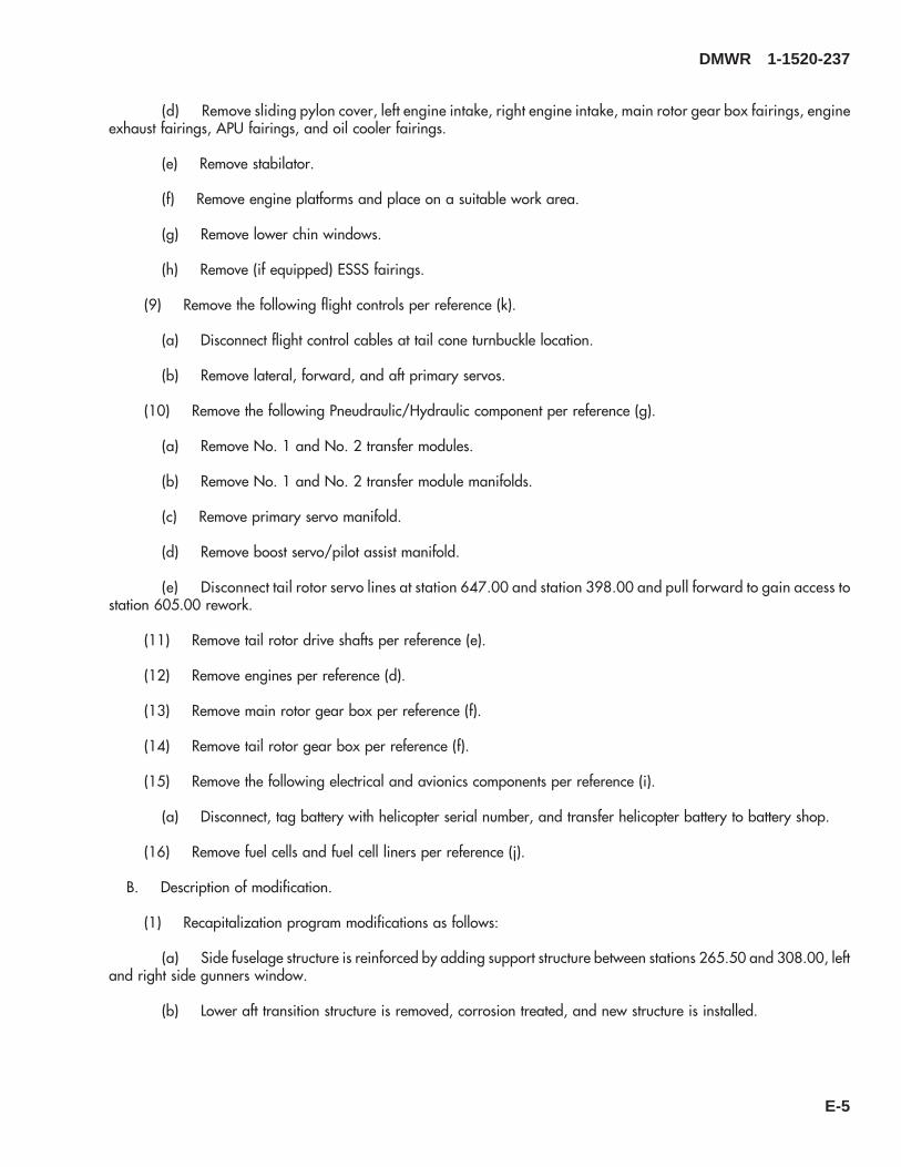
(d) Remove sliding pylon cover, left engine intake, right engine intake, main rotor gear box fairings, engineexhaust fairings, APU fairings, and oil cooler fairings.
(e) Remove stabilator.
(f) Remove engine platforms and place on a suitable work area.
(g) Remove lower chin windows.
(h) Remove (if equipped) ESSS fairings.
(9) Remove the following flight controls per reference (k).
(a) Disconnect flight control cables at tail cone turnbuckle location.
(b) Remove lateral, forward, and aft primary servos.
(10) Remove the following Pneudraulic/Hydraulic component per reference (g).
(a) Remove No. 1 and No. 2 transfer modules.
(b) Remove No. 1 and No. 2 transfer module manifolds.
(c) Remove primary servo manifold.
(d) Remove boost servo/pilot assist manifold.
(e) Disconnect tail rotor servo lines at station 647.00 and station 398.00 and pull forward to gain access tostation 605.00 rework.
(11) Remove tail rotor drive shafts per reference (e).
(12) Remove engines per reference (d).
(13) Remove main rotor gear box per reference (f).
(14) Remove tail rotor gear box per reference (f).
(15) Remove the following electrical and avionics components per reference (i).
(a) Disconnect, tag battery with helicopter serial number, and transfer helicopter battery to battery shop.
(16) Remove fuel cells and fuel cell liners per reference (j).
B. Description of modification.
(1) Recapitalization program modifications as follows:
(a) Side fuselage structure is reinforced by adding support structure between stations 265.50 and 308.00, leftand right side gunners window.
(b) Lower aft transition structure is removed, corrosion treated, and new structure is installed.
DMWR 1-1520-237
E-5

(c) Buttline 34.50 is modified by installing new reinforcements, coldworking fasteners locations, and installingnew fasteners.
(d) Tail rotor gear box pylon mount fitting is modified by installing a new left side doubler and two right sidestraps with coldworked fasteners. Tail gear box mount fitting is removed and a new fitting is installed. Forward spardoubler is removed and replaced with a new doubler. Gear box fairing installation is modified.
(e) Tail rotor drive shaft supports are modified at stations 410.00, 471.00, 531.43, and 591.88 by installingnew supports, doublers, and brackets.
(f) New doublers and stiffeners are added to the existing tail pylon side skin between stations 645.00 and660.00.
(g) Lower skin and doubler between stations 485.00 and 605.00 are removed and new skin and doubler areinstalled. New doublers are installed at left and right side locations between tailcone stations 625.00 and 635.00.
(h) New skins and doublers are installed between stations 295.00 and 308.00 on helicopters equipped withESSS provisions.
(i) New cabin upper plating is installed between stations 320.00 and 380.00 with coldworked fasteners com-mon to buttline 16.5 transmission beams.
(j) Tailcone station 605.00 is modified by installing a new doubler, filler, and radius block.
(k) New doublers, angles, straps, and spacers are installed to left and right side firewall assemblies.
(l) New intercostals which support vapor barriers over fuel cells between stations 413.00 and 443.50 areinstalled.
(m) Station 205.00, left and right side door post locations are modified by installing new fittings, angles andnutplates.
(n) Tailcone structure between stations 485.00 and 565.00 is modified by adding stringers and shear ties.
(o) Stabilator attachment fittings are modified by removing bushings and liners and installing new Forcematebushings and spherical bearings.
(p) New straps and doublers are installed at station 379.00 frame left and right sides with coldworked fasten-ers.
(q) Tail cone shear deck is modified by installing new doublers and angles between stations 605.00 and645.00.
(r) HIRSS structure is modified by installing new doublers, fillers, angles, and radius blocks on helicoptersequipped with HIRSS.
(s) New hinge fitting assemblies are installed to reinforce the hinge area on the engine cowl assemblies.
(t) A new fitting and fasteners are installed at station 485.00.
(u) Two access holes, doublers, and new seal are added to the nose door hinge area.
DMWR 1-1520-237
E-6

C. Installation
(1) Perform recapitalization modifications as follows:
(a) Rework nose/canopy per references (y), and (ag).
(b) Rework cabin per references (l), (n), (s), (t), and (ab).
(c) Rework of transition per references (m), (v), (w), (x), (ad), (ae), and (af).
(d) Rework tail cone per references (p), (r), (u), (z), and (ac).
(e) Rework tail pylon per reference (o), (q), and (aa).
D. Reinstallation of removed equipment:
(1) Install fuel cells and fuel cell liners per reference (j).
(2) Install main rotor gear box per reference (f).
(3) Install tail rotor gear box per reference (f).
(4) Install tail rotor drive shafts per reference (e).
(5) Install engines per reference (d).
(6) Install the following pneudraulic/hydraulic components per reference (g).
(a) Install No. 1 and No. 2 transfer modules.
(b) Install No. 1 and No. 2 transfer modules manifolds.
(c) Install boost servo/pilot assist manifold.
(d) Install primary servo manifold.
(7) Install the following flight control per reference (k).
(a) Install lateral, forward, and aft primary servos.
(b) Reconnect flight control cables at tail cone turnbuckle locations.
(8) Install the following airframe components per reference (c).
(a) Install pilots door, pilots seat, copilots door, copilots seat, cockpit floor panels, and cockpit floor covers.
(b) Install aft cargo floor to station 397.00, troop seats, troop seat supports, left cargo door, right cargo door,gunner seats, gunner seat supports, and soundproofing.
(c) Install fuel cell enclosure panels, drive shaft covers, stabilator, stabilator fairings, and tail gear box cover.
(d) Install sliding pylon cover, left engine intake, right engine intake, main rotor gear box fairings, engineexhaust fairings, engine platform doors, APU fairings, and oil cooler fairings.
DMWR 1-1520-237
E-7
(e) Install control enclosure left side and control enclosure right side, nose and cabin vibration absorber, noseaccess panel, and drip pan assembly.
(f) Install lower chin windows.
(g) Install ESSS fairings (if equipped).
(9) Install tail rotor blades per reference (e).
(10) Install main rotor blades per reference (e).
(11) Remove covers from pitot tubes per reference (h).
E. Perform operational check out as follows:
(1) Perform applicable operational checks that are identified in Technical Manual (TM) upon installation ofcomponents.
F. Record of Compliance:
(1) Make an appropriate logbook entry to show compliance with this Special Service Instruction.
(2) Upon compliance with these Special Service Instructions, complete SA Form 7614 and return it to SikorskyAircraft ILS Manager.
Weight and Balance Data:
QTY PART NO. NOMENCLATUREPOUNDSWEIGHT
INCHES AFTOF DATUM
MOMENT/1000
1 70070-95122-011 Mod. Kit + 61.7 359.1 24.40
Weight and Balance: Change resulting from these instructions are as follows:
Change in basic weight: + 61.7 pounds
Moment arm: 359.1 in.
Change in basic moment/1000 24.40
Manpower (Estimated)
No. of Personel No. of Hours Man-hours
Sheet Metal Mechanic 8 209.0 *1672.0Helicopter Electrician 1 8.0 *8.0Fuel Mechanic 1 2.0 *2.0
*Does not include time required to prepare helicopter or return it to flight status.
DMWR 1-1520-237
E-8

Material Information:
A. Modification Kit Required:
Qty Nomenclature Part Number Source
1 RECAP Top Kit, 70070-95122-011 (1)
consisting of:1 Mod. Kit, Nose/Canopy, 70070-20566-011
consisting of:1 Mod. Kit, Door Post, 70070-20566-012
consisting of:1 Mod. Kit, Floor Instl, 70070-20566-0151 Mod. Kit, Fitting Installation Left
Hand,70070-20566-019
1 Mod. Kit, Fitting Installation RightHand,
70070-20566-020
1 Mod. Kit, Floor Left Hand, 70070-20566-0171 Mod. Kit, Floor Right Hand, 70070-20566-0181 Mod. Kit, Jamb Installation, 70070-20566-0341 Mod. Kit, Jamb Installation, 70070-20566-0351 Mod. Kit, Frame Installation, 70070-20566-0371 Mod. Kit, Frame Installation, 70070-20566-0381 Mod. Kit, Hinge Access, 70070-20566-013
1 Mod. Kit, Cabin, 70070-20567-011
consisting of:1 Mod. Kit, Side Fuselage, 70070-20527-011
consisting of:1 Mod. Kit, 70070-20167-0261 Mod. Kit, 70070-20470-0111 Mod. Kit, Beef-Up, 70070-20527-0121 Mod. Kit, Beef-Up, 70070-20527-013
1 Mod. Kit, Station 379.00, 70070-20568-011
consisting of:1 Mod. Kit, SPL Instl, 70070-20568-0121 Mod. Kit, Strap Instl, 70070-20568-013
1 Mod. Kit, Upper Plating, 70070-20570-011
consisting of:1 Mod. Kit, Plate Instl, 70070-20570-0121 Mod. Kit, Nutplate Instl, 70070-20570-013
DMWR 1-1520-237
E-9
Qty Nomenclature Part Number Source
1 Mod. Kit, Frame Instl, 70070-20570-0141 Mod. Kit, Angle Instl, 70070-20570-015
1 Mod. Kit, Buttline 34.50, 70070-20572-011
consisting of:1 Mod. Kit, R/H Reinforcement, 70070-20572-0121 Mod. Kit, L/H Reinforcement, 70070-20572-013
1 Mod. Kit, ESSS Doubler, 70070-20641-011
consisting of:1 Mod. Kit, Support R/H Instl, 70070-20641-0121 Mod. Kit, Support L/H Instl, 70070-20641-0131 Mod. Kit, Plating Instl, 70070-20641-0141 Mod. Kit, Shim Instl, 70070-20641-018
1 Mod. Kit, Transition, 70070-20575-011
consisting of:1 Mod. Kit, TRDS Brackets, 70070-20488-023
consisting of:1 Mod. Kit, Support Instl, 70070-20488-0121 Mod. Kit, Support Instl, 70070-20488-022
1 Mod. Kit, Station 485.00, 70070-20575-012
1 Mod. Kit, Lower Aft Transition, 70070-20577-011
consisting of:1 Mod. Kit, Plate Assembly, 70070-20577-0121 Mod. Kit, Frame Instl, 70070-20577-0131 Mod. Kit, Hardware, 70070-20577-0141 Mod. Kit, Door Instl, 70070-20577-0161 Mod. Kit, Fuel Dump, 70070-20577-0171 Mod. Kit, Fuel Vent, 70070-20577-018
1 Mod. Kit, Foam Liner, 70070-20577-015
1 Mod. Kit, Enclosure, 70070-20578-011
1 Mod. Kit, Tail Cone, 70070-20580-011
consisting of:1 Mod. Kit, Support, Shaft, 70070-20266-013
1 Mod. Kit, Support, Shaft, 70070-20266-014
DMWR 1-1520-237
E-10
Qty Nomenclature Part Number Source
1 Mod. Kit, Shear Deck, 70070-20581-011
1 Mod. Kit, Stringer/Frame, 70070-20582-011
consisting of:1 Mod. Kit, Frame, 70070-20582-0121 Mod. Kit, Frame, 70070-20582-0131 Mod. Kit, Frame, 70070-20582-0141 Mod. Kit, Frame, 70070-20582-0271 Mod. Kit, Frame, 70070-20582-0281 Mod. Kit, Frame, 70070-20582-0151 Mod. Kit, Plating, 70070-20582-0161 Mod. Kit, Skin Assy, 70070-20582-0241 Mod. Kit, Plating, 70070-20582-0171 Mod. Kit, Skin Assy, 70070-20582-0251 Mod. Kit, Skin Assembly, 70070-20582-026
1 Mod. Kit, Skin Doubler, 70070-20583-011
1 Mod. Kit, Plate Instl, 70070-20615-011
1 Mod. Kit, Bulkhead Instl, 70070-20617-011
1 Mod. Kit, Pylon, 70070-20585-011
consisting of:1 Mod. Kit, Tail Pylon, 70070-20465-017
consisting of:1 Mod. Kit, Plating, 70070-20465-0121 Mod. Kit, Fairing, 70070-20465-0141 Mod. Kit, 70070-20465-0151 Mod. Kit, 70070-20465-0161 Mod. Kit, Fitting, 70070-20465-018
1 Mod. Kit, Crescent Doubler, 70070-20465-019
consisting of:1 Mod. Kit, Plating TRP, 70070-20465-0211 Mod. Kit, Plating TRP, 70070-20465-022
1 Mod. Kit, Front SPAR Fitting, 70070-20465-020
consisting of:1 Mod. Kit, Front SPAR, 70070-20465-0271 Mod. Kit, Support Instl, 70070-20465-0281 Mod. Kit, Support Instl, 70070-20465-029
DMWR 1-1520-237
E-11
Qty Nomenclature Part Number Source
1 Mod. Kit, Side Skin, 70070-20587-011
consisting of:1 Mod. Kit, Plating Instl, 70070-20587-0151 Mod. Kit, Plating Instl, 70070-20587-0161 Mod. Kit, SPAR Instl, 70070-20587-017
1 Mod. Kit, Aft SPAR Fitting, 70070-20588-011
consisting of:1 Mod. Kit, Fitting Assembly, 70070-20588-0121 Mod. Kit, Fitting Assembly 70070-20588-0131 Mod. Kit, Stab Instl, 70070-20588-014
1 Mod. Kit, LH Firewall Improve-ments,
70070-30307-011
1 Mod. Kit, RH Firewall Improve-ments,
70070-30307-012
1 Mod. Kit, Cowl Engine, 70070-30308-011
1 Mod. Kit, HIRSS Repair, 70072-30000-011
consisting of:1 Repair Kit, 70072-30000-0121 Repair Kit LH, 70072-30000-013
B. Consumable Material:
WARNING
OBSERVE ALL CAUTIONS AND WARNINGS ON CONTAINERS WHEN USING CONSUMABLES.WHEN APPLICABLE, WEAR NECESSARY PROTECTIVE GEAR DURING HANDLING AND USE. IF ACONSUMABLE IS FLAMMABLE OR EXPLOSIVE, MAKE CERTAIN CONSUMABLE AND ITS VAPORS AREKEPT AWAY FROM HEAT, SPARK, AND FLAME. MAKE CERTAIN EQUIPMENT IS PROPERLYGROUNDED AND FIREFIGHTING EQUIPMENT IS READILY AVAILABLE PRIOR TO USE. FOR AD-DITIONAL INFORMATION ON TOXICITY, FLASHPOINT, AND FLAMMABILITY OF CHEMICALS,CONSULT YOUR MEDICAL PEOPLE, OR MANUFACTURER OF THE CONSUMABLE.
Qty Nomenclature Part Number Source
32 oz. Adhesive EC-1357 or equivalent (1)64 oz. Sealant AMS-S-8802, A2 or equivalent (1)64 oz. Sealant AMS-S-8802, B2 or equivalent (1)
DMWR 1-1520-237
E-12
Qty Nomenclature Part Number Source
64 oz. Sealant MIL-S-8802, Class A2, orequivalent
(1)
64 oz. Sealant MIL-S-8802, Class B2, orequivalent
(1)
64 oz. Sealant MIL-S-8802, Class C20, orequivalent
(1)
8 oz. Chemical Conversion Coating forAluminum (Alodine 600)
MIL-C-5541, Class 3, orequivalent
(1)
8 oz. Sealant RTV133 or equivalent (1)16 oz. Primer MIL-P-85582A or equivalent (1)16 oz. Paint, Green SS8511-40-34031 or equivalent (1)16 oz. Paint, Black SS8511-40-37038 or equivalent (1)8 oz. Chemical Conversion Coating for
Aluminum (Alodine 1200)MIL-C-5541, Class 1A, orequivalent
(1)
32 oz. Adhesive EA9309.3NA or equivalent (1)8 oz. Foam Syntactic SS9587-002 or equivalent (1)8 oz. Foam Syntactic SS9587-001 or equivalent (1)8 oz. Foam Syntactic SS9587-003 or equivalent (1)6 oz. Sealant MIL-S-81733, Type 1 or IV or
equivalent(1)
2 oz. Primer, Adhesive EC-3917 or equivalent (1)6 oz. Sealing Compound AMS3267 Class A2 or C2, or
equivalent2 oz. Antiseize Compound MIT-T-83483 or equivalent (1)2 oz. 1,1,1-Trichloroethane MIL-T-81533 or equivalent (1)1 pkg Mat, Abrasive MIL-A-9962 or equivalent (1)1 pkg Cloth, Cheesecloth CCC-C-440 or equivalent (1)2 oz. Sealing Compound CA1000 or equivalent4 oz. Compound Dinotrol Av30 or Av15, or
equivalent(1)
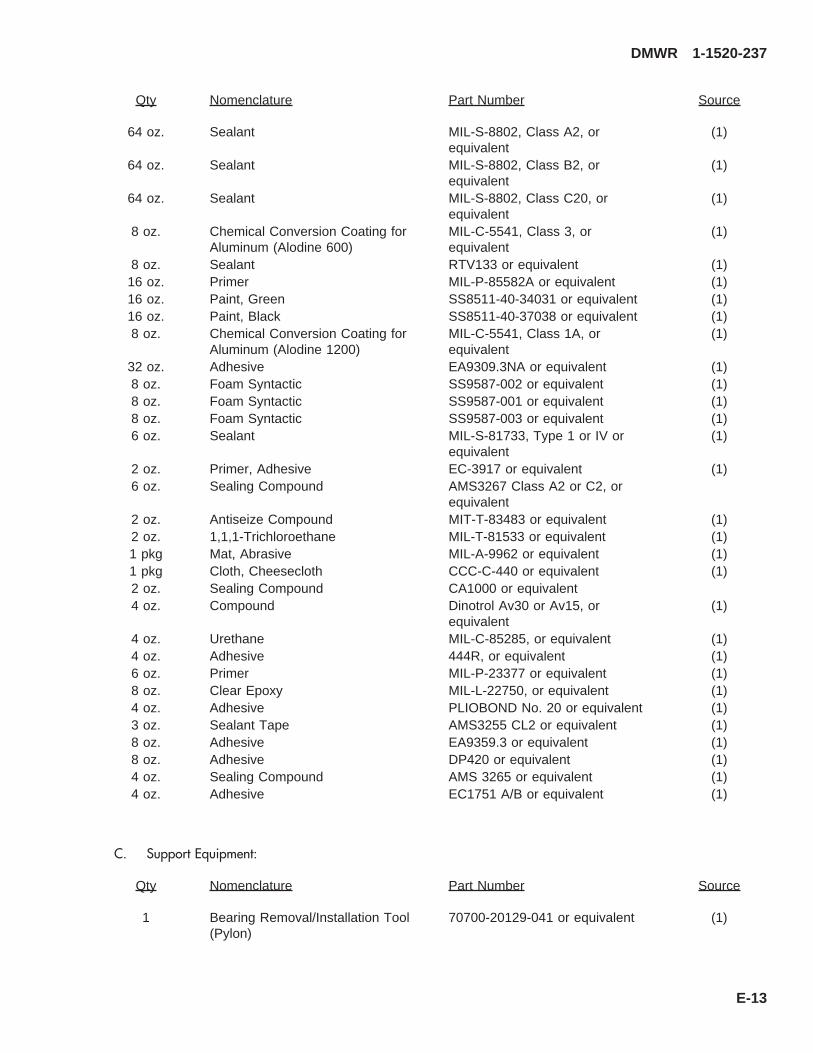
4 oz. Urethane MIL-C-85285, or equivalent (1)4 oz. Adhesive 444R, or equivalent (1)6 oz. Primer MIL-P-23377 or equivalent (1)8 oz. Clear Epoxy MIL-L-22750, or equivalent (1)4 oz. Adhesive PLIOBOND No. 20 or equivalent (1)3 oz. Sealant Tape AMS3255 CL2 or equivalent (1)8 oz. Adhesive EA9359.3 or equivalent (1)8 oz. Adhesive DP420 or equivalent (1)4 oz. Sealing Compound AMS 3265 or equivalent (1)4 oz. Adhesive EC1751 A/B or equivalent (1)
C. Support Equipment:
Qty Nomenclature Part Number Source
1 Bearing Removal/Installation Tool(Pylon)
70700-20129-041 or equivalent (1)
DMWR 1-1520-237
E-13

Qty Nomenclature Part Number Source
1 Installation Tool (Pylon) 70209-06056-041T046 orequivalent
(1)
1 Locally designed andmanufactured fuselage supporttool
N/A (2)
1 Edge Distance Tool (Pylon) 70070-77399-041 (1)1 Drill Tool (Door post) 70070-20566-017T046 (1)1 Installation Tool (Hinge) 70070-20566-019T046 (1)1 Installation Tool (Hinge) 70070-20566-020T046 (1)
D. Source:
(1) Available through normal supply channels
(2) Locally Manufactured
DMWR 1-1520-237
E-14
SAAB3088_1
A
1
4
10
16
24
1
23
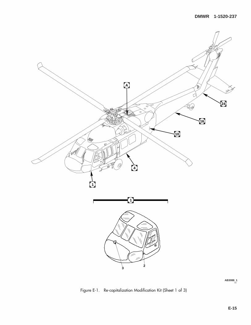
Figure E-1. Re-capitalization Modification Kit (Sheet 1 of 3)
DMWR 1-1520-237
E-15

SAAB3088_2
6
7
8
9
5
9
11
12
13
14
154 10
17
18
19
20
21
22
23
16
Figure E-1. Re-capitalization Modification Kit (Sheet 2 of 3)
DMWR 1-1520-237
E-16

SAAB3088_3
252627
28
29
24
30
31
33
32
A
Figure E-1. Re-capitalization Modification Kit (Sheet 3 of 3)
DMWR 1-1520-237
E-17

E-1- 70070-95122-011 RE-CAPATIALIZATION MODIFICATION KIT ............. 1-1 70070-20566-011 . DOOR POST MODIFICATION KIT .......................... 1-2 70070-20566-012 . . DOOR POST MODIFICATION KIT, (See Fig.
E-2 for Breakdown)................................................ 1-3 70070-20566-013 . . HINGE ACCESS MODIFICATION KIT, (See Fig.
E-3 for Breakdown)................................................ 1-4 70070-20567-011 . CABIN MODIFICATION KIT ..................................... 1-5 70070-20527-011 . . MODIFICATION KIT, (See Fig. E-4 for
Breakdown) ............................................................ 1-6 70070-20568-011 . . STATION 379 MODIFICATION KIT, (See Fig.
E-5 for Breakdown)................................................ 1-7 70070-20570-011 . . UPPER PLATING MODIFICATION KIT, (See
Fig. E-6 for Breakdown)......................................... 1-8 70070-20572-011 . . BL 34.5 MODIFICATION KIT, (See Fig. E-7 for
Breakdown) ............................................................ 1-9 70070-20641-011 . . ESSS DOUBLER MODIFICATION KIT, (See
Fig. E-8 for Breakdown)......................................... 1-10 70070-20575-011 . TRANSITION MODIFICATION KIT .......................... 1-11 70070-20488-023 . . TAIL ROTOR DRIVE SHAFT BRACKETS
MODIFICATION KIT, (See Fig. E-9 forBreakdown) ............................................................ 1
-12 70070-20575-012 . . STATION 485 MODIFICATION KIT, (See Fig.E-10 for Breakdown).............................................. 1
-13 70070-20577-011 . . LOWER AFT TRANSITION MODIFICATION KIT-, (See Fig. E-11 for Breakdown)........................... 1
-14 70070-20577-015 . . FOAM LINER MODIFICATION KIT, (See Fig.E-12 for Breakdown).............................................. 1
-15 70070-20578-011 . . ENCLOSURE MODIFICATION KIT, (See Fig.E-13 for Breakdown).............................................. 1
-16 70070-20580-011 . TAILCONE MODIFICATION KIT .............................. 1-17 70070-20266-013 . . SUPPORT SHAFT MODIFICATION KIT, (See
Fig. E-14 for Breakdown)....................................... 1-18 70070-20266-014 . . SUPPORT SHAFT MODIFICATION KIT, (See
Fig. E-15 for Breakdown)....................................... 1-19 70070-20581-011 . . SHEAR DECK MODIFICATION KIT, (See Fig.
E-16 for Breakdown).............................................. 1-20 70070-20582-011 . . STRINGER/FRAME MODIFICATION KIT, (See
Fig. E-17 for Breakdown)....................................... 1-21 70070-20583-011 . . SKIN DOUBLER MODIFICATION KIT, (See Fig.
E-18 for Breakdown).............................................. 1-22 70070-20615-011 . . PLATE INSTALLATION MODIFICATION KIT-
, (See Fig. E-19 for Breakdown)........................... 1-23 70070-20617-011 . . BULKHEAD INSTALLATION MODIFICATION
KIT, (See Fig. E-20 for Breakdown) ..................... 1-24 70070-20585-011 . PYLON MODIFICATION KIT.................................... 1-25 70070-20465-017 . . TAIL PYLON MODIFICATION KIT, (See Fig.
E-21 for Breakdown).............................................. 1-26 70070-20465-019 . . CRCT DOUBLE MODIFICATION KIT, (See Fig.
E-22 for Breakdown).............................................. 1-27 70070-20465-020 . . FRONT SPAR FT MODIFICATION KIT, (See
Fig. E-23 for Breakdown)....................................... 1-28 70070-20587-011 . . SIDE SKIN MODIFICATION KIT, (See Fig. E-24
for Breakdown)....................................................... 1-29 70070-20588-011 . . AFT SPAR FITTING MODIFICATION KIT, (See
Fig. E-25 for Breakdown)....................................... 1-30 70070-30307-011 . L/H FIREWALL MODIFICATION KIT, (See Fig.
E-26 for Breakdown)................................................. 1-31 70070-30307-012 . R/H FIREWALL MODIFICATION KIT, (See Fig.
E-27 for Breakdown)................................................. 1-32 70070-30308-011 . COWL ASSEMBLY MODIFICATION KIT, (See
Fig. E-28 for Breakdown).......................................... 1
DMWR 1-1520-237
QTY USABLEFIGURE & PER ONINDEX NO. PART NUMBER 1 2 3 4 5 6 7 DESCRIPTION ASSY CODE
E-18

-33 70072-30000-011 . HIRSS REPAIR KIT, (See Fig. E-29 forBreakdown) ............................................................... 1
DMWR 1-1520-237
QTY USABLEFIGURE & PER ONINDEX NO. PART NUMBER 1 2 3 4 5 6 7 DESCRIPTION ASSY CODE
E-19

E-3. DOOR POST MODIFICATION KIT (50-22).
Subject: Cockpit Door Posts, Modification of, dated 31 March 2003
Purpose: Provide instructions for the structural strengthening of the left and right side cockpit lower door post hingearea.
Model: UH-60A
Description: The left and right side lower door post structure at station 205.00 are modified to improve the structuralstrength at these locations.
Drawings required for modification:
70070-20566, 70500-01053, 70211-01005
References: (a) Special Service Instructions (SSI) No. 50-31, Installation of 9A to A9 Recapitalization Program, datedMarch 31, 2003
Instructions:
NOTE
• A complete review of this SSI is recommended before incorporating the Door Post Modification Kit.
• Before beginning this modification procedure, use the material information list to inventory the modificationkit. Make sure all parts are present and in serviceable condition.
• The sheet metal and structural modifications in this SSI shall be done by personnel experienced in readingmodification drawings. Routine steps such as cleaning, layout and drilling, deburring, standard repairs,corrosion control, clean up after rework, chemical coating for aluminum after cutting/trimming parts, andpaint touch up and safety practices may not be called out herein. However, these steps and all otherrequired routine tasks shall be done.
• Where drawing numbers are not listed within individual step(s), drawing(s) listed in preceding step(s) arethe controlling authority.
• Slight variations to the instructions contained herein are allowed, as long as the intent of the modificationis accomplished.
A. Preparation for modification and removal of equipment:
(1) Confirm that all warnings, cautions, and notes are complied with per reference (a).
(2) Perform preparation for modification per reference (a).
B. Modification, left side door post.
(1) Remove fasteners at station 205.00, waterline 226.00, left buttline 41.00 and remove duct assembly(70500-01053-043). Keep for reuse (Dwg 70500-01053, Sheet 1, Zones 14-E and 11-C).
(2) Remove two RFI grounding seals (03-0402-A137), straps (70211-01005-103 and 70211-01005-105), andjambs (70211-01005-104 and -107) at station 205.00 (Dwg 70211-01005, Sheet 1, Zones 9-E, 9-F and 6-F).
DMWR 1-1520-237
E-20

(3) Remove fasteners, doubler (70214-01003-112), and angle (70211-01011-117) (Dwg 70070-20566,Sheet 6, View H-H, Zones 12-C and 9-B).
(4) Remove fasteners shown from floor skin, between station 194.00 and station 209.00, between buttline 30.00and buttline 40.00 (Sheet 6, Zones 12-B through 9-D).
(5) Trim floor skin (70214-01003-101) to agree with support fitting (70209-21206-113) and peel back to sta-tion 210.00 (Sheet 6, View H-H, Zone 11-C).
(6) Remove nutplates (MS21075-3N and 52LHA3575-02), station 200.00, waterline 215.00, between buttline30.00 and buttline 40.00 (Sheet 6, View H-H, Zones 9-D and 12-C).
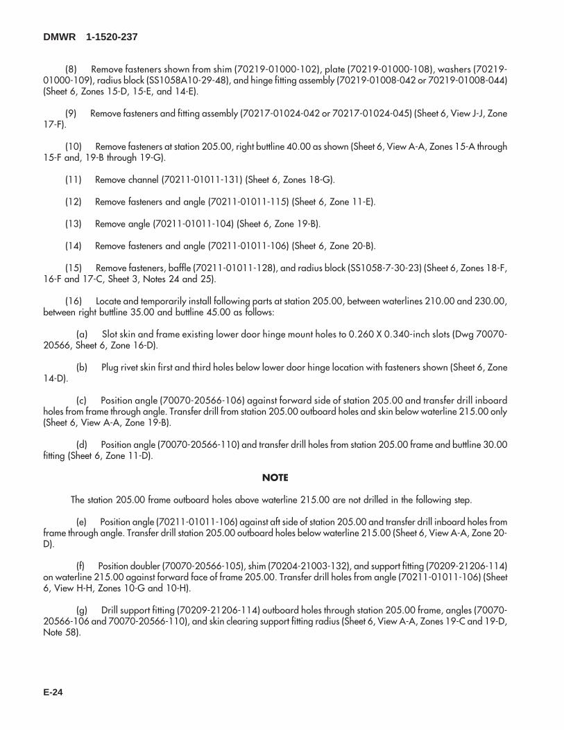
(7) Remove fasteners shown from shim (70219-01000-102), plate (70219-01000-108), washers (70219-01000-109), radius block (SS1058A10-29-48), and hinge fitting assembly (70219-01008-041 or 70219-01008-043)(Sheet 6, Zones 15-D, 15-E, and 14-E).
(8) Remove fasteners and fitting assembly (70217-01024-041 or 70217-01024-045) (Sheet 6, View J-J, Zone17-F).
(9) Remove fasteners at station 205.00, left buttline 40.00 as shown (Sheet 6, View A-A, Zones 15-A through15-F and, 19-B through 19-G).
(10) Remove channel (70211-01011-130) (Sheet 6, Zones 18-G).
(11) Remove fasteners and angle (70211-01011-111) (Sheet 6, Zone 11-D).
(12) Remove angle (70211-01011-103) (Sheet 6, Zone 19-B).
(13) Remove fasteners and angle (70211-01011-105) (Sheet 6, Zone 20-B).
(14) Remove fasteners, baffle (70211-01011-127), and radius block (SS1058-7-30-23) (Sheet 6, Zones 18-F,16-F and 17-C; Sheet 3, Notes 24 and 25).
(15) Locate and temporarily install following parts at station 205.00, between waterline 210.00 and waterline230.00, between left buttline 35.00 and buttline 45.00 as follows:
(a) Slot skin and frame existing lower door hinge mount holes to 0.260 X 0.340-inch slots (Dwg 70070-20566, Sheet 6, Zone 16-D).
(b) Plug rivet skin first and third holes below lower door hinge location with fasteners shown (Sheet 6, Zone14-D).
(c) Position angle (70070-20566-107) against forward side of station 205.00 and transfer drill inboardholes from frame through angle. Transfer drill station 205.00 outboard holes and skin below waterline 215.00 only(Sheet 6, View A-A, Zone 19-B).
(d) Position angle (70070-20566-111) and transfer drill holes from station 205.00 frame and buttline 30.00fitting (Sheet 6, Zone 11-D).
DMWR 1-1520-237
E-21
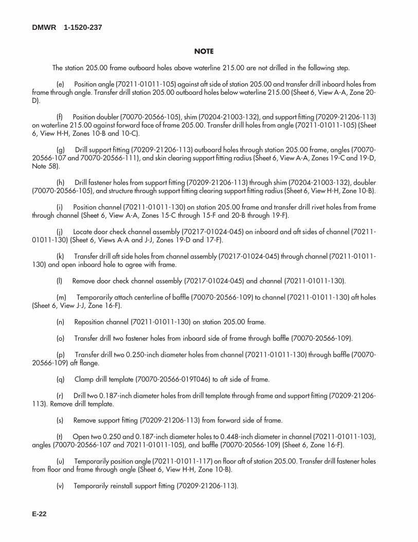
NOTE
The station 205.00 frame outboard holes above waterline 215.00 are not drilled in the following step.
(e) Position angle (70211-01011-105) against aft side of station 205.00 and transfer drill inboard holes fromframe through angle. Transfer drill station 205.00 outboard holes below waterline 215.00 (Sheet 6, View A-A, Zone 20-D).
(f) Position doubler (70070-20566-105), shim (70204-21003-132), and support fitting (70209-21206-113)on waterline 215.00 against forward face of frame 205.00. Transfer drill holes from angle (70211-01011-105) (Sheet6, View H-H, Zones 10-B and 10-C).
(g) Drill support fitting (70209-21206-113) outboard holes through station 205.00 frame, angles (70070-20566-107 and 70070-20566-111), and skin clearing support fitting radius (Sheet 6, View A-A, Zones 19-C and 19-D,Note 58).
(h) Drill fastener holes from support fitting (70209-21206-113) through shim (70204-21003-132), doubler(70070-20566-105), and structure through support fitting clearing support fitting radius (Sheet 6, View H-H, Zone 10-B).
(i) Position channel (70211-01011-130) on station 205.00 frame and transfer drill rivet holes from framethrough channel (Sheet 6, View A-A, Zones 15-C through 15-F and 20-B through 19-F).
(j) Locate door check channel assembly (70217-01024-045) on inboard and aft sides of channel (70211-01011-130) (Sheet 6, Views A-A and J-J, Zones 19-D and 17-F).
(k) Transfer drill aft side holes from channel assembly (70217-01024-045) through channel (70211-01011-130) and open inboard hole to agree with frame.
(l) Remove door check channel assembly (70217-01024-045) and channel (70211-01011-130).
(m) Temporarily attach centerline of baffle (70070-20566-109) to channel (70211-01011-130) aft holes(Sheet 6, View J-J, Zone 16-F).
(n) Reposition channel (70211-01011-130) on station 205.00 frame.
(o) Transfer drill two fastener holes from inboard side of frame through baffle (70070-20566-109).
(p) Transfer drill two 0.250-inch diameter holes from channel (70211-01011-130) through baffle (70070-20566-109) aft flange.
(q) Clamp drill template (70070-20566-019T046) to aft side of frame.
(r) Drill two 0.187-inch diameter holes from drill template through frame and support fitting (70209-21206-113). Remove drill template.
(s) Remove support fitting (70209-21206-113) from forward side of frame.
(t) Open two 0.250 and 0.187-inch diameter holes to 0.448-inch diameter in channel (70211-01011-103),angles (70070-20566-107 and 70211-01011-105), and baffle (70070-20566-109) (Sheet 6, Zone 16-F).
(u) Temporarily position angle (70211-01011-117) on floor aft of station 205.00. Transfer drill fastener holesfrom floor and frame through angle (Sheet 6, View H-H, Zone 10-B).
(v) Temporarily reinstall support fitting (70209-21206-113).
DMWR 1-1520-237
E-22

(w) Temporarily attach door check channel assembly (70217-01024-045) to channel (70211-01011-130)with work hardware and bushings (NAS73-4-107).
(x) Position installation tool (70070-20566-019T046) onto upper door hinge and door check channel as-sembly (70217-01024-045).
(y) Drill two 0.250-inch diameter holes. Remove installation tool.
(z) Remove parts from station 205.00, clean, deburr, and touch up as required.
(aa) Position radius block (70201-21011-135) onto inboard side of support fitting (70209-21206-113). Drilltwo No. 30 (0.128-inch diameter) holes with 100° countersink and transfer drill two 0.250-inch diameter holes (Sheet 6,View K-K, Zone 17-B).
(ab) Install radius block (70201-21011-135) to support fitting (70209-21206-113) with fasteners shown(Sheet 6, View K-K, Zone 17-B).
(ac) Install new frame parts with fasteners shown (Sheet 6, Zones 8 through 20, Note 44).
(ad) Install door hinge fitting assembly (70219-01008-045), shim (70219-01000-102), and plate (70219-01000-108) with fasteners shown (Sheet 6, Zones 7-C, 14-E, and 16-E, Notes 44 and 45).
(ae) Install nutplates (MS21075-3N and 52LHA3575-02) with fasteners shown (Sheet 6, Zones 10-D and 12-D).
(af) Reinstall floor with fasteners shown (Sheet 6, View H-H, Zone 9-B through 12-D).
(ag) Reinstall duct assembly (70500-01053-043) (Dwg 70500-01053, Sheet 1, Zones 14-E and 11-C).
(ah) Install two RFI grounding seals (03-0402-A137), straps (70211-01005-103 and -105), and jambs(70211-01005-104 and -107) at station 205.00 with fasteners shown (Dwg 70211-01005, Sheet 1, Zones 9-E, 9-F and6-F).
C. Modification, right side door post.
(1) Remove fasteners at station 205.00, waterline 226.00, right buttline 41.00 and remove duct assembly(70500-01053-044). Keep for reuse (Dwg 70500-01053, Sheet 1, Zones 14-E and 11-C).
(2) Remove two RFI grounding seals (03-0402-A137), straps (70211-01005-103 and 70211-01005-106), andjambs (70211-01005-104 and -108) at station 205.00 (Dwg 70211-01005, Sheet 1, Zones 9-E, 9-F and 6-F).
(3) Remove fasteners and angle (70211-01011-118) (Dwg 70070-20566, Sheet 6, View H-H, Zone 9-G).
(4) Remove fasteners shown from floor skin, between station 194.00 and station 209.00, between buttline 30.00and buttline 40.00 (Sheet 6, Zones 12-B through 9-D).
(5) Trim floor skin (70214-01003-102) to agree with support fitting (70209-21206-114) and peel back to sta-tion 210.00 (Sheet 6, View H-H, Zone 11-F).
(6) Remove radius block (SS1056-7-24-26) (Sheet 6, View H-H, Zone 11-F).
(7) Remove nutplates (MS21075-3N and 52LHA3575-02), station 200.00, waterline 215.00, between buttline30.00 and buttline 40.00 (Sheet 6, View H-H, Zones 9-E and 12-F).
DMWR 1-1520-237
E-23
(8) Remove fasteners shown from shim (70219-01000-102), plate (70219-01000-108), washers (70219-01000-109), radius block (SS1058A10-29-48), and hinge fitting assembly (70219-01008-042 or 70219-01008-044)(Sheet 6, Zones 15-D, 15-E, and 14-E).
(9) Remove fasteners and fitting assembly (70217-01024-042 or 70217-01024-045) (Sheet 6, View J-J, Zone17-F).
(10) Remove fasteners at station 205.00, right buttline 40.00 as shown (Sheet 6, View A-A, Zones 15-A through15-F and, 19-B through 19-G).
(11) Remove channel (70211-01011-131) (Sheet 6, Zones 18-G).
(12) Remove fasteners and angle (70211-01011-115) (Sheet 6, Zone 11-E).
(13) Remove angle (70211-01011-104) (Sheet 6, Zone 19-B).
(14) Remove fasteners and angle (70211-01011-106) (Sheet 6, Zone 20-B).
(15) Remove fasteners, baffle (70211-01011-128), and radius block (SS1058-7-30-23) (Sheet 6, Zones 18-F,16-F and 17-C, Sheet 3, Notes 24 and 25).
(16) Locate and temporarily install following parts at station 205.00, between waterlines 210.00 and 230.00,between right buttline 35.00 and buttline 45.00 as follows:
(a) Slot skin and frame existing lower door hinge mount holes to 0.260 X 0.340-inch slots (Dwg 70070-20566, Sheet 6, Zone 16-D).
(b) Plug rivet skin first and third holes below lower door hinge location with fasteners shown (Sheet 6, Zone14-D).
(c) Position angle (70070-20566-106) against forward side of station 205.00 and transfer drill inboardholes from frame through angle. Transfer drill from station 205.00 outboard holes and skin below waterline 215.00 only(Sheet 6, View A-A, Zone 19-B).
(d) Position angle (70070-20566-110) and transfer drill holes from station 205.00 frame and buttline 30.00fitting (Sheet 6, Zone 11-D).
NOTE
The station 205.00 frame outboard holes above waterline 215.00 are not drilled in the following step.
(e) Position angle (70211-01011-106) against aft side of station 205.00 and transfer drill inboard holes fromframe through angle. Transfer drill station 205.00 outboard holes below waterline 215.00 (Sheet 6, View A-A, Zone 20-D).
(f) Position doubler (70070-20566-105), shim (70204-21003-132), and support fitting (70209-21206-114)on waterline 215.00 against forward face of frame 205.00. Transfer drill holes from angle (70211-01011-106) (Sheet6, View H-H, Zones 10-G and 10-H).
(g) Drill support fitting (70209-21206-114) outboard holes through station 205.00 frame, angles (70070-20566-106 and 70070-20566-110), and skin clearing support fitting radius (Sheet 6, View A-A, Zones 19-C and 19-D,Note 58).
DMWR 1-1520-237
E-24
(h) Drill fastener holes from support fitting (70209-21206-114) through shim (70204-21003-132), doubler(70070-20566-105), and structure through support fitting clearing support fitting radius (Sheet 6, View H-H, Zone 10-G).
(i) Position channel (70211-01011-131) on station 205.00 frame and transfer drill rivet holes from framethrough channel (Sheet 6, View A-A, Zones 15-C through 15-F and 20-B through 19-F).
(j) Locate door check channel assembly (70217-01024-044) on inboard and aft sides of channel (70211-01011-131) (Sheet 6, Views A-A and J-J, Zones 19-D and 17-F).
(k) Transfer drill aft side holes from channel assembly (70217-01024-044) through channel (70211-01011-131) and open inboard hole to agree with frame.
(l) Remove door check channel assembly (70217-01024-044) and channel (70211-01011-131).
(m) Temporarily attach centerline of baffle (70070-20566-108) to channel (70211-01011-131) aft holes(Sheet 6, View J-J, Zone 16-F).
(n) Reposition channel (70211-01011-131) on station 205.00 frame.
(o) Transfer drill two fastener holes from inboard side of frame through baffle (70070-20566-108).
(p) Transfer drill two 0.250-inch diameter holes from channel (70211-01011-131) through baffle (70070-20566-108) aft flange.
(q) Clamp drill template (70070-20566-019T046) to aft side of frame.
(r) Drill two 0.187-inch diameter holes from drill template through frame and support fitting (70209-21206-114). Remove drill template.
(s) Remove support fitting (70209-21206-114) from forward side of frame.
(t) Open two 0.250 and 0.187-inch diameter holes to 0.448-inch diameter in channel (70211-01011-103),angles (70070-20566-106 and 70211-01011-106), and baffle (70070-20566-108) (Sheet 6, Zone 16-F).
(u) Temporarily position angle (70211-01011-118) on floor aft of station 205.00. Transfer drill fastener holesfrom floor and frame through angle (Sheet 6, View H-H, Zone 9-H).
(v) Temporarily reinstall support fitting (70209-21206-114).
(w) Temporarily attach door check channel assembly (70217-01024-044) to channel (70211-01011-131)with work hardware and bushings (NAS73-4-107).
(x) Position installation tool (70070-20566-019T046) onto upper door hinge and door check channel as-sembly (70217-01024-045).
(y) Drill two 0.250-inch diameter holes. Remove installation tool.
(z) Remove parts from station 205.00, clean, deburr, and touch up as required.
(aa) Position radius block (70201-21011-135) onto inboard side of support fitting (70209-21206-114). Drilltwo No. 30 (0.128-inch diameter) holes with 100° countersink and transfer drill two 0.250-inch diameter holes (Sheet 6,View K-K, Zone 17-B).
DMWR 1-1520-237
E-25

(ab) Install radius block (70201-21011-135) to support fitting (70209-21206-114) with fasteners shown(Sheet 6, View K-K, Zone 17-B).
(ac) Install new frame parts with fasteners shown (Sheet 6, Zones 8 through 20, Note 44).
(ad) Install door hinge fitting assembly (70219-01008-044), shim (70219-01000-102), and plate (70219-01000-108) with fasteners shown (Sheet 6, Zones 7-C, 14-E, and 16-E, Notes 44 and 45).
(ae) Install nutplates (MS21075-3N and 52LHA3575-02) and radius block (SS1056-7-24-26) with fastenersshown (Sheet 6, View H-H, Zones 10-E, 11-F, and 12-F).
(af) Reinstall floor with fasteners shown (Sheet 6, View H-H, Zone 9-B through 12-D).
(ag) Reinstall duct assembly (70500-01053-044) (Dwg 70500-01053, Sheet 1, Zones 14-E and 11-C).
(ah) Install two RFI grounding seals (03-0402-A137), straps (70211-01005-103 and 70211-01005-106),and jambs (70211-01005-104 and -108) at station 205.00 with fasteners shown (Dwg 70211-01005, Sheet 1, Zones9-E, 9-F and 6-F).
D. Reidentification:
NOTE
The following reidentifications are for record purposes only. No physical reidentification is required.
FROM TO Nomenclature
70214-01003-011 70070-20566-031 Floor Instl, LH70214-01003-016 70070-20566-033 Floor Instl, LH70214-01003-012 70070-20566-030 Floor Instl, RH70214-01003-017 70070-20566-032 Floor Instl, RH70214-01003-041 70070-20566-041 Floor Assy, LH70214-01003-043 70070-20566-043 Floor Assy, LH70214-01003-042 70070-20566-042 Floor Assy, RH70214-01003-044 70070-20566-044 Floor Assy, RH70214-01003-101 70070-20566-103 Skin70214-01003-102 70070-20566-104 Skin70219-01000-011 70070-20566-025 Fitting Instl, LH70219-01000-013 70070-20566-029 Fitting Instl, LH70219-01000-012 70070-20566-026 Fitting Assy, RH70219-01000-014 70070-20566-028 Fitting Instl, RH70211-01011-012 70070-20566-014 Frame Instl70211-01011-011 70070-20566-039 Frame Instl70211-01001-041 70070-20566-045 Frame Assy70211-01001-042 70070-20566-046 Frame Assy70211-01001-044 70070-20566-047 Frame Assy70211-01001-045 70070-20566-048 Frame Assy
DMWR 1-1520-237
E-26

E. Reinstallation of removed equipment:
(1) Perform reinstallation of parts and equipment per reference (a).
F. Record of Compliance:
(1) Make an appropriate logbook entry to show compliance with this Special Service Instruction.
Weight and Balance Data:
QTY PART NO. NOMENCLATUREPOUNDSWEIGHT
INCHES AFTOF DATUM
MOMENT/1000
1 70070-20566-012 Mod. Kit, Door Post +5.9 210.0 +1.239
Weight and Balance: Change resulting from these instructions are as follows:
Change in basic weight: +5.9 pounds
Moment arm: 210.0 in.
Change in basic moment/1000: 1.239
Manpower (Estimated)
No. of Personel No. of Hours Man-hours
Sheet Metal Mechanic 2 40.0 *80.0
*Does not include time required to prepare helicopter or return it to flight status.
Material Information:
A. Modification Kit Required:
Qty Nomenclature Part Number Source
1 Mod. Kit, Door Post 70070-20566-011 (1)
consisting of:
1 Mod. Kit, Door Post, 70070-20566-012
consisting of:1 Mod. Kit, Floor Instl, 70070-20566-015
DMWR 1-1520-237
E-27
Qty Nomenclature Part Number Source
consisting of:1 Mod. Kit, Fitting Instl, LH, 70070-20566-019
consisting of:2 Bolt AN4C14A2 Nut MS21043-42 Fastener, Blind MS90354U05023 Fastener, Blind MS90354U06023 Rivet NAS1097AD4-94 Rivet NAS1097AD5-92 Washer, Flat NAS1149D0463K1 Radius Block 70201-21011-1354 Washer SS5072-41 Shim 70219-01000-1021 Plate 70219-01000-1082 Washer 70219-01000-1091 Fitting Assembly 70219-01008-04510 Rivet MS20470AD5-92 Rivet MS20470AD6-33 Rivet RA097AD5-34 Rivet, Blind NAS1738B6-5
1 Mod. Kit, Fitting Instl, RH, 70070-20566-020
consisting of:
2 Bolt AN4C14A2 Nut MS21043-42 Fastener, Blind MS90354U05023 Fastener, Blind MS90354U06023 Rivet NAS1097AD4-94 Rivet NAS1097AD5-92 Washer, Flat NAS1149D0463K1 Radius Block 70201-21011-1354 Washer SS5072-41 Shim 70219-01000-1021 Plate 70219-01000-1082 Washer 70219-01000-1091 Fitting Assembly 70219-01008-04610 Rivet MS20470AD5-92 Rivet MS20470AD6-33 Rivet RA097AD5-34 Rivet, Blind NAS1738B6-5
1 Mod. Kit, Floor LH, 70070-20566-017
DMWR 1-1520-237
E-28

Qty Nomenclature Part Number Source
consisting of:2 Washer AN960PD10L8 Rivet CCR244SS-3-28 Rivet CCR244SS-3-416 Collar HL1087A-516 Pin, Hi Lok HL20PB-5-43 Nutplate MS21075-3N2 Rivet NAS1097AD5-910 Rivet, Blind NAS1738B4-110 Rivet, Blind NAS1738B4-215 Rivet, Blind NAS1738B5-215 Rivet, Blind NAS1739B4-22 Rivet, Blind NAS1739B4-33 Nutplate 52LHA3575-021 Doubler 70070-20566-1051 Support Fitting 70209-21206-1131 Angle 70211-01011-1172 Screw MS27039-1-093 Rivet, Blind NAS1739B4-11 Shim, Laminated 70204-21003-132
1 Mod. Kit, Floor, RH 70070-20566-018
consisting of:2 Washer AN960PD10L8 Rivet CCR244SS-3-28 Rivet CCR244SS-3-416 Collar HL1087A-516 Pin, Hi Lok HL20PB-5-43 Nutplate MS21075-3N2 Rivet NAS1097AD5-93 Rivet, Blind NAS1738B4-222 Rivet, Blind NAS1738B5-216 Rivet, Blind NAS1739B4-22 Rivet, Blind NAS1739B4-31 Radius Block SS1058-7-24-263 Nutplate 52LHA3575-021 Doubler 70070-20566-1051 Shim, Laminated 70204-21003-1321 Angle 70211-01011-1181 Support Fitting 70209-21206-1142 Screw MS27039-1-0915 Rivet, Blind NAS1738B4-2
1 Mod. Kit, Jamb Instl, 70070-20566-034
consisting of:2 Pin, Hi Lok HL20PB-5-5
DMWR 1-1520-237
E-29

Qty Nomenclature Part Number Source
2 Collar HL70TW-56 Rivet MS20470AD5-39 Rivet MS20470AD5-43 Fastener, Blind MS90354U06031 Washer, Flat NAS1149DN416K5 Rivet, Blind NAS1738B4-22 Rivet, Blind NAS1738B4-32 Seal, RFI Grndng 03-0402-A1371 Strap 70211-01005-1031 Jamb 70211-01005-1041 Strap 70211-01005-1051 Jamb 70211-01005-107
1 Mod. Kit, Jamb Instl, 70070-20566-035
consisting of:2 Pin, Hi Lok HL20PB-5-52 Collar HL70TW-56 Rivet MS20470AD5-39 Rivet MS20470AD5-43 Fastener, Blind MS90354U06031 Washer, Flat NAS1149DN416K5 Rivet, Blind NAS1738B4-22 Rivet, Blind NAS1738B4-32 Seal, RFI Grndng 03-0402-A1371 Strap 70211-01005-1031 Jamb 70211-01005-1041 Strap 70211-01005-1061 Jamb 70211-01005-108
1 Mod. Kit, Frame Instl, 70070-20566-037
consisting of:2 Bolt AN4-2127 Rivet MS20470AD5-92 Nut MS21043-47 Fastener, Blind MS90354U05062 Washer, Flat NAS1149D0416K2 Washer, Flat NAS1149D0463K2 Pin, SWG LKG NAS1525-024 Pin, SWG LKG NAS1525-035 Pin, SWG LKG NAS1526-0310 Rivet, Blind NAS1738B5-27 Rivet, Blind NAS1738B5-32 Bushing NAS73-4-1071 Baffle 70070-20566-1091 Channel 70211-01011-1301 Channel Assembly 70217-01024-045
DMWR 1-1520-237
E-30

Qty Nomenclature Part Number Source
1 Channel 70070-20566-1111 Angle 70211-01011-1051 Angle 70070-20566-107
1 Mod. Kit, Frame Instl, 70070-20566-038
consisting of:2 Bolt AN4-2127 Rivet MS20470AD5-92 Nut MS21043-47 Fastener, Blind MS90354U05062 Washer, Flat NAS1149D0416K2 Washer, Flat NAS1149D0463K2 Pin, SWG LKG NAS1525-024 Pin, SWG LKG NAS1525-035 Pin, SWG LKG NAS1526-0310 Rivet, Blind NAS1738B5-27 Rivet, Blind NAS1738B5-32 Bushing NAS73-4-1071 Angle 70211-01011-1061 Baffle 70070-20566-1081 Channel 70211-01011-1311 Channel Assembly 70217-01024-0441 Angle 70070-20566-1061 Channel 70070-20566-110
B. Consumable Material:
WARNING
OBSERVE ALL CAUTIONS AND WARNINGS ON CONTAINERS WHEN USING CONSUMABLES.WHEN APPLICABLE, WEAR NECESSARY PROTECTIVE GEAR DURING HANDLING AND USE. IF ACONSUMABLE IS FLAMMABLE OR EXPLOSIVE, MAKE CERTAIN CONSUMABLE AND ITS VAPORS AREKEPT AWAY FROM HEAT, SPARK, AND FLAME. MAKE CERTAIN EQUIPMENT IS PROPERLYGROUNDED AND FIREFIGHTING EQUIPMENT IS READILY AVAILABLE PRIOR TO USE. FOR AD-DITIONAL INFORMATION ON TOXICITY, FLASHPOINT, AND FLAMMABILITY OF CHEMICALS,CONSULT YOUR MEDICAL PEOPLE, OR MANUFACTURER OF THE CONSUMABLE.
NOTE
The following material is required to incorporate this SSI per drawing Notes.
Qty Nomenclature Part Number Source
8 oz. Sealant MIL-S-8802, Class A2 orequivalent
(1)
4 oz. Adhesive EC1751A/B or equivalent (1)
DMWR 1-1520-237
E-31

Qty Nomenclature Part Number Source
8 oz. Adhesive EA9309.3NA or equivalent (1)
C. Support Equipment:
Qty Nomenclature Part Number Source
1 Installation Tool 70070-20566-019T046 (1)1 Installation Tool 70070-20566-020T046 (1)1 Drill Tool 70070-20566-017T046 (1)
D. Source:
(1) Available through normal supply channels
DMWR 1-1520-237
E-32

8
7
6
5
4
2
2
35
6
13
10
9
12
11
9
14
11
1
A
1
A
SAAB3096_1
17
B
1516
Figure E-2. Door Post Modification Kit (Sheet 1 of 3)
DMWR 1-1520-237
E-33
23
23
SAAB3096_2
20
25
19
18
2726
24
2829
22
21
34 3333
3130
32
35
35
C
37
D
C
FRONT
53
54
5657
58
59
60
37
22
B
42
63
17
62
36
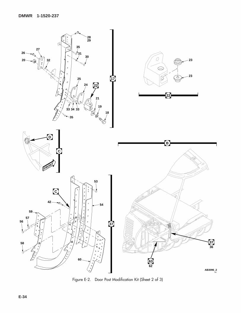
Figure E-2. Door Post Modification Kit (Sheet 2 of 3)
DMWR 1-1520-237
E-34

4547
45
44
46
46
50
48
49
51
SAAB3096_3
4140
52
55
42
39
38
43D 43
STA195
STA200
STA205
STA210
BL
RH40
BL
RH35
BL
RH30
BL
LH30
BL
LH35
BL
LH40
6868 69
657980
81
65
83
65
71
82
67
67
7273
64
66
61 647475
7677
7475
64
70
67
67
64 64 6464
67
66
65
6868
69
68
64
68
67
78
68
63
Figure E-2. Door Post Modification Kit (Sheet 3 of 3)
DMWR 1-1520-237
E-35

E-2- 70070-20566-012 DOOR POST MODIFICATION KIT ............................. REF-1 70070-20566-034 . M/K JAMB INSTL...................................................... 1
70070-20566-035 . M/K JAMB INSTL...................................................... 1-2 NAS1738B4-2 . . BLIND RIVET......................................................... 5-3 70211-01005-103 . . STRAP ................................................................... 1-4 70211-01005-104 . . JAMBP ................................................................... 1-5 03-0402-A137 . . SEAL,RFI GRNDNG, (12881)............................... 2-6 70211-01005-105 . . STRAP, (Used on 70070-20566-034)................... 1
70211-01005-106 . . STRAP, (Used on 70070-20566-035)................... 1-7 MS90354U0603 . . BLIND FASTENER ................................................ 3-8 NAS1738B4-3 . . BLIND RIVET......................................................... 2-9 MS20470AD5-3 . . RIVET..................................................................... 6
-10 NAS1149DN416K . . FLAT WASHER ..................................................... 1-11 MS20470AD5-4 . . RIVET..................................................................... 9-12 HL20PB-5-5 . . HI-LOK PIN, (73197)............................................. 2-13 HL70TW-5 . . COLLAR, (73197) ................................................. 2-14 70211-01005-107 . . JAMB, (Used on 70070-20566-034) ..................... 1
70211-01005-108 . . JAMB, (Used on 70070-20566-035) ..................... 1-15 70070-20566-015 . M/K DOOR POST..................................................... 1-16 70070-20566-019 . . M/K DOOR POST L............................................... 1
70070-20566-020 . . M/K DOOR POST R.............................................. 1-17 70070-20566-025 . . . FITTING INST LH, (Reidentified from 70219-
01000-011_ ......................................................... REF70070-20566-029 . . . FITTING INST LH, (Reidentified from 70219-
01000-013).......................................................... REF70070-20566-026 . . . FITTING INST RH, (Reidentified from 70219-
01000-012).......................................................... REF70070-20566-028 . . . FITTING INST RH, (Reidentified from 70219-
01000-014).......................................................... REF-18 AN4C14A . . . BOLT................................................................... 2-19 NAS1149D0463K . . . FLAT WASHER .................................................. 2-20 MS21043-4 . . . NUT..................................................................... 2-21 70219-01000-109 . . . WASHER ............................................................ 2-22 70219-01008-045 . . . FITTING ASSY, (Used on 70070-20566-019)... 1
70219-01008-046 . . . FITTING ASSY, (Used on 70070-20566-020)... 1-23 NAS77A4-14P . . . . BUSHING......................................................... 2-24 70219-01000-108 . . . PLATE................................................................. 1-25 70219-01000-102 . . . SHIM ................................................................... 1-26 NAS1097AD4-9 . . . RIVET.................................................................. 3-27 70201-21011-135 . . . RADIUS BLOCK ................................................. 1-28 MS90354U0502 . . . BLIND FASTENER ............................................. 2-29 MS90354U0602 . . . BLIND FASTENER ............................................. 3-30 NAS1097AD5-9 . . . RIVET.................................................................. 4-31 SS5072-4 . . . WASHER ............................................................ 4-32 NAS1738B6-5 . . . BLIND RIVET...................................................... 4-33 RA097AD5-3 . . . RIVET.................................................................. 3-34 MS20470AD6-3 . . . RIVET.................................................................. 2-35 MS20470AD5-9 . . . RIVET.................................................................. 10-36 70070-20566-037 . M/K FRAME INSTL LH............................................. 1
70070-20566-038 . M/K FRAME INSTL RH ............................................ 1-37 70070-20566-014 . . FRAME INSTL, (Modified from 70211-01011-
012) ........................................................................ REF70070-20566-039 . . FRAME INSTL, (Modified from 70211-01011-
011) ........................................................................ REF70070-20566-045 . . FRAME ASSY LH, (Reidentified from 70211-
01001-041)............................................................. REF70070-20566-046 . . FRAME ASSY RH, (Reidentified from 70211-
01001-042)............................................................. REF70070-20566-048 . . FRAME ASSY LH, (Reidentified from 70211-
01001-045)............................................................. REF
DMWR 1-1520-237
QTY USABLEFIGURE & PER ONINDEX NO. PART NUMBER 1 2 3 4 5 6 7 DESCRIPTION ASSY CODE
E-36

70070-20566-047 . . FRAME ASSY RH, (Reidentified from 70211-01001-044)............................................................. REF
-38 AN4-21 . . BOLT...................................................................... 2-39 NAS1149D0463K . . FLAT WASHER ..................................................... 2-40 NAS1149D0416K . . FLAT WASHER ..................................................... 2-41 MS21043-4 . . NUT........................................................................ 2-42 NAS1738B5-3 . . BLIND RIVET......................................................... 7-43 70217-01024-045 . . CHANNEL ASSY, (Used on 70070-20566-037)... 1
70217-01024-044 . . CHANNEL ASSY, (Used on 70070-20566-038)... 1-44 NAS77-3-10 . . . BUSHING............................................................ 2-45 MS24665-1013 . . . COTTER PIN ...................................................... 2-46 AN960PD416L . . . WASHER ............................................................ 2-47 70217-01024-104 . . . SPRING .............................................................. 1-48 HL20PB-5-4 . . . HI-LOK PIN, (73197).......................................... 2-49 HL1087-5 . . . COLLAR, (73197) .............................................. 2-50 70217-01024-107 . . . WEAR PLATE..................................................... 1-51 70217-01024-105 . . . CHECK FITTING, (Used on 70217-
01024-045).......................................................... 170217-01024-106 . . . CHECK FITTING, (Used on 70217-
01024-044).......................................................... 1-52 NAS73-4-107 . . BUSHING............................................................... 2-53 NAS1738B5-2 . . BLIND RIVET......................................................... 10-54 70211-01011-130 . . CHANNEL, (Used on 70070-20566-037) ............. 1
70211-01011-131 . . CHANNEL, (Used on 70070-20566-038) ............. 1-55 70070-20566-109 . . BAFFLE, (Used on 70070-20566-037) ................. 1
70070-20566-108 . . BAFFLE, (Used on 70070-20566-038) ................. 1-56 MS20470AD5-9 . . RIVET..................................................................... 27-57 MS90354U0506 . . BLIND FASTENER ................................................ 7-58 NAS1525-03 . . SWAGE LOCKING PIN ......................................... 4
NAS1525-02 . . SWAGE LOCKING PIN, ........................................ 2 *NAS1526-03 . . SWAGE LOCKING PIN, ........................................ 5 *
-59 70070-20566-107 . . ANGLE, (Used on 70070-20566-037) .................. 170070-20566-106 . . ANGLE, (Used on 70070-20566-038) .................. 1
-60 70211-01011-105 . . ANGLE, (Used on 70070-20566-037) .................. 170211-01011-106 . . ANGLE, (Used on 70070-20566-038) .................. 1
-61 70070-20566-111 . . CHANNEL, (Used on 70070-20566-037) ............. 170070-20566-110 . . CHANNEL, (Used on 70070-20566-038) ............. 1
-62 70070-20566-017 . M/K FLOOR LH ........................................................ 170070-20566-018 . M/K FLOOR RH........................................................ 1
-63 70070-20566-031 . . FLOOR INSTL LH, (Modified from 70214-01003-011) ........................................................................ REF
70070-20566-030 . . FLOOR INSTL RH, (Modified from 70214-01003-012)............................................................. REF
70070-20566-033 . . FLOOR INSTL LH, (Modified from 70214-01003-016) ........................................................................ REF
70070-20566-032 . . FLOOR INSTL RH, (Modified from 70214-01003-017)............................................................. REF
70070-20566-041 . . FLOOR ASSY LH, (Reidentified from 70214-01003-041)............................................................. REF
70070-20566-042 . . FLOOR ASSY RH, (Reidentified from 70214-01003-042)............................................................. REF
70070-20566-043 . . FLOOR ASSY LH, (Reidentified from 70214-01003-043)............................................................. REF
70070-20566-044 . . FLOOR ASSY RH, (Reidentified from 70214-01003-044)............................................................. REF
-64 NAS1739B4-2 . . BLIND RIVET, (Used on 70070-20566-017) ........ 15NAS1739B4-2 . . BLIND RIVET, (Used on 70070-20566-018) ........ 16
-65 NAS1738B4-1 . . BLIND RIVET, (Used on 70070-20566-017) ........ 10NAS1738B4-1 . . BLIND RIVET, (Used on 70070-20566-018) ........ 3
-66 NAS1739B4-1 . . BLIND RIVET, (Used on 70070-20566-017) ........ 3-67 NAS1738B5-2 . . BLIND RIVET, (Used on 70070-20566-017) ........ 15
DMWR 1-1520-237
QTY USABLEFIGURE & PER ONINDEX NO. PART NUMBER 1 2 3 4 5 6 7 DESCRIPTION ASSY CODE
E-37

NAS1738B5-2 . . BLIND RIVET, (Used on 70070-20566-018) ........ 22-68 NAS1738B4-2 . . BLIND RIVET, (Used on 70070-20566-017) ........ 10
NAS1738B4-2 . . BLIND RIVET, (Used on 70070-20566-018) ........ 15-69 70211-01011-117 . . ANGLE, (Used on 70070-20566-017) .................. 1
70211-01011-118 . . ANGLE, (Used on 70070-20566-018) .................. 1-70 NAS1739B4-3 . . BLIND RIVET......................................................... 2
NAS1097AD5-9 . . RIVET..................................................................... 2 *-71 70070-20566-103 . . SKIN, (Reidentified from 70214-01003-
101) (Used on 70070-20566-017) ........................ REF70070-20566-104 . . SKIN, (Reidentified from 70214-01003-
102) (Used on 70070-20566-018) ........................ REF-72 CCR244SS-3-2 . . RIVET, (11815) ..................................................... 8-73 MS21075-3N . . NUTPLATE ............................................................ 3-74 CCR244SS-3-4 . . RIVET, (11815) ..................................................... 8-75 52LHA3575-02 . . NUTPLATE, (72962) (Superseded by
NAS1149D0316K).................................................. 3NAS1149D0316K . . NUTPLATE ............................................................ 3
-76 MS27039-1-09 . . SCREW.................................................................. 2-77 AN960PD10L . . WASHER, (Superseded by NAS1789X3)............. 2
NAS1789X3 . . WASHER ............................................................... 2-78 SS1058-7-24-26 . . RADIUS BLOCK, RH, (Used on 70070-20566-
018) ........................................................................ 2-79 HL20PB-5-4 . . HI-LOK PIN, (73197)............................................. 16-80 HL1087A-5 . . COLLAR, (73197) ................................................. 16-81 70209-21206-113 . . SUPPORT FITTING, (Used on 70070-20566-
017) ........................................................................ 170209-21206-114 . . SUPPORT FITTING, (Used on 70070-20566-
018) ........................................................................ 1-82 70204-21003-132 . . LAMINATED SHIM ................................................ 1-83 70070-20566-105 . . DOUBLER.............................................................. 1
DMWR 1-1520-237
QTY USABLEFIGURE & PER ONINDEX NO. PART NUMBER 1 2 3 4 5 6 7 DESCRIPTION ASSY CODE
E-38
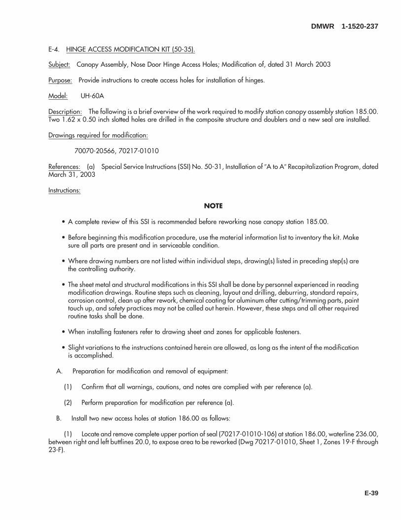
E-4. HINGE ACCESS MODIFICATION KIT (50-35).
Subject: Canopy Assembly, Nose Door Hinge Access Holes; Modification of, dated 31 March 2003
Purpose: Provide instructions to create access holes for installation of hinges.
Model: UH-60A
Description: The following is a brief overview of the work required to modify station canopy assembly station 185.00.Two 1.62 x 0.50 inch slotted holes are drilled in the composite structure and doublers and a new seal are installed.
Drawings required for modification:
70070-20566, 70217-01010
References: (a) Special Service Instructions (SSI) No. 50-31, Installation of 9A to A9 Recapitalization Program, datedMarch 31, 2003
Instructions:
NOTE
• A complete review of this SSI is recommended before reworking nose canopy station 185.00.
• Before beginning this modification procedure, use the material information list to inventory the kit. Makesure all parts are present and in serviceable condition.
• Where drawing numbers are not listed within individual steps, drawing(s) listed in preceding step(s) arethe controlling authority.
• The sheet metal and structural modifications in this SSI shall be done by personnel experienced in readingmodification drawings. Routine steps such as cleaning, layout and drilling, deburring, standard repairs,corrosion control, clean up after rework, chemical coating for aluminum after cutting/trimming parts, painttouch up, and safety practices may not be called out herein. However, these steps and all other requiredroutine tasks shall be done.
• When installing fasteners refer to drawing sheet and zones for applicable fasteners.
• Slight variations to the instructions contained herein are allowed, as long as the intent of the modificationis accomplished.
A. Preparation for modification and removal of equipment:
(1) Confirm that all warnings, cautions, and notes are complied with per reference (a).
(2) Perform preparation for modification per reference (a).
B. Install two new access holes at station 186.00 as follows:
(1) Locate and remove complete upper portion of seal (70217-01010-106) at station 186.00, waterline 236.00,between right and left buttlines 20.0, to expose area to be reworked (Dwg 70217-01010, Sheet 1, Zones 19-F through23-F).
DMWR 1-1520-237
E-39

(2) Locate and slot two holes (1.62 x .50) inch at station 186.00 at right and left buttlines 9.43 and 10.56 (Dwg70070-20566, Sheet 7, Zones 14-F and 15-G).
(3) Deburr, clean and touch up as required.
(4) Install doublers (70070-20611-101 and -102) using fasteners shown (Sheet 7, Zone 15-G).
WARNING
OBSERVE ALL CAUTIONS AND WARNINGS ON CONTAINERS WHEN USING CONSUMABLES.WHEN APPLICABLE, WEAR NECESSARY PROTECTIVE GEAR DURING HANDLING AND USE. IF ACONSUMABLE IS FLAMMABLE OR EXPLOSIVE, MAKE CERTAIN CONSUMABLE AND ITS VAPORS AREKEPT AWAY FROM HEAT, SPARK, AND FLAME. MAKE CERTAIN EQUIPMENT IS PROPERLYGROUNDED AND FIREFIGHTING EQUIPMENT IS READILY AVAILABLE PRIOR TO USE. FOR AD-DITIONAL INFORMATION ON TOXICITY, FLASHPOINT, AND FLAMMABILITY OF CHEMICALS,CONSULT YOUR MEDICAL PEOPLE, OR MANUFACTURER OF THE CONSUMABLE.
(5) Apply a bead of sealant (AMS3265 or AMS-S-8802 or equivalent) around doublers (70070-20611-101and -102) (Sheet 7, Zone 15-D, and Sheet 5, Note 57).
(6) Install seal (70217-01010-106) at station 186.00, between right and left buttline 20.0 using sealant (EC-1357 or equivalent) (Dwg 70217-01010, Sheet 1, Zones 19-F through 23-F, Note 14).
C. Reinstallation of removed equipment;
(1) Reinstall removed equipment per reference (a).
D. Record of Compliance:
(1) Make an appropriate logbook entry to show compliance with this Special Service Instruction.
Weight and Balance Data:
QTY PART NO. NOMENCLATUREPOUNDSWEIGHT
INCHES AFTOF DATUM
MOMENT/1000
1 70070-20566-013 Mod. Kit, Door Post +.13 187.5 +.024
Weight and Balance: Change resulting from these instructions are as follows:
Change in basic weight: 0.14 pounds
Moment arm: 187.5 in.
Change in basic moment/1000: 0.263
DMWR 1-1520-237
E-40

Manpower (Estimated)
No. of Personel No. of Hours Man-hoursStructural Mechanic 1 4.0 *4.0
*Does not include time required to prepare helicopter or return it to flight status.
Material Information:
A. Modification Kit Required:
Qty Nomenclature Part Number Source
1 Mod. Kit, Door Post, 70070-20566-013 (1)
consisting of:1 Seal 70217-01010-1061 Doubler 70070-20611-1011 Doubler 70070-20611-1025 Rivet CCR244SS3-4
B. Consumable Material:
WARNING
OBSERVE ALL CAUTIONS AND WARNINGS ON CONTAINERS WHEN USING CONSUMABLES.WHEN APPLICABLE, WEAR NECESSARY PROTECTIVE GEAR DURING HANDLING AND USE. IF ACONSUMABLE IS FLAMMABLE OR EXPLOSIVE, MAKE CERTAIN CONSUMABLE AND ITS VAPORS AREKEPT AWAY FROM HEAT, SPARK, AND FLAME. MAKE CERTAIN EQUIPMENT IS PROPERLYGROUNDED AND FIREFIGHTING EQUIPMENT IS READILY AVAILABLE PRIOR TO USE. FOR AD-DITIONAL INFORMATION ON TOXICITY, FLASHPOINT, AND FLAMMABILITY OF CHEMICALS,CONSULT YOUR MEDICAL PEOPLE, OR MANUFACTURER OF THE CONSUMABLE.
Qty Nomenclature Part Number Source
8 oz. Sealant EC-1357 or equivalent (1)8 oz Sealant AMS 3265 or AMS-S-8802 or
equivalent(1)
C. Source:
(1) Available through normal supply channels
DMWR 1-1520-237
E-41

SAAB3091
A
A
1
23
4
5
6
Figure E-3. Hinge Access Modification Kit
DMWR 1-1520-237
E-42
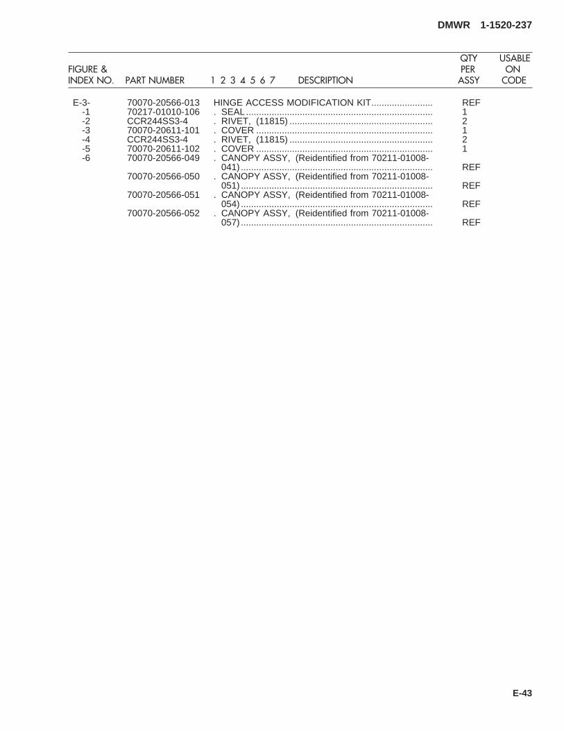
E-3- 70070-20566-013 HINGE ACCESS MODIFICATION KIT........................ REF-1 70217-01010-106 . SEAL......................................................................... 1-2 CCR244SS3-4 . RIVET, (11815) ........................................................ 2-3 70070-20611-101 . COVER ..................................................................... 1-4 CCR244SS3-4 . RIVET, (11815) ........................................................ 2-5 70070-20611-102 . COVER ..................................................................... 1-6 70070-20566-049 . CANOPY ASSY, (Reidentified from 70211-01008-
041) ........................................................................... REF70070-20566-050 . CANOPY ASSY, (Reidentified from 70211-01008-
051) ........................................................................... REF70070-20566-051 . CANOPY ASSY, (Reidentified from 70211-01008-
054) ........................................................................... REF70070-20566-052 . CANOPY ASSY, (Reidentified from 70211-01008-
057) ........................................................................... REF
DMWR 1-1520-237
QTY USABLEFIGURE & PER ONINDEX NO. PART NUMBER 1 2 3 4 5 6 7 DESCRIPTION ASSY CODE
E-43
E-5. MODIFICATION KIT (50-5).
Subject: Side Fuselage Structural Reinforcement; Installation of, dated 31 March 2003
Purpose: Provide instructions for the structural strengthening of the fuselage on the left and right side around the gun-ners window.
Model: UH-60A
Description: The left and right side gunner windows are reworked to add support structure between stations 265.50and 308.00.
Drawings required for modification:
70070-20167, 70070-20470, 70070-20527, 70083-20110, 70212-02307, 70213-02301
References: (a) Special Service Instructions (SSI) No. 50-31, Installation of 9A to A9 Recapitalization Program, datedMarch 31, 2003
(b) SSI No. 50-7 Buttline 34.50, Modification of dated March 31, 2003
Instructions:
NOTE
• A complete review of this SSI is recommended before incorporating the side fuselage structural reinforce-ment installation kit.
• Before beginning this modification procedure, use the material information list to inventory the modificationkit. Make sure all parts are present and in serviceable condition.
• Where drawing numbers are not listed within individual step(s), drawing(s) listed in preceding step(s) arethe controlling authority.
• The sheet metal and structural modifications in this SSI shall be done by personnel experienced in readingmodification drawings. Routine steps such as cleaning, layout and drilling, deburring, standard repairs,corrosion control, clean up after rework, chemical coating for aluminum after cutting/trimming parts, painttouch up, and safety practices may not be called out herein. However, these steps and all other requiredroutine tasks shall be done.
• When installing fasteners refer to drawing sheet and zones for applicable fasteners.
• Slight variations to the instructions contained herein are allowed, as long as the intent of the modificationis accomplished.
• Reference (b) must be done concurrently with this SSI.
A. Preparation for modification and removal of equipment:
(1) Confirm that all warnings, cautions, and notes are complied with per reference (a).
(2) Perform preparation for modification per reference (a).
DMWR 1-1520-237
E-44

(3) Remove wiring routed through left and right side channel (70212-02037-105 and -106) between stations247.00 and station 265.00, waterline 227.00.
B. Modification, left and right side gunners window structural and plating installation as follows:
(1) Modify left side gunners window structure and plating installation as follows (Dwg 70213-02301):
CAUTION
TO AVOID DAMAGING COMPONENTS, USE EXTREME CARE WHEN DRILLING INTO AIRFRAME.TEMPORARILY MOVE ANY TUBE ASSEMBLIES OR WIRING HARNESSES OUT OF REWORK AREA.
(a) Remove and keep for reuse, ring (70219-02313-101) and fitting (70219-02313-102) with attachinghardware, at station 308.00, waterline 221.00 (Dwg 70213-02301, Sheet 1, Zones 7-G and 10-C).
(b) Drill out fasteners and remove inner skin (70213-02301-105) between stations 265.00 and 295.00,waterlines 221.00 and 227.00 (Sheet 1, Zone 7-C).
(c) Drill out fasteners and remove bracket assembly (70551-02001-064) at station 297.00, waterline 259.00(Sheet 2, Zone 7-G).
(d) Drill out fasteners and remove doubler (70213-02301-113) between stations 295.00 and 308.00,waterlines 238.22 and 260.00 (Sheet 2, Zone 7-H).
(e) Remove and keep for reuse ring (70219-02313-101) and fitting (70219-02313-102) with attachinghardware, at station 308.00, waterline 260.00 (Sheet 1, Zone 12-F).
(f) Drill out fasteners and remove skin (70213-02301-117) between stations 295.00 and 308.00, waterlines207.00 and 260.00 (Sheet 1, Zone 9-E).
(g) Remove and keep for reuse fitting (70751-02022-101). Remove stiffiners (70212-02307-113 and -123)at station 268.12, between waterlines 221.00 and 227.00 (Dwg 70083-20110, Sheet 1, Zones 8-E, 8-J, and 8-C).
(h) Drill out fasteners, remove and keep for reuse stringer (70202-02310-109) between station 247.00 andstation 265.50, waterline 233.80 (Sheet 1, Zone 10-F).
(i) Drill out fasteners and remove angle (70211-02304-105) at station 265.50, waterline 233.80 (Sheet 1,Zone 10-G).
(j) Drill out fasteners and remove channel (70212-02307-105) between station 247.00 and station 265.50,waterline 227.00 (Sheet 1, Zone 11-E).
(k) Drill out fasteners and remove angle (70212-02307-126) at station 265.00, waterline 221.00 (Sheet 1,Zone 7-H).
DMWR 1-1520-237
E-45
NOTE
Reference (b) must be completed in it’s entirety at this time.
(l) Locate and temporarily install left side channel, (70083-20110-105) at station 265.50, between waterlines221.00 and 233.80 (Sheet 1, Zone 4-F).
1 Drill out and remove any fasteners or parts that would interfere with the installation of channel.
2 Transfer drill five, 0.375-inch diameter holes, from channel (70211-02304-101) through left side chan-nel (70083-20110-105) ( Sheet 1, Zone 6-F).
(m) Locate and temporarily reinstall stringer (70202-02310-109) between stations 247.00 and 265.50,waterline 233.80, removed in step (h) (Sheet 1, Zone 10-F).
(n) Locate and temporarily install angle (70083-20110-113) at station 265.50, waterline 233.80 (Sheet 1,Zone 10-G).
(o) Locate and temporarily install left side channel (70083-20110-103) between stations 247.00 and265.50, waterline 227.00 (Sheet 1, Zone 11-E).
(p) Locate and temporarily install angle (70083-20110-111) at station 265.50, waterline 221.00 (Sheet 1,Zone 7-H).
(q) Locate and temporarily install doubler (70083-20110-115) between stations 265.50 and 278.50,waterline 227.00 (Sheet 1, Zone 7-F).
1 Cutout 2.25-inch diameter hole through doubler (70083-20110-115) to match cutout in channel(70212-02307-101) station 268.12, waterline 227.00.
(r) Locate and temporarily install shims (70083-20110-107 and -109) at station 265.50, waterline 226.00(Sheet 1, Zones 4-E and 6-D).
1 Remove four fasteners at station 278.50 (Sheet 1, Zone 7-H).
(s) Locate and temporarily install strap (70083-20110-118) at station 278.50, waterline 227.00 (Sheet 1,Zone 6-J).
(t) Locate and temporarily install stiffeners (70212-02307-113 and -123) between stations 276.00 and308.00, waterlines 221.00 and 227.00 (Dwg 70212-02307, Sheet 1, Zones 4-D, 5-D, 16-H, and 17-J).
(u) Locate and temporarily reinstall fitting (70751-02022-101) at station 268.12, waterline 227.00, removedin step (g) (Sheet 1, Zone 8-E).
(v) Transfer drill the remaining fastener holes needed for assembly.
(w) Remove fitted parts and deburr and touch up as required.
(x) Install fitted parts using fasteners shown (Dwg’s 70083-20110 and 70212-02307).
(y) Locate and temporarily install stringer (70070-20167-127) with clips (70070-20167-106 and -113)between stations 247.00 and 265.50, trace waterline 229.45 (Dwg 70070-20167, Sheet 3, Zones 11-E, 12-E, 17-F,and 18-E).
DMWR 1-1520-237
E-46

(z) Locate and temporarily install stringer (70070-20167-117), clip (70070-20167-106), and bracket angle(SS1082-192) between stations 247.00 and 265.50, trace waterline 237.18 (Sheet 3, Zones 11-G, 12-F, 13-G, and17-F).
(aa) Locate and temporarily install stringer (70070-20167-111), clips (70070-20167-106 and -113), andradius block (SS1058A5-24-12) between stations 247.00 and 265.50, waterline 245.00 (Sheet 3, Zones 11-E, 11-J,12-K, 15-J, and 17-H).
(ab) Locate and temporarily install stringer (70070-20167-103) with clips (70070-20167-106 and -107)between stations 247.00 and 265.50, trace waterline 250.92 (Sheet 2, Zones 11-E, 12-E, 14-E, and 17-D).
(ac) Locate and temporarily install stringer (70070-20167-119), clip (70070-20167-105), and bracketangle (SS1082-192) between stations 250.06 and 265.50, waterline 257.73 (Sheet 2, Zones 4-C, 5-B, and 6-B).
(ad) Locate and temporarily install stiffener (70070-20167-123) and clip (70070-20167-125) at station255.00, waterline 260.00, left buttline 40.00 (Sheet 2, Zone 6-F).
(ae) Locate and temporarily install stiffener (70070-20167-121) and clip (70070-20167-125) at station260.00, waterline 260.00, left buttline 40.00 (Sheet 2, Zone 4-F).
(af) Transfer drill the remaining fastener holes needed for assembly.
(ag) Remove fitted parts, deburr and touch up as required.
(ah) Install fitted parts, using fasteners shown on (Dwg 70070-20167, Sheets 2 and 3).
(ai) Install shims (70212-02307-104) and angles (70212-02307-117 and -119) (Dwg 70212-02307, Sheet1, Zones 4-D, 5-D, 16-H and 17-J).
(aj) Locate and temporarily install plating assembly (70213-02301-041) between stations 295.00 and308.00, waterlines 207.00 and 260.00 (Dwg 70213-02301, Sheet 5, Zone 7-F).
(ak) Locate and temporarily install skin inner (70213-02301-129) between stations 265.00 and 295.00,waterlines 221.00 and 227.00 (Sheet 5, Zone 6-C).
(al) Locate and temporarily reinstall two rings (70219-02313-101) and fitting (70219-02313-102), at sta-tion 308.00, waterlines 221.00 and 260.00 (Sheet 5, Zones 10-C and 12-F).
(am) Locate and temporarily install doubler (70213-02301-113) between stations 295.00 and 308.00,waterlines 238.22 and 260.00 (Sheet 2, Zone 7-H).
(an) Locate and temporarily install bracket assembly (70551-02001-064) at station 297.00, waterline259.00 (Sheet 2, Zone 7-G).
(ao) Locate and temporarily install zee (70213-02301-137) between stations 289.14 and 308.00, waterline227.00 (Sheet 5, Zone 7-E).
(ap) Transfer drill the remaining fastener holes needed for assembly.
(aq) Remove fitted parts, deburr and touch up as required.
(ar) Install fitted parts, using fasteners shown (Dwg 70213-02301, Sheets 2, 3, and 5).
DMWR 1-1520-237
E-47

WARNING
OBSERVE ALL CAUTIONS AND WARNINGS ON CONTAINERS WHEN USING CONSUMABLES.WHEN APPLICABLE, WEAR NECESSARY PROTECTIVE GEAR DURING HANDLING AND USE. IF ACONSUMABLE IS FLAMMABLE OR EXPLOSIVE, MAKE CERTAIN CONSUMABLE AND ITS VAPORS AREKEPT AWAY FROM HEAT, SPARK, AND FLAME. MAKE CERTAIN EQUIPMENT IS PROPERLYGROUNDED AND FIREFIGHTING EQUIPMENT IS READILY AVAILABLE PRIOR TO USE. FOR AD-DITIONAL INFORMATION ON TOXICITY, FLASHPOINT, AND FLAMMABILITY OF CHEMICALS,CONSULT YOUR MEDICAL PEOPLE, OR MANUFACTURER OF THE CONSUMABLE.
(as) Install skins and fasteners wet with sealant (AMS-S-8802, A2 or C20 or equivalent) (Sheet 3, Notes 15and 16).
(at) Apply a bead of sealant (AMS-S-8802, B-2 or equivalent) along edge of exterior skins and frame joints(Sheet 1, Zone 3-C, Note 15).
(au) Install foam (70213-02301-139) and grommet (MS21266-2N) to zee (70213-02301-138) betweenstations 289.14 and 308.00, waterline 227.00 with adhesive EC-1357 (Sheet 5, Zones 7-E, 10-E, and 12-H, Note 22).
(av) Install foam (70213-02301-139) and grommet (MS21266-2N) to zee (70213-02301-137) between sta-tions 289.14 and 308.00, waterline 227.00 (Sheet 5, Zones 7-E, 10-E, and 12-H, Note 22).
(2) Modify right side gunners window structural and plating installation as follows:
CAUTION
TO AVOID DAMAGING COMPONENTS, USE EXTREME CARE WHEN DRILLING INTO AIRFRAME.TEMPORARILY MOVE ANY TUBE ASSEMBLIES OR WIRING HARNESSES OUT OF REWORK AREA.
(a) Remove and keep for reuse, ring (70219-02313-101) and fitting (70219-02313-102) with attachinghardware, at station 308.00, waterline 221.00 (Dwg 70213-02301, Sheet 1, Zones 7-G, and 10-C).
(b) Drill out fasteners and remove inner skin (70213-02301-106) between stations 265.00 and 295.00,waterlines 221.00 and 227.00 (Sheet 1, Zone 7-C).
(c) Drill out fasteners and remove bracket assembly (70551-02001-065) at station 297.00, waterline 259.00(Sheet 2, Zone 7-G).
(d) Drill out fasteners and remove doubler (70213-02301-114) between stations 295.00 and 308.00,waterlines 238.22 and 260.00 (Sheet 2, Zone 7-H).
(e) Remove and keep for reuse, ring (70219-02313-101) and fitting (70219-02313-102) with attachinghardware, at station 308.00, waterline 260.00 (Sheet 1, Zone 12-F).
(f) Drill out fasteners and remove skin (70213-02301-118) between stations 295.00 and 308.00, waterlines207.00 and 260.00 (Sheet 1, Zone 9-E).
DMWR 1-1520-237
E-48

(g) Remove and keep for reuse, fitting (70751-02022-102). Remove stiffiners (70212-02307-114 and -124)at station 268.12, between waterlines 221.00 and 227.00 (Dwg 70083-20110, Sheet 1, Zones 16-B, 16-C, and 16-J).
(h) Drill out fasteners, remove and keep for reuse, stringer (70202-02310-110) between stations 247.00 and265.50, waterline 233.80 (Sheet 1, Zone 10-F).
(i) Drill out fasteners and remove angle (70211-02304-106) at station 265.50, waterline 233.80 (Sheet 1,Zone 10-G).
(j) Drill out fasteners and remove channel (70212-02307-106) between stations 247.00 and 265.50,waterline 227.00 (Sheet 1, Zone 11-E).
(k) Drill out fasteners and remove angle (70212-02307-127) at station 265.00, waterline 221.00 (Sheet 1,Zone 7-H).
NOTE
Reference (b) must be completed in it’s entirety at this time.
(l) Locate and temporarily install right side channel (70083-20110-106) at station 265.50, betweenwaterlines 221.00 and 233.80 (Sheet 1, Zone 4-F).
1 Drill out and remove any fasteners or parts that would interfere with the installation of channel.
2 Transfer drill five 0.375-inch diameter holes from channel (70211-02304-102) through right side chan-nel (70083-20110-106) (Sheet 1, Zone 6-F).
(m) Locate and temporarily reinstall stringer (70202-02310-110) between stations 247.00 and 265.50,waterline 233.80, removed in step (h) (Sheet 1, Zone 10-F).
(n) Locate and temporarily install angle (70083-20110-114) at station 265.50, waterline 233.60 (Sheet 1,Zone 10-G).
(o) Locate and temporarily install right side channel (70083-20110-104) between stations 247.00 and265.50, waterline 227.00 (Sheet 1, Zone 11-E).
(p) Locate and temporarily install angle (70083-20110-112) at station 265.50, waterline 221.00 (Sheet 1,Zone 7-H).
(q) Locate and temporarily install doubler (70083-20110-116) betrween stations 265.00 and 278.50,waterline 227.00 (Sheet 1, Zone 16-H).
1 Cutout 2.25-inch diameter hole through doubler (70083-20110-116) to match cutout in channel(70212-02307-103).
(r) Locate and temporarily install shims (70083-20110-108 and -109) at station 265.50, waterline 226.00(Sheet 1, Zones 4-E and 6-D).
(s) Locate and temporarily install strap (70083-20110-117) at station 278.50, waterline 227.00 (Sheet 1,Zone 17-H)
(t) Locate and temporarily install stiffeners (70212-02307-114 and -124) between stations 276.00 and308.00, waterlines 221.00 and 227.00 (Dwg 70212-02307, Sheet 1, Zones 4-D, 5-D, 16-H, and 17-J).
DMWR 1-1520-237
E-49

(u) Locate and temporarily reinstall fitting (70751-02022-102) at station 268.12, waterline 227.00, removedin step (g) (Sheet 1, Zone 16-C).
(v) Transfer drill the remaining fastener holes needed for assembly.
(w) Remove fitted parts, deburr and touch up as required.
(x) Install fitted parts using fasteners shown (Dwg’s 70083-20110 and 70212-02307, Sheet 1).
(y) Locate and temporarily install stringer (70070-20167-126) with clips (70070-20167-106 and -114)between stations 247.00 and 265.50, trace waterline 229.45 (Dwg 70070-20167, Sheet 3, Zones 7-D, 11-E, 12-E, and17-F).
(z) Locate and temporarily install stringer (70070-20167-118), clip (70070-20167-106), and bracket angle(SS1082-192) between stations 247.00 and 265.50, trace waterline 237.18 (Sheet 3, Zones 11-G, 12-F, and 13-G).
(aa) Locate and temporarily install stringer (70070-20167-112), clips (70070-20167-106 and 70070-20167-114), and radius block (SS1058A5-24-12) between stations 247.00 and 265.50, waterline 245.00 (Sheet 3,Zones 11-E, 11-J, 12-K, and 15-J).
(ab) Locate and temporarily install stringer (70070-20167-104) with clips (70070-20167-106 and -108)between stations 247.00 and 265.50, trace waterline 250.92 (Sheet 2, Zones 11-E, 12-E, and 14-E).
(ac) Locate and temporarily install stringer (70070-20167-120), clip (70070-20167-105), and bracketangle (SS1082-192) between stations 250.06 and 265.50, waterline 257.73 (Sheet 2, Zones 4-C, 5-B, and 6-B).
(ad) Locate and temporarily install stiffener (70070-20167-124) and clip (70070-20167-125) at station255.00, waterline 260.00, left buttline 40.00 (Sheet 2, Zone 6-F).
(ae) Locate and temporarily install stiffener (70070-20167-122) and clip (70070-20167-125) at station260.00, waterline 260.00, left buttline 40.00 (Sheet 2, Zone 4-F).
(af) Transfer drill the remaining fastener holes needed for assembly.
(ag) Remove fitted parts, deburr and touch up as required.
(ah) Install fitted parts, using fasteners shown (Dwg 70070-20167, Sheets 2 and 3).
(ai) Install shims (70212-02307-104) and angles (70212-02307-118 and -120) (Dwg 70212-02307, Sheet1, Zones 4-D, 5-D, 16-H and 17-J).
(aj) Locate and temporarily install plating assembly (70213-02301-042) between stations 295.00 and308.00, waterlines 207.00 and 260.00 (Dwg 70213-02301, Sheet 5, Zone 7-F).
(ak) Locate and temporarily install skin inner (70213-02301-130) between stations 265.00 and 295.00,waterlines 221.00 and 227.00 (Sheet 5, Zone 6-C).
(al) Locate and temporarily reinstall two rings (70219-02313-101) and fitting (70219-02313-102) at station308.00, waterlines 221.00 and 260.00 (Sheet 5, Zones 10-C and 12-F).
(am) Locate and temporarily install doubler (70213-02301-114) between stations 295.00 and 308.00,waterlines 238.22 and 260.00 (Sheet 2, Zone 7-H).
DMWR 1-1520-237
E-50

(an) Locate and temporarily install bracket assembly (70551-02001-065) at station 297.00, waterline259.00 (Sheet 2, Zone 7-G).
(ao) Locate and temporarily install zee (70213-02301-138) between stations 289.14 and 308.00, waterline227.00 (Sheet 5, Zone 7-E).
(ap) Transfer drill the remaining fastener holes needed for assembly.
(aq) Remove fitted parts deburr and touch up as required.
(ar) Install fitted parts, using fasteners shown (Dwg 70213-02301, Sheets 2, 3, and 5).
WARNING
OBSERVE ALL CAUTIONS AND WARNINGS ON CONTAINERS WHEN USING CONSUMABLES.WHEN APPLICABLE, WEAR NECESSARY PROTECTIVE GEAR DURING HANDLING AND USE. IF ACONSUMABLE IS FLAMMABLE OR EXPLOSIVE, MAKE CERTAIN CONSUMABLE AND ITS VAPORS AREKEPT AWAY FROM HEAT, SPARK, AND FLAME. MAKE CERTAIN EQUIPMENT IS PROPERLYGROUNDED AND FIREFIGHTING EQUIPMENT IS READILY AVAILABLE PRIOR TO USE. FOR AD-DITIONAL INFORMATION ON TOXICITY, FLASHPOINT, AND FLAMMABILITY OF CHEMICALS,CONSULT YOUR MEDICAL PEOPLE, OR MANUFACTURER OF THE CONSUMABLE.
(as) Install skins and fasteners wet with sealant (AMS-S-8802, A2 or C20 or equivalent) (Sheet 3, Notes 15and 16).
(at) Apply a bead of sealant (AMS-S-8802, B-2 or equivalent) along edge of exterior skins and frame joints(Sheet 1, Zone 3-C, Note 15).
(au) Install foam (70213-02301-139) and grommet (MS21266-2N) to zee (70213-02301-138) betweenstations 289.14 and 308.00, waterline 227.00 with adhesive (EC-1357) (Sheet 5, Zones 7-E, 10-E, and 12-H, Note 22).
C. Reinstallation of removed equipment:
(1) Perform reinstallation of parts and equipment per reference (a).
D. Record of Compliance:
(1) Make an appropriate logbook entry to show compliance with this Special Service Instruction.
Weight and Balance Data:
QTY PART NO. NOMENCLATUREPOUNDSWEIGHT
INCHES AFTOF DATUM
MOMENT/1000
1 70070-20527-011 Mod. Kit +15.6 281.0 4.4
Weight and Balance: Change resulting from these instructions are as follows:
Change in basic weight: +15.6 pounds
DMWR 1-1520-237
E-51

Moment arm: 281.0 in.
Change in basic moment/1000: 4.4
Manpower (Estimated)
No. of Personel No. of Hours Man-hours
Sheet Metal Mechanic 2 100.0 *200.0
*Does not include time required to prepare helicopter or return it to flight status.
Material Information:
A. Modification Kit Required:
Qty Nomenclature Part Number Source
1 Mod. Kit, Side Fuselage StructuralBeef Up,
70070-20527-011 (1)
consisting of:
1 Mod. Kit, Stringer InstallationCabin Sta 247.00 - 265.00,
70070-20167-026
consisting of:1 Mod. Kit, Left Side, 70070-20167-027
consisting of:9 Rivet MS20470AD4-49 Rivet MS20470AD4-5
106 Rivet MS20470AD5-56 Rivet MS20470AD5-66 Rivet MS20470AD5-741 Rivet MS20470AD5-84 Rivet MS20470AD6-855 Rivet, Blind NAS1738B5-21 Radius Block SS1058A5-24-122 Bracket Angle SS1082-1921 Stringer 70070-20167-1031 Clip 70070-20167-1054 Clip 70070-20167-1061 Clip 70070-20167-1071 Stringer 70070-20167-1112 Clip 70070-20167-1131 Stringer 70070-20167-1171 Stringer 70070-20167-119
DMWR 1-1520-237
E-52
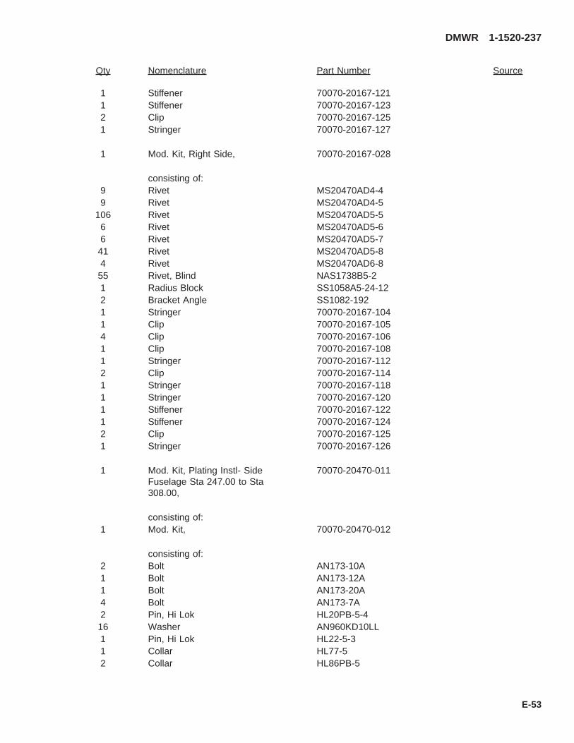
Qty Nomenclature Part Number Source
1 Stiffener 70070-20167-1211 Stiffener 70070-20167-1232 Clip 70070-20167-1251 Stringer 70070-20167-127
1 Mod. Kit, Right Side, 70070-20167-028
consisting of:9 Rivet MS20470AD4-49 Rivet MS20470AD4-5
106 Rivet MS20470AD5-56 Rivet MS20470AD5-66 Rivet MS20470AD5-741 Rivet MS20470AD5-84 Rivet MS20470AD6-855 Rivet, Blind NAS1738B5-21 Radius Block SS1058A5-24-122 Bracket Angle SS1082-1921 Stringer 70070-20167-1041 Clip 70070-20167-1054 Clip 70070-20167-1061 Clip 70070-20167-1081 Stringer 70070-20167-1122 Clip 70070-20167-1141 Stringer 70070-20167-1181 Stringer 70070-20167-1201 Stiffener 70070-20167-1221 Stiffener 70070-20167-1242 Clip 70070-20167-1251 Stringer 70070-20167-126
1 Mod. Kit, Plating Instl- SideFuselage Sta 247.00 to Sta308.00,
70070-20470-011
consisting of:1 Mod. Kit, 70070-20470-012
consisting of:2 Bolt AN173-10A1 Bolt AN173-12A1 Bolt AN173-20A4 Bolt AN173-7A2 Pin, Hi Lok HL20PB-5-416 Washer AN960KD10LL1 Pin, Hi Lok HL22-5-31 Collar HL77-52 Collar HL86PB-5
DMWR 1-1520-237
E-53

Qty Nomenclature Part Number Source
3 Rivet MS20426AD6-911 Rivet MS20470AD4-916 Rivet MS20470AD5-9258 Rivet MS20470AD6-922 Rivet MS20605S3W58 Nut MS21044N310 Nutplate MS21075-3N23 Grommet MS21266-2N8 Fastener, Blind MS90354U05026 Fastener, Blind MS90354U05031 Collar NAS1080-548 Collar NAS1080-062 Rivet NAS1097AD5-91 Pin, SWG LKG NAS1465-0328 Pin, SWG LKG NAS1466-0420 Pin, SWG LKG NAS1466-0832 Rivet, Blind NAS1738B4-315 Rivet, Blind NAS1738B5-240 Rivet, Blind NAS1738B6-229 Rivet, Blind NAS1738B6-317 Rivet, Blind NAS1738B6-420 Rivet, Blind NAS1738B6-54 Rivet, Blind NAS1738B6-66 Rivet, Blind NAS1738B6-72 Rivet, Blind NAS1738B6-83 Shim 70212-02307-1041 Stiffener 70212-02307-1141 Angle 70212-02307-1181 Angle 70212-02307-1201 Stiffner 70212-02307-1241 Plating Assy 70213-02301-0421 Doubler 70213-02301-1141 Skin Inner 70213-02301-1301 Zee 70213-02301-1381 Foam 70213-02301-1391 Bracket Assy 70551-02001-065
1 Mod. Kit, Left Side, 70070-20470-013
consisting of:2 Bolt AN173-10A1 Bolt AN173-12A1 Bolt AN173-20A4 Bolt AN173-7A2 Pin, Hi Lok HL20PB-5-4E16 Washer AN960KD10LL1 Pin, Hi Lok HL22-5-31 Collar HL77-5
DMWR 1-1520-237
E-54

Qty Nomenclature Part Number Source
2 Collar HL86PB-53 Rivet MS20426AD6-911 Rivet MS20470AD4-916 Rivet MS20470AD5-9258 Rivet MS20470AD6-922 Rivet MS20605S3W58 Nut MS21044N310 Nutplate MS21075-3N23 Grommet MS21266-2N8 Fastener, Blind MS90354U05026 Fastener, Blind MS90354U05031 Collar NAS1080-0548 Collar NAS1080-062 Rivet NAS1097AD5-91 Pin, SWG LKG NAS1465-0328 Pin, SWG LKG NAS1466-0420 Pin, SWG LKG NAS1466-0832 Rivet, Blind NAS1738B4-315 Rivet, Blind NAS1738B5-240 Rivet, Blind NAS1738B6-229 Rivet, Blind NAS1738B6-317 Rivet, Blind NAS1738B6-420 Rivet, Blind NAS1738B6-54 Rivet, Blind NAS1738B6-66 Rivet, Blind NAS1738B6-72 Rivet, Blind NAS1738B6-83 Shim 70212-02307-1041 Stiffner 70212-02307-1131 Angle 70212-02307-1171 Angle 70212-02307-1191 Stiffner 70212-02307-1231 Plating Assy 70213-02301-0411 Doubler 70213-02301-1131 Skin Inner 70213-02301-1291 Zee 70213-02301-1371 Foam 70213-02301-1391 Bracket Assy 70551-02001-064
1 Mod. Kit, Beef Up, Left Side, 70070-20527-012
consisting of:20 Rivet MS20470AD4-946 Rivet MS20470AD5-969 Rivet MS20470AD6-99 Fastener, Blind MS90354-05027 Fastener, Blind MS90354-05033 Collar NAS1080-0516 Collar NAS1080-06
DMWR 1-1520-237
E-55

Qty Nomenclature Part Number Source
3 Collar NAS1080D052 Rivet NAS1097AD4-93 Pin, SWG LKG NAS1465-035 Pin, SWG LKG NAS1466-0311 Pin, SWG LKG NAS1466-043 Pin, SWG LKG NAS1525-0416 Rivet, Blind NAS1738B5-211 Rivet, Blind NAS1738B5-359 Rivet, Blind NAS1738B6-26 Rivet, Blind NAS1738B6-39 Rivet, Blind NAS1738B6-41 Channel, LH 70083-20110-1031 Channel, LH 70083-20110-1051 Shim 70083-20110-1071 Shim 70083-20110-1091 Angle 70083-20110-1111 Angle 70083-20110-1131 Doubler 70083-20110-1151 Strap 70083-20110-118
1 Mod. Kit, Right Side, Beef Up, 70070-20527-013
consisting of:20 Rivet MS20470AD4-946 Rivet MS20470AD5-997 Rivet MS20470AD6-99 Fastener, Blind MS90354-05027 Fastener, Blind MS90354-05033 Collar NAS1080-0516 Collar NAS1080-063 Collar NAS1080D052 Rivet NAS1097AD4-93 Pin, SWG LKG NAS1465-035 Pin, SWG LKG NAS1466-0311 Pin, SWG LKG NAS1466-043 Pin, SWG LKG NAS1525-0416 Rivet, Blind NAS1738B5-211 Rivet, Blind NAS1738B5-359 Rivet, Blind NAS1738B6-26 Rivet, Blind NAS1738B6-39 Rivet, Blind NAS1738B6-41 Channel, RH 70083-20110-1041 Channel, RH 70083-20110-1061 Shim 70083-20110-1081 Shim 70083-20110-1091 Angle 70083-20110-1121 Angle 70083-20110-114
DMWR 1-1520-237
E-56

Qty Nomenclature Part Number Source
1 Doubler 70083-20110-1161 Strap 70083-20110-117
B. Consumable Material:
WARNING
OBSERVE ALL CAUTIONS AND WARNINGS ON CONTAINERS WHEN USING CONSUMABLES.WHEN APPLICABLE, WEAR NECESSARY PROTECTIVE GEAR DURING HANDLING AND USE. IF ACONSUMABLE IS FLAMMABLE OR EXPLOSIVE, MAKE CERTAIN CONSUMABLE AND ITS VAPORS AREKEPT AWAY FROM HEAT, SPARK, AND FLAME. MAKE CERTAIN EQUIPMENT IS PROPERLYGROUNDED AND FIREFIGHTING EQUIPMENT IS READILY AVAILABLE PRIOR TO USE. FOR AD-DITIONAL INFORMATION ON TOXICITY, FLASHPOINT, AND FLAMMABILITY OF CHEMICALS,CONSULT YOUR MEDICAL PEOPLE, OR MANUFACTURER OF THE CONSUMABLE.
Qty Nomenclature Part Number Source
4 oz. Adhesive EC-1357 (1)8 oz. Sealant AMS-S-8802, A2 or equivalent (1)8 oz. Sealant AMS-S-8802, B2 or equivalent (1)8 oz. Sealant AMS-S-8802, C20 or equivalent (1)
C. Source:
(1) Available through normal supply channels
DMWR 1-1520-237
E-57

SAAB3102_1
F
3
87
44
E
87
1
1
44
E
A
3
2
268
68
A
F
C
STA295
STA255.5
WL227
WL221
8
9
7
6
12
10 11
B45
3A
BL
LH42
BL
LH44
BL
LH46
STA265.5
STA266
STA268
STA271
14
13
B
D
C
D
STA283.5
STA278.5
Figure E-4. Modification Kit (Sheet 1 of 4)
DMWR 1-1520-237
E-58

SAAB3102_2
21
16
18
16
19
16
20
20
1622
22
16
2117
17
17
17
15
16
16
16
16
16
30
29
31
34
35
36
37
37
38
D
23
23
FRONT
26
25
24
4342
24
24
2732
28
40
33
39
41
C
23
Figure E-4. Modification Kit (Sheet 2 of 4)
DMWR 1-1520-237
E-59

STA247
STA265.5
SAAB3102_3
5655
61 59
58
60
57
54
52
47
53
51
47
47
47
49
50
47
47
47
47
48
48
62
59
58
47 55
57
64
60
6366
60
52
6559
58
57
62
59
58
55
57
67
60
45
45
46
44
E
Figure E-4. Modification Kit (Sheet 3 of 4)
DMWR 1-1520-237
E-60
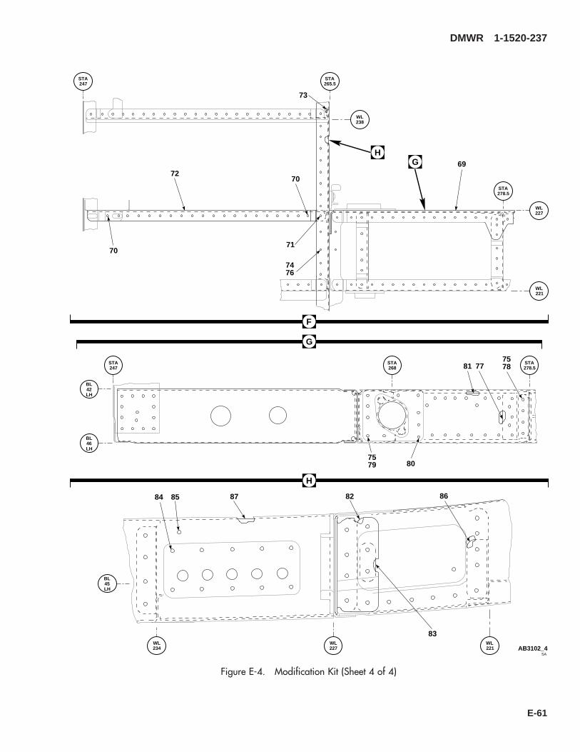
F
H
70
70
71
72
73
7476
G 69
STA247
STA265.5
STA278.5
WL238
WL227
WL221
H
STA247
STA268
STA278.5
BL
LH42
BL
LH46
77817578
807579
BL
LH45
WL234
WL227
WL221
82
83
84 85 8687
SAAB3102_4
G
Figure E-4. Modification Kit (Sheet 4 of 4)
DMWR 1-1520-237
E-61
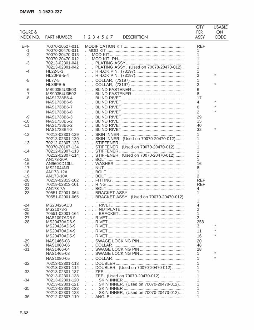
E-4- 70070-20527-011 MODIFICATION KIT .................................................... REF-1 70070-20470-011 . MOD KIT ................................................................... 1-2 70070-20470-013 . . MOD KIT ................................................................ 1
70070-20470-012 . . MOD KIT, RH......................................................... 1-3 70213-02301-041 . . . PLATING ASSY.................................................. 1
70213-02301-042 . . . PLATING ASSY, (Used on 70070-20470-012) . 1-4 HL22-5-3 . . . HI-LOK PIN, (73197).......................................... 1
HL20PB-5-4 . . . HI-LOK PIN, (73197).......................................... 2 *-5 HL77-5 . . . COLLAR, (73197) .............................................. 1
HL86PB-5 . . . COLLAR, (73197) .............................................. 2 *-6 MS90354U0503 . . . BLIND FASTENER ............................................. 6-7 MS90354U0502 . . . BLIND FASTENER ............................................. 8-8 NAS1738B6-4 . . . BLIND RIVET...................................................... 17
NAS1738B6-6 . . . BLIND RIVET...................................................... 4 *NAS1738B6-7 . . . BLIND RIVET...................................................... 6 *NAS1738B6-8 . . . BLIND RIVET...................................................... 2 *
-9 NAS1738B6-3 . . . BLIND RIVET...................................................... 29-10 NAS1738B5-2 . . . BLIND RIVET...................................................... 15-11 NAS1738B6-2 . . . BLIND RIVET...................................................... 40
NAS1738B4-3 . . . BLIND RIVET...................................................... 32 *-12 70213-02301-129 . . . SKIN INNER ....................................................... 1
70213-02301-130 . . . SKIN INNER, (Used on 70070-20470-012)....... 1-13 70212-02307-123 . . . STIFFENER ........................................................ 1
70070-20167-124 . . . STIFFENER, (Used on 70070-20470-012)........ 1-14 70212-02307-113 . . . STIFFENER ........................................................ 1
70212-02307-114 . . . STIFFENER, (Used on 70070-20470-012)........ 1-15 AN173-20A . . . BOLT................................................................... 1-16 AN960KD10LL . . . WASHER ............................................................ 16-17 MS21044N3 . . . NUT..................................................................... 8-18 AN173-12A . . . BOLT................................................................... 1-19 AN173-10A . . . BOLT................................................................... 2-20 70219-02313-102 . . . FITTING .............................................................. REF-21 70219-02313-101 . . . RING ................................................................... REF-22 AN173-7A . . . BOLT................................................................... 4-23 70551-02001-064 . . . BRACKET ASSY ................................................ 1
70551-02001-065 . . . BRACKET ASSY, (Used on 70070-20470-012)............................................................................ 1
-24 MS20426AD3 . . . . RIVET............................................................... 4-25 MS21073-3 . . . . NUTPLATE ...................................................... 2-26 70551-02001-164 . . . . BRACKET ........................................................ 1-27 NAS1097AD5-9 . . . RIVET.................................................................. 2-28 MS20470AD6-9 . . . RIVET.................................................................. 258
MS20426AD6-9 . . . RIVET.................................................................. 3 *MS20470AD4-9 . . . RIVET.................................................................. 11 *MS20470AD5-9 . . . RIVET.................................................................. 16 *
-29 NAS1466-08 . . . SWAGE LOCKING PIN ...................................... 20-30 NAS1080-06 . . . COLLAR.............................................................. 48-31 NAS1466-04 . . . SWAGE LOCKING PIN ...................................... 28
NAS1465-03 . . . SWAGE LOCKING PIN ...................................... 1 *NAS1080-05 . . . COLLAR.............................................................. 1 *
-32 70213-02301-113 . . . DOUBLER........................................................... 170213-02301-114 . . . DOUBLER, (Used on 70070-20470-012) .......... 1
-33 70213-02301-137 . . . ZEE ..................................................................... 170213-02301-138 . . . ZEE, (Used on 70070-20470-012)..................... 1
-34 70213-02301-120 . . . . SKIN INNER .................................................... 170213-02301-121 . . . . SKIN INNER, (Used on 70070-20470-012).... 1
-35 70213-02301-122 . . . . SKIN INNER .................................................... 170213-02301-123 . . . . SKIN INNER, (Used on 70070-20470-012).... 1
-36 70212-02307-119 . . . ANGLE................................................................ 1
DMWR 1-1520-237
QTY USABLEFIGURE & PER ONINDEX NO. PART NUMBER 1 2 3 4 5 6 7 DESCRIPTION ASSY CODE
E-62
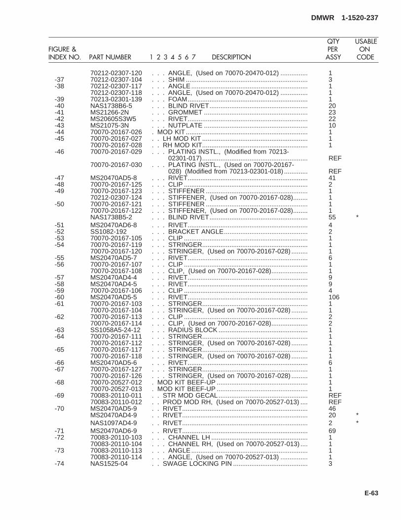
70212-02307-120 . . . ANGLE, (Used on 70070-20470-012) ............... 1-37 70212-02307-104 . . . SHIM ................................................................... 3-38 70212-02307-117 . . . ANGLE................................................................ 1
70212-02307-118 . . . ANGLE, (Used on 70070-20470-012) ............... 1-39 70213-02301-139 . . . FOAM.................................................................. 1-40 NAS1738B6-5 . . . BLIND RIVET...................................................... 20-41 MS21266-2N . . . GROMMET ......................................................... 23-42 MS20605S3W5 . . . RIVET.................................................................. 22-43 MS21075-3N . . . NUTPLATE ......................................................... 10-44 70070-20167-026 . MOD KIT ................................................................... 1-45 70070-20167-027 . . LH MOD KIT .......................................................... 1
70070-20167-028 . . RH MOD KIT.......................................................... 1-46 70070-20167-029 . . . PLATING INSTL., (Modified from 70213-
02301-017).......................................................... REF70070-20167-030 . . . PLATING INSTL., (Used on 70070-20167-
028) (Modified from 70213-02301-018) ............. REF-47 MS20470AD5-8 . . . RIVET.................................................................. 41-48 70070-20167-125 . . . CLIP .................................................................... 2-49 70070-20167-123 . . . STIFFENER ........................................................ 1
70212-02307-124 . . . STIFFENER, (Used on 70070-20167-028)........ 1-50 70070-20167-121 . . . STIFFENER ........................................................ 1
70070-20167-122 . . . STIFFENER, (Used on 70070-20167-028)........ 1NAS1738B5-2 . . . BLIND RIVET...................................................... 55 *
-51 MS20470AD6-8 . . . RIVET.................................................................. 4-52 SS1082-192 . . . BRACKET ANGLE.............................................. 2-53 70070-20167-105 . . . CLIP .................................................................... 1-54 70070-20167-119 . . . STRINGER.......................................................... 1
70070-20167-120 . . . STRINGER, (Used on 70070-20167-028) ......... 1-55 MS20470AD5-7 . . . RIVET.................................................................. 6-56 70070-20167-107 . . . CLIP .................................................................... 1
70070-20167-108 . . . CLIP, (Used on 70070-20167-028).................... 1-57 MS20470AD4-4 . . . RIVET.................................................................. 9-58 MS20470AD4-5 . . . RIVET.................................................................. 9-59 70070-20167-106 . . . CLIP .................................................................... 4-60 MS20470AD5-5 . . . RIVET.................................................................. 106-61 70070-20167-103 . . . STRINGER.......................................................... 1
70070-20167-104 . . . STRINGER, (Used on 70070-20167-028) ......... 1-62 70070-20167-113 . . . CLIP .................................................................... 2
70070-20167-114 . . . CLIP, (Used on 70070-20167-028).................... 2-63 SS1058A5-24-12 . . . RADIUS BLOCK ................................................. 1-64 70070-20167-111 . . . STRINGER.......................................................... 1
70070-20167-112 . . . STRINGER, (Used on 70070-20167-028) ......... 1-65 70070-20167-117 . . . STRINGER.......................................................... 1
70070-20167-118 . . . STRINGER, (Used on 70070-20167-028) ......... 1-66 MS20470AD5-6 . . . RIVET.................................................................. 6-67 70070-20167-127 . . . STRINGER.......................................................... 1
70070-20167-126 . . . STRINGER, (Used on 70070-20167-028) ......... 1-68 70070-20527-012 . MOD KIT BEEF-UP .................................................. 1
70070-20527-013 . MOD KIT BEEF-UP .................................................. 1-69 70083-20110-011 . . STR MOD GECAL................................................. REF
70083-20110-012 . . PROD MOD RH, (Used on 70070-20527-013) .... REF-70 MS20470AD5-9 . . RIVET..................................................................... 46
MS20470AD4-9 . . RIVET..................................................................... 20 *NAS1097AD4-9 . . RIVET..................................................................... 2 *
-71 MS20470AD6-9 . . RIVET..................................................................... 69-72 70083-20110-103 . . . CHANNEL LH ..................................................... 1
70083-20110-104 . . . CHANNEL RH, (Used on 70070-20527-013) .... 1-73 70083-20110-113 . . . ANGLE................................................................ 1
70083-20110-114 . . . ANGLE, (Used on 70070-20527-013) ............... 1-74 NAS1525-04 . . SWAGE LOCKING PIN ......................................... 3
DMWR 1-1520-237
QTY USABLEFIGURE & PER ONINDEX NO. PART NUMBER 1 2 3 4 5 6 7 DESCRIPTION ASSY CODE
E-63
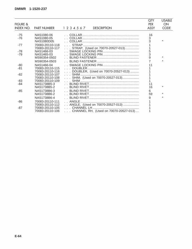
-75 NAS1080-06 . . COLLAR................................................................. 16-76 NAS1080-05 . . COLLAR................................................................. 3
NAS1080D05 . . COLLAR................................................................. 3 *-77 70083-20110-118 . . . STRAP ................................................................ 1
70083-20110-117 . . . STRAP, (Used on 70070-20527-013)................ 1-78 NAS1466-03 . . SWAGE LOCKING PIN ......................................... 5-79 NAS1465-03 . . SWAGE LOCKING PIN ......................................... 3
MS90354-0502 . . BLIND FASTENER ................................................ 9 *MS90354-0503 . . BLIND FASTENER ................................................ 7 *
-80 NAS1466-04 . . SWAGE LOCKING PIN ......................................... 11-81 70083-20110-115 . . . DOUBLER........................................................... 1
70083-20110-116 . . . DOUBLER, (Used on 70070-20527-013) .......... 1-82 70083-20110-107 . . . SHIM ................................................................... 1
70083-20110-108 . . . SHIM, (Used on 70070-20527-013)................... 1-83 70083-20110-109 . . . SHIM ................................................................... 1-84 NAS1738B5-3 . . BLIND RIVET......................................................... 11
NAS1738B5-2 . . BLIND RIVET......................................................... 16 *-85 NAS1738B6-3 . . BLIND RIVET......................................................... 6
NAS1738B6-2 . . BLIND RIVET......................................................... 59 *NAS1738B6-4 . . BLIND RIVET......................................................... 9 *
-86 70083-20110-111 . . ANGLE................................................................... 170083-20110-112 . . ANGLE, (Used on 70070-20527-013) .................. 1
-87 70083-20110-105 . . . CHANNEL LH ..................................................... 170083-20110-106 . . . CHANNEL RH, (Used on 70070-20527-013) .... 1
DMWR 1-1520-237
QTY USABLEFIGURE & PER ONINDEX NO. PART NUMBER 1 2 3 4 5 6 7 DESCRIPTION ASSY CODE
E-64

E-6. STATION 379 MODIFICATION KIT (50-26).
Subject: Station 379.00 Frame, Modification of, dated 31 March 2003
Purpose: Provide instructions to install straps and doublers at station 379.00 frame left and right sides.
Model: UH-60A
Description: The left and right side station 379.00 frame at waterlines 206.00 and 255.00 are modified by installaingnew straps and doublers and cold expanding holes.
Drawings required for modification:
70070-20568
References: (a) Special Service Instructions (SSI) No. 50-31, Installation of 9A to A9 Recapitalization Program, datedMarch 31, 2003
(b) SSI No. 50-6, Lower Aft Transition, Rework of, dated 31 March 2003
(c) TM 1-1500-335-23, Technical Manual, Nondestructive Inspection Methods
(d) TM 1-1520-265-23, Technical Manual, Aviation Unit Maintenance (AVUM) and Aviation Intermedi-ate Maintenance (AVIM) Manual, Nondestructive Inspection Procedures for H-60 Helicopter Series
Instructions:
NOTE
• A complete review of this SSI is recommended before modifying station 379.00 frame.
• Before beginning this modification procedure, use the material information list to inventory the kit. Makesure all parts are present and in serviceable condition.
• Where drawing numbers are not listed within individual steps, drawing(s) listed in preceding step(s) arethe controlling authority.
• The sheet metal and structural modifications in this SSI shall be done by personnel experienced in readingmodification drawings. Routine steps such as cleaning, layout and drilling, deburring, standard repairs,corrosion control, clean up after rework, chemical coating for aluminum after cutting/trimming parts, painttouch up, and safety practices may not be called out herein. However, these steps and all other requiredroutine tasks shall be done.
• When installing fasteners refer to drawing sheet and zones for applicable fasteners.
• Slight variations to the instructions contained herein are allowed, as long as the intent of the modificationis accomplished.
• Personnel must be trained and certified in hole quality assurance and proper cold expansion proceduresper SS5098.
• This modification is to be done concurrently with reference (b).
A. Preparation for modification and removal of equipment:
DMWR 1-1520-237
E-65
(1) Confirm that all warnings, cautions, and notes are complied with per reference (a).
(2) Perform preparation for modification per reference (a).
B. Installation of new straps at station 379.00 left and right sides:
NOTE
Rework and installation of doublers (70070-20568-101 and -102) at waterline 206.75 left and right sidesmust be done in conjunction with reference (b).
(1) Remove existing fasteners between station 373.00 and station 385.00, waterline 206.75, left side (Dwg70070-20568, Sheet 3, Zones 7-E through 9-E).
(2) Position doubler (70070-20568-101) and tapered shim (SS81-202-I) between station 373.00 and station385.00 and transfer drill from structure into doubler (-101) (Sheet 3, Zones 9-F and 7-F).
(3) Inspect holes and surrounding area prior to cold expansion (Sheet 2, Note 7).
(4) Cold work holes where existing fasteners were removed in step B.(1) (Sheet 3, Zones 7-E through 9-E; Sheet2, Note 2, and reference (c) and (d)).
(5) Remove doubler (70070-20568-101) deburr and touch up as required reworked area.
WARNING
OBSERVE ALL CAUTIONS AND WARNINGS ON CONTAINERS WHEN USING CONSUMABLES.WHEN APPLICABLE, WEAR NECESSARY PROTECTIVE GEAR DURING HANDLING AND USE. IF ACONSUMABLE IS FLAMMABLE OR EXPLOSIVE, MAKE CERTAIN CONSUMABLE AND ITS VAPORS AREKEPT AWAY FROM HEAT, SPARK, AND FLAME. MAKE CERTAIN EQUIPMENT IS PROPERLYGROUNDED AND FIREFIGHTING EQUIPMENT IS READILY AVAILABLE PRIOR TO USE. FOR AD-DITIONAL INFORMATION ON TOXICITY, FLASHPOINT, AND FLAMMABILITY OF CHEMICALS,CONSULT YOUR MEDICAL PEOPLE, OR MANUFACTURER OF THE CONSUMABLE.
(6) Install doubler (70070-20568-101) wet with sealant (AMS-S-8802 or equivalent) using fasteners shown(Sheet 3, Zone 9-F and Sheet 2, Note 2).
(7) Repeat steps B.(1) through (5) to install right side doubler (70070-20568-102).
(8) Remove existing fasteners at station 379.00, waterline 255.00, left buttline 40.00 (Sheet 2, Zones 4-Ethrough 6-H).
(9) Position strap (70211-02111-120) at station 370.00, waterline 255.00, left buttline 40.00 and transfer drillfrom structure into strap (-120) (Sheet 2, Zones 4-F through 6-H).
(10) Inspect holes and surrounding area prior to cold expansion (Sheet 2, Note 7).
(11) Cold work holes where existing fasteners were removed in step B.(7) (Sheet 2, Zones 3-F through 5-G,Notes 1, 2, and reference (c) and (d)).
(12) Remove strap (70211-02111-120) deburr and touch as required reworked area.
DMWR 1-1520-237
E-66

WARNING
OBSERVE ALL CAUTIONS AND WARNINGS ON CONTAINERS WHEN USING CONSUMABLES.WHEN APPLICABLE, WEAR NECESSARY PROTECTIVE GEAR DURING HANDLING AND USE. IF ACONSUMABLE IS FLAMMABLE OR EXPLOSIVE, MAKE CERTAIN CONSUMABLE AND ITS VAPORS AREKEPT AWAY FROM HEAT, SPARK, AND FLAME. MAKE CERTAIN EQUIPMENT IS PROPERLYGROUNDED AND FIREFIGHTING EQUIPMENT IS READILY AVAILABLE PRIOR TO USE. FOR AD-DITIONAL INFORMATION ON TOXICITY, FLASHPOINT, AND FLAMMABILITY OF CHEMICALS,CONSULT YOUR MEDICAL PEOPLE, OR MANUFACTURER OF THE CONSUMABLE.
(13) Install strap (70211-02111-120) wet with sealant (AMS-S-8802 or equivalent) using fasteners shown(Sheet 2, Zones 4-F through 6-H, Notes 1 and 2).
(14) Repeat steps B.(7) through (11) to install right side strap (70211-02111-120).
C. Reinstallation of removed equipment:
(1) Install removed equipment per reference (a).
D. Record of Compliance:
(1) Make an appropriate logbook entry to show compliance with this Special Service Instruction.
Weight and Balance Data:
QTY PART NO. NOMENCLATUREPOUNDSWEIGHT
INCHES AFTOF DATUM
MOMENT/1000
1 70070-20568-011 Mod. Kit +0.6 379.0 0.227
Weight and Balance: Change resulting from these instructions are as follows:
Change in basic weight: +0.6 pounds
Moment arm: 379.0 in.
Change in basic moment/1000: 0.227
Manpower (Estimated)
No. of Personel No. of Hours Man-hours
Sheet Metal Mechanic 1 24.0 *24.0
*Does not include time required to prepare helicopter or return it to flight status.
DMWR 1-1520-237
E-67

Material Information:
A. Modification kit required:
Qty Nomenclature Part Number Source
1 Mod. Kit, Station 379.00, 70070-20568-011 (1)
consisting of:
1 Mod. Kit, Spl. Inst 70070-20568-012
consisting of:66 Collar HL1087ATW-631 Pin, Hi Lok HL20PB-6-39 Pin, Hi Lok HL20PB-6-426 Pin, Hi Lok HL20PB-6-52 Strap 70211-02111-120
1 Mod. Kit, Strap Instl, 70070-20568-013
consisting of:5 Pin, Hi-Lok HL12VAZ-6-322 Pin, Hi-Lok HL12VAZ-6-53 Pin, Hi-Lok HL12VAZ-6-63 Pin, Hi-Lok HL12VAZ-6-933 Collar HL75DU-6ADW12 Fastener, Blind MS90354U06053 Fastener, Blind MS90354U06063 Fastener, Blind MS90354U060810 Collar NAS1080-065 Pin, SWG LKG NAS1466-045 Pin, SWG LKG NAS1466-053 Rivet, Blind NAS1738B5-63 Rivet, Blind NAS1738B5-71 Doubler 70070-20568-1011 Doubler 70070-20568-1022 Shim, Tapered SS81-202-I
DMWR 1-1520-237
E-68

B. Consumable Material:
WARNING
OBSERVE ALL CAUTIONS AND WARNINGS ON CONTAINERS WHEN USING CONSUMABLES.WHEN APPLICABLE, WEAR NECESSARY PROTECTIVE GEAR DURING HANDLING AND USE. IF ACONSUMABLE IS FLAMMABLE OR EXPLOSIVE, MAKE CERTAIN CONSUMABLE AND ITS VAPORS AREKEPT AWAY FROM HEAT, SPARK, AND FLAME. MAKE CERTAIN EQUIPMENT IS PROPERLYGROUNDED AND FIREFIGHTING EQUIPMENT IS READILY AVAILABLE PRIOR TO USE. FOR AD-DITIONAL INFORMATION ON TOXICITY, FLASHPOINT, AND FLAMMABILITY OF CHEMICALS,CONSULT YOUR MEDICAL PEOPLE, OR MANUFACTURER OF THE CONSUMABLE.
Qty Nomenclature Part Number Source
6 oz. Sealant AMS-S-8802 or equivalent (1)
C. Source:
(1) Available through normal supply channels
DMWR 1-1520-237
E-69
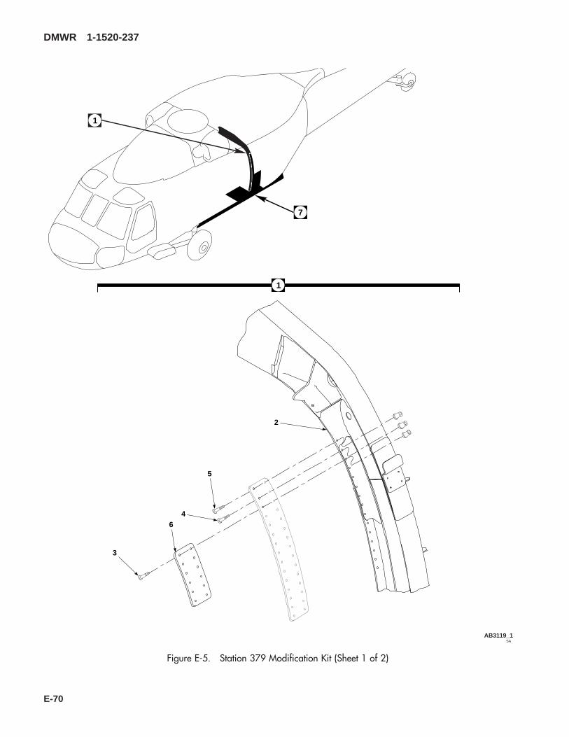
SAAB3119_1
1
2
5
46
1
7
3
Figure E-5. Station 379 Modification Kit (Sheet 1 of 2)
DMWR 1-1520-237
E-70

SAAB3119_2
7
13
11
17
16
18
101512
14
8
9
Figure E-5. Station 379 Modification Kit (Sheet 2 of 2)
DMWR 1-1520-237
E-71

E-5- 70070-20568-011 STATION 379 MODIFICATION KIT ............................ REF-1 70070-20568-012 . M/K SPLICE INSALLATION ..................................... 1-2 70070-20568-015 . . SPLICE INSTALLATION, (Modified from 70211-
02111-013)............................................................. REF70070-20568-016 . . SPLICE INSTALLATION, (Modified from 70211-
02111-014)............................................................. REF-3 HL64PB-6-5 . . HI-LOK PIN, (73197)............................................. 26
HL1087ATW-6 . . COLLAR, (73197) ................................................. 26-4 HL64PB-6-4 . . HI-LOK PIN, (73197)............................................. 9
HL1087ATW-6 . . COLLAR, (73197) ................................................. 9-5 HL20PB-6-3 . . HI-LOK PIN, (73197)............................................. 31
HL1087ATW-6 . . COLLAR, (73197) ................................................. 31-6 70211-02111-120 . . STRAP ................................................................... 2-7 70070-20568-013 . M/K STRAP INSTALLATION.................................... 1-8 70070-20568-014 . . STRAP INSTALLATION, (Modified from 70213-
02501-014)............................................................. REF-9 70070-20568-017 . . SEAL INSTALLATION, (Modified from 70217-
02721-013)............................................................. REF70070-20568-018 . . SEAL INSTALLATION, (Modified from 70217-
02721-014)............................................................. REF-10 NAS1466-05 . . SWAGE LOCKING PIN ......................................... 5
NAS1466-04 . . SWAGE LOCKING PIN ......................................... 5-11 NAS1080-06 . . COLLAR................................................................. 10-12 HL12VAZ-6-9 . . HI-LOK PIN, (73197)............................................. 3
HL12VAZ-6-6 . . HI-LOK PIN, (73197)............................................. 3HL12VAZ-6-3 . . HI-LOK PIN, (73197)............................................. 5HL12VAZ-6-5 . . HI-LOK PIN, (73197)............................................. 22
-13 HL75DU-6ADW . . COLLAR (73197) .................................................. 33-14 MS90354U0605 . . BLIND FASTENER ................................................ 12
MS90354U0606 . . BLIND FASTENER ................................................ 3MS90354U0608 . . BLIND FASTENER ................................................ 3
-15 NAS1738B5-7 . . BLIND RIVET......................................................... 3NAS1738B5-6 . . BLIND RIVET......................................................... 13
-16 NAS1738B4-7 . . BLIND RIVET......................................................... 3-17 SS81-202-I . . TAPERED SHIM.................................................... 2-18 70070-20568-101 . . DOUBLER, LH....................................................... 1
70070-20568-102 . . DOUBLER, RH ...................................................... 1
DMWR 1-1520-237
QTY USABLEFIGURE & PER ONINDEX NO. PART NUMBER 1 2 3 4 5 6 7 DESCRIPTION ASSY CODE
E-72

E-7. UPPER PLATING MODIFICATION KIT (50-16).
Subject: Upper Plating and Doubler Installation, Rework of, dated 31 March 2003
Purpose: Provide instructions for installing new cabin upper plating and doubler.
Model: UH-60A
Description: The following is a brief overview of the work required to rework upper transition stations 320.00 through380.00. New doublers and upper deck plating is installed.
Drawings required for modification:
70070-20570, 70213-02101
References: (a) Special Service Instructions (SSI) No. 50-31, Installation of 9A to A9 Recapitalization Program, datedMarch 31, 2003
(b) TM-1-1520-265-23, Technical Manual, Aviation Unit Maintenance (AVUM) and Aviation Intermedi-ate (AVIM) Manual, Nondestructive Test Procedure for H-60 Helicopter Series
(c) TM-1-1500-335-23, Technical Manual, Nondestructive Inspection Method
Instructions:
NOTE
• A complete review of this SSI is recommended before installing the upper plating and doubler installation.
• Before beginning this modification procedure, use the material information list to inventory the kit. Makesure all parts are present and in serviceable condition.
• The sheet metal and structural modifications in this SSI shall be done by personnel experienced in readingmodification drawings. Routine steps such as cleaning, layout and drilling, deburring, standard repairs,corrosion control, clean up after rework, chemical coating for aluminum after cutting/trimming parts, painttouch up, and safety practices may not be called out herein. However, these steps and all other requiredroutine tasks shall be done.
• Where drawing numbers are not listed within individual steps, drawing(s) listed in preceding step(s) arethe controlling authority.
• When installing fasteners refer to drawing sheet and zones for applicable fasteners.
• Slight variations to the instructions contained herein are allowed, as long as the intent of the modificationis accomplished.
• Personnel must be trained and certified in hole quality assurance and proper cold expansion proceduresper SS5098.
A. Preparation for modification and removal of equipment:
(1) Confirm that all warnings, cautions, and notes are complied with per reference (a).
(2) Perform preparation for modification per reference (a).
DMWR 1-1520-237
E-73

B. Rework of plating installation (70213-02101-011, -013, or -014), stringer installation (70212-02119-011,-012, -013, or -014), frame assembly (70211-02109-041 or -042), nutplate installation (70213-02101-012), stringerinstallation (70202-02120-011 or -012), and angle installation (70304-02201-011 or -012) as follows:
(1) Removals between stations 320.00 and 380.00, left and right buttlines 34.50 as follows (Dwg 70070-20570):
(a) Remove and save for reuse fairing (70213-02101-127 or -163) and doubler (70213-02101-129) station335.00, left buttline 22.25 (Sheet 5, View D, Zone 5-E).
(b) Remove and save for reuse fairing (70213-02101-128 or -162) and doubler (70213-02101-129) station335.00, right buttline 22.25 (Sheet 5, View P, Zones 7-B and 7-D).
(c) Remove five nutplates (MS21075-3) and four nutplates (MS21069-3) left and right sides (Sheet 4, Zones12-G, 13-G, and 16-E; Sheet 6, Zones 12-B, 16-D, and 16-E).
(d) Remove two doubler washers (SS430X15B000431) between left buttline 18.00 and 22.00 (Sheet 4,Zones 14-G and 16-F).
(e) Remove angle (70304-02201-109) and angle (70304-02201-103 or -112) left side firewall (Sheet 4,Zones 10-D and 11-G).
(f) Remove gusset (70213-02101-106) left side (Sheet 4, Zone 16-D).
(g) Remove and save for reuse angle (70211-02109-117) station 343.61, left side (Sheet 7, Zone 11-B).
(h) Remove clips (70211-02110-111, -112, and 70211-02109-121) station 343.61, left side (Sheet 7, Sec-tion T-T, Zones 13-D, 14-E, and 16-E).
(i) Remove angles (70211-02109-109, -115, and 70213-02101-121) left side (Sheet 5, Zone 5-G; Sheet 7,Zones 8-G and 9-C).
(j) Remove and save for reuse angle (70211-02109-118) station 343.61, right side (Sheet 7, Zone 7-B).
(k) Remove angles (70211-02109-110, -116, and 70213-02101-122) right side (Sheet 5, Zone 5-G; Sheet7, Zones 8-G and 9-C).
(l) Remove clips (70211-02110-111, -112, and 70211-02109-121) right side (Sheet 7, Section T-T, Zones13-D, 14-E, and 16-E).
(m) Remove gusset (70213-02101-106) right side (opposite) (Sheet 4, Zone 16-D).
(n) Remove angle (70304-02201-107 or -113) and angle (70304-02201-106) right side firewall (Sheet 6,Zones 10-D and 11-B).
(o) Remove gusset (70213-02101-126) station 365.00, right buttline 5.00 (Sheet 5, Zone 10-G).
(p) Remove remaining fasteners shown on sheets 4, 5, 6, and 7.
(2) Installations between stations 320.00 and 380.00, left and right buttlines 34.50 as follows (Dwg 70070-20570):
DMWR 1-1520-237
E-74
(a) Temporarily install doubler (70070-20570-141), gusset (70070-20570-105), and filler (70070-20570-139) between stations 328.00 and 355.00, left buttlines 16.50 and 30.00 (Sheet 4, Zones 9-A, 13-C, and 16-D).
(b) Make cutout in doubler (70070-20570-141) and gusset (70070-20570-105) using hole in skin as atemplate (Sheet 5, View D, Zone 3-C).
(c) Temporarily reinstall saved fairing (70213-02101-127 or -163) and doubler (70213-01201-129) (Sheet5, View D, Zone 4-E; Sheet 4, Zones 13-D, 13-E, 14-D, and 14-E).
(d) Temporarily install angle (70070-20570-125 or -127) and angle (70070-20570-107) to left side firewall(Sheet 2, Notes 10 and 11; Sheet 4, Zones 10-D and 11-G; Sheet 6, Sections W-W, AB-AB, and Y-Y, Zones 3-D, 3-G,and 6-C).
(e) Temporarily install zee (70070-20570-111) with two clips (70070-20570-110) to left side cabinoverhead (Sheet 4, Zones 11-C and 11-G; Sheet 5, Sections F-F, G-G, and H-H, Zones 4-G, 6-F, and 7-F).
(f) Make cutout in angle (70070-20570-125 or -127) using existing hole in firewall as a template (Sheet 6,Sections AB-AB and Y-Y; Sheet 2, Notes 10 and 11; Sheet 3, Note 24).
(g) Temporarily install two doubler washers (SS430X15B000431) between stations 330.00 and 340.00, leftbuttlines 16.50 and 22.50 (Sheet 4, Zones 14-G and 16-F).
(h) Drill two number 8 (0.199-inch diameter) holes, one number 11 (0.191-inch diameter) hole, and threenumber 1 (0.228-inch diameter) holes (Sheet 4, Zones 12-G, 13-G, 14-F, and 16-E).
(i) Temporarily install three nutplates (MS21075-3) and two nutplates (MS21069-3) between stations 330.00and 345.00, left buttlines 16.5 and 22.50 (Sheet 4, Zones 12-G and 16-E).
(j) Temporarily install clip (70070-20570-117) in cabin overhead station 343.61, left buttline 28.75 (Sheet 7,Sections E-E and R-R, Zones 13-D and 15-B).
(k) Temporarily install angles (70070-20570-135 and -137) and two clips (70070-20570-123) in cabinoverhead station 343.61, between left buttlines 16.00 and 23.00 (Sheet 7, Sections E-E, T-T, U-U, and V-V, Zones 8-G,9-C, 14-E, and 16-E).
(l) Temporarily reinstall angle (70211-02109-117) in cabin overhead station 343.61, left buttline 23.50(Sheet 7, Section E-E, Zone 11-B).
(m) Temporarily install clip (70070-20570-118) in cabin overhead station 343.61, right buttline 28.75(Sheet 7, Sections E-E, N-N, and R-R, Zones 5-C, 13-C, and 15-B).
(n) Temporarily install angles (70070-20570-136 and -138) and two clips (70070-20570-123) in cabinoverhead station 343.61, between right buttlines 16.00 and 23.00 (Sheet 7, Sections N-N, T-T, U-U, and V-V, Zones8-G, 9-C, 14-E, and 16-E).
(o) Temporarily reinstall angle (70211-02109-118) in cabin overhead station 343.61, right buttline 23.50(Sheet 7, Section N-N, Zone 7-B).
(p) Temporarily install doubler (70070-20570-142), gusset (70070-20570-106), and filler (70070-20570-140) between stations 328.00 and 355.00, right buttlines 16.50 and 30.00 (right side opposite) (Sheet 4, Zones 9-A,13-B, and 16-D; Sheet 6, Zones 10-F, 11-F, and 16-D).
DMWR 1-1520-237
E-75
(q) Make cutout in doubler (70070-20570-142) and gusset (70070-20570-106) on right side using hole inskin as template (Sheet 5, View P, Zone 6-D).
(r) Temporarily reinstall saved fairing (70213-02101-128 or -162) and doubler (70213-02101-129) (Sheet5, View P, Zones 7-B and 8-D; Sheet 6, Zones 13-D, 13-E, 14-D, and 14-E).
(s) Temporarily install angle (70070-20570-126 or -128) and angle (70070-20570-108) to right firewall(Sheet 2, Notes 10 and 11; Sheet 6, Sections AA-AA, AB-AB, and Y-Y, Zones 6-E, 10-E, and 11-B).
(t) Temporarily install zee (70070-20570-112) with two clips (70070-20570-110) to right side cabinoverhead (Sheet 5, Sections F-F, G-G, and H-H, Zones 4-G, 6-F, and 7-F).
(u) Make cutout in angle (70070-20570-126 or -128) using existing hole in firewall as a template (Sheet 6,Sections AB-AB and Y-Y; Sheet 2, Notes 10 and 11; Sheet 3, Note 24).
(v) Drill two number 8 (0.199-inch diameter) holes, one number 11 (0.191-inch diameter) hole, and twonumber 1 (0.288-inch diameter) holes (Sheet 6, Zones 12-B, 14-B, 16-D, and 16-E).
(w) Temporarily install two nutplates (MS21075-3) and two nutplates (MS21069-3) between stations 325.00and 345.00, right buttlines 16.50 and 22.25 (Sheet 6, Zones 12-B, 16-D, and 16-E).
(x) Temporarily install angle (70070-20570-143) with clips (70070-20570-115 and -116) and radius block(SS1058-1-18-14) between buttline 0.00 and left buttline 5.33 (Sheet 5, View B, Sections J-J, L-L, M-M, and K-K, Zones15-F, 15-G, and 16-G).
(y) Temporarily install angle (70070-20570-144) with clips (70070-20570-115 and -116) and radius block(SS1058-1-18-14) between buttline 0.00 and right buttline 5.33 (Sheet 5, View B, Sections J-J, L-L, M-M, and K-K, Zones15-F, 15-G, and 16-G).
(z) Temporarily install gusset (70070-20570-109) between stations 362.00 and 370.00, left and right butt-line 5.33 (Sheet 5, View B, Zone 10-G).
(aa) Perform penetrant or Eddy current inspection to holes and surrounding area prior to cold expansion(Sheet 4, Note 45).
(ab) Cold work holes where existing fasteners were removed and hi lok pins (HL20PB) are installed (Sheet 2,Note 18; Sheet 3, Note 27; Sheet 4, Zones 9-F, 9-G, and 15-F; Sheet 6, Zones 9-B, 10-B, 9-C, 10-C, 15-C, and 16-C).
(ac) Inspect each hole and a 0.20-inch minimum surrounding area for cracks (Sheet 3, Note 27).
(ad) Cold work holes where existing fasteners were removed and hi lok pins (HL64PB) are installed (Sheet 2,Note 18; Sheet 3, Note 28; Sheet 4, Zones 9-F, 9-G, 10-F, 11-F, 11-E, 12-E, 13-E, 13-F, 14-F, and 15-F; Sheet 6, Zones9-A, 10-C, 11-C, 12-C, 13-C, 14-C, and 15-C; Sheet 7, Zones 7-D, 10-D, and 11-G).
(ae) Inspect each hole and a 0.20-inch minimum surrounding area for cracks (Sheet 3, Note 28).
(af) Transfer drill any remaining fastener holes for assembly (Sheets 4, 5, 6, and 7).
(ag) Remove parts fitted in steps B.(2) (a) through B.(2) (z), deburr and touch up as required.
DMWR 1-1520-237
E-76
WARNING
OBSERVE ALL CAUTIONS AND WARNINGS ON CONTAINERS WHEN USING CONSUMABLES.WHEN APPLICABLE, WEAR NECESSARY PROTECTIVE GEAR DURING HANDLING AND USE. IF ACONSUMABLE IS FLAMMABLE OR EXPLOSIVE, MAKE CERTAIN CONSUMABLE AND ITS VAPORS AREKEPT AWAY FROM HEAT, SPARK, AND FLAME. MAKE CERTAIN EQUIPMENT IS PROPERLYGROUNDED AND FIREFIGHTING EQUIPMENT IS READILY AVAILABLE PRIOR TO USE. FOR AD-DITIONAL INFORMATION ON TOXICITY, FLASHPOINT, AND FLAMMABILITY OF CHEMICALS,CONSULT YOUR MEDICAL PEOPLE, OR MANUFACTURER OF THE CONSUMABLE.
(ah) Apply sealant (MIL-S-8802, A2, or C20, or equivalent) to areas indicated by crosshatch (Dwg 70070-20570, Sheet 1, Note 7; Dwg 70213-02101, Sheet 1, Note 1).
(ai) Install parts fitted in steps B.(2)(a) through B.(2)(z) using fasteners shown (Dwg 70070-20570, Sheet 1,Note 7, Sheet 3, Notes 27 and 28, Sheets 4, 5, 6, and 7).
(aj) Reidentify the following parts using pen and contrasting ink (Sheet 4, Note 37):
Old Part No. Nomenclature New Part No.
70212-02119-111 Stringer 70070-20570-12970212-02119-112 Stringer 70070-20570-13070212-02119-113 Stringer 70070-20570-13170212-02119-114 Stringer 70070-20570-13270202-02120-101 Stringer Zee 70070-20570-13370202-02120-102 Stringer Zee 70070-20570-134
C. Reinstallation of removed equipment:
(1) Install removed equipment per reference (a).
D. Record of Compliance:
(1) Make an appropriate logbook entry to show compliance with this Special Service Instruction.
Weight and Balance Data:
QTY PART NO. NOMENCLATUREPOUNDSWEIGHT
INCHES AFTOF DATUM
MOMENT/1000
1 70070-20570-011 Mod. Kit +11.4 345.0 3.933
Weight and Balance: Change resulting from these instructions are as follows:
Change in basic weight: +11.4 pounds
Moment arm: 345.0 in.
DMWR 1-1520-237
E-77

Change in basic moment/1000: 3.933
Manpower (Estimated):
No. of Personel No. of Hours Man-hours
Sheet Metal Mechanic 2 80.0 *160.0
*Does not include time required to prepare helicopter or return it to flight status.
Material Information:
A. Modification Kit Required:
Qty Nomenclature Part Number Source
1 Mod. Kit, Upper Plating, DoublerInstl,
70070-20570-011 (1)
consisting of:
1 Mod. Kit, Plate Assembly, 70070-20570-012
consisting of:31 Collar HL1087A-5487 Collar HL1087A-629 Pin, Hi Lok HL20PB-5-22 Pin, Hi Lok HL20PB-5-3
160 Pin, Hi Lok HL20PB-6-338 Pin, Hi Lok HL20PB-6-4100 Pin, Hi Lok HL20PB-6-516 Pin, Hi Lok HL20PB-6-625 Pin, Hi Lok HL20PB-6-712 Pin, Hi Lok HL64PB-6-310 Pin, Hi Lok HL64PB-6-431 Pin, Hi-Lok HL64PB-6-567 Pin HL64PB-6-628 Pin, Hi Lok HL64PB-6-75 Rivet MS20470AD4-35 Rivet MS20470AD4-4
228 Rivet MS20470AD5-2155 Rivet MS20470AD5-3
9 Rivet MS20470AD5-49 Rivet, Blind NAS1738B4-411 Rivet, Blind NAS1738B5-355 Rivet, Blind NAS1738B5-456 Rivet, Blind NAS1738B5-5
DMWR 1-1520-237
E-78

Qty Nomenclature Part Number Source
22 Rivet RA615-5M22 Radius Block SS1058-1-18-142 Washer, Doubler SS430X15B0004311 Filler 70070-20570-1391 Filler 70070-20570-1401 Doubler 70070-20570-1411 Doubler 70070-20570-1421 Gusset 70070-20570-1051 Gusset 70070-20570-1061 Gusset 70070-20570-1094 Clip 70070-20570-1101 Zee 70070-20570-1111 Zee 70070-20570-1121 Angle 70070-20570-1431 Angle 70070-20570-1442 Clip 70070-20570-1152 Clip 70070-20570-116
1 Mod. Kit, Nutplate Instl, 70070-20570-013
consisting of:4 Nutplate MS21069-35 Nutplate MS21075-314 Rivet NAS1097AD3-33 Rivet NAS1097AD3-45 Rivet NAS1097AD3-6
1 Mod. Kit, Frame Instl, 70070-20570-014
consisting of:82 Collar HL1087A-612 Pin, Hi Lok HL20PB-6-218 Pin, Hi Lok HL20PB-6-34 Pin, Hi Lok HL20PB-6-46 Pin, Hi Lok HL20PB-6-512 Pin, Hi Lok HL20PB-6-64 Pin, Hi Lok HL20PB-6-822 Pin, Hi-Lok HL64PB-6-54 Pin HL64PB-6-61 Clip 70070-20570-1171 Clip 70070-20570-1181 Angle 70070-20570-1351 Angle 70070-20570-1361 Angle 70070-20570-1371 Angle 70070-20570-1384 Clip 70070-20570-123
DMWR 1-1520-237
E-79

Qty Nomenclature Part Number Source
1 Mod. Kit, Angle Instl, 70070-20570-015
consisting of:39 Collar HL1087-66 Pin, Hi Lok HL20PB-6-314 Pin, Hi Lok HL20PB-6-42 Pin, Hi Lok HL20PB-6-53 Pin, Hi Lok HL64PB-6-412 Pin HL64PB-6-62 Pin, Hi Lok HL64PB-6-718 Rivet MS20615-4M2 Rivet NAS1097AD6-71 Angle 70070-20570-1071 Angle 70070-20570-1081 Angle 70070-20570-1251 Angle 70070-20570-1261 Angle 70070-20570-1271 Angle 70070-20570-128
B. Consumable Material:
WARNING
OBSERVE ALL CAUTIONS AND WARNINGS ON CONTAINERS WHEN USING CONSUMABLES.WHEN APPLICABLE, WEAR NECESSARY PROTECTIVE GEAR DURING HANDLING AND USE. IF ACONSUMABLE IS FLAMMABLE OR EXPLOSIVE, MAKE CERTAIN CONSUMABLE AND ITS VAPORS AREKEPT AWAY FROM HEAT, SPARK, AND FLAME. MAKE CERTAIN EQUIPMENT IS PROPERLYGROUNDED AND FIREFIGHTING EQUIPMENT IS READILY AVAILABLE PRIOR TO USE. FOR AD-DITIONAL INFORMATION ON TOXICITY, FLASHPOINT, AND FLAMMABILITY OF CHEMICALS,CONSULT YOUR MEDICAL PEOPLE, OR MANUFACTURER OF THE CONSUMABLE.
Qty Nomenclature Part Number Source
16 oz. Sealant MIL-S-8802, A2, or C20, orequivalent
(1)
C. Source:
(1) Available through normal supply channels
DMWR 1-1520-237
E-80
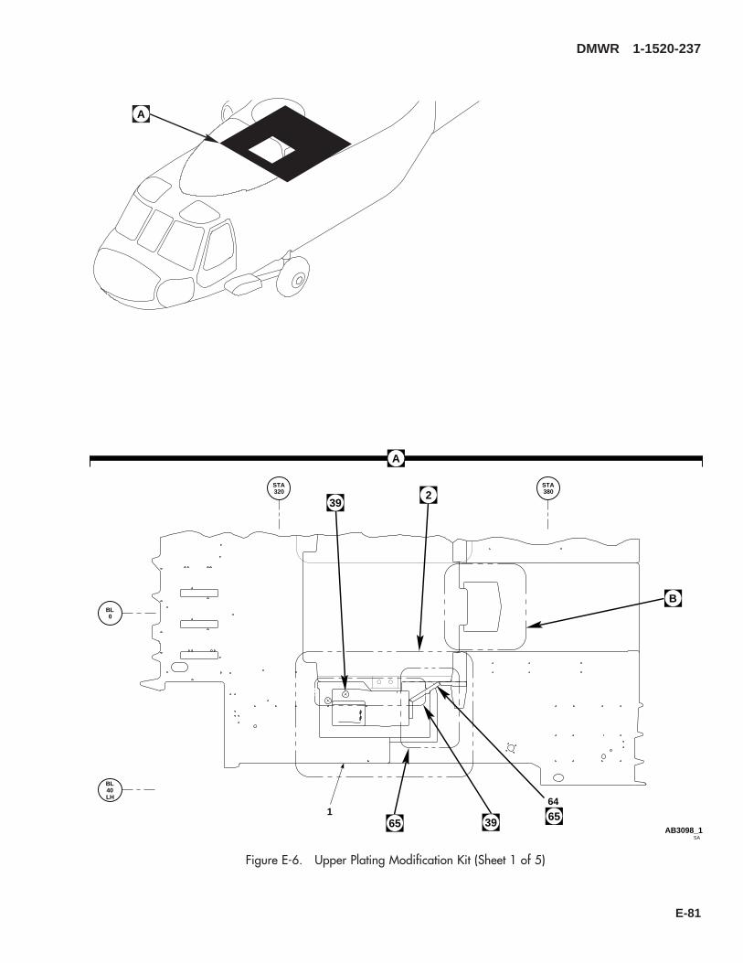
A
A
3965
B
2
SAAB3098_1
STA320
STA380
BL0
BL
LH40
1 6564
39
Figure E-6. Upper Plating Modification Kit (Sheet 1 of 5)
DMWR 1-1520-237
E-81
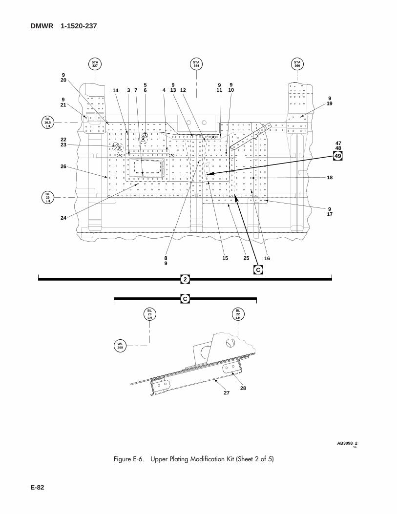
BL
LH29
BL
LH22
WL269
SAAB3098_2
STA327
STA344
STA360
BL
LH29
BL
LH16.5
3 4567
89
911
91012
91314
15 16
917
18
199
920
219
2223
26
24
25
2728
C
2
C
494847
Figure E-6. Upper Plating Modification Kit (Sheet 2 of 5)
DMWR 1-1520-237
E-82
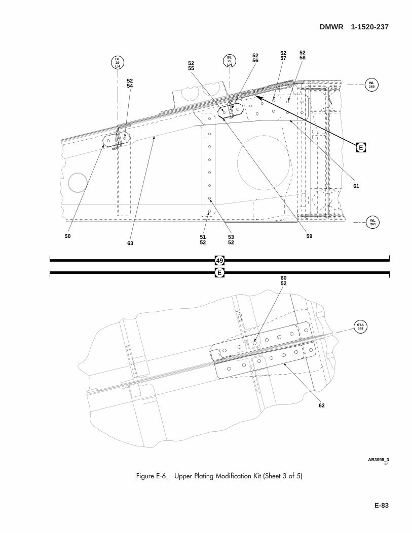
STA344
SAAB3098_3
WL261
WL269
BL
LH29
BL
LH22
6052
62
50 5152
5352
5452
5552 56
52 5752
5852
59
61
49
E
63
E
Figure E-6. Upper Plating Modification Kit (Sheet 3 of 5)
DMWR 1-1520-237
E-83
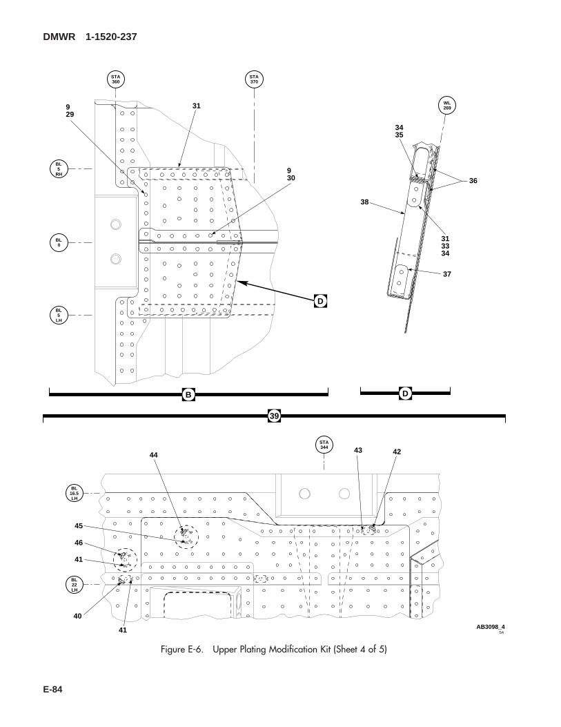
39
SAAB3098_4
BL0
BL
RH5
BL
LH5
STA360
STA370
WL269
STA344
BL
LH16.5
BL
LH22
929
31
930
3435
38
36
37
313334
40
41
424344
45
46
41
D
B D
Figure E-6. Upper Plating Modification Kit (Sheet 4 of 5)
DMWR 1-1520-237
E-84
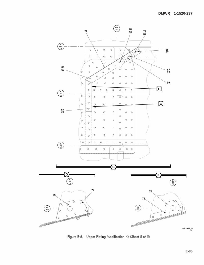
WL269
WL269
BL
LH22
BL
LH23
SAAB3098_5
BL
LH22
BL
LH16.5
BL
LH29
STA353
74
75
74
76
726768
7367
6667
7067
69
6667
G F
65
F
G
7167
Figure E-6. Upper Plating Modification Kit (Sheet 5 of 5)
DMWR 1-1520-237
E-85
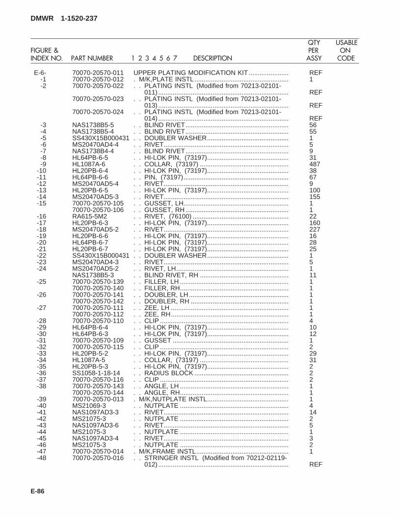
E-6- 70070-20570-011 UPPER PLATING MODIFICATION KIT ...................... REF-1 70070-20570-012 . M/K,PLATE INSTL .................................................... 1-2 70070-20570-022 . . PLATING INSTL (Modified from 70213-02101-
011) ........................................................................ REF70070-20570-023 . . PLATING INSTL (Modified from 70213-02101-
013) ........................................................................ REF70070-20570-024 . . PLATING INSTL (Modified from 70213-02101-
014) ........................................................................ REF-3 NAS1738B5-5 . . BLIND RIVET......................................................... 56-4 NAS1738B5-4 . . BLIND RIVET......................................................... 55-5 SS430X15B000431 . . DOUBLER WASHER............................................. 1-6 MS20470AD4-4 . . RIVET..................................................................... 5-7 NAS1738B4-4 . . BLIND RIVET......................................................... 9-8 HL64PB-6-5 . . HI-LOK PIN, (73197)............................................. 31-9 HL1087A-6 . . COLLAR, (73197) ................................................. 487
-10 HL20PB-6-4 . . HI-LOK PIN, (73197)............................................. 38-11 HL64PB-6-6 . . PIN, (73197).......................................................... 67-12 MS20470AD5-4 . . RIVET..................................................................... 9-13 HL20PB-6-5 . . HI-LOK PIN, (73197)............................................. 100-14 MS20470AD5-3 . . RIVET..................................................................... 155-15 70070-20570-105 . . GUSSET, LH.......................................................... 1
70070-20570-106 . . GUSSET, RH......................................................... 1-16 RA615-5M2 . . RIVET, (76100) ..................................................... 22-17 HL20PB-6-3 . . HI-LOK PIN, (73197)............................................. 160-18 MS20470AD5-2 . . RIVET..................................................................... 227-19 HL20PB-6-6 . . HI-LOK PIN, (73197)............................................. 16-20 HL64PB-6-7 . . HI-LOK PIN, (73197)............................................. 28-21 HL20PB-6-7 . . HI-LOK PIN, (73197)............................................. 25-22 SS430X15B000431 . . DOUBLER WASHER............................................. 1-23 MS20470AD4-3 . . RIVET..................................................................... 5-24 MS20470AD5-2 . . RIVET, LH.............................................................. 1
NAS1738B5-3 . . BLIND RIVET, RH ................................................. 11-25 70070-20570-139 . . FILLER, LH ............................................................ 1
70070-20570-140 . . FILLER, RH............................................................ 1-26 70070-20570-141 . . DOUBLER, LH....................................................... 1
70070-20570-142 . . DOUBLER, RH ...................................................... 1-27 70070-20570-111 . . ZEE, LH ................................................................. 1
70070-20570-112 . . ZEE, RH................................................................. 1-28 70070-20570-110 . . CLIP ....................................................................... 4-29 HL64PB-6-4 . . HI-LOK PIN, (73197)............................................. 10-30 HL64PB-6-3 . . HI-LOK PIN, (73197)............................................. 12-31 70070-20570-109 . . GUSSET ................................................................ 1-32 70070-20570-115 . . CLIP ....................................................................... 2-33 HL20PB-5-2 . . HI-LOK PIN, (73197)............................................. 29-34 HL1087A-5 . . COLLAR, (73197) ................................................. 31-35 HL20PB-5-3 . . HI-LOK PIN, (73197)............................................. 2-36 SS1058-1-18-14 . . RADIUS BLOCK .................................................... 2-37 70070-20570-116 . . CLIP ....................................................................... 2-38 70070-20570-143 . . ANGLE, LH ............................................................ 1
70070-20570-144 . . ANGLE, RH............................................................ 1-39 70070-20570-013 . M/K,NUTPLATE INSTL............................................. 1-40 MS21069-3 . . NUTPLATE ............................................................ 4-41 NAS1097AD3-3 . . RIVET..................................................................... 14-42 MS21075-3 . . NUTPLATE ............................................................ 2-43 NAS1097AD3-6 . . RIVET..................................................................... 5-44 MS21075-3 . . NUTPLATE ............................................................ 1-45 NAS1097AD3-4 . . RIVET..................................................................... 3-46 MS21075-3 . . NUTPLATE ............................................................ 2-47 70070-20570-014 . M/K,FRAME INSTL................................................... 1-48 70070-20570-016 . . STRINGER INSTL (Modified from 70212-02119-
012) ........................................................................ REF
DMWR 1-1520-237
QTY USABLEFIGURE & PER ONINDEX NO. PART NUMBER 1 2 3 4 5 6 7 DESCRIPTION ASSY CODE
E-86

70070-20570-017 . . STRINGER INSTL (Modified from 70212-02119-013) ........................................................................ REF
70070-20570-018 . . STRINGER INSTL (Modified from 70212-02119-014) ........................................................................ REF
70070-20570-019 . . STRINGER INSTL (Modified from 70202-02120-011) ........................................................................ REF
70070-20570-020 . . STRINGER INSTL (Modified from 70202-02120-012) ........................................................................ REF
70070-20570-021 . . STRINGER INSTL (Modified from 70212-02119-011) ........................................................................ REF
-49 70070-20570-041 . . STRINGER ASSY (Modified from 70211-02109-041) ........................................................................ REF
70070-20570-042 . . STRINGER ASSY (Modified from 70211-02109-042) ........................................................................ REF
-50 70070-20570-117 . . CLIP, LH ................................................................ 170070-20570-118 . . CLIP, RH................................................................ 1
-51 HL20PB-6-4 . . HI-LOK PIN, (73197)............................................. 4-52 HL1087A-6 . . COLLAR, (73197) ................................................. 82-53 HL20PB-6-2 . . HI-LOK PIN, (73197)............................................. 12-54 HL20PB-6-5 . . HI-LOK PIN, (73197)............................................. 6-55 HL20PB-6-8 . . HI-LOK PIN, (73197)............................................. 4-56 HL20PB-6-3 . . HI-LOK PIN, (73197)............................................. 18-57 HL20PB-6-6 . . HI-LOK PIN, (73197)............................................. 12-58 HL64PB-6-5 . . HI-LOK PIN, (73197)............................................. 22-59 70070-20570-123 . . CLIP ....................................................................... 4-60 HL64PB-6-6 . . PIN, (73197).......................................................... 4-61 70070-20570-137 . . ANGLE, LH ............................................................ 1
70070-20570-138 . . ANGLE, RH............................................................ 1-62 70070-20570-135 . . ANGLE, LH ............................................................ 1
70070-20570-136 . . ANGLE, RH............................................................ 1-63 70070-20570-129 . . STRINGER (Reidentified from 70212-02119-
111) ........................................................................ REF70070-20570-130 . . STRINGER (Reidentified from 70212-02119-
112) ........................................................................ REF70070-20570-131 . . STRINGER (Reidentified from 70212-02119-
113) ........................................................................ REF70070-20570-132 . . STRINGER (Reidentified from 70212-02119-
114) ........................................................................ REF70070-20570-133 . . STRINGER ZEE (Reidentified from 70202-
02120-101)............................................................. REF70070-20570-134 . . STRINGER ZEE (Reidentified from70202-
02120-102)............................................................. REF-64 70070-20570-015 . M/K,ANGLE INSTL ................................................... 1-65 70070-20570-025 . . ANGLE INSTL (Modified from 70304-02201
-011)....................................................................... REF70070-20570-026 . . ANGLE INSTL (Modified from 70304-02201
-012)....................................................................... REF-66 HL20PB-6-4 . . HI-LOK PIN, (73197)............................................. 14-67 HL1087-6 . . COLLAR, (73197) ................................................. 39-68 HL20PB-6-5 . . HI-LOK PIN, (73197)............................................. 2-69 NAS1097AD6-7 . . RIVET..................................................................... 2-70 HL64PB-6-7 . . HI-LOK PIN, (73197)............................................. 2-71 HL64PB-6-6 . . PIN, (73197).......................................................... 12-72 70070-20570-107 . . ANGLE, LH ............................................................ 1
70070-20570-108 . . ANGLE, RH............................................................ 1-73 HL20PB-6-3 . . HI-LOK PIN, (73197)............................................. 6-74 MS20615-4M3 . . RIVET..................................................................... 36-75 70070-20570-127 . . ANGLE, LH ............................................................ 1
70070-20570-128 . . ANGLE, RH............................................................ 1-76 70070-20570-125 . . ANGLE, LH ............................................................ 1
70070-20570-126 . . ANGLE, RH............................................................ 1
DMWR 1-1520-237
QTY USABLEFIGURE & PER ONINDEX NO. PART NUMBER 1 2 3 4 5 6 7 DESCRIPTION ASSY CODE
E-87
E-8. BL 34.5 MODIFICATION KIT (50-7).
Subject: Buttline 34.50, Modification of, dated 31 March 2003
Purpose: Provide instructions to modify buttline 34.50 to eliminate cracking and to replace existing fasteners.
Model: UH-60A
Description: The following is a brief overview of the work required to modify buttline 34.50. New reinforcements areinstalled, existing fasteners are removed, the holes are coldworked and new fasteners are installed.
Drawings required for modification:
70070-20572
References: (a) Special Service Instructions (SSI) No. 50-31, Installation of 9A to A9 Recapitalization Program, datedMarch 31, 2003
(b) TM 1-1520-265-23, Technical Manual, Aviation Unit Maintenance (AVUM) and Aviation Intermedi-ate (AVIM) Manual, Nondestructive Inspection Procedure for H-60 Helicopter Series
(c) TM 1-1500-335-23, Technical Manual, Nondestructive Inspection Method
Instructions:
NOTE
• A complete review of this SSI is recommended before modifying buttline 34.50.
• Before beginning this modification procedure, use the material information list to inventory the kit. Makesure all parts are present and in serviceable condition.
• The sheet metal and structural modifications in this SSI shall be done by personnel experienced in readingmodification drawings. Routine steps such as cleaning, layout and drilling, deburring, standard repairs,corrosion control, clean up after rework, chemical coating for aluminum after cutting/trimming parts, painttouch up and safety practices may not be called out herein. However, these steps and all other requiredroutine tasks shall be done.
• Where drawing numbers are not listed within individual steps, drawing(s) listed in preceding step(s) arethe controlling authority.
• When installing fasteners refer to drawing sheet and zones for applicable fasteners.
• Slight variations to the instructions contained herein are allowed, as long as the intent of the modificationis accomplished.
• Personnel must be trained and certified in hole quality assurance and proper cold expansion proceduresper SS5098.
A. Preparation for modification and removal of equipment:
(1) Confirm that all warnings, cautions, and notes are complied with per reference (a).
(2) Perform preparation for modification per reference (a).
DMWR 1-1520-237
E-88

B. Modify right side buttline 34.50 as follows:
(1) Remove and save for reinstallation angle (70212-02112-170, 70211-02108-119 or -171) (Dwg 70070-20572, Sheet 3, Zone 5-F, Notes 16, 18, 19, and 20).
(2) Remove and discard angle (70212-02112-132 or -162) at buttline 34.50, waterline 265.00 (Sheet 3, Zone6-G, Notes 16 and 17).
(3) Temporarily install new reinforcement (70080-70107-222) transfer drilling through existing fastener loca-tions and adding new fasteners (Sheet 3, Zones 5-F through 8-F).
(4) Remove remaining fasteners identified on drawing in preparation for cold expansion process (Sheet 3, Zones7-E through 9-E and 7-E through 9-G).
(5) Inspect holes prior to cold working (Dwg 70070-20572, Sheet 3, Note 22).
(6) Cold work fastener locations at buttline 34.50 between stations 305.00 and 315.00, and waterlines 260.00and 265.00 identified on drawing (Sheet 3, Zones 7-E through 9-E, 7-F through 9-F, Notes 12, 13, 14, 16, 17, and 23).
(7) Inspect holes per Sheet 3, Note 22.
(8) Remove parts installed in step B.(3) deburr and touch up as required.
(9) Install all parts removed in step B.(8) and angle (70212-02112-170, 70211-02108-119, or -171) usingfasteners shown (Sheet 3, Zones 6-G, 5-F, 7-E through 9-E, 7-G through 9-G, Notes 9, 12, 13, and 14).
C. Modify left side buttline 34.50 as follows:
(1) Remove and discard angle (70212-02112-131 or -161) at buttline 34.50, waterline 265.00 (Dwg 70070-20572, Sheet 3, Zone 13-G, Notes 16 and 17).
(2) Temporarily install new reinforcement (70080-70107-223) transfer drilling through existing fastener loca-tions and adding new fasteners (Sheet 3, Zones 12-G through 15-G).
(3) Remove remaining fasteners identified on drawing in preparation for cold expansion process (Sheet 3, Zones11-E through 13-E and 11-F through 13-F).
(4) Inspect holes per Sheet 3, Note 22.
(5) Cold work fastener locations at buttline 34.50 between stations 305.00 and 315.00, and waterlines 260.00and 265.00 identified on drawing (Sheet 2, Zones 11-E through 12-E, 11-F through 12-F, Notes 12, 13, 14, 16, 17 and23).
(6) Inspect holes per Sheet 3, Note 22.
(7) Remove part installed in step C.(2) deburr and touch up as required.
(8) Install parts removed in step C.(7) using fasteners shown (Sheet 3, Zones 11-E through 11-G, 13-G, 11-Fthrough 13-F, Notes 9, 12, 13, 1 and 234).
D. Reinstallation of removed equipment:
(1) Install removed equipment per reference (a).
DMWR 1-1520-237
E-89
E. Record of Compliance:
(1) Make an appropriate logbook entry to show compliance with this Special Service Instruction.
Weight and Balance Data:
QTY PART NO. NOMENCLATUREPOUNDSWEIGHT
INCHES AFTOF DATUM
MOMENT/1000
1 70070-20572-011 Mod. Kit +1.0 308.0 0.308
Weight and Balance: Change resulting from these instructions are as follows:
Change in basic weight: +1.0 pounds
Moment arm: 308.0 in.
Change in basic moment/1000: 0.308
Manpower (Estimated)
No. of Personel No. of Hours Man-hours
Sheet Metal Mechanic 2 24.0 *48.0
*Does not include time required to prepare helicopter or return it to flight status.
Material Information:
A. Modification Kit Required:
Qty Nomenclature Part Number Source
1 Mod. Kit, Buttline 34.5, 70070-20572-011 (1)
consisting of:
1 Mod. Kit, R.H Reinforcement, 70070-20572-012
consisting of:18 Collar HL1087A-66 Collar HL1087A-84 Pin Collar Assy HL20PB86-6-36 Pin Collar Assy HL20PB86-6-43 Pin Collar Assy HL20PB86-6-65 Pin HL204-6-25 Pin HL204-6-3
DMWR 1-1520-237
E-90

Qty Nomenclature Part Number Source
5 Pin HL204-6-45 Pin HL204-6-510 Pin HL204-6-65 Pin HL204-6-75 Pin HL204-6-85 Pin HL204-8-55 Pin HL204-8-65 Pin HL204-8-75 Pin HL204-8-85 Pin, Hi-Lok HL220-6-25 Pin, Hi-Lok HL220-6-35 Pin, Hi-Lok HL220-6-45 Pin, Hi-Lok HL220-6-510 Pin, Hi-Lok HL220-6-65 Pin HL220-6-75 Pin, Hi-Lok HL220-6-85 Pin, Hi-Lok HL220-8-55 Pin, Hi-Lok HL220-8-65 Pin, Hi-Lok HL220-8-75 Pin, Hi-Lok HL220-8-840 Collar HL287-620 Collar HL287-83 Pin, Hi-Lok HL64PB-6-22 Pin, Hi-Lok HL64PB-6-31 Pin, Hi-Lok HL64PB-6-42 Pin, Hi-Lok HL64PB-6-55 Pin HL64PB-6-64 Pin, Hi-Lok HL64PB-6-71 Pin, Hi-Lok HL64PB-6-84 Pin, Hi-Lok HL64PB-8-52 Pin HL64PB-8-840 Collar HL93-620 Collar HL93-815 Rivet MS20470AD5-213 Rivet MS20470AD5-518 Rivet MS20470AD6-59 Rivet MS20470AD6-61 Reinforcement 70080-70107-222
1 Mod. Kit, R.H Reinforcement, 70070-20572-013
consisting of:18 Collar HL1087A-66 Collar HL1087A-84 Pin Collar Assy HL20PB86-6-36 Pin Collar Assy HL20PB86-6-43 Pin Collar Assy HL20PB86-6-65 Pin HL204-6-2
DMWR 1-1520-237
E-91
Qty Nomenclature Part Number Source
5 Pin HL204-6-35 Pin HL204-6-45 Pin HL204-6-510 Pin HL204-6-65 Pin HL204-6-75 Pin HL204-6-85 Pin HL204-8-55 Pin HL204-8-65 Pin HL204-8-75 Pin HL204-8-85 Pin, Hi-Lok HL220-6-25 Pin, Hi-Lok HL220-6-35 Pin, Hi-Lok HL220-6-45 Pin, Hi-Lok HL220-6-510 Pin, Hi-Lok HL220-6-65 Pin HL220-6-75 Pin, Hi-Lok HL220-6-85 Pin, Hi-Lok HL220-8-55 Pin, Hi-Lok HL220-8-65 Pin, Hi-Lok HL220-8-75 Pin, Hi-Lok HL220-8-840 Collar HL287-620 Collar HL287-83 Pin, Hi-Lok HL64PB-6-22 Pin, Hi-Lok HL64PB-6-31 Pin, Hi-Lok HL64PB-6-42 Pin, Hi-Lok HL64PB-6-55 Pin HL64PB-6-64 Pin, Hi-Lok HL64PB-6-71 Pin, Hi-Lok HL64PB-6-84 Pin, Hi-Lok HL64PB-8-52 Pin HL64PB-8-840 Collar HL93-620 Collar HL93-816 Rivet MA20470AD5-213 Rivet MS20470AD5-517 Rivet MS20470AD6-57 Rivet MS20470AD6-61 Reinforcement 70080-70107-223
B. Source:
(1) Available through normal supply channels
DMWR 1-1520-237
E-92
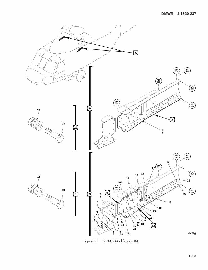
WL265
WL260
BL34.5
STA325
STA320
STA308
A
WL265
WL260
BL34.5
STA325
STA320
STA308
3
15215
14
45
519
520
513
56
57
57
58
58
9
1514
518
57
22
513
25
25
2612
1216
12
12
17
17
17
12
3
11
10
9
24
23
22
SAAB3093
A
Figure E-7. BL 34.5 Modification Kit
DMWR 1-1520-237
E-93

E-7- 70070-20572-011 BL 34.5 MODIFICATION KIT ...................................... REF-1 70070-20572-013 . M/K L/H REINFORCEMENT .................................... 1
70070-20572-012 . M/K R/H REINFORCEMENT.................................... 1-2 70070-20572-014 . . BEAM INSTL RH, (Modified from 70212-02112-
012) ........................................................................ REF70070-20572-015 . . BEAM INSTL LH, (Modified from 70212-02112-
011) ........................................................................ REF70070-20572-016 . . BEAM INSTL RH, (Modified from 70212-02112-
014) ........................................................................ REF70070-20572-017 . . BEAM INSTL LH, (Modified from 70212-02112-
013) ........................................................................ REF-3 70070-20572-041 . . BEAM ASSY, (Reidentified from 70212-02112-
051) ........................................................................ REF70070-20572-042 . . BEAM ASSY, (Reidentified from 70212-02112-
050) ........................................................................ REF70070-20572-043 . . BEAM ASSY, (Reidentified from 70212-02112-
043) ........................................................................ REF70070-20572-044 . . BEAM ASSY, (Reidentified from 70212-02112-
047) ........................................................................ REF-4 HL64PB-6-2 . . HI-LOK PIN, (73197)............................................. 3
HL220-6-2 . . HI-LOK PIN, (73197)............................................. 5 *HL204-6-2 . . PIN, (73197).......................................................... 5 *
-5 HL1087A-6 . . COLLAR, (73197) ................................................. 18HL287-6 . . COLLAR, (73197) ................................................. 40 *HL93-6 . . COLLAR, (73197) ................................................. 40 *
-6 HL64PB-6-4 . . HI-LOK PIN, (73197)............................................. 1HL220-6-4 . . HI-LOK PIN, (73197)............................................. 5 *HL204-6-4 . . PIN, (73197).......................................................... 5 *
-7 HL64PB-6-6 . . PIN, (73197).......................................................... 5HL204-6-6 . . PIN, (73197).......................................................... 10 *HL220-6-6 . . HI-LOK PIN, (73197)............................................. 10 *
-8 HL20PB86-6-3 . . PIN COLLAR ASSY, (73197) ............................... 4-9 HL20PB86-6-6 . . PIN COLLAR ASSY, (73197) ............................... 3
-10 HL20PB-6-6 . . . HI-LOK PIN, (73197).......................................... 1-11 HL86-6 . . . COLLAR, (73197) (Superseded By HL1086A-
6) ......................................................................... 1HL1086A-6 . . . COLLAR, (73197) .............................................. 1
-12 MS20470AD6-6 . . RIVET..................................................................... 9-13 HL64PB-6-5 . . HI-LOK PIN, (73197)............................................. 2
HL204-6-5 . . PIN, (73197).......................................................... 5 *HL220-6-5 . . HI-LOK PIN, (73197)............................................. 5 *
-14 HL64PB-8-8 . . PIN, (73197).......................................................... 2HL220-8-8 . . HI-LOK PIN, (73197)............................................. 5 *HL204-8-8 . . PIN, (73197).......................................................... 5 *
-15 HL1087A-8 . . COLLAR, (73197) ................................................. 6HL287-8 . . COLLAR, (73197) ................................................. 40 *HL93-8 . . COLLAR, (73197) ................................................. 20 *
-16 MS20470AD5-5 . . RIVET..................................................................... 13-17 MS20470AD6-5 . . RIVET..................................................................... 18-18 HL64PB-6-8 . . HI-LOK PIN, (73197)............................................. 1
HL220-6-8 . . HI-LOK PIN, (73197)............................................. 5 *HL204-6-8 . . PIN, (73197).......................................................... 5 *
-19 HL64PB-6-3 . . HI-LOK PIN, (73197)............................................. 2HL220-6-3 . . HI-LOK PIN, (73197)............................................. 5 *HL204-6-3 . . PIN, (73197).......................................................... 5 *
-20 HL64PB-6-7 . . HI-LOK PIN, (73197)............................................. 4HL204-6-7 . . PIN, (73197).......................................................... 5 *
DMWR 1-1520-237
QTY USABLEFIGURE & PER ONINDEX NO. PART NUMBER 1 2 3 4 5 6 7 DESCRIPTION ASSY CODE
E-94

HL220-6-7 . . HI-LOK PIN, (73197)............................................. 5 *-21 HL64PB-8-5 . . HI-LOK PIN, (73197)............................................. 4
HL220-8-5 . . HI-LOK PIN, (73197)............................................. 5 *HL204-8-5 . . PIN, (73197).......................................................... 5 *HL220-8-6 . . HI-LOK PIN, (73197)............................................. 5 *HL204-8-6 . . PIN, (73197).......................................................... 5 *HL220-8-7 . . HI-LOK PIN, (73197)............................................. 5 *HL204-8-7 . . PIN, (73197).......................................................... 5 *
-22 HL20PB86-6-4 . . PIN COLLAR ASSY, (73197) ............................... 6-23 HL20PB-6-4 . . . HI-LOK PIN, (73197).......................................... 1-24 HL86-6 . . . COLLAR, (73197) (Superseded By HL1086A-
6) ......................................................................... 1HL1086A-6 . . . COLLAR, (73197) .............................................. 1
-25 MS20470AD5-2 . . RIVET..................................................................... 15-26 70080-70107-222 . . REINFORCEMENT, (Used on 70070-20572-
012) ........................................................................ 170080-70107-223 . . REINFORCEMENT, (Used on 70070-20572-
013) ........................................................................ 1
DMWR 1-1520-237
QTY USABLEFIGURE & PER ONINDEX NO. PART NUMBER 1 2 3 4 5 6 7 DESCRIPTION ASSY CODE
E-95

E-9. ESSS DOUBLER MODIFICATION KIT (50-15).
Subject: ESSS Doubler; Installation of, dated 31 March 2003
Purpose: Provide instructions to install new doublers and skins between station 295.00 and station 308.00 right and leftsides on UH-60A helicopters equipped with ESSS provisions.
Model: UH-60A
Description: The following is a brief overview of the work required to modify left and right sides between station 295.00and 308.00. New doublers and skins are installed between station 295.00 and station 308.00, buttline 16.50 through34.50. This modification is applicable to UH-60A equipped with ESSS.
Drawings required for modification:
70070-20641, 70652-02150
References: (a) Special Service Instructions (SSI) No. 50-31, Installation of 9A to A9 Recapitalization Program, datedMarch 31, 2003
Instructions:
NOTE
• A complete review of this SSI is recommended before installing new doublers and skins between station295.00 and station 308.00.
• Before beginning this modification procedure, use the material information list to inventory the kit. Makesure all parts are present and in serviceable condition.
• Where drawing numbers are not listed within individual steps, drawing(s) listed in preceding step(s) arethe controlling authority.
• The sheet metal and structural modifications in this SSI shall be done by personnel experienced in readingmodification drawings. Routine steps such as cleaning, layout and drilling, deburring, standard repairs,corrosion control, clean up after rework, chemical coating for aluminum after cutting/trimming parts, painttouch up, and safety practices may not be called out herein. However, these steps and all other requiredroutine tasks shall be done.
• When installing fasteners refer to drawing sheet and zones for applicable fasteners.
• Slight variations to the instructions contained herein are allowed, as long as the intent of the modificationis accomplished.
A. Preparation for modification and removal of equipment.
(1) Confirm that all warnings, cautions, and notes are complied with per reference (a).
(2) Perform preparation for modification per reference (a).
DMWR 1-1520-237
E-96

B. Install right and left side ESSS doublers as follows:
(1) Modify right side between station 295.00 and station 308.00 as follows (Dwg 70070-20641):
(a) Remove and save for reuse, strap (70213-02101-173) at buttline 16.50, waterline 269.00 (Sheet 3, Zone12-B).
(b) Remove fasteners attaching hat (70219-04203-130) between buttlines 28.75 and 34.50, waterline269.00 leaving hat (-130) in place (Sheet 3, Zone 9-E).
(c) Position doubler (70070-20641-102) (top deck) and skin (70085-22135-117) (cabin ceiling) betweenbuttlines 16.50 and 34.50, waterline 269.00 and mark rivets to be removed (Sheet 3, Zones 10-G and 12-B).
(d) Remove fasteners identified in previous step.
NOTE
In step B.(1)(e), existing rivets may interfere with the flange on skin (70085-22135-117). If this conditionexists trimming the flange enough to clear rivets is permissible.
(e) Position and temporarily install skin (70085-22135-117) (cabin ceiling) and doubler (70070-20641-102)(top deck) (Sheet 3, Zones 10-G and 12-B).
(f) Remove skin (70085-22135-117) and doubler (70070-20641-102), deburr and touch up as required.
WARNING
OBSERVE ALL CAUTIONS AND WARNINGS ON CONTAINERS WHEN USING CONSUMABLES.WHEN APPLICABLE, WEAR NECESSARY PROTECTIVE GEAR DURING HANDLING AND USE. IF ACONSUMABLE IS FLAMMABLE OR EXPLOSIVE, MAKE CERTAIN CONSUMABLE AND ITS VAPORS AREKEPT AWAY FROM HEAT, SPARK, AND FLAME. MAKE CERTAIN EQUIPMENT IS PROPERLYGROUNDED AND FIREFIGHTING EQUIPMENT IS READILY AVAILABLE PRIOR TO USE. FOR AD-DITIONAL INFORMATION ON TOXICITY, FLASHPOINT, AND FLAMMABILITY OF CHEMICALS,CONSULT YOUR MEDICAL PEOPLE, OR MANUFACTURER OF THE CONSUMABLE.
(g) Install skin (70085-22135-117), doubler (70070-20641-102), and strap (70213-02101-173) wet withsealant (AMS-S-88022, A2 or C20 or equivalent) using fasteners shown (Sheet 3, Zones 12-B and 10-H; Sheet 2, Notes9, 12 and 13).
(2) Modify left side between station 295.00 and station 308.00 as follows (Dwgs 70070-20641 and 70652-02151):
(a) Remove and discard spacer (70213-02101-174) and nutplate (MS21075-4) at buttline 16.50, waterline269.00 (Dwg 70070-20641, Sheet 3, Zone 18-H).
(b) Remove shim (70652-02151-102) at left buttline 16.50 using a nonmetallic scraper, measure and recordthickness of shim (-102) for use in step B.(2)(l) (Dwg 70652-02151, Sheet 1, Zone 12-F).
DMWR 1-1520-237
E-97

(c) Remove and save for reuse, strap (70213-02101-172) at buttline 16.50, waterline 269.00 (Dwg 70070-20641, Sheet 3, Zone 18-A).
(d) Remove fasteners attaching hat (70219-04203-129) between buttlines 28.75 and 34.50, waterline269.00 leaving hat (-129) in place (Sheet 3, Zone 23-D).
(e) Remove and discard nutplates (MS21075-3) (two places) and nutplate (MS21069-3) (Sheet 3, Zones 22-B, 19-B, and 20-H).
(f) Position doubler (70070-20641-101) (top deck) and skin (70085-22135-113) (cabin ceiling) betweenbuttlines 16.50 and 34.50, waterline 269.00 and mark rivets to be removed (Sheet 3, Zones 20-B and 23-D).
(g) Remove fasteners identified in previous step.
NOTE
In step B.(2)(h), existing rivets may interfere with the flange on skin (70085-22135-117). If this conditionexists trimming the flange enough to clear rivets is permissible.
(h) Position and temporarily install skin (70085-22135-113) (cabin ceiling) and doubler (70070-20641-101) (top deck) (Sheet 3, Zones 20-B and 23-D).
(i) Remove skin (70085-22135-113) and doubler (70070-20641-101), deburr and touch up as required.
WARNING
OBSERVE ALL CAUTIONS AND WARNINGS ON CONTAINERS WHEN USING CONSUMABLES.WHEN APPLICABLE, WEAR NECESSARY PROTECTIVE GEAR DURING HANDLING AND USE. IF ACONSUMABLE IS FLAMMABLE OR EXPLOSIVE, MAKE CERTAIN CONSUMABLE AND ITS VAPORS AREKEPT AWAY FROM HEAT, SPARK, AND FLAME. MAKE CERTAIN EQUIPMENT IS PROPERLYGROUNDED AND FIREFIGHTING EQUIPMENT IS READILY AVAILABLE PRIOR TO USE. FOR AD-DITIONAL INFORMATION ON TOXICITY, FLASHPOINT, AND FLAMMABILITY OF CHEMICALS,CONSULT YOUR MEDICAL PEOPLE, OR MANUFACTURER OF THE CONSUMABLE.
(j) Install skin (70085-22135-113), doubler (70070-20641-101), and strap (70213-02101-172) wet withsealant (AMS-S-8802, A2 or C20 or equivalent) using fasteners shown (Sheet 3, Zones 23-D, 20-B, and 18-A; Sheet 2,Notes 9, 12, and 13).
(k) Install three new nutplates (MS21075-3) (two places) and MS21069-3) (Sheet 3, Zones 20-B, 22-B and20-H).
(l) Install new shim (70652-02151-102) from previous step using adhesive (EA 9309.3NA or equivalent)(Dwg 70652-02151, Sheet 1, Zone 12-D and Note 2).
C. Reinstallation of removed equipment:
(1) Reinstall removed equipment per reference (a).
D. Record of Compliance:
(1) Make an appropriate logbook entry to show compliance with this Special Service Instruction.
DMWR 1-1520-237
E-98

Weight and Balance Data:
QTY PART NO. NOMENCLATUREPOUNDSWEIGHT
INCHES AFTOF DATUM
MOMENT/1000
1 70070-20641-011 Mod. Kit + 1.9 301.4 0.573
Weight and Balance: Change resulting from these instructions are as follows:
Change in basic weight: +1.9 pounds
Moment arm: in. 301.4
Change in basic moment/1000: 0.573
Manpower (Estimated)
No. of Personel No. of Hours Man-hours
Sheet Metal Mechanic 2 24.0 *48.0
*Does not include time required to prepare helicopter or return it to flight status.
Material Information
A. Modification Kit Required:
Qty Nomenclature Part Number Source
1 Mod. Kit, ESSS Doubler, 70070-20641-011 (1)
consisting of:
1 Mod. Kit, Support R/H Instl, 70070-20641-012
consisting of:19 Rivet MS20470AD5-92 Pin, SWG LKG NAS1465-047 Pin, SWG LKG NAS1525-0311 Rivet, Blind NAS1738B4-327 Rivet, Blind NAS1738B5-91 Skin 70085-22135-117
DMWR 1-1520-237
E-99

Qty Nomenclature Part Number Source
1 Mod. Kit, Support L/H Instl, 70070-20641-013
consisting of:19 Rivet MS20470AD5-92 Pin, SWG LKG NAS1465-047 Pin, SWG LKG NAS1525-0311 Rivet, Blind NAS1738B4-327 Rivet, Blind NAS1738B5-91 Skin 70085-22135-113
1 Mod. Kit, Plating Instl, 70070-20641-014
consisting of:2 Pin Collar Assy HL19PB86-6-82 Pin Collar Assy HL20PB86-6-68 Pin Collar Assy HL20PB86-6-82 Pin Collar Assy HL20PB86-6-93 Rivet MS20426AD3-994 Rivet MS20470AD4-364 Rivet MS20426AD5-935 Rivet MS20470AD6-91 Nutplate MS21069-32 Nutplate MS21075-3N1 Nutplate MS21075-4N5 Rivet NAS1097AD3-33 Rivet NAS1097AD3-97 Rivet NAS1097AD5-947 Pin, SWG LKG NAS1466-0523 Pin, SWG LKG NAS1466-0618 Pin, SWG LKG NAS1466-076 Pin, SWG LKG NAS1466-0822 Pin, SWG LKG NAS1466-091 Doubler 70070-20641-1011 Doubler 70070-20641-102
1 Mod. Kit, Shim Instl, 70070-20641-018
consisting of:8 Shim 70652-02151-10110 Shim 70652-02151-1024 Shim 70652-02151-103
DMWR 1-1520-237
E-100

B. Consumable Material:
WARNING
OBSERVE ALL CAUTIONS AND WARNINGS ON CONTAINERS WHEN USING CONSUMABLES.WHEN APPLICABLE, WEAR NECESSARY PROTECTIVE GEAR DURING HANDLING AND USE. IF ACONSUMABLE IS FLAMMABLE OR EXPLOSIVE, MAKE CERTAIN CONSUMABLE AND ITS VAPORS AREKEPT AWAY FROM HEAT, SPARK, AND FLAME. MAKE CERTAIN EQUIPMENT IS PROPERLYGROUNDED AND FIREFIGHTING EQUIPMENT IS READILY AVAILABLE PRIOR TO USE. FOR AD-DITIONAL INFORMATION ON TOXICITY, FLASHPOINT, AND FLAMMABILITY OF CHEMICALS,CONSULT YOUR MEDICAL PEOPLE, OR MANUFACTURER OF THE CONSUMABLE.
Qty Nomenclature Part Number Source
8 oz. Sealant AMS-S-8802, A2, C20, orequivalent
(1)
8 oz. Adhesive EA9309.3NA or equivalent (1)
C. Source:
(1) Available through normal supply channels
DMWR 1-1520-237
E-101

SAAB3097_1
1
29
AB
STA295
STA308
BL
RH16.5
BL
RH34.5
BL
LH16.5
BL
LH34.5
BL0.0
3334
3334
1
1
Figure E-8. ESSS Doubler Modification Kit (Sheet 1 of 2)
DMWR 1-1520-237
E-102

B
A
SAAB3097_2
40
40
39
39
38
38
38
38
37
19
36
19 1936
36
36
36
36
37
35
35
35
35
35
35
35 2728
25 26 25 26
2423
22
22
21
21
21
2020
19
2020
20
20
2020
20 20
18
18
18
18
17
17
17
17
7
7
8
8
11
14
8
8
6
6
6
6
6
6
6
6
55
5
5
5
5
55
5
5
5
5
4
4
4
4
4
45 43 3
4
4
4
3
33
3
STA295
STA308
39
37
37
BL
LH16.5
BL
LH34.5
BL
RH34.5
BL
RH16.5
STA295
STA308
37
37
2
2
Figure E-8. ESSS Doubler Modification Kit (Sheet 2 of 2)
DMWR 1-1520-237
E-103

E-8- 70070-20641-011 ESSS DOUBLER MODIFICATION KIT....................... REF-1 70070-20641-014 . M/K PLATING INSTL................................................ 1-2 70070-20641-015 . . PLATING INSTL, (Modified from 70213-02101-
014) ........................................................................ REF-3 MS20470AD6-9 . . RIVET..................................................................... 35-4 NAS1466-05 . . SWAGE LOCKING PIN ......................................... 47-5 NAS1466-06 . . SWAGE LOCKING PIN ......................................... 23-6 NAS1466-07 . . SWAGE LOCKING PIN ......................................... 18-7 HL19PB86-6-8 . . PIN COLLAR ASSY, (73197) ............................... 8-8 HL20PB86-6-8 . . PIN COLLAR ASSY, (73197) ............................... 8-9 HL20PB-6-8 . . . HI-LOK PIN, (73197).......................................... 1
-10 HL86-6 . . . COLLAR, (73197) (Superseded by HL1087A-6) ......................................................................... 1
HL1087A-6 . . . COLLAR, (73197) .............................................. 1-11 HL20PB86-6-9 . . PIN COLLAR ASSY, (73197) ............................... 2-12 HL20PB-6-9 . . . HI-LOK PIN, (73197).......................................... 1-13 HL86-6 . . . COLLAR, (73197) (Superseded by HL1087A-
6) ......................................................................... 1HL1087A-6 . . . COLLAR, (73197) .............................................. 1
-14 HL20PB86-6-6 . . PIN COLLAR ASSY, (73197) ............................... 2-15 HL20PB-6-6 . . . HI-LOK PIN, (73197).......................................... 1-16 HL86-6 . . . COLLAR, (73197) (Superseded By HL1087A-
6) ......................................................................... 1HL1087A-6 . . . COLLAR, (73197) .............................................. 1
-17 NAS1466-09 . . SWAGE LOCKING PIN ......................................... 22-18 NAS1466-08 . . SWAGE LOCKING PIN ......................................... 6-19 MS20470AD4-3 . . RIVET..................................................................... 94-20 MS20470AD5-9 . . RIVET..................................................................... 64-21 NAS1097AD5-9 . . RIVET..................................................................... 7-22 70070-20641-101 . . DOUBLER, LH....................................................... 1
70070-20641-102 . . DOUBLER, RH ...................................................... 1-23 MS21075-4N . . NUTPLATE ............................................................ 1-24 MS20426AD3-9 . . RIVET..................................................................... 3-25 MS21075-3N . . NUTPLATE ............................................................ 2-26 NAS1097AD3-3 . . RIVET..................................................................... 5-27 MS21069-3 . . NUTPLATE ............................................................ 1-28 NAS1097AD3-9 . . RIVET..................................................................... 3-29 70070-20641-018 . M/K SHIM INSTL ...................................................... 1-30 70652-02151-101 . . SHIM ...................................................................... 8-31 70652-02151-102 . . SHIM ...................................................................... 10-32 70652-02151-103 . . SHIM ...................................................................... 4-33 70070-20641-013 . M/K SUPPORT L/H INSTL ....................................... 1
70070-20641-012 . M/K SUPPORT R/H INSTL ...................................... 1-34 70070-20641-016 . . SUPPORT INSTL, (Modified from 70219-42426-
014) ........................................................................ REF70070-20641-017 . . SUPPORT INSTL, (Modified from 70219-42426-
013) ........................................................................ REF-35 MS20470AD5-9 . . RIVET..................................................................... 19-36 NAS1738B5-9 . . BLIND RIVET......................................................... 27-37 NAS1738B4-3 . . BLIND RIVET......................................................... 11-38 NAS1525-03 . . SWAGE LOCKING PIN ......................................... 7-39 NAS1465-04 . . SWAGE LOCKING PIN ......................................... 2-40 70085-22135-117 . . SKIN, LH (Used on 70070-20641-013) ................ 1
70085-22135-113 . . SKIN, RH (Used on 70070-20641-012)................ 1
DMWR 1-1520-237
QTY USABLEFIGURE & PER ONINDEX NO. PART NUMBER 1 2 3 4 5 6 7 DESCRIPTION ASSY CODE
E-104

E-10. TRDS BRACKETS MODIFICATION KIT (50-20).
Subject: Tail Rotor Drive Shaft Support Brackets; Modification of, dated 31 March 2003
Purpose: Provide instructions for the structural strengthening of the tail rotor drive shaft supports to eliminate cracking.
Model: UH-60A
Description: The tail rotor drive shaft support brackets at station 410.00 and station 472.00 are modified to improvethe structural strength at these locations.
Drawings required for modification:
70070-20488
References: (a) Special Service Instructions (SSI) No. 50-31, Installation of 9A to A9 Recapitalization Program, datedMarch 31, 2003
(b) SSI No. 50-9, Drive Shaft Supports; Modification of, dated March 31, 2003
(c) TM 1-1520-237-23-2, Technical Manual Aviation Unit and Intermediate Maintenance for UH-60A,UH-60L, EH-60A, UH-60Q and HH-60L Helicopters
Instructions:
NOTE
• A complete review of this SSI is recommended before incorporating the tail rotor drive shaft supportbrackets modification kit.
• Before beginning this modification procedure, use the material information list to inventory the modificationkit. Make sure all parts are present and in serviceable condition.
• Where drawing numbers are not listed within individual step(s), drawing(s) listed in preceding step(s) arethe controlling authority.
• The sheet metal and structural modifications in this SSI shall be done by personnel experienced in readingmodification drawings. Routine steps such as cleaning, layout and drilling, deburring, standard repairs,corrosion control, clean up after rework, chemical coating for aluminum after cutting/trimming parts, painttouch up, and safety practices may not be called out herein. However, these steps and all other requiredroutine tasks shall be done.
• When installing fasteners refer to drawing sheet and zones for applicable fasteners.
• Slight variations to the instructions contained herein are allowed, as long as the intent of the modificationis accomplished.
• This modification is to be done concurrently with reference (b).
A. Preparation for modification and removal of equipment:
(1) Confirm that all warnings, cautions, and notes are complied with per reference (a).
(2) Perform preparation for modification per reference (a).
DMWR 1-1520-237
E-105
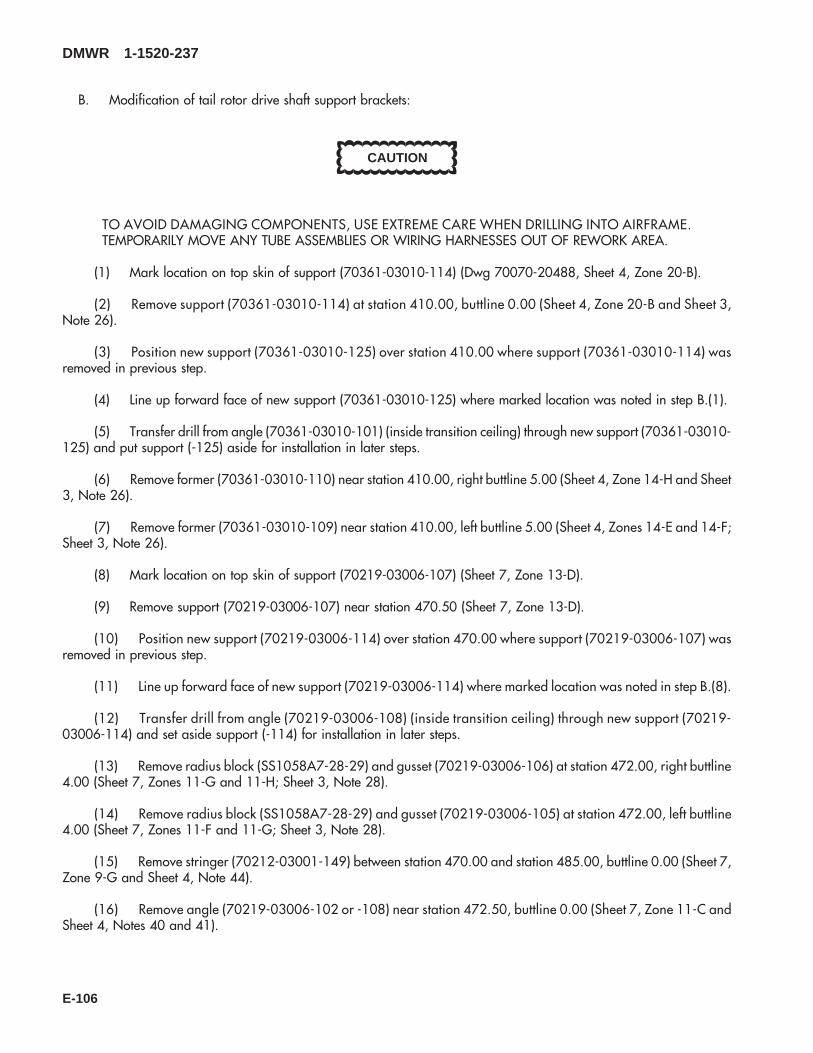
B. Modification of tail rotor drive shaft support brackets:
CAUTION
TO AVOID DAMAGING COMPONENTS, USE EXTREME CARE WHEN DRILLING INTO AIRFRAME.TEMPORARILY MOVE ANY TUBE ASSEMBLIES OR WIRING HARNESSES OUT OF REWORK AREA.
(1) Mark location on top skin of support (70361-03010-114) (Dwg 70070-20488, Sheet 4, Zone 20-B).
(2) Remove support (70361-03010-114) at station 410.00, buttline 0.00 (Sheet 4, Zone 20-B and Sheet 3,Note 26).
(3) Position new support (70361-03010-125) over station 410.00 where support (70361-03010-114) wasremoved in previous step.
(4) Line up forward face of new support (70361-03010-125) where marked location was noted in step B.(1).
(5) Transfer drill from angle (70361-03010-101) (inside transition ceiling) through new support (70361-03010-125) and put support (-125) aside for installation in later steps.
(6) Remove former (70361-03010-110) near station 410.00, right buttline 5.00 (Sheet 4, Zone 14-H and Sheet3, Note 26).
(7) Remove former (70361-03010-109) near station 410.00, left buttline 5.00 (Sheet 4, Zones 14-E and 14-F;Sheet 3, Note 26).
(8) Mark location on top skin of support (70219-03006-107) (Sheet 7, Zone 13-D).
(9) Remove support (70219-03006-107) near station 470.50 (Sheet 7, Zone 13-D).
(10) Position new support (70219-03006-114) over station 470.00 where support (70219-03006-107) wasremoved in previous step.
(11) Line up forward face of new support (70219-03006-114) where marked location was noted in step B.(8).
(12) Transfer drill from angle (70219-03006-108) (inside transition ceiling) through new support (70219-03006-114) and set aside support (-114) for installation in later steps.
(13) Remove radius block (SS1058A7-28-29) and gusset (70219-03006-106) at station 472.00, right buttline4.00 (Sheet 7, Zones 11-G and 11-H; Sheet 3, Note 28).
(14) Remove radius block (SS1058A7-28-29) and gusset (70219-03006-105) at station 472.00, left buttline4.00 (Sheet 7, Zones 11-F and 11-G; Sheet 3, Note 28).
(15) Remove stringer (70212-03001-149) between station 470.00 and station 485.00, buttline 0.00 (Sheet 7,Zone 9-G and Sheet 4, Note 44).
(16) Remove angle (70219-03006-102 or -108) near station 472.50, buttline 0.00 (Sheet 7, Zone 11-C andSheet 4, Notes 40 and 41).
DMWR 1-1520-237
E-106

(17) Remove remaining fasteners, as required (Sheets 4 and 7).
C. Installation of tail rotor drive shaft support brackets.
(1) Locate and temporarily install new radius block (SS1058A7-20-51) and former (70070-20488-102) at sta-tion 410.00, right buttline 5.00 (Dwg 70070-20488, Sheet 4, Zones, 14-G and 14-H).
(2) Locate and temporarily install new radius block (SS1058A7-20-51) and former (70070-20488-103) at sta-tion 410.00, left buttline 5.00 (Sheet 4, Zone 14-E).
(3) Locate and temporarily install support (70361-03010-125) (previously fit-out) at station 410.00, buttline0.00 (Sheet 4, Zone 19-B and Sheet 2, Notes 10 and 11).
(4) Locate and temporarily install stringer (70212-03001-168) between station 470.00 and station 485.00, but-tline 0.00 (Sheet 7, Zones 9-F to 12-F).
(5) Locate and temporarily install new angle (70219-03006-108) near station 472.50, buttline 0.00 (Sheet 7,Zone 11-C).
(6) Locate and temporarily install radius block (SS1058A7-28-29) and gusset (70070-20488-106) at station472.00, right buttline 4.00 (Sheet 7, Zone 11-H).
(7) Locate and temporarily install radius block (SS1058A7-28-29) and gusset (70070-20488-105) at station472.00, left buttline 4.00 (Sheet 7, Zone 11-F).
(8) Locate and temporarily install support (70219-03006-114) (previously fit-out) at station 472.50, buttline0.00 (Sheet 7, Zone 13-C, and Sheet 2, Notes 10 and 11).
(9) Locate and temporarily install clip (70212-03001-171) at station 485.00, buttline 0.00 (Sheet 7, Zone 9-F).
(10) Transfer drill remaining fastener holes for assembly.
(11) Line up new brackets (70070-20488-101 and -104) at stations 410.00 and 470.00 per reference (c).
(12) Locate and temporarily install bracket (70070-20488-104) at station 472.50, buttline 0.00 (Sheet 7, Zone11-D).
(13) Locate and temporarily install bracket (70070-20488-101) at station 410.00, buttline 0.00 (Sheet 4, Zone18-B and Sheet 2, Notes 9, 10 and 11).
(14) Remove fitted parts, deburr and touch up as required.
(15) Install parts removed in previous step using fasteners shown (Sheet 1, Note 2 and Sheet 2, Note 12).
D. Reinstallation of removed equipment:
(1) Install removed equipment per reference (a).
E. Record of Compliance:
(1) Make an appropriate logbook entry to show compliance with this Special Service Instruction.
DMWR 1-1520-237
E-107
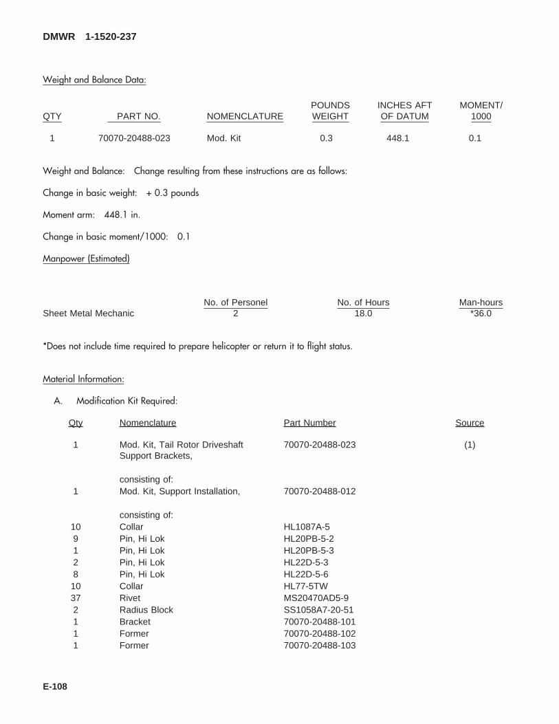
Weight and Balance Data:
QTY PART NO. NOMENCLATUREPOUNDSWEIGHT
INCHES AFTOF DATUM
MOMENT/1000
1 70070-20488-023 Mod. Kit 0.3 448.1 0.1
Weight and Balance: Change resulting from these instructions are as follows:
Change in basic weight: + 0.3 pounds
Moment arm: 448.1 in.
Change in basic moment/1000: 0.1
Manpower (Estimated)
No. of Personel No. of Hours Man-hoursSheet Metal Mechanic 2 18.0 *36.0
*Does not include time required to prepare helicopter or return it to flight status.
Material Information:
A. Modification Kit Required:
Qty Nomenclature Part Number Source
1 Mod. Kit, Tail Rotor DriveshaftSupport Brackets,
70070-20488-023 (1)
consisting of:1 Mod. Kit, Support Installation, 70070-20488-012
consisting of:10 Collar HL1087A-59 Pin, Hi Lok HL20PB-5-21 Pin, Hi Lok HL20PB-5-32 Pin, Hi Lok HL22D-5-38 Pin, Hi Lok HL22D-5-610 Collar HL77-5TW37 Rivet MS20470AD5-92 Radius Block SS1058A7-20-511 Bracket 70070-20488-1011 Former 70070-20488-1021 Former 70070-20488-103
DMWR 1-1520-237
E-108

Qty Nomenclature Part Number Source
1 Support 70361-03010-125
1 Mod. Kit, Support Installation, 70070-20488-022
consisting of:86 Rivet MS20470AD5-98 Pin Collar Assy HL20PB86-5-21 Angle 70219-03006-1084 Rivet MS20470AD4-92 Radius Block SS1058A7-28-291 Bracket 70070-20488-1041 Stringer 70212-03001-1681 Clip 70212-03001-1712 Collar NAS1080D052 Pin, SWG LKG NAS1525-031 Gusset 70070-20488-1051 Gusset 70070-20488-1061 Support 70219-03006-114
B. Consumable Material:
WARNING
OBSERVE ALL CAUTIONS AND WARNINGS ON CONTAINERS WHEN USING CONSUMABLES.WHEN APPLICABLE, WEAR NECESSARY PROTECTIVE GEAR DURING HANDLING AND USE. IF ACONSUMABLE IS FLAMMABLE OR EXPLOSIVE, MAKE CERTAIN CONSUMABLE AND ITS VAPORS AREKEPT AWAY FROM HEAT, SPARK, AND FLAME. MAKE CERTAIN EQUIPMENT IS PROPERLYGROUNDED AND FIREFIGHTING EQUIPMENT IS READILY AVAILABLE PRIOR TO USE. FOR AD-DITIONAL INFORMATION ON TOXICITY, FLASHPOINT, AND FLAMMABILITY OF CHEMICALS,CONSULT YOUR MEDICAL PEOPLE, OR MANUFACTURER OF THE CONSUMABLE.
Qty Nomenclature Part Number Source
4 oz. Sealant AMS-S-8802, A2, or C20, orequivalent
(1)
C. Source:
(1) Available through normal supply channels
DMWR 1-1520-237
E-109
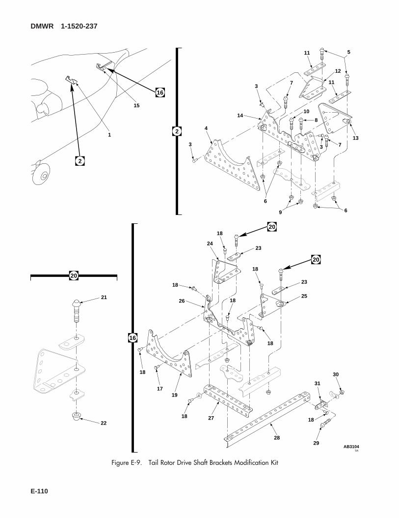
SAAB3104
5
7 11
3
13
10
8
11
3
12
14
3
4
6
9 6
7
2
23
18
18
24
18
18
23
25
18
20
20
26
18
1719
18 27
2829
18
31
30
16
21
22
20
1
15
2
16
Figure E-9. Tail Rotor Drive Shaft Brackets Modification Kit
DMWR 1-1520-237
E-110

E-9- 70070-20488-023 TAIL ROTOR DRIVE SHAFT BRACKETSMODIFICATION KIT .................................................... REF
-1 70070-20488-012 . M/K SUPPORT INSTL.............................................. 1-2 70070-20488-013 . . SUPPORT INSTL .................................................. REF-3 MS20470AD5-9 . . RIVET, .................................................................. 37-4 70361-03010-125 . . SUPPORT.............................................................. 1-5 HL22D-5-6 . . HI-LOK PIN, (73197)............................................. 8-6 HL77-5TW . . COLLAR, (73197) ................................................. 10-7 HL22D-5-3 . . HI-LOK PIN, (73197)............................................. 2-8 HL20PB-5-2 . . HI-LOK PIN, (73197)............................................. 9-9 HL1087A-5 . . COLLAR, (73197) ................................................. 1
-10 HL20PB-5-3 . . HI-LOK PIN, (73197)............................................. 1-11 SS1058A7-20-51 . . RADIUS BLOCK .................................................... 2-12 70070-20488-102 . . FORMER................................................................ 1-13 70070-20488-103 . . FORMER................................................................ 1-14 70070-20488-101 . . BRACKET .............................................................. 1-15 70070-20488-022 . M/K SUPT INSTL...................................................... 1-16 70070-20488-024 . . SUPPORT INSTL (Reidentifed from 70219-
03006-011)............................................................. REF70070-20488-025 . . PLATING ASSY (Reidentified from 70213-
03001-043)............................................................. REF70070-20488-026 . . PLATING ASSY (Reidentified from 70213-
03001-044)............................................................. REF70070-20488-027 . . PLATING ASSY (Reidentified from 70213-
03001-045)............................................................. REF70070-20488-028 . . PLATING ASSY (Reidentified from 70213-
03001-046)............................................................. REF-17 MS20470AD4-9 . . RIVET..................................................................... 4-18 MS20470AD5-9 . . RIVET..................................................................... 86-19 70219-03006-114 . . SUPPORT.............................................................. 1-20 HL20PB86-5-2 . . PIN COLLAR ASSY, (73197) ............................... 8-21 HL20PB-5-2 . . . HI-LOK PIN, (73197).......................................... 1-22 HL86-5 . . . COLLAR, (73197) (Superseded By HL1087A-
5) ......................................................................... 1HL1087A-5 . . . COLLAR, (73197) .............................................. 1
-23 SS1058A7-28-29 . . RADIUS BLOCK .................................................... 2-24 70070-20488-106 . . GUSSET ................................................................ 1-25 70070-20488-105 . . GUSSET ................................................................ 1-26 70070-20488-104 . . BRACKET .............................................................. 1-27 70219-03006-108 . . ANGLE................................................................... 1-28 70212-03001-168 . . STGR #0................................................................ 1-29 NAS1525-03 . . SWAGE LOCKING PIN ......................................... 2-30 NAS1080D05 . . COLLAR................................................................. 2-31 70212-03001-171 . . CLIP ....................................................................... 1
DMWR 1-1520-237
QTY USABLEFIGURE & PER ONINDEX NO. PART NUMBER 1 2 3 4 5 6 7 DESCRIPTION ASSY CODE
E-111

E-11. STATION 485 MODIFICATION KIT (50-34).
Subject: Transition Station 485.00; Modification of, dated 31 March 2003
Purpose: Provide instructions to remove and replace fitting at station 485.00.
Model: UH-60A
Description: The following is a brief overview of the work required to modify station 485.00. Fitting is removed andreplaced, using new fasteners.
Drawings required for modification:
70000-03200, 70070-20575, 70211-03009, 70213-03001
References: (a) Special Service Instructions (SSI) No. 50-31, Installation of 9A to A9 Recapitalization Program, datedMarch 31, 2003
Instructions:
NOTE
• A complete review of this SSI is recommended before reworking station 485.00.
• Before beginning this modification procedure, use the material information list to inventory the kit. Makesure all parts are present and in serviceable condition.
• Where drawing numbers are not listed within individual steps, drawing(s) listed in preceding step(s) arethe controlling authority.
• The sheet metal and structural modifications in this SSI shall be done by personnel experienced in readingmodification drawings. Routine steps such as cleaning, layout and drilling, deburring, standard repairs,corrosion control, clean up after rework, chemical coating for aluminum after cutting/trimming parts, painttouch up, and safety practices may not be called out herein. However, these steps and all other requiredroutine tasks shall be done.
• When installing fasteners refer to drawing sheet and zones for applicable fasteners.
• Slight variations to the instructions contained herein are allowed, as long as the intent of the modificationis accomplished.
A. Preparation for modification and removal of equipment:
(1) Confirm that all warnings, cautions and notes are complied with per reference (a).
(2) Perform preparation for modification per reference (a).
B. Installation of new brackets at station 485.00:
(1) Locate and remove fitting (70209-03007-125) at station 485.00 left side (Dwg 70211-03009, Sheet 1,Zone 21-L).
(2) Position new fitting (70209-03007-125) at station 485.00 and transfer drill holes from structure, through fit-ting.
DMWR 1-1520-237
E-112
(3) Remove fitting (70209-03007-125) deburr and touch up as required.
(4) Install fitting (70209-03007-125) at station 485.00 using hardware shown (Dwg 70213-03001, Sheet 1,Zone 23-F).
(5) Line ream/drill 0.3125-inch diameter hole from backside fitting into new fitting (70209-03007-125).
(6) Install remaining new hardware to fitting (70209-03007-125) (Dwg 70000-03200, Sheet 1, Zone 4-E, andNote 1).
C. Record of Compliance:
(1) Make an apropriate logbook entry to show compliance with this Special Service Instruction.
Weight and Balance Data: Negligible:
Manpower (Estimated)
No. of Personel No. of Hours Man-hoursStructural Mechanic 1 4.0 *4.0
*Does not include time required to prepare helicopter or return it to flight status.
Material Information:
A. Modification Kit Required:
Qty Nomenclature Part Number Source
1 Mod. Kit, Station 485.00 70070-20575-012 (1)
consisting of:1 Washer MS20002-51 Washer MS20002C52 Rivet MS20470AD5-44 Rivet MS20470AD6-43 Rivet NAS1097AD6-51 Pin, Swg Lkg NAS1446-041 Bolt NAS625-141 Nut SS5081-051 Fitting 70209-03007-125
B. Source:
(1) Available through normal supply channels
DMWR 1-1520-237
E-113
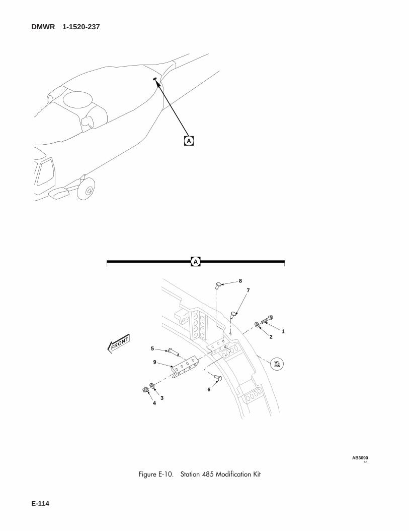
SAAB3090
FRONT
A
43
9
5
6
21
7
8
A
WL255
Figure E-10. Station 485 Modification Kit
DMWR 1-1520-237
E-114
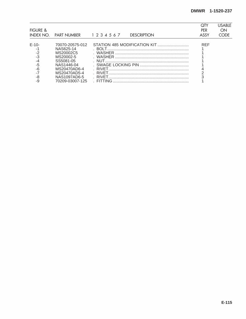
E-10- 70070-20575-012 STATION 485 MODIFICATION KIT ............................ REF-1 NAS625-14 . BOLT......................................................................... 1-2 MS20002C5 . WASHER .................................................................. 1-3 MS20002-5 . WASHER .................................................................. 1-4 SS5081-05 . NUT........................................................................... 1-5 NAS1446-04 . SWAGE LOCKING PIN ............................................ 1-6 MS20470AD6-4 . RIVET........................................................................ 4-7 MS20470AD5-4 . RIVET........................................................................ 2-8 NAS1097AD6-5 . RIVET........................................................................ 3-9 70209-03007-125 . FITTING .................................................................... 1
DMWR 1-1520-237
QTY USABLEFIGURE & PER ONINDEX NO. PART NUMBER 1 2 3 4 5 6 7 DESCRIPTION ASSY CODE
E-115
E-12. LOWER AFT TRANSITION/FOAM LINER MODIFICATION KIT (50-6).
Subject: Lower Aft Transition Section, Rework of, dated 31 March 2003
Purpose: Provide instructions to rework lower aft transition section structure.
Model: UH-60A
Description: The lower aft transition section structure is removed, corrosion treated, and new structure is installed.
Drawings Required for Modification:
70203-03003, 70211-03001, 70211-03002, 70211-03003, 70211-03004, 70211-03005, 70211-03006, 70211-03007, 70211-03009, 70212-03002, 70212-03003, 70209-03012, 70209-03022, 70213-02501,70213-03002, 70213-03004, 70070-20577, 70217-03001, 70219-03011
References: (a) Special Service Instructions (SSI) No. 50-31, Installation of 9A to A9 Recapitalization Program, datedMarch 31, 2003
(b) SSI 50-26, Station 379.00 Frame, Modification of dated 31 March, 2003
Instructions:
NOTE
• A complete review of this directive is recommended before starting the installation of the lower aft transitionsection modification.
• Before beginning this modification procedure, use the material information list to inventory the kit. Makesure all parts are present and in serviceable condition.
• The sheet metal and structural modifications in this SSI shall be done by personnel experienced in readingmodification drawings. Routine steps such as cleaning, layout and drilling, deburring, standard repairs,corrosion control, clean up after rework, chemical coating for aluminum after cutting/trimming parts, painttouch up and safety practices may not be called out herein. However, these steps and all other requiredroutine tasks shall be done.
• Where drawing numbers are not listed within individual steps, drawing(s) listed in preceding step(s) arethe controlling authority.
• Slight variations to the instructions contained herein are allowed, as long as the intent of the modificationis accomplished.
• This modification must be done concurrently with reference (b).
A. Preparation for modification and removal of equipment:
(1) Confirm that all warnings, cautions, and notes are complied with per reference (a).
(2) Perform preparation for modification per reference (a).
(3) Support helicopter forward of station 379.00 with locally manufactured support.
(4) Support helicopter aft of station 485.00 with locally manufactured support.
DMWR 1-1520-237
E-116

B. Modification, lower aft transition section.
(1) Remove lower aft transition section structure as follows:
(a) Remove aft fuselage fuel sump and drain door assemblies (70217-03001-041 and 70217-03001-042 or70217-03001-045 and 70217-03001-046) Keep serviceable parts for reuse (Dwg 70217-03001, Sheet 1, Zones 5-B,5-C, and 6-E, Dwg 70070-20577, Sheet 5, Note 48).
(b) Remove aft fuselage extended range fuel dump outlet cover (70209-03022-101) and scuppers (70209-03022-101 and 70209-03022-103). Keep serviceable parts for reuse (Dwg 70209-03022, Sheet 1, Zones 11-E and12-F).
(c) Remove aft fuselage fuel vent assembly (70209-03012-041). Keep serviceable parts for reuse (Dwg70209-03012, Sheet 1, Zone 11-E).
(d) Remove aft fuselage foam, and scrap.
NOTE
The following airframe parts, when removed are kept for use as templates and then scraped.
(e) Remove station 379.00 strap (70213-02501-126) (Dwg 70213-02501, Sheet 3, Zone 15-A).
(f) Remove doubler (70213-03002-113) (Dwg 70213-03002, Sheet 3, Zone 16-B).
(g) Remove aft fuselage antenna doubler (70203-03003-101) (Dwg 70203-03003, Sheet 1, Zone 12-C).
NOTE
The following steps are done to aid in removing skins.
(h) Remove rivets from left and right buttlines 30.00 through buttlines 40.00, station 379.00 through station485.00 and roll skins back as necessary.
(i) Remove rivets from station 379.00 forward, between buttlines 30.00, and roll skins back.
(j) Remove station 379.00 through station 443.50 left and right side skins (70213-03002-116, 70213-03002-117, and 70213-03002-118) (Dwg 70213-03002, Sheet 1, Zone 15-A, Sheet 3, Zone 11-B).
(k) Remove doubler (70213-03004-101) and bracket angles (SS1083-147, SS1083-192, and SS1083-237)(Dwg 70213-03004, Sheet 1, Zones 8-E, 7-F, 7-G, and 7-H).
(l) Remove station 443.50 through station 485.00 left and right side skins (70213-03002-107, 70213-03002-108, and 70213-03002-119) (Dwg 70213-03002, Sheet 1, Zone 10-B, and Sheet 3, Zone 8-B).
(m) Remove left and right side No. 19 stringers (70212-03002-117 and 70212-03002-118) at station379.00, station 398.00, station 416.60, station 424.90, and station 443.50 frames (Dwgs 70070-20577, Sheet 5,Zones 15-G and 15-C, 70212-03002, Sheet 2, Zones 4-F through 17-F, and Sheet 1, Section A-A, Zone 11-L).
(n) Remove left and right side No. 20 stringers (70212-03002-113 and 70212-03002-114) at station379.00, station 398.00, station 416.60, station 424.90, and station 443.50 frames (Dwg 70070-20577, Sheet 5,Zones 15-F and 15-C, Dwg 70212-03002, Sheet 2, Zones 4-N through 17-, and Sheet 1, Section A-A, Zone 11-L).
DMWR 1-1520-237
E-117

(o) Remove left and right side No. 22 stringers (70212-03002-103, 70212-03002-104, 70212-03002-105, 70212-03002-106) at station 379.00, station 398.00, station 416.60, station 424.90, and station 443.50 frames(Dwg 70070-20577, Sheet 5, Zones 15-E, 15-D, 14-H, and 14-B, Dwg 70212-03002, Sheet 1, Zones 6-P through 13-Pand 15-P through 19-P, Section A-A, Zone 11-L).
(p) Remove No. 23 stringer (70212-03002-111) at station 379.00 through station 416.50 (Dwg 70070-20577, Sheet 5, Zone 15-D, Dwg 70212-03002, Sheet 2, Zones 6-E through 10-F).
(q) Remove aft fuselage left and right side beam assemblies (70212-03003-041, 70212-03003-042,70212-03003-043, and 70212-03003-044) and angle splices (70212-03003-131 and 70212-03003-132), station379.00 through station 443.50, buttline 10.00 (Dwg 70070-20577, Sheet 6, Zones 15-E and 15-D, Dwg 70212-03003, Sheet 1, Zones 15-E, 22-L, and 24-E).
(r) Remove aft fuselage left and right side beam assemblies (70212-03003-048, 70212-03003-049, 70212-03003-047, and 70212-03003-050), cap angles (70212-03003-115 and 70212-03003-116), and splice angles(70212-03003-141 and 70212-03003-142), station 379.00 through station 443.50, buttline 30.00 (Dwg 70070-20577, Sheet 6, Zones 15-C and 15-G, Dwg 70212-03003, Sheet 2, Zones 10-H, 15-G, 15-D, and 15-L).
(s) Remove station 398.00 shear angle (70211-03002-101) (Dwg 70211-03002, Sheet 1, Zone 15-B).
(t) Remove station 408.30 intercostals (70211-03003-101, 70211-03003-102, 70211-03003-103, and70211-03003-104), angles (70211-03003-114 and 70211-03003-115), and gussets (70211-03003-116, 70211-03003-117, and 70211-03003-118) (Dwg 70211-03003, Sheet 1, Zones 12-A, 14-A, 14-D, 13-D, and 9-D).
(u) Remove station 416.60 intercostals (70211-03004-101, 70211-03004-102, 70211-03004-105, and70211-03004-106), stiffeners (70211-03004-103, 70211-03004-104, 70211-03004-107, and 70211-03004-108),angles (70211-03004-117, 70211-03004-118, 70211-03004-119, 70211-03004-120, 70211-03004-121, 70211-03004-122, 70211-03004-126, and 70211-03004-127), between left and right side buttlines 29.97 (Dwg 70211-03004, Sheet 1, Views C-C and F-F, Zones 10-A through 21-D, 13-D, and 9-E).
(v) Remove station 424.90 intercostals (70211-03005-101, 70211-03005-102, 70211-03004-103, and70211-03004-104) and angles (70211-03005-115, 70211-03005-116, 70211-03005-117, and 70211-03005-118,70211-03005-120, 70211-03005-121, 70211-03004-117, 70211-03004-118, 70211-03004-119, and 70211-03004-120), between left and right side buttlines 29.99 (Dwg 70211-03005, Sheet 1, Views A-A and B-B, Zones 10-A,11-A, 12-B, 14-D, 9-F, 17-D, and 22-D).
(w) Remove station 433.20 frames (70211-03006-101, 70211-03006-102, 70211-03006-103, and70211-03006-104), gussets (70211-03006-114), and angles (70211-03006-115 and 70211-03006-0116) betweenleft and right side buttlines 30.00 (Dwg 70211-03006, Sheet 1, Zones 10-A through 22-D).
(x) Remove station 443.50 shear angle (70211-03007-185) (Dwg 70211-03007, Sheet 1, Zone 14-B).
(y) Remove No. 22 stringers (70212-03002-107 and 70212-03002-108) between station 464.00 and sta-tion 485.00 (Dwg 70070-20577, Sheet 5. Zones 9-E and 9-F).
(z) Remove stringers (70212-03002-124 and 70212-03002-123) between station 464.00 and 485.00(Sheet 5, Zones 11-E and 9-E).
(aa) Remove No. 20 stringers (70212-03002-115 and 70212-03002-116) at station 443.50, 464.00, andstation 485.00 (Dwg 70070-20577, Sheet 5, Zones 10-C and 10-F, 70212-03002, Sheet 1, Section A-A, Zone 11-L).
(ab) Remove No. 17 stringers (70212-03002-109 and 70212-03002-110) at station 443.50, station464.00, and station 485.00 (Dwg 70070-20577, Sheet 5, Zones 11-B and 10-G, Dwg 70212-03002, Sheet 1, SectionA-A, Zone 11-L).
DMWR 1-1520-237
E-118

(ac) Remove buttline 10.00 stringers (70212-03002-119 and 70212-03002-120) at station 443.50, station464.00, and station 485.00 (Dwgs 70070-20577, Sheet 5, Zones 9-D and 9-F, 70212-03002, Sheet 1, Section A-A,Zone 11-L).
(2) Install lower aft transition section structure as follows:
(a) Inspect lower aft transition section structure for corrosion and repair damaged areas (Dwg 70070-20577,Sheet 5, Note 48).
(b) Install station 398.00 shear angle (70211-03002-101) (Dwg 70070-20577, Sheet 6, Zone 16-F, Note43).
(c) Install station 408.30 intercostals (70211-03003-101, 70211-03003-102, 70211-03003-103, and70211-03003-104), angles (70211-03003-114 and 70211-03003-115), and gussets (70211-03003-116, 70211-03003-117, and 70211-03003-118) (Sheet 6, Zone 14-B, Note 40).
(d) Install station 416.60 intercostals (70211-03004-101, 70211-03004-102, 70211-03004-103, 70211-03004-104, 70211-03004-105, and 70211-03004-106), stiffeners (70211-03004-107 and 70211-03004-108), andangles (70211-03004-117, 70211-03004-118, 70211-03004-119, 70211-03004-120, 70211-03004-121, 70211-03004-122, 70211-03004-126, and 70211-03004-127) (Sheet 6, Zone 12-B, Note 39).
(e) Install station 424.90 intercostals (70211-03005-101, 70211-03005-102, 70211-03005-103, and70211-03005-104) and angles (70211-03005-115. 70211-03005-116, 70211-03005-117, 70211-03005-118,70211-03005-120, 70211-03005-121, 70211-03004-117, 70211-03004-118, 70211-03004-119, and 70211-03004-120) (Sheet 6, Zone 12-H, Note 36).
(f) Install station 433.20 frames (70211-03006-101, 70211-03006-102, 70211-03006-103, and 70211-03006-104), gussets (70211-03006-114), and angles (70211-03006-115 and 70211-03006-116) (Sheet 6, Zone 11-G, Note 37).
(g) Install station 443.50 shear angle (70211-03007-185) (Sheet 6, Zone 11-B, Note 38).
NOTE
• In the following step, beam assemblies (70212-03003-554 and 70212-03003-544) are installed in placeof (70212-03003-054 and 70212-03003-044). The splice angles (70212-03003-132 and 70212-03003-131) are preinstalled on (70212-03003-054 and 70212-03003-044) creating (70212-03003-554 and 70212-03003-544).
• After installation is completed the (70212-03003-554 and 70212-03003-544) are reidentified to(70212-03003-054 and 70212-03003-044).
(h) Install aft fuselage left and right side beam assemblies (70212-03003-041, 70212-03003-554, 70212-03003-042, and 70212-03003-544) between station 379.00 and station 443.50, buttline 10.00 (Dwgs 70212-03003,Sheet 1, Zones 24-F, 24-G, and 22-L, Dwg 70211-03007, Sheet 1, Section A-A, Zone 9-A).
NOTE
• In the following step, beam assemblies (70212-03003-555 and 70212-03003-548) are installed in placeof (70212-03003-055 and 70212-03003-048). The splice angles (70212-03003-142 and 70212-03003-141) are preinstalled on (70212-03003-055 and 70212-03003-048) creating (70212-03003-555 and 70212-03003-548).
DMWR 1-1520-237
E-119

• After installation is completed the (70212-03003-555 and 70212-03003-548) are reidentified to(70212-03003-055 and 70212-03003-048).
(i) Install aft fuselage left and right side beam assemblies (70070-20577-041, 70212-03003-555, 70212-03003-548, and 70070-20577-042) and cap angles (70212-03003-115 and 70212-03003-116) between station379.00 and station 443.50, buttline 30.00 (Dwg 70212-03003, Sheet 2, Zone 15-D, 15-L, 18-E, and 18-F, Dwg70211-03007, Sheet 1, Zone 11-C through 11-E).
(j) Install No. 23 stringer (70212-03002-111) between station 379.00 and station 398.00, buttline 0.00(Dwg 70213-03002, Sheet 3, Zone 17-C, Dwg 70211-03001, Sheet 1, Section R-R, Zone 8-F, Dwg 70212-03002,Sheet 1, Zone 6-F).
(k) Install left and right side No. 22 stringers (70212-03002-103 and 70212-03002-104) between station379.00 and station 416.60, buttline 5.00 (Dwg 70213-03002, Sheet 3, Zone 17-C and Dwg 70212-03002, Sheet 1,Section A-A, Zones 11-L and 13-N).
(l) Install left and right side No. 20 stringers (70212-03002-113 and 70212-03002-114) between station379.00 and station 443.50, buttline 16.70 (Dwg 70213-03002, Sheet 3, Zone 17-E, Dwg 70211-03001, Sheet 1, Sec-tion S-S, Zone 5-H, Dwg 70211-03007, Sheet 1, Section B-B, Zone 7-A, Dwg 70212-03002, Sheet 1, Section A-A,Zone 11-L).
(m) Install left and right side No. 19 stringers (70212-03002-117 and 70212-03002-118) between station379.00 and station 443.50, buttline 23.70 (Dwg 70213-03002, Sheet 3, Zone 17-F, Dwg 70211-03007, Sheet 1, Sec-tion AB-AB, Dwg 70212-03002, Sheet 1, Section A-A, Zone 11-L).
(n) Install left and right side No. 22 stringers (70212-03002-105 and 70212-03002-106) between station424.90 and station 443.50, buttline 5.00 (Dwg 70213-03002, Sheet 3, Zone 10-A, Dwg 70212-03002, Sheet 1, Sec-tion A-A, Zones 11-L and 15-J).
(o) Install position No. 22 stringers (70212-03002-107 and 70212-03002-108) between station 464.00and station 485.00 (Dwg 70213-03002, Sheet 3, Zone 7-B, Dwg 70211-03009, Sheet 1, Section R-R, Zone 8-J).
(p) Install buttline 10.00 stringers (70212-03003-119 and 70212-03003-120) at station 443.50, station464.00, and station 485.00 (Dwg 70213-03002, Sheet 1, Zone 6-G, Dwg 70211-03007, Sheet 1, Section A-A, Zone8-A, Dwg 70211-03009, Sheet 1, Section F-F, Zone 4-J, Dwg 70212-03002, Sheet 1, Section A-A, Zone 11-L).
(q) Install stringer (70212-03002-123) forward of station 485.00, buttline 0.00 (Dwg 70213-03002, Sheet3, Zone 7-B, Dwg 70211-03009, Sheet 1, Section S-S, Zone 9-B).
(r) Install stringer (70212-03002-124) aft of station 464.00 (Dwg 70213-03002, Sheet 3, Zones 8-A, Note16).
NOTE
The nutplates for the IFF antenna are installed after the skins and structure are urethane coated.
(s) Install IFF antenna doubler (70213-03004-101) with angles (SS1083-147, SS1083-192, and SS1083-237) (Dwg 70070-20577, Sheet 9-D and Sheet 2, Note 18).
(t) Install No. 20 stringers (70213-03002-115 and 70213-03002-116) at station 443.50, station 464.00,and station 485.00 (Dwg 70213-03002, Sheet 1, Zone 7-F, Dwg 70211-03007, Sheet 1, Section B-B, Zone 7-A, Dwg70211-03009, Sheet 1, Section P-P, Zone 9-L, Dwg 70212-03002, Sheet 1, Section A-A, Zone 11-L).
DMWR 1-1520-237
E-120
(u) Install No. 19 stringers (70212-03003-125 and 70212-03003-126) at station 443.50, station 464.00,and station 485.00, buttline 10.00 (Dwg 70213-03002, Sheet 3, Zone 8-G, Zone 10-B, and Dwg 70211-03009, Sheet1, Section N-N, Zone 14-D, Dwg 70212-03002, Sheet 1, Section A-A, Zone 11-L).
(v) Install No. 17 stringers (70212-03002-109 and 70212-03002-110), at station 443.50, station 464.00,and 485.00, buttline 30.00 (Dwg 70213-03002, Sheet 1, Zone 8-H, Dwg 70211-03007, Sheet 1, Section F-F, and Dwg70211-03009, Sheet 1, Section M-M, Zone 7-L, Dwg 70212-03002, Sheet 1, Section A-A, Zone 11-L).
(w) Position skins (70213-03002-107, 70213-03002-119, 70213-03002-108), from station 443.50through station 485.00. Transfer drill fastener holes from structure and doublers through skins (Dwg 70070-20577,Sheet 5, Zones 10-B, 9-D, and 10-F, Dwg 70213-03002, Sheet 1, Zone 10-B, Sheet 3, Zone 8-B).
(x) Position skin (70070-20577-103) and transfer hole cutout from doubler (70213-03004-101) installed instep (s) on page 6 (Dwg 70070-20577, Sheet 5, Zone 9-D, Notes 19, 32 and 57).
(y) Transfer drill nutplate holes from IFF antenna doubler through skin.
(z) Position skins (70213-03002-117, 70213-03002-118, 70213-03002-116), from station 379.00through station 443.50. Transfer drill fastener holes from structure and doublers through skins (Dwg 70070-20577,Sheet 5, Zones 16-F and 16-C, Dwg 70213-03002, Sheet 1, Zone 15-A, Sheet 3, Zone 11-B).
NOTE
The antenna mount doubler nutplates are installed after the skins and structure are urethane coated.
(aa) Position antenna mount doubler (70203-03003-101) on skin at station 443.50 through station 464.00.Drill fastener and nutplate holes (Dwg 70070-20577, Sheet 5, Zone 10-C, Dwg 70203-03003, Sheet 1, Zone 13-C).
(ab) Position serviceable aft fuselage fuel vent assembly (70209-03012-041), kept for reuse, into skin cutoutbetween station 443.50 and station 450.00, left buttline 20.00. Drill fastener holes (Dwg 70209-03012, Sheet 1, Zone11-E).
(ac) Position serviceable aft fuselage extended range fuel dump outlet scuppers (70209-03022101 and70209-03022-103) and cover (70209-03022-102), kept for reuse, into skin cutout between station 443.50 and station450.00, right buttline 20.00. Drill fastener holes (Dwg 70209-03022, Sheet 1, Zone 12-D).
(ad) Position new fuel sump drain doublers (70217-03001-111) and doors (70217-03001-041 and 70217-03001-042 or 70217-03001-045 and 70217-03001-045 and 70217-03001-046), into skin cutouts, between station416.60 and station 424.90, between left and right side buttlines 3.00 and 10.00. Drill fastener holes (Dwg 70217-03001, Sheet 1, Zones 4-B and 6-E).
(ae) Drill stud receptacle holes from doublers (70217-03001-111) through skin.
(af) Position doubler (70213-03002-113) on skin between station 385.00 and station 393.00, buttline 0.00and left side buttline 5.00. Drill fastener holes (Dwg 70213-03002, Sheet 3, Zone 16-A).
(ag) Drill eight nutplate holes in skin (Sheet 3, Detail B, Zone 5-H).
(ah) Position strap (70213-02501-126) on skins, station 379.00. Drill fastener holes (Dwg 70213-02501,Sheet 3, Detail H, Zone 15-A).
(ai) Drill 40 0.320-inch diameter drain holes in skins (Dwg 70070-20577, Sheet 5, Zone 14-E, Note 32).
(aj) Remove doublers, scuppers, doors, fuel vent, strap, and skins.
DMWR 1-1520-237
E-121

NOTE
• The receptacles used in the following step are for the fuel sump assemblies (70217-03001-045 and70217-03001-046) only.
• In the next two steps, do not install fasteners that are used to secure doublers, scuppers, doors, fuel vent,and strap.
(ak) Install receptacles (212-12) and nutplates (MS21075-3 and MS21059-3) with fasteners shown on IFFantenna doubler, station 443.50 through station 464.00 antenna mount, fuel dump outlet, fuel sump drain, and station389.00 antenna mount (Dwg 70213-03004, Sheet 1, Zone 7-G, Dwg 70203-03003, Sheet 1, Zone 11-B, Dwg 70217-03001, Sheet 1, Zone 3-E, Dwg 70213-03002, Sheet 3, Zone 17-A).
WARNING
OBSERVE ALL CAUTIONS AND WARNINGS ON CONTAINERS WHEN USING CONSUMABLES.WHEN APPLICABLE, WEAR NECESSARY PROTECTIVE GEAR DURING HANDLING AND USE. IF ACONSUMABLE IS FLAMMABLE OR EXPLOSIVE, MAKE CERTAIN CONSUMABLE AND ITS VAPORS AREKEPT AWAY FROM HEAT, SPARK, AND FLAME. MAKE CERTAIN EQUIPMENT IS PROPERLYGROUNDED AND FIREFIGHTING EQUIPMENT IS READILY AVAILABLE PRIOR TO USE. FOR AD-DITIONAL INFORMATION ON TOXICITY, FLASHPOINT, AND FLAMMABILITY OF CHEMICALS,CONSULT YOUR MEDICAL PEOPLE, OR MANUFACTURER OF THE CONSUMABLE.
(al) Touch up skins and structure with epoxy primer ( MIL-P-85582 or equivalent), urethane (MIL-C-85285 orequivalent), and corrosion preventive compound, (Dinotrol AV30 or AV15 or equivalent) (Dwg 70070-20577, Sheet 5,Note 47).
WARNING
OBSERVE ALL CAUTIONS AND WARNINGS ON CONTAINERS WHEN USING CONSUMABLES.WHEN APPLICABLE, WEAR NECESSARY PROTECTIVE GEAR DURING HANDLING AND USE. IF ACONSUMABLE IS FLAMMABLE OR EXPLOSIVE, MAKE CERTAIN CONSUMABLE AND ITS VAPORS AREKEPT AWAY FROM HEAT, SPARK, AND FLAME. MAKE CERTAIN EQUIPMENT IS PROPERLYGROUNDED AND FIREFIGHTING EQUIPMENT IS READILY AVAILABLE PRIOR TO USE. FOR AD-DITIONAL INFORMATION ON TOXICITY, FLASHPOINT, AND FLAMMABILITY OF CHEMICALS,CONSULT YOUR MEDICAL PEOPLE, OR MANUFACTURER OF THE CONSUMABLE.
NOTE
The side skins that were loosened to remove the bottom skin are reattached when the bottom skins areinstalled.
(am) Install skins with fasteners wet with sealant (AMS 3265, Class A or Class C or equivalent) between sta-tion 443.50 and station 485.00 using drawing cross hatch sections (Dwg 70213-03002, Sheet 5, Zones 5-C through 3-Eand 14-H through 12-F, Dwg 70203-03003, Sheet 2, Dwg 70070-20577, Sheet 5, Note 10, 11, 21, 12, 13, 14, 15,19, 17, and 47).
(an) Install skins with fasteners wet with sealant (AMS 3265, Class A or Class C or equivalent) between station379.00 and station 443.50 using drawing cross hatch sections (Dwg 70213-03002, Sheet 5, Zones 8-B through 5-E and17-I through 14-F, Dwg 70217-03001, Sheet 2, Dwg 70070-20577, Sheet 5, Note 23, 24, 25, 26, 27, 28, and 47).
DMWR 1-1520-237
E-122

(ao) Install doublers, scuppers, doors, fuel vent, strap with sealant (AMS 3265, Class A or Class C orequivalent) using cross hatch sections (Dwg 70203-03003, Sheet 2, Dwg 70217-03001, Sheet 2, Dwg 70213-02501,Sheet 5, Section AE-AE, Zone 6-B, Dwg 70070-20577, Sheet 5, Note 47).
(ap) Bond foam blocks (70219-03001-123 through 70219-03011-144) to structure with adhesive, (444R)(Dwg 70219-03011, Sheet 1 Note 3).
NOTE
There are no reidentification of structure assemblies or installations created by this modification.
C. Reinstallation of removed equipment:
(1) Install removed equipment per reference (a).
D. Record of Compliance:
(1) Make an appropriate logbook entry to show compliance with this Special Service Instruction.
Weight and Balance Data:
QTY PART NO. NOMENCLATUREPOUNDSWEIGHT
INCHES AFTOF DATUM
MOMENT/1000
1 70070-20577-011 Lwr. Aft Negligible 409.4 0.0
Weight and Balance: Change resulting from these instructions are as follows:
Change in basic weight: Negligible
Moment arm: 409.4
Change in basic moment/1000: 0.0
Manpower (Estimated)
No. of Personel No. of Hours Man-hours
Helicopter Structural Mechanic 2 240.0 *480.0
*Does not include time required to prepare helicopter or return it to flight status.
DMWR 1-1520-237
E-123
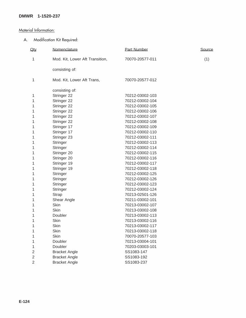
Material Information:
A. Modification Kit Required:
Qty Nomenclature Part Number Source
1 Mod. Kit, Lower Aft Transition, 70070-20577-011 (1)
consisting of:
1 Mod. Kit, Lower Aft Trans, 70070-20577-012
consisting of:1 Stringer 22 70212-03002-1031 Stringer 22 70212-03002-1041 Stringer 22 70212-03002-1051 Stringer 22 70212-03002-1061 Stringer 22 70212-03002-1071 Stringer 22 70212-03002-1081 Stringer 17 70212-03002-1091 Stringer 17 70212-03002-1101 Stringer 23 70212-03002-1111 Stringer 70212-03002-1131 Stringer 70212-03002-1141 Stringer 20 70212-03002-1151 Stringer 20 70212-03002-1161 Stringer 19 70212-03002-1171 Stringer 19 70212-03002-1181 Stringer 70212-03002-1251 Stringer 70212-03002-1261 Stringer 70212-03002-1231 Stringer 70212-03002-1241 Strap 70213-02501-1261 Shear Angle 70211-03002-1011 Skin 70213-03002-1071 Skin 70213-03002-1081 Doubler 70213-03002-1131 Skin 70213-03002-1161 Skin 70213-03002-1171 Skin 70213-03002-1181 Skin 70070-20577-1031 Doubler 70213-03004-1011 Doubler 70203-03003-1012 Bracket Angle SS1083-1472 Bracket Angle SS1083-1922 Bracket Angle SS1083-237
DMWR 1-1520-237
E-124

Qty Nomenclature Part Number Source
1 Mod. Kit, 70070-20577-013
consisting of:1 Beam Assy 70070-20577-0411 Beam Assy 70070-20577-0421 Intercostal 70211-03003-1011 Intercostal 70211-03003-1021 Intercostal 70211-03003-1031 Intercostal 70211-03003-1041 Angle 70211-03003-1141 Angle 70211-03003-1152 Gusset 70211-03003-1161 Gusset 70211-03003-1171 Gusset 70211-03003-1181 Intercostal 70211-03004-1011 Intercostal 70211-03004-1021 Stiffener 70211-03004-1031 Stiffener 70211-03003-1041 Intercostal 70211-03004-1051 Intercostal 70211-03004-1062 Stiffener 70211-03004-1072 Stiffener 70211-03004-1084 Angle 70211-03004-1174 Angle 70211-03004-1184 Angle 70211-03004-1194 Angle 70211-03004-1202 Angle 70211-03004-1212 Angle 70211-03004-1221 Angle 70211-03004-1261 Angle 70211-03004-1271 Intercostal 70211-03005-1011 Intercostal 70211-03005-1021 Intercostal 70211-03005-1031 Intercostal 70211-03005-1041 Angle 70211-03005-1151 Angle 70211-03005-1162 Angle 70211-03005-1172 Angle 70211-03005-1181 Angle 70211-03005-1201 Angle 70211-03005-1211 Frame 70211-03006-1011 Frame 70211-03006-1021 Frame 70211-03006-1031 Frame 70211-03006-1044 Gusset 70211-03006-1141 Angle 70211-03006-1151 Angle 70211-03006-1161 Shear Angle 70211-03007-185
DMWR 1-1520-237
E-125

Qty Nomenclature Part Number Source
1 Beam Assy 70212-03003-0411 Beam Assy 70212-03003-042$1 Beam Assy 70212-03003-544$1 Beam Assy 70212-03003-5481 Beam Assy 70212-03003-0411 Beam Assy 70212-03003-042$1 Beam Assy 70212-03003-554$1 Beam Assy 70212-03003-5551 Angle Cap 70212-03003-1151 Angle Cap 70212-03003-1161 Stringer BL10 70212-03003-1191 Stringer BL10 70212-03003-120
&Ref Angle Splice 70212-03003-131&Ref Angle Splice 70212-03003-132&Ref Angle Splice 70212-03003-141&Ref Angle Splice 70212-03003-142
1 Mod. Kit, 70070-20577-014
consisting of:8 Bolt AN173-14A12 Bolt AN173-15A5 Pin Collar Assy HL20PB86-6-105 Pin Collar Assy HL20PB86-6-810 Pin Collar Assy HL20PB86-6-918 Collar HL86TW-614 Rivet MS20426AD3-245 Rivet MS20426AD3-410 Rivet MS20426AD5-226 Rivet MS20470AD4-2
1000 Rivet MS20470AD5-21385 Rivet MS20470AD5-3400 Rivet MS20470AD5-4125 Rivet MS20470AD5-522 Rivet MS20470AD6-2380 Rivet MS20470AD6-365 Rivet MS20470AD6-458 Rivet MS20470AD6-518 Nut MS21044N322 Nutplate MS21059-316 Nutplate MS21075-3170 Collar NAS1080C0630 Rivet NAS1097AD4-3140 Rivet NAS1097AD5-435 Washer Flat NAS1149F0332P14 Pin, Swg Lkg NAS1436-0346 Pin, Swg Lkg NAS1446-0328 Pin, Swg Lkg NAS1446-0426 Pin, Swg Lkg NAS1446-05
DMWR 1-1520-237
E-126
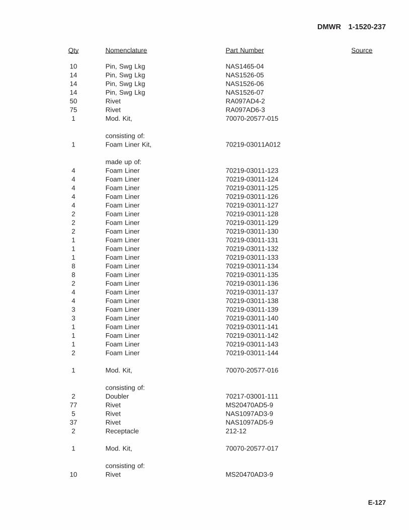
Qty Nomenclature Part Number Source
10 Pin, Swg Lkg NAS1465-0414 Pin, Swg Lkg NAS1526-0514 Pin, Swg Lkg NAS1526-0614 Pin, Swg Lkg NAS1526-0750 Rivet RA097AD4-275 Rivet RA097AD6-31 Mod. Kit, 70070-20577-015
consisting of:1 Foam Liner Kit, 70219-03011A012
made up of:4 Foam Liner 70219-03011-1234 Foam Liner 70219-03011-1244 Foam Liner 70219-03011-1254 Foam Liner 70219-03011-1264 Foam Liner 70219-03011-1272 Foam Liner 70219-03011-1282 Foam Liner 70219-03011-1292 Foam Liner 70219-03011-1301 Foam Liner 70219-03011-1311 Foam Liner 70219-03011-1321 Foam Liner 70219-03011-1338 Foam Liner 70219-03011-1348 Foam Liner 70219-03011-1352 Foam Liner 70219-03011-1364 Foam Liner 70219-03011-1374 Foam Liner 70219-03011-1383 Foam Liner 70219-03011-1393 Foam Liner 70219-03011-1401 Foam Liner 70219-03011-1411 Foam Liner 70219-03011-1421 Foam Liner 70219-03011-1432 Foam Liner 70219-03011-144
1 Mod. Kit, 70070-20577-016
consisting of:2 Doubler 70217-03001-11177 Rivet MS20470AD5-95 Rivet NAS1097AD3-937 Rivet NAS1097AD5-92 Receptacle 212-12
1 Mod. Kit, 70070-20577-017
consisting of:10 Rivet MS20470AD3-9
DMWR 1-1520-237
E-127

Qty Nomenclature Part Number Source
60 Rivet MS20470AD5-94 Nutplate MS21075-34 Screw MS27039-1-105 Rivet NAS1097AD4-95 Rivet, Blind NAS1739B4-22 Rivet, Blind NAS1739B5-230 Rivet, Blind NAS1739B5-3
$ Beam assemblies (70212-03003-544, 70212-03003-548, 70212-03003-554, and 70212-03003-555) are suppliedin place of (70212-03003-044, 70212-03003-048, 70212-03003-054, and 70212-03003-055).
& Angle splices (70212-03003-131, 70212-03003-132, 70212-03003-141, and 70212-03003-142) are not used.They are preassembled onto the above mentioned beam assemblies.
B. Consumable Material:
WARNING
OBSERVE ALL CAUTIONS AND WARNINGS ON CONTAINERS WHEN USING CONSUMABLES.WHEN APPLICABLE, WEAR NECESSARY PROTECTIVE GEAR DURING HANDLING AND USE. IF ACONSUMABLE IS FLAMMABLE OR EXPLOSIVE, MAKE CERTAIN CONSUMABLE AND ITS VAPORS AREKEPT AWAY FROM HEAT, SPARK, AND FLAME. MAKE CERTAIN EQUIPMENT IS PROPERLYGROUNDED AND FIREFIGHTING EQUIPMENT IS READILY AVAILABLE PRIOR TO USE. FOR AD-DITIONAL INFORMATION ON TOXICITY, FLASHPOINT, AND FLAMMABILITY OF CHEMICALS,CONSULT YOUR MEDICAL PEOPLE, OR MANUFACTURER OF THE CONSUMABLE.
Qty Nomenclature Part Number Source
8 oz. Sealant AMS 3265, Class A or C orequivalent
(1)
8 oz. Corrosion Preventive Compound Dinotrol Av30 or Av15 orequivalent
(1)
8 oz. Primer, Epoxy MIL-P-85582 or equivalent (1)8 oz. Urethane MIL-C-85285 or equivalent (1)8 oz. Adhesive 444R or equivalent (1)
C. Support Equipment:
Qty Nomenclature Part Number Source
1 Locally designed andmanufactured fuselage supports
N/A (2)
D. Source
(1) Available through normal supply channels.
(2) Locally fabricated
DMWR 1-1520-237
E-128

1
14
7
16
A
58
82SA
AB3095_1
STA485
STA424.9
STA379
BL0.0
BL
LH40
BL
RH40
A
Figure E-11. Lower Aft Transition Modification Kit (Sheet 1 of 8)
DMWR 1-1520-237
E-129
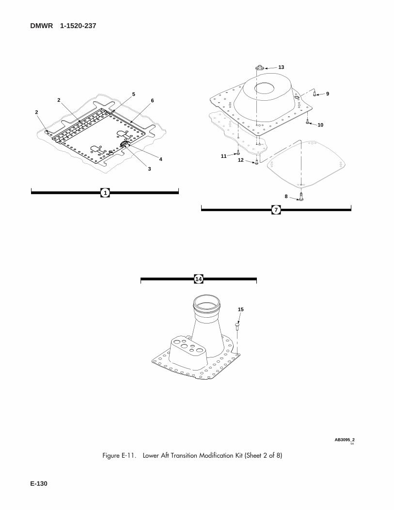
15
2 6
4
3
2
5
8
9
10
1112
13
1
7
14
SAAB3095_2
Figure E-11. Lower Aft Transition Modification Kit (Sheet 2 of 8)
DMWR 1-1520-237
E-130

SAAB3095_3
46
STA485
STA424.9
STA379
BL0.0
BL
LH40
BL
RH40
16
43 49
454851
444750
333435363753
263233343537404142
333435363740414252
2426
19212737545556
172829
2557
3334353637
181920212223242526
2426303132
17
1819203839
43
46
49
Figure E-11. Lower Aft Transition Modification Kit (Sheet 3 of 8)
DMWR 1-1520-237
E-131
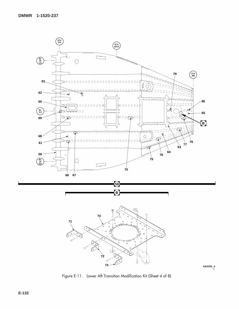
SAAB3095_4
STA485
STA424.9
STA379
BL0.0
BL
LH40
BL
RH40
58
59
60
61
62
63
64
65
66 67
68
69
70
7576
7778
79
80
71
72
73
74
B
B
81
Figure E-11. Lower Aft Transition Modification Kit (Sheet 4 of 8)
DMWR 1-1520-237
E-132

SAAB3095_5
STA485
STA424.9
STA379
BL0.0
BL
LH40
BL
RH40
82
84
92
84
92
109
116
109
116
172
129
130131132133134135136137138
139140141142143144145146147148149150151152153154
147148149
156157158159160161162163164
155
165166167168169170171
Figure E-11. Lower Aft Transition Modification Kit (Sheet 5 of 8)
DMWR 1-1520-237
E-133
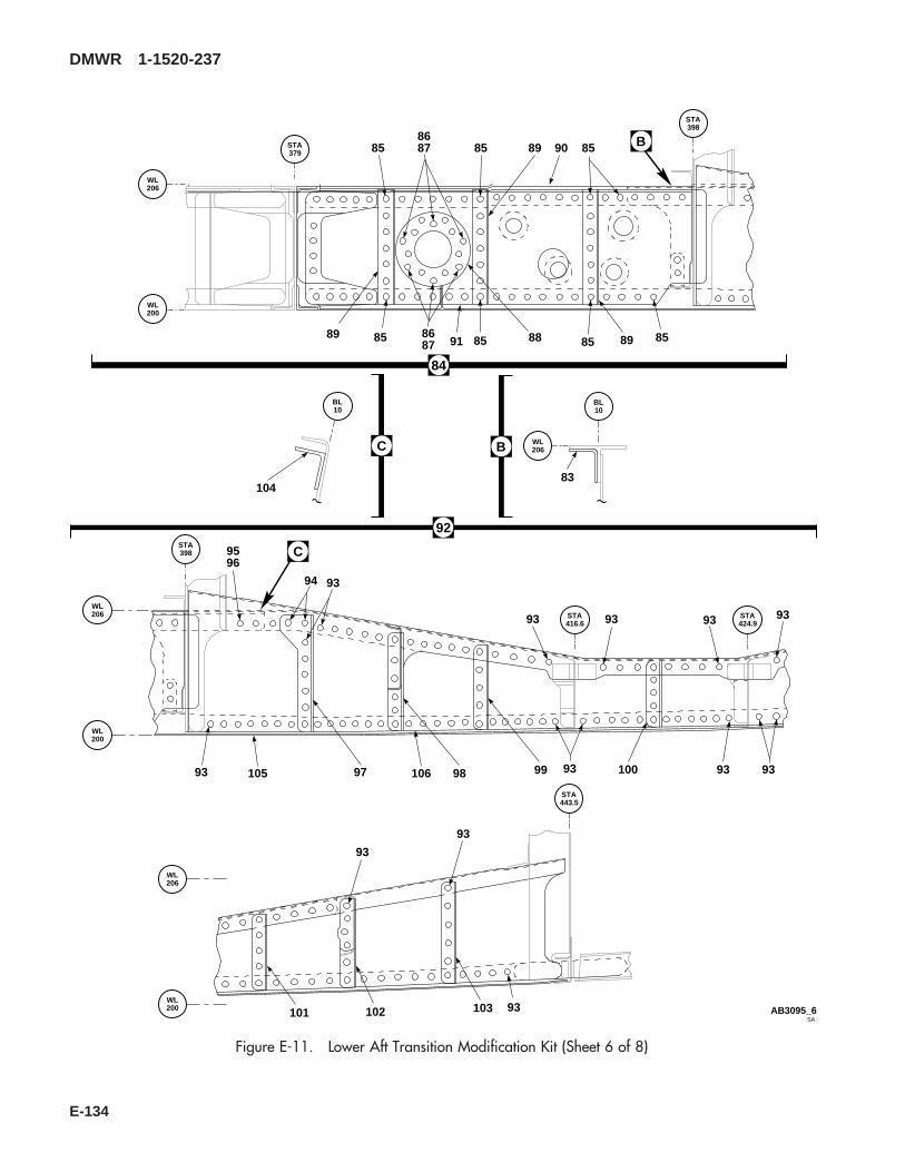
STA398
STA416.6
STA424.9
BL10
WL206
WL206
WL200
STA379
STA398
WL206
WL200
STA443.5
WL206
WL200
92
BL10
SAAB3095_6
83
91
90
85 85 85 85
85 85 858687
8687
88
89
89 89
9596
97 98 99 100
101 102 103
104
105 10693 93 9393
93
94
93
93
93 93 93 93
93
84
B
B
C
C
Figure E-11. Lower Aft Transition Modification Kit (Sheet 6 of 8)
DMWR 1-1520-237
E-134
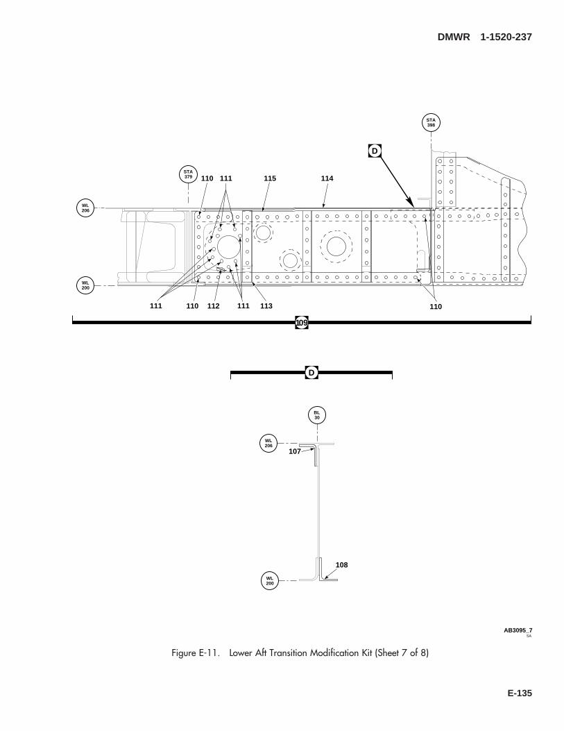
111
112 113
114115
107
108
110
110
110111111
STA379
STA398
BL30
WL206
WL200
WL200
WL206
SAAB3095_7
D
D
109
Figure E-11. Lower Aft Transition Modification Kit (Sheet 7 of 8)
DMWR 1-1520-237
E-135

128
126
127
BL30
STA398
WL206
WL200
STA443.5
STA416.6
STA424.9
WL200
WL206
SAAB3095_8
117
118
119120
121 122
123
124
125
128
117
117
117
117
117
117 117
117
117
117
117
117
117117
117117
E
E
116
Figure E-11. Lower Aft Transition Modification Kit (Sheet 8 of 8)
DMWR 1-1520-237
E-136

E-11- 70070-20577-011 LOWER AFT TRANSITION MODIFICATION KIT....... REF-1 70070-20577-016 . M/K DOOR INSTL .................................................... 1-2 MS20470AD5-9 . . RIVET..................................................................... 77-3 NAS1097AD3-9 . . RIVET..................................................................... 5-4 212-12 . . RECEPTACLE, (71286)........................................ 2-5 NAS1097AD5-9 . . RIVET..................................................................... 37-6 70217-03001-111 . . DOUBLER.............................................................. 2-7 70070-20577-017 . M/K FUEL DUMP...................................................... 1-8 MS27039-1-10 . . SCREW.................................................................. 4-9 NAS1739B5-3 . . BLIND RIVET......................................................... 30
-10 NAS1739B4-2 . . BLIND RIVET......................................................... 5NAS1097AD4-9 . . RIVET..................................................................... 5 *NAS1739B5-2 . . BLIND RIVET......................................................... 2 *
-11 MS20470AD5-9 . . RIVET..................................................................... 60-12 MS20470AD3-9 . . RIVET..................................................................... 10-13 MS21075-3 . . NUTPLATE ............................................................ 4-14 70070-20577-018 . M/K FUEL VENT....................................................... 1-15 NAS1738B5-3 . . BLIND RIVET......................................................... 42-16 70070-20577-014 . M/K HARDWARE...................................................... 1-17 NAS1097AD5-4 . . RIVET..................................................................... 140-18 MS20470AD5-2 . . RIVET..................................................................... 1000-19 MS20470AD5-3 . . RIVET..................................................................... 1385-20 MS20470AD5-4 . . RIVET..................................................................... 400-21 MS20470AD6-3 . . RIVET..................................................................... 380-22 MS20470AD6-5 . . RIVET..................................................................... 58-23 MS20470AD5-5 . . RIVET..................................................................... 125-24 NAS1446-04 . . SWAGE LOCKING PIN ......................................... 28-25 NAS1446-05 . . SWAGE LOCKING PIN ......................................... 26-26 NAS1080C06 . . COLLAR................................................................. 170-27 MS20470AD6-4 . . RIVET..................................................................... 65-28 MS20426AD3-4 . . RIVET..................................................................... 45-29 MS21059-3 . . NUTPLATE ............................................................ 22-30 RA097AD6-3 . . RIVET..................................................................... 75-31 NAS1436-03 . . SWAGE LOCKING PIN ......................................... 14-32 NAS1446-03 . . SWAGE LOCKING PIN ......................................... 46-33 AN173-14A . . BOLT...................................................................... 8-34 AN173-15A . . BOLT...................................................................... 12-35 NAS1149F0332P . . FLAT WASHER ..................................................... 35-36 MS21044N3 . . NUT........................................................................ 18-37 NAS1097AD4-3 . . RIVET..................................................................... 30-38 MS20470AD6-2 . . RIVET..................................................................... 22-39 MS20426AD5-2 . . RIVET..................................................................... 10-40 NAS1526-05 . . SWAGE LOCKING PIN ......................................... 14-41 NAS1526-06 . . SWAGE LOCKING PIN ......................................... 14-42 NAS1526-07 . . SWAGE LOCKING PIN ......................................... 14-43 HL20PB86-6-8 . . PIN COLLAR ASSY, (73197) ............................... 5-44 HL20PB-6-8 . . . HI-LOK PIN, (73197).......................................... 1-45 HL86-6 . . . COLLAR, (73197) (Superseded by HL1087A-
6) ......................................................................... 1HL1087A-6 . . . COLLAR, (73197) .............................................. 1
-46 HL20PB86-6-9 . . PIN COLLAR ASSY, (73197) ............................... 10-47 HL20PB-6-9 . . . HI-LOK PIN, (73197).......................................... 1-48 HL86-6 . . . COLLAR, (73197) (Superseded by HL1087A-
6) ......................................................................... 1HL1087A-6 . . . COLLAR, (73197) .............................................. 1
-49 HL20PB86-6-10 . . PIN COLLAR ASSY, (73197) ............................... 5-50 HL20PB-6-10 . . . HI-LOK PIN, (73197).......................................... 1-51 HL86-6 . . . COLLAR, (73197) (Superseded by HL1087A-
6) ......................................................................... 1HL1087A-6 . . . COLLAR, (73197) .............................................. 1
-52 HL86TW-6 . . COLLAR, (73197) ................................................. 18
DMWR 1-1520-237
QTY USABLEFIGURE & PER ONINDEX NO. PART NUMBER 1 2 3 4 5 6 7 DESCRIPTION ASSY CODE
E-137
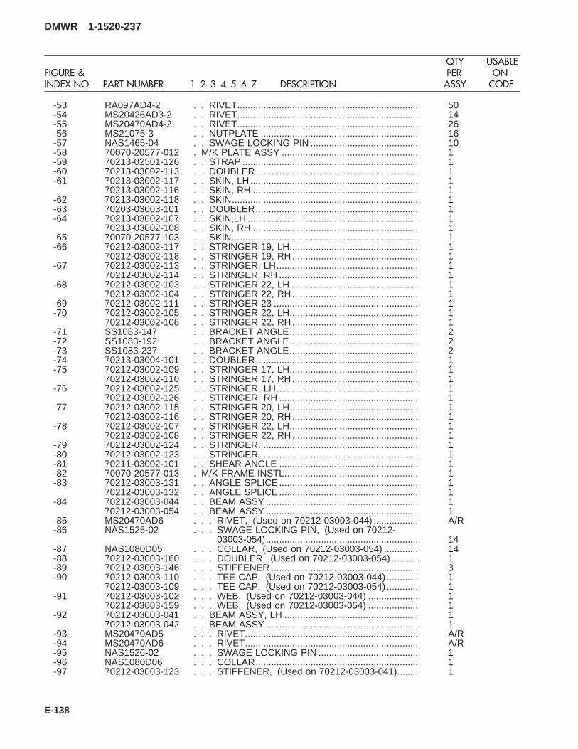
-53 RA097AD4-2 . . RIVET..................................................................... 50-54 MS20426AD3-2 . . RIVET..................................................................... 14-55 MS20470AD4-2 . . RIVET..................................................................... 26-56 MS21075-3 . . NUTPLATE ............................................................ 16-57 NAS1465-04 . . SWAGE LOCKING PIN ......................................... 10-58 70070-20577-012 . M/K PLATE ASSY .................................................... 1-59 70213-02501-126 . . STRAP ................................................................... 1-60 70213-03002-113 . . DOUBLER.............................................................. 1-61 70213-03002-117 . . SKIN, LH................................................................ 1
70213-03002-116 . . SKIN, RH ............................................................... 1-62 70213-03002-118 . . SKIN....................................................................... 1-63 70203-03003-101 . . DOUBLER.............................................................. 1-64 70213-03002-107 . . SKIN,LH ................................................................. 1
70213-03002-108 . . SKIN, RH ............................................................... 1-65 70070-20577-103 . . SKIN....................................................................... 1-66 70212-03002-117 . . STRINGER 19, LH................................................. 1
70212-03002-118 . . STRINGER 19, RH................................................ 1-67 70212-03002-113 . . STRINGER, LH...................................................... 1
70212-03002-114 . . STRINGER, RH ..................................................... 1-68 70212-03002-103 . . STRINGER 22, LH................................................. 1
70212-03002-104 . . STRINGER 22, RH................................................ 1-69 70212-03002-111 . . STRINGER 23 ....................................................... 1-70 70212-03002-105 . . STRINGER 22, LH................................................. 1
70212-03002-106 . . STRINGER 22, RH................................................ 1-71 SS1083-147 . . BRACKET ANGLE................................................. 2-72 SS1083-192 . . BRACKET ANGLE................................................. 2-73 SS1083-237 . . BRACKET ANGLE................................................. 2-74 70213-03004-101 . . DOUBLER.............................................................. 1-75 70212-03002-109 . . STRINGER 17, LH................................................. 1
70212-03002-110 . . STRINGER 17, RH................................................ 1-76 70212-03002-125 . . STRINGER, LH...................................................... 1
70212-03002-126 . . STRINGER, RH ..................................................... 1-77 70212-03002-115 . . STRINGER 20, LH................................................. 1
70212-03002-116 . . STRINGER 20, RH................................................ 1-78 70212-03002-107 . . STRINGER 22, LH................................................. 1
70212-03002-108 . . STRINGER 22, RH................................................ 1-79 70212-03002-124 . . STRINGER............................................................. 1-80 70212-03002-123 . . STRINGER............................................................. 1-81 70211-03002-101 . . SHEAR ANGLE ..................................................... 1-82 70070-20577-013 . M/K FRAME INSTL................................................... 1-83 70212-03003-131 . . ANGLE SPLICE..................................................... 1
70212-03003-132 . . ANGLE SPLICE..................................................... 1-84 70212-03003-044 . . BEAM ASSY .......................................................... 1
70212-03003-054 . . BEAM ASSY .......................................................... 1-85 MS20470AD6 . . . RIVET, (Used on 70212-03003-044) ................. A/R-86 NAS1525-02 . . . SWAGE LOCKING PIN, (Used on 70212-
03003-054).......................................................... 14-87 NAS1080D05 . . . COLLAR, (Used on 70212-03003-054) ............. 14-88 70212-03003-160 . . . DOUBLER, (Used on 70212-03003-054) .......... 1-89 70212-03003-146 . . . STIFFENER ........................................................ 3-90 70212-03003-110 . . . TEE CAP, (Used on 70212-03003-044) ............ 1
70212-03003-109 . . . TEE CAP, (Used on 70212-03003-054) ............ 1-91 70212-03003-102 . . . WEB, (Used on 70212-03003-044) ................... 1
70212-03003-159 . . . WEB, (Used on 70212-03003-054) ................... 1-92 70212-03003-041 . . BEAM ASSY, LH ................................................... 1
70212-03003-042 . . BEAM ASSY .......................................................... 1-93 MS20470AD5 . . . RIVET.................................................................. A/R-94 MS20470AD6 . . . RIVET.................................................................. A/R-95 NAS1526-02 . . . SWAGE LOCKING PIN ...................................... 1-96 NAS1080D06 . . . COLLAR.............................................................. 1-97 70212-03003-123 . . . STIFFENER, (Used on 70212-03003-041)........ 1
DMWR 1-1520-237
QTY USABLEFIGURE & PER ONINDEX NO. PART NUMBER 1 2 3 4 5 6 7 DESCRIPTION ASSY CODE
E-138
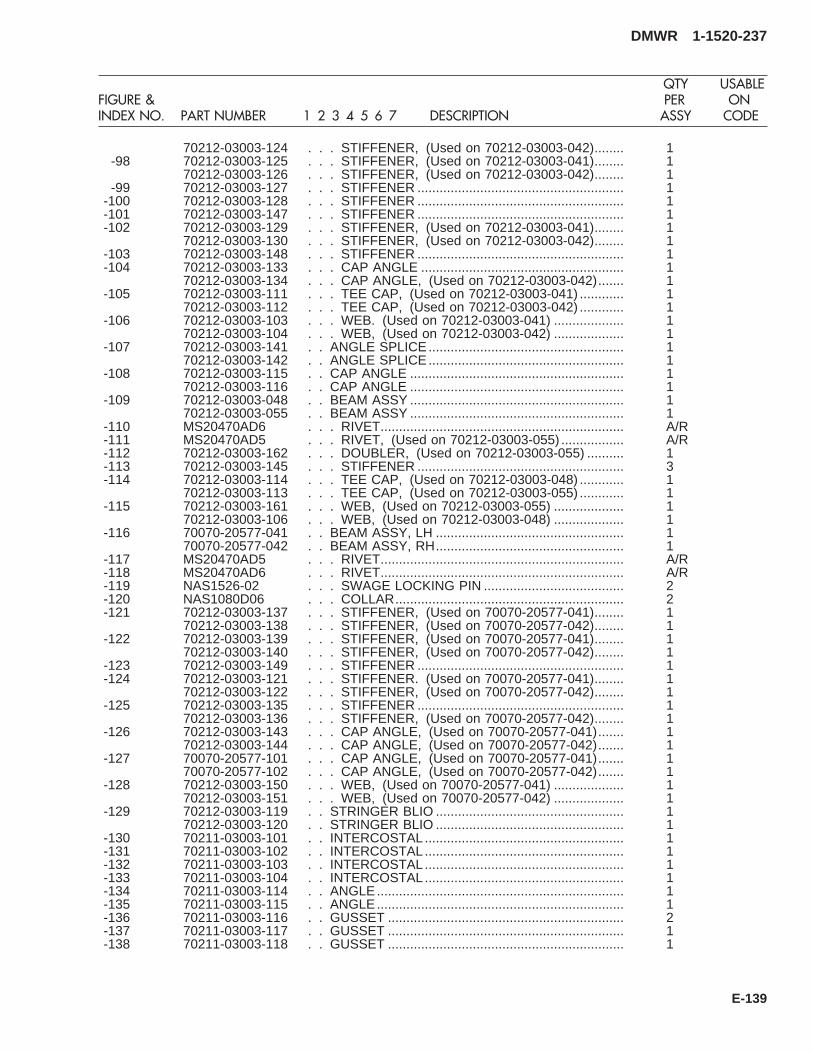
70212-03003-124 . . . STIFFENER, (Used on 70212-03003-042)........ 1-98 70212-03003-125 . . . STIFFENER, (Used on 70212-03003-041)........ 1
70212-03003-126 . . . STIFFENER, (Used on 70212-03003-042)........ 1-99 70212-03003-127 . . . STIFFENER ........................................................ 1
-100 70212-03003-128 . . . STIFFENER ........................................................ 1-101 70212-03003-147 . . . STIFFENER ........................................................ 1-102 70212-03003-129 . . . STIFFENER, (Used on 70212-03003-041)........ 1
70212-03003-130 . . . STIFFENER, (Used on 70212-03003-042)........ 1-103 70212-03003-148 . . . STIFFENER ........................................................ 1-104 70212-03003-133 . . . CAP ANGLE ....................................................... 1
70212-03003-134 . . . CAP ANGLE, (Used on 70212-03003-042)....... 1-105 70212-03003-111 . . . TEE CAP, (Used on 70212-03003-041) ............ 1
70212-03003-112 . . . TEE CAP, (Used on 70212-03003-042) ............ 1-106 70212-03003-103 . . . WEB. (Used on 70212-03003-041) ................... 1
70212-03003-104 . . . WEB, (Used on 70212-03003-042) ................... 1-107 70212-03003-141 . . ANGLE SPLICE..................................................... 1
70212-03003-142 . . ANGLE SPLICE..................................................... 1-108 70212-03003-115 . . CAP ANGLE .......................................................... 1
70212-03003-116 . . CAP ANGLE .......................................................... 1-109 70212-03003-048 . . BEAM ASSY .......................................................... 1
70212-03003-055 . . BEAM ASSY .......................................................... 1-110 MS20470AD6 . . . RIVET.................................................................. A/R-111 MS20470AD5 . . . RIVET, (Used on 70212-03003-055) ................. A/R-112 70212-03003-162 . . . DOUBLER, (Used on 70212-03003-055) .......... 1-113 70212-03003-145 . . . STIFFENER ........................................................ 3-114 70212-03003-114 . . . TEE CAP, (Used on 70212-03003-048) ............ 1
70212-03003-113 . . . TEE CAP, (Used on 70212-03003-055) ............ 1-115 70212-03003-161 . . . WEB, (Used on 70212-03003-055) ................... 1
70212-03003-106 . . . WEB, (Used on 70212-03003-048) ................... 1-116 70070-20577-041 . . BEAM ASSY, LH ................................................... 1
70070-20577-042 . . BEAM ASSY, RH................................................... 1-117 MS20470AD5 . . . RIVET.................................................................. A/R-118 MS20470AD6 . . . RIVET.................................................................. A/R-119 NAS1526-02 . . . SWAGE LOCKING PIN ...................................... 2-120 NAS1080D06 . . . COLLAR.............................................................. 2-121 70212-03003-137 . . . STIFFENER, (Used on 70070-20577-041)........ 1
70212-03003-138 . . . STIFFENER, (Used on 70070-20577-042)........ 1-122 70212-03003-139 . . . STIFFENER, (Used on 70070-20577-041)........ 1
70212-03003-140 . . . STIFFENER, (Used on 70070-20577-042)........ 1-123 70212-03003-149 . . . STIFFENER ........................................................ 1-124 70212-03003-121 . . . STIFFENER. (Used on 70070-20577-041)........ 1
70212-03003-122 . . . STIFFENER, (Used on 70070-20577-042)........ 1-125 70212-03003-135 . . . STIFFENER ........................................................ 1
70212-03003-136 . . . STIFFENER, (Used on 70070-20577-042)........ 1-126 70212-03003-143 . . . CAP ANGLE, (Used on 70070-20577-041)....... 1
70212-03003-144 . . . CAP ANGLE, (Used on 70070-20577-042)....... 1-127 70070-20577-101 . . . CAP ANGLE, (Used on 70070-20577-041)....... 1
70070-20577-102 . . . CAP ANGLE, (Used on 70070-20577-042)....... 1-128 70212-03003-150 . . . WEB, (Used on 70070-20577-041) ................... 1
70212-03003-151 . . . WEB, (Used on 70070-20577-042) ................... 1-129 70212-03003-119 . . STRINGER BLIO ................................................... 1
70212-03003-120 . . STRINGER BLIO ................................................... 1-130 70211-03003-101 . . INTERCOSTAL...................................................... 1-131 70211-03003-102 . . INTERCOSTAL...................................................... 1-132 70211-03003-103 . . INTERCOSTAL...................................................... 1-133 70211-03003-104 . . INTERCOSTAL...................................................... 1-134 70211-03003-114 . . ANGLE................................................................... 1-135 70211-03003-115 . . ANGLE................................................................... 1-136 70211-03003-116 . . GUSSET ................................................................ 2-137 70211-03003-117 . . GUSSET ................................................................ 1-138 70211-03003-118 . . GUSSET ................................................................ 1
DMWR 1-1520-237
QTY USABLEFIGURE & PER ONINDEX NO. PART NUMBER 1 2 3 4 5 6 7 DESCRIPTION ASSY CODE
E-139
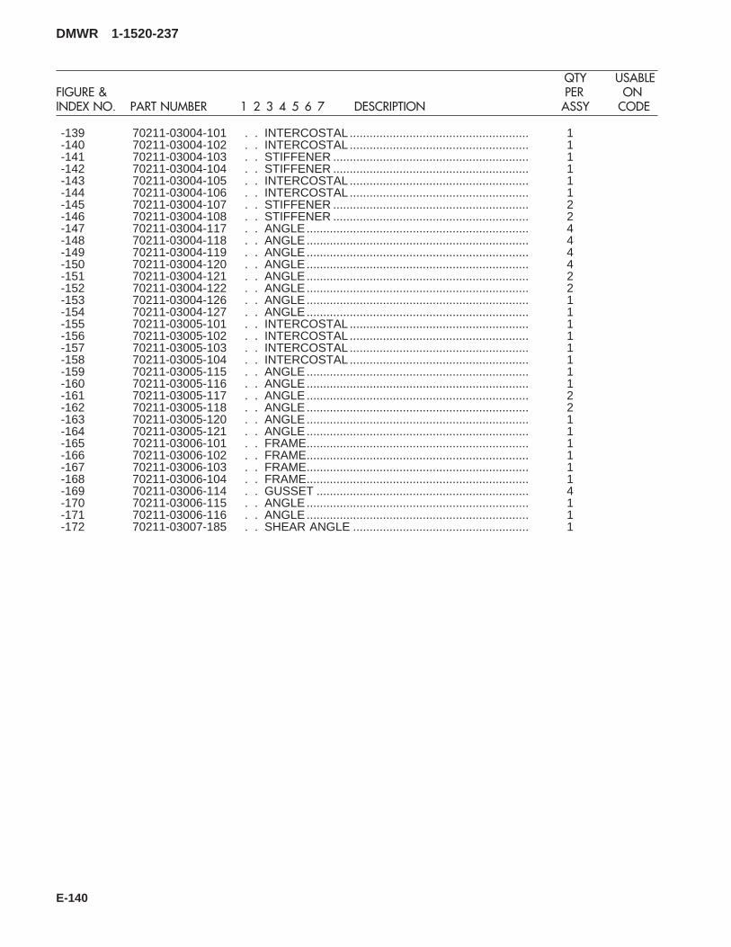
-139 70211-03004-101 . . INTERCOSTAL...................................................... 1-140 70211-03004-102 . . INTERCOSTAL...................................................... 1-141 70211-03004-103 . . STIFFENER ........................................................... 1-142 70211-03004-104 . . STIFFENER ........................................................... 1-143 70211-03004-105 . . INTERCOSTAL...................................................... 1-144 70211-03004-106 . . INTERCOSTAL...................................................... 1-145 70211-03004-107 . . STIFFENER ........................................................... 2-146 70211-03004-108 . . STIFFENER ........................................................... 2-147 70211-03004-117 . . ANGLE................................................................... 4-148 70211-03004-118 . . ANGLE................................................................... 4-149 70211-03004-119 . . ANGLE................................................................... 4-150 70211-03004-120 . . ANGLE................................................................... 4-151 70211-03004-121 . . ANGLE................................................................... 2-152 70211-03004-122 . . ANGLE................................................................... 2-153 70211-03004-126 . . ANGLE................................................................... 1-154 70211-03004-127 . . ANGLE................................................................... 1-155 70211-03005-101 . . INTERCOSTAL...................................................... 1-156 70211-03005-102 . . INTERCOSTAL...................................................... 1-157 70211-03005-103 . . INTERCOSTAL...................................................... 1-158 70211-03005-104 . . INTERCOSTAL...................................................... 1-159 70211-03005-115 . . ANGLE................................................................... 1-160 70211-03005-116 . . ANGLE................................................................... 1-161 70211-03005-117 . . ANGLE................................................................... 2-162 70211-03005-118 . . ANGLE................................................................... 2-163 70211-03005-120 . . ANGLE................................................................... 1-164 70211-03005-121 . . ANGLE................................................................... 1-165 70211-03006-101 . . FRAME................................................................... 1-166 70211-03006-102 . . FRAME................................................................... 1-167 70211-03006-103 . . FRAME................................................................... 1-168 70211-03006-104 . . FRAME................................................................... 1-169 70211-03006-114 . . GUSSET ................................................................ 4-170 70211-03006-115 . . ANGLE................................................................... 1-171 70211-03006-116 . . ANGLE................................................................... 1-172 70211-03007-185 . . SHEAR ANGLE ..................................................... 1
DMWR 1-1520-237
QTY USABLEFIGURE & PER ONINDEX NO. PART NUMBER 1 2 3 4 5 6 7 DESCRIPTION ASSY CODE
E-140

11
11
12
12
14
14
A
2
2
2
4
4
4
6 7
9 10
8
1 3
3
1
1 3
3
1
5
5
13
A
SAAB3094
1516
1718
19
1716
15
18
1516
1718
19
1716 15
18
22
20
21
21
20
21
22
20
20
Figure E-12. Foam Liner Modification Kit
DMWR 1-1520-237
E-141
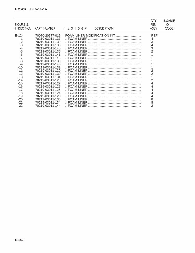
E-12- 70070-20577-015 FOAM LINER MODIFICATION KIT............................. REF-1 70219-03011-137 . FOAM LINER............................................................ 4-2 70219-03011-139 . FOAM LINER............................................................ 3-3 70219-03011-138 . FOAM LINER............................................................ 4-4 70219-03011-140 . FOAM LINER............................................................ 3-5 70219-03011-136 . FOAM LINER............................................................ 2-6 70219-03011-141 . FOAM LINER............................................................ 1-7 70219-03011-142 . FOAM LINER............................................................ 1-8 70219-03011-133 . FOAM LINER............................................................ 1-9 70219-03011-143 . FOAM LINER............................................................ 1
-10 70219-03011-132 . FOAM LINER............................................................ 1-11 70219-03011-129 . FOAM LINER............................................................ 2-12 70219-03011-130 . FOAM LINER............................................................ 2-13 70219-03011-131 . FOAM LINER............................................................ 1-14 70219-03011-128 . FOAM LINER............................................................ 2-15 70219-03011-127 . FOAM LINER............................................................ 4-16 70219-03011-126 . FOAM LINER............................................................ 4-17 70219-03011-125 . FOAM LINER............................................................ 4-18 70219-03011-124 . FOAM LINER............................................................ 4-19 70219-03011-123 . FOAM LINER............................................................ 4-20 70219-03011-135 . FOAM LINER............................................................ 8-21 70219-03011-134 . FOAM LINER............................................................ 8-22 70219-03011-144 . FOAM LINER............................................................ 2
DMWR 1-1520-237
QTY USABLEFIGURE & PER ONINDEX NO. PART NUMBER 1 2 3 4 5 6 7 DESCRIPTION ASSY CODE
E-142

E-13. ENCLOSURE MODIFICATION KIT (50-21).
Subject: Vapor Barrier Support Structure; Replacement of, dated 31 March 2003
Purpose: Provide instructions for the replacement of structure supporting vapor barriers above fuel cells.
Model: UH-60A
Description: The structure which supports vapor barrier between stations 413.00 and 443.50, right and left buttline10.00 is replaced.
Drawings required for modification:
70070-20578, 70219-03002, 70400-03611, 70551-03140, 70551-03101, 70551-03102
References: (a) Special Service Instructions (SSI) No. 50-31, Installation of 9A to A9 Recapitalization Program, datedMarch 31, 2003
(b) TM 1-1520-237-23, Technical Manual, Aviation Unit And Intermediate Maintenance For ArmyModels UH-60A, UH-60L, EH-60A and UH-60Q Helicopters, Chapter 10, Fuel Systems
Instructions:
NOTE
• A complete review of this SSI is recommended before incorporating the rework of vapor barrier.
• Before beginning this modification procedure, use the material information list to inventory the modificationkit. Make sure all parts are present and in serviceable condition.
• Where drawing numbers are not listed within individual step(s), drawing(s) listed in preceding step(s) arethe controlling authority.
• The electrical, sheet metal, and structural modifications in this SSI shall be done by personnel experiencedin reading modification drawings. Routine steps such as cleaning, layout and drilling, deburring, standardrepairs, corrosion control, clean up after rework, chemical coating for aluminum after cutting/trimmingparts, paint touch up, routing, clamping, and safety practices may not be called out herein. However, thesesteps and all other required routine tasks shall be done.
• When installing fasteners refer to drawing sheet and zones for applicable fasteners.
• Slight variations to the instructions contained herein are allowed, as long as the intent of the modificationis accomplished.
A. Preparation for modification and removal of equipment:
(1) Confirm that all warnings, cautions, and notes are complied with per reference (a).
(2) Perform preparation for modification per reference (a).
(3) Disconnect connectors and pull back wiring as required for rework of vapor barriers.
(4) Remove fuel lines as required for rework of vapor barriers per reference (b).
DMWR 1-1520-237
E-143
B. Rework of enclosure installation (70219-03002-012) as follows:
(1) Modification of enclosure installation (70219-03002-012) left side as follows:
CAUTION
TO AVOID DAMAGING COMPONENTS, USE EXTREME CARE WHEN DRILLING INTO AIRFRAME.TEMPORARILY MOVE ANY TUBE ASSEMBLIES OR WIRING HARNESSES OUT OF REWORK AREA.
(a) Remove bracket installation (70400-03611-012 or -016) as required to gain access to intercostal(70219-03002-111, -142, -143, or -151) keep parts as required for reinstallation (Dwg 70400-03611, Sheet 1, Zones10-B, 12-B, 13-E, 14-D, 16-B, 16-C, 16-F, 17-A, 17-C, and 17-H; Dwg 70070-20578, Sheet 1, Notes 13 and 14).
(b) Remove angle (70219-03002-133 or -153) as required to remove intercostal (70219-03002-111, -142,-143, or -151) keep parts as required for reinstallation (Dwg 70219-03002, Sheet 2, Zones 8-G and 16-B).
(c) Remove left side intercostal (70219-03002-111, -142, -143, or -151) (Dwg 70219-03002, Sheet 1,Zones 13-M and 14-M; Dwg 70070-20578, Sheet 1, Notes 7, 8, 9, and 10).
(d) Install four brackets (MS3341-2-9) on new intercostal (70070-20578-101) using hardware shown andold intercostal (70219-03002-111, -142, -143, or -151) as a template (Dwg 70551-03140, Sheet 3, View AC-AC,Zones 7-H, 8-H, and 9-H; Dwg 70070-20578, Sheet 1, Note 5).
WARNING
OBSERVE ALL CAUTIONS AND WARNINGS ON CONTAINERS WHEN USING CONSUMABLES.WHEN APPLICABLE, WEAR NECESSARY PROTECTIVE GEAR DURING HANDLING AND USE. IF ACONSUMABLE IS FLAMMABLE OR EXPLOSIVE, MAKE CERTAIN CONSUMABLE AND ITS VAPORS AREKEPT AWAY FROM HEAT, SPARK, AND FLAME. MAKE CERTAIN EQUIPMENT IS PROPERLYGROUNDED AND FIREFIGHTING EQUIPMENT IS READILY AVAILABLE PRIOR TO USE. FOR AD-DITIONAL INFORMATION ON TOXICITY, FLASHPOINT, AND FLAMMABILITY OF CHEMICALS,CONSULT YOUR MEDICAL PEOPLE, OR MANUFACTURER OF THE CONSUMABLE.
(e) Install grommet (MS21266-1N) on new intercostal (70070-20578-101) using adhesive (PLIOBOND NO.20, or equivalent) (Dwg 70219-03002, Sheet 1, Zone 10-L, Note 17).
(f) Install nameplates (SS9014J308 and SS9014J323) (Dwg 70070-20578, Sheet 1, Notes 19 and 20, Sheet2, Notes 21 and 22; Dwg 70551-03101, Sheet 2, Zones 11-C and 11-G; Dwg 70551-03102, Sheet 2, Zones 4-D, 4-Hand 7-D).
(g) Install intercostal (70070-20578-101) using hardware shown (Dwg 70219-03002, Sheet 1, Zones 13-Mand 14-M; Dwg 70070-20578, Sheet 1, Notes 4 and 5).
(h) Reinstall angle (70219-03002-133 or -153) using hardware shown (Dwg 70319-03002, Sheet 2, Zones8-G and 16-B).
DMWR 1-1520-237
E-144

(i) Reinstall bracket installation (70400-03611-012 or -016) using hardware shown (Dwg 70400-03611,Sheet 1, Zones 10-B, 12-B, 13-E, 14-D, 16-B, 16-C,16-F, 17-A, 17-C, 17-H, and Note 13; Dwg 70070-20578, Sheet1, Notes 15 and 16).
(2) Modification of enclosure installation (70219-03002-012) right side as follows:
CAUTION
TO AVOID DAMAGING COMPONENTS, USE EXTREME CARE WHEN DRILLING INTO AIRFRAME.TEMPORARILY MOVE ANY TUBE ASSEMBLIES OR WIRING HARNESSES OUT OF REWORK AREA.
(a) Remove bracket installation (70400-03611-011 or -015) as required to gain access to intercostal(70219-03002-112, -144, or -150) keep parts as required for reinstallation (Dwg 70400-03611, Sheet 1, Zones 10-B,12-B, 13-E, 14-D, 16-B, 16-C, 16-F, 17-A, 17-C, and 17-H; Dwg 70070-20578, Sheet 1, Notes 13 and 14).
(b) Remove angle (70219-03002-134 or -152) as required to remove intercostal (70219-03002-112, -144,or -150) keep parts as required for reinstallation (Dwg 70319-03002, Sheet 2, Zones 4-G and 16-G).
(c) Remove right side intercostal (70219-03002-112, -144, or -150) (Dwg 70219-03002, Sheet 1, Zones13-M and 14-M; Dwg 70070-20578, Sheet 1, Notes 7, 8, 9, and 10).
(d) Install three brackets (MS3341-2-9) on new intercostal (70070-20578-102) using hardware shown andold intercostal (70219-03002-112, -144, or -150) as a template (Dwg 70551-03140, Sheet 3, View AA-AA, Zone 7-Band Dwg 70070-20578, Sheet 1, Note 6).
(e) Install cover, protector (MS3181-10CA) to new intercostal (70070-20578-102) using hardware shown(Dwg 70551-03102, Sheet 2, Zones 3-C and 7-C).
(f) Install nameplates (SS9014J347, SS9014J307, and SS9014J322) (Dwg 70070-20578, Sheet 1, Notes19 and 20, Sheet 2, Notes 21 and 22; Dwg 70551-03101, Sheet 2, Zones 11-C and 11-G; Dwg 70551-03102, Sheet2, Zones 4-D, 4-H and 7-D).
WARNING
OBSERVE ALL CAUTIONS AND WARNINGS ON CONTAINERS WHEN USING CONSUMABLES.WHEN APPLICABLE, WEAR NECESSARY PROTECTIVE GEAR DURING HANDLING AND USE. IF ACONSUMABLE IS FLAMMABLE OR EXPLOSIVE, MAKE CERTAIN CONSUMABLE AND ITS VAPORS AREKEPT AWAY FROM HEAT, SPARK, AND FLAME. MAKE CERTAIN EQUIPMENT IS PROPERLYGROUNDED AND FIREFIGHTING EQUIPMENT IS READILY AVAILABLE PRIOR TO USE. FOR AD-DITIONAL INFORMATION ON TOXICITY, FLASHPOINT, AND FLAMMABILITY OF CHEMICALS,CONSULT YOUR MEDICAL PEOPLE, OR MANUFACTURER OF THE CONSUMABLE.
(g) Install grommet (MS21266-1N) on new intercostal (70070-20578-102) using adhesive (PLIOBONDNO.20 or equivalent) (Dwg 70219-03002, Sheet 1, Zone 10-L, Note 17).
(h) Install intercostal (70070-20578-102) using hardware shown (Dwg 70219-03002, Sheet 1, Zones 13-Mand 14-M; Dwg 70070-20578, Sheet 1, Notes 4 and 6).
DMWR 1-1520-237
E-145
(i) Reinstall angle (70219-03002-134 or -152) using hardware shown (Dwg 70219-03002, Sheet 2, Zones8-G and 16-B).
(j) Reinstall bracket installation (70400-03611-011 or -015) using hardware shown (Dwg 70400-03611,Sheet 1, Zones 10-B, 12-B, 13-E, 14-D, 16-B, 16-C,16-F, 17-A, 17-C, 17-H, and Note 13; Dwg 70070-20578, Sheet1, Notes 15 and 16).
C. Reinstallation of removed equipment:
(1) Reinstall removed wiring and reconnect connectors as required.
(2) Reinstall removed fuel lines as required per reference (b).
(3) Install removed equipment per reference (a).
D. Record of Compliance:
(1) Make an appropriate logbook entry to show compliance with this Special Service Instruction.
Weight and Balance Data:
QTY PART NO. NOMENCLATUREPOUNDSWEIGHT
INCHES AFTOF DATUM
MOMENT/1000
1 70070-20578-011 Mod. Kit +0.2 432.0 0.086
Weight and Balance: Change resulting from these instructions are as follows:
Change in basic weight: +0.2 pounds
Moment arm: 432.0 in.
Change in basic moment/1000: 0.086
Manpower (Estimated)
No. of Personel No. of Hours Man-hours
Sheet Metal Mechanic 1 24.0 *24.0Helicopter Electrican 1 8.0 *8.0Fuel Mechanic 1 2.0 *2.0
*Does not include time required to prepare helicopter or return it to flight status.
DMWR 1-1520-237
E-146
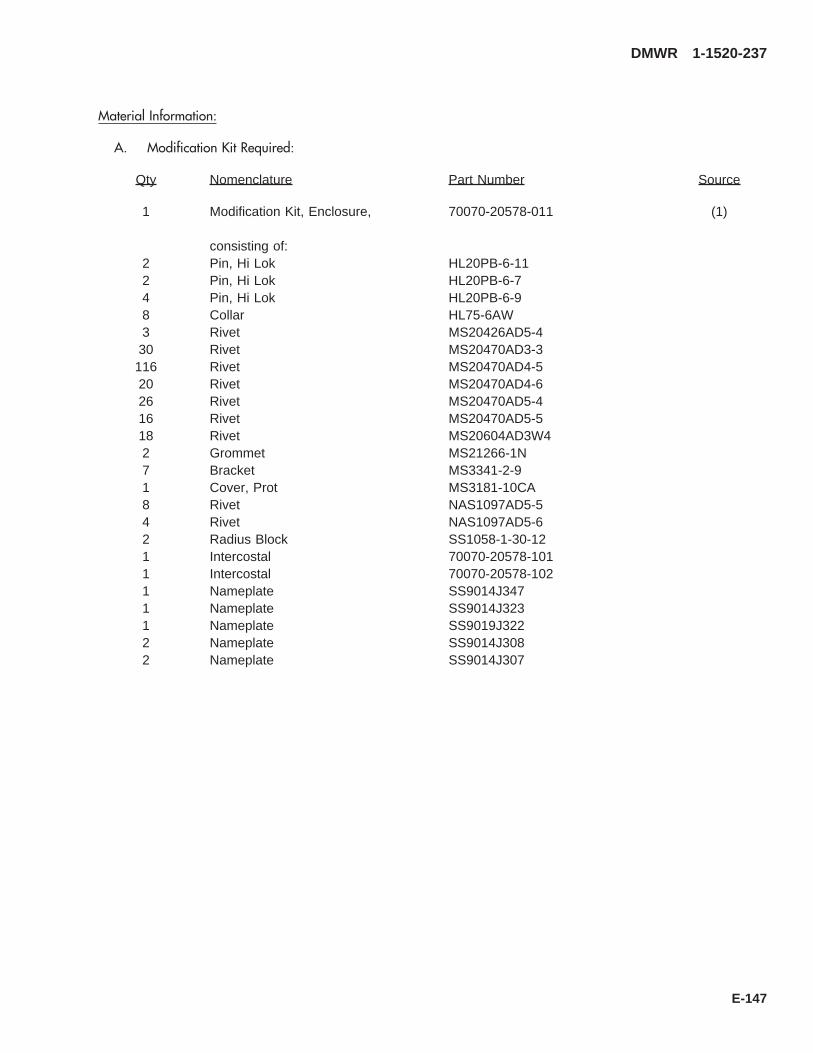
Material Information:
A. Modification Kit Required:
Qty Nomenclature Part Number Source
1 Modification Kit, Enclosure, 70070-20578-011 (1)
consisting of:2 Pin, Hi Lok HL20PB-6-112 Pin, Hi Lok HL20PB-6-74 Pin, Hi Lok HL20PB-6-98 Collar HL75-6AW3 Rivet MS20426AD5-430 Rivet MS20470AD3-3116 Rivet MS20470AD4-520 Rivet MS20470AD4-626 Rivet MS20470AD5-416 Rivet MS20470AD5-518 Rivet MS20604AD3W42 Grommet MS21266-1N7 Bracket MS3341-2-91 Cover, Prot MS3181-10CA8 Rivet NAS1097AD5-54 Rivet NAS1097AD5-62 Radius Block SS1058-1-30-121 Intercostal 70070-20578-1011 Intercostal 70070-20578-1021 Nameplate SS9014J3471 Nameplate SS9014J3231 Nameplate SS9019J3222 Nameplate SS9014J3082 Nameplate SS9014J307
DMWR 1-1520-237
E-147
B. Consumable Material:
WARNING
OBSERVE ALL CAUTIONS AND WARNINGS ON CONTAINERS WHEN USING CONSUMABLES.WHEN APPLICABLE, WEAR NECESSARY PROTECTIVE GEAR DURING HANDLING AND USE. IF ACONSUMABLE IS FLAMMABLE OR EXPLOSIVE, MAKE CERTAIN CONSUMABLE AND ITS VAPORS AREKEPT AWAY FROM HEAT, SPARK, AND FLAME. MAKE CERTAIN EQUIPMENT IS PROPERLYGROUNDED AND FIREFIGHTING EQUIPMENT IS READILY AVAILABLE PRIOR TO USE. FOR AD-DITIONAL INFORMATION ON TOXICITY, FLASHPOINT, AND FLAMMABILITY OF CHEMICALS,CONSULT YOUR MEDICAL PEOPLE, OR MANUFACTURER OF THE CONSUMABLE.
Qty Nomenclature Part Number Source
4 oz. Adhesive PLIOBOND NO. 20 or equivalent (1)
C. Source:
(1) Available through normal supply channels
DMWR 1-1520-237
E-148

A
SAAB3115_1
108
7
15
7
2
11
64
12
21
98
7
7
7
21
5
7
6
11
112
4
2
1
3
A
B
C
5
5
Figure E-13. Enclosure Modification Kit (Sheet 1 of 2)
DMWR 1-1520-237
E-149

13
1415
1415
1415
1415
1415
20
1618
19
17
17
C
1415
B
SAAB3115_2
Figure E-13. Enclosure Modification Kit (Sheet 2 of 2)
DMWR 1-1520-237
E-150

E-13- 70070-20578-011 ENCLOSURE MODIFICATION KIT............................. REF-1 SS9014J307 . NAMEPLATE, LH...................................................... 2
SS9014J308 . NAMEPLATE, RH..................................................... 2-2 SS9014J322 . NAMEPLATE, LH...................................................... 1
SS9014J323 . NAMEPLATE, RH..................................................... 1-3 SS9014J347 . NAMEPLATE ............................................................ 1-4 MS3181-10CA . PROTECTIVE COVER ............................................. 2-5 MS21266-1N . GROMMET ............................................................... 2-6 MS20470AD3-3 . RIVET........................................................................ 30-7 MS20470AD4-5 . RIVET........................................................................ 116-8 MS20470AD4-6 . RIVET........................................................................ 20-9 NAS1097AD5-5 . RIVET........................................................................ 8
-10 NAS1097AD5-6 . RIVET........................................................................ 4-11 MS20604AD3W4 . RIVET........................................................................ 18-12 MS3341-2-9 . BRACKET ................................................................. 7-13 MS20426AD5-4 . RIVET........................................................................ 3-14 MS20470AD5-4 . RIVET........................................................................ 26-15 MS20470AD5-5 . RIVET........................................................................ 16-16 HL20PB-6-7 . HI-LOK PIN, (73197)................................................ 2-17 HL75-6AW . COLLAR, (73197) .................................................... 8-18 HL20PB-6-11 . HI-LOK PIN, (73197)................................................ 2-19 HL20PB-6-9 . HI-LOK PIN, (73197)................................................ 4-20 SS1058-1-30-12 . RADIUS BLOCK ....................................................... 2-21 70070-20578-101 . INTERCOSTAL, LH .................................................. 1
70070-20578-102 . INTERCOSTAL, RH.................................................. 1
DMWR 1-1520-237
QTY USABLEFIGURE & PER ONINDEX NO. PART NUMBER 1 2 3 4 5 6 7 DESCRIPTION ASSY CODE
E-151

E-14. SUPPORT SHAFT MODIFICATION KIT (50-9).
Subject: Drive Shaft Supports; Modification of, dated 31 March 2003
Purpose: Provide instructions to remove and install new drive shaft supports along tail cone section.
Model: UH-60A
Description: The following is a brief overview of the work required to rework drive shaft supports at station 531.43 andstation 591.88. Tail drive shaft supports are removed and new supports and doublers are installed.
Drawings required for modification:
70070-20266
References: (a) Special Service Instructions (SSI) No. 50-31, Installation of 9A to A9 Recapitalization Program, datedMarch 31, 2003
(b) SSI No. 50-20, Tail Rotor Drive Shaft Support Brackets; Modification of, dated March 31, 2003
(c) TM 1-1520-237-23-2, Technical Manual Aviation Unit and Intermediate Maintenance for UH-60A,UH-60L, EH-60A, UH-60Q and HH-60L Helicopters
Instructions:
NOTE
• A complete review of this SSI is recommended before reworking station 531.43 and station 591.88.
• Before beginning this modification procedure, use the material information list to inventory the kit. Makesure all parts are present and in serviceable condition.
• Where drawing numbers are not listed within individual steps, drawing(s) listed in preceding step(s) arethe controlling authority.
• The sheet metal and structural modifications in this SSI shall be done by personnel experienced in readingmodification drawings. Routine steps such as cleaning, layout and drilling, deburring, standard repairs,corrosion control, clean up after rework, chemical coating for aluminum after cutting/trimming parts, painttouch up, and safety practices may not be called out herein. However, thesesteps and all other requiredroutine tasks shall be done.
• When installing fasteners refer to drawing sheet and zones for applicable fasteners.
• Slight variations to the instructions contained herein are allowed, as long as the intent of the modificationis accomplished.
• This modification is to be done concurrently with reference (b).
A. Preparation for modification and removal of equipment:
(1) Confirm that all warnings, cautions and notes are complied with per reference (a).
(2) Perform preparation for modification per reference (a).
DMWR 1-1520-237
E-152

B. Rework of drive shaft supports at station 531.88 and station 591.88 as follows:
(1) Remove angle supports (70212-05005-105 and -106) at station 531.43 (Dwg 70070-20266, Sheet 6,Zone 10-G).
(2) Mark location on top skin of support (70212-05005-123 or -125) (Sheet 6, Zone 11-G and Sheet 5, Notes4 and 7).
(3) Remove support (70212-05005-123 or -125) at station 531.43 (Sheet 6, Zone 11-G and Sheet 5, Notes 4and 7).
(4) Position new support (70070-20266-106) over station 531.00 where support (70212-05005-123 or -125)was removed in step (3).
(5) Line up forward face of new support (70070-20266-106) where marked location was noted in step (2).
(6) Transfer drill from angle (70212-05005-109) (inside tailcone) through new support (70070-20266-106)and put new support (-106) aside for installation in later steps.
(7) Remove angle (70212-05005-109) at station 531.43 (Sheet 6, Zone 13-B).
(8) Remove angle supports (70212-05005-119 and -120) at station 591.88 (Sheet 6, Zone 4-G).
NOTE
Before removing support (70212-05005-124 or -126) in step B.(10) perform the following step.
(9) Mark location on top skin of support (70212-05005-124 or -126) (Sheet 6, Zone 5-G and Sheet 5, Notes 4and 7).
(10) Remove support (70212-05005-124 or -126) at station 591.88 (Sheet 6, Zone 5-G and Sheet 5, Notes 4and 7).
(11) Postion new support (70070-20266-107) over station 591.88 where support (70212-05005-124 or -126)was removed in step B.(10).
(12) Line up forward face of new support (70070-20266-107) where marked location was noted in step B. (9).
(13) Transfer drill from angle (70212-05005-110) (inside tailcone) through new support (70070-20266-107)and set aside support (-107) for installation in a later step.
(14) Remove angle (70212-05005-110) at station 591.88 (Sheet 6, Zone 8-G).
(15) Remove and keep for reuse, angle (70215-05002-107 or -109) and clips (70215-05002-110 and -121)at station 525.00 (Sheet 4, Zones 16-C and 15-A).
(16) Remove and keep for reuse clips (70215-05002-111 and -122) at station 545.00 (Sheet 4, Zones 14-Cand 14-B).
(17) Remove and keep for reuse, clips (70215-05002-113 and -124) at station 585.00 (Sheet 4, Zones 15-Jand 16-F).
(18) Remove and keep for reuse, clips (70215-05002-114 and -125) at station 605.00 (Sheet 4, Zones 14-Hand 14-F).
DMWR 1-1520-237
E-153

(19) Temporarily install doubler (70070-20266-101) between station 520.00 and station 545.00, buttline 0.00(Sheet 4, Zone 16-B).
(20) Transfer drill holes from structure into doubler (70070-20266-101) (Sheet 4).
(21) Pick up remaining field holes in doubler (70070-20266-101) and transfer drill from doubler (70070-20266-101) into structure (Sheet 4, Zones 13-B through 16-B).
(22) Temporarily install angle (70215-05002-107 or -109) and clips (70215-05002-110 and -121) saved forreuse at station 525.00 (Sheet 4, Zones 15-A and 16-D).
(23) Temporarily install clips (70215-05002-111 and -122) saved for reuse in step B.(8) at station 545.00(Sheet 4, Zones 14-A and 14-C).
(24) Temporarily install at station 531.43 support (70070-20266-106), angle (previously fit out), angle (70070-20266-105) angle supports (70212-05005-130 and -134) and filler (70212-05005-133) (Sheet 6, Zones 12-C and9-G).
(25) Temporarily install doublers (70070-20266-102 and -103) between station 585.00 and station 605.00,buttline 0.00 (Sheet 4, Zones 13-G through 16-G; Sheet 3, Notes 3 and 4 and Sheet 2, Note 4).
(26) Transfer drill holes from structure into doublers (70070-20266-102 and -103) (Sheet 4, Zones 13-Gthrough 16-G).
(27) Pick up remaining field holes in doublers (70070-20266-102 and -103) and transfer drill from doublers(-102 and -103) into structure (Sheet 4, Zones 13-G through 16-G).
(28) Temporarily install clips (70215-05005-113 and -124) saved for reuse in step B.(9) at station 585.00(Sheet 4, Zones 15-J and 16-F).
(29) Temporarily install clips (70215-05005-114 and -125) saved for reuse in step B. (10) at station 605.00(Sheet 4, Zones 13-F and 13-H).
(30) Temporarily install at station 591.88 support (70070-20266-107) (previously fit out) angle (70070-20266-104) angle supports (70212-05005-131 and -132) and filler (70212-05005-133) (Sheet 6, Zones 8-B, 8-C, 8-D and4-G).
(31) Remove all parts temporarily installed deburr, and touch up as required.
(32) Install all parts removed in previous steps and install using fasteners shown (Sheets 3, 4, and 6).
(33) Line up and install new brackets (70212-05003-135 and -137) at stations 531.00 and 591.00 per refer-ence (c).
(34) Remove fitted parts, deburr and touch up as required.
(35) Install fitted parts using fasteners shown (Sheets 3, 4, and 6).
DMWR 1-1520-237
E-154

WARNING
OBSERVE ALL CAUTIONS AND WARNINGS ON CONTAINERS WHEN USING CONSUMABLES.WHEN APPLICABLE, WEAR NECESSARY PROTECTIVE GEAR DURING HANDLING AND USE. IF ACONSUMABLE IS FLAMMABLE OR EXPLOSIVE, MAKE CERTAIN CONSUMABLE AND ITS VAPORS AREKEPT AWAY FROM HEAT, SPARK, AND FLAME. MAKE CERTAIN EQUIPMENT IS PROPERLYGROUNDED AND FIREFIGHTING EQUIPMENT IS READILY AVAILABLE PRIOR TO USE. FOR AD-DITIONAL INFORMATION ON TOXICITY, FLASHPOINT, AND FLAMMABILITY OF CHEMICALS,CONSULT YOUR MEDICAL PEOPLE, OR MANUFACTURER OF THE CONSUMABLE.
(36) Apply a bead of sealant (AMS-S-8802 or equivalent) around doublers (70070-20266-101, -102, and-103) between station 525.00 and station 605.00 (Sheet 3, Note 4).
C. Reinstallation of removed equipment:
(1) Reinstall removed equipment per reference (a).
D. Record of Compliance:
(1) Make an appropriate logbook entry to show compliance with this Special Service Instruction.
Weight and Balance Data:
QTY PART NO. NOMENCLATUREPOUNDSWEIGHT
INCHES AFTOF DATUM
MOMENT/1000
1 70070-20266-013 Mod. Kit 0.9 531.9 .501 70070-20266-014 Mod. Kit. 0.9 531.9 .54
Weight and Balance: Change resulting from these instructions are as follows:
Change in basic weight: +1.8 pounds
Moment arm: 531.9 in.
Change in basic moment/1000: 1.0
Manpower (Estimated)
No. of Personel No. of Hours Man-hours
Sheet Metal Mechanic 2 32 *64
*Does not include time required to prepare helicopter or return it to flight status.
DMWR 1-1520-237
E-155
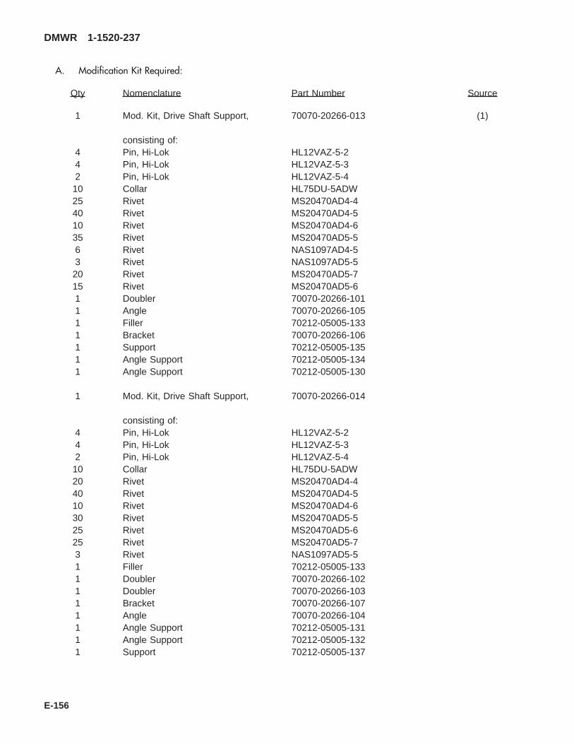
A. Modification Kit Required:
Qty Nomenclature Part Number Source
1 Mod. Kit, Drive Shaft Support, 70070-20266-013 (1)
consisting of:4 Pin, Hi-Lok HL12VAZ-5-24 Pin, Hi-Lok HL12VAZ-5-32 Pin, Hi-Lok HL12VAZ-5-410 Collar HL75DU-5ADW25 Rivet MS20470AD4-440 Rivet MS20470AD4-510 Rivet MS20470AD4-635 Rivet MS20470AD5-56 Rivet NAS1097AD4-53 Rivet NAS1097AD5-520 Rivet MS20470AD5-715 Rivet MS20470AD5-61 Doubler 70070-20266-1011 Angle 70070-20266-1051 Filler 70212-05005-1331 Bracket 70070-20266-1061 Support 70212-05005-1351 Angle Support 70212-05005-1341 Angle Support 70212-05005-130
1 Mod. Kit, Drive Shaft Support, 70070-20266-014
consisting of:4 Pin, Hi-Lok HL12VAZ-5-24 Pin, Hi-Lok HL12VAZ-5-32 Pin, Hi-Lok HL12VAZ-5-410 Collar HL75DU-5ADW20 Rivet MS20470AD4-440 Rivet MS20470AD4-510 Rivet MS20470AD4-630 Rivet MS20470AD5-525 Rivet MS20470AD5-625 Rivet MS20470AD5-73 Rivet NAS1097AD5-51 Filler 70212-05005-1331 Doubler 70070-20266-1021 Doubler 70070-20266-1031 Bracket 70070-20266-1071 Angle 70070-20266-1041 Angle Support 70212-05005-1311 Angle Support 70212-05005-1321 Support 70212-05005-137
DMWR 1-1520-237
E-156

B. Consumable Material:
WARNING
OBSERVE ALL CAUTIONS AND WARNINGS ON CONTAINERS WHEN USING CONSUMABLES.WHEN APPLICABLE, WEAR NECESSARY PROTECTIVE GEAR DURING HANDLING AND USE. IF ACONSUMABLE IS FLAMMABLE OR EXPLOSIVE, MAKE CERTAIN CONSUMABLE AND ITS VAPORS AREKEPT AWAY FROM HEAT, SPARK, AND FLAME. MAKE CERTAIN EQUIPMENT IS PROPERLYGROUNDED AND FIREFIGHTING EQUIPMENT IS READILY AVAILABLE PRIOR TO USE. FOR AD-DITIONAL INFORMATION ON TOXICITY, FLASHPOINT, AND FLAMMABILITY OF CHEMICALS,CONSULT YOUR MEDICAL PEOPLE, OR MANUFACTURER OF THE CONSUMABLE.
Qty Nomenclature Part Number Source
8 oz. Sealant AMS-S-8802, or equivalent (1)6 oz. Primer MIL-P-23377, or equivalent (1)
C. Source:
(1) Available through normal supply channels
DMWR 1-1520-237
E-157
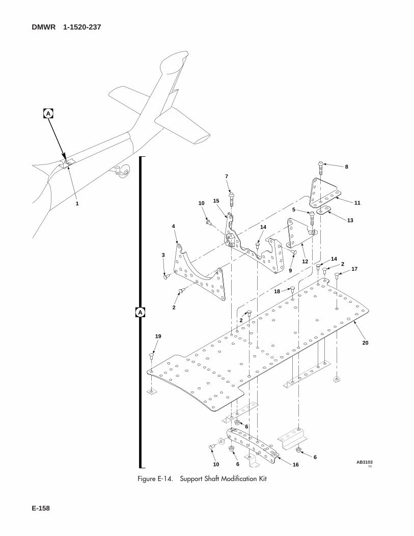
SAAB3103
A
8
11
13
5
12
9
144
3
10 15
7
2
20
66 1610
1
A
17
142
18
2
19
6
Figure E-14. Support Shaft Modification Kit
DMWR 1-1520-237
E-158

E-14- 70070-20266-013 SUPPORT SHAFT MODIFICATION KIT..................... REF-1 70070-20266-015 . SUPPORT INSTL, (Modified by 70212-
05005-011)................................................................ REF-2 MS20470AD4-6 . RIVET........................................................................ 10-3 MS20470AD5-6 . RIVET........................................................................ 15-4 70212-05005-135 . SUPPORT................................................................. 1-5 HL12VAZ-5-2 . HI-LOK PIN, (73197)................................................ 4-6 HL75DU-5ADW . COLLAR, (73197) .................................................... 10-7 HL12VAZ-5-4 . HI-LOK PIN, (73197)................................................ 2-8 HL12VAZ-5-3 . HI-LOK PIN, (73197)................................................ 4-9 NAS1097AD5-5 . RIVET........................................................................ 3
-10 MS20470AD5-5 . RIVET........................................................................ 35-11 70212-05005-130 . ANGLE SUPPORT ................................................... 1-12 70212-05005-134 . ANGLE SUPPORT ................................................... 1-13 70212-05005-133 . FILLER...................................................................... 1-14 MS20470AD5-7 . RIVET........................................................................ 20-15 70070-20266-106 . BRACKET ................................................................. 1-16 70070-20266-105 . ANGLE...................................................................... 1-17 MS20470AD4-4 . RIVET........................................................................ 25-18 MS20470AD4-5 . RIVET........................................................................ 40-19 NAS1097AD4-5 . RIVET........................................................................ 6-20 70070-20266-101 . DOUBLER................................................................. 1
DMWR 1-1520-237
QTY USABLEFIGURE & PER ONINDEX NO. PART NUMBER 1 2 3 4 5 6 7 DESCRIPTION ASSY CODE
E-159
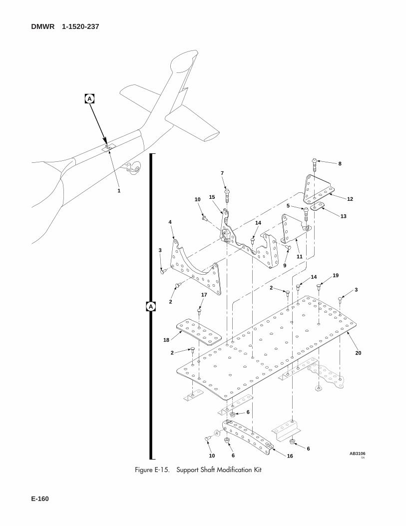
SAAB3106
A
8
12
13
5
11
9
144
3
10 15
7
217
18
2
14
20
32
6
66 1610
1
A
19
Figure E-15. Support Shaft Modification Kit
DMWR 1-1520-237
E-160
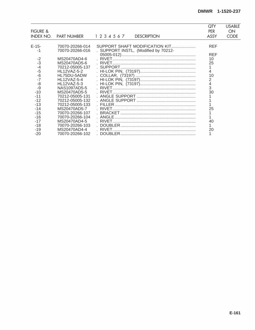
E-15- 70070-20266-014 SUPPORT SHAFT MODIFICATION KIT..................... REF-1 70070-20266-016 . SUPPORT INSTL, (Modified by 70212-
05005-012)................................................................ REF-2 MS20470AD4-6 . RIVET........................................................................ 10-3 MS20470AD5-6 . RIVET........................................................................ 25-4 70212-05005-137 . SUPPORT................................................................. 1-5 HL12VAZ-5-2 . HI-LOK PIN, (73197)................................................ 4-6 HL75DU-5ADW . COLLAR, (73197) .................................................... 10-7 HL12VAZ-5-4 . HI-LOK PIN, (73197)................................................ 2-8 HL12VAZ-5-3 . HI-LOK PIN, (73197)................................................ 4-9 NAS1097AD5-5 . RIVET........................................................................ 3
-10 MS20470AD5-5 . RIVET........................................................................ 30-11 70212-05005-131 . ANGLE SUPPORT ................................................... 1-12 70212-05005-132 . ANGLE SUPPORT ................................................... 1-13 70212-05005-133 . FILLER...................................................................... 1-14 MS20470AD5-7 . RIVET........................................................................ 25-15 70070-20266-107 . BRACKET ................................................................. 1-16 70070-20266-104 . ANGLE...................................................................... 1-17 MS20470AD4-5 . RIVET........................................................................ 40-18 70070-20266-103 . DOUBLER................................................................. 1-19 MS20470AD4-4 . RIVET........................................................................ 20-20 70070-20266-102 . DOUBLER................................................................. 1
DMWR 1-1520-237
QTY USABLEFIGURE & PER ONINDEX NO. PART NUMBER 1 2 3 4 5 6 7 DESCRIPTION ASSY CODE
E-161
E-15. SHEAR DECK MODIFICATION KIT (50-29).
Subject: Tail Cone Shear Deck; Modification of, dated 31 March 2003
Purpose: Provide instructions for modification of tail cone shear deck
Model: UH-60A
Description: The tail cone shear deck is reworked to improve the structure by adding doublers and angles between sta-tion 605.00 and station 645.00.
Drawing required for modification:
70070-20581
References: (a) Special Service Instructions (SSI) No. 50-31, Installation of 9A to A9 Recapitalization Program, datedMarch 31, 2003
(b) SSI No. 50-17, Station 605.00 Bulkhead; Modification of, dated March 31, 2003
Instructions:
NOTE
• A complete review of this s SSI is recommended before modification of the tail cone shear deck.
• Before beginning this modification procedure, use the material information list to inventory the modificationkit. Make sure all parts are present and in serviceable condition.
• Where drawing numbers are not listed within individual step(s), drawing(s) listed in preceding step(s) arethe controlling authority.
• The sheet metal and structural modifications in this SSI shall be done by personnel experienced in readingmodification drawings. Routine steps such as cleaning, layout and drilling, deburring, standard repairs,corrosion control, clean up after rework, chemical coating for aluminum after cutting/trimming parts, peel-ing shims, paint touch up, and safety practices may not be called out herein. However, these steps and allother required routine tasks shall be done.
• Slight variations to the instructions contained herein are allowed, as long as the intent of the modificationis accomplished.
• This modification is to be done concurrently with reference (b).
A. Preparation for modification and removal of equipment:
(1) Confirm that all warnings, cautions, and notes are complied with per reference (a).
(2) Perform preparation for modification per reference (a).
B. Rework shear deck installation (70211-05010-011 or -012) as follows:
(1) Remove shear deck with channels (70211-05010-107 and -108) and place on a suitable work area.
DMWR 1-1520-237
E-162
(2) Locate and remove channels (70211-05010-107 and -108) between station 605.00 and station 645.00(Dwg 70070-20581, Sheet 2, Zones 10-C, 11-C, 16-C through 23-C, and 16-E through 23-E).
(3) Remove and keep for reuse two clips (70211-05010-114) at station 640.00 (Sheet 2, Zones 15-G, 17-C,and 17-D).
(4) Remove and keep for reuse two clips (70211-05010-115) at station 645.00 (Sheet 2, Zones 15-C, 16-C,and 16-D).
(5) Remove two tapered shims (SS81-018-I) at station 608.00 (Sheet 2, Zones 23-C and 23-E).
(6) Locate and temporarily install doubler (70070-20581-101) between station 605.00 and station 623.00(Sheet 2, Zone 19-F and Note 9).
(7) Locate and temporarily install channel (70070-20581-102) between station 605.00 and station 645.00(Sheet 2, Zones 11-C, 19-F, and 16-E through 21-E).
(8) Locate and temporarily install channel (70070-20581-103) between station 605.00 and station 645.00(Sheet 2, Zones 10-C, 18-F, and 16-C through 21-C).
(9) Locate remaining field fastener holes and transfer drill in channels (70070-20581-102 and -103) (Sheet 2,Zones 16-C through 21-C and 16-E through 21-E).
(10) Locate and temporarily install two shims, tapered (SS81-014-I) at station 607.00, two clips (70211-05010-114) at station 640.00 and two clips (70211-05010-115) at station 645.00 (Sheet 2, Zones 23-C, 23-E, 17-C, 17-D,16-C and 16-D).
(11) Remove fitted parts, deburr and touch up as required.
(12) Install fitted parts using fasteners shown (Sheet 2, Note 9).
C. Reinstallation of removed equipment:
(1) Install removed equipment per reference (a).
D. Record of Compliance:
(1) Make an appropriate logbook entry to show compliance with this Special Service Instruction.
Weight and Balance Data:
QTY PART NO. NOMENCLATUREPOUNDSWEIGHT
INCHES AFTOF DATUM
MOMENT/1000
1 70070-20581-011 Mod. Kit, Shear Deck +1.9 621.7 1.18
Weight and Balance: Change resulting from these instructions are as follows:
Change in basic weight: + 1.9 pounds
Moment arm: 621.7 in.
DMWR 1-1520-237
E-163
Change in basic moment/1000: 1.18
Manpower (Estimated)
No. of Personel No. of Hours Man-hoursSheet Metal Mechanic 2 20.0 * 40.0
*Does not include time required to prepare helicopter or return it to flight status.
Material Information:
A. Modification Kit Required:
Qty Nomenclature Part Number Source
1 Mod. Kit, Shear Deck, 70070-20581-011 (1)
consisting of:53 Rivet MS20470AD6-73 Rivet MS20470AD5-93 Rivet MS20470AD5-89 Rivet MS20470AD5-791 Rivet MS20470AD5-668 Rivet MS20470AD5-572 Rivet MS20470AD4-42 Pin, SWG LKG NAS1465-062 Pin, SWG LKG NAS1465-034 Pin, SWG LKG NAS1465-028 Collar NAS1080-052 Shim, Tapered SS81-014-I1 Doubler 70070-20581-1011 Channel 70070-20581-1021 Channel 70070-20581-103
B. Source:
(1) Available through normal supply channels
DMWR 1-1520-237
E-164

2
SAAB3121
1
BL0
BL10
BL10
STA605
STA615
STA625
STA635
STA645
6
5
7 9
34
17
13
12
15
16
14
310
311
1
8
Figure E-16. Shear Deck Modification Kit
DMWR 1-1520-237
E-165

E-16- 70070-20581-011 SHEAR DECK MODIFICATION KIT ........................... REF-1 70070-20581-012 . SHEAR DECK INSTL, (Modified from 70211-
05010-011)................................................................ REF70070-20581-013 . SHEAR DECK INSTL, (Modified from 70211-
05010-012)................................................................ REF-2 70070-20581-041 . SHEAR DECK ASSY, (Modified from 70211-
05010-041)................................................................ REF-3 NAS1465-06 . SWAGE LOCKING PIN ............................................ 2-4 NAS1080-05 . COLLAR.................................................................... 8-5 MS20470AD5-9 . RIVET........................................................................ 3-6 MS20470AD5-8 . RIVET........................................................................ 3-7 MS20470AD5-7 . RIVET........................................................................ 9-8 MS20470AD5-6 . RIVET........................................................................ 91-9 MS20470AD6-7 . RIVET........................................................................ 53
-10 NAS1465-02 . SWAGE LOCKING PIN ............................................ 4-11 NAS1465-03 . SWAGE LOCKING PIN ............................................ 2-12 MS20470AD4-4 . RIVET........................................................................ 72-13 MS20470AD5-5 . RIVET........................................................................ 68-14 70070-20581-101 . DOUBLER................................................................. 1-15 70070-20581-103 . CHANNEL................................................................. 1-16 70070-20581-102 . CHANNEL................................................................. 1-17 SS81-014-I . TAPERED SHIM....................................................... 2
DMWR 1-1520-237
QTY USABLEFIGURE & PER ONINDEX NO. PART NUMBER 1 2 3 4 5 6 7 DESCRIPTION ASSY CODE
E-166

E-16. STRINGER/FRAME MODIFICATION KIT (50-24).
Subject: Tail Cone, Modification of, dated 31 March 2003
Purpose: To provide instructions to install tail cone modification kit.
Model: UH-60A
Description: To strengthen the tail cone structure by adding stringers and shear ties to station 485.00 through station565.00.
Drawings required for modification:
70070-20582
References: (a) Special Service Instructions (SSI) No. 50-31, Installation of 9A to A9 Recapitalization Program, datedMarch 31, 2003
(b) SSI No. 50-13 Tail Cone Plating, Modification of, dated 31 March 2003
(c) Technical Manual (TM) 1-1520-237-23-1, Aviation Unit And Intermediate Maintenance for ArmyModels UH-60A, UH-60L, and EH-60A Helicopters, Chapter 1, Aircraft General
Instructions:
NOTE
• A complete review of this SSI is recommended before installing tail cone modification kit.
• Before beginning this modification procedure, use the material information list to inventory the kit. Makesure all parts are present and in serviceable condition.
• Where drawing numbers are not listed within individual steps, drawing(s) listed in preceding step(s) arethe controlling authority.
• The sheet metal and structural modifications in this SSI shall be done by personnel experienced in readingmodification drawings. Routine steps such as cleaning, layout and drilling, deburring, standard repairs,corrosion control, clean up after rework, chemical coating for aluminum after cutting/trimming parts, painttouch up, and safety practices may not be called out herein. However, these steps and all other requiredroutine tasks shall be done.
• Slight variations to the instructions contained herein are allowed, as long as the intent of the modificationis accomplished.
• This modification is to be done concurrently with reference (b).
A. Preparation for modification and removal of equipment.
(1) Confirm that all warnings, cautions, and notes are complied with per reference (a).
(2) Perform preparation for modification per reference (a).
(3) Inspect and repair structure for corrosion and damage per reference (c).
DMWR 1-1520-237
E-167

B. Modification, tailcone:
(1) Modify tail cone after removal of lower skin (70213-05001-041 or 70213-05001-048) per reference (b).
(2) Installation, tail cone structure:
(a) Use portions of removed stringers from lower skin to align shear ties on lower section of modified frames.
(b) Modify station 505.00 as follows:
1 Remove right side brackets (70213-05001-154) between waterline 215.00 and waterline 230.00,waterline 255.00 (Dwg 70070-20582, Sheet 6, Zones 11-E through 11-G, Sheet 7, Section W-W, Zone 23-D, Notes 10and 11).
2 Position shear ties (70070-20582-136, 70070-20582-101, 70070-20582-102, 70070-20582-135,70070-20582-134, 70070-20582-103, and 70070-20582-137) as shown (Sheet 6, Zones 13-C through 11-E, Sheet7, Zones 17-D and 18-F through 21-F).
3 Position splice (70084-25104-116) (Sheet 7, Zone 17-B).
4 Transfer drill fastener holes from shear ties and splice through frame and skins (Sheet 6, Zones 15through 10, Sheet 7, Zones 16 through 22).
NOTE
Clips 96203-05001 are not secured at this time.
5 Secure shear ties and splice to frame with fasteners shown (Sheet 6, Zones 11 through 10, and Sheet 7,Zones 17 through 22).
6 Secure shear ties and skin with fasteners shown wet with sealant (MIL-S-8802 or equivalent) (Sheet 6,Views D-D, F-F, E-E, K-K, and L-L, Zones 14-A through 9-C, Sheet 7, Views P-P, R-R, S-S, and U-U, Zones 16-A through22-F, Sheet 5, Note 4).
(c) Install station 485.00 to station 505.00 stringers as follows:
1 Position left side stringers (70213-05001-155 and 70213-05001-157) between waterline 215.00 andwaterline 225.00 as shown (Sheet 6, Zones 20-C and 20-E, Note 12).
2 Drill fastener holes from stringers through skin, station 485.00 and station 505.00 frames.
3 Position angle brackets (SS1076-57 and SS1076-183) onto stringers and against frame (Sheet 6, Sec-tions G-G, H-H, and J-J, Zones 23-C through 24-G, Note 12).
4 Drill fastener holes from angle brackets through stringers and frame.
5 Position right side stringers (70213-05001-156, 70213-05001-158, and 70213-05001-159) betweenwaterline 215.00 and waterline 230.00 in shear tie (70070-20582-102) cutouts as shown (Sheet 6, View D-D, Zone6-C, Note 12).
6 Drill fastener holes from stringers through skin, station 485.00 and station 505.00 frames as shown.
7 Position clips (96203-05001-152, 96203-05001-151, and 96203-05001-150) as shown (Sheet 6,Zones 11-E, 11-F, and 11-G).
DMWR 1-1520-237
E-168
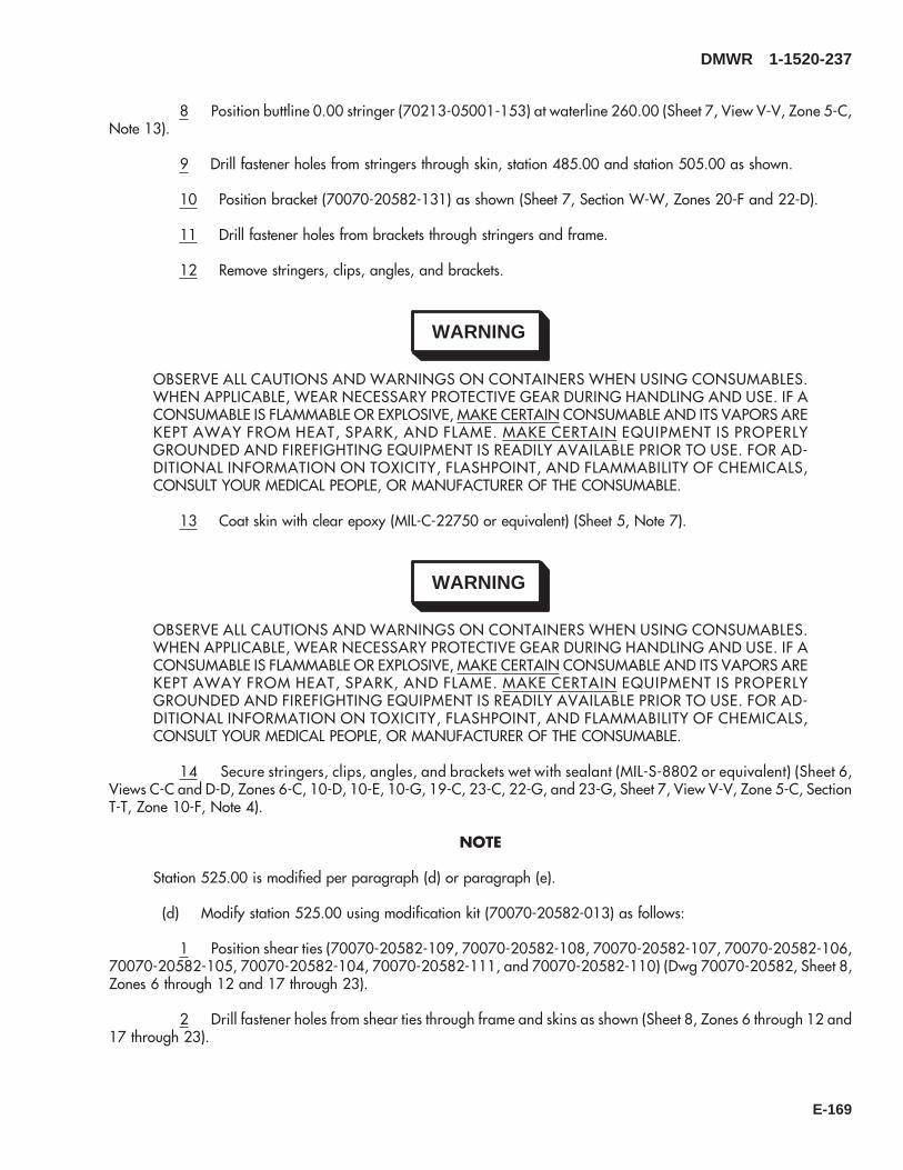
8 Position buttline 0.00 stringer (70213-05001-153) at waterline 260.00 (Sheet 7, View V-V, Zone 5-C,Note 13).
9 Drill fastener holes from stringers through skin, station 485.00 and station 505.00 as shown.
10 Position bracket (70070-20582-131) as shown (Sheet 7, Section W-W, Zones 20-F and 22-D).
11 Drill fastener holes from brackets through stringers and frame.
12 Remove stringers, clips, angles, and brackets.
WARNING
OBSERVE ALL CAUTIONS AND WARNINGS ON CONTAINERS WHEN USING CONSUMABLES.WHEN APPLICABLE, WEAR NECESSARY PROTECTIVE GEAR DURING HANDLING AND USE. IF ACONSUMABLE IS FLAMMABLE OR EXPLOSIVE, MAKE CERTAIN CONSUMABLE AND ITS VAPORS AREKEPT AWAY FROM HEAT, SPARK, AND FLAME. MAKE CERTAIN EQUIPMENT IS PROPERLYGROUNDED AND FIREFIGHTING EQUIPMENT IS READILY AVAILABLE PRIOR TO USE. FOR AD-DITIONAL INFORMATION ON TOXICITY, FLASHPOINT, AND FLAMMABILITY OF CHEMICALS,CONSULT YOUR MEDICAL PEOPLE, OR MANUFACTURER OF THE CONSUMABLE.
13 Coat skin with clear epoxy (MIL-C-22750 or equivalent) (Sheet 5, Note 7).
WARNING
OBSERVE ALL CAUTIONS AND WARNINGS ON CONTAINERS WHEN USING CONSUMABLES.WHEN APPLICABLE, WEAR NECESSARY PROTECTIVE GEAR DURING HANDLING AND USE. IF ACONSUMABLE IS FLAMMABLE OR EXPLOSIVE, MAKE CERTAIN CONSUMABLE AND ITS VAPORS AREKEPT AWAY FROM HEAT, SPARK, AND FLAME. MAKE CERTAIN EQUIPMENT IS PROPERLYGROUNDED AND FIREFIGHTING EQUIPMENT IS READILY AVAILABLE PRIOR TO USE. FOR AD-DITIONAL INFORMATION ON TOXICITY, FLASHPOINT, AND FLAMMABILITY OF CHEMICALS,CONSULT YOUR MEDICAL PEOPLE, OR MANUFACTURER OF THE CONSUMABLE.
14 Secure stringers, clips, angles, and brackets wet with sealant (MIL-S-8802 or equivalent) (Sheet 6,Views C-C and D-D, Zones 6-C, 10-D, 10-E, 10-G, 19-C, 23-C, 22-G, and 23-G, Sheet 7, View V-V, Zone 5-C, SectionT-T, Zone 10-F, Note 4).
NOTE
Station 525.00 is modified per paragraph (d) or paragraph (e).
(d) Modify station 525.00 using modification kit (70070-20582-013) as follows:
1 Position shear ties (70070-20582-109, 70070-20582-108, 70070-20582-107, 70070-20582-106,70070-20582-105, 70070-20582-104, 70070-20582-111, and 70070-20582-110) (Dwg 70070-20582, Sheet 8,Zones 6 through 12 and 17 through 23).
2 Drill fastener holes from shear ties through frame and skins as shown (Sheet 8, Zones 6 through 12 and17 through 23).
DMWR 1-1520-237
E-169
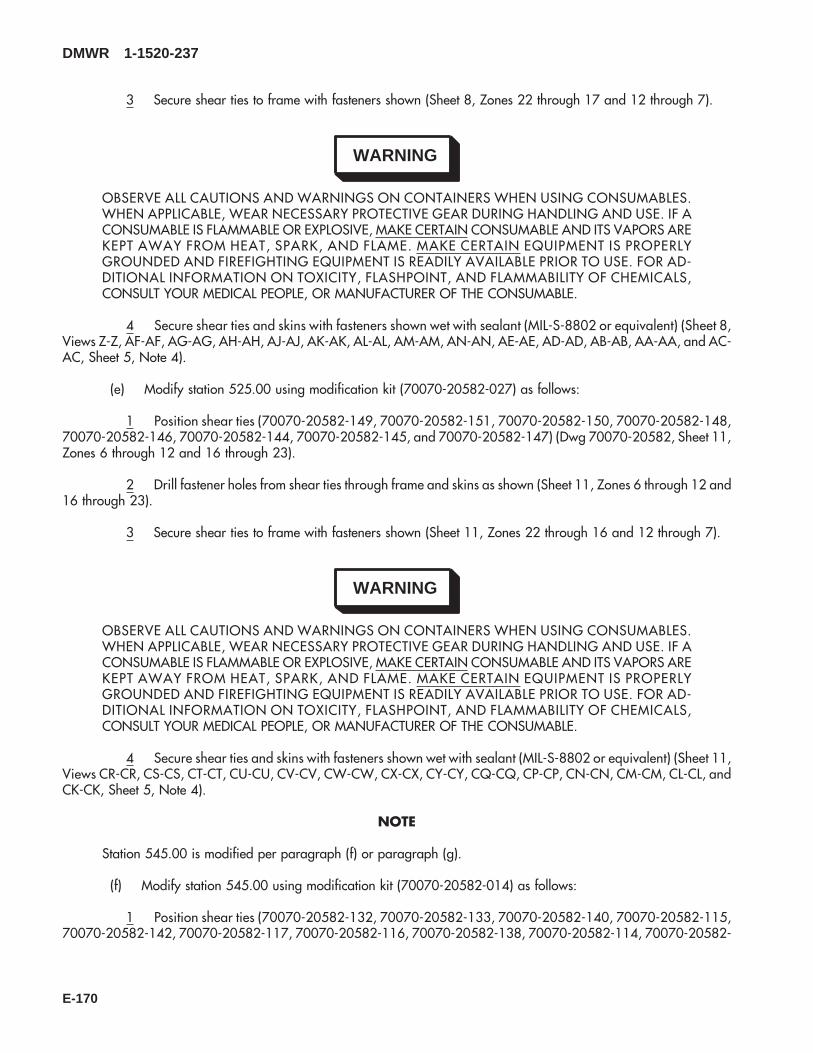
3 Secure shear ties to frame with fasteners shown (Sheet 8, Zones 22 through 17 and 12 through 7).
WARNING
OBSERVE ALL CAUTIONS AND WARNINGS ON CONTAINERS WHEN USING CONSUMABLES.WHEN APPLICABLE, WEAR NECESSARY PROTECTIVE GEAR DURING HANDLING AND USE. IF ACONSUMABLE IS FLAMMABLE OR EXPLOSIVE, MAKE CERTAIN CONSUMABLE AND ITS VAPORS AREKEPT AWAY FROM HEAT, SPARK, AND FLAME. MAKE CERTAIN EQUIPMENT IS PROPERLYGROUNDED AND FIREFIGHTING EQUIPMENT IS READILY AVAILABLE PRIOR TO USE. FOR AD-DITIONAL INFORMATION ON TOXICITY, FLASHPOINT, AND FLAMMABILITY OF CHEMICALS,CONSULT YOUR MEDICAL PEOPLE, OR MANUFACTURER OF THE CONSUMABLE.
4 Secure shear ties and skins with fasteners shown wet with sealant (MIL-S-8802 or equivalent) (Sheet 8,Views Z-Z, AF-AF, AG-AG, AH-AH, AJ-AJ, AK-AK, AL-AL, AM-AM, AN-AN, AE-AE, AD-AD, AB-AB, AA-AA, and AC-AC, Sheet 5, Note 4).
(e) Modify station 525.00 using modification kit (70070-20582-027) as follows:
1 Position shear ties (70070-20582-149, 70070-20582-151, 70070-20582-150, 70070-20582-148,70070-20582-146, 70070-20582-144, 70070-20582-145, and 70070-20582-147) (Dwg 70070-20582, Sheet 11,Zones 6 through 12 and 16 through 23).
2 Drill fastener holes from shear ties through frame and skins as shown (Sheet 11, Zones 6 through 12 and16 through 23).
3 Secure shear ties to frame with fasteners shown (Sheet 11, Zones 22 through 16 and 12 through 7).
WARNING
OBSERVE ALL CAUTIONS AND WARNINGS ON CONTAINERS WHEN USING CONSUMABLES.WHEN APPLICABLE, WEAR NECESSARY PROTECTIVE GEAR DURING HANDLING AND USE. IF ACONSUMABLE IS FLAMMABLE OR EXPLOSIVE, MAKE CERTAIN CONSUMABLE AND ITS VAPORS AREKEPT AWAY FROM HEAT, SPARK, AND FLAME. MAKE CERTAIN EQUIPMENT IS PROPERLYGROUNDED AND FIREFIGHTING EQUIPMENT IS READILY AVAILABLE PRIOR TO USE. FOR AD-DITIONAL INFORMATION ON TOXICITY, FLASHPOINT, AND FLAMMABILITY OF CHEMICALS,CONSULT YOUR MEDICAL PEOPLE, OR MANUFACTURER OF THE CONSUMABLE.
4 Secure shear ties and skins with fasteners shown wet with sealant (MIL-S-8802 or equivalent) (Sheet 11,Views CR-CR, CS-CS, CT-CT, CU-CU, CV-CV, CW-CW, CX-CX, CY-CY, CQ-CQ, CP-CP, CN-CN, CM-CM, CL-CL, andCK-CK, Sheet 5, Note 4).
NOTE
Station 545.00 is modified per paragraph (f) or paragraph (g).
(f) Modify station 545.00 using modification kit (70070-20582-014) as follows:
1 Position shear ties (70070-20582-132, 70070-20582-133, 70070-20582-140, 70070-20582-115,70070-20582-142, 70070-20582-117, 70070-20582-116, 70070-20582-138, 70070-20582-114, 70070-20582-
DMWR 1-1520-237
E-170

112, 70070-20582-143, 70070-20582-139, and 70070-20582-141) (Dwg 70070-20582, Sheet 9, Zones 22through 17 and 11 through 6).
2 Drill fastener holes from shear ties and angles through frame and skins (Sheet 9, Zones 22 through 17and 11 through 6).
3 Secure shear ties and angles to frame with fasteners shown (Sheet 9, Zones 22 through 17 and 11through 7).
WARNING
OBSERVE ALL CAUTIONS AND WARNINGS ON CONTAINERS WHEN USING CONSUMABLES.WHEN APPLICABLE, WEAR NECESSARY PROTECTIVE GEAR DURING HANDLING AND USE. IF ACONSUMABLE IS FLAMMABLE OR EXPLOSIVE, MAKE CERTAIN CONSUMABLE AND ITS VAPORS AREKEPT AWAY FROM HEAT, SPARK, AND FLAME. MAKE CERTAIN EQUIPMENT IS PROPERLYGROUNDED AND FIREFIGHTING EQUIPMENT IS READILY AVAILABLE PRIOR TO USE. FOR AD-DITIONAL INFORMATION ON TOXICITY, FLASHPOINT, AND FLAMMABILITY OF CHEMICALS,CONSULT YOUR MEDICAL PEOPLE, OR MANUFACTURER OF THE CONSUMABLE.
4 Secure shear ties and skins with fasteners shown wet with sealant (MIL-S-8802 or equivalent) (Sheet 9,Views AV-AV, AU-AU, AT-AT, AS-AS, BA-BA, BB-BB, BC-BC, BD-BD, BE-BE, BF-BF, BG-BG, BH-BH, AZ-AZ, AY-AY, AX-AX, and AW-AW, Sheet 5, Note 4).
(g) Modify station 545.00 using modification kit (70070-20582-028) as follows:
1 Position shear ties (70070-20582-152, 70070-20582-154, 70070-20582-156, 70070-20582-158,70070-20582-160, 70070-20582-162, 70070-20582-161, 70070-20582-159, 70070-20582-157, 70070-20582-164, 70070-20582-163, 70070-20582-155, and 70070-20582-153) (Dwg 70070-20582, Sheet 12, Zones 22through 17 and 11 through 6).
2 Drill fastener holes from shear ties and angles through frame and skins (Sheet 12, Zones 22 through 17and 11 through 6).
3 Secure shear ties and angles to frame with fasteners shown (Sheet 12, Zones 22 through 17 and 11through 7).
WARNING
OBSERVE ALL CAUTIONS AND WARNINGS ON CONTAINERS WHEN USING CONSUMABLES.WHEN APPLICABLE, WEAR NECESSARY PROTECTIVE GEAR DURING HANDLING AND USE. IF ACONSUMABLE IS FLAMMABLE OR EXPLOSIVE, MAKE CERTAIN CONSUMABLE AND ITS VAPORS AREKEPT AWAY FROM HEAT, SPARK, AND FLAME. MAKE CERTAIN EQUIPMENT IS PROPERLYGROUNDED AND FIREFIGHTING EQUIPMENT IS READILY AVAILABLE PRIOR TO USE. FOR AD-DITIONAL INFORMATION ON TOXICITY, FLASHPOINT, AND FLAMMABILITY OF CHEMICALS,CONSULT YOUR MEDICAL PEOPLE, OR MANUFACTURER OF THE CONSUMABLE.
4 Secure shear ties and skins with fasteners shown wet with sealant (MIL-S-8802 or equivalent) (Sheet 12,Views DE-DE, DF-DF, DG-DG, DH-DH, DD-DD, DR-DR, DP-DP, DN-DN, DM-DM, DL-DL, DK-DK, DJ-DJ, CZ-CZ, DA-DA,DB-DB, and DC-DC, Sheet 5, Note 4).
DMWR 1-1520-237
E-171

(h) Modify station 565.00 as follows:
1 Position shear ties (70070-20582-119, 70070-20582-120, 70080-20582-118, 70070-20582-129,70070-20582-130, 70070-20582-121, 70070-20582-122, 70070-20582-123, 70070-20582-124, 70070-20582-125, 70070-20582-126, 70070-20582-127, and 70070-20582-128) (Dwg 70070-20582, Sheet 10, Zones 21through 17 and 11 through 7).
2 Drill fastener holes from shear ties through frame and skins (Sheet 10, Zones 21 through 17 and 11through 7).
3 Secure shear ties to frame with fasteners shown (Sheet 10, Zones 21 through 17 and 11 through 7).
WARNING
OBSERVE ALL CAUTIONS AND WARNINGS ON CONTAINERS WHEN USING CONSUMABLES.WHEN APPLICABLE, WEAR NECESSARY PROTECTIVE GEAR DURING HANDLING AND USE. IF ACONSUMABLE IS FLAMMABLE OR EXPLOSIVE, MAKE CERTAIN CONSUMABLE AND ITS VAPORS AREKEPT AWAY FROM HEAT, SPARK, AND FLAME. MAKE CERTAIN EQUIPMENT IS PROPERLYGROUNDED AND FIREFIGHTING EQUIPMENT IS READILY AVAILABLE PRIOR TO USE. FOR AD-DITIONAL INFORMATION ON TOXICITY, FLASHPOINT, AND FLAMMABILITY OF CHEMICALS,CONSULT YOUR MEDICAL PEOPLE, OR MANUFACTURER OF THE CONSUMABLE.
4 Secure shear ties and skins with fasteners shown wet with sealant (MIL-S-8802 or equivalent) (Sheet 10,Views BT-BT, BS-BS, BR-BR, BP-BP, BN-BN, BZ-BZ, CA-CA, CB-CB, CC-CC, CD-CD, CE-CE, X-X, Y-Y, BY-BY, BX-BX, BW-BW, BV-BV, and BU-BU, Sheet 5, Note 4).
(3) Reidentification:
NOTE
The following reidentifications are for record purposes only. No physical reidentification is required.
FROM TO Nomenclature70211-05002-011 70070-20582-018 Frame Instl*70211-05003-011 70070-20582-019 Frame Instl**70211-05004-011 70070-20582-020 Frame Instl&70211-05003-011 70070-20582-019 Frame Instl
&&70211-05004-011 70070-20582-020 Frame Instl70211-05005-011 70070-20582-021 Frame Instl70213-05001-011 70070-20582-022 Plating Instl70213-05001-012 70070-20582-023 Plating Instl70213-05001-041 70070-20582-041 Skin Assy70213-05001-042 70070-20582-042 Skin Assy70213-05001-044 70070-20582-043 Skin Assy
*Reidentify when incorporating 70070-20582-013 modification kit.**Reidentify when incorporating 70070-20582-014 modification kit&Reidentify when incorporating 70070-20582-027 modification kit&&Reidentify when incorporating 70070-20582-028 modification kit
DMWR 1-1520-237
E-172
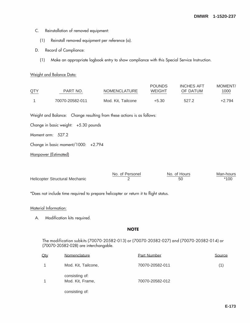
C. Reinstallation of removed equipment:
(1) Reinstall removed equipment per reference (a).
D. Record of Compliance:
(1) Make an appropriate logbook entry to show compliance with this Special Service Instruction.
Weight and Balance Data:
QTY PART NO. NOMENCLATUREPOUNDSWEIGHT
INCHES AFTOF DATUM
MOMENT/1000
1 70070-20582-011 Mod. Kit, Tailcone +5.30 527.2 +2.794
Weight and Balance: Change resulting from these actions is as follows:
Change in basic weight: +5.30 pounds
Moment arm: 527.2
Change in basic moment/1000: +2.794
Manpower (Estimated)
No. of Personel No. of Hours Man-hoursHelicopter Structural Mechanic 2 50 *100
*Does not include time required to prepare helicopter or return it to flight status.
Material Information:
A. Modification kits required.
NOTE
The modification subkits (70070-20582-013) or (70070-20582-027) and (70070-20582-014) or(70070-20582-028) are interchangable.
Qty Nomenclature Part Number Source
1 Mod. Kit, Tailcone, 70070-20582-011 (1)
consisting of:1 Mod. Kit, Frame, 70070-20582-012
consisting of:
DMWR 1-1520-237
E-173

Qty Nomenclature Part Number Source
103 Rivet MS20470AD5-512 Rivet MS20470AD5-61 Shear Tie 70070-20582-1011 Shear Tie 70070-20582-1021 Shear Tie 70070-20582-1031 Shear Tie 70070-20582-1341 Shear Tie 70070-20582-1351 Shear Tie 70070-20582-1361 Shear Tie 70070-20582-1371 Splice 70084-25104-116
1 Mod. Kit, Frame, 70070-20582-013
consisting of:134 Rivet MS20470AD5-5
2 Rivet MS20470AD5-61 Shear Tie 70070-20582-1041 Shear Tie 70070-20582-1051 Shear Tie 70070-20582-1061 Shear Tie 70070-20582-1071 Shear Tie 70070-20582-1081 Shear Tie 70070-20582-1091 Shear Tie 70070-20582-1101 Shear Tie 70070-20582-111
1 Mod. Kit Frame, 70070-20582-014
consisting of:123 Rivet MS20470AD5-5
1 Shear Tie 70070-20582-1121 Shear Tie 70070-20582-1391 Shear Tie 70070-20582-1141 Shear Tie 70070-20582-1151 Shear Tie 70070-20582-1161 Shear Tie 70070-20582-1171 Shear Tie 70070-20582-1321 Shear Tie 70070-20582-1331 Shear Tie 70070-20582-1381 Shear Tie 70070-20582-1401 Shear Tie 70070-20582-1411 Shear Tie 70070-20582-1421 Shear Tie 70070-20582-143
1 Mod. Kit, Plating, 70070-20582-015
consisting of:109 Rivet MS20470AD5-5
1 Shear Tie 70070-20582-118
DMWR 1-1520-237
E-174
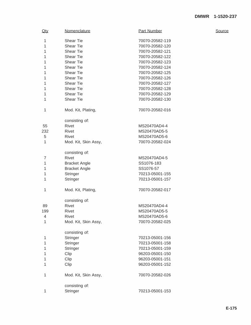
Qty Nomenclature Part Number Source
1 Shear Tie 70070-20582-1191 Shear Tie 70070-20582-1201 Shear Tie 70070-20582-1211 Shear Tie 70070-20582-1221 Shear Tie 70070-20582-1231 Shear Tie 70070-20582-1241 Shear Tie 70070-20582-1251 Shear Tie 70070-20582-1261 Shear Tie 70070-20582-1271 Shear Tie 70070-20582-1281 Shear Tie 70070-20582-1291 Shear Tie 70070-20582-130
1 Mod. Kit, Plating, 70070-20582-016
consisting of:55 Rivet MS20470AD4-4232 Rivet MS20470AD5-5
5 Rivet MS20470AD5-61 Mod. Kit, Skin Assy, 70070-20582-024
consisting of:7 Rivet MS20470AD4-51 Bracket Angle SS1076-1831 Bracket Angle SS1076-571 Stringer 70213-05001-1551 Stringer 70213-05001-157
1 Mod. Kit, Plating, 70070-20582-017
consisting of:89 Rivet MS20470AD4-4199 Rivet MS20470AD5-5
4 Rivet MS20470AD5-61 Mod. Kit, Skin Assy, 70070-20582-025
consisting of:1 Stringer 70213-05001-1561 Stringer 70213-05001-1581 Stringer 70213-05001-1591 Clip 96203-05001-1501 Clip 96203-05001-1511 Clip 96203-05001-152
1 Mod. Kit, Skin Assy, 70070-20582-026
consisting of:1 Stringer 70213-05001-153
DMWR 1-1520-237
E-175
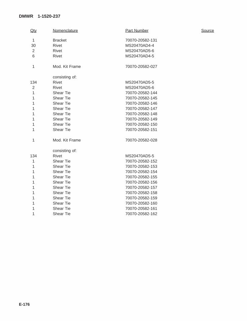
Qty Nomenclature Part Number Source
1 Bracket 70070-20582-13130 Rivet MS20470AD4-42 Rivet MS20470AD5-66 Rivet MS20470AD4-5
1 Mod. Kit Frame 70070-20582-027
consisting of:134 Rivet MS20470AD5-5
2 Rivet MS20470AD5-61 Shear Tie 70070-20582-1441 Shear Tie 70070-20582-1451 Shear Tie 70070-20582-1461 Shear Tie 70070-20582-1471 Shear Tie 70070-20582-1481 Shear Tie 70070-20582-1491 Shear Tie 70070-20582-1501 Shear Tie 70070-20582-151
1 Mod. Kit Frame 70070-20582-028
consisting of:134 Rivet MS20470AD5-5
1 Shear Tie 70070-20582-1521 Shear Tie 70070-20582-1531 Shear Tie 70070-20582-1541 Shear Tie 70070-20582-1551 Shear Tie 70070-20582-1561 Shear Tie 70070-20582-1571 Shear Tie 70070-20582-1581 Shear Tie 70070-20582-1591 Shear Tie 70070-20582-1601 Shear Tie 70070-20582-1611 Shear Tie 70070-20582-162
DMWR 1-1520-237
E-176
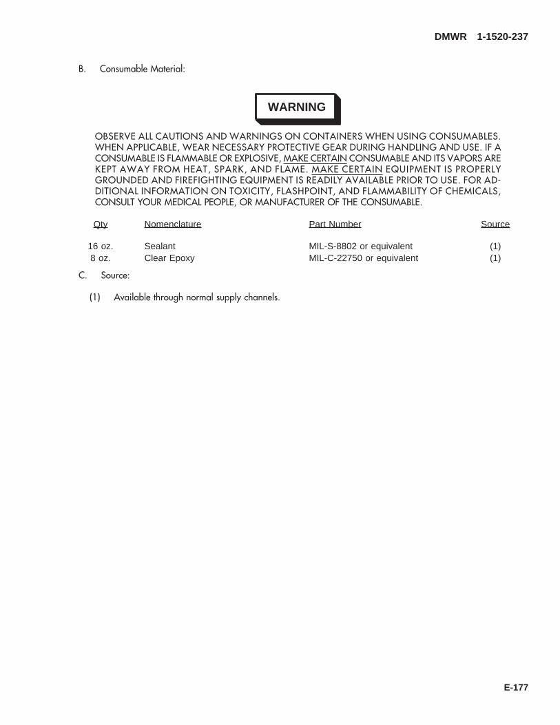
B. Consumable Material:
WARNING
OBSERVE ALL CAUTIONS AND WARNINGS ON CONTAINERS WHEN USING CONSUMABLES.WHEN APPLICABLE, WEAR NECESSARY PROTECTIVE GEAR DURING HANDLING AND USE. IF ACONSUMABLE IS FLAMMABLE OR EXPLOSIVE, MAKE CERTAIN CONSUMABLE AND ITS VAPORS AREKEPT AWAY FROM HEAT, SPARK, AND FLAME. MAKE CERTAIN EQUIPMENT IS PROPERLYGROUNDED AND FIREFIGHTING EQUIPMENT IS READILY AVAILABLE PRIOR TO USE. FOR AD-DITIONAL INFORMATION ON TOXICITY, FLASHPOINT, AND FLAMMABILITY OF CHEMICALS,CONSULT YOUR MEDICAL PEOPLE, OR MANUFACTURER OF THE CONSUMABLE.
Qty Nomenclature Part Number Source
16 oz. Sealant MIL-S-8802 or equivalent (1)8 oz. Clear Epoxy MIL-C-22750 or equivalent (1)
C. Source:
(1) Available through normal supply channels.
DMWR 1-1520-237
E-177

SAAB3092_1
A
14
27
1
A
WL210
WL240
STA485
STA505
STA525
STA545
STA565
STA585
STA605
WL240
WL210
BL10
BL10
29
28
15
2
88
6036
4872
Figure E-17. Stringer/Frame Modification Kit (Sheet 1 of 9)
DMWR 1-1520-237
E-178

SAAB3092_2
WL225
WL220
WL215
STA505
STA495
STA490
STA485
2
3
5
46
6
WL225
WL220
WL215
OUTBD
BL
LH15
89
7
12
13
1011
STA500
Figure E-17. Stringer/Frame Modification Kit (Sheet 2 of 9)
DMWR 1-1520-237
E-179
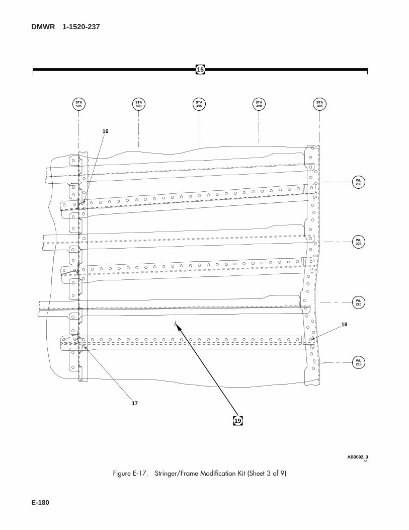
SAAB3092_3
STA505
STA500
STA495
STA490
STA485
WL230
WL225
WL220
WL215
15
17
16
18
19
Figure E-17. Stringer/Frame Modification Kit (Sheet 3 of 9)
DMWR 1-1520-237
E-180

SAAB3092_4
BL
RH5
BL
RH10
BL
RH15BL
0
WL230
WL225
WL220
WL215
WL210
WL205
19
20
24
25
26
22
23
1721
OUTBD
Figure E-17. Stringer/Frame Modification Kit (Sheet 4 of 9)
DMWR 1-1520-237
E-181

SAAB3092_5
STA505 STA
500STA495
STA490
STA485
BL
LH5
BL
RH5
BL0
IN
UP
STA505
STA500
STA495
WL260
30 31
B
B
34
3233
BD
29
Figure E-17. Stringer/Frame Modification Kit (Sheet 5 of 9)
DMWR 1-1520-237
E-182

WL235
WL240
WL245
WL250
WL255
WL205
WL210
WL215
WL220
WL225
WL230
RBL15
RBL5
BL0
LBL5
LBL10
LBL15
38
43
35
4241
40
39
37
46
45
44
28
SAAB3092_6
VIEW LOOKING FORWARD − STA 505
RBL10
Figure E-17. Stringer/Frame Modification Kit (Sheet 6 of 9)
DMWR 1-1520-237
E-183
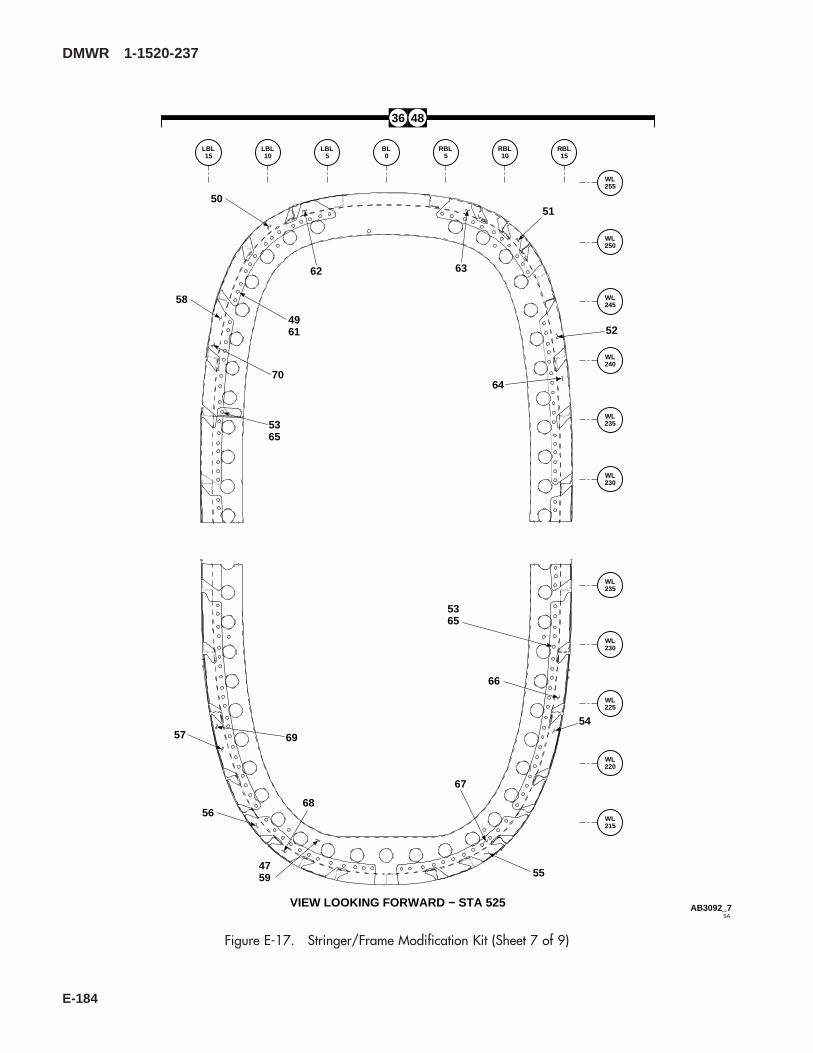
WL255
LBL15
LBL10
LBL5
BL0
RBL5
RBL10
RBL15
WL250
WL245
WL240
WL235
WL230
WL235
WL230
WL225
WL220
WL215
36 48
4759
66
67
6856
57 69
50
58
62
4961
70
63
64
52
51
SAAB3092_7VIEW LOOKING FORWARD − STA 525
5365
55
54
5365
Figure E-17. Stringer/Frame Modification Kit (Sheet 7 of 9)
DMWR 1-1520-237
E-184
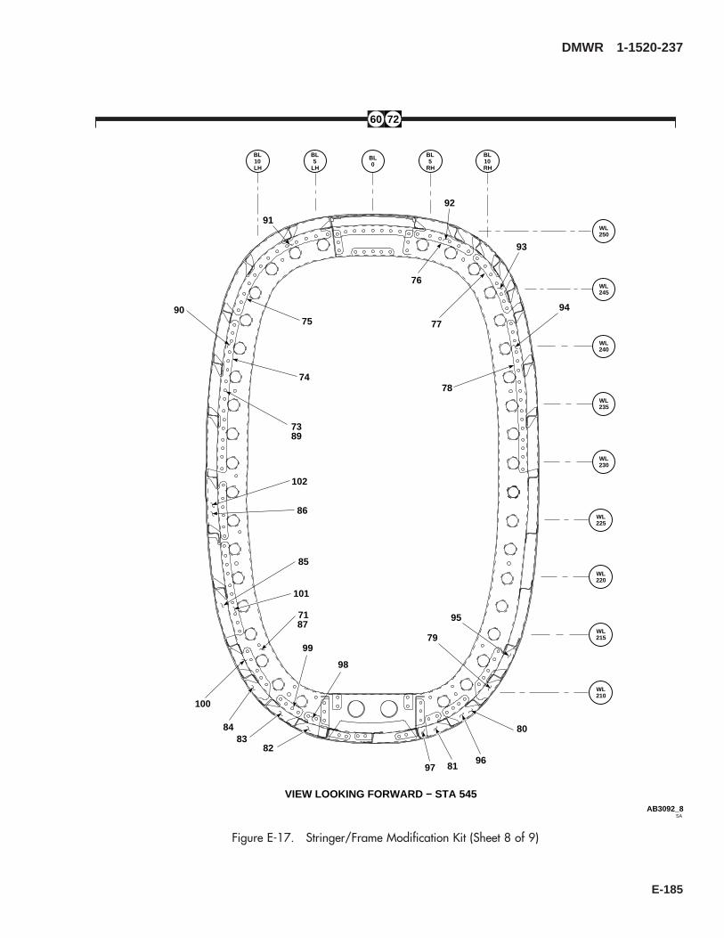
60 72
SAAB3092_8
BL
LH5
BL
LH10
BL0
BL
RH5
BL
RH10
WL250
WL245
WL240
WL235
WL230
76
92
77
93
78
94
91
75
74
90
7389
WL225
WL220
WL215
WL210
102
86
85
101
7187
100
84
99
8382
98
95
79
80
968197
VIEW LOOKING FORWARD − STA 545
Figure E-17. Stringer/Frame Modification Kit (Sheet 8 of 9)
DMWR 1-1520-237
E-185

SAAB3092_9
BL
LH10
BL
LH5
BL
LH0
BL
RH5
BL
RH10
WL245
WL240
WL235WL235
WL230
WL225
WL220
WL215
WL210
88
106
107
108
109
105
103104 110
111
112114
113
116
115
117
VIEW LOOKING FORWARD − STA 565
Figure E-17. Stringer/Frame Modification Kit (Sheet 9 of 9)
DMWR 1-1520-237
E-186
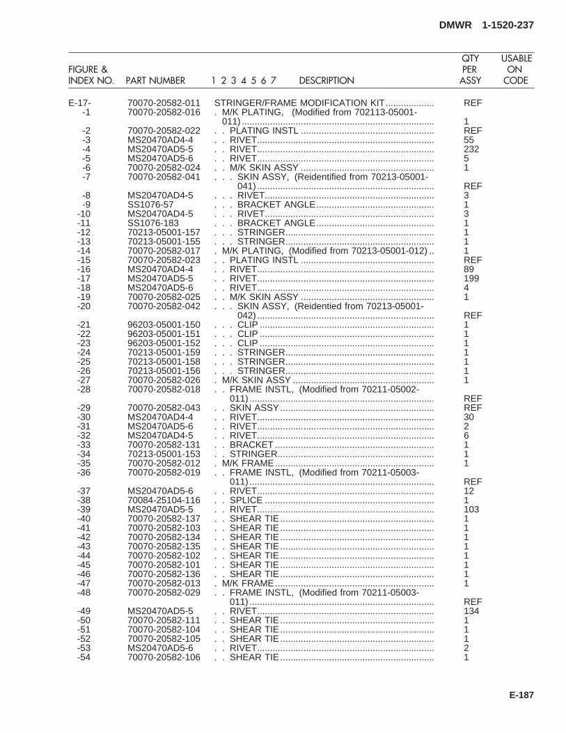
E-17- 70070-20582-011 STRINGER/FRAME MODIFICATION KIT................... REF-1 70070-20582-016 . M/K PLATING, (Modified from 702113-05001-
011) ........................................................................... 1-2 70070-20582-022 . . PLATING INSTL .................................................... REF-3 MS20470AD4-4 . . RIVET..................................................................... 55-4 MS20470AD5-5 . . RIVET..................................................................... 232-5 MS20470AD5-6 . . RIVET..................................................................... 5-6 70070-20582-024 . . M/K SKIN ASSY .................................................... 1-7 70070-20582-041 . . . SKIN ASSY, (Reidentified from 70213-05001-
041) ..................................................................... REF-8 MS20470AD4-5 . . . RIVET.................................................................. 3-9 SS1076-57 . . . BRACKET ANGLE.............................................. 1
-10 MS20470AD4-5 . . . RIVET.................................................................. 3-11 SS1076-183 . . . BRACKET ANGLE.............................................. 1-12 70213-05001-157 . . . STRINGER.......................................................... 1-13 70213-05001-155 . . . STRINGER.......................................................... 1-14 70070-20582-017 . M/K PLATING, (Modified from 70213-05001-012) .. 1-15 70070-20582-023 . . PLATING INSTL .................................................... REF-16 MS20470AD4-4 . . RIVET..................................................................... 89-17 MS20470AD5-5 . . RIVET..................................................................... 199-18 MS20470AD5-6 . . RIVET..................................................................... 4-19 70070-20582-025 . . M/K SKIN ASSY .................................................... 1-20 70070-20582-042 . . . SKIN ASSY, (Reidentied from 70213-05001-
042) ..................................................................... REF-21 96203-05001-150 . . . CLIP .................................................................... 1-22 96203-05001-151 . . . CLIP .................................................................... 1-23 96203-05001-152 . . . CLIP .................................................................... 1-24 70213-05001-159 . . . STRINGER.......................................................... 1-25 70213-05001-158 . . . STRINGER.......................................................... 1-26 70213-05001-156 . . . STRINGER.......................................................... 1-27 70070-20582-026 . M/K SKIN ASSY ....................................................... 1-28 70070-20582-018 . . FRAME INSTL, (Modified from 70211-05002-
011) ........................................................................ REF-29 70070-20582-043 . . SKIN ASSY............................................................ REF-30 MS20470AD4-4 . . RIVET..................................................................... 30-31 MS20470AD5-6 . . RIVET..................................................................... 2-32 MS20470AD4-5 . . RIVET..................................................................... 6-33 70070-20582-131 . . BRACKET .............................................................. 1-34 70213-05001-153 . . STRINGER............................................................. 1-35 70070-20582-012 . M/K FRAME.............................................................. 1-36 70070-20582-019 . . FRAME INSTL, (Modified from 70211-05003-
011) ........................................................................ REF-37 MS20470AD5-6 . . RIVET..................................................................... 12-38 70084-25104-116 . . SPLICE .................................................................. 1-39 MS20470AD5-5 . . RIVET..................................................................... 103-40 70070-20582-137 . . SHEAR TIE ............................................................ 1-41 70070-20582-103 . . SHEAR TIE ............................................................ 1-42 70070-20582-134 . . SHEAR TIE ............................................................ 1-43 70070-20582-135 . . SHEAR TIE ............................................................ 1-44 70070-20582-102 . . SHEAR TIE ............................................................ 1-45 70070-20582-101 . . SHEAR TIE ............................................................ 1-46 70070-20582-136 . . SHEAR TIE ............................................................ 1-47 70070-20582-013 . M/K FRAME.............................................................. 1-48 70070-20582-029 . . FRAME INSTL, (Modified from 70211-05003-
011) ........................................................................ REF-49 MS20470AD5-5 . . RIVET..................................................................... 134-50 70070-20582-111 . . SHEAR TIE ............................................................ 1-51 70070-20582-104 . . SHEAR TIE ............................................................ 1-52 70070-20582-105 . . SHEAR TIE ............................................................ 1-53 MS20470AD5-6 . . RIVET..................................................................... 2-54 70070-20582-106 . . SHEAR TIE ............................................................ 1
DMWR 1-1520-237
QTY USABLEFIGURE & PER ONINDEX NO. PART NUMBER 1 2 3 4 5 6 7 DESCRIPTION ASSY CODE
E-187

-55 70070-20582-107 . . SHEAR TIE ............................................................ 1-56 70070-20582-108 . . SHEAR TIE ............................................................ 1-57 70070-20582-109 . . SHEAR TIE ............................................................ 1-58 70070-20582-110 . . SHEAR TIE ............................................................ 1-59 70070-20582-027 . M/K FRAME.............................................................. 1-60 70070-20582-020 . . FRAME INSTL, (Modified from 70211-05004-
011) ........................................................................ REF-61 MS20470AD5-5 . . RIVET..................................................................... 134-62 70070-20582-145 . . SHEAR TIE ............................................................ 1-63 70070-20582-144 . . SHEAR TIE ............................................................ 1-64 70070-20582-146 . . SHEAR TIE ............................................................ 1-65 MS20470AD5-6 . . RIVET..................................................................... 2-66 70070-20582-148 . . SHEAR TIE ............................................................ 1-67 70070-20582-150 . . SHEAR TIE ............................................................ 1-68 70070-20582-151 . . SHEAR TIE ............................................................ 1-69 70070-20582-149 . . SHEAR TIE ............................................................ 1-70 70070-20582-147 . . SHEAR TIE ............................................................ 1-71 70070-20582-014 . M/K FRAME.............................................................. 1-72 70070-20582-030 . . FRAME INSTL, (Modified from 70211-05004-
011) ........................................................................ REF-73 MS20470AD5-5 . . RIVET..................................................................... 123-74 70070-20582-139 . . SHEAR TIE ............................................................ 1-75 70070-20582-141 . . SHEAR TIE ............................................................ 1-76 70070-20582-132 . . SHEAR TIE ............................................................ 1-77 70070-20582-133 . . SHEAR TIE ............................................................ 1-78 70070-20582-140 . . SHEAR TIE ............................................................ 1-79 70070-20582-115 . . SHEAR TIE ............................................................ 1-80 70070-20582-142 . . SHEAR TIE ............................................................ 1-81 70070-20582-117 . . SHEAR TIE ............................................................ 1-82 70070-20582-116 . . SHEAR TIE ............................................................ 1-83 70070-20582-138 . . SHEAR TIE ............................................................ 1-84 70070-20582-114 . . SHEAR TIE ............................................................ 1-85 70070-20582-112 . . SHEAR TIE ............................................................ 1-86 70070-20582-143 . . SHEAR TIE ............................................................ 1-87 70070-20582-028 . M/K FRAME.............................................................. 1-88 70070-20582-021 . . FRAME INSTL, (Modified from 70211-05005-
011) ........................................................................ REF-89 MS20470AD5-5 . . RIVET..................................................................... 123-90 70070-20582-155 . . SHEAR TIE ............................................................ 1-91 70070-20582-153 . . SHEAR TIE ............................................................ 1-92 70070-20582-152 . . SHEAR TIE ............................................................ 1-93 70070-20582-154 . . SHEAR TIE ............................................................ 1-94 70070-20582-156 . . SHEAR TIE ............................................................ 1-95 70070-20582-158 . . SHEAR TIE ............................................................ 1-96 70070-20582-160 . . SHEAR TIE ............................................................ 1-97 70070-20582-162 . . SHEAR TIE ............................................................ 1-98 70070-20582-161 . . SHEAR TIE ............................................................ 1-99 70070-20582-159 . . SHEAR TIE ............................................................ 1
-100 70070-20582-157 . . SHEAR TIE ............................................................ 1-101 70070-20582-164 . . SHEAR TIE ............................................................ 1-102 70070-20582-163 . . SHEAR TIE ............................................................ 1-103 70070-20582-015 . M/K FRAME.............................................................. 1-104 MS20470AD5-5 . . RIVET..................................................................... 109-105 70070-20582-119 . . SHEAR TIE ............................................................ 1-106 70070-20582-118 . . SHEAR TIE ............................................................ 1-107 70070-20582-129 . . SHEAR TIE ............................................................ 1-108 70070-20582-130 . . SHEAR TIE ............................................................ 1-109 70070-20582-120 . . SHEAR TIE ............................................................ 1-110 70070-20582-122 . . SHEAR TIE ............................................................ 1-111 70070-20582-124 . . SHEAR TIE ............................................................ 1-112 70070-20582-126 . . SHEAR TIE ............................................................ 1
DMWR 1-1520-237
QTY USABLEFIGURE & PER ONINDEX NO. PART NUMBER 1 2 3 4 5 6 7 DESCRIPTION ASSY CODE
E-188

-113 70070-20582-128 . . SHEAR TIE ............................................................ 1-114 70070-20582-127 . . SHEAR TIE ............................................................ 1-115 70070-20582-125 . . SHEAR TIE ............................................................ 1-116 70070-20582-123 . . SHEAR TIE ............................................................ 1-117 70070-20582-121 . . SHEAR TIE ............................................................ 1
DMWR 1-1520-237
QTY USABLEFIGURE & PER ONINDEX NO. PART NUMBER 1 2 3 4 5 6 7 DESCRIPTION ASSY CODE
E-189

E-17. SKIN DOUBLER/PLATE INSTALLATION MODIFICATION KIT (50-13).
Subject: Tail Cone Plating Modification Kit, Installation of, dated 31 March 2003
Purpose: Provide instructions for installations of tail cone lower plating modification kit and tail cone side skin modifica-tion kit.
Model: UH-60A
Description: Lower skin and doubler are removed between station 485.00 and station 605.00, and new lower skin anddoubler are installed. Doublers are installed left and right side of tail cone between stations 625.00 and 635.00.
Drawings Required for Modification:
70070-20615, 70212-05004, 70070-20583
References: (a) TM 1-1520-237-23, Aviation Unit And Intermediate Maintenance For Army Models UH-60A, UH-60L, EH-60A, and UH-60Q Helicopters, Chapter 2, Airframe
(b) Special Service Instructions (SSI) No. 50-31, Installation of 9A to A9 Recapitalization Program, datedMarch 31, 2003
(c) SSI No. 50-24, Tail Cone, Modification of dated 31 March 2003
Instructions:
NOTE
• A complete review of this SSI is recommended before modifying tail cone plating.
• Before beginning this modification procedure, use the material information list to inventory the kit. Makesure all parts are present and in serviceable condition.
• The sheet metal and structural modifications in this SSI shall be done by personnel experienced in readingmodification drawings. Routine steps such as cleaning, layout and drilling, deburring, standard repairs,corrosion control, clean up after rework, chemical coating for aluminum after cutting/trimming parts, painttouch up, and safety practices may not be called out herein. However, these steps and all other requiredroutine tasks shall be done.
• Where drawing numbers are not listed within individual steps, drawing(s) listed in preceding step(s) arethe controlling authority.
• Slight variations to the instructions contained herein are allowed, as long as the intent of the modificationis accomplished.
• This modification is to be done concurrently with reference (c).
A. Preparation for modification and removal of equipment:
(1) Confirm that all warnings, cautions, and notes are complied with per reference (b).
(2) Perform preparation for modification per reference (b).
DMWR 1-1520-237
E-190

B. Modify tail cone as follows:
(1) Remove skin assembly (70213-05001-043) as follows:
(a) Remove fasteners securing skin assembly to frame between station 485.00 and station 585.00 (Dwg70070-20615, Sheet 2, Zones 10-B through 10-G to 19-B through 19-G).
(b) Remove skin assembly with stringers attached, and discard.
(c) Inspect and clean exposed stringers and frame components per reference (a).
(2) Rework left and right side tail cone between stations 625.00 and 635.00 as follows:
(a) Locate doubler (70070-20583-101) on left side of tail cone between station 624.00 and station 635.00along waterline 235.00 (Dwg 70070-20583, Sheet 2, Zone 6-H).
(b) Mark and remove existing fasteners.
(c) Locate doubler (70070-20583-102) on right side of tail cone between station 624.00 and station 635.00along waterline 235.00 (Sheet 2, Zone 6-H).
(d) Mark and remove existing fasteners.
(e) Locate and temporarily secure doublers and back drill through existing fastener holes.
(f) Remove doublers, deburr and touch up, as required. Remove skin assembly, deburr and touch up, asrequired.
WARNING
OBSERVE ALL CAUTIONS AND WARNINGS ON CONTAINERS WHEN USING CONSUMABLES.WHEN APPLICABLE, WEAR NECESSARY PROTECTIVE GEAR DURING HANDLING AND USE. IF ACONSUMABLE IS FLAMMABLE OR EXPLOSIVE, MAKE CERTAIN CONSUMABLE AND ITS VAPORS AREKEPT AWAY FROM HEAT, SPARK, AND FLAME. MAKE CERTAIN EQUIPMENT IS PROPERLYGROUNDED AND FIREFIGHTING EQUIPMENT IS READILY AVAILABLE PRIOR TO USE. FOR AD-DITIONAL INFORMATION ON TOXICITY, FLASHPOINT, AND FLAMMABILITY OF CHEMICALS,CONSULT YOUR MEDICAL PEOPLE, OR MANUFACTURER OF THE CONSUMABLE.
(g) Install doublers (70070-20583-101 and -102) on left and right side wet with sealant (AMS-S-8802 orAMS 3265 or equivalent) using fasteners shown (Sheet 2, Zone 6-H and Note 7).
NOTE
After modification structure assembly (70210-05001-045) becomes (70070-20583-041) and structureassembly (70210-05001-046) becomes (70070-20583-042). No physical reidentification is required.
(3) Perform reference (c) modification before completing skin assembly installation.
(4) Install new skin assembly (70213-55001-041/-541) between stations 485.00 and 565.00 as follows:
DMWR 1-1520-237
E-191
(a) Locate and temporarily install bracket (AN743Z12) on stringer at location shown (Dwg 70070-20615,Sheet 2, Zone 12-B, Section J-J).
(b) Drill fastener hole at location shown (Sheet 2, Zone 13-A).
(c) Remove bracket, deburr and touch up, as required.
(d) Secure bracket (AN743Z12) to stringer using fastener shown (Sheet 2, Zone 13-A).
(e) Locate and temporarily secure new skin assembly (70213-55001-041/-541) onto frames (Sheet 2, Zones10-B through 10-D to 19-B through 19-E).
WARNING
OBSERVE ALL CAUTIONS AND WARNINGS ON CONTAINERS WHEN USING CONSUMABLES.WHEN APPLICABLE, WEAR NECESSARY PROTECTIVE GEAR DURING HANDLING AND USE. IF ACONSUMABLE IS FLAMMABLE OR EXPLOSIVE, MAKE CERTAIN CONSUMABLE AND ITS VAPORS AREKEPT AWAY FROM HEAT, SPARK, AND FLAME. MAKE CERTAIN EQUIPMENT IS PROPERLYGROUNDED AND FIREFIGHTING EQUIPMENT IS READILY AVAILABLE PRIOR TO USE. FOR AD-DITIONAL INFORMATION ON TOXICITY, FLASHPOINT, AND FLAMMABILITY OF CHEMICALS,CONSULT YOUR MEDICAL PEOPLE, OR MANUFACTURER OF THE CONSUMABLE.
(f) Locate and bond grommets (AN231-4) eight places using adhesive (EA9309.3NA or equivalent) as shown(Sheet 2, Zones 11-B and 19-B and Sheet 1, Note 9).
NOTE
Reference (c) shear ties at or below waterline 215.00 should be fit-out at this time to ensure propercontour.
(g) Remove skin assembly, and reference (c) shear ties, deburr and touch up, as required.
WARNING
OBSERVE ALL CAUTIONS AND WARNINGS ON CONTAINERS WHEN USING CONSUMABLES.WHEN APPLICABLE, WEAR NECESSARY PROTECTIVE GEAR DURING HANDLING AND USE. IF ACONSUMABLE IS FLAMMABLE OR EXPLOSIVE, MAKE CERTAIN CONSUMABLE AND ITS VAPORS AREKEPT AWAY FROM HEAT, SPARK, AND FLAME. MAKE CERTAIN EQUIPMENT IS PROPERLYGROUNDED AND FIREFIGHTING EQUIPMENT IS READILY AVAILABLE PRIOR TO USE. FOR AD-DITIONAL INFORMATION ON TOXICITY, FLASHPOINT, AND FLAMMABILITY OF CHEMICALS,CONSULT YOUR MEDICAL PEOPLE, OR MANUFACTURER OF THE CONSUMABLE.
(h) Apply adhesive (MIL-C-22750 or equivalent) on inboard side of skin and structure as shown (Sheet 2,Zones 18-A through 18-E, and Sheet 1, Note 7).
DMWR 1-1520-237
E-192
WARNING
OBSERVE ALL CAUTIONS AND WARNINGS ON CONTAINERS WHEN USING CONSUMABLES.WHEN APPLICABLE, WEAR NECESSARY PROTECTIVE GEAR DURING HANDLING AND USE. IF ACONSUMABLE IS FLAMMABLE OR EXPLOSIVE, MAKE CERTAIN CONSUMABLE AND ITS VAPORS AREKEPT AWAY FROM HEAT, SPARK, AND FLAME. MAKE CERTAIN EQUIPMENT IS PROPERLYGROUNDED AND FIREFIGHTING EQUIPMENT IS READILY AVAILABLE PRIOR TO USE. FOR AD-DITIONAL INFORMATION ON TOXICITY, FLASHPOINT, AND FLAMMABILITY OF CHEMICALS,CONSULT YOUR MEDICAL PEOPLE, OR MANUFACTURER OF THE CONSUMABLE.
(i) Apply sealant (AMS-S-8802 A2 or equivalent) to skin overlap areas (Sheet 1, Note 8).
(j) Secure skin onto frame and wet install fasteners as shown (Sheet 2, Zones 10-B through 10-D to 19-Bthrough 19-E).
NOTE
70070-20615-101 doubler may already be installed on skin 70213-55001. If installed proceed to stepC.(1).
(k) Locate and temporarily secure doubler (70070-20615-101) (Sheet 2, Zone 14-B).
(l) Drill fastener holes as shown (Sheet 2, Zone 14-B and Dwg 70212-05004, Sheet 1, Zone 17-C).
(m) Remove doubler, deburr and touch up, as required.
WARNING
OBSERVE ALL CAUTIONS AND WARNINGS ON CONTAINERS WHEN USING CONSUMABLES.WHEN APPLICABLE, WEAR NECESSARY PROTECTIVE GEAR DURING HANDLING AND USE. IF ACONSUMABLE IS FLAMMABLE OR EXPLOSIVE, MAKE CERTAIN CONSUMABLE AND ITS VAPORS AREKEPT AWAY FROM HEAT, SPARK, AND FLAME. MAKE CERTAIN EQUIPMENT IS PROPERLYGROUNDED AND FIREFIGHTING EQUIPMENT IS READILY AVAILABLE PRIOR TO USE. FOR AD-DITIONAL INFORMATION ON TOXICITY, FLASHPOINT, AND FLAMMABILITY OF CHEMICALS,CONSULT YOUR MEDICAL PEOPLE, OR MANUFACTURER OF THE CONSUMABLE.
(n) Install sealant tape (AMS3255 CL2) to doubler seating surface (Dwg 70070-20615, Sheet 1, Note 10).
(o) Secure doubler (70070-20615-101) using fasteners shown (Dwg 70213-55001, Sheet 1, Zone 14-B andDwg 70212-05004, Sheet 1, Zone 17-C, and Note 8).
C. Reinstallation of removed equipment:
(1) Install removed equipment per reference (b).
D. Record of Compliance:
(1) Make an appropriate logbook entry to show compliance with this Special Service Instruction.
DMWR 1-1520-237
E-193

Weight and Balance Data:
QTY PART NO. NOMENCLATUREPOUNDSWEIGHT
INCHES AFTOF DATUM
MOMENT/1000
1 70070-20615-011 Mod. Kit 3.98 535.0 +2.129
1 70070-20583-011 Mod. Kit +0.50 630.0 +0.315
Weight and Balance: Change resulting from these instructions are as follows:
Change in basic weight: +4.5 pounds
Moment arm: 543.0 in.
Change in basic moment/1000: +2.444
Manpower (Estimated)
No. of Personel No. of Hours Man-hoursHelicopter Mechanic 2 40.0 *80.0
*Does not include time required to prepare helicopter or return it to flight status.
DMWR 1-1520-237
E-194

Material Information:
A. Modification Kits Required:
(1) Kit A:
Qty Nomenclature Part Number Source
1 Mod Kit, Plating Instl 70070-20615-011 (1)
consisting of:
8 Grommet AN231-41 Bracket AN743Z1290 Rivet MS20470AD4-584 Rivet MS20470AD5-5200 Rivet MS20470AD5-670 Rivet MS20470AD6-6100 Rivet MS20470AD6-812 Collar NAS1080D066 Pin, Swg Lkg NAS1526-026 Pin, Swg Lkg NAS1526-031 Doubler 70070-20615-101*1 Skin Assy 70213-55001-041/541*
*70213-55001-541 consists of 70213-55001-041 skin assembly and 70070-20615-101 doubler
(2) Kit B:
Qty Nomenclature Part Number Source
1 Mod. Kit, Skin Doubler, 70070-20583-011 (1)
consisting of:1 Doubler 70070-20583-1011 Doubler 70070-20583-10214 Rivet MS20470AD4-262 Rivet MS20470AD5-33 Rivet MS20470AD5-425 Rivet MS20470AD6-43 Rivet MS20470AD6-5
DMWR 1-1520-237
E-195

B. Consumable Material:
WARNING
OBSERVE ALL CAUTIONS AND WARNINGS ON CONTAINERS WHEN USING CONSUMABLES.WHEN APPLICABLE, WEAR NECESSARY PROTECTIVE GEAR DURING HANDLING AND USE. IF ACONSUMABLE IS FLAMMABLE OR EXPLOSIVE, MAKE CERTAIN CONSUMABLE AND ITS VAPORS AREKEPT AWAY FROM HEAT, SPARK, AND FLAME. MAKE CERTAIN EQUIPMENT IS PROPERLYGROUNDED AND FIREFIGHTING EQUIPMENT IS READILY AVAILABLE PRIOR TO USE. FOR AD-DITIONAL INFORMATION ON TOXICITY, FLASHPOINT, AND FLAMMABILITY OF CHEMICALS,CONSULT YOUR MEDICAL PEOPLE, OR MANUFACTURER OF THE CONSUMABLE.
Qty Nomenclature Part Number Source
16 oz. Sealant AMS-S-8802 A2, or equivalent (1)8 oz. Sealant AMS 3255 CL2, or equivalent (1)8 oz. Adhesive EA9309-3NA, or equivalent (1)8 oz. Epoxy, Clear MIL-C-22750, or equivalent (1)
C. Source:
(1) Available through normal supply channels
DMWR 1-1520-237
E-196
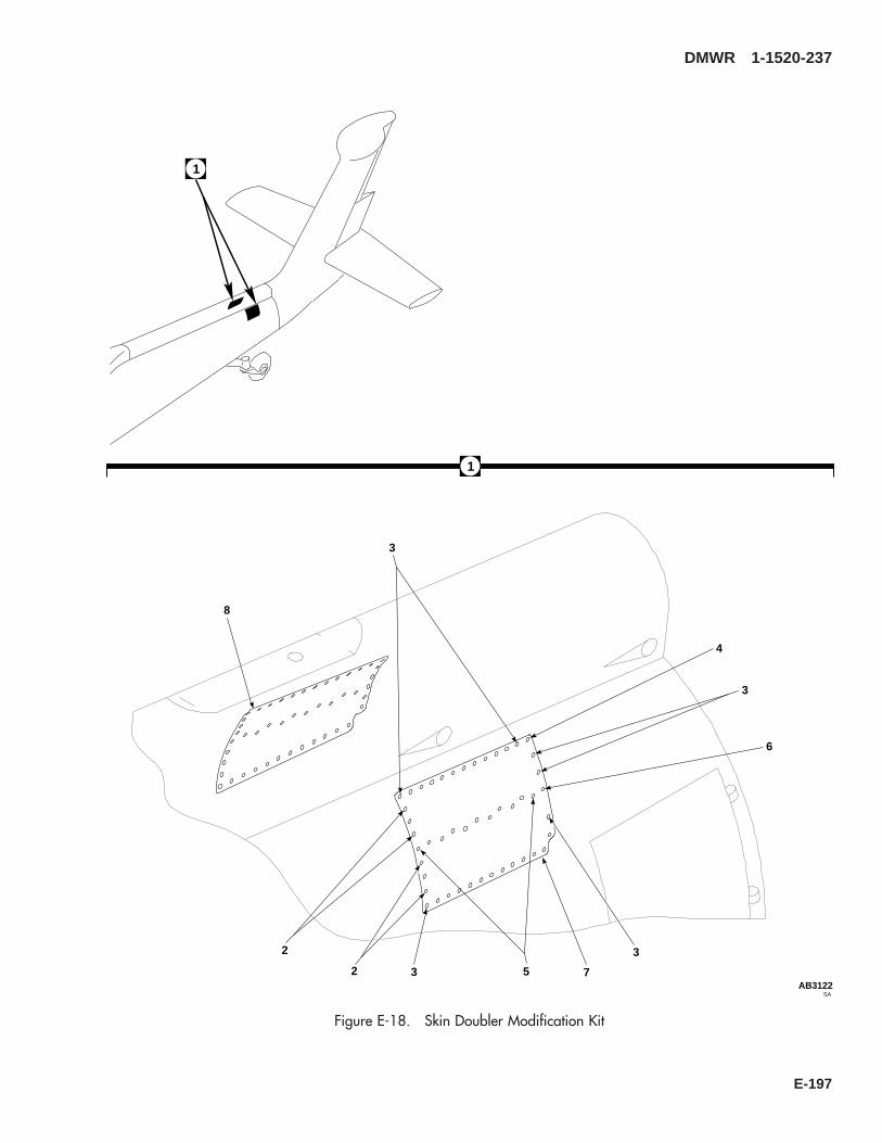
1
8
3
3
5
6
2
2
3
3
4
SAAB3122
1
7
Figure E-18. Skin Doubler Modification Kit
DMWR 1-1520-237
E-197

E-18- 70070-20583-011 SKIN DOUBLER MODIFICATION KIT ........................ REF-1 70070-20583-041 STRUCTURAL ASSY, (Reidentifed from 70210-
05001-045)................................................................... REF70070-20583-042 STRUCTURAL ASSY, (Reidentifed from 70210-
05001-046)................................................................... REF-2 MS20470AD4-2 . RIVET........................................................................ 14-3 MS20470AD5-3 . RIVET........................................................................ 62-4 MS20470AD5-4 . RIVET........................................................................ 3-5 MS20470AD6-4 . RIVET........................................................................ 25-6 MS20470AD6-5 . RIVET........................................................................ 3-7 70070-20583-101 . DOUBLER, LH.......................................................... 1-8 70070-20583-102 . DOUBLER, RH ......................................................... 1
DMWR 1-1520-237
QTY USABLEFIGURE & PER ONINDEX NO. PART NUMBER 1 2 3 4 5 6 7 DESCRIPTION ASSY CODE
E-198

45
12
A
1
45678
1
2
2
3
7
SAAB3123_1
13
Figure E-19. Plate Installation Modification Kit (Sheet 1 of 2)
DMWR 1-1520-237
E-199

13
222026
24
27
19
21
18 23
1725
SAAB3123_2
141516
FRONT
910
11
A
Figure E-19. Plate Installation Modification Kit (Sheet 2 of 2)
DMWR 1-1520-237
E-200

E-19- 70070-20615-011 PLATE INSTALLATION MODIFICATION KIT............. REF-1 70213-55001-011 . PLATING INSTL, (Reidentified from 70213-05001-
013) ........................................................................... REF-2 AN231-4 . GROMMET ............................................................... 8-3 AN743Z12 . BRACKET ................................................................. 1-4 MS20470AD4-5 . RIVET........................................................................ 90-5 MS20470AD5-5 . RIVET........................................................................ 84-6 MS20470AD5-6 . RIVET........................................................................ 200-7 MS20470AD6-6 . RIVET........................................................................ 70-8 MS20470AD6-8 . RIVET........................................................................ 100-9 NAS1526-02 . SWAGE LOCKING PIN ............................................ 6
-10 NAS1526-03 . SWAGE LOCKING PIN ............................................ 6-11 NAS1080D06 . COLLAR.................................................................... 12-12 70070-20615-101 . DOUBLER................................................................. 1-13 70213-55001-041 . SKIN ASSY............................................................... 1-14 MS20470AD4 . . RIVET..................................................................... 1009-15 MS20470AD5 . . RIVET..................................................................... 246-16 NAS1738B4-2 . . BLIND RIVET......................................................... 28-17 70213-05001-173 . . STRINGER............................................................. 1-18 70213-05001-174 . . STRINGER............................................................. 1-19 70213-05001-182 . . STRINGER............................................................. 1-20 70213-05001-183 . . STRINGER............................................................. 1-21 70213-05001-187 . . STRINGER............................................................. 2-22 70213-05001-188 . . STRINGER............................................................. 2-23 70213-05001-190 . . SKIN....................................................................... 1-24 70213-55001-101 . . STRINGER............................................................. 1-25 70213-55001-102 . . STRINGER............................................................. 1-26 70213-55001-103 . . STRINGER............................................................. 1-27 70213-55001-104 . . STRINGER............................................................. 1
DMWR 1-1520-237
QTY USABLEFIGURE & PER ONINDEX NO. PART NUMBER 1 2 3 4 5 6 7 DESCRIPTION ASSY CODE
E-201

E-18. BULKHEAD INSTALLATION MODIFICATION KIT (50-17).
Subject: Station 605.00 Bulkhead, Modification of
Purpose: Provide instructions to modify tailcone station 605.00 bulkhead
Model: UH-60A
Description: Tailcone station 605.00 bulkhead is modified by adding a new doubler, filler, and radius block at rightbuttline 4.80.
Drawings required for modification:
70551-05140, 70070-20617
References: (a) Special Service Instructions (SSI) No. 50-31, Installation of 9A to A9 Recapitalization Program, datedMarch 31, 2003
(b) SSI No. 50-29 Tailcone Shear Deck, Modification of dated 31 March 2003
Instructions:
NOTE
• A complete review of this SSI is recommended before modiying station 605.00.
• Before beginning this modification procedure, use the material information list to inventory the kit. Makesure all parts are present and in serviceable condition.
• Where drawing numbers are not listed within individual steps, drawing(s) listed in preceding step(s) arethe controlling authority.
• The sheet metal and structural modifications in this SSI shall be done by personnel experienced in readingmodification drawings. Routine steps such as cleaning, layout and drilling, deburring, standard repairs,corrosion control, clean up after rework, chemical coating for aluminum after cutting/trimming parts, painttouch up, and safety practices may not be called out herein. However, these steps and all other requiredroutine tasks shall be done.
• Slight variations to the instructions contained herein are allowed, as long as the intent of the modificationis accomplished.
• This modification is to be done concurrently with reference (b).
A. Preparation for modification and removal of equipment:
(1) Confirm that all warnings, cautions, and notes are complied with per reference (a).
(2) Perform preparation for modification per reference (a).
DMWR 1-1520-237
E-202

B. Rework channel (70211-05007-109) as follows (Dwg 70070-20617):
CAUTION
TO AVOID DAMAGING COMPONENTS, USE EXTREME CARE WHEN DRILLING INTO AIRFRAME.TEMPORARILY MOVE ANY TUBE ASSEMBLIES OR WIRING HARNESS OUT OF REWORK AREA.
NOTE
• Rework of channel (70211-05007-109) can be accomplished while channel (-109) remains installed atstation 605.00.
• If shear deck is removed to facilitate other maintenance, proceed to step B.(4).
(1) Rework channel (70211-05007-109) per dimensions shown (Dwg 70070-20617, Sheet 3, Zone 16-C).
(2) Deburr and touch up channel (70211-05007-109) as required.
(3) After rework reidentify channel (70211-05007-109) to (70070-20617-101) using pen and contracting ink.
(4) Remove four clips (two SS1050-1 and two SS1051-3) (Sheet 2, Zones 15-H, 11-H, and 12-B).
(5) Remove bracket assembly (SS7061-252) at buttline 0.00 (Sheet 2, Zone 9-E).
(6) Remove fasteners between left buttline 3.50 and right buttline 4.80 from channels (70211-05007-108 and-109) and angle (70211-05007-107) as shown (Sheet 1, Note 12 and Sheet 2, Zones 13-D and 13-E).
(7) Temporarily install radius block (70070-20617-103), filler (70070-20617-104), and doubler (70070-20617-105) (Sheet 2, Zones 7-C, 7-D, and 11-H, Sheet 1, Notes 14 and 15).
(8) Temporarily install two clips (SS1051-03) (Sheet 2, Zones 11-H and 12-B).
(9) Temporarily install bracket assembly (SS7061-252), two clips (SS1050-1), and nutplate (NAS1033N3)(Dwg 70551-05140, Sheet 3, Zones 6-C, 6-E, and 8-E, View F-F).
(10) Scribe directional cable hole in filler (70070-20617-104) and doubler (70070-20617-105).
(11) Remove parts temporarily installed in steps B.(7) through B.(9), deburr and touch up as required.
(12) Cut out hole in filler (70070-20617-104) and doubler (70070-20617-105) marked in step (B).(10).
(13) Install parts removed in step B.(11) using fasteners shown (Dwg 70070-20617, Sheet 1, Notes 2, 9, 12,and 16; Sheet 2, Zones 11-E through 13-E; Dwg 70551-05140, Sheet 3, View F-F, Zone 7-B).
DMWR 1-1520-237
E-203
WARNING
OBSERVE ALL CAUTIONS AND WARNINGS ON CONTAINERS WHEN USING CONSUMABLES.WHEN APPLICABLE, WEAR NECESSARY PROTECTIVE GEAR DURING HANDLING AND USE. IF ACONSUMABLE IS FLAMMABLE OR EXPLOSIVE, MAKE CERTAIN CONSUMABLE AND ITS VAPORS AREKEPT AWAY FROM HEAT, SPARK, AND FLAME. MAKE CERTAIN EQUIPMENT IS PROPERLYGROUNDED AND FIREFIGHTING EQUIPMENT IS READILY AVAILABLE PRIOR TO USE. FOR AD-DITIONAL INFORMATION ON TOXICITY, FLASHPOINT, AND FLAMMABILITY OF CHEMICALS,CONSULT YOUR MEDICAL PEOPLE, OR MANUFACTURER OF THE CONSUMABLE.
(14) Install grommet (MS21266-1N) using adhesive (SS9230-001 or equivalent) around control cable hole.
C. Reinstallation of removed equipment:
(1) Install removed equipment per reference (a).
D. Record of Compliance:
(1) Make an appropriate logbook entry to show compliance with this Special Service Instruction.
Weight and Balance Data:
QTY PART NO. NOMENCLATUREPOUNDSWEIGHT
INCHES AFTOF DATUM
MOMENT/1000
1 70070-20617-011 Mod. Kit +0.50 604.6 0.302
Weight and Balance: Change resulting from these instructions are as follows:
Change in basic weight: +0.50 pounds
Moment arm: 604.6 in.
Change in basic moment/1000: 0.302
Manpower (Estimated)
No. of Personel No. of Hours Man-hoursSheet Metal Mechanic 1 20.0 *20.0
*Does not include time required to prepare helicopter or return it to flight status.
DMWR 1-1520-237
E-204
Material Information:
A. Modification Kit Required:
Qty Nomenclature Part Number Source
1 Mod. Kit, Bulkhead Installation, 70070-20617-011 (1)
consisting of:1 Collar HL1087A-61 Pin, Hi Lok HL20PB-6-73 Rivet MS20470AD3-514 Rivet MS20470AD4-55 Rivet MS20470AD5-1035 Rivet MS20470AD5-69 Rivet MS20470AD5-728 Rivet MS20470AD5-92 Rivet MS20470AD6-101 Nutplate NAS1033N32 Clip SS1050-12 Clip SS1051-31 Bracket Assy SS7061-2521 Doubler 70070-20617-1051 Radius Block 70070-20617-1031 Filler 70070-20617-1041 Grommet MS21266-1N
B. Consumable Material:
WARNING
OBSERVE ALL CAUTIONS AND WARNINGS ON CONTAINERS WHEN USING CONSUMABLES.WHEN APPLICABLE, WEAR NECESSARY PROTECTIVE GEAR DURING HANDLING AND USE. IF ACONSUMABLE IS FLAMMABLE OR EXPLOSIVE, MAKE CERTAIN CONSUMABLE AND ITS VAPORS AREKEPT AWAY FROM HEAT, SPARK, AND FLAME. MAKE CERTAIN EQUIPMENT IS PROPERLYGROUNDED AND FIREFIGHTING EQUIPMENT IS READILY AVAILABLE PRIOR TO USE. FOR AD-DITIONAL INFORMATION ON TOXICITY, FLASHPOINT, AND FLAMMABILITY OF CHEMICALS,CONSULT YOUR MEDICAL PEOPLE, OR MANUFACTURER OF THE CONSUMABLE.
Qty Nomenclature Part Number Source
1 oz. Adhesive SS9230-001 or equivalent (1)
C. Source:
(1) Available through normal supply channels
DMWR 1-1520-237
E-205

SAAB3084
2
2
4
5
5
11 10
12
13
76
24
15
22
2321
17
17
20
3
8
9
16
17
17
19
14
2019
18
17
1
Figure E-20. Bulkhead Installation Modification Kit
DMWR 1-1520-237
E-206
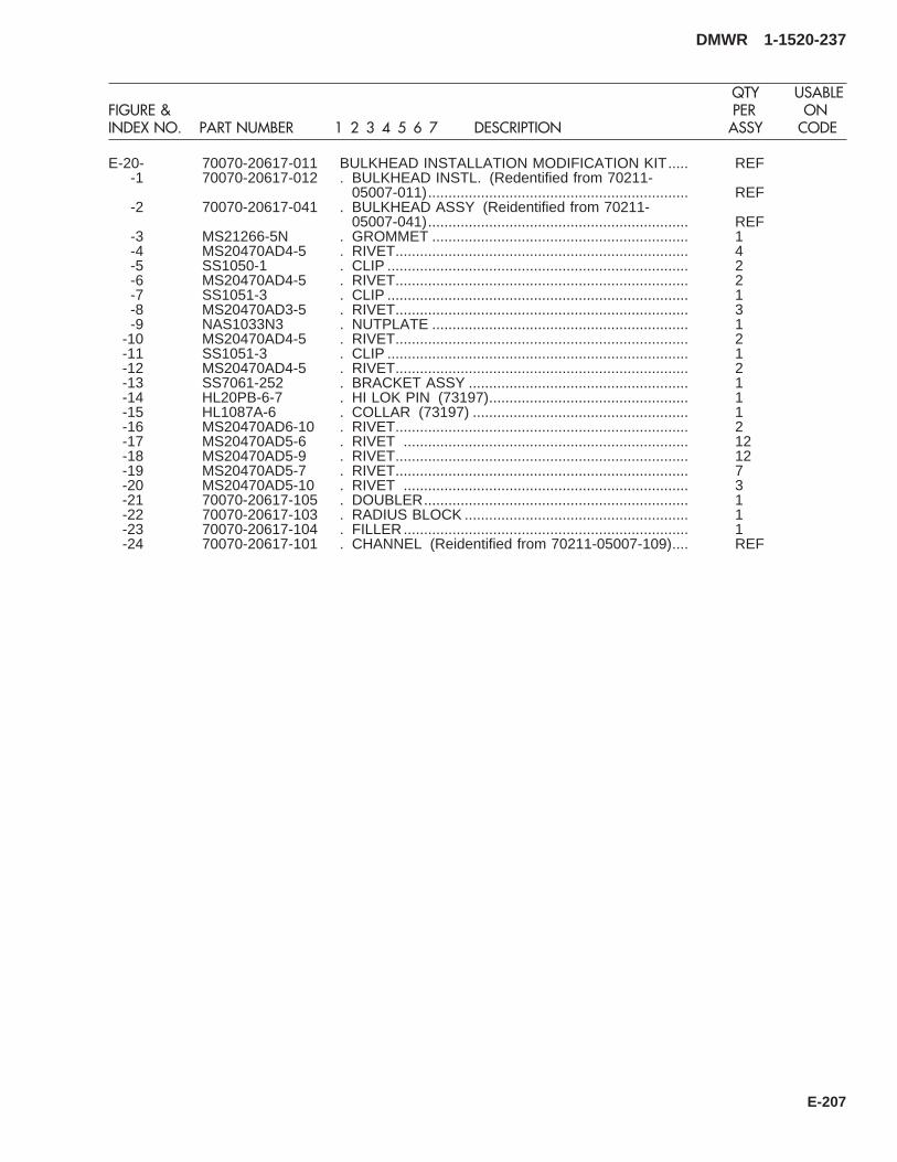
E-20- 70070-20617-011 BULKHEAD INSTALLATION MODIFICATION KIT..... REF-1 70070-20617-012 . BULKHEAD INSTL. (Redentified from 70211-
05007-011)................................................................ REF-2 70070-20617-041 . BULKHEAD ASSY (Reidentified from 70211-
05007-041)................................................................ REF-3 MS21266-5N . GROMMET ............................................................... 1-4 MS20470AD4-5 . RIVET........................................................................ 4-5 SS1050-1 . CLIP .......................................................................... 2-6 MS20470AD4-5 . RIVET........................................................................ 2-7 SS1051-3 . CLIP .......................................................................... 1-8 MS20470AD3-5 . RIVET........................................................................ 3-9 NAS1033N3 . NUTPLATE ............................................................... 1
-10 MS20470AD4-5 . RIVET........................................................................ 2-11 SS1051-3 . CLIP .......................................................................... 1-12 MS20470AD4-5 . RIVET........................................................................ 2-13 SS7061-252 . BRACKET ASSY ...................................................... 1-14 HL20PB-6-7 . HI LOK PIN (73197)................................................. 1-15 HL1087A-6 . COLLAR (73197) ..................................................... 1-16 MS20470AD6-10 . RIVET........................................................................ 2-17 MS20470AD5-6 . RIVET ...................................................................... 12-18 MS20470AD5-9 . RIVET........................................................................ 12-19 MS20470AD5-7 . RIVET........................................................................ 7-20 MS20470AD5-10 . RIVET ...................................................................... 3-21 70070-20617-105 . DOUBLER................................................................. 1-22 70070-20617-103 . RADIUS BLOCK ....................................................... 1-23 70070-20617-104 . FILLER...................................................................... 1-24 70070-20617-101 . CHANNEL (Reidentified from 70211-05007-109).... REF
DMWR 1-1520-237
QTY USABLEFIGURE & PER ONINDEX NO. PART NUMBER 1 2 3 4 5 6 7 DESCRIPTION ASSY CODE
E-207

E-19. TAIL PYLON, CRCT DOUBLER, FRONT SPAR FT MODIFICATION KIT (50-8).
Subject: Tail Rotor Pylon, Modification of, dated 31 March 2003
Purpose: Provide instructions for modification of tail rotor pylon.
Model: UH-60A
Description: The tail rotor pylon is modified by installing a new left side doubler, two right side straps and cold workingeight fastener holes. Tail rotor gearbox mount fitting is removed and a new fitting is installed. Forward spar doubler isreplaced with a new doubler, one support assembly is modified and one support assembly is replaced with a new as-sembly. Fairing installation is modified.
Drawings Required for Modification:
70070-20465, 70202-06051, 70201-06164
References: (a) Special Service Instructions (SSI) No. 50-31, Installation of 9A to A9 Recapitalization Program, datedMarch 31, 2003
(b) TM 1-1520-265-23, Technical Manual, Aviation Unit Maintenance (AVUM) and Aviation Intermedi-ate (AVIM) Manual, Nondestructive Inspection Procedure for H-60 Helicopter Series
(c) TM 1-1500-335-23, Technical Manual, Nondestructive Inspection Methods
Instructions:
NOTE
• A complete review of this Special Service Instructions (SSI) is recommended before starting the tail rotorpylon modification.
• Before beginning this modification procedure, use the material information list to inventory the kit. Makesure all parts are present and in serviceable condition.
• The sheet metal and structural modifications in this SSI shall be done by personnel experienced in readingmodification drawings. Routine steps such as cleaning, layout and drilling, deburring, standard repairs,corrosion control, clean up after rework, chemical coating for aluminum after cutrting/trimming parts,paint touch up and safety practices may not be called out herein. However, these steps and all otherrequired routine tasks shall be done.
• Where drawing numbers are not listed within individual steps, drawing(s) listed in preceding step(s) arethe controlling authority.
• Slight variations to the instructions contained herein are allowed, as long as the intent of the modificationis accomplished.
• Personnel must be trained and certified in hole quality assurance and proper cold expansion proceduresper SS5098.
A. Preparation for modification and removal of equipment:
(1) Confirm that all warnings, cautions, and notes are complied with per reference (a).
DMWR 1-1520-237
E-208

(2) Perform preparation for modification per reference (a).
B. Modify tail rotor pylon as follows:
(1) Drill out fasteners and remove strap (70203-06050-114) from between pylon station 204.00 and pylon sta-tion 212.00. Keep strap for use as template (Dwg 70070-20465, Sheet 4, Zone 4-E).
(2) Remove washers, nuts, and fasteners as shown (Sheet 4, Zone 8-C).
(3) Remove fasteners shown (Sheet 4, Zones 7-B through 10-B, 6-C through 10-C, 5-D through 8-D, 4-E, 6-E,and 6-F).
(4) Remove tail rotor gear box fitting (70209-06056-041) from tail rotor pylon as follows:
(a) Locate and align tail rotor gearbox fitting installation tool (70209-06056-041T046 or equivalent) asfollows:
1 Thoroughly clean surface of tail rotor gear box mounting pads.
2 Install tool (70209-06056-041T046) on fitting (70209-06056-041) and secure in place using pins,clamps, and barrel nuts.
3 Loosen two clamp block screws and thumb screws, and align pins with center of dimple in fastener.
4 Adjust rods and pointer to any four fasteners on each side of pylon. Tighten screws after correct position-ing of pins.
5 Mark eight fastener heads with marker, or equivalent.
NOTE
These eight marked fasteners will be the trammel points to locate new fitting (70209-06056-042).
6 Apply torque stripe to each tool screw to ensure alignment.
7 Back pins out of fastener heads enough to allow for removal of tool, and remove mount fitting tool fromfitting.
8 Store and secure tool in such a way as to avoid disturbing tool settings.
(b) Remove fasteners securing left and right side skin, between pylon station 200.31 and station 210.69 asrequired (Dwg 70202-06051, Sheet 3, Zones 4-G and 5-G, and Sheet 2, Zones 4-C and 4-D through 6-C and 6-D).
(c) Remove web splice fasteners as required (Sheet 2, Zones 3-J to 3-M through 6-J to 6-M).
(d) Peel back pylon skin, as required, to remove fitting (70209-06056-041).
(e) Remove angles as required.
(f) Remove remaining fasteners securing fitting to pylon structure, and remove fitting (70209-06056-041).
(g) Discard removed fitting (70209-06056-041).
(h) Clean and inspect rework area.
DMWR 1-1520-237
E-209

(i) Install new fitting (70209-06056-042) into position in pylon frame and secure inner structure componentswith temporary fasteners or clamps.
(j) Install alignment tool (70209-06056-041T046), align eight pins with eight marked fasteners andtemporarily secure.
(k) Drill fastener holes, as required, on each leg of fitting and secure with temporary fasteners or clamps.
(l) Recheck alignment tool to insure that pointers are still in position.
(m) Remove alignment tool and continue drilling fastener holes, as required.
(5) Modify forward spar and support assemblies as follows:
(a) Drill out fasteners and remove support assembly (70400-06681-042, or -043) from pylon station 193.00(Dwg 70070-20465, Sheet 8, Zones 12-G and 13-G, and Sheet 6, Notes 26, and 27).
(b) Drill out fasteners and remove angle (70202-06051-149) as shown (Sheet 8, Zone 14-E).
(c) Drill out fasteners and remove angle (70400-06680-143) at pylon station 187.00 (Sheet 8, Zone 6-F).
(d) Drill out fasteners and remove support assembly (70400-06680-041) from pylon station 185.00 (Sheet 8,Zone 15-B).
(e) Drill out fasteners and remove doubler (70202-06051-158) from pylon station 190.47 (Sheet 8, Zone 13-B).
(f) Drill out fasteners and remove radius block (SS1058A7-27-46) (Sheet 8, Zone 6-C).
(g) Drill out fasteners and remove radius block (SS1058A7-25-24) (Sheet 2, Zone 8-D).
(h) Temporarily install new radius blocks (SS1058A7-25-24 and SS1058A7-27-46) as shown (Sheet 8,Zones 8-D and 6-C).
(i) Temporarily install doubler (70070-20465-104) at pylon station 190.47 (Sheet 8, Zone 13-B).
(j) Temporarily install angle (70070-20465-105) as shown (Sheet 8, Zone 5-G).
(k) Temporarily install angle (70202-06051-149) as shown (Sheet 8, Zone 14-E).
(l) Mark and drill fastener holes in doubler (70070-20465-105), radius blocks (SS1058A7-25-24 andSS1058A7-27-46), and angles (70070-20465-400-06680-143) and (70202-06051-149) (Sheet 8, Zones 12-C and12-D through 13-C and 13-D, and 6-E, 6-C, 7-E, and 7-D).
(m) Remove temporarily installed doubler, radius blocks, and angles, deburr and touch up as required.
(n) Install radius blocks (SS1058A7-25-24 and SS1058A7-27-46) using fasteners shown (Sheet 8, Zones 8-Dand 6-C).
(o) Install doubler (70070-20465-104) and angle (70070-20465-105) and (70202-06051-149) usingfasteners shown (Dwg 70070-20465, Sheet 8, Zone 12-C, 12-D through 14-C and 14-D, and 5-D through 7-D).
(p) Temporarily install support assembly (70400-06680-546) with laminated shim (70400-06680-145) (ifrequired) as shown (Sheet 8, Zones 10-B and 11-C). Adjust shim as required.
DMWR 1-1520-237
E-210

(q) Temporarily install new support assembly (70400-06681-044) as shown (Sheet 8, Zone 12-G).
(r) Mark and drill fastener holes through temporarily installed support assemblies, and shim as required.
(s) Remove temporarily installed support assembly with laminated shim and support assembly (70400-06681-044), deburr and touch up as required.
(t) Install support assembly (70400-06680-046) with laminated shim (70400-06680-145) (if required) andsecure using fasteners shown (Sheet 8, Zones 10-B and 11-C).
(u) Install support assembly (70400-06681-044) using fasteners shown (Sheet 8, Zones 12-G and 13-G).
(v) After modification, reidentify upper spar assembly (70202-06051-043) to (70070-20465-044) and up-per spar assembly (70202-06051-044) to (70070-20465-045) using pen and constrasting ink.
NOTE
After modification, spar installation (70202-06051-012) becomes (70070-20465-030), support installa-tion (70400-06680-012) becomes (70070-20465-031), and support installation (70400-06680-014)becomes (70070-20465-032). No physical reidentification required.
(6) Install new tail rotor gearbox fitting (70209-06056-042) as follows:
(a) Remove fitting and deburr all components, as required.
WARNING
OBSERVE ALL CAUTIONS AND WARNINGS ON CONTAINERS WHEN USING CONSUMABLES.WHEN APPLICABLE, WEAR NECESSARY PROTECTIVE GEAR DURING HANDLING AND USE. IF ACONSUMABLE IS FLAMMABLE OR EXPLOSIVE, MAKE CERTAIN CONSUMABLE AND ITS VAPORS AREKEPT AWAY FROM HEAT, SPARK, AND FLAME. MAKE CERTAIN EQUIPMENT IS PROPERLYGROUNDED AND FIREFIGHTING EQUIPMENT IS READILY AVAILABLE PRIOR TO USE. FOR AD-DITIONAL INFORMATION ON TOXICITY, FLASHPOINT, AND FLAMMABILITY OF CHEMICALS,CONSULT YOUR MEDICAL PEOPLE, OR MANUFACTURER OF THE CONSUMABLE.
(b) Locate fitting, wet with sealant (AMS-S-8802, A2, or equivalent) and install fasteners wet with primer (MIL-P-23377, or equivalent) securing fitting to pylon structure (Dwg 70070-20465, Sheet 4, Zone 11-E and Dwg 70202-06051, Sheet 2, Zones 6-J through 6-M and 3-J through 3-M).
NOTE
After installation, fitting assembly (70209-06056-042) fitting becomes (-041). No physical reidentificationrequired.
(c) Install right side skin and temporarily secure, as required.
(d) Install cold worked fasteners right side pylon as follows:
1 Locate and remove eight fasteners shown (Dwg 70070-20465, Sheet 4, Zones 6-F and 13-F).
2 Measure and mark eight fastener holes using edge distance tool (70700-77399-041) (Sheet 4, Zones6-F and 13-F, and Sheet 2, Note 16).
DMWR 1-1520-237
E-211

3 Prepare cold work area (Sheet 3, Note 25).
4 Inspect eight holes prior to cold working as shown (Sheet 4, Zones 6-F and 13-F, and Sheet 2, Note 16).
5 Cold work eight holes shown (Sheet 4, Zones 6-F and 13-F, Notes 16 and 17 and reference (b) and (c)).
6 Inspect eight holes after cold working (Sheet 2, Notes 16 and 17).
7 Install eight fasteners into cold worked holes as shown (Sheet 4, Zones 8-F and 13-F).
(e) Place template (70070-20422-104) on inboard side of strap (70203-06050-114) kept for reuse (Sheet 4,Zone 4-E).
(f) Position template (70070-20422-104) and strap (70203-06050-114) over existing hole pattern on pylonand trace holes onto template (Dwg 70070-20465, Sheet 2, Note 21).
(g) Temporarily position straps (70203-06050-122 and -123) on pylon, and trim as required (Sheet 4, Zone7-B and 4-D).
(h) Drill existing holes in new straps (70203-06050-122 and -123) using template (70070-20422-104).
(i) Remove templates and discard.
(j) Remove straps (70203-06050-122 and -123), deburr and touch up as required.
WARNING
OBSERVE ALL CAUTIONS AND WARNINGS ON CONTAINERS WHEN USING CONSUMABLES.WHEN APPLICABLE, WEAR NECESSARY PROTECTIVE GEAR DURING HANDLING AND USE. IF ACONSUMABLE IS FLAMMABLE OR EXPLOSIVE, MAKE CERTAIN CONSUMABLE AND ITS VAPORS AREKEPT AWAY FROM HEAT, SPARK, AND FLAME. MAKE CERTAIN EQUIPMENT IS PROPERLYGROUNDED AND FIREFIGHTING EQUIPMENT IS READILY AVAILABLE PRIOR TO USE. FOR AD-DITIONAL INFORMATION ON TOXICITY, FLASHPOINT, AND FLAMMABILITY OF CHEMICALS,CONSULT YOUR MEDICAL PEOPLE, OR MANUFACTURER OF THE CONSUMABLE.
(k) Place two straps (70203-06050-122 and -123) into position wet with sealant (AMS-S-8802, A-2, orequivalent) (Sheet 4, Zones 4-E and 6-B, and Sheet 2, Note 19).
WARNING
OBSERVE ALL CAUTIONS AND WARNINGS ON CONTAINERS WHEN USING CONSUMABLES.WHEN APPLICABLE, WEAR NECESSARY PROTECTIVE GEAR DURING HANDLING AND USE. IF ACONSUMABLE IS FLAMMABLE OR EXPLOSIVE, MAKE CERTAIN CONSUMABLE AND ITS VAPORS AREKEPT AWAY FROM HEAT, SPARK, AND FLAME. MAKE CERTAIN EQUIPMENT IS PROPERLYGROUNDED AND FIREFIGHTING EQUIPMENT IS READILY AVAILABLE PRIOR TO USE. FOR AD-DITIONAL INFORMATION ON TOXICITY, FLASHPOINT, AND FLAMMABILITY OF CHEMICALS,CONSULT YOUR MEDICAL PEOPLE, OR MANUFACTURER OF THE CONSUMABLE.
(l) Install fasteners wet with primer (MIL-P-23377, or equivalent) as shown (Sheet 4, Zones 4-E, 5-C, 6-C, 6-D,7-A through 7-D, 8-A, through 8-C, 9-B, 10-A, and 10-B; and Sheet 2, Notes 11 and 13).
DMWR 1-1520-237
E-212
(m) Install hardware and fasteners shown (Sheet 4, Zones 8-C and 6-F, and Sheet 3, Notes 26 and 29).
WARNING
OBSERVE ALL CAUTIONS AND WARNINGS ON CONTAINERS WHEN USING CONSUMABLES.WHEN APPLICABLE, WEAR NECESSARY PROTECTIVE GEAR DURING HANDLING AND USE. IF ACONSUMABLE IS FLAMMABLE OR EXPLOSIVE, MAKE CERTAIN CONSUMABLE AND ITS VAPORS AREKEPT AWAY FROM HEAT, SPARK, AND FLAME. MAKE CERTAIN EQUIPMENT IS PROPERLYGROUNDED AND FIREFIGHTING EQUIPMENT IS READILY AVAILABLE PRIOR TO USE. FOR AD-DITIONAL INFORMATION ON TOXICITY, FLASHPOINT, AND FLAMMABILITY OF CHEMICALS,CONSULT YOUR MEDICAL PEOPLE, OR MANUFACTURER OF THE CONSUMABLE.
(n) Install right side upper plate (70203-06050-112), wet with sealant (AMS-S-8802, A2, or equivalent), intoposition and secure with fasteners shown (Dwg 70202-06051, Sheet 2, Zones 4-C, 4-D through 6-C and 6-D).
NOTE
• After modification plating assembly (70203-06050-044) becomes (70203-06050-047). No physical re-identification required.
• After modification, plating installation (70203-06050-016) becomes (70203-06050-017). No physicalreidentification required.
(7) Modify left side plating installation as follows:
(a) Drill out fasteners and remove strap (70203-06050-113) from between pylon station 194.00 and pylonstation 216.00 left side (Dwg 70070-20465, Sheet 7, Zone 12-C).
(b) Drill out fasteners and remove strap (70201-06164-102) from between pylon station 215.00 and 225.00as shown (Sheet 7, Zone 7-C).
(c) Position and temporarily install strap (70070-20465-102) as shown (Sheet 7, Zone 7-C).
NOTE
70070-20465-101 strap may require trimming if whip antenna modification has been installed.
(d) Position and temporarily install strap (70070-20465-101) as shown (Sheet 7, Zones 12-C).
(e) Mark and drill fastener holes in two straps, as shown (Sheet 7, Zones 9-C through 11-F and 11-E through15-F).
(f) Mark one receptacle location and seven nutplate locations, and backdrill fastener holes from skin (Sheet 7,Zones 15-F and 14-B).
(g) Mark 12 nutplate locations, and backdrill fastener holes as shown (Dwg 70201-06164, Sheet 1, Zone6-E).
(h) Remove two straps, deburr and touch up as required.
DMWR 1-1520-237
E-213

(i) Install 12 nutplates (MS21075-3) in strap (70070-20465-102) with fasteners as shown (Dwg 70201-06164, Sheet 1, Zone 6-E).
(j) Install receptacle (212-12) and seven nutplates (MS21075-3) in doubler (70070-20465-101) using fasten-ers shown (Dwg 70070-20465, Sheet 7, Zones 15-F and 14-B).
WARNING
OBSERVE ALL CAUTIONS AND WARNINGS ON CONTAINERS WHEN USING CONSUMABLES.WHEN APPLICABLE, WEAR NECESSARY PROTECTIVE GEAR DURING HANDLING AND USE. IF ACONSUMABLE IS FLAMMABLE OR EXPLOSIVE, MAKE CERTAIN CONSUMABLE AND ITS VAPORS AREKEPT AWAY FROM HEAT, SPARK, AND FLAME. MAKE CERTAIN EQUIPMENT IS PROPERLYGROUNDED AND FIREFIGHTING EQUIPMENT IS READILY AVAILABLE PRIOR TO USE. FOR AD-DITIONAL INFORMATION ON TOXICITY, FLASHPOINT, AND FLAMMABILITY OF CHEMICALS,CONSULT YOUR MEDICAL PEOPLE, OR MANUFACTURER OF THE CONSUMABLE.
(k) Install straps (70070-20465-101) and (70070-20465-102) wet with sealant (AMS-S-8802, A2, orequivalent), into position with fasteners shown (Sheet 7, Zones 11-E, 12-D, 13-D, 14-E, and 14-F, and 10-C and 10-D).
(l) After modification reidentify plating assembly (70203-06050-043) to (70070-20465-041), rib assembly(70201-06154-043) to (70070-20465-042) and rib assembly (70201-06154-045) to (70070-20465-043) using penand contrasting ink.
NOTE
After modification, plating installation (70203-06050-011) becomes (70070-20465-023), plating instal-lation (70203-06050-013) becomes (70070-20465-024), plating installation (70203-06050-015)becomes (70070-20465-025), and rib installation (70201-06164-011) becomes (70070-20465-026).No physical reidentification required.
(8) Modify fairing installation (70205-06052-012) as follows:
(a) Remove screws, washers, nutplates and fasteners shown (Dwg 70070-20465, Sheet 4, Zones 18-C, 18-H,and 20-F).
(b) Remove receptacles, studs, washers, and fasteners shown (Sheet 4, Zones 15-G, 17-C, 17-H, and Sheet3, Note 30).
(c) Locate and temporarily install two fillers (70070-20422-101 and -103) as shown (Sheet 4, Zones 19-Cand 21-C).
(d) Locate and temporarily Install spacer (70070-20422-102) as shown (Sheet 4, Zone 15-E, and Sheet 2,Note 24).
(e) Mark and drill fastener holes, as required.
(f) Remove temporarily installed fillers and spacer, deburr and touch up as required.
DMWR 1-1520-237
E-214
WARNING
OBSERVE ALL CAUTIONS AND WARNINGS ON CONTAINERS WHEN USING CONSUMABLES.WHEN APPLICABLE, WEAR NECESSARY PROTECTIVE GEAR DURING HANDLING AND USE. IF ACONSUMABLE IS FLAMMABLE OR EXPLOSIVE, MAKE CERTAIN CONSUMABLE AND ITS VAPORS AREKEPT AWAY FROM HEAT, SPARK, AND FLAME. MAKE CERTAIN EQUIPMENT IS PROPERLYGROUNDED AND FIREFIGHTING EQUIPMENT IS READILY AVAILABLE PRIOR TO USE. FOR AD-DITIONAL INFORMATION ON TOXICITY, FLASHPOINT, AND FLAMMABILITY OF CHEMICALS,CONSULT YOUR MEDICAL PEOPLE, OR MANUFACTURER OF THE CONSUMABLE.
(g) Install two fillers (70070-20422-101 and -103) wet with adhesive (EA9309.3NA, or equivalent) usingfasteners shown (Sheet 4, Zones 19-C and 21-C, and Sheet 2, Note 15).
WARNING
OBSERVE ALL CAUTIONS AND WARNINGS ON CONTAINERS WHEN USING CONSUMABLES.WHEN APPLICABLE, WEAR NECESSARY PROTECTIVE GEAR DURING HANDLING AND USE. IF ACONSUMABLE IS FLAMMABLE OR EXPLOSIVE, MAKE CERTAIN CONSUMABLE AND ITS VAPORS AREKEPT AWAY FROM HEAT, SPARK, AND FLAME. MAKE CERTAIN EQUIPMENT IS PROPERLYGROUNDED AND FIREFIGHTING EQUIPMENT IS READILY AVAILABLE PRIOR TO USE. FOR AD-DITIONAL INFORMATION ON TOXICITY, FLASHPOINT, AND FLAMMABILITY OF CHEMICALS,CONSULT YOUR MEDICAL PEOPLE, OR MANUFACTURER OF THE CONSUMABLE.
(h) Install spacer (70070-20422-102) wet with adhesive (EA9309.3NA, or equivalent) using fasteners shown(Sheet 4, Zone 15-E, and Sheet 2, Notes 15 and 24).
(i) Install nutplates, screws, washers, and fasteners shown (Dwg 70070-20465, Sheet 4, Zones 18-C, 18-H,and 20-F).
(j) Install receptacles with fasteners shown (Sheet 4, Zones 15-G, 16-C, and 17-G).
(k) After modification reidentify fairing assembly (70205-06052-061) to (70205-06052-065), and fairingassembly (70205-06052-053) to (70205-06052-067) using pen and contrasting ink.
NOTE
After modification, fairing installation (70205-06052-012) becomes (70205-06052-013). No physicalreidentification required.
C. Reinstallation of removed equipment:
(1) Reinstall removed equipment per reference (a).
D. Record of Compliance:
(1) Make an appropriate logbook entry to show compliance with this Special Service Instruction.
DMWR 1-1520-237
E-215
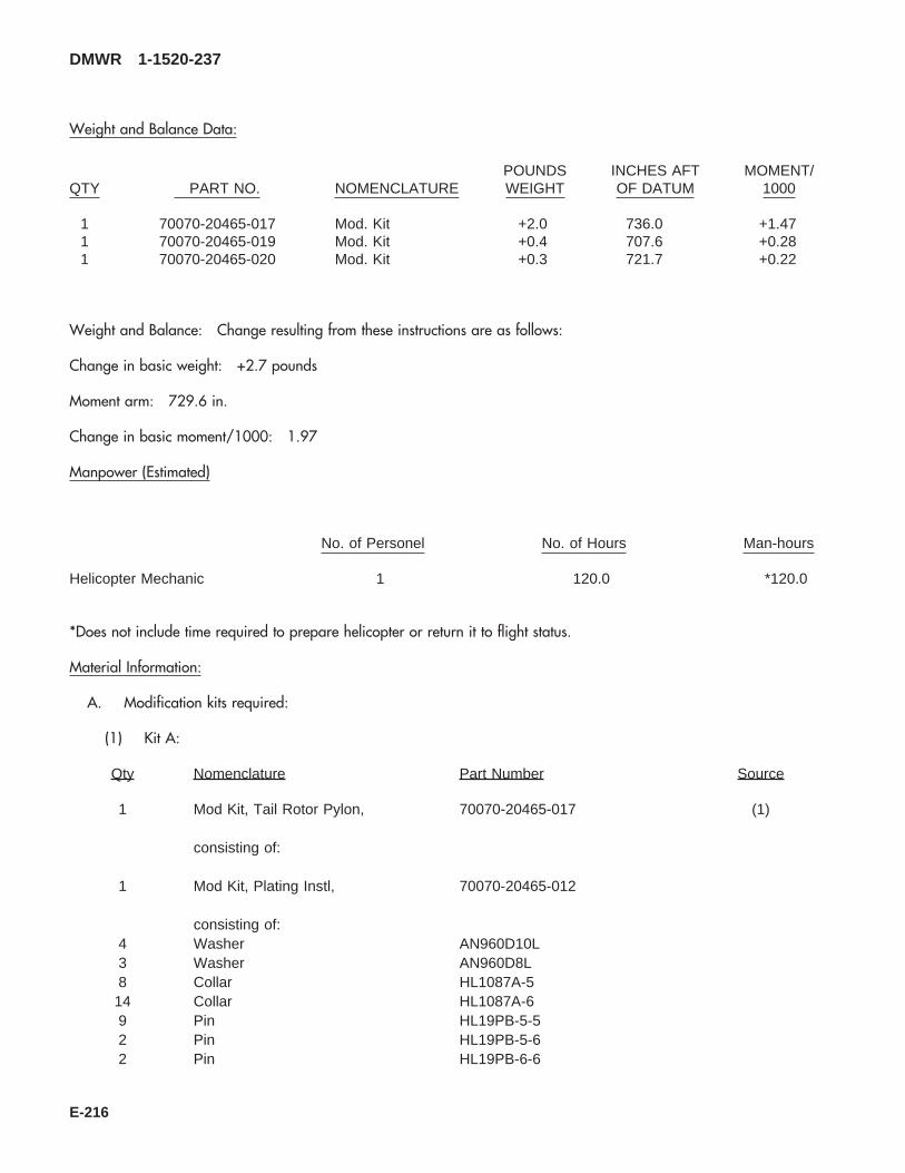
Weight and Balance Data:
QTY PART NO. NOMENCLATUREPOUNDSWEIGHT
INCHES AFTOF DATUM
MOMENT/1000
1 70070-20465-017 Mod. Kit +2.0 736.0 +1.471 70070-20465-019 Mod. Kit +0.4 707.6 +0.281 70070-20465-020 Mod. Kit +0.3 721.7 +0.22
Weight and Balance: Change resulting from these instructions are as follows:
Change in basic weight: +2.7 pounds
Moment arm: 729.6 in.
Change in basic moment/1000: 1.97
Manpower (Estimated)
No. of Personel No. of Hours Man-hours
Helicopter Mechanic 1 120.0 *120.0
*Does not include time required to prepare helicopter or return it to flight status.
Material Information:
A. Modification kits required:
(1) Kit A:
Qty Nomenclature Part Number Source
1 Mod Kit, Tail Rotor Pylon, 70070-20465-017 (1)
consisting of:
1 Mod Kit, Plating Instl, 70070-20465-012
consisting of:4 Washer AN960D10L3 Washer AN960D8L8 Collar HL1087A-514 Collar HL1087A-69 Pin HL19PB-5-52 Pin HL19PB-5-62 Pin HL19PB-6-6
DMWR 1-1520-237
E-216
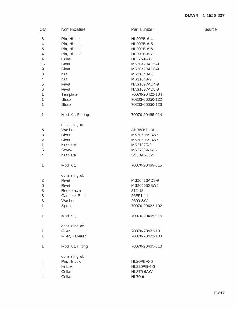
Qty Nomenclature Part Number Source
3 Pin, Hi Lok HL20PB-6-44 Pin, Hi Lok HL20PB-6-55 Pin, Hi Lok HL20PB-6-64 Pin, Hi Lok HL20PB-6-74 Collar HL375-6AW16 Rivet MS20470AD5-99 Rivet MS20470AD6-93 Nut MS21043-084 Nut MS21043-35 Rivet NAS1097AD4-96 Rivet NAS1097AD5-91 Template 70070-20422-1041 Strap 70203-06050-1221 Strap 70203-06050-123
1 Mod Kit, Fairing, 70070-20465-014
consisting of:5 Washer AN960KD10L8 Rivet MS20605S3W52 Rivet MS20605S3W71 Nutplate MS21075-35 Screw MS27039-1-164 Nutplate SS5091-03-5
1 Mod Kit, 70070-20465-015
consisting of:2 Rivet MS20426AD3-96 Rivet MS20605S3W53 Receptacle 212-123 Camlock Stud 26S51-113 Washer 2600-SW1 Spacer 70070-20422-102
1 Mod Kit, 70070-20465-016
consisting of:1 Filler 70070-20422-1011 Filler, Tapered 70070-20422-103
1 Mod Kit, Fitting, 70070-20465-018
consisting of:4 Pin, Hi Lok HL20PB-6-64 Hi Lok HL220PB-6-64 Collar HL375-6AW4 Collar HL70-6
DMWR 1-1520-237
E-217

Qty Nomenclature Part Number Source
21 Collar NAS1080-0631 Rivet MS20470AD4-431 Rivet MS20470AD4-625 Rivet MS20470AD5-68 Pin, Swg Lkg NAS1466-036 Pin, Swg Lkg NAS1466-044 Pin, Swg Lkg NAS1466-057 Rivet, Blind NAS1738B4-38 Rivet, Blind NAS1738B5-325 Rivet, Blind NAS1738B5-58 Pin, Swg Lk NAS1466-0613 Pin, Swg Lk NAS1526-034 Pin, Swg Lk NAS1526-051 Fitting Assy 70209-06056-042
(2) Kit B:
Qty Nomenclature Part Number Source
1 Mod Kit, Crescent Doubler, 70070-20465-019
consisting of:
1 Mod Kit, Plating, 70070-20465-021
consisting of:16 Rivet CCR264SS-3-28 Rivet MS20470AD5-57 Nutplate MS21075-345 Rivet NAS1097AD4-520 Rivet NAS1097AD5-53 Pin, Swg Lkg NAS1465-032 Pin, Swg Lkg NAS1466-033 Pin, Swg Lkg NAS1466-043 Pin, Swg Lkg NAS1466-056 Pin, Swg Lkg NAS1466-063 Rivet, Blind NAS1738B4-34 Rivet, Blind NAS1738B4-53 Rivet, Blind NAS1739B4-44 Rivet, Blind NAS1739B4-51 Receptacle 212-121 Strap 70070-20465-101
1 Mod Kit, Plating, 70070-20465-022
consisting of:12 Nutplate MS21075-330 Rivet NAS1097AD3-3
DMWR 1-1520-237
E-218
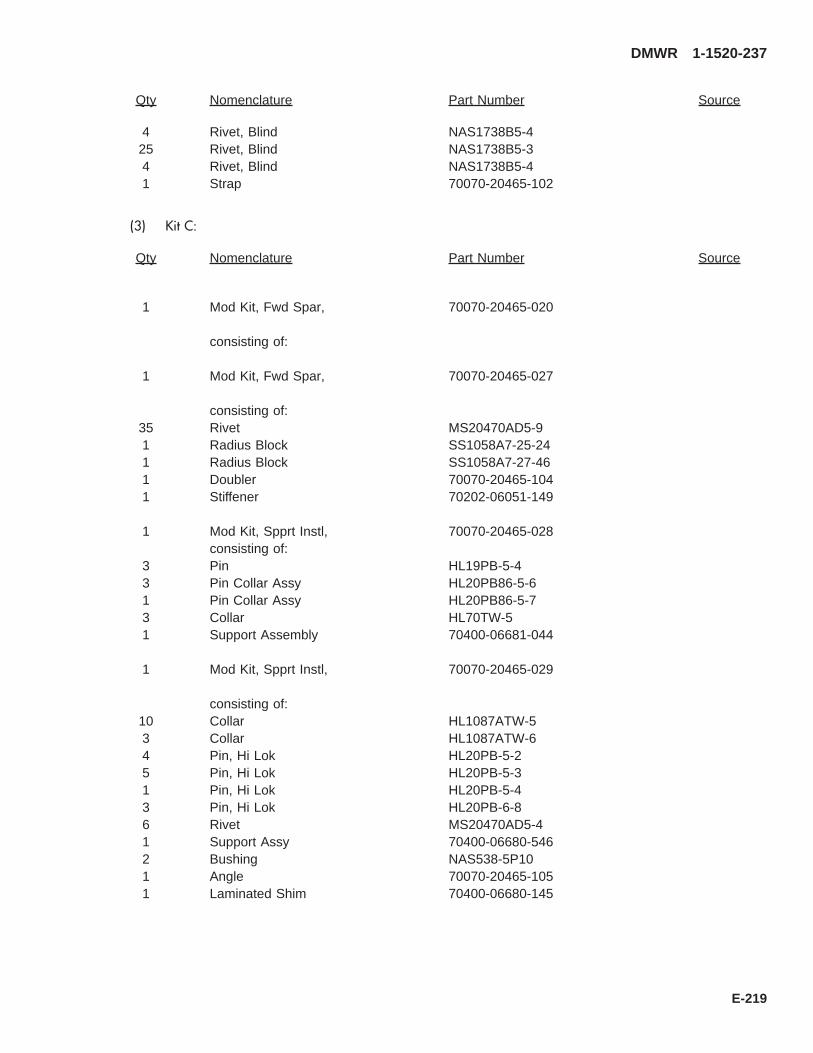
Qty Nomenclature Part Number Source
4 Rivet, Blind NAS1738B5-425 Rivet, Blind NAS1738B5-34 Rivet, Blind NAS1738B5-41 Strap 70070-20465-102
(3) Kit C:
Qty Nomenclature Part Number Source
1 Mod Kit, Fwd Spar, 70070-20465-020
consisting of:
1 Mod Kit, Fwd Spar, 70070-20465-027
consisting of:35 Rivet MS20470AD5-91 Radius Block SS1058A7-25-241 Radius Block SS1058A7-27-461 Doubler 70070-20465-1041 Stiffener 70202-06051-149
1 Mod Kit, Spprt Instl, 70070-20465-028consisting of:
3 Pin HL19PB-5-43 Pin Collar Assy HL20PB86-5-61 Pin Collar Assy HL20PB86-5-73 Collar HL70TW-51 Support Assembly 70400-06681-044
1 Mod Kit, Spprt Instl, 70070-20465-029
consisting of:10 Collar HL1087ATW-53 Collar HL1087ATW-64 Pin, Hi Lok HL20PB-5-25 Pin, Hi Lok HL20PB-5-31 Pin, Hi Lok HL20PB-5-43 Pin, Hi Lok HL20PB-6-86 Rivet MS20470AD5-41 Support Assy 70400-06680-5462 Bushing NAS538-5P101 Angle 70070-20465-1051 Laminated Shim 70400-06680-145
DMWR 1-1520-237
E-219
B. Consumable Material:
WARNING
OBSERVE ALL CAUTIONS AND WARNINGS ON CONTAINERS WHEN USING CONSUMABLES.WHEN APPLICABLE, WEAR NECESSARY PROTECTIVE GEAR DURING HANDLING AND USE. IF ACONSUMABLE IS FLAMMABLE OR EXPLOSIVE, MAKE CERTAIN CONSUMABLE AND ITS VAPORS AREKEPT AWAY FROM HEAT, SPARK, AND FLAME. MAKE CERTAIN EQUIPMENT IS PROPERLYGROUNDED AND FIREFIGHTING EQUIPMENT IS READILY AVAILABLE PRIOR TO USE. FOR AD-DITIONAL INFORMATION ON TOXICITY, FLASHPOINT, AND FLAMMABILITY OF CHEMICALS,CONSULT YOUR MEDICAL PEOPLE, OR MANUFACTURER OF THE CONSUMABLE.
Qty Nomenclature Part Number Source
8 oz. Primer MIL-P-23377 or equivalent (1)8 oz. Adhesive EA9305. 3NA or equivalent (1)2 oz Alodine MIL-C-541, Class 1A or equivalent (1)8 oz. Sealant AMS-S-8802, A-2, or equivalent (1)
C. Support Equipment:
Qty Nomenclature Part Number Source
1 Installation Tool 70209-06056-041T046 (1)1 Edge Distance Tool 70070-77399-041 (1)
D. Source of supply:
(1) Available through normal supply channels
DMWR 1-1520-237
E-220
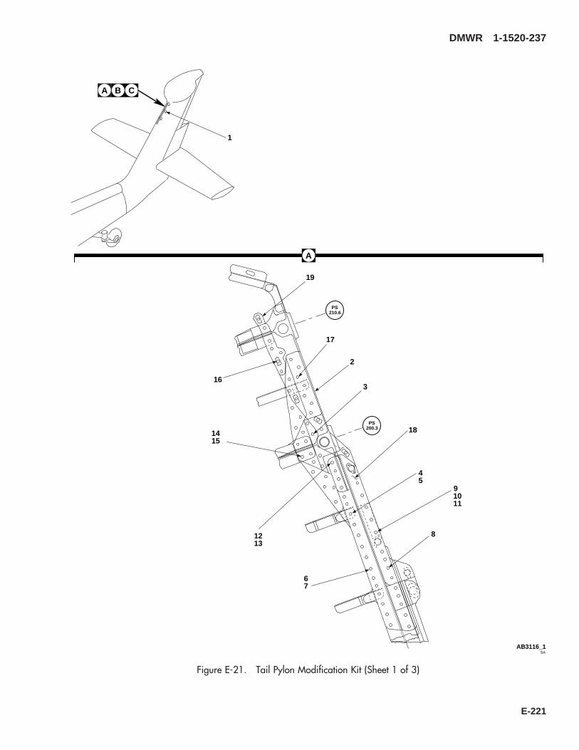
A
SAAB3116_1
B C
1
PS210.6
PS200.3
A
19
16
17
2
3
181415
1213
45
67
8
91011
Figure E-21. Tail Pylon Modification Kit (Sheet 1 of 3)
DMWR 1-1520-237
E-221
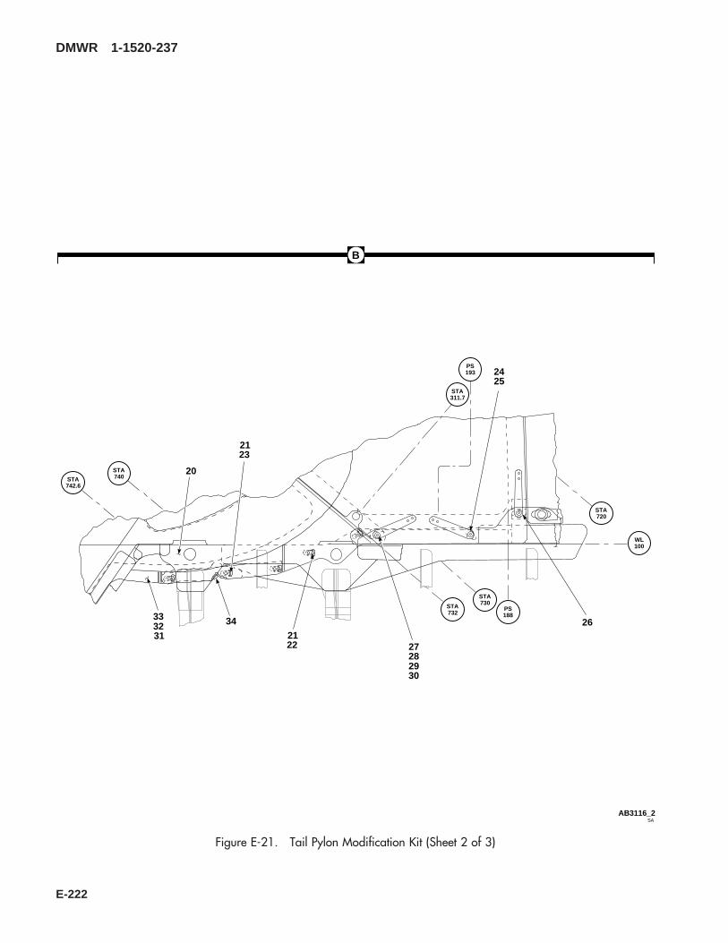
SAAB3116_2
STA742.6
STA740
STA311.7
PS193
STA720
PS188
STA730STA
732
WL100
B
2425
26
2728
2122
2123
20
34
2930
333231
Figure E-21. Tail Pylon Modification Kit (Sheet 2 of 3)
DMWR 1-1520-237
E-222

38
PS214.5PS
180
PS160
PS140
PS120
PS111.9
4142
4344
45
3637
3940
SAAB3116_3
35
C
35
Figure E-21. Tail Pylon Modification Kit (Sheet 3 of 3)
DMWR 1-1520-237
E-223
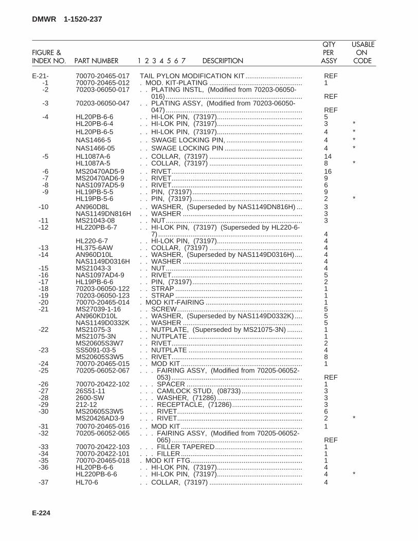
E-21- 70070-20465-017 TAIL PYLON MODIFICATION KIT .............................. REF-1 70070-20465-012 . MOD. KIT-PLATING ................................................. 1-2 70203-06050-017 . . PLATING INSTL, (Modified from 70203-06050-
016) ........................................................................ REF-3 70203-06050-047 . . PLATING ASSY, (Modified from 70203-06050-
047) ........................................................................ REF-4 HL20PB-6-6 . . HI-LOK PIN, (73197)............................................. 5
HL20PB-6-4 . . HI-LOK PIN, (73197)............................................. 3 *HL20PB-6-5 . . HI-LOK PIN, (73197)............................................. 4 *NAS1466-5 . . SWAGE LOCKING PIN, ........................................ 4 *NAS1466-05 . . SWAGE LOCKING PIN ......................................... 4 *
-5 HL1087A-6 . . COLLAR, (73197) ................................................. 14HL1087A-5 . . COLLAR, (73197) ................................................. 8 *
-6 MS20470AD5-9 . . RIVET..................................................................... 16-7 MS20470AD6-9 . . RIVET..................................................................... 9-8 NAS1097AD5-9 . . RIVET..................................................................... 6-9 HL19PB-5-5 . . PIN, (73197).......................................................... 9
HL19PB-5-6 . . PIN, (73197).......................................................... 2 *-10 AN960D8L . . WASHER, (Superseded by NAS1149DN816H) ... 3
NAS1149DN816H . . WASHER ............................................................... 3-11 MS21043-08 . . NUT........................................................................ 3-12 HL220PB-6-7 . . HI-LOK PIN, (73197) (Superseded by HL220-6-
7) ............................................................................ 4HL220-6-7 . . HI-LOK PIN, (73197)............................................. 4
-13 HL375-6AW . . COLLAR, (73197) ................................................. 4-14 AN960D10L . . WASHER, (Superseded by NAS1149D0316H).... 4
NAS1149D0316H . . WASHER ............................................................... 4-15 MS21043-3 . . NUT........................................................................ 4-16 NAS1097AD4-9 . . RIVET..................................................................... 5-17 HL19PB-6-6 . . PIN, (73197).......................................................... 2-18 70203-06050-122 . . STRAP ................................................................... 1-19 70203-06050-123 . . STRAP ................................................................... 1-20 70070-20465-014 . MOD KIT-FAIRING ................................................... 1-21 MS27039-1-16 . . SCREW.................................................................. 5
AN960KD10L . . WASHER, (Superseded by NAS1149D0332K) .... 5NAS1149D0332K . . WASHER ............................................................... 5
-22 MS21075-3 . . NUTPLATE, (Superseded by MS21075-3N) ........ 1MS21075-3N . . NUTPLATE ............................................................ 1MS20605S3W7 . . RIVET..................................................................... 2
-23 SS5091-03-5 . . NUTPLATE ............................................................ 4MS20605S3W5 . . RIVET..................................................................... 8
-24 70070-20465-015 . . MOD KIT ................................................................ 1-25 70205-06052-067 . . . FAIRING ASSY, (Modified from 70205-06052-
053) ..................................................................... REF-26 70070-20422-102 . . . SPACER ............................................................. 1-27 26S51-11 . . . CAMLOCK STUD, (08733) ................................ 3-28 2600-SW . . . WASHER, (71286) ............................................. 3-29 212-12 . . . RECEPTACLE, (71286)..................................... 3-30 MS20605S3W5 . . . RIVET.................................................................. 6
MS20426AD3-9 . . . RIVET.................................................................. 2 *-31 70070-20465-016 . . MOD KIT ................................................................ 1-32 70205-06052-065 . . . FAIRING ASSY, (Modified from 70205-06052-
065) ..................................................................... REF-33 70070-20422-103 . . . FILLER TAPERED.............................................. 1-34 70070-20422-101 . . . FILLER................................................................ 1-35 70070-20465-018 . MOD KIT FTG........................................................... 1-36 HL20PB-6-6 . . HI-LOK PIN, (73197)............................................. 4
HL220PB-6-6 . . HI-LOK PIN, (73197)............................................. 4 *-37 HL70-6 . . COLLAR, (73197) ................................................. 4
DMWR 1-1520-237
QTY USABLEFIGURE & PER ONINDEX NO. PART NUMBER 1 2 3 4 5 6 7 DESCRIPTION ASSY CODE
E-224
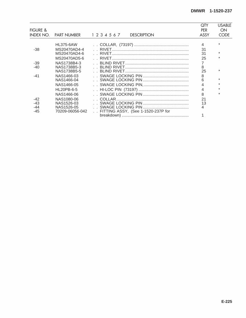
HL375-6AW . . COLLAR, (73197) ................................................. 4 *-38 MS20470AD4-4 . . RIVET..................................................................... 31
MS20470AD4-6 . . RIVET..................................................................... 31 *MS20470AD5-6 . . RIVET..................................................................... 25 *
-39 NAS1738B4-3 . . BLIND RIVET......................................................... 7-40 NAS1738B5-3 . . BLIND RIVET......................................................... 8
NAS1738B5-5 . . BLIND RIVET......................................................... 25 *-41 NAS1466-03 . . SWAGE LOCKING PIN ......................................... 8
NAS1466-04 . . SWAGE LOCKING PIN ......................................... 6 *NAS1466-05 . . SWAGE LOCKING PIN, ........................................ 4 *HL20PB-6-5 . . HI-LOC PIN (73197) ............................................. 4 *NAS1466-06 . . SWAGE LOCKING PIN ......................................... 8 *
-42 NAS1080-06 . . COLLAR................................................................. 21-43 NAS1526-03 . . SWAGE LOCKING PIN ......................................... 13-44 NAS1526-05 . . SWAGE LOCKING PIN ......................................... 4-45 70209-06056-042 . . FITTING ASSY, (See 1-1520-237P for
breakdown) ............................................................ 1
DMWR 1-1520-237
QTY USABLEFIGURE & PER ONINDEX NO. PART NUMBER 1 2 3 4 5 6 7 DESCRIPTION ASSY CODE
E-225
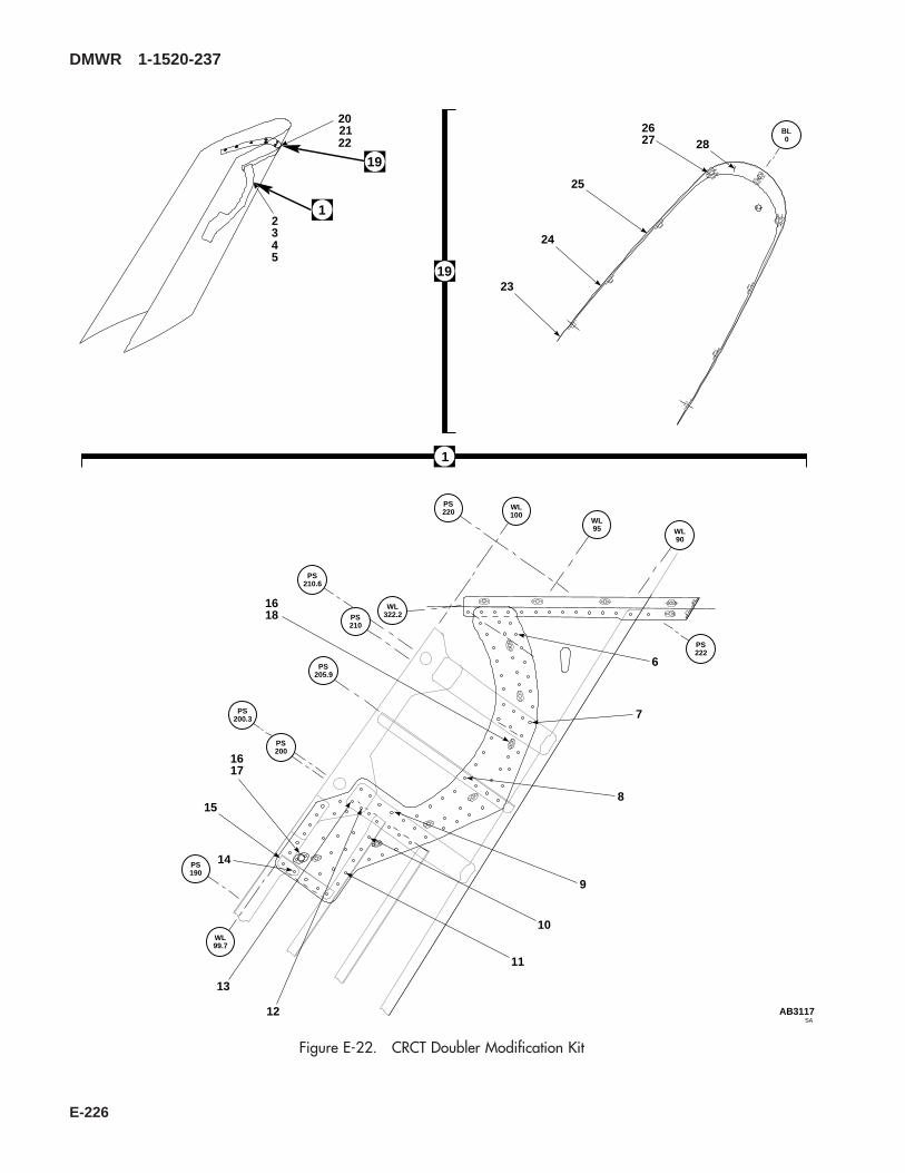
SAAB3117
BL0
19
1
202122
2345
282627
25
24
2319
1
6
7
8
9
10
11
12
13
14
15
1617
1618
WL99.7
PS190
PS200.3
PS200
PS205.9
PS210.6
PS210
WL322.2
PS220
WL100
WL95 WL
90
PS222
Figure E-22. CRCT Doubler Modification Kit
DMWR 1-1520-237
E-226

E-22- 70070-20465-019 CRCT DOUBLE MODIFICATION KIT ......................... REF-1 70070-20465-021 . M/K PLATING TRP................................................... 1-2 70070-20465-023 . . M/K PLATING INSTL, (Modified from 70203-
06050-011)............................................................. REF-3 70070-20465-024 . . M/K PLATING INSTL, (Modified from 70203-
06050-013)............................................................. REF-4 70070-20465-025 . . M/K PLATING INSTL, (Modified from 70203-
06050-015)............................................................. REF-5 70070-20465-041 . . M/K PLATING ASSY, (Reidentified from 70203-
06050-043)............................................................. REF-6 NAS1097AD4-5 . . RIVET..................................................................... 45-7 NAS1097AD5-5 . . RIVET..................................................................... 20-8 NAS1739B4-4 . . BLIND RIVET......................................................... 3-9 MS20470AD5-5 . . RIVET..................................................................... 8
-10 NAS1739B4-5 . . BLIND RIVET......................................................... 4-11 NAS1738B4-5 . . BLIND RIVET......................................................... 4-12 NAS1466-03 . . SWAGE LOCKING PIN ......................................... 2
NAS1466-04 . . SWAGE LOCKING PIN ......................................... 3 *NAS1466-05 . . SWAGE LOCKING PIN ......................................... 3 *HL20PB-6-5 . . HI-LOK PIN............................................................ 3 *NAS1466-06 . . SWAGE LOCKING PIN ......................................... 6 *
-13 NAS1465-03 . . SWAGE LOCKING PIN ......................................... 3-14 NAS1738B4-3 . . BLIND RIVET......................................................... 3-15 70070-20465-101 . . STRAP ................................................................... 1-16 CCR264SS-3-2 . . RIVET, (11815) (Superseded by
MS20605S3W2)..................................................... 16MS20605S3W2 . . RIVET,.................................................................... 16
-17 212-12 . . RECEPTACLE, (71286)........................................ 1-18 MS21075-3 . . NUTPLATE, (Superseded by MS21075-3N) ........ 7
MS21075-3N . . NUTPLATE, ........................................................... 7-19 70070-20465-022 . M/K PLATING TRP................................................... 1-20 70070-20465-026 . . M/K RIB INSTL, (Modified from 70201-06164-
011) ........................................................................ REF-21 70070-20465-042 . . M/K RIB ASSY, (Reidentified from 70201-06164-
043) ........................................................................ REF-22 70070-20465-043 . . M/K RIB ASSY, (Reidentified from 70201-06164-
045) ........................................................................ REF-23 NAS1738B5-4 . . BLIND RIVET......................................................... 4-24 NAS1738B5-3 . . BLIND RIVET......................................................... 25-25 NAS1738B4-5 . . BLIND RIVET......................................................... 4-26 NAS1097AD3-3 . . RIVET..................................................................... 30-27 MS21075-3 . . NUTPLATE ............................................................ 12-28 70070-20465-102 . . STRAP ................................................................... 1
DMWR 1-1520-237
QTY USABLEFIGURE & PER ONINDEX NO. PART NUMBER 1 2 3 4 5 6 7 DESCRIPTION ASSY CODE
E-227

123
9
WL100
STA193
STA190
1
STA195.5
STA190.5
BL0
SAAB3118_1
15
9
7
6
8
4
5
1011
1213
14
Figure E-23. Front Spar FT Modification Kit (Sheet 1 of 2)
DMWR 1-1520-237
E-228

15 A
B
B
A
16
1718
SAAB3118_2
WL100
19
20
2122
24
25
26
2223
BL0
Figure E-23. Front Spar FT Modification Kit (Sheet 2 of 2)
DMWR 1-1520-237
E-229
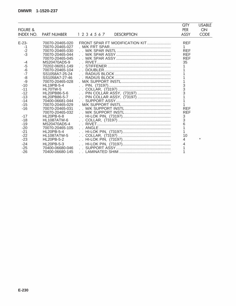
E-23- 70070-20465-020 FRONT SPAR FT MODIFICATION KIT ...................... REF-1 70070-20465-027 . M/K FRT SPAR......................................................... 1-2 70070-20465-030 . . M/K SPAR INSTL .................................................. REF-3 70070-20465-044 . . M/K SPAR ASSY................................................... REF
70070-20465-045 . . M/K SPAR ASSY................................................... REF-4 MS20470AD5-9 . . RIVET..................................................................... 35-5 70202-06051-149 . . STIFFENER ........................................................... 1-6 70070-20465-104 . . DOUBLER.............................................................. 1-7 SS1058A7-25-24 . . RADIUS BLOCK .................................................... 1-8 SS1058A7-27-46 . . RADIUS BLOCK .................................................... 1-9 70070-20465-028 . M/K SUPPORT INSTL.............................................. 1
-10 HL19PB-5-4 . . PIN, (73197).......................................................... 3-11 HL70TW-5 . . COLLAR, (73197) ................................................. 3-12 HL20PB86-5-6 . . PIN COLLAR ASSY, (73197) ............................... 3-13 HL20PB86-5-7 . . PIN COLLAR ASSY, (73197) ............................... 1-14 70400-06681-044 . . SUPPORT ASSY................................................... 1-15 70070-20465-029 . M/K SUPPORT INSTL.............................................. 1-16 70070-20465-031 . . M/K SUPPORT INSTL........................................... REF
70070-20465-032 . . M/K SUPPORT INSTL........................................... REF-17 HL20PB-6-8 . . HI-LOK PIN, (73197)............................................. 3-18 HL1087ATW-6 . . COLLAR, (73197) ................................................. 3-19 MS20470AD5-4 . . RIVET..................................................................... 6-20 70070-20465-105 . . ANGLE................................................................... 1-21 HL20PB-5-4 . . HI-LOK PIN, (73197)............................................. 1-22 HL1087ATW-5 . . COLLAR, (73197) ................................................. 10-23 HL20PB-5-2 . . HI-LOK PIN, (73197)............................................. 4 *-24 HL20PB-5-3 . . HI-LOK PIN, (73197)............................................. 4-25 70400-06680-046 . . SUPPORT ASSY................................................... 1-26 70400-06680-145 . . LAMINATED SHIM ................................................ 1
DMWR 1-1520-237
QTY USABLEFIGURE & PER ONINDEX NO. PART NUMBER 1 2 3 4 5 6 7 DESCRIPTION ASSY CODE
E-230

E-20. SIDE SKIN MODIFICATION KIT (50-10).
Subject: Tail Pylon Side Skin, Modification of, dated 31 March 2003
Purpose: To provide instruction for the rework of the tail pylon side skin.
Model: UH-60A
Description: Additional doublers are added to the existing tail pylon side skin between station 645.00 and station660.00.
Drawing Required for Modification:
70070-20587
References: (a) Special Service Instructions (SSI) No. 50-31, Installation of 9A to A9 Recapitalization Program, datedMarch 31, 2003
Instructions:
NOTE
• A complete review of this SSI is recommended before incorporating the modification of tail pylon side skin.
• Before beginning this modification procedure, use the material information list to inventory the modificationkit. Make sure all parts are present and in serviceable condition.
• Where drawing numbers are not listed within individual step(s), drawing(s) listed in preceding step(s) arethe controlling authority.
• The sheet metal and structural modifications in this SSI shall be done by personnel experienced in readingmodification drawings. Routine steps such as cleaning, layout and drilling, deburring, standard repairs,corrosion control, clean up after rework, chemical coating for aluminum after cutting/trimming parts, painttouch up, and safety practices may not be called out herein. However, these steps and all other requiredroutine tasks shall be done.
• When installing fasteners refer to drawing sheet and zones for applicable fasteners.
• Slight variations to the instructions contained herein are allowed, as long as the intent of the modificationis accomplished.
A. Preparation for modification and removal of equipment:
(1) Confirm that all warnings, cautions, and notes are complied with per reference (a).
(2) Perform preparation for modification per reference (a).
B. Modification of tail pylon side skin as follows:
(1) Modify left side plating installation (70203-06050-011, -013, -015, or -018) as follows:
(a) Remove pneumatic lines as required for access to left side pylon interior.
DMWR 1-1520-237
E-231
(b) Remove fasteners shown (Dwg 70070-20587, Sheet 2, Zones 9-D, 10-C, 10-E, 11-C through 11-E, 12-Cthrough 12-F, and Notes 5, 7, and 8).
(c) Locate and temporarily install doubler (70070-20587-101), stiffener (70070-20587-103), clip (70070-20587-105), and radius block (SS1058A7-26-13) as shown (Sheet 2, Zones 10-E, 11-E, 14-C, and 15-E).
(d) Drill fastener holes, as shown (Sheet 2, Zones 9-D, 10-C, 10-D, 11-C, and 11-D).
(e) Remove temporarily installed doubler (70070-20587-101), stiffener (70070-20587-103), clip (70070-20587-105), and radius block (SS1058A7-26-13), deburr and touch up, as required.
WARNING
OBSERVE ALL CAUTIONS AND WARNINGS ON CONTAINERS WHEN USING CONSUMABLES.WHEN APPLICABLE, WEAR NECESSARY PROTECTIVE GEAR DURING HANDLING AND USE. IF ACONSUMABLE IS FLAMMABLE OR EXPLOSIVE, MAKE CERTAIN CONSUMABLE AND ITS VAPORS AREKEPT AWAY FROM HEAT, SPARK, AND FLAME. MAKE CERTAIN EQUIPMENT IS PROPERLYGROUNDED AND FIREFIGHTING EQUIPMENT IS READILY AVAILABLE PRIOR TO USE. FOR AD-DITIONAL INFORMATION ON TOXICITY, FLASHPOINT, AND FLAMMABILITY OF CHEMICALS,CONSULT YOUR MEDICAL PEOPLE, OR MANUFACTURER OF THE CONSUMABLE.
(f) Install doubler (70070-20587-101) wet with sealant (AMS-S-8802 A2 or equivalent) using fastenersshown (Sheet 2, Zones 9-E, 10-C, 10-E, and 11-C through 11-E).
(g) Install stiffener (70070-20587-103), clip (70070-20587-105), and radius block (SS1058A7-26-13) us-ing fasteners shown (Sheet 2, Zones 10-E, 14-D, and 14-F).
WARNING
OBSERVE ALL CAUTIONS AND WARNINGS ON CONTAINERS WHEN USING CONSUMABLES.WHEN APPLICABLE, WEAR NECESSARY PROTECTIVE GEAR DURING HANDLING AND USE. IF ACONSUMABLE IS FLAMMABLE OR EXPLOSIVE, MAKE CERTAIN CONSUMABLE AND ITS VAPORS AREKEPT AWAY FROM HEAT, SPARK, AND FLAME. MAKE CERTAIN EQUIPMENT IS PROPERLYGROUNDED AND FIREFIGHTING EQUIPMENT IS READILY AVAILABLE PRIOR TO USE. FOR AD-DITIONAL INFORMATION ON TOXICITY, FLASHPOINT, AND FLAMMABILITY OF CHEMICALS,CONSULT YOUR MEDICAL PEOPLE, OR MANUFACTURER OF THE CONSUMABLE.
(h) Reinstall fasteners wet with sealant (AMS-S-8802 A2 or equivalent) at locations shown (Sheet 2, Zones11-B, 11-D, 11-F, 12-C through 12-E, and Notes 5, 7, and 8).
(i) Remove and replace fasteners wet with sealant (AMS-S-8802 A2 or equivalent) at locations shown (Sheet2, Zones 5-E through 5-G, 6-E through 6-G, 9-F, and Note 5).
(2) Modify right side plating installation (70203-06050-012, -014, -016, or -017) as follows:
(a) Remove fasteners shown (Dwg 70070-20587, Sheet 2, Zones 9-D, 10-C, 10-E, 11-C through 11-E, 12-Cthrough 12-F, and Notes 5, 7, and 8).
DMWR 1-1520-237
E-232
(b) Locate and temporarily install doubler (70070-20587-102), stiffener (70070-20587-104), clip (70070-20587-106), and radius block (SS1058A7-26-13) as shown (Sheet 2, Zones 10-E, 11-E, 14-C, and 15-E).
(c) Drill fastener holes, as shown (Sheet 2, Zones 9-D, 10-C, 10-D, 11-C, and 11-D).
(d) Remove temporarily installed doubler (70070-20587-102), stiffener (70070-20587-104), clip (70070-20587-106), and radius block (SS1058A7-26-13), deburr and touch up, as required.
WARNING
OBSERVE ALL CAUTIONS AND WARNINGS ON CONTAINERS WHEN USING CONSUMABLES.WHEN APPLICABLE, WEAR NECESSARY PROTECTIVE GEAR DURING HANDLING AND USE. IF ACONSUMABLE IS FLAMMABLE OR EXPLOSIVE, MAKE CERTAIN CONSUMABLE AND ITS VAPORS AREKEPT AWAY FROM HEAT, SPARK, AND FLAME. MAKE CERTAIN EQUIPMENT IS PROPERLYGROUNDED AND FIREFIGHTING EQUIPMENT IS READILY AVAILABLE PRIOR TO USE. FOR AD-DITIONAL INFORMATION ON TOXICITY, FLASHPOINT, AND FLAMMABILITY OF CHEMICALS,CONSULT YOUR MEDICAL PEOPLE, OR MANUFACTURER OF THE CONSUMABLE.
(e) Install doubler (70070-20587-102) wet with sealant (AMS-S-8802 A2, or equivalent) using fastenersshown (Sheet 2, Zones 9-E, 10-C, 10-E, and 11-C through 11-E).
(f) Install stiffener (70070-20587-104), clip (70070-20587-106), and radius block (SS1058A7-26-13) usingfasteners shown (Sheet 2, Zones 10-E, 14-D, and 14-F).
WARNING
OBSERVE ALL CAUTIONS AND WARNINGS ON CONTAINERS WHEN USING CONSUMABLES.WHEN APPLICABLE, WEAR NECESSARY PROTECTIVE GEAR DURING HANDLING AND USE. IF ACONSUMABLE IS FLAMMABLE OR EXPLOSIVE, MAKE CERTAIN CONSUMABLE AND ITS VAPORS AREKEPT AWAY FROM HEAT, SPARK, AND FLAME. MAKE CERTAIN EQUIPMENT IS PROPERLYGROUNDED AND FIREFIGHTING EQUIPMENT IS READILY AVAILABLE PRIOR TO USE. FOR AD-DITIONAL INFORMATION ON TOXICITY, FLASHPOINT, AND FLAMMABILITY OF CHEMICALS,CONSULT YOUR MEDICAL PEOPLE, OR MANUFACTURER OF THE CONSUMABLE.
(g) Reinstall fasteners wet with sealant (AMS-S-8802, A2 or equivalent) at locations shown (Sheet 2, Zones11-B, 11-D, 11-F, 12-C through 12-E, and Notes 5, 7, and 8).
(h) Remove and replace fasteners wet with sealant (AMS-S-8802, A2 or equivalent) at locations shown (Sheet2, Zones 5-E through 5-G, 6-E through 6-G, 9-F, and Note 5).
(i) Reinstall pneumatic lines previously removed.
C. Reinstallation of removed equipment:
(1) Install removed equipment per reference (a).
D. Record of Compliance:
(1) Make an appropriate logbook entry to show compliance with this Special Service Instruction.
DMWR 1-1520-237
E-233

Weight and Balance Data:
QTY PART NO. NOMENCLATUREPOUNDSWEIGHT
INCHES AFTOF DATUM
MOMENT/1000
1 70070-20587-011 Mod. Kit +1.8 653.7 1.177
Weight and Balance: Change resulting from these instructions are as follows:
Change in basic weight: +1.8 pounds
Moment arm: 653.7 in.
Change in basic moment/1000: 1.177
Manpower (Estimated)
No. of Personel No. of Hours Man-hours
Sheet Metal Mechanic 1 24.0 *24.0
*Does not include time required to prepare helicopter or return it to flight status.
Material Information:
A. Modification Kit Required:
Qty Nomenclature Part Number Source
1 Mod. Kit, Side Skin, 70070-20587-011 (1)
consisting of:
1 Mod. Kit, Plating Instl, 70070-20587-015
consisting of:41 Collar HL1087A-63 Collar HL1087A-826 Pin, Hi-Lok HL64PB-6-35 Pin, Hi Lok HL64PB-6-41 Pin, Hi-Lok HL64PB-6-54 Pin HL64PB-6-65 Pin, Hi Lok HL64PB-6-73 Pin HL64PB-8-830 Rivet MS20470AD4-215 Rivet MS20470AD5-3
DMWR 1-1520-237
E-234

Qty Nomenclature Part Number Source
2 Rivet MS20470AD5-78 Rivet MS20470AD6-51 Radius Block SS1058A7-26-131 Doubler 70070-20587-1011 Stiffener 70070-20587-1031 Clip 70070-20587-105
1 Mod. Kit, Plating Instl, 70070-20587-016
consisting of:47 Collar HL1087A-63 Collar HL1087A-830 Pin, Hi-Lok HL64PB-6-36 Pin, Hi Lok HL64PB-6-41 Pin, Hi-Lok HL64PB-6-55 Pin HL64PB-6-65 Pin, Hi Lok HL64PB-6-73 Pin HL64PB-8-830 Rivet MS20470AD4-215 Rivet MS20470AD5-32 Rivet MS20470AD5-78 Rivet MS20470AD6-51 Radius Block SS1058A7-26-131 Doubler 70070-20587-1021 Stiffener 70070-20587-1041 Clip 70070-20587-106
1 Mod. Kit, Spar Instl, 70070-20587-017
consisting of:3 Rivet MS20470AD6-63 Pin, SWG LKG NAS1526-06
DMWR 1-1520-237
E-235

B. Consumable Material:
WARNING
OBSERVE ALL CAUTIONS AND WARNINGS ON CONTAINERS WHEN USING CONSUMABLES.WHEN APPLICABLE, WEAR NECESSARY PROTECTIVE GEAR DURING HANDLING AND USE. IF ACONSUMABLE IS FLAMMABLE OR EXPLOSIVE, MAKE CERTAIN CONSUMABLE AND ITS VAPORS AREKEPT AWAY FROM HEAT, SPARK, AND FLAME. MAKE CERTAIN EQUIPMENT IS PROPERLYGROUNDED AND FIREFIGHTING EQUIPMENT IS READILY AVAILABLE PRIOR TO USE. FOR AD-DITIONAL INFORMATION ON TOXICITY, FLASHPOINT, AND FLAMMABILITY OF CHEMICALS,CONSULT YOUR MEDICAL PEOPLE, OR MANUFACTURER OF THE CONSUMABLE.
Qty Nomenclature Part Number Source
8 oz. Sealant AMS-S-8802, A2 or equivalent (1)
C. Source:
(1) Available through normal supply channels
DMWR 1-1520-237
E-236

AC
WL230
WL220
STA650
STA660
2
SAAB3120_1
3
4
256
78
10
1415
16
1
812
12
12
11
11
11
9
99
9
11
813
B
A
Figure E-24. Side Skin Modification Kit (Sheet 1 of 2)
DMWR 1-1520-237
E-237
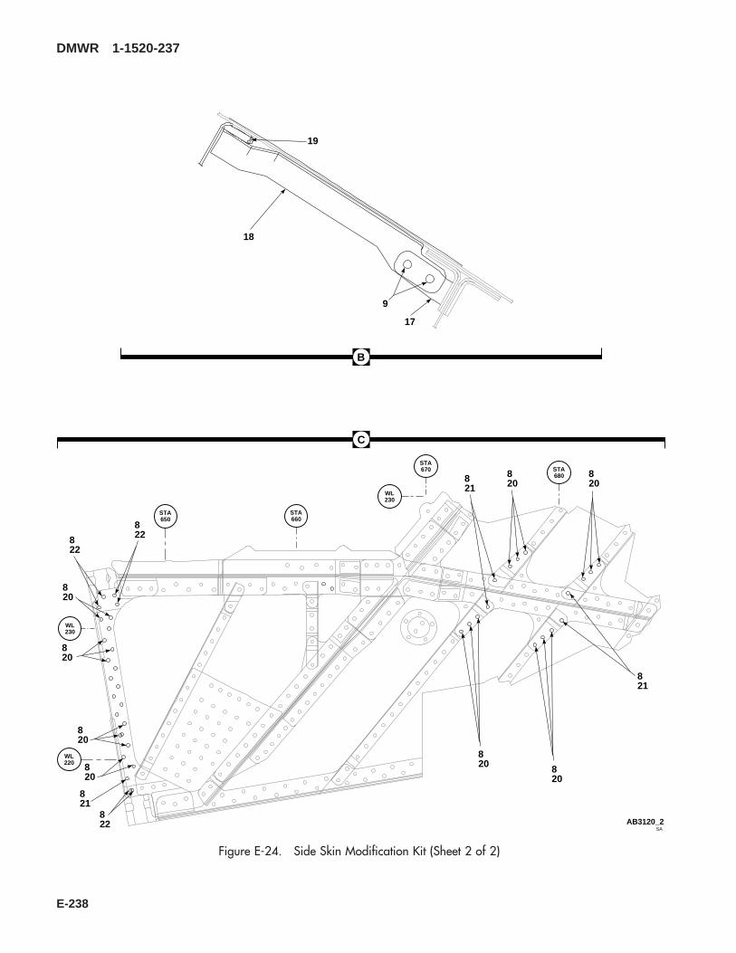
WL220
WL230
STA650
STA660
STA670 STA
680
WL230
SAAB3120_2
C
B
19
17
9
18
820
820
820
820
820
820
820
8208
21
821
821
822
822
822
Figure E-24. Side Skin Modification Kit (Sheet 2 of 2)
DMWR 1-1520-237
E-238

E-24- 70070-20587-011 SIDE SKIN MODIFICATION KIT ................................. REF-1 70070-20587-017 . M/K SPAR INSTL ..................................................... 1-2 70070-20587-023 . . SPAR INSTL, (Modified from 70203-06051-012) . REF-3 MS20470AD6-6 . . RIVET..................................................................... 3-4 NAS1526-06 . . SWAGE LOCKING PIN ......................................... 3-5 70070-20587-015 . M/K PLTG INSTL, LH............................................... 1
70070-20587-016 . M/K PLTG INSTL, RH .............................................. 1-6 70070-20587-012 . . PLATING INSTL, (Modified from 70203-06050-
011) ........................................................................ REF70070-20587-013 . . PLATING INSTL, (Modified from 70203-06050-
013) ........................................................................ REF70070-20587-014 . . PLATING INSTL, (Modified from 70203-06050-
015) ........................................................................ REF70070-20587-018 . . PLATING INSTL, (Modified from 70203-06050-
018) ........................................................................ REF70070-20587-019 . . PLATING INSTL, (Modified from 70203-06050-
012) ........................................................................ REF70070-20587-020 . . PLATING INSTL, (Modified from 70203-06050-
014) ........................................................................ REF70070-20587-021 . . PLATING INSTL, (Modified from 70203-06050-
016) ........................................................................ REF70070-20587-022 . . PLATING INSTL, (Modified from 70203-06050-
017) ........................................................................ REF-7 HL64PB-6-5 . . HI-LOK PIN, (73197)............................................. 1-8 HL1087A-6 . . COLLAR, (73197) (Used on 70070-20587-015).. 41
HL1087A-6 . . COLLAR, (73197) (Used on 70070-20587-016).. 47-9 MS20470AD5-3 . . RIVET..................................................................... 15
-10 MS20470AD5-7 . . RIVET..................................................................... 2-11 MS20470AD4-2 . . RIVET..................................................................... 30-12 MS20470AD6-5 . . RIVET..................................................................... 8-13 HL64PB-6-7 . . HI-LOK PIN, (73197)............................................. 5-14 HL64PB-8-8 . . PIN ......................................................................... 3-15 HL1087A-8 . . COLLAR, (73197) ................................................. 3-16 70070-20587-101 . . DOUBLER, (Used on 70070-20587-015) ............. 1
70070-20587-102 . . DOUBLER, (Used on 70070-20587-016) ............. 1-17 70070-20587-105 . . CLIP, (Used on 70070-20587-015)....................... 1
70070-20587-106 . . CLIP, (Used on 70070-20587-016)....................... 1-18 70070-20587-103 . . STIFFENER, (Used on 70070-20587-015)........... 1
70070-20587-104 . . STIFFENER, (Used on 70070-20587-016)........... 1-19 SS1058A7-26-13 . . RADIUS BLOCK .................................................... 1-20 HL64PB-6-3 . . HI-LOK PIN, (73197) (Used on 70070-20587-
015) ........................................................................ 26HL64PB-6-3 . . HI-LOK PIN, (73197) (Used on 70070-20587-
016) ........................................................................ 30-21 HL64PB-6-4 . . HI-LOK PIN, (73197) (Used on 70070-20587-
015) ........................................................................ 5HL64PB-6-4 . . HI-LOK PIN, (73197) (Used on 70070-20587-
016) ........................................................................ 6-22 HL64PB-6-6 . . PIN, (73197).......................................................... 4
DMWR 1-1520-237
QTY USABLEFIGURE & PER ONINDEX NO. PART NUMBER 1 2 3 4 5 6 7 DESCRIPTION ASSY CODE
E-239

E-21. AFT SPAR FT MODIFICATION KIT (50-25).
Subject: Tail Rotor Pylon, Aft Spar Stabilator Attachment Fitting, Modification of, dated 31 March 2003
Purpose: Provide instructions to remove bushings and install new Forcemate bushings and spherical bearings at the tailrotor pylon aft spar attachment location.
Model: UH-60A
Description: The stabilator attachment fittings are reworked by removing bushings and liners and installing new Force-mate bushings and spherical bearings.
Drawings required for modification:
70070-20588
References: (a) Special Service Instructions (SSI) No. 50-31, Installation of 9A to A9 Recapitalization Program, datedMarch 31, 2003
(b) Technical Manual (TM) 1-1520-237-23, Aviation Unit And Intermediate Maintenance For ArmyModels UH-60A, UH-60L, EH-60A, and UH-60Q Helicopters, Chapter 2, Airframe
(c) Fatigue Technologies Inc., FAN-718, dated March 4, 2002
(d) TM 1-1520-265-23, Technical Manual, Aviation Unit Maintenance (AVUM) and Aviation Intermedi-ate (AVIM) Manual, Nondestructive Inspection Procedures for H-60 Helicopter Series
(e) TM 1-1500-335-23, Technical Manual, Nondestructive Inspection Methods
Instructions:
NOTE
• A complete review of this SSI is recommended before incorporating the tail rotor pylon stabilator attach-ment fitting modification kit.
• Before beginning this modification procedure, use the material information list to inventory the modificationkit. Make sure all parts are present and in serviceable condition.
• Where drawing numbers are not listed within individual step(s), drawing(s) listed in preceding step(s) arethe controlling authority.
• The sheet metal and structural modifications in this SSI shall be done by personnel experienced in readingmodification drawings. Routine steps such as cleaning, layout and drilling, deburring, standard repairs,corrosion control, clean up after rework, chemical coating for aluminum after cutting/trimming parts, painttouch up, and safety practices may not be called out herein. However, these steps and all other requiredroutine tasks shall be done.
• Slight variations to the instructions contained herein are allowed, as long as the intent of the modificationis accomplished.
DMWR 1-1520-237
E-240

• During rework refer to reference (c) as required.
A. Preparation for modification and removal of equipment:
(1) Confirm that all warnings, cautions, and notes are complied with per reference (a).
(2) Perform preparation for modification per reference (a).
WARNING
FLIGHT SAFETY PARTTAIL ROTOR PYLON STABILATOR ATTACHMENT FITTING CONTAINS CRITICAL CHARACTERISTICSWHICH MUST NOT BE DAMAGED DURING REMOVAL AND REWORK. USE EXTREME CAUTION DUR-ING REMOVAL AND REWORK.
B. Modification, tail rotor pylon, aft spar assembly (70202-06052-041, -043, -044, or -045) stabilator attachmentfitting:
(1) Modification of left side attachment fitting assembly (70209-06052-041) as follows (Dwg 70070-20588):
(a) Remove two bushings (NAS538-10P024) and one bushing (NAS537-10P062) using bearing removal/installation tool (70700-20129-041) (Sheet 2, Zones 6-G and 6-E).
WARNING
OBSERVE ALL CAUTIONS AND WARNINGS ON CONTAINERS WHEN USING CONSUMABLES.WHEN APPLICABLE, WEAR NECESSARY PROTECTIVE GEAR DURING HANDLING AND USE. IF ACONSUMABLE IS FLAMMABLE OR EXPLOSIVE, MAKE CERTAIN CONSUMABLE AND ITS VAPORS AREKEPT AWAY FROM HEAT, SPARK, AND FLAME. MAKE CERTAIN EQUIPMENT IS PROPERLYGROUNDED AND FIREFIGHTING EQUIPMENT IS READILY AVAILABLE PRIOR TO USE. FOR AD-DITIONAL INFORMATION ON TOXICITY, FLASHPOINT, AND FLAMMABILITY OF CHEMICALS,CONSULT YOUR MEDICAL PEOPLE, OR MANUFACTURER OF THE CONSUMABLE.
(b) Clean lug bore surfaces using cheesecloth cloth (CCC-C-440 or equivalent) and 1,1,1- trichloroethane(MIL-T-81533 or equivalent).
(c) Inspect for damage to critical areas (minimum thickness and minimum area) of stabilator attachment fitting(70209-06052-101 or -103) and repair as required (Sheet 2, View F, Zone 11-G, Note 10; Sheet 3, Note 43).
(d) Inspect fitting assembly (70209-06052-041) bores and measure diameters. Line ream hole to 0.8120 -0.8130-inch diameter nominal. See Sheet 2, Note 7 for over sized holes (Sheet 2, Zone 7-G, Notes 7 and 12; Sheet 3,Note 32).
(e) Break all sharp edges of line reamed holes.
DMWR 1-1520-237
E-241
WARNING
OBSERVE ALL CAUTIONS AND WARNINGS ON CONTAINERS WHEN USING CONSUMABLES.WHEN APPLICABLE, WEAR NECESSARY PROTECTIVE GEAR DURING HANDLING AND USE. IF ACONSUMABLE IS FLAMMABLE OR EXPLOSIVE, MAKE CERTAIN CONSUMABLE AND ITS VAPORS AREKEPT AWAY FROM HEAT, SPARK, AND FLAME. MAKE CERTAIN EQUIPMENT IS PROPERLYGROUNDED AND FIREFIGHTING EQUIPMENT IS READILY AVAILABLE PRIOR TO USE. FOR AD-DITIONAL INFORMATION ON TOXICITY, FLASHPOINT, AND FLAMMABILITY OF CHEMICALS,CONSULT YOUR MEDICAL PEOPLE, OR MANUFACTURER OF THE CONSUMABLE.
(f) Perform liquid penetrant or Eddy Current inspection of holes (Sheet 2, Note 13 and reference (d) and (e)).
(g) Inspect for damage to critical areas (minimum thickness and minimum area) of stabilator attachment fitting(70209-06052-101 or -103) and repair as required (Sheet 2, View F, Zone 11-G, Note 10; Sheet 3, Note 43).
WARNING
OBSERVE ALL CAUTIONS AND WARNINGS ON CONTAINERS WHEN USING CONSUMABLES.WHEN APPLICABLE, WEAR NECESSARY PROTECTIVE GEAR DURING HANDLING AND USE. IF ACONSUMABLE IS FLAMMABLE OR EXPLOSIVE, MAKE CERTAIN CONSUMABLE AND ITS VAPORS AREKEPT AWAY FROM HEAT, SPARK, AND FLAME. MAKE CERTAIN EQUIPMENT IS PROPERLYGROUNDED AND FIREFIGHTING EQUIPMENT IS READILY AVAILABLE PRIOR TO USE. FOR AD-DITIONAL INFORMATION ON TOXICITY, FLASHPOINT, AND FLAMMABILITY OF CHEMICALS,CONSULT YOUR MEDICAL PEOPLE, OR MANUFACTURER OF THE CONSUMABLE.
(h) Apply alodine 1200S or equivalent and apply primer (EA9203 or equivalent) to reworked area (Sheet 2,Note 14).
NOTE
Allow primer (EA9203 or equivalent) to dry before proceeding to next step.
(i) Install bushing (FMI-718-45010-A) inner on fitting assembly (70209-06052-041). See Sheet 2, Note 7 forover sized bushing (Sheet 2, Zone 6-G, Note 8; Sheet 3, Note 32).
(j) Perform axial load proof test on inner shoulder bushing (FMI-718-45010-A) (Sheet 2, Zone 5-G, Note 11).
RESULT: Verify bushing or bearing does not move.
(k) Install nominal bushing (FMI-718-45030-A) outer on fitting assembly (70209-06052-041). See Sheet 2,Note 7 for over sized bushing (Sheet 2, Zone 6-E, Note 8; Sheet 3, Note 32).
(l) Perform axial load proof test on inboard end of nominal bushing (FMI-718-45030-A) (Sheet 2, Zones 5-E,5-G, 6-E, and 6-G, Note 11).
RESULT: Verify movement of bushing at or below 2000 pound force.
(m) Line ream hole to 0.6250 - 0.6265-inch diameter (Sheet 2, Zone 7-G).
DMWR 1-1520-237
E-242

(n) Chamfer (inside only) both edges of bushings (FMI-718-45010-A and FMI-718-45030-A) 0.015 / 0.030x 45 degrees (Sheet 2, Details B and E, Zones 5-C and 7-C).
WARNING
OBSERVE ALL CAUTIONS AND WARNINGS ON CONTAINERS WHEN USING CONSUMABLES.WHEN APPLICABLE, WEAR NECESSARY PROTECTIVE GEAR DURING HANDLING AND USE. IF ACONSUMABLE IS FLAMMABLE OR EXPLOSIVE, MAKE CERTAIN CONSUMABLE AND ITS VAPORS AREKEPT AWAY FROM HEAT, SPARK, AND FLAME. MAKE CERTAIN EQUIPMENT IS PROPERLYGROUNDED AND FIREFIGHTING EQUIPMENT IS READILY AVAILABLE PRIOR TO USE. FOR AD-DITIONAL INFORMATION ON TOXICITY, FLASHPOINT, AND FLAMMABILITY OF CHEMICALS,CONSULT YOUR MEDICAL PEOPLE, OR MANUFACTURER OF THE CONSUMABLE.
(o) Fillet seal inboard side of bushing (FMI-718-45010-A) inner using sealing compound (AMS3265 orequivalent) (Sheet 2, Zone 8-G; Sheet 3, Note 19).
(p) Apply coating of antiseize compound (MIL-T-83483 or equivalent) to inner bores of bushings (Sheet 3,Note 24).
(q) Reidentify fitting assembly (70209-06052-041) to (70070-20588-043) with pen and contrasting ink(Sheet 1, Note 4).
(2) Modification of right side attachment fitting assembly (70209-06052-043 or -046) as follows (Dwg 70070-20588):
(a) Remove bearing (B5539WZZ) or sherical bearings (KNDB 12-25) from fitting assembly (70209-06052-043 or -046) using bearing removal/installation tool (70700-20129-041). If bearing is roller staked remove stakingflanges on outside of race by rotating arbor and cutter while applying light pressure until cutter has penetrated stake0.020-inch (Sheet 2, Zones 13-E and 13-G; Sheet 1, Notes 1 and 2).
(b) Remove four liners (70209-06052-104) using a drift and mallet from fitting assembly (70209-06052-043or -046) (Sheet 2, Zones 13-E and 13-G; Sheet 3, Note 30).
(c) Remove remaining adhesive using a nonmetallic scraper and/or abrasive mat (MIL-A-9962 orequivalent).
WARNING
OBSERVE ALL CAUTIONS AND WARNINGS ON CONTAINERS WHEN USING CONSUMABLES.WHEN APPLICABLE, WEAR NECESSARY PROTECTIVE GEAR DURING HANDLING AND USE. IF ACONSUMABLE IS FLAMMABLE OR EXPLOSIVE, MAKE CERTAIN CONSUMABLE AND ITS VAPORS AREKEPT AWAY FROM HEAT, SPARK, AND FLAME. MAKE CERTAIN EQUIPMENT IS PROPERLYGROUNDED AND FIREFIGHTING EQUIPMENT IS READILY AVAILABLE PRIOR TO USE. FOR AD-DITIONAL INFORMATION ON TOXICITY, FLASHPOINT, AND FLAMMABILITY OF CHEMICALS,CONSULT YOUR MEDICAL PEOPLE, OR MANUFACTURER OF THE CONSUMABLE.
(d) Clean lug bore surfaces using cheesecloth cloth (CCC-C-440 or equivalent) and 1,1,1- trichloroethane(MIL-T-81533 or equivalent).
DMWR 1-1520-237
E-243

(e) Inspect for damage to critical areas (minimum thickness and minimum area) of stabilator attachment fitting(70209-06052-101 or -103) and repair as required (Sheet 2, View F, Zone 11-G, Note 10; Sheet 3, Note 43).
(f) Inspect fitting assembly (70209-06052-043 or -046) bores and measure diameters. Line ream hole to1.2523 - 1.2533-inch diameter nominal. See Sheet 2, Note 7 for over sized holes (Sheet 2, Zone 14-G, Notes 7 and 12;Sheet 3, Note 32).
WARNING
OBSERVE ALL CAUTIONS AND WARNINGS ON CONTAINERS WHEN USING CONSUMABLES.WHEN APPLICABLE, WEAR NECESSARY PROTECTIVE GEAR DURING HANDLING AND USE. IF ACONSUMABLE IS FLAMMABLE OR EXPLOSIVE, MAKE CERTAIN CONSUMABLE AND ITS VAPORS AREKEPT AWAY FROM HEAT, SPARK, AND FLAME. MAKE CERTAIN EQUIPMENT IS PROPERLYGROUNDED AND FIREFIGHTING EQUIPMENT IS READILY AVAILABLE PRIOR TO USE. FOR AD-DITIONAL INFORMATION ON TOXICITY, FLASHPOINT, AND FLAMMABILITY OF CHEMICALS,CONSULT YOUR MEDICAL PEOPLE, OR MANUFACTURER OF THE CONSUMABLE.
(g) Perform liquid penetrant or Eddy Current inspection of holes (Sheet 2, Note 13 and reference (d) and (e)).
(h) Line ream holes to applicable size.
(i) Chamfer both edges of fitting assembly (70209-06052-043 or -046) 0.045 / 0.035 x 45 degrees (Sheet2, Detail D, Zone 15-B).
WARNING
OBSERVE ALL CAUTIONS AND WARNINGS ON CONTAINERS WHEN USING CONSUMABLES.WHEN APPLICABLE, WEAR NECESSARY PROTECTIVE GEAR DURING HANDLING AND USE. IF ACONSUMABLE IS FLAMMABLE OR EXPLOSIVE, MAKE CERTAIN CONSUMABLE AND ITS VAPORS AREKEPT AWAY FROM HEAT, SPARK, AND FLAME. MAKE CERTAIN EQUIPMENT IS PROPERLYGROUNDED AND FIREFIGHTING EQUIPMENT IS READILY AVAILABLE PRIOR TO USE. FOR AD-DITIONAL INFORMATION ON TOXICITY, FLASHPOINT, AND FLAMMABILITY OF CHEMICALS,CONSULT YOUR MEDICAL PEOPLE, OR MANUFACTURER OF THE CONSUMABLE.
(j) Perform liquid peneterant or Eddy Current inspection of holes (Sheet 2, Note 13 and reference (d) and (e)).
(k) Inspect for damage to critical areas (minimum thickness and minimum area) of stabilator attachment fitting(70209-06052-101 or -103) and repair as required (Sheet 2, View F, Zone 11-G, Note 10; Sheet 3, Note 43).
DMWR 1-1520-237
E-244

WARNING
OBSERVE ALL CAUTIONS AND WARNINGS ON CONTAINERS WHEN USING CONSUMABLES.WHEN APPLICABLE, WEAR NECESSARY PROTECTIVE GEAR DURING HANDLING AND USE. IF ACONSUMABLE IS FLAMMABLE OR EXPLOSIVE, MAKE CERTAIN CONSUMABLE AND ITS VAPORS AREKEPT AWAY FROM HEAT, SPARK, AND FLAME. MAKE CERTAIN EQUIPMENT IS PROPERLYGROUNDED AND FIREFIGHTING EQUIPMENT IS READILY AVAILABLE PRIOR TO USE. FOR AD-DITIONAL INFORMATION ON TOXICITY, FLASHPOINT, AND FLAMMABILITY OF CHEMICALS,CONSULT YOUR MEDICAL PEOPLE, OR MANUFACTURER OF THE CONSUMABLE.
(l) Apply alodine 1200S or equivalent and apply primer (EA9203 or equvalent) to reworked area (Sheet 2,Note 14).
NOTE
Allow primer (EA9203 or equivalent) to dry before proceeding to next step.
(m) Install two bushings (FMI-718-45020-A) on fitting assembly (70209-06052-043 or -046). See Sheet 2,Note 7 for over sized bushings (Sheet 2, Zones 12-E and 12-F, Notes 8 and 16; Sheet 3, Note 32).
(n) Inspect bushings (FMI-718-45020-A) for flushness (+0.010 / -0.010) after installation (Sheet 3, Note 33).
(o) Line ream hole to 1.1870 - 1.1875-inch diameter (Sheet 2, Zone 14-H).
(p) Chamfer (inside only) both edges of bushings (FMI-718-45020-A) 0.045 / 0.035 x 45 degrees (Sheet 2,Detail D, Zone 15-B).
WARNING
OBSERVE ALL CAUTIONS AND WARNINGS ON CONTAINERS WHEN USING CONSUMABLES.WHEN APPLICABLE, WEAR NECESSARY PROTECTIVE GEAR DURING HANDLING AND USE. IF ACONSUMABLE IS FLAMMABLE OR EXPLOSIVE, MAKE CERTAIN CONSUMABLE AND ITS VAPORS AREKEPT AWAY FROM HEAT, SPARK, AND FLAME. MAKE CERTAIN EQUIPMENT IS PROPERLYGROUNDED AND FIREFIGHTING EQUIPMENT IS READILY AVAILABLE PRIOR TO USE. FOR AD-DITIONAL INFORMATION ON TOXICITY, FLASHPOINT, AND FLAMMABILITY OF CHEMICALS,CONSULT YOUR MEDICAL PEOPLE, OR MANUFACTURER OF THE CONSUMABLE.
(q) Install two sherical bearings (KNDB 12-25) wet with sealing compound (CA1000 or equivalent) on fittingassembly (70209-06052-043 or -046) and roller stake (Sheet 2, Zones 13-E and 13-F, Note 9).
(r) Perform axial test on sherical bearings (KNDB 12-25) (Sheet 2, Zones 13-E and 13-F, Note 11).
RESULT: Verify bushing or bearing does not move.
(s) Check for alignment after staking and check for rotational movement after staking with finger pressure(Sheet 3, Notes 34 and 35).
DMWR 1-1520-237
E-245

WARNING
OBSERVE ALL CAUTIONS AND WARNINGS ON CONTAINERS WHEN USING CONSUMABLES.WHEN APPLICABLE, WEAR NECESSARY PROTECTIVE GEAR DURING HANDLING AND USE. IF ACONSUMABLE IS FLAMMABLE OR EXPLOSIVE, MAKE CERTAIN CONSUMABLE AND ITS VAPORS AREKEPT AWAY FROM HEAT, SPARK, AND FLAME. MAKE CERTAIN EQUIPMENT IS PROPERLYGROUNDED AND FIREFIGHTING EQUIPMENT IS READILY AVAILABLE PRIOR TO USE. FOR AD-DITIONAL INFORMATION ON TOXICITY, FLASHPOINT, AND FLAMMABILITY OF CHEMICALS,CONSULT YOUR MEDICAL PEOPLE, OR MANUFACTURER OF THE CONSUMABLE.
(t) Seal groves between fitting assembly (70209-06052-043 or -046), bushing (FMI-718-45020-A), andsherical bearing (KNDB 12-25) using sealing compound (AMS3265 or equivalent) (Sheet 2, Zones 13-E and 13-F, Note16).
(u) Reidentify fitting (70209-06052-044) to (70070-20588-044) with pen and contrasting ink (Sheet 3, Note36).
(v) Reidentify fitting assembly (70209-06052-043 or -046) to (70070-20588-041 or -042) with pen andcontrasting ink (Sheet 1, Notes 5 and 6).
(3) Fit out of stabilator assembly (70070-20589-041, -042, -043, or -044) as follows (Dwg 70070-20588):
(a) Bond steel washer (70070-20588-101) to gasket washer (70070-20588-102) (Sheet 3, Zone 7-E, Note25).
WARNING
OBSERVE ALL CAUTIONS AND WARNINGS ON CONTAINERS WHEN USING CONSUMABLES.WHEN APPLICABLE, WEAR NECESSARY PROTECTIVE GEAR DURING HANDLING AND USE. IF ACONSUMABLE IS FLAMMABLE OR EXPLOSIVE, MAKE CERTAIN CONSUMABLE AND ITS VAPORS AREKEPT AWAY FROM HEAT, SPARK, AND FLAME. MAKE CERTAIN EQUIPMENT IS PROPERLYGROUNDED AND FIREFIGHTING EQUIPMENT IS READILY AVAILABLE PRIOR TO USE. FOR AD-DITIONAL INFORMATION ON TOXICITY, FLASHPOINT, AND FLAMMABILITY OF CHEMICALS,CONSULT YOUR MEDICAL PEOPLE, OR MANUFACTURER OF THE CONSUMABLE.
(b) Fillet seal steel washer (70070-20588-101) and gasket washer (70070-20588-102) to fitting assembly(70070-20588-043) using sealing compound (AMS3265 or equivalent) (Sheet 3, View A, Note 31).
CAUTION
Allow time for sealing compound to cure prior to installing stabilator assembly on pylon.
(c) Temporarily install stabilator assembly (70200-07050-043, -044, -047 or -051) to right side fitting as-sembly (70070-20588-041 or -042) with hardware saved from removal per reference (b).
DMWR 1-1520-237
E-246
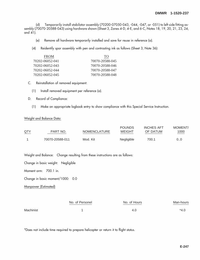
(d) Temporarily install stabilator assembly (70200-07050-043, -044, -047, or -051) to left side fitting as-sembly (70070-20588-043) using hardware shown (Sheet 3, Zones 4-D, 4-E, and 6-C, Notes 18, 19, 20, 21, 23, 24,and 41).
(e) Remove all hardware temporarily installed and save for reuse in reference (a).
(4) Reidentify spar assembly with pen and contrasting ink as follows (Sheet 3, Note 36):
FROM TO70202-06052-041 70070-20588-04570202-06052-043 70070-20588-04670202-06052-044 70070-20588-04770202-06052-045 70070-20588-048
C. Reinstallation of removed equipment:
(1) Install removed equipment per reference (a).
D. Record of Compliance:
(1) Make an appropriate logbook entry to show compliance with this Special Service Instruction.
Weight and Balance Data:
QTY PART NO. NOMENCLATUREPOUNDSWEIGHT
INCHES AFTOF DATUM
MOMENT/1000
1 70070-20588-011 Mod. Kit Negligible 700.1 0..0
Weight and Balance: Change resulting from these instructions are as follows:
Change in basic weight: Negligible
Moment arm: 700.1 in.
Change in basic moment/1000: 0.0
Manpower (Estimated)
No. of Personel No. of Hours Man-hours
Machinist 1 4.0 *4.0
*Does not include time required to prepare helicopter or return it to flight status.
DMWR 1-1520-237
E-247

Material Information:
A. Modification Kit Required:
Qty Nomenclature Part Number Source
1 Mod. Kit, TRP, Aft Spar, 70070-20588-011 (1)
consisting of:
1 Mod. Kit, TRP, Aft Spar, 70070-20588-012
consisting of:2 Bushing FMI-718-45020-A2 Bushing FMI-718-45120-A2 Bushing FMI-718-45220-A2 Bushing FMI-718-45320-A2 Bushing FMI-718-45420-A2 Bushing, 5TH-OS FMI-718-45520-A2 Bushing OS FMI-718-45620-A2 Sherical BRG KNDB 12-25
1 Mod. Kit TRP, Aft Spar, 70070-20588-013
consisting of:1 Bushing FMI-718-45010-A1 Bushing, Nominal FMI-718-45030-A1 Bushing FMI-718-45110-A1 Bushing, 1ST-OS FMI-718-45130-A1 Bushing FMI-718-45210-A1 Bushing, 2ND-OS FMI-718-45230-A1 Bushing FMI-718-45310-A1 Bushing, 3RD-OS FMI-718-45330-A1 Bushing FMI-718-45410-A1 Bushing, 4TH-OS FMI-718-45430-A1 Bushing, 5TH-OS FMI-718-45510-A1 Bushing, 5TH-OS FMI-718-45530-A
1 Mod. Kit, Stabilator INSTL, 70070-20588-014
consisting of:1 Nut MS17826-102 Washer MS20002-101 Washer MS20002C101 Pin, Cotter MS24665-3741 Bolt NAS6210-48D1 Washer, STL 70070-20588-1011 Washer, Gasket 70070-20588-102
DMWR 1-1520-237
E-248
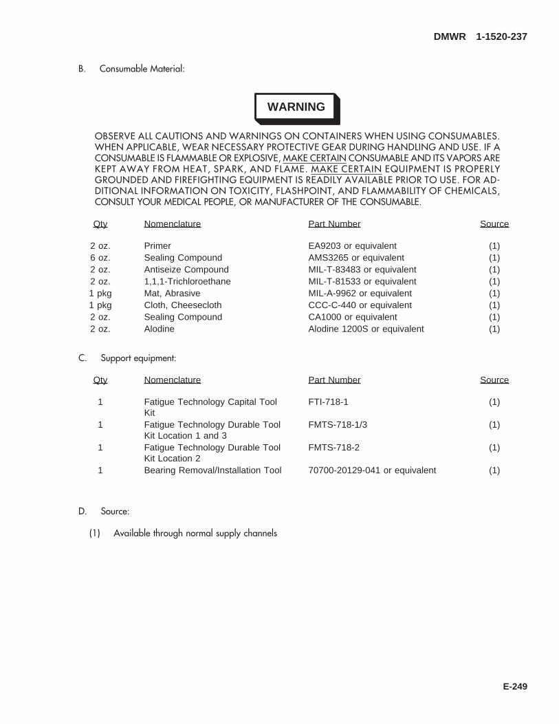
B. Consumable Material:
WARNING
OBSERVE ALL CAUTIONS AND WARNINGS ON CONTAINERS WHEN USING CONSUMABLES.WHEN APPLICABLE, WEAR NECESSARY PROTECTIVE GEAR DURING HANDLING AND USE. IF ACONSUMABLE IS FLAMMABLE OR EXPLOSIVE, MAKE CERTAIN CONSUMABLE AND ITS VAPORS AREKEPT AWAY FROM HEAT, SPARK, AND FLAME. MAKE CERTAIN EQUIPMENT IS PROPERLYGROUNDED AND FIREFIGHTING EQUIPMENT IS READILY AVAILABLE PRIOR TO USE. FOR AD-DITIONAL INFORMATION ON TOXICITY, FLASHPOINT, AND FLAMMABILITY OF CHEMICALS,CONSULT YOUR MEDICAL PEOPLE, OR MANUFACTURER OF THE CONSUMABLE.
Qty Nomenclature Part Number Source
2 oz. Primer EA9203 or equivalent (1)6 oz. Sealing Compound AMS3265 or equivalent (1)2 oz. Antiseize Compound MIL-T-83483 or equivalent (1)2 oz. 1,1,1-Trichloroethane MIL-T-81533 or equivalent (1)1 pkg Mat, Abrasive MIL-A-9962 or equivalent (1)1 pkg Cloth, Cheesecloth CCC-C-440 or equivalent (1)2 oz. Sealing Compound CA1000 or equivalent (1)2 oz. Alodine Alodine 1200S or equivalent (1)
C. Support equipment:
Qty Nomenclature Part Number Source
1 Fatigue Technology Capital ToolKit
FTI-718-1 (1)
1 Fatigue Technology Durable ToolKit Location 1 and 3
FMTS-718-1/3 (1)
1 Fatigue Technology Durable ToolKit Location 2
FMTS-718-2 (1)
1 Bearing Removal/Installation Tool 70700-20129-041 or equivalent (1)
D. Source:
(1) Available through normal supply channels
DMWR 1-1520-237
E-249

45
3
2
6
1
A
7
SAAB3105_1
89
10
B
1
A
7
Figure E-25. Aft Spar Fitting Modification Kit (Sheet 1 of 2)
DMWR 1-1520-237
E-250

FRONT
1817
1817
SAAB3105_2
15
11
16
12
B
16
13
14
12
Figure E-25. Aft Spar Fitting Modification Kit (Sheet 2 of 2)
DMWR 1-1520-237
E-251
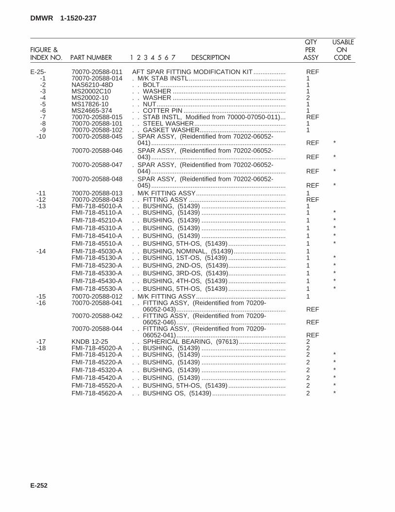
E-25- 70070-20588-011 AFT SPAR FITTING MODIFICATION KIT .................. REF-1 70070-20588-014 . M/K STAB INSTL...................................................... 1-2 NAS6210-48D . . BOLT...................................................................... 1-3 MS20002C10 . . WASHER ............................................................... 1-4 MS20002-10 . . WASHER ............................................................... 2-5 MS17826-10 . . NUT........................................................................ 1-6 MS24665-374 . . COTTER PIN ......................................................... 1-7 70070-20588-015 . . STAB INSTL, Modified from 70000-07050-011)... REF-8 70070-20588-101 . . STEEL WASHER................................................... 1-9 70070-20588-102 . . GASKET WASHER................................................ 1
-10 70070-20588-045 . SPAR ASSY, (Reidentified from 70202-06052-041) ........................................................................... REF *
70070-20588-046 . SPAR ASSY, (Reidentified from 70202-06052-043) ........................................................................... REF *
70070-20588-047 . SPAR ASSY, (Reidentified from 70202-06052-044) ........................................................................... REF *
70070-20588-048 . SPAR ASSY, (Reidentified from 70202-06052-045) ........................................................................... REF *
-11 70070-20588-013 . M/K FITTING ASSY.................................................. 1-12 70070-20588-043 . . FITTING ASSY ...................................................... REF-13 FMI-718-45010-A . . BUSHING, (51439) ............................................... 1
FMI-718-45110-A . . BUSHING, (51439) ............................................... 1 *FMI-718-45210-A . . BUSHING, (51439) ............................................... 1 *FMI-718-45310-A . . BUSHING, (51439) ............................................... 1 *FMI-718-45410-A . . BUSHING, (51439) ............................................... 1 *FMI-718-45510-A . . BUSHING, 5TH-OS, (51439) ................................ 1 *
-14 FMI-718-45030-A . . BUSHING, NOMINAL, (51439)............................. 1FMI-718-45130-A . . BUSHING, 1ST-OS, (51439) ................................ 1 *FMI-718-45230-A . . BUSHING, 2ND-OS, (51439)................................ 1 *FMI-718-45330-A . . BUSHING, 3RD-OS, (51439)................................ 1 *FMI-718-45430-A . . BUSHING, 4TH-OS, (51439) ................................ 1 *FMI-718-45530-A . . BUSHING, 5TH-OS, (51439) ................................ 1 *
-15 70070-20588-012 . M/K FITTING ASSY.................................................. 1-16 70070-20588-041 . . FITTING ASSY, (Reidentified from 70209-
06052-043)............................................................. REF70070-20588-042 . . FITTING ASSY, (Reidentified from 70209-
06052-046)............................................................. REF70070-20588-044 . . FITTING ASSY, (Reidentified from 70209-
06052-041)............................................................. REF-17 KNDB 12-25 . . SPHERICAL BEARING, (97613) .......................... 2-18 FMI-718-45020-A . . BUSHING, (51439) ............................................... 2
FMI-718-45120-A . . BUSHING, (51439) ............................................... 2 *FMI-718-45220-A . . BUSHING, (51439) ............................................... 2 *FMI-718-45320-A . . BUSHING, (51439) ............................................... 2 *FMI-718-45420-A . . BUSHING, (51439) ............................................... 2 *FMI-718-45520-A . . BUSHING, 5TH-OS, (51439) ................................ 2 *FMI-718-45620-A . . BUSHING OS, (51439) ......................................... 2 *
DMWR 1-1520-237
QTY USABLEFIGURE & PER ONINDEX NO. PART NUMBER 1 2 3 4 5 6 7 DESCRIPTION ASSY CODE
E-252
E-22. L/H R/H FIREWALL MODIFICATION KIT (50-19).
Subject: Left and Right Side Firewall Assemblies, Modification of, dated 31 March 2003
Purpose: Provide instructions to modify/reinforce existing firewall installation to prevent wear and fatigue cracking.
Model: UH-60A
Description: The following is a brief overview of the work required to modify left and right side firewall assemblies. Newdoublers, angles, straps, and spacers are installed to left and right firewall assemblies.
Drawings required for modification:
70070-30307, 70304-02114
References: (a) Special Service Instructions (SSI) No. 50-31, Installation of 9A to A9 Recapitalization Program, datedMarch 31, 2003
Instructions:
NOTE
• A complete review of this SSI is recommended before modifying right and left side firewall assemblies.
• Before beginning this modification procedure, use the material information list to inventory the kit. Makesure all parts are present and in serviceable condition.
• Where drawing numbers are not listed within individual steps, drawing(s) listed in preceding step(s) arethe controlling authority.
• The sheet metal and structural modifications in this SSI shall be done by personnel experienced in readingmodification drawings. Routine steps such as cleaning, layout and drilling, deburring, standard repairs,corrosion control, clean up after rework, chemical coating for aluminum after cutting/trimming parts, painttouch up, and safety practices may not be called out herein. However, these steps and all other requiredroutine tasks shall be done.
• Slight variations to the instructions contained herein are allowed, as long as the intent of the modificationis accomplished.
A. Preparation for modification and removal of equipment:
(1) Confirm that all warnings, cautions, and notes are complied with per reference (a).
(2) The helicopter is prepared for modification per reference (a).
B. Modification of left side firewall as follows (Dwg 70070-30307):
(1) Remove and discard angle (70304-02115-117) from left side firewall assembly (Sheet 3, Zone 7-B).
(2) Remove and save for reinstallation angle (70304-02115-118) (Sheet 3, Zone 6-E).
(3) Install doubler (70070-30307-101) at station 349.00, left buttline 21.25 using fasteners shown (Sheet 3,Zone 14-B).
DMWR 1-1520-237
E-253
(4) Install angle (70070-30275-103), spacer (70070-30275-104), and angle (removed in step B.(2)) (70304-02115-118) using fasteners shown (Sheet 3, Zones 7-B, 5-D, and 6-E).
(5) Install strap (70070-30307-102) at station 355.00, left buttline 20.00 using fasteners shown (Sheet 3, Zone11-D).
C. Modification of right side firewall as follows (Dwg’s 70070-30307, and 70304-02114):
(1) Remove and save for reinstallation bracket assembly (70551-01101-041) and bracket (AN743C13) (Dwg70070-30307, Sheet 3, Zones 14-H and 14-F).
(2) Remove two doublers (70304-02114-133) and angles (70304-02114-116, -119 and -157) from right sidefirewall (Dwg 70304-02114, Sheet 1, Zones 16-L, 17-M, 14-K and 17-L).
(3) Install doubler (70070-30307-103), bracket assembly (removed in step C.(1)) (70551-01101-041), angles(70304-02114-167, -168 and -170), two doublers (70304-02114-169) and bracket (AN743C13) using fastenersshown (Dwg 70070-30307, Sheet 3, Zones 14-G, 13-H and 14-F; Dwg 70304-02114, Sheet 1, Zones 17-N, 14-L and17-L).
(4) Install strap (70070-30307-104) using fasteners shown (Dwg 70070-30307, Sheet 3, Zone 11-F).
(5) After rework reidentify firewall assemblies with pen and contrasting ink as follows:
FROM TO70304-02115-041 70070-30307-04170304-02115-045 70070-30307-04270304-02115-047 70070-30307-04370304-02115-049 70070-30307-04470304-02115-053 70070-30307-04570304-02114-041 70070-30307-04670304-02114-043 70070-30307-04770304-02114-045 70070-30307-04870304-02114-046 70070-30307-04970304-02115-052 70070-30307-05570304-02115-048 70070-30307-05470304-02115-044 70070-30307-05370304-02115-043 70070-30307-05270304-02114-049 70070-30307-05070304-02114-051 70070-30307-051
D. Reinstallation of removed equipment:
(1) Reinstall removed equipment per reference (a).
E. Record of Compliance:
(1) Make an appropriate logbook entry to show compliance with this Special Service Instruction.
DMWR 1-1520-237
E-254

Weight and Balance Data:
QTY PART NO. NOMENCLATUREPOUNDSWEIGHT
INCHES AFTOF DATUM
MOMENT/1000
1 70070-30307-011 Mod. Kit, Firewall1 70070-30307-012 Mod. Kit, Firewall
Total: +1.1 350.8 0.386
Weight and Balance: Change resulting from these instructions are as follows:
Change in basic weight: +1.1 pounds
Moment arm: 350.8 in.
Change in basic moment/1000: 0.386
Manpower (Estimated)
No. of Personel No. of Hours Man-hoursSheet Metal Mec 1 28.0 *28.0
*Does not include time required to prepare helicopter or return it to flight status.
Material Information:
A. Modification Kit Required:
(1) Kit A:
Qty Nomenclature Part Number Source
1 Mod. Kit, Firewall LH, 70070-30307-011 (1)
consisting of:70 Rivet MS20615-4M51 Doubler 70070-30307-1011 Strap 70070-30307-1021 Angle 70070-30275-1031 Spacer 70070-30275-104
(2) Kit B:
Qty Nomenclature Part Number Source
1 Mod. Kit, Firewall RH, 70070-30307-012 (1)
DMWR 1-1520-237
E-255

Qty Nomenclature Part Number Source
consisting of:71 Rivet MS20615-4M54 Nutplate MS21060-33 Nutplate MS21062-31 Nutplate MS21074-L318 Rivet NAS1097AD3-91 Doubler 70070-30307-1031 Strap 70070-30307-1041 Angle 70304-02114-1671 Angle 70304-02114-1682 Doubler 70304-02114-1691 Angle 70304-02114-170
B. Source:
(1) Available through normal supply channels
DMWR 1-1520-237
E-256

A
SAAB3085
A
1
2
1
5
4
3
16
FRONT
Figure E-26. L/H Firewall Modification Kit
DMWR 1-1520-237
E-257

E-26- 70070-30307-011 L/H FIREWALL MODIFICATION KIT .......................... REF-1 MS20615-4M5 . RIVET........................................................................ 70-2 70070-30275-102 . STRAP ...................................................................... 1-3 70070-30275-104 . SPACER ................................................................... 1-4 70070-30307-103 . ANGLE...................................................................... 1-5 70070-30307-101 . DOUBLER................................................................. 1-6 70070-30307-013 . FIREWALL INSTL (Reidentified from 70304-
02200-011)................................................................ REF70070-30307-041 . FIREWALL ASSY (Reidentified from 70304-
02115-041)................................................................ REF70070-30307-042 . FIREWALL ASSY (Reidentified from 70304-
02115-045)................................................................ REF70070-30307-043 . FIREWALL ASSY (Reidentified from 70304-
02115-047)................................................................ REF70070-30307-044 . FIREWALL ASSY (Reidentified from 70304-
02115-049)................................................................ REF70070-30307-045 . FIREWALL ASSY (Reidentified from 70304-
02115-053)................................................................ REF70070-30307-052 . FIREWALL ASSY (Reidentified from 70304-
02115-043)................................................................ REF70070-30307-053 . FIREWALL ASSY (Reidentified from 70304-
02115-044)................................................................ REF70070-30307-054 . FIREWALL ASSY (Reidentified from 70304-
02115-048)................................................................ REF70070-30307-055 . FIREWALL ASSY (Reidentified from 70304-
02115-052)................................................................ REF
DMWR 1-1520-237
QTY USABLEFIGURE & PER ONINDEX NO. PART NUMBER 1 2 3 4 5 6 7 DESCRIPTION ASSY CODE
E-258

FRONT
SAAB3086
A
A
4
10
1
1 1 1
9
9
4
5
86
3
2
2
24
7
3
11
12
Figure E-27. R/H Firewall Modification Kit
DMWR 1-1520-237
E-259

E-27- 70070-30307-012 R/H FIREWALL MODIFICATION KIT.......................... REF-1 NAS1097AD3-9 . RIVET........................................................................ 18-2 MS21060-3 . NUTPLATE ............................................................... 4-3 MS21062-3 . NUTPLATE ............................................................... 3-4 MS20615-4M5 . RIVET........................................................................ 71-5 70070-30307-104 . STRAP ...................................................................... 1-6 MS21074-L3 . NUTPLATE ............................................................... 1-7 70304-02114-167 . ANGLE...................................................................... 1-8 70304-02114-168 . ANGLE...................................................................... 1-9 70304-02114-169 . DOUBLER................................................................. 2
-10 70070-30307-103 . DOUBLER................................................................. 1-11 70304-02114-170 . ANGLE...................................................................... 1-12 70070-30307-014 . FIREWALL INSTL (Reidentified from 70304-
02200-012)................................................................ REF70070-30307-046 . FIREWALL ASSY (Reidentified from 70304-
02114-041)................................................................ REF70070-30307-047 . FIREWALL ASSY (Reidentified from 70304-
02114-043)................................................................ REF70070-30307-048 . FIREWALL ASSY (Reidentified from 70304-
02114-045)................................................................ REF70070-30307-049 . FIREWALL ASSY (Reidentified from 70304-
02114-046)................................................................ REF70070-30307-050 . FIREWALL ASSY (Reidentified from 70304-
02114-049)................................................................ REF70070-30307-051 . FIREWALL ASSY (Reidentified from 70304-
02114-051)................................................................ REF
DMWR 1-1520-237
QTY USABLEFIGURE & PER ONINDEX NO. PART NUMBER 1 2 3 4 5 6 7 DESCRIPTION ASSY CODE
E-260

E-23. COWL ASSEMBLY MODIFICATION KIT (50-33).
Subject: Engine Cowl Assembly, Left and Right Side, Modification of, dated 31 March 2003
Purpose: Provide instructions for installation of splice straps on engine cowl assembly.
Model: UH-60A
Description: New one piece hinge fitting assemblies are installed to reinforce the hinge area.
Drawings Required for Modification:
70070-30308
References: (a) Special Service Instructions (SSI) No. 50-31, Installation of 9A to A9 Recapitalization Program, datedMarch 31, 2003
Instructions:
NOTE
• A complete review of this SSI is recommended before incorporating the engine cowl assembly modificationkit.
• Before beginning this modification procedure, use the material information list to inventory the kit. Makesure all parts are present and in serviceable condition.
• Slight variations to the instructions contained herein are allowed, as long as the intent of the modificationis accomplished.
• The sheet metal and structural modifications in this SSI shall be done by personnel experienced in sheetmetal/structural work, skilled in reading modification drawings, standard working/repair, and safetypractices. Routine steps such as cleaning, layout and drilling, deburring, standard repairs, corrosioncontrol, clean up after rework, chemical coating for aluminum after cutting/trimming parts, and painttouch up may not be called out herein. However, these steps and all other required routine tasks shall bedone.
• Where drawing numbers are not listed within individual steps, drawing(s) listed in preceding step(s) arethe controlling authority.
• When installing fasteners refer to drawing sheet and zones for rivet code on applicable drawings.
A. Preparation for modification:
(1) Confirm all warnings, cautions, and notes are complied with per reference (a).
(2) Perform preparation for modification per reference (a).
B. Installation of parts for modification of engine cowl assembly:
NOTE
• Drawing shows right side foward hinge only. Rework of remaining hinge locations is the same, exceptremove hinge -042, and install hinge fitting assembly -048.
DMWR 1-1520-237
E-261

• This modification does not apply to platforms with alternate method of manufacturing with walkingsurfaces intergral with rib support.
(1) Position cowl assembly (70302-02141-041, -042, -044, -045, -048, or -049) on suitable work bench.
(2) Remove hinge (70302-02157-041 and -042) and shims (70302-02141-109) if applicable, from forwardand aft ribs as follows:
(a) Remove and discard seven screws, nuts, and washers on hinge assembly (70302-02157-041 and -042)(Dwg 70070-30308, Sheet 2, Zone 6-E).
NOTE
If shims (70302-02141-109) are installed proceed to step B.(2)(b). Otherwise proceed to step B.(2).
(b) Wedge a non-metalic scraper in between the shims of aluminum stock (70302-02141-109) and removeand save for reinstallation (Sheet 2, Zone 5-C and Note 12).
(c) Position and pin at two locations removed hinge (70302-02141-041 or -042) on top of new hinge fittingassembly (70070-30308-047 or -048).
NOTE
Placing a spacer bar in between the old and new hinge assemblies will insure proper alignment duringpinning and drilling operation.
(d) Transfer drill from old hinge (70302-02141-041 or -042) into new hinge fitting assembly (70070-30308-047 or -048) at two locations.
(e) Remove pins and clean and deburr the two holes drilled in step (d).
(f) Position hinge fitting assembly (70070-30308-047 or -048) into engine cowling (70302-02141-041,-042, -044,-045, -048, or -049) and pin two previously drilled holes (Sheet 2, Zone 6-E).
(g) Transfer drill remaining five 0.1935-inch diameter holes from engine cowl (70302-02141-042, -044,-045, -048, or -049) to hinge fitting assembly (70070-30308-047, or -048) to match existing hole locations (Sheet 2,Zone 7-C).
(h) Temporarily fasten all holes in hinge fitting (70070-30308-047 or -048) to engine cowl assembly (70302-02141-041, -042, -044, -045, -048, or -049) (Sheet 2, Zone 7-C).
(i) Layout 14 holes in engine cowl assembly (70070-30308-041, -042, -044, -045, -045, -048, or -049)and hinge fitting assembly (70070-30308-047 or -048) (Sheet 2, Zone 8-G).
(j) Remove hinge ftting assembly (70070-30308-047 or -048) deburr and touch up as required.
(k) Install hinge fitting assembly (70070-30308-047 or -048) into cowl assembly (70302-02141-041, -042,-044, -045, -048, or -049) using hardware shown. If shims were previously removed, reinstall at this time (Sheet 2, Zone8-C).
DMWR 1-1520-237
E-262

WARNING
OBSERVE ALL CAUTIONS AND WARNINGS ON CONTAINERS WHEN USING CONSUMABLES.WHEN APPLICABLE, WEAR NECESSARY PROTECTIVE GEAR DURING HANDLING AND USE. IF ACONSUMABLE IS FLAMMABLE OR EXPLOSIVE, MAKE CERTAIN CONSUMABLE AND ITS VAPORS AREKEPT AWAY FROM HEAT, SPARK, AND FLAME. MAKE CERTAIN EQUIPMENT IS PROPERLYGROUNDED AND FIREFIGHTING EQUIPMENT IS READILY AVAILABLE PRIOR TO USE. FOR AD-DITIONAL INFORMATION ON TOXICITY, FLASHPOINT, AND FLAMMABILITY OF CHEMICALS,CONSULT YOUR MEDICAL PEOPLE, OR MANUFACTURER OF THE CONSUMABLE.
(l) Mix syntactic foam (Epocast, Type II, 1652 A/B) per manufacturers instructions and fill interior of the ribsthrough previously drilled holes in step B.(2)(i) (Sheet 2, Zone 5-G).
(m) Drill out holes previously filled with syntactic foam (Epocast, Type II, 1652 A/B) and install fastenersshown (Sheet 2, Zone 8-G).
(3) After rework reidentify engine cowl assembly using pen and contrasting ink as follows:
FROM TO70302-02141-041 70070-30308-04170302-02141-042 70070-30308-04270302-02141-044 70070-30308-04370302-02141-045 70070-30308-04470302-02141-048 70070-30308-04570302-02141-049 70070-30308-046
C. Reinstallation of removed equipment:
(1) Perform installation of parts and equipment per reference (a).
D. Record of Compliance:
(1) Make an appropriate logbook entry to show compliance with this Special Service Instruction.
Weight and Balance Data:
QTY PART NO. NOMENCLATUREPOUNDSWEIGHT
INCHES AFTOF DATUM
MOMENT/1000
1 70070-30308-011 Mod. Kit +3.0 375.5 +1.126
Weight and Balance: Change resulting from these instructions are as follows:
Change in basic weight: +3.0 pounds
Moment arm: 375.5 in.
DMWR 1-1520-237
E-263

Change in basic moment/1000: 1.126
Manpower (Estimated)
No. of Personel No. of Hours Man-hoursSheet Metal Mechanic 1 32.0 *32.0
*Does not include time required to prepare helicopter or return it to flight status.
Material Information:
A. Modification Kit Required:
Qty Nomenclature Part Number Source
1 Mod. Kit, Cowl Assembly-Engine 70070-30308-011 (1)
consisting of:2 Hinge Fitting Assembly 70070-30308-0472 Hinge Fitting Assembly 70070-30308-04875 Pin, Hi Lok HL20PB-6-1075 Collar HL75-6AW31 Screw MS27039C1-1431 Nut MS21043-362 Washer NAS1149C0332R
B. Consumable Material:
WARNING
OBSERVE ALL CAUTIONS AND WARNINGS ON CONTAINERS WHEN USING CONSUMABLES.WHEN APPLICABLE, WEAR NECESSARY PROTECTIVE GEAR DURING HANDLING AND USE. IF ACONSUMABLE IS FLAMMABLE OR EXPLOSIVE, MAKE CERTAIN CONSUMABLE AND ITS VAPORS AREKEPT AWAY FROM HEAT, SPARK, AND FLAME. MAKE CERTAIN EQUIPMENT IS PROPERLYGROUNDED AND FIREFIGHTING EQUIPMENT IS READILY AVAILABLE PRIOR TO USE. FOR AD-DITIONAL INFORMATION ON TOXICITY, FLASHPOINT, AND FLAMMABILITY OF CHEMICALS,CONSULT YOUR MEDICAL PEOPLE, OR MANUFACTURER OF THE CONSUMABLE.
Qty Nomenclature Part Number Source
16 oz. Foam, Syntactic Epocast, Type II, 1652 A/B,SS9587-003 or equivalent
(1)
C. Source:
(1) Available through normal supply channels
DMWR 1-1520-237
E-264
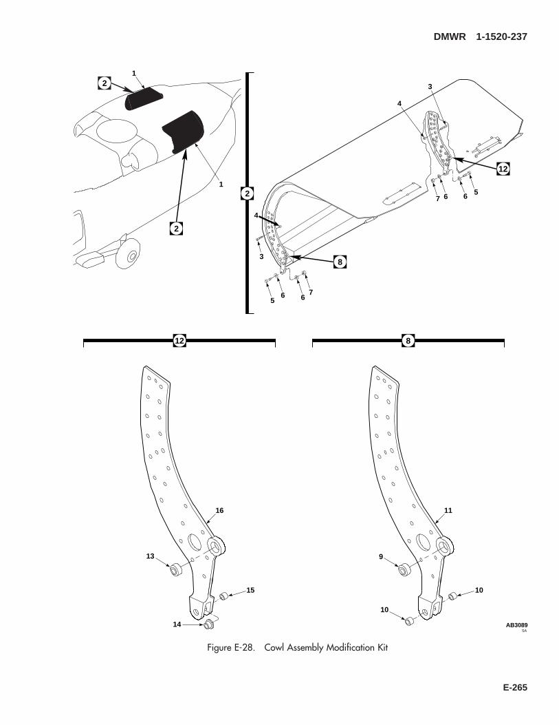
2
6
2
5
2
76
SAAB3089
8
9
11
10
10
12
13
16
14
15
8
4
3
65
7 6
4
3
12
1
1
Figure E-28. Cowl Assembly Modification Kit
DMWR 1-1520-237
E-265

E-28- 70070-30308-011 COWL ASSEMBLY MODIFICATION KIT.................... REF-1 70070-30308-013 . COWL INSTALLATION, (Modifies 70302-02200-
011) ........................................................................... REF-2 70070-30308-041 . COWL ASSY (Reidentified from 70302-02141-
041) ........................................................................... REF70070-30308-042 . COWL ASSY (Reidentified from 70302-02141-
042) ........................................................................... REF70070-30308-043 . COWL ASSY (Reidentified from 70302-02141-
044) ........................................................................... REF70070-30308-044 . COWL ASSY (Reidentified from 70302-02141-
045) ........................................................................... REF70070-30308-045 . COWL ASSY (Reidentified from 70302-02141-
048) ........................................................................... REF70070-30308-046 . COWL ASSY (Reidentified from 70302-02141-
049) ........................................................................... REF-3 HL20PB-6-10 . HI-LOK PIN, (73197)................................................ 14-4 HL75-6AW . COLLAR, (73197) .................................................... 14-5 MS27039C1-14 . SCREW..................................................................... 28-6 NAS1149C0332R . FLAT WASHER ........................................................ 56-7 MS21043-3 . NUT........................................................................... 28-8 70070-30308-047 . HINGE FITTING ASSEMBLY................................... 2-9 MS14103-4K . . BEARING............................................................... 1
SBSH8ATC20ZM . . BEARING............................................................... 1 *-10 NAS537-4-034 . . BUSHING............................................................... 2-11 70070-30308-102 . . HINGE FITTING..................................................... 1-12 70070-30308-048 . HINGE FITTING ASSEMBLY................................... 2-13 MS14103-4K . . BEARING............................................................... 1
SBSH8ATC20ZM . . BEARING............................................................... 1 *-14 NAS77-4-020 . . BEARING............................................................... 1-15 NAS75-4-011 . . BUSHING............................................................... 1-16 70070-30308-102 . . HINGE FITTING..................................................... 1
DMWR 1-1520-237
QTY USABLEFIGURE & PER ONINDEX NO. PART NUMBER 1 2 3 4 5 6 7 DESCRIPTION ASSY CODE
E-266
E-24. HIRSS REPAIR KIT (50-30).
Subject: HIRSS Repair Kit ; Installation of
Purpose: Provide instructions to install HIRSS repair kit.
Model: UH-60A
Description The following is a brief overview of the work required to install the HIRSS repair kit. New doublers, fillers,angles, and radius blocks are installed to the left and right exhaust extenders.
Drawings required for modification:
70072-30000, 70308-03611
References: (a) Special Service Instructions (SSI) No. 50-31, Installation of 9A to A9 Recapitalization Program, datedMarch 31, 2003
Instructions:
NOTE
• A complete review of this SSI is recommended before installing HIRSS repair kit.
• Before beginning this modification procedure, use the material information list to inventory the kit. Makesure all parts are present and in serviceable condition.
• Where drawing numbers are not listed within individual steps, drawing(s) listed in preceding step(s) arethe controlling authority.
• The sheet metal and structural modifications in this SSI shall be done by personnel experienced in readingmodification drawings. Routine steps such as cleaning, layout and drilling, deburring, standard repairs,corrosion control, clean up after rework, chemical coating for aluminum after cutting/trimming parts, painttouch up, and safety practices may not be called out herein. However, these steps and all other requiredroutine tasks shall be done.
• When installing fasteners refer to drawing sheet and zones and rivet code on applicable drawing.
• Slight variations to the instructions contained herein are allowed, as long as the intent of the modificationis accomplished.
A. Preparation for modification and removal of equipment.
(1) Confirm that all warnings, cautions, and notes are complied with per reference (a).
(2) Perform preparation for modification per reference (a).
B. Modification of left and right exhaust extender assemblies as follows (Dwg 70308-03611):
(1) Remove support angle (70308-03611-124) from right side exhaust extender (Sheet 2, Zone 21-D).
(2) Temporarily install new support angle (70308-03611-124), angle clip (70308-03611-159), filler plate(70308-03611-160), and radius block (SS1058-5-38-24) (Sheet 2, Zones 21-D, 22-B, and 24-H; Sheet 6, Zone 21-C).
DMWR 1-1520-237
E-267

(3) Position and temporarily install doubler (70308-03611-166) and fillers (70308-03611-167 and 168) (Sheet2, Zones 18-H, 20-G, and 18-F).
(4) Remove all parts temporarily installed in steps B.(2) and B.(3), deburr and touch up as required.
(5) Install all parts removed in step B.(4) using fasteners shown (Sheet 2, Zones 21-D, 22-B, 24-H, 18-H, 20-G,and 18-F; Sheet 6, Zone 21-C; Sheet 1, Note 20).
(6) Remove support angle (70308-03611-123) from left side exhaust extender (Sheet 2, Zone 21-D).
(7) Temporarily install new support angle (70308-03611-123), angle clip (70308-03611-159), filler plate(70308-03611-160), and radius block (SS1058-5-38-24) (Sheet 2, Zones 21-D, 22-B, and 24-H; Sheet 6 Zone 21-C).
(8) Position and temporarily install doubler (70308-03611-165) and fillers (70308-03611-167 and -168)(Sheet 2, Zones 18-H, 20-G, and 18-F).
(9) Remove fitted parts, deburr and touch up as required.
(10) Install fitted parts using fasteners shown (Sheet 2, Zones 21-D, 22-B, 24-H, 18-H, 20-G, and 18-F; Sheet 6,Zone 21-C; Sheet 1, Note 20).
C. Reinstallation of removed equipment:
(1) Install removed equipment per reference (a).
D. Record of Compliance:
(1) Make an appropriate logbook entry to show compliance with this Special Service Instruction.
Weight and Balance Data:
QTY PART NO. NOMENCLATUREPOUNDSWEIGHT
INCHES AFTOF DATUM
MOMENT/1000
1 70072-3000-011 Mod. Kit, HIRSS Repair Kit +2.1 442.2 0.929
Weight and Balance: Change resulting from these instructions are as follows:
Change in basic weight: + 2.1 pounds
Moment arm: 442.2 in.
Change in basic moment/1000: 0.929
DMWR 1-1520-237
E-268

Manpower (Estimated)
No. of Personel No. of Hours Man-hoursSheet Metal Mechanic 1 16.0 *16.0
*Does not include time required to prepare helicopter or return it to flight status.
Material Information:
A. Modification Kit Required:
Qty Nomenclature Part Number Source
1 Mod. Kit, HIRSS Repair Kit, 70072-30000-011 (1)
consisting of:1 Repair Kit, RH, 70072-30000-012
consisting of:2 Collar HL1087ATW-52 Pin, Hi Lok HL20PB-5-211 Rivet, Blind NAS1738M4-215 Rivet, Blind NAS1738M4-38 Rivet, Blind NAS1738M4-441 Rivet, Blind NAS1738M4-51 Radius Block SS1058-5-38-241 Support Angle 70308-03611-1241 Angle Clip 70308-03611-1591 Filler Plate 70308-03611-1601 Doubler 70308-03611-1661 Filler 70308-03611-1672 Filler 70308-03611-1681 Repair Kit, LH, 70072-30000-013
consisting of:2 Collar HL1087ATW-52 Pin, Hi Lok HL20PB-5-211 Rivet, Blind NAS1738M4-215 Rivet, Blind NAS1738M4-38 Rivet, Blind NAS1738M4-441 Rivet, Blind NAS1738M4-51 Radius Block SS1058-5-38-241 Support Angle 70308-03611-1231 Angle Clip 70308-03611-1591 Filler Plate 70308-03611-1601 Doubler 70308-03611-1651 Filler 70308-03611-167
DMWR 1-1520-237
E-269
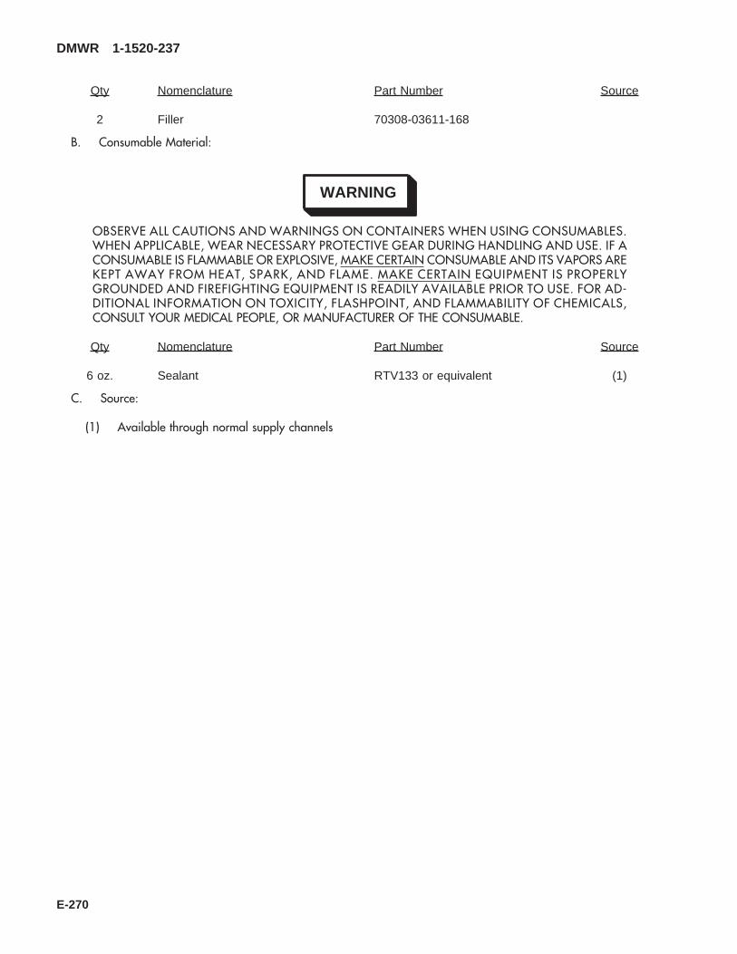
Qty Nomenclature Part Number Source
2 Filler 70308-03611-168
B. Consumable Material:
WARNING
OBSERVE ALL CAUTIONS AND WARNINGS ON CONTAINERS WHEN USING CONSUMABLES.WHEN APPLICABLE, WEAR NECESSARY PROTECTIVE GEAR DURING HANDLING AND USE. IF ACONSUMABLE IS FLAMMABLE OR EXPLOSIVE, MAKE CERTAIN CONSUMABLE AND ITS VAPORS AREKEPT AWAY FROM HEAT, SPARK, AND FLAME. MAKE CERTAIN EQUIPMENT IS PROPERLYGROUNDED AND FIREFIGHTING EQUIPMENT IS READILY AVAILABLE PRIOR TO USE. FOR AD-DITIONAL INFORMATION ON TOXICITY, FLASHPOINT, AND FLAMMABILITY OF CHEMICALS,CONSULT YOUR MEDICAL PEOPLE, OR MANUFACTURER OF THE CONSUMABLE.
Qty Nomenclature Part Number Source
6 oz. Sealant RTV133 or equivalent (1)
C. Source:
(1) Available through normal supply channels
DMWR 1-1520-237
E-270

SAAB3087_1
1
1
FRONT
2
3
1
Figure E-29. HIRSS Repair Kit (Sheet 1 of 2)
DMWR 1-1520-237
E-271

SAAB3087_2
FRONT
45
6
7
8
9
10
11
12
13
14
15
16
3
Figure E-29. HIRSS Repair Kit (Sheet 2 of 2)
DMWR 1-1520-237
E-272

E-29- 70072-30000-011 HIRSS REPAIR KIT..................................................... REF-1 70308-03611-011 . EXTENDER INSTALLATION.................................... REF
70308-03611-012 . EXTENDER INSTALLATION.................................... REF70308-03611-013 . EXTENDER INSTALLATION.................................... REF70308-03611-014 . EXTENDER INSTALLATION.................................... REF
-2 70308-03611-041 . EXTENDER ASSY. (Used on70308-03611-011)..................................................... REF
70308-03611-042 . EXTENDER ASSY. (Used on70308-03611-012)..................................................... REF
70308-03611-053 . EXTENDER ASSY. (Used on70308-03611-013)..................................................... REF
70308-03611-054 . EXTENDER ASSY. (Used on70308-03611-014)..................................................... REF
-3 70072-30000-013 . REPAIR KIT LH ........................................................ 170072-30000-012 . REPAIR KIT .............................................................. 1
-4 HL20PB-5-2 . . HI-LOK PIN, (73197)............................................. 2-5 HL1087ATW-5 . . COLLAR, (73197) ................................................. 2-6 NAS1739M4-3 . . BLIND RIVET......................................................... 2-7 70308-03611-159 . . ANGLE CLIP.......................................................... 1-8 NAS1738M4-2 . . BLIND RIVET......................................................... 11-9 NAS1738M4-3 . . BLIND RIVET......................................................... 15
-10 NAS1738M4-4 . . BLIND RIVET......................................................... 8NAS1738M4-5 . . BLIND RIVET......................................................... 41 *
-11 70308-03611-165 . . DOUBLER, (Used on 70308-03611-041 and-053)....................................................................... 1
70308-03611-166 . . DOUBLER, (Used on 70308-03611-042 and-054)....................................................................... 1
-12 70308-03611-167 . . FILLER................................................................... 1-13 70308-03611-168 . . FILLER................................................................... 2-14 SS1058-5-38-24 . . RADIUS BLOCK .................................................... 1-15 70308-03611-123 . . SUPPORT ANGLE, (Used on 70308-03611-041
and -053)................................................................ 170308-03611-124 . . SUPPORT ANGLE, (Used on 70308-03611-042
and -054)................................................................ 1-16 70308-03611-160 . . FILLER PLATE ...................................................... 1
DMWR 1-1520-237
QTY USABLEFIGURE & PER ONINDEX NO. PART NUMBER 1 2 3 4 5 6 7 DESCRIPTION ASSY CODE
E-273/(E-274 blank)

FOR THE COMMANDER: JOHN B. SMITH
Colonel, QM Chief of Staff OFFICIAL:
RICHARD E. TURNER Deputy Director Integrated Materiel Management Center
DMWR 1-1520-237-3

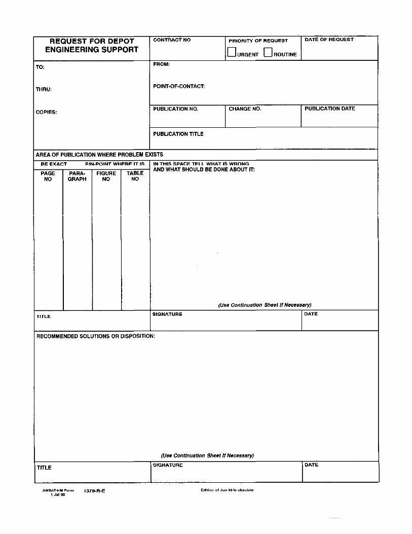

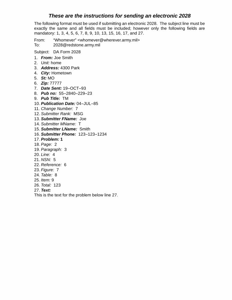
These are the instructions for sending an electronic 2028The following format must be used if submitting an electronic 2028. The subject line must beexactly the same and all fields must be included; however only the following fields aremandatory: 1, 3, 4, 5, 6, 7, 8, 9, 10, 13, 15, 16, 17, and 27.
From: “Whomever” <[email protected]>To: [email protected]
Subject: DA Form 20281. From: Joe Smith2. Unit: home3. Address: 4300 Park4. City: Hometown5. St: MO6. Zip: 777777. Date Sent: 19--OCT--938. Pub no: 55--2840--229--239. Pub Title: TM10. Publication Date: 04--JUL--8511. Change Number: 712. Submitter Rank: MSG13. Submitter FName: Joe14. Submitter MName: T15. Submitter LName: Smith16. Submitter Phone: 123--123--123417. Problem: 118. Page: 219. Paragraph: 320. Line: 421. NSN: 522. Reference: 623. Figure: 724. Table: 825. Item: 926. Total: 12327. Text:This is the text for the problem below line 27.


RECOMMENDED CHANGES TO PUBLICATIONS AND
BLANK FORMSFor use of this form, see AR 25--30; the proponent agency is ODISC4.
Use Part II (reverse) for Repair Parts and Spe-cial Tool Lists (RPSTL) and Supply Catalogs/Supply Manuals (SC/SM)
DATE
8/30/02
TO: (Forward to proponent of publication or form)(Include ZIP Code)
Commander, U.S. Army Aviation and Missile Command
ATTN: AMSAM--MMC--MA--NP
R eds t one A r s enal, AL 35898
FROM: (Activity and location)(Include ZIP Code)
MSG, Jane Q. Doe
1234 Any Street
Nowhere Town, AL 34565
PART 1 -- ALL PUBLICATIONS (EXCEPT RPSTL AND SC/SM) AND BLANK FORMS
PUBLICATION/FORM NUMBER
TM 9--1005--433--24DATE
16 Sep 2002TITLE Organizational, Direct Support, And GeneralSupport Maintenance Manual for Machine Gun, .50Caliber M3P and M3P Machine Gun Electrical Test SetUsed On Avenger Air Defense Weapon System
ITEM
NO.
PAGE
NO.
PARA--
GRAPH
LINE
NO. *
FIGURE
NO.
TABLE
NO.RECOMMENDED CHANGES AND REASON
1 WP0005
PG 3
2 Test or Corrective Action column should identify a different WP number.
* Reference to line numbers within the paragraph or subparagraph.
TYPED NAME, GRADE OR TITLE
MSG, Jane Q. Doe, SFC
TELEPHONE EXCHANGE/AUTOVON, PLUS EXTEN-SION
788--1234
SIGNATURE
DA FORM 2028, FEB 74 REPLACES DA FORM 2028, 1 DEC 68, WHICH WILL BE USED. USAPA V3.01

TO: (Forward direct to addressee listed in publication)
Commander, U.S. Army Aviation and Missile Command
ATTN: AMSAM--MMC--MA--NP
R eds t one A r s enal, AL 35898
FROM: (Activity and location) (Include ZIP Code)
MSG, Jane Q. Doe
1234 Any Street
Nowhere Town, AL 34565
DATE
8/30/02
PART II -- REPAIR PARTS AND SPECIAL TOOL LISTS AND SUPPLY CATALOGS/SUPPLY MANUALS
PUBLICATION NUMBER DATE TITLE
PAGE
NO.
COLM
NO.
LINE
NO.
NATIONAL STOCK
NUMBER
REFERENCE
NO.
FIGURE
NO.
ITEM
NO.
TOTAL NO.OF MAJOR
ITEMSSUPPORTED
RECOMMENDED ACTION
PART III -- REMARKS (Any general remarks or recommendations, or suggestions for improvement of publications and
blank forms. Additional blank sheets may be used if more space is needed.)
TYPED NAME, GRADE OR TITLE
MSG, Jane Q. Doe, SFC
TELEPHONE EXCHANGE/AUTOVON,PLUS EXTENSION
788--1234
SIGNATURE
USAPA V3.01

RECOMMENDED CHANGES TO PUBLICATIONS AND
BLANK FORMSFor use of this form, see AR 25--30; the proponent agency is ODISC4.
Use Part II (reverse) for Repair Parts and Spe-cial Tool Lists (RPSTL) and Supply Catalogs/Supply Manuals (SC/SM)
DATE
TO: (Forward to proponent of publication or form)(Include ZIP Code) FROM: (Activity and location)(Include ZIP Code)
PART 1 -- ALL PUBLICATIONS (EXCEPT RPSTL AND SC/SM) AND BLANK FORMS
PUBLICATION/FORM NUMBER DATE T I T LE
ITEM
NO.
PAGE
NO.
PARA--
GRAPH
LINE
NO. *
FIGURE
NO.
TABLE
NO.RECOMMENDED CHANGES AND REASON
* Reference to line numbers within the paragraph or subparagraph.
TYPED NAME, GRADE OR TITLE TELEPHONE EXCHANGE/AUTOVON, PLUS EXTEN-SION
SIGNATURE
DA FORM 2028, FEB 74 REPLACES DA FORM 2028, 1 DEC 68, WHICH WILL BE USED. USAPA V3.01
Commander, U.S. Army Aviation and Missile CommandATTN: AMSAM-MMC-MA-NPRedstone Arsenal, AL 35898

TO: (Forward direct to addressee listed in publication) FROM: (Activity and location) (Include ZIP Code) DATE
PART II -- REPAIR PARTS AND SPECIAL TOOL LISTS AND SUPPLY CATALOGS/SUPPLY MANUALS
PUBLICATION NUMBER DATE TITLE
PAGE
NO.
COLM
NO.
LINE
NO.
NATIONAL STOCK
NUMBER
REFERENCE
NO.
FIGURE
NO.
ITEM
NO.
TOTAL NO.OF MAJOR
ITEMSSUPPORTED
RECOMMENDED ACTION
PART III -- REMARKS (Any general remarks or recommendations, or suggestions for improvement of publications and
blank forms. Additional blank sheets may be used if more space is needed.)
TYPED NAME, GRADE OR TITLE TELEPHONE EXCHANGE/AUTOVON,PLUS EXTENSION
SIGNATURE
USAPA V3.01
Commander, U.S. Army Aviation and Missile CommandATTN: AMSAM-MMC-MA-NPRedstone Arsenal, AL 35898
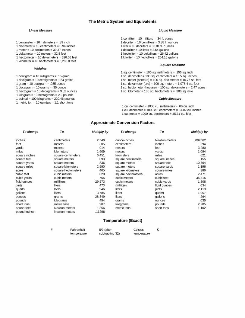
The Metric System and Equivalents
Linear Measure Liquid Measure
1 centiliter = 10 milliters = .34 fl. ounce1 centimeter = 10 millimeters = .39 inch 1 deciliter = 10 centiliters = 3.38 fl. ounces1 decimeter = 10 centimeters = 3.94 inches 1 liter = 10 deciliters = 33.81 fl. ounces1 meter = 10 decimeters = 39.37 inches 1 dekaliter = 10 liters = 2.64 gallons1 dekameter = 10 meters = 32.8 feet 1 hectoliter = 10 dekaliters = 26.42 gallons1 hectometer = 10 dekameters = 328.08 feet 1 kiloliter = 10 hectoliters = 264.18 gallons1 kilometer = 10 hectometers = 3,280.8 feet
Square MeasureWeights
1 sq. centimeter = 100 sq. millimeters = .155 sq. inch1 centigram = 10 milligrams = .15 grain 1 sq. decimeter = 100 sq. centimeters = 15.5 sq. inches1 decigram = 10 centigrams = 1.54 grains 1 sq. meter (centare) = 100 sq. decimeters = 10.76 sq. feet1 gram = 10 decigram = .035 ounce 1 sq. dekameter (are) = 100 sq. meters = 1,076.4 sq. feet1 decagram = 10 grams = .35 ounce 1 sq. hectometer (hectare) = 100 sq. dekameters = 2.47 acres1 hectogram = 10 decagrams = 3.52 ounces 1 sq. kilometer = 100 sq. hectometers = .386 sq. mile1 kilogram = 10 hectograms = 2.2 pounds1 quintal = 100 kilograms = 220.46 pounds Cubic Measure1 metric ton = 10 quintals = 1.1 short tons
1 cu. centimeter = 1000 cu. millimeters = .06 cu. inch1 cu. decimeter = 1000 cu. centimeters = 61.02 cu. inches1 cu. meter = 1000 cu. decimeters = 35.31 cu. feet
Approximate Conversion Factors
To change To Multiply by To change To Multiply by
inches centimeters 2.540 ounce-inches Newton-meters .007062feet meters .305 centimeters inches .394yards meters .914 meters feet 3.280miles kilometers 1.609 meters yards 1.094square inches square centimeters 6.451 kilometers miles .621square feet square meters .093 square centimeters square inches .155square yards square meters .836 square meters square feet 10.764square miles square kilometers 2.590 square meters square yards 1.196acres square hectometers .405 square kilometers square miles .386cubic feet cubic meters .028 square hectometers acres 2.471cubic yards cubic meters .765 cubic meters cubic feet 35.315fluid ounces milliliters 29,573 cubic meters cubic yards 1.308pints liters .473 milliliters fluid ounces .034quarts liters .946 liters pints 2.113gallons liters 3.785 liters quarts 1.057ounces grams 28.349 liters gallons .264pounds kilograms .454 grams ounces .035short tons metric tons .907 kilograms pounds 2.205pound-feet Newton-meters 1.356 metric tons short tons 1.102pound-inches Newton-meters .11296
Temperature (Exact)
°F Fahrenheit 5/9 (after Celsius °Ctemperature subtracting 32) temperature
