container refrigeration
TRANSCRIPT

Container Refrigeration
T−359PL − Change 03/12
SERVICE PARTS LISTfor
69NT40−561−019PID NT−2047
Evergreen ContainerRefrigeration Units
89
6
7
5
34
101112
1
17
16
15
14
8765
9101112
SERVICE PARTS LISTCONTAINER REFRIGERATION UNIT
MODEL69NT40-561−019
PID NT−2047

T‐359PLi
TABLE OF CONTENTS
PARAGRAPH NUMBER Page
INTRODUCTION iii. . . . . . . . . . . . . . . . . . . . . . . . . . . . . . . . . . . . . . . . . . . . . . . . . . . . . . . . . . . . . . . . . . . . . . . . . . .
CONFIGURATION IDENTIFICATION iii. . . . . . . . . . . . . . . . . . . . . . . . . . . . . . . . . . . . . . . . . . . . . . . . . . . . . . . . .
FEATURE DESCRIPTIONS iii. . . . . . . . . . . . . . . . . . . . . . . . . . . . . . . . . . . . . . . . . . . . . . . . . . . . . . . . . . . . . . . . .
OPTION DESCRIPTIONS iii. . . . . . . . . . . . . . . . . . . . . . . . . . . . . . . . . . . . . . . . . . . . . . . . . . . . . . . . . . . . . . . . . . .
1 REFRIGERATION UNIT ASSEMBLY 2. . . . . . . . . . . . . . . . . . . . . . . . . . . . . . . . . . . . . . . . . . . . . . . . . . . .
1.1 REFRIGERATION UNIT − AREA LOCATOR 2. . . . . . . . . . . . . . . . . . . . . . . . . . . . . . . . . . . . . . . . . .
1.2 UPPER FRESH AIR − VPS Panel 4. . . . . . . . . . . . . . . . . . . . . . . . . . . . . . . . . . . . . . . . . . . . . . . . . . .
1.3 UPPER FRESH AIR − Blank Panel 6. . . . . . . . . . . . . . . . . . . . . . . . . . . . . . . . . . . . . . . . . . . . . . . . . .
1.4 BULKHEAD PENETRATION − UPPER AIR EXCHANGE 8. . . . . . . . . . . . . . . . . . . . . . . . . . . . . . .
1.5 RAIN GUTTER 9. . . . . . . . . . . . . . . . . . . . . . . . . . . . . . . . . . . . . . . . . . . . . . . . . . . . . . . . . . . . . . . . . . .
1.6 USDA 10. . . . . . . . . . . . . . . . . . . . . . . . . . . . . . . . . . . . . . . . . . . . . . . . . . . . . . . . . . . . . . . . . . . . . . . . . . .
1.7 CONTROL BOX − DOOR 14. . . . . . . . . . . . . . . . . . . . . . . . . . . . . . . . . . . . . . . . . . . . . . . . . . . . . . . . . .
1.8 CONTROL BOX − SHIELD 16. . . . . . . . . . . . . . . . . . . . . . . . . . . . . . . . . . . . . . . . . . . . . . . . . . . . . . . . .
1.9 CONTROL BOX − WIRING 18. . . . . . . . . . . . . . . . . . . . . . . . . . . . . . . . . . . . . . . . . . . . . . . . . . . . . . . . .
1.10 CONTROL BOX − RMU RECEPTACLE, SWITCH PANEL, WITH REMOTE MONITORING 20.
1.11 CONTROL BOX − REMOTE MONITORING UNIT (RMU) 22. . . . . . . . . . . . . . . . . . . . . . . . . . . . . .
1.12 CONTROL BOX − CONTROLLER MODULE SECTION AND SOFTWARE CARDS 24. . . . . . . .
1.13 CONTROL BOX PREPARATION 26. . . . . . . . . . . . . . . . . . . . . . . . . . . . . . . . . . . . . . . . . . . . . . . . . . . .
1.14 CONTROLLER KIT − FACING VIEW 28. . . . . . . . . . . . . . . . . . . . . . . . . . . . . . . . . . . . . . . . . . . . . . . .
1.15 CONTROLLER KIT − FACING VIEW WITH AND WITHOUT SHIELDS 30. . . . . . . . . . . . . . . . . . .
1.16 CONTROLLER KIT − REAR VIEW 31. . . . . . . . . . . . . . . . . . . . . . . . . . . . . . . . . . . . . . . . . . . . . . . . . .
1.17 INTERROGATOR RECEPTACLE 32. . . . . . . . . . . . . . . . . . . . . . . . . . . . . . . . . . . . . . . . . . . . . . . . . . .
1.18 HANDLES 34. . . . . . . . . . . . . . . . . . . . . . . . . . . . . . . . . . . . . . . . . . . . . . . . . . . . . . . . . . . . . . . . . . . . . . .
1.19 COMPRESSOR, MOUNTING COMPONENTS, AND POWER CABLE 35. . . . . . . . . . . . . . . . . . .
1.20 COMPRESSOR TUBING 36. . . . . . . . . . . . . . . . . . . . . . . . . . . . . . . . . . . . . . . . . . . . . . . . . . . . . . . . . .
1.21 ECONOMIZER 40. . . . . . . . . . . . . . . . . . . . . . . . . . . . . . . . . . . . . . . . . . . . . . . . . . . . . . . . . . . . . . . . . . .
1.22 LIQUID LINE COMPONENTS 42. . . . . . . . . . . . . . . . . . . . . . . . . . . . . . . . . . . . . . . . . . . . . . . . . . . . . .
1.23 RECEIVER 44. . . . . . . . . . . . . . . . . . . . . . . . . . . . . . . . . . . . . . . . . . . . . . . . . . . . . . . . . . . . . . . . . . . . . . .
1.24 CONDENSER COIL AND COVERS 46. . . . . . . . . . . . . . . . . . . . . . . . . . . . . . . . . . . . . . . . . . . . . . . . .
1.25 CONDENSER FAN MOTOR 48. . . . . . . . . . . . . . . . . . . . . . . . . . . . . . . . . . . . . . . . . . . . . . . . . . . . . . . .
1.26 CONDENSER FAN GRILLE ASSEMBLY, BOLTED 50. . . . . . . . . . . . . . . . . . . . . . . . . . . . . . . . . . . .
1.27 VOLTAGE CABLES 51. . . . . . . . . . . . . . . . . . . . . . . . . . . . . . . . . . . . . . . . . . . . . . . . . . . . . . . . . . . . . . .
1.28 CABLE GUARDS 52. . . . . . . . . . . . . . . . . . . . . . . . . . . . . . . . . . . . . . . . . . . . . . . . . . . . . . . . . . . . . . . . .
1.29 AUTOTRANSFORMER PROVISION 54. . . . . . . . . . . . . . . . . . . . . . . . . . . . . . . . . . . . . . . . . . . . . . . .
1.30 CABLE RESTRAINT COMPONENTS 55. . . . . . . . . . . . . . . . . . . . . . . . . . . . . . . . . . . . . . . . . . . . . . . .
1.31 TEMPERATURE RECORDER 56. . . . . . . . . . . . . . . . . . . . . . . . . . . . . . . . . . . . . . . . . . . . . . . . . . . . . .
1.32 DRAIN 57. . . . . . . . . . . . . . . . . . . . . . . . . . . . . . . . . . . . . . . . . . . . . . . . . . . . . . . . . . . . . . . . . . . . . . . . . . .
1.33 LOWER AIR EXCHANGE − None 58. . . . . . . . . . . . . . . . . . . . . . . . . . . . . . . . . . . . . . . . . . . . . . . . . . .
iiT‐359PL
TABLE OF CONTENTS − Continued
PARAGRAPH NUMBER Page
1.34 BULKHEAD PENETRATION − LOWER AIR EXCHANGE 59. . . . . . . . . . . . . . . . . . . . . . . . . . . . . .
1.35 LABELS AND DECALS 60. . . . . . . . . . . . . . . . . . . . . . . . . . . . . . . . . . . . . . . . . . . . . . . . . . . . . . . . . . . .
1.36 EVAPORATOR FAN ASSEMBLY 61. . . . . . . . . . . . . . . . . . . . . . . . . . . . . . . . . . . . . . . . . . . . . . . . . . . .
1.37 EVAPORATOR TUBING AND COIL 62. . . . . . . . . . . . . . . . . . . . . . . . . . . . . . . . . . . . . . . . . . . . . . . . .
1.38 HEATERS / SENSORS & DEHUMIDIFICATION SYSTEM 64. . . . . . . . . . . . . . . . . . . . . . . . . . . . . .
1.39 BACK PANEL ASSEMBLY − ALUMINUM BOLTED / 5+1 HEATER ARRANGEMENT 66. . . . . .
1.40 HARNESS − LOW VOLTAGE 68. . . . . . . . . . . . . . . . . . . . . . . . . . . . . . . . . . . . . . . . . . . . . . . . . . . . . . .
1.41 HARNESS − HIGH VOLTAGE 70. . . . . . . . . . . . . . . . . . . . . . . . . . . . . . . . . . . . . . . . . . . . . . . . . . . . . .
2 INTERROGATOR ACCESSORIES 72. . . . . . . . . . . . . . . . . . . . . . . . . . . . . . . . . . . . . . . . . . . . . . . . . . . . .
2.1 DATALINE/DATAREADER 72. . . . . . . . . . . . . . . . . . . . . . . . . . . . . . . . . . . . . . . . . . . . . . . . . . . . . . . . .
3 TOOLS 74. . . . . . . . . . . . . . . . . . . . . . . . . . . . . . . . . . . . . . . . . . . . . . . . . . . . . . . . . . . . . . . . . . . . . . . . . . . . . .
T-359PLiii
INTRODUCTION
1 INTRODUCTION
The Carrier Transicold model 69NT40−561−019 seriesunits are of lightweight aluminum frame construction,designed to fit in the front of a container and serve as thecontainer’s front wall.
They are one piece, self−contained, all electric units,which include cooling and heating systems to provideprecise temperature control.
The units are supplied with a complete charge ofrefrigerant R−134a and compressor lubricating oil, andare ready for operation upon installation. Forkliftpockets are provided for unit installation and removal.
The base unit operates on nominal 380/460 volt,3−phase, 50/60 hertz (Hz) power. An optionalautotransformer may be fitted to allow operation onnominal 190/230, 3−phase, 50/60 Hz power. Power forthe control system is provided by a transformer whichsteps the supply power down to 18 and 24 volts, singlephase.
The controller is a Carrier Transicold Micro−Link 3microprocessor. The controller will operateautomatically to select cooling, holding or heating asrequired to maintain the desired set point temperaturewithin very close limits. The unit may also be equippedwith an electronic temperature recorder.
The controller has a keypad and display for viewing orchanging operating parameters. The display is alsoequipped with lights to indicate various modes ofoperation.
2 CONFIGURATION IDENTIFICATION
Unit identification information is provided on a platelocated to the left of the receiver or water−cooledcondenser, on the back wall of the condenser section.The plate provides the unit model number, the unit serialnumber and the unit parts identification number (PID).The model number identifies the overall unitconfiguration, while the PID number providesinformation on specific optional equipment, factoryprovisioned to allow for field installation of optionalequipment and differences in detailed parts.
3 FEATURE DESCRIPTIONS
3.1 Control Box
Units are equipped with an aluminum box, and may befitted with a lockable door.
3.2 Temperature Readout
The unit is fitted with suction and discharge temperaturesensors. The sensor readings may be viewed on thecontroller display.
3.3 Pressure Readout
The unit is fitted with evaporator and dischargetransducers. The transducer readings may be viewedon the controller display.
3.4 Compressor
The unit is fitted with a scroll compressor equipped withsuction and discharge service connections.
3.5 Condenser Coil
The unit is fitted with a four−row condenser coil using7mm tubing.
3.6 Evaporator
Evaporator section is equipped with an electronicexpansion valve (EEV).
3.7 Evaporator Fan Operation
Units are equipped with three−phase evaporator fanmotors. Opening of an evaporator fan internal protectorwill shut down the unit.
3.8 Plate Set
Each unit is equipped with a tethered set of wiringschematics and wiring diagram plates. The plate setsare ordered using a seven−digit base part number and atwo−digit dash number.
4 OPTION DESCRIPTIONS
Various options may be factory or field equipped to thebase unit. These options are listed in the tables anddescribed in the following subparagraphs.
4.1 Battery
The refrigeration controller may be fitted with standardreplaceable batteries or a rechargeable battery pack.Rechargeable battery packs may be fitted in thestandard or in a secure location.
4.2 Dehumidification
The unit may be fitted with a humidity sensor. Thissensor allows setting of a humidity set point in thecontroller. In dehumidification mode, the controller willoperate to reduce internal container moisture level.
4.3 USDA
The unit may be supplied with fittings for additionaltemperature probes, which allow recording of USDACold Treatment data by the integral DataCORDERfunction of the Micro−Link refrigeration controller.

T-359PL iv
INTRODUCTION − Continued
4.4 Interrogator
Units that use the DataCORDER function are fitted withinterrogator receptacles for connection of equipment todownload the recorded data. Two receptacles may befitted; one is accessible from the front of the containerand the other is mounted inside the container (with theUSDA receptacles).
4.5 Remote Monitoring
The unit may be fitted with a remote monitoringreceptacle. This item allows connection of remoteindicators for COOL, DEFROST and IN RANGE.Unless otherwise indicated, the receptacle is mountedat the control box location.
4.6 Communications Interface Module
The unit may be fitted with a communications interfacemodule. The communications interface module is aslave module, which allows communication with amaster central monitoring station. The module willrespond to communication and return information overthe main power line. Refer to the ship master systemtechnical manual for additional information.
4.7 Autotransformer
An autotransformer may be provided to allow operationon 190/230, 3−phase, 50/60 Hz power. Theautotransformer raises the supply voltage to thenominal 380/460 volt power required by the base unit.The autotransformer may also be fitted with anindividual circuit breaker for the 230 volt power.
If the unit is equipped with an autotransformer andcommunications module, the autotransformer will befitted with a transformer bridge unit (TBU) to assist incommunications.
4.8 Temperature Recorder
The units may be fitted with an electronic temperaturerecording device.
4.9 Handles
The unit may be equipped with handles to facilitateaccess to stacked containers. These fixed handles arelocated on either side of the unit.
4.10 Thermometer Port
The unit may be fitted with ports in the front of the framefor insertion of a thermometer to measure supply and/orreturn air temperature. If fitted, the port(s) will require acap and chain.

1 T-359PL
2T-359PL
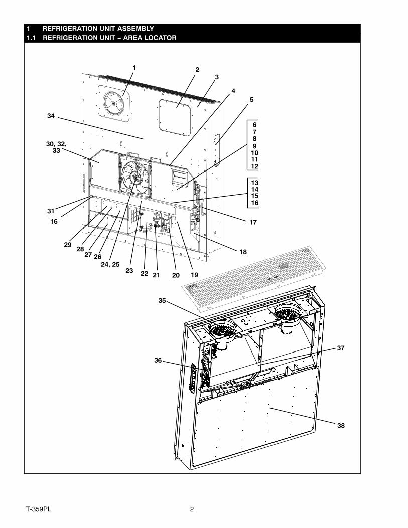
1 REFRIGERATION UNIT ASSEMBLY1.1 REFRIGERATION UNIT − AREA LOCATOR
3
45
89
1011
13
1514
17
18
1922 21 20
26
2928
31
30, 32,33
34
35
36
37
2724, 25
67
16
23
16
1 2
38
12

3 T-359PL
1.1 REFRIGERATION UNIT − AREA LOCATOR (Continued)Item Section Number Area Description
1 Refer to Section 1.2 Upper Fresh Air − VPS Panel2 Refer to Section 1.3 Upper Fresh Air − Blank Panel3 Refer to Section 1.4 Bulkhead Penetration − Upper Air Exchange4 Refer to Section 1.5 Rain Gutters5 Refer to Section 1.6 USDA6 Refer to Section 1.7 Control Box − Door7 Refer to Section 1.8 Control Box − Shield8 Refer to Section 1.9 Control Box − Wiring9 Refer to Section 1.10 Control Box − RMU Receptacle, Switch Panel with Remote Monitoring
10 Refer to Section 1.11 Control Box − Remote Monitoring (RMU)11 Refer to Section 1.12 Control Box − Controller Module Section and Software Cards12 Refer to Section 1.13 Control Box Preparation13 Refer to Section 1.14 Controller Kit − Facing View14 Refer to Section 1.15 Controller Kit − Detailed View With and Without Shields15 Refer to Section 1.16 Controller Kit − Rear View16 Refer to Section 1.17 Interrogator Receptacle17 Refer to Section 1.18 Handles18 Refer to Section 1.19 Compressor, Mounting Components, and Power Cable19 Refer to Section 1.20 Compressor Tubing20 Refer to Section 1.21 Economizer21 Refer to Section 1.22 Liquid Line Components22 Refer to Section 1.23 Receiver23 Refer to Section 1.24 Air−Cooled Condenser Coil and Covers24 Refer to Section 1.25 Condenser Fan Motor25 Refer to Section 1.26 Condenser Fan Grille Assembly26 Refer to Section 1.27 Voltage Cables27 Refer to Section 1.28 Cable Guards28 Refer to Section 1.29 Autotransformer29 Refer to Section 1.30 Cable Restraint Components30 Refer to Section 1.31 Temperature Recorder31 Refer to Section 1.32 Drain32 Refer to Section 1.33 Lower Air Exchange − None33 Refer to Section 1.34 Bulkhead Penetration − Lower Air Exchange34 Refer to Section 1.35 Labels and Decals35 Refer to Section 1.36 Evaporator Fan Assembly36 Refer to Section 1.37 Evaporator Tubing and Coil37 Refer to Section 1.38 Heaters and Sensors (Rear Panels Removed)38 Refer to Section 1.39 Back Panel Assembly − Aluminum Bolted / 5+1 HeaterNS Refer to Section 1.40 Harness − Low VoltageNS Refer to Section 1.41 Harness − High VoltageNS Refer to Section 2.1 DataLine/Data Reader
4T-359PL
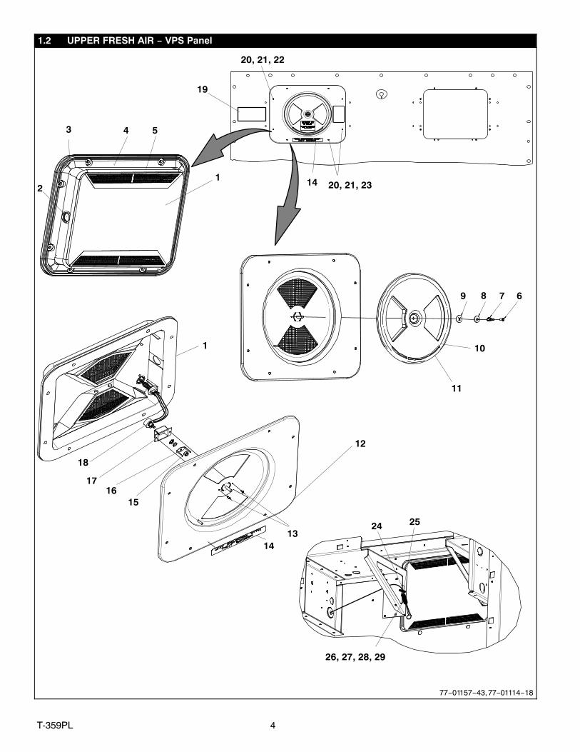
1.2 UPPER FRESH AIR − VPS Panel
20, 21, 22
14 20, 21, 231
4 5
2
3
11
10
9 8 7 6
1
18
1716
15
12
13
14
2425
26, 27, 28, 29
19
77−01157−43, 77−01114−18

5 T-359PL
1.2 UPPER FRESH AIR − VPS Panel (Continued)Item Part Number Description Qty
1 79−66626−00 Panel Assembly, Access, White − Includes: 12 66U1−5562−2 Plug Button, 1.25 Inch Diameter Hole 13 68−12940−05 Cover, Top, Evaporator Access Panel, White 14 42−00296−01 Gasket, Evaporator Access Panel 15 42−00327−00 Gasket, 0.26 X 0.50 Half−Round 16 34−06185−01 Screw, Pan Head, #8−32 X 0.50 with Nylock 17 66U1−5362−2 Nut, Wing, 5/16−18, SST 18 66U1−5321−13 Washer, Plain 5/16 W Type A, SST 19 34−06053−19 Washer, Mylar 1.00 OD X 0.312 ID 1
10 42−00407−00 Gasket, 0.50 Fresh Air Disc 111 68−12933−07 Disc, 12.35 Inch Diameter, White 112 58−04376−05 Panel 113 34−00928−02 Rivet, Blind 0.125 Inch Diameter 0.126−0.187 214 62−10930−00 Label VPS 115 NSS Nut, Self Lock, 1/4−20 116 NSS Plate 217 NSS Bracket, Sensor 218 NSS Sensor, Rotary Position 119 62−66723−00 Label Fresh Air 120 34−06053−13 Washer, Mylar, 1/4 ID X 0.80 OD 821 34−06212−12 Washer, Flat, 1/4, SST 822 34−00655−08 Screw, Hex Head, 1/4−20 X 1.00 Inch Long 623 34−06154−00 Screw, Hex Head, 1/4−20 X 1.00 Inch Long − TIR 224 66CH1−1172−2 Trim, Flexible 2.00 Inches Long 125 58−00969−00 Wire Tie 2.80 Inch Diameter, Double Loop 126 22−01613−10 Plug, 4−Pin 127 22−01613−13 Contact, Socket #16 328 22−01613−11 Lock, 4−Pin − Secondary 129 22−01660−08 Plug, 0.12 Inch Diameter X 0.58 1
6T-359PL
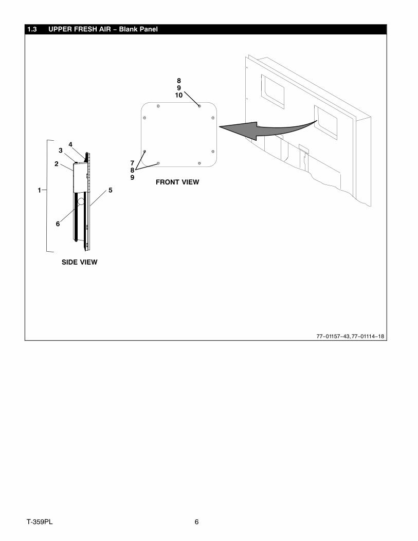
1.3 UPPER FRESH AIR − Blank Panel
43
5FRONT VIEW
SIDE VIEW
1
2
6
89
10
789
77−01157−43, 77−01114−18

7 T-359PL
1.3 UPPER FRESH AIR − Blank Panel (Continued)Item Part Number Description Qty
1 79−01697−06SV Panel Assembly, Access, Evaporator, White − Includes: A/R2 58−04378−01 Panel, Access 13 42−00327−00 Gasket, 0.26 X 0.50 Half−Round 14 42−00296−01 Gasket, Evaporator Access Panel 15 68−11989−00 Cover, Top, Evaporator Access Panel, White A/R6 66U1−5562−2 Plug Button 17 34−06154−00 Screw, Hex Head, 1/4−20 X 1.00 Inch Long − TIR A/R8 34−06053−13 Washer, Mylar 89 34−06212−12 Washer, Plain, 1/4 8
10 34−00655−08 Screw, Hex Head, 1/4−20 X 1.00 Inch Long A/R

8T-359PL
1.4 BULKHEAD PENETRATION − UPPER AIR EXCHANGE
23
1
77−01208−04
Item Part Number Description Qty1 66U1−5562−12 Plug, Button 1.25 Dia Hole 12 66U1−5562−2 Plug, Button 1.25 Dia Hole 13 58−00616−00 Plug, Hole 2.00 Dia X .12 Pnl 1
9 T-359PL
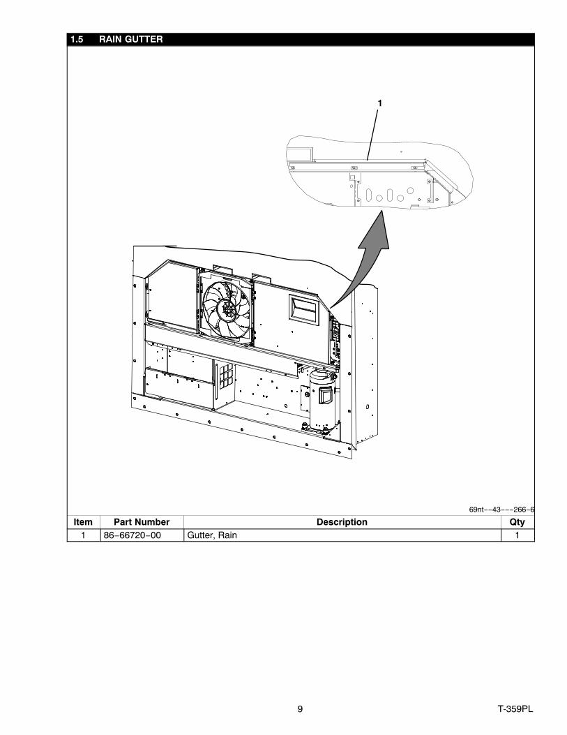
1.5 RAIN GUTTER
1
69nt−−43−−−266−6
Item Part Number Description Qty1 86−66720−00 Gutter, Rain 1

10T-359PL
1.6 USDA
2
8
3
7 1
4
6
1011
2
9
5
77−01283−00

11 T-359PL
1.6 USDA (Continued)Item Part Number Description Qty
1 Receptacle (PR1, PR2, PR3, Cargo Probe 4) (3−Pin) (Refer to Section 1.40)2 69NT35−636−1 Tether Assembly 53 22−01660−02 Cap, Dust, (3−Pin Receptacle) 44 66U1−5371−7 Screw, Machine, Hex Head, #10−24 X 0.500 Slotted 75 68−14444−00 Panel Assembly, 0.063 Thick Aluminum 16 22−01660−05 Cap, Dust (5−Pin Receptacle) 17 34−06142−00 Rivet, 0.110 Inch Diameter, 0.126−0.250 258 22−02205−00 Connector Splice, Non−Insulated 59 68−15343−00 Channel Assembly 1
10 62−11275−00 Label, USDA Cold Treatment Certified 111 62−11274−01 Label, USDA, 5+1 Heater 1NS 66U1−3882 Wire Tie, 1/16−1−3/4, Self−Locking 4

12T-359PL
1.6 USDA (Continued)
17
16
15
4
10
11
12
1314
77−01283−00

13 T-359PL
1.6 USDA (Continued)Item Part Number Description Qty
FIELD INSTALLED KITS (USDA PROVISIONS AND 5+1 HEATER ARRANGEMENT)− 76−00676−00 Field−installed Kits for units provisioned for side−mounted USDA − Includes: −4 66U1−5371−7 Screw, Machine, Hex Head, #10−24 X 0.500 Slotted 7
10 62−11275−00 Label, USDA Cold Treatment Certified 111 62−11274−01 Label, USDA, 5+1 Heater 112 79−01879−00 Panel Assembly 113 34−00928−09 Rivet, Blind, 0.156 Inch Diameter 1014 68−14701−00 Plate 1NS 22−01613−14 Contact Pin #16, Deutsch 13NS 66U1−3882 Wire Tie, 1/16−1−3/4, Self−Locking 4
USDA PROBE KITSItem Part Number Description Qty15 12−50089−00 Sensor Assembly, 600 Inches Long (15M) (USDA Probe) − Includes: A/R16 22−50127−00 Plug, Socket (PR1, PR2, PR3, Cargo Probe 4) 117 22−01613−15 Contact, Socket, #16 A/R

14T-359PL
1.7 CONTROL BOX − DOOR
8
1
4
6
9
11121314
10
7
5
3
77−01211−04
6
2
20, 21
15, 16, 17
22
18, 19
16, 17, 18

15 T-359PL
1.7 CONTROL BOX − DOOR (Continued)Item Part Number Description Qty
1 79−66655−04 Door Assembly, Blue, With Latches − Includes:2 86−66688−01 Door, Control Box, Latch 13 58−04366−00 Window 14 42−00270−02 Gasket, Control Box Door 15 58−04389−00 Pocket 16 44−00300−00 Hinge Assembly with Tethered Pin 27 34−06107−00 Rivet, Blind, 0.125 Inch Diameter, 0.188−0.250 38 58−04101−00 Protector, 1.00 X 3.62 29 34−01167−01 Nut, Retainer 10−24 X 1.75 2
10 58−04101−00 Protector 1.00 X 2.63 211 66U1−2403−1 Screw, 10−24 X 0.750 Slotted 412 34−00663−09 Washer, Lock 10 Spring 413 66U1−5321−8 Washer, Plain 10 Type A 414 34−06053−05 Washer, 0.205 ID X 0.600 OD 415 66U1−6651−22 Screw, Machine, Pan Head 8−32 X 3/4 116 34−00663−08 Washer, Lock 417 66U1−5321−2 Washer, Plain 418 66U1−6651−2 Screw, Machine, Pan Head 8−32 X 1/2 319 34−66621−04 Washer, Lock 120 58−04026−74 Protector, Latch 221 44−66605−00 Latch 222 48−66611−00 Pin, Guide 1

16T-359PL
1.8 CONTROL BOX − SHIELD
1
2
3
567
89 10
11
1415
12
4
13
5
567
67
16
77−01211−04
17 T-359PL
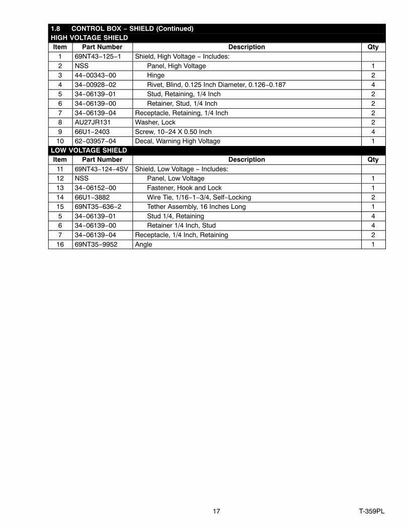
1.8 CONTROL BOX − SHIELD (Continued)HIGH VOLTAGE SHIELDItem Part Number Description Qty
1 69NT43−125−1 Shield, High Voltage − Includes:2 NSS Panel, High Voltage 13 44−00343−00 Hinge 24 34−00928−02 Rivet, Blind, 0.125 Inch Diameter, 0.126−0.187 45 34−06139−01 Stud, Retaining, 1/4 Inch 26 34−06139−00 Retainer, Stud, 1/4 Inch 27 34−06139−04 Receptacle, Retaining, 1/4 Inch 28 AU27JR131 Washer, Lock 29 66U1−2403 Screw, 10−24 X 0.50 Inch 4
10 62−03957−04 Decal, Warning High Voltage 1LOW VOLTAGE SHIELDItem Part Number Description Qty11 69NT43−124−4SV Shield, Low Voltage − Includes:12 NSS Panel, Low Voltage 113 34−06152−00 Fastener, Hook and Lock 114 66U1−3882 Wire Tie, 1/16−1−3/4, Self−Locking 215 69NT35−636−2 Tether Assembly, 16 Inches Long 15 34−06139−01 Stud 1/4, Retaining 46 34−06139−00 Retainer 1/4 Inch, Stud 47 34−06139−04 Receptacle, 1/4 Inch, Retaining 2
16 69NT35−9952 Angle 1
18T-359PL
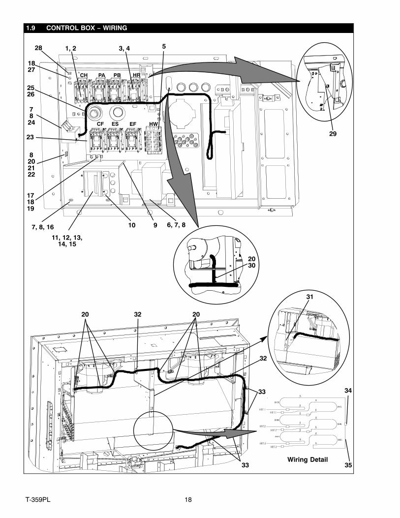
1.9 CONTROL BOX − WIRING
10 9
7824
171819
1827
31
34
35
32
33
28
2526
7, 8, 16
20 20
32
33Wiring Detail
CF ES
HR
8202122
1, 2
11, 12, 13,14, 15
2923
2030
EF
CH PA PB
HW
6, 7, 8
3, 4 5
19 T-359PL
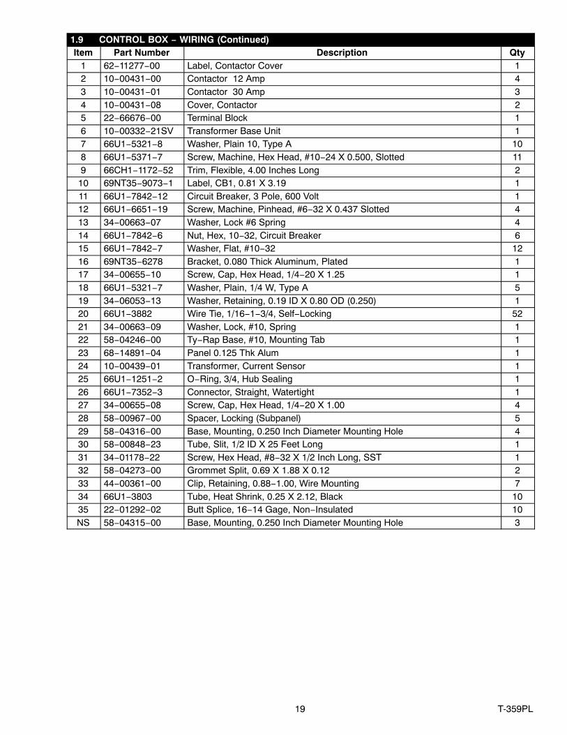
1.9 CONTROL BOX − WIRING (Continued)Item Part Number Description Qty
1 62−11277−00 Label, Contactor Cover 12 10−00431−00 Contactor 12 Amp 43 10−00431−01 Contactor 30 Amp 34 10−00431−08 Cover, Contactor 25 22−66676−00 Terminal Block 16 10−00332−21SV Transformer Base Unit 17 66U1−5321−8 Washer, Plain 10, Type A 108 66U1−5371−7 Screw, Machine, Hex Head, #10−24 X 0.500, Slotted 119 66CH1−1172−52 Trim, Flexible, 4.00 Inches Long 2
10 69NT35−9073−1 Label, CB1, 0.81 X 3.19 111 66U1−7842−12 Circuit Breaker, 3 Pole, 600 Volt 112 66U1−6651−19 Screw, Machine, Pinhead, #6−32 X 0.437 Slotted 413 34−00663−07 Washer, Lock #6 Spring 414 66U1−7842−6 Nut, Hex, 10−32, Circuit Breaker 615 66U1−7842−7 Washer, Flat, #10−32 1216 69NT35−6278 Bracket, 0.080 Thick Aluminum, Plated 117 34−00655−10 Screw, Cap, Hex Head, 1/4−20 X 1.25 118 66U1−5321−7 Washer, Plain, 1/4 W, Type A 519 34−06053−13 Washer, Retaining, 0.19 ID X 0.80 OD (0.250) 120 66U1−3882 Wire Tie, 1/16−1−3/4, Self−Locking 5221 34−00663−09 Washer, Lock, #10, Spring 122 58−04246−00 Ty−Rap Base, #10, Mounting Tab 123 68−14891−04 Panel 0.125 Thk Alum 124 10−00439−01 Transformer, Current Sensor 125 66U1−1251−2 O−Ring, 3/4, Hub Sealing 126 66U1−7352−3 Connector, Straight, Watertight 127 34−00655−08 Screw, Cap, Hex Head, 1/4−20 X 1.00 428 58−00967−00 Spacer, Locking (Subpanel) 529 58−04316−00 Base, Mounting, 0.250 Inch Diameter Mounting Hole 430 58−00848−23 Tube, Slit, 1/2 ID X 25 Feet Long 131 34−01178−22 Screw, Hex Head, #8−32 X 1/2 Inch Long, SST 132 58−04273−00 Grommet Split, 0.69 X 1.88 X 0.12 233 44−00361−00 Clip, Retaining, 0.88−1.00, Wire Mounting 734 66U1−3803 Tube, Heat Shrink, 0.25 X 2.12, Black 1035 22−01292−02 Butt Splice, 16−14 Gage, Non−Insulated 10NS 58−04315−00 Base, Mounting, 0.250 Inch Diameter Mounting Hole 3

20T-359PL
1.10 CONTROL BOX − RMU RECEPTACLE, SWITCH PANEL, WITH REMOTE MONITORING
18
2
6 17
4
7
19
8
10
9
1516
11
3
12
13
14
5
1
SEE SECTION 1.12for location and
1.41 High VoltageHarness for part numbers
20
77−01150−00

21 T-359PL
1.10 CONTROL BOX − RMU RECEPTACLE, SWITCH PANEL, WITH REMOTE MONITORING (Continued)Item Part Number Description Qty
1 79−66669−00 Key Pad Assembly − Includes: 12 NSS Plate, Backup Keypad, Composite Box 13 NSS Key Pad, Core Micro 14 NSS Gasket Keypad, 0.125 Thick 15 NSS Dot, Indicator (Green) − See NOTE 16 34−06212−10 Washer, Plain #10 Type A 67 34−66630−00 Screw, Pinhead #10−9 X 0.75 Long 68 34−66629−05 Screw, Machined Thread #10−24 X 0.750 Slotted 49 34−00848−10 Screw, Machined Roundhead #4−40 X 0.625 4
10 22−02341−01 Cap and Tether Receptacle Assembly 111 22−01604−00 Receptacle, 4 Connections 112 MS510074 Gasket 113 62−10914−03 Switch Label, ST, RM 114 68−14796−03 Plate, Switch ST, Remote Monitoring 115 66U1−5321−6 Washer, Plain 0.125 ID Type A 416 34−00667−05 Nut, Self Lock 4−40 417 66U1−9752 Seal 0.427/0.432, Bushing 218 10−01129−20 Nut, Hex 15/32−32 Un−2B 119 42−00608−00 Gasket Switch Plate 120 44−00391−00 Clamp 1

22T-359PL
1.11 CONTROL BOX − REMOTE MONITORING UNIT (RMU)
1
5, 75, 642, 3
77−00888−01

23 T-359PL
1.11 CONTROL BOX − REMOTE MONITORING UNIT (RMU) (Continued)Item Part Number Description Qty
1 22−01713−03 Harness 12 AT39JA171 Nut, Hex 23 AU27JR171 Washer, Lock 1/4 24 22−01556−00 Connector 15 66U1−5371−7 Screw, Mach Hex Head 10−24 X 0.500 46 69NT35−2692−4 Washer, Fender 27 66U1−5321−8 Washer, Plain 10 Type A 2

24T-359PL
1.12 CONTROL BOX − CONTROLLER MODULE SECTION AND SOFTWARE CARDS
10
11
1
56
34
8
2
VIEW − BACK OF CONTROLLER/DataCORDER
16 17
7 1415
18
1422 1513 12
SEE SECTION 1.41(High Voltage
Wire Harness) for part numbers
25 T-359PL
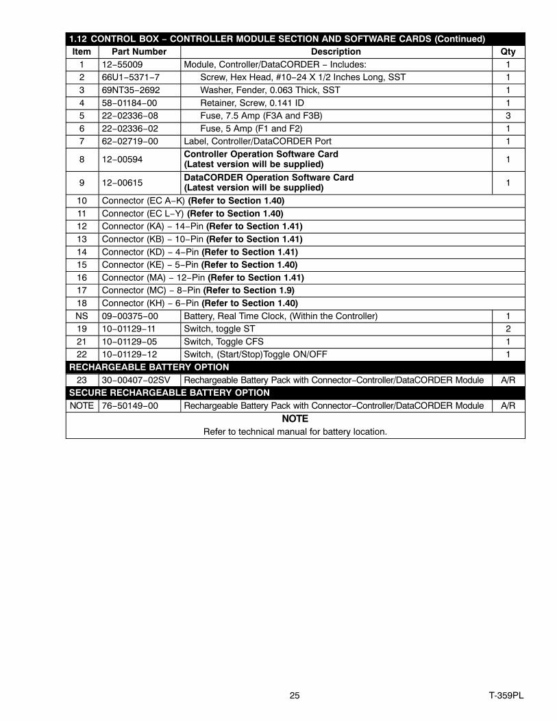
1.12 CONTROL BOX − CONTROLLER MODULE SECTION AND SOFTWARE CARDS (Continued)Item Part Number Description Qty
1 12−55009 Module, Controller/DataCORDER − Includes: 12 66U1−5371−7 Screw, Hex Head, #10−24 X 1/2 Inches Long, SST 13 69NT35−2692 Washer, Fender, 0.063 Thick, SST 14 58−01184−00 Retainer, Screw, 0.141 ID 15 22−02336−08 Fuse, 7.5 Amp (F3A and F3B) 36 22−02336−02 Fuse, 5 Amp (F1 and F2) 17 62−02719−00 Label, Controller/DataCORDER Port 1
8 12−00594 Controller Operation Software Card (Latest version will be supplied) 1
9 12−00615 DataCORDER Operation Software Card (Latest version will be supplied) 1
10 Connector (EC A−K) (Refer to Section 1.40)11 Connector (EC L−Y) (Refer to Section 1.40)12 Connector (KA) − 14−Pin (Refer to Section 1.41)13 Connector (KB) − 10−Pin (Refer to Section 1.41)14 Connector (KD) − 4−Pin (Refer to Section 1.41)15 Connector (KE) − 5−Pin (Refer to Section 1.40)16 Connector (MA) − 12−Pin (Refer to Section 1.41)17 Connector (MC) − 8−Pin (Refer to Section 1.9)18 Connector (KH) − 6−Pin (Refer to Section 1.40)NS 09−00375−00 Battery, Real Time Clock, (Within the Controller) 119 10−01129−11 Switch, toggle ST 221 10−01129−05 Switch, Toggle CFS 122 10−01129−12 Switch, (Start/Stop)Toggle ON/OFF 1
RECHARGEABLE BATTERY OPTION23 30−00407−02SV Rechargeable Battery Pack with Connector−Controller/DataCORDER Module A/R
SECURE RECHARGEABLE BATTERY OPTIONNOTE 76−50149−00 Rechargeable Battery Pack with Connector−Controller/DataCORDER Module A/R
NOTERefer to technical manual for battery location.

26T-359PL
1.13 CONTROL BOX PREPARATION
LATCHED DOOR
18
7
12
14
15
17
13
12
21 6
16
38
9
10 3
GROUNDWIRE
11
19, 23
22
21
4, 5
77−66622−12
4, 5, 20
27 T-359PL
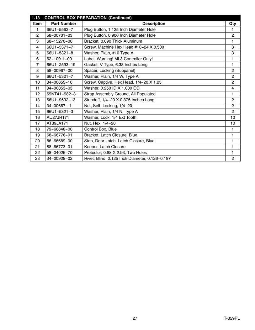
1.13 CONTROL BOX PREPARATION (Continued)Item Part Number Description Qty
1 66U1−5562−7 Plug Button, 1.125 Inch Diameter Hole 12 58−00701−03 Plug Button, 0.906 Inch Diameter Hole 23 68−15270−00 Bracket, 0.090 Thick Aluminum 14 66U1−5371−7 Screw, Machine Hex Head #10−24 X 0.500 35 66U1−5321−8 Washer, Plain, #10 Type A 36 62−10911−00 Label, Warning! ML3 Controller Only! 17 66U1−2593−19 Gasket, V Type, 6.38 Inches Long 18 58−00967−00 Spacer, Locking (Subpanel) 29 66U1−5321−7 Washer, Plain, 1/4 W, Type A 2
10 34−00655−10 Screw, Captive, Hex Head, 1/4−20 X 1.25 211 34−06053−03 Washer, 0.250 ID X 1.000 OD 412 69NT41−982−3 Strap Assembly Ground, All Populated 113 66U1−9592−13 Standoff, 1/4−20 X 0.375 Inches Long 214 34−00667−11 Nut, Self−Locking, 1/4−20 215 66U1−5321−3 Washer, Plain, 1/4 N, Type A 216 AU27JR171 Washer, Lock, 1/4 Ext Tooth 1017 AT39JA171 Nut, Hex, 1/4−20 1018 79−66648−00 Control Box, Blue 119 68−66776−01 Bracket, Latch Closure, Blue 120 86−66689−00 Stop, Door Latch, Latch Closure, Blue 121 68−66773−01 Keeper, Latch Closure 122 58−04026−70 Protector, 0.88 X 2.93, Two Holes 123 34−00928−02 Rivet, Blind, 0.125 Inch Diameter, 0.126−0.187 2

28T-359PL
1.14 CONTROLLER KIT − FACING VIEW
21 3
45
2
2891014, 15 13
2
21
163
318
21
STS PROBE
SRS PROBE
133
3132
19 20 21
22232425
262728
7
30
REAR VIEW
2
29
14
6
1112
77−01291−02
17
29 T-359PL
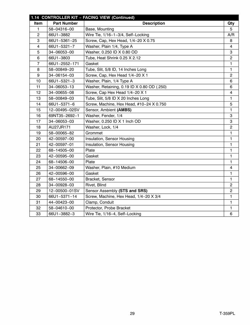
1.14 CONTROLLER KIT − FACING VIEW (Continued)Item Part Number Description Qty
1 58−04316−00 Base, Mounting 52 66U1−3882 Wire Tie, 1/16−1−3/4, Self−Locking A/R3 66U1−5361−25 Screw, Cap, Hex Head, 1/4−20 X 0.75 84 66U1−5321−7 Washer, Plain 1/4, Type A 45 34−06053−00 Washer, 0.250 ID X 0.80 OD 36 66U1−3803 Tube, Heat Shrink 0.25 X 2.12 27 66U1−2552−171 Gasket 18 58−00849−20 Tube, Slit, 5/8 ID, 14 Inches Long 19 34−06154−03 Screw, Cap, Hex Head 1/4−20 X 1 2
10 66U1−5321−3 Washer, Plain, 1/4 Type A 611 34−06053−13 Washer, Retaining, 0.19 ID X 0.80 OD (.250) 612 34−00655−08 Screw, Cap Hex Head 1/4−20 X 1 413 58−00849−03 Tube, Slit, 5/8 ID X 20 Inches Long 114 66U1−5371−6 Screw, Machine, Hex Head, #10−24 X 0.750 515 12−00495−02SV Sensor, Ambient (AMBS) 116 69NT35−2692−1 Washer, Fender, 1/4 317 34−06053−03 Washer, 0.250 ID X 1 Inch OD 318 AU27JR171 Washer, Lock, 1/4 219 58−00065−82 Grommet 120 42−00597−00 Insulation, Sensor Housing 121 42−00597−01 Insulation, Sensor Housing 122 68−14505−00 Plate 123 42−00595−00 Gasket 124 68−14506−00 Plate 125 34−00662−09 Washer, Plain, #10 Medium 426 42−00596−00 Gasket 127 68−14550−00 Bracket, Sensor 128 34−00928−03 Rivet, Blind 229 12−00500−01SV Sensor Assembly (STS and SRS) 230 66U1−5371−14 Screw, Machine, Hex Head, 1/4−20 X 3/4 131 44−00423−00 Clamp, Conduit 132 58−04610−00 Protector, Probe Bracket 133 66U1−3882−3 Wire Tie, 1/16−4, Self−Locking 6
30T-359PL
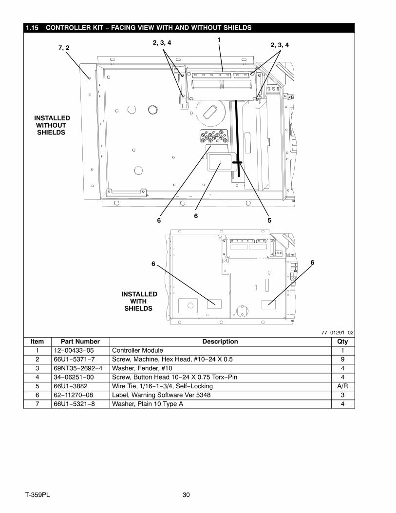
1.15 CONTROLLER KIT − FACING VIEW WITH AND WITHOUT SHIELDS
17, 2
2, 3, 4
5
6 6
66
INSTALLEDWITH
SHIELDS
INSTALLEDWITHOUTSHIELDS
77−01291−02
2, 3, 4
Item Part Number Description Qty1 12−00433−05 Controller Module 12 66U1−5371−7 Screw, Machine, Hex Head, #10−24 X 0.5 93 69NT35−2692−4 Washer, Fender, #10 44 34−06251−00 Screw, Button Head 10−24 X 0.75 Torx−Pin 45 66U1−3882 Wire Tie, 1/16−1−3/4, Self−Locking A/R6 62−11270−08 Label, Warning Software Ver 5348 37 66U1−5321−8 Washer, Plain 10 Type A 4
31 T-359PL
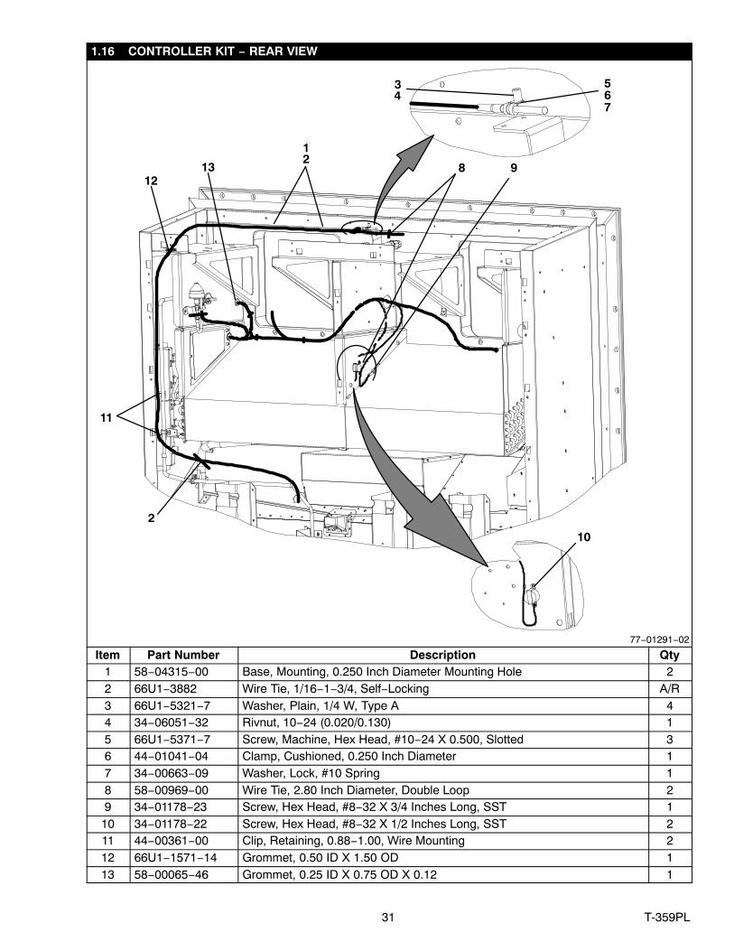
1.16 CONTROLLER KIT − REAR VIEW
10
11
4
8 9
2
3
1213
12
567
77−01291−02
Item Part Number Description Qty1 58−04315−00 Base, Mounting, 0.250 Inch Diameter Mounting Hole 22 66U1−3882 Wire Tie, 1/16−1−3/4, Self−Locking A/R3 66U1−5321−7 Washer, Plain, 1/4 W, Type A 44 34−06051−32 Rivnut, 10−24 (0.020/0.130) 15 66U1−5371−7 Screw, Machine, Hex Head, #10−24 X 0.500, Slotted 36 44−01041−04 Clamp, Cushioned, 0.250 Inch Diameter 17 34−00663−09 Washer, Lock, #10 Spring 18 58−00969−00 Wire Tie, 2.80 Inch Diameter, Double Loop 29 34−01178−23 Screw, Hex Head, #8−32 X 3/4 Inches Long, SST 1
10 34−01178−22 Screw, Hex Head, #8−32 X 1/2 Inches Long, SST 211 44−00361−00 Clip, Retaining, 0.88−1.00, Wire Mounting 212 66U1−1571−14 Grommet, 0.50 ID X 1.50 OD 113 58−00065−46 Grommet, 0.25 ID X 0.75 OD X 0.12 1
32T-359PL
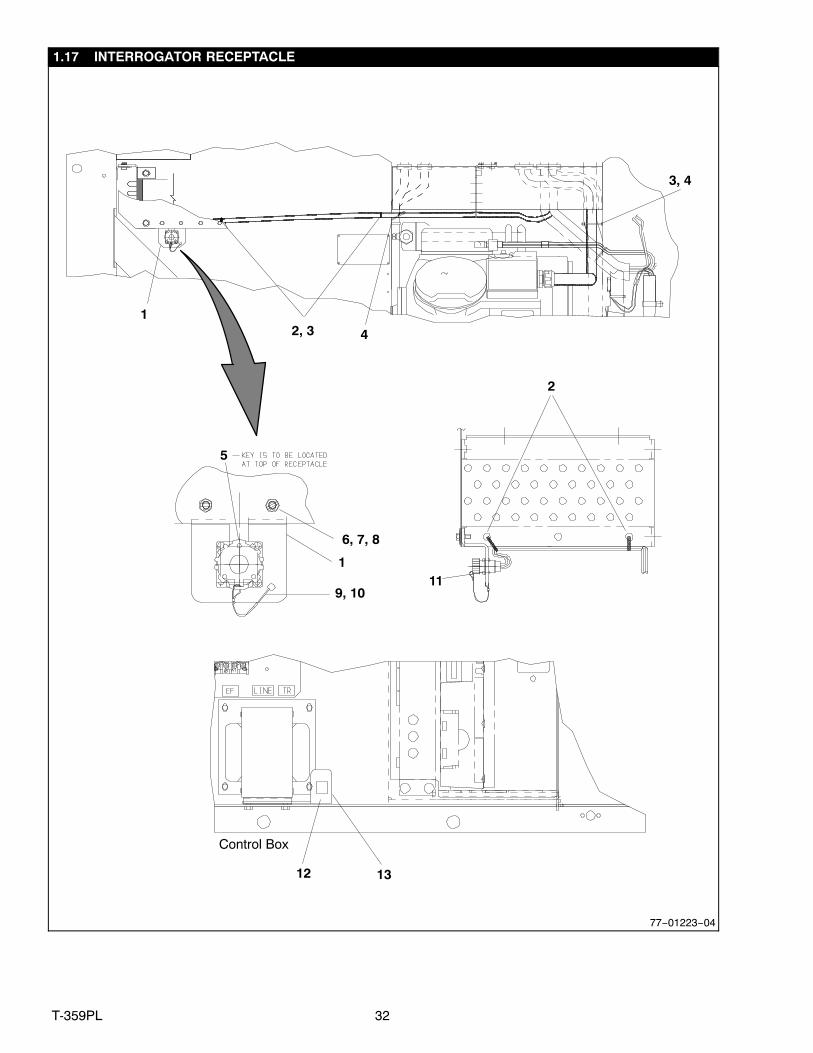
1.17 INTERROGATOR RECEPTACLE
Control Box
2, 3 4
5
6, 7, 8
1
9, 1011
12 13
2
3, 4
1
77−01223−04

33 T-359PL
1.17 INTERROGATOR RECEPTACLE (Continued)Item Part Number Description Qty− 77−01223−00 Left Mount Interrogator Receptacle − Includes:1 69NT41−192 Bracket Assembly, White 12 66U1−3882 Wire Tie, 1/16−1 3/4 Self−Locking 43 58−04316−00 Base, Mounting 0.250 Diameter Mounting Hole 34 66U1−3882−3 Wire Tie, 1/16− 4.0 Self−Locking 25 22−01660−05 Cap, Dust, 5−Pin 16 66U1−5321−8 Washer, Plain, #10 Type A 27 66U1−5371−7 Screw, Machine, Hex Head, #10−24 X 0.500 Slotted 28 34−06053−05 Washer, 0.205 ID X 0.600 OD 29 58−01097−00 Cord, Nylon, 0.085 OD 2
10 22−02205−00 Connector, Splice, Non−Insulated 211 34−06142−00 Rivet, 0.110 Diameter, 0.126−0.250 4
Note: Connector, Interrogator (Refer to Section 1.40)12 34−06139−04 Receptacle, 1/4 Inch Retaining 113 69NT35−9952 Angle, 0.080 Thick Aluminum, Painter 1

34T-359PL
1.18 HANDLES
1
1
1
2
3
4
77−01236−00
Item Part Number Description Qty1 69NT35−8113 Handle, Fixed 22 34−00792−07 Screw, Captive, Hex Head, 5/16−18 X 0.88 43 66U1−5331 Washer, Lock, 5/16 Spring 44 34−06053−15 Washer, Mylar, 0.313 ID X 0.875 OD 4
35 T-359PL
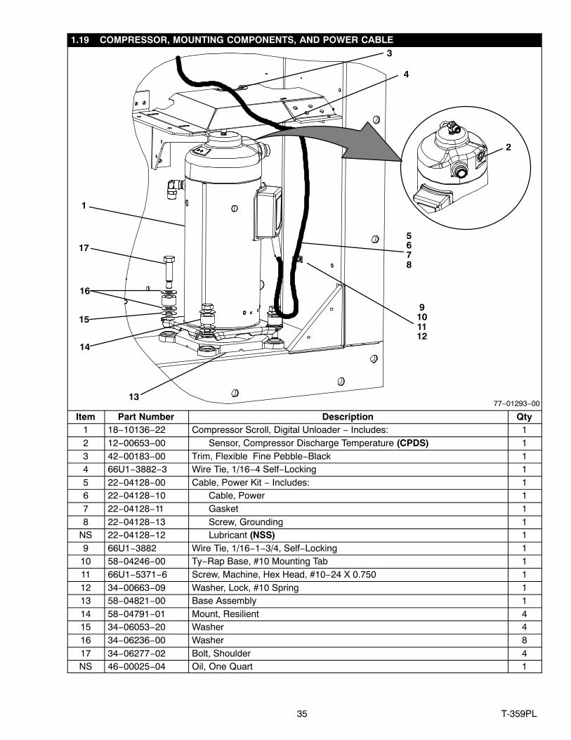
1.19 COMPRESSOR, MOUNTING COMPONENTS, AND POWER CABLE
1
13
17
16
15
876
14
9
3
1011
4
12
2
5
77−01293−00
Item Part Number Description Qty1 18−10136−22 Compressor Scroll, Digital Unloader − Includes: 12 12−00653−00 Sensor, Compressor Discharge Temperature (CPDS) 13 42−00183−00 Trim, Flexible Fine Pebble−Black 14 66U1−3882−3 Wire Tie, 1/16−4 Self−Locking 15 22−04128−00 Cable, Power Kit − Includes: 16 22−04128−10 Cable, Power 17 22−04128−11 Gasket 18 22−04128−13 Screw, Grounding 1
NS 22−04128−12 Lubricant (NSS) 19 66U1−3882 Wire Tie, 1/16−1−3/4, Self−Locking 1
10 58−04246−00 Ty−Rap Base, #10 Mounting Tab 111 66U1−5371−6 Screw, Machine, Hex Head, #10−24 X 0.750 112 34−00663−09 Washer, Lock, #10 Spring 113 58−04821−00 Base Assembly 114 58−04791−01 Mount, Resilient 415 34−06053−20 Washer 416 34−06236−00 Washer 817 34−06277−02 Bolt, Shoulder 4NS 46−00025−04 Oil, One Quart 1
36T-359PL
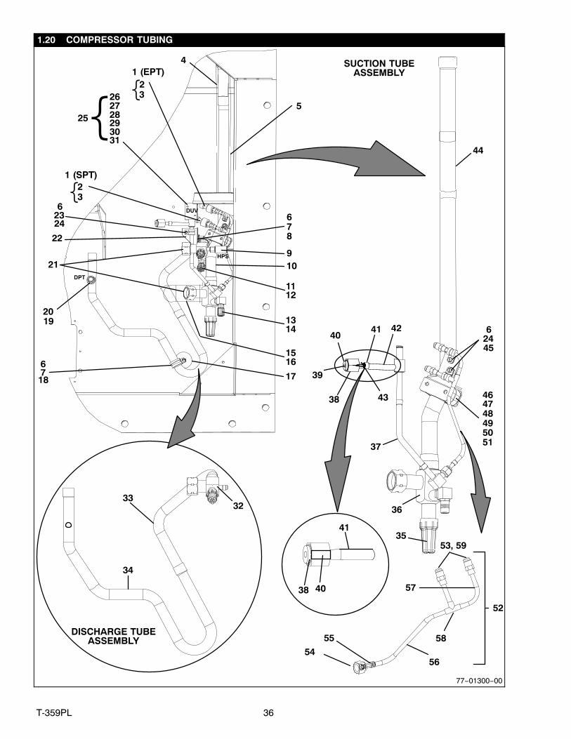
1.20 COMPRESSOR TUBING
SUCTION TUBEASSEMBLY
DISCHARGE TUBEASSEMBLY
21
6
87
9
1112
1314
176718
42
16
20
22
623
39
24
38
4041
37
3332
34
19
36
43
15
44
2627282925
31
HPS
DPT
DUV
1 (EPT)
1 (SPT)
4
5
52
53, 59
464748495051
45
624
41
38 40
23
30{{
23{
77−01300−00
10
54
55
56
58
57
35
37 T-359PL
1.20 COMPRESSOR TUBING (Continued)Item Part Number Description Qty
1 76−00816−00 Transducer, Service (EPT), (SPT) 22 22−01713−46 Wire Harness Transducer, Service 13 66U−1−3803 Tube, Heat Shrink .25 X 2.12 Blk 34 42−00425−110 Insulation Tube, Pre−Taped 15 42−00425−114 Insulation Tube, Pre−Taped 16 34−06053−05 Washer 57 66U1−3632−20 Clamp, Tube 28 34−00795−09 Nut, Self−Locking, 10−32 19 12−00309−05 Switch, Pressure (HPS) 1
10 42−00425−115 Insulation,Tube − location 111 40−00542−01 Elbow Adapter (Includes O−ring) 112 40−00520−03 Cap 113 40−00542−00 Elbow Adapter (Includes O−ring) 114 40−00520−02 Cap 115 42−00425−112 Insulation, Tube, Pre−Taped 116 66U1−3882−3 Wire Tie, 1/16−4 Self−Locking 217 34−06295−00 Washer, Fender #10 118 66U1−5371−10 Screw, Machine, Hex Head, 10−24 X 1 119 40−01124−00 Valve Body 220 12−00352−00 Transducer, Pressure (DPT) 1

38T-359PL
1.20 COMPRESSOR TUBING (Continued)Item Part Number Description Qty21 42−00384−02 Seal, Rotolock 222 68−15532−00 Bracket, White 123 34−00373−53 Clamp, Tube 124 66U1−5371−6 Screw, Machine, Hex Head, #10−24 X 0.750 325 14−00361−01 Coil, Kit, Solenoid − Includes: 126 NSS Coil, Solenoid 127 NSS Spacer 128 NSS Washer, Plain, M4 129 NSS Washer, Spring, M4 130 NSS Screw, Coil, M4 131 66U1−3803 Tube, Heat Shrink 232 40−00583−05 Valve, Service, 7/8 ID 133 56−08638−00 Tube, Discharge − Upper 134 56−08635−00 Tube, Discharge − Lower 135 40−50025−00 Valve, Service Cap 136 40−00665−20 Valve, Service, 1−1/8 ID 237 56−08689−00 Tube 138 40−00675−00 Nut, Hex, 37 Degree, Flare, 1/2 OD 239 42−00243−12 O−Ring 140 40−00663−00 Sleeve 2

39 T-359PL
1.20 COMPRESSOR TUBING (Continued)Item Part Number Description Qty41 56−07257−11 Tube 142 14−00361−00 Solenoid Valve − Includes: 143 NSS Screen, Valve 144 56−08634−01 Tube, Suction 145 34−00373−51 Clamp, Tube 246 68−15997−00 Bracket 147 44−00285−54 Clamp, Tube 148 34−00655−18 Screw, Cap, Hex Head 1/4−20 X 2.25 249 34−06053−00 Washer 250 66U1−5321−7 Washer, Plain 1/4 W Type A 251 68−15998−00 Nut Plate, 1.125 Thick Aluminum 152 79−01977−00 Tube Assembly − Includes: 153 14−00351−00 Valve, Core Check 254 NSS Nut,Flare 1/4 Standard 155 NSS Fitting Depressor 156 NSS Tube 157 NSS Tube 158 NSS Tee 159 NSS Valve 1/4 Flare 2
Change 03/12
40T-359PL
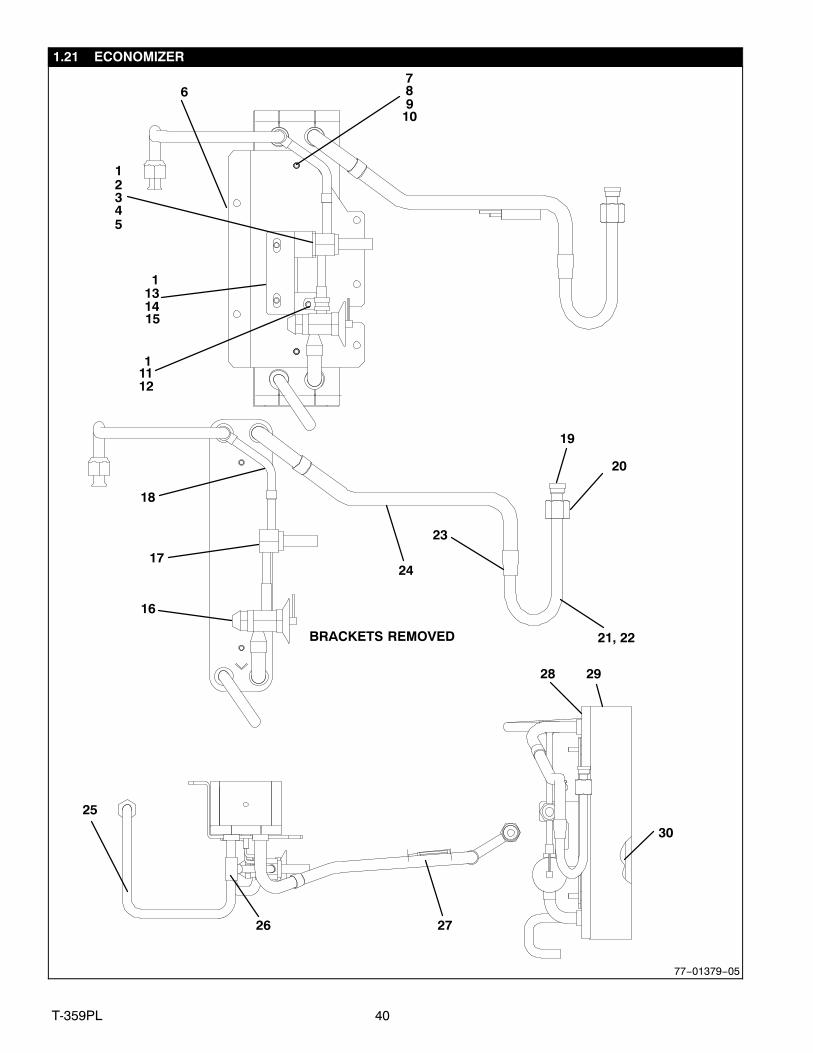
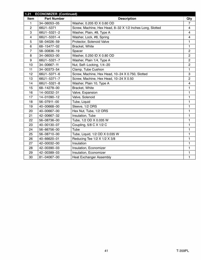
1.21 ECONOMIZER
12345
23
26
2928
6789
10
11314
1112
1
27
20
19
25
21, 22
30
16
17
18
BRACKETS REMOVED
15
77−01379−05
24
41 T-359PL
1.21 ECONOMIZER (Continued)Item Part Number Description Qty
1 34−06053−05 Washer, 0.205 ID X 0.60 OD 72 66U1−5371 Screw, Machine, Hex Head, 8−32 X 1/2 Inches Long, Slotted 43 66U1−5321−2 Washer, Plain, #8, Type A 44 66U1−5331−4 Washer, Lock, #8, Spring 45 58−04026−59 Protector, Solenoid Valve 16 68−15477−02 Bracket, White 17 58−00836−19 Spacer 28 34−06053−00 Washer, 0.250 ID X 0.80 OD 29 66U1−5321−7 Washer, Plain 1/4, Type A 2
10 34−00667−11 Nut, Self−Locking, 1/4−20 211 34−00373−54 Clamp, Tube Cushion 112 66U1−5371−6 Screw, Machine, Hex Head, 10−24 X 0.750, Slotted 313 66U1−5371−7 Screw, Machine, Hex Head, 10−24 X 0.50 214 66U1−5321−8 Washer, Plain 10, Type A 415 68−14278−00 Bracket, White 116 14−00232−31 Valve, Expansion 117 14−01090−12 Valve, Solenoid 118 56−07911−00 Tube, Liquid 119 40−00668−00 Sleeve, 1/2 ORS 120 40−00667−00 Hex Nut, Tube, 1/2 ORS 121 42−00667−32 Insulation, Tube 122 56−08736−00 Tube, 1/2 OD X 0.035 W 123 40−00130−07 Coupling, 5/8 C X 1/2 C 124 56−66756−00 Tube 125 56−08710−00 Tube, Liquid, 1/2 OD X 0.035 W 126 40−66620−01 Reducing Tee 1/2 X 1/2 X 3/8 127 42−00032−00 Insulation 128 42−00390−03 Insulation, Economizer 129 42−00389−03 Insulation, Economizer 130 81−04067−00 Heat Exchanger Assembly 1
42T-359PL
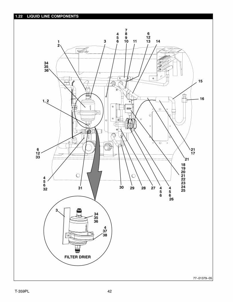
1.22 LIQUID LINE COMPONENTS
11
45
30
6
6
3132
1, 2
21
36
34
3
26
15
16
18
17
19
24
2221
23272829
12
10 13
7
21
25
33
FILTER DRIER
34
3738
3
35
ESV
20
3635
4
456
456
456
1289
612
14
77−01379−05
43 T-359PL
1.22 LIQUID LINE COMPONENTS (Continued)Item Part Number Description Qty
1 42−00032−13 Insulation 22 66U1−3882 Wire Tie, 1/16 − 1−3/4, Self−Locking 43 66U1−2552−133 Gasket 14 66U1−5361−25 Screw, Cap, Hex Head, 1/4−20 X 0.75 A/R5 66U1−5321−7 Washer, Plain, 1/4, Type A A/R6 34−06053−00 Washer, 0.250 ID X 0.8 OD A/R7 68−15852−00 Bracket 18 66U1−5371−7 Screw, Machine, Hex Head, #10−24 X 0.500 89 34−06053−05 Washer, 0.205 ID X 0.6 OD 2
10 66U1−5371−7 Screw, Machine, Hex Head, 10−24 X 0.50 1211 42−00667−249 Insulation, Tube, Pre−Taped 112 66U1−5371−6 Screw, Machine, Hex Head, #10−24 X 0.750 Slotted 213 44−00370−03 Clamp, Cushioned 114 42−00667−30 Insulation, Tube, Pre−Taped 115 42−00667−27 Insulation, Tube, Pre−Taped 116 42−00243−04 O−Ring, 0.50 ID X 0.62 OD 117 42−00425−69 Insulation, Tube, Pre−Taped 118 34−66638−00 Screw, Captured Washer #10−32 119 14−01091−04 Coil, Kit, Solenoid Valve (ESV) − Includes: 220 NSS Coil, Solenoid 221 NSS O−Ring 222 NSS O−Ring 223 NSS Spacer, Brass 224 NSS Screw, Captive Washer, #10−32 125 66U1−3803 Tube, Heat Shrink 426 68−15478−02 Bracket, White 127 42−00425−93 Insulation, Tube, Pre−Taped 128 42−00425−78 Insulation, Tube, Pre−Taped 129 66U1−1571−3 Grommet 130 42−00667−28 Insulation, Tube, Pre−Taped 1331 40−00520−01 Coupling 132 68−15172−00 Bracket, White 133 34−00373−07 Clamp, Tube, Cushion 134 14−00341−07 Filter Drier, O−Ring Single 135 14−00341−07PK25 Filter Drier O−Ring, 25 Pack 2536 14−00284−20 O−Ring Filter Drier 137 69NP20−1031 Clamp, Tube, Cushion 138 34−06053−03 Washer 2

44T-359PL
1.23 RECEIVER
1
2
3
4
5
7
6
77−01379−05

45 T-359PL
1.23 RECEIVER (Continued)Item Part Number Description Qty− 79−01785−02 Receiver Assembly − Includes: 11 65−66603−01 Receiver 12 14−00220−04 Sight Glass 13 14−01032−14 Plug, Fusible, 3/8 NFPT 14 14−00221−04 Indicator, Moisture and Liquid 15 58−04026−61 Protector 26 56−08480−00 Tube, Liquid 17 56−08644−00 Tube, Liquid 1
46T-359PL
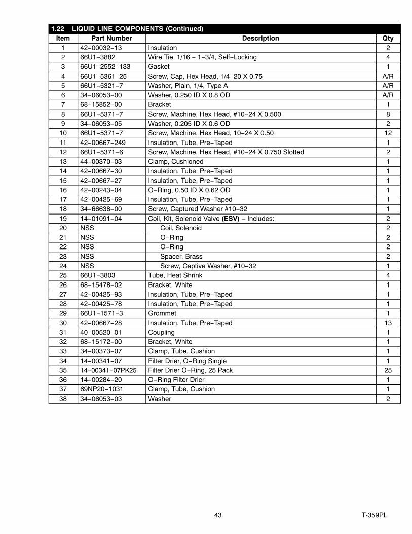
1.24 CONDENSER COIL AND COVERS
1
13
21
27
6 17
2
16
26
11
15
12
25 2223
14
6
45
7
7, 8
9 1045
2223
345
5
3
2019
24
345
6
45
6
45
77−01379−05
18

47 T-359PL
1.24 CONDENSER COIL AND COVERS (Continued)Item Part Number Description Qty
1 08−00319−20 Coil Assembly, Condenser 12 58−04026−46 Protector, Coil Cover 13 34−00655−04 Screw, Cap Hex Head, 1/4−20 X 0.50 44 66U1−5321−7 Washer, Plain, 1/4 A/R5 34−06053−00 Mylar Washer, 0.250 ID X 0.800 OD A/R6 66U1−5361−25 Screw, Cap Hex Head, 1/4−20 X 0.75 57 58−04026−50 Protector, Tube Sheet 28 58−04026−76 Protector, Condenser Coil 19 58−04026−57 Protector, Center Tube Sheet 2
10 58−04026−45 Protector, Tube Sheet 211 68−15476−00 Cover, White 112 68−15285−00 Baffle, White 113 34−00928−03 Rivet, Blind 214 58−04026−77 Protector 115 58−04026−21 Protector 116 58−04026−41 Protector, Coil Cover 217 58−04026−42 Protector, Coil Cover 218 58−04026−44 Protector, Coil Cover 219 68−14754−00 Bracket, Tube Sheet Support 120 34−00928−04 Rivet, Blind 221 34−00655−08 Screw, Cap, Hex Head, 1/4−20 X 1.00 122 34−01181−02 Washer, Flat 223 34−06053−22 Mylar Washer, 0.195 ID X 1.125 OD 224 66U1−5371−7 Screw, Machine, Hex Head, #10−24 X 0.500 425 69NT35−2692−4 Washer, Fender 426 68−15851−02 Cover 127 69NT35−8693−11 Protector 6

48T-359PL
1.25 CONDENSER FAN MOTOR
234
3
6
5
789
10
11121314
1
77−01212−00

49 T-359PL
1.25 CONDENSER FAN MOTOR (Continued)Item Part Number Description Qty
1 38−00585−00 Fan, Condenser 12 34−00667−12 Nut, Self−Locking, 5/16−18 43 34−01181−01 Washer, Flat 84 34−06053−02 Washer, 0.375 ID X 1.000 OD 45 69NT35−6112 Protector, Condenser Fan Motor Mounting 26 66U1−5361 Screw, Cap, Hex Head, 5/16−18 X 1.25 47 54−00586−20 Motor, Condenser, Single Phase − Includes: 18 04−50029−00 Bearing 29 22−01997−05 Pin A/R
10 22−01997−10 Pin, Grounding A/R11 69NT35−3452 Shim 112 69NT35−3452−1 Shim 113 69NT35−3452−2 Shim 114 69NT35−3452−3 Shim 1
50T-359PL
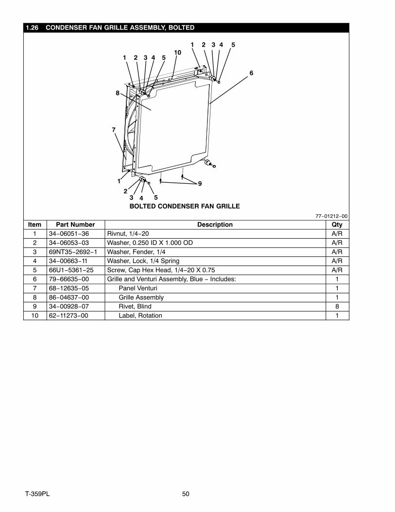
1.26 CONDENSER FAN GRILLE ASSEMBLY, BOLTED
2 3 4 5
23 4 5
1
2 3 4 51
1
10
7
8
BOLTED CONDENSER FAN GRILLE
9
77−01212−00
6
Item Part Number Description Qty1 34−06051−36 Rivnut, 1/4−20 A/R2 34−06053−03 Washer, 0.250 ID X 1.000 OD A/R3 69NT35−2692−1 Washer, Fender, 1/4 A/R4 34−00663−11 Washer, Lock, 1/4 Spring A/R5 66U1−5361−25 Screw, Cap Hex Head, 1/4−20 X 0.75 A/R6 79−66635−00 Grille and Venturi Assembly, Blue − Includes: 17 68−12635−05 Panel Venturi 18 86−04637−00 Grille Assembly 19 34−00928−07 Rivet, Blind 8
10 62−11273−00 Label, Rotation 1

51 T-359PL
1.27 VOLTAGE CABLES
21
22−66665−06
Item Part Number Description Qty1 22−02378−00 Plug 4 Pole, 440V 12 22−66654−00 Cable Assy 460V 1

52T-359PL
1.28 CABLE GUARDS
1, 23, 4, 5
6, 7, 8
11 7, 8, 9, 1017
7, 8, 9, 10
7, 8, 19
8, 7, 19
13, 14, 15
6, 7, 8 12
7, 16, 18, 19
6, 7, 8
ITEM 17 REMOVED FOR CLARITY
77−01380−06
53 T-359PL
1.28 CABLE GUARDS (Continued)Item Part Number Description Qty
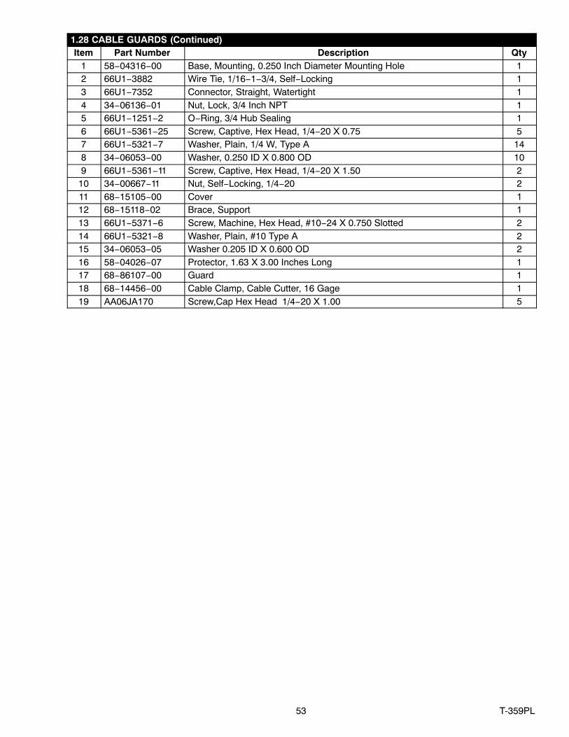
1 58−04316−00 Base, Mounting, 0.250 Inch Diameter Mounting Hole 12 66U1−3882 Wire Tie, 1/16−1−3/4, Self−Locking 13 66U1−7352 Connector, Straight, Watertight 14 34−06136−01 Nut, Lock, 3/4 Inch NPT 15 66U1−1251−2 O−Ring, 3/4 Hub Sealing 16 66U1−5361−25 Screw, Captive, Hex Head, 1/4−20 X 0.75 57 66U1−5321−7 Washer, Plain, 1/4 W, Type A 148 34−06053−00 Washer, 0.250 ID X 0.800 OD 109 66U1−5361−11 Screw, Captive, Hex Head, 1/4−20 X 1.50 2
10 34−00667−11 Nut, Self−Locking, 1/4−20 211 68−15105−00 Cover 1
12 68−15118−02 Brace, Support 1
13 66U1−5371−6 Screw, Machine, Hex Head, #10−24 X 0.750 Slotted 214 66U1−5321−8 Washer, Plain, #10 Type A 215 34−06053−05 Washer 0.205 ID X 0.600 OD 216 58−04026−07 Protector, 1.63 X 3.00 Inches Long 117 68−86107−00 Guard 118 68−14456−00 Cable Clamp, Cable Cutter, 16 Gage 119 AA06JA170 Screw,Cap Hex Head 1/4−20 X 1.00 5

54T-359PL
1.29 AUTOTRANSFORMER PROVISION
1, 2, 3
1, 2, 3
77−01001−03
Item Part Number Description Qty1 AA06JA170 Screw, Hex Head, 1/4−20 X 1.00 72 34−06053−00 Washer, Mylar, 0.250 ID X 0.800 OD 73 66U1−5321−7 Washer, Plain, 1/4 W Type A 7

55 T-359PL
1.30 CABLE RESTRAINT COMPONENTS
62−0
2458−0
0 R
EV
C
1 2, 3, 4, 5
69nt−−43−−−379
Item Part Number Description Qty1 66U1−5321−7 Washer, Flat, 1/4, SST 22 66U1−5361−25 Screw, Captive, Hex Head, 1/4−20 X 0.75 Inches Long, SST 23 34−06053−03 Washer, Mylar, 0.25 ID X 1.00 OD 24 69NT35−5992 Cable Restraint, SST 15 66U1−2603 Strap, Tie Down 1
56T-359PL
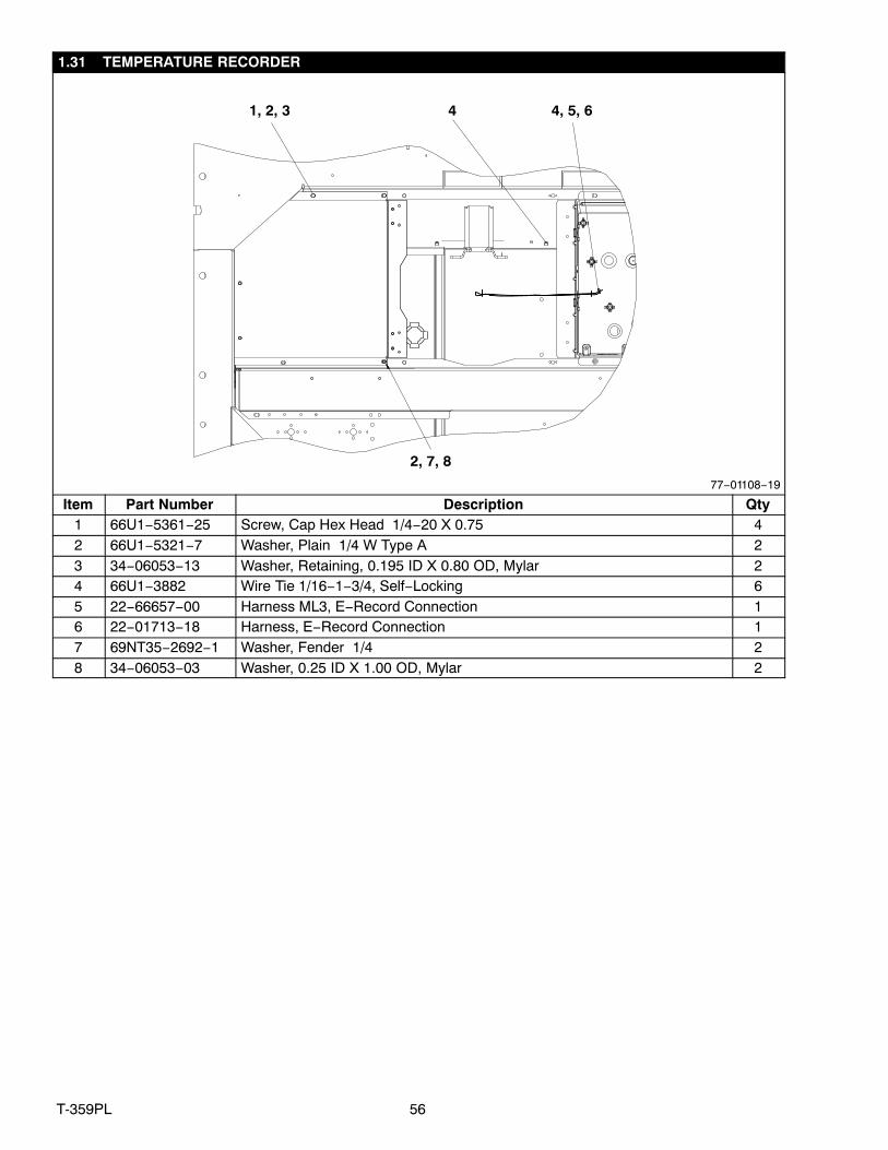
1.31 TEMPERATURE RECORDER
1, 2, 3 4 4, 5, 6
2, 7, 8
77−01108−19
Item Part Number Description Qty1 66U1−5361−25 Screw, Cap Hex Head 1/4−20 X 0.75 42 66U1−5321−7 Washer, Plain 1/4 W Type A 23 34−06053−13 Washer, Retaining, 0.195 ID X 0.80 OD, Mylar 24 66U1−3882 Wire Tie 1/16−1−3/4, Self−Locking 65 22−66657−00 Harness ML3, E−Record Connection 16 22−01713−18 Harness, E−Record Connection 17 69NT35−2692−1 Washer, Fender 1/4 28 34−06053−03 Washer, 0.25 ID X 1.00 OD, Mylar 2
57 T-359PL
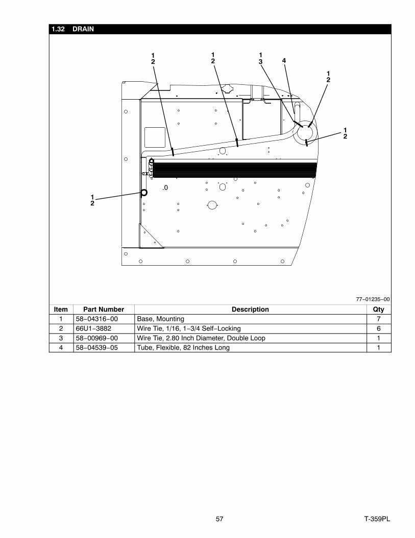
1.32 DRAIN
41
31
2
.0
12
12
12
12
77−01235−00
Item Part Number Description Qty1 58−04316−00 Base, Mounting 72 66U1−3882 Wire Tie, 1/16, 1−3/4 Self−Locking 63 58−00969−00 Wire Tie, 2.80 Inch Diameter, Double Loop 14 58−04539−05 Tube, Flexible, 82 Inches Long 1
58T-359PL
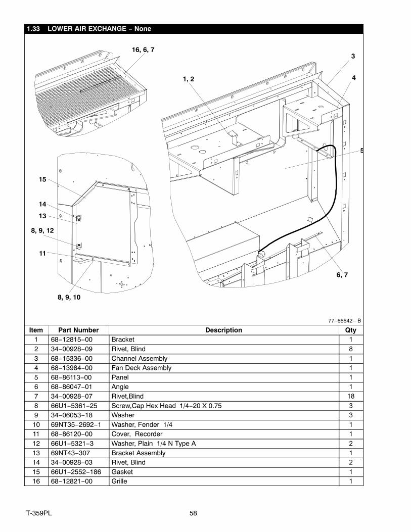
1.33 LOWER AIR EXCHANGE − None
1, 2
3
4
5
6, 7
8, 9, 10
11
8, 9, 12
13
14
15
16, 6, 7
77−66642 − B
Item Part Number Description Qty1 68−12815−00 Bracket 1
2 34−00928−09 Rivet, Blind 8
3 68−15336−00 Channel Assembly 1
4 68−13984−00 Fan Deck Assembly 1
5 68−86113−00 Panel 1
6 68−86047−01 Angle 1
7 34−00928−07 Rivet,Blind 18
8 66U1−5361−25 Screw,Cap Hex Head 1/4−20 X 0.75 3
9 34−06053−18 Washer 3
10 69NT35−2692−1 Washer, Fender 1/4 1
11 68−86120−00 Cover, Recorder 1
12 66U1−5321−3 Washer, Plain 1/4 N Type A 2
13 69NT43−307 Bracket Assembly 1
14 34−00928−03 Rivet, Blind 2
15 66U1−2552−186 Gasket 1
16 68−12821−00 Grille 1
59 T-359PL
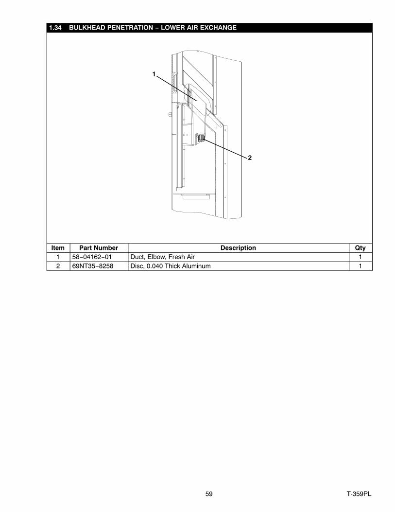
1.34 BULKHEAD PENETRATION − LOWER AIR EXCHANGE
1
2
Item Part Number Description Qty1 58−04162−01 Duct, Elbow, Fresh Air 12 69NT35−8258 Disc, 0.040 Thick Aluminum 1

60T-359PL
1.35 LABELS AND DECALS
5
1
4
2
7
3
6
77−01294−47
Rivets ForDrain Cup
Lower BackPanel
Item Part Number Description Qty1 62−02823−07 Label Evergreen Logo 12 62−10799−04 Label Function Code, (Eng) 23 62−66682−01 Label Pti 14 62−11263−02 Label Poe Compr. Oil 15 62−11424−01 Label Carrier Primeline 16 62−66776−00 Label Rivets Warning 17 62−11252−00 Label R−134A 1
61 T-359PL
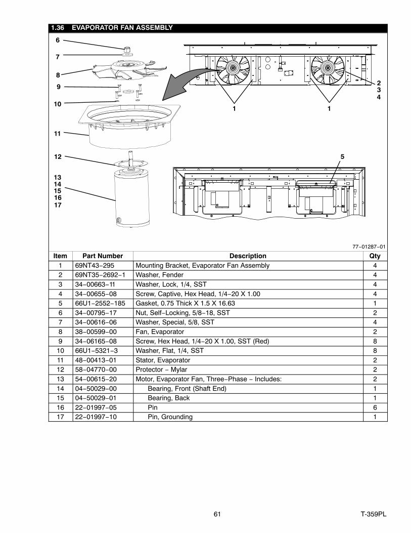
1.36 EVAPORATOR FAN ASSEMBLY
11
8
6
12
7
39
410
5
2
16
131415
1 1
77−01287−01
17
Item Part Number Description Qty1 69NT43−295 Mounting Bracket, Evaporator Fan Assembly 42 69NT35−2692−1 Washer, Fender 43 34−00663−11 Washer, Lock, 1/4, SST 44 34−00655−08 Screw, Captive, Hex Head, 1/4−20 X 1.00 45 66U1−2552−185 Gasket, 0.75 Thick X 1.5 X 16.63 16 34−00795−17 Nut, Self−Locking, 5/8−18, SST 27 34−00616−06 Washer, Special, 5/8, SST 48 38−00599−00 Fan, Evaporator 29 34−06165−08 Screw, Hex Head, 1/4−20 X 1.00, SST (Red) 8
10 66U1−5321−3 Washer, Flat, 1/4, SST 811 48−00413−01 Stator, Evaporator 212 58−04770−00 Protector − Mylar 213 54−00615−20 Motor, Evaporator Fan, Three−Phase − Includes: 214 04−50029−00 Bearing, Front (Shaft End) 115 04−50029−01 Bearing, Back 116 22−01997−05 Pin 617 22−01997−10 Pin, Grounding 1
62T-359PL
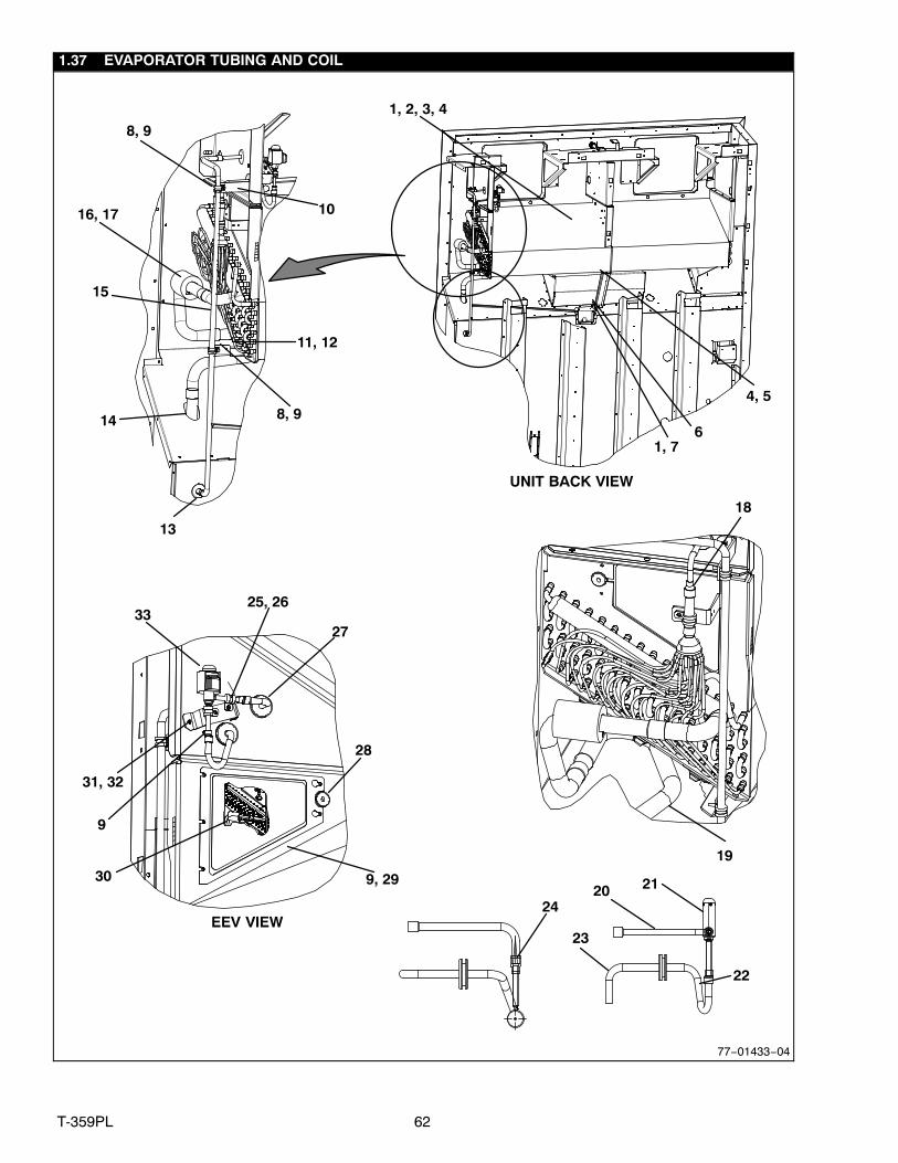
1.37 EVAPORATOR TUBING AND COIL
1, 2, 3, 4
4, 5
61, 7
16, 17
3325, 26
27
28
9, 29
31, 32
18
19
15
10
11, 12
8, 9
24
21
23
20
22
UNIT BACK VIEW
EEV VIEW
30
14
9
77−01433−04
13
8, 9

63 T-359PL
1.37 EVAPORATOR TUBING AND COIL (Continued)Item Part Number Description Qty
1 66U1−5321−3 Washer, Plain, 1/4, Type A 102 66U1−5361−25 Screw, Cap, Hex Head, 1/4−20 X 0.75 93 08−66616−00 Coil Assembly, Evaporator 14 34−00663−11 Washer, Lock, 1/4, Spring 105 AA06JA166 Screw, Cap Hex Head, 1/4−20 X 0.50 16 68−15406−00 Bracket, Support 17 66U1−7452−3 Screw, Lag, 1/4−10 X 2, Hex Head 18 44−00370−03 Clamp, Cushioned 29 66U1−5381−1 Screw, Hex Head, #10−24 X 0.75 8
10 68−86116−00 Bracket 111 66U1−5381−3 Screw, Hex Head, #10−24 X 0.63 212 68−14890−00 Bracket 113 58−00065−56 Grommet 114 42−00183−08 Flexible Trim 115 56−66726−00 Tube, Liquid 116 66U1−3882−3 Wire Tie, 1/16−4 Self−Locking 217 42−00425−109 Insulation Tube, Pre−Taped 118 40−66629−00 Bushing 119 56−08502−01 Tube, Suction 120 56−66766−00 Tube, Liquid 121 14−00393−00SV Valve, Evaporator Expansion Valve (EEV) 122 40−66628−03 Coupling 3/8C X 5/16C 223 56−66767−00 Tube, Liquid 124 14−00176−01 Strainer 125 66U1−5371−7 Screw, Machine, Hex Head, 10−24 X 0.50 326 34−00373−52 Clamp, Tube 227 58−00065−91 Grommet 228 58−00065−46 Grommet 129 68−14892−00 Plate, Cover 130 62−11427−00 Label, Sensors 131 66U1−5371−6 Screw, Machine, Hex Head, #10−24 X 0.750 332 68−15768−01 Bracket 133 14−00393−10 Coil 1
64T-359PL
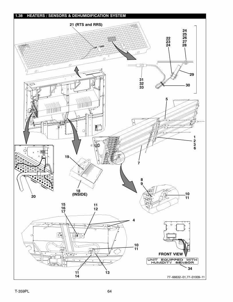
1.38 HEATERS / SENSORS & DEHUMIDIFICATION SYSTEM
19
3
222324
29
18(INSIDE)
30313233
24252627
FRONT VIEW
34
28
4
2
20
21 (RTS and RRS)
5
6
12
14
10
13
7
89
11
151617
1
11
11
1011
77−66632−01, 77−01009−11
65 T-359PL
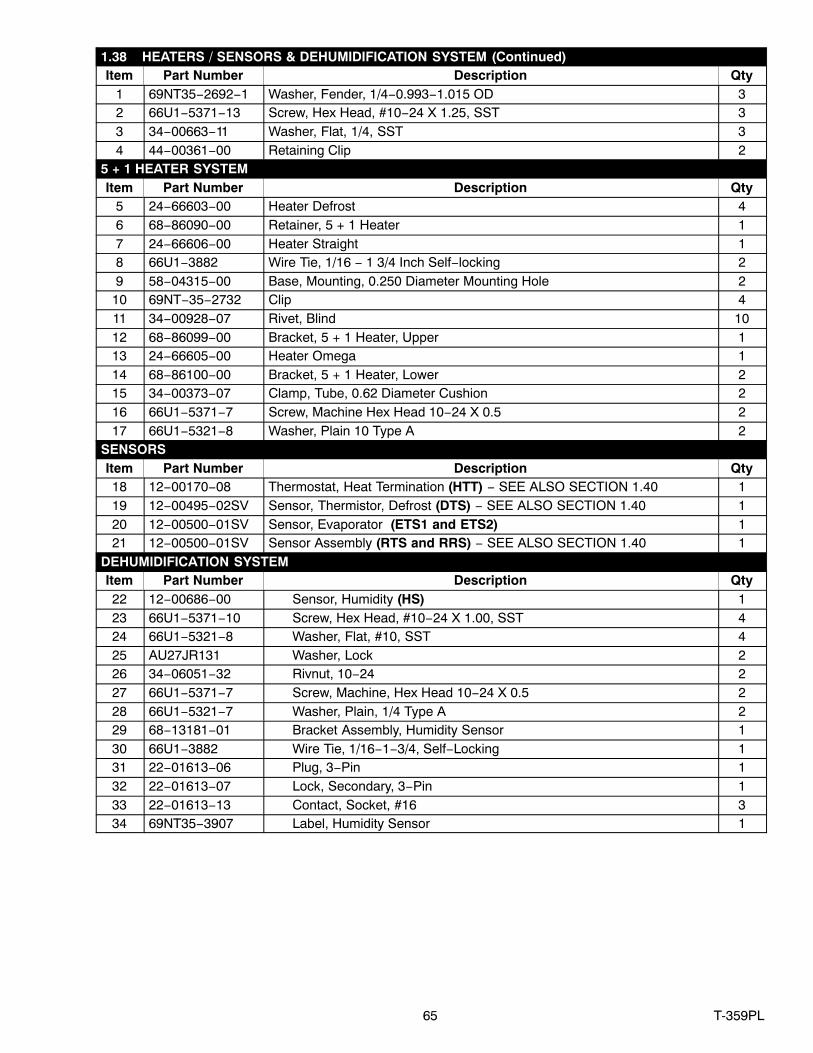
1.38 HEATERS / SENSORS & DEHUMIDIFICATION SYSTEM (Continued)Item Part Number Description Qty
1 69NT35−2692−1 Washer, Fender, 1/4−0.993−1.015 OD 32 66U1−5371−13 Screw, Hex Head, #10−24 X 1.25, SST 33 34−00663−11 Washer, Flat, 1/4, SST 34 44−00361−00 Retaining Clip 2
5 + 1 HEATER SYSTEMItem Part Number Description Qty
5 24−66603−00 Heater Defrost 46 68−86090−00 Retainer, 5 + 1 Heater 17 24−66606−00 Heater Straight 18 66U1−3882 Wire Tie, 1/16 − 1 3/4 Inch Self−locking 29 58−04315−00 Base, Mounting, 0.250 Diameter Mounting Hole 2
10 69NT−35−2732 Clip 411 34−00928−07 Rivet, Blind 1012 68−86099−00 Bracket, 5 + 1 Heater, Upper 113 24−66605−00 Heater Omega 114 68−86100−00 Bracket, 5 + 1 Heater, Lower 215 34−00373−07 Clamp, Tube, 0.62 Diameter Cushion 216 66U1−5371−7 Screw, Machine Hex Head 10−24 X 0.5 217 66U1−5321−8 Washer, Plain 10 Type A 2
SENSORSItem Part Number Description Qty18 12−00170−08 Thermostat, Heat Termination (HTT) − SEE ALSO SECTION 1.40 119 12−00495−02SV Sensor, Thermistor, Defrost (DTS) − SEE ALSO SECTION 1.40 120 12−00500−01SV Sensor, Evaporator (ETS1 and ETS2) 121 12−00500−01SV Sensor Assembly (RTS and RRS) − SEE ALSO SECTION 1.40 1
DEHUMIDIFICATION SYSTEMItem Part Number Description Qty22 12−00686−00 Sensor, Humidity (HS) 123 66U1−5371−10 Screw, Hex Head, #10−24 X 1.00, SST 424 66U1−5321−8 Washer, Flat, #10, SST 425 AU27JR131 Washer, Lock 226 34−06051−32 Rivnut, 10−24 227 66U1−5371−7 Screw, Machine, Hex Head 10−24 X 0.5 228 66U1−5321−7 Washer, Plain, 1/4 Type A 229 68−13181−01 Bracket Assembly, Humidity Sensor 130 66U1−3882 Wire Tie, 1/16−1−3/4, Self−Locking 131 22−01613−06 Plug, 3−Pin 132 22−01613−07 Lock, Secondary, 3−Pin 133 22−01613−13 Contact, Socket, #16 334 69NT35−3907 Label, Humidity Sensor 1

66T-359PL
1.39 BACK PANEL ASSEMBLY − ALUMINUM BOLTED / 5+1 HEATER ARRANGEMENT
INTERIOR VIEW OF PANELS
5
15, 9
8, 9
5
9
11, 12, 13
14
6
4
16
16
1, 10
7
1, 2, 3
77−66633−00

67 T-359PL
1.39 BACK PANEL ASSEMBLY − ALUMINUM BOLTED / 5+1 HEATER ARRANGEMENT (Continued)Item Part Number Description Qty
1 34−00928−03 Rivet, Blind 192 42−66625−00 Gasket Drain 13 86−66709−00 Drain Cup 14 42−00334−00 Gasket 15 68−86092−00 Panel Assembly 16 42−00174−34 Gasket 17 42−00174−101 Gasket 28 68−15425−00 Channel 19 34−00928−02 Rivet, Blind 50
10 68−86080−01 Standoff 5+1 Heater 111 69NT35−2692 Washer, Fender 1912 66U1−2403 Screw, Machine 1913 66U1−7982−2 Rivet 414 68−14046−00 Panel, Back 115 68−15426−00 Channel 116 66U1−2593−24 Gasket 2
68T-359PL
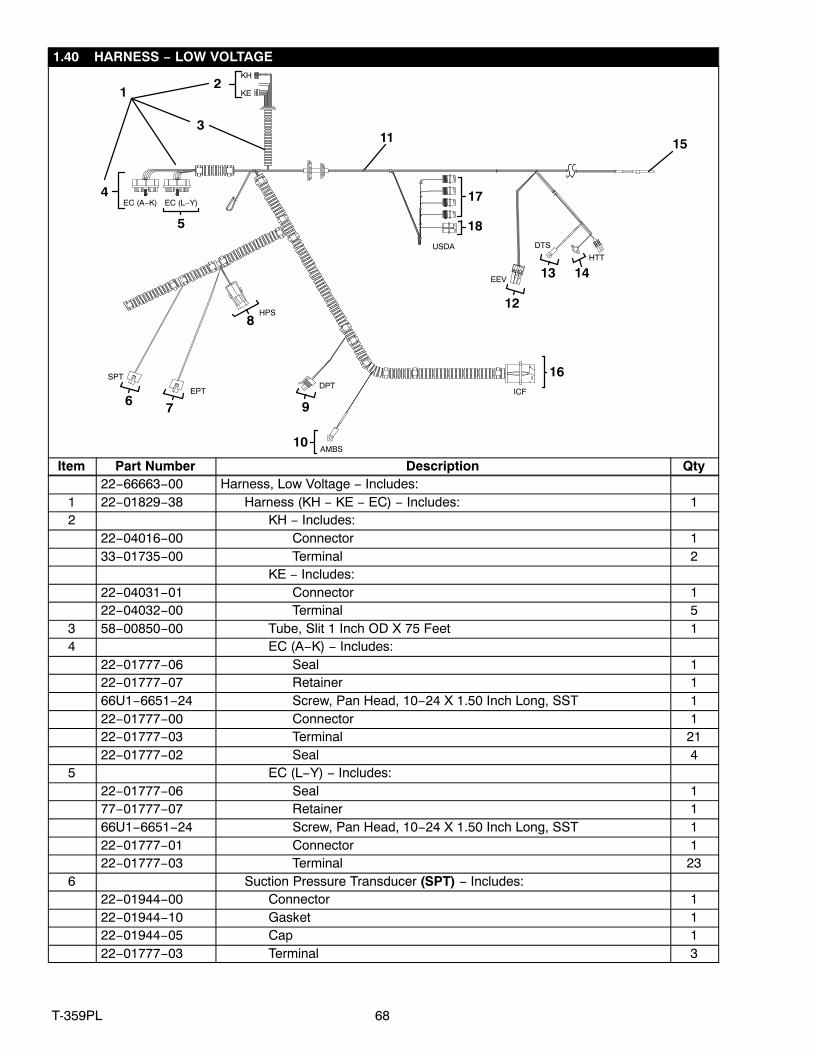
1.40 HARNESS − LOW VOLTAGE
KE
SPTDPT
HPS
EC (A−K) EC (L−Y)
ICF
KH
EPT
EEV
1
4
5
USDA
3
AMBS
DTS
HTT
2
6 7
8
9
10
11
12
13 14
15
17
18
16
Item Part Number Description Qty22−66663−00 Harness, Low Voltage − Includes:
1 22−01829−38 Harness (KH − KE − EC) − Includes: 12 KH − Includes:
22−04016−00 Connector 133−01735−00 Terminal 2
KE − Includes:22−04031−01 Connector 122−04032−00 Terminal 5
3 58−00850−00 Tube, Slit 1 Inch OD X 75 Feet 14 EC (A−K) − Includes:
22−01777−06 Seal 122−01777−07 Retainer 166U1−6651−24 Screw, Pan Head, 10−24 X 1.50 Inch Long, SST 122−01777−00 Connector 122−01777−03 Terminal 2122−01777−02 Seal 4
5 EC (L−Y) − Includes:22−01777−06 Seal 177−01777−07 Retainer 166U1−6651−24 Screw, Pan Head, 10−24 X 1.50 Inch Long, SST 122−01777−01 Connector 122−01777−03 Terminal 23
6 Suction Pressure Transducer (SPT) − Includes:22−01944−00 Connector 122−01944−10 Gasket 122−01944−05 Cap 122−01777−03 Terminal 3

69 T-359PL
1.40 HARNESS − LOW VOLTAGE (Continued)Item Part Number Description Qty
7 Evaporator Pressure Transducer (EPT) − Includes:22−01944−00 Connector 122−01944−10 Gasket 122−01944−05 Cap 122−01777−03 Terminal 3
8 High Pressure Switch (HPS) − Includes:22−02392−00 Connector 122−02393−01 Terminal 222−02394−04 Cable Seal 2
9 Discharge Pressure Transducer (DPT) − Includes:22−02448−00 Connector 122−01777−03 Terminal 3
10 12−00765−00 Thermistor, Ambient (AMBS) 111 66U1−3882 Wire Tie, 1/16−1 3/4, Self−Locking A/R12 Electronic Expansion Valve (EEV) − Includes:
22−01835−00 Connector 122−01566−01 Terminal 522−02394−02 Cable Seal 5
13 12−00495−02SV Thermistor, Defrost (DTS) 114 12−00170−08 Thermistor, Evaporator Defrost (HTT) 115 12−00500−01SV Thermistor, Combo/Return (RTS/RRS) 116 ICF − Includes:
22−01660−03 Connector 122−01613−14 Terminal 5
17 USDA − Includes:22−01660−00 Connector 422−01613−12 Terminal 822−01614−06 Plug 4
18 USDA − Includes:22−01660−03 Connector 122−01613−12 Terminal 5

70T-359PL
1.41 HARNESS − HIGH VOLTAGE
EM1
EM2
CM
12
11
14
15
MA
CIB
KD
KA
KB
5
6
7
8
9
CIC
4
16 (40 TOTAL)
17
1013
MD
CFS
ST1
3
2
Item Part Number Description Qty1 10−01129−11 Switch, Toggle, Start/Stop (ST) 12 10−01129−05 Switch, Toggle, Condenser Fan Switch (CFS) 13 10−01129−10 Switch, Toggle, Manual Defrost (MD) 1
91−66620−00 High Voltage Harness − Includes:4 CIC − Includes:
22−01556−06 Connector Interface, CIC 122−02324−09 Terminal 3
5 CIB − Includes:22−01556−04 Connector Interface, CIB 122−01735−00 Terminal 3
71 T-359PL
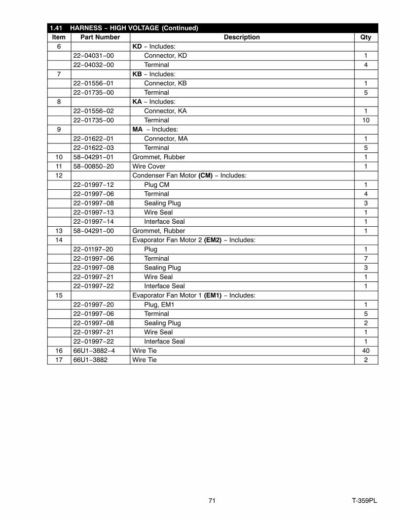
1.41 HARNESS − HIGH VOLTAGE (Continued)Item Part Number Description Qty
6 KD − Includes:22−04031−00 Connector, KD 122−04032−00 Terminal 4
7 KB − Includes:22−01556−01 Connector, KB 122−01735−00 Terminal 5
8 KA − Includes:22−01556−02 Connector, KA 122−01735−00 Terminal 10
9 MA − Includes:22−01622−01 Connector, MA 122−01622−03 Terminal 5
10 58−04291−01 Grommet, Rubber 111 58−00850−20 Wire Cover 112 Condenser Fan Motor (CM) − Includes:
22−01997−12 Plug CM 122−01997−06 Terminal 422−01997−08 Sealing Plug 322−01997−13 Wire Seal 122−01997−14 Interface Seal 1
13 58−04291−00 Grommet, Rubber 114 Evaporator Fan Motor 2 (EM2) − Includes:
22−01197−20 Plug 122−01997−06 Terminal 722−01997−08 Sealing Plug 322−01997−21 Wire Seal 122−01997−22 Interface Seal 1
15 Evaporator Fan Motor 1 (EM1) − Includes:22−01997−20 Plug, EM1 122−01997−06 Terminal 522−01997−08 Sealing Plug 222−01997−21 Wire Seal 122−01997−22 Interface Seal 1
16 66U1−3882−4 Wire Tie 4017 66U1−3882 Wire Tie 2
72T-359PL
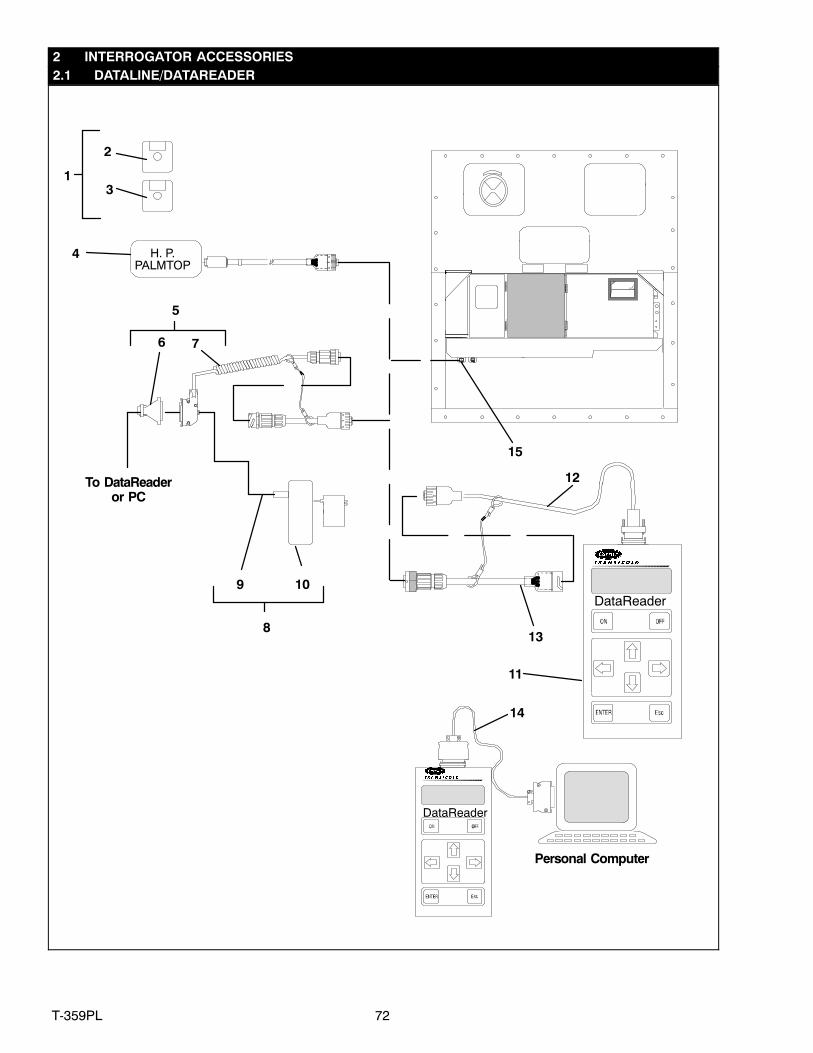
2 INTERROGATOR ACCESSORIES2.1 DATALINE/DATAREADER
DataReader
Personal Computer
DataReader
To DataReaderor PC
H. P.PALMTOP
76
11
12
13
14
31
2
4
8
9 10
5
15
73 T-359PL
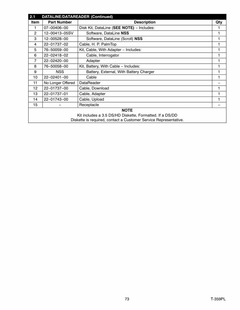
2.1 DATALINE/DATAREADER (Continued)Item Part Number Description Qty
1 07−00406−00 Disk Kit, DataLine (SEE NOTE) − Includes: 12 12−00413−05SV Software, DataLine NSS 13 12−00528−00 Software, DataLine (Scroll) NSS 14 22−01737−02 Cable, H. P. PalmTop 15 76−50059−00 Kit, Cable, With Adapter − Includes: 16 22−02418−02 Cable, Interrogator 17 22−02420−00 Adapter 18 76−50058−00 Kit, Battery, With Cable − Includes: 19 NSS Battery, External, With Battery Charger 1
10 22−02401−00 Cable 111 No Longer Offered DataReader −12 22−01737−00 Cable, Download 113 22−01737−01 Cable, Adapter 114 22−01743−00 Cable, Upload 115 − Receptacle −
NOTEKit includes a 3.5 DS/HD Diskette, Formatted. If a DS/DD
Diskette is required, contact a Customer Service Representative.
74T-359PL
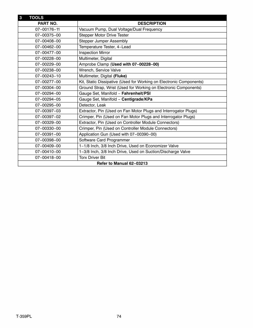
3 TOOLSPART NO. DESCRIPTION
07−00176−11 Vacuum Pump, Dual Voltage/Dual Frequency07−00375−00 Stepper Motor Drive Tester07−00408−00 Stepper Jumper Assembly07−00462−00 Temperature Tester, 4−Lead07−00477−00 Inspection Mirror07−00228−00 Multimeter, Digital07−00229−00 Amprobe Clamp (Used with 07−00228−00) 07−00238−00 Wrench, Service Valve07−00243−10 Multimeter, Digital (Fluke) 07−00277−00 Kit, Static Dissipative (Used for Working on Electronic Components)07−00304−00 Ground Strap, Wrist (Used for Working on Electronic Components)07−00294−00 Gauge Set, Manifold − Fahrenheit/PSI07−00294−05 Gauge Set, Manifold − Centigrade/KPa07−00295−00 Detector, Leak07−00397−03 Extractor, Pin (Used on Fan Motor Plugs and Interrogator Plugs)07−00397−02 Crimper, Pin (Used on Fan Motor Plugs and Interrogator Plugs)07−00329−00 Extractor, Pin (Used on Controller Module Connectors)07−00330−00 Crimper, Pin (Used on Controller Module Connectors)07−00391−00 Application Gun (Used with 07−00390−00)07−00398−00 Software Card Programmer07−00409−00 1−1/8 Inch, 3/8 Inch Drive, Used on Economizer Valve07−00410−00 1−3/8 Inch, 3/8 Inch Drive, Used on Suction/Discharge Valve07−00418−00 Torx Driver Bit
Refer to Manual 62−03213
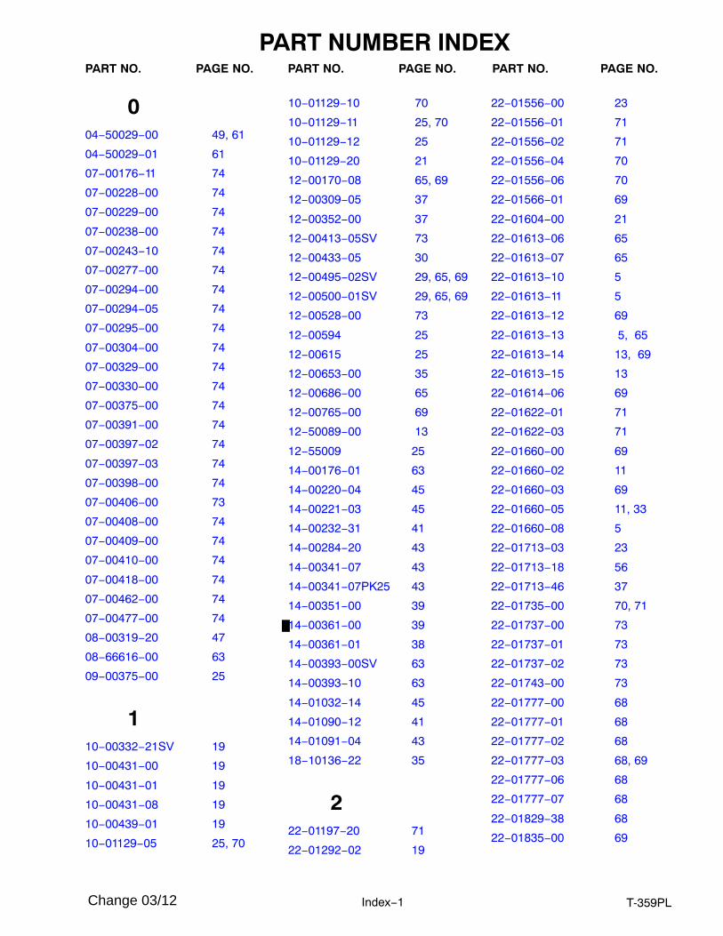
PART NUMBER INDEX
Index−1 T-359PL
PART NO. PAGE NO. PART NO. PAGE NO. PART NO. PAGE NO.
004−50029−00 49, 61
04−50029−01 61
07−00176−11 74
07−00228−00 74
07−00229−00 74
07−00238−00 74
07−00243−10 74
07−00277−00 74
07−00294−00 74
07−00294−05 74
07−00295−00 74
07−00304−00 74
07−00329−00 74
07−00330−00 74
07−00375−00 74
07−00391−00 74
07−00397−02 74
07−00397−03 74
07−00398−00 74
07−00406−00 73
07−00408−00 74
07−00409−00 74
07−00410−00 74
07−00418−00 74
07−00462−00 74
07−00477−00 74
08−00319−20 47
08−66616−00 63
09−00375−00 25
110−00332−21SV 19
10−00431−00 19
10−00431−01 19
10−00431−08 19
10−00439−01 19
10−01129−05 25, 70
10−01129−10 70
10−01129−11 25, 70
10−01129−12 25
10−01129−20 21
12−00170−08 65, 69
12−00309−05 37
12−00352−00 37
12−00413−05SV 73
12−00433−05 30
12−00495−02SV 29, 65, 69
12−00500−01SV 29, 65, 69
12−00528−00 73
12−00594 25
12−00615 25
12−00653−00 35
12−00686−00 65
12−00765−00 69
12−50089−00 13
12−55009 25
14−00176−01 63
14−00220−04 45
14−00221−03 45
14−00232−31 41
14−00284−20 43
14−00341−07 43
14−00341−07PK25 43
14−00351−00 39
14−00361−00 39
14−00361−01 38
14−00393−00SV 63
14−00393−10 63
14−01032−14 45
14−01090−12 41
14−01091−04 43
18−10136−22 35
222−01197−20 71
22−01292−02 19
22−01556−00 23
22−01556−01 71
22−01556−02 71
22−01556−04 70
22−01556−06 70
22−01566−01 69
22−01604−00 21
22−01613−06 65
22−01613−07 65
22−01613−10 5
22−01613−11 5
22−01613−12 69
22−01613−13 5, 65
22−01613−14 13, 69
22−01613−15 13
22−01614−06 69
22−01622−01 71
22−01622−03 71
22−01660−00 69
22−01660−02 11
22−01660−03 69
22−01660−05 11, 33
22−01660−08 5
22−01713−03 23
22−01713−18 56
22−01713−46 37
22−01735−00 70, 71
22−01737−00 73
22−01737−01 73
22−01737−02 73
22−01743−00 73
22−01777−00 68
22−01777−01 68
22−01777−02 68
22−01777−03 68, 69
22−01777−06 68
22−01777−07 68
22−01829−38 68
22−01835−00 69
Change 03/12

PART NUMBER INDEX
Index−2T-359PL
PART NO. PAGE NO. PART NO. PAGE NO. PART NO. PAGE NO.
22−01944−00 68, 69
22−01944−05 68, 69
22−01944−10 68, 69
22−01997−04 61
22−01997−05 49
22−01997−06 71
22−01997−08 71
22−01997−10 49, 61
22−01997−12 71
22−01997−13 71
22−01997−14 71
22−01997−20 71
22−01997−21 71
22−01997−22 71
22−02205−00 1, 33
22−02324−09 70
22−02336−02 25
22−02336−08 25
22−02341−01 21
22−02378−00 51
22−02392−00 69
22−02393−01 69
22−02394−02 69
22−02394−04 69
22−02401−00 73
22−02418−02 73
22−02420−00 73
22−02448−00 69
22−04016−00 68
22−04031−00 71
22−04031−01 68
22−04032−00 68, 71
22−04128−00 35
22−04128−10 35
22−04128−11 35
22−04128−12 35
22−04128−13 35
22−50127−00 13
22−66654−00 51
22−66657−00 56
22−66663−00 68
22−66676−00 19
24−66603−00 65
24−66605−00 65
24−66606−00 65
330−00407−02SV 25
33−01735−00 68
34−00373−07 43, 65
34−00373−51 39
34−00373−52 63
34−00373−53 38
34−00373−54 41
34−00616−06 61
34−00655−04 47
34−00655−08 5, 19, 29,47, 61
34−00655−10 19, 27
34−00655−18 39
34−00662−09 29
34−00663−07 19
34−00663−08 15
34−00663−09 15, 19, 31,35
34−00663−11 50, 61, 63,65
34−00667−05 21
34−00667−11 27, 41, 53
34−00667−12 49
34−00792−07 34
34−00795−09 37
34−00795−17 61
34−00848−10 21
34−00928−02 5, 17, 27,67
34−00928−03 29, 47, 58,67
34−00928−04 47
34−00928−07 50, 58, 65
34−00928−09 13, 58
34−01167−01 15
34−01178−22 19, 31
34−01178−23 31
34−01181−01 49
34−01181−02 47
34−06051−32 31, 65
34−06051−36 50
34−06053−00 29, 39, 41,43, 47, 53, 54
34−06053−02 49
34−06053−03 27, 29, 43,50, 55, 56
34−06053−05 15, 33, 37,41, 43, 53
34−06053−13 5, 7, 19,29, 56
34−06053−15 34
34−06053−18 58
34−06053−19 5
34−06053−20 35
34−06053−22 47
34−06107−00 15
34−06136−01 53
34−06139−00 17
34−06139−01 17
34−06139−04 17, 33
34−06142−00 11, 33
34−06152−00 17
34−06154−00 5, 7
34−06154−03 29
34−06165−08 61
34−06185−01 5
34−06212−10 21
34−06212−12 5, 7
34−06236−00 35
34−06251−00 30
34−06277−02 35
34−06295−00 37
34−66621−04 15
34−66629−05 21

PART NUMBER INDEX
Index−3 T-359PL
PART NO. PAGE NO. PART NO. PAGE NO. PART NO. PAGE NO.
34−66630−00 21
34−66638−00 43
38−00585−00 49
38−00599−00 61
440−00130−07 41
40−00520−01 43
40−00520−02 37
40−00520−03 37
40−00542−00 37
40−00542−01 37
40−00583−05 38
40−00663−00 38
40−00665−20 38
40−00667−00 41
40−00668−00 41
40−00675−00 38
40−01124−00 37
40−50025−00 38
40−66620−01 41
40−66628−03 63
40−66629−00 63
42−00032−00 41
42−00032−13 43
42−00174−101 67
42−00174−34 67
42−00183−00 35
42−00183−08 63
42−00243−04 43
42−00243−12 38
42−00270−02 15
42−00296−01 5, 7
42−00327−00 5, 7
42−00334−00 67
42−00384−02 38
42−00389−03 41
42−00390−03 41
42−00407−00 5
42−00425−109 63
42−00425−110 37
42−00425−112 37
42−00425−114 37
42−00425−115 37
42−00425−69 43
42−00425−78 43
42−00425−93 43
42−00595−00 29
42−00596−00 29
42−00597−00 29
42−00597−01 29
42−00608−00 21
42−00667−249 43
42−00667−27 43
42−00667−28 43
42−00667−30 43
42−00667−32 41
42−66625−00 67
44−00285−54 39
44−00300−00 15
44−00343−00 17
44−00361−00 19, 31, 65
44−00370−03 43, 63
44−00391−00 21
44−00423−00 29
44−01041−04 31
44−66605−00 15
46−00025−04 35
48−00413−01 61
48−66611−00 15
554−00586−20 49
54−00615−20 61
56−07257−11 39
56−07911−00 41
56−08480−00 45
56−08502−01 63
56−08634−01 39
56−08635−00 38
56−08638−00 38
56−08644−00 45
56−08689−00 38
56−08710−00 41
56−08736−00 41
56−66726−00 63
56−66756−00 41
58−66766−00 63
58−66767−00 63
58−00065−46 31, 63
58−00065−56 63
58−00065−82 29
58−00065−91 63
58−00616−00 8
58−00701−03 27
58−00836−19 41
58−00848−23 19
58−00849−03 29
58−00849−20 29
58−00850−00 68
58−00850−20 71
58−00967−00 19, 27
58−00969−00 5, 31, 57
58−01097−00 33
58−01184−00 25
58−04026−07 53
58−04026−08 47
58−04026−21 47
58−04026−41 47
58−04026−42 47
58−04026−44 47
58−04026−45 47
58−04026−50 47
58−04026−57 47
58−04026−59 41
58−04026−61 45
58−04026−70 27
PART NUMBER INDEX
Index−4T-359PL
PART NO. PAGE NO. PART NO. PAGE NO. PART NO. PAGE NO.
58−04026−74 15
58−04026−76 47
58−04026−77 47
58−04101−00 15
58−04162−01 59
58−04246−00 19, 35
58−04273−00 19
58−04291−00 71
58−04291−01 71
58−04315−00 19, 31, 65
58−04316−00 19, 29, 33,53, 57
58−04366−00 15
58−04376−05 5
58−04378−01 7
58−04389−00 15
58−04539−05 57
58−04610−00 29
58−04770−00 61
58−04791−01 35
58−04821−00 35
662−02719−00 25
62−02823−07 60
62−03957−04 17
62−10799−04 60
62−10911−00 27
62−10914−03 21
62−10930−00 5
62−11252−00 60
62−11263−02 60
62−11270−08 30
62−11273−00 50
62−11274−01 11, 13
62−11275−00 11, 13
62−11277−00 19
62−11424−01 60
62−11427−00 63
62−66682−01 60
62−66723−00 5
62−66776−00 60
65−66603−01 45
66CH1−1172−2 5
66CH1−1172−52 19
66U−1−3803 37
66U1−1251−2 19, 53
66U1−1571−14 31
66U1−1571−3 43
66U1−2403 17, 67
66U1−2403−1 15
66U1−2552−133 43
66U1−2552−171 29
66U1−2552−185 61
66U1−2552−186 58
66U1−2593−19 27
66U1−2593−24 67
66U1−2603 55
66U1−3632−20 37
66U1−3803 19, 29, 38,43
66U1−3882 11, 13, 17,19, 29, 30,31, 33, 35,43, 53, 56,57, 65, 69,71
66U1−3882−3 29, 33, 35,37, 63
66U1−3882−4 71
66U1−5321−13 5
66U1−5321−2 15, 41
66U1−5321−3 27, 29, 58,61, 63
66U1−5321−6 21
66U1−5321−7 19, 27, 29,31, 39, 41,43, 47, 53,54, 55, 56,65
66U1−5321−8 15, 19, 23,27, 30, 33,41, 53, 65
66U1−5331 34
66U1−5331−4 41
66U1−5361 49
66U1−5361−11 53
66U1−5361−25 29, 43, 47,50, 53, 55,56, 58, 63
66U1−5362−2 5
66U1−5371 41
66U1−5371−10 37, 65
66U1−5371−13 65
66U1−5371−14 29
66U1−5371−6 29, 35, 38,41, 43, 53,63
66U1−5371−7 11, 13, 19,23, 25, 27,30, 31, 33,41, 43, 47,63, 65
66U1−5371−8 43
66U1−5381−1 63
66U1−5381−3 63
66U1−5562−12 8
66U1−5562−2 5, 7, 8
66U1−5562−7 27
66U1−6651−19 19
66U1−6651−2 15
66U1−6651−22 15
66U1−6651−24 68
66U1−7352 53
66U1−7352−3 19
66U1−7452−3 63
66U1−7842−12 19
66U1−7842−6 19
66U1−7842−7 19
66U1−7982−2 67
66U1−9592−13 27
66U1−9752 21
68−11989−00 7
68−12635−05 50
68−12815−00 58
68−12821−00 58
68−12933−07 5
68−12940−05 5
PART NUMBER INDEX
Index−5 T-359PL
PART NO. PAGE NO. PART NO. PAGE NO. PART NO. PAGE NO.
68−13181−01 65
68−13984−00 58
68−14046−00 67
68−14278−00 41
68−14444−00 11
68−14456−00 53
68−14505−00 29
68−14506−00 29
68−14550−00 29
68−14701−00 13
68−14754−00 47
68−14796−03 21
68−14890−00 63
68−14891−04 19
68−14892−00 63
68−15105−00 53
68−15118−02 53
68−15172−00 43
68−15270−00 27
68−15285−00 47
68−15336−00 58
68−15343−00 11
68−15406−00 63
68−15425−00 67
68−15426−00 67
68−15476−00 47
68−15477−02 41
68−15478−02 43
68−15532−00 38
68−15768−01 63
68−15851−02 47
68−15852−00 43
68−15997−00 39
68−15998−00 39
68−66773−01 27
68−66776−01 27
68−86047−01 58
68−86080−01 67
68−86090−00 65
68−86092−00 67
68−86099−00 65
68−86100−00 65
68−86107−00 53
68−86113−00 58
68−86116−00 63
68−86120−00 58
69NP20−1031 43
69NT−35−2732 65
69NT35−2692 25, 67
69NT35−2692−1 29, 50, 56,58, 61, 65
69NT35−2692−4 23, 30, 47
69NT35−3452 49
69NT35−3452−1 49
69NT35−3452−2 49
69NT35−3452−3 49
69NT35−3907 65
69NT35−5992 55
69NT35−6112 49
69NT35−6278 19
69NT35−636−1 11
69NT35−636−2 17
69NT35−8113 34
69NT35−8258 59
69NT35−8693−11 47
69NT35−9073−1 19
69NT35−9952 17, 33
69NT41−192 33
69NT41−982−3 27
69NT43−124−4SV 17
69NT43−125−1 17
69NT43−295 61
69NT43−307 58
776−00676−00 13
76−00816−00 37
76−50058−00 73
76−50059−00 73
76−50149−00 25
77−01223−00 33
77−01777−07 68
79−01697−06SV 7
79−01785−02 45
79−01879−00 13
79−01977−00 39
79−66626−00 5
79−66635−00 50
79−66648−00 27
79−66655−04 15
79−66669−00 21
881−04067−00 41
86−04637−00 50
86−66688−01 15
86−66689−00 27
86−66709−00 67
86−66720−00 9
991−66620−00 70
AAA06JA166 63
AA06JA170 53, 54
AT39JA171 23, 27
AU27JR131 17, 65
AU27JR171 23, 27, 29
MMS510074 21

Carrier Transicold Division,Carrier CorporationContainer Products GroupP.O. Box 4805Syracuse, N.Y. 13221 U.S A
www.carrier.transicold.comA member of the United Technologies Corporation family. Stock symbol UTX© 2010 Carrier Corporation � Printed in USA. 0711