construction standard details and … standard details and notes r-o 2015 update (1 of 1)...
TRANSCRIPT
CONSTRUCTION STANDARD DETAILS AND NOTES 6/22/16 UPDATE

Construction Standard Details and Notes
Construction Standard Details and Notes
Roadway/Sidewalk/Miscellaneous R‐0 Miscellaneous Roadway Standards/NotesR‐1 Industrial, Commercial, or Office Driveway ApproachR‐2 Multi‐Family Residential Driveway ApproachR‐3 Single Family Residential Driveway ApproachR‐4 Sidewalk Detail R‐5 Residential Cul‐De‐Sac Design R‐6 Manhole Ramping Detail R‐7 Open Cut Roadway Patching/Pavement Removal and Replacement (New Utility Connections) R‐8 Parking Lot Typical Pavement SectionR‐9 Local and Collector/Industrial Streets Typical Pavement SectionR‐9c Local Street Typical Concrete Pavement SectionR‐10 ROW/Roadway/Widths and Minimum Centerline Horizontal RadiusR‐11 Typical Street Utility Locations R‐12 Street Sign Standards R‐13 Curb Expansion Joint R‐14 Standard Mailbox Requirements and Support DetailR‐15 Benchmark Monument Detail R‐16 Field Quality Control Procedures for Pavement SubgradeR‐17 Roadway Median Detail Sanitary Sewer SAN‐0 Miscellaneous Sanitary Standards/NotesSAN‐1 Sanitary Manhole Type 1 SAN‐2 Building Service Riser Detail SAN‐3 Control and Sampling (Inspection) Sanitary ManholeSAN‐4 Drop Manhole Detail (Outside) SAN‐5 Sanitary Manhole Internal Chimney SealSAN‐6 Sanitary Sewer Air Release Manhole DetailSAN‐7 Typical Sanitary Trench Cross‐SectionSAN‐8 Sanitary Existing Manhole Pipe Entry DetailSAN‐9 Sanitary Sewer Service Cleanout SAN‐10 Sanitary Manhole Self Sealing Lid SAN‐11 R‐1650‐LM Manhole Frame and Grate DetailSAN‐12 Sanitary Sewer Testing SpecificationsSAN‐13 Sanitary Sewer Disconnection Detail Storm Sewer ST‐1 Curb Inlet
Construction Standard Details and Notes
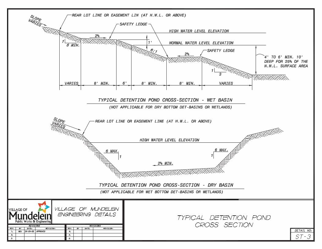
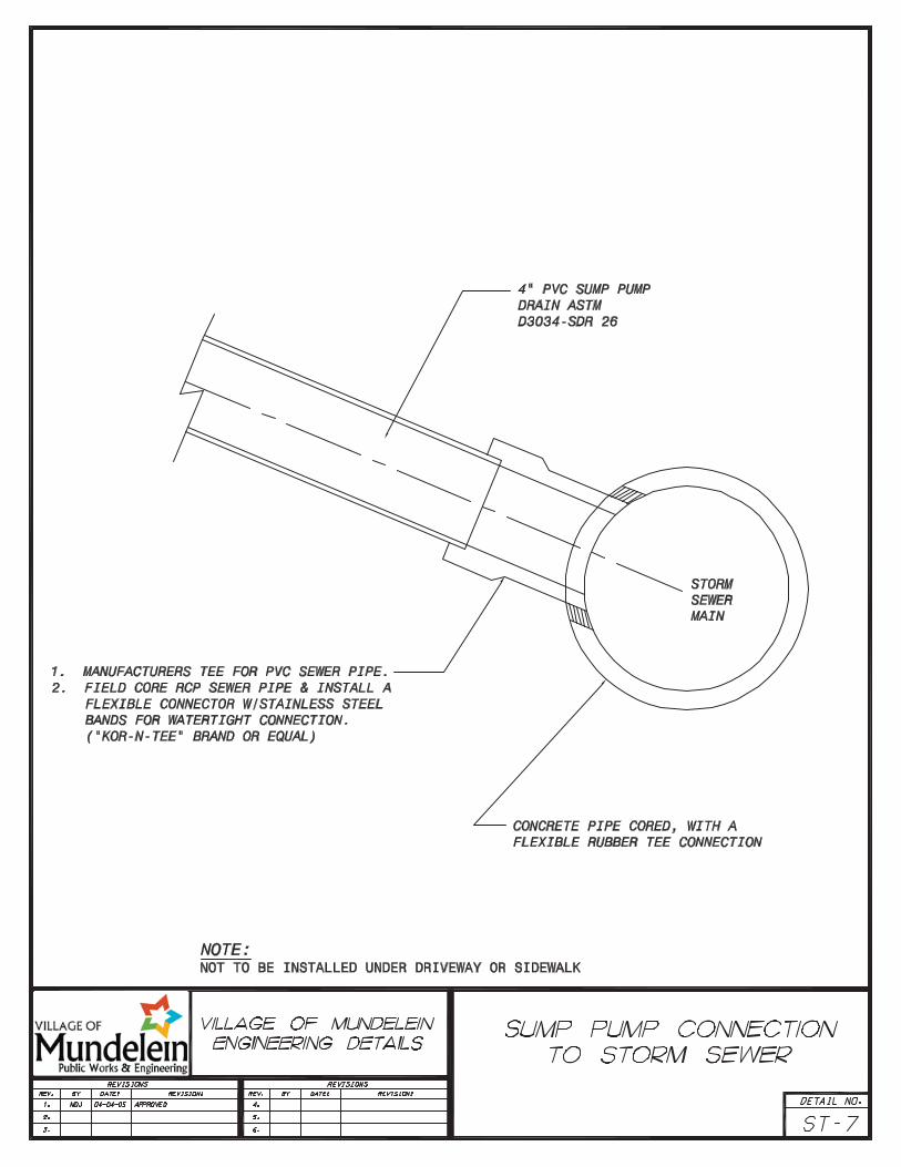
ST‐2 Detention Pond Outlet Structure ST‐3 Typical Detention Pond Cross‐SectionST‐4 Restrictor Structure ST‐5 Temporary Siltation Fabric Installation between Inlet Frame and GrateST‐6 Rear Yard Inlet Details ST‐7 Sump Pump Connection to Storm SewerST‐8 Typical Storm Sewer Trench Detail Water Main W‐0 Miscellaneous Water Main Notes W‐1 Fire Hydrant Detail W‐2 Valve Vault W‐3 Pressure Connection Tapping Valve VaultW‐4 Typical Water Main Trench Cross‐SectionW‐5 Water Service Connection W‐6 Steel Casing Pipe W‐7 Water Sampling Station W‐8 Tracer Wire Access Box W‐9 Water Main Testing Specifications Street Lighting L‐0 Street Lighting Notes and Special ProvisionsL‐1 Sternberg Pole LED Detail L‐2 Sternberg Mast Arm LED Detail L‐3 Street Light Cable Trench Detail L‐4 Street Light Cable Crossing Under DrivewaysL‐5 Light Pole Foundation Detail

Construction Standard Details and Notes R-O 2015 Update (1 of 1)
Miscellaneous Roadway Standards/Notes
1. All connecting roadway gradients with an algebraic difference of greater than 1.2 percent shall be connected with a vertical curve. All standards contained in AASHTO’s "A Policy on Geometric Design of Highways and Streets," latest edition, regarding vertical curves shall be followed. A design speed of 45 mph shall be used on collector commercial/industrial roads and a design speed of 35 mph shall be used on local streets.
2. Street jogs with centerline offsets of less than 150-feet are not allowed on local roads. Offsets on collector roads are not allowed, and spacing between two (2) cross streets on collector roads shall be no closer than 500-feet.
3. Gradients of all streets shall be at least 0.6 percent
a. Collector and industrial streets shall not exceed five (5) percent;
b. Local streets shall not exceed eight (8) percent.
4. Any pavement patches located within intersections will require the entire intersection, to radius returns on all the legs, to be milled and resurfaced with two (2)-inch bituminous concrete surface course.
5. Roadway cross-sections showing existing and proposed sections shall be provided at a scale of one (1)-inch = two (2)-feet V, one (1)-inch = ten (10)-feet H for any existing roadway reconstruction and at a scale of one (1)-inch = five (5)-feet V, one (1)-inch = ten (10)-feet H for new roadways.
6. One (1) copy of the Final Engineering Plans must be submitted to the Village in Adobe® format.
7. All Plats of Subdivision shall be submitted to the Village on a 24-inch x 36-inch Mylar for recording purposes. It shall also be submitted to the Village in Adobe® format on a CD. All coordinates shall be based upon State Plane Coordinates and shall tie to existing monuments as established by the Village of Mundelein. The following specific electronic layers are required: the boundary, roadway centerline, property lines, and roadway right-of-way must each be on a separate layer.
8. A minimum of two (2) permanent concrete bench mark monuments (see Standard Detail R-17) shall be established in all new residential, commercial, and industrial subdivisions. Number of monuments and monument placement shall be approved by the Village Engineer.
9. A qualified soils engineer must certify the acceptability of the subgrade of all subdivision streets prior to placing any base course material. This must be based upon the latest addition of the Village of Mundelein’s Specifications "Field Quality Control Procedures for Pavement Area Subgrade" (I-1.)

18" FLAREREQUIRED

18" FLARE REQUIRED

NOTES:

1.0' 1.0'
33'E-E
66'R.O.W.
9.0'5.0'5.0'
9.0'
30' RAD
SIDEWALK (TYP.)
30' RAD
70' R MIN.
55' E.P. MIN.
1.0'
5.0'
7.5'
B-6.12 CURB AND GUTTER
PROPERTY LINE
DEPRESSED CURB AT SIDEWALKS30' RAD
1.5'

3' MIN.
3% MAX.
NOTES:
1. RAMP TO BE MAINTAINED THROUGHOUT THE WINTER AND UNTIL FINAL SURFACE IS IN PLACE.
2. RAMP MATERIAL TO BE REMOVED BY MILLING OR OTHERWISE REMOVED BEFORE PLACEMENT OF FINAL SURFACE COURSE.
EXISTING BINDER COURSE(CLEANED AND DRY)
PRIME COAT(0.2 G/S.Y.MIN.)
BITUMINOUS SURFACE COURSE(HOT MIX TYP. AROUND MANHOLE)
BUTT JOINT1" MIN.
EXISTING MANHOLE FRAME

** BASE COURSE THICKNESSES SHALL BE IN ACCORDANCE WITH DETAIL R-9
ALL BEDDING AND TRENCHBACKFILL TO CONFORM TODETAIL SAN-8 AND/OR W-4
UNDISTRURBEDGROUND
EXISTINGBITUMINOUSCONCRETE
*OR AS DIRECTED BY VILLAGE ENGINEER
MILLAND
RESURFACE
WIDTH OFTRENCH ASREQUIRED
MILLAND
RESURFACE
FULL DEPTH SAWCUT(TYP.)
WIDTH OF TRENCH AS REQUIRED1'MIN.
2'MIN.
2'MIN.
1'MIN.
SAW CUT(TYP)
SURFACE COURSE
BASE COURSE **
SUB-BASE
50' MIN * 50' MIN *
OFCUT

1 1/2" BITUMINOUS CONCRETE SURFACE COURSE,SUPERPAVE, MIXTURE D, N50
BITUMINOUS MATERIAL PRIME COAT (IF TRAFFICIS ALLOWED ON BINDER COURSE).
1-1/2" BITUMINOUS CONCRETE BINDER COURSE,SUPERPAVE, IL 19, N50
BITUMINOUS MATERIAL PRIME COAT (MC-30)(0.35 gal/sy)
9" AGGREGATE BASE COURSE, TYPE B CA-6 (CRUSHED)

13" AGGREGATE BASE COURSE, TYPE B CA-6(CRUSHED)., [ 7" B.A.M. WITH 4" GRANULARMATERIAL SUBBASE MAY BE USED IN LIEU OF 13"OF AGGREGATE ]
BITUMINOUS MATERIAL PRIME COAT (MC-30)(0.35 gal/sy)
2" BITUMINOUS CONCRETE BINDER COURSESUPERPAVE, IL 19, N50
BITUMINOUS MATERIAL PRIME COAT (IF TRAFFICIS ALLOWED ON BINDER COURSE).
1-1/2" BITUMINOUS CONCRETE SURFACESUPERPAVE, MIXTURE D, N50
9 1/2" AGGREGATE BASE COURSE, TYPE B CA-6(CRUSHED)., [ 6" B.A.M. WITH 4" GRANULARMATERIAL SUBBASE MAY BE USED IN LIEU OF 9 1/2"OF AGGREGATE ]
BITUMINOUS MATERIAL PRIME COAT (MC-30)(0.35 gal/sy)
2" BITUMINOUS CONCRETE BINDER COURSE,SUPERPAVE, IL 19, N50
BITUMINOUS MATERIAL PRIME COAT (IF TRAFFICIS ALLOWED ON BINDER COURSE).
1 1/2" BITUMINOUS CONCRETE SURFACE COURSE,SUPERPAVE, MIXTURE D, N50
LOCAL STREETPAVEMENT SECTION
COLLECTOR / INDUSTRIALPAVEMENT SECTION


Construction Standard Details and Notes R-10 2015 Update (1 of 1)
Pavement & Right-of-Way Widths
Type of Street Pavement Width (Feet) Right-of-Way Width (Feet)
Local 33 66
Industrial 36 80
Collector 36 - 60 80 - 100
Minimum Horizontal Street Radius
Type of Street Minimum Centerline Radius (Feet)
Local 250
Industrial 400
Collector 350

Construction Standard Details and Notes R-12 Page 1 of 3
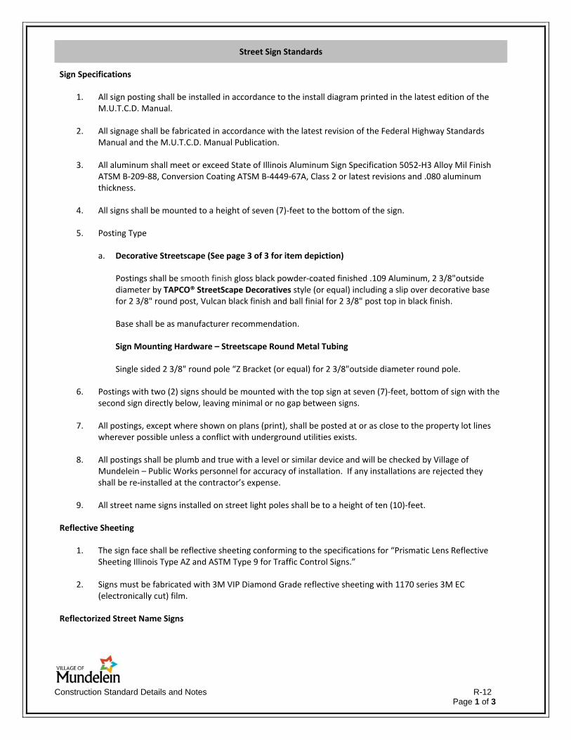
Street Sign Standards
Sign Specifications
1. All sign posting shall be installed in accordance to the install diagram printed in the latest edition of the M.U.T.C.D. Manual.
2. All signage shall be fabricated in accordance with the latest revision of the Federal Highway Standards Manual and the M.U.T.C.D. Manual Publication.
3. All aluminum shall meet or exceed State of Illinois Aluminum Sign Specification 5052‐H3 Alloy Mil Finish ATSM B‐209‐88, Conversion Coating ATSM B‐4449‐67A, Class 2 or latest revisions and .080 aluminum thickness.
4. All signs shall be mounted to a height of seven (7)‐feet to the bottom of the sign.
5. Posting Type
a. Decorative Streetscape (See page 3 of 3 for item depiction)
Postings shall be smooth finish gloss black powder‐coated finished .109 Aluminum, 2 3/8"outside diameter by TAPCO® StreetScape Decoratives style (or equal) including a slip over decorative base for 2 3/8" round post, Vulcan black finish and ball finial for 2 3/8" post top in black finish.
Base shall be as manufacturer recommendation.
Sign Mounting Hardware – Streetscape Round Metal Tubing
Single sided 2 3/8" round pole “Z Bracket (or equal) for 2 3/8"outside diameter round pole.
6. Postings with two (2) signs should be mounted with the top sign at seven (7)‐feet, bottom of sign with the second sign directly below, leaving minimal or no gap between signs.
7. All postings, except where shown on plans (print), shall be posted at or as close to the property lot lines wherever possible unless a conflict with underground utilities exists.
8. All postings shall be plumb and true with a level or similar device and will be checked by Village of Mundelein – Public Works personnel for accuracy of installation. If any installations are rejected they shall be re‐installed at the contractor’s expense.
9. All street name signs installed on street light poles shall be to a height of ten (10)‐feet.
Reflective Sheeting
1. The sign face shall be reflective sheeting conforming to the specifications for “Prismatic Lens Reflective Sheeting Illinois Type AZ and ASTM Type 9 for Traffic Control Signs.”
2. Signs must be fabricated with 3M VIP Diamond Grade reflective sheeting with 1170 series 3M EC (electronically cut) film.
Reflectorized Street Name Signs

Construction Standard Details and Notes R-12 Page 2 of 3
1. Mounted street name signs shall have a standard width of nine (9)‐inches. The overall length of the face and blade shall be determined by the number of letters in the street name, including the prefixes and suffixes. The name plate shall have a minimum length of 30‐inches or as requested. Where extra length is required, it shall be provided in six (6)‐inch increments.
2. Sign blanks are to be flat .080 aluminum.
3. All cut uppercase letters are to be six (6)‐inches in height, lowercase letters to be three (3)‐inches in height.
4. All compass prefix and suffix letters are to be three (3)‐inches in height.
5. Sign blanks are to be faced with 3M VIP Diamond Grade (White) sheeting.
6. White base material shall be covered with Green EC (electronically cut) film with ¾‐inch borders.
Traffic Control Signs
1. Stop signs shall be 30‐inches x 30‐inches with 3M VIP Diamond Grade reflective sheeting.
2. Yield signs shall be 30‐inches with 3M VIP Diamond Grade reflective sheeting.

Construction Standard Details and Notes R-12 Page 3 of 3
Decorative Streetscape Posting


RESIDENTIAL MAILBOX REQUIREMENTS
STRUCTURE:
NOTE: STRUCTURE ORNAMENTAL MONUMENT TYPE MAILBOXES, WHICH DO NOT MEET THE FOLLOWING REQUIREMENTS,ARE NOT PERMITTED.
THE MAILBOX IS TO BE OF LIGHT STEEL, ALUMINUM, PLASTIC, OR SIMILAR WEIGHT MATERIALS AND NOT EXCEED 11POUNDS. IT SHALL MEET U.S. POSTAL SERVICE REGULATIONS.
THE MAILBOX POST IS TO BE A SINGLE 4" BY 4" WOOD POST, A 4 1/2" DIAMETER WOOD POST, OR A METAL POSTWITH STRENGTH NO GREATER THAN A 2" IN DIAMETER STANDARD STEEL PIPE. A METAL POST SHALL NOT BE FITTEDWITH AN ANCHOR PLATE, BUT MAY HAVE AN ANTI-TWIST DEVISE THAT EXTENDS NO MORE THAN 10" BELOW THEGROUNDS SURFACE.
THE MAILBOX POST SHALL BE EMBEDDED INTO THE GROUND 24". POST NOT ALLOWED TO BE SET IN CONCRETE.
THE MAILBOX POST SHALL NOT BE EMBEDDED OVER 24" INTO THE GROUND TO ALLOW POST TO BREAK RATHER THAN BEA SAFETY HAZARD TO MOTORISTS.
THE POST-TO-BOX ATTACHMENT SHOULD BE OF SUFFICIENT STRENGTH TO PREVENT THE BOX FROM SEPARATING FROMTHE POST IF A CAR STRIKES THE INSTALLATION.
LOCATION:
MAILBOXES SHALL BE PLACED 12" FROM THE FACE OF THE CURB TO THE FACE OF THE MAILBOX. EXISTING PAVEDROADS WITHOUT CURBS SHALL REQUIRE THE FACE OF THE MAILBOX TO BE SETBACK THE WIDTH OF THE SHOULDER,PLUS 12".
THE MAILBOX SHALL BE MOUNTED NOT MORE THAN 52" FROM THE GROUND TO THE TOP OF THE BOX, AND NO LESSTHAN 42" FROM THE GROUND TO THE BOTTOM OF THE BOX.
FOR FURTHER REQUIREMENTS CONTACT THE MUNDELEIN POST OFFICE.

NOTES1. MONUMENT COORDINATES SHALL BE ESTABLISHED USING NAD83 (1986 OR 1997)2. MONUMENT ELEVATION SHALL BE ESTABLISHED USING NAVD88
5/8" REBAR 30"TO 36" LENGTH BERNSTEN CD2 OR EQUIVALENT
MINIMUM 2" DOMED CONCRETE MARKER(ALUMINUM) (BERNSTEN CD2 OREQUIVALENT) WITH ACTUAL CORNERPOSITION STAMPED ON MARKER.
2"
2"
3/4"
8" MIN.
2"

Construction Standard Details and Notes R-16 2015 update (1 of 1)
Field Quality Control Procedures For Pavement Area Subgrade
1. The work area will first be stripped of vegetation or, in cut areas, excavated to a Design Subgrade Elevation as shown on the plans.
a. The subgrade after cut will be proof rolled to verify a stable subgrade as directed by the soils engineer.
b. A series of test pits may be needed as directed by the soils engineer to verify additional undercut as predicted or estimated by Boring Logs and the Earthwork Undercut Plan.
c. Proof rolling procedures will be as follows:
1) Two (2) to four (4) passes with a 25 ton rubber tire roller or equivalent; and
2) Concentrate additional passes in areas that exhibit instability as directed by the soils engineer.
2. Unstable and unsuitable subgrade materials will be removed to the depth encountered as directed by the Soils Engineer.
a. Materials at undercut subgrade elevation should:
1) Have an unconfined compressive strength (Qu) of 2.0 tsf minimum, or cone index of 250 minimum;
2) Contain no foreign materials or have organic contents in excess of six (6) percent total organic matter as determined by the Wet Combustion Method (AASHTO T-194); or maximum dry densities less than 105 pcf as determined by AASHTO T-180 (ASTM D-1557); and
3) Be able to support necessary construction equipment without severe rutting or deflection.
3. At undercut subgrade elevation, the upper eight (8)-inches of soil shall be scarified or disked and re-compacted to 95 percent of the maximum dry density as defined by AASHTO T-180 (ASTMD-1557), prior to remedial work fill placement.
4. Proof rolling of the prepared undercut subgrade will be done if required by the soils engineer to further verify a stable subgrade prior to fill placement.
5. Roadway FILL shall be placed in successive horizontal lifts of not more than six (6)-inches in loose depth (cohesive material), or not more than nine (9)-inches in loose depth (porous granular material.)
6. The upper eight (8)-inches of subgrade in areas not undercut shall also be scarified and re-compacted to 95 percent of the maximum dry density as defined by AASHTO T-180 (ASTM D-1557), prior to placement of subsequent lift of FILL material.
7. Once the existing subgrade is stabilized, FILL can be placed and compacted in lifts to Design Subgrade Elevation. All roadway FILL materials shall be compacted to 95 percent of AASHTO T-180 (ASTM D-1557.)
8. When the work listed in the steps above has been completed, the subgrade will be checked by proof rolling and approved by the Village before construction of the subbase, base course, or pavement is started. The Village will make the determination as to whether areas failing this proof roll require additional drying and re-compaction or whether the soil conditions warrant more extensive treatment.
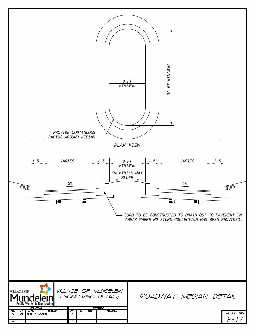
PLAN VIEW

Construction Standard Details and Notes SAN-O 2015 Update (2 of 2)
Miscellaneous Sanitary Standards/Notes
1. Sanitary sewers, main, and services and their fittings shall be constructed of one (1) or more of the following materials:
a. PVC pipe, ASTM D-3034, SDR 26, with elastomeric gasket joints conforming to ASTM D-3212.
b. Ductile iron pipe Class 52 with joints conforming to ANSI A21.11. Only when approved for structural purposes by the Village Engineer.
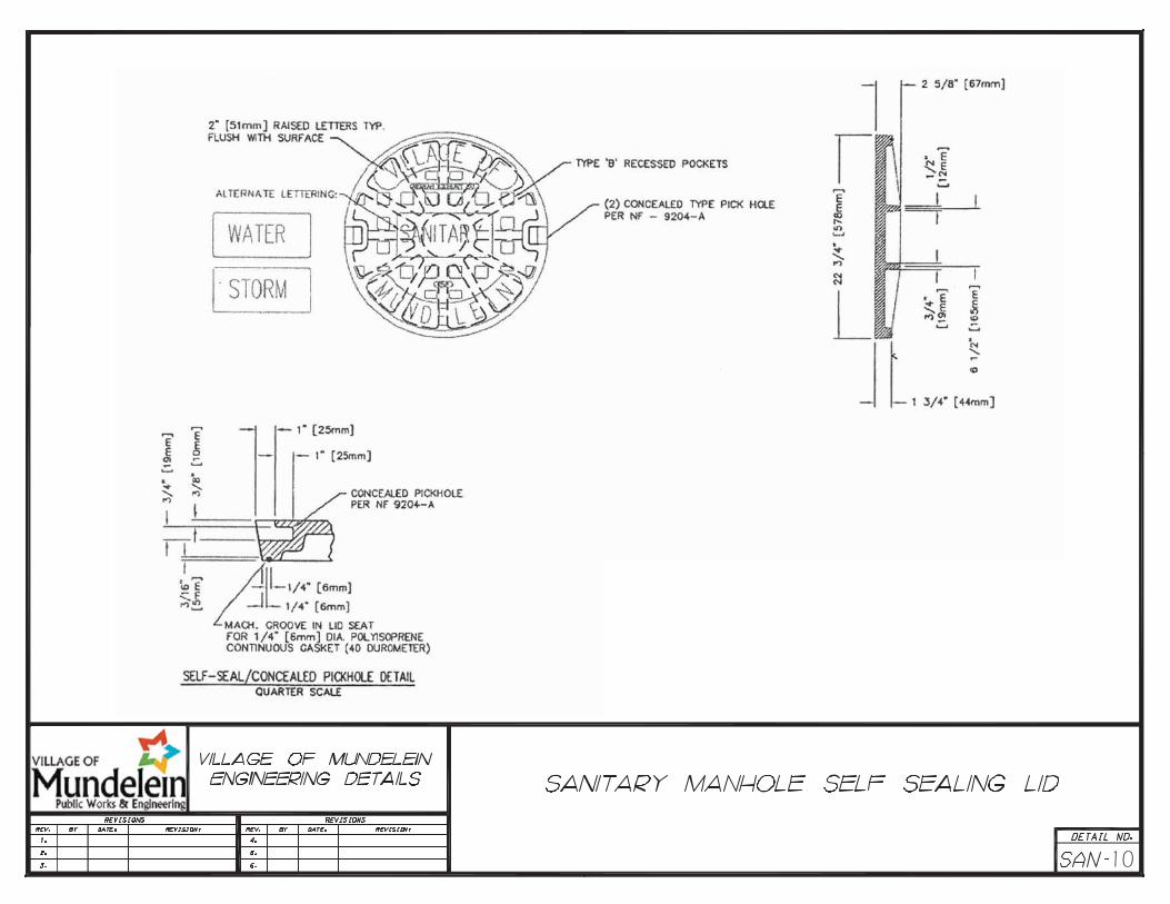
2. Sanitary sewer manholes shall be five (5)-feet zero (0)-inches diameter precast structures. Frames shall be Neenah R1712-C or EAST Jordan 1050 HD with self-sealing application lids with concealed pick holes. Lids shall be imprinted with the word “sanitary.”
3. Sanitary sewer manholes and inspection manholes shall have eccentric cones. All manhole sections and adjusting rings shall be securely sealed to each other using pre-formed bituminous mastic such as “RAM-NEK.” This mastic shall be applied in such a manner that ground water inflow cannot enter the manhole through gaps between barrel sections or cone sections and adjusting rings. Double “TAR STICK” may be required in areas with high water tables. Internal “CRETEX” brand chimney seals shall be installed in all manholes. “MAC RAP” is to be used at all manhole section joints.
4. Water stop gaskets shall be provided at all sanitary sewer manhole/pipe connections as approved by the Village Engineer.
5. Sanitary sewer service risers shall be used when sewer main exceeds 12-feet in depth. The bedding under the riser tee shall be thoroughly compacted. The engineer reserves the right to require concrete encasement of the riser or a concrete thrust block under the tee.
6. All sanitary sewers including service stubs shall be subject to an air test Section 31 of the Standard Specifications. Applicable portions of main line sewer including main with riser sections shall be subjected to a deflection test conducted by the contractor. All testing shall be observed by a Village of Mundelein Engineering Department Representative.
7. The main sanitary sewer shall be televised prior to acceptance. A videotape, CD, or DVD along with a paper report shall be submitted to the Village of Mundelein Engineering Department. The paper reports shall include the following: Date, time, street name, manhole numbers from and to, manhole depths, pipe size, pipe type, direction televised, surface conditions, clock position of services, final distances in feet, and observation details with footage. (Include still photos for each observation that is indicated.) The contractor, without delay, shall perform all necessary corrective work.
8. Control and sampling manholes must be installed in the ROW or as approved by the Village of Mundelein on a straight portion of the line without any bends inside the manhole or within five (5)-feet of the exterior of the manhole. In the event that a grease trap is needed, the grease trap shall precede the sample manhole. The grease waste service must connect to a main service before the sample manhole.
9. All sump pumps must discharge to the storm sewer system. All interior floor drains and waste ejector pits must connect to the sanitary sewer system.
10. All sanitary sewer stubs shall be marked with 4x4 post painted red.
11. Structures, manholes, inlets, catch basin sumps, and valve vaults shall be cleaned prior to any inspection at the end of the project and prior to Village acceptance. Sanitary and storm sewer main shall be jet
1

Construction Standard Details and Notes SAN-O 2015 Update (2 of 2)
cleaned if evidence of debris build-up is present at the time of Village acceptance.
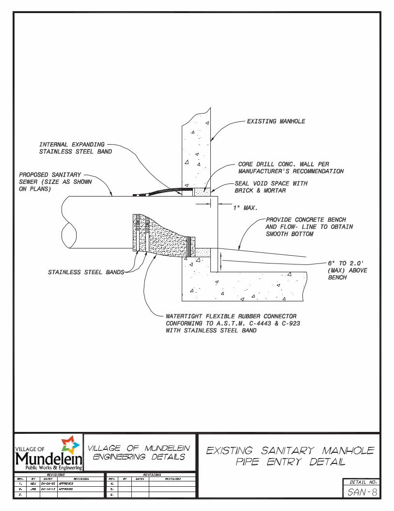
12. Connections to any existing manhole shall be done using a KOR-N-SEAL connection.
13. All external drains shall connect to the storm sewer system.
14. Vehicle and truck dock drains must meet the plumbing code requirements, including waste interceptors, and must be approved by the Village Plumbing Inspector.
15. When existing stubs are not available, all service connections to mainline sewers shall consist of the following:
a. If existing sewer is PVC or clay pipe, the mainline sewer shall be cut and a wye section with chamfer shall be installed with non-sheer mission coupling placed over connection points; for clay, a minimum of two (2)-feet of PVC is required on each side of wye;
b. Existing stubs or services planned for use must be televised and verified by the Village of Mundelein to be in acceptable condition prior to use or reuse; and
c. Break in connections are not permitted.


NOTES:1. DEPTHS , 10' SDR 26 PVC SEWER PIPE PER ASTM D-3034 CELL CLASS 12454B2. NEW SERVICES TO BE PVC OR CAST IRON ONLY CLAY NO PERMITTED 4. SEE SAN-8 FOR BEDDING AND BACKFILL3. SEE SAN-08 FOR BEDDING AND BACKFINLL.
WELL COMPACTED CA-6 ORAPPROVED FLOWABLE FILL
WYE BRANCH
18"+ PIPE O.D.+ 18"TRENCH DEPTH 5' AND GREATER
SUPPORT RISER AGAINSTSIDE OF TRENCH
CONNECT TO EXISTINGSERVICE WITH NON-SHEARMISSION COUPLING(A.S.T.M. C-594)
BUILDING SERVICE DETAIL UNDER 5 FEET
9"+ PIPE O.D.+ 9"TRENCH DEPTH LESS THAN 5'
1% MINIMUM SLOPE
1% MINIMUM SLOPE
SEE BELOW
WYE BRANCH
45° BEND
CONNECT TO EXISTING SERVICEWITH NON-SHEAR MISSION COUPLING(A.S.T.M. C-594)
O.D.
PIPE
12" MIN.
6"
22.5°BEND
45° BEND
45°
45° 22.5°BEND
6" PIPE
6" PIPE

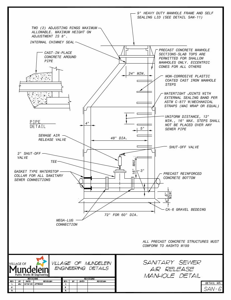
ECCENTRIC CONE SECTION ONLY

ALL PRECAST CONCRETE STRUCTURESMUST CONFORM TO AASMTO M199
USE DROP CONNECTIONS FOR ANYSANITARY SEWER PIPE ENTERING TWO(2) FEET OR MORE ABOVE THE LOWESTPIPE INVERT.
CA-6 GRAVEL BEDDING
6"
MIN.
6"
PRECAST REINFORCEDCONCRETE BOTTOM
CLASS SI CONCRETE FILLET
GASKET TYPE WATER STOPCOLLAR REQUIRED FOR ALLSANITARY SEWER CONNECTIONS
UNIFORM DISTANCE, 12" MIN.,16" MAX. STEPS SHALL NOTBE PLACED OVER ANY SEWERPIPE
WATERTIGHT JOINTS WITHEXTERNAL SEALING BAND PERASTM C-877 W/MECHANICALSTRAPS (MAC WRAP OR EQUAL)
NON-CORROSIVE PLASTICCOATED CAST IRON MANHOLESTEPS
PRECAST CONCRETE MANHOLESECTIONS-SLAB TOPS AREPERMITTED FOR SHALLOWMANHOLES ONLY. ECCENTRICCONES FOR ALL OTHERS
9" HEAVY DUTY FRAME NEENAH FOUNDRY CO.R1713 W/SELF SEALING LID IMPRINTED W/"SANITARY" (OR EQUIVALENT EJIW PRODUCT)
TWO (2) ADJUSTING RINGSMAXIMUM ALLOWABLE. MAXIMUMHEIGHT ON ADJUSTMENT IS 8".
INTERNALCHIMNEY SEAL
CORE MANHOLE WITH ACIRCULAR HOLE CUTTING TOOL
MIN. 6"PVC SDR 26
60" DIA.
CONCRETEENCASEMENT
2"/FT.
D/2
3"
6"
5"
72"

MANHOLE FRAME AND COVER
STAINLESS STEELEXPANSION BAND
3" MIN.
CHIMNEYHEIGHT
RUBBER SLEEVE
RUBBER EXTENSION
STAINLESS STEELEXPANSION BAND
PRECAST BLOCK OR BRICKMANHOLE CONE / CORBEL
TAPEREDFRAME
STRAIGHTFRAME
REQUIRED ON ALL SANITARYMANHOLES EXCEPT FOR CONTROLAND SAMPLING INSPECTIONMANHOLES
"CRE-TEX" INTERNAL SEALSARE REQUIRED

7
8

Wye
Tee
9
10

11

Construction Standard Details and Notes SAN-12 2015 Update (1 of 2)
Sanitary Sewer Testing Specifications
1. Testing and Inspection for Acceptance of Sanitary Sewers
a. Exfiltration of air under pressure.
b. Deflection of flexible Thermoplastic Pipe.
c. Televising.
2. Testing Technique
All Testing Methods: All wyes, tees, and stubs shall be plugged with flexible jointed caps, or acceptable alternate, securely fastened to withstand the internal test pressure. Such plugs or caps shall be readily removable.
a. Air Testing Method Procedures: The section of sewer to be tested shall have been trench backfilled and cleared. Pneumatic plugs (having a sealing length equal to or greater than the diameter of the pipe to be tested) placed in both ends of the pipe to be tested shall be inflated to 25 psig. The sealed sewer pipe shall then be pressurized to four (4) psig above the average back pressure of groundwater over the sewer pipe and the air pressure allowed to stabilize for at least two (2) minutes.
After the stabilization period the line shall be pressurized to three and a half (3.5) psig and the time in minutes measured for pressure to drop to two and a half (2.5) psig. If groundwater is present, the air pressure within shall be increased to three and a half (3.5) psig above the level of the groundwater and the drop of one (1) pound of air pressure measured in minutes.
Air testing techniques shall be in accordance with the latest ASTM Standard Practice for testing sewer lines by low-pressure air test method for the appropriate pipe material, except that the time shall not be less than that shown in the Air Test Table contained in Section 31-1.11 C of the Standard Specifications for Water and Sewer Main Construction.
3. Deflection Testing for Flexible Thermoplastic Pipe:
a. The pipeline shall be tested for excess deflection by pulling a “go/no go” mandrel through the pipe from manhole to manhole. The mandrel shall be sized in accordance with Section 31-1.11 C (4) and as specified in the Special Provisions. A “deflectometer” may also be used to check and record deflection.
b. Wherever possible and practical, the testing shall initiate at the downstream lines and proceed towards the upstream lines.
c. Where deflection is found to be in excess of allowable testing limits, the Contractor shall excavate to the point of excess deflection and carefully compact around the point where excess deflection was found. The line shall then be retested for deflection. However, should after the initial testing the deflected pipe fail to return to the original size (inside diameter), the line shall be replaced.
4. Televising Standards
a. The main sanitary sewer shall be televised prior to acceptance. A videotape, CD, or DVD (along with a paper report) shall be submitted to the Village of Mundelein Engineering Department. The paper reports shall include the following: Date, time, street name, manhole numbers from

Construction Standard Details and Notes SAN-12 2015 Update (1 of 2)
and to, manhole depths, pipe size, pipe type, direction televised, surface conditions, clock position of services, final distances in feet, and observation details with footage. (Include still photos for each observation that is indicated.) The contractor without delay shall perform all necessary corrective work
AIR TEST TABLE
TIME (MIN:SEC) REQUIRED FOR PRESSURE DROP FROM 30 TO 20 PSIG WHEN TESTING ONE PIPE DIAMETER ONLY Pipe Length PIPE DIAMETER, Inches
(feet) 4 6 8 10 12 15 18 21 24 2 0:04 0:10 0:18 0:28 0:40 1:02 1:29 2:01 2:38 4 0:09 0:20 0:35 0:55 1:19 2:04 2:58 4:03 5:17 6 0:13 0:30 0:53 1:23 1:59 3:06 4:27 6:04 7:55 8 0:18 0:40 1:10 1:50 2:38 4:08 5:56 8:05 10:34
10 0:22 0:50 1:28 2:18 3:18 5:09 7:26 9:55 11:20 12 0:26 0:59 1:46 2:45 3:58 6:11 8:30 14 0:31 1:09 2:03 3:13 4:37 7:05 16 0:35 1:19 2:21 3:40 5:17 12:06 18 0:40 1:29 2:38 4:08 5:40 10:25 13:36 20 0:44 1:39 2:56 4:35 8:31 11:35 15:07 22 0:48 1:49 3:14 4:43 9:21 12:44 16:38 24 0:53 1:59 3:31 10:12 13:53 18:09 30 1:02 2:19 3:47 8:16 11:54 16:12 21:10 32 1:10 2:38 6:30 9:27 13:36 18:31 24:12 38 1:19 2:50 6:48 10:38 15:19 20:50 27:13 40 1:28 5:14 7:34 11:49 17:01 23:09 30:14
2
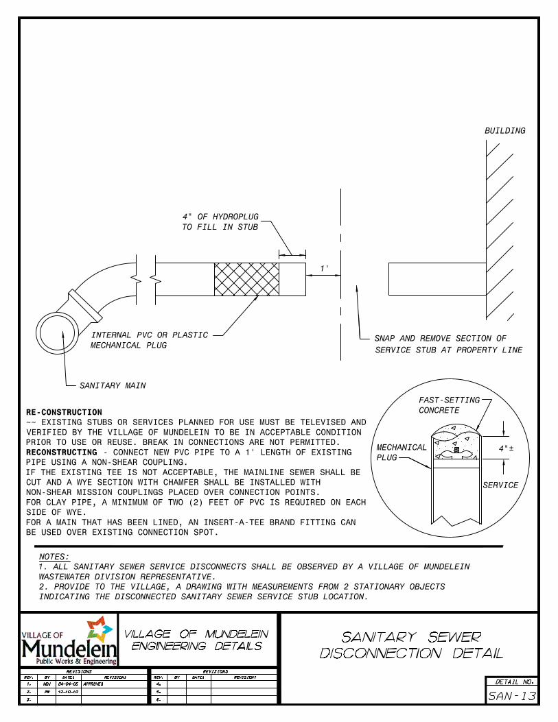
MECHANICALPLUG
FAST-SETTINGCONCRETE
4"±
SERVICE
BUILDING
SNAP AND REMOVE SECTION OFSERVICE STUB AT PROPERTY LINE
4" OF HYDROPLUGTO FILL IN STUB
1'
INTERNAL PVC OR PLASTICMECHANICAL PLUG
SANITARY MAIN
RE-CONSTRUCTION~~ EXISTING STUBS OR SERVICES PLANNED FOR USE MUST BE TELEVISED ANDVERIFIED BY THE VILLAGE OF MUNDELEIN TO BE IN ACCEPTABLE CONDITIONPRIOR TO USE OR REUSE. BREAK IN CONNECTIONS ARE NOT PERMITTED.RECONSTRUCTING - CONNECT NEW PVC PIPE TO A 1' LENGTH OF EXISTINGPIPE USING A NON-SHEAR COUPLING.IF THE EXISTING TEE IS NOT ACCEPTABLE, THE MAINLINE SEWER SHALL BECUT AND A WYE SECTION WITH CHAMFER SHALL BE INSTALLED WITHNON-SHEAR MISSION COUPLINGS PLACED OVER CONNECTION POINTS.FOR CLAY PIPE, A MINIMUM OF TWO (2) FEET OF PVC IS REQUIRED ON EACHSIDE OF WYE.FOR A MAIN THAT HAS BEEN LINED, AN INSERT-A-TEE BRAND FITTING CANBE USED OVER EXISTING CONNECTION SPOT.
NOTES:1. ALL SANITARY SEWER SERVICE DISCONNECTS SHALL BE OBSERVED BY A VILLAGE OF MUNDELEINWASTEWATER DIVISION REPRESENTATIVE.2. PROVIDE TO THE VILLAGE, A DRAWING WITH MEASUREMENTS FROM 2 STATIONARY OBJECTSINDICATING THE DISCONNECTED SANITARY SEWER SERVICE STUB LOCATION.

24"
MIN.
4"
6"
MIN


12" MIN.
96"
12" 12"
8"
2'
UNDISTURBED EARTH
3" COMPACTEDCA-6
SUMP18" MIN.
2 YR EVENTINV ELE.=______DIAMETER _____
#5 EPOXY COATED BARS @ 8"O.C. VERT & HORIZONTAL
STEPS @ 16" O.C.BOTH SIDES
96" MIN. PRECASTCONCRETE CATCH BASINWITH 8" REINFORCEDCONCRETE BAFFLE WALL
RIM ELE.=______
#5 EPOXY COATED DOWELSDRILL & GROUT @ 16" O.C.
TWIN NEENAH R-1700-AFRAMES & LIDSIMPRINTED "STORM"
INTERNAL SPILLWAY@ 100 YR H.W.L.ELEV.=______
100 YR EVENTINV ELE.=______DIAMETER _____
INLET OUTLET

GEOTEXTILE FILTER BAGWITH REINFORCEDPOLYESTER OUTER MESH
STAINLESS STEEL LOCKING BANDOVERFLOW FEATURE
LIFT HANDLESGALVANIZED STEEL FRAME
MANHOLEADJUSTINGRINGS
SECTION THROUGH MANHOLE
FILTER INSERT


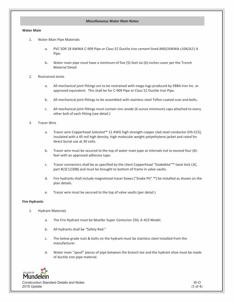
Construction Standard Details and Notes W-O 2015 Update (4 of 4)
Miscellaneous Water Main Notes
Water Main
1. Water Main Pipe Materials
a. PVC SDR 18 AWWA C-909 Pipe or Class 52 Ductile Iron cement lined ANSI/AWWA c104/A21.4 Pipe.
b. Water main pipe must have a minimum of five (5)-feet six (6)-inches cover per the Trench Material Detail.
2. Restrained Joints
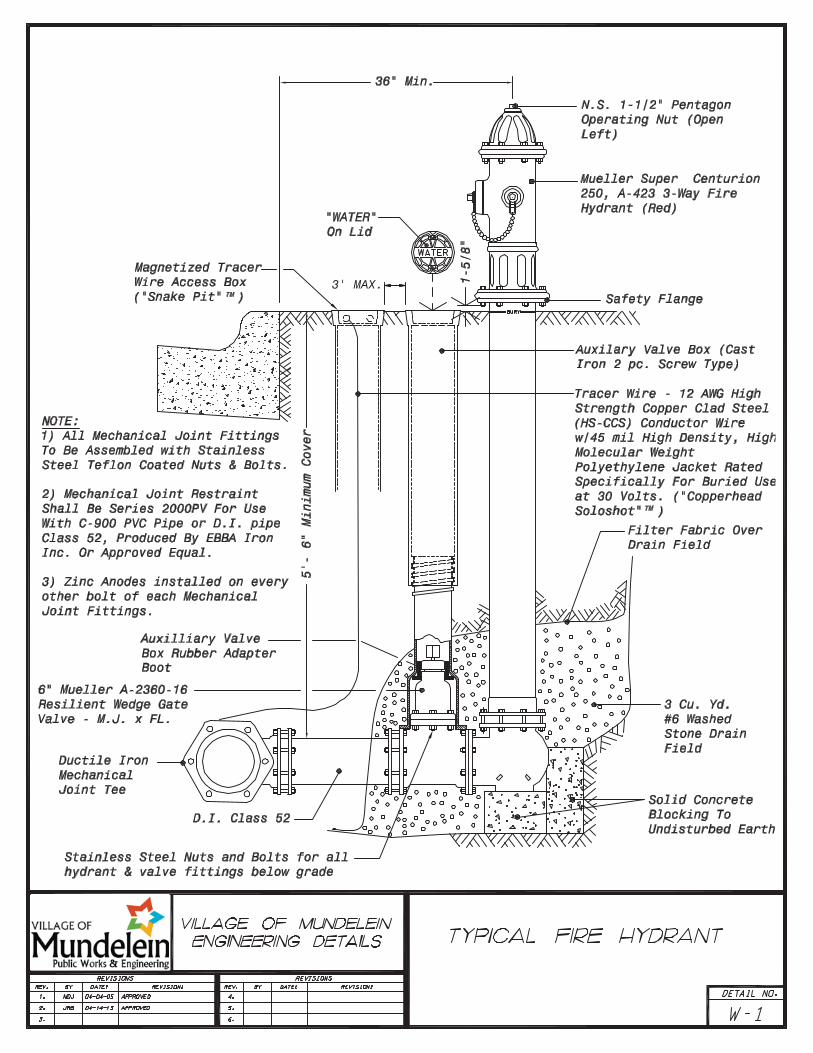
a. All mechanical joint fittings are to be restrained with mega-lugs produced by EBBA Iron Inc. or approved equivalent. This shall be for C-909 Pipe or Class 52 Ductile Iron Pipe.
b. All mechanical joint fittings to be assembled with stainless steel Teflon coated nuts and bolts.
c. All mechanical joint fittings must contain zinc anode (6 ounce minimum) caps attached to every other bolt of each fitting (see detail.)
3. Tracer Wire
a. Tracer wire Copperhead Soloshot™ 12 AWG high strength copper clad steel conductor (HS-CCS), insulated with a 45-mil high density, high molecular weight polyethylene jacket and rated for direct burial use at 30 volts.
b. Tracer wire must be secured to the top of water main pipe at intervals not to exceed four (4)-feet with an approved adhesive tape.
c. Tracer connectors shall be as specified by the client Copperhead “Snakebite”™ twist lock LSC, part #LSC1230B) and must be brought to bottom of frame in valve vaults.
d. Fire hydrants shall include magnetized tracer boxes (“Snake Pit” ™) be installed as shown on the plan details.
e. Tracer wire must be secured to the top of valve vaults (per detail.)
Fire Hydrants
1. Hydrant Materials
a. The Fire Hydrant must be Mueller Super Centurion 250, A-423 Model.
b. All hydrants shall be “Safety Red.”
c. The below grade nuts & bolts on the hydrant must be stainless steel installed from the manufacturer.
d. Water main “spool” pieces of pipe between the branch tee and the hydrant shoe must be made of ductile iron pipe material.
1

Construction Standard Details and Notes W-O 2015 Update (4 of 4)
e. Fire hydrant tees must be installed in a horizontal position to the water main. Hydrant auxiliary value boxes of excessive depth must have an extension on the value operative nut to permit clear operation above the hydrant.
f. Bury depth of hydrant must be parallel to profile grade line. Grade line on hydrant must meet final ground elevation. Field adjustments must include hydrant bury depth.
2. Hydrant Spacing and Locations
a. Fire hydrants shall be installed along all water mains constructed in public right-of-way, at a maximum spacing of 350-feet. However, fire hydrants must be installed on lot lines in single-family residential installations.
b. Fire hydrants must be at least 20-feet from any intersection.
c. Hydrants shall be installed no closer than three (3)-feet to the back of curb from the steamer port (pumper nozzle), nor further than eight (8)-feet from the back curb unless otherwise approved by the Water Superintendent. No hydrant shall be installed within 48-inches of any obstruction, nor shall any obstruction be placed within 48-inches of an existing hydrant. A minimum five (5)-foot distance from any driveway entrance must be maintained.
d. Fire Department review required for distance from building.
Valves
1. Materials
a. All water valves must be Mueller Brand (per detail.)
2. Spacing and Location
a. Water main valves shall be spaced at a minimum of 400-feet, or at a distance such that in the event of a required shut down of the public main, no more than 24 single family residential units shall be out of water service, whichever results in the shortest valve spacing or as approved by the Public Works Department. Valve vaults shall not be allowed within driveways or sidewalks.
Connection to Existing Mains
1. All connections to the Village water distribution system shall be made under full water service pressure in accordance with Village Engineering Design Details or as required.
2. Materials
a. When connection is size on size piping, a two (2) piece Ductile Iron Sleeve is required.
b. When branch size is smaller than existing pipe, a stainless steel tapping sleeve will be used.
c. All tapping sleeves must be air tested prior to tapping water main.
Water Service Lines (Two (2)-Inches and Smaller)
1. Materials
2

Construction Standard Details and Notes W-O 2015 Update (4 of 4)
a. A water service line is designed to deliver water from a public water distribution main from the main to a single building, and includes corporation stop, curb stop, and service box. Service lines shall be Type K copper and installed approximately at a right angle to the centerline of the right-of-way. Service lines shall be continuous with no splices between either the corporation and the curb stop or the curb stop and the water meter.
b. The water service tap will include a full circle stainless steel tapping sleeve.
c. All fittings will consist of a flare by flare connection or a compression by compression connection.
d. Contractor/developer must complete all work related to the service line.
2. Spacing and Locations
a. Service connections must maintain a three (3)-foot separation from any other service connection, pipe bell or fitting, valve vault, and/or fire hydrant.
3. Inspections Required
a. The Village of Mundelein Water Superintendent or his designate must witness the tap/connection to water main. For taps on PVC water main, a coupon from the tap must be provided to the inspector. 24 hour advance notice is required.
b. The Village of Mundelein Plumbing Inspector or his designate must inspect the service line from the corporation stop to the curb stop. 24 hour advance notice is required.
c. The Village of Mundelein Plumbing Inspector or his designee must inspect the service line from the curb stop to the water meter. 24 hour advance notice is required.
4. Special Notes
a. The water service line inside of building must have a minimum of 12 inches of Type K copper prior to the first fitting. The water meter must be set within 18-inches after entering the building.
b. The water service must enter the front side of a single family residential building upon which it services.
Water Service/Fire Lines (Larger Than Two (2)-Inches)
1. Water services that are larger than two (2)-inch Type K copper services shall be a minimum size of four (4)-inch water main pipe. (Three (3)-inch piping is not permitted.) These water services can be a combination system for both domestic use and fire protection.
2. Materials
a. Water service lines larger than two (2)-inches must follow all the materials, procedures, policies, and details for water main installations.
3. Fire Protection
a. Any water service line designated for fire protection must be sized appropriately in order to
3

Construction Standard Details and Notes W-O 2015 Update (4 of 4)
sufficiently supply water for fire protection based on the fire flow requirement of the building. Documentation must be submitted and approved by the Village of Mundelein Fire Department.
4. Combination Fire/Domestic Usage
a. Any water service line designated for both fire and domestic usage must meet the following requirements.
b. Water service line must be sized to meet the fire protection requirements and domestic usage of the building.
c. Water service line must enter the building in a designated Meter/Fire Sprinkler Room. Meter/Fire Sprinkler Room must meet Village of Mundelein Code 16.08.260(f) meter rooms.
d. Upon entering Meter/Fire Sprinkler Room, the domestic service will branch off from the fire service with valves installed on the fire line and domestic service prior to pressure testing.
5. Inspections and Testing
a. The inspections and testing of the water service for fire/domestic usage shall follow the guidelines and methods for water main inspections and testing procedures.
3' MAX.


Construction Standard Details and Notes W-9 2015 Update (7 of 7)
Water Main Testing Specifications
Pressure and Leakage Test
1. Testing Procedures
a. All pressure leakage testing shall be tested against installed pipe, fittings, valves, joints, and fire hydrants up to nozzles.
2. Valve Operations
a. Village of Mundelein Water Division personnel are the only individuals authorized to operate any water valves.
3. Taps for Testing
a. Contractor/developer is required to provide one (1)-inch service taps in manholes for test gauges, flushing needs, and for disinfection at each end of the pipe test section.
b. Service tap shall include a full circle stainless steel tapping sleeve.
c. Contractor shall make the tap connection using an approved tapping tool on PVC C-900 piping, contractor shall provide removed coupon to Village of Mundelein Water Division Inspector.
d. Contractor shall schedule an appointment with the Village of Mundelein Water Division for the witnessing/inspection of all taps. 24-hour notice prior to appointment must be provided to the Village of Mundelein Water Division.
e. Contractor shall remove copper tube with goose neck assembly from manholes upon completion of testing and chlorination procedures.
4. Air Removal
a. Before applying the specified test pressure, air shall be expelled completely from the section of piping under test. Air removal will be done in conjunction with the flushing procedures of the water main (see Flushing Requirements.)
5. Allowable Leakage
a. No pipe installations will be accepted if the leakage is greater than that determined by the following formula:
Inch-pound units, L = SD√P 133,200
L=allowable leakage, in gallons per hour S=length of pipe tested, in feet D=nominal diameter of the pipe, in inches P=average test pressure during the leakage test, in pounds per square inch (gauge)
In metric units Lm = SD√P 715,317
LM=allowable leakage, in liters per hour S=length of pipe tested, in meters D=nominal diameter of the pipe, in millimeters P=average test pressure during the leakage test, in kPa
1

Construction Standard Details and Notes W-9 2015 Update (7 of 7)
These formulas are based on an allowable leakage of 11.85 gpd/mi/in. of nominal diameter at a pressure of 150 psi.
When testing against closed metal-seated valves, an additional leakage per closed valve of 0.0078 gal/b/in. of nominal valve size shall be allowed. When hydrants are in the test section, the test shall be made against the main valve in the hydrant.
6. Acceptance of Installation
a. Acceptance shall be determined as the basis of allowable leakage or the procedures established by the Village of Mundelein Engineering Department. If any test of laid pipe discloses leakage greater than that specified, repairs or replacements shall be accomplished in accordance with the Specifications.
b. All visible leaks are to be repaired regardless of the amount of leakage.
c. Dye or any other form of colorizing the water will not be introduced into the water main for the purpose of locating leaks.
Disinfection of Water Mains
1. Flushing Water Main
a. Sections of pipe to be disinfected shall first be flushed to remove any solids or contaminated material that may have become lodged in the pipe. Fire hydrants in these sections will be flushed using either the two and a half (2 ½)-inches nozzle or the pumper nozzle to develop a velocity of at least two and five-tenths (2 5/10)-feet per second in the main.
b. All fire hydrants will be flushed and operated in the section of water main to be tested and disinfected.
c. Village of Mundelein Water Division personnel are the only individuals authorized to operate any water valves.
d. All valves that are closed will have a tap with copper tube and goose neck assembly installed in the vault for the purpose of flushing, and disinfecting the water main to the furthest end point of each section being tested.
2. Requirement of Chlorine
Before being placed into service, all new mains and repaired portion of, or extensions to existing mains shall be chlorinated so that the initial chlorine residual is not less than 50 mg/l and that a chlorine residual of not less than 25 mg/l remains in the water after standing 24 hours in the pipe.
a. Liquid Chlorine
A chlorine gas-water mixture shall be applied by means of a solution-feed chlorinating device, or the dry gas may be fed directly through proper devices for regulating the rate of low and providing effective diffusion of the gas into the water within the pipe being treated. Chlorinating devices for feeding solutions of the chlorine gas, or the gas itself, must provide means for preventing the backflow of water into the chlorine.
b. Chlorine- Bearing Compounds in Water
2

Construction Standard Details and Notes W-9 2015 Update (7 of 7)
This method must have prior approval from the Village of Mundelein Water Superintendent before introduction. A mixture of water and high-test calcium hypo chlorite (65-70% Chlorine) may be substituted for the chlorine gas water mixture. The dry powder shall first be mixed as a paste and then thinned to a one (1) percent chlorine solution by adding water to give a total quantity of seven and five-tenths (7 5/10) gallons of water per pound of dry powder. This solution shall be injected in one (1) end of the section of main to be disinfected while filling the main with water in the amounts as shown in the table which follows:
Chlorine Requirements to Produce to mg/1 Concentration in 100-feet of Pipe – By Diameter Pipe Size In Inches 100 % Chlorine, Lb. 1 % Chlorine Solution, Gals. 4 0.027 0.33 6 0.061 0.73 8 0.108 1.30 10 0.170 2.04 12 0.240 2.88
c. Tablet Disinfection
This method must have prior approval from Village of Mundelein Water Superintendent before introduction. Since preliminary flushing must be eliminated in using this method, it should be utilized only when scrupulous cleanliness has been used in construction. It shall not be used if trench water or foreign material has entered the main or if the water is below 41° F, or if the piping length exceeds 50 linear feet.
Tablets should be placed in each section of pipe, hydrants, hydrant branches, and other appurtenances. Tablets must be at the top of the main and shall be attached by an adhesive approved by the Village Water Superintendent. Tablets in joints between pipe sections, hydrants, hydrant branches, or appurtenances are to be crushed and placed inside the annular space, rubbed like chalk in butt ends of sections to coat them if the type of assembly does not permit crushing.
In filling a section of piping with water when using the tablet method water velocity shall be less than one (1)-foot per second.
No. of 5-Grain Hypochlorite Tablets per Dosage of 50 MG/L per Length of Pipe Section Pipe Size Length of Pipe Section (Feet) (Inches) Up to 13 18 20 30 40 2 1 1 1 1 1 4 1 1 2 2 2 6 2 2 3 3 4 10 3 5 7 7 9 12 5 6 10 10 14
3. Point of Application
The preferred point of application of the chlorinating agent is at the beginning of the pipeline extension or any valved section of it, and through a corporation stop inserted in the pipe.
a. The contractor will install corporation cocks with a copper tube gooseneck assembly for the purpose of disinfecting and as sample collection point at each branch, dead end, or a location which has a closed valve. Fire hydrants will be disinfected as part of this procedure.
b. At a point not to exceed five (5)-feet downstream from the beginning of the new main the water entering the new main will receive a dose of chlorine fed at a constant rate such that the
3

Construction Standard Details and Notes W-9 2015 Update (7 of 7)
water will have not less than 25 mg/1 free chlorine.
c. Water from the existing distribution system shall be made to flow at a constant rate into the new main.
d. The Village of Mundelein Water Division personnel must witness the disinfection process. An appointment with 24-hour prior notice must be scheduled with Village of Mundelein Water Division.
e. In the process of chlorinating newly laid pipe, all valves, fire hydrants, or other appurtenances shall be operated while the pipe line is filled with the chlorinating agent and under normal operating pressures.
Disinfection of Water Services (Larger Than Two (2)-Inches)
For the purpose of clarifying this section, water service in this section refers to one (1) or more of the following installations that terminate inside of a building under construction.
� The service line being installed is for the purpose of a combination domestic and fire protection use.
� The service line being installed is for the purpose of branching into multiple domestic services inside of a meter room.
� The service line is the section of main being tested from the Village of Mundelein right-of-way valve to a location inside of the building.
� There are no fire hydrants installed on the service line.
1. Meter Rooms/Building Installations
a. The service line will be disinfected to the inside valve of the meter room prior to any branch service being connected.
b. The meter room will have a permanent heating system installed and in working condition prior to the disinfection.
c. One (1) sample point will be provided at the source and one (1) sample point will be provided at the inside valve provided the length of pipe does not exceed 1,000-feet.
d. The contractor will supply a copper tube gooseneck assembly at each of the sample points.
e. The Village of Mundelein in Water Division personnel must witness the disinfection process. An appointment with 24 hours prior notice must be scheduled with Village of Mundelein Water Division.
2. Domestic/Fire Service Mains/Meter Room
a. The service line will be disinfected up to the inside valve on both the fire branch and the domestic branch.
b. The Fire Service Main Branch will have a valve of equal size to the riser section installed prior to chlorination.
4

Construction Standard Details and Notes W-9 2015 Update (7 of 7)
c. The building, meter room, or location of the incoming service line will have a permanent heating system installed and in working condition prior to the disinfection.
d. One (1) sample point will be provided at the source and one (1) sample point will be provided at the inside valve provided the length of pipe does not exceed 1,000-feet.
e. The contractor will supply a copper tube goose neck assembly at each of the sample points.
f. The Village of Mundelein Water Division personnel must witness the disinfection process. An appointment with 24 hours prior notice must be scheduled with Village of Mundelein Water Division.
De-chlorination Requirements
Following chlorination, all treated water shall be thoroughly flushed from the newly laid pipe using the fire hydrant(s) and/or all the copper gooseneck assemblies. The flushing shall replace the highly chlorinated water with water that has a chlorine residual of less than 1mg/1 or equal to the residual from the supply service.
� The discharging of chlorinated water must be expelled to the surrounding ground surface.
� The contractor/developer must comply with all of the I.E.P.A. Rules, Regulations, and Standards for de-chlorinating water as part of the discharging.
� The contractor/developer is responsible for the equipment and materials to de-chlorinate the water at each point it is discharging.
� The Village of Mundelein Water Division personnel are the only individuals authorized to operate the valves.
� The Village of Mundelein Water Division personnel must witness the de-chlorination procedures when flushing the water mains. An appointment with 24-hour prior notice must be scheduled with Village of Mundelein Water Division.
Sampling and Testing
Sample collection for bacterial testing will start immediately after flushing the highly chlorinated water from the system and prior to any portion of the water main being placed into service. Samples will be collected at all sample points designated by the Village of Mundelein Water Superintendent. Sampling procedures must follow the I.E.P.A. Standards for construction of new water mains.
1. Locations and Spacing
a. Samples will be collected from each dead end, branch lateral, or section of pipe that has a closed valve. Samples will be collected from the copper tube with gooseneck assembly at these points.
b. Samples will be collected from fire hydrants at points not to exceed 1,000-feet of linear water main.
c. A sample will be collected from the copper goose-neck assembly point that is located no further than five (5)-feet downstream from the beginning of the new water main.
5

Construction Standard Details and Notes W-9 2015 Update (7 of 7)
2. Collection Requirements
a. The contractor is required to collect all samples at the location(s) designated by the Village of Mundelein Water Superintendent.
b. Village of Mundelein Water Division personnel are the only individuals authorized to operate any water valves and must witness all samples at time of collection. 24-hour prior notice must be scheduled with the Village of Mundelein Water Division.
c. The contractor is required to take the collected samples to a certified laboratory approved by the Village of Mundelein Water Superintendent.
d. The Village of Mundelein Water Division has the right to collect quality control samples at the same time contractor collects samples. The charges for the quality control samples will be charged to the contractor.
e. Samples will be collected on consecutive days with at least 24-hours of separation between the collection times.
f. Each sample collected will be tested for quality and must show the absence of coliform organisms.
3. Satisfactory Sample Results
If all the samples tested meet the Bacterial Quality Standards and are certified as satisfactory by the testing lab:
a. The contractor may have the lab email [[email protected]] the results directly to the Village of Mundelein Water Division;
b. The contractor must provide original copies of the certified results to the Village of Mundelein Water Superintendent within seven (7) business days of the date on the test results; and
c. The contractor must contact the Village of Mundelein Water Division to schedule an appointment to have the water main placed into service within 72 hours of the satisfactory test results being certified and only as approved by the Water Superintendent.
4. Unsatisfactory Sample Results
If anyone (1) of the samples tested fails to meet the Bacterial Quality Standards and is deemed unsatisfactory, then all the samples collected on the same date for the tested section of pipe, will be considered unsatisfactory.
a. Unsatisfactory samples from the first day of collection will be discarded. A new first day collection must be scheduled with the second day to be consecutive.
b. Unsatisfactory samples from the second day of collection will be discarded. First day samples will also be discarded and the contractor must schedule new first and second day samples.
The contractor will have up to three (3) chances of first day and two (2) chances of second day bacterial testing to obtain satisfactory results on all the samples collected and tested.
c. Should the contractor fail to obtain satisfactory results after the allotted attempts, the water
6

Construction Standard Details and Notes W-9 2015 Update (7 of 7)
main section being tested is to have the original disinfection procedures repeated until satisfactory results are obtained.

Construction Standard Details and Notes L-0 2015 Update (1 of 3)
Street�Lighting�Notes�and�Special�Provisions�
General�
1. � At�least�two�(2)�weeks�prior�to�the�installation�of�street�lighting,�contact�the�Village�of�Mundelein�Engineering�Department�and�the�Village�of�Mundelein�Public�Works�Department�Facility�Maintenance�Division�at�(847)�949�3278�to�schedule�a�pre�construction�conference.��The�Public�Works�Department�must�also�be�notified�a�minimum�of�24�hours�prior�to�commencement�of�work.��All�street�lighting�components�must�be�within�the�right�of�way�or�dedicated�easement.�
2. � The�contractor�shall�call�J.U.L.I.E.�at�(800)�892�0123�for�utility�locations�prior�to�beginning�any�excavations.�
3. � Street�lighting�shall�be�based�on�a�110�volt�AC�system,�with�a�maximum�of�ten�(10)�lamps�per�circuit.��Streetlights�shall�be�controlled�by�a�central�controller.��The�Controller�shall�be�located�three�(3)�feet�behind�the�sidewalk�within�the�right�of�way�or�dedicated�easement.�
4. � All�underground�circuit�wiring�shall�be�run�in�minimum�one�(1)�inch�“Unit�Duct”�with�three�(3)�#6�U.S.E�XLP�Copper�Conductors.��No�circuit�wiring�shall�be�run�in�side�or�backyards.��Larger�conductors�may�be�required�by�the�Village�for�compensation�of�line�loss�over�long�distances.�
5. � The�electrical�supply�from�the�utility�company�pedestal�to�the�streetlight�controller�shall�be�determined�by�length�of�run�and�placed�in�a�two�(2)�inch�rigid�conduit.�
6. � A�#6�Stranded�Copper�Ground�Cable�shall�be�installed�in�the�same�trench�and�adjacent�to�the�unit�duct.�
7. � A�5/8�inch�diameter�by�eight�(8)�foot�copper�ground�rod�shall�be�installed�at�each�streetlight�and�at�the�controller.�
8. � Street�lighting�cables�shall�be�installed�three�(3)�feet�behind�the�back�of�the�curb,�and�a�minimum�of�24�inches�below�finished�grade.�
9. � When�circuit�wiring�must�cross�under�permanent�pavement�(streets,�driveways,�sidewalks,�etc.),�the�unit�duct�must�be�installed�within�a�four�(4)�inch�PVC�Schedule�40�conduit�that�shall�extend�a�minimum�of�one�(1)�foot�beyond�the�edge�of�the�concrete�or�blacktop.�
Streetlight�Controller�
1. � The�controller�box�shall�be�a�minimum�26�inches�x�17�inches�x�15�inches�NEMA�3R�Single�Door�Enclosure���installed�on�a�30�inch�long,�four�and�a�half�(4�½)�inch�O.D.�Spun�Aluminum�pedestal�pole,�with�a�square�aluminum�base.�
2. � The�aluminum�controller�box�shall�have�a�one�quarter�inch�stiffener�plate�installed�in�the�base.�
3. � The�controller�box�catalog�cuts�must�be�supplied�to�and�approved�by�the�Village�prior�to�installation.�
4. � There�shall�be�a�maximum�of�ten�(10)�streetlights�per�branch�breaker�within�the�controller�cabinet�and�branch�breakers�shall�be�FA�Type.�
5. � The�cabinet�shall�be�equipped�with�a�latching�device�operated�by�a�“Universal�Key.”�
6. � The�cabinet�shall�be�factory�painted�black�and�have�a�three�(3)�inch�x�11�inch�stainless�steel�plate�imprinted�with�“Street�Lighting.�

Construction Standard Details and Notes L-0 2015 Update (1 of 3)
7. � The�equipment�mounting�panel�shall�be�half�(½)�inch�thick�Arboron�Material.�
8. � Exposed�bus�bars�shall�be�insulated.�
9. � Connector�screws�shall�be�painted�white�for�neutral�bar,�and�green�for�ground�bar�connectors.�
10. � Power�wiring�screws�shall�be�XLP�600�volts�and�control�wiring�shall�be�#12�MTW.�
11. � The�power�circuit�shall�be�protected�by�Busman�Brand�Fast�Acting�KTK�20�Fuses�in�a�BM�Fuse�Block.�
12. � All�control�wiring�shall�be�stranded�and�marked�with�Brady�Markers.�
13. � The�controller�shall�be�equipped�with�commercial�grade,�internal,�GFCI�Duplex�Outlet�with�a�rain�tight�horizontal�mounting�cover�and�a�three�(3)�inch�gang�box.�
14. � The�controller�box�shall�have�a�standard�125�volt�outlet�box�lamp�holder�with�pull�chain�mounted�in�the�cabinet.�
Residential�Poles�&�Lamps�–�New�Developments�
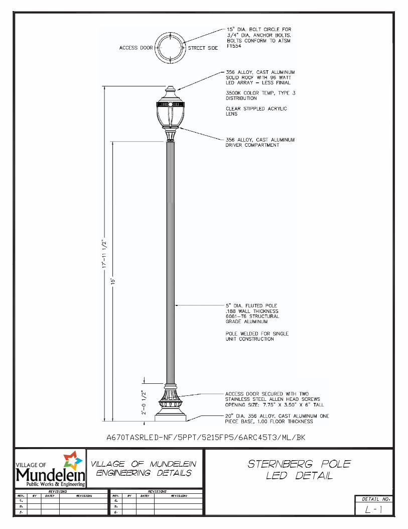
1. � Standard�residential�streetlight�poles�shall�be�Sternberg�Lighting�and�have�a�15�foot�mounting�height�with�a�20�inch�base.��(Ordering�Logic�A670TASRLED�NF/5PPT/5215FP5/6ARC45T3/ML/BK)�
2. � Poles�located�at�intersections�with�arterial�or�collector�streets�or�highways�shall�be�Sternberg�with�a�23�foot�mounting�height.��(Ordering�Logic�1�1914LEDF/A/HS�H/FFA6/5223FP6.250/40L45T3�MDL21/BK)�
3. � The�15�foot�poles�should�be�installed�three�(3)�feet�from�the�back�of�the�curb�to�the�center�of�the�base.��The�23�foot�poles�should�be�installed�eight�(8)�feet�behind�the�back�of�the�curb�center�of�the�radius.�
4. � Photoelectric�controls�shall�not�be�used�on�the�luminaries.��A�single�photocell�shall�be�located�at�the�controller.�
5. � Each�pole�shall�have�a�Fuse�Tron�inline�fuse,�with�rubber�boot�on�the�load�side�of�the�circuit.��Sufficient�internal�wiring�shall�be�provided�at�each�pole�for�ease�of�maintenance.�
6. � Internal�wiring�of�pole�and�luminaire�shall�be�ten�(10)�gauge�THHN�wire,�minimum.�
7. � Maximum�spacing�between�poles�in�a�residential�development�shall�be�designed�at�200�feet,�measured�along�the�centerline�of�the�street.��Additional�lights�must�be�installed�at�all�intersections,�road�curves,�and�at�the�end�of�cul�de�sacs.���
8. � Poles�shall�not�be�closer�than�15�feet�measured�from�any�trunk�of�a�tree.�
9. � Poles�shall�not�be�placed�within�six�(6)�feet�of�a�driveway.�
Design�References�
All�street�or�parking�area�lighting�systems�shall�be�designed�and�constructed�in�accordance�with�one�(1)�or�more�of�the�following�references�as�they�apply:�
1. � National�Electric�Code;�
(2 of 3)
Construction Standard Details and Notes L-0 2015 Update (1 of 3)
2. � “Standard�Specifications�for�Road�and�Bridge�Construction”�by�Illinois�Department�of�Transportation;�
3. � “Standard�Specifications�for�Traffic�Control�Items”�by�Illinois�Department�of�Transportation;�
4. � “Design�Manual”�by�Illinois�Department�of�Transportation;�
5. � Manufacturer�–�supplied�literature;�and�
6. � Municipal�Electric�Code.�
�
(3 of 3)
1

2

24"
NOTE:A CABLE INSPECTION IS REQUIRED PRIOR TO BACKFILL.CONTACT VILLAGE OF MUNDELEIN ENGINEERING DEPT. TOSCHEDULE.
1" MIN.UNIT DUCT
8" MIN.12" MAX.
UNDISTURBEDGROUND
SAND BACKFILLMIN. 3" ON ALLSIDES OF WIRE
SELECT BACKFILL
4"
TOPSOIL
FINISHED GRADE3' FROMB.O.C.
#6 STRANDEDBARE COPPERGROUND CABLE
3

NEW CONSTRUCTION
1' MIN.(TYP)
STREET LIGHTUNIT DUCT 4" PVC
SCH. 40
4" PVCSCH. 40 W/CAPPED ENDS
STREET LIGHTUNIT DUCT
PRE-EXISTING STREET LIGHT CABLE
4

5