construction specifications manual...city of elk grove standard construction specifications table of...
TRANSCRIPT

CONSTRUCTION
SPECIFICATIONS MANUAL
Adopted October 24, 2018

City of Elk Grove Standard Construction Specifications
Table of Contents-Page i
CITY OF ELK GROVE CONSTRUCTION SPECIFICATIONS
TABLE OF CONTENTS
SECTION 1 – TERMS AND DEFINITIONS 1-1 GENERAL .............................................................................................................................................................................1 1-2 ABBREVIATIONS ..............................................................................................................................................................1 1-3 DEFINITIONS .....................................................................................................................................................................3
SECTION 2 - BID REQUIREMENTS AND CONDITIONS 2-1 BID FORM ............................................................................................................................................................................9
2-1.01 UNIT PRICE BID ..............................................................................................................................................9 2-1.02 LUMP SUM BID ................................................................................................................................................9 2-1.03 ALLOWANCES..................................................................................................................................................9
2-2 PREPARATION AND SUBMISSION OF BIDS ..................................................................................................... 10 2-3 EXAMINATIONS OF PLANS, SPECIFICATIONS, AND SITE
OF WORK .......................................................................................................................................................................... 10 2-4 SUBSURFACE CONDITIONS ..................................................................................................................................... 11 2-5 CONTRACTORS/SUBCONTRACTORS REQUIRED TO BE
LICENSED ......................................................................................................................................................................... 11 2-6 COMPETENCY OF BIDDERS ..................................................................................................................................... 11 2-7 JOINT VENTURE BIDS ................................................................................................................................................. 12 2-8 SUBCONTRACTORS ..................................................................................................................................................... 12 2-9 ADDENDA ......................................................................................................................................................................... 13 2-10 ASSIGNMENT OF ANTITRUST ACTIONS ........................................................................................................... 13 2-11 BID GUARANTEE ........................................................................................................................................................... 13 2-12 WITHDRAWAL OF BID ............................................................................................................................................... 13 2-13 PUBLIC OPENING OF BIDS ....................................................................................................................................... 13 2-14 REJECTION OF BIDS .................................................................................................................................................... 14 2-15 RELIEF OF BIDDERS .................................................................................................................................................... 14
SECTION 3 – AWARD AND EXECUTION OF CONTRACT 3-1 AWARD OF CONTRACT .............................................................................................................................................. 15 3-2 TIME OF AWARD ........................................................................................................................................................... 15 3-3 CONSIDERATION OF BIDS ........................................................................................................................................ 15 3-4 PERFORMANCE AND PAYMENT BONDS ........................................................................................................... 15
3-4.01 PERFORMANCE BOND ............................................................................................................................. 16 3-4.02 PAYMENT BOND ......................................................................................................................................... 16
3-5 NOTIFICATION OF SURETY COMPANIES.......................................................................................................... 16 3-6 RETURN OF BID GUARANTEES ............................................................................................................................. 16 3-7 EXECUTION OF CONTRACT ..................................................................................................................................... 16 3-8 FAILURE TO EXECUTE CONTRACT ...................................................................................................................... 17 3-9 INSURANCE ..................................................................................................................................................................... 17
3-9.01 GENERAL LIABILITY ................................................................................................................................. 17 3-9.02 AUTOMOBILE LIABILITY ........................................................................................................................ 18

City of Elk Grove Standard Construction Specifications
Table of Contents-Page ii
3-9.03 WORKERS' COMPENSATION................................................................................................................. 18 3-9.04 EXCESS OR UMBRELLA LIABILITY .................................................................................................... 18 3-9.04.A CONTRACTOR’S EQUIPMENT ............................................................................................................... 18 3-9.04.B RAILROAD PROTECTIVE LIABILITY ................................................................................................. 18 3-9.04.C BUILDER’S RISK INSURANCE ............................................................................................................... 19 3-9.04.D ENVIRONMENTAL LIABILITY INSURANCE ................................................................................... 20 3-9.04.E OTHER PROVISIONS .................................................................................................................................. 20 3-9.05 NOTIFICATION OF ACCIDENT OR OCCURRENCE ....................................................................... 22
SECTION 4 –SCOPE OF WORK 4-1 INTENT OF CONTRACT DOCUMENTS ................................................................................................................ 23 4-2 PLANS AND SPECIFICATIONS FURNISHED ..................................................................................................... 23 4-3 CONFORMANCE WITH CODES AND STANDARDS ........................................................................................ 24 4-4 SUPPLEMENTAL DRAWINGS .................................................................................................................................. 24 4-5 FIELD INSTRUCTIONS OR OTHER WRITTEN DIRECTIVES ..................................................................... 24 4-6 DOCUMENT PRECEDENCE ....................................................................................................................................... 25 4-7 REQUESTS FOR INFORMATION ............................................................................................................................ 25
4-7.01 GENERAL ........................................................................................................................................................ 25 4-7.02 PROCEDURE .................................................................................................................................................. 25 4-7.03 RESPONSE ...................................................................................................................................................... 26
4-8 DELETED ITEMS............................................................................................................................................................ 26 4-9 EXTRA WORK ................................................................................................................................................................. 26 4-10 USE OF COMPLETED PORTIONS ........................................................................................................................... 26 4-11 LANDS AND RIGHTS-OF-WAY ................................................................................................................................ 27 4-12 WARRANTY ..................................................................................................................................................................... 27
SECTION 5 - CONTROL OF WORK AND MATERIALS 5-1 AUTHORITY OF CITY................................................................................................................................................... 28 5-2 ATTENTION AND COOPERATION OF CONTRACTOR ................................................................................. 28 5-3 SUGGESTIONS TO CONTRACTOR ......................................................................................................................... 28 5-4 SEPARATE CONTRACTS ............................................................................................................................................ 28 5-5 COOPERATION WITH OTHER CONTRACTORS .............................................................................................. 28 5-6 CONTRACTOR’S DISMISSAL OF UNSATISFACTORY
EMPLOYEES ..................................................................................................................................................................... 29 5-7 CONTRACTOR'S EQUIPMENT ................................................................................................................................. 29 5-8 CONTRACTOR'S SUBMITTALS ............................................................................................................................... 29
5-8.01 SUBMITTALS - GENERAL ........................................................................................................................ 29 5-8.02 RESUBMITTALS ........................................................................................................................................... 30 5-8.03 SUBMITTALS CONTAINING PROPRIETARY
INFORMATION ............................................................................................................................................. 30 5-8.04 ELECTRICAL, INSTRUMENTATION, CONTROL,
AND COMMUNICATION SYSTEMS ...................................................................................................... 31 5-8.05 MAINTENANCE AND OPERATIONS (M&O)
SUBMITTALS ................................................................................................................................................. 31 5-9 SURVEYS ........................................................................................................................................................................... 32
5-9.02 STREETS AND HIGHWAYS ..................................................................................................................... 32 5-9.03 SEWER, WATER, AND DRAINAGE FACILITIES............................................................................. 33 5-9.04 SURVEY MONUMENTS ............................................................................................................................. 33
5-10 RESPONSIBILITY FOR ACCURACY........................................................................................................................ 33 5-11 DUTIES AND POWERS OF INSPECTORS ............................................................................................................ 33 5-12 INSPECTION .................................................................................................................................................................... 34

City of Elk Grove Standard Construction Specifications
Table of Contents-Page iii
5-13 QUALITY OF MATERIALS AND WORKMANSHIP .......................................................................................... 34 5-14 SUBSTITUTIONS ............................................................................................................................................................ 34
5-14.01 WRITTEN REQUEST .................................................................................................................................. 35 5-14.02 DOCUMENTATION ..................................................................................................................................... 35
5-15 PREPARATION FOR TESTING ................................................................................................................................. 35 5-16 MATERIALS SAMPLING AND TESTING .............................................................................................................. 35 5-17 APPROVAL OF MATERIALS ..................................................................................................................................... 36
5-17.01 SOURCES OF SUPPLY ................................................................................................................................ 36 5-17.02 PLANT INSPECTION .................................................................................................................................. 36
5-18 PROVISIONS FOR EMERGENCIES ......................................................................................................................... 36 5-19 RIGHT TO RETAIN IMPERFECT WORK .............................................................................................................. 37 5-20 REMOVAL OF REJECTED MATERIALS OR WORK ......................................................................................... 37 5-21 TEMPORARY SUSPENSION OR DELAY OF WORK......................................................................................... 37 5-22 TERMINATION OF CONTRACT............................................................................................................................... 37
5-22.01 REASONS FOR TERMINATION ............................................................................................................. 37 5-22.01.A CONTRACTOR BANKRUPT ..................................................................................................................... 37 5-22.01.B COMPLETION DELAY ................................................................................................................................ 38 5-22.01.C ABANDONMENT AND UNSATISFACTORY
PERFORMANCE ........................................................................................................................................... 38 5-22.01.D TERMINATION OF CONTRACT FOR
CONVENIENCE ............................................................................................................................................. 38 5-22.02 NOTICE OF TERMINATION .................................................................................................................... 38 5-22.03 PAYMENTS TO CONTRACTOR UPON
TERMINATION OF CONTRACT............................................................................................................. 39 5-22.04 CITY COMPLETION .................................................................................................................................... 40 5-22.04.A PAYMENT FOR CITY COMPLETION ................................................................................................... 40 5-22.04.B CITY COMPLETION NOT A WAIVER OF CITY
RIGHTS ............................................................................................................................................................. 41 5-23 TERMINATION OF UNSATISFACTORY SUBCONTRACTS .......................................................................... 41
SECTION 6 – LEGAL RELATIONS AND RESPONSIBILITIES 6-1 COMPLIANCE WITH LAWS AND REGULATIONS .......................................................................................... 42
6-1.01 HOURS OF LABOR ....................................................................................................................................... 42 6-1.02 PREVAILING WAGE ................................................................................................................................... 42 6-1.03 PAYROLL RECORDS ................................................................................................................................... 43 6-1.04 NONDISCRIMINATION ............................................................................................................................. 43 6-1.05 APPRENTICES ............................................................................................................................................... 43 6-1.06 WORKERS’ COMPENSATION ................................................................................................................. 44 6-1.07 FAIR LABOR STANDARDS ...................................................................................................................... 44 6-1.08 CONTRACTORS LICENSE ........................................................................................................................ 44 6-1.09 USE OF PESTICIDES ................................................................................................................................... 44 6-1.10 REPORTING REQUIREMENTS AND SANCTIONS ......................................................................... 44 6-1.11 SUBCONTRACTING .................................................................................................................................... 45 6-1.12 OCCUPATIONAL SAFETY AND HEALTH .......................................................................................... 45
6-2 INDEMNIFICATION ...................................................................................................................................................... 45 6-2.01 CONTRACTOR'S PERFORMANCE ........................................................................................................ 45 6-2.02 NO LIMITATION OF LIABILITY FOR
INDEMNIFICATION .................................................................................................................................... 46 6-3 CONTRACTOR'S LEGAL ADDRESS ........................................................................................................................ 46 6-4 CONTRACTOR NOT AN AGENT OF CITY ........................................................................................................... 46 6-5 SUBSTITUTION OF SUBCONTRACTORS ............................................................................................................ 46 6-6 ASSIGNMENT OF CONTRACT ................................................................................................................................. 47

City of Elk Grove Standard Construction Specifications
Table of Contents-Page iv
6-7 ASSIGNMENT OF MONIES ........................................................................................................................................ 47 6-8 PROTECTION OF CITY AGAINST PATENT CLAIMS ...................................................................................... 47 6-9 RESPONSIBILITY OF THE CONTRACTOR ......................................................................................................... 47 6-10 PERMITS AND LICENSES .......................................................................................................................................... 48 6-11 GENERAL SAFETY REQUIREMENTS ................................................................................................................... 48
6-11.01 COMPLIANCE WITH SAFETY & HEALTH REGULATIONS .............................................................................................................................................. 48
6-11.02 24-HOUR CONTACT INFORMATION ................................................................................................. 49 6-11.03 WORK DURING HOURS OF DARKNESS ............................................................................................ 49
6-12 PUBLIC CONVENIENCE AND SAFETY ................................................................................................................. 49 6-12.01 PUBLIC CONVENIENCE ............................................................................................................................ 49 6-12.02 PEDESTRIAN AND BICYCLIST ACCESS ............................................................................................ 49 6-12.03 WRITTEN NOTIFICATION TO RESIDENCES AND
BUSINESSES................................................................................................................................................... 50 6-12.04 ACCESS TO DRIVEWAYS, HOUSES AND
BUILDINGS ..................................................................................................................................................... 50 6-12.05 PROPERTY DAMAGE ................................................................................................................................. 50 6-12.06 ERECTION OF SIGNS TO EXPEDITE PASSAGE OF
VEHICLES ........................................................................................................................................................ 50 6-12.07 TRAFFIC OBSTRUCTIONS, DELAYS AND
INCONVENIENCES ...................................................................................................................................... 51 6-12.08 WORK ON PRIVATE PROPERTY .......................................................................................................... 51 6-12.09 HAZARDOUS CONDITIONS CREATED .............................................................................................. 51
6-13 PUBLIC SAFETY AND TRAFFIC CONTROL ........................................................................................................ 51 6-13.01 GENERAL ........................................................................................................................................................ 51 6-13.02 RESPONSIBILITY FOR SAFETY ............................................................................................................ 51 6-13.03 PASSAGE OF EMERGENCY VEHICLES ............................................................................................... 51 6-13.04 FURNISHING, INSTALLING, AND MAINTAINING
TRAFFIC CONTROLS ................................................................................................................................. 52 6-13.05 INADEQUATE TRAFFIC CONTROLS AND AFTER-
HOUR MAINTENANCE AND REPAIRS............................................................................................... 52 6-13.06 COMPETENT FLAGGERS ......................................................................................................................... 52 6-13.07 CONSTRUCTION SIGNS ............................................................................................................................ 52 6-13.08 TEMPORARY BRIDGING OF EXCAVATIONS AND
TRENCHES...................................................................................................................................................... 53 6-13.09 ENTERING AND LEAVING THE CONSTRUCTION
ZONE ................................................................................................................................................................. 53 6-13.10 EXISTING TRAFFIC SIGNAL AND LIGHTING
SYSTEMS, SIGNS AND PAVEMENT MARKINGS ............................................................................ 54 6-13.11 BUS STOPS ...................................................................................................................................................... 54 6-13.12 DUST.................................................................................................................................................................. 54 6-13.13 REMOVAL OF SPILLAGE FROM ROADWAY ................................................................................... 54
6-14 TRAFFIC CONTROL PLANS (TCP) ......................................................................................................................... 54 6-14.01 TRAFFIC PATTERN CHANGES .............................................................................................................. 54 6-14.02 TRAFFIC CONTROL PLANS (TCP) ....................................................................................................... 55
6-15 BARRICADING OPEN TRENCHES .......................................................................................................................... 55 6-16 EXISTING UTILITIES.................................................................................................................................................... 55
6-16.01 GENERAL ........................................................................................................................................................ 55 6-16.02 MAINTENANCE AND PROTECTION ................................................................................................... 55 6-16.03 EXACT LOCATIONS UNKNOWN ........................................................................................................... 56 6-16.04 UNDERGROUND SERVICE ALERT (USA) ......................................................................................... 56 6-16.05 DAMAGE TO EXISTING UTILITIES...................................................................................................... 57 6-16.06 MARKINGS...................................................................................................................................................... 57

City of Elk Grove Standard Construction Specifications
Table of Contents-Page v
6-17 APPROVAL OF CONTRACTOR'S PLANS NO RELEASE FROM LIABILITY ......................................................................................................................................................................... 58
6-18 CONTRACTOR SHALL NOT MORTGAGE EQUIPMENT ................................................................................ 58 6-19 PROPERTY RIGHTS IN MATERIALS ..................................................................................................................... 58 6-20 EXCAVATION AND TRENCH SAFETY .................................................................................................................. 58
6-20.01 PERMIT ............................................................................................................................................................ 58 6-20.02 SHORING, BRACING, SHIELDING AND SHEETING...................................................................... 58
6-21 PRESERVATION OF PROPERTY ............................................................................................................................. 59 6-22 OVERLOADING ............................................................................................................................................................... 59
SECTION 7 – PROSECUTION OF THE WORK 7-1 BEGINNING OF WORK ................................................................................................................................................ 60 7-2 AMOUNT OF WORK UNDER CONSTRUCTION ................................................................................................ 60 7-3 PRECONSTRUCTION CONFERENCE AND PROGRESS
MEETINGS ........................................................................................................................................................................ 60 7-4 WORK TO BE PROSECUTED WITH ADEQUATE
SUPERVISION, LABOR FORCE, EQUIPMENT AND METHODS ......................................................................................................................................................................... 60
7-4.01 SUPERINTENDENCE ................................................................................................................................. 60 7-4.02 LABOR .............................................................................................................................................................. 61 7-4.03 EQUIPMENT AND METHODS ................................................................................................................ 61
7-5 SCHEDULES ..................................................................................................................................................................... 61 7-5.01 PROGRESS SCHEDULE.............................................................................................................................. 61 7-5.02 CPM SCHEDULE ........................................................................................................................................... 62 7-5.03 THREE-WEEK ROLLING SCHEDULE ................................................................................................. 63
7-6 UNUSUAL SITE CONDITIONS .................................................................................................................................. 63 7-7 PURSUANCE OF WORK DURING INCLEMENT WEATHER ....................................................................... 63 7-8 PEAK HOURS, HOURS OF DARKNESS, HOLIDAYS, AND
WEEKENDS ...................................................................................................................................................................... 64 7-8.01 ALLOWABLE TIMES AND HOURS OF WORK ............................................................................... 64 7-8.02 OFF-PERIOD WORK ................................................................................................................................... 64 7-8.03 EMERGENCY REPAIRS ............................................................................................................................. 64 7-8.04 REVOCATION OF PERMISSION FOR OFF-PERIOD
WORK ............................................................................................................................................................... 64 7-8.05 WORKING SHIFTS....................................................................................................................................... 64 7-8.06 LANE AND ROAD CLOSURES DURING
NOVEMBER/DECEMBER HOLIDAY SEASON ................................................................................ 65 7-9 TEMPORARY FACILITIES AND SERVICES ........................................................................................................ 65 7-10 PROTECTION OF WORK, PERSONS AND PROPERTY .................................................................................. 65 7-11 PROOF OF COMPLIANCE WITH CONTRACT ................................................................................................... 65 7-12 DELAYS .............................................................................................................................................................................. 65
7-12.01 AVOIDABLE DELAYS ................................................................................................................................. 65 7-12.02 UNAVOIDABLE DELAYS .......................................................................................................................... 66
7-13 NOTICE OF DELAYS ..................................................................................................................................................... 66 7-14 CARELESS DESTRUCTION OF STAKES AND MARKS NO
CAUSE FOR DELAY ....................................................................................................................................................... 67 7-15 TIME OF COMPLETION .............................................................................................................................................. 67 7-16 EXTENSION OF TIME NOT A WAIVER ................................................................................................................ 67 7-17 INCLEMENT WEATHER AND CONTRACT TIME ............................................................................................ 67 7-18 EXTENSION OF TIME .................................................................................................................................................. 67 7-19 SUBSTANTIAL COMPLETION.................................................................................................................................. 68 7-20 CLEANING UP ................................................................................................................................................................. 68

City of Elk Grove Standard Construction Specifications
Table of Contents-Page vi
7-21 FINAL INSPECTION AND FIELD ACCEPTANCE .............................................................................................. 68 7-22 FINAL ACCEPTANCE AND NOTICE OF COMPLETION ................................................................................ 69 7-23 RELEASE OF WARRANTY PERIOD ....................................................................................................................... 69
SECTION 8 – MEASUREMENT AND PAYMENT 8-1 BASIS AND MEASUREMENT OF PAYMENT QUANTITIES ......................................................................... 70
8-1.01 UNIT PRICE CONTRACTS ........................................................................................................................ 70 8-1.02 LUMP SUM OR JOB CONTRACTS ......................................................................................................... 70 8-1.03 PAYMENT FOR MOBILIZATION ........................................................................................................... 70 8-1.03.A MOBILIZATION NOT A PAY ITEM ....................................................................................................... 70 8-1.03.B MOBILIZATION A PAY ITEM ................................................................................................................. 70
8-2 SCOPE OF PAYMENT ................................................................................................................................................... 71 8-2.01 GENERAL ........................................................................................................................................................ 71 8-2.02 UNIT PRICE CONTRACT .......................................................................................................................... 71 8-2.03 LUMP SUM OR JOB CONTRACT ............................................................................................................ 72 8-2.04 FINAL PAY ITEMS ....................................................................................................................................... 72 8-2.05 ALLOWANCES............................................................................................................................................... 72 8-2.06 PAYMENT FOR MATERIAL NOT INCORPORATED
IN THE WORK ............................................................................................................................................... 72 8-3 WORK TO BE DONE WITHOUT DIRECT PAYMENT ..................................................................................... 72 8-4 PAYMENT FOR USE OF COMPLETED PORTIONS OF WORK ................................................................... 72 8-5 PROGRESS PAYMENT PROCEDURES .................................................................................................................. 73 8-6 INSPECTION AND PROGRESS PAYMENTS NOT A WAIVER
OF CONTRACT PROVISIONS .................................................................................................................................... 73 8-7 RETENTION ..................................................................................................................................................................... 73
8-7.01 RETENTION TO ENSURE PERFORMANCE ..................................................................................... 73 8-7.02 NON-COMPLIANCE .................................................................................................................................... 73 8-7.03 SUBSTITUTION OF SECURITIES .......................................................................................................... 73
8-8 WITHHOLDINGS/DENIAL OF PROGRESS PAYMENT REQUEST ........................................................................................................................................................................... 74
8-9 DEDUCTIONS FOR IMPERFECT WORK .............................................................................................................. 75 8-10 LIQUIDATED DAMAGES FOR DELAY .................................................................................................................. 75 8-11 FINAL ESTIMATE AND PAYMENT ........................................................................................................................ 75 8-12 FINAL PAYMENT TO TERMINATE LIABILITY OF CITY OF
ELK GROVE ...................................................................................................................................................................... 75 8-13 DISPUTED PAYMENTS ............................................................................................................................................... 76
SECTION 9 – CHANGES AND CLAIMS 9-1 AUTHORITY FOR CHANGES..................................................................................................................................... 77 9-2 ORDERING OF CHANGES .......................................................................................................................................... 77 9-3 CONSTRUCTION INCENTIVE CHANGE PROPOSAL (CICP) ....................................................................... 77
9-3.01 GENERAL ...................................................................................................................................................... 77 9-3.02 DESCRIPTION ............................................................................................................................................... 77 9-3.03 SUBMITTAL ................................................................................................................................................... 78 9-3.04 ACCEPTANCE ................................................................................................................................................ 79 9-3.05 SHARING PROVISIONS AND FORMULA ........................................................................................... 79
9-4 CHANGES TO THE CONTRACT ............................................................................................................................... 79 9-5 PROSECUTION OF CHANGES TO THE CONTRACT ....................................................................................... 80 9-6 COST AND PRICING DATA ........................................................................................................................................ 80 9-7 ACCESS TO RECORDS.................................................................................................................................................. 80 9-8 PAYMENT FOR CHANGES ......................................................................................................................................... 80

City of Elk Grove Standard Construction Specifications
Table of Contents-Page vii
9-8.01 LUMP SUM PRICE ....................................................................................................................................... 80 9-8.02 UNIT PRICES ................................................................................................................................................. 81 9-8.03 FORCE ACCOUNT ........................................................................................................................................ 81 9-8.03.A LABOR .............................................................................................................................................................. 81 9-8.03.A.(1) ACTUAL WAGES .......................................................................................................................................... 81 9-8.03.A.(2) LABOR SURCHARGE .................................................................................................................................. 81 9-8.03.A.(3) SUBSISTENCE AND TRAVEL ................................................................................................................. 82 9-8.03.B MATERIALS.................................................................................................................................................... 82 9-8.03.C EQUIPMENT .................................................................................................................................................. 82 9-8.03.D SUBCONTRACTS .......................................................................................................................................... 82
9-9 MARKUPS FOR CHANGED WORK ......................................................................................................................... 82 9-10 COMPENSABLE UNAVOIDABLE DELAYS ........................................................................................ 83 9-10.01 CONSTRUCTION EQUIPMENT .............................................................................................................. 83 9-10.02 JOBSITE INDIRECT COSTS ...................................................................................................................... 83 9-10.03 MARKUP FOR COMPENSABLE UNAVOIDABLE
DELAYS ............................................................................................................................................................ 84 9-10.04 DUPLICATED OVERHEAD COSTS........................................................................................................ 84
9-11 LIMITATIONS ON PAYMENTS FOR CHANGED WORK ................................................................................ 84 9-12 TIME EXTENSIONS FOR CHANGES ...................................................................................................................... 84 9-13 EFFECT ON SURETIES OF CHANGES TO THE WORK .................................................................................. 84 9-14 CONTRACT CHANGE ORDER (CCO) ..................................................................................................................... 84 9-15 ACCEPTANCE OF ORDERS FOR CHANGES ....................................................................................................... 85 9-16 DISPUTE REGARDING CONTRACT REQUIREMENTS .................................................................................. 85 9-17 NOTICE OF POTENTIAL CLAIM ............................................................................................................................. 85 9-18 RESOLUTION OF CLAIMS .......................................................................................................................................... 86
9-18.01 CONTRACTOR’S DUTY DURING CLAIM RESOLUTION ................................................................................................................................................. 87
9-19 ENGINEER’S DECISION .............................................................................................................................................. 87 9-20 ALTERNATIVE DISPUTE RESOLUTION ............................................................................................................. 88
9-20.01 INITIATION OF MEDIATION.................................................................................................................. 88 9-20.02 REQUEST FOR MEDIATION ................................................................................................................... 88 9-20.03 SELECTION OF MEDIATOR .................................................................................................................... 88 9-20.04 QUALIFICATIONS OF A MEDIATOR ................................................................................................... 88 9-20.05 VACANCIES .................................................................................................................................................... 88 9-20.06 REPRESENTATION ..................................................................................................................................... 89 9-20.07 TIME AND PLACE OF MEDIATION ..................................................................................................... 89 9-20.08 IDENTIFICATION OF MATTERS IN DISPUTE ................................................................................ 89 9-20.09 AUTHORITY OF MEDIATOR................................................................................................................... 89 9-20.10 PRIVACY .......................................................................................................................................................... 89 9-20.11 CONFIDENTIALITY .................................................................................................................................... 89 9-20.12 NO STENOGRAPHIC RECORD ............................................................................................................... 90 9-20.13 TERMINATION OF MEDIATION ........................................................................................................... 90 9-20.14 EXCLUSION OF LIABILITY ...................................................................................................................... 90 9-20.15 INTERPRETATION AND APPLICATION OF THESE
MEDIATION PROVISIONS ....................................................................................................................... 90 9-20.16 EXPENSES ....................................................................................................................................................... 90
9-21 NO ALTERNATIVE CLAIMS PROCEDURE .......................................................................................................... 90 9-22 ASSIGNMENT OF CLAIMS ......................................................................................................................................... 90
SECTION 10 – ENVIRONMENTAL CONTROLS AT WORK SITE 10-1 DUST CONTROL ............................................................................................................................................................. 91 10-2 AIR POLLUTION CONTROL ...................................................................................................................................... 91

City of Elk Grove Standard Construction Specifications
Table of Contents-Page viii
10-3 BURNING ........................................................................................................................................................................... 91 10-4 EROSION, SEDIMENT, AND WATER POLLUTION CONTROL .................................................................. 91
10-4.01 GENERAL ........................................................................................................................................................ 91 10-4.02 CITY REQUIREMENTS .............................................................................................................................. 91 10-4.03 REGULATIONS, ORDINANCES, PERMITS, AND
SPECIFICATIONS ......................................................................................................................................... 92 10-4.04 STORMWATER POLLUTION PREVENTION PLAN ...................................................................... 92 10-4.05 EROSION AND SEDIMENT CONTROL PLAN .................................................................................. 94 10-4.06 MINIMUM CITY REQUIREMENTS ....................................................................................................... 94 10-4.07 COMPLIANCE ................................................................................................................................................ 95 10-4.08 PAYMENT ....................................................................................................................................................... 95
10-5 CONTROL OF WATER IN THE WORK.................................................................................................................. 95 10-6 NOISE CONTROL ........................................................................................................................................................... 96 10-7 CONTAMINATED AND HAZARDOUS MATERIALS OR
ENVIRONMENTS ........................................................................................................................................................... 96 10-7.01 CONTAMINATED OR HAZARDOUS MATERIALS ......................................................................... 96 10-7.02 HAZARDOUS ENVIRONMENTS ............................................................................................................ 96
10-8 USE OF EXPLOSIVES .................................................................................................................................................... 96 10-9 SANITARY REGULATIONS ........................................................................................................................................ 96 10-10 CONFINED SPACES ...................................................................................................................................................... 97
10-10.01 CONTRACTOR RESPONSIBILITIES AND QUALIFICATIONS ........................................................................................................................................ 97
10-10.02 CITY RESPONSIBILITIES FOR PERMIT CONFINED SPACES ............................................................................................................................................................. 97
10-10.03 EXISTING SEWERS AND STORM DRAINS ....................................................................................... 98 10-10.04 JOINT CITY – CONTRACTOR ENTRIES ............................................................................................. 98
10-11 CLEANING UP ................................................................................................................................................................. 98 10-12 ARCHEOLOGICAL AND CULTURAL RESOURCES .......................................................................................... 98 10-13 PROTECTION OF EXISTING TREES ..................................................................................................................... 99
SECTION 11 – RECORD DRAWINGS 11-1 GENERAL ....................................................................................................................................................................... 100 11-2 RESERVED ..................................................................................................................................................................... 100 11-3 AS BUILT DRAWINGS (AS BUILTS) ................................................................................................................... 100
SECTION 12 – CONSTRUCTION AREA TRAFFIC CONTROL 12-1 GENERAL ....................................................................................................................................................................... 101 12-2 FLAGGING ...................................................................................................................................................................... 101
12-2.01 FLAGGERS ................................................................................................................................................... 101 12-2.02 FLAGGING COSTS ..................................................................................................................................... 101
12-3 TRAFFIC-HANDLING EQUIPMENT AND DEVICES..................................................................................... 102 12-3.01 GENERAL ..................................................................................................................................................... 102 12-3.02 CONES ............................................................................................................................................................ 102 12-3.03 PORTABLE CHANNELIZERS ............................................................................................................... 102 12-3.04 TELESCOPING FLAG TREES ................................................................................................................ 103 12-3.05 PORTABLE FLASHING BARRICADES ............................................................................................. 103 12-3.06 BARRICADES .............................................................................................................................................. 103 12-3.06.A MATERIALS................................................................................................................................................. 103 12-3.06.B INSTALLATION AND MAINTENANCE............................................................................................ 104 12-3.06.B.(1) CONSTRUCTION BARRICADES.......................................................................................................... 104 12-3.06.B.(2) PERMANENT BARRICADES ................................................................................................................ 104

City of Elk Grove Standard Construction Specifications
Table of Contents-Page ix
12-3.07 FLASHING ARROW SIGN (FAS) ......................................................................................................... 104 12-3.08 CONSTRUCTION AREA SIGNS ............................................................................................................ 105 12-3.08.A GENERAL REQUIREMENTS ................................................................................................................ 105 12-3.08.B COVERING SIGNS ..................................................................................................................................... 105 12-3.08.C CLEANING SIGNS ..................................................................................................................................... 105 12-3.08.D USED SIGNS................................................................................................................................................. 105 12-3.08.E REPLACEMENT AND BACKUP SIGNS............................................................................................. 105 12-3.08.F STOPPING OR PARKING PROHIBITION (TOW-
AWAY ZONE) .............................................................................................................................................. 106 12-3.08.G PROTECTION, MAINTENANCE, REMOVAL,
STORAGE, AND RESETTING OF SIGNS .......................................................................................... 106 12-3.08.H MOVEMENT OF TRAFFIC SIGNS AND TRAFFIC
CONTROL FACILITIES ........................................................................................................................... 106 12-3.08.I “ROAD CONSTRUCTION AHEAD (C-18)” AND
“END OF CONSTRUCTION (C-13)” SIGNS ..................................................................................... 106 12-3.08.J CONTRACTOR FURNISHED SIGNS .................................................................................................. 106 12-3.08.K OBSCURING VISIBILITY AND CONFLICTING WITH
MEANING ..................................................................................................................................................... 106 12-3.08.L PERMANENT CONSTRUCTION SIGNS ........................................................................................... 107 12-3.08.M REMOVAL OF PERMANENT TRAFFIC CONTROL
SIGNS.............................................................................................................................................................. 107 12-3.08.N REGULATORY SIGN PLACEMENT AND REMOVAL .................................................................. 107 12-3.08.O SIGN POSTS ................................................................................................................................................. 108
12-4 MEASUREMENT AND PAYMENT ....................................................................................................................... 108
SECTION 13 –EXISTING FACILITIES 13-1 GENERAL ....................................................................................................................................................................... 110 13-2 REMOVING EXISTING FACILITIES..................................................................................................................... 110
13-2.01 MAILBOXES................................................................................................................................................. 110 13-2.02 SIGNS.............................................................................................................................................................. 111 13-2.03 SURVEY MONUMENTS .......................................................................................................................... 111 13-2.04 LANDSCAPING IMPROVEMENTS ..................................................................................................... 111 13-2.05 ABANDONED UNDERGROUND FACILITIES ................................................................................ 111 13-2.06 DRAINAGE FACILITIES ......................................................................................................................... 111 13-2.07 FENCES ......................................................................................................................................................... 112 13-2.08 CONCRETE .................................................................................................................................................. 112
13-3 MEASUREMENT AND PAYMENT ....................................................................................................................... 112
SECTION 14 – RESTORATION OF SURFACES 14-1 GENERAL ....................................................................................................................................................................... 114 14-2 PRIVATE ROADS ......................................................................................................................................................... 114 14-3 STREETS AND PARKING LOTS ............................................................................................................................ 114
14-3.01 AGGREGATE BASE ................................................................................................................................... 114 14-3.02 ASPHALT CONCRETE ............................................................................................................................. 114 14-3.03 SEAL COATS ................................................................................................................................................ 115 14-3.04 SHOULDERS ................................................................................................................................................ 115 14-3.05 CUTS IN NEW PAVEMENT ................................................................................................................... 115
14-4 CONCRETE .................................................................................................................................................................... 115 14-5 PAVEMENT MARKINGS .......................................................................................................................................... 116 14-6 TEMPORARY PAVING .............................................................................................................................................. 116 14-7 MEASUREMENT AND PAYMENT ....................................................................................................................... 116

City of Elk Grove Standard Construction Specifications
Table of Contents-Page x
SECTION 15 – CLEARING AND GRUBBING 15-1 GENERAL ....................................................................................................................................................................... 118
15-1.01 VEGETATION AND DEBRIS ................................................................................................................. 118 15-1.02 TREES, SHRUBS, GROUND COVER, AND LAWNS ..................................................................... 118 15-1.03 DISPOSAL AND SALVAGE .................................................................................................................... 119 15-1.04 ABANDONMENT OF CONDUITS AND
STRUCTURES ............................................................................................................................................. 119 15-1.05 SILT CONTROL .......................................................................................................................................... 120 15-1.06 MISCELLANEOUS ..................................................................................................................................... 120
15-2 PAYMENT ...................................................................................................................................................................... 120
SECTION 16 – WATER USED IN CONSTRUCTION 16-1 GENERAL ....................................................................................................................................................................... 121 16-2 PAYMENT ...................................................................................................................................................................... 121
SECTION 17 – DUST CONTROL 17-1 GENERAL ....................................................................................................................................................................... 122 17-2 DUST PALLIATIVE ..................................................................................................................................................... 122 17-3 MEASUREMENT AND PAYMENT ....................................................................................................................... 122
SECTION 18 – EARTHWORK 18-1 GENERAL ....................................................................................................................................................................... 123 18-2 ROADWAY EXCAVATION ....................................................................................................................................... 123
18-2.01 GENERAL ..................................................................................................................................................... 123 18-2.02 UNSUITABLE ROADWAY EXCAVATION AND
BACKFILL ..................................................................................................................................................... 123 18-2.03 SURPLUS MATERIAL .............................................................................................................................. 123 18-2.04 UNSUITABLE MATERIAL IN EMBANKMENTS........................................................................... 123 18-2.05 SUBGRADE PREPARATION`................................................................................................................ 124 18-2.05A SUBGRADE SOILS – ROADWAY, CURB AND
GUTTER, AND SIDEWALKS ................................................................................................................. 125 18-2.06 MEASUREMENT AND PAYMENT ..................................................................................................... 126
18-3 STRUCTURE EXCAVATION AND BACKFILL .................................................................................................. 126 18-3.01 GENERAL ..................................................................................................................................................... 126 18-3.02 CONTROL DENSITY BACKFILL.......................................................................................................... 127 18-3.03 FINAL QUANTITY..................................................................................................................................... 127 18-3.04 MEASUREMENT AND PAYMENT ..................................................................................................... 127
18-4 DITCH AND CHANNEL EXCAVATION............................................................................................................... 127 18-4.01 GENERAL ..................................................................................................................................................... 127 18-4.02 GRADE CONTROL - LINED CHANNELS ......................................................................................... 127 18-4.03 UNSUITABLE DITCH AND CHANNEL EXCAVATION
AND BACKFILL .......................................................................................................................................... 127 18-4.04 UNSUITABLE OR SURPLUS MATERIAL DISPOSAL .................................................................. 127 18-4.05 CHANNEL BACKFILL .............................................................................................................................. 128 18-4.06 CHANNEL EMBANKMENTS ................................................................................................................ 128 18-4.07 PIPE ADJUSTMENTS ............................................................................................................................... 128
18-5 UNSUITABLE MATERIAL EXCAVATION ......................................................................................................... 128 18-5.01 GENERAL ..................................................................................................................................................... 128 18-5.02 BACKFILL ..................................................................................................................................................... 129

City of Elk Grove Standard Construction Specifications
Table of Contents-Page xi
18-5.03 GEOTEXTILE MATERIAL ...................................................................................................................... 129 18-5.04 APPROXIMATE QUANTITY ................................................................................................................. 129 18-5.05 PAYMENT .................................................................................................................................................... 130
18-6 IMPORTED BORROW ............................................................................................................................................... 130 18-6.01 GENERAL ..................................................................................................................................................... 130 18-6.02 AGREEMENTS ............................................................................................................................................ 131 18-6.03 PLACEMENT ............................................................................................................................................... 131
18-7 SURPLUS MATERIAL DISPOSAL ......................................................................................................................... 131 18-7.01 GENERAL ..................................................................................................................................................... 131 18-7.02 AGREEMENT .............................................................................................................................................. 131 18-7.03 PERMITS....................................................................................................................................................... 131 18-7.04 PAYMENT .................................................................................................................................................... 132
18-8 CLASS “C” SUBGRADE .............................................................................................................................................. 132 18-8.01 GENERAL ..................................................................................................................................................... 132 18-8.02 PREPARATION .......................................................................................................................................... 132 18-8.03 PAYMENT .................................................................................................................................................... 133
SECTION 19 – TRENCH EXCAVATION, BEDDING AND BACKFILL 19-1 TRENCH EXCAVATION ............................................................................................................................................ 134
19-1.01 EXPLORATORY EXCAVATION ........................................................................................................... 134 19-1.02 TRENCH WIDTH ....................................................................................................................................... 134 19-1.02A STORM DRAIN PIPE ................................................................................................................................ 134 19-1.02B SEWER PIPE ............................................................................................................................................... 134 19-1.02C WATER PIPE ............................................................................................................................................... 134 19-1.03 PAVEMENT CUTTING ............................................................................................................................ 135 19-1.04 MAXIMUM LENGTH OF OPEN TRENCH ........................................................................................ 135 19-1.05 CONTROL OF GROUNDWATER ......................................................................................................... 135 19-1.06 SHORING AND BRACING ...................................................................................................................... 135 19-1.07 SPECIAL FOUNDATION TREATMENT ........................................................................................... 136 19-1.08 EXCAVATION METHOD ........................................................................................................................ 137 19-1.09 PAYMENT .................................................................................................................................................... 137
19-2 PIPE BEDDING AND BACKFILLING OF TRENCHES................................................................................... 137 19-2.01 PIPE BEDDING ........................................................................................................................................... 137 19-2.01.A SEWER ........................................................................................................................................................... 137 19-2.01.B STORM DRAIN ........................................................................................................................................... 138 19-2.01.C WATER DISTRIBUTION SYSTEMS ................................................................................................... 139 19-2.02 INITIAL BACKFILL ................................................................................................................................... 139 19-2.02.A STORM DRAIN ........................................................................................................................................... 139 19-2.02.C WATER DISTRIBUTION SYSTEMS ................................................................................................... 139 19-2.03 TRENCH BACKFILL ................................................................................................................................. 140 19-2.03A CUT OFF COLLARS................................................................................................................................... 141 19-2.03B BACKFILL WITHIN EXISTING STREETS ....................................................................................... 142 19-2.04 PAYMENT .................................................................................................................................................... 142
SECTION 20 – LANDSCAPING 20-1 GENERAL ....................................................................................................................................................................... 143 20-2 MATERIALS................................................................................................................................................................... 143
20-2.01 ROOT CONTROL BARRIER .................................................................................................................. 143 20-2.02 TOPSOIL ....................................................................................................................................................... 143 20-2.03 SOIL AMENDMENT ................................................................................................................................. 143 20-2.04 LIQUID GREEN DYE ................................................................................................................................ 143

City of Elk Grove Standard Construction Specifications
Table of Contents-Page xii
20-2.05 MULCH .......................................................................................................................................................... 144 20-3 EROSION CONTROL .................................................................................................................................................. 144
20-3.01 SEEDING AND FERTILIZING............................................................................................................... 144 20-3.02 MEASUREMENT AND PAYMENT ..................................................................................................... 145
20-4 PLANTING ..................................................................................................................................................................... 145 20-4.01 PESTICIDES ................................................................................................................................................. 145 20-4.02 PREPARING PLANTING AREAS ......................................................................................................... 145 20-4.03 HEADER BOARDS .................................................................................................................................... 146 20-4.04 PLANTING ................................................................................................................................................... 146 20-4.04.A PREPARATION FOR GROUND COVERS ......................................................................................... 148 20-4.04.B PREPARATION FOR TREES AND SHRUBS ................................................................................... 148 20-4.04.C PREPARATION FOR TURF ................................................................................................................... 149 20-4.05 WATERING .................................................................................................................................................. 150 20-4.06 PLANT REPLACEMENT ......................................................................................................................... 150 20-4.07 PLANT ESTABLISHMENT WORK ..................................................................................................... 150 20-4.08 INSPECTION FOR PLANT ESTABLISHMENT WORK............................................................... 152 20-4.09 MEASUREMENT AND PAYMENT ..................................................................................................... 152
20-5 IRRIGATION SYSTEMS ............................................................................................................................................ 152 20-5.01 MAINTAIN EXISTING WATER SUPPLY ......................................................................................... 152 20-5.02 REMOVE EXISTING PLANTS FOR TRENCHING ......................................................................... 153 20-5.03 ELECTRICAL SERVICE FOR ELECTRIC
AUTOMATIC IRRIGATION SYSTEMS .............................................................................................. 153 20-5.03.A COMPONENTS ........................................................................................................................................... 153 20-5.03.B CONTROLLERS .......................................................................................................................................... 153 20-5.03.C CONTROL WIRE, ELECTRICAL CONDUIT AND
PULL BOXES ............................................................................................................................................... 154 20-5.03.D TESTING ....................................................................................................................................................... 154 20-5.04 INSTALLATION ......................................................................................................................................... 155 20-5.04.A GENERAL ..................................................................................................................................................... 155 20-5.04.B IRRIGATION SLEEVING......................................................................................................................... 155 20-5.04.C WATER LINE CROSSOVERS ................................................................................................................ 156 20-5.04.D TRENCHING AND BACKFILLING ...................................................................................................... 156 20-5.05 PIPE ................................................................................................................................................................ 157 20-5.05.A SUBSURFACE DRIPPERLINE .............................................................................................................. 158 20-5.05.B VALVES AND VALVE BOXES ............................................................................................................... 159 20-5.05.C QUICK COUPLING VALVE ..................................................................................................................... 159 20-5.05.D BACKFLOW PREVENTERS................................................................................................................... 159 20-5.05.E MASTER VALVE/FLOW METER ASSEMBLY ............................................................................... 160 20-5.05.F AIR VACUUM RELIEF VALVE ............................................................................................................. 160 20-5.05.G FLUSH VALVE ............................................................................................................................................ 160 20-5.05.H SPRINKLERS AND EMITTERS ............................................................................................................ 161 20-5.05.I PRESSURE TESTING ............................................................................................................................... 161 20-5.05.J REPAIRS AND COVERAGE ................................................................................................................... 162 20-5.06 MEASUREMENT AND PAYMENT ..................................................................................................... 162
20-6 AS BUILT DRAWINGS AND CONTROLLER CHARTS ................................................................................. 162
SECTION 21 – FINISHING ROADWAY 21-1 GENERAL ....................................................................................................................................................................... 164 21-2 PAYMENT ...................................................................................................................................................................... 164

City of Elk Grove Standard Construction Specifications
Table of Contents-Page xiii
SECTION 22 – BASE MATERIAL 22-1 GENERAL ....................................................................................................................................................................... 165
SECTION 23 – ASPHALT CONCRETE 23-1 GENERAL ....................................................................................................................................................................... 166 23-2 MIX FORMULA AND DESIGN ................................................................................................................................ 166 23-3 AGGREGATE ................................................................................................................................................................ 166 23-4 RECYCLED ASPHALT PAVEMENT ..................................................................................................................... 166 23-5 HAULING EQUIPMENT ............................................................................................................................................ 168 23-6 CONSTRUCTION PLAN ............................................................................................................................................ 169 23-7 ASPHALT CONCRETE PLACEMENT METHOD ............................................................................................. 169
23-7.01 GENERAL ..................................................................................................................................................... 169 23-7.02 PRE-OVERLAY PREPARATION .......................................................................................................... 170 23-7.03 SPREADING ................................................................................................................................................. 171 23-7.03.A HAND SPREADING .................................................................................................................................. 172 23-7.03.B MECHANICAL SPREADING EQUIPMENT ..................................................................................... 172 23-7.04 JOINTS ........................................................................................................................................................... 173 23-7.05 COMPACTING............................................................................................................................................. 173
23-8 ASPHALT CONCRETE PLACEMENT ACCEPTANCE TESTING ............................................................... 174 23-8.01 PAVEMENT DENSITY TESTING ........................................................................................................ 174 23-8.01.A LOT SIZES ................................................................................................................................................... 174 23-8.01.B LABORATORY DENSITY ...................................................................................................................... 174 23-8.01.C CORE DENSITY ......................................................................................................................................... 174 23-8.02 PAY FACTORS ............................................................................................................................................ 175
23-9 ASPHALT RUBBER HOT MIX-GAP GRADED (ARHM-GG) ....................................................................... 175 23-9.01 TYPE 1 ASPHALT-RUBBER BINDER (PG 64-16) ...................................................................... 177 23-9.02 TYPE 2 ASPHALT-RUBBER BINDER ............................................................................................... 177 23-9.03 AGGREGATE ............................................................................................................................................... 179 23-9.04 EQUIPMENT ............................................................................................................................................... 179 23-9.04.A HAULERS ...................................................................................................................................................... 179 23-9.04.B ASPHALT HEATING TANK ................................................................................................................... 179 23-9.04.C MECHANICAL BLENDER ...................................................................................................................... 179 23-9.04.D STORAGE/REACTION TANK .............................................................................................................. 180 23-9.04.E SUPPLY SYSTEM ....................................................................................................................................... 180 23-9.04.F TEMPERATURE GAGE ........................................................................................................................... 180 23-9.05 PLACEMENT ............................................................................................................................................... 180
23-10 MEASUREMENT AND PAYMENT ....................................................................................................................... 180
SECTION 24 – SIDE FORMS AND HEADERS 24-1 GENERAL ....................................................................................................................................................................... 182 24-2 FORM JOINTS ............................................................................................................................................................... 182 24-3 TIMBER SIDE FORMS ............................................................................................................................................... 182 24-4 METAL SIDE FORMS ................................................................................................................................................. 182 24-5 FORM MAINTENANCE ............................................................................................................................................. 183 24-6 PAYMENT ...................................................................................................................................................................... 183
SECTION 25 – PORTLAND CEMENT CONCRETE PAVEMENT 25-1 GENERAL ....................................................................................................................................................................... 184 25-2 SUBGRADE .................................................................................................................................................................... 184 25-3 SIDE FORMS.................................................................................................................................................................. 184

City of Elk Grove Standard Construction Specifications
Table of Contents-Page xiv
25-4 CONCRETE CUTTING ............................................................................................................................................... 184 25-5 EXPANSION JOINTS IN ALLEY PAVEMENT ................................................................................................... 184 25-6 PLACING CONCRETE PAVEMENT...................................................................................................................... 184 25-7 FINISHING CONCRETE PAVEMENT .................................................................................................................. 185 25-8 CURING PORTLAND CEMENT CONCRETE PAVEMENT .......................................................................... 185 25-9 PROTECTION OF PAVEMENT .............................................................................................................................. 185 25-10 PAVEMENT DAMAGE AND REPAIR .................................................................................................................. 185 25-11 MEASUREMENT ......................................................................................................................................................... 186 25-12 PAYMENT ...................................................................................................................................................................... 186
SECTION 26 – COLD PLANE ASPHALT CONCRETE PAVEMENT 26-1 GENERAL ....................................................................................................................................................................... 187 26-2 PAVEMENT KEY CUTTING .................................................................................................................................... 187 26-3 PAVEMENT PLANING .............................................................................................................................................. 188 26-4 PLANED PAVEMENT CONFORMS ...................................................................................................................... 188 26-5 PAVEMENT REINFORCING FABRIC .................................................................................................................. 189 26-6 MEASUREMENT ......................................................................................................................................................... 189 26-7 PAYMENT ...................................................................................................................................................................... 190
SECTION 27 – CURBS, GUTTERS, SIDEWALKS, AND DRAINAGE STRUCTURES 27-1 GENERAL ....................................................................................................................................................................... 191 27-2 FORMS ............................................................................................................................................................................. 191 27-3 CONCRETE IN CURBS, GUTTERS, AND SIDEWALKS ................................................................................ 191
27-3.01 EXPANSION JOINTS, WEAKENED PLANE JOINTS, AND SCORE MARKS ................................................................................................................................ 192
27-3.02 FINISHING CONCRETE SURFACES .................................................................................................. 192 27-3.03 CURING OF CONCRETE ......................................................................................................................... 192 27-3.04 ALLOWANCE FOR SIGNS IN MEDIAN AND
TRAFFIC ISLANDS ................................................................................................................................... 193 27-3.05 MINOR CURB AND GUTTER AND SIDEWALK
REPLACEMENT ......................................................................................................................................... 193 27-3.06 CONCRETE TESTING .............................................................................................................................. 193
27-4 DAMAGE REPAIRS ..................................................................................................................................................... 193 27-5 SLOPE OF SIDEWALKS ............................................................................................................................................ 194 27-6 CURB DOWELS AND REINFORCEMENT ......................................................................................................... 194 27-7 EXTRUDED CONSTRUCTION................................................................................................................................ 194 27-8 CURB RAMPS AND DRIVEWAYS ......................................................................................................................... 195 27-9 RECONSTRUCTION OF CURBS, GUTTER, AND SIDEWALK ................................................................... 195 27-10 RECONSTRUCTION OF CURBS, GUTTER, AND CURB AND
GUTTER TO ACCOMMODATE SEWER AND STORM DRAIN SERVICE INSTALLATION AND DRIVEWAYS ................................................................................................ 195
27-11 CURB AND GUTTER TESTING AND TOLERANCE....................................................................................... 195 27-12 RESERVED ..................................................................................................................................................................... 196 27-13 DROP INLETS AND CATCH BASINS .................................................................................................................. 196 27-14 MEASUREMENT ......................................................................................................................................................... 196 27-15 PAYMENT ...................................................................................................................................................................... 197
SECTION 28 – PILING 28-1 GENERAL ....................................................................................................................................................................... 199

City of Elk Grove Standard Construction Specifications
Table of Contents-Page xv
SECTION 28 – PRESTRESS CONCRETE 29-1 GENERAL ....................................................................................................................................................................... 200
SECTION 30 – CONCRETE STRUCTURES 30-1 GENERAL ....................................................................................................................................................................... 201 30-2 FOOTINGS ...................................................................................................................................................................... 201 30-3 FORMS ............................................................................................................................................................................. 201 30-4 REMOVAL OF FORMS ............................................................................................................................................... 202 30-5 REINFORCEMENT ..................................................................................................................................................... 202 30-6 MIXING AND TRANSPORTING............................................................................................................................. 202 30-7 PLACING CONCRETE ................................................................................................................................................ 202
30-7.01 GENERAL ..................................................................................................................................................... 202 30-7.02 PLACEMENT ............................................................................................................................................... 203 30-7.03 VIBRATING.................................................................................................................................................. 203 30-7.04 CONCRETE TESTING .............................................................................................................................. 203
30-8 BONDING ....................................................................................................................................................................... 204 30-9 CONCRETE PLACED UNDER WATER ............................................................................................................... 204 30-10 EXPANSION JOINTS .................................................................................................................................................. 204 30-11 CONSTRUCTION JOINTS ......................................................................................................................................... 204 30-12 WATERSTOPS .............................................................................................................................................................. 205 30-13 CURING ........................................................................................................................................................................... 205 30-14 PROTECTING CONCRETE ...................................................................................................................................... 205 30-15 SURFACE FINISH ........................................................................................................................................................ 205
30-15.01 GENERAL ..................................................................................................................................................... 205 30-15.02 SMOOTH FORM FINISH (SACKING) ................................................................................................ 206 30-15.03 ORDINARY SURFACE FINISH ............................................................................................................. 206 30-15.04 TOLERANCE ON CONCRETE PAVING ............................................................................................ 206
30-16 CONCRETE REPAIR ................................................................................................................................................... 207 30-16.01 GENERAL ..................................................................................................................................................... 207 30-16.02 REPLACEMENT WITH CONCRETE .................................................................................................. 207 30-16.03 MORTAR (DRY PACK) ............................................................................................................................ 207 30-16.04 SHOTCRETE ................................................................................................................................................ 207 30-16.05 TOPPING....................................................................................................................................................... 207
30-17 MEASUREMENT AND PAYMENT ....................................................................................................................... 207
SECTION 31 – REINFORCEMENT 31-1 GENERAL ....................................................................................................................................................................... 209 31-2 MEASUREMENT AND PAYMENT ....................................................................................................................... 209
SECTION 32 – WATERPROOFING 32-1 GENERAL ....................................................................................................................................................................... 210
SECTION 33 – STEEL STRUCTURES 33-1 GENERAL ....................................................................................................................................................................... 211 33-2 PAYMENT ...................................................................................................................................................................... 211
SECTION 34 – SIGNS 34-1 OVERHEAD SIGN STRUCTURES.......................................................................................................................... 212 34-2 ROADSIDE SIGNS ....................................................................................................................................................... 212

City of Elk Grove Standard Construction Specifications
Table of Contents-Page xvi
34-2.01 SIGN PANEL FASTENING HARDWARE.......................................................................................... 212 34-2.02 PARK SIGNS ................................................................................................................................................ 212 34-2.03 SIGN PANEL INSTALLATION.............................................................................................................. 212
34-3 MEASUREMENT AND PAYMENT ....................................................................................................................... 212
SECTION 35 – TIMBER STRUCTURES 35-1 GENERAL ....................................................................................................................................................................... 214
SECTION 36 – CAST IN-PLACE CONCRETE PIPE (CIPCP) 36-1 GENERAL ....................................................................................................................................................................... 215 36-2 PIPEMAKING EQUIPMENT .................................................................................................................................... 215 36-3 TRENCH EXCAVATION ............................................................................................................................................ 215 36-4 SPECIAL FOUNDATION TREATMENT ............................................................................................................. 215 36-5 CONCRETE .................................................................................................................................................................... 216 36-6 PLACING CONCRETE ................................................................................................................................................ 216 36-7 START AND CLOSE SECTIONS ............................................................................................................................. 217 36-8 CONSTRUCTION JOINTS ......................................................................................................................................... 217 36-9 FINISH ............................................................................................................................................................................. 217 36-10 FORMS ............................................................................................................................................................................. 218 36-11 CURING ........................................................................................................................................................................... 218 36-12 FIELD QUALITY CONTROL .................................................................................................................................... 219
36-12.01 PLACEMENT TESTS ................................................................................................................................ 219 36-12.01A REJECTION .................................................................................................................................................. 219 36-12.02 CRACK REPAIR .......................................................................................................................................... 220
36-13 REIMBURSEMENT FOR FIELD QUALITY CONTROL ................................................................................. 221 36-14 BACKFILL ....................................................................................................................................................................... 221 36-15 LOADING DURING CURING ................................................................................................................................... 221 36-16 MEASUREMENT AND PAYMENT ....................................................................................................................... 221
SECTION 37 – BORING AND JACKING 37-1 GENERAL ....................................................................................................................................................................... 223 37-2 DIRECT JACKING REINFORCED CONCRETE PIPE ..................................................................................... 223 37-3 INSTALLATION OF CONDUCTOR PIPE ............................................................................................................ 223 37-4 INSTALLING CARRIER PIPE INSIDE CONDUCTOR PIPE ........................................................................ 223 37-5 VOIDS ............................................................................................................................................................................... 224 37-6 TOLERANCES ............................................................................................................................................................... 224 37-7 DRY BORING UNDER CURB, GUTTER AND SIDEWALK .......................................................................... 224 37-8 WET BORING OF SMALL DIAMETER PIPELINES ....................................................................................... 225 37-9 MEASUREMENT AND PAYMENT ....................................................................................................................... 225
SECTION 38 – STORM DRAIN CONSTRUCTION 38-1 GENERAL ....................................................................................................................................................................... 226 38-2 MATERIALS................................................................................................................................................................... 226
38-2A CAUSES FOR REJECTION ...................................................................................................................... 226 38-3 EXCAVATION AND BEDDING ............................................................................................................................... 227 38-4 LAYING PIPE................................................................................................................................................................. 227 38-5 STORM DRAIN INLET LATERALS ...................................................................................................................... 228 38-6 PIPE JOINTS .................................................................................................................................................................. 229 38-7 PROTECTIVE COVERING ........................................................................................................................................ 229
38-7.01 STORM DRAIN PIPE ................................................................................................................................ 229

City of Elk Grove Standard Construction Specifications
Table of Contents-Page xvii
38-8 BACKFILLING PIPE TRENCHES .......................................................................................................................... 229 38-9 TESTING OF PIPE ....................................................................................................................................................... 229
38-9.01 TESTS FOR OBSTRUCTIONS ............................................................................................................... 229 38-9.02 TESTS FOR LEAKAGE ............................................................................................................................. 230 38-9.02.A AIR TEST FOR LEAKAGE - STORM DRAIN ................................................................................... 230 38-9.02.A.(1) PLUG RESTRAINT .................................................................................................................................... 230 38-9.02.A.(2) RELIEF VALVE ........................................................................................................................................... 230 38-9.02.A.(3) EQUIPMENT ............................................................................................................................................... 231 38-9.02.A.(3)(A) PLUG DESIGN ............................................................................................................................................. 231 38-9.02.A.(3)(B) SINGULAR CONTROL PANEL ............................................................................................................. 231 38-9.02.A.(3)(C) EQUIPMENT CONTROLS ...................................................................................................................... 231 38-9.02.A.(3)(D) SEPARATE HOSES.................................................................................................................................... 231 38-9.02.A.(3)(E) PNEUMATIC PLUGS ................................................................................................................................ 231 38-9.02.A.(4) LINE PREPARATION ............................................................................................................................... 231 38-9.02.A.(4)(A) LATERALS, STUBS AND FITTINGS .................................................................................................. 231 38-9.02.A.(4)(B) PIPE WETTING .......................................................................................................................................... 231 38-9.02.A.(5) TEST PROCEDURE ................................................................................................................................... 232 38-9.02.A.(5)(A) PLUG INSTALLATION AND TESTING ............................................................................................. 232 38-9.02.A.(5)(B) LINE PRESSURIZATION ........................................................................................................................ 232 38-9.02.A.(5)(C) PRESSURE STABILIZATION ................................................................................................................ 232 38-9.02.A.(5)(D) TIMING PRESSURE LOSS ...................................................................................................................... 232 38-9.02.A.(5)(E) DETERMINATION OF LINE ACCEPTANCE .................................................................................. 233 38-9.02.A.(5)(F) DETERMINATION OF LINE FAILURE ............................................................................................. 233 38-9.02.A.(5)(G) LINE REPAIR OR REPLACEMENT .................................................................................................... 233 38-9.02.A.(6) DETERMINATION OF GROUNDWATER
ELEVATION AND AIR PRESSURE ADJUSTMENT ...................................................................... 233 38-9.02.A.(6)(A) APPLICABILITY ......................................................................................................................................... 233 38-9.02.A.(6)(B) PIPE NIPPLE INSTALLATION............................................................................................................. 233 38-9.02.A.(6)(C) GROUNDWATER ELEVATION............................................................................................................ 233 38-9.02.A.(6)(D) AIR PRESSURE ADJUSTMENT............................................................................................................ 235 38-9.02.A.(6)(E) MAXIMUM TEST PRESSURE ............................................................................................................... 236 38-9.02.A.(6)(F) RE-SEALING OF PIPE NIPPLES.......................................................................................................... 236 38-9.02.A.(7) TEST TIMES ................................................................................................................................................ 236 38-9.02.A.(7)(A) TEST TIME CRITERIA ............................................................................................................................ 236 38-9.02.A.(7)(B) TEST TIME CALCULATION .................................................................................................................. 236 38-9.02.A.(7)(C) TESTING MAIN STORM DRAINS WITH LATERAL
CONNECTORS ............................................................................................................................................ 237 38-9.02.A.(7)(D) SPECIFIED TIME TABLE ....................................................................................................................... 237 38-9.02.B HYDROSTATIC TEST FOR LEAKAGE – STORM
DRAIN ............................................................................................................................................................ 238 38-9.02.B.(1) WATER EXFILTRATION TEST ........................................................................................................... 238 38-9.03 TESTS FOR DEFLECTION ..................................................................................................................... 238 38-9.03.A SEWER ........................................................................................................................................................... 238 38-9.04 TELEVISION INSPECTION – STORM DRAINS ............................................................................. 239 38-9.04.A SAFETY.......................................................................................................................................................... 239 38-9.04.B EQUIPMENT ............................................................................................................................................... 240 38-9.04.B.(1) CAMERA ....................................................................................................................................................... 240 38-9.04.B.(2) COMPUTER SYSTEM............................................................................................................................... 240 38-9.04.B.(3) LIGHTING ..................................................................................................................................................... 241 38-9.04.C PRE-REHABILITATION CCTV INSPECTION ................................................................................ 241 38-9.04.C.(1) PRE-LINING VIDEO ................................................................................................................................. 241 38-9.04.D POST REHABILITATION AND NEWLY
CONSTRUCTED DRAIN PIPELINES ............................................................................................... 242

City of Elk Grove Standard Construction Specifications
Table of Contents-Page xviii
38-9.04.E CCTV INSPECTION REPORT AND VIDEO ..................................................................................... 242 38-9.04.F.(1) PROCEDURE ............................................................................................................................................... 243 38-9.04.F.(2) TIMING .......................................................................................................................................................... 243 38-9.04.F.(3) RESERVED ................................................................................................................................................... 244 38-9.04.F.(4) INITIAL SCREEN TEXT AND AUDIO
INFORMATION .......................................................................................................................................... 244 38-9.04.F.(4)(A) VIDEO INFORMATION ........................................................................................................................... 244 38-9.04.F.(4)(B) AUDIO INFORMATION .......................................................................................................................... 244 38-9.04.F.(5) RUNNING SCREEN TEXT AND ENDING SCREEN
TEXT ............................................................................................................................................................... 244 38-9.04.F.(6) CCTV RECORDING LABELS ................................................................................................................. 245 38-9.04.G NON-CONFORMING CCTV INSPECTION ....................................................................................... 245 38-9.05 LAMPING OF STORM DRAIN INLET LATERALS ....................................................................... 245 38-9.06 PIPELINE ACCEPTANCE CRITERIA ................................................................................................. 246
38-10 RESTORATION OF SURFACES ............................................................................................................................. 246 38-11 MEASUREMENT AND PAYMENT ....................................................................................................................... 247
SECTION 39 – MANHOLES 39-1 GENERAL ....................................................................................................................................................................... 248 39-2 PRECAST CONCRETE MANHOLES ..................................................................................................................... 248
39-2.01 PRECAST CONCRETE STORM DRAIN MANHOLES .................................................................. 248 39-3 SADDLE MANHOLES ................................................................................................................................................ 250
39-3.01 SADDLE STORM DRAIN MANHOLES .............................................................................................. 250 39-4 MANHOLE TESTING ................................................................................................................................................. 250
39-4.01 STORM DRAIN MANHOLES................................................................................................................. 250 39-4.02 MANHOLE PIPE ZONE BACKFILL .................................................................................................... 251
39-5 ADJUST STORM DRAIN MANHOLES TO GRADE ......................................................................................... 251 39-6 RECONSTRUCT STORM DRAIN MANHOLES ................................................................................................ 252 39-7 ABANDON STORM DRAIN MANHOLES ........................................................................................................... 252 39-8 MEASUREMENT AND PAYMENT ....................................................................................................................... 252
SECTION 40 – MISCELLANEOUS FACILITIES 40-1 RESERVED ..................................................................................................................................................................... 254
SECTION 41 – WATER DISTRIBUTION SYSTEMS 41-1 GENERAL ....................................................................................................................................................................... 255 41-2 PAYMENT ...................................................................................................................................................................... 255
SECTION 42 – RELOCATION AND MAINTENANCE OF UTILITY FACILITIES 42-1 RELOCATION OF UTILITY FACILITIES ............................................................................................................ 256 42-2 MEASUREMENT AND PAYMENT ....................................................................................................................... 256
SECTION 43 – CLEANING PIPELINES 43-1 GENERAL ....................................................................................................................................................................... 257 43-2 MEASUREMENT AND PAYMENT ....................................................................................................................... 257
SECTION 44 – SHOTCRETE, CAST CONCRETE CHANNEL LINING, AND GROUTED COBBLE 44-1 SHOTCRETE .................................................................................................................................................................. 258

City of Elk Grove Standard Construction Specifications
Table of Contents-Page xix
44-1.01 DESCRIPTION ............................................................................................................................................ 258 44-1.02 MATERIALS................................................................................................................................................. 258 44-1.03 PROPORTIONS .......................................................................................................................................... 258 44-1.04 MIXING .......................................................................................................................................................... 258 44-1.05 SURFACE PREPARATION ..................................................................................................................... 258 44-1.06 PLACING ....................................................................................................................................................... 259 44-1.07 CURING AND PROTECTION ................................................................................................................ 259 44-1.08 REINFORCEMENT ................................................................................................................................... 259 44-1.09 EXPANSION JOINTS ................................................................................................................................ 259 44-1.10 MEASUREMENT AND PAYMENT ..................................................................................................... 259
44-2 CAST CONCRETE CHANNEL LINING ................................................................................................................ 260 44-2.01 DESCRIPTION ............................................................................................................................................ 260 44-2.02 MATERIALS................................................................................................................................................. 260 44-2.03 PLACEMENT AND THICKNESS .......................................................................................................... 260 44-2.04 REINFORCEMENT ................................................................................................................................... 260 44-2.05 JOINTS ........................................................................................................................................................... 261 44-2.06 WEEP HOLES.............................................................................................................................................. 261 44-2.07 CUTOFF WALLS ........................................................................................................................................ 261 44-2.08 FINISHING ................................................................................................................................................... 262 44-2.09 CURING AND PROTECTION ................................................................................................................ 262 44-2.10 MEASUREMENT AND PAYMENT ..................................................................................................... 262
44-3 GROUTED COBBLES ................................................................................................................................................. 262 44-3.01 DESCRIPTION ............................................................................................................................................ 262 44-3.02 MATERIALS AND PLACEMENT ......................................................................................................... 262 44-3.03 MEASUREMENT AND PAYMENT ..................................................................................................... 263
SECTION 45 – CHAIN LINK FENCE 45-1 GENERAL ....................................................................................................................................................................... 264 45-2 MATERIALS................................................................................................................................................................... 264 45-3 CONSTRUCTION ......................................................................................................................................................... 264 45-4 MEASUREMENT AND PAYMENT ....................................................................................................................... 264
SECTION 46 – SURVEY MONUMENTS 46-1 GENERAL ....................................................................................................................................................................... 265 46-2 MATERIALS................................................................................................................................................................... 265 46-3 CONSTRUCTION ......................................................................................................................................................... 265 46-4 MEASUREMENT AND PAYMENT ....................................................................................................................... 266
SECTION 47 – RAILINGS AND BARRIERS 47-1 GENERAL ....................................................................................................................................................................... 267
SECTION 48 – TRAFFIC STRIPES AND PAVEMENT MARKINGS 48-1 GENERAL ....................................................................................................................................................................... 268 48-2 THERMOPLASTIC TRAFFIC STRIPES AND PAVEMENT
MARKINGS..................................................................................................................................................................... 268 48-3 PLACEMENT ................................................................................................................................................................. 268 48-4 MEASUREMENT AND PAYMENT ....................................................................................................................... 268

City of Elk Grove Standard Construction Specifications
Table of Contents-Page xx
SECTION 49 – SIGNALS, LIGHTING AND ELECTRICAL SYSTEMS 49-1 GENERAL ....................................................................................................................................................................... 270
49-1.01 DEFINITIONS ............................................................................................................................................. 270 49-1.02 ABBREVIATIONS ...................................................................................................................................... 270 49-1.04 EQUIPMENT LIST AND DRAWINGS ................................................................................................ 270 49-1.05 ORDERING OF SIGNAL AND LIGHTING
EQUIPMENT ............................................................................................................................................... 271 49-1.06 MAINTAINING EXISTING AND TEMPORARY
ELECTRICAL SYSTEMS .......................................................................................................................... 271 49-1.07 SCHEDULING OF WORK ....................................................................................................................... 272 49-1.08 SAFETY PRECAUTIONS ......................................................................................................................... 272 49-1.09 INSPECTION ............................................................................................................................................... 272
49-2 MATERIALS AND INSTALLATION ..................................................................................................................... 272 49-2.01 TRENCH EXCAVATION AND BACKFILL ........................................................................................ 272 49-2.02 REMOVING AND REPLACING IMPROVEMENTS ....................................................................... 273 49-2.03 FOUNDATIONS .......................................................................................................................................... 273 49-2.04 STANDARDS, STEEL PEDESTALS AND POSTS .......................................................................... 273 49-2.04.A ALUMINUM AND CONCRETE STREET LIGHT
STANDARDS ............................................................................................................................................... 274 49-2.04.B PLACEMENT OF STANDARDS, ENCLOSURES,
POSTS AND ASSOCIATED DEVICES ................................................................................................ 275 49-2.04.C FINAL LOCATION OF TRAFFIC SIGNAL POLES ......................................................................... 275 49-2.05 CONDUIT ...................................................................................................................................................... 275 49-2.06 PULL BOXES ............................................................................................................................................... 278 49-2.07 CONDUCTORS AND CABLES ............................................................................................................... 279 49-2.07.A SIGNAL INTERCONNECT CABLE ...................................................................................................... 279 49-2.07.B INTERCONNECT CABLE TESTING AFTER
INSTALLATION ......................................................................................................................................... 280 49-2.08 SPLICES ......................................................................................................................................................... 281 49-2.09 BONDING AND GROUNDING .............................................................................................................. 281 49-2.10 SERVICE ........................................................................................................................................................ 281 49-2.10.A METERED SERVICE (120/208 VOLT, 120/240
VOLT) ............................................................................................................................................................. 282 49-2.10.B METERED SERVICE WITH ENCAPSULATED STEP-
DOWN TRANSFORMER (277/480 VOLT TO 120-240 VOLT) ................................................................................................................................................... 283
49-2.10.C UNMETERED SERVICE (120/208 VOLT, 120/240 VOLT) ............................................................................................................................................................. 285
49-2.10.D UNMETERED SERVICE (277/480 VOLT) ..................................................................................... 285 49-2.10.E UNMETERED SERVICE WITH ENCAPSULATED
STEP-DOWN TRANSFORMER (277/480 VOLT TO 120/240 VOLT)......................................................................................................................................... 286
49-2.11 TESTING ....................................................................................................................................................... 287 49-3 CONTROLLER ASSEMBLIES.................................................................................................................................. 287 49-4 TRAFFIC SIGNAL FACES AND FITTINGS ........................................................................................................ 288
49-4.01 VEHICLE SIGNAL FACES AND SIGNAL HEADS .......................................................................... 288 49-4.02 DIRECTIONAL LOUVERS ...................................................................................................................... 288 49-4.03 BACKPLATES ............................................................................................................................................. 288 49-4.04 ACCESSIBLE PEDESTRIAN SIGNALS .............................................................................................. 288
49-5 DETECTORS .................................................................................................................................................................. 288 49-5.01 VEHICLE DETECTORS ........................................................................................................................... 289 49-5.01.A CONSTRUCTION MATERIALS ............................................................................................................ 289 49-5.01.B INSTALLATION DETAILS ..................................................................................................................... 290
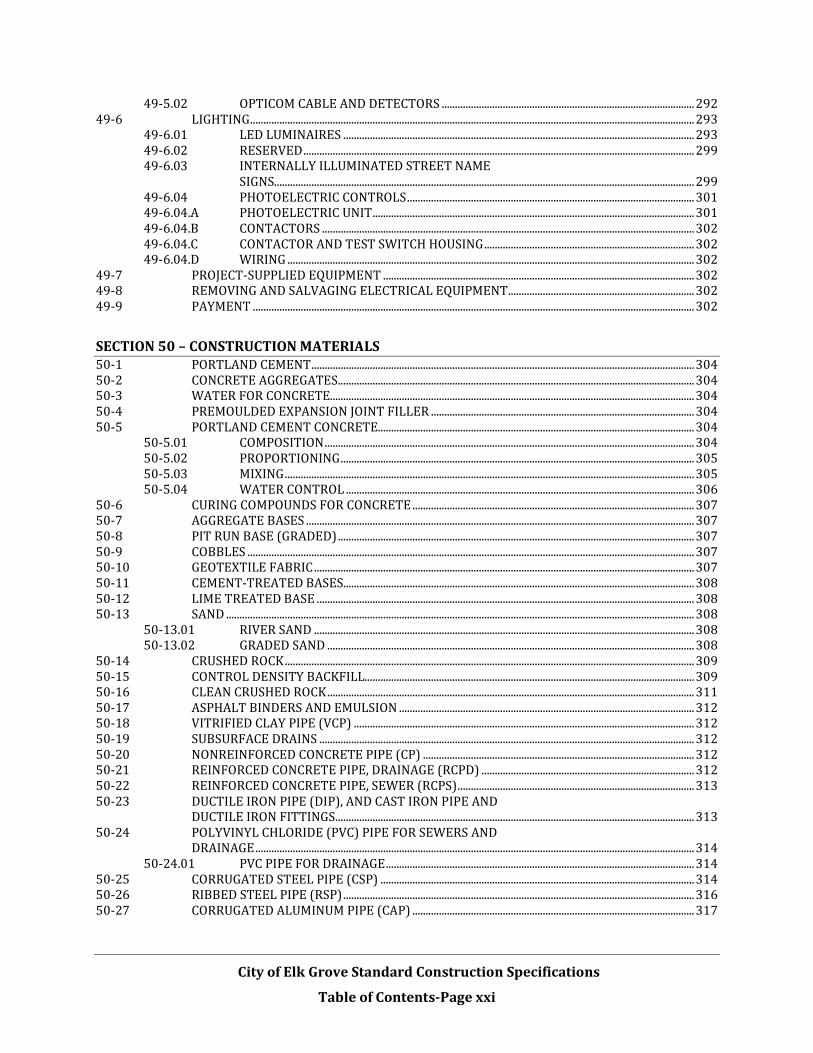
City of Elk Grove Standard Construction Specifications
Table of Contents-Page xxi
49-5.02 OPTICOM CABLE AND DETECTORS ............................................................................................... 292 49-6 LIGHTING ....................................................................................................................................................................... 293
49-6.01 LED LUMINAIRES .................................................................................................................................... 293 49-6.02 RESERVED ................................................................................................................................................... 299 49-6.03 INTERNALLY ILLUMINATED STREET NAME
SIGNS.............................................................................................................................................................. 299 49-6.04 PHOTOELECTRIC CONTROLS ............................................................................................................ 301 49-6.04.A PHOTOELECTRIC UNIT ......................................................................................................................... 301 49-6.04.B CONTACTORS ............................................................................................................................................ 302 49-6.04.C CONTACTOR AND TEST SWITCH HOUSING ............................................................................... 302 49-6.04.D WIRING ......................................................................................................................................................... 302
49-7 PROJECT-SUPPLIED EQUIPMENT ..................................................................................................................... 302 49-8 REMOVING AND SALVAGING ELECTRICAL EQUIPMENT ...................................................................... 302 49-9 PAYMENT ...................................................................................................................................................................... 302
SECTION 50 – CONSTRUCTION MATERIALS 50-1 PORTLAND CEMENT ................................................................................................................................................ 304 50-2 CONCRETE AGGREGATES ...................................................................................................................................... 304 50-3 WATER FOR CONCRETE......................................................................................................................................... 304 50-4 PREMOULDED EXPANSION JOINT FILLER ................................................................................................... 304 50-5 PORTLAND CEMENT CONCRETE....................................................................................................................... 304
50-5.01 COMPOSITION ........................................................................................................................................... 304 50-5.02 PROPORTIONING ..................................................................................................................................... 305 50-5.03 MIXING .......................................................................................................................................................... 305 50-5.04 WATER CONTROL ................................................................................................................................... 306
50-6 CURING COMPOUNDS FOR CONCRETE .......................................................................................................... 307 50-7 AGGREGATE BASES .................................................................................................................................................. 307 50-8 PIT RUN BASE (GRADED) ...................................................................................................................................... 307 50-9 COBBLES ........................................................................................................................................................................ 307 50-10 GEOTEXTILE FABRIC ............................................................................................................................................... 307 50-11 CEMENT-TREATED BASES.................................................................................................................................... 308 50-12 LIME TREATED BASE .............................................................................................................................................. 308 50-13 SAND ................................................................................................................................................................................ 308
50-13.01 RIVER SAND ............................................................................................................................................... 308 50-13.02 GRADED SAND .......................................................................................................................................... 308
50-14 CRUSHED ROCK .......................................................................................................................................................... 309 50-15 CONTROL DENSITY BACKFILL............................................................................................................................ 309 50-16 CLEAN CRUSHED ROCK .......................................................................................................................................... 311 50-17 ASPHALT BINDERS AND EMULSION ............................................................................................................... 312 50-18 VITRIFIED CLAY PIPE (VCP) ................................................................................................................................ 312 50-19 SUBSURFACE DRAINS ............................................................................................................................................. 312 50-20 NONREINFORCED CONCRETE PIPE (CP) ...................................................................................................... 312 50-21 REINFORCED CONCRETE PIPE, DRAINAGE (RCPD) ................................................................................ 312 50-22 REINFORCED CONCRETE PIPE, SEWER (RCPS) ......................................................................................... 313 50-23 DUCTILE IRON PIPE (DIP), AND CAST IRON PIPE AND
DUCTILE IRON FITTINGS ....................................................................................................................................... 313 50-24 POLYVINYL CHLORIDE (PVC) PIPE FOR SEWERS AND
DRAINAGE ..................................................................................................................................................................... 314 50-24.01 PVC PIPE FOR DRAINAGE .................................................................................................................... 314
50-25 CORRUGATED STEEL PIPE (CSP) ...................................................................................................................... 314 50-26 RIBBED STEEL PIPE (RSP) .................................................................................................................................... 316 50-27 CORRUGATED ALUMINUM PIPE (CAP) .......................................................................................................... 317

City of Elk Grove Standard Construction Specifications
Table of Contents-Page xxii
50-28 FIELD ASSEMBLED PLATE CULVERT .............................................................................................................. 318 50-29 HIGH DENSITY POLYETHYLENE PIPE (HDPE) ........................................................................................... 318 50-30 REINFORCING STEEL, CURB DOWELS AND TIE BARS............................................................................ 319 50-31 STORM DRAIN CASTINGS ...................................................................................................................................... 320 50-32 JOINT MATERIALS FOR MANHOLES ................................................................................................................ 321 50-33 FENCING - CHAIN LINK .......................................................................................................................................... 321 50-34 LANDSCAPING MATERIALS.................................................................................................................................. 322
50-34.01 TOPSOIL ....................................................................................................................................................... 322 50-34.02 COMMERCIAL FERTILIZER ................................................................................................................. 323 50-34.03 SOIL AMENDMENT ................................................................................................................................. 324 50-34.04 IRON SULFATE .......................................................................................................................................... 324 50-34.05 STRAW .......................................................................................................................................................... 324 50-43.06 FIBER ............................................................................................................................................................. 324 50-34.07 MULCH .......................................................................................................................................................... 324 50-34.08 PLANTING MIX .......................................................................................................................................... 325 50-34.09 SEED ............................................................................................................................................................... 325 50-34.09.A TURF SEED .................................................................................................................................................. 325 50-34.09.B WILDFLOWER SEED FOR HYDROSEEDING ................................................................................ 326 50-34.10 STABILIZING EMULSION ..................................................................................................................... 326 50-34.11 LUMBER........................................................................................................................................................ 326 50-34.12 TREE STAKES AND TIES....................................................................................................................... 326 50-34.13 ROOT CONTROL BARRIER .................................................................................................................. 326 50-34.14 PLANTS ......................................................................................................................................................... 327 50-34.14.A TURF............................................................................................................................................................... 328 50-34.14.B TREES ............................................................................................................................................................ 328 50-34.15 WATER .......................................................................................................................................................... 330 50-34.16 IRRIGATION PIPE .................................................................................................................................... 330 50-34.16.A STEEL PIPE ................................................................................................................................................. 330 50-34.16.B PLASTIC PIPE ............................................................................................................................................. 330 50-34.16.B.(1) MAIN LINE ................................................................................................................................................... 330 50-34.16.B.(2) LATERAL LINE .......................................................................................................................................... 331 50-34.17 SUBSURFACE DRIPPERLINE .............................................................................................................. 331 50-34.18 IRRIGATION SLEEVING CONDUIT ................................................................................................... 331 50-34.19 SPRINKLERS AND EMITTERS ............................................................................................................ 332 50-34.20 AUTOMATIC IRRIGATION CONTROLLERS .................................................................................. 332 50-34.21 QUICK COUPLING VALVES .................................................................................................................. 332 50-34.22 CONTROL VALVES ................................................................................................................................... 333 50-34.23 MASTER CONTROL VALVE/FLOW SENSOR
ASSEMBLY ................................................................................................................................................... 333 50-34.24 VALVE BOXES ............................................................................................................................................ 333 50-34.25 BACKFLOW PREVENTERS................................................................................................................... 333 50-34.26 CONCRETE .................................................................................................................................................. 334 50-34.27 FILTER ASSEMBLY UNITS ................................................................................................................... 334 50-34.28 IPS FLEXIBLE PVC HOSE ...................................................................................................................... 334 50-34.29 GATE VALVES ............................................................................................................................................ 334 50-34.30 AIR VACUUM RELIEF VALVE ............................................................................................................. 334 50-34.31 FLUSH VALVE ASSEMBLY ................................................................................................................... 335 50-34.32 UNIONS ......................................................................................................................................................... 335 50-34.33 IRRIGATION CONTROL WIRES ......................................................................................................... 335 50-34.34 PULL BOXES ............................................................................................................................................... 335 50-34.35 PRESSURE GAUGES ................................................................................................................................. 335
50-35 ENGINEERING FABRICS ......................................................................................................................................... 336 50-36 PAINT ............................................................................................................................................................................... 336

City of Elk Grove Standard Construction Specifications
Table of Contents-Page xxiii
50-37 LIQUID ASPHALT ....................................................................................................................................................... 336 50-38 ASPHALTIC EMULSION ........................................................................................................................................... 336 50-39 EPOXY .............................................................................................................................................................................. 337 50-40 PAVING STONES ......................................................................................................................................................... 337 50-41 COLORED OR PATTERNED CONCRETE .......................................................................................................... 337

SECTION 1 – TERMS AND DEFINITIONS
City of Elk Grove Standard Construction Specifications
Page 1 of 361
1-1 GENERAL
Whenever the following terms, titles, or abbreviations are used in these Specifications or in any document or instrument where these Specifications govern, the intent and meaning shall be as herein defined . Working titles having a masculine gender, such as "workman" and "journeyman" and the pronoun "he”, are utilized in the specifications for the sake of brevity, and are intended to refer to persons of either gender.
1-2 ABBREVIATIONS
AAN American Association of Nurserymen
AASHTO American Association of State Highway and Transportation Officials
AC Asphalt Concrete
ACI American Concrete Institute
AI The Asphalt Institute
AIA American Institute of Architects
AIEE American Institute of Electrical Engineers
AISC American Institute of Steel Construction
AISI American Iron and Steel Institute
ANSI American National Standards Institute, Inc.
APA American Plywood Association
API American Petroleum Institute
APWA American Public Works Association
ARA American Railway Association
AREA American Railway Engineering Association
ASA American Standards Association
ASCE American Society of Civil Engineers
ASME American Society of Mechanical Engineers
ASTM American Society for Testing and Materials
AWG American Wire Gage
AWS American Welding Society
AWWA American Water Works Association
Cal-OSHA California Occupational Safety and Health Administration
Caltrans California Department of Transportation
CAMUTCD California Manual on Uniform Traffic Control Devices
CASQA California Storm Water Quality Association

SECTION 1 – TERMS AND DEFINITIONS
City of Elk Grove Standard Construction Specifications
Page 2 of 361
CDF Controlled Density Fill
CL Centerline
CRSI Concrete Reinforcement Steel Institute
CSI Construction Specifications Institute
COEG City of Elk Grove
CY Cubic Yards
DI Drop Inlet
EA Each
EGMC City of Elk Grove Municipal Code
EP Edge of Pavement
FS Federal Specifications
IEEE The Institute of Electrical and Electronics Engineers
IES Illuminating Engineering Society
INV Invert
ISA International Society of Arboriculture
LB Pound
LF Linear Feet
LS Lump Sum
MSS Manufacturer’s Standardization Society of the Valve and Fitting Industry Standards
NBFU National Board of Fire Underwriters
NEC National Electrical Code
NEMA National Electrical Manufacturers Association
NFPA National Fire Protection Association
NSF National Sanitation Foundation
OSHA Occupational Safety and Health Act
PCA Portland Cement Association
PCC Portland Cement Concrete
PG Performance Grade
SD Storm Drain
SF Square Foot/Feet
SS Sanitary Sewer
SSPWC Standard Specifications for Public Works Construction

SECTION 1 – TERMS AND DEFINITIONS
City of Elk Grove Standard Construction Specifications
Page 3 of 361
STA Station
Title 8 Title 8 (Construction Safety Orders) of the California Code of Regulations
Title 19 Title 19 (Public Safety) of the California Code of Regulations
Title 24 Title 24 (Building Standards) of the California Code of Regulations
TOC Top of Curb
Typ. Typical
UL Underwriters' Laboratories, Inc.
UBC Uniform Building Code (latest edition adopted by City of Elk Grove)
UMC Uniform Mechanical Code (latest edition adopted by City of Elk Grove)
UPC Uniform Plumbing Code (latest edition adopted by City of Elk Grove)
USAS The United States of America Standard Institute
USBR United States Bureau of Reclamation
USPHS United States Public Health Service
WCLA West Coast Lumbermen's Association
WIC Woodwork Institute of California
1-3 DEFINITIONS
Acceptance -- The formal acceptance by the City Council of the City of Elk Grove of the entire Contract which has been completed in all respects in accordance with the Specifications and any approved modifications.
Addenda -- Any written change, clarification or supplement to documents issued for bidding, issued by the City or its Engineer prior to bid.
Agency -- Shall mean the City of Elk Grove, or another agency or district that may adopt these Specifications, acting through its authorized representatives.
Allowance -- An amount of money set aside under the Contract for a special purpose identified in the Contract.
Architect and/or Consulting Engineer -- A person or persons, firm, partnership, joint venture, corporation, or combination thereof or authorized representative thereof, acting in the capacity of consultant to the City of Elk Grove. The Architect or Consulting Engineer shall issue directions to the Contractor only through the City or the Engineer. When the Specifications require that approval be obtained from the Architect or Consulting Engineer, such approval shall be requested from and be given by the City or the Engineer.
As Builts -- Drawings prepared by the Contractor that document changes to, additions to, or deductions from the Plans, and which represent the Work as constructed..
As Shown, Etc. -- Where "as shown", "as latest indicated", "as detailed", or words of similar import are used, the reference is to the Contract unless specifically stated otherwise. Where "as directed", "as permitted", "approved", or words of similar import are used, they shall mean the direction, permission, or approval of the City.

SECTION 1 – TERMS AND DEFINITIONS
City of Elk Grove Standard Construction Specifications
Page 4 of 361
Award -- The decision of the City Council to accept the proposal of the lowest responsible bidder for the Work, subject to the execution and approval of a satisfactory contract therefore and bond to secure the performance thereof, and to such other conditions as may be specified or required by law.
Bid -- When submitted on the prescribed bid form, properly signed and guaranteed, the Bid constitutes the offer of the Bidder to complete the Work at the price shown on the Bidder’s bid form.
Bid Bond -- The cash, cashier’s check, certified check, or bidder’s bond accompanying the bid submitted by the bidder, as a guarantee that the bidder will enter into a Contract with the City for the performance of Work herein described.
Bidder -- Any person, persons, firm, partnership, joint venture, corporation, or combination thereof, submitting a Bid for the Work, acting directly or through a duly authorized representative.
Bid Documents -- The sum of the documents that comprise the Bid by a Bidder to perform the Work.
Bid Opening -- The event conducted by the City during which the sealed Proposals submitted by Bidders to perform the Work are opened and publicly read.
Bid Security -- The cash, cashier’s check, certified check, or bidder’s bond accompanying the bid submitted by the bidder, as a guarantee that the bidder will enter into a Contract with the City for the performance of Work herein described.
Board Of Supervisors -- The Board of Supervisors of the County of Sacramento, a political subdivision of the State of California. Also referred to as “Board”.
Board of Directors -- The Board of Directors of the special district named in the Notice to Contractors. Also referred to as “Board”.
Bureau -- United States Bureau of Reclamation
Calendar Day -- Every day shown on the calendar. When the Contract Time is stated in Calendar Days, every day will be charged toward the Contract Time.
Capital Improvement Project –A project initiated and supported by the City to build or modify a piece of publicly owned infrastructure (building, road, park etc.)
City -- The City of Elk Grove, a political sub-division of the County of Sacramento and the State of California.
City Council -- The City Council of the City of Elk Grove, a political sub-division of the County of Sacramento and the State of California.
Claim – A separate demand by the contractor, sent by registered mail or certified mail with return receipt requested, for (i) a time extension, (ii) payment of money or damages arising from work done by or on behalf of the contractor pursuant to the contract for a public work and payment of which is not otherwise expressly provided for or the claimant is not otherwise entitled to, or (iii) an amount the payment of which is disputed by the City.
Contract -- The written agreement signed by the City and the Contractor covering the Work and the furnishing of labor, materials, tools, and equipment in the construction of the Work. The Contract shall include the Notice to Contractors, Bid, Plans, Specifications,

SECTION 1 – TERMS AND DEFINITIONS
City of Elk Grove Standard Construction Specifications
Page 5 of 361
Special Provisions, contract bonds, and any project-specific specifications or documents; also any and all supplemental agreements amending or extending the Work contemplated and which may be required to complete the Work in a substantial and acceptable manner. Supplemental agreements are written agreements covering alterations, amendments, or extensions to the Contract and include Contract Change Orders.
Contract Change Order -- A Contract amendment approved by the City or by the Board that includes, but is not limited to, alterations, deviations, additions to, or deletions from, the Contract which are required for the proper completion of the Work.
Contract Documents -- The Contract Documents are the collective term for all of the documents listed in Article II of the Contract.
Contracting Officer -- The City Manager of the City of Elk Grove or the City Manager’s representative authorized to enter into a contract on behalf of the City of Elk Grove.
Contractor -- The person or persons firm, partnership, joint venture, corporation, or combination thereof, private or municipal, who (that) has (have) entered into a Contract, as defined in these Specifications, with the City of Elk Grove, or with a private owner or developer for Work to be dedicated to the City of Elk Grove.
Contract Time - - The time stated in the Contract for completion of the Work. The Contract Time may be a single allotment of time, a group of times specific to portions of the Work, or a combination of the two.
Council Member -- A member of the City of Elk Grove City Council.
Datum -- The Figures given in the Specifications or upon the drawings after the word “Elevation” or an abbreviation of it, shall mean U.S.G.S datum, unless otherwise noted.
Days -- Unless otherwise designated, days as used in the Contract Documents shall mean calendar days.
Elevation -- The figures given on the Plans or in the other Contract Documents after the word “Elevation” or abbreviation of it shall mean the distance in feet above the standard datum used by the City.
Engineer -- The City’s Director of Public Works/City Engineer, acting personally or through agents or assistants duly authorized by the Director.
Estimated Quantities -- The list of items of work and the estimated quantities associated with the Work. The Estimated Quantities provide the basis for the Bid. Also referred to as “Engineer’s Estimate”.
Extra Work -- Work other than that required either expressly or implied by the Contract in its executed form.
Substantial Completion -- The formal written acceptance by the Engineer that field work is substantially complete. . This may initiate the beginning of the warranty period defined by the Contract, but shall not bind the City to final Acceptance nor relieve the Contractor from the responsibility of completing or correcting any Work.
Field Instructions -- Direction given, in writing, by the Engineer.
Haul Route -- Route for ingress and egress of materials hauled to and from a project site within the City limits or the City of Elk Grove.

SECTION 1 – TERMS AND DEFINITIONS
City of Elk Grove Standard Construction Specifications
Page 6 of 361
Inspector -- The person or persons authorized to act as agent(s) for the City in the inspection of the Work.
Major Bid Item -- Five percent (5%) of the total contract bid price.
Notice To Contractors -- The written notice whereby interested parties are informed of the date, location, and time of the Bid Opening of a proposed City of Elk Grove Project and the terms and conditions of submitting Bids to perform the Work.
Notice To Proceed -- The written authorization by the City to the Contractor specifying the date the Work may begin and any conditions regarding the beginning of the Work.
Or Equal -- The term “or equal” shall be understood to indicate that the “equal” product be the equivalent or better than the product named in function, performance, reliability, quality, and general configuration. Determination of equality in reference to the project design requirements shall be made by the Engineer.
Plans -- The plans, drawings, profiles, cross sections, Working Drawings, m a p s , and Supplemental Drawings, or reproductions thereof, approved by the City, which show the locations, character, dimensions, and details of the Work.
Plant -- All resources, facilities, machinery, equipment, staging, tools, work and storage space other than provided by the Contract, together with subsidiary essentials and necessary maintenance for proper construction and acceptable completion of the project.
Project -- Shall mean the Work.
Project Manager -- The person designated by the City as its project management representative during the course of construction, acting either directly or through properly authorized agents, such agents acting within the scope of the particular duties delegated to them.
Proposal -- Shall mean “Bid”.
Record Drawings -- Drawings prepared by the Engineer that document changes to, additions to, or deductions from the Plans, and which represent the Work as constructed.
Schedule of Values -- A statement furnished by the Contractor to the City reflecting the portions of the Total Contract Price allotted for the various parts of the Work for each work activity contained on the project schedule. Unless otherwise indicated in the Specifications, the total of the Schedule of Values shall equal the full cost of the Work, including all labor, material, equipment, overhead, and profit. For lump sum contracts, the Schedule of Values is the basis for reviewing the Contractor's application for progress payments.
Shop Drawings -- Drawings prepared by the fabricator or supplier showing the layout and details of components fabricated in a shop for inclusion in the permanent facility (e.g., structural steel, reinforcing steel, railings).
Site – The area upon or in which the Contractor’s operations are carried out and such other areas adjacent thereto as may be designated by the Engineer.
Special Provisions -- The Special Provisions are specific clauses setting forth conditions or requirements peculiar to the Work and supplementary to these Standard Construction Specifications.

SECTION 1 – TERMS AND DEFINITIONS
City of Elk Grove Standard Construction Specifications
Page 7 of 361
Standard Construction Specifications -- The directions, provisions, and requirements contained herein. When the term “Standard Specifications" or "these Specifications" is used, it means the provisions as set forth herein, together with any amendments or revisions that may be set forth in the Special Provisions. The Standard Specifications are comprised of “General Provisions” and “Technical Provisions”.
Standard Drawings -- The Standard Drawings of the City of Elk Grove, which are incorporated into the Standard Construction Specifications, and made a part of the Plans by reference to one or more specific Standard Drawings.
State -- The State of California.
State Specifications – Unless specified differently in the Special Provisions, the 2015 version of Standard Specifications of the State of California, Department of Transportation as amended through the revised standard specifications dated 4-28-2018. Reference to the “Department” in the State Specifications shall be construed as the City of Elk Grove.
State Plans – Unless referenced differently in the contract plans, the 2015 version of the Standard Plans of the State of California, Department of Transportation unless specified differently in the Special Provisions.
Subcontractor -- A properly licensed party under contract to and responsible to the Contractor for performing a specified part of the Work; or a properly licensed party under contract and responsible to a Subcontractor of the Contractor.
Supplemental Conditions – Additions, revisions, special directions, and requirements peculiar to a project site and not otherwise thoroughly set forth in General Conditions and/or these Specifications.
Supplemental Drawing -- Supplemental Drawings define the Plans or Specifications in greater detail by providing additional information that may have not been specifically or clearly shown or called out on the Plans or in the Specifications.
Technical Provisions -- The provisions of the Standard Construction Specifications that describe the technical aspects of the Work.
Total Contract Price - - The total price for the Work as bid by the Contractor, including any additions or subtractions made via Contract Change Orders.
Work -- All actions which the Contractor is contractually required to do as specified, indicated, shown, contemplated, or implied in the Contract to construct the Work, including all alterations, amendments, or extensions made by Contract Change Order or other written orders or directives of the City. Unless specified otherwise in the Contract, the Work includes furnishing all materials, supplies, equipment, tools, labor, transportation, supervision, and all incidentals necessary to complete the Work.
Working Day -- Any day except: (a) Saturdays, Sundays, and legal holidays; (b) days on which the Contractor is specifically required by the Contract or by law to suspend construction operations; or (c) days on which the Contractor is prevented from proceeding with the current controlling operation or operations of the Work for at least five (5) hours per day due to inclement weather, or conditions resulting immediately therefrom; or (d) as defined in the Contract.
Working Drawing -- Working Drawings detail a particular item of work and the manner

SECTION 1 – TERMS AND DEFINITIONS
City of Elk Grove Standard Construction Specifications
Page 8 of 361
in which it is to be accomplished or performed. Working Drawings are prepared by the Contractor as a submittal or a portion of a submittal and may be specifically requested by the City or required in the Contract or a Field Instruction or other written directive.
Written Notice -- “Written Notice” shall be deemed to have been duly served when delivered in person to the individual or to a member of the firm or to an officer of the corporation for whom it is intended, or if delivered at or sent by U.S. mail to the last business address known to him who gives the notice.

SECTION 2 - BID REQUIREMENTS AND CONDITIONS
City of Elk Grove Standard Construction Specifications
Page 9 of 361
2-1 BID FORM
The City shall furnish to each prospective Bidder a bid form which, when properly completed and executed, shall be submitted as the Bidder's Bid for the Work. All Bids shall be submitted on the City-furnished bid form to be valid and accepted. Bids that are not submitted on the City-furnished bid form shall be rejected. The completed bid form shall be in English and legible, and shall be properly signed in longhand by the Bidder, if an individual, by a member of a partnership, by an officer of a corporation authorized to sign contracts on behalf of the corporation, or by an agent of the Bidder. If submitted by a corporation, the Bid shall show the name of the state under the laws of which the corporation is chartered or organized.
The Bid shall be made on the bid form in clearly legible figures as follows:
2-1.01 Unit Price Bid
Where the bid for an item of work is to be submitted on a unit price basis, the Bidder shall bid a unit price as total compensation for completion of one unit of the work described under that item. This price shall be multiplied by the Estimated Quantity included in the bid form to derive a total bid price for that item. The total amount bid for a unit price contract shall be entered on the space provided on the bid form as a grand total of all individual items.
The Estimated Quantities included on the bid form are approximate and are only included in the bid form as a basis for comparison of Bids. The City does not, expressly or by implication, represent or agree that the actual amount of work shall equal the approximate Estimated Quantities. Payment shall be made for the actual quantity of Work performed in accordance with the Contract. The City reserves the right to increase or decrease the amount of any class or portion of the Work, or to omit portions of the Work, as may be deemed necessary or advisable in the sole discretion of the City. Any major bid item with an increase or decrease in estimated quantity greater than 25%, the unit price bid shall be adjusted. Contractor shall submit detailed cost data to substantiate any unit price adjustment. See Section 9-8.02, “Payment for Changes – Unit Prices”, of these Specifications.
2-1.02 Lump Sum Bid
Where the bid for an item of work is to be submitted on a "Lump Sum" or "Job" basis, a single lump-sum price shall be submitted in the appropriate place on the bid form. Items bid on a lump-sum basis shall result in a complete structure, operating plant, or system, in satisfactory working condition with respect to the functional purposes of the installation, as described in the Contract, and no extra compensation shall be paid for anything omitted but fairly implied.
2-1.03 Allowances
Where specific allowance items have been entered on the bid form by the City, the total amount entered on the bid form shall be included in the Total Bid Price. However, the total amount to be paid for the Work included in the Allowance shall be the amount of the Allowance actually utilized in the course of completing the Work.

SECTION 2 - BID REQUIREMENTS AND CONDITIONS
City of Elk Grove Standard Construction Specifications
Page 10 of 361
2-2 PREPARATION AND SUBMISSION OF BIDS
By submission of a Bid, the Bidder acknowledges acceptance of the nature and location of the Work, the general and local conditions, conditions of the site, the character, quality and scope of work to be performed, the availability of labor, electric power, water, the kind of surface and subsurface materials on the site, the materials and equipment to be furnished, and all requirements of the Contract or other matters which may affect the Work or the cost. Any failure of a Bidder to become acquainted with all of the available information concerning conditions shall not relieve the Bidder from the responsibility for estimating properly the difficulties or cost of the Work.
The Bidder declares by the submission of a Bid that the Bid is not made in the interest of, or on behalf of, any undisclosed person, partnership, company, association, organization, or corporation; that the Bid is genuine and not collusive or a sham; that the Bidder has not directly or indirectly induced or solicited any other Bidder to put in a false or sham Bid, and has not directly or indirectly colluded or agreed with any Bidder or anyone else to put in a sham Bid or to refrain from bidding; that the Bidder has not directly or indirectly sought by agreement, communication, or conference with anyone to fix the Bid price or the Bid price of any other Bidder, or to fix any overhead, profit, or cost element of such Bid price or that of any other Bidder, or to secure any advantage against the City, anyone interested in the Bid as principal, or those named within the Bid; that all statements contained in the Bid are true; that the Bidder has not directly or indirectly submitted a Bid price or any breakdown thereof or the contents thereof, or divulged information or data relative thereto, to any other person, partnership, corporation or association, except to person or persons as have a direct financial interest in the Bidder's general business.
Bid prices shall include everything necessary for the completion of the Work and fulfillment of the Contract, including but not limited to furnishing all materials, equipment, tools, excavation sheeting, bracing and supports, plant, labor and services, except as may be provided otherwise in the Contract. Bid prices shall include all Federal, State, and local taxes, and all other fees and costs not expressly paid for by the City as stated in the Special Provisions.
The Bid shall be submitted in a sealed envelope as directed in the Notice to Contractors. The Bidder shall plainly mark the exterior of the envelope in which the Bid is submitted to indicate that it contains a Bid for the project for which the Bid is submitted, and the date of the Bid opening therefore.
Bids submitted in envelopes that are not properly marked shall be rejected.
2-3 EXAMINATIONS OF PLANS, SPECIFICATIONS, AND SITE OF WORK
The Bidder shall examine carefully the site of the proposed Work and the Plans, Specifications and Bid Documents, and shall be satisfied as to the character, quality, and quantity of surface and subsurface materials or obstacles to be encountered. The submission of a Bid shall be conclusive evidence that the Bidder is satisfied through the Bidder’s own investigation as to the conditions to be encountered; the character, quality, quantity and scope of work to be performed; and the materials and equipment to be furnished.
If material discrepancies or apparent material errors are found in the Plans and Specifications prior to the date of bid opening, an Addendum may be issued (see Section 2-9,“Addenda”, in this Section of these Specifications). Otherwise, in figuring the Work, Bidders shall consider that any discrepancies or conflict between Plans and Specifications shall be governed by Section 4-1, “Intent of Contract Documents”.

SECTION 2 - BID REQUIREMENTS AND CONDITIONS
City of Elk Grove Standard Construction Specifications
Page 11 of 361
2-4 SUBSURFACE CONDITIONS
Where investigations of subsurface conditions have been made by the City with respect to subsurface conditions, utilities, foundation, or other structural designs, and that information is shown in the Plans, it represents only a statement by the City as to the character of materials which have actually been encountered by the City’s investigation. This information is only included for the convenience of Bidders.
Investigations of subsurface conditions are made for the purpose of design only. The City assumes no responsibility with respect to the sufficiency or accuracy of borings or of the log of test borings or other preliminary investigations or of the interpretation thereof. There is no guaranty, either expressed or implied, that the conditions indicated are representative of those existing throughout the Work, or any part of it, or that unanticipated conditions may not occur. When a log of test borings is included in the Plans, it is expressly understood and agreed that said log of test borings does not constitute a part of the Contract. The log of test borings represents only an opinion of the City as to the character of the materials to be encountered, and is included in the Plans only for the convenience of the Bidders. Making information available to Bidders is not to be construed in any way as a waiver of the provisions of the first paragraph of this Section, and Bidders shall satisfy themselves through their own investigations as to conditions to be encountered.
2-5 CONTRACTORS/SUBCONTRACTORS REQUIRED TO BE LICENSED
The Bidder shall be licensed under the provisions of Chapter 9, Division 3, of the Business and Professions Code to do the type of work contemplated in the project, and shall be skilled and regularly engaged in the general class or type of work called for under the Contract. The specific type of license required shall be indicated in the “Notice to Contractors”. Unless specified otherwise in the Special Provisions, the Bidder shall indicate the license number and class in the space provided for that purpose on the bid form.
All Subcontractors engaged to perform portions of the Work shall be licensed under the provisions of Chapter 9, Division 3, of the Business and Professions Code to do the type of work for which they are subcontracted, and shall be skilled and regularly engaged in the general class or type of work called for under their subcontracts.
Attention is also directed to the provisions of Public Contract Code Section 20103.5, which addresses Contractor licensing requirements. The City may not award the Contract if it cannot be verified that the low Bidder is an appropriately licensed Contractor at the time of Contract award.
In addition to the above state license requirements, all contractors and subcontractors performing work on the Contract must have valid City of Elk Grove Business licenses.
2-6 COMPETENCY OF BIDDERS
It is the intention of the City to award a Contract only to a Bidder who furnishes satisfactory evidence that the Bidder has the requisite experience and ability, and has sufficient capital, facilities, and plant to enable the Contractor to prosecute the Work successfully and promptly, and to complete the Work within the time stated in the Contract.
If required by the Special Provisions, a statement of experience and business standing, together with that of all Subcontractors that were designated in the Bid, shall be submitted on a City-

SECTION 2 - BID REQUIREMENTS AND CONDITIONS
City of Elk Grove Standard Construction Specifications
Page 12 of 361
provided form by the three (3) apparent low Bidders within seven (7) days after the opening of Bids. To determine the experience of a Bidder, any relevant evidence shall be considered that the Bidder, or personnel, has satisfactorily performed on other contracts of similar nature and magnitude or difficulty.
2-7 JOINT VENTURE BIDS
If two or more prospective Bidders desire to bid jointly as a joint venture on a single project, the joint venture Bid shall be accompanied by a notarized copy of a valid license issued to the joint venture by the Contractor’s State License Board. If a copy of the joint venture license is not filed with the Bid, the Bid shall be rejected.
2-8 SUBCONTRACTORS
Except as noted in the Special Provisions, the Contractor shall perform, with the Contractor's own organization and with workers under the Contractor's immediate supervision, work of a value not less than fifty percent (50%) of the value of original Total Contract Price less “Specialty Items”. “Specialty Items” may be performed by subcontract and the cost of any “Specialty Items” so performed may be deducted from the original Total Contract Price before computing the amount of work required to be performed by the Contractor. Where an entire item is subcontracted, the value of work subcontracted shall be based on the Contract item bid price. When a portion of an item is subcontracted, the value of work subcontracted shall be based on the estimated percentage of the contract item bid price, determined from information submitted by the Contractor, subject to approval by the City. In accordance with the Subletting and Subcontracting Fair Practices Act, of the Public Contract Code, Section 4100 et seq., each Bidder shall list in the bid form:
• The name and the location of the place of business of each Subcontractor whom the Bidder proposes to perform work or labor or render service to the prime Contractor in or about the construction of the Work, or a Subcontractor licensed by the State of California who, under subcontract to the prime Contractor, is proposed by the Bidder to specially fabricate and install a portion of the Work according to detailed drawings contained in the Contract, in an amount in excess of one-half of one percent (0.5%) of the Total Bid or, in the case of a Bid for the construction of streets or highways, including bridges, in excess of one-half of one percent (0.5%) of the Bidder’s Total Bid or ten thousand dollars ($10,000), whichever is greater.
• The portion of the Work [ type of work and percentage if not one hundred percent (100%)] that shall be done by each Subcontractor. The Bidder shall list only one Subcontractor for each portion as is defined by the Bidder in the Bid.
If a Bidder fails to specify a Subcontractor for any portion of the Work to be performed under the Contract (or specifies more than one Subcontractor for the same work), the Bidder agrees that the Bidder is fully qualified and shall perform that portion of the Work. If after the award of the Contract, the Contractor subcontracts any portion of the Work, except as provided in Section 4107 or 4109 of the Act, the Contractor shall be subject to the penalties specified in Section 4111 of the Act.
A listed Subcontractor shall perform with the Subcontractor’s own organization and with workers under the Subcontractor’s immediate supervision, work of a value of not less than seventy-five percent (75%) of the value of each item of work for which the Subcontractor is listed.
Pursuant to Public Contract Code Section 6109, a Contractor may not perform work with a
SECTION 2 - BID REQUIREMENTS AND CONDITIONS
City of Elk Grove Standard Construction Specifications
Page 13 of 361
Subcontractor who is ineligible to perform work on public works projects pursuant to Labor Code Sections 1777.1 and 1777.7.
The apparent low Bidder shall submit the license numbers of all Subcontractors to the City within three (3) days, not counting Saturdays, Sundays, and holidays, of Bid opening. If the low Bidder is not the apparent low Bidder, the low Bidder shall submit the license numbers of all listed subcontractors to the City within three (3) days, not counting Saturdays, Sundays, and holidays, of the date notified.
The Contractor shall include provisions in every Subcontract that the Contract between the Contractor and the City is part of the Subcontract, and that all terms and provisions of the Contract are incorporated in the Subcontract. Copies of all Subcontracts shall be available to the City upon written request.
2-9 ADDENDA
The correction of any material discrepancies in, or material additions to/omissions from, the Plans, Specifications, or other part of the Contract, or any interpretation thereof, during the bidding period shall be made only by an Addendum issued by the City. A copy of each Addendum issued by the City shall be mailed or delivered to each planholder listed on the City planholder list and is a part of the Contract. Any interpretation or explanation not included in the addenda shall not be considered binding.
2-10 ASSIGNMENT OF ANTITRUST ACTIONS
The Bidder is required to comply with Public Contract Code Section 7103.5(b), which addresses assignment of antitrust actions.
2-11 BID GUARANTEE
The Bid shall be accompanied by a Bid Guarantee in the form of cash, a certified check, a cashier’s check, or a bidder’s bond in the form provided by the City. The Bid Guarantee shall be executed by an admitted surety insurer in favor of the City, the amount of which shall be not less than ten percent (10%) of the Base Bid amount, or other security acceptable to the City. No Bid shall be considered unless accompanied by a Bid Guarantee.
The City is authorized to forfeit such Bid Guarantee as necessary to reimburse for costs incurred for failure of the successful Bidder to enter into a contract. The amount of the Bid Guarantee shall not be deemed to constitute a penalty or liquidated damages. The City is not precluded by a Bid Guarantee from recovering from the defaulting Bidder damages in excess of the amount of said Bid Guarantee incurred as a result of the failure of the successful Bidder to enter into a contract with the City for the Work.
2-12 WITHDRAWAL OF BID
A Bid may be withdrawn at any time prior to the hour fixed in the Notice to Contractors for the submission of Bids by a written request of the Bidder filed with the City at the location where the Bid was submitted. The withdrawal of a Bid shall not prejudice the right of a Bidder to file a new Bid within the time prescribed.
2-13 PUBLIC OPENING OF BIDS
Bids shall be opened and read publicly at the time and place indicated in the Notice to

SECTION 2 - BID REQUIREMENTS AND CONDITIONS
City of Elk Grove Standard Construction Specifications
Page 14 of 361
Contractors or in a subsequent Addendum. Bidders or their authorized representatives and other interested parties are invited to be present.
2-14 REJECTION OF BIDS
The City reserves the right to reject any and all Bids. The City reserves the right to waive irregularities in a Bid and to make an award in the best interest of the City. Bids containing omissions, erasures, alterations, conditions, or additions not called for shall be rejected.
2-15 RELIEF OF BIDDERS
Attention is directed to Public Contract Code Sections 5100 through 5107, concerning relief of Bidders and in particular to the requirement therein that if the Bidder claims a material mistake was made in its Bid, the Bidder shall give the City written notice within five (5) days after the opening of the Bids (excluding Saturdays, Sundays, or legal holidays) of the alleged mistake, explaining in the notice in detail how the mistake occurred.

SECTION 3 – AWARD AND EXECUTION OF CONTRACT
City of Elk Grove Standard Construction Specifications
Page 15 of 361
3-1 AWARD OF CONTRACT
The award of the Contract, if the Contract is to be awarded, will be to the lowest responsive, responsible Bidder. In addition to price in determining the lowest responsive, responsible Bidder, consideration will be given to:
• the ability, capacity and skill of the Bidder to perform the Work;
• the ability of the Bidder to perform the Work within the time specified, without delay;
• the ability of the Bidder to perform the Work in a safe manner;
• the character, integrity, reputation, judgment, experience and efficiency of the Bidder; and
• the quality of the Bidder's performance on previous work with the City.
If an alternate or alternates are selected by the City, unless otherwise specified in the Contract, award will be based on the lowest total price for the sum of the base bid price plus the bid prices of the selected alternate or alternates.
3-2 TIME OF AWARD
The award, if made, will be made within sixty (60) calendar days after the Bid Opening. If the lowest responsive, responsible Bidder refuses or fails to execute the Contract, the City shall award the Contract to the second lowest responsive, responsible Bidder. The specified period of time within which the award of the Contract shall be made shall be subject to extension for further periods as agreed upon in writing by the City and the Bidder.
3-3 CONSIDERATION OF BIDS
After the Bids have been opened and read, they will be checked for accuracy and compliance with the Specifications.
In the event that the product of a unit price and an estimated quantity does not equal the extended amount quoted, the unit price shall govern and the correct product of the unit price and the estimated quantity shall be deemed to be the amount bid. If the sum of two or more items in a bidding schedule or the sum of two or more bidding schedules does not equal the total amounts quoted, the individual item or schedule amounts shall govern and the correct total shall be deemed to be the amount bid. If the Bid is missing the unit price, then it shall be deemed incomplete and the Bid shall be rejected.
After the City has made any necessary corrections in mathematical errors appearing on the face of the Bid, all Bids will be compared based on the bid form.
3-4 PERFORMANCE AND PAYMENT BONDS
The format of the Performance Bond and Payment Bond forms shall be those contained in these Specifications.
As part of the execution of the Contract, the successful Bidder shall furnish the following corporate surety bonds to the benefit of the City. Bonds shall be executed by a surety company authorized to do business in the State of California and listed in the current Federal Department of Treasury Circular 570. When the amount to be paid to the Contractor is based upon units of work

SECTION 3 – AWARD AND EXECUTION OF CONTRACT
City of Elk Grove Standard Construction Specifications
Page 16 of 361
to be performed or items to be provided, the term “Total Contract Price” as used below for the purpose of posting Performance and Payment Bonds shall be computed on the basis of the unit price bid multiplied by the Estimated Quantities of work to be performed.
3-4.01 Performance Bond
The Performance Bond, to guarantee the performance of all covenants and stipulations of the Contract, shall be on the form provided by the City and shall be in a sum not less than one hundred percent (100%) of the original Total Contract Price as set forth in the Contract.
3-4.02 Payment Bond
The Payment Bond, to guarantee the payment of wages and of bills contracted for materials, supplies, or equipment used in the performance of the Contract, shall be on the form provided by the City and shall be in a sum not less than one hundred percent (100%) of the original Total Contract Price as set forth in the Contract.
3-5 NOTIFICATION OF SURETY COMPANIES
The surety company shall be familiar with all the provisions and conditions of the Contract. It is understood and agreed that the surety company waives notice of change, extension of time, alteration or addition to the terms of the Contract or to the Work to be performed thereunder or to the specifications accompanying the same, or any other act or acts by the City or the City’s authorized agents under the terms of the Contract; and failure to so notify the surety company of changes shall in no way relieve the surety company of its obligations under the Contract.
3-6 RETURN OF BID GUARANTEES
After Bids have been received and reviewed by the City, Bid Guarantees will be returned to the respective Bidders except those submitted by the three lowest responsive, responsible Bidders.
Bid Guarantees for Bids not to be further considered in executing the Contract will be returned within ten (10) days, not counting Saturdays, Sundays, and holidays, after the award of the Contract. The Bid Guarantees of the three lowest responsive, responsible Bidders will be returned within ten (10) days, not counting Saturdays, Sundays, and holidays, after the successful Bidder has filed satisfactory bonds and proof of insurance as specified and the Bidder and the City have executed the Contract. If all Bids are rejected and no award is made, all Bid Guarantees will be returned within ten (10) days, not counting Saturdays, Sundays, and holidays, of the decision of the City Council to not award the Contract.
3-7 EXECUTION OF CONTRACT
The Contract shall be executed by the successful Bidder and returned to the City, together with the Performance Bond, Payment Bond and certificates of insurance within ten (10) days, not counting Saturdays, Sundays, and holidays, of the Bidder’s receipt of the documents. Insurance certificates shall be signed by a person authorized by the insurer to bind coverage on its behalf and shall be accompanied by copies of all endorsements required by Section 3-9 in this Section of these Specifications. When requested by the City, the successful bidder shall furnish complete, certified copies of all required insurance policies, including endorsements specifically required by Section 3-9. After execution by the City, one copy of the Contract, bonds, and certificates of insurance will be returned to the Contractor.

SECTION 3 – AWARD AND EXECUTION OF CONTRACT
City of Elk Grove Standard Construction Specifications
Page 17 of 361
3-8 FAILURE TO EXECUTE CONTRACT
If the Bidder to whom the Contract is awarded fails to execute the Contract and file acceptable bonds and insurance certificates as provided herein within ten (10) days, not counting Saturdays, Sundays, and holidays, from the time the Contract forms are received by the Bidder, the award shall be annulled and the Bidder’s Bid Guarantee forfeited to the City. At the City’s discretion, the Contract shall then be awarded to the next lowest responsive, responsible Bidder.
If the City awards the Contract to the second lowest responsive, responsible Bidder, the amount of the lowest responsive, responsible Bidder's Bid Guarantee shall be applied by the City to the difference between the lowest Bid and the Bid of the second lowest responsive, responsible Bidder, and the surplus, if any, will be returned to the lowest responsive, responsible Bidder if a check or cash is used, or credited to the surety on the Bidder's Bond if a bond is used.
On refusal or failure of the second lowest responsive, responsible Bidder to execute the Contract, the City shall award it to the third lowest responsive, responsible Bidder. If the City awards the Contract to the third lowest responsive, responsible Bidder, in addition to application of the lowest Bidder’s Bid Guarantee as aforesaid, the amount of the second lowest responsive, responsible Bidder’s Bid Guarantee shall be applied by the City to the difference between the Bid of the second lowest responsive, responsible Bidder and the Bid of the third lowest responsive, responsible Bidder, and the surplus, if any, shall be returned to the second lowest responsive, responsible Bidder if a check or cash is used, or credited to the surety on the second lowest Bidder’s Bid Bond if a bond is used.
3-9 INSURANCE
Unless otherwise stated in the Contract, the Contractor shall procure, maintain, and keep in force at all times during the term of the Contract, at the Contractor’s sole expense, the following insurance:
3-9.01 General Liability
General Liability insurance including, but not limited to, protection for claims of bodily injury and property damage liability, personal and advertising injury liability, and products and completed operations liability. Coverage shall be at least as broad as “Insurance Services Office Commercial General Liability Coverage Form CG 0001” (occurrence). The limits of liability shall be not less than:
Each Occurrence One Million Dollars ($1,000,000)
Personal & Advertising Injury One Million Dollars ($1,000,000)
Products and Completed Operations Aggregate Two Million Dollars ($2,000,000)
General Aggregate Two Million Dollars ($2,000,000)
Fire Damage One Hundred Thousand Dollars ($100,000)
The policy shall cover contractual liability applicable to the Contractor’s assumed liability under this Contract. The policy shall provide coverage for claims arising out of subsidence. The Products and Completed Operations coverage shall be maintained for at least two years after completion of the Contract.

SECTION 3 – AWARD AND EXECUTION OF CONTRACT
City of Elk Grove Standard Construction Specifications
Page 18 of 361
3-9.02 Automobile Liability
Automobile Liability insurance providing protection against claims of bodily injury and property damage arising out of ownership, operation, maintenance, or use of owned, hired, and non-owned automobiles. Coverage shall be at least as broad as “Insurance Services Office Business Auto Coverage Form CA 0001,” symbol 1 (any auto). The limits of liability shall not be less than:
Bodily Injury and Property Damage Combined Single Limit One Million Dollars ($1,000,000)
3-9.03 Workers' Compensation
Workers' Compensation insurance, with coverage as required by the State of California (unless the Contractor is a qualified self-insurer with the State of California), and Employers’ Liability coverage. The limits of Employers’ Liability shall not be less than:
Each Accident One Million Dollars ($1,000,000)
Disease Each Employee One Million Dollars ($1,000,000)
Disease Policy Limit One Million Dollars ($1,000,000)
The Workers’ Compensation policy required hereunder shall be endorsed to state that the Workers’ Compensation carrier waives its right of subrogation against the City, its officers, officials, employees, agents or volunteers.
In the event the Contractor is self-insured, the Contractor shall furnish a Certificate of Permission to Self-Insure by the Department of Industrial Relations Administration of Self- Insurance, Sacramento.
3-9.04 Excess or Umbrella Liability
If the Special Provisions require limits of general liability insurance of more than one million dollars ($1,000,000) per occurrence, the Contractor shall carry excess or umbrella liability insurance providing excess coverage at least as broad as the underlying coverage for general, automobile and employer’s liability with a limit equal to the amount stated in the Special Provisions per occurrence and aggregate.
3-9.04.A Contractor’s Equipment
The Contractor, and each of its Subcontractors, shall separately insure its own equipment for loss and damage. The Contractor’s Property and Inland Marine policies shall include, or be endorsed to include, a waiver of subrogation against the City, its officers, officials, employees, agents, and volunteers which might arise by reason of damage to the Contractor’s property or equipment (owned, leased or borrowed) in connection with work performed under this Contract by the Contractor.
3-9.04.B Railroad Protective Liability
When stated as a requirement in the Special Provisions, the Contractor shall procure, maintain, and keep in force at all times during the term of the Contract, at the Contractor’s sole expense, Railroad Protective Liability insurance with limits of liability as set forth in the

SECTION 3 – AWARD AND EXECUTION OF CONTRACT
City of Elk Grove Standard Construction Specifications
Page 19 of 361
Special Provisions.
3-9.04.C Builder’s Risk Insurance
When stated as a requirement in the Special Provisions, the Contractor shall procure, maintain, and keep in force at all times during the term of the Contract and until the date of transfer of the insurable interest to and acceptance by the City, at the Contractor’s sole expense, Builder's Risk insurance with limits of liability equal to one hundred percent (100%) of the replacement cost of the Work.
a. Coverage shall be written on a completed value, non-reporting form, on a replacement cost basis, and shall cover the property against all risks of physical loss or damage including:
i. land movement and flood
ii.loss that ensues from design error, defective materials, or faulty workmanship
iii.mechanical breakdown or electrical damage including testing, magnetic disturbance and changes in temperature or humidity.
The property covered shall include the Work, including any materials, equipment, or other items to be incorporated therein while the same are located at the construction site, stored off site, while in transit or at the place of manufacture. The policy shall contain a provision that both the interests of the City and the Contractor are covered and that any loss shall be payable to the City and the Contractor as their interests shall appear.
When stated as a requirement in the Special Provisions, Builders Risk insurance shall include Delay in Opening coverage with limits of liability, and for the period of time, as set forth in the Special Provisions. Coverage shall include debt service, expense, loss of earnings or rental income or other loss incurred by the City, without deduction, due to the failure of the project being completed on schedule.
b. The maximum deductible for land movement and flood allowable under this policy shall be five percent (5%) of replacement value at the time loss or one hundred thousand dollars ($100,000), whichever is less, per occurrence and in the aggregate. The maximum deductible for all other perils allowable under this policy shall be ten thousand dollars ($10,000). All deductibles shall be borne solely by the Contractor, and the City shall not be responsible to pay any deductible, in whole or in part.
c.The City and the Contractor waive all rights against each other and against all other contractors for loss or damage to the extent reimbursed by Builders' Risk insurance or any other property or equipment insurance applicable to the Work, except such rights as they shall have to the proceeds of such insurance. If the policies of insurance referred to in this section require an endorsement or consent of the insurance company to provide for continued coverage where there is a waiver of subrogation, the owners of such policies will cause them to be so endorsed to obtain such consent.
d. If not covered by Builders' Risk insurance or any other property or equipment

SECTION 3 – AWARD AND EXECUTION OF CONTRACT
City of Elk Grove Standard Construction Specifications
Page 20 of 361
insurance required by this Contract, the Contractor shall procure, maintain, and keep in force at all times during the term of the Contract, at the Contractor’s sole expense, property insurance for portions of the Contractor's work and/or equipment to be incorporated therein stored offsite or in transit.
3-9.04.D Environmental Liability Insurance
When stated as a requirement in the Special Provisions, the Contractor shall procure, maintain, and keep in force at all times during the term of the Contract, at the Contractor’s sole expense, Environmental Liability insurance which includes coverage for sudden and accidental pollution arising out of the handling of hazardous materials or hazardous wastes, and coverage for liability arising out of the handling of asbestos. If coverage for Environmental Liability insurance is written on a claims-made form, the following provisions apply:
1. The "Retro Date" must be shown, and must be on or before the date of the Contract or the beginning of the Work.
2. Insurance must be maintained and evidence of insurance must be provided for at least one (1) year after completion of the Contract.
3. If coverage is cancelled or non-renewed, and not replaced with another claims-made policy form with a "Retro Date" prior to the Contract effective date, the Contractor must purchase "extended reporting" coverage for a minimum of one (1) year after completion of the Contract.
3-9.04.E Other Provisions
1. The Contractor's General Liability, Automobile Liability, and any Excess or Umbrella Liability, shall contain the following provisions:
a.The City, its officers, officials, employees, agents, and volunteers shall be covered as additional insureds as respects liability arising out of the activities performed by or on behalf of the Contractor, products and completed operations of the Contractor, premises owned, occupied, or used by the Contractor, or automobiles owned, leased, hired, or borrowed by the Contractor. The policy shall contain no special limitations on the scope of coverage afforded to the City, its officers, officials, employees, agents, or volunteers.
b. For any claims related to this Contract, the Contractor's insurance coverage shall be primary insurance as respects the City, its officers, officials, employees, agents, or volunteers. Any insurance or self-insurance maintained by the City, its officers, officials, employees, agents, or volunteers shall be excess of the Contractor's insurance and shall not contribute with it.
c.Any failure to comply with reporting or other provisions of the policies on the part of the Contractor, including breaches of warranties, shall not affect coverage provided to the City, its officers, officials, employees, agents, or volunteers.
2. The Contractor's General Liability and any Excess or Umbrella Liability insurance policies shall contain an endorsement stating that any aggregate limits shall apply separately to the Work.
3. The Contractor’s insurance shall apply separately to each insured against whom
SECTION 3 – AWARD AND EXECUTION OF CONTRACT
City of Elk Grove Standard Construction Specifications
Page 21 of 361
claim is made or suit is brought, except with respect to the limits of the insurer’s liability.
4. Each insurance policy shall state that coverage shall not be suspended, voided, cancelled by the Contractor or the City, reduced in scope of coverage or in limits, non-renewed, or materially changed unless the insurer(s) provide thirty (30) days written notice by certified mail to the City prior to such change. Ten (10) days prior written notice by certified mail shall be given to the City in the event of cancellation due to nonpayment of premium.
5. All of the Contractor's insurance coverage, except as noted below, shall be placed with insurance companies with a current A.M. Best rating of at least A-:X.
Exceptions:
a.Underwriters at Lloyd's of London, which are not rated by A.M. Best.
b.Workers' Compensation which is provided through a State Compensation Insurance Fund or a qualified self-insurer for Workers' Compensation under California law.
c.For liability insurance required under Section 3-9.04D (Environmental Liability insurance), insurance requirements shall be placed with insurance companies with a current A.M. Best rating of at least B+:VII.
6. The Contractor shall sign and file with the City the following certification prior to commencing performance of the work of the Contract:
“I am aware of the provisions of Section 3700 of the Labor Code which require every employer to be insured against liability for worker’s compensation or to undertake self-insurance in accordance with the provisions of the Code, and I will comply with such provisions before commencing the performance of the Work of this Contract.”
Said certification is included in the Contract, and signature and return of the Contract shall constitute signing and filing of the said certification.
7. The City, at its discretion, shall require new types of insurance coverage or increase the limits of insurance coverage required hereunder at any time during the term of the Contract by giving thirty (30) days written notice to the Contractor. Contractor shall immediately procure such insurance or increase the limits of coverage and provide certificates of insurance, including copies of all required endorsements, to the City within thirty (30) days of receipt of the City’s request.
8. The required insurance coverage shall be subject to the approval of the City, but any acceptance of insurance certificates by the City shall in no way limit or relieve the Contractor of its duties and responsibilities in this Contract.
9. If the Contractor fails to procure or maintain insurance as required by this Section and any Special Provisions, or fails to furnish the City with proof of such insurance, the City, at its discretion, shall procure any or all such insurance. Premiums for such insurance procured by the City shall be deducted and retained from any sums due the Contractor under the Contract. Failure of the City to obtain such insurance shall in no way relieve the Contractor from any of the Contractor’s responsibilities under

SECTION 3 – AWARD AND EXECUTION OF CONTRACT
City of Elk Grove Standard Construction Specifications
Page 22 of 361
the Contract. Any failure of the Contractor to maintain any item of the required insurance is sufficient cause for termination of the Contract.
10. The making of progress payments to the Contractor shall not be construed as relieving the Contractor of responsibility for loss or damage, or destruction occurring prior to final acceptance by the City.
11. The City is authorized to execute amendments and waivers, with or without conditions, to the insurance requirements of the Contract. The City will provide such amendments or waivers in writing to the Contractor. The failure of the City to enforce in a timely manner any of the provisions of this Section shall not act as a waiver to enforcement of any of these provisions at any time during the term of the Contract.
3-9.05 Notification of Accident or Occurrence
The Contractor shall report by telephone to the City within twenty-four (24) hours and also report in writing to the City within fifteen (15) days after the Contractor or any subcontractors or agents have knowledge of any accident or occurrence involving death of or injury to any person or persons, or damage in excess of ten thousand dollars ($10,000) to the Work, property of the City or others, arising out of any work done by or on behalf of the Contractor as part of the Contract. Such report shall contain:
1. the date and time of the occurrence,
2. the names and addresses of all persons involved, and
3. a description of the accident or occurrence and the nature and extent of injury or damage.

SECTION 4 –SCOPE OF WORK
City of Elk Grove Standard Construction Specifications
Page 23 of 361
4-1 INTENT OF CONTRACT DOCUMENTS
The Work shall be performed and completed according to the Contract documents. The Contract documents provide the details for completing the Work in accordance with the terms of the Contract. Each Contract document is an integral part of the Contract, and a requirement occurring in one is as binding as though occurring in all. The Contract documents shall be interpreted as being explanatory and complementary in requiring complete work ready for use and occupancy or operation in satisfactory working condition with respect to the functional purposes of the installation.
The Contractor shall do all of the work and furnish all labor, materials, tools, equipment, and appliances, except as otherwise herein expressly stipulated, necessary or proper for performing and completing the work herein required, including any Change Order work or disputed work directed by the City of Elk Grove in conformity with the true meaning and intent of the Contract documents, within the time specified.
All work shown on the Plans, the dimensions of which are not figured, shall be accurately followed to the scale to which the drawings are made; however, figured dimensions shall in all cases be followed, even if they differ from scaled measurements. Full-size drawings shall be followed in the execution of the Work.
If the Contract does not specifically allow the Contractor a choice of quality or cost of items to be furnished, but could be interpreted to permit such a choice, the Contractor shall furnish the highest quality under current industry standards, regardless of the cost of the item.
Unless otherwise specified, the Contractor agrees to furnish all tools, equipment, apparatus, facilities, labor, material, and transportation necessary to perform and complete the Work in a good and workmanlike manner to the satisfaction of the City of Elk Grove, in the manner designated, and in strict conformity to the Contract. When portions of the Work are described in general terms, but not in complete detail, it is understood that the Contractor will employ only the best general practice and incorporate only the best quality materials and workmanship in the Work.
No extra compensation will be allowed for anything omitted but fairly implied. The prices paid for the various items will include full compensation for furnishing all labor, materials, tools, equipment, overhead, and incidentals and doing all work necessary to complete the Work as provided in the Contract. The prices paid include all markups and profit.
If the Contractor discovers any discrepancies during the course of the Work between the Contract drawings and conditions in the field, or any errors or omissions in the Contract drawings and conditions in the field, or any errors or omissions in the Contract drawings, the Specifications, or in the layout given by stakes, points, or instructions, it shall be the Contractor's duty to inform the Engineer immediately, and the Engineer shall promptly verify the same. Any work done after such discovery, until authorized by the Engineer, will be done at the Contractor's risk.
4-2 PLANS AND SPECIFICATIONS FURNISHED
The City of Elk Grove will provide, at no cost to the Contractor, copies of Project Plans (except Standard Drawings or State Plans), Project Specifications (except these Standard Construction Specifications or the State Specifications) and Special Provisions, and the fully executed Contract for the Contractor’s use in prosecuting the Work. The total number of copies of the Plans, Specifications, and Special Provisions provided shall equal the total of the prime Contractor plus the

SECTION 4 –SCOPE OF WORK
City of Elk Grove Standard Construction Specifications
Page 24 of 361
number of Subcontractors listed in the Bid. The Contractor may purchase additional copies of Plans, Specifications, and Special Provisions at cost.
The Contractor shall retain an approved set of Contract documents on the job during the progress of the Work. This set shall be used by the Contractor as the As Built Drawings as described in Section 11-3, “As Built Drawings”, of these Specifications.
4-3 CONFORMANCE WITH CODES AND STANDARDS
The Work shall be in full compliance with the latest adopted edition of the following applicable standards and regulations:
• the State Fire Marshal
• the UBC
• Title 8
• Title 24
• the NEC
• the UPC
• other codes, laws or regulations applicable to the Work or the Contract.
Nothing in the Contract is to be construed to permit work not conforming to these requirements. When the work detailed in the Plans and Specifications differs from governing codes, the Contractor shall complete the Work in accordance with the higher standard. If the higher standard is more expensive than the work detailed in the Plans and Specifications, the Contractor will be compensated for the Contractor’s additional costs by Contract Change Order as provided in Section 9, “Changes and Claims”, of these Specifications.
4-4 SUPPLEMENTAL DRAWINGS
In addition to the Plans incorporated in the Contract at the time of signing, the City may furnish Supplemental Drawings as necessary to clarify or define in greater detail the intent of the Contract. In furnishing such Supplemental Drawings, the City may make minor changes in the Work, not involving extra cost and not inconsistent with the nature of the Work. The Supplemental Drawings shall become a part of the Contract.
4-5 FIELD INSTRUCTIONS OR OTHER WRITTEN DIRECTIVES
The City may issue Field Instructions or other written directives during the course of the Work, and the Contractor shall comply with the Field Instruction or other written directive. A Field Instruction or other written directive may be used to add, delete, modify, or reject work, to note deficiencies in work, to clarify the Contract or to order work to be performed. Work required by a Field Instruction or other written directive shall be in accordance with the Contract and any previously executed Contract Change Orders, except as delineated otherwise in the Field Instruction or other written directive. Drawings included with Field Instructions or other written directives are part of the Contract and shall be incorporated into the As Built and Record Drawings.
If the Contractor refuses or neglects to comply with or make progress in the execution of any Field Instruction or other written directive, the City may employ any person or persons to perform such work, and the Contractor shall not interfere with the person or persons so employed.

SECTION 4 –SCOPE OF WORK
City of Elk Grove Standard Construction Specifications
Page 25 of 361
At appropriate intervals, Field Instructions and other written directives that alter the Contract will be grouped to form a Contract Change Order as described in Section 9, “Changes and Claims”, of these Specifications.
4-6 DOCUMENT PRECEDENCE
The component Contract documents are intended to provide explanation for each other. Any work shown on the Plans and not in the Specifications, or vice versa, is to be executed as if indicated in both. In case of conflict in the Contract, the following order of precedence will govern interpretation of the Contract:
1. Field Instructions or other written directives
2. Special Provisions and Project-specific Specifications
3. Project Plans
4. City Standard Drawings (latest adopted edition)
5. City Standard Specifications (latest adopted edition)
6. State Standard Plans (latest adopted edition)
7. State Standard Specifications
Any work for which there are no provisions in these Specifications, the Special or Technical Provisions, or on the Contract drawings, shall be performed as directed by the Engineer.
4-7 REQUESTS FOR INFORMATION
4-7.01 General
Contractor shall prepare a Request for Information (RFI) when additional information, clarification, or interpretation of the Contract is required. RFI’s may also be used for apparent conflicts, inconsistencies, ambiguities, or omissions.
RFI’s shall be submitted to the Engineer sufficiently in advance of the work to permit time for investigation and preparation of a response. Any work undertaken prior to receipt of a response to an RFI will be at the Contractor’s risk.
RFI’s shall not be used for submittals or for substitution of material or equipment, or for waiving of requirements.
4-7.02 Procedure
An RFI shall be submitted on an approved form as defined at the preconstruction meeting, and shall be numbered consecutively. A status log shall be prepared and updated by the Contractor and reviewed with the City at each progress meeting. Each RFI shall deal with only one topic, item, issue, or system.
The RFI shall clearly describe and specifically state what is being requested. Relevant portions of the Contract shall be cited, marked-up, and attached.
The Contractor shall review each RFI before submittal and compare it with the Contract to verify that a response is required. RFI’s will only be accepted from the Contractor and not from Subcontractors or suppliers.

SECTION 4 –SCOPE OF WORK
City of Elk Grove Standard Construction Specifications
Page 26 of 361
A recommendation or proposed solution may be included when appropriate or expedient. RFI’s that are not clear or RFI’s for which a response is clearly identified in the Contract will not be accepted.
4-7.03 Response
The City e shall respond within fifteen (15) Working Days. The City shall provide a written response, and that response shall control.
The Contractor shall indicate a priority for responses to RFI’s if more than three (3) RFI’s are pending at the same time. In case of a dispute between the Contractor and the City, protest may be made as provided in Section 9-16, “Dispute Regarding Contract Requirements”, of these Specifications.
Subsequent resubmittals of an RFI shall be identified with the same RFI number and a letter designation, or other label as approved by the Engineer. Resubmittals shall clearly state the reason for the resubmittal.
Responses to RFI's shall be recorded by the Contractor on the As Builts in accordance with Section 11-3, “As Built Drawings”, of these Specifications.
4-8 DELETED ITEMS
The City may delete from the Work any item of work. The Contractor will be paid for all work done toward the completion of the item prior to such omission, as provided in Section 9, “Changes and Claims”, of these Specifications, but in no event will the amount paid exceed the Bid or Schedule of Values amount less the value of the deleted work.
The Contractor shall make no claim, nor receive any compensation for profits, for loss of profit, for damages, or for any extra payment whatever because of any deleted items of work.
4-9 EXTRA WORK
Work not covered by the Contract but necessary for the proper completion of the Project will be classed as extra work and shall be performed by the Contractor when directed in writing by the Engineer. Extra work shall be performed in accordance with the Contract and as directed by the Engineer.
Extra work must be authorized in writing by the Engineer before the work is started. Payment for extra work will not be made unless such prior written authorization is obtained.
In the event of an emergency or other situation that endangers the Work or endangers public safety, the Engineer may direct the Contractor to perform such extra work necessary to protect the Work or the public.
4-10 USE OF COMPLETED PORTIONS
The City has the right during the progress of the Work to take over and place in service any completed or partially completed portion of the Work. Taking possession shall not be deemed acceptance of any other portions of the Work, nor work on those portions not completed in accordance with the Contract.

SECTION 4 –SCOPE OF WORK
City of Elk Grove Standard Construction Specifications
Page 27 of 361
4-11 LANDS AND RIGHTS-OF-WAY
The City shall provide the lands, rights-of-way, and easements upon which the Work is to be done, and such other lands as may be designated on the Plans for the use of the Contractor. The Contractor shall confine his operations to within these limits.
The Contractor shall provide at the Contractor's own expense any additional land and access that is required for temporary construction facilities or storage of materials. The Contractor shall obtain all required permissions for use of private property prior to taking possession or use. The permission shall be obtained in writing and a copy forwarded to the City of Elk Grove prior to the Contractor taking possession of said property.
4-12 WARRANTY
The Performance Bond furnished by the Contractor as part of the execution of the Contract shall define the terms and time period of the Warranty of the Contractor’s work unless otherwise specified in the Special Provisions. If no time period is specified in the Bond, the time period will be one year after field acceptance of Work (see Sections 7-21 & 7-23, “Final Inspection and Field Acceptance” and “Release of Warranty Period”, of these Specifications).
If required by the Special Provisions, the Contractor shall enter into and sign Warranty statements in the form provided to warranty various segments of the Work for the time specified.
If failure of any portion of the Work can be attributed to faulty materials, poor workmanship, defective equipment, or any other reason that can be attributed to Contractor’s performance, and occurs within the specified warranty period, the Contractor shall promptly make the needed repairs at the Contractor's expense.
The City of Elk Grove is hereby authorized to make such needed repairs if the Contractor fails to undertake, with due diligence, the needed repairs within five (5) Calendar Days after the Contractor is given written notice of such failure and without notice to the surety; provided, however, that in case of emergency where, in the opinion of the City, delay would cause serious loss or damages or a serious hazard to the public, the repairs may be made or lights, signs, and barricades erected without prior notice to the Contractor or surety, and the Contractor shall pay the entire costs.

SECTION 5 - CONTROL OF WORK AND MATERIALS
City of Elk Grove Standard Construction Specifications
Page 28 of 361
5-1 AUTHORITY OF CITY
The City will decide all questions regarding the quality and acceptability of materials furnished, work performed, and rate of progress of the Work. The City will decide all questions regarding the interpretation and fulfillment of the Contract on the part of the Contractor, and all questions as to the rights of different contractors involved with the Work. The City will determine the amount and quality of the Work performed and materials furnished for which payment is to be made under the Contract.
The City will administer its authority through a duly designated representative identified at the preconstruction meeting. The Contractor and the City representative shall make good faith attempts to resolve disputes that arise during the performance of the Work.
Any order given by the City not otherwise required by the Contract to be in writing will be given or confirmed by the City in writing at the Contractor’s request. Such request shall state the specific subject of the decision, order, instruction, or notice and, if it has been given orally, its date, time, place, author and recipient.
5-2 ATTENTION AND COOPERATION OF CONTRACTOR
The Contractor shall comply with any written instruction delivered to the Contractor or the Contractor’s authorized representative.
5-3 SUGGESTIONS TO CONTRACTOR
Any plan or method suggested to the Contractor by the City, but not specified or required in writing, if adopted or followed in whole or in part by the Contractor, shall be used at the risk and responsibility of the Contractor. The City assumes no responsibility.
5-4 SEPARATE CONTRACTS
The City reserves the right to award other Contracts in connection with the Work. The Contractor shall afford other contractors reasonable opportunity for the delivery and storage of their materials and the execution of their work and shall properly connect and coordinate their work with the other contractors.
If any part of the Contractor's work depends upon the work of any other contractor for proper execution or results, the Contractor shall inspect and promptly report to the City any defects in such work that render it unsuitable for proper execution and results. The Contractor's failure to inspect and promptly report shall constitute an acceptance of the other contractor's work as fit and proper for the reception of the Contractor's work, unless defects develop in the other contractor's work after the execution of the Contractor's work.
5-5 COOPERATION WITH OTHER CONTRACTORS
The City or adjacent property owners may perform work adjacent to or within the Work area concurrent with the Contractor's operations. The Contractor shall conduct operations to minimize interference with the work of other forces or contractors.
Any disputes or conflicts between the Contractor and other forces or contractors retained by the City which create delays or hindrance to each other shall be referred to the City for resolution. If the Contractor’s work is delayed because of the acts or omissions of any other force or contractor,

SECTION 5 - CONTROL OF WORK AND MATERIALS
City of Elk Grove Standard Construction Specifications
Page 29 of 361
the Contractor shall have no claim against the City other than for an extension of time (see Section 7-18, ”Extension of Time”, of these Specifications).
5-6 CONTRACTOR’S DISMISSAL OF UNSATISFACTORY EMPLOYEES
If any person employed by the Contractor or any Subcontractor shall fail or refuse to carry out the directions of the City or the provisions of the Contract, or is, in the opinion of the City, incompetent, unfaithful, intemperate, or disorderly; or uses threatening or abusive language to any person on or associated with the Work; or is acting or working in a manner that compromises the safety of the Work or persons or property involved with the Work, or is otherwise unsatisfactory, the Contractor shall, when requested by the City, remove the worker from the Work immediately, and shall not again employ the removed worker on the Work, or any work within the City jurisdiction, except with the written consent of the City.
5-7 CONTRACTOR'S EQUIPMENT
The Contractor shall provide adequate and suitable equipment, labor, and means of construction to meet all the requirements of the Work, including completion within the Contract Time. Only equipment suitable to produce the quality of work required will be permitted to operate on the Project. Specific types of equipment may be requested by the City on component parts of the Work.
The City may, at the City's option, permit the use of new or improved equipment. If such permission is granted, it is understood that it is granted for the purpose of testing the quality and continuous attainment of work produced by the equipment, and the City shall have the right to withdraw such permission at any time that the City determines that the alternative equipment is not producing work that is equal in all respects to that specified, or will not complete the Work in the time specified in the Contract.
In any case where the use of a particular type or piece of equipment has been banned, or in cases where the City has condemned for use on the Work any piece or pieces of equipment, the Contractor shall promptly remove such equipment from the site of the work. Failure to do so within a reasonable time may be considered a breach of contract.
5-8 CONTRACTOR'S SUBMITTALS
5-8.01 Submittals - General
The Contractor shall furnish all shop drawings, plans, specifications, descriptive data, certificates, samples, tests, methods, schedules, and manufacturer's instructions as required in the Contract, and any other information required to demonstrate that the materials and equipment to be furnished and the methods of work comply with the provisions and intent of the Contract. Submittals shall be submitted by the dates specified in the Contract or as directed by the Engineer.
Submittals for systems shall be bound together and include all information for the system. Three (3) copies of all submittals shall be furnished, one (1) of which will be returned after review. Depending on the complexity of the submittal, the number of submittals, and the express needs of the Contractor, the submittal shall be returned to the Contractor within thirty (30) days, exclusive of any time awaiting clarification or further information. Submittals shall be transmitted using submittal transmittal forms provided by the City or on a different form approved by the Engineer. Where any item of the work is

SECTION 5 - CONTROL OF WORK AND MATERIALS
City of Elk Grove Standard Construction Specifications
Page 30 of 361
required to be installed in accordance with the manufacturer's recommendations, the Contractor shall furnish three (3) complete sets of the manufacturer's installation recommendations to the City prior to starting the installation. These submittals will be retained by the City.
If the information furnished in a submittal shows any deviation from the Contract requirements, the Contractor shall, by a statement in writing accompanying the information, advise the City of the deviation and state the reasons. It shall be the Contractor's responsibility to ensure there is no conflict with other submittals and to notify the City in any case where the Contractor's submittal may concern work by another contractor or the City. The Contractor is solely responsible for coordination of submittals among all related crafts performing the Work. The Contractor shall verify that its Subcontractors’ submittals are complete in every way and meet the requirements of the Contract.
The approval of the Contractor's submittals shall not relieve the Contractor of responsibility for any error or of any obligation for accuracy of dimensions and details, for agreement with and conformity to the Contract, or responsibility to fulfill the Contract as prescribed. Nor shall such approval be considered as approval of any deviation or conflict unless the City has been expressly advised of the same as set forth immediately above, and the City has expressly approved such deviation or conflict in writing.
The Contractor shall make no changes to any submittal after it has been approved, and the equipment or materials shall not deviate in any way except with written approval by the City. Fabrication or other work performed in advance of approval shall be done entirely at the Contractor's risk.
Minimum requirements for submittals are contained in these Specifications. Additional and/or project-specific requirements may be contained in the Contract. The Contractor is responsible for identifying and providing all required submittals.
5-8.02 Resubmittals
Resubmittals shall address all comments from the City. Partial resubmittals may be returned "REJECTED". The Contractor is responsible for the City's review costs for each resubmittal in excess of the first resubmittal. These costs will be back charged to the Contractor and will be deducted from progress payments.
5-8.03 Submittals Containing Proprietary Information
All required information shall be provided even though some or all of such information may be considered proprietary. If any of the information required herein is considered proprietary shall be executed between the City and the Contractor, stipulating that all such information will be supplied by the Contractor and kept confidential by the City. All proprietary data shall be identified as part of the Contractor's Bid. Proprietary information is defined as any information or data describing or defining a product, process or system which 1) was developed at the expense of the Contractor, a Subcontractor or supplier; 2) is not generally available in the industry; and 3) is kept secret by its owner for purposes of preventing its use by others. Application software and all other documentation, or any other product, prepared by the Contractor, Subcontractor, or supplier at the expense of the City for specific use on the facility being constructed under the Contract shall not be

SECTION 5 - CONTROL OF WORK AND MATERIALS
City of Elk Grove Standard Construction Specifications
Page 31 of 361
considered proprietary.
All submitted proprietary information shall describe the final record Work. No part of the Work covered by the proprietary agreement shall be modified after proprietary submittal acceptance until updated proprietary information has been submitted by the Contractor and accepted by the City. Updated proprietary information shall fully document all modifications to be implemented. All proprietary data shall be marked “PROPRIETARY” by the Contractor.
5-8.04 Electrical, Instrumentation, Control, and Communication Systems
Electrical, instrumentation, control, and communication system drawings shall include elementary and loop diagram drawings, functional single line system layout drawings, connection drawings, interconnection drawings, panel/cabinet fabrication drawings, and detailed circuit board and component drawings. Detailed circuit schematics and circuit board layout drawings shall clearly show, locate, and identify all components and wiring. Each circuit board component shall be identified by the component's original manufacturer name and part number. Industry standard part numbers shall be used. Component values, voltage/current levels, setpoints, and timing values shall be defined. Drawings shall be in the latest version of AutoCAD or other electronic reproducible medium specified by the City.
Complete annotated software/firmware source code listings and program documentation shall be provided for all electronic/electrical systems, subsystems, assemblies, parts, components, and equipment that incorporate programmable devices. All instructions and hardware necessary to load, store, modify, and activate software/firmware source codes and programs shall be provided.
Not more than seventy percent (70%) of all electronic/electrical work shall be paid for until all proprietary information has been submitted and approved. All submitted proprietary information shall be that which describes the final as-built work. No part of the work covered by the proprietary agreement shall be modified after proprietary submittal acceptance until after updated proprietary information has been submitted by the Contractor and accepted by the City. Updated proprietary information shall fully document all modifications to be implemented. All proprietary data shall be marked “PROPRIETARY” by the Contractor.
5-8.05 Maintenance and Operations (M&O) Submittals
For use in subsequent maintenance and operations the Contractor shall furnish, unless otherwise provided for in the Special Provisions, one (1) original and five (5) copies, all bound and indexed, of maintenance and operation information, including all the highest level of factory maintenance manuals that are available to factory representatives with a three-year subscription to newsletters and updates supplied by the manufacturer covering all equipment and systems included in the Contract. The City may withhold up to thirty percent (30%) of the Total Contract Price until M&O submittals have been submitted and approved. The submittal shall include at a minimum:
• Drawings
• Illustrations
• Parts lists
SECTION 5 - CONTROL OF WORK AND MATERIALS
City of Elk Grove Standard Construction Specifications
Page 32 of 361
• Wiring diagrams of systems
• Internal wiring diagrams and circuit board schematics and layout drawings
• Manufacturer's recommended spare parts lists
• Name, address and phone number of nearest parts and service City
• Systems balance data
• Maintenance and service instructions
• Operation instructions
• Software including annotated source lists and programs
The submittal of maintenance and operation information is required for all mechanical, electrical, instrumentation, control, communications, sound, or special equipment and systems. The Contractor shall submit the required data for review at least thirty (30) Calendar Days prior to any required training or the final inspection date. Corrections, additions, and/or resubmittal of data shall be made as directed by the City.
The City, and such representatives as the City may designate, shall receive complete maintenance and operating instructions for all items included above prior to final inspection of the Work.
5-9 SURVEYS
Unless otherwise specified in the Special Provisions, the Contractor shall be responsible for performing all necessary surveys to lay out and control the Work to the locations, elevations, lines, and dimensions shown or specified in the Contract and as required by these specifications. Any deviations must receive prior written approval of the City. All surveys affecting the line or elevation of underground drainage, sewers, or utilities, and all other work within public rights-of-way or easements, shall be performed by or under the direction and supervision of a California Registered Civil Engineer authorized to practice land surveying or a California Licensed Land Surveyor. The Contractor shall be responsible for protecting and perpetuating survey monuments affected by construction activities in accordance with Business and Professions Code Section 8771(b). The Contractor shall be responsible for the accuracy of the Contractor's own layout work, and shall be liable for the preservation of all established lines and grades. Stakes damaged or destroyed by the operations of the Contractor shall be replaced at the Contractor’s expense.
5-9.02 Streets and Highways
• Slope Stakes -- One line of slope stakes at fifty-foot (50’) intervals for the construction of each pavement edge. The Contractor shall set back and reference the stakes.
• Subgrade -- One line of blue tops for each two (2) lanes of the roadway at fifty-foot (50’) intervals, and three (3) lines on super-elevated sections for each two (2) lanes. The Contractor shall reference subgrade stakes for the subbase and base layers.
• Finished Base -- One (1) line of blue tops for each two (2) lanes of roadway at fifty-foot (50’) intervals, and three (3) lines for each (2) lanes on super-elevated and widened sections.

SECTION 5 - CONTROL OF WORK AND MATERIALS
City of Elk Grove Standard Construction Specifications
Page 33 of 361
• All necessary line, location, and elevation stakes for curb and gutter, inlets, pipes, drainage structures, signals, box culverts, and other miscellaneous facilities.
5-9.03 Sewer, Water, and Drainage Facilities
• For all pipelines to be laid on grade: the Contractor will establish an offset line at fifty-foot (50’) intervals, furnish cut sheets and necessary land surveys, and establish bench marks, base lines, and reference points for locating principal structures.
• For drainage channels: the Contractor will furnish slope stakes at fifty-foot (50’) intervals. From this information, the Contractor shall develop and make all additional detail surveys and measurements necessary for the construction of the Work.
5-9.04 Survey Monuments
It is the Contractor’s responsibility to arrange and pay for a diligent and thorough search for survey monuments. This shall be performed by or under the direction of a California Licensed Land Surveyor or a California Registered Civil Engineer authorized to practice Land Surveying, prior to the beginning of construction or maintenance work that could disturb or destroy a survey monument. Any monuments found shall be referenced and reset by or under the direction of a California Licensed Land Surveyor or a California Registered Civil Engineer authorized to practice Land Surveying in accordance with Business and Professions Code Section 8771. On thin surface treatments, such as slurry seals, the monuments can be covered in advance of the maintenance treatment with a suitable material that can be removed to expose the monument. When survey monuments not shown on the plans are discovered, the Contractor shall bring them to the attention of the City prior to damaging them. Any damaged or destroyed survey monuments shall by reset by the Contractor at his sole expense. Monuments shall be reset by the Contractor in accordance with the Land Surveyors Act (Business & Professions Code 8700 et seq.).
The Contractor shall be responsible for referencing, resetting, and filing of corner records for all survey monuments disturbed or destroyed by construction activities in accordance with Business and Professions Code Section 8771.
All survey monuments and references shall be set or reset by or under the direction of a California Licensed Land Surveyor or a California Registered Civil Engineer authorized to practice Land Surveying.
5-10 RESPONSIBILITY FOR ACCURACY
The Contractor shall obtain all necessary measurements for and from the Work, and shall check dimensions, elevations, and grades for all layout and construction work and shall supervise such work; the accuracy for all of which the Contractor shall be responsible. The Contractor is responsible for adjusting, correcting, and coordinating the work of all Subcontractors so that no discrepancies result.
5-11 DUTIES AND POWERS OF INSPECTORS
Inspectors are the authorized representatives of the City. Their duty is to inspect materials and

SECTION 5 - CONTROL OF WORK AND MATERIALS
City of Elk Grove Standard Construction Specifications
Page 34 of 361
workmanship of those portions of the Work to which they are assigned, either individually or collectively, under instructions of the City, and to report all deviations from the Contract.
5-12 INSPECTION
The inspection of the Work does not relieve the Contractor of the obligation to fulfill all Contract requirements. Any work, materials, or equipment not meeting the requirements and intent of the Contract will be rejected, and unsuitable work or materials shall be made good, notwithstanding the fact that such work or materials may have previously been inspected or approved and payment may have been made. Any inspection of the work by the City is not a waiver of full compliance with these requirements
Re-examination of any part of the Work may be ordered by the City, and such part of the Work shall be uncovered by the Contractor. The Contractor shall pay the entire cost of such uncovering, re-examination, and replacement if the reexamined work does not conform to the Contract.
All work and materials furnished pursuant to the Contract shall be subject to inspection and approval by the City. The Contractor shall provide the City and Inspectors with access to the Work during construction and shall furnish every reasonable facility and assistance for ascertaining that the materials and the workmanship are in accordance with the requirements and intent of the Contract.
The Contractor shall notify the City of the time and place of any factory tests and submit test procedures for approval thirty (30) Calendar Days in advance for any tests that are required by the Contract. The Contractor shall report the time and place of preparation, manufacture or construction of any material for the Work, or any part of the Work, that the City wishes to inspect. The Contractor shall give five (5) Working Days notice in advance of the beginning of work on any such material or of the beginning of any such test to allow the City to make arrangements for inspecting and testing or witnessing.
5-13 QUALITY OF MATERIALS AND WORKMANSHIP
Unless otherwise allowed or required by the Contract, all materials shall be new and of a quality at least equal to that specified. When the Contractor is required to furnish materials or manufactured articles or shall do work for which no detailed specifications are set forth, the materials or manufactured articles shall be of the best grade in quality and workmanship obtainable in the market. If not ordinarily carried in stock, the articles shall conform to the usual standards for first-class materials or articles of the kind required. The work performed shall secure the best standard of construction and equipment of the work as a whole or in part.
Materials shall be furnished in sufficient quantities and at such times to ensure uninterrupted progress of the Work. All required spare parts shall be delivered in new condition, not in a used or unknown condition, and with any certificates required. Materials, supplies, and equipment shall be stored properly and protected as required. The Contractor shall be entirely responsible for damage or loss by weather or other causes.
5-14 SUBSTITUTIONS
Certain materials, articles, or equipment may be designated in the Contract by brand or trade name or manufacturer together with catalog designation or other identifying information. Substitute material, article, or equipment which is of equal quality and of required characteristics for the intended purpose may be proposed for use, provided the Contractor complies with the

SECTION 5 - CONTROL OF WORK AND MATERIALS
City of Elk Grove Standard Construction Specifications
Page 35 of 361
requirements of the following paragraphs.
5-14.01 Written Request
The Contractor shall submit any request for substitution in writing no later than five (5) Working Days after Bid opening.
5-14.02 Documentation
If requested by the City, a proposal for substitution must be accompanied by complete information and descriptive data, including cost of operation, cost of maintenance, and physical requirements necessary to determine the equality of offered materials, articles, or equipment. The Contractor shall also submit such shop drawings, descriptive data, and samples as requested. The burden of proof of comparative quality, suitability, and performance of the offered proposal shall be upon the Contractor. The determination of equal quality suitability, and performance shall be at the sole discretion of the City. The City will examine such submittals with reasonable promptness. If the City rejects the request for such substitution, then one of the particular products designated by brand name in the Contract shall be furnished. Acceptance of substitution by the City shall not relieve the Contractor from responsibility for deviations from the Plans and Specifications or from responsibility for errors in submittals.Failure by the Contractor to identify deviations in the requested material from the Plans and Specifications shall void the submittal and any action taken thereon by the City.
If mechanical, electrical, structural or other changes are required for proper installation and fit of substitute materials, articles or equipment, or because of deviations from the Contract, such changes shall not be made without the written consent of the City and shall be made by the Contractor without additional cost to the City. The Contractor shall pay the costs of design, drafting, architectural or engineering services and building alterations of the construction required to accommodate any Contractor substitution or construction error to maintain the original function and design.
5-15 PREPARATION FOR TESTING
The Contractor shall maintain proper facilities and provide safe access for inspection by the City to all parts of the Work and to the shops wherein parts of the Work are in preparation. Where the Contract or these Specifications require work to be tested or approved, such work shall not be tested or covered up without at least a five (5) Working Day notice to the City of its readiness for inspection, unless the written approval of the City for such testing or covering is first obtained.
5-16 MATERIALS SAMPLING AND TESTING
The Contractor shall submit to the City for approval a Quality Control Plan (QCP) for the material sampling and testing methods and procedures to be used on the Contract. The QCP shall include the following:
1. Names and qualifications of personnel involved with the inspection, sampling and testing 2. Testing laboratories' identification and certifications 3. Sampling frequencies and testing procedures for materials used 4. Record management process for sampling and tests performed 5. Summary reports of test results 6. Corrective actions taken to address

SECTION 5 - CONTROL OF WORK AND MATERIALS
City of Elk Grove Standard Construction Specifications
Page 36 of 361
Materials to be used in the Work will be subject to the sampling and testing requirements of the approved QCP. All sampling and tests shall be performed by the Contractor at their sole expense. The Contractor shall furnish the City with a list of the Contractor’s sources of materials and the locations at which such materials will be available for inspection, and shall be furnished to the City in time to permit the inspection and testing of materials in advance of their use should the City wish to inspect them.
Testing shall be done to acceptable industry standards as set forth in the Contract or as approved by the Engineer. References made in these documents to standard methods of testing materials shall make such standards a part of the Contract.
Whenever a reference is made in the Contract to a specification or test designation of any recognized national organization or State of California Agency, and the number or other identification representing the year of adoption or the latest revision is omitted, it shall mean the specification or test designation in effect on the date of the original Notice to Contractors for the Work.
When requested by the City, samples or test specimens of the proposed materials shall be prepared at the expense of the Contractor and furnished by the Contractor in such quantities and sizes required for proper examination and tests, and with complete information describing type, kind, or size of material, and its source. All samples shall be submitted in time to permit the making of proper tests, analyses, or examinations before incorporating the materials into the Work. No material shall be used in the Work unless or until it has been approved by the City. All material tests shall be performed by the Contractor. If testing criteria as noted in these Specifications are not met to the satisfaction of the Engineer, the City reserves the right to perform its own testing using at the Contractor’s expense.
5-17 APPROVAL OF MATERIALS
5-17.01 Sources Of Supply
The City’s approval at the source of supply may be required prior to procurement. Such approval shall not prevent subsequent disapproval or rejection of materials by the City if the quality is less then required by the Contract.
5-17.02 Plant Inspection
The City assumes no obligation to inspect materials at the source of supply. The Contractor is responsible for incorporating satisfactory materials into the Work, notwithstanding any prior inspections or tests.
The City will inspect materials at the source if the Contractor submits a written request and if the City deems the inspection necessary. The Contractor and the supplier shall cooperate with and assist the City while performing the inspection. The City shall have access to all production areas of the plant.
5-18 PROVISIONS FOR EMERGENCIES
The City may provide necessary labor, material and equipment to correct any emergency resulting from the Contractor’s operation including noncompliance with the Contract, public convenience, safety, traffic control, and protection of work, persons and property. The nature of the emergency may prevent the City from notifying the Contractor prior to taking action.The costs of

SECTION 5 - CONTROL OF WORK AND MATERIALS
City of Elk Grove Standard Construction Specifications
Page 37 of 361
such labor, material, and equipment will be deducted from progress payments.
The performance of such emergency work under the direction of the City shall not relieve the Contractor from any damages resulting from the emergency.
5-19 RIGHT TO RETAIN IMPERFECT WORK
If any portion of the work done or materials furnished under the Contract shall prove defective or not in accordance with the Contract, and if the defect in the work or materials is not of sufficient magnitude or importance to make the work dangerous or undesirable, or if the removal of such work or materials is impracticable or will create conditions which are dangerous or undesirable, the City shall have the right and authority to retain the work or materials instead of requiring it to be removed and reconstructed or replaced. Progress payment deductions will be made as described in Section 8-9, “Deductions for Imperfect Work”, of these Specifications.
5-20 REMOVAL OF REJECTED MATERIALS OR WORK
The Contractor shall remove all rejected or condemned materials or structures brought to or incorporated in the Work within two (2) Working Days of the City’s written order. No such rejected or condemned materials shall again be offered for use in the Work. The Contractor shall, at the Contractor’s expense, bring into Contract compliance all rejected material or work in a manner acceptable to the City.
The City may bring into Contract compliance the rejected material if the Contractor fails to comply with this Section. All costs will be deducted from the Progress Payment.
5-21 TEMPORARY SUSPENSION OR DELAY OF WORK
The City has the authority to suspend or delay the Work, wholly or in part, for any period the City deems necessary. The Contractor shall immediately comply with the City’s written order to suspend or delay the Work. The suspended or delayed work shall be resumed only when conditions are favorable or methods are corrected, as ordered or approved in writing by the City. Public safety and convenience must be maintained throughout the suspension or delay in accordance with Sections 6-12, “Public Convenience and Safety”, and 6-13, “Public Safety and Traffic Control”, of these Specifications.
Delays due to suspension of work shall be classified as Avoidable or Unavoidable Delays in accordance with Section 7-12, “Delays”, of these Specifications.
Such suspension shall not relieve the Contractor of the Contractor’s responsibilities as described in the Contract.
5-22 TERMINATION OF CONTRACT
5-22.01 Reasons for Termination
The City Council reserves the right to terminate the Contract for any of the reasons listed below:
5-22.01.A Contractor Bankrupt
If the Contractor is adjudged bankrupt or makes an assignment for the benefit of the Contractor’s creditors, or if a receiver is appointed because of the Contractor's insolvency,

SECTION 5 - CONTROL OF WORK AND MATERIALS
City of Elk Grove Standard Construction Specifications
Page 38 of 361
the City Council may terminate the Contractor's control over the Work and so notify the Contractor and the Contractor's sureties.
5-22.01.B Completion Delay
The City Council may terminate the Contract if the Contractor has not completed the Work on or before the completion date adjusted by Contract Change Order. The Contractor is not entitled to any compensation and is liable to the City for liquidated damages for all time beyond such Contract completion date until the Work is completed, if the City chooses to complete the Work.
5-22.01.C Abandonment and Unsatisfactory Performance
The City Council may give the Contractor and the Contractor’s surety written notice that the Contract will be terminated if the following breaches are not corrected:
• The Contractor abandons the Work.
• The Work or any portion is sublet or assigned without the City’s consent.
• The rate of progress is not in accordance with the Contract.
• Any portion of the Work is unnecessarily delayed.
• The Contractor willingly violates any terms or conditions of the Contract.
• The Contractor does not supply sufficient materials or properly skilled labor.
• The Contractor fails to promptly pay its Subcontractors.
• The Contractor disregards laws, ordinances, or City orders.
• The Contractor fails to respond to defective work notices.
The Contractor shall cease and terminate the Work if satisfactory arrangement for correction is not made within five (5) Calendar Days from such notification.
5-22.01.D Termination of Contract for Convenience
The City Council may terminate the performance of work in whole or in part for any of the following reasons:
• Issuance of an order of a court or other public authority having jurisdiction.
• An act of government, such as a declaration of national emergency, causing material to be unavailable.
• Conditions encountered during the Work make it impossible or impractical to proceed.
• Such termination is in the best interest of the City.
5-22.02 Notice of Termination
The City Council may give written Notice of Termination of at least five (5) Calendar Days to the Contractor and the Contractor's sureties that the Contractor's control over the Work will be terminated for the reasons stated in the Notice of Termination. The surety

SECTION 5 - CONTROL OF WORK AND MATERIALS
City of Elk Grove Standard Construction Specifications
Page 39 of 361
shall have the right to take over and perform the Work. The City may take over the Work at the Contractor’s expense if the surety does not commence performance within thirty (30) Calendar Days from the date of mailing the Notice of Termination. The Contractor shall be liable for any excess cost incurred by the City.
Immediately upon receipt of a Notice of Termination, except as otherwise directed in writing by the City, the Contractor shall:
1. Stop work under the Contract on the date and to the extent specified in the Notice of Termination.
2. Place no further orders or subcontracts for materials, services, or facilities except as necessary to complete the portion of the Work that is not terminated.
3. Terminate all orders and subcontracts to the extent that they relate to the performance of work terminated by the Notice of Termination.
4. Assign to the City, in the manner, at the times, and to the extent directed by the City, all of the rights, titles, and interests of the Contractor under the orders and subcontracts so terminated. The City shall have the right, at its discretion, to settle or pay any or all claims arising out of the termination of such orders and subcontracts.
5. Settle all outstanding liabilities and all claims arising out of such termination of orders and subcontracts with the approval or ratification of the City. The City's approval or ratification shall be final.
6. Transfer title to the City, and deliver in the manner, at the times, and to the extent directed by the City, fabricated or unfabricated parts, work in process, completed work, supplies, other material produced as a part of, or acquired in connection with, the terminated work, and the completed or partially completed drawings, information, and other property that, if the Contract had been completed, would have been submitted to the City.
7. Sell, in the manner, at the times, to the extent, and at the price that the City directs or authorizes, any property of the types referred to in Item 6 of this Section (Section 5-22.02). The Contractor is not required to extend credit to any purchaser, and may acquire any such property under the conditions prescribed and at a price approved by the City. The proceeds of any such transfer or disposition shall be used to reduce any payments made to the Contractor under the Contract or be credited to the cost of the work covered by the Contract or paid as the City directs.
8. Complete performance of the Work not terminated by the Notice of Termination.
9. Take necessary action, or as the City directs, to protect and preserve the property related to the Contract in which the City has an interest.
5-22.03 Payments to Contractor Upon Termination of Contract
The Contractor and the City may agree upon the amount paid to the Contractor for the total or partial termination of the Work. The amount may include those items specified in Section 9, “Changes and Claims”, of these Specifications. However, such agreed amount shall not exceed the Total Contract Price, reduced by the amount of payments already made and the Contract price of work not terminated. The Contract shall be amended accordingly,

SECTION 5 - CONTROL OF WORK AND MATERIALS
City of Elk Grove Standard Construction Specifications
Page 40 of 361
and the Contractor shall be paid the agreed amount.
If the Contractor and the City fail to agree on the amount to pay the Contractor because of the termination of work under this Section, the City shall determine the amount due the Contractor.
If the work is completed as provided in Section 5-22.02 in this Section of these Specifications, the Contractor is not entitled to receive any portion of the amount to be paid under the Contract until it is fully completed. After completion, if the unpaid balance exceeds the sum of the amount expended by the City in finishing the work, plus all damages sustained or to be sustained by the City, plus any unpaid claims on account of labor, materials, tools, equipment, or supplies contracted for by the Contractor for the Work, provided that sworn statements of said claims shall have been filed as required by Section 9, “Changes and Claims”, of these Specifications, the excess not otherwise required by these Specifications to be retained shall be paid to the Contractor. If the sum so expended exceeds the unpaid balance of the Total Contract Price, the Contractor and the Contractor's surety are liable to the City for the amount of such excess. If the surety completes the Work as provided above, such surety shall be subrogated to money due under the Contract and to money which shall become due in the course of completion by the surety.
The Contractor shall submit to the City any termination claim in the form and with the certification that the City prescribes. Such claim shall be submitted no later than ninety (90) Calendar Days from the effective date of termination unless the City grants one or more extensions, in writing, upon Contractor’s written request transmitted within such ninety (90) day period or authorized extension. If the Contractor fails to submit a termination claim within the time allowed, the City may determine the amount, if any, due the Contractor because of the termination. The City will then pay the Contractor that amount.
5-22.04 City Completion
In the event of termination of the Contract, the City may take possession of and use all or any part of the Contractor's materials, tools, equipment, and appliances on the premises to complete the Work. The City assumes the responsibility for returning such equipment in as good condition as when it was taken over, reasonable wear and tear excepted. The items shall be returned when the Work is complete or sooner, at the City’s discretion. The City agrees to pay a reasonable amount for the use of such materials and equipment.
The City may direct all or any part of the Work be completed by day labor and/or other contractors.
5-22.04.A Payment for City Completion
If the City completes the Work, no payment will be made to the Contractor until the Work is complete. All costs of completing the Work, including, but not limited to, legal expenses, City forces, administration and management, direct and indirect, shall be deducted from any sum due the Contractor. If the cost of completing the Work exceeds sums due the Contractor, the Contractor and the Contractor’s surety shall, upon demand, pay the City a sum equal to the difference. If the City completes the Work and there is a sum due the Contractor after the City deducts the costs of completing the Work, the City will pay such sum to the Contractor and/or the Contractor's surety, as appropriate.

SECTION 5 - CONTROL OF WORK AND MATERIALS
City of Elk Grove Standard Construction Specifications
Page 41 of 361
5-22.04.B City Completion Not a Waiver of City Rights
No act by the City before the Work is finally accepted shall operate as a waiver or stop the City from acting upon any subsequent event, occurrence or failure by the Contractor to fulfill the terms and conditions of the Contract. The rights of the City pursuant to this Section are in addition to all other rights of the City pursuant to the Contract, and at law or in equity.
5-23 TERMINATION OF UNSATISFACTORY SUBCONTRACTS
When any portion of the Work subcontracted by the Contractor is not prosecuted in a satisfactory manner, as deemed solely by the City, the Contractor shall immediately terminate the subcontract upon written notice from the City. The Subcontractor shall not again be employed for any portion of the work on which the Subcontractor's performance was unsatisfactory.

SECTION 6 – LEGAL RELATIONS AND RESPONSIBILITIES
City of Elk Grove Standard Construction Specifications
Page 42 of 361
6-1 COMPLIANCE WITH LAWS AND REGULATIONS
The Contractor shall be familiar and comply with all Federal, State, and local laws, ordinances, codes and regulations which in any manner affect the Work, those engaged or employed in the Work or the material or equipment used in or upon the Work, or in any way affect the conduct of the Work. No pleas of misunderstanding of such laws, ordinances, codes, or regulations or of ignorance of the same on the part of the Contractor shall modify the provisions of the Contract. The Contractor and the Contractor’s surety shall indemnify and save harmless the City and the City’s officers, officials, agents, employees, volunteers, members, affiliates and their duty authorized representatives against any claim for liability arising from, or based upon, the violation of any such law, ordinance, regulation, decree, or order, whether by the Contractor or by the Contractor’s employees.
The attention of the Contractor is directed to certain laws that affect the Contract. The listing of these laws in this Section is not to be construed as a listing of all applicable laws. The Contractor is solely responsible for familiarity and compliance with all applicable laws. Particular attention is called to the following:
6-1.01 Hours of Labor
Eight (8) hours of labor shall constitute a legal day's work and the Contractor or any Subcontractor under the Contractor, in the execution of the Contract, shall not require more than eight (8) hours of labor in any Calendar Day, and forty (40) hours of labor in any calendar week, from any person employed by the Contractor in the performance of the Work under the Contract, except as permitted under the provisions of Labor Code Sections 1810 to 1815 of the Labor Code of the State of California. The Contractor shall forfeit, as penalty to the City, twenty-five dollars ($25) for each worker employed by the Contractor or any Subcontractor under the Contractor in the execution of the Contract for each Calendar Day during which any worker is required or permitted to labor more than eight (8) hours and for each calendar week during which any worker is required or permitted to labor more than forty (40) hours, in violation of the provisions of such Labor Code.
Overtime and shift work may be established by the Contractor with reasonable notice and the written permission of the City. No work other than overtime and shift work shall be done between the hours of 6:00 p.m. and 7:00 a.m., except such work as is necessary for the proper care and protection of work already performed or except in case of an emergency. Failure of the Contractor to perform the Work in accordance with this policy shall be cause for termination under Section 5-22, “Termination of Contract”, of these Specifications.
6-1.02 Prevailing Wage
Pursuant to Labor Code Section 1770, the Contractor and the Contractor’s Subcontractors shall pay not less than the prevailing rate of per diem wages, including, but not limited to, overtime, Saturday, Sunday, and holiday work, travel and subsistence, as determined by the Director of the California Department of Industrial Relations pursuant to Labor Code Section 1773. Copies of such prevailing rate of per diem wages are available upon request at the office of the Clerk of the Board of Supervisors, Suite 2450, 700 ‘H’ Street, Sacramento, California 95814.
The wage rates determined by the Director of the California Department of Industrial

SECTION 6 – LEGAL RELATIONS AND RESPONSIBILITIES
City of Elk Grove Standard Construction Specifications
Page 43 of 361
Relations refer to expiration dates. Prevailing wage determinations with a single asterisk (*) after the expiration date that are in effect on the date of Notice to Contractors remain in effect for the duration of the project. Prevailing wage determinations with double asterisks (**) after the expiration date indicate that the basic hourly wage rate, overtime and holiday wage rates, and employer payments to be paid for work performed after this date have been determined. If work extends past this date, the new rate shall be paid and should be incorporated in contracts entered. The Contractor should contact the Department of Industrial Relations as indicated in the prevailing wage determinations to obtain predetermined wage changes. All determinations that do not have double asterisks (**) after the expiration date remain in effect for the duration of the project.
The Contractor and the Contractor’s Subcontractors shall forfeit, as penalty to the City, not more than fifty dollars ($50) per Calendar Day or portion thereof, for each worker paid less than the prevailing wage rates for any work done under the Contract by the Contractor or by any Subcontractor. The Contractor shall comply with the provisions of Labor Code Section 1775. In addition to said penalty, the Contractor or Subcontractor shall pay each worker the difference between the prevailing wage and the amount paid for every hour the worker was paid less than the prevailing wage.
6-1.03 Payroll Records
Contractor shall comply with Labor Code Section 1776. Regulations implementing Section 1776 are located in Section 16000 and Sections 16401 through 16403 of Title 8, California Code of Regulations. The Contractor shall be responsible for compliance by the Contractor's Subcontractors.
The Contractor and the Contractor’s Subcontractors shall keep accurate payroll records, showing the name, address, Social Security number, straight time and overtime hours worked each day and week, and the actual wages paid to each journeyman, apprentice, worker, or other employee employed in connection with the Work. Such records shall be certified and available for inspection at all reasonable hours at the principal offices of the Contractor and the Contractor’s Subcontractors in a manner set forth in Labor Code Section 1776. The Contractor and the Contractor’s Subcontractors shall file a certified copy of the records enumerated above with the City within ten (10) Calendar Days after receipt of a written request. The Contractor shall be held responsible for all Subcontractors' compliance with this requirement.
The non-compliance penalties specified in subdivision (g) of Labor Code Section 1776 may be deducted from progress payments to the Contractor.
6-1.04 Nondiscrimination
Attention is directed to Labor Code Section 1735, which prohibits discrimination in the employment of persons upon public works because of race, religious creed, color, national origin, ancestry, physical handicap, medical condition, marital status, or sex of such persons, and provides for penalties.
6-1.05 Apprentices
The Contractor shall comply with Labor Code Section 1777.5, concerning the employment of apprentices. The Contractor shall be responsible for compliance by all

SECTION 6 – LEGAL RELATIONS AND RESPONSIBILITIES
City of Elk Grove Standard Construction Specifications
Page 44 of 361
Subcontractors.
6-1.06 Workers’ Compensation
Pursuant to Labor Code Section 1860, in accordance with the provisions of Section 3700 of the Labor Code, the Contractor is required to secure the payment of compensation to his employees.
6-1.07 Fair Labor Standards
The Contractor shall comply with the Fair Labor Standards Act of 1938 as amended (29 U.S.C. 3201 et seq.) as applicable.
6-1.08 Contractors License
The Contractor shall comply with Chapter 9 of Division 3 of the Business & Professions Code.
6-1.09 Use of Pesticides
The Contractor shall comply with all rules and regulations that govern the use of pesticides required in the performance of the Work, including any certifications that may be required for purchase, use, storage or application.
Pesticides include, but are not limited to, herbicides, insecticides, fungicides, rodenticides, germicides, nematocides, bactericides, inhibitors, fumigants, defoliants, desiccants, soil sterilants, and repellants.
Any substance or mixture of substances intended for preventing, repelling, mitigating, or destroying weeds, insects, diseases, rodents, or nematodes and any substance or mixture of substances intended for use as a plant regulator, defoliant or desiccant shall be considered a pesticide.
6-1.10 Reporting Requirements and Sanctions
Failure to provide specific information, records, reports, certifications, or any other documents required for compliance with the Contract will be considered noncompliance. At a minimum, documents required include:
1. –Form CEM-1201 Subcontracting Request
Caltrans Form CEM-1201 is required from the Contractor and each Subcontractor with a lower tier Subcontractor. This form is due within ten (10) Calendar Days after the date of the preconstruction conference or within ten (10) Calendar Days after the date of award of the subcontract. The later of the two dates will apply.
2. Certified Payroll Reports
Certified Payroll Reports are required from the Contractor and each Subcontractor, regardless of the subcontract amount or the type of procurement, for every payroll period in which work is performed. These reports are due within ten (10) Working Days of the ending date of the payroll period.
3. Fringe Benefit Statement

SECTION 6 – LEGAL RELATIONS AND RESPONSIBILITIES
City of Elk Grove Standard Construction Specifications
Page 45 of 361
A Fringe Benefit Statement is required from the Contractor and each Subcontractor if fringe benefits are paid to an approved plan, fund, or program. The statement is due with first certified payroll report and any time the fringe benefit amounts change. The statement is not required if the fringe benefits are paid in cash to the employees.
4. Other Documentation
When required by the Contract or if requested by the Engineer, other reporting documentation may be required depending on the source of funding for the project.
If the Contractor fails to comply with the provisions of this Section, the Contractor will be advised of the specific deficiencies and requested to make immediate corrections. The Contractor will also be advised that monetary deductions will be made for failure to effect corrections or delinquencies.
If the Contractor fails to correct a deficiency in the reporting requirements within fifteen (15) Calendar Days after notification, a deduction may be made. In such cases, the deduction will be ten percent (10%) of the estimated value of the work done during the month, except that the deduction will not exceed ten thousand dollars ($10,000), nor be less than one thousand dollars ($1,000), and will be deducted from the next progress payment.
Deductions for non-compliance will be in addition to all other deductions provided for in the Contract and will apply irrespective of the number of instances of noncompliance. Deductions will be made separately and cumulate for each estimate period in which a new deficiency appears. When all deficiencies for a period have been corrected, the deduction covering that period will be released on the next progress payment. Otherwise, the deduction will be retained.
6-1.11 Subcontracting
The Contractor must comply with Section 4101 to Section 4113, inclusive, of the Public Contract Code.
6-1.12 Occupational Safety and Health
The Contractor must comply with all applicable provisions of the California Occupational Safety and Health Act (Labor Code Sections 6300 et seq.). The foregoing includes, but is not limited to, all applicable Title 8 Safety Orders issued by the State of California Occupational Safety and Health Administration (Cal/OSHA). Failure of the City to suspend the work or notify the Contractor of the inadequacy of the safety precautions or non-compliance with existing laws and regulations shall not relieve the Contractor of this responsibility.
6-2 INDEMNIFICATION
6-2.01 Contractor's Performance
The Contractor shall indemnify, defend and hold harmless the City, its officers, employees, and agents, from and against any and all claims, losses, liabilities, or damages, demands and actions including payment of reasonable attorneys’ fees, arising out of or resulting from the performance of this Agreement, caused in whole or in part by any

SECTION 6 – LEGAL RELATIONS AND RESPONSIBILITIES
City of Elk Grove Standard Construction Specifications
Page 46 of 361
negligent or willful act or omission of the Contractor, its officers, employees, or agents, or anyone directly or indirectly acting on behalf of the Contractor, regardless of whether caused in part by a party indemnified hereunder.
6-2.02 No Limitation of Liability for Indemnification
The indemnities set forth in this Section shall not be limited by the insurance requirements set forth in the Contract.
6-3 CONTRACTOR'S LEGAL ADDRESS
Both the address given in the Bid and the Contractor's office in the vicinity of the Work are designated as places that samples, notices, letters, or other articles or communications to the Contractor may be mailed or delivered. The delivery to either of these places shall be deemed sufficient service to the Contractor and the date of such service shall be the date of delivery. The address named in the Bid may be changed at any time by written notice from the Contractor to the City. Nothing herein shall be deemed to preclude or render inoperative the service of any drawing, sample, notice, letter or other article or communication to the Contractor.
6-4 CONTRACTOR NOT AN AGENT OF CITY
The Contractor shall be an independent contractor and not an employee, agent, or other representative of the City. Nothing in the Contract shall be construed to create any relationship of joint venture, partnership or any other association of any nature whatsoever between the City and the Contractor other than that of owner and independent contractor. The City shall have the right to direct the Contractor as provided in the Contract. The aforementioned right of supervision shall not reduce or abrogate the Contractor's liability of all damage or injury to persons, public property, or private property that may arise directly or indirectly from the Contractor's execution of the Work.
6-5 SUBSTITUTION OF SUBCONTRACTORS
The Contractor shall not, without the written consent of the City: (a) substitute any party as Subcontractor in place of the Subcontractor designated in the original bid; (b) permit any such subcontract to be assigned or transferred; or (c) allow the subcontracted work to be performed by anyone other than the original Subcontractor listed on the bid. Consent for substitution or subletting shall only be given:
1. when the Subcontractor listed in the bid, after having reasonable opportunity to do so, fails or refuses to execute a written contract that is based upon the Plans and Specifications for the project or the terms of such Subcontractor's written bid and is presented to the Subcontractor by the Contractor; or
2. when the listed Subcontractor becomes bankrupt or insolvent; or
3. when the listed Subcontractor fails or refuses to perform the subcontract; or
4. when the listed Subcontractor fails or refuses to meet the bond requirements of the Contractor as set forth in California Public Contract Code Section 4108; or
5. when the Contractor demonstrates to the City, subject to the further provisions set forth in California Public Contract Code Section 4107.5, that the name of the Subcontractor was listed as a result of an inadvertent clerical error; or
6. when the listed Subcontractor is not licensed pursuant to the Contractor License
SECTION 6 – LEGAL RELATIONS AND RESPONSIBILITIES
City of Elk Grove Standard Construction Specifications
Page 47 of 361
Law as set forth in the Business and Professions Code; or
7. When the City determines that the work performed by the listed Subcontractor is substantially unsatisfactory and not in substantial accordance with the Contract, or that the Subcontractor is substantially delaying or disrupting the progress of the work; or
8. when the listed Subcontractor is ineligible to work on a public works project pursuant to Section 1777.1 and 1777.7 of the Labor Code.
In the event of such substitution, the City will give at least five (5) Working Days notice in writing to the listed Subcontractor, unless they have advised the City in writing that they have knowledge of the Contractor's request for the substitution.
6-6 ASSIGNMENT OF CONTRACT
The Contract or the performance of the Contract may be assigned by the Contractor, but only upon written consent of the City and the Contractor’s surety, unless the surety has waived its right of notice of assignment. No such assignment or subcontracting shall be permitted that would relieve the Contractor or the Contractor’s surety of their responsibilities under the Contract.
6-7 ASSIGNMENT OF MONIES
The Contractor may assign monies due the Contractor under the Contract, and such assignment will be recognized by the City, if given proper notice, to the extent permitted by law. Any assignment of monies shall be subject to all deductions provided for in the Contract. All money withheld may be used by the City for the completion of the Work if the Contractor defaults.
6-8 PROTECTION OF CITY AGAINST PATENT CLAIMS
The Contractor shall assume all costs arising from the use of patented materials, equipment, devices, and processes on or incorporated in the Work and shall indemnify and hold harmless the City and the City’s officers, officials, agents, employees, volunteers, members, affiliates and their duly authorized representatives from all actions for, or on account of, the use of any patented materials, equipment, devices, or processes in the construction of, or subsequent operation of, the Work. Before final payment, if requested by the City, the Contractor shall furnish acceptable proof of a proper release from all costs or claims arising from the use of patented materials, equipment, devices, or processes used on or incorporated in the Work.
6-9 RESPONSIBILITY OF THE CONTRACTOR
The Contractor shall be solely responsible for, and have control over, construction means, methods, techniques, sequences, procedures, and coordination of all portions of the Work under the Contract, unless otherwise provided in the Contract.
The Work shall be under the Contractor's responsible care and charge until completion and final acceptance, and the Contractor shall bear the entire risk of injury, loss, or damage to any part by any cause. The Contractor shall rebuild, repair, restore, and make good all injuries, losses or damage to any portion of the Work or the materials occasioned by any cause, and shall bear the entire expense.
In no case shall the Contractor’s use of Subcontractors in any way alter the position of the Contractor or the Contractor’s sureties with relation to the Contract. When a Subcontractor is used,

SECTION 6 – LEGAL RELATIONS AND RESPONSIBILITIES
City of Elk Grove Standard Construction Specifications
Page 48 of 361
the responsibility for every portion of the Work shall remain with the Contractor. No Subcontractor will be recognized as having a direct contractual relationship with the City. All persons engaged in the Work under the Contract will be considered as employees of the Contractor and their work shall be subject to all the provisions of the Contract. The City will deal only with the Contractor who is responsible for the proper execution of the Work. The Contractor shall pay when due all valid claims of Subcontractors, suppliers, and workmen with respect to the Work.
The mention herein of any specific duty or responsibility imposed upon the Contractor shall not be construed as a limitation or restriction of any other responsibility or duty imposed upon the Contractor by the Contract, said reference being made herein merely for the purpose of explaining the specific duty or responsibility.
The Contractor shall do all of the work and furnish all labor, materials, tools, equipment, and appliances, except as otherwise herein expressly stipulated, necessary or proper for performing and completing the Work herein required, including any change order work or disputed work directed by the City in conformity with the true meaning and intent of the Contract drawings, Specifications, and all provisions of the Contract, within the time specified.
If the Contractor discovers any discrepancies during the course of the Work between the Contract drawings and conditions in the field, or any errors or omissions in the Contract drawings and conditions in the field, or any errors or omissions in the Contract drawings, the Specifications, or in the layout given by stakes, points, or instructions, it shall be the Contractor's duty to notify the City immediately in writing, and the City shall promptly verify the same. Any work done after such discovery until authorized by the City, will be done at the Contractor's risk.
6-10 PERMITS AND LICENSES
The Contractor shall, at the Contractor’s sole expense, obtain all necessary permits and licenses for the construction of the Work, give all necessary notices, pay all fees required by law, and comply with all laws, ordinances, rules and regulations relating to the Work and to the preservation of the public health and safety. The Contractor shall also procure all permits and licenses necessary for the normal conduct of the Contractor’s business and construction operations.
Unless otherwise noted in the Special Provisions, building, plumbing, heating, electrical, and similar permits that the Contractor is required to obtain from the City Building Department for City-owned projects are fee exempt and will be obtained by the City.
The California Environmental Quality Act of 1970 (CEQA) may be applicable to permits, licenses, and other authorizations that the Contractor shall obtain from local agencies in connection with performing the Work. The Contractor shall comply with the provisions of CEQA in obtaining such permits, licenses, and other authorizations, which will be obtained in time to prevent delays to the Work.
The Contractor shall comply with permits, licenses, or other authorizations applicable to the Work obtained by the City in conformance with the requirements in CEQA.
6-11 GENERAL SAFETY REQUIREMENTS
6-11.01 Compliance With Safety & Health Regulations
Safety is a prime consideration in all City Projects. The Contractor shall conform to all applicable occupational safety and health standards, rules, regulations, and orders established by the State of California or Federal Government. The Contractor shall, upon

SECTION 6 – LEGAL RELATIONS AND RESPONSIBILITIES
City of Elk Grove Standard Construction Specifications
Page 49 of 361
request, submit to the City a copy of their Injury Illness Prevention Program (IIPP) (including Site Safety Plan and Code of Safe Work Practices) for review. The Contractor is required to fulfill the requirements of these programs during the prosecution of their work.
6-11.02 24-Hour Contact Information
The Contractor shall have on record with the City the following twenty-four (24) hour emergency contact numbers:
• Traffic control device supplier: Supplier of barricades, steel plates, delineators, channelizers, construction signs, and other traffic control equipment to be used during construction.
• Contractor representative: An employee of the Contractor having the authority to make decisions and the ability to respond to an emergency on the project at any time.
• Safety representative: The Contractor’s Safety Representative shall have the authority to make decisions regarding safety and health concerns on the project and to direct the Contractor’s personnel to abate any hazard identified by the City.
6-11.03 Work During Hours of Darkness
Working areas utilized by the Contractor during the hours of darkness shall be illuminated to conform to the minimum illumination intensities established by California Occupational Safety and Health Administration, Construction Safety Orders and the Traffic Control Plans (TCP).
6-12 PUBLIC CONVENIENCE AND SAFETY
6-12.01 Public Convenience
All work within public streets and/or roadway rights-of-way shall be done in an expeditious manner and cause as little inconvenience to the traveling public as possible. Vehicles, bicycles, and pedestrians must be allowed to pass at all times except during an emergency closure. See Section 7-8, “Peak Hours, Hours of Darkness, Holidays and Weekends”, of these Specifications for time limitations.
6-12.02 Pedestrian and Bicyclist Access
The Contractor shall not block the movement of pedestrian or bicycle traffic. The Contractor shall provide for pedestrian and bicycle traffic by phasing construction operations or by providing alternative pedestrian and bicyclist access through or adjacent to construction areas.Proper advance notice signage with reasonable detours shall be installed and maintained through all phases of construction. Access to pedestrian and bicycle devices at traffic signals shall be maintained at all times. At no time shall pedestrians be diverted into a portion of the street used for vehicular traffic or on to private property unless adequate lane closure signage is in place. Pedestrian and bicycle access shall consist of four-foot (4’) wide bridges across trenches and four-foot (4’) wide passageways through construction areas. Hand railings for pedestrians shall be provided when required by Cal/OSHA Regulations or the Americans with Disabilities Act (ADA) on

SECTION 6 – LEGAL RELATIONS AND RESPONSIBILITIES
City of Elk Grove Standard Construction Specifications
Page 50 of 361
each side of each bridge or passageway to protect pedestrians from hazards caused by construction operations or adjacent vehicular traffic.
Railings or barricades, which border passageways located in roadway areas, shall be reflectorized on the side facing oncoming traffic.
6-12.03 Written Notification To Residences and Businesses
Unless stated otherwise in the Special Provisions, the Contractor shall notify, in writing, residents and business establishments along the route of the Work at least ten (10) Working Days prior to road closures and at least three (3) Working Days prior to disruption of ingress and egress. The notice provided to the residences or businesses shall include, at a minimum, schedule of closures with estimated closure times, closure location, alternate route or detour, and name and twenty-four (24) hour phone number of a contact person employed by the Contractor.
The Contractor shall notify, in writing, residents and business establishments along the route of the Work at least three (3) Working Days prior to placing parking restrictions within the City right-of-way. The notice provided to the residences or businesses shall include, at a minimum, schedule of parking restrictions with estimated times, location, and a name and twenty-four (24) hour phone number of a contact person employed by the Contractor.
All notices required by this section shall be reviewed by the Engineer a minimum of five (5) working days prior to the date the notice is required to be issued.
6-12.04 Access To Driveways, Houses and Buildings
Access and passable grades shall be maintained at all times for business establishments during construction. Safe and passable pedestrian, bicyclist, and vehicular access shall be provided and maintained to fire hydrants, homes, commercial and industrial establishments, churches, schools, parking lots, service stations, motels, fire and police stations, hospitals, and establishments of similar nature. Access to these facilities shall be continuous and unobstructed unless otherwise approved. Ramps and driveways shall not have “lips” or elevation differences greater than three-eighths of an inch (3/8”) or one centimeter (1 cm).
When abutting property owner’s access across the right-of-way line is to be eliminated, repaired, or replaced under the Contract, the existing access shall not be closed until the replacement access facilities are completed and functional.
6-12.05 Property Damage
Any property damage caused by the Contractor shall be repaired at the Contractor’s expense to the satisfaction of the City.
6-12.06 Erection of Signs To Expedite Passage of Vehicles
The Contractor shall erect such warning and directional signs as necessary or as directed by the City for expediting the passage of public traffic through or around the Work and the approaches. All warning and directional signs shall comply with Section 6-13, “Public Safety and Traffic Control”, in this Section of these Specifications; Section 12, “Construction Area Traffic Control”, of these Specifications; and the Caltrans Manual of
SECTION 6 – LEGAL RELATIONS AND RESPONSIBILITIES
City of Elk Grove Standard Construction Specifications
Page 51 of 361
Traffic Controls.
6-12.07 Traffic Obstructions, Delays and Inconveniences
All public traffic shall be permitted to pass through the Work and the Contractor shall conduct operations that offer the least possible obstruction, delay, and inconvenience to the public. All haul routes must be accepted by the City and must be followed. Failure to comply with haul routes may result in a citation and/or project shutdown.
6-12.08 Work On Private Property
The Contractor must obtain written permission from the owner of any privately owned property prior to beginning any work, storing materials or otherwise conducting any operations on said property. The written approval from the property owner must be on file with the City before any operations will be permitted on said property.
6-12.09 Hazardous Conditions Created
Whenever the Contractor’s operations create a condition hazardous to pedestrians, bicyclists, or the traveling public, the Contractor shall, at the Contractor’s own expense, furnish, erect and maintain any fences, temporary railing (Type K), barricades, lights, signs and other devices necessary or as directed by the City to prevent accidents or damage or injury to the public or property.
If needed for public use, roadway excavation shall be conducted to maintain a smooth and even surface satisfactory for use by public traffic at all times. The surface of the roadbed shall be kept in a smooth, even condition free of humps and depressions, satisfactory for the use of public traffic as determined by the City.
Temporary facilities that the Contractor uses to perform the Work or store or stage material or equipment shall not be installed or placed where they will interfere with the free and safe passage of public vehicular, bicycle, or pedestrian traffic.
6-13 PUBLIC SAFETY AND TRAFFIC CONTROL
6-13.01 General
All traffic controls shall be installed in accordance with the latest edition of the California Manual on Uniform Traffic Control Devices of (CA MUTCD) and these Specifications.
6-13.02 Responsibility For Safety
It is the Contractor's responsibility to provide for public safety and traffic control. The City may review the Contractor’s operations and inform the Contractor if an unsafe or hazardous condition is observed. The Contractor may be directed verbally or via Field Instruction, letter, or other means to abate the hazard. The Contractor must comply with all directives for hazard abatement immediately and within the timeframe imposed by the City.
6-13.03 Passage of Emergency Vehicles
The Contractor shall provide for the uninterrupted passage of emergency vehicles through the Work zone at all times regardless of the controlled traffic conditions in place at

SECTION 6 – LEGAL RELATIONS AND RESPONSIBILITIES
City of Elk Grove Standard Construction Specifications
Page 52 of 361
the time.
6-13.04 Furnishing, Installing, and Maintaining Traffic Controls
Signs, lights, barriers, fences, temporary railing (Type K), barricades, and other facilities shall be furnished, erected and maintained by the Contractor to provide an adequate warning to the public of dangerous conditions to be encountered during construction at all hours of the day or night. Warning and directional signs shall be erected and maintained as required by the City and by law. All traffic controls shall be installed as required by this Section and Section 12, “Construction Area Traffic Controls”, of these Specifications.
6-13.05 Inadequate Traffic Controls and After-Hour Maintenance and Repairs
Should the Contractor appear negligent in furnishing and maintaining sufficient traffic control devices or protective measures or fail to provide flaggers as necessary to control traffic, the City may direct the Contractor, at the Contractor’s expense, to abate the hazard.
Should the City point out the inadequacy of warning devices and protective measures, that action shall not relieve the Contractor from responsibility for public safety or abrogate the obligation to furnish and pay for these devices and measures.
Should the Contractor fail to properly furnish or maintain traffic controls, or correct a hazard caused by inadequate or inappropriate traffic control, the City will abate the hazard. All City costs to abate the hazard shall be reimbursed by the Contractor or deducted from the progress payment. If the Contractor is not available to perform after-hour maintenance and repair to traffic control devices, the City will correct the situation and deduct all costs from the progress payment.
6-13.06 Competent Flaggers
The Contractor shall provide competent and courteous flaggers to control traffic when necessary or requested by the City. All flaggers shall be trained as required by Cal/OSHA regulations and shall be prepared to provide verification of such training to the City when requested. Flaggers unable to provide verification of training must be removed if requested by the City. See Section 12-2, “Flagging”, of these Specifications for additional information.
6-13.07 Construction Signs
The Contractor is responsible for supplying, installing and maintaining all construction signs and posts. The Contractor shall install signs pursuant to the approved Traffic Control Plan (TCP) and as directed by the Engineer. Regulatory signs or guide signs erected and maintained by the City shall be protected from damage from construction activities by the Contractor through the duration of the Work. See Section 12-3.08, “Construction Area Signs”, of these Specifications for additional information.

SECTION 6 – LEGAL RELATIONS AND RESPONSIBILITIES
City of Elk Grove Standard Construction Specifications
Page 53 of 361
6-13.08 Temporary Bridging of Excavations and Trenches
WIDTH OF EXCAVATION MINIMUM THICKNESS OF STEEL PLATES
2.0 ft. or less (0.6 m or less) 7/8 inch (22mm)
3.0 ft. (0.9 m) 1 inch (25 mm)
4.0 ft. (1.2 m) 1-1/4 inch (32mm)
Whenever necessary or requested by the City, excavations shall be bridged with steel plates to allow an unobstructed flow of traffic.
1. Asphalt concrete “cutback” or better shall be placed around the edges of the plate to provide a ramp and smooth transition from the pavement to the plate to minimize wheel impact. All ramping must be accomplished to provide a minimum angle of approach of twelve to one (12:1). If plates will be used for forty-eight (48) hours or more, hot mix asphalt (HMA) shall be used.
2. Bridging shall be secured against displacement by using railroad spikes or other approved fastening device.
3. Bridging shall be placed and secured to work within the minimum noise levels indicated in Elk Grove City Code, Section 6.68, “Noise Control”.
4. Steel plates used for bridging shall extend at least one (1) trench width on each side beyond the edges of the trench. Any deviations from these requirements must be designed by a California Licensed Engineer and reviewed by the City.
5. Depending upon the depth of the excavation, soil type, vibration and other variables, the trench may require shoring to support bridging. The Contractor should confer with a California Licensed Engineer or other appropriate professional if there is any question about the capability of the excavation and bridging to support the forces of traffic.
6. In sidewalk areas, plywood is not permitted as a substitute for steel plating. Asphalt concrete “cutback” or other non-displaceable material must be used to provide a ramp for pedestrian and handicap access. All ramping must be accomplished to provide a minimum angle of approach of twelve to one (12:1). Vehicular travel over backfilled but unpaved excavations will not be allowed, unless the Contractor provides a temporary surface suitable for driving consisting of at least two inches (2”) of HMA over six inches (6”) of aggregate base, concrete slurry (completely cured), or traffic plates placed over the excavated area of sufficient width and thickness as indicated in this Section.
6-13.09 Entering and Leaving the Construction Zone
Construction equipment shall enter and leave the roadway by moving in the direction of public traffic. All movements of workmen and construction equipment on or across lanes open to public traffic shall be performed in a safe manner that will not endanger the workmen or the public. When leaving a work area and entering a roadway carrying public traffic, the Contractor's equipment operator shall yield to public traffic.

SECTION 6 – LEGAL RELATIONS AND RESPONSIBILITIES
City of Elk Grove Standard Construction Specifications
Page 54 of 361
6-13.10 Existing Traffic Signal and Lighting Systems, Signs and Pavement MARKINGS
Existing traffic signal and highway lighting systems shall be kept in operation during progress of the Work. When traffic signal shutdown is permitted by the City, the Contractor shall notify the City at least five (5) Working Days prior to shutdown. Existing vehicle detection shall be maintained at all times. In the event that existing detector loops must be disconnected, the Contractor shall furnish and install a replacement detection system at Contractor expense prior to disconnecting the existing loops. The replacement system may utilize video, radar, or other technology as approved by the Engineer. The replacement system shall remain in operation until permanent loops are functional or as approved by the Engineer. Traffic signal detectors that are unintentionally cut or damaged during construction shall be repaired or replaced by the Contractor at Contractor’s expense, regardless of fault, within twenty-four (24) hours. When traffic signals are approved for shutdown, the Contractor shall control traffic by use of flaggers as directed by the City. ”STOP” signs will not be permitted at these locations unless approved in writing by the Engineer.
Existing signs and pavement markings shall be maintained by the Contractor and shall not be removed or altered without City approval.
6-13.11 Bus Stops
If construction operations will obstruct a bus stop, the Contractor shall notify e-tran forty-eight (48) hours in advance of beginning that portion of the Work and make provisions agreeable to e-tran to provide an alternate location where people can safely board the bus.
6-13.12 Dust
Water or dust palliative shall be applied if ordered by the City for the alleviation or prevention of dust nuisance caused by the Contractor's operations as provided in Section 17, “Dust Control’, of these Specifications.
6-13.13 Removal of Spillage From Roadway
The Contractor shall immediately remove any spillage resulting from hauling operations along or across any public traveled way.
6-14 TRAFFIC CONTROL PLANS (TCP)
6-14.01 Traffic Pattern Changes
The Contractor shall notify the City in advance of the Contractor's desire to change any existing traffic patterns. Traffic lanes for public use shall be at least ten feet (10’) in width. Whenever feasible an additional four feet (4’) shall be provided for a bicycle lane. If it is not feasible to provide a separate bicycle lane, the Contractor shall post signage before the construction area stating, “SHARE the Road with Bicyclists”. Additionally, when the lane is shared, the Contractor shall post signage for a maximum speed limit of 25 MPH in the shared lane. For traffic pattern changes that do not require a road closure, the Contractor shall provide the City with a minimum of five (5) Working Days advance notification, unless otherwise approved or deemed an emergency lane closure by the City. For all road closures, the Contractor shall provide the City with a minimum of twenty (20) Working

SECTION 6 – LEGAL RELATIONS AND RESPONSIBILITIES
City of Elk Grove Standard Construction Specifications
Page 55 of 361
Days notice prior to the desired closure date, unless otherwise approved or deemed an emergency road closure by the City.
6-14.02 Traffic Control Plans (TCP)
Unless the requirement has been modified by 1) the Special Provisions, 2) specifications for development or frontage work, or 3) an encroachment permit, the Contractor shall submit a Traffic Control Plan (TCP) to the City for review. The TCP shall show traffic control measures to be used for vehicles, bicyclists, and pedestrians affected by the construction. Three (3) sets of the TCP shall be submitted on eleven-inch by seventeen-inch (11”x17”) (minimum) paper. The Contractor will not be allowed to begin work associated with the road or lane closure until the TCP is reviewed and approved by the Engineer. The City has at least 5 days to make their review of the TCP.
Detours used exclusively by the Contractor for hauling materials and equipment shall be constructed and maintained by the Contractor at the Contractor’s expense. If the Contractor's operations are damaging the roadway, the City has the authority to regulate the Contractor's operations and direct the Contractor to repair the roadway at the Contractor’s expense.
6-15 BARRICADING OPEN TRENCHES
Any excavation permitted by the City to be left open shall be barricaded with Type II or Type III barricades with flashers. Signs stating "OPEN TRENCH" shall be posted when requested by the City. All open excavated areas shall be barricaded with at least two (2) Type III barricades at the end of the excavation that faces oncoming traffic. Any excavation within four feet (4’) of the traveled way, not protected by K-rail or a similar traffic control barrier approved by the City, shall be backfilled at the end of the work shift or plated in accordance with Section 6-13.08, "Temporary Bridging of Excavations and Trenches”, in this Section of these Specifications.
6-16 EXISTING UTILITIES
6-16.01 General
The Contractor shall coordinate and fully cooperate with the City and utility owners for the location, relocation, and protection of utilities. The Contractor’s attention is directed to the existence of utilities, underground and overhead, necessary for all buildings in the Work area. The Contractor shall arrange with utility owners for the location of service lines serving these buildings in advance of the actual construction and for the relocation of such facilities, if necessary, by the utility owner or the Contractor.
6-16.02 Maintenance and Protection
Unless otherwise shown or specified in the Contract, the Contractor shall maintain in service all drainage, water, gas, sewer lines, power, lighting, telephone conduits, and any other surface or subsurface utility structure that may be affected by the Work. However, the Contractor, for convenience, may arrange with individual owners to temporarily disconnect service lines or other facilities along the line of the Work. The cost of disconnecting and restoring such utilities shall be borne by the Contractor.
Unless otherwise shown or specified in the Contract, the Contractor shall protect all existing utilities on all projects being constructed, whether inside or outside of highway

SECTION 6 – LEGAL RELATIONS AND RESPONSIBILITIES
City of Elk Grove Standard Construction Specifications
Page 56 of 361
rights-of-way. The utility owner in these cases may elect to provide the necessary protective measures and bill the Contractor for the cost. “Existing utilities” includes traffic control devices, conduits, streetlights, and related appurtenances.
Existing utility facilities that are to be relocated, including traffic signals and light poles, shall be relocated prior to paving. No paving shall be performed around existing utility facilities that are to be relocated.
6-16.03 Exact Locations Unknown
The locations of existing utility facilities shown on the Plans are approximate and represent the best information obtainable from utility maps and other information furnished by the various utility owners involved. The City warrants neither the accuracy nor the extent of actual installations as shown on the Plans. There may be additional utilities on the property unknown to either party to the Contract. If, during the course of the Work, additional subsurface utilities are discovered, the City may make adjustments to the Work. Compensation for such adjustments will be in accordance with Section 9, “Changes and Claims”, of these Specifications.
In accordance with Government Code Section 4215, the City will compensate the Contractor for the costs of locating, repairing damage not due to the failure of the Contractor to exercise reasonable care, removing, relocating or protecting existing main or trunk line utility facilities not indicated in the Plans and Specifications with reasonable accuracy, and for equipment on the Work necessarily idled during such work. In no event shall the City be liable for any further or additional costs resulting directly or indirectly from any such occurrence.
Compensation will be in accordance with Section 9, “Changes and Claims”, of these Specifications. Nothing herein shall be deemed to require the City to indicate the presence of existing utility services, laterals, or appurtenances whenever their presence can be inferred from other visible facilities such as buildings, meters, junction boxes, valves, service facilities, identification markings, and other indicators on or adjacent to the Work.
If the Contractor discovers utilities not identified in the Plans or Specifications, the Contractor shall immediately notify the City and the utility owner by the most expeditious means available and later confirm in writing. If the completion of the Work is delayed by failure of the City or the utility owner to remove, repair, or relocate the utility, such delay may be an unavoidable delay as defined and provided for in Section 7-12.02, “Unavoidable Delays”, of these Specifications. Nothing herein shall preclude the City from pursuing any appropriate remedy against the utility for delays that are the responsibility of the utility. The Contractor shall not be assessed liquidated damages for delay in completion of the Work for that portion of such delay as is caused by failure of the City or the owner of a utility to provide for the removal or relocation of existing utilities.
6-16.04 Underground Service Alert (USA)
The excavator is responsible for protecting operators’ marking or markers until they are removed.
Prior to Field Acceptance, all USA North markings shall be removed by the Contractor to the satisfaction of the City. During the progress of the Work, markings or markers shall be removed within two (2) months of the date the markings or markers are no longer needed

SECTION 6 – LEGAL RELATIONS AND RESPONSIBILITIES
City of Elk Grove Standard Construction Specifications
Page 57 of 361
or upon completion of the Work whichever is sooner. The City will accept natural weathering or markings if the markings disappear within the two-month period or prior to Field Acceptance. If the marking are in brick pavers or concrete areas and if, by natural weathering or other approved removal methods, the markings still remain, the Contractor must replace the concrete or the brick pavers in-kind, unless the utility operator has failed to use chalk based paint or other non-permanent marking materials. Excavators and utility operators are encouraged to avoid marking in these areas by using offset markings. Removal methods shall be non-destructive and residual shadowing shall not remain.
Removal of markings shall comply with requirements of the National Pollutant Discharge Elimination System (NPDES), the Regional Water Quality Control Board (RWQCB), and any other applicable federal, state, and local laws, rules regulations.
USA North markings not removed by the required time lines may be removed and the sidewalk or street repaired/replaced by the City at its discretion. The City will charge the excavator a service fee equal to the actual costs of removal for removing the markings and making any repairs and/or replacements. This fee will include the cost to comply with NPDES, the RWQCB, and any other applicable federal, state, and local laws, rules or regulations.”
6-16.05 Damage to Existing Utilities
The Contractor shall notify the affected utility of any contact, scrape, dent, nick, or damage to their facility. Any operator or excavator who negligently violates Government Code Section 4215 is subject to a civil penalty in an amount not to exceed ten thousand dollars ($10,000). Any operator or excavator who knowingly and willfully violates Government Code Section 4215 is subject to a civil penalty in an amount not to exceed fifty thousand dollars ($50,000).
6-16.06 Markings
The following table designates color codes and symbols that shall be used by the Contractor and the utility owners to identify utilities:
FIELD MARKINGS COLOR CODES AND SYMBOLS
Color Symbol Name Safety Precaution Blue W Water
Safety Alert Orange
FA Tel R
TV WU
Fire Alarm Telephone/Communication
Railroad Television/CATV Western Union
Safety Green S D
Sewer Storm Drain
Safety Red L E T
Street Lighting Electric
Traffic Signals

SECTION 6 – LEGAL RELATIONS AND RESPONSIBILITIES
City of Elk Grove Standard Construction Specifications
Page 58 of 361
High Visibility Safety Yellow
G Company Name
Gas Oil or Chemical
Steam Purple RW Reclaimed Water
Pink/Fuschia TSM Temporary Survey
White USA
Proposed Excavation – Paint outline of proposed
excavation area with white dotted line.
6-17 APPROVAL OF CONTRACTOR'S PLANS NO RELEASE FROM LIABILITY
The review or approval by the City of any working drawing or any method of work proposed by the Contractor shall not relieve the Contractor of any of the Contractor’s responsibility for any errors and shall not be regarded as any assumption of risk or liability by the City or any officer, official, agent, employee, member, volunteer, affiliate, or their duly authorized representatives. The Contractor shall have no claim under the Contract because of the failure or partial failure or inefficiency of any reviewed or approved plan or method. City review or approval means that the City has no objection to the Contractor using the proposed plan or method at the Contractor's responsibility and risk.
6-18 CONTRACTOR SHALL NOT MORTGAGE EQUIPMENT
The Contractor shall not mortgage or otherwise convey the title of the plant, machinery, tools, appliances, supplies, or materials that may at any time be in use, or further required or useful, in the prosecution of the Work, without prior written consent of the City.
6-19 PROPERTY RIGHTS IN MATERIALS
Nothing in the Contract shall be construed as vesting in the Contractor any right of property in the materials used after they have been installed, attached or affixed to the Work, and on which partial payments have been made by the City. All such materials shall be the property of the Contractor and the City jointly as their interests may appear, and shall not be removed from the Work by the Contractor without the City’s consent .
6-20 EXCAVATION AND TRENCH SAFETY
6-20.01 Permit
The Contractor must obtain a permit from the Division of Industrial Relations per Labor Code Section 6500, as specified in California Code of Regulations, Title 8, Article 6, Section 1539 “Permits” of the Construction Safety Orders, for all excavations five feet (5’) or deeper to which an employee is required to descend. The permit shall be kept at the construction site at all times.
6-20.02 Shoring, Bracing, Shielding and Sheeting
In accordance with Labor Code Section 6705, at least five (5) Working Days in advance of excavation of any trench or trenches five feet (5’) or more in depth, with a total value of twenty- five thousand dollars ($25,000) or more, the Contractor shall submit to the City a detailed plan showing the design of shoring, bracing, sloping, or other provisions for worker
SECTION 6 – LEGAL RELATIONS AND RESPONSIBILITIES
City of Elk Grove Standard Construction Specifications
Page 59 of 361
protection from the hazard of caving ground during the excavation of such trench or trenches. If such plan varies from the shoring system standards, the plan shall be prepared by a California registered civil or structural engineer. A signed copy of the detailed plan shall be on the site at the time of the excavation. Nothing in this Section shall be deemed to allow the use of a shoring, sloping, or protective system less effective than that required by the Construction Safety Orders. Nothing in this Section shall be construed to impose tort liability on the City or any of its employees.
These systems must support the sides of the excavation and prevent soil movement that could cause injury to any person or structure. Any damage resulting from a lack of adequate shoring, bracing, shielding or sheeting shall be repaired at the Contractor's expense.
The Contractor shall immediately replace or repair any unsafe ladder, scaffolding, shoring, or bracing, or correct any other dangerous or hazardous situation that exists. The Contractor is to provide written notification of the “Competent Person” for each phase of work.
A Competent Person, as defined in California Code of Regulations, Title 8, Construction Safety Orders, Section 1504, “Definitions”, shall be on site at all times when the Contractor's employees are working within the trench. A "Competent Person" is one who is capable of identifying existing and predictable hazards in the surroundings, or working conditions which are unsanitary, hazardous, or dangerous to employees, and who has authorization to take prompt corrective measures to eliminate them.
The price bid for work that will require an excavation of five feet (5’) or deeper (or less if conditions warrant) shall include the cost of adequate sheeting, shoring and bracing, or equivalent method conforming to applicable safety orders, unless a separate bid item for such work is included in the bid form.
6-21 PRESERVATION OF PROPERTY
Roadside trees and shrubbery that are to remain, pole lines, fences, signs, traffic control devices, striping, survey markers and monuments, buildings and structures, conduits, under- or above-ground pipelines, and any other improvements and facilities shall be protected from injury or damage. If ordered by the City, the Contractor shall provide and install suitable safeguards to protect such objects from injury or damage. If such objects are injured or damaged by reason of the Contractor's operations, said objects shall be replaced or restored at the Contractor’s expense to a condition as good as when the Contractor entered upon the Work. The Contractor shall receive City approval before the removal of any road sign or permanent traffic control device that interferes with the Work.
6-22 OVERLOADING
The Contractor shall determine safe loading capacities and shall not overload any structure, equipment, pavement, or material beyond its safe capacity, or significantly deteriorate the preconstruction condition, during construction. In addition to assuming full responsibility for bodily injury resulting from any such overloading, the Contractor shall repair to the City’s satisfaction or reimburse the City for the costs of repairing the damage. For pavement assessment prior to construction, contact the Department of Transportation Maintenance Manager.
SECTION 7 – PROSECUTION OF THE WORK
City of Elk Grove Standard Construction Specifications
Page 60 of 361
7-1 BEGINNING OF WORK
No work may take place prior to receipt of the executed Contract and review of the prescribed bonds and insurance. Upon receipt of the executed Contract and approval of the bonds and insurance by the City, a Notice to Proceed will be issued which will constitute authorization to begin work.
Contract time shall begin as indicated in the Notice to Proceed or per contract documents for development projects and encroachment permits.
7-2 AMOUNT OF WORK UNDER CONSTRUCTION
The Contractor shall not have more work under construction than can be prosecuted properly with regard to the rights of the public.
7-3 PRECONSTRUCTION CONFERENCE AND PROGRESS MEETINGS
Prior to beginning work a preconstruction conference shall be held for the purpose of reviewing the Work. The Contractor must attend this preconstruction conference, and shall invite Subcontractors and others necessary to ensure all topics are adequately covered. Topics discussed include, but are not limited to, mobilization, access, temporary facilities, utilities, subcontractors, schedules, procedures, correspondence, progress payments, payroll records, Storm Water Pollution Prevention Plans (SWPPP), coordination, safety, after-hour contacts for Contractor and City of Elk Grove personnel, quality control/quality assurance, personnel assignments, and other topics as appropriate.
Progress meetings, as stipulated in the Special Provisions or as required by the City, will be conducted throughout the duration of the Contract. The purpose of these meetings is to inform, discuss, and resolve issues related to the Work; the Contractor or the Contractor’s agent shall attend. Topics discussed include, but are not limited to, progress, schedules, safety, SWPPP, Requests for Information, Change Orders, Field Instructions, field coordination, submittals, quality control/quality assurance, testing, startup, safety, and other topics related to the Work.
7-4 WORK TO BE PROSECUTED WITH ADEQUATE SUPERVISION, LABOR FORCE, EQUIPMENT AND METHODS
The Contractor shall prosecute the Work under the Contract with all materials, tools, machinery, apparatus, and labor necessary to complete the Work as described, shown, or reasonably implied under the Contract, or as directed by the City, on or before the scheduled completion date.
7-4.01 Superintendence
The Contractor shall keep on the Work, throughout its progress, a competent superintendent who shall have complete authority to represent and act for the Contractor. Such superintendent shall be capable of reading and understanding the Contract, and shall receive and follow any instruction given by the City. The Contractor shall notify the City in writing of the proposed superintendent for City approval. Further changes to this appointment must be submitted for approval in writing.
Whenever the Contractor or the Contractor’s superintendent is not present on a particular part of the Work where it may be desired to give direction, orders will be given

SECTION 7 – PROSECUTION OF THE WORK
City of Elk Grove Standard Construction Specifications
Page 61 of 361
by the City and shall be received and obeyed by the foreman or other representative who may have charge of the particular work in reference to which the orders are given, or the City may stop the work until the Contractor or the Contractor's superintendent arrives.
7-4.02 Labor
Workers, laborers, or mechanics skilled in each class of work shall accomplish every part of the Work.
7-4.03 Equipment and Methods
Only equipment and methods suitable to produce the quality required by the Contract will be permitted to operate on the Work. Except as specified in Section 5-7, “Contractor’s Equipment”, of these Specifications, equipment shall be that used in general practice for the work undertaken. If any part of the Contractor's plant, equipment, or methods of executing the Work is unsafe, inefficient, or inadequate to ensure the required quality or rate of progress of the Work, the City of Elk Grove may order the Contractor to modify the Contractor’s facilities or methods. The Contractor shall promptly comply with such orders at the Contractor’s expense. However, neither compliance with such orders nor failure of the City to issue such orders shall relieve the Contractor from the obligation to secure the degree of safety, the quality of the Work, and the rate of progress required by the Contract. The Contractor is responsible for the safety, adequacy, and efficiency of his plant, equipment, and methods.
7-5 SCHEDULES
The Contractor shall submit a schedule, in accordance with this Section and Section 5-8, “Contractor’s Submittals”, of these Specifications, which illustrates the Contractor’s plans for carrying out the Work. The City will review the schedule, and any updates or revisions, for conformance to the Contract. City review of a schedule, update, or revision does not relieve the Contractor of responsibility for the feasibility of the schedule or requirements for accomplishments of milestones and completion within Contract Time, nor does the City of Elk Grove review warrant or acknowledge the reasonableness of the schedule’s logic, durations, labor estimates, or equipment productivity.
If no separate item is provided in the Bid Form, payment for schedules shall be included in payments for mobilization. If no bid item for mobilization is included in the Bid Form, conformance with this provision is incidental to and included in the various bid items and no additional payment will be made. Updates and revisions of the schedules are included in the prices paid for other items of work.
The City may withhold twenty-five percent (25%) of the Progress Payment but not more than fifty thousand dollars ($50,000), whichever is greater, until a satisfactory baseline schedule, update, or revision has been submitted and reviewed.
7-5.01 Progress Schedule
A bar chart or similar form of progress schedule will be required for all contracts. Unless otherwise agreed to by the City, the latest version of MS Project or Primavera shall be used. The Contractor shall submit three (3) copies, plus an electronic copy, of a complete baseline progress schedule at the preconstruction conference (see Section 7-3, “Preconstruction Conference and Progress Meetings”, in this Section of these

SECTION 7 – PROSECUTION OF THE WORK
City of Elk Grove Standard Construction Specifications
Page 62 of 361
Specifications). The baseline progress schedule shall show all major portions of the Work, the estimated dates on which the Contractor shall start each portion of the Work, and the contemplated dates for completing each portion of the Work or the approximate percentage of the Work or portions of the Work scheduled for completion at any time.
Unless agreed to by the City, the progress schedule shall be updated and submitted to the City with each Progress Payment request or when requested by the City. All schedule updates or revisions shall show the effects of any occurrence upon which the Contractor will base a notice of potential claim or has based any claim (see Section 9, “Changes and Claims”, of these Specifications), and shall expressly call the City’s attention to those effects in writing. A revised or updated schedule shall be submitted within ten (10) Working Days of a City request.
The Contractor shall carry out the various elements of the Work concurrently, as is practicable, and shall not defer construction of any portion of the Work in favor of any other portion, without the express written approval of the City.
Despite the submission of a progress schedule, the Contractor shall be governed by the direction of the City if, in the judgment of the City, it becomes necessary to accelerate the Work or any part thereof, or cease work at any particular point and concentrate the Contractor’s forces at such other point or points, with the intent of preventing delays.
7-5.02 CPM Schedule
When required by the Special Provisions, in lieu of the progress schedule required by the previous Section (Section 7-5.01), the Contractor shall submit a practicable Critical Path Method (CPM) network schedule within ten (10) days of receipt of the Contract. Unless otherwise agreed to by the City, the latest version of MS Project or Primavera shall be used. The CPM network diagram shall be time-scaled and include printouts showing the mathematical analysis of the CPM network diagram. Activities shall include, but not be limited to, construction activities, procurement activities, submittal activities, and any other activities by the Contractor, the City of Elk Grove, or any other entity that may impact the Work. Submittal and procurement activities shall include falsework drawings, post tensioning drawings, test procedures, mix designs, long time lead items, etc. The following information shall be shown for each activity:
1. Unique number(s) for each activity
2. Activity description
3. Activity relationships and dependencies (logic)
4. Activity duration in Working Days
5. Early start, early finish, late start, late finish dates (calendar date, i.e. day, month, year)
6. Total float, free float
7. For completed activities: actual start dates, actual finish dates, duration, and logic
8. Interim milestone dates and completion dates
9. Detailed list of work contained within each activity
10. Manpower loading for each item of work for unit price contracts

SECTION 7 – PROSECUTION OF THE WORK
City of Elk Grove Standard Construction Specifications
Page 63 of 361
11. Cost loading for each item of work for lump sum contracts
The Contractor shall submit three (3) full-size paper copies and an electronic copy of each CPM schedule. Updates to the CPM schedule shall be submitted with each Progress Payment request, when Contract events are changed, or within five (5) Working Days of a City request. A narrative describing the general status of the Work and addressing any problem areas or delays shall be submitted with each revision or update, with impacts on critical path items of work highlighted. A corrective course of action shall also be included when problem areas or delays are encountered.
All schedule updates or revisions shall show on the critical path the effects of any occurrence upon which the Contractor has based a notice of potential claim or will base any claim (see Section 9, “Changes and Claims”, of these Specifications) and shall expressly call the City’s attention to the effects in writing.
7-5.03 Three-Week Rolling Schedule
A three-week rolling schedule shall be provided by the Contractor at each progress meeting. The schedule shall provide an accurate representation of the work planned for the current week and subsequent two (2) weeks.
The schedule shall be provided in a bar chart form with information derived from and consistent with the current project schedule. The schedule shall include activity ID number, activity description, start and finish dates (both scheduled and actual), and any other information requested by the City. Each activity shall be coded to note activities on the critical path and activities that are behind schedule.
7-6 UNUSUAL SITE CONDITIONS
The Contractor shall promptly, and before the following conditions are disturbed, notify the City, in writing, of any:
1. Material that the Contractor believes may be hazardous waste, as defined in Section 25117 of the Health and Safety Code, that is required to be removed to a Class I, Class II, or Class III disposal site in accordance with provisions of existing law.
2. in the Contract.
3. Unknown physical conditions at the site of any unusual nature, differing materially from those ordinarily encountered and generally recognized as inherent in work of the character provided for in the Contract.
The Contractor shall follow up the prompt notification with written documentation of the unusual site condition within five (5) Working Days. The City will have the site remediated or issue a Contract Change Order per Section 9, “Changes and Claims”, of these Specifications if it finds that the conditions do materially differ or involve hazardous waste.
7-7 PURSUANCE OF WORK DURING INCLEMENT WEATHER
During inclement or unsuitable weather or other unfavorable conditions, the Contractor shall pursue only such portions of the Work that will not be damaged by the weather or unfavorable conditions. When the weather or unfavorable conditions creates hazardous travel or working conditions, as determined by the City, the Contractor may be directed to stop that portion of the Work, in accordance with Section 5-21, “Temporary Suspension or Delay of Work”, of these

SECTION 7 – PROSECUTION OF THE WORK
City of Elk Grove Standard Construction Specifications
Page 64 of 361
Specifications, until the weather clears or the conditions are no longer unfavorable.
The Contractor must keep roads safe and inspect and maintain stormwater pollution prevention and erosion control devices during inclement weather or unfavorable conditions. Lane and road closures may not be allowed if the City determines that the traffic controls will create unnecessary risk to the traveling public, the Contractor, and/or City of Elk Grove employees.
7-8 PEAK HOURS, HOURS OF DARKNESS, HOLIDAYS, AND WEEKENDS
7-8.01 Allowable Times and Hours of Work
Unless otherwise noted in the Special Provisions or approved by the City, no work shall be done between the hours of 6 p.m. and 7 a.m., or on Saturdays, Sundays, or legal holidays. Unless otherwise noted in the Special Provisions or approved by the City, no lane of traffic shall be closed to the public during the peak hours of 7:00 a.m. to 8:30 a.m. and 3:00 p.m. to 6:00 p.m., except as necessary for the proper care and protection of work already performed or in case of an emergency repair as defined below. Exceptions are allowed only with the City’s written permission.
7-8.02 Off-Period Work
A written request to work between 6 p.m. and 7 a.m. or on Saturdays, Sundays, or legal holidays, or to close a lane of traffic during peak hours must be submitted at least two (2) Working Days in advance of the intended work. The City will evaluate the Contractor's request to determine if there is a benefit to the City, a nuisance or a hazard to the public, the project, or the area surrounding the site, and if the Contractor should pay any City overtime costs related to the off-period work. The City may place conditions on any approval of off-period work based on this analysis.
7-8.03 Emergency Repairs
An emergency repair is a repair to the Work (including traffic controls, barricades, or temporary signs) required as a result of an unforeseen event that poses a danger to the public or jeopardizes the integrity of the Work, whether completed or not. The Contractor may be allowed to close a lane of traffic or work at night, on Saturdays, Sundays, or legal holidays for an emergency repair. The Contractor must notify the City within one (1) hour of dispatch of the Contractor’s repair crews, and give their name, an emergency contact number, the location of the emergency repair, and a tentative completion date and time. The Contractor shall notify the City when the emergency repair is completed and the road is clear, or, if an extension of time is required, the Contractor must provide a revised tentative completion date and time.
7-8.04 Revocation of Permission For Off-Period Work
The City may revoke permission for off-period work if the Contractor endangers the public, an employee, or themselves by violating a safety and health regulation, or fails to maintain an adequate work force and traffic control devices for reasonable prosecution and inspection of such work.
7-8.05 Working Shifts
Two- or three-shift operations may be established as a regular procedure by the

SECTION 7 – PROSECUTION OF THE WORK
City of Elk Grove Standard Construction Specifications
Page 65 of 361
Contractor upon written permission from the City. Such permission may be revoked if the Contractor fails to comply with applicable safety and health regulations, fails to maintain adequate force and equipment for reasonable prosecution and inspection of the Work, or fails to provide sufficient artificial light to permit the Work to be carried out safely and appropriately and to permit proper inspection.
7-8.06 Lane and Road Closures During November/December Holiday SEASON
Except as provided in the Special Provisions or approved by the City, construction will be suspended and no activities that interfere with public traffic shall be conducted on designated streets during the holiday season (defined as the four-day Thanksgiving weekend through January 1). A map showing designated streets is included as Appendix A. Changes to this map may be done by the Public Works Department before the start of the holiday season. Contact the Director of Public Works at the City of Elk Grove, 8401 Laguna Palms Way, Elk Grove, CA 95758 to receive a copy of the latest map. All existing pits, excavations, trenches, and openings in the road surface shall be backfilled and paved to produce a level and smooth surface. All barricades and barriers shall be removed from all traffic lanes, unless authorized by the City as long-term traffic controls. Only emergency repairs as defined in Section 7-8.03, “Emergency Repairs”, in this Section of these Specifications will be permitted during the holiday season.
7-9 TEMPORARY FACILITIES AND SERVICES
Unless specified otherwise in the Special Provisions, the Contractor shall be responsible for providing and maintaining necessary material storage facilities, utilities, field offices, temporary roads, fences, security, etc. for prosecuting the Work. The Contractor shall not connect to or draw construction water from fire hydrants without written approval from the utility owner and the City.
7-10 PROTECTION OF WORK, PERSONS AND PROPERTY
The Contractor shall protect the Work and materials from damage until completion and acceptance of the Work. Neither the City nor any of its agents assume any responsibility for collecting funds from any person or persons that damages the Contractor’s work.
The Contractor shall store materials and equipment in accordance with manufacturer’s recommendations and erect such temporary structures as required to protect them from damage.
The Contractor shall furnish guards, fences, warning signs, walks, and lights, and shall take all other necessary precautions to prevent damage or injury to persons or property.
7-11 PROOF OF COMPLIANCE WITH CONTRACT
When requested by the City, the Contractor shall submit properly authenticated proof of the Contractor’s compliance with the Contract.
7-12 DELAYS
The Contractor shall provide notification to the City for any delays, in accordance with Section 7-13, “Notice of Delays”, in this Section of these Specifications.
7-12.01 Avoidable Delays
The Contractor shall not receive any time extensions or compensation for avoidable delays.

SECTION 7 – PROSECUTION OF THE WORK
City of Elk Grove Standard Construction Specifications
Page 66 of 361
Avoidable delays include, but are not limited to, the following:
1. Delays that affect only a portion of the work but do not prevent or delay the prosecution of controlling items of work nor the completion of the whole Work within the Contract Time.
2. Delays associated with the reasonable interference of other contractors employed by the City that do not necessarily prevent or delay the prosecution of controlling items of work or the completion of the whole Work within the Contract Time.
3. Delays associated with loss of time resulting from the necessity of submitting plans for City approval or from City surveys, measurements, inspections, and testing.
4. Delays that could have been avoided by the exercise of care, prudence, foresight, and diligence on the part of the Contractor or Subcontractors.
5. Any curtailment of the Contractor’s operations due to the action of the Air Quality Management District (AQMD) or other agency having jurisdiction over the Work or the City.
7-12.02 Unavoidable Delays
The Contractor may be granted an extension of Contract time for delays that are determined to be beyond the control of the Contractor, impact a controlling item of work, and could not be prevented by the exercise of care, prudence, foresight, and diligence. Unavoidable delays may include City acts, acts of God or of the public enemy, fire, floods, epidemics, and strikes. Material shortages and delays in utility company relocations may be classified as unavoidable if the Contractor produces satisfactory evidence of acting in a timely manner.
1. The Contractor shall not receive any additional compensation due to inclement or unsuitable weather or conditions resulting therefrom, acts of God or of the public enemy, fire, floods, epidemics, strikes, material shortages, or utility relocations.
2. The Contractor may be entitled to additional compensation for unavoidable delays the City determined resulted from a City act or the discovery of cultural resources as specified in Section 10-12, “Archeological and Cultural Resources”, of these Specifications, except as modified below:
a. Compensation for unavoidable delays shall not be granted when the Contractor could have reasonably anticipated the delay.
b. When there are two (2) or more concurrent delays and at least one (1) is noncompensable, no compensation other than time extension shall be provided.
c. Compensation for unavoidable delays shall be granted only if such unavoidable delay affects controlling operations that would prevent completion of the Work.
7-13 NOTICE OF DELAYS
The Contractor shall immediately notify the City in writing if the Contractor foresees any delay in the prosecution of the Work or immediately upon the occurrence of any unavoidable delay, but in no case shall the written notice be provided to the City later than two (2) Working Days after the

SECTION 7 – PROSECUTION OF THE WORK
City of Elk Grove Standard Construction Specifications
Page 67 of 361
occurrence of the unavoidable delay. The Contractor shall state the probability of the delay occurring and its cause so the City may take steps to prevent the occurrence or continuance of the delay and determine whether the delay is avoidable or unavoidable, its duration, and the extent.
The City of Elk Grove will assume that all delays were avoidable unless the City was notified as indicated above and through its investigation found them unavoidable. No consideration for additional time or compensation will be given for any delay not called to the City’s attention at the time of its occurrence.
7-14 CARELESS DESTRUCTION OF STAKES AND MARKS NO CAUSE FOR DELAY
If the Contractor or Subcontractors carelessly destroy City-placed stakes and marks causing a delay in the Work, the Contractor shall have no claim for damages or time extensions. See also Section 5-9, “Surveys”, of these Specifications.
7-15 TIME OF COMPLETION
Time is of the essence on all City contracts. The Contractor shall complete all of the Work called for under the Contract within the Contract Time set forth in the Special Provisions. The City will furnish the Contractor a weekly statement showing the number of days charged to the Contract for the preceding week, the number of days of time extensions approved or under consideration, the number of days originally specified for the completion of the Contract, and the extended date for completion.
The Contractor will be allowed fifteen (15) days from the issuance of the weekly statement to file a written protest stating how the Contractor’s estimate of Contract days charged to the Contract differs from the City’s. If no protest is received, it shall be deemed by the City that the Contractor has accepted the statement as being correct.
7-16 EXTENSION OF TIME NOT A WAIVER
Time extensions granted for unavoidable delays or for the execution of extra or additional work shall not operate as a waiver of the City of Elk Grove’s rights under the Contract.
7-17 INCLEMENT WEATHER AND CONTRACT TIME
Except as modified by the Contract Documents, a Contract day will not be charged if, in the opinion of the Engineer, inclement or unsuitable weather or its effects prevents working on the current controlling operation at the beginning of the shift for at least five (5) consecutive hours, or for at least (5) hours during the shift. A current controlling operation is any feature of the Work (e.g., an operation or activity including settlement, curing periods, and submittal activities) that if delayed or prolonged will delay the time of completion of the Contract.
7-18 EXTENSION OF TIME
The Contractor will be allowed a time extension to complete the Work equal to the sum of all unavoidable delays as determined in accordance with Section 7-12.02, “Unavoidable Delays”, in this Section of these Specifications, plus any adjustments in Contract Time due to Contract Change Orders as outlined in Section 9-12, “Time Extensions for Changes", in these Specifications. During such time extension, the Contractor will not be charged for extra engineering and inspection or liquidated damages. Requests for a time extension must be submitted in writing to the City within ten (10) days of the event that is the reason for the request for time extension and before the

SECTION 7 – PROSECUTION OF THE WORK
City of Elk Grove Standard Construction Specifications
Page 68 of 361
expiration of the Contract time. Any extension shall be referenced on the updated monthly progress schedule and shown as days impacted.
7-19 SUBSTANTIAL COMPLETION
Only if substantial completion is recognized in the Contract Documents will this section apply. When the Contractor considers the entire Work, or a specific portion of the Work, substantially complete, the Contractor shall certify in writing to the City that the Work is substantially complete and request that the City grant substantial completion. Within five (5) Working Days, the City and the Contractor shall inspect the Work to determine the status of completion. If the City does not consider the Work ready for its intended use, the City will notify the Contractor in writing, giving the City’s reasons. If the City considers the Work ready for its intended use, the City will grant substantial completion. The City will provide a list of items to be completed or corrected (punch list) before Final Acceptance and Final Payment. Within ten (10) Calendar Days of being provided a list of items to be completed or corrected, the Contractor shall proceed to correct or complete such items. The counting of time for liquidated damages will cease for the entire Work, or a specific portion of the Work, on the date substantial completion is granted, but shall not bind the City to formal acceptance nor relieve the Contractor from the responsibility of completing or correcting any work.
7-20 CLEANING UP
Throughout the construction period, the Contractor shall keep the site of the Work in a presentable condition, dispose of any surplus materials, keep roadways reasonably clear of dirt and debris, keep all sidewalk and other pedestrian areas clear of dirt, loose gravel, debris and any tripping hazards, clean out all drainage ditches and structures, and repair any fences or other property damaged during the progress of the Work, to the satisfaction of the City of Elk Grove. The Contractor shall also keep the work site cleaned of all rubbish, excess material, and equipment. All portions of the work shall be left in a neat and orderly condition prior to requesting final inspection. Surplus material shall be disposed of in accordance with Section 18-7, “Surplus Material Disposal”, of these Specifications. The final inspection will not be made until final clean up has been accomplished.
7-21 FINAL INSPECTION AND FIELD ACCEPTANCE
The Contractor shall notify the City in writing of the completion of the Work, and the City shall promptly inspect the Work. The Contractor or the Contractor's representative shall be present at the final inspection. The Contractor will be notified in writing of any defects or deficiencies. The Contractor shall proceed to correct such defects or deficiencies within ten (10) days of such notification. When notified that correction of the defective or deficient work is complete, the City will again inspect the Work to ascertain that the corrections are in accordance with the Contract. Proof that a “Notice of Termination” has been received and accepted by SWRBC must be received by the City prior to acceptance. The City will issue a field acceptance letter and, for Capital Improvement Projects, will recommend to the Council final acceptance of the Work if it finds all the corrections acceptable. Acceptance by the City shall cause the commencement of warranty periods, but shall not bind the Council to final acceptance nor relieve the Contractor from the responsibility of completing or correcting any work.

SECTION 7 – PROSECUTION OF THE WORK
City of Elk Grove Standard Construction Specifications
Page 69 of 361
7-22 FINAL ACCEPTANCE AND NOTICE OF COMPLETION
Upon completion of the Work, including acceptance of M&O manuals, As Built Drawings, and test reports, the City will recommend to City Council that it accept the Project as complete. Upon acceptance by City Council, a Notice of Completion will be filed with the City Clerk and a thirty-five (35) day lien period begins. (See Section 8-11, “Final Estimate and Payment”, of these Specifications)
7-23 RELEASE OF WARRANTY PERIOD
Unless modified by more specific Contract Documents, this section shall apply to all projects and encroachment permits issued by the City.
Contractors are to inform the City sixty (60) days prior to the end of the one-year warranty period and schedule an inspection. The City requires five (5) working days notice to schedule the inspection. Any items found deficient shall be corrected by the Contractor at no expense to the City.
The warranty period does not end until all items have been verified as complete by the City. Once all items have been verified as complete, the City will return any security held. The City may extend warranty periods and hold securities if agreed to by the Contractor under exceptional circumstances.

SECTION 8 – MEASUREMENT AND PAYMENT
City of Elk Grove Standard Construction Specifications
Page 70 of 361
8-1 BASIS AND MEASUREMENT OF PAYMENT QUANTITIES
It is the Contractor’s responsibility to measure and/or compute the quantities of work completed, subject to verification by the City, under the terms of the Contract. In computing quantities, the length, area, solid contents, number, weight, or time as specified in the Contract or the Schedule of Values shall be used.
8-1.01 Unit Price Contracts
Payment for all work bid at a price per unit of measurement will be based upon the actual quantities of work as measured upon completion. The Estimated Quantities provided in the Bid Documents are for comparative bidding only. The City of Elk Grove does not express or imply that the actual amount of work or materials will correspond to the Estimated Quantities. The Contractor shall make no claim nor receive any compensation for anticipated profits, loss of profit, damages, or any extra payment due to any difference between the amount of work actually completed, or materials or equipment furnished, and the Estimated Quantities. See also Section 9-14, “Contract Change Order (CCO)”, of these Specifications.
8-1.02 Lump Sum or Job Contracts
Progress Payments will be based on the Schedule of Values prepared by the Contractor and approved by the City prior to acceptance of the first Progress Payment request (see Section 8-5, “Progress Payment Procedures”, in this Section of these Specifications). If requested by the City of Elk Grove, the Contractor shall furnish full copies of Subcontracts showing actual costs. The Schedule of Values shall be consistent with the baseline progress schedule prepared by the Contractor pursuant to Section 7-5.01, “Progress Schedule”, of these Specifications.
8-1.03 Payment for Mobilization
Mobilization shall consist of preparatory work and operations, including, but not limited to, those necessary for the movement of personnel, equipment, supplies, and incidentals to the site; for the establishment of all offices, buildings, and other facilities necessary for the Work; and for all other work and operations which must be performed, or costs incurred, prior to beginning the Work, as well as all demobilization costs.
Payment for mobilization will be as follows:
8-1.03.A Mobilization Not a Pay Item
When the Contract does not include a separate pay item for mobilization, full compensation for mobilization will be included in the Contract lump sum price or in the prices paid for the various items of work in a unit price contract, and no additional compensation will be paid.
8-1.03.B Mobilization a Pay Item
When the Contract or proposed Schedule of Values includes a separate item for mobilization, payment for mobilization will include full compensation for the furnishing of all labor, materials, tools, equipment, administrative costs, and incidentals for mobilization.

SECTION 8 – MEASUREMENT AND PAYMENT
City of Elk Grove Standard Construction Specifications
Page 71 of 361
1. The City will pay no greater than five percent (5%) of the Total Contract Price as a separate pay item for mobilization. In the event the Contractor submits a mobilization pay item greater than five percent (5%) of the Total Contract Price, the City of Elk Grove will pay any excess mobilization amount with the final Progress Payment.
2. Payment for mobilization will be prorated as follows:
a. When the Progress Payment request is five percent (5%) or more of the original Total Contract Price (excluding mobilization), fifty percent (50%) of the contract item price for mobilization or two and one-half percent (2.5%) of the Total Contract Price, whichever is less, will be paid for mobilization.
b. When the Progress Payment request is ten percent (10%) or more of the original Total Contract Price (excluding mobilization), seventy percent (70%) of the contract item price for mobilization or three and one-half percent (3.5%) of the Total Contract Price, whichever is less, will be paid for mobilization.
c. When the Progress Payment request is twenty percent (20%) or more of the original Total Contract Price (excluding mobilization), ninety percent (90%) of the contract item price for mobilization or four and one-half percent (4.5%) of the Total Contract Price, whichever is less, will be paid for mobilization.
d. When the Progress Payment request is fifty percent (50%) or more of the original Total Contract Price (excluding mobilization), one hundred percent (100%) of the contract item price for mobilization or five percent (5%) of the Total Contract Price, whichever is less, will be paid for mobilization.
e. After final acceptance of the Contract, the amount, if any, of the Contract item price for mobilization in excess of five percent (5%) of the original Total Contract Price will be included for payment in the final estimate made in accordance with Section 8-11, “Final Estimate and Payment”, in this Section of these Specifications.
3. The City will not pay additional mobilization compensation for work under a Contract Change Order. Payment for mobilization shall be subject to retention per Section 8-7, “Retention”, in this Section of these Specifications.
8-2 SCOPE OF PAYMENT
8-2.01 General
Compensation under the terms of the Contract shall be full payment for the Work, including loss or damage arising from the nature of the Work, action of the elements, or unforeseen difficulties encountered during the prosecution of the Work and until its final acceptance; and all risks connected with the prosecution of the Work.
8-2.02 Unit Price Contract
Progress Payments will be made based on the unit price bid and measured quantities for work completed, plus work completed on approved Change Orders. For compensation

SECTION 8 – MEASUREMENT AND PAYMENT
City of Elk Grove Standard Construction Specifications
Page 72 of 361
for alterations in quantities of work, including deviations greater than twenty-five percent (25%), see Section 9-8.02, “Payment for Changes – Unit Prices”, in these Specifications.
8-2.03 Lump Sum or Job Contract
Progress Payments will be based on the approved Schedule of Values for work completed, plus work completed on approved Change Orders.
8-2.04 Final Pay Items
An item designated as a Final Pay Item in the Contract shall be paid for as specified in Section 9-1.02C, “Final Pay Item Quantities”, of the State Specifications.
8-2.05 Allowances
Allowances may be included in the Bid Form for materials and/or work that may be added during the course of the Contract. The Allowance may be used in whole, in part, or not at all as determined by the City of Elk Grove. Whenever costs of the Work included in the Allowance item are more or less than the specified Allowance amount, the Total Contract Price will be adjusted accordingly by Contract Change Order. The Contractor shall make no claim nor receive any compensation for anticipated profits, loss of profit, damages, or any extra payment due to any difference between the amount of work actually completed, or materials or equipment furnished, and the Estimated Quantities for the Allowance.
8-2.06 Payment for Material Not Incorporated in the Work
No Progress Payments will be made for materials and equipment not incorporated in the Work, unless specifically set forth in the Special Provisions or authorized by the Engineer.
8-3 WORK TO BE DONE WITHOUT DIRECT PAYMENT
Compensation for any portion of the Work not specifically identified in the Bid Form or Schedule of Values is understood to be included in the price for other items, unless specified in the Special Provisions as extra work. No additional compensation is allowed for additional shifts or premium pay necessary to ensure that the Work is completed within the time limits specified in the Contract.
8-4 PAYMENT FOR USE OF COMPLETED PORTIONS OF WORK
If the City of Elk Grove accepts a completed or partially completed portion of the Work under Section 4-10, “Use of Completed Portions”, of these Specifications, the Contractor will be compensated in accordance with Sections 8-11, “Final Estimate and Payment”, and 8-12, “Final Payment to Terminate Liability of City of Elk Grove”, in this Section of these Specifications. When the City of Elk Grove accepts a completed or partially completed portion of the Work, the warranty period for that portion commences and the Contractor will be relieved of any further maintenance and protection of that portion. The Contractor will not be relieved of the Contract requirements for repairing or replacing defective work and materials.
SECTION 8 – MEASUREMENT AND PAYMENT
City of Elk Grove Standard Construction Specifications
Page 73 of 361
8-5 PROGRESS PAYMENT PROCEDURES
No Progress Payment will be made when, in the judgment of the City of Elk Grove, the Work is not proceeding in accordance with the provisions of the Contract or when the total work done since the last Progress Payment amounts to less than one thousand dollars ($1,000). Unless otherwise agreed to at the preconstruction meeting or identified in the Special Provisions, on the 20th of each month the Contractor shall submit in writing for City review an estimate of the total amount and value of work done, including that done under approved Change Orders, and the acceptable materials furnished and incorporated in the work through the 20th day of the month. The Bid Form or Schedule of Values shall be used to prepare a Progress Payment request for the items, or portions of items, of the Work completed during the monthly progress period. After deducting all previous payments, the retention as described in Section 8-7, “Retention”, in this Section of these Specifications, and other withholdings as specified in the Contract from the estimated total value, the City will pay the Contractor the balance.
The payment of a Progress Payment or the acceptance thereof by the Contractor does not constitute acceptance of any portion of the Work, and does not reduce the Contractor’s liability to replace unsatisfactory work, material, or equipment. An inadvertence or error in an approved Progress Payment request will not release the Contractor or the Contractor's surety from damages arising from the work covered by the approved payment request or from enforcement of every provision of the Contract. The City has the right to correct any error made in any Progress Payment.
8-6 INSPECTION AND PROGRESS PAYMENTS NOT A WAIVER OF CONTRACT PROVISIONS
No inspection, order, measurement, approval modification, payment, acceptance of work or material (including, but not limited to, acceptance of the entire Work), time extension, or possession of the Work or any part thereof shall be a waiver of any of the terms and conditions of the Contract, the powers reserved by the City, or any right of the City to damages or to reject the Work in whole or part. No breach of this Contract shall be construed a waiver of any other or subsequent breach. All remedies provided in the Contract shall be cumulative and shall be in addition to all other rights and remedies that may exist at law or in equity.
8-7 RETENTION
8-7.01 Retention to Ensure Performance
As described in Section 8-11, “Final Estimate and Payment”, in this Section of these Specifications, the City o will retain five percent (5%) of each Progress Payment to ensure performance under the Contract until thirty-five (35) days after filing of the Notice of Completion.
8-7.02 Non-Compliance
The City of Elk Grove may also retain portions of a Progress or Final Payment for Contract non- compliance in an amount deemed appropriate by the City.
8-7.03 Substitution Of Securities
At the request and expense of the Contractor, in accordance with California Public Contract Code Section 22300, in lieu of the City withholding the retention defined in Section 8-7.01, “Retention to Ensure Performance”, in this Section of these Specifications, the

SECTION 8 – MEASUREMENT AND PAYMENT
City of Elk Grove Standard Construction Specifications
Page 74 of 361
Contractor may: 1) substitute a deposit of securities at least equivalent to the retention to be paid, or 2) request the City of Elk Grove pay retention directly to an escrow agent.
The Contractor and City of Elk Grove shall enter an escrow agreement in the exact form specified by the City. All forms or correspondence pertaining to Security Deposit in Lieu of Withhold shall be addressed to:
CITY OF ELK GROVE DEAPRTEMENT OF FINANCE 8401 LAGUNA PALMS WAY
ELK GROVE, CA 95758
8-8 WITHHOLDINGS/DENIAL OF PROGRESS PAYMENT REQUEST
The City may deny a Progress Payment request and/or withhold money from any Progress Payment to:
• cover any unpaid claims filed pursuant to Civil Code Sections 3179 et seq.;
• protect the City’sinterest; and/or
• pay any fines levied against the Work by the City or other entities.
The City may also deny a Progress Payment request and/or withhold money, or modify any previous Progress Payment, as necessary to protect the City from loss due to or affecting enforcement of:
• Defective work not remedied.
• Stop notices filed.
• Failure of the Contractor to make payments properly to Subcontractors for labor, materials, or equipment.
• Evidence that the Work cannot be completed for the unpaid balance of the Contract sum.
• Evidence that the Work will not be completed within the Contract time. Damage to the City of Elk Grove or another contractor.
• Failure to carry out the Work in accordance with the Contract.
• Any violation or non-compliance with Contractor’s legal responsibilities (see Section 6, “Legal Relations and Responsibilities”, of these Specifications), including withholds for wages adjustments in accordance with California Labor Code Section 1727 and any fines incurred by the City as a result of the Contractor’s actions.
• If Notices of Correction or Non-Compliance are outstanding and not satisfied.
When, under the provisions of the Contract, the City charges any sum of money against the Contractor, the City will deduct and retain the amount of such charge from a Progress or Final Payment. If, on completion or termination of the Contract, sums due the Contractor are insufficient to pay the City charges against the Contractor, the City has the right to recover the balance from the Contractor or the Contractor's surety.

SECTION 8 – MEASUREMENT AND PAYMENT
City of Elk Grove Standard Construction Specifications
Page 75 of 361
8-9 DEDUCTIONS FOR IMPERFECT WORK
For any portion of the Work retained in accordance with Section 5-19, “Right to Retain Imperfect Work”, of these Specifications, the City will deduct from a Progress Payment a just and reasonable amount as determined by the Engineer.
8-10 LIQUIDATED DAMAGES FOR DELAY
All parties to the Contract agree that time is of the essence, and that the Work shall be completed within the time stated in the Special Provisions, plus any time extensions as provided in Section 7-18, “Extension of Time”, of these Specifications. The Contractor’s failure to complete the Work within the time allowed will result in damages to the City. Because it is impracticable to determine the actual amount of damage by reason of such delay, the Contractor agrees that the sum(s) set forth in the Special Provisions is (are) a reasonable amount to be charged for liquidated damages. It is agreed that the Contractor shall pay to the City the sum set forth in the Special Provisions for each and every Calendar day’s delay beyond the time prescribed in the Contract, and the Contractor further agrees that the City may deduct and retain the amount thereof from any monies due or to become due the Contractor under the Contract.
8-11 FINAL ESTIMATE AND PAYMENT
Subsequent to Field Acceptance as detailed in Section 7-21, “Final Inspection and Field Acceptance”, of these Specifications, the Contractor shall provide a proposed Final Payment request, segregated as to Contract item and Contract Change Order work.
The City will review the proposed Final Payment request and, after deducting all previous payments and all amounts to be deducted, withheld, and/or retained under the provisions of the Contract and Public Contract Code Section 7107, shall create the Final Payment request. All Progress Payments shall be subject to correction in the Final Payment. Within fifteen (15) Calendar Days after the proposed Final Payment request is returned to the Contractor, the Contractor shall submit to the City a written approval of said request or a written statement of exceptions. The Contractor’s statement of exceptions shall be in sufficient detail for the City to ascertain the basis and amount of the exceptions; failure to provide the detail shall be sufficient cause for denial of the exceptions. Any claim of the Contractor or the Contractor’s Subcontractors or suppliers with respect to the performance or breach of the Contract or any alterations thereof (except for payment of the balance of the Contract price as set forth in the Final Payment request) not specifically set forth in the statement of exceptions, is waived by the Contractor. If the Contractor fails to file a statement of exceptions within the time allowed, the City will infer acceptance of the Final Payment request as submitted to the Contractor.
If no liens or claims have been filed against the Contractor after thirty-five (35) days from the filing of Notice of Completion, the City will approve for payment the entire sum due, including the release of any retention.
8-12 FINAL PAYMENT TO TERMINATE LIABILITY OF CITY OF ELK GROVE
Payment of the final amount due under the Contract shall release the City, and the City’s officers, officials, agents, employees, members, volunteers, affiliates, and their duly authorized representatives from all claims or liability on account of work performed under the Contract. Tender of this payment shall constitute denial by the City of any unresolved claim of the Contractor not specifically excepted in writing by the Contractor. The Contractor’s acceptance of the Final

SECTION 8 – MEASUREMENT AND PAYMENT
City of Elk Grove Standard Construction Specifications
Page 76 of 361
Payment shall release the City and the City’s officers, officials, agents, employees, members, volunteers, affiliates, and their duly authorized representatives from all claims or liability on account of work performed under the Contract or any alterations thereof, except unresolved items set forth in the statement of exceptions.
8-13 DISPUTED PAYMENTS
The City will decide disputes regarding payments under the Contract according to the procedures set forth in Section 9, “Changes and Claims”, of these Specifications. The decision of the City will be final.

SECTION 9 – CHANGES AND CLAIMS
City of Elk Grove Standard Construction Specifications
Page 77 of 361
9-1 AUTHORITY FOR CHANGES
The City reserves the right to order corrections, alterations, additions, modifications, deletions or other changes as required for the proper completion of the Work. The order may be made prior to the final acceptance of the Contract without voiding the Contract, without notice to the Contractor’s sureties, and in accordance with the provisions of Section 9-2, “Ordering of Changes”, in this Section of these Specifications.
The Contractor shall not perform corrections, alterations, additions, modifications, deletions, or other changes to the Work without a written order from the City, in accordance with Section 9-2, “Ordering of Changes”, in this Section of these Specifications.
Payment for changed or extra work will not be made without the City’s written authorization.
9-2 ORDERING OF CHANGES
The City may order a change, in writing, during the course of the Work, and the Contractor shall comply with the order. Changes to the Work shall in no way affect, vitiate, or make void the Contract or any part thereof, except that which is necessarily affected by such changes and is clearly the evident intention of the parties to the Contract.
Changes to the Work may be initiated as described in Section 4-5, “Field Instructions or Other Written Directives”, of these Specifications. Changes that require an adjustment to the total Contract Price or the Contract Time will be formalized in a Contract Change Order, in accordance with Section 9-14, “Contract Change Order (CCO)”, in this Section of these Specifications. Failure of the City and Contractor to agree to terms of any order for change shall not relieve the Contractor of his obligation to complete all work specified in the order.
9-3 CONSTRUCTION INCENTIVE CHANGE PROPOSAL (CICP)
9-3.01 General
The Construction Incentive Change Proposal (CICP) Program provides a program for the Contractor to use his expertise to improve Contract performance to create an overall reduction in the Total Contract Price. Proposing to delete work is not a CICP. Deleted work is addressed in Section 4-8, “Deleted Items”, in these Specifications. The CICP Program shall not apply to City contracts of less than one hundred thousand dollars ($100,000). The Contractor and Subcontractors may participate in the CICP Program. Participation of Subcontractors shall be through the Contractor, and the Contractor and his Subcontractor must agree upon the sharing arrangement; written evidence of such agreement must be submitted with the CICP.
While a CICP is being considered or processed, the Contractor shall proceed with the Work as scheduled.
9-3.02 Description
A CICP is a formally written proposal for a Contract Change Order. A CICP must be initiated, developed, and identified as such by the Contractor or his Subcontractor. A CICP must result in a net capital cost reduction while causing no increase in the total life cycle cost of the project and shall comply with the following conditions:

SECTION 9 – CHANGES AND CLAIMS
City of Elk Grove Standard Construction Specifications
Page 78 of 361
• Required function, reliability, and safety of the project will be maintained without detracting from the life expectancy or increasing maintenance requirements. The proposed change shall not cause undue interruption of the Work, nor shall it extend the Contract Time.
• The proposed change shall comply with all applicable permits, regulations, and code requirements, and any other requirements as set forth in the Contract.The proposed change shall not involve payment of royalties by the City to the Contractor.
9-3.03 Submittal
The Contractor shall submit a brief description of the proposed CICP prior to preparing the detailed submittal as outlined below.
A CICP submittal must contain pertinent information in supporting documents for City evaluation. As a minimum, the following information shall be submitted:
1. Name of individuals associated with the development and preparation of the CICP.
2. A detailed description and duly signed plans and specifications showing work as presently designed and the proposed changes.
3. A clear identification of all advantages and disadvantages for each proposed change.
4. Detailed procedure and schedule for implementing the proposed change. This detailed procedure and schedule shall include all necessary Contract amendments. Also indicated must be the latest date that the CICP can be approved for implementation.
5. A summary of estimated costs, including the following:
a. Project construction costs before and after the CICP. This shall be a detailed estimate identifying the following items for each trade involved in the CICP:
• Quantities of material and equipment
• Unit prices of materials and equipment
• Labor hours and rates for installation
• Subcontractor and prime Contractor mark ups
• Operation and maintenance costs before and after the CICP
• Cost for implementing the CICP not included elsewhere
b. Contractor's share of the savings based on the sharing provision in Section 9-3.05, “Sharing Provisions and Formula”, in this Section of these Specifications.
c. Other data as required by local permits and regulations and code requirements as set forth in the Contract.
6. Time required for execution of the proposed change. To the extent indicated herein, the Contractor may restrict the City of Elk Grove's use of any CICP or the supporting data submitted pursuant to this program. Suggested wording for inclusion in CICP's is as follows:

SECTION 9 – CHANGES AND CLAIMS
City of Elk Grove Standard Construction Specifications
Page 79 of 361
"This data furnished pursuant to the construction incentive clause of the Contract shall not be disclosed or duplicated in whole or in part beyond what is necessary to accomplish the review. This restriction does not limit the City of Elk Grove's right to use the information if it is available from any source without limitations. The City of Elk Grove has the right to duplicate, use and disclose any information if the CICP is accepted." The City of Elk Grove may modify, accept, or reject the CICP. However, if the CICP is modified or not acted upon within the time allotted in the proposal, the City of Elk Grove will not be liable for the Contractor's cost of developing the CICP if it is withdrawn or rejected.
9-3.04 Acceptance
The City will use the processing procedure specified for Change Orders in Section 9-14, “Contract Change Order (CCO)”, in this Section of these Specifications, if a CICP is accepted. The City’s written approval of the CICP is required. If the CICP is rejected, the Contractor shall not appeal the decision.
9-3.05SHARING PROVISIONS AND FORMULA Upon acceptance of the CICP, the Contractor will receive fifty percent (50%) of the Net
Capital Savings based on the following formula:
Net Capital Savings = Contract Cost Prior to CICP - (Revised Contract Cost After CICP + CICP Development Cost + CICP Implementation Cost)
The Contractor's development cost is limited to that directly associated with the preparation of the CICP package. Development costs will be reimbursed after approval. However, the City will reject costs that cannot be satisfactorily substantiated.
The CICP implementation costs include, when appropriate, engineering costs for reviewing and redesigning the changes. However, City costs for processing the CICP are excluded.
9-4 CHANGES TO THE CONTRACT
If directed by the City, within ten (10) Calendar Days of issuance of an order for a change, the Contractor shall provide a cost and time proposal prepared in accordance with the requirements of Sections 9-8, “Payment for Changes”, and 9-12, “Time Extensions for Changes”, in this Section of these Specifications. The Contractor’s proposal shall indicate the amount to be added or deducted from the Total Contract Price, supported by complete details of all Contractor, Subcontractor, vendor or supplier costs per Section 9-6, “Cost and Pricing Data”, in this Section of these Specifications.
If the Contractor does not submit a proposal within ten (10) Calendar Days, and unless the City is otherwise notified within ten (10) Calendar Days of a potential cost impact, the Contractor agrees to perform the work described in the order for change with no additional compensation. If the order for change is issued on a force account basis, the Contractor must immediately begin keeping records in accordance with Section 9-8.03, “Force Account”, in this Section of these Specifications.

SECTION 9 – CHANGES AND CLAIMS
City of Elk Grove Standard Construction Specifications
Page 80 of 361
9-5 PROSECUTION OF CHANGES TO THE CONTRACT
The Contractor shall comply with and prosecute all portions of the order for change with the same diligence and manner as if the changes were originally included in the Contract, except as otherwise provided in the order.
If agreement is reached regarding payment, but not a time adjustment, the City shall have the right to direct the Contractor to proceed with the change at the agreed price. The impact of the changed work on the project schedule will be considered by the City in accordance with Section 9-12, “Time Extensions for Changes”, in this Section of these Specifications.
When the City and Contractor cannot agree on the credit for deleted work, the City’s estimate will be deducted from the Total Contract Price, unless the Contractor presents proof prior to the Final Payment that the City’s estimate is in error.
9-6 COST AND PRICING DATA
Cost and pricing data submitted by the Contractor shall be true, complete, accurate, and current. The City may require a formal certification to verify Contractor-submitted cost and pricing data. Additional requirements for cost and pricing data may also be included in the Special Provisions. The City shall have access to the records supporting such cost and pricing data in accordance with the following Section (Section 9-7, “Access to Records”).
9-7 ACCESS TO RECORDS
Upon reasonable notice and during normal business hours, the City shall have access to the Contractor’s and Subcontractors’ records for the purpose of verifying and evaluating the accuracy of cost and pricing data submitted by the Contractor. “Records” as used in this Section shall include, but not be limited to: original estimates, subcontract agreements, purchase orders, books, documents, accounting records, papers, project correspondence, project files, and scheduling information necessary to determine the direct and indirect costs, job site, area and home office overhead, delay and impact costs. Records shall include the original Bid and all documents related to the Bid and its preparation, the as-planned construction schedule and all related documents. Such access shall include the right to examine and audit such records and make excerpts, transcriptions, and photocopies at the City’s cost.
9-8 PAYMENT FOR CHANGES
The method of payment agreed upon by the Contractor and the City, or selected by the City in the absence of agreement, shall be set forth in the order for change. The three methods of payment are as follows:
9-8.01 Lump Sum Price
The Contractor shall submit a lump sum price proposal. The proposal shall include an estimate of labor, material, equipment, Subcontractor, and material supplier costs. The proposal shall include labor surcharges , sales tax, and markups as stipulated in Section 9-9, “Markups for Changed Work”, in this Section of these Specifications. Labor Surcharge rates will be those listed in the current edition of the Caltrans publication, “Labor Surcharge and Equipment Rental Rates”

SECTION 9 – CHANGES AND CLAIMS
City of Elk Grove Standard Construction Specifications
Page 81 of 361
9-8.02 Unit Prices
If payment for Contract work is based on unit prices, payment for changed work will be made based on actual quantities of work done at the unit prices contained in the Contract or unit prices otherwise agreed upon by the City and Contractor if none are contained in the Contract. Payment for changed work based on Contract or agreed upon unit prices includes the full cost of the item of work including profit and overhead; and no additional payment or adjustment will be allowed. If the final quantity of any major item of work required under the Contract varies from the Engineer’s Estimate by twenty-five percent (25%) or more, the Contractor or the City may request an adjustment in the unit price contained in the Contract.
9-8.03 Force Account
In the absence of either an agreed lump sum price or unit prices for the change, the City may direct the Contractor to proceed with the changed work on a force account basis. The Contractor shall keep and present, in a form acceptable to the City, a complete and correct accounting of all costs associated with the change, including all pay records, vouchers, invoices, etc. The Contractor will be paid for labor, materials, and equipment actually used during the performance of the changed work as specified in this Section of these Specifications in Sections 9-8.03.A, “Labor”, 9-8.03.B, “Materials”, and 9-8.03.C, “Equipment”; plus the percentages stipulated in Section 9-9, “Markups for Changed Work”.
To facilitate agreement on direct craft labor hours, construction equipment hours, and material quantities, the Contractor shall notify the City not less than four (4) hours prior to starting force account work. The Contractor shall submit Daily Extra Work Reports (DEWR’s) for signature not later than 9:00 a.m. the day following performance of any force account work. DEWR’s shall list names of all Contractor’s staff, the staff person’s craft or trade, all craft or trade labor hours, and all material and construction equipment used. The Contractor shall use the City’s DEWR’s in preparing billings for force account work.
9-8.03.A Labor
The Contractor will be paid the cost of direct labor (foreperson and below) used in the actual and direct performance of the changed work including working foreman when authorized by the City. Except as otherwise provided, the Contractor will receive no additional compensation for overtime work without prior written authorization from the City. The cost of labor will be the sum of the following:
9-8.03.A.(1)Actual Wages
Charges for labor will be the Contractor’s actual payroll costs for labor of any classification, including employer payments to or on behalf of the workers for health and welfare, pension, vacation, and similar purposes.
9-8.03.A.(2)Labor Surcharge
Unless otherwise specified in the Contract Documents, labor surcharge shall be added to the actual wages, with proper verification. Labor Surcharge rates will be those listed in the current edition of the Caltrans publication, “Labor Surcharge and Equipment Rental Rates”

SECTION 9 – CHANGES AND CLAIMS
City of Elk Grove Standard Construction Specifications
Page 82 of 361
9-8.03.A.(3)Subsistence and Travel
Any subsistence and travel shall be incidental to the work and will not be compensated by the City.
9-8.03.B Materials
Payment will be for the purchaser’s actual cost of supplier or vendor furnished materials. If the Contractor does not furnish satisfactory evidence of the cost of such materials, the cost will be the lowest current wholesale price at which such quantities of materials are available and delivered to the job site. The City reserves the right to purchase materials for the changed work; the Contractor shall have no claims for costs or profit on such materials.
9-8.03.C Equipment
The prices paid for equipment directly and solely required for performance of the changed work will be those listed in the current edition of the Caltrans publication, “Labor Surcharge and Equipment Rental Rates”. If the equipment is not shown in this publication, the Contractor shall be paid such hourly rental rates as are agreed upon by the Contractor and the City prior to use of the equipment, plus thirty-three and one-third percent (33-1/3%) for the cost of fuel, oil, lubrication, and field repairs and maintenance. In no case shall the hourly rental rates exceed those of established distributors or equipment rental agencies serving the area.
The rate paid for the use of equipment constitutes full compensation to the Contractor for all costs, including fuel, power, oil, lubrication, supplies, small tools, small equipment, necessary attachments, repairs and maintenance of any kind, depreciation, storage, insurance, labor (except for equipment operators) and any and all costs to the Contractor incidental to the use of such equipment for the changed work.
Payment will not be made for the equipment while it is inoperative due to breakdowns or for time in which no changed work was performed. Payment for rentals will include time required to move equipment to the changed work from the nearest available rental source and to return it to the source. However, no moving, loading, or transportation costs will be paid if the equipment is used for any other portion of the Work.
Individual pieces of equipment having replacement value of five hundred dollars ($500) or less shall be considered tools or small equipment and no payment will be made for those pieces of equipment.
9-8.03.D Subcontracts
Subcontract costs shall be the actual cost to the Contractor for work performed by a Subcontractor.The provisions of Section 9-8.03, “Force Account”, in this Section of these Specifications, apply to the computation of subcontract costs. Subcontractors shall compute markups per the following Section (Section 9-9, “Markups for Changed Work”).
9-9 MARKUPS FOR CHANGED WORK
Only the direct costs directly attributable to the performance of the changed work shall be allowed. All other costs shall be included in the allowed markups, including, but not limited to, profit, home office overhead, jobsite indirect costs, jobsite office personnel, general field

SECTION 9 – CHANGES AND CLAIMS
City of Elk Grove Standard Construction Specifications
Page 83 of 361
superintendence, general engineering, supervision of labor, bond and insurance premiums, and general field expense, and shall constitute full compensation for all costs not included as actual labor, materials, equipment, or Subcontractor costs. Markups for changed work shall not exceed the following:
Labor 15%
Materials 15%
Equipment Rental 15%
Bonds and Insurance 2%
The Contractor or Subcontractor, whomever actually performs the changed work, may add the markups to the total of allowable costs. When a Subcontractor performs work, the Contractor and any higher tiered Subcontractor may add as mark-up to the total of allowable costs an amount not to exceed five percent (5%), subject to the limitations of this Section.
When the City is entitled to credit for deleted work, a ten percent (10%) credit for deleted overhead of the Contractor or Subcontractor, as applicable, will be added to such credit.
9-10 COMPENSABLE UNAVOIDABLE DELAYS
Payments will be made as follows for compensable unavoidable delays, as defined in Section 7-12.02, “Unavoidable Delays”, in these Specifications.
9-10.01 Construction Equipment
Compensation will be paid for construction equipment idle as a result of a compensable unavoidable delay to the extent costs are incurred. The prices paid for equipment will be those in the current edition of the Caltrans publication, “Labor Surcharge and Equipment Rental Rates”, with the following modifications:
• The right-of-way delay factor for each classification of equipment will be applied to the rental rate.
• Compensation will be provided for the actual time of the delay, but not more than eight (8) hours per day.
• Compensation will be provided for each day or portion of a day, excluding Saturdays, Sundays and holidays, for the duration of the delay.
9-10.02 Jobsite Indirect Costs
Indirect costs shall be limited to the following:
1. Actual payroll costs for field office staff incurred as a result of the delay, including management, supervision, safety, estimating, engineering, drafting, clerical, secretarial and accounting. Labor Surcharge rates will be those listed in the current edition of the Caltrans publication, “Labor Surcharge and Equipment Rental Rates” and may be added to the payroll costs.
2. Actual cost for third-party services provided for the field office, such as management, supervision, safety, estimating, engineering, drafting, clerical, secretarial, and accounting utilized in lieu of employees.

SECTION 9 – CHANGES AND CLAIMS
City of Elk Grove Standard Construction Specifications
Page 84 of 361
3. Applicable field office expenses for rent and utilities that are substantiated by invoices. Compensation for on-site plant, incidentals, and facilities for non-field office personnel including branch office and home office personnel will not be provided. Compensation for these items and other incidentals is included in the following Section (Section 9-10.03, “Markup for Compensable Unavoidable Delays”).
9-10.03 Markup for Compensable Unavoidable Delays
Except for compensable unavoidable delays associated with archeological and cultural resources as described in Section 10-12, “Archeological and Cultural Resources”, of these Specifications and right-of-way delays, fifteen percent (15%) shall be added to job-site indirect costs for onsite plant, incidentals, overhead, home and branch office costs, bonds and profit. The Contractor shall determine the distribution of the markup among the Contractor, Subcontractors, and suppliers.
9-10.04 Duplicated Overhead Costs
If the Contractor is compensated for delays in accordance with this Section, and the delay is attributable to direct cost changes to which markups were added, equitable adjustments shall be made to eliminate the duplication of compensation for indirect and overhead costs and profit.
9-11 LIMITATIONS ON PAYMENTS FOR CHANGED WORK
The City will not pay the Contractor for costs in excess of prevailing market values, unless the Contractor can establish, to the satisfaction of the City, that the Contractor has investigated all possible means of providing the work and that the excess costs could not be avoided. The City will be the sole judge of the necessity of incurring costs in excess of market value and whether the excess costs are directly required for performance of changed work. The City’sdetermination will be final.
9-12 TIME EXTENSIONS FOR CHANGES
The Contractor is entitled only to adjustment in Contract Time if completion of the entire Work is extended due to the change impacting the controlling item of work. Each proposal submitted by the Contractor in accordance with Section 9-4, “Changes to the Contract”, in this Section of these Specifications shall state the amount of extra time the Contractor believes the change added to the overall project schedule. Failure to request a time extension within the time allowed constitutes a waiver of the Contractor’s right to subsequently claim an adjustment in Contract Time.
9-13 EFFECT ON SURETIES OF CHANGES TO THE WORK
No alterations, time extensions, extra or additional work or other changes authorized by these conditions or any part of the Contract shall affect the sureties’ obligations under the Contract.
9-14 CONTRACT CHANGE ORDER (CCO)
The City will issue a Contract Change Order (CCO) for approval if a change to the Total Contract Price or Contract Time is necessary. The Contractor shall not be entitled to any adjustments in either Total Contract Price or Contract Time for changes performed before receipt of a Contract Change Order signed by the Engineer. A Contract Change Order is generally comprised of one or more Field Instructions or other written directives, and contains a summary of each change and

SECTION 9 – CHANGES AND CLAIMS
City of Elk Grove Standard Construction Specifications
Page 85 of 361
changes to the Total Contract Price and Contract Time.
9-15 ACCEPTANCE OF ORDERS FOR CHANGES
The Contractor’s written agreement of a Contract Change Order, Field Instruction, or other written directive will constitute his final and binding agreement to the provisions of the Contract Change Order, Field Instruction, or other written directive, and a waiver of all claims in connection therewith, whether direct or consequential in nature, including those of any Subcontractors or suppliers. If the Contractor disagrees with any Contract Change Order, Field Instruction, or other written directive, the Contractor may submit a notice of potential claim to the City in accordance with Section 9-17, “Notice of Potential Claim”, in this Section of these Specifications. Disagreement with the provisions of a Change Order, Field Instruction, or other written directive will not relieve the Contractor of the Contractor’s obligations under the Contract.
9-16 DISPUTE REGARDING CONTRACT REQUIREMENTS
If the Contractor and City fail to agree whether or not any work or other matter is within the scope of the Contract, the Contractor shall nevertheless immediately perform such work upon receipt of a written Field Instruction or other written directive. Within fifteen (15) Calendar Days after receipt of the Field Instruction or other written directive, the Contractor may submit a written protest detailing the Contract requirements exceeded and the approximate cost and/or time change. Failure to submit a protest within the specified period constitutes a waiver of the Contractor’s rights to adjustments in the Total Contract Price or Contract Time for the disputed Contract requirement.
The Contractor shall not stop performing the Work pending resolution of a dispute, unless ordered in writing by the City.
If the City agrees with the Contractor’s written protest, the Total Contract Price and/or Contract Time will be adjusted through a Contract Change Order. Protests and claims denied by the City will be so stated in writing.
9-17 NOTICE OF POTENTIAL CLAIM
The Contractor shall not be entitled to payment of any additional compensation for any cause, including any disagreement, protest, or change, any act or failure to act by the City, or the happening of any event, thing or occurrence, unless the Contractor has given the City due advance written notice of potential claim as hereinafter specified. The written notice of potential claim shall set forth the reasons for which the Contractor believes additional compensation and/or time will or may be due, the nature of the costs and/or time involved, and, insofar as possible, the amount of the potential claim.
Except as required below, the Contractor shall promptly provide written notification to the City upon discovery of concealed or unknown conditions or any disagreement, protest, situation, event, or occurrence that may result in a claim. This notice shall be submitted prior to the time the Contractor commences performance of the work giving rise to the potential claim, if based on an act or failure to act by the City, or in all other cases within fifteen (15) Calendar Days after the discovery or occurrence of any event that may be the basis for a claim for additional compensation; failure to do so waives the claim.

SECTION 9 – CHANGES AND CLAIMS
City of Elk Grove Standard Construction Specifications
Page 86 of 361
9-18 RESOLUTION OF CLAIMS
The Contractor may submit a claim to the City concerning any matter for which a notice of potential claim is filed. Such claims shall be submitted to the City within sixty (60) Calendar Days following the submission of said notice, unless, due to the nature of the claim or the uncompleted state of the Work, it is impracticable to determine the amount or the extent of the claim within such period. In such cases, claims shall be submitted at the earliest practicable time in which such a determination can be made. In any event, all claims shall be filed on or before the date of Acceptance.
All claims shall be in writing, sent by registered mail or certified mail with return receipt requested, and shall set forth clearly and in detail, for each item of additional compensation claimed, the reasons for the claim, reference to applicable provisions of the Specifications, the nature and the amount of the cost involved, the computations used in determining such costs, all pertinent factual data and all the documents necessary to substantiate the claim. The Contractor shall maintain complete and accurate records of the cost or any portion of the Work for which additional compensation is claimed, and shall provide the Engineer with copies thereof, as required.
The City will respond in writing to all claims within forty-five (45) Calendar Days of receipt of the claim. The City’s response shall identify what portion of the claim is disputed and what portion is undisputed.
Upon receipt of a claim, or if additional information is thereafter required, City and Contractor may, by mutual written agreement, extend the time period provided in this subdivision.
If the City needs approval from its City Council to provide the claimant a written statement identifying the disputed portion and the undisputed portion of the claim, and the City Council does not meet within the forty-five (45) Calendar Days or within the mutually agreed to extension of time following receipt of a claim sent by registered mail or certified mail, return receipt requested, the City shall have up to three days following the next duly publicly noticed meeting of the City Council after the forty-five (45) Calendar Day period, or extension, expires to provide the claimant a written statement identifying the disputed portion and the undisputed portion.
Any payment due on an undisputed portion of the claim shall be processed and made within sixty (60) Calendar Days after the City issues its written statement. Amounts not paid in a timely manner as required by this Section shall incur interest at seven percent (7%) per annum.
Failure by the City to respond to a claim from a contractor within the time periods described in this subdivision or to otherwise meet the time requirements of this Section shall result in the claim being deemed rejected in its entirety. A claim that is denied by reason of the City’s failure to have responded to a claim, or its failure to otherwise meet the time requirements of this section, shall not constitute an adverse finding with regard to the merits of the claim or the responsibility or qualifications of the claimant.
If the claimant disputes the City’s written response, or if the City fails to respond to a claim issued pursuant to this section within the time prescribed, the claimant may demand in writing an informal conference to meet and confer for settlement of the issues in dispute. Upon receipt of a demand in writing sent by registered mail or certified mail, return receipt requested, the City shall schedule a meet and confer conference within thirty (30) Calendar Days for settlement of the dispute.
Within ten (10) Working Days following the conclusion of the meet and confer conference, if the claim or any portion of the claim remains in dispute, the City shall provide the claimant a written

SECTION 9 – CHANGES AND CLAIMS
City of Elk Grove Standard Construction Specifications
Page 87 of 361
statement identifying the portion of the claim that remains in dispute and the portion that is undisputed. Any payment due on an undisputed portion of the claim shall be processed and made within sixty (60) Calendar Days after the City issues its written statement. Any disputed portion of the claim, as identified by the Contractor in writing, shall be submitted to nonbinding mediation, with the City and the claimant sharing the associated costs equally. The City and claimant shall mutually agree to a mediator within ten (10) Working Days after the disputed portion of the claim has been identified in writing. If the parties cannot agree upon a mediator, each party shall select a mediator and those mediators shall select a qualified neutral third party to mediate with regard to the disputed portion of the claim. Each party shall incur the fees and costs charged by its respective mediator in connection with the selection of the neutral mediator. If mediation is unsuccessful, the parts of the claim remaining in dispute shall be subject to applicable procedures outside this section.
Each copy of claim documentation shall include the following certification, signed in the same manner as the Contract was signed:
“I, ______________, being the (must be an officer) of (general contractor), declare under penalty of perjury under the laws of the State of California, and do personally certify and attest that: I have thoroughly reviewed the attached claim for additional compensation and/or extension of time, and know its contents, and said claim is made in good faith; the supporting data is truthful and accurate; that the amount requested accurately reflects the Contract adjustment for which the Contractor believes the City of Elk Grove is liable; and, further, that I am familiar with California Penal Code Section 72 and California Government Code Section 12650, et seq., pertaining to false claims, and further know and understand that submission or certification of a false claim may lead to fines, imprisonment and/or other severe legal consequences.
(Signature of officer)(Date) "
If the Contractor is unable to support any part of a claim and it is determined that such inability is attributable to falsity of such certification or misrepresentation of fact or fraud by the Contractor, the Contractor shall be liable to the City of Elk Grove for three (3) times the amount of damages which the City of Elk Grove sustains, plus the cost of civil action, and may be liable to the City of Elk Grove for a civil penalty of up to ten thousand dollars ($10,000) for each false claim.
9-18.01 Contractor’s Duty During Claim Resolution
The Contractor shall proceed with the Work in accordance with the Contract and determinations and instructions of the Engineer during the resolution of any claim disputes.
9-19 ENGINEER’S DECISION
The Engineer may be requested to consider a dispute or claim if the City and Contractor representatives reach an impasse. A request for an Engineer’s Decision shall be made by the Contractor, in writing, within ten (10) Working Days of the date of impasse. In requesting an Engineer’s Decision, each party shall provide a detailed description of their position and state the objections to the position of the other party. Evidence, records, and supporting information shall be included. Copies of all correspondence and information shall be provided to both parties.
The Engineer will review the facts of the dispute and may request additional information,

SECTION 9 – CHANGES AND CLAIMS
City of Elk Grove Standard Construction Specifications
Page 88 of 361
evidence, or testimony. The Engineer will render a fair, impartial decision based on the Contract, and the evidence submitted by the City and Contractor representatives.
The Engineer may decline to consider a dispute and refer the matter to a Dispute Review Board, if provided for in the Contract.
9-20 ALTERNATIVE DISPUTE RESOLUTION
After all remedies and provisions of the Contract are exhausted, any dispute related to the Work or Contract may be resolved by Mediation if the Contractor and the City agree in writing. The Contractor shall submit a written request for Mediation no later than thirty (30) days after the City issues the final written decision.
Said Mediation is voluntary, non-binding, and intended to provide an opportunity for the parties to evaluate each other's cases and arrive at a mutually agreeable solution. These provisions relating to voluntary Mediation shall not be construed or interpreted as mandatory arbitration.
9-20.01 Initiation of Mediation
Any party to a dispute or claim may initiate Mediation by notifying the other party or parties in writing.
9-20.02 Request for Mediation
A Request for Mediation shall contain a brief statement of the nature of the dispute or claim, and the names, addresses, and phone numbers of all parties to the dispute or claim, and those who will represent them, if any, in the Mediation.
9-20.03 Selection Of Mediator
Upon receipt of a Request for Mediation, within thirty (30) Calendar Days, the parties will meet and confer to select an appropriate Mediator agreeable to all parties. If the parties cannot agree upon a mediator, each party shall select a mediator and those mediators shall select a qualified neutral third party to mediate with regard to the disputed portion of the claim. Each party shall incur the fees and costs charged by its respective mediator in connection with the selection of the neutral mediator.
9-20.04 Qualifications Of A Mediator
Any Mediator selected shall have expertise in the area of the dispute and be knowledgeable in the Mediation process. No person shall serve as a Mediator in any dispute in which that person has any financial or personal interest in the result of the Mediation. Before accepting an appointment, the prospective Mediator shall disclose any circumstances likely to create a presumption of bias or prevent a prompt meeting with the parties. Upon receipt of such information, the parties shall meet and confer and decide whether to select another Mediator.
9-20.05 Vacancies
If any Mediator shall become unwilling or unable to serve, another Mediator shall be selected unless the parties agree otherwise.

SECTION 9 – CHANGES AND CLAIMS
City of Elk Grove Standard Construction Specifications
Page 89 of 361
9-20.06 Representation
Any party may be represented by persons of their choice, who shall have full authority to negotiate. The names and addresses of such persons shall be communicated in writing to all parties and to the Mediator.
9-20.07 Time and Place Of Mediation
The Mediator shall set the time of each Mediation session. The Mediation shall be held at any convenient location agreeable to the Mediator and the parties, as the Mediator shall determine. All reasonable efforts will be made by the parties and the Mediator to schedule the first session within thirty (30) Calendar Days after selection of the Mediator.
9-20.08 Identification Of Matters In Dispute
At least ten (10) Working Days before the first scheduled Mediation session, each party shall provide the Mediator with a brief memorandum setting forth its position with regard to the issues that need to be resolved. Such memoranda shall be mutually exchanged by the parties. At the first session, the parties will be expected to produce all information reasonably required for the Mediator to understand the issue presented. The Mediator may require each party to supplement such information.
9-20.09 Authority Of Mediator
The Mediator does not have authority to impose a settlement upon the parties but will attempt to help the parties reach a satisfactory resolution of their dispute. The Mediator is authorized to conduct joint and separate meetings with the parties and to make oral and written recommendations for settlement. Whenever necessary, the Mediator may also obtain expert advice concerning technical aspects of the dispute, provided the parties agree and assume the expenses of obtaining such advice. Arrangements for obtaining such advice shall be made by the Mediator or the parties, as the Mediator shall determine. The Mediator is authorized to end the Mediation whenever, in the Mediator's judgment, further efforts at Mediation would not contribute to a resolution of the dispute between the parties.
9-20.10 Privacy
Mediation sessions are private. The parties and their representatives may attend Mediation sessions. Other persons may attend only with the permission of the parties and with the consent of the Mediator.
9-20.11 Confidentiality
Confidential information disclosed to a Mediator by the parties or by witnesses in the course of the Mediation shall not be divulged by the Mediator. All records, reports, or other documents received by a Mediator while serving as Mediator shall be confidential. The Mediator shall not be compelled to divulge such records or to testify in regard to the Mediation in any adversary proceeding or judicial forum. The parties shall maintain the confidentiality of the Mediation and shall not rely on, or introduce as evidence in any arbitration, judicial or other proceedings or any
of the following: (a) Views expressed or suggestions made by the other party with respect to a possible settlement of the dispute; (b) Statements made by the other party in

SECTION 9 – CHANGES AND CLAIMS
City of Elk Grove Standard Construction Specifications
Page 90 of 361
the course of the Mediation proceedings; (c) Proposals made or views expressed by the Mediator; or (d) Whether the other party had or had not indicated willingness to accept a proposal for settlement made by the Mediator.
9-20.12 No Stenographic Record
There shall be no stenographic record of the Mediation.
9-20.13 Termination Of Mediation
The Mediation shall be terminated (a) by the execution of a settlement agreement by the parties; (b) by a written declaration of the Mediator to the effect that further efforts at Mediation are no longer worthwhile; or (c) by a written declaration of a party or parties to the effect that the Mediation proceedings are terminated.
9-20.14 Exclusion Of Liability
No Mediator shall be a necessary party in judicial proceedings related to the Mediation. No Mediator shall be liable to any party for any act or omission in connection with any Mediation conducted hereunder.
9-20.15 Interpretation and Application Of These Mediation Provisions
The Mediator shall interpret and apply these Mediation provisions insofar as they relate to the Mediator's duties and responsibility.
9-20.16 Expenses
The expenses of witnesses for either side shall be paid by the party producing the witnesses. All other expenses of the Mediation, including required traveling and other expenses of the Mediator, the expenses of any witness called by the Mediator, and the cost of any proofs or expert advice produced at the request of the Mediator, shall be split equally between the parties.
9-21 NO ALTERNATIVE CLAIMS PROCEDURE
Nothing in the Contract constitutes an agreement for an alternative claim procedure under the provisions of Government Code Section 930.2, nor relieves the Contractor of the requirements of Government Code, Part 3, Chapters 1 and 2 and Title 1, Division 3.6, Chapters 1, 2, 3, and 4.
9-22 ASSIGNMENT OF CLAIMS
The Contractor shall not assign any portion of the moneys due the Contractor without written City approval. No person other than the party signing the Contract has any claim under the Contract, except as provided in the Contract.

SECTION 10 – ENVIRONMENTAL CONTROLS AT WORK SITE
City of Elk Grove Standard Construction Specifications
Page 91 of 361
10-1 DUST CONTROL
Dust control shall conform to Section 17, “Dust Control”, of these Specifications.
10-2 AIR POLLUTION CONTROL
The Contractor shall comply with all Federal, State, City, and local air pollution control rules, regulations, ordinances, and statutes that apply to the Work. The Contractor shall also comply with the requirements of any permits issued to the City as noted in the Special Provisions.
10-3 BURNING
Unless otherwise provided in the Special Provisions or approved by the City in writing, material shall not be burned on site.
10-4 EROSION, SEDIMENT, AND WATER POLLUTION CONTROL
10-4.01 General
The Federal Clean Water Act requires construction sites to prevent pollutants from leaving the construction site and entering storm drain systems. Storm drain systems include both constructed and natural facilities, including streams, waterways, and other bodies of water. The Contractor shall protect the local storm drain system from pollution, and shall conduct and schedule operations to avoid erosion and sediments. Where erosion may cause water pollution due to the nature of the material or the season, the Contractor's operations shall be scheduled so temporary and/or permanent erosion control features are installed concurrently with, and/or immediately following, grading operations depending on the season.
The Contractor is responsible for organizing and scheduling the Work to prevent, control, and/or abate water pollution. In order to provide effective and continuous control of water pollution, it may be necessary for the Contractor to perform the Work in small or multiple units, on an out-of-phase schedule, and/or with modified construction procedures. The Contractor shall coordinate water pollution control work with all other Contract work.
10-4.02 City Requirements
Unless specified otherwise in the Contract, all construction projects in the City of Elk Grove must have a water pollution control program as follows:
• Construction projects disturbing more than the threshold number of acres as defined in the State General Construction Permit [currently one (1) acre] must have a site specific Stormwater Pollution Prevention Plan (SWPPP). (See Section 10-4.04 in this Section of these Specifications.)
• Construction involving the grading, filling, excavating, storage, or disposal of three hundred fifty (350) cubic yards or more of soil, or the clearing or grubbing of one (1) acre or more must have a Stormwater Pollution Prevention Plan (SWPPP). (See Section 10-4.05 in this Section of these Specifications.)
• All other construction must comply with the Minimum City Requirements.

SECTION 10 – ENVIRONMENTAL CONTROLS AT WORK SITE
City of Elk Grove Standard Construction Specifications
Page 92 of 361
(See Section 10-4.06 in this Section of these Specifications.)
The minimum program required will be specified in the Special Provisions or by the City. Contractor may opt to comply with a more restrictive program than that which is required by the Special Provisions or the City. The Contractor must then conform to all requirements of both the minimum applicable program and the more restrictive program.
Before starting the Work, the Contractor shall develop a program for the control of water pollution during the Work. The program shall indicate how the Contractor proposes to effectively control water pollution during the Work. During the course of work the program shall also describe how the Contractor plans to monitor the effectiveness of the program. The program shall show erosion control work and all water pollution control measures the Contractor plans to implement in connection with the Work. The Contractor shall not perform any clearing, grubbing or earthwork on the project, other than that specifically authorized in writing by the City, without a water pollution control program. When requested by the City, the Contractor shall submit the program for review.
The City is not liable to the Contractor for any portion of the water pollution control program or subsequent revisions nor for any delays to the Work due to the Contractor’s failure to prepare and implement a program nor for any delays as a result of City review.
10-4.03 Regulations, Ordinances, Permits, and Specifications
The Contractor is responsible for compliance with all Federal, State, City and local permits, rules, regulations, ordinances, statutes, and City directions that apply to erosion, sediment, and water pollution control. The Contractor, at a minimum, shall comply with the most stringent regulation, ordinance, permit, or specification of the following applicable to the Work. This includes, but is not limited to:
• These Specifications or the Project’s Special Provisions
• State of California Construction Activities Storm Water General Permit
• Specific or general National Pollution Discharge Elimination System (NPDES) or other permits that cover the Work or are specific to the area of the Work
• The City of Elk Grove Municipal NPDES Permit
The Contractor’s responsibility to provide water pollution control under this Section ends at Field Acceptance of the Work and proof of a “Notice of Termination” being filed with the SWRBC. (See Section 7-21, “Final Inspection and Field Acceptance”, of these Specifications)
10-4.04 Stormwater Pollution Prevention Plan
Construction projects disturbing more than one (1) acre must obtain coverage under the State Water Resources Control Board (SWRCB) General Storm Water Permit to Discharge Storm Water Associated with Construction Activity (General Permit). The General Permit is issued by the SWRCB and is enforced by the City and the Central Valley Regional Water Quality Control Board (Regional Board). Failure to obtain General Permit coverage or to comply with the requirements of the General Permit could result in significant daily fines. General Permit coverage is obtained by certifying and filing a Notice

SECTION 10 – ENVIRONMENTAL CONTROLS AT WORK SITE
City of Elk Grove Standard Construction Specifications
Page 93 of 361
of Intent (NOI) with the Regional Board. The Contractor will be responsible for filing the NOI unless specified otherwise in the Special Provisions. The General Permit also requires inspection of erosion and sediment control measures and all BMP categories before, during, and after storm events and at routine intervals in the rainy and non-rainy seasons.
The site specific SWPPP shall be prepared in accordance with the General Permit or other permit specified in the Special Provisions, regardless of whether or not the Work is subject to said permit. The site specific SWPPP shall be prepared using the California Storm Water Quality Association’s (CASQA) Construction Storm Water Best Management Practices and shall be signed by the QSD. The SWPPP shall be implemented by the Contractor before Work commences. The Contractor may not be allowed to mobilize until the plan is accepted. The SWPPP shall be kept onsite at all times, updated for the various phases of the project, and made immediately available for City and Regional Board Inspectors upon request. Updates shall be submitted to the City immediately for review. At a minimum, the SWPPP shall include:
1. Site Drawing (to scale)
• Indicate Best Management Practices (BMP’s) locations and types.
• Indicate location of soil stockpiles and solid waste containers.
• Delineate vehicle and equipment fueling, servicing, cleaning and storage areas.
• Designate material storage areas.
• Show grading limits.
• Indicate site drainage during execution of the Work.
• Identify provisions for stabilization of vehicle access to site. Details
• Provide drawings and information for BMP’s and other pollution prevention measures.
• Provide drawings for secondary containment.
2. Narrative
• Indicate chemicals, potential pollutants and hazardous materials to be used and methods for safekeeping.
• Describe the implementation and locations of erosion and sediment controls in both the wet and dry seasons.
• Describe de-watering operations.
• Describe methods for spill prevention and control.
• Describe secondary containment.
• Describe handling and disposal of solid waste.
• Describe method and equipment for treatment and disposal of de-watering discharge.
• Describe storage and dispensing of fuel and lubricants.

SECTION 10 – ENVIRONMENTAL CONTROLS AT WORK SITE
City of Elk Grove Standard Construction Specifications
Page 94 of 361
• Describe cleanout and disposal of ready mix concrete.
• Describe sanitation provisions.
• Describe method for inspection and maintenance to ensure effectiveness of BMP’s.
3. Monitoring procedures (including forms and schedules)
• Sampling and analysis for non-visible pollutants.
10-4.05 Erosion and Sediment Control Plan
Construction projects involving the grading, filling, excavating, storage, or disposal of three hundred fifty (350) cubic yards or more of soil, or the clearing or grubbing of one (1) acre or more, must prepare a site specific SWPPP. The SWPP shall be prepared QSD and shall be reviewed by the City before work commences. Unless otherwise approved in writing by the City, the Contractor will not be allowed to mobilize until the plan is prepared and reviewed. If the Contractor’s methods fail to prevent erosion or siltation, the Contractor shall revise and adjust the control measures to provide effective control, and shall be responsible for any damage resulting from erosion or siltation originating on the Work site and any other site the Contractor controls or passes through. No work, other than BMP installation, shall commence until a SWPP Inspector has released the project by signing the SWPPP Compliance Release Form.
10-4.06 Minimum City Requirements
If the Work does not fall under Sections 10-4.04 or 10-4.05 in this Section of these Specifications, the Contractor, prior to commencing work, shall prepare a water pollution control program detailing the following:
• Implementation of erosion and sediment controls
• Location of soil stockpiles and solid waste containers
• Vehicle and equipment fueling, servicing, cleaning and storage areas
• Material storage areas
• Chemicals, potential pollutants and hazardous materials to be used and methods for safekeeping
• Site drainage during execution of the Work
• Stabilization of vehicle access to site
• De-watering operations
• Methods for spill prevention and control
• Secondary containment
• Handling and disposal of solid waste
• Storage and dispensing of fuel and lubricants
• Clean out and disposal of ready mix concrete

SECTION 10 – ENVIRONMENTAL CONTROLS AT WORK SITE
City of Elk Grove Standard Construction Specifications
Page 95 of 361
• Sanitation provisions
• Monitoring procedures
When requested by the City, the water pollution control program shall be submitted to the City for review.
10-4.07 Compliance
Compliance with the provisions in this Section does not relieve the Contractor of the responsibility for compliance with other Contract provisions.
The Contractor shall perform routine inspection and maintenance of BMP’s. Inspections shall be done prior to, during, and after each rain event, and routinely once a week during the rainy season and every two weeks during the non-rainy season regardless of weather. The Contractor is solely responsible for preparing and maintaining inspection and monitoring records; and for including those records in the SWPPP or, in the case of Erosion and Sediment Control Plans, the site or project Maintenance Log, copies of which shall be available to the City on site at all times.
The Contractor shall immediately correct or replace any ineffective BMP. If the measures taken by the Contractor are inadequate to effectively control water pollution, the City may direct the Contractor to revise the operations and water pollution control program. The City may restrict work from being performed until the water pollution control measures are adequate and, if required, a revised water pollution control program is in place. Continued non- compliance may result in the City suspending the Work in accordance with Section 5-21, “Temporary Suspension or Delay of Work”, of these Specifications. The City reserves the right to take corrective action and withhold City costs for corrective action from progress payments or final payment in accordance with Section 8-8, “Withholdings/Denial of Progress Payment Request”, of these Specifications.
Any fines, including third-party claims, levied against the City as a result of Contractor's non-compliance are the Contractor's sole responsibility and will be withheld from progress payments or final payment in accordance with Section 8-8, “Withholdings/Denial of Progress Payment Request”, of these Specifications.
10-4.08 Payment
Except as otherwise provided in the Special Provisions, full compensation for compliance with all applicable erosion and sediment control and storm water pollution and prevention requirements will be included in the prices paid for the various Contract items of work and no additional compensation will be allowed.
10-5 CONTROL OF WATER IN THE WORK
When groundwater or surface run-off water is encountered, the Contractor shall furnish, install, maintain, and operate all necessary machinery, appliances, and equipment to keep excavations and wet areas reasonably free from water. De-watering operations shall remain in effect until the Work has been completed, inspected, and approved, and all danger of flotation and other damage is eliminated. Water pumped from waterways, trenches, excavations, or low spots shall be disposed as specified in the project SWPPP, Special Provisions or as directed by the City. The Contractor is not allowed to dispose of any water that contains sediment or other contaminants. The Contractor

SECTION 10 – ENVIRONMENTAL CONTROLS AT WORK SITE
City of Elk Grove Standard Construction Specifications
Page 96 of 361
is responsible for providing filtration, settlement, or disposal facilities as required to comply with the requirements of Section 10-4, “Erosion, Sediment, and Water Pollution Control”, in this Section of these Specifications.
10-6 NOISE CONTROL
The Contractor shall comply with all local noise control and noise level rules, regulations, and laws that apply to the Work. The Special Provisions may contain specific or additional requirements. Internal combustion engines used for any purpose on the Work must be equipped with a muffler recommended by the manufacturer.
10-7 CONTAMINATED AND HAZARDOUS MATERIALS OR ENVIRONMENTS
10-7.01 Contaminated or Hazardous Materials
The Contractor shall comply with all Federal, State and local rules, regulations, ordinances, and statutes that apply to the handling, storage, and disposal of contaminated and hazardous materials. All work involving material containing asbestos must be performed in accordance with California Labor Code, Sections 6501.5 through 6510 and California Code of Regulations, Title 8, Section 5208 and any other pertinent regulations.
10-7.02 Hazardous Environments
Existing sewers and appurtenances exposed to sewage and industrial wastes are considered contaminated with disease-causing organisms. The Contractor shall advise all personnel (including Subcontractor personnel) in contact with contaminated facilities, debris, wastewater, or similar items of the necessary precautions to avoid disease. It is the Contractor's responsibility to urge all personnel to observe a strict regimen of proper hygienic precautions, including any inoculations recommended by the local public health officer.
10-8 USE OF EXPLOSIVES
The Contractor shall not use explosives on the Work unless the City grants permission in writing or the use of explosives is specified in the Contract Documents, and then only under such conditions as the City prescribes.
10-9 SANITARY REGULATIONS
The Contractor shall comply with all Federal, State and local rules, regulations, ordinances, and statutes with respect to sanitation. The Contractor shall obey and enforce such sanitary requirements, and shall take precautions against contagious or infectious diseases.
Sanitary conveniences for the use of the workers shall be obscured from the public and constructed or installed and maintained by the Contractor. The Contractor shall strictly enforce use of such facilities.
Any necessary facilities shall be in place prior to the start of work.

SECTION 10 – ENVIRONMENTAL CONTROLS AT WORK SITE
City of Elk Grove Standard Construction Specifications
Page 97 of 361
10-10 CONFINED SPACES
10-10.01 Contractor Responsibilities and Qualifications
When working in a confined space, the Contractor shall comply with all confined space requirements of Title 8, General Industry Safety Orders (Cal-OSHA), Article 108, Sections 5156 through 5159.
Prior to any confined space entry, the Contractor shall submit for City review:
1. The Contractor’s procedures for confined space operations.
2. Copies of all documents and certificates that qualify the Contractor to safely perform work in permit-required confined spaces. The Contractor shall also submit all applicable Material Safety Data Sheets (MSDS) and hazard information on chemicals, products, materials, or procedures.
3. Sufficient documentation and evidence that a permit-required confined space entry can be made in accordance with Article 108. Documentation shall include, but not be limited to the following:
• Equipment availability, suitability, and integrity
• Personnel training
• Experience
• Supervision
• Safety
• Accident experience
• Permit-required confined space policy
• Hot work procedures (if applicable)
• Lock-out/tag-out procedures (if applicable)
The Contractor's submittal shall be made thirty (30) days prior to any confined space entry in accordance with Section 5-8, “Contractor’s Submittals”, of these Specifications.
The Contractor will not be allowed to make a permit-required confined space entry until the City has reviewed the Contractor’s qualifications and proposed methods.
The Contractor shall conform to the procedures established by the Contractor’s submittal during all confined space operations. Contractor shall provide all monitoring and safety equipment necessary to perform pre-entry checks of confined spaces. The Contractor shall also provide all monitoring, safety, and communications equipment required for confined space operations.
10-10.02 City Responsibilities for Permit Confined Spaces
The Contractor shall be provided with information regarding known hazards and known or potential permit spaces.
After the City has reviewed the Contractor’s submittal to perform permit-required confined space entry work, the Contractor will be provided with the following:

SECTION 10 – ENVIRONMENTAL CONTROLS AT WORK SITE
City of Elk Grove Standard Construction Specifications
Page 98 of 361
• Notification of the location, physical characteristics, known hazards, etc. regarding the permit-required confined space the Contractor anticipates entering.
• Information regarding safety items (e.g. nearby emergency equipment), precautions, procedures, safeguards, etc. installed or implemented and that may be available to the Contractor's employees in or near the permit-required confined space.
A debriefing session will be held with the Contractor at the conclusion of the entry operation to ascertain if any hazards were encountered or created and remain.
The City’s failure to identify a confined space does not relieve the Contractor of the responsibility for compliance with the requirements of Article 108 (Cal-OSHA) and this Section (Section 10).
10-10.03 Existing Sewers and Storm Drains
Because of the potential danger of solvents, gasoline, and other hazardous material in existing sewers and storm drainpipes, these areas shall be treated as permit-required confined spaces unless it has been proven, through appropriate testing, that no hazards exist or are expected to develop.
10-10.04 Joint City – Contractor Entries
Unless otherwise directed in writing by the City, when City employees work along side the Contractor in a permit-required confined space, the permit procedures for both the City and the Contractor shall be used. The Entry Supervisor shall coordinate the requirements of both permit procedures prior to entry.
10-11 CLEANING UP
The Contractor shall keep the site in a neat and presentable condition throughout the duration of work. The Contractor shall dispose of surplus materials, clean out all drainage ditches and structures, and repair any fences or other property damaged during the progress of the Work. When material is disposed of outside of an easement, street, or highway right-of-way, or other City-owned properties, the Contractor shall do so in accordance with the Contract Documents.
10-12 ARCHEOLOGICAL AND CULTURAL RESOURCES
If archeological or cultural resources are discovered during the Work, the Contractor shall cease all construction operations in the vicinity of the discovery until a qualified archeologist can assess the value of these resources and make recommendations to the State Historic Preservation Officer. Archeological and cultural resources include artifacts, large amounts of bone, shell, or flaked stone, and other evidence of human activity. If the State Historic Preservation Officer or the City directs that work be temporarily ceased at the location of an archeological or cultural find, the Contractor shall temporarily suspend work at the location.
If the City or the State Historic Preservation Officer temporarily suspends a portion of the Work for cultural purposes, any associated delays are considered unavoidable in accordance with Section 7-12.02, “Unavoidable Delays”, of these Specifications.
SECTION 10 – ENVIRONMENTAL CONTROLS AT WORK SITE
City of Elk Grove Standard Construction Specifications
Page 99 of 361
10-13 PROTECTION OF EXISTING TREES
Special attention shall be given to protection of certain native and ornamental trees or shrubs, landmark trees, and all native oak trees in the City of Elk Grove. Additional requirements for specific trees may be shown on the Plans, or designated in the Special Provisions or by the City. No native oak trees shall be removed or disturbed unless specifically designated for removal on the Plans or by the City. Every reasonable effort shall be made to avoid creating conditions adverse to the tree’s health. The natural ground within the dripline of protected trees shall remain as undisturbed as possible. The dripline area shall be identified on the ground by a circle with a radius measurement from the trunk of the tree to the tip of its longest limb. The limb cannot be cut back in order to change the dripline. The area within the dripline is a critical portion of the root zone and defines the minimum protected area of each tree. Removing limbs within the dripline does not change the originally protected root zone. Measures required for protection of existing trees shall be in accordance with EGMC 19.12.

SECTION 11 – RECORD DRAWINGS
City of Elk Grove Standard Construction Specifications
Page 100 of 361
11-1 GENERAL
Record and As Built Drawings are required on all City Work, unless directed otherwise in writing by the City.
11-2 RESERVED
11-3 AS BUILT DRAWINGS (AS BUILTS)
The Contractor shall maintain a neat and accurately marked set of As Builts, which shall be provided to the City for review and approval prior to final acceptance of the Work, for all City work. The As Builts shall represent the Work as constructed and document changes to the Work shown on the Project Plans, and shall show the actual as-constructed conditions of installed or modified systems, equipment, and material. All changes to the original plans must be shown in RED.
The As Builts shall show, by field measured dimensions, the exact locations of all underground work, including all sprinkler system piping and components, and the final elevations and locations of all improvements constructed, modified or adjusted. As Builts shall be available for inspection by the City at all times and shall be updated at least weekly with all Field Instructions and other written directives, Contract Change Orders, and Contract adjustments shown thereon and initialed by the City. Progress payments or portions thereof may be withheld if As Builts are not kept up to date.
Unless otherwise specified in the Special Provisions, the Contractor shall submit one (1) full sized set and one (1) digital set of As Builts to the City at the final inspection. These As Builts shall include certification by the Contractor that the As Builts are a true representation of the Work as actually constructed. The Work will not be formally accepted until the As Builts are provided to and approved by the City. Final payment or a portion thereof may be withheld if final As Builts are not provided.
Full compensation for As Builts is included in the prices paid for the various items of work and no separate payment will be made.

SECTION 12 – CONSTRUCTION AREA TRAFFIC CONTROL
City of Elk Grove Standard Construction Specifications
Page 101 of 361
12-1 GENERAL
Construction area traffic controls and devices shall conform to the requirements in the following Sections of these Specifications: Section 6-11, “General Safety Requirements”; Section 6-12, “Public Convenience and Safety”; Section 6-13, “Public Safety and Traffic Control”; Section 6-14, “Traffic Control Plans (TCP)”; Section 7-8, “Peak Hours, Hours of Darkness, Holidays, and Weekends”; and this Section (Section 12). Attention is directed to the CAMUTCD. All traffic controls and devices shall be as specified in the CAMUTCD unless otherwise indicated herein or in the Contract. At no time shall the requirements in these Specifications be construed as to reduce the minimum standards of the CAMUTCD.
All traffic control devices including, but not limited to, traffic cones or portable delineators, telescoping flag trees, arrow boards, barricades, and signs shall be placed before beginning work and shall be removed from the right-of-way at the end of each day or shift, or, for long- term closures, when no longer needed, and shall be placed so as to not obstruct bicycle lanes and pedestrian facilities. All traffic control devices left in the right-of-way by the Contractor are subject to removal by the City. The Contractor shall be required to pay any costs incurred by the City associated with the removal of these devices.
No equipment shall be parked within any traffic lanes, medians, or within the public right-of- way at any time of day or night, including holidays and weekends, without an approved lane or road closure. The Contractor shall notify the City a minimum of three (3) Working Days in advance of any lane closure and twenty (20) Working Days in advance of any road closure. Attention is directed to Sections 6 and 7 of these Specifications for additional information.
12-2 FLAGGING
12-2.01 Flaggers
Flaggers shall perform their duties and shall be provided with the necessary equipment in accordance with the current “Instructions to Flaggers” published by Caltrans. The equipment shall be furnished and kept clean and in good repair by the Contractor at the Contractor's expense. All flaggers shall be trained as required by Cal/OSHA Regulations, and proof of such training shall be made available by the Contractor upon request by the City. Flaggers who cannot produce proof of training must be removed immedidately if requested by the City.
Flaggers shall be used where necessary to control the flow of traffic through the construction site and shall be used in all cases where traffic is being routed through the construction zone under one-way control, or when ordered by the City.
12-2.02 Flagging Costs
Unless specified otherwise in the Special Provisions, the cost of furnishing all flaggers, including transporting flaggers to provide for passage of public traffic through the construction site in accordance with the provisions in Sections 6-12, “Public Convenience and Safety”, and 6-13, “Public Safety and Traffic Control”, of these Specifications shall be considered included in other items of work and no additional compensation will be made.

SECTION 12 – CONSTRUCTION AREA TRAFFIC CONTROL
City of Elk Grove Standard Construction Specifications
Page 102 of 361
12-3 TRAFFIC-HANDLING EQUIPMENT AND DEVICES
12-3.01 General
In addition to the requirements in the CAMUTCD, all devices used by the Contractor in the performance of the Work shall conform to the requirements in this Section (Section 12).
Traffic-handling equipment and devices damaged from any cause during the progress of the Work shall be repaired or replaced by the Contractor at the Contractor's expense. If this is not done, the City reserves the right to replace damaged traffic devices and all costs will be borne by the Contractor.
12-3.02 Cones
Traffic cones shall be of good commercial quality, flexible material suitable for the purpose intended. Reflective bands shall be used with cones when lane or road closures are conducted at night. The outer section of the portion above the base of the cone shall be a highly pigmented fluorescent orange polyvinyl compound. The overall height of the cone shall be at least twenty-eight inches (28”). The base shall be of sufficient weight and size or shall be anchored in a manner such that the traffic cone will remain in an upright position. All cones shall be clean and free of oils, dirt, etc.
If the traffic cones are damaged, displaced, or are not in an upright position, they shall immediately be replaced or restored to their original location and position by the Contractor.
The traffic cones shall be placed at intervals as shown in the CAMUTCD, or as directed by the City.
When no longer required for delineation, all portable cones shall be removed from the work site.
12-3.03 Portable Channelizers
Portable channelizers shall be fabricated from materials having sufficient rigidity to remain upright when unattended, but shall be flexible enough to collapse upon impact by a vehicle. The base shall be of such shape as to prevent roll after impact. The base shall be of sufficient mass or shall be anchored in a manner such that the channelizer shall remain in an upright position. Ballast, if used for the bases of portable channelizers, shall be sand or water. On long-term closures, channelizers shall be affixed to the pavement as required by the City.
If the portable channelizers are displaced or are not in an upright position, the channelizers shall immediately be replaced or restored to their original location and position by the Contractor.
The vertical portion of the portable channelizer shall be of a fluorescent orange or predominantly orange color. Reflective bands shall be affixed to all channelizers used for night operations. The posts shall be not less than three and one-half inches (3-1/2”) in diameter. The minimum height shall be three feet (3’) above the road surface. When no longer required for delineation, all portable channelizers shall be removed from the work site immediately.

SECTION 12 – CONSTRUCTION AREA TRAFFIC CONTROL
City of Elk Grove Standard Construction Specifications
Page 103 of 361
12-3.04 Telescoping Flag Trees
Telescoping flag trees shall be of good commercial quality material, clean and intelligible, suitable for the purpose intended, and capable of maintaining an upright position at all times while in use.
12-3.05 Portable Flashing Barricades
Each flashing barricade unit shall consist of a lamp, a flasher unit, a standard, a battery power source, and a base. The units shall be assembled to form a complete, self-contained, flashing beacon that can be delivered to the Work and placed in immediate operation.
• The barricade standard shall be adjustable with provisions for securing the standard at the desired height.
• The lens for the beacon lighting unit shall be glass or plastic conforming to the provisions in ANSI Standard: D-10.1 for yellow traffic signal lens.
• The lamp shall be rated at 25 W for operation on 12-V battery current.
• The flashing beacon assembly shall be weatherproof and shall be capable of operating a minimum of 150 hours between battery recharging or other routine maintenance.
Portable flashing barricades shall be checked periodically to insure functionality. Any flashing barricades found to be in a condition that would prevent them from functioning as required to provide adequate warning at night shall be promptly removed from service and replaced with an operational unit.
12-3.06 Barricades
Barricades are designated by type according to function and physical characteristics. Type I, II and III barricades are portable construction barricades; Type IV barricades are intended for permanent installation. Type I, II, and III barricades shall conform to the provisions, details and dimensions as specified in the CAMUTCD. Type IV barricades shall conform to the Contract.
12-3.06.A Materials
Materials for Type I, II and III barricades shall conform to provisions of the CAMUTCD. Type IV barricades shall be constructed of materials as follows:
• Posts shall be four inches by four inches (4”x4”), nominal size, highway post grade redwood or No. 2 heart structural grade redwood (1000f).
• Rails shall be two inches by six inches (2”x6”), nominal size light framing construction grade Douglas fir, free of heart center.
• Object markers for mounting on each post between the rails shall be red reflectorized sheeting, tape or plates, [three inches by five inches (3”x5”) minimum size]. Where called for on the Plans, object markers shall be Type N markers (9- spot) conforming to the provisions of the CAMUTCD.
• Paint for posts and rails shall consist of a minimum of one coat of wood primer and two coats of white exterior latex enamel, conforming to the

SECTION 12 – CONSTRUCTION AREA TRAFFIC CONTROL
City of Elk Grove Standard Construction Specifications
Page 104 of 361
provisions of Section 50-45, "Paint", of these Specifications.
Barricade warning lights shall conform to the provisions as specified in the CAMUTCD. Unless otherwise specified in the Contract, Type A Barricade Warning Lights (flashers) shall be used.
The Contractor shall establish the necessary quality control to assure compliance with these Specifications. No Certificate of Compliance, as such, will be required for Type IV barricades. A Certificate of Compliance may be required for Type I, II and III barricades for warning lights to assure compliance with these Specifications.
12-3.06.B Installation and Maintenance
12-3.06.B.(1)Construction Barricades
Construction barricades of the type specified in the Special Provisions shall be furnished and set at locations as directed by the City. The barricades shall be maintained for as long as necessary and shall be checked for their position location at the close of each day's activity and more often as necessary.
The batteries of warning lights shall be maintained at a high rate of charge at all times.
12-3.06.B.(2)Permanent Barricades
The posts of the barricade shall be placed in holes excavated to the required depth as shown on the Plans. The space around the posts shall be backfilled with selected earth free of deleterious material and compacted. Wood wedges may be used to plumb posts prior to backfilling. Wood posts of barricades shall not be embedded in concrete.
Rails shall be attached to posts with 16d-galvanized nails.
All exposed wood surfaces shall be given one application of wood primer and two (2) coats of white exterior enamel, conforming to the provisions of Section 50-45, "Paint”, of these Specifications. After painting, the object markers shall be attached to each post as shown on the Plans.
12-3.07 Flashing Arrow Sign (FAS)
The use of a Flashing Arrow Sign (FAS) is required on major streets for lane closures during hours of darkness and for all lane closures lasting more than two (2) hours, or as specified in the Contract or as directed by City. Major streets are those roadways with two or more marked traffic lanes in each direction. An exception may be allowed in situations where it is determined by the City that the amount of traffic does not warrant the use of a FAS.
FAS shall be finished with commercial quality flat black enamel and shall be equipped with yellow or amber lamps that form arrows. Each lamp shall be provided with a visor and the lamps shall be controlled by an electronic circuit. The control shall be capable of dimming the lamps by reducing the voltage to fifty percent plus or minus five percent (50% ± 5%) for nighttime use.
Each FAS shall be mounted on a truck or on a trailer and shall be capable of operating while the vehicle is moving and being placed and when the FAS is operating in place or being maintained. The trailer on which the FAS is mounted shall be equipped so that it can

SECTION 12 – CONSTRUCTION AREA TRAFFIC CONTROL
City of Elk Grove Standard Construction Specifications
Page 105 of 361
be leveled and plumbed.
Power to operate the sign shall be obtained from the vehicle on which the sign is mounted or from a generating plant mounted on the vehicle. The power supply shall be monitored by the Contractor and, if failure is observed, a replacement FAS shall be put in use immediately either by the Contractor or the City. If the City provides and places the replacement FAS, the Contractor is responsible for reimbursement of the City’s costs.
12-3.08 Construction Area Signs
12-3.08.A General Requirements
The Contractor is responsible for informing the public of traffic conditions existing within the construction area at all times by placing warning and advisory signs. The term “Construction Area Signs” shall include all temporary signs required for the direction of public traffic through or around the Work during construction. These signs are shown in or referred to in the current CAMUTCD. All construction area signs shall be installed at the locations shown on the Plans and as directed by the City.
All construction area signs shall conform to the dimensions, color, and legend requirements of the Plans, the current CAMUTCD, and these Specifications. All sign panels shall be the product of a commercial sign manufacturer, and shall be as specified in these Specifications.
12-3.08.B Covering Signs
The Contractor may be required to cover certain signs during the progress of the Work. Covers for construction area signs shall be of sufficient size and density to completely block out the message so that it is not visible either during the day or at night. Covers shall be fastened securely to prevent movement caused by wind.
12-3.08.C Cleaning Signs
The Contractor shall clean all construction area sign panels at the time of installation and as often thereafter as the City determines to be necessary, but at least once every month.
12-3.08.D Used Signs
Used signs will be considered satisfactory for use if approved by the City before placement.
12-3.08.E Replacement and Backup Signs
To properly provide for changing traffic conditions and damage caused by public traffic or otherwise, the Contractor shall be prepared to furnish additional construction area sign panels, posts, and mounting hardware or portable sign mounts on short notice. The Contractor shall maintain an inventory of the commonly required items at the jobsite or shall make arrangements with a supplier who is able, on a daily basis, to furnish the items on short notice.

SECTION 12 – CONSTRUCTION AREA TRAFFIC CONTROL
City of Elk Grove Standard Construction Specifications
Page 106 of 361
12-3.08.F Stopping or Parking Prohibition (Tow-Away Zone)
The Contractor may install "Tow-Away" or "No Parking, No Stopping" signs in critical areas to provide traffic lanes or work areas. Prohibition of stopping or parking, or the installation of tow-away signs, requires written approval from the City. The Contractor shall notify the City five (5) Working Days in advance of the placement of the signs. After approval of the stopping or parking restrictions or tow-away signs, the Contractor shall furnish and place approved "NO STOPPING" or "NO PARKING" signs where directed. The messages on the signs must include the dates and times of the required prohibition. Article 22652 of the California State Vehicle Code requires a sign to be in place twenty-four (24) hours before it becomes legally enforceable.
12-3.08.G Protection, Maintenance, Removal, Storage, and Resetting of Signs
The protection and maintenance of existing signs and the removal, protection, storage, and resetting of traffic signs that are affected by the Work is the responsibility of the Contractor, as directed by the City or as specified in the Special Provisions. The Contractor shall inventory all existing signs prior to the start of work. The City will confirm the inventory in writing prior to the start of work.
12-3.08.H Movement of Traffic Signs and Traffic Control Facilities
Existing traffic signs and traffic control facilities within the limits of the Work shall not be moved except as necessary to prevent them from being damaged by construction operations or as directed in writing by the City. When a sign needs to be removed because it interferes with the Contractor's work, it shall be done only with the written permission of the City.
12-3.08.I “Road Construction Ahead (C-18)” and “End of Construction (C-13)” Signs
All scheduled road construction within the right-of-way lasting longer than twenty-four (24) hours shall have permanent construction signs installed. C-18 “Road Construction Ahead” signs shall be installed at the approaches to the Work and C-13 “End of Construction” signs shall be installed at the egresses of the Work. Each sign shall be permanently placed on a four-inch by four-inch (4" x 4") post and shall remain in place until the Work has been completed, or until directed by the City in writing. Exact placement of the signs will be determined in the field by the City.
12-3.08.J Contractor Furnished Signs
The size, wording, and location of all signs furnished and erected by the Contractor must be approved by the City prior to placement.
12-3.08.K Obscuring Visibility and Conflicting With Meaning
Signs or other protective devices furnished and erected by the Contractor shall not obscure the visibility of, nor conflict in intent, meaning, and/or function with existing signs, lights, or traffic control devices, or any construction area signs, lights, and traffic control devices.

SECTION 12 – CONSTRUCTION AREA TRAFFIC CONTROL
City of Elk Grove Standard Construction Specifications
Page 107 of 361
12-3.08.L Permanent Construction Signs
Permanent construction signs shall be installed on wood posts in the same manner shown on the Plans for installation of roadside signs.
Post sizes and numbers of posts shall be as shown on the Plans, except that when stationary mounted signs are installed and the type of sign installation is not shown on the Plans, post size and the number of posts will be determined by the City. Posts shall be good, sound, wood posts, suitable for the purpose intended.
Sign panels for stationary signs shall consist of Type IIIA reflective sheeting applied to a sign substrate. Sign panels shall conform to the requirements specified for aluminum signs in the Caltrans “Specifications for Aluminum Signs”. Copies of the Caltrans “Specifications for Reflective Sheeting Aluminum Signs and Framing Details for Sheet Aluminum Signs” may be obtained from the Caltrans Office of Business Management, Materiel Operations Branch, 1900 Royal Oaks Drive, Sacramento, CA 95815.
Sign panels shall also conform to the following:
• Type IIIA reflective sheeting and aluminum substrates shall be as specified in the “Specifications for Reflective Sheeting Aluminum Signs”. Sign substrates fabricated from materials other than aluminum shall be as specified in the Special Provisions.
• Legend and border may be applied by a screening process or by use of pressure sensitive cut-out sheeting. Size and spacing of letters and symbols shall be as depicted on the sign specification sheets published by Caltrans. Copies of the sign specifications may be purchased from the Caltrans Publication Unit, 1900 Royal Oaks Drive, Sacramento, CA 95815.
• All rectangular sheet aluminum signs over 1375 mm measured along the horizontal axis, and all diamond-shaped sheet aluminum signs 1500 mm and larger shall be framed unless otherwise specified. Frames shall be constructed in accordance with “Framing Details for Sheet Aluminum Signs”, Sheets 1 through 4 and Table 1 on Sheet 5, as published by Caltrans.
• Sign panel fastening hardware shall be commercial quality.
12-3.08.M Removal of Permanent Traffic Control Signs
For existing permanent traffic control signs that are to be removed and not relocated, the Contractor shall remove all sign faces, hardware, and posts. The Contractor shall deliver the removed items to the City facility designated in the Special Provisions. The Contractor shall replace any sign faces, hardware, or posts damaged during removal and transport.
12-3.08.N Regulatory Sign Placement and Removal
The temporary relocation of each "STOP" or other regulatory traffic sign shall be done immediately upon its removal, and to a location as close as possible to the original position of sign or as directed by the City.
Stop signs and other traffic control signs and facilities necessary for the control of traffic during the project shall be maintained in their original positions, as noted in the City’s inventory, except for temporary repositioning necessitated by the Work. No signs may be

SECTION 12 – CONSTRUCTION AREA TRAFFIC CONTROL
City of Elk Grove Standard Construction Specifications
Page 108 of 361
moved from their original positions without prior written approval of the City. Temporary sign positions must be equivalent to the original positions. The standard sign position is seven to ten feet (7’ to 10’) from the edge of pavement. Stop signs should not be located more than thirty feet (30’) from the painted roadway centerline, unless they are supplemental signs, more than forty feet (40’) in advance of the limit line, or more than twenty feet (20’) beyond the limit line. When the intersection approach width for one direction of traffic is thirty feet (30’) or more, the City may require that stop signs be erected on both the left and right sides of that approach.
Temporary traffic control signs may be mounted on portable supports only during working hours when the Contractor's workers are available to maintain the signs in proper position at all times. The position and mounting devices for temporary signs shall be subject to the approval of the City.
Outside of working hours, and at all other times when the Contractor is not available to maintain signs on portable temporary supports, all temporary stop signs and other traffic control signs must be mounted on their original or equivalent posts. The posts must be set in the ground with compacted backfill to a depth of at least thirty-two inches (32”) in the same way that permanent signs are installed. The bottom of the sign face must be at least five feet (5’) but not more than seven feet (7’) above the edge of traveled way, and must be seven feet (7’) above the edge of traveled way if subject to pedestrian traffic adjacent to the post. When temporary sign post holes must be dug in completed pavement surfaces, the City shall review the temporary position with respect to the proper final position.
12-3.08.O Sign Posts
When the Work will change traffic patterns, require relocation, removal, or installation of permanent regulatory traffic control and other signs, the Contractor shall relocate, remove, or install sign posts as shown on the Plans, or as directed by the City.
12-4 MEASUREMENT AND PAYMENT
Except as otherwise provided in these Specifications or the Special Provisions, full compensation for conforming to the requirements in the following Sections of these Specifications—this Section (Section 12); Section 6-11, “General Safety Requirements”; Section 6-12, “Public Convenience and Safety”; Section 6-13, “Public Safety and Traffic Control”; Section 6-14, “Traffic Control Plans (TCP)”; and Section 7-8, “Peak Hours, Hours of Darkness, Holidays, and Weekends”—is included in the prices paid for the various items of work and no additional compensation will be paid.
When the Contract includes an item for Type I, II, III, and IV barricades, the payment will be made per barricade ordered by the City. After initial placement of Type I, II, and III barricades, and if ordered by the City, the barricades shall be moved from location to location and the moving costs will be paid for as extra work, as provided in Section 9, “Changes and Claims”, of these Specifications. The unit price paid for each Type I, II, and III barricade includes full compensation for furnishing all labor, materials, tools, equipment, and incidentals, and for doing all the work involved in the furnishing, placing, maintaining, repairing, replacing and removing the barricades, as shown on the Plans, as specified in these Specifications and the Special Provisions, and as directed by the City.
Full compensation for repairing damage to detours caused by public traffic is included in the

SECTION 12 – CONSTRUCTION AREA TRAFFIC CONTROL
City of Elk Grove Standard Construction Specifications
Page 109 of 361
prices paid for the various items of work and no additional compensation will be paid.

SECTION 13 –EXISTING FACILITIES
City of Elk Grove Standard Construction Specifications
Page 110 of 361
13-1 GENERAL
This work shall conform to Section 15, “Existing Facilities,” of the State Specifications, and these Specifications.
Facilities subject to these Specifications include existing facilities that interfere with planned construction as shown or specified in the Contract. The removal of existing utilities shall be by the utility owner, unless otherwise shown or specified in the Contract.
Attention is directed to Section 6-21, “Preservation of Property”, of these Specifications. Existing facilities within the rights-of-way and construction areas that do not interfere with the Work shall be protected from damage. Unless otherwise shown or specified in the Contract, the minimum cover requirements during construction for temporary construction vehicle loading shall be as follows:
• For metal and plastic pipes, place at least four feet (4') of cover over the top of the pipe at construction crossings.
• For reinforced concrete pipe, place at least three feet (3') of cover over the top of the pipe at construction crossings.
Attention is directed to Section 14, “Restoration of Surfaces”, and Section 15, “Clearing and Grubbing”, of these Specifications for additional requirements.
13-2 REMOVING EXISTING FACILITIES
Existing facilities that interfere with the Work shall be removed, reset, relocated, adjusted, or otherwise modified as specified herein, as shown on the Plans, as specified in the Special Provisions, or as directed by the City.
Trenches, holes, depressions and pits resulting from the removal of existing facilities shall be backfilled with embankment material as provided in Section 18, “Earthwork”, of these Specifications. Such trenches, holes, depressions and pits that are in surfaced areas, otherwise to remain undisturbed, shall be backfilled with materials equal to or better in quality and to the same thicknesses as the surrounding materials.
13-2.01 Mailboxes
Existing mailboxes and newspaper tubes shall be removed and reset where shown on the Plans or as directed by the City. All mailboxes shall be maintained in an upright position adjacent to the construction area between the time the mailbox is removed and reset in its final location.
Mailboxes shall be reset on four-inch by four-inch (4" x 4") Douglas fir or redwood posts S4S, unless otherwise noted on the Plans. Posts shall be set a minimum of twenty- four inches (24”) in concrete bases. Concrete shall be Class “C” portland cement concrete as defined in Section 50-5, ”Portland Cement Concrete”, of these Specifications. Mailboxes that can be salvaged intact, including ornamental or iron supports, shall be salvaged and reset. The bottom of mailboxes shall be set at a height of three-feet six-inches (3'6") above the back of curb or edge of shoulder.
SECTION 13 –EXISTING FACILITIES
City of Elk Grove Standard Construction Specifications
Page 111 of 361
13-2.02 Signs
Attention is directed to Section 12, “Construction Area Traffic Control”, of these Specifications regarding the maintenance of existing traffic control signs.
13-2.03 Survey Monuments
Existing survey monuments and markers shown on the Plans or found during progress of the Work shall be preserved. (See Section 5-9.02, “Survey Monuments”, of these Specifications.) Survey monuments and markers are hereinafter referred to as “monuments.” Any monuments removed, destroyed or damaged must be replaced or repaired at the Contractor’s expense.
13-2.04 Landscaping Improvements
Existing landscape improvements and appurtenances including irrigation pipes, gate valves, remote control valves, sprinkler heads, hose bibs, automatic irrigation controllers, and yard lighting systems that interfere with the Work shall be removed. Irrigation pipes shall be capped at the right-of-way line or easement line, unless otherwise shown or specified in the Contract. Irrigation systems that are affected by the Work that provide irrigation to existing landscaping that is not to be removed as part of the Work shall be replumbed and rewired, when necessary, to be operational within two (2) Working Days of being affected by the Work. Care shall be taken to guarantee that the system is plumbed consistent with appropriate design pressure and flow. All irrigation lines shall be flushed and free of dirt and debris prior to re-plumbing. The Contractor shall make arrangements with the abutting property owner to salvage and stockpile any materials removed during the Contractor’s operations. On projects for underground construction of sewer, drainage, or water facilities in public utility easements or other easements, existing landscape improvements and appurtenances shall be reconstructed to their original location and condition, unless otherwise shown or specified in the Contract.
Existing plant material (i.e. trees, shrubs, ground cover and lawn) within the area affected by the Work and designated for removal shall be removed per Section 15, “Clearing and Grubbing”, of these Specifications.
13-2.05 Abandoned Underground Facilities
All abandoned pipes, conduits, and other abandoned structures within two feet (2’) below the roadway subgrade shall be removed and disposed of. Pipes that are lower than two feet (2’) below the roadway subgrade shall either be removed or the ends plugged with concrete, at the option of the Contractor, unless specified otherwise in the Contract. Pipe ends shall be plugged in accordance with Section 15-1.04, “Abandonment of Conduits and Structures”, of these Specifications.
13-2.06 Drainage Facilities
The Contractor shall maintain existing drainage facilities, including ditches, during the Work. Except where otherwise shown on the Plans, the Contractor shall re-establish the drainage facilities to their original locations and in working condition as soon as possible after completing work in the area. For remedial maintenance projects or improvement projects in established areas, the Contractor shall coordinate the work so that storm drain systems are fully operational at the end of each Working Day. No runoff shall be allowed to

SECTION 13 –EXISTING FACILITIES
City of Elk Grove Standard Construction Specifications
Page 112 of 361
flow unconfined through any trenches or excavations without approval of the City.
13-2.07 Fences
All fence material and gates to be relocated or reset shall be removed with care to prevent any damage to the material. All adhering concrete footings shall be removed from fence posts and braces that are to be relocated or reset.
Relocated or reset fences shall provide two feet (2’) minimum clearance from relocated or new fire hydrants.
Temporary fencing shall be furnished and erected where the removed existing fencing is for security of property or containment, as shown on the Plans and as directed by the City.
Materials removed from existing fences that, in the opinion of the City, are unsuitable for reuse shall become the property of the Contractor and shall be disposed of. The unsuitable material shall be replaced with material of a kind and quality equal to the best of the material in the existing facility. Furnishing of material to replace material that has been damaged by the Contractor’s operations will be at the Contractor’s expense. Furnishing of material to replace unsuitable material as ordered by the City will be paid for as extra work as provided in Section 9, “Changes and Claims”, of these Specifications.
13-2.08 Concrete
Where a portion of a concrete structure, slab, or curb is to be removed, the concrete shall be cut with a concrete saw so that the visible edge of the remaining concrete shall form a neat, straight line to the nearest score line. Where concrete slabs, curbs, ornamental walls, brick work, or similar items are encountered in the course of the construction of underground facilities, except drainage facilities within road right-of-way, the structure or facility shall be reconstructed to match the existing portion of the facility. On roadway projects and drainage construction in highway rights-of-way, the facility shall be removed to the right-of-way line and the end of the facility shall be reconstructed to provide a neat appearance.
13-3 MEASUREMENT AND PAYMENT
Full compensation for protecting existing facilities shall be considered as included in the prices paid for the various items of work and no additional compensation will be allowed.
Payment for removing, resetting, relocating, adjusting, or otherwise working on existing facilities will be made at the prices for the various items of work in the Contract, and will be payment for all work involved including disposal and salvaging.
Full compensation for conforming to the provisions in this Section (Section 13), not otherwise provided for, is included in the prices paid for the various items of work involved and no additional compensation will be allowed.
The Contract price paid per linear foot for relocating existing fence, or resetting existing fence includes full compensation for furnishing all labor, materials, tools, equipment, and incidentals and doing all the work involved in removing existing fence materials and gates, and relocating or resetting existing fences, complete in place, as specified in these Specifications, as shown or specified in the Contract, and as directed by the City.
Full compensation for clearing fence lines and disposing of the resulting material, excavating

SECTION 13 –EXISTING FACILITIES
City of Elk Grove Standard Construction Specifications
Page 113 of 361
high points in the existing ground between posts, excavating holes, disposing of surplus excavated material, furnishing and placing portland cement concrete footings, connecting the fences to structures and existing cross fences, and constructing temporary fences, is included in the price paid for relocating or resetting existing fences and no additional compensation will be paid.
If there is no item in the Contract for relocating or resetting fences, full compensation for conforming to the provisions in this Section (Section 13), not otherwise provided for, is included in the prices paid for the various items of work involved, and no separate payment will be made.

SECTION 14 – RESTORATION OF SURFACES
City of Elk Grove Standard Construction Specifications
Page 114 of 361
14-1 GENERAL
All existing curbs, gutters, sidewalks, driveways, road shoulders, pavement, and similar items removed, damaged, cracked, or displaced during the Work shall be restored by the Contractor. Restoration shall be done using the same types of materials as in the original construction, and to not less than the original dimensions, subject to minimum requirements specified herein, as shown or as specified in the Contract, or as directed by City. All work shall be constructed to match current standards and shall match the appearance of the existing improvements.
14-2 PRIVATE ROADS
Trench compaction shall conform to the requirements in Section 19, “Trench Excavation, Bedding and Backfill”, of these Specifications. Where asphalt surfacing exists, the surface restoration shall be a minimum of four inches (4”) of aggregate base and two inches (2”) of asphalt concrete, but in no case shall the thickness of either the asphalt or the thickness of the aggregate base be less than the thickness of the corresponding portions of the existing private road. Aggregate base and asphalt concrete shall be as specified in Section 14-3, “Streets and Parking Lots”, in this Section of these Specifications. Where gravel, stone, or crushed rock surfacing exists, surface restoration shall consist of a minimum of four inches (4”) of aggregate base, but in no case shall the thickness of the aggregate base be less than the thickness of the existing surface of the private road. The remaining gravel or stone roadway shall be reshaped to preconstruction cross section and given an application of a minimum of two inches (2”) of three-quarter inch (3/4”) maximum size gravel or crushed rock compacted into place. The restored surface of a private road shall be at least equivalent to the preconstruction surface condition.
14-3 STREETS AND PARKING LOTS
Attention is directed to the requirements specified in Section 12, “Construction Area Traffic Control”, of these Specifications.
Repaving of trench areas in bituminous pavement shall be in accordance with the applicable “ST” Standard Drawing. The asphalt concrete shall be placed as specified in Section 23, “Asphalt Concrete”, of these Specifications.
AC trench patches that settle more than ¼” shall be milled to 1-1/2” and repaved. AC trench patches that settle more than 1/2” shall be excavated to suitable material and replaced per Section 14-3.02.
14-3.01 Aggregate Base
The aggregate base materials and placement shall meet the requirements of Section 22, “Base Material”, of these Specifications.
14-3.02 Asphalt Concrete
Immediately prior to placing asphalt concrete pavement, the top four inches (4”) of base material, or more where greater depth of paving is shown on the Plans, shall be recompacted to a minimum relative compaction of ninety-five percent (95%). Base or underlying material that is wet, loose, or otherwise unsuitable for supporting the new paving shall be removed, to a minimum of twelve inches (12”), and replaced with aggregate base material and compacted in layers not exceeding six inches (6”) in depth to a minimum

SECTION 14 – RESTORATION OF SURFACES
City of Elk Grove Standard Construction Specifications
Page 115 of 361
relative compaction of ninety-five percent (95%). If unsuitable material is evident, see Section 18-5, “Unsuitable Material Excavation”, of these Specifications. Edges of trenches that are broken or damaged shall be removed and neatly trimmed back to stable and undisturbed base and surface materials.
All vertical edges adjacent to the pavement shall be given a tack coat of asphaltic emulsion. The trench shall then be filled and compacted, in layers not to exceed two inches (2”), with asphalt concrete, Type "A", conforming to Section 23, “Asphalt Concrete”, of these Specifications until the trench has been brought to approximately two inches (2”) below the finish grade and cross section of the street. The Contractor shall immediately repair any settlement more than one inch (1”) below finish grade.
Prior to placement of the second lift, the surface of the first lift of pavement and the edges of the existing pavement shall be given a tack coat of asphaltic emulsion. The trench shall then be filled and compacted with asphalt concrete Type "A", one-half inch (1/2”) or three-quarter inch (3/4”) maximum gradation, as specified above, until the pavement has been brought to the final grade and cross section of the street.
14-3.03 Seal Coats
Seal Coats shall conform to Section 37 “Bituminous Seals”, of the State Specifications. Seal coat treatment shall be applied at locations specified, as shown on the Plans or as directed by the City. Seal coat shall not be placed until at least seventy-two (72) hours after placement of the final paving lift. Any subdivision streets damaged during construction shall be slurry sealed as part of final warranty work, or when all building construction is complete, unless otherwise directed by the City. Should building construction not be completed at the end of the warranty period, the slurry seal and pavement markings shall be deferred to an encroachment permit with adequate security to cover the costs for those improvements as deemed by the City. Permit holder agrees to complete the necessary slurry seal and pavement marking within thirty (30) calendar days of written notice from the City, weather dependent.
14-3.04 Shoulders
Surface restoration of trenches located in a shoulder within six feet (6’) of the traveled way shall consist of a structural section equal to the original, or as shown on the Plans, but having a minimum of five inches (5”) of aggregate base compacted to a relative compaction of ninety-five percent (95%). This aggregate base shall then receive a double seal coat treatment as specified in Section 14-3.03.B, in this Section of these Specifications unless otherwise specified in the Special Provisions or directed by the City.
14-3.05 Cuts in New Pavement
Cuts in new pavement are only allowed when approved by the City.
14-4 CONCRETE
Repairs to concrete curbs, gutters, sidewalks, driveways, and other concrete surfaces shall be made by removing and replacing the entire portions between joints or scores, except as follows:
Curb and gutter shall be replaced between saw cuts so that the remaining or new curb and gutter will not be less than four feet (4’) in length, measured from the saw cut to the nearest score

SECTION 14 – RESTORATION OF SURFACES
City of Elk Grove Standard Construction Specifications
Page 116 of 361
mark, expansion joint, construction joint or weakened plane joint. Dowels and/or epoxy are mandatory with frequency and placement as per City representative. Greased dowels are also permitted where applicable.
The entire width of sidewalk shall be replaced between saw cuts for a length of not less than four feet (4’) providing the remaining sidewalk shall not be less than four feet (4’) in length, measured from the saw cut to the nearest score mark, expansion joint, construction joint or weakened plane joint.
Driveways shall be replaced as directed by the City, either completely or partially by saw cutting in the middle of the driveway.
Damaged asphalt concrete adjacent to curb and gutter shall be removed and replaced to minimum of 2’ beyond the damaged area, or as directed by the Inspector.
Replacement shall be in accordance with the applicable requirements, including the placement of Aggregate Base Class 2 under the new concrete as specified in Section 27, “Curbs, Gutters, Sidewalks, and Drainage Structures”, of these Specifications, except provisions for payment, for the type and classification of work set forth in other Sections of these Specifications. Pedestrian access shall be maintained in accordance with Section 6-12.02, “Pedestrian Access”, of these Specifications. Dowels shall conform to Section 31, “Reinforcement” of these Specifications.
14-5 PAVEMENT MARKINGS
Except where specified otherwise in these Specifications or the Special Provisions, the Contractor will replace all crosswalks and other permanent pavement markings and raised markers that have been disturbed, destroyed, or covered by the Work. If the Special Provisions indicate that the City will replace pavement markings, the Contractor shall pay the current prices per square foot for pavement markings or unit price per marker to the City, and City forces will replace the markers or markings on the completed surface. The current prices per square foot for pavement markings or unit price per marker are specified in the Contract.
Pavement markings damaged by construction activities during the warranty period will be repaired or replaced at the end of the warranty period.
14-6 TEMPORARY PAVING
Temporary paving shall be placed at locations shown on the Plans or as directed by the City. Asphalt concrete Type "A”, conforming to Section 23, “Asphalt Concrete”, of these Specifications, shall be used as temporary paving on all major streets (see Section 12-3.07, “Flashing Arrow Sign”, of these Specifications, for definition) and two-lane roadways. Temporary paving in all other paved areas may be asphalt plant-mix cutback, unless otherwise directed by the City. Thickness of temporary paving shall be one and one-half inches (1-1/2”) unless otherwise shown on the Plans. Temporary paving shall be maintained at the same level as the existing pavement until the permanent surfacing is placed.
14-7 MEASUREMENT AND PAYMENT
The lump sum price paid for items of work included in the Contract for restoration of surfaces removed, damaged, or displaced by the Work includes full compensation for furnishing all labor, materials, tools, equipment, and incidentals and for doing all the work involved, complete in place, as shown or as specified in the Contract, specified in these Specifications, and as directed by the City.

SECTION 14 – RESTORATION OF SURFACES
City of Elk Grove Standard Construction Specifications
Page 117 of 361
If no item is included in the Contract for restoration of surfaces, full compensation for conforming to the provisions in this Section (Section 14), not otherwise provided for, is included in the prices paid for the various items of work involved, and no separate payment will be made. Temporary paving will be measured for payment by weight of asphalt concrete placed in the Work, in accordance with Section 39-8.01, “Measurement”, of the State Specifications.
The price paid per ton for temporary paving includes full compensation for furnishing all labor, materials, tools, equipment, and incidentals and for doing all the work involved in temporary paving, complete in place, as shown or specified in the Contract, specified in these Specifications, and directed by the City.
If there is no item in the Contract for temporary paving, full compensation for conforming to the provisions in this Section, not otherwise provided for, is included in the prices paid for the various items of work involved, and no separate payment will be made.

SECTION 15 – CLEARING AND GRUBBING
City of Elk Grove Standard Construction Specifications
Page 118 of 361
15-1 GENERAL
Clearing and grubbing shall consist of removing all objectionable material, and material as designated in these Specifications, from within the work site, or other areas as shown on the Plans or specified in the Special Provisions.
The methods of removing existing facilities shall conform to Section 13, “Existing Facilities”, of these Specifications.
Attention is directed to Section 10, “Environmental Controls at Work Site”, of these Specifications for additional requirements.
Clearing and grubbing operations must not cause more than minimal damage to public and private property, and improvements, including existing trees, shrubbery and lawns, outside of the work site, or other areas as shown or specified in the Contract.
15-1.01 Vegetation and Debris
Vegetation designated for removal, such as weeds, grass, shrubbery, roots, and stumps, and debris, such as broken concrete and trash, shall be removed from the right-of-way or construction areas and disposed of by the Contractor. Vegetation and debris shall be stockpiled and disposed of before the end of each shift. Vegetation to remain shall be protected in place.
15-1.02 Trees, Shrubs, Ground Cover, and Lawns
For the purpose of these Specifications, trees shall be defined as having a trunk diameter of six inches (6”) and greater measured at a height of four and one-half feet (4-1/2’) above the ground. Shrubs shall be defined as single or multi-stem individual plants, not of tree size. Ground cover shall be defined as multiple spreading and matting plant material of a density to cover bare ground, including turf lawn.
Only plant material shown on the Plans to be removed and disposed of shall be removed and disposed of. Prior to the clearing and grubbing operations on a particular property or portion of the work site, the City will mark and designate the trees, shrubs, and ground cover areas to be removed and disposed of.
Trees, shrubs and ground cover that are not to be removed shall be protected from injury or damage. Attention is directed to Section 10-13, “Protection of Existing Trees”, of these Specifications for protection of certain existing trees within the City of Elk Grove.
Trees, shrubs and ground cover designated to be relocated, and not specifically designated for disposal, shall be preserved by removing an adequate and substantial root mass of native soil and roots with the rootball wrapped in burlap and kept moist until the Work has progressed to permit the replanting. The removal and replanting shall be performed in a careful and professional manner at the direction of an Arborist certified by the International Society of Arborists, hereinafter designated as a “Certified Arborist”. The tree trimming shall be limited to tree limbs required to be removed to allow for minimum required vehicular clearance. Tree root cutting shall be limited to that which is required for earthwork operations, so as to minimize impact on existing trees. All roots one-half inch (1/2”) in diameter or greater shall be cut cleanly and sealed as directed by the Certified Arborist or by the Certified Arborist's staff. Any root cutting on trees to remain which, in

SECTION 15 – CLEARING AND GRUBBING
City of Elk Grove Standard Construction Specifications
Page 119 of 361
the opinion of the Certified Arborist, will jeopardize the health or stability of the tree shall be brought to the attention of the City for specific instructions prior to the cutting of the roots.
The Contractor shall submit the name of the Certified Arborist to the City, in writing, a minimum of four (4) Working Days prior to the start of clearing and grubbing operations.
Tree branches or portions of shrubs which extend over a roadway shall be trimmed to provide a minimum clearance of fourteen feet (14’) above the shoulder point of the roadbed, unless specifically permitted otherwise in writing by the City. The tree or shrub branches to be removed shall be removed by a tree trimmer certified by the International Society of Arborists.
Lawns which are disrupted during the Work shall be regraded and replaced or repaired to match the existing lawn. Unless shown or specified otherwise in the Contract or directed otherwise by the City, lawns that are damaged shall be replanted with new sod. The resulting lawn shall be left in a condition equal to or better than the condition of the lawn prior to the start of the work.
15-1.03 Disposal and Salvage
All materials removed become the property of the Contractor and shall be disposed of off the rights-of-way or easement, unless otherwise shown or specified in the Contract. Existing public or private improvements that are designated in the Contract to be salvaged shall be carefully removed and stockpiled in the right-of-way or easement for later removal by the City or the adjacent property owner, as specified.
15-1.04 Abandonment of Conduits and Structures
When underground utilities (including storm drains) are to be abandoned within specified limits, all structures and appurtenances within said limits shall also be abandoned.
When underground utilities (including storm drains) have been or are to be abandoned and, in the opinion of the City, are found to interfere with construction, the interfering portion shall be removed and the remaining open portion securely sealed. Where the greatest internal dimension of the conduit is three feet (3’) or less, the seal shall consist of a wall of concrete not less than six inches (6”) thick or an eight-inch (8”) thick wall of brick and mortar. For larger openings, details of the seal will be as shown on the Plans or as directed by the City.
When catch basins, drain inlets, or manholes are to be abandoned, the upper portion shall be removed to a depth of at least one foot (1’) below street subgrade and the conduits connected to the structure shall be sealed as provided herein. The bottom of such structures shall be perforated or broken to prevent the entrapment of water.
Structures designated on the Plans to be removed shall be removed to the full depth of the structure, including its foundation. Voids resulting from abandoned or removed structures shall be filled with suitable material, in accordance with Section 18-5.02, “Backfill”, of these Specifications, and compacted to a relative compaction of ninety percent (90%). If the voids are in surfaced areas otherwise to remain undisturbed, they shall be backfilled with materials equal to or better in quality and to the same thicknesses as the surrounding materials, as directed by the City. All costs for this work shall be included in

SECTION 15 – CLEARING AND GRUBBING
City of Elk Grove Standard Construction Specifications
Page 120 of 361
the prices bid for the items involved.
15-1.05 Silt Control
Attention is directed to Section 10-4, “Erosion, Sediment, and Water Pollution Control”, of these Specifications.
15-1.06 Miscellaneous
Clearing and grubbing includes the removal and proper disposal of existing barricades as shown on the Plans for removal, and removal of pavement markers prior to asphalt overlays and application of slurry seal as directed by the City. Unless otherwise provided for in the Special Provisions, all concrete removal shown on the Plans, or otherwise directed by the City, shall be in accordance with Section 13, “Existing Facilities”, of these Specifications and included in the price paid for clearing and grubbing with no additional payment allowed. Actual limit of concrete removal shall extend to nearest score mark or joint, if nearest score mark or joint is within three feet (3’) of limit of removal as indicated on the Plans. Adjacent to all areas of removal of curb and gutter, a two-foot (2') minimum width, six-inch (6") minimum depth wide bank of existing roadway pavement shall be saw cut and removed. Unless otherwise provided for in the Special Provisions, clearing and grubbing shall also include removal of existing storm drainage facilities as shown on the Plans. Removal shall be in accordance with Section 13, “Existing Facilities”, of these Specifications and included in the price paid for clearing and grubbing and no additional payment will be made.
15-2 PAYMENT
The lump sum price paid for clearing and grubbing includes full compensation for furnishing all labor, materials, tools, equipment, and incidentals necessary to perform the work, and for doing all the work involved in clearing and grubbing, including protection of existing trees, as shown or specified in the Contract, specified in these Specifications, and directed by the City, including the removal and disposal of all the resulting material.
When the Contract does not include an item for clearing and grubbing, full compensation for clearing and grubbing required to perform the Work is included in the prices paid for the items of work requiring clearing and grubbing, and no additional compensation will be paid.

SECTION 16 – WATER USED IN CONSTRUCTION
City of Elk Grove Standard Construction Specifications
Page 121 of 361
16-1 GENERAL
Water used in construction shall conform to Section 10-16, “Watering”, of the State Specifications, and these Specifications.
The City shall be notified as to the source of construction water and shall have the right to reject any potentially contaminated sources.
At the option of the Contractor, areas to be excavated may be watered prior to excavation. Excess water is the responsibility of the Contractor.
Unless otherwise permitted by the City, at least one mobile unit with a minimum capacity of one thousand (1,000) gallons shall be available for applying water on the project at all times.
The Contractor may use chemical additives in water used for compaction upon approval by City. If such additives are used, furnishing and applying the additives is at the Contractor's expense. The City reserves the right to prohibit the use of a particular type of additive, to designate the locations where a particular type of additive may be used, or both if the City has reasonable grounds for believing that such use will be detrimental to the Work.
Arrangements for obtaining water for use in construction shall be made by the Contractor. Proof of such arrangement, including method of payment, shall be subject to review and approval by the City.
Before drawing any water, the Contractor shall show proof that a permit has been obtained from the appropriate water supplier. Within the City of Elk Grove those suppliers are, but are not limited to, the Sacramento County Water Agency or the Elk Grove Water Service.
The Contractor must adhere to all stormwater pollution control requirements, including those in Section 10-4, “Erosion, Sediment, and Water Pollution Control”, of these Specifications to prevent sediment from entering the stormwater collection and conveyance system.
16-2 PAYMENT
Full compensation for water used in construction is included in the prices paid for the various items of work involving the use of water and no separate payment will be made.

SECTION 17 – DUST CONTROL
City of Elk Grove Standard Construction Specifications
Page 122 of 361
17-1 GENERAL
Dust control is a year-round requirement. Dust control shall consist of applying water and/or soil binder/dust palliative to alleviate or prevent fugitive and nuisance dust resulting from the Contractor's operations, either within or outside the Work right-of-way.
Dust control shall be performed by the Contractor at any time dust, resulting from the Contractor’s operations, becomes a fugitive or a nuisance or visual impediment, or as directed by the City. Failure to adequately control dust will be cause for the City to direct the Contractor to suspend operations or for the City to perform such activity with all costs to be borne by the Contractor.
Water shall be applied as provided in Section 16, “Water Used in Construction”, of these Specifications.
17-2 DUST PALLIATIVE
Dust palliative shall be applied when deemed necessary by the City. Dust palliative may be used for dust control on disturbed soil areas, haul roads and staging areas. Dust palliatives are to be submitted to the City for approval prior to use and applied per manufacturer’s recommendation. Costs for dust palliatives will be borne solely by Contractor.
17-3 MEASUREMENT AND PAYMENT
Full compensation for applying water and/or dust palliatives for dust control is included in the prices paid for the various items of work involved and no additional compensation will be paid.

SECTION 18 – EARTHWORK
City of Elk Grove Standard Construction Specifications
Page 123 of 361
18-1 GENERAL
Earthwork shall conform to Section 17, “Earthwork”, of the State Specifications, and these Specifications. All references to the “roadway prism”, “roadway facilities”, “roadway”, and “highway” shall be considered to mean the applicable project features, shown on the Plans or referenced in the Special Provisions.
The method and rate of applying water for earthwork and dust control shall conform to Section 16, “Water Used in Construction”, and Section 17, “Dust Control”, of these Specifications.
Attention is directed to Section 10, “Environmental Controls at Work Site”, of these Specifications for additional requirements.
18-2 ROADWAY EXCAVATION
18-2.01 General
Roadway excavation shall conform to Section 19-2, “Roadway Excavation”, of the State Specifications, and these Specifications.
Roadway excavation shall include removal of existing pavement sections, ditches and channels in the median area, between roadway and frontage roads and side ditches contiguous to the roadway and other locations as shown on the Plans. Excavation and embankment side slopes shall be adjusted by the Contractor to clear existing utility poles, vegetation, and other improvements, as directed by the City.
Roadway excavation shall also include excavation of waterway channels as necessary to create a grading plane for the placement of slope protection.
18-2.02 Unsuitable Roadway Excavation and Backfill
Any unsuitable material encountered shall be removed and backfilled in accordance with Section 18-5, “Unsuitable Material Excavation”, in this Section of these Specifications.
18-2.03 Surplus Material
Unless otherwise specified in the Special Provisions, surplus excavated material shall become the property of the Contractor and shall be disposed of away from the project site in accordance with the provisions in Section 18-7, “Surplus Material Disposal”, in this Section of these Specifications.
18-2.04 Unsuitable Material in Embankments
Unsuitable material excavated as roadway excavation which, in the opinion of the City, can be used for roadway embankment shall be placed in the embankment below a plane thirty inches (30”) below the finished grade and compacted to a minimum relative compaction of ninety three percent (93%).
Unsuitable material excavated as roadway excavation which, in the opinion of the City, cannot be worked into the roadway embankment shall be considered as surplus material and removed from the work site or wasted within the right-of-way as directed by the City.

SECTION 18 – EARTHWORK
City of Elk Grove Standard Construction Specifications
Page 124 of 361
18-2.05 Subgrade Preparation`
Subgrade preparation shall be as specified in Section 19-5, “Compaction”, of these Specifications, and Section 19-6, “Embankment Construction”, of the State Specifications. Organics that exist within the roadway prism prior to grading shall be stripped from the ground surface. Stripping should extend to between two inches (2”) to three inches (3”) below the existing surface or as directed by the City. Strippings are the property of the Contractor and shall be removed from the job site. After removal of strippings, areas to receive fill material or new structural sections shall be scarified to a depth of at least twelve inches (12”) and recompacted to a relative compaction of not less than ninety-three percent (93%).
Relative compaction of not less than ninety-five percent (95%) shall be obtained for a minimum depth of one foot (1’) below the subgrade grading plane for the width between the outer edges of shoulders, whether in excavation, embankment, or at original ground level. All other material shall be compacted to a relative compaction of ninety three percent (93%), excluding subgrade under meandering sidewalks that is not adjacent to curb and gutter. Embankment under bridge and retaining wall footings shall be compacted as specified in Section 19-5.03B, “Relative Compaction (95 Percent)”, of the State Specifications.
When the next layer of material to be placed on the subgrade is an asphalt concrete pavement, asphalt concrete base, or asphalt concrete subbase, the subgrade grading plane at any point shall not vary more than three-hundredths of a foot (0.03’) above or below the grade established by the City. All subgrade or base shall be verified by stringline or GPS by the inspector.
Subgrade or aggregate base shall be stable prior to paving. The City requires the Contractor to proof roll the area prior to placing asphaltic concrete. Proof rolling shall be performed by a fully loaded 4,000 gallon water truck.
For roadway construction, material encountered at the subgrade grading plane, as shown on the Plans, that the City determines unacceptable for roadway foundation shall be removed. Should the depth of removal of unacceptable material be less than twelve inches (12”), the area shall be filled with roadway excavation material, if available, or as approved by the City. Should no roadway excavation material be available, the area of unacceptable material removal less than twelve inches (12”) in depth shall be filled with Class 2 aggregate base. Should the depth of unsuitable material encountered within the roadway prism extend to a depth of more than twelve inches (12”) below the grading plane as shown on the Plans, removal of unsuitable material shall extend to twelve inches (12”) below said grading plane. The area from which the unacceptable material has been removed shall then be compacted to a relative compaction of ninety-three percent (93%) as determined by the City. Fill for areas of unsuitable material removed to a depth of twelve inches (12”) below the grading plane for roadway construction shown on the Plans shall consist of placement of geotextile fabric as specified in Section 18-5.03, “Geotextile Fabric or Geogrid”, in this Section of these Specifications and backfilled with Class 2 aggregate base.
For roadway construction, if there are insufficient quantities of native material to make subgrade, recycled asphalt concrete or aggregate base from project removals may be used. Removed asphalt concrete shall be processed to three-inch (3”) maximum size and thoroughly mixed with local native material and placed in the lower lifts of roadway fills as

SECTION 18 – EARTHWORK
City of Elk Grove Standard Construction Specifications
Page 125 of 361
necessary to achieve subgrade. The City may order removal of soft and unstable material below the grading plane and backfill with acceptable import materials if the subgrade (grading plane) is unsuitable to place the next layer of the structural section.
18-2.05A Subgrade Soils – Roadway, Curb and Gutter, and Sidewalks
Subgrade soils shall be stable and unyielding, compacted as specified, and graded as designed. All work shall comply with Section 19 of the Caltrans Standard Specifications unless addressed by these specifications.
1. Subgrade Preparation
All subgrade shall be scarified to a depth of twelve inches (12”) and moisture conditioned to between 0 and 3 percent above optimum moisture content as determined by ASTM D3017. If the roadway was undercut by more than twelve inches (12”) during mass grading to account for trench spoils scarification will not be necessary. However, all material placed within the undercut shall be compacted to at least ninety-three (93%) percent of the ASTM D1557 maximum dry density and moisture conditioned to between 0 and 3 percent above optimum moisture content.
2. Compaction
Prepared subgrade soils shall be compacted to at least 95 percent of the ASTM D1557 maximum dry density and moisture conditioned to between 0 and 3 percent above optimum moisture content. Testing shall conform to ASTM D2922 and D2017 for nuclear density testing. Nuclear density tests shall be performed at intervals no greater than 150 linear feet for each of the following, sidewalk, curb and gutter, and roadway. A minimum of 3 density tests shall be performed on each cul-de-sac. Density tests shall also be performed at all curb returns. All tests shall be plotted on the plan views of the record drawings. The moisture content shall be maintained until the placement of AB. If the moisture content is not maintained then steps 1 and 2 shall repeated prior to placement of AB.
3. Subgrade Stability
The finished subgrade shall be proof rolled prior to aggregate base placement to evaluate the load/deflection characteristics of the finished subgrade materials. Proof rolling shall be performed by a fully loaded 4,000 gallon water truck. Proof rolling shall be performed in each lane of the roadway. If the tested surface shows a visible deflection at the time of loading or a visible crack remains after loading, corrective measures shall be implemented. Corrective measures shall be determined on a case-by-case basis. All corrective measures shall be documented and located on the record drawings.
4. Finished Subgrade
Finished subgrade shall be compacted in accordance with the Geotechnical Engineer’s soils report for the project, with all tests achieving ninety-five percent (95%) of the ASTM D1557 maximum dry density. Finished subgrade will be tested at a frequency of (1) test per 150 linear feet of roadway. Tests should be located so an even distribution is made across the cross section. For roadways with median islands, the subgrade will be treated as that section between lip of gutter and face of

SECTION 18 – EARTHWORK
City of Elk Grove Standard Construction Specifications
Page 126 of 361
median curb for each side. Where a median exists, each side of the roadway shall be considered as an individual length of road for the purpose of this testing. Sidewalk, curb and gutter sections shall be tested at a frequency of one (1) test per 150 linear feet and be independent of the testing in the roadway section.
18-2.06 Measurement and Payment
Measurement and payment for roadway excavation will be as set forth in Section 19-2.04, “Payment”, of the State Specifications, except that the Contract price paid per cubic yard for roadway excavation will include full compensation for compacting natural and original ground, for subgrade preparation, for all haul and overhaul, for excavation, for placing earth embankment as shown on the Plans and as directed by the City, and for furnishing all water necessary for the compaction of the material and subgrade preparation. The Contract price paid also includes shaping and trimming slopes to solid material and to the lines and elevations shown on the Plans.
The removal of material within the areas of new landscaped median construction to a depth of two feet (2’) below the new pavement elevation, to allow for fill with imported topsoil for landscaping, shall be measured and paid for as roadway excavation. Material to be removed may include existing pavement, existing base material, existing soil and new fill material up to the elevation of the new roadway surface placed to construct the new roadway.
No additional compensation will be allowed for proof rolling subgrade as directed by the City.
No additional compensation will be allowed for removing unsuitable material from the work site.
No additional compensation will be allowed for placing unsuitable material in the roadway embankment.
Payment for geotextile fabric used in the backfill of unacceptable material encountered during roadway excavation for roadway construction will be paid for as detailed in Section 18-5.05, “Unsuitable Material Excavation – Payment”, in this Section of these Specifications. Payment for Class 2 aggregate base used in the backfill of unacceptable material encountered during roadway excavation for roadway construction will be paid for as detailed in Section 22-4, “Base and Subbase Material - Measurement and Payment”,of these Specifications.
18-3 STRUCTURE EXCAVATION AND BACKFILL
18-3.01 General
Structure excavation and backfill shall conform to Section 19-3, “Structure Excavation and Backfill”, of the State Specifications, and these Specifications. Structure excavation and backfill shall include all necessary excavation, structure backfill, and pervious backfill within the limits set forth on the Plans, Standard Drawings, and in the Special Provisions.
Unless otherwise specified in the Special Provisions, jetting of structure backfill will not be permitted.

SECTION 18 – EARTHWORK
City of Elk Grove Standard Construction Specifications
Page 127 of 361
18-3.02 Control Density Backfill
Control density backfill will be permitted when specified in the Special Provisions or when written permission is given. Where permitted, control density backfill shall conform to the requirements of Section 50-15, “Control Density Backfill”, of these Specifications.
18-3.03 Final Quantity
The quantity of structure excavation shown on the Plans and in the Estimated Quantities will be the final quantity for which payment will be made as provided in Section 9-1.02C, “Final Pay Item Quantities”, of the State Specifications.
18-3.04 Measurement and Payment
Measurement and payment for structure excavation and backfill will be as set forth in Section 19-3.04, “Payment”, of the State Specifications, and these Specifications.
The Contract price per cubic yard for structure excavation includes full compensation for all necessary excavation, structure backfill, and pervious backfill within the limits set forth on the Plans, Standard Drawings, and in the Special Provisions.
When removing an existing structure which is to be replaced with a new structure, no payment will be made under this item for the area occupied by the existing structure.
18-4 DITCH AND CHANNEL EXCAVATION
18-4.01 General
Ditches and channels shall be excavated to line and grade and sections as shown on the Plans. Material resulting from excavating ditches and channels shall be used in fill and embankment areas as shown on the Plans.
18-4.02 Grade Control - Lined Channels
The Contractor shall place grade control points at twenty-five-foot (25’) intervals along the invert of the shaped channel. For channels greater than twelve feet (12’) wide, the Contractor shall place grade control points at twenty-five-foot (25’) intervals along each edge of the bottom. Care shall be taken to prevent excavating below the channel grade line or beyond the slope lines. Areas excavated below grade or beyond the slope shall be filled with suitable materials, as determined by the City, and compacted to ninety three percent (93%) relative compaction by the Contractor at the Contractor’s expense.
18-4.03 Unsuitable Ditch and Channel Excavation and Backfill
Any unsuitable material encountered shall be removed and backfilled in accordance with Section 18-5, “Unsuitable Material Excavation”, in this Section of these Specifications.
18-4.04 Unsuitable or Surplus Material Disposal
Unsuitable or surplus material excavated as channel excavation which, in the opinion of the City, cannot be worked into the required embankments, shall become the property of the Contractor and shall be disposed of as specified in Section 18-7, “Surplus Material Disposal”, in this Section of these Specifications, unless otherwise specified in the Special

SECTION 18 – EARTHWORK
City of Elk Grove Standard Construction Specifications
Page 128 of 361
Provisions.
18-4.05 Channel Backfill
In those areas where the bottom of the existing channel is below the proposed grade or beyond the slope lines, the Contractor shall fill and compact these areas to a minimum ninety three percent (93%) relative compaction with suitable material, as determined by the City. No additional payment will be made for this work, as it shall be considered as included in the Contract price for channel excavation.
18-4.06 Channel Embankments
Embankments shall be placed as shown on the Plans. Embankment areas shall be filled with suitable material, as determined by the City, resulting from channel excavation. The fill shall be placed in a neat and uniform manner, and shall be spread uniformly to the grades as shown on the Plans. Where embankment is made on the existing channel or on other slopes, the existing slope shall be plowed or cut into as the embankment is constructed so as to tie the new embankment to the existing slope. All fill slopes shall be trimmed for a uniform appearance. Fill areas in unlined channels shall be compacted to a minimum relative compaction of ninety three percent (93%), unless otherwise shown on the Plans.
In lined channels, fill areas shall be compacted to a minimum relative compaction of ninety three percent (93%) to an elevation one foot (1’) above the top of the channel lining, unless otherwise shown on the Plans.
Localized erosion, sloughing or other slight irregularities in the existing channel which may occur between cross-sections, may not be shown on the Plans or cross-sections. Where the localized erosion, sloughing or irregularities extend beyond the limits of the channel cross- section, these areas shall be filled and compacted to conform to the design channel cross- section. No additional payment will be made for these fills.
18-4.07 Pipe Adjustments
Side drain pipes without racks or flap gates shall be extended or shortened as required to discharge into the new channel so that the pipe outlet is flush with the channel slope in conformance with Standard Drawing SD-26. The pipe used for extending existing side drains shall be of the same diameter as the existing pipe, and shall conform to one of the options specified in these Specifications.
The method of placing pipe extensions shall conform to these Specifications and the Standard Drawings. Existing side drain pipes to be shortened shall be neatly cut off parallel to the slope of the channel.
18-5 UNSUITABLE MATERIAL EXCAVATION
18-5.01 General
Unsuitable or unacceptable material encountered in the construction of roadways shall be removed as roadway excavation and backfilled as detailed in Section 18-2.05, “Subgrade Preparation”, in this Section of these Specifications.
Unsuitable material is that material determined by the City to be unsuitable in its natural location and condition for roadway, channel, or structural foundation.

SECTION 18 – EARTHWORK
City of Elk Grove Standard Construction Specifications
Page 129 of 361
The Contractor’s method of excavating unsuitable material shall not undermine the existing base material. If, in the opinion of the City, the Contractor’s method of excavating is increasing the amount of unsuitable material required to be excavated, the City will require the Contractor to take the necessary steps to correct the condition at the Contractor’s expense.
18-5.02 Backfill
Backfill to replace unsuitable materials shall be placed and compacted to a minimum relative compaction per Section 18-2 on roadways and structural foundations.
Suitable backfill material shall be one of the following:
1. Pit run materials as specified in Section 50-8, “Pit Run Base (Graded)”, of these Specifications.
2. Roadway excavation, structural excavation, or channel excavation material approved by the City.
3. Imported borrow as specified in Section 18-6, “Imported Borrow”, in this Section of these Specifications.
4. Cobbles as specified in Section 50-9, “Cobbles”, of these Specifications.
5. Geotextile fabric as specified in Section 50-10, “Geotextile Fabric”, of these Specifications, and backfilled with Class 2 aggregate base.
6. Any approved combination of 1, 2, 3 and 4 above.
18-5.03 Geotextile Material
The need for this item is contingent upon the need to stabilize unsuitable basement material encountered during construction and may be extended or deleted at the discretion of the City. The material required “fabric or geogrid will be determined by the Engineer and shall be as specified in Section 50-10 “Geotextile Fabric”, of these Specifications.
Geotextile material at the overlap shall be either lapped a minimum of eighteen inches (18”) or sewn or glued if fabric is used. If lapped, the geotextile material shall be placed so that the preceding roll overlaps the following roll in the direction the fill backfill material is being spread. If sewn or glued, the seam strength shall not be less than ninety percent (90%) of the required tensile strength of the unaged fabric. The surface to receive the geotextile material shall be prepared to a smooth condition free of obstructions and debris that may damage the geotextile material during installation. Geotextile fabric shall be furnished in a protective wrapping that shall protect the fabric from ultraviolet radiation and from abrasion due to shipping and handling. The geotextile material shall be covered with the fill material within two (2) Calendar Days of its placement. Should the geotextile material be damaged during construction, the torn or punctured section shall be repaired by placing a piece of geotextile material that is large enough to cover the damaged area and to meet the overlap requirement.
18-5.04 Approximate Quantity
Where a quantity is shown in the Contract for unsuitable material excavation, the quantity shall be considered as approximate and is indicated for bid comparison only. No

SECTION 18 – EARTHWORK
City of Elk Grove Standard Construction Specifications
Page 130 of 361
guarantee is made or implied that the quantity shown will not be reduced or increased or deleted, as may be required by the City. See Section 9-8.02, “Payment for Changes – Unit Prices”, of these Specifications.
18-5.05 Payment
The additional excavation greater than that required for preparation of original ground or subgrade will be paid for at the Contract unit price per cubic yard for the various types of excavation involved. Unsuitable material excavated more than two feet (2’) below subgrade shall be paid for as extra work as provided in Section 9, “Changes and Claims”, of these Specifications if no item for unsuitable material excavation appears in the Contract.
Backfill, when made with material excavated from the work site, will be paid for at the same Contract unit price paid for roadway excavation or channel excavation, whichever applies. The pay quantity will be the same as that quantity computed for unsuitable material excavated.
Imported borrow, pit run material and cobbles, and the placing of such materials, will be paid for as specified in these Specifications for those items.
The quantity of geotextile fabric to be paid for will be measured by the square yard of area covered, not including additional fabric for overlap. The Contract price paid per square yard for the geotextile includes full compensation for furnishing all labor, materials, tools, equipment, and incidentals. The price per yard also includes doing all work involved in placing the geotextile, complete in place, as directed by the City. The need for this item is contingent upon the need to stabilize unsuitable base material encountered during construction and may be extended or deleted without limit at the discretion of the City with no change in the Contract unit price.
Should the Contractor elect to place cobbles or other material in the channel bottom to provide a working surface, in lieu of de-watering the channel, the cost of furnishing and placing such material shall be at the Contractor’s sole expense.
18-6 IMPORTED BORROW
18-6.01 General
Imported borrow shall consist of material required for the construction of embankments and shall be obtained from sources listed in the Special Provisions or, if no sources are listed, from sources the Contractor may elect. The Contractor’s sources shall be approved in advance by the City. Imported borrow shall be free of roots, vegetable matter, and other unsatisfactory material, and be of such character that it will readily bind to form a firm and stable embankment when compacted.
The imported borrow material shall have a sand equivalent of not less than the average sand equivalent of the native material that is adjacent to the existing roadbed, and an R-value of not less than 20, or as otherwise specified in the Special Provisions. Clayey soils shall not be used. Imported borrow material shall be tested prior to being transported to the project site. Contractor to provide certification of suitability by a geotechnical engineer prior to start of earthwork. Testing of imported fill shall be the responsibility of the Contractor.
If no item for imported borrow appears in the Contract, the earthwork shall be

SECTION 18 – EARTHWORK
City of Elk Grove Standard Construction Specifications
Page 131 of 361
considered balanced with no imported material required. If the City deems it necessary to place imported borrow due to field conditions, shrinkage, or swell factors experienced, the imported material shall be furnished and placed as extra work, as provided in Section 9, “Changes and Claims”, of these Specifications.
18-6.02 Agreements
The Contractor shall enter into an agreement with the property owner of any privately owned material site to hold said owner harmless from any claims for injury to persons or damage to property resulting from the Contractor’s operations on said property. The agreement shall contain provisions to relieve the City of any obligation to the property owner or claims for injury or damage of persons or property. A copy of the agreement shall be furnished by the Contractor to the City a minimum of two (2) Working Days prior to commencing operations at the material site.
18-6.03 Placement
The imported borrow material shall be placed and compacted as specified for roadway embankment.
18-7 SURPLUS MATERIAL DISPOSAL
18-7.01 General
Surplus materials, resulting from excavations that are not required for backfill or embankment construction or to satisfy right-of-way agreements as set forth on the Plans and in the Special Provisions, shall become the property of the Contractor, and the Contractor shall dispose of the surplus materials off the rights-of-way or easements, unless permitted by the City to be disposed of on the work site.
18-7.02 Agreement
When any materials are to be disposed of outside the rights-of-way or easements, the Contractor shall obtain written permission from the property owner upon whose property the disposal is to be made. The Contractor shall also enter into an agreement with the property owner to hold said owner harmless from any claims for injury to persons or damage to property resulting from the Contractor’s operations on said property. The agreement shall contain provisions to relieve the City of any obligation to the property owner for any injury or damage to persons or property. The agreement shall also include a sketch showing the location where the material is to be deposited. A copy of the permission obtained from the property owner and the agreement shall be furnished by the Contractor to the City a minimum of two (2) Working Days prior to commencing disposal operations. Excess materials shall not be deposited in any location that will block or restrict a natural or artificial drain. No material shall be deposited within the dripline of certain ornamental, landmark, and native oak trees, as specified in Section 10-13, “Protection of Existing Trees”, of these Specifications.
18-7.03 Permits
The Contractor or owner of the property where excess material is to be deposited shall be responsible for obtaining all required permits from any City which may have jurisdiction

SECTION 18 – EARTHWORK
City of Elk Grove Standard Construction Specifications
Page 132 of 361
over the proposed disposal site.
When any materials are to be disposed of outside the right-of-way or easements which would affect any waterway, the Contractor shall obtain a permit from that City, in addition to the property owner agreement as set forth above.
In addition to any permit required by the City, disposed of material shall also conform to the applicable City grading ordinances. The Contractor or the owner of property on which material is to be disposed of shall obtain a grading permit, if required, prior to disposal of any excess excavated material.
Copies of any required permits shall be furnished to the City. No permits will be required if disposal sites are shown on the Plans unless otherwise specified on the Plans or in the Special Provisions.
Prior to placing any material within the 100-year floodplain of any acknowledged natural streams as adopted by Council, the Contractor or property owner shall first obtain a Use Permit from the Planning Department.
18-7.04 Payment
No separate payment will be made for disposal of surplus material and all compensation therefore is included in payment for other earthwork items.
18-8 CLASS “C” SUBGRADE
18-8.01 General
Those areas of existing pavement as shown on the Plans or as directed by the City to receive an overlay of asphalt concrete shall be prepared as Class "C" subgrade. Class "C" subgrade shall apply to subgrade prepared on an existing roadbed, subbase, base, surfacing or pavement which was not constructed by the Contractor, and on which a layer of subbase, base, surfacing, pavement, or other specified material is to be placed.
18-8.02 Preparation
In advance of spreading new subbase, base, surfacing or pavement material, the existing roadbed, subbase, base, surfacing or pavement shall be cleaned of all dirt and loose material.
If ordered by the City, a leveling course of material to be placed shall be spread upon the existing roadbed, subbase, base, surfacing, or pavement, in accordance with the specifications for the type of material being placed.
Where shown on the Plans or specified or directed by the City, the existing roadbed, subbase, base, surfacing or pavement shall be scarified, watered, and rolled in advance of placing new material thereon.
Broken, failed or other unsatisfactory portions of the existing roadbed, subbase, base, surfacing or pavement, and sections interfering with new construction shall be removed and disposed of. The areas and depths to be removed shall be as ordered by the City. The area in the exposed spaces shall be watered and compacted, after which the space shall be filled with subbase, base, surfacing or pavement material as directed by the City.

SECTION 18 – EARTHWORK
City of Elk Grove Standard Construction Specifications
Page 133 of 361
18-8.03 Payment
Unless otherwise specified in the Special Provisions, the excavation and disposal of existing pavement other than that shown on the Plans to be excavated as a part of, or adjacent to, an area to be excavated to provide a new structural section, will be paid for as extra work as provided in Section 9, “Changes and Claims”, of these Specifications.
Excavation of pavement and materials shown on the Plans necessary for preparation of Class "C" subgrade will be paid for as roadway excavation as set forth in Section 18-2.07 “Roadway Excavation - Measurement and Payment”, in this Section of these Specifications.
Full compensation for furnishing all labor, material, tools, equipment, and incidentals and for doing all the work involved in preparing Class "C" subgrade, including the leveling course, excluding excavation, as shown on the Plans, specified in these Specifications or the Special Provisions, or as directed by the City, is included in the Contract prices paid for the materials, in place on the subgrade as shown on the Plans, or directed by the City.

SECTION 19 – TRENCH EXCAVATION, BEDDING AND BACKFILL
City of Elk Grove Standard Construction Specifications
Page 134 of 361
19-1 TRENCH EXCAVATION
Trench excavation shall include the removal of all materials or obstructions and the control of water as necessary to construct the Work as shown or specified in the Contract. Unless otherwise shown or specified in the Contract, excavation shall be by open cut or as directed by the City.
Attention is directed to Section 10-5, “Control of Water in the Work”, and Section 14, “Restoration of Surfaces”, of these Specifications, for additional requirements. Surface water shall not be allowed to enter any pipe trench and shall not be permitted to enter the existing downstream pipe system.
19-1.01 Exploratory Excavation
An encroachment permit shall be obtained from the City prior to any exploratory excavation within roadway rights-of-way or other public easements. Prior to the end of each Working Day, exploratory excavations made outside the paved surface during that Working Day shall be backfilled with sand or native excavated materials as directed by City and mechanically compacted to prevent subsequent settlement. Excavations made within the paved surface shall be permanently restored per Standard Drawing ST-6.
19-1.02 Trench Width
Minimum and maximum trench widths at the top of the pipe shall be shown or specified elsewhere under the specific facility sections in the Contract or as specified in these Specifications.
19-1.02A Storm Drain Pipe
Unless otherwise shown or specified in the Contract, for storm drain pipe the minimum and maximum trench width shall be as shown on Standard Drawing ST-1A If trench widths at the top of the pipe are exceeded by any amount, the Contractor shall provide stronger pipe or improved bedding and backfill conditions, as approved by the City to meet the changed load requirements. If the trench width is exceeded for any reason within the Contractor's control, the stronger pipe or improved bedding and backfill shall be provided at the Contractor's expense.
19-1.02B Sewer Pipe
Unless stated otherwise, all trench excavation, requirements for sanitary sewer systems shall be constructed in accordance with the standard specifications of the specific utility company. Within the City Limits of Elk Grove, the primary sewer utility companies include, but are not limited to, Sacramento Area Sewer District (SASD), and Sacramento Regional County Sewer District (SRCSD).
19-1.02C Water Pipe
Unless stated otherwise, all trench excavation, requirements for water distribution systems shall be constructed in accordance with the standard specifications of the specific utility company. Within the City Limits of Elk Grove, the primary water supply companies include, but are not limited to, Elk Grove Water Service District, Sacramento County Water City, Zone 40, and Omochumne-Hartnell Water District.

SECTION 19 – TRENCH EXCAVATION, BEDDING AND BACKFILL
City of Elk Grove Standard Construction Specifications
Page 135 of 361
19-1.03 Pavement Cutting
When the trench is in an existing paved area, the pavement shall be saw cut on neat lines parallel and equidistant from the trench centerline. The width of the saw cut shall not be any greater than is required to properly install the pipe and not damage the edges of the pavement left in place, or as directed by the City. Pavement between the lines shall be broken and removed as directed by the City immediately ahead of the trenching operations. The existing pavement shall be removed and repaired in conformance with. Standard Drawing ST-1A.
Pavement shall not be cut until the respective utility companies have marked the location of their underground facilities and the City has given final approval of the trench alignment.
19-1.04 Maximum Length of Open Trench
Unless otherwise specified in these Specifications or the Special Provisions, at the end of each Working Day, there shall be a maximum of three hundred feet (300’) of trench allowed to remain open in unimproved areas, excluding manhole excavations, for each operation unless otherwise authorized by the City. The remainder of the trench shall be backfilled and compacted, and when in active streets, opened to traffic as soon as possible. The maximum length of trench open for cast-in-place concrete pipe shall be as specified in Section 36-3, “Trench Excavation”, of these Specifications.
19-1.05 Control of Groundwater
If groundwater is encountered in the trench, the Contractor shall design a method to remove the groundwater from the trench in order to allow for the proper installation of the planned designed pipe. The means and methods of groundwater removal from the trench shall be such that existing underground improvements are not affected by removal of water through the pipe zone materials causing potential settlement of previously placed backfill materials. All adjacent improvements shall be protected during trench dewatering operations.
19-1.06 Shoring and Bracing
The Contractor shall furnish and install sufficient shoring and bracing to insure the safety of personnel and public, the protection of the Work, and the protection of adjacent improvements. The Contractor must comply with all of the requirements of Section 6-20, “Excavation and Trench Safety”, of these Specifications.
Sheeting shall not extend below the bottom of the pipe barrel. Unless otherwise specified in the Special Provisions or required by the City, all sheeting, timbering, lagging, and bracing shall be removed during backfilling, and in such a manner to prevent any movement of the ground or damage to the pipe or to other structures. When the City requires that sheet piling, lagging, and bracing be left in place, such materials shall be cut off where designated and the upper part withdrawn. If steel piling is used, it may be removed simultaneously with placing and compacting of backfill.
When using movable trench supports, care shall be exercised to prevent disturbing the pipe location, jointing, or embedment. Removal of any trench protection below the top of the pipe and within two and one-half (2-1/2) pipe diameters of each side of the pipe will be

SECTION 19 – TRENCH EXCAVATION, BEDDING AND BACKFILL
City of Elk Grove Standard Construction Specifications
Page 136 of 361
prohibited after the pipe embedment has been placed and compacted. Movable trench supports shall only be used in either wide trench construction where supports extend below the top of the pipe on a shelf above the pipe with the pipe installed in a narrow, vertical wall sub-ditch. Any voids left in the trench wall or embedment materials by support removal shall be carefully filled with bedding material and compacted. Removal of bracing between sheeting shall only be done where backfilling proceeds and bracing is removed in a manner that does not relax trench support.
19-1.07 Special Foundation Treatment
Whenever the bottom of the trench is soft or rocky, or, in the opinion of the City, otherwise unsuitable as a foundation for pipe bedding, the unsuitable material shall be removed to a minimum depth of six inches (6”) and replaced with crushed rock, gravel, or sand as directed by the City. When the trench bottom is cobbled or of any other material which might, in the opinion of the City, allow loss of sand backfill, the backfill material shall be crushed rock or gravel graduated so that one hundred percent (100%) will pass the three- quarter inch (3/4”) sieve and not more than fifteen percent (15%) will pass the number 8 sieve. Crushed rock or gravel shall conform to Section 50-14, “Crushed Rock”, of these Specifications. Sand backfill, when permitted by the City, shall conform to the requirements in Section 50-13.01, “River Sand”, of these Specifications. Such backfill material shall be compacted to a minimum relative compaction of ninety percent (90%).
As an alternate to the bedding materials specified above, the City may direct the Contractor to furnish and place geotextile fabric below the bedding materials. The geotextile material shall be a high modulus woven fabric, and shall be inert to commonly encountered chemicals, rot-proof and resistant to ultraviolet light exposures, insects, and rodents. The geotextile fabric shall have a minimum grab tensile strength of two hundred pounds (200 lbs.) in any direction as measured in accordance with ASTM D 1682, a Mullen burst strength of at least four hundred pounds (400 lbs.) per square inch per ASTM D 3786, and an Equivalent Opening Size no larger than U.S. Standard Sieve Number 50 as determined by U.S. Corps of Engineers Specification CW-02215. Geotextile fabric shall be Mirafi 600X, or equal. Each roll of fabric used shall be labeled in accordance with ASTM D 4873. Geotextile fabric shall be handled and placed in accordance with the manufacturer’s recommendations. Furnishing and placing of geotextile fabric will be paid for as extra work as provided in Section 9, “Changes and Claims”, of these Specifications.
If material more than twelve inches (12”) below the typical trench bottom is ordered removed by the City, the excavation below that point and the imported material required to backfill the trench to that elevation will be paid for as extra work as provided in Section 9, “Changes and Claims”, of these Specifications unless otherwise specified in the Special Provisions. Before excavation of the pipe trench in fill areas or roadway embankments, the fill area or embankment shall be completed to a height above the pipe invert grade line of not less than twice the internal pipe diameter or to final fill or embankment subgrade, whichever is lower, but in no case less than twelve inches (12”) above the top of the pipe. Such embankment shall be compacted to a minimum relative compaction of ninety three percent (93%) for a distance on each side of the pipe equal to at least two (2) pipe diameters. The remainder of the embankment shall be compacted to the minimum relative compaction specified elsewhere in these Specifications for the type of construction being done, or as specified in the Special Provisions or on the Plans. Special foundation treatment for cast-in-place concrete pipe shall be as specified in Section 36-4, “Cast-In-Place Concrete

SECTION 19 – TRENCH EXCAVATION, BEDDING AND BACKFILL
City of Elk Grove Standard Construction Specifications
Page 137 of 361
Pipe (CIPCP) - Special Foundation Treatment”, of these Specifications.
When soft, loose, or yielding materials are encountered in the roadway subgrade or trench bottom, the unsuitable material shall be removed to a suitable depth such that aggregate replacement materials will provide adequate support for the overlying pipe and trench backfill or and roadway section. The City Public Works representative should be consulted to evaluate the proper depth of removals during construction. Crushed rock with a maximum dimension of one and one-half inches (1-1/2”) shall be used as replacement material. If sand bedding is used for underground installations, this crushed rock layer shall be wrapped in fabric meeting the requirements discussed in the section entitled “Geotextile Fabric”.
19-1.08 Excavation Method
Methods used in excavation shall not cause damage to surrounding property or damage remaining pavement and other existing improvements that are to remain. Outriggers for excavation equipment, and other heavy equipment, shall be fitted with street pads to prevent pavement damage.
19-1.09 Payment
Full compensation for trench excavation, including all equipment, labor, materials, control of water, shoring and bracing, and other safety measures required, is included in the prices paid per linear foot of the respective sizes, grades, and types of pipes listed in the Contract, and no additional compensation will be paid.
19-2 PIPE BEDDING AND BACKFILLING OF TRENCHES
19-2.01 Pipe Bedding
Compaction of Bedding and Pipe Zone Backfill
Pipe bedding and pipe zone backfill materials shall meet the requirements of the City. Bedding and backfill shall be placed in loose lifts not exceeding eight (8) inches and mechanically compacted to a minimum of 90 percent of the ASTM D1557 maximum dry density, and be consistent with the typical trench detail. Where clean crushed rock is used and conventional compaction testing is not practical, the material shall be mechanically compacted until no further yielding of the material is observed under the compactor. Sand should be placed at or above the optimum moisture content, not to exceed 5 percentage points over the optimum moisture content. . Tests should be completed at a frequency of one (1) per 200 linear feet or one (1) per manhole run whichever occurs first.
Pipe Zone Materials
Pipe zone material shall meet the requirements of the City. For storm drains the pipe zone material shall consist of Type “D” Material. For reinforced concrete storm drain pipes greater than 48 inches in inside diameter, the pipe zone material shall extend vertically to at least the spring line of the pipe. Alternate pipe zone materials may be submitted by Contractor for City review and approval.
19-2.01.A Sewer
Unless stated otherwise, all bedding and backfill requirements for sanitary sewer

SECTION 19 – TRENCH EXCAVATION, BEDDING AND BACKFILL
City of Elk Grove Standard Construction Specifications
Page 138 of 361
systems shall be constructed in accordance with the standard specifications of the specific utility company. Within the City Limits of Elk Grove, the primary sewer utility companies include, but are not limited to, County Sewer District 1 (CSD-1) and Sacramento Area Sewer District SASD.
Geotextile Fabric
A layer of non-woven geotextile fabric shall be placed between the pipe zone backfill and the intermediate zone backfill to reduce fines migration into the pipe zone. Filter fabric placement shall conform to standard drawing SD-6 . Filter fabric shall meet the specifications presented in the table below:
Table 1: Recommended Filter Fabric Specifications
Property Requirement Test Method
Apparent Opening Size (AOS)
#70 U.S Standard Sieve Size ASTM D4751
Grab Tensile/Elongation 120 lbs./50% ASTM D4632
Puncture Strength 70 lb. minimum,
Average Roll Value
ASTM D4833
Filter fabric is not required over sand bedding. An example of a fabric meeting these specifications is Mirafi 160N or equivalent.
19-2.01.B Storm Drain
Where crushed rock is allowed as pipe zone backfill for pipes with diameters greater than 12 inches, it shall be placed and shovel sliced as described herein. The crushed rock shall be placed up to the spring line of the pipe and shovel sliced (a procedure used to force material under the haunches of the pipe by the lateral movement of the shovel) to provide proper support of the haunches of the pipe.
The Pipe shall be bedded uniformly throughout its length. The bearing shall be achieved by shaping the bedding or by lightly "bouncing" the pipe to set it into the bedding. Pipe bedding material shall be placed at a minimum thickness meeting the greater of the following criteria:
1. The minimum bedding thickness shall be four inches (4”) for pipe with internal diameter forty eight inches (48”) or less, and six inches (6”) for pipe with internal diameter greater than forty eight inches (48”); or
2. The minimum bedding thickness shall be equal to the difference between the outside diameter of the pipe barrel and bell plus one and one-half inches (1-1/2”); or
3. When soil conditions in the trench bottom are unstable, rocky, or otherwise unsuitable as a foundation for pipe bedding, the minimum bedding thickness shall conform to Section 19-1.07, "Trench Excavation - Special Foundation Treatment", in this Section.

SECTION 19 – TRENCH EXCAVATION, BEDDING AND BACKFILL
City of Elk Grove Standard Construction Specifications
Page 139 of 361
19-2.01.C Water Distribution Systems
Unless stated otherwise, all bedding and backfill requirements for water distribution systems shall be constructed in accordance with the standard specifications of the specific utility company. Within the City Limits of Elk Grove, the primary water supply companies include, but are not limited to, Elk Grove Water District Sacramento County Water Agency.
19-2.02 Initial Backfill
Initial backfill shall be in accordance with the requirements in these Specifications.
19-2.02.A Storm Drain
Unless otherwise specified in the Special Provisions, the following initial backfill requirements shall apply. For cast-in-place concrete pipe, initial backfill shall conform to Section 36-14, “Cast-in-Place Concrete Pipe (CIPCP) – Backfill”, of these Specifications and Standard DrawingSD-6. . For all other pipes initial backfill for storm drain construction shall conform to this Section 19 and Standard Drawing SD-6.
Granular materials shall conform to Section 50-14, "Crushed Rock”, of these Specifications. For field conditions requiring control density backfill the material shall conform to Section 50-15, "Control Density Backfill", of these Specifications. For field conditions requiring portland cement concrete backfill the material shall conform to Section 50-5.01, "Portland Cement Concrete - Composition”, Class "C”, of these Specifications.
After placement of bedding, the Contractor shall place initial backfill material to the spring line of the pipe, thoroughly compacting it by shovel slicing or light tamping to provide proper support under the pipe haunches. The remaining initial backfill material shall be placed per Standard DrawingSD-6. . Care shall be used not to disturb or displace the pipe. When using control density or concrete backfill, the Contractor shall anchor the pipe to prevent floating or displacement of the pipe. The anchors shall be spaced to insure a continuous even grade in the flow line of the pipe.
19-2.02.C Water Distribution Systems
Initial backfill for water distribution systems shall conform to the requirements of Standard Drawing 8-17. Unless otherwise specified in the Special Provisions, initial backfill for water distribution systems, including water mains, fire hydrant branch leads, and water services, shall be sand conforming to the requirements in Section 50-13.02, “Graded Sand”, of these Specifications. Ductile iron distribution mains shall have sand backfill to eight inches (8”) above the top of the distribution main. Initial backfill for PVC water distribution pipe may be of native material or sand. Initial backfill for ductile iron or cast iron fittings used with PVC pipe shall be sand to eight inches (8”) above the top of the fittings.
Initial backfill shall be placed immediately after pipe joints have been completed and inspected by the Agency. The material shall be carefully placed so as not to disturb or damage the pipe, and shall be brought up evenly on both sides. Initial backfill material shall be placed in layers not exceeding eight inches (8”) in depth before compaction at or near optimum moisture content. Compaction shall be by mechanical pneumatic or vibratory compaction equipment approved by the Agency. Ponding and jetting methods will not be permitted, although water may be sprayed from a two-inch (2”) truck hose onto initial and final sand backfill. The compacted material must achieve a relative compaction of at least

SECTION 19 – TRENCH EXCAVATION, BEDDING AND BACKFILL
City of Elk Grove Standard Construction Specifications
Page 140 of 361
ninety percent (90%) as determined by ASTM Designation: D 698. If steel piling is used, it may be removed simultaneously with placement and compaction of intermediate backfill. Trench jacks or other shoring shall not be removed before completion of initial backfill.
19-2.03 Trench Backfill
Trench backfill shall consist of material placed between the initial backfill and subgrade in paved areas or to the top of the trench in unpaved areas, unless otherwise shown or specified in the Contract.
The trench backfill material may be native material excavated at the work site if the trench depth is greater than four feet (4’) measured from the top pipe to the finished road surface. Such material must be free of organic or other unsuitable materials as determined by the City that may cause voids or depressions to develop during or after placement of the backfill. Rocks, stones and solid earth chunks exceeding three inches (3”) in greatest dimension shall be removed from the trench backfill material.
The backfill material for trench depths less than four feet (4’) measured from the top pipe to the finished road surface shall be imported granular material, uniformly graded Class 2 aggregate base conforming to the requirements in Section 50-7, “Aggregate Bases”, of these Specifications. The imported granular material shall be placed in lifts not to exceed six inches (6”) after compaction. Compaction requirements for imported granular material shall be the same as required for compaction of job excavated native material.
Unless otherwise shown or specified in the Contract, compaction of all backfill material shall be by mechanical pneumatic or vibratory compaction equipment. Hydraulic ponding and hydraulic jetting methods are not permitted.
1. Compaction
The first lift of the intermediate backfill shall be no more than eighteen inches (18”) in loose thickness and shall be compacted to achieve a minimum of 90 percent of the ASTM D1557 maximum dry density at a moisture content between 0 and 3 percent above the optimum moisture content. This lift shall be tested for relative compaction prior to continuation of backfill procedures. All subsequent backfill shall be placed in lifts no greater than 12 inches in loose thickness (or less depending on ability of compaction equipment) and compacted to achieve a minimum of 93 percent of the ASTM D1557 maximum dry density at a moisture content between 0 and 3 percent above the optimum moisture content. The backfill material within a two foot (2’) wide zone surrounding vertical structures shall be mechanically compacted by smaller hand operated or walk behind compactors in addition to the larger trench compaction equipment. Hydraulic jetting will not be permitted in the City of Elk Grove.
For new and existing street areas where over-compaction of expansive soils is a concern, if native material, used in the upper three feet (3’) of trenches, has an Expansion Index (EI) greater than 70 (based on 1997 UBC Test Method 29-2), then the contractor/developer shall submit for approval, alternative methods to either reduce the expansion potential of the native material or replace with suitable non-expansive material. An alternative to conventional trench backfill materials would be Type “C” or “F” CDF.

SECTION 19 – TRENCH EXCAVATION, BEDDING AND BACKFILL
City of Elk Grove Standard Construction Specifications
Page 141 of 361
2. Moisture Content
The moisture content of the backfill during compaction shall be between 0 and 3 percent above the optimum moisture content as established by ASTM D1557 unless otherwise specified by the geotechnical report for the specific project. The backfill material shall be uniformly moisture conditioned as needed prior to placement and compaction.
Construction Quality Assurance
1. Field Density Tests
Nuclear moisture content and density testing shall conform to ASTM D2922 and ASTM D3017. Test frequency, at minimum, shall include at least one test per 200 linear feet of trench length and every two feet (2’) vertically starting two feet (2’) above the pipe. Density tests shall be performed at a frequency of at least one test for every two feet (2’) of backfill vertically for vertical structures (i.e. manholes, valve risers, etc.). Backfill above lateral services shall be tested at least every two feet (2’) vertically. Calibration shall be performed for each nuclear gauge on a weekly basis to confirm the accuracy of nuclear density gauge moisture readings. The frequency and location of testing may be revised as determined by the Engineer.
2. Modified Proctor Compaction Curve
Modified Proctor compaction curves (ASTM D1557) shall be performed as needed depending on changes in material types or a minimum once for every 2,000 cubic yards of material placed.
3. Profile Plots of Test Locations
All compaction tests performed on trench backfill placed in utility trench mainlines, services, and around manholes shall be plotted and individually numbered on a set of record drawings.
Unless otherwise specified in the Special Provisions, the Contractor has the option to use imported granular material for trench backfill in place of native material excavated at the work site. The imported granular material shall be uniformly graded Class 2 aggregate base conforming to the requirements in Section 50-7, “Aggregate Bases”, of these Specifications. The imported granular material shall be placed in lifts not to exceed six inches (6”) after compaction. Compaction requirements for imported granular material shall be the same as required for compaction of job excavated native material. Unless otherwise specified in the Special Provisions, the optional use of imported granular material for trench backfill will be at the Contractor’s expense.
19-2.03A Cut Off Collars
If crushed rock, Type “E” Material, is selected for pipe zone backfill on sewer pipe, a path is created that can allow water flow within the pipe zone material. Trench plugs or cut off collars of Type “C” material (CDF) shall be installed within the pipe zone. Cut off collars, where required, shall be at least 8 inches thick (as measured in the direction of the pipeline) and extend at least one foot (1’) laterally beyond the pipe zone backfill into the surrounding soils in all directions. The required pipe sleeves shall be placed a minimum of 2 feet away

SECTION 19 – TRENCH EXCAVATION, BEDDING AND BACKFILL
City of Elk Grove Standard Construction Specifications
Page 142 of 361
from all service connections on the main line. The plugs or collars shall be generally placed near the mid point of the pipeline between manholes. However, final placement shall be determined at the mandatory pre-construction meeting with City representatives.
Cut off collars shall also be installed around all services that extend beyond the curb or back of sidewalk at the outside edge of a roadway, including joint utility crossings. The collars may either be installed on the horizontal portion of the main service lateral prior to the elbow or on the vertical portion of the service prior to any plumbing fittings installed by the Contractor. The collar shall be placed behind the back of curb and sidewalk where present. The horizontal collar has the added benefit of being easier to construct and reduces the potential of the pipe shearing by extending horizontally through a rigid structure.
19-2.03B Backfill within Existing Streets
Backfill operations performed within existing City streets shall be backfilled with Type “A” material (AB). Materials shall be compacted per the appropriate “ST Drawing”, and moisture conditioned to be between 0 and 3 percent above the optimum moisture content. An alternative use of Type “F” material shall be approved in writing by the project’s City Inspector. Type “F” material will not be allowed over SCWA water pipes or CSD-1 sewer pipes.
19-2.04 Payment
Full compensation for furnishing, placing, and compacting pipe bedding and trench backfill materials is included in the prices paid per linear foot of the respective sizes, grades, and types of pipes listed in the Contract, and no additional compensation will be paid.

SECTION 20 – LANDSCAPING
City of Elk Grove Standard Construction Specifications
Page 143 of 361
20-1 GENERAL
Landscaping work shall consist of performing roadway planting, park landscaping, irrigation installation, and other work necessary for improving the appearance of the roadside and park facilities, as shown on the Plans and in accordance with these Specifications.
20-2 MATERIALS
Landscaping materials shall conform to the requirements in Section 50-34, “Landscaping Materials”, and these Specifications.
20-2.01 Root Control Barrier
Root control barrier shall be installed prior to topsoil placement or by means of trenching against existing surfaces. Panels shall be installed one inch (1”) higher than finish grade, flush against edge of pavement, and joined with locking strips or integral male/female sliding locks. Locking mechanism shall have a close tolerance to restrict any slippage between panels. Barrier shall be installed with root deflectors facing inward and shall provide a continuous barrier around the perimeter of each median, tree well, sidewalk or other hardscape surface.
20-2.02 Topsoil
Topsoil shall be placed and spread to the line and grade as shown on the Plans or as directed by the City. Topsoil shall be compacted to approximately eighty percent (80%) relative compaction. Topsoil in tree or shrub pits shall be lightly tamped by hand so as to form a firm setting for the plant, but not hinder growth. Mechanical tamping will not be permitted.
After spreading the topsoil, any extraneous or unacceptable material not previously removed shall be raked off and removed from the topsoil area. Spreading and compacting shall be completed in such a manner that seeding, sodding, or planting can proceed without additional grading.
Immediately before planting, the topsoil shall be cultivated and raked to provide a uniformly smooth, firm, friable, fine textured finished surface. No grading equipment will be permitted on the topsoil after the area has been finish graded and prepared for planting.
20-2.03 Soil Amendment
Soil amendment shall be uniformly spread at the rate specified and incorporated with a rotary cultivator to obtain a homogeneously blended soil six inches (6”) in depth, unless specified otherwise in the Special Provisions.
20-2.04 Liquid Green Dye
Liquid green dye used in erosion control and hydroseeding work shall be forty-eight- (48-) hour colorfast, applied at the rate of two (2) quarts per acre, unless otherwise specified in the Special Provisions.

SECTION 20 – LANDSCAPING
City of Elk Grove Standard Construction Specifications
Page 144 of 361
20-2.05 Mulch
Mulch shall be top dressed, where specified, to a minimum depth of three inches (3”) over soil level. Taper mulch away from the crowns of all newly planted and existing trees.
20-3 EROSION CONTROL
Erosion control materials shall conform to Section 50-34, “Landscaping Materials”, the Special Provisions, and these Specifications.
20-3.01 Seeding and Fertilizing
Seeding and fertilizing shall conform to the Special Provisions and these Specifications.
If the Contractor elects to hydroseed, a minimum of fifteen hundred (1,500) pounds of fiber per acre shall be mixed and applied with the seed, and fertilizer (if required) may be mixed with the seed and fiber and applied in the hydroseeding operation.
The Contractor shall scarify to a depth of six inches (6”) and uniformly fine grade so that proper drainage of the entire ground cover is assured. All rocks, soil lumps, and other deleterious materials larger than one inch (1”) shall be removed and the area raked smooth.
The Contractor shall avoid any compaction of the soils after treatment, and shall not permit traffic over such areas. In case of such compaction, the areas shall be recultivated by the Contractor, at the Contractor’s expense.
Areas to be treated for weed control shall be treated as shown or specified in the Contract . Equipment for hydroseeding application shall have a built-in agitation system with an operating capacity sufficient to agitate, suspend, and homogeneously mix a slurry of fiber, fertilizer, seed, and water. The discharge line shall provide even distribution of the slurry on the slopes to be seeded. The slurry tank shall have a minimum capacity of one thousand (1,000) gallons.
The slurry preparation shall begin by adding water to the tank. When the water level has reached the height of the agitator shaft, the stabilizing agent shall be added. Seed and fertilizer shall then be added, followed by the fiber mulch. The combined materials shall then be uniformly blended prior to application. Spraying shall commence within two (2) hours after the tank is full.
The Contractor shall perform hydroseeding during calm wind conditions. The operator shall spray the slopes with a uniform, visible coat, using the color of the mulch as a guide. The slurry shall be applied in a sweeping motion to allow the fibers to build on each other, until a good coat is achieved. Unless otherwise specified in the Special Provisions, the application rates shall be:
Material Application Rate per Acre
Mulch 1,500 pounds 6-20-20 fertilizer 400 pounds
Seed Mix See Plans or Special Provisions Liquid Green Dye 2 quarts
Stabilizing Emulsion As approved by the City

SECTION 20 – LANDSCAPING
City of Elk Grove Standard Construction Specifications
Page 145 of 361
20-3.02 Measurement and Payment
The quantity of erosion control to be paid for by the square foot, square yard, acre or as designated in the Contract will be calculated on the basis of actual or computed slope measurements.
The price paid per square foot, square yard, or acre includes compensation for furnishing all labor, materials, tools, equipment, incidentals and for doing all the work involved in performing erosion control work and hydroseeding, complete in place, including site preparation, hydroseeding application, and clean-up as shown on or specified in the Contract, as specified in these Specifications, and as directed by the City.
20-4 PLANTING
This work shall consist of furnishing and installing planting materials, clearing planting areas, preparing planting areas, planting plants and establishing plants as shown on the Plans and as specified in these Specifications and the Special Provisions.
Planting materials shall be as specified in Section 50-34, "Landscaping Materials”, and these Specifications, and shall be installed in accordance with Standard Drawings L-1 and L-2.
20-4.01 Pesticides
The Contractor shall obtain recommendations for the use of pesticides from a licensed Pest Control Adviser in accordance with the requirements of the California Food and Agricultural Code. At least twenty-four (24) hours prior to using any pesticides, a copy of such recommendations shall be submitted to the City for approval. The recommendations shall include, but not be limited to, the pesticides to be used, rates of application, methods of application and areas to which pesticides are to be applied.
Pesticides for weed control shall be applied with a photosensitive dye which will produce a contrasting color when sprayed upon the ground. The color shall disappear between two (2) and three (3) days after being applied. The dye shall not stain any surfaces nor injure plant or animal life when applied at the manufacturer's recommended application rate.
Pesticides shall not be applied when weather conditions, including wind conditions, are unsuitable for such work.
Any new or existing plants which, in the opinion of the City, have been damaged by the application of pesticides shall be replaced by the Contractor at his expense.
20-4.02 Preparing Planting Areas
The City shall approve the ground locations of plants by inspecting the placement of the plants, stakes, or other suitable markers. The Contractor shall furnish all labor, materials, and transportation required to adequately mark the various plant locations.
In areas to be planted, all rocks and other debris greater than one inch (1”) in diameter shall be removed and disposed of.
In areas to be planted, the grade shall be one (1”) to two inches (2”) below the planned finish grade prior to conditioning the soil. In all other areas, the grades shall be as indicated at the grading plane for the type of facility to be constructed thereon.

SECTION 20 – LANDSCAPING
City of Elk Grove Standard Construction Specifications
Page 146 of 361
The formation and compaction of embankments shall conform to the provisions as specified in Section 18, "Earthwork”, of these Specifications and as modified herein. In areas to be planted, compaction of the fill shall be not more than eighty-five percent (85%) for the upper one foot (1’) of such fill.
Cultivation shall be performed with as many passes with the cultivator as necessary, as determined by the City, to produce a friable, uniformly mixed soil, free of pockets of unmixed soil, amendments, or fertilizers if such are specified.
Areas adjacent to walks, structures, or other such facilities that are inaccessible or difficult to reach by mechanical rotary cultivators shall be cultivated by hand.
After cultivation, the surface shall be raked, rolled, or otherwise smoothed to remove ridges and fill depressions. The finished surface shall be uniform, evenly graded, and reasonably firm. The grades of the finished surface shall be approximately two inches (2”) below the top of adjacent curbs or pavement, unless otherwise shown on the plans and except for those areas designated to receive topsoil, where the grade shall be six inches (6”) below planned finish grade.
Soil preparation and planting operations shall be conducted under favorable weather conditions only. Soil shall not be worked when excessively dry or wet and the City has the right to stop any work taking place during a period when conditions are considered detrimental to soil structure or plant growth.
The work involved in preparing planting areas shall be so conducted that the existing flow line in drainage ditches will be maintained. Material displaced by the Contractor's operations that interferes with drainage shall be removed and dispersed of as directed by the City.
Cultivation shall be performed until the soil is in a loose condition to a minimum depth of six inches (6”). Soil clods shall not be larger than two inches (2”) in any dimension after cultivation. Planting areas that have been cultivated and become compacted for any reason shall be recultivated by the Contractor at his expense.
20-4.03 Header Boards
Header boards shall conform to Section 50-34.11, "Lumber", of these Specifications and shall be installed in accordance with Standard Drawing L-27.
Header board stakes shall be of the size and shape shown on the Plans. Each stake shall be driven flush with the top edge of the header board and the stake top shall be beveled away from the header board on a forty-five-degree (45 ) angle. Stakes shall be at four feet (4’) on center along the length of the header board. Stakes shall be attached to header boards with a minimum of two (2) 12-penny hot-dip galvanized common nails per stake.
Where asphalt concrete or portland cement concrete surfacing must be removed to permit the installation of header boards, and no joint exists between the surfacing to be removed and surfacing to remain in place, the surfacing shall be cut in a neat line to a minimum depth of 0.17-foot with a power driven saw before the surfacing is removed.
20-4.04 Planting
Plant material shall conform to Section 50-34.14, “Plants”, of these Specifications and shall be installed in accordance with Standard Drawings L-1 and L-2.

SECTION 20 – LANDSCAPING
City of Elk Grove Standard Construction Specifications
Page 147 of 361
No planting shall be done in any area until the area concerned has been prepared in accordance with these Specifications and the Special Provisions and presents a neat and uniform appearance satisfactory to the City. When an irrigation system is required, the irrigation system shall be installed and checked for coverage to the satisfaction of the City prior to planting plants.
Planting will not be allowed in any area that in the opinion of the Landscape Architect is too wet or too dry or that is in any other way unacceptable for planting.
Where vines are to be planted against walls or fences, the vines shall be planted as close as possible to the wall or fence as shown on the Plans.
Plants shall be removed from the containers in such a manner that the ball of earth surrounding the roots remains intact, and they shall be planted and watered as hereinafter specified immediately after removal from the containers. Containers shall not be cut prior to delivery to the planting site.
Roots of plants not in containers shall be kept moist and covered until such plants are planted.
Before planting in holes or trenches, water shall be applied to the backfill with a pipe or tube inserted to the bottom of the hole until the backfill material is saturated for the full depth. Backfill for planting holes and trenches shall be placed in two (2) lifts. Water shall be applied to the backfill between lifts with a hose and allowed to fill and percolate. Additional backfill shall not be placed until the water has percolated and saturated the planting hole to its full depth.
Each tree and shrub location shall be as shown on the Plans, or as approved by the City. Plants shall be spaced as indicated on the Plans or in the Special Provisions. Plants in adjacent rows shall be staggered. Tree and shrub locations shall not conflict with any existing utilities, utility boxes, or other improvements. Plants improperly located shall be replanted by the Contractor in the proper location at no additional cost to the City.
Planting shall be performed in accordance with the details shown on the Plans and Standard Drawings. Each plant shall be placed in the planting excavation in an upright position in the center of the hole, and the space around it backfilled with planting mix so that amended soil of a thickness equal to at least half the diameter of the root ball is around the sides of the root ball. Organic matter shall not be placed beneath the plant's root ball. Plants shall be set in the backfill material in flat bottomed holes to such depth that after the soil has settled, the top of the plant ball will be one inch (1") above the bottom of the basin or even with surrounding soil where there is no basin. Plants shall be planted in such a manner that the roots will not be restricted or distorted. Soil shall not be compacted around the roots or ball of the plant during or after planting operations. The plant shall be set so that the root crown is one-half inch (1/2”) or three-quarter-inch (3/4”) higher than average surrounding grade. The ground around the plant shall be shaped to drain water away from the root crown or trunk of plant. Any plants that have settled deeper or stand higher than specified shall either be raised back to the required level or replaced, at the option of the Contractor.
After planting operations have been completed, the Contractor shall remove all trash, empty plant containers, tools, and equipment used in this work, and any other marks in the area caused by this work shall be repaired at the Contractor's expense, and the ground left

SECTION 20 – LANDSCAPING
City of Elk Grove Standard Construction Specifications
Page 148 of 361
in a neat and orderly condition.
20-4.04.A Preparation for Ground Covers
Areas to be planted with ground cover shall receive fertilizer and soil amendment, uniformly distributed and thoroughly cultivated into the top six inches of soil (6”). The rate of application for fertilizer and soil amendment shall be as shown or specified in the Contract.
The Contractor shall fine grade the planting area so that proper drainage of the entire ground cover is assured.
The Contractor shall avoid any compaction of the soils after treatment, and shall not permit traffic over such areas. In the event of such compaction, the areas shall be recultivated by the Contractor, at the Contractor’s expense.
Areas to receive a pre-emergent weed control shall be treated prior to planting as shown in the Plans or specified in the Special Provisions.
Ground covers shall be planted in the prepared soil, which shall be moist and friable, never dry or wet and soggy. The moist condition shall extend to the full depth of cultivation.
Ground cover plants shall be planted in neat, straight rows parallel to the nearest pavement or fence.
The spacing of ground cover plants shall be as shown on the Plans and in the Plant List. Plants shall be planted in neat, evenly spaced rows with staggered triangular spacing. Ground cover shall be planted around shrubs to within one foot (1’), and around trees to within eighteen inches (18”). Ground cover in one (1) gallon containers shall not be planted closer than two feet (2’) to curbs, dikes, paved areas, walls, and fences, unless otherwise shown on the Plans or specified in the Special Provisions. Ground cover from flats shall not be planted closer than six inches (6”) to curbs, dikes, paved areas, walls, and fences, unless otherwise shown or specified in the Contract.
20-4.04.B Preparation for Trees and Shrubs
Trees, shrubs, and vines in ground cover areas shall be planted before ground cover plants or cuttings are planted. Holes for trees and shrubs shall be excavated by auger unless otherwise indicated on the Plans or specified in the Special Provisions. Before an augured hole is made, the top six inches (6”) of soil amendment treated soil shall be removed and stockpiled at one side of hole.
A twelve-inch (12”) diameter by ten feet (10’) deep tree pit shall be bored prior to planting all trees fifteen (15) gallons or larger, unless otherwise specified in the Special Provisions. Boring shall take place prior to placement of topsoil. Backfill for bored pit shall be excavated bored material. Backfill shall be jetted and settled a minimum of four (4) days prior to planting trees.
When the backfill around the plant is approximately two-thirds (2/3) completed, the plant shall be thoroughly watered, after which the backfill shall be completed to the grade of the surrounding area.
Planting tablets conforming to Section 50-34.02, “Commercial Fertilizer”, of these Specifications shall be installed according to the following schedule:

SECTION 20 – LANDSCAPING
City of Elk Grove Standard Construction Specifications
Page 149 of 361
Plant Container Size Planting Tablets
One gallon 2 tablets, 21 gram 2 or 5 gallon 3 tablets, 21 gram
15 gallon 6 tablets, 21 gram 24-inch box stock or larger 10 tablets, 21 gram
No boxed, balled, or canned trees shall be planted if the rootball is broken or cracked, either before or during the process of planting.
All trees shall be provided with two (2) tree stakes. Tree ties shall be placed in one place just below the main fork or branches. Tree ties shall be nailed or tacked through knot to the tree stake with an appropriate length fastener. Tree stakes shall not be driven into the root ball. Except in turf areas, each plant shall have a soil berm constructed around it to retain water. The soil berm shall be at least four inches (4”) high and shall have a minimum inside diameter of two feet (2’) for shrubs and three feet (3’) for trees.
Each tree in a turf area shall have the turf removed in a ring around the tree base. For five-(5) gallon trees, the ring shall be twenty-four inches (24”) in diameter; for fifteen-(15) gallon and larger trees, the ring shall be thirty inches (30”) in diameter.
20-4.04.C Preparation for Turf
All areas to be turfed shall receive fertilizer and soil amendment, uniformly distributed at the following minimum rates per one thousand (1,000) square feet and thoroughly cultivated into the top six inches (6”) of soil, unless otherwise specified in the Special Provisions:
Material Distribution Rate per 1,000 Square Feet
Fertilizer 18 pounds Soil Amendment 4 cubic yards
After application of fertilizer and preparation of soil has been completed, the areas to be sodded or seeded in lawn shall be brought to a smooth, uncompacted grade.
The Contractor shall fine grade so proper drainage of the entire area is assured. Rocks, soil lumps, and other deleterious materials larger than one inch (1”) shall be removed and the area raked smooth.
The Contractor shall avoid any compaction of the soils after treatment, and shall not permit traffic over such areas. In case of such compaction, the areas shall be recultivated by the Contractor, at the Contractor’s expense.
The soil on which the turf sod is to be placed shall be moist at the time of planting. The Contractor shall install the turf sod in conformance with the supplier’s recommendations.
The sod shall be installed to the smooth finish grade with tight edges and no gaps. Sod pieces shall be placed with ends staggered. Sod shall not be stretched.
After the sod has been placed, it shall be rolled with a roller to ensure no air pockets are between the roots and the soil. Sod shall be watered immediately after installation.
Turf to be seeded shall be sown in prepared soil at the rate of twelve (12) pounds per

SECTION 20 – LANDSCAPING
City of Elk Grove Standard Construction Specifications
Page 150 of 361
one thousand (1,000) square feet or as shown on the Plans or specified in the Special Provisions. Seed shall be raked in lightly and rolled.
20-4.05 Watering
Trees, shrubs, and vines shall be watered immediately after planting. Water shall be applied until the backfill soil around and below the roots or ball of earth around the roots of each plant is thoroughly saturated.
Where watering is done with a hose, a water disbursement device or pressure-reducing device shall be used. Under no circumstances shall the full force of the water from the open end of a hose be allowed to fall within the basin around any plant.
Sprinklers shall water ground cover plants in areas provided with an irrigation system. Several consecutive waterings may be necessary to thoroughly saturate the soil around each plant.
Water shall be applied to plants as often and in sufficient amount to keep the plants in a healthy, growing condition during the life of the Contract.
Precautions shall be taken to prevent water from wetting vehicles, pedestrians, and pavement. The Contractor, at the Contractor’s expense, shall repair any erosion or slippage of the soil caused by watering.
Compliance with the provisions in this Section does not relieve the Contractor of responsibility for the replacement of plants. The Contractor, at the Contractor’s expense, shall furnish any additional watering required to maintain the plants in a growing condition.
20-4.06 Plant Replacement
Plants that show signs of failure to grow at any time during the warranty period, or which have been injured, damaged, vandalized, or stolen as to render them unsuitable for the purpose intended, as determined by the City, shall be removed and replaced. Replacement plants shall be furnished and planted by the Contractor at the Contractor’s expense. The Contractor and Landscape Architect may agree to the substitution of alternative species of plants to be used as replacements. Any damage to the finish grading caused by replanting operations and/or vandalism shall be repaired and replanted by the Contractor at the Contractor’s expense and the plant establishment period extended thirty (30) additional Calendar Days after the replanting or as required by the City.
Turf damage caused by vandalism or premature use shall be repaired and reseeded before final inspection but will not cause extension of the plant establishment period. Turf failure caused by improper maintenance practices and/or weather shall be replanted and the plant establishment period extended thirty (30) additional Calendar Days after the replanting or as required by the City.
Unless otherwise permitted by the City, the Contractor shall complete replacement of unsuitable plants within one (1) week after the City marks or otherwise indicates that such plants shall be replaced.
20-4.07 Plant Establishment Work
The plant establishment period shall begin after all landscape work has been completed and shall continue until final acceptance of the Work. Unless specified in the City’s contract

SECTION 20 – LANDSCAPING
City of Elk Grove Standard Construction Specifications
Page 151 of 361
documents, the plant establishment period shall be 180 days or until release of the entire project, whichever is later.
Plant establishment work shall include, but is not limited to, all watering, weeding, debris removal, fertilizing, cultivation, spraying, cutting, and pruning necessary to keep the plant material in a healthy, growing condition, and to keep the planted areas neat and attractive throughout the plant establishment period. Vines next to walls and fences shall be kept staked and tied.
During the plant establishment period, electric automatic irrigation systems shall be operated in the automatic mode, unless otherwise permitted by the City. Plants shall be watered to provide optimum growth conditions. The Contractor shall provide equipment and means for the proper applications of water to planted areas not provided with an irrigation system and shall make the necessary changes and additions to the irrigation system when coverage is not adequate to assist in the plant establishment.
The project site shall be kept free of trash and debris during the plant establishment period. Commercial fertilizer shall be applied to trees, shrubs, vines, and ground cover areas as specified in the Special Provisions and shall be watered into the soil after each application.
The Contractor shall notify the City at least forty-eight (48) hours prior to applying each application of commercial fertilizer. As part of the plant establishment work, five (5) Working Days prior to completion of the plant establishment period instructions shall be given to designated City maintenance personnel by a qualified person from the Contractor's personnel on the use and adjustment of the irrigation controllers installed.
During the plant establishment period, trees, shrubs, vines, and ground cover plants, planted as part of the Contract, shall be pruned by the Contractor at the Contractor’s expense, as directed by the City.
Trees and shrubs shall be watered, cultivated, and sprayed as required to assure a vigorous, thriving condition from day of planting to end of plant establishment period. Weeds shall be removed during this period. During the plant establishment period, the Contractor shall not water between the hours of 7:00 a.m. and 7:00 p.m., unless otherwise approved by City in writing.
Should the Contractor fail, be neglectful, or negligent in this work, the City may elect to perform plant establishment work. The City will charge the Contractor the cost for performing the required work by deducting this cost from the payments due the Contractor.
Turf shall be watered, reseeded, edged, weeded, and mowed as required to assure a neat appearance and a healthy and vigorous growth from the day of seeding to the end of plant establishment period. The first mowing shall not be done until the grass is generally at least two inches (2”) but less than three inches (3”) high. For the first mowing and all subsequent mowing, the mower shall be set to cut at a height of one and one-half inches (1-1/2”). Subsequent mowings, as required, shall be done before the grass is three inches (3”) high. Grass clippings for all mowings shall not be allowed to lie after mowing. A catcher shall be used on the mower, and grass clippings shall be removed and discarded off site. Immediately following the first mowing of the turf, turf areas shall be fertilized at the rate of eight (8) lbs. per one thousand (1,000) square feet or as otherwise specified in the Special Provisions. Reapplication of fertilizer shall take place as directed by the City during the

SECTION 20 – LANDSCAPING
City of Elk Grove Standard Construction Specifications
Page 152 of 361
plant establishment period.
Just prior to the end of the plant establishment period, the Contractor shall cut all grass weed all planting areas, and leave the work area in a neat and attractive condition. Prior to final inspection, all trash and debris shall be removed and disposed of off site. A final inspection shall then be requested by the contractor and held at a time designated by the City Inspector at which time the Plant Establishment Period may be extended due to poor establishment of all or a portion of the plant material. At the end of the plant establishment period, all plant material shall be in a healthy, growing condition.
The Contractor shall guarantee a weed free, even stand of the lawn grass, with ninety-five percent (95%) coverage, of the varieties specified. If such stand does not develop as a result of the first seeding, the Contractor shall reseed and care for thin spots until an even stand with ninety-five percent (95%) coverage is produced.
Weed control herbicides, in addition to that which is specifically required elsewhere, may be applied to planted areas at no expense to the City, if the Contractor deems it necessary. The type of herbicide to be used and method of application shall be approved by the City. Following the plant establishment period, the Contractor shall provide a warranty that guarantees all trees for one (1) year from date of Final Acceptance. The Contractor shall replace any tree that dies during the warranty period and the replacement shall be the same size container as originally designated on the Plans.
20-4.08 Inspection for Plant Establishment Work
Upon completion of the planting work and irrigation installation, the Contractor shall notify the City that the project is ready for maintenance. The City will then schedule a pre- maintenance walk-through inspection and will notify the Contractor and the Landscape Architect of the time and date. Upon inspection, if the City and the Landscape Architect find the irrigation, turf, and planting work complete and in compliance with the Contract, the City will authorize the start of the plant establishment period. Written notice will be given to the Contractor by the City as to the starting date of the plant establishment period.
20-4.09 Measurement and Payment
Planting work will be paid for at a single lump sum price or at unit prices for separate items of planting work, as designated in the Contract. Full compensation for providing planting work is included in the prices paid for the various items and no additional compensation will be paid.
20-5 IRRIGATION SYSTEMS
Irrigation system materials shall be as specified in Section 50-34, “Landscaping Materials “of these Specifications.
20-5.01 Maintain Existing Water Supply
The Contractor shall notify the City and the property owner, manager, or tenant at least forty-eight (48) hours prior to shutting off the water supply to any portion of an existing irrigation system. The City and the property owner, manager, or tenant shall also be notified when the water supply is returned to said portion of the irrigation system.
Where work is performed on an existing irrigation system, the system shall be checked

SECTION 20 – LANDSCAPING
City of Elk Grove Standard Construction Specifications
Page 153 of 361
by the Contractor for proper operation after the work is completed and any malfunctions resulting from the Contractor's operations shall be corrected at the Contractor's expense. If the work will interrupt the water supply for more than twenty-four (24) hours, the Contractor shall water existing landscaping, including that being maintained by City landscape maintenance forces, in the area irrigated from that water supply as often as necessary to maintain healthy plant growth. The watering will be at the Contractor’s expense. At the option of the Contractor, temporary connections to an operational existing irrigation system may be made as approved by the City until the interrupted water supply has been restored.
20-5.02 Remove Existing Plants for Trenching
Where trenching for new irrigation facilities is performed in areas planted with existing trees or shrubs, the trenching alignment shall be adjusted as necessary to avoid damage to such trees or shrubs and their root systems.
Where trenching for new irrigation facilities is performed in existing ground cover or turf, sufficient plant material shall be removed to permit the proper installation of such facilities, but in no case shall the removal width exceed five feet (5’). All turf repair or ground cover replacement planting shall be performed before the start of the plant establishment period, or at least fourteen (14) Calendar Days prior to the acceptance of the Contract if there is no plant establishment period.
20-5.03 Electrical Service for Electric Automatic Irrigation Systems
Electrical service for electric automatic irrigation systems shall conform to Section 49,“Signals, Lighting and Electrical Systems”, of these Specifications.
20-5.03.A Components
Electrical components for electric automatic irrigation systems shall include irrigation controllers with weatherproof enclosures, remote control valves; valve boxes; pull boxes; conductors between controllers, pumps and valves; moisture sensors; rain switches; and all appurtenances, incidentals, and accessories required for proper installation and operation of the electrical portions of such systems.
Electrical components requiring modifications to conform to the specified requirements shall have such modifications made by the manufacturer before shipment to theproject. Components shall also include the electric service pedestal for the irrigation controller.
20-5.03.B Controllers
Controllers shall conform to Section 50-34.20, “Automatic Irrigation Controllers”, of these Specifications and shall be installed in accordance with Standard Drawing L-17.
Controllers shall be the type and model specified in the Plans and Special Provisions. All wiring to and from the controller shall be through color-coded plugs and sockets.
All controller locations are essentially diagrammatic and shall be specifically located by the owner, or his representative.
Remote control valves shall be connected to the controller as shown on the Plans, unless otherwise directed by the City.

SECTION 20 – LANDSCAPING
City of Elk Grove Standard Construction Specifications
Page 154 of 361
A complete maintenance and operations manual for each type of controller installed shall be submitted to the City.
The controller housing enclosure shall house the irrigation controller and moisture sensor control panel (if specified) and shall be installed according to the Standard Drawings.
20-5.03.C Control Wire, Electrical Conduit and Pull Boxes
Control wire shall conform to Section 50-34.33, “Irrigation Control Wires”, of these Specifications. Pull boxes shall conform to Section 50-34.34, “Pull Boxes”, of these Specifications.
Where control wires are installed in the same trench or opening as irrigation pipe, such control wires shall be placed at the same depth or below the pipe.
Sharp bends or kinks in the control wires will not be permitted. Control wires shall be unreeled in place alongside or in the trench and shall be carefully placed along the bottom of the trench and installed in conduit when under pavement. Under no condition shall the cable be unreeled and pulled into the trench from one end.
Not less than one foot (1’) of cable slack shall be left on each side of all splices at all points where cable is connected to field equipment. The slack cable shall be placed in the trench in a series of “S” curves.
Conductors shall be run continuous without splices from controller enclosure to the valve boxes. Splices shall be made only in pull boxes or valve boxes. Splices shall be clamped and sealed with waterproof connectors. When splices are necessary, the wire color shall not change along the wire run. Conductors from controllers to valves shall be wrapped together with electrical tape at ten-foot (10') intervals. An eighteen-inch (18”) wire loop shall be provided at each valve.
Pullboxes shall be installed at the following locations:
1. At all control wire splices, except splices made in valve boxes.
2. At intervals not to exceed two hundred fifty feet (250’) along any low voltage, neutral and control wire runs. Valve boxes installed along a control wire run shall not be considered as pull boxes in determining the spacing.
3. Within five feet (5’) of irrigation controllers or within five feet (5’) of cabinets housing one (1) or more controllers.
4. At ends of electrical conduits.
5. At other locations shown on the Plans.
When approved by the City, the Contractor may install additional pull boxes to facilitate the work. Additional pull boxes installed for the Contractor’s convenience will be at the Contractor’s expense.
The tops of all pull boxes shall be flush with the surrounding finished grade.
20-5.03.D Testing
Field tests shall be performed by the Contractor to demonstrate that electrical

SECTION 20 – LANDSCAPING
City of Elk Grove Standard Construction Specifications
Page 155 of 361
components of the irrigation systems function as specified and the system is operational.
A field test shall be satisfactorily completed prior to the start of planting, the plant establishment period, and Final Acceptance, unless otherwise authorized by the City. Field test shall be done to determine that all sprinklers function according to manufacturer’s data. The Contractor shall replace any sprinklers/emitters not functioning as specified; otherwise correct system to provide satisfactory performance and retest.
The controller shall be tested in the automatic, semi-automatic, and manual operation modes.
20-5.04 Installation
20-5.04.A General
Foreign material shall be prevented from entering the irrigation system during installation. Immediately prior to assembling, all pipes, valves, and fittings shall be cleaned. All unattached ends of pipe, fittings, and valves shall be plugged or capped pending attachment of additional pipe or fittings. All lines shall be thoroughly flushed out prior to attachment of sprinklers, emitters, and other terminal fittings. Repair of irrigation systems shall be made within one (1) Calendar Day after a malfunction or damage to any portion of the system has occurred, unless otherwise directed by the City.
The system shall completely, efficiently and evenly irrigate all areas, and shall be left ready for operation to the satisfaction of the City.
The Contractor shall install the specified pipe, valves fittings, wiring, switches, controls and appurtenances at the locations shown on the Plans. The irrigation system as shown on the Plans, except for sprinkler locations, is diagrammatic. The City will, or direct the Contractor to, determine specific locations.
The Contractor shall provide, at the work site, temporary facilities required for the safe and proper storage of materials, tools, etc. These facilities shall be constructed only in locations approved by the City or as designated on the Plans, and must not interfere with the work of any other contractor. At such times as the Contractor’s facilities interfere with the proper installation and completion of the Work, they shall be removed by the Contractor, at the Contractor’s expense, within three (3) Calendar Days after having been notified by the City that such removal is necessary.
20-5.04.B Irrigation Sleeving
Sleeving for water line crossovers and sprinkler control crossovers shall conform to Section 50-34.18, “Irrigation Sleeving Conduit”, of these Specifications.
Control wire, water supply line or lateral line pipe crossovers shall be installed in conduits or as shown on the Plans. After completing conduit backfill and prior to performing the pressure test on a water line crossover, the Contractor shall demonstrate that the water line crossover can be moved longitudinally within the conduit. Where water line crossovers are installed for future use, the ends of such crossovers shall be capped immediately after testing. Conduits shall extend twelve inches (12”) beyond edge of paving unless otherwise noted on the Plans.
The location of each conduit shall be designated by cementing a Type A pavement

SECTION 20 – LANDSCAPING
City of Elk Grove Standard Construction Specifications
Page 156 of 361
marker to the paved shoulder near each end and over the centerline of the conduit using a standard set type adhesive. Type A pavement markers and adhesive shall conform to the provisions in Section 85, "Pavement Markers”, of the State Specifications and shall not conflict with existing markers within the project site.
20-5.04.C Water Line Crossovers
Water line crossovers are supply line or lateral line pipes installed in conduits.
Water line crossovers shall be polyvinyl chloride (PVC) plastic pipe, Class 315 or Schedule 40, with a minimum pressure rating of three hundred fifteen (315) pounds per square inch, and shall be sized as shown or specified in the Contract .
After completing conduit backfill and prior to performing the pressure test on a water line crossover, the Contractor shall demonstrate that the water line crossover can be moved longitudinally within the conduit. The water line crossover shall then be positioned to extend at least one (1) foot beyond each end of the conduit.
Where water line crossovers are installed for future use, the ends of such crossovers shall be capped immediately after testing.
20-5.04.D Trenching and Backfilling
Trenching and backfilling shall be in accordance with Standard Drawing L-18. Trenches shall be excavated only as far in advance of pipe laying as is permitted by the City. Excavated material shall be piled in a manner that will not endanger the Work and will avoid obstructing sidewalks and driveways. Open trenches and piles of dirt shall be marked and lighted as to provide safety to all pedestrians and to vehicular traffic.
Rock, pavement, and other debris encountered during trenching operation shall be removed and disposed of outside of the project limits at the Contractor's expense. The size and quantity of material to be disposed of will be determined by the City.
Trenches for plastic pipe shall be smooth and free of jagged rubble or sharp objects which will cause bending stress and uneven weight distribution to pipes, conduits and conductors during backfilling operations. Trenches for solvent-cemented plastic pipe supply lines shall be of sufficient width to permit snaking of the pipe. Other trenches shall not be excavated wider than necessary for the proper installation of pipe supply lines.
Except as otherwise specified in this Section, backfill material shall be material excavated from the trenches, compacted by an City-approved method other than ponding or jetting with water until the backfill material, after settlement, is level with the surrounding soil. When any backfilled area has settled excessively, said area shall be refilled and compacted by the Contractor at the Contractor’s expense, including furnishing, placing, and compacting the fill material.
Trenches for pipe and electrical conductors may be excavated manually or with mechanical trenching equipment. Trenching equipment shall be essentially vertical so that a minimum of surface is disturbed. Blades of road graders shall not be used to excavate trenches. Trenches for pipe shall be excavated to the depths shown on the Plans.
Pipe shall have a firm, uniform bearing for the entire length of each pipe line. Wedging or blocking of pipe will not be permitted.
SECTION 20 – LANDSCAPING
City of Elk Grove Standard Construction Specifications
Page 157 of 361
Trenches shall not be excessively wet and shall not contain pools of water during backfilling operations.
Extreme care shall be exercised by the Contractor while backfilling. Any materials or equipment damaged while backfilling shall be repaired or replaced by the Contractor as directed by the City, at no cost to the City.
Rock saw trenching within asphalt pavement shall be repaired in accordance with Section 14, “Restoration of Surfaces”, of these Specifications.
20-5.05 Pipe
Plastic pipe supply lines, plastic pipe irrigation lines, and fittings shall be installed in accordance with the pipe and fitting manufacturers' printed instructions and these Specifications.
PVC pipe one and one-half inches (1-1/2”) or less in diameter shall be cut with "PVC cutters”, not by sawing. Pipe greater than one and one-half inches (1-1/2”) in diameter shall be cut with a fine-toothed hacksaw and any burrs shall be removed. All pipe shall be cut straight and true.
The outside surface of the pipe and the inside surface of the fittings shall be wiped with a clean cloth to remove all dirt and moisture before the solvent cement solution is applied. Solvent cement welding shall be done in accordance with the printed instructions of the solvent manufacturer.
The male portion of each threaded plastic pipe and fitting connection shall be wrapped with at least two (2) layers of approved pipe thread sealant tape. Pipe from the service connection through a backflow preventer assembly to plastic pipe supply lines shall be copper, bronze, or as shown on the Plans, and shall be wrapped with six (6) mil plastic tape.
Plastic pipe supply lines shall be installed not less than twenty-four inches (24”) below the finished grade, measured from the top of pipe, unless otherwise shown or specified in the Contract.
Valves and fittings shall be designed for and shall meet the requirements for service at an operating pressure of one hundred fifty pounds per square inch (150 psi), unless otherwise specified.
Valves and fittings shall have connections compatible with the type of pipe joint selected by the Contractor. If mechanical joints or slip-type joints are used, the Contractor shall furnish and install necessary portland cement concrete thrust blocks as specified by the City.
Guarantee shall cover workmanship of materials from the plastic pipe manufacturer for all plastic pipe and fittings. Main irrigation lines shall be Schedule 40 for lines one and one-half inches (1-1/2”) and smaller and Class 315 PVC for lines two inches (2”) and larger. Lateral irrigation lines shall be Class 200 PVC. PVC pipe shall conform to CS 256 and ASTM Designation: D 2241.
Pipe fittings shall be of the same material as pipe where applicable and recommended by the pipe manufacturer for the particular type of pipe to which they are to be connected, and shall conform to the following specifications.
All slip-joint PVC fittings shall be Schedule 40. All Schedule 40 PVC couplings four

SECTION 20 – LANDSCAPING
City of Elk Grove Standard Construction Specifications
Page 158 of 361
inches (4”) in diameter or larger shall be a minimum of seven inches (7”) in length.
The Contractor shall use only the solvent supplied and recommended by the manufacturer to attach PVC pipe and pipe joints. The pipe and fittings shall be thoroughly cleaned of dirt, dust, and moisture before applying solvent.
The Contractor shall make solvent weld joints with nonsynthetic bristle brush in the following sequence:
1. Apply a liberal, even coat of purple PVC primer to the pipe and fitting immediately before applying the solvent.
2. Apply a liberal even coat of solvent to the inside of the fitting and then to the outside of the pipe, making sure that the coated area is equal to the depth of the fitting socket.
3. Insert the pipe quickly into the fitting and turn the pipe approximately one-quarter (1/4) turn to distribute the solvent and remove air bubbles. Hold the joint for approximately fifteen (15) seconds so the fitting does not push off the pipe.
4. Use a clean rag and wipe off all excess solvent.
5. To prevent disturbing the last completed joint, the pipe shall not be twisted when making subsequent joints.
6. Allow at least fifteen (15) minutes setup time for each welded joint before moving.
On plastic to steel connections, the Contractor shall work the steel connections first. For all PVC threaded connections use thread sealing paste with virgin Teflon. In no event shall an oil base joint compound be used on a PVC joint.
The Contractor shall exercise care in handling, loading, unloading, and storing plastic pipe and fittings. All plastic pipe and fittings shall be stored under cover before using, and shall be transported in a vehicle that can support the entire length of pipe. The City will inspect all pipe before it is laid and will reject any section that is damaged or is found to be defective to a degree which will materially affect function and service of pipe. Any section of pipe that has been bent, dented, or damaged shall be discarded until said section of pipe is cut out and rejoined with a coupling.
The Contractor shall install the pipe to line and grade, as staked by the City. The Contractor's facilities for lowering the pipe into the trench shall be such that neither the pipe nor the trench will be damaged.
All pipes shall be assembled free from dirt, pipe scale, and burrs. Each section of lateral pipe shall be flushed out before sprinkler heads or emitters are attached.
Plastic pipe shall not be laid when there is water in the trench.
20-5.05.A Subsurface Dripperline
Subsurface dripperline shall conform to Section 50-34.17, “Subsurface Dripperline”, of these Specifications and shall be installed in accordance with Standard Drawings L-13, L-14, and L-15.
Dripperlines shall be installed four inches (4”) below finish grade unless otherwise specified on the Plans or in the Special Provisions. Dripperlines shall be installed at the

SECTION 20 – LANDSCAPING
City of Elk Grove Standard Construction Specifications
Page 159 of 361
spacing distance specified on the Plans or in the Special Provisions. Install dripperlines with orifices facing down and as shown on the Plans.
Dripperlines shall be installed using barbed fittings only. Subsurface dripperline systems shall be installed with flush valves and air vacuum relief valves.
20-5.05.B Valves and Valve Boxes
Irrigation control valves and valve boxes shall be of the type shown on the Plans or specified in the Special Provisions and shall conform to Sections 50-34.22, “Control Valves,” and 50-34.24, “Valve Boxes”, of these Specifications. Irrigation control valves shall be installed in accordance with Standard Drawings L-3 and L-4.
The Contractor shall provide and install valves as shown on the Plans and as required for the proper control of the piping systems in which they are incorporated. Main shut-off valves shall be gate valves.
Where a remote control valve is shown on the Plans as located at the edge of turf and shrub areas, it shall be placed in the shrub area.
Valves shall be placed in groupings for ease of maintenance.
Valve boxes that contain remote control valves shall be identified on the top surface of the valve box covers by the appropriate letters and numbers for controller and station numbers as shown on the Plans.
Valve boxes shall be identified by labels attached to the covers that contain the appropriate abbreviations. Remote control valves shall be labeled with the controller station. Quick coupling valves shall be labeled “QCV.” Gate valves shall be labeled “GV.” Labels for valve boxes shall consist of engraved letters and numbers on a two-layer white over black, exterior- sign-plate plastic. The dimensions of the labels shall be a minimum of two inches by three inches by one-eighth inch thick (2" x 3" x 1/8" thick). The letters and numbers shall be a minimum of one and one-eighth inches (1-1/8”) in height. Labels shall be attached to the valve box covers with commercial quality brass or stainless steel machine screws, nuts, and washers.
Valve boxes shall be provided with valve box extensions when required.
20-5.05.C Quick Coupling Valve
Quick coupling valves shall conform to Section 50-34.21, “Quick Coupling Valves”, of these Specifications and shall be installed in accordance with Standard Drawing L-5. Quick coupling valves shall be installed with Sch. 80 PVC fittings and swing joint assemblies.
Valve box for the quick coupling valve shall be ten-inch (10") diameter and installed two inches (2”) above finished grade.
20-5.05.D Backflow Preventers
Backflow preventers shall conform to Section 50-34.25, “Backflow Preventers”, of these Specifications unless otherwise specified. Backflow preventer assemblies shall consist of backflow preventer, wye strainer, gate valves, pipe fittings, portland cement concrete supports, and portland cement concrete pad for the assembly, and shall conform to the details shown on the Plans, these Specifications, and the Special Provisions. Components of

SECTION 20 – LANDSCAPING
City of Elk Grove Standard Construction Specifications
Page 160 of 361
the backflow preventer assembly shall be of the type shown on the Plans or specified in the Special Provisions and shall conform to Section 50-34.25, "Backflow Preventers”, of these Specifications. Backflow preventer assemblies shall be from the approved list issued by the Sacramento County Environmental Health Division.
Installation of backflow preventer assemblies shall conform to City codes and ordinances regarding cross connection control installation, shall be UL listed and approved by the Research Foundation for Cross Connection Control, University of Southern California. Special attention shall be given to the minimum and maximum heights of assemblies.
The bottom of backflow preventers shall be installed twelve inches (12”) above finished grade or concrete pad. Exposed top surfaces of concrete foundations and pads shall have a medium broom-finish applied parallel to the long dimension of foundations and pads. Backflow preventer assembly shall be tested by a certified backflow device tester prior to initial usage and operation of the system.
Backflow preventer installations shall include a backflow device protection blanket.
20-5.05.E Master Valve/Flow Meter Assembly
Assembly shall conform to Section 50-34.23, “Master Control Valve/Flow Sensor Assembly”, of these Specifications and be installed in accordance with Standard Drawing L-6. Assembly shall be installed after the water meter and the backflow preventer at the irrigation point of connection. Assembly shall be as shown or specified in the Contract, and shall conform to Section 50-34.23, “Master Control Valve/Flow Sensor Assembly”, of these Specifications.
Installation shall include providing five (5) #14 control wires, unless otherwise specified, from the master valve/flow meter assembly to the irrigation controller. Wiring shall include a hot and a common conductor for both the master valve and the flow meter and one (1) spare conductor.
20-5.05.F Air Vacuum Relief Valve
Air vacuum relief valve shall conform to Section 50-34.30, “Air Vacuum Relief Valve”, of these Specifications and shall be installed in accordance with Standard Drawing L-8.
Air vacuum relief valve shall be installed in-line with a subsurface dripperline at the highest point of the system. Valve box for the air vacuum relief valve shall be ten inches (10") diameter with a two-inch (2”) layer of pea gravel and installed two inches (2”) above finished grade.
20-5.05.G Flush Valve
Flush valve shall conform to Section 50-34.31, “Flush Valve Assembly”, of these Specifications and shall be installed in accordance with Standard Drawing L-7.
Flush valve shall be installed at the end of a subsurface dripperline system as shown on the Plans.
Valve box for the flush valve shall be ten inch (10") diameter with a two-inch (2”) layer of pea gravel and installed two inches (2”) above finished grade.
Installation shall include providing a plastic ball valve before the flush valve with an

SECTION 20 – LANDSCAPING
City of Elk Grove Standard Construction Specifications
Page 161 of 361
eighteen-inch (18”) minimum length of flexible hosing or blank dripperline for the purpose of periodic system maintenance.
20-5.05.H Sprinklers and Emitters
Sprinklers and emitters shall conform to Section 50-34.19, “Sprinklers and Emitters”, of these Specifications and shall be installed in accordance with Standard Drawings L-9, L-10, L-11, and L-12.
20-5.05.I Pressure Testing
Except for nonrigid pipelines and lateral irrigation lines, pressure testing for leakage shall be performed on all supply lines installed by the Contractor. Pipelines shall be tested in place and all open ends of the pipeline and fittings shall be plugged or capped prior to testing.
The Contractor shall notify the City at least twenty-four (24) hours prior to performing any pressure test. Pressure tests shall be performed only between the hours of 8:00 a.m. and 5:00 p.m. except that no pressure tests shall be made on Saturdays, Sundays, or legal holidays, unless otherwise approved in writing by the City. Each pressure test shall be observed by the City.
Pipelines to be tested shall be filled with water, and a pressure gauge shall be connected to the pipeline. The pipe shall then be placed under a pressure of one hundred twenty-five pounds per square inch (125 psi) (except as otherwise specified below) by air or water pressure, after which the source of pressure shall be cut off, leaving the line under the required pressure.
The pressure gauge shall be calibrated from zero (0) to two hundred (200) pounds per square inch (psi) in five-(5-) pound increments and shall be accurate within a tolerance of two (2) pounds.
The Contractor shall provide the necessary pump and equipment required for this test.
The pipeline shall be tested under the required pressure for a period of one (1) hour. The pressure gauge shall remain in place until each test period has been completed. Leaks that develop in the tested portion of the system shall be located and repaired after each test period when a drop of more than two (2) pounds is indicated by the pressure gauge when testing pipe over one hundred feet (100’) in length. There shall be no pressure drop permitted when testing pipe from one foot (1’) to one hundred feet (100’) in length. After such leaks have been repaired, the one- (1) hour pressure test shall be repeated and additional repairs made until there is no drop in pressure for pipe lengths up to one hundred feet (100’), or the drop in pressure is two pounds per square inch (2 psi) or less for pipe lengths over one hundred feet (100’). If testing by means of water pressure, air shall be expelled from the pipe prior to testing. Tests on pressure lines shall be completed prior to backfilling; however, sufficient backfill shall be placed in trenches between fittings to insure the stability of the line under pressure. In all cases, fittings and couplings must be open to visual inspection for the full period of the test. No testing shall be done until the last solvent welded joint has had twenty-four (24) hours to cure.
Where any section of the pipe system is provided with a concrete thrust block, the test shall not be made until at least five (5) Calendar Days have passed after the concrete thrust

SECTION 20 – LANDSCAPING
City of Elk Grove Standard Construction Specifications
Page 162 of 361
block was installed. If higher early-strength cement is used in the concrete thrust block, the test shall not be made until at least two (2) Calendar Days have elapsed.
Contractor shall disinfect potable water lines according to AWWA standards.
20-5.05.J Repairs and Coverage
All leaks that develop and all defective material in any portion of the irrigation system installed by the Contractor shall be repaired or replaced by the Contractor.
The entire system shall be checked and, if necessary, adjusted for uniform and complete coverage after installing the sprinklers. All emitters shall be checked for proper operation and, if necessary, cleaned and replaced.
The risers for sprinklers on slopes shall be set approximately perpendicular to the slope. Each series of sprinklers shall be installed and test operated. Nozzles of all sprinklers and bubblers shall be adjusted for proper rate of flow and coverage. Sprinklers and/or bubblers shall be relocated as required to produce uniform coverage.
Any revision of the proposed irrigation systems ordered by the City and necessary to achieve complete and adequate coverage and operation of the system, which is not within the scope of work, shall be paid for as extra work as provided in Section 9, “Changes and Claims”, of these Specifications.
20-5.06 Measurement and Payment
Except as otherwise provided in these Specifications or the Special Provisions, full compensation for conforming to the requirements in this Section (Section 20) is included in the prices paid for the various items of work and no additional compensation will be paid.
20-6 AS BUILT DRAWINGS AND CONTROLLER CHARTS
The Contractor shall maintain as built drawings and controller drawings in conformance with the requirements in Section 11, “Record Drawings”, of these Specifications and this Section (Section 20).
Prior to the final inspection, the Contractor shall submit to the City, for review and comment by the Landscape Architect, one (1) set of As Builts and a completed inventory sheet in the City’s format verifying the quantities of each type and item of work.. The work will not be formally accepted until the As Builts are accepted by the Landscape Architect. Upon approval by the Landscape Architect, these records shall be delivered to the City, in reproducible form, and in good and acceptable condition prior to final acceptance of the Work. The Contractor shall provide two (2) reduced (original 11” x 17”) charts for each controller. One copy shall be placed on the inside of the controller enclosure door. The second copy shall be provided to City maintenance personnel. As Builts shall be approved by the Landscape Architect prior to preparing the charts.
Each controller chart shall show the as-built condition of the area controlled by the automatic controller. All symbols shall be readable at the final reduced size. The controller chart shall include:
1. Connections to existing water lines.
2. Routing of pressure lines.

SECTION 20 – LANDSCAPING
City of Elk Grove Standard Construction Specifications
Page 163 of 361
3. Routing of control valves.
4. Locations of remote control valves, gate valves, and quick coupling valves.
5. Other items as directed by the City.
The chart shall be a black line or blue line print and shall be colored or otherwise coded to indicate the area of coverage for each station.
When completed and approved, the chart shall be hermetically sealed between two (2) pieces of 10 mil plastic, minimum.
Each chart shall be completed and approved prior to final inspection of the irrigation system.

SECTION 21 – FINISHING ROADWAY
City of Elk Grove Standard Construction Specifications
Page 164 of 361
21-1 GENERAL
Upon completion of all construction operations, the entire roadway or roadways shall be finished as specified in Section 22, “Finishing Roadway” of the State Specifications, and these Specifications.
21-2 PAYMENT
Full compensation for any necessary finishing is included in the prices paid for the various items of work and no additional compensation will be paid.

SECTION 22 – BASE MATERIAL
City of Elk Grove Standard Construction Specifications
Page 165 of 361
22-1 GENERAL
Base material shall conform to Division IV, “Subbases and Bases” of the State Specifications.

SECTION 23 – ASPHALT CONCRETE
City of Elk Grove Standard Construction Specifications
Page 166 of 361
23-1 GENERAL
Asphalt concrete shall conform to Section 39, “Asphalt Concrete” of the State Specifications, and these Specifications.
23-2 MIX FORMULA AND DESIGN
The Contractor shall submit to the City for approval a job mix formula and mix design. Mix designs shall be accompanied by current test results, conducted within the previous eight (8) months, that indicate compliance with these Specifications and the Special Provisions. A job mix formula shall be submitted by the Contractor for each designation of asphalt concrete, based on samples of conforming aggregate materials supplied for each source or supplier proposed by the Contractor, with optimum binder content determined per California Test Method 367. The job mix formula shall establish a single percentage of aggregate passing each required sieve size, a percentage of asphalt binder to be added to the aggregate, and a single temperature at which the mixture shall be discharged from the pugmill to the haul vehicle.
Where more than one source or supplier is designated to supply asphalt concrete, those mixes shall be kept separated. The mixes shall not be intermixed in the same lift or section of pavement. The Contractor shall submit paving plans showing, in advance, where the mixes from each source will be used. This paving plan will be subject to approval by the City.
23-3 AGGREGATE
Unless otherwise shown or specified in the Contract, aggregate for asphalt concrete structural sections of two and one quarter inches (2-1/4”) or greater in thickness shall be Type “A” and meet the specifications for three-quarter-inch (3/4”) maximum, medium grading as specified in Section 39, “Asphalt Concrete”, of the State Specifications; and the paving asphalt shall be PG grade 64-16 unless otherwise approved via submittal. Asphalt mix designs shall be approved on all projects prior to placement.
Unless otherwise shown or specified in the Contract, the aggregate for all other structural sections shall be Type “A” and shall meet the specifications for one-half inch (1/2”) maximum, medium grading as specified in Section 39, “Asphalt Concrete”, of the State Specifications. Asphalt binder and proportioning shall be as specified in this Section (Section 23), in the Contract, or by the City.
23-4 RECYCLED ASPHALT PAVEMENT
At the option of the Contractor, reclaimed asphalt pavement (RAP) may be substituted for virgin aggregate at a rate of up to fifteen percent (15%) by total weight of aggregate in the asphalt concrete. Unless otherwise specified, RAP shall be permitted for use in all asphalt concrete construction except for the top lift of pavement on major streets. For the purpose of this section, major streets shall be defined as all City roadways within the limits of work for the Project with two or more striped vehicular traffic lanes in one direction. A list of any additional streets designated as major may be indicated on the Plans or provided in the Special Provisions.
RAP stockpiles may be from a single source or multiple sources and shall consist solely of RAP material. Stockpiling and processing of RAP shall be performed in a manner that will prevent contamination and segregation, resulting in a uniformly blended and homogenous material. Heavy equipment shall not be permitted on RAP stockpiles. Stockpiles shall be located on surfaces that

SECTION 23 – ASPHALT CONCRETE
City of Elk Grove Standard Construction Specifications
Page 167 of 361
are smooth and free of debris and organic material. The City shall be given approval, from supplying facility, for visitor access to facility for safety purposes for inspection and testing as deemed necessary.
The amount of virgin asphalt binder to be mixed with the combined virgin aggregate and RAP will be determined by the Contractor in conformance with California Test Method 367, with the exception that the C.K.E. test shall be waived and the Test Method ASTM D 2041 shall be used to determine the Maximum Theoretical Density. In lieu of historical data, the approximate asphalt demand may be calculated in accordance with the Asphalt Institute Handbook MS-4.
The percentage of RAP and the mixture gradation X values shall be designated at the time of the asphalt mix design. Subsequent changes in the X values of the aggregate grading and design asphalt content will not be permitted without additional testing to verify compliance with the requirements for stability and air voids. Changes will not be allowed without the approval of the City.
The proposed mix design, performed within sixty (60) calendar days of the submittal date, shall be submitted to the City for review and approval. In addition to the requirements of Section 39 of the State Specifications, the Contractor shall provide the City with the following information:
1. Location of RAP stockpile.
2. The individual and average asphalt content test results representative of the proposed RAP stockpile based on a minimum of 1 test per 1,000 tons of material in the RAP stockpile. The asphalt content shall be determined in accordance with ASTM D 2172, Method B.
3. The individual and average asphalt-free gradations of the RAP material derived from the samples used to determine the asphalt content.
4. When the City specifies the binder (blended virgin and RAP binder at the appropriate percentage), it must meet the specified PG grade.
5. The individual and average asphalt viscosities of the recovered asphalt derived from the samples used to determine the asphalt content. Asphalt viscosities shall be determined in accordance with ASTM D 2170.
6. An Asphalt Institute viscosity-blending chart (or equal) indicating that the resultant asphalt grade will be within 2000 cSt of the specified asphalt grading limits.
7. The binder meets specified grade.
8. A power 45 grading chart showing the combined gradation and the associated specification grading band of the virgin and asphalt-free RAP aggregate at the proposed percentages.

SECTION 23 – ASPHALT CONCRETE
City of Elk Grove Standard Construction Specifications
Page 168 of 361
For the purpose of quality control the following test shall be performed by the Contractor:
TABLE 23-1. QUALITY CONTROL TESTING
Quality Characteristic
Action Limit Test Method Testing
Frequency Point of
Sampling
Gradation Per
Specified Tolerance
Cal. Test 202 1/500 tons (1) Composite
cold feed or hot bins (2)
Mix Asphalt Content + .5% Cal. Test 379 or
382 1/1000 tons
(1)
From truck, windrow, or behind paver
RAP Mix Asphalt Content + .5%
(1) One per day minimum (2) At continuous mix plants from composite cold feed belt. At batch plants from hot bins.
Quality control testing shall be performed in a timely manner. Quality control test results shall be provided to the City upon request.
Asphalt concrete shall be produced in conformance with the requirements of Section 39 of the State Specifications, except that the requirement for storing and drying shall not apply to the RAP material. Ingredient proportioning shall comply with the requirements of Section 39 of the State Specifications. The virgin aggregate may be heated to a temperature to properly heat the RAP to essentially achieve the required mix temperature. The mix may be heated to a higher temperature should the approved mix design call for it.
When the recycled asphalt pavement mixture is produced by batch mixing, the time of mixing shall not be less than thirty-five (35) seconds. When combined mathematically, the virgin aggregate and the asphalt-free RAP aggregates shall conform to the design gradation as required by these Specifications.
The Contractor’s mixing equipment shall be equipped with a suitable, safe sampling device, or locations, capable of providing representative samples of virgin aggregates and RAP production materials being incorporated into the recycled asphalt pavement mixture. Should a continuous mixing plant be used, the RAP material shall be protected from direct contact with the burner flame by means of a shield, separator, secondary drum or other method approved by the City.
The binder shall be introduced into the mixer after the virgin aggregate and RAP material have been combined. Should a batch mixing plant be used, the RAP material shall be kept separate from the virgin aggregate until both ingredients enter the weigh hopper and/or pugmill.
23-5 HAULING EQUIPMENT
Vehicles used for hauling asphalt concrete mixtures shall have tight, smooth, metal beds, and shall be free from dust, screenings, excessive petroleum oils, volatiles, or other mineral spirits that may affect the mix being hauled. Trucks shall be provided with tarpaulins or cargo covers of

SECTION 23 – ASPHALT CONCRETE
City of Elk Grove Standard Construction Specifications
Page 169 of 361
sufficient size and weight to protect the entire load. Loads shall be covered whenever the air temperature is 70°F or below, if the temperature of any load leaving the plant falls more than 20°F between the time of leaving the plant and placing on the roadbed, the haul distance is ten (10) miles or greater, and at other times as directed by the City. The Contractor shall provide haul trucks of size, speed, and condition to ensure orderly and continuous operation
23-6 CONSTRUCTION PLAN
After acceptable results have been obtained from the test sections per Section 23-6 in this Section of these Specifications, the Contractor shall submit to the City a written construction plan. No paving will be allowed until the written construction plan is submitted. This plan shall be based on the test sections for each asphalt type and shall include:
• sweeping and cleaning equipment
• paving equipment and speed
• breakdown and finish roller type
• roller speed and number of passes required
• amplitude and period of roller vibration (if used)
• truck haul route
• number of trucks and rate of material delivery
23-7 ASPHALT CONCRETE PLACEMENT METHOD
23-7.01 General
Unless otherwise specified in the Special Provisions, asphalt concrete shall be placed as specified in this Section.
The top layer and the next lower layer of asphalt concrete shall be placed in a lift no less than three (3) times the nominal size of the aggregate (2 ¼” for ¾” aggregate; 1 ½” for ½” aggregate)and no greater than three inches (3”) in compacted thickness. The next lower layer of asphalt concrete shall be placed in a lift no less than one and one-half inches (1-1/2”) and no greater than three (3”) in compacted thickness. All other lower layers shall be placed in lifts no greater than four inches (4”) in compacted thickness. The total thickness of asphalt concrete surfacing shall be as shown on the Plans.
Paving work shall be a continuous non-stop operation with delivery trucks arriving in a uniform manner. The City has the right to consult with the Contractor regarding the speed of the paver if the work is not progressing in a uniform manner. The City will meet daily with the Contractor to evaluate the Contractor’s operations relative to the work time restrictions.
The asphalt concrete shall be delivered to the site in a thoroughly blended condition and shall be spread by a self-propelled asphalt paving machine in such a manner as to avoid segregation during the placing operations. Initial rolling shall be performed immediately after placement. No asphalt concrete shall be placed when the atmospheric temperature is below 55°F, except as follows:
Spread HMA Type A and Type B only if atmospheric and surface temperatures are:

SECTION 23 – ASPHALT CONCRETE
City of Elk Grove Standard Construction Specifications
Page 170 of 361
Minimum Atmospheric and Surface Temperatures
Compacted Layer
Thickness (feet)
Atmospheric, F Surface, F
Unmodified Asphalt Binder
Modified Asphalt Bindera
Unmodified Asphalt Binder
Modified Asphalt Bindera
< 0.15 55 50 60 55
0.15 – 0.25 45 45 50 50
Note: a. Except asphalt rubber binder
• When asphalt concrete is placed as a base course, the asphalt concrete may be placed when the ambient temperature is 40°F and rising, if the material is delivered to the site as a covered load and deposited directly into the hopper of the paving machine.
• No paving work whatsoever shall be allowed when the roadway is wet. No paving work whatsoever shall be allowed when it is raining. For the purpose of this provision, "raining" shall mean any weather condition that causes the roadway to become wet. In the case of sudden precipitation, all paving work must stop immediately, all asphalt concrete on site not yet placed and all asphalt concrete in transit from the plant shall be rejected and no payment will be allowed.
Any time new asphalt concrete is to be placed in contact with existing asphalt concrete, the surface shall be cleaned and a tack coat of asphaltic emulsion shall be applied to the entire surface, to ensure proper bond. The only exception to this is if asphalt is placed on a clean lift that was placed on the same day. Asphaltic emulsion shall be applied to all surfaces of any existing pavement and all lips of gutter adjoining the area to be paved. Asphaltic emulsion shall be of the high viscosity type subject to the approval of the City, and shall conform to Sections 39 and 94 of the State Specifications.
Unless otherwise specified in the Special Provisions or these Specifications, the minimum compacted thickness of asphalt concrete shall be the thickness shown on the Plans. The tolerance for minimum thickness for all operations shall be 0.03 feet, unless otherwise specified.
At the end of the Working Day, the distance between the ends of the adjacent improved lanes shall be between five feet (5’) and ten feet (10’), on existing streets open to traffic.
23-7.02 Pre-Overlay Preparation
Existing asphalt concrete roadways to be overlaid with asphalt concrete shall be prepared as follows:
A leveling course may be required. Leveling courses shall be Type "A" asphalt concrete with three-eighths inch (3/8”) inch maximum aggregate gradation. A leveling course shall be required for all locations for which the difference in elevation between the existing pavement surface and the finished pavement surface, as indicated on the Plans, exceeds the thickness of the overlay designated for the associated areas of roadway by more than 0.04

SECTION 23 – ASPHALT CONCRETE
City of Elk Grove Standard Construction Specifications
Page 171 of 361
feet. The total thickness for asphalt concrete leveling course varies. At locations where the leveling course thickness exceeds three inches (3”), the leveling course shall be placed in lifts not exceeding three inches (3”). For projects with pavement reinforcing fabric, leveling course material shall be placed at least one day prior to the placement of the fabric.
The Contractor is responsible for removing all vegetation from the edge of pavement and sweeping and washing the pavement, if required, in advance of the overlay operation.
The Contractor shall remove and dispose of all pavement markers, temporary Type "B" Detector Handhole protection devices, and temporary traffic stripe (tape), if any, prior to the overlay. In addition, the Contractor shall remove and dispose of existing traffic bars as required by the City.
All thermoplastic limit lines, crosswalks, and legends existing on the road surface shall be scarified prior to placing the overlay. Scarification shall be performed by grinding such that approximately twenty percent (20%) of the underlying pavement is exposed. All material resulting from the grinding operation shall be removed immediately from the right-of-way and shall become the property of the Contractor and properly disposed of.
Striping removal shall occur no sooner than one Calendar Day prior to the scheduled date for the placement of asphalt concrete overlay. If the stripe removal is performed on a day other than the day of the pavement overlay, the Contractor shall supply and install temporary pavement markings. Temporary pavement markings shall be flush mounted reflectorized tape squares, 4” x 4” #M “Staymark” with backing liners, detour grade, #6350 yellow and #6351 white, or approved equal. Right turn barrier lines, edge lines, and shoulder lane lines shall not be delineated with temporary pavement markings. The spacing of the temporary pavement markings shall be as follows:
Line Type Color Spacing
Centerline (straight roadway portions) Yellow 48’ O.C.
Centerline (tapered or curving portions) Yellow 24’ O.C.
Stop Lines White 6’ O.C. Channelizing Line White 24’ O.C.
The Contractor shall be responsible for the removal of the temporary pavement markings prior to the placement of the overlay.
All manhole and other utility covers encountered in the area to be overlaid with asphalt concrete shall be carefully referenced out by the Contractor and the locations of the cover painted on the surface immediately after paving. All storm drain and sewer manhole and monitoring well box adjustments are the responsibility of the Contractor. Adjustment to grade of other utility covers will be by others.
The Contractor is responsible for furnishing and placing an asphalt emulsion tack coat in advance of the overlay as provided in Sections 37, 39, and 94 of the State Specifications.
23-7.03 Spreading
All standard mixtures shall be spread at a temperature of not less than 275°F, and not

SECTION 23 – ASPHALT CONCRETE
City of Elk Grove Standard Construction Specifications
Page 172 of 361
greater than 315°F. Rubber mixtures shall be spread at a temperature not less than 285°F and not greater than 330°F.
23-7.03.A Hand Spreading
Areas inaccessible to spreading and compaction equipment may be paved by such methods as approved by the City. In limited areas where irregularities or unavoidable obstacles make the use of mechanical spreading and finishing equipment impracticable, the asphalt concrete mixture may be spread and raked (luted) by hand tools. The mixture shall be thoroughly compacted by means of pneumatic tampers or other methods that will produce the required compacted thickness.
When hand spreading is permitted, the mixture shall be dumped either on the grade or on dump sheets outside the area upon which it is to be spread, and then distributed into place using hot shovels, and spread with hot rakes in a uniformly loose layer to the full width required, and at a depth that, when the Work is completed, will have the required thickness and will conform to the grade and surface tolerance specified.
Whenever hand spreading or backwork is required behind the paving spread, the paving machine shall be stopped until such hand spreading or backwork is completed, unless the contractor has a separate small crew to perform these duties.
23-7.03.B Mechanical Spreading Equipment
In addition to the requirements in Section 39-5.01, “Spreading Equipment”, of the State Specifications, asphalt equipment shall be equipped with automatic screed controls and a sensing device or devices. A twelve-foot (12’) long straightedge shall be required on all paving machines.
Asphalt pavers shall be self-propelled mechanical spreading and finishing equipment, provided with a screed or strike-off assembly capable of distributing the material to not less than twelve feet (12’) in width. Screed actions shall include any cutting, crowding, or other practical action which is effective on the mixture without tearing, shoving, or gouging, and which produces a surface texture of uniform appearance. The screed shall be adjustable to the required section and thickness. The paver shall be provided with a full width roller, tamper, or other suitable compacting devices. Pavers shall not leave ridges, indentations, or other marks that cannot be eliminated by rolling or prevented by adjustment of operation.
The paver shall have a receiving hopper of sufficient capacity to permit a uniform spreading operation.
The hopper shall be equipped as such to place the mixture uniformly in front of the screed.
The screed shall be equipped with a controlled heating device for use when required. The screed shall strike off the mix to the depth and cross-section specified without the aid of manual adjustment during operation. Particular attention shall be directed to the setting, clearance and wear condition of the tamper bar on paver screeds so equipped.
The material being placed in the abutting lanes shall be tightly crowded against the face of the previously placed lane. The paving machine shall be positioned to overlap the existing mat only to the extent that the material placed against the joint is tightly crowded against the vertical face at the joint and that the conform raking leaves no ridges or

SECTION 23 – ASPHALT CONCRETE
City of Elk Grove Standard Construction Specifications
Page 173 of 361
depressions. Before compacting or pinching the joint, the coarse aggregate in the overlapped material that has dislodged through raking shall be removed from the pavement surface and discarded.
When placing asphalt concrete to lines and grades established by the City or existing curb and gutter, the automatic controls shall control the longitudinal grade and transverse slope of the screed. Grade and slope references shall be furnished, installed, and maintained by the Contractor, using a ski device with minimum length of twenty-seven feet (27’). The ski device shall be a rigid one- piece unit and the entire length shall be utilized in activating the sensor.
When placing the initial mat of asphalt concrete on existing pavement, the end of the screed nearest the centerline shall be controlled by a sensor activated by a ski device not less than twenty-seven feet (27’) long. The end of the screed farthest from centerline shall be controlled by an automatic transverse slope device set to reproduce the cross slope designated by the City. When paving contiguously with previously placed mats, the end of the screed adjacent to the previously placed mat shall be controlled by a sensor that responds to the grade of the previously placed mat and will reproduce the grade in the new mat within a 0.01-foot tolerance. The end of the screed farthest from the previously placed mat shall be controlled in the same manner as when placing the initial mat.
Should the automatic screed controls fail to operate properly during any day’s work, the Contractor may use manual control of spreading equipment for the remainder of that day. However, the equipment shall be corrected or replaced with alternative automatically controlled equipment conforming to the requirements in this Section before starting another day’s work.
23-7.04 Joints
Longitudinal joints and edges shall be constructed to true line markings. Lines for the paver to follow in placing individual lanes shall be parallel to the centerline of the roadway or to a baseline established by the City. Longitudinal pavement joints shall be on, or as close as possible to, the lane lines shown on the Plans. The City shall determine the locations of the longitudinal pavement joints.
Transverse construction joints and temporary runoff tapers shall be constructed so that no gradual ramping down of the mat occurs back from the joint. Bond breaking paper may be required under the runoff taper for later removal if specified by the Special Provisions.
AC paving must be flush with the lip of gutter in access ramp sections. It may be up to ¼” higher than lip of gutter elsewhere. AC which is lower than lip of gutter shall be rejected.
23-7.05 Compacting
The Contractor shall furnish equipment capable of producing the required compaction. Vibratory rollers shall be double steel drum, having adjustable frequency and amplitude settings directly available to the operator during operation. The roller shall be equipped with self- reversing eccentrics. The vibratory mode shall automatically shut off when machine direction is changed. Rolling spread, for all mix except rubberized asphalt, must include a rubber-tired roller. A pneumatic tired roller shall complete a minimum of four coverage’s at a speed not to exceed 5 mph on all standard mixes before the temperature is

SECTION 23 – ASPHALT CONCRETE
City of Elk Grove Standard Construction Specifications
Page 174 of 361
below 200F.
The base course of paving, that layer of asphalt concrete that is constructed upon aggregate base (or upon subgrade for deep lift applications), should be constructed conforming to the requirements of Section 39-6.03, “Compacting”, of the State Specifications. For the base course of paving, the pay reduction factors included in Section 23-9.02, “Pay Factors”, in this Section of these Specifications shall not apply. Unless otherwise indicated in the Special Provisions, all subsequent layers of asphalt concrete, including any paving placed upon existing roadway surfaces, are to be subject to the contract requirements detailed in Section 23-9.02, “Pay Factors”, in this Section of these Specifications.
23-8 ASPHALT CONCRETE PLACEMENT ACCEPTANCE TESTING
Materials testing necessary to determine conformance with the requirements of this Section, excluding bituminous distributor testing, will be performed by the City and the cost thereof will be borne by the City.
23-8.01 Pavement Density Testing
Pavement density will be determined by comparing the average density of cores taken from the compacted pavement to the average density of the Maximum Theoretical Density samples obtained during production. The Maximum Theoretical Density of the HMA mixture will be determined in accordance with ASTM D 2041.
23-8.01.A Lot Sizes
The pavement will be accepted for density on a lot basis. A lot will consist of five hundred (500) tons or portions thereof.
23-8.01.B Laboratory Density
Bituminous mixture used to determine the Maximum Theoretical Density of the HMA mixture will be sampled on a production shift basis. One random sample of HMA mixture shall be obtained for every four hours of paving with a minimum of two (2) random samples per paving shift.
23-8.01.C Core Density
Cores for determining the density of the compacted pavement will be taken on a lot basis. The lot size shall be as indicated in Section 23-9.01.A in this Section of these Specifications. A minimum of three (3) cores shall be taken from each lot on a random basis. The cores shall be taken in accordance with these Special Provisions and as directed by the City. The density of each core shall be determined per ASTM D 2726-89.
Core samples used to determine the density of the completed pavement shall be obtained by the City at the City’s expense. The core samples shall be a minimum of four inches (4”) in diameter. Dry ice may be used to cool the pavement prior to coring. The cores shall be neatly cut with a saw, core drill or other approved equipment. Core samples will be coordinated by the City inspector.
The Contractor or representatives of their Material Testing Laboratory may review the City’s sampling plan to assure compliance with the sampling procedures contained in ASTM

SECTION 23 – ASPHALT CONCRETE
City of Elk Grove Standard Construction Specifications
Page 175 of 361
D 3665 or equivalent. Random sample reference points will be marked on the sidewalk or side of the road. A copy of the City’s sampling plan will be provided to the Contractor upon request. If necessary, additional testing shall be solely at the Contractor’s expense.
23-8.02 Pay Factors
For all asphalt concrete pavement subject to acceptance testing (unless otherwise specified in the contract documents), the finished asphalt concrete pavements that do not conform to the specified relative compaction requirements will be paid for using the following pay factors: The cores are averaged to meet this table:
Reduced Payment Factors for Percent of Maximum Theoretical Density
HMA Type A and B Percent of Maximum
Theoretical Density
RHMA-G Percent of Maximum
Theoretical Density
Reduced Payment Factor
HMA Type A and B and RHMA-G
Percent of Maximum
Theoretical Density
Reduced Payment Factor
92.0 91.0 0.0000 96.0 0.0000 91.9 90.9 0.0125 96.1 0.0125 91.8 90.8 0.0250 96.2 0.0250 91.7 90.7 0.0375 96.3 0.0375 91.6 90.6 0.0500 96.4 0.0500 91.5 90.5 0.0625 96.5 0.0625 91.4 90.4 0.0750 96.6 0.0750 91.3 90.3 0.0875 96.7 0.0875 91.2 90.2 0.1000 96.8 0.1000 91.1 90.1 0.1125 96.9 0.1125 91.0 90.0 0.1250 97.0 0.1250 90.9 89.9 0.1375 97.1 0.1375 90.8 89.8 0.1500 97.2 0.1500 90.7 89.7 0.1625 97.3 0.1625 90.6 89.6 0.1750 97.4 0.1750 90.5 89.5 0.1875 97.5 0.1875 90.4 89.4 0.2000 97.6 0.2000 90.3 89.3 0.2125 97.7 0.2125 90.2 89.2 0.2250 97.8 0.2250 90.1 89.1 0.2375 97.9 0.2375 90.0 89.0 0.2500 98.0 0.2500
<90.0 <89.0 Remove and Replace >98.0 Remove and
replace
23-9 ASPHALT RUBBER HOT MIX-GAP GRADED (ARHM-GG)
Where specified in the Special Provisions, Asphalt Rubber Hot Mix-Gap Graded (ARHM- GG) shall be used. Asphalt Rubber Hot Mix-Gap Graded shall conform to the provisions for Type A asphalt concrete in Section 39, “Asphalt Concrete”, of the State Specifications, and these Specifications.

SECTION 23 – ASPHALT CONCRETE
City of Elk Grove Standard Construction Specifications
Page 176 of 361
Binder for ARHM-GG shall be, at the Contractor’s option, Type 1 or Type 2 asphalt-rubber binder as specified in Sections 23-10.01 and 23-10.02 respectively, in this Section of these Specifications.
The asphalt used in asphalt-rubber binder shall be, unless otherwise approved, PG 64-16 per the State Specifications.
The amount of asphalt used in asphalt-rubber binder to be added to the aggregate shall be between six and seven-tenths percent (6.7%) and eight and seven-tenths percent (8.7%) by dry weight of the aggregate. The amount used will be determined by the City. The temperature of the aggregate at the time the asphalt-rubber binder is added shall be not more than 350 F. Rubber for use in asphalt-rubber binder shall be free of loose fabric, wire, and other contaminants, except that up to four percent (4%) (by weight of rubber) calcium carbonate or talc may be added to prevent rubber particles from sticking together. The rubber shall be sufficiently dry to be free flowing and not produce foaming when blended with the hot asphalt. The Contractor shall furnish a "Certificate of Compliance" as outlined in Section 6- 1.07, "Certificates of Compliance”, of the State Specifications.
A sample of the asphalt-rubber binder proposed for use on the project, consisting of four (4) one-quarter (1/4) cans, together with the proposed formulation of the binder, shall be furnished to the City at least two weeks before ARHM-GG pavement construction is scheduled to begin. These samples will be held at the City Lab for comparison to material in the field, if necessary.
The method and equipment for combining the rubber and asphalt shall be so designed and accessible that the City can readily determine the percentage by weight for each material being incorporated into the mixture.
Equipment utilized in the production and proportioning of the asphalt-rubber binder shall include the following:
• An asphalt heating tank (per Section 23-10.04.B in this Section)
• A mechanical blender (per Section 23-10.04.C in this Section)
• A supply system (per Section 23-10.04.E in this Section)
The swell, moisture vapor susceptibility, and the stabilometer value requirement in Section 39-2.02, "Aggregate”, of the State Specifications shall not apply to ARHM-GG.
Traffic shall not be allowed on the ARHM-GG for at least one hour after final rolling operations have been completed. Before opening a traffic lane to public traffic, the City may direct a sand cover be spread uniformly over areas where ARHM-GG has been placed.
Sand shall be free from clay or organic material and shall be of such size that from ninety to one hundred percent (90 to 100%) will pass a No. 4 sieve and not more than five percent (5%) will pass a No. 200 sieve. Sand shall be spread at the approximate rate of one (1) to two (2) pounds per square yard.
It is important that the breakdown roller compact the mat while the ARHM-GG is within the proper temperature zone. A cool mat will be resistant to compaction. At least two (2) vibratory rollers are to be used to insure timely compaction. Pneumatic tired rollers shall not be used to compact ARHM-GG.
The asphalt-rubber mixture shall not be used as a binder after it has been retained for more than forty-eight (48) hours.

SECTION 23 – ASPHALT CONCRETE
City of Elk Grove Standard Construction Specifications
Page 177 of 361
23-9.01 Type 1 Asphalt-Rubber Binder (PG 64-16)
Type 1 asphalt-rubber binder shall be a uniform reacted mixture of compatible paving grade asphalt and reclaimed vulcanized rubber.
The reclaimed vulcanized rubber shall be produced primarily from the processing of automobile and truck tires. The rubber shall be produced by ambient temperature grinding process only.
The specific gravity of the rubber shall be between 1.10 and 1.20 and shall conform to the following gradation when tested in accordance with ASTM C 136:
Sieve Size Percentage Passing
No. 10 100%
The length of the individual rubber particles shall not exceed three-sixteenths inch (3/16”). The asphalt-rubber mixture shall contain between fourteen percent (14%) and twenty percent (20%) rubber by weight of the total asphalt-rubber mixture.
The temperature of the asphalt shall be between 350 F and 425 F at the time the rubber is blended with the asphalt. The asphalt and rubber shall be combined and mixed together in a blender unit, pumped into the agitated storage tank, and then reacted for a minimum of forty- five (45) minutes from the time the rubber is added to the asphalt. The temperature of the asphalt-rubber mixture shall be maintained between 325 F and 375 F during the reaction period and shall possess the following physical property after the reaction period:
Viscosity, 350 F (ASTM D 2196)
(Brookfield) 1500 cp minimum
After the material has reacted for at least thirty (30) minutes, the asphalt-rubber shall be metered into the mixing chamber of the asphalt concrete production plant at the percentage specified or designated by the City.
After reaching the desired consistency, the asphalt-rubber mixture shall not be held at temperatures over 325 F for more than four (4) hours.
The Contractor shall provide to the City confirmation of viscosity test results from the asphalt-rubber tank. The test shall be, in the opinion of the City, sufficient to verify that the viscosity of the entire tank is homogenous during the asphalt concrete production.
23-9.02 Type 2 Asphalt-Rubber Binder
Type 2 asphalt-rubber binder shall be a uniform reacted mixture of compatible paving grade asphalt, extender oil, and granulated reclaimed vulcanized rubber.
Extender oil shall be resinous, high flash point aromatic hydrocarbon conforming to the following:

SECTION 23 – ASPHALT CONCRETE
City of Elk Grove Standard Construction Specifications
Page 178 of 361
Test Parameter Requirement
Viscosity, SUS @ 100ºF (ASTM D 88) 2500. min
Flash Point, COC, ºF (ASTM D 92) 390. min
Molecular Analysis (ASTM D 2007)
Asphaltness, % by weight Aromatics, % by weight
0.1 max 55.0 min
The asphalt and extender oil, when combined, shall form a material that is chemically compatible with the rubber.
The rubber used in Type 2 asphalt-rubber binder shall be reclaimed vulcanized rubber and shall contain between twenty percent (20%) and thirty percent (30%), by weight, natural rubber when tested in accordance with ASTM D 297. The rubber shall conform to the following grading when tested in accordance with ASTM C 136:
Sieve Size Percentage Passing
No. 8 100
The rubber shall contain no particles longer than one-quarter inch (1/4”) in length.
The extender oil shall be added to the asphalt at a rate between two percent (2%) and six percent (6%) by weight of the asphalt. The exact amount shall be determined by the asphalt- rubber supplier. The asphalt shall be at a temperature of not less than 350 F nor more than 425 F when the extender oil is added.
The asphalt-extender oil blend and rubber shall be combined and mixed together in the blender unit to produce a homogeneous mixture.
The amount of rubber to be added to the asphalt-extender oil blend shall be between seventeen percent (17%) and twenty-three percent (23%) by weight of the total combined mixture of asphalt, extender oil, and rubber. The exact amount shall be determined by the asphalt-rubber supplier. The asphalt-extender oil blend shall be at a temperature of not less than 350 F nor more than 425 F when the rubber is added. After the material has reacted for at least thirty (30) minutes, the asphalt-rubber shall be metered into the mixing chamber of the asphalt concrete production plant at the percentage specified or ordered.
The asphalt-rubber mixture shall be reacted for a minimum of thirty (30) minutes from the time the rubber is added to the asphalt-extender oil blend. The temperature of the asphalt- rubber mixture shall be maintained between 375 F and 425 F during the reaction period.
The asphalt-rubber mixture shall possess the following physical property after the reaction period:
Viscosity, 400 F (ASTM D 2196)
(Brookfield)
600 to 2,000 cp minimum
The asphalt-rubber mixture, after reaching the desired consistency, shall not be held at temperatures over 375 F for more than four (4) hours.

SECTION 23 – ASPHALT CONCRETE
City of Elk Grove Standard Construction Specifications
Page 179 of 361
The Contractor shall provide the City viscosity test results from the asphalt-rubber tank, which shall be, in the opinion of the City, sufficient to verify that the viscosity of the entire tank is homogenous during the asphalt concrete production.
23-9.03 Aggregate
The aggregate for ARHM-GG shall conform to the following gradation and shall meet the quality requirements for "Type A" as specified in Section 39-2.02, "Aggregate”, of the State Specifications.
SIEVE SIZE LIMITS OF PROPOSED
GRADATION
OPERATING RANGE
CONTRACT
COMPLIANCE 3/4" 100 100 1/2" 90-100 90-100 3/8" 79-87 X 5 X 7 #4 32-40 X 5 X 7 #8 18-24 X 4 X 5
#30 9-12 X 4 X 5 #200 2-7 0-8
The stabilometer value requirement in Section 39-2.02, "Aggregate”, of the State Specifications, shall not apply to ARHM-GG.
The Los Angeles Rattler requirement in Section 39-2.02, "Aggregate”, of the State Specifications shall be amended to read "forty percent (40%) maximum loss at five-hundred (500) revolutions".
23-9.04 Equipment
23-9.04.A Haulers
All trucks hauling asphalt concrete shall have tarps available and the loads shall be covered from the plant to the paving machine, unless the ambient air temperature exceeds 75°F or the haul distance is less than 10 miles.
23-9.04.B Asphalt Heating Tank
The asphalt heating tank shall be equipped with a hot oil heat transfer system or retort heating system capable of heating asphalt cement to the necessary temperature for blending with granulated rubber. This unit shall be equipped with a thermostatic heat control device and capable of heating a minimum of twenty-five hundred (2,500) gallons of asphalt cement.
23-9.04.C Mechanical Blender
The asphalt-rubber mechanical blender shall be capable of proper proportioning and thorough mixing of the asphalt and rubber, and have a two (2) stage continuous mixing process capable of producing a homogenous mixture of asphalt cement and granulated rubber at the mix design specified ratios as directed by the City. This unit shall be equipped with a granulated rubber feed system capable of supplying the asphalt cement feed system

SECTION 23 – ASPHALT CONCRETE
City of Elk Grove Standard Construction Specifications
Page 180 of 361
so the continuity of the blending process is not interrupted. The maximum capacity of the primary blending vessel shall be five hundred (500) gallons. Both the primary and secondary blenders shall be equipped with an agitation device oriented horizontally in the blending vessel. The blending unit shall be capable of fully blending the individual rubber particles with the asphalt cement. A separate asphalt cement feed pump and finished product pump are required. This unit shall have both an asphalt cement totaling meter (gallons or liters) and a flow rate meter (gallons per minute or liters per minute).
23-9.04.D Storage/Reaction Tank
The asphalt-rubber storage/reaction tank shall be equipped with a heating system capable of maintaining a temperature of 300°F to 375°F for reacting, pumping, and for adding the binder to the aggregate. The storage/reaction tank shall be separate from the primary blender and secondary blender of the blending unit. The maximum capacity of the storage/reaction unit shall be eight-hundred (800) gallons. This unit shall have an internal mixing device capable of maintaining a uniform mixture of asphalt cement and granulated rubber. The internal mixing device shall be oriented horizontally in the tank.
23-9.04.E Supply System
The asphalt-rubber supply system shall be equipped with a pump and a direct interlock metering device capable of adding the binder by volume to the aggregate at the percentage required by the mix design.
23-9.04.F Temperature Gage
An armored thermometer of adequate range in temperature reading shall be fixed in the asphalt-rubber feed line at a suitable location near the mixing unit.
23-9.05 Placement
ARHM-GG is particularly temperature sensitive and shall be spread at a temperature of not less than 285 F and not more than 330 F, measured in the hopper of the paving machine. See Section 23-8.02, “Pre–Overlay Preparation”, in this Section of these Specifications for additional placement requirements.
23-10 MEASUREMENT AND PAYMENT
Measurement and payment for asphalt concrete shall be as specified in these Specifications.
When acceptance testing is required for asphalt concrete placement, full compensation for placement of the test section shall be considered as included in the price paid per ton for asphalt concrete and no additional compensation will be paid.
ARHM-GG will be measured by the ton as specified for asphalt concrete in Section 39-8.01, "Measurement”, of the State Specifications.
The unit price paid per ton for ARHM-GG includes full compensation for furnishing all labor, materials, tools, equipment, and incidentals, and for doing all work involved in placing ARHM- GG complete in place, including furnishing and spreading sand cover if directed by the City, as shown on the Plan, as specified in the State Specifications, these Specifications, and the Special Provisions, and as directed by the City, except that Type "A" asphalt concrete leveling courses shall be paid per ton of Type "A" asphalt concrete, and no additional compensation will be paid.

SECTION 23 – ASPHALT CONCRETE
City of Elk Grove Standard Construction Specifications
Page 181 of 361
Type “A” asphalt concrete leveling courses will be measured and paid for by the ton as asphalt concrete.

SECTION 24 – SIDE FORMS AND HEADERS
City of Elk Grove Standard Construction Specifications
Page 182 of 361
24-1 GENERAL
Side forms and headers for portland cement concrete pavement or asphalt concrete pavement shall be furnished and placed upon an approved subgrade as prepared in conformance with the requirements of Section 18, “Earthwork”, of these Specifications. All requirements specified in this Section for forms shall also apply to headers. All forms shall be mortar tight.
Side forms of timber or metal shall be straight, free from warps, bends, indentations, or other defects. The top edge of each individual section of form shall not vary more than one quarter inch (1/4”) from a true, straight line in the length of the form, and shall be placed to the required grade and alignment of the edge of the finished pavement. Side forms shall not deflect during placing, tamping and finishing of the pavement. Side forms shall not deviate laterally more than one-quarter inch (1/4”) or vertically more than one-eighth inch (1/8”) from proper line and grade. Defective forms shall be removed from the Work.
All forms, whether timber or metal, shall be thoroughly cleaned and oiled before each time they are used throughout the Work.
24-2 FORM JOINTS
Form joints shall be so designed that a perfect support is obtained, and in case joints do not furnish such support, the Contractor will be required either to substitute acceptable forms or, with the approval of the City, to wedge the forms with wood and provide double supporting stakes underneath the form ends. There shall be a one-quarter inch (1/4”) expansion gap between the ends of the frame.
24-3 TIMBER SIDE FORMS
Timber side forms shall be Construction Grade Douglas Fir, in accordance with Standard Grading Rules of the Western Wood Products Association, and shall consist of at least two-inch (2”) material, surfaced on one edge and on the side which is placed next to the pavement. The depth of timber forms shall equal the specified depth of the edge of the pavement, but shall not be less than four inches (4”), except where placed on existing pavements. Timbers with rounded edges, ends, corners, or split ends shall not be used.
Timber side forms shall be secured by nailing to side stakes spaced not more than 4 feet (4’) apart and driven vertically in such a manner that their tops are one inch (1”) below the top edge of the side form. Stake dimensions shall not be less than three inches (3”) wide, one and one-half inches (1-1/2”) thick, and eighteen inches (18”) long. Stake length shall be increased when the character of the soil does not permit sufficient bearing to an eighteen-inch (18”) stake. Side form joints shall be spliced with a section of timber four feet (4’) long, one inch (1”) thick and six inches (6”) wide. The splice section shall be nailed lengthwise, lapping the joints. Timber side forms shall be supported on two-inch by three-inch (2" x 3") stakes, spaced not more than four feet (4’) apart and driven with their tops to the line and grade for the bottom of the side form. These stakes shall be of adequate length to rigidly support the forms, but in no case shall they be less than eight inches (8”) long.
24-4 METAL SIDE FORMS
Metal side forms shall have sufficient rigidity to prevent springing during the placing, tamping and finishing of the pavement. The depth of the metal side forms shall equal the specified depth of

SECTION 24 – SIDE FORMS AND HEADERS
City of Elk Grove Standard Construction Specifications
Page 183 of 361
the edge of the pavement. Forms shall be of the full depth required, in one piece. Splicing of forms by the addition of a wooden base will not be permitted.
Metal side forms shall be supported at each end on a two-inch by three-inch (2" x 3") stake. Stakes shall be of adequate length to rigidly support the form, but in no case shall they be less than eight inches (8”) long. The stakes shall be driven with their tops to the line and grade for the bottom of the side form.
Metal forms shall be staked firmly by means of steel stakes, placed not more than five feet (5’) apart, and shall be so designed that stakes may be driven through the base of the form and locked in position.
24-5 FORM MAINTENANCE
Side forms of either wood or metal shall be furnished, installed, and maintained to the required line and grade at least one day ahead of the placing of portland cement concrete or asphaltic concrete. When side forms do not conform to the correct line and grade, or have become loose, this shall be considered sufficient cause to stop work until the side forms are corrected by the Contractor, to the satisfaction of the City.
24-6 PAYMENT
Full compensation for furnishing and placing side forms and headers is included in the prices paid for the various items of work involving the use of side forms and headers and no separate payment will be made.

SECTION 25 – PORTLAND CEMENT CONCRETE PAVEMENT
City of Elk Grove Standard Construction Specifications
Page 184 of 361
25-1 GENERAL
Portland cement concrete pavement shall conform to Section 40, “Concrete Pavement”, of the State Specifications, and these Specifications.
Portland cement concrete pavement shall be constructed to the dimensions, lines and grades shown on the Plans. Unless otherwise provided in the Special Provisions, the pavement shall be constructed of Class “A” or "B" concrete, at the Contractor’s option, conforming to the requirements of Section 50-5, “Portland Cement Concrete”, of these Specifications. Unless otherwise specified in the Special Provisions, the portland cement used in the concrete shall be Type II as described in said Section 50-5, “Portland Cement Concrete”.
25-2 SUBGRADE
Subgrade for concrete pavement shall be prepared as specified in Section 18-2.05, “Subgrade Preparation”, of these Specifications. Subgrade shall be free of all loose or deleterious material when concrete is placed thereon and shall be uniformly moist. Any excess water on subgrade surface shall be removed prior to placing concrete, as directed by the City.
25-3 SIDE FORMS
Side forms shall be furnished and installed in accordance with Section 24, “Side Forms and Headers”, of these Specifications.
25-4 CONCRETE CUTTING
Where new concrete is to join existing concrete, the existing concrete shall be cut to a true line to a minimum depth of one and one-half inches (1-1/2”) with a power driven abrasive type saw.
25-5 EXPANSION JOINTS IN ALLEY PAVEMENT
An expansion joint shall be placed ten feet (10’) from each end of the work and every twenty feet (20’) therefrom, and at other places shown or specified in the Contract. The expansion joint material shall be not less than three-eighths-inch (3/8”) in thickness and shall conform to Section 50-4, “Premoulded Expansion Joint Filler”, of these Specifications.
25-6 PLACING CONCRETE PAVEMENT
The Contractor shall make adequate advance arrangements to prevent delay in delivery and placing of the concrete. An interval of more than forty-five (45) minutes between placing of any two (2) consecutive batches or loads shall constitute cause for stopping paving operations, and the Contractor shall make a contact joint, in the concrete already placed, at the location and of the type directed by the City. Such contact joint shall be made at the Contractor’s expense.
Slip-form paving and finishing equipment shall be properly adjusted and in satisfactory operating condition. Prior to placing concrete, the Contractor shall demonstrate proper adjustment of all screeds and floats on slip-form pavers by measurements from grade stakes driven to known elevations. Satisfactory operation and adjustment of all propulsion and control equipment, including pre-erected grade and alignment lines, shall be demonstrated by moving slip-form pavers and finishing machines over a five-hundred-foot (500’) length of prepared subgrade, with all propulsion and control equipment fully operational.

SECTION 25 – PORTLAND CEMENT CONCRETE PAVEMENT
City of Elk Grove Standard Construction Specifications
Page 185 of 361
Unless otherwise required by these Specifications or the Contract, concrete pavement shall be constructed in twelve-foot (12’) traffic lane widths separated by contact joints, or monolithically in multiples of twelve-foot (12’) traffic lane widths with a longitudinal weakened plane joint at each traffic lane line.
All pavement concrete shall be placed while fresh. The use of water for retempering any concrete will not be permitted. The temperature of the concrete mix at the time of placement shall not exceed 90°F.
25-7 FINISHING CONCRETE PAVEMENT
The surface of concrete pavement shall be finished smooth and true to grade with wooden floats. Floats shall be operated from the end of the pavement and parallel with the centerline of the pavement.
High areas of concrete pavement shall be cut down using the edge of a float while the concrete is workable. Material removed by the float shall be worked into depressions by the float until a true surface is obtained.
Finishing and floating of the concrete pavement shall continue after concrete placement has stopped, until the concrete has achieved initial set.
25-8 CURING PORTLAND CEMENT CONCRETE PAVEMENT
The curing of portland cement concrete pavement shall be with a pigmented curing compound as specified in Section 50-6, “Curing Compounds for Concrete“, of these Specifications.
25-9 PROTECTION OF PAVEMENT
The Contractor shall protect the surface of the concrete pavement from damage and markings, both from pedestrian and other traffic. Barriers shall be placed as necessary to protect the concrete from traffic.
The concrete pavement shall be maintained at a temperature of not less than 45°F for seventy-two (72) hours after placement. When required by the City, the Contractor shall submit a written outline of the proposed methods for protecting the concrete pavement and maintaining the required temperature.
When required by the Special Provisions, bridges or other devices shown on the Plans, or approved by the City, shall be furnished and installed by the Contractor across the pavement to provide crossing for the public and private traffic. The Contractor shall maintain the crossing devices throughout the period of their use at any location. When no longer required, the crossing devices shall be removed and disposed of by the Contractor.
After the City has ordered the pavement opened to traffic, the Contractor will not be held responsible for damage resulting from its use by public traffic. The Contractor is liable for any damage to newly laid pavement caused by the Contractor’s operations.
25-10 PAVEMENT DAMAGE AND REPAIR
All damage done to concrete pavement, or openings cut in concrete pavement or alley crossings during the progress of the Work, shall be repaired by the Contractor under the direction of the City. Materials for all repairs shall conform to these Specifications.

SECTION 25 – PORTLAND CEMENT CONCRETE PAVEMENT
City of Elk Grove Standard Construction Specifications
Page 186 of 361
25-11 MEASUREMENT
Earthwork and subgrade preparation shall be measured in accordance with Section 18, “Earthwork”, of these Specifications.
The quantity of portland cement concrete pavement to be paid for will be measured by the cubic yard. The volume to be paid for will be calculated on the basis of the lines, grade and thickness shown on the Plans. Should the subgrade be low or irregular, thus requiring additional yardage above that computed from the dimensions shown on the Plans, no allowance shall be made for such additional concrete pavement, unless otherwise ordered by the City.
25-12 PAYMENT
Earthwork and subgrade preparation shall be paid for in accordance with Section 18, “Earthwork”, of these Specifications.
The price paid per cubic yard for portland cement concrete pavement includes full compensation for furnishing all labor, materials, tools, equipment, and incidentals, and for doing all the work involved in constructing the portland cement concrete pavement complete in place, including furnishing and placing expansion joint material, finishing concrete surface, furnishing and applying curing compound, protecting the pavement and repairing any damage, as shown or specified in the Contract, in these Specifications, and directed by the City.

SECTION 26 – COLD PLANE ASPHALT CONCRETE PAVEMENT
City of Elk Grove Standard Construction Specifications
Page 187 of 361
26-1 GENERAL
Existing asphalt concrete pavement shall be cold planed at the locations shown or specified in the Contract and in accordance with these Specifications, unless directed otherwise by the City.
Cold planing machines shall have a cutter head not less than thirty inches (30”) in width and shall be operated so as not to produce fumes or smoke. The cold planing machine shall be capable of planing the pavement without requiring the use of a heating device to soften the pavement during or prior to the planing operation.
The depth, width and shape of the cut shall be as shown or specified in the Contract or as directed by the City. The final cut shall result in a uniform surface conforming to the details shown or specified in the Contract. The outside lines of the planed area shall be neat and uniform.
The Contractor shall remove existing asphalt concrete from the top of the gutter pan and from the face of gutter lip as directed by the City. The Contractor shall not damage the surfacing to remain in place or the gutter lips during the planing operation. The Contractor shall replace damaged gutter lips with spalls in excess of one half inch (1/2”) deep by three inches (3”) long at the Contractor’s expense.
Streets being planed shall be swept with a mechanical type pickup machine throughout the course of planing operations and shall be left clean of all planing debris at the end of each Working Day. Planing debris shall not be spilled into drain inlets and rail tracks, and the Contractor shall clean up any spillage immediately. All vegetation shall be removed from the gutter lip and other street areas to be resurfaced.
The planed material shall remain the property of the Contractor, unless otherwise specified in the Special Provisions.
At the option of the Contractor, planed material may be used as fill material within the balance of the project and shall be considered as included in the price paid for Imported Borrow.
26-2 PAVEMENT KEY CUTTING
Pavement key cutting shall consist of cold planing asphalt concrete pavement adjacent to the lip of gutters and across street intersections, as shown on the Plans. Cold planing for pavement key cutting shall be to a minimum depth of one and one-half inches (1-1/2”) adjacent to the gutter lip and shall be tapered to the existing pavement grade over a distance of approximately twelve feet (12’) from the gutter lip, as shown on the approved plans or as otherwise directed by the City.
At cross-streets within the limits of the Work, pavement key cutting shall continue in a straight line from curb line to curb line parallel to the direction of work. Elevation differences between the pavement key cutting and cross-streets shall be lessened with temporary asphalt concrete tapers. The slope of the temporary asphalt concrete tapers shall not be greater than one inch (1”) vertical in twelve inches (12”) horizontal. Asphalt concrete for tapers shall be commercial quality and may be spread and compacted by any method that will produce a smooth riding surface. Temporary asphalt concrete tapers and all loose material from the underlying surface shall be completely removed before placing the permanent surfacing.
At the beginning and ending limits of the planing work, a planed pavement conform shall be constructed as specified in Section 26-4, “Planed Pavement Conforms”, in this Section of these Specifications.

SECTION 26 – COLD PLANE ASPHALT CONCRETE PAVEMENT
City of Elk Grove Standard Construction Specifications
Page 188 of 361
26-3 PAVEMENT PLANING
Pavement planing shall consist of cold planing a continuous width of asphalt concrete pavement, to the limits shown or specified in the Contract. The depth of planing below gutter lips shall equal the specified thickness of asphalt concrete overlay as shown or specified in the Contract. . The depth of planing at the street centerline shall equal the specified thickness of asphalt concrete to be placed on the street, and shall slope smoothly from the lip of gutter to the street centerline. Planing must take place within five (5) days of paving operations.
Planed widths of pavement shall be continuous except for special treatment at traffic signal detector loops and at manhole rims as shown or specified in the Contract or as directed by the City. In areas where full width planing is not possible because of traffic signal detector loops, separation shall be maintained from traffic signal detector saw cuts and loops. Pavement planing shall be to within one foot (1’) horizontally of manhole rim on all sides.
At cross streets, the planing shall be carried around the radius and extended 10’ beyond BC/EC, unless otherwise directed by the City.
At the end of each Working Day there shall not be any elevation difference between planed and unplaned pavement in the traveled vehicle lanes. Any differences that parallel the centerline of the street shall be sloped by either temporary asphalt concrete tapers or additional planing to produce a bevel within the planed pavement. The slope of either the temporary asphalt concrete tapers or the bevel shall not be greater than one inch (1”) vertical in twelve inches (12”) horizontal. When temporary asphalt concrete tapers are used, asphalt concrete for tapers shall be Type “B” commercial quality and may be spread and compacted by any method that will produce a smooth riding surface. Temporary asphalt concrete tapers and all loose material from the underlying surface shall be completely removed before placing the permanent surfacing. Elevation differences between planed pavement and lips of gutters are not required to be sloped.
Elevation differences perpendicular to the centerline of the street or elevation differences between the planed street and cross-streets shall be lessened with temporary asphalt concrete tapers, as specified above. Temporary asphalt concrete tapers and all loose material from the underlying surface shall be completely removed before placing the permanent surfacing.
At the limits of the planing work, a planed pavement conform shall be constructed as specified in Section 26-4, “Planed Pavement Conforms”, in this Section of these Specifications, or as directed by City.
Contractor shall provide a means for temporary lane delineation, including centerline (yellow) and lane lines (white), between the time of planing operations and roadway paving, as specified in Section 6-13, “Public Safety and Traffic Control”, of these Specifications.
26-4 PLANED PAVEMENT CONFORMS
Planed pavement conforms shall be constructed at the limits of the Work as shown or specified in the Contract and as directed by the City.
Except on residential streets or where otherwise shown or specified in the Contract, where the beginning or ending limit is a cross street, a fifty-foot (50’) planed conform or as directed by the City; extending to the round corner of the cross street shall be constructed to the dimensions and depths of cut shown or specified in the Contract. On residential streets, an eighteen-foot (18’) planed pavement conform or as directed by the City shall be constructed. The slope of the temporary asphalt concrete tapers at the limits shall not be greater than one inch (1”) vertical to

SECTION 26 – COLD PLANE ASPHALT CONCRETE PAVEMENT
City of Elk Grove Standard Construction Specifications
Page 189 of 361
thirty-six inches (36”) horizontal.
Where the beginning or ending limit is not at a cross street, or where a cross street or other such feature that is not to be resurfaced causes a discontinuity in the Work, a planed pavement conform shall be constructed. The conform shall span the full width of the street for a distance of fifty feet (50’) back from the limit line or feature causing the discontinuity in the work. At bridge decks the conform shall span the full width of the street for a distance of fifty feet (50’). The depth of cut shall be one and one-half inches (1-1/2”) at the limit of work and shall be progressively decreased to zero (0”) over the conform length.
Planed pavement conforms shall also be constructed at freeway entrance and exit ramps and at right and left long-radius turn lanes which diverge from or converge onto the street to be resurfaced. These conforms shall span the full width of the ramp or turn lane for a minimum of eighteen feet (18’) and shall be constructed where shown on the Plans or directed by the City.
26-5 PAVEMENT REINFORCING FABRIC
Pavement reinforcing fabric shall be installed in conformance with the provisions in Sections 39-2.01B(9) Geosynthetic Pavement Interlayer, 39-2.01C(3)(g) Geosynthetic Pavement Interlayer , and ) and 96-1.02J Paving Fabric through 96-1.02M Paving Geocomposite Grid of the State Standard Specifications, the manufacturer's recommendations, and the Contract.
Pavement fabric shall be used in pavement overlay areas where shown or specified in the Contract and shall extend at least two feet (2') beyond any joints between the new pavement section and the overlay section. When installed, the fabric shall be a minimum of twenty-four inches (24”) away from the lip of gutter and from the edge of pavement.
After thoroughly cleaning the surface to receive fabric, all cracks greater than one-quarter inch (1/4”) in width shall be filled with a hot asphaltic crack filler and allowed to cure. Crack filler shall not extend above the existing pavement surface. Crack filler material shall be paid for under the unit price bid per pound for crack filler, and no additional payment will be made. If a leveling course is used, crack sealing is not required. Type “A” three-eighths inch (3/8”) maximum gradation leveling course material shall be placed prior to pavement reinforcing fabric. Leveling course material shall be placed as shown on the Plans and paid for under the unit price bid per ton for asphalt concrete, and no additional payment will be made.
The minimum asphalt binder temperature shall be 290 degrees F, with a distributor tank temperature not to exceed 324 degrees F. The asphalt binder shall be placed at a rate of one-quarter gallon (0.25 gal.) per square yard, or as directed by the City.
If mechanical laydown equipment is used, it must be capable of handling full rolls of fabric and be capable of laying the fabric smoothly without excessive wrinkles and/or folds.
26-6 MEASUREMENT
Cold planing asphalt concrete for pavement key cutting will be measured by the linear foot for the pavement key cutting width shown or specified in the Contract. The quantity to be paid for will be the actual length of pavement cold planed, irrespective of the number of passes required to obtain the specified depth.
Cold planing asphalt concrete for pavement planing of continuous widths of asphalt concrete pavement will be measured by the square yard. The quantity to be paid for will be the actual area of pavement cold planed, irrespective of the number of passes required to obtain the specified

SECTION 26 – COLD PLANE ASPHALT CONCRETE PAVEMENT
City of Elk Grove Standard Construction Specifications
Page 190 of 361
depth.
Planed pavement conforms will be measured by the square yard. The quantity to be paid for will be the actual area of pavement conforms planed, irrespective of the number of passes required to obtain the specified depth.
Quantities of pavement reinforcing fabric, including binder, will be measured by the area of roadway covered with pavement fabric, not the area or quantity of fabric installed. Placement of pavement fabric beyond the limits shown or specified in the Contract, without written direction from the City, shall not be allowed and no payment will be made.
26-7 PAYMENT
The price paid per linear foot for pavement key cutting for the width shown on the Plans includes full compensation for furnishing all labor, materials, tools, equipment, and incidentals and for doing all the work involved in pavement key cutting, complete in place, including disposal or transport of planed material, as shown or specified in the Contract, specified in these Specifications, and directed by the City.
The price paid per square foot for pavement planing includes full compensation for furnishing all labor, materials, tools, equipment, and incidentals and for doing all the work involved in pavement planing, complete in place, including disposal or transport of planed material, as shown or specified in the Contract, specified in these Specifications, and directed by the City.
The price paid per square foot for planed pavement conforms includes full compensation for furnishing all labor, materials, tools, equipment, and incidentals and for doing all the work involved in planed pavement conforms, complete in place, including disposal or transport, and processing for fill of planed material, as shown or specified in the Contract, specified in these Specifications, and directed by the City.
Full compensation for furnishing asphalt concrete for temporary tapers and for constructing, maintaining, removing, and disposing of the tapers is included in the prices paid for the various items of work involved in cold planning asphalt concrete pavement, and no additional compensation will be paid.
Full compensation for furnishing and applying the pavement reinforcing fabric, the binder, and for furnishing and spreading sand to cover exposed binder material, as necessary, or as directed by City, and all preparation activities, including, but not limited to, street cleaning and crack sealing, is incidental and included in the unit price paid for reinforcing fabric and no additional compensation will be paid.

SECTION 27 – CURBS, GUTTERS, SIDEWALKS, AND DRAINAGE STRUCTURES
City of Elk Grove Standard Construction Specifications
Page 191 of 361
27-1 GENERAL
Concrete curbs, gutters, sidewalks, and drainage structures shall be constructed as shown on the Plans and as specified in these Specifications. Unless modified by contract documents or project design, concrete used in the rights-of-way shall meet minimum compressive strength of 3000 psi at 28 days. Concrete that does not meet this requirement will be removed and replaced at no cost to the City..
27-2 FORMS
Forms shall conform to the requirements in Section 24, “Side Forms and Headers”, and this Section (Section 27), of these Specifications.
Forms for curb and gutter shall be wood with a smooth upper edge, having a width equal to the full depth of the curb and gutter and a nominal thickness of two inches (2”). Warped forms and forms not having a straight upper edge shall not be used. Benders, or thin plank forms, rigidly placed, may be used for returns and other curves. All forms shall be carefully set to proper alignment and grades and shall be rigidly held in place by the use of not less than five (5) pairs of stakes to every twenty-foot (20’) section, and other sections in proportion. Clamps, spreaders, and braces shall be used where required or as directed by the City.
Sidewalk forms shall be surfaced wood with a smooth upper edge, having a width equal to the full depth of the finished sidewalk and a nominal thickness of two inches (2”). Warped forms and forms not having a straight upper edge shall not be used. Sidewalk forms shall be set with the upper edge true to line and grade and shall be rigidly held in place by stakes placed on the outside of the forms and set flush with the top edge of the form. The side forms shall not be removed for at least twelve (12) hours after the finishing has been completed.
Curbs, gutters, and sidewalks may be placed by using an extrusion machine as provided in Section 27-7, “Extruded Construction”, in this Section of these Specifications in lieu of using forms.
27-3 CONCRETE IN CURBS, GUTTERS, AND SIDEWALKS
Concrete in curbs, gutters, and sidewalks shall be six inches (6”) thick, Class "B-2”, as specified in Section 50-5, “Portland Cement Concrete”, of these Specifications. Concrete being transported must maintain consistency and workability; no additional mixing water shall be incorporated unless authorized by the City.
Subgrade shall be prepared as specified in Section 18-2.05, “Subgrade Preparation”, of these Specifications. A six-inch (6”) thick Class 2 aggregate base section shall be required under all curbs, gutters, and sidewalks. The requirement to excavate for and place the six-inch (6”) thick Class II aggregate base section shall apply to both construction of new curbs, gutters, and sidewalks, and to the replacement of existing curbs, gutters, and sidewalks.
Before placing concrete, the subgrade shall be well dampened. A joint shall be constructed at the end of concrete placement, each day, or whenever the concrete placement work is terminated. The joint shall be vertical and square ended, and shall be placed at the point of an expansion joint, as defined in the following Section (27-3.01) and shall be dowelled into the existing concrete 6’ and 2” below the surface.

SECTION 27 – CURBS, GUTTERS, SIDEWALKS, AND DRAINAGE STRUCTURES
City of Elk Grove Standard Construction Specifications
Page 192 of 361
27-3.01 Expansion Joints, Weakened Plane Joints, and Score Marks
In curbs, gutters, and sidewalks, an expansion joint shall be placed at the end of round corners and at major structures such as utility vaults, at portions of sidewalk that include a manhole, and at other places as shown on the Plans or as directed by the City. In addition, an expansion joint shall be placed at sixty-foot (60’) intervals of curbs, gutters and sidewalks. Expansion joint material shall be three-eighths inch (3/8”) thick and extend for the full depth of the section. Expansion joint material shall conform to Section 50-4, “Premoulded Expansion Joint Filler”, of these Specifications. Expansion joints shall be at right angles to the line of the work.
All five-foot (5’) wide sidewalk shall be scored at five-foot (5’) intervals. Standard control score lines are to be ½ ” deep with a 1/8” radius. In lieu of every other score mark, at ten foot (10’) intervals, weakened plane joints shall be constructed. In lieu of every sixth weakened plane joint, at sixty-foot (60’) intervals, expansion joints shall be constructed as detailed above.
All six-foot (6’) sidewalk shall be scored at five-foot (5’) intervals. In lieu of every other score mark, at ten-foot (10’) intervals, weakened plane joints shall be constructed. In lieu of every sixth weakened plane joint, at sixty-foot (60’) intervals, expansion joints shall be constructed as detailed above.
Weakened plane joints shall extend through both the sidewalk and the curb and gutter when constructed at the same time and monolithically. Curb and gutter constructed without monolithic sidewalk construction shall be constructed with weakened plane joints at ten-foot (10’) intervals and expansion joints at sixty-foot (60’) intervals.
27-3.02 Finishing Concrete Surfaces
The top and exposed surface of the concrete curb shall be finished as follows:
• A direct finishing method, whereby the curb concrete shall be placed to exact form, double screeded, floated, troweled and smoothly finished, after which it shall be broomed with a fine hair push broom drawn over the surface transverse to the line of work. Water may be applied to the surface immediately in advance of brooming.
• Surfaces of sidewalks shall be finished by double screeding, which shall include working the concrete until the coarse aggregate is forced down into the body of the concrete and a layer of mortar is thus forced to the top for floating, and troweling. The surface shall then be marked as directed by the City, and broomed as described above.
27-3.03 Curing of Concrete
Curing of concrete in curbs, gutters, and sidewalks shall be with pigmented compound as specified in Section 50-6, “Curing Compounds for Concrete”, of these Specifications. The curing compound shall be applied as recommended by the manufacturer. Curing compound is to be completely and uniformly applied to the exposed surfaces of the concrete such that the compound leaves a neat appearance. Median islands shall have white-pigmented compound. The Contractor shall take care that the pigmented compound is contained within the intended area of work and does not discolor asphalt concrete or other adjoining

SECTION 27 – CURBS, GUTTERS, SIDEWALKS, AND DRAINAGE STRUCTURES
City of Elk Grove Standard Construction Specifications
Page 193 of 361
improvements.
27-3.04 Allowance for Signs in Median and Traffic Islands
At each end of all new medians and traffic islands, the Contractor shall place a four-inch (4”) diameter PVC pipe, aligned vertically and cut flush with surface grade of the median. Pipes shall extend from the surface grade of the median to the pavement surface. Pipes shall be centered in the medians and shall be located approximately two feet (2’) from the ends of the medians. Pipes shall be left unfilled and will be used by City forces for installation of signposts. Supply and installation of PVC pipe sections shall be considered incidental and included in the various unit prices paid for median construction.
27-3.05 Minor Curb and Gutter and Sidewalk Replacement
For minor curb and gutter and sidewalk replacement only, the Contractor may use a portable concrete mixer (“Mix On Site” truck) with approval from the City Inspector. Pre-mixed “buggy” concrete is not acceptable. The amount of concrete placed by this method shall not exceed twenty (20) cubic yards per work day. A 50-50 mixture of concrete mix (fine and coarse aggregate) may be used. The mix shall be proportioned (aggregate and cement approximately 4:1) such that an equivalent five (5) sack mix is obtained. The City inspector may make concrete test cylinders in order to verify the mix. Test cylinders should attain strength of three thousand (3000) psi psi in twenty-eight (28) days.
Just like ready-mixed concrete, minor concrete that does not attain three thousand (3000) psi in twenty-eight (28) days shall be removed and replaced with transit mix concrete at the Contractor’s expense.
This method of mixing and placing concrete applies only to minor curb and gutter and sidewalk replacement.
27-3.06 Concrete Testing
Concrete sampling and testing for sidewalk, curb and gutter shall be completed at a minimum frequency of one (1) test per mix design, per project per day and be made in accordance with ACI standards. Additional testing may be required at the direction of a representative of the Public Works Department. Compression testing results and load tickets will be submitted to Public Works at the completion of the project. For specialty concrete designs (air-entrained concrete, high-early strength, etc.) the Contractor shall submit a quality control plan for review and approval by the Public Works Department.
27-4 DAMAGE REPAIRS
All damage done or openings cut in concrete walks, curbs, or gutters during the progress of the Work shall be repaired by the Contractor to the satisfaction of the City. Patching of damaged areas shall not be allowed. Partial removal and replacement of flags of sidewalk or portions of curbs and/or gutters less than five feet (5’) in length will not be allowed. All removal of damaged sidewalk and/or curbing and gutter sections shall extend to the nearest score mark, weakened plane joint, construction joint or expansion joint if within five feet (5’) of the limit of damaged concrete. Damaged areas shall be removed and replaced to the satisfaction of the City without additional cost to the City.

SECTION 27 – CURBS, GUTTERS, SIDEWALKS, AND DRAINAGE STRUCTURES
City of Elk Grove Standard Construction Specifications
Page 194 of 361
27-5 SLOPE OF SIDEWALKS
Unless otherwise shown or specified in the Contract, sidewalks and planting strips between curb and sidewalk shall slope uniformly toward the street at a rate of one-quarter inch per foot of width (1/4” per 1’). The transverse slope of the finished surface shall be uniform to a degree such that no depressions greater than 0.01 foot are present when tested with a ten-foot (10’) straightedge laid in a direction transverse to the centerline and extending across the width of the sidewalk.
27-6 CURB DOWELS AND REINFORCEMENT
Where shown or specified in the Contract, curb dowels and reinforcement shall be installed. The dowels and reinforcement shall conform to Section 31, “Reinforcement”, of these Specifications.
27-7 EXTRUDED CONSTRUCTION
At the Contractor's option, subject to the City's approval, curbs, gutters, and sidewalks may be constructed monolithically using an approved extrusion machine.
Concrete for extruded construction shall be Class "B-2”, as specified in Section 50-1, “Portland Cement Concrete”, of these Specifications. The grading limits shall be restricted if necessary to produce concrete that, after extrusion, has well defined web marks of water on the surface and is free from surface pits larger than three-sixteenths-inch (3/16”) in diameter.
The consistency of the concrete shall be such that it will maintain the shape of the section without support after extrusion.
At the Contractor's option, or at the direction of the City, extruded concrete curbs shall be anchored to existing pavement either by placing dowels and reinforcing or by using an approved adhesive. If an adhesive is used, in advance of placing the curbs on the existing pavement, the surface of the pavement shall be thoroughly cleaned and the adhesive shall be applied. The pavement shall be cleaned either by wire brushing or by blast cleaning. The cleaned surface shall be free from dust, loose material, or oil.
The adhesive shall be an epoxy resin adhesive conforming to Section 95-2.03, “Epoxy Resin Adhesive for Bonding New Concrete to Old Concrete”, of the State Specifications. Such adhesive may also be used for bonding new portland cement concrete to existing asphalt concrete.
The top and face of the finished curbs shall be true and straight and the top surface of curbs shall be of uniform width, free from humps, sags, or other irregularities. Grade tolerance of the gutter flowline, back of curb and gutter, and back of sidewalk shall not exceed ± 0.05 foot in any twenty-five-foot (25’) length.
Concrete shall be fed to the machine at a uniform rate. The machine shall be operated under sufficient uniform restraint to forward motion to produce a well compacted mass of concrete free from surface pits and requiring no further finishing, other than light brooming with a broom filled with water only. Finishing with a brush application of grout will not be permitted.
In extruded construction, deep-score lines may be placed in curbs, gutters and sidewalks in lieu of expansion joints. Deep-score lines shall be one and one-half inches (1-1/2”) deep and one-eighth inch (1/8”) to one-quarter inch (1/4”) wide. For six-foot (6’) wide sidewalks deep- score lines shall be placed every ten feet (10’) with a standard control score line every five feet (5’) between deep-score lines, . For sidewalk widths other than five feet (5’) or six feet (6’), deep-score lines and control score lines shall be placed at the direction of the City. Standard control score lines are to be

SECTION 27 – CURBS, GUTTERS, SIDEWALKS, AND DRAINAGE STRUCTURES
City of Elk Grove Standard Construction Specifications
Page 195 of 361
½ ” deep with a 1/8 ” radius. Expansion joints in conformance with the requirements of Section 27-3.01, “Expansion Joints, Weakened Plane Joints, and Score Marks”, in this Section of these Specifications shall be placed at sixty-foot (60’) maximum spacing, and at curb returns, light poles, fire hydrants, both sides of driveways, and other fixed objects, or as directed by the City. Deep-score lines and control score lines shall conform to the details shown on the Standard Drawings. In addition, dowels or keyways shall be placed at the end of concrete placement, each day, with a deep-score line placed at the cold joint.
27-8 CURB RAMPS AND DRIVEWAYS
Curb ramps and driveways shall be constructed to the dimensions, lines, grades, and details shown or specified in the Contract. Curb ramps and driveways shall conform to all requirements in these Specifications, including the requirement for excavating for and placing the six-inch (6”) thick Class II aggregate base section. No utility pull box, utility pole, traffic signal pull box, traffic signal pole foundation, or any other facility that is visible on or above the surface of a curb ramp may be located within the area of a curb ramp. For the purpose of this Section, the area of the curb ramp shall be the area including and bounded by the inclined portion of the ramp, the gutter section and the curb along the back of sidewalk.
27-9 RECONSTRUCTION OF CURBS, GUTTER, AND SIDEWALK
Where curb and gutter and/or sidewalk are to be removed for the purpose of constructing a driveway, a sidewalk ramp, utility relocation or construction of utility facilities, or to replace cracked, broken, heaved or otherwise unacceptable concrete, the entire curb and gutter and/or sidewalk shall be removed and reconstructed. Actual limit of concrete removal shall extend to nearest score mark or joint, if nearest score mark or joint is within five feet (5’) of limit of removal as indicated on the Plans. At the discretion of the City, adjacent to all areas of removal of curb and gutter, a two- foot (2') minimum width, four-inch (4") minimum depth bank of existing roadway pavement shall be saw cut and removed and replaced with permanent asphalt concrete pavement. Removed materials shall be disposed by the Contractor outside of the road right-of-way. Unless otherwise directed in the Special Provisions, payment for removals shall be considered to be included in the price paid for clearing and grubbing and no additional payment shall be allowed.
27-10 RECONSTRUCTION OF CURBS, GUTTER, AND CURB AND GUTTER TO ACCOMMODATE SEWER AND STORM DRAIN SERVICE INSTALLATION AND DRIVEWAYS
Where curbs, gutters, or curb and gutter are to be removed for the purpose of constructing a sewer service or storm drain service, the entire curb, gutter, or curb and gutter shall be removed and reconstructed. Actual limit of concrete removal shall extend to nearest score mark or joint, if nearest score mark or joint is within three feet (3’) of limit of removal as indicated on the Plans. Adjacent to all areas of removal of curb and gutter, a two-foot (2’) minimum width, six-inch (6”) minimum depth bank of existing roadway pavement shall be saw cut and removed. Pavement removal is to be in accordance with the appropriate standard detail for the trench and extend the full length of the affected area of curb and gutter. Removed materials shall be disposed of by the Contractor. Portland cement concrete for the replacement shall be Class “A-2” in accordance with Section 50-5, “Portland Cement Concrete”, of these Specifications.
27-11 CURB AND GUTTER TESTING AND TOLERANCE
The finished surface of curb and gutter shall be free from humps, sags, or other irregularities.

SECTION 27 – CURBS, GUTTERS, SIDEWALKS, AND DRAINAGE STRUCTURES
City of Elk Grove Standard Construction Specifications
Page 196 of 361
The surface shall be uniform to a degree such that no depressions greater than 0.02 foot are present in face or pan when tested with a ten-foot (10’) straightedge, except at grade changes. Curb and gutter shall be tested by the application of water in the presence of the City. No standing water will be permitted.
27-12 RESERVED
27-13 DROP INLETS AND CATCH BASINS
Drop inlets, catch basins, grates, and frame types shall conform to the Standard Drawings and Section 50- 31, "Sewer and Storm Drain Castings", of these Specifications.
Concrete for drop inlets and/or catch basins shall be either Class "A" or "B", and shall conform to Section 50-5, “Portland Cement Concrete”, of these Specifications. The concrete box portion of the drop inlet and/or catch basin shall be cast to the proper grade in a maximum of one (1) placement of concrete. Use of grout to adjust the drop inlet and/or catch basin frame to the proper grade will not be permitted without written approval of the City.
Concrete used for drop inlets and/or catch basins shall be tested at a minimum frequency of one (1) test per mix design, per project per day and be made in accordance with ACI standards. Additional testing may be required at the direction of a representative of the Public Works Department. Compression testing results and load tickets will be submitted to Public Works at the completion of the project. For specialty concrete designs (air-entrained concrete, high-early strength, etc.) the Contractor shall submit a quality control plan for review and approval by the Public Works Department.
Grate and frame materials and method of placement shall conform to the requirements in Section 75-1.02, “Miscellaneous Iron and Steel”, of the State Specifications. Reinforcing bar supports or other approved means shall be used to hold the frame at proper grade during final placement of concrete. Broken pieces of concrete, or other debris, shall not be used for this purpose.
At the option of the Contractor, drop inlets and/or catch basins may be furnished and installed as precast units, or the units may be combined precast and cast-in-place structures, provided the structures in place substantially conform to cast-in-place construction as specified in these Specifications.
All drop inlet and catch basin installations, whether new or reconstructions, shall include a permanent stormwater quality marking per the City of Elk Grove Improvement Standards, or as directed by City.
27-14 MEASUREMENT
Curb, gutter, and curb and gutter will be measured and paid for by the linear foot for the type of curb, gutter, or curb and gutter designated in the Contract.
Sidewalks will be measured and paid for by the square foot for the type of sidewalk designated in the Contract.
Curb ramps will be measured and paid for by the unit, as designated in the Contract. If curb ramps are not included as a separate pay item in the Contract, the curb and gutter portion of the curb ramp shall be measured and paid for by the linear foot as curb and gutter, and the sidewalk portion of the curb ramp shall be measured and paid for by the square foot as sidewalk.
SECTION 27 – CURBS, GUTTERS, SIDEWALKS, AND DRAINAGE STRUCTURES
City of Elk Grove Standard Construction Specifications
Page 197 of 361
Driveways will be measured and paid for by the square foot or by the unit, as designated in the Contract. If driveways are not included as a separate pay item in the Contract, the curb and gutter portion of the driveway shall be measured and paid for by the linear foot as curb and gutter, and the sidewalk portion of the driveway shall be measured and paid for by the square foot as sidewalk.
Removal of sidewalk, curbs, gutters, or curb and gutters will be measured and paid for by the linear foot as designated in the Contract. If removal of sidewalks, curbs, gutters, or curb and gutters are not designated as separate pay items in the Contract, the removal of said facilities is included in the various items of work and no additional payment will be made.
Gutter drains, drop inlets, and/or catch basins will be measured and paid for by the unit for the types of gutter drains, drop inlets, and/or catch basins designated in the Contract.
27-15 PAYMENT
The price paid per linear foot for curb, gutter, or curb and gutter includes full compensation for furnishing all labor, materials, tools, equipment, and incidentals and for doing all the work involved in constructing curb, gutter, or curb and gutter, complete in place, including preparing the subgrade, all form work, finishing and curing the concrete, furnishing and placing expansion joint material, furnishing and placing dowels and reinforcement, curb and gutter testing, and repairing any damage, as shown on the Plans, as specified in these Specifications and the Special Provisions, and as directed by the City.
The price paid per square foot for sidewalk includes full compensation for furnishing all labor, materials, tools, equipment, and incidentals and for doing all the work involved in constructing sidewalk complete in place, including all form work, finishing and curing the concrete, furnishing and placing expansion joint material, and repairing any damage, as shown on the Plans, as specified in these Specifications and the Special Provisions, and as directed by the City.
The unit price paid for curb ramps includes full compensation for furnishing all labor, materials, tools, equipment, and incidentals and for doing all the work involved in constructing curb ramps complete in place, including all form work, finishing and curing the concrete, furnishing and placing expansion joint material, and repairing any damage, as shown on the Plans, as specified in these Specifications and the Special Provisions, and as directed by the City.
The unit price paid for driveways includes full compensation for furnishing all labor, materials, tools, equipment, and incidentals and for doing all the work involved in constructing driveway complete in place, including all form work, finishing and curing the concrete, furnishing and placing expansion joint material, and repairing any damage, as shown on the Plans, as specified in these Specifications and the Special Provisions, and as directed by the City.
Cost of removal and replacement of the required amount of any existing curb and gutter to obtain the standard depression as indicated on the Plans, Special Provisions, or the Specifications is included in the unit price paid for each drop inlet or catch basin.
The unit price paid for gutter drains includes full compensation for furnishing all labor, materials, tools, equipment, and incidentals and for doing all the work involved in gutter drains, complete in place, including excavation, furnishing and installing the cast iron drain and vitrified clay or PVC elbow, and the concrete pad foundation and elbow encasement, as shown on the Plans, as specified in these Specifications and the Special Provisions, and as directed by the City.
Excavation for and placement of aggregate base beneath sidewalk, curb ramps, driveways, and curb and gutter is incidental and included in the unit prices paid for the various pay items and no

SECTION 27 – CURBS, GUTTERS, SIDEWALKS, AND DRAINAGE STRUCTURES
City of Elk Grove Standard Construction Specifications
Page 198 of 361
additional payment will be made. Class II aggregate base will be measured and paid for as detailed in Section 22-3, “Aggregate Base”, of these Specifications.

SECTION 28 – PILING
City of Elk Grove Standard Construction Specifications
Page 199 of 361
28-1 GENERAL
Piling shall conform to Section 49, “Piling”, of the State Specifications, and these Specifications.
The pile fabricator shall furnish a Certificate of Compliance to the City of Elk Grove, stamped and signed by an engineer, registered as a Civil Engineer in the State of California, with experience in pile fabrication. Certificate of Compliance shall conform to the provisions in 49-2.02A(3)(d) Certificate of Compliance, of the State Specifications and shall certify conformance to the Contract.

SECTION 29 – PRESTRESS CONCRETE
City of Elk Grove Standard Construction Specifications
Page 200 of 361
29-1 GENERAL
Prestressing concrete shall conform to Section 50, “Prestressing Concrete”, of the State Specifications.

SECTION 30 – CONCRETE STRUCTURES
City of Elk Grove Standard Construction Specifications
Page 201 of 361
30-1 GENERAL
Concrete structures shall conform to Section 51, “Concrete Structures”, of the State Specifications, and these Specifications.
Work under this Section shall include constructing culverts, headwalls, retaining walls, slabs, foundations, and similar concrete structures. Concrete pavement, curbs, gutters, sidewalks, and drainage structures shall be as specified elsewhere in these Specifications.
All concrete will be tested for compliance with the mix design. All concrete not meeting the mix design requirements will be rejected and removed and replaced at no cost to the City.
30-2 FOOTINGS
The elevations of the bottoms of footings shown on the Plans shall be considered as approximate only and the City of Elk Grove may order, in writing, such changes in dimensions or elevations of footings as may be necessary for a satisfactory foundation. Additional structure excavation and structure backfill resulting from such changes will be measured and paid for as specified in Section 18-3, “Structure Excavation and Backfill”, of these Specifications.
If the Contractor elects to fabricate materials or do other work prior to the final determination of footing elevations, the Contractor is responsible for additional costs incurred.
30-3 FORMS
Forms shall be smooth and mortar tight, true to the required lines and grade, and of sufficient strength and supported in such a manner that no springing out of shape or sagging occurs between form supports during the placing of concrete. All dirt, chips, sawdust, nails and other foreign matter shall be completely removed from forms before any concrete is deposited. Forms shall be thoroughly coated with bio-degradable form oil, which shall be of high penetrating qualities leaving no film on the surface of the forms that can be absorbed by the concrete.
Forms for all surfaces that will be exposed to view shall be made of surfaced lumber or of other material that will provide a smooth and satisfactory surface. Lumber which is warped, badly checked, or contains loose knots or knot holes shall not be used on any surface form.
All sharp edges shall be chamfered with three-quarter inch by three-quarter inch (3/4" x 3/4") triangular fillets, unless the Plans specify that they not be used. Curved surfaces shall be formed in a manner that will give accurate and true surfaces. The City of Elk Grove shall approve the construction methods of curved forms before such forms are placed.
Forms shall be constructed so that form marks conform to the general lines of the structure. Only approved form clamps, ties, or bolts shall be used to fasten forms. Twisted wire ties will not be permitted.
The strength of the forms and the supporting structure for forms are the responsibility of the Contractor and permission by the City of Elk Grove to place concrete in forms does not relieve the Contractor of this responsibility. If sagging or appreciable deflection or movement of the forms occurs as the concrete is being placed, the City of Elk Grove may reject the work. Rejected work shall be removed and replaced at the expense of the Contractor.

SECTION 30 – CONCRETE STRUCTURES
City of Elk Grove Standard Construction Specifications
Page 202 of 361
30-4 REMOVAL OF FORMS
In general, forms for columns and piers may be removed before those for beams and decks. Form removal should be based on the resulting effect on the concrete. That is, there must be no deflection, distortion or damage to the concrete. Supporting forms must not be removed from beams, floors and walls until they are able to carry their own weight and any approved live load. Unless otherwise specified in the Contract, no forms shall be removed until at least twenty-four (24) hours after the concrete has been placed, and until the concrete has sufficient strength to prevent damage to the surface.
In no case should supporting forms be removed from horizontal members before concrete is eighty percent (80%) of design strength. When high-early strength concrete is used, removal time may be reduced at the discretion of the City of Elk Grove. When retarding agents are used, removal time should be increased at the discretion of the City of Elk Grove.
30-5 REINFORCEMENT
Reinforcement in concrete structures shall be as shown on the Plans and conform to Section 31, “Reinforcement”, of these Specifications.
30-6 MIXING AND TRANSPORTING
Mixing and transporting of concrete shall be in accordance with Section 90 of the State Specifications.All concrete shall be mixed in mechanically operated mixers except when permitted by the Contract. Concrete being transported must maintain consistency and workability; no additional mixing water shall be incorporated unless authorized by the City of Elk Grove.
The use of admixtures in concrete for structures will be subject to the written approval of the City of Elk Grove, or as otherwise specified in the Special Provisions.
Unless otherwise shown or specified in the Contract, concrete in structures shall be Class 1 as specified in Section 90-1.01 of the State Specifications.
30-7 PLACING CONCRETE
30-7.01 General
No concrete shall be placed in forms until the forms have been approved by the City of Elk Grove. Concrete shall not be placed on frozen or ice-coated ground or subgrade, or on ice-coated forms, reinforcing steel, structural steel, conduits, precast members, or construction joints. Under rainy conditions, placing of concrete shall be stopped before the quantity of surface water is sufficient to damage surface mortar or cause a flow or wash of the concrete surface, unless the Contractor provides adequate protection against damage, as determined by the City of Elk Grove.
All concrete shall be fresh and shall be placed before it has taken an initial set. Retempering with additional water to make concrete more workable after it has partially hardened will not be permitted. The temperature of the concrete at the time of placement shall not fall below fifty-five degrees (55°) or exceed ninety degrees (90°) F, per ACI Manual of Concrete Practice Table 3.1.

SECTION 30 – CONCRETE STRUCTURES
City of Elk Grove Standard Construction Specifications
Page 203 of 361
30-7.02 Placement
When the Contract shows or specifies a concrete placement sequence or schedule, such a sequence or schedule shall not be varied without written approval of the City of Elk Grove.
Fresh concrete shall be placed in horizontal layers no deeper than can be satisfactorily consolidated with the vibrators. The concrete shall be placed at or near its final position; the use of vibrators for extensive shifting of fresh concrete will not be permitted. Fresh concrete shall not be permitted to fall from a height greater than three feet (3’). Tremies or "elephant trunks" shall be used if the concrete is to be placed in a deep or hard to reach area.
After being deposited, the fresh concrete shall be consolidated by mechanical vibration until voids are filled and free mortar appears on the surface.
The use of additional water in mixing the concrete to promote free flow will not be permitted.
30-7.03 Vibrating
The location, manner, and duration of the application of the vibrators shall be such as to secure maximum consolidation of the concrete without causing segregation of the mortar and coarse aggregate. Vibrators shall not be attached to or held against the forms or the reinforcing steel. The use of external form vibrators will only be permitted with written approval of the City of Elk Grove when the concrete is inaccessible for adequate internal consolidation, and the forms are constructed sufficiently rigid to resist displacement or damage from external vibration. Concrete in structures shall be tamped and consolidated by means of high frequency internal vibrators of a size, type, and number as approved by the City of Elk Grove. The number of vibrators shall be sufficient to consolidate the incoming concrete within fifteen (15) minutes after it is deposited in the forms. No less than two (2) serviceable vibrators shall be available at all times. Surfaces shall be smooth and free from voids caused by rock pockets. Where necessary, vibration shall be supplemented by hand spading to secure these results.
30-7.04 Concrete Testing
Concrete used in wall footings and for cast in place manholes will be tested at a minimum frequency of one (1) test per mix design, per project per day and be made in accordance with ACI standards. Additional testing may be required at the direction of a representative of the Public Works Department. Compression testing results and load tickets will be submitted to Public Works at the completion of the project. For specialty concrete designs (air-entrained concrete, high-early strength, etc.) the Contractor shall submit a quality control plan for review and approval by the Public Works Department. Concrete used in Cast-In-Place Concrete Pipe (CIPCP) construction will be tested in accordance with Section 36-12.01, “Placement Tests” of these Specifications. Compression testing results and load tickets will be submitted to Public Works at the completion of the project.
No Changes are proposed to Asphalt Concrete Testing which shall continue to be performed in accordance with Section 23-8, “Asphalt Concrete Placement Acceptance Testing” of the Standard Construction Specifications. Testing for concrete used in Concrete Pavements will continue to be addressed as a special provision in the project specifications.

SECTION 30 – CONCRETE STRUCTURES
City of Elk Grove Standard Construction Specifications
Page 204 of 361
30-8 BONDING
Non-epoxy bonding compounds shall be used for dry areas and epoxy resin bonding compounds shall be used for areas exposed to moisture. Bonding compounds shall be applied in accordance with the manufacturer's instructions.
Epoxy resins may be used for grouting dowels in concrete, crack injection, adhesive for bonding fresh and hardened concrete, as a binder for epoxy mortar in making concrete repairs, and under water. Some epoxies are not suitable for temperature extremes such as freeze-thaw environments; placing shall be done within manufacturer’s allowable parameters. Epoxies may be fast-setting when approved by the City of Elk Grove. The epoxy binder and adhesive shall be two- component mixture conforming to Section 95-2.01, "Binder (Adhesive), Epoxy Resin Base”, of the State Specifications, and shall be mixed at the work site. Safety, proportioning, mixing, and temperature are critical and shall be done according to manufacturer’s instructions. Aggregate shall conform to Section 90-2.02, "Aggregates”, of the State Specifications. When using epoxy as a binder to make mortar, the two components shall be thoroughly mixed to a uniform gray color before the aggregate is added. Unless otherwise specified, the mix proportions shall be one (1) part epoxy binder to four (4) parts aggregate by volume. When fine aggregate (sand) is used, the mix shall be one (1) part epoxy binder to six (6) parts aggregate, by volume.The aggregate shall have a moisture content of not more than one-half of one percent (0.50%) when mixed with binder. The aggregate size and proportions shall be determined by the Contractor, subject to the approval of the City of Elk Grove.
Appropriate uses of epoxy resin shall conform to Section 95, “Epoxy”, of the State Specifications.
30-9 CONCRETE PLACED UNDER WATER
Unless specifically shown or specified in the Contract, no concrete may be placed underwater without written direction from the City of Elk Grove.
When underwater placement of concrete is directed, the placement shall be by approved tremie or bottom dump bucket. The consistency of the concrete shall be appropriate for underwater placement and must be approved in writing by the City of Elk Grove. Underwater placement shall be continuous until completed. Placing concrete in running water will not be permitted.
30-10 EXPANSION JOINTS
When premolded joint filler is shown or specified in the Contract, the filler shall be anchored in the correct position before concrete is placed. The edges of the concrete at the joint shall be finished with a one-quarter inch (1/4”) radius edging tool. Unless otherwise specified in the Contract, expansion joint material shall be as specified in Section 50-4, “Premolded Expansion Joint Filler”, of these Specifications, except that partial depth expansion joint filler material with a minimum penetration of two inches (2”) will be permitted in minor concrete structures, slope paving, sidewalk, curb, and gutter applications as specified in Section 90-10, "Minor Concrete”, of the State Specifications.
30-11 CONSTRUCTION JOINTS
Construction joints are required when sequencing concrete placement of large areas. Construction joints shall be made only where shown or specified in the Contract or authorized or directed by the City of Elk Grove. When it is necessary to make a joint because of an emergency, as determined by the City of Elk Grove, reinforcing steel shall be placed through the joint as directed by the City of Elk Grove. Furnishing and placing such reinforcing steel shall be at the Contractor's

SECTION 30 – CONCRETE STRUCTURES
City of Elk Grove Standard Construction Specifications
Page 205 of 361
expense and no additional compensation will be paid.
After the concrete in a poured segment has hardened, the entire surface of the joint shall be thoroughly cleaned of surface laitance, and aggregate shall be exposed by abrasive blast cleaning. Wire brushing, air, or water blasting may be used while the concrete is fresh, provided results equal to abrasive blast cleaning are obtained.
Construction joints shall be keyed. Keyways shall be formed by beveled strips or boards placed at right angles to the direction of shear or as directed by the City of Elk Grove. Except where otherwise shown or specified in the Contract, keyways shall be at least one and one-half inches (1-1/2”) deep over at least twenty-five percent (25%) of the area of the section.
When new concrete is to be joined to existing concrete, holes shall be drilled in the existing concrete and bar reinforcing steel dowels shall be grouted in, as specified in Section 51-1.13, “Bonding”, of the State Specifications.
30-12 WATERSTOPS
Waterstops, when shown or specified in the Contract, shall conform to the requirements of Section 51-2.04, “Waterstops”, of the State Specifications.
30-13 CURING
Curing of concrete is essential for development of specified strength and durability. When not curing by forms-in-place, then exposed surfaces shall be cured by one or more of the following methods: burlap or rugs kept continuously wet, waterproof membranes such as paper or plastic, or spraying liquid-membrane curing compound applied as soon as free water on the surface has disappeared but before surface drying begins. Unless otherwise shown or specified in the Contract, curing compounds shall conform to the requirements in Section 50-6, “Curing Compounds for Concrete”, of these Specifications.
Curing practices for concrete placed in extreme weather conditions must prevent too-rapid hydration or cold-weather freeze-thaw damage as specified in ACI Manual of Concrete Practice (most recent) or Section 90, “Concrete” of the State Specifications.
30-14 PROTECTING CONCRETE
In addition to the requirements of Section 5, "Control of Work and Materials”, of these Specifications, the Contractor shall protect concrete as provided in this Section 30.
All concrete that has been frozen or damaged by other causes, as determined by the City, shall be removed and replaced by the Contractor at the Contractor’s expense.
All concrete in structures shall be maintained at a temperature of not less than forty-five degrees (45°) F for seventy-two (72) hours after placement, and at not less than forty degrees (40°) F for an additional four (4) days. When required by the City, the Contractor shall submit a written outline of the proposed methods for protecting the concrete.
30-15 SURFACE FINISH
30-15.01 General
All exposed surfaces of structures shall have a smooth form finish as specified in the ACI Manual of Concrete Practice 301.5.3.3, ”Finishing Formed Surfaces”, unless otherwise

SECTION 30 – CONCRETE STRUCTURES
City of Elk Grove Standard Construction Specifications
Page 206 of 361
shown or specified in the Contract. All other surfaces shall have an ordinary surface finish unless otherwise shown or specified in the Contract.
Immediately after forms have been removed, all form bolts shall be cut off one inch (1”) below the finished surface of the structure and the holes remaining shall be filled with cement mortar using one (1) part cement to two (2) parts sand. Add white cement as needed to match surrounding concrete on all exposed surfaces.
Any defects in the concrete surface caused by poor material in the forms, poor form construction, or by voids or pockets in the concrete, shall be repaired and finished to make the surface finish uniform. The City may direct the Contractor to correct such defects at the Contractor’s expense.
30-15.02 Smooth Form Finish (Sacking)
A smooth form surface for exposed surfaces or preparation for coating shall consist of finishing the surfaces of the structure as necessary to produce smooth, even surfaces of uniform texture and appearance, free of unsightly bulges, depressions and other imperfections. The degree of care in building forms and character of materials used in form work will be a contributing factor in the amount of additional finishing required to produce smooth, even surfaces of uniform texture and appearance, free of unsightly bulges, depressions and other imperfections, and the City shall be the sole judge in this respect. The use of power carborundum stones or disks may be required to remove bulges and other imperfections. The grout-cleaned finish (sacking) requires a sound, clean, dry substrate. Grind surfaces, including seams, bumps, and imperfections smooth and flat. Remove form release agent, laitance, and cure, if present. If coating is required, provide a profile for coating adherence by whip-blasting or acid-etching. Wet a small area of concrete to be sacked and rub a slurry of gray concrete, white concrete (to match existing color), and fine sand into the surface with a sponge float, filling all holes. Non-epoxy acrylic bonding compound may be used in the slurry or in the water. Scrape off excess slurry and rub area lightly with a burlap sack until uniform in appearance. If approved by the City, a cementitious mortar may be troweled on the concrete surface after achieving a smooth and flat surface by grinding, including seams, bumps, and imperfections.
30-15.03 Ordinary Surface Finish
The ordinary surface finish required on non-exposed concrete structures shall be minimized by careful forming, use of quality materials, and proper concrete placement procedures. Ordinary surface finish shall consist of removing snap ties and bolts to a minimum depth of one inch (1") and filling the holes. Holes or depressions three-eighths inch (3/8”) or larger shall be filled, all rock pockets shall be repaired, and all fins shall be removed.
30-15.04 Tolerance on Concrete Paving
All concrete structures having a roadway deck shall have a smooth riding surface. The finished surface shall be tested with a twelve-foot (12’) straight edge. The surface shall not vary more than 0.01 foot from a plane defined by the lower edge of the straight edge. All areas higher than 0.01 foot above the test plane shall be removed by abrasive means. All areas lower than 0.01 foot below the test plane shall be cut out to a depth of one inch (1”) below the test plane and patched with epoxy concrete.

SECTION 30 – CONCRETE STRUCTURES
City of Elk Grove Standard Construction Specifications
Page 207 of 361
30-16 CONCRETE REPAIR
30-16.01 General
Evaluate the unsuitable concrete area to determine whether the concrete repair should be made with concrete, mortar (dry pack), shotcrete, or topped with an overlay.
30-16.02 Replacement with Concrete
When there are extensive honeycombs or large voids in new construction, or extensive deterioration of existing concrete, the affected area shall be removed to sound concrete and the area cleaned of deleterious material. Forming may be required. Concrete for the repair shall be similar to the original in cement-water ratio and aggregate size.
30-16.03 Mortar (Dry Pack)
This method is suitable for snap-tie holes, spalls, and cavities (rock pockets) with a relatively high ratio of depth to width. Unsuitable concrete must be chipped by hand or mechanical means to sound and clean concrete. Flush the patch area with water and allow to dry. Coat surface with epoxy compound or acrylic bonding compound and allow to dry until tacky to the touch. Mix mortar composed of portland cement, sand, and water. White cement shall be added when matching the color of the surrounding concrete is required. Proportion of cement to sand, by volume, shall be no more than 1:2. Add only enough water to permit placing and packing. The mortar shall be rammed into place in thin layers and leveled to the plane of the surrounding concrete. Cure with liquid-membrane cure, wet burlap, or water. Fast-setting, cementitious, pre-mixed packing materials may be used when approved by the City and shall be applied per manufacturer’s instructions.
30-16.04 Shotcrete
Shotcrete is suitable for repairs to overhead or vertical surfaces and shall be placed according to procedures in ACI Manual of Concrete Practice, 506R or another industry standard publication.
30-16.05 Topping
Topping may be placed with or without surface hardener on a pre-existing base slab. Prior to placing, the entire area to be topped shall be cleaned and free of all loose and unsound materials by abrasive blasting or machine scarifying, and clean aggregate exposed. The cleaned base shall be kept wet for a period of 24 hours prior to the application of topping. Excess water shall be removed and a neat cement bonding grout shall be applied. It shall be of equal parts cement and sand and enough water to make a creamy mixture. The cement bonding grout shall not be allowed to dry or set before topping placement. Bonding agents other than cement grout may be used with prior City approval. The topping shall then be placed to grade, compacted, and floated. The Contractor shall check for trueness of surface with a 12-foot straightedge. Surface hardener, when used, shall be applied according to manufacturer’s instructions. Trowel or broom finish as specified in Contract.
30-17 MEASUREMENT AND PAYMENT
Except as otherwise provided, pay quantities of concrete in structures will be measured by the cubic yard in accordance with the dimensions shown or specified in the Contract, or as ordered in

SECTION 30 – CONCRETE STRUCTURES
City of Elk Grove Standard Construction Specifications
Page 208 of 361
writing by the City. No deduction will be made for volume of reinforcing steel.
The price paid per cubic yard for concrete in structures includes full compensation for furnishing all labor, materials, tools, equipment, and incidentals and for doing all the work involved in constructing concrete structures, complete in place, including furnishing and building all necessary forms and falsework, furnishing and placing all concrete, reinforcing steel, expansion joint material and waterstops, curing the concrete, providing weep holes in walls, and finishing all concrete surfaces, as shown or specified in the Contract, specified in these Specifications, and directed by the City.

SECTION 31 – REINFORCEMENT
City of Elk Grove Standard Construction Specifications
Page 209 of 361
31-1 GENERAL
Steel reinforcement shall conform to Section 52, “Reinforcement”, of the State Specifications, and Section 50-32, “Reinforcing Steel”, of these Specifications.
Reinforcing steel lists showing lengths and bending details shall be prepared by the Contractor and submitted to the City for approval. Such approval is intended only as an additional precaution against error, and does not relieve the Contractor of the responsibility for the accuracy of the steel reinforcement.
31-2 MEASUREMENT AND PAYMENT
Unless otherwise specified in the Special Provisions, reinforcement will not be measured or paid for separately.
Full compensation for furnishing and placing reinforcement as specified in these Specifications, including preparing and submitting reinforcing steel lists, is included in the prices paid for the various items of work involved, and no separate payment will be made.

SECTION 32 – WATERPROOFING
City of Elk Grove Standard Construction Specifications
Page 210 of 361
32-1 GENERAL
Waterproofing shall conform to Section 54, “Waterproofing”, of the State Specifications.

SECTION 33 – STEEL STRUCTURES
City of Elk Grove Standard Construction Specifications
Page 211 of 361
33-1 GENERAL
Steel Structures shall conform to Section 55, “Steel Structures”, of the State Specifications, and these Specifications.
33-2 PAYMENT
Payment will conform to Section 55-1.04, “Payment”, of the State Specifications, and these Specifications.

SECTION 34 – SIGNS
City of Elk Grove Standard Construction Specifications
Page 212 of 361
34-1 OVERHEAD SIGN STRUCTURES
Overhead sign structures shall conform to Section 56 “Overhead Sign Structures, Standards, and Poles”, of the State Specifications, and these Specifications.
34-2 ROADSIDE SIGNS
Roadside signs shall conform to Section 82, “Signs and Markers”, of the State Specifications, and these Specifications. Unless otherwise shown or specified in the Contract, all sign panels for permanent installation as standard roadside signs will be furnished and installed by the City. Construction signs, including sign panels, shall be furnished and installed by the Contractor. This work shall also include park signs, as specified in this Section, which will be furnished by the City.
Construction signs shall conform to the provisions of the Caltrans "Traffic Manual" and the CAMUTCD.
34-2.01 Sign Panel Fastening Hardware
Sign panel fastening hardware shall conform to Section 82-3.02 “MATERIALS” , of the State Specifications, and these Specifications. Lag screws, bolts, metal washers, and nuts may be cadmium-plated steel instead of commercial quality galvanized steel.
34-2.02 Park Signs
Signs with "Park Rules and Regulations" and "Park Hours" will be furnished by the City. The posts for park signs shall be furnished by the Contractor and shall be two and three-eighths inches (2-3/8”) outside diameter galvanized steel pipe, fourteen feet (14’) in length, with a minimum wall thickness of 0.116 inches (0.116”). Posts for park signs shall be placed in a three-foot six-inch (3’-6") deep x ten inch (10”) diameter portland cement concrete footing, leaving a ten foot-six inch (10’-6") height from top of grade. Footing concrete shall be Class “C” in accordance with Section 50-5, “Portland Cement Concrete”, of these Specifications.
34-2.03 Sign Panel Installation
Sign panels, blind rivets, and closure inserts shall be furnished by the Contractor and shall be fabricated of materials as specified in this Section.
The exposed portion of fastening hardware on the face of signs shall be painted using touch-up enamel that matches the background color exactly.
Park rules sign panels shall be mounted flush with top of the post, with park hours sign panels mounted directly under. The bottom of the lowest sign panel shall be no less than seven feet (7’) above the ground.
34-3 MEASUREMENT AND PAYMENT
Signs will be measured by the unit from actual count, complete in place, of the type or types of signs designated in the Contract.
The unit price paid for each sign of the type or types designated in the Contract includes full compensation for furnishing all labor, materials (except City-furnished materials), tools, equipment, and incidentals, and for doing all the work involved in furnishing and installing roadside signs,

SECTION 34 – SIGNS
City of Elk Grove Standard Construction Specifications
Page 213 of 361
complete in place, including the installation of sign panels, shown or specified in the Contract, specified in these Specifications, and directed by the City.
SECTION 35 – TIMBER STRUCTURES
City of Elk Grove Standard Construction Specifications
Page 214 of 361
35-1 GENERAL
Timber structures shall conform to Section 57, “Wood and Plastic Lumber Structures”, of the State Specifications.

SECTION 36 – CAST IN-PLACE CONCRETE PIPE (CIPCP)
City of Elk Grove Standard Construction Specifications
Page 215 of 361
36-1 GENERAL
Construction of cast-in-place concrete pipe will be permitted when shown or specified in the Contract or if approved by the City in writing. . Cast-in-place concrete pipe shall consist of portland cement concrete placed in a prepared trench at the locations shown and specified in the Contract and these Specifications. The City may deny the use of cast-in-place concrete pipe if, in the City’s judgment, local conditions make the use of such pipe undesirable.
It is the Contractor’s responsibility to determine the suitability of the excavated trench for the placement of cast-in-place concrete pipe. The Contractor shall determine whether the trench walls will provide sufficient lateral support to prevent deflection and cracking of the pipe due to backfill and live loads, and that the trench width at the top of the pipe will be sufficiently narrow to preclude additional loading on the pipe.
If, after examining the sides of the trench, the Contractor elects to place cast-in-place concrete pipe, and the pipe subsequently develops longitudinal cracks exceeding five feet (5’) in length, the Contractor, at the Contractor’s expense, shall repair or replace the pipe as directed by the City.
Should the Contractor decide not to place cast-in-place concrete pipe after examination of the trench sidewalls, alternative pipe conforming to the requirements in Section 38, “Drain Construction”, of these Specifications shall be furnished and placed, and no additional payment will be made.
36-2 PIPEMAKING EQUIPMENT
The pipe shall be constructed with equipment specially designed for constructing cast-in- place concrete pipe, as approved by the City. The Contractor shall furnish evidence of successful operation of the proposed equipment on other work. Equipment not suitable to produce the quality of work required for the pipeline will not be permitted to operate on the Work.
36-3 TRENCH EXCAVATION
Trench excavation shall conform to Section 19, “Trench Excavation, Bedding and Backfill”, of these Specifications. The trench shall be excavated to the lines and grades of the completed pipe as shown on the Plans and within the tolerance specified in these Specifications. The trench shall be of the proper width and the bottom of the trench shall be shaped to the external diameter of the pipe to be constructed. The bottom of the trench shall be prepared to provide full, firm, uniform support by undisturbed earth or compacted fill over a minimum of the bottom one hundred eighty degrees (180°) of the outside of the pipe. Trench width at the top of pipe shall not exceed the outside diameter of the pipe at the spring line.
Unless otherwise directed by City or specified in the Special Provisions, the trench in which pipe was placed during the previous 24 hours, plus the trench required for the next day’s work, plus additional trench one half the length of the trench required for the next day’s work, is the total maximum allowable length of trench on any one portion of the Work that may remain open at the end of each Working Day. The remainder of the trench shall be backfilled and compacted, and when in streets or highways, opened to traffic as soon as practicable.
36-4 SPECIAL FOUNDATION TREATMENT
Whenever the bottom of the trench is soft, rocky or in the opinion of the City otherwise unsuitable as a foundation for the pipe, the unsuitable material shall be removed to a depth such

SECTION 36 – CAST IN-PLACE CONCRETE PIPE (CIPCP)
City of Elk Grove Standard Construction Specifications
Page 216 of 361
that when replaced with a suitable material, it will provide a stable and satisfactory foundation. Suitable materials for backfilling the trench below the pipe shall consist of select material approved by the City compacted to a relative compaction of not less than ninety three percent (93%). Alternate backfill materials and methods may be used with the approval of the City.
36-5 CONCRETE
Concrete shall be Class “A-1” portland cement concrete conforming to Section 50-5, “Portland Cement Concrete”, and these Specifications.
The maximum aggregate size shall be determined by the size of cast-in-place concrete pipe constructed, and shall be as follows:
Pipe Size Maximum Aggregate 48” or less 1” Over 48” 1-1/2”
Slump shall not exceed two inches (2”) (tolerance of +/- one half inch (1/2”)) as determined by the slump cone method of ASTM Designation: C 143 or an equivalent slump as determined by California Test Method 533, unless otherwise permitted or directed by the City.
The minimum wall thicknesses for the various sizes of pipe shall conform to the following table:
Internal Diameter Minimum Wall Thickness
24” through 30” 3” 33” and 36” 3-1/2”
42” 4” 48” 5” 54” 5-1/2” 60” 6” 72” 7” 78” 7-1/2” 84” 8” 90” 8-1/2” 96” 9”
108” 10” 120” 12” 132” 14” 144” 15”
The compressive strength of the concrete shall be not less than seven hundred pounds per square inch (700 psi) at one day, not less than fourteen hundred pounds per square inch (1400 psi) at three (3) days, not less than twenty-one hundred pounds per square inch (2100 psi) at seven (7) days, and not less than thirty-five hundred pounds per square inch (3500 psi) at twenty-eight (28) days, as determined by moist-cured test cylinders.
36-6 PLACING CONCRETE
Prior to placing any pipe, the Contractor shall secure the City’s written approval of the

SECTION 36 – CAST IN-PLACE CONCRETE PIPE (CIPCP)
City of Elk Grove Standard Construction Specifications
Page 217 of 361
excavated trench. All surfaces against which concrete is to be placed shall be free from standing water, mud, and debris, and shall be firm enough to prevent contamination of the concrete by earth or other foreign material. Absorptive surfaces against which concrete is to be placed shall be moistened thoroughly so that the moisture will not be drawn from the freshly placed concrete.
An approved method or device shall be used when placing invert concrete to insure that thickness is maintained at not less than minimum wall thickness at any point. Written approval of this method or device shall be obtained from the City prior to beginning concrete placement.
The cast-in-place concrete pipe shall be constructed in one placement around the complete periphery.
The temperature of the concrete when it is being placed shall be not more than 90 F and not less than 40 F in moderate weather, or not less than 50 F in weather during which the temperature in the vicinity of the work site falls below 40 F. Whenever the temperature in the vicinity of the work falls below 40 F for more than one day, the concrete shall be maintained at a temperature not lower than 50 F for at least seventy-two (72) hours after it is placed. Concrete shall be protected against freezing temperatures for three (3) days immediately following the seventy-two (72) hours of protection at 50 F. Where artificial heat is employed, special care shall be taken to prevent the concrete from drying. If concrete is placed when the weather is such that the temperature of the concrete would exceed 90 F, the Contractor shall employ effective means, such as precooling of aggregates and mixing water and placing at night, as necessary to maintain the temperature of the concrete, as it is placed, below 90 F.
36-7 START AND CLOSE SECTIONS
A starter section may be used at the beginning of each run of cast-in-place concrete pipe, such as beginning from an existing structure, or from a manhole, at a change in size or from a manhole at an angle point. Starter sections shall be approximately six feet (6’) in length and of the same inside diameter as the cast-in-place concrete pipe, unless otherwise approved by the City. The strength of the reinforced concrete starter section shall be as shown on the Plans and shall be placed in accordance with the requirements of these Specifications.
A closing section shall be used when directed by the City or where it is not possible to complete a run of cast-in-place concrete pipe because of lack of clearance ahead in the trench. Starting and closing sections are to be constructed using reinforced concrete pipe meeting the strength requirements indicated on the Plans.
36-8 CONSTRUCTION JOINTS
If construction of the pipe stops short of a manhole or for a period exceeding twenty (20) minutes, the resulting construction joint shall be reinforced with a concrete collar. This collar shall extend one foot (1’) either side of the joint and shall be a minimum thickness equal to that of the pipe. The resulting end of pipe shall be securely closed by a heavy canvas or equal to prevent excessive dehydration of the concrete already placed.
Joints shall be clean and damp when covered with fresh concrete or mortar. Cleaning of construction joints shall consist of removing all laitance, loose or defective concrete, coating, and foreign material.
36-9 FINISH
Flowline elevations of the completed pipe shall not vary more than 0.05 feet from the design

SECTION 36 – CAST IN-PLACE CONCRETE PIPE (CIPCP)
City of Elk Grove Standard Construction Specifications
Page 218 of 361
grade shown on the Plans. Variations in the internal diameter shall not exceed one thirty- second inch (1/32”) per diameter inch. (For example, for 24-inch pipe, 1/32” x 24“ = 3/4“ variation). Offsets at form laps shall not exceed the limits specified in the following table:
Pipe Diameter Maximum Offset
24” through 30” 3/8” 33” through 42” 1/2” 48” through 66” 5/8” 72” through 90” 7/8”
96” through 108” 1” 120” and larger 1-1/8”
The finished surface of the concrete pipe shall be substantially free of fractures, cracks and interior surface roughness.
The Contractor shall hand trowel the bottom ninety degrees (90°) of the inside of the pipe unless alternate provisions are made to provide a smooth interior surface satisfactory to the City. The remaining interior surface of the pipe not covered by forms shall be equivalent to a steel screeded finish. All extraneous concrete shall be removed from the interior surface as soon as possible after placing. Any additional finish work or repair work required to be done on the pipe shall be completed within five (5) days after the pipe is placed.
If obvious segregation or honeycombing or inadequate wall thickness is found by the City, the pipe may be rejected.
36-10 FORMS
Forms shall be strong enough to permit the placement and vibrating of the concrete without causing distortion at any point. Form support systems shall be constructed so that previously placed concrete will not be damaged. Form structure bearing plate indentations shall not exceed one-eighth inch (1/8”) and care shall be taken when removing the forms to prevent damage to the pipe. After removal of the forms, the inside of the pipe will be inspected by the City and any repairs made promptly by the Contractor, at the Contractor’s expense.
The surfaces of the forms against which concrete is to be placed shall be cleaned of all dirt, mortar, and foreign material. Forms shall be thoroughly coated with bio-degradable form oil prior to use. The form oil shall be a commercial quality form oil or other equivalent coating that will permit the ready release of the forms.
36-11 CURING
Immediately after finishing exposed exterior surfaces, the curing of these surfaces shall be undertaken by any one or a combination of the following methods:
• Pigmented curing compound, blanketing, cotton mat, polyethylene film or spraying methods as specified in Section 90-7.01, “Methods of Curing”, of the State Specifications.
• A six-inch layer of moist earth backfilled over the pipe. Care shall be taken to avoid damage to the fresh concrete while placing the backfill. This backfill shall be kept moist for not less than seven (7) days.

SECTION 36 – CAST IN-PLACE CONCRETE PIPE (CIPCP)
City of Elk Grove Standard Construction Specifications
Page 219 of 361
During the curing period, the ends of the pipeline shall be securely closed with heavy canvas, or by other methods approved by the City, to maintain a humid condition within the pipe for a minimum of seven (7) days, except during periods when repair work is actually in progress on the inside of the pipe.
36-12 FIELD QUALITY CONTROL
36-12.01 Placement Tests
The City shall be present for testing and inspection at all times during construction of a cast-in-place concrete pipe. No cast-in-place concrete pipe may be constructed without the presence of the City, unless this requirement is waived by the Engineer in writing. Failure by the Contractor to ensure City is present may result in rejection of CIPCP.
Slump testing of concrete shall occur at a minimum frequency of one per 50 cubic yards or at the discretion of the City representative before the concrete will be permitted to be placed in the pipe casting machine.
Any concrete having a slump that exceeds the specified slump by more than one-half inch (1/2”) will be rejected. At least five (5) compressive test cylinders will be cast from representative portions of each load of concrete sampled. Each cylinder shall have recorded the line, station number, date and batch ticket number. Compression tests will be made at the City’s expense. Concrete compressive strength shall be determined from six-inch by twelve-inch (6” x 12”) cylinders conforming to ASTM Designation: C 31, tested in conformance with ASTM Designation: C 39.
One (1) cylinder of each set will be tested after curing for three (3) days and seven (7) days, at the option of the City. The other cylinders of the set will be held for testing per ASTM requirements.
If more than two (2) cylinders tested in any day’s concrete placement fall more than ten percent (10%) below the minimum specified compressive strength, cores will be taken from the pipe and tested for compressive strength at the expense of the Contractor. If cores indicate concrete strength more than twenty percent (20%) below the minimum specified compressive strength, that portion of pipe shall be removed and replaced with precast concrete pipe, at the expense of the Contractor.
36-12.01A Rejection
Pipe will be rejected for any of the following reasons:
1. Rock pockets, honeycombing, blisters, voids, or other defects that extend through the pipe wall.
2. A wall thickness less than the minimum as specified.
3. A diameter that does not meet the requirements of the specifications.
4. Application of any wash coat of cement, grout, or other material prior to reinspection after the entire backfill has been placed.
5. Air bubble voids (bugholes) on interior surface of the pipe exceeding ¼ inch in depth unless pointed with mortar or other approved material.
6. Unpaired offsets or indentations, including transverse and longitudinal form

SECTION 36 – CAST IN-PLACE CONCRETE PIPE (CIPCP)
City of Elk Grove Standard Construction Specifications
Page 220 of 361
offsets exceeding those allowed.
7. Deviation or departure from true grade or alignment exceeding that allowed by the engineer.
8. Concrete used that has a slump of less than 1 inch or more than 3 inches or as approved by the engineer.
9. Concrete that has had water added after slump and/or cylinder samples have been taken or that does not meet the proportioning requirements of the specifications.
10. Concrete that has core strengths less than that required by the specifications.
11. The pipe does not pass the specified load test.
12. The pipe has been damaged in any manner including but not limited to placing or compacting the backfill.
13. Concrete that has been placed when the concrete temperature exceeds specifications was less than 50 degrees F. or when the soil adjacent to the trench was below freezing.
14. The trench does not provide full, firm and uniform support over the bottom 210 degrees of the pipe or the trench width exceeds the OD by more than 2 inches unless approved by the engineer.
15. The interior of the pipe is not at least as smooth as a steel trowel finish except for the form lap ridges.
16. The pipe was placed without City Inspection.
Repair methods shall be submitted in writing not less than seven (7) calendar days prior to use for approval by the Engineer. Any repairs performed shall ensure the specified structural strength is not compromised and by techniques which have been approved by the Engineer.
36-12.02 Crack Repair
After completion of entire backfill and compaction, all cracks shall be repaired as follows: Crack width shall be determined by penetration to more than 0.25 inch (6.4mm) of a standard machinist gage leaf defined in AASHTO T 280.
Where the pipe requires repair, circumferential cracks greater than 0.01 inch (0.3mm) and less than 0.06 inches (1.5mm) in width shall be cleaned and filled with mortar. Circumferential cracks 0.06 inches or more in width shall be cleaned and filled to a depth of 0.38 inches (9.5mm) with an elastomeric sealant.
Longitudinal cracks with a width of more than 0.01 inches (0.3mm) and a length less than that determined by the formula 0.0005 times the outside pipe diameter shall be cleaned and filled to a depth of 0.38 inches (9.5mm) with an elastomeric sealant.
Longitudinal cracks having displacement greater than 0.08 inches (2.0mm) or width greater than that determined by the formula 0.0005 times the outside pipe diameter shall be repaired by full depth epoxy pressure grouting.

SECTION 36 – CAST IN-PLACE CONCRETE PIPE (CIPCP)
City of Elk Grove Standard Construction Specifications
Page 221 of 361
36-13 REIMBURSEMENT FOR FIELD QUALITY CONTROL
The City has determined that there is an additional cost to the City for field quality control of cast-in-place concrete pipe over and above that required for other types of underground construction. For City owned projects, this additional cost is fixed at the amount specified in the Special Provisions and shall be reimbursed to the City in order that bids received for various pipe materials and methods of construction will be comparable in total cost. Reimbursement will be deducted from the prices paid per linear foot for each size of cast-in-place concrete pipe. For development projects, the additional inspection and testing costs will be billed directly to the project.
36-14 BACKFILL
Initial backfill shall be the material placed between the top of the pipe shoulder in contact with the trench and a point twelve inches (12”) above the top of the pipe. Initial backfill selected from job excavated material must be finely divided and free from debris, organic matter and pieces larger than one inch (1”). The material shall be placed immediately after the pipe has been completed, inspected and accepted by the City and permission to backfill has been obtained in writing from the City. The material shall be carefully placed so as not to disturb or damage the pipe and shall be brought up evenly on both sides. At the option of the Contractor 2-sack CDF “Type F” may be used up to the finished subgrade elevation.
The material shall be compacted to a relative compaction of at least ninety percent (90%) for the first 18” of backfill, and 93% thereafter as determined by ASTM Designation: D 1557. Jetting is not permitted.
Intermediate and final trench backfill shall conform to Section 19, “Trench Excavation, Bedding and Backfill”, of these Specifications.
36-15 LOADING DURING CURING
No backfill other than a six-inch (6”) layer permitted for curing purposes shall be placed until the tests designated have been made and permission to backfill has been obtained from the City. Depth of backfill over the top of the pipe shall not exceed twelve inches (12”) until the concrete compressive strength reaches seven hundred pounds per square inch (700 psi) or the pipe has been in place twenty-four (24) hours, whichever is longer. Light traffic [axle load less than six thousand (6000) pounds] may be routed over the pipe when loosely backfilled. Unrestricted traffic will be permitted over the pipe when the concrete strength reaches fourteen hundred pounds per square inch (1400 psi) or the pipe has been in place for seventy-two (72) hours, whichever is longer. In all cases, the Contractor is responsible for correcting any damage to cast-in-place concrete pipe caused by premature or excessive loading prior to the end of a seven (7) day curing period.
36-16 MEASUREMENT AND PAYMENT
The length of cast-in-place concrete pipe to be paid for will be the slope length designated by the City. Pipe placed in excess of the length designated will not be paid for. The price paid per linear foot for cast-in-place concrete pipe includes full compensation for furnishing all labor, materials, tools, equipment, and incidentals, and for doing all the work involved in constructing the pipeline, complete in place, including excavation, bedding material, special foundation treatment, backfill, and construction joints, as shown or specified in the Contract, specified in these

SECTION 36 – CAST IN-PLACE CONCRETE PIPE (CIPCP)
City of Elk Grove Standard Construction Specifications
Page 222 of 361
Specifications, and directed by the City.

SECTION 37 – BORING AND JACKING
City of Elk Grove Standard Construction Specifications
Page 223 of 361
37-1 GENERAL
At locations shown or specified in the Contract, conductor pipe and associated carrier pipe shall be jacked into place between the limits shown or specified. All boring and jacking operations shall comply with Cal OSHA Tunnel Safety Orders.
The Contractor shall provide a boring and jacking plan to the City prior to beginning the boring and jacking operations. The boring and jacking plan shall describe the equipment, method, and construction sequence for boring and jacking. The Plan shall identify the location of all potential conflicting public and private utilities and address any conflicts with their systems. The Plan shall also identify the location of nearby trees and address any conflicts with their root systems. Work associated with boring and jacking shall not begin until the City has reviewed the Contractor’s boring and jacking plan.
Excavation of boring and receiving pits shall be the minimum size necessary to complete the Work. Shoring and bracing for the boring and receiving pits shall conform to the requirements in Section 19-1.06, “Shoring and Bracing”, of these Specifications. Unless otherwise specified in the Special Provisions, backfill of the area excavated for the boring operation shall conform to the requirements for structure excavation in Section 18-3, “Structure Excavation and Backfill”, of these Specifications.
Unless otherwise specified in the Special Provisions, the Contractor may elect to either jack reinforced concrete pipe, or reinforced concrete sewer pipe, directly or place it in a conductor in conformance with these Specifications.
37-2 DIRECT JACKING REINFORCED CONCRETE PIPE
Reinforced concrete pipe may be jacked directly. Only pipe using double-rubber gasket, fiberglass reinforced collar, or approved equal type joints may be jacked directly. Guide rails shall be accurately set to line and grade to insure installation within permitted tolerances. Unless otherwise shown or specified in the Contract, the maximum length of direct jacking shall be one hundred feet (100’). The diameter of the bored hole shall be not more than one-tenth foot (0.1’) greater than the outside diameter of the reinforced concrete pipe.
37-3 INSTALLATION OF CONDUCTOR PIPE
The diameter of the bored hole shall be not more than one-tenth foot (0.1’) greater than the outside diameter of the conductor pipe. Guide rails shall be accurately set to line and grade to insure installation of the conductor pipe within permitted tolerances. The conductor pipe diameter shall be sufficient to allow adjustment of line and grade of the carrier pipe to meet allowable tolerances and to allow sand to be placed between the conductor pipe and the carrier pipe. Conductor pipe sizes shall be as shown or specified in the Contract, but in no case shall the inside diameter of the conductor pipe be less than six inches (6”) greater than the outside diameter of the carrier pipe. In place elevations are to be recorded on the conductor pipe and submitted to the City in writing.
37-4 INSTALLING CARRIER PIPE INSIDE CONDUCTOR PIPE
Except for water pipe, carrier pipe having any part of a joint larger in diameter than the barrel of the pipe shall be fitted with two (2) twenty-four-inch (24”) long polyurethane skids. The polyurethane skids shall be attached to the carrier pipe as recommended by the manufacturer. The

SECTION 37 – BORING AND JACKING
City of Elk Grove Standard Construction Specifications
Page 224 of 361
polyurethane skids shall be located near the center of each carrier pipe section, and shall be large enough to prevent any part of a joint from bearing on the conductor pipe.
Each joint of carrier pipe for water shall be strapped according to the manufacturer’s recommendations to two (2) pairs of twenty-four-inch (24”) long polyurethane skids. The polyurethane skids shall be located at approximately one-fifth (1/5) of the pipe length from each end of each carrier pipe section.
Carrier pipe with joints not larger than the pipe barrel shall be slid into place on two (2) polyurethane skids which have been securely fastened to the invert of the conductor pipe, or strapped to the barrel of the carrier pipe as specified above.
Carrier pipe sections shall be joined outside the conductor pipe and then slid into place. The space between the carrier pipe and the conductor pipe shall be completely filled with clean, dry sand. The method of placing sand shall be as approved by the City. Except for water pipe, necessary adjustments in grade shall be made by adjusting the height of the skids. Adjustment in grades for water pipe shall be as shown or specified in the Contract, or directed by City.
37-5 VOIDS
When material tends to cave in from outside the permitted diameter of the bored hole, a shield shall be used ahead of the first section of conductor pipe or the face of excavation shall not extend beyond the end of pipe more than one and one-half feet (1-1/2’), unless permitted by the City. The shield shall cover the upper two-thirds (2/3) of the conductor pipe and project not more than one-half inch (1/2”) beyond the conductor pipe’s outer surface. Excavation shall not project beyond the shield.
Voids larger than those permitted by these Specifications shall be filled with sand or mortar, as directed by the City.
To assist in the detection of voids, a settlement monitoring grid will be established by the City. A minimum number of monitoring points will be quarter stations along the centerline of the pipe alignment plus wing points twenty-five feet (25’) on either side of the centerline points. The Contractor shall run levels over these points, and record their elevations, before either the boring or receiving pit is constructed, and subsequently each day that material is removed from the excavation. A final set of elevations shall be recorded two (2) weeks after the conductor pipe is filled with sand and the bulkheads are in place. A copy of the elevation records shall be provided to the City at the end of each day. Any settlement over one- quarter-inch (1/4”) shall be corrected by the Contractor to the satisfaction of the City, at the Contractor’s expense.
37-6 TOLERANCES
The maximum deviation of conductor pipe from the line and grade shown on the Plans shall be such that line and grade of the carrier pipe can be adjusted within the conductor pipe and maintain the line and grade along its full length.
Unless otherwise shown or specified in the Contract, directly jacked reinforced concrete pipe shall not deviate more than three inches (3”) per one hundred feet (100’) from the line and grade shown on the Plans.
37-7 DRY BORING UNDER CURB, GUTTER AND SIDEWALK
Unless otherwise specified in the Special Provisions, portions of sanitary sewers, service

SECTION 37 – BORING AND JACKING
City of Elk Grove Standard Construction Specifications
Page 225 of 361
sewers, drainage lines, irrigation lines, water mains, and services that pass beneath curbs, gutters, sidewalks, and other obstructions may be installed by dry boring. For such locations, the bore shall begin at the edge of the street pavement, or as directed by City, and continue to six inches (6”) beyond the property line.
37-8 WET BORING OF SMALL DIAMETER PIPELINES
When specified in the Special Provisions, pipelines that are six inches (6”) and smaller may be installed by wet boring. Pipe shall be either ductile iron pipe conforming to Section 50-25, “Ductile Iron Pipe (DIP), and Cast Iron Pipe and Ductile Iron Fittings”, of these Specifications or polyvinyl chloride (PVC) pressure Class 200 pipe conforming to the requirements of AWWA Standard C900.
If the diameter of the boring hole is more than one-tenth of a foot (0.1’) greater than the outside diameter of the pipe to be installed, the void shall be filled with sand or mortar, as directed by the City.
37-9 MEASUREMENT AND PAYMENT
Boring and jacking will be measured by the unit for each location for the size and type of pipe to be placed by boring and jacking as designated in the Contract.
The unit price paid for boring and jacking for each location for the size and type pipe includes full compensation for furnishing all labor, materials (including conductor pipe when specified), tools, equipment, and incidentals, and for doing all the work involved in boring and jacking pipe, complete in place, including the excavation and backfill, as shown or specified in the Contract, as specified in these Specifications, and directed by the City.

SECTION 38 – STORM DRAIN CONSTRUCTION
City of Elk Grove Standard Construction Specifications
Page 226 of 361
38-1 GENERAL
Storm drain construction shall conform to the details shown on the Plans and these Specifications.
38-2 MATERIALS
Storm drain pipe shall be of the type, class and size as shown or specified in the Contract, , and shall conform to the requirements of Section 50, “Construction Materials”, of these Specifications for each respective type and class of pipe. All storm drain materials shall be inspected for compliance with these Standard Specifications prior to installation by the Contractor, and clearly marked and identified if found to be out of compliance. Contractor is to schedule material inspection with the City inspector forty-eight (48) hours prior to placement of pipe.
38-2A CAUSES FOR REJECTION
Inspection of pipe as may be deemed necessary by the City will be made. Proposed methods to repair pipe identified by the City and marked “reject” must be specified in writing to the engineer for review by the contractor. Repaired pipe may not be deemed as conforming to specifications. Pipe may be rejected for any of the following reasons:
1) A piece of any size broken out of the pipe.
2) Defects that indicate imperfect mixing or molding.
3) Any crack extending entirely through the wall of the pipe and having a longitudinal or transverse length greater than the wall thickness of the pipe.
4) Any shattering or flaking of concrete at a crack.
5) A deficiency greater than ¼“ from the specified wall thickness of pipe 30 inches or smaller in diameter, or a deficiency greater than 5 percent from the specified wall thickness of pipe larger than 30 inches in internal diameter, except that the deficiency may be 7 percent adjacent to the longitudinal joint, provided that additional deficiency does not lie closer than 20 percent of the internal diameter to the vertical axis of the pipe and does not extend along the circumference for a distance greater than 20 percent of the internal diameter. The deficiencies in wall thickness permitted herein do not apply to gasket contract surfaces in gasketed joint pipe. Dimensions and tolerances of such contact surfaces shall be submitted for approval.
6) Internal diameter of the pipe exceeds the variation from a true circle of the specified diameter by more than 1 percent.
7) The roundness of the pipe varies from a true circle of the actual internal diameter by more than onc percent at any location along the barrel.
8) Rock pockets and water pockets in any pipe.
9) Exposure of any reinforcement arising from misplacement thereof.
10) Evidence of cage twist or misplacement of reinforcement.
11) Delamination of the concrete.

SECTION 38 – STORM DRAIN CONSTRUCTION
City of Elk Grove Standard Construction Specifications
Page 227 of 361
12) Surface defects indicating honeycomb or open-texture.
13) Separations or “blisters”.
14) Slumped or sagged concrete.
15) Any continuous crack or concrete separation having a surface width of 0.010 inch or more and extending for a length of 12 inches or more, regardless of depth or position in the wall of the pipe.
16) The pipe fails the D-load bearing strength test, if requested by the City.
17) The pipe was backfilled prior to City inspection.
The imperfections and variations as causes for rejection in storm drain pipe, as specified herein, shall apply to all pipe for which design details are indicated on the Plans as well as for pipe which is specified by D-load.
Pipe shall be considered ready for installation at the project site when it conforms to the specified requirements for curing, testing and inspection.
38-3 EXCAVATION AND BEDDING
Trench excavation and bedding for all storm drain pipe construction shall conform to Section 19, “Trench Excavation, Bedding and Backfill”, of these Specifications.
The Contractor shall expose the end of existing pipe to be extended, and verify alignment and elevation for the City, prior to trenching for any pipe that may be affected.
38-4 LAYING PIPE
Pipe laying shall proceed after the trench for the pipe has been brought to the proper line and grade. Pipe laying shall proceed upgrade with the bell or groove end of the pipe placed upstream. Each section of pipe shall be laid true to line and grade and in such a manner as to form a watertight, concentric joint with the adjoining pipe. The interior of the pipe shall be cleared of all dirt and debris as the work progresses. Pipe shall not be laid when the condition of the trench or the weather is unsuitable, in the opinion of the City, because of water or mud that may interfere with proper jointing. All open ends of pipe and fittings shall be closed whenever the work is discontinued. For remedial maintenance or improvement projects in established areas, the Contractor shall coordinate the work so that storm drain systems are fully operational at the end of each Working Day. No runoff shall be allowed to flow uncontained through any trenches or excavations without approval of the City.
Where plain end vitrified clay pipe with the compression coupling is installed, the Contractor shall tighten the compression bands as pipe laying proceeds. The first length of pipe laid on any run, except where a connection is made to an existing line, shall be anchored securely to prevent movement when each succeeding length is pushed into place. After each compression band is tightened, the Contractor shall replace and tamp any bedding material that may have been displaced under the pipe, and particularly under the coupler, before proceeding with the initial backfill.
Circular reinforced concrete pipe with elliptical reinforcement shall be placed with the minor axis of the reinforcement in a vertical position.
All pipe shall be laid in strict conformity to the prescribed line and grade with grade bars set

SECTION 38 – STORM DRAIN CONSTRUCTION
City of Elk Grove Standard Construction Specifications
Page 228 of 361
and each pipe length checked to the top grade line. Three consecutive points on the same grade of slope shall be used at all times to detect any variation from a straight grade. In case any discrepancy exists, the work shall be stopped and the discrepancy immediately reported to the City.In addition, when requested by the City, a string line shall be used in the bottom of the trench to insure a straight grade and alignment of the pipe.
The Contractor may elect to furnish a laser beam system for grade and alignment control. Such laser beam shall have a minimum accuracy of ± 0.01 foot per one hundred feet (100’) on line; and a minimum visible range of one thousand feet (1000’), and shall comply with OSHA requirements. The laser system shall have good visibility when used with suitable target material. The laser system shall be of the self-leveling type so that the laser beam is automatically compensated for small grade disturbances. The laser system shall also have an early warning system that warns when the laser is off grade.
Grade tolerance of the flow line of pipe shall not exceed ± 0.03 feet. In addition, the total variation plus and minus from flow line grade shall not exceed 0.03 feet in any twenty-five-foot (25’) length. Contractor to verify in the presence of the Inspector.
Mortar or brick plugs shall be installed in existing manholes as directed by the City in order to prevent surface water, ground water, and debris from entering existing storm drain systems during construction. Inflatable plugs will be considered on a case by case basis. Care shall be exercised in installing plugs to avoid interrupting service to existing storm drain services. Plugs shall be removed upon completion of testing as provided in Section 38-10, “Testing of Pipe”, in this Section of these Specifications.
The Contractor is responsible for avoiding all utility, service, or other conflicting lines that are not in direct physical conflict with the facility under construction. The Contractor may arrange with the owner of the utility to temporarily disconnect house service lines or other facilities along the line of work for the Contractor’s convenience. The Contractor is responsible for all costs for disconnecting and restoring such utilities.
Utility or other lines which are in direct physical conflict with the structural section of the facility being constructed or appurtenant structures, and which cannot be avoided by rerouting the facility being constructed, or for which relocation is not provided in the Plans and Specifications, will be relocated by the owner of the utility prior to or during construction in accordance with Section 42, “Relocation and Maintenance of Utility Facilities”, of these Specifications.
Should it become necessary to reroute the facility being constructed to avoid an existing utility or other obstruction and such rerouting is ordered by the City, compensation for the installation of such rerouted line shall be made at the unit price bid for the installation of said facility and no additional compensation will be made except as provided in Section 9, “Changes and Claims”, of these Specifications. Reroute sewer service in accordance with Standard Drawing 7-13.When indicated on the Plans or directed by the City, storm drain pipes and structures shall be abandoned in conformance with Section 15-1.04, "Abandonment of Pipes and Manholes", of these Specifications.
38-5 STORM DRAIN INLET LATERALS
Unless otherwise indicated on the Plans or in the Special Provisions, storm drain inlet laterals shall be a minimum of fifteen inches (15”) in diameter. Unless otherwise indicated on in the Plans Contract, materials for inlet laterals shall conform to requirements of Section 50, “Construction Materials”, of these Specifications for each respective type and class of pipe.

SECTION 38 – STORM DRAIN CONSTRUCTION
City of Elk Grove Standard Construction Specifications
Page 229 of 361
Connections of laterals to manholes and inlets shall be water and soil tight, and shall conform to Section 39, "Manholes", and Section 27-13, "Drop Inlets and Catch Basins”, of these Specifications.
All inlet laterals shall be inspected by lamping conforming to Section 38-10.05, "Lamping of Storm Drain Inlet Laterals", in this Section of these Specifications or television inspection. When the radius or length of the lateral exceeds 30’, a television inspection is required conforming to Section 38-10.04, "Television Inspection", in this Section of these Specifications. Other proposed methods of inspection may be approved by the City
38-6 PIPE JOINTS
Joints in pipe shall conform to the requirements of Section 50, “Construction Materials”, of these Specifications for the type of pipe being installed.
Care shall be used to prevent chipping or cracking of either end of the pipe during installation.
All joints for concrete pipe shall be rubber gasketed joints. All joint surfaces shall be cleaned before joints are made.
38-7 PROTECTIVE COVERING
38-7.01 Storm Drain Pipe
Unless otherwise shown in the Contract, storm drain pipe laid in trenches at such an elevation that the top of the pipe bell has less than twenty-four (24”) inches of cover shall be protected with a concrete cap, as shown on Standard Drawing SD-6, "Storm Drain Trench Detail". The cover shall be measured from the top of a rigid pavement or the bottom of a flexible pavement. Unless otherwise shown on the Plans the concrete used in making the cap shall be Class "C" concrete conforming to Section 50-5, "Portland Cement Concrete", of these Specifications.
38-8 BACKFILLING PIPE TRENCHES
Backfill of all storm drain pipes shall conform to the requirements in Section 19, “Trench Excavation, Bedding and Backfill”, of these Specifications. Bedding and backfill for drain pipes shall be in accordance with Standard Drawing SD-6.
38-9 TESTING OF PIPE
After laying, backfilling and compacting of drain pipe, and before placing the aggregate base, the pipes shall be tested for obstructions and leakage and the television inspection performed, unless otherwise specified in the Special Provisions.
Obstruction or leakage tests for storm drain shall be required when required by the Contract or when visual inspection by television or lamping indicates that there may be obstructions or leaks in the pipe.
38-9.01 Tests for Obstructions
Unless otherwise indicated in the Contract, balling and flushing or other approved methods for cleaning storm drains will be required.

SECTION 38 – STORM DRAIN CONSTRUCTION
City of Elk Grove Standard Construction Specifications
Page 230 of 361
38-9.02 Tests for Leakage
All leakage tests shall be completed and approved at finished subgrade and prior to placing the aggregate base.
When leakage or infiltration exceeds the amount allowed by the Specifications, the Contractor shall locate the leaks and make necessary repairs or replacements in accordance with the Specifications to reduce the leakage or infiltration to the specified limits, at the Contractor’s expense. Any individually detectable leaks shall be repaired, regardless of the results of the tests.
Leakage tests for storm drains shall be required when indicated in the Contract, when inferior materials or construction methods are used, or when visual inspection by television or lamping indicates a potential for leakage. All or any sections of storm drains which the City may select, shall be tested by the Contractor by the following methods:
38-9.02.A Air Test for Leakage - Storm Drain
Only lines tested after backfilling to final grade will be considered for acceptability. However, this test may also be used by the installer as a presumptive test to determine the condition of the line prior to backfilling.
The Contractor shall furnish all the necessary equipment and be responsible for conducting all low-pressure air tests. In addition, the Contractor is responsible for any necessary repair work on sections that do not pass the test. No sealant shall be used in any newly installed storm drain without the prior approval of the City. Using sealant in a storm drain is not the equivalent of a sound storm drain pipe. Proper structural repair work may be required by the City.
The City will witness all low-pressure air tests and verify the accuracy and acceptability of the equipment utilized.
38-9.02.A.(1)Plug Restraint
Restraints must be provided for plug to prevent blowouts of the plug. As an example of the hazard, a force of two hundred fifty (250) pounds is exerted on an eight-inch (8”) plug by an internal pipe pressure of five pounds per square inch, gauge (5 psig), and a force of two thousand two hundred fifty (2,250) pounds is exerted on a twenty-four-inch (24”) plug by an internal pressure of five pounds per square inch, gauge (5 psig). Sudden expulsion of a poorly installed plug or of a plug that is partially deflated before the pipe pressure is released can be very dangerous. For this reason, it is recommended that every plug be positively braced against the manhole walls, and that no one be allowed in the manhole adjoining a line being tested so long as pressure is maintained in the line. It is further recommended that no internal pressure of more than nine pounds per square inch, gauge (9 psig) be permitted except for leak location equipment where the plugs are firmly tied together.
38-9.02.A.(2)Relief Valve
All pressurizing equipment used for low-pressure air testing shall include a regulator or relief valve set no higher than nine pounds per square inch, gauge (9 psig) to avoid over-pressurizing and displacing temporary or permanent plugs. As an added safety precaution, the pressure in the test section should be continuously monitored to make certain that it

SECTION 38 – STORM DRAIN CONSTRUCTION
City of Elk Grove Standard Construction Specifications
Page 231 of 361
does not at any time exceed nine pounds per square inch, gauge (9 psig). (Note: It may be necessary to apply higher pressure at the control panel to overcome friction in the air supply hose during pressurization.)
38-9.02.A.(3)Equipment
38-9.02.A.(3)(a)Plug Design
Either mechanical or pneumatic plugs may be used. The Contractor shall internally restrain or externally brace the plugs to the manhole wall as a safety precaution throughout the test. Prior to any air pressure testing, all pipe plugs shall be checked with a soap solution to detect any air leakage. If any leaks are found, the air pressure shall be released, the leaks eliminated, and the test procedure started over again.
38-9.02.A.(3)(b)Singular Control Panel
To facilitate test verification by the City, all air used shall pass through a single, above ground control panel.
38-9.02.A.(3)(c)Equipment Controls
The above ground air control equipment shall include a shut-off valve, pressure regulating valve, pressure relief valve, input pressure gauge and a continuous monitoring pressure gauge having a pressure range from zero (0) to at least ten (10) pounds per square inch (psi). The continuous monitoring gauge shall be no less than four inches (4”) in diameter with minimum divisions of 0.10 psi and an accuracy of ± 0.04 psi.
38-9.02.A.(3)(d)Separate Hoses
Two separate hoses shall be used: (1) to connect the control panel to the sealed line for introducing low-pressure air, and (2) a separate hose connection for constant monitoring of air pressure build-up in the line. This requirement greatly diminishes any chance for over- pressurizing the line.
38-9.02.A.(3)(e)Pneumatic Plugs
If pneumatic plugs are utilized, a separate hose shall also be required to inflate the pneumatic plugs from the above ground control panel.
38-9.02.A.(4)Line Preparation
38-9.02.A.(4)(a)Laterals, Stubs and Fittings
During storm drain construction all laterals, stubs and fittings into the storm drain test section shall be properly capped or plugged so as not to allow for air loss that could cause an erroneous air test result. It may be necessary and is always advisable to restrain gasketed caps, plugs or short pipe lengths with bracing stakes, clamps and tie-rods or wire harnesses over the pipe bells.
38-9.02.A.(4)(b)Pipe Wetting
Air may pass through some porous pipe materials. If such materials are used, the pipe

SECTION 38 – STORM DRAIN CONSTRUCTION
City of Elk Grove Standard Construction Specifications
Page 232 of 361
walls may be wetted to temporarily reduce the porosity of the material. Non-porous pipe materials need not be wetted.
38-9.02.A.(5)Test Procedure
38-9.02.A.(5)(a)Plug Installation and Testing
After a manhole-to-manhole reach of pipe has been backfilled to final grade, prepared for testing and the specified waiting period has elapsed, the plugs shall be placed in the line at each manhole and secured.
It is advisable to seal test all plugs before use. Seal testing may be accomplished by laying one length of pipe on the ground and sealing it at both ends with the plugs to be checked. The sealed pipe should be pressurized to nine pounds per square inch, gauge, (9 psig). The plugs shall hold against this pressure without bracing and without any movement of the plugs out of the pipe. No persons shall be allowed in the alignment of the pipe during plug testing.
It is advisable to plug the upstream end of the line first to prevent any upstream water from collecting in the test line. This is particularly important in high groundwater situations.
When plugs are being placed, the pipe adjacent to the manhole shall be visually inspected to detect any evidence of shear in the pipe due to differential settlement between the pipe and the manhole. A probable point of leakage is at the junction of the manhole and the pipe, and this fault may be covered by the pipe plug, and thus not revealed by the air test.
38-9.02.A.(5)(b)Line Pressurization
Low pressure air shall be slowly introduced into the sealed line until the internal air pressure reaches four pounds per square inch, gauge, (4 psig) greater than the average back pressure of any groundwater above the pipe, but not greater than nine pounds per square inch, gauge, (9 psig). If groundwater is present, refer to Section 38-10.02.C.(6), "Determination of Ground Water Elevation and Air Pressure Adjustment", in this Section of these Specifications.
38-9.02.A.(5)(c)Pressure Stabilization
After a constant pressure of four pounds per square inch, gauge, (4.0 psig) greater than the average groundwater back pressure is reached, the air supply shall be throttled to maintain that internal pressure for at least two (2) minutes. This time permits the temperature of the entering air to equalize with the temperature of the pipe wall.
38-9.02.A.(5)(d)Timing Pressure Loss
When temperatures have been equalized and the pressure stabilized at four pounds per square inch, gauge, (4.0 psig) greater than the average groundwater back pressure, the air hose from the control panel to the air supply shall be shut off or disconnected. The continuous monitoring pressure gauge shall then be observed while the pressure is decreased to no less than three and one-half pounds per square inch, gauge (3.5 psig) greater than the average back pressure of any groundwater over the pipe. At a reading of

SECTION 38 – STORM DRAIN CONSTRUCTION
City of Elk Grove Standard Construction Specifications
Page 233 of 361
three and one-half pounds per square inch, gauge (3.5 psig), or any convenient observed pressure reading between three and one-half pounds per square inch, gauge (3.5 psig) and four pounds per square inch, gauge, (4.0 psig) greater than the average groundwater back pressure, timing shall commence with a stopwatch or other timing device that is at least ninety-nine and eight-tenths percent (99.8%) accurate.
38-9.02.A.(5)(e)Determination Of Line Acceptance
If the time shown in Table 38-1 for the designated pipe size and length elapses before the air pressure drops one pound per square inch, gauge (1 psig); the section undergoing test shall have passed and shall be presumed to be free of defects. The test may be discontinued once the prescribed time has elapsed even though the one pound per square inch, gauge (1 psig) drop has not occurred.
38-9.02.A.(5)(f)Determination Of Line Failure
If the pressure drops one pound per square inch, gauge (1 psig) before the appropriate time shown in Table 38-1 has elapsed, the air loss rate is considered excessive and the section of pipe has failed the test.
38-9.02.A.(5)(g)Line Repair Or Replacement
If the section fails to meet these requirements, the Contractor shall, at his own expense, determine the source, or sources, of leakage, and repair or replace all defective materials and/or workmanship to the satisfaction of the City. The extent and type of repair that may be allowed, as well as results, shall be subject to the approval of the City. The completed pipe installation shall then be retested and required to meet the requirements of this test.
38-9.02.A.(6)Determination Of Groundwater Elevation and Air Pressure Adjustment
38-9.02.A.(6)(a)Applicability
The requirements of this Section shall only apply where groundwater is known to exist or is anticipated above the storm drain to be tested.
38-9.02.A.(6)(b)Pipe Nipple Installation
During manhole installation, a one-half inch (1/2”) diameter threaded pipe nipple shall be installed through the manhole wall directly on top of one (1) of the storm drain pipes entering the manhole. The threaded end of the nipple shall extend no more than two inches (2”) on the inside of the manhole. The total length of the nipple shall exceed the manhole wall thickness by no less than four inches (4”). The pipe nipple shall be non-corrosive and resistant to chemicals common in domestic sewage. Special attention shall be given to providing a permanent, watertight seal around the pipe nipple at the manhole wall. The pipe nipple shall be sealed with a threaded one-half inch (1/2”) cap. Not every manhole need have a pipe nipple. A few key manhole locations should be sufficient to establish a groundwater profile for the test area. The City will assist the Contractor in selecting appropriate manholes for pipe nipple installation.
38-9.02.A.(6)(c)Groundwater Elevation
Immediately before air testing, the groundwater level shall be determined by removing

SECTION 38 – STORM DRAIN CONSTRUCTION
City of Elk Grove Standard Construction Specifications
Page 234 of 361
the threaded cap(s) from the nipple(s) nearest the section to be tested, blowing air through the pipe nipple(s) to remove any obstructions, and then connecting clear plastic tube(s) to the pipe nipple(s). Each plastic tube shall be held vertically to allow groundwater to rise in it. After the water level in the tube has stopped rising, a measurement of the height in feet of water over the invert of the storm drain pipe shall be taken. (See Figure 38A below.) If the section to be tested is not immediately adjacent to an installed pipe nipple, the groundwater height shall be estimated based upon nearby height readings and the pipe's invert elevation.

SECTION 38 – STORM DRAIN CONSTRUCTION
City of Elk Grove Standard Construction Specifications
Page 235 of 361
FIGURE 38A
MANHOLE CROSS-SECTIONAL VIEW OF THE PROPER METHOD
FOR DETERMINING GROUND WATER HEIGHT

SECTION 38 – STORM DRAIN CONSTRUCTION
City of Elk Grove Standard Construction Specifications
Page 236 of 361
38-9.02.A.(6)(d)Air Pressure Adjustment
The air pressure correction, which must be added to the three and one-half pounds per square inch, gauge (3.5 psig) normal test starting pressure, shall be calculated as follows:
(Average vertical height, in feet, of groundwater above the invert of the storm drain pipe to be tested) divided by 2.31.
The result gives the air pressure correction in pounds per square inch to be added. (For example, if the average vertical height of groundwater above the pipe invert were 2.8 feet, the additional air pressure required would equal 2.8 divided by 2.31, or 1.2 psig. This would require a minimum starting pressure of 3.5 plus 1.2, or 4.7 psig.). The allowable pressure drop of one pound per square inch, gauge (1.0 psig) and the timing in Table 38-1 are not affected and shall remain the same.
38-9.02.A.(6)(e)Maximum Test Pressure
In no case should the starting test pressure exceed nine pounds per square inch, gauge (9 psig). If the average vertical height of groundwater above the pipe invert is more than twelve and seven tenths feet (12.7’), the section so submerged may be tested using nine pounds per square inch, gauge (9 psig) as the starting test pressure. The nine pounds per square inch, gauge (9 psig) limit is intended to further ensure worker safety and falls within the range of the pressure monitoring gauges normally used.
38-9.02.A.(6)(f)Re-sealing Of Pipe Nipples
After the groundwater height has been determined, each pipe nipple shall be recapped and sealed to prevent any future infiltration.
38-9.02.A.(7)Test Times
38-9.02.A.(7)(a)Test Time Criteria
The test time criteria requires that no test section shall be accepted if it loses more than 0.0015 cubic feet per minute per square foot of internal pipe surface area for any portion containing less than six hundred twenty-five (625) square feet internal pipe surface area. The total leakage from any test section shall not exceed 0.9375 cubic feet per minute.
38-9.02.A.(7)(b)Test Time Calculation
All test times shall be calculated using the following equation: T = 0.085(DK/Q) WHERE:
T = Shortest time, in seconds, allowed for the air pressure to drop 1.0 psig K = 0.000419 DL, but not less than 1.0 Q = 0.0015 cubic feet/minute/ square feet of internal surface D = Nominal pipe diameter in inches L = Length of pipe being tested in feet.
For more efficient testing of long test sections and/or sections of larger diameter pipes, a timed pressure drop of one-half pound per square inch, gauge (0.5 psig) may be used in

SECTION 38 – STORM DRAIN CONSTRUCTION
City of Elk Grove Standard Construction Specifications
Page 237 of 361
lieu of the one pound per square inch, gauge (1.0 psig) timed pressure drop. If a one-half pound per square inch, gauge (0.5 psig) pressure drop is used, the appropriate required test times shall be exactly half as long as those obtained using the equation for T cited above.
38-9.02.A.(7)(c)Testing Main Storm Drains With Lateral Connectors
It is often convenient to include connected lateral storm drains when testing storm drain mains having lateral connectors. If lateral storm drains are included in the test, their lengths may generally be ignored for computing required test times. This can be done because in practice, ignoring the branch or lateral storm drains will normally increase the severity of the air test whenever the tested surface area is less than six hundred twenty-five (625) square feet so that the total rate of rejection may only be increased about two percent (2%). If the total tested surface area is greater than six hundred twenty-five (625) square feet, ignoring the lateral storm drains will only slightly decrease the severity of the test.
In the event a test section, having a total internal surface area less than six hundred twenty- five (625) square feet, fails to pass the air test when lateral storm drains have been ignored; the test time shall be recomputed to include all lateral storm drains using the following formula:
T = 0.085 [D1L1 + D2L2 + ... + DnLn ](K / Q) D1L1 + D2L2 + ... + DnLn
Where: T = Shortest time, in seconds, allowed for the air pressure to drop 1.0 psig, K = 0.000419 (D1L1 + D2L2 + ... + DnLn), but not less than 1.0, Q = 0.0015 cu.ft./min./sq.ft. of internal surface, D1, D2, etc. = Nominal diameters of the different size pipes being tested, and L1, L2, etc. = Respective lengths of the different size pipes being tested.
If the recomputed test time is short enough to allow the section tested to pass, then the section shall be presumed to be free of defects and comply with this Specification.
38-9.02.A.(7)(d)Specified Time Table
To facilitate the proper use of this recommended practice for air testing, Table 38-1 is provided, which contains the specified minimum times required for a one pound per square inch, gauge (1 psig) pressure drop from a starting pressure of at least three and one-half pounds per square inch, gauge (3.5 psig) greater than the average back pressure of any groundwater above the pipe's invert. The table also includes easy-to-use formulas for calculating required test times for various pipe sizes and odd lengths. All costs for this work are to be included in the prices paid for the items involved.

SECTION 38 – STORM DRAIN CONSTRUCTION
City of Elk Grove Standard Construction Specifications
Page 238 of 361
TABLE 38-1 MINIMUM SPECIFIED TIME REQUIRED FOR A 1.0 PSIG PRESSURE DROP FOR SIZE AND LENGTH OF PIPE INDICATED FOR
Q = 0.0015 Pipe Dia. (in.)
Min. Time (min)
Length for MinimumTime
(ft)
Time For
Longer Length
(sec)
Specified Time For Length (L) Shown(min: sec)
100 150 200 250 300 350 400 450
15 14:10 159 5.342 L 14:10 14:10 17:48 22:15 26:42 31:09 35:36 40:04 18 17:00 133 7.692 L 17:00 19:13 25:38 32:03 38:27 44:52 51:16 57:41 21 19:50 114 10.470 L 19:50 26:10 34:54 43:37 52:21 61:00 69:48 78:31 24 22:40 99 13.674 L 22:47 34:11 45:34 56:58 68:22 79:46 91:10 102:33 27 25:30 88 17.306 L 28:51 43:16 57:41 72:07 86:32 100:57 115:22 129:38 30 28:20 80 21.366 L 35:37 53:25 71:13 89:02 106:50 124:38 142:26 160:15 33 31:10 72 25.852 L 43:05 64:38 86:10 107:43 129:16 150:43 172:21 193:53 36 34:00 66 30.768 L 51:17 76:55 102:34 128:12 153:50 179:29 205:07 230:46
38-9.02.B Hydrostatic Test for Leakage – Storm Drain
If, in the opinion of the Inspector, excessive groundwater is encountered in the construction of a section of the storm drain, the exfiltration test for leakage shall not be used.
The end of the storm drain at the upper structure shall be closed sufficiently to prevent the entrance of water, and pumping of groundwater shall be discontinued for at least three (3) Calendar Days, after which the section shall be tested for infiltration.
The infiltration into each individual reach of storm drain between adjoining manholes shall not exceed five hundred (500) gallons per inch of internal diameter per mile per day.
The allowable infiltration for any portion of the storm drain system shall be measured by a weir or current meter placed in the appropriate manhole.
38-9.02.B.(1)Water Exfiltration Test
The allowable water exfiltration for any length of the storm drain pipe between manholes shall be measured and shall not exceed five hundred (500) gallons per inch of internal pipe diameter per mile of pipe per day. The maximum testing pressure at any joint shall be five pounds per square inch (5 psi) or eleven and one-half feet (11.5’) of head. If it is not possible to test the pipe to five pounds per square inch (5 psi), the system shall be tested to the surface of the lowest manhole or inlet rim in the section tested. In lieu of water exfiltration testing, the Contractor may perform air testing as described below.
The Contractor is responsible for providing all equipment, materials, water and labor for performing infiltration and exfiltration tests and making measurements. Payment for these items will be included in the bid items for pipes and manholes. All tests shall be made in the presence of the Inspector.
38-9.03 Tests for Deflection
38-9.03.A Sewer
Unless otherwise shown or specified in these Specifications or in the Contract, where PVC, ABS, or HDPE pipe are installed as sewer a deflection test shall be made by the Contractor upon completion and acceptance by the Agency of all backfill operations and prior to the placement of the aggregate base, if any. Deflection testing shall be conducted no

SECTION 38 – STORM DRAIN CONSTRUCTION
City of Elk Grove Standard Construction Specifications
Page 239 of 361
sooner than thirty (30) Calendar Days following completion and acceptance of all backfill operations, unless otherwise approved by the Agency.
The deflection testing will be witnessed by the Agency and shall be conducted by the Contractor at the Contractor’s expense. One-hundred percent (100%) of all mainline PVC, ABS, or HDPE sewer installed shall be deflection tested for excessive vertical deflection using a pre-sized, rigid mandrel or "Go-No-Go" device approved by the Agency. The mandrel size shall be clearly labeled and shall be sized so as to provide a diameter of at least ninety-seven percent (97%) of the base internal diameter as specified in ASTM Designations: D 3034 or D
2680 for PVC, and ABS or AASHTO Designations: M294 or MP7-97 Type S or Type D for HDPE. The mandrel shall be drawn through the pipe using only the force that can be exerted by one man on the end of a rope, using no mechanical advantage. Under no conditions shall the mandrel device be attached to the cleaning ball.
The Contractor shall remove, replace, and retest any pipe section through which the mandrel is unable to pass. The use of any rerounding device or similar method to correct or reduce over deflection will not be permitted. Re-tests for deflections shall be made at the Contractor’s expense.
38-9.04 Television Inspection – Storm Drains
A closed circuit television (CCTV) inspection shall be conducted prior to new storm drain pipeline acceptance and prior to and after completion of pipeline rehabilitation projects. The CCTV inspection shall document and verify the following:
1. the overall condition of the host pipeline,
2. line and grade,
3. a minimum of 2 per 300’ of pipe installed, per manhole run,
4. cleanliness, and
5. that post-installation per the Contract has taken place.
The CCTV inspection shall be documented in an electronic report (Inspection Report) and digital video recording as specified herein. It is the Contractor’s responsibility to verify that the indexing, report and video documentation format is in the latest, most up-to-date format required by the City. Contractors shall comply with the Contract regarding specific information, indexing, and documentation requirements.
CCTV inspection of new construction shall be performed after all required testing specified in this Section is satisfactorily completed. Cleaning storm drains shall be performed prior to the television inspection in a separate operation. Unless otherwise shown or specified in the Contract, the Contractor shall perform a television inspection on all storm drains between manholes and all storm drain inlet laterals. Unless the lateral run is less than 30 LF, these laterals may be lamped.
38-9.04.A Safety
Safety and traffic control procedures shall be maintained at all times in accordance with the requirements of Sections 6-11, “General Safety Requirements”; 6-12, “Public Convenience and Safety”; 6-13, “Public Safety and Traffic Control”; and 10-10, “Confined

SECTION 38 – STORM DRAIN CONSTRUCTION
City of Elk Grove Standard Construction Specifications
Page 240 of 361
Space Entry”, of these Specifications, and any other applicable procedures or requirements.
38-9.04.B Equipment
CCTV equipment shall include video cameras, a color video monitor, video recording equipment, sound and voice recording capabilities, gauging tool, cables, power sources, and all equipment necessary to perform a CCTV inspection in accordance with this Section and the Contract.
38-9.04.B.(1)Camera
The camera shall be a pan and tilt camera system with pipe grade verification system (inclinometer), and shall be specifically designed and constructed for the storm drain environment.The camera shall include: a solid state color TV camera with a panning and rotational camera head, remote adjustable optical focus and automatic light compensation iris with remote override, camera controller with remote focus, iris and auto centering control and camera lighting system.
There shall be no geometrical distortion of the image. The camera and monitor shall be able to produce a minimum 460 lines of horizontal resolution and 400 lines of vertical resolution. Focal distance shall be adjustable through a range of 1 inch to infinity. The camera shall be mounted on skids or a tractor suitably sized for each pipe diameter to be investigated. The camera shall move through the pipeline in a downstream direction whenever possible at a maximum uniform rate of 45 feet per minute. Maximum allowable error for all the TV footage counters shall not exceed 0.05% (1/2 foot per 100 feet).
The inclinometer shall detect and record variations in pipe grade angle from true horizontal. The inclinometer shall be capable of detecting pipe grade variations of +/- 5 degrees from true horizontal (+/- 8.7% grade) with a maximum error of +/- 0.1 degree with readings taken at a minimum of one/tenth foot (0.1’) intervals. The inclinometer shall include a vertical sensing, single axis, precision sensor mounted internally to the camera. Inclinometer data shall be capable of being displayed in either a numerical or graphical format, or both, that can be printed or exported to an external database. Inclinometers with external electronic modules towed behind the camera will not be allowed.
(Graduated gauging tools of 1” or 1 ½” dia. are to be used, with clearly visible markings every 0.25” from outside center.)
38-9.04.B.(2)Computer System
The computer system shall be capable of recording, indexing, and processing data and printing pipeline Inspection Reports and graphics in accordance with Section 38-10.04.F, “CCTV Inspection Report and Video”, of these Specifications, and the Contract. The system shall also be capable of recording, storing, and playing video and images of defects and other related significant visual information using City-selectable defect codes to identify standard defects.
The data shall be indexed and recorded in color on a digital video disc (DVD) in digital format. The DVD shall be of such quality that all videos, graphics, and reports are high-resolution. The disc shall be presented in a plastic protective case. The digital information shall be compatible with a 32bit Windows NT/2000 standard MPG-1 format.
The computer system shall be able to produce graphic and tabular reports to include
SECTION 38 – STORM DRAIN CONSTRUCTION
City of Elk Grove Standard Construction Specifications
Page 241 of 361
pipe graphics showing all observation points/pertinent data and pipe inclination data in an intuitive graphic format. All graphic and tabular reports shall be recorded and printed in color to match the defect severity codes.
38-9.04.B.(3)Lighting
Illumination sensitivity shall be 3 lux or less. During inspection, lighting intensity shall be adjusted to minimize glare. Lighting and picture quality shall be adjusted to provide a clear, in- focus picture of the entire periphery of the pipeline for all conditions encountered. Lighting shall be adjusted according to the size of the pipe.
38-9.04.C Pre-Rehabilitation CCTV Inspection
The report shall be clearly labeled as “Pre-Rehabilitation CCTV Inspection”. During the pre- rehabilitation CCTV inspection, the camera shall stop at all significant observations to ensure a clear and focused view of the pipe condition. Only significant observations shall be code documented on the video and voice recording. The observations shall also be noted on the inspection report. At a minimum, the report shall contain the following:
1. A clear view of a minimum of 75% of the pipe wall.
2. A list of “significant observations”, including, but not limited to: services, blockages, medium to large cracks, medium to large roots, medium to heavy grease, medium to large offsets, inflow or infiltration, changes of material and any significant structural decay.
3. An incliometer survey.
If the camera cannot pass through the entire section of pipeline (blockage, etc.), the Contractor shall reset the equipment at the downstream manhole and attempt to inspect the section of pipe from the opposite direction. If the camera again fails to pass through the blocked section, the video inspection shall be temporarily suspended and the City notified. The Contractor shall clear the obstruction as directed by the City, and then resume the inspection. The finished Inspection Report shall run from manhole to manhole.
The cost of each CCTV set-up and inspection shall be paid at the unit cost per foot of pipe as specified in the Contract.
38-9.04.C.(1)Pre-lining Video
An inspection shall be performed focusing on conditions that may prevent a successful lining of the pipe including sources of possible inflow and infiltration. Prior to CCTV inspection for pre-lining the following is required:
1. All sand, debris, grease and roots shall be removed from the line.
2. The operator shall have a clear view of 100% of the pipe wall.
a. A plug shall be used at the upstream location and monitored; or
b. A bypass shall be used in order to ensure that no upstream flow is present at the time of inspection. Extreme care shall be taken to avoid flooding any upstream property. In case of any overflow, the Contractor shall immediately notify the engineer. The Contractor is financially responsible for all costs incurred due to the overflow, including any fines.

SECTION 38 – STORM DRAIN CONSTRUCTION
City of Elk Grove Standard Construction Specifications
Page 242 of 361
3. Each service connection shall be panned and viewed in detail.
38-9.04.D Post Rehabilitation and Newly Constructed Drain Pipelines
CCTV Inspection (for sanitary sewer, refer to CSD-1 requirements)
A CCTV inspection shall be performed to determine if the rehabilitation or new installation was performed per the Contract. The report shall be clearly labeled as “Post Rehabilitation CCTV Inspection” or “Newly Constructed Drain Pipelines”, as appropriate, and be on a separate DVD from the pre-rehabilitation or preconstruction Inspection Report. The inspection shall also verify that all live laterals and service connections have been re- established per the Contract.
During the post installation CCTV inspection, the Contractor shall have a clear view of a minimum of seventy-five percent (75%) of the pipe wall. The camera shall stop at all significant observations to ensure a clear and complete view of the pipe condition. Each observation encountered shall be documented by coded text and voice recording to the video. The observations shall also be noted on the Inspection Report for each segment. A video capture picture shall be taken of every significant observation described as large, heavy or severe. If there is movement (I & I) or the camera needs to move or the lens needs to pan to capture the observation, a video clip shall also be taken. The screen text shall not obscure the critical portions of the video captured pictures or video clips. Each service connection shall be panned and viewed in detail and an inclinometer survey shall be performed. If an obstruction (debris, collapse, etc.) is encountered during the post installation video inspection, the Contractor shall remove the obstruction or repair the pipe (at the Contractor’s cost) prior to final video inspection.
38-9.04.E CCTV Inspection Report and Video
Upon completion of the video inspection, the Contractor shall provide the City with an Inspection Report in electronic format that includes, at a minimum, the following:
1. Summary list of all pipeline segments inspected (i.e. manhole to manhole, stub, or drain inlet).
2. Inspection Reports (log sheets) of each segment.
3. Video of each segment.
4. All joints panned to be shown.
5. Photographs and video clips of major defects for each pipeline segment.
6. An inclinometer survey of each pipeline segment.
The Inspection Report shall be indexed and coded for easy location of each line segment, video clips, images captured and inclinometer surveys.
The videos and captured images shall be clear and sharp. Voice recordings on the video shall be clear, complete, and distinct. A vocal description shall be recorded at the beginning of each inspection while the “Initial Screen Text” is displayed. A voice recording shall also be performed during each observation and at the conclusion of each inspection. Poor picture quality, extended periods of inactivity, inappropriate language or idle chatter are not acceptable and shall be grounds for rejection by the City.

SECTION 38 – STORM DRAIN CONSTRUCTION
City of Elk Grove Standard Construction Specifications
Page 243 of 361
The DVD shall become the property of the City upon completion of the televised inspection. The DVD shall be given to the City Inspector by the TV company upon completion of televising and evaluation or as requested by the Inspector.
38-9.04.F.(1)Procedure
Mainlines shall be televised from upstream manhole to downstream manholes whenever possible,. All lines televised against the flow direction shall be noted “Reverse Set-up” on the report form. The recording shall begin at the street surface. Video manhole barrels and shelves completely and include the camera set footage. The focal point of the camera shall be the point at which all footages are measured.
Footage counter verification shall be completed prior to the start of, and every two weeks during TV operations. The Contractor shall verify accuracy of all TV footage counters. Camera set footage (footage counter set) shall be noted as from the centerline of the manhole to the focal point in the direction of camera travel. The camera shall travel at a maximum speed of 45 feet per minute with slow downs at joints. The camera shall stop at all service connections and possible defects. The picture shall be clear and bright enough to allow a photograph of a section to be made. The footage counter shall appear on the screen at all times. User defined electronic codes shall be placed at each of the following observation points and the camera shall stop, pan and tilt and inspect at each of the following:
1. Inside each service connection
2. Inside each drain lateral connection
3. Joint separation
4. Offset joints
5. Alignment problems and elbows
6. Cracked or damaged pipe, including lined or point repaired pipe
7. Debris in the line
8. Identifiable sags or high points in the line
9. Root intrusion
10. In-flow or infiltration
11. Grease
12. Corrosion
38-9.04.F.(2)Timing
The Contractor shall coordinate with the City to have the City Inspector on site at the time of the television inspection, where practicable.
Television inspection may proceed as specified in the Contract only after compaction of street subgrade and prior to placement of the AB roadbase. The following items must be complete:
1. All underground facilities, utility piping, conduits and access structures are installed,

SECTION 38 – STORM DRAIN CONSTRUCTION
City of Elk Grove Standard Construction Specifications
Page 244 of 361
backfilled, and trench backfill compacted.
38-9.04.F.(3)RESERVED
38-9.04.F.(4)Initial Screen Text and Audio Information
Each pipe segment (manhole to manhole/ /stub/drain inlet) shall be identified with an initial screen text and voice recording.
38-9.04.F.(4)(a)Video Information
The following items shall be recorded as screen text on the first 15+/- seconds of the disc:
1. Upstream and downstream manhole numbers and direction of camera’s travel
2. Purpose of the CCTV inspection (Pre-Rehab, Post-Rehab, etc.)
3. Location and/or subdivision name
4. Date
5. Job number
6. TV company name, operator’s name, and evaluator’s name
7. Note all tape and inside drop connections in the manhole using clock positions (camera direction of travel being 12 o’clock).
38-9.04.F.(4)(b)Audio Information
The following items shall be voice recorded during actual televising:
1. Date of inspection
2. Verbal confirmation of upstream and downstream manhole numbers
3. Verbal descriptions of pipe size, type and pipe joint length
4. Verbal description and location of each defect
5. Verbal description and location of each service connection in accordance with clock position (top of pipe being 12 o’clock).
6. Verbal description and location of each line connection or service connection including inside drops entering manholes according to clock position (camera travel being 12 o’clock).
Audio capability will not replace the required written report.
38-9.04.F.(5)Running Screen Text and Ending Screen Text
During the CCTV inspection, the running screen shall show the following information on the screen away from the central focus of the main:
1. Running footage (distance traveled)
2. Date
3. Time of day
SECTION 38 – STORM DRAIN CONSTRUCTION
City of Elk Grove Standard Construction Specifications
Page 245 of 361
A gauging tool, e.g. ¾ -inch cylinder (size of cylinder shall be indicated on the label) shall proceed the camera for gauging offsets.
38-9.04.F.(6)CCTV Recording Labels
Each DVD of the CCTV inspection data may contain one or more pipeline segments. The DVD shall have a label affixed to the top surface and inserted in the plastic protective case. Both labels shall be printed. Each label shall contain the following information:
1. City Name
2. Project Name and Contract Number
3. List of pipeline segment(s) listed from the upstream to the downstream manhole numbers.
4. Contractor’s name, address and phone number.
38-9.04.G Non-Conforming CCTV Inspection
If the quality of the video Inspection Report and/or video recording are not in compliance with these Specifications and/or the Contract, the pipeline shall be re-televised or the Inspection Report revised at the Contractor’s expense.
38-9.05 Lamping of Storm Drain Inlet Laterals
Each storm drain inlet lateral shall be inspected for obstructions, cracks, grade consistency, joint continuity, alignment, and other defects by lamping. If the radius of the alignment precludes the effective use of lamping or the length of the lateral is greater than thirty feet (30’), a television inspection is required conforming to Section 38-10.04, "Television Inspection”.
Lamping shall be accomplished by using an appropriate bright light source and a mirror. After the manhole lid is removed, the light source shall be directed onto a mirror that is held at the end of the lateral within the manhole or inlet at an angle that allows the Contractor to see the length of the pipe. The mirror may be mounted on a pole to avoid entering the inlet or manhole to carry out this procedure. The light source and mirror shall be rotated to inspect the entire inside circumference of the pipe for its entire length. Defects detectable by lamping include offset joints, poor grade, poor alignment, excessive deflection, obstructions, and other irregularities.
A record of each lateral shall be made by the Contractor. The record shall include the following information:
Date
Name
Company Name
Inlet Type
Inlet Location Manhole Type
Manhole Location
Lateral Diameter
SECTION 38 – STORM DRAIN CONSTRUCTION
City of Elk Grove Standard Construction Specifications
Page 246 of 361
Lateral Material
Lateral Length
Description of defects (pass or fail)
Corrective action (if needed)
Follow up inspection results (if corrective action required)
Any defects or obstructions detected by lamping shall be corrected at the Contractor's expense.
38-9.06 Pipeline Acceptance Criteria
All new storm drain pipeline shall be inspected in accordance with the requirements of Sections 38-9.4, “Television Inspection”, unless otherwise specified in the Contract. The recorded DVD shall be delivered to the appropriate City no later than 2 (two) Working Days after completion of the inspection. The DVD shall become the property of the City. The City will review the CCTV inspection records within ten (10) Working Days and will notify the Contractor if:
1. The review revealed a satisfactory installation, or
2. The review revealed deficiencies.
The following deficiencies in storm drain installation that are identified by the Inspector or by television inspection shall be corrected by the Contractor at no cost to the City:
1. Joint separation greater than one-half inch (1/2”).
2. Offset joints greater than one-half the pipe wall thickness.
3. Joint deflection of more than seventy-five percent (75%) of manufacturer’s recommended maximum.
4. Cracked or damaged pipe, including liner pipe.
5. Debris in the line.
6. Identifiable sags or high points in the line greater than ¾ inches in pipes 6” and larger.
All other criteria as set by the City Standard Specification and/or special conditions shall apply for storm drain pipes.
The Contractor will be notified in writing of any deficiencies revealed by the television inspection that will require repair. The Contractor may request a review of the video with the City. A video report form will be needed.
Upon completion of the required corrective actions, the storm drain will be re- televised in accordance with this Section 38-9.04. This process shall be repeated until the review of the recorded television inspection reveals a satisfactory installation.
The storm drain will be ball and flushed at the end of the warranty period.
38-10 RESTORATION OF SURFACES
Restoration of existing paved surfaces shall conform to Section 14, “Restoration of Surfaces”, of

SECTION 38 – STORM DRAIN CONSTRUCTION
City of Elk Grove Standard Construction Specifications
Page 247 of 361
these Specifications.
38-11 MEASUREMENT AND PAYMENT
The quantity of storm drain construction of the sizes, grades, and types of pipes listed in the Contract is the slope length designated by the City, measured along the centerline of the pipe from manhole to manhole, and includes the straight run of all wyes and tees where used. The prices paid per linear foot for the sizes, grades, and types of pipes listed in the Contract include full compensation for furnishing all labor, materials, tools, equipment, and incidentals and for doing all the work involved in storm drain construction, complete in place, including furnishing pipe, excavation and backfill, removing obstructions, removing and replacing utilities, bedding, placing and jointing the pipe, testing pipe lines, connecting to existing manholes or pipes, as shown or specified in the Contract, in these Specifications, and as directed by the City. Full compensation for wye or tee fittings placed in a main sewer or storm drain in connection with storm drain services is included in the price paid per linear foot for the main storm drain pipe and no additional compensation will be paid.
The quantity of storm drain services of the sizes, grades, and types of pipes listed in the Contract will be measured by the unit constructed in place. The unit prices paid for the storm drain services of the respective sizes, grades, and types of pipes listed in the Contract include full compensation for furnishing all labor, materials, tools, equipment, and incidentals and for doing all the work involved in furnishing and placing all service pipe from the wye or the fitting in the main storm drain to the property line, complete in place, including furnishing and placing other necessary bends and stoppers to construct the service, as shown or specified in the Contract, as specified in these Specifications, and directed by the City.

SECTION 39 – MANHOLES
City of Elk Grove Standard Construction Specifications
Page 248 of 361
39-1 GENERAL
Storm drain manholes, consisting of precast concrete manholes or saddle manholes as shown on the Plans, shall be in accordance with these Specifications.
39-2 PRECAST CONCRETE MANHOLES
39-2.01 Precast Concrete Storm Drain Manholes
Precast manhole barrels, risers, cones, flat tops, and grade rings shall conform to ASTM Designation: C 478 with the additional requirement that the cement used shall be Type II. Manhole sections shall be manufactured without the provision for steps.
Flat slab tops shall be constructed of Class "A" concrete conforming to Section 50-5, "Portland Cement Concrete", of these Specifications and shall conform to Standard Drawing SD-7.
Manhole bases shall be precast when the internal diameter of the largest pipe is less than thirty-three inches (33”). Precast manhole bases shall be placed on a minimum of four inches (4”) of three-quarter-inch (3/4”) crushed rock conforming to Section 50-16, "Clean Crushed Rock", of these Specifications. Pipe connections to manholes shall be made using a resilient connector conforming to ASTM Designation: C 923. For precast bases the connection shall be made with a flexible compression gasket, which is set during the precast process, or a boot connector. For cast in place bases the connection shall be made with a water stop. All connections shall be water and soil tight. Mortar used in finishing the manhole and the method of placement shall conform to Section 51-1.135, "Mortar”, of the State Specifications. The surface finish shall conform to Section 51-1.8A, "Ordinary Surface Finish”, of the State Specifications.
When the inside diameter of the largest pipe is thirty-three inches (33”) or greater, the manhole base may be cast-in-place. The base shall not be cast higher than six inches (6”) above the outside top of the main incoming or outgoing pipe. Concrete used shall be Class "A" conforming to Section 50-5, "Portland Cement Concrete”, of these Specifications. Slump shall not exceed two inches (2”) as determined by the slump cone method of ASTM Designation: C143, or an equivalent slump as determined by Test Method No. California 533. Minimum and maximum wall thickness for the cast-in-place sections shall conform to the following Table 39-1 and shall be strictly adhered to:

SECTION 39 – MANHOLES
City of Elk Grove Standard Construction Specifications
Page 249 of 361
TABLE 39-1
MINIMUM/MAXIMUM WALL THICKNESSES FOR CAST-IN-PLACE SECTIONS
Manhole Diameter(inches)
Minimum Wall Thickness (inches)
Maximum Wall Thickness (inches)
48 5 7 60 6 8 72 7 9 84 8 10 96 9 11
Inside diameters of the cast-in-place portions shall equal the diameter of the manhole specified. Standard precast manhole riser sections and other components as specified in this Section shall be used above the cast-in-place base to bring the manhole rim to grade. Manholes with cast-in-place bases and all of the associated connections and joints shall be capable of passing the leakage test as specified in this Section.
Concrete on the cast portion may be placed against undisturbed earth provided wall thickness requirements are met; otherwise outside forms shall be required. Forms shall be removed and the structure visually inspected prior to backfill. All rock pockets, cracks, or other defects shall be patched in conformance with Section 51-1.135, "Mortar”, of the State Specifications or, as an alternate, Section 30-15.05, "Concrete Repair", of these Specifications. Standard concentric cones conforming to ASTM Designation: C 478 shall be used on all manholes shown on the Plans unless otherwise specified. Where depth is insufficient for cones, concentric flat slab tops shall be used.
Joints in precast manhole shafts shall be sealed by buttering the joint space of the previously laid barrel section or base with mortar, or shall be sealed with preformed plastic sealing compound conforming to Federal Specifications SS-S-0021A and installed as recommended by the manufacturer. All joint surfaces shall be thoroughly cleaned prior to placing the sealing compound or buttering with mortar. The inside and outside of mortared joints shall be plastered with mortar and the inside brushed to a smooth finish with a wet brush. Special precautions shall be taken to see that the entire joint space is filled with mortar and is watertight.
Manhole frames and covers shall be of the type and size shown on the Plans and shall conform to Section50-31 , “Storm Drain Castings”, of these Specifications, Standard Drawing SD-9, SD-10.1 or SD-10.2 in paved areas or Standard Drawing SD-11 in unpaved areas, and these Specifications, unless otherwise shown on the Plans or specified in the Special Provisions. The joint between the manhole frame and the cone or grade ring shall be sealed by buttering the joint space with mortar, or the joint shall be sealed using an epoxy adhesive. The adhesive shall be as described in Section 95-2.05, "Standard Set Epoxy Adhesive for Pavement Markers”, of the State Specifications. A concrete collar shall be placed on all manhole frames per Standard Drawing SD-7. The concrete collar shall be Class "A-2" in conformance with Section 50-5, "Portland Cement Concrete", of these Specifications. The in-place depth of the twenty-four-inch (24”) manhole opening shall not

SECTION 39 – MANHOLES
City of Elk Grove Standard Construction Specifications
Page 250 of 361
exceed eighteen inches (18”) from the top of the frame to the top of the cone or from the top of the frame to the soffit of the flat slab top. If the depth of the twenty-four inch (24”) opening must exceed eighteen inches (18”), a thirty-six inch (36”) frame and cover with the corresponding thirty-six inch (36”) manhole components shall be used. The depth of a thirty-six inch (36”) opening as described above shall not exceed twenty-four inches (24”). Components for construction of manholes shall be selected to provide the least achievable vertical dimension between the finished frame surface and the top of the cone or soffit of the flat slab top. The depth of precast grade rings or cast-in-place grade rings shall not exceed eight inches (8”) on new or reconstructed manholes.
All castings shall be manufactured true to pattern and with satisfactory fit of all component parts. Round frames and covers shall have machined bearing surfaces. All manhole covers which do not fit neatly and bear firmly in the ring will be rejected.
The pipe zone material surrounding pre-cast concrete manholes and extending out minimum of 2 feet horizontally from the manhole barrel shall be backfilled with Type “C” material (CDF) up to a level at least 1 foot over the highest associated pipe, unless specified otherwise. The Type “C” backfill shall extend a minimum of 4 vertical feet (or to the base of the conical section of the manhole barrel) above the top of the lowest associated pipe. The material shall extend horizontally to the edges of the manhole excavation where adjoining trenches do not exist. In no case shall the Type “C” backfill material extend above the base of the conical section of the manhole barrel.
39-3 SADDLE MANHOLES
39-3.01 Saddle Storm Drain Manholes
Saddle storm drain manholes shall not be installed in new facilities. Saddle storm drain manholes shall only be installed in retrofit and repair situations as directed by the City Engineer.
Saddle storm drain manholes shall be constructed in accordance with either Standard Drawings SD-8A (for cast-in-place pipe) or SD-8B (for all other pipe). The concrete shall be Class "A" in conformance with Section 50-5, "Portland Cement Concrete”, of these Specifications. Reinforcing steel shall conform to Section 50-26, "Reinforcing Steel”, of these Specifications. Manhole frames and covers, risers, cones, grade rings, flat tops, and other features of the manholes shall be constructed in accordance with Section 39-2.02 in this Section of these Specifications.
39-4 MANHOLE TESTING
39-4.01 Storm Drain Manholes
All new manholes shall be tested for leakage after assembly but prior to back-filling around the manhole. The contractor shall furnish all labor, tools, and equipment necessary to make the test and to perform any work incidental thereto. The Contractor shall correct any excess leakage, and repair any damage to the manhole and its appurtenances at the Contractor's own expense.
The manholes shall be tested for leakage by the following method:

SECTION 39 – MANHOLES
City of Elk Grove Standard Construction Specifications
Page 251 of 361
Manhole Vacuum Test
All lift holes, connections, and inside and outside joints shall be sealed as described in this Section. All pipes entering the manhole shall be plugged, taking care to securely brace the plug from being drawn into the manhole. The test head shall be placed at the inside of the top of the cone section and the seal inflated in accordance with the manufacturer’s recommendations. In the case of flat top manholes, the test head shall be placed at the top surface of the flat top. A vacuum of ten inches (10”) of mercury [approximately five pounds per square inch (5 psi)] shall be drawn and the vacuum pump shut off. With the valves closed, the time shall be measured for the vacuum to drop to nine inches (9”). The manhole shall pass if the time is greater than the times listed in the following Table 39-2 for the particular manhole size.
TABLE 39-2
MINIMUM VACUUM PASS TIMES
Manhole Size (inches) Minimum time to drop to 9” Hg (seconds)
48 60 54 67 60 75 72 90 84 105 96 120
If the manhole fails the initial test, necessary repairs shall be made while the vacuum is still being drawn. Re-testing shall proceed until a satisfactory test is obtained.
39-4.02 Manhole Pipe Zone Backfill
The pipe zone material surrounding pre-cast concrete manholes and extending out a minimum of 2 feet horizontally from the manhole barrel shall be backfilled with Type “C” material (CDF) up to a level at least 1 foot over the highest associated pipe, unless specified otherwise. CDF material must be in contact with trench wall. The Type “C” backfill shall extend a minimum of 4 vertical feet (or to the base of the conical section of the manhole barrel) above the top of the lowest associated pipe. The material shall extend horizontally to the edges of the manhole excavation where adjoining trenches do not exist. In no case shall the Type “C” backfill material extend above the base of the conical section of the manhole barrel. See standard plan drawing ST-8A.
Sanitary sewer drop manholes will be addressed on a case-by-case basis.
39-5 ADJUST STORM DRAIN MANHOLES TO GRADE
Existing manholes shall be adjusted to grade or elevation as indicated on the Plans and shall conform to Section 15-2.05A of the State Specifications, with the exception that raising devices are not allowed. Adjustment may be made by utilization of precast grade rings or by a cast-in-place ring. Cast-in-place rings shall be Class "A-2”, in conformance with Section 50-5, "Portland Cement Concrete", of these Specifications. The cast-in-place rings shall have a minimum height of three inches (3”) and a maximum of six inches (6”). The concrete pour shall extend to one and one

SECTION 39 – MANHOLES
City of Elk Grove Standard Construction Specifications
Page 252 of 361
half inch (1.5”) below the top of the frame.
Adjusting manholes to grade within publicly used traffic lanes shall be completed, including placing paving material around and to the level of the frame and cover, by the end of the same day on which work is started. If permanent pavement backfill cannot be completed by the end of the work day, the Contractor shall place temporary paving material to the finished grade level of the frame and cover. The Contractor shall maintain the temporary paving smooth and level with the frame and cover until such time as the permanent paving is placed.
39-6 RECONSTRUCT STORM DRAIN MANHOLES
The Contractor shall reconstruct storm drain manholes as shown or specified in the Contract.
In order to access and maintain storm drain facilities, the maximum depth of a twenty-four inch (24”) manhole opening is eighteen inches (18”) and the maximum depth of a thirty-six inch (36”) manhole opening is twenty-four inches (24”). The depth of the opening is measured from the top of the finished grade of the frame to the top of the cone or to the soffit of the flat slab top. When the depth of the opening exceeds this requirement, it is necessary to reconstruct the manhole by placing additional barrel sections to bring the top of the cone or soffit of the flat slab top to within eighteen inches (18”) of the finished surface.
The Contractor shall remove and dispose of the existing frame and cover and demolish the remaining structure down to the elevation where a standard precast barrel section or combination of barrel sections will bring the top of the cone or soffit of the flat slab top to within a maximum of eighteen inches (18”) of the finished surface or as indicated on the Plans. The resulting debris and hardware become the property of the Contractor. Standard precast barrel sections are available in depths of twelve, eighteen, twenty-four, thirty-six, and forty-eight inches (12”, 18”, 24”, 36”, and 48”). The top of the remaining structure shall be trimmed to provide a suitable foundation for the new barrel components. The joint between the existing structure and the new component shall be sealed in conformance with Section 39-2.02, "Precast Concrete Storm Drain Manholes" in this Section of these Specifications. The remaining structure shall be constructed in conformance with Sections 39-2.02 or 39-3.02. If not called out on the Plan, it is the responsibility of the Contractor to determine whether the existing structure is precast, cast-in-place, or a precast structure with a cast-in-place base.
39-7 ABANDON STORM DRAIN MANHOLES
When indicated on the Plans or directed by the City, storm drain pipes, manholes, and other structures shall be abandoned in conformance with Section 15-1.04, "Abandonment of Pipes and Manholes”, of these Specifications.
39-8 MEASUREMENT AND PAYMENT
The quantity of sewer manholes, consisting of precast concrete manholes or saddle manholes, will be measured by the unit.
The unit price paid for sewer manholes includes full compensation for furnishing all labor, materials, tools, equipment, and incidentals, and for doing all the work involved in constructing sewer manholes, complete in place, including excavation and backfill, manhole bases, mortar, concrete, reinforcement, and acceptance testing, as shown or specified in the Contract, specified in these Specifications, and directed by the City.
The quantity of storm drain manholes, consisting of precast concrete manholes or saddle

SECTION 39 – MANHOLES
City of Elk Grove Standard Construction Specifications
Page 253 of 361
manholes, will be measured by the unit.
The unit price paid for storm drain manholes includes full compensation for furnishing all labor, materials, tools, equipment, and incidentals and for doing all the work involved in construction of storm drain manholes, complete in place, including excavation and backfill, manhole bases, mortar, concrete, reinforcement, and acceptance testing, as shown or specified in the Contract, and as directed by the City.
Payment for adjusting storm drain manholes shall conform to Section 15-2.07 of the State Specifications, with the following exceptions: 1) the unit price paid includes all necessary excavation, backfill, sealing, and concrete; and 2) the unit price paid will be the average of all depths and limits of adjustment required.
The unit price paid for storm drain manhole reconstruction includes full compensation for furnishing all labor, materials, tools, equipment, and incidentals and for doing all the work involved in reconstructing manholes, complete in place, including excavation and backfill, demolition, disposal, mortar, concrete, and reinforcement as shown or specified in the Contract, in these Specifications, and as directed by the City.

SECTION 40 – MISCELLANEOUS FACILITIES
City of Elk Grove Standard Construction Specifications
Page 254 of 361
40-1 RESERVED

SECTION 41 – WATER DISTRIBUTION SYSTEMS
City of Elk Grove Standard Construction Specifications
Page 255 of 361
41-1 GENERAL
Unless stated otherwise, all construction, materials, and testing requirements for water distribution systems shall be in accordance with the standard specifications of the specific water utility company. Within the City Limits of Elk Grove, the primary water utility companies include, but are not limited to, Elk Grove Water Service, Sacramento County Water Agency.
41-2 PAYMENT
Unless otherwise specified in the Special Provisions, payment for the water distribution system will be by lump sum. The lump sum price paid for water distribution system includes full compensation for furnishing all labor, materials, tools, equipment, and incidentals, and for doing all the work involved in constructing the water distribution system, including cutting, trenching, laying, blocking, making connections, disinfecting, testing, backfilling, as shown or specified in the Contract, in these Specifications, and as directed by the City.
The unit price paid for fire hydrants includes excavation, furnishing and placing the tee in the main, the six-inch (6”) lateral to the hydrant, the gate valve, the fittings, and the hydrant, all as detailed on the Plans. Also included in the unit price are blocking, backfill, restoration of street surfaces, and all other labor, equipment and material necessary for installing the fire hydrant in accordance with the Contract.
.

SECTION 42 – RELOCATION AND MAINTENANCE OF UTILITY FACILITIES
City of Elk Grove Standard Construction Specifications
Page 256 of 361
42-1 RELOCATION OF UTILITY FACILITIES
When shown or specified in the Contract, existing utility facilities shall be relocated during the Work. The Contractor shall notify the City in writing prior to doing any work in the vicinity of the affected facilities. Unless otherwise indicated in the Contract, the utility facility shall be relocated by the owner of the facility within the Working Days listed in the Contract, after said notification is received by the City. The Contractor shall not interfere with such utility facility until after the expiration of the time specified, and then only with the permission of the City.
In the event that the utility facilities mentioned above are not removed or relocated by the times specified and if, in the opinion of the City, the Contractor's operations are delayed or interfered with by reason of the utility facilities not being removed or relocated by said times, the City will compensate the Contractor for such delays to the extent provided in Section 7-12.02, “Unavoidable Delays”, of these Specifications.
The right is reserved by the City and the owners of utility facilities, or their authorized agents, to enter the work site to make such changes as are necessary for the rearrangement of their facilities. The Contractor shall cooperate with forces engaged in such work. The Contractor’s operations shall be conducted in such a manner as to avoid any unnecessary delay or hindrance to the work being performed by other forces.
42-2 MEASUREMENT AND PAYMENT
Full compensation for conforming to the provisions in this Section, not otherwise provided for, is incidental to other items of work and no additional compensation will be paid

SECTION 43 – CLEANING PIPELINES
City of Elk Grove Standard Construction Specifications
Page 257 of 361
.43-1 GENERAL
Upon completion of construction and prior to final inspection, the Contractor shall clean new pipelines of all dirt and debris.
Pipelines with a diameter of twenty-four inches (24”) or less shall be cleaned by vacuum and flushing, or other alternative method if approved in writing by the City. Pipelines greater than twenty-four inches (24”) in diameter shall be cleaned as approved in writing by the City.
Temporary plugs shall be installed and maintained during cleaning operations at points of connection to existing facilities to prevent water, dirt, and debris from entering the existing facility. The temporary plugs shall be as approved by the City and shall remain in place until the completion of the vacuumed and flushed operation. The plugs shall be installed and removed in the presence of the City.
All public storm drains shall be vacuumed and flushed at the end of the warranty period.
43-2 MEASUREMENT AND PAYMENT
Full compensation for cleaning pipelines, including all equipment, labor, materials, is included in the prices paid per linear foot of the respective sizes, grades, and types of pipes listed in the Contract, and no additional compensation will be paid.

SECTION 44 – SHOTCRETE, CAST CONCRETE CHANNEL LINING, AND GROUTED COBBLE
City of Elk Grove Standard Construction Specifications
Page 258 of 361
44-1 SHOTCRETE
44-1.01 Description
This work shall consist of lining ditches and channels, embankment protection, and constructing warped sections and other similar features with shotcrete in accordance with the details and dimensions shown or specified in the Contract and as specified in these Specifications.
Shotcrete shall consist of concrete or mortar pneumatically applied onto a surface. Shotcrete shall be applied by the dry-mix process. The dry-mix process shall consist of delivering dry mixed aggregate and cement pneumatically to the nozzle body, and adding water and mixing the materials in the nozzle body.
The resulting surface shall be uniform and free from humps or depressions.
44-1.02 Materials
Portland cement shall conform to the requirements of Section 50-5, “Portland Cement”, of these Specifications.
Sand shall be clean, sharp, and free from clay, silt and loam. Sand shall be well graded and suitable for the purpose intended with no particles larger than three-eighths inch (3/8”). The sand shall contain not less than three percent (3%) nor more than five percent (5%) moisture by weight.
44-1.03 Proportions
The proportion of cement to sand shall be based on dry and loose volume and shall not be less than one (1) part portland cement to four and one-half (4-1/2) parts sand. The water content shall be maintained at a practical minimum and not in excess of three (3) gallons per ninety-four (94) pounds of cement as placed.
44-1.04 Mixing
Before being charged into the machine, the cement and sand shall be thoroughly mixed dry in an approved power batch mixer equipped with a device for accurately measuring the quantity of sand and timing the mixing operation. The mixture shall be mixed for at least one and a half (1-1/2) minutes during which time the mixer shall rotate at a peripheral speed of two hundred (200) feet per minute. The dry mixed materials shall be used promptly after their preparation and any material that has been mixed for more than forty-five (45) minutes shall not be used. Rebound shall not be used on any portion of the Work.
44-1.05 Surface Preparation
When shotcrete is to be placed on an earth slope for embankment protection, the earth surface shall be cleaned of grass, roots, and other deleterious matter. The surface shall be made smooth and shall be well watered and compacted. Header board shall be placed as shown on the Plans. All surfaces shall be damp, but not wet to the extent that free water may exist at the time of application.
When shotcrete is applied to steel or concrete structures, the surface shall be cleaned of

SECTION 44 – SHOTCRETE, CAST CONCRETE CHANNEL LINING, AND GROUTED COBBLE
City of Elk Grove Standard Construction Specifications
Page 259 of 361
all loose material and be damp, as above specified, at the time of application of the material.
44-1.06 Placing
The velocity of the material as it leaves the nozzle shall be such that minimum rebound occurs. Velocities of the material shall be constant. The nozzle shall be held in such position and at such distance that the stream of flowing material will impinge at approximately right angles to the surface being covered and that excessive impact will be avoided.
Pneumatic pressure at the machine shall not be less than thirty pounds per square inch (30 psi) when the length of hose does not exceed one hundred feet (100’). Pressure shall be increased five pounds per square inch (5 psi) for each additional fifty feet (50’) of hose or fraction thereof. Water used for hydration at the nozzle shall be supplied at pressure of not less than fifteen pounds per square inch (15 psi) greater than the air pressure. The shotcrete shall have uniform consistency at all times.
After the shotcrete has been applied to the surface as nearly as practicable to finished grade, the surface of the shotcrete shall be checked with a minimum ten-foot (10’) length straightedge. Low spots shall be raised by additional application of shotcrete. The final surface of the shotcrete shall be finished with a wood float.
44-1.07 Curing and Protection
Curing shall be as specified in Section 30-13, “Curing”; protection shall be as specified in Section 30-14, “Protecting Concrete”, of these Specifications.
44-1.08 Reinforcement
Reinforcement shall be as shown on the Plans and shall conform to Section 31, “Reinforcement” of these Specifications. Reinforcement shall be placed in the shotcrete as it is applied. Reinforcement shall be not less than one-quarter inch (1/4”) from unexposed faces and three-quarters inch (3/4”) from exposed faces.
44-1.09 Expansion Joints
When premoulded joint filler is shown or specified in the Contract, the filler shall be placed in correct position before shotcrete is placed. The edges of the shotcrete at the joint shall have a finished edge, edged with a one-quarter-inch (1/4”) radius edging tool. Unless otherwise specified in the Special Provisions, expansion joint material shall be as specified in Section 50-4, “Premoulded Expansion Joint Filler”, of these Specifications.
44-1.10 Measurement and Payment
Unless otherwise specified in the Special Provisions, quantities of shotcrete in lining ditches and channels, embankment protection, and constructing warped sections and other similar features will be measured by the square foot, computed from measurements along the slope of actual areas placed. Shotcrete placed outside the dimensions shown on the Plans or to fill low foundations will not be paid for. The price paid per square foot for shotcrete shall include full compensation for furnishing all labor, materials, tools, equipment, and incidentals, and for doing all the work involved in placing shotcrete, including surface preparation, reinforcement, joint filling material, and finishing, as shown or specified in the Contract, as specified in these Specifications, and as directed by the City.

SECTION 44 – SHOTCRETE, CAST CONCRETE CHANNEL LINING, AND GROUTED COBBLE
City of Elk Grove Standard Construction Specifications
Page 260 of 361
No additional compensation will be allowed for rebound.
44-2 CAST CONCRETE CHANNEL LINING
44-2.01 Description
This work shall consist of lining channels with cast-in-place concrete in accordance with the details and dimensions shown or specified in the Contract and as specified in these Specifications.
44-2.02 Materials
Materials for cast-in-place concrete lining shall be Class "B" concrete as specified in Section 50-5, “Portland Cement Concrete”, of these Specifications. Slump for concrete channel lining shall not exceed four inches (4”) as determined by the slump cone method of ASTM Designation: C 143 or an equivalent slump as determined by California Test Method 533. Lesser slumps may be required by the City if the concrete begins to develop surface cracks. At the Contractor’s option, shotcrete conforming to Section 44-1, “Shotcrete”, in this Section of these Specifications may be used for side lining only.
When shown or specified in the Contract, grouted cobbles conforming to Section 44-3, “Grouted Cobbles”, in this Section of these Specifications shall be used for side or bottom lining.
44-2.03 Placement and Thickness
The thickness of the bottom lining in channels shall not be less than four inches (4”). The thickness of the side lining in channels shall not be less than three inches (3”).
Lining shall be placed as shown on the Plans, and as directed by the City.
The appearance of the lining shall be neat and uniform conforming to the lines shown on the Plans or as directed by the City. A two-inch by four-inch (2" x 4") header board placed along the top of the lining or other method approved by the City shall be used as a control while placing the lining.
The surfaces of those areas to be lined shall be evenly graded to the lines and grade and sections as shown on the Plans. The surfaces shall be moistened thoroughly. All surfaces on which lining is to be placed shall be free from standing water, mud, and debris and shall be firm enough to prevent contamination of the fresh lining by earth or other foreign material. The excavated channel must be approved by the City before the Contractor may begin concrete placement.
Grade control points shall be placed in accordance with Section 18-4.02, “Grade Control - Lined Channels”, of these Specifications.
After the concrete has been placed, the surface shall be checked with a minimum ten-foot (10’) length straightedge. Low spots shall be filled to finish grade. The finished concrete surface shall be smooth and uniformly constructed to the design finish grade.
44-2.04 Reinforcement
The channel lining shall be reinforced with 6” x 6” – W6 x W6 welded wire fabric conforming to ASTM Designation: A 185. The welded wire fabric reinforcement shall be

SECTION 44 – SHOTCRETE, CAST CONCRETE CHANNEL LINING, AND GROUTED COBBLE
City of Elk Grove Standard Construction Specifications
Page 261 of 361
embedded in the concrete so that it will be a minimum of one inch (1”) clear from either face of the concrete, unless otherwise shown on the Plans. The wire fabric shall be maintained at the required minimum clear distance from the soil through the use of dobies or other methods approved by the City before and during concrete placement.
44-2.05 Joints
Joints in cast concrete channel lining shall consist of construction joints, transverse expansion joints, and transverse contraction joints. All joints shall be true to a uniform line and neat in appearance.
Construction joints shall be square, and shall have a finished edge, edged with a one- quarter-inch (1/4”) radius edging tool. The edge shall be thoroughly wetted before the next section of lining is placed. Construction joints shall be constructed whenever the operation is halted for a period exceeding thirty (30) minutes. Reinforcement shall extend through the construction joints.
Transverse expansion joints shall be constructed at intervals of not more than fifty feet (50’) and shall be filled with premoulded expansion joint filler material, unless otherwise shown on the Plans. The material shall have a minimum thickness of three-eighths inch (3/8”). The edges of the concrete at the joint shall have a finished edge, edged with a one-quarter-inch (1/4”) radius edging tool. Unless otherwise specified in the Special Provisions, expansion joint material shall be as specified in Section 50-4, “Premoulded Expansion Joint Filler”, of these Specifications.
Transverse contraction joints shall be constructed at intervals of ten feet (10’) and shall be scored by troweling a five-eighths-inch (5/8”) deep groove, one-quarter inch (1/4”) wide, unless otherwise shown on the Plans.
44-2.06 Weep Holes
On channels with side lining extending more that eighteen inches (18”) vertically above the channel toe, weep holes shall be constructed at intervals of ten feet (10’) midway between contraction joints on each side of the channel. Weep holes shall be constructed using perforated two-inch (2”) diameter, schedule 40, polyvinyl chloride (PVC) or acrylonitrite butadine-styrene (ABS) pipe. The pipe shall be cut to fit the channel slope and shall be placed at an elevation of one foot (1’) above the toe of slope. The pipe perforations shall be a minimum of one (1) square inch per linear foot of pipe. The weep holes shall be backed by a minimum of one cubic foot of aggregate material tied in a burlap bag. The aggregate shall extend at least six inches (6”) above and below and to each side of the weep hole, and at least ten inches (10”) into the side slope. The side and back of the burlap bag shall be protected from being coated by concrete during the placing operation by a suitable means approved by the City.On the day following concrete placement, each weep hole shall be rodded to assure that it has not been blocked.
44-2.07 Cutoff Walls
Cutoff walls shall be constructed around the perimeter at each end of the channel lining and at all locations where the new lining meets structures or an existing lining, and in other locations as shown on the Plans. The cutoff walls shall be a minimum of six inches (6”) thick and eighteen inches (18”) deep measured from the surface of the lining. The channel lining

SECTION 44 – SHOTCRETE, CAST CONCRETE CHANNEL LINING, AND GROUTED COBBLE
City of Elk Grove Standard Construction Specifications
Page 262 of 361
reinforcement shall be bent down into the cutoff walls.
44-2.08 Finishing
Cast-in-place concrete channel lining shall be placed and tamped until it is thoroughly compacted and mortar flushes to the surface. After striking off to grade, the concrete shall be hand floated with wooden floats. The entire surface shall then be broomed with a fine hair push broom to produce a uniform surface. Brooming shall be done when the surface is sufficiently set to prevent deep scarring, and shall be accomplished by drawing the broom parallel to the expansion and construction joints.
44-2.09 Curing and Protection
Curing shall be as specified in Section 30-13, “Curing”; protection shall be as specified in Section 30-14, “Protecting Concrete”, of these Specifications.
44-2.10 Measurement and Payment
Unless otherwise specified in the Special Provisions, quantities of cast-in-place concrete channel lining will be measured by the square foot computed from measurements, along the slope, of actual areas placed. The vertical legs of cutoff walls will not be considered surface area. The price paid per square foot for cast-in-place concrete channel lining includes full compensation for furnishing all labor, materials, tools, equipment and incidentals, and for doing all the work involved in cast-in-place concrete channel lining, including surface preparation, reinforcement, joint filling material, finishing, and constructing cutoff walls, as shown or specified in the Contract, specified in these Specifications, and directed by the City.
44-3 GROUTED COBBLES
44-3.01 Description
This work shall consist of furnishing and placing grouted cobbles in the side or bottom of cast-in-place concrete channel lining. Grouted cobbles shall be in accordance with the details shown or specified in the Contract, and these Specifications. Cast-in-place concrete channel lining shall conform to Section 44-2, “Cast Concrete Channel Lining”, in this Section of these Specifications.
Reinforcement and expansion joints will not be required in grouted cobble channel lining.
44-3.02 Materials and Placement
Cobbles shall be clean river rock cobbles having a maximum size of ten inches (10”) and shall conform to the following grading:
Sieve Sizes Percentage Passing Greater than 4” 40 – 100
4” 0 – 40 1 – ½” 0

SECTION 44 – SHOTCRETE, CAST CONCRETE CHANNEL LINING, AND GROUTED COBBLE
City of Elk Grove Standard Construction Specifications
Page 263 of 361
Grout shall conform to the requirements for Class “B” concrete as specified in Section 50-5 “Portland Cement Concrete”, and these Specifications. Aggregate size shall be limited to that necessary to obtain the required penetration into the interstices of the cobbles, as specified below. The water content of the grout shall be such as to permit gravity flow of the grout into the interstices of the cobbles.
The cobbles shall be uniformly placed to a thickness of approximately twelve inches (12”). Minimum penetration of the grout into the interstices of the cobbles shall be four inches (4”) measured from the outer surface of the cobbles.
The surfaces of the cobbles shall be cleaned of any adhering soil and then moistened. Grout shall be uniformly placed over the cobbles. In no case shall grout be permitted to flow across the cobbles a distance in excess of ten feet (10’). The temperature of the grout at the time of placement shall not exceed 90°F.
Immediately after placement, the grout shall be spaded or rodded into place until the minimum penetration is obtained.
After the grout has been placed, the cobbles shall be thoroughly brushed to expose their top surfaces. The outer cobbles shall project one-quarter to one-third (1/4 to 1/3) of their diameter above the grout surface. After completion of any ten-foot (10’) strip of grouted cobbles, no personnel or equipment shall be permitted on the surface for a period of twenty-four (24) hours. Grouted cobbles shall be cured as specified in Section 30-13, “Curing”, of these Specifications.
44-3.03 Measurement and Payment
Unless otherwise specified in the Special Provisions, quantities of grouted cobbles will be measured by the square foot computed from measurements, along the slope, of actual areas placed. The vertical legs of cutoff walls will not be considered surface area. The price paid per square foot for grouted cobbles includes full compensation for furnishing all labor, materials, tools, equipment and incidentals, and for doing all the work involved in grouted cobbles, including surface preparation, and finishing, as shown or specified in the Contract, specified in these Specifications, and directed by the City

SECTION 45 – CHAIN LINK FENCE
City of Elk Grove Standard Construction Specifications
Page 264 of 361
45-1 GENERAL
Fences shall conform to Section 80, “Fences”, of the State Specifications, and these Specifications.
Temporary fencing, for the control, safety or convenience of traffic, or the preservation of property required during the course of construction, shall conform to these Specifications or the Special Provisions.
45-2 MATERIALS
Chain link fence and gate materials shall conform to Section 80, “Fences”, of the State Specifications.
45-3 CONSTRUCTION
Unless otherwise shown or specified in the Contract, chain link fences and gates shall be constructed as shown on State Plan A85, and in accordance with these Specifications. Concrete for post foundations shall be Class “4” concrete as specified in Section 90, “Portland Cement Concrete”, of the State Specifications. Concrete bases for terminal, gate and line posts shall cure for not less than seventy-two (72) hours before chain link fence fabric is placed. Allow bases to cure for five (5) days before any tensioning devices (gates, guy wires, etc.) are installed.
Unless otherwise specified in the Special Provisions, all fence shall be constructed with a top rail and a bottom tension wire.
Fabric shall be fastened to line posts with fabric bands spaced approximately fourteen inches (14”) apart, and to top rail and bottom tension wire with nine (9) gauge galvanized tie wires spaced approximately twenty-four inches (24”) apart.
At locations where breaks in a run of fencing are required for gates, or at intersections with existing fences, adjustments in post spacing shall be made to conform to the requirements for the type of closure indicated.
Unless otherwise directed by the City, temporary guys or bracing shall be installed to hold posts in proper position until the concrete has set.
45-4 MEASUREMENT AND PAYMENT
Quantities of chain link fence to be paid for will be determined by the linear foot from actual measurements of the completed fence, such measurements to be made parallel to the ground slope along the line of completed fence, deducting the widths of openings. Chain link fence will be paid for at the price per linear foot for chain link fence of the type designated in the Contract. Quantities of gates will be determined from actual count. When more than one gate is placed in an opening, each single unit placed will be counted as a gate. A gate unit complete in place shall include one gate with all necessary fittings, hardware, and gate and latch posts with braces. Gates will be paid for at the unit price per chain link gate. The size and type of gate will be designated in the Contract.
The above prices and payments include full compensation for furnishing all labor, materials, tools, equipment, and incidentals, and for doing all the work involved in constructing chain link fences and gates, complete in place, as shown or specified in the Contract, specified in these Specifications, and directed by the City.

SECTION 46 – SURVEY MONUMENTS
City of Elk Grove Standard Construction Specifications
Page 265 of 361
46-1 GENERAL
This work shall consist of constructing cast-in-place portland cement concrete survey monuments at the locations shown on the Plans or directed by the City. Survey monuments shall conform to these Specifications, and Section 12 of the Improvement Standards.
Whenever a survey monument not shown on the plan is discovered, the Contractor shall immediately bring it to the attention of the Engineer and shall take all precautions necessary to avoid damaging it.
When set forth in the Special Provisions that the Contractor is to provide all surveys, the Contractor shall be responsible for referencing, re-setting, and filing of corner records for all survey monuments disturbed or destroyed by construction activities in accordance with Section 8771 of the Land Surveyors Act.
All survey monuments and references shall be set or re-set by or under the direction of a California Licensed Land Surveyor or a California Registered Civil Engineer authorized to practice Land Surveying.
46-2 MATERIALS
Unless otherwise specified in the Contract, survey monuments shall be Type D, Alternative 1, as detailed on the State Plan A74, except for those to be installed in new bridge deck construction. Survey monuments placed in new bridge deck construction shall be modified Type A, as detailed on State Plan A74, and shall consist of a marker disc placed on the surface of the concrete bridge deck without specific concrete depth, reinforcing or chamfer.
Concrete shall be Class "B-2" concrete as specified in Section 50-5, “Portland Cement Concrete”, of these Specifications.
Unless otherwise specified in the Special Provisions, survey marker discs shall be furnished by the Contractor and shall be leaded red or semi-red brass conforming to ASTM Designation: B 584, Copper Alloy UNS No. C84400. The disc shall be two and one-half inches (2-1/2”) in diameter and not less than two and one-half inches (2-1/2”) long.
Mortar shall be as specified in Section 51-1.135, “Mortar”, of the State Specifications.
The street survey monument well is to be installed per ST-40 of the Standard Drawings.
46-3 CONSTRUCTION
The brass disc shall be imbedded in fresh concrete and centered within the cross ties of the survey point.
Finished monument cases shall be flush with the surrounding area and shall be secured by a concrete or mortar collar as detailed on the State Plan A74. Survey monuments on new deck construction do not have monument cases.
It is essential that the survey monuments be placed in the correct locations. Survey monuments placed in locations unacceptable to the City shall be removed and replaced at the Contractor’s expense.
The Contractor shall be responsible for installation of the marker disc in fresh concrete so that it is properly centered within the cross ties of the survey point.

SECTION 46 – SURVEY MONUMENTS
City of Elk Grove Standard Construction Specifications
Page 266 of 361
46-4 MEASUREMENT AND PAYMENT
The quantities of each type of survey monument will be paid for as survey monuments by units, in place, determined from actual count. The unit prices paid for survey monuments include full compensation for furnishing all labor, materials, tools, equipment, and incidentals, and for doing all the work involved in constructing the survey monuments, complete in place, including monument cases, granular material, excavating and backfilling holes, and disposing of surplus excavated material, as shown or specified in the Contract, specified in these Specifications, and directed by the City.

SECTION 47 – RAILINGS AND BARRIERS
City of Elk Grove Standard Construction Specifications
Page 267 of 361
47-1 GENERAL
Railings and barriers shall conform to Section 83, “Railings and Barriers”, of the State Specifications.

SECTION 48 – TRAFFIC STRIPES AND PAVEMENT MARKINGS
City of Elk Grove Standard Construction Specifications
Page 268 of 361
48-1 GENERAL
Traffic stripes and pavement markings shall be as shown on the Plans and shall conform to these Specifications.
The traffic stripes and pavement markings shall conform to Section 84, “Markings” of the State Specifications and these Specifications.
48-2 THERMOPLASTIC TRAFFIC STRIPES AND PAVEMENT MARKINGS
Thermoplastic striping shall be used on all City Roadways.
48-3 PLACEMENT
New traffic striping of the roadway centerline shall be installed on each segment of roadway construction within twenty four (24) hours of the final lift of asphalt concrete pavement being placed on that roadway segment.
New traffic striping of lane lines, crosswalks, and stop bars (skip white and solid white) shall be installed on each segment of roadway construction within two (2) Calendar Days of the final lift of asphalt concrete pavement placed on that roadway segment.
If application of lane line striping, crosswalks, and/or stop bars is not completed on the required day, the Contractor shall supply and install temporary pavement markings as detailed below:
Temporary pavement markings shall be flush mounted reflectorized tape squares, four inch by four inch (4” x 4”) 3M “Staymark” with backing liners, detour grade, #6350 yellow and #6351 white, or approved equal. Right turn barrier lines, edge lines, and shoulder lane lines shall not be delineated with temporary pavement markings. The spacing of the temporary pavement markings shall be as follows:
Line Type Color Spacing Centerline (straight roadway portions) Yellow 48’ O.C. Centerline (tapered or curving portions) Yellow 24’ O.C. Stop Lines White 6’ O.C. Channelizing Line White 24’ O.C.
The Contractor shall remove the temporary pavement markings prior to the installation of new striping.
All other required new striping (e.g. bicycle lane stripes, edge lines, pavement markings, etc., not listed above) shall be installed on each roadway segment within two (2) Working Days of the day the final lift of asphalt concrete pavement is placed on that roadway segment.
48-4 MEASUREMENT AND PAYMENT
Thermoplastic traffic stripes will be measured by the linear foot along the line of the traffic stripes, without deductions for gaps in broken traffic stripes. If the Contract includes a separate pay item for two-direction, no passing zone striping, each stripe of the double traffic stripe is measured separately by the linear foot. If the Contract does not have a separate pay item for two- direction, no passing zone striping, a double traffic stripe, consisting of two (2) four-inch (4”) wide yellow stripes, will be measured as two (2) traffic stripes. If the Contract includes a separate pay

SECTION 48 – TRAFFIC STRIPES AND PAVEMENT MARKINGS
City of Elk Grove Standard Construction Specifications
Page 269 of 361
item for median island and/or two-way left turn striping as depicted in Details 28, 29, and 31 of State Plan A20B, each stripe of the quadruple traffic striping shall be measured by the linear foot. If the Contract does not have a separate pay item for median island and/or two-way left turn striping, as depicted in Detail 28, 29 and/or 31 of State Plan A20B, a quadruple traffic stripe consisting of either four (4) solid four-inch (4”) yellow stripes or two (2) solid and two (2) skip four- inch (4”) wide yellow stripes, will be measured as four (4) traffic stripes. If the Contract includes a separate pay item for channelizing striping, an eight-inch (8”) stripe shall be measured by the linear foot. If the Contract does not include a separate pay item for channelizing striping, as depicted in Detail 38 of State Plan A20D, an eight-inch (8”) stripe shall be measured as two feet (2’) of traffic striping for each linear foot of striping installed. If the Contract includes a separate pay item for bike lane striping, as depicted in Detail 39 or 39A of State Plan A20D, a six-inch (6”) stripe shall be measured by the linear foot. If the Contract does not include a separate pay item for bike lane striping, as depicted in Detail 39 or 39A of State Plan A20D, a six-inch (6”) stripe shall be measured as one and one-half feet (1-½’) of traffic striping for each linear foot of striping installed.
Thermoplastic pavement markings, including crosswalk lines and stop bars, will be measured by the square foot for the actual area covered. The prices paid per linear foot for thermoplastic traffic stripes of the widths and patterns designated in the Contract and per square foot for thermoplastic pavement markings include full compensation for furnishing all labor, materials, tools, equipment, and incidentals, and for doing all the work involved in applying thermoplastic traffic stripes and pavement markings, complete in place, including establishing alignment for stripes, and layout work, as shown or specified in the Contract, these Specifications, and directed by the City.
Painted traffic stripes will be measured by the linear foot along the line of the traffic stripes, without deductions for gaps in broken traffic stripes. A double traffic stripe, consisting of two (2) four-inch (4”) wide yellow stripes separated by a three-inch (3”) wide black stripe, will be measured as one (1) traffic stripe. Painted pavement markings will be measured by the square foot for the actual area painted. The prices paid per linear foot for painted traffic stripes and per square foot for painted pavement markings include full compensation for furnishing all labor, materials, tools, equipment, and incidentals involved in painting traffic stripes. Compensation shall include establishing alignment for stripes and layout work as shown or specified in the Contract, these Specifications, and directed by the City.

SECTION 49 – SIGNALS, LIGHTING AND ELECTRICAL SYSTEMS
City of Elk Grove Standard Construction Specifications
Page 270 of 361
49-1 GENERAL
Traffic signals, intersection safety lighting and electrical systems shall be constructed or installed as shown or specified in the Contract, these Specifications, the applicable State Plans, and the applicable provisions of Section 86, “General” and Section 87, ”Electrical Systems”, of the State Specifications.
The provisions of Section 7-19, “Substantial Completion”, of the City Construction Specifications shall not apply.
49-1.01 Definitions
Definitions for signals, lighting and electrical systems shall be as specified in Section 86-1.01.B, “Definitions”, of the State Specifications, and the following:
Signal Standard - Any pole which supports signal head(s).
Street Light Standard - The pole, and mast arm if required, which supports the luminaire.
49-1.02 Abbreviations
Abbreviations for signals, lighting and electrical systems shall be as specified on page ES-1A of the State Plans, and the following:
EVD - Emergency Vehicle Detector
I/C - Interconnect Cable
L.C. -Lower Case
PG&E -Pacific Gas & Electric Company
SMUD -Sacramento Municipal Utility District
U.C. - Upper Case
49-1.04 Equipment List and Drawings
If requested by the City, the Contractor shall submit for review sample articles of the material proposed for use. After review, said sample articles will be returned. The Contractor shall include on the equipment list the installation location of material supplied. This shall be done by the use of street names, the alphabetical letter designation used on the Plans, or a location as otherwise noted on the Plans. Equipment lists and drawings shall conform to Section 86-1.04, “Equipment List and Drawings”, of the State Specifications.
The equipment and materials proposed for use on any project shall be approved by the City before starting work.
In conformance with the requirements in Section 11-3, “Record Drawings”, of these Specifications, the Contractor shall maintain As Builtsthat shall show in detail the construction changes of all traffic signal and streetlight wiring, conduits, standards, and associated equipment. In particular, the As Builtsshall accurately depict the location and depth of conduits, location of standards, pull boxes, wiring changes, and all applicable manufacturer’s operation and maintenance information.

SECTION 49 – SIGNALS, LIGHTING AND ELECTRICAL SYSTEMS
City of Elk Grove Standard Construction Specifications
Page 271 of 361
49-1.05 Ordering of Signal and Lighting Equipment
The Contractor shall place the order for long lead-time signal and lighting equipment not provided by the City within five (5) days of receiving notice that they have been awarded the Contract. The Contractor shall submit a copy of the equipment order to the City. Liquidated damages, as set forth in Section 8-10, “Liquidated Damages for Delay”, of these Specifications, shall apply in case of failure to comply. No extension of time will be allowed for delay in delivery of traffic signal poles, street light standards, luminaries, or traffic signal equipment. The City hereby guarantees payment for long lead-time equipment ordered prior to execution of the Contract.
The Contractor shall furnish the City with a statement from the vendor(s) that the order for the electrical material required for the contract has been received and accepted by said vendor(s). Said statement shall be furnished within ten (10) days after receiving notice that the Contract has been executed for the City. Said statement shall give the date that the electrical equipment will be shipped.
49-1.06 Maintaining Existing and Temporary Electrical Systems
Maintaining existing and temporary electrical systems shall conform to Section 87-12.03B,“Maintaining Existing Electrical Systems”, of the State Specifications.
The Contractor shall notify the City at least two (2) Working Days prior to performing any work on existing systems, including any work that may take vehicle detectors out of service or may reroute traffic off of existing vehicle detectors.
The Contractor shall notify the City at least two (2) Working Days prior to any operational shutdown of traffic signals, street lighting or other electrical systems or facilities.
Traffic control to direct traffic during the shutdown of a traffic signal system shall be provided by the Contractor at the Contractor’s expense. The Contractor shall submit a traffic control plan to the City for review and approval a minimum of five (5) Working Days prior to a shutdown of a traffic signal. Traffic signal shutdowns shall be limited to Monday through Thursday, excluding holidays, from 9:00 a.m. to 3:00 p.m., or as specified in the Special Provisions.
Where a facility requires continuous lighting, the shutdown time shall be limited to one-half (1/2) hour as scheduled by the City, unless otherwise specified in the Special Provisions or permitted by the City. The shutdown of lighting systems shall not interfere with the regular lighting schedule, unless otherwise permitted by the City.
Vehicle detectors and pedestrian push buttons shall remain in operation at all times during the progress of the Work on an existing actuated traffic signal system, except as otherwise specified in the Special Provisions or as provided herein.
Vehicle detectors taken out of service shall be repaired or replaced within seventy-two (72) hours. New vehicle detectors for rerouted traffic shall be installed within seventy-two (72) hours. Where work site conditions do not permit the installation of permanent vehicle detectors within seventy-two (72) hours, temporary vehicle detectors shall be installed, at the Contractor's expense, as directed by the City. Permanent vehicle detectors shall be installed as soon as work site conditions permit.

SECTION 49 – SIGNALS, LIGHTING AND ELECTRICAL SYSTEMS
City of Elk Grove Standard Construction Specifications
Page 272 of 361
49-1.07 Scheduling of Work
Scheduling of work shall conform to Section 8-1.02, “Schedule”, of the State Specifications,.
Functional tests shall start on any Working Day except Monday, Friday, or the day preceding or following a legal holiday.
A traffic signal turn-on will not be scheduled until a pre-turn-on inspection has been completed and related issues have been resolved. The Contractor shall obtain City approval of the turn-on date at least five (5) working days in advance. The Contractor shall be responsible for notification and coordination with other personnel, agencies, and entities as appropriate, including coordination of related signing and striping work.
49-1.08 Safety Precautions
Attention is directed to Section 6, “Legal Relations and Responsibilities”, of these Specifications. Before starting work on existing series street-lighting circuits, the Contractor shall obtain daily a safety circuit clearance from SMUD. By-pass switch plugs shall be pulled, “WORKERS” and other required construction signs posted, and lockouts installed at switch boxes before any work is done.
49-1.09 Inspection
Prior to backfilling conduit trenches or placing concrete foundations, the Contractor shall notify the City and request inspection of all conduits and foundation forms.
All conduits, conduit couplings and conduit bends shall be in place and properly tightened and secured, and all anchor rods, anchor bolts and ground rods shall be in place in the foundation form prior to the request for inspection. Wire shall not be pulled in conduits until inspection, backfilling and foundation concrete placement are completed. Stub ends of all conduits shall have approved caps installed prior to backfilling or placing concrete for foundations.
The Contractor shall not backfill, enclose, or otherwise cover up any electrical work prior to inspection or testing. Should any of the work be backfilled, enclosed or covered up, the work shall be exposed by the Contractor, at the Contractor’s expense, for such inspection or testing.
49-2 MATERIALS AND INSTALLATION
49-2.01 Trench Excavation and Backfill
Unless otherwise permitted in writing by the City, all surplus excavated material shall be removed and disposed of the same day the surplus material is excavated outside the highway right-of-way in accordance with the provisions in Section 18-7 SURPLUS MATERIAL DISPOSAL of these Specifications.
Unless otherwise shown or specified in the Contract, trench excavation and backfill shall conform to Section 19, “Trench Excavation, Bedding, and Backfill”, of the City Construction Specifications, and restoration of surfaces shall conform to Section 14, “Restoration of Surfaces”, of the City Construction Specifications.
The Contractor must contact Underground Service Alert a minimum of forty-eight (48)

SECTION 49 – SIGNALS, LIGHTING AND ELECTRICAL SYSTEMS
City of Elk Grove Standard Construction Specifications
Page 273 of 361
hours before any excavation work begins. The Contractor shall outline the excavation area in white.
49-2.02 Removing and Replacing Improvements
Sidewalks, sprinklers and irrigation systems, curbs, gutters, portland cement concrete and asphalt concrete pavement, underlying material, lawns and plants, and any other improvements removed, broken or damaged by the Contractor's operations, shall be replaced or reconstructed with the same kind of material as found on the Work or with materials of equal quality. The new work shall be left in a serviceable condition.
Whenever a part of a square or slab of existing concrete sidewalk, curb, gutter, or driveway is broken or damaged, the entire square, section, or slab shall be removed or as directed by the City and the concrete reconstructed as above specified or as directed by the City.
The outline of all areas to be removed in portland cement concrete sidewalks, curbing, and driveways shall be cut to a minimum depth of two inches (2”) with an abrasive type saw prior to removing the material. Cuts shall be neat and true along score lines or constructed joints, with no shatter outside the removal area. Cuts shall not extend beyond the limits of the removal area.
49-2.03 Foundations
Foundations shall conform to Section 87-1.03E(3), “Concrete Pads, Foundations, and Pedestals”, of the State Specifications, and these Specifications. Foundations shall conform to the size(s) and shape(s) shown on the Plans, the Standard Drawings, or the State Plans, or as otherwise detailed in the Contract, as applicable. The Contractor shall provide anchor bolts for all foundations unless otherwise specified in the Special Provisions. Anchor bolts shall be positioned so that a minimum of two (2) to a maximum of four (4) threads will be visible above the top nuts after the pole has been erected and plumbed. Rigid non-metallic conduit shall be allowed in traffic signal and street light foundations.
All traffic signal pole foundations shall be located such that no existing conduit, pipe or other underground utility facility shall conflict with the entire volume of the pole foundation. If a conflict with an existing street light conduit or an existing traffic signal conduit is determined to exist, the Contractor shall modify the existing conduit such that it is removed from the area of conflict. If a conflict with any underground utility facility other than streetlight and traffic signal conduit is determined to exist, the Contractor shall bring the potential conflict to the attention of the Engineer. The signal foundation location may be adjusted as detailed in Section 49-2.05 of the City Construction Specifications.
All traffic signal poles and pull boxes shall be located outside the limits of sidewalk ramps.
49-2.04 Standards, Steel Pedestals and Posts
Standards, steel pedestals, and posts shall conform to Section 87-1.03J, “Standards, Poles, Pedestals and Posts”, of the State Specifications, and these Specifications.
Powder Coating
All traffic signal poles, mast arms, luminaire arms and internally illuminated street

SECTION 49 – SIGNALS, LIGHTING AND ELECTRICAL SYSTEMS
City of Elk Grove Standard Construction Specifications
Page 274 of 361
name sign support arms at intersections in the Zone 2 area, which includes the areas noted in Section 5 of the Improvements Standard, shall be finished with a stock color black super-durable TGIC polyester powder coat prior to installation and a color sample shall be provided for City approval prior to painting. All pole, mast arm and support arm surfaces shall be recoatable with standard maintenance finishes.
Pretreatment
All surfaces to be powder coated shall first be swept to provide a better profile and remove oxidation. The sweeping process may consist of blasting with a light abrasive media such as glass beads or very fine sand. The sweeping shall not be so aggressive that it degrades the galvanized surface. The media shall then be blown off completely. Certification of pretreatment shall be provided by the powder coat finisher.
Primer
A coat of protective primer shall be applied with a minimum thickness of 2 mils. The primer shall be partially cured for 2 minutes at 400 degrees at substrate.
Topcoat
A topcoat shall be applied with a minimum thickness of 3.5 mils. Curing time shall be a minimum of 15 minutes at 400 degrees at substrate.
49-2.04.A Aluminum and Concrete Street Light Standards
Aluminum and concrete street light standards shall conform to the American Association of Highway and Transportation Officials (AASHTO) “Standard Specifications for Structural Supports for Highway Signs, Luminaires and Traffic Signals”, and these Specifications. Standards shall be round in cross-section and have continuous tapered shafts and arms of approximately one-fourth inch (1/4”) per foot. A wind velocity of seventy (70) miles per hour and a projected area of three (3) square feet of luminaire shall be used for the design of the standard. Handholes for standards shall be reinforced in such a manner as to distribute the load. Handholes shall be provided on the street-side of the standard and have a tamper-proof handhole cover. Eight (8) nuts and flat washers shall be provided for installing and plumbing the standards.
Series A aluminum and concrete street light standards shall be equipped with a two-inch (2”) diameter by seven-inch (7”) long tenon. Arm-to-standard connections shall be a three (3) bolt simplex type with five-eighths inch (5/8”) H.S. cap screws. Standards with arms shall be provided with a rain-tight metal cap. Base plates for aluminum standards shall be provided with eleven and one-half inch (11-1/2”) bolt circles. Bolt circles for concrete standards shall be twelve and one-half inches (12-1/2”).
Series B aluminum and concrete street light standards shall be equipped with a two and seven-eighths inch (2-7/8”) diameter by three inch (3”) long tenon. Base plates shall be provided with nine and one-half inch (9-1/2”) bolt circles for aluminum standards and twelve and one-half inch (12-1/2”) bolt circles for concrete standards.
Shop drawings for aluminum and concrete street light standards shall be submitted for approval before any fabrication is begun.

SECTION 49 – SIGNALS, LIGHTING AND ELECTRICAL SYSTEMS
City of Elk Grove Standard Construction Specifications
Page 275 of 361
49-2.04.B Placement of Standards, Enclosures, Posts and Associated Devices
The Contractor is advised that traffic signal and pedestrian facilities in corner rounding areas are difficult to describe accurately on the Plans. Final placement of these facilities shall be determined by the engineer at the time of their installation.
Any field adjustment needed to meet the above described criteria of location of crosswalks, signal poles, ramps, and pull boxes shall be considered incidental and no additional payment will be made. All field adjustments shall be coordinated with the City in the field.
49-2.04.C Final Location of Traffic Signal Poles
The Contractor shall pothole the pole location area for utility conflicts. If the site is found to be unsuitable, the Contractor shall re-pothole in the vicinity, as approved by the City, until a suitable location is found. Unused pothole areas shall be restored to their original or better conditions. The pothole and restoration work shall be considered as included in the contract lump sum price paid for individual traffic signal and no additional compensation will be allowed therefore.
49-2.05 Conduit
Conduit installation shall be as specified in Section 86-1.02 “Materials” and Section 87-1.03B, “Conduit Installation”, of the State Specifications, and the following:
Unless otherwise indicated all conduit shall be type 3 at least 2.5” or larger in diameter. Conduit shall be at least Schedule 40 and pole risers shall be Schedule 80.
The conduit shall be free from defects including non-circularity, foreign inclusions, etc. It shall be nominally uniform (as commercially practical) in color, density, and physical properties. It shall be straight and the ends shall be cut square to the inside diameter. The conduit system shall be designed so that straight sections and fittings will assemble without the need for lubricants. Conduits and fittings shall be fastened together with cement as recommended by the manufacturer or as approved by the Engineer.
Non-metallic conduit shall have an integral bell on each length, suitably designed to give a clearance fit on the outer diameter of the conduit. The conduit shall have a circumferential ring on the spigot end, which shall be used to insure proper insertion depth when connecting conduit ends.
INTERCONNECT CONDUIT
Unless otherwise indicated, interconnect conduit shall consist of three 2” type 3 conduits. The conduits shall be Schedule 40 or better. The following provisions shall apply:
A complete line of fittings, adapters, and bends (sweeps) shall be provided by the conduit manufacturer and shall be manufactured from the same materials and manufacturing process as the conduit. The complete system will allow for coupling kits, manhole terminator kits, lubrication fittings, repair kits, and installation accessories.
PVC conduit shall have system compatible bell and spigot ends. All bend radii shall

SECTION 49 – SIGNALS, LIGHTING AND ELECTRICAL SYSTEMS
City of Elk Grove Standard Construction Specifications
Page 276 of 361
be two (2) feet or greater.
The conduit shall be marked with data traceable to plant location, date, shift, and machine of manufacture.
Conduits entering splice vaults and pull boxes shall be capped with conduit plugs, terminated flush with the inside walls of each vault or pull box, and terminated with a manufacturer-produced terminator connector to tightly connect to and seal the wall of the splice vault.
PVC Conduit – PVC conduit shall conform to the requirements of NEMA TC-2, NFPA 70, and UL 651.
HDPE Conduit – High Density Polyethylene (HDPE) conduits shall conform to the following applicable standards: NEMA TC-7, UL 651B, NFPA 70, and ASTM F2160. Each conduit shall be a different color, which shall remain consistent throughout the project. The Contractor shall submit the color coding scheme to the City for approval.
Conduits shall normally be placed behind the curb. No trenching of a finish grade pavement is allowed unless otherwise approved by the Engineer. Base paving may be trenched to allow conduit installation if a final lift of asphalt will be placed by the same project.
All conduit systems, new or existing, shall be blown out with compressed air.
Conduits terminating in standards or enclosures shall emerge from the foundation vertically, ± 5˚ in any direction.
Conduit runs terminating in the controller cabinet shall consist of at least two 4-inch conduits with 2-foot minimum radii.
When multiple conduits are installed by trenching, they shall be installed together in a common trench. If the resulting trench size would exceed maximums required by these special provisions, the Contractor shall obtain the City’s approval for any modifications to standard trench requirements prior to beginning the work and shall be responsible for any additional traffic control, trench plating, or other work related to the trenching. To avoid modifying standard trench requirements, the City reserves the right to require conduit to be placed by boring instead of trenching.
Transition of the conduit without bends shall not exceed more than 1 foot for every 10 feet. Interconnect conduit bends shall comply with requirements stated elsewhere in these special provisions.
The Contractor shall furnish and install end bushings.
To enable tracing the location of the conduit, a 10 AWG green wire shall be installed in conduits.
After conductors have been installed, the ends of conduits terminating in pull boxes, interconnect cabinets, splice vaults, controller cabinets, and service enclosures shall be sealed with Duct Seal or other approved sealing compound.
An orange warning tape or 2-sack red slurry backfill shall be placed in all trenches six inches above the conduit.

SECTION 49 – SIGNALS, LIGHTING AND ELECTRICAL SYSTEMS
City of Elk Grove Standard Construction Specifications
Page 277 of 361
Where conduit in unpaved areas is to be placed in a trench, the trench shall be approximately 2 inches wider than the outside diameter of the conduit to be installed. Trench shall not exceed 6 inches in width. At all pull boxes, the trench may be hand dug to required depth. The conduit shall be placed in the bottom of the trench and the trench shall be backfilled with commercial quality concrete, colored red and containing not less than 2-sacks of cement per cubic yard, to a point approximately 8-inches below finished grade. The top 8-inches shall be backfilled and compacted with native soil. The top of the installed conduit shall be a minimum of 18-inches below grade.
When “Trenching in Pavement Method” is specifically allowed or required in the special provisions, installation of conduit under pavement shall conform to the following:
Conduit shall be Type 3. Conduit shall be placed under existing pavement in a trench approximately 2-inches wider than the outside diameter of the conduit to be installed. Trench shall not exceed 6 inches in width. Trench depth shall not exceed the greater of 14-inches or roadway structural section less 2”, except that at pull boxes the trench may be hand dug to required depth. The top of the installed conduit shall be a minimum of 9-inches below finished grade.
Trenches to be made using this method shall be cut by a machine that will produce smooth edge cuts in the pavement and will move at a speed in excess of 4-feet per minute while cutting pavement. The trenching machine shall be shielded to prevent loose material from being thrown away from the machine. Loose material deposited on the pavement behind the cutting machine shall be removed from the pavement immediately and the pavement cleared to allow the passage of traffic. Only those traffic lanes occupied by the cutting machine and the cleanup operation shall be closed and they shall be opened as soon as the work has moved sufficiently to clear them.
In areas where additional pavement is to be placed, trenching installation shall be completed prior to placing the final pavement layer.
The conduit shall be placed in the bottom of the trench and the trench shall be backfilled with commercial quality concrete, colored red and containing not less than 5-sacks of cement per cubic yard. The concrete backfill shall extend to the existing pavement surface in areas that are to receive an asphalt overlay as part of the same contract, and to a point 1.5-inches from the surface of existing pavements that are not to receive an asphalt overlay as part of the same contract.
The pavement shall be cold-planed to a depth of 1.5-inches for a minimum of 6-inches on each side of the trench. The cold-planed area shall extend to the lip of gutter if the trench is within 20-inches of the gutter. The sides of the trench above the concrete backfill shall be coated with an asphaltic emulsion and the remaining depth of the trench shall be backfilled with asphalt concrete placed in one layer. The asphalt shall conform to Section 23 “Asphalt Concrete” of the City Construction Specifications, and shall be manufactured with half-inch (1/2”) maximum-sized rock.
SECTION 49 – SIGNALS, LIGHTING AND ELECTRICAL SYSTEMS
City of Elk Grove Standard Construction Specifications
Page 278 of 361
Once work is started on a trench, all work necessary to complete that trench, with the exception of the 1.5-inch permanent asphalt concrete surfacing, shall be performed during the same day. This includes cutting, placing of conduit or cable, removing all spoils from work site, barricades, maintaining a clean road surface for the safety of vehicular and pedestrian traffic, and backfilling trench with concrete. The permanent asphalt concrete pavement replacement shall be completed no later than one Working Day following placement of the concrete backfill.
Trenching in medians shall be as specified above, except that the requirement to complete the trench on the same day shall not apply. In addition, median trenches may be backfilled to the surface of the median with concrete colored and textured to match the median surface.
49-2.06 Pull Boxes
Pull Boxes shall be as specified in Section 86-1.02C “Pull Boxes”, of the State Specifications, and the following:
All new traffic signal interconnect pull boxes shall be No. 6.
All new traffic signal pull boxes adjacent to traffic signal mast arm poles shall be No. 6.
All new traffic signal pull boxes adjacent to controller cabinets shall be No. 6E unless otherwise specified on the plans.
All new electrical service pull boxes shall comply with requirements of the serving utility.
Except for traffic-rated pull boxes, all lids for #5, #6, and #6E pull boxes shall be Fibrelyte or approved equal.
The requirement that pull box covers be secured with bolts, cap screws, or studs shall not apply except to traffic-rated pull boxes with steel traffic lids.
The cover marking for all traffic signal pull boxes shall read “TRAFFIC SIGNAL.”
The cover marking for all signal interconnect pull boxes shall read “SIGNAL INTERCONNECT.”
Unless otherwise approved by the Engineer, no pull box shall be placed in the traveled way, on a driveway apron or within one foot of any existing, proposed or future (as shown on the plans) curb ramp. Unless otherwise approved by the Engineer, no traffic signal interconnect pull box shall be placed within 30-inches of any pole foundation or other location which may interfere with the movement of people or vehicles.
Excavating and backfilling shall conform to the provision in Section 87.1.03E, “Excavating and Backfilling for Electrical Systems” of State Specifications
The bottom of pull boxes installed in unimproved areas or in sidewalk areas shall be bedded on a six inch (6”) minimum layer of three-quarter inch (3/4”) crushed rock. Grout will not be required.
The top portion of the conduit shall be not more than 4” nor less than 2” from the

SECTION 49 – SIGNALS, LIGHTING AND ELECTRICAL SYSTEMS
City of Elk Grove Standard Construction Specifications
Page 279 of 361
bottom of the pull box. The conduit shall be placed in a manner to allow the cable/wire to be pulled in a straight line.
If new pull boxes are replacing existing pull boxes, the Contractor shall protect existing conduit and cable from damage. Should the existing conduit or cable become damaged, the Contractor shall repair and/or replace damaged conduit or cable. Prior to repair/replacement, the Contractor shall notify the City of exact location, and provide a detailed description of damage.
Pull boxes within unimproved areas shall have a Class 1 flexible post delineator, per State Standard Plans A73-C installed adjacent to the pull box.
49-2.07 Conductors and Cables
Conductors shall conform to Section 86-1.02F, “Conductors and Cables”, of the State Specifications, and these Specifications.
The “Conductor Identification” table found in the State Standards shall be amended to include the following:
CONDUCTOR TABLE
Conductor Use Signal Phase or Function Base Stripe Label
Designation Conductor
Size
Irrigation Control Underground-Line 1 Black None IR1 As Req’d. Neutral White None IRN As Req’d.
Neutral Traffic Signals White None TSN As Req’d. Neutral Street Lighting White None None As Req’d.
Traffic Signal Communication As Required As
Req’d. As Req’d Per Special Provisions As Req’d.
Highway (street) Lighting Pull Box to
Luminaire As Required As
Req’d. As Req’d. None As Req’d.
Multiple Highway (Street) Lighting As Required As
Req’d As Req’d None As Req’d.
Emergency Vehicle Preemption As Required
Black or As Req’d.
As Req’d. Per Special Provisions As Req’d.
Inductive Loop Detector Circuits Vehicle Detection As
Req’d. None Per Section 86-5.01A of State Specifications
As Req’d.
Conductors shall not be pulled into and through conduits until after pull boxes are set to grade, drain rock sumps installed, and the conduits bonded and blown out with compressed air.
49-2.07.A Signal Interconnect Cable
Signal Interconnect Cables shall conform to Section 86-1.02F(2)(d)(v) , “Signal Interconnect Cables” and 87-1.03F(2)(c)(iv) “Signal Interconnect Cable”, of the State Specifications, and these Specifications.

SECTION 49 – SIGNALS, LIGHTING AND ELECTRICAL SYSTEMS
City of Elk Grove Standard Construction Specifications
Page 280 of 361
All new traffic signals installed in the City shall be interconnected to an adjacent signal determined by the Director of Public Works.
The cable shall consist of twenty (20) twisted pairs of No. 20 AWG solid copper conductors.
Prior to delivery of the cable, the Contractor shall furnish the City with a certified report, in a City-approved form, of the tests made on the cable to show compliance with the Contract. In addition, the City may request samples for testing upon delivery of the cable to the work site, and, at City expense, test the samples for compliance with the Contract.
Cables shall only be installed under dry conditions. Each end of the cable shall be properly sealed against moisture intrusion and shall be protected against damage. Interconnect cable having damaged insulation will not be accepted. If the Contractor damages the insulation during or after installation, the entire cabinet to cabinet run shall be replaced with new cable. Cable shall be installed in conduit between termination points. Termination points are identified as controller cabinets, interconnect terminal cabinets, master controller building, City Hall, or transportation management center. No splices shall be allowed between termination points. A minimum of eight feet (8’) of slack cable shall be coiled in each pull box and a minimum of ten feet (10’) at each controller/termination cabinet.
After field testing of the cable by the Contractor, termination of cable will be made by City forces unless otherwise specified.
49-2.07.B Interconnect Cable Testing After Installation
Signal interconnect cable shall be tested in accordance with these Specifications.
The interconnect cable shall be installed and ready for cable testing twenty (20) Working Days prior to anticipated use of said cable.
Each insulated conductor in each length of completed cable, with all other insulated conductors grounded, shall have an insulation resistance of not less than the following:
Cable Lengths, feet 500 1000 1500 2000
Megohms 500 250 160 125
The tests shall be made using a 500-volt megohm meter applied for one (1) minute. The test may be terminated as soon as the measurement demonstrates that the specified value has been met or exceeded for a period of one (1) minute.
The direct current (D.C.) resistance of each pair shall be measured by connecting each pair together at one end of the cable and measuring loop resistance at the other end. The maximum resistance shall be 0.01012 OHMS per linear foot ±10 percent for a single #20 AWG conductor.
If the cable being tested fails any one or more of the above tests, the Contractor shall replace the defective cable. No extension of time or compensation will be allowed for replacement of cable. All tests and corrections of failures shall be documented and shall be available for future reference.

SECTION 49 – SIGNALS, LIGHTING AND ELECTRICAL SYSTEMS
City of Elk Grove Standard Construction Specifications
Page 281 of 361
All electrical tests shall be made after the cable has been installed in the conduit. The conduit shall also be filled with water.
49-2.08 Splices
Splices shall conform to Section 86-1.02H “Splicing Materials” and 87-1.03H “Conductor and Cables Splices”, of the State Specifications, and these Specifications.
Unless otherwise noted all splices shall be by Method B.
In the handhole section of each luminaire pole, a fused disconnect splice connector shall be installed in each ungrounded conductor between the line and the ballast. Luminaires with up to 200-watt bulbs shall have six-amp (6A) fuses installed.
49-2.09 Bonding and Grounding
Bonding and Grounding shall conform to Section 86-1.02F(1)(c)(ii) “Bonding Jumpers and Equipment Grounding Conductors” and 87-1.03J “Standards, Poles, Pedestals, and Posts”, of the State Specifications, and these Specifications For bonding purposes in all non-metallic type conduits, a No. 8 copper wire shall be run continuously in circuits used for series lighting, and a No. 10 copper wire shall be run continuously in all other circuits. Where non-metallic conduit is to be installed for future conductors, a green No. 10 THW copper wire shall be installed in these conduits. Equipment bonding and grounding conductors are not required in conduits which contain only loop lead-in cable or signal interconnect cable or both.
Grounding jumper shall be attached by a three-sixteenths inch (3/16”) or larger brass bolt in the standard or pedestal and shall be run to the metallic conduit, ground rod, or bonding wire in the adjacent pull box. The grounding jumper shall be visible and accessible after the cap has been poured on the foundation.
49-2.10 Service
Each service enclosure (or “can”) shall be fabricated from 14 gauge Type 304D stainless steel and shall conform to the requirements for cabinets fabricated from stainless steel as specified in Section 86-3.07A, “Cabinet Construction”, of the State Specifications, and these Specifications.
The mounting brackets shall be 10 gauge Type 304D stainless steel. All welds shall be of highest quality and ground smooth and finished so that grind marks are not visible.
The enclosure shall be rain-tight and dust-tight. For new construction, anchor bolts shall be inside the service enclosure. For modification construction, anchor bolts shall be inside or outside the service enclosure as shown on the Plans.
A hinged dead front plate with cutouts for the handles of the breakers and the switch shall be provided. A hinged outside door equipped with a heavy duty draw latch and two (2) heavy duty hasps suitable for padlocking shall be provided for the service section. The dead front panel on the service enclosure shall have a continuous stainless steel piano hinge.
The enclosure shall have no screws, nuts, or bolts on the exterior, except utility sealing screws. All screws, nuts, bolts, and washers shall be stainless steel. All hinges and hinge pins shall be stainless steel.
SECTION 49 – SIGNALS, LIGHTING AND ELECTRICAL SYSTEMS
City of Elk Grove Standard Construction Specifications
Page 282 of 361
No surface of the enclosure shall be deflected inward or outward more than one-sixteenth inch (1/16”), measured from the intended plane of the surface.
Service enclosures shall be factory wired and conform to NEMA Standards. All control wiring shall be stranded copper, No. 14 AWG THHN/THWN rated for 600 volts. Wiring shall be arranged so that any piece of equipment can be removed without disconnecting any wiring other than the leads to the equipment being removed. All wiring shall be marked with permanent clip sleeve wire markers. Felt, pencil, or stick back markers will not be acceptable. A copy of the wiring diagram for the service enclosure and a typewritten circuit directory shall be enclosed in plastic and mounted on the inside of the front door.
All circuit breakers, contactors, and wire shall be listed by UL or ETL. The enclosure shall conform to the NEMA 3-R standard.
The terminal lugs or strips shall be copper or alloyed aluminum. All terminals shall be compatible with either aluminum or copper conductors.
The service enclosure shall have provisions for the installation of up to a total of sixteen (16) single-pole circuit breakers, including brass links and mounting hardware. Branch circuit panel shall use loop wiring rated for 125 amperes with THHN/THWN insulation. All copper wiring used for main bussing shall be No. 2 AWG THHN/THWN and rated for 125 amperes.
Nameplates of a reasonable size identifying the control unit therein shall be installed on the dead front panel. Nameplates shall be black laminated plastic with white characters, and shall be fastened by screws.
The entire service enclosure shall be constructed with the highest quality workmanship and shall meet all applicable codes, and shall bear a factory applied label of approval by a recognized testing laboratory.
Complete shop drawings on all substitutions shall be submitted to the City for approval prior to fabrication. If the proposed substitute is rejected or if the submittal is not made within a reasonable time, the specified equipment shall be furnished.
The Contractor shall protect and lock the service enclosure during construction. When the work has been accepted for maintenance, each enclosure shall be locked with a Contractor-supplied master lock that will accept a Type 2526 key.
Street light “ON” and “OFF” control will be by photoelectric cell. All conduits and wires shall be furnished and installed by the Contractor.
49-2.10.A Metered Service (120/208 Volt, 120/240 Volt)
The metered electrical service will be served from SMUD facilities as shown on the Plans. Unless otherwise specified, service shall be wired for 120/208 volts or 120/240 volts, three-wire and single phase as shown on the Plans.
New service enclosures shall be supplied by the Contractor and installed as shown on the Plans.
The service enclosure shall consist of a separate metering section and a service section. The metering section shall be complete with SMUD approved meter socket, steel socket cover, and manual circuit closing device.

SECTION 49 – SIGNALS, LIGHTING AND ELECTRICAL SYSTEMS
City of Elk Grove Standard Construction Specifications
Page 283 of 361
The meter section shall have a removable cover with the top and front sections welded together so that it is rain-tight and padlockable. The meter section shall include provisions to allow SMUD to lock and seal the meter section.
The service enclosure shall be fabricated in accordance with the dimensions shown on Standard Drawing SL-8.
Mounted in each metered service enclosure shall be the following equipment:
1. Two 2-pole, 120-volt alternating current main breakers with 100-ampere trip and a rating of 10,000 amperes AIC at 120/240 volts. Each main breaker shall have an internal common trip. Each pole shall have individual “ON-OFF” control and handle tie for common operation. Breakers shall be Westinghouse Quicklag C or approved equal.
2. One single-pole, 120-volt alternating current branch circuit breaker for control circuit with 15-ampere trip and a rating of 10,000-amperes AIC at 120/240 volts. Breaker shall be Westinghouse Quicklag C or approved equal.
3. Two single-pole, 120-volt alternating current branch circuit breakers for traffic signals, each with 60-ampere trip and a rating of 10,000 amperes AIC at 120/240 volts. Breakers shall be Westinghouse Quicklag C or approved equal.
4. Minimum six, single-pole, 120-volt alternating current branch circuit breakers for street lighting, each sized per the Special Provisions and the Standard Drawings (minimum 30-ampere trip), and with a rating of 10,000 amperes AIC at 120/240 volts. Breakers shall be Westinghouse Quicklag C or approved equal.
5. Minimum two, 3-pole, normally open, 60-ampere mercury displacement lighting contactors. Coil voltage shall be 120 VAC, 60 cycle. Mercury displacement lighting contactors shall be Dayton Electric Manufacturing Co., Model Number 3X753E, or approved equal.
6. One oil tight “Hand-Off-Auto” selector switch.
7. One solid copper neutral bus.
8. Incoming terminals (landing lugs).
9. Solid neutral terminal strip.
10. Terminal strips for conductors within the cabinet.
49-2.10.B Metered Service with Encapsulated Step-Down Transformer (277/480 Volt to 120-240 Volt)
The metered electrical service will be served from SMUD facilities as shown on the Plans. Unless otherwise specified, service shall be wired for 277/480 volts, four-wire and three phase as shown on the Plans.
New service enclosures shall be supplied by the Contractor and installed as shown on the Plans.
The service enclosures shall consist of a separate metering section and a service section. The metering section shall be complete with SMUD-approved three-phase meter socket, steel socket cover and manual circuit closing device.

SECTION 49 – SIGNALS, LIGHTING AND ELECTRICAL SYSTEMS
City of Elk Grove Standard Construction Specifications
Page 284 of 361
The meter section shall have a removable cover with the top and front sections welded together so that it is rain tight and padlockable. The meter section shall include provisions to allow SMUD to lock and seal the meter section.
The service enclosure shall be fabricated in accordance with the dimensions shown on Standard Drawing SL-9.
Mounted in each metered service enclosure shall be the following equipment:
1. One 2-pole, 277/480-volt alternating current main breaker with 100-ampere trip and a rating of 14,000 amperes AIC at 277/480 volts. The main breaker shall have an internal common trip. Each pole shall have individual “ON-OFF” control and handle tie for common operation. Breaker shall be Westinghouse Quicklag GHC or approved equal.
2. Minimum six, single-pole, 277/480-volt alternating current branch circuit breakers for street lighting, each sized per the Special Provisions and the Standard Drawings (minimum 30-ampere trip), and with a rating of 14,000 amperes AIC at 277/480 volts. Breakers shall be Westinghouse Quicklag GHC or approved equal.
3. One single-pole, 120-volt alternating current branch circuit breaker for control circuit with 15-ampere trip and a rating of 10,000 amperes AIC at 120/240 volts. Breaker shall be Westinghouse Quicklag C or approved equal.
4. One single-pole, 120-volt alternating current branch circuit breaker for traffic signals, with 50-ampere trip and a rating of 10,000 amperes AIC at 120/240 volts. The breaker shall be Westinghouse Quicklag C or approved equal.
5. One 2-pole, 120-volt alternating current branch circuit breaker for intersection safety lighting, with 15-ampere trip and a rating of 10,000 amperes AIC at 120/240 volts. The breaker shall have an internal common trip. Each pole shall have individual “ON-OFF” control and handle tie for common operation. The breaker shall be Westinghouse Quicklag C or approved equal.
6. Minimum three, 3-pole, normally open, 60-ampere mercury displacement lighting contactors. Coil voltage shall be 120 VAC, 60 cycle. Mercury displacement lighting contactors shall be Dayton Electric Manufacturing Co., Model Number 3X753E, or approved equal.
7. One oil tight “Hand-Off-Auto” selector switch.
8. One solid copper neutral bus.
9. Incoming terminals (landing lugs).
10. Solid neutral terminal strip.
11. Terminal strips for conductors within the cabinet.
12. One single-phase transformer rated at 5KVA. Primary shall be 277 volts and secondary shall be 120 volts. This transformer to be metered and shall supply the traffic signal power.
13. One single phase transformer rated at 2 KVA. Primary shall be 480 volts and secondary shall be 120/240 volts. This transformer to be unmetered and shall provide the power for intersection safety lighting and the control circuit.

SECTION 49 – SIGNALS, LIGHTING AND ELECTRICAL SYSTEMS
City of Elk Grove Standard Construction Specifications
Page 285 of 361
14. Provide primary transformer protection per the NEC.
49-2.10.C Unmetered Service (120/208 Volt, 120/240 Volt)
The unmetered electrical service will be served from SMUD facilities as shown on the Plans. Service shall be wired for 120/208 volts or 120/240 volts, three-wire and single phase as shown on the Plans. The Contractor shall connect the luminaires to the circuits shown on the Plans.
New service enclosures shall be supplied by the Contractor and installed as shown on the Plans.
The service enclosures shall be fabricated in accordance with the dimensions shown on Standard Drawing SL-10.
Mounted in each unmetered service enclosure shall be the following equipment:
1. One, 2-pole, 120-volt alternating current main breaker with 100-ampere trip and a rating of 10,000 amperes AIC at 120/240 volts. The main breaker shall have an internal common trip. Each pole shall have individual “ON-OFF” control and handle tie for common operation. Breaker shall be Westinghouse Quicklag C or approved equal.
2. One single-pole, 120-volt alternating current branch circuit breaker for control circuit with 15-ampere trip and a rating of 10,000 amperes AIC at 120/240 volts. Breaker shall be Westinghouse Quicklag C or approved equal.
3. Minimum six single-pole, 120-volt alternating current branch circuit breakers for street lighting, each sized per the Special Provisions and the Standard Drawings (minimum 30-ampere trip), and with a rating of 10,000 amperes AIC at 120/240 volts. Breakers shall be Westinghouse Quicklag C or approved equal.
4. Minimum two 3-pole, normally open, 60-ampere mercury displacement lighting contactors. Coil voltage shall be 120 VAC, 60 cycle. Mercury displacement lighting contactors shall be Dayton Electric Manufacturing Co., Model Number 3X753E, or approved equal.
5. One oil tight “Hand-Off-Auto” selector switch.
6. One solid copper neutral bus.
7. Incoming terminals (landing lugs).
8. Solid neutral terminal strip.
9. Terminal strips for conductors within the cabinet.
49-2.10.D Unmetered Service (277/480 Volt)
The unmetered electrical service will be served from SMUD facilities as shown on the Plans. Service shall be wired for 277/480 volt, four-wire and three phase as shown on the Plans. The Contractor shall connect the luminaires to the circuits shown on the Plans.
New service enclosures shall be supplied by the Contractor and installed as shown on the Plans.
The service enclosures shall be fabricated in accordance with the dimensions shown on

SECTION 49 – SIGNALS, LIGHTING AND ELECTRICAL SYSTEMS
City of Elk Grove Standard Construction Specifications
Page 286 of 361
Standard Drawing SL-10.
Mounted in each unmetered service enclosure shall be the following equipment:
1. One 2-pole, 277/480-volt alternating current main breaker with 100-ampere trip and a rating of 14,000 amperes AIC at 277/480 volts. The breaker shall have an internal common trip. Each pole shall have individual “ON-OFF” control and handle tie for common operation. Breaker shall be Westinghouse Quicklag GHC or approved equal.
2. One single-pole, 277-volt alternating current branch circuit breaker for control circuit with 15-ampere trip and a rating of 14,000 amperes AIC at 277/480 volts. Breaker shall be Westinghouse Quicklag GHC or approved equal.
3. Minimum six single-pole, 277-volt alternating current branch circuit breakers for street lighting, each sized per the Special Provisions and the Standard Drawings (minimum 30-ampere trip), and with a rating of 14,000 amperes AIC at 277/480 volts. Breakers shall be Westinghouse Quicklag GHC or approved equal.
4. Minimum two 3-pole, normally open, 60-ampere mercury displacement lighting contactors. Coil voltage shall be 277 VAC, 60 cycle. Mercury displacement lighting contactors shall be Mercury Displacement Industries (MDI), Part Number 360NO- 277V, or approved equal.
5. One oil tight “Hand-Off-Auto” selector switch.
6. One solid copper neutral bus.
7. Incoming terminals (landing lugs).
8. Solid neutral terminal strip.
9. Terminal strips for conductors within the cabinet.
49-2.10.E Unmetered Service with Encapsulated Step-Down Transformer (277/480 Volt to 120/240 Volt)
The unmetered electrical service will be served from SMUD facilities as shown on the Plans. Unless otherwise specified, service shall be wired for 277/480 volts, four-wire and three phase as shown on the Plans.
New service enclosures shall be supplied by the Contractor and installed as shown on the Plans.
The service enclosure shall be fabricated in accordance with the dimensions shown on Standard Drawing SL-11.
Mounted in each unmetered service enclosure shall be the following equipment:
1. One 2-pole, 277/480-volt alternating current main breaker with 100-ampere trip and a rating of 14,000 amperes AIC at 277/480 volts. The main breaker shall have an internal common trip. Each pole shall have individual “ON-OFF” control and handle tie for common operation. Breaker shall be Westinghouse Quicklag GHC or approved equal.
2. One single-pole, 120-volt alternating current branch circuit breaker for control circuit with 15-ampere trip and a rating of 10,000 amperes AIC at 120/240 volts.

SECTION 49 – SIGNALS, LIGHTING AND ELECTRICAL SYSTEMS
City of Elk Grove Standard Construction Specifications
Page 287 of 361
Breaker shall be Westinghouse Quicklag C or approved equal.
3. Minimum ten (10) single-pole, 120-volt alternating current branch circuit breakers for street lighting, each sized per the Special Provisions and the Standard Drawings (minimum 30-ampere trip) and with a rating of 10,000 amperes AIC at 120/240 volts. Breakers shall be Westinghouse Quicklag C or approved equal.
4. One single-pole, 120-volt alternating current branch circuit breaker for receptacle with 20-ampere trip and a rating of 10,000 amperes AIC at 120/240 volts. Breaker shall be Westinghouse Quicklag C or approved equal.
5. Minimum three, 3-pole, normally open, 60-ampere mercury displacement lighting contactors. Coil voltage shall be 120 VAC, 60 cycle. Mercury displacement lighting contactors shall be Dayton Electric Manufacturing Co., Model Number 3X753E, or approved equal.
6. One oil tight “Hand-Off-Auto” selector switch.
7. One solid copper neutral bus.
8. Incoming terminals (landing lugs).
9. Solid neutral terminal strip.
10. 1Terminal strips for conductors within the cabinet.
11. One single-phase transformer rated at 10KVA. Primary shall be 480 volts and secondary shall be 120/240 volts.
12. Provide primary and secondary transformer protection per the NEC.
49-2.11 Testing
Testing shall conform to these Specifications.
Any fault in any material or in any part of the installation revealed by testing shall be replaced or repaired by the Contractor, at the Contractor’s expense, in a manner approved by the City, and the same test shall be repeated until no fault appears.
Attention is directed to the additional requirements in the Special Provisions with regard to notifications, scheduling, and approval of testing for traffic signal and street lighting work.
New or modified street lighting work shall be tested with lamps being energized for 24 hours continuously and a second test to verify the photo cell is functioning by placing a cover over the photocell to insure the street lights work in “AUTO” mode. The tests of the street lighting shall be for the purpose of identifying the light distribution patterns, determining the acceptability of the ballasts, fixtures and lamps for electrical and noise standards, verifying that all connections are electrically and mechanically sufficient, and for other purposes as directed by the City or in the Special Provisions. The Contractor shall furnish all material and equipment for such testing at the Contractor’s expense.
49-3 CONTROLLER ASSEMBLIES
All controller assemblies will be furnished by the project and shall be approved by the City for use by the Contractor, unless otherwise shown or specified in the Contract.

SECTION 49 – SIGNALS, LIGHTING AND ELECTRICAL SYSTEMS
City of Elk Grove Standard Construction Specifications
Page 288 of 361
The controller assemblies shall be installed complete by the Contractor. The Contractor shall construct the foundation and install the controller cabinet on the constructed foundation as shown on the Plans and as designated by the City. Seams where the controller cabinet rests on the foundation shall be sealed with an approved joint sealing compound. The Contractor shall make all wire connections to the appropriate terminals in the cabinet. All detector equipment external to the wired cabinet shall be furnished and installed by the Contractor. The Contractor shall provide anchor bolts for each controller cabinet.
Upon the receipt of a written request to the City at least two (2) Working Days in advance, equipment and materials will be made available to the Contractor for pick up. The Contractor shall be responsible for the safe pickup and delivery of the Traffic Controller Assemblies to the work site. Traffic Controller Assemblies shall be delivered directly to the work site and installed the same day they are acquired by the Contractor.
49-4 TRAFFIC SIGNAL FACES AND FITTINGS Traffic signal faces and fittings shall conform to Division X, “Electrical Work”, of the State
Specifications, and these Specifications.
49-4.01 Vehicle Signal Faces and Signal Heads
All vehicle signal sections, housings, and visors shall be metal.
All reflectors shall be made of specular aluminum with an anodic coating.
The Contractor shall remove all manufacturing labels from the traffic signal head lenses prior to installation.
All vehicle signal heads (red circle, yellow circle, green circle, red arrow, yellow arrow, and green arrow) shall be Caltrans-approved “L.E.D.” type.
All new vehicle indications shall be 12-inch.
The Contractor shall furnish a manufacturer’s 5-year warranty for all new signal indications.
49-4.02 Directional Louvers
Plastic programmable directional louvers will be permitted where shown or specified in the Contract.
49-4.03 Backplates
Backplates shall be furnished and installed on all vehicle signal faces. All backplates shall be metal.
49-4.04 Accessible Pedestrian Signals
Accessible Pedestrian Signals shall conform to 86-1.02T “Accessible Pedestrian Signals” and 87-1.03T “Accessible Pedestrian Signals”, of the State Specifications, and these Specifications.
49-5 DETECTORS
Detectors shall conform to Section 87-1.03V “Detectors”, of the State Specifications, and to

SECTION 49 – SIGNALS, LIGHTING AND ELECTRICAL SYSTEMS
City of Elk Grove Standard Construction Specifications
Page 289 of 361
these Specifications.
49-5.01 Vehicle Detectors
Splices shall be insulated as specified in these Specifications.
Detector lead-in cables shall be continuous, without splices, from the controller cabinet detector panel terminal block to the loop termination pull box unless otherwise shown on the Plans.
All detector loops shall be 5’ by 5’. Detector loops near intersection limit lines shall consist of an array of two loops for each lane, including right turn lane. The front loop shall be a modified Type A loop with four turns and the back loop is a Type A loop with three turns. Spacing between loops in the same lane shall be 10-feet. Each detector loop shall be provided with its own detector lead in cable and connected in controller for operation.
The Contractor shall be responsible for laying out all detector loops in conformance with the traffic signal and striping plans. Detector loops shall be centered within each lane except that within left turn lanes less than 11-feet wide, the right side of the loop shall be located 3.5-feet from the lane line on the right. Detector loops shall be marked and their location approved by the Engineer prior to pavement cutting.
Detector lead-in cables shall be provided as shown on the plans and loops shall be connected to the lead-in cables as shown on the plans.
Detectors for right turn lanes shall provide an adjustable delay feature.
All testing shall be completed and approved prior to traffic signal turn-on.
Detector handhole shall be Type “B”.
All conduits connecting to detector loop handholes shall be 2-inch minimum.
The cement used to join the ABS sweep “Y” to the PVC conduit shall be capable of providing a solvent type weld between the two materials.
49-5.01.A Construction Materials
Each inductive detector loop conductor shall be continuous, unspliced, Type RHW-USE neoprene-jacketed or Type USE crosslinked polyethylene insulated No. 12 stranded copper wire. Conductor insulation thickness shall be forty (40) mils minimum.
Loop detector lead-in cable shall consist of four (4) No. 18 AWG stranded copper conductors insulated with nine (9) mils minimum of polypropylene, color coded, parallel laid, twisted together with four (4) to six (6) turns per foot. An amorphous interior moisture penetration barrier shall be provided to prevent hosing, siphoning, or capillary absorption of water along cable interstices. Aluminum-polyester shielding shall be applied around the conductors. The outer jacket shall be thirty-two (32) mils minimum in thickness, high density polyethylene conforming to ASTM Designation: D 1248, 65T for Dielectric Material, Type I, Class C, Grade 5, J3. The diameter of the lead-in cable shall be approximately one-quarter inch (0.25”).
All detector loops shall be 5’ by 5’. Detector loops near intersection limit lines shall consist of an array of two loops for each lane, including right turn lane. The front loop shall be a modified Type A loop with four turns and the back loop is a Type A loop with three

SECTION 49 – SIGNALS, LIGHTING AND ELECTRICAL SYSTEMS
City of Elk Grove Standard Construction Specifications
Page 290 of 361
turns. Spacing between loops in the same lane shall be 10-feet. Each detector loop shall be provided with its own detector lead in cable and connected in controller for operation.
49-5.01.B Installation Details
Installation and testing shall conform to the details and notes shown in the Standard Drawings and these Specifications.
Unless otherwise shown on the plans or specified in the Special Provisions, loop detectors shall be installed after the construction of all lower lifts of paving and after construction of pavement leveling courses but prior to the placement of the final lift of asphalt concrete for the affected portion of the roadway.
Unless otherwise shown or specified in the Contract or directed by the City in the field, each new detector loop shall be five feet by five feet (5’ x 5’) and shall be centered in the traveled lane.All detector loops shall be field marked by the Contractor and their location approved by the City prior to pavement cutting. For installations that will serve lanes that are not parallel or concentric to lane markings existing at the time of loop installation, the Contractor shall accurately mark the future lane lines prior to pavement cutting.
Sawcut slots shall be cut into the pavement to the depth and width shown on the Standard Drawings. Slots cut in the pavement shall be blown out with compressed air, then dried and inspected for any sharp objects or corners, which shall be removed prior to installation of loop conductors. All conductors and conductor loops installed in the traveled way shall be installed so that the top of the conductor is a minimum of five-eighths inch (5/8”) below the surface grade of the street.
Unless specified otherwise, each loop shall consist of the three (3) turns of conductors for each detector loop. All detector loops located two hundred fifty feet (250’) or farther from the stop line shall consist of four (4) turns of conductors for each detector loop.
The loop conductors shall be installed in the slots using a five-sixteenths inch (5/16") to one- quarter inch (1/4”) wooden paddle. As it is installed, the wire shall be kept under slight tension and shall be kept in the slots with suitable cardboard wedges. The cardboard wedges shall not be removed until the loop sealant operation requires removal.
Loop conductors shall be installed without splices and shall terminate in the nearest pull box. Detector loops shall be joined, in series parallel, in the nearest pull box. See the Standard Drawings for typical loop connection details.
Each detector loop shall be identified and tagged by loop number, start (S), and finish (F). Loop lead-ins shall be individually identified as shown on the Plans. Identification shall be by means of bands placed on the lead-in cable.
Each detector loop circuit shall be tested for continuity, circuit resistance, and insulation resistance at the controller location. The loop circuit resistance shall not exceed 0.50 ohms plus 0.35 ohms per one hundred feet (100’) of lead-in cable. The insulation resistance shall be performed between each circuit conductor and ground. The meggared insulation resistance shall not be less than two hundred (200) megohms. The Contractor shall replace any detector loop that fails this requirement at the Contractor’s expense. All test results and corrections of failures shall be documented. Test documentation shall be provided to the City to become a permanent record for future reference. All testing shall be completed to the satisfaction of the City prior to traffic signal turn-on.

SECTION 49 – SIGNALS, LIGHTING AND ELECTRICAL SYSTEMS
City of Elk Grove Standard Construction Specifications
Page 291 of 361
All loop conductors shall be spliced to a lead-in cable, which shall be run from the pull box adjacent to the loop detector to a sensor unit mounted in the controller cabinet. All splices between loops and the lead-in cable shall be soldered.
If the conduit is not dry, the ends of all lead-in cable shall be taped and waterproofed prior to installation. If splicing is not done immediately after installation, the ends of both the loop conductors and lead-in cable shall be taped and waterproofed with an electrical insulating coating. The insulating coating shall be fast drying, resistant to oils, acids, alkalis and corrosive atmospheric conditions and shall be compatible with the insulations used in the conductors and cables.
Sealant for loop detectors shall be as specified for Elastomeric Sealant. Epoxy sealant will not be permitted.
The City may allow the use of Asphaltic Emulsion Sealant in areas scheduled for asphalt concrete overlay.
Detector handholes shall be type “B.” Detector handholes shall be installed at the locations shown on the Plans, in the center of the lanes and in conformance with the Standard Drawings.
The cement used to joint the ABS sweep “Y” to the PVC conduit shall be capable of providing a solvent type weld between the two materials.

SECTION 49 – SIGNALS, LIGHTING AND ELECTRICAL SYSTEMS
City of Elk Grove Standard Construction Specifications
Page 292 of 361

SECTION 49 – SIGNALS, LIGHTING AND ELECTRICAL SYSTEMS
City of Elk Grove Standard Construction Specifications
Page 293 of 361
49-5.02 Opticom Cable and Detectors
The Contractor shall furnish and install new 3M opticom cable, where shown on the plan. Opticom cable shall be installed to the opticom detector installed on the traffic signal mast arm, as shown on the plan. New 3M opticom detectors, Model 721 or better, shall be furnished and installed on the top of the signal mast arm for each approach as shown on the plans. For each detector installation, the associated cable shall be continuous and unspliced from the controller cabinet to each opticom detector with a minimum of five feet of slack in the pull box at the base of pole. The Contractor shall furnish and install Opticom Model 752 phase selectors as required for complete signal operations as required by the plans.
49-6 LIGHTING
Lighting shall conform to these Specifications.
49-6.01 LED Luminaires
Light emitting diode (LED) luminaires shall conform to the Specifications noted herein. Iso footcandle diagrams are not required to be shown on the Plans.
A. General
1. Luminaires for street lighting shall be Type III cutoff distribution, unless otherwise specified in these Standards.
2. LED luminaires shall be of the same style and color of existing luminaire types in conformance to the Standard Drawing and Approved Equipment List. Where conflicts exist between Standard Drawing and these specifications, these specifications shall govern.
3. Common Type, Series A (Cobrahead) LED luminaires shall have a slim, low profile design that minimizes wind load requirements (EPA ≤ 1 SF). Fixture housing shall be constructed from rugged aluminum components. LED drivers shall be mounted in the housing which shall be suitable for wet listed operation (per UL 1508 requirements). A high performance heat-sink shall be specifically designed for LED ‘Street Light’ application.
4. Finish color shall include an E-coat epoxy primer with an ultra-durable powder topcoat providing excellent resistance to corrosion and ultraviolet degradation and abrasion, exceeding a rating of six per ASTM D1654 after 1,000 hours of testing per ASTM B117. Laguna West Luminaires” (Standard Drawing SL-43) SHALL BE Aqua Marine, federal standard color #14516.
5. All luminaires and luminaire components, including, but not limited to, lamps, fuses, and housings, shall be new, unused, and of the manufacturer’s latest design and model available at the time the Plans are approved, unless otherwise specified by the City.
6. Luminaires shall have an external label per ANSI C136.15 (Luminaire Field Identification). If applicable, luminaires shall have an internal label per ANSI C136.22 (Internal Labeling of Luminaires).
7. Luminaires and all components shall be UL and/or CSA listed.
8. All wiring shall be neat, bundled, and kept away from excess heat.

SECTION 49 – SIGNALS, LIGHTING AND ELECTRICAL SYSTEMS
City of Elk Grove Standard Construction Specifications
Page 294 of 361
9. On some streetlight luminaires, one or more third-party devices may be wired to the photocontrol receptacle or to the same power feed as the luminaire. For example, third-party devices include WiFi equipment and traffic cameras. Manufacturer’s luminaire warranty must allow for such attachments.
B. Mechanical Specifications
1. Luminaire housing components shall be low-copper aluminum, with high performance heat sink(s) designed specifically for LED luminaires. No active cooling features (fans, etc.) are permitted.
2. Luminaire configuration shall allow for modular upgradability and/or field repair of all electrical components (i.e. led modules, Driver(s), etc.)
3. Luminaire shall have phenolic terminal block for power input suitable for #6 - #14 AWG wire.
4. Luminaire shall have lens gasket designed to prevent entrance of foreign material into the sealed optical system.
5. Luminaire shall allow for:
a. Tool-less access to LED Driver compartment
b. Unit shall provide tool-free access to all electrical components.
6. For cobrahead luminaires, the Effective Projected Area (EPA) of luminaires shall not exceed 1.0 square feet, and shall withstand 100mph wind gusts when mounted on a standard 8’ aluminum mounting bracket arm without additional reinforcement.
7. Gasket seals shall be designed to prevent intrusion by birds, insects, moisture, and environmental contaminants.
8. Mounting and housing bolts shall be of non-corrosive material.
9. Luminaires shall be weatherproofed and meet the Minimum National Electrical Manufactures Association (NEMA) Ingress Protection (IP) rating of 55 for the lamp cavity and 24 for the gear cavity.
10. Mechanical design of protruding external surfaces (heat sink fins) shall facilitate hose-down cleaning and discourage debris accumulation.
11. For cobrahead luminaires, refractors or lenses shall be made from UV inhibited high impact optical grade material that is resistant to scratching.
12. The luminaire shall incorporate a heavy duty latching system to keep luminaire closed (no wire latches). Latching system shall be of non-corrosive material.
13. For cobrahead luminaires, total luminaire weight shall be less than 30 pounds.
14. House shield option shall be available for field-installable house-side light control for all luminaires.
C. Electrical Specifications
1. Drivers shall be Class 1. Driver requirement include:
a. Electronic

SECTION 49 – SIGNALS, LIGHTING AND ELECTRICAL SYSTEMS
City of Elk Grove Standard Construction Specifications
Page 295 of 361
b. Input voltage range 120-277 ± 10%
c. Output Current 0.35A dc- 1.0A dc (+/-5%)
d. Input Frequency 50/60 Hz
e. Power Factor >90% at full load
f. THD <20% at full load
g. Load regulation: +/- 1% from no load to full load
h. Output ripple <10%
i. Output should be isolated
j. Case temperature: rated for -40ºC through +80ºC
k. Overheat protection, self-limited short circuit protection and overload protected
l. Primary fused
m. Driver Life Rating – less than 0.5% failure rate at 100,000 operating hours (at full rated power and operating ambient temperature of 25ºC)
n. Rated case temperature suitable for operation in a luminaire operating in the ambient temperatures indicated above.
o. Same rated life as the luminaire. If the driver’s lifetime is less than that quoted for the luminaire, the driver’s lifetime must be used instead.
p. Thermally separated from the LED chips.
q. Upon receiving a 0-10V signal, LEDs shall dim down to at least 10% power. Driver must include leads to accept a 0-10 V signal.
2. Units to be provided with integral 10kV surge suppression protection standard, as tested in accordance with ANSI/IEEE C62.41.2 and ANSI standard C136.37.
3. Electromagnetic interference meets the requirements of 47 CFR part 15/18, class A.
4. LED circuity shall prevent visible flicker to the unaided eye over typical voltage fluctuations.
5. Individual LEDs shall be constructed such that a catastrophic loss or failure of one LED will not result in the loss of the entire luminaire.
6. Units shall have quick disconnect harness to be provided on power fed to driver for ease of maintenance.
7. Luminaire Operating Ambient Range: -40ºC to + 40ºC
8. Active Thermal Monitoring: Both driver and optical unit shall have thermal sensors to detect over-temperature conditions.
9. Off-state power consumption shall be < 0.5 watts, excluding lighting controls.
10. Average rated life of the luminaire and all electrical components shall be greater than or equal to 100,000 hrs.

SECTION 49 – SIGNALS, LIGHTING AND ELECTRICAL SYSTEMS
City of Elk Grove Standard Construction Specifications
Page 296 of 361
D. Standards and Tests
1. Luminaire shall meet the requirements of the following standards and tests:
a. UL 1598, UL 1598C for retrofit conversion kits, and UL 8750 safety standards.
b. IEC605598, IEC62031 and IEC60950 safety standards.
c. ASTM B117 500-hour Salt Fog
d. ASTM G53 UVB313 1000-hour UV
e. IEC60068-2 Thermal Shock
f. IEC60068-14 High Temperature / High Humidity
g. ANSI C36.31 Vibration
h. IEC61000, EN55015 and CISPR15 for radiated emissions and electrical noise.
i. FCC Title 47, Part 15
j. International Dark-Skies Association BUG ratings
k. European Directive on Reduction of Hazardous Substances (RoHS).
l. IEEE C62.41.2 Category C-Medium Surge Protection
m. NEMA SSL 3-2010, high power white LED binning for general illumination
E. Photometric Performance
1. Minimum average maintained illuminance measured between the project limits on a given roadway shall be in conformance with Standard Drawing SL-2
2. Minimum average maintained illuminance for intersections shall be as follows:
a. In urban areas, 1.6 horizontal lux (0.16 fc) on the area normally bounded by the crosswalks, and 6.5 horizontal lux (0.65 fc) at the intersection of centerlines of the entering streets.
b. In rural areas, 1.1 horizontal lux on the area normally bounded by the crosswalks, and 3.2 horizontal lux at the intersection of centerlines of the entering streets.
3. Light pattern (distribution) shall be type III, except that “Old Town” decorative luminaires (OTB) shall be type V, or as approved by City.
4. Maximum backlight, uplight, and glare (BUG) ratings per IES TM-15-11 (Luminaire Classification System for Outdoor Luminaires) for the various luminaires shall be as follows:

SECTION 49 – SIGNALS, LIGHTING AND ELECTRICAL SYSTEMS
City of Elk Grove Standard Construction Specifications
Page 297 of 361
Luminaire Type Backlight Rating
Uplight Rating
Glare Rating
Common Type, Series A (Cobrahead) B2 U0 G2
Common Type, Series B (Post-top mounted) B1 U3 G1
All Decorative Types B3 U3 G3
5. Zonal Lumen Density: 100%: 0-90°, ≤10%: 80-90° (DLC qualification)
6. Correlated Color Temperature (CCT) and Color Rendering Index (CRI):
a. CCT = 4000K ±300
b. CRI ≥ 70 for cobraheads, CRI ≥ 65 for all other luminaire types
7. L70 Lumen Maintenance: 100,000 hrs; using IES LM-80
8. Minimum initial delivered lumens per watt requirement 70 lm/W (DLC qualification; using IES LM-79)
F. Photoelectric Control Devices
1. A 7 pin photocontrol receptacle in full compliance with ANSI C136.41-2013 shall be accessible, installed, and prewired in each luminaire. For cobrahead and Common Type, Series B, post top mounted luminaires, photocontrol receptacles shall be mounted on the top of the fixture.
2. A photocontrol receptacle shorting cap shall be included with each LED luminaire.
3. Photo cell receptacles shall be "long life" with a minimum twenty-year design life. Photoelectric controls shall meet the applicable requirements of the following industry standard: ANSI C136.10-2006 - American National Standard for Roadway and Area Lighting Equipment-Locking-type Photocontrol Devices and Mating Receptacles• Physical and Electrical Interchangeability and Testing.
4. Requirements:
a. Assembled photoelectric controls and each of their individual components shall be designed and constructed to have a nominal life of 10 years.
b. Each photoelectric control shall be provided with a means to conveniently and permanently record date of installation and date of removal.
c. Each photoelectric control shall be provided with an internal, 160 joule minimum, metaloxide varistor (MOV) type surge arrester.
d. Photoelectric controls shall be provided with a means of sealing according to the requirements of ANSI C136.10, Section 4.3
e. Photoelectric control base gasket shall be fabricated from a neoprene blend.
f. Photoelectric control circuit boards shall be constructed of glass epoxy material.

SECTION 49 – SIGNALS, LIGHTING AND ELECTRICAL SYSTEMS
City of Elk Grove Standard Construction Specifications
Page 298 of 361
g. Circuit board components shall be protected from the environment with a thin, transparent coating that does not promote heat buildup.
Color code Black
Plug Type Locking type,
three-pole, three-wire
Photosensor Type Silicon Operating voltage range, volts, ac 105 to 305 Load rating, LED, minimum, watts 1,000 Load rating, incandescent lamp, minimum, watts 1,000 Load rating, high-intensity discharge (HID), minimum, VA
1,800
Operating temperature range, ambient, degrees C -40 to +70 Tum on response time range, seconds 0.5 to 5.0 Tum off response time range, seconds 0.5 to 5.0 Tum on light level, fc 2.8 +/- 0.6 Tum off light level, maximum, fc 5.1 Tum-off/tum-on ratio, nominal 1.5 Failure mode, nominal Fail-off
5. Testing
a. Photoelectric controls shall be tested according to the requirements of ANSI C136.10. Test results shall be provided upon request.
6. Marking
a. Each individual photoelectric control device shall be marked with the following information: • Manufacturer's name • Model number • Voltage rating • Load rating • North orientation • Rotation of installation and removal
7. Approved Manufacturers
a. Photoelectric control devices shall be one of the following types, or approved equal.
Manufactures Catalog Numbers
Ripley Lighting Controls 6390LL-BK-FO Dark to Light DLL 127-F-l.5-BK
Sun-Tech (Sunrise Technologies, Inc.) TRS-2-FO

SECTION 49 – SIGNALS, LIGHTING AND ELECTRICAL SYSTEMS
City of Elk Grove Standard Construction Specifications
Page 299 of 361
8. Warranty
a. All photoelectric control components shall be warranted by its manufacturer for a minimum often (10) years.
G. Warranty
All electrical components including, but not limited to, light emitting diodes (LED) and drivers shall be warranted by the luminaire's manufacturer for a minimum of ten (10) years from the date of acceptance by the City. All manufacturer supplied components of the luminaire shall have an included minimum 10 year full warranty. Each LED streetlight luminaire shall have a unique serial/tracking number sufficient for use by Manufacturer and the City to track warranty start and end dates. If the warranty is not a full 10 year warranty on all luminaire components in the finished luminaire assembly, the luminaire will be determined to not meet City specifications and will be rejected.
The Developer shall, as part of the guarantee, replace with the Developer's forces at the Developer's expense any and all LED luminaires that fail within a one-year period following final job acceptance. If the Developer fails to respond within two (2) Working Days after notification, the City reserves the right to replace the luminaire and the Developer shall pay the City for the cost of each lamp replaced for such failure.
If any LED fails within a given luminaire upon initial installation, the luminaire shall be considered failed and eligible for replacement under the warranty. Post initial installation, if 10% or more of the LEDs within a given luminaire cease to be operational or demonstrate negligible light output within the warranty period, the luminaire shall be considered failed and eligible for replacement under the warranty.
Luminaire finish shall also be warranted by the luminaire's manufacturer for a minimum of ten (10) years from the date of acceptance.
Luminaire's manufacturer shall be responsible to City for full replacement of LED streetlight luminaries that fail during the warranty period as determined by the City. All replacement LED streetlight luminaries shall be warranted for an additional ten (10) year period from the date of acceptance.
Delivery location for replacement luminaires shall be as specified by City at the time of shipment. Prior to shipping replacement luminaires Manufacturer shall confirm the delivery location with City.
Any additional warranties provided by law, including, but not limited to, the warranty of merchantability and warranty of fitness for a particular purpose shall remain in full force and effect and inure to the benefit of City. City reserves all rights and remedies provided by law for breach of any applicable warranty.
49-6.02 Reserved
49-6.03 Internally Illuminated Street Name Signs
A. General
1. Mechanical Specifications
• IISNS shall be fabricated for mounting with Pelco Tri Stud brackets, or

SECTION 49 – SIGNALS, LIGHTING AND ELECTRICAL SYSTEMS
City of Elk Grove Standard Construction Specifications
Page 300 of 361
approved equal, on a separate IISNS support arm between the signal mast arm and the luminaire arm, as shown on the details.
• The outer dimensions of the sign assembly (excluding the mounting brackets) shall be standard widths of 15, 18, 20 and 24 inches, and standard lengths of 48 – 96 inches, at 6 inches increments.
• IISNS shall be double-sided, unless otherwise noted on the plans. The maximum thickness of the sign shall be 1.38 inches for single-sided sign, and 1.77 inches for double-sided signs.
• The long edges of the sign shall be made from a single section of 6063-T5 Aluminum extrusion. The end caps shall be affixed to the frame with stainless. The end caps shall be removable to enable replacing panels and components.
• The overall weight, excluding mounting hardware, shall not exceed 6 pounds per square foot for single-sided signs, and 8 pounds per square foot for double-sided signs.
• 1/8” diameter steel safety cable with a minimum breaking strength of 1760 lbs. shall be attached to each end of the sign assembly to connect sign to the IISNS support arm.
2. Environmental Specifications
• The sign shall be designed and constructed to withstand 110 miles per hour wind loads in conformance with the requirements of the AASHTO publication, “Standard Specifications for Structural Support of Highway Signs, Luminaires and Traffic Signals”, 4th Edition 2001.
• The sign and power supply should be able to withstand and operate at temperature extremes of -40 degree F to +140 degree F.
3. Light Source
• The light source for the sign shall be LEDs (light emitting diodes) mounted along both the top and bottom edges inside the sign frame assembly. The LEDs shall evenly illuminate a light panel that is the same dimensions of the sign face. The LEDs shall have a minimum projected life of 50,000 hours.
4. Electrical
• The power supply shall be housed inside the sign frame assembly. Power supply shall be UL Class 2 limited output voltage and current plus isolation for safe operation, and UL Outdoor damp location rated. Power supply shall be IP66 Outdoor rated.
• IISNS electrical service shall be metered.
5. Energy Requirements
• The overall average power required shall not exceed 48 watts for 6-foot single-sided or double-sided signs, and 55 watts for 8-foot single-sided or double-sided signs.

SECTION 49 – SIGNALS, LIGHTING AND ELECTRICAL SYSTEMS
City of Elk Grove Standard Construction Specifications
Page 301 of 361
6. Energy Star Partner
• The sign shall be an Energy Star Qualified Product.
7. Quality Assurance
• Manufacturer must be ISO 9001 certified.
8. Product Guarantee
• Product must be guaranteed for a minimum of three years.
B. Sign Panel
• The sign face shall be 1/8” white polycarbonate panel that is UV, weather, abrasion and impact resistant, with flexible, colored, wide-angle prismatic retroreflective sheeting, tape and related processing materials designed to enhance the visibility of the signs.
• The sign panels shall be replaceable.
• The retroreflective sheeting for sign faces/finished signs shall have a smooth surface with a distinctive interlocking diamond seal pattern and orientation marks visible from the face. The sheeting shall be precoated with a pressure sensitive adhesive backing protected by a removable liner. The adhesive shall require no heat for proper bonding when applied in accordance with the manufacturer’s recommendations to substrates 65˚ F or above. The retroreflective sheeting shall be 3M, “Scotchlite”, Diamond grade Series 3970G or equivalent.
• Formatted letters shall conform to the MUTCD Clearview font for highway signs and shall be 8” upper case and 6” lower case letters. If necessary, the width of each letter (“stroke”) and the spacing between letters may be reduced for the legend to fit on an 8-foot sign.
• Face Colors – letters and border shall be white with a green background.
49-6.04 Photoelectric Controls
The control circuit wiring between the photoelectric unit and the contactor shall be installed as shown on the Standard Drawings.
Unless otherwise shown or specified in the Contract, the photoelectric controls shall be Type II as modified herein. Type II photoelectric control shall consist of a luminaire mounted EEI-NEMA twist-lock type photoelectric unit in a weatherproof housing, a separate contactor and a test switch located in the service enclosure.
Switches shall be furnished with an indicating nameplate reading "Hand-Off-Auto" and shall be connected as specified in Section 49-2.11, “Service”, in this Section of these Specifications and as shown on the Standard Drawings. Test switch shall have an “OFF” position.
49-6.04.A Photoelectric Unit
The photoelectric unit shall be furnished and installed by the Contractor. The unit shall be designed such that, in the event of failure, it fails in the “on” mode so that the circuit is

SECTION 49 – SIGNALS, LIGHTING AND ELECTRICAL SYSTEMS
City of Elk Grove Standard Construction Specifications
Page 302 of 361
complete.
The photoelectric unit receptacle shall be an EEI-NEMA twist-lock type and shall be provided on the luminaire(s) as shown on the Plans. If approved by the City, mounting brackets shall be used where luminaire mounting is not possible.
49-6.04.B Contactors
Contactors shall be as specified in Section 49-2.11, “Service”, in this Section of these Specifications and as shown on the Standard Drawings.
49-6.04.C Contactor and Test Switch Housing
Contactor and test switch housing shall be as specified in Section 49-2.11, “Service”, in this Section of these Specifications and as shown on the Standard Drawings.
49-6.04.D Wiring
Wiring shall be as specified in Section 49-2.11, “Service”, in this Section of these Specifications and as shown on the Standard Drawings.
49-7 PROJECT-SUPPLIED EQUIPMENT
The Contractor shall notify the Engineer fourteen (14) weeks in advance of the date when the project-supplied equipment will be needed. This equipment consists of the traffic signal controller, traffic signal controller cabinets, and the battery backup system. The Contractor shall pick up and transport to the job site all project-supplied equipment and shall contact the City signal inspector at least 48 hours in advance to schedule pick-up at the City Corporation Yard at 10250 Iron Rock Way, Elk Grove, CA 95624. Tel. (916) 871-7192.
The Contractor shall supply all poles, heads, framework, all detector equipment external to the cabinet, conduit, conductors, pullboxes and all other materials and equipment not specifically identified as “Project-Supplied” on the Contract Plans.
49-8 REMOVING AND SALVAGING ELECTRICAL EQUIPMENT
All equipment shown on the plans as salvaged shall be tagged with a suitable waterproof tag and marking pen before removal from the work site. The tag shall show the date, the intersection name, and the corner from which the equipment was removed. The Contractor shall be responsible for unloading the equipment at the delivery location, including providing any necessary cranes or other lifting devices. The Contractor shall contact the City signal inspector at least 48 hours in advance to schedule delivery to Republic ITS, 1513 Sports Drive, Suite 250, Sacramento, CA 95834. Tel. (916) 515-0855. All other equipment shown to be removed and not reused shall become the property of the Contractor and shall be removed from the right-of-way and disposed of by the Contractor.
49-9 PAYMENT
The lump sum price or prices paid for signal, lighting, electrical system, or combinations thereof; for modifying or removing such systems; for temporary systems; or the lump sum or unit prices paid for various units of said systems include full compensation for furnishing all labor, materials, tools, equipment and incidentals, and for doing all the work involved in furnishing and installing, modifying, or removing the systems, combinations or units thereof, as shown or specified

SECTION 49 – SIGNALS, LIGHTING AND ELECTRICAL SYSTEMS
City of Elk Grove Standard Construction Specifications
Page 303 of 361
in the Contract, these Specifications, and directed by the City. The price also includes pull boxes; excavation and backfill; concrete foundations (except when shown as a separate contract item); pedestrian barricades; furnishing and installing illuminated street name signs; installing project-furnished sign panels and equipment; salvaging existing materials; and performing required tests.
Full compensation for all additional materials and labor, not shown or specified in the Contract or these Specifications, which are necessary to complete the installation of the various systems, is included in the prices paid for the systems, or units thereof, and no additional compensation will be paid.
Full compensation for pick up and safe and direct transport of controller assemblies and other project-furnished materials and equipment to the work is included in the price paid for the various items of work and no additional compensation will be paid.
Full compensation for loading and transporting the salvaged equipment to the stockpile location is included in the price paid for the various items of work and no additional compensation will be paid.

SECTION 50 – CONSTRUCTION MATERIALS
City of Elk Grove Standard Construction Specifications
Page 304 of 361
This Section indicates the requirements for various classes and types of materials used in construction. Materials not included in this Section shall be as described and specified in other Sections of these Specifications or in the Special Provisions.
50-1 PORTLAND CEMENT
Unless otherwise specified in the Special Provisions, all cement used in concrete shall conform to ASTM Designation: C 150, Type II.
Type III portland cement may be substituted for Type II when Special Provisions require high early strength.
All portland cements shall be "low alkali", containing not more than 0.60 percent by weight of alkalis, calculated as the percentage of Na2O plus 0.658 times the percentage of K2O.
Unless otherwise specified in the Special Provisions, calcium chloride shall not be used in any concrete containing steel reinforcement or other embedded metals.
When directed by the City, the Contractor shall furnish certificates of compliance stating that the cement delivered to the work complies with these Specifications.
50-2 CONCRETE AGGREGATES
Unless otherwise specified in the Special Provisions, concrete aggregates shall conform to ASTM Designation: C 33
50-3 WATER FOR CONCRETE
Water used for mixing and curing concrete shall be clean, free from oil, acid, alkalis, vegetable matter, or other deleterious matter. No water containing excessive amounts of salts, sulfates, or chlorides shall be used.
50-4 PREMOULDED EXPANSION JOINT FILLER
Unless otherwise specified in the Special Provisions, premoulded expansion joint filler material shall conform to ASTM Designation: D 1751.
50-5 PORTLAND CEMENT CONCRETE
50-5.01 Composition
Portland cement concrete shall be composed of portland cement, fine aggregate, coarse aggregate, admixtures (if used) and water; and shall be designated as one of the following classes:
Class "A-1" Concrete—Shall contain six (6) sacks (564 pounds) of portland cement per cubic yard and shall have a maximum size of coarse aggregate of either one inch (1”) or one and one-half inches (1-1/2”).
Class "A-2" Concrete—Shall contain six (6) sacks 4,000 psi (564 pounds) of Portland cement per cubic yard and shall have a maximum size of coarse aggregate of three quarters inch (3/4”).
Class "B-1" Concrete—Shall contain five (5) sacks 3,500 psi (470 pounds) of

SECTION 50 – CONSTRUCTION MATERIALS
City of Elk Grove Standard Construction Specifications
Page 305 of 361
portland cement per cubic yard and shall have a maximum size of coarse aggregate of either one inch (1”) or one and one-half inches (1-1/2”).
Class"B-2" Concrete—Shall contain five (5) sacks 3,000 psi (470 pounds) of portland cement per cubic yard and shall have a maximum size of coarse aggregate of three-quarters inch (3/4”).
Class "C" Concrete—Shall contain four (4) sacks 2,500 psi (376 pounds) of portland cement per cubic yard and shall have a maximum size of coarse aggregate of either one inch (1”) or one and one-half inches (1-1/2”).
Should the quantity of ingredients designed to produce a cubic yard of finished concrete result in a yield greater than one (1) cubic yard, the relative proportions of fine and coarse aggregates shall be adjusted as necessary to maintain a consistent quantity of portland cement in each cubic yard of concrete. Fly ash contents not to exceed 20% by weight of cementitious material.
A mix design for each class of portland cement concrete used in the Work shall be submitted to the City for approval at least seven (7) days prior to the proposed portland cement concrete being incorporated into the Work.
50-5.02 Proportioning
The Contractor shall determine the mix proportions for all portland cement concrete to be used in the Work. The coarse and fine aggregates shall be combined in such proportions that the percentage composition by weight of the individual and primary aggregate sizes, as determined by laboratory screens and sieves, conforms to Section 90-1.02C, “Aggregates”, of the State Specifications.
Exact proportions of primary aggregate sizes used in the concrete mix shall be as designated or approved by the City. The City may adjust the mix to accommodate changes in aggregate and moisture contents, to improve mixing and placing characteristics and to secure maximum quality of the finished concrete.
50-5.03 Mixing
Concrete shall be from an approved plant. All concrete mixing shall be done in machine batch mixers of an approved type, having a capacity of not less than that which utilizes a full sack of cement, unless, in the opinion of the City, the quantity to be mixed is too small to justify the use of a batch mixer. Sacks of cement shall be completely emptied by dumping directly upon other materials previously measured into the mixer. No splitting of sacks of cement will be allowed. The cement may be weighed into the batch from bulk storage if the Contractor provides suitable equipment approved by the City.
Mixing shall continue for a minimum of one (1) minute. In mixers larger than one (1) cubic yard capacity the mixing time shall be increased so minimum mixing time is not less than one (1) minute for each cubic yard, or part thereof, of the mixer capacity.
The total volume of material mixed per batch shall not exceed the rated capacity of the mixer as determined by the standard requirements of the Associated General Contractors of America. Mixing equipment not indicated in this Section shall be operated at the speeds recommended by the manufacturer. Revolving drum mixers, except on transit mixers, shall not make less than fourteen (14) nor more than eighteen (18) revolutions per minute. The

SECTION 50 – CONSTRUCTION MATERIALS
City of Elk Grove Standard Construction Specifications
Page 306 of 361
rotation rate of transit mixers shall produce a peripheral speed of approximately two hundred (200) feet per minute.
Each paving mixer or stationary mixer shall be equipped with an acceptable timing device. Should the Contractor elect to utilize transit-mixing equipment, the Contractor shall make adequate advance arrangements for preventing delays in delivery and placing of the concrete. If there is an interval of more than forty-five (45) minutes between any two (2) consecutive batches or loads, or a delivery and placing rate of less than eight (8) cubic yards of concrete per hour, a construction joint be installed and a 12’ gap left in the work, and the work continued wherever practical for the remainder of the day. If the work is shut down, the Contractor, at the Contractor’s expense, shall make a construction joint in the concrete already placed at the location and of the type directed by the City.
Transit-mixed concrete shall be delivered to the site of the Work and discharge shall be completed within ninety (90) minutes after the addition of the cement to the aggregates or before the drum has been revolved two hundred fifty (250) revolutions, whichever comes first. In hot weather or under conditions contributing to quick set up of the concrete or when the temperature of the concrete is eighty-five degrees (85°) F or above, the time between the introduction of the cement to the aggregates and discharge shall not exceed forty-five (45) minutes.
Batch or transit-mixed concrete delivered to the Work shall be accompanied by a batch ticket and the weight ticket showing all of the ingredients in pounds. The batch ticket shall also show the time of day the materials were batched. Trucks arriving at the work site without both tickets will be rejected.
The City may stop concrete pouring if the placing of the concrete is causing separation of constituent materials of the concrete.
Transporting of concrete in non-mixing trucks or trailers will not be permitted.
50-5.04 Water Control
Within the limits hereinafter specified, the amount of water required for the proper consistency of concrete shall be determined by the slump test, in accordance with ASTM Designation: C 143.
The Allowance for slump, unless otherwise directed by the City, shall be as follows:
1. Concrete paving and reinforced structures - Not more than three inches (3”).
2. Reinforced structures and columns -Not more than four inches (4”).
3. Concrete placed under water - Not less than six inches (6”) nor more than eight inches (8”).
4. Water shall conform to Section 50-3, “Water for Concrete”, in this Section of these Specifications.
The Contractor shall furnish, without charge, such materials as may be required for making tests of concrete during the progress of the Work. Such tests will be made at the City’s expense.
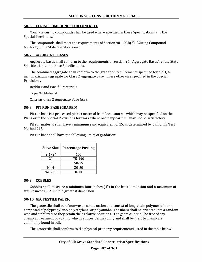
SECTION 50 – CONSTRUCTION MATERIALS
City of Elk Grove Standard Construction Specifications
Page 307 of 361
50-6 CURING COMPOUNDS FOR CONCRETE
Concrete curing compounds shall be used where specified in these Specifications and the Special Provisions.
The compounds shall meet the requirements of Section 90-1.03B(3), “Curing Compound Method”, of the State Specifications.
50-7 AGGREGATE BASES
Aggregate bases shall conform to the requirements of Section 26, “Aggregate Bases”, of the State Specifications, and these Specifications.
The combined aggregate shall conform to the gradation requirements specified for the 3/4- inch maximum aggregate for Class 2 aggregate base, unless otherwise specified in the Special Provisions.
Bedding and Backfill Materials
Type “A” Material
Caltrans Class 2 Aggregate Base (AB).
50-8 PIT RUN BASE (GRADED)
Pit run base is a processed pit run material from local sources which may be specified on the Plans or in the Special Provisions for work where ordinary earth fill may not be satisfactory.
Pit run material shall have a minimum sand equivalent of 25, as determined by California Test Method 217.
Pit run base shall have the following limits of gradation:
Sieve Size Percentage Passing
2-1/2" 100 2" 75-100 1" 50-75
No.4 20-50 No. 200 0-10
50-9 COBBLES
Cobbles shall measure a minimum four inches (4”) in the least dimension and a maximum of twelve inches (12”) in the greatest dimension.
50-10 GEOTEXTILE FABRIC
The geotextile shall be of nonwoven construction and consist of long-chain polymeric fibers composed of polypropylene, polyethylene, or polyamide. The fibers shall be oriented into a random web and stabilized so they retain their relative positions. The geotextile shall be free of any chemical treatment or coating which reduces permeability and shall be inert to chemicals commonly found in soil.
The geotextile shall conform to the physical property requirements listed in the table below:

SECTION 50 – CONSTRUCTION MATERIALS
City of Elk Grove Standard Construction Specifications
Page 308 of 361
TABLE 50-1
REQUIRED GEOTEXTILE PROPERTIES
Physical Property Test Method Acceptable Minimum
Test Results Tensile strength, lb ASTM D 1682 120 Elongation, % ASTM D 1682 60 Coefficient of water permeability, cm/sec ASTM D 4491 0.10 Puncture strength, lb ASTM D 7511 65 Mullen Burst strength, psi ASTM D 3786 215 Note: Tension testing machine with ring clamp, steel ball replaced with a 5/16-inch-diameter solid steel cylinder, with flat tip and beveled edges, centered within the ring clamp.
Supac 4NP as manufactured by Phillips Fibers Corporation meets these specifications.
50-11 CEMENT-TREATED BASES
Road-mixed and plant-mixed cement treated base shall comply with Section 27, “Cement
Treated Bases”, of the State Specifications.
50-12 LIME TREATED BASE
Lime treated base shall comply with 24-2 “LIME STABILIZED SOIL” of the State specification.
50-13 SAND
Sand bedding shall be free from clay or organic material. 90 percent to 100 percent shall pass a No. 4 sieve and not more than 5 percent shall pass a No. 200 sieve.
50-13.01 River Sand
River sand shall be free from vegetable matter, lumps, balls of clay, or adherent films of clay. The material shall not have more than twenty percent (20%) passing a two hundred (200) mesh screen.
50-13.02 Graded Sand
Graded sand shall be free from vegetable matter, lumps, balls of clay, or adherent films of clay.

SECTION 50 – CONSTRUCTION MATERIALS
City of Elk Grove Standard Construction Specifications
Page 309 of 361
The percentage composition by weight of graded sand shall conform to the following gradations:
Sieve Size Percentage Passing by Weight
9.5 mm (3/8”) 100 4.75 mm (#4) 95-100 2.36 mm (#8) 90-100
1.18 mm (#16) 80-100 600 µm (#30) 65-100 300 µm (#50) 40-70
150 µm (#100) 0-30 75 µm (#200) 0-12
50-14 CRUSHED ROCK
A uniformly graded material that is the product of crushing rock or gravel, free of organic matter, oil, alkali, or other deleterious substances, and is hard, sound and durable.
Unless otherwise specified in the Special Provisions, crushed rock shall conform to the requirements for coarse (1/2" x No. 4) crushed screenings as specified in Section 90-1.02C “Aggregates”, of the State Specifications, and these Specifications. Crushed rock shall have a minimum Cleanliness Value of 80 as determined by California Test Method 227.
Sanitary sewer pipe bedding material shall be as directed by CSD-1.
50-15 CONTROL DENSITY BACKFILL
Control density backfill material shall consist of a workable mixture of aggregate, cementitious materials, and water.
Prior to excavation, the Contractor shall submit to the City for approval a mix design, and test data that demonstrate that the mix design complies with the following:
• Portland cement shall be Type II conforming to the requirements in Section 50-1, “Portland Cement”, in this Section of these Specifications.
• Admixtures, including mineral admixtures (pozzalan), may be used in conformance with Section 90-4, "Admixtures”, of the State Specifications. Chemical admixtures containing chlorides such as Cl in excess of one percent
• (1%) by mass of admixture, as determined by California Test Method 415, shall not be used. The amount of air-entraining admixture added shall be a maximum of twenty percent (20%).
• Course aggregate shall consist of a well-graded mixture of crushed rock with a maximum size aggregate of three-eighths inch (3/8”). One hundred percent
• (100%) shall pass the one-half-inch (1/2”) sieve. Not more than thirty percent
• (30%) shall be retained by the three-eighths inch (3/8”) sieve and not more than twelve percent (12%) shall pass the No. 200 sieve. All material shall be free from organic matter and not contain more alkali, sulfates, or salts than the native materials at the site

SECTION 50 – CONSTRUCTION MATERIALS
City of Elk Grove Standard Construction Specifications
Page 310 of 361
of work.
• The minimum twenty-eight-day (28-day) compressive strength shall be one hundred pounds per square inch (100 psi) and the maximum shall be two hundred pounds per square inch (200 psi).
Water shall conform to Section 50-3, “Water for Concrete”, in this Section of these Specifications.
Materials for control density backfill shall be thoroughly machine-mixed in a pugmill, rotary drum, or other approved mixer. Mixing shall continue until the cementitious material and water are thoroughly mixed. Batch or transit-mixed concrete delivered to the Work shall be accompanied by a batch ticket and the weight ticket showing all of the ingredients in pounds. The batch ticket shall also show the time of day the materials were batched. Trucks arriving at the Work without both tickets will be rejected.
Control density backfill shall be placed within ninety (90) minutes after introduction of the cement to the aggregates.
Control density backfill shall be placed in a uniform manner that will prevent voids in, or segregation of, the backfill. Foreign material that falls into the trench prior to or during placing of the control density backfill shall be immediately removed.
When control density backfill is to be placed within the traveled way or otherwise to be covered by paving, the material shall achieve a maximum indentation diameter of three inches (3”) prior to covering and opening to traffic. Penetration resistance shall be as measured by ASTM Designation: C 6024.
Type “C” Material
Controlled Density Fill (CDF) shall consist of a workable mixture of aggregate, cementitious material and water.
• Portland cement shall be Type II.
• Water used for CDF shall be potable.
• Admixtures including mineral admixtures (pozzolan) shall meet the requirements of the State Standard Specifications Section 90-4. The amount of air entraining admixture shall be a minimum of eight percent (8%) and a maximum of twenty percent (20%).
• Course aggregate shall consist of a well graded mixture of crushed rock with a maximum aggregate size of three-eighths of an inch (3/8”). One hundred percent (100%) shall pass the one-half-inch (1/2”) sieve. Not more than thirty percent (30%) shall be retained on the three-eighths-inch (3/8”) sieve and not more than twelve percent (12%) shall pass the No. 200 sieve. All material shall be free from organic matter and not contain more alkali, sulfated, or salts than the native materials at the site of work.
• CDF should have a minimum twenty-eight day (28-day) compressive strength of one hundred pounds per square inch (100 psi) and a maximum of one hundred and twenty five pounds per square inch (125 psi).
• Water shall conform to Section 50-3, “Water for Concrete”, in this Section of these Specifications.

SECTION 50 – CONSTRUCTION MATERIALS
City of Elk Grove Standard Construction Specifications
Page 311 of 361
Materials for CDF shall be thoroughly machine-mixed in a pugmill, rotary drum, or other approved mixer. The material shall be placed within 90 minutes after introduction of the water to the cement and aggregates.
CDF shall be placed in a uniform manner that will prevent voids in, or segregation of, the backfill. Foreign material that falls into the trench prior to or during CDF placement shall be immediately removed.
The CDF shall not be excavated, moved, or otherwise disturbed after a period of 120 minutes following the addition of water to the cement and aggregates so as to permit proper curing.
The slump, as determined by ASTM C94, will be 6” to 8” maximum.
. A minimum of 48 hours should be allowed for curing prior to subsequent backfill operations. Type “C” material shall not be placed above the base of the conical section of manhole barrels.
Type “F” Material
Controlled Density Fill (CDF) similar to Type “C” above except provide a minimum of 2-sacks of Portland cement per cubic yard of material. Compressive strength is not specified for this material. A minimum of 24 hours should be allowed for curing prior to subsequent backfill operations, unless otherwise authorized in writing by the City Engineer’s project representative. Type “F” is not allowed over SCWA water pipes or CSD-1 sewer pipes.
50-16 CLEAN CRUSHED ROCK
Clean crushed rock of the type shown or specified in the Contract shall be the product of crushing rock or gravel. The percentage composition by weight of clean crushed rock shall conform to the following gradations for the Type specified:
Sieve Size
Type A (1/2” crushed)
Type B (3/4” crushed)
Type C (1” crushed)
Type D (1-1/2”
crushed) 2” -- -- -- 100
1-1/2” -- -- 100 -- 3/4" 100 90-100 30-60 0-17 1/2” 90-100 30-60 0-20 -- 3/8” 20-60 0-20 -- 0-7 No. 4 0-15 0-5 0-5 --
No. 200 0-2 0-2 -- 0-2
Clean crushed rock shall have a minimum Cleanliness Value of 60 as determined by California Test Method 227. The portion of the material which is retained on the three-eighths inch (3/8”) sieve shall contain at least fifty percent (50%) of particles having three (3) or more fractured faces.

SECTION 50 – CONSTRUCTION MATERIALS
City of Elk Grove Standard Construction Specifications
Page 312 of 361
Type “E” Material: Clean crushed rock material shall meet the following gradation limits (per ASTM D448-03):
Sieve Size Size No. 7 (1/2” Crushed)
Size No. 6 (3/4”
Crushed)
Size No. 5 (1” Crushed)
Size No. 4 (1-1/2”
Crushed) 2” -- -- -- 100
1-1/2” -- -- 100 90-100 1” -- 100 90-100 20-55 ¾” 100 90-100 20-55 0-15 ½” 90-100 20-55 0-10 --
3/8” 40-70 0-15 0-5 0-5 No. 4 0-15 0-5 -- -- No. 8 0-5 -- -- --
Clean crushed rock shall have a minimum Cleanliness Value of 60, as determined by California Test Method 227. Clean crushed rock shall contain at least seventy-five percent (75%) of particles having two (2) or more crushed faces.
50-17 ASPHALT BINDERS AND EMULSION
Asphalt, liquid asphalt, and asphaltic emulsion, as required by these Specifications or by the Special Provisions, shall be as specified in Section 92, “Asphalt Binders”, of the State Specifications, and asphaltic emulsions as specified in Section 94, “Asphaltic Emulsions”, of the State Specifications.
50-18 VITRIFIED CLAY PIPE (VCP)
Vitrified clay pipe shall conform to the specifications of the specifying agency. The City does not currently own any facilities using VCP.
50-19 SUBSURFACE DRAINS
Subsurface drains shall comply with Section 68, “Subsurface Drains”, of the State Specifications.
50-20 NONREINFORCED CONCRETE PIPE (CP)
Nonreinforced concrete pipe shall conform to ASTM Designation: C 14.
50-21 REINFORCED CONCRETE PIPE, DRAINAGE (RCPD)
Reinforced concrete pipe shall conform to ASTM Designation: C 76 for Class I, II, III, IV, or V. The class of pipe will be shown on the Plans or specified in the Special Provisions.
Sections of circular pipe with elliptical reinforcing shall have the location of the minor axis of the reinforcing indicated by three-inch (3”) wide, waterproof, painted stripes on the inside and outside of the pipe at the top and bottom, at least twelve inches (12”) long at each end of the pipe section.
Unless otherwise indicated on the Plans or in the Special Provisions, joints for concrete pipe shall be bell and spigot and shall be of a design that, when properly laid, shall have a smooth and uniform interior surface. Each joint shall be sealed to prevent leakage. Unless otherwise indicated

SECTION 50 – CONSTRUCTION MATERIALS
City of Elk Grove Standard Construction Specifications
Page 313 of 361
on the Plans or in the Special Provisions, joints shall be sealed with a rubber O-ring gasket conforming to ASTM C443. Compression couplings capable of the same performance are also allowed where splices are needed.
50-22 REINFORCED CONCRETE PIPE, SEWER (RCPS)
Concrete cylinder pipe shall conform to Federal Specifications SS-P-381a and cement mortar lined and coated steel pipe shall conform to Federal Specifications SS-P-385a, each subject to the following modifications:
a. Minimum steel cylinder thickness shall be 0.109 inch.
b. Mortar coating shall provide a minimum of three-quarters inch (3/4‖) cover over all structural steel
c. Cement mortar lining shall be of Type II portland cement and shall be centrifugally applied. Minimum lining thickness shall be one-half inch (1/2‖). The finished inside diameter of the lined pipe shall be the diameter shown on the plans and shall match the inside diameter of the adjoining pipe sections to within one percent (1%), or one- quarter inch (1/4‖), whichever is greater.
d. Pipe shall be Class 100, unless otherwise shown or specified in the Contract
e. Deflection of the pipe cross section shall be limited to one percent (1%) of the inside diameter when the pipe is placed under full external design load.
f. Pipe sections of less than standard length may only be used with approval of the City.
Joints for concrete cylinder pipe and cement mortar lined and coated steel pipe shall be O-ring rubber gasket type with grout “diaper” finish, bolted flange type, “Dresser” or “Victaulic” couplings.
50-23 DUCTILE IRON PIPE (DIP), AND CAST IRON PIPE AND DUCTILE IRON FITTINGS
Ductile iron pipe shall conform to ANSI A21.51 (AWWA C151) for a minimum working pressure of one hundred fifty (150) psi unless otherwise specified. Ductile iron casting shall conform to and be tested in accordance with ASTM Designation: A 536. Casting grade for pipe shall be 60-42-10. Laying length shall be the manufacturer’s standard length, normally eighteen feet (18’). Shorter lengths may be used for closures and proper location of special sections.
Except for gravity sanitary sewer, the interior surface of all ductile iron pipe shall be cement- mortar lined and seal coated in conformance with AWWA C104 and the exterior surface shall have a bituminous coating of either coal tar or asphalt base, approximately 1 mil thick or as directed by the City or specified in the Special Provisions.
For gravity sanitary sewers, coat interior of ductile iron pipe with 40 mil (minimum) of two- component polyisocyanate, polyol-cured urethane coating equivalent to Corropipe II manufactured by Madison Chemical Industries. Wrap ductile iron pipe with two wraps of 8-mil HDPE wrapping sleeve. Secure sleeve with 3 wraps of 10 mil HDPE tape, overlapping each wrap one-half tape width.
Fittings shall have push-on, mechanical joints or flanged ends. Four-inch (4”) through twelve-inch (12”) fittings shall be ductile iron, fittings larger than twelve inches (12”) shall be cast iron or ductile iron. All fittings shall conform to ANSI 21.10 (AWWA C110), ANSI 21.11 (AWWA C111), or AWWA C153 designed for a working pressure of two hundred fifty (250) or three hundred fifty (350) pounds per square inch (psi). Coating and lining requirements shall be

SECTION 50 – CONSTRUCTION MATERIALS
City of Elk Grove Standard Construction Specifications
Page 314 of 361
the same as specified for the pipe.
Joints shall be push-on or mechanical type and shall conform to ANSI 21.11 (AWWA C111) with rubber gaskets unless otherwise specified. Gasket lubricant shall be minimum required plus ten percent (10%).
50-24 POLYVINYL CHLORIDE (PVC) PIPE FOR SEWERS AND DRAINAGE
50-24.01 PVC Pipe for Drainage
Polyvinyl Chloride Pipe for drainage shall conform to one of the following Standards:
Diameter (inches) Standard Designation
12 ASTM D3034, SDR 35, AWWA C900, DR 18 14 AWWA, C905, DR 18 15 ASTM D2023, SDR 35, AWWA C905, DR 18 16 AWWA C905, DR 18 18 ASTM D2241, SDR 51, AWWA C905, DR 18 20 AWWA C905, DR 18 21 ASTM D2241, SDR 51 24 ASTM D2241, SDR 51; AWWA C905, DR 18 27 ASTM D2241, SDR 51 30 AWWA C905, DR18
Joints of PVC pipe shall consist of either an elastomeric gasket coupling or an integral bell and spigot with an elastomeric gasket. The assembly of joints shall be in accordance with the pipe manufacturer's recommendations and the requirements of ASTM Designation: D 3212.
The quality of material and installation of all PVC pipe shall meet or exceed the requirements of Section 38-10, "Testing of Pipe”, of these Specifications.
Use of PVC pipe downstream of the last manhole or junction structure to an open channel, detention facilities or a daylight condition is not allowed.
50-25 CORRUGATED STEEL PIPE (CSP)
Corrugated steel pipe shall conform to the material and fabrication methods of Section 66, “Corrugated Metal Pipe”, of the State Specifications, except as modified in these Specifications. Corrugated steel pipe shall only be used when specified in the Special Provisions. All corrugated steel pipe shall be fabricated with helical corrugations and with a continuous lock or weld seam extending from end to end of each length of pipe. Steel shall be zinc coated unless otherwise specified. Helically corrugated steel pipe shall be fabricated using corrugation profiles as shown in the following table:

SECTION 50 – CONSTRUCTION MATERIALS
City of Elk Grove Standard Construction Specifications
Page 315 of 361
TABLE 50-3 CORRUGATION PROFILE
Diameter (Inches)
Normal Pitch (Inches)
Maximum Pitch (Inches)
Minimum Depth (Inches)
8 and 10 1-1/2 1-7/8 1/4 12 through 96 2-2/3 2-3/4 1/2
48 through 120 3 3-1/4 1 Note: The corrugation profile of 2-2/3” x ½” shall be used for all pipes from twelve-inch (12”) through ninety-six-inch (96”) diameter, unless otherwise shown on or specified in the Contract.
Lock or welded seams shall develop the full strength of the pipe in accordance with the herein referenced Specifications.
Pipe that has been patched will be rejected.
When shown or specified in the Contract, the pipe, couplings, and fittings shall be protected with a bituminous coating as specified in Section 66-1.02C, “Protective Coating, Linings and Paving”, of the State Specifications.
Corrugated steel products shall be shipped, handled, and placed in such a manner as to prevent scaling, bruising, or breaking of the galvanized surface or protective coating.
Couplings for corrugated steel pipe shall be of durable gasket design. Couplings shall consist of galvanized steel coupling bands fitted with gaskets fabricated from neoprene or butyl rubber or other durable resilient material approved by the City, and assembled in such a manner as to form a sealed joint. The City may require that the coupling design be submitted for approval prior to placing, and may require supporting data showing that the coupling is tight and durable. Heat-shrinkable plastic couplings will not be permitted.
Corrugated steel pipe fittings shall be constructed of the thickness of steel shown on the Plans.
The fittings shall conform to the details shown on the Plans or Standard Drawings.
Mitered joints shall be welded from the inside where practicable. Welded joints shall be as smooth and even as practicable. Welded joints shall be repaired according to Section 66-1.02E(4), “Damaged Galvanizing”, of the State Specifications.
All fabrication shall be done in accordance with generally accepted practice for good workmanship. The Contractor shall notify the City at least forty-eight (48) hours before delivery of the fittings so the City may inspect the fittings at the fabrication plant.
Diameter of fittings depends on the pipe option selected by the Contractor. Upstream diameter of fittings shall match upstream pipe diameter; downstream diameter of fittings shall match downstream pipe diameter.
If the size of the corrugated pipe fitting is too large to conveniently fabricate or transport in one (1) piece, the fitting may be fabricated in two (2) or more parts which will then be jointed at the site with couplings. The joint shall be located sufficiently distant from a welded joint so that there is no interference between the coupling and the welded joint.

SECTION 50 – CONSTRUCTION MATERIALS
City of Elk Grove Standard Construction Specifications
Page 316 of 361
50-26 RIBBED STEEL PIPE (RSP)
Ribbed steel pipe shall meet the requirements for corrugated steel pipe in Section 66, “Corrugated Metal Pipe”, of the State Specifications, except as modified in these Specifications. Ribbed steel pipe shall only be used when specified in the Special Provisions. Steel shall be zinc coated unless otherwise specified. Ribbed steel pipe shall be fabricated to one of the following configurations:
a. The pipe shall be fabricated to meet the requirements for Type IR pipe as specified in ASTM Designation: A 760, Sections 4, 7, 8, and 10; or
b. The pipe shall consist of pipe with 3/4" x 3/4" inside dimension, outward projecting reinforcing ribs located on approximately 7-1/2" centers. These ribs shall be located symmetrically between lockseams, which shall be on approximately 22-1/2" centers. All ribs shall be helical and continuous.
Ribbed steel pipe shall be fabricated with a continuous helical lock seam in accordance with Section 66, “Corrugated Metal Pipe”, of the State Specifications. Lock seams shall develop the full strength of the pipe.
The pipe shall be furnished with re-rolled ends to produce a profile for connecting with the approved coupling band.
Any pipe that has been damaged during fabrication, handling, or construction shall be rejected or repaired to the satisfaction of the City.
Lateral field connections between metal pipes shall be welded and any galvanizing damaged by welding shall be repaired according to Section 66, “Corrugated Metal Pipe”, of the State Specifications.
When shown on the Plans or specified in the Special Provisions, the pipe, couplings, and fittings shall be protected with a bituminous coating as specified in Section 66 -1.02C, “Protective Coating, Linings and Pavings”, of the State Specifications. Ribbed steel pipe shall be shipped, handled, and laid in such a manner as to prevent bruising, scaling or breaking of the galvanized surface or protective coating.
Coupling bands for ribbed steel pipe shall be manufactured from 0.064 inch thick galvanized steel conforming to Section 66, “Corrugated Metal Pipe”, of the State Specifications. The coupling bands shall be either a hat shaped band, winged band, annular band, or other approved design and shall be fitted with gaskets fabricated from neoprene or butyl rubber or other durable, resilient material approved by the City, and assembled in such a manner as to form a sealed joint.
Hat shaped band and winged band couplers shall conform to the following table:

SECTION 50 – CONSTRUCTION MATERIALS
City of Elk Grove Standard Construction Specifications
Page 317 of 361
TABLE 50-4 BAND COULER/RIBBED STEEL PIPE
(Dimensions in Inches)
Pipe Size Band Type Band
Minimum Thickness
Flange Height
Band Width
Bolt Diameter
24 - 36 Hat 0.064 5/8 2-3/4 1/2
42 - 90 Winged 0.064 5/8 7-1/2 1/2 (2 ea req’d)
50-27 CORRUGATED ALUMINUM PIPE (CAP)
Corrugated aluminum pipe shall conform to the material and fabrication methods of AASHTO Designation M196 and as modified herein. Corrugated aluminum pipe shall only be used when specified in the Special Provisions. All corrugated aluminum pipe shall be fabricated with helical corrugations and with a continuous lock seam extending from end to end of each length of pipe.
Helically corrugated aluminum pipe shall be fabricated using corrugation profiles as shown in the following table:
TABLE 50-5 CORRUGATION PROFILE
Diameter (Inches) Normal Pitch (Inches)
Maximum Pitch
(Inches)
Minimum Depth
(Inches) 8 and 10 1-1/2 1-7/8 1/4
12 through 96 2-2/3 2-3/4 1/2
48 through 120 3 3-1/4 1
Note: The corrugation profile of 2-2/3” x 1/2" shall be used for all pipes from twelve-inch (12”) through ninety-six-inch (96”) diameter, unless otherwise shown on or specified in the Contract.
Couplings for corrugated aluminum pipe shall be of a durable, tight design. Couplings shall consist of aluminum coupling bands fitted with gaskets fabricated from neoprene or butyl rubber, or other durable resilient material approved by the City and assembled to form a tight joint. The City may require that the coupling design be submitted for approval prior to placing, and may require the supporting data showing that the coupling is tight and durable. Heat-shrinkable plastic couplings will not be permitted.
Corrugated aluminum pipe fittings shall be constructed of the gauge aluminum indicated on the Plans.
The fittings shall conform to the details shown on the Plans or Standard Drawings.
All fabrication shall be done in accordance with generally accepted practice for good workmanship. The Contractor shall notify the City at least forty-eight (48) hours before delivery of the fittings so that the City may inspect the fittings at the fabrication plant.
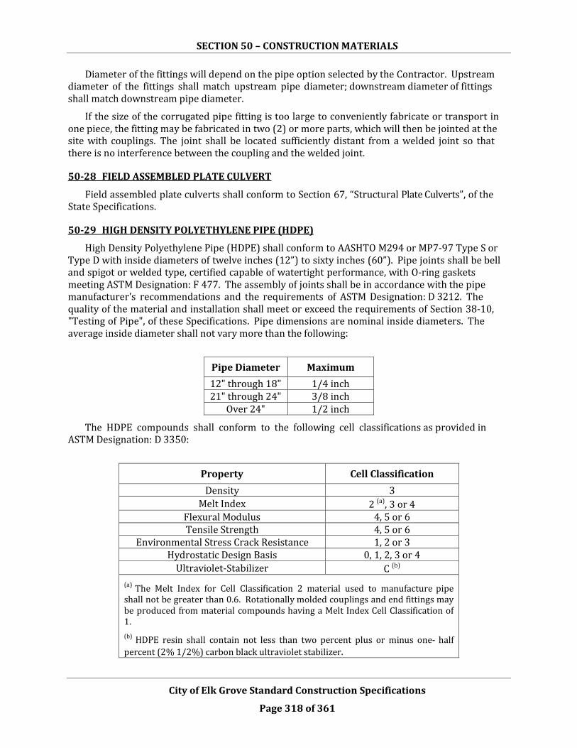
SECTION 50 – CONSTRUCTION MATERIALS
City of Elk Grove Standard Construction Specifications
Page 318 of 361
Diameter of the fittings will depend on the pipe option selected by the Contractor. Upstream diameter of the fittings shall match upstream pipe diameter; downstream diameter of fittings shall match downstream pipe diameter.
If the size of the corrugated pipe fitting is too large to conveniently fabricate or transport in one piece, the fitting may be fabricated in two (2) or more parts, which will then be jointed at the site with couplings. The joint shall be located sufficiently distant from a welded joint so that there is no interference between the coupling and the welded joint.
50-28 FIELD ASSEMBLED PLATE CULVERT
Field assembled plate culverts shall conform to Section 67, “Structural Plate Culverts”, of the State Specifications.
50-29 HIGH DENSITY POLYETHYLENE PIPE (HDPE)
High Density Polyethylene Pipe (HDPE) shall conform to AASHTO M294 or MP7-97 Type S or Type D with inside diameters of twelve inches (12”) to sixty inches (60”). Pipe joints shall be bell and spigot or welded type, certified capable of watertight performance, with O-ring gaskets meeting ASTM Designation: F 477. The assembly of joints shall be in accordance with the pipe manufacturer's recommendations and the requirements of ASTM Designation: D 3212. The quality of the material and installation shall meet or exceed the requirements of Section 38-10, "Testing of Pipe", of these Specifications. Pipe dimensions are nominal inside diameters. The average inside diameter shall not vary more than the following:
Pipe Diameter Maximum 12" through 18" 1/4 inch 21" through 24" 3/8 inch
Over 24" 1/2 inch
The HDPE compounds shall conform to the following cell classifications as provided in ASTM Designation: D 3350:
Property Cell Classification Density 3
Melt Index 2 (a), 3 or 4 Flexural Modulus 4, 5 or 6 Tensile Strength 4, 5 or 6
Environmental Stress Crack Resistance 1, 2 or 3 Hydrostatic Design Basis 0, 1, 2, 3 or 4
Ultraviolet-Stabilizer C (b)
(a) The Melt Index for Cell Classification 2 material used to manufacture pipe shall not be greater than 0.6. Rotationally molded couplings and end fittings may be produced from material compounds having a Melt Index Cell Classification of 1. (b) HDPE resin shall contain not less than two percent plus or minus one- half percent (2% 1/2%) carbon black ultraviolet stabilizer.

SECTION 50 – CONSTRUCTION MATERIALS
City of Elk Grove Standard Construction Specifications
Page 319 of 361
Wall thickness of Type S corrugated polyethylene pipe shall be the thickness of the inner liner measured between corrugation valleys. The wall thickness of the polyethylene pipe, measured as specified above, shall equal or exceed the minimum wall thickness values in Table 50-6.
The pipe stiffness shall be determined in accordance with ASTM Designation: D 2412 at five percent (5%) deflection. Average pipe stiffness shall be determined for each manufactured run from three (3) test specimens. The length of test specimens shall be one pipe diameter or a maximum of thirty-six inches (36”), whichever is less. The average pipe stiffness shall equal or exceed the minimum pipe stiffness value for each size of HDPE pipe listed in Table 50-6 below. The pipe unit weight for corrugated HDPE shall be computed as the average weight per foot of length determined from three (3) test specimens, taken from each manufactured run. Each test specimen for pipes twenty-four inches (24”) in diameter and less shall be a minimum length of two (2) pipe diameters. Test specimens for pipes larger than twenty-four inches (24”) in diameter shall be one (1) diameter or a maximum of thirty-six inches (36”), whichever is less. The weight of pipe specimens shall be determined with any suitable weighing device accurate to 0.10 pounds. The pipe unit weight for each size of polyethylene pipe shall equal or exceed the minimum unit weight value for each size of plastic pipe listed in Table 50-6.
TABLE 50-6 HDPE PIPE
Nominal Diameter (inches)
Minimum Wall Thickness (inches)
Minimum Pipe Stiffness
(PSI)
Minimum Unit Weight
(lbs. per linear foot)
12 0.035 45 2.7 15 0.035 42 4.0 18 0.050 40 6.0 24 0.050 34 10.2 30 0.050 28 15.0 36 0.050 22 18.1 42 .071 20 22.5 48 .071 18 26.9 60 .079 14 38.7
50-30 REINFORCING STEEL, CURB DOWELS AND TIE BARS
Reinforcing steel shall conform to Section 52, "Reinforcement”, of the State Specifications. Unless shown or specified in the Contract, bar reinforcement shall be deformed Grade 60 conforming to ASTM Designation: A 615.
Welded steel wire fabric for concrete reinforcement shall conform to ASTM Designation: A 185. The gauge of the wire and the dimensions of the mesh will be as shown or specified in the Contract.
Dowel and tie bars for curbs shall be bar reinforcement conforming to Section 50-32, “Reinforcing Steel”, in these Specifications. At the Contractor's option, either Grade 60 or Grade

SECTION 50 – CONSTRUCTION MATERIALS
City of Elk Grove Standard Construction Specifications
Page 320 of 361
40 may be used.
50-31 STORM DRAIN CASTINGS
Castings for manhole frames and covers, drop inlet frames, gutter drain frames, open-back hoods, flushing branch frames and covers, or other purposes shall be tough gray iron, shall have a coating of black bituminous material or hot dip galvanized, per the standard drawing SD section per corresponding detail notes. free from cracks, holes, swells, and cold sheets, and be of workmanlike finish. A "Certificate of Compliance" signed by an authorized agent of the manufacturer or supplier shall be required and shall be delivered to the City. Each certificate so furnished shall be accompanied by a copy of test results stating that the material has been sampled, tested, and inspected in accordance with the provisions of ASTM Designation: A 48, Gray Iron Castings Class 35B.
Test bars shall be cast and tested for the first lot of casting and every four (4) months thereafter. If production is interrupted for any period longer than four (4) months, test bars shall be cast and tested from the initial lot after production is resumed and every four (4) months thereafter. The first lot is defined as the first castings produced after January 1 every year. The tension tests specified shall be performed and the results certified by an independent testing laboratory.
The cast iron shall meet the requirements of ASTM Designation: A 48, Class 35. The seating faces of manhole covers and frames shall be machined as shown on the Standard Drawings or Plans to assure a tight fit and prevent rocking. The name of the manufacturer shall be cast on the manhole cover and frame. In addition, the day, month, and year of manufacture shall be cast on the frame and cover adjacent to the name of the manufacturer.
Twenty-four inch (24”) diameter manhole frames and covers shall conform to Standard Drawings SD-9 and SD-11for storm drain, unless otherwise shown on the Plans or specified in the Special Provisions.
Thirty-six inch (36”) diameter manhole frames and covers shall conform to Standard Drawings SD-10.1 & 10.2 for storm drain, unless otherwise shown on the Plans or in the Special Provisions.
The CSD-1 logo covers are required on all County Sanitation District 1 sewer lines; the SRCSD logo covers are required on all Sacramento Regional County Sanitation District sewer lines.
When required by the City, proof-load tests shall be performed on manhole frames and covers in accordance with Section 3.3 of Federal Specification A-A-60005.
Exposed edges of castings shall be chamfered or rounded, and all exposed surfaces shall be smooth unless otherwise shown.
Manhole frames and covers shall be clearly marked with the country of origin as specified in the Trade of Tariff Act of 1984.
At the Contractor's option, drop inlet frames and open back hoods may be fabricated from steel plate as structural shapes in lieu of cast iron. If the Contractor elects to use fabricated steel drop inlet frames or open back hoods, the Contractor shall submit Working Drawings to the City for approval prior to fabrication. This submittal requirement does not apply to the drop inlet frame shown on Standard Drawing 9-14.

SECTION 50 – CONSTRUCTION MATERIALS
City of Elk Grove Standard Construction Specifications
Page 321 of 361
50-32 JOINT MATERIALS FOR MANHOLES
Joint materials for precast reinforced concrete manhole sections shall conform to one of the following:
1. Mortar proportioned as one (1) cubic foot of portland cement to two (2) cubic feet of concrete sand. All mortar shall be used within thirty (30) minutes after the mixing water has been added.
2. Preformed plastic sealing compound shall conform to Type 1 - Rope Form, one and one-half inch (1-1/2‖) diameter, Federal Specification SS-S-210A.
3. Gulf States Pre-Extruded concrete joint sealant.
50-33 FENCING - CHAIN LINK
Chain link fence and gate materials shall conform to Section 80, “Fences”, of the State Specifications, and these Specifications.
The carbon content of steel posts shall not exceed 0.82 percent.
Chain link fence fabric shall meet the requirements of zinc-coated steel chain link fence fabric, ASTM Designation: A 392 with Class 1 zinc coating. Unless otherwise shown on the Plans or specified in the Special Provisions, the fabric shall be a two-inch (2‖) mesh of nine (9) gauge wire, with a minimum breaking strength of one thousand two hundred ninety (1,290) pounds.
Vinyl coated chain link fence fabric, when shown on the Plans or specified in the Special Provisions, shall be black polyvinyl chloride coated steel link fabric and fittings. Polyvinyl chloride shall be applied by the thermal extrusion process.
Slats shall be as specified in the Special Provisions.
Base material for the manufacture of steel pipe used for posts, braces, rails and gate frames shall be commercial quality, or better, weldable steel, conforming to the specifications of ASTM Designation: A 120. At the option of the Contractor, and upon approval of the City; high-strength tubing fabricated by cold rolling and radio frequency welding from steel conforming to ASTM Designation: A 446, Grade D, may be used provided that the product of the yield strength and the section modules shall not be less than that of pipe conforming to ASTM Designation: A 120.
The base material for the manufacture of other steel sections used for posts and braces shall conform to ASTM Designation: A 572, Grade 45, with a minimum yield strength of forty thousand (40,000) pounds per square inch. All posts, braces, rails and gate frames shall be hot dipped galvanized in accordance with ASTM Designation: A 123, or ASTM Designation: A 525, Coating Designation G235 plus chromate conversion coating and 0.4 mils minimum thickness finish coat of clear, cross-linked acrylic.
Posts and rails for vinyl coated chain link fence shall be hot dipped galvanized and covered with two (2) coats of black metal paint applied over a metal primer.
Posts and rails shall be as specified in the following Table 50-7, unless otherwise shown or specified in the Contract. The Contractor shall have the option of section types to be used with the condition that the option exercised shall be uniform throughout the Work.

SECTION 50 – CONSTRUCTION MATERIALS
City of Elk Grove Standard Construction Specifications
Page 322 of 361
TABLE 50-7 CHAIN LINK FENCING
Fence Member Section Type Dimension O.D. (Inches)
Minimum Weight
(LBS/FT)
Line Posts
C-Section 1.875 2.15 Sch. 40 pipe 2.375 3.65 Hi-strength
tubing 2.375 3.12
Terminal, Corner & Latch Posts
Sch. 40 pipe’ 2.875 5.79 Hi-Strength
tubing 2.875 4.64
Horizontal & Diagonal Braces, Top Rails
C-Section 1.825 1.35 Sch. 40 pipe 1.660 2.27 Hi-Strength
tubing 1.660 1.82
Gate Frames Sch. 40 pipe 2.375 3.65 Hi-Strength
tubing 2.375 3.12
Gate Post
Gate width up through 6’
Sch. 40 pipe 2.875 5.79
Gate width over 6’ Sch. 40 pipe 4.500 10.79
Gate width over 12’ Sch. 40 pipe 5.563 14.62
Gate width over 18’ (24’Max gate width)
Sch. 40 pipe 6.625 18.97
Fittings shall be hot-dip galvanized and shall be of malleable, cast iron, or pressed steel. A Certificate of Compliance in accordance with the provisions of Section 6-1.07, "Certificates of Compliance‖, of the State Specifications, shall be furnished to the City prior to the installation of any chain link fencing, gates or components
50-34 LANDSCAPING MATERIALS
50-34.01 Topsoil
Topsoil shall be sandy loam of an even texture and shall pass through a one-half inch (1/2”) screen.
The topsoil shall be free from insects, animal life, or any toxic substances that may be detrimental to the growth of vegetation. Topsoil shall be capable of sustaining healthy plant life. Soil sterilizers or weed killers shall permit growth of nursery stock planted three (3) weeks after application. Compounds containing cyanide or arsenic will not be allowed.
The Contractor shall provide a soils report to the City for approval prior to placement of topsoil. The report shall indicate conformance with these Specifications and the following:

SECTION 50 – CONSTRUCTION MATERIALS
City of Elk Grove Standard Construction Specifications
Page 323 of 361
SOIL ELEMENTS ACCEPTABLE RANGE
pH 6.6 - 8.0 CEC (Cation Exchange
Capacity) 12.00 - 35.00 meg/100g
SAR (Sodium Absorption Ratio)
less than 5.00
ESP (Exchangeable Sodium Percentage)
less than 5.00
EC (Electronic Conductivity) 2.0 - 2.5 mmho/cm SP (Sodium Percentage) less than 45%
Percentage Organic Matter 2% - 5%
Topsoil shall be delivered reasonably dry and in a workable condition.
Sandy loam of low fertility, even though mixed with leaf mold, manure, or other fertilizers, will not be acceptable unless prior approval has been granted by the City. The Contractor shall attach soil and plant Lab Report for the City's approval.
50-34.02 Commercial Fertilizer
Planting tablets for planting trees and shrubs shall be tightly compressed, non-burning, long lasting fertilizer, weighing between 5 and 12.5 grams of the following guaranteed analysis:
Nitrogen, water soluble 7.00% Nitrogen, water insoluble 13.00% Phosphoric Acid, available 10.00% Potash, soluble 5.00% Calcium combined 2.60% Sulfur, combined 1.60% Iron, expressed as Fe 0.35%
Quantity of planting tablets per plant shall be based on the manufacturer’s recommendation unless otherwise specified in the Special Provisions.
Fertilizer used for planting maintenance shall have a minimum guaranteed chemical analysis of twenty-one percent (21%) nitrogen, zero percent (0%) phosphoric acid, and zero percent (0%) soluble potash.
Fertilizer for turf installation, unless otherwise specified, shall have a minimum guaranteed chemical analysis of twenty-one percent (21%) nitrogen, ten percent (10%) phosphoric acid and ten percent (10%) soluble potash.
Fertilizer for tree, turf, and shrub plantings shall be in granular or pelleted form, shall conform to the standards of the Association of Official Agricultural Chemists, and shall provide the minimum percentage of available nutrients as specified in the Plans or Special Provisions. A liquid fertilizer may be used when specified in the Special Provisions.
Fertilizer used for erosion control work shall be in a form which will readily disperse into the slurry, and shall have a minimum guaranteed chemical analysis of six percent (6%) nitrogen, twenty percent (20%) phosphoric acid, and twenty percent (20%) soluble potash.

SECTION 50 – CONSTRUCTION MATERIALS
City of Elk Grove Standard Construction Specifications
Page 324 of 361
50-34.03 Soil Amendment
Soil amendment shall be a ground wood product such as bark or redwood fortified with nitrogen and treated to absorb water quickly, or a relatively dry organic compost derived from sewage sludge. Soil amendment shall be friable and shall be free of weed seed, dust and other objectionable materials. Soil amendment shall pass a one-inch (1”) sieve and shall comply with the requirements in the California Food and Agricultural Code.
50-34.04 Iron Sulfate
Iron sulfate shall be ferrous sulfate in pelleted or granular form containing not less than 18.5 percent iron expressed as metallic iron. Iron sulfate shall conform to the requirements of the California Food and Agricultural Code.
50-34.05 Straw
Straw shall be derived from wheat, rice or barley. The Contractor shall furnish to the City evidence that clearance has been obtained from the Sacramento County Agricultural Commissioner, as required by law, before straw obtained from outside the County is delivered to the site of the Work. Straw that has been used for stable bedding shall not be used.
50-43.06 Fiber
Fiber used for hydroseeding shall be produced from natural or recycled (pulp) fiber, such as wood chips or similar wood materials or from newsprint, chipboard, corrugated cardboard or a combination of these processed materials, and shall be free of synthetic or plastic materials. Fiber shall disperse uniformly into a slurry when mixed with water. Fiber shall be colored to contrast with the area on which the fiber is to be applied, and shall not stain concrete or painted surfaces. The slurry, when hydraulically applied to the ground, shall form an absorptive mat of mulch uniformly impregnated with seed and other ingredients. No materials that inhibit growth or germination shall be present in the mixture.
50-34.07 Mulch
Unless otherwise specified in the Special Provisions or shown on the Plans, mulch shall consist of wood chips, tree bark, or shredded bark, or any combination thereof, at the Contractor's option. Shredded redwood bark ("gorilla hair") shall not be used. Materials deemed highly flammable or a potential fire hazard by the City shall not be used.
Wood chips shall be manufactured from clean wood. The particle size of the chips shall be between one-half inch (1/2”) and three inches (3”) in length, and not less than three-eighths inch (3/8”) in width and one-sixteenth inch (1/16”) in thickness. At least 85 percent, by volume, of wood chips shall conform to the sizes specified.
Tree bark shall have a particle size between one-half inch (1/2”) and one-and-one-half inches (1-1/2”) and shall be free of salt and foreign materials such as clods, coarse objects, sticks, rocks, weeds or weed seeds.
Shredded bark shall be a mixture of shredded bark and wood; shall have a particle size between one-eighth inch (1/8”) and one-and-one-half inches (1-1/2”) in thickness and one inch (1”) to eight inches (8”) in length; and shall be free of salt and deleterious materials
SECTION 50 – CONSTRUCTION MATERIALS
City of Elk Grove Standard Construction Specifications
Page 325 of 361
such as clods, coarse objects, and rocks. At least seventy-five percent (75%), by volume, of shredded bark shall conform to the sizes specified.
50-34.08 Planting Mix
Planting mix for backfilling planting holes shall consist of two (2) parts of soil excavated from the planting holes free of rocks over one-half inch (1/2”) in diameter and one part soil amendment. The materials shall be thoroughly mixed.
50-34.09 Seed
Seed shall be furnished separately or in mixtures in standard sealed containers labeled with the seed name, lot number, net weight, percentage of purity, germination and hard seed, and percentage of maximum wildflower or grass seed content for each kind of seed furnished and, in the case of a mixture, the proportions of each kind of seed.
The Contractor shall furnish the City duplicate signed copies of a certificate of compliance by the vendor certifying that each lot of seed has been tested by a recognized laboratory for seed testing within six (6) months of date of delivery. The testing shall be in conformance with test procedure standards of the Association of Official Seed Analysts and the provisions of the Agricultural Code of the State of California. The certificate of compliance shall include name and address of laboratory, date of test, lot number for each kind of seed, and results of tests as to name, percentages of purity and of germination, and percentage of wildflower or grass content for each kind of seed furnished and, in case of a mixture, the proportions of each kind of seed.
Seed with less than the specified purity or germination may be used under the following conditions:
a.The application rate for such seed shall be increased to compensate for the less than specified purity or germination.
b.Prior to using such seed, the Contractor shall submit to the City the purity and germination percentages, and the proposed increased application rate for such seed.
c.No such seed shall be used before the City has approved, in writing, the use of such seed and the increased application rate.
d.The additional seed required because of the increased application rate shall be furnished and applied at the Contractor’s expense.
Seed specified without a purity or germination requirement shall be labeled to include the name, date (month and year) collected and name and address of the supplier. Said seed shall be, at the time of sowing, from the previous or current year’s harvest.
Seeds that become wet, moldy, or otherwise damaged in transit or in storage will be subject to retest at the discretion of the Landscape Architect.
50-34.09.A Turf Seed
Turf seed or mixtures of seed are classified by type according to species or variety of grass. Types of seed or seed mixtures shall be as shown on the Plans or specified in the Special Provisions.
Lawn seed shall be true to species or variety for the type as specified and shall conform

SECTION 50 – CONSTRUCTION MATERIALS
City of Elk Grove Standard Construction Specifications
Page 326 of 361
to the Agricultural Code of the State of California and the standards of the Association of Official Seed Analysts.
50-34.09.B Wildflower Seed for Hydroseeding
Wildflower seed type to be used for hydroseeding shall be as indicated in the Plans or Special Provisions.
Seed shall be labeled in accordance with the California Department of Agriculture, State Seed Law requirements, effective on the date of invitation for bids. The seed shall be supplied in unopened containers from a commercial seed dealer and may either be mixed or in separate containers for each lot. Tags shall be given to the City. Final acceptance will not be considered unless all tags are produced and verified.
50-34.10 Stabilizing Emulsion
Stabilizing emulsion (tackier or binder) shall be a concentrated liquid chemical that forms a plastic film upon drying and allows water and air to penetrate. The film shall be nonflammable and shall have an effective life of at least one year.
Stabilizing emulsion shall be nontoxic to plant or animal life and non-staining to concrete or painted surfaces. In the cured state, the stabilizing emulsion shall not be re-emulsifiable. Stabilizing emulsion shall be miscible with water at the time of mixing and application.
50-34.11 Lumber
Lumber shall be construction grade cedar, pressure treated Douglas fir, or heart redwood, rough cut, from sound timber. It shall be straight and free from loose or unsound knots, shakes in excess of 1/3 the thickness of the lumber, splits longer than the thickness of the lumber, or other defect which would render the lumber unfit structurally for the purpose intended. Knots in all lumber shall be sound, tight, well spaced, and shall not exceed two inches (2”) in size on any face. Sweep shall not exceed 0.08 foot in six feet (6’).
50-34.12 Tree Stakes and Ties
Stakes for support of trees shall be lodge-pole pine, unless otherwise specified in the Special Provisions. Stakes for fifteen- (15) gallon trees or smaller shall be two-inch (2”) diameter x ten feet (10’) long. Stakes for twenty-four inch (24”) box trees or larger shall be two-inch (2”) diameter x twelve feet (12’) long. The tree ties shall be black rubber cinch ties, unless otherwise specified in the Special Provisions.
50-34.13 Root Control Barrier
Root control barrier shall be an injection molded or extruded modular component made of high density polypropylene or polyethylene plastic. Panels shall have a minimum thickness of 0.080 inch (2.032 mm). Each panel shall have molded vertical ribs (four minimum) and locking strips or integral male/female sliding locks. Vertical root deflecting ribs or channels shall be one-half inch (1/2") high, perpendicular to the panel, and between six (6) and eight (8) inches apart. Panel shall be twenty-four inch x twenty-four inch (24” x 24") size unless otherwise specified in the Special Provisions.

SECTION 50 – CONSTRUCTION MATERIALS
City of Elk Grove Standard Construction Specifications
Page 327 of 361
50-34.14 Plants
Plants shall be of the variety and size shown on the Plans or specified in the Special Provisions and shall conform to the requirements of these Specifications.
Plants shall be vigorous, first class representations of the species and cultivars specified, and shall conform to State and local laws governing the sale and transportation of plant materials. Only plants of the size and type shown on the Plans or designated in these Specifications or the Special Provisions, and only plants with normal plant and root structures will be acceptable.
All plants shall be nursery grown in containers, unless otherwise shown on the Plans or designated in the Special Provisions, and shall have been grown in the specified containers for not less than six (6) months. They shall have straight, single trunks, unless otherwise specified on the Plans. No pruning shall be undertaken before planting. Plants specified as multi-trunk shall have at least three (3) main leaders from the base.
Any and all plants that have any encircling roots (not rootbound) shall have root balls lightly slashed on a minimum of three (3) sides to stop encircling root growth. Plants shall have well developed root systems and not be rootbound or show sunscald, injuries, abrasions or other objectionable disfigurements. Plants shall be free of disease, insects, pests, eggs, or larvae. Tree trunks shall be sturdy and well "hardened off”. Plants not meeting these specifications shall be rejected.
Any plants delivered to the work site which are found to be not true to name or unsuitable in growth or conditions shall be removed from the site and replaced with acceptable plants. All plants shall be of the species, variety, size, age, and condition as specified herein or as shown on the Plans or described in the Special Provisions. Under no condition shall there by any substitution of plants or sizes for those listed on the Plans, except with the written consent of the Landscape Architect.
No plant shall be transported to the planting area that is not thoroughly wet throughout the root ball. Any plant that, in the opinion of the City, has a damaged root ball or is dry or in a wilted condition when delivered to the planting area will not be accepted, and shall be replaced by the Contractor at the Contractor’s expense. Trucks used for transporting plants shall be equipped with covers to protect plants from windburn.
One plant of each bundle or lot shall be tagged with the name and size of the plant, in accordance with the standards of practice recommended by the American Association of Nurserymen.
All plant materials shall meet the specifications of Federal, State, County and City laws requiring inspection for plant disease and insect infestations. Inspection certifications required by law shall accompany each shipment, invoice, or order for stock, and when such plants arrive at the site of the Work, the certificate of inspection shall be filed with the City.
Inspection of all plant material for acceptance shall be made at the project site at time of delivery. All plant material shall be approved by the Landscape Architect prior to installation. All rejected plant material shall be marked as such and removed from the project site immediately.
The Contractor shall notify the City at least two (2) days prior to the delivery of each shipment of plant materials. Plant materials shall be protected and maintained in good

SECTION 50 – CONSTRUCTION MATERIALS
City of Elk Grove Standard Construction Specifications
Page 328 of 361
condition. Bare root and balled materials shall be watered regularly and placed in a cool area protected from sun and wind.
Plants shall be classified by type as to species, variety and genus and will be specified by scientific name conforming to the publication "Standard Plant Names" as adopted by the American Joint Committee on Horticultural Nomenclature. The plant materials to be planted will be shown on the Plans or specified in the Special Provisions.
50-34.14.A Turf
Grass sod shall be well established mown lawn grass turf and shall be free of weeds and any other harmful or deleterious matter.
At least eighty percent (80%) of the grass plants in the cut sod shall be composed of the species or varieties specified in the Special Provisions.
Grass sod shall be grown, inspected, and shipped in accordance with the provisions of the Agricultural Code of the State of California.
Sod shall be machine stripped or cut of a uniform soil thickness of one inch plus-or-minus one-quarter inch (1” ± 1/4”). The measurement for thickness shall exclude top growth and thatch and shall be determined at the time of cutting in the field.
Sod shall be rolled or folded prior to lifting. Handling of sod shall be done in a manner that will prevent tearing, breaking, drying, or any other damage.
Sod shall be transplanted within twenty-four (24) hours from the time it is stripped, unless circumstances beyond the Contractor's control make storing necessary. In such case, sod shall be stacked, kept moist, and protected from exposure to the air and sun. The stored sod shall be installed in place not more than forty-eight (48) hours after cutting.
50-34.14.B Trees
Trees are classified by type as to genus, species, and variety as well as common name. The tree varieties to be planted shall be as shown on the Plans or described in the Special Provisions.
Tree species shall meet minimum size requirements for caliper size of trunk and height of tree stock or they shall be rejected. Table 50-8 below indicates the height to caliper of trunk relationship. Trees shall be specified by container size in the Contract, and shall meet the minimum height and caliper of trunk indicated in the table. For shade trees of recognized slower growth, as identified by the City, the height and caliper shall be not less than two- thirds (2/3) the height and caliper indicated below:

SECTION 50 – CONSTRUCTION MATERIALS
City of Elk Grove Standard Construction Specifications
Page 329 of 361
TABLE 50-8 TREE CALIPER-HEIGHT RATIO
Container Size (gallons)
Caliper of Trunk (inches)
Average Height Range (feet)
5 3/8 to 1/2 4 to 5 5 1/2 to 5/8 5 to 6 7 5/8 to 3/4 6 to 7 7 3/4 to 1 7 to 8 7 1 to 1-1/4 8 to 9
15 1-1/4 to 1-1/2 9 to 10 15 1-1/2 to 1-3/4 10 to 12 15 1-3/4 to 2 12 to 14
In size grading of container grown trees, caliper measurement shall take precedence over height measurement, unless otherwise specified in the Special Provisions.
Caliper measurement shall be taken five inches (5”) above soil level. If the tree is budded or grafted to a root system, the measurement shall be taken two inches (2”) above the bud or graft union.
Trees to be planted as street trees shall be free of branches for approximately the lower half of their height.
Trees shall have reasonably straight stems and shall be well branched and symmetrical in accordance with their natural habits of growth. The branch system shall be free from dead or dry wood or broken terminal growth.
If possible, container grown trees shall be capable of standing upright without staking and shall have been grown in the container sufficiently long for the fibrous roots to have developed so that the root mass will retain its shape and hold together when removed from the container. Trees shall not be rootbound or show evidence of girdling or kinked root systems. Trees shall not exhibit co-dominant trunks or branching with included bark. Trees shall not be severely topped or headed. Trees shall not have surface roots larger than one-quarter-inch (¼”) diameter. Trees shall not exhibit evidence of sunscald or pest infestation. Upon inspection, trees not meeting these requirements will be rejected.
The container shall be sufficiently rigid to protect the root mass during shipping.
At least one tree of each species or variety delivered to the work site shall be identified by scientific name and size on a legible waterproof label securely attached to the tree.
All trees shall be subject to inspection by the City at any time during the Project—at the place of growth, upon delivery, or during planting operations. However, such inspection shall not be construed as final acceptance or even conditional acceptance of such trees until completion of the Project.
The Contractor shall establish the necessary quality control and inspection practice to assure compliance with these specifications. The Contractor shall furnish a California Nursery Stock Certificate for each shipment of trees.

SECTION 50 – CONSTRUCTION MATERIALS
City of Elk Grove Standard Construction Specifications
Page 330 of 361
50-34.15 Water
Water shall be of such quality that it will promote germination of seeds and growth of plants. Should recycled (or reclaimed) water be used, please refer to the Sacramento County Standard Construction Specifications Section 41-22 – “Recycled Water” for the unique requirements of using recycled water.
50-34.16 Irrigation Pipe
Pipe and fittings for irrigation systems shall be as specified in these Specifications and the Special Provisions.
Unless otherwise shown on the Plans, risers and threaded nipples for irrigation systems shall be Schedule 80, PVC 1120 or PVC 1220, or PVC pipe conforming to the requirements of ASTM Designation: D 1785.
50-34.16.A Steel Pipe
For installation of backflow preventers, steel pipe and couplings and wrought iron couplings shall conform to AWWA standard C200 and the specifications of ASTM Designation: A 53, standard weight, galvanized, except that the weight of zinc coating shall be not less than ninety percent (90%) of the weight specified in said ASTM Designation. Fittings, except couplings, shall be galvanized malleable iron, banded and threaded, conforming to ANSI Standard: B16.3, 150 pound class.
Steel pipe below grade shall be wrapped with six (6) mil plastic tape.
50-34.16.B Plastic Pipe
Plastic pipe for irrigation systems will be shown on the Plans as main line and lateral line (non-pressure).
Solvent cement and primer for PVC plastic pipe and fittings shall be of commercial quality specifically manufactured for use with rigid PVC plastic pipe and fittings. The solvent cement and primer used shall be made by the same manufacturer. The color of the primer shall contrast with the color of the pipe and fittings.
The pipe shall be furnished in minimum standard lengths of twenty feet (20’).
All plastic pipe shall be continuously and permanently marked with the following information—manufacturer's name, kind of pipe, material, size, NSF approved, and schedule or type.
The manufacturer shall also mark the date of extrusion on pipe. This dating shall be done in conjunction with records to be held by the manufacturer for two (2) years, covering quality control tests, raw material batch numbers, and any other information deemed necessary by the manufacturer.
50-34.16.B.(1)Main Line
Main line shall be PVC of the types and classifications shown or specified in the Contract. Main line shall be approved by the National Sanitation Foundation, and shall conform to the requirements of either ASTM Designation: D 2241 or D 2672, except that main line with a bell socket formed as an integral part of the pipe for use with rubber ring gaskets shall

SECTION 50 – CONSTRUCTION MATERIALS
City of Elk Grove Standard Construction Specifications
Page 331 of 361
conform to the requirements of ASTM Designation: D 2241. The belled portion of said pipe for use with rubber ring gaskets shall conform to the requirements of ASTM Designation: D 3139 (except for the dimensional ratio), shall be formed to maintain uniformity in alignment and roundness and shall be free of irregularities and defects.
The wall thickness of the bell shall not be less than the specified minimum wall thickness of the pipe.
The wall thickness of the bell end of the pipe may exceed maximum allowable wall thickness of the pipe for a length not to exceed twenty-four inches (24”) from the end of the pipe.
Main line and fittings on the pressure side of control valves that are two inches (2”) or larger in diameter shall be either the rubber ring gasket type or the solvent cemented type, except that all pipe and fittings installed in conduits or sleeves shall be the solvent cemented type.
Threaded fittings and fittings to be solvent cemented to main line shall be injection molded PVC, Schedule 40. Fittings equipped with rubber ring gaskets for main line shall be either injection molded PVC plastic pipe fittings or machined pipestock fittings.
50-34.16.B.(2)Lateral Line
Lateral line shall be PVC of the type and classification shown on the Plans or specified in the Special Provisions. Lateral line shall be approved by the National Sanitation Foundation, and shall conform to the requirements of ASTM Designation: D 2241. PVC pipe shall be solvent weld, minimum Class 200, and shall be manufactured of Type 1, Grade I or II, 2000 psi design stress compound designated as PVC 1120 or 1220, and shall conform to ASTM Designation: D 1784 for rigid PVC compounds.
Fittings shall be molded fittings manufactured of the same material as the pipe and shall be suitable for either solvent weld or screwed connections. Solvent weld fittings shall be of a pressure rating equal to or greater than that of the pipe.
50-34.17 Subsurface Dripperline
Subsurface dripperline shall conform to Section 20-5.05A, “Subsurface Dripperline”, of these Specifications and the Special Provisions. The dripperline shall consist of one-half inch (1/2") low density linear polyethylene tubing, housing internal, pressure compensating, self- cleaning, integral drip emitters.
The dripperline shall be available with two different emitter discharge rates. Low flow discharge rates shall range from .53 to .61 GPH. High flow discharge rates shall range from .92 to 1.02 GPH. Dripperline shall be available with twelve-inch (12"), eighteen-inch (18") and twenty-four inch (24") emitter spacing.
50-34.18 Irrigation Sleeving Conduit
Irrigation sleeving for irrigation line crossovers or control wire shall conform to Section 20-5.04B, “Irrigation Sleeving”, of these Specifications and the Special Provisions.
Conduit shall be Schedule 40 PVC pipe. Conduit shall extend a minimum of twelve inches (12”) beyond the back of all pavement.

SECTION 50 – CONSTRUCTION MATERIALS
City of Elk Grove Standard Construction Specifications
Page 332 of 361
50-34.19 Sprinklers and Emitters
Sprinklers and emitters shall be the type and model as noted on the Plans or as specified in the Special Provisions.
50-34.20 Automatic Irrigation Controllers
Automatic irrigation controllers shall be the type and model noted on the Plans or specified in the Special Provisions. Automatic irrigation controllers shall be fully automatic, with all solid state electronic components. The controller shall be rated for 117 volt, 60 cycle AC input and 26.5 volt, 2.2 amp output for continuous operation of 24 volt valves, with 14-day programming capability.
The controller shall be capable of manual station selection and operation. The controller shall have a 24-hour clock dial with one-hour increment starts. Each station shall have an "Off" switch for zero watering time and individual infinitely variable timing control for two- to sixty- (2- to 60-) minute station timing as well as an "On-Off-Repeat" switch for eliminating one or more stations from the timing sequence without changing timing dial setting. The 14-day clock shall provide maximum programming versatility.
The controller shall have the following standard features: an electrical circuit to operate a master valve, a reset circuit breaker to protect the controller from damage due to excessive voltage surges and a master "on-off" switch for turning controller "off" during rainy weather while allowing day and hour clocks to continue operation.
Irrigation controllers shall be housed in pedestal or wall-mounted enclosures as specified in the Contract.
Irrigation controllers shall conform to NEC Class 2 requirements. The controller output shall be less than 110 volt-amps to qualify for direct burial of output wires.
The irrigation controller enclosure shall be constructed of stainless steel and shall be a minimum of thirty-six inches (36”) high and twenty-four inches (24”) wide and deep enough to house the components. Enclosure shall have a vented door and/or sides and shall be lockable. The enclosure shall be mounted on a concrete pad with a minimum dimension of thirty-six inches x thirty-six inches x six inches (36” x 36” x 6”).
50-34.21 Quick Coupling Valves
Quick coupling valves shall be of brass or bronze construction with one-inch (1”) IPS female pipe connections. The valve body shall be of two-piece construction, consisting of an upper and a lower piece body. The upper valve body shall be easily removable for replacement.
All quick coupling valves shall be the type used on nonpotable systems marked with special "Do Not Drink" warnings. Quick coupling valve shall have a durable locking rubber or vinyl cover, yellow in color. Purple covers shall only be used on systems using non-potable water.
All quick coupling valve keys shall be of the same manufacturer as the quick coupling valve, and shall be the proper size to fit the valves as specified. Valve key shall be of brass or bronze construction with a replaceable stainless steel lug.

SECTION 50 – CONSTRUCTION MATERIALS
City of Elk Grove Standard Construction Specifications
Page 333 of 361
50-34.22 Control Valves
Control valves shall be the electric remote control, battery-operated remote control or manual type straight or angle pattern globe valves, and shall be of glass filled nylon, plastic, brass, bronze, or cast iron construction as shown on the Plans or specified in the Special Provisions. All metal parts of glass filled nylon valves shall be stainless steel or brass. Valves shall be of the same size as the pipeline that said valves serve, unless otherwise shown on the Plans. Control valves shall be capable of withstanding a cold water working pressure of one hundred fifty (150) pounds per square inch.
Automatic valves shall have a manual flow control adjustment with shut-off provisions. The valves shall also have an external “bleed” to enable manual operation. Automatic actuation shall be by means of an encapsulated type solenoid with a minimum rating of 24 volts, 60 cycle and 2 to 5 watts.
50-34.23 Master Control Valve/Flow Sensor Assembly
Master Control Valve/Flow Sensor Assembly shall combine a turbine type (vertical impeller) water meter and a diaphragm actuated solenoid controlled valve mounted in a single globe style valve body. Master control valve shall be an electric normally open valve with a 24V solenoid. The main valve shall fully open and close drip tight in response to an electrical signal. The meter shall power a gear mechanism that activates a reed switch that transmits a pulse at a pre-determined amount of flow. Pulse transmitter shall be one pulse per ten (10) gallons through the master valve and flow sensor unit. The unit should include integral flow guides to eliminate the need for straight pipe allowances before and after the valve.
Maintenance operations on the valve and meter shall be feasible without removing the valve body from the line.
50-34.24 Valve Boxes
Valve boxes and valve box lids shall be precast portland cement concrete when installed in concrete or other paving. Valve boxes and valve box lids shall be reinforced plastic when installed in turf or planter areas. Concrete valve box lids shall be marked "IRRIGATION" in cast-in letters not less than one inch (1”) high.
Valve boxes for control valves shall be 17" x 11-3/4" x 12" depth (minimum size) with 3" x 4" knock outs and installed two inches (2”) above finished grade.
50-34.25 Backflow Preventers
Backflow preventers shall be reduced-pressure type as approved by the Sacramento County Environmental Health Division.
Backflow preventers shall have a bronze main valve body and relief valve body. Backflow preventers shall be factory-assembled and shall consist of two independently operating, center- guided, spring-loaded, “Y” pattern check valves, one hydraulically dependent differential relief valve, two (2) shut-off valves and four (4) test cocks. Pressure loss shall not exceed ten pounds per square inch (10 psi) at twenty (20) gpm.
Backflow preventers shall be the same size as the service line in which they are installed, unless otherwise shown on the Plans.

SECTION 50 – CONSTRUCTION MATERIALS
City of Elk Grove Standard Construction Specifications
Page 334 of 361
Protection blanket shall be provided for each device, and it shall be the appropriate size to fit the backflow prevention assembly specified. Fabric shall be a heavy-duty resin or vinyl coated 100% polyester plain weave. Fabric shall be water, mildew and flame resistant. Insulation shall be a layer of Radiant Barrier Foil (BF) consisting of a layer of polyethylene bubbles bonded to and sandwiched between two industrial strength foil sheets with a minimum R-value of R-9. This material is impervious to moisture and is unsuitable for rodent nesting material. Blanket shall have a water repellent lining of nylon fabric to resist tearing from backflow parts. Blanket shall be machine stitched with metal grommet reinforcement for installation of an individual lock. Blanket shall be forest green in color and have a manufacturer's five-year warranty.
50-34.26 Concrete
Unless otherwise specified in the Special Provisions, concrete for irrigation facilities shall be Class “B” concrete as specified in Section 50-5, “Portland Cement Concrete”, in this Section of these Specifications. Hand mixing of the concrete will be permitted.
50-34.27 Filter Assembly Units
Filter assembly units shall be as specified in the Special Provisions.
50-34.28 IPS Flexible PVC Hose
IPS flexible PVC hose shall be nonrigid polyvinyl chloride (nonrigid PVC) hose conforming to the specifications of ASTM Designation: D 2287, Cell-type 66404006.
The hose shall provide leak-free, non-separating connections suitable for the purpose intended when connected to the fittings specified herein. Flexible hose shall be algae resistant. Fittings for flexible hose shall be injection molded PVC, Schedule 40, conforming to the specifications of ASTM Designation: D 2466. Fittings shall be solvent cemented type.
Solvent cement and primer for flexible hose and fittings shall be of commercial quality as specified for use with rigid PVC pipe and plastic pipe fittings.
50-34.29 Gate Valves
Gate valves shall be either flanged, threaded or ring type, iron or bronze body, bronze trimmed valves with rising (internally threaded) or non-rising stem, and shall withstand a cold water working pressure of one hundred fifty (150) pounds per square inch (psi). Gate valves shall be of the same size as the pipeline that the valves serve, unless otherwise shown on the Plans.
Gate valves three inches (3”) and smaller shall be bronze or brass. Gate valves four inches (4”) and larger shall be cast iron.
Ball valves at control valve assemblies shall be plastic.
Valve boxes for gate valves shall be ten-inch (10") diameter with a bolt down lid and installed two inches (2”) above finished grade.
50-34.30 Air Vacuum Relief Valve
Air vacuum relief valve shall be non-corrosive plastic with one-half inch (1/2”) MPT threads. Maximum operating pressure of air vacuum relief valve shall be 140 psi. Valve

SECTION 50 – CONSTRUCTION MATERIALS
City of Elk Grove Standard Construction Specifications
Page 335 of 361
shall eliminate negative pressure and vacuum within subsurface dripperline systems that may draw contaminants into the system.
50-34.31 Flush Valve Assembly
Flush valve shall be non-corrosive plastic with one-half inch (1/2”) MPT threads. Maximum operating pressure of flush valve at ends of dripperline shall be fifty-seven (57) pounds per square inch (psi). Valve shall flush approximately one (1) gallon per cycle. Valve shall reduce sediment build-up within the dripperline system.
50-34.32 Unions
Unions shall be brass or malleable iron. All unions shall withstand the working pressure range requirements of the pipes with which they are used.
50-34.33 Irrigation Control Wires
Control wire for automatic control valves shall be #10, #12, or #14 as necessary for operation, shall be UL rated for direct burial, and shall be underground feeder type identified as
(UF). Control wire shall have 4/64 inch (56 mils) minimum thickness of TW grade polyvinyl chloride insulation. Control wire shall be able to withstand a crush test of five thousand (5000) psi. Common or neutral conductors shall be white. The control wires to the automatic control valves shall be red. The spare wires shall be yellow.
Splices for control wire shall be specifically designed to insure waterproof underground direct bury wire connection, and shall be UL listed "Water Resistant Wire Connector Rated 60c, 600v for PVC insulated copper wires". Each connector shall consist of a crimp sleeve, base socket, sealing plug, and inert sealer.
50-34.34 Pull Boxes
Pull boxes for irrigation control wiring shall be No. 5 or larger unless otherwise shown on the Plans, and shall conform to these Specifications.
Pull boxes shall be precast portland cement concrete boxes with concrete covers, unless otherwise noted.
Pull box covers for pull boxes used solely for irrigation control wiring shall be marked “IRRIGATION” or “IRRIGATION CONTROL” in cast-in letters. Cover markings shall be clearly defined and uniform in depth and may be placed parallel to either the long or the short sides of the cover. Marking letters shall be between one inch (1”) and three inches (3”) high.
50-34.35 Pressure Gauges
Pressure gauges shall be hermetically sealed, water tight, and dust proof. Gauge shall be a two-inch (2”) bottom-connected gauge with one-quarter-inch (¼”) brass standard pipe thread and shatterproof face. Gauge shall be rated for one hundred pounds per square inch (100 psi).
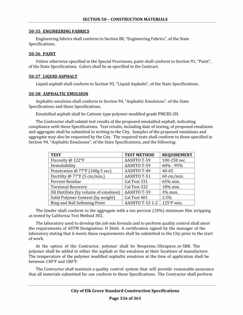
SECTION 50 – CONSTRUCTION MATERIALS
City of Elk Grove Standard Construction Specifications
Page 336 of 361
50-35 ENGINEERING FABRICS
Engineering fabrics shall conform to Section 88, “Engineering Fabrics”, of the State Specifications.
50-36 PAINT
Unless otherwise specified in the Special Provisions, paint shall conform to Section 91, “Paint”, of the State Specifications. Colors shall be as specified in the Contract.
50-37 LIQUID ASPHALT
Liquid asphalt shall conform to Section 93, “Liquid Asphalts”, of the State Specifications.
50-38 ASPHALTIC EMULSION
Asphaltic emulsion shall conform to Section 94, “Asphaltic Emulsions”, of the State Specifications and these Specifications.
Emulsified asphalt shall be Cationic type polymer modified grade PMCRS-2H.
The Contractor shall submit test results of the proposed emulsified asphalt, indicating compliance with these Specifications. Test results, including date of testing, of proposed emulsions and aggregate shall be submitted in writing to the City. Samples of the proposed emulsions and aggregate may also be requested by the City. The required tests shall conform to those specified in Section 94, “Asphaltic Emulsions”, of the State Specifications, and the following:
TEST TEST METHOD REQUIREMENT Viscosity @ 122°F AASHTO T-59 100-250 sec. Demulsibility AASHTO T-59 60% - 95% Penetration @ 77°F (100g 5 sec) AASHTO T-49 40-65 Ductility @ 77°F (5 cm/min.) AASHTO T-51 60 cm/min. Percent Residue Cal Test 331 65% min. Torsional Recovery Cal Test 332 18% min. Oil Distillate (by volume of emulsion) AASHTO T-59 3% max. Solid Polymer Content (by weight) Cal Test 401 2.5% Ring and Ball Softening Point AASHTO T-53 1-2 125°F min.
The binder shall conform to the aggregate with a ten percent (10%) minimum film stripping as tested by California Test Method 302.
The laboratory used to develop the job mix formula and to perform quality control shall meet the requirements of ASTM Designation: D 3666. A certification signed by the manager of the laboratory stating that it meets these requirements shall be submitted to the City prior to the start of work.
At the option of the Contractor, polymer shall be Neoprene, Ultrapave, or SBR. The polymer shall be added to either the asphalt or the emulsion at their locations of manufacture. The temperature of the polymer modified asphaltic emulsion at the time of application shall be between 130°F and 180°F.
The Contractor shall maintain a quality control system that will provide reasonable assurance that all materials submitted for use conform to these Specifications. The Contractor shall perform

SECTION 50 – CONSTRUCTION MATERIALS
City of Elk Grove Standard Construction Specifications
Page 337 of 361
two (2) random samples each day, to verify compliance with the operations quality control. Samples shall be taken from the spray bar of the distributor truck at mid-load. The tests shown above shall be performed on each sample taken. The City reserves the right to suspend Contractor activities and reject the material until it can be shown that the material is in compliance with these Specifications.
If a sample of asphaltic emulsion taken during a Working Day does not conform to these Specifications, the price paid per ton for that day’s production of asphaltic emulsion will be subject to the penalties listed for the nonconformities in the following table:
TABLE 50-9
Nonconformity Penalty
Viscosity is in excess of 75 seconds or less than 300 seconds.
5 percent deduction from the bid price per ton for emulsified asphalt.
Torsional recovery exceeds 11 percent but is less than 18 percent.
5 percent deduction from the bid price per ton for emulsified asphalt.
Torsional recovery is less than 11 percent.
10 percent deduction from the bid price per ton for emulsified asphalt.
Test results shall be identified by the production date and time of sample and shall be submitted, in writing, to the City within two (2) Working Days of the sample date. The City reserves the right to witness the quality control testing performed by the testing lab and to test any material at any time during the course of the work. Each distributor truck shall be equipped, at all times, with the proper measuring stick and calibration card. On-site calibration of distributor trucks, for determining actual spread rate of asphaltic emulsion, shall be performed when directed by the City. The asphaltic emulsion shall be stored in heated circulation tanks at controlled temperatures, between 140°F and 180°F, for a period not to exceed seven (7) days. The temperatures of the asphaltic emulsion shall be between 130°F and 180°F at the time of application.
50-39 EPOXY
Epoxy shall conform to Section 95, “Epoxy”, of the State Specifications.
50-40 PAVING STONES
Paving stones, including type and color, shall be approved by the City. All paving stones shall be installed per manufacturer’s recommendations and per plan. All paving stones shall be cleaned and sealed with an approved seal prior to initial acceptance.
50-41 COLORED OR PATTERNED CONCRETE
The mix design, including color, pattern and compressive strength of concrete shall be approved by the City. All colored or patterned concrete shall be cleaned and sealed with an approved seal prior to initial acceptance.