construction, geologic, and hydrologic data from five · pdf fileconstruction, geologic, and...
TRANSCRIPT
14˚10'
14˚05'30”
145˚10' 145˚15'
PuntanSailigai
PuntanPoña
PuntanHaiña
PuntanFina Atkos
PuntanSaguagahga
PuntanTaipingot
SasanhayaBay
P H I L I P
P I N E
S E A
P A C I F I C
O
C E A N
EX-5 EX-2 EX-3 EX-4
EX-1
DEPTH
EX-1
602
500
400
300
200
100
sea level
-100
ELEVATION
-143
0
90
130
380
609
670
720745
Open-File Report 2005-1042
U.S. Department of the InteriorU.S. Geological Survey
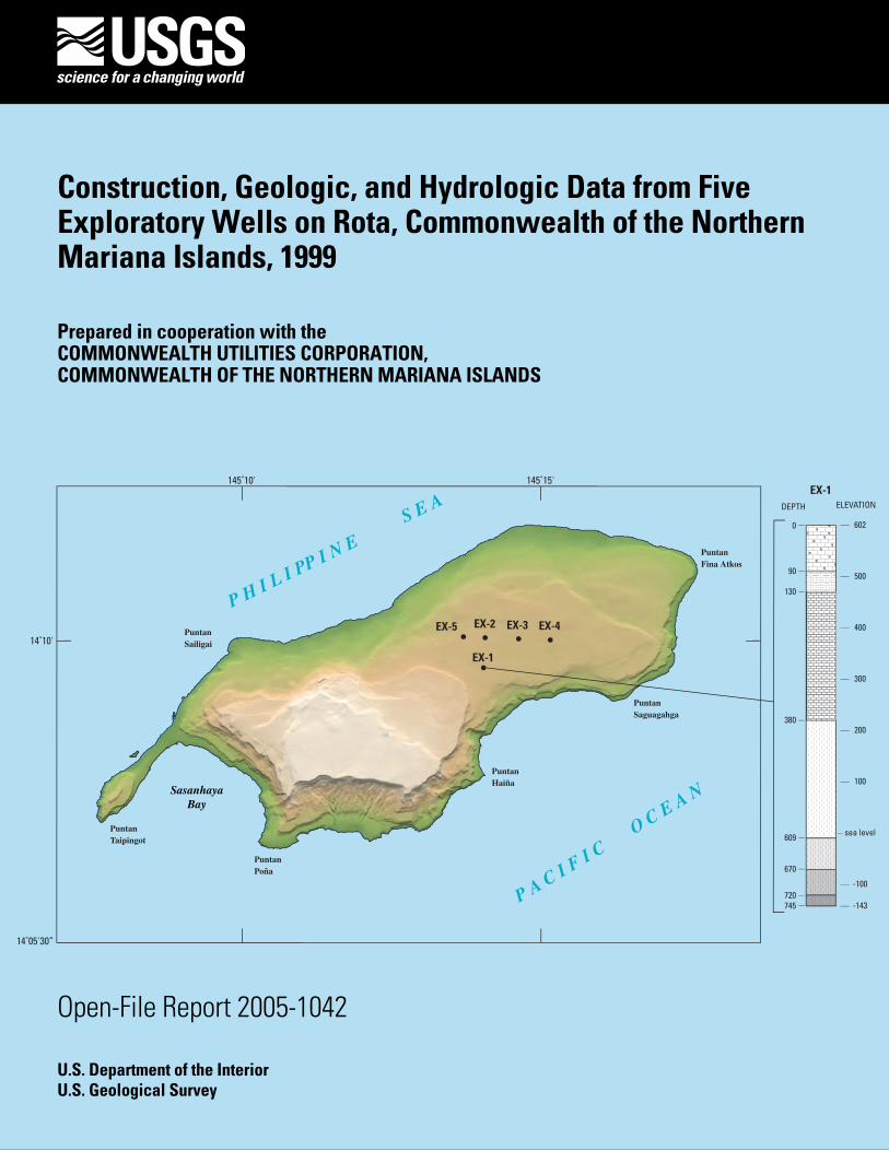
Construction, Geologic, and Hydrologic Data from Five Exploratory Wells on Rota, Commonwealth of the Northern Mariana Islands, 1999
Prepared in cooperation with theCOMMONWEALTH UTILITIES CORPORATION,COMMONWEALTH OF THE NORTHERN MARIANA ISLANDS

Construction, Geologic, and Hydrologic Data from Five Exploratory Wells on Rota, Commonwealth of the Northern Mariana Islands, 1999
By Robert L. Carruth
U.S. Department of the Interior U.S. Geological Survey
Prepared in cooperation with theCOMMONWEALTH UTILITIES CORPORATION,COMMONWEALTH OF THE NORTHERN MARIANA ISLANDS
Open-File Report 2005-1042
U.S. Department of the InteriorGale A. Norton, Secretary
U.S. Geological SurveyCharles G. Groat, Director
U.S. Geological Survey, Reston, Virginia: 2005For sale by U.S. Geological Survey, Information Services Box 25286, Denver Federal Center Denver, CO 80225
For more information about the USGS and its products: Telephone: 1-888-ASK-USGS World Wide Web: http://www.usgs.gov/
Any use of trade, product, or firm names in this publication is for descriptive purposes only and does not imply endorsement by the U.S. Government.
Although this report is in the public domain, permission must be secured from the individual copyright owners to repro-duce any copyrighted materials contained within this report.
Suggested citation: Carruth, R.L., 2005, Construction, geologic, and hydrologic data from five exploratory wells on Rota, Commonwealth of the Northern Mariana Islands, 1999 : U.S. Geological Survey Open-File Report 2005-1042, 40 p.

iii
Contents
Abstract. . . . . . . . . . . . . . . . . . . . . . . . . . . . . . . . . . . . . . . . . . . . . . . . . . . . . . . . . . . . . . . . . . . . . . . . . . . . 1Introduction . . . . . . . . . . . . . . . . . . . . . . . . . . . . . . . . . . . . . . . . . . . . . . . . . . . . . . . . . . . . . . . . . . . . . . . . 1
Physical Setting . . . . . . . . . . . . . . . . . . . . . . . . . . . . . . . . . . . . . . . . . . . . . . . . . . . . . . . . . . . . . . . . 4Location and Name of Wells . . . . . . . . . . . . . . . . . . . . . . . . . . . . . . . . . . . . . . . . . . . . . . . . . . . . . 4Acknowledgments. . . . . . . . . . . . . . . . . . . . . . . . . . . . . . . . . . . . . . . . . . . . . . . . . . . . . . . . . . . . . . 6
Drilling Methods and History. . . . . . . . . . . . . . . . . . . . . . . . . . . . . . . . . . . . . . . . . . . . . . . . . . . . . . . . . . 6Geologic Logs. . . . . . . . . . . . . . . . . . . . . . . . . . . . . . . . . . . . . . . . . . . . . . . . . . . . . . . . . . . . . . . . . . . . . . . 18Aquifer Tests . . . . . . . . . . . . . . . . . . . . . . . . . . . . . . . . . . . . . . . . . . . . . . . . . . . . . . . . . . . . . . . . . . . . . . . 18Water Levels . . . . . . . . . . . . . . . . . . . . . . . . . . . . . . . . . . . . . . . . . . . . . . . . . . . . . . . . . . . . . . . . . . . . . . . 26Water Quality . . . . . . . . . . . . . . . . . . . . . . . . . . . . . . . . . . . . . . . . . . . . . . . . . . . . . . . . . . . . . . . . . . . . . . . 32Summary . . . . . . . . . . . . . . . . . . . . . . . . . . . . . . . . . . . . . . . . . . . . . . . . . . . . . . . . . . . . . . . . . . . . . . . . . . . 40References Cited . . . . . . . . . . . . . . . . . . . . . . . . . . . . . . . . . . . . . . . . . . . . . . . . . . . . . . . . . . . . . . . . . . . . 40Appendices Provided in Excel Format
Figures
1–3.Maps showing: 1. Loation and shaded relief of Rota, Commonwealth of the
Northern Mariana Islands. . . . . . . . . . . . . . . . . . . . . . . . . . . . . . . . . . . . . . . . . . . . . . . . . 22. Location of the five exploratory wells drilled in 1999 and pre-existing wells in the
northern plateau, Rota . . . . . . . . . . . . . . . . . . . . . . . . . . . . . . . . . . . . . . . . . . . . . . . . . . . . 33. Generalized surficial geology of Rota . . . . . . . . . . . . . . . . . . . . . . . . . . . . . . . . . . . . . . . 5
4–8. Drawings showing: 4. Geologic log and construction details of well EX-1 (CUC well SP-MW1), Rota . . . . . . . 95. Geologic log and construction details of well EX-2 (CUC well SP-1), Rota. . . . . . . . . . . 116. Geologic log and construction details of well EX-3 (CUC well SP-2), Rota. . . . . . . . . . . 137. Geologic log and construction details of well EX-4 (CUC well SP-3), Rota. . . . . . . . . . . 158. Geologic log and construction details of well EX-5 (CUC well SP-MW2), Rota . . . . . . . 17
9–20. Graphs showing: 9. Drawdown and recovery with time during and after the 8-day sustained aquifer
test (Aug 30 -- September 7, 1999), at well EX-2 (CUC well SP-1) Rota . . . . . . . . . . . . . . 2010. Drawdown with time during the step-drawdown aquifer test (September 8, 1999),
at well EX-2 (CUC well SP-1) Rota. . . . . . . . . . . . . . . . . . . . . . . . . . . . . . . . . . . . . . . . . . . . 2111. Drawdown and recovery with time during and after the 8-day sustained aquifer test
(October 27 – November 4, 1999), at well EX-3 (CUC well SP-2) Rota . . . . . . . . . . . . . . . 2212. Drawdown with time during the step-drawdown aquifer test (November 4, 1999),
at well EX-3 (CUC well SP-2) Rota. . . . . . . . . . . . . . . . . . . . . . . . . . . . . . . . . . . . . . . . . . . . 2313. Drawdown and recovery with time during and after the 8-day sustained-rate aquifer test
(September 23 -- October 1, 1999), at well EX-4 (CUC well SP-3) Rota . . . . . . . . . . . . . . 2414. Drawdown with time during the step-drawdown aquifer test (October 2, 1999),
at well EX-4 (CUC well SP-3) Rota. . . . . . . . . . . . . . . . . . . . . . . . . . . . . . . . . . . . . . . . . . . . 2515. Intermitent ground-water data at well EX-1 (CUC well SP-MW1), 2000-2001, Rota . . . . 2716. Intermitent ground-water data at well EX-2 (CUC well SP-1), 2000-2001, Rota. . . . . . . . 2817. Intermitent ground-water data at well EX-3 (CUC well SP-2), 2000-2001, Rota. . . . . . . . 2918. Intermitent ground-water data at well EX-4 (CUC well SP-3), 2000-2001, Rota. . . . . . . . 3019. Intermitent ground-water data at well EX-5 (CUC well SP-MW2), 2000-2001, Rota . . . . 3120. Specific conductance profile at well EX-1 (CUC well SP-MW1) , August 4, 2000,
Rota . . . . . . . . . . . . . . . . . . . . . . . . . . . . . . . . . . . . . . . . . . . . . . . . . . . . . . . . . . . . . . . . . . . . 33
iv
Tables
1. Exploratory well name, CUC well name, location, and elevation of the five exploratory wells on Rota . . . . . . . . . . . . . . . . . . . . . . . . . . . . . . . . . . . . . . . . . . . . . . . . . . . . . . . . . . . . . . . . . . . . 6
2. Construction summary of exploratory well EX-1 (SP-MW1), Rota . . . . . . . . . . . . . . . . . . . . . . . . 83. Construction summary of exploratory well EX-2 (SP-1), Rota . . . . . . . . . . . . . . . . . . . . . . . . . . . . 104. Construction summary of exploratory well EX-3 (SP-2), Rota . . . . . . . . . . . . . . . . . . . . . . . . . . . . 125. Construction summary of exploratory well EX-4 (SP-3), Rota . . . . . . . . . . . . . . . . . . . . . . . . . . . . 146. Construction summary of exploratory well EX-5 (SP-MW2), Rota . . . . . . . . . . . . . . . . . . . . . . . . 167. Water-quality data at well EX-2 (CUC well SP-1) on June 6, 2000 and
September 25, 2000, Rota . . . . . . . . . . . . . . . . . . . . . . . . . . . . . . . . . . . . . . . . . . . . . . . . . 348. Water-quality data at well EX-3 (CUC well SP-2) on June 6, 2000 and
September 25, 2000, Rota . . . . . . . . . . . . . . . . . . . . . . . . . . . . . . . . . . . . . . . . . . . . . . . . . 359. Water-quality data at well EX-4 (CUC well SP-3) on June 6, 2000 and
September 25, 2000, Rota . . . . . . . . . . . . . . . . . . . . . . . . . . . . . . . . . . . . . . . . . . . . . . . . . 3610. Pesticides, herbicides, and other volatile organic constituents found to be less than
detection limits in water samples from EX-2 (CUC well SP-1) on June 6, 2000 and September 25, 2000, Rota . . . . . . . . . . . . . . . . . . . . . . . . . . . . . . . . . . 37
11. Pesticides, herbicides, and other volatile organic constituents found to be less than detection limits in water samples from EX-3 (CUC well SP-2) on June 6, 2000 and September 25, 2000, Rota . . . . . . . . . . . . . . . . . . . . . . . . . . . . . . . . . . 38
12. Pesticides, herbicides, and other volatile organic constituents found to be less than detection limits in water samples from EX-4 (CUC well SP-3) on June 6, 2000 and September 25, 2000, Rota . . . . . . . . . . . . . . . . . . . . . . . . . . . . . . . . . . 39
Appendices Provided in Excel Format
1. Lithologic descriptions of drill cuttings from Rota exploratory wells.2. Data from 8-day sustained-rate aquifer test conducted on August 30--September 7, 1999, before
installation of casing and gravel pack, well EX-2 (CUC well SP-1), Rota.3. Data from recovery test, September 7, 1999, well EX-2 (CUC well SP-1), Rota.4. Data from step-drawdown aquifer test, September 8, 1999, well EX-2 (CUC well SP-1), Rota.5. Data from 8-day sustained-rate aquifer test conducted on October 27--November 4, 1999, before
installation of casing and gravel pack, well EX-3 (CUC well SP-2), Rota.6. Data from recovery test, November 4, 1999, well EX-3 (CUC well SP-2), Rota.7. Data from step-drawdown aquifer test, November 4, 1999, well EX-3 (CUC well SP-2), Rota.8. Data from 8-day sustained-rate aquifer test conducted on September 23--October 1, 1999,
before installation of casing and gravel pack, well EX-4 (CUC well SP-3), Rota.9. Data from recovery test, October 1, 1999, well EX-4 (CUC well SP-3), Rota.10.Data from step-drawdown aquifer test, October 2, 1999, well EX-4 (CUC well SP-3), Rota.
v
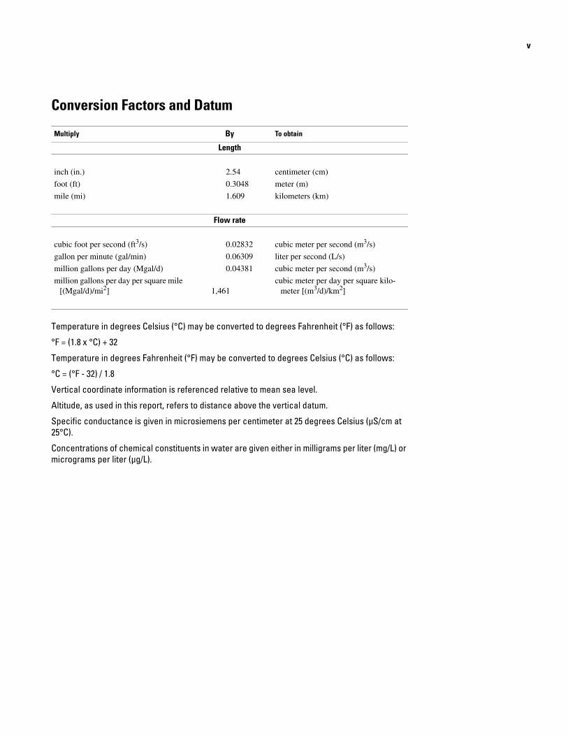
Conversion Factors and Datum
Multiply By To obtain
Length
inch (in.) 2.54 centimeter (cm)
foot (ft) 0.3048 meter (m)
mile (mi) 1.609 kilometers (km)
Flow rate
cubic foot per second (ft3/s) 0.02832 cubic meter per second (m3/s)
gallon per minute (gal/min) 0.06309 liter per second (L/s)
million gallons per day (Mgal/d) 0.04381 cubic meter per second (m3/s)
million gallons per day per square mile [(Mgal/d)/mi2] 1,461
cubic meter per day per square kilo-meter [(m3/d)/km2]
Temperature in degrees Celsius (°C) may be converted to degrees Fahrenheit (°F) as follows:
°F = (1.8 x °C) + 32
Temperature in degrees Fahrenheit (°F) may be converted to degrees Celsius (°C) as follows:
°C = (°F - 32) / 1.8
Vertical coordinate information is referenced relative to mean sea level.
Altitude, as used in this report, refers to distance above the vertical datum.
Specific conductance is given in microsiemens per centimeter at 25 degrees Celsius (µS/cm at 25°C).
Concentrations of chemical constituents in water are given either in milligrams per liter (mg/L) or micrograms per liter (µg/L).

Construction, Geologic, and Hydrologic Data from Five Exploratory Wells on Rota, Commonwealth of the Northern Mariana Islands, 1999
By Robert L. Carruth
Abstract
Rota is the southernmost of the 14 small islands that make up the Commonwealth of the Northern Mariana Islands. Reduced springflow at Matan Hanom and As Onan springs occurred during a drought associated with the 1997-98 El Niño. Water from the two developed springs constituted the only municipal water source for the island at that time. In April 1998, reduced water supplies forced the Commonwealth Utilities Cor-poration to restrict water service in the principal villages of Songsong and Sinapalu for the duration of the dry season.
In 1999, Five exploratory wells, EX-1 through EX-5 (CUC wells SP-MW1, SP-1, -2, -3, and SP-MW2), were drilled in the Sinapalu region of Rota to (1) assess the availability of fresh ground-water resources in an area where no other well informa-tion were available, and (2) to provide a new water source to help mitigate the impacts of drought associated with recurring El Niño weather events. The wells penetrated mainly light col-ored (dirty white to brownish), fragmental limestones contain-ing abundant coral remains.
Sustained-rate, recovery, and step-drawdown aquifer tests were attempted at each of the five exploratory wells to estimate aquifer properties in the vicinity of the wells and to assess the potential for new water sources. At wells EX-1 (CUC well SP-MW1) and EX-5 (CUC well SP-MW2), attempts to conduct sustained-rate aquifer tests resulted in excessive drawdown to the pump intakes in the vicinity of the wells. At well EX-2 (CUC well SP-1), the maximum drawdown measured in the pumped well was 3.93 ft during 8 days of sustained pumping at an average rate of 187 gal/min. At well EX-3 (CUC well SP-2), the maximum drawdown measured in the pumped well was 2.31 ft during 8 days of sustained pumping at an average rate of 108 gal/min, and at well EX-4 (CUC well SP-3), the maximum drawdown measured in the pumped well was 3.27 ft during 8 days of sustained pumping at an average rate of 139 gal/min. Specific conductance at the end of 8 days of pumping was 403, 358, and 445 µS/cm at well EX-2, EX-3, and EX-4 (CUC wells SP-1, -2, and -3), respectively.
Introduction
The island of Rota is about 45 mi north-northeast of Guam in the western Pacific and lies between 14°06’ and 14°12’ north latitude and between 145°07’ and 145°17’ east longitude (fig. 1). The island is oriented on an east-west axial direction and is approximately 11.5 mi long and 3 mi wide. Including two small islets along the west shore, the land area of Rota is about 33 mi2 or about 15 percent of the land area of Guam. Rota is the south-ernmost of the 14 small islands that make up the Common-wealth of the Northern Mariana Islands.
Water-supply shortages occur on Rota during extended dry periods, which are often attributed to the El Niño. The 1997–98 El Niño in the Northern Mariana Islands was marked by four destructive typhoons (Wynne, Joan, Keith, and Paka) followed by a drought. Rainfall at the Rota Airport in 1998 was 58 in., which is about 40 percent below the annual average of 95 in. (Chip Guard, National Weather Service, pers. commun.). Flows from the Matan Hanom and As Onan springs, the only munici-pal water-supply source for the island, also were below normal in 1998. From April through June 1998, the Commonwealth Utilities Corporation (CUC) was forced for the first time to restrict water service in the principal villages of Songsong and Sinapalu.
In March 1998, the Federal Emergency Management Agency (FEMA) approved a grant application from the CUC for Hazard Mitigation Grant Program (HMGP) funding. Part of the federal funding was for water-supply augmentation projects on Rota to help mitigate the impacts of future droughts. As a result, the U.S. Geological Survey (USGS), in cooperation with the CUC, (1) selected locations for five exploratory wells and provided oversight during drilling operations, (2) collected aquifer-test data to determine the availability of fresh ground water at the five exploratory wells, and (3) and reviewed water-quality data. The five exploratory wells (EX-1 through EX-5) were sited in the Sinapalu region (fig. 2), an area where no wells had been drilled and no subsurface information were available.

RO
AD
S -
Das
hed
whe
re
unim
prov
ed
PIPE
LIN
E
STR
EA
MS
DE
VE
LO
PED
SPR
ING
A
ND
NA
ME
EX
PL
AN
AT
ION
01/
21
2 M
ILES
SCAL
E
14˚1
0'
14˚1
5'30
”
145˚
10'
145˚
15'
160˚
E14
0˚12
0˚
0˚
20˚N40
˚
Phili
ppin
es
Japa
n ROTA
Guam
PAC
IFIC
O
CE
AN
01,
000
MI
01,
000
KM
FED
ER
AT
ED
STA
TE
S O
F
M
ICR
ON
ESI
AR
EPU
BL
ICO
F PA
LA
U
CO
MM
ON
WE
ALT
HO
F T
HE
NO
RT
HE
RN
MA
RIA
NA
ISL
AN
DS
RE
PUB
LIC
OF
TH
EM
AR
SHA
LL
ISL
AN
DS
Mat
anH
anom
Mat
anH
anom
As
Ona
n
Sina
palu
Vill
age
Rot
a
Air
port
Saba
na
Mt.
Man
ira
Song
song
Vill
age
Punt
anSa
iliga
i
Punt
anPo
ña
Punt
anH
aiña
Punt
anFi
na A
tkos
Punt
anSa
guag
ahga
Punt
anTa
ipin
got
Sasa
nhay
aB
ay
P H
I L
I P
P I
N E
S
E A
P A
C I
F I
C
O
C E
A N
2 Construction, Geologic, and Hydroligic Data from Five Exploratory Wells on Rota, CNMI, 1999
Figu
re 1
. Lo
catio
n an
d sh
aded
relie
f of R
ota,
Com
onw
ealth
of t
he N
orth
ern
Mar
iana
isla
nds.

Introduction 3
Figure 2. Location of the five exploratory wells drilled in 1999 and pre-existing wells in the northern plateau, Rota. (Inset map modified from Bridge, 1947)
PRE-EXISTING RESORT WELL AND NUMBER
EXPLORATORY WELL AND NUMBER
EXPLANATION
1
2
3
4
5
6
7
9
8
1A
10
11
11
EX-5
EX-5
EX-2 EX-3 EX-4
EX-1
ROTA
Area of Map
COASTALLOWLAND
SOUTHERN PLATEAU
NORTHERNPLATEAU
VOLCANIC AREAWESTERN
PENINSULA
0 1/2 1 MILE
SCALE
P H I L I P P I N E S E A
P A C I F I C O C E A N
SNM Rota Resort
Mochong Beach
140˚12'30"
14˚10'
14˚07'30"
140˚15' 140˚17'30"

4 Construction, Geologic, and Hydroligic Data from Five Exploratory Wells on Rota, CNMI, 1999
The objectives of this project were met by analysis of data collected during and after the drilling operations. These data included (1) the driller’s description of well-construction details and the drilling history, (2) a description of the geology from the rock chips (drill cuttings) brought to the surface during drilling, (3) sustained-rate, recovery, and step-drawdown tests at wells EX-2, -3, and -4, (4) a review of water-quality data at wells EX-2, -3, and -4, and (5) a review of water-level data collected at wells EX-1 through EX-5. This report documents the location, drilling history, construction details, geology, aquifer-test, water-level, and water-quality data of the five exploratory wells on Rota.
Physical Setting
Rota is a subareal peak on the Mariana Island Arc and con-sists of a volcanic core overlain by younger limestones (fig. 3). Mt. Manira is the highest point on the island at an elevation of 1,612 ft above sea level. Undifferentiated, coralline limestone rocks cover most of the surface area above sea level, occurring as a series of plateaus separated by steep scarps. Less than 10 percent of the exposed area is volcanic rock. Younger beach deposits mantle the older longshore limestone benches and the entire island is surrounded by a fringing reef in a relatively young stage of development (Piper, 1947).
The five exploratory wells are located in the Sinapalu region of Rota, a coralline limestone plateau in the northeastern section of the island that contains the Sinapalu Village and the Rota Airport (fig. 2). This limestone plateau, referred to as the northern plateau by Bridge (1946), ranges in large part between 500 and 625 ft above sea level, and is part of a large plateau that roughly comprises the eastern half of the island. The southern and eastern sides of the plateau are discontinuously terraced and terminate in pronounced cliffs that lead to a rocky shoreline. In the north, the plateau gradually slopes in an unterraced ramp toward the sea, terminating at the Mochon Beach area.
The corralline limestones which make up the northern pla-teau have been described by Piper (1947) as largely compact, massive or indistinctly bedded, and locally including moder-ately consolidated reef rubble. The surface of the northern pla-teau is thinly mantled by residual soil, lacks surface streams, and has subdued epikarst features. The features of the limestone rocks of the northern plateau are consistent with other Pleis-tocene limestones in the Mariana Islands whose properties include moderate to high transmission of ground water.
Prior to 1999, ground-water exploration on the northern plateau was limited to the site of the SNM Rota Resort located east-northeast of the Sinapalu area (fig. 2). In 1991 and 1992, 11 exploratory wells were drilled to investigate the availability of ground-water resources beneath the SNM Rota Resort site. The borings, ranging from 120 to 400 ft below land surface, encoun-tered medium-hard to hard, pure to argillaceous coralline lime-stone of varying color (white, yellow, and tan) throughout the drilled depths. Cavities of various sizes were encountered in most of the test holes. Static (non-pumping) ground-water lev-els at wells along the inland boundary of the resort’s property
are between 2 and 4 ft, and range from about 1 to 2 ft at wells along the seaward boundary. Nance (1993) reported that results of the drilling and testing indicate the presence of an exploitable freshwater lens and recommended further study to characterize the hydrologic properties of the aquifer beneath the site. Eight of the original 11 exploratory wells were converted to water-supply wells in 1993 and are operated intermittently for a water source for the golf course and resort. Of the remaining three wells, the two drilled near the seaward boundary of the resort were converted to monitor wells and one well was abandoned due to low yield.
Ground-water exploration in the northern plateau has been moderately successful within the limited area of drilling and testing (SNM Rota Resort), owing in part to the generally mod-erate-to-high permeabilities of the limestones. However, low permeability zones in the limestones occur, evidenced in part by a wide range of specific capacities of exploratory wells at the resort (Nance, 1993). The thickness and structure of the lime-stones of the northern plateau is unknown and thus far, none of the exploratory wells have encountered the volcanic basement rock. The limited information available indicate that a freshwa-ter lens of significant thickness and aerial extent may exist in the limestones that make up the northern plateau; however, the occurrence and movement of ground water within the plateau remain largely unknown.
Location and Name of Wells
The five exploratory wells (EX-1 through EX-5) are located in the Sinapalu area of the northern plateau of Rota (fig. 2 and table 1). Four of the wells (EX-2 through EX-5) are located along the road that makes up the southern boundary of the Rota Airport. Well EX-1 is located within the Sinapalu Vil-lage inside the fenced area that contains the 0.5 Mgal Sinapalu water-storage reservoir. All five wells are located on land that is administered by the government of the Commonwealth of the Northern Mariana Islands (CNMI).
Well EX-4 is located 0.5 mi east of the intersection of the road leading north into the Rota Airport with the road heading east towards Gampapa and west towards the entrance to Sina-palu Village and further west towards the entrance to the SNM Rota Resort (herein referred to as the airport intersection). Well EX-3 is located 0.2 mi west of the airport intersection, and wells EX-2 and EX-5 are located 0.9 mi west and 1.3 mi west of the airport intersection, respectively. Well EX-1 is located 0.5 mi south of well EX-2 along the road leading into the Sinapalu Vil-lage.
Upon completion of drilling and testing, the CUC assigned well names according to their well-naming system for water-supply wells and monitor wells. The well-naming system uses a two-letter abbreviation for the place name on the island (SP for Sinapalu) with sequential numbering for water-supply wells (SP-1, for example). Similarly, monitor wells are assigned the two-letter place name abbreviation, a two-letter abbreviation for monitor well, and a sequential number (SP-MW1, for exam-ple).

1,50
01,
000
500
Sea
Leve
l
Surfa
ce p
rofil
e al
ong
line
A-A
'
GE
OL
OG
Y
C
oral
line
limes
tone
V
olca
nic
rock
s
LIN
E O
F SE
CT
ION
RO
AD
S -
Das
hed
whe
re u
nim
prov
ed
EX
PLO
RA
TO
RY
WE
LL
AN
D N
AM
E
EX
PL
AN
AT
ION
01/
21
2 M
ILES
SCAL
E
14˚1
0'
14˚1
5'30
”
145˚
10'
145˚
15'
BEND INSECTION
EX-5
EX-5
EX-2
EX-3
EX-4
EX-1
A'
A'
A'
north
ern
plat
eau
A
A
A
Mt.
Man
ira aH
Introduction 5
Figu
re 3
. Ge
nera
lized
sur
ficia
l geo
logy
of R
ota
(mod
ified
from
Pip
er, 1
947)
.

Table 1. Exploratory well name, CUC well name, location, and elevation of the five exploratory wells on Rota
[datum is mean sea level]
Exploratory CUC Latitude1
Longitude1 Approximate elevation Elevation of brass Elevation of Location of
well name well name of land surface, monument in concrete well pad, measuring point, measuring
(feet) (feet) (feet) point
EX-1 SP-MW 1 14 09 37 145 13 40 602 603.16 603.98 Top of casing
EX-2 SP-1 14 10 03 145 13 42 593 594.06 594.53 Top of sounding tube
EX-3 SP-2 14 10 03 145 14 16 573 575.91 576.38 Top of sounding tube
EX-4 SP-3 14 10 02 145 14 48 570 570.19 570.71 Top of sounding tube
EX-5 SP-MW 2 14 10 05 145 13 20 590 591.07 591.52 Top of sounding tube(top of casing)(592.16)
1Estimated from 1:25,000 USGS topographic map, revised in 1999. North American Datum of 1983.
6 Construction, Geologic, and Hydroligic Data from Five Exploratory Wells on Rota, CNMI, 1999
Acknowledgments
The construction, data collection, and testing of the five exploratory wells were made possible with the cooperation and assistance of Mr. Rodel Alvidera, Drilling Project Engineer for Geotesting Inc., and Mr. Danny Barrion, Drilling Project Man-ager for the CUC. I am grateful to Mr. Don Smith, Technical Assistance Engineer for the CUC, for his technical input and drilling contract oversight. Drilling, aquifer-test, and elevation information were drawn extensively from the notes of Mr. Charles Ewart of the U.S. Geological Survey (retired).
Data were compiled from the following agencies:Commonwealth Utilities Corporation (CUC)Geotesting Inc.Permits or permission were obtained from the following
agencies:Commonwealth Ports Authority (CPA)Commonwealth Department of Environmental Quality
(DEQ)Commonwealth Historical Preservation Office (HPO)Commonwealth Department of Land and Natural
Resources (DLNR)
Assistance from these agencies in support of the explor-atory drilling and testing program is gratefully acknowledged. Field and office support from the staff of CUC is also appreci-ated.
Drilling Methods and History
The wells were initially bored by rotary drilling with a 9-7/8-in. diameter tungsten-carbide tri-cone bit. Air and drilling
foam were injected down through the hollow drill stem and cir-culated back up the annular space between the drill stem and the well boring to remove cuttings from the hole. When the initial pilot borings neared the target depth of -15 ft relative to mean sea level, the drill stem and bit were removed and the holes were reamed to 13-in. diameter by rotary drilling with a 13-in. hole-opening tool down to the target depth of -15 ft. Tables 2–6 and figures 4–8 summarize the construction of the five wells.
The elevation of the brass plate in the concrete pad at well EX-1 (SP-MW1) is 603.16 ft and the well is 745 ft deep (bottom is at -143 ft elevation). The well was initially drilled to -15 ft elevation, the target depth for initial testing. The initial water level was about 3.95 ft elevation. An aquifer test was attempted but had to be terminated due to rapid drawdown and low yield. A decision was made to install 8-in. steel casing, with perfora-tions between the water table and the initial bottom at -15 ft, and to deepen the well from the elevation of -15 ft to -143 ft (total depth of 745 ft from land surface). The well was deepened by lowering a 7 7/8-in. diameter bit through the 8-in. steel casing to continue drilling beyond -15 ft. Flush-threaded 6-in. polyvi-nyl-chloride (PVC) casing, with perforations between the water table and the bottom, was installed. The well was designated as a monitor well and renamed by the CUC to SP-MW1. CUC well SP-MW1 will be used as a vertical-profiling well to monitor the thickness of the freshwater lens and the movement of the tran-sition zone. Table 2 summarizes the construction history of the well. A drawing of the construction details of the finished well is shown in figure 4.
The elevation of the brass plate in the concrete pad at well EX-2 (SP-1) is 594.06 ft and the well is 608 ft deep (bottom is at -15 ft elevation). A void in the limestone was encountered at 3 ft elevation and drilling fluid circulation was lost as the drill bit penetrated from 3 ft (590 ft deep) to -8 ft elevation (601 ft), where drilling fluid circulation to the surface resumed. The ini-
Drilling Methods and History 7
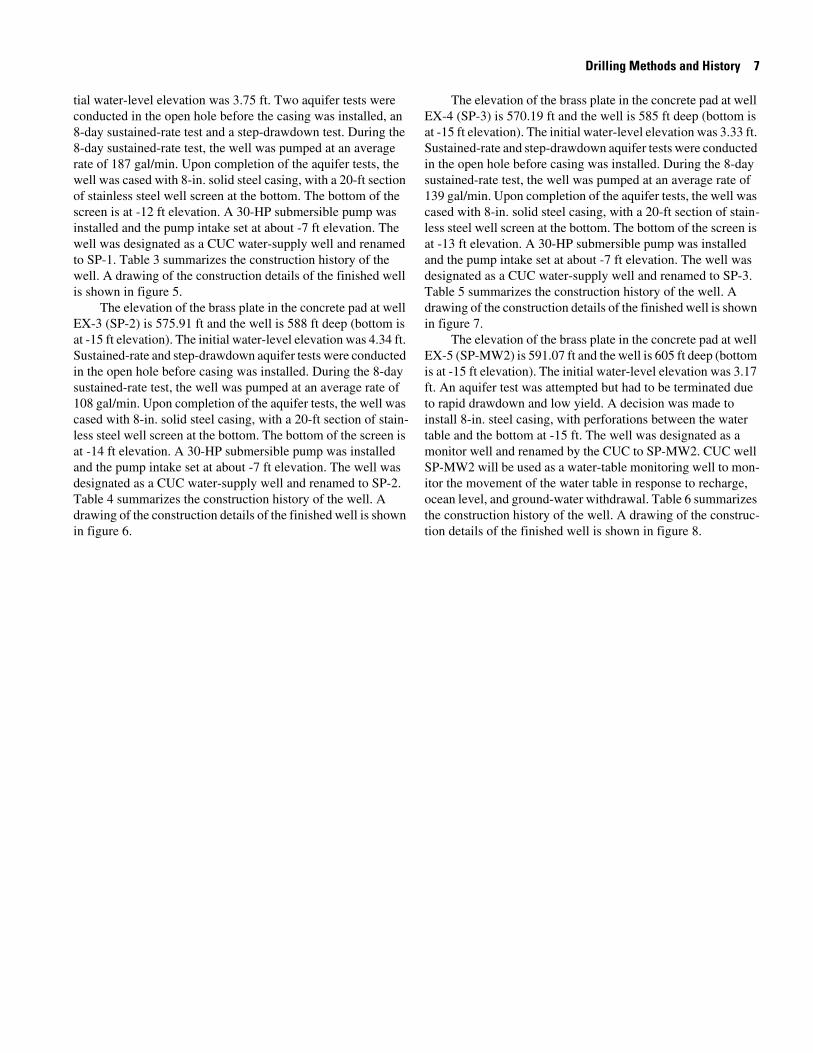
tial water-level elevation was 3.75 ft. Two aquifer tests were conducted in the open hole before the casing was installed, an 8-day sustained-rate test and a step-drawdown test. During the 8-day sustained-rate test, the well was pumped at an average rate of 187 gal/min. Upon completion of the aquifer tests, the well was cased with 8-in. solid steel casing, with a 20-ft section of stainless steel well screen at the bottom. The bottom of the screen is at -12 ft elevation. A 30-HP submersible pump was installed and the pump intake set at about -7 ft elevation. The well was designated as a CUC water-supply well and renamed to SP-1. Table 3 summarizes the construction history of the well. A drawing of the construction details of the finished well is shown in figure 5.
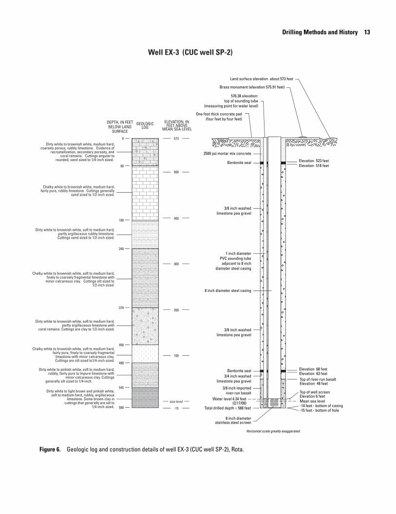
The elevation of the brass plate in the concrete pad at well EX-3 (SP-2) is 575.91 ft and the well is 588 ft deep (bottom is at -15 ft elevation). The initial water-level elevation was 4.34 ft. Sustained-rate and step-drawdown aquifer tests were conducted in the open hole before casing was installed. During the 8-day sustained-rate test, the well was pumped at an average rate of 108 gal/min. Upon completion of the aquifer tests, the well was cased with 8-in. solid steel casing, with a 20-ft section of stain-less steel well screen at the bottom. The bottom of the screen is at -14 ft elevation. A 30-HP submersible pump was installed and the pump intake set at about -7 ft elevation. The well was designated as a CUC water-supply well and renamed to SP-2. Table 4 summarizes the construction history of the well. A drawing of the construction details of the finished well is shown in figure 6.
The elevation of the brass plate in the concrete pad at well EX-4 (SP-3) is 570.19 ft and the well is 585 ft deep (bottom is at -15 ft elevation). The initial water-level elevation was 3.33 ft. Sustained-rate and step-drawdown aquifer tests were conducted in the open hole before casing was installed. During the 8-day sustained-rate test, the well was pumped at an average rate of 139 gal/min. Upon completion of the aquifer tests, the well was cased with 8-in. solid steel casing, with a 20-ft section of stain-less steel well screen at the bottom. The bottom of the screen is at -13 ft elevation. A 30-HP submersible pump was installed and the pump intake set at about -7 ft elevation. The well was designated as a CUC water-supply well and renamed to SP-3. Table 5 summarizes the construction history of the well. A drawing of the construction details of the finished well is shown in figure 7.
The elevation of the brass plate in the concrete pad at well EX-5 (SP-MW2) is 591.07 ft and the well is 605 ft deep (bottom is at -15 ft elevation). The initial water-level elevation was 3.17 ft. An aquifer test was attempted but had to be terminated due to rapid drawdown and low yield. A decision was made to install 8-in. steel casing, with perforations between the water table and the bottom at -15 ft. The well was designated as a monitor well and renamed by the CUC to SP-MW2. CUC well SP-MW2 will be used as a water-table monitoring well to mon-itor the movement of the water table in response to recharge, ocean level, and ground-water withdrawal. Table 6 summarizes the construction history of the well. A drawing of the construc-tion details of the finished well is shown in figure 8.

atoR ,)1WM-PS( 1-XE llew yrotarolpxe fo yrammus noitcurtsnoC Table 2.
]teef ,tf ;level aes naem evoba tf 206 tuoba si noitavele ecafrus dnaL .level aes naem si noitavele eloh-fo-mottob dna level-retaw rof mutaD[
etaD stneve tnacifingiS
9991 yluJ 21 lenap lortnoc eht fo erutpuR .)tf 011 ot 0 fo htped( noitavele tf 294 ot tf 206 morf dellirD .nageb gnillirD
MP 53:2 yb deriaper ,MA 03:01 ta esoh ciluardyh
31 MP 03:3 ta retrats eht no nwodkaerB .)tf 072 ot 011 fo htped( noitavele tf 233 ot tf 294 morf gnillird deunitnoC
51 )tf 054 ot 072 fo htped( noitavele tf 251 ot tf 233 morf gnillird deunitnoc dna MA 51:8 yb retrats gir dellatsnI
61 )tf 906 ot 054 fo htped( noitavele tf 7- ot tf 251 morf gnillird deunitnoC
91 MP 00:4 litnu eloh eht gnimaer nageb ,MP 02:3 litnu sepip llird tuo gnillup nageB
72 tib llird tuo dellup ,eloh eht gnimaer detelpmoC
9991 tsuguA 52 MP 03:1 ta )tf 716 fo htped latot( noitavele tf 51- fo htped lanif dehcaer ,MP 00:1 ta gnillird deunitnoC
9991 rebmetpeS 41 tset-gnipmup rof ylbmessa pmup fo noitallatsni nageB
51 ylbmessa pmup fo noitallatsni detelpmoC
61 dleiy wol dna nwodward hgih ot eud detanimret ;tset refiuqa etar-deniatsus tcudnoc ot detpmettA
9991 rebmevoN 21 neercs llew dna gnisac leets "8 fo noitallatsni nageB
51 neercs llew dna gnisac leets "8 fo noitallatsni detelpmoC
61 eloh eht tuorg ot nageB
71 eloh eht gnituorg detelpmoC
91 )tf 547 fo htped lanif( noitavele tf 341- ot tf 51- morf eloh fo gninepeed nageB
22 neercs llew dna gnisac CVP "6 fo noitallatsni nageB
32 neercs llew dna gnisac CVP "6 fo noitallatsni detelpmoC
0002 yraurbeF 71 noitavele tf 59.3 ta edutitla level retaW
8 Construction, Geologic, and Hydroligic Data from Five Exploratory Wells on Rota, CNMI, 1999

DEPTH, IN FEETBELOW LAND
SURFACEGEOLOGIC
LOG
Well EX-1 (CUC well SP-MW1)
Elevation 547 feet
Brass monument (elevation 603.16 feet)
One foot thick concrete pad(four feet by four feet)
Land surface elevation about 602 feet
Elevation 11 feetElevation 6 feet
Top of well screenElevation 18 feet
Water level 3.95 feet(2/17/00)Mean sea level
-140 feet - bottom of casing-143 feet - bottom of hole
6 inch diameterPVC screen
Total drilled depth = 745 feet
3/4 inch importedriver-run basalt
3/4 inch importedriver-run basalt
8 inch diameter steel casing
6 inch diameter PVC casing
Bentonite seal
3/8 inch washedlimestone pea gravel
Bentonite seal
2500 psi mortar mix concrete
2500 psi mortar mix concrete
Elevation 552 feet
Measuring point elevation 603.98 feet
602
500
400
300
200
100
sea level
-100
ELEVATION, INFEET ABOVE
MEAN SEA LEVEL
Elevation -15 feet
Chalky white to brownish white, soft to medium hard, partly argillaceous,
finely fragmental limestone.Cutting silt sized to 2/8-inch.
Dirty white to brownish white,medium hard, impure, fragmental
limestone. Evidence of secondaryporosity. Cuttings generaly silt to
gravel sized.
Dirty white to brownish white,soft to medium hard, impure limestone.
Partly argillaceous, some calcareous clay.Cuttings generaly silt to gravel sized.
Tan to brown, soft, argillaceous limestone.Presence of calcareous silt and clay.
Cuttings soft and powdery, clay, silt, andsand sized.
Chalky white to brownish white,medium hard, coarsely porous, rubbly limestone. Evidence of
recrystallization, secondary porosity, and coral remains. Cuttings angular to
rounded, 1/10 to 5/8-inch sized.
Chalky white, medium hard, impure,rubbly, limestone. Cuttings angular to
rounded, 1/16 to 1/2-inch sized.
Chalky white to brownish white,medium hard, finely fragmental limestone.
Cuttings sand sized to 3/8-inch.
-143
0
90
130
380
609
670
720
745
Horizontal scale greatly exaggerated
Drilling Methods and History 9
Figure 4. Geologic log and construction details of well EX-1 (CUC well SP-MW1), Rota.
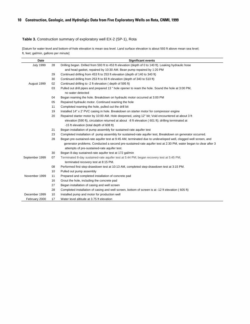
Table 3. Construction summary of exploratory well EX-2 (SP-1), Rota
[Datum for water-level and bottom-of-hole elevation is mean sea level. Land surface elevation is about 593 ft above mean sea level;
ft, feet; gal/min, gallons per minute]
Date Significant events
July 1999 28 Drilling began. Drilled from 593 ft to 453 ft elevation (depth of 0 to 140 ft). Leaking hydraulic hose
and head gasket, repaired by 10:30 AM. Bean pump repaired by 1:20 PM
29 Continued drilling from 453 ft to 253 ft elevation (depth of 140 to 340 ft)
30 Continued drilling from 253 ft to 83 ft elevation (depth of 340 to 510 ft)
August 1999 02 Continued drilling to -2 ft elevation ( depth of 595 ft)
03 Pulled out drill pipes and prepared 13 " hole opener to ream the hole. Sound the hole at 3:00 PM,
no water detected
04 Began reaming the hole. Breakdown on hydraulic motor occurred at 3:00 PM
05 Repaired hydraulic motor. Continued reaming the hole
11 Completed reaming the hole, pulled out the drill bit
19 Installed 14" x 2' PVC casing in hole. Breakdown on starter motor for compressor engine
20 Repaired starter motor by 10:00 AM. Hole deepened, using 12" bit; Void encountered at about 3 ft
elevation (590 ft), circulation returned at about -8 ft elevation ( 601 ft); drilling terminated at
-15 ft elevation (total depth of 608 ft)
21 Began installation of pump assembly for sustained-rate aquifer test
23 Completed installation of pump assembly for sustained-rate aquifer test, Breakdown on generator occurred.
28 Began pre-sustained-rate aquifer test at 9:45 AM, terminated due to undeveloped well, clogged well screen, and
generator problems. Conducted a second pre-sustained-rate aquifer test at 2:30 PM, water began to clear after 3
attempts of pre-sustained-rate aquifer test.
30 Began 8-day sustained-rate aquifer test at 172 gal/min
September 1999 07 Terminated 8-day sustained-rate aquifer test at 5:44 PM; began recovery test at 5:45 PM;
terminated recovery test at 8:15 PM.
08 Performed first step-drawdown test at 10:13 AM, completed step-drawdown test at 3:15 PM.
10 Pulled out pump assembly
November 1999 11 Prepared and completed installation of concrete pad
16 Grout the hole, including the concrete pad
27 Began installation of casing and well screen
28 Completed installation of casing and well screen, bottom of screen is at -12 ft elevation ( 605 ft)
December 1999 10 Installed pump and motor for production well
February 2000 17 Water level altitude at 3.75 ft elevation
10 Construction, Geologic, and Hydroligic Data from Five Exploratory Wells on Rota, CNMI, 1999

Horizontal scale greatly exaggerated
Elevation 538 feet
Brass monument (elevation 594.06 feet)
One foot thick concrete pad(four feet by four feet)
594.53 elevation:top of sounding tube
(measuring point for water level)
Land surface elevation about 593 feet
Elevation 173 feetElevation 168 feet
Top of river-run basaltElevation 58 feet
Top of well screenElevation 8 feet
Water level 3.75 feet(2/17/00) Mean sea level
-12 feet - bottom of casing-15 feet - bottom of hole
8 inch diameterstainless steel screen
Total drilled depth = 608 feet
3/4 inch importedriver-run basalt
8 inch diameter steel casing
Bentonite seal
1 inch diameter PVC sounding tube
adjacent to 8 inchdiameter steel casing
3/8 inch washedlimestone pea gravel
3/8 inch washedlimestone pea gravel
Bentonite seal
2600 psi mortar mix concrete
Elevation 543 feet
sea level
-15
100
200
300
400
500
5930
80
270
580
608
ELEVATION, INFEET ABOVE
MEAN SEA LEVEL
DEPTH, IN FEETBELOW LAND
SURFACEGEOLOGIC
LOG
Well EX-2 (CUC well SP-1)
Dirty white to brownish white, medium hard, partly argillaceous, finely fragmental
limestone. Cuttings generally silt to gravel sized.
White to tan, medium hard, fairly pure, finely fragmental limestone. Evidence of
secondary porosity. Cuttings sand sized to gravel sized.
Dirty white to brownish white, medium hard, coarsely porous, rubbly limestone.
Evidence of recrystallization and coral remains. Cuttings sand sized to
1/2-inch.
Chalky white to brownish white, medium hard, coarsely porous, rubbly limestone with
coral remains. Cuttings generally 1/16 to 1/2-inch sized.
Drilling Methods and History 11
Figure 5. Geologic log and construction details of well EX-2 (CUC well SP-1), Rota.

Table 4. Construction summary of exploratory well EX-3 (SP-2), Rota
[Datum for water-level and bottom-of-hole elevation is mean sea level. Land surface elevation is about 573 ft above mean sea level;
ft, feet; gal/min, gallons per minute]
Date Significant events
October 1999 12 Set up rig and started drilling at 9:30 AM, drilled to 393 ft sea level elevation
13 Continue drilling 7:00 AM
14 Completed the pilot hole drilling at -15 ft sea level elevation (total depth of 588 ft), possible change of
formation at bottom of hole, found light greenish-brown clay attached to the drill
bit, USGS representative was present and took sample when the hole was reamed.
15 Pulled out drill bit, installed hole opener and began reaming the hole
19 Completed reaming the hole
21 Began installation of pump assembly for sustained-rate aquifer test
22 Completed installation of pump assembly. Problem encountered after 46 minutes of pump test run, motor
burned out, scheduled to pull out pump
23 Pulled out pump. Pump was burned and inoperable.
25 Pump from Saipan office received, pump installed, encountered another problem; possible breakdown
on submersible pump. Decided to pull out pipes and replace pump
26 Installed CUC pump and motor
27 Began 8-day sustained-rate aquifer test at 8:30 AM, 112 gal/min
November 1999 04 Terminated 8-day sustained-rate aquifer test at 8:30 AM; performed
recovery test at 8:31 AM, end recovery test at 11:01 AM; start
step-drawdown test at 12:00 PM, completed step-drawdown test at 4:34 PM.
05 Pulled out pump
09 Began installation of casing and well screen
10 Completed installation of casing and well screen
17 Grout the hole
December 1999 09 Installed pump and motor for production well
February 2000 17 Water level altitude at 4.34 ft elevation
12 Construction, Geologic, and Hydroligic Data from Five Exploratory Wells on Rota, CNMI, 1999
Horizontal scale greatly exaggerated
Elevation 518 feet
Brass monument (elevation 575.91 feet)
One foot thick concrete pad(four feet by four feet)
576.38 elevation:top of sounding tube
(measuring point for water level)
Land surface elevation about 573 feet
Elevation 68 feetElevation 63 feetTop of river-run basaltElevation 48 feet
Top of well screenElevation 6 feet
Water level 4.34 feet(2/17/00) Mean sea level
-15 feet - bottom of hole-14 feet - bottom of casing
8 inch diameterstainless steel screen
Total drilled depth = 588 feet
3/8 inch importedriver-run basalt
8 inch diameter steel casing
Bentonite seal
1 inch diameter PVC sounding tube
adjacent to 8 inchdiameter steel casing
3/8 inch washedlimestone pea gravel
3/8 inch washedlimestone pea gravel
3/4 inch washedlimestone pea gravel
Bentonite seal
2500 psi mortar mix concrete
Elevation 523 feet
5730
60
180
240
370
450
490
545
588
500
400
300
200
100
sea level
-15
ELEVATION, INFEET ABOVE
MEAN SEA LEVEL
DEPTH, IN FEETBELOW LAND
SURFACE
Well EX-3 (CUC well SP-2)
GEOLOGICLOG
Dirty white to brownish white, medium hard, coarsely porous, rubbly limestone. Evidence of
recrystallization, secondary porosity, and coral remains. Cuttings angular to
rounded, sand sized to 1/4-inch sized.
Chalky white to brownish white, soft to medium hard, finely to coarsely fragmental limestone with
minor calcareous clay. Cuttings silt sized to 1/2-inch sized.
Dirty white to brownish white, soft to medium hard, partly argillaceous limestone with
coral remains. Cuttings are clay to 1/2-inch sized.
Chalky white to brownish white, soft to medium hard, fairly pure, finely to coarsely fragmental
limestone with minor calcareous clay. Cuttings are silt sized to1/4-inch sized.
Dirty white to pinkish white, soft to medium hard, rubbly, fairly pure to impure limestone with
minor calcareous clay. Cuttings generally silt sized to 1/4-inch.
Dirty white to light brown and pinkish white, soft to medium hard, rubbly, argillaceous
limestone. Some brown clay in cuttings that generally are silt to
1/4-inch sized.
Chalky white to brownish white, medium hard, fairly pure, rubbly limestone. Cuttings generally
sand sized to 1/2-inch sized.
Dirty white to brownish white, soft to medium hard, partly argillaceous rubbly limestone. Cuttings sand sized to 1/2-inch sized.
Drilling Methods and History 13
Figure 6. Geologic log and construction details of well EX-3 (CUC well SP-2), Rota.
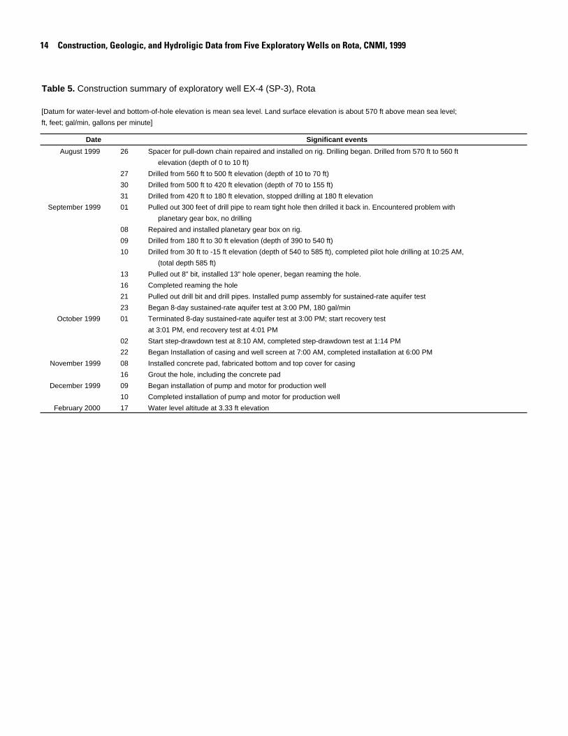
Table 5. Construction summary of exploratory well EX-4 (SP-3), Rota
[Datum for water-level and bottom-of-hole elevation is mean sea level. Land surface elevation is about 570 ft above mean sea level;
ft, feet; gal/min, gallons per minute]
Date Significant events
August 1999 26 Spacer for pull-down chain repaired and installed on rig. Drilling began. Drilled from 570 ft to 560 ft
elevation (depth of 0 to 10 ft)
27 Drilled from 560 ft to 500 ft elevation (depth of 10 to 70 ft)
30 Drilled from 500 ft to 420 ft elevation (depth of 70 to 155 ft)
31 Drilled from 420 ft to 180 ft elevation, stopped drilling at 180 ft elevation
September 1999 01 Pulled out 300 feet of drill pipe to ream tight hole then drilled it back in. Encountered problem with
planetary gear box, no drilling
08 Repaired and installed planetary gear box on rig.
09 Drilled from 180 ft to 30 ft elevation (depth of 390 to 540 ft)
10 Drilled from 30 ft to -15 ft elevation (depth of 540 to 585 ft), completed pilot hole drilling at 10:25 AM,
(total depth 585 ft)
13 Pulled out 8" bit, installed 13" hole opener, began reaming the hole.
16 Completed reaming the hole
21 Pulled out drill bit and drill pipes. Installed pump assembly for sustained-rate aquifer test
23 Began 8-day sustained-rate aquifer test at 3:00 PM, 180 gal/min
October 1999 01 Terminated 8-day sustained-rate aquifer test at 3:00 PM; start recovery test
at 3:01 PM, end recovery test at 4:01 PM
02 Start step-drawdown test at 8:10 AM, completed step-drawdown test at 1:14 PM
22 Began Installation of casing and well screen at 7:00 AM, completed installation at 6:00 PM
November 1999 08 Installed concrete pad, fabricated bottom and top cover for casing
16 Grout the hole, including the concrete pad
December 1999 09 Began installation of pump and motor for production well
10 Completed installation of pump and motor for production well
February 2000 17 Water level altitude at 3.33 ft elevation
14 Construction, Geologic, and Hydroligic Data from Five Exploratory Wells on Rota, CNMI, 1999

Horizontal scale greatly exaggerated
Elevation 515 feet
Brass monument (elevation 570.19 feet)
One foot thick concrete pad(four feet by four feet)
570.71 elevation:top of sounding tube
(measuring point for water level)
Land surface elevation about 570 feet
Elevation 140 feetElevation 135 feet
Top of river-run basaltElevation 50 feet
Top of well screenElevation 7 feet
Water level 3.33 feet(2/17/00) Mean sea level
-15 feet - bottom of hole-13 feet - bottom of casing
8 inch diameterstainless steel screen
Total drilled depth = 585 feet
3/8 inch importedriver-run basalt
8 inch diameter steel casing
Bentonite seal
1 inch diameter PVC sounding tube
adjacent to 8 inchdiameter steel casing
3/8 inch washedlimestone pea gravel
3/8 inch washedlimestone pea gravel
3/8 inch washedlimestone pea gravel
Bentonite seal
2500 psi mortar mix concreteElevation 520 feet
ELEVATION, INFEET ABOVE
MEAN SEA LEVELGEOLOGICLOG
Dirty white to brownish white, medium hard, coarsely porous, rubbly, limestone.
Evidence of recrystallization and coral remains. Cuttings angular to
rounded, sand sized to 1/2-inch.
Dirty white to brownish white, soft to medium hard, finely to coarsely
fragmental limestone with minor calcareous clay. Cuttings
generally silt to gravel sized.
Dirty white to brownish white, soft to medium hard,
finely to coarsely fragmental, partly argillaceous limestone.
Cuttings silt to 1/2-inch sized.
5700
60
390
585
500
400
300
200
100
sea level
-15
DEPTH, IN FEETBELOW LAND
SURFACE
Well EX-4 (CUC well SP-3)
Drilling Methods and History 15
Figure 7. Geologic log and construction details of well EX-4 (CUC well SP-3), Rota.

Table 6. Construction summary of exploratory well EX-5 (SP-MW2), Rota
[Datum for water-level and bottom-of-hole elevation is mean sea level. Land surface elevation is about 590 ft above mean sea level;
ft, feet]
Date Significant events
September 1999 23 Surface casing installed
24 Drilling began. Drilled from 590 ft to 420 ft elevation (depth of 0 to 170 ft)
27 Drilled from 420 to 250 ft elevation (depth of 170 to 340 ft), no samples taken after 290 ft elevation
due to loss of circulation. No cuttings recovered.
28 Drilled from 250 ft to 150 ft elevation (depth of 340 to 440 ft), pulled out pipe to avoid tightness of
hole over 190 ft elevation
29 Continued drilling with no circulation. Drilled from 150 ft to 10 ft elevation (depth of 440 to 580 ft)
30 Terminated drilling at -15 ft elevation (total depth of 605 ft), start pulling out the drill pipes, replaced
8" pilot bit with 13" hole opener, start reaming the hole.
October 1999 02 Completed reaming the hole
11 Attempted to conduct sustained-rate aquifer test; terminated due to high drawdown and low yield
November 1999 02 Began installation of casing and well screen
03 Completed installation of casing and well screen, bottom of well is at -15 ft elevation (605 ft ),
bottom of screen is at -14 ft elevation (604 ft)
16 Grout the hole, including the concrete pad
February 2000 17 Water level altitude at 3.17 ft elevation
16 Construction, Geologic, and Hydroligic Data from Five Exploratory Wells on Rota, CNMI, 1999

Horizontal scale greatly exaggerated
Elevation 535 feet
Brass monument (elevation 591.07 feet)
One foot thick concrete pad(four feet by four feet)
591.52 elevation:top of sounding tube
(measuring point for water level)
Land surface elevation about 590 feet
Elevation 75 feetElevation 70 feet
Top of river-run basaltElevation 50 feetTop of well screenElevation 6 feet
Water level 3.17 feet(2/17/00) Mean sea level
-15 feet - bottom of hole-14 feet - bottom of casing
8 inch diameterstainless steel screen
Total drilled depth = 605 feet
3/8 inch importedriver-run basalt
8 inch diameter steel casing
Bentonite seal
1 inch diameter PVC sounding tube
adjacent to 8 inchdiameter steel casing
3/8 inch washedlimestone pea gravel
3/8 inch washedlimestone pea gravel
Bentonite seal
2500 psi mortar mix concrete
Elevation 540 feet
ELEVATION, INFEET ABOVE
MEAN SEA LEVELGEOLOGIC
LOG
Chalky white, medium-hard, coarsely porous, rubbly limestone. Evidence of recrystallization,
secondary porosity, and coral remains. Cuttings angular to rounded, 1/16 to 1/2-inch sized.
Chalky white to brownish white, medium hard, partly argillaceous limestone. Cuttings
angular to rounded, 1/16 to 5/8-inch sized.
Chalky white to brownish white, medium hard, fairly pure, limestone. Cuttings angular to
rounded, sand to 1/2-inch sized.
Lost circulation at 300 feet, no cuttings collected from 300 feet to bottom of hole
Dirty white to brownish white, medium hard, coarsely porous, partly argillaceous,
rubbly limestone. Cuttings angular to rounded, 1/16 to 5/8-inch sized.
Dirty white to brownish white, medium hard to hard, finely fragmental limestone. Cuttings
mostly angular, 1/16 to 5/8-inch.
0
70
170
220
240
300
605
590
500
400
300
200
100
sea level
-15
DEPTH, IN FEETBELOW LAND
SURFACE
Well EX-5 (CUC well SP-MW2)
?
?
?
Drilling Methods and History 17
Figure 8. Geologic log and construction details of well EX-5 (CUC well SP-MW2), Rota.

18 Construction, Geologic, and Hydroligic Data from Five Exploratory Wells on Rota, CNMI, 1999
Geologic Logs
The geologic logs of the five exploratory wells on Rota were compiled by examination and description of cuttings brought to the surface by the air and foam circulated through the well bore. Samples were collected at 5-ft depth intervals and air dried before being examined macroscopically. The complete lithologic descriptions for each of the five wells are in appendix 1; the geologic logs are shown in figures 4–8.
All five exploratory wells penetrated mainly light colored (dirty white to brownish), coarsely porous, finely to coarsely fragmental limestone containing abundant coral remains. The limestone rocks penetrated by the wells varied from soft to medium hard and from fairly pure calcium carbonate to rocks containing fine-grained material of volcanic origin (impure). Some sections penetrated by the wells, particularly towards the bottom of the borings, contain significant amounts of calcare-ous silt and clay. Rocks composed of or containing clay-sized particles are know as argillaceous
Well EX-1, the deepest of the five wells, penetrated a 745 ft section of light colored (chalky white to brownish) coarsely porous, fragmental limestone. The uppermost part of the section consists of 90 ft of rubbly limestone with evidence of recrystal-lization. The section from 90 ft to 130 ft contains impure rubbly limestone. From 130 ft to 670 ft, the limestone mainly is finely fragmental and impure. The bottom section, from 670 to 745 ft, contains soft to medium hard impure limestone with calcareous silt and clay.
Well EX-2 penetrated a 608 ft section of limestone. The uppermost section consists of 80 ft of rubbly and coarsely porous rock with evidence of recrystallization. From 80 to 270 ft, the limestone is rubbly and has abundant coral remains. The section from 270 to 580 ft is finely fragmental and impure. From 580 ft to the bottom at 608 ft, the limestone is fine grained, mostly pure, and has evidence of solution-enhanced porosity.
Well EX-3 penetrated a 588 ft section of limestone. The uppermost section, about 60 ft, consists of rubbly limestone with evidence of solution-enhanced porosity and recrystalliza-tion. From 60 to 180 ft, the cuttings are fairly pure. Samples of the section from 180 to 545 ft are fairly pure to impure with minor amounts or calcareous clay. From 545 ft to the bottom at 588 ft, the limestone is mostly impure, rubbly and contains minor amounts of brown clay.
Well EX-4 penetrated a 585 ft section of limestone. The uppermost section consists of 60 ft of rubbly limestone with evi-dence of recrystallization and coral remains. From 60 to 390 ft, the limestone is partly argillaceous and finely to coarsely frag-mental. From 390 ft to the bottom at 585 ft, the limestone is mostly impure and contains minor amounts of calcareous clay.
Well EX-5 was bored to 605 ft; however, no cuttings were recovered beyond 290 ft because a cavity in the limestone caused a loss of circulation of drilling fluids. The uppermost section, about 70 ft, consists of coarsely porous, rubbly lime-stone with evidence of recrystallization. From 70 to 170 ft, the
well bore. Samples were collected at 5-ft depth intervals and air dried before being examined macroscopically. The complete lithologic descriptions for each of the five wells are in appendix 1; the geologic logs are shown in figures 4–8. limestone is partly argillaceous, rubbly, and coarsely porous. Samples of the sec-tion from 170 to 220 ft are fairly pure and finely fragmental. The section from 220 to 240 ft is partly argillaceous. From 240 ft to 290 ft the limestone is fairly pure. No cuttings were recov-ered beyond 290 ft; however, the drillers reported that the rota-tional torque and action of the drill bit from 290 ft to the bottom at 605 ft was consistent with boring to similar depths at the other exploratory wells.
Aquifer Tests
Aquifer tests were attempted at each of the five explor-atory wells. At wells EX-1 (CUC well SP-MW1) and EX-5 (CUC well SP-MW2), excessive water-level drawdown to the pump intake in the vicinity of these two wells precluded sus-tained-rate aquifer tests. At wells EX-2, EX-3, and EX-4, (CUC wells SP-1, -2, and -3, respectively) three aquifer tests were per-formed; (1) a sustained-rate test, which can be used to estimate aquifer properties in the vicinity of the well, (2) a recovery test, which also can be used to estimate aquifer properties in the vicinity of the well (thereby providing a check on the results of the sustained-rate test), and (3) a step-drawdown test which can be used to determine the component of drawdown attributed to well losses. Data for the aquifer tests at the three wells are shown in appendices 2–10.
All tests were conducted before installation of casing and gravel pack. The tests were conducted using a 30-horsepower, 6-in. diameter submersible pump with the intake elevation set at about -7 ft for each test in each well. Measurements of the depth to water in the pumping wells were made using an electric tape lowered through 1-in. PVC pipe attached to the pump column to minimize the effects of turbulence near the pump intake. The flow rate was measured using a totalizing flow meter. For all tests, the pumped water was discharged through 4-in. PVC pipe about 800 ft away from the pumping well.
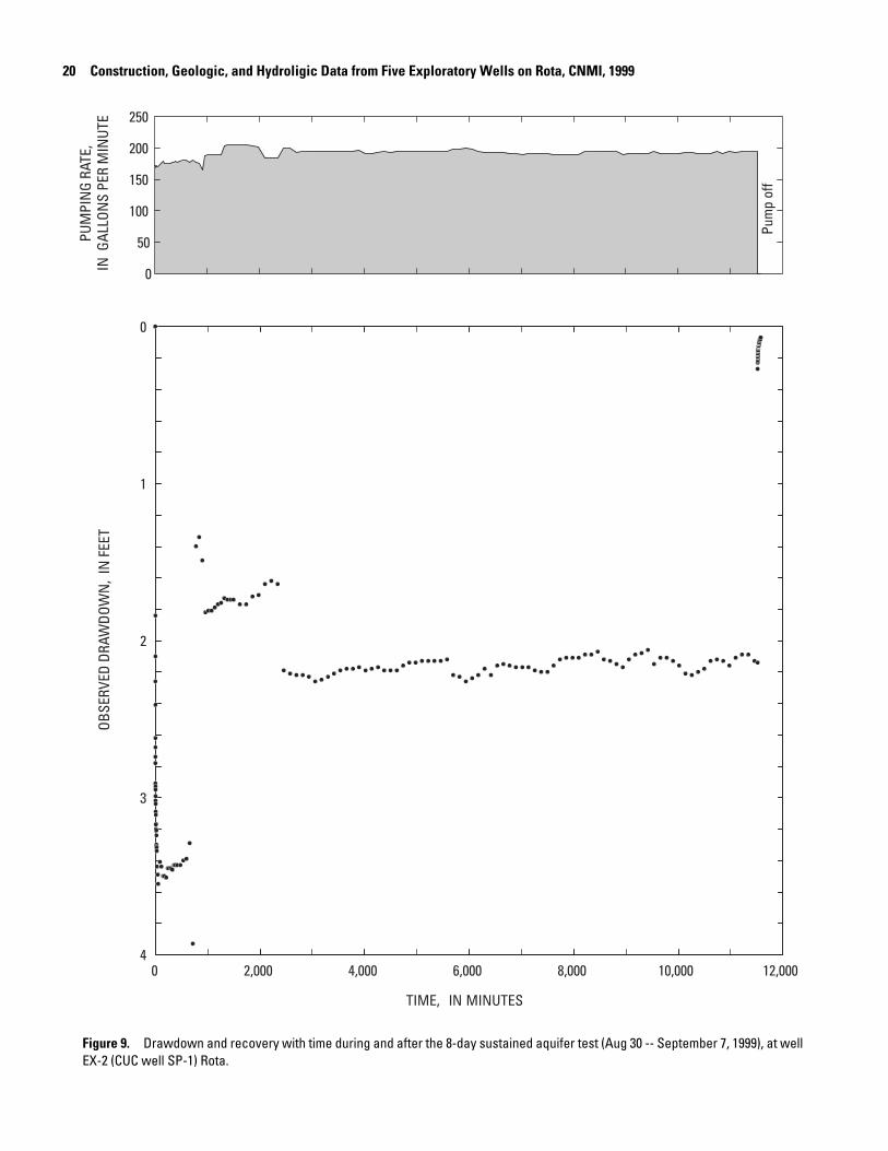
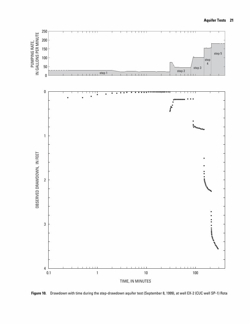
The sustained-rate aquifer test at well EX-2 (CUC well SP-1) was conducted from August 30-September 7, 1999 for 11,520 min (8 days) at an average rate of 187 gal/min (appendix 2). Flow rates during the test fluctuated between 168 and 205 gal/min with most of the fluctuation occurring during the first day. The period of greatest drawdown occurred during the first 720 min (12 hours) of the test as the well was developed; max-imum drawdown measured in the pumped well was 3.93 ft at 720 min into the test. Depth-to-water prior to the start of the test was 590.28 ft. Following the sustained-rate test, recovery was monitored for 225 min (fig. 9 and appendix 3). The step-draw-down test, conducted on September 8, 1999, consisted of five steps at average rates of 23, 55, 103, 155, and 180 gal/min for durations of 30, 60, 60, 60, and 80 min, respectively (fig. 10 and appendix 4).

Aquifer Tests 19
The sustained-rate aquifer test at well EX-3 (CUC well SP-2) was conducted from October 27-November 4, 1999 for 11,520 min (8 days) at an average rate of 108 gal/min (appendix 5). Flow rates during the test fluctuated between 104 and 112 gal/min with most of the fluctuation occurring during the first day (fig. 11). Drawdown continued to increase from 1.74 to 2.31 ft during the first 60 min of the test. Maximum drawdown measured in the pumped well was 2.31 ft at 60 min into the test (fig. 11 and appendix 5). Depth-to-water prior to the start of the test was 571.84 ft. Following the sustained-rate test, recovery was monitored for 150 min (fig. 11 and appendix 6). The step-drawdown test, conducted on November 4, 1999, consisted of five steps at average rates of 21, 36, 73, 94, and 103 gal/min for durations of 30 min for the first step and 60 min for steps 2–5, respectively (fig. 12 and appendix 7)
The sustained-rate aquifer test at well EX-3 (CUC well SP-2) was conducted from October 27-November 4, 1999 for 11,520 min (8 days) at an average rate of 108 gal/min (appendix 5). Flow rates during the test fluctuated between 104 and 112 gal/min with most of the fluctuation occurring during the first day (fig. 11). Drawdown continued to increase from 1.74 to 2.31 ft during the first 60 min of the test. Maximum drawdown measured in the pumped well was 2.31 ft at 60 min into the test (fig. 11 and appendix 5). Depth-to-water prior to the start of the test was 571.84 ft. Following the sustained-rate test, recovery was monitored for 150 min (fig. 11 and appendix 6). The step-drawdown test, conducted on November 4, 1999, consisted of five steps at average rates of 21, 36, 73, 94, and 103 gal/min for durations of 30 min for the first step and 60 min for steps 2–5, respectively (fig. 12 and appendix 7).
The sustained-rate aquifer test at well EX-4 (CUC well SP-3) was conducted from September 23-October 1, 1999 for 11,520 min (8 days) at an average rate of 139 gal/min (appendix 8). Flow rates during the test fluctuated between 112 and 180 gal/min, with the higher rates occurring during the first day. The discharge rate was lowered after the first day from about 175 gal/min to about 125 gal/min because the initial pumping water level had stabilized near or below sea level. A sharp decrease in drawdown occurred when the discharge rate was lowered (fig. 13). Maximum drawdown during the test was 3.30 ft, recorded 1 min into the test at a discharge rate of 180 gal/min (fig. 13 and appendix 8).
Depth-to-water prior to the start of the test was 567.40 ft. Following the sustained-rate test, recovery was monitored for 60 min (fig. 13 and appendix 9). The step-drawdown test, con-ducted on October 2, 1999, consisted of five 60 min steps at average rates of 27, 74, 95, 134, and 179 gal/min (fig. 14 and appendix 10).
Samples of the pumped water were collected during the sustained-rate tests and analyzed for temperature and specific conductance. At well EX-2 (CUC well SP-1), the temperature of the pumped water was 26.5°C at the start and end of the test, and ranged from a low of 26.0°C to a high of 27.5°C (appendix 2). Specific conductance at the start and end of the test was nearly the same at 400 and 403 µS/cm (appendix 2). At well EX-3 (CUC well SP-2), the temperature of the pumped water was 28°C and 27.5°C at the start and end of the test, respec-tively, and ranged from a low of 27.0°C to a high of 28.5°C (appendix 5). Specific conductance decreased slowly during the test from 383 µS/cm at the start to 358 µS/cm at the end (appen-
Depth-to-water prior to the start of the test was 567.40 ft. Following the sustained-rate test, recovery was monitored for 60 min (fig. 13 and appendix 9). The step-drawdown test, con-ducted on October 2, 1999, consisted of five 60 min steps at average rates of 27, 74, 95, 134, and 179 gal/min (fig. 14 and appendix 10).
Samples of the pumped water were collected during the sustained-rate tests and analyzed for temperature and specific conductance. At well EX-2 (CUC well SP-1), the temperature of the pumped water was 26.5°C at the start and end of the test, and ranged from a low of 26.0°C to a high of 27.5°C (appendix 2). Specific conductance at the start and end of the test was nearly the same at 400 and 403 µS/cm (appendix 2). At well EX-3 (CUC well SP-2), the temperature of the pumped water was 28°C and 27.5°C at the start and end of the test, respec-tively, and ranged from a low of 27.0°C to a high of 28.5°C (appendix 5). Specific conductance decreased slowly during the test from 383 µS/cm at the start to 358 µS/cm at the end (appen-dix 5). At well EX-4 (CUC well SP-3), the temperature of the pumped water was 28°C and 27.5°C at the start and end of the test, respectively, and ranged from a low of 26.5°C to a high of 28°C (appendix 8). Specific conductance at well EX-4 was nearly constant during the test after an initial decrease from 456 µS/cm to 445 µS/cm during the first 30 min (appendix 8).
TIME, IN MINUTES
0 2,000 4,000 6,000 8,000 10,000 12,000
OBSE
RVED
DRA
WDO
WN
, IN
FEE
T
0
1
2
3
4
PUM
PIN
G RA
TE,
IN G
ALLO
NS
PER
MIN
UTE
0
50
100
150
200
250
Pum
p of
f
20 Construction, Geologic, and Hydroligic Data from Five Exploratory Wells on Rota, CNMI, 1999
Figure 9. Drawdown and recovery with time during and after the 8-day sustained aquifer test (Aug 30 -- September 7, 1999), at well EX-2 (CUC well SP-1) Rota.
TIME, IN MINUTES
0.1 1 10 100
OBSE
RVED
DRA
WDO
WN
, IN
FEE
T
0
1
2
3
4
PUM
PIN
G RA
TE,
IN G
ALLO
NS
PER
MIN
UTE
0
50
100
150
200
250
step 1 step 2step 3
step4
step 5
Aquifer Tests 21
Figure 10. Drawdown with time during the step-drawdown aquifer test (September 8, 1999), at well EX-2 (CUC well SP-1) Rota

TIME, IN MINUTES
0 2,000 4,000 6,000 8,000 10,000 12,000
OBSE
RVED
DRA
WDO
WN
, IN
FEE
T
0
1
2
3
4
PUM
PIN
G RA
TE,
IN G
ALLO
NS
PER
MIN
UTE
0
50
100
150
200
250
Pum
p of
f
22 Construction, Geologic, and Hydroligic Data from Five Exploratory Wells on Rota, CNMI, 1999
Figure 11. Drawdown and recovery with time during and after the 8-day sustained aquifer test (October 27 -- November 4, 1999), at well EX-3 (CUC well SP-2) Rota.

step 1 step 2step 3
step4
step 5
TIME, IN MINUTES
0.1 1 10 100
OBSE
RVED
DRA
WDO
WN
, IN
FEE
T
0
1
2
3
4
PUM
PIN
G RA
TE,
IN G
ALLO
NS
PER
MIN
UTE
0
50
100
150
200
250
1 1 10 100
Aquifer Tests 23
Figure 12. Drawdown with time during the step-drawdown aquifer test (November 4, 1999), at well EX-3 (CUC well SP-2) Rota.

TIME, IN MINUTES
0 2,000 4,000 6,000 8,000 10,000 12,000
OBSE
RVED
DRA
WDO
WN
, IN
FEE
T
0
1
2
3
4
PUM
PIN
G RA
TE,
IN G
ALLO
NS
PER
MIN
UTE
0
50
100
150
200
250
Pum
p of
f
24 Construction, Geologic, and Hydroligic Data from Five Exploratory Wells on Rota, CNMI, 1999
Figure 13. Drawdown and recovery with time during and after the 8-day sustained-rate aquifer test (September 23 -- October 1, 1999), at well EX-4 (CUC well SP-3) Rota.

OBSE
RVED
DRA
WDO
WN
, IN
FEE
T
0
1
2
3
4
PUM
PIN
G RA
TE,
IN G
ALLO
NS
PER
MIN
UTE
0
50
100
150
200
250
TIME, IN MINUTES
0.1 1 10 100
step 1step 2
step3
step4
step 5
Aquifer Tests 25
Figure 14. Drawdown with time during the step-drawdown aquifer test (October 2, 1999), at well EX-4 (CUC well SP-3) Rota.

26 Construction, Geologic, and Hydroligic Data from Five Exploratory Wells on Rota, CNMI, 1999
Water Levels
Ground-water levels relative to mean sea level are mea-sured intermittently at the five exploratory wells by the CUC (figs 15-19). Static (non-pumping) ground-water levels at all five wells were more than 2.5 ft during the period from Febru-ary 17, 2000 to March 5, 2001. Static water levels at the three wells (EX-2, -3, and -4) converted to water-supply wells by the CUC (CUC wells SP-1, -2, and-3) averaged 3.54 ft, 4.15 ft, and 3.19 ft, respectively. Pumping water level at well EX-2 (CUC well SP-1), recorded on August 4, 2000 at 9:25 AM, was -3.83 ft at 123 gal/min. Three pumping water levels recorded at well EX-3 (CUC well SP-2) ranged from a low of -0.14 ft at 167 gal/min on June 7, 2000, to a high of 0.23 ft at 168 gal/min on August 4, 2000.
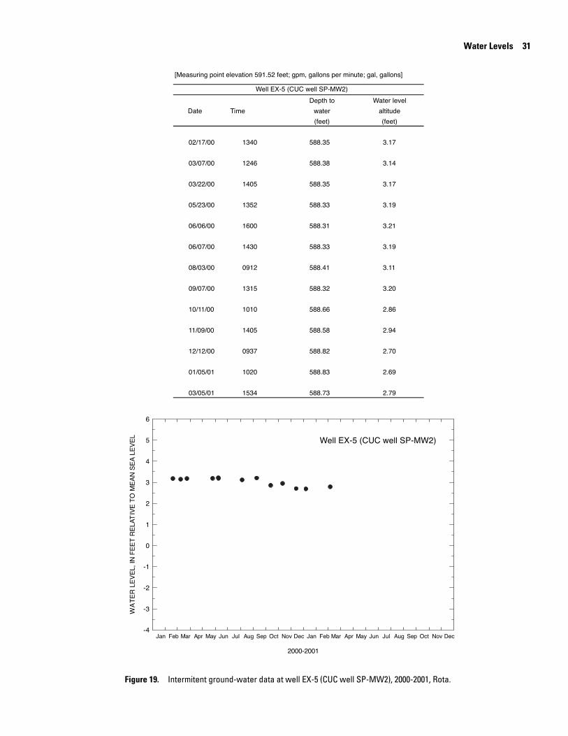
At the two wells (EX-1 and EX-5) designated as monitor wells by the CUC (SP-MW1 and SP-MW2), the measured water level ranged from 3.42 to 4.00 ft at well EX-1 (CUC well SP-MW1) and from 2.69 to 3.21 ft at well EX-5 (CUC well SP-MW2). Average water level for the 13 measurements made from February 17, 2000 to March 5, 2001 was 3.79 ft at well EX-1 (CUC well SP-MW1) and 3.03 ft at well EX-5 (CUC well SP-MW2).

Well EX-1 (CUC well SP-MW1)
Well EX-1 (CUC well SP-MW1)
2000-2001
Jan Feb Mar Apr May Jun Jul Aug Sep Oct Nov Dec Jan Feb Mar Apr May Jun Jul Aug Sep Oct Nov Dec
WA
TE
R L
EV
EL,
IN F
EE
T R
ELA
TIV
E T
O M
EA
N S
EA
LE
VE
L
-4
-3
-2
-1
0
1
2
3
4
5
6
[Measuring point elevation 603.98 feet; gpm, gallons per minute; gal, gallons]
Date Time
02/17/00 1400 600.03 3.95
03/07/00 1246 600.02 3.96
03/10/00 1030 600.11 3.87
03/22/00 1405 600.05 3.93
05/23/00 1337 599.99 3.99
06/07/00 1425 599.98 4.00
08/04/00 1015 600.04 3.94
09/07/00 1345 600.07 3.91
10/20/00 1515 600.20 3.78
11/09/00 1334 600.22 3.76
12/12/00 0908 600.55 3.43
01/05/01 0930 600.56 3.42
03/05/01 1038 600.51 3.47
(feet)(feet)
Depth to Water level
altitudewater
Water Levels 27
Figure 15. Intermitent ground-water data at well EX-1 (CUC well SP-MW1), 2000-2001, Rota.

2000-2001
Jan Feb Mar Apr May Jun Jul Aug Sep Oct Nov Dec Jan Feb Mar Apr May Jun Jul Aug Sep Oct Nov Dec
WA
TE
R L
EV
EL,
IN F
EE
T R
ELA
TIV
E T
O M
EA
N S
EA
LE
VE
L
-5
-4
-3
-2
-1
0
1
2
3
4
5
[Measuring point elevation 594.53 feet; gpm, gallons per minute; gal, gallons]
Pumping
Date Time rate
(gpm)
02/17/00 1418 0 590.78 3.75
03/07/00 1150 0 590.85 3.68
03/22/00 1337 0 590.84 3.69
05/23/00 1324 0 1625826 590.82 3.71
06/07/00 1405 0 1636800 590.81 3.72
08/04/00 0925 123 7488900 598.36 -3.83
09/07/00 0949 0 8210137 590.78 3.75
10/11/00 0836 0 8219900 591.11 3.42
10/20/00 0730 0 8219900 591.01 3.52
11/09/00 1315 0 8228200 591.04 3.49
12/12/00 1000 0 8228200 591.26 3.27
01/05/01 0915 0 8228900 591.27 3.26
03/05/01 0949 0 8256100 591.29 3.24
(gal) (feet) (feet)
Meter Depth to Water level
reading water altitude
Well EX-2 (CUC well SP-1)
Well EX-2 (CUC well SP-1)
28 Construction, Geologic, and Hydroligic Data from Five Exploratory Wells on Rota, CNMI, 1999
Figure 16. Intermitent ground-water data at well EX-2 (CUC well SP-1), 2000-2001, Rota.

2000-2001
Jan Feb Mar Apr May Jun Jul Aug Sep Oct Nov Dec Jan Feb Mar Apr May Jun Jul Aug Sep Oct Nov Dec
WA
TE
R L
EV
EL,
IN F
EE
T R
ELA
TIV
E T
O M
EA
N S
EA
LE
VE
L
-5
-4
-3
-2
-1
0
1
2
3
4
5
[Measuring point elevation 576.38 feet; gpm, gallons per minute; gal, gallons]
Pumping
Date Time rate
(gpm)
02/17/00 1432 572.04 4.34
03/10/00 1000 572.12 4.26
03/22/00 1417 571.99 4.39
05/23/00 1305 167 7881200 576.49 -0.11
06/07/00 1334 167 11483700 576.52 -0.14
08/04/00 0945 168 2527700 576.15 0.23
09/07/00 1009 0 29434200 571.98 4.40
10/11/00 0900 0 29451600 572.26 4.12
10/20/00 0820 0 29451600 572.21 4.17
11/09/00 0832 0 29452100 572.28 4.10
12/12/00 1015 0 29452100 572.52 3.86
01/05/01 0849 0 29451600 572.47 3.91
03/05/01 0932 0 29496700 572.39 3.99
altitude
(feet)(feet)
reading
(gal)
water
Depth to Water levelMeter
Well EX-3 (CUC well SP-2)
Well EX-3 (CUC well SP-2)
Water Levels 29
Figure 17. Intermitent ground-water data at well EX-3 (CUC well SP-2), 2000-2001, Rota.

2000-2001
Jan Feb Mar Apr May Jun Jul Aug Sep Oct Nov Dec Jan Feb Mar Apr May Jun Jul Aug Sep Oct Nov Dec
WA
TE
R L
EV
EL,
IN F
EE
T R
ELA
TIV
E T
O M
EA
N S
EA
LE
VE
L
-5
-4
-3
-2
-1
0
1
2
3
4
5
[Measuring point elevation 570.71 feet; gpm, gallons per minute; gal, gallons; --, no data]
Pumping
Date Time rate
(gpm)
02/17/00 1455 0 -- 567.38 3.33
03/07/00 1330 0 -- 567.35 3.36
03/10/00 0937 0 -- 567.60 3.11
03/22/00 1430 0 -- 567.39 3.32
05/22/00 1312 0 -- 567.29 3.42
06/07/00 1350 0 -- 567.16 3.55
08/04/00 1005 0 -- 567.22 3.49
09/07/00 1034 0 -- 567.39 3.32
10/11/00 0923 0 -- 567.61 3.10
11/09/00 1258 0 -- 567.68 3.03
12/12/00 1030 0 -- 567.92 2.79
01/05/01 0959 0 -- 567.85 2.86
03/05/01 0846 0 -- 567.78 2.93
altitude
(feet)(feet)
reading
(gal)
water
Depth to Water levelMeter
Well EX-4 (CUC well SP-3)
Well EX-4 (CUC well SP-3)
30 Construction, Geologic, and Hydroligic Data from Five Exploratory Wells on Rota, CNMI, 1999
Figure 18. Intermitent ground-water data at well EX-4 (CUC well SP-3), 2000-2001, Rota.
2000-2001
Jan Feb Mar Apr May Jun Jul Aug Sep Oct Nov Dec Jan Feb Mar Apr May Jun Jul Aug Sep Oct Nov Dec
WA
TE
R L
EV
EL,
IN F
EE
T R
ELA
TIV
E T
O M
EA
N S
EA
LE
VE
L
-4
-3
-2
-1
0
1
2
3
4
5
6
[Measuring point elevation 591.52 feet; gpm, gallons per minute; gal, gallons]
Date Time
02/17/00 1340 588.35 3.17
03/07/00 1246 588.38 3.14
03/22/00 1405 588.35 3.17
05/23/00 1352 588.33 3.19
06/06/00 1600 588.31 3.21
06/07/00 1430 588.33 3.19
08/03/00 0912 588.41 3.11
09/07/00 1315 588.32 3.20
10/11/00 1010 588.66 2.86
11/09/00 1405 588.58 2.94
12/12/00 0937 588.82 2.70
01/05/01 1020 588.83 2.69
03/05/01 1534 588.73 2.79
(feet) (feet)
Depth to Water level
water altitude
Well EX-5 (CUC well SP-MW2)
Well EX-5 (CUC well SP-MW2)
Water Levels 31
Figure 19. Intermitent ground-water data at well EX-5 (CUC well SP-MW2), 2000-2001, Rota.
32 Construction, Geologic, and Hydroligic Data from Five Exploratory Wells on Rota, CNMI, 1999
Water Quality
An appraisal of water quality was made at exploratory wells that may be converted to municipal water-supply wells. The CUC installed submersible pumps for water production in wells EX-2, -3, and -4 (CUC wells SP-1, -2, and-3) based on favorable aquifer-test results. Water samples were collected on June 6, and September 25, 2000, from hose bibs located on the well heads after the pump had been running for 30 min. Before connecting the wells to the distribution system, the CUC sent the water samples for laboratory analyses to determine if any aspects of water quality might pose a threat to health. The Stan-dard USEPA sampling procedures for quality assurance were followed and all samples were stored on ice prior to analysis. The samples were shipped to the Montgomery Watson Labora-tory in California and analyzed for a suite of inorganic and organic constituents included in the primary drinking-water
standards established by the U.S. Environmental Protection Agency (USEPA) in the Safe Drinking Water Act (U.S. Envi-ronmental Protection Agency, 1989).
Results of the water-quality analyses, shown in tables 7–12, indicate that the samples of water from the three wells meet the requirements set by the USEPA for a potable water source. A summary of the inorganic and organic constituents found in water from the three wells are listed in tables 7–9. Pesticides, herbicides, and other volatile organic constituents found to be less than detection limits in water from the three wells are shown in tables 10–12.
In addition to the water-quality analyses at the three pro-posed water-supply wells, specific conductance was measured by the USGS throughout the water column at well EX-1 (CUC well SP-MW1) using an electronic down-the-hole logging instrument on August 4, 2000. The vertical specific-conduc-tance profile of the monitoring well is shown in figure 20.

SPECIFIC CONDUCTANCE, IN MICROSIEMENS PER CENTIMETER AT 25 DEGREES CELSIUS
0 2,000 4,000 6,000 8,000 10,000 12,000 14,000 16,000 18,000 20,000
DEPT
H BE
LOW
WAT
ER S
URFA
CE, I
N F
EET
0
10
20
30
40
50
60
70
80
90
100
110
120
130
140
150
160
170
Water Quality 33
Figure 20. Specific conductance profile at well EX-1 (CUC well SP-MW1) , August 4, 2000, Rota

Table 7. Water-quality data at well EX-2 (CUC well SP-1) on June 6, 2000 and September 25, 2000, Rota
[<, actual value is less than value shown, value shown is detection limit; us/cm, microsiemens per centimeter at 26.8oC;
oC,
degrees Celsius; mg/L, milligrams per liter; ug/L, micrograms per liter; --, not analyzed; pg/L, picograms per liter; pCi/L, picocurie
per liter; ND, no detection; analyses by Montgomery Watson Laboratories]
Property or constituent Detection limit June 6, 2000 September 25, 2000
INORGANIC
Field measurements
Specific conductance (us/cm at 26.8oC) 403
1
pH (units) 7.91
PHYSICAL PROPERTIES
Temperature, water (oC) 27
1
Major ions, total (mg/L)
Chloride 191
Flouride 0.05 0.12 0.12
Nutrients, total (mg/L)
Nitrate + Nitrate as N by RFA 0.1 2.57 2.6
Metals, total recoverable (ug/L)
Antimony, Total, ICAP/MS 1 ND ND
Arsenic, Total, ICAP/MS 1 ND ND
Barium, Total, ICAP/MS 2 ND ND
Beryllium, Total, ICAP/MS 1 ND ND
Cadmium, Total, ICAP/MS 0.5 ND ND
Chromium, Total, ICAP/MS 2 10 3.7
Mercury 0.2 ND ND
Nickel, Total, ICAP/MS 5 ND ND
Selenium, Total, ICAP/MS 5 ND ND
Thallium, Total, ICAP/MS 1 ND ND
ORGANIC
Cyanide, total (mg/L) 0.025 ND ND
Pesticides and herbicides, total recoverable
alpha-Chlordane, ug/L 0.05 ND ND
gamma-Chlordane, ug/L 0.05 ND ND
2,3,7,8 - TCDD, pg/L 2 ND ND
Hexachlorobenzene, ug/L 0.05 ND --
Radiation and Radionuclides (pCi/L)
Gross, alpha……………………………………. 1 -- 2.4
Gross, beta…………………………………….. 1.2 -- <1.2
1 Measured by USGS during sustained-rate aquifer test on September 7, 1999
34 Construction, Geologic, and Hydroligic Data from Five Exploratory Wells on Rota, CNMI, 1999

Table 8. Water-quality data at well EX-3 (CUC well SP-2) on June 6, 2000 and September 25, 2000, Rota
[<, actual value is less than value shown, value shown is detection limit; us/cm, microsiemens per centimeter at 27.3oC;
oC,
degrees Celsius; mg/L, milligrams per liter; ug/L, micrograms per liter; --, not analyzed; pg/L, picograms per liter; pCi/L, picocurie
per liter; ND, no detection; analyses by Montgomery Watson Laboratories]
Property or constituent Detection limit June 6, 2000 September 25, 2000
INORGANIC
Field measurements
Specific conductance (us/cm at 27.3oC) 302
1
pH (units) 7.31
PHYSICAL PROPERTIES
Temperature, water (oC) 27
1
Major ions, total (mg/L)
Chloride 221
Flouride 0.05 0.17 0.17
Nutrients, total (mg/L)
Nitrate + Nitrate as N by RFA 0.1 1.25 1.1
Metals, total recoverable (ug/L)
Antimony, Total, ICAP/MS 1 ND ND
Arsenic, Total, ICAP/MS 1 ND ND
Barium, Total, ICAP/MS 2 ND ND
Beryllium, Total, ICAP/MS 1 ND ND
Cadmium, Total, ICAP/MS 0.5 ND ND
Chromium, Total, ICAP/MS 2 8.3 2.8
Mercury 0.2 ND ND
Nickel, Total, ICAP/MS 5 ND ND
Selenium, Total, ICAP/MS 5 ND ND
Thallium, Total, ICAP/MS 1 ND ND
ORGANIC
Cyanide, total (mg/L) 0.025 ND ND
Pesticides and herbicides, total recoverable
alpha-Chlordane, ug/L 0.05 ND ND
gamma-Chlordane, ug/L 0.05 ND ND
2,3,7,8 - TCDD, pg/L 2 ND ND
Hexachlorobenzene, ug/L 0.05 ND ND
Radiation and Radionuclides (pCi/L)
Gross, alpha……………………………………. 1 -- <1
Gross, beta…………………………………….. 1.2 -- 2.3
1 Measured by USGS during sustained-rate aquifer test on November 4, 1999
Water Quality 35

Table 9. Water-quality data at well EX-4 (CUC well SP-3) on June 6, 2000 and September 25, 2000, Rota
[<, actual value is less than value shown, value shown is detection limit; us/cm, microsiemens per centimeter at 27.3oC;
oC,
degrees Celsius; mg/L, milligrams per liter; ug/L, micrograms per liter; --, not analyzed; pg/L, picograms per liter; pCi/L, picocurie
per liter; ND, no detection; analyses by Montgomery Watson Laboratories]
Property or constituent Detection limit June 6, 2000 September 25, 2000
INORGANIC
Field measurements
Specific conductance (us/cm at 27.3oC) 445
1
pH (units) 8.11
PHYSICAL PROPERTIES
Temperature, water (oC) 27
1
Major ions, total (mg/L)
Chloride 271
Flouride 0.05 0.15 0.14
Nutrients, total (mg/L)
Nitrate + Nitrate as N by RFA 0.1 2.02 2
Metals, total recoverable (ug/L)
Antimony, Total, ICAP/MS 1 ND ND
Arsenic, Total, ICAP/MS 1 1 1
Barium, Total, ICAP/MS 2 2 2
Beryllium, Total, ICAP/MS 1 ND ND
Cadmium, Total, ICAP/MS 0.5 ND ND
Chromium, Total, ICAP/MS 2 ND 4.4
Mercury 0.2 ND ND
Nickel, Total, ICAP/MS 5 ND ND
Selenium, Total, ICAP/MS 5 ND ND
Thallium, Total, ICAP/MS 1 ND ND
ORGANIC
Cyanide, total (mg/L) 0.025 ND ND
Pesticides and herbicides, total recoverable
alpha-Chlordane, ug/L 0.05 ND ND
gamma-Chlordane, ug/L 0.05 ND ND
2,3,7,8 - TCDD, pg/L 2 ND ND
Hexachlorobenzene, ug/L 0.05 ND ND
Volatile organic constituents, (ug/L)
(found to be above detection limits)
Chloroform (Trichloromethane) 0.5 0.8 0.7
Total THM 0.5 0.8 0.7
Radiation and Radionuclides (pCi/L)
Gross, alpha……………………………………. 1 -- <1
Gross, beta…………………………………….. 1.2 -- 2.3
1 Measured by USGS during sustained-rate aquifer test on October 1, 1999
36 Construction, Geologic, and Hydroligic Data from Five Exploratory Wells on Rota, CNMI, 1999

Table 10. Pesticides, herbicides and other volatile organic constituents found to be less than detection limits in water
samples from well EX-2 (CUC well SP-1) on June 6, 2000 and September 25, 2000, Rota
[ug/L, micrograms per liter; analyses by Montgomery Watson Laboratories]
Organic Organic Organic
(total recoverable) (total recoverable) (total recoverable)
1,1,1,2-Tetrachloroethane 0.5 Carbon Tetrachloride 0.5 Methomyl 1
1,1,1-Trichloroethane 0.5 Chlordane 0.1 Methoxychlor 0.05
1,1,2,2-Tetrachloroethane 0.5 Chlorobenzene 0.5 Methoxychlor 0.05
1,1,2-Trichloroethane 0.5 Chlorodibromomethane 0.5 Methyl Tert-butyl ether (MTBE) 3
1,1-Dichloroethane 0.5 Chloroethane 0.5 Metolachlor 0.05
1,1-Dichloroethylene 0.5 Chloroform (Trichloromethane) 0.5 Metribuzin 0.05
1,1-Dichloropropene 0.5 Chloromethane(Methyl Chloride) 0.5 Molinate 0.2
1,2,3-Trichlorobenzene 0.5 Chlorthalonil (Draconil,Bravo) 0.01 Naphthalene 0.5
1,2,3-Trichloropropane 0.5 Chrysene 0.02 n-Butylbenzene 0.5
1,2,4-Trichlorobenzene 0.5 cis-1,2-Dichloroethylene 0.5 Nitrobenzene 10
1,2,4-Trimethylbenzene 0.5 cis-1,3-Dichloropropene 0.5 n-Propylbenzene 0.5
1,2-Dichloroethane 0.5 Dalapon (qualitative) 1 o-Chlorotoluene 0.5
1,2-Dichloropropane 0.5 Delta-BHC 0.01 o-Dichlorobenzene (1,2-DCB) 0.5
1,3,5-Trimethylbenzene 0.5 Di-(2-Ethylhexyl)adipate 0.6 Oxamyl (Vydate) 2
1,3-Dichloropropane 0.5 Di(2-Ethylhexyl)phthalate 0.6 o-Xylene 0.5
2,2-Dichloropropane 0.5 Dibenz(a,h)Anthracene 0.05 p,p' DDD 0.01
2,4,5-T 0.2 Dibromochloropropane (DBCP) 0.01 p,p' DDE 0.01
2,4,5-TP (Silvex) 0.2 Dibromomethane 0.5 p,p' DDT 0.01
2,4-D 0.1 Dicamba 0.08 Paraquat 2
2,4-DB 2 Dichlorodifluoromethane 0.5 PCB 1016 Aroclor 0.07
2,4-Dinitrotoluene 0.1 Dichloromethane 0.5 PCB 1221 Aroclor 0.1
2-Butanone (MEK) 5 Dichlorprop 0.5 PCB 1232 Aroclor 0.1
3,5-Dichlorobenzoic acid 0.5 Dieldrin 0.2 PCB 1242 Aroclor 0.1
3-Hydroxycarbofuran 2 Dieldrin 0.01 PCB 1248 Aroclor 0.1
4-Methyl-2-Pentanone (MIBK) 5 Diethylphthalate 0.5 PCB 1254 Aroclor 0.1
4-Nitrophenol (qualitative) 5 Di-isopropyl ether 5 PCB 1260 Aroclor 0.1
Acenaphthylene 0.1 Dimethoate 10 p-Chlorotoluene 0.5
Acifluorfen (qualitative) 0.2 Dimethylphthalate 0.5 p-Dichlorobenzene (1,4-DCB) 0.5
Alachlor 0.05 Di-n-Butylphthalate 0.5 Pentachlorophenol 1
Alachlor (Alanex) 0.05 Dinoseb 0.2 Pentachlorophenol 0.04
Aldicarb (Temik) 0.5 Diquat 0.4 Phenanthrene 0.02
Aldicarb sulfone 0.7 Endosulfan I (alpha) 0.01 Picloram 0.1
Aldicarb sulfoxide 0.5 Endosulfan II (beta) 0.01 p-Isopropyltoluene 0.5
Aldrin 0.05 Endosulfan sulfate 0.01 Prometryn 0.5
Aldrin 0.01 Endothall 5 Propachlor 0.05
Alpha-BHC 0.01 Endrin 0.1 Pyrene 0.05
Anthracene 0.02 Endrin 0.01 sec-Butylbenzene 0.5
Atrazine 0.05 Endrin Aldehyde 0.01 Simazine 0.05
Baygon 2 Ethyl benzene 0.5 Styrene 0.5
Bentazon 0.5 Ethylene Dibromide (EDB) 0.01 tert-amyl Methyl Ether 3
Benz(a)Anthracene 0.05 Fluoranthene 0.1 tert-Butyl Ethyl Ether 3
Benzene 0.5 Fluorene 0.05 tert-Butylbenzene 0.5
Benzo(a)pyrene 0.02 Fluorotrichloromethane-Freon11 0.5 Tetrachloroethylene (PCE) 0.5
Benzo(b)Fluoranthene 0.02 Glyphosate 6 Thiobencarb 0.2
Benzo(g,h,i)Perylene 0.05 Heptachlor 0.04 Toluene 0.5
Benzo(k)Fluoranthene 0.02 Heptachlor 0.01 Tot DCPA Mono&Diacid Degradate 0.1
Beta-BHC 0.01 Heptachlor Epoxide 0.02 Total THM 0.5
Bromacil 0.2 Heptachlor Epoxide 0.01 Total xylenes 0.5
Bromobenzene 0.5 Hexachlorobutadiene 0.5 Toxaphene 0.5
Bromochloromethane 0.5 Hexachlorocyclopentadiene 0.05 trans-1,2-Dichloroethylene 0.5
Bromodichloromethane 0.5 Indeno(1,2,3,c,d)Pyrene 0.05 trans-1,3-Dichloropropene 0.5
Bromoform 0.5 Isophorone 0.5 trans-Nonachlor 0.05
Bromomethane (Methyl Bromide) 0.5 Isopropylbenzene 0.5 Trichloroethylene (TCE) 0.5
Butachlor 0.05 Lindane 0.02 Trichlorotrifluoroethane(Freon) 0.5
Butylbenzylphthalate 0.5 Lindane (gamma-BHC) 0.01 Trifluralin 0.1
Caffeine 0.02 m,p-Xylenes 0.5 Vinyl chloride (VC) 0.3
Carbaryl 2 m-Dichlorobenzene (1,3-DCB) 0.5
Carbofuran (Furadan) 0.9 Methiocarb 2
Detection
limit (ug/L)
Detection
limit (ug/L)
Detection
limit (ug/L)
Water Quality 37

Table 11. Pesticides, herbicides and other volatile organic constituents found to be less than detection limits in water
samples from well EX-3 (CUC well SP-2) on June 6, 2000 and September 25, 2000, Rota
[ug/L, micrograms per liter; analyses by Montgomery Watson Laboratories]
Organic Organic Organic
(total recoverable) (total recoverable) (total recoverable)
1,1,1,2-Tetrachloroethane 0.5 Carbon Tetrachloride 0.5 Methomyl 1
1,1,1-Trichloroethane 0.5 Chlordane 0.1 Methoxychlor 0.05
1,1,2,2-Tetrachloroethane 0.5 Chlorobenzene 0.5 Methoxychlor 0.05
1,1,2-Trichloroethane 0.5 Chlorodibromomethane 0.5 Methyl Tert-butyl ether (MTBE) 3
1,1-Dichloroethane 0.5 Chloroethane 0.5 Metolachlor 0.05
1,1-Dichloroethylene 0.5 Chloroform (Trichloromethane) 0.5 Metribuzin 0.05
1,1-Dichloropropene 0.5 Chloromethane(Methyl Chloride) 0.5 Molinate 0.2
1,2,3-Trichlorobenzene 0.5 Chlorthalonil (Draconil,Bravo) 0.01 Naphthalene 0.5
1,2,3-Trichloropropane 0.5 Chrysene 0.02 n-Butylbenzene 0.5
1,2,4-Trichlorobenzene 0.5 cis-1,2-Dichloroethylene 0.5 Nitrobenzene 10
1,2,4-Trimethylbenzene 0.5 cis-1,3-Dichloropropene 0.5 n-Propylbenzene 0.5
1,2-Dichloroethane 0.5 Dalapon (qualitative) 1 o-Chlorotoluene 0.5
1,2-Dichloropropane 0.5 Delta-BHC 0.01 o-Dichlorobenzene (1,2-DCB) 0.5
1,3,5-Trimethylbenzene 0.5 Di-(2-Ethylhexyl)adipate 0.6 Oxamyl (Vydate) 2
1,3-Dichloropropane 0.5 Di(2-Ethylhexyl)phthalate 0.6 o-Xylene 0.5
2,2-Dichloropropane 0.5 Dibenz(a,h)Anthracene 0.05 p,p' DDD 0.01
2,4,5-T 0.2 Dibromochloropropane (DBCP) 0.01 p,p' DDE 0.01
2,4,5-TP (Silvex) 0.2 Dibromomethane 0.5 p,p' DDT 0.01
2,4-D 0.1 Dicamba 0.08 Paraquat 2
2,4-DB 2 Dichlorodifluoromethane 0.5 PCB 1016 Aroclor 0.07
2,4-Dinitrotoluene 0.1 Dichloromethane 0.5 PCB 1221 Aroclor 0.1
2-Butanone (MEK) 5 Dichlorprop 0.5 PCB 1232 Aroclor 0.1
3,5-Dichlorobenzoic acid 0.5 Dieldrin 0.2 PCB 1242 Aroclor 0.1
3-Hydroxycarbofuran 2 Dieldrin 0.01 PCB 1248 Aroclor 0.1
4-Methyl-2-Pentanone (MIBK) 5 Diethylphthalate 0.5 PCB 1254 Aroclor 0.1
4-Nitrophenol (qualitative) 5 Di-isopropyl ether 5 PCB 1260 Aroclor 0.1
Acenaphthylene 0.1 Dimethoate 10 p-Chlorotoluene 0.5
Acifluorfen (qualitative) 0.2 Dimethylphthalate 0.5 p-Dichlorobenzene (1,4-DCB) 0.5
Alachlor 0.05 Di-n-Butylphthalate 0.5 Pentachlorophenol 1
Alachlor (Alanex) 0.05 Dinoseb 0.2 Pentachlorophenol 0.04
Aldicarb (Temik) 0.5 Diquat 0.4 Phenanthrene 0.02
Aldicarb sulfone 0.7 Endosulfan I (alpha) 0.01 Picloram 0.1
Aldicarb sulfoxide 0.5 Endosulfan II (beta) 0.01 p-Isopropyltoluene 0.5
Aldrin 0.05 Endosulfan sulfate 0.01 Prometryn 0.5
Aldrin 0.01 Endothall 5 Propachlor 0.05
Alpha-BHC 0.01 Endrin 0.1 Pyrene 0.05
Anthracene 0.02 Endrin 0.01 sec-Butylbenzene 0.5
Atrazine 0.05 Endrin Aldehyde 0.01 Simazine 0.05
Baygon 2 Ethyl benzene 0.5 Styrene 0.5
Bentazon 0.5 Ethylene Dibromide (EDB) 0.01 tert-amyl Methyl Ether 3
Benz(a)Anthracene 0.05 Fluoranthene 0.1 tert-Butyl Ethyl Ether 3
Benzene 0.5 Fluorene 0.05 tert-Butylbenzene 0.5
Benzo(a)pyrene 0.02 Fluorotrichloromethane-Freon11 0.5 Tetrachloroethylene (PCE) 0.5
Benzo(b)Fluoranthene 0.02 Glyphosate 6 Thiobencarb 0.2
Benzo(g,h,i)Perylene 0.05 Heptachlor 0.04 Toluene 0.5
Benzo(k)Fluoranthene 0.02 Heptachlor 0.01 Tot DCPA Mono&Diacid Degradate 0.1
Beta-BHC 0.01 Heptachlor Epoxide 0.02 Total THM 0.5
Bromacil 0.2 Heptachlor Epoxide 0.01 Total xylenes 0.5
Bromobenzene 0.5 Hexachlorobutadiene 0.5 Toxaphene 0.5
Bromochloromethane 0.5 Hexachlorocyclopentadiene 0.05 trans-1,2-Dichloroethylene 0.5
Bromodichloromethane 0.5 Indeno(1,2,3,c,d)Pyrene 0.05 trans-1,3-Dichloropropene 0.5
Bromoform 0.5 Isophorone 0.5 trans-Nonachlor 0.05
Bromomethane (Methyl Bromide) 0.5 Isopropylbenzene 0.5 Trichloroethylene (TCE) 0.5
Butachlor 0.05 Lindane 0.02 Trichlorotrifluoroethane(Freon) 0.5
Butylbenzylphthalate 0.5 Lindane (gamma-BHC) 0.01 Trifluralin 0.1
Caffeine 0.02 m,p-Xylenes 0.5 Vinyl chloride (VC) 0.3
Carbaryl 2 m-Dichlorobenzene (1,3-DCB) 0.5
Carbofuran (Furadan) 0.9 Methiocarb 2
Detection
limit (ug/L)
Detection
limit (ug/L)
Detection
limit (ug/L)
38 Construction, Geologic, and Hydroligic Data from Five Exploratory Wells on Rota, CNMI, 1999

Table 12. Pesticides, herbicides and other volatile organic constituents found to be less than detection limits in water
samples from well EX-4 (CUC well SP-3) on June 6, 2000 and September 25, 2000, Rota
[ug/L, micrograms per liter; analyses by Montgomery Watson Laboratories]
Organic Organic Organic
(total recoverable) (total recoverable) (total recoverable)
1,1,1,2-Tetrachloroethane 0.5 Carbon Tetrachloride 0.5 Methomyl 1
1,1,1-Trichloroethane 0.5 Chlordane 0.1 Methoxychlor 0.05
1,1,2,2-Tetrachloroethane 0.5 Chlorobenzene 0.5 Methoxychlor 0.05
1,1,2-Trichloroethane 0.5 Chlorodibromomethane 0.5 Methyl Tert-butyl ether (MTBE) 3
1,1-Dichloroethane 0.5 Chloroethane 0.5 Metolachlor 0.05
1,1-Dichloroethylene 0.5 Chloromethane(Methyl Chloride) 0.5 Metribuzin 0.05
1,1-Dichloropropene 0.5 Chlorthalonil (Draconil,Bravo) 0.01 Molinate 0.2
1,2,3-Trichlorobenzene 0.5 Chrysene 0.02 Naphthalene 0.5
1,2,3-Trichloropropane 0.5 cis-1,2-Dichloroethylene 0.5 n-Butylbenzene 0.5
1,2,4-Trichlorobenzene 0.5 cis-1,3-Dichloropropene 0.5 Nitrobenzene 10
1,2,4-Trimethylbenzene 0.5 Dalapon (qualitative) 1 n-Propylbenzene 0.5
1,2-Dichloroethane 0.5 Delta-BHC 0.01 o-Chlorotoluene 0.5
1,2-Dichloropropane 0.5 Di-(2-Ethylhexyl)adipate 0.6 o-Dichlorobenzene (1,2-DCB) 0.5
1,3,5-Trimethylbenzene 0.5 Di(2-Ethylhexyl)phthalate 0.6 Oxamyl (Vydate) 2
1,3-Dichloropropane 0.5 Dibenz(a,h)Anthracene 0.05 o-Xylene 0.5
2,2-Dichloropropane 0.5 Dibromochloropropane (DBCP) 0.01 p,p' DDD 0.01
2,4,5-T 0.2 Dibromomethane 0.5 p,p' DDE 0.01
2,4,5-TP (Silvex) 0.2 Dicamba 0.08 p,p' DDT 0.01
2,4-D 0.1 Dichlorodifluoromethane 0.5 Paraquat 2
2,4-DB 2 Dichloromethane 0.5 PCB 1016 Aroclor 0.07
2,4-Dinitrotoluene 0.1 Dichlorprop 0.5 PCB 1221 Aroclor 0.1
2-Butanone (MEK) 5 Dieldrin 0.2 PCB 1232 Aroclor 0.1
3,5-Dichlorobenzoic acid 0.5 Dieldrin 0.01 PCB 1242 Aroclor 0.1
3-Hydroxycarbofuran 2 Diethylphthalate 0.5 PCB 1248 Aroclor 0.1
4-Methyl-2-Pentanone (MIBK) 5 Di-isopropyl ether 5 PCB 1254 Aroclor 0.1
4-Nitrophenol (qualitative) 5 Dimethoate 10 PCB 1260 Aroclor 0.1
Acenaphthylene 0.1 Dimethylphthalate 0.5 p-Chlorotoluene 0.5
Acifluorfen (qualitative) 0.2 Di-n-Butylphthalate 0.5 p-Dichlorobenzene (1,4-DCB) 0.5
Alachlor 0.05 Dinoseb 0.2 Pentachlorophenol 1
Alachlor (Alanex) 0.05 Diquat 0.4 Pentachlorophenol 0.04
Aldicarb (Temik) 0.5 Endosulfan I (alpha) 0.01 Phenanthrene 0.02
Aldicarb sulfone 0.7 Endosulfan II (beta) 0.01 Picloram 0.1
Aldicarb sulfoxide 0.5 Endosulfan sulfate 0.01 p-Isopropyltoluene 0.5
Aldrin 0.05 Endothall 5 Prometryn 0.5
Aldrin 0.01 Endrin 0.1 Propachlor 0.05
Alpha-BHC 0.01 Endrin 0.01 Pyrene 0.05
Anthracene 0.02 Endrin Aldehyde 0.01 sec-Butylbenzene 0.5
Atrazine 0.05 Ethyl benzene 0.5 Simazine 0.05
Baygon 2 Ethylene Dibromide (EDB) 0.01 Styrene 0.5
Bentazon 0.5 Fluoranthene 0.1 tert-amyl Methyl Ether 3
Benz(a)Anthracene 0.05 Fluorene 0.05 tert-Butyl Ethyl Ether 3
Benzene 0.5 Fluorotrichloromethane-Freon11 0.5 tert-Butylbenzene 0.5
Benzo(a)pyrene 0.02 Glyphosate 6 Tetrachloroethylene (PCE) 0.5
Benzo(b)Fluoranthene 0.02 Heptachlor 0.04 Thiobencarb 0.2
Benzo(g,h,i)Perylene 0.05 Heptachlor 0.01 Toluene 0.5
Benzo(k)Fluoranthene 0.02 Heptachlor Epoxide 0.02 Tot DCPA Mono&Diacid Degradate 0.1
Beta-BHC 0.01 Heptachlor Epoxide 0.01 Total xylenes 0.5
Bromacil 0.2 Hexachlorobutadiene 0.5 Toxaphene 0.5
Bromobenzene 0.5 Hexachlorocyclopentadiene 0.05 trans-1,2-Dichloroethylene 0.5
Bromochloromethane 0.5 Indeno(1,2,3,c,d)Pyrene 0.05 trans-1,3-Dichloropropene 0.5
Bromodichloromethane 0.5 Isophorone 0.5 trans-Nonachlor 0.05
Bromoform 0.5 Isopropylbenzene 0.5 Trichloroethylene (TCE) 0.5
Bromomethane (Methyl Bromide) 0.5 Lindane 0.02 Trichlorotrifluoroethane(Freon) 0.5
Butachlor 0.05 Lindane (gamma-BHC) 0.01 Trifluralin 0.1
Butylbenzylphthalate 0.5 m,p-Xylenes 0.5 Vinyl chloride (VC) 0.3
Caffeine 0.02 m-Dichlorobenzene (1,3-DCB) 0.5
Carbaryl 2 Methiocarb 2
Carbofuran (Furadan) 0.9
Detection
limit (ug/L)
Detection
limit (ug/L)
Detection
limit (ug/L)
Water Quality 39

40 Construction, Geologic, and Hydroligic Data from Five Exploratory Wells on Rota, CNMI, 1999
Summary
The five exploratory wells were located and constructed in the Sinapalu region of Rota, a coralline limestone plateau in the northeastern section of the island that includes the Sinapalu Vil-lage and the Rota Airport. This limestone plateau is referred to as the northern plateau and ranges in large part between 500 and 625 ft above sea level. The wells were constructed during the period from July 12 to November 23, 1999 to explore for the availability of fresh ground-water resources in an area where no other well information was available.
The wells were bored by rotary drilling with air and foam to -15 ft relative to mean sea level, the target depth for initial testing. Samples of cuttings were collected at 5-ft depth inter-vals during the drilling process. All five exploratory wells pen-etrated mainly light colored fragmental limestones containing abundant coral remains. The limestones varied from soft to medium hard and some sections penetrated by the wells, partic-ularly towards the bottom of the borings, contain calcareous silt and clay. Volcanic basement rock was not encountered at depth by any of the five exploratory borings.
Sustained-rate, recovery, and step-drawdown aquifer tests were attempted at each of the five exploratory wells to (1) esti-mate aquifer properties in the vicinity of the wells and (2) to provide information to the CUC for assessment of potential for new municipal water sources to mitigate the impact of future periods of drought. The CUC installed submersible pumps for water production in wells EX-2, -3, and -4 (CUC wells SP-1, -2, and-3) based on favorable aquifer-test results. At wells EX-1 (CUC well SP-MW1) and EX-5 (CUC well SP-MW2), attempts to conduct sustained-rate aquifer tests resulted in excessive water-level drawdown to the pump intakes; these wells have been designated as monitor wells by the CUC.
An appraisal of water quality was made at wells EX-2, -3, and -4 (CUC wells SP-1, -2, and-3). Samples were analyzed for constituents included in the primary drinking-water standards established by the USEPA. Water-quality data collected by the CUC indicate that water from the three wells meet the require-ments set by the USEPA for a potable water source. Based on information collected during this project, the CUC designated the three wells as new municipal water-supply wells.
References Cited
Bridge, J., 1946, Economic Survey of Micronesia, Volume 3, Geology: Microfilm call number S00796 v.3 at University of Hawaii, Manoa main library, reel 1 of 5.
Nance, T., 1993, Results of Drilling and Pump Testing of Exploratory Borings on the SNM Rota Resort Site: Tom Nance Water Resources Engineering, 18 p.
Piper, A.M., 1947, Water Resources of Guam and the Ex-Japa-nese Mandated Islands of the Western Pacific: unpublished U.S. Geological Survey report for the U.S. Navy on file at the U.S. Geological Survey Water Resources Division office in Honolulu, 181 p.
U.S. Environmental Protection Agency, 1989, Proposed rule, National primary and secondary drinking water regulations: U.S. Federal Register, v. 54, no. 97, May 22, 1989, p. 22,062–22,160.