construction engineering technical report m-171 · to test the resonance and anti-resonance...
TRANSCRIPT

pr ^.f-p^^y-jfr—Tyjr,' 'X<?3'r~.
.:^-:,f^-r^^fl^'v-^'i- ■.■.>,;.-"-.':.l-v ■••■':■.<--.-.■■=-■■ .'S'-V-Vt."!,'^--!'--,^*::.: yKVfä**.'\'~&X■^^''■**•^^^^^'*^■*S••:■•'r*, ^r^i\tx^7■'^'■■-•^yv.v-'r**:^^::y.y'**>:y\>''' ^:.rtr.-.v-A:.^/v1v/v^»-*^^-'tN^^^^^M^>^*;'^^,:.:»-,«>
H construction engineering research laboratory
05
TECHNICAL REPORT M-171 November 1975
Hardness Assurance Assessment
RFI SHIELDING EFFECTIVENESS OF STEEL SHEETS WITH PARTLY WELDED SEAMS
by E. M. Honig, Jr.
n O O \KH S9 1976
(p^ A
1
Approved for public release; distribution unlimited.
.-i;r.-w-,i;»>ir,i*vi,--.i1J,,..v^M.-v.-,üL-.",:w.," ..i4.:rtli-'.:-Wf\*q.wWWir**i».» -*««^«a.**ä(^*K5!«a«ö*;iä«iCi'it, i ,,.,„

■ I-.'""11 '-,7K~V*wr~i-Tr<w,7*rr.--vtr"<- :,.. ■-i.-'-:,iiy:r':1-''™'.- ■
The contents of this report are not to be used for advertising, publication, or promotional purposes. Citation of trade names does not constitute an official indorsement or approval of the use of such commercial products The findings of this report are not to be construed as an official Department of the Army position, unless so designated by other authorized documents.
DESTROY THIS REPORT WHEN IT IS NO LONGER NEEDED
DO NOT RETURN IT TO THE ORIGIN A TOR

!T CT: i" ■■iT-.'.r; v "^^(■yvj'^^T.-^
UNCLASSIFIED SECURITY CLASSIFICATION OF THIS PACE fUTien D»(« Enf»r»rf)
K
(
// >
REPORT DOCUMENTATION PAGE i__REPaauuma£H..,
CERL'TR-M-171
2. GOVT ACCESSION NO
¥nB nc BBIIDBT * rrnion COVERED
J£I-SHIELDING EFFECTIVENESS OFJTEEL 5HEETS WITH PARTLY WELDED SEAMS#
(FINAL i'CUtr.j/
E. M. Hon ig, Jr/
9. PERFORMING ORGANIZATION NAME AND ADDRESS CONSTRUCTION ENGINEERING RESEARCH LABORATORY P.O. Box 4005 Champaign, IL 61820
76J IM
H, CONTROLLING OFFICE NAME AND ADDRESS
'ng Oltlce)
READ INSTRUCTIONS BEFORE COMPLETING FORM
3. RECIPIENT'S CATALOG NUMBER
n
6. PERFORMING ORG. REPORT NUMBER
8. CONTRACT OR GRANT NUMBERra)
im tO. PROGRAM ELTMENT^ PROJECT. TASK JtflBA > ilMt-#NlT NUMBERS M~yi
1-003
NUMBER OF PAGES
2L lb. SECURITY CLASS, (ol Ihla tepotl)
Unclassified 15a. DECLASSIFI CATION/DOWN GRADING
SCHEDULE
16. DISTRIBUTION STATEMENT (o( Ihl* Report) Approved for public release; distribution unlimited.
17. DISTRIBUTION STATEMENT (ol the abttract entered In Block 30, II dlllerenl from Report)
IB. SUPPLEMENTARY NOTES Copies are obtainable from National Technical Information Service
Springfield, VA 22151
19. KEY WORDS (Coniinue on revert« side II necessary and Identify by block number)
shielding effectiveness weld defects electromagnetic shielded enclosures
"porosity
20. ABSTRACTTConllnue on reveree elde If neceeeary and Identify by block number) This report presents the results of an investigation to determine the effect of six forms
of incomplete welds containing slots and holes on the shielding effectiveness of shielded enclosures. The test specimens were butted plates and slotted plates (with and without tacked backing strips), wide-slot plates, and drilled plates. The plates were subjected to radio frequency interference (RF1) radiation from nominally 10 kHz to 10 GHz in fre- quency. Shielding effectiveness as a function of flaw size was determined for each defect class. Three critical, or transition, flaw sizes were determined for the three minimum specified shielding levels for each class of defect. Since through-thickness slots and holes ov? fi- ll.
DD , FORM JAN 73 1473 EDITION OF t NOV 6S IS OBSOLETE UNCLASSIFIED j^Sj^?'}
THIS PAGE fWTien Data Entered)
TWWTOTWr'1-,—*«-:
\).. UNCLASSIFIED
^
CURITV CLASSIFICATION OF THIS PAQgQWun Dmlm Knfnd)
Block 20 continued.
arc limiliiig. or worst, cases of cracks and porosity respectively, the critical flaw sizes de- termine the sizes of the cracks and porosity in welds that are not cost-effective to repair.
Results showed that weld seams having unweldcd, but tightly butted, lengths up to 41/. in. (11.43 cm) afford at least 60 dB shielding effectiveness at all test frequencies. Slots of finite width seriously compromise shielding by acting as resonant radiators. Backing strips tacked (without burn-through) over welded seams have minor effect on shielding effective- ness. Holes up to 0.3 in, (0.762 cm) can be tolerated at all test frequencies since at least 60 dB shielding effectiveness is maintained.
A
**. *-*a*-' ■
UNCLASSIFIED SECURITY CLASSIFICATION OF THIS PAGEfWTiM D«« Entered)
FOREWORD
This investigation was performed for the Directorate of Military Construction. Office of the Chief of Engineers (OCE), under Project 4A162118A880, "Nuclear Construction and Engineering"; Task 11, "Advanced BMD Facilities, Engineering Design Criteria". Work Unit 003, "Hardness Assurance Assessment." The OCE Technical Monitor was Mr. D. S. Reynolds.
This investigation was performed by the Metallurgy Branch, Materials Systems and Sci- ence Division (MS), U.S. Army Construction Engineering Research Laboratory (CERL). CERL personnel directly involved in the study were Mr. F. H. Kistersand Dr. E. M. Honig, Jr. of the MS Metallurgy Branch; Messrs. R. McCormack, P. Nielson, J. Simon, and M. J. Pollock of the Electro-Mechanical Branch, Facilities Engineering and Construction Division; and Mr. H. Stringfellow of the Support Office Technical Services Branch.
Dr. R. Quattrone is Chief of the Metallurgy Branch and Dr. W. E. Fisher is Acting Chief of MS. COL M. D. Remus is Commander and Director of CERL, and Dr. L. R. Shaffer is Deputy Director.
■vf^afcit^t.'^aö,

CONTENTS
\ DD FORM 1473 1 FOREWORD 3 LIST OF TABLES AND FIGURES 5
1 INTRODUCTION 7 Background Objective Approach
2 PROCEDURE 7 Specimen Fabrication Conduct of Tests
3 RESULTS AND ANALYSIS 10
4 CONCLUSIONS AND RECOMMENDATIONS 14 Conclusions Recommendations
REFERENCES IS FIGURES 16 DISTRIBUTION
_/.:,- ... ,,._,,..,.,««.-

l^K?7?,'5~J'/f'VT* ■■■■■-■i--.:i--- - ■
TABLES
Number Page
1 Procedural Data for Butted Plates 8
2 Procedural Data for Slotted Plates S
3 Procedural Data for Wide-Slot Plates 9
4 Procedural Data for Backing-Strip Plates 9
5 Procedural Data for Slotted Backing-Strip Plates 10
6 Procedural Data for Drilled Plates 10
7 Equipment Used for Shielding Effectiveness Measurements 11
8 Transition Flaw Sizes for Various Test Geometries 13
FIGURES
1 Butted Plate With 12.1-in. Slot Length 16
2 Slotted Plate With Slot 9.44 in. Long and l/16in. Wide-Shielded Enclosure Side 17
3 Wide-Slot Plate With Slot 3.54 in. Long and 1/2 in. Wide-Shielded Enclosure Side 17
4 Backing-Strip Plate With 3.54-in. Long Slot 18
5 Drilled Plates-Shielded Enclosure Sides 19
6 Shielded Enclosure With Cover Plate Over Test Panel and Door Into One of Two Compartments 19
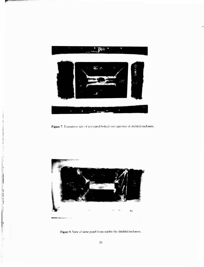
7 Transmitter Side of Test Panel Bolted Over Aperture of Shielded Enclosure 20
8 View of Same Panel From Within Shielded Enclosure 20
9 Receiving Antenna Positioned Before Test Panel 21
10 Shielding Effectiveness vs Frequency 21
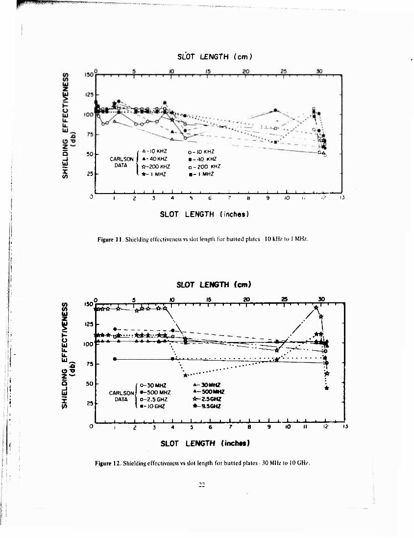
11 Shielding Effectiveness vs Slot Length for Butted Plates-10 kHz to 1 MHz 22
12 Shielding Effectiveness vs Slot Length for Butted Plates-30 MHz to 10 GHz 22
13 Shielding Effectiveness vs Slot Length for Slotted Plates-10 kHz to 1 MHz 23
14 Shielding Effectiveness vs Slot Length for Slotted Plates-30 MHz to 10 GHz 23

vi;-7'v--.ri-T---,-r;i. ■' ";---\'TT---."VT -'■■w;'sr??rw-\'-:-:. •:: TWWJBajpSJBpi'.'
FIGURES (Com.)
Number Page
15 Shielding Ktfccliveness vs Slot Length for Wide-Slot Plates 10 kHz to 1 MM/. 24
16 Shielding Hffccliveness vs Slot Length for Wide-Slot Plates 30 MM/, to 9,09 GHz 24
17 Shielding Effectiveness vs Slot Length for Backing-Strip Plate;. 10 kHz to 1 MHz 25
18 Shielding Effectiveness vs Slot Length for Backing-Strip Plates 30 MHz to 9.09 GHz
19 Shielding Effectiveness vs Slot Length for Slotted Backing-Strip Plates 10 kHz to 1 MHz
20 Shielding Effectiveness vs Slot Length for Slotted Backing-Strip Plates 30 MHz to 9.09 GHz
25
26
26
21 Shielding Effectiveness v<i Hole Diameter for Drilled Plates 10 kHz to 1 MHz 27
22 Shielding Effectiveness vs Hole Diameter for Drilled Plates 30 MHz to 10 GHz 27
ftv,*.^.;^«»^'»^-1»4"»-""-*

RFI SHIELDING EFFECTIVENESS OF STEEL SHEETS WITH PARTLY WELDED SEAMS
1 INTRODUCTION
Background Current specifications, largely unsupported by ex-
perimental data, require weld seams in electromagnet- ically shielded facilities to be radiographically defect- free. These specifications have necessitated spending $1,000,000 for inspection and weld rework at SAFE- GUARD missile sites. In a study of the effect of weld defects on the shielding effectiveness of shielded en- closures containing welded seams, Carlson found that weld seams having weld defects under a critical size could provide adequate shielding effectiveness, and that repair of such seams was an unnecessary expense.1
He suggested that (he effect of crack (or slot) width and length on shielding effectiveness be evaluated in a future study that would determine critical sizes for classes of defects and would investigate circumstances in which a flaw might act as a resonant antenna.
sure, if incident radiation has wavelength X. and slot length is X/2, the slot can act as a resonant cavity of the first order. An Nth order cavity results from slots of length NX/2. It was hypothesized that anti-reso- nance might result from a slot of length X/4. Such a condition, if obtainable, could produce a sharp rise in shielding effectiveness as a function of slot length, con- trasting with the sharp drop produced by resonance. To test the resonance and anti-resonance concepts, some slot lengths were made equal to the resonant wave- lengths (even multiples of X/2), while others were made equal to odd multiples of X/4. The resonant slots can also be considered as waveguides for the fundamental transverse-electric (TE) rectangular waveguide mode, TEQI. The null index indicates a wave propagation through a slotlikc waveguide.
Through-plate holes in resonant sizes were also desired. Since determination of resonant size for holes is mathematically more sophisticated than for slots, the holes were likened to circular waveguides, and cer- tain hole diameters were chosen for resonance in low- order transverse-electric (TE) and transverse-magnetic (TM) circular waveguide modes.
Objective
The objectives of this study were twofold; to deter- mine the effect of certain large welding defects on the shielding effectiveness of steel plates; and to determine the critical size below which cracks and porosity in welds do not degrade shielding effectiveness below specifications and are thus uneconomical to repair.
Approach
Welded steel panels containing through-thickness slots and holes of varying sizes in welds were tested for shielding effectivness in a high-quality shielded en- closure. These defects were considered as limiting, or worst, cases of cracks and porosity in welds. The tests for each panel covered a frequency range from 10 kHz to 9.5 GHz. Degradation of shielding effectiveness as a function of disturbance size and geometry was noted. Applying specifications for minimum shielding effec- tiveness as a function of frequency to these data pro- duced critical sizes for each of the aperture geometries.
The slot lengths chosen were multiples of the quar- ter-wavelengths of the higher radio frequencies trans- mitted through the test panels into the shielded enclo-
'K. W. Carlson, The Effect of Weld Defects on RFI Shield- ing Effectiveness, Technical Report M-43/AD773716 (Con- struction Engineering Rer«arch Laboratory [CERt], January 1974).
2 PROCEDURE
Specimen Fabrication
Each specimen was composed of two 11 -gage (approximately 1/8 in. or 0.32 cm thick), 8 in. x 24 in. (20.32 cm x 60.96 cm), low-carbon steel panels butted together and gas-metal arc welded. Slot flaws were made by leaving an unwelded seam of the desired length in the central portion of the weld line (Figure 1). Contraction of the adjacent weld metal during cooling kept the contiguous unwelded edges of each specimen tightly butted. Welds were made in a single pass from the side of the panel that was intended to face the shielded enclosure. Full penetration welds were made, and excess weld metal was ground off. Each weld was radiographed to insure that no effective flaws except the implanted one existed. The side of the panel con- taining the weld crown was then flame-sprayed with tin to a thickness of about 0.01 in. (0.03 cm). This pro- vided a conducting interface between the panel and the shielded enclosure cover plate for effective attenuation of the Radio Frequency Interference (RFI) signal re- ceived in the enclosure from the external source.
The first test series, butted plates (Figure 1), con- sisted of varying lengths of unwelded seam (Table I).

Table 1
Procedural DiU for Butted Plates (Test Serie» 1)
Table 2
Procedural Data for Slotted Plates (Test Series 2-Slots 1/16 in. or 0.16 cm Wide)
\ Specimen
Calculated Calculated Test Slot Length, Resonant Frequency Specimen Test Slot Length, Resonant Frequency
Number Order in. (cm) CTEoi Rectangular Mode) Number Order in. (cm) (TEQI Rectangular Mode)
1 11 0.15 1 6 0.165 ( 0.38) ( 0.419)
2 5 0.31 ( 0.79)
10 GHz* 2 4 0.345 ( 0.876)
9.09 GH*'
3 1 0.59 ( 1.50)
10 GHz 3 10 0.645 ( 1.638)
9.09 GHz
4 10 1.18 ( 3.00)
10 GHz" 4 1 1.300 ( 3.302)
2.27 GHz;* 9.09 GHz**
5 4 2.07 ( 5.26)
5 8 2.225 ( 5.652)
6 3 2.36 ( 5.99)
2.5 GHz 6 7 2.595 ( 6.591)
2.27 GHz
7 13 2.66 ( 6.76)
7 9 2.915 ( 7.404)
8 8 3.24 ( 8.23)
8 3 3.545 ( 9.004)
9 9 3.54 ( 8.99)
9 5 3.885 ( 9.868)
10 4.72 (11.99)
2.5 GHz" 10 2 5.170 (13.132)
2.27 GHz;** 568 MHz*
11 14 9.44 (23.98)
11 13 10.405 (26.429)
568 MHz
12 11.51 (29.24)
12 11 11.665 (29.629)
13 11.80 (29.97)
500 MHz 13 12 12.020 (30.531)
|4 12 12.10 (30.73) •Anti-resonance
••Second-order resonance *Anti-resonance
••Second-order resonance
To insure that no sprayed tin lay in the slots, concen- dated HC1 was dripped onto each slot. Since the re- action of tin and HCl creates H-, gas and a salt of tin and chlorine, the treatment was applied until no evolu- tion of H-) gas was noted. Seepage of HCl throughout each slot was noted.
The second test series, slotted plates (Table 2), used the plates from the first series with l/16-in.(O.I6cm) wide slots (Figure 2) milled to the same length as the butted slot length tested in the first series. The third test series, wide-slot plates (Table 3), used the same plates with the three smallest slots widened to 3/16-in. (0.48 cm) (to keep the slot axis horizontal) and the rest to 1/2-in. (1.27 cm) (Figure 3).
The fourth test series, backing-strip plates (Table 4), was fabricated similarly to the first series, with the ad- dition of backing strips. The strips were 2 in. x 13 in. (5.08 cm x 33.02 cm) and were tack-welded to the
panels symmetrically about the weld flaw, on the side containing the weld root (Figure 4). The butted panel weld did not penetrate into the strip, thus providing a "worst case" configuration. Since the strip was short enough to fit inside the aperture of the shielded en- closure cover plate to which the specimen plate was bolted during testing, the backing strip was not sand- wiched between the test panels and the cover plate. The slots were covered with aluminum adhesive tape prior to flame spraying, to prevent tin from entering the slots.
The fifth test series, slotted backing-strip plates (Table 5), used the plates of the fourth series with 1/16-in. (0.16 cm) wide slots milled as in the second test series. Only the welded plates were slotted; the backing strips were not.
The sixth test series, drilled plates (Table 6), con- sisted of single holes drilled through otherwise perfect welds (Figure 5) after flame spraying.
... ■•.. ■ J-..;.««-.*,V ■•*».»-

f^™**f!7w*rwT^*-r~':-j
Table 3 Table 4 Procedural DaU for Wide-Slo« Plates Procedural Data for Backing-Strip Plates
(Test Series 3) (Test Series 4)
Slot Ülol Calculated Calculated Specimen Test Length, Width. Resonant Frequency Specimen Test Slot Length, Resonant Frequency Number Order in. (cm) in. (cm) (TEQI Rectangular Mode) Number Order in. (cm) (TEQI Rectangular Mode)
1 11 0.165 (0.419)
3/16 (0.48)
1 10 0.15 ( 0.38)
2 7 0.345 (0.876)
3/16 (0.48)
9.09 GIU^ 2 9 0.31 ( 0.79)
10 GHz'
3 12 0.645 (1.638)
3/16 (0.48)
9.09 GHz 3 7 0.59 ( 1.50)
10 GHz
4 5 1.300 (3.302)
1/2 (1.27)
2.27 (.Hz;* 9.09 GHz'* 4 2 1.18 ( 3.00)
10 GHz**
5 10 2.225 (5.657;
1/2 (1.27)
5 1 2.07 ( 5.26)
6 8 2.595 (6.591)
1/2 (1.27)
2.27 GHz 6 5 2.36 ( 5.99)
2.5 GHz
7 1 2.915 (7.404)
1/2 (1.27)
7 8 2,66 ( 6.76)
8 2 3.545 (9.004)
1/2 (1.27)
8 13 3.24 ( 8.23)
9 6 3.885 (9.868)
1/2 (1.27)
9 4 3.54 ( 8.99)
10 3 5.170 (13.132)
1/2 (1.27)
2.27 GHz;" 568 MHz' 10 12 4.72 (11.99)
2.5 GHz"
11 9 10.405 (26.429)
1/2 (1.27)
568 MHz 11 6 9.44 (23.98)
12 4 11.665 (29.629)
1/2 (1.27)
12 11 11.51 (29.24)
13 13 12.020 (30.531)
1/2 (1.27)
13 3 11.80 (29,97)
500 MHz
•Anti-resonance •Anti-resonance ••Second-order resonance ••Second-order resonance
Conduct of Tests Each lest panel was bolted over an aperture in the
shielded enclosure (Figure 6), with RFI gasket material sandwiched between the panel perimeter and the enclo- sure. Figure 7 shows the transmitter side of a slotted plate bolted to the shielded enclosure cover plate; Figure 8 shows the enclosure side ot the same panel. Hardened steel bolts were used to compress the test plate and RFI gasket to the cover plate. The bolts were torqued to over 50 ft-lb (67.8 Nm) urn 1 no RF leakage through the gasket could be detected by an RF "sniffer," or leak detector.
After bolting, the panels were illuminated by electro- magnetic waves of eight different frequencies in se- quence. The tests were made in accordance with Military Standard 2852 and Institute of Electric and Electronic
Engineers Standard 2993; the attenuated signal re- ceived in the shielded enclosure was measured in deci- bels with respect to free space (uncovered aperture in the enclosure). The electric field vector was perpendic- ular to the slot axis of slotted test panels. Details of the test arrangement and equipment are presented in the previous study.4 Table 7 lists the test equipment used.
A shielded septum divided the enclosure into two compartments, each roughly 10 ft (3.04 m) cubed. One compartment supported the test panel and con- tained the RF receiving antenna (Figure 9). The anten- na cable passed through the septum to the receiver in the other compartment. Testing personnel monitored
Method of Attenuation Measurements for Enclosures, Electromagnetic Shielding, for Electronic Test Purposes, MIL-STD-285 (Department of" Defense, June 1956).
Measurement of Shielding Effectiveness of High Perfor- mance Shielding Enclosures, IF.EF. Standard 299 (Institute of Electrical and Electronic F.npineers, 1969).
4K. W. Carlson, The Effect of Weld Defects on RFI Shield- ing Effectiveness, Technical Report M43/AD773716 (CFRL, January 1974).

TPIfSPiPB^J^W-i""
TableS Procedunl Dia for Slatted Backing-Strip PUtet
(Test Series S -Slot« I /164n or . 16 cm Wide)
Calculated Specimen Teit Slot Length, Resonant Frequency Number Order in. (cm) (TEQI Rectangular Mode)
10 GHz*
10 GHz
10 GHz**
2.5 GHz
Table 6 Procedural Data for Drilled Plates
(Test Series 6)
9 0.15 ( 0.38)
6 0.31 ( 0.79)
5 0.59 ( 1.50)
2 1.18 ( 3.00)
10 2.07 ( 5.26)
6 7 2.36 ( 5.99)
7 8 2.66 ( 6.76)
8 11 3.24 ( 8.23)
9 4 3.54 ( 8.99)
10 13 4.72 (11.99)
11 12 9.44 (23.98)
12 1 11.51 (29.24)
13 3 11.80 (29.97)
*Anti-reso nance **Second-orde' resonance
2.5 GHz**
500 MHz
the signals received in the second compartment, which was accessed by a shielded sliding door with a pneuma- tic shielding gasket.
Experience over a number of projects has shown that a strong resonance in the first compartment of the shielded enclosure exists in the vicinity of 500 MHZ. Considering fields in a closed rectangular cavity does not explain this resonance. That theory predicts the first normal frequency, or (110) mode, to be 10 MHz for a 10-ft (3.04 m) cubed room.
The three highest frequencies repor'ed in the pre- vious study5 were 500 MHz, 2.5 GHz, and 10 GHz. However, 2.5 GHz is the top of the Maxson oscillator's range, and the Narda oscillator is calibrated to only 9.8 GHz (Table 7). Thus the signal at 2.5 GHz was shifted
Calculated Circular Mode
Specimen Test Hole Diameter, Resonant at Number Order in. (cm) 9.09 GHz
1 1 1/8 (0.32)
3 1/4 (0.64)
5 1/2 (1.27)
2 49/64 (1.96)
TEn
4 1 (2.54)
TMoi
6 1 17/64 (3.22)
TE21
7 1 19/32 (4.06)
TMn
5 K. W. Carlson, The Effect of Weld Defects on RFI Shield- ing Effectiveness, Technical Report M-43/AD773716 (CF.RL, January 1974).
to 2.27 GHz, the signal at 500 MHz was raised to 568 MHz (2.27 GHZ + 4), and the 10 GHz signal was lowered to 9.09 GHZ (2.Z7 GHz x 4) to fit within the instruments' calibrated ranges. Specimen fabrication and testing was initiated on the basis of information in the previous study (with the signal at 10 GHz shifted to 9.5 GHz to accommodate the Narda) before this equipment limitation was fully realized.Consequently, the early tests were performed at the old top frequen- cies, while later tests were performed at the new fre- quencies. Although Tables 1 through 6 are arranged logically according to the flaw character of their data, the tests were performed in an experimentally conveni- ent order: consequently, "early tests" refers to the actual test performance order rather than the test series number.
3 RESULTS AND AMALYSIS
All results are stated in decibels with respect to free space measurements made without a test panel over the aperture of the shielded enclosure. The electric field vector was propagated prependicular to the axis of welds and slots in the test panels to achieve the greatest discontinuity in the current flow in the test panels. This was expected to cause slots to be strong re-radia- tors of signals, thus constituting a worst case of slot axis orientation with respect to electric field vector. For sufficiently small apertures (flaws) the recorded shielding effectiveness was at the top of the receiver's
10
*,***...*».-,...• -.■•■ ■

Table 7 Equipment Used for Shielding Effectiveness Measurements
Dynamic Range Antenna
Fiequency (dB) Separation Equipment Used
10 kHz 116 2 ft (.61m) Hewlett Packard 2021) Signal (iencratut 40 kHz 117 MB l.lectronics 2250 Power Amplifier
CTRL Loop Antenna (radiating) Sloddard NM-12AT Held Intensity Meier Empire LP-105 Loop Antenna (rcccivinx) Sing« 500 Shielded Enclosure Leak
Detector
200 kHz 108 2 ft (.61m) Hewlett Packard 606 Signal Generator Electronic Navigation Industries 310L
Amplifier CERL Matched Loop Antenna (radiating) Stoddard NM-12AT Held Intensity Meter Empire LM-105 Loop Antenna (receiving)
1 MHz 104 2 ft (.61m) Hewlett Packard 606 Signal Generator 30 MHz 103 Electronic Navigation Industries 310L
Amplifier CERL Matched Loop Antennas (radiating) Empire NF105 Field Intensity Meter,
TA Tuning Head Empire LP-10S Loop Antenna (receiving) Hewlett Packard 3SSD Attenuator Hewlett Packard 3SSC Attenuator
SOG MHz 103 2m Maxson 1141A Power Oscillator 568 MHz 103 CERL Dipole Antenna (radiating)
Empire NF10S Field Intensity Meter, T-3 Tuning Head
Empire DM-10S T3 Dipole Antenna (receiving)
2.27 GHz 121 18 in. (.46 m) Maxson 1141A Power Oscillator 2.5 GHz 144 S-Band Waveguide (radiating)
Polatad RS-T Receiver S-Band Horn PRD Electronics 1211 Isolator
9.09 GHz 115 12 in. (.30 m) Narda 18S00B RF Power Pulser 9.5 GH* 111 X-Band Waveguide (radiating)
Polarad RX-T Receiver X-Band Horn (receiving)
11

dynamic raupe. Ciinscqucnlly. ihc actual shielding ef- fecltveness ol the Haw may have been greater than recorded. The dynamic range of instrumentation and specified minimum shielding effectiveness are shown as functions of frequency in Higure 10. (The dynamic range is also the shielding effectiveness at /.cm flaw si/.e, shown in the remaining figures.) The dynamic range was at least 24 dB above the specified minimum shielding effectiveness.
Shielding effectiveness data for a sound weld arc also shown in Figure 10. These data are below the dy- namic range only at the extreme frequencies, 10 kHz and 9 GHz, and are always over 100 dB shielding ef- fectiveness. Carlson's data6 for a sound weld are also shown in the figure. Those data are at the dynamic range stated in the Carlson report for almost all the lest frequencies. Moreover, those data are in general higher than the data obtained in this study, due to the greater dynamic range obtained in Carlson's work. Why the ranges differ is uncertain.
The data for each test series are divided into two groups by frequency to simplify graphing. Figures 11 and 12 present shielding data for butted plates. The data are somewhat paired: 10 and 40 kHz, 200 kHz and I MHz, 30 and 500 MHz, and 2.5 and 9.5 GHz. The data as functions of frequency are generally not monotonic, but have many extrema. Table I and Figure 12 show that none of the calculated resonances and anti-resonances were observed. The data for 200 kHz and higher frequencies are virtually constant for slot lengths less than about 3.5 in. (8.89 cm), indicating that the actual shielding effectivenesses of such small flaws exceeded the instrumentation's dynamic range. Three transition flaw sizes can be determined for the three minimum specified shielding effectiveness levels and associated frequency ranges presented in Figure 10. Table 8 presents these transition flaw sizes and the fre- quencies at which they were noted.
One may suppose that the more tightly butted plates will have better conductivity and permeability across the slot width than those that are less tightly butted. This tightness was an uncontrolled fabrication factor, which may account for some of the extrema observed. However, this effect can be considered in- fluential only when alt the shielding data at a given slot length rise or fall sharply, reflecting a respective
tightness or looseness id the loinl relative to iliat ol adjacent slot lengths. I his is based on the ubservaiinn that a lightly butted sloi will shield better than a loosely bulled one, regardless of the frequency. The frequency-independent drop in shielding effectiveness at a slot length of 4.7 in. (11.94 cm) observed in Figures 1 I and 12 may be due to the joint tightness factor.
Also shown in Figures I I and 12 arc Carlson's data on gaplcss. unwclded segments of 1-, 4-, and 12-in. (1.27-, 10.16-, and 30.4K cm) lengths, his specimens P-l, P-2, and P-3, respectively. Those data are well im- bedded in the data obtained in this study and are some- what similarly paired by frequency. Agreement be- tween the two sets of data is tolerable at 10 kHz, 200 kHz, and 1 MH/, but is generally not good at other frequencies.
Figures 13 and 14 present shielding data for slotted plates. The data in Figure 13 show a strong trend of de- creasing shielding effectiveness with increasing slot length. The data are very closely grouped, indicating a distinct insensitivity of shielding to frequency. The data of 30 and 568 MHz generally run with the lower frequency data. However, the data at 2.27 and 9.09 GHz form a band separate from the other data. First- order lesonances at 9.09 and 2.27 GHz were observed at the calculated resonant slot lengths of ~0.6 in. (1.52 cm) and ~ 2.6 in. (5,16 cm), respectively, as evi- denced by the sharp drops in shielding effectiveness at those slot length-frequency combinations (Table 2 and Figure 14). The slight dip at 10.4 in. (26.42 cm) and 568 MHz may also be due to a first-order resonance. No second-order resonances or anti-resonances were observed. None of the data in Figures 13 and 14 ex- ceeded the dynamic range. The three transition flaw sizes are reported in Table 8. The effect of slots in the GHz range has been discussed by Jarva.7
Data for the Carlson specimen P-4 with a slot 1 in. (2.54cm) long by 0.06 in. (.15 cm) wide are also re- ported in Figures 13 and 14. These data agree with the data obtained in this study except at the two high- est frequencies. Since 1 in. (2.54 cm) is not a first-order resonance for either 2.5 or 10 GHz, the shielding data from Carlson's specimen should be better than the near-resonant data at 2.27 and 0.09 GHz.
"K. W Carlson, The Effect of Weld Defects on RFI Shield- ing Effectiveness. Technical Report M-43/An773716 (CT.RL, January 1974),
'W. Jarva, "Shiclitint; Tests for Cables and Small I nclosurcs in the 1- to U)-GH? Ranuc," IEEE Trans. Eleclrmmswtk Compatibility. Vol I 2, No. 1 (1970). pp I : 24
12

VPV9^MIV> f ft1'WWCPWft »mfßfumitmi
Flaw Type
Table 8 Transition Flaw Sizes for Various Test Cieometries
Transition Flaw Size by Shielding Level
70dB (< 200kHz) 80dB (200kHz < 3 GHz) 60dB(>3(;Hz)
Butted Plate-
Slotted Plate
Wide-Slot Plate
Backinp-Strip Plate
Slotted Hacking-Strip Plate
Drilled Plate
4.7 in, w 10 kHz (11.94 cm)
1.9in>; 10 kHz (4.83 cm)
1.3 in.'" 10 kHz (3.30 cm)
4.7 in. r«' 10 kHz (11.94 cm)
2 in. f"'40 kHz (5.08 cm)
1 in.(" 10 kHz (2.54 cm)
9.4^.^ I MHz (23.88 cm)
0.6in> ~2(;ilz (1.52 cm)
0.4in. f" ~2(illz (1.02 cm)
4.4 in. f"1 ~2 GHz (11.18cm)
0.3 in. f" 1 MHz & 2 GHz (0.76 cm)
0.3 in. ("^2 GHz. (0.76 cm)
4.7 in. * ~9GH/. (11.94 cm)
0.3 in.'" ~9(;ilz (0.76 cm)
0.4 in.* ~9(;ilz (1.02 cm)
4.7 in. & ~9 GHz (11.94 cm)
0.3 in. <"' ~9 GHz. (0.76 cm)
0.3 in. f" ~9(;Hz (0.76 cm)
Shielding data for wide-slot plates are shown in Figures 15 and 16. The three lowest frequencies in Figure 15 form a very narrow band; the fourth fits well among them except at one point. In Figure 16, the data fall into two bands by frequency. Using Table 3 with Figure 16 shows that the data for 2.27 and 9.09 GHz fall rapidly until their first resonant slot lengths are reached. Thereafter, the data vary little. Data at lower frequencies display the expected decrease in shielding with increasing slot length. The three tran- sition flaw sizes are recorded in Table 8. No second- order resonances or anti-resonances were observed.
Shielding data for the backing-strip plates are pre- sented in Figures 17 and 18. The data in Figure 17 fall into a band somewhat broader than observed at these frequencies for other test series. Data for 200 kHz and 1 MHz are at the dynamic range for slot lengths up to 3.6 in. (9.14 cm). In Figure 18, the data at 30 and 568 MHz are almost entirely independent of slot length, while the data at 2.27 and 9.09 GHz are grouped into a generally narrow band. Both frequencies in this band drop sharply at a slot length of 0.15 in. (0.38 cm); this is about one-fourth the size calculated for first- order resonance. Since the actual two highest frequen- cies differed from those for which the resonant slot lengths had been designed, no resonances were ob- served. The three transition flaw sizes are given in Table 8.
Figures 19 and 20 show the shielding data for the slotted backing-strip plates. The data in Figure 19 form a well-defined band, while the data in Figure 20 form
two bands by frequency. The data at 30 and 568 MHz are at the dynamic range for slot lengths up to 1.2 in. (3.09 cm). The data for the top two frequencies drop quickly with increasing slot lengths, but the slot length at minimum shielding effectiveness does not agree with calculated values. The three transition flaw sizes ate shown in Table 8.
Shielding data for drilled plates are presented in Figures 21 and 22. The data in Figure 21 form a single band, while the data in Figure 22 form two bands. The data at 30 and 568 MHz are at the dynamic range for hole diameters up to Vi in. (1.27 cm). The data for 2.27 and 9.09 GHz are near the dynamic range for hole diameters up to 1/8 in. (0.32 cm); the data fall as the diameter increases beyond 1/8 in. (0.32 cm). Table 6 and Figure 22 show that the shielding is very low for the first four resonant modes at 9.09 GHz. The effect of holes in the GHz range has also been discussed by Jarva.8 The three transition flaw sizes are shown in Table 8.
Data from Carlson's "drilled plate" specimen having a 1/16 in. (0.16 cm) diameter hole are given also in Figures 21 and 22. Those data agree fairly well with the data obtained in this study.
Data from Figures 11 through 16 can be compared by progression of defect width. Tightly butted plates
W. larva, "Shicldinj: Tests tor Cables and Small Indosures in the 1- to 10-GHz Ranpe," IHEh Trans. Klectmmgnvtk Compatibility. Vol 12. No. I (1970). pp 12-24.
13

pmitvnp
jFigures II ;irul I_) hail inuletüctahle resonance;Iheir ilalu generally fell in a broad band. Plates with a nar- row diseoniinuity (Figures 13 and 14) displayed rc- sonaneos; their data tell into a fairly narrow band. As expected, plates with wide discontinuities (Figures 15 and 16) generally had lower shielding elTectiveness at a given slot length than those with narrow slots. However, some wide slots did have greater shielding elTectiveness than some narrow slots of the same length.
The effect of a tacked backing strip is mixed. Tran- sition (law si/e was not significantly affected below 200 kHz or above 3 GHz. However, use of backing strips halved the transition flaw size in the 200 kHz-3 (iH/ range (Table 8). The gap between the backing strip and plate may have produced a resonant condi- tion at these intermediate frequencies.
4 CONCLUSIONS AND RECOMMENDATIONS
Conclusions The data obtained in this study and the Carlson
study show that sound welds have a shielding effective- ness far above the minimum specified levels.
Plates having unwelded but tightly butted seams over a moderate length still have very good shielding effectiveness. Lengths up to 4.7 in. (11.94 cm) pro- vided at least 60 dB shielding at all test frequencies. While these defects do allow some radiation to pass, they are inpapable of resonant radiation due to the high quality of electrical conductivity afforded by the tight butting. When the seam forms a slot of finite but small width, resonant radiation is observed, and shield- ing is seriously degraded at key combinations of fre- quency and slot length. Shielding to 60 dB for slot flaws can be assured only for flaw lengths under 0.3 in. (0.76 cm). Increasing slot width at a fixed slot length and radiation frequency does not necessarily degrade the shielding; it may improve. The general increase in aperture area tends to obscure resonance as slot width increases. Thus, tight cracks or other forms of one- dimensional weld defects will not compromise the shielding effectiveness to less than 60 dB if the defect does not exceed 4!4 in.(11.43 cm).
Backing strips placed over scams with unwelded lengths have little effect below 200 kHz and above 3 GHz. Between 200 kHz and 3 GHz, backing strips may halve the tolerable defect length.
Plates having holes as large as 0.3 in. (0.76cm) can still afford at least 60 dB shielding at all test frequencies. Larger holes can also assure good shielding al selected frequencies. Thus, porosity or other spheroidal weld defects will not compromise shielding effectiveness to less than 60 dB if the defect's major dimension in the plane of the plate docs not exceed 0.3 in. (0.76 cm).
No sharp increases in shielding effectiveness were observed at those slot lengths for which anti-resonance was predicted. Consequently, it is doubtful that such a phenomenon occurs. No second-order resonance was observed.
Figures 12 and IH show that very high shielding ef- fectiveness existed at 300 ~ 500 MHz over a broad range of butted plate defect lengths. The shape of the shielded enclosure used may have permitted the high shielding effectiveness over this frequency range. If so. it may be possible to design a shielded enclosure that offers high shielding effectiveness due to Hs geometrical character. Schulz and his associates9 have attributed resonance in the 5 to 200 kHz range in typical shielding enclosures to a difference in phase retardation between a path through the shielding material and a path through seams. Schulz also observed that seam effects are negligible below 5 kHz. significant between 50 kHz and 5 MHz, and predominant (along with cavity resonance and material configuration) above 5 MHz.10
Recommendations
Shielding specifications should be changed to incor- puiate the technical aspects of this report and should permit acceptance of welds that have been visually in- spected and found to contain no flaws in excess of the critical flaw sizes. Table 8 can be used to establish in- spection and acceptance criteria for SAFEGUARD- type facilities.
The apertures affording tolerable shielding effective- ness were all easily detected visually. Hence, welds need only be visually inspected; radiographic or mag- netic particle inspection is not necessary. Porosity that is not open to the surface need not be a concen1
R. U. Schulz. V, C. I'lantz. and l>. R. Brush, "l.nw-l rc- quency Shielding Resonance," fEEE Trans Ekciromagnetk Compatibility. Vol 10. No. 1 (1968). pp 7-15.
I0R. B. Schulz. G. C. Huanp. and W. 1. Williams. "R1 Shieldinj; Resign,"/fc'fcTt Trans. Flcctroinaxnctk Compatahilitv. Vol 10, No, 1 (1968). pp 168-175.
14
DiK- in ihc siront; shielding cl'lcclivcness encnun- Icicd in lite iiciglihorlmod ol 500 MH/, ct't'ort should be nuide in develop design principles for shielded en- closure shapes thai olier high shielding elTcctivencss.
Mcamrerm-ni uj StiieUing l-.jjcviivciww <ij High I'n fomtancc Shielding Enclosures, II.I I Siaiulaiil 299 (Institute of Klectrical and l.leclriuiic In^l- neers, 1969).
REFERENCES
Carlson, K. W., T/it- Effect of Weld Defects on RFl Shielding Effectiveness, Technical Report M43/ AD7737I6 (Construction Engineering Research Laboratory |Ci;RLl January 1974).
Method of Attenuation Measurements for / m/m/m s. Electromagnetic Shielding, for EkTirmtk 7iw Purposes, MIL-STD-2X5 (Department ol Dek-nse. June 1956).
Schulz, R. B., G. C. Huang, and W. L. Williams. Rl Shielding Design," IEEE Trans. Electromagneiif Compatability, Vol. 10,No. I (196H),pp 16H.I75.
Jarva. W., "Shielding Tests for Cables and Small En- closures in the 1- to 10-GHz Range," IEEE Trans. Electromagnetic Compatability, Vol 12, No. 1 (1970),PF 12-24.
Schulz, R. B., V. C. Plantz, and D. R. Brush, "l.im- Frequency Shielding Resonance," IEEE Trans. Electromagnetic Compatability, Vol. 10. No. I (1968), pp 7-15.
15

a. Shielded enclosure side
b. Transmitter side
Figure I. Butted plate with 1 -.1 -in. <30.73 cm) slot length.
16

- 38
Figure 2. Slotted plate with slot l>44 in. (23.98 cm) long and 1/16 in. (0.16 cm) wide-shielded enclosure side.
Figure 3. Wide-slot plate with slot 3.54 in. (8.99 cm) long and 1/2 in. (1.27 cm) wide-shielded enclosure side.
17

a. Shielded enclosure side
b. Transmitter side showing tacked backing strip
Figure 4. Backing-strip plate with 3.54-in. (8.99 cm) long slot.
18
'- ^TT^'-SrilP'-i"■■/■■■ :,■■■
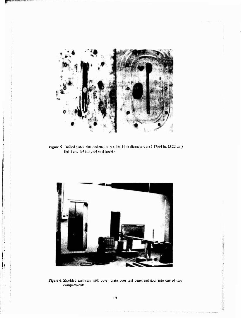
Figure S. Drilled plates shielded enclosure sides. Hole diameters are 1 17/64 in. (3.22 cm) {left) and 1/4 in. (0.64 cm) (right).
Figure 6, Shielded enclosure with cover plate over test panel and door into one of two compartuients.
19
"-."■-'f^^U-itf,
■Op WWS-*'-'ZJ? p-v«L" ^ ■"''
Figure 7. Transmitter side nl test panel bolted over aperture ol'sliieMed enclosure.
Figure S. View ol same panel from within the shielded ciielosure.
20

Figure 9. Receiving antenna positioned before lest panel. Shielded septum (right) passes antenna cable to receiver in adjacent compartment.
(/) 0) bJ Z
>
o UJ u. UJ XI
ow
z 5 -i UJ z V)
150
125 -
-'S
50
25 -
^ - - - • •—
MOKHZ
o-DYNAMIC RANGE
• -SPECIFIED MINIMUM SHIELDING EFFECTIVENESS D-SOUND WELD ■ -SOUND WELD (CARLSON DATA)
J_ 100 KHZ I MHZ 10 MHZ
FREQUENCY
100 MHZ IGHZ 10 GH?.
Figure 10. Shield'ngeffectiveness vs frequency.
BfW?|||PyWy<V^"la"J.J!»»>».i|TO'.-T.^-T-r..
SLOT LENGTH (cm)
UJ I
50 -
25 -
CARLSON DATA
A-10 KHZ
A-40KHZ
<r-200 KHZ •- I MHZ
O-IO KHZ • -40 KHZ a-200 KHZ ■ - I MHZ
QA,
I I I i I I 1 L i < I i J L 10 n U
SLOT LENGTH (inches)
Figure 11. Shielding elYectiveness vs slot length for butted plates 10 kHz to 1 MHz.
i ISO W-4-iJjHLVV ' ' 125
O UJ u. u. w^
ja
S -> UJ
X
100
75
50
25 -
^A-A—A * * A + *'
^H^
SLOT LENGTH (cm)
K) 15 20 25 30 I I I I—| I i i » | i i i 1 | i » i i.| i ' i
~tf
■ y
A
^-4 CARLSON
DATA
0-30 MHZ •-500 MHZ a-2.5GHZ ■-10 GHZ
A-30 MHZ *-500MHZ <^ 2.5 GHZ #-a5GHZ
■ i . i i i » i i I i—t__j—L_J—I—I—L_x-J—i l t i—L. 10 II 12 li
SLOT LENGTH (inchct)
Figure 12. Shielding effectiveness vs slot length for butted plates- 30 MHz to 10 GHz.

npppp^l^l •* • U,! .,■ vr irRP^tVaHBP*1
ISO I I I I I I I I I I I I I I I
SLOT LENGTH (cm)
10 is ao 25 30 T 1 1
A- 10KHZ CAASON ;*-<0KMZ
DATA i A-200 KHZ
O-tO KHZ • -40 KHZ O-200 KH7 ■- I MHZ
JU_J L__l I I l__J I I t , 1 I ' ' ' ' I I L-J I I I L. I 2 3 4 S 6 7 8 9 IO II I? 13
SLOT LENGTH (inchM)
Figure 13. Shielding effectiveness vs slot length for slotted plates 10 kHz to 1 MM/. Slot width is 1/16 in. (0.16 cm);Carlson slot width is 0.06 in. (0.15 cm).
SLOT LENGTH (cm)
10 15 20
2 3456789
SLOT LENGTH (inches)
Figure 14. Shielding effectiveness vs slot length for slotted plates-30 MHz to 10 GHz. Slot width is 1/16 in. (0.16 cm);Carlson slot width is 0.06 in. (0.15 cm).
23

SLOT LENGTH (cm)
K) 15 20
0-10 KHZ • -40 KHZ 0-200 KHZ ■ - I MHZ
SLOT LENGTH (inchet)
Figure 15. Shielding effectiveness vs slot length for wide-slot plates 10 kHz to 1 MHz. Slot widths are 3/16 in. (0.48 cm) for slot lengths under 1 in. (2.54 cm); other slot widths are 1/2 in. (1.27 cm).
SLOT LENGTH (cm)
CO
12 13
SLOT LENGTH (inchtt)
Figure 16. Shielding effectiveness vs slot length for wide-slot plates-30 MHz to 9.09 GHz. Slot widths are 3/16 in. (0.48 cm) foi slot lengths under 1 in. (2.54 cm); other slot widths are 1/2 in. (1.27 cm).
m ■
i 24
.Ä-rtotiuiiiäiiii^kiiif'^ii'-"■■•''""' '

^^WHHWgfft.K.*iV.; w>**m,>:&;iimim\^iilim**r>
SLOT LENGTH (cm)
(A W Ui
Ü UI ll. b.
S -i Ui z (A
SLOT LENGTH (inches)
Figure 17. Shielding effectiveness vs slot length for backing-strip plates-10 kHz to 1 MH/.
(0 ISO V)
z IfJ (25
UJ 100 u. u.
A
S Ui
75 -
50
r i i | ■ r
SLOT LENGTH (cm)
10 15 20 t i i i [ i i I I |'
25 30 I I '—' ' ' I ' i
z V) 25 -
A-30 MHZ *- 568 MHZ
■^ 2.27 GHZ ♦-9.09GHZ
■ ■ ' ' ■ ' ' ■ I I I I i I L_J I I l_J—I 1 1 L I 2 3 4 5 6 7 8 9 10 II 12 13
SLOT LENGTH (inches)
Figure 18. Shielding effectiveness vs slot length for backing-strip plates - 30 MHz to 9.09 GHz.
25

XI
SLOT LENGTH (cm)
10 15 20
100
Q ul I
123456789
SLOT LENGTH (inchet)
10 II 12 13
Figure 19. Shielding effectiveness vs slot length for slotted backing-strip plates-10 kHz to 1 MHz. Slots are 1/16 in. (0.16 cm) wide.
o it b.
5
X
(50
125 -
SLOT LENGTH (cm)
10 15 20 25 30
100
75
50 -
25 -
A-30 MHZ *-568 MHZ Ä-2.27GHZ •-9.09 GHZ
s s
• ____
A
' ' 1 ' ' <
X v 1
1 * * *
J 1—1 1 1 ;C II
SLOT LENGTH (inches)
Figure 20. Shielding effectiveness vs slot length for slotted backing-strip plates-30 MHz to9.09GHz. Slotsarc 1/16 in.(0.16 cm) wide.

PfM'i;;^.^-^.ii;i.u.^ii^.^.^.i^4,^«««T^.-< M wmwrnh i.
HOLE DIAMETER (cm)
en tn UJ z >
o z o -J UJ
to
50
25
A-|0 KHZ
V ■*- I MHZ
O-10 KHZ • -40KHZ Q_200KHZ
■ - IMHZ _i_ .25 .50 1.25 1.50
HOLE DIAMETER (inches)
F,,„ 21.S«.B .ff«U« . «e ...... - a*, p.«-.» .H. ,o , MH,.
HCLE DIAMETER (cm)
8 Ui z UJ >
u. U. Ä uiS oS z
1 z (0
150
125
100 f
75
50
251-
■^v
CARLSON DATA ) o- 2.
f ■- 10
- 30 MHZ 500 MHZ
-2.5 GHZ 10 GHZ
A_ 30MHZ A-566MHZ *- 2.2TGHZ #- 9.09GHZ
Ji±- .25 .50 1.25 1.50
HOLE DIAMETER (inches)
Figure 22. Shielding effectiveness vs hole diameter for drilled plates 30 MHz to 10 GH/..
27

!ii>.(imp*|j(Dsy!,(!ui
CLRL DISTRIBUT 10(1
! hii't nf ifujineers AHN A' r; A ' 'i A; -.U
iiAIN-MC/-S !Iä;|;-ASI-1
.)ALN-rEL-A DAf.N-FE
(?)
«TTN DAIN-RD i' ri. DSn;.CH7-R P! ■MM fWH-M (?)
ATTN DAEN-MCD-E of tnt' Aniiy
HAS!1 DC 20314
U.S. Military Academy ATTN Dept of Mechanics ATTN Library Wt^t Point, NY 10996
Thp Lniineering School Technical Information Br. Archives Section (Bldg 270) Ft Hrlvoir, VA 22060
USA [nqineerinq School ATTN: ATStN-DT-LD (2) ft Belvoir, VA 22060
Director USA Cold Renions Research
Engineering Laboratory P0 Box 282 Hanover, NH 03755
Director, USA-WES ATTN: Concrete Div ATTN: Soils Div ATTN: Library PC Box 631 Vicksburg, MS 39181
Deputy Chief of Staff for Logistics
US Army, The Pentagon WASH DC 20310
The Army Library Office of the Adjutant
General Room 1A530, The Pentagon WASH DC 20315
HQDA (SGRD/Chief), Sanitary Erqr Br
WASH DC 20314
Dept of the Army ATTN: EACICT-P HQ I Corps (Group) APO San Francisco 96358
Commander-in-Chief US Army, Europe ATTN: AEAEN APO New York, NY 094(H
Commander, Naval Facilities Engineering Command
ATTN: Dep Ass't Commander for Design & Spec (040)
200 Stnvall Street Alexandria, VA 22332
Chief, Naval Operations ATTN: The Library Dept of the Nav/ WASH DC 20360
Chief, Hydrographie Office ATTN: The Library Dtpt of the Navy WASH DC 20360
Chief Naval Air Systems Command ATTN: The Library Dept of the Navy WASH DC 20360
Naval Civil Engineering Lab Technical Library Code L31 Port Hueneme, CA 93043
Officer in Charge Naval Civil Engineering Lab Port Hueneme, CA 93043'
AF Civil Engr Center/PG Tyndall ARB, FL 32401
AFWL/Civil Engr Div Kirtland AFB, NM 87117
AF/PREE Boiling AFB, DC 20332
AF/RDPQ WASH DC 20330
Each Division Engineer US Army Engr Div ATTN: Library ATTN: Chief, Engr Div
Each District Engineer US Army Engr District ATTN: Library ATTN: Chief, Engr Div
Defense Documentation Center
ATTN: TCA (12) Cameron Station Alexandria, VA 22314
Chief, Airports Standard Div-AS58
Federal Aviation Administration 800 Independence Ave SW WASH DC 20553
Office of Management Svc, MS 110 - FAA
800 Independence Ave SW WASH DC 20553
Transportation Research Board National Research Council (3) 2101 Constitution Ave WASH DC 20418
Dept of Trans Library Acquisitions Sm t ion (SRj
TA0-491.1 400 7th Street SW WASH DC 20590
Enijineer irn SOL if* ((-•, i i1' T / 345 Fast aTJ' '.frc-t New York, NY ("017
L ibrary of Con ■rt",-. ' ', ; Exchange dnd C,»f t ;, > (
ATTN: Ancri' ..n f. Bt i» -■ ■, WASH DC 20-40
Superintt-ndent of io ane«' Div of Publ ii. .lorliin.'i ATTN: L mrary l?) US Govt Printing Of« t. ■-• WASH DC 20402
ComntdndinT General USA Engr loimar'. lurope APO New York, M ;.wr.
Engineer US Army, Alaska APO Seattle, WA '';:'.; i
Commander, TPADOC Office of the [:■ um" r ATTN: ATEN Ft Monroe, VA 23bSi
Bldg Research Advisor/ BuiH National Academy at '-cieftcM 2101 Constitutor ."i--ri'io WASH DC 20418
Air Force Weapon' I Jb Technical Library (QOUl) Kirtland AFB, NM r^ll?
Commanding Gencrdl US Army Forces Command ATTN: AFEN-FEB Ft. McPherscn, CA 3033C
Commanding General, 6th USA ATTN: Engineer Ft Sam Houston, TX 78234
Commanding General, 6th USA ATTN: Engineer Presidio of San Francisco, CA 94129
Plastics Technical Evaljation Center
ATTN: SMUPA-VP' Picatinny Arsenal Dover, NY 07801
Institute of Defense Analysis 400 Army-Navy Drive Arlington, VA 22202
Defense Logistics Studies Infor- mation Exchange (2)
U.S. Army Logistics Manaqcx-n1
Center ATTN: AMXMC-tl Ft. Lee, VA :33C]
Chief, Civil Engineering KI-SO,!»- r. Division
Air Force Weapons •> A:y. Kirtland AFB, NM rt/ll?
»»^•^'■"■"
Coastal Engineering Research Center
Kingman Bldg ATTN: Library Ft. Belvoir, VA 22060
Dept of the Army HQ 15th Engineer Battalion 9th Infantry Division Ft. Lewis, WA 98433
Main Library, Documents Section
State University of New York at Stony Brook
Stony Brook, NY 11790
W. N. Lofroos, P.E. Chief, Bureau of Planning Dept of Transportation 605 Suwannee St. Tallahassee, FL 32304
Dept of the Army U.S. Army Human Engr Lab ATTN: AMZHE/J. D. Weisz Aberdeen Proving Ground,
MD 21005
Naval Facilities Engineering Command
ATTN: Code 04 200 Stovall St. Alexandria, VA 22332
Ass'st Chief of Engineers ATTü: DAEN-ZCI WASH DC 20314
314/DEEE Little Rock Air Force Base Jacksonville, AR 72076
Defense Nuclear Agency
ATTN: DNA-SPSS HASH DC Z0305
Chief of tnqineers ATTN: DAUH'M' 12) Dept of the Army WASH DC 20314
For forwdrding to:
British Liaisim Officer CM n s Army Mobility Equipmont
Research and Development Center Fort Belvoir, VA 2?06n
Canadian Forces Liaison Officer (4) (j s. Army Mobility Equipment
Research and Development Center Fort Belvoir, VA 22060
Chief Construction Engineer Air Service Branch Department of Transport Ottawa, Ontario, Canada
Div of Bldg Research National Research Council Montreal Road Ottawa, Ontario, K1A0R6 National Defense Headquarters Director General of Construction Ottawa, Ontario K1A 0K2 Canada
:--y ..^;^'.^.:'•■■ jW^rf «.t**^-1-«^ '