construction documents - astoria school district
TRANSCRIPT

PROJECT MANUAL OF
CONSTRUCTION DOCUMENTS
JOHN JACOB ASTOR ELEMENTARY BOILER REPLACEMENT
Project No: 19.12P
Astoria School District No. 1C 785 Alameda Avenue
Astoria, OR 97103
CONSTRUCTION DOCUMENTS
VOLUME 1 OF 1 (Divisions 00 - 26)
June 14, 2019

PROJECT MANUAL OF CONSTRUCTION DOCUMENTS
JOHN JACOB ASTOR ELEMENTARY BOILER REPLACEMENT PROJECT NO. 19.12P ASTORIA SCHOOL DISTRICT NO. 1C CRAIG HOPPES, SUPERINTENDENT BLRB ARCHITECTS JESSICA ARCHER, AIA, PROJECT MANAGER LEE FENTON, AIA, PRINCIPAL-IN-CHARGE
CONSTRUCTION DOCUMENTS VOLUME 1 OF 1 (Divisions 00 - 26)
June 14, 2019
© 2019 BLRB ARCHITECTS
PROJECT MANUAL OF
CONSTRUCTION DOCUMENTS
JOHN JACOB ASTOR ELEMENTARY
BOILER REPLACEMENT
OWNER ASTORIA SCHOOL DISTRICT #1C
785 Alameda Avenue
Astoria, OR 97103
Craig Hoppes, Superintendent
ARCHITECT
BLRB Architects, P.S.
1250 Pacific Avenue, Suite 700
Tacoma, WA 98402
253.627.5599
Jessica Archer, AIA, Project Manager - [email protected]
Lee Fenton, AIA, Principal-in-Charge – [email protected]
ENGINEER
SAZAN Group
111 SW Fifth Avenue, Suite 2120
Portland, OR 97204
503.416.2400
Daniel Touger, PE, Associate Mechanical Engineer - [email protected]

ARCHITECT’S SEAL
THE UNDERSIGNED HEREBY CERTIFIES THAT THE ARCHITECTURAL TECHNICAL SPECIFICATIONS IN THIS PROJECT MANUAL WERE PREPARED BY ME OR UNDER MY DIRECT SUPERVISION, AND THAT I AM DULY REGISTERED UNDER THE LAWS OF THE STATE OF OREGON AND HEREBY AFFIX MY PROFESSIONAL SEAL.
MECHANICAL ENGINEER’S SEAL
THE UNDERSIGNED HEREBY CERTIFIES THAT THE MECHANICAL TECHNICAL SPECIFICATIONS IN THIS PROJECT MANUAL WERE PREPARED BY ME OR UNDER MY DIRECT SUPERVISION, AND THAT I AM DULY REGISTERED UNDER THE LAWS OF THE STATE OF OREGON AND HEREBY AFFIX MY PROFESSIONAL SEAL.
John Jacob Astor Elementary - Boiler Replacement
Astoria School District
BLRB Project No. 19.12P
Construction Documents
June 14, 2019
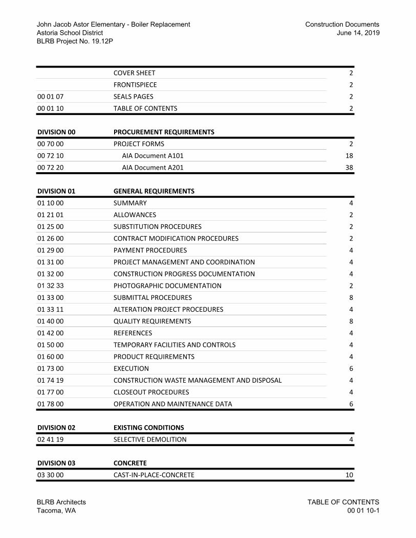
COVER SHEET 2
FRONTISPIECE 2
00 01 07 SEALS PAGES 2
00 01 10 TABLE OF CONTENTS 2
DIVISION 00 PROCUREMENT REQUIREMENTS
00 70 00 PROJECT FORMS 2
00 72 10 AIA Document A101 18
00 72 20 AIA Document A201 38
DIVISION 01 GENERAL REQUIREMENTS
01 10 00 SUMMARY 4
01 21 01 ALLOWANCES 2
01 25 00 SUBSTITUTION PROCEDURES 2
01 26 00 CONTRACT MODIFICATION PROCEDURES 2
01 29 00 PAYMENT PROCEDURES 4
01 31 00 PROJECT MANAGEMENT AND COORDINATION 4
01 32 00 CONSTRUCTION PROGRESS DOCUMENTATION 4
01 32 33 PHOTOGRAPHIC DOCUMENTATION 2
01 33 00 SUBMITTAL PROCEDURES 8
01 33 11 ALTERATION PROJECT PROCEDURES 4
01 40 00 QUALITY REQUIREMENTS 8
01 42 00 REFERENCES 4
01 50 00 TEMPORARY FACILITIES AND CONTROLS 4
01 60 00 PRODUCT REQUIREMENTS 4
01 73 00 EXECUTION 6
01 74 19 CONSTRUCTION WASTE MANAGEMENT AND DISPOSAL 4
01 77 00 CLOSEOUT PROCEDURES 4
01 78 00 OPERATION AND MAINTENANCE DATA 6
DIVISION 02 EXISTING CONDITIONS
02 41 19 SELECTIVE DEMOLITION 4
DIVISION 03 CONCRETE
03 30 00 CAST-IN-PLACE-CONCRETE 10
BLRB Architects
Tacoma, WA
TABLE OF CONTENTS
00 01 10-1

John Jacob Astor Elementary - Boiler Replacement
Astoria School District
BLRB Project No. 19.12P
Construction Documents
June 14, 2019
DIVISION 07 THERMAL AND MOISTURE PROTECTION
07 62 00 SHEET METAL FLASHING AND TRIM 8
DIVISION 23 HEATING, VENTILATING, AND AIR CONDITIONING (HVAC)
23 05 19 METERS AND GAUGES FOR HVAC PIPING 2
23 05 23 GENERAL-DUTY VALVES FOR HVAC PIPING 6
23 05 48 VIBRATION AND SEISMIC CONTROLS FOR HVAC 4
23 05 53 IDENTIFICATION FOR HVAC PIPING AND EQUIPMENT 2
23 07 19 HVAC PIPING INSULATION 2
23 11 23 FACILITY NATURAL-GAS PIPING 4
23 22 13 STEAM AND CONDENSATE HEATING PIPING 4
23 51 00 BREECHINGS, CHIMNEYS, AND STACKS 4
DIVISION 26 ELECTRICAL
26 05 05 SELECTIVE DEMOLITION FOR ELECTRICAL 2
26 05 19 LOW-VOLTAGE ELECTRICAL POWER CONDUCTORS AND CABLES 2
26 05 33.13 CONDUIT FOR ELECTRICAL SYSTEMS 2
26 28 16.16 ENCLOSED SWITCHES 2
END OF TABLE OF CONTENTS
BLRB Architects
Tacoma, WA
TABLE OF CONTENTS
00 01 10-2

John Jacob Astor Elementary - Boiler Replacement Construction Documents Astoria School District June 14, 2019 BLRB Project No. 19.12P
BLRB Architects PROJECT FORMS Tacoma, WA 00 70 00- 1
SECTION 00 70 00 - PROJECT FORMS
PART 1 - GENERAL
1.01 CONTRACT FORMS
A. Contract Agreement and Conditions: The following forms of Owner/Contractor Agreement and General Conditions shall be used for the Project as revised, modified and supplemented with other Contract Documents included with the Project Manual:
1. AIA Document A101-2017, "Standard Form of Agreement between Owner and Contractor, Stipulated Sum."
2. The General Conditions for Project are AIA Document A201-2017, "General Conditions of the Contract for Construction."
3. Refer to A101 and A201 documents bound herein after this Section.
B. Administrative Forms: Additional administrative forms are specified in Division 00 "Procurement and Contracting Requirements" and Division 01 "General Requirements."
1. Copies of AIA standard forms may be obtained from the American Institute of Architects; http://www.aia.org/contractdocs/purchase/index.htm; [email protected]; (800) 942-7732.
2. Information and Modification Forms:
a. Form for Requests for Information (RFIs): AIA Document G716, "Request for Information (RFI)."
b. Form of Request for Proposal: AIA Document G709, "Work Changes Proposal Request."
c. Change Order Form: AIA Document G701, "Change Order."
d. Form of Architect's Memorandum for Minor Changes in the Work: AIA Document G710, "Architect's Supplemental Instructions."
e. Form of Change Directive: AIA Document G714, "Construction Change Directive."
3. Payment Forms:
a. Schedule of Values Form: AIA Document G703, "Continuation Sheet."
b. Payment Application: AIA Document G702/703, "Application and Certificate for Payment and Continuation Sheet."
c. Form of Contractor's Affidavit: AIA Document G706, "Contractor's Affidavit of Payment of Debts and Claims."
d. Form of Affidavit of Release of Liens: AIA Document G706A, "Contractor's Affidavit of Payment of Release of Liens."
e. Form of Consent of Surety: AIA Document G707, "Consent of Surety to Final Payment."
PART 2 - PRODUCTS (NOT USED)
PART 3 - EXECUTION (NOT USED)
END OF SECTION

John Jacob Astor Elementary - Boiler Replacement Construction Documents Astoria School District June 14, 2019 BLRB Project No. 19.12P
BLRB Architects PROJECT FORMS Tacoma, WA 00 70 00- 2
This Page Intentionally Left Blank

John Jacob Astor Elementary - Boiler Replacement Construction Documents Astoria School District June 14, 2019 BLRB Project No. 19.12P
BLRB Architects SUMMARY Tacoma, WA 01 10 00- 1
SECTION 01 10 00 - SUMMARY
PART 1 - GENERAL
1.01 RELATED DOCUMENTS
A. Drawings and general provisions of the Contract, including General and Supplementary Conditions and Division 01 Specification Sections, apply to this Section.
1.02 SUMMARY
A. Section Includes:
1. Project information.
2. Work covered by Contract Documents.
3. Work under separate contracts.
4. Access to site.
5. Coordination with occupants.
6. Work restrictions.
7. Specification and Drawing conventions.
B. Related Requirements:
1. Division 01 Section "Temporary Facilities and Controls" for limitations and procedures governing temporary use of Owner's facilities.
1.03 PROJECT INFORMATION
A. Project Identification: Astor Primary School Boiler Replacement.
1. Project Location: 3500 Franklin Avenue, Astoria, OR 97103.
B. Owner: Astoria School District - 785 Alameda Avenue, Astoria, OR 97130.
1. Owner's Representative: Craig Hoppes, Superintendent.
C. Architect: BLRB Architects - 1250 Pacific Avenue, Suite 700, Tacoma, WA 98402.
1.04 WORK COVERED BY CONTRACT DOCUMENTS
A. The Work of Project is defined by the Contract Documents and consists of the following:
1. The Astoria Primary School Boiler replacement project includes demolition and removal of existing boiler, construction of new boiler pad(s), installation of new boilers, hook-up to existing piping, related mechanical and electrical systems, project related repairs and patching, and commissioning of new mechanical systems.
2. Base Bids: The Contract Documents indicate the scope of work for Base bid work.
B. Type of Contract.
1. Project will be constructed under a single prime contract with a fixed Contract Sum.

John Jacob Astor Elementary - Boiler Replacement Construction Documents Astoria School District June 14, 2019 BLRB Project No. 19.12P
BLRB Architects SUMMARY Tacoma, WA 01 10 00- 2
1.05 OWNER-FURNISHED PRODUCTS
A. Owner will furnish products indicated in individual specification section. The Work includes providing support systems to receive Owner's equipment and making plumbing, mechanical, and electrical connections.
B. Owner-Furnished Products:
1. Boilers (OFCI).
2. See individual Specification Sections for any other Owner Furnished Contractor Installed (OFCI) items.
1.06 ACCESS TO SITE
A. General: Contractor shall have limited use of Project site for construction operations as indicated on Drawings by the Contract limits and as indicated by requirements of this Section.
B. Use of Site: Limit use of Project site to areas within the Contract limits indicated. Do not disturb portions of Project site beyond areas in which the Work is indicated.
1. Limits: Confine construction operations to areas where work is permitted.
2. Driveways, Walkways and Entrances: Keep driveways, loading areas, and entrances serving premises clear and available to Owner, Owner's employees, and emergency vehicles at all times. Do not use these areas for parking or storage of materials.
a. Schedule deliveries to minimize use of driveways and entrances by construction operations.
b. Schedule deliveries to minimize space and time requirements for storage of materials and equipment on-site.
C. Condition of Existing Building: Maintain portions of existing building affected by construction operations in a weathertight condition throughout construction period. Repair damage caused by construction operations. Protect building and its occupants during construction period and all construction activities
1.07 COORDINATION WITH OCCUPANTS
A. Partial Owner Occupancy: Owner will occupy the premises during entire construction period, with the exception of areas under construction. Cooperate with Owner during construction operations to minimize conflicts and facilitate Owner usage. Perform the Work so as not to interfere with Owner's operations. Maintain existing exits unless otherwise indicated.
1. Maintain access to existing walkways, corridors, and other adjacent occupied or used facilities. Do not close or obstruct walkways, corridors, or other occupied or used facilities without written permission from Owner and authorities having jurisdiction.
2. Provide not less than 72 hours' notice to Owner of activities that will affect Owner's operations.
1.08 WORK RESTRICTIONS
A. Work Restrictions, General: Comply with restrictions on construction operations.
1. Comply with limitations on use of public streets and with other requirements of authorities having jurisdiction.
B. On-Site Work Hours: Work shall be generally performed inside the existing building to normal business working hours of 7:00 am to 5:00 pm, Monday through Friday, unless otherwise indicated.
John Jacob Astor Elementary - Boiler Replacement Construction Documents Astoria School District June 14, 2019 BLRB Project No. 19.12P
BLRB Architects SUMMARY Tacoma, WA 01 10 00- 3
1. Verify restrictions on times permitted for work and specific activities with School District and Building Official.
C. Existing Utility Interruptions: Do not interrupt utilities serving facilities occupied by Owner or others unless permitted under the following conditions and then only after providing temporary utility services according to requirements indicated:
1. Notify Owner not less than two days in advance of proposed utility interruptions.
2. Obtain Owner's written permission before proceeding with utility interruptions.
D. Parking Restrictions: Coordinate areas allowable for construction related parking with School District.
E. Noise, Vibration, and Odors: Coordinate operations that may result in high levels of noise and vibration, odors, or other disruption to Owner occupancy with Owner.
1. Notify Owner not less than two days in advance of proposed disruptive operations.
2. Obtain Owner's written permission before proceeding with disruptive operations.
F. Nonsmoking Building: Smoking is not permitted on district property.
G. Controlled Substances: Use of tobacco products and other controlled substances within the existing building and on Project site is not permitted.
1.09 SPECIFICATION AND DRAWING CONVENTIONS
A. Specification Format: The Specifications are organized into Divisions and Sections using the 50-division format and CSI/CSC's "MasterFormat" numbering system.
1. Section Identification: The Specifications use Section numbers and titles to help cross-referencing in the Contract Documents. Sections in the Project Manual are in numeric sequence; however, the sequence is incomplete because all available Section numbers are not used. Consult the table of contents at the beginning of the Project Manual to determine numbers and names of Sections in the Contract Documents.
2. Division 01: Sections in Division 01 govern the execution of Work of all Sections in the Specifications.
B. Specification Content: The Specifications use certain conventions for the style of language and the intended meaning of certain terms, words, and phrases when used in particular situations. These conventions are as follows:
1. Abbreviated Language: Language used in the Specifications and other Contract Documents is abbreviated. Words and meanings shall be interpreted as appropriate. Words implied, but not stated, shall be inferred as the sense requires. Singular words shall be interpreted as plural, and plural words shall be interpreted as singular where applicable as the context of the Contract Documents indicates.
2. Imperative mood and streamlined language are generally used in the Specifications. Requirements expressed in the imperative mood are to be performed by Contractor. Occasionally, the indicative or subjunctive mood may be used in the Section Text for clarity to describe responsibilities that must be fulfilled indirectly by Contractor or by others when so noted.
a. The words "shall," "shall be," or "shall comply with," depending on the context, are implied where a colon (:) is used within a sentence or phrase.
3. Specification requirements are to be performed by Contractor unless specifically stated otherwise.
C. Drawing Coordination: Requirements for materials and products identified on Drawings are described in detail in the Specifications. One or more of the following are used on Drawings to identify materials and products:
John Jacob Astor Elementary - Boiler Replacement Construction Documents Astoria School District June 14, 2019 BLRB Project No. 19.12P
BLRB Architects SUMMARY Tacoma, WA 01 10 00- 4
1. Terminology: Materials and products are identified by the typical generic terms used in the individual Specifications Sections.
2. Abbreviations: Materials and products are identified by abbreviations published as part of the U.S. National CAD Standard and scheduled on Drawings.
PART 2 - PRODUCTS (NOT USED)
PART 3 - EXECUTION
3.01 OWNER OCCUPANCY
A. The Owner will occupy existing facility at all times as indicated in the Contract Documents and in accordance with the School Calendar. Owner will perform routine maintenance and operations activities. Owner will perform or award contracts for miscellaneous small works projects during the Contract period of this Project.
B. Cooperate with Owner to minimize conflict, and to facilitate Owner’s operations.
C. Schedule the Work to accommodate Owner.
D. Owner reserves the right to occupy the Project prior to their acceptance of the Work.
E. Use and occupancy by Owner prior to Project acceptance does not relieve Contractor of their responsibility to maintain all insurance and bonds required of Contractor under the Contract until Project is completed and accepted by Owner.
3.02 WORK SEQUENCE - PHASING
A. Time is of the essence for commencement and completion of the Work.
B. Substantial Completion: By October 1, 2019, the system shall be sufficiently operational to provide heat to school classrooms within a normal temperature range.
3.03 CRITICAL OPERATIONAL SYSTEMS
A. Coordinate Work activities with utility providers if needed.
B. Coordinate work with Owner and maintenance personnel.
1. Set up and coordinate site meetings.
2. Existing utility shut-offs/decommissioning and removal.
3. Scheduling of installation and start up activities.
4. Troubleshooting “issues” as needed to provide complete and operational installation.
5. Providing timely notices for required responses and payments required of Owner.
6. Other activities and support necessary for the timely execution of the Work.
END OF SECTION

John Jacob Astor Elementary - Boiler Replacement Construction Documents Astoria School District June 14, 2019 BLRB Project No. 19.12P
BLRB Architects ALLOWANCES Tacoma, WA 01 21 00- 1
SECTION 01 21 00 - ALLOWANCES
PART 1 GENERAL
1.01 RELATED DOCUMENTS
A. Drawings and general provisions of the Contract, including General and Supplementary Conditions and Division 01 Specification Sections, apply to this Section.
1.02 SUMMARY
A. Section Includes: Allowances, included within Base Bid, covering costs of providing items not determined as to number or amount by Contract Documents.
B. Related Sections:
1. Division 01 Section - Submittal Procedures
2. Division 01 Section - Contract Modification Procedures
1.03 CASH ALLOWANCES
A. Costs Included in Allowance:
1. Actual material cost of Products, less sales taxes.
2. Delivery, unloading, uncrating, storage, handling, and coordination.
3. Complete installation costs including providing related work for complete and finished installation.
B. Architect Responsibilities:
1. Consult with Contractor. Determine specific requirements, including size, type, and quantity, conforming with provisions of Sections affected by Allowances.
2. Select Products in consultation with Owner and transmit decision to Contractor.
3. Prepare Change Order for cost difference above or below stipulated Allowance based on Unit Prices.
C. Contractor Responsibilities:
1. Include stipulated Allowances as part of Base Bid.
2. Assist in finalizing Product determination, such as size, type, and quantity, as necessary to conform to provisions Sections affected by Allowances.
3. Submit cost proposals in conformance to Contract Modification provisions of Division 01 and the Conditions of the Contract.
4. Submit Shop Drawings, Product Data, and Samples in accordance with Division 01 Section "Submittal Procedures."
5. Provide Products affected by allowances under Work of this Contract.
D. Cost Adjustments: Adjust cost above or below stipulated allowance by Change Order. Any remaining allowance to be credited to Owner.
John Jacob Astor Elementary - Boiler Replacement Construction Documents Astoria School District June 14, 2019 BLRB Project No. 19.12P
BLRB Architects ALLOWANCES Tacoma, WA 01 21 00- 2
PART 2 PRODUCTS (NOT USED)
PART 3 EXECUTION
3.01 EXAMINATION
A. Examine products covered by an allowance promptly on delivery for damage or defects. Return damaged or defective products to manufacturer for replacement.
3.02 PREPARATION
A. Coordinate materials and their installation for each allowance with related materials and installations to ensure that each allowance item is completely integrated and interfaced with related work.
END OF SECTION

John Jacob Astor Elementary - Boiler Replacement Construction Documents Astoria School District June 14, 2019 BLRB Project No. 19.12P
BLRB Architects SUBSTITUTION PROCEDURES Tacoma, WA 01 25 00- 1
SECTION 01 25 00 - SUBSTITUTION PROCEDURES
PART 1 - GENERAL
1.01 RELATED DOCUMENTS
A. Drawings and general provisions of the Contract, including General and Supplementary Conditions and Division 01 Specification Sections, apply to this Section.
1.02 SUMMARY
A. Section includes administrative and procedural requirements for substitutions.
B. Related Requirements:
1. Section 01 60 00 "Product Requirements" for requirements for submitting comparable product submittals for products by listed manufacturers.
1.03 DEFINITIONS
A. Substitutions: Changes in products, materials, equipment, and methods of construction from those required by the Contract Documents and proposed by Contractor.
1. Substitutions for Cause: Changes proposed by Contractor that are required due to changed Project conditions, such as unavailability of product, regulatory changes, or unavailability of required warranty terms.
2. Substitutions for Convenience: Changes proposed by Contractor or Owner that are not required in order to meet other Project requirements but may offer advantage to Contractor or Owner.
1.04 ACTION SUBMITTALS
A. Substitution Requests: Submit one electronic copy of each request for consideration. Identify product or fabrication or installation method to be replaced. Include Specification Section number and title and Drawing numbers and titles.
1. Substitution Request Form: Use CSI Form 13.1A
2. Documentation: Show compliance with requirements for substitutions and the following:
a. Statement indicating why specified product or fabrication or installation cannot be provided, if applicable.
b. Coordination information, including a list of changes or revisions needed to other parts of the Work and to construction performed by Owner and separate contractors, that will be necessary to accommodate proposed substitution.
c. Detailed comparison of significant qualities of proposed substitution with those of the Work specified. Include annotated copy of applicable Specification Section. Significant qualities may include attributes such as performance, weight, size, durability, visual effect, sustainable design characteristics, warranties, and specific features and requirements indicated. Indicate deviations, if any, from Work specified.
d. Product Data, including drawings and descriptions of products and fabrication and installation procedures.
e. Samples, where applicable or requested.

John Jacob Astor Elementary - Boiler Replacement Construction Documents Astoria School District June 14, 2019 BLRB Project No. 19.12P
BLRB Architects SUBSTITUTION PROCEDURES Tacoma, WA 01 25 00- 2
f. Certificates and qualification data, where applicable or requested.
g. Material test reports from a qualified testing agency indicating and interpreting test results for compliance with requirements indicated.
h. Cost information, including a proposal of change, if any, in the Contract Sum.
i. Contractor's certification that proposed substitution complies with requirements in the Contract Documents except as indicated in substitution request, is compatible with related materials, and is appropriate for applications indicated.
j. Contractor's waiver of rights to additional payment or time that may subsequently become necessary because of failure of proposed substitution to produce results.
3. Architect's Action: If necessary, Architect will request additional information or documentation for evaluation within seven days of receipt of a request for substitution.
1.05 PROCEDURES
A. Coordination: Revise or adjust affected work as necessary to integrate work of the approved substitutions.
PART 2 - PRODUCTS
2.01 SUBSTITUTIONS
A. Substitutions for Cause: Submit requests immediately on discovery of need for change, but not later than 15 days prior to time required for preparation and review of related submittals.
1. Conditions: Architect will consider Contractor's request for substitution when the following conditions are satisfied. If following are not satisfied, Architect will return requests without action, except to record noncompliance with these requirements:
a. Substitution is consistent with Contract Documents and produce indicated results.
b. Substitution request is fully documented and properly submitted.
c. Requested substitution will not adversely affect Contractor's construction schedule.
d. Requested substitution has received approvals of authorities having jurisdiction.
e. Requested substitution is compatible with other portions of the Work.
f. Requested substitution has been coordinated with other portions of the Work.
g. Requested substitution provides specified warranty.
h. If requested substitution involves more than one contractor, is compatible with other products, and is acceptable to all contractors involved.
PART 3 - EXECUTION (NOT USED)
END OF SECTION

John Jacob Astor Elementary - Boiler Replacement Construction Documents Astoria School District June 14, 2019 BLRB Project No. 19.12P
BLRB Architects CONTRACT MODIFICATION PROCEDURES Tacoma, WA 01 26 00- 1
SECTION 01 26 00 - CONTRACT MODIFICATION PROCEDURES
PART 1 - GENERAL
1.01 RELATED DOCUMENTS
A. Drawings and general provisions of the Contract, including General and Supplementary Conditions and Division 01 Specification Sections, apply to this Section.
1.02 SUMMARY
A. Administrative and procedural requirements for Contract modifications.
B. Related Requirements:
1. Division 01 Section "Substitution Procedures" for administrative procedures for handling requests for substitutions made after the Contract award.
1.03 MINOR CHANGES IN THE WORK
A. Architect will issue supplemental instructions authorizing minor changes in the Work, not involving adjustment to Contract Sum or Contract Time, on AIA Document G710, "Architect's Supplemental Instructions."
1.04 PROPOSAL REQUESTS
A. Owner-Initiated Proposal Requests: Architect will issue detailed description of proposed changes in the Work that may require adjustment to the Contract Sum or the Contract Time. If necessary, the description will include supplemental or revised Drawings and Specifications.
1. Work Change Proposal Requests issued by Architect are not instructions either to stop work in progress or to execute the proposed change.
2. Within time specified in Proposal Request or 20 days, when not otherwise specified, after receipt of Proposal Request, submit a quotation estimating cost adjustments to the Contract Sum and the Contract Time necessary to execute the change.
a. Include a list of quantities of products required or eliminated and unit costs. If requested, furnish survey data to substantiate quantities.
b. Indicate applicable taxes, delivery charges, equipment rental, and trade discounts.
c. Include costs of labor and supervision directly attributable to the change.
d. Include an updated Contractor's construction schedule that indicates effect of change, including, but not limited to, changes in activity duration, start and finish times, and activity relationship. Use available total float before requesting an extension of the Contract Time.
e. Quotation Form: Use CSI Form 13.6D, "Proposal Worksheet Summary," and Form 13.6C, "Proposal Worksheet Detail."
B. Contractor-Initiated Proposals: If latent or changed conditions require modifications to the Contract, Contractor may initiate a claim by submitting a request for a change to Architect.
1. Include a statement outlining reasons for the change and the effect of the change on the Work. Provide a complete description of the proposed change
2. Include a list of quantities of products required or eliminated and unit costs, with total amount of purchases and credits to be made.
John Jacob Astor Elementary - Boiler Replacement Construction Documents Astoria School District June 14, 2019 BLRB Project No. 19.12P
BLRB Architects CONTRACT MODIFICATION PROCEDURES Tacoma, WA 01 26 00- 2
3. Indicate applicable taxes, delivery charges, equipment rental, and trade discounts.
4. Include costs of labor and supervision directly attributable to the change.
5. Include updated Contractor's construction schedule that indicates effect of the change, including, but not limited to, duration, start and finish times, and activity relationship. Use available total float before requesting an extension of the Contract Time.
6. Comply with requirements in Division 01 Section "Substitution Procedures."
7. Proposal Request Form: Use CSI Form 13.6A, "Change Order Request (Proposal)," with attachments CSI Form 13.6D, "Proposal Worksheet Summary," and Form 13.6C, "Proposal Worksheet Detail."
1.05 ADMINISTRATIVE CHANGE ORDERS
A. Allowance Adjustment: See Division 01 Section "Allowances" for administrative procedures for preparation of Change Order Proposal for adjusting Contract Sum to reflect actual costs of allowances.
1.06 CHANGE ORDER PROCEDURES
A. On Owner's approval of a Work Changes Proposal Request, Architect will issue a Change Order for signatures of Owner and Contractor on AIA Document G701.
1.07 CONSTRUCTION CHANGE DIRECTIVE
A. Construction Work Change Directive: Architect may issue a Construction Work Change Directive on AIA Document G714. Change Directive instructs Contractor to proceed with a change in the Work, for subsequent inclusion in a Change Order.
1. Construction Work Change Directive contains a complete description of change in the Work. It also designates method to be followed to determine change in the Contract Sum or the Contract Time.
B. Documentation: Maintain detailed records on a time and material basis of work required by the Construction Work Change Directive.
1. After completion of change, submit an itemized account and supporting data necessary to substantiate cost and time adjustments to the Contract.
PART 2 - PRODUCTS (NOT USED)
PART 3 - EXECUTION (NOT USED)
END OF SECTION
John Jacob Astor Elementary - Boiler Replacement Construction Documents Astoria School District June 14, 2019 BLRB Project No. 19.12P
BLRB Architects PAYMENT PROCEDURES Tacoma, WA 01 29 00- 1
SECTION 01 29 00 - PAYMENT PROCEDURES
PART 1 - GENERAL
1.01 RELATED DOCUMENTS
A. Drawings and general provisions of the Contract, including General and Supplementary Conditions and Division 01 Specification Sections, apply to this Section.
1.02 SUMMARY
A. Section includes administrative and procedural requirements necessary to prepare and process Applications for Payment.
B. Related Requirements:
1. Division 01 Section "Contract Modification Procedures" for administrative procedures for handling changes to the Contract.
2. Division 01 Section "Construction Progress Documentation" for administrative requirements governing the preparation and submittal of the Contractor's construction schedule.
1.03 DEFINITIONS
A. Schedule of Values: A statement furnished by Contractor allocating portions of the Contract Sum to various portions of the Work and used as the basis for reviewing Contractor's Applications for Payment.
1.04 SCHEDULE OF VALUES
A. Coordination: Coordinate preparation of the schedule of values with preparation of Contractor's construction schedule.
1. Coordinate line items in the schedule of values with other required administrative forms and schedules, including the following:
a. Application for Payment forms with continuation sheets.
b. Submittal schedule.
c. Items required to be indicated as separate activities in Contractor's construction schedule.
2. Submit the schedule of values to Architect at earliest possible date, but no later than 7 days before the date scheduled for submittal of initial Applications for Payment.
3. Subschedules for Separate Elements of Work: Where the Contractor's construction schedule defines separate elements of the Work, provide subschedules showing values coordinated with each element.
B. Format and Content: Use Project Manual table of contents as a guide to establish line items for the schedule of values. Provide at least one line item for each Specification Section.
1. Identification: Include the following Project identification on the schedule of values:
a. Project name and location.
b. Name of Architect.
c. Architect's project number.

John Jacob Astor Elementary - Boiler Replacement Construction Documents Astoria School District June 14, 2019 BLRB Project No. 19.12P
BLRB Architects PAYMENT PROCEDURES Tacoma, WA 01 29 00- 2
d. Contractor's name and address.
e. Date of submittal.
2. Provide a breakdown of the Contract Sum in enough detail to facilitate continued evaluation of Applications for Payment and progress reports. Coordinate with Project Manual table of contents. Provide multiple line items for principal subcontract amounts in excess of five percent of the Contract Sum.
3. Round amounts to nearest whole dollar; total shall equal the Contract Sum.
4. Provide a separate line item in the schedule of values for each part of the Work where Applications for Payment may include materials or equipment purchased or fabricated and stored, but not yet installed.
5. Provide separate line items in the schedule of values for initial cost of materials, for each subsequent stage of completion, and for total installed value of that part of the Work.
6. Schedule Updating: Update and resubmit the schedule of values before the next Applications for Payment when Change Orders or Construction Change Directives result in a change in the Contract Sum.
1.05 APPLICATIONS FOR PAYMENT
A. Each Application for Payment following the initial Application for Payment shall be consistent with previous applications and payments as certified by Architect and paid for by Owner.
1. Initial Application for Payment, Application for Payment at time of Substantial Completion, and final Application for Payment involve additional requirements.
B. Payment Application Times: The date for each progress payment is indicated in the Agreement between Owner and Contractor. The period of construction work covered by each Application for Payment is the period indicated in the Agreement.
C. Application for Payment Forms: Use AIA Document G702 and AIA Document G703 as form for Applications for Payment.
D. Application Preparation: Complete every entry on form. Execute by a person authorized to sign legal documents on behalf of Contractor. Architect will return incomplete applications without action.
1. Entries shall match data on the schedule of values and Contractor's construction schedule. Use updated schedules if revisions were made.
2. Include amounts for work completed following previous Application for Payment, whether or not payment has been received. Include only amounts for work completed at time of Application for Payment.
3. Include amounts of Change Orders and Construction Change Directives issued before last day of construction period covered by application.
E. Stored Materials: Include in Application for Payment amounts applied for materials or equipment purchased or fabricated and stored, but not yet installed.
1. Provide supporting documentation that verifies amount requested, such as paid invoices. Match amount requested with amounts indicated on documentation; do not include overhead and profit on stored materials.
2. No payments shall be made for materials or equipment stored off-site.
3. Provide summary documentation for stored materials indicating the following:
a. Value of materials previously stored and remaining stored as of date of previous Applications for Payment.
b. Value of previously stored materials put in place after date of previous Application for Payment and on or before date of current Application for Payment.
c. Value of materials stored since date of previous Application for Payment and remaining stored as of date of current Application for Payment.

John Jacob Astor Elementary - Boiler Replacement Construction Documents Astoria School District June 14, 2019 BLRB Project No. 19.12P
BLRB Architects PAYMENT PROCEDURES Tacoma, WA 01 29 00- 3
F. Transmittal: Application for Payment may be submitted electronically to Architect or by a method ensuring receipt within 24 hours. One copy shall include waivers of lien and similar attachments if required.
G. Waivers of Mechanic's Lien: With each Application for Payment, submit waivers of mechanic's liens from subcontractors, sub-subcontractors, and suppliers for construction period covered by the previous application.
1. Submit partial waivers on each item for amount requested in previous application, after deduction for retainage, on each item.
2. When an application shows completion of an item, submit conditional final or full waivers.
3. Owner reserves the right to designate which entities involved in the Work must submit waivers.
4. Submit final Application for Payment with or preceded by conditional final waivers from every entity involved with performance of the Work covered by the application who is lawfully entitled to a lien.
5. Waiver Forms: Submit executed waivers of lien on forms, acceptable to Owner.
H. Initial Application for Payment: Administrative actions and submittals that must precede or coincide with submittal of first Application for Payment include the following:
1. List of subcontractors.
2. Schedule of values.
3. Contractor's construction schedule (preliminary if not final).
4. Products list (preliminary if not final).
5. Submittal schedule (preliminary if not final).
6. Copies of building permits.
7. Copies of authorizations and licenses from authorities having jurisdiction for performance of the Work.
8. Initial progress report.
9. Report of preconstruction conference.
10. Certificates of insurance and insurance policies.
11. Performance and payment bonds.
12. Data needed to acquire Owner's insurance.
I. Application for Payment at Substantial Completion: After Architect issues the Certificate of Substantial Completion, submit an Application for Payment showing 100 percent completion, less appropriate amounts for completion of incomplete work and project closeout, for portion of the Work claimed as substantially complete.
1. This application shall reflect Certificate(s) of Substantial Completion issued previously for Owner occupancy of designated portions of the Work.
J. Final Payment Application: After completing Project closeout requirements, submit final Application for Payment with releases and supporting documentation not previously submitted and accepted, including, but not limited, to the following:
1. Evidence of completion of Project closeout requirements.
2. Insurance certificates for products and completed operations where required and proof that taxes, fees, and similar obligations were paid.
3. Updated final statement, accounting for final changes to the Contract Sum.
4. AIA Document G706, "Contractor's Affidavit of Payment of Debts and Claims."
5. AIA Document G706A, "Contractor's Affidavit of Release of Liens."
6. AIA Document G707, "Consent of Surety to Final Payment."
7. Evidence that claims have been settled.
8. Final liquidated damages settlement statement.

John Jacob Astor Elementary - Boiler Replacement Construction Documents Astoria School District June 14, 2019 BLRB Project No. 19.12P
BLRB Architects PAYMENT PROCEDURES Tacoma, WA 01 29 00- 4
PART 2 - PRODUCTS (NOT USED)
PART 3 - EXECUTION (NOT USED)
END OF SECTION

John Jacob Astor Elementary - Boiler Replacement Construction Documents Astoria School District June 14, 2019 BLRB Project No. 19.12P
BLRB Architects PROJECT MANAGEMENT AND COORDINATION Tacoma, WA 01 31 00- 1
SECTION 01 31 00 - PROJECT MANAGEMENT AND COORDINATION
PART 1 - GENERAL
1.01 RELATED DOCUMENTS
A. Drawings and general provisions of the Contract, including General and Supplementary Conditions and Division 01 Specification Sections, apply to this Section.
1.02 SUMMARY
A. Section includes administrative provisions for coordinating construction operations on Project including, but not limited to, the following:
1. General coordination procedures.
2. RFIs.
3. Digital project management procedures.
4. Project meetings.
B. Related Requirements:
1. Division 01 Section "Summary".
2. Division 01 Section "Submittal Procedures".
3. Division 01 Section "Quality Requirements".
1.03 DEFINITIONS
A. RFI: Request for Information. Request from Owner, Architect, or Contractor seeking information required by or clarifications of the Contract Documents.
1.04 INFORMATIONAL SUBMITTALS
A. Subcontract List: Prepare a written summary identifying individuals or firms proposed for each portion of the Work, including those who are to furnish products or equipment fabricated to a special design. Include the following information in tabular form:
1. Name, address, telephone number, and email address of entity performing subcontract or supplying products.
2. Number and title of related Specification Section(s) covered by subcontract.
3. Drawing number and detail references, as appropriate, covered by subcontract.
B. Key Personnel Names: Within 15 days of starting construction operations, submit a list of key personnel assignments, including superintendent and other personnel in attendance at Project site. Identify individuals and their duties and responsibilities; list addresses and cellular telephone numbers and e-mail addresses. Provide names, addresses, and telephone numbers of individuals assigned as alternates in the absence of individuals assigned to Project.
1. Post copies of list in project meeting room, in temporary field office, and in prominent location in the built facility. Keep list current at all times.

John Jacob Astor Elementary - Boiler Replacement Construction Documents Astoria School District June 14, 2019 BLRB Project No. 19.12P
BLRB Architects PROJECT MANAGEMENT AND COORDINATION Tacoma, WA 01 31 00- 2
1.05 GENERAL COORDINATION PROCEDURES
A. Coordination: Coordinate construction operations included in different Sections of the Specifications to ensure efficient and orderly installation of each part of the Work. Coordinate construction operations included in different Sections that depend on each other for proper installation, connection, and operation.
1. Schedule construction operations in sequence required to obtain the best results where installation of one part of the Work depends on installation of other components, before or after its own installation.
2. Coordinate installation of different components to ensure maximum performance and accessibility for required maintenance, service, and repair.
3. Make adequate provisions to accommodate items scheduled for later installation.
B. Administrative Procedures: Coordinate scheduling and timing of required administrative procedures with other construction activities and scheduled activities of other contractors to avoid conflicts and to ensure orderly progress of the Work. Such administrative activities include, but are not limited to, the following:
1. Preparation of Contractor's construction schedule.
2. Preparation of the schedule of values.
3. Installation and removal of temporary facilities and controls.
4. Delivery and processing of submittals.
5. Progress and coordination meetings.
6. Preinstallation conferences.
7. Project closeout activities.
8. Startup and adjustment of systems.
1.06 REQUEST FOR INFORMATION (RFI)
A. General: Immediately on discovery of the need for additional information, clarification, or interpretation of the Contract Documents, Contractor shall prepare and submit an RFI in the form specified.
1. Architect will return without response those RFIs submitted to Architect by other entities controlled by Contractor.
2. Coordinate and submit RFIs in a prompt manner so as to avoid delays in Contractor's work or work of subcontractors.
B. Content of the RFI: Include a detailed, legible description of item needing information or interpretation and the following:
1. Project name.
2. Project number.
3. Date.
4. Name of Contractor.
5. Name of Architect.
6. RFI number, numbered sequentially.
7. RFI subject.
8. Specification Section number and title and related paragraphs, as appropriate.
9. Drawing number and detail references, as appropriate.
10. Field dimensions and conditions, as appropriate.
11. Contractor's suggested resolution. If Contractor's suggested resolution impacts the Contract Time or the Contract Sum, Contractor shall state impact in the RFI.
12. Contractor's signature.
C. RFI Forms:

John Jacob Astor Elementary - Boiler Replacement Construction Documents Astoria School District June 14, 2019 BLRB Project No. 19.12P
BLRB Architects PROJECT MANAGEMENT AND COORDINATION Tacoma, WA 01 31 00- 3
1. Attachments shall be electronic files in PDF format.
D. RFI Log: Prepare, maintain, and submit a tabular log of RFIs organized by the RFI number. Submit log weekly.
1. Project name.
2. Name and address of Contractor.
3. Name and address of Architect.
4. RFI number including RFIs that were returned without action or withdrawn.
5. RFI description.
6. Date the RFI was submitted.
7. Date Architect's response was received.
8. Identification of related Minor Change in the Work, Construction Change Directive, and Proposal Request, as appropriate.
E. On receipt of Architect's action, update the RFI log and immediately distribute the RFI response to affected parties. Review response and notify Architect within seven days if Contractor disagrees with response.
1.07 PROJECT MEETINGS
A. General: Contractor will schedule and conduct meetings at Project site unless otherwise indicated.
1. Attendees: Inform participants and others involved, and individuals whose presence is required, of date and time of each meeting. Notify Owner and Architect of scheduled meeting dates and times a minimum of 10 working days prior to meeting.
2. Agenda: Prepare the meeting agenda. Distribute the agenda to all invited attendees.
3. Minutes: Entity responsible for conducting meeting will record significant discussions and agreements achieved. Distribute the meeting minutes to everyone concerned, including Owner, and Architect, within three days of the meeting.
B. Preconstruction Conference: Contractor will schedule and conduct a preconstruction conference before starting construction, at a time convenient to Owner and Architect, but no later than 15 days after execution of the Agreement.
1. Attendees: Authorized representatives of Owner, Owner's Commissioning Authority, Architect, and their consultants; Contractor and its superintendent; major subcontractors; suppliers; and other concerned parties shall attend the conference. Participants at the conference shall be familiar with Project and authorized to conclude matters relating to the Work.
2. Agenda: Discuss items of significance that could affect progress, including the following:
a. Responsibilities and personnel assignments.
b. Tentative construction schedule.
c. Critical work sequencing and long lead items.
d. Designation of key personnel and their duties.
e. Lines of communications.
f. Procedures for processing field decisions and Change Orders.
g. Procedures for RFIs.
h. Procedures for testing and inspecting.
i. Procedures for processing Applications for Payment.
j. Submittal procedures.
k. Use of the premises.
l. Working hours.
m. Responsibility for temporary facilities and controls.
n. Procedures for disruptions and shutdowns.

John Jacob Astor Elementary - Boiler Replacement Construction Documents Astoria School District June 14, 2019 BLRB Project No. 19.12P
BLRB Architects PROJECT MANAGEMENT AND COORDINATION Tacoma, WA 01 31 00- 4
o. Construction waste management and recycling.
p. Parking availability.
q. Office, work, and storage areas.
r. Equipment deliveries and priorities.
s. First aid.
t. Security.
u. Progress cleaning.
3. Minutes: Architect will record and distribute Pre-Construction Meeting minutes electronically.
C. Project Closeout Conference: Contractor will schedule and conduct a project closeout conference, at a time convenient to Owner and Architect, but no later than 14 days prior to the scheduled date of Substantial Completion.
1. Conduct the conference to review requirements and responsibilities related to Project closeout.
2. Attendees: Authorized representatives of Owner, Owner's Commissioning Authority, Architect, and their consultants; Contractor and its superintendent; major subcontractors; suppliers; and other concerned parties shall attend the meeting. Participants at the meeting shall be familiar with Project and authorized to conclude matters relating to the Work.
3. Agenda: Discuss items of significance that could affect or delay Project closeout, including the following:
a. Procedures required prior to inspection for Substantial Completion and for final inspection for acceptance.
b. Procedures for completing and archiving web-based Project software site data files.
c. Submittal of written warranties.
d. Requirements for preparing operations and maintenance data.
e. Requirements for demonstration and training.
f. Preparation of Contractor's punch list.
g. Procedures for processing Applications for Payment at Substantial Completion and for final payment.
h. Submittal procedures.
i. Coordination of separate contracts.
j. Responsibility for removing temporary facilities and controls.
4. Minutes: Entity conducting meeting will record and distribute meeting minutes.
D. Reporting: Record meeting results and distribute copies to everyone in attendance and to others affected by decisions or actions resulting from each meeting.
PART 2 - PRODUCTS (NOT USED)
PART 3 - EXECUTION (NOT USED)
END OF SECTION

John Jacob Astor Elementary - Boiler Replacement Construction Documents Astoria School District June 14, 2019 BLRB Project No. 19.12P
BLRB Architects CONSTRUCTION PROGRESS DOCUMENTATION Tacoma, WA 01 32 00- 1
SECTION 01 32 00 - CONSTRUCTION PROGRESS DOCUMENTATION
PART 1 - GENERAL
1.01 RELATED DOCUMENTS
A. Drawings and general provisions of the Contract, including General and Supplementary Conditions and Division 01 Specification Sections, apply to this Section.
1.02 SUMMARY
A. Section includes administrative and procedural requirements for documenting the progress of construction during performance of the Work, including the following:
1. Contractor's construction schedule.
B. Related Requirements:
1. Division 01 Section "Submittal Procedures" for submitting schedules and reports.
2. Division 01 Section "Quality Requirements" for submitting a schedule of tests and inspections.
1.03 DEFINITIONS
A. Activity: A discrete part of a project that can be identified for planning, scheduling, monitoring, and controlling the construction project. Activities included in a construction schedule consume time and resources.
1. Critical Activity: An activity on the critical path that must start and finish on the planned early start and finish times.
2. Predecessor Activity: An activity that precedes another activity in the network.
3. Successor Activity: An activity that follows another activity in the network.
B. Float: The measure of leeway in starting and completing an activity.
1. Float time belongs to Owner.
2. Free float is the amount of time an activity can be delayed without adversely affecting the early start of the successor activity.
3. Total float is the measure of leeway in starting or completing an activity without adversely affecting the planned Project completion date.
C. Resource Loading: The allocation of manpower and equipment necessary for the completion of an activity as scheduled.
1.04 INFORMATIONAL SUBMITTALS
A. Format for Submittals: Submit required submittals in the following format:
1. Working electronic copy of schedule file, where indicated.
2. PDF electronic file.
B. Contractor's Construction Schedule: Initial schedule, of size required to display entire schedule for entire construction period.
C. Construction Schedule Updating Reports: Submit with Applications for Payment.

John Jacob Astor Elementary - Boiler Replacement Construction Documents Astoria School District June 14, 2019 BLRB Project No. 19.12P
BLRB Architects CONSTRUCTION PROGRESS DOCUMENTATION Tacoma, WA 01 32 00- 2
1.05 QUALITY ASSURANCE
1.06 COORDINATION
A. Coordinate Contractor's construction schedule with the schedule of values, list of subcontracts, submittal schedule, progress reports, payment requests, and other required schedules and reports.
1. Secure time commitments for performing critical elements of the Work from entities involved.
2. Coordinate each construction activity in the network with other activities and schedule them in proper sequence.
PART 2 - PRODUCTS
2.01 CONTRACTOR'S CONSTRUCTION SCHEDULE, GENERAL
A. Time Frame: Extend schedule for each Project Site from date established for commencement of the Work to date of final completion.
B. Activities; Comply with the following:
1. Activity Duration: Define activities so no activity is longer than 20 days, unless specifically allowed by Architect.
2. Procurement Activities: Include procurement process activities for the following long lead items and major items, requiring a cycle of more than 60 days, as separate activities in schedule. Procurement cycle activities include, but are not limited to, submittals, approvals, purchasing, fabrication, and delivery.
3. Submittal Review Time: Include review and resubmittal times indicated in Section 013300 "Submittal Procedures" in schedule. Coordinate submittal review times in Contractor's construction schedule with submittal schedule.
4. Substantial Completion: Indicate completion in advance of date established for Substantial Completion, and allow time for Architect's administrative procedures necessary for certification of Substantial Completion.
5. Punch List and Final Completion: Include not more than 30 days for completion of punch list items and final completion.
C. Constraints: Include constraints and work restrictions indicated in the Contract Documents and as follows in schedule, and show how the sequence of the Work is affected.
D. Milestones: Include milestones indicated in Contract Documents in schedule, including, but not limited to, Notice to Proceed, Substantial Completion, and final completion of each Project Site Location
E. Upcoming Work Summary: Prepare summary report indicating activities scheduled to occur or commence prior to submittal of next schedule update. Summarize the following issues:
1. Unresolved issues.
2. Unanswered Requests for Information.
3. Rejected or unreturned submittals.
4. Notations on returned submittals.
5. Pending modifications affecting the Work and Contract Time.
F. Computer Scheduling Software: Prepare schedules using current version of a program that has been developed specifically to manage construction schedules.

John Jacob Astor Elementary - Boiler Replacement Construction Documents Astoria School District June 14, 2019 BLRB Project No. 19.12P
BLRB Architects CONSTRUCTION PROGRESS DOCUMENTATION Tacoma, WA 01 32 00- 3
PART 3 - EXECUTION
3.01 CONTRACTOR'S CONSTRUCTION SCHEDULE
A. Contractor's Construction Schedule Updating: At monthly intervals, update schedule to reflect actual construction progress and activities. Issue schedule one week before each regularly scheduled progress meeting.
1. Revise schedule immediately after each meeting or other activity where revisions have been recognized or made. Issue updated schedule concurrently with the report of each such meeting.
2. Include a report with updated schedule that indicates every change, including, but not limited to, changes in logic, durations, actual starts and finishes, and activity durations.
3. As the Work progresses, indicate final completion percentage for each activity.
B. Distribution: Distribute copies of approved schedule to Architect, Owner, separate contractors, testing and inspecting agencies, and other parties identified by Contractor with a need-to-know schedule responsibility.
1. Post copies in Project meeting rooms and temporary field offices.
2. When revisions are made, distribute updated schedules to the same parties and post in the same locations. Delete parties from distribution when they have completed their assigned portion of the Work and are no longer involved in performance of construction activities.
END OF SECTION

John Jacob Astor Elementary - Boiler Replacement Construction Documents Astoria School District June 14, 2019 BLRB Project No. 19.12P
BLRB Architects CONSTRUCTION PROGRESS DOCUMENTATION Tacoma, WA 01 32 00- 4
This Page Intentionally Left Blank

John Jacob Astor Elementary - Boiler Replacement Construction Documents Astoria School District June 14, 2019 BLRB Project No. 19.12P
BLRB Architects PHOTOGRAPHIC DOCUMENTATION Tacoma, WA 01 32 33- 1
SECTION 01 32 33 - PHOTOGRAPHIC DOCUMENTATION
PART 1 - GENERAL
1.01 RELATED DOCUMENTS
A. Drawings and general provisions of the Contract, including General and Supplementary Conditions and Division 01 Specification Sections, apply to this Section.
1.02 SUMMARY
A. Section Includes: Administrative and procedural requirements for photographic documentation of the Work.
1. Preconstruction photography.
2. Construction photography of work-in-progress.
1.03 SUBMITTAL REQUIREMENTS
A. Make Submittals with each monthly Application for Payment.
B. Submit colored photos in JPG or PDF file format.
C. Identify each photograph file with location, compass direction, and date of each photo using month/day/year format.
1.04 PRECONSTRUCTION PHOTOGRAPHS
A. Take photographs prior to beginning Work of this Contract.
1.05 CONSTRUCTION PHOTOGRAPHS
A. Locate photographs as necessary to document phases of construction, milestones, and general progress of the Work.
PART 2 - PRODUCTS (NOT USED)
PART 3 - EXECUTION (NOT USED)
END OF SECTION

John Jacob Astor Elementary - Boiler Replacement Construction Documents Astoria School District June 14, 2019 BLRB Project No. 19.12P
BLRB Architects PHOTOGRAPHIC DOCUMENTATION Tacoma, WA 01 32 33- 2
This Page Intentionally Left Blank

John Jacob Astor Elementary - Boiler Replacement Construction Documents Astoria School District June 14, 2019 BLRB Project No. 19.12P
BLRB Architects SUBMITTAL PROCEDURES Tacoma, WA 01 33 00- 1
SECTION 01 33 00 - SUBMITTAL PROCEDURES
PART 1 - GENERAL
1.01 RELATED DOCUMENTS
A. Drawings and general provisions of the Contract, including General and Supplementary Conditions and Division 01 Specification Sections, apply to this Section.
1.02 SUMMARY
A. This Section includes administrative and procedural requirements for submitting Shop Drawings, Product Data, Samples, and other miscellaneous submittals.
B. Related Sections include the following:
1. Division 01 Section "Payment Procedures" for submitting Applications for payment.
2. Division 01 Section "Project Management Coordination" for submitting Coordination Drawings.
3. Division 01 Section "Construction Progress Documentation" for submitting schedules and reports, including Contractor's Construction Schedule and the Submittals Schedule and construction photographs.
4. Division 01 Section "Quality Requirements" for submitting test and inspection reports and Delegated-Design Submittals and for erecting mockups.
5. Division 01 Section “Product Requirements” for submitting Product List and substitutions requests.
6. Division 01 Section “Execution and Closeout Requirements" for submitting warranties, project record documents and Operation and Maintenance Manuals.
7. Divisions 01 Section “Operation and Maintenance Data” (need to add) for submitting operation and maintenance manuals.
8. Divisions 02 through 26 Sections for specific requirements for submittals.
1.03 DEFINITIONS
A. Action Submittals: Written and graphic information that requires Architect's responsive action.
B. Informational Submittals: Written information that does not require Architect's approval. Submittals will be rejected for not complying with requirements.
1.04 SUBMITTAL PROCEDURES
A. Document Exchange: Utilize Astoria School District’s website for operating Microsoft Window Sharepoint Program. Contractor has the option of proposing an alternate electronic site.
B. Coordination: Coordinate preparation and processing of submittals with performance of construction activities.
1. Coordinate each submittal with fabrication, purchasing, testing, delivery, other submittals, and related activities that require sequential activity.
2. Coordinate transmittal of different types of submittals for related parts of the Work so processing will not be delayed because of need to review submittals concurrently for coordination.

John Jacob Astor Elementary - Boiler Replacement Construction Documents Astoria School District June 14, 2019 BLRB Project No. 19.12P
BLRB Architects SUBMITTAL PROCEDURES Tacoma, WA 01 33 00- 2
a. Architect reserves the right to withhold action on a submittal requiring coordination with other submittals until related submittals are received.
3. Number each submittal sequentially. Number resubmittals with a version number (ie, ’24.1’, ‘24r1’), not a new submittal number. If submittals are numbered in the submittal schedule, reflect that numbering in the individual submittal identification.
C. Submittals Schedule and Log: Comply with requirements in Division 01 Section "Construction Progress Documentation" for list of submittals and time requirements for scheduled performance of related construction activities. The Submittal Schedule and Log shall be in digital tabular form (Microsoft Excel).
D. Processing Time: Allow enough time for submittal review, including time for re-submittals, as follows. Time for review shall commence on Architect's receipt of submittal.
1. Submittal received after 1:00 PM will be considered received the following day.
2. Initial Review: Allow seven (7) working days for initial review of each submittal. Allow additional time if processing must be delayed to permit coordination with subsequent submittals. Architect will advise Contractor when a submittal being processed must be delayed for coordination.
3. Sequential Review: Where sequential review of submittals by Architect's consultants, Owner, or other parties is required, allow fourteen (14) days for initial review of each submittal.
4. Concurrent Review: Where the Contract Documents indicate that submittals may be transmitted simultaneously to Architect and to Architect’s consultants, allow ten (10) days for review of each submittal. Submittal will be returned to Architect before being returned to Contractor.
5. If intermediate submittal is necessary, process it in same manner as initial submittal.
6. Allow ten (10) days for processing each resubmittal.
7. No extension of the Contract Time will be authorized because of failure to transmit submittals with enough time in advance of the Work to permit processing.
E. Identification: Place a permanent label or title block on each submittal for identification.
1. Indicate name of firm or entity that prepared each submittal on label or title block.
2. Provide a space approximately 4 by 5 inches on label or beside title block to record Contractor's review and approval markings and action taken by Architect.
3. Include the following information on label for processing and recording action taken:
a. Project name.
b. Date.
c. Name and address of Architect.
d. Name and address of Contractor.
e. Name and address of subcontractor.
f. Name and address of supplier.
g. Name of manufacturer.
h. Submittal numbering:
i. Referencing CSI Number.
j. Use Specification Section number followed by a decimal point and then a sequential number (e.g., 03 30 00.01). Resumittals shall include an alphabetic suffix after another decimal point (e.g., 03 30 00.01.A).
k. Number and title of appropriate Specification Section.
l. Drawing number and detail references, as appropriate.
m. Other necessary identification.
F. Deviations: Highlight, encircle, or otherwise identify deviations from the Contract Documents on submittals.

John Jacob Astor Elementary - Boiler Replacement Construction Documents Astoria School District June 14, 2019 BLRB Project No. 19.12P
BLRB Architects SUBMITTAL PROCEDURES Tacoma, WA 01 33 00- 3
G. Transmittal: Package each submittal individually and appropriately for transmittal and handling. Transmit each submittal using a transmittal form. Architect will return submittals, without review received from sources other than Contractor.
1. Transmittal Form: Provide locations on form for the following information:
a. Project name.
b. Date.
c. Destination (To:).
d. Source (From:).
e. Transmittal number, numbered consecutively.
f. Names of subcontractor, manufacturer, and supplier.
g. Category and type of submittal.
h. Submittal purpose and description.
i. Submittal and transmittal distribution record.
j. Remarks.
k. Signature of transmitter.
H. Distribution: Furnish copies of final submittals to manufacturers, subcontractors, suppliers, fabricators, and installers, authorities having jurisdiction, and others as necessary for performance of construction activities. Show distribution on transmittal forms.
I. Use for Construction: Use only final submittals with mark indicating action taken by Architect in connection with construction.
J. The Architect's review shall not relieve the Contractor from completing the work in accordance with the Contract Documents. The Architect is not responsible for the completeness or accuracy of these submittals.
K. The Contractor shall direct specific attention, in writing or on resubmitted Shop Drawings, Product Data, Samples or similar submittals, to revisions other than those requested by the Architect on previous submittals.
L. Begin no fabrication or work which requires submittals until return of submittals with Architect’s approval.
M. Submit work of interdependent Sections as one submittal package where possible, including:
1. Divisions 21, 22, 23.
2. Division 26.
1.05 CONTRACTOR’S USE OF ARCHITECT’S ELECTRONIC FILES
A. General: At Contractor’s written request, copies of Architect’s consultant's CAD and/or REVIT files will be provided to Contractor for Contractor’s use in connection with Project, subject to the following conditions:
1. Architect can only release CAD and REVIT information for use of Shop Drawing submittal, with signed media release available through the Architect’s office. Media release shall be signed by Contractor and subcontractor requesting electronic media.
a. Execution of Agreement: After agreement is signed the Architect/Engineer will transmit drawings requested via e-mail or through a secured FTP site.
b. General Contractor will be responsible for the transfer, accuracy, completeness, suitability and management of electronic media for submittal procedures as outlined by this specification.

John Jacob Astor Elementary - Boiler Replacement Construction Documents Astoria School District June 14, 2019 BLRB Project No. 19.12P
BLRB Architects SUBMITTAL PROCEDURES Tacoma, WA 01 33 00- 4
1.06 ACTION SUBMITTALS
A. General: Prepare and submit Action Submittals required by individual Specification Sections.
B. Product Data: Collect information into a single submittal for each element of construction and type of product or equipment.
1. If information must be specially prepared for submittal because standard printed data are not suitable for use, submit as Shop Drawings, not as Product Data.
2. Mark submittals to show which products and options are applicable.
3. Include the following information, as applicable:
a. Manufacturer's written recommendations.
b. Manufacturer's product specifications.
c. Manufacturer's installation instructions.
d. Manufacturer's catalog cuts.
e. Wiring diagrams showing factory-installed wiring.
f. Printed performance curves.
g. Operational range diagrams.
h. Mill reports.
i. Standard product operating and maintenance manuals.
j. Compliance with recognized trade association standards.
k. Compliance with recognized testing agency standards.
l. Application of testing agency labels and seals.
m. Notation of coordination requirements.
4. Submit product data concurrent with or before samples.
5. Format of Submittals: Submit electronic PDF versions for Project Data, unless otherwise indicated. Architect will return electronic submittals marked with Architect's and, where applicable, consultant's action. The General Contractor shall mark up and retain returned submittal as a Project Record Document, specified elsewhere.
a. Submit information in PDF format, using Adobe Acrobat Pro-Version 9.0 minimum.
b. To the greatest extent possible, provide “PDF” files.
C. Shop Drawings: Prepare Project-specific information, drawn accurately to scale. Do not base Shop Drawings on reproductions of the Contract Documents or standard printed data, unless utilizing provided Architect’s consultant's CAD Drawings.
1. Preparation: Include the following information, as applicable:
a. Dimensions.
b. Identification of products.
c. Fabrication and installation drawings.
d. Roughing-in and setting diagrams.
e. Wiring diagrams showing field-installed wiring, including power, signal, and control wiring.
f. Shop work manufacturing instructions.
g. Templates and patterns.
h. Schedules.
i. Design calculations.
j. Compliance with specified standards.
k. Notation of coordination requirements.
l. Notation of dimensions established by field measurement.
m. Highlight, encircle, or otherwise indicate deviations from the Contract Documents on the Shop Drawings.
2. Wiring Diagrams: Differentiate between manufacturer-installed and field-installed wiring.

John Jacob Astor Elementary - Boiler Replacement Construction Documents Astoria School District June 14, 2019 BLRB Project No. 19.12P
BLRB Architects SUBMITTAL PROCEDURES Tacoma, WA 01 33 00- 5
3. Sheet Size: Except for templates, patterns, and similar full-size drawings, submit Shop Drawings on sheets at least 8-1/2 by 11 inches but no larger than 30 by 40 inches.
4. Number of Copies: Submit as follows:
a. No hardcopies are required.
b. Markups will be done electronically and returned electronically.
c. Distribute marked-up/reviewed submittals as needed for the work.
d. If submittals are provided and approved electronically, the Contractor will be responsible for providing a full-size print copy for a Project Record Document.
5. Resubmittal: Same requirements as Initial Submittal.
a. The Contractor shall print the final approved color “pdf” with comments from all parties duly noted. Stamp or otherwise permanently mark and retain one set of prints as a “Record Document” and keep in a safe and protected location.
b. Contractor and/or subcontractor shall distribute as many copies of the returned submittal as required to inform all concerned parties.
D. Coordination Drawings: Comply with requirements in Division 01 Section "Project Management and Coordination."
E. Contractor's Construction Schedule: Comply with requirements in Division 01 Section "Construction Progress Documentation" for Architect's action.
F. Submittals Schedule: Comply with requirements in Division 01 Section "Construction Progress Documentation."
G. Application for Payment: Comply with requirements in Division 01 Section “Payment Procedures."
H. Schedule of Values: Comply with requirements in Division 01 Section "Payment Procedures."
I. Subcontract List: Prepare a written summary identifying individuals or firms proposed for each portion of the Work, including those who are to furnish products or equipment fabricated to a special design. Include the following information in tabular form:
1. Name, address, and telephone number of entity performing subcontract or supplying products.
2. Number and title of related Specification Section(s) covered by subcontract.
3. Drawing number and detail references, as appropriate, covered by subcontract.
1.07 INFORMATIONAL SUBMITTALS
A. General: Prepare and submit Informational Submittals required by other Specification Sections.
1. No Action: Informational Submittals will be filed for record; Architect will not return informational submittals marked with action.
2. Certificates and Certifications: Provide a notarized statement that includes signature of Contractor, testing agency, or design professional responsible for preparing certification. Certificates and certifications shall be signed by an officer or other individual authorized to sign documents on behalf of the company.
3. Test and Inspection Reports: Comply with requirements in Division 01 Section "Quality Requirements."
B. Contractor's Construction Schedule: Comply with requirements in Division 01 Section "Construction Progress Documentation."
C. Qualification Data: Prepare written information that demonstrates capabilities and experience of firm or person. Include lists of completed projects with project names and addresses, names and addresses of architects and owners, and other information specified.

John Jacob Astor Elementary - Boiler Replacement Construction Documents Astoria School District June 14, 2019 BLRB Project No. 19.12P
BLRB Architects SUBMITTAL PROCEDURES Tacoma, WA 01 33 00- 6
D. Product Certificates: Prepare written statements on manufacturer's letterhead certifying that product complies with requirements.
E. Welding Certificates: Prepare written certification that welding procedures and personnel comply with requirements. Submit record of Welding Procedure Specification (WPS) and Procedure Qualification Record (PQR) on AWS forms. Include names of firms and personnel certified.
F. Installer Certificates: Prepare written statements on manufacturer's letterhead certifying that Installer complies with requirements and, where required, is authorized by manufacturer for this specific Project.
G. Manufacturer Certificates: Prepare written statements on manufacturer's letterhead certifying that manufacturer complies with requirements. Include evidence of manufacturing experience where required.
H. Material Certificates: Prepare written statements on manufacturer's letterhead certifying that material complies with requirements.
I. Material Test Reports: Prepare reports written by a qualified testing agency, on testing agency's standard form, indicating and interpreting test results of material for compliance with requirements.
J. Field Test Reports: Prepare reports written by a qualified testing agency, on testing agency's standard form, indicating and interpreting results of field tests performed either during installation of product or after product is installed in its final location, for compliance with requirements.
K. Product Test Reports: Prepare written reports indicating current product produced by manufacturer complies with requirements. Base reports on evaluation of tests performed by manufacturer and witnessed by a qualified testing agency, or on comprehensive tests performed by a qualified testing agency.
L. Research/Evaluation Reports: Prepare written evidence, from a model code organization acceptable to authorities having jurisdiction, that product complies with building code in effect for Project. Include the following information:
1. Name of evaluation organization.
2. Date of evaluation.
3. Time period when report is in effect.
4. Product and manufacturers' names.
5. Description of product.
6. Test procedures and results.
7. Limitations of use.
M. Maintenance Data: Prepare written and graphic instructions and procedures for operation and normal maintenance of products and equipment. Comply with requirements in Division 01 Section "Operation and Maintenance Data."
N. Design Data: Prepare written and graphic information, including, but not limited to, performance and design criteria, list of applicable codes and regulations, and calculations. Include list of assumptions and other performance and design criteria and a summary of loads. Include load diagrams if applicable. Provide name and version of software, if any, used for calculations. Include page numbers.
O. Manufacturer's Instructions: Prepare written or published information that documents manufacturer's recommendations, guidelines, and procedures for installing or operating a

John Jacob Astor Elementary - Boiler Replacement Construction Documents Astoria School District June 14, 2019 BLRB Project No. 19.12P
BLRB Architects SUBMITTAL PROCEDURES Tacoma, WA 01 33 00- 7
product or equipment. Include name of product and name, address, and telephone number of manufacturer. Include the following, as applicable:
1. Preparation of substrates.
2. Required substrate tolerances.
3. Sequence of installation or erection.
4. Required installation tolerances.
5. Required adjustments.
6. Recommendations for cleaning and protection.
P. Manufacturer's Field Reports: Prepare written information documenting factory-authorized service representative's tests and inspections. Include the following, as applicable:
1. Name, address, and telephone number of factory-authorized service representative making report.
2. Statement on condition of substrates and their acceptability for installation of product.
3. Statement that products at Project site comply with requirements.
4. Summary of installation procedures being followed, whether they comply with requirements and, if not, what corrective action was taken.
5. Results of operational and other tests and a statement of whether observed performance complies with requirements.
6. Statement whether conditions, products, and installation will affect warranty.
7. Other required items indicated in individual Specification Sections.
Q. Insurance Certificates and Bonds: Prepare written information indicating current status of insurance or bonding coverage. Include name of entity covered by insurance or bond, limits of coverage, amounts of deductibles, if any, and term of the coverage.
R. Material Safety Data Sheets: Submit information directly to Owner. If submitted to Architect, Architect will not review this information but will return it with no action taken.
1.08 CONTRACTOR'S REVIEW
A. Review each submittal and check for compliance with the Contract Documents. Note corrections and field dimensions. Mark with approval stamp before submitting to Architect. Contractor is required to thoroughly review all submittals BEFORE sending to the Architect for review.
B. Approval Stamp: Stamp each submittal with a uniform, approval stamp. Include Project name and location, submittal number, Specification Section title and number, name of reviewer, date of Contractor's approval, and statement certifying that submittal has been reviewed, checked, and approved for compliance with the Contract Documents.
1.09 SUBMITTAL COMPLETENESS
A. Submittals deemed incomplete by the Architect may be rejected without review and returned to the Contractor for re-submittal
B. The following shall be used to deem completeness of submittals:
1. Correct submittal numbering, transmittal, and quantity.
2. Submittals which have been fully reviewed by the Contractor. Submittals which are not stamped as reviewed, or as determined at the sole discretion of the Architect, to have not been reviewed by the Contractor, may be rejected.
3. Submittals with materials which are not approved for use in the project, or for which no Substitution Request has been submitted and approved may be rejected.

John Jacob Astor Elementary - Boiler Replacement Construction Documents Astoria School District June 14, 2019 BLRB Project No. 19.12P
BLRB Architects SUBMITTAL PROCEDURES Tacoma, WA 01 33 00- 8
4. Partial submittals, unless specifically approved in advance by the Architect may be rejected.
1.10 DELEGATED DESIGN
A. Performance and Design Criteria: Where professional design services or certifications by a design professional are specifically required of Contractor by the Contract Documents, provide products and systems complying with specific performance and design criteria indicated.
PART 2 - PRODUCTS (NOT USED)
PART 3 - EXECUTION (NOT USED)
END OF SECTION

John Jacob Astor Elementary - Boiler Replacement Construction Documents Astoria School District June 14, 2019 BLRB Project No. 19.12P
BLRB Architects ALTERATION PROJECT PROCEDURES Tacoma, WA 01 36 16- 1
SECTION 01 36 16 - ALTERATION PROJECT PROCEDURES
PART 1 - GENERAL
1.01 RELATED DOCUMENTS
A. Drawings and general provisions of the Contract, including General and Supplementary Conditions and Division 01 Specification Sections, apply to this Section.
1.02 SUMMARY
A. Section includes special procedures for alteration work.
1.03 DEFINITIONS
A. Alteration Work: This term includes remodeling, renovation, repair, and maintenance work performed within existing spaces or on existing surfaces as part of the Project.
B. Consolidate: To strengthen loose or deteriorated materials in place.
C. Design Reference Sample: A sample that represents the Architect's prebid selection of work to be matched; it may be existing work or work specially produced for the Project.
D. Dismantle: To remove by disassembling or detaching an item from a surface, using gentle methods and equipment to prevent damage to the item and surfaces; disposing of items unless indicated to be salvaged or reinstalled.
E. Match: To blend with adjacent construction and manifest no apparent difference in material type, species, cut, form, detail, color, grain, texture, or finish; as approved by Architect.
F. Refinish: To remove existing finishes to base material and apply new finish to match original, or as otherwise indicated.
G. Repair: To correct damage and defects, retaining existing materials, features, and finishes. This includes patching, piecing-in, splicing, consolidating, or otherwise reinforcing or upgrading materials.
H. Replace: To remove, duplicate, and reinstall entire item with new material. The original item is the pattern for creating duplicates unless otherwise indicated.
I. Retain: To keep existing items that are not to be removed or dismantled.
J. Strip: To remove existing finish down to base material unless otherwise indicated.
1.04 COORDINATION
A. Alteration Work Subschedule: A construction schedule coordinating the sequencing and scheduling of alteration work for entire Project, including each activity to be performed, and based on Contractor's Construction Schedule. Secure time commitments for performing critical construction activities from separate entities responsible for alteration work.
1. Schedule construction operations in sequence required to obtain best Work results.
2. Coordinate sequence of alteration work activities to accommodate the following:

John Jacob Astor Elementary - Boiler Replacement Construction Documents Astoria School District June 14, 2019 BLRB Project No. 19.12P
BLRB Architects ALTERATION PROJECT PROCEDURES Tacoma, WA 01 36 16- 2
a. Owner's continuing occupancy of portions of existing building.
b. Owner's partial occupancy of completed Work.
c. Other known work in progress.
d. Tests and inspections.
3. Utility Services: Indicate how long utility services will be interrupted. Coordinate shutoff, capping, and continuation of utility services.
B. Pedestrian and Vehicular Circulation: Coordinate alteration work with circulation patterns within Project building and site.
1.05 QUALITY ASSURANCE
A. Specialist Qualifications: An experienced firm regularly engaged in specialty work similar in nature, materials, design, and extent to alteration work as specified in each Section and that has completed a minimum of five recent projects with a record of successful in-service performance that demonstrates the firm's qualifications to perform this work.
1. Field Supervisor Qualifications: Full-time supervisors experienced in specialty work similar in nature, material, design, and extent to that indicated for this Project. Supervisors shall be on-site when specialty work begins and during its progress. Supervisors shall not be changed during Project except for causes beyond the control of the specialist firm.
B. Safety and Health Standard: Comply with ANSI/ASSE A10.6.
1.06 STORAGE AND HANDLING OF SALVAGED MATERIALS
A. Salvaged Materials:
1. Clean loose dirt and debris from salvaged items.
2. Transport items to salvage yard or recycling center.
B. Salvaged Materials for Reinstallation:
1. Repair and clean items for reuse as indicated.
2. Protect items from damage during transport and storage.
3. Reinstall items in locations indicated. Comply with installation requirements for new materials and equipment unless otherwise indicated. Provide connections, supports, and miscellaneous materials to make items functional for use indicated.
C. Existing Materials to Remain: Protect construction indicated to remain against damage and soiling from construction work. Where permitted by Architect, items may be dismantled and taken to a suitable, protected storage location during construction work and reinstalled in their original locations after alteration and other construction work in the vicinity is complete.
1.07 FIELD CONDITIONS
A. Survey of Existing Conditions: Record existing conditions that affect the Work by use of measured drawings, and preconstruction photographs.
B. Discrepancies: Notify Architect of discrepancies between existing conditions and Drawings before proceeding with removal and dismantling work.
C. Size Limitations in Existing Spaces: Materials, products, and equipment used for performing the Work and for transporting debris, materials, and products shall be of sizes that clear surfaces within existing spaces, areas, rooms, and openings, including temporary protection, by 12 inches (300 mm) or more.

John Jacob Astor Elementary - Boiler Replacement Construction Documents Astoria School District June 14, 2019 BLRB Project No. 19.12P
BLRB Architects ALTERATION PROJECT PROCEDURES Tacoma, WA 01 36 16- 3
PART 2 - PRODUCTS - (NOT USED)
PART 3 - EXECUTION
3.01 PROTECTION
A. Protect persons, motor vehicles, surrounding surfaces of building, building site, plants, and surrounding buildings from harm resulting from alteration work.
1. Use only proven protection methods, appropriate to each area and surface being protected.
2. Provide temporary barricades, barriers, and directional signage to exclude the public from areas where alteration work is being performed.
3. Contain dust and debris generated by alteration work, and prevent it from reaching the public or adjacent surfaces.
4. Protect floors and other surfaces along hauling routes from damage, wear, and staining.
B. Temporary Protection of Materials to Remain:
1. Protect existing materials with temporary protections and construction. Do not remove existing materials unless otherwise indicated.
C. Comply with each product manufacturer's written instructions for protections and precautions. Protect against adverse effects of products and procedures on people and adjacent materials, components, and vegetation.
D. Utility and Communications Services:
1. Notify Owner, Architect, authorities having jurisdiction, and entities owning or controlling wires, conduits, pipes, and other services affected by alteration work before commencing operations.
2. Disconnect and cap pipes and services as required by authorities having jurisdiction, as required for alteration work.
3. Maintain existing services unless otherwise indicated; keep in service, and protect against damage during operations. Provide temporary services during interruptions to existing utilities.
E. Existing Drains: Prior to the start of work in an area, test drainage system to ensure that it is functioning properly. Notify Architect immediately of inadequate drainage or blockage. Do not begin work in an area until the drainage system is functioning properly.
1. Prevent solids such as adhesive or mortar residue or other debris from entering the drainage system. Clean out drains and drain lines that become sluggish or blocked by sand or other materials resulting from alteration work.
2. Protect drains from pollutants. Block drains or filter out sediments, allowing only clean water to pass.
3.02 PROTECTION FROM FIRE
A. General: Follow fire-prevention plan and the following:
1. Comply with NFPA 241 requirements unless otherwise indicated.
2. Remove and keep area free of combustibles, including rubbish, paper, waste, and chemicals, unless necessary for the immediate work.
B. Heat-Generating Equipment and Combustible Materials: Comply with the following procedures while performing work with heat-generating equipment or combustible materials, including welding, torch-cutting, soldering, brazing, removing paint with heat, or other operations where

John Jacob Astor Elementary - Boiler Replacement Construction Documents Astoria School District June 14, 2019 BLRB Project No. 19.12P
BLRB Architects ALTERATION PROJECT PROCEDURES Tacoma, WA 01 36 16- 4
open flames or implements using high heat or combustible solvents and chemicals are anticipated:
1. Obtain Owner's approval for operations involving use of welding or other high-heat equipment. Use of open-flame equipment is not permitted. Notify Owner at least 72 hours before each occurrence, indicating location of such work.
2. As far as practicable, restrict heat-generating equipment to shop areas or outside the building.
3. Do not perform work with heat-generating equipment in or near rooms or in areas where flammable liquids or explosive vapors are present or thought to be present. Use a combustible gas indicator test to ensure that the area is safe.
4. Use fireproof baffles to prevent flames, sparks, hot gases, or other high-temperature material from reaching surrounding combustible material.
5. Prevent the spread of sparks and particles of hot metal through open windows, doors, holes, and cracks in floors, walls, ceilings, roofs, and other openings.
6. Fire Watch: Before working with heat-generating equipment or combustible materials, station personnel to serve as a fire watch at each location where such work is performed. Fire-watch personnel shall have the authority to enforce fire safety. Station fire watch according to NFPA 51B, NFPA 241, and as follows:
C. Fire-Control Devices: Provide and maintain fire extinguishers, fire blankets, and rag buckets for disposal of rags with combustible liquids. Maintain each as suitable for the type of fire risk in each work area. Ensure that nearby personnel and the fire-watch personnel are trained in fire-extinguisher and blanket use.
D. Sprinklers: Where sprinkler protection exists and is functional, maintain it without interruption while operations are being performed. If operations are performed close to sprinklers, shield them temporarily with guards.
1. Remove temporary guards at the end of work shifts, whenever operations are paused, and when nearby work is complete.
3.03 GENERAL ALTERATION WORK
A. Have specialty work performed only by qualified specialists.
B. Ensure that supervisory personnel are present when work begins and during its progress.
C. Record existing work before each procedure (preconstruction), and record progress during the work. Use digital preconstruction documentation photographs or video recordings. Comply with requirements in Division 01 Section "Photographic Documentation."
D. Perform surveys of Project site as the Work progresses to detect hazards resulting from alterations.
E. Notify Architect of visible changes in the integrity of material or components whether from environmental causes including biological attack, UV degradation, freezing, or thawing or from structural defects including cracks, movement, or distortion.
1. Do not proceed with the work in question until directed by Architect.
END OF SECTION

John Jacob Astor Elementary - Boiler Replacement Construction Documents Astoria School District June 14, 2019 BLRB Project No. 19.12P
BLRB Architects QUALITY REQUIREMENTS Tacoma, WA 01 40 00- 1
SECTION 01 40 00 - QUALITY REQUIREMENTS
PART 1 - GENERAL
1.01 RELATED DOCUMENTS
A. Drawings and general provisions of the Contract, including General and Supplementary Conditions and Division 01 Specification Sections, apply to this Section.
1.02 SUMMARY
A. Section includes administrative and procedural requirements for quality assurance and quality control.
B. Testing and inspection services are required to verify compliance with requirements specified or indicated. These services do not relieve Contractor of responsibility for compliance with the Contract Document requirements.
1. Specific quality-assurance and quality-control requirements for individual work results are specified in their respective Specification Sections. Requirements in individual Sections may also cover production of standard products.
2. Specified tests, inspections, and related actions do not limit Contractor's other quality-assurance and quality-control procedures that facilitate compliance with the Contract Document requirements.
3. Requirements for Contractor to provide quality-assurance and quality-control services required by Architect, Owner, Commissioning Authority, or authorities having jurisdiction are not limited by provisions of this Section.
4. Specific test and inspection requirements are not specified in this Section.
C. Related Requirements:
1. Division 01 Section "Construction Progress Documentation" for developing a schedule of required tests and inspections.
1.03 DEFINITIONS
A. Experienced: When used with an entity or individual, "experienced" unless otherwise further described means having successfully completed a minimum of five previous projects similar in nature, size, and extent to this Project; being familiar with special requirements indicated; and having complied with requirements of authorities having jurisdiction.
B. Field Quality-Control Tests: Tests and inspections that are performed on-site for installation of the Work and for completed Work.
C. Installer/Applicator/Erector: Contractor or another entity engaged by Contractor as an employee, Subcontractor, or Sub-subcontractor, to perform a particular construction operation, including installation, erection, application, assembly, and similar operations.
1. Use of trade-specific terminology in referring to a trade or entity does not require that certain construction activities be performed by accredited or unionized individuals, or that requirements specified apply exclusively to specific trade(s).

John Jacob Astor Elementary - Boiler Replacement Construction Documents Astoria School District June 14, 2019 BLRB Project No. 19.12P
BLRB Architects QUALITY REQUIREMENTS Tacoma, WA 01 40 00- 2
D. Preconstruction Testing: Tests and inspections performed specifically for Project before products and materials are incorporated into the Work, to verify performance or compliance with specified criteria.
E. Product Tests: Tests and inspections that are performed by a nationally recognized testing laboratory (NRTL) according to 29 CFR 1910.7, by a testing agency accredited according to NIST's National Voluntary Laboratory Accreditation Program (NVLAP), or by a testing agency qualified to conduct product testing and acceptable to authorities having jurisdiction, to establish product performance and compliance with specified requirements.
F. Source Quality-Control Tests: Tests and inspections that are performed at the source; for example, plant, mill, factory, or shop.
G. Testing Agency: An entity engaged to perform specific tests, inspections, or both. Testing laboratory shall mean the same as testing agency.
H. Quality-Assurance Services: Activities, actions, and procedures performed before and during execution of the Work to guard against defects and deficiencies and substantiate that proposed construction will comply with requirements.
I. Quality-Control Services: Tests, inspections, procedures, and related actions during and after execution of the Work to evaluate that actual products incorporated into the Work and completed construction comply with requirements. Contractor's quality-control services do not include contract administration activities performed by Architect.
1.04 CONFLICTING REQUIREMENTS
A. Conflicting Standards and Other Requirements: If compliance with two or more standards or requirements are specified and the standards or requirements establish different or conflicting requirements for minimum quantities or quality levels, comply with the most stringent requirement. Refer conflicting requirements that are different, but apparently equal, to Architect for direction before proceeding.
B. Minimum Quantity or Quality Levels: The quantity or quality level shown or specified shall be the minimum provided or performed. The actual installation may comply exactly with the minimum quantity or quality specified, or it may exceed the minimum within reasonable limits. To comply with these requirements, indicated numeric values are minimum or maximum, as appropriate, for the context of requirements. Refer uncertainties to Architect for a decision before proceeding.
1.05 INFORMATIONAL SUBMITTALS
A. Contractor's Quality-Control Plan: For quality-assurance and quality-control activities and responsibilities.
B. Qualification Data: For Contractor's quality-control personnel.
C. Contractor's Statement of Responsibility: When required by authorities having jurisdiction, submit copy of written statement of responsibility submitted to authorities having jurisdiction before starting work on the following systems:
1. Seismic-force-resisting system, designated seismic system, or component listed in the Statement of Special Inspections.

John Jacob Astor Elementary - Boiler Replacement Construction Documents Astoria School District June 14, 2019 BLRB Project No. 19.12P
BLRB Architects QUALITY REQUIREMENTS Tacoma, WA 01 40 00- 3
D. Testing Agency Qualifications: For testing agencies specified in "Quality Assurance" Article to demonstrate their capabilities and experience. Include proof of qualifications in the form of a recent report on the inspection of the testing agency by a recognized authority.
E. Schedule of Tests and Inspections: Prepare in tabular form and include the following:
1. Specification Section number and title.
2. Entity responsible for performing tests and inspections.
3. Description of test and inspection.
4. Identification of applicable standards.
5. Identification of test and inspection methods.
6. Number of tests and inspections required.
7. Time schedule or time span for tests and inspections.
8. Requirements for obtaining samples.
9. Unique characteristics of each quality-control service.
F. Reports: Prepare and submit certified written reports and documents as specified.
G. Permits, Licenses, and Certificates: For Owner's record, submit copies of permits, licenses, certifications, inspection reports, releases, jurisdictional settlements, notices, receipts for fee payments, judgments, correspondence, records, and similar documents established for compliance with standards and regulations bearing on performance of the Work.
1.06 REPORTS AND DOCUMENTS
A. Test and Inspection Reports: Prepare and submit certified written reports specified in other Sections. Include the following:
1. Date of issue.
2. Project title and number.
3. Name, address, telephone number, and email address of testing agency.
4. Dates and locations of samples and tests or inspections.
5. Names of individuals making tests and inspections.
6. Description of the Work and test and inspection method.
7. Identification of product and Specification Section.
8. Complete test or inspection data.
9. Test and inspection results and an interpretation of test results.
10. Record of temperature and weather conditions at time of sample taking and testing and inspection.
11. Comments or professional opinion on whether tested or inspected Work complies with the Contract Document requirements.
12. Name and signature of laboratory inspector.
13. Recommendations on retesting and reinspecting.
B. Factory-Authorized Service Representative's Reports: Prepare written information documenting manufacturer's factory-authorized service representative's tests and inspections specified in other Sections. Include the following:
1. Name, address, telephone number, and email address of factory-authorized service representative making report.
2. Statement that equipment complies with requirements.
3. Results of operational and other tests and a statement of whether observed performance complies with requirements.
4. Statement whether conditions, products, and installation will affect warranty.
5. Other required items indicated in individual Specification Sections.

John Jacob Astor Elementary - Boiler Replacement Construction Documents Astoria School District June 14, 2019 BLRB Project No. 19.12P
BLRB Architects QUALITY REQUIREMENTS Tacoma, WA 01 40 00- 4
1.07 QUALITY ASSURANCE
A. General: Qualifications paragraphs in this article establish the minimum qualification levels required; individual Specification Sections specify additional requirements.
B. Manufacturer Qualifications: A firm experienced in manufacturing products or systems similar to those indicated for this Project and with a record of successful in-service performance, as well as sufficient production capacity to produce required units. As applicable, procure products from manufacturers able to meet qualification requirements, warranty requirements, and technical or factory-authorized service representative requirements.
C. Fabricator Qualifications: A firm experienced in producing products similar to those indicated for this Project and with a record of successful in-service performance, as well as sufficient production capacity to produce required units.
D. Testing Agency Qualifications: An NRTL, an NVLAP, or an independent agency with the experience and capability to conduct testing and inspection indicated, as documented according to ASTM E329; and with additional qualifications specified in individual Sections; and, where required by authorities having jurisdiction, that is acceptable to authorities.
E. Manufacturer's Technical Representative Qualifications: An authorized representative of manufacturer who is trained and approved by manufacturer to observe and inspect installation of manufacturer's products that are similar in material, design, and extent to those indicated for this Project.
F. Factory-Authorized Service Representative Qualifications: An authorized representative of manufacturer who is trained and approved by manufacturer to inspect installation of manufacturer's products that are similar in material, design, and extent to those indicated for this Project.
1.08 QUALITY CONTROL
A. Owner Responsibilities: Where quality-control services are indicated as Owner's responsibility, Owner will engage a qualified testing agency to perform these services.
1. Owner will furnish Contractor with names, addresses, and telephone numbers of testing agencies engaged and a description of types of testing and inspection they are engaged to perform.
2. Costs for retesting and reinspecting construction that replaces or is necessitated by work that failed to comply with the Contract Documents will be charged to Contractor, and the Contract Sum will be adjusted by Change Order.
B. Contractor Responsibilities: Tests and inspections not explicitly assigned to Owner are Contractor's responsibility. Perform additional quality-control activities, whether specified or not, to verify and document that the Work complies with requirements.
1. Unless otherwise indicated, provide quality-control services specified and those required by authorities having jurisdiction. Perform quality-control services required of Contractor by authorities having jurisdiction, whether specified or not.
2. Engage a qualified testing agency to perform quality-control services.
a. Contractor shall not employ same entity engaged by Owner, unless agreed to in writing by Owner.
3. Notify testing agencies at least 24 hours in advance of time when Work that requires testing or inspection will be performed.
4. Where quality-control services are indicated as Contractor's responsibility, submit a certified written report, in duplicate, of each quality-control service.

John Jacob Astor Elementary - Boiler Replacement Construction Documents Astoria School District June 14, 2019 BLRB Project No. 19.12P
BLRB Architects QUALITY REQUIREMENTS Tacoma, WA 01 40 00- 5
5. Testing and inspection requested by Contractor and not required by the Contract Documents are Contractor's responsibility.
6. Submit additional copies of each written report directly to authorities having jurisdiction, when they so direct.
C. Retesting/Reinspecting: Regardless of whether original tests or inspections were Contractor's responsibility, provide quality-control services, including retesting and reinspecting, for construction that replaced Work that failed to comply with the Contract Documents.
D. Testing Agency Responsibilities: Cooperate with Architect, Commissioning Authority, and Contractor in performance of duties. Provide qualified personnel to perform required tests and inspections.
1. Notify Architect, Owner, Commissioning Authority, and Contractor promptly of irregularities or deficiencies observed in the Work during performance of its services.
2. Determine the locations from which test samples will be taken and in which in-situ tests are conducted.
3. Conduct and interpret tests and inspections and state in each report whether tested and inspected work complies with or deviates from requirements.
4. Submit a certified written report, in electronic format, of each test, inspection, and similar quality-control service to the Contractor, Owner, Architect and AHJ. Submit electronic copies to Commissioning Authority and Architect’s consultants as appropriate to type of test being conducted.
5. Do not release, revoke, alter, or increase the Contract Document requirements or approve or accept any portion of the Work.
6. Do not perform duties of Contractor.
E. Manufacturer's Field Services: Where indicated, engage a factory-authorized service representative to inspect field-assembled components and equipment installation, including service connections. Report results in writing as specified in Division 01 Section "Submittal Procedures."
F. Manufacturer's Technical Services: Where indicated, engage a manufacturer's technical representative to observe and inspect the Work. Manufacturer's technical representative's services include participation in preinstallation conferences, examination of substrates and conditions, verification of materials, observation of Installer activities, inspection of completed portions of the Work, and submittal of written reports.
G. Associated Contractor Services: Cooperate with agencies and representatives performing required tests, inspections, and similar quality-control services, and provide reasonable auxiliary services as requested. Notify agency sufficiently in advance of operations to permit assignment of personnel. Provide the following:
1. Access to the Work.
2. Incidental labor and facilities necessary to facilitate tests and inspections.
3. Adequate quantities of representative samples of materials that require testing and inspection. Assist agency in obtaining samples.
4. Facilities for storage and field curing of test samples.
5. Delivery of samples to testing agencies, as applicable.
6. Preliminary design mix proposed for use for material mixes that require control by testing agency.
7. Security and protection for samples and for testing and inspection equipment at Project site.
John Jacob Astor Elementary - Boiler Replacement Construction Documents Astoria School District June 14, 2019 BLRB Project No. 19.12P
BLRB Architects QUALITY REQUIREMENTS Tacoma, WA 01 40 00- 6
H. Coordination: Coordinate sequence of activities to accommodate required quality-assurance and quality-control services with a minimum of delay and to avoid necessity of removing and replacing construction to accommodate testing and inspection.
1. Schedule times for tests, inspections, obtaining samples, and similar activities.
I. Schedule of Tests and Inspections: Prepare a schedule of tests, inspections, and similar quality-control services required by the Contract Documents. Coordinate and submit concurrently with Contractor's Construction Schedule. Update as the Work progresses.
1. Distribution: Distribute schedule to Owner, Architect, Commissioning Authority, testing agencies, and each party involved in performance of portions of the Work where tests and inspections are required.
1.09 SPECIAL TESTS AND INSPECTIONS
A. Special Tests and Inspections: Owner may engage a qualified testing agency to conduct special tests and inspections required by authorities having jurisdiction as the responsibility of Owner, and as follows:
1. Notifying Architect, Owner, Commissioning Authority and Contractor promptly of irregularities and deficiencies observed in the Work during performance of its services.
2. Submitting a certified written report of each test, inspection, and similar quality-control service to Architect, Owner and Commissioning Authority with copy to Contractor and to authorities having jurisdiction. Commissioning Authority does not need copies or notification of structural test reports.
3. Submitting a final report of special tests and inspections at Substantial Completion, which includes a list of unresolved deficiencies.
4. Interpreting tests and inspections and stating in each report whether tested and inspected work complies with or deviates from the Contract Documents.
5. Retesting and reinspecting corrected work.
PART 2 - PRODUCTS (NOT USED)
PART 3 - EXECUTION
3.01 TEST AND INSPECTION LOG
A. Test and Inspection Log: Prepare a record of tests and inspections. Include the following:
1. Date test or inspection was conducted.
2. Description of the Work tested or inspected.
3. Date test or inspection results were transmitted to Architect, Owner, Contractor, and AHJ.
4. Identification of testing agency or special inspector conducting test or inspection.
B. Maintain log at Project site. Post changes and revisions as they occur. Provide access to test and inspection log for Architect's and Commissioning Authority's reference during normal working hours.
1. Submit log at Project closeout as part of Operation and Maintenance Data.
3.02 REPAIR AND PROTECTION
A. General: On completion of testing, inspection, sample taking, and similar services, repair damaged construction and restore substrates and finishes.

John Jacob Astor Elementary - Boiler Replacement Construction Documents Astoria School District June 14, 2019 BLRB Project No. 19.12P
BLRB Architects QUALITY REQUIREMENTS Tacoma, WA 01 40 00- 7
1. Provide materials and comply with installation requirements specified in other Specification Sections or matching existing substrates and finishes. Restore patched areas and extend restoration into adjoining areas with durable seams that are as invisible as possible. Comply with the Contract Document requirements for cutting and patching in Division 01 Section "Execution."
B. Protect construction exposed by or for quality-control service activities.
C. Repair and protection are Contractor's responsibility, regardless of the assignment of responsibility for quality-control services.
END OF SECTION

John Jacob Astor Elementary - Boiler Replacement Construction Documents Astoria School District June 14, 2019 BLRB Project No. 19.12P
BLRB Architects QUALITY REQUIREMENTS Tacoma, WA 01 40 00- 8
This Page Intentionally Left Blank

John Jacob Astor Elementary - Boiler Replacement Construction Documents Astoria School District June 14, 2019 BLRB Project No. 19.12P
BLRB Architects REFERENCES Tacoma, WA 01 42 00- 1
SECTION 01 42 00 - REFERENCES
PART 1 - GENERAL
1.01 RELATED DOCUMENTS
A. Drawings and general provisions of the Contract, including General and Supplementary Conditions and Division 01 Specification Sections, apply to this Section.
1.02 DEFINITIONS
A. General: Basic Contract definitions are included in the Conditions of the Contract.
B. "Approved": When used to convey Architect's action on Contractor's submittals, applications, and requests, "approved" is limited to Architect's duties and responsibilities as stated in the Conditions of the Contract.
C. "Directed": A command or instruction by Architect. Other terms including "requested," "authorized," "selected," "required," and "permitted" have the same meaning as "directed."
D. "Indicated": Requirements expressed by graphic representations or in written form on Drawings, in Specifications, and in other Contract Documents. Other terms including "shown," "noted," "scheduled," and "specified" have the same meaning as "indicated."
E. "Regulations": Laws, ordinances, statutes, and lawful orders issued by authorities having jurisdiction, and rules, conventions, and agreements within the construction industry that control performance of the Work.
F. "Furnish": Supply and deliver to Project site, ready for unloading, unpacking, assembly, installation, and similar operations.
G. "Install": Unload, temporarily store, unpack, assemble, erect, place, anchor, apply, work to dimension, finish, cure, protect, clean, and similar operations at Project site.
H. "Provide": Furnish and install, complete and ready for the intended use.
I. "Project Site": Space available for performing construction activities. The extent of Project site is shown on Drawings and may or may not be identical with the description of the land on which Project is to be built.
1.03 INDUSTRY STANDARDS
A. Applicability of Standards: Unless the Contract Documents include more stringent requirements, applicable construction industry standards have the same force and effect as if bound or copied directly into the Contract Documents to the extent referenced. Such standards are made a part of the Contract Documents by reference.
B. Publication Dates: Comply with standards in effect as of date of the Contract Documents unless otherwise indicated.

John Jacob Astor Elementary - Boiler Replacement Construction Documents Astoria School District June 14, 2019 BLRB Project No. 19.12P
BLRB Architects REFERENCES Tacoma, WA 01 42 00- 2
C. Copies of Standards: Each entity engaged in construction on Project should be familiar with industry standards applicable to its construction activity. Copies of applicable standards are not bound with the Contract Documents.
1. Where copies of standards are needed to perform a required construction activity, obtain copies directly from publication source.
1.04 ABBREVIATIONS AND ACRONYMS
A. Industry Organizations: Where abbreviations and acronyms are used in Specifications or other Contract Documents, they shall mean the recognized name of the entities indicated in Gale's "Encyclopedia of Associations: National Organizations of the U.S." or in Columbia Books' "National Trade & Professional Associations of the United States."
B. Code Agencies: Where abbreviations and acronyms are used in Specifications or other Contract Documents, they shall mean the recognized name of the entities in the following list. This information is believed to be accurate as of the date of the Contract Documents.
1. IAPMO - International Association of Plumbing and Mechanical Officials; www.iapmo.org.
2. ICC - International Code Council; www.iccsafe.org.
3. ICC-ES - ICC Evaluation Service, LLC; www.icc-es.org.
C. Federal Government Agencies: Where abbreviations and acronyms are used in Specifications or other Contract Documents, they shall mean the recognized name of the entities in the following list. Information is subject to change and is up-to-date as of the date of the Contract Documents.
1. CPSC - Consumer Product Safety Commission; www.cpsc.gov.
2. DOC - Department of Commerce; National Institute of Standards and Technology; www.nist.gov.
3. DOE - Department of Energy; www.energy.gov.
4. EPA - Environmental Protection Agency; www.epa.gov.
5. GSA - General Services Administration; www.gsa.gov.
6. OSHA - Occupational Safety & Health Administration; www.osha.gov.
7. TRB - Transportation Research Board; National Cooperative Highway Research Program; www.trb.org.
8. USDA - Department of Agriculture; Rural Utilities Service; www.usda.gov.
D. Standards and Regulations: Where abbreviations and acronyms are used in Specifications or other Contract Documents, they shall mean the recognized name of the standards and regulations in the following list. This information is subject to change and is believed to be accurate as of the date of the Contract Documents.
1. CFR - Code of Federal Regulations; Available from Government Printing Office; www.gpo.gov/fdsys.
2. FED-STD - Federal Standard; (See FS).
3. FS - Federal Specification; Available from Department of Defense Single Stock Point; http://dodssp.daps.dla.mil.
4. USATBCB - U.S. Architectural & Transportation Barriers Compliance Board; (See USAB).
E. State Government Agencies: Where abbreviations and acronyms are used in Specifications or other Contract Documents, they shall mean the recognized name of the entities in the following list. This information is subject to change and is believed to be accurate as of the date of the Contract Documents.

John Jacob Astor Elementary - Boiler Replacement Construction Documents Astoria School District June 14, 2019 BLRB Project No. 19.12P
BLRB Architects REFERENCES Tacoma, WA 01 42 00- 3
PART 2 - PRODUCTS (NOT USED)
PART 3 - EXECUTION (NOT USED)
END OF SECTION

John Jacob Astor Elementary - Boiler Replacement Construction Documents Astoria School District June 14, 2019 BLRB Project No. 19.12P
BLRB Architects REFERENCES Tacoma, WA 01 42 00- 4
This Page Intentionally Left Blank

John Jacob Astor Elementary - Boiler Replacement Construction Documents Astoria School District June 14, 2019 BLRB Project No. 19.12P
BLRB Architects TEMPORARY FACILITIES AND CONTROLS Tacoma, WA 01 50 00- 1
SECTION 01 50 00 - TEMPORARY FACILITIES AND CONTROLS
PART 1 - GENERAL
1.01 RELATED DOCUMENTS
A. Drawings and general provisions of the Contract, including General and Supplementary Conditions and Division 01 Specification Sections, apply to this Section.
1.02 SUMMARY
A. Section includes requirements for temporary utilities, support facilities, and security and protection facilities.
B. Related Section:
1. Division 01 Section "Summary" for work restrictions and limitations on utility interruptions.
1.03 USE CHARGES
A. General: Installation and removal of temporary facilities shall be included in the Contract Sum unless otherwise indicated. Allow other entities to use temporary services and facilities without cost, including, but not limited to, Architect, testing agencies, and authorities having jurisdiction.
1.04 PROJECT CONDITIONS
A. Temporary Use of Permanent Facilities: Assume responsibility for operation, maintenance, and protection of each permanent service during its use as a construction facility before Owner's acceptance.
PART 2 - PRODUCTS
2.01 TEMPORARY FACILITIES
A. Field Offices: May be mobile units, if needed, or space available in existing building with prior approval of Owner.
B. Storage and Fabrication Sheds: Provide sheds, if needed, to accommodate materials and equipment for construction operations, or use space available in existing building with prior approval of Owner.
1. Store combustible materials apart from building.
2.02 EQUIPMENT
A. Fire Extinguishers: Portable, UL rated; with class and extinguishing agent as required by locations and classes of fire exposures.

John Jacob Astor Elementary - Boiler Replacement Construction Documents Astoria School District June 14, 2019 BLRB Project No. 19.12P
BLRB Architects TEMPORARY FACILITIES AND CONTROLS Tacoma, WA 01 50 00- 2
PART 3 - EXECUTION
3.01 INSTALLATION, GENERAL
A. Locate facilities where they will serve Project adequately and result in minimum interference with performance of the Work. Relocate and modify facilities as required by progress of the Work.
3.02 SUPPORT FACILITIES INSTALLATION
A. General: Comply with the following:
1. Provide construction for temporary offices, shops, and sheds located within construction area or within 30 feet of building lines that is noncombustible according to ASTM E 136. Comply with NFPA 241.
B. Parking: Use designated areas of Owner's existing parking areas for construction personnel.
C. Project Signs: Provide Project signs as indicated. Unauthorized signs are not permitted.
1. Temporary Signs: Provide other signs as indicated and as required to inform public and individuals seeking entrance to Project.
2. Maintain and touchup signs so they are legible at all times.
D. Waste Disposal Facilities: Comply with requirements specified in Division 01 Section "Construction Waste Management and Disposal."
E. Waste Disposal Facilities: Provide waste-collection containers in sizes adequate to handle waste from construction operations. Comply with requirements of authorities having jurisdiction. Comply with progress cleaning requirements in Division 01 Section "Execution."
3.03 SECURITY AND PROTECTION FACILITIES INSTALLATION
A. Protection of Existing Facilities: Protect existing vegetation, equipment, structures, utilities, and other improvements at Project site and on adjacent properties. Repair damage to existing facilities.
B. Security Enclosure and Lockup: Secure area of Work and any temporary facilities to prevent unauthorized entrance, vandalism, theft, and similar violations of security. Lock entrances at end of each work day.
C. Temporary Egress: Maintain egress from existing occupied facilities as indicated and as required by authorities having jurisdiction.
D. Temporary Fire Protection: Maintain temporary fire-protection facilities of types needed to protect against reasonably predictable and controllable fire losses. Comply with NFPA 241; manage fire-prevention program.
1. Prohibit smoking in construction areas and on school property.
2. Supervise welding operations, combustion-type temporary heating units, and similar sources of fire ignition according to requirements of authorities having jurisdiction.
3. Develop and supervise an overall fire-prevention and -protection program for personnel at Project site. Review needs with local fire department and establish procedures to be followed. Instruct personnel in methods and procedures. Post warnings and information.

John Jacob Astor Elementary - Boiler Replacement Construction Documents Astoria School District June 14, 2019 BLRB Project No. 19.12P
BLRB Architects TEMPORARY FACILITIES AND CONTROLS Tacoma, WA 01 50 00- 3
3.04 OPERATION, TERMINATION, AND REMOVAL
A. Supervision: Enforce strict discipline in use of temporary facilities. To minimize waste and abuse, limit availability of temporary facilities to essential and intended uses.
B. Maintenance: Maintain facilities in good operating condition until removal.
C. Operate Project-identification-sign lighting daily from dusk until 12:00 midnight.
D. Temporary Facility Changeover: Do not change over from using temporary security and protection facilities to permanent facilities until Substantial Completion.
E. Termination and Removal: Remove each temporary facility when need for its service has ended or no later than Substantial Completion. Repair damaged Work, clean exposed surfaces, and replace construction that cannot be satisfactorily repaired.
1. Materials and facilities that constitute temporary facilities are property of Contractor. Owner reserves right to take possession of Project identification signs.
2. At Substantial Completion, repair, renovate, and clean permanent facilities used during construction period. Comply with final cleaning requirements specified in Division 01 Section "Closeout Procedures."
END OF SECTION

John Jacob Astor Elementary - Boiler Replacement Construction Documents Astoria School District June 14, 2019 BLRB Project No. 19.12P
BLRB Architects TEMPORARY FACILITIES AND CONTROLS Tacoma, WA 01 50 00- 4
This Page Intentionally Left Blank

John Jacob Astor Elementary - Boiler Replacement Construction Documents Astoria School District June 14, 2019 BLRB Project No. 19.12P
BLRB Architects PRODUCT REQUIREMENTS Tacoma, WA 01 60 00- 1
SECTION 01 60 00 - PRODUCT REQUIREMENTS
PART 1 - GENERAL
1.01 RELATED DOCUMENTS
A. Drawings and general provisions of the Contract, including General and Supplementary Conditions and Division 01 Specification Sections, apply to this Section.
1.02 SUMMARY
A. Section includes administrative and procedural requirements for selection of products for use in Project; product delivery, storage, and handling; manufacturers' standard warranties on products; special warranties; and comparable products.
B. Related Sections:
1. Division 01 Section "Allowances" for products selected under an allowance.
2. Division 01 Section "Substitution Procedures" for requests for substitutions.
3. Division 01 Section "References" for applicable industry standards for products specified.
1.03 DEFINITIONS
A. Products: Items obtained for incorporating into the Work, whether purchased for Project or taken from previously purchased stock. The term "product" includes the terms "material," "equipment," "system," and terms of similar intent.
1. Named Products: Items identified by manufacturer's product name, including make or model number or other designation shown or listed in manufacturer's published product literature, that is current as of date of the Contract Documents.
2. New Products: Items that have not previously been incorporated into another project or facility. Products salvaged or recycled from other projects are not considered new products.
3. Comparable Product: Product that is demonstrated and approved through submittal process to have the indicated qualities related to type, function, dimension, in-service performance, physical properties, appearance, and other characteristics that equal or exceed those of specified product.
B. Basis-of-Design Product Specification: A specification in which a specific manufacturer's product is named and accompanied by the words "basis-of-design product," including make or model number or other designation, to establish the significant qualities related to type, function, dimension, in-service performance, physical properties, appearance, and other characteristics for purposes of evaluating comparable products of additional manufacturers named in the specification.
1.04 ACTION SUBMITTALS
A. Comparable Product Requests: Submit request for consideration of each comparable product. Identify product or fabrication or installation method to be replaced. Include Specification Section number and title and Drawing numbers and titles.
1. Include data to indicate compliance with the requirements specified in "Comparable Products" Article.

John Jacob Astor Elementary - Boiler Replacement Construction Documents Astoria School District June 14, 2019 BLRB Project No. 19.12P
BLRB Architects PRODUCT REQUIREMENTS Tacoma, WA 01 60 00- 2
2. Architect's Action: If necessary, Architect will request additional information or documentation for evaluation within one week of receipt of a comparable product request. Architect will notify Contractor of approval or rejection of proposed comparable product request within 10 days of receipt of request, or seven days of receipt of additional information or documentation, whichever is later.
a. Form of Approval: As specified in Division 01 Section "Submittal Procedures."
b. Use product specified if Architect does not issue a decision on use of a comparable product request within time allocated.
B. Basis-of-Design Product Specification Submittal: Comply with requirements in Division 01 Section "Submittal Procedures." Show compliance with requirements.
1.05 QUALITY ASSURANCE
A. Compatibility of Options: If Contractor is given option of selecting between two or more products for use on Project, select product compatible with products previously selected, even if previously selected products were also options.
1.06 PRODUCT DELIVERY, STORAGE, AND HANDLING
A. Deliver, store, and handle products using means and methods that will prevent damage, deterioration, and loss, including theft and vandalism. Comply with manufacturer's written instructions.
B. Delivery and Handling:
1. Schedule delivery to minimize long-term storage at Project site and to prevent overcrowding of construction spaces.
2. Coordinate delivery with installation time to ensure minimum holding time for items that are flammable, hazardous, easily damaged, or sensitive to deterioration, theft, and other losses.
3. Deliver products to Project site in an undamaged condition in manufacturer's original sealed container or other packaging system, complete with labels and instructions for handling, storing, unpacking, protecting, and installing.
4. Inspect products on delivery to determine compliance with the Contract Documents and to determine that products are undamaged and properly protected.
C. Storage:
1. Store products to allow for inspection and measurement of quantity or counting of units.
2. Store products that are subject to damage by the elements, under cover in a weathertight enclosure above ground, with ventilation adequate to prevent condensation.
3. Comply with product manufacturer's written instructions for temperature, humidity, ventilation, and weather-protection requirements for storage.
4. Provide a secure location and enclosure at Project site for storage of materials and equipment. Coordinate location with Owner.
1.07 PRODUCT WARRANTIES
A. Warranties specified in other Sections shall be in addition to, and run concurrent with, other warranties required by the Contract Documents. Manufacturer's disclaimers and limitations on product warranties do not relieve Contractor of obligations under requirements of the Contract Documents.
1. Manufacturer's Warranty: Written warranty furnished by individual manufacturer for a particular product and specifically endorsed by manufacturer to Owner.

John Jacob Astor Elementary - Boiler Replacement Construction Documents Astoria School District June 14, 2019 BLRB Project No. 19.12P
BLRB Architects PRODUCT REQUIREMENTS Tacoma, WA 01 60 00- 3
2. Special Warranty: Written warranty required by the Contract Documents to provide specific rights for Owner.
B. Special Warranties: Prepare a written document that contains appropriate terms and identification, ready for execution.
1. Manufacturer's Standard Form: Modified to include Project-specific information and properly executed.
2. Specified Form: When specified forms are included with the Specifications, prepare a written document using indicated form properly executed.
3. See other Sections for specific content requirements and particular requirements for submitting special warranties.
C. Submittal Time: Comply with requirements in Division 01 Section "Closeout Procedures."
PART 2 - PRODUCTS
2.01 PRODUCT SELECTION PROCEDURES
A. General Product Requirements: Provide products that comply with the Contract Documents, are undamaged and, unless otherwise indicated, are new at time of installation.
1. Provide products complete with accessories, trim, finish, fasteners, and other items needed for a complete installation and indicated use and effect.
2. Standard Products: If available, and unless custom products or nonstandard options are specified, provide standard products of types that have been produced and used successfully in similar situations on other projects.
3. Owner reserves the right to limit selection to products with warranties not in conflict with requirements of the Contract Documents.
4. Descriptive, performance, and reference standard requirements in the Specifications establish salient characteristics of products.
5. Or Equal: For products specified by name and accompanied by the term "or equal," or "or approved equal," or "or approved," comply with requirements in "Comparable Products" Article to obtain approval for use of an unnamed product.
B. Product Selection Procedures:
1. Product: Where Specifications name a single manufacturer and product, provide the named product that complies with requirements. Comparable products or substitutions for Contractor's convenience will not be considered.
2. Manufacturer/Source: Where Specifications name a single manufacturer or source, provide a product by the named manufacturer or source that complies with requirements.
3. Products:
a. Restricted List: Where Specifications include a list of names of both manufacturers and products, provide one of the products listed that complies with requirements. Comparable products or substitutions for Contractor's convenience will be considered unless otherwise indicated.
b. Nonrestricted List: Where Specifications include a list of names of both available manufacturers and products, provide one of the products listed, or an unnamed product, that complies with requirements. Comply with requirements in "Comparable Products" Article for consideration of an unnamed product.
4. Manufacturers:
a. Restricted List: Where Specifications include a list of manufacturers' names, provide a product by one of the manufacturers listed that complies with requirements. Comparable products or substitutions for Contractor's convenience will be considered unless otherwise indicated.

John Jacob Astor Elementary - Boiler Replacement Construction Documents Astoria School District June 14, 2019 BLRB Project No. 19.12P
BLRB Architects PRODUCT REQUIREMENTS Tacoma, WA 01 60 00- 4
b. Nonrestricted List: Where Specifications include a list of available manufacturers, provide a product by one of the manufacturers listed, or a product by an unnamed manufacturer, that complies with requirements. Comply with requirements in "Comparable Products" Article for consideration of an unnamed manufacturer's product.
2.02 COMPARABLE PRODUCTS
A. Conditions for Consideration: Architect will consider Contractor's request for comparable product when the following conditions are satisfied. If the following conditions are not satisfied, Architect may return requests without action, except to record noncompliance with these requirements:
1. Evidence that the proposed product does not require revisions to the Contract Documents, that it is consistent with the Contract Documents and will produce the indicated results, and that it is compatible with other portions of the Work.
2. Detailed comparison of significant qualities of proposed product with those named in the Specifications. Significant qualities include attributes such as performance, weight, size, durability, visual effect, and specific features and requirements indicated.
3. Evidence that proposed product provides specified warranty.
4. List of similar installations for completed projects with project names and addresses and names and addresses of architects and owners, if requested.
5. Samples, if requested.
PART 3 - EXECUTION (NOT USED)
END OF SECTION

John Jacob Astor Elementary - Boiler Replacement Construction Documents Astoria School District June 14, 2019 BLRB Project No. 19.12P
BLRB Architects EXECUTION Tacoma, WA 01 73 00- 1
SECTION 01 73 00 - EXECUTION
PART 1 - GENERAL
1.01 RELATED DOCUMENTS
A. Drawings and general provisions of the Contract, including General and Supplementary Conditions and Division 01 Specification Sections, apply to this Section.
1.02 SUMMARY
A. Section includes general administrative and procedural requirements governing execution of the Work including, but not limited to, the following:
1. Installation of the Work.
2. Cutting and patching.
3. Coordination of Owner-installed products.
4. Progress cleaning.
5. Starting and adjusting.
6. Protection of installed construction.
B. Related Requirements:
1. Division 01 Section "Summary" for limits on use of Project site.
2. Section 01 33 00 "Submittal Procedures" for submitting surveys.
3. Section 02 41 19 "Selective Demolition" for demolition and removal of selected portions of the building.
1.03 DEFINITIONS
A. Cutting: Removal of in-place construction necessary to permit installation or performance of other work.
B. Patching: Fitting and repair work required to restore construction to original conditions after installation of other work.
1.04 INFORMATIONAL SUBMITTALS
A. Landfill Receipts: Submit copy of receipts issued by a landfill facility, licensed to accept hazardous materials, if present, for hazardous waste disposal.
1.05 QUALITY ASSURANCE
A. Cutting and Patching: Comply with requirements for and limitations on cutting and patching of construction elements.
1. Operational Elements: Do not cut and patch operating elements and related components in a manner that results in reducing their capacity to perform as intended or that results in increased maintenance or decreased operational life or safety.
2. Visual Elements: Do not cut and patch construction in a manner that results in visual evidence of cutting and patching. Remove and replace construction that has been cut and patched in a visually unsatisfactory manner.

John Jacob Astor Elementary - Boiler Replacement Construction Documents Astoria School District June 14, 2019 BLRB Project No. 19.12P
BLRB Architects EXECUTION Tacoma, WA 01 73 00- 2
PART 2 - PRODUCTS
2.01 MATERIALS
A. General: Comply with requirements specified in other Sections.
B. In-Place Materials: Use materials for patching identical to in-place materials. For exposed surfaces, use materials that visually match in-place adjacent surfaces to the fullest extent possible.
1. If identical materials are unavailable or cannot be used, use materials that, when installed, will provide a match acceptable to Architect for the visual and functional performance of in-place materials.
PART 3 - EXECUTION
3.01 EXAMINATION
A. Examination and Acceptance of Conditions: Before proceeding with each component of the Work, examine substrates, areas, and conditions, with Installer or Applicator present where indicated, for compliance with requirements for installation tolerances and other conditions affecting performance. Record observations.
1. Examine walls, floors, and roofs for suitable conditions where products and systems are to be installed.
B. Proceed with installation only after unsatisfactory conditions have been corrected. Proceeding with the Work indicates acceptance of surfaces and conditions.
3.02 PREPARATION
A. Field Measurements: Take field measurements as required to fit the Work properly. Recheck measurements before installing each product. Where portions of the Work are indicated to fit to other construction, verify dimensions of other construction by field measurements before fabrication. Coordinate fabrication schedule with construction progress to avoid delaying the Work.
B. Space Requirements: Verify space requirements and dimensions of items shown diagrammatically on Drawings.
C. Review of Contract Documents and Field Conditions: Immediately on discovery of the need for clarification of the Contract Documents caused by differing field conditions outside the control of Contractor, submit a request for information to Architect according to requirements in Division "Project Management and Coordination."
3.03 CONSTRUCTION LAYOUT
A. Verification: Before proceeding to lay out the Work, verify layout information shown on Drawings, in relation to existing benchmarks. If discrepancies are discovered, notify Architect promptly.

John Jacob Astor Elementary - Boiler Replacement Construction Documents Astoria School District June 14, 2019 BLRB Project No. 19.12P
BLRB Architects EXECUTION Tacoma, WA 01 73 00- 3
3.04 INSTALLATION
A. General: Locate the Work and components of the Work accurately, in correct alignment and elevation, as indicated.
1. Make vertical work plumb and make horizontal work level.
2. Where space is limited, install components to maximize space available for maintenance and ease of removal for replacement.
3. Maintain minimum headroom clearance of 96 inches (2440 mm)] in occupied spaces and 90 inches (2300 mm) in unoccupied spaces.
B. Comply with manufacturer's written instructions and recommendations for installing products in applications indicated.
C. Install products at the time and under conditions that will ensure the best possible results. Maintain conditions required for product performance until Substantial Completion.
D. Conduct construction operations so no part of the Work is subjected to damaging operations or loading in excess of that expected during normal conditions of occupancy.
E. Sequence the Work and allow adequate clearances to accommodate movement of construction items on site and placement in permanent locations.
F. Tools and Equipment: Do not use tools or equipment that produce harmful noise levels.
G. Templates: Obtain and distribute to the parties involved templates for work specified to be factory prepared and field installed. Check Shop Drawings of other work to confirm that adequate provisions are made for locating and installing products to comply with indicated requirements.
H. Attachment: Provide blocking and attachment plates and anchors and fasteners of adequate size and number to securely anchor each component in place, accurately located and aligned with other portions of the Work. Where size and type of attachments are not indicated, verify size and type required for load conditions.
1. Allow for building movement, including thermal expansion and contraction.
2. Coordinate installation of anchorages. Furnish setting drawings, templates, and directions for installing anchorages, including sleeves, concrete inserts, anchor bolts, and items with integral anchors, that are to be embedded in concrete or masonry. Deliver such items to Project site in time for installation.
I. Joints: Make joints of uniform width. Where joint locations in exposed work are not indicated, arrange joints for the best visual effect. Fit exposed connections together to form hairline joints.
J. Hazardous Materials: Use products, cleaners, and installation materials that are not considered hazardous.
3.05 CUTTING AND PATCHING
A. Cutting and Patching, General: Employ skilled workers to perform cutting and patching. Proceed with cutting and patching at the earliest feasible time, and complete without delay.
1. Cut in-place construction to provide for installation of other components or performance of other construction, and subsequently patch as required to restore surfaces to their original condition.
B. Existing Warranties: Remove, replace, patch, and repair materials and surfaces cut or damaged during installation or cutting and patching operations, by methods and with materials so as not to void existing warranties.
John Jacob Astor Elementary - Boiler Replacement Construction Documents Astoria School District June 14, 2019 BLRB Project No. 19.12P
BLRB Architects EXECUTION Tacoma, WA 01 73 00- 4
C. Protection: Protect in-place construction during cutting and patching to prevent damage. Provide protection from adverse weather conditions for portions of Project that might be exposed during cutting and patching operations.
D. Cutting: Cut in-place construction by sawing, drilling, breaking, chipping, grinding, and similar operations, including excavation, using methods least likely to damage elements retained or adjoining construction.
1. In general, use hand or small power tools designed for sawing and grinding, not hammering and chopping. Cut holes and slots neatly to minimum size required, and with minimum disturbance of adjacent surfaces. Temporarily cover openings when not in use.
2. Finished Surfaces: Cut or drill from the exposed or finished side into concealed surfaces.
3. Concrete and Masonry: Cut using a cutting machine, such as an abrasive saw or a diamond-core drill.
4. Mechanical and Electrical Services: Cut off pipe or conduit in walls or partitions to be removed. Cap, valve, or plug and seal remaining portion of pipe or conduit to prevent entrance of moisture or other foreign matter after cutting.
5. Proceed with patching after construction operations requiring cutting are complete.
E. Patching: Patch construction by filling, repairing, refinishing, closing up, and similar operations following performance of other work. Patch with durable seams that are as invisible as practicable. Provide materials and comply with installation requirements specified in other Sections, where applicable.
1. Inspection: Where feasible, test and inspect patched areas after completion to demonstrate physical integrity of installation.
2. Exposed Finishes: Restore exposed finishes of patched areas and extend finish restoration into retained adjoining construction in a manner that will minimize evidence of patching and refinishing.
a. Clean piping, conduit, and similar features before applying paint or other finishing materials.
b. Restore damaged pipe covering to its original condition.
F. Cleaning: Clean areas and spaces where cutting and patching are performed. Remove paint, mortar, oils, putty, and similar materials from adjacent finished surfaces.
3.06 PROGRESS CLEANING
A. General: Clean Project site and work areas daily, including common areas. Enforce requirements strictly. Dispose of materials lawfully.
1. Comply with requirements in NFPA 241 for removal of combustible waste materials and debris.
2. Do not hold waste materials more than seven days during normal weather or three days if the temperature is expected to rise above 80 deg F (27 deg C).
3. Containerize hazardous and unsanitary waste materials separately from other waste. Mark containers appropriately and dispose of legally, according to regulations.
a. Use containers intended for holding waste materials of type to be stored.
B. Site: Maintain Project site free of waste materials and debris.
C. Work Areas: Clean areas where work is in progress to the level of cleanliness necessary for proper execution of the Work.
1. Remove liquid spills promptly.
2. Where dust would impair proper execution of the Work, broom-clean or vacuum the entire work area, as appropriate.

John Jacob Astor Elementary - Boiler Replacement Construction Documents Astoria School District June 14, 2019 BLRB Project No. 19.12P
BLRB Architects EXECUTION Tacoma, WA 01 73 00- 5
D. Installed Work: Keep installed work clean. Clean installed surfaces according to written instructions of manufacturer or fabricator of product installed, using only cleaning materials specifically recommended. If specific cleaning materials are not recommended, use cleaning materials that are not hazardous to health or property and that will not damage exposed surfaces.
E. Concealed Spaces: Remove debris from concealed spaces before enclosing or covering the space.
F. Exposed Surfaces in Finished Areas: Clean exposed surfaces and protect as necessary to ensure freedom from damage and deterioration at time of Substantial Completion.
G. Waste Disposal: Do not bury or burn waste materials on-site. Do not wash waste materials down sewers or into waterways. Comply with waste disposal requirements in Division 01 Section "Construction Waste Management and Disposal."
H. During handling and installation, clean and protect construction in progress and adjoining materials already in place. Apply protective covering where required to ensure protection from damage or deterioration at Substantial Completion.
I. Clean and provide maintenance on completed construction as frequently as necessary through the remainder of the construction period. Adjust and lubricate operable components to ensure operability without damaging effects.
J. Limiting Exposures: Supervise construction operations to assure that no part of the construction, completed or in progress, is subject to harmful, dangerous, damaging, or otherwise deleterious exposure during the construction period.
3.07 STARTING AND ADJUSTING
A. Coordinate startup and adjusting of equipment and operating components with requirements in Division 01 Section "General Commissioning Requirements."
B. Start equipment and operating components to confirm proper operation. Remove malfunctioning units, replace with new units, and retest.
C. Adjust equipment for proper operation. Adjust operating components for proper operation without binding.
D. Test each piece of equipment to verify proper operation. Test and adjust controls and safeties. Replace damaged and malfunctioning controls and equipment.
E. Manufacturer's Field Service: Comply with qualification requirements in Division 01 Section "Quality Requirements."
3.08 PROTECTION OF INSTALLED CONSTRUCTION
A. Provide final protection and maintain conditions that ensure installed Work is without damage or deterioration at time of Substantial Completion.
B. Comply with manufacturer's written instructions for temperature and relative humidity.
END OF SECTION

John Jacob Astor Elementary - Boiler Replacement Construction Documents Astoria School District June 14, 2019 BLRB Project No. 19.12P
BLRB Architects EXECUTION Tacoma, WA 01 73 00- 6
This Page Intentionally Left Blank

John Jacob Astor Elementary - Boiler Replacement Construction Documents Astoria School District June 14, 2019 BLRB Project No. 19.12P
BLRB Architects CONSTRUCTION WASTE MANAGEMENT AND DISPOSAL Tacoma, WA 01 74 19- 1
SECTION 01 74 19 - CONSTRUCTION WASTE MANAGEMENT AND DISPOSAL
PART 1 - GENERAL
1.01 RELATED DOCUMENTS
A. Drawings and general provisions of the Contract, including General and Supplementary Conditions and Division 01 Specification Sections, apply to this Section.
1.02 SUMMARY
A. Section includes administrative and procedural requirements for the following: Salvaging, recycling, and disposing of hazardous and non-hazardous demolition and construction waste at the Site.
B. Related Sections:
1. Division 02 Section "Selective Demolition" for disposition of waste resulting from partial demolition of buildings, structures, and site improvements.
1.03 DEFINITIONS
A. Construction Waste: Building and site improvement materials and other solid waste resulting from construction, remodeling, renovation, or repair operations. Includes packaging.
B. Demolition Waste: Building and site improvement materials resulting from demolition or selective demolition operations.
C. Disposal: Removal off-site of demolition and construction waste and subsequent sale, recycling, reuse, or deposit in landfill or incinerator acceptable to authorities having jurisdiction.
D. Recycle: Recovery of demolition or construction waste for processing in preparation for reuse.
E. Salvage: Recovery and subsequent sale or reuse in another facility.
F. Salvage and Reuse: Recovery for subsequent incorporation into the Work.
1.04 INFORMATIONAL SUBMITTALS
A. Recycling and Processing Facility Records: Indicate receipt and acceptance of recyclable waste by recycling and processing facilities licensed to accept them. Include manifests, weight tickets, receipts, and invoices.
B. Landfill and Incinerator Disposal Records: Indicate receipt and acceptance of waste by landfills and incinerator facilities licensed to accept them. Include manifests, weight tickets, receipts, and invoices.
1.05 QUALITY ASSURANCE
A. Regulatory Requirements: Comply with hauling and disposal regulations of authorities having jurisdiction.

John Jacob Astor Elementary - Boiler Replacement Construction Documents Astoria School District June 14, 2019 BLRB Project No. 19.12P
BLRB Architects CONSTRUCTION WASTE MANAGEMENT AND DISPOSAL Tacoma, WA 01 74 19- 2
PART 2 - PRODUCTS
2.01 PERFORMANCE REQUIREMENTS
A. General: Achieve end-of-Project rates for salvage/recycling of 50 percent by weight of total non-hazardous solid waste generated by the Work. Practice efficient waste management in the use of materials in the course of the Work. Use all reasonable means to divert construction and demolition waste from landfills and incinerators. Facilitate recycling and salvage of materials.
1. Demolition Waste:
a. Structural and miscellaneous steel.
b. Insulation.
c. Equipment.
d. Plumbing fixtures.
e. Piping.
f. Supports and hangers.
g. Valves.
h. Mechanical equipment.
i. Electrical conduit.
j. Copper wiring.
k. Electrical devices.
l. Switchgear and panelboards.
m. Transformers.
2. Construction Waste:
a. Metals.
b. Piping.
c. Electrical conduit.
d. Packaging: Regardless of salvage/recycle goal indicated in "General" Paragraph above, salvage or recycle 100 percent of the following uncontaminated packaging materials:
1) Aluminum cans.
2) Paper.
3) Cardboard.
4) Boxes.
5) Plastic sheet and film.
6) Polystyrene packaging.
7) Wood crates.
8) Plastic pails.
PART 3 - EXECUTION
3.01 PLAN IMPLEMENTATION
A. General: Provide handling, containers, storage, signage, transportation, and other items as required to properly manage waste during the entire duration of the Contract.
1. Comply with operation, termination, and removal requirements in Division 01 Section "Temporary Facilities and Controls."
B. Site Access and Temporary Controls: Conduct waste management operations to ensure minimum interference with roads, streets, walks, walkways, and other adjacent occupied and used facilities.

John Jacob Astor Elementary - Boiler Replacement Construction Documents Astoria School District June 14, 2019 BLRB Project No. 19.12P
BLRB Architects CONSTRUCTION WASTE MANAGEMENT AND DISPOSAL Tacoma, WA 01 74 19- 3
3.02 SALVAGING DEMOLITION WASTE
A. Salvaged Items: Salvage metal items to the greatest extent possible for disposal at salvage yard.
B. Equipment: Drain tanks, piping, and fixtures. Seal openings with caps or plugs.
3.03 RECYCLING DEMOLITION, AND CONSTRUCTION WASTE, GENERAL
A. General: Recycle paper and beverage containers used by on-site workers.
B. Preparation of Waste: Prepare and maintain recyclable waste materials according to recycling or reuse facility requirements. Maintain materials free of dirt, adhesives, solvents, petroleum contamination, and other substances deleterious to the recycling process.
C. Procedures: Separate recyclable waste from other waste materials, trash, and debris. Separate recyclable waste by type at Project site to the maximum extent practical according to approved construction waste management plan.
3.04 RECYCLING DEMOLITION WASTE
A. Metals: Separate metals by type.
1. Boiler tank.
2. Pipe and fittings.
3. Remove and dispose of bolts, nuts, washers, and other rough hardware.
B. Conduit: Reduce conduit to straight lengths and store by type and size.
3.05 RECYCLING CONSTRUCTION WASTE
A. Packaging:
1. Cardboard and Boxes: Break down packaging flat. Bundle and store in a dry location.
2. Polystyrene Packaging: Separate and bag materials.
3. Pallets: As much as possible, require deliveries using pallets to remove pallets from Project site. For pallets that remain on-site, break down pallets into component wood pieces and comply with requirements for recycling wood.
4. Crates: Break down into component pieces. Recycling wood.
3.06 DISPOSAL OF WASTE
A. General: Except for items or materials to be salvaged or recycled, remove waste materials from Project site and legally dispose of them in a landfill or incinerator acceptable to authorities having jurisdiction.
B. Burning: Do not burn waste materials.
C. Disposal: Remove waste materials from Owner's property and legally dispose of them.
END OF SECTION

John Jacob Astor Elementary - Boiler Replacement Construction Documents Astoria School District June 14, 2019 BLRB Project No. 19.12P
BLRB Architects CONSTRUCTION WASTE MANAGEMENT AND DISPOSAL Tacoma, WA 01 74 19- 4
This Page Intentionally Left Blank

John Jacob Astor Elementary - Boiler Replacement Construction Documents Astoria School District June 14, 2019 BLRB Project No. 19.12P
BLRB Architects CLOSEOUT PROCEDURES Tacoma, WA 01 77 00- 1
SECTION 01 77 00 - CLOSEOUT PROCEDURES
PART 1 - GENERAL
1.01 RELATED DOCUMENTS
A. Drawings and general provisions of the Contract, including General and Supplementary Conditions and Division 01 Specification Sections, apply to this Section.
1.02 SUMMARY
A. Section includes administrative and procedural requirements for contract closeout, including, but not limited to, the following:
1. Substantial Completion procedures.
2. Final completion procedures.
3. Warranties.
4. Final cleaning.
5. Repair of the Work.
B. Related Requirements:
1. Division 01 Section "Execution" for progress cleaning of Project site.
2. Division 01 Section "Operation and Maintenance Data" for operation and maintenance manual requirements.
1.03 ACTION SUBMITTALS
A. Product Data: For cleaning agents.
B. Contractor's List of Incomplete Items: Initial submittal at Substantial Completion.
C. Certified List of Incomplete Items: Final submittal at Final Completion.
1.04 CLOSEOUT SUBMITTALS
A. Certificates of Release: From authorities having jurisdiction.
B. Certificate of Insurance: For continuing coverage.
1.05 MAINTENANCE MATERIAL SUBMITTALS
A. Schedule of Maintenance Material Items: For maintenance material submittal items specified in other Sections.
1.06 SUBSTANTIAL COMPLETION PROCEDURES
A. Contractor's List of Incomplete Items: Prepare and submit a list of items to be completed and corrected (Contractor's punch list), indicating the value of each item on the list and reasons why the Work is incomplete.

John Jacob Astor Elementary - Boiler Replacement Construction Documents Astoria School District June 14, 2019 BLRB Project No. 19.12P
BLRB Architects CLOSEOUT PROCEDURES Tacoma, WA 01 77 00- 2
B. Submittals Prior to Substantial Completion: Complete the following a minimum of 10 days prior to requesting inspection for determining date of Substantial Completion. List items below that are incomplete at time of request.
1. Certificates of Release: Obtain and submit releases from authorities having jurisdiction permitting Owner unrestricted use of the Work and access to services and utilities. Include operating certificates, and similar releases.
2. Submit closeout submittals specified in other Division 01 Sections, including, operation and maintenance manuals, final completion construction photographic documentation, and similar final record information.
3. Submit closeout submittals specified in individual Sections, including specific warranties, workmanship bonds, maintenance service agreements, final certifications, and similar documents.
4. Submit maintenance material submittals specified in individual Sections, including tools, spare parts, and similar items, and deliver to location designated by Architect. Label with manufacturer's name and model number where applicable.
5. Submit test/adjust/balance records.
6. Submit changeover information related to use, operation, and maintenance.
C. Procedures Prior to Substantial Completion: Complete the following a minimum of 10 days prior to requesting inspection for determining date of Substantial Completion. List items below that are incomplete at time of request.
1. Advise Owner of pending insurance changeover requirements.
2. Complete startup and testing of systems and equipment.
3. Perform preventive maintenance on equipment used prior to Substantial Completion.
4. Instruct Owner's personnel in operation, adjustment, and maintenance of products, equipment, and systems.
5. Advise Owner of changeover in heat and other utilities.
6. Participate with Owner in conducting inspection and walkthrough.
7. Terminate and remove temporary facilities from Project site.
8. Complete final cleaning requirements.
9. Touch up and otherwise repair and restore marred exposed finishes to eliminate visual defects.
D. Inspection: Submit a written request for inspection to determine Substantial Completion a minimum of 10 days prior to date the work will be completed and ready for final inspection and tests. On receipt of request, Architect will either proceed with inspection or notify Contractor of unfulfilled requirements. Architect will prepare the Certificate of Substantial Completion after inspection or will notify Contractor of items, either on Contractor's list or additional items identified by Architect, that must be completed or corrected before certificate will be issued.
1. Reinspection: Request reinspection when the Work identified in previous inspections as incomplete is completed or corrected.
2. Results of completed inspection will form the basis of requirements for final completion.
1.07 FINAL COMPLETION PROCEDURES
A. Submittals Prior to Final Completion: Before requesting final inspection for determining final completion, complete the following:
1. Submit a final Application for Payment according to Division 01 Section "Payment Procedures."
2. Certified List of Incomplete Items: Submit certified copy of Architect's Substantial Completion inspection list of items to be completed or corrected (punch list), endorsed and dated by Architect. Certified copy of the list shall state that each item has been completed or otherwise resolved for acceptance.
John Jacob Astor Elementary - Boiler Replacement Construction Documents Astoria School District June 14, 2019 BLRB Project No. 19.12P
BLRB Architects CLOSEOUT PROCEDURES Tacoma, WA 01 77 00- 3
3. Certificate of Insurance: Submit evidence of final, continuing insurance coverage complying with insurance requirements.
B. Inspection: Submit a written request for final inspection to determine acceptance a minimum of 10 days prior to date the work will be completed and ready for final inspection and tests. On receipt of request, Architect will either proceed with inspection or notify Contractor of unfulfilled requirements. Architect will prepare a final Certificate for Payment after inspection or will notify Contractor of construction that must be completed or corrected before certificate will be issued.
1. Reinspection: Request reinspection when the Work identified in previous inspections as incomplete is completed or corrected.
1.08 LIST OF INCOMPLETE ITEMS (PUNCH LIST)
A. Organization of List: Include name and identification of space and area affected by construction operations for incomplete items and items needing correction including, if necessary, areas disturbed by Contractor that are outside the limits of construction. Use CSI Form 14.1A.
1. Organize items applying to equipment, and building systems.
2. Include the following information at the top of each page:
a. Project name.
b. Date.
c. Name of Architect.
d. Name of Contractor.
e. Page number.
3. Submit list of incomplete items in the following format:
a. PDF electronic file. Architect will return annotated file.
1.09 SUBMITTAL OF PROJECT WARRANTIES
A. Time of Submittal: Submit written warranties on request of Architect for designated portions of the Work where commencement of warranties other than date of Substantial Completion is indicated, or when delay in submittal of warranties might limit Owner's rights under warranty.
B. Provide additional copies of each warranty to include in operation and maintenance manuals.
PART 2 - PRODUCTS
2.01 MATERIALS
A. Cleaning Agents: Use cleaning materials and agents recommended by manufacturer or fabricator of the surface to be cleaned. Do not use cleaning agents that are potentially hazardous to health or property or that might damage finished surfaces.
1. Use cleaning products that comply with Green Seal's GS-37, or if GS-37 is not applicable, use products that comply with the California Code of Regulations maximum allowable VOC levels.
PART 3 - EXECUTION
3.01 FINAL CLEANING
A. General: Perform final cleaning. Conduct cleaning and waste-removal operations to comply with local laws and ordinances and Federal and local environmental and antipollution regulations.

John Jacob Astor Elementary - Boiler Replacement Construction Documents Astoria School District June 14, 2019 BLRB Project No. 19.12P
BLRB Architects CLOSEOUT PROCEDURES Tacoma, WA 01 77 00- 4
B. Cleaning: Clean each surface or unit to condition expected in an average commercial building cleaning and maintenance program. Comply with manufacturer's written instructions.
C. Construction Waste Disposal: Comply with waste disposal requirements in Division 01 Section "Construction Waste Management and Disposal."
3.02 REPAIR OF THE WORK
A. Complete repair and restoration operations before requesting inspection for determination of Substantial Completion.
B. Repair or remove and replace defective construction. Repairing includes replacing defective parts, refinishing damaged surfaces, touching up with matching materials, and properly adjusting operating equipment. Where damaged or worn items cannot be repaired or restored, provide replacements. Remove and replace operating components that cannot be repaired. Restore damaged construction and permanent facilities used during construction to specified condition.
1. Touch up and otherwise repair and restore marred or exposed finishes and surfaces. Replace finishes and surfaces that that already show evidence of repair or restoration.
a. Do not paint over "UL" and other required labels and identification, including mechanical and electrical nameplates. Remove paint applied to required labels and identification.
2. Replace parts subject to operating conditions during construction that may impede operation or reduce longevity.
END OF SECTION

John Jacob Astor Elementary - Boiler Replacement Construction Documents Astoria School District June 14, 2019 BLRB Project No. 19.12P
BLRB Architects OPERATION AND MAINTENANCE DATA Tacoma, WA 01 78 00- 1
SECTION 01 78 00 - OPERATION AND MAINTENANCE DATA
PART 1 - GENERAL
1.01 RELATED DOCUMENTS
A. Drawings and general provisions of the Contract, including General and Supplementary Conditions and Division 01 Specification Sections, apply to this Section.
1.02 SUMMARY
A. Section includes administrative and procedural requirements for preparing operation and maintenance manuals, including the following:
1. Operation manuals for systems, subsystems, and equipment.
2. Systems and equipment maintenance manuals.
B. Related Requirements:
1. Division 01 Section "Submittal Procedures" for submitting copies of submittals for operation and maintenance manuals.
1.03 DEFINITIONS
A. System: An organized collection of parts, equipment, or subsystems united by regular interaction.
B. Subsystem: A portion of a system with characteristics similar to a system.
1.04 CLOSEOUT SUBMITTALS
A. Manual Content: Operations and maintenance manual content is specified in individual Specification Sections to be reviewed at the time of Section submittals. Submit reviewed manual content formatted and organized as required by this Section.
B. Format: Submit operations and maintenance manuals in the following format:
1. PDF electronic file. Assemble each manual into a composite electronically indexed file. Submit on digital media acceptable to Architect.
a. Name each indexed document file in composite electronic index with applicable item name.
b. Enable inserted reviewer comments on draft submittals.
2. One paper copy. Include a complete operation and maintenance directory. Enclose title pages and directories in clear plastic sleeves.
PART 2 - PRODUCTS
2.01 OPERATION AND MAINTENANCE DOCUMENTATION DIRECTORY
A. Directory: Prepare a single, comprehensive directory of emergency, operation, and maintenance data and materials. Include a section in the directory for each of the following:
1. List of documents.

John Jacob Astor Elementary - Boiler Replacement Construction Documents Astoria School District June 14, 2019 BLRB Project No. 19.12P
BLRB Architects OPERATION AND MAINTENANCE DATA Tacoma, WA 01 78 00- 2
2. List of systems.
3. List of equipment.
4. Table of contents.
B. List of Systems and Subsystems: List systems alphabetically. Include references to operation and maintenance manuals that contain information about each system.
C. Organize O&M Manuals by Specification Section number. List Equipment within each Specification Section as follows:
1. List equipment for each system, organized alphabetically by system.
2. For pieces of equipment not part of system, list alphabetically in separate list.
D. Tables of Contents: Include a table of contents for each emergency, operation, and maintenance manual.
E. Identification: In the documentation directory and in each operation and maintenance manual, identify each system, subsystem, and piece of equipment with same designation used in the Contract Documents. If no designation exists, assign a designation according to ASHRAE Guideline 4, "Preparation of Operating and Maintenance Documentation for Building Systems."
2.02 REQUIREMENTS FOR EMERGENCY, OPERATION, AND MAINTENANCE MANUALS
A. Organization: Unless otherwise indicated, organize each manual into a separate section for each system and subsystem, and a separate section for each piece of equipment not part of a system. Each manual shall contain the following materials, in the order listed:
1. Title page.
2. Table of contents.
3. Manual contents.
B. Title Page: Include the following information:
1. Subject matter included in manual.
2. Name and address of Project.
3. Name and address of Owner.
4. Date of submittal.
5. Name and contact information for Contractor.
6. Name and contact information for Architect.
7. Name and contact information for Commissioning Authority.
8. Names and contact information for major consultants to the Architect that designed the systems contained in the manuals.
C. Table of Contents: Organize by Specification Section number. List each product included in manual, identified by product name, indexed alphabetically within each Section.
D. Manual Contents: Organize by Specification Section into sets of manageable size. Arrange contents alphabetically by system, subsystem, and equipment within each Section. Assemble instructions for subsystems, equipment, and components of one system into a single binder.
E. Manuals, Electronic Files: Submit manuals in the form of a multiple file composite electronic PDF file for each manual type required.
1. Electronic Files: Use electronic files prepared by manufacturer where available. Where scanning of paper documents is required, configure scanned file for minimum readable file size.
2. File Names and Bookmarks: Enable bookmarking of individual documents based on file names. Name document files to correspond to system, subsystem, and equipment
John Jacob Astor Elementary - Boiler Replacement Construction Documents Astoria School District June 14, 2019 BLRB Project No. 19.12P
BLRB Architects OPERATION AND MAINTENANCE DATA Tacoma, WA 01 78 00- 3
names used in manual directory and table of contents. Group documents for each system and subsystem into individual composite bookmarked files, then create composite manual, so that resulting bookmarks reflect the system, subsystem, and equipment names in a readily navigated file tree. Configure electronic manual to display bookmark panel on opening file.
F. Manuals, Paper Copy: Submit manuals in the form of hard copy, bound and labeled volumes.
1. Binders: Heavy-duty, three-ring, vinyl-covered, loose-leaf binders, in thickness necessary to accommodate contents, sized to hold 8-1/2-by-11-inch (215-by-280-mm) paper; with clear plastic sleeve on spine to hold label describing contents and with pockets inside covers to hold folded oversize sheets.
a. Identify binder on front and spine, with printed title "OPERATION AND MAINTENANCE MANUAL," Project title or name and subject matter of contents.
2. Dividers: Heavy-paper dividers with plastic-covered tabs for each section of the manual. Mark each tab to indicate contents. Include typed list of products and major components of equipment included in the section on each divider, cross-referenced to Specification Section number and title of Project Manual.
3. Protective Plastic Sleeves: Transparent plastic sleeves designed to enclose diagnostic software storage media for computerized electronic equipment.
4. Supplementary Text: Prepared on 8-1/2-by-11-inch (215-by-280-mm) white bond paper.
5. Drawings: Attach reinforced, punched binder tabs on drawings and bind with text.
2.03 EMERGENCY MANUALS
A. Content: Organize manual into a separate section for each of the following:
1. Type of emergency.
2. Emergency instructions.
3. Emergency procedures.
B. Type of Emergency: For each type of emergency indicated below, where applicable, include instructions and procedures for each system, subsystem, piece of equipment, and component:
1. Fire.
2. Flood.
3. Gas leak.
4. Water leak.
5. Power failure.
6. Water outage.
7. System, subsystem, or equipment failure.
8. Chemical release or spill.
C. Emergency Instructions: Describe and explain warnings, trouble indications, error messages, and similar codes and signals. Include responsibilities of Owner's operating personnel for notification of Installer, supplier, and manufacturer to maintain warranties.
D. Emergency Procedures: Include the following, as applicable:
1. Instructions on stopping.
2. Shutdown instructions for each type of emergency.
3. Operating instructions for conditions outside normal operating limits.
4. Required sequences for electric or electronic systems.
5. Special operating instructions and procedures.

John Jacob Astor Elementary - Boiler Replacement Construction Documents Astoria School District June 14, 2019 BLRB Project No. 19.12P
BLRB Architects OPERATION AND MAINTENANCE DATA Tacoma, WA 01 78 00- 4
2.04 OPERATION MANUALS
A. Content: In addition to requirements in this Section, include operation data required in individual Specification Sections and the following information:
1. System, subsystem, and equipment descriptions. Use designations for systems and equipment indicated on Contract Documents.
2. Operating standards.
3. Operating procedures.
4. Operating logs.
5. Wiring diagrams.
6. Control diagrams.
7. Piped system diagrams.
8. Precautions against improper use.
9. License requirements including inspection and renewal dates.
B. Descriptions: Include the following:
1. Product name and model number. Use designations for products indicated on Contract Documents.
2. Manufacturer's name.
3. Equipment identification with serial number of each component.
4. Equipment function.
5. Operating characteristics.
6. Limiting conditions.
7. Performance curves.
8. Engineering data and tests.
9. Complete nomenclature and number of replacement parts.
C. Operating Procedures: Include the following, as applicable:
1. Startup procedures.
2. Equipment or system break-in procedures.
3. Routine and normal operating instructions.
4. Regulation and control procedures.
5. Instructions on stopping.
6. Normal shutdown instructions.
7. Seasonal and weekend operating instructions.
8. Required sequences for electric or electronic systems.
9. Special operating instructions and procedures.
D. Systems and Equipment Controls: Describe the sequence of operation, and diagram controls as installed.
E. Piped Systems: Diagram piping as installed, and identify color-coding where required for identification.
2.05 SYSTEMS AND EQUIPMENT MAINTENANCE MANUALS
A. Content: For each system, subsystem, and piece of equipment not part of a system, include source information, manufacturers' maintenance documentation, maintenance procedures, maintenance and service schedules, spare parts list and source information, maintenance service contracts, and warranty and bond information, as described below.
B. Source Information: List each system, subsystem, and piece of equipment included in manual, identified by product name and arranged to match manual's table of contents. For each product,

John Jacob Astor Elementary - Boiler Replacement Construction Documents Astoria School District June 14, 2019 BLRB Project No. 19.12P
BLRB Architects OPERATION AND MAINTENANCE DATA Tacoma, WA 01 78 00- 5
list name, address, and telephone number of Installer or supplier and maintenance service agent, and cross-reference Specification Section number and title in Project Manual and drawing or schedule designation or identifier where applicable.
C. Manufacturers' Maintenance Documentation: Manufacturers' maintenance documentation including the following information for each component part or piece of equipment:
1. Standard maintenance instructions and bulletins.
2. Drawings, diagrams, and instructions required for maintenance, including disassembly and component removal, replacement, and assembly.
3. Identification and nomenclature of parts and components.
4. List of items recommended to be stocked as spare parts.
D. Maintenance Procedures: Include the following information and items that detail essential maintenance procedures:
1. Test and inspection instructions.
2. Troubleshooting guide.
3. Precautions against improper maintenance.
4. Disassembly; component removal, repair, and replacement; and reassembly instructions.
5. Aligning, adjusting, and checking instructions.
6. Demonstration and training video recording, if available.
E. Maintenance and Service Schedules: Include service and lubrication requirements, list of required lubricants for equipment, and separate schedules for preventive and routine maintenance and service with standard time allotment.
1. Scheduled Maintenance and Service: Tabulate actions for daily, weekly, monthly, quarterly, semiannual, and annual frequencies.
2. Maintenance and Service Record: Include manufacturers' forms for recording maintenance.
F. Spare Parts List and Source Information: Include lists of replacement and repair parts, with parts identified and cross-referenced to manufacturers' maintenance documentation and local sources of maintenance materials and related services.
G. Maintenance Service Contracts: Include copies of maintenance agreements with name and telephone number of service agent.
H. Warranties and Bonds: Include copies of warranties and bonds and lists of circumstances and conditions that would affect validity of warranties or bonds.
1. Include procedures to follow and required notifications for warranty claims.
PART 3 - EXECUTION
3.01 MANUAL PREPARATION
A. Emergency Manual: Assemble a complete set of emergency information indicating procedures for use by emergency personnel and by Owner's operating personnel for types of emergencies indicated.
B. Operation and Maintenance Manuals: Assemble a complete set of operation and maintenance data indicating operation and maintenance of each system, subsystem, and piece of equipment not part of a system.
1. Engage a factory-authorized service representative to assemble and prepare information for each system, subsystem, and piece of equipment not part of a system.
John Jacob Astor Elementary - Boiler Replacement Construction Documents Astoria School District June 14, 2019 BLRB Project No. 19.12P
BLRB Architects OPERATION AND MAINTENANCE DATA Tacoma, WA 01 78 00- 6
2. Prepare a separate manual for each system and subsystem, in the form of an instructional manual for use by Owner's operating personnel.
C. Manufacturers' Data: Where manuals contain manufacturers' standard printed data, include only sheets pertinent to product or component installed. Mark each sheet to identify each product or component incorporated into the Work. If data include more than one item in a tabular format, identify each item using appropriate references from the Contract Documents. Identify data applicable to the Work and delete references to information not applicable.
1. Prepare supplementary text if manufacturers' standard printed data are not available and where the information is necessary for proper operation and maintenance of equipment or systems.
D. Drawings: Prepare drawings supplementing manufacturers' printed data to illustrate the relationship of component parts of equipment and systems and to illustrate control sequence and flow diagrams. Coordinate these drawings with information contained in record Drawings to ensure correct illustration of completed installation.
E. Comply with Section 01 77 00 "Closeout Procedures" for schedule for submitting operation and maintenance documentation.
END OF SECTION

John Jacob Astor Elementary - Boiler Replacement Construction Documents Astoria School District June 14, 2019 BLRB Project No. 19.12P
BLRB Architects SELECTIVE DEMOLITION Tacoma, WA 02 41 19- 1
SECTION 02 41 19 - SELECTIVE DEMOLITION
PART 1 - GENERAL
1.01 RELATED DOCUMENTS
A. Drawings and general provisions of the Contract, including General and Supplementary Conditions and Division 01 Specification Sections, apply to this Section.
1.02 SUMMARY
A. Section Includes:
1. Demolition and removal of Boiler.
B. Related Requirements:
1. Division 01 Section "Summary of Work" for restrictions on use of the premises and Owner-occupancy requirements.
1.03 DEFINITIONS
A. Remove: Detach items from existing construction and dispose of them off-site unless indicated to be salvaged.
B. Existing to Remain: Leave existing items that are not to be removed and that are not otherwise indicated to be salvaged or reinstalled.
1.04 MATERIALS OWNERSHIP
A. Unless otherwise indicated, demolition waste becomes property of Contractor.
1.05 PREINSTALLATION MEETINGS
A. Pre-demolition Conference: Conduct conference at Project site.
1. Inspect and discuss condition of construction to be selectively demolished.
2. Review areas where existing construction is to remain and requires protection.
1.06 INFORMATIONAL SUBMITTALS
A. Provide a Schedule of Selective Demolition Activities: Indicate the following:
1. Sequence of selective demolition and removal work, with starting and ending dates for each activity.
2. Interruption of utility services. Indicate how long utility services will be interrupted.
3. Coordination for shutoff with Owner personnel.
B. Pre-demolition Photographs: Show existing conditions of adjoining construction, including finish surfaces, that might be misconstrued as damage caused by demolition operations. Comply with Division 01 Section "Photographic Documentation." Submit before Work begins.

John Jacob Astor Elementary - Boiler Replacement Construction Documents Astoria School District June 14, 2019 BLRB Project No. 19.12P
BLRB Architects SELECTIVE DEMOLITION Tacoma, WA 02 41 19- 2
1.07 FIELD CONDITIONS
A. Conditions existing at time of inspection for bidding purpose will be maintained by Owner as far as practical.
B. Hazardous Materials: Present in Boiler/piping to be selectively demolished. A report on the presence of hazardous materials is on file for review and use. Examine report to become aware of locations where hazardous materials are present.
1. Hazardous material remediation is specified elsewhere in the Contract Documents.
2. Do not disturb hazardous materials or items suspected of containing hazardous materials except under procedures specified elsewhere in the Contract Documents.
3. Owner will provide material safety data sheets for suspected hazardous materials that are known to be present in buildings and structures to be selectively demolished because of building operations or processes performed there.
C. Utility Service: Maintain existing utilities indicated to remain in service and protect them against damage during selective demolition operations.
1. Maintain fire-protection facilities in service during selective demolition operations.
PART 2 - PRODUCTS
2.01 PERFORMANCE REQUIREMENTS
A. Comply with hauling and disposal regulations of authorities having jurisdiction.
B. Document: waste stream of materials, separated by type and materials recycled that are diverted from waste stream. See Division 01 Section “Construction Waste Management" for additional information and requirements.
PART 3 - EXECUTION
3.01 EXAMINATION
A. Verify that utilities have been disconnected before starting selective demolition operations.
B. Review Project Record Documents of existing construction or other existing condition and hazardous material information provided by Owner. Owner does not guarantee that existing conditions are same as those indicated in Project Record Documents.
C. Verify that hazardous materials have been remediated before proceeding with building demolition operations.
D. Survey of Existing Conditions: Record existing conditions by use of preconstruction photographs.
1. Comply with requirements specified in Division 01 Section "Photographic Documentation."
3.02 UTILITY SERVICES AND MECHANICAL/ELECTRICAL SYSTEMS
A. Existing Services/Systems to Remain: Maintain services/systems indicated to remain and protect them against damage.

John Jacob Astor Elementary - Boiler Replacement Construction Documents Astoria School District June 14, 2019 BLRB Project No. 19.12P
BLRB Architects SELECTIVE DEMOLITION Tacoma, WA 02 41 19- 3
B. Existing Services/Systems to Be Removed: Locate, identify, disconnect, and seal or cap off utility services and piping systems serving areas to be selectively demolished.
1. Owner will arrange to shut off indicated services/systems when requested by Contractor.
2. Arrange to shut off utilities with utility companies.
3. Disconnect, demolish, and remove plumbing systems, equipment, and components indicated on Drawings to be removed.
a. Piping to Be Removed: Remove portion of piping indicated to be removed and cap or plug remaining piping with same or compatible piping material.
b. Piping to Be Abandoned in Place: Drain piping and cap or plug piping with same or compatible piping material and leave in place.
c. Equipment to Be Removed: Disconnect and cap services and remove equipment.
3.03 PROTECTION
A. Temporary Protection: Provide temporary barricades and other protection required to prevent injury to people and damage to adjacent buildings and facilities to remain.
1. Provide protection to ensure safe passage of people around selective demolition area and to and from occupied portions of building.
2. Protect walls, ceilings, floors, and other existing finish work that are to remain or that are exposed during selective demolition operations.
3. Comply with requirements for temporary enclosures, dust control, heating, and cooling specified in Division 01 Section "Construction Facilities and Temporary Controls."
B. Remove temporary barricades and protections where hazards no longer exist.
3.04 SELECTIVE DEMOLITION, GENERAL
A. General: Demolish and remove existing boiler only to the extent required by new boiler installation and as indicated. Use methods required to complete the Work within limitations of governing regulations.
1. Neatly cut openings and holes plumb, square, and true to dimensions required. Use cutting methods least likely to damage construction to remain or adjoining construction. Use hand tools or small power tools designed for sawing or grinding, not hammering and chopping. Temporarily cover openings to remain.
2. Cut or drill from the exposed or finished side into concealed surfaces to avoid marring existing finished surfaces.
3. Do not use cutting torches until work area is cleared of flammable materials. Maintain portable fire-suppression devices during flame-cutting operations.
4. Maintain adequate ventilation when using cutting torches.
5. Dispose of demolished items and materials promptly. Comply with requirements in Division 01 Section "Construction Waste Management."
B. Site Access and Temporary Controls: Conduct selective demolition and debris-removal operations to ensure minimum interference with roads, streets, walks, walkways, and other adjacent occupied and used facilities.
C. Removed and Reinstalled Items:
1. Clean and repair items to functional condition adequate for intended reuse.
2. Protect items from damage during transport and storage.
3. Comply with installation requirements for new materials and equipment. Provide connections, supports, and miscellaneous materials necessary to make item functional for use.

John Jacob Astor Elementary - Boiler Replacement Construction Documents Astoria School District June 14, 2019 BLRB Project No. 19.12P
BLRB Architects SELECTIVE DEMOLITION Tacoma, WA 02 41 19- 4
D. Existing Items to Remain: Protect construction indicated to remain against damage and soiling during selective demolition.
3.05 DISPOSAL OF DEMOLISHED MATERIALS
A. Remove demolition waste materials from Project site and recycle or dispose of them according to Division 01 Section "Construction Waste Management."
1. Do not allow demolished materials to accumulate on-site.
2. Remove and transport debris in a manner that will prevent spillage on adjacent surfaces and areas.
3. Comply with requirements specified in Division 01 Section "Construction Waste Management."
B. Burning: Do not burn demolished materials.
3.06 CLEANING
A. Clean adjacent structures and improvements of dust, dirt, and debris caused by selective demolition operations. Return adjacent areas to condition existing before selective demolition operations began.
END OF SECTION

John Jacob Astor Elementary - Boiler Replacement Construction Documents Astoria School District June 14, 2019 BLRB Project No. 19.12P
BLRB Architects CAST-IN-PLACE-CONCRETE Tacoma, WA 03 30 00- 1
SECTION 03 30 00 - CAST-IN-PLACE-CONCRETE
PART 1 - GENERAL
1.01 RELATED DOCUMENTS
A. Drawings and general provisions of the Contract, including General and Supplementary Conditions and Division 01 Specification Sections, apply to this Section.
1.02 SUMMARY
A. Section specifies cast-in place concrete, including formwork, reinforcement, concrete materials, mixture design, placement procedures, and finishes, for the following:
1. Equipment bases and Foundations.
B. Related Sections:
1. Division 23 Sections for boiler equipment requirements.
1.03 DEFINITIONS
A. Cementitious Materials: Portland cement alone or in combination with one or more of the following: blended hydraulic cement, fly ash and other pozzolans, ground granulated blast-furnace slag, and silica fume; subject to compliance with requirements.
1.04 SUBMITTALS
A. Product Data: For each type of product indicated.
1. Cementitious materials.
2. Admixtures.
3. Form materials and form-release agents.
4. Steel reinforcement and accessories.
5. Curing compounds.
6. Bonding agents.
7. Adhesives.
B. Design Mixtures: For each concrete mixture. Submit alternate design mixtures when characteristics of materials, Project conditions, weather, test results, or other circumstances warrant adjustments.
C. Steel Reinforcement Shop Drawings: Placing drawings that detail fabrication, bending, and placement. Include bar sizes, lengths, material, and grade, bar schedules, stirrup spacing, bent bar diagrams, bar arrangement, splices and laps, mechanical connections, tie spacing, hoop spacing, and supports for concrete reinforcement.
D. Welding certificates.
E. Qualification Data: For Installer.
F. Material Test Reports: For the following, from a qualified testing agency, indicating compliance with requirements:
John Jacob Astor Elementary - Boiler Replacement Construction Documents Astoria School District June 14, 2019 BLRB Project No. 19.12P
BLRB Architects CAST-IN-PLACE-CONCRETE Tacoma, WA 03 30 00- 2
1. Aggregates. Include service record data indicating absence of deleterious expansion of concrete due to alkali aggregate reactivity.
1.05 QUALITY ASSURANCE
A. Flatwork Tolerances:
1. Exposed Slabs: Floor Flatness 40; Floor Levelness 35.
2. Concrete slab for all other finishes: 1/4 -inch per 10 (ten) feet
B. Source Limitations: Obtain each type or class of cementitious material of the same brand from the same manufacturer's plant, obtain aggregate from one source, and obtain admixtures through one source from a single manufacturer.
C. Welding: Qualify procedures and personnel according to AWS D1.4, "Structural Welding Code--Reinforcing Steel" and WABO.
D. ACI Publications: Comply with the following unless modified by requirements in the Contract Documents:
1. ACI 301, "Specification for Structural Concrete."
2. ACI 117, "Specifications for Tolerances for Concrete Construction and Materials."
1.06 DELIVERY, STORAGE, AND HANDLING
A. Steel Reinforcement: Deliver, store, and handle steel reinforcement to prevent bending and damage. Avoid damaging coatings on steel reinforcement.
PART 2 - PRODUCTS
2.01 MANUFACTURERS
A. In other Part 2 articles where titles below introduce lists, the following requirements apply to product selection:
1. Available Products: Subject to compliance with requirements, products that may be incorporated into the Work include, but are not limited to, products specified.
2. Available Manufacturers: Subject to compliance with requirements, manufacturers offering products that may be incorporated into the Work include, but are not limited to, manufacturers specified.
2.02 FORM-FACING MATERIALS
A. Smooth-Formed Exposed-Finished Concrete: Form-facing panels that will provide continuous, true, and smooth concrete surfaces. Furnish in largest practicable sizes to minimize number of joints.
1. Plywood, metal, or other approved panel materials.
B. Chamfer Strips: Wood, metal, PVC, or rubber strips, 3/4 by 3/4 inch, minimum.
C. Form-Release Agent: Commercially formulated form-release agent that will not bond with, stain, or adversely affect concrete surfaces and will not impair subsequent treatments of concrete surfaces.

John Jacob Astor Elementary - Boiler Replacement Construction Documents Astoria School District June 14, 2019 BLRB Project No. 19.12P
BLRB Architects CAST-IN-PLACE-CONCRETE Tacoma, WA 03 30 00- 3
D. Form Ties: Factory-fabricated, removable or snap-off metal or glass-fiber-reinforced plastic form ties designed to resist lateral pressure of fresh concrete on forms and to prevent spalling of concrete on removal.
2.03 STEEL REINFORCEMENT
A. Reinforcing Bars: ASTM A 61, Grade 60, deformed. Provide Grade A706 for welded bars, unless otherwise noted. Bar lengths and dowels- As required by boiler equipment manufacturer and design load performance requirements.
B. Plain-Steel Wire: ASTM A 82, as drawn.
C. Plain-Steel Welded Wire Reinforcement: (WWR) ASTM A 185, plain, fabricated from as-drawn steel wire into flat sheets.
2.04 REINFORCEMENT ACCESSORIES
A. Joint Dowel Bars: ASTM A 615, Grade 60, plain-steel bars, cut bars true to length with ends square and free of burrs.
B. Bar Supports: Bolsters, chairs, spacers, and other devices for spacing, supporting, and fastening reinforcing bars and welded wire reinforcement in place. Manufacture bar supports from steel wire, plastic, or precast concrete according to CRSI's "Manual of Standard Practice," of greater compressive strength than concrete and as follows:
1. For concrete surfaces exposed to view where legs of wire bar supports contact forms, use CRSI Class 1 plastic-protected steel wire or CRSI Class 2 stainless-steel bar supports.
2. For zinc-coated reinforcement, use galvanized wire or dielectric-polymer-coated wire bar supports.
2.05 CONCRETE MATERIALS
A. Cementitious Material: Use the following cementitious materials, of the same type, brand, and source, throughout Project:
1. Portland cement: ASTM C 150, Type II, gray.
a. Fly Ash: ASTM C 618, Class C or F, maximum loss of ignition shall be 1.0%.
B. Normal-Weight Aggregates: ASTM C 33, Class Insert class coarse aggregate or better, graded. Provide aggregates from a single source.
1. Maximum Coarse-Aggregate Size: 3/4 inch nominal.
2. Fine Aggregate: Free of materials with deleterious reactivity to alkali in cement.
C. Water: Shall be clean and potable.
2.06 ADMIXTURES
A. Air-Entraining Admixture: ASTM C 260.
B. Chemical Admixtures: Provide admixtures certified by manufacturer to be compatible with other admixtures and that will not contribute water-soluble chloride ions exceeding those permitted in hardened concrete. Do not use calcium chloride or admixtures containing calcium chloride.
1. Water-Reducing Admixture: ASTM C 494/C 494M, Type A.
2. Retarding Admixture: ASTM C 494/C 494M, Type B.

John Jacob Astor Elementary - Boiler Replacement Construction Documents Astoria School District June 14, 2019 BLRB Project No. 19.12P
BLRB Architects CAST-IN-PLACE-CONCRETE Tacoma, WA 03 30 00- 4
3. Water-Reducing and Retarding Admixture: ASTM C 494/C 494M, Type D.
4. High-Range, Water-Reducing Admixture: ASTM C 494/C 494M, Type F.
5. High-Range, Water-Reducing and Retarding Admixture: ASTM C 494/C 494M, Type G.
6. Plasticizing and Retarding Admixture: ASTM C 1017/C 1017M, Type II.
2.07 CURING AND SEALING MATERIALS
A. Clear, Waterborne, Membrane-Forming Curing and Sealing Compound: ASTM C 1315, Type I, Class A.
1. Basis of Design Products: Subject to compliance with requirements, provide PROSOCO Consolideck SingleStep cure ‘n seal for concrete or a comparable product by one of the following:
a. BASF Construction Chemicals - Building Systems.
b. ChemMasters.
c. Conspec by Dayton Superior.
d. Edoco by Dayton Superior.
e. Euclid Chemical Company (The), an RPM company.
f. Kaufman Products, Inc.
g. Lambert Corporation.
h. L&M Construction Chemicals, Inc.
i. Meadows, W. R., Inc.
j. Metalcrete Industries.
k. Right Pointe.
l. Symons by Dayton Superior.
m. Vexcon Chemicals, Inc.
n. Master Builders (BASF).
2.08 RELATED MATERIALS
A. Expansion- and Isolation-Joint-Filler Strips: ASTM D 1751, asphalt-saturated cellulosic fiber.
B. Semirigid Joint Filler: Two-component, semirigid, 100 percent solids, aromatic polyurea with a Type A shore durometer hardness range of 90 to 95 per ASTM D 2240.
C. Bonding Agent: ASTM C 1059, Type II, non-redispersible, acrylic emulsion or styrene butadiene.
D. Epoxy Bonding Adhesive: ASTM C 881, two-component epoxy resin, capable of humid curing and bonding to damp surfaces, of class suitable for application temperature and of grade to suit requirements, and as follows:
1. Types I and II, non-load bearing, for bonding hardened or freshly mixed concrete to hardened concrete.
E. Dovetail Anchor Slots: Hot-dip galvanized steel sheet, not less than 0.0336 inch thick, with bent tab anchors. Temporarily fill or cover face opening of slots to prevent intrusion of concrete or debris.
2.09 CONCRETE MIXTURES, GENERAL
A. Prepare design mixtures for each type and strength of concrete, proportioned on the basis of laboratory trial mixture or field test data, or both, according to ACI 301.

John Jacob Astor Elementary - Boiler Replacement Construction Documents Astoria School District June 14, 2019 BLRB Project No. 19.12P
BLRB Architects CAST-IN-PLACE-CONCRETE Tacoma, WA 03 30 00- 5
B. Cementitious Materials: Limit percentage, by weight, of cementitious materials (fly ash or slag) other than portland cement in concrete as follows:
1. 25 percent maximum.
C. Limit water-soluble, chloride-ion content in hardened concrete to 0.15 percent by weight of cement.
D. Admixtures: Use admixtures according to manufacturer's written instructions.
1. Use water-reducing or plasticizing admixture in concrete, as required, for placement and workability.
2. Use water-reducing and retarding admixture when required by high temperatures, low humidity, or other adverse placement conditions.
2.10 CONCRETE MIXTURES FOR BUILDING ELEMENTS
A. Footings: Proportion normal-weight concrete mixture as follows:
1. Minimum Compressive Strength: See Structural General Notes.
2. Maximum Water-Cementitious Materials Ratio: See Structural General Notes.
3. Slump Limit: See Structural General Notes.
4. Air Content: See Structural General Notes.
B. Slabs-on-Grade: Proportion normal-weight concrete mixture as follows:
1. Minimum Compressive Strength: See Structural General Notes.
2. Minimum Cementitious Materials Content: See Structural General Notes.
3. Slump Limit: See Structural General Notes.
4. Air Content: See Structural General Notes.
2.11 FABRICATING REINFORCEMENT
A. Fabricate steel reinforcement according to CRSI's "Manual of Standard Practice."
2.12 CONCRETE MIXING
A. Ready-Mixed Concrete: Measure, batch, mix, and deliver concrete according to ASTM C 94/C 94M, and furnish batch ticket information.
1. When air temperature is between 85 and 90 deg F, reduce mixing and delivery time from 1-1/2 hours to 75 minutes; when air temperature is above 90 deg F, reduce mixing and delivery time to 60 minutes.
PART 3 - EXECUTION
3.01 FORMWORK
A. Design, erect, shore, brace, and maintain formwork, according to ACI 301, to support vertical, lateral, static, and dynamic loads, and construction loads that might be applied, until structure can support such loads.
B. Construct formwork so concrete members and structures are of size, shape, alignment, elevation, and position indicated, within tolerance limits of ACI 117.
C. Limit concrete surface irregularities, designated by ACI 347R as abrupt or gradual, as follows:
1. Class A, 1/8 inch for smooth-formed finished surfaces.

John Jacob Astor Elementary - Boiler Replacement Construction Documents Astoria School District June 14, 2019 BLRB Project No. 19.12P
BLRB Architects CAST-IN-PLACE-CONCRETE Tacoma, WA 03 30 00- 6
D. Construct forms tight enough to prevent loss of concrete mortar.
E. Fabricate forms for easy removal without hammering or prying against concrete surfaces. Provide crush or wrecking plates where stripping may damage cast concrete surfaces.
1. Install keyways, reglets, recesses, and the like, for easy removal.
2. Do not use rust-stained steel form-facing material.
F. Chamfer exterior corners and edges of permanently exposed concrete.
G. Clean forms and adjacent surfaces to receive concrete. Remove chips, wood, sawdust, dirt, and other debris just before placing concrete.
H. Retighten forms and bracing before placing concrete, as required, to prevent mortar leaks and maintain proper alignment.
I. Coat contact surfaces of forms with form-release agent, according to manufacturer's written instructions, before placing reinforcement.
3.02 EMBEDDED ITEMS
A. Place and secure anchorage devices and other embedded items required for adjoining work that is attached to or supported by cast-in-place concrete. Use setting drawings, templates, diagrams, instructions, and directions furnished with items to be embedded.
1. Install anchor rods, accurately located, to elevations required and complying with tolerances in Section 7.5 of AISC's "Code of Standard Practice for Steel Buildings and Bridges."
3.03 REMOVING AND REUSING FORMS
A. Clean and repair surfaces of forms to be reused in the Work. Split, frayed, delaminated, or otherwise damaged form-facing material will not be acceptable for exposed surfaces. Apply new form-release agent.
B. When forms are reused, clean surfaces, remove fins and laitance, and tighten to close joints. Align and secure joints to avoid offsets. Do not use patched forms for exposed concrete surfaces unless approved by Architect.
3.04 STEEL REINFORCEMENT
A. General: Comply with CRSI's "Manual of Standard Practice" for placing reinforcement.
1. Do not cut or puncture vapor retarder. Repair damage and reseal vapor retarder before placing concrete.
B. Clean reinforcement of loose rust and mill scale, earth, ice, and other foreign materials that would reduce bond to concrete.
C. Accurately position, support, and secure reinforcement against displacement. Locate and support reinforcement with bar supports to maintain minimum concrete cover. Do not tack weld crossing reinforcing bars.
1. Weld reinforcing bars according to AWS D1.4, where indicated.
D. Set wire ties with ends directed into concrete, not toward exposed concrete surfaces.
E. Install welded wire reinforcement in longest practicable lengths on bar supports spaced to minimize sagging. Lap edges and ends of adjoining sheets at least one mesh spacing. Offset

John Jacob Astor Elementary - Boiler Replacement Construction Documents Astoria School District June 14, 2019 BLRB Project No. 19.12P
BLRB Architects CAST-IN-PLACE-CONCRETE Tacoma, WA 03 30 00- 7
laps of adjoining sheet widths to prevent continuous laps in either direction. Lace overlaps with wire.
3.05 JOINTS
A. General: Construct joints true to line with faces perpendicular to surface plane of concrete.
B. Construction Joints: Install so strength and appearance of concrete are not impaired.
1. Place joints perpendicular to main reinforcement. Continue reinforcement across construction joints, unless otherwise indicated. Do not continue reinforcement through sides of strip placements of floors and slabs.
2. Locate joints for beams, slabs, joists, and girders in the middle third of spans. Offset joints in girders a minimum distance of twice the beam width from a beam-girder intersection.
3. Use a bonding agent at locations where fresh concrete is placed against hardened or partially hardened concrete surfaces.
3.06 CONCRETE PLACEMENT - GENERAL
A. Before placing concrete, verify that installation of formwork, reinforcement, and embedded items is complete and that required inspections have been performed.
B. Do not add water to concrete during delivery, at Project site, or during placement unless approved by Architect.
C. Before test sampling and placing concrete, water may be added at Project site, subject to limitations of ACI 301.
1. Do not add water to concrete after adding high-range water-reducing admixtures to mixture.
D. Deposit concrete in formwork continuously in one layer or in horizontal layers of such thickness that no new concrete will be placed on concrete that has hardened enough to cause seams or planes of weakness. If a section cannot be placed continuously, provide construction joints as needed. Deposit concrete to avoid segregation.
1. Deposit concrete in horizontal layers of depth to not exceed formwork design pressures and in a manner to avoid inclined construction joints.
2. Consolidate placed concrete with mechanical vibrating equipment according to ACI 301.
3. Do not use vibrators to transport concrete inside forms. Insert and withdraw vibrators vertically at uniformly spaced locations to rapidly penetrate placed layer and at least 6 inches into preceding layer. Do not insert vibrators into lower layers of concrete that have begun to lose plasticity. At each insertion, limit duration of vibration to time necessary to consolidate concrete and complete embedment of reinforcement and other embedded items without causing mixture constituents to segregate.
E. Hot-Weather Placement: Comply with ACI 305 and as follows:
1. Maintain concrete temperature below 100 deg F at time of placement. Chilled mixing water or chopped ice may be used to control temperature, provided water equivalent of ice is calculated to total amount of mixing water. Using liquid nitrogen to cool concrete is Contractor's option.
2. Application of an evaporation retarder.
3. Reduction of pour size.
4. Placing concrete at night.

John Jacob Astor Elementary - Boiler Replacement Construction Documents Astoria School District June 14, 2019 BLRB Project No. 19.12P
BLRB Architects CAST-IN-PLACE-CONCRETE Tacoma, WA 03 30 00- 8
3.07 FINISHING FORMED SURFACES
A. Smooth-Formed Finish: As-cast concrete texture imparted by form-facing material, arranged in an orderly and symmetrical manner with a minimum of seams. Repair and patch tie holes and defects. Remove fins and other projections that exceed specified limits on formed-surface irregularities.
1. Apply to concrete surfaces exposed to public view,
B. Related Unformed Surfaces: At tops of walls, horizontal offsets, and similar unformed surfaces adjacent to formed surfaces, strike off smooth and finish with a texture matching adjacent formed surfaces. Continue final surface treatment of formed surfaces uniformly across adjacent unformed surfaces, unless otherwise indicated.
3.08 EQUIPMENT BASES AND FOUNDATIONS
A. Provide machine and equipment bases and foundations as required by equipment manufacturer. Set anchor bolts for machines and equipment at correct elevations, complying with diagrams or templates from manufacturer furnishing machines and equipment.
3.09 MISCELLANEOUS CONCRETE ITEMS
A. Filling In: Fill in holes and openings left in concrete structures, unless otherwise indicated, after work of other trades is in place. Mix, place, and cure concrete, as specified, to blend with in-place construction. Provide other miscellaneous concrete filling indicated or required to complete the Work.
3.10 CONCRETE PROTECTING AND CURING
A. General: Protect freshly placed concrete from premature drying and excessive cold or hot temperatures. Comply with ACI 306.1 for cold-weather protection and ACI 301 for hot-weather protection during curing.
B. Formed Surfaces: Cure formed concrete surfaces, including underside of beams, supported slabs, and other similar surfaces. If forms remain during curing period, moist cure after loosening forms. If removing forms before end of curing period, continue curing for the remainder of the curing period.
C. Cure concrete according to ACI 308.1, by one or a combination of the following methods:
1. Application: Floors and slabs that are to remain exposed or are to receive flooring materials that are not adhered or are indicated to receive liquid floor treatment.
a. Curing Compound: Apply uniformly in continuous operation by power spray or roller according to manufacturer's written instructions. Repeat process 24 hours later and apply a second coat. Maintain continuity of coating and repair damage during curing period.
2. Application: Other floor slabs or concrete toppings not indicated above provide one of the following methods:
a. Curing Compound: Apply uniformly in continuous operation by power spray or roller according to manufacturer's written instructions. Recoat areas subjected to heavy rainfall within three hours after initial application. Repeat process 24 hours later and apply a second coat. Maintain continuity of coating and repair damage during curing period.
b. Moisture Curing: Keep surfaces continuously moist for not less than seven days with the following materials.

John Jacob Astor Elementary - Boiler Replacement Construction Documents Astoria School District June 14, 2019 BLRB Project No. 19.12P
BLRB Architects CAST-IN-PLACE-CONCRETE Tacoma, WA 03 30 00- 9
1) Water.
2) Continuous water-fog spray.
3) Absorptive cover, water saturated, and kept continuously wet. Cover concrete surfaces and edges with 12-inch lap over adjacent absorptive covers.
4) Moisture-Retaining-Cover Curing: Cover concrete surfaces with moisture-retaining cover for curing concrete, placed in widest practicable width, with sides and ends lapped at least 12 inches, and sealed by waterproof tape or adhesive. Cure for not less than seven days. Immediately repair any holes or tears during curing period, using cover material and waterproof tape.
3.11 JOINT FILLING
A. Prepare, clean, and install joint filler according to manufacturer's written instructions.
1. Defer joint filling until concrete has aged at least one month(s). Do not fill joints until construction traffic has permanently ceased.
B. Remove dirt, debris, saw cuttings, curing compounds, and sealers from joints; leave contact faces of joint clean and dry.
C. Install semirigid joint filler full depth in saw-cut joints and at least 2 inches deep in formed joints. Overfill joint and trim joint filler flush with top of joint after hardening. Install joint filler in slabs where exposed to public view.
END OF SECTION

John Jacob Astor Elementary - Boiler Replacement Construction Documents Astoria School District June 14, 2019 BLRB Project No. 19.12P
BLRB Architects CAST-IN-PLACE-CONCRETE Tacoma, WA 03 30 00- 10
This Page Intentionally Left Blank

John Jacob Astor Elementary - Boiler Replacement Construction Documents Astoria School District June 14, 2019 BLRB Project No. 19.12P
BLRB Architects SHEET METAL FLASHING AND TRIM Tacoma, WA 07 62 00- 1
SECTION 07 62 00 - SHEET METAL FLASHING AND TRIM
PART 1 - GENERAL
1.01 RELATED DOCUMENTS
A. Drawings and general provisions of the Contract, including General and Supplementary Conditions and Division 01 Specification Sections, apply to this Section.
1.02 SUMMARY
A. Section includes:
1. Formed Products:
a. Chimney cap flashing.
b. Through-wall flashing.
B. Related Sections:
1. Division 23 Section "Flues and Stacks."
1.03 SUBMITTALS
A. Product Data: For each type of product indicated. Include construction details, material descriptions, dimensions of individual components and profiles, and finishes for each manufactured product and accessory.
B. Shop Drawings: Show fabrication and installation layouts of sheet metal flashing and trim, including plans, elevations, expansion-joint locations, and keyed details. Distinguish between shop- and field-assembled works. Details and drawings are to be drafted using CAD drafting. Include the following:
1. Identification of material, thickness, weight, and finish for each item and location in Project.
2. Details for forming sheet metal flashing and trim, including profiles, shapes, seams, and dimensions.
3. Details for joining, supporting, and securing sheet metal flashing and trim, including layout of fasteners, cleats, clips, and other attachments. Include pattern of seams.
4. Details of termination points and assemblies, including fixed points.
5. Details of connections to adjoining work.
6. Detail formed flashing and trim at a scale of not less than 1-1/2 inches per 12 inches.
C. Samples for Initial Selection: For each type of sheet metal flashing, trim, and accessory indicated with factory-applied color finishes involving color selection.
D. Samples for Verification: For each type of exposed finish required, prepared on Samples of size indicated below:
1. Sheet Metal Flashing: 12 inches long by actual width of unit, including finished seam and in required profile. Include fasteners, cleats, clips, closures, and other attachments.
2. Trim, Metal Closures, Expansion Joints, Joint Intersections, and Miscellaneous Fabrications: 12 inches long and in required profile. Include fasteners and other exposed accessories.
3. Accessories and Miscellaneous Materials: Full-size Sample.

John Jacob Astor Elementary - Boiler Replacement Construction Documents Astoria School District June 14, 2019 BLRB Project No. 19.12P
BLRB Architects SHEET METAL FLASHING AND TRIM Tacoma, WA 07 62 00- 2
4. Anodized Aluminum Samples: Samples to show full range to be expected for each color required.
E. Qualification Data: For qualified fabricator.
F. Maintenance Data: For sheet metal flashing, trim, and accessories to include in maintenance manuals.
G. Warranty: Sample of special warranty.
1.04 QUALITY ASSURANCE
A. Fabricator Qualifications: Shop that employs skilled workers who custom fabricate sheet metal flashing and trim similar to that required for this Project and whose products have a record of successful in-service performance.
B. Sheet Metal flashing and Trim Standard: Comply with SMACNA's "Architectural Sheet Metal Manual" unless more stringent requirements are specified or shown on Drawings.
1. NRCA - Latest Edition of the NRCA Roofing and Waterproofing Manual.
C. Preinstallation Conference: Conduct conference at Project site.
1. Meet with Owner, Architect, Owner's insurer if applicable, Installer, and installers whose work interfaces with or affects sheet metal flashing and trim including installers of roofing materials, roof accessories, unit skylights, and roof-mounted equipment.
2. Review methods and procedures related to sheet metal flashing and trim.
3. Examine substrate conditions for compliance with requirements, including flatness and attachment to structural members.
4. Review special roof details, roof drainage, roof penetrations, equipment curbs, and condition of other construction that will affect sheet metal flashing.
5. Document proceedings, including corrective measures and actions required, and furnish copy of record to each participant.
1.05 DELIVERY, STORAGE, AND HANDLING
A. Do not store sheet metal flashing and trim materials in contact with other materials that might cause staining, denting, or other surface damage. Store sheet metal flashing and trim materials away from uncured concrete and masonry.
B. Protect strippable protective covering on sheet metal flashing and trim from exposure to sunlight and high humidity, except to the extent necessary for the period of sheet metal flashing and trim installation.
1.06 WARRANTY
A. Special Warranty on Finishes: Manufacturer's standard form in which manufacturer agrees to repair finish or replace sheet metal flashing and trim that shows evidence of deterioration of factory-applied finishes within specified warranty period.
1. Exposed Finish: Deterioration includes, but is not limited to, the following:
a. Color fading more than 5 Hunter units when tested according to ASTM D 2244.
b. Chalking in excess of a No. 8 rating when tested according to ASTM D 4214.
c. Cracking, checking, peeling, or failure of paint to adhere to bare metal.
2. Finish Warranty Period: 20 years from date of Substantial Completion.

John Jacob Astor Elementary - Boiler Replacement Construction Documents Astoria School District June 14, 2019 BLRB Project No. 19.12P
BLRB Architects SHEET METAL FLASHING AND TRIM Tacoma, WA 07 62 00- 3
PART 2 - PRODUCTS
2.01 PERFORMANCE REQUIREMENTS
A. General: Sheet metal flashing and trim assemblies as indicated shall withstand wind loads, structural movement, thermally induced movement, and exposure to weather without failure due to defective manufacture, fabrication, installation, or other defects in construction. Completed sheet metal flashing and trim shall not rattle, leak, or loosen, and shall remain watertight.
B. Thermal Movements: Provide sheet metal flashing and trim that allows for thermal movements from ambient and surface temperature changes.
1. Temperature Change (Range): 120 deg F, ambient; 180 deg F, material surfaces.
2.02 SHEET METALS
A. General: Protect mechanical and other finishes on exposed surfaces from damage by applying a strippable, temporary protective film before shipping.
B. Aluminum Sheet: ASTM B 209, alloy as standard with manufacturer for finish required, with temper as required to suit forming operations and performance required.
1. As-Milled Finish: Standard one-side bright finish.
2. Surface: Smooth, flat.
3. Exposed Coil-Coated Finishes:
a. Mica Fluoropolymer: AAMA 620. Two-coat fluoropolymer finish with suspended mica flakes containing not less than 70 percent PVDF resin by weight in color coat. Prepare, pretreat, and apply coating to exposed metal surfaces to comply with coating and resin manufacturers' written instructions.
4. Color: Match existing flashing.
5. Concealed Finish: Pretreat with manufacturer's standard white or light-colored acrylic or polyester backer finish, consisting of prime coat and wash coat with a minimum total dry film thickness of 0.5 mil.
C. Stainless-Steel Sheet: ASTM A 240/A 240M or ASTM A 666, Type 304, dead soft, fully annealed.
1. Finish: 2B (bright, cold rolled) and 4 (polished directional satin) as selected by Architect.
2. Surface: Smooth, flat.
D. Metallic-Coated Steel Sheet: Restricted flatness steel sheet, metallic coated by the hot-dip process and prepainted by the coil-coating process to comply with ASTM A 755/A 755M.
1. Zinc-Coated (Galvanized) Steel Sheet: ASTM A 653/A 653M, G90 coating designation; structural quality.
2. Surface: Smooth, flat.
3. Exposed Coil-Coated Finish:
a. Mica Fluoropolymer: AAMA 621. Two-coat fluoropolymer finish with suspended mica flakes containing not less than 70 percent PVDF resin by weight in color coat. Prepare, pretreat, and apply coating to exposed metal surfaces to comply with coating and resin manufacturers' written instructions.
4. Color: Match existing flashing.
5. Concealed Finish: Pretreat with manufacturer's standard white or light-colored acrylic or polyester backer finish, consisting of prime coat and wash coat with a minimum total dry film thickness of 0.5 mil.

John Jacob Astor Elementary - Boiler Replacement Construction Documents Astoria School District June 14, 2019 BLRB Project No. 19.12P
BLRB Architects SHEET METAL FLASHING AND TRIM Tacoma, WA 07 62 00- 4
2.03 UNDERLAYMENT MATERIALS
A. General: Provide as needed to separate dissimilar metals.
B. Self-Adhering, High-Temperature Sheet: Minimum 30 to 40 mils thick, consisting of slip-resisting polyethylene-film top surface laminated to layer of butyl or SBS-modified asphalt adhesive, with release-paper backing; cold applied. Provide primer when recommended by underlayment manufacturer.
1. Thermal Stability: ASTM D 1970; stable after testing at 240 deg F.
2. Low-Temperature Flexibility: ASTM D 1970; passes after testing at minus 20 deg F.
3. Products: Subject to compliance with requirements, provide one of the following:
a. Carlisle Coatings & Waterproofing Inc.; CCW WIP 300HT.
b. Grace Construction Products, a unit of W. R. Grace & Co.; Ultra.
c. Henry Company; Blueskin PE200 HT.
2.04 MISCELLANEOUS MATERIALS
A. General: Provide materials and types of fasteners, solder, welding rods, protective coatings, separators, sealants, and other miscellaneous items as required for complete sheet metal flashing and trim installation and recommended by manufacturer of primary sheet metal or manufactured item unless otherwise indicated.
B. Fasteners: Wood screws, annular threaded nails, self-tapping screws, self-locking rivets and bolts, and other suitable fasteners designed to withstand design loads and recommended by manufacturer of primary sheet metal or manufactured item.
1. General: Blind fasteners or self-drilling screws, gasketed, with hex-washer head.
a. Exposed Fasteners: Heads matching color of sheet metal using plastic caps or factory-applied coating.
b. Blind Fasteners: High-strength aluminum or stainless-steel rivets suitable for metal being fastened.
2. Fasteners for Aluminum Sheet: Aluminum or Series 300 stainless steel.
3. Fasteners for Stainless-Steel Sheet: Series 300 stainless steel.
4. Fasteners for Zinc-Tin Alloy-Coated Stainless-Steel Sheet: Series 300 stainless steel.
5. Fasteners for Zinc-Coated (Galvanized): Hot-dip galvanized steel according to ASTM A 153/A 153M or ASTM F 2329 or Series 300 stainless steel.
C. Solder:
1. For Stainless Steel: ASTM B 32, Grade Sn60, with an acid flux of type recommended by stainless-steel sheet manufacturer.
2. For Zinc-Tin Alloy-Coated Stainless Steel: ASTM B 32, 100 percent tin.
D. Sealant Tape: Pressure-sensitive, 100 percent solids, gray polyisobutylene compound sealant tape with release-paper backing. Provide permanently elastic, nonsag, nontoxic, nonstaining tape 1/2 inch wide and 1/8 inch thick.
E. Elastomeric Sealant: ASTM C 920, elastomeric polyurethane or silicone polymer sealant; low modulus; of type, grade, class, and use classifications required to seal joints in sheet metal flashing and trim and remain watertight.
F. Butyl Sealant: ASTM C 1311, single-component, solvent-release butyl rubber sealant; polyisobutylene plasticized; heavy bodied for hooked-type expansion joints with limited movement.

John Jacob Astor Elementary - Boiler Replacement Construction Documents Astoria School District June 14, 2019 BLRB Project No. 19.12P
BLRB Architects SHEET METAL FLASHING AND TRIM Tacoma, WA 07 62 00- 5
G. Epoxy Seam Sealer: Two-part, noncorrosive, aluminum seam-cementing compound, recommended by aluminum manufacturer for exterior nonmoving joints, including riveted joints.
2.05 FABRICATION, GENERAL
A. General: Custom fabricate sheet metal flashing and trim to comply with recommendations in SMACNA's "Architectural Sheet Metal Manual" that apply to design, dimensions, geometry, metal thickness, and other characteristics of item indicated. Fabricate items at the shop to greatest extent possible.
1. Fabricate sheet metal flashing and trim in thickness or weight needed to comply with performance requirements, but not less than that specified for each application and metal.
2. Obtain field measurements for accurate fit before shop fabrication.
3. Form sheet metal flashing and trim without excessive oil canning, buckling, and tool marks and true to line and levels indicated, with exposed edges folded back to form hems.
4. Conceal fasteners and expansion provisions where possible. Exposed fasteners are not allowed on faces exposed to view.
B. Fabrication Tolerances: Fabricate sheet metal flashing and trim that is capable of installation to a tolerance of 1/4 inch in 20 feet on slope and location lines as indicated and within 1/8-inch offset of adjoining faces and of alignment of matching profiles.
C. Sealed Joints: Form non-expansion but movable joints in metal to accommodate elastomeric sealant.
D. Expansion Provisions: Where lapped expansion provisions cannot be used, form expansion joints of intermeshing hooked flanges, not less than 1 inch deep, filled with butyl sealant concealed within joints.
E. Fabricate cleats and attachment devices from same material as accessory being anchored or from compatible, noncorrosive metal.
F. Fabricate cleats and attachment devices of sizes as recommended by SMACNA's "Architectural Sheet Metal Manual" for application, but not less than thickness of metal being secured.
G. Seams: Fabricate nonmoving seams with flat-lock seams. Tin edges to be seamed, form seams, and solder.
H. Seams: Fabricate nonmoving seams with flat-lock seams. Form seams and seal with elastomeric sealant unless otherwise recommended by sealant manufacturer for intended use. Rivet joints where necessary for strength.
I. Seams for Aluminum: Fabricate nonmoving seams with flat-lock seams. Form seams and seal with epoxy seam sealer. Rivet joints where necessary for strength.
J. Do not use graphite pencils to mark metal surfaces.
2.06 WALL SHEET METAL FABRICATIONS
A. Through-Wall Flashing: Fabricate continuous flashings to full length of installation, and where indicated. Fabricate from the following materials:
1. Stainless Steel: 0.016 inch thick.
2. Zinc-Tin Alloy-Coated Stainless Steel: 0.015 inch thick.

John Jacob Astor Elementary - Boiler Replacement Construction Documents Astoria School District June 14, 2019 BLRB Project No. 19.12P
BLRB Architects SHEET METAL FLASHING AND TRIM Tacoma, WA 07 62 00- 6
B. Opening Flashings in Frame Construction: Fabricate head, sill, jamb, and similar flashings to extend beyond wall openings. Form head and sill flashing with 2-inch high, end dams. Fabricate from the following materials:
1. ZincGalvanized Steel: 0.022 inch thick.
2. Aluminum-Zinc Alloy-Coated Steel: 0.022 inch thick.
2.07 MISCELLANEOUS SHEET METAL FABRICATIONS
A. Equipment Support Flashing: Fabricate from the following materials:
1. Galvanized Steel: 0.028 inch thick.
2. Aluminum-Zinc Alloy-Coated Steel: 0.028 inch thick.
B. Overhead-Piping Safety Pans: Fabricate from the following materials: Soldered fabrication
1. Zinc-Tin Alloy-Coated Stainless Steel: 0.024 inch thick.
PART 3 - EXECUTION
3.01 EXAMINATION
A. Examine substrates, areas, and conditions, with Installer present, to verify actual locations, dimensions and other conditions affecting performance of the Work.
1. Verify compliance with requirements for installation tolerances of substrates.
2. Verify that substrate is sound, dry, smooth, clean, sloped for drainage, and securely anchored.
B. Proceed with installation only after unsatisfactory conditions have been corrected.
3.02 UNDERLAYMENT INSTALLATION
A. General: Install underlayment as indicated on Drawings.
B. Self-Adhering Sheet Underlayment: Install self-adhering sheet underlayment, wrinkle free. Apply primer if required by underlayment manufacturer. Comply with temperature restrictions of underlayment manufacturer for installation; use primer rather than nails for installing underlayment at low temperatures.
3.03 INSTALLATION, GENERAL
A. General: Anchor sheet metal flashing and trim and other components of the Work securely in place, with provisions for thermal and structural movement. Use fasteners, solder, welding rods, protective coatings, separators, sealants, and other miscellaneous items as required to complete sheet metal flashing and trim system.
1. Install sheet metal flashing and trim true to line and levels indicated. Provide uniform, neat seams with minimum exposure of solder, welds, and sealant.
2. Install sheet metal flashing and trim to fit substrates and to result in watertight performance. Verify shapes and dimensions of surfaces to be covered before fabricating sheet metal.
3. Space cleats not more than 12 inches apart. Anchor each cleat with two fasteners. Bend tabs over fasteners.
4. Install exposed sheet metal flashing and trim without excessive oil canning, buckling, and tool marks.
5. Install sealant tape where indicated.

John Jacob Astor Elementary - Boiler Replacement Construction Documents Astoria School District June 14, 2019 BLRB Project No. 19.12P
BLRB Architects SHEET METAL FLASHING AND TRIM Tacoma, WA 07 62 00- 7
6. Torch cutting of sheet metal flashing and trim is not permitted.
7. Do not use graphite pencils to mark metal surfaces.
B. Metal Protection: Where dissimilar metals will contact each other or corrosive substrates, protect against galvanic action by painting contact surfaces with bituminous coating or by other permanent separation as recommended by SMACNA.
1. Coat back side of sheet metal flashing and trim with bituminous coating where flashing and trim will contact wood, ferrous metal, or cementitious construction.
2. Underlayment: Where installing metal flashing directly on cementitious or wood substrates, install a course of felt underlayment and cover with a slip sheet or install a course of polyethylene sheet.
C. Expansion Provisions: Provide for thermal expansion of exposed flashing and trim. Space movement joints at a maximum of 10 feet with no joints allowed within 24 inches of corner or intersection. Where lapped expansion provisions cannot be used or would not be sufficiently watertight, form expansion joints of intermeshing hooked flanges, not less than 1 inch deep, filled with sealant concealed within joints.
D. Fastener Sizes: Use fasteners of sizes that will penetrate metal decking not less than recommended by fastener manufacturer to achieve maximum pull-out resistance.
E. Seal joints as shown and as required for watertight construction.
1. Where sealant-filled joints are used, embed hooked flanges of joint members not less than 1 inch into sealant. Form joints to completely conceal sealant. When ambient temperature at time of installation is moderate, between 40 and 70 deg F, set joint members for 50 percent movement each way. Adjust setting proportionately for installation at higher ambient temperatures. Do not install sealant-type joints at temperatures below 40 deg F.
2. Prepare joints and apply sealants to comply with requirements in Division 07 Section "Joint Sealants."
F. Soldered Joints: Clean surfaces to be soldered, removing oils and foreign matter. Pre-tin edges of sheets to be soldered to a width of 1-1/2 inches, except reduce pre-tinning where pre-tinned surface would show in completed Work.
1. Do not solder metallic-coated steel and aluminum sheet.
2. Pre-tinning is not required for zinc-tin alloy-coated stainless steel.
3. Do not use torches for soldering. Heat surfaces to receive solder and flow solder into joint. Fill joint completely. Completely remove flux and spatter from exposed surfaces.
4. Stainless-Steel Soldering: Tin edges of uncoated sheets using solder recommended for stainless steel and acid flux. Promptly remove acid flux residue from metal after tinning and soldering. Comply with solder manufacturer's recommended methods for cleaning and neutralization.
G. Rivets: Rivet joints in matching colored metal where indicated and where necessary for strength.
3.04 WALL FLASHING INSTALLATION
A. General: Install sheet metal wall flashing to intercept and exclude penetrating moisture according to SMACNA recommendations and as indicated. Coordinate installation of wall flashing with installation of wall-opening components such as windows, doors, and louvers.
B. Through-Wall Flashing: Installation of through-wall flashing is specified in Division 04 Section "Unit Masonry."

John Jacob Astor Elementary - Boiler Replacement Construction Documents Astoria School District June 14, 2019 BLRB Project No. 19.12P
BLRB Architects SHEET METAL FLASHING AND TRIM Tacoma, WA 07 62 00- 8
C. Reglets: Installation of reglets is specified in Division 03 Section "Cast-in-Place Concrete” and Division 04 Section "Unit Masonry."
D. Opening Flashings in Frame Construction: Install continuous head, sill, jamb, and similar flashings to extend 4 inches beyond wall openings.
E. Rubberized flexible flashing at Louvers: Install rubberized flexible flashings in louver opening and into plenum sheet metal of mechanical duct. Install inside duct floor of plenum ( 3’-0” back and 3” up sides) and up sides to provide drainage plane for wind-driven rain to drain back out of sheet metal enclosure.
3.05 MISCELLANEOUS FLASHING INSTALLATION
A. Overhead-Piping Safety Pans: Suspend pans independent from structure above as indicated on Drawings. Pipe and install drain line to plumbing waste or drainage system.
B. Equipment Support Flashing: Coordinate installation of equipment support flashing with installation of roof vent cap on existing chimney. Weld or seal flashing with elastomeric sealant to equipment support member.
3.06 ERECTION TOLERANCES
A. Installation Tolerances: Shim and align sheet metal flashing and trim within installed tolerance of 1/4 inch in 20 feet on slope and location lines as indicated and within 1/8-inch offset of adjoining faces and of alignment of matching profiles.
3.07 CLEANING AND PROTECTION
A. Clean exposed metal surfaces of substances that interfere with uniform oxidation and weathering.
B. Clean and neutralize flux materials. Clean off excess solder.
C. Clean off excess sealants.
D. Remove temporary protective coverings and strippable films as sheet metal flashing and trim are installed unless otherwise indicated in manufacturers written installation instructions. On completion of installation, remove unused materials and clean finished surfaces. Maintain in a clean condition during construction.
E. Replace sheet metal flashing and trim that have been damaged or that have deteriorated beyond successful repair by finish touchup or similar minor repair procedures.
END OF SECTION

John Jacob Astor Elementary - Boiler Replacement Construction DocumentsAstoria School District June 14, 2019BLRB Project No. 19.12P
Sazan Group METERS AND GAUGES FOR HVAC PIPINGPortland OR 23 05 19 - 1
SECTION 23 05 19 - METERS AND GAUGES FOR HVAC PIPINGPART 1 GENERAL1.01 SECTION INCLUDES
A. Pressure gauges and pressure gauge taps.B. Thermometers and thermometer wells.
1.02 REFERENCE STANDARDSA. ASME B40.100 - Pressure Gauges and Gauge Attachments; 2013.B. ASTM E1 - Standard Specification for ASTM Liquid-in-Glass Thermometers; 2014.C. UL 393 - Indicating Pressure Gauges for Fire-Protection Service; Current Edition, Including All
Revisions.1.03 SUBMITTALS
A. See Section 01 30 00 - Administrative Requirements, for submittal procedures.B. Product Data: Provide list that indicates use, operating range, total range and location for
manufactured components.PART 2 PRODUCTS2.01 PRESSURE GAUGES
A. Manufacturers:1. Dwyer Instruments, Inc: www.dwyer-inst.com.2. Moeller Instrument Company, Inc: www.moellerinstrument.com.3. Omega Engineering, Inc: www.omega.com.
B. Pressure Gauges: ASME B40.100, UL 393 drawn steel case, phosphor bronze bourdon tube,rotary brass movement, brass socket, with front recalibration adjustment, black scale on whitebackground.1. Case: Steel with brass bourdon tube.2. Size: 4-1/2 inch (115 mm) diameter.3. Mid-Scale Accuracy: One percent.4. Scale: Psi and KPa.
2.02 PRESSURE GAUGE TAPPINGSA. Gauge Cock: Tee or lever handle, brass for maximum 150 psi (1034 kPa).B. Needle Valve: Brass, 1/4 inch (6 mm) NPT for minimum 150 psi (1034 kPa).C. Pulsation Damper: Pressure snubber, brass with 1/4 inch (6 mm) connections.D. Syphon: Steel, Schedule 40, 1/4 inch (6 mm) angle or straight pattern.
2.03 STEM TYPE THERMOMETERSA. Manufacturers:
1. Dwyer Instruments, Inc: www.dwyer-inst.com.2. Omega Engineering, Inc: www.omega.com.3. Weksler Glass Thermometer Corp: www.wekslerglass.com.
B. Thermometers - Fixed Mounting: Red- or blue-appearing non-toxic liquid in glass; ASTM E1; lens front tube, cast aluminum case with enamel finish.
C. Thermometers - Adjustable Angle: Red- or blue-appearing non-toxic liquid in glass; ASTM E1;lens front tube, cast aluminum case with enamel finish, cast aluminum adjustable joint withpositive locking device; adjustable 360 degrees in horizontal plane, 180 degrees in verticalplane.
2.04 DIAL THERMOMETERSA. Manufacturers:
1. Dwyer Instruments, Inc: www.dwyer-inst.com.

John Jacob Astor Elementary - Boiler Replacement Construction DocumentsAstoria School District June 14, 2019BLRB Project No. 19.12P
Sazan Group METERS AND GAUGES FOR HVAC PIPINGPortland OR 23 05 19 - 2
2. Omega Engineering, Inc: www.omega.com.3. Weksler Glass Thermometer Corp: www.wekslerglass.com.
B. Thermometers - Fixed Mounting: Dial type bimetallic actuated; ASTM E1; stainless steel case,silicone fluid damping, white with black markings and black pointer, hermetically sealed lens,stainless steel stem.
C. Thermometer: ASTM E1, stainless steel case, adjustable angle with front recalibration,bimetallic helix actuated with silicone fluid damping, white with black markings and black pointerhermetically sealed lens, stainless steel stem.
D. Thermometers: Dial type vapor or liquid actuated; ASTM E1; stainless steel case, with brass orcopper bulb, copper or bronze braided capillary, white with black markings and black pointer,glass lens.
2.05 THERMOMETER SUPPORTSA. Socket: Brass separable sockets for thermometer stems with or without extensions as
required, and with cap and chain.B. Flange: 3 inch (75 mm) outside diameter reversible flange, designed to fasten to sheet metal
air ducts, with brass perforated stem.PART 3 EXECUTION3.01 INSTALLATION
A. Install in accordance with manufacturer's instructions.END OF SECTION

John Jacob Astor Elementary - Boiler Replacement Construction DocumentsAstoria School District June 14, 2019BLRB Project No. 19.12P
Sazan Group GENERAL-DUTY VALVES FOR HVAC PIPINGPortland OR 23 05 23 - 1
SECTION 23 05 23 - GENERAL-DUTY VALVES FOR HVAC PIPINGPART 1 GENERAL1.01 SECTION INCLUDES
A. Applications.B. General requirements.C. Angle valves.D. Globe valves.E. Ball valves.F. Butterfly valves.G. Check valves.H. Gate valves.I. Plug valves.
1.02 REFERENCE STANDARDSA. ASME B1.20.1 - Pipe Threads, General Purpose (Inch); 2013.B. ASME B16.5 - Pipe Flanges and Flanged Fittings NPS 1/2 Through NPS 24 Metric/Inch
Standard; 2013.C. ASME B16.18 - Cast Copper Alloy Solder Joint Pressure Fittings; 2012.D. ASME B31.9 - Building Services Piping; 2014.E. ASTM A48/A48M - Standard Specification for Gray Iron Castings; 2003 (Reapproved 2012).F. ASTM A126 - Standard Specification for Gray Iron Castings for Valves, Flanges, and Pipe
Fittings; 2004 (Reapproved 2014).G. ASTM B62 - Standard Specification for Composition Bronze or Ounce Metal Castings; 2015.H. MSS SP-68 - High Pressure Butterfly Valves with Offset Design; 2011.I. MSS SP-70 - Cast Iron Gate Valves, Flanged and Threaded Ends; 2011.J. MSS SP-71 - Cast Iron Swing Check Valves, Flanged and Threaded Ends; 2011.K. MSS SP-72 - Ball Valves with Flanged or Butt-Welding Ends for General Service; 2010.L. MSS SP-78 - Cast Iron Plug Valves, Flanged and Threaded Ends; 2011.M. MSS SP-80 - Bronze Gate, Globe, Angle and Check Valves; 2013.N. MSS SP-85 - Cast Iron Globe & Angle Valves, Flanged and Threaded Ends; 2011.O. MSS SP-110 - Ball Valves Threaded, Socket-Welding, Solder Joint, Grooved and Flared Ends;
2010.1.03 SUBMITTALS
A. See Section 01 30 00 - Administrative Requirements, for submittal procedures.B. Product Data: Provide data on valves including manufacturers catalog information. Submit
performance ratings, rough-in details, weights, support requirements, and piping connections.C. Maintenance Materials: Furnish Owner with one wrench for every five plug valves, in each size
of square plug valve head.1. See Section 01 60 00 - Product Requirements, for additional provisions.
PART 2 PRODUCTS2.01 APPLICATIONS
A. Low Pressure Steam Valves (15 PSIG (104 kPa) or Less):1. 2 NPS (50 DN) and Smaller, Brass and Bronze Valves:
a. Angle: Bronze disc, Class 125.

John Jacob Astor Elementary - Boiler Replacement Construction DocumentsAstoria School District June 14, 2019BLRB Project No. 19.12P
Sazan Group GENERAL-DUTY VALVES FOR HVAC PIPINGPortland OR 23 05 23 - 2
b. Ball: Full port, one piece, brass trim.c. Swing Check: Bronze disc, Class 125.d. Gate: NRS, Class 125.e. Globe: Bronze disc, Class 125.
2. 2-1/2 NPS (65 DN) and Larger, Iron Valves:a. 2-1/2 NPS (65 DN) to 4 NPS (100 DN): Threaded or Flanged ends.b. Ball: 2-1/2 NPS (65 DN) to 10 NPS (250 DN), Class 150.c. Butterfly: High performance, single flange, Class 150.d. Swing Check: Metal seats, Class 125.e. Swing Check: 2-1/2 NPS (65 DN) to 12 NPS (300 DN), lever and spring closure.
control, Class 125.f. Gate: NRS, Class 125.g. Globe: 2-1/2 NPS (65 DN) to 12 NPS (300 DN): Class 125.
B. Steam-Condensate Valves:1. 2 NPS (50 DN) and Smaller, Brass and Bronze Valves:
a. Gate: NRS and RS, Class 125.b. Ball: Full port, one piece, brass trim.c. Angle: Bronze disc, Class 150.d. Globe: Bronze disc, Class 125.
2. 2-1/2 NPS (65 DN) and Larger, Iron Valves:a. Provide 2-1/2 NPS (65 DN) to 4 NPS (100 DN) with threaded or flanged ends.b. Ball: 2-1/2 NPS (65 DN) to 10 NPS (250 DN), Class 150.c. Butterfly: High performance, single flange, Class 300.d. Swing Check: Metal seats, Class 125.e. Swing Check: Lever and spring closure control, Class 125.f. Gate: NRS, Class 125.g. Globe: 2-1/2 NPS (65 DN) to 12 NPS (300 DN), Class 125.h. Lubricated Plug: Threaded, cylindrical, threaded, Class 125.
2.02 GENERAL REQUIREMENTSA. Valve Pressure and Temperature Ratings: No less than rating indicated; as required for system
pressures and temperatures.B. Valve Sizes: Match upstream piping unless otherwise indicated.C. Valve Actuator Types:
1. Gear Actuator: Quarter-turn valves 8 NPS (200 DN) and larger.2. Wrench: Plug valves with square heads.
D. Valves in Insulated Piping: Provide 2 NPS (50 DN) stem extensions and the following features:1. Ball Valves: Extended operating handle of non-thermal-conductive material, and
protective sleeve that allows operation of valve without breaking the vapor seal or disturbing insulation.
E. Valve-End Connections:1. Threaded End Valves: ASME B1.20.1.2. Pipe Flanges and Flanged Fittings 1/2 NPS (15 DN) through 24 NPS (600 DN): ASME
B16.5.3. Solder Joint Connections: ASME B16.18.
F. General ASME Compliance:1. Building Services Piping Valves: ASME B31.9.
2.03 BRONZE ANGLE VALVESA. Class 125: CWP Rating: 200 psig: (1380 kPa), and Class 150: CWP Rating: 300 psig: (2070
kPa).1. Comply with MSS SP-80, Type 1.
John Jacob Astor Elementary - Boiler Replacement Construction DocumentsAstoria School District June 14, 2019BLRB Project No. 19.12P
Sazan Group GENERAL-DUTY VALVES FOR HVAC PIPINGPortland OR 23 05 23 - 3
2. Body: Bronze; ASTM B62, with integral seat and screw in bonnet.3. Ends: Threaded.4. Stem: Bronze.5. Disc: Bronze, PTFE, or TFE.6. Packing: Asbestos free.7. Handwheel: Bronze or aluminum.
2.04 BRONZE GLOBE VALVESA. Class 125: CWP Rating: 200 psig: (1380 kPa).
1. Comply with MSS SP-80, Type 1.2. Body: Bronze; ASTM B62, with integral seat and screw in bonnet.3. Ends: Threaded or solder joint.4. Stem and Disc: Bronze, PTFE, or ____.5. Packing: Asbestos free.
a. Handwheel: Malleable iron.2.05 IRON GLOBE VALVES
A. Class 125: CWP Rating: 200 psig: (1380 kPa), and Class 250: CWP Rating: 500 psig: (3450 kPa).1. Comply with MSS SP-85, Type I.2. Body: Gray iron; ASTM A126, with bolted bonnet.3. Ends: Flanged.4. Trim: Bronze.5. Packing and Gasket: Asbestos free.6. Operator: Handwheel or chainwheel.
2.06 BRASS BALL VALVESA. Two Piece, Full Port with Stainless Steel Trim:
1. Comply with MSS SP-110.2. SWP Rating: 150 psig (1035 kPa).3. CWP Rating: 600 psig (4140 kPa).4. Body: Forged brass.5. Ends: Threaded.6. Seats: PTFE, TFE, PTFE or TFE, or ____.7. Ball: Chrome-plated brass.
2.07 BRONZE BALL VALVESA. Two Piece, Full Port with Bronze or Brass Trim:
1. Comply with MSS SP-110.2. SWP Rating: 150 psig (1035 kPa).3. CWP Rating: 600 psig (4140 kPa).4. Body: Bronze.5. Ends: Threaded.6. Seats: PTFE .
2.08 IRON BALL VALVESA. Split Body, Full Port:
1. Comply with MSS SP-72.2. CWP Rating: 200 psig (1380 kPa).3. Body: ASTM A126, gray iron.4. Ends: Flanged.5. Seats: PTFE.6. Stem: Stainless steel.7. Ball: Stainless steel.

John Jacob Astor Elementary - Boiler Replacement Construction DocumentsAstoria School District June 14, 2019BLRB Project No. 19.12P
Sazan Group GENERAL-DUTY VALVES FOR HVAC PIPINGPortland OR 23 05 23 - 4
2.09 HIGH-PERFORMANCE SINGLE FLANGE BUTTERFLY VALVESA. Lug type: Bi-directional dead end service without downstream flange.
1. Comply with MSS SP-68.2. Class 150: CWP Rating: 285 psig (1965 kPa), and Class 300: CWP Rating: 720 psig
(4965 kPa) at 100 degrees F (38 degrees C).3. Body: Provide carbon steel, cast iron, ductile Iron, or stainless steel.4. Seat: Metal or reinforced PTFE.5. Offset stem: Stainless steel.6. Disc: Carbon steel.
2.10 BRONZE SWING CHECK VALVESA. Class 125: CWP Rating: 200 psig (1380 kPa) and Class 150: CWP Rating: 300 psig (2070
kPa).1. Comply with MSS SP-80, Type 3.2. Body Design: Horizontal flow.3. Body Material: Bronze, ASTM B62.4. Ends: Threaded.5. Disc: Bronze.
2.11 IRON, FLANGED END SWING CHECK VALVESA. Class 125: CWP Rating: 200 psig (1380 kPa) with Metal Seats, Class 125: CWP Rating: 150
psig (1035 kPa) with Metal Seats, Class 250: CWP Rating: 500 psig (3450 kPa) with Metal Seats, Class 250: CWP Rating: 300 psig (2070 kPa) with Metal Seats, and Class 125: CWP Rating: 200 psig (1380 kPa) with Nonmetallic-to-Metal Seats.1. Comply with MSS SP-71, Type I.2. Design: Clear or full waterway with flanged ends.3. Body: Gray iron with bolted bonnet in accordance with ASTM A126.4. Trim: Bronze.5. Disc Holder: Bronze.6. Disc: PTFE, TFE, or _____.7. Gasket: Asbestos free.
2.12 IRON SWING CHECK VALVES WITH CLOSURE CONTROL2.13 BRONZE GATE VALVES
A. Non-Rising Stem (NRS) or Rising Stem (RS):1. Comply with MSS SP-80, Type I.2. Body Material: Bronze with integral seat and union-ring bonnet.3. Ends: Threaded or solder joint.4. Stem: Bronze.5. Disc: Solid wedge; bronze.6. Packing: Asbestos free.7. Handwheel: Malleable iron, bronze, or aluminum.
2.14 IRON GATE VALVESA. NRS or OS & Y:
1. Comply with MSS SP-70, Type I.2. Body Material: Gray iron with bolted bonnet.3. Ends: Flanged.4. Trim: Bronze.5. Disc: Solid wedge.6. Packing and Gasket: Asbestos free.
2.15 LUBRICATED PLUG VALVESA. Regular Gland and Cylindrical with Threaded Ends:

John Jacob Astor Elementary - Boiler Replacement Construction DocumentsAstoria School District June 14, 2019BLRB Project No. 19.12P
Sazan Group GENERAL-DUTY VALVES FOR HVAC PIPINGPortland OR 23 05 23 - 5
1. Comply with MSS SP-78, Type II.2. Body Material: Cast iron with lubrication sealing system.3. Pattern: Regular or short.4. Plug: Cast iron or bronze with sealant groove.
PART 3 EXECUTION3.01 INSTALLATION
A. Provide unions or flanges with valves to facilitate equipment removal and maintenance while maintaining system operation and full accessibility for servicing.
B. Provide separate valve support as required and locate valve with stem at or above center of piping, maintaining unimpeded stem movement.

John Jacob Astor Elementary - Boiler Replacement Construction DocumentsAstoria School District June 14, 2019BLRB Project No. 19.12P
Sazan Group GENERAL-DUTY VALVES FOR HVAC PIPINGPortland OR 23 05 23 - 6
This Page Intentionally Left Blank
END OF SECTION

John Jacob Astor Elementary - Boiler Replacement Construction DocumentsAstoria School District June 14, 2019BLRB Project No. 19.12P
Sazan Group VIBRATION AND SEISMIC CONTROLS FORHVAC
Portland OR 23 05 48 - 1
SECTION 23 05 48 - VIBRATION AND SEISMIC CONTROLS FOR HVACPART 1 GENERAL1.01 SECTION INCLUDES
A. Vibration isolators.B. Seismic restraints for suspended components and equipment.
1.02 REFERENCE STANDARDSA. ASCE 7 - Minimum Design Loads for Buildings and Other Structures; 2010, with 2013
Supplements and Errata.B. ASHRAE (HVACA) - ASHRAE Handbook - HVAC Applications; 2015.
1.03 SUBMITTALSA. See Section 01 30 00 - Administrative Requirements, for submittal procedures.B. Product Data:
1. Provide manufacturer's product literature documenting compliance with PART 2PRODUCTS.
2. Include seismic rating documentation for each isolator and restraint component accountingfor horizontal, vertical, and combined loads.
C. Shop Drawings:1. Provide schedule of vibration isolator type with location and load on each.2. Fully dimensioned fabrication drawings and installation details for vibration isolation bases,
member sizes, attachments to isolators, and supported equipment.3. Include the calculations that indicate compliance with the applicable building code for
seismic controls and the vibration isolator manufacturer's requirements.4. Include the seal of the Professional Structural Engineer registered in the State of the
project in which the Project is located, on the drawings and calculations which at aminimum include the following:a. Seismic Restraint Details: Detailed drawings of seismic restraints and snubbers
including anchorage details that indicate quantity, diameter, and depth of penetration,edge distance, and spacing of anchors.
b. Equipment Seismic Qualification Certification: Certification by the manufacturer orresponsible party that each piece of equipment provided will withstand seismic forcelevels as specified in the applicable building code for seismic controls.1) Basis for Certification: Indicate whether the withstand certification is based on
actual testing of assembled components, on calculations, or on historic data.2) Indicate equipment to be sufficiently durable to resist design forces and or
remain functional after the seismic event.c. Dimensioned outline drawings of equipment identifying center of gravity, locations,
and provisions for mounting and anchorage.d. Detailed description of the equipment anchorage devices on which the certifications
are based.D. Manufacturer's Instructions: Indicate installation instructions with special procedures and
setting dimensions.1.04 QUALITY ASSURANCE
A. Perform design and installation in accordance with applicable codes.B. Designer Qualifications: Perform design of seismic controls under direct supervision of a
Professional Engineer experienced in design of this type of work and registered and licensed inthe State in which the Project is located.
C. Manufacturer Qualifications: Company specializing in manufacturing products specified in thissection, with not less than three years of documented experience.

John Jacob Astor Elementary - Boiler Replacement Construction DocumentsAstoria School District June 14, 2019BLRB Project No. 19.12P
Sazan Group VIBRATION AND SEISMIC CONTROLS FORHVAC
Portland OR 23 05 48 - 2
PART 2 PRODUCTS2.01 MANUFACTURERS
A. Kinetics Noise Control, Inc: www.kineticsnoise.com.B. Mason Industries: www.mason-ind.com.C. Vibration Eliminator Company, Inc: www.veco-nyc.com.
2.02 PERFORMANCE REQUIREMENTSA. General:
1. All vibration isolators, base frames and inertia bases to conform to all uniform deflectionand stability requirements under all operating loads.
2. Steel springs to function without undue stress or overloading.3. Steel springs to operate in the linear portion of the load versus deflection curve over
deflection range of not less than 50 percent above specified deflection.2.03 VIBRATION ISOLATORS
A. Non-Seismic Type:1. All Elastomeric-Fiber Glass Pads:
a. Configuration: Flat or molded.b. Thickness: 0.25 inch (6 mm) minimum.c. Assembly: Single or multiple layers using bonded, galvanized sheet metal separation
plate between each layer with load plate providing evenly distributed load over padsurface.
2. Elastomeric Mounts:a. Material: Oil, ozone, and oxidant resistant compounds.b. Assembly: Encapsulated load transfer plate bolted to equipment and base plate with
anchor hole bolted to supporting structure.3. Steel Springs:
a. Assembly: Freestanding, laterally stable without housing.b. Leveling Device: Rigidly connected to equipment or frame.
4. Restrained Steel Springs:a. Housing: Rigid blocking during rigging prevents equipment installed and operating
height from changing during temporary weight reduction.b. Equipment Wind Loading: Adequate means for fastening isolator top to equipment
and isolator base plate to supporting structure.5. Elastomeric Hangers:
a. Housing: Steel construction containing elastomeric isolation element to prevent rodcontact with housing and short-circuiting of isolating function.
b. Incorporate steel load distribution plate sandwiching elastomeric element to housing.6. Spring Hanger:
a. Housing: Steel construction containing stable steel spring and integral elastomericelement preventing metal to metal contact.
b. Bottom Opening: Sized to allow plus/minus 15 degrees rod misalignment.7. Combination Elastomeric-Spring Hanger:
a. Housing: Steel construction containing stable steel spring with elastomeric element inseries isolating upper connection of hanger box to building structure.
b. Bottom Opening: Sized to allow plus/minus 15 degrees rod misalignment.8. Thrust Restraints:
a. Housing: Steel construction containing stable steel spring and integral elastomericelement installed in pairs to resist air pressure thrusts.
b. Bottom Openings: Sized to allow plus/minus 15 degrees rod misalignment.B. Seismic Type:
1. Coil Springs Consisting of Single Elements:a. Housing: Manufactured from cast iron material.

John Jacob Astor Elementary - Boiler Replacement Construction DocumentsAstoria School District June 14, 2019BLRB Project No. 19.12P
Sazan Group VIBRATION AND SEISMIC CONTROLS FORHVAC
Portland OR 23 05 48 - 3
b. Ductile Material: Designed and rated for seismic applications.c. Spring: Restrained by housing without significant degradation of vibration isolation
capabilities during normal equipment operating conditions.d. Resilient Snubbing Grommet System: Incorporated and designed with clearances of
no more than 0.25 inch (6 mm) in any direction preventing direct metal-to-metalcontact between supported member and fixed restraint housing.
e. Resilient Pad: Located in series with spring.f. Coil Springs: Color coded elements to have a lateral stiffness greater than 0.8 times
the rated vertical stiffness with 50 percent overload capacity.g. Finish: Suitable for the application.
2. All Directional Elastomeric:a. Material: Molded from oil, ozone, and oxidant resistant compounds.b. Operating Parameters: Designed to operate within the isolator strain limits providing
maximum performance and service life.c. Attachment Method: Encapsulated load transfer plate bolted to equipment and base
plate with anchor hole bolted to supporting structure.d. Rating: Cast iron and aluminum housings rated for seismic restraint applications.e. Minimum Operating Static Deflections: Deflections indicated in project documents are
not to exceed published load capacities.2.04 SEISMIC RESTRAINTS FOR SUSPENDED COMPONENTS AND EQUIPMENT
A. Comply with:1. ASHRAE (HVACA) Handbook - HVAC Applications.
B. Cable Restraints:1. Wire Rope: Steel wire strand cables sized to resist seismic loads in all lateral directions.2. Protective Thimbles: Eliminates potential for dynamic cable wear and strand breakage.3. Size: Based on the lesser of cable capacity or anchor load taking into account bracket
geometry.4. Connections:
a. Use overlapping wire rope U clips, cable clamping bolts, swaged sleeves orseismically rated tool-less wedge insert lock connectors.
b. Internally brace clevis hanger bracket cross bolt to prevent deformation.5. Vertical Suspension Rods: Attach required bracing of sufficient strength to prevent rod
buckling from vertical compression forces utilizing series of attachment clips.C. Rigid Restraints:
1. Structural Element: Sized to resist seismic loads in all lateral directions and carry bothcompressive and tensile loading.
2. Size: Based on the lesser of cable capacity or anchor load taking into account bracketgeometry.
3. Connections: Internally brace clevis hanger bracket cross bolt to prevent deformation.4. Static Support System: Anchorage capable of carrying additional tension loads generated
by the vertical component of the rigid brace compression which is additive to any staticload requirements on the system.
5. Vertical Suspension Rods: Attached required bracing of sufficient strength to prevent rodbuckling from vertical compression forces utilizing series of attachment clips.
PART 3 EXECUTION3.01 INSTALLATION - GENERAL
A. Install in accordance with manufacturer's instructions.B. On closed spring isolators, adjust so side stabilizers are clear under normal operating
conditions.

John Jacob Astor Elementary - Boiler Replacement Construction DocumentsAstoria School District June 14, 2019BLRB Project No. 19.12P
Sazan Group VIBRATION AND SEISMIC CONTROLS FORHVAC
Portland OR 23 05 48 - 4
C. Prior to making piping connections to equipment with operating weights substantially differentfrom installed weights, block up equipment with temporary shims to final height. When full loadis applied, adjust isolators to load to allow shim removal.
D. Provide pairs of horizontal limit springs on fans with more than 6.0 inches WC (1.5 kPa) staticpressure, and on hanger supported, horizontally mounted axial fans.
E. Support piping connections to equipment mounted on isolators using isolators or resilienthangers for scheduled distance.
3.02 INSTALLATION - SEISMICA. Comply with:
1. ASHRAE (HVACA) Handbook - HVAC Applications.B. Piping:
1. Provide seismic bracing in accordance ASCE 7.2. Provide supports, braces, and anchors to resist gravity and seismic design forces.3. Provide flexible connections between floor mounted equipment and suspended piping;
between unbraced piping and restrained suspended items; as required for thermalmovement; at building separations and seismic joints; and wherever relative differentialmovements could damage pipe in an earthquake.
4. Brace resiliently supported pipe with cable bracing or alternate means designed to preventtransmission of vibrations and noise to the structure.
5. Re-use of Existing Hangers:a. Unless otherwise shown on drawings, it is assumed all hangers supporting new
piping, located at a seismic brace, will be new.END OF SECTION

John Jacob Astor Elementary - Boiler Replacement Construction DocumentsAstoria School District June 14, 2019BLRB Project No. 19.12P
Sazan Group IDENTIFICATION FOR HVAC PIPING ANDEQUIPMENT
Portland OR 23 05 53 - 1
SECTION 23 05 53 - IDENTIFICATION FOR HVAC PIPING AND EQUIPMENTPART 1 GENERAL1.01 SECTION INCLUDES
A. Nameplates.B. Tags.C. Pipe markers.
1.02 REFERENCE STANDARDSA. ASME A13.1 - Scheme for the Identification of Piping Systems; 2015.B. ASTM D709 - Standard Specification for Laminated Thermosetting Materials; 2016.
1.03 SUBMITTALSA. See Section 01 30 00 - Administrative Requirements for submittal procedures.B. List: Submit list of wording, symbols, letter size, and color coding for mechanical identification.C. Chart and Schedule: Submit valve chart and schedule, including valve tag number, location,
function, and valve manufacturer's name and model number.D. Product Data: Provide manufacturers catalog literature for each product required.
PART 2 PRODUCTS2.01 IDENTIFICATION APPLICATIONS
A. Control Panels: Nameplates.B. Piping: Tags.C. Pumps: Nameplates.D. Thermostats: Nameplates.E. Valves: Tags.
2.02 NAMEPLATESA. Manufacturers:
1. Advanced Graphic Engraving, LLC: www.advancedgraphicengraving.com.2. Brimar Industries, Inc: www.pipemarker.com.3. Kolbi Pipe Marker Co: www.kolbipipemarkers.com.4. Substitutions: See Section 01 60 00 - Product Requirements.
B. Letter Color: White.C. Letter Height: 1/4 inch (6 mm).D. Background Color: Black.E. Plastic: Conform to ASTM D709.
2.03 TAGSA. Manufacturers:
1. Advanced Graphic Engraving: www.advancedgraphicengraving.com.2. Brady Corporation: www.bradycorp.com.3. Brimar Industries, Inc: www.pipemarker.com.4. Substitutions: See Section 01 60 00 - Product Requirements.
B. Metal Tags: Brass with stamped letters; tag size minimum 1-1/2 inch (40 mm) diameter withsmooth edges.
C. Valve Tag Chart: Typewritten letter size list in anodized aluminum frame.2.04 PIPE MARKERS
A. Manufacturers:1. Brady Corporation: www.bradycorp.com.

John Jacob Astor Elementary - Boiler Replacement Construction DocumentsAstoria School District June 14, 2019BLRB Project No. 19.12P
Sazan Group IDENTIFICATION FOR HVAC PIPING ANDEQUIPMENT
Portland OR 23 05 53 - 2
2. Brimar Industries, Inc: www.pipemarker.com.3. Kolbi Pipe Marker Co: www.kolbipipemarkers.com.
B. Color: Conform to ASME A13.1.C. Plastic Pipe Markers: Factory fabricated, flexible, semi- rigid plastic, preformed to fit around
pipe or pipe covering; minimum information indicating flow direction arrow and identification offluid being conveyed.
D. Plastic Tape Pipe Markers: Flexible, vinyl film tape with pressure sensitive adhesive backingand printed markings.
PART 3 EXECUTION3.01 PREPARATION
A. Degrease and clean surfaces to receive adhesive for identification materials.3.02 INSTALLATION
A. Install nameplates with corrosive-resistant mechanical fasteners, or adhesive. Apply withsufficient adhesive to ensure permanent adhesion and seal with clear lacquer.
B. Install tags with corrosion resistant chain.C. Use tags on piping 3/4 inch (20 mm) diameter and smaller.
1. Identify service, flow direction, and pressure.2. Install in clear view and align with axis of piping.3. Locate identification not to exceed 20 feet (6 m) on straight runs including risers and
drops, adjacent to each valve and Tee, at each side of penetration of structure orenclosure, and at each obstruction.
END OF SECTION

John Jacob Astor Elementary - Boiler Replacement Construction DocumentsAstoria School District June 14, 2019BLRB Project No. 19.12P
Sazan Group HVAC PIPING INSULATIONPortland OR 23 07 19 - 1
SECTION 23 07 19 - HVAC PIPING INSULATIONPART 1 GENERAL1.01 SECTION INCLUDES
A. Piping insulation.B. Flexible removable and reusable blanket insulation.C. Jackets and accessories.
1.02 RELATED REQUIREMENTSA. Section 07 84 00 - Firestopping.
1.03 REFERENCE STANDARDSA. ASTM C177 - Standard Test Method for Steady-State Heat Flux Measurements and Thermal
Transmission Properties by Means of the Guarded-Hot-Plate Apparatus; 2013.B. ASTM C547 - Standard Specification for Mineral Fiber Pipe Insulation; 2015.C. ASTM C795 - Standard Specification for Thermal Insulation for Use in Contact with Austenitic
Stainless Steel; 2008 (Reapproved 2013).D. ASTM E84 - Standard Test Method for Surface Burning Characteristics of Building Materials;
2016.E. ASTM E96/E96M - Standard Test Methods for Water Vapor Transmission of Materials; 2014.F. UL 723 - Standard for Test for Surface Burning Characteristics of Building Materials; Current
Edition, Including All Revisions.1.04 SUBMITTALS
A. See Section 01 30 00 - Administrative Requirements, for submittal procedures.B. Product Data: Provide product description, thermal characteristics, list of materials and
thickness for each service, and locations.1.05 QUALITY ASSURANCE
A. Manufacturer Qualifications: Company specializing in manufacturing the Products specified inthis section with not less than three years of documented experience.
PART 2 PRODUCTS2.01 REGULATORY REQUIREMENTS
A. Surface Burning Characteristics: Flame spread index/Smoke developed index of 25/50,maximum, when tested in accordance with ASTM E84 or UL 723.
2.02 GLASS FIBERA. Manufacturers:
1. CertainTeed Corporation: www.certainteed.com/#sle.2. Johns Manville Corporation: www.jm.com/#sle.3. Knauf Insulation; Earthwool 1000 Degree Pipe Insulation: www.knaufinsulation.com/#sle.4. Owens Corning Corporation; Fiberglas Pipe Insulation ASJ:
www.ocbuildingspec.com/#sle.5. Substitutions: See Section 01 60 00 - Product Requirements.
B. Insulation: ASTM C547 and ASTM C795; rigid molded, noncombustible.1. 'K' ('Ksi') Value: ASTM C177, 0.24 at 75 degrees F (0.035 at 24 degrees C).2. Maximum Service Temperature: 850 degrees F (454 degrees C).3. Maximum Moisture Absorption: 0.2 percent by volume.
C. Vapor Barrier Jacket: White kraft paper with glass fiber yarn, bonded to aluminized film;moisture vapor transmission when tested in accordance with ASTM E96/E96M of 0.02perm-inches (0.029 ng/Pa s m).

John Jacob Astor Elementary - Boiler Replacement Construction DocumentsAstoria School District June 14, 2019BLRB Project No. 19.12P
Sazan Group HVAC PIPING INSULATIONPortland OR 23 07 19 - 2
2.03 JACKETSA. PVC Plastic.
1. Manufacturers:a. Johns Manville Corporation: www.jm.com/#sle.b. Substitutions: See Section 01 60 00 - Product Requirements.
2. Jacket: One piece molded type fitting covers and sheet material, off-white color.a. Minimum Service Temperature: 0 degrees F (minus 18 degrees C).b. Maximum Service Temperature: 150 degrees F (66 degrees C).c. Moisture Vapor Permeability: 0.002 perm inch (0.0029 ng/Pa s m), maximum, when
tested in accordance with ASTM E96/E96M.d. Thickness: 10 mil (0.25 mm).e. Connections: Brush on welding adhesive.
PART 3 EXECUTION3.01 EXAMINATION
A. Verify that piping has been tested before applying insulation materials.B. Verify that surfaces are clean and dry, with foreign material removed.
3.02 INSTALLATIONA. Install in accordance with manufacturer's instructions.B. Exposed Piping: Locate insulation and cover seams in least visible locations.C. For hot piping conveying fluids over 140 degrees F (60 degrees C), insulate flanges and unions
at equipment.D. Glass fiber insulated pipes conveying fluids above ambient temperature.
1. Provide standard jackets, with or without vapor barrier, factory-applied or field-applied. Secure with self-sealing longitudinal laps and butt strips with pressure sensitive adhesive. Secure with outward clinch expanding staples.
2. Insulate fittings, joints, and valves with insulation of like material and thickness as adjoiningpipe. Finish with glass cloth and adhesive or PVC fitting covers.
E. Continue insulation through walls, sleeves, pipe hangers, and other pipe penetrations. Finish atsupports, protrusions, and interruptions. At fire separations, refer to Section 07 84 00.
F. Pipe Exposed in Mechanical Equipment Rooms or Finished Spaces (less than 10 feet (3meters) above finished floor): Finish with canvas jacket sized for finish painting.
3.03 SCHEDULEA. Heating Systems:
1. Low Pressure Steam Piping2. Low Pressure Steam Condensate3. Gravity Steam Condensate4. Pumped Steam Condensate
END OF SECTION

John Jacob Astor Elementary - Boiler Replacement Construction DocumentsAstoria School District June 14, 2019BLRB Project No. 19.12P
Sazan Group FACILITY NATURAL-GAS PIPINGPortland OR 23 11 23 - 1
SECTION 23 11 23 - FACILITY NATURAL-GAS PIPINGPART 1 GENERAL1.01 SECTION INCLUDES
A. Pipe, pipe fittings, valves, and connections for natural gas piping systems.1.02 RELATED REQUIREMENTS
A. Section 08 31 00 - Access Doors and Panels.B. Section 09 91 13 - Exterior Painting.C. Section 09 91 23 - Interior Painting.D. Section 22 05 16 - Expansion Fittings and Loops for Plumbing Piping.E. Section 22 07 19 - Plumbing Piping Insulation.F. Section 33 52 16 - Gas Hydrocarbon Piping.
1.03 REFERENCE STANDARDSA. ANSI Z223.1 - National Fuel Gas Code; 2015.B. ASME BPVC-IX - Boiler and Pressure Vessel Code, Section IX - Welding, Brazing, and Fusing
Qualifications; 2015.C. ASME B16.3 - Malleable Iron Threaded Fittings: Classes 150 and 300; 2011.D. ASME B31.1 - Power Piping; 2014.E. ASME B31.9 - Building Services Piping; 2014.F. ASTM A53/A53M - Standard Specification for Pipe, Steel, Black and Hot-Dipped, Zinc-Coated,
Welded and Seamless; 2012.G. ASTM A234/A234M - Standard Specification for Piping Fittings of Wrought Carbon Steel and
Alloy Steel for Moderate and High Temperature Service; 2015.H. AWWA C105/A21.5 - Polyethylene Encasement for Ductile-Iron Pipe Systems; 2010.I. MSS SP-110 - Ball Valves Threaded, Socket-Welding, Solder Joint, Grooved and Flared Ends;
2010.1.04 SUBMITTALS
A. See Section 01 30 00 - Administrative Requirements, for submittal procedures.B. Product Data: Provide data on pipe materials, pipe fittings, valves, and accessories. Provide
manufacturers catalog information. Indicate valve data and ratings.C. Welder Certificate: Include welders certification of compliance with ASME BPVC-IX.D. Shop Drawings: For non-penetrating rooftop supports, submit detailed layout developed for
this project, with design calculations for loadings and spacings.1.05 QUALITY ASSURANCE
A. Perform work in accordance with applicable codes.B. Valves: Manufacturer's name and pressure rating marked on valve body.C. Welding Materials and Procedures: Conform to ASME BPVC-IX and applicable state labor
regulations.D. Welder Qualifications: Certified in accordance with ASME BPVC-IX.E. Identify pipe with marking including size, ASTM material classification, and ASTM specification.
1.06 DELIVERY, STORAGE, AND HANDLINGA. Accept valves on site in shipping containers with labeling in place. Inspect for damage.B. Provide temporary protective coating on cast iron and steel valves.

John Jacob Astor Elementary - Boiler Replacement Construction DocumentsAstoria School District June 14, 2019BLRB Project No. 19.12P
Sazan Group FACILITY NATURAL-GAS PIPINGPortland OR 23 11 23 - 2
C. Provide temporary end caps and closures on piping and fittings. Maintain in place until installation.
D. Protect piping systems from entry of foreign materials by temporary covers, completing sections of the work, and isolating parts of completed system.
1.07 FIELD CONDITIONSA. Do not install underground piping when bedding is wet or frozen.
PART 2 PRODUCTS2.01 NATURAL GAS PIPING, BURIED WITHIN 5 FEET (1500 MM) OF BUILDING
A. Steel Pipe: ASTM A53/A53M, Schedule 40 black.1. Fittings: ASTM A234/A234M, wrought steel welding type.2. Joints: ANSI Z223.1, welded.3. Jacket: AWWA C105/A21.5 polyethylene jacket or double layer, half-lapped 10 mil (0.25
mm) polyethylene tape.2.02 NATURAL GAS PIPING, ABOVE GRADE
A. Steel Pipe: ASTM A53/A53M, Schedule 40 black.1. Fittings: ASME B16.3, malleable iron, or ASTM A234/A234M, wrought steel welding type.2. Joints: Threaded or welded to ASME B31.1.
2.03 FLANGES, UNIONS, AND COUPLINGSA. Unions for Pipe Sizes 3 Inches (80 mm) and Under:
1. Ferrous pipe: Class 150 malleable iron threaded unions.2. Copper tube and pipe: Class 150 bronze unions with soldered joints.
B. Flanges for Pipe Size Over 1 Inch (25 mm):1. Ferrous Pipe: Class 150 malleable iron threaded or forged steel slip-on flanges;
preformed neoprene gaskets.2. Copper Tube and Pipe: Class 150 slip-on bronze flanges; preformed neoprene gaskets.
2.04 PIPE HANGERS AND SUPPORTSA. Provide hangers and supports that comply with MSS SP-58.
1. If type of hanger or support for a particular situation is not indicated, select appropriate type using MSS SP-58 recommendations.
2. Overhead Supports: Individual steel rod hangers attached to structure or to trapeze hangers.
3. Trapeze Hangers: Welded steel channel frames attached to structure.4. Vertical Pipe Support: Steel riser clamp.
2.05 BALL VALVESA. Construction, 4 Inches (100 mm) and Smaller: MSS SP-110, Class 150, 400 psi (2760 kPa)
CWP, bronze or ductile iron body, 304 stainless steel or chrome plated brass ball, regular port, Teflon seats and stuffing box ring, blow-out proof stem, lever handle with balancing stops, solder, threaded, or grooved ends with union.
PART 3 EXECUTION3.01 EXAMINATION
A. Verify that excavations are to required grade, dry, and not over-excavated.3.02 PREPARATION
A. Ream pipe and tube ends. Remove burrs. Bevel plain end ferrous pipe.B. Remove scale and dirt, on inside and outside, before assembly.C. Prepare piping connections to equipment with flanges or unions.

John Jacob Astor Elementary - Boiler Replacement Construction DocumentsAstoria School District June 14, 2019BLRB Project No. 19.12P
Sazan Group FACILITY NATURAL-GAS PIPINGPortland OR 23 11 23 - 3
3.03 INSTALLATIONA. Install in accordance with manufacturer's instructions.B. Provide non-conducting dielectric connections wherever jointing dissimilar metals.C. Route piping in orderly manner and maintain gradient. Route parallel and perpendicular to
walls.D. Install piping to maintain headroom, conserve space, and not interfere with use of space.E. Group piping whenever practical at common elevations.F. Install piping to allow for expansion and contraction without stressing pipe, joints, or connected
equipment. Refer to Section 22 05 16.G. Provide clearance in hangers and from structure and other equipment for installation of
insulation and access to valves and fittings.1. Refer to Section 22 07 19.
H. Provide access where valves and fittings are not exposed.1. Coordinate size and location of access doors with Section 08 31 00.
I. Prepare exposed, unfinished pipe, fittings, supports, and accessories ready for finish painting.1. Painting of interior piping systems and components is specified in Section 09 91 23.2. Painting of exterior piping systems and components is specified in Section 09 91 13.
J. Pipe Hangers and Supports:1. Install in accordance with ASME B31.9.2. Support horizontal piping as indicated.3. Install hangers to provide minimum 1/2 inch (15 mm) space between finished covering
and adjacent work.4. Place hangers within 12 inches (300 mm) of each horizontal elbow.5. Use hangers with 1-1/2 inch (40 mm) minimum vertical adjustment. Design hangers for
pipe movement without disengagement of supported pipe.3.04 APPLICATION
A. Install unions downstream of valves and at equipment or apparatus connections.B. Install brass male adapters each side of valves in copper piped system. Solder adapters to
pipe.C. Install ball valves for shut-off and to isolate equipment, part of systems, or vertical risers.D. Install ball valves for throttling, bypass, or manual flow control services.E. Provide plug valves in natural gas systems for shut-off service.
3.05 SERVICE CONNECTIONSA. Provide new gas service complete with gas meter and regulators in accordance with Section 33
52 16. Gas service distribution piping to have initial minimum pressure of 7 inch wg (1.75 kPa). Provide regulators on each line serving gravity type appliances, sized in accordance with equipment.
3.06 SCHEDULESA. Pipe Hanger Spacing:
1. Metal Piping:a. Pipe Size: 1/2 inches (15 mm) to 1-1/4 inches (32 mm):
1) Maximum Hanger Spacing: 6.5 ft (2 m).2) Hanger Rod Diameter: 3/8 inches (9 mm).
b. Pipe Size: 1-1/2 inches (40 mm) to 2 inches (50 mm):1) Maximum Hanger Spacing: 10 ft (3 m).2) Hanger Rod Diameter: 3/8 inch (9 mm).
END OF SECTION

John Jacob Astor Elementary - Boiler Replacement Construction DocumentsAstoria School District June 14, 2019BLRB Project No. 19.12P
Sazan Group FACILITY NATURAL-GAS PIPINGPortland OR 23 11 23 - 4
This Page Intentionally Left Blank

John Jacob Astor Elementary - Boiler Replacement Construction DocumentsAstoria School District June 14, 2019BLRB Project No. 19.12P
Sazan Group STEAM AND CONDENSATE HEATING PIPINGPortland OR 23 22 13 - 1
SECTION 23 22 13 - STEAM AND CONDENSATE HEATING PIPINGPART 1 GENERAL1.01 SECTION INCLUDES
A. Pipe and pipe fittings.B. Pipe hangers and supports.C. Steam piping system.D. Steam condensate piping system.
1.02 REFERENCE STANDARDSA. ASME B16.3 - Malleable Iron Threaded Fittings: Classes 150 and 300; 2011.B. ASME B31.9 - Building Services Piping; 2014.C. ASTM A53/A53M - Standard Specification for Pipe, Steel, Black and Hot-Dipped, Zinc-Coated,
Welded and Seamless; 2012.D. ASTM A234/A234M - Standard Specification for Piping Fittings of Wrought Carbon Steel and
Alloy Steel for Moderate and High Temperature Service; 2015.E. AWS D1.1/D1.1M - Structural Welding Code - Steel; 2015 (Errata 2016).F. MSS SP-58 - Pipe Hangers and Supports - Materials, Design, Manufacture, Selection,
Application, and Installation; 2009.1.03 SYSTEM DESCRIPTION
A. When more than one piping system material is selected, ensure systems components arecompatible and joined to ensure the integrity of the system is not jeopardized. Providenecessary joining fittings. Ensure flanges, unions, and couplings for servicing are consistentlyprovided.
B. Use unions and flanges downstream of valves and at equipment or apparatus connections. Use dielectric unions where joining dissimilar materials. Do not use direct welded or threadedconnections.
C. Provide pipe hangers and supports in accordance with ASME B31.9 or MSS SP-58 unlessindicated otherwise.
D. Use gate valves for shut-off and to isolate equipment, part of systems, or vertical risers.1.04 SUBMITTALS
A. See Section 01 30 00 - Administrative Requirements, for submittal procedures.B. Product Data: Provide data on pipe materials, pipe fittings, valves and accessories. Provide
manufacturers catalogue information. Indicate valve data and ratings.C. Manufacturer's Installation Instructions: Indicate hanging and support methods, joining
procedures.1.05 QUALITY ASSURANCE
A. Manufacturer Qualifications: Company specializing in manufacturing the type of productsspecified in this section, with minimum three years of documented experience.
1.06 DELIVERY, STORAGE, AND HANDLINGA. Accept valves on site in shipping containers with labelling in place. Inspect for damage.B. Provide temporary end caps and closures on piping and fittings. Maintain in place until
installation.C. Protect piping systems from entry of foreign materials by temporary covers, completing sections
of the work, and isolating parts of completed system.

John Jacob Astor Elementary - Boiler Replacement Construction DocumentsAstoria School District June 14, 2019BLRB Project No. 19.12P
Sazan Group STEAM AND CONDENSATE HEATING PIPINGPortland OR 23 22 13 - 2
PART 2 PRODUCTS2.01 LOW PRESSURE STEAM PIPING (15 PSIG (103 KPA) MAXIMUM)
A. Steel Pipe: ASTM A53/A53M, Schedule 40, black.1. Fittings: ASME B16.3 malleable iron Class 150, or ASTM A234/A234M wrought steel.2. Joints: Threaded, or AWS D1.1/D1.1M welded.
B. Steel Pipe Sizes 12 Inch (300 mm) and Over: ASTM A53/A53M, 3/8 inch (9.5 mm) wall, black.1. Fittings: ASTM A234/A234M wrought steel.2. Joints: Welded in accordance with AWS D1.1/D1.1M.
2.02 LOW PRESSURE STEAM CONDENSATE PIPINGA. Steel Pipe: ASTM A53/A53M, Schedule 80, black.
1. Fittings: ASME B16.3 malleable iron Class 150, or ASTM A234/A234M wrought steel.2. Joints: Threaded, or AWS D1.1/D1.1M welded.
B. Steel Pipe Sizes 12 Inch (300 mm) and Over: ASTM A53/A53M, 3/8 inch (9.5 mm) wall, black.1. Fittings: ASTM A234/A234M wrought steel.2. Joints: Welded in accordance with AWS D1.1/D1.1M.
2.03 PIPE HANGERS AND SUPPORTSA. Provide hangers and supports that comply with MSS SP-58.
1. If type of hanger or support for a particular situation is not indicated, select appropriatetype using MSS SP-58 recommendations.
B. Hangers for Pipe Sizes 1/2 to 1-1/2 Inch (13 to 38 mm): Malleable iron, adjustable swivel, splitring.
C. Hangers for Pipe Sizes 2 to 4 Inches (50 to 100 mm): Carbon steel, adjustable, clevis.D. Hangers for Pipe Sizes 6 Inches (150 mm) and Over: Adjustable steel yoke, cast iron roll,
double hanger.E. Multiple or Trapeze Hangers for Pipe Sizes to 4 inches (100 mm): Steel channels with welded
spacers and hanger rods.F. Multiple or Trapeze Hangers for Pipe Sizes 6 Inches (150 mm) and Over: Steel channels with
welded spacers and hanger rods; cast iron roll and stand.G. Wall Support for Pipe Sizes to 3 Inches (70 mm): Cast iron hook.H. Wall Support for Pipe Sizes 4 to 5 Inches (100 to 125 mm): Welded steel bracket and wrought
steel clamp.I. Wall Support for Pipe Sizes 6 Inches (150 mm) and Over: Welded steel bracket and wrought
steel clamp; adjustable steel yoke and cast iron roll.J. Vertical Support: Steel riser clamp.K. Hanger Rods: Mild steel threaded both ends, threaded one end, or continuous threaded.L. Inserts: Malleable iron case of galvanized steel shell and expander plug for threaded
connection with lateral adjustment, top slot for reinforcing rods, lugs for attaching to forms; sizeinserts to suit threaded hanger rods.
2.04 UNIONS, FLANGES, AND COUPLINGSA. Unions for Pipe 2 Inches (50 mm) and Under:
1. Ferrous Piping: 150 psig (1034 kPa) galvanized malleable iron, threaded.2. Copper Pipe: Bronze, soldered joints.
B. Flanges for Pipe Over 2 Inches (50 mm):1. Ferrous Piping: 150 psig (1034 kPa) forged steel, slip-on.2. Gaskets: 1/16 inch (1.6 mm) thick preformed non-asbestos graphite fiber.

John Jacob Astor Elementary - Boiler Replacement Construction DocumentsAstoria School District June 14, 2019BLRB Project No. 19.12P
Sazan Group STEAM AND CONDENSATE HEATING PIPINGPortland OR 23 22 13 - 3
C. Dielectric Connections: Union with galvanized or plated steel threaded end, copper solder end,water impervious isolation barrier.
PART 3 EXECUTION3.01 INSTALLATION
A. Install in accordance with manufacturer's instructions.B. Route piping in orderly manner, plumb and parallel to building structure, and maintain gradient.C. Install piping to conserve building space and avoid interference with use of space.D. Install piping to allow for expansion and contraction without stressing pipe, joints, or connected
equipment.E. Provide clearance for installation of insulation and access to valves and fittings.F. Slope steam condensate piping one inch in 40 feet (0.25 percent). Provide drip trap assembly
at low points and before control valves. Run condensate lines from trap to nearest condensatereceiver. Provide loop vents over trapped sections.
3.02 SCHEDULESA. Hanger Spacing for Steel Steam Piping.
1. 1/2 inch (15 mm): Maximum span, 8 feet (2400 mm); minimum rod size, 1/4 inch (6 mm).2. 3/4 inch (20 mm) and 1 inch (25 mm): Maximum span, 9 feet (2700 mm); minimum rod
size, 1/4 inch (6 mm).3. 1-1/4 inches (32 mm): Maximum span, 11 feet (3.3 m); minimum rod size, 3/8 inch (9
mm).4. 1-1/2 inches (40 mm): Maximum span, 12 feet (3.6 m); minimum rod size, 3/8 inch (9
mm).5. 2 inches (50 mm): Maximum span, 13 feet (4.0 m); minimum rod size, 3/8 inch (9 mm).6. 2-1/2 inches (65 mm): Maximum span, 14 feet (4.2 m); minimum rod size, 3/8 inch (9
mm).7. 3 inches (80 mm): Maximum span, 15 feet (4.5 m); minimum rod size, 3/8 inch (9 mm).8. 4 inches (100 mm): Maximum span, 17 feet (5.1 m); minimum rod size, 1/2 inch (13 mm).9. 6 inches (150 mm): Maximum span, 21 feet (6.4 m); minimum rod size, 1/2 inch (13 mm).10. 8 inches (200 mm): Maximum span, 24 feet (7.3 m); minimum rod size, 5/8 inch (16 mm).11. 10 inches (250 mm): Maximum span, 26 feet (7.9 m); minimum rod size, 3/4 inch (19
mm).12. 12 inches (300 mm): Maximum span, 30 feet (9.1 m); minimum rod size, 7/8 inch (22
mm).B. Hanger Spacing for Steel Steam Condensate Piping.
1. 1/2 inch (15 mm), 3/4 inch (20 mm), and 1 inch (25 mm): Maximum span, 7 feet (2100mm); minimum rod size, 1/4 inch (6 mm).
2. 1-1/4 inches (32 mm): Maximum span, 8 feet (2400 mm); minimum rod size, 3/8 inch (9mm).
3. 1-1/2 inches (40 mm): Maximum span, 9 feet (2700 mm); minimum rod size, 3/8 inch (9mm).
4. 2 inches (50 mm): Maximum span, 10 feet (3.0 m); minimum rod size, 3/8 inch (9 mm).5. 2-1/2 inches (65 mm): Maximum span, 11 feet (3.4 m); minimum rod size, 3/8 inch (9
mm).6. 3 inches (80 mm): Maximum span, 12 feet (3.6 m); minimum rod size, 3/8 inch (9 mm).7. 4 inches (100 mm): Maximum span, 14 feet (4.3 m); minimum rod size, 1/2 inch (13 mm).8. 6 inches (150 mm): Maximum span, 17 feet (5.1 m); minimum rod size, 1/2 inch (13 mm).9. 8 inches (200 mm): Maximum span, 19 feet (5.8 m); minimum rod size, 5/8 inch (16 mm).10. 10 inches (250 mm): Maximum span, 20 feet (6.1 m); minimum rod size, 3/4 inch (19
mm).

John Jacob Astor Elementary - Boiler Replacement Construction DocumentsAstoria School District June 14, 2019BLRB Project No. 19.12P
Sazan Group STEAM AND CONDENSATE HEATING PIPINGPortland OR 23 22 13 - 4
11. 12 inches (300 mm): Maximum span, 23 feet (7.0 m); minimum rod size, 7/8 inch (22mm).
END OF SECTION

John Jacob Astor Elementary - Boiler Replacement Construction DocumentsAstoria School District June 14, 2019BLRB Project No. 19.12P
Sazan Group BREECHINGS, CHIMNEYS, AND STACKSPortland OR 23 51 00 - 1
SECTION 23 51 00 - BREECHINGS, CHIMNEYS, AND STACKSPART 1 GENERAL1.01 SECTION INCLUDES
A. Manufactured breechings.B. Double wall metal stacks.C. Induced draft fans.
1.02 RELATED REQUIREMENTSA. Section 07 84 00 - Firestopping.B. Section 22 05 13 - Common Motor Requirements for Plumbing Equipment: Induced draft fan
motor.C. Section 23 07 16 - HVAC Equipment Insulation.D. Section 26 05 83 - Wiring Connections: Electrical characteristics and wiring connections.
1.03 REFERENCE STANDARDSA. NFPA 54 - National Fuel Gas Code; 2015.B. NFPA 70 - National Electrical Code; Most Recent Edition Adopted by Authority Having
Jurisdiction, Including All Applicable Amendments and Supplements.C. NFPA 82 - Standard on Incinerators and Waste and Linen Handling Systems and Equipment;
2014.D. NFPA 211 - Guide for Smoke and Heat Venting; 2013, Including All Amendments.E. SMACNA (DCS) - HVAC Duct Construction Standards Metal and Flexible; 2005 (Rev. 2009).F. UL 103 - Factory-Built Chimneys for Residential Type and Building Heating Appliances; Current
Edition, Including All Revisions.G. UL 378 - Standard for Draft Equipment; Current Edition, Including All Revisions.
1.04 DEFINITIONSA. Breeching: Vent Connector.B. Vent: That portion of a venting system designed to convey flue gases directly outdoors from a
vent connector or from an appliance when a vent connector is not used.C. Vent Connector: That part of a venting system that conducts the flue gases from the flue collar
of an appliance to a chimney or vent, and may include a draft control device.1.05 DESIGN REQUIREMENTS
A. Factory built vents and chimneys used for venting natural draft appliances shall comply with NFPA 211 and be UL listed and labeled.
1.06 SUBMITTALSA. See Section 01 30 00 - Administrative Requirements, for submittal procedures.B. Product Data: Provide data indicating factory built chimneys, including dimensional details of
components and flue caps, dimensions and weights, electrical characteristics and connection requirements.
C. Shop Drawings: Indicate general construction, dimensions, weights, support and layout of breechings. Submit layout drawings indicating plan view and elevations.
PART 2 PRODUCTS2.01 MANUFACTURERS
A. AMPCO by Hart & Cooley, Inc; Model VSI: www.ampcostacks.com/#sle.B. Metal-Fab, Inc: www.mtlfab.com.

John Jacob Astor Elementary - Boiler Replacement Construction DocumentsAstoria School District June 14, 2019BLRB Project No. 19.12P
Sazan Group BREECHINGS, CHIMNEYS, AND STACKSPortland OR 23 51 00 - 2
C. Selkirk Corporation; Model PS: www.selkirkcommercial.com/#sle.D. Substitutions: See Section 01 60 00 - Product Requirements.
2.02 BREECHINGS, CHIMNEYS, AND STACKS - GENERAL REQUIREMENTSA. Regulatory Requirements:
1. Conform to applicable code for installation of natural gas burning appliances and equipment.
2.03 MANUFACTURED BREECHINGSA. Provide factory-built, modular connector and manifold system, tested to UL 103 with positive
pressure rating.B. Assembly to be UL listed for use with building equipment in compliance with NFPA 211.C. Fabricate with 1 inch (25 mm) minimum air space between walls and construct inner liner of
304 stainless steel and outer jacket of 304 stainless steel.1. Protect aluminized steel surfaces exposed to the elements with a minimum of one base
coat of primer and one finish coat of corrosion resistant paint suitable for outer jacket skin temperatures of the application.
D. Design, fabricate, and install gas-tight preventing products of combustion leaking into the building.1. Securely connect inner joints and seal with factory supplied overlapping V-bands and
appropriate sealant in accordance with manufacturer's instructions.2. System design to compensate for all flue gas induced thermal expansion.
2.04 DOUBLE WALL METAL STACKSA. Provide double wall metal stacks, tested to UL 103 and UL listed with positive pressure rating,
for use with building heating equipment, in compliance with NFPA 211.B. Fabricate with 1 inch (25 mm) minimum air space between walls and construct inner liner of
304 stainless steel and outer jacket of AL29-4C stainless steel.1. Protect aluminized steel surfaces exposed to the elements with a minimum of one base
coat of primer and one finish coat of corrosion resistant paint suitable for outer jacket skin temperatures of the application.
2.05 INDUCED DRAFT FANSA. Mechanical Draft Induction Type:
1. Venturi Tube Section Fabrication: Enameled steel for sizes up to 20 inch (500 mm) and Type 304 stainless steel for sizes 22 inch (550 mm) to 48 inch (1200 mm) diameter.
2. Fan: Forward curved venturi type, tested to UL 378, with shaded pole, sleeve bearing motor, refer to Section 22 05 13.
B. Electrical Characteristics:1. Wiring Terminations: Provide terminal lugs to match branch circuit conductor quantities,
sizes, and materials indicated. Enclose terminal lugs in terminal box sized to NFPA 70.2. Disconnect Switch: Factory mount disconnect switch in control panel.
PART 3 EXECUTION3.01 INSTALLATION
A. Install in accordance with manufacturer's instructions.B. Install in accordance with NFPA 54.C. Install breechings with minimum of joints. Align accurately at connections, with internal
surfaces smooth.D. Support breechings from building structure, rigidly with suitable ties, braces, hangers and
anchors to hold to shape and prevent buckling. Support vertical breechings, chimneys, and stacks at 12 foot (4 m) spacing, to adjacent structural surfaces, or at floor penetrations. Refer to SMACNA (DCS) for equivalent duct support configuration and size.

John Jacob Astor Elementary - Boiler Replacement Construction DocumentsAstoria School District June 14, 2019BLRB Project No. 19.12P
Sazan Group BREECHINGS, CHIMNEYS, AND STACKSPortland OR 23 51 00 - 3
E. Pitch breechings with positive slope up from fuel-fired equipment to chimney or stack.F. Install firestopping to preserve fire resistance rating of partitions and other elements, using
materials and methods specified in Section 07 84 00.G. Coordinate installation of dampers, and induced draft fans. Refer to Section 26 05 83.H. Insulate breechings in accordance with Section 23 07 16.I. Assemble and install stack sections in accordance with NFPA 82, industry practices, and in
compliance with UL listing. Join sections with acid-resistant joint cement. Connect base section to foundation using anchor lugs.
J. Level and plumb chimney and stacks.K. Clean breechings, chimneys, and stacks during installation, removing dust and debris.

John Jacob Astor Elementary - Boiler Replacement Construction DocumentsAstoria School District June 14, 2019BLRB Project No. 19.12P
Sazan Group BREECHINGS, CHIMNEYS, AND STACKSPortland OR 23 51 00 - 4
This Page Intentionally Left Blank
END OF SECTION

John Jacob Astor Elementary - Boiler Replacement Construction DocumentsAstoria School District June 14, 2019BLRB Project No. 19.12P
Sazan Group SELECTIVE DEMOLITION FOR ELECTRICALPortland OR 26 05 05 - 1
SECTION 26 05 05 - SELECTIVE DEMOLITION FOR ELECTRICALPART 3 EXECUTION1.01 EXAMINATION
A. Beginning of demolition means installer accepts existing conditions.1.02 PREPARATION1.03 DEMOLITION AND EXTENSION OF EXISTING ELECTRICAL WORK
A. Remove, relocate, and extend existing installations to accommodate new construction.B. Repair adjacent construction and finishes damaged during demolition and extension work.C. Maintain access to existing electrical installations that remain active. Modify installation or
provide access panel as appropriate.

John Jacob Astor Elementary - Boiler Replacement Construction DocumentsAstoria School District June 14, 2019BLRB Project No. 19.12P
Sazan Group SELECTIVE DEMOLITION FOR ELECTRICALPortland OR 26 05 05 - 2
This Page Intentionally Left Blank
END OF SECTION

John Jacob Astor Elementary - Boiler Replacement Construction DocumentsAstoria School District June 14, 2019BLRB Project No. 19.12P
Sazan Group LOW-VOLTAGE ELECTRICAL POWERCONDUCTORS AND CABLES
Portland OR 26 05 19 - 1
SECTION 26 05 19 - LOW-VOLTAGE ELECTRICAL POWER CONDUCTORS AND CABLESPART 2 PRODUCTS1.01 CONDUCTOR AND CABLE GENERAL REQUIREMENTS
A. Provide products that comply with requirements of NFPA 70.B. Provide products listed, classified, and labeled as suitable for the purpose intended.C. Unless specifically indicated to be excluded, provide all required conduit, boxes, wiring,
connectors, etc. as required for a complete operating system.D. Comply with NEMA WC 70.E. Thermoplastic-Insulated Conductors and Cables: Listed and labeled as complying with UL 83.F. Thermoset-Insulated Conductors and Cables: Listed and labeled as complying with UL 44.G. Conductor Material:
1. Copper Conductors: Soft drawn annealed, 98 percent conductivity, uncoated copperconductors complying with ASTM B3, ASTM B8, or ASTM B787/B787M unless otherwiseindicated.
2. Tinned Copper Conductors: Comply with ASTM B33.H. Conductor Color Coding:
1. Color code conductors as indicated unless otherwise required by the authority havingjurisdiction. Maintain consistent color coding throughout project.
2. Color Coding Method: Integrally colored insulation.3. Color Code:
a. Equipment Ground, All Systems: Green.1.02 WIRING CONNECTORS
A. Description: Wiring connectors appropriate for the application, suitable for use with theconductors to be connected, and listed as complying with UL 486A-486B or UL 486C asapplicable.
PART 3 EXECUTION2.01 INSTALLATION
A. Install products in accordance with manufacturer's instructions.B. Perform work in accordance with NECA 1 (general workmanship).C. Installation in Raceway:
1. Tape ends of conductors and cables to prevent infiltration of moisture and othercontaminants.
2. Pull all conductors and cables together into raceway at same time.3. Do not damage conductors and cables or exceed manufacturer's recommended maximum
pulling tension and sidewall pressure.4. Use suitable wire pulling lubricant where necessary, except when lubricant is not
recommended by the manufacturer.D. Paralleled Conductors: Install conductors of the same length and terminate in the same
manner.E. Secure and support conductors and cables in accordance with NFPA 70 using suitable supports
and methods approved by the authority having jurisdiction. Provide independent support frombuilding structure. Do not provide support from raceways, piping, ductwork, or other systems.
F. Install conductors with a minimum of 12 inches (300 mm) of slack at each outlet.G. Neatly train and bundle conductors inside boxes, wireways, panelboards and other equipment
enclosures.H. Group or otherwise identify neutral/grounded conductors with associated ungrounded
conductors inside enclosures in accordance with NFPA 70.

John Jacob Astor Elementary - Boiler Replacement Construction DocumentsAstoria School District June 14, 2019BLRB Project No. 19.12P
Sazan Group LOW-VOLTAGE ELECTRICAL POWERCONDUCTORS AND CABLES
Portland OR 26 05 19 - 2
I. Make wiring connections using specified wiring connectors.1. Make splices and taps only in accessible boxes. Do not pull splices into raceways or make
splices in conduit bodies or wiring gutters.2. Remove appropriate amount of conductor insulation for making connections without
cutting, nicking or damaging conductors.3. Do not remove conductor strands to facilitate insertion into connector.4. Clean contact surfaces on conductors and connectors to suitable remove corrosion,
oxides, and other contaminates. Do not use wire brush on plated connector surfaces.J. Insulate splices and taps that are made with uninsulated connectors using methods suitable for
the application, with insulation and mechanical strength at least equivalent to unsplicedconductors.
K. Insulate ends of spare conductors using vinyl insulating electrical tape.L. Install firestopping to preserve fire resistance rating of partitions and other elements, using
materials and methods specified in Section 07 84 00.M. Unless specifically indicated to be excluded, provide final connections to all equipment and
devices, including those furnished by others, as required for a complete operating system.END OF SECTION

John Jacob Astor Elementary - Boiler Replacement Construction DocumentsAstoria School District June 14, 2019BLRB Project No. 19.12P
Sazan Group CONDUIT FOR ELECTRICAL SYSTEMSPortland OR 26 05 33.13 - 1
SECTION 26 05 33.13 - CONDUIT FOR ELECTRICAL SYSTEMSPART 1 GENERAL1.01 SECTION INCLUDES
A. Galvanized steel rigid metal conduit (RMC).B. Intermediate metal conduit (IMC).C. Electrical metallic tubing (EMT).D. Conduit fittings.
1.02 REFERENCE STANDARDSA. ANSI C80.1 - American National Standard for Electrical Rigid Steel Conduit (ERSC); 2015.B. ANSI C80.3 - American National Standard for Electrical Metallic Tubing -- Steel (EMT-S); 2015.C. ANSI C80.6 - American National Standard for Electrical Intermediate Metal Conduit (EIMC);
2005.D. NEMA FB 1 - Fittings, Cast Metal Boxes, and Conduit Bodies for Conduit, Electrical Metallic
Tubing, and Cable; 2014.E. NFPA 70 - National Electrical Code; Most Recent Edition Adopted by Authority Having
Jurisdiction, Including All Applicable Amendments and Supplements.F. UL 6 - Electrical Rigid Metal Conduit-Steel; Current Edition, Including All Revisions.G. UL 514B - Conduit, Tubing, and Cable Fittings; Current Edition, Including All Revisions.H. UL 797 - Electrical Metallic Tubing-Steel; Current Edition, Including All Revisions.I. UL 1242 - Electrical Intermediate Metal Conduit-Steel; Current Edition, Including All Revisions.
PART 2 PRODUCTS2.01 CONDUIT APPLICATIONS
A. Do not use conduit and associated fittings for applications other than as permitted by NFPA 70and product listing.
B. Unless otherwise indicated and where not otherwise restricted, use the conduit types indicatedfor the specified applications. Where more than one listed application applies, comply with themost restrictive requirements. Where conduit type for a particular application is not specified,use galvanized steel rigid metal conduit.
C. Concealed Within Masonry Walls: Use galvanized steel rigid metal conduit, intermediate metalconduit (IMC), or electrical metallic tubing (EMT).
D. Concealed Within Hollow Stud Walls: Use galvanized steel rigid metal conduit, intermediatemetal conduit (IMC), or electrical metallic tubing (EMT).
E. Concealed Above Accessible Ceilings: Use galvanized steel rigid metal conduit, intermediatemetal conduit (IMC), or electrical metallic tubing (EMT).
F. Interior, Damp or Wet Locations: Use galvanized steel rigid metal conduit.G. Exposed, Interior, Not Subject to Physical Damage: Use galvanized steel rigid metal conduit,
intermediate metal conduit (IMC), or electrical metallic tubing (EMT).2.02 CONDUIT REQUIREMENTS
A. Provide all conduit, fittings, supports, and accessories required for a complete raceway system.B. Provide products listed, classified, and labeled as suitable for the purpose intended.C. Where conduit size is not indicated, size to comply with NFPA 70 but not less than applicable
minimum size requirements specified.

John Jacob Astor Elementary - Boiler Replacement Construction DocumentsAstoria School District June 14, 2019BLRB Project No. 19.12P
Sazan Group CONDUIT FOR ELECTRICAL SYSTEMSPortland OR 26 05 33.13 - 2
2.03 GALVANIZED STEEL RIGID METAL CONDUIT (RMC)A. Description: NFPA 70, Type RMC galvanized steel rigid metal conduit complying with ANSI
C80.1 and listed and labeled as complying with UL 6.B. Fittings:
1. Non-Hazardous Locations: Use fittings complying with NEMA FB 1 and listed and labeledas complying with UL 514B.
2. Material: Use steel or malleable iron.3. Connectors and Couplings: Use threaded type fittings only. Threadless set screw and
compression (gland) type fittings are not permitted.2.04 INTERMEDIATE METAL CONDUIT (IMC)
A. Description: NFPA 70, Type IMC galvanized steel intermediate metal conduit complying withANSI C80.6 and listed and labeled as complying with UL 1242.
B. Fittings:1. Non-Hazardous Locations: Use fittings complying with NEMA FB 1 and listed and labeled
as complying with UL 514B.2. Material: Use steel or malleable iron.3. Connectors and Couplings: Use threaded type fittings only. Threadless set screw and
compression (gland) type fittings are not permitted.2.05 ELECTRICAL METALLIC TUBING (EMT)
A. Description: NFPA 70, Type EMT steel electrical metallic tubing complying with ANSI C80.3and listed and labeled as complying with UL 797.
B. Fittings:1. Description: Fittings complying with NEMA FB 1 and listed and labeled as complying with
UL 514B.2. Material: Use steel or malleable iron.3. Connectors and Couplings: Use compression (gland) or set-screw type.
a. Do not use indenter type connectors and couplings.END OF SECTION

John Jacob Astor Elementary - Boiler Replacement Construction DocumentsAstoria School District June 14, 2019BLRB Project No. 19.12P
Sazan Group ENCLOSED SWITCHESPortland OR 26 28 16.16 - 1
SECTION 26 28 16.16 - ENCLOSED SWITCHESPART 2 PRODUCTS1.01 ENCLOSED SAFETY SWITCHES
A. Description: Quick-make, quick-break enclosed safety switches listed and labeled as complying with UL 98; heavy duty; ratings, configurations, and features as indicated on the drawings.
B. Provide products listed, classified, and labeled as suitable for the purpose intended.C. Unless otherwise indicated, provide products suitable for continuous operation under the
following service conditions:1. Altitude: Less than 6,600 feet (2,000 m).2. Ambient Temperature: Between -22 degrees F (-30 degrees C) and 104 degrees F (40
degrees C).D. Horsepower Rating: Suitable for connected load.E. Voltage Rating: Suitable for circuit voltage.F. Short Circuit Current Rating:G. Provide with switch blade contact position that is visible when the cover is open.H. Conductor Terminations: Suitable for use with the conductors to be installed.I. Provide solidly bonded equipment ground bus in each enclosed safety switch, with a suitable
lug for terminating each equipment grounding conductor.J. Enclosures: Comply with NEMA 250, and list and label as complying with UL 50 and UL 50E.
1. Environment Type per NEMA 250: Unless otherwise indicated, as specified for the following installation locations:
K. Provide safety interlock to prevent opening the cover with the switch in the ON position with capability of overriding interlock for testing purposes.
L. Heavy Duty Switches:1. Comply with NEMA KS 1.2. Conductor Terminations:
a. Lug Material: Aluminum, suitable for terminating aluminum or copper conductors.3. Provide externally operable handle with means for locking in the OFF position, capable of
accepting three padlocks.

John Jacob Astor Elementary - Boiler Replacement Construction DocumentsAstoria School District June 14, 2019BLRB Project No. 19.12P
Sazan Group ENCLOSED SWITCHESPortland OR 26 28 16.16 - 2
This Page Intentionally Left Blank
END OF SECTION