construction codes and licensing, boiler division boiler inspection requirements joel t. amato chief...
TRANSCRIPT

Construction Codes and Licensing, Boiler Division
Boiler Inspection Requirements
Joel T. Amato
Chief Boiler Inspector

Boiler Division
Established in 1881, 133 years old Regulate the Construction, Installation, and
Inspection of Boilers and Pressure Vessels Boats for hire Historical Boilers Manufacturers and Repair Firms

Boiler Division
10- Inspectors 78,736- Boilers and Pressure Vessels
Approximately 20,000 boilers 242- Historical Boilers 103- Boats 78- ASME / National Board Stampholders
Boilers Steam boilers over 100,000 btu input HWH boilers over 750,000 btu input HWS boilers over 500,000 btu input
Built to ASME Code Registered with the National Board Compliance with ASME CSD-1 required All new installations of steam and HWH boilers
must be hydrostatically tested after installation is complete and before boiler is put in operation. Test must be witnessed by a State inspector. Hydrostatic test requirements do not apply to HWS.

Pressure Vessels
Inspection Required Air storage greater than 5 cubic feet (38 gallons)
or 100 psi Air storage greater than 1.5 cubic feet (11.22
gallons) and 600 psi Other tanks over that exceed 210 degrees, 160
psi, or 120 gallons Possible changes to Section VIII, for pressure
vessels

Manufacturers and Repair Firms ASME Code Shops National Board “R” Stamp Holders Triennial Audits

Why do we inspect?
https://www.youtube.com/watch?v=JsoE4F2Pb20
https://www.youtube.com/watch?v=jbreKn4PoAc

CF-190 Vents, Bleeds, and Relief valve lines Vent Lines: piping or tubing that conveys the
release of gases from fuel train components Bleed Lines: piping or tubing that conveys the
release of gases from fuel train components, which periodically releases gas pressure to the atmosphere in order to operate properly
Relief Valve Lines: piping or tubing that conveys the release of gas from the relief valve

CF-190 Vent Lines
Gas-pressure regulators, combination gas controls, pressure interlock switches, and all other fuel train components requiring atmospheric pressure to balance a diaphragm shall have the atmospheric side of the diaphragm connected to a vent line that shall be piped by the installer to the outdoors at a safe point of discharge as determined by the AHJ.
CF-190 Bleed Lines
Gas-pressure regulators, combination gas controls, pressure interlock switches, and all other fuel train components that periodically release gas into the atmosphere in order to properly operate shall be connected to a bleed line that shall be piped by the installer to the outdoors at a safe point of discharge as determined by the AHJ.

CF-190 Vent Limiters
Gas pressure regulators, combination gas control, pressure interlock switch, or other fuel train components incorporating a vent limiter shall be permitted to vent directly into ambient space.

CF-190 Gas Pressure Relief Lines Outlets of gas pressure relief valves shall
be piped by the installer to the outdoors at a safe point of discharge as determined by the AHJ.
Piping must be the same size or greater than the outlet connection to the valve
Multiple relief lines must be piped independently

CF-190 Vent Valve lines
Vent Valve: A normally open, power closed valve piped between the two safety shutoff valves.
Must be piped outdoors by installer Piping must be full size for the entire
length Multiple lines must be piped
seperately

CF-190 Manifolding Lines
Must be approved by AHJ Shall have cross sectional area of the
largest branch line plus 50% of the additional cross sectional area of additional lines

CF-190 Manifolding lines
The following is not permitted Manifolding gas-pressure relief lines Manifolding of vent valve lines with vent
lines or bleed lines Manifolding of any vent, bleed, relief, or
vent valve lines of one boiler unit to any lines from another boiler

CF-190 Vents, Bleeds, etc.
Combination gas control integrating an internal gas bleed line shall be permitted to discharge its bleed line back into the valve body
Piping or line point of discharge shall be protected from foreign material, moisture, or insects
Bleed or vent lines may discharge to a continuous pilot, not manifolded and point of discharge uses a burner tip

Code Facts, Section IV
ASME Certification Mark “H” Designator for shop/field assembled
boilers Use of Stainless Steel (HF-201)
Limited to 210 degrees Maximum Temperature Safety valve mounting

Section IV Boilers Hamilton Engineering (EVO Boilers)

Section IV Boilers (EVO Boilers)

Section IV Boilers (Viessmann) Must Comply with ANSI Z21.13 or CSD-1 Observation port for burner and main flame Vitodens 200-W

Section IV Boilers (Viessmann) ANSI Z 21.13 1.6.14
Provision shall be made to permit observation of main burner flames during adjustment and under operating conditions.
1.6.15
A flame observation port of a direct vent boiler shall be constructed of heat resistant material and, unless
located within the cabinet casing, shall be protected from mechanical damage. Glass, if used, shall be
framed and not less than 1/8 in (3.2 mm) thick.

Section IV Boilers (Fulton Pulse) Gems Sensors, Probe type LWCO
Does not prove lockout, resets after 60 second test.
Under Review by CSD-1 Committee

Section IV Boilers (Aerco)
Combustion Air Proving Switch Must be tested by AERCO trained Technician Test performed at start up
High Temp Limit Switch New sensors eliminate over temperature prior to
shutting off fuel supply to burner

Section IV Boilers (Aerco)
Gas Pressure Regulator Cracks

Section IV Boilers, (Aerco)

Section IV Boilers, (Weil Mclain) Lowest visible part of the gage glass shall be at least 1”
above the the lowest permissible water level recommended by the manufacturer. HG-603

Section IV Boilers, Patterson Kelley

Section IV Boilers, Patterson Kelley

Section IV Boilers, Patterson Kelley

Important Dates 1957: ASME Code 1982: NBIC 1984: CSD-1, 1982 Edition
Steam: 2 LWCO Steam: High Pressure Limit, Manual Reset HWH: LWCO with Manual Reset HWH: High Temp limit with Manual Reset
1993: E-Stop 1994: National Board Registration Current Edition Adopted: 2012

Inspection Reports Electronic Transfer, 75% Violation Tracking
Must be written out
Each Report must have one of these MNB (State Reg No / Jurisdiction No) NB (National Board Number) Serial No, or Other No

CSD-1, CW-520 Water heater
A vessel which is closed except for openings through which water can flow, that includes the apparatus by which heat is generated and on which all controls and safety devices necessary to prevent pressure greater than 160 psig and water temperatures greater than 210 degrees F are provided, in which potable water is heated by the combustion of fuels, electricity or any other heat source withdrawn for external use.
CSD-1, CW-520
Hot water supply boiler A boiler that furnishes hot water to be used
externally to itself at a pressure less than or equal to 160 psig or a temperature less than or equal to 250 degrees F at or neat the boiler outlet.
ASME Code Section IV Limits Temperature of Water Heaters to 210
degrees F, and 160 psi (HLW stamp)
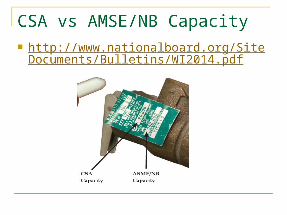
CSA vs AMSE/NB Capacity http://www.nationalboard.org/SiteDocuments/
Bulletins/WI2014.pdf

NB Bulletin, Winter 2014
Which capacity should be used? The answer: match the code of construction with the certified capacity rating. If the valve is protecting an ASME Section IV code-stamped hot water heater, then use the ASME/National Board capacity which is determined by ASME Section IV requirements. If it is not ASME Section IV code stamped, then use the CSA rating.

Commission Continuing Education

Commission Continuing Education
