construction and test of a 1 1-2 inch centrifugal pump · constructionandirlolura 11-zunv^ri...
TRANSCRIPT

:-v.::?:;:;?>'-r
....u^ifuction & Test -of a
Mechanical Engneering
' B. S.. .v;
I 9 9
•UNIVKRPITTOF
ILL.LIHKAI^Y


CONSTRUCTION AND IrLol Ur A 1 1-z UN v^ri
CENTRIFUGAL PUMP. u
BY
HENRY POLLARD
MARK ELMER POWERS
THESIS FOR THE DEGREE OF BACHELOR OF SCIENCE
IN MECHANICAL ENGINEERING
IN THE
COLLEGE OF ENGINEERING
OF THE
UNIVERSITY OF ILLINOIS
Presented June, 1909

Digitized by the Internet Archive
in 2013
http://archive.org/details/constructiontestOOpoll

i%0\
UNIVERSITY OF ILLINOIS
JUNE 1, 1909
THIS IS TO CERTIFY THAT THE THESIS PREPARED UNDER MY SUPERVISION BY
HENRY EOLLARn. : LARK ELMER POWERS
ENTITLED CONSTRDCTIDJNi AMD lEST OF. A 1 l/2 INCH CENTRIFUGAL PUMP
IS APPROVED BY ME AS FULFILLING THIS PART OF THE REQUIREMENTS FOR THE
DEGREE OF BACHELOR OF SCIENCE
APPROVED:
HEAD OF DEPARTMENT OF MECHANICAL EKGIII1':ERING
144254

UlUC

TABLE OP CONTENTS.
IntToduotion -
O'b.ieot -
DQsoription of Apparatus -
Mathod of Tasting- - -..----.gCaloulations - -- -- -.-.-.-=«4
Conolusions - - - - = a
Data Sheets. - - - - - -- - 9-18
Curves. ---------- 14-22


The following: is a report on th3 test of a one and ona-half
inoh osntrifugal pump oonstruoted in the shops of the Univarsity
of Illinois hy the authors of this thesis. Working drawings
were furnished hy the meohanioal engineering department and em-
hody the ideas of J . J. Harm^, the designer. The patterns for
the castings were made hy a pattern maker and the castings by stu-
dents in the foundry. The work from this point was carried on by
the authors and consisted of the machining of the castings, erec-
tion and construction.
OBJECT—The ot);]eot of the test was to determine the range
of operation and the corresponding efficiencies of the pump.
DESCRIPTION OP APPARATUS The pump tested was a single
stage centrifugal pump with an impeller eight inches in diameter.
The impeller was made of bronze, while the other parts of the ma-
chine, with the exception of the shaft, were of cast iron. The
impeller or rotor carried four vanes of the open tyv^ and was
finished all over. The water entered the pump at the center of
one side, and leaving the periphery of the impeller, passed into
the volute or outer casing, and from thence out through the verti-
cal discharge pipe. The water from the discharge pipe passed
through a weir box into a tank from ^vhioh the suction pipe again
carried it to the pump.
The discharge pipe was one and one-half inches m diameter
/


and th9 diametar of the suction pipa was two inches. It was found
nacassary, howevar, to inoreasa tha siza of tha suction pipa to
thraa inches in ordar to sacura tha low haad readings at tha higher
dischargas. Tha friction loss in tha smallar pipa wara axoassiva.
The weir into which tha water was dischargad was a contracted wair
with a standard rectangular steal wair plate twalva inches wide.
The height of tha watar on tha crast of tha wair was measured t>y
a hook gage fastened to one side of the box. Oagas ware plaoad
on the suction and discharge pipas. Tlia fomar indicated the suc-
tion head and the latter tha discharge head.
Tha discharge head was controlled l^y a gate valva introduced
in the pipa ^nst a"bova tha gage and tha sama results ohtained "by
opening and shutting tha valva as would have "been ohtained "by
shortening and lengthening the discharge pipe in a vertical direc-
tion. The gate valva gave a finer regulation than a glo"ba valve
as the pitch of the thraad on tha valve stem was smaller and also
the loss dua to friction when fully opanad was lass sinoa the water
had a straight passaga and no eddy currents formed in passing over
the valve seat.
The pump was Daltad to a saven and ona-half horsepower Gen-
eral Electric direct currant motor operating on 220 volts. The
speed of tha motor, and hence the spaed of tha pirnip, was controlled
hy inserting resistance into tha fiald of the motor. A large re-
sistance hox of 650 ohms capacity and sixty-four points, placed
in the fiald circuit hatwaen the starting hox and the motor, gave
a range in motor speeds of alDout four hundred ravolutions.
Photographs of the drawings of the impeller and the assam-
Z


"bly view of the pump show the details of oons true t ion. The ar-i-
rangement of the testing apparatus is also illustrated.
METHOD OP TESTING In testing a piece of naohinery for
effiolenoy, it is essential to know the amount of work put in and
the amount of work given out W the machine in question. In a
pump, the factors entering into the calculations of output are the
weight of water discharged during a knovm interval of time and the
height to which the pump raised the water. Introducing; the proper
time elements of these factors, the hydraulic horsepower may be
computed. The readings taken, therefore, in making the test were
of the gages registering the suction and discharge heads, the speed
of the motor and the pump, the head on the weir hy the hook gage. and
the voltage and amperes used T>y the motor.
After the pump was in operation the speed was ad;justed to the
required numher of revolutions hy changing the resistance in the
field of the mo tor • With the pump at the required speed, the head
was adjusted hy means of the discharge valve. The speed of "both
the pump and motor ^ere taken at the same time with spe3d counters
for thirty second intervals. An ammeter placed in the armature
circuit of the motor measured the current passing through the
armature. When the limit of speed variation "by the field resis-
tance was reached (ahout 400 revolutions), the motor pulley was
changed for one of larger diameter. Pour pulley changes were made
in securing the speed range of the pump.
Speeds were taken every 200 revolutions beginning at 800 and
continuing up to and including g?00. Heads were taken about every
twenty*" feet from the minimum to the maximum that could be obtained.
3


o4-
4-U
r
u
UJ -C3
Q (0


Th9 fina regulation possible in oontrolling tha sp^ad of tha motor
mada it mora praotioal to kaap tha spead constant, vary tha haad
and maasura tha resulting discharge than to Icaep the discharge
constant and vary tha spaed ^Ith tha head. Tha tima required in
getting tha spaeds and tha readings of tha othar instrumants gave
ample time for tha weir discharge to hecopie constant so that a
hook gaga reading might "be made.
CALCULATIONS The hydraulic horsepower delivered by the
pump equals the product of tha weight of water in pounds dis-
charged par minute and tha total haad in faet of water, divided
hy 33000. Tha weight of a ouhio foot of water was taken as 62.5
po^inds
.
The power delivared to tha pump "by tha motor equals the
power input to tha motor less tha motor losses. Tlia power input
to the motor was the product of the voltaga across tha switch ter-
minals and tha amperes passing through tha armature, tha product
"being watts. To have inoludad tha fiald amperes in measuring
tha watts input would only result in subtracting them as losses
and tha watts of power input to tha motor would have remainad
unchanged. Prom this product of watts input was subtracted the
stray power loss and the I R loss, the remainder being the power
furnished to the pump. Tha stray power of a motor is constant for
givan speeds and the amounts ware determined by a stray powar
test on tha motor. Tha resistanoa of the armature was also found
as a part of the motor test for tha calculation of tha J^R losses.
Tha watts furnished to the pump ware changed to horsepower by
dividing by 748.
^


The po'^'-er delivered to ths piimp as thus computed includes
not only that required to raise the water throu^f-h a given height,
hut also the power consumed "by all the friction in the pump and
the helt losses.
The values given in the data sheets as suction head include
the reading of the suction gage and also the distance "between the
gage centers. The column headed weir readings gives the difference
"between the actual weir reading and the zero reading of the weir.
The gage on the suction pipe indicated the head up to the center
of the gage. The total head is the sum of the two gage readings
plus the distance "between the centers of the two gages.
The pump efficiency as herein figured is the hydraulic
horsepower divided hy the power output of the motor.
Tlier© was an error introduced in measuring the dischaTges
for the maximum pump heads since the water leaving th^ weir crest
followed the plate down and across part of the weir "box without
allowing any air to he under the water in front of the crest, as
should "be the case.
A. formula that is characteristic for all centrifugal pumps
is Nrkyn-f , where N is the numher of revolutions, k is a con-
stant for the pump, H is the total head and o is the losses in
the pump which is constant for a given discharge, k was deter-
mined hy making several readings at different speeds with no dis-
charge. The average value of three readings was 236. Knowing
k, the value of c was then determined for the whole range of speeds
and heads of the pump. A our^/e was then drawn through those
plotted values, on a plane with discharges as abscissae and the
values of c as ordinates. Taking values of o from this curve and


heads avery ten feet, thsse quantities were suTDstitutad in th3 for-
mula a"bava and ths value of N found. The head, disoharga and
speeds are taiDulated in the revolution table. Curves using the
values in the tahle were plotted for each discharge with revolu-
tions as absoissae and total head as ordinates.
CONCLUSIONS The designer's rating of the pump was that it
deliver seventy gallons of water per minute against a forty foot
head at 1J300 revolutions. The curves plainly show that this rat-
ing was much too high, as the speed giving this discharge and
head was 1800. The efficiencies ohtained were very fair consider-
ing the small size of the pump and agree very closely with the
efficiencies of a one end one-half inch Gould pump tested at the
university in Pe'bruary, 190S.
In caloTUating the total head, the head due to the velocity
of the water in the discharge pipe was neglected. The velocity
may he calculated, knowing the discharge and the area of the
pipe (Qisv.). Suhstituting in v^Sgh, the velocity head may he
found. It is evident that the velocity head varies with the dis-
charge, "but several calculations for the maximum discharges gave
only ahout ten feet and the efficiency was changed very little.
Since most of the discharges ware considerably less than these
maximum amounts, vexy little error is made in neglecting this head.
In making the calculations, however, for a pump of larger size
and discharging a large quantity of water for low heads this head
will amount to considerable, perhaps as much, if not more, than
the pressure head indicated by the gages. In that case it would
be a gross error not to credit the pump with that head.


Th3 term affioianoy as harein ussd might "be oalled tha oom-
marclal affioisnoy as it is mads up of "both the meshanioal effi-
oienoy of the pump and the hydraulic effioienoy. The meohanioal
effioienoy is made up of the effioienoy of the helt and the shaft
and impeller effioienoy. It is praotioally impossit)le to separate
these t^o factors and say what per cent of the power v/as lost
in the "belt and what per oent was lost in the machine itself.
Sometimes five per oent. is allowed for "belt losses, but this is
only approximate at best. But inasmuch as the pump as oonstruo-
t«d. will alv^ays be belted to a source of po7/er, no appreciable
benefit would be derived in separating the two factors. This me-
ohanioal efficiency is then multiplied by the hydraulic efficiency
and this combined efficiency given as the overall or copjmeroial
effioienoy of the machine.
Some of the high efficiencies advertised by manufacturers
for their respective pumps are the result of making arbitrary de-
ductions of five per cent or so for belt loss and by crediting
the pump with all possible benefits, get an efficiency of per-
haps sixty per oent. Therefore,, when the performance of two or
more pumps are to be compared it is essential to know the basis
of the computations of the various pumps if each pump is to re-
ceive its proBer rating.
The revolution table is of great use to those desiring to
know the performance of the pump as the information is at once
available and for all conditions under which the pump may be used.
Several changes should be made in the details of construction
of the piunp before beginning manufacture for the market. The suc-
tion entrance should be at least three inches, if not more, in
7
diamatsr instead of tha two inchas at present. Otherwise, the pump
oannot he used for low heads and high discharges. Another change
is in th3 nethod of ;ioining the base and the volute. As arranged
at present it is very awkward to reach the cap screws in ques-
tion and necessitates the use of a socket wrench, Furthermore,
Txiore metal should h^ allowed for tapping for these cap screws
as only two or three threads are available with the present di-
mensions. It is true that much of the weight is taken hy the
shoulder on the volute if the fit is tight, hut if it is not, then
the holding power of the cap screws is too small. A higher shoulder
would remedy "both of these defects. It would also probably be
better to increase the length of the babbitted bearing that the
bearing might stand the increased friction due to tight belts with-
out undue heating.
8


bonstruotion and Test of a 1 I/2 Inoh Centrifugal Pump.
Hydraulic Data Sheet.
Read-ingNO.
PumpSpeedR.P.M.
.
Headfeet
Weir
inches
DisohargagclX. i/OX
niin. •
Horse-
luotion Disoliarg 3Total •
1 QOO .56 2.0 2.5 .22 3.9 .002
S 800 6.04 P 7.0 .15 1.0 .001
3 1000 1.98 A «f^. 5 1.44 60.5 .053
4 1000 5.94 7.9 1.27 50.3 .100
1010 5.94 ? 7.9 1.28 50.8 .101
6 1000 17.0 .41 10.3 .044
7 1200 — 2.0 2.0 .59 14.9 .007
8 1200 3 • 'J9 1.8 5.3 1.6G 78.2 .032
9 1200 7.00 2.0 9.0 1.65 75.8 .172
10 1200 7.00 2.0 9.0 1.65 75.8 .172
11 1196 7.94 13.4 1.50 67.0 .223
12 1200 7.94 10 17 .9 1.33 56.0 .254
IS 1205 8.18 TOO 13.1 1.22 43.5 .221
14 1200 8.16 TOO 13.1 1.20 46.6 .213
15 1200 8.05 15.8 24.3 .56 18.4 .101
16 1200 8.05 15.8 24.3 . .53 18.4 .101
17 1202 7.94 16.8 34.7 .76 23.4
18 1410 5.95 2.0 7.9 1.90 92.1 .184
19 1400 7.94 13.0 21.0 1.57 70.2 .372
20 1400 8.05 12.6 21.1 1.81 71.8 .383
21 1408 7.94 17.0 74r,9 1.53 65.7 .414
3

e.

Oonstruotion and Tast of a 1 l/s Inoh Centrifugal Pump.
Wdraulio Data Sheet.
Read-ingNO,
rumpspeedR.P.M.
Haadfeet
WeirReadingInches
Dischargegal. per
min.
Horse-
-Suction Disohari Total
22 1400 7.94 25.8 33.7 .86 28.6 .242
23 1400 7.94 30.0 37.9 .45 .535
24 1600 8.50 5.5 14.0 2.09 106.0 .575
26 1606 4.54 22.5 27.0 1.74 30.6 .550
23 1620 7,94 30.0 38.0 1.24 49.2 .471
27 1610 8.00 30.0 38.0 1.23 48.8 .467
28 1600 8.00 33.5 41.5 .96 34.0 .364
29 1600 8.00 34.0 42.0 .95 33.3 .344
30 1810 44.7 44.7 .64 19.7 .222
31 1800 11.06 4.6 15.3 2.36 126.1 .500
32 1810 6.80 28.0 39.8 2.02 101.0 .890
33 1800 8.00 24.0 42.0 1.34 72.0 .761
34 1810 3.00 36.0 44.0 1.63 72.4 .805
35 1820 3.00 40.0 48.0 1.46 63.2 .765
36 1820 3.00 40.0 48.0 1.45 62.7 .739
37 1820 8.00 50.0 58.0 .77 23.7 .346
38 1820 8.00 50.0 53.0 .72 22.5 .331
39 2000 12.61 8.2 19.8 2.50 136.2 .684
40 2008 11.34 21.2 32.5 2.56 126.2 1.035
41 2000 8.53 43.0 49.5 1.96 96.6 1.212
42 2000 8.00 48.5 56.5 1.63 72.7 1.038
10

construction and Tast of a 1 I/2 Inoh Centrifugal Pump.
iVdraulio Data Sheet.
Read- Pump Head Weir Discharge Horse-ing Speed feet Reading gal. peT powerNoT R.P.M. i^uotionDis Glaarg e Total Inclies min.
43 2000 8.00 50.0 58.0 1.63 72.7 1.030
44 2040 8.00 80.0 68.0 ,80 28.4 .486
45 2040 8.00 eo.o 68.0 1.11 35.8 .814
48 2000 — 71.5 71.5 .86 23.4 .388
47 2200 15.31 6.5 21.8 2.55 139.0 .770
48 2208 13.61 22.5 36.1 2.45 133.5 1.220
40 2220 9.52 4.2 51.9 2.18 112.0 1.470
50 2200 5.39 61.3 66.7 1.83 87.4 1.470
51 2200 8.00 68.8 78.0 1.67 68.9 1.320
52 2210 8.00 68.8 76.8 1.53 67.1 1.300
53 2210 8.00 80.0 88.0 1.86 28.6 .636
54 2220 8.00 30.0 88.0 .83 27.6 .814
55 2204 39.0 89.0 .54 13.7 .303


construotion and Test of a 1 I/2 Inch Centrifugal Pump.
Electrioal Data Sheet.
Read-ing
No.
Volts Amp.WattsInput
Rev.perMin
PowerT PJ. Xl
LossesYYcl U uo
Output power
1 217 2.5 543 930 423.0 2.58 117 .157
2 213 2.9 820 930 422.0 3.43 194 .261
3 215 3.5 753 1150 387 .'5 5.00 360 .482
4 218 4.0 873 1130 388.8 6.55 477 .840
5 215 3.9 840 1138 388,0 6.22 448 .598
6 215 2.3 602 1160 387.0 3.20 211 .260
7 215 3.5 753 948 420.0 5.00 328 .440
8 203 5.0 1015 940 421.0 10.25 584 .782
9 211 8.0 1265 360 417.4 14.70 833 1.120
10 211 6.1 1285 948 420.0 15.20 850 1.140
11 216 5.5 1188 950 419.5 12.40 756 1.010
12 221 5.0 1105 950 419.5 10.40 675 .905
13 212 5.5 1165 948 419 .
5
12.30 734 .984
14 212 5.4 1144 980 417.4 11.90 715 .958
15 220 4.0 880 940 421.0 8.53 453 .608
16 219 4.2 932 950 419.0 7.35 506 .878
17 217 4.4 955 982 417.0 7.94 530 .710
18 212 7.0 1484 1040 400.0 20.30 1063 1.420
19 210 7.0 1470 1124 389.0 20.00 1061 1.420
20 217 8.5 1845 1140 383.0 29.00 1428 1.91
21 214 6.8 1455 1140 388.0 18.80 1048 1.400
22 208 5.7 1185 1140 388.0 13.30 784 1.050


Oonstruotion and Test of a 1 1/2 Inoh Contrifiigal Pump.
Electrical Data Sheet.
Haad-ingNo.
Volts . Arup
,
WattsInput
Rev.perMin.
StrayPowerWatts
I RLosses
' atts
WattsOutput
Horse-power
28 212 6.6 1400 1135 388.4 17.8 994 1. 380
24 214 9.5 2030 1260 388.4 36.8 1608 2.150
25 212 8,4 1780 1260 388.4 28.8 1366 1.820
26 207 7.6 1572 1300 388.4 23.8 1164 1.550
27 207 7.5 1552 1260 388.4 23. 1144 1.530
28 214 6.8 1454 1270 388.4 18.
9
1051 1.411
29 214 8.8 1454 1240 18.9 1050 X . 4X J
90 215 7.5 1610 1280 388.4 23 .
9
1191 ± . o 'J 'J
k1 214 13.0 2780 1060 397 . 89, 2 2314 o 1 rift
32 214 12.0 2570 1080 P93. 59 , 1118 i . OUU
33 210 10.75 2280 lOoO 393. o 47.0 1820
34 212 10.75 2280 1090 39 3 . o ATI f\47. 1840 O ^ Aft
8n 215 10.0 2150 lOoO 393 .
5
40. 1717
36 215 10.0 2150 1090 393.
5
40. 1717
37 216 7.8 1642 1080 39 3.5 23.6 1215 T Q Oft
38 216 7.8 1885 1076 393.5 . 29.8 1267 T ftft
39 213 17.2 3670 1198 385.0 12.1 3184 y! otJ ft
40 213 18.2 3450 1207 335.-5 10.7 2957 3.980
41 213 14.8 3110 1210 385.0 87.2 2637 3.540
42 208 13.1 2725 1190 333.0 70.0 2269 2.910
43 211 12.8 2700 1200 338.5 37.0 2247 3.010
44 211 10.0 2110 1200 385.5 40.0 1885 3.040
13

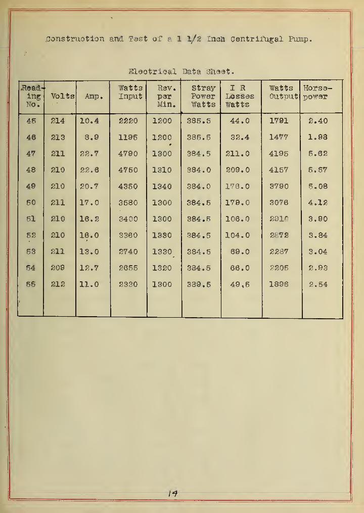
.Oonstruotion and Tast of e. 1 I/2 rnoh Centrifagal Pump.
Eleotrioal Data 31i93t.
«Read-IngNo.
Volts Amp.WattsInput
R3V.perMin.
Stray-PowerWatts
I RLossesV/atts
WattsOutput
Horsa-power
46 214 10.4 2220 1200 385.5 44.0 1791 2.40
48 213 3.9 1195 1200 385.5 32.4 1477 1.98
47 211 22.7 4790 1300 384.5 211.0 4195 5.62
48 210 22.6 4750 1310 384.0 209.0 4157 5.57
49 210 20.7 4350 1340 884.0 3790 5.08
50 211 17.0 3580 1300 384.5 179.0 3076 4.12
61 210 16.2 3400 1300 384.5 106.0 291^^ 3.90
5S 210 16.0 3360 1330 384 .
5
104.0 2572 3.84
53 211 13.0 2740 1330 384 .
5
69.0 2287 3.04
54 209 12.7 2655 1320 334.5 66.0 2205 2.93
55 212 11.0 2330 1300 389.5 49,5 1898 2.54


'Construotion and Test of a 1 I/2 Inch Centrifugal Punip.
General Data Sheet.
Read-ingNo.
RmipSDeedR.P.M.
Dischargegal. per
min.
Totalheadfeet •
EleotrioalH. P.
Input
HydraulicH. P.Output
Efficiencyper cent
1 800 .3.9 2.56 .157 .002 1.6
2 800 1.0 7.04 .281 .001 .7
3 lOOC 80.6 3.48 .482 .053 11.0
4 1000 50.3 7-94 . .640 .105 15.6
R 1010 50.6 7.94 .693 .111 16.9
6 1000 10.3 17.00 .258 .044 17.0
7 1200 14.9 2.00 .440 .007 17.1
8 1200 78.2 5.29 .782 .031 4.0
9 1200 75.8 9.00 1.120 .172 16.4
10 1200 75.8 9.00 1.140 .172 15.1
11 1196 67.0 13.44 1.010 .223 22.6
12 1200 56.0 17.94 .905 .254 28.1
13 1205 48.5 18.10 .984 .221 22.5
14 1200 48.6 18.10 .958 .214 22.3
IR 1200 16.4 24.30 . .608 .101 13.6
16 1200 16.4 24.30 .678 .101 14.9
17 1202 23.4 34.74 .710 .205 28.9
18 1410 92.1 7.95 1.420 .184 13.0
19 1400 70.2 21.00 1.420 .372 26.2
20 1400 71.8 21.10 1.910 .383 20.0
21 1408 65.7 24.94 1.400 .414 29.6
22 1400 28.6 33.74 1.050 .242 23.2
IS-


Construotion and Tast of a 1 1/2 Inch centrifugal Pump.
Genersl Data Sheet.
Read-inrNo.
Pump
RJP.M.
Disoliargefal . D3"P
min.
Total
feet
ElectricalH. P.
Input
ify'draulioH- P.
Output
Efficiency
23 1400 55.8 37.9 1.330 • 535 40.0
24 1600 106.0 14.0 2.150 .375 17.4
26 1606 80.6 27.0 1.820 .550 SG . 1
26 1620 49.2 38.0 1.550 .471 30.2
27 1610 48.8 33.0 1.530 .467 30.5
28 1600 34.0 41.5 1.410 .354 25.1
29 1600 33.8 42.0 1.410 .344 24.4
30 1610 19.7 44.7 1.060 .222 13.9
31 1800 126.1 15.6 3.100 .500 16.1
32 1810 101.0 34.8 1.500 .890 59.4
33 1800 72.0 42.0 2.440 .761 31.2
34 1810 72.4 44.0 2.460 .805 32.8
3R 1820 63.2 48.0 2.300 .765 33.3
36 1820 62.7 48.0 2.300 .739 32.1
37 1820 23.7 58.0 1.620 .348 21.4
38 1820 22.5 53.0 1.700 .331 19.6
39 2000 138.2 19.8 4. 250 . 684 18.0
40 2008 126.2 32.5 3.960 1.035 26.2
41 2000 98.6 49.5 3.530 1.212 34.3
42 ?^000 72.7 56.5 2.910 1.038 35.8
43 2010 70.6 58.0 3.010 1.030 34.2


Gonstruotion and Tsst of a 1 I/2 Inoh Centrifugal Pump.
Senaral Data Sheet.
Read-ingNo.
PumpSpeedR.P.M.
Di3chargegal. permin.
Totalheadfeet
EleotriealH. P.
Input
HydraulicH. P.Output
Effiolenoyper cent
44 2040 28.4 68.0 3.04 .486 18.0
45 2040 35.8 68.0 2.40 .814 25.6
48 2000 23.4 71.5 1.98 .368 18.6
47 2200 139.0 21.8 5.62 .770 13.6
48 2208 133.5 38.1 5.57 1.220 21.9
49 2220 112.0 51.9 5.05 1.470 29.0
60 2200 87.4 66.7 4.12 1.470 35.8
51 2200 68.9 76.0 3.90 1.320 34.0
52 2210 07.1 76.8 3.84 1.300 34.0
53 2210 28.8 88.0 3.04 .638 20.9
54 2220 27.8 88.0 2.93 .614 20.9
55 2204 13.7 89.0 2,54 .308 12.2
17


Construct ion and Tast of a 1 l/s Inoh c«ntrifiigal Pimp.
Revolution Tatole.
Hea4
feat
Dissharge in gal. per min.
10 20 40 60 80 100 120 140
10 700 788 d3B 1108 1280 1485 1671 1970
20 1050 1069 1192 1387 1482 1834 1832 2102
SO 1275 1304 1408 1527 1658 1794 1978 2231
40 1468 1498 1533 1700 1814 1945 2112 2350
50 1842 1674 1754 1858 1959 2081 2234 2488
30 1814 1829 1906 1998 2094 2208 2580 2581
70 1981 1974 2044 2132 2221 2328 2478 2884
80 2475 2108 2176 2255 2342 2452 2578 2781
Value -1.1 .6 6.8 12.2 19.7 28.5 40.7 80.2•f
18


UhiversiTy of ItLiNOIS -S.C.A» FORM !