construction and characterization of a spray-ice pad, tuktoyaktuk, northwest territories
TRANSCRIPT

, Construction and characterization of a spray-ice pa& ~ukio~ak'tuk,
'B Northwest Territories
Geoteclzrzical Division, Norrvegim I~~st i tute qf Techr~ology, Uuiversity of Trorldllei~n, H~~gskoleringen 7A, N-7034 Tronrlheim, Norway
DAVID C . SEGO
Geotechrzical G r o ~ ~ p , Depr tme~z t qf Civil Eugineering, The University of Alberta, Ediizo~zto~~, AB T6G 2G7, Canada
AND
KOFI ADDO
Cor~etec I~westigntior~s Ltrl., Unit 3, 9 / 1 3 Sha~~glzrzessy Street, V ~ ~ r ~ c o l w e ~ ; BC V6P 6R9, Carlncln
Received May 18, 1993
Accepted May 17, 1994
During the winter of 1990-1991, a field research program was undertaken to investigate the in situ properties of spray ice, since information on the mechanical and physical properties of undisturbed field-produced spray ice is scarce. The main objective of this research was to retrieve undisturbed field samples for laboratory characterization and to make field measurements to assist in studying the formation processes and physical properties after formation. For this purpose, a spray-ice pad was constructed in the freshwater Tuktoyaktuk Harbour, Northwest Territories, Canada. The 4.3 m thick pad was partly grounded in water depths of 3-6 m and had a maximum freeboard of 2,Zm. The spray- ice pad was constructed using a mobile spray-ice system placed on the first-year ice sheet. The ice production effi- ciency of the system was measured and found to give an ice content higher than 50%. A total of E1.8 m of cores of nonsaturated undisturbed spray ice were retrieved from three locations on the pad and transported to' a cold room facil- ity for density, shear wave velocity, and mechanical behavior testing. In addition, surface wave testing of the in situ spray ice and first-year ice was performed. This paper describes the field study and the methodologies employed to carry out this research.
Key words: spray ice, construction, sampling, density, Rayleigh wave velocity. ,.
Au cours de l'hiver 1990-1991, un programme de recherche en nature a CtC entrepris pour Ctudier les propriCtCs in situ de la glace giclCe compte tenu que les informations sur les propriCtCs mkcaniques et physiques des champs de glace intacte giclCe en nature sont peu abondantes. Le principal objectif de cette recherche a 6tC de prklever en nature des Cchantillons intacts pour les caractCriser en laboratoire, et de faire des mesures sur le terrain pour aider h I'Ctude des processus de formation et des propriCtCs physiques aprbs formation. A cette fin, une planche de glace giclee a CtC construite dans les eaux douces du Port de Tuktoyaktuk, Territoires du Nord-Ouest, Canada. La planche d'une Cpaisseur de 4,3 m Ctait partiellement CchouCe dans des profondeurs d'eau de 3-6 m, et avait une hauteur de revanche maximale de 2,2 m. La planche de glace giclCe a CtC construite au moyen d'un systbme mobile de giclage reposant sur Le couvert de glace de la premikre annCe. Le rendement en glace du systkme a CtC mesurC et l'on a trouvC qu'il produisait une teneur en glace supCrieure h 50 %. Un total de 11,8 m de carottes intactes de glace giclCe ont CtC prClevCes en trois endroits sur la planche et transportCes vers une chambre froide pour des mesures de densite, de vitesse de I'onde cisaillement, et du comportenient mCcanique. De plus, I'on a rCalisC des mesures de I'onde de surface dans la glace giclCe in situ et dans le couvert de glace de la premibre annCe. Cet article dCcrit I'Ctude en nature et les mCthodologies utilisCes pour rCaliser cette recherche.
Mots cle's : glace giclCe, construction, Cchantillonnage, densitC, vitesse de I'onde de Rayleigh. [Traduit par la redaction]
Can. Gcotech. J . 31. 703-713 (1094)
Introduction Spray-ice technology has been used in North America to
construct exploratory oil drilling platforms, relief-well pads, and protect ive barriers around offshore structures (Allyn and Masterson 1989; Bugno et al. 1989; C o x 1979; Goff e t al. 1987; Jahns e t al. 1986; Juvkam-Wold 1986; Wang and Peters 1985; Weaver e t al. 1991). T h e technique may also be used to construct ice bridges rapidly, parking lots, and runways (Northwest Tesritories Department of Transportation 1992; Gerard et al. 1990). Spray ice is produced by using high-pressure pumps and conventional fire-fighting moni- tors and nozzles to spray water into the air at subzero tem- peratures. While in the air the water droplets lose heat to the atmosphere and may partially freeze to form ice spheres.
O n impact with the ground, the fallen spray consists of a mixture of ice, unfrozen water, air, and brine if a sa l ine water source is used.
T h e mechanical behavior of the in situ spray ice must b e understood to ensure a safe and economical design when it is used for construction. In situ field measurements made within the field-produced spray ice are required to ensure compliance with the design. At present, information in the open literature on the mechanical properties available f o r use in the design have been determined by triaxial tes ts without volume change control on reconstituted spray-ice samples prepared in the laboratory (Chen and Gram 1989; Steel e t al. 1990; Weaver and McKeown 1986). A s well, the in situ evaluation of the mechanical properties of spray
Can
. Geo
tech
. J. D
ownl
oade
d fr
om w
ww
.nrc
rese
arch
pres
s.co
m b
y U
NIV
LE
ED
S on
08/
29/1
3Fo
r pe
rson
al u
se o
nly.

CAN. GEOTECH. J . VOL. 31, 1994 ,
8 1 2 1 6
Time ( h )
FIG. 1. Observed air temperature during spraying operations.
ice has depended on the use of destructive and location- specific testing to measure the properties. The owners and regulators would prefer an assessment of the variation in the spray ice making up the offshore facility. Although there are still uncertainties in the determination of environmental loads, understanding the mechanical behaviour of in situ spray ice will allow for better utilization of the material for its intended purpose.
The research project described herein had three main goals. The first was to measure the ice production efficiency of a lightweight spray-ice system. The second was to retrieve undisturbed field samples of spray ice for later laboratory measurements, and the third was to measure in situ Rayleigh wave velocities within the spray-ice pad and the underlying first-year ice sheet to assist in evaluating the in situ char- acteristics. The field research was undertaken during March to May of 1991 at Tuktoyaktuk, Northwest Territories.
Spray-ice system The selection of a pump for use in a spray-ice produc,
tion system depends very much on the project requirements and construction location. For sites that are easily accessi- ble with heavy equipment, large pumps are probably the best alternative because of the higher pumping and spray-ice buildup rates that are achieved (Weaver et al. 1991). For construction of spray-ice structures in remote areas such as the Canadian Beaufort Sea, it can be more convenient to use smaller, lighter pumps like the one used in this project. These pumps can easily be moved around the construction site and from one remote location to another. Using lighter equipment is also an advantage when spraying from a float- ing ice sheet, especially when an early construction start is required (Weaver et al. 1992).
The lightweight spray-ice system used for this project con- sisted of the following: ( i ) a Cummins 4BT3.9P diesel engine to drive the pump; (ii) a Monarch Industries NH4L15S end suction horizontal centrifugal pump; ( i i i ) a WFR FP3 1200wINo. 3526 monitor; and (iv) a standard straight-stream fire-fighting nozzle with orifice diameter of 41.91 mm (1.65 in.). The total weight of the system was 922 kg exclud- ing parts that could be easily disconnected, namely moni- tor, battery, discharge hose, and enclosure. The maximum flow rate was 3785 Llmin with a nozzle pressure of 965 kPa.
An enclosure protected the spray-ice system from the wind and freezing temperatures.
Construction of the spray-ice pad The pad was constructed in water depths of 3-6 m in the
east part of the freshwater harbour at Tuktoyaktuk (site coordinates: latitude 69"42' N; longitude 132'06' W). The pad construction was accomplished by placing the spray system on the first-year ice sheet. The first-year ice thickness ranged from 1.8 to 2.1 m during construction and an ice auger was used to drill a 250 mm diameter hole for the intake hose to the pump. The spraying operation to con- struct the pad was limited to about 20 h of nonstop spraying between March 6 and 7, 1991. The air temperature varied between -20 and -24°C during the spraying operations and its variation is presented in Fig. 1. The wind speed was favourable for spraying operation at less than 0.4 m/s. Spraying might be halted during periods of strong winds to avoid the spray being carried away by the wind. It should be noted that during periods of no wind, the falling drops will increase the air temperature and humidity as they fall and decrease the growth rate. The majority of the spray was deposited in a concentrated area about 40 m horizontal dis- tance from the pump.
Immediately after completing the spraying operations the spray-ice pad was profiled using a thermal drill. The water was obtained directly from the harbour and then warmed by a heater and pumped through the thermal-drill probe (Poplin et al. 1987). The hot water leaving the tip erodes and melts the ice, allowing rapid penetration of the drilling probe. An electronic distance meter (EDM) - theodolite survey was then used to establish the contour of the spray-ice pad. Due to logistical problems the EDM survey could not be per- formed prior to May 23, 1991. Based on the measured core sample densities and thermal-drill profiles, the settlement of the spray-ice pad between the end of construction and the EDM survey was approximately 0.5 m. This is probably due to deterioration of the spray ice caused by solar radia- tion, rain showers, and air temperatures above 0°C. Figure 2 shows the location of EDM-theodolite survey points (28), surface wave (SASW) profile (I) , thermal drill profiles (3), and sampling boreholes (3). The contours above mean first- year ice level of the spray-ice pad are presented in Fig. 3. The
Can
. Geo
tech
. J. D
ownl
oade
d fr
om w
ww
.nrc
rese
arch
pres
s.co
m b
y U
NIV
LE
ED
S on
08/
29/1
3Fo
r pe
rson
al u
se o
nly.

INSTANES ET AL. 5
-20 -15 - 1 0 -5 0 5 1 0 15 2 0
Easting (m) FIG. 2. Location of EDM-theodolite survey points (O), thermal-drill profiles, SASW profile, and core samples.
cross sections through the pad and sea ice to the sea bed prepared using the thermal drill are shown in Figs. 4-7. The contour plot and the thermal-drill profiles show that the spray-ice pad was partially grounded on the sea bed about 40 m from the pump, and the maximum freeboard was 2.2 m with a maximum spray-ice thickness of 4.3 m. The high buildup rate was due to favourable meteorological conditions and the use of fresh water.
Ice-content determinations When building structures of spray ice, it is important to
know if the pumping system gives sufficient buildup rates to complete the structure within the time limits of the project. The main design criterion is the ice content contained in the spray, which is defined as
" [I] i =
ini fin,,
where i is the ice content or spray-ice production efficiency, m i is the mass of ice in spray, and in,,, is the mass of unfrozen water in spray.
Three different methods were used to estimate the ice content contained in the spray: estimations based on thermal- drill data, calorimetry tests, and spray-ice production model. Despite all the uncertainties and assumptions in the esti- mations of ice content, there is good agreement between the three different predictions. This supports the use of the ice production model as outlined in Instanes (1993).
Based on thernzal-drill data An estimate of ice content in the spray during construction
of the spray-ice pad can be obtained using the thermal-drill profile data, pump volumes, and average density measured in the constructed pad: (i) construction time 20.5 h; (ii) volume of spray ice (estimated from approximately 30 thermal-drill holes) 3000 m3; (iii) average water flow rate during con- struction 2600 Llmin; (iv) average density (estimated from core samples) 560 kg/m3; and ( v ) estimated losses due to evaporation (J.S. Weaver, personal communication, 199 1) 10%. These give:
total mass of water pumped = 20.5 X 6 0 X 2600 X (1-10%) = 2.88 X lo6 kg,
SPRAY PUMP
1 -20 -15 -10 -5 0 5 10 15 20
Easting (m)
FIG. 3. Contour map of spray-ice pad based on EDM survey May 1991. Contour intervai is 0.25 m.
total mass of spray ice produced = 3000 X 560 = 1.68 X lo6 kg, and
calc~dated ice content in spray 58%.
Based on calorimetry test The ice production efficiency of the spray-ice system can
also be estimated by measuring the ice content in the spray upon impact with the ground. Calorimetry tests were
Can
. Geo
tech
. J. D
ownl
oade
d fr
om w
ww
.nrc
rese
arch
pres
s.co
m b
y U
NIV
LE
ED
S on
08/
29/1
3Fo
r pe
rson
al u
se o
nly.

CAN. GEOTECH. J. VOL. 31, 1994 , i
seabed
Horizontal distance from pump (m)
FIG. 4. Thermal-drill profile B, March 7, 1991.
i Profile C
Horizontal distance from pump (m)
FIG. 5. Thermal-drill profile C, March 7, 1991.
i Profile D
sea ice
sea water
0 10 20 33 40 50
Horizontal distance from pump (m)
FIG. 6. Thermal-drill profile D, March 7, 1991.
Can
. Geo
tech
. J. D
ownl
oade
d fr
om w
ww
.nrc
rese
arch
pres
s.co
m b
y U
NIV
LE
ED
S on
08/
29/1
3Fo
r pe
rson
al u
se o
nly.
INSTANES ET AL. > \ \
SASW profile , I, I , i-
\
...........................
Horizontal distance (rn)
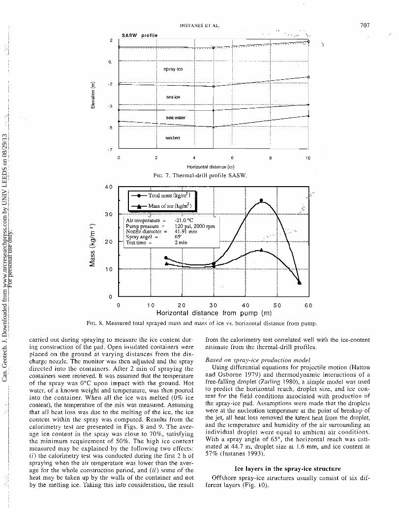
FIG. 7. Thermal-drill profile SASW.
+ Total mass (kglm2 )
+ Mass of ice (ke/m2)
t Air temperature = -21.0 "C Pump pressure = 120 si, 2000 rum 1 / i Nozzle diameter = 4 l . d mm Spray angel = 65"
' Test time = 2 min I....... 1 f
0 1 0 2 0 3 0 4 0 5 0 6 0 Horizontal distance from pump (m)
FIG. 8. Measured total sprayed mass and mass of ice vs. horizontal distance from pump.
carried out during spraying to measure the ice content dur- ing construction of the pad. Open insulated containers were placed on the ground at varying distances from the dis- charge nozzle. The monitor was then adjusted and the spray directed into the containers. After 2 min of spraying the containers were retrieved. It was assumed that the temperature of the spray was 0°C upon impact with the ground. Hot water, of a known weight and temperature, was then poured into the container. When all the ice was melted (0% ice content), the temperature of the mix was measured. Assuming that all heat loss was due to the melting of the ice, the ice content within the spray was computed. Results from the calorimetry test are presented in Figs. 8 and 9. The aver- age ice content in the spray was close to 70%, satisfying the minimum requirement of 50%. The high ice content measured may be explained by the following two effects: (i) the calorimetry test was conducted during the first 2 h of spraying when the air temperature was lower than the aver- age for the whole construction period, and (ii) some of the heat may be taken up by the walls of the container and not by the melting ice. Taking this into consideration, the result
from the calorimetry test correlated well with the ice-content estimate from the thermal-drill profiles.
Based on spi-ay-ice productiorz model Using differential equations for projectile motion (Hatton
and Osborne 1979) and thermodynamic interactions of a free-falling droplet (Zarling 1980), a simple model was used to predict the horizontal reach, droplet size, and ice con- tent for the field conditions associated with production of the spray-ice pad. Assumptions were made that the droplets were at the nucleation temperature at the point of breakup of the jet, all heat loss removed the latent heat from the droplet, and the temperature and humidity of the air surrounding an individual droplet were equal to ambient air conditions. With a spray angle of 65", the horizontal reach was esti- mated at 44.7 m, droplet size at 1.6 mm, and ice content at 57% (Instanes 1993).
Ice layers in the spray-ice structure Offshore spray-ice structures usually consist of six dif-
ferent layers (Fig. 10).
Can
. Geo
tech
. J. D
ownl
oade
d fr
om w
ww
.nrc
rese
arch
pres
s.co
m b
y U
NIV
LE
ED
S on
08/
29/1
3Fo
r pe
rson
al u
se o
nly.

Layer
Crust
Dry spray ice
'artly saturated spray ice
Saturated spray ice
Submerged spray ice
First-year ice
CAN GEOTECH J VOL 3 1 1994 5
a , 4
0 10 20 30 4 0 5 0 6 0
Horizontal distance from pump (rn)
FIG. 9. Ice content vs. horizontal distance from pump.
Density
SEA LEVEL
FIG. 10. Ice layers in a spray-ice structure.
(1) Crust This layer forms when the air temperature is low (T , <
-20°C). When the spraying operation is complete the unfrozen water near the surface does not have time to drain down through the porous spray ice before it freezes due to convective heat transfer at the surface. The crust is generally less than 0.1 m thick and has a colder temperature and
higher density (because of the increased freezing of water) than the underlying layers.
(2 ) Dry spray ice In this layer, the unfrozen water has either drained down
to lower layers or changed phase to form ice between the contacts of the spray-ice grains. The thickness of the layer depends on the freeboard of-the structure. Dry spray ice is generally found more than 1 m above sea level and its initial density depends on the meteorological and spray-system characteristics. It increases in density with time and with the stresses acting within the spray ice due to a creep mech- anism similar to the processes observed in snowbanks.
( 3 ) Partly saturated spray ice above the capillary zone This layer is partly saturated because of the underlying
saturated capillary zone found above sea level. The degree of saturation decreases with distance above the saturation zone. Thermodynamic equilibrium is reached between the spray ice and the unfrozen water since variation in the tem- perature, pressure, and chemical environment stabilizes.
(4 ) Saturated spray ice in the capillary zone The spray ice in this layer is fully saturated because of
capillary forces due to the surface tension of water within the pores of the spray-ice mass. The thickness of the layer is less than 0.5 m and it is found immediately above sea level.
(5) Submerged s p m y ice This is saturated spray ice in thermodynamic equilibrium
with the water below the surface.
( 6 ) First-year ice Spray operations usually are carried out from a natural
ice cover. The ice thickness depends on the climatic con- ditions prior to the beginning of construction. Rubble ice has also been used as a spray-ice construction surface to reduce the volumes necessary for grounding of the spray- ice mound (Esso Resources Canada Ltd. 1992).'
' ~ s s o Resources Canada Ltd. 1992. A field study of the slid- ing resistance of a grounded rubble field on a soft seabed. Esso Resources Canada Ltd., RS.91.35. Proprietary. Written permission is required from Imperial Oil Ltd., to obtain this report.
Can
. Geo
tech
. J. D
ownl
oade
d fr
om w
ww
.nrc
rese
arch
pres
s.co
m b
y U
NIV
LE
ED
S on
08/
29/1
3Fo
r pe
rson
al u
se o
nly.

\
TABLE 1. Layered spray-ice structure I i
*, Density Saturation
Layer Description Thickness (kg/m3) (%I Pore pressure
1 Crust <O. 1 m 600-700 0 0 2 Dry Function of freeboard 450-700" 0 0 3 Partly saturated <0.5 m 450-700" < 100 0 4 Saturated <0.5 m 450-700" 100 <0, suction 5 Submerged Floating feature: 450-700" 100 >0, hydrostatic
function of freeboard; grounded feature: function of water depth
6 First-year ice 0.5-2.5 m 900 100
"Density is increasing with increasing time and stress.
..................... .................... .......................... I ............................. 1 ........<. ....
........................ ............................. ...... Temperature profde through spray ice pa ..... 0 . 8 ..........................# .................................... 12 hours after spraying
............................................................ I.... Ta = - 25.0 OC, Salinity = 0 - '-- .....
.. ""'."....".............~ .......................... ..... ............ ............ .......... ""'.."" .."" " .......... I.......... ................... I.... .............<.......... .......................... 1
Temperature ( O C )
FIG. 1 1. Temperature profile through the top 1.0 m of spray-ice pad
It is important to recognize the presence of these six zones when sampling or making any in situ measurements of a spray-ice structure. Only core samples removed from layers 1 and 2 can be considered to be undisturbed, since samples removed from layers 3-6 have water in the pores which will freeze or drain on removal for storage at subzero temperatures. This introduces a change in density and in the mechanical properties determined in the laboratory compared with the field. The six different ice layers of the spray-ice pad con- structed in Tuktoyaktuk Harbour are presented in Table 1.
The above-water dry spray ice is in general well bonded. The mechanical behavior of saturated or partly saturated spray ice will be controlled by the thermodynamic processes between the ice and water in the pores. Previous field experience (Chen and Gram 1989; Bugno et al. 1989) suggests that below-water spray ice is cohesive but not as strong as dry spray ice. For offshore spray-ice structures, the pore water is usually saline and has a lower temperature than the melting point of the spray-ice particles; this keeps the material coher- ent. For the spray-ice pad constructed in the freshwater Tuktoyaktuk Harbour, the temperature of the submerged spray ice was close to its melting temperature.
Figure 11 shows a temperature profile through the upper 1.0 m of the pad 12 h after spraying was completed. The temperature approaches 0°C at 0.8 m below the surface. The temperature profile indicates that the spray ice is dry to a depth of 0.8 m and that unfrozen water is only present below
TABLE 2. Spray-ice cores
Length Air temp. Location Date (m) ( " 0
Tuk B March 10 2.5 - 33 April 10 2.7 - 13
Tuk C March 8 1.9 - 27 March 10 1.1 - 33
Tuk D March 10 1.6 -33 April 10 2.0 -13
Tuk sea ice March 10 0.6 -33
this depth. The maximum combined thickness of layers 3 and 4 is 1.0 m and the spray ice above the 1.0 m elevation is dry.
Sampling of the spray-ice pad On the basis of previous experience with broken ice (Wong
1990; Wong et al. 1990), a laboratory study on the ultra- sonic and mechanical properties of spray ice was planned. The comparison between laboratory- and field-produced spray-ice test results requires undisturbed field samples, thus this field sampling program was undertaken from the spray-ice pad.
The spray ice was cored at three different locations (Fig. 2), and one core was obtained from the first-year ice sheet. The cores were obtained using a standard 102 mm
Can
. Geo
tech
. J. D
ownl
oade
d fr
om w
ww
.nrc
rese
arch
pres
s.co
m b
y U
NIV
LE
ED
S on
08/
29/1
3Fo
r pe
rson
al u
se o
nly.

CAN GEOTECH J VOL 3 1 , 1994 \
Void ratio, e
400 500 600 700 800 900 1000
Dens~ty (kg/&)
FIG. 12. Density profile core B, west peak.
Void ratio, e
1 .O 0.5 0.2 0.0 a
6 A : :
400 500 600 700 800 900 1000
Density (kg/m3)
FIG. 13. Density profile core D, east peak.
j
. :
diameter CRREL core barrel (Rand and Mellor 1985). The softness of the spray ice allowed the core barrel to be advanced manually. The coring was stopped when the retrieved samples were observed to be saturated, because the unfrozen water contained in the samples would freeze in the cold air and in situ void ratios of the saturated samples could not be determined. Consequently, samples were obtained only from layers 1 and 2. A total of 7.1 m of core was obtained from the three different locations between March 8 and 10, 1991. An additional 4.7 m of core was retrieved on April 10. Table 2 summarizes the core lengths retrieved on each date and at each location.
In the field, the cores were identified, sealed in plastic bags, and placed in insulated sample boxes. The sample boxes were packed with snow and transported by truck from Tuktoyaktuk to Inuvik, Northwest Territories, and then by air cargo from Inuvik to Edmonton where they were transferred to cold-room facilities at the University of Alberta.
Density profiles of the spray ice from three locations are shown in Figs. 12-14. "Saturated sample" indicates a sam- ple from layers 3-6. Excellent agreement exists between the density profiles lneas~~red from the cores retrieved in both March and April. It can thus be concluded that little densification of the spray-ice pad occurred between March and April. No further density changes of the retrieved sam- ples were detected when the densities were again checked in June or 9 months later when the samples were used for the laboratory test program (Instanes 1993).
: * ; ............. ..................................... ....................... - ...................... < ........................ ........................ , ,
: A ;
............................................... - ....................... - ...................................
.................................... ..... - I '.'..! ..........+........... ! ............>........... 3
.................................................................................... ....................... ...................................
A i
- - - j SATURATED SAMPLE : :
I I I I I
Sampled March 10 (tested at the U of A. June 27)
A Sampled April I 0 (tested at the U of A. June 27)
Spectral analysis of surface waves Generally, it is difficult to obtain undisturbed samples of
the saturated layers of spray ice, because the water either freezes or drains out of the sample when it is brought to the surface or placed in storage. This represents a distur- bance to the in situ spray-ice samples which changes its mechanical properties. Sampling and laboratory testing of
...j...-...
Can
. Geo
tech
. J. D
ownl
oade
d fr
om w
ww
.nrc
rese
arch
pres
s.co
m b
y U
NIV
LE
ED
S on
08/
29/1
3Fo
r pe
rson
al u
se o
nly.

INSTANES ET AL. 1
' I 1 ., . -.
I .o 0.5 Void ratio, %,2 0.0
I e Sampled March 8 (tested in Tuktoyaktuk, March 8) . i 0 Sampled March 8 (tested at the U of A, June 27) I
. O O 5 0 0 6 0 0 700 800 900 1000
Density ( kg / m3) FIG. 14. Density profile, core C, SASW line.
MIN. M A X .
0 200 400 600 8 0 0 1000
Rayleigh wave velocity (m ls )
FIG. 15. Rayleigh wave velocities, SASW line.
samples are also expensive due to high transportation and cold-room facility maintenance costs. For these reasons a study was undertaken to relate the wave velocities mea- sured in the field with those measured in the laboratory.
Measurements of Rayleigh wave velocities of the in situ spray ice were performed using spectral analysis of surface waves (SASW) (Addo 1992). SASW is a technique where Rayleigh wave velocities are measured in situ and the dynamic material parameters can be obtained without dis- turbing the spray ice. The field measurements of the waves can then be compared with laboratory measurements to establish a correlation between the in situ and laboratory measured data. The correlation between laboratory and field measurements of elastic waves will create a basis for the use of nondestructive and nonintrusive in situ testing of spray-ice islands or pads to evaluate its in situ properties (Instanes 1993). These indirect measurements of the physi- cal properties will aid in ensuring that the constructed ice structures are economical and safe.
A 10 m horizontal line on the s ~ ~ r f a c e of the spray-ice pad was chosen for SASW profiling (see Fig. 2). A ham- mer impact was used to generate the signal, and two geo- phones placed directly on the spray-ice surface were used to obtain the velocity profile. The spacing between the geo- phones was varied to record waves of different frequencies. The same procedure was used on the first-year ice sheet. In Fig. 15 the variation of Rayleigh wave velocity with depth in the spray-ice pad is presented. Together with the thermal-drill profile (Fig. 7) and the density profile (Fig. 14), the following information can be obtained:
(i) Depth 0-0.5 in, crust and dry spray ice The core samples showed a well-bonded material with
densities between 450 and 500 kg/m3. The average Rayleigh wave velocity increased from 550 m/s at 0.1 m depth to 850 m/s at 0.5 m depth.
(ii) Depth 0.5-1.0 m, dry spray ice The core samples showed a well-bonded material with
Can
. Geo
tech
. J. D
ownl
oade
d fr
om w
ww
.nrc
rese
arch
pres
s.co
m b
y U
NIV
LE
ED
S on
08/
29/1
3Fo
r pe
rson
al u
se o
nly.

densities increasing from 475 to 525 kg/m3, with a layer of higher density (550 kg/m" at 0.7 m. The average Rayleigh wave velocity decreased from 850 to 610 mls, influenced by the dense layer at 0.7 m.
712 CAN. GEOTECH. J. VOL. 31, 1994
(iii) Depth 1.0-2.0 In, partly satuizted spray ice above the capillary zone
The core samples again showed a well-bonded material, with average density increasing from 525 to 555 kg/m! The average Rayleigh wave velocity decreased from 610 to 400 mls. This layer is close to the water table and is partly saturated. The in situ density and degree of ice bonding are lower than those obtained from the core samples due to freezing of unfrozen pore water in the samples after retrieval to the surface for storage. However, no pore-water drainage was observed from the cores, but the decrease in Rayleigh wave velocity with depth supports the assumption of increas- ing unfrozen water content with depth in the spray-ice pad.
(iv) Depth 2.0-4.0 tn, saturated spray ice Core samples from this layer are not available. At the
water table the Rayleigh wave velocity dropped to approx- imately 400 m/s, increasing slightly with further depth. This indicates that the below-water saturated spray ice is weaker with fewer bonds than the above-water layer. The slight increase in velocity with depth is due to an increase in the spray-ice density associated with self-weight consolidation.
(v) Depth below 4.0 in, first-year ice The spray ice - first-year ice interface was picked up by
the SASW measurements; however, the magnitude of the velocities is not reliable because of the large number of cracks in the first-year ice resulting from construction of the spray-ice pad, which deflects the first-year ice.
It can be concluded that the SASW technique gives valu- able information on the Rayleigh wave velocity of the dif- ferent layers in a spray-ice structure. The boundaries between dry spray ice, saturated spray ice and first-year ice can be established. SASW should be performed in future on a full- scale spray-ice island to develop and evaluate the technique further.
Conclusions
On the basis of the field construction and the research presented the following conclusions can be drawn:
1. The light-weight spray-ice system gave a spray effi- ciency of approximately 60% and spray-ice production of 150 m3/h.
2. Field samples were retrieved from the dry layers of the spray-ice structure. No change in density was observed during transportation and storage, or due to the in situ stresses between construction and final abandonment of the spray-ice pad.
3. Spectral analysis of surface waves (SASW) represents a nondestructive and nonintrusive technique for measuring in situ Rayleigh wave velocities of spray ice. These indi- rect measurements of the in situ physical properties aid in ensuring that the constructed spray-ice structures are eco- nomical and safe (Instanes 1993).
Acknowledgments
Funding was provided by Esso Resources Canada Limited, Energy, Mines and Resources Canada, and the Natural Sciences and Engineering Research Council of Canada. The
\
authors wish to thank Ji'mjPoplin and Dr. Jeff Weaver of Esso Resources Canada Limited, Nick>de Reuter of MT&T Ltd., and Gerry Cyre of the University of Alberta for their assistance in the field operations. Special thanks are due to Dr. Jeff Weaver of Esso Resources Canada Limited for his continuing active support of the research.
Addo, K. 1992. Development of a computerized SASW technique. Ph.D. thesis, Department of Civil Engineering, The University of Alberta, Edmonton.
Allyn, N., and Masterson, D. 1989. Spray ice construction and simulation. In Proceedings of the 8th International Offshore Mechanics and Arctic Engineering Symposium (OMAE), The Hague, The Netherlands, March 19-23, 1989. Vo1.4. pp. 253-262.
Bugno, W., Masterson, D., Kenny, J., and Gamble, R. 1990. Karluk ice island. In Proceedings of the 9th International Offshore Mechanics and Arctic Engineering Symposium (OMAE), Houston, Texas, Feb. 18-23, 1990. Vol. 4. pp. 9-17.
Chen, A.C.T., and Gram, K.G. 1989. Strength and deformation of spray ice. In Proceedings of the 10th International Con- ference on Port and Ocean Engineering Under Arctic Condi- tions (POAC), Luleb, Sweden, June 12-16, 1989. Edited by K.B.E. Axelsson and L.A. Franssp, University of Lulema, Sweden. Vol. 2. pp. 681-693. ,-::
Cox, G.F.N. 1979. Artificial ice islands for exploratory drilling. In Proceedings of the 5th International Conference on Port and Ocean Engineering under Arctic Conditions (POAC), Trondheim, Norway, Aug. 13-19, 1979. Vol. 1. pp. 147-161.
Gerard, R., Sego, D.C., and Hrudey, T.M. 1990. Aspects of the use of spray ice in ice bridge construction, Mackenzie River at Ft. Providence, NWT. Water Resources Engineering Report 90-2, Highway Operations Division, Department of Transportation, Government of Northwest Territories, Hay River, N.W.T.
Goff, R.D., Thomas, G.A.N., and Maddock, W. 1987. Applications of spray ice and rubble ice for Arctic offshore exploration. In Proceedings of the 6th International Conference on Offshore Mechanics and Arctic Engineering (OMAE), Houston, Texas, March 1-6, 1987. Edited by the OMAE Organizing Committee. Vol. 4. pp. 1-7.
Hatton, A.P., and Osborne, M.J. 1979. The trajectories of large fire fighting jets. International Journal of Heat and Fluid Flow, 1: 37-41.
Instanes, A. 1993. An experimental study of the mechanical behavior of spray ice. Dr. Ing. thesis, Department of Civil Engineering, Norwegian Institute of Technology, University of Trondheim, Trondheim, Norway.
Jahns, H.O., Petrie, D.H., and Lockett, A.V. 1986. CIDS spray ice barrier. In Proceedings of the 18th Annual Offshore Technology Conference (OTC), Houston, Texas, May 5-6, 1986. OTC Paper 5290.
Juvkam-Wold, H.C. 1986. Spray ice islands evaluated for Arctic drilling structures. Oil & Gas Journal, 84: 57-66.
Northwest Territories Department of Transportation. 1992. Spray ice. Program evaluation and review. Report published by the Department of Transportation, Northwest Territories, Hay River, N.W.T.
Poplin, J.P., Ralston, T.D., and St Lawrence, W. 1987. A thermal drill for profiling thick multiyear ice. Cold Regions Science and Technology, 14: 1-1 I.
Rand, J., and Mellor, M. 1985. Ice coring augers for shallow depth sampling. United States Army Corps of Engineers, Cold Regions Research and Engineering Laboratories, Hanover, NH, CRREL Report 85-2 1.
Steel, A., Morin, P.J., and Clark, J.I. 1990. Behaviour of laboratory made spray ice in triaxial compression testing. Journal of Cold Regions Engineering, 4(4): 192-204.
Wang, J.L., and Peters, D.B. 1985. Overview of artificial island
Can
. Geo
tech
. J. D
ownl
oade
d fr
om w
ww
.nrc
rese
arch
pres
s.co
m b
y U
NIV
LE
ED
S on
08/
29/1
3Fo
r pe
rson
al u
se o
nly.

I N S T A N E S E T A L . 713
design and construction in the Arctic. Civil Engineering in the Arctic Offshore. In Proceedings of the Conference Arctic '85, San Francisco, March 25-27, 1985. pp. 28-38.
Weaver, J.S., and McKeown, S. 1986. Observations of the strength properties of spray ice. In Proceedings of the 5th International Conference on Offshore Mechanics and Arctic Engineering (OMAE), Tokyo, Japan, April 13-18, 1986. American Society of Mechanical Engineering. Vol. 4. pp. 96-104.
Weaver, J.S., Poplin, J.P., and Croasdale, K.R. 1990. Spray ice islands for exploration in the Canadian Beaufort Sea. In Proceedings of the 11 th International Conference on Port and Ocean Engineering under Arctic Conditions (POAC), St. John's, Nfld., Sept . 24-28, 1991. Edited by O.B. Muggeridge, D.B. Colbourne, and H.M. Muggeridge. Ocean Engineering Research Centre, St. John's, Nfld. Vol. 3. pp. 581-590.
\
Weaver, J.S., Poplin, J.P., Instanes, A.,'and Sayed, M. 1992. Ice force and spray ice research at a naturally grounded rubble field. In Proceedings of the 1 lth International Conference on Offshore Mechanics and Arctic Engineering (OMAE), Calgary, June 7-12, 1992. Vol. 4. pp. 311-317.
Wong, T.T. 1990. The mechanical properties of broken ice. Ph.D. thesis, Department of Civil Engineering, The University of Alberta, Edmonton.
Wong, T.T., Morgenstern, N.R., and Sego, D.C. 1990. A con- stitutive model for broken ice. Cold Regions Science and Technology, 17(3): 241-252.
Zarling, J.P. 1980. Heat and mass transfer from freely falling drops at low temperatures. United States Army Corps of Engineers, Cold Regions Research and Engineering Laboratory, Hanover, NH, CRREL Report 80-18.
Can
. Geo
tech
. J. D
ownl
oade
d fr
om w
ww
.nrc
rese
arch
pres
s.co
m b
y U
NIV
LE
ED
S on
08/
29/1
3Fo
r pe
rson
al u
se o
nly.