constructal tree network for fluid flow between a finite ... tree network for fluid flow between a...
TRANSCRIPT

Rev GCn Therm (1997) 36, 592-604 0 Elsevier, Paris
Constructal tree network for fluid flow between a finite-size volume and one source or sink
Adrian Bejan
Department of Mechanical Engineering and Materials Science, Duke University, Durham, NC 27708-0300, USA
(Received 9 April 1997; accepted 15 June 1997)
Summary - The ‘constructal theory’ of formation of structure in nature is extended to fluid-flow systems. The fluid flow path between one point and a finite-size volume (an infinite number of points) is optimized by minimizing the overall flow resistance when the flow rate and the duct volume are fixed. The solution is constructed as a sequence of optimization and organization steps. The sequence has a definite time direction: it begins with the smallest building block (elemental system, with flow by volumetric diffusion), and proceeds toward larger building blocks (assemblies, with flow collected in ducts). Optimized at each level are the shape of the assembly, the number of constituents (ie, smaller assemblies), and the distribution of the duct volume. It is shown that the ducts of the optimized assemblies form a tree-like structure, in which every architectural detail is deterministic. It is also shown that the structure cannot be determined when the time direction is reversed, from large elements toward smaller elements. The general importance of the constructal law (access-optimization principle) in physics, biology and economics is discussed.
constructal theory / optimization and organization steps / tree-like structure / reversed time direction
Resume - Rbseau ramifih constructif d’un koulement de fluide entre un volume de dimension finie et un point. La thCorie constructale (ou constructive) relative d la formation de structures dans la nature est appliquCe ti des systtimes fluides ouverts. Le trajet de I’tcoulement d’un guide d partir d’un point vers un volume de dimension finie (un nombre infini de points) est optimise par la minimisation de la r&stance globale d’&oulement, dans des conditions de ddbit du Puide et de volume du tube impost!es. La solution re’sulte d’une stquence de paliers d’optimisation et d’organisation. La stquence a une direction du temps bien pre’cise ; e//e a comme origine le plus petit bloc (systime &mentaire oti I’tcoulement se fait par diffusion volumique) et tvolue vers des blocs de plus en plus grands (groupes de composants) dont I’t?oulement est collects’ dans des tubes. A chaque niveau on optimise /a configuration du groupe, le nombre de composants (par exemple /es groupes plus petits) et /a distribution du volume du tube. On montre que les tubes des groupes de composants optimise’s prPsentent une structure ramifite (ou de type arborescent), dont chaque detail architectural est diterministe. II en r&.&e aussi que la structure ne peut pas e^tre dtterminCe quand la direction du temps est inverste, c’est-&dire en al/ant des plus grands tltments vers /es plus petits. L’importance g&&ale de la thLorie constructale en physique, biologie et &onomie politique est discutie.
theorie constructale / paliers d’optimisation et d’organisation / arborescence / inversion de la direction du temps
Nomenclature
A, area ......................... D, tube diameter ............... 23 mass diffusivity. ............. H, volume height. .............. K permeability. ................ 1, duct length. ................. L, volume length.. ............. m, mass flow rate ............... m “’ volumetric mass flow rate. ... % number of constituents 4 number of branches P pressure ..................... t volume thickness ............ tt1 breathing time. .............. 11 mean velocity in duct flow ...
...... m2 ...... m ...... m’.s-’ ...... m ...... m2 ...... m ...... ...... kg.s-’ ...... kg.m-“.s-’
...... N.m-’ ...... m ...... ...... mJ:
1’ volume averaged velocity in Darcy flow ................................
1; volume ............................. Vr, pore volume ........................ .I-. y Cartesian coordinates ...............
m.s-’ m3
m3 m
Greek symbols
n factor (equation (16)) AP, pressuredrop....................... x factor (equation (15)) x Lagrange multiplier (equation (44)) v kinematic viscosity 0 fluid density
N/m’
m’.s ’ kg.m-”
592
Constructal tree network for fluid flow between a finite-size volume and one source or sink
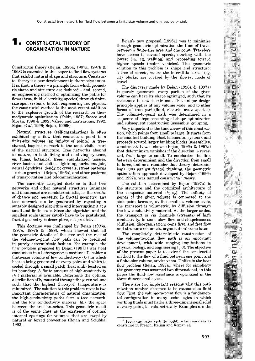
1 n CONSTRUCTAL THEORY OF ORGANIZATION IN NATURE
Constructal theory (Bejan, 1996a, 1997a, 1997b & 1998) is extended in this paper to fluid flow systems that exhibit natural shape and structure. Construc- tal theory is a new development in thermodynamics. It is, first, a theory - a principle from which geomet- ric shape and structure are deduced - and, second, an engineering method of optimizing the paths for flows (heat, fluid, electricity, species) through finite- size open systems. In both engineering and physics, the constructal method is the most recent addition to the explosive growth of the research on ther- modynamic optimization (Feidt, 1987; Stecco and Moran, 1990 & 1992; Valero and Tsatsaronis, 1992; Bejan et al, 1996; Bejan, 1996b).
Natural structure (self-organization) is often exhibited by a flow that connects a point to a finite-size volume (an infinity of points). A tree- shaped, loopless network is the most visible part of the natural structure. Tree networks abound in nature, in both living and nonliving systems, eg, lungs, botanical trees, vascularized tissues, river basins and deltas, lightning, turbulent jets, neural dendrites, dendritic crystals, street patterns -urban growth - (Bejan, 1996a), and other patterns of transportation and telecommunication.
The currently accepted doctrine is that tree networks and other natural structures (animate and inanimate) are nondeterministic, ie, the results of chance and necessity. In fractal geometry, any tree network can be generated by repeating a suitably designed algorithm and interrupting it at a small and finite scale. Since the algorithm and the smallest scale (inner cutoff) have to be postulated, fractal geometry is descriptive, not predictive.
This doctrine was challenged by Bejan (1996a, 1997a, 199713 & 19981, which showed that all the geometric details of the tree and the rest of the volume-to-point flow path can be predicted in purely deterministic fashion. For example, the flow problem proposed by Bejan (1997a) was heat conduction in a heterogeneous medium: ‘Consider a finite-size volume of low conductivity (/G,) in which heat is being generated at every point and which is cooled through a small patch (heat sink) located on its boundary. A finite amount of high-conductivity (IcP) material is available. Determine the optimal distribution of lc, material through the given volume such that the highest (hot-spot) temperature is minimized.’ The solution to this problem reveals two important characteristics of natural organization: the high-conductivity paths form a tree network, and the low conductivity material fills the space between the tree branches. This geometric result is of the same class as the existence of optimal internal spacings for volumes that are swept by natural or forced convection (Bejan and Sciubba, 1992).
Bejan’s new proposal (1996a) was to minimize through geometric optimization the time of travel between a finite-size area and one point. Travelers have access to several speeds, starting with the lowest (Vo, eg, walking) and proceeding toward higher speeds (faster vehicles). The geometric solution to this problem is shape and structure: a tree of streets, where the interstitial areas (eg, city blocks) are covered by the slowest mode of travel.
The discovery made by Bejan (1996a & 1997a) is purely geometric: every portion of the given volume can have its shape optimized, such that its resistance to flow is minimal. This unique design principle applies at any volume scale, and to other forms of transport (fluid, electric, mass species). The volume-to-point path was determined in a sequence of steps consisting of shape optimization and subsequent construction (assembly, grouping).
Very important is the time arrow of this construc- tion, which points from small to large. It starts from the smallest building block (elemental system), and proceeds toward larger building blocks (assemblies, constructs). It was shown (Bejan, 1996a & 1997a) that determinism vanishes if the direction is rever- sed, from large to small. To emphasize the link between determinism and the direction from small to large, and as a reminder that theory (determin- ism) runs against fractal thinking, the geometric optimization approach developed by Bejan (1996a and 1997a) was named constructal* theory.
The solution determined by Bejan (1997a) is the structure and the optimized architecture of the composite material (lco, kP). The infinity of points of the given volume is connected to the sink point because, at the smallest volume scale, the transport is volumetric, by diffusion through the low-conductivity material. At the larger scales, the transport is via channels (streams) of high conductivity. In time, slow flow and shapelessness (diffusion, disorganization) come first, and fast flow and structure (channels, organization) come later.
The completely deterministic construction of the volume-to-point flow path is an important development, with wide ranging implications in physics, biology, and engineering (3 8). The objective of the present paper is to extend the constructal method to the ilow of a fluid between one point and a finite-size volume, or vice versa. Unlike in the heat flow problem (Bejan, 1997a), where for simplicity the geometry was assumed two-dimensional, in this paper the fluid-flow resistance is optimized in the three-dimensional space.
There are two important reasons why this opti- mization method deserves to be extended to fluid flow. First, the volume-to-point tlow is a fundamen- tal configuration in many technologies in which working fluids must bathe a three-dimensional solid at every point, ie, volumetrically. Examples are the
* From the Latin verb (to build), which survives as construire in French, Italian and Romanian.
593

A Bejan
porous beds used for energy storage, matrices of periodic-flow heat or mass exchangers, gas cooled electric windings, and convection cooled electronic packages. This optimization is generally important in engineering, because fluid networks (eg, piping) are one of the most basic aspects of power-system engineering (Padet, 1991; Falempe, 1995).
The second reason is purely theoretical. The volume-to-point fluid flow has received considerable attention in biophysics and geophysics because of its numerous manifestations in natural systems. Most of this work has been devoted to understanding the origin of the architecture of air passages in the lungs and capillaries in vascularized tissues. As shown in the concluding part of this paper (3 7 and 8), previous studies of the minimal resistance problem used as starting point the observations that tree networks exist, and that ducts bifurcate. To predict these properties - the tree, and the integer 2 (bifurcation) - are the essential objectives of the analysis developed in this paper.
2 I THE FLOW RATE CONSTRAINT
To construct an analysis that is both effective and transparent, it is advisable to rely on the simplest, most general possible model that still retains the most essential feature of the flow path: its function. Such a model begins with figure 1, which shows that the function of the path is to distribute the stream riz from the point M to every elemental volume AV. We focus on this function and optimization problem in a general way, without reference to a specific application (natural occurrence) of the flow pattern.
An important consequence of the function of the flow path is that in some cases two superimposed paths are needed. For example, in the bronchial tree the flow is periodic (in 8z out), and only one path is needed. In the circulatory system two identical paths (in counter-flow) are needed, such that each elemental volume fIV receives arterial blood at the rate dictated by local metabolism, Ati. The elemental volume returns the blood at the same rate to the veins (eg, the dark network in figure I). Similar pairs of paths in counterflow are encountered in trees, roots and leaves. A river basin needs only one path, because the volume V is flat (the basin area) and Ati is proportional to the rainfall per unit area.
In sum, the function of the flow path is well represented by the volumetric mass flow rate density
11, ATil m =-
AV
which must be collected (integrated) over the volume V, and channeled as a single stream (ti) to the point M. This operational characteristic
(ti”‘) is assumed given, and serves as constraint in the thermodynamic optimization of the network. For simplicity we assume that ti”’ is distributed uniformly over V, such that
7jL = TiL”‘V (2) We focus on only one of the tlow paths of figure 1,
namely the dark one, and recognize that Arh is driven from the elemental volume to the origin by the pressure difference (P - P&f). This difference varies with the position of the AV element relative to M: of special interest is the maximum pressure difference, AP = (enaLp - PM), which is needed by the elemental volumes that are situated the farthest from the end of the network. In the lungs and the circulatory system, for example, AP is the pressure level that must be maintained by the thorax and heart muscles. The time-averaged mechanical power consumed by these pumps, or the entropy generation rate of the entire network is proportional to the product ti AP. The total flowrate ti is fixed, because V and ti”’ are fixed. In conclusion, the thermodynamic optimization of the flow path is equivalent to minimizing the maximum pressure difference.
3 n THE FIRST VOLUME ELEMENT
Two features distinguish the methodology of this paper from approaches tried in the past (3 7). First, the optimization process has a definite direction: from small volume elements toward larger volumes (assemblies). Second, the smallest scale of the network is finite and known (predictable): this scale serves as starting point in the step-by-step optimization and organization procedure.
3.1. OPTIMIZATION OF VOLUME SHAPE
The smallest volume element is shown in figure 2. The volume VI = HI L1 t is fixed because the thickness t and the area AI = HI L1 are fixed. The shape of the element is variable, and is represented by the aspect ratio Hl/Ll.
The volume VI is visited uniformly by the mass flow rate til = h”‘VI. At this first (elemental) level, only one tube (diameter DI in figure 3) is used to collect the til stream and lead it to one point on the boundary: in figure 2, that point is the origin (0,O). Symmetry and the requirement that AP be minimum suggest that the tube should be placed along the 5 axis. The mass flow rate through this tube is h(z), with h(O) = til at the origin (O-O), and ti(L1) = 0. Except for the point of origin, the surfaces of the elemental volume K are impermeable. The thickness t is assumed to be sufficiently small, t < (HI, L1), such that the pressure field that drives the flow is essentially two-dimensional, P(x,. y).
594

Constructal tree network for fluid flow between a finite-size volume and one source or sink
Fig 1. Flow paths between one point M with every point inside a finite volume (V).
Fig 1. Trajets d’6coulement d’un fluide A partir d’un point M vers chaque point d’un volume de dimension finie V.
Y
H,/2
a 0)
-H,12
F /
111 m, K ” t P(x. Y)
ml 4 Jb FX
N Ll ,n
m, K fi(x)
Fig 2. The flow through the first (smallest) volume element.
Fia 2. Flux traversant le oremier (et le DIUS oetit) Clement de-volume.
+lt+ 71-r1-r i I ; I ;
I I DO-c ‘4! I !
D1+ i I I I I i I i I i .
._.-.-.-.-.-.-.-.-.
t
-I
LI
T LO
A-
Fig 3. The first element modeled as an anisotropic porous medium.
Fig 3. Premier element mod&lis& en tant que milieu poreux anisotrope.
The rest of the flow path between the origin (0,O) and any other point (z, y) is located in the material situated above and below the z axis. To account for the flow that originates from an arbitrary point of the finite volume VI, we model this material as an anisotropic porous medium in which Darcy flow (Nield and Bejan, 1992) is oriented purely in the y direction when y # 0,
K dP v=- -- P ( > aY
(3)
The Darcy flow bathes every one of the infinity of points contained by VI. In equation (3), w and K are the volume-averaged velocity and, respectively, the permeability in the y direction. The fluid may flow in the x direction only along the z axis. This anisotropic model is clearly a simplification, which later will restrict our geometric constructions to drawing only 90” angles between successive assemblies. At this early stage in the analysis, however, this is a reasonable modeling approximation, especially if K is small.
The pressure field P(x, y) can be determined by eliminating w between equation (3) and the local mass continuity condition
all ?v’ a?J=p
and applying the boundary conditions aP/ay = 0 at y = HI/2 and P = P(x, 0) at y = 0:
P(X> Y) = $$(HI y - y”) + P(x,O) (5)
Equation (5) holds only for y > 0: the corresponding expression for y < 0 is obtained by replacing HI with -HI in equation (5).
The function describing the pressure distribution along the x axis can be determined after making similar assumptions about the fluid mechanics of the stream that eventually exits as +a1 through the origin. Let us assume as in earlier studies (Thomson, 1942; Mac Donald, 1983) that this stream is a low Reynolds number (Hagen-Poiseuille) flow through a round tube of length L1 and diameter D1. First, we use the classical result for the mean velocity in the x direction:
y=o
to estimate the local mass flow rate +(x), which points toward the origin,
Mass conservation requires that the mass gener- ated in the infinitesimal volume slice (HI t dx) con- tribute to the k(x) stream,
ti”‘H1 t dx = -dti (8)
Integrating equation (8) away from the imperme- able plane x = L (where ti = 0), and recalling that til = ti”‘HILlt, we obtain:
ti(x)=?ir”‘H&1-z)=til(l+) (9)
Finally, equations (7) and (9) yield the pressure distribution along the x axis
P(x, 0) = PO + 128 3 (Llx- $) (10)
595
A Bejan
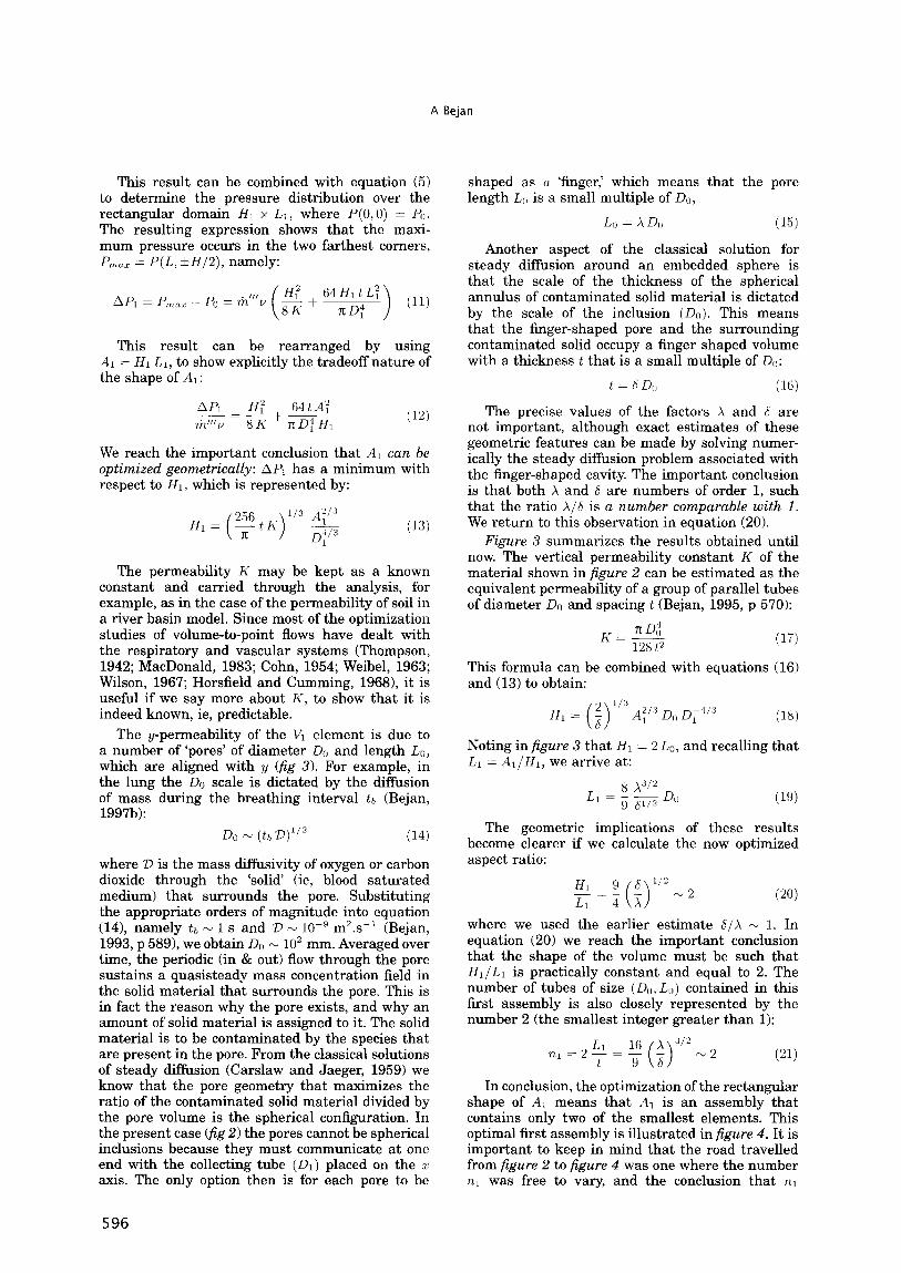
This result can be combined with equation (5) to determine the pressure distribution over the rectangular domain HI x LI, where P(O,O) = PO. The resulting expression shows that the maxi- mum pressure occurs in the two farthest corners, P - P(L, &H/2), namely: nlar -
API = P,,, - PO = ril”‘Y 64HltL: lTD;1 (11)
This result can be rearranged by using A1 = HI LI, to show explicitly the tradeoff nature of the shape of Al:
(12)
We reach the important conclusion that A1 can be optimized geometrically: API has a minimum with respect to HI, which is represented by:
H1 = (!+)I” !ii!$ 1
The permeability K may be kept as a known constant and carried through the analysis, for example, as in the case of the permeability of soil in a river basin model. Since most of the optimization studies of volume-to-point flows have dealt with the respiratory and vascular systems (Thompson, 1942; MacDonald, 1983; Cohn, 1954; Weibel, 1963; Wilson, 1967; Horsfield and Cumming, 19681, it is useful if we say more about K, to show that it is indeed known, ie, predictable.
The y-permeability of the VI element is due to a number of ‘pores’ of diameter DO and length LO, which are aligned with y (fig 3). For example, in the lung the DO scale is dictated by the diffusion of mass during the breathing interval tb (Bejan, 199713):
DO N (tb l3)l” (14)
where D is the mass diffusivity of oxygen or carbon dioxide through the ‘solid (ie, blood saturated medium) that surrounds the pore. Substituting the appropriate orders of magnitude into equation (14), namely tb N 1 s and D N lop9 rn’.s-l (Bejan, 1993, p 5891, we obtain DO N 10’ mm. Averaged over time, the periodic (in & out) flow through the pore sustains a quasisteady mass concentration field in the solid material that surrounds the pore. This is in fact the reason why the pore exists, and why an amount of solid material is assigned to it. The solid material is to be contaminated by the species that are present in the pore. From the classical solutions of steady diffusion (Carslaw and Jaeger, 1959) we know that the pore geometry that maximizes the ratio of the contaminated solid material divided by the pore volume is the spherical configuration. In the present case cf;g 2) the pores cannot be spherical inclusions because they must communicate at one end with the collecting tube (Dl) placed on the z axis. The only option then is for each pore to be
shaped as a ‘finger,’ which means that the pore length LO is a small multiple of DO,
Lo = X Do (15)
Another aspect of the classical solution for steady diffision around an embedded sphere is that the scale of the thickness of the spherical annulus of contaminated solid material is dictated by the scale of the inclusion (DO). This means that the finger-shaped pore and the surrounding contaminated solid occupy a finger shaped volume with a thickness t that is a small multiple of Do:
t = h D,, (16)
The precise values of the factors X and 6 are not important, although exact estimates of these geometric features can be made by solving numer- ically the steady diffusion problem associated with the finger-shaped cavity. The important conclusion is that both X and 6 are numbers of order 1, such that the ratio X/S is a number comparable with 1. We return to this observation in equation (20).
Figure 3 summarizes the results obtained until now. The vertical permeability constant K of the material shown in figure 2 can be estimated as the equivalent permeability of a group of parallel tubes of diameter DO and spacing t (Bejan, 1995, p 570):
K-3 (17)
This formula can be combined with equations (16) and (13) to obtain:
HI= f 0
l/3 z/3 A, Do D,+
Noting in figure 3 that HI = 2 Lo, and recalling that LI = A1 /HI, we arrive at:
The geometric implications of these results become clearer if we calculate the now optimized aspect ratio:
HI 9 6 llJ2 -2 -=- - Ll 0 4 x (20)
where we used the earlier estimate S/X w 1. In equation (20) we reach the important conclusion that the shape of the volume must be such that H~/LI is practically constant and equal to 2. The number of tubes of size (DO, LO) contained in this first assembly is also closely represented by the number 2 (the smallest integer greater than 1):
Ll 3/2 n,1 E 2-.- 16 X = -
t 9 0 s
rv 2 (21)
In conclusion, the optimization of the rectangular shape of A1 means that AI is an assembly that contains only two of the smallest elements. This optimal first assembly is illustrated in figure 4. It is important to keep in mind that the road travelled from figure 2 to figure 4 was one where the number nl was free to vary, and the conclusion that nl
596
T Hl
I
AL Dl T
Constructal tree network for fluid flow between a finite-size volume and one source or sink
(4
D
~
T LO
.-. .- -L
kLl -+I
tb)
i
- .-
kLl -+I
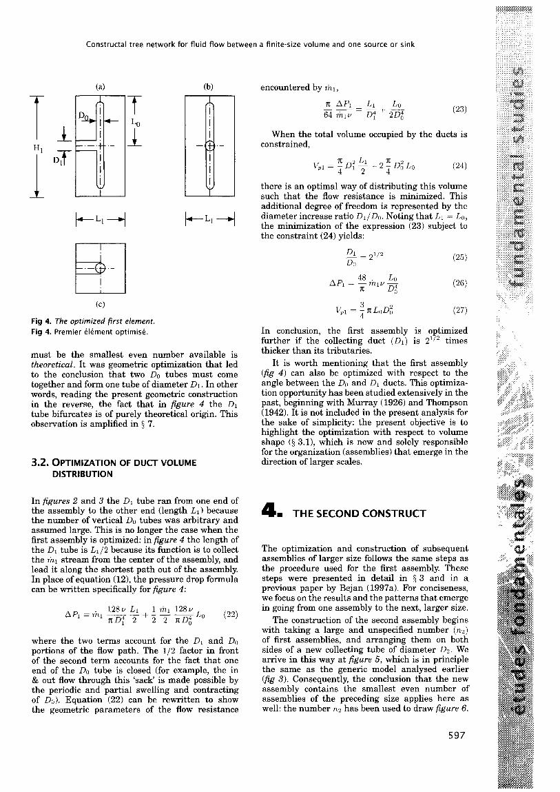
(cl Fig 4. The optimized first element.
Fig 4. Premier &ment optimise.
must be the smallest even number available is theoretical. It was geometric optimization that led to the conclusion that two ~0 tubes must come together and form one tube of diameter DI. In other words, reading the present geometric construction in the reverse, the fact that in figure 4 the DI tube bifurcates is of purely theoretical origin. This observation is amplified in 3 7.
3.2. OPTIMIZATION OF DUCT VOLUME DISTRIBUTION
In figures 2 and 3 the D1 tube ran from one end of the assembly to the other end (length Li) because the number of vertical DO tubes was arbitrary and assumed large. This is no longer the case when the first assembly is optimized: in figure 4 the length of the D1 tube is L1/2 because its function is to collect the rizi stream from the center of the assembly, and lead it along the shortest path out of the assembly In place of equation (12), the pressure drop formula can be written specifically for figure 4:
where the two terms account for the DI and DO portions of the flow path. The 112 factor in front of the second term accounts for the fact that one end of the DO tube is closed (for example, the in & out flow through this ‘sack’ is made possible by the periodic and partial swelling and contracting of DO). Equation (22) can be rewritten to show the geometric parameters of the flow resistance
encountered by tii,
(23)
When the total volume occupied by the ducts is constrained,
V,l = 2D:++2;D;Lo
there is an optimal way of distributing this volume such that the flow resistance is minimized. This additional degree of freedom is represented by the diameter increase ratio D1 /DO. Noting that LI = LO, the minimization of the expression (23) subject to the constraint (24) yields:
Dl -=2 l/2 Do
(26)
3 Vpl = - n: LoD,2
4 (27)
In conclusion, the first assembly is optimized further if the collecting duct (01) is 21/2 times thicker than its tributaries.
It is worth mentioning that the first assembly (fig 4) can also be optimized with respect to the angle between the Do and D1 ducts. This optimiza- tion opportunity has been studied extensively in the past, beginning with Murray (1926) and Thompson (1942). It is not included in the present analysis for the sake of simplicity: the present objective is to highlight the optimization with respect to volume shape (3 3.1), which is new and solely responsible for the organization (assemblies) that emerge in the direction of larger scales.
4 I THE SECOND CONSTRUCT
The optimization and construction of subsequent assemblies of larger size follows the same steps as the procedure used for the first assembly. These steps were presented in detail in 3 3 and in a previous paper by Bejan (1997a). For conciseness, we focus on the results and the patterns that emerge in going from one assembly to the next, larger size.
The construction of the second assembly begins with taking a large and unspecified number (nz) of first assemblies, and arranging them on both sides of a new collecting tube of diameter D2. We arrive in this way at figure 5, which is in principle the same as the generic model analysed earlier (fig 3). Consequently, the conclusion that the new assembly contains the smallest even number of assemblies of the preceding size applies here as well: the number n2 has been used to draw figure 6.
597
A Bejan
We see that the shape-optimized second assembly contains two first assemblies, which form the larger stream (tiz = til + til) right in the center of the second assembly. The lizz stream is guided out of the second assembly through a new duct of diameter Dz and length L2/2 (= LO/~).
Fig. 4c
T
I
D2 n n n H2
t u
il I I l+-L2B
Fig 5. Second construct containing an unspecified number of first elements. Fig 5. Deuxieme construction contenant un nombre non sphcifik de premiers elements.
T T Li 1 l--i--l .-.-.- - - Fig 6. The optimized second construct.
Fig 6. Deuxieme construction optimiske.
The second step in the optimization of the second assembly consists in minimizing the total flow resistance overcome by ti;?,
128~ Lz AP2=ti2 D1+AP, (28)
2
subject to the total pore volume constraint
In these equations, API and V,I are provided by equations (26) and (27). The optimal distribution of pore volume is described by:
D2 -=2 S/6
DO
AP2 = ; (2-l’” + 3) Lo tizv- D4 0
1/1,2 = ; (2Z’3 + 3) L,, 0;
In view of equation (25), the ratio DnlDo = 2’16 means that in going from the first to the second as- sembly the diameter of the collecting duct increases by a factor DzlDI = 2l/“.
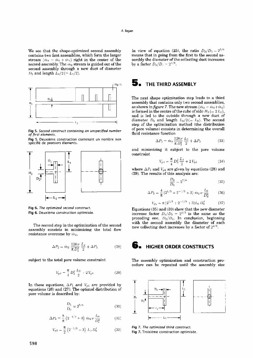
5 I THE THIRD ASSEMBLY
The next shape optimization step leads to a third assembly that contains only two second assemblies, as shown in figure 7. The new stream (tis = tia+tiz) is formed in the centre of the cube of side E-r, (= 2 Lo), and is led to the outside through a new duct of diameter DS and length L3/2 (= Lo). The second step of the optimization method (the distribution of pore volume) consists in determining the overall fluid resistance function
128~ L3 AP:S = ti3 - -
7~03” 2 sAp2 (33)
and minimizing it subject to the pore volume constraint
b1;,3 = !! D2 L3 4 3 2 f2Vp2 (34)
where AP2 and V,Z are given by equations (28) and (29). The results of this analysis are:
D3 -=2 7/6
Do (35)
A& = $ (z113 + 2-l/” + 3) ti3v- ;4 (36) 0
v,pj = TT (21’3 + 2-“3 + 3)L,, 0; (37) Equations (35) and (30) show that the new diameter increase factor D3/D2 = 2l/” is the same as the preceding one, Dz/DI. In conclusion, beginning with the second assembly the diameter of each new collecting duct increases by a factor of 2’i3.
6 m HIGHER ORDER CONSTRUCTS
The assembly optimization and construction pro- cedure can be repeated until the assembly size
T 1 D2 i “3 -i-
I
DT
I (3
f 4 ---i- r 1 I
t+--- L3-4
Fig 7. The optimized third construct. Fig 7. Troisieme construction optimisbe.
598
Constructal tree network for fluid flow between a finite-size volume and one source or sink
TABLE I Summary of the optimized geometries and fluid flow resistances of the first nine constructs
Assembly 1,/1,+1 D,/Di-1 AP, 0; V ___ -2% m, u LO D:Lo
i
1 1
i p/2 +f (3) 2 (3)
2 1 p/3 a (3 + 2-“3) ; (3 + 2-1’3)
3 2 p/3 i (3 + 2-W + 219 n (3 + 2-1’3 + 21’3)
4 1 21/3 1 (4 + 2-W + 2W) 2 n (4 + 2-1’3 + 21’3)
5 1 p/3 ; (4 + 2 x 2-1’3 + 2l’3) 4n (4 + 2 x 2-1’3 + 21’3)
6 2 p/3 & (4 + 2 x 2-l’” + 2 x 21’3) 8n (4 + 2 x 2-l’” + 2 x 21’“)
7 1 21/s & (5 + 2 x 2-1’3 + 2 x 21’3) 16x (5 + 2 x 2-~1’3 + 2 x 2”“)
8 1 p/3 & (5 + 3 x 2-1’3 + 2 x 21’3) 32~(5+3~2-~‘~+2~2~‘“)
9 2 p/3 & (5 + 3 x 2-1’3 + 3 x ~2~‘~) 64~ (5 + 3 x 2-1’3 + 3 x 2l’“)
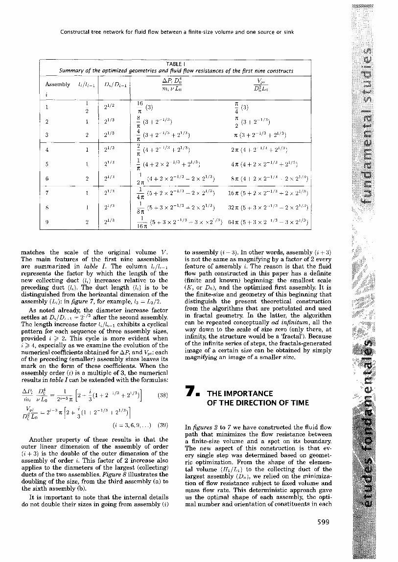
matches the scale of the original volume V. The main features of the first nine assemblies are summarized in table I. The column 1,/1,-l represents the factor by which the length of the new collecting duct (1%) increases relative to the preceding duct (li). The duct length (li) is to be distinguished from the horizontal dimension of the assembly (L,): in figure 7, for example, 13 = L3/2.
As noted already, the diameter increase factor settles at D,/Dtel = 2 ‘i3 after the second assembly. The length increase factor &/1,-l exhibits a cyclical pattern for each sequence of three assembly sizes, provided i 3 2. This cycle is more evident when i 2 4, especially as we examine the evolution of the numerical coefficients obtained for AP, and V,i: each of the preceding (smaller) assembly sizes leaves its mark on the form of these coefficients. When the assembly order (i) is a multiple of 3, the numerical results in table I can be extended with the formulas:
AP, 0; 1 --=- rni VLO ‘p5 n 2 + i(1+ 2-1’3 + 21’3) 1 (38)
61 m=
22-3 7T 2 + f(1 + 2-1’3 + 21/3)]
(i=3,6,9,...) (39)
Another property of these results is that the outer linear dimension of the assembly of order (i + 3) is the double of the outer dimension of the assembly of order i. This factor of 2 increase also applies to the diameters of the largest (collecting) ducts of the two assemblies. Figure 8 illustrates the doubling of the size, from the third assembly (a) to the sixth assembly (b).
It is important to note that the internal details do not double their sizes in going from assembly (i)
to assembly (i + 3). In other words, assembly (i + 3) is not the same as magnifying by a factor of 2 every feature of assembly i. The reason is that the fluid flow path constructed in this paper has a definite (finite and known) beginning: the smallest scale (K, or DO), and the optimized first assembly. It is the finite-size and geometry of this beginning that distinguish the present theoretical construction from the algorithms that are postulated and used in fractal geometry. In the latter, the algorithm can be repeated conceptually ad infinitum, all the way down to the scale of size zero (only there, at infinity, the structure would be a ‘fractal’). Because of the infinite series of steps, the fractals-generated image of a certain size can be obtained by simply magnifying an image of a smaller size.
7 I THE IMPORTANCE OF THE DIRECTION OF TIME
In figures 2 to 7 we have constructed the fluid flow path that minimizes the flow resistance between a finite-size volume and a spot on its boundary. The new aspect of this construction is that ev- ery single step was determined based on geomet- ric optimization. From the shape of the elemen- tal volume (H1/L1) to the collecting duct of the largest assembly (Dn), we relied on the minimiza- tion of flow resistance subject to fixed volume and mass flow rate. This deterministic approach gave us the optimal shape of each assembly, the opti- mal number and orientation of constituents in each
599

A Bejan
Fig 8. The doubling of the outer dimension in going from the optimized third construct (a) to the optimized sixth construct (b). Fig 8. Doublement de la dimension extkrieure en passant de la troisieme construction optimiske (a) ti la sixieme (b).
new assembly, and the optimal dimensions of each new duct. The construction began with the smallest element, in which the fluid flowed volumetrically (Darcy flow), and proceeded step-by-step toward assemblies of larger sizes.
To see what is new in this approach, note that one portion of the network pattern (namely, the portion formed by the higher-order assemblies, table I for i > 4) is not new. It was proposed in physiology as a heuristic model for the circulatory system (Cohn, 1954), where it was known empirically that each tube is followed by two smaller tubes, ie, each tube undergoes bifurcation. It was also known that the tube diameter must decrease by a constant factor (2-l’“) during each bifurcation: this result had been derived based on flow resistance minimization (Thompson, 1942) and later, based on entropy generation minimization (Wilson, 1967); it was the only theory-based notion present in the algorithms used to reconstruct the pulmonary tree or other tree-shaped networks that appear in nature (trees, roots, leaves, river basins, deltas, lightning). The description of these geometric constructions was made popular through the advent of fractal geometry: in fact, a two-dimensional version of Cohn’s (1954) branching fluid network appeared later in the books by Mandelbrot (1983) and Prigogine (1980), where it was presented heuristically as a ‘model of the lung’.
In spite of these advances, the theory of branch- ing fluid networks remained limited to one result:
600
the constant factor for diameter reduction during branching [which, upon closer scrutiny, turns out to be empirical not theoretical: see equation (48)]. The construction steps that were left to be determined theoretically are the number of new (smaller) ducts formed during branching (why two branches, and not six?), the relation between the branch length and the length of the original (larger) duct, and the position of the smaller branches relative to larger branches, ie, the manner in which the flow path fills the volume. Another extremely important aspect that awaited an explanation is why the theoretical diameter reduction factor (z-‘/~) fails to describe the sizes of the smallest ducts. In other words, why does the heuristic construction of an algorithm- based network break down at a sufficiently small scale (as in figures 2 and 3)?
The analysis of sections 2-6 provided theoretical answers to all these questions. To see why the previous investigations of the volume-to-point flow did not lead to a pure theory, let us rethink the problem by relying on the traditional approach. In past studies of branching fluid networks, the network was first seen and accepted, and then it was broken down repeatedly (eg, through postulated bifurcation), beginning with the largest duct and proceedings toward smaller scales. In figure 9 we assume that the volume V is filled by an existing network of ducts. The network is seen as a sequence of n branching stages (j = I,&. , n), which proceeds in the direction of smaller scales. At

Constructal tree network for fluid flow between a finite-size volume and one source or sink
1 =o j =I J =2 No=1 N, N2
LO f-1 L2
DO 4 D2
Fig 9. The time-reversed approach: an assumed fluid network that branches in the direction of smaller scales.
Fig 9. Inversion de la direction du temps : proposition de r&.eau de fluides en direction des plus petits Sments.
each branching stage, the unknown dimensions of each duct are D, and Lj. The total number of ducts of size (D,, L3) is also unknown, and is labeled NJ. The starting (zeroth) duct of the network is characterized by DO, LO and NO = 1, where Do should not be confused with the smallest scale identified in the present analysis @g 3 and 4). The directions in which the branches invade the volume are unknown. The number of branching stages n is also unknown.
The conservation of the total mass flow rate tie at each branching stage j requires:
tie = NJ ri2, (40)
where riz, is the mass flow rate through one branch of the jth order,
n AP, 0," m3=128Ty
and AP, is the pressure difference across the jth branching stage. Combining equations (40) and (41), and summing over all the branching stages, we estimate the total pressure difference sustained by the network:
We then minimize the flow resistance subject to the duct volume constraint
J=o 3=0
This optimization problem is equivalent ing the extremum of the function
(42)
AP/rizo
(43)
to find-
(44)
where X is a Lagrange multiplier. The sequence of optimal tube diameters that minimizes P, is:
2 l/6
Qopt = x
0
N3-1’3 (j = 0, 1,. . ,n) (45)
which shows that the optimal diameters decrease as NJ:1’3 from one branching stage to the next. The value of the Lagrange multiplier can be determined by substituting the optimal distribution (45) into the duct volume constraint (43),
In conclusion, equation (45) shows that if the number of ducts at each branching stage is known (N,), then we have an optimal sequence of duct diameters for minimum overall flow resistance. For illustration, consider Thompson’s (1942) example of the respiratory and vascular systems, where observations showed that each tube is continued by two smaller tubes:
NJ = 2J (47)
According to equation (45), in this case the optimal diameters decrease as Z-J/~, and the ratio between two consecutive tube sizes is a constant:
= 2-l/” g 0.8 (48) opt
Equation (45) is a theoretical result, and, in it, the NJ and L, values are left unspecified. Equation (48), on the other hand, is empirical because equation (47) is empirical: it rests on the direct and unexplained observation that in the lung and the vascularized tissue each large tube is continued by two smaller tubes.
Equation (45) is the most that the approach based on figure 9 can predict. The analysis of this section - the breaking down of each duct into a more numerous generation of ducts - showed very simply why this approach cannot advance theoretically beyond the ability to predict the tube diameters when the tube numbers are accepted empirically. The features of the fluid network can be anticipated in a purely deterministic manner only when the analysis proceeds from small building blocks toward larger building blocks. The present method of accessing a finite volume from one point invites us to rethink the language in which we describe naturally organized systems. Confluence yes, branching no. Coalescence yes, bifurcation no. Construction yes, fracturing no. Constructal yes, fractal no.
8 I THE OPTIMAL-ACCESS LAW, AND THE ORIGIN OF SHAPE AND STRUCTURE IN NATURE
The present method suggests that the three- dimensional tree networks that are so common in
601

A Bejan
nature are the fingerprint of the minimization of the flow resistance between a finite volume and one point. They are the result of optimizing the access between all the points of the volume (an infinite number of points) and the single point that serves as source or sink.
This deterministic approach has two very special features that have not been recognized in the past. One is the time direction (from small to large), which was discussed at length in 5 7. The other is the notion that the flow (the access) between the source point and a point inside the finite volume can occur via two regimes, not one. One regime is volumetric diffusion [disorganized molecular motion, eg, equation (311 and the other is an ‘organized’ flow [streams, eg, equation (6)]. Each flow path is a combination of a portion with high resistance (diffusion) and a portion with low resistance (streams).
Access to the infinite number of points inside the finite size volume is assured by placing the slowest (diffusion) regime in the smallest volume element. This is why the small-to-large direction is so important. After this initial step, the access optimization problem becomes one of allocating low- resistance path (duct volume) to finite volumes of increasingly larger sizes. Had there been only one flow regime in the finite volume (eg, diffusion), the volume-to-point access would have been described by the well known ‘radial’ flow (sink, source) solution.
These two features are evident in all the volume- to-point and area-to-point flows found in animate and inanimate systems in nature. There are most visible at the end of the pencil-and-paper analysis by which the time of travel between an area and one point is minimized (Bejan, 1996a). Tree networks of alleys, streets of avenues emerge naturally They are the result of the same principle (time minimization) that in the past allowed us to rationalize the natural occurrence of straight rays of light, the equality of the incident and reflection angles (Heron of Alexandria), and the existence of an optimal angle of refraction (Fermat).
The discovery that tree networks are determin- istic is very important to the design of telecom- munication networks and computer architecture. In mathematics, the problem of connecting with the shortest line several points spread over a finite area is known as Steiner’s problem (Courant and Rob- bins, 1941). According to Bern and Graham’s review (19891, ‘the solution to this problem has eluded the fastest computers and the sharpest mathematical minds,’ and its solutions ‘defy analysis.’ Solutions have been found for connecting a moderate num- ber of points in a plane. Worth noting is that as computers become more powerful this number will increase, but it will never be infinite to cover com- pletely the given area. Furthermore, the opaque optimization performed by the computer will never be theory The alternative to Steiner’s problem (Be- jan, 1996a & 1997a) was the proposal to optimize access (ie, to minimize flow resistance, travel time,
602
etc), when the flow has at least two regimes, one slow, and the others considerably faster.
The geometric structure formed by slow and fast flow regimes is a feature that unites all the volume- to-point access phenomena found in nature. In this paper, we discussed the flow of oxygen through a mammal: the slow flow is volumetric mass diffusion through the tissues, while the faster regime is mass convection through blood vessels and bronchial pas- sages. The same is true in every turbulent flow, which is another form of natural organization: vol- umetric diffusion in the smallest volume elements is accompanied by faster and thinner currents known as eddies. Artificial constructs such as the internal architecture of computers require the same cooper- ation between slow and fast heat transfer, with the slow mode (volumetric thermal diffusion) placed at the smallest scale. The examples go on. This co- operation is most obvious in living groups, from bacterial colonies to the most advanced societies: every member has a place in the structure, in such a way that every member benefits. The urge to organize is an expression of selfish behavior.
In the fluid flow system analyzed in this paper we neglected some of the internal details (degrees of freedom) of the structure, eg, the angles between the collecting ducts and their tributaries. In a follow up study (Ledezma et al, 1997) of the heat flow problem (Bejan, 1997a), we demonstrated numerically that the finer details of the tree network play a negligible role indeed. The shapes of each of the building blocks are the important geometric optima that determine the optimal numbers of streams that merge into larger streams at each level of assembly. This is an important conclusion because it sheds light on the origin of the coexistence of order and disorder in natural structures. If the optimal access from a finite-size volume to one point is what counts, then the finer details of the path are not important: they may vary according to unknown, incidental factors that can be labeled ‘chance.’
The main point is that the larger picture, the op- timal overall performance, structure, and working mechanisms, can be described in a purely deter- ministic fashion; that is, if the access-optimization principle is recognized as a law. This law can be stated as follows: For a finite-size system to persist in time (to live), it must evolve in such a way that it provides easier access (less resistance) to the im- posed currents that flow through it (Bejan, 1997a). This statement has two parts. First, it recognizes the natural tendency of imposed global currents to construct paths (shapes, structures) for better ac- cess through constrained open systems. The second part accounts for the evolution of the structure, which occurs in an identifiable direction that can be aligned with time itself Small size and shapeless flow (disorganization, diffusion) are followed in time by larger sizes and organized flows (organization, streams). Complexity continues to increase in time.
The importance of this theoretical development stretches beyond engineering, physics and biology. Consider the economic activity that covers a given
Constructal tree network for fluid flow between a finite-size volume and one source or sink
area. The economic activity is the optimization principle, and the structure that covers the area is its result. To see how the present constructal theory explains the origin of structure in economics and business, consider a stream of goods that proceeds from one point (producer, or factory) to every point of a finite-size territory (consumers). The flow may also proceed in the opposite direction (eg, grain, carpets woven by individuals). The objective is to minimize the total cost associated with the given stream. The economies of scale principle tells us that the unit cost is lower when the goods move in the aggregate, ie, when they are organized into thicker streams. The unit cost is also proportional to the distance traveled. Clearly, the unit cost plays the same role as the local thermal resistance in heat trees (Bejan, 1997a), or the inverse of the travel speed in street trees (Bejan, 1996a), or the local fluid-flow resistance in the present paper. The given territory is covered naturally by links of decreasing unit cost, starting from the highest unit cost which is allocated to the smallest area scale (the individual), and continuing with a sequence of intermediaries (distributors) who handle increasingly larger fractions of the given stream of goods.
Another by-product of the constructal theory is that it explains also why natural structures ‘happen to look’ like the images generated by assumed fractal algorithms that are truncated arbitrarily An explanation for the physics principle behind the design of the algorithm had been missing. Constructal theory is about the single physics principle from which geometry (shape, structure, organization) can be deduced. Constructal theory is deterministic (predictive), in sharp contrast to fractal geometry, which is at best descriptive.
How important is the constructal theory of op- timal access, ie, this single geometric optimization principle that allows us to anticipate the tree ar- chitecture seen in so many natural systems? In contemporary physics a significant research vol- ume is being devoted to the search for universal design principles that may explain organization in animate and inanimate systems. In this search, the tree network is recognized as the symbol of the challenge that physicists and biologists face (Kauffman, 1993, pp 13-14): ‘Image a set of identi- cal round-topped hills, each subjected to rain. Each hill will develop a particular pattern of rivulets which branch and converge to drain the hill. Thus the particular branching pattern will be unique to each hill, a consequence of particular contingencies in rock placement, wind direction, and other fac- tors. The particular history of the evolving patterns of rivulets will be unique to each hill. But viewed from above, the statistical features of the branching patterns may be very similar. Therefore, we might hope to develop a theory of the statistical features of such branching patterns, if not of the particular pattern on one hill.’
The constructal approach described in this paper and in previous ones (Bejan, 1996a, 1997a, 199713
& 1998; Ledezma et al, 1997) is a deterministic answer to the challenge articulated so well by Kauffman. It introduces an engineering flavor in the current debate on natural organization, which until now has been carried out mainly in physics and biology. By training, engineers begin the design of a device by first understanding its purpose. The size of the device is always finite, never infinitesimal. The device must function (ie, fulfill its purpose) subject to certain constraints. Finally, to analyze (describe) the device is not sufficient: to optimize it, to construct it, and to make it work is the ultimate objective. All these features, purpose, finite size, constraints, optimization, and construction, can be seen in the constructions reported in this paper and in previous ones (Bejan, 1996a, 1997a, 1997b & 1998; Ledezma et al, 1997). The resulting tree networks are entirely deterministic, and, consequently, they represent an alternative worthy of consideration in fields outside engineering. The progress made in this direction is reviewed in a new book (Bejan, 1998).
Acknowledgments
This work was supported by the National Science Foundation, USA. MR Err-era’s assistance in this project is gratefully acknowledged. Figures 1 to 7 and 9 were drawn by Kathy Vickers, and figure 8 by G Ledezma.
REFERENCES
Bejan A (1993) Heat Transfer. Wiley & Sons, New York
Bejan A (1995) Convection Heat Transfer, 2nd ed. John Wiley & Sons, New York
Bejan A (1996a) Street network theory of organization in nature. 1 Adv Jrunsportution 30(2), 85-107
Bejan A (1996b) Entropy Generation Minimization. CRC Press, Boca Raton, FL, USA
Bejan A (1997a) Constructal-theory network of conducting paths for cooling a heat generating volume. Int I Heat Muss Transfer 40, 799-8 16
Bejan A (1997b) Theory of organization in nature: pulsating physiological processes. Int J Heat Muss Transfer 40, 2097-2 104
Bejan A (1998) Advanced Engineering Thermodynamics, 2nd ed. John Wiley & Sons, New York
Bejan A, Sciubba E (1992) The optimal spacing of Parallel plates cooled by forced convection. In? J Heat Mass Transfer 35, 3259-3264
Bejan A, Tsatsaronis C, Moran M (1996) Thermal Design and Optimization. John Wiley & Sons, New York
Bern MW, Graham RL (1989) The shortest-network problem. Scientific American, Jan, 84-89
Carslaw HS and Jaeger JC (1959) Conduction of Heat in Solids. Oxford University Press, Oxford
Cohn DL (1954) Optimal systems: I. The vascular system. Bull Math Biophys 16, 59-74
Courant R, Robbins H (1941) What is Mathematics?Oxford University Press, London
603
A Bejan
Falempe M (1995) Synthese des reseaux de fluides et leurs methodes d’etude, aspects pedagogiques, experimentaux et industriels. These de doctorat, Universite de Valenciennes et du Hainaut-Cambresis, France
Feidt M (1987) Thermodynamique et optimisation Cnergttique des systtmes et procedds. Technique et Documentation, Lavoisier, Paris
Horsfield K, Cumming C (1968) Morphology of the bronchial tree in man. J Appl Physiol 24, 373-383
Kauffman SA (1993) The Origins of Order. Oxford University Press, New York
Ledezma GA, Bejan A, Errera MR (1997) Constructal tree networks for heat transfer. J Appl Phys 82(l), 89-100
MacDonald N (1983) Trees and Networks in Biological Mode/s. John Wiley & Sons, Chichester, UK
Mandelbrot BB (1983) The Fructal Geometry of Nature. Freeman & Co, New York
Murray CD (1926) The physiological principle of minimal work, in the vascular system, and the cost of blood- volume. Proc Acad Nat Sci XII, 207-2 14
Nield DA, Bejan A (1992) Convection in Porous Media. Springer Verlag, New York
Padet J (1991) fluides en hcoulement, methodes et mode’les, enseignement de /a physique. Editions Mas- son, Paris
Prigogine I (1980) From Being to Becoming. Freeman & Co, San Francisco
Stecco 55, Moran MJ, eds (1990) A Future for Energy. Pergamon, Oxford
Stecco 55, Moran MJ, eds (1992) Energy for the Transition Age. Nova Science, New York
Thompson DAW (1942) On Growth and Form. Cambridge University Press, Cambridge
Valero A, Tsatsaronis G eds (1992) In: EC05 ‘92, Proc international Symposium on Efficiency, Costs, Optimization and Simulation of Energy Systems, Zaragoza, Spain. ASME, New York
Weibel ER (1963) Morphometry of the Human Lung. Springer Verlag, New York
Wilson TA (1967) Design of the bronchial tree. Nature 2 13, 668-669
604