constructability & maintainability seminar...drain piping compartment space heaters jack stand...
TRANSCRIPT

Constructability & Maintainability Seminar
7HA Gas Turbine
* Trademark of General Electric Company
GE Proprietary and Confidential

2 7HA Constructability Seminar
3/23/2014 Comparative statements refer to GE technology unless otherwise stated. © 2013 General Electric Company. All rights reserved.
GT Accessory Modularization Overview
Fuel Control Module Air Extraction Module, Lower
Air Extraction Module, Left
Upper Enclosure Module, Left
Upper Enclosure Module, Right
Air Extraction Module, Right
GT Drains Module

3 7HA Constructability Seminar
3/23/2014 Comparative statements refer to GE technology unless otherwise stated. © 2013 General Electric Company. All rights reserved.
Modularization Example…Cooling & Sealing Air Build Scaffolding
Install piping and piping supports
Install ship loose valves in piping
Build enclosure around piping, mount junction boxes, cut piping penetrations through walls
Route instrument air tubing, electrical wiring
& conduit to wall of enclosure
Complete water wash drain piping (EPC scope of design & supply within enclosure)
Commission valves and instrumentation
Insulate all piping
Install turbine maintenance grating and handrails
1
2
3
5
6
7
8
4
9
7F.03 Cooling and Sealing Air
7HA.01 Modularized Design
1
2
3
Install modules
Install piping between GT and modules
Insulate field installed piping
7HA 7F.03

4 7HA Constructability Seminar
3/23/2014 Comparative statements refer to GE technology unless otherwise stated. © 2013 General Electric Company. All rights reserved.
Air Extraction Module, Lower
Purge air cooler
Water wash drain piping
Compartment space heaters
Jack stand
•Purge air cooler complete with water control valve and piping
• Jack stand integrated as piping support to prevent from unnecessary piping removal during maintenance
5 7HA Constructability Seminar
3/23/2014 Comparative statements refer to GE technology unless otherwise stated. © 2013 General Electric Company. All rights reserved.
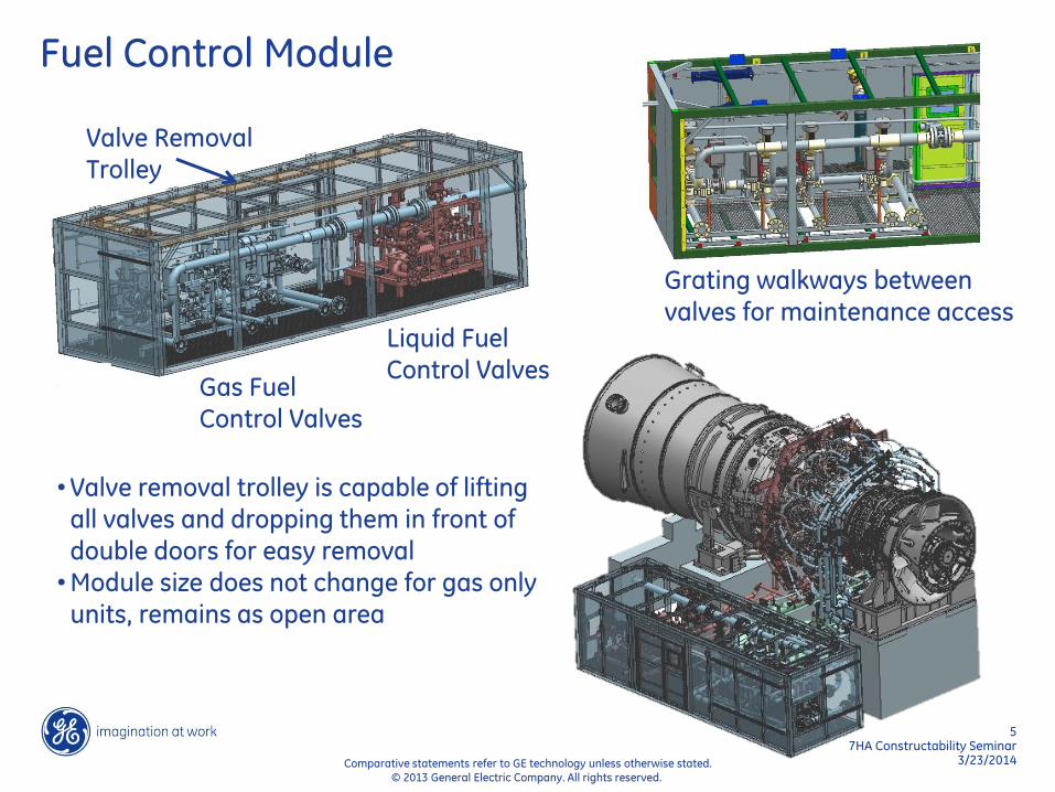
Fuel Control Module
Gas Fuel Control Valves
Liquid Fuel Control Valves
Valve Removal Trolley
•Valve removal trolley is capable of lifting all valves and dropping them in front of double doors for easy removal
•Module size does not change for gas only units, remains as open area
Grating walkways between valves for maintenance access

6 7HA Constructability Seminar
3/23/2014 Comparative statements refer to GE technology unless otherwise stated. © 2013 General Electric Company. All rights reserved.
Quick Disconnect Flanges Gas Fuel Manifolds
Liquid Fuel Manifolds
104 quick release flanges 6 WW drain flanges
32 quick release flanges
24 SAE 4-bolt flanges

7 7HA Constructability Seminar
3/23/2014 Comparative statements refer to GE technology unless otherwise stated. © 2013 General Electric Company. All rights reserved.
Air Extraction Module, Left
• Cooling and sealing air piping • Compressor bleed valve • Inlet bleed heat valve • Stage 2 and 3 nozzle cooling valves • Integrated grating for maintenance
access • Handrails (not shown) included

8 7HA Constructability Seminar
3/23/2014 Comparative statements refer to GE technology unless otherwise stated. © 2013 General Electric Company. All rights reserved.
Air Extraction Module, Right
Stage 2 Nozzle
cooling valve
Over Board Bleed valve (FSFL test hardware only)

9 7HA Constructability Seminar
3/23/2014 Comparative statements refer to GE technology unless otherwise stated. © 2013 General Electric Company. All rights reserved.
GT Drains Module
Water wash supply
control valves
Water wash
drain valves
False start drain valves
Simplified
interface points
Removable grating and sill for roll-in access
through double doors

10 7HA Constructability Seminar
3/23/2014 Comparative statements refer to GE technology unless otherwise stated. © 2013 General Electric Company. All rights reserved.
Combustion Can Maintenance Access
Maintenance area reserved to allow can removal from below
Width: 5’ Height: 6’ Length: 12’
Double door with removable sill for “roll-in roll out” access
11 7HA Constructability Seminar
3/23/2014 Comparative statements refer to GE technology unless otherwise stated. © 2013 General Electric Company. All rights reserved.
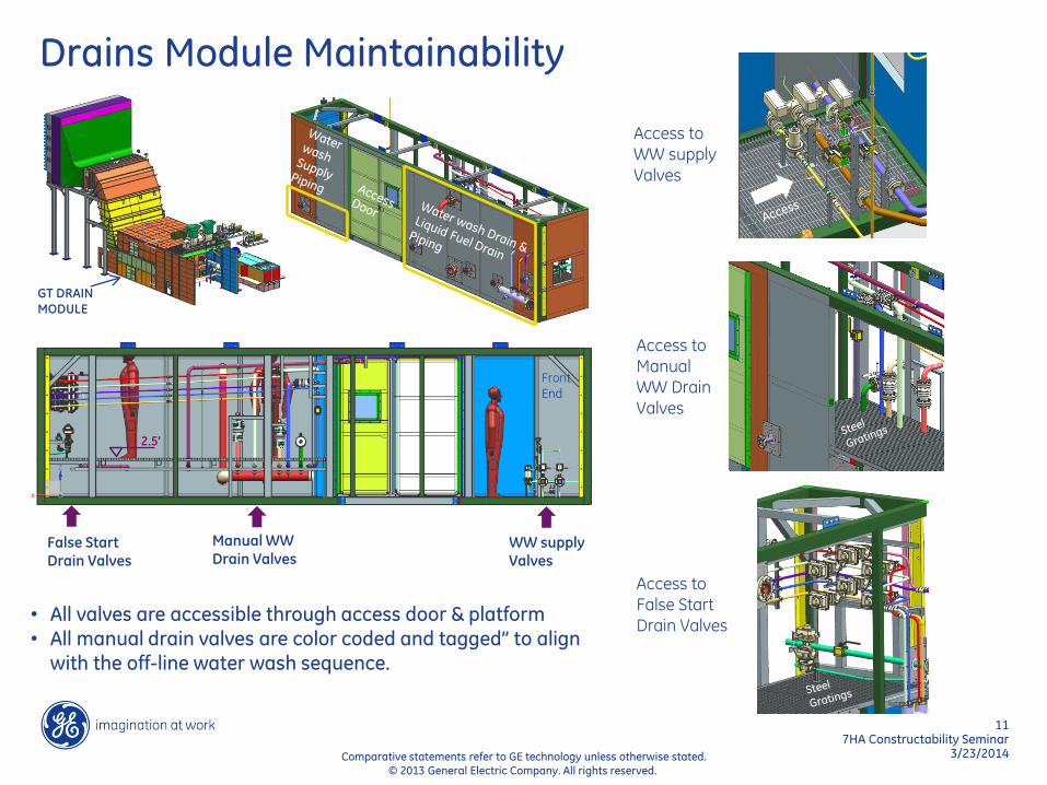
Drains Module Maintainability
• All valves are accessible through access door & platform • All manual drain valves are color coded and tagged” to align
with the off-line water wash sequence.
GT DRAIN
MODULE
False Start Drain Valves
Access to False Start Drain Valves
Access to Manual WW Drain Valves
Access to WW supply
Valves
2.5’
Front End
Manual WW Drain Valves
WW supply Valves
12 7HA Constructability Seminar
3/23/2014 Comparative statements refer to GE technology unless otherwise stated. © 2013 General Electric Company. All rights reserved.
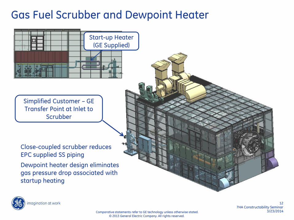
Gas Fuel Scrubber and Dewpoint Heater
Close-coupled scrubber reduces
EPC supplied SS piping
Dewpoint heater design eliminates
gas pressure drop associated with
startup heating
Start-up Heater
(GE Supplied)
Simplified Customer – GE
Transfer Point at Inlet to Scrubber

13 7HA Constructability Seminar
3/23/2014 Comparative statements refer to GE technology unless otherwise stated. © 2013 General Electric Company. All rights reserved.
External Modules
Lube Oil
Module
Liquid Fuel
Filtering
Inlet Plenum
Load Coupling
Guard

14 7HA Constructability Seminar
3/23/2014 Comparative statements refer to GE technology unless otherwise stated. © 2013 General Electric Company. All rights reserved.
Lube Oil Piping
Simplified lube oil flushing developed with field engineers reduce setup time

Enclosures and Ventilation

16 7HA Constructability Seminar
3/23/2014 Comparative statements refer to GE technology unless otherwise stated. © 2013 General Electric Company. All rights reserved.
Ventilation
Single extraction & instrumentation duct
Ventilation inlets and dampers included in modules
GT Insulated at site by GE or GE supervision (Union Sites)
Modules ship with insulation pre-installed
Fans are moved aft over exhaust to enable simpler roof design and easier maintenance access

17 7HA Constructability Seminar
3/23/2014 Comparative statements refer to GE technology unless otherwise stated. © 2013 General Electric Company. All rights reserved.
GT Enclosure Maintenance Provisions
Deck height set below
turbine centerline to
allow for easy bolt access
Maintenance access points for pneumatic
hoses and power cords
Ladders and Handrails
incorporated in modules
Removable grating and
bracing allow valves to
be pulled up to main deck

18 7HA Constructability Seminar
3/23/2014 Comparative statements refer to GE technology unless otherwise stated. © 2013 General Electric Company. All rights reserved.
Clean Roof
Single Ventilation Extraction (no removal required)
Exhaust Frame and #2 Bearing Blowers
GT Compartment Ventilation Fans
CI HGP Maj

19 7HA Constructability Seminar
3/23/2014 Comparative statements refer to GE technology unless otherwise stated. © 2013 General Electric Company. All rights reserved.
Load Compartment & Load Coupling Guard
No separate off base load compartment
Load Compartment ventilation fans (2) and silencer eliminated
Self-Ventilating Load Coupling Guard
Shaft windage used to dissipate heat generated by coupling
Natural ventilation path for hydrogen dissipation when not running
Current 7F.03 Design
New 7HA.01 Design
Ventilation CFD

20 7HA Constructability Seminar
3/23/2014 Comparative statements refer to GE technology unless otherwise stated. © 2013 General Electric Company. All rights reserved.
Instrument Air
Instrument air tubing to valves pre-installed in modules and routed to customer connection

21 7HA Constructability Seminar
3/23/2014 Comparative statements refer to GE technology unless otherwise stated. © 2013 General Electric Company. All rights reserved.
Inlet Filter House and IBH
2-Pipe IBH Manifold
Simplified Interconnect Piping by GE (no bellows)
IBH Control Valve modularized into GT
enclosure
All IBH piping is in GE
scope of supply

22 7HA Constructability Seminar
3/23/2014 Comparative statements refer to GE technology unless otherwise stated. © 2013 General Electric Company. All rights reserved.
Inlet Bleed Heat Simplification
Previous 7F Design
Trombone Pipes
Piccolo Pipes
2 Horizontal
Distribution Pipes
Simplified 7HA Design
All piping field installed
Extensive welding and x-ray test required
Welding inside duct required for supports
Internal piping shipped pre-installed
6 field welds and standard 10% x-ray testing
No welding inside duct required
Overmixed Proper Mixing
23 7HA Constructability Seminar
3/23/2014 Comparative statements refer to GE technology unless otherwise stated. © 2013 General Electric Company. All rights reserved.
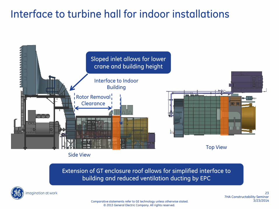
Interface to turbine hall for indoor installations
Rotor Removal Clearance
Interface to Indoor Building
Side View
Top View
Extension of GT enclosure roof allows for simplified interface to
building and reduced ventilation ducting by EPC
Sloped inlet allows for lower
crane and building height

Electrical
25 7HA Constructability Seminar
3/23/2014 Comparative statements refer to GE technology unless otherwise stated. © 2013 General Electric Company. All rights reserved.
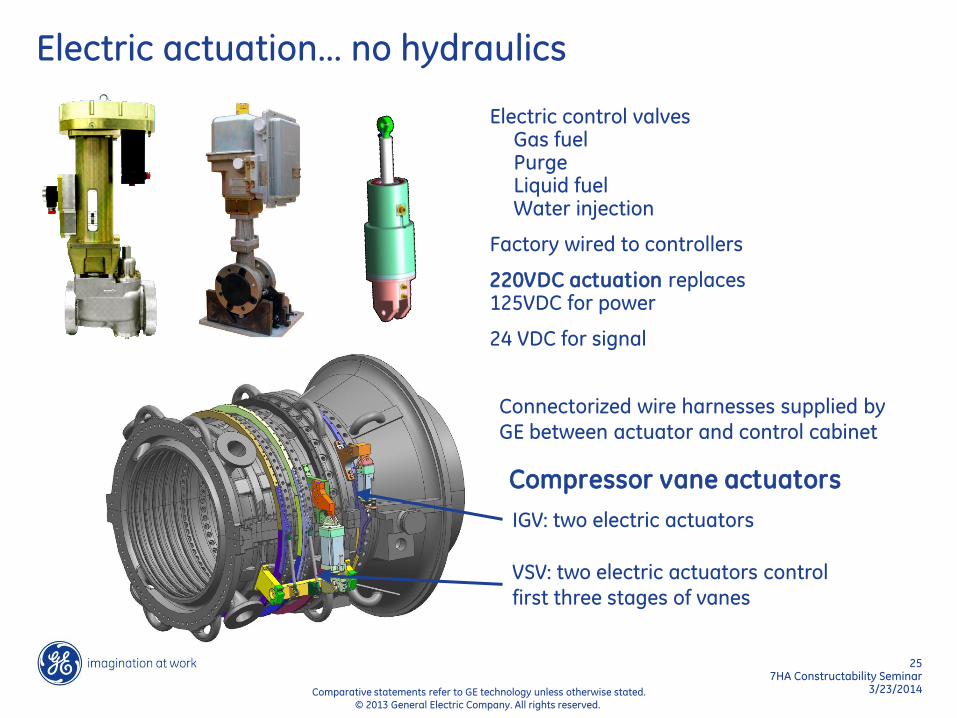
Electric actuation… no hydraulics
Electric control valves Gas fuel Purge Liquid fuel Water injection
Factory wired to controllers
220VDC actuation replaces 125VDC for power
24 VDC for signal
IGV: two electric actuators
VSV: two electric actuators control
first three stages of vanes
Compressor vane actuators
Connectorized wire harnesses supplied by
GE between actuator and control cabinet

26 7HA Constructability Seminar
3/23/2014 Comparative statements refer to GE technology unless otherwise stated. © 2013 General Electric Company. All rights reserved.
IGV & VSV Maintenance Simplification
Connectorized Digital Valve Positioner Cabinet for electrically actuated valves IGV (2) & VSV (2) Gas Fuel Control (4) Liquid Fuel Control (3)
Plug and Play electrical
design to reduce
installation and
commissioning time
Roxtec cable sealing for enclosure penetrations
Hydraulic tubing and
servos eliminated

27 7HA Constructability Seminar
3/23/2014 Comparative statements refer to GE technology unless otherwise stated. © 2013 General Electric Company. All rights reserved.
• Cable tray instead of conduit
• Electrical pre-wired for accessory modules
• Exposed run rated cable to allow for free length at device termination
• 125 VDC power level has been eliminated (replaced by 24 VDC for low power signals and 220 VDC for high power level)
~50% reduction in # of JBs.
~70% reduction in # of field terminations.
BEFORE – Conduit AFTER – Cable Tray
Electrical Design Highlights
Field installed, cut, and
routed conduit is replaced
by pre-installed cable tray

28 7HA Constructability Seminar
3/23/2014 Comparative statements refer to GE technology unless otherwise stated. © 2013 General Electric Company. All rights reserved.
FFB minifast connectors at T/Cs, transmitters, segment
protectors and linking devices for Plug and Play wiring design.
Example FFB Network Topology (Lube Oil)
Connectorized FBSPs - Plug and Play Design

29 7HA Constructability Seminar
3/23/2014 Comparative statements refer to GE technology unless otherwise stated. © 2013 General Electric Company. All rights reserved.
• Aspirated IR design for GT
enclosure, aspirated cat
bead technology for
generator and generator
collector enclosures.
• New technology reduces #
of false trips which was a
nuisance with the older
technology. It is also
immune to poisons which
was a major limitation of
the BN cat bead sensors.
• New design can tolerate
tighter LEL settings and
has a lower calibration
frequency.
Haz Gas Detection System Design Highlights
30 7HA Constructability Seminar
3/23/2014 Comparative statements refer to GE technology unless otherwise stated. © 2013 General Electric Company. All rights reserved.
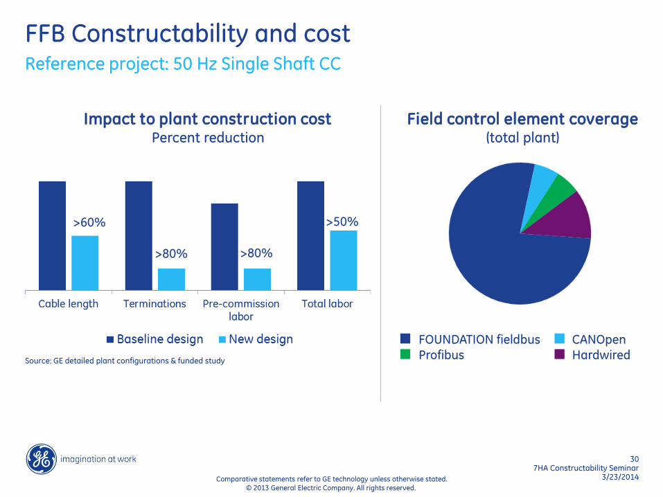
FFB Constructability and cost Reference project: 50 Hz Single Shaft CC
Source: GE detailed plant configurations & funded study
Impact to plant construction cost Percent reduction
>60%
>80% >80%
>50%
Field control element coverage (total plant)
FOUNDATION fieldbus CANOpen Profibus Hardwired

Fire Protection

32 7HA Constructability Seminar
3/23/2014 Comparative statements refer to GE technology unless otherwise stated. © 2013 General Electric Company. All rights reserved.
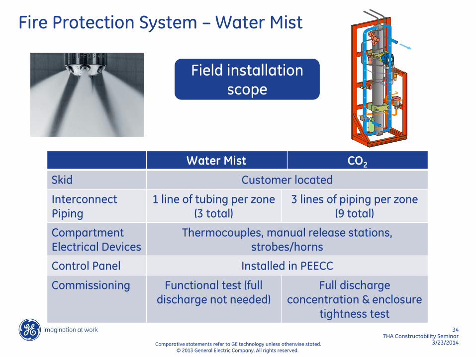
Fire Protection System – Water Mist
Customer located skid: Tubing to each zone up to 150ft.
Zone 1 – Turbine Compartment
Zone 2 – #2 Bearing Tunnel
Zone 3 – Lube Oil Skid
Water mist is standard for fire protection instead of CO2.
• Meets NFPA 750 standard
• FM Approved system
• Gas pump unit (GPU) is driven by compressed air cylinders to drive water to the nozzles.
• Discharge solenoid valve open on fire detection or manual release.

33 7HA Constructability Seminar
3/23/2014 Comparative statements refer to GE technology unless otherwise stated. © 2013 General Electric Company. All rights reserved.
Fire Protection System – Water Mist
Water Mist vs CO2
• SAFETY - Eliminates personnel risks. Mist insulates personnel from thermal
radiation. No Risk of Asphyxiation. C02
also causes carbonic acid build up in
lungs.
• SYSTEM EFFECTIVENESS - Eliminates
suppression failures from loss of
enclosure tightness (37% of CO2 system
failures due to C02 system leaks causing
inability to reach required concentrations). Water Mist remains effective with open
doors.
• EQUIPMENT DAMAGE - Reduces fire damage potential by eliminating
discharge delay (30 Seconds). Potential
spread of fire reduced.
• COST OF OWNERSHIP - Reduces long term cost of ownership, eliminates
periodic full discharge concentration tests
following major GT maintenance
(Currently $24,000 per re-test).
• ENVIRONMENT – Eliminates hazards to
environment due to C02 Production.
34 7HA Constructability Seminar
3/23/2014 Comparative statements refer to GE technology unless otherwise stated. © 2013 General Electric Company. All rights reserved.
Fire Protection System – Water Mist
Field installation scope
Water Mist CO2
Skid Customer located
Interconnect Piping
1 line of tubing per zone (3 total)
3 lines of piping per zone (9 total)
Compartment Electrical Devices
Thermocouples, manual release stations, strobes/horns
Control Panel Installed in PEECC
Commissioning Functional test (full discharge not needed)
Full discharge concentration & enclosure
tightness test

Liquid Fuel System Design

36 7HA Constructability Seminar
3/23/2014 Comparative statements refer to GE technology unless otherwise stated. © 2013 General Electric Company. All rights reserved.
Liquid Fuel System: New Design Legacy Design New Design
Atomization Atomizing Air Pressure Atomized
NOx abatement Water injection Pre-mixed Water & Fuel
Anti-coking Recirculation/N2 Purge Water purge
Purge credit Secondary Design Features Inherent to Design
Purge Cooled Air Purge Water Block

37 7HA Constructability Seminar
3/23/2014 Comparative statements refer to GE technology unless otherwise stated. © 2013 General Electric Company. All rights reserved.
Simplified EPC Scope
Filtration skid
By GE
Piping by GE
Liquid Fuel and Water Injection pumps by GE
Interconnect
Piping by EPC
7F.03 Skids Liquid fuel forwarding Water injection (A035) Fuel heating (E041) Fuel management spool piece (A245) Liquid Fuel and Atomizing Air (A162) 7HA Skids Liquid fuel pumping Water injection pumping Liquid fuel and Water Injection Filtering AM10 Fuel Control Module (shared with gas)
Fuel forwarding pumps are no longer required for new design
4” if < 1400 ft

38 7HA Constructability Seminar
3/23/2014 Comparative statements refer to GE technology unless otherwise stated. © 2013 General Electric Company. All rights reserved.
Labor intensive site installation Modularized manifolds with quick disconnects at mid-line
Pressure Atomized LF LF w/ Atomizing Air
Simplified field installation & maintenance

39 7HA Constructability Seminar
3/23/2014 Comparative statements refer to GE technology unless otherwise stated. © 2013 General Electric Company. All rights reserved.
Pressure Atomized LF LF w/ Atomizing Air
• Many potential leak points • Labor intensive for CIs
• Flanges minimized, no tube fittings • Only 2 tubes to remove for CI
On-base Piping

40 7HA Constructability Seminar
3/23/2014 Comparative statements refer to GE technology unless otherwise stated. © 2013 General Electric Company. All rights reserved.
6 endcover connections 2 Valves on endcover
2 endcover connections No valves on endcover
LF w/ Atomizing Air
Simplified field installation
Pressure Atomized LF
41 7HA Constructability Seminar
3/23/2014 Comparative statements refer to GE technology unless otherwise stated. © 2013 General Electric Company. All rights reserved.
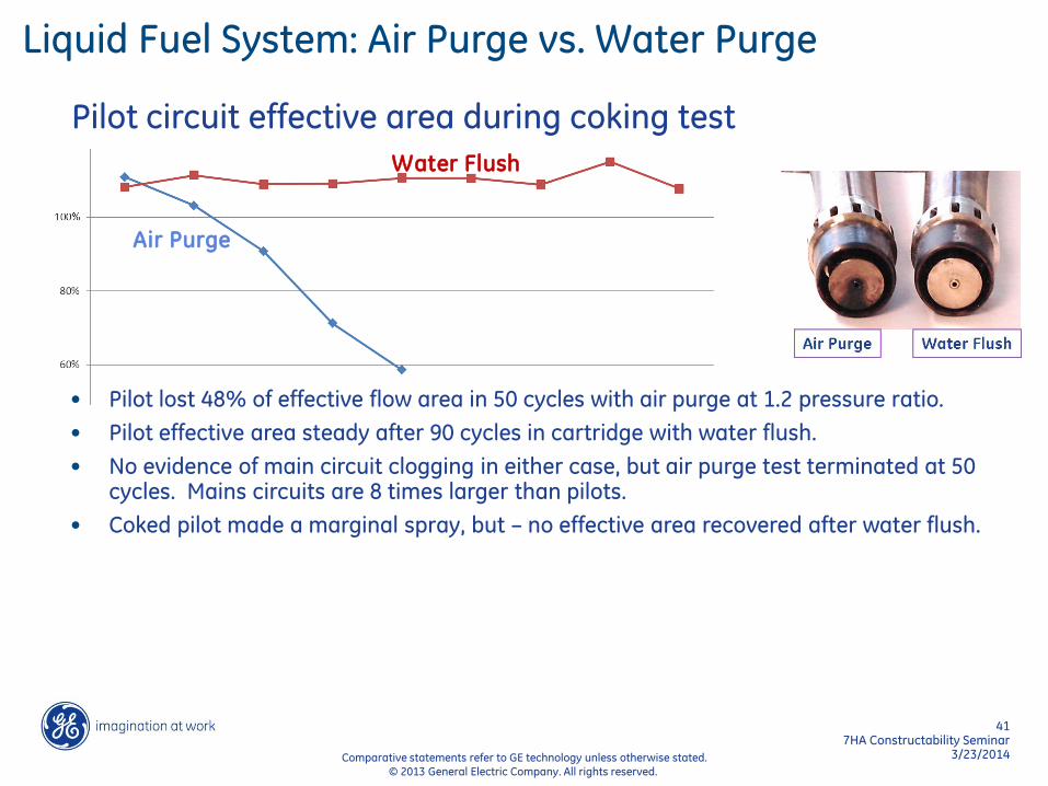
Pilot circuit effective area during coking test
Water Flush
Air Purge
Liquid Fuel System: Air Purge vs. Water Purge
• Pilot lost 48% of effective flow area in 50 cycles with air purge at 1.2 pressure ratio.
• Pilot effective area steady after 90 cycles in cartridge with water flush.
• No evidence of main circuit clogging in either case, but air purge test terminated at 50 cycles. Mains circuits are 8 times larger than pilots.
• Coked pilot made a marginal spray, but – no effective area recovered after water flush.

42 7HA Constructability Seminar
3/23/2014 Comparative statements refer to GE technology unless otherwise stated. © 2013 General Electric Company. All rights reserved.
Flush Effectiveness Testing - Main
Coupon Testing
Filled/Brushed, Covered & Cooked 1 hr @ 425 °F
UV Dye Flush Testing
Main Fuel Valve: Test Point #1 Main Fuel Valve: Test Point #7
Flush/Coke Testing
Main Flushed per Test Point #7, cooked 2 hrs @ 425 °F (3x total)
Conclusion • Final flush test point conservative
compared to actual worst-case main flush (shutdown)
• Main flush strategy yields very good results according to dye and coke tests

43 7HA Constructability Seminar
3/23/2014 Comparative statements refer to GE technology unless otherwise stated. © 2013 General Electric Company. All rights reserved.
Liquid Fuel Installation Savings
*GE installation hour estimates are based on field feedback for various 7F-3 sites
* 7HA
7HA

Shipping

45 7HA Constructability Seminar
3/23/2014 Comparative statements refer to GE technology unless otherwise stated. © 2013 General Electric Company. All rights reserved.
GT Shipping Configuration
• All combustion cans ship installed on unit
• Inner two fuel manifolds and flex hoses ship installed
• Shipping beam has bolted joint, forward stub used for fuel gas piping manifold support

Summary

47 7HA Constructability Seminar
3/23/2014 Comparative statements refer to GE technology unless otherwise stated. © 2013 General Electric Company. All rights reserved.
Reduction in Field Welds
MLI 7F.03 7HA.01 Reference Drawings
Notes
0909 74 35 102T0554 Modularized CSA inside GT enclosure.
0972 33 6 146E1221 Simplified exhaust frame cooling path, fewer supports on roof.
969G 31 16 119E6563 Greatly simplified and shortened interconnect piping.
0962 2 2 146E5542 Mostly spool pieces with flex hoses.
969A 39 32 146E3071 Piping will be hung from enclosure, less supports to ground
0905 13 10 143E5962 Welds completed on pipe in pipe and prefit up at supplier
0906 34 30 101T3905 Common supports with main lube oil supply
0907 13 13 146E3514 Similar to 7FA.03
969M 37 0 141E7353 All 969M eliminated with electric IGV implementation.
0965 2 0 102T1571 AA eliminated as part of new pressure atomized LF system.
969D 17 0 102T0837 AA eliminated as part of new pressure atomized LF system.
0924 52 9 119E6562 & 102T3794
Modularized IBH piping
0920 43 20 146E3255 Modularized Drains
0979 6 6 138E5391 Same as 7FA.03
0976 18 16 138E6029 Simplified supports
0918 24 10 146E3136 Purge for Gas Fuel side only, LF purges w/ water through manifold
0961 1 12 137E2503 Mostly tubing before. Now some piping.
969L 33 0 141E7765 Piping eliminated as part of pressure atomized LF system.
969C 30 6 146E6343 Vastly simplified LF interconnect, no tubing, 2 lines now.
0968 5 5 100T7549 Same as 7FA.03
0953 10 10 100T5598 Same as 7FA.03
0915 8 0 102T0095 All 0915 piping eliminated.
525 238 54% Reduction in Field Welds
48 7HA Constructability Seminar
3/23/2014 Comparative statements refer to GE technology unless otherwise stated. © 2013 General Electric Company. All rights reserved.
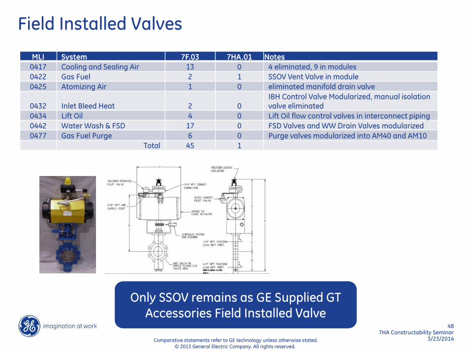
Field Installed Valves
MLI System 7F.03 7HA.01 Notes
0417 Cooling and Sealing Air 13 0 4 eliminated, 9 in modules
0422 Gas Fuel 2 1 SSOV Vent Valve in module
0425 Atomizing Air 1 0 eliminated manifold drain valve
0432 Inlet Bleed Heat 2 0 IBH Control Valve Modularized, manual isolation valve eliminated
0434 Lift Oil 4 0 Lift Oil flow control valves in interconnect piping
0442 Water Wash & FSD 17 0 FSD Valves and WW Drain Valves modularized
0477 Gas Fuel Purge 6 0 Purge valves modularized into AM40 and AM10
Total 45 1
Only SSOV remains as GE Supplied GT Accessories Field Installed Valve

49 7HA Constructability Seminar
3/23/2014 Comparative statements refer to GE technology unless otherwise stated. © 2013 General Electric Company. All rights reserved.
GE to EPC Piping Interface Points
MLI System 7F.03 7HA.01
0416 Lube and Lift Oil 9 8
0417 Cooling and Sealing Air 13 5
0420 Cooling Water 9 6
0422 Gas Fuel 4 4
0424 Liquid Fuel 4 1
0425 Atomizing Air 1 0
0426 Fire Protection 11 4
0442 Water Wash 13 8
0462 Water Injection 1 1
0471 Inlet and Exhaust 2 1
0477 Gas Fuel Purge 4 4
Total 71 42

50 7HA Constructability Seminar
3/23/2014 Comparative statements refer to GE technology unless otherwise stated. © 2013 General Electric Company. All rights reserved.
Constructability Guide
A single document that compiles pertinent information relevant to a constructor and erector to estimate the scope of work necessary to install a GE 7HA gas turbine, generator, and associated ancillaries compared to the 7F.03.
