consideration of residual stress and geometry during heat ... · consideration of residual stress...
TRANSCRIPT

Consideration of residual stress and geometry during
heat treatment to decrease shaft bending
Remi Husson, Cyrille Baudouin, Regis Bigot, Edoardo Sura
To cite this version:
Remi Husson, Cyrille Baudouin, Regis Bigot, Edoardo Sura. Consideration of residual stressand geometry during heat treatment to decrease shaft bending. International Journal AdvancedManufacturing Technology, 2014, 72 (9-12), pp.1455-1463. .
HAL Id: hal-01020954
https://hal.archives-ouvertes.fr/hal-01020954
Submitted on 8 Jul 2014
HAL is a multi-disciplinary open accessarchive for the deposit and dissemination of sci-entific research documents, whether they are pub-lished or not. The documents may come fromteaching and research institutions in France orabroad, or from public or private research centers.
L’archive ouverte pluridisciplinaire HAL, estdestinee au depot et a la diffusion de documentsscientifiques de niveau recherche, publies ou non,emanant des etablissements d’enseignement et derecherche francais ou etrangers, des laboratoirespublics ou prives.

Science Arts & Métiers (SAM)is an open access repository that collects the work of Arts et Métiers ParisTech
researchers and makes it freely available over the web where possible.
This is an author-deposited version published in: http://sam.ensam.euHandle ID: .http://hdl.handle.net/10985/8333
To cite this version :
Rémi HUSSON, Cyrille BAUDOUIN, Régis BIGOT, Edoardo SURA - Consideration of residualstress and geometry during heat treatment to decrease shaft bending - International JournalAdvanced Manufacturing Technology - Vol. 72, n°9-12, p.1455-1463 - 2014
Any correspondence concerning this service should be sent to the repository
Administrator : [email protected]

Consideration of residual stress and geometryduring heat treatment to decrease shaft bending
Remi Husson · Cyrille Baudouin · Regis Bigot ·Edoardo Sura
Abstract In automotive industry, heat treatment of compo-nents is implicitly related to distortion. This phenomenonis particularly obvious in the case of gearbox parts becauseof their typical geometry and precise requirements. Even ifdistortion can be anticipated to an extent by experience, itremains complex to comprehend. Scientific literature andindustrial experience show that the whole manufacturingprocess chain has an influence on final heat treatment dis-tortions. This paper presents an approach to estimate theinfluence of some factors on the distortion, based on theidea of a distortion potential taking into account not onlygeometry but also the manufacturing process history. Thenthe idea is developed through experiments on an industrialmanufacturing process to understand the impact of residualstress due to machining on shaft bending and teeth distortion
R. Husson (�) · E. SuraRenault, Powertrain Process Engineering Division,CTR A02 010, 67 rue des Bons Raisins,92508 Rueil Malmaison, Francee-mail: [email protected]
E. Surae-mail: [email protected]
R. Husson · C. Baudouin · R. BigotLCFC (EA 4495)-Arts et Metiers ParisTech,4 rue Augustin Fresnel, 57078 Metz, France
C. Baudouine-mail: [email protected]
R. Bigote-mail: [email protected]
during heat treatment. Instead of being measured, resid-ual stress is being neutralized. By comparing lots betweeneach other, connections between gear teeth geometry andmanufacturing steps before heat treatment are obtained.As a consequence, geometrical nonconformities roots canbe determined more easily thanks to this diagnosis tool,and corrective actions can be applied. Secondly, the influ-ence of product geometry on bending is experimentallyconsidered. Moreover, metallurgical observations enable toexplain the influence of workpieces geometry on shaft bend-ing. Thanks to the obtained results, process and productrecommendations to decrease shafts bending are proposed.
Keywords Heat-treatment · Shaft · Manufacturing ·Distortion · Identification
1 Introduction
Heat treatment is widely used in automotive industry inorder to improve mechanical properties of workpieces. Nev-ertheless, heat treatment has side effects such as geometricalvariations on global and local scales [1]. Industrially, itmeans that these defects sometimes lead to increase scraprates. In order to limit this problem, the goal of this study isto improve the understanding of distortion phenomena andso the quality of manufacturing.
Distortion is related to several causes. This study experi-mentally focuses on residual stress and geometry, which aretwo of these factors, and their influences on distortion afterheat treatment are evaluated through experiments. In ourcase, major distortions during heat treatment are the bending

of the shafts and teeth distortions. Therefore, these geomet-rical parameters are considered during this study. The globalaim of this project is to support both the design and thedevelopment of the manufacturing process chain. Thus, itwill improve the control of gear quality.
2 State of the art
Distortion during heat treatment is a consequence of thefollowing three major phenomena:
– Spatial and temporal heterogeneities of temperatureduring heating and quenching leading to heterogeneousexpansion [2]
– Timing of phase transformations, for example fromaustenite to martensite [2]
– Decrease of yield strength when temperature increasescausing stress relief by plastic deformation [2]
A high number of process parameters influences distor-tion. They are evaluated to more than 200 [3]. Moreover,Fig. 1 shows that distortion during heat treatment is not onlydue to heat treatment but also to previous manufacturingsteps. As a consequence, dealing with heat treatment distor-tion is complex and requires taking into account the entiremanufacturing process. One idea is to consider distortionafter heat treatment as the result of a distortion potentialgradually stored into the material all through the process[4]. Each manufacturing step contributes to the distortion
potential, physically related to physical carriers. Carriershave dependencies on each other, as shown in Fig. 2 [5].
3 Objective
In this study, the manufacturing process includes cold forg-ing, machining, and heat treatment. First, the relief of resid-ual stress induced by forging affects distortion [6]. Then,during machining steps, turning and gear hobbing modifyresidual stress distribution and distortion [7]. As a conse-quence, residual stress can be considered in this study asa major factor of distortion [8]. Thus, among all carriersof distortion potential described in Fig. 1, this study firstfocuses on residual stress.
On the other hand, geometry also has a significant influ-ence on distortion phenomena. For example, a heteroge-neous geometry will generate a heterogeneous cooling andthen distortions [9]. That is why this study secondly dealswith the influence of geometry on distortion. The distortionis defined as the difference between geometry after a man-ufacturing step and geometry before this step. Geometry ismeasured all along the process by a coordinate-measuringmachine.
As previously said, residual stress and geometry havedependencies on each other [5]. Indeed, when residualstress relieves, elastic and/or plastic deformation happen,modifying geometry of the workpiece. Microstructure also
Fig. 1 Synthesis of majorfactors influencing distortionduring heat treatment [2]

Fig. 2 Process chain and carriers of distortion potential of a typicalcomponent for the transmission industry before operational behavior[5]
appears as a factor influencing other carriers of distortionpotential. In the case of our study, it has been observedthat microstructure does not evolve during stress relief andmanufacturing (except during heat treatment) and can beconsidered as steady [10]. As a consequence, residual stressand geometry will be both studied.
The global aim of this project is to improve the under-standing of gearbox shafts and teeth distortion during heattreatment. Experiments are carried out with a secondarygearbox shaft of automotive industry represented in Fig. 3.Manufacturing steps are performed in industrial conditionsin a Renault (French car manufacturer) plant. It has beenobserved that teeth distortion is a consequence of size andshape changes of the base-body [1]. As a consequence,by improving the understanding of shaft distortion anddecreasing it, teeth distortion should be limited.
4 Experimental procedure
4.1 Experimental principle
In order to observe the influence of a carrier of potentialdistortion, this carrier is neutralized before heat treatment
Fig. 3 Picture and cross-section view of the secondary automotivegearbox shaft used during industrial experiments. Axial and radialholes are drilled during machining to enable lubrication during opera-tional behavior
Fig. 4 Experimental principle: two different lots (A, B) are set upafter manufacturing step k. Contrary to lot B, lot A is not neutralized.By comparing the geometry of lot A and lot B after heat treatment, theinfluence of the carrier of distortion potential is revealed
as presented in Fig. 4. After manufacturing step k, both lotsA and B have the same geometry GA(k) and GB(k). Then,lot A goes directly to heat treatment and finally obtainsgeometry GA(HT ) while lot B is being “neutralized.” Atlast, lot B is heat treated. Its geometry after heat treatmentis GB(HT ). Finally, to observe the influence of the carrierof distortion on heat treatment distortion, a comparison ismade between both geometries after heat treatment GA(HT )
and GB(HT ).The hypothesis is made that during the residual stress
neutralization, geometry remains consistent. Thanks to acomparison between GB(k)N and GB(k), this hypothesis islately checked in Fig. 5. Indeed, stress relief does not mod-ify shaft bending. Secondly, because machining steps areperformed at ambient temperature, the carrier of distor-tion potential “temperature” is considered as steady dur-ing the experiments. Finally, raw parts have been selectedinto the same raw lot, therefore the carrier of distor-tion potential “material” is considered as consistent duringexperiments.
During the experiments, five lots are considered as fol-lows:
– Lot A is not neutralized and all manufacturing steps areperformed,
– Lot B is neutralized before heat treatment and all man-ufacturing steps are performed,
– Lot C is not neutralized and all manufacturing stepsexcept radial drilling are performed,
– Lot D is not neutralized and all manufacturing stepsexcept axial drilling are performed,
– Lot E is not neutralized and all manufacturing stepsexcept rolling are performed.

Fig. 5 Shaft Bending in μm for two lots A and B represented withstandard deviation. Lot A and B follow the same manufacturingprocess with the exception: lot B is stress relieved after shaving
4.2 Application to residual stress
First, in order to observe the influence of residual stressafter machining on heat treatment distortion, behaviorsof two lots are experimentally compared. Evaluation ofresidual stress is a complex matter. Thus, instead of resid-ual stress measurements, the before-mentioned method hasbeen applied. After machining, gearbox shafts are separatedin two different lots. Neutralization for lot B is appliedthrough a 4-h 600 ◦C stress relief under a low-pressureatmosphere.
This stress relief has been chosen because it enablesto decrease the levels of superficial residual stress from300 MPa to less than 150 MPa in absolute value, whichis less than 20 % of the rupture stress of the studied steel[8]. Thus, the residual stress level is hypothesized as notsignificant after the 4-h 600 ◦C stress relief. Finally, bycomparing both geometries after heat treatment, the influ-ence of residual stress due to the manufacturing process isrevealed.
Fig. 6 Shaft bending in μm for three lots A, C, and D representedwith standard deviation. Lot A, C, and D follow the same manufac-turing process but lot C is not radially drilled and lot D is not axiallydrilled
4.3 Application to geometry
Once geometry is generated, it is complex to neutralize it.As a consequence, instead of adding a new step of “neutral-ization” as previously presented, the choice has been madeto not apply a manufacturing step for one lot. In the case ofthe secondary shaft, experiments are made particularly onthree machining operations: axial drilling, splines rolling,and radial drilling. The goal of cold-rolling is to generatesplines along the shaft, as visible in Fig. 3.
Finally, by comparison between each lot and a “normal”lot, the influence of geometry on heat treatment distortion isobserved.
5 Results on residual stress
By comparing shafts from lot A and B in Fig. 5, it can beseen that the amplitude of bending after heat treatment islower for lot B that has been stress-relieved between shav-ing and heat treatment. Actually, shaft bending is almost thesame all along the machining process for both lots and evenduring stress relief for lot B .
The biggest difference is observed after heat treatmentwhere bending is about the double (34 μm) for lot A com-pared to lot B (17 μm). It is also visible that scatteringalso significantly increases during heat treatment, whichconfirms the instability of heat treatment in general.
As a consequence, stress relief appears as a manufac-turing step which does not affect shaft bending directlybut enables to decrease bending during heat treatment.Thus, applying a stress relief decreases the level of resid-ual stress that has been stored into the material all alongthe process. Moreover, it does not lead to shaft bendingbut decreases the future bending due to heat treatment. Inother words, shaft bending has an advantageous influenceon the distortion potential regarding the carrier “residualstress.”
Industrially, by applying a stress relief at the end ofthe machining process and just before heat treatment, shaftbending will be limited. Another way to take advantageof this result is to modify conditions of heat treatment insuch a way that the beginning of heating becomes “softer”:maintaining workpieces at about 600 ◦C during a few hoursbefore increasing temperature for carbonitriding.
6 Results on geometry
6.1 Axial and radial drilling
In the case of geometry, a comparison is made between“normal” shafts (lot A), “radial drilling-less” shafts
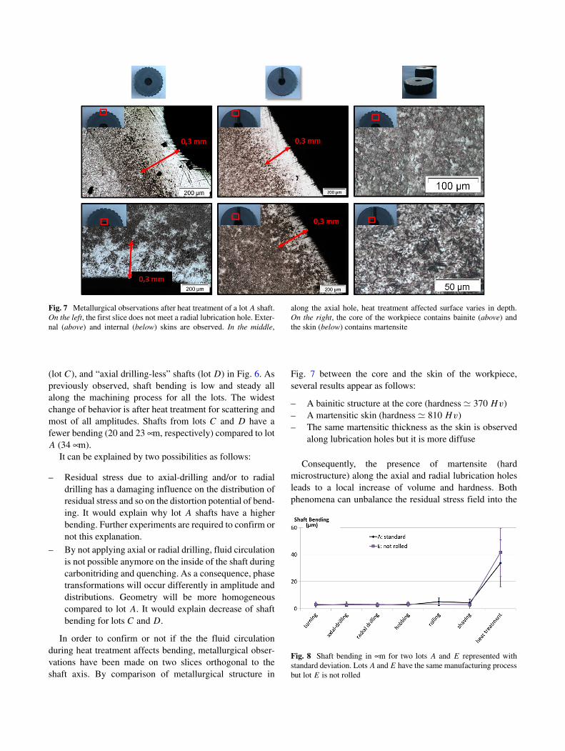
Fig. 7 Metallurgical observations after heat treatment of a lot A shaft.On the left, the first slice does not meet a radial lubrication hole. Exter-nal (above) and internal (below) skins are observed. In the middle,
along the axial hole, heat treatment affected surface varies in depth.On the right, the core of the workpiece contains bainite (above) andthe skin (below) contains martensite
(lot C), and “axial drilling-less” shafts (lot D) in Fig. 6. Aspreviously observed, shaft bending is low and steady allalong the machining process for all the lots. The widestchange of behavior is after heat treatment for scattering andmost of all amplitudes. Shafts from lots C and D have afewer bending (20 and 23 μm, respectively) compared to lotA (34 μm).
It can be explained by two possibilities as follows:
– Residual stress due to axial-drilling and/or to radialdrilling has a damaging influence on the distribution ofresidual stress and so on the distortion potential of bend-ing. It would explain why lot A shafts have a higherbending. Further experiments are required to confirm ornot this explanation.
– By not applying axial or radial drilling, fluid circulationis not possible anymore on the inside of the shaft duringcarbonitriding and quenching. As a consequence, phasetransformations will occur differently in amplitude anddistributions. Geometry will be more homogeneouscompared to lot A. It would explain decrease of shaftbending for lots C and D.
In order to confirm or not if the the fluid circulationduring heat treatment affects bending, metallurgical obser-vations have been made on two slices orthogonal to theshaft axis. By comparison of metallurgical structure in
Fig. 7 between the core and the skin of the workpiece,several results appear as follows:
– A bainitic structure at the core (hardness � 370 Hv)– A martensitic skin (hardness � 810 Hv)– The same martensitic thickness as the skin is observed
along lubrication holes but it is more diffuse
Consequently, the presence of martensite (hardmicrostructure) along the axial and radial lubrication holesleads to a local increase of volume and hardness. Bothphenomena can unbalance the residual stress field into the
Fig. 8 Shaft bending in μm for two lots A and E represented withstandard deviation. Lots A and E have the same manufacturing processbut lot E is not rolled

workpiece and lead to bending distortion during heat treat-ment. Indeed, heat treatment distortion of nonsymmetricalcomponents is higher [2]. Thus, a recommendation is tomodify the orientation of the radial lubrication holes and toavoid alignment of radial lubrication holes.
6.2 Rolling
In this case, lot E shafts are more bended (42 μm) afterheat treatment than lot A workpieces (34 μm), as visible inFig. 8. Thus, geometry changes due to rolling tend to
decrease indirectly heat treatment bending.This result can be explained by two reasons as follows:
– Splines geometry increases the stiffness of the shaft,leading to lower shaft bending during heat treatment.
– Splines geometry increases external surface of the shaft.Consequently, carbon diffusion and heat transfer aregreater due to the splines. Then, heat treatment is moreefficient and leads to a deeper layer of martensite (hardmetallurgical structure) and a higher stiffness of theshaft.
Fig. 9 Metallurgical observations (x100) after heat treatment in three cross-sections of a lot E non-rolled shaft (above) and of a lot A rolled shaft(below). The rolled shaft is more deeply affected by heat treatment

Fig. 10 Hardness Hv0.5 profiles for the three considered zones ofobservation confirm the difference of structure between both work-pieces
To know more about the second phenomenon, a met-allurgical observation is made on both a rolled and ona non-rolled shaft in Fig. 9. Heat treatment affects moredeeply the rolled shaft than the non-rolled one. Hardnessprofiles confirms this differences of structure from 0 to0.5 mm in Fig. 10. These results confirm the influence ofsplines (by the increase of heat transfer and the carbondiffusion) that has been previously described.
Heat treatment generates a harder skin surface for rolledshafts. Consequently, rolling increases the efficiency of heattreatment. Finally, the difference of microstructure can bean explanation to the distinct behaviors considering heattreatment bending.
Fig. 11 Experimental principle, two different lots (1, 2) are neutral-ized before and after manufacturing step k. By comparing geometriesof lots 1 and 2 after heat treatment, the influence of the carrier ofdistortion potential is revealed
7 Other example of evaluation of distortion potential
In order to have deeper results, further experiments werecarried out. The same gearbox shaft is studied, but in thiscase a focus is made on the teeth. The objective is still toevaluate the distortion potential due to each manufacturingstep. In order to do so, stress relief is applied to two lots.By considering the manufacturing step k as represented inFig. 11, two lots are compared. In order to observe theinfluence of a carrier of potential distortion, this carrier isneutralized before and after step k. Lot 1 is neutralized afterstep k and lot 2 is neutralized before it. Other manufacturingsteps are exactly the same for both lots. The only differencebetween both is the moment they have been neutralized. Inthe case of a geometrical deformation due to the neutraliza-tion, this variation can be checked thanks to measurements.Finally, by comparing geometry of lot 1 (G1(T TH)) and lot2 (G2(T TH)) after heat treatment, the influence of the carrierof distortion potential attached to step k is revealed.
7.1 Experiments
This approach has been applied to an experimental manu-facturing process, as presented in Fig. 12. The neutralizationthat has been chosen is the same as previously: a 4-h 600◦stress relief (designated by “SR”) [8]. Eight lots are con-sidered: one lot without any stress relief and seven lots thatare stress relieved once during their manufacturing history.

Fig. 12 Experimentalmanufacturing process andprocedure. Each one of theseven lots B,F,G,H, I, J,K isstress relieved once during itshistory. By comparing thegeometry of two lots, theinfluence of the carrier ofdistortion potential is revealed
Thus, 131 workpieces are manufactured under similar con-ditions in terms of time, tools, and machines. At last, eachworkpiece is identified with a letter from its lot name. Gearsare measured by a coordinate-measuring machine whoseuncertainties are evaluated to 5 μm for first scale of gearsand 3 μm for second scale. Gear parameters are defined in[11]. Even if dispersion is quite high, it is possible to iden-tify qualitative tendencies. Details about each result are notgiven here because of their complexity and confidentiality.
7.2 Results and discussion
The approach by neutralization and comparison can beapplied to results and measurements. The purpose is todetermine the influence of the carrier of distortion poten-tial on the gear distortion. In our case, this carrier is“residual stress” and it is correlated to each manufacturingstep. To obtain its influence, differences between previouslyobtained values are calculated and presented in Table 1.
Table 1 Influence of each manufacturing step on the teeth distortion potential through the carrier “residual stress”
Step Difference First level Second level
between Gear teeth Gear teeth
lots Fr , Fpl , Fpr fHαl fHβl fHβr
Turning K - J NS NS NS NS
Axial Drilling J - I NS NS NS NS
Radial Drilling I - H < 0 NS NS NS
Hobbing H - G NS > 0 > 0 NS
Rolling G - F > 0 NS NS NS
Shaving F - B NS > 0 < 0 < 0
The indicated value takes into account the norm but not its sign
NS refers to nonsignificant

At first geometrical level, only two manufacturing stepsmodify significantly the “residual stress” carrier of distor-tion: radial drilling and rolling. Radial drilling appears asfavorable for first-level gear geometry. On the contrary,rolling modifies the residual stress distribution in such away that it leads to an unfavorable impact on the shaft afterheat treatment. Rolling is a cold-press forming process. Ifthe geometrical and stress balance between the two rollingracks and both tips is not respected, then residual stresscan be heterogeneous. It may cause deformation during heattreatment.
These results are not necessary in conflict with results ofSection 6 about the influence of rolling and radial drilling.In the case of Section 6, influence of a manufacturing stepregarding the “geometry” carrier of distortion potential isconsidered. In the case of this section, influence of a man-ufacturing step regarding the “residual stress” carrier ofdistortion potential is considered. As a consequence, oneinfluence can counterbalance another.
In the case of the second geometrical level, only hobbingand shaving have an influence on profile and helix slopedeviations. Hobbing and shaving are, respectively, roughmachining and finish machining of the gear. Consequently,they are implicitly linked to the gear geometry. But theirinfluences depend on gear parameter according to Table 1.For example, in the case of profile slope deviation of theleft flank fHαl , hobbing and shaving tend to increase thedistortion potential because of the “residual stress” car-rier. Results also show possible correlations between profileslope deviation of the left flank fHαl and helix slope devi-ation of the left flank fHβl because classification betweenlots is similar.
8 Conclusion and perspectives
The proposed approach using a “neutralization” has beensuccessfully applied to two carriers of distortion potential:residual stress and geometry. Thus, two main results havebeen obtained. First, shaft bending has been decreased byapplying a 600 ◦C and 4-h stress relief before heat treatment.Secondly, by modifying the geometry of the componentsdue to drilling and rolling, distortion during heat treatmenthas been changed. These geometrical influences have beenexplained by microstructure. As a consequence, the “shaftbending” distortion potential is highly dependent on geom-etry and residual stress. By improving the consistency ofresidual stress and geometry distribution within the processand particularly before heat treatment, shaft bending can bedecreased significantly.
Moreover, by using another technique to evaluate thedistortion potential, each gear geometrical parameter hasbeen related to manufacturing steps. By neutralization and
comparison, the “residual stress” carrier of distortion poten-tial [4] has been revealed. Thus, when a nonconformity isdetected after heat treatment for this experimental process,the synthesis table can be used as a diagnosis tool to cor-rect machining parameters of the responsible manufacturingstep.
Industrially, it means that residual stress as much asgeometry should be taken into account during product andprocess design in order to limit bending distortion. Thanksto these results, time and cost savings will be earned duringproduction. New production lines will be designed takinginto account this feedback.
A further study on the shaft bending and correla-tion between various geometrical scales would providemore data about the complex phenomenon of heat treat-ment distortion. Secondly, stress relief highly decreasesresidual stress levels, therefore another perspective is toobserve residual stress modifications and its consequenceson fatigue strength of the components.
References
1. Kohlhoff T, Prinz C, Rentsch R, Surm H (2011) Influence ofmanufacturing parameters on gear distortion. Proc. of the 3rdinternational conference on distortion engineering 2011, Bremen,14th to 16th September, pp 155–165
2. Cook WT (1999) A review of selected steel-related factors con-trolling distortion in heat-treatable steels. Heat Treat Met 26:27–36
3. Clausen B, Frerichs F, Kohlhoff T, Lubben T, Prinz C, RentschR, Solter J, Surm H, Stobener D, Klein D (2009) Identification ofprocess parameters affecting distortion of disks for gear manufac-ture part I: casting, forming and machining. Materialwiss Werkst40(5,6):354–360
4. Hoffmann F, Keßler O, Lubben T, Mayr P (2002) “Distor-tion Engineering” Verzugsbeherrschung in der Fertigung. HTM57(3):213–217
5. Zoch HW (2009) Distortion engineering: vision or ready to appli-cation. Materialwiss Werkst 40(5,6):342–348
6. Cho JR, Kang WJ, Kim MG, Lee JH, Lee YS, Bae WB (2004)Distortions induced by heat treatment of automotive bevel gears. JMater Process Technol 153:476–481
7. Kohlhoff T (2009) Analysis of the forces in different regions dur-ing hobbing and their effect on distortion. Materialwiss Werkst40:390–395
8. Husson R, Dantan JY, Baudouin C, Silvani S, Scheer T, BigotR (2012) Evaluation of process causes and influences of residualstress on gear distortion. Ann CIRP 61(1):551–554
9. Sugimoto T, Watanabe Y (2004) Evaluation of important fac-tors affecting quench distortion of carburized hypoid gear withshaft by using computer simulation methods. Cailiao RechuliXuebao/Trans Mater Heat Treat 25(5):480–485
10. Husson R (2013) Contribution a l’identification des origines desdeformations revelees au traitement thermique. Application al’analyse d’une gamme de fabrication d’arbres a dentures de boitesde vitesses. Arts et Metiers ParisTech, PhD thesis
11. Goch G (2003) Gear metrology. Ann CIRP 52(2):659–695