consideration concerning the static and dynamic stability of
TRANSCRIPT

Consideration concerning the static and dynamic stability of metallic bunker on environmental engineering
ADRIAN ROSCA, DANIELA ROSCA
University of Craiova 13, A.I. Cuza Street, 200585, Craiova
ROMANIA [email protected], [email protected]
Abstract: - The paper presents considerations concerning static and dynamic stability of metallic bunker on environmental engineering. There are presented theoretical considerations and experimental results concerning the shock wave velocity / dynamic pressure, the shock wave influence on the bunker’s walls deformation and long term stability. Key-Words: metallic bunker, static/dynamic stability, air shock waves, environment engineering 1 Introduction The Air Blaster Devices (ABD) are used extensively to prevent the blockage of bulk material in the bunker, and to determine the flow of bulk materials from storage bunker/hopper/silo/bin. The bulk materials are represented by solid or powder material (for large electro-thermal plants, for metal moulding; for cement plants; raw materials for metallurgy), viscous materials in food industry, or dust filtering system for belt conveyors. In a National Research Institute in Craiova were made several ABD consisting in 0,012m3, 0,020 m3, 0,050 m3, 0,100 m3, and 0,150 m3 vessel capacity. The raw material type and the bunker’s dimension determine the size and the number of ABD on the bunker’s walls that can be made in metallic structure or in concrete structure (Fig.1 to Fig.6). In principle, the ABD is composed in a pressured gas vessel with a special electrical pneumatic fast valve due to the compressed gas initial stocked into the vessel can be supersonic velocity discharged.[12]
Fig. 1. Small and large capacity ABD mounted on the metallic wall of dozing weighting bunker
for raw materials storage in cement plant
In order to optimize the compressed air consume, to decrease the initial investment costs and maintenance costs, and to decrease the dynamic loads in the walls of the bunker, there were made small and large capacity air blaster devices with two opposite pneumatic fast valve (Fig.2).[10,12]
Fig. 2. Small capacity ABD with two opposite
electro-pneumatic fast valve (mounted on metallic wall of bunker for sand storage in cement plant)
Fig. 3. Large capacity ABD mounted on the
metallic wall of bunker for coal storage in large electro-thermal plants
WSEAS TRANSACTIONS onAPPLIED and THEORETICAL MECHANICS
Adrian Rosca and Daniela Rosca
ISSN: 1991-8747 63 Issue 2, Volume 3, February 2008

Fig. 4. Small capacity ABD mounted on the wall
of coal dust filtration system for belt conveyor in large electro-thermal plants
Fig. 5. Small capacity ABD mounted on the
metallic wall of bunker for sand storage
in metal moulding plant
Fig. 6. Small capacity ABD mounted on the
metallic wall of bunker for viscous raw materials processing in beer plant
The ABD utilizing have to consider for each industrial application both the bulk material properties (density, granulation, humidity, adhesive properties with the bunker’ walls, abrasion, corrosion, storage time period, properties changes due to storage temperature) and the characteristics of the metallic bunker (size, geometrical configuration, nominal bulk material quantity into the bunker, rigidity elements, wall thickness, real period of exploitation, wear grade due to the corrosion and abrasion conditions, maintenance quality). The most important parameter for a safety static and dynamic stability of the bunker is the walls thickness, which could be reduced due to corrosion and abrasion conditions, atmospheric factors, and low maintenance quality. The efficiency of this method for bulk materials unblocking has to consider the environmental protection during the entire duty fife of the bunker. 2 Consideration concerning the shock wave velocity Technical applications usually called air cannon /air blaster are based on the expanding effect of the compressed gas wave shock discharged with high velocity from a storage vessel. During this fast process, the gas flow is characterized by high rate pressure variation; therefore there is no heat exchange with the outside environment, and the flow process can be considered adiabatic [4, 6]. For adiabatic process, with Bernoulli equation for compressible fluids, it results:
o
o20
2 p1k
k2vp
1kk
2v
ρρ⋅
−+=⋅
−+ , (1)
where po and ρo are the initial parameter of the gas; p and ρ are the final parameter of the gas; k is the adiabatic coefficient; vo is the initial gas velocity ( in the storage vessel vo = 0) . In contrast with slow / static adiabatic transformations, which are isentropic (the entropy S is constant), the dynamic adiabatic transformations are irreversible, then it take place with entropy increasing by means of the internal heat stored by gas due to viscosity. Neglecting the viscosity force, it can be considered that the motion is isentropic, this hypothesis being admissible for air blaster discharge phenomena. When the compressed gas (initial parameter po, ρo, To) is discharging from a storage vessel through a nozzle in the atmosphere (characterized by parameter pat, ρat, Tat), the gas velocity is determined with relation [4, 6]:
WSEAS TRANSACTIONS onAPPLIED and THEORETICAL MECHANICS
Adrian Rosca and Daniela Rosca
ISSN: 1991-8747 64 Issue 2, Volume 3, February 2008

−⋅⋅
−=
−k
1k
o
at
o pp
11k
k2vρρ , (2)
Considering the initial parameter and the final parameter of the blasting air (k = 1,4 ; po = 5 - 10 bar; pat = 1 bar; To = Tat = 293 °K), the velocity of the pressured discharged gas is presented in Table 1.[4,6] Table 1
po [bar] 5 6 7 ρo [kg/m3] 5,946 7,135 8,324
v [m/s] 465,8 485,6 501 po [bar] 8 9 10 ρo [kg/m3] 9,522 10,713 11, 903
v [m/s] 513,2 523,6 532,4
Qualitative and quantitative evaluation of characteristic dimensions of the round free jet permit to determine the main manufacturing dimensional parameters of convergent - divergent nozzle which is able to direction the compressed air shock wave to the bulk material inlet the bunker: b - distance from the jet pole; xo - length of initial zone; α - angle of jet action (Fig. 7). The theoretical considerations concerning the air discharge from the stocking vessel take into account the similitude with the flow process into a round free jet. This free jet is a gas current that freely penetrates (with no wall restriction) into an environment of the same or different gas (the flow in jet is generally turbulent, particles of the discharged gas getting out its limits, with neighbouring gas particles taking their place; a mass gas transfer with the exterior is achieved). The jet's range is the length where the kinetic energy of gas is not greater then the viscosity forces and therefore the swirling flow disappears.
Fig. 7. Circular jet geometry
The characteristic dimensions of a jet circular are: initial velocity vo; shape of the discharge nozzle; length of the initial zone xo; jet range xlim; convergence angle of the initial zone αo; the enlarging jet border angle α; gas debit in initial section Qo ; jet pole b; jet radius Rgr. The initial section of the discharging nozzle is the circular section in which the medium velocity vo of the jet is realized. The environment velocity ve can be equal to zero, bigger or smaller than vo; for ve = 0, the jet is considered to be free. The velocity in the jet's axe vx depends by the initial velocity vo and by the distance x. For x < xo, the velocity vx = vo, and for x > xo the velocity vx depends of distance x. The velocity in the transversal jet section vy is the velocity at distance x and at the level y, depends by the velocity vx and level y. Theoretical and experimental researches determine the relation:
( )[ ]22/3/1/ groy Ryvv −= , (3) where Rgr is the jet’s radius limit for x > xo. Due to the symmetric axial jet law, the impulse has the same value in any section. Using the notation vy the velocity in a certain point, I the impulse, and mo the masse passing through the elementary surface dA from the jets section in the time unity, it obtained: 2222 ooo
R
o y RvydyvI gr πρρπ == ∫ , (4)
here the jet’s radius limit Rgr is obtained with the relation: ( )xoogr vvRR /3,3= , (5) where Ro is the jet’s source radius. The medium velocity of jet vm is determined knowing that the medium flowing velocity in a section A is obtaining from the continuity equation: )/(/ 2
grm RQAQv π== . (6) Because in the initial section the velocity value is obtained with the relation )/(/ 2
oo RQAQv π== , with relation (4) is obtained ( )oxom vvvv /2,0/ = . Using the above presented relations, for initial storage pressures in the vessel po = 5 - 10bar, the following results were obtained for free circular jet: the jet range xlim = 1,1 - 2,3m; the conical jet border angle α = 60 - 70°; the jet diameter Dgr = 1,4m for jet range xlim = 1m, and Dgr = 2,5m for jet range xlim = 2,3m; the medium velocity vm in the jet transversal section up to equivalent velocity of 80…100km/h. These theoretical considerations determined a new air blaster technical application which takes into account the important role held by wind action in the fruits harvest, whose velocity/intensity determines the falling /dropping of the fruits. [7, 9]
WSEAS TRANSACTIONS onAPPLIED and THEORETICAL MECHANICS
Adrian Rosca and Daniela Rosca
ISSN: 1991-8747 65 Issue 2, Volume 3, February 2008

An unconventional and ecological equipment was designed to replace the effect of the windblasts, with orientated air blaster shock waves (with adjustable velocity / intensity), which replace the velocity and orientation of strong winds. This new ecological equipment is proposed to replace the traditional harvesting machines which produce strong vibrations to the tree. During harvesting with the traditional vibration machines, the vibrations cause severe damage to the roots of the tree, and the scratching of the tree trunk causes the premature drying of the tree. [7, 9] Fig.8 presents the main component of the experimental equipment for Modular Equipment for Nuts Harvesting by Pneumatic Impulses, made in Unconventional Equipment and Technologies for the Agro-Food Industry Laboratory, at the Faculty of Horticulture in the University of Craiova. [7, 9]
Fig. 8. Experimental equipment for
Modular Equipment for Nuts Harvesting by Pneumatic Impulses
In order to permit a maximum visibility during the harvest operations, this modular equipment was mounted in front of the tractor structure. To optimize the blasting gas working parameter, a supplementary air compressor was mounted in the pneumatically circuit. After two years of experiments made with this modular equipment on nutty fruits, on apple and plums for industrialization, there were observed no damages in the tree fruity branches.
3 Consideration concerning the shock wave dynamic pressure
In order to determine the dynamic pressure produce by ABD, was made an experimental installation, in principle, consisting in a conical nozzle (Ømax / Ømin = 300/100mm; h = 250mm) with a metallic round flange mounted at the large base, respectively in direct connection with the circular nozzle of the ABD’s vessel. The size and the dimension of the conical nozzle are similar with the discharging zone in the bunker. On the metallic round flange were disposed three pressure transducer connected with an amplifier device to a data acquisition system, respectively an acceleration transducer connected with another amplifier device and data acquisition system. The dynamic pressure pdin, the shock wave acceleration asw and the specific energy of the shock wave Esw, determined for initial compressed gas (air+nitrogen) pressure po in the ABD 0,050m3 vessel capacity are presented in Table 2. [4, 5, 6]
Table 2 po [bar] pdin [bar/s] asw [m/s2] Esw [J ] 5 582 28,5 86 6 634 37,3 104 7 697 49,4 143 8 776 61,2 197 9 845 74,8 265 10 938 85,6 323
In Fig. 9 are presented the dynamic pressure evolution (from maximum to zero) and the shock wave duration for an initial pressure in storage vessel po = 5 bar, for 0,8s total shock wave duration. [3, 5, 7]
Fig. 9. Dynamic pressure evolution for 0,8s shock wave duration, produced by initial
pressure po = 5 bar in storage vessel
WSEAS TRANSACTIONS onAPPLIED and THEORETICAL MECHANICS
Adrian Rosca and Daniela Rosca
ISSN: 1991-8747 66 Issue 2, Volume 3, February 2008
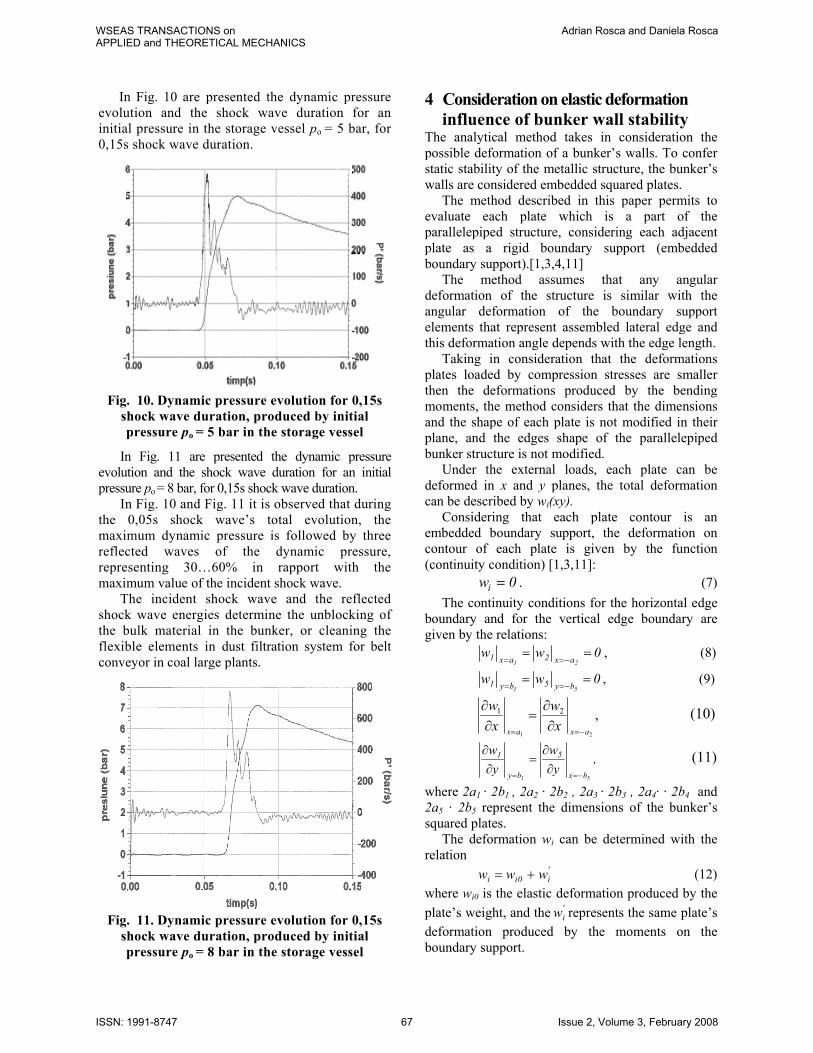
In Fig. 10 are presented the dynamic pressure evolution and the shock wave duration for an initial pressure in the storage vessel po = 5 bar, for 0,15s shock wave duration.
Fig. 10. Dynamic pressure evolution for 0,15s
shock wave duration, produced by initial pressure po = 5 bar in the storage vessel
In Fig. 11 are presented the dynamic pressure evolution and the shock wave duration for an initial pressure po = 8 bar, for 0,15s shock wave duration. In Fig. 10 and Fig. 11 it is observed that during the 0,05s shock wave’s total evolution, the maximum dynamic pressure is followed by three reflected waves of the dynamic pressure, representing 30…60% in rapport with the maximum value of the incident shock wave. The incident shock wave and the reflected shock wave energies determine the unblocking of the bulk material in the bunker, or cleaning the flexible elements in dust filtration system for belt conveyor in coal large plants.
Fig. 11. Dynamic pressure evolution for 0,15s shock wave duration, produced by initial pressure po = 8 bar in the storage vessel
4 Consideration on elastic deformation influence of bunker wall stability The analytical method takes in consideration the possible deformation of a bunker’s walls. To confer static stability of the metallic structure, the bunker’s walls are considered embedded squared plates. The method described in this paper permits to evaluate each plate which is a part of the parallelepiped structure, considering each adjacent plate as a rigid boundary support (embedded boundary support).[1,3,4,11] The method assumes that any angular deformation of the structure is similar with the angular deformation of the boundary support elements that represent assembled lateral edge and this deformation angle depends with the edge length. Taking in consideration that the deformations plates loaded by compression stresses are smaller then the deformations produced by the bending moments, the method considers that the dimensions and the shape of each plate is not modified in their plane, and the edges shape of the parallelepiped bunker structure is not modified. Under the external loads, each plate can be deformed in x and y planes, the total deformation can be described by wi(xy). Considering that each plate contour is an embedded boundary support, the deformation on contour of each plate is given by the function (continuity condition) [1,3,11]: iw 0= . (7) The continuity conditions for the horizontal edge boundary and for the vertical edge boundary are given by the relations: 0ww
21 ax2ax1 ==−==
, (8)
0ww51 by5by1 ==
−==, (9)
,21
21
axax xw
xw
−== ∂∂
=∂∂ (10)
,y
wy
w
51 bx
5
by
1
−== ∂∂
=∂∂ (11)
where 2a1 · 2b1 , 2a2 · 2b2 , 2a3 · 2b3 , 2a4· · 2b4 and 2a5 · 2b5 represent the dimensions of the bunker’s squared plates. The deformation wi can be determined with the relation
'i0ii www += (12)
where wi0 is the elastic deformation produced by the plate’s weight, and the '
iw represents the same plate’s deformation produced by the moments on the boundary support.
WSEAS TRANSACTIONS onAPPLIED and THEORETICAL MECHANICS
Adrian Rosca and Daniela Rosca
ISSN: 1991-8747 67 Issue 2, Volume 3, February 2008

In order to determine the admissible pressure in the parallelepiped bunker (dimensions length a, width b, height c; walls’ thickness h; admissible strength of walls’ material σadm), the spatial structure must consider fixed edges and for each edge must be considered an embedded factor. If for i plate the embedded factor Nk is considered, for the boundary plate on the same support has to be considered the embedded factor
,1
2
aaN kkξ where a1 and a2 are the first plate’s and
the second plate’s dimensions on the normal direction on the common support, and
.th
th
1
2
1
1
2
1
1
2
1
2
⋅⋅=
bak
ba
k
DD
aa
aa
k
π
πξ (13)
According the symmetry conditions, results only three factors systems Ak,, Bk,, Ck. (k with no-par values) that can be determined (assuming the parameter q = 1 and q = 3), with the relations:
−
+
+
−
=⋅
1
2
1
1
1
12
1 221
baE
baB
baAb
q qqqqqqq ββαπψπ
[ ( ) −+
−
− ∑
∞
παξ kDCabR
ba
aaA kkqkqqq cos2
1 1
1
1
2
1
2
( )]; 2
1kkqk GF
ab
R +
(14)
−
+
+
−
=⋅
1
2
1
1
1
12
1 221
baE
baB
baAb
r rrrrrrr ββαπψπ
[ ( ) −−
+
− ∑
∞
παξ kDCabR
ba
aaA kkrkrrr cos2
1 1
1
1
2
1
2
( )]kkrk GFabR −
2
1 , (15)
where qξ are determined using the relation (13) and
qα şi qβ are determined using the relations
=−⋅−
1
2
1
2
2
1
1
2th1
th
1ba
ba
kka
b
ba
kkαπ
ππ (16)
.ch
11
sh
1
1
2
1
22
1
1
2
=⋅⋅−
ba
ba
kkab
ba
kkβ
πππ (17)
and Rqk are determined with the relation
.
2th1
2th
22
21
212
2
21
21
1
12
1
1
+
⋅⋅⋅+
⋅=
qabk
kab
abk
abk
R qk π
π (18)
The equation system to determine the embedded factors Ak,, Bk,, Ck , have to consider the values for q = 1,3,5..., and r = 2,4,6..., respectively [3,11]. For the horizontal edges a:
−
−
+
+
+
−
=
bc
acA
bc
acA
baA
baA
2b
2
111111
1111
2A
1
αξβξ
βαπψπ
(19)
( ) −
+
−+
−−
abC
abC
cbRBB
abR2 1111111111 ξξ
( ) ;abC
abC
cbRBB
abR2 3333133313
+
−+
+−− ξξ
−
−
+
+
+
−
=
bc
acA
bc
acA
baA
baA
2b
6
333333
3333
2A3
αξβξ
βαπψπ
(20)
( ) −
+
−+
−−
abC
abC
cbRBB
abR 11113111312 ξξ
( ) .2 3333333333
+
−+
−−
abC
abC
cbRBB
abR ξξ
For the horizontal edges b:
_ac
bcB
ac
bcB
abB
abB
2a
2
111111
1111
2B1
−
+
+
+
−
=
αξβξ
βαπψπ
(21)
( ) ( ) −
+
−+
−− 111111112 CC
caRAA
baR
( ) ( ) ;CCcaRAA
baR2 33133331
+
−+
−−
−
−
−
−
+
−
=
ac
bcB
ac
bcB
abB
abB
2a
6
333333
3333
2B3
αξβξ
βαπψπ
(22)
( ) ( ) −
+
−+
−− 113111312 CC
caRAA
baR
( ) ( ) .CCcaRAA
baR2 33333333
+
−+
−−
WSEAS TRANSACTIONS onAPPLIED and THEORETICAL MECHANICS
Adrian Rosca and Daniela Rosca
ISSN: 1991-8747 68 Issue 2, Volume 3, February 2008
For the vertical edges c:
−
−
+
+
+
−
=
cb
abC
cb
abC
caC
caC
2c
2
111111
1111
2C1
αξβξ
βαπψπ
(23)
−
+
−
−
+
−−
acA
acA
bcR
bcB
bcB
acR2
111111
111111
ξξ
ξξ
+
−
−
+
−−
acA
acA
bcR
bcB
bcB
acR2
333313
333313
ξξ
ξξ
−
−
+
+
+
−
=
cb
abC
cb
abC
caC
caC
2c
6
333333
3333
2C3
αξβξ
βαπψπ
(24)
−
+
−
−
+
−−
acA
acA
bcR
bcB
bcB
acR2
111131
111131
ξξ
ξξ
+
−
−
+
−−
acA
acA
bcR
bcB
bcB
acR2
333333
333333
ξξ
ξξ
After several transformations there are obtained the following 6 equations (25-30):
+
+
+
−
−
+
−
ab
cbR4C
abR4B
bc
ac
bc
ac
ba
ba
2A
111111111
1111
2
1
ξαξ
βξαβπ
;b2a
bcbR4C
abR4B A
13133133 ψπξ =
+
+ (25)
+
+
+
++
caR4C
baR4A
caR4C
baR4A 133133111111 (26)
;a2a
cbc
ac
bc
ab
ab
2B B
1111111
2
1 ψπαξβξαβπ=
−
+
−
+
×
+
+
2
111111111 2C
bc
acR4B
ac
bcR4A π
ξξ (27)
+
−
+
−
×
cb
ab
cb
ab
ca
ca
111111 αξβξαβ
;c2b
cacR4B
ac
bcR4A C
131333133 ψπξξ =
+
+
+
−
+
−
×
×
+
+
bc
ac
bc
ac
ba
ba
2A
ab
cbR4C
abR4B
333333
2
31311311
αξβξαβ
πξ
;b6a
bcbR4C
abR4B A
33333333 ψπξ =
+
+ (28)
+
−
+
−
×
×
+
+
+
ac
bc
ac
bc
ab
ab
2B
baR4A
caR4C
baR4A
333333
2
3333311311
αξβξαβ
π
;a6c
aR4C B3333 ψπ
=
+ (29)
+
+
+
ac
bcRA
bc
acRB
ac
bcRA 333313111311 444 ξξξ
+
−
+
−
+
bc
ab
cb
ab
ca
ca
2C 333333
2
3 αξβξαβπ
.c6b
cacR4B C
33333 ψπξ =
+ (30)
Knowing the bunker’s dimensions a,b and c, using the relations 13, 16, 17 and 18, can be determined Rij and 313131 ,,,,, ξξββαα ; then using the relations 25-30, the embedded factors A1, A3, B1, B3, C1, C3 are obtained. The elastic deformation of each squared plate stressed by a linear distributed load is given by the relation
( )( )
∑∞ +
⋅
⋅⋅+⋅+
++−=
...5,3,1nn
4224
a2xansin
a2ynshyB
a2ynchA
a5xa6xD24
pw
πππ (31)
where D represents the bending rigidity of the plate determined with the relation:
( )2
3
112hEDµ−
= (32)
The maximum elastic deformation on the vertical plane of the bunker’s wall (waxc) is determined with the relation:
WSEAS TRANSACTIONS onAPPLIED and THEORETICAL MECHANICS
Adrian Rosca and Daniela Rosca
ISSN: 1991-8747 69 Issue 2, Volume 3, February 2008

( )
×++−−
=× 4
44224
3
2
caa1536a5xa6x
Eh21pw
πµ
( )∑∞
+
+
+−×
+
×...5,3,1 4 a2
qysha4y
a2qych
2qth
41
q1
2qchq
a2xaqsin πππ
ππ
π
∑∞
×+
−
+
⋅
+
⋅+...5,3,1
q a2xa
qsha
xa2
qsh
aya
2qsinA
π
ππ
+
+
⋅×
π
π
qcha
xa2
qch×
−−
−
⋅
a2xa
qsha
xa2
qsh
π
π
(33)
−
+
⋅
+
⋅+
−
⋅×
π
ππ
π
π
qsha
ya2
qsh
axa
2qsin
qcha
xa2
qch
.qcha
ya2
qch
a2qa
qsha
ya2
qsh
qcha
ya2
qch
a2ya
−
⋅⋅
−−
−
⋅+
+
⋅⋅
+−
π
π
π
π
π
π
The maximum elastic deformation on the vertical plane of the bunker’s wall (wbxc) is determined with the relation
( )( )
×
+
++−−
= ∑∞
×...5,3,1 4
4
44224
3
2
cb
c2bqchq
a2xaqsinc1536c5xc6x
Eh21pw π
π
πµ
+
+
+−×
c2qysh
c4y
c2qych
c2qbth
c4b
q1 ππππ
∑∞
+
+
⋅⋅
+−
+
⋅
×
+
⋅+...5,3,1
q
bcqch
bxc
2qch
c2xc
bcqsh
bxc
2qsh
byb
2qsinA
π
π
π
ππ
+
−
⋅⋅
−−
−
⋅+
bcqch
bxc
2qch
c2xc
bcqsh
bxc
2qsh
π
π
π
π
(34)
−
+
⋅
+
⋅+
cbqsh
cyb
2qsh
cxc
2qsinC q
π
ππ
.
bbqsh
cyb
2qch
b2yb
cbqsh
cyb
2qsh
cbqch
cyb
2qch
b2yb
−
⋅⋅
−+
−
⋅+
+
⋅⋅
+−
π
π
π
π
π
π
The pressure determined by the bulk material stored in the bunker can be determined with the approximative relation Hbbm R55p ⋅≈ ρ , (35) where bmρ represents the bulk material density, and RHb represents the hydraulic radius/factor of the bunker, determined with relation RHb = Ab / Bb , (36) where Ab is the transversal area of the bunker, and Bb is the bunker’s perimeter. In order to establish the correctitude of the described analytical method to determine the elastic deformation of the bunker’s walls, a new made bunker for coal storage was chosen. The bunker’s shape presented in Fig.3 is an irregular pyramid with maximum height cmax = 12m, variable length amin/amax =1,5/7,5m, and variable width bmin/bmax = 3/6m; walls’ thickness h =10mm. To prevent the material’s blocking, on three sides of the bunker 0,050m3 and 0,150m3 capacity ABD are placed on 4 height equal levels (clevel = 3m). An experimental method was set to measure the elastic deformation of the walls when the bunker contains bulk material that is blocking the bunker, and when the material in the bunker is free to flow with no hazard of bunker blocking. This experimental method permits to determine the supplementary elastic deformations produced by the shock waves during the bunker unblocking process, too. In Table 3 are presented the values obtained for the elastic deformation waxc of vertical plane ca × , determined using the analytical method (ALM), and the experimentally method (EXM), respectively. Table 3
Elastic deformation waxc [mm]Level a [m] ALM EXM
1 1,5 2,4 2,8 2 3 4,1 4,6 3 4,5 5,7 6,3 4 7,5 7,3 8,1
In Table 4 are presented the values obtained for the elastic deformation wbxc of vertical plane cb× , determined using the analytical method (ALM), and the experimentally method (EXM), respectively. Table 4
Elastic deformation wbxc [mm]Level b [m] ALM EXM
1 3 1,9 2,1 2 4 3,6 4,2 3 5 4,8 5,4 4 6 6,2 7,0
WSEAS TRANSACTIONS onAPPLIED and THEORETICAL MECHANICS
Adrian Rosca and Daniela Rosca
ISSN: 1991-8747 70 Issue 2, Volume 3, February 2008

In Table 3 and Table 4 can be observed that the experimentally method values are 10-15% larger then the values obtained with analytical method. In Table 5 are presented the supplementary elastic deformations the shock waves during the bunker unblocking process (waxc,s and wbxc,s) on ca × and
cb× squared plates, produced by several initial pressure shock waves during the bunker unblocking process. The table presents also the total deformation of the wall experimentally determined wtot. Table 5
Supplementary deformation [mm] Level p0[bar] waxc,s wtot,bxc wbxc,s wtot,bxc
1 6 8 10
1,1 1,4 1,8
3,9 4,2 4,6
0,9 1,1 1,4
3,0 3,2 3,5
2 6 8 10
2,2 2,6 2,9
6,8 7,2 9,5
1,8 2,1 2,5
6,0 6,3 6,7
3 6 8 10
3,1 3,6 4,2
9,4 9,9 10,5
2,6 3,2 3,9
8,0 8,6 9,3
4 6 8 10
4,6 5,0 5,6
12,7 13,1 13,7
4,3 4,6 5,1
11,3 11,6 12,1
In Table 5 can be observed that the total deformation of the wall is comparable with the wall’s thickness and this confirm the justness of the small deformation theory which was used [1,11]. In the same time is observed that the wall thickness decreasing due to the corrosion and abrasion common action can determine the deformation increase that cause important damages of the bunker structure which could determine high impact problems on the environment. 5 Consideration on the shock wave influence on bunker wall stability
A global evaluation of bunker stability has to take into account the real thickness of the walls, which in principle, is reduced by the abrasion phenomena between bulk material and the walls, by the internal and external corrosion phenomena (determined by the bulk material chemical characteristics and by the atmospherically conditions) and low maintenance quality. The real thickness of the walls is determined with drilling method for metallic bulk material inlet the bunker, and with ultrasonic method for nonmetallic material inlet the bunker. To prevent the wall deformation due to the dynamic load produced by the shock wave, the
ABD’s discharge pipe is assembled to the wall using a increasing rigidity element (round or square plate welded on the bunker’s wall are presented in Fig.1 - Fig. 6). Many industrial applications need to determine the bunker’s stability stressed by the static loads produced by the material’s weight and by the dynamic loads produced by the ABD’s shock wave. [1, 3] According with relations 33 and 34, the maximum bending moments in the median plane of the squared plate ( ca × or cb× ) can be determined using the relations: 2
max,y ap45,0M ⋅= or 2max,y bp45,0M ⋅= , (37)
where p represents the pressure produced by the material stored in the bunker. The equivalent strength in the wall material can be evaluated using with relation
adm2maxy
ech h
M6σσ ≤= . (38)
In FEM the theoretical considerations for static stress take into account the small deformation and the linear material deformability hypothesis. In FEM the high velocity deformation theory for dynamic stress is based on elastic-plastically model of the material: the material has a linear elastic evolution up to the yield limit and for elastic - plastically deformation has to be considered the total Lagrange formulation. [2, 8] The total Lagrange formulation analyzes admits large deformations and needs to consider the isotropic hardness of the material, especially due to the deformation velocity. [2] In order to determine von Misses equivalent strength in the wall material, the nonlinear analyze for the elastic-plastically deformation of the metallic bunker wall has to consider the following hypothesis: - the dynamic load is represented by the dynamic pressure produced by ABD; - the adjacent corner zone of the walls is with axial-symmetrical elements, with linear elastic deformation; - the deformable plate considered two opposite sides embedded PLANE2D with linear deformation, with isotropic hardness of the material and GAP element contact, with no friction. In the dynamic nonlinear analysis, for a quick convergence, the Newton - Raphson method was used and, as an integration method, the Newmark method with Rayleigh amortization factor for maximum 0,8s time range, divided in an increment DTmin =1E-5 and DTmax=5E-3, was used too [2,4,5,6,7]. The von Misses equivalent strength determined with FEM for the bunker presented in Fig.3 are presented in Fig. 12 and Fig. 13.
WSEAS TRANSACTIONS onAPPLIED and THEORETICAL MECHANICS
Adrian Rosca and Daniela Rosca
ISSN: 1991-8747 71 Issue 2, Volume 3, February 2008
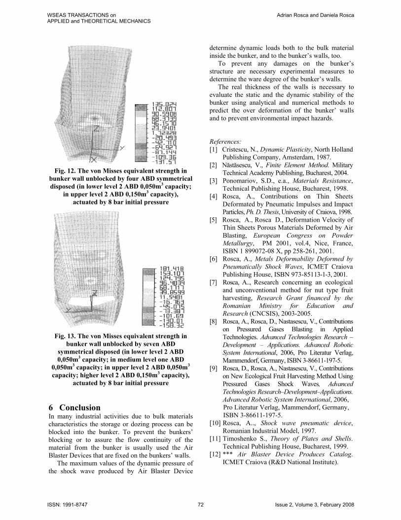
Fig. 12. The von Misses equivalent strength in
bunker wall unblocked by four ABD symmetrical disposed (in lower level 2 ABD 0,050m3 capacity;
in upper level 2 ABD 0,150m3 capacity), actuated by 8 bar initial pressure
Fig. 13. The von Misses equivalent strength in
bunker wall unblocked by seven ABD symmetrical disposed (in lower level 2 ABD 0,050m3 capacity; in medium level one ABD
0,050m3 capacity; in upper level 2 ABD 0,050m3 capacity; higher level 2 ABD 0,150m3 capacity),
actuated by 8 bar initial pressure
6 Conclusion In many industrial activities due to bulk materials characteristics the storage or dozing process can be blocked into the bunker. To prevent the bunkers’ blocking or to assure the flow continuity of the material from the bunker is usually used the Air Blaster Devices that are fixed on the bunkers’ walls. The maximum values of the dynamic pressure of the shock wave produced by Air Blaster Device
determine dynamic loads both to the bulk material inside the bunker, and to the bunker’s walls, too. To prevent any damages on the bunker’s structure are necessary experimental measures to determine the ware degree of the bunker’s walls. The real thickness of the walls is necessary to evaluate the static and the dynamic stability of the bunker using analytical and numerical methods to predict the over deformation of the bunker’ walls and to prevent environmental impact hazards. References: [1] Cristescu, N., Dynamic Plasticity, North Holland
Publishing Company, Amsterdam, 1987. [2] Năstăsescu, V., Finite Element Method. Military
Technical Academy Publishing, Bucharest, 2004. [3] Ponomariov, S.D., e.a., Materials Resistance,
Technical Publishing House, Bucharest, 1998. [4] Rosca, A., Contributions on Thin Sheets
Deformated by Pneumatic Impulses and Impact Particles, Ph. D. Thesis, University of Craiova, 1998.
[5] Rosca, A., Rosca D., Deformation Velocity of Thin Sheets Porous Materials Deformed by Air Blasting, European Congress on Powder Metallurgy, PM 2001, vol.4, Nice, France, ISBN 1 899072-08 X, pp 258-261, 2001.
[6] Rosca, A., Metals Deformability Deformed by Pneumatically Shock Waves, ICMET Craiova Publishing House, ISBN 973-85113-1-3, 2001.
[7] Rosca, A.., Research concerning an ecological and unconventional method for nut type fruit harvesting, Research Grant financed by the Romanian Ministry for Education and Research (CNCSIS), 2003-2005.
[8] Rosca, A., Rosca, D., Nastasescu, V., Contributions on Pressured Gases Blasting in Applied Technologies. Advanced Technologies Research – Development – Applications. Advanced Robotic System International, 2006, Pro Literatur Verlag, Mammendorf, Germany, ISBN 3-86611-197-5.
[9] Rosca, D., Rosca, A., Nastasescu, V., Contributions on New Ecological Fruit Harvesting Method Using Pressured Gases Shock Waves, Advanced Technologies Research–Development–Applications. Advanced Robotic System International, 2006,
Pro Literatur Verlag, Mammendorf, Germany, ISBN 3-86611-197-5. [10] Rosca, A.., Shock wave pneumatic device,
Romanian Industrial Model, 1997. [11] Timoshenko S., Theory of Plates and Shells.
Technical Publishing House, Bucharest, 1999. [12] *** Air Blaster Device Produces Catalog.
ICMET Craiova (R&D National Institute).
WSEAS TRANSACTIONS onAPPLIED and THEORETICAL MECHANICS
Adrian Rosca and Daniela Rosca
ISSN: 1991-8747 72 Issue 2, Volume 3, February 2008