conservation-oriented structural analysis of the spire...
TRANSCRIPT

International Journal of Materials Science and Applications 2016; 5(6-2): 1-9
http://www.sciencepublishinggroup.com/j/ijmsa
doi: 10.11648/j.ijmsa.s.2016050602.11
ISSN: 2327-2635 (Print); ISSN: 2327-2643 (Online)
Conservation-Oriented Structural Analysis of the Spire of Barcelona Cathedral
Ahmed Elyamani
Archaeological Conservation Department, Faculty of Archaeology, Cairo University, Giza, Egypt
Email address: [email protected]
To cite this article: Ahmed Elyamani. Conservation-Oriented Structural Analysis of the Spire of Barcelona Cathedral. International Journal of Materials Science
and Applications. Special Issue: New Strategies for Conservation of Historical Objects, Principles and Practical Applications.
Vol. 5, No. 6-2, 2016, pp. 1-9. doi: 10.11648/j.ijmsa.s.2016050602.11
Received: May 13, 2016; Accepted: July 22, 2016; Published: September 3, 2016
Abstract: The spire of Barcelona cathedral suffered from severe problems due to the corrosion of the steel ties used in
reinforcing its stone masonry beams. Wide visible cracks were noticed in the stone beams and large parts were detached.
Therefore, the full spire was dismantled and reconstructed using titanium ties to eliminate the corrosion problem. A finite
element model of the spire was created and analyzed using DIANA software to support this decision. This analysis helped in
understanding the role and strength contributions of these ties in resisting the applied loads on the spire, specifically, the lateral
loads of earthquakes and wind. A nonlinear static (pushover) analysis was carried out to assess the spire capacity under the
lateral loads. A number of constitutive models for modeling the masonry behavior were tried. Also, a number of seismic
actions patterns were considered. As a main conclusion of this study, the ties were highly needed to carry the tensile stresses
caused by earthquakes and wind loads. Therefore, in the reconstruction of the spire, such ties must be kept in the masonry
beams.
Keywords: Conservation, Structural Analysis, Spire, Corrosion, Ties, Pushover, Wind, Earthquake
1. Introduction
Structural analysis plays an important role in conservation
of historical structures. In the assessment phase, it helps in
understanding the structural behavior under different loads.
As well, it is an efficient tool for identifying the weakness
places where intervention is possibly needed. In designing
the intervention, a numerical model may work is a virtual
laboratory in which different intervention proposals could be
simulated to reveal its efficiency. There are many successful
cases in the literature in which structural analysis have been
used as an efficient tool for restoration of historical structures
[1-8].
This paper deals with the structural analysis of the spire of
Barcelona cathedral (Fig. 1) as a useful tool for its
conservation. The builders of the spire reinforced all of its
stone masonry beams with steel ties. Due to the coastal
weather of Barcelona city which is full of rains and also
because of sea spray and pollution products these ties were
corroded and the spire faced severe problems. Wide visible
cracks were noticed in the stone beams and large parts were
detached. This situation led to carry out a complete project
for the restoration of the spire. In this project, the entire spire
was dismantled and reconstructed and the steel ties were
replaced by titanium ones to eliminate the corrosion problem.
To understand the role and strength contributions of the
steel ties, a finite element (FE) model of the spire was created
and analyzed using DIANA software [10]. Specific concern
was given to the analysis of the spire under lateral loads
because it reaches a height of 90 m over the ground level
which makes it vulnerable when subjected to such type of
loads. The earthquake and wind loads were estimated using
the Eurocodes [11, 12].
A FE nonlinear static (pushover) analysis was performed
using the estimated lateral loads. To reveal the dependency of
the results on the used constitutive models, a number of
constitutive models for modeling the stone masonry were
tried. As well, a number of load patterns were tried to study
the dependency of the results on the used load pattern.

2 Ahmed Elyamani: Conservation-Oriented Structural Analysis of the Spire of Barcelona Cathedral
Figure 1. Main façade of Barcelona cathedral (left) [9] and the spire of the
cathedral (right).
2. Barcelona Cathedral
The construction of the cathedral (Fig. 2) started in 1298
and continued for more than a century. The apse and the
entire nave were finished in 1327 and 1417, respectively. The
span of central nave is 12.80 m and the maximum high is
25.6 m. The span of the side aisles is equal to one half the
span of the nave. The total length of the cathedral is 93 m.
The plan of the temple is not conventional because the
cimborio was not constructed over the crossing but over the
first bay of the nave close to the façade. A similar distribution
can be observed in very few cases, such as the German
cathedrals of Ulm and Friburg [14].
Figure 2. Plan of Barcelona cathedral showing spire location (adopted from
[13]).
3. Spire of Barcelona Cathedral
3.1. Description
The spire of Barcelona cathedral is a symmetrical stone
masonry structure built at the beginning of the 20th
century. It
has an octagonal shape in plan, Fig. 3. It consists of 8
columns connected together by 8 beams. The columns have
irregular shapes with an average cross sectional area of about
0.3 m2. The beam section can be approximated as a rectangle
of 25 cm × 60 cm reinforced at the center with a steel tie of 1
cm × 4 cm. The shortest beam span is about 1 m (at the last
level of the spire) and the longest one is about 2.5 m (at the
first level of the spire). The eight columns rise up to the top
of the spire until they are attached together forming a base
for a stone statue (Fig. 1) which has a height of 5 meters and
a weight of 6.25 t.
Figure 1. Typical plan and cross sections of the spire.
Figure 2. Corroded steel ties extracted from the spire.
Figure 3. Wide cracks due to corrosion products.
Figure 4. Corrosion products resulted in stone fall down.
International Journal of Materials Science and Applications 2016; 5(6-2): 1-9 3
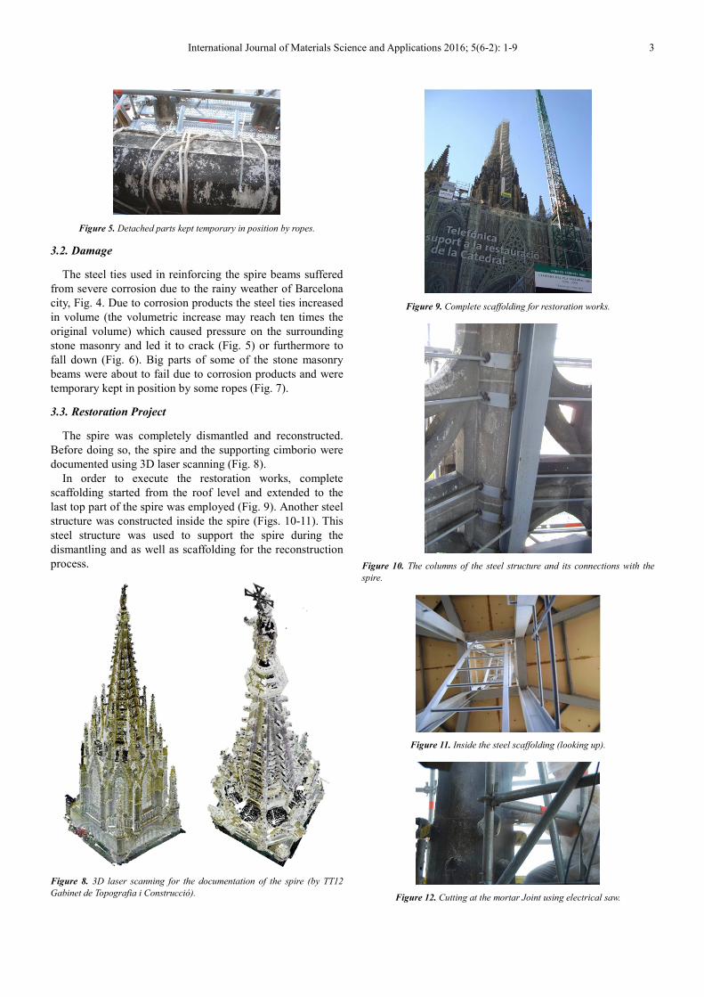
Figure 5. Detached parts kept temporary in position by ropes.
3.2. Damage
The steel ties used in reinforcing the spire beams suffered
from severe corrosion due to the rainy weather of Barcelona
city, Fig. 4. Due to corrosion products the steel ties increased
in volume (the volumetric increase may reach ten times the
original volume) which caused pressure on the surrounding
stone masonry and led it to crack (Fig. 5) or furthermore to
fall down (Fig. 6). Big parts of some of the stone masonry
beams were about to fail due to corrosion products and were
temporary kept in position by some ropes (Fig. 7).
3.3. Restoration Project
The spire was completely dismantled and reconstructed.
Before doing so, the spire and the supporting cimborio were
documented using 3D laser scanning (Fig. 8).
In order to execute the restoration works, complete
scaffolding started from the roof level and extended to the
last top part of the spire was employed (Fig. 9). Another steel
structure was constructed inside the spire (Figs. 10-11). This
steel structure was used to support the spire during the
dismantling and as well as scaffolding for the reconstruction
process.
Figure 8. 3D laser scanning for the documentation of the spire (by TT12
Gabinet de Topografia i Construcció).
Figure 9. Complete scaffolding for restoration works.
Figure 10. The columns of the steel structure and its connections with the
spire.
Figure 11. Inside the steel scaffolding (looking up).
Figure 12. Cutting at the mortar Joint using electrical saw.

4 Ahmed Elyamani: Conservation-Oriented Structural Analysis of the Spire of Barcelona Cathedral
Figure 6. Storing the dismantled parts on the cathedral roof.
The different parts of the spire were numbered and then
were cut at the locations of the mortar joints using electrical
saw, Fig. 12. The spire pieces were stored on the roof of the
cathedral, Fig. 13. The stone was cleaned and then the spire
was reconstructed again.
4. Numerical Model
The spire was modeled using the DIANA FE code [10]. The
model (Fig. 14) consisted of 4011 nodes and 5055 elements.
The maximum element size was 0.1 m. Both of the columns
and the beams were modeled using frame elements, in specific,
the element type L13BE was used. The arches supporting the
spire and the base of the statue were modeled using shell
elements. The statue was not modeled; instead, it was taken as
a concentrated load at the top of the spire. The steel ties were
modeled as reinforcement for the beams from B1 to B9.
Figure 7. 3D FE model of the spire (left) and corresponding parts in the
spire (right).
To simulate the nonlinear behavior of the masonry, both
cracking (tensile regime) and crashing (compressive regime)
were considered. The two regimes were modeled using
smeared cracking, in specific; the Total Strain Fixed Crack
Model was used. This model proved its efficiency in many
previous studies, see for instance [5] and [6]. Two softening
models were tried. The first was the ideal softening in both
tension and compression (Fig. 15). This model in tension
does not represent the masonry nonlinear behavior, but it is
an approximation to obtain an idea about the model nonlinear
behavior with less computational troubles.
Figure 15. Ideal softening model in tension (left) and in compression (right)
[10], see Table 1 for symbols definitions.
Figure 16. Linear softening model in tension (left) and parabolic softening
in compression (right) [10], see Table 1 for symbols definitions.
The second model was linear softening in tension and
parabolic softening in compression (Fig. 16). The steel
nonlinear behavior was modeled using Von Misses model.

International Journal of Materials Science and Applications 2016; 5(6-2): 1-9 5
The used properties of the stone masonry and steel are
summarized in Tab. 1. The values were taken as
recommended by some previous studies carried out using the
same stone masonry [16].
Table 1. Properties of stone masonry and steel.
Density (kg/m3) Modulus of Elasticity (E) (GPa) Poisson’s ratio Compressive Strength (fc) (MPa)
2200 12 0.30 8
Tensile Strength (ft) (MPa) Fracture Energy in Tension (Gf
I) (N.
mm/mm2)
Fracture Energy in
Compression (Gc) (N. mm/mm2) Steel Yield Strength (Fy) (MPa)
0.60 0.1 17.8 280
5. Earthquake Analysis
A pushover analysis was performed to assess the behavior
of the spire under seismic actions. Two seismic actions were
tried. The first was forces at the nodes of each level of the
spire, and the second was prescribed displacements at the
same nodes.
The tried combinations of the aforementioned constitutive
models and the seismic actions are summarized in Tab. 2. For
the ideal softening model, two seismic actions were tried: (1)
forces proportional to the mass of each level of the spire, (2)
displacements proportional to the 1st mode which had the
highest mass participation (49%). For the second softening
model, two seismic actions were tried: (1) displacements
proportional to the 1st mode and (2) displacements
proportional to the Square Root of Sum of Squares (SRSS) of
the modes number 1, 3, 10 and 13. These modes had mass
participation ratios of 49%, 11%, 10% and 13%, respectively
which were the highest of all the modes.
For the estimation of the applied forces on the spire, the
lateral force method of analysis described in Eurocode 8 [12]
was employed. The base shear was estimated as 30 tons
which represented about 11.5% of the spire weight. More
details can be consulted at [15].
For the all examined cases, a phased analysis was followed.
In the first phase, the self-weight of the spire was applied in
two load increments, each of 50% of the spire weight. In the
second phase, the seismic action was applied incrementally at
a chosen control points at each level. These points were the
corners of the octagonal section of the spire.
The obtained capacity curves for the four cases are shown
in Fig. 17. The displacement is for the top point of the spire.
For the effect of the used constitutive model, it was found
that the ideal softening model gave higher capacities than the
Table 2. Tried combinations of constitutive models and seismic actions for
earthquake analysis.
Case
no. Softening model Seismic action pattern
1 Ideal (tension and
compression)
Forces proportional to mass
2 Displacements proportional to 1st mode
3 Linear (tension) and
Parabolic
(compression)
Displacements proportional to 1st mode
4 Displacements proportional to SRSS of
1st, 3rd, 10th & 13th modes
Figure 17. Capacity curves of the spire (see Tab. 2 for cases definition).

6 Ahmed Elyamani: Conservation-Oriented Structural Analysis of the Spire of Barcelona Cathedral
Figure 18. Spire in plan showing damage (locations in blue with stresses
(MPa) higher than masonry tensile strength) at collapse for case 2 (a) and
case 3 (b) (see Tab. 2 for cases definition).
second softening model. Case 2 was around 35% higher than
case 3 (0.23 compared to 0.15). For the effect of the used
seismic action pattern, it was noticed that representing the
seismic action in the form of prescribed displacements
resulted in a lower capacity than the case of using forces.
Case 2 was about 13% lower than case 1. For the second
softening model, changing the pattern of the prescribed
displacements didn’t result in a significant effect neither in
the capacity nor in the maximum displacement. Regarding to
the maximum displacement at failure, all the cases gave near
values from about 4 cm to about 5.5 cm.
For the failure mechanism, the two cases 1 and 2 showed
that the damaged places at collapse were at: (1) the columns
of the first level of the spire, (2) almost half the span of
almost all the beams at all the levels and (3) at the
connections between the columns and the beams, Fig. 18. For
the two cases 3 and 4, less damaged locations were noticed,
as the middle span of the beams were damaged at collapse,
see Fig. 18 for case 3.
Figure 19. Axial stresses (MPa) in reinforcement at failure for case 2. Odd
beams (B3, B5, B7 and B9) (a) and even beams (B2, B4, B6 and B8) (b).

International Journal of Materials Science and Applications 2016; 5(6-2): 1-9 7
Figure 20. Axial stresses (MPa) in reinforcement at failure for case 3. Odd
beams (B3, B5, B7 and B9) (a) and even beams (B2, B4, B6 and B8) (b).
The role of reinforcement in resisting the seismic actions
was investigated. It was found that at failure, the steel
reached its yield strength as shown in Figs. 19 and 20 for the
cases 2 and 3. The highest stresses were noticed at the beams
corners, i.e. at the connections with the columns.
6. Wind Analysis
The wind loads were estimated using the Eurocode 1 [11].
The total wind load was estimated as 60 tons. Full details are
found in [15]. The ideal softening model was employed in
the nonlinear static analysis under wind loads. The same
phased analysis used for the earthquake analysis was also
followed here. The load-displacement diagram is presented in
Fig. 21 for the top point of the spire. The spire was able to
resist the wind loads with a maximum displacement at failure
of about 4.2 cm.
The damage at collapse is plotted in Fig. 22. It can be
noticed that it is quiet similar to that found for the cases 1
and 2 of the seismic analysis. The stress in the reinforcement
is depicted in Fig. 23. Again for the wind analysis, the steel
ties were found to resist high values of stresses at failure that
were near to its yield strength, Fig. 23.
Figure 21. Load-displacement curve for wind analysis.
Figure 22. Spire in plan showing damage for wind analysis at collapse
(locations in blue with stresses (MPa) higher than masonry tensile strength).

8 Ahmed Elyamani: Conservation-Oriented Structural Analysis of the Spire of Barcelona Cathedral
Figure 23. Axial stresses (MPa) in reinforcement at failure for wind analysis.
Odd beams (B3, B5, B7 and B9) (a) and even beams (B2, B4, B6 and B8) (b).
7. Conclusions
The spire of Barcelona cathedral was subjected to a
complete restoration project in which the spire was totally
dismantled and reconstructed. This was due to the corrosion
of the steel ties used to reinforce its stone masonry beams.
The steel ties corrosion led to sever problems like the
developing of wide visible cracks in the stone beams and
detaching of large parts of the beams stones.
It was necessary for the restoration to understand the
behavior of the spire under lateral loads and the role of the
steel ties in resisting these loads.
The spire was modeled using the FE code DIANA and
analyzed under the effect of earthquakes and wind. Different
constitutive models and load patterns were tried. It was found
that:
� The seismic capacity and the damage pattern depended
significantly on the employed constitutive model.
� Using the same seismic action pattern, the ideal
softening model in tension and compression gave about
35% higher capacity than the model of linear softening
in tension and parabolic softening in compression. For
the ideal softening model, the spire manifested more
extended damage than the other softening model.
� Using the same constitutive model, lower seismic
capacity was obtained when applying the seismic
action in the form of prescribed displacements
according to the first mode shape than that obtained
one when applying forces proportional to mass.
� The steel ties were highly needed to resist both of the
wind and the earthquakes. The stresses in the ties were
found to be near to the steel yield strength.
Acknowledgement
I would like to express my gratitude to the MSc SAHC
Consortium and the Erasmus Mundus Programme for the
financial support. Heartfelt thanks for Prof. Pere Roca the
supervisor of my MSc and PhD.
References
[1] Elyamani, A. "Integrated monitoring and structural analysis strategies for the study of large historical construction. Application to Mallorca cathedral", PhD Thesis, Technical University of Catalonia, Spain (2015).
[2] Lourenço, P. B. "Recommendations for restoration of ancient buildings and the survival of a masonry chimney", Construction and Building Materials, 20, no. 4 (2006): 239-251.
[3] Asteris, P. G. “On the structural analysis and seismic protection of historical masonry structures”, Open Construction and Building Technology Journal 2 (2008): 124-133.
[4] Ademovic, N., Mustafa H., and Oliveira, D. V. "Pushover analysis and failure pattern of a typical masonry residential building in Bosnia and Herzegovina." Engineering Structures 50 (2013): 13-29.
[5] Peña, F., Lourenço, P. B., Mendes, N., and Oliveira, D. V. "Numerical models for the seismic assessment of an old masonry tower." Engineering Structures (2010), 32 (5): 1466-1478.
[6] Akcay, C., Bozkurt, T. S., Sayin, B. and Yildizlar, B. "Seismic retrofitting of the historical masonry structures using numerical approach." Construction and Building Materials 113 (2016): 752-763.
[7] Caselles, O., Clapes, J., Roca, P. and Elyamani, A. "Approach to seismic behavior of Mallorca cathedral." 15th World Conference of Earthquake Engineering, Lisbon, Portugal, 24-28 September (2012).
[8] El-Derby, A. A. and Elyamani, A. "The adobe barrel vaulted structures in ancient Egypt: a study of two case studies for conservation purposes". Mediterranean Archaeology and Archaeometry, 16(1), pp.295-315, (2016).
[9] http://listas.20minutos.es/lista/catedrales-goticas-y-romanicas-en-europa-345380/. Visited on July, 2016.
[10] DIANA. Diana 9.4, user’s manual. The Netherlands: TNO Building and Construction Research. Available from www.diana.tno.nl. (2009).
[11] EN - Eurocode 1: Actions on structures, Part 1-4: General actions – Wind actions, (1991).
[12] EN - Eurocode 8: Design of structures for earthquake resistance, (1998).
[13] Canada, A. "Analisi d’estabilitat del cimbori de la cathedral de Barcelona", Graduation thesis, Technical University of Catalonia, Barcelona, Spain. (2010).
[14] Roca, P. and Molins, C. "Computer analysis of a Gothic cathedral", Engenharia Civil. UM, Numero 9, (2000).
[15] Elyamani, A. Wind and earthquake analysis of spire of cimborio of Barcelona cathedral. MSc thesis, Technical University of Catalonia, Barcelona, Spain. (2009).

International Journal of Materials Science and Applications 2016; 5(6-2): 1-9 9
[16] Murcia, J. "Seismic analysis of Santa Maria del Mar church in Barcelona". MSc thesis, Technical University of Catalonia, Barcelona, Spain. (2008).