conservation in air - universiti putra...
TRANSCRIPT

Pertanika J. Sci. & Techno\. Supplement 9(2): 251-257 (2001)ISSN: 0128-7680
© Universiti Putra Malaysia Press
The Utilization of Heat Exchangers for EnergyConservation in Air Conditioning
Yau Y. H., Wong S. W., Tong C.Y. & Than C. F.Mechanical and Material Department
Universiti Malaya50603 Lembah Pantai, Kuala Lumpur
ABSTRACf
This paper investigates the characteristics of heat exchanger (HPHE) as an efficientcoolness recovery unit in air conditioning through experimental studies. It was conductedunder a multiple-nozzle code tester based on the ASHRAE standards. The wind tunnelwas subjected to airflow with considerable variation in its inlet air temperature. Amongthe factors being investigated are the air velocity, inlet and outlet air temperatures,overall efficiency and the number of rows in longitudinal direction. The data obtainedwere compared with the results predicted by previous theoretical studies. Good agreementwas observed.
Keywords: Utilization, heat exchangers, multiple-nozzle code tester
INTRODUCTION
A heat is a device that allows very high rates of heat transfer over medium distances withlow temperature differences. A heat pipe may have effective conductivity up to severalhundred times that of an equivalent solid copper bar. It requires no external drivingforce other than a small temperature difference. It is lightweight and responds quicklyto changes in heat load. A heat pipe heat exchanger composed of an array of individualheat pipes installed in a metal casing as illustrated in Fig.I.
~~
/'""" ."-~M(M
<::J=
Fig. 1. Heat pipe heat exchanger
The special features of heat pipe have made them attractive for use as heatexchangers, especially in the recovery of waste energy. HPHE may also served for energysavings in commercial air conditioning system under the following forms:(i) Recovering energy from the cold exhaust air to precool the incoming fresh air.(ii) Provide precooling down to 50% RH and reheat to 75°F leading to smaller
refrigeration plants.

Yau Y. H., Wong S. W., Tong C. Y. & Than C. F.
This study would lead to smaller size refrigeration units in providing a morecomfortable and healthy environment. Various attempts to predict the performance ofheat pipe heat exchangers have been proposed. Attempts to predict the performance ofheat pipe heat exchangers using a conductance model were made by Amode andFeldman, and Lee and Bedrossian.
The effectiveness-NTU method had been widely used to predict the performance ofHPHE. Expressions of effectiveness for single heat pipe, and for n-rows of a HPHE werereported by Krishman and Rao, and Chaudrone. However, most of the work publishedearlier concentrated on theoretical studies and lacked of experimental data.
Wadowski et at. indicated that a minimum temperature difference of 5°C betweenthe two air streams was required to initiate operation of a six-row heat exchanger at0.17kg/s. When full operating power is reached, the effectiveness became independentof the temperature difference of the two air streams. Effectiveness of the heat exchangerinstalled in the stream of moist exhausted air could be estimated on the basis ofcalculations of an ideal effectiveness for a particular condition. It had been found thatthe performance of six row heat exchanger, with equal supply and exhaust air streammass flow rates, did not improve with change in air stream density and with condensation.
Good agreement of experimental and simulation results of a seven-row (HPHE),consisting of 3 pipes per row with pipe ID of 21mm, proved that the computationscheme using heat balance in each flow can be conveniently used for thermal calculationsof HPHE of various configurations involving different number of rows of tubes anddiffrence types of the outer transfer surfaces.
Azad et at. presented a theoretical analysis to predict the performances of a HPHEwith 16.38 x 10⁻³ m tube diameter, fin density 275.59 fins per meter, 6.68 x 10⁻³ m flowpassage hydraulic diameter and 2.54 x 10⁴ m fin thickness. He showed that for HPHEwith six and ten rows and for Ce>Cc or Ce>Cc' the overall effectiveness increased withrow and at C =C , the overall effectiveness was minimum. Also, the overall effectivenesswas minimum~ Also, the overall effectiveness increased with the number of fins perunitlength.
HPHE TEST FACIUTY
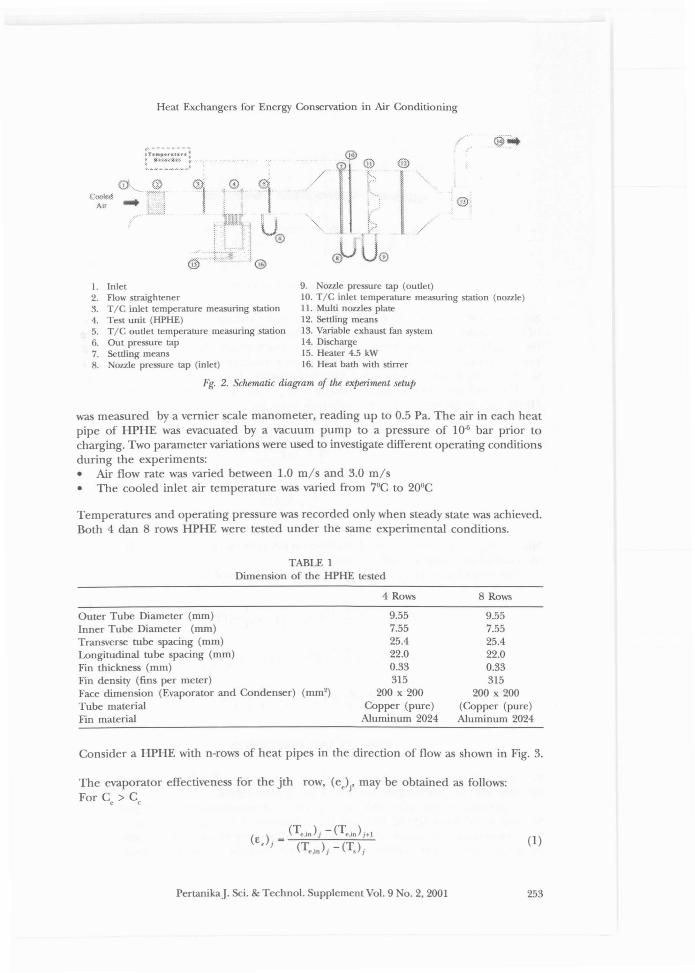
In this study, tests with two units of gravity-assisted wickless heat pipe heat exchangerwere conducted. Both of the test units were constructed in staggered configuration.Their detailed geometric parameters are tabulated in Table 1. Refrigerant 134a was usedas the working fluid, which filled up 60% of the evaporator section. Experiment wasconducted in a forced-draft wind tunnel as shown in Fig. 2, equipped with a 1.1 kWcentrifugal fan and an inverter. This air-flow measuring station is a multiple-nozzle codetester based on the ASHRAE 41.2 standard. In order to obtain good laminar flow, a wiremesh air straightener was installed near the inlet. The evaporator section of HPHE wassubmerged into a hot water reservoir that maintains a constant temperature. This heatbath is analogous to a very high capacity hot-air stream or outdoor fresh air. A goodinternal circulation of water flow ensured equal temperature distribution in the bath, aswell as continuous flow across the evaporator section. The wind tunnel's inlet isconnected to an air-conditioning unit that controlled the inlet is connected to ananalogous to the exhaust air from a refrigerated space passes through the condensersection of HPHE and is heated by heat transferred from the evaporator section.
The inlet and outlet temperatures across the test units are measured by two K-typethermocouple meshes. Each of this mesh consists of 9 thermocouple, having an accuracyof approximately 0.5°C. The pressure drop across the test units and the nozzle section
252 PertanikaJ. Sci. & Techno!. Supplement Vol. 9 No.2, 2001
Heat Exchangers for Energy Conservation in Air Conditioning
(:(NJ~
)\ff
'" .,. -~ .,. y.,,'" ~ .~
IT,;r~fo6".I.U :
~ ...:,~~::~ ....~:
,} ....
(9~ - - $,
(&
·1uo
@
I
I"~"
/
1. Inlet2. Flow str.tightener3. TIC inlet temperarure measuring station4. Test unit (HPHE)5. TIC outlet temperarure measuring station6. Out pressure tap7. Settling means8. Nozzle pressure tap (inlet)
9. Nozzle pressure tap (outlet)10. TIC inlet temperarure measuring station (nozzle)II. Multi nozzles plate12. Settling means13. Variable exhaust fan system14. Discharge15. Heater 4.5 kW16. Heat bath with stirrer
1"15. 2. Schematic diagram oj the experiment setup
was measured by a vernier scale manometer, reading up to 0.5 Pa. The air in each heatpipe of HPHE was evacuated by a vacuum pump to a pressure of 10-6 bar prior tocharging. Two parameter variations were used to investigate different operating conditionsduring the experiments:• Air flow rate was varied between 1.0 mls and 3.0 mls• The cooled inlet air temperature was varied from 7°C to 20°C
Temperatures and operating pressure was recorded only when steady state was achieved.Both 4 dan 8 rows HPHE were tested under the same experimental conditions.
TABLE 1Dimension of the HPHE tested
Outer Tube Diameter (mm)Inner Tube Diameter (mm)Transverse tube spacing (mm)Longitudinal tube spacing (mm)Fin thickness (mm)Fin density (fins per meter)Face dimension (Evaporator and Condenser) (mm')Tube materialFin material
4 Rows
9.557.5525.422.00.33315
200 x 200Copper (pure)
Aluminum 2024
8 Rows
9.557.5525.422.00.33315
200 x 200(Copper (pure)Aluminum 2024
Consider a HPHE with n-rows of heat pipes in the direction of flow as shown in Fig. 3.
The evaporator effectiveness for the jth row, (e.)j' may be obtained as follows:For C > Ce e
( ). = (Te,in> i - (Te.;,,) i.1
E, ) (T ). _ (T ) .~.m J S J
PertanikaJ. Sci. & Technol. Supplement Vol. 9 No.2, 2001
(1)
253

Yau Y. H., Wong S. W., Tong C. Y. & Than C. F.
j"'l j"'2 J"*3 .1'91Fig. 3. A n-row Heat Pipe Heat Exchanger
Submersion of evaporator section into the water bath resulting a higher overall coefficientof heat transfer for the evaporator, De' as compared to the condenser, Dc. In addition,the specific heat, C
p' and density, p, of water is much greater than air, thus causing the
evaporator effectiveness (E.)j to close to unity. As a result, the saturation temperature, T"is almost equivalent to the water bath temperature, T
w'
The condenser effectiveness for the jth row, (E.). and the overall effectiveness of theHPHE for the jth row, (E)/ are respectively given by:
1(E,)j= 1 CIC
_+_c__eten ten
Since C/Ce...(), it can be assumed that the overall effectiveness of the HPHE,
identical to the condenser effectiveness, Ec'
The temperature (T.)j' (T)/ and (T,)j may be calculated as follows:
RESULTS AND DISCUSSION
(2)
(3)
(4)
(5)
(6)
Fig. 4 and 5 show the condenser outlet air temperature distribution in reponse todifferent inlet air temperature for both 4 and 8 rows HPHE.
In general, the test unit outlet air temperature increased with the inlet temperaturefor both 4 and 8-row HPHE. However, the magnitude of increment decreases with theinlet temperature. A considerable temperat:l:re difference between the condenser andevaporator section of the HPHE is essential in initiating the refrigerant boiling process.
254 PertanikaJ. Sci. & Techno!. Supplement Vo!. 9 No.2, 2001

Heat Exchangers for Energy Conservation in Air Conditioning
...
..
"
!""
............
....~.. ~ ... ~ ...-~ ...
.-~.".
+ ..' ..~.•....
'6 ..... ,
Fig. 4. Condenser IlUtlet air temperaturedistribution vs inlet air temperature
for 4-raw HPHE
Fig. 5. Condenser IlUtlet air temperaturedistribution vs inlet air temperature for lYraw
HPHE
Higher inlet air temperature resulted in lower temperature differences and, therefore,reducing the outlet air temperature as well as the heat transfer rate.
The effect of air velocities are such that the outlet air temperature experienced adescending profile as air velocity increased. Lower air velocity means more time is takenin flowing across the HPHE, thus allows the air to be higher temperature.
The outlet air temperatures taken from the experiment was compared with thetheoretical values calculated from equation (5). The results are shown in Fig. 6. otethat good agreement is obtained in the lower region of the 4-row HPHE.
,."""fl:; .4~ti ....~1i(~!
"At v~u),~>l~~;)
. tA~~
:,.~~~
,//'
"Hi/
'" .It ~ '"~-...
~...,.~ /4
./>.,
.,
Fig. 6. Comparison of the theoretical andexperimental temperature distribution
Fig. 7. Comparison of the overaU effectiveness
Equations 2 and 3 give the condenser effectiveness and consequently the overalleffectiveness of the HPHE. Fig. 7 presents the comparison of the overall effectiveness.Generally, eo increases about 0.2 when the number of rows is doubled. However, thepercentage of increment is much more significant, which varies from 25% to 45% as theair velocity changes between 1.0 mls and 3.0 mls respectively. This means that to obtain
PertanikaJ. Sci. & Techno\. Supplement Vol. 9 No.2, 2001 255
Yau Y. H., Wong S. W., Tong C. Y. & Than C. F.
excellent performance in a high capacity coolness recovery, the number off rows shouldbe increased. The results that we calculated are also in conformity with the theoreticalvalues predicted by Vau et. al.
CONCLUSION
A themosyphon heat pipe heat exchanger, with no wicks can be used as a highly efficientdevice in heat recovery. It has been found that with different combination of parameters,the heat exchanger may achieve its optimum potential. Good agreement is also beingobserved between the experimental results and the theoretical values.
NOTATION
specific heat at constant pressure (Jklf1KI]
flow-stream capacity of cold-side fluid [WK1]
flow-stream capacity of hot-side fluid [WK1]
air mass flow rate [kgso1]
number of rows in flow direction [dimensionless]number of heat-transfer units of an exchanger [dimensionless]heat transfer rate [W]temperature [0C]overall heat transfer coefficient [Wmo2K I
]
face velocity [msol]
Greek letterEi exchanger effectivenessp density [kgm-3
]
Subscriptsair air sidec condensere evaporatorin inleto outlet overallout outlets saturationw water
REFERENCES
AMODE, ].0. and KT. FELDMAN. 1976. Preliminary analysis of heat pipe heat exchangers for heatrecovery, ASME Paper No. 75-WA/Ht-36.
A:zAn E., F. MOHAMMADIEH and F. MOZTARZADEH. 1985. Thermal performance of heat pipe heatrecovery system. 5(6): 561-570. Pergamon Press Ltd.
CIlAUDRONE, S. 1984. Modelization and optimization of heat pipe heat exchangers. In Proc. 5" intoHeat Pipe Con!, p. 53-58. Tsukuba Science City, Japan.
CHI S.W. 1996. Heat Pipe Theury and Practice. ew York: McGraw-Hill.
KJusIlMAN, K . and KS. RAo. 1984. Analysis and design of heat pipe heat exchanger. In Proc.5" intoHeat Pipe Con!, Tsukuba Science City, Japan, 152-156.
256 Pertanika]. Sci. & Techno!. Supplement Vo!. 9 O. 2, 2001
Heat Exchangers for Energy Conservation in Air Conditioning
LEE, Y. and A. BEDROSSlAN. 1976. The characteristics of heat exchanger using heat pipes orthermosyphons. Int. J. Heat Mass Transfer 21: 221-229.
Standard Methods for Laboratory Air-Bow Measurement, ASHRAE Standard 41.2-1987, AmericanSociety of Heating, Refrigerating and Air Conditioning Engineers, Inc., Atlanta.
STULC P., L.L. VASlLlEV, V.G. KIsELJEV andju. N. MAlVEJEV. 1985. Heat pipe heat exchangers in heatrecovery system. Heat Recovery System. 5(5): 415-418. Pergamon Press Ltd.
TAN ].0., C.Y. Lru and Y.W. WONG. 1990. Predicting the performance of heat pipe heat exchanger,using effectiveness-NTU method. Int. j. Heat and Fluid Flow 11(4).
WADOWSKI T., A. A!rnARzADEH and P. JOHNSON. 1991. Characteristics of A Gravity-Assisted Heat PipeBased Heat Exchanger, Heat Recovery System & CHP. 11: 69-77. Pergamon Press.
WASlM SAMAN. Performance of A Thermosyphon Heat Exchanger in An Evaporative Air-COnditioningSystem, Energy/Engines Research Group, University of South Australia, Australia.
Wu X. P., P. JOHNSON and A!rnARzADEII. 1997. Application of heat pipe heat exchangers to humiditycontrol in aiHonditioning system Applied Thermal Engineering 17(6): 561-568.
VA Y. H, S.W. WONG and C.F. THAN. 1998. Thermal Performance of Heat Pipe Heat Exchangers,The 7th jSPS- vee Seminar on Integrated Engineering, p. 408-413. Kuala Lumpur, Malaysia.
YAu Y.H. 1998. Thermal Performance of Heat Pipe Heat Exchangers, Ph.D. in MechanicalEngineering Progress Report, Kuala Lumpur, Malaysia.
Pertanikaj. Sci. & Techno\. Supplement Vo\. 9 o. 2, 2001 257