conquas 2005
TRANSCRIPT
7/27/2019 Conquas 2005
http://slidepdf.com/reader/full/conquas-2005 1/65
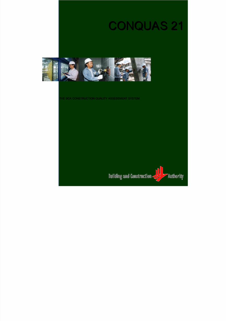
CONQUAS 21CONQUAS 21
THE BCA CONSTRUCTION QUALITY ASSESSMENT SYSTEMTHE BCA CONSTRUCTION QUALITY ASSESSMENT SYSTEM

7/27/2019 Conquas 2005
http://slidepdf.com/reader/full/conquas-2005 2/65
CCOONNQQUU A ASS 2211
Effective date: 1st
J an 2005 i
CCOONNQQUU A ASS 2211
TTHHEE BBCC A A
CCOONNSSTTRRUUCCTTIIOONN QQUU A ALLIITTYY A ASSSSEESSSSMMEENNTT
SSYYSSTTEEMM

7/27/2019 Conquas 2005
http://slidepdf.com/reader/full/conquas-2005 3/65
CCOONNQQUU A ASS 2211
Effective date: 1st
J an 2005 ii
First Edition 1989Second Edition 1990 Third Edition 1992Fourth Edition 1995Fifth Edition 1998
Fifth Edition 2000 versionFifth Edition 2003 version
Six Edition 2005
Copyright @ 2005 by the Building and Construction Authority, Singapore. Allrights reserved. No part may be reproduced, in any form or by any means,without permission in writing from the publisher.
While every effort has been made to ensure the accuracy of the informationpresented in this publication, neither the Board nor its employees or agentscan accept responsibility for any loss or damage incurred in connection withthe use of the contents.

7/27/2019 Conquas 2005
http://slidepdf.com/reader/full/conquas-2005 4/65
CCOONNQQUU A ASS 2211
Effective date: 1st
J an 2005 iii
CCOONNTTEENNTTSS
1.0 INTRODUCTION..................................................................................1
1.1 Objectives of CONQUAS1.2 Scope of CONQUAS 211.3 Derivation of CONQUAS
2.0 CONQUAS 21......................................................................................3
2.1 Components to be assessed
2.2 The Weightages2.3 CONQUAS Assessor2.4 Sampling
3.0 THE ASSESSMENT.............................................................................6
3.1 Assessment Approach3.2 Structural Works Assessment3.3 Architectural Works Assessment3.4 M&E Works Assessment
3.5 Computation of CONQUAS Score
APPENDICES
Appendix 1 Quality Standards for Structural Works...................................19Appendix 2 Quality Standards for Architectural Works...............................28Appendix 3 Quality Standards for M&E Works...........................................46Appendix 4 Defects Grouping Guide for Assessment of Internal Finishes……..59Appendix 5 Building Grouping Guide…………………………………...........60 Appendix 6 Points Allocation Table For M&E Works Assessment ….…………61
7/27/2019 Conquas 2005
http://slidepdf.com/reader/full/conquas-2005 5/65
CCOONNQQUU A ASS 2211
Effective date: 1st
J an 2005 Page 1
11..00 IINNTTRROODDUUCCTTIIOONN
1.1 OObb j jeecctt iivveess oof f CCOONNQQUU A ASS
The Construction Quality Assessment System or CONQUAS wasdeveloped by the Building and Construction Authority (BCA) inconjunction with the major public sector agencies and the variousleading industry professional bodies to measure the quality levelachieved in a completed project.
CONQUAS was designed with three objectives:
(a) To have a standard quality assessment system for constructionprojects.
(b) To make quality assessment objective by:
- measuring constructed works against workmanshipstandards and specification.
- using a sampling approach to suitably represent thewhole project.
(c) To enable quality assessment to be carried out systematicallywithin reasonable cost and time.
CONQUAS is an independent assessment. Unless specified in thebuilding contract, project engineers or architects should not useCONQUAS to decide if the building or parts of the building project areacceptable.
11..22 SSccooppee oof f CCOONNQQUU A ASS 2211
CONQUAS sets out the standards for the various aspects of construction work and awards points for works that meet the standards. These points are then summed up to give a total quality score called theCONQUAS Score for the building project.
CONQUAS 21 covers most aspects of the general building works. Theassessment consists of three components:
(1) Structural Works,(2) Arch itectural Works and(3) Mechanical & Electrical (M&E) Works.
7/27/2019 Conquas 2005
http://slidepdf.com/reader/full/conquas-2005 6/65
CCOONNQQUU A ASS 2211
Effective date: 1st
J an 2005 Page 2
Each component is further divided into different items for assessment.However, the assessment excludes works such as piling, heavyfoundation and sub-structure works which are heavily equipment-based
and called under separate contracts or sub-contracts.
The building is assessed primarily on workmanship standards achieved through site inspection and field testing. The assessment isdone throughout the construction process for Structural and M&E Worksand on the completed building for Architectural Works.
Apart from site inspection, the assessment also includes tests on thematerials and the functional performance of selected services andinstallations. These tests help to safeguard the interest of buildingoccupants in relation to safety, comfort and aesthetic defects which
surface only after sometime.
11..33 DDeer r iivvaatt iioonn oof f CCOONNQQUU A ASS
The minimum standards were derived from discussions with themajor public sector agencies, developers, consultants andcontractors based on the general specifications used in their projects.
To match the expectations from the end users, feedback through
complaints and defects listing were also considered in refining theweightages and assessment standards.
In developing CONQUAS 21, studies and numerous trials wereconducted to fine-tune its new test techniques and assessmentstandards. Moderation of the scoring system was carried out along withthe trials to ensure its accuracy and consistency.
7/27/2019 Conquas 2005
http://slidepdf.com/reader/full/conquas-2005 7/65
CCOONNQQUU A ASS 2211
Effective date: 1st
J an 2005 Page 3
22..00 CCOONNQQUU A ASS 2211
22
.
.11
CC
oo
mm
pp
oo
nn
ee
nn
ttss
ttoo
bb
ee
aa
ss
ss
ee
ss
ss
ee
dd
The CONQUAS assessment is divided into three main components -Structural Works, Architectural Works and M&E Works.
((aa)) SSttr r uuccttuur r aall WWoor r kkss..
The structural integrity of the building is of paramount importanceas the costs of failure and repairs are very significant. Theassessment of Structural Works comprises:
(i) Site inspection of formwork, steel reinforcement,prefabricated components, etc during construction. Theassessment shall include structural steel and pre-stressedconcrete if each constitutes more than 20% of the totalstructural cost. Precast elements will also be assessed if the precast concrete volume exceeds 20% of totalstructural concrete volume.
(ii) Laboratory testing of compressive strength of concrete andtensile strength of steel reinforcement.
(iii) Non-destructive testing of the uniformity and the cover of hardened concrete.
The quality standards for Structural Works are given in Appendix1.
((bb)) A Ar r cchhii tteeccttuur r aall WWoor r kkss..
Architectural Works deals mainly with the finishes andcomponents. This is the part where the quality and standard of workmanship are most visible. The assessment covers:
(i) Site inspection of internal finishes, roofs, external walls andexternal works at the completion stage of the building.Internal finishes include floors, internal walls, ceiling, doors,windows and components (architectural works that are notclassified above).

7/27/2019 Conquas 2005
http://slidepdf.com/reader/full/conquas-2005 8/65
CCOONNQQUU A ASS 2211
Effective date: 1st
J an 2005 Page 4
(ii) Material & functional tests such as on window water-tightness, wet area water-tightness test and adhesion of internal wall tiles. There is also in-process assessment on
installation of waterproofing for internal wet areas.
The quality standards for Architectural Works are given inAppendix 2.
((cc)) MMeecchhaanniiccaall && EElleeccttr r iiccaall ((MM&&EE)) WWoor r kkss..
The quality of M&E Works is important in view of its increasinglyhigh cost proportion and its impact on the performance of abuilding. The assessment covers Electrical Works, Air-conditioning & Mechanical Ventilation Works (ACMV), Fire
Protection Works, Sanitary & Plumbing Works and the basic M&Efittings. The stages of the assessment include:
(i) Site inspection of installed works before embedded/concealed. Such items include ACMVductworks, electrical conduits, concealed pipes, etc.
(ii) Site inspection of final installed works such as the Air-Handling Unit (AHU), cooling tower, fire alarm controlpanel, etc.
(iii) Performance tests on selected works such as the WaterPressure Test, Earthing Test, Dry Riser Test, etc.
The quality standards for M&E Works are given in Appendix 3.

7/27/2019 Conquas 2005
http://slidepdf.com/reader/full/conquas-2005 9/65
CCOONNQQUU A ASS 2211
Effective date: 1st
J an 2005 Page 5
22..22 TThhee WWeeiigghhttaaggeess
In CONQUAS 21, the weightages for Structural, Architectural and M&Eworks are allocated according to four categories of buildings as follows:
Components
CAT ACommercial,
Industrial,Institution& others
CAT BCommercial,
Industrial,Institution& others
CAT BPrivateHousing
CAT C Public
Housing
CAT D LandedHousing
Structural Works 25% 30% 25% 35% 30%
Architectural Works 55% 60% 65% 60% 65%
M&E Works 20% 10% 10% 5% 5%
CONQUAS Score 100% 100% 100% 100% 100%
Note : In general, projects with central cooling system having cooling tower, chiller system, etc are classified under CAT A. Otherwise, it will be classified under CAT B. Appendix 5 provides a guides with listing of buildings under the variouscategories.
The weightage system, which is aimed at making the CONQUAS scoreobjective in representing the quality of a building, is a compromisebetween the cost proportions of the three components in the variousbuildings and their aesthetic consideration.
The CONQUAS score of a building is the sum of points awarded to thethree components in each category of buildings.
22..33 CCOONNQQUU A ASS A Asssseessssoor r
BCA assessors undergo a vigorous training programme. They arerequired to attend BCA's CONQUAS training and calibration programmeto ensure competency and consistency in the assessment.
22..44 SSaammppll iinngg
As it is impractical to assess all elements in a building, CONQUAS 21uses a sampling system for the assessment. The sampling system,which is mainly based on the gross floor area of the building, will ensurethat the assessment adequately represents the entire building.
7/27/2019 Conquas 2005
http://slidepdf.com/reader/full/conquas-2005 10/65

7/27/2019 Conquas 2005
http://slidepdf.com/reader/full/conquas-2005 11/65
CCOONNQQUU A ASS 2211
Effective date: 1st
J an 2005 Page 7
33..22 SSttr r uuccttuur r aall WWoor r kkss A Asssseessssmmeenntt
The assessment for Structural Work will be carried out for every building
block as the construction proceeds. A sample in structural work can be abeam, a column, a wall or a slab. The assessment of a reinforcedconcrete structure consists of the following items:
Reinforced Concrete Structure Weightage %
Formwork 15
Rebar 20
Finished Concrete 25
Concrete Quality 5
Steel Reinforcement Quality 5
NDT - UPV test for concrete uniformity 15
NDT - Electro-Covermeter test for concrete cover 15
Total 100
* If total precast concrete volume exceeds 20% of total structural concrete volume,
assessment will be carried out for precast concrete construction. The points will bedistributed proportionately between formwork/rebar assessment and precastconcrete assessment based on the respective concrete volume percentage.

7/27/2019 Conquas 2005
http://slidepdf.com/reader/full/conquas-2005 12/65
CCOONNQQUU A ASS 2211
Effective date: 1st
J an 2005 Page 8
For a typical reinforced concrete structure, selection of samples forassessment is based on the following guidelines:
ItemsGFA per Sample
MinSample
MaxSample
Remarks
1 Structural Elements 500 m2 30 150 For Non-Housing Project
1a Structural Elements 1500 m2 30 50 For Housing Project
2Concrete CompressiveStrength
- 100% -Declaration by QualifiedPerson
3 Steel reinforcement TensileStrength
- 100% - Declaration by QualifiedPerson
4NDT- UPV test for concrete
uniformity5,000 m2
2sets
20sets
5structure membersper set
5NDT- Electro-Covermeter
test for concrete cover 5,000 m2
2sets
20sets
5structure membersper set
Note: The computed number of elements to be checked must be evenlydistributed throughout the entire block and cover at least 50% of floors ina block. They should also as far as possible cover the different types of
structural elements.
The resulting score for the formwork/rebar/precast and finished concretewill be the sum of the number of checks that meet the standards.
There is no assessment of precast components at the precast yard. Theassessment is applicable for all types of precast components at site.
The assessment of the quality of concrete and steel reinforcement andthe non-destructive tests is based on compliance to the standards (seeAppendix 1a).
The introduction of the non-destructive tests, i.e. on concrete uniformityand cover for steel reinforcement, is to minimise the risk of carbonationand steel corrosion which affect the durability of the concrete structures.
If Structural Works consists of structural steelwork which constitutesmore than 20% of the structural cost, assessment will be required for thelatter and the points will be distributed proportionately. This applies toPre-stressing Works as well. In any case, the distribution should followthe cost composition for these three types of structural works in aproject.

7/27/2019 Conquas 2005
http://slidepdf.com/reader/full/conquas-2005 13/65
CCOONNQQUU A ASS 2211
Effective date: 1st
J an 2005 Page 9
The distribution of points for Structural Steelwork and Pre-stressedConcrete are as follows:
Structu ral Steelwork Weightage %
Main Member/Partially Assembled Component 40
Metal Decking 20
Erection Tolerances 10
Corrosion & Fire Protection 10
Welding Test Reports 20
Total 100
Note: Assessment for Structural steel roof truss is
compulsory irregardless of the 20% costing criteria
Pre-stressed Concrete Weightage %
Tendon & Anchorage 25
Sheathing 25
Stressing & Grouting 25
Debonding 25
Total 100
The selection of samples forStructural Steelwork assessment is basedon the following guidelines:
ItemsSteel tonnage
per sampleMin
Sample
Structural Elements
Main member / Partialassembled component
250 5
Metal decking 250 5
Erection Tolerances 500 5
Corrosion & Fire Protection 500 5
Material & Functional Test
Welding Test Reports (NDT) All critical welding joints
Note: Samples will be taken before and after installation

7/27/2019 Conquas 2005
http://slidepdf.com/reader/full/conquas-2005 14/65
CCOONNQQUU A ASS 2211
Effective date: 1st
J an 2005 Page 10
33..33 A Ar r cchhii tteeccttuur r aall WWoor r kkss A Asssseessssmmeenntt
Assessment of Architectural works is carried out upon completion of the
building and before handing over of the project to the owner.
The assessment consists of the following items:
Weightage % Architectural Elements
Total Breakdown
Internal Finishes 56
Floor 16
Internal Wall 16
Ceiling 6
Door 6
Window 6
Component 6
Roof 4 4
External Wall 12 12
External Work 6 6
Material & Functional Tests 22
Pre-packed Plaster 1Field Window Water-Tightness Test (WTT)
(BCA Test 8 pts +Self-Testing 2 pts) 10Wet Area Water-Tightness Test(BCA Test 4 pts +Self-Testing 1 pt)
5
Internal Wet Area Waterproofing Process 2
Pull-Off-Test for Internal Wall Tiles 4
Total 100
7/27/2019 Conquas 2005
http://slidepdf.com/reader/full/conquas-2005 15/65
CCOONNQQUU A ASS 2211
Effective date: 1st
J an 2005 Page 11
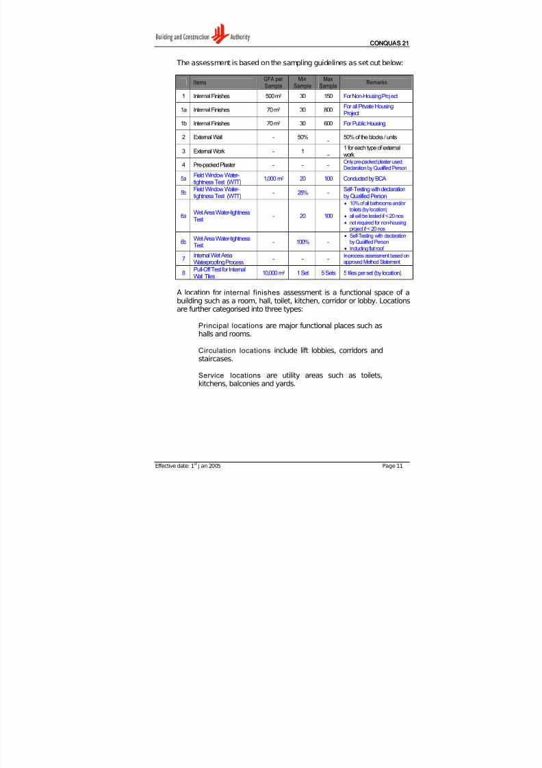
The assessment is based on the sampling guidelines as set out below:
ItemsGFA per
Sample
Min
Sample
Max
Sample
Remarks
1 Internal Finishes 500 m2 30 150 For Non-Housing Project
1a Internal Finishes 70 m2 30 800For all Private HousingProject
1b Internal Finishes 70 m2 30 600 For Public Housing
2 External Wall - 50%-
50% of the blocks / units
3 External Work - 1-
1 for each type of externalwork
4 Pre-packed Plaster - - -Only pre-packed plaster used.Declaration by Qualified Person
5a Field Window Water-tightness Test (WTT) 1,000 m2 20 100 Conducted by BCA
5bField Window Water-tightness Test (WTT)
- 25% -Self-Testing with declarationby Qualified Person
6aWet Area Water-tightnessTest
- 20 100
• 10% of all bathrooms and/or toilets (by location)
• all will be tested if < 20 nos
• not required for non-housingproject if < 20 nos
6bWet Area Water-tightnessTest
- 100% -• Self-Testing with declaration
by Qualified Person
• Including flat roof
7Internal Wet AreaWaterproofing Process
- - -In-process assessment based onapproved Method Statement
8Pull-Off Test for InternalWall Tiles
10,000 m2 1 Set 5 Sets 5 tiles per set (by location)
A location for internal finishes assessment is a functional space of abuilding such as a room, hall, toilet, kitchen, corridor or lobby. Locationsare further categorised into three types:
Principal locations are major functional places such ashalls and rooms.
Circulation locations include lift lobbies, corridors and
staircases.
Service locations are utility areas such as toilets,kitchens, balconies and yards.

7/27/2019 Conquas 2005
http://slidepdf.com/reader/full/conquas-2005 16/65
CCOONNQQUU A ASS 2211
Effective date: 1st
J an 2005 Page 12
The computed number of locations will be distributed according to"Principal", "Circulation" and "Service" based on the percentages set outin the four categories of buildings as below:
CAT B
Locations
CAT ACommercialIndustrialInstitutionOthers
Housing Non-Housing
CAT CPublic
Housing
CAT DLandedHousing
Principal 60% 40% 60% 40% 40%
Service 15% 40% 15% 40% 40%
Circulation 25% 20% 25% 20% 20%
Scoring of internal finishes is based on the defects groups as shown inAppendix 4 'Defects Grouping Guide for Assessment of InternalFinishes'. In general, any item which is not available in a project will notbe considered for scoring. For such case, the architectural score will bepro-rated accordingly.
An item under assessment will be considered failed if it does not meetthe standards. In addition, any item found to be defective functionallysuch as evidence of water seepage in the window, slab, ceiling or roof, isconsidered to have failed the assessment. Likewise for a particulardefect that is found excessive in an item (say excessive cracks on a
wall).
For the assessment of roof , a minimum 50% of the total number of buildings will be assessed. This applies to the assessment of externalwalls where a minimum 50% of the total number of buildings will berequired. For a building, the external wall will be divided into 4 walls forassessment.
The External Works assessment consists of the following locations:
(a) Link-way / Shelter - 10m length section per sample and minimum 2 samples
(b) Apron & Drain - 10m length section per sample and minimum 2 samples(c) Roadwork & Carpark - 10m length section per sample and minimum 1 sample(d) Footpaths & Turfing - 10m length section per sample and minimum 2 samples(e) Playground - 1 location(f) Court - 1 location(g) Fencing & Gate - 10m length section per sample and minimum 1 sample(h) Swimming Pool - 10m length section per sample and minimum 1 sample(i) Club House - 1 location(j) Guard House - 1 location(k) Electrical Substation - 1 location
Each item in the External Works will be assessed separately and all the
locations listed above must be assessed where applicable.
7/27/2019 Conquas 2005
http://slidepdf.com/reader/full/conquas-2005 17/65
CCOONNQQUU A ASS 2211
Effective date: 1st
J an 2005 Page 13
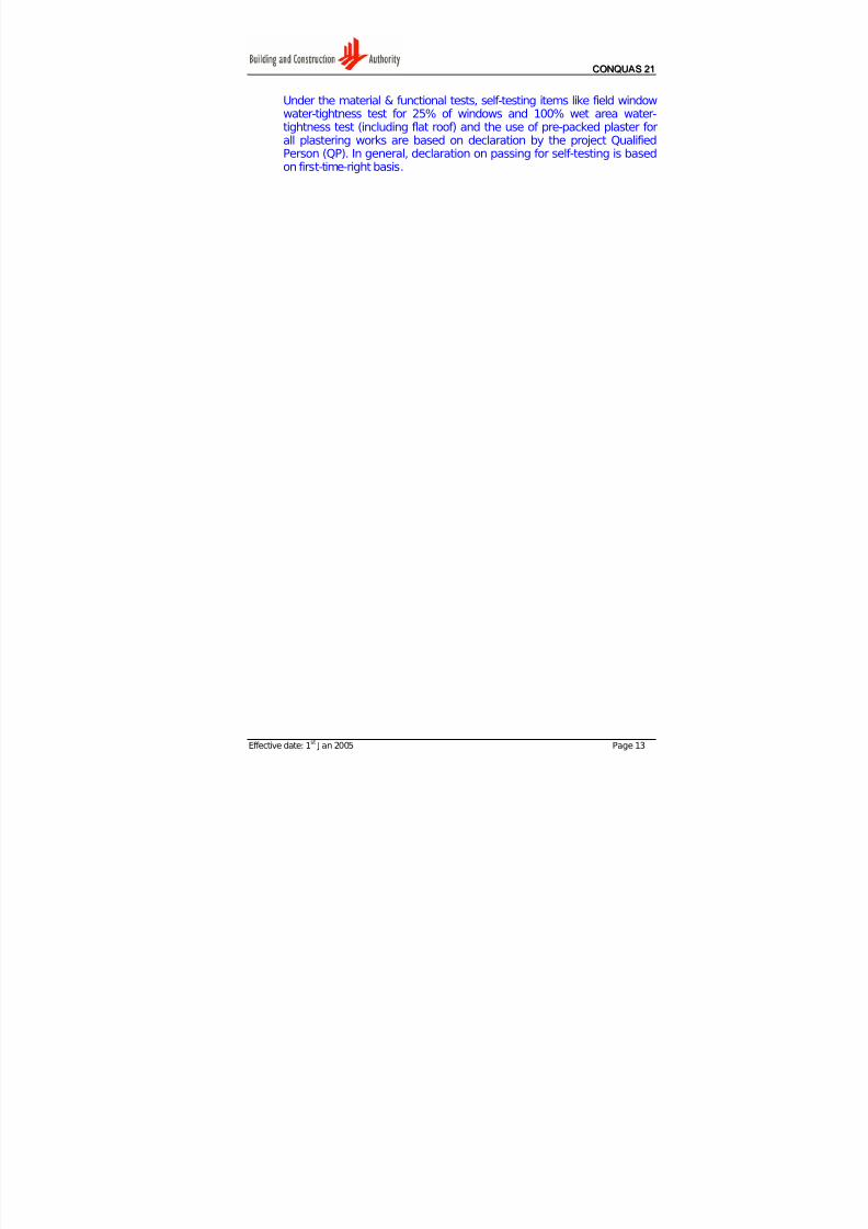
Under the material & functional tests, self-testing items like field windowwater-tightness test for 25% of windows and 100% wet area water-tightness test (including flat roof) and the use of pre-packed plaster for
all plastering works are based on declaration by the project QualifiedPerson (QP). In general, declaration on passing for self-testing is basedon first-time-right basis.
7/27/2019 Conquas 2005
http://slidepdf.com/reader/full/conquas-2005 18/65
CCOONNQQUU A ASS 2211
Effective date: 1st
J an 2005 Page 14
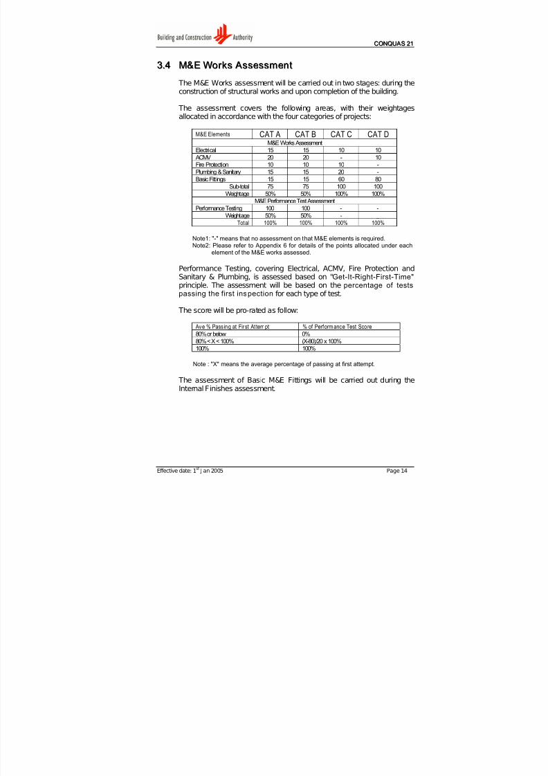
33..44 MM&&EE WWoor r kkss A Asssseessssmmeenntt
The M&E Works assessment will be carried out in two stages: during the
construction of structural works and upon completion of the building.
The assessment covers the following areas, with their weightagesallocated in accordance with the four categories of projects:
M&E Elements CAT A CAT B CAT C CAT DM&E Works Assessment
Electrical 15 15 10 10
ACMV 20 20 - 10
Fire Protection 10 10 10 -
Plumbing & Sanitary 15 15 20 -
Basic Fittings 15 15 60 80Sub-total 75 75 100 100
Weightage 50% 50% 100% 100%
M&E Performance Test Assessment
Performance Testing 100 100 - -
Weightage 50% 50% - _
Total 100% 100% 100% 100%
Note1: "-" means that no assessment on that M&E elements is required.Note2: Please refer to Appendix 6 for details of the points allocated under each
element of the M&E works assessed.
Performance Testing, covering Electrical, ACMV, Fire Protection andSanitary & Plumbing, is assessed based on "Get-It-Right-First-Time" principle. The assessment will be based on the percentage of testspassing the first inspection for each type of test.
The score will be pro-rated as follow:
Ave % Passing at First At tempt % of Performance Test Score
80% or below 0%
80% < X < 100% (X-80)/20 x 100%
100% 100%
Note : "X" means the average percentage of passing at first attempt.
The assessment of Basic M&E Fittings will be carried out during theInternal Finishes assessment.

7/27/2019 Conquas 2005
http://slidepdf.com/reader/full/conquas-2005 19/65
CCOONNQQUU A ASS 2211
Effective date: 1st
J an 2005 Page 15
Like the Architectural Works, sampling of M&E works will be determinedbased on the four categories of buildings as per the guidelines below:
CAT A CAT B CAT C CAT D1,000 m2 per
sample1,500 m2 per
sample3,500 m2 per
sample3,500 m2 per
sampleElectrical
1. Embedded conduit 2+ 2+ 2+
2. Main cables 1 1
3. Surface conduits 1+ 1+ 1+ 1+
4. Cable tray, ladder & trunking 1+ 1+ 1+ 1
5. Distribution board 2+ 2+ 1
ACMV
1. Air handling unit 1+2. Pump 1
3. Cooling tower 1
4. Chiller 1
5. Pipework 1
6. Split unit / Window air conditioner 2+ 2+ 3+
7. Air-con comfort 1+ 1+ 2+
8. Ductwork 3+ 1
9. Fire-rated duct 1 1
10. Dampers 1+ 1
11. Fire Dampers 1 1
12. Flexible ducts 2
13. Flexible connectors 1
Fire Protection
1. Wet / Dry riser 1+ 1+ 1+
2. Sprinkler 1+ 1
3. Fire Alarm 1 1
4. Hosereel 1+ 1+ 1+
Plumbing & Sanitary
1. Concealed pipes 1+ 1+
2. Exposed pipes 4+ 4+ 4+
3. Water tank 1 1 1
4. Pump 1 1 1
Minimum Samples 35 25 10 10
Maximum Samples 70 50 20 20
Remarks : + means to be repeated for additional samples required
Note : Basic M&E Fittings - 500 m2 per sample wit h min 30 and max 150 samples
7/27/2019 Conquas 2005
http://slidepdf.com/reader/full/conquas-2005 20/65
CCOONNQQUU A ASS 2211
Effective date: 1st
J an 2005 Page 16
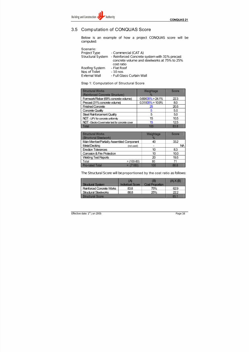
3.5 Computation of CONQUAS Score
Below is an example of how a project CONQUAS score will be
computed:
Scenario:Project Type - Commercial (CAT A)Structural System - Reinforced Concrete system with 31% precast
concrete volume and steelworks at 75% to 25%cost ratio
Roofing System - Flat Roof Nos of Toilet - 10 nosExternal Wall - Full Glass Curtain Wall
Step 1: Computation of Structural Score
Structural Works(Reinforced Concrete Structure)
Weightage%
Score
Formwork/Rebar (69% concrete volume) 0.69X35%= 24.1% 22.3
Precast (31% concrete volume) 0.31X35%= 10.9% 8.0
Finished Concrete 25 20.5
Concrete Quality 5 5.0
Steel Reinforcement Quality 5 5.0
NDT - UPV for concrete uniformity 15 10.5
NDT - Electro-Covermeter test for concrete cover 15 12.5Total 100 83.8
Structural Works(Structural Steelwork)
Weightage%
Score
Main Member/Partially Assembled Component 40 33.2
Metal Decking (not used) - NA
Erection Tolerances 10 8.3
Corrosion & Fire Protection 10 10.0
Welding Test Reports 20 19.5
Total = (100-80) 80 71
Pro-rated Total = (71/80) 100 88.8
The Structural Score will be proportioned by the cost ratio as follows:
Structural System(A)
Individual Score(B)
Cost Proportion(A) X (B)
Reinforced Concrete Works 83.8 75% 62.9
Structural Steelworks 88.8 25% 22.2
Structural Score 85.1
7/27/2019 Conquas 2005
http://slidepdf.com/reader/full/conquas-2005 21/65
CCOONNQQUU A ASS 2211
Effective date: 1st
J an 2005 Page 17
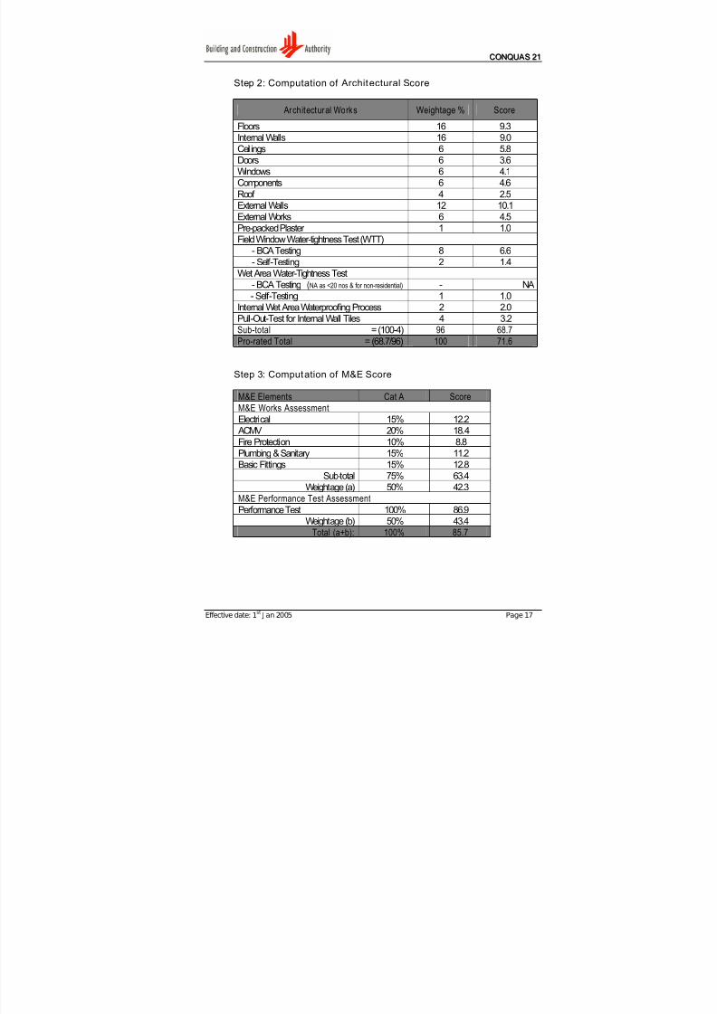
Step 2: Computation of Architectural Score
Architectural Works Weightage % Score
Floors 16 9.3
Internal Walls 16 9.0
Ceilings 6 5.8
Doors 6 3.6
Windows 6 4.1
Components 6 4.6
Roof 4 2.5
External Walls 12 10.1
External Works 6 4.5
Pre-packed Plaster 1 1.0
Field Window Water-tightness Test (WTT)
- BCA Testing 8 6.6
- Self-Testing 2 1.4
Wet Area Water-Tightness Test
- BCA Testing (NA as <20 nos & for non-residential) - NA
- Self-Testing 1 1.0
Internal Wet Area Waterproofing Process 2 2.0
Pull-Out-Test for Internal Wall Tiles 4 3.2
Sub-total = (100-4) 96 68.7
Pro-rated Total = (68.7/96) 100 71.6
Step 3: Computation of M&E Score
M&E Elements Cat A Score
M&E Works Assessment
Electrical 15% 12.2
ACMV 20% 18.4
Fire Protection 10% 8.8
Plumbing & Sanitary 15% 11.2
Basic Fittings 15% 12.8
Sub-total 75% 63.4
Weightage (a) 50% 42.3
M&E Performance Test Assessment
Performance Test 100% 86.9
Weightage (b) 50% 43.4
Total (a+b): 100% 85.7

7/27/2019 Conquas 2005
http://slidepdf.com/reader/full/conquas-2005 22/65
CCOONNQQUU A ASS 2211
Effective date: 1st
J an 2005 Page 18
Step 4: Computation of Final CONQUAS Score
Area of Works
(A)
ActualScore
(B)
CAT A
(A) X (B)
Structural Works 85.1 25% 21.3
Architectural Works 71.6 55% 39.4M&E Works 85.7 20% 17.1
CONQUAS Score 100% 77.8
7/27/2019 Conquas 2005
http://slidepdf.com/reader/full/conquas-2005 23/65
A Appppeennddiixx 11aa
Effective date: 1st
J an 2005 Page 19
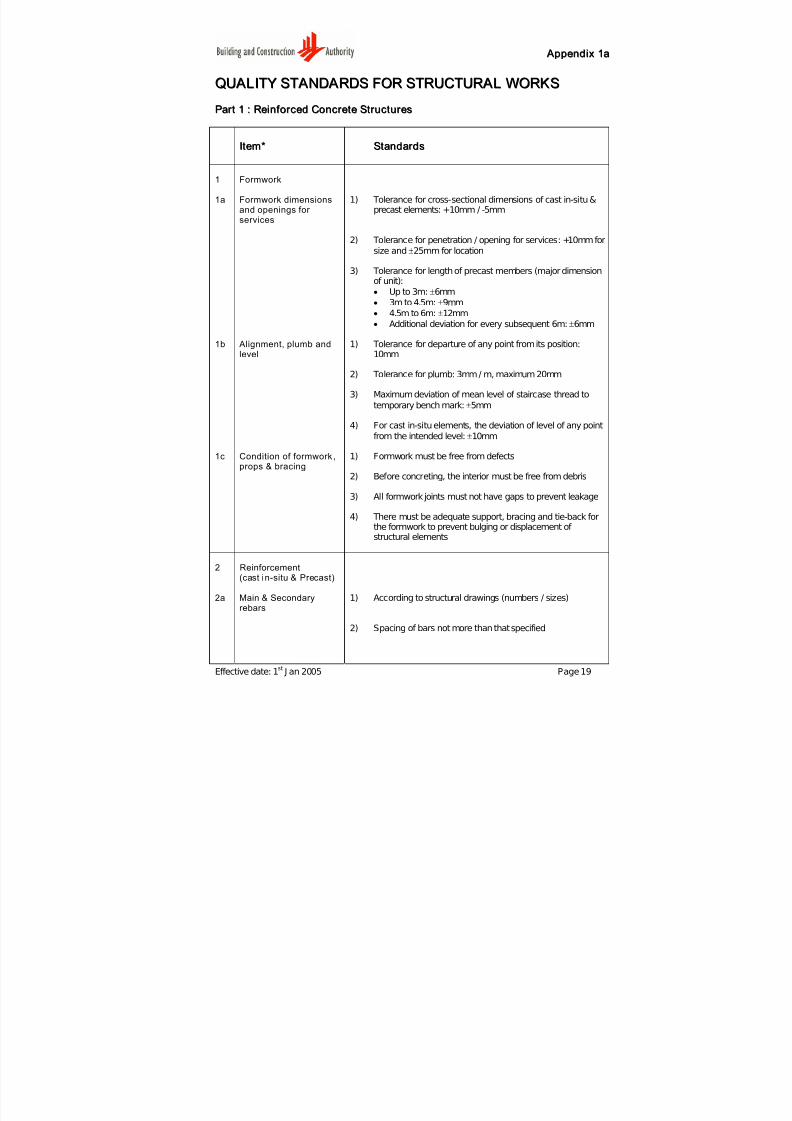
QQUU A ALLIITTYY SSTT A ANNDD A ARRDDSS FFOORR SSTTRRUUCCTTUURR A ALL WWOORRKKSS
PPaar r tt 11 :: RReeiinnf f oor r cceedd CCoonnccr r eettee SSttr r uuccttuur r eess
IItteemm** SSttaannddaar r ddss
1 Formwork
1a Formwork dimensionsand openings for services
1) Tolerance for cross-sectional dimensions of cast in-situ &precast elements: +10mm / -5mm
2) Tolerance for penetration / opening for services: +10mm for
size and ±25mm for location
3) Tolerance for length of precast members (major dimensionof unit):
• Up to 3m: ±6mm
• 3m to 4.5m: ±9mm
• 4.5m to 6m: ±12mm
• Additional deviation for every subsequent 6m: ±6mm
1b Alignment, plumb andlevel
1) Tolerance for departure of any point from its position:10mm
2) Tolerance for plumb: 3mm / m, maximum 20mm
3) Maximum deviation of mean level of staircase thread to
temporary bench mark: ±5mm
4) For cast in-situ elements, the deviation of level of any point
from the intended level: ±10mm
1c Condition of formwork,props & bracing
1) Formwork must be free from defects
2) Before concreting, the interior must be free from debris
3) All formwork joints must not have gaps to prevent leakage
4) There must be adequate support, bracing and tie-back forthe formwork to prevent bulging or displacement of structural elements
2 Reinforcement(cast in-situ & Precast)
2a Main & Secondaryrebars
1) According to structural drawings (numbers / sizes)
2) Spacing of bars not more than that specified
7/27/2019 Conquas 2005
http://slidepdf.com/reader/full/conquas-2005 24/65
A Appppeennddiixx 11aa
Effective date: 1st
J an 2005 Page 20
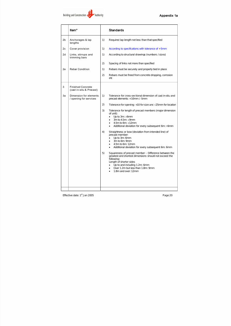
IItteemm** SSttaannddaar r ddss
2b Anchorages & laplengths
1) Required lap length not less than that specified
2c Cover provision 1) According to specifications with tolerance of +5mm
2d Links, stirrups andtrimming bars
1) According to structural drawings (numbers / sizes)
2) Spacing of links not more than specified
2e Rebar Condit ion 1) Rebars must be securely and properly tied in place
2) Rebars must be freed from concrete dropping, corrosionetc
3 Finished Concrete(cast in-situ & Precast)
3a Dimension for elements/ opening for services
1) Tolerance for cross-sectional dimension of cast in-situ andprecast elements: +10mm / -5mm
2) Tolerance for opening: +10 for size and ±25mm for location
3) Tolerance for length of precast members (major dimension
of unit):• Up to 3m: ±6mm
• 3m to 4.5m: ±9mm
• 4.5m to 6m: ±12mm
• Additional deviation for every subsequent 6m: ±6mm
4) Straightness or bow (deviation from intended line) of precast member:
• Up to 3m: 6mm
• 3m to 6m: 9mm
• 4.5m to 6m: 12mm
• Additional deviation for every subsequent 6m: 6mm
5) Squareness of precast member – Difference between thegreatest and shortest dimensions should not exceed thefollowing:Length of shorter sides
• Up to and including 1.2m: 6mm
• Over 1.2m but less than 1.8m: 9mm
• 1.8m and over: 12mm
7/27/2019 Conquas 2005
http://slidepdf.com/reader/full/conquas-2005 25/65
A Appppeennddiixx 11aa
Effective date: 1st
J an 2005 Page 21
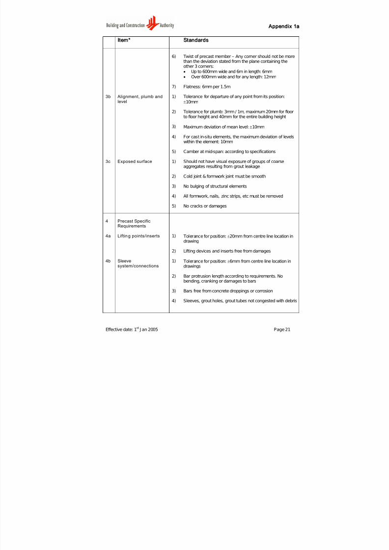
IItteemm** SSttaannddaar r ddss
6) Twist of precast member – Any corner should not be morethan the deviation stated from the plane containing theother 3 corners:
• Up to 600mm wide and 6m in length: 6mm
• Over 600mm wide and for any length: 12mm
7) Flatness: 6mm per 1.5m
3b Alignment, plumb andlevel
1) Tolerance for departure of any point from its position:
±10mm
2) Tolerance for plumb: 3mm / 1m, maximum 20mm for floorto floor height and 40mm for the entire building height
3) Maximum deviation of mean level: ±10mm
4) For cast in-situ elements, the maximum deviation of levelswithin the element: 10mm
5) Camber at mid-span: according to specifications
3c Exposed surface 1) Should not have visual exposure of groups of coarseaggregates resulting from grout leakage
2) Cold joint & formwork joint must be smooth
3) No bulging of structural elements
4) All formwork, nails, zinc strips, etc must be removed
5) No cracks or damages
4 Precast SpecificRequirements
4a Lifting points/inserts 1) Tolerance for position: ±20mm from centre line location indrawing
2) Lifting devices and inserts free from damages
4b Sleevesystem/connections
1) Tolerance for position: ±6mm from centre line location indrawings
2) Bar protrusion length according to requirements. Nobending, cranking or damages to bars
3) Bars free from concrete droppings or corrosion
4) Sleeves, grout holes, grout tubes not congested with debris
7/27/2019 Conquas 2005
http://slidepdf.com/reader/full/conquas-2005 26/65
A Appppeennddiixx 11aa
Effective date: 1st
J an 2005 Page 22
IItteemm** SSttaannddaar r ddss
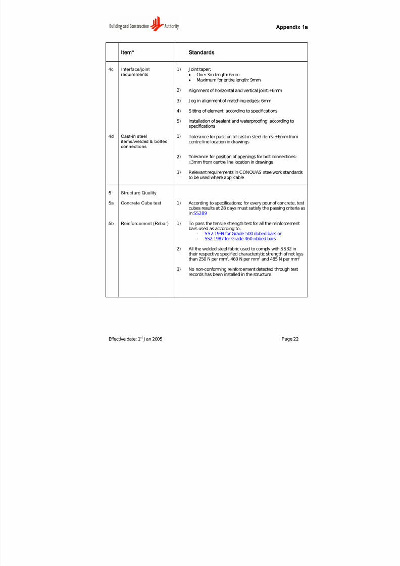
4c Interface/jointrequirements
1) J oint taper:
• Over 3m length: 6mm• Maximum for entire length: 9mm
2) Alignment of horizontal and vertical joint: ±6mm
3) J og in alignment of matching edges: 6mm
4) Sitting of element: according to specifications
5) Installation of sealant and waterproofing: according tospecifications
4d Cast-in steelitems/welded & boltedconnections
1) Tolerance for position of cast-in steel items: ±6mm fromcentre line location in drawings
2) Tolerance for position of openings for bolt connections:
±3mm from centre line location in drawings
3) Relevant requirements in CONQUAS steelwork standardsto be used where applicable
5 Structure Quality
5a Concrete Cube test 1) According to specifications; for every pour of concrete, testcubes results at 28 days must satisfy the passing criteria asinSS289
5b Reinforcement (Rebar) 1) To pass the tensile strength test for all the reinforcementbars used as according to:
- SS2:1999 for Grade 500 ribbed bars or- SS2:1987 for Grade 460 ribbed bars
2) All the welded steel fabric used to comply with SS32 intheir respective specified characteristic strength of not lessthan 250 N per mm
2, 460 N per mm
2and 485 N per mm
2
3) No non-conforming reinforcement detected through testrecords has been installed in the structure
7/27/2019 Conquas 2005
http://slidepdf.com/reader/full/conquas-2005 27/65
A Appppeennddiixx 11aa
Effective date: 1st
J an 2005 Page 23
IItteemm** SSttaannddaar r ddss
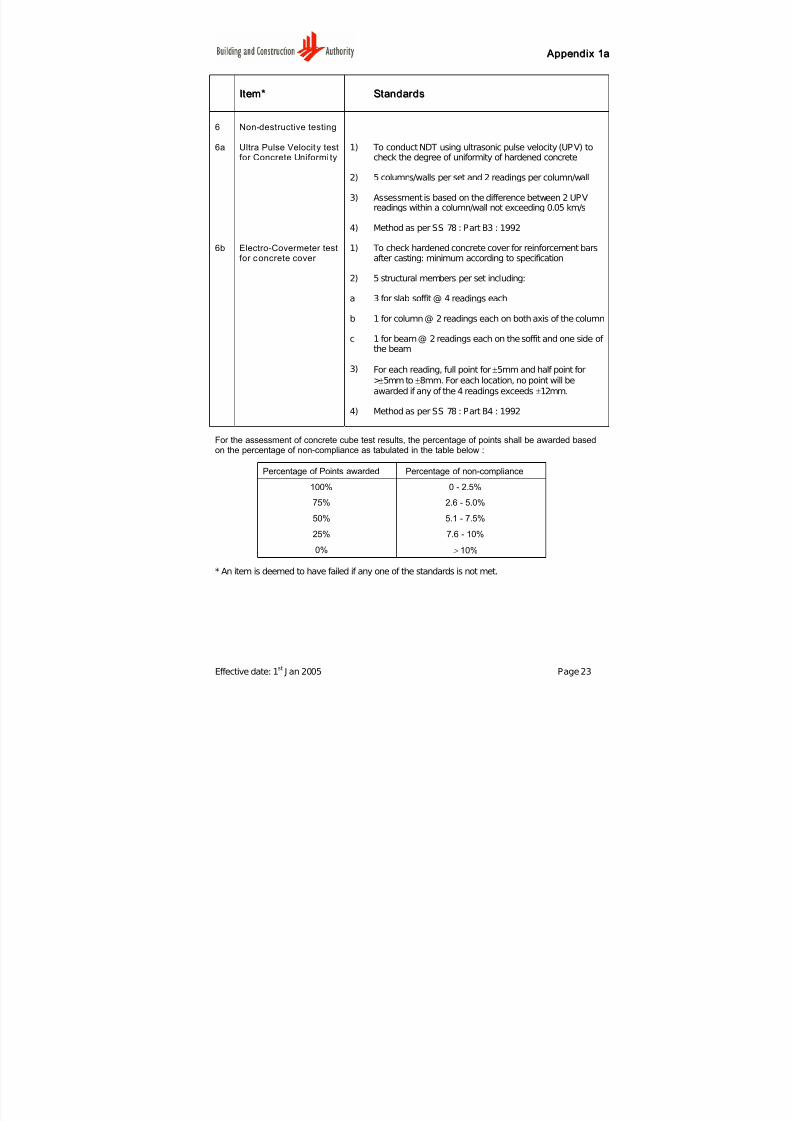
6 Non-destructive testing
6a Ultra Pulse Velocity testfor Concrete Uniformi ty
1) To conduct NDT using ultrasonic pulse velocity (UPV) tocheck the degree of uniformity of hardened concrete
2) 5 columns/walls per set and 2 readings per column/wall
3) Assessment is based on the difference between 2 UPVreadings within a column/wall not exceeding 0.05 km/s
4) Method as per SS 78 : Part B3 : 1992
6b Electro-Covermeter test
for concrete cover
1) To check hardened concrete cover for reinforcement bars
after casting: minimum according to specification
2) 5 structural members per set including:
a 3 for slab soffit @ 4 readings each
b 1 for column @ 2 readings each on both axis of the column
c 1 for beam @ 2 readings each on the soffit and one side of the beam
3) For each reading, full point for ±5mm and half point for
>±5mm to ±8mm. For each location, no point will be
awarded if any of the 4 readings exceeds ±12mm.
4) Method as per SS 78 : Part B4 : 1992
For the assessment of concrete cube test results, the percentage of points shall be awarded basedon the percentage of non-compliance as tabulated in the table below :
Percentage of Points awarded Percentage of non-compliance
100% 0 - 2.5%
75% 2.6 - 5.0%
50% 5.1 - 7.5%25% 7.6 - 10%
0% > 10%
* An item is deemed to have failed if any one of the standards is not met.

7/27/2019 Conquas 2005
http://slidepdf.com/reader/full/conquas-2005 28/65
A Appppeennddiixx 11bb
Effective date : 1st J an 2005 Page 24
QQUU A ALLIITTYY SSTT A ANNDD A ARRDDSS FFOORR SSTTRRUUCCTTUURR A ALL WWOORRKKSS
PPaar r tt 22 :: SSttr r uuccttuur r aall SStteeeell WWoor r kkss
IItteemm** SSttaannddaar r ddss
1 Main member/Partialassembled component
1a Physical dimensions 1) Cross sectional tolerance should meet approved structuralsteel specifications or approved plan
2) Tolerance for length of structural steel member: ±3mm
3) Tolerance for bolt hole size:
• ≤2mm for bolt diameter <24mm
• ≤3mm for bolt diameter ≥ 24mm
Tolerance for bolt hole position: ±2mm
1b Type and condition 1) According to the structural steel specifications
2) Surface preparation shall meet the surface roughnessspecifications
3) Material used must be traceable to its original millcertificates
1c Welding 1) Weld size, length and profile shall meet the structural steelspecifications and drawings
2) Visual inspection shall meet the structural steelspecifications
3) All weld shall follow approved welding procedures
4) All welding must be done by qualified welders
1d Bolting 1) Bolts and washers, type, size and number shall beaccording to the structural steel specifications
2) Drilled holes shall be free from burrs
3) The condition of bolted parts adjacent to the bolt heads,nuts, flat washers, connection gussets and splice platesshall be free from oil, paint, and loose mill scales orotherwise specified by the structural steel specifications
4) Gap between adjacent parts shall not exceed 2mm
7/27/2019 Conquas 2005
http://slidepdf.com/reader/full/conquas-2005 29/65
A Appppeennddiixx 11bb
Effective date : 1st J an 2005 Page 25
IItteemm** SSttaannddaar r ddss
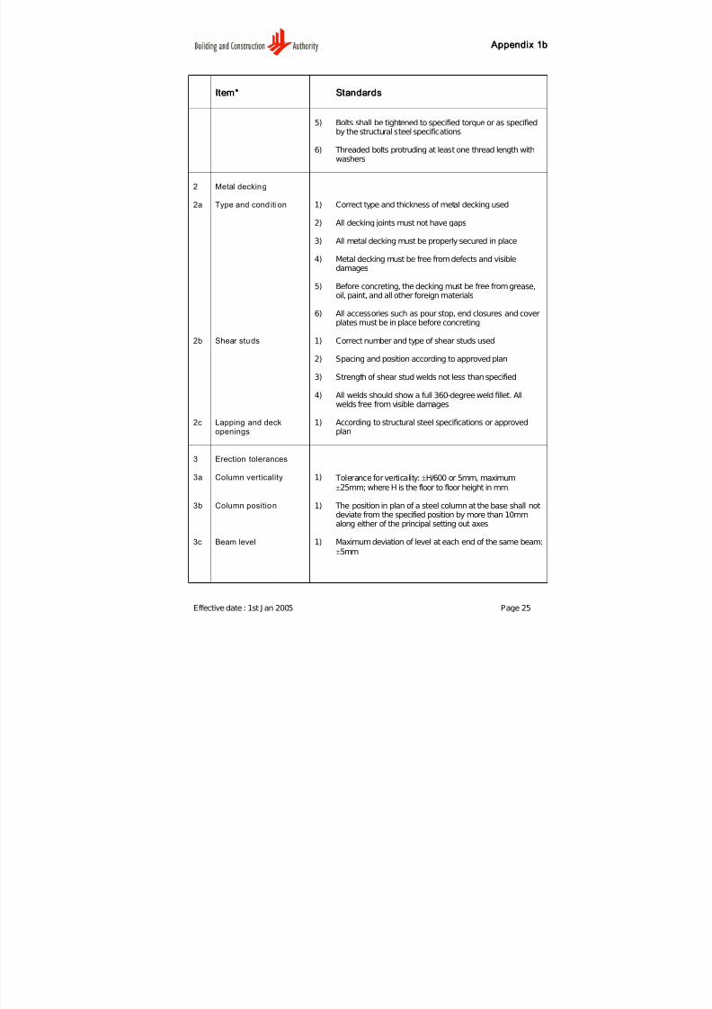
5) Bolts shall be tightened to specified torque or as specifiedby the structural steel specifications
6) Threaded bolts protruding at least one thread length withwashers
2 Metal decking
2a Type and cond ition 1) Correct type and thickness of metal decking used
2) All decking joints must not have gaps
3) All metal decking must be properly secured in place
4) Metal decking must be free from defects and visibledamages
5) Before concreting, the decking must be free from grease,oil, paint, and all other foreign materials
6) All accessories such as pour stop, end closures and coverplates must be in place before concreting
2b Shear studs 1) Correct number and type of shear studs used
2) Spacing and position according to approved plan
3) Strength of shear stud welds not less than specified
4) All welds should show a full 360-degree weld fillet. Allwelds free from visible damages
2c Lapping and deckopenings
1) According to structural steel specifications or approvedplan
3 Erection tolerances
3a Column verticality 1) Tolerance for verticality: ±H/600 or 5mm, maximum
±25mm; where H is the floor to floor height in mm.
3b Column position 1) The position in plan of a steel column at the base shall notdeviate from the specified position by more than 10mmalong either of the principal setting out axes
3c Beam level 1) Maximum deviation of level at each end of the same beam:
±5mm
7/27/2019 Conquas 2005
http://slidepdf.com/reader/full/conquas-2005 30/65
Appendix 1b
Item* Standards
2) The level of the top of the steelwork at any storey shall be
within±10mm of the specified level
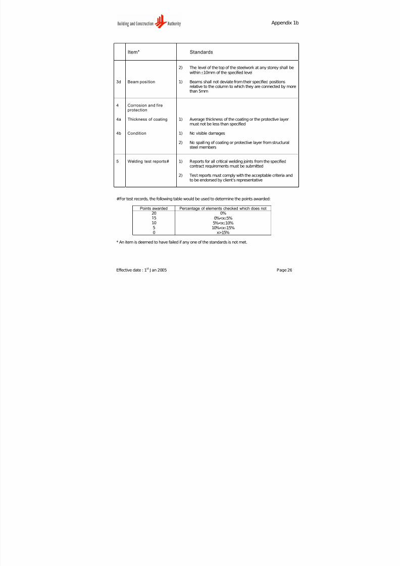
3d Beam posi tion 1) Beams shall not deviate from their specified positionsrelative to the column to which they are connected by morethan 5mm
4 Corrosion and fireprotection
4a Thickness of coating 1) Average thickness of the coating or the protective layermust not be less than specified
4b Condition 1) No visible damages
2) No spalling of coating or protective layer from structuralsteel members
5 Welding test reports# 1) Reports for all critical welding joints from the specifiedcontract requirements must be submitted
2) Test reports must comply with the acceptable criteria andto be endorsed by client’s representative
#For test records, the following table would be used to determine the points awarded:
Points awarded Percentage of elements checked which does not20 0%15 0%<x≤5%10 5%<x≤10%5 10%<x≤15%0 x>15%
* An item is deemed to have failed if any one of the standards is not met.
Effective date : 1st
J an 2005 Page 26
7/27/2019 Conquas 2005
http://slidepdf.com/reader/full/conquas-2005 31/65
A Appppeennddiixx 11cc
Effective date: 1st
J an 2005 Page 27
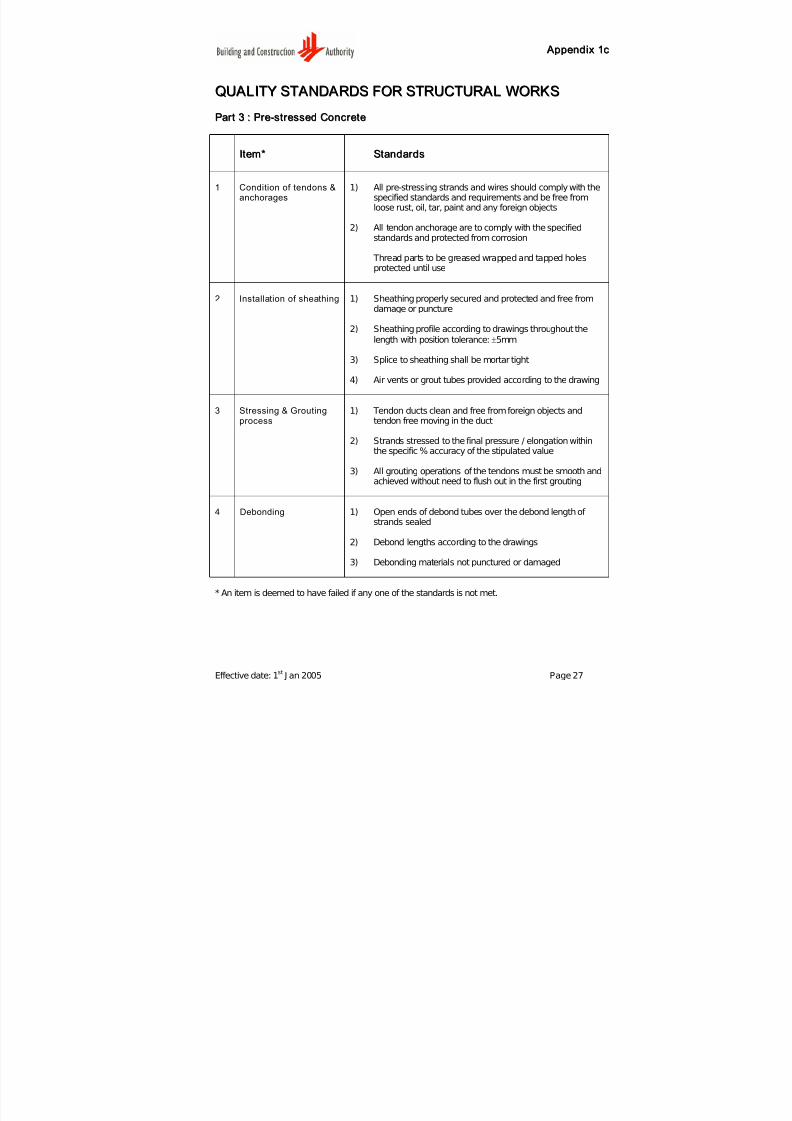
QQUU A ALLIITTYY SSTT A ANNDD A ARRDDSS FFOORR SSTTRRUUCCTTUURR A ALL WWOORRKKSS
PPaar r tt 33 :: PPr r ee--ssttr r eesssseedd CCoonnccr r eettee
IItteemm** SSttaannddaar r ddss
1 Condition of tendons &anchorages
1) All pre-stressing strands and wires should comply with thespecified standards and requirements and be free fromloose rust, oil, tar, paint and any foreign objects
2) All tendon anchorage are to comply with the specifiedstandards and protected from corrosion
Thread parts to be greased wrapped and tapped holesprotected until use
2 Installation of sheathing 1) Sheathing properly secured and protected and free fromdamage or puncture
2) Sheathing profile according to drawings throughout the
length with position tolerance: ±5mm
3) Splice to sheathing shall be mortar tight
4) Air vents or grout tubes provided according to the drawing
3 Stressing & Groutingprocess
1) Tendon ducts clean and free from foreign objects andtendon free moving in the duct
2) Strands stressed to the final pressure / elongation withinthe specific % accuracy of the stipulated value
3) All grouting operations of the tendons must be smooth andachieved without need to flush out in the first grouting
4 Debonding 1) Open ends of debond tubes over the debond length of
strands sealed
2) Debond lengths according to the drawings
3) Debonding materials not punctured or damaged
* An item is deemed to have failed if any one of the standards is not met.
7/27/2019 Conquas 2005
http://slidepdf.com/reader/full/conquas-2005 32/65
A Appppeennddiixx 22
Effective date: 1st
J an 2005 Page 28
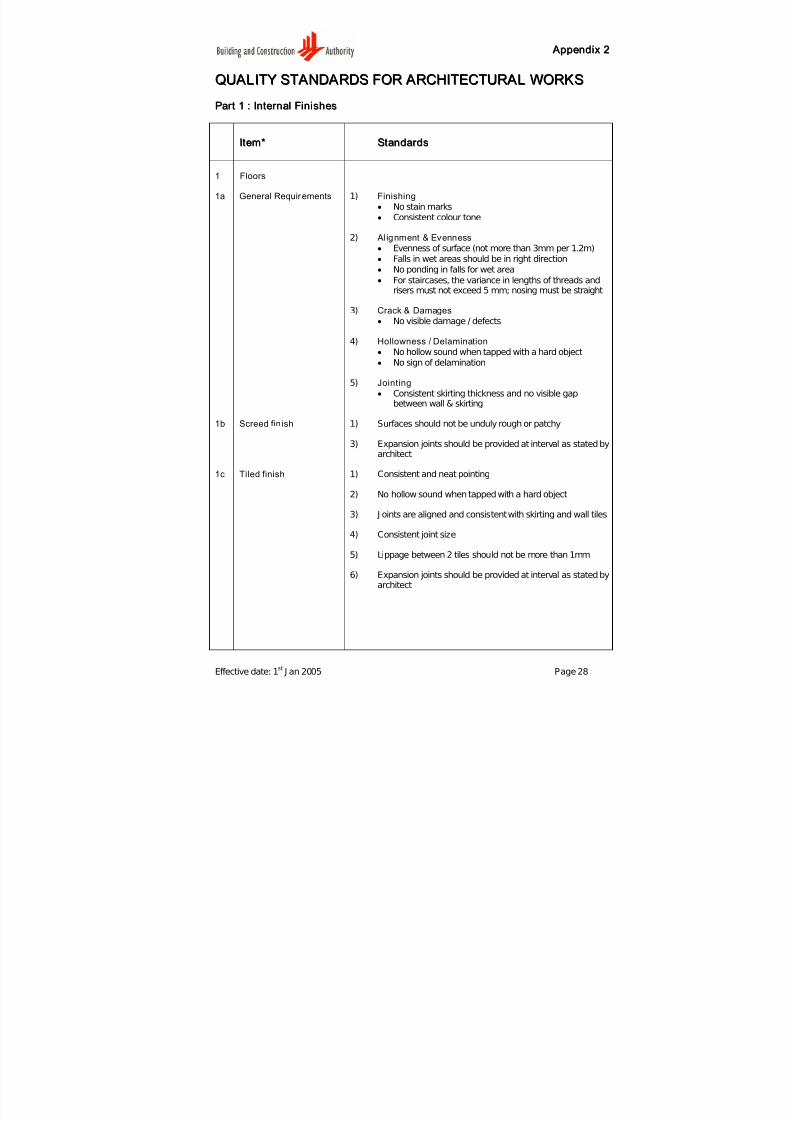
QQUU A ALLIITTYY SSTT A ANNDD A ARRDDSS FFOORR A ARRCCHHIITTEECCTTUURR A ALL WWOORRKKSS
PPaar r tt 11 :: IInntteer r nnaall FFiinniisshheess
IItteemm** SSttaannddaar r ddss
1 Floors
1a General Requirements 1) Finishing
• No stain marks
• Consistent colour tone
2) Al ignment & Evenness
• Evenness of surface (not more than 3mm per 1.2m)
• Falls in wet areas should be in right direction• No ponding in falls for wet area
• For staircases, the variance in lengths of threads andrisers must not exceed 5 mm; nosing must be straight
3) Crack & Damages
• No visible damage / defects
4) Hollowness / Delamination
• No hollow sound when tapped with a hard object
• No sign of delamination
5) Jointing
• Consistent skirting thickness and no visible gapbetween wall & skirting
1b Screed fin ish 1) Surfaces should not be unduly rough or patchy
3) Expansion joints should be provided at interval as stated byarchitect
1c Tiled finish 1) Consistent and neat pointing
2) No hollow sound when tapped with a hard object
3) J oints are aligned and consistent with skirting and wall tiles
4) Consistent joint size
5) Lippage between 2 tiles should not be more than 1mm
6) Expansion joints should be provided at interval as stated byarchitect

7/27/2019 Conquas 2005
http://slidepdf.com/reader/full/conquas-2005 33/65
A Appppeennddiixx 22
Effective date: 1st
J an 2005 Page 29
IItteemm** SSttaannddaar r ddss
1d Timber floor 1) No warpage
2) Timber strips to rest firmly on joists or screed
3) No visible gap between timber strips
4) Edges of the floor to be properly sealed
1e Carpet 1) Stretched and even surface
2) J oint should not be visible
3) Proper anchoring at all edges
1e Raised Floor 1) No loose floor panels or rocking
2) No protrusion / potential of stripping over floor panels
7/27/2019 Conquas 2005
http://slidepdf.com/reader/full/conquas-2005 34/65
A Appppeennddiixx 22
Effective date: 1st
J an 2005 Page 30
IItteemm** SSttaannddaar r ddss
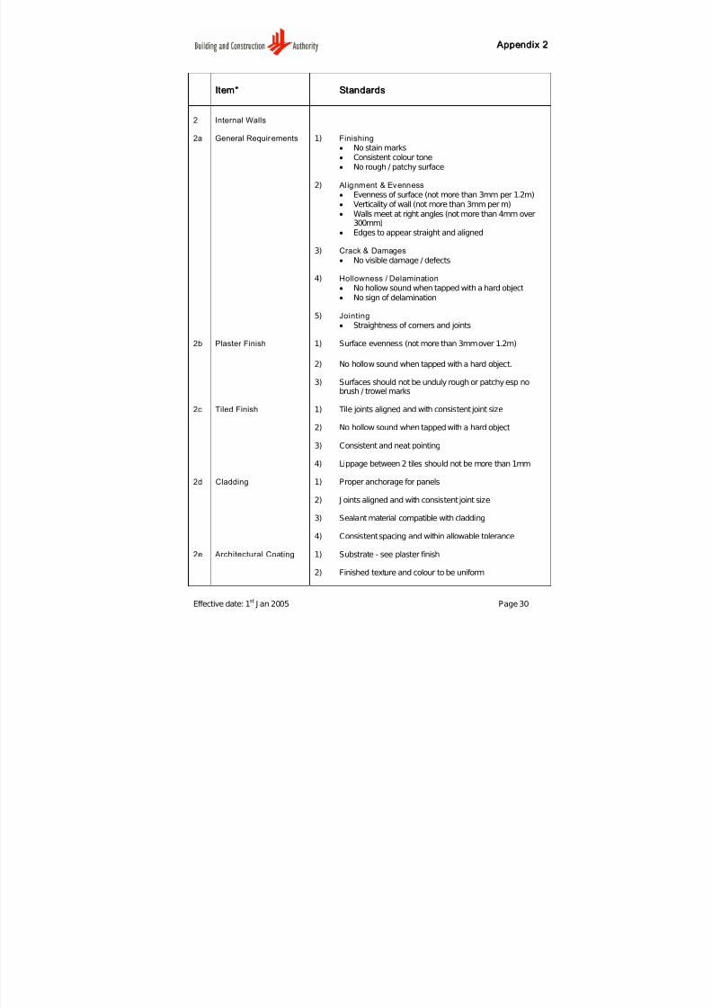
2 Internal Walls
2a General Requirements 1) Finishing
• No stain marks
• Consistent colour tone
• No rough / patchy surface
2) Al ignment & Evenness
• Evenness of surface (not more than 3mm per 1.2m)
• Verticality of wall (not more than 3mm per m)
• Walls meet at right angles (not more than 4mm over300mm)
• Edges to appear straight and aligned
3) Crack & Damages
• No visible damage / defects
4) Hollowness / Delamination
• No hollow sound when tapped with a hard object
• No sign of delamination
5) Jointing
• Straightness of corners and joints
2b Plaster Finish 1) Surface evenness (not more than 3mm over 1.2m)
2) No hollow sound when tapped with a hard object.
3) Surfaces should not be unduly rough or patchy esp nobrush / trowel marks
2c Tiled Finish 1) Tile joints aligned and with consistent joint size
2) No hollow sound when tapped with a hard object
3) Consistent and neat pointing
4) Lippage between 2 tiles should not be more than 1mm
2d Cladding 1) Proper anchorage for panels
2) J oints aligned and with consistent joint size
3) Sealant material compatible with cladding
4) Consistent spacing and within allowable tolerance
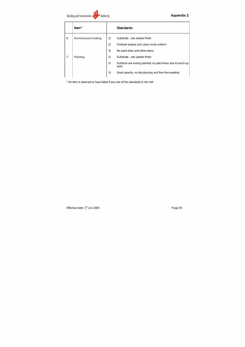
2e Architectural Coating 1) Substrate - see plaster finish
2) Finished texture and colour to be uniform

7/27/2019 Conquas 2005
http://slidepdf.com/reader/full/conquas-2005 35/65
A Appppeennddiixx 22
Effective date: 1st
J an 2005 Page 31
Item* Standards
2f Painting 1) Substrate - see plaster finish
2) Surfaces are evenly painted with no visible brush marks
3) Good opacity, no patchiness resulted from touch up works
4) Free from peeling, blister and chalkiness
5) No discolouration and fading
2g Pre-cast concreteplanks
1) Alignment with adjacent planks not more than 3mm
2) Plane tolerance (3mm / 1.2m)
3) Standard of finishes - see above
2h Wall Paper 1) Stretched and even surface
2) J oint should not be visible
3) Proper anchoring at all edges
4) Edges should be neatly laid and finished
2i Glass Blocks 1) Pointing should be satisfactory
2) J oint should be even
3) Glass blocks should be properly aligned
2j Wood / Timber Panels 1) Timber panels to rest firmly on joist or render
2) No visible gaps between panels
3) Edges should be properly aligned and sealed
4) No warpage

7/27/2019 Conquas 2005
http://slidepdf.com/reader/full/conquas-2005 36/65
A Appppeennddiixx 22
Effective date: 1st
J an 2005 Page 32
Item* Standards
3 Ceilings
3a General Requirements 1) Finishing
• No stain marks
• Consistent colour tone
• No patchy surface
2) Al ignment & Evenness
• Overall surface should be smooth, even, not wavey
• Straightness of Corners
3) Crack & Damages
•
No visible damage e.g spalling, leaks, cracks, etc
4) Roughness
• No rough surface
5) Jointing
• Consistent, aligned and neat
3b Skim Coats / Boardedceiling
1) Not patchy, with no pin holes and with no trowel marks
2) Formwork joints are grounded smooth
3) Paintwork with good opacity and with no brush marks
4) Access door joints should be sharp and in consistent width
3c False ceiling / GridSystem
1) Alignment of rails should be visually straight
2) Surface should be overall level and even
3) Chipped surfaces or corners should not be seen
7/27/2019 Conquas 2005
http://slidepdf.com/reader/full/conquas-2005 37/65
A Appppeennddiixx 22
Effective date: 1st
J an 2005 Page 33
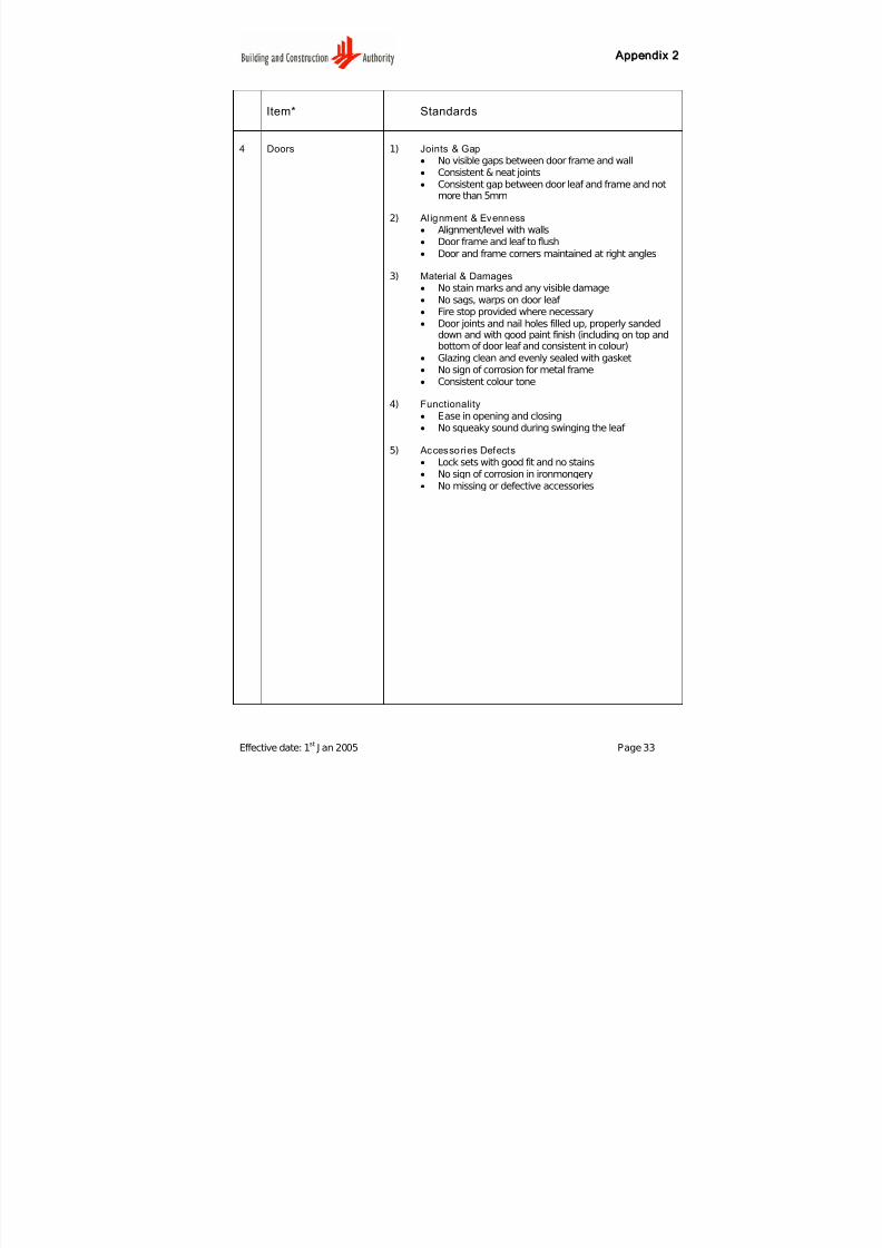
Item* Standards
4 Doors 1) Joints & Gap
• No visible gaps between door frame and wall
• Consistent & neat joints
• Consistent gap between door leaf and frame and notmore than 5mm
2) Al ignment & Evenness
• Alignment/level with walls
• Door frame and leaf to flush
• Door and frame corners maintained at right angles
3) Material & Damages
• No stain marks and any visible damage• No sags, warps on door leaf
• Fire stop provided where necessary• Door joints and nail holes filled up, properly sanded
down and with good paint finish (including on top andbottom of door leaf and consistent in colour)
• Glazing clean and evenly sealed with gasket• No sign of corrosion for metal frame
• Consistent colour tone
4) Functionality
• Ease in opening and closing• No squeaky sound during swinging the leaf
5) Accessories Defects
• Lock sets with good fit and no stains• No sign of corrosion in ironmongery
• No missing or defective accessories
7/27/2019 Conquas 2005
http://slidepdf.com/reader/full/conquas-2005 38/65
A Appppeennddiixx 22
Effective date: 1st
J an 2005 Page 34
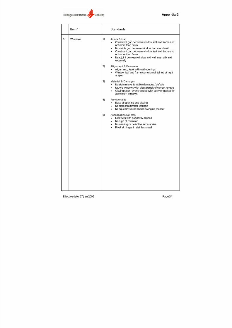
Item* Standards
5 Windows 1) Joints & Gap
• Consistent gap between window leaf and frame andnot more than 5mm
• No visible gap between window frame and wall
• Consistent gap between window leaf and frame andnot more than 5mm
• Neat joint between window and wall internally andexternally
2) Al ignment & Evenness
• Alignment / level with wall openings
• Window leaf and frame corners maintained at right
angles
3) Material & Damages
• No stain marks & visible damages / defects
• Louvre windows with glass panels of correct lengths
• Glazing clean, evenly sealed with putty or gasket foraluminium windows
4) Functionality
• Ease of opening and closing
• No sign of rainwater leakage
• No squeaky sound during swinging the leaf
5) Accessories Defects• Lock sets with good fit & aligned
• No sign of corrosion
• No missing or defective accessories
• Rivet at hinges in stainless steel
7/27/2019 Conquas 2005
http://slidepdf.com/reader/full/conquas-2005 39/65
A Appppeennddiixx 22
Effective date: 1st
J an 2005 Page 35
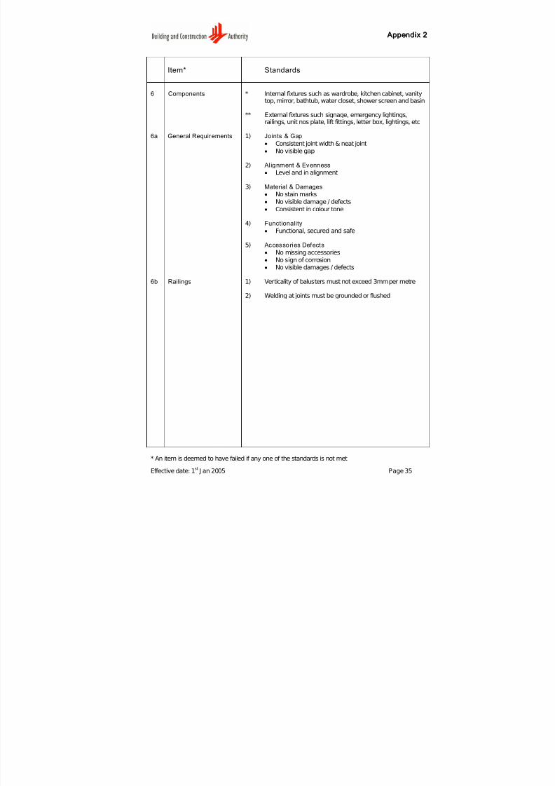
Item* Standards
6 Components * Internal fixtures such as wardrobe, kitchen cabinet, vanitytop, mirror, bathtub, water closet, shower screen and basin
** External fixtures such signage, emergency lightings,railings, unit nos plate, lift fittings, letter box, lightings, etc
6a General Requirements 1) Joints & Gap
• Consistent joint width & neat joint
• No visible gap
2) Al ignment & Evenness
• Level and in alignment
3) Material & Damages
• No stain marks
• No visible damage / defects
• Consistent in colour tone
4) Functionality
• Functional, secured and safe
5) Accessories Defects
• No missing accessories
• No sign of corrosion
• No visible damages / defects
6b Railings 1) Verticality of balusters must not exceed 3mm per metre
2) Welding at joints must be grounded or flushed
* An item is deemed to have failed if any one of the standards is not met
7/27/2019 Conquas 2005
http://slidepdf.com/reader/full/conquas-2005 40/65
A Appppeennddiixx 22
Effective date: 1st
J an 2005 Page 36
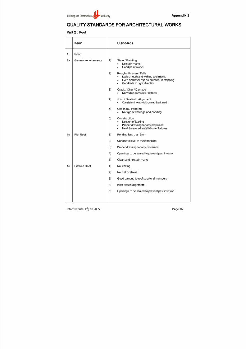
QQUU A ALLIITTYY SSTT A ANNDD A ARRDDSS FFOORR A ARRCCHHIITTEECCTTUURR A ALL WWOORRKKSS
PPaar r tt 22 :: RRoooof f
IItteemm** SSttaannddaar r ddss
1 Roof
1a General requirements 1) Stain / Painting
• No stain marks
• Good paint works
2) Rough / Uneven / Falls
• Look smooth and with no tool marks
•
Even and level esp no potential in stripping• Good falls in right direction
3) Crack / Chip / Damage
• No visible damages / defects
4) Joint / Sealant / Alignment
• Consistent joint width, neat & aligned
5) Chokage / Ponding
• No sign of chokage and ponding
6) Construction
• No sign of leaking• Proper dressing for any protrusion
• Neat & secured installation of fixtures
1c Flat Roof 1) Ponding less than 3mm
2) Surface to level to avoid tripping
3) Proper dressing for any protrusion
4) Openings to be sealed to prevent pest invasion
5) Clean and no stain marks
1c Pitched Roof 1) No leaking
2) No rust or stains
3) Good painting to roof structural members
4) Roof tiles in alignment
5) Openings to be sealed to prevent pest invasion

7/27/2019 Conquas 2005
http://slidepdf.com/reader/full/conquas-2005 41/65
A Appppeennddiixx 22
Effective date: 1st
J an 2005 Page 37
IItteemm** SSttaannddaar r ddss
6) Consistent colour tone
7) Proper dressing for any protrusion
1d Waterproofing(exposed)
1) Should be evenly installed, no sharp protrusion
2) Complete adhesion to base
3) Good laps at joints and proper vertical abutment details
4) No leaking and sign of damage to membrane/coating
5) Clean and no mortar stains
6) No paint defects
1e Gutters 1) No ponding and chokage
2) No cracks, chips and any other visible damages / defects
3) RWDP inlet should be lower than the surrounding gutterinvert level
4) Gutter and RWDP inlet to be covered to prevent chokagewhere practical
5) Clean and no cement stains
* An item is deemed to have failed if any one of the standards is not met

7/27/2019 Conquas 2005
http://slidepdf.com/reader/full/conquas-2005 42/65
A Appppeennddiixx 22
Effective date: 1st
J an 2005 Page 38
QQUU A ALLIITTYY SSTT A ANNDD A ARRDDSS FFOORR A ARRCCHHIITTEECCTTUURR A ALL WWOORRKKSS
PPaar r tt 33 :: EExxtteer r nnaall WWaall ll
IItteemm** SSttaannddaar r ddss
1 General Requirements 1) Evenness / Roughness
• Overall surface should be even, not wavey & notpatchy
2) Staining / Painting
• No visible stain marks
• Good paint works
2) Cracking / Damages• No visible damage / defects
3) Jointing / Alignment
• External features visually in alignment
• Corners of wall maintained at right angles and straight
• Consistent joint width, neat & aligned
2 Plaster Finish 1) As above
3 Tiled Finish 1) Tile joints aligned and between 2-4mm wide unlessspecified
2) Plumb tolerance and evenness of surface (3mm / 1.2m)
4 Claddings / CurtainWalls
1) Gaps around openings to be properly sealed
2) J oints of regular widths as specified
3) Plumb tolerance as specified
4) Evenness of surface, no dents or scratches
5) Sealant material compatible with cladding
5 Facing Brickwork 1) 10mm joint with pointing
2) Weepholes are provided as specified
3) No mortar droppings and other stains
4) No efflorescence
7/27/2019 Conquas 2005
http://slidepdf.com/reader/full/conquas-2005 43/65
A Appppeennddiixx 22
Effective date: 1st
J an 2005 Page 39
IItteemm** SSttaannddaar r ddss
6 Architectural Coating 1) Substrate - see plaster finish
2) Finished texture and colour to be uniform
3) No paint drips and other stains
7 Painting 1) Substrate - see plaster finish
2) Surfaces are evenly painted; no patchiness due to touch upwork
3) Good opacity, no discolouring and free from peeling
* An item is deemed to have failed if any one of the standards is not met

7/27/2019 Conquas 2005
http://slidepdf.com/reader/full/conquas-2005 44/65
A Appppeennddiixx 22
Effective date: 1st
J an 2005 Page 40
QQUU A ALLIITTYY SSTT A ANNDD A ARRDDSS FFOORR A ARRCCHHIITTEECCTTUURR A ALL WWOORRKKSS
PPaar r tt 44 :: EExxtteer r nnaall WWoor r kkss
IItteemm** SSttaannddaar r ddss
1 General Requirements 1) No stain marks and visible damages / defects(basis for assessment)
2) Finishes must be even, level , align & consistent
3) Consistent joints width and neat
4) Paintworks with good opacity, no patchiness and brushmarks
5) Constructed according to Contract Specifications
6) Fixtures installed must be safe, secured and functional
7) Standards defined under Part 1: Internal Finishes, Part 2:Roof and Part 3: External Wall shall apply for similar items.
1a Link-Way / Shelter 1) Floor as per Internal Finishes - Floor
2) Column as per Internal Finishes - Wall
3) Ceiling as per Internal Finishes – Ceiling
4) Other Finishes as per Internal Finishes – Components
5) M&E Fitting as per M&E Works – Part 5 Basic M&EFittings
1b Apron & Drain 1) Drain - Free flowing and no ponding of water
2) Drain Cover - level and do not warp or rock- Gaps between drain covers and side of drain between 5-
10mm wide
- Drain grating properly painted
3) Apron 1- Bitumen joints with neat edges and sufficient length- No ponding
4) Apron 2 – as per Apron 1
5) Inspection Chamber - Inspection chambers are level with surrounding withoutdepression and with tolerance of 20mm for protrusion
- Covers to be level with frames
7/27/2019 Conquas 2005
http://slidepdf.com/reader/full/conquas-2005 45/65
A Appppeennddiixx 22
Effective date: 1st
J an 2005 Page 41
Item* Standards
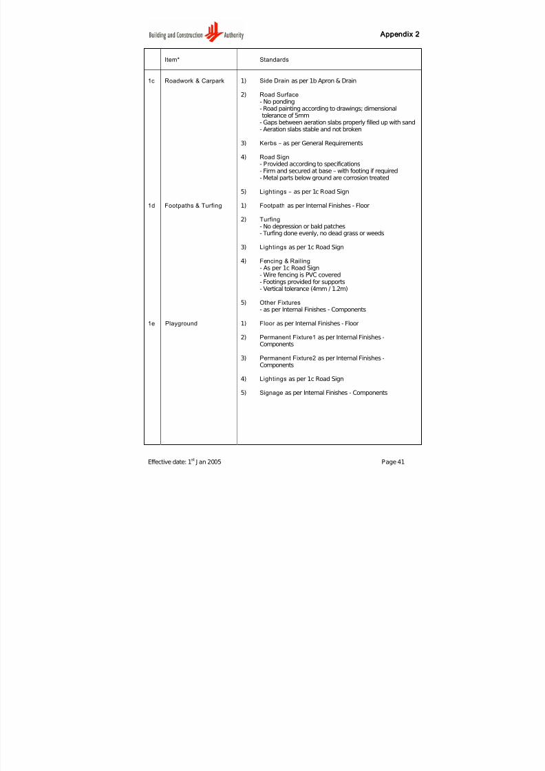
1c Roadwork & Carpark 1) Side Drain as per 1b Apron & Drain
2) Road Surface- No ponding- Road painting according to drawings; dimensionaltolerance of 5mm
- Gaps between aeration slabs properly filled up with sand- Aeration slabs stable and not broken
3) Kerbs – as per General Requirements
4) Road Sign- Provided according to specifications- Firm and secured at base – with footing if required
- Metal parts below ground are corrosion treated
5) Lightings – as per 1c Road Sign
1d Footpaths & Turfing 1) Footpath as per Internal Finishes - Floor
2) Turfing- No depression or bald patches- Turfing done evenly, no dead grass or weeds
3) Lightings as per 1c Road Sign
4) Fencing & Railing
- As per 1c Road Sign- Wire fencing is PVC covered- Footings provided for supports- Vertical tolerance (4mm / 1.2m)
5) Other Fixtures- as per Internal Finishes - Components
1e Playground 1) Floor as per Internal Finishes - Floor
2) Permanent Fixture1 as per Internal Finishes -Components
3) Permanent Fixture2 as per Internal Finishes -Components
4) Lightings as per 1c Road Sign
5) Signage as per Internal Finishes - Components

7/27/2019 Conquas 2005
http://slidepdf.com/reader/full/conquas-2005 46/65
A Appppeennddiixx 22
Effective date: 1st
J an 2005 Page 42
IItteemm** SSttaannddaar r ddss
1f Court 1) Floor 1 as per Internal Finishes - Floor
2) Floor 2 as per Internal Finishes - Floor
3) Signage as per Internal Finishes - Components
4) M&E Fitting as per M&E Works – Part 5 Basic M&EFittings
5) Permanent Fixture as per Internal Finishes - Components
1g Fences & Gate 1) Fence Left as per 1d – item 4)
2) Gate as per Internal Finishes - Components
3) Fence Right as per 1d – item 4)
4) M&E Fitting as per M&E Works – Part 5 Basic M&EFittings
5) Signage as per Internal Finishes - Components
1h Swimming Pool 1) Side Drain as per Internal Finishes - Floor
2) Foot Path 1 as per Internal Finishes - Floor
3) Floor Path 2 as per Internal Finishes - Floor
4) M&E Fitting as per M&E Works – Part 5 Basic M&EFittings
5) Other Fixtu re as per Internal Finishes - Components
1i Club House 1) External Wall 1 as Part 3 External Wall
2) External Wall 2 as Part 3 External Wall
3) External Wall 4 as Part 3 External Wall
4) External Wall 5 as Part 3 External Wall
5) Apron & Drain as per 1b

7/27/2019 Conquas 2005
http://slidepdf.com/reader/full/conquas-2005 47/65
A Appppeennddiixx 22
Effective date: 1st
J an 2005 Page 43
IItteemm** SSttaannddaar r ddss
1j Guard House 1) External Wall 1 as Part 3 External Wall
2) External Wall 2 as Part 3 External Wall
3) Apron & Drain as per 1b
4) Gantry as per Internal Finishes - Components
5) Other Fixtu re as per Internal Finishes - Components
1k Electrical Substation 1) External Wall 1 as Part 3 External Wall
2) External Wall 2 as Part 3 External Wall
3) External Wall 4 as Part 3 External Wall
4) External Wall 5 as Part 3 External Wall
5) Apron & Drain as per 1b
* An item is deemed to have failed if any one of the standards is not met

7/27/2019 Conquas 2005
http://slidepdf.com/reader/full/conquas-2005 48/65
A Appppeennddiixx 22
Effective date: 1st
J an 2005 Page 44
QQUU A ALLIITTYY SSTT A ANNDD A ARRDDSS FFOORR A ARRCCHHIITTEECCTTUURR A ALL WWOORRKKSS
PPaar r tt 55 :: MMaatteer r iiaall && FFuunncctt iioonnaall TTeessttss
IItteemm** SSttaannddaar r ddss
1 Plastering 1) Use Pre-packed Plaster only.
2 Field window water-tightness Test
1) No sign of leakage using BCA's Window Water-tightness Test method. Leakage is defined as “any appearance of uncontrolled water, other than condensation, on the indoor face of any part of the wall & window ”.
2) BCA's Window Water-tightness Test parameters:
Water intensity : 300mm/hr: 1 litre/min/m of joint
Wind Pressure : 240 PaNozzle inclination : 90
oto window
1 sample =2m length of jointSpray duration : 10 mins
3 Wet Area Water-tightness test (i.e.Bathrooms, toilets &flat roof)
1) No sign of leakage after ponding wet areas over aminimum period of 24 hrs.
2) Ponding with final finish in-place
4 Internal wet areawaterproofing process
1) According to approved method statement, shop drawingsand related BCA’s Good Industry Practices guides
5 Pull-off test (POT)for internal wall tiles
1) Minimum tensile strength of 0.15 N / mm2
For the assessment of the field window water-tightness test, the number of points shall beawarded based on the percentage of non-compliance as tabulated in the table below :
Points Awarded for BCA Field Test (80%)
Points Awarded for Self-Testing (20%)
Percentage of non-compliance
8 2 0%
(15-x)* 8/15 (15-x)* 2/15 0% < x < 15%
0 0 ≥ 15%
Note : No points shall be given if test is not carried out.“x” is the percentage of samples failed .
7/27/2019 Conquas 2005
http://slidepdf.com/reader/full/conquas-2005 49/65
Appendix 2
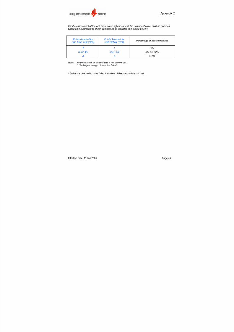
For the assessment of the wet area water-tightness test, the number of points shall be awarded based on the percentage of non-compliance as tabulated in the table below :
Points Awarded for BCA Field Test (80%)
Points Awarded for Self-Testing (20%)
Percentage of non-compliance
4 1 0%
(2-x)* 4/2 (2-x)* 1/2 0% < x < 2%
0 0 ≥ 2%
Note: No points shall be given if test is not carried out.“x” is the percentage of samples failed .
* An item is deemed to have failed if any one of the standards is not met.
Effective date: 1st
J an 2005 Page 45
7/27/2019 Conquas 2005
http://slidepdf.com/reader/full/conquas-2005 50/65
A Appppeennddiixx 33
Effective date: 1st
J an 2005 Page 46
QQUU A ALLIITTYY SSTT A ANNDD A ARRDDSS FFOORR MM&&EE WWOORRKKSS
PPaar r tt 11 :: EElleecctt r r iiccaall WWoor r kkss
IItteemm** SSttaannddaar r ddss
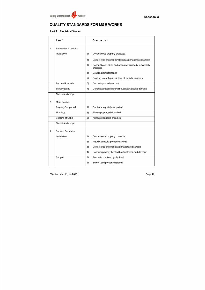
1 Embedded Condui ts
Installation 1) Conduit ends properly protected
2) Correct type of conduit installed as per approved sample
3) Conduit boxes clean and open end plugged / temporarily
protected
4) Coupling joints fastened
5) Bonding to earth provided for all metallic conduits
Secured Properly 6) Conduits properly secured
Bent Properly 7) Conduits properly bent without distortion and damage
No visible damage
2 Main Cables
Properly Supported 1) Cables adequately supported
Fire Stop 2) Fire stops properly installed
Spacing of Cable 3) Adequate spacing of cables
No visible damage
3 Surface Conduits
Installation 1) Conduit ends properly connected
2) Metallic conduits properly earthed
3) Correct type of conduit as per approved sample
4) Conduits properly bent without distortion and damage
Support 5) Support / brackets rigidly fitted
6) Screw used properly fastened

7/27/2019 Conquas 2005
http://slidepdf.com/reader/full/conquas-2005 51/65
A Appppeennddiixx 33
Effective date: 1st
J an 2005 Page 47
IItteemm** SSttaannddaar r ddss
Fire Stop 7) Fire stops properly installed
No Visible Damage 8) Conduits and accessories properly painted
4 Cable Tray, Ladder And Trunking
Installation 1) J oints protected against corrosion
2) Correct type of material used as per approved sample
3) Metallic trunking properly earthed
Support 4) Support / brackets rigidly fitted
5) Screw used properly fastened
Fire Stop 6) Fire stops properly installed
No visible damage
5 Distribution Board
Circuit Diagram 1) Circuit diagram provided
2) Proper labeling for panel
Cable Termination /Earthing
3) Suitable cable termination provided
4) All live parts to be non-accessible
5) All exposed metal parts effectively earthed
No visible damage
* An item is deemed to have failed if any one of the standards is not met
7/27/2019 Conquas 2005
http://slidepdf.com/reader/full/conquas-2005 52/65
A Appppeennddiixx 33
Effective date: 1st
J an 2005 Page 48
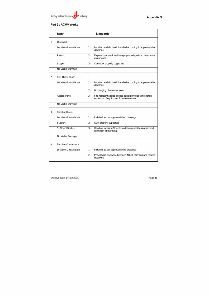
PPaar r tt 22 :: A ACCMMVV WWoor r kkss
IItteemm** SSttaannddaar r ddss
1 Ductwork
Location & Installation 1) Location and ductwork installed according to approved shopdrawings
Paints 2) Exposed ductwork and hanger properly painted to approvedcolour code
Support 3) Ductwork properly supported
No Visible Damage
2 Fire-Rated Ducts
Location & Installation 1) Location and ductwork installed according to approved shopdrawings
2) No hanging of other services
Access Panel 3) Fire-resistant sealed access panel provided to fire-ratedenclosure of equipment for maintenance
No Visible Damage
3 Flexible Ducts
Location & Installation 1) Installed as per approved shop drawings
Support 2) Duct properly supported
Sufficient Radius 3) Bending radius sufficiently wide to prevent tensioning andrestriction of the throat
No Visible Damage
4 Flexible Connectors
Location & Installation 1) Installed as per approved shop drawings
2) Provided at ductwork, between AHU/FCU/Fans and relatedductwork

7/27/2019 Conquas 2005
http://slidepdf.com/reader/full/conquas-2005 53/65
A Appppeennddiixx 33
Effective date: 1st
J an 2005 Page 49
IItteemm** SSttaannddaar r ddss
Length Limit 3) Within 50-250mm length
No Visible Damage
5 Dampers
Location & Installation 1) Location of dampers as per approved shop drawings
2) Dampers / splitter dampers can be adjusted freely betweenthe open and close position
Access Door 3) Access doors provided to all dampers
No Visible Damage
6 Fire Dampers
Location & Installation 1) Location of dampers as per approved shop drawings
2) Installed as per CP13 and no gap around fire dampers
3) Dampers in open position and held in position by fusible link.
Access Door 4) Access doors provided to all dampers according to CP13
No Visible Damage
7 Split Unit/Window Air Conditioner
Installation 1) Units are leveled when placed on plinth
2) Drainage provided/units slightly tilted for condensation
3) Drain hose connected to the drain pipe
4) Cool air is not blocked by wall., beam, shelving or other built-inFurniture in the room
Seal Penetration 5) Proper sealant of wall or roof opening after pipes are fixed

7/27/2019 Conquas 2005
http://slidepdf.com/reader/full/conquas-2005 54/65
A Appppeennddiixx 33
Effective date: 1st
J an 2005 Page 50
IItteemm** SSttaannddaar r ddss
No Leakage 6) No sign of leakage from pipes
No Visible Damage
8 Air -Con Comfor t
Temperature 1) Room temperature between 23oC - 25
oC or according to
specification
Air Flow 2) Room airflow rate not exceeding 0.25 m/s or according tospecification
Relative Humidity 3) Room relative humidity not more than 60% or according tospecification
9 Air Handling Unit
Location & Installation 1) Location & pipe layout installed as per approved shopdrawings
2) Inspection access door for fan, coil, motor and filter
3) All metal parts properly earthed
4) Smoke detector installed at the return air stream
5) Name plate installed with manufacturer's name, serialnumber and model number
Support 6) Pipe / duct from AHU must be supported
No Visible Damage
10 Pump
Location & Installation 1) Location & pipe layout installed as per approved shopdrawings
2) Pump & motor assembly installed on inertia block & springisolator
3) Guard provided to exposed shafts, coupling & moving parts
4) Name plate installed with manufacturer's name, serialnumber and model number

7/27/2019 Conquas 2005
http://slidepdf.com/reader/full/conquas-2005 55/65
A Appppeennddiixx 33
Effective date: 1st
J an 2005 Page 51
IItteemm** SSttaannddaar r ddss
Electrical Termination 5) No bad electrical termination
No Visible Damage
11 Cooling Tower
Self-Earthing System 1) Cooling tower completed with self-earthing system forconnection to building lightning protection system
Location & Installation 2) Name plate installed with manufacturer's name, serial
number and model number
3) Location & pipe layout installed as per approved shopdrawing
No Visible Damage 4) Cooling tower clear of all debris
12 Pipeworkincluding Chilled water, Hot water, Steam, Condenser water, Condenser drain,Cold
Water make-up, water treatment and refrigerant 1) Pipe installed as per approved shop drawing
Paints & Support 2) Pipework provided with drains at each low point andautomatic air vents with manual isolating valve at each highpoint
Fire Stop 3) Properly painted and supported
No Visible Damage 4) Fire stop for passage of pipes at opening for fire resistancewalls and floor
13 Chiller
Location & Installation 1) Location & pipe layout installed as per approved shopdrawing
2) Chiller to be leveled when placed on plinth or vibrationisolators
3) Chiller fixed securely in position
4) Correct model, make & capacity

7/27/2019 Conquas 2005
http://slidepdf.com/reader/full/conquas-2005 56/65
A Appppeennddiixx 33
Effective date: 1st
J an 2005 Page 52
IItteemm** SSttaannddaar r ddss
Pipe Support & Label 5) Pipes supported properly by hangers or brackets
6) Pipe connections follow specified flow direction
No Leakage 7) No sigh of leakage
No Visible Damage
* An item is deemed to have failed if any one of the standards is not met
7/27/2019 Conquas 2005
http://slidepdf.com/reader/full/conquas-2005 57/65
A Appppeennddiixx 33
Effective date: 1st
J an 2005 Page 53
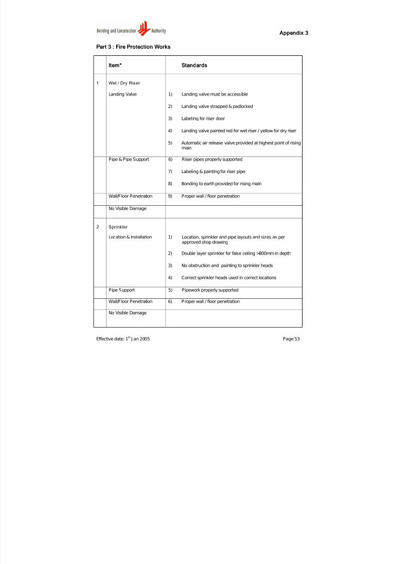
PPaar r tt 33 :: FFiir r ee PPr r ootteecctt iioonn WWoor r kkss
IItteemm** SSttaannddaar r ddss
1 Wet / Dry Riser
Landing Valve 1) Landing valve must be accessible
2) Landing valve strapped & padlocked
3) Labeling for riser door
4) Landing valve painted red for wet riser / yellow for dry riser
5) Automatic air release valve provided at highest point of risingmain
Pipe & Pipe Support 6) Riser pipes properly supported
7) Labeling & painting for riser pipe
8) Bonding to earth provided for rising main
Wall/Floor Penetration 9) Proper wall / floor penetration
No Visible Damage
2 Sprinkler
Location & Installation 1) Location, sprinkler and pipe layouts and sizes as perapproved shop drawing
2) Double layer sprinkler for false ceiling >800mm in depth
3) No obstruction and painting to sprinkler heads
4) Correct sprinkler heads used in correct locations
Pipe Support 5) Pipework properly supported
Wall/Floor Penetration 6) Proper wall / floor penetration
No Visible Damage

7/27/2019 Conquas 2005
http://slidepdf.com/reader/full/conquas-2005 58/65
A Appppeennddiixx 33
Effective date: 1st
J an 2005 Page 54
IItteemm** SSttaannddaar r ddss
3 Fire Alarm
Location & Installation 1) Location of fire alarm panel, breakglass & bell is correct
2) Location & spacing of detectors are correct
3) Fire alarm wiring in conduit (G1 type)
Paints 4) Panel and conduit properly painted
Fire Alarm Zoning Diagram 5) Fire Alarm Zoning diagram provided near panels / sub-panels
No Visible Damage
4 Hosereel
Location & Installation 1) Location of hosereel as per approved shop drawing
2) Hosereel cabinet properly labeled
3) Hosereel pipe properly fixed with hangers & brackets
3) Hosereel operation instruction fixed on hosereel drum ordoor
Paints 4) Correct & proper painting for hosereel
No Visible Damage 5) No visible damage
* An item is deemed to have failed if any one of the standards is not met

7/27/2019 Conquas 2005
http://slidepdf.com/reader/full/conquas-2005 59/65
A Appppeennddiixx 33
Effective date: 1st
J an 2005 Page 55
PPaar r tt 44 :: PPlluummbbiinngg && SSaannii ttaar r yy WWoor r kkss
IItteemm** SSttaannddaar r ddss
1 Concealed Pipes
Location & Installation 1) Pipes properly support, bent without distortion, kink anddamage
2) Pipe & fittings ends properly capped
3) Proper joints
4) Materials used are of approved types
Alignment 5) Vertically or horizontally aligned
No Visible Damage
2 Exposed Pipes
Location & Installation 1) Location of pipes installed and labeled as per approvedshop drawing
2) Pipes properly support, bent without distortion, kink anddamage
3) J oints are watertight
4) Pipe & fitting ends properly capped
5) No potable water pipes below non-potable water pipes
6) Materials used are of approved types
Alignment 7) Horizontally, vertically and parallel aligned to buildingsurface
8) Inclined pipes laid to proper gradients
9) Plumb <3mm per 1m height
Clearance 10) Do not cause obstruction / pose safety hazard at public area
11) Sufficient clearance between installed pipes / ceiling andpipes / wall for accessibility
12) Service pipe duct accessible

7/27/2019 Conquas 2005
http://slidepdf.com/reader/full/conquas-2005 60/65
A Appppeennddiixx 33
Effective date: 1st
J an 2005 Page 56
IItteemm** SSttaannddaar r ddss
No Visible Damage 13) Painting with good opacity and no drippings
14) No visible damage
3 Water Tank
Location & Installation 1) Location, type & capacity as per approved shop drawing
2) All openings properly covered
3) J oints & pipe connections are watertight
4) Not located below non-potable water pipes
5) Corrosion-resistant external cat ladders provided for largewater tank
Netting 6) Netting properly fitted for overflow / warning / vent pipes
Clearance 7) Accessible for maintenance. Minimum clearance of 600mmall rounded the water tank
No Visible Damage 8) No visible damage
9) Clean & free from debris
4 Pump & Motor
Location & Installation 1) Location & type as per approved shop drawing
2) No noticeable vibration & noise from pump / motor
3) Test certificate for alignment of Pump & Motor frommanufacturer
Electrical Termination 4) No bad / loose electrical terminations
No Visible Damage
* An item is deemed to have failed if any one of the standards is not met
7/27/2019 Conquas 2005
http://slidepdf.com/reader/full/conquas-2005 61/65
A Appppeennddiixx 33
Effective date: 1st
J an 2005 Page 57
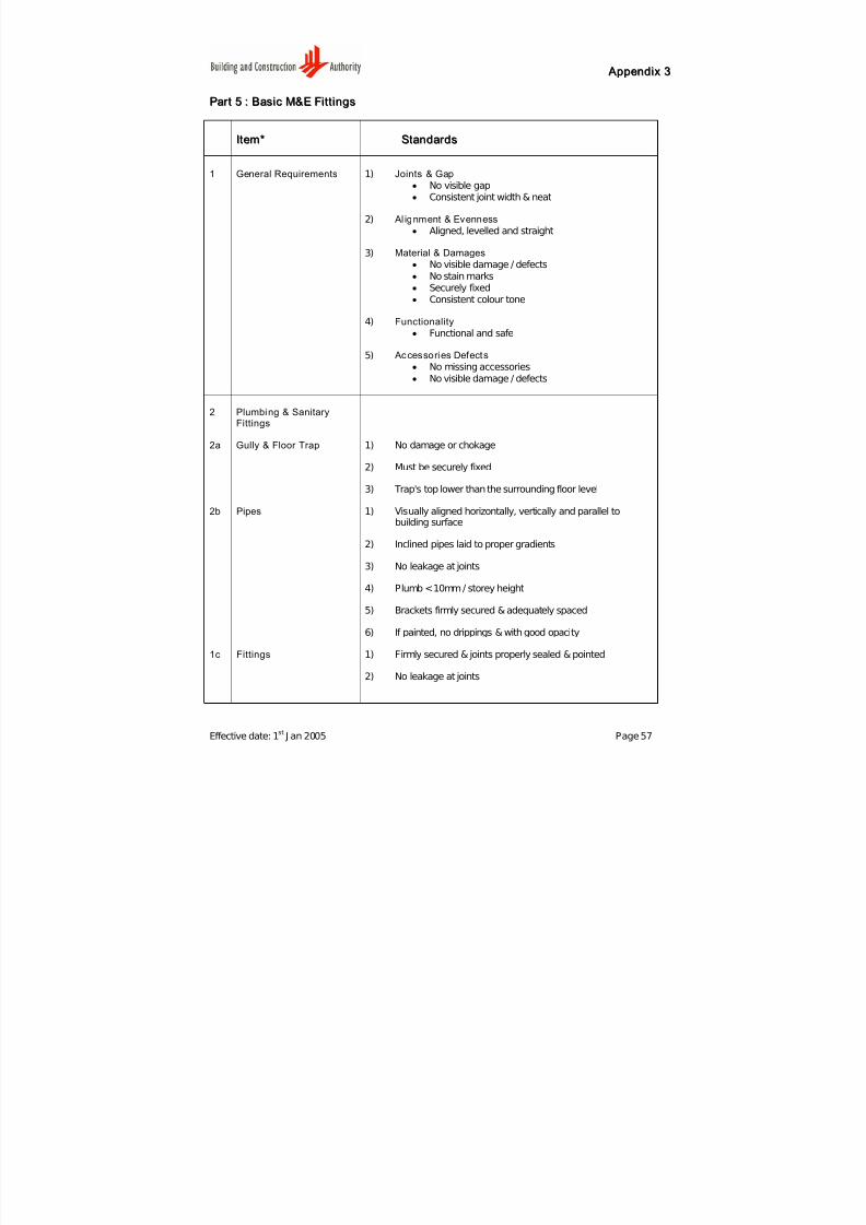
PPaar r tt 55 :: BBaassiicc MM&&EE FFii tt tt iinnggss
IItteemm** SSttaannddaar r ddss
1 General Requirements 1) Joints & Gap
• No visible gap
• Consistent joint width & neat
2) Al ignment & Evenness
• Aligned, levelled and straight
3) Material & Damages
• No visible damage / defects
• No stain marks
• Securely fixed• Consistent colour tone
4) Functionality
• Functional and safe
5) Accessories Defects
• No missing accessories
• No visible damage / defects
2 Plumbing & Sanitary
Fittings
2a Gully & Floor Trap 1) No damage or chokage
2) Must be securely fixed
3) Trap's top lower than the surrounding floor level
2b Pipes 1) Visually aligned horizontally, vertically and parallel tobuilding surface
2) Inclined pipes laid to proper gradients
3) No leakage at joints
4) Plumb <10mm / storey height
5) Brackets firmly secured & adequately spaced
6) If painted, no drippings & with good opacity
1c Fittings 1) Firmly secured & joints properly sealed & pointed
2) No leakage at joints
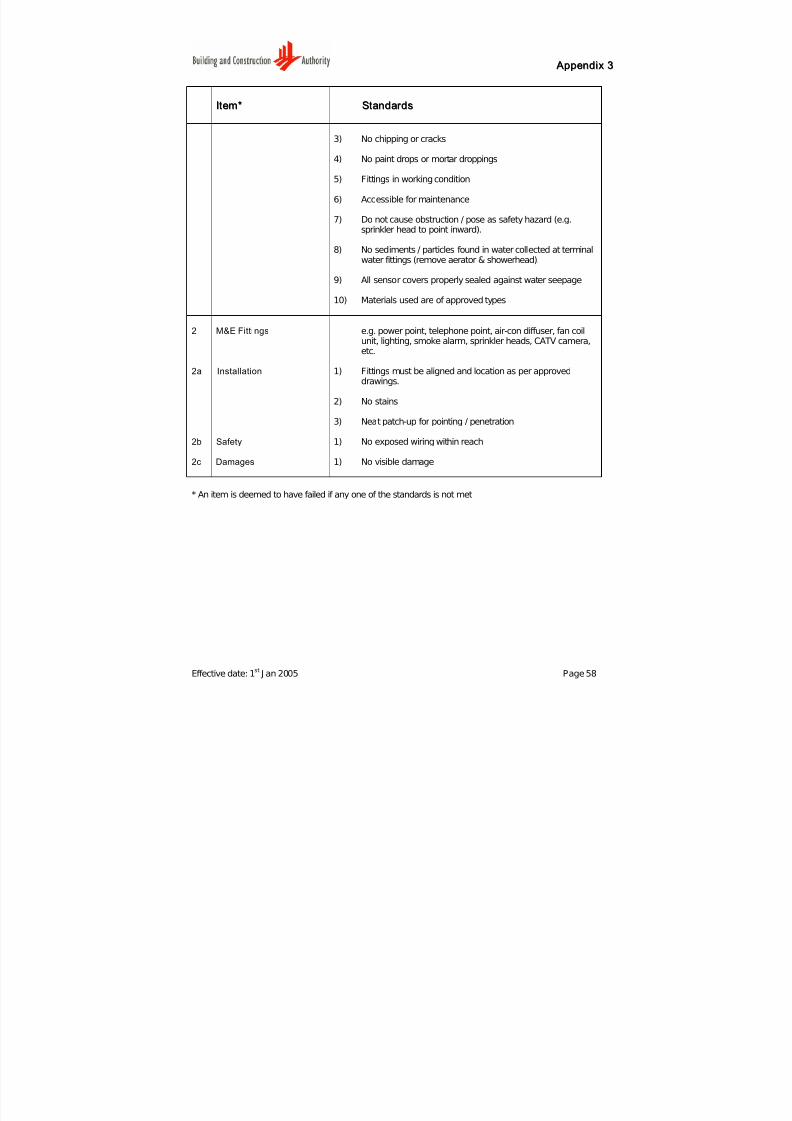
7/27/2019 Conquas 2005
http://slidepdf.com/reader/full/conquas-2005 62/65
A Appppeennddiixx 33
Effective date: 1st
J an 2005 Page 58
IItteemm** SSttaannddaar r ddss
3) No chipping or cracks
4) No paint drops or mortar droppings
5) Fittings in working condition
6) Accessible for maintenance
7) Do not cause obstruction / pose as safety hazard (e.g.sprinkler head to point inward).
8) No sediments / particles found in water collected at terminal
water fittings (remove aerator & showerhead).
9) All sensor covers properly sealed against water seepage
10) Materials used are of approved types
2 M&E Fittings e.g. power point, telephone point, air-con diffuser, fan coilunit, lighting, smoke alarm, sprinkler heads, CATV camera,etc.
2a Installation 1) Fittings must be aligned and location as per approveddrawings.
2) No stains
3) Neat patch-up for pointing / penetration
2b Safety 1) No exposed wiring within reach
2c Damages 1) No visible damage
* An item is deemed to have failed if any one of the standards is not met
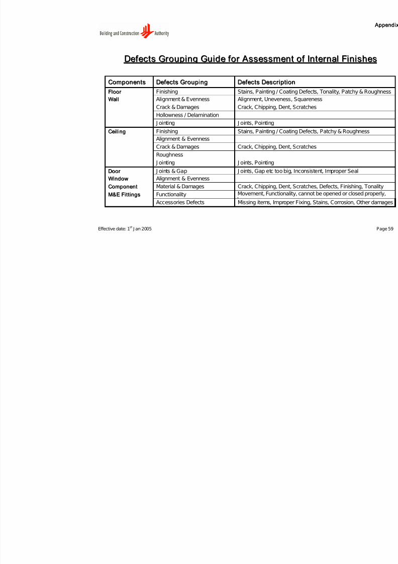
7/27/2019 Conquas 2005
http://slidepdf.com/reader/full/conquas-2005 63/65
Effective date: 1st
J an 2005
DDeef f eeccttss GGr r oouuppiinngg GGuuiiddee f f oor r A Asssseessssmmeenntt oof f IInntteer r nn
CCoommppoonneennttss DDeef f eeccttss GGr r oouuppiinngg DDeef f eeccttss DDeessccr r iipptt iioonn
FFlloooor r Finishing Stains, Painting / Coating Defects, Tona
WWaall ll Alignment & Evenness Alignment, Uneveness, Squareness
Crack & Damages Crack, Chipping, Dent, Scratches
Hollowness / Delamination
J ointing J oints, Pointing
CCeeii ll iinngg Finishing Stains, Painting / Coating Defects, PatcAlignment & Evenness
Crack & Damages Crack, Chipping, Dent, Scratches
Roughness
J ointing J oints, Pointing
DDoooor r J oints & Gap J oints, Gap etc too big, Inconsistent, Im
WWiinnddooww Alignment & Evenness
CCoommppoonneenntt Material & Damages Crack, Chipping, Dent, Scratches, Defe
MM&&EE FFii tt tt iinnggss Functionality Movement, Functionality, cannot be opeAccessories Defects Missing items, Improper Fixing, Stains,
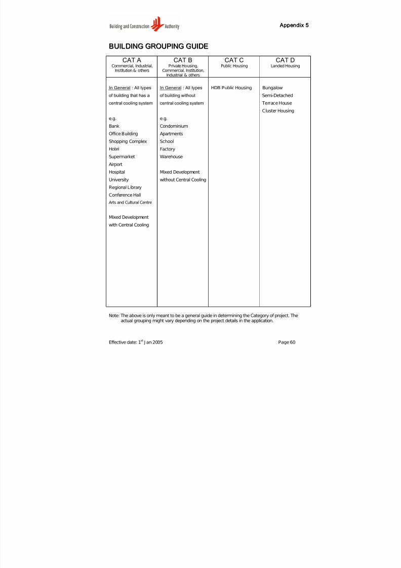
7/27/2019 Conquas 2005
http://slidepdf.com/reader/full/conquas-2005 64/65
A Appppeennddiixx 55
Effective date: 1st
J an 2005 Page 60
BBUUIILLDDIINNGG GGRROOUUPPIINNGG GGUUIIDDEE
CAT ACommercial, Industrial,
Institution & others
CAT BPrivate Housing,
Commercial, Institution,Industrial & others
CAT C
Public Housing
CAT D
Landed Housing
In General : All types
of building that has a
central cooling system
e.g.
Bank
Office Building
Shopping Complex
Hotel
Supermarket
Airport
Hospital
University
Regional Library
Conference Hall
Arts and Cultural Centre
Mixed Development
with Central Cooling
In General : All types
of building without
central cooling system
e.g.
Condominium
Apartments
School
Factory
Warehouse
Mixed Development
without Central Cooling
HDB Public Housing Bungalow
Semi-Detached
Terrace House
Cluster Housing
Note: The above is only meant to be a general guide in determining the Category of project. Theactual grouping might vary depending on the project details in the application.
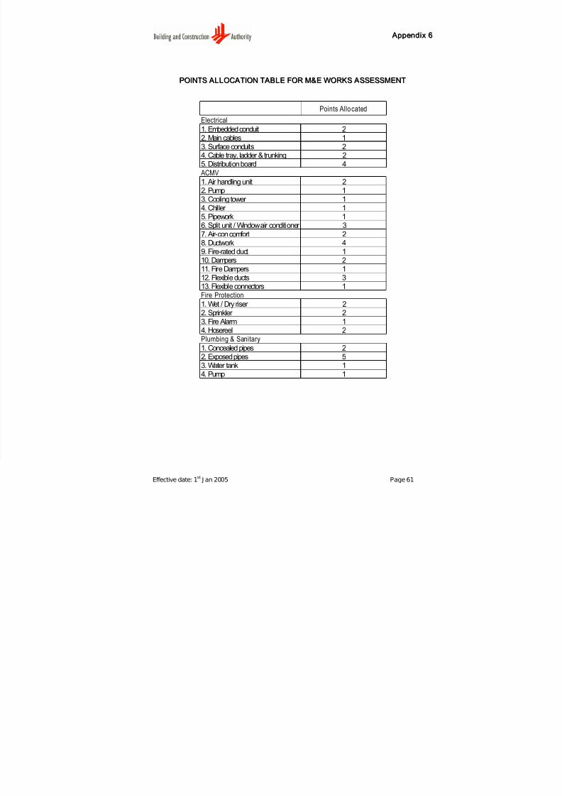
7/27/2019 Conquas 2005
http://slidepdf.com/reader/full/conquas-2005 65/65
A Appppeennddiixx 66
PPOOIINNTTSS A ALLLLOOCC A ATTIIOONN TT A ABBLLEE FFOORR MM&&EE WWOORRKKSS A ASSSSEESSSSMMEENNTT
Points Allocated
Electrical
1. Embedded conduit 22. Main cables 13. Surface conduits 24. Cable tray, ladder & trunking 25. Distribution board 4
ACMV
1. Air handling unit 22. Pump 13. Cooling tower 14. Chiller 15. Pipework 16. Split unit / Window air conditioner 37. Air-con comfort 28. Ductwork 49. Fire-rated duct 110. Dampers 211. Fire Dampers 1
12. Flexible ducts 313. Flexible connectors 1Fire Protection
1. Wet / Dry riser 22. Sprinkler 23. Fire Alarm 14. Hosereel 2Plumbing & Sanitary
1. Concealed pipes 22. Exposed pipes 53. Water tank 14. Pump 1