connectors for multi-couplings - electrical connectors and...
TRANSCRIPT

Dockingline | Connectors for Automatic Systems
Connectors for multi-couplings

2 Connectors for multi-couplings
STÄUBLI ELECTRICAL CONNECTORS
Long-term solutions – Expert connections
Stäubli Electrical Connectors is a leading
international manufacturer of high-quality
electrical connector systems. We are part
of the Stäubli Group which off ers mecha-
tronics solutions for electrical connectors,
liquid and gas couplings, robots and textile
machinery.
Stäubli develops, produces, sells and main-
tains products for markets with high produc-
tivity standards. As recognized specialists,
our focus is always on solutions and cus-
tomers. Many new developments got their
start here and have begun to make their way
around the world.
Businesses and customers count on our
commitment and our active support when
dealing with unusual problems. With us, you
are entering into a long-term partnership
built on reliability, dynamism, and excep-
tional quality in both products and services.

Connectors for multi-couplings 3
STÄUBLI ELECTRICAL CONNECTORS
Long-term solutions – Expert connections
Stäubli Electrical Connectors is a leading
international manufacturer of high-quality
electrical connector systems. We are part
of the Stäubli Group which off ers mecha-
tronics solutions for electrical connectors,
liquid and gas couplings, robots and textile
machinery.
Stäubli develops, produces, sells and main-
tains products for markets with high produc-
tivity standards. As recognized specialists,
our focus is always on solutions and cus-
tomers. Many new developments got their
start here and have begun to make their way
around the world.
Businesses and customers count on our
commitment and our active support when
dealing with unusual problems. With us, you
are entering into a long-term partnership
built on reliability, dynamism, and excep-
tional quality in both products and services.
Applications and benefi ts
Stäubli’s multipole connectors are used
in docking systems, tool changers, and
in manually or automatically operated
multi-couplings.
Our solutions are ideal for a wide range of
standard industrial applications, as well as
other highly demanding applications where
reliability is of the essence.
■ Unparalleled contact reliability thanks to
MULTILAM advanced contact technology
■ Robust, reliable and user-friendly – up to
1 million mating cycles
■ High current-carrying capacity with mini-
mal contact resistance for a long lifespan
■ Many possible combinations to work
with almost any application, from data
transmission to high-current applications
■ Our standard program covers cable
cross-sections of up to 50 mm²
(AWG 1/0), currents up to 200 A and
up to 72 poles

4 Connectors for multi-couplings
Page 7 Introduction
■ Technical data
■ Assembly principle
■ Installation situation
■ Combination possi bilities
■ Connector selection
■ Overview of products
■ Contact carrier
■ Housings
■ Plugging frequency test
■ Footprints
■ Insertion and withdrawal force
Page 26 Contacts
■ Overview
■ Signal
■ Thermocouple pressure contacts
■ BUS
■ Hybrid
■ Power
■ High Current
■ PEEK
Page 48 Contact carriers
■ Overview
■ Signal
■ BUS
■ Hybrid
■ Power
■ High Current
■ Special contact carriers (CR + SIL)
■ PEEK
Page 60 Contact insert sets
■ Overview
■ Signal
■ Hybrid
■ Power
■ High Current
■ Special contact insert sets (CR + SIL)
■ PEEK
Page 74 Housings
■ Overview
■ Shielding principle
■ Plastic housings
■ Special pin and socket housings
■ Housing front parts
■ Plastic housings, shielded, insulated
■ Metal housing, shielded
■ Metal housing
Page 86 Assembly tools
Page 88 Accessories
Page 90 Appendix
■ Installation situation
■ Outer dimensions
■ Drilling plan
■ Derating-diagrams
■ Index
Content
Connectors for multi-couplings 5
Colour code
For those items available in various colours,
replace the asterisk “*” with the appropriate
colour code.
20 green-yellow 26 violet
21 black 27 brown
22 red 28 grey
23 blue 29 white
24 yellow 33 transparent
25 green
Changes / Provisos
All data, illustrations and drawings in the
catalogue have been carefully checked.
They are in accordance with our experience
to date, but no responsibility can be accept-
ed for errors.
We also reserve the right to make modifica-
tions for design and safety reasons. When
designing equipment incorporating our
components, it is therefore advisable not to
rely solely on the data in the catalogue but
to consult us to make sure this information
is up to date. We shall be pleased to advise
you.
Copyright
The use of this catalogue for any other pur-
pose, in whatever form, without our prior
written consent is not permitted.
RoHS ready
Directive 2011/65/EC on the restriction of
the use of certain hazardous substances in
electrical and electronic equipment.
Symbols
Accessories or special tools
exist for this product
www.staubli.com/electrical
RZ
Before use, please read the enclosed
instruction leaflet RZ000
www.staubli.com/electrical
MAIch bin eine Montageanleitung.
Man sollte mich unbedingt le-
sen, bevor man das Produkt ver-
wendet! Ich beinhalte wertvolle
Hinweise zur korrekten Montage
und zum richtigen Einsatz des
Produktes. Im Moment ist die
Schrift zwar ein bischen klein,
aber später geht das dann ganz
gut zu lesen, da die MA dann
The assembly instruction MA000 is
available for this product
www.staubli.com/electrical
General information

6 Connectors for multi-couplings
MULTIL AM are specially formed and
resilient contact elements. All Stäubli
Electrical Connectors products benefi t
from the unique and outstanding perfor-
mance of the MULTIL AM Technology.
Thanks to their constant spring pressure,
MULTIL AM louvers ensure continuous con-
tact with the contact surface, resulting in a
constantly low contact resistance.
MULTIL AM Technology allows to fi nd solu-
tions for connectors within the severest con-
straints and in certain products for up to 1
million mating cycles.
This makes the MULTIL AM Technology the
best choice for applications with demanding
requirements:
■ Reliable and longlife operation due to
constantly high performance
■ Safe operation under highest environ-
mental demands on temperature, vibra-
tion and shock
■ Suitable for data and signal contacts as
well as high-current connectors
■ Automated solutions with a high number
of mating cycles
UNLIMITED POSSIBILITIES FOR CONTACT SOLUTIONS
MULTIL AM Technology

Connectors for multi-couplings 7
The contacts are equipped with a crimping
sleeve. In the unplugged condition the com-
plete socket and pin parts are longitudinally
waterproof over the contacts. The use of plas-
tic housings eliminates the need for earthing,
thus simplifying the work of assembly.
When using metal housings, the housings
must be earthed using a protective conduc-
tor according to IEC 60364-4-41.
1) Except PEEK (Pollution degree 2)2) Except PEEK 19.6660, 19.6658, 19.6654 & 19.6626
Technical data
Note:
The housings may not be used as mechani-
cal centering. For safe operation and correct
alignment of plates stable guiding pins are
mandatory.
Technical data
Contact system MULTILAM
Rated voltage max. 830 V
Rated current (Derating diagrams, page 95)
max. 200 A
Overvoltage categoryPollution degree
CATIII 31)
Test voltage 0,84 kV – 3,31 kV / 50 – 60 Hz / 1 min.
Insulation coordination according to IEC 60664-1, DIN VDE 0110-1
4 kV: 3 V – 300 V 6 kV: 3 V – 630 V
Temperature resistance contact carriers
NBR: –30°C...+100°C CR: –40°C...+100°C SIL: –40°C...+150°C PK: –40°C...+150°C
Operating temperature (Plastic housing) (Metal housing)
–10°C...+90°C –40°C...+150°C
Storage temperature –40°C...+80°C
Degree of protection, mated (DIN 40050) MGK..., MGS... mated (DIN 40050) MGA... unmated (Socket side)
IP65IP67IP2X2)
Safety class II1)
Number of poles 2+PE – 70+2PE
Nominal-Ø contact 1 mm – 11 mm
Conductor cross section0.14 mm² – 50 mm²26 AWG – 1/0 AWG
Type of connection Crimping
Contact material CuZn alloy; silver or gold plated
Carrier material NBR / CR / SIL / PEEK
Housing material Metal / POM or PA
Shielding (360°) Available (G1 – G3)
For further instructionsEN 60664-1 / 2008-01 DIN VDE 0627 / EN 61984 / 2009-11 DIN VDE 0298-4 / 2003-08
INTRODUCTION

8 Connectors for multi-couplings
Socket carrier with contacts
Retaining ring
Retaining ring
Socket housing front sectionDocking plate
Docking plate
Grooved pins
Spacers (depending on situation)
Housing back section
Cable gland, optional
Cable gland, optional
Blind plug, supplied
Blind plug, supplied
Assembly principle
Installation situation

Connectors for multi-couplings 9
Blind plug, supplied
Pin carrier with contacts
Retaining ring
Retaining ring
Pin housing front section
Additional 90° cable outlet
Grooved pins
Docking plate
Spacers (depending on situation)
Docking plate Housing back section
Cable gland, optional
Cable gland, optional

10 Connectors for multi-couplings
Ø 1.5 mm
Ø 1 mm
Ø 2 mm
Ø 3 mm (K)
Ø 2 mm
Ø 2 mm
Ø 1.6 mm
Ø 1.5 mm
Ø 2 mm
Ø 3 mm (K)
Ø 3 mm
Ø 10 mm
Ø 2 mm
Ø 2 mm
Sockets
Sockets
Contact carrier
Contact carrier
Socket housing
Socket housing
Except PEEK
Only PEEK
Size G1
Size G2
Combination possibilities
Note:
In case insulators do not exist with the exact
pole count:
■ pick an insulator with more poles than
needed
■ close the empty contact chambers with
blind plugs ( page 88).

Connectors for multi-couplings 11
Ø 1.5 mm
Ø 1 mm
Ø 2 mm
Ø 3 mm (K)
Ø 2 mm
Ø 2 mm
Ø 1.5 mm
Ø 2 mm
Ø 3 mm (K)
Ø 2 mm
Ø 2 mm
Ø 1.6 mm
Ø 3 mm
Ø 10 mm
Pins
Pins
Contact carrier
Contact carrier
Pin housing
Pin housing
Except PEEK
Only PEEK

12 Connectors for multi-couplings
Ø 1.5 mm
Ø 11 mm
Ø 2 mm
Ø 2 mm
Ø 1.5 mm
Ø 2 mm
Ø 3 mm
Ø 5 mm
Ø 6 mm
Ø 6 mm
Ø 8 mm
Ø 2 mm
Ø 2 mm
Ø 1.6 mm
Ø 3 mm
Except PEEK
Only PEEK
Size G3
Size G4
Sockets
Sockets
Contact carrier
Contact carrier
Socket housing
Socket housing

Connectors for multi-couplings 13
Ø 1.5 mm
Ø 2 mm
Ø 3 mm
Ø 5 mm
Ø 6 mm
Ø 8 mm
Ø 2 mm
Ø 2 mm
Ø 1.5 mm
Ø 11 mm
Ø 2 mm
Ø 2 mm
Ø 6 mm
Ø 1.6 mm
Ø 3 mm
Except PEEK
Only PEEK
Pins
Pins
Contact carrier
Contact carrier
Pin housing
Pin housing

14 Connectors for multi-couplings
Signal
Standard Thermocouple pressure contacts Pressure contacts
0.14 mm² – 1.5 mm²1 A – 16 APage 28
0.14 mm² – 0.5 mm²
Page 30
0.5 mm² – 1.5 mm²2 A – 10 APage 32
Power
Standard Short version
0.5 mm² – 4 mm²10 A – 36 APage 40
2.5 mm² – 4 mm²20 A – 32 APage 40
BUS
Standard
0.14 mm² – 1.5 mm²1 A – 16 APage 34
Step
1
High Current
Standard
6 mm² – 50 mm²50 A – 200 APage 42
PEEK
Standard
0.15 mm² – 70 mm²5 A – 200 APage 46
Hybrid
Standard Short version
0.14 mm² – 50 mm²1 A – 200 APage 36
2.5 mm² – 4 mm²20 A – 32 APage 36
Connector selection
Select application and contacts

Connectors for multi-couplings 15
Synthetic rubber (NBR)
Signal BUS Hybrid
2+PE – 70+2PE 25 V – 630 V Page 50
6+PE – 70+2PE 25 V – 250 V Page 52
2+PE+9 – 70+2PE 25 V – 630 V Page 53
Power High Current
2+PE – 36+PE 250 V – 400 V Page 54
2+PE – 6+PE 25 V – 630 V Page 55
Chloroprene (CR) Silicone (SIL) PEEK (PK)
36+PE 250 V Page 56
3+PE+4, 6+PE, 15+PE, 36+PE 250 V Page 57
1 – 47+PE 150 V – 600 V Page 59
Plastic
Standard Insulated, shielded Specials
Page 76 Page 80 Page 78
Metal
Shielded Standard
Page 83 Page 84
Form shroud
Page 79
Step
2
Step
3
Select contacts carriers
Select housings

16 Connectors for multi-couplings
Overview of products
Note:
In case insulators do not exist with the exact
pole count:
Carrier size
G2 G3 G4
400
V
250
V
830
V
400
V
400
V
250
V
150
V
630
V
630
V
400
V
400
V
630
V
400
V
250
V
25 V
250
V
150
V
24 V
630
/ 25
V
250
V
1 3+P
E
3+P
E+4
4+P
E
6+P
E
15+P
E
19+P
E
2+P
E
3+P
E
4+P
E
6+P
E
9+P
E
13+P
E
24+P
E
27 36+P
E
47+P
E
4NE
T
2+P
E
70+2
PE
25 V 25 V 25 V 25 V 25 V
15+PE 24+PE 27 36+PE 70+2PE
ContactsCarrier size
G1
Conductor cross section Nom.-Ø contact Max. rated current Mating cycles
250
V
250
V
250
V
150
V
mm² AWG mm A
2+P
E
2+P
E+9
6+P
E
18+P
E
0.14 – 0.5 26 – 20 Ø 1.5 1 – 10 1,000,000
0.5 – 1.5 20 – 16
Ø 1.5 10 – 16 1,000,000
Ø 1.6 16 10,000
Ø 2 10 – 16 1,000,000
1 18 Ø 1 5 1,000,000
2.5 14 Ø 2 20 1,000,000
2.5 – 4 14 – 12 Ø 3 20 – 36 1,000,000
2.5 – 6 14 – 10 Ø 3 36 – 50 10,000
6 10Ø 5 50 500,000
Ø 6 50 500,000
10 8
Ø 5 63 500,000
Ø 6 80 500,000
Ø 6 80 10,000
16 6Ø 6 90 500,000
Ø 6 110 10,000
25 4
Ø 6 135 500,000
Ø 6 135 10,000
Ø 8 135 500,000
Ø 11 135 500,000
35 2Ø 8 150 500,000
Ø 10 150 10,000
35 – 38 ~ 2 Ø 11 170 500,000
50 1/0Ø 10 180 10,000
Ø 11 200 500,000
70 2/0 Ø 10 200 10,000
Short version
2,5 – 4 (K) 14 – 12 Ø 3 20 – 32 1,000,000
Spring-loaded pressure contacts
Conductor cross section Nom.-Ø contact Max. rated current Mating cycles 25 V
mm² AWG mm A 6+PE
0.5 – 1.5 20 – 16 Ø 2 10 – 16 10,000
Thermocouple pressure contacts
0.14 – 0.5 26 – 20 Ø 2 < 1 100,000
■ pick an insulator with more poles than
needed
■ close the empty contact chambers with
blind plugs ( page 88).
When selecting the conductor cross-sec-
tions, please observe DIN VDE 0298-4, DIN
EN 60204-1 and the derating diagrams,
page 95.

Connectors for multi-couplings 17
Carrier size
G2 G3 G4
400
V
250
V
830
V
400
V
400
V
250
V
150
V
630
V
630
V
400
V
400
V
630
V
400
V
250
V
25 V
250
V
150
V
24 V
630
/ 25
V
250
V
1 3+P
E
3+P
E+4
4+P
E
6+P
E
15+P
E
19+P
E
2+P
E
3+P
E
4+P
E
6+P
E
9+P
E
13+P
E
24+P
E
27 36+P
E
47+P
E
4NE
T
2+P
E
70+2
PE
25 V 25 V 25 V 25 V 25 V
15+PE 24+PE 27 36+PE 70+2PE
Surface Au
Surface Ag Material NBR
Material Chloroprene
Material Silicone
Material PEEK

18 Connectors for multi-couplings
Our contact carriers in NBR material are
available in four sizes. Carriers in silicone
and chloroprene are also available. The use
The standard plastic housings are available
in four sizes. Additionally, shielded and in-
sulated housings as well as metal housings
can be provided for sizes 1 to 3. For size 3
and for applications where space is restrict-
Contact carrier
Housings
of rubber material for these insulators allows
a resilient mounting of the contacts in the
carriers.
ed, form shrouds are available as an alter-
native to cubic housing backs with cable
glands (see page 79).
Housings with various threads are avail-
able for the installation of the cable glands.
For demanding applications we are able to
offer contact carriers in PEEK material in
combination with special contacts.
Stäubli provides generally housings with
metric threads, but also housings with PG
and NPT threads.
Carrier sizeMaterial
NBR CR (Chloroprene) SIL (Silicone) PK (PEEK)
–30°C...+100°C –40°C...+100°C –40°C...+150°C –40°C...+150°C
G1
G2
G3
G4
Carrier size Plastic Shielded, insulated Aluminum, shielded Aluminum Form shroud
MGK... MGS...-IS MGS...-S MGA... MGK...-WST
G1M201) Pg13
M202) Pg13, Pg16
M20 Pg13
– –
G2M251)
Pg21M252) Pg21
–M25 Pg21 NPT3/4"
–
G3M25, M321) Pg21, Pg29
M322)
Pg29–
M32 + M40 Pg29 + Pg36 NPT1"
Axial + 90°
G4 M501) – – On request –
1) PA cable gland available as accessory (see page 88)2) Available with or without EMC cable gland
Connectors for multi-couplings 19
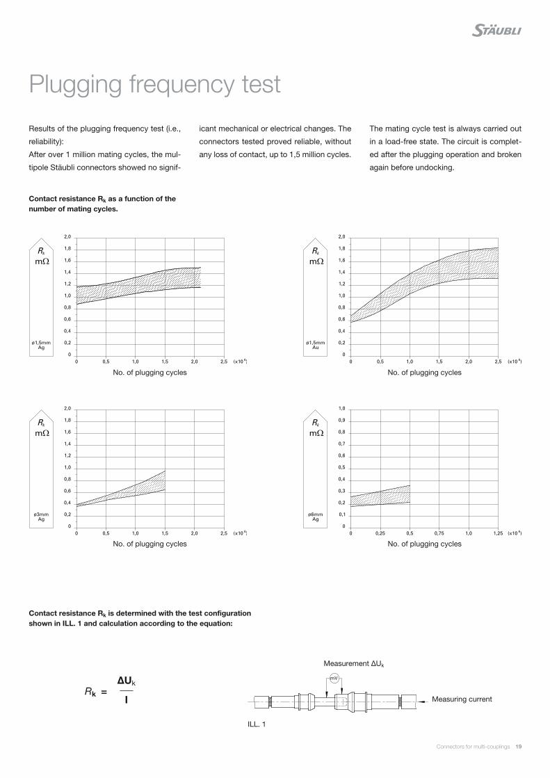
Results of the plugging frequency test (i.e.,
reliability):
After over 1 million mating cycles, the mul-
tipole Stäubli connectors showed no signif-
icant mechanical or electrical changes. The
connectors tested proved reliable, without
any loss of contact, up to 1,5 million cycles.
Plugging frequency test
The mating cycle test is always carried out
in a load-free state. The circuit is complet-
ed after the plugging operation and broken
again before undocking.
ILL. 1
Contact resistance Rk as a function of the number of mating cycles.
Contact resistance Rk is determined with the test configuration shown in ILL. 1 and calculation according to the equation:
No. of plugging cycles
No. of plugging cycles
No. of plugging cycles
No. of plugging cycles
Measurement ΔUk
Measuring currentRk =
ΔUk
I

20 Connectors for multi-couplings
Footprints
Number of poles Carrier size
G1 G2 G3 G4
1 – – –
2+PE –
Ø 6 mm Ø 8 mm
2+PE+6 – – –
2+PE+9 – – –
3+PE – –
3+PE+4 – – –
The pole diagrams show the male insulators
(mating side, top view).

Connectors for multi-couplings 21
Number of poles Carrier size
G1 G2 G3 G4
4+PE – – –
6+PE –
9+PE – – –
13+PE – – –
15+PE – – –
18+PE – – –

22 Connectors for multi-couplings
Number of poles Carrier size
G1 G2 G3 G4
19+PE – – –
24+PE – – –
27 – – –
36+PE – – –
47+PE – – –
70+2PE – – –

Connectors for multi-couplings 23
We are a solution provider – from the first concept to the final product
Gigabit Ethernet connectors available in the document „Gigabit Ethernet connectors GigaDock“ see also www.staubli.com/electrical
Dockingline | Connectors for Automatic Systems
Gigabit Ethernet connectorsGigaDock

24 Connectors for multi-couplings
Insertion and withdrawal force
The insertion and withdrawal forces depend
on the number of poles and the surface
characteristics of the contacts. The sliding
properties can be improved by the use of
gold contacts.
Note:
The withdrawal force is smaller than the
insertion force.
Withdrawal force AuInsertion force Au Insertion force Ag
Size Number of poles
Contact Ø Insertion and withdrawal force
mm 20N 40N 60N 80N 100N 120N 140N 160N 180N 200N 220N 240N 260N 280N 300N 320N 340N 360N 380N 400N
G1
2+PE 3
6+PE 2 / 1.5
18+PE 1
G2
4+PE
3
6+PE
15+PE 2 / 1.5
G3
2+PE-S8/B8 8
2+PE
6
4+PE
6+PE 5
13+PE 3
24+PE27
1.5
36+PE36PE/2,5
2 / 1.5
G4
2+PE 11 / 1.5
70+2PE 1.5

Connectors for multi-couplings 25
Withdrawal force Ag
Size Number of poles
Contact Ø Insertion and withdrawal force
mm 20N 40N 60N 80N 100N 120N 140N 160N 180N 200N 220N 240N 260N 280N 300N 320N 340N 360N 380N 400N
G1
2+PE 3
6+PE 2 / 1.5
18+PE 1
G2
4+PE
3
6+PE
15+PE 2 / 1.5
G3
2+PE-S8/B8 8
2+PE
6
4+PE
6+PE 5
13+PE 3
24+PE27
1.5
36+PE36PE/2,5
2 / 1.5
G4
2+PE 11 / 1.5
70+2PE 1.5

26 Connectors for multi-couplings
Conductor cross section1)
Nom.-Ø contact
Surface Rated current Mating cycles
Page
mm² AWG mm A max.
Signal applications
0.14 – 1.5 26 – 16 1 – 2 1 – 16 1,000,000 28
Thermocouple pressure contacts
0.14 – 0.5 26 – 20 2Details see page 30
10,000 30
Pressure contacts
0.5 – 1.5 20 – 16 2 2 – 10 10,000 32
BUS applications
0.14 – 1.5 26 – 16 1 – 1.5 1 – 16 1,000,000 34
OverviewCONTACTS

Connectors for multi-couplings 27
Conductor cross section1)
Nom.-Ø contact
Surface Rated current Mating cycles
Page
mm² AWG mm A max.
Hybrid applications
0.14 – 50 26 – 1/0 1 – 11 1 – 200500,000 – 1,000,000
36
Power applications
0.5 – 4 20 – 12 2 – 3 10 – 36 1,000,000 40
High Current applications
6 – 50 10 – 1/0 5 – 11 50 – 200 500,000 42
PEEK applications
0.5 – 70 20 – 2/0 1.6 – 10 5 – 200 10,000 46

28 Connectors for multi-couplings
Contacts for the transmission of signal
currents between 1 A and 16 A for cable
cross-sections of 0.14 mm² to 1.5 mm².
They are either silver plated (Ag) or gold
plated (Au) and every socket is provided
with the tried and tested MULTILAM.
Contacts for Signal applications
These contacts can then be used in different
types of contact carriers (up to 72 poles).
Important:
Empty contact cavities must be fitted with
blind plugs. If the cavities are only partly
occupied, care must be taken to distribute
the contacts evenly in the carrier; this way,
connectors remain longitudinally waterproof
and carriers do not get deformed.
Mating cycles: max. 1,000,000
Standard version
Assembly tools, page 86
MAIch bin eine Montageanleitung.
Man sollte mich unbedingt le-
sen, bevor man das Produkt ver-
wendet! Ich beinhalte wertvolle
Hinweise zur korrekten Montage
und zum richtigen Einsatz des
Produktes. Im Moment ist die
Schrift zwar ein bischen klein,
aber später geht das dann ganz
gut zu lesen, da die MA dann
Assembly instructions MA202
www.staubli.com/electrical
1) If the number of contacts is > 2, when selecting the con-ductor cross-sections observe DIN VDE 0298-4, DIN EN 60204-1 and the derating diagrams, page 95
2) Dependent on conductor cross section
Conductor cross section ¹⁾ Nom.-Ø contact Surface Order No. Type Max. rated current ²⁾ For appropriate carrier size on page 50 Blind plug
mm² AWG mm A G1 G2 G3 G4
0.14 – 0.5 26 – 20 1.5
18.902418.8024
SP1.5/0.14-0.5BP1.5/0.14-0.5
1 – 10 6+PE 15+PE 24+PE / 27 / 36+PE 70+2PE 18.550018.902518.8025
SP1.5/0.14-0.5 AUBP1.5/0.14-0.5 AU
0.2 – 1 24 – 18 1
18.900218.8002
SP1/1BP1/1
2 – 5 18+PE – – – 18.550618.900318.8003
SP1/1 AUBP1/1 AU
0.5 – 1.5 20 – 16 1.5
18.900418.8004
SP1.5/0.5-1.5BP1.5/0.5-1.5
10 – 16 6+PE3+PE+415+PE
24+PE / 27 / 36+PE 70+2PE 18.550018.900518.8005
SP1.5/0.5-1.5 AUBP1.5/0.5-1.5 AU
0.5 – 1.5 20 – 16 2
18.900818.8008
SP2/0.5-1.5BP2/0.5-1.5
10 – 16 6+PE 15+PE – – 18.550018.900918.8009
SP2/0.5-1.5 AUBP2/0.5-1.5 AU

Connectors for multi-couplings 29
Conductor cross section ¹⁾ Nom.-Ø contact Surface Order No. Type Max. rated current ²⁾ For appropriate carrier size on page 50 Blind plug
mm² AWG mm A G1 G2 G3 G4
0.14 – 0.5 26 – 20 1.5
18.902418.8024
SP1.5/0.14-0.5BP1.5/0.14-0.5
1 – 10 6+PE 15+PE 24+PE / 27 / 36+PE 70+2PE 18.550018.902518.8025
SP1.5/0.14-0.5 AUBP1.5/0.14-0.5 AU
0.2 – 1 24 – 18 1
18.900218.8002
SP1/1BP1/1
2 – 5 18+PE – – – 18.550618.900318.8003
SP1/1 AUBP1/1 AU
0.5 – 1.5 20 – 16 1.5
18.900418.8004
SP1.5/0.5-1.5BP1.5/0.5-1.5
10 – 16 6+PE3+PE+415+PE
24+PE / 27 / 36+PE 70+2PE 18.550018.900518.8005
SP1.5/0.5-1.5 AUBP1.5/0.5-1.5 AU
0.5 – 1.5 20 – 16 2
18.900818.8008
SP2/0.5-1.5BP2/0.5-1.5
10 – 16 6+PE 15+PE – – 18.550018.900918.8009
SP2/0.5-1.5 AUBP2/0.5-1.5 AU
SP2/0,5 – 1,5 AUSP: Pin; BP: Socket
SP2/0,5 – 1,5 AU Nom.-Ø pin (mm)
SP2/0,5 – 1,5 AU Conductor cross section (mm²)
SP2/0,5 – 1,5 AU Surface
Type code example:
SP2/0,5 – 1,5 AU

250 500 750 1000 1250 1500
80
70
60
50
40
30
20
10
0
47,5mV48,8mV
68,1mV
42,2mV
19,7mV
Type E
Type J
Type K
Type N
Type T
30 Connectors for multi-couplings
Thermocouple allow the precise measure-
ment of temperatures. The combination of
two wires made from different materials
generates a voltage that varies depending
on the temperature level.
The electrical measurement of temperature
requires that the entire measurement chain
(temperature sensor, cable connection points)
consist of the same combination of materials.
With Stäubli Thermocouple contacts, you
can extend the measurement chains or lay
them out as plug contact connections.
There are several types of thermocouples
made from different materials adapted to the
measured temperature range accor- ding to
standard.
Stäubli thermocouple contacts are adapted
for 5 different types of probes: E, J, K, N and
T. For that reason, Stäubli has developed
different types of spring loaded contacts for
thermocouples from the 7 most commonly
used materials: chromel, constantan, iron,
alumel, nicrosil, nisil and copper.
Stäubli Thermocuple pressure contacts can
be built into standard contact carriers.
Mating cycles: max. 100,000
MAIch bin eine Montageanleitung.
Man sollte mich unbedingt le-
sen, bevor man das Produkt ver-
wendet! Ich beinhalte wertvolle
Hinweise zur korrekten Montage
und zum richtigen Einsatz des
Produktes. Im Moment ist die
Schrift zwar ein bischen klein,
aber später geht das dann ganz
gut zu lesen, da die MA dann
Assembly instructions MA202
www.staubli.com/electrical
Thermocouple pressure contacts
Contacts for Signal applications
Stäubli thermocouple types
Type J Iron + Constantan Type T Copper + Constantan
Maintenance note (Cleaning): Every 10,000 mating cycles with compressed air Every 50,000 mating cycles with alcohol
Stäubli thermocouple types
Type E Chromel + Constantan Type K Chromel + Alumel Type N Nicrosil + Nisil
Maintenance note (Cleaning): Every 50,000 mating cycles with compressed air Every 100,000 mating cycles with alcohol
Temperature °C
Vo
ltag
e m
V

Connectors for multi-couplings 31
To ensure clear identification, our thermocouple pressure contacts are provided with different grooves and markings.
Cu
Copper (without groove)
Fe
Iron (without groove)
NiAl
Alumel® (1 groove)
NiCr
Chromel® (2 grooves)
NiSi
Nisil (3 grooves)
NiCrSi
Nicrosil (4 grooves)
CuNi
Konstantan® (1 wide groove)
Material marking
Groove
Description according to: EN60584
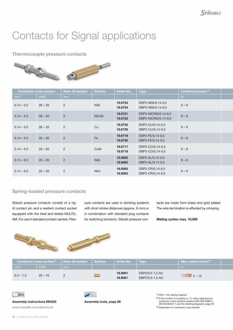
32 Connectors for multi-couplings
Stäubli pressure contacts consist of a rig-
id contact pin and a resilient contact socket
equipped with the tried and tested MULTIL-
AM. For use in standard contact carriers. Pres-
sure contacts are used in docking systems
with short stroke distances (approx. 6 mm) or
in combination with standard plug contacts
for switching functions. Stäubli pressure con-
tacts are made from brass and gold plated.
The wire termination is effected by crimping.
Mating cycles: max. 10,000
Assembly tools, page 86
MAIch bin eine Montageanleitung.
Man sollte mich unbedingt le-
sen, bevor man das Produkt ver-
wendet! Ich beinhalte wertvolle
Hinweise zur korrekten Montage
und zum richtigen Einsatz des
Produktes. Im Moment ist die
Schrift zwar ein bischen klein,
aber später geht das dann ganz
gut zu lesen, da die MA dann
Assembly instructions MA202
www.staubli.com/electrical
Spring-loaded pressure contacts
1) With 1 mm spring insertion2) If the number of contacts is > 2, when selecting the
conductor cross-sections observe DIN VDE 0298-4, DIN EN 60204-1 and the derating diagrams, page 95
3) Dependent on conductor cross section
Thermocouple pressure contacts
Contacts for Signal applications
Conductor cross section Nom.-Ø contact Surface Order No. Type Contact pressure ¹⁾ For appropriate carrier size on pages 50, 53 Blind plug
mm² AWG mm N G1 G2 G3 G4
0.14 – 0.5 26 – 20 2 NiSi19.672319.6724
DSP2-NISI/0,14-0,5DBP2-NISI/0,14-0,5
6 – 9 6+PE 15+PE 24+PE / 27 / 36+PE 70+2PE 18.5500
0.14 – 0.5 26 – 20 2 NiCrSi19.672119.6722
DSP2-NICRSI/0,14-0,5DBP2-NICRSI/0,14-0,5
6 – 9 6+PE 15+PE 24+PE / 27 / 36+PE 70+2PE 18.5500
0.14 – 0.5 26 – 20 2 Cu19.672519.6726
DSP2-CU/0,14-0,5DBP2-CU/0,14-0,5
6 – 9 6+PE 15+PE 24+PE / 27 / 36+PE 70+2PE 18.5500
0.14 – 0.5 26 – 20 2 Fe19.671919.6720
DSP2-FE/0,14-0,5DBP2-FE/0,14-0,5
6 – 9 6+PE 15+PE 24+PE / 27 / 36+PE 70+2PE 18.5500
0.14 – 0.5 26 – 20 2 CuNi19.671719.6718
DSP2-CO/0,14-0,5DBP2-CO/0,14-0,5
6 – 9 6+PE 15+PE 24+PE / 27 / 36+PE 70+2PE 18.5500
0.14 – 0.5 26 – 20 2 NiAl18.906218.8062
DSP2-AL/0,14-0,5DBP2-AL/0,14-0,5
6 – 9 6+PE 15+PE 24+PE / 27 / 36+PE 70+2PE 18.5500
0.14 – 0.5 26 – 20 2 NiCr18.906318.8063
DSP2-CR/0,14-0,5DBP2-CR/0,14-0,5
6 – 9 6+PE 15+PE 24+PE / 27 / 36+PE 70+2PE 18.5500
Conductor cross section ²⁾ Nom.-Ø contact Surface Order No. Type Max. rated current ³⁾ For appropriate carrier size on pages 50, 53 Blind plug
mm² AWG mm A G1 G2 G3 G4
0.5 – 1.5 20 – 16 218.906118.8061
DSP2/0,5-1,5 AUDBP2/0,5-1,5 AU 2 – 10 6+PE 15+PE 24+PE / 27 / 36+PE 70+2PE 18.5500

Connectors for multi-couplings 33
Contact carrier with pressure contact sockets
Contact carrier with pressure contact pins, mixed with standard pins
Conductor cross section Nom.-Ø contact Surface Order No. Type Contact pressure ¹⁾ For appropriate carrier size on pages 50, 53 Blind plug
mm² AWG mm N G1 G2 G3 G4
0.14 – 0.5 26 – 20 2 NiSi19.672319.6724
DSP2-NISI/0,14-0,5DBP2-NISI/0,14-0,5
6 – 9 6+PE 15+PE 24+PE / 27 / 36+PE 70+2PE 18.5500
0.14 – 0.5 26 – 20 2 NiCrSi19.672119.6722
DSP2-NICRSI/0,14-0,5DBP2-NICRSI/0,14-0,5
6 – 9 6+PE 15+PE 24+PE / 27 / 36+PE 70+2PE 18.5500
0.14 – 0.5 26 – 20 2 Cu19.672519.6726
DSP2-CU/0,14-0,5DBP2-CU/0,14-0,5
6 – 9 6+PE 15+PE 24+PE / 27 / 36+PE 70+2PE 18.5500
0.14 – 0.5 26 – 20 2 Fe19.671919.6720
DSP2-FE/0,14-0,5DBP2-FE/0,14-0,5
6 – 9 6+PE 15+PE 24+PE / 27 / 36+PE 70+2PE 18.5500
0.14 – 0.5 26 – 20 2 CuNi19.671719.6718
DSP2-CO/0,14-0,5DBP2-CO/0,14-0,5
6 – 9 6+PE 15+PE 24+PE / 27 / 36+PE 70+2PE 18.5500
0.14 – 0.5 26 – 20 2 NiAl18.906218.8062
DSP2-AL/0,14-0,5DBP2-AL/0,14-0,5
6 – 9 6+PE 15+PE 24+PE / 27 / 36+PE 70+2PE 18.5500
0.14 – 0.5 26 – 20 2 NiCr18.906318.8063
DSP2-CR/0,14-0,5DBP2-CR/0,14-0,5
6 – 9 6+PE 15+PE 24+PE / 27 / 36+PE 70+2PE 18.5500
Conductor cross section ²⁾ Nom.-Ø contact Surface Order No. Type Max. rated current ³⁾ For appropriate carrier size on pages 50, 53 Blind plug
mm² AWG mm A G1 G2 G3 G4
0.5 – 1.5 20 – 16 218.906118.8061
DSP2/0,5-1,5 AUDBP2/0,5-1,5 AU 2 – 10 6+PE 15+PE 24+PE / 27 / 36+PE 70+2PE 18.5500

34 Connectors for multi-couplings
Contacts for the transmission of BUS sig-
nals and are suitable for cable cross-sec-
tions of 0.14 mm² to 1.5 mm².
They are either silver plated (Ag) or gold
plated (Au) and every socket is provided
with the tried and tested MULTILAM.
Contacts for BUS applications
These contacts can then be used in different
types of contact carriers (up to 72 poles),
including hybrid carriers (page 53).
Important:
Empty contact cavities must be fitted with
blind plugs. If the cavities are only partly
occupied, care must be taken to distribute
the contacts evenly in the carrier; this way,
connectors remain longitudinally waterproof
and carriers do not get deformed.
Mating cycles: max. 1,000,000
Standard version
Assembly tools, page 86
MAIch bin eine Montageanleitung.
Man sollte mich unbedingt le-
sen, bevor man das Produkt ver-
wendet! Ich beinhalte wertvolle
Hinweise zur korrekten Montage
und zum richtigen Einsatz des
Produktes. Im Moment ist die
Schrift zwar ein bischen klein,
aber später geht das dann ganz
gut zu lesen, da die MA dann
Assembly instructions MA202
www.staubli.com/electrical
1) If the number of contacts is > 2, when selecting the conductor cross-sections observe DIN VDE 0298-4, DIN EN 60204-1 and the derating diagrams, page 95
2) Dependent on conductor cross section
Conductor cross section ¹⁾ Nom.-Ø contact Surface Order No. Type Max. rated current ²⁾ For appropriate carrier size on page 52 Blind plug
mm² AWG mm A G1 G2 G3 G4
0.14 – 0.5 26 – 20 1.518.902518.8025
SP1,5/0,14-0,5 AUBP1,5/0,14-0,5 AU 1 – 10 6+PE 15+PE 24+PE / 27 / 36+PE 70+2PE 18.5500
0.2 – 1 24 – 18 118.900318.8003
SP1/1 AUBP1/1 AU 2 – 5 18+PE – – – 18.5506
0.5 – 1.5 20 – 16 1.5
18.900418.8004
SP1,5/0,5-1,5BP1,5/0,5-1,5
10 – 16 6+PE 15+PE 24+PE / 27 / 36+PE 70+2PE 18.550018.900518.8005
SP1,5/0,5-1,5 AUBP1,5/0,5-1,5 AU

Connectors for multi-couplings 35
Conductor cross section ¹⁾ Nom.-Ø contact Surface Order No. Type Max. rated current ²⁾ For appropriate carrier size on page 52 Blind plug
mm² AWG mm A G1 G2 G3 G4
0.14 – 0.5 26 – 20 1.518.902518.8025
SP1,5/0,14-0,5 AUBP1,5/0,14-0,5 AU 1 – 10 6+PE 15+PE 24+PE / 27 / 36+PE 70+2PE 18.5500
0.2 – 1 24 – 18 118.900318.8003
SP1/1 AUBP1/1 AU 2 – 5 18+PE – – – 18.5506
0.5 – 1.5 20 – 16 1.5
18.900418.8004
SP1,5/0,5-1,5BP1,5/0,5-1,5
10 – 16 6+PE 15+PE 24+PE / 27 / 36+PE 70+2PE 18.550018.900518.8005
SP1,5/0,5-1,5 AUBP1,5/0,5-1,5 AU

36 Connectors for multi-couplings
Contacts for the connection of data leads
with different voltages or for carriers
equipped with mixed contacts, allowing the
combination of power and control contacts
(e.g. servo motor). They cover a range of ca-
ble cross sections from 0.14 mm² to 4 mm².
Contacts for Hybrid applications
They are either silver plated (Ag) or gold
plated (Au) and every socket is provided
with the tried and tested MULTILAM.
Important:
Empty contact cavities must be fitted with
blind plugs. If the cavities are only partly
occupied, care must be taken to distribute
the contacts evenly in the carrier; this way,
connectors remain longitudinally waterproof
and carriers do not get deformed.
Mating cycles: max. 1,000,000
Standard and short version
Assembly tools, page 86
MAIch bin eine Montageanleitung.
Man sollte mich unbedingt le-
sen, bevor man das Produkt ver-
wendet! Ich beinhalte wertvolle
Hinweise zur korrekten Montage
und zum richtigen Einsatz des
Produktes. Im Moment ist die
Schrift zwar ein bischen klein,
aber später geht das dann ganz
gut zu lesen, da die MA dann
Assembly instructions MA202
www.staubli.com/electrical
1) If the number of contacts is > 2, when selecting the conductor cross-sections observe DIN VDE 0298-4, DIN EN 60204-1 and the derating diagrams, page 95
2) Dependent on conductor cross section
Conductor cross section ¹⁾ Nom.-Ø contact Surface Order No. Type Max. rated current ²⁾ For appropriate carrier size on page 53 Blind plug
mm² AWG 0 A G1 G2 G3 G4
0.14 – 0.5 26 – 20 1.5
18.902418.8024
SP1,5/0,14-0,5BP1,5/0,14-0,5
1 – 10 6+PE 15+PE 24+PE / 27 / 36+PE 70+2PE 18.550018.902518.8025
SP1,5/0,14-0,5 AUBP1,5/0,14-0,5 AU
0.2 – 1 24 – 18 1
18.900218.8002
SP1/1BP1/1
2 – 5 18+PE – – – 18.550618.900318.8003
SP1/1 AUBP1/1 AU
0.5 – 1.5 20 – 16 1.5
18.900418.8004
SP1,5/0,5-1,5BP1,5/0,5-1,5
10 – 16 6+PE 15+PE 24+PE / 27 / 36+PE 70+2PE 18.550018.900518.8005
SP1,5/0,5-1,5 AUBP1,5/0,5-1,5 AU
Short version
2.5 – 4 14 – 12 3
18.901218.8012
SP3/2,5-4(K)BP3/2,5-4(K)
20 – 32 – 3+PE+4 / 4+PE / 6+PE – – 18.550118.901318.8013
SP3/2,5-4(K) AUBP3/2,5-4(K) AU

Connectors for multi-couplings 37
Conductor cross section ¹⁾ Nom.-Ø contact Surface Order No. Type Max. rated current ²⁾ For appropriate carrier size on page 53 Blind plug
mm² AWG 0 A G1 G2 G3 G4
0.14 – 0.5 26 – 20 1.5
18.902418.8024
SP1,5/0,14-0,5BP1,5/0,14-0,5
1 – 10 6+PE 15+PE 24+PE / 27 / 36+PE 70+2PE 18.550018.902518.8025
SP1,5/0,14-0,5 AUBP1,5/0,14-0,5 AU
0.2 – 1 24 – 18 1
18.900218.8002
SP1/1BP1/1
2 – 5 18+PE – – – 18.550618.900318.8003
SP1/1 AUBP1/1 AU
0.5 – 1.5 20 – 16 1.5
18.900418.8004
SP1,5/0,5-1,5BP1,5/0,5-1,5
10 – 16 6+PE 15+PE 24+PE / 27 / 36+PE 70+2PE 18.550018.900518.8005
SP1,5/0,5-1,5 AUBP1,5/0,5-1,5 AU
Short version
2.5 – 4 14 – 12 3
18.901218.8012
SP3/2,5-4(K)BP3/2,5-4(K)
20 – 32 – 3+PE+4 / 4+PE / 6+PE – – 18.550118.901318.8013
SP3/2,5-4(K) AUBP3/2,5-4(K) AU

38 Connectors for multi-couplings
Contacts for the connection of data leads
with different voltages or for carriers
equipped with mixed contacts, allowing the
combination of power and control contacts
(e.g. servo motor).
They cover a range of cable cross sections
from 6 mm² to 50 mm².
Hybrid applications
They are either silver plated (Ag) or gold
plated (Au) and every socket is provided
with the tried and tested MULTILAM.
These contacts can then be used in different
types of contact carriers, including in partic-
ular hybrid carriers (page 53).
Important:
Empty contact cavities must be fitted with
blind plugs. If the cavities are only partly
occupied, care must be taken to distribute
the contacts evenly in the carrier; this way,
connectors remain longitudinally waterproof
and carriers do not get deformed.
Mating cycles: max. 500,000
Standard version
1) If the number of contacts is > 2, when selecting the conductor cross-sections observe DIN VDE 0298-4, DIN EN 60204-1 and the derating diagrams, page 95
2) Dependent on conductor cross section3) IP2X
Conductor cross section ¹⁾ Nom.-Ø contact Surface Order No. Type Max. rated current ²⁾ For appropriate carrier size on page 53 Blind plug
mm² AWG mm A G1 G2 G3 G4
6 10 5
18.901618.8016
SP5/6BP5/6
50 – – 6+PE – 18.550218.903018.8030
SP5/6 AUBP5/6 AU
10 8 5
18.901718.8017
SP5/10BP5/10
63 – – 6+PE – 18.550218.903118.8031
SP5/10 AUBP5/10 AU
25 4 1118.905518.8055
SP11/25BP11/25 135 – – – 2+PE –
35 – 38 ~ 2 1118.902118.8021
SP11/35-38 ³⁾BP11/35-38 ³⁾ 170 – – – 2+PE –
50 1/0 1118.905618.8056
SP11/50 ³⁾BP11/50 ³⁾ 200 – – – 2+PE –

Connectors for multi-couplings 39
Conductor cross section ¹⁾ Nom.-Ø contact Surface Order No. Type Max. rated current ²⁾ For appropriate carrier size on page 53 Blind plug
mm² AWG mm A G1 G2 G3 G4
6 10 5
18.901618.8016
SP5/6BP5/6
50 – – 6+PE – 18.550218.903018.8030
SP5/6 AUBP5/6 AU
10 8 5
18.901718.8017
SP5/10BP5/10
63 – – 6+PE – 18.550218.903118.8031
SP5/10 AUBP5/10 AU
25 4 1118.905518.8055
SP11/25BP11/25 135 – – – 2+PE –
35 – 38 ~ 2 1118.902118.8021
SP11/35-38 ³⁾BP11/35-38 ³⁾ 170 – – – 2+PE –
50 1/0 1118.905618.8056
SP11/50 ³⁾BP11/50 ³⁾ 200 – – – 2+PE –

40 Connectors for multi-couplings
Contacts for the transmission of currents
between 10 A and 36 A for cable cross sec-
tions from 0.5 mm² to 4 mm².
They are mainly silver plated (Ag), or also
gold plated (Au) for demanding applications
and every socket is provided with the tried
Contacts for Power applications
and tested MULTILAM. These contacts can
be used in different types of contact carriers
(up to 37 poles).
Important:
Empty contact cavities must be fitted with
blind plugs. If the cavities are only partly
occupied, care must be taken to distribute
the contacts evenly in the carrier; this way,
connectors remain longitudinally waterproof
and carriers do not get deformed.
Mating cycles: max. 1,000,000
Standard and short version
Assembly tools, page 86
MAIch bin eine Montageanleitung.
Man sollte mich unbedingt le-
sen, bevor man das Produkt ver-
wendet! Ich beinhalte wertvolle
Hinweise zur korrekten Montage
und zum richtigen Einsatz des
Produktes. Im Moment ist die
Schrift zwar ein bischen klein,
aber später geht das dann ganz
gut zu lesen, da die MA dann
Assembly instructions MA202
www.staubli.com/electrical
1) If the number of contacts is > 2, when selecting the conductor cross-sections observe DIN VDE 0298-4, DIN EN 60204-1 and the derating diagrams, page 95
2) Dependent on conductor cross section
Conductor cross section ¹⁾ Nom.-Ø contact Surface Order No. Type Max. rated current ²⁾ For appropriate carrier size on page 54 Blind plug
mm² AWG mm A G1 G2 G3 G4
0.5 – 1.5 20 – 16 2
18.900818.8008
SP2/0,5-1,5BP2/0,5-1,5
10 – 16 6+PE 15+PE – – 18.550018.900918.8009
SP2/0,5-1,5 AUBP2/0,5-1,5 AU
2.5 14 2
18.901018.8010
SP2/2,5BP2/2,5
20 – –36+PE(CR / SIL)
– 18.550018.901118.8011
SP2/2,5 AUBP2/2,5 AU
2.5 – 4 14 – 12 3
18.901418.8014
SP3/2,5-4BP3/2,5-4
20 – 36 – – 13+PE – 18.550118.901518.8015
SP3/2,5-4 AUBP3/2,5-4 AU
Short versionThese contacts are ideal for applications with limited stroke distance (8 mm shorter in mated condition).
2.5 – 4 14 – 12 3
18.901218.8012
SP3/2,5-4(K)BP3/2,5-4(K)
20 – 32 2+PE 3+PE+4 / 4+PE / 6+PE – – 18.550118.901318.8013
SP3/2,5-4(K) AUBP3/2,5-4(K) AU

Connectors for multi-couplings 41
Conductor cross section ¹⁾ Nom.-Ø contact Surface Order No. Type Max. rated current ²⁾ For appropriate carrier size on page 54 Blind plug
mm² AWG mm A G1 G2 G3 G4
0.5 – 1.5 20 – 16 2
18.900818.8008
SP2/0,5-1,5BP2/0,5-1,5
10 – 16 6+PE 15+PE – – 18.550018.900918.8009
SP2/0,5-1,5 AUBP2/0,5-1,5 AU
2.5 14 2
18.901018.8010
SP2/2,5BP2/2,5
20 – –36+PE(CR / SIL)
– 18.550018.901118.8011
SP2/2,5 AUBP2/2,5 AU
2.5 – 4 14 – 12 3
18.901418.8014
SP3/2,5-4BP3/2,5-4
20 – 36 – – 13+PE – 18.550118.901518.8015
SP3/2,5-4 AUBP3/2,5-4 AU
Short versionThese contacts are ideal for applications with limited stroke distance (8 mm shorter in mated condition).
2.5 – 4 14 – 12 3
18.901218.8012
SP3/2,5-4(K)BP3/2,5-4(K)
20 – 32 2+PE 3+PE+4 / 4+PE / 6+PE – – 18.550118.901318.8013
SP3/2,5-4(K) AUBP3/2,5-4(K) AU

42 Connectors for multi-couplings
Contacts for the transmission of currents
between 50 A and 135 A for cable cross
sections from 6 mm² to 25 mm². They are
silver plated (Ag), or also gold plated (Au) for
demanding applications and every socket is
provided with the tried and tested MULTILAM.
Contacts for High Current applications
These contacts can then be used in different
types of contact carriers (up to 7 poles).
Important:
Empty contact cavities must be fitted with
blind plugs. If the cavities are only partly
occupied, care must be taken to distribute
the contacts evenly in the carrier; this way,
connectors remain longitudinally waterproof
and carriers do not get deformed.
Mating cycles: max. 50,000
Standard version
MAIch bin eine Montageanleitung.
Man sollte mich unbedingt le-
sen, bevor man das Produkt ver-
wendet! Ich beinhalte wertvolle
Hinweise zur korrekten Montage
und zum richtigen Einsatz des
Produktes. Im Moment ist die
Schrift zwar ein bischen klein,
aber später geht das dann ganz
gut zu lesen, da die MA dann
Assembly instructions MA202
www.staubli.com/electrical
1) If the number of contacts is > 2, when selecting the conductor cross-sections observe DIN VDE 0298-4, DIN EN 60204-1 and the derating diagrams, page 95
2) Dependent on conductor cross section
Conductor cross section ¹⁾ Nom.-Ø contact Surface Order No. Type Max. rated current ²⁾ For appropriate carrier size on page 55 Blind plug
mm² AWG mm A G1 G2 G3 G4
6 10 5
18.901618.8016
SP5/6BP5/6
50 – – 6+PE – 18.550218.903018.8030
SP5/6 AUBP5/6 AU
6 10 6
18.902918.8029
SP6/6BP6/6
50 – – 2+PE / 4+PE – 18.550318.903218.8032
SP6/6 AUBP6/6 AU
10 8 5
18.901718.8017
SP5/10BP5/10
63 – – 6+PE – 18.550218.903118.8031
SP5/10 AUBP5/10 AU
10 8 6
18.901818.8018
SP6/10BP6/10
80 – – 2+PE / 4+PE – 18.550318.903318.8033
SP6/10 AUBP6/10 AU
16 6 6
18.901918.8019
SP6/16BP6/16
90 – – 2+PE / 4+PE – 18.550318.903418.8034
SP6/16 AUBP6/16 AU
25 4 6
18.902018.8020
SP6/25BP6/25
135 – – 2+PE – 18.550318.903518.8035
SP6/25 AUBP6/25 AU

Connectors for multi-couplings 43
Conductor cross section ¹⁾ Nom.-Ø contact Surface Order No. Type Max. rated current ²⁾ For appropriate carrier size on page 55 Blind plug
mm² AWG mm A G1 G2 G3 G4
6 10 5
18.901618.8016
SP5/6BP5/6
50 – – 6+PE – 18.550218.903018.8030
SP5/6 AUBP5/6 AU
6 10 6
18.902918.8029
SP6/6BP6/6
50 – – 2+PE / 4+PE – 18.550318.903218.8032
SP6/6 AUBP6/6 AU
10 8 5
18.901718.8017
SP5/10BP5/10
63 – – 6+PE – 18.550218.903118.8031
SP5/10 AUBP5/10 AU
10 8 6
18.901818.8018
SP6/10BP6/10
80 – – 2+PE / 4+PE – 18.550318.903318.8033
SP6/10 AUBP6/10 AU
16 6 6
18.901918.8019
SP6/16BP6/16
90 – – 2+PE / 4+PE – 18.550318.903418.8034
SP6/16 AUBP6/16 AU
25 4 6
18.902018.8020
SP6/25BP6/25
135 – – 2+PE – 18.550318.903518.8035
SP6/25 AUBP6/25 AU

44 Connectors for multi-couplings
Contacts for the transmission of currents
between 135 A and 200 A for cable cross
sections from 25 mm² to 50 mm².
They are either silver plated (Ag) and every
socket is provided with the tried and tested
MULTILAM.
High Current applications
These contacts can then be used in different
types of contact carriers (up to 3 poles).
Important:
Empty contact cavities must be fitted with
blind plugs. If the cavities are only partly
occupied, care must be taken to distribute
the contacts evenly in the carrier; this way,
connectors remain longitudinally waterproof
and carriers do not get deformed.
Mating cycles: max. 500,000
Standard version
1) If the number of contacts is > 2, when selecting the conductor cross-sections observe DIN VDE 0298-4, DIN EN 60204-1 and the derating diagrams, page 95
2) Dependent on conductor cross section3) IP2X
MAIch bin eine Montageanleitung.
Man sollte mich unbedingt le-
sen, bevor man das Produkt ver-
wendet! Ich beinhalte wertvolle
Hinweise zur korrekten Montage
und zum richtigen Einsatz des
Produktes. Im Moment ist die
Schrift zwar ein bischen klein,
aber später geht das dann ganz
gut zu lesen, da die MA dann
Assembly instructions MA202
www.staubli.com/electrical
Conductor cross section ¹⁾ Nom.-Ø contact Surface Order No. Type Max. rated current ²⁾ For appropriate carrier size on page 55 Blind plug
mm² AWG mm A G1 G2 G3 G4
25 4 818.905018.8050
SP8/25BP8/25 135 – – 2+PE – 18.5505
25 4 1118.905518.8055
SP11/25BP11/25 135 – – – 2+PE –
35 2 818.905118.8051
SP8/35BP8/35 150 – – 2+PE – 18.5505
35 – 38 ~ 2 1118.902118.8021
SP11/35-38 ³⁾BP11/35-38 ³⁾ 170 – – – 2+PE –
50 1/0 1118.905618.8056
SP11/50 ³⁾BP11/50 ³⁾ 200 – – – 2+PE –

Connectors for multi-couplings 45
Conductor cross section ¹⁾ Nom.-Ø contact Surface Order No. Type Max. rated current ²⁾ For appropriate carrier size on page 55 Blind plug
mm² AWG mm A G1 G2 G3 G4
25 4 818.905018.8050
SP8/25BP8/25 135 – – 2+PE – 18.5505
25 4 1118.905518.8055
SP11/25BP11/25 135 – – – 2+PE –
35 2 818.905118.8051
SP8/35BP8/35 150 – – 2+PE – 18.5505
35 – 38 ~ 2 1118.902118.8021
SP11/35-38 ³⁾BP11/35-38 ³⁾ 170 – – – 2+PE –
50 1/0 1118.905618.8056
SP11/50 ³⁾BP11/50 ³⁾ 200 – – – 2+PE –

46 Connectors for multi-couplings
Special contacts for the transmission of cur-
rents up to 200 A for cable cross sections
from 0.15 mm² to 70 mm².
They are gold plated (Au) and every socket
is provided with the tried and tested
MULTILAM. These contacts can be used in
different types of machined contact carri-
Contacts for PEEK applications
ers (up to 48 poles), plus custom carriers,
if necessary.
Important:
If the cavities are only partly occupied, care
must be taken to distribute the contacts
evenly in the carrier.
Mating cycles: max. 10,000
Note:
Ø 6 mm and Ø 10 mm contacts are on
request.
Standard version
MAIch bin eine Montageanleitung.
Man sollte mich unbedingt le-
sen, bevor man das Produkt ver-
wendet! Ich beinhalte wertvolle
Hinweise zur korrekten Montage
und zum richtigen Einsatz des
Produktes. Im Moment ist die
Schrift zwar ein bischen klein,
aber später geht das dann ganz
gut zu lesen, da die MA dann
Assembly instructions MA303
www.staubli.com/electrical
1) If the number of contacts is > 2, when selecting the conductor cross-sections observe DIN VDE 0298-4, DIN EN 60204-1 and the derating diagrams, page 95
2) Dependent on conductor cross section3) Set including 8 contacts
Conductor cross section ¹⁾ Nom.-Ø contact Surface Order No. Type Max. rated current ²⁾ For appropriate carrier size on page 61
mm² AWG mm A G1 G2 G3 G4
0.15 – 0.75 26 – 18 119.911019.9108
CT-NET/S ³⁾CT-NET/B ³⁾ 5 – – 4 –
0.5 – 1.5 20 – 16 1.619.674219.6741
SP-C1,6/0,5-1,5 AUBP-C1,6/0,5-1,5 AU 16 – 19+PE 47+PE –
2.5 – 4 14 – 12
3
19.674419.6743
SP-C3/2,5-4 AUBP-C3/2,5-4 AU 36 – 3+PE 9+PE –
4 – 6 12 – 1019.675919.6745
SP-C3/4-6 AUBP-C3/4-6 AU 50 – 3+PE 13+PE –
10 8
6
19.674819.6747
SP-C6/10 AUBP-C6/10 AU 80 – – 3+PE –
16 619.675019.6749
SP-C6/16 AUBP-C6/16 AU 110 – – 3+PE –
25 419.675219.6751
SP-C6/25 AUBP-C6/25 AU 135 – – 3+PE –
35 2
10
19.675419.6753
SP-R10/35 AUBP-R10/35 AU 150 – 1 – –
50 1/019.675619.6755
SP-R10/50 AUBP-R10/50 AU 180 – 1 – –
70 2/019.675819.6757
SP-R10/70 AUBP-R10/70 AU 200 – 1 – –

Connectors for multi-couplings 47
Conductor cross section ¹⁾ Nom.-Ø contact Surface Order No. Type Max. rated current ²⁾ For appropriate carrier size on page 61
mm² AWG mm A G1 G2 G3 G4
0.15 – 0.75 26 – 18 119.911019.9108
CT-NET/S ³⁾CT-NET/B ³⁾ 5 – – 4 –
0.5 – 1.5 20 – 16 1.619.674219.6741
SP-C1,6/0,5-1,5 AUBP-C1,6/0,5-1,5 AU 16 – 19+PE 47+PE –
2.5 – 4 14 – 12
3
19.674419.6743
SP-C3/2,5-4 AUBP-C3/2,5-4 AU 36 – 3+PE 9+PE –
4 – 6 12 – 1019.675919.6745
SP-C3/4-6 AUBP-C3/4-6 AU 50 – 3+PE 13+PE –
10 8
6
19.674819.6747
SP-C6/10 AUBP-C6/10 AU 80 – – 3+PE –
16 619.675019.6749
SP-C6/16 AUBP-C6/16 AU 110 – – 3+PE –
25 419.675219.6751
SP-C6/25 AUBP-C6/25 AU 135 – – 3+PE –
35 2
10
19.675419.6753
SP-R10/35 AUBP-R10/35 AU 150 – 1 – –
50 1/019.675619.6755
SP-R10/50 AUBP-R10/50 AU 180 – 1 – –
70 2/019.675819.6757
SP-R10/70 AUBP-R10/70 AU 200 – 1 – –

48 Connectors for multi-couplings
Overview of contact carriers
Carrier size Number of poles Rated voltage Page
V
NBRSignal applications
G1 – G4 6+PE – 70+2PE 25 – 250 50
BUS applications
G1 – G4 6+PE – 70+2PE 25 – 250 52
Hybrid applications
G1 – G2, G42+PE+6 2+PE+9 3+PE+4
25 – 830 53
Power applications
G1 – G3 2+PE – 36+PE 250 – 630 54
High Current applications
G3 – G4 2+PE – 6+PE 400 – 630 55
Note:
All earth contacts (PE) are mating first and
breaking last:
■ Up to a nominal Ø of 3 mm, the pin
mates first and breaks last.
■ As of a nominal Ø of 5 mm, the socket
mates first and breaks last.
CONTACT CARRIERS

Connectors for multi-couplings 49
Carrier size Number of poles Rated voltage Page
V
Chloroprene (CR)
G3 36+PE 250 56
Silicone (SIL)
G2 – G3
3+PE+4 6+PE 15+PE 36+PE
250 – 830 57
PEEK (PK)
G2 – G3 On request
1 – 47+PE 24 – 600 59

50 Connectors for multi-couplings
The pin and socket carriers are made of
synthetic rubber. After the leads have been
crimped onto the pins and sockets resp.,
they can be mounted and dismounted
with the suitable tooling accordingly (See
Contact carriers for Signal applications
page 86). The pins and sockets are seat-
ed elastically in their carrier.
Operating temperature: +5°C...+100°C.
Note:
■ The nominal voltage can be increased
by selectively populating the carrier with
less contacts. Ask us for special pole
diagrams!
■ Inserts populated with contacts see
page 62.
Standard, without contacts
Assembly tools, page 86
E1-6PE/S Empty Contact carrier
E1-6PE/S Housing size
E1-6PE/S Number of contacts
E1-6PE/S S: Pin; B: Socket
Type code example:
E1-6PE/S

Connectors for multi-couplings 51
1) Special contact arrangements are required for applications using 250 V; please request pole diagram.
Carrier size Number of poles
Order No. Type Rated voltage for plastic housings
To fit housing size
V
G1
6+PE18.4201 E1-6PE/S
250 MGK1...MGS1...-ISMGS1...-S
18.4301 E1-6PE/B
18+PE18.4202 E1-18PE/S
150 ¹⁾18.4302 E1-18PE/B
G2 15+PE
18.4401 E2-15PE/S
250
MGK2...MGS2...-ISMGA2...18.4501 E2-15PE/B
G3
24+PE18.4604 E3-24PE/S
250
MGK3...MGS3...-ISMGA3...
18.4704 E3-24PE/B
2718.4605 E3-27/S
25 18.4705 E3-27/B
36+PE18.4606 E3-36PE/S
25018.4706 E3-36PE/B
G4 70+2PE18.4800 E4-70/2PE/S
250 MGK4...18.4900 E4-70/2PE/B

52 Connectors for multi-couplings
The pin and socket carriers are made of
synthetic rubber. After the leads have been
crimped onto the pins and sockets resp.,
they can be mounted and dismounted
with the suitable tooling accordingly (See
Contact carriers for BUS applications
page 86). The pins and sockets are seat-
ed elastically in their carrier.
Operating temperature: +5°C...+100°C.
Note:
The nominal voltage can be increased by
selectively populating the carrier with less
contacts. Ask us for special pole diagrams!
Standard, without contacts
1) For pilot contacts
Assembly tools, page 86
Carrier size Number of poles
Order No. Type Rated voltage To fit housing size
V
G1
2+PE+918.4203 E1-2PE+9/S 250
25 ¹⁾MGK1...MGS1...-ISMGS1...-S
18.4303 E1-2PE+9/B
6+PE18.4201 E1-6PE/S
25018.4301 E1-6PE/B
18+PE18.4202 E1-18PE/S
18.4302 E1-18PE/B
G2 15+PE
18.4401 E2-15PE/S
250
MGK2...MGS2...-ISMGA2...18.4501 E2-15PE/B
G3
24+PE18.4604 E3-24PE/S
250
MGK3...MGS3...-ISMGA3...
18.4704 E3-24PE/B
2718.4605 E3-27/S
25 18.4705 E3-27/B
36+PE18.4606 E3-36PE/S
25018.4706 E3-36PE/B
G4 70+2PE18.4800 E4-70/2PE/S
250 MGK4...18.4900 E4-70/2PE/B

Connectors for multi-couplings 53
The pin and socket carriers are made of
synthetic rubber. After the leads have been
crimped onto the pins and sockets resp.,
they can be mounted and dismounted
with the suitable tooling accordingly (See
Contact carriers for Hybrid applications
page 86). The pins and sockets are seat-
ed elastically in their carrier.
Operating temperature: +5°C...+100°C.
Note:
■ The nominal voltage can be increased
by selectively populating the carrier with
less contacts. Ask us for special pole
diagrams!
■ Inserts populated with contacts see
page 64.
Standard, without contacts
1) For pilot contacts
Assembly tools, page 86
Carrier size Number of poles
Order No. Type Rated voltage To fit housing size
V
G1 2+PE+9
18.4203 E1-2PE+9/S 250
25 ¹⁾
MGK1...MGS1...-ISMGS1...-S18.4303 E1-2PE+9/B
G2 3+PE+4
18.4403 E2-3PE+4/S 830
250 ¹⁾
MGK2...MGS2...-ISMGA2...18.4503 E2-3PE+4/B
G4 2+PE+618.4801 E4-2PE+6/S 630
25 ¹⁾MGK4...
18.4901 E4-2PE+6/B

54 Connectors for multi-couplings
The pin and socket carriers are made of
synthetic rubber. After the leads have been
crimped onto the pins and sockets resp.,
they can be mounted and dismounted
with the suitable tooling accordingly (See
Contact carriers for Power applications
page 86). The pins and sockets are seat-
ed elastically in their carrier.
Operating temperature: +5°C...+100°C.
Note:
■ The nominal voltage can be increased
by selectively populating the carrier with
less contacts. Ask us for special pole
diagrams!
■ Inserts populated with contacts see
page 66.
Standard, without contacts
Assembly tools, page 86
Carrier size Number of poles
Order No. Type Rated voltage for plastic housings
To fit housing size
V
G1
2+PE18.4200 E1-2PE/S
250
MGK1...MGS1...-ISMGS1...-S
18.4300 E1-2PE/B
6+PE18.4201 E1-6PE/S
18.4301 E1-6PE/B
G2
6+PE18.4400 E2-6PE/S
400 MGK2...MGS2...-ISMGA2...
18.4500 E2-6PE/B
15+PE18.4401 E2-15PE/S
25018.4501 E2-15PE/B
G3
2+PE
18.4650 E3-2PE/S8
630
MGK3...MGS3...-ISMGA3...
18.4750 E3-2PE/B8
18.4600 E3-2PE/S
18.4700 E3-2PE/B
4+PE18.4601 E3-4PE/S
40018.4701 E3-4PE/B
6+PE18.4602 E3-6PE/S
40018.4702 E3-6PE/B
13+PE18.4603 E3-13PE/S
40018.4703 E3-13PE/B
36+PE18.4606 E3-36PE/S
25018.4706 E3-36PE/B

Connectors for multi-couplings 55
The pin and socket carriers are made of
synthetic rubber. After the leads have been
crimped onto the pins and sockets resp.,
they can be mounted and dismounted
with the suitable tooling accordingly (See
Contact carriers for High Current applications
page 86). The pins and sockets are sea-
ted elastically in their carrier.
Operating temperature: +5°C...+100°C.
Note:
■ The nominal voltage can be increased
by selectively populating the carrier with
less contacts. Ask us for special pole
diagrams!
■ Inserts populated with contacts see
page 68.
Standard, without contacts
Assembly tools, page 86
Carrier size Number of poles
Order No. Type Rated voltage for plastic housings
To fit housing size
V
G3
2+PE18.4650 E3-2PE/S8
630
MGK3...MGS3...-ISMGA3...
18.4750 E3-2PE/B8
2+PE18.4600 E3-2PE/S
18.4700 E3-2PE/B
4+PE18.4601 E3-4PE/S
40018.4701 E3-4PE/B
6+PE18.4602 E3-6PE/S
40018.4702 E3-6PE/B
G4 2+PE18.4802 E4-2PE/S
630 MGK4...18.4902 E4-2PE/B

56 Connectors for multi-couplings
These grey contact carriers are suitable
for oil-sensitive applications.
The swelling behavior with the following oils
have been tested and passed:
■ Motorex COOLANT-F
■ AVIA Fluid HLPD-46
■ FRAGOL Ucotherm W-EGA
For all other oil types, tests would need to
be carried out.
Special contact carrier in Chloroprene
Note:
■ The nominal voltage can be increased
by selectively populating the carrier with
less contacts. Ask us for special pole
diagrams!
■ Inserts populated with contacts see
page 70.
■ Single contacts see page 28, 40.
Carrier size Number of poles
Order No. Type Rated voltage Operating temperature
To fit housing size
V °C
G3 36+PE18.4608 E3-36PE/S2,5-CR
250 –10...+100°CMGK3...MGA3...18.4708 E3-36PE/B2,5-CR

Connectors for multi-couplings 57
Special contact carrier in Silicone
These red contact carriers, in combination
with gold plated contacts, are suitable for
high-temperature applications (up to 150°C).
Note:
■ The nominal voltage can be increased
by selectively populating the carrier with
less contacts. Ask us for special pole
diagrams!
■ At temperatures above 90°C, we recom-
mend the use of metallic housings.
■ Inserts populated with contacts see
page 71.
■ Single contacts see page 40.
Carrier size Number of poles
Order No. Type Rated voltage Operating temperature
To fit housing size
V °C
G2
3+PE+418.4612 E2-3+PE+4/S SIL 830
250
–10...+150°C
MGK2...MGA2...
18.4712 E2-3+PE+4/B SIL
6+PE18.4613 E2-6PE/S SIL
40018.4713 E2-6PE/B SIL
15+PE18.4614 E2-15PE/S SIL
25018.4714 E2-15PE/B SIL
G3
6+PE18.4609 E3-6PE/S SIL
400MGK3...MGA3...
18.4709 E3-6PE/B SIL
36+PE18.4607 E3-36PE/S2,5-SIL
25018.4707 E3-36PE/B2,5-SIL

58 Connectors for multi-couplings

Connectors for multi-couplings 59
These beige pin and socket carriers are
made of hard PEEK material and are suit-
able for very demanding areas of appli-
cation, such as in nuclear technology. To
match, there are 10 types of gold plated
special contacts (see page 46). After the
leads have been crimped onto the contacts,
Special contact carrier in PEEK
they can normally be fitted by hand. If nec-
essary, they can be removed using a suit-
able extraction tool (see page 86).
Operating temperature: –10°C...+150°C.
Note:
■ The nominal voltage can be increased
by selectively populating the carrier with
less contacts. Ask us for special pole
diagrams!
■ Inserts populated with contacts see
page 72.
■ Single contacts see page 46.
Standard, without contacts
1) Mating compatibility with the standard (NBR) version2) No touch protection
Assembly tools, page 86
Carrier size Number of poles
Order No. Type Rated voltage for plastic housings
To fit housing size
V
G2
1 19.6627 E2-1-PK/S
600
MGK2...MGS2...-ISMGA2...
19.6626 E2-1-PK/B ²⁾
3+PE19.6633 E2-3PE-PK/S
60019.6632 E2-3PE-PK/B
19+PE19.6635 E2-19PE-PK/S
15019.6634 E2-19PE-PK/B
G3
3+PE19.6637 E3-3PE-PK/S
600
MGK3...MGS3...-ISMGA3...
19.6636 E3-3PE-PK/B
9+PE19.6645 E3-9PE-PK/S
19.6644 E3-9PE-PK/B
13+PE ¹⁾19.6649 E3-13PE-PK/S
60019.6648 E3-13PE-PK/B
47+PE19.6647 E3-47PE-PK/S
15019.6646 E3-47PE-PK/B
4xNET 19.9109 E3-4NET-PK/S
2419.9106 E3-4NET-PK/B

60 Connectors for multi-couplings
Overview
Carrier size Number of poles Rated voltage Page
V
NBRSignal applications
G1 – G4 6+PE – 70+2PE 25 – 250 62
Hybrid applications
G1, G2, G4 2+PE+6 – 3+PE+4 250 – 830 64
Power applications
G1 – G3 2+PE – 15+PE 250 – 400 66
High Current applications
G3 – G4 2+PE – 6+PE 25 – 630 68
Note:
All earth contacts (PE) are mating first and
breaking last:
■ Up to a nominal Ø of 3 mm, the pin
mates first and breaks last.
■ As of a nominal Ø of 5 mm, the socket
mates first and breaks last.
CONTACT INSERT SETS

Connectors for multi-couplings 61
Carrier size Number of poles Rated voltage Page
V
Chloroprene (CR)
G3 36+PE 250 70
Silicone (SIL)
G2 – G3
3+PE+4 6+PE 15+PE 36+PE
250 – 830 71
PEEK (PK)
G2 – G3 On request
1 – 47+PE 24 – 600 72

62 Connectors for multi-couplings
These sets are consisting of a contact car-
rier and the corresponding number of pins
or sockets.
This makes it easier for you to order contact
carriers which are to be fully loaded (after
crimping).
Note:
■ Empty contact carrier see page 48.
■ Single contacts pins/sockets see
page 28.
Contact insert sets for Signal applications
ME1-18+PE-SP1/1 AU Contact insert-set
ME1-18+PE-SP1/1 AU Housing size
ME1-18+PE-SP1/1 AU Number of contacts
ME1-18+PE-SP1/1 AU SP: Pin; BP: Socket
ME1-18+PE-SP1/1 AU Nom.-Ø pin (mm)
ME1-18+PE-SP1/1 AU max. conductor cross section (mm²)
ME1-18+PE-SP1/1 AU Surface
Type code example:
ME1-18+PE-SP1/1 AU

Connectors for multi-couplings 63
1) Special contact arrangements are required for applications using 250 V; please request pole diagram.
2) Also available with: SP1,5/0,14-0,5 / BP1,5/0,14-0,5
Car
rier
siz
e
Co
nduc
tor
cro
ss s
ectio
n
Num
ber
of
po
les
No
m.-
Ø
Co
ntac
t
Sur
face
Ord
er N
o.
Typ
e
Max
. rat
ed
curr
ent
Rat
ed v
olta
ge
mm² AWG mm A V
G1
0.2 – 1 24 – 18 18+PE 1
18.1206 ME1-18+PE-SP1/1
5 1501)18.1207 ME1-18+PE-BP1/1
18.1306 ME1-18+PE-SP1/1 AU
18.1307 ME1-18+PE-BP1/1 AU
0.5 – 1.5 20 – 16 6+PE
2
18.1202 ME1-6+PE-SP2/0,5-1,5
16 250
18.1203 ME1-6+PE-BP2/0,5-1,5
18.1302 ME1-6+PE-SP2/0,5-1,5 AU
18.1303 ME1-6+PE-BP2/0,5-1,5 AU
1.5
18.1204 ME1-6+PE-SP1,5/0,5-1,5
18.1205 ME1-6+PE-BP1,5/0,5-1,5
18.1304 ME1-6+PE-SP1,5/0,5-1,5 AU
18.1305 ME1-6+PE-BP1,5/0,5-1,5 AU
G2 0.5 – 1.5 20 – 16 15+PE
2
18.1404 ME2-15+PE-SP2/0,5-1,5
16 250
18.1405 ME2-15+PE-BP2/0,5-1,5
18.1504 ME2-15+PE-SP2/0,5-1,5 AU
18.1505 ME2-15+PE-BP2/0,5-1,5 AU
1.5
18.1406 ME2-15+PE-SP1,5/0,5-1,5
18.1407 ME2-15+PE-BP1,5/0,5-1,5
18.1506 ME2-15+PE-SP1,5/0,5-1,5 AU
18.1507 ME2-15+PE-BP1,5/0,5-1,5 AU
G3 0.5 – 1.5 20 – 16
24+PE 1.5
18.1616 ME3-24+PE-SP1,5/0,5-1,5 ²⁾
16
25018.1617 ME3-24+PE-BP1,5/0,5-1,5 ²⁾
18.1702 ME3-24+PE-SP1,5/0,5-1,5 AU ²⁾
18.1703 ME3-24+PE-BP1,5/0,5-1,5 AU ²⁾
27 1.5
18.1618 ME3-27-SP1,5/0,5-1,5
25 18.1619 ME3-27-BP1,5/0,5-1,5
18.1704 ME3-27-SP1,5/0,5-1,5 AU
18.1705 ME3-27-BP1,5/0,5-1,5 AU
36+PE 1.5
18.1622 ME3-36+PE-SP1,5/0,5-1,5
25018.1623 ME3-36+PE-BP1,5/0,5-1,5
18.1708 ME3-36+PE-SP1,5/0,5-1,5 AU
18.1709 ME3-36+PE-BP1,5/0,5-1,5 AU
G4 0.5 – 1.5 20 – 16 70+2PE 1.5
18.1800 ME4-70+2PE-SP1,5/0,5-1,5
16 25018.1801 ME4-70+2PE-BP1,5/0,5-1,5
18.1900 ME4-70+2PE-SP1,5/0,5-1,5 AU
18.1901 ME4-70+2PE-BP1,5/0,5-1,5 AU

64 Connectors for multi-couplings
Contact insert sets for Hybrid applications
Contact inserts equipped with mixed con-
tacts for power supply and signal transmis-
sion to servo motors.
Note:
■ Empty contact carrier see page 53.
■ Single contacts pins/sockets see
page 36.
Power Signal
Car
rier
siz
e
Num
ber
of
po
les
(P
ow
er &
Sig
nal)
Co
nduc
tor
cro
ss
sect
ion
Num
ber
of
po
les
No
m.-
Ø c
ont
act
Max
. rat
ed c
urre
nt
Rat
ed v
olta
ge
Co
nduc
tor
cro
ss
sect
ion
Num
ber
of
po
les
No
m.-
Ø c
ont
act
Max
. rat
ed c
urre
nt
Rat
ed v
olta
ge
Sur
face
Ord
er N
o.
Typ
e
mm² AWG mm A V mm² AWG mm A V
G1 2+PE+9 0.5 – 1.5 20 – 16 2+PE 1.5 16 250 0.2 – 1 9 1 5 25
18.1212 ME1-2+PE-SP1,5/0,5-1,5+9SP1/1K
18.1312 ME1-2+PE-BP1,5/0,5-1,5+9BP1/1K
G2 3+PE+4 2.5 – 4 14 – 12 3+PE 3 32 830 0.5 – 1.5 20 – 16 4 1.5 16 250
18.1410 ME2-3+PE-SP3/2,5-4(K)+4SP1,5/0,5-1,5
18.1411 ME2-3+PE-BP3/2,5-4(K)+4BP1,5/0,5-1,5
G4 2+PE+6
25/50 4 – 1/0
2+PE 11
200
630 0.5 – 1.5 20 – 16 6 1.5 5 25
18.1816 ME4-2+PE-SP11/25+50 ¹⁾
18.1817 ME4-2+PE-BP11/25+50 ¹⁾
35-38 ~ 2 170
18.1812 ME4-2+PE-SP11/35-38 ¹⁾
18.1813 ME4-2+PE-BP11/35-38 ¹⁾

Connectors for multi-couplings 65
1) Can be fitted with up to 6 pilot contacts (please order separately)
Power Signal
Car
rier
siz
e
Num
ber
of
po
les
(P
ow
er &
Sig
nal)
Co
nduc
tor
cro
ss
sect
ion
Num
ber
of
po
les
No
m.-
Ø c
ont
act
Max
. rat
ed c
urre
nt
Rat
ed v
olta
ge
Co
nduc
tor
cro
ss
sect
ion
Num
ber
of
po
les
No
m.-
Ø c
ont
act
Max
. rat
ed c
urre
nt
Rat
ed v
olta
ge
Sur
face
Ord
er N
o.
Typ
e
mm² AWG mm A V mm² AWG mm A V
G1 2+PE+9 0.5 – 1.5 20 – 16 2+PE 1.5 16 250 0.2 – 1 9 1 5 25
18.1212 ME1-2+PE-SP1,5/0,5-1,5+9SP1/1K
18.1312 ME1-2+PE-BP1,5/0,5-1,5+9BP1/1K
G2 3+PE+4 2.5 – 4 14 – 12 3+PE 3 32 830 0.5 – 1.5 20 – 16 4 1.5 16 250
18.1410 ME2-3+PE-SP3/2,5-4(K)+4SP1,5/0,5-1,5
18.1411 ME2-3+PE-BP3/2,5-4(K)+4BP1,5/0,5-1,5
G4 2+PE+6
25/50 4 – 1/0
2+PE 11
200
630 0.5 – 1.5 20 – 16 6 1.5 5 25
18.1816 ME4-2+PE-SP11/25+50 ¹⁾
18.1817 ME4-2+PE-BP11/25+50 ¹⁾
35-38 ~ 2 170
18.1812 ME4-2+PE-SP11/35-38 ¹⁾
18.1813 ME4-2+PE-BP11/35-38 ¹⁾

66 Connectors for multi-couplings
Contact insert sets for Power applications
The contact insert sets are consisting of a
contact carrier and the corresponding num-
ber of pins or sockets.
This makes it easier for you to order contact
carriers which are to be fully loaded (after
crimping).
Note:
■ Empty contact carrier see page 54.
■ Single contacts pins/sockets see
page 40.
ME1-6+PE-SP2/0,5-1,5 AU Contact insert-set
ME1-6+PE-SP2/0,5-1,5 AU Housing size
ME1-6+PE-SP2/0,5-1,5 AU Number of contacts
ME1-6+PE-SP2/0,5-1,5 AU SP: Pin; BP: Socket
ME1-6+PE-SP2/0,5-1,5 AU Nom.-Ø pin (mm)
ME1-6+PE-SP2/0,5-1,5 AU max. conductor cross section (mm²)
ME1-6+PE-SP2/0,5-1,5 AU Surface
Type code example:
ME1-6+PE-SP2/0,5-1,5 AU

Connectors for multi-couplings 67
Car
rier
siz
e
Co
nduc
tor
cro
ss s
ectio
n
Num
ber
of
po
les
No
m.-
Ø
Co
ntac
t
Sur
face
Ord
er N
o.
Typ
e
Max
. rat
ed
curr
ent
Rat
ed v
olta
ge
mm² AWG mm A V
G1
0.5 – 1.5 20 – 16 6+PE 2
18.1202 ME1-6+PE-SP2/0,5-1,5
16
250
18.1203 ME1-6+PE-BP2/0,5-1,5
18.1302 ME1-6+PE-SP2/0,5-1,5 AU
18.1303 ME1-6+PE-BP2/0,5-1,5 AU
2.5 – 4 14 – 12 2+PE 3
18.1200 ME1-2+PE-SP3/2,5-4(K)
3618.1201 ME1-2+PE-BP3/2,5-4(K)
18.1300 ME1-2+PE-SP3/2,5-4(K) AU
18.1301 ME1-2+PE-BP3/2,5-4(K) AU
G2
0.5 – 1.5 20 – 16 15+PE 2
18.1404 ME2-15+PE-SP2/0,5-1,5
16 25018.1405 ME2-15+PE-BP2/0,5-1,5
18.1504 ME2-15+PE-SP2/0,5-1,5 AU
18.1505 ME2-15+PE-BP2/0,5-1,5 AU
2.5 – 4 14 – 12
4+PE
3
18.1400 ME2-4+PE-SP3/2,5-4(K)
36 400
18.1401 ME2-4+PE-BP3/2,5-4(K)
18.1500 ME2-4+PE-SP3/2,5-4(K) AU
18.1501 ME2-4+PE-BP3/2,5-4(K) AU
6+PE
18.1402 ME2-6+PE-SP3/2,5-4(K)
18.1403 ME2-6+PE-BP3/2,5-4(K)
18.1502 ME2-6+PE-SP3/2,5-4(K) AU
18.1503 ME2-6+PE-BP3/2,5-4(K) AU
G3 2.5 – 4 14 – 12 13+PE 3
18.1614 ME3-13+PE-SP3/2,5-4
27 40018.1615 ME3-13+PE-BP3/2,5-4
18.1700 ME3-13+PE-SP3/2,5-4 AU
18.1701 ME3-13+PE-BP3/2,5-4 AU

68 Connectors for multi-couplings
Contact insert sets for High Current applications
The contact insert sets are consisting of a
contact carrier and the corresponding num-
ber of pins or sockets.
This makes it easier for you to order contact
carriers which are to be fully loaded (after
crimping).
Note:
■ Empty contact carrier see page 55.
■ Single contacts pins/sockets see
page 42.
ME3-6+PE-SP5/6 Contact insert-set
ME3-6+PE-SP5/6 Housing size
ME3-6+PE-SP5/6 Number of contacts
ME3-6+PE-SP5/6 SP: Pin; BP: Socket
ME3-6+PE-SP5/6 Nom.-Ø pin (mm)
ME3-6+PE-SP5/6 max. conductor cross section (mm²)
Type code example:
ME3-6+PE-SP5/6

Connectors for multi-couplings 69
1) Can be fitted with up to 6 pilot contacts (please order separately)
2) For pilot contacts
Car
rier
siz
e
Co
nduc
tor
cro
ss s
ectio
n
Num
ber
of
po
les
No
m.-
Ø
Co
ntac
t
Sur
face
Ord
er N
o.
Typ
e
Max
. rat
ed
curr
ent
Rat
ed v
olta
ge
mm² AWG mm A V
G3
6 10 6+PE 518.1612 ME3-6+PE-SP5/6
50 40018.1613 ME3-6+PE-BP5/6
10 8
2+PE 618.1604 ME3-2+PE-SP6/10
80 63018.1605 ME3-2+PE-BP6/10
4+PE 618.1608 ME3-4+PE-SP6/10
63 40018.1609 ME3-4+PE-BP6/10
6+PE 518.1610 ME3-6+PE-SP5/10
18.1611 ME3-6+PE-BP5/10
16 6
2+PE 618.1602 ME3-2+PE-SP6/16
110 63018.1603 ME3-2+PE-BP6/16
4+PE 618.1606 ME3-4+PE-SP6/16
90 40018.1607 ME3-4+PE-BP6/16
25 4 2+PE
618.1600 ME3-2+PE-SP6/25
135
630
18.1601 ME3-2+PE-BP6/25
818.1750 ME3-2+PE-SP8/25
18.1751 ME3-2+PE-BP8/25
35 2 2+PE 818.1752 ME3-2+PE-SP8/35
15018.1753 ME3-2+PE-BP8/35
G4
25/50 4 – 1/0
2+PE 11
18.1816 ME4-2+PE-SP11/25+50 ¹⁾ 200 16 ²⁾ 630
25 ²⁾
18.1817 ME4-2+PE-BP11/25+50 ¹⁾
35 – 38 218.1812 ME4-2+PE-SP11/35-38 ¹⁾ 170
16 ²⁾18.1813 ME4-2+PE-BP11/35-38 ¹⁾

70 Connectors for multi-couplings
The contact inserts consist of the grey con-
tact carriers and the corresponding number
of pins or sockets.
This makes it easier for you to order contact
carriers which are to be fully loaded (after
crimping). These grey contact carriers are
suitable for oil-sensitive applications.
Special contact insert sets for Chloroprene applications
The swelling behavior with the following oils
have been tested and passed:
■ Motorex COOLANT-F
■ AVIA Fluid HLPD-46
■ FRAGOL Ucotherm W-EGA
For all other oil types, tests would need to
be carried out.
Note:
■ Empty contact carrier see page 56.
■ Single contacts Pins/Sockets see
pages 28, 40.
Car
rier
siz
e
Co
nduc
tor
cro
ss s
ectio
n
Num
ber
of
po
les
No
m.-
Ø
Co
ntac
t
Sur
face
Ord
er N
o.
Typ
e
Max
. rat
ed
curr
ent
Rat
ed v
olta
ge
mm² AWG mm A V
G3 2.5 14 36+PE 218.1624 ME3-36+PE-SP2/2,5-CR
25 25018.1625 ME3-36+PE-BP2/2,5-CR

Connectors for multi-couplings 71
Special contact insert sets for Silicone applications
The contact inserts consist of the red con-
tact carriers and the appropriate number of
pins or sockets.
They are suitable for high-temperature ap-
plications (up to 150 °C).
For applications above 90 °C we recom-
mend the use of gold plated contacts and
tinned cable strands and the use of metallic
housings.
This makes it easier for you to order contact
carriers which are to be fully loaded (after
crimping).
Note:
■ Empty contact carrier see page 57.
■ Single contacts see page 40.
Car
rier
siz
e
Co
nduc
tor
cro
ss s
ectio
n
Num
ber
of
po
les
No
m.-
Ø
Co
ntac
t
Sur
face
Ord
er N
o.
Typ
e
Max
. rat
ed
curr
ent
Rat
ed v
olta
ge
mm² AWG mm A V
G2
0.5 – 1.5 20 – 16 15+PE 218.1512 ME2-15PE/S SIL
16 25018.1513 ME2-15PE/B SIL
2.5 – 40.5 – 1.5
14 – 1220 – 16
3+PE+431.5
18.1508 ME2-3+PE+4/S SIL 32 16
830 25018.1509 ME2-3+PE+4/B SIL
2.5 – 4 14 – 12 6+PE 318.1510 ME2-6PE/S SIL
32 40018.1511 ME2-6PE/B SIL
G3
2.5 14 36+PE 218.1706 ME3-36+PE-SP2/2,5-SIL AU
25 25018.1707 ME3-36+PE-BP2/2,5-SIL AU
10 8 6+PE 518.1710 ME3-6PE/S SIL
63 40018.1711 ME3-6PE/B SIL

72 Connectors for multi-couplings
Special contact insert sets for PEEK applications
The contact insert sets are consisting of a
contact carrier and the corresponding num-
ber of pins or sockets.
This makes it easier for you to order contact
carriers which are to be fully loaded (after
crimping).
Note:
■ Empty contact carrier see page 59.
■ Single contacts pins/sockets see
page 46.
ME2-19+PE-SP-C1,6/0,5-1,5-PK AU Contact insert-set
ME2-19+PE-SP-C1,6/0,5-1,5-PK AU Housing size
ME2-19+PE-SP-C1,6/0,5-1,5-PK AU Number of contacts
ME2-19+PE-SP-C1,6/0,5-1,5-PK AU SP: Pin; BP: Socket
ME2-19+PE-SP-C1,6/0,5-1,5-PK AU C: Clip; R: Retaining ring
ME2-19+PE-SP-C1,6/0,5-1,5-PK AU Nom.-Ø pin (mm)
ME2-19+PE-SP-C1,6/0,5-1,5-PK AU Conductor cross section (mm²)
ME2-19+PE-SP-C1,6/0,5-1,5-PK AU PEEK
ME2-19+PE-SP-C1,6/0,5-1,5-PK AU Surface
Type code example:
ME2-19+PE-SP-C1,6/0,5-1,5-PK AU

Connectors for multi-couplings 73
Car
rier
siz
e
Co
nduc
tor
cro
ss
sect
ion
Num
ber
of
po
les
No
m.-
Ø c
ont
act
Sur
face
Ord
er N
o.
Typ
e
Max
. rat
ed c
urre
nt
Rat
ed v
olta
ge
mm² AWG mm A V
G2
0.5 – 1.5 20 – 16 19+PE 1.619.6651 ME2-19+PE-SP-C1,6/0,5-1,5-PK AU
16 15019.6650 ME2-19+PE-BP-C1,6/0,5-1,5-PK AU
2.5 – 4 14 – 12
3+PE 3
19.6657 ME2-3+PE-SP-C3/2,5-4-PK AU 36
60019.6656 ME2-3+PE-BP-C3/2,5-4-PK AU
4 – 6 12 – 1019.6653 ME2-3+PE-SP-C3/4-6-PK AU
5019.6652 ME2-3+PE-BP-C3/4-6-PK AU
35 2
1 10
19.6661 ME2-1-SP-R10/35-PK AU 150
600
19.6660 ²⁾ ME2-1-BP-R10/35-PK AU
50 1/019.6659 ME2-1-SP-R10/50-PK AU
18019.6658 ²⁾ ME2-1-BP-R10/50-PK AU
70 2/019.6655 ME2-1-SP-R10/70-PK AU
20019.6654 ²⁾ ME2-1-BP-R10/70-PK AU
G3
0.5 – 1.5 20 – 16 47+PE 1.619.6663 ME3-47+PE-SP-C1,6/0,5-1,5-PK AU
16 15019.6662 ME3-47+PE-BP-C1,6/0,5-1,5-PK AU
2.5 – 4 14 – 12
9+PE
3
19.6669 ME3-9+PE-SP-C3/2,5-4-PK AU 36 600
19.6668 ME3-9+PE-BP-C3/2,5-4-PK AU
13+PE ¹⁾19.6675 ME3-13+PE-SP3/2,5-4-PK AU
36 60019.6674 ME3-13+PE-BP3/2,5-4-PK AU
4 – 6 12 – 10
9+PE19.6665 ME3-9+PE-SP-C3/4-6-PK AU
50 60019.6664 ME3-9+PE-BP-C3/4-6-PK AU
13+PE ¹⁾19.6677 ME3-13+PE-SP3/4-6-PK AU
50 60019.6676 ME3-13+PE-BP3/4-6-PK AU
10 8
3+PE 6
19.6671 ME3-3+PE-SP-C6/10-PK AU 80
600
19.6670 ME3-3+PE-BP-C6/10-PK AU
16 619.6667 ME3-3+PE-SP-C6/16-PK AU
11019.6666 ME3-3+PE-BP-C6/16-PK AU
25 419.6673 ME3-3+PE-SP-C6/25-PK AU
13519.6672 ME3-3+PE-BP-C6/25-PK AU
0.5 – 0.75 26 – 18 4xNET1 119.9111 ME3-4NET-PK/S
5 2419.9107 ME3-4NET-PK/B
1) Mating compatibility with the standard (NBR) version2) No touch protection

74 Connectors for multi-couplings
Overview
Housing size Mating cycles Page
Plastic housings
MGK1 – MGK4 10,000,000 76
Plastic housings, shielded, insulated
MGS1...-IS – MGS3...-IS
MGS3...N-...1,000,000 80
Metal housing, shielded
MGS1...-S 1,000,000 83
Metal housing
MGA2... – MGA3... 1,000,000 84
Note:
Housings out of stainless steel on request
HOUSINGS

Lmax.2) Lmax.2)
Connectors for multi-couplings 75
Shielding principle
The MULTILAM serve as a contact element
between the housings, providing continuity
of the shield and an optimum 360° schield-
ing effect.
For selected housings, the shield is con-
nected via an EMC cable gland that is pro-
tected against touching by means of insu-
lating sleeves.
Advantages (shielding):
■ Secure BUS signal transfer (360°
shielding)
■ Ideal for Profinet and Ethernet
applications (CAT5 and CAT6)
■ Simple cabling with shielded cable gland
Advantages (plastic insulation):
■ No electrical connection between
housing and mounting panel
■ Shield loops are already prevented on
assembly
1) EMC-threaded glands are supplied with selected housings. Please see ordering information2) If alternative glands are used, please observe the correct size Lmax:
Housing size 1: 25 mm Housing size 2: 31.5 mm Housing size 3: 32.5 mm
EMC-Cable gland1) MULTILAM for contacting shield EMC-Cable gland1)
Continuous shield contacting Plastic housing Pin Socket

76 Connectors for multi-couplings
Plastic housings
Fully insulated plastic housings of high-impact
material. Unlike metal housings, they do not
need to be earthed.
The standard housings are available in 4
different sizes. For size 3 a special housing
for mounting a form shroud (page 80) is
available.
The socket and pin housings each consist
of two parts (front and rear part) which are
screwed together. The cylindrical front part
of the housing serves for the positioning of
the contact carrier and the square rear part
for the insertion and mounting of the leads.
The strain relief on the housing is provided
by the cable gland.
The cable lead-in may be in-line or right-an-
gled. as desired. Only plastic cable glands
may be used.
For multicouplings and docking systems
the housings are incorporated in prepared
mounting panels, see section “installation
situation” page 90. A retaining ring is sup-
plied for mounting in panels.
Depending on the panel thickness and panel
spacing, spacer rings may be required, see
pages 89 and 90.
Pin and socket housing MGK...
Cable outlets: 2 (5 directions)
MGK1VB10-14+MGK1R-M20 “Multi-pole” series
MGK1VB10-14+MGK1R-M20 Housings plastic
MGK1VB10-14+MGK1R-M20 Housing size
MGK1VB10-14+MGK1R-M20VB: Front section of socket housingVS: Front section of pin housing
MGK1VB10-14+MGK1R-M20 Plate thickness (mm)
MGK1VB10-14+MGK1R-M20 Back of housing
MGK1VB10-14+MGK1R-M20 Cable glands metric threads
Type code example:
MGK1VB10-14+MGK1R-M20

Connectors for multi-couplings 77
Housing size Order No. Type Cable gland Spacers Fits
optional not supplied
MGK1...
18.0111 MGK1VB10-14+MGK1R-M20 M20 18.5896
18.5652 ¹⁾ME1...E1...
18.0110 MGK1VS10-14+MGK1R-M20
18.0101 MGK1VB10-14+MGK1R13PG13
18.0100 MGK1VS10-14+MGK1R13
MGK2...
18.0211 MGK2VB10-14+MGK2R-M25 M25 15.5377
18.5633 ¹⁾
ME2...E2...
18.0210 MGK2VS10-14+MGK2R-M25 18.5632 ¹⁾
18.0201 MGK2VB10-14+MGK2R21PG21
18.5633 ¹⁾
18.0200 MGK2VS10-14+MGK2R21 18.5632 ¹⁾
MGK3...
18.0309 MGK3VB10-14+MGK3R-M25 M25 15.5377
18.5617 ¹⁾
ME3...E3...
18.0311 MGK3VS10-14+MGK3R-M25 18.5618 ¹⁾
18.0308 MGK3VB10-14+MGK3R-M32 M32 15.5378
18.5617 ¹⁾
18.0310 MGK3VS10-14+MGK3R-M32 18.5618 ¹⁾
18.0303 MGK3VB10-14+MGK3R21PG21
18.5617 ¹⁾
18.0302 MGK3VS10-14+MGK3R21 18.5618 ¹⁾
18.0301 MGK3VB10-14+MGK3R29PG29
18.5617 ¹⁾
18.0300 MGK3VS10-14+MGK3R29 18.5618 ¹⁾
MGK4...18.0415 MGK4VB10-14+MGK4R-M50 M50
15.5373
– ME4...E4...18.0414 MGK4VS10-14+MGK4R-M50 18.5809 ²⁾
Special case in housing size 3
Both the pin as well as the socket contact
carrier may be fitted into housing front part.
Example of use: Power supply on the con-
sumer side, e.g. battery set for mobile power
supply on tool.
Note:
In the case of the pin housing front part (pic-
ture left), an adapter ring (supplied) is need-
ed for assembly.
1) For plate spacing 13 mm, not supplied2) For plate spacing 37 mm, supplied
Adapter ring Pin housing front part Socket housing front part
MAIch bin eine Montageanleitung.
Man sollte mich unbedingt le-
sen, bevor man das Produkt ver-
wendet! Ich beinhalte wertvolle
Hinweise zur korrekten Montage
und zum richtigen Einsatz des
Produktes. Im Moment ist die
Schrift zwar ein bischen klein,
aber später geht das dann ganz
gut zu lesen, da die MA dann
Assembly instructions MA202, MA203, MA303
www.staubli.com/electrical

78 Connectors for multi-couplings
Housing size Order No. Socket housing Pin housing Short housing Cable gland¹⁾ Fits
G118.0103 ×
PG16ME1...E1...18.0102 ×
G218.0205 ×
PG21ME2...E2...18.0204 ×
G3
18.0319 ×PG29
ME3...E3...18.0318 ×
18.0317 × ×PG21
ME3...E3...18.0316 × ×
18.0321 ×PG21
ME3...E3...18.0320 ×
Special pin and socket housings
In addition to our standard housings, we
also offer special housings. Available in
three sizes, with PG threads, fitting the
standard contact carriers (E…) and contact
insert sets (ME…).
Only available on request.
For plate thickness 20 mm and plate spacing 28 mm
1) not supplied

Connectors for multi-couplings 79
Housing front parts
To save space, a shrink-on shroud may be
used instead of a cubic rear housing (only
in size 3). This enables the total length to be
reduced in mated condition.
The shrink-on shrouds are available with
either an axial or a right-angled cable outlet.
For form shroud
Housing size Order No. Type Form shroud Fits
Axial 90 °
-WST
18.0305 MGK3VB10-14+MGK3R-WST
30.0021 WST-TS 150 30.0022 WST90-TS 150
ME3...E3...
18.0304 MGK3VS10-14+MGK3R-WST
30.0021 WST-TS 150 30.0022 WST90-TS 150

80 Connectors for multi-couplings
Plastic housings, shielded, insulated
These housings are used in all applications
where continuous shielding contact is re-
quired.
If separation between the shield and earth
connection is required, these are housing
(MGS...-IS) to use.
The MULTILAM serve as a contact element
between the housings, providing continuity
of the shield and an optimum 360° shielding
effect.
In selected housings the shield is connect-
ed via an EMC gland (Stäubli recommends:
Pflitsch “Iris UNI Dicht”, if not supplied in
delivery). EMC glands are protected against
touching by means of insulating sleeves.
Pin and socket housing shielded/insulated MGS... -IS
MGS1VS-90-M20-IS MGS1VB-90-M20-IS
Cable outlet: 1 (90°)
MGS1VB-M20-IS/9-13 “Multi-pole” series
MGS1VB-M20-IS/9-13 Shielded plastic housing
MGS1VB-M20-IS/9-13 Housing size
MGS1VB-M20-IS/9-13VB: Front section of socket housingVS: Front section of pin housing
MGS1VB-M20-IS/9-13 Cable gland metric
MGS1VB-M20-IS/9-13 Insulated, shielded
MGS1VB-M20-IS/9-13 Cable outer Ø (min. – max.)
Type code example:
MGS1VB-M20-IS/9-13

Connectors for multi-couplings 81
1) only for plate spacing 13 mm
Ho
usin
g s
ize
Ord
er N
o.
Typ
e
EM
C c
able
gla
nd
For
cab
le
out
sid
e Ø
Rig
ht a
ngle
d
Sp
acer
s1)
Fits
without with mm 90°
MGS1...-IS
18.0137 MGS1VB-90-M20-IS ×7.0 – 10.5
×
18.5652ME1...E1...
18.0136 MGS1VS-90-M20-IS × ×
18.0133 MGS1VB-M20-IS ×
18.0130 MGS1VS-M20-IS ×
18.0134 MGS1VB-M20-IS/7-10,5 ×7.0 – 10.5
18.0131 MGS1VS-M20-IS/7-10,5 ×
18.0135 MGS1VB-M20-IS/9-13 ×9 – 13
18.0132 MGS1VS-M20-IS/9-13 ×
18.0121 MGS1VB-R13-IS ×
18.0120 MGS1VS-R13-IS ×
18.0123 MGS1VB-R16-IS ×
18.0122 MGS1VS-R16-IS ×
MGS2...-IS
18.0231 MGS2VB-M25-IS ×
18.5954ME2...E2...
18.0229 MGS2VS-M25-IS ×
18.0232 MGS2VB-M25-IS/9-13 ×9 – 13
18.0230 MGS2VS-M25-IS/9-13 ×
18.0221 MGS2VB-R21-IS ×
18.0220 MGS2VS-R21-IS ×

82 Connectors for multi-couplings
Warning note:
The new MGS3...N-... housings are not
mating-compatible with the previous version!
If upgrading, the pin and socket side need to
be replaced by the new MGS3...N-... version.
The new housings are optimized in terms of
insertion and withdrawal forces and there-
fore designed for a long service life.
Housing size
Order No. Type EMC cable gland For cable outside Ø
Spacers¹⁾ Fits
NEW OLD²⁾ without with mm
MGS3...-IS
18.0350 18.0340 MGS3BN-M32-IS × 18.5675
ME3...E3...
18.0353 18.0338 MGS3SN-M32-IS × 18.5674
18.0351 18.0339 MGS3BN-M32-IS/14-18 ×14 –18
18.5675
18.0354 18.0337 MGS3SN-M32-IS/14-18 × 18.5674
18.0352 18.0328 MGS3BN-R29-IS × 18.5675
18.0355 18.0327 MGS3SN-R29-IS × 18.5674
MGS3SN... MGS3BN...
1) only for plate spacing 13 mm2) Spare parts, still available on request
Important:
The drilling plan distinguishes between
MGS3...-IS and MGK3... see page 94.
Cable outlet: 1 (straight)
Plastic housings, shielded, insulated

Connectors for multi-couplings 83
Metal housing, shielded
With voltages > 60 V DC or > 30 V AC, the
housing must be connected to the earth line
(PE).
If EMC cable glands are used, the housing can
also be used for shielding. It may be necessary
to insulate it from the mounting panel.
EMC cable glands are not supplied in the
delivery. (Stäubli recommends: Pflitsch “Iris
UNI Dicht“). The cable outlet may be either
axial or right-angled.
Note:
The shielding connection between the pin
and the socket housing is via the contact
carrier. The shield is laid on a contact pair
(pin and socket contact), and thus an elec-
trical connection is made.
Type code see page 80.
Cable outlets: 2 (5 directions)
Housing size Order No. Type Cable gland Spacers¹⁾ Fits
without with
MGS1...-S
18.0117 MGS1VB-10-14+MGS1R-M20 ×
18.5652ME1...E1...
18.0116 MGS1VS-10-14+MGS1R-M20 ×
18.0107 MGS1VB-R13-S ×
18.0106 MGS1VS-R13-S ×
1) only for plate spacing 13 mm
Pin and socket housing shielded MGS...-S

84 Connectors for multi-couplings
Pin and socket housing MGA...
Metal housing
These aluminum housings are suitable for
demanding areas of application, mostly but
not exclusively in combination with contact
carriers made from silicon or PEEK mate-
rials.
With voltages > 60 V DC or > 30 V AC, metal
housings must be connected to the earth
line (PE).
As well as metric and PG cable glands, NPT
cable glands can also be used.
Note:
The housings listed below are designed for
a plate spacing of 37 mm when mated. They
fit both 10 mm and 14 mm mounting plates.
Spacer rings (if required) are included in the
delivery.
Housing size Order No. Type Mounting plates Cable gland¹⁾ Fits
mm Axial 90°
MGA2...
18.0240 MGA2B14-PG21 14 PG21 PG21
ME2...E2...
18.0241 MGA2B14-NPT3/4 14 NPT3/4 NPT3/4
18.0242 MGA2B14-M25 14 M25×1,5 M25×1,5
18.0243 MGA2S10-PG21 10 PG21 PG21
18.0244 MGA2S14-PG21 14 PG21 PG21
18.0245 MGA2S10-NPT3/4 10 NPT3/4 NPT3/4
18.0246 MGA2S14-NPT3/4 14 NPT3/4 NPT3/4
18.0247 MGA2S10-M25 10 M25×1,5 M25×1,5
18.0248 MGA2S14-M25 14 M25×1,5 M25×1,5
1) Not supplied.

Connectors for multi-couplings 85
Housing size Order No. Type Mounting plates Cable gland¹⁾ Fits
mm Axial 90°
MGA3...
18.0360 MGA3B14-2PG 14 PG36 PG29
ME3...E3...
18.0361 MGA3B14-NPT1 14 NPT1" NPT1"
18.0362 MGA3B14-2M 14 M40×1,5 M32×1,5
18.0363 MGA3S10-2PG 10 PG36 PG29
18.0364 MGA3S14-2PG 14 PG36 PG29
18.0365 MGA3S10-NPT1 10 NPT1" NPT1"
18.0366 MGA3S14-NPT1 14 NPT1" NPT1"
18.0367 MGA3S10-2M 10 M40×1,5 M32×1,5
18.0368 MGA3S14-2M 14 M40×1,5 M32×1,5

86 Connectors for multi-couplings
1) For PEEK carriers, other tools see MA303
Insertion tool Nom.-Ø contact Order No. Type
ME-... mm
1 / 1.2 18.3000 ME-WZ1/1,2
1.5 / 1.57 / 2 / 2.36 18.3003 ME-WZ1,5/2
1.6 18.3039 ME-CWZ1,6 ¹⁾
3 18.3010 ME-WZ3
5 18.3013 ME-WZ5
6 18.3016 ME-WZ6
8 / 11 18.3021 ME-WZ11/38
Extraction tool (pin) Nom.-Ø contact Order No. Type
M...A-WZ..., MA-CWZ... mm
1 / 1.2 18.3002 MSA-WZ1/1,2
1.5 / 1.57 18.3005 MSA-WZ1,5
1.5 18.3020 MSA-WZ1,5/109
1.6 18.3037 MA-CWZ1,6 ¹⁾
2 18.3009 MSA-WZ2
2.36 / 3 18.3012 MSA-WZ3
3 18.3036 MA-CWZ3 ¹⁾
5 18.3015 MSA-WZ5
6 18.3018 MSA-WZ6
6 18.3038 MA-CWZ6 ¹⁾
8 18.3022 MSA-WZ8
11 18.3014 MBA-WZ5
Extraction tool (socket) Nom.-Ø contact Order No. Type
M...A-WZ..., MA-CWZ... mm
1 / 1.2 18.3001 MBA-WZ1/1,2
1.5 / 1.57 18.3004 MBA-WZ1,5
1.5 18.3019 MBA-WZ1,5/109
1.6 18.3037 MA-CWZ1,6 ¹⁾
2 / 2.36 18.3008 MBA-WZ2
3 18.3011 MBA-WZ3
3 18.3036 MA-CWZ3 ¹⁾
5 18.3014 MBA-WZ5
6 / 8 18.3017 MBA-WZ6
6 18.3038 MA-CWZ6 ¹⁾
11 18.3022 MSA-WZ8
MAIch bin eine Montageanleitung.
Man sollte mich unbedingt le-
sen, bevor man das Produkt ver-
wendet! Ich beinhalte wertvolle
Hinweise zur korrekten Montage
und zum richtigen Einsatz des
Produktes. Im Moment ist die
Schrift zwar ein bischen klein,
aber später geht das dann ganz
gut zu lesen, da die MA dann
Assembly instructions MA202, MA203, MA205, MA303
www.staubli.com/electrical
ASSEMBLY TOOLS
Insertion tool ME-...
Extraction tools M...A-WZ..., MA-CWZ...

CZK2-... M-PZ13
MES-CZM-CZ
MES-PZ-T...
MTB9-16-50 MTB14,5-50-50 MES-CZ1,5/2
Connectors for multi-couplings 87
Recommended by Stäubli
■ Leads from 0.14 mm² to 4 mm²: Crimp-
ing tool M-CZ
■ Leads from 6 mm² to 35 mm²: Crimping
tool M-PZ13 (small volumes)
Crimping tools
Conductor cross section
Nom.-Ø contact Order No. Type DesignationMA
Ich bin eine Montageanleitung.
Man sollte mich unbedingt le-
sen, bevor man das Produkt ver-
wendet! Ich beinhalte wertvolle
Hinweise zur korrekten Montage
und zum richtigen Einsatz des
Produktes. Im Moment ist die
Schrift zwar ein bischen klein,
aber später geht das dann ganz
gut zu lesen, da die MA dann
mm² AWG mm
For power contacts
25 / 35 / 38 4 / ~2 6 / 8 / 10 / 11
18.3111 CZK2-230Crimping tool case (Battery charger 230 V) see Flyer „Crimping Tool Case CZK2“
MA306
18.3112 CZK2-110Crimping tool case (Battery charger 110 V) see Flyer „Crimping Tool Case CZK2“
Optionales Accessories
16 6 18.3029 MTB9-16-50 Crimping dieMA306
50 1/0 18.3025 MTB14,5-50-50 Crimping die
– – – 18.3700 M-PZ13 Crimping tool
MA224
6 10 5/6 18.3701 MES-PZ-TB5/6 Crimping die for M-PZ13
10 8 5/6 18.3702 MES-PZ-TB8/10 Crimping die for M-PZ13
16 6 6 18.3703 MES-PZ-TB9/16 Crimping die for M-PZ13
25 4 6 / 8 / 11 18.3704 MES-PZ-TB11/25 Crimping die for M-PZ13
35 2 8 / 10 / 11 18.3705 MES-PZ-TB13/35 Crimping die for M-PZ13
For signal contacts
– – – 18.3800 M-CZ Crimping toolMA085
0.14 – 4 26 – 12 1 – 3 18.3801 MES-CZ Locator to M-CZ
0.5 – 1.5 20 – 16 1.5 / 1.6 / 2 18.3802 MES-CZ1,5/2 Locator to M-CZ MA200
■ Leads from 16 mm² to 70 mm²: crimping
tool CZK2-... (series assembly)
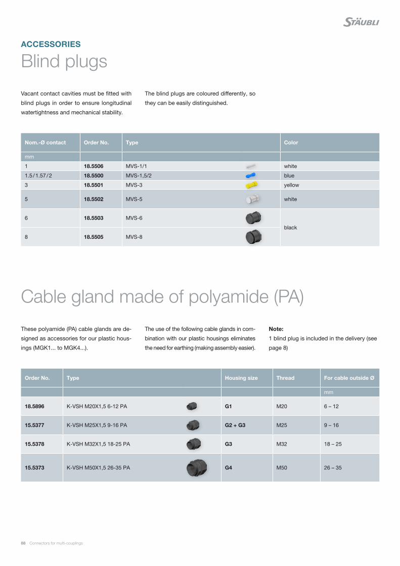
88 Connectors for multi-couplings
ACCESSORIES
Blind plugs
Cable gland made of polyamide (PA)
Vacant contact cavities must be fitted with
blind plugs in order to ensure longitudinal
watertightness and mechanical stability.
These polyamide (PA) cable glands are de-
signed as accessories for our plastic hous-
ings (MGK1... to MGK4...).
The blind plugs are coloured differently, so
they can be easily distinguished.
The use of the following cable glands in com-
bination with our plastic housings eliminates
the need for earthing (making assembly easier).
Nom.-Ø contact Order No. Type Color
mm
1 18.5506 MVS-1/1 white
1.5 / 1.57 / 2 18.5500 MVS-1,5/2 blue
3 18.5501 MVS-3 yellow
5 18.5502 MVS-5 white
6 18.5503 MVS-6
black
8 18.5505 MVS-8
Order No. Type Housing size Thread For cable outside Ø
mm
18.5896 K-VSH M20X1,5 6-12 PA G1 M20 6 – 12
15.5377 K-VSH M25X1,5 9-16 PA G2 + G3 M25 9 – 16
15.5378 K-VSH M32X1,5 18-25 PA G3 M32 18 – 25
15.5373 K-VSH M50X1,5 26-35 PA G4 M50 26 – 35
Note:
1 blind plug is included in the delivery (see
page 8)

Connectors for multi-couplings 89
Spacers
By means of the spacer rings, the housing
can be adapted to different panel thickness-
Carrier size Order No. Type Fits Socket side Pin side
G1 18.5652 DST-RG GR. 1/10MGK1...MGS1...
G2
18.5633 DST-RG GR. 2/12 BU
MGK2...
–
18.5632 DST-RG GR. 2/8 STI –
18.5954 DST-RG GR. 2/10 MGS2...-IS
G3
18.5618 DST-RG GR. 3/14 BU
MGK3...
–
18.5617 DST-RG GR. 3/6 STI –
18.5675 DST-RG-3S/14BU-IS
MGS3...-IS
–
18.5674 DST-RG-3S/6STI-IS –
es and panel spacings in mated condition,
see installation situation on page 90.

90 Connectors for multi-couplings
APPENDIX
Admissible installation situation
Stäubli Dockingline connectors have been
designed for mounting inside a plate. De-
pending on the thickness of the plate (e.g.
14 mm and/or 10 mm) and the distance
between the plates (e.g. 37 mm or 13 mm
in mated condition) spacer rings (see table
Plate spacing 37 mm Plate spacing 13 mm
Housings Plate thicknesses Plate thicknesses
Size Type Socket housing Pin housing Socket housing Pin housing
14 mm 10 mm 14 mm 14 mm
1
MGK1...
no spacing ring 18.5652 18.5652MGS1...-IS
MGS1...-S
2MGK2...
no spacing ring18.5633 18.5632
MGS2...-IS 18.5954 18.5954
3MGK3...
no spacing ring18.5618 18.5617
MGS3...-IS 18.5675 18.5674
4 MGK4... no spacing ring supplied
Size 1 MGK1...
Size 2 MGK2...
Size 3 MGK3...
Size 4 MGK4...
page 89) may be required. This allows
various combinations.
Plate spacing 37 mm (MGK...)
supplied

Connectors for multi-couplings 91
Size 1 MGS1...-IS
Size 2 MGS2...-IS
Size 3 MGS3...-IS
Size 1 MGS1...-S
Plate spacing 37 mm (MGS...-IS)
Plate spacing 37 mm (MGS...)

92 Connectors for multi-couplings
Outer dimensions
MGK1VB10-14+MGK1R-M20
MGK2VB10-14+MGK2R-M25
MGK3VB10-14+MGK3R-M...
MGK1VS10-14+MGK1R-M20
MGK2VS10-14+MGK2R-M25
MGK3VS10-14+MGK3R-M...
MGK4VB10-14+MGK4R-M50 MGK4VS10-14+MGK4R-M50
Plastic housings MGK...

Connectors for multi-couplings 93
MGS1VB-M20-IS... MGS1VS-M20-IS...
MGS2VB-M25-IS... MGS2VS-M25-IS...
MGS3VB-M32-IS... MGS3VS-M32-IS...
MGS1VB-M20 MGS1VS-M20
Plastic housings, shielded, insulated MGS...-IS
Metal housing, shielded MGS...-S

94 Connectors for multi-couplings
Drilling plan
Drilling plan for mounting plates. View from
front of pin housing. Slotted pins are includ-
MGK1... MGS1...-IS MGS1...-S
MGK2... MGS2...-IS
MGK3...
MGK4...
MGS3...-IS
ed in the delivery of the housing (see Instal-
lation situation, page 9).

0,0
2,0
4,0
6,0
8,0
10,0
12,0
14,0
16,0
18,0
20,0
20° 25° 30° 35° 40° 45° 50° 55° 60° 65° 70° 75° 80° 85° 90° 95° 100°0,0
5,0
10,0
15,0
20,0
25,0
30,0
35,0
40,0
20° 25° 30° 35° 40° 45° 50° 55° 60° 65° 70° 75° 80° 85° 90° 95° 100°
0,0
1,0
2,0
3,0
4,0
5,0
6,0
7,0
20° 25° 30° 35° 40° 45° 50° 55° 60° 65° 70° 75° 80° 85° 90° 95° 100°0,0
2,0
4,0
6,0
8,0
10,0
12,0
20° 25° 30° 35° 40° 45° 50° 55° 60° 65° 70° 75° 80° 85° 90° 95° 100°
Connectors for multi-couplings 95
Derating diagrams
The current capacity of a connection is lim-
ited by the thermal capacity of its contact,
connecting and insulating materials. The
derating diagram shows the continous cur-
rent (not intermittent) that flows through all
the contact elements of a connector at one
time, whereby the max. temperature limit is
not exceeded.
Calibration and test method according to
DIN 41640/Part 3.
The derating diagram values are valid for the
connection (see standard EN 60204).
The permissable current load of the cables
can be seen in DIN VDE 0298-4 and DIN EN
60204-1, IEC 60204-1.
NBR/CR: Cable 0.25 mm² & 0.5 mm² NBR/CR: Cable 0.75 mm² & 1 mm²
NBR/CR: Cable 1.5 mm² NBR/CR: Cable 2.5 mm² & 4 mm²
Ope
ratin
g cu
rren
t AO
pera
ting
curr
ent A
Ambient temperature °C
Ambient temperature °C
Ambient temperature °C
Ambient temperature °C
Ope
ratin
g cu
rren
t AO
pera
ting
curr
ent A
6 Strands, 0.25 mm²36 Strands, 0.25 mm²24 Strands, 0.5 mm²
2 Strands, 1.5 mm² 8 Strands, 1.5 mm²28 Strands, 1.5 mm²
15 Strands, 0.25 mm² 6 Strands, 0.5 mm²36 Strands, 0.5 mm²
3 Strands, 1.5 mm²16 Strands, 1.5 mm²36 Strands, 1.5 mm²
24 Strands, 0.25 mm²15 Strands, 0.5 mm²
4 Strands, 1.5 mm²22 Strands, 1.5 mm²
6 Strands, 0.75 mm²36 Strands, 0.75 mm²24 Strands, 1.0 mm²
15 Strands, 0.75 mm² 6 Strands, 1.0 mm²36 Strands,1.0 mm²
3 Strands, 2.5 mm² 2 Strands, 4 mm²12 Strands, 4 mm²
2 Strands, 2.5 mm²12 Strands, 2.5 mm² 6 Strands, 4 mm²
24 Strands, 0.75 mm²15 Strands, 1.0 mm²
6 Strands, 2.5 mm² 3 Strands, 4 mm²

0,0
10,0
20,0
30,0
40,0
50,0
60,0
70,0
20° 25° 30° 35° 40° 45° 50° 55° 60° 65° 70° 75° 80° 85° 90° 95° 100°0
50
100
150
200
250
20° 25° 30° 35° 40° 45° 50° 55° 60° 65° 70° 75° 80° 85° 90° 95° 100°
0
50
100
150
200
250
300
0 10 20 30 40 50 60 70 80 90 100 110 120 130 140 150 160
Ø 3 – 6 mm² Ø 10 – 35 mm² Ø 6 – 10 mm² Ø 3 – 2.5 mm² Ø 1.5 – 1.5 mm²
96 Connectors for multi-couplings
NBR/CR: Cable 6 mm² & 10 mm² NBR/CR: Cable 16 mm², 25 mm², 35 mm² & 50 mm²
PEEK: Cable 1.5 mm² 2.5 mm², 6 mm², 10 mm² & 35 mm²
Ope
ratin
g cu
rren
t A
Ope
ratin
g cu
rren
t A
Ope
ratin
g cu
rren
t A
Ambient temperature °C Ambient temperature °C
Ambient temperature °C
2 Strands, 6 mm²6 Strands, 6 mm²4 Strands, 10 mm²
3 Strands, 6 mm²2 Strands, 10 mm²6 Strands, 10 mm²
4 Strands, 6 mm²3 Strands, 10 mm²
2 Strands, 16 mm²
2 Strands, 25 mm²
3 Strands, 16 mm²
2 Strands, 35 mm²
4 Strands, 16 mm²
2 Strands, 50 mm²

0,0
2,0
4,0
6,0
8,0
10,0
12,0
14,0
16,0
18,0
20,0
0,0
2,0
4,0
6,0
8,0
10,0
12,0
0,0
10,0
20,0
30,0
40,0
50,0
60,0
70,0
0,0
5,0
10,0
15,0
20,0
25,0
30,0
35,0
40,0
Connectors for multi-couplings 97
SIL: Cable 0.25 mm², 0.5 mm² & 0.75 mm² SIL: Cable 1 mm² & 1.5 mm²
SIL: Cable 2.5 mm² & 4 mm² SIL: Cable 6 mm² & 10 mm²
Ope
ratin
g cu
rren
t A
Ope
ratin
g cu
rren
t A
Ope
ratin
g cu
rren
t A
Ope
ratin
g cu
rren
t A
Ambient temperature °C Ambient temperature °C
Ambient temperature °C Ambient temperature °C
2 Strands, 1 mm²10 Strands, 1 mm² 4 Strands, 1.5 mm²16 Strands, 1.5 mm²
4 Strands, 1 mm²16 Strands, 1 mm² 6 Strands, 1.5 mm²
6 Strands, 1 mm² 2 Strands, 1.5 mm²10 Strands, 1.5 mm²
2 Strands, 0.25 mm² 2 Strands, 0.5 mm² 2 Strands, 0.75 mm²
8 Strands, 0.25 mm² 8 Strands, 0.5 mm² 8 Strands, 0.75 mm²
14 Strands, 0.25 mm²14 Strands, 0.5 mm²14 Strands, 0.75 mm²
2 Strands, 6 mm²6 Strands, 6 mm²4 Strands, 10 mm²
3 Strands, 6 mm²2 Strands, 10 mm²6 Strands, 10 mm²
4 Strands, 6 mm²3 Strands, 10 mm²
2 Strands, 2.5 mm²6 Strands, 2.5 mm²4 Strands, 4 mm²
3 Strands, 2.5 mm²2 Strands, 4 mm²6 Strands, 4 mm²
4 Strands, 2.5 mm²3 Strands, 4 mm²

98 Connectors for multi-couplings
Index
Sorted by type
Type Page
BP1/1 28, 36
BP1/1 AU 28, 34, 36
BP1,5/0,5-1,5 28, 34, 36
BP1,5/0,5-1,5 AU 28, 34, 36
BP1,5/0,14-0,5 28, 36
BP1,5/0,14-0,5 AU 28, 34, 36
BP2/0,5-1,5 28, 40
BP2/0,5-1,5 AU 28, 40
BP2/2,5 40
BP2/2,5 AU 40
BP3/2,5-4 40
BP3/2,5-4 AU 40
BP3/2,5-4(K) 36, 40
BP3/2,5-4(K) AU 36, 40
BP5/6 38, 42
BP5/6 AU 38, 42
BP5/10 38, 42
BP5/10 AU 38, 42
BP6/6 42
BP6/6 AU 42
BP6/10 42
BP6/10 AU 42
BP6/16 42
BP6/16 AU 42
BP6/25 42
BP6/25 AU 42
BP8/25 44
BP8/35 44
BP11/25 38, 44
BP11/35-38 38, 44
BP11/50 38, 44
BP-C1,6/0,5-1,5 AU 46
BP-C3/2,5-4 AU 46
BP-C3/4-6 AU 46
BP-C6/10 AU 46
BP-C6/16 AU 46
BP-C6/25 AU 46
BP-R10/35 AU 46
BP-R10/50 AU 46
BP-R10/70 AU 46
CT-NET/B 46
CT-NET/S 46
CZK2-110 87
CZK2-230 87
Type Page
DBP2/0,5-1,5 AU 32
DBP2-AL/0,14-0,5 32
DBP2-CO/0,14-0,5 32
DBP2-CR/0,14-0,5 32
DBP2-CU/0,14-0,5 32
DBP2-FE/0,14-0,5 32
DBP2-NICRSI/0,14-0,5 32
DBP2-NISI/0,14-0,5 32
DSP2/0,5-1,5 AU 32
DSP2-AL/0,14-0,5 32
DSP2-CO/0,14-0,5 32
DSP2-CR/0,14-0,5 32
DSP2-CU/0,14-0,5 32
DSP2-FE/0,14-0,5 32
DSP2-NICRSI/0,14-0,5 32
DSP2-NISI/0,14-0,5 32
DST-RG-3S/6STI-IS 89
DST-RG-3S/14BU-IS 89
DST-RG GR. 1/10 89
DST-RG GR. 2/8 STI 89
DST-RG GR. 2/10 89
DST-RG GR. 2/12 BU 89
DST-RG GR. 3/6 STI 89
DST-RG GR. 3/14 BU 89
E1-2PE+9/B 52, 53
E1-2PE+9/S 52, 53
E1-2PE/B 54
E1-2PE/S 54
E1-6PE/B 51, 52, 54
E1-6PE/S 51, 52, 54
E1-18PE/B 51, 52
E1-18PE/S 51, 52
E2-1-PK/B 59
E2-1-PK/S 59
E2-3PE+4/B 53
E2-3+PE+4/B SIL 57
E2-3PE+4/S 53
E2-3+PE+4/S SIL 57
E2-3PE-PK/B 59
E2-3PE-PK/S 59
E2-6PE/B 54
E2-6PE/B SIL 57
E2-6PE/S 54
E2-6PE/S SIL 57

Connectors for multi-couplings 99
Type Page
E2-15PE/B 51, 52, 54
E2-15PE/B SIL 57
E2-15PE/S 51, 52, 54
E2-15PE/S SIL 57
E2-19PE-PK/B 59
E2-19PE-PK/S 59
E3-2PE/B 54, 55
E3-2PE/B8 54, 55
E3-2PE/S 54, 55
E3-2PE/S8 54, 55
E3-3PE-PK/B 59
E3-3PE-PK/S 59
E3-4NET-PK/B 59
E3-4NET-PK/S 59
E3-4PE/B 54, 55
E3-4PE/S 54, 55
E3-6PE/B 54, 55
E3-6PE/B SIL 57
E3-6PE/S 54, 55
E3-6PE/S SIL 57
E3-9PE-PK/B 59
E3-9PE-PK/S 59
E3-13PE/B 54
E3-13PE-PK/B 59
E3-13PE-PK/S 59
E3-13PE/S 54
E3-24PE/B 51, 52
E3-24PE/S 51, 52
E3-27/B 51, 52
E3-27/S 51, 52
E3-36PE/B 51, 52, 54
E3-36PE/B2,5-CR 56
E3-36PE/B2,5-SIL 57
E3-36PE/S 51, 52, 54
E3-36PE/S2,5-CR 56
E3-36PE/S2,5-SIL 57
E3-47PE-PK/B 59
E3-47PE-PK/S 59
E4-2PE+6/B 53
E4-2PE+6/S 53
E4-2PE/B 55
E4-2PE/S 55
E4-70/2PE/B 51, 52
E4-70/2PE/S 51, 52
Type Page
K-VSH M20X1,5 6-12 PA 88
K-VSH M25X1,5 9-16 PA 88
K-VSH M32X1,5 18-25 PA 88
K-VSH M50X1,5 26-35 PA 88
MA-CWZ1,6 86
MA-CWZ3 86
MA-CWZ6 86
MBA-WZ1/1,2 86
MBA-WZ1,5 86
MBA-WZ1,5/109 86
MBA-WZ2 86
MBA-WZ3 86
MBA-WZ5 86
MBA-WZ6 86
M-CZ 87
ME1-2+PE-BP1,5/0,5-1,5+9BP1/1K 64
ME1-2+PE-BP3/2,5-4(K) 67
ME1-2+PE-BP3/2,5-4(K) AU 67
ME1-2+PE-SP1,5/0,5-1,5+9SP1/1K 64
ME1-2+PE-SP3/2,5-4(K) 67
ME1-2+PE-SP3/2,5-4(K) AU 67
ME1-6+PE-BP1,5/0,5-1,5 63
ME1-6+PE-BP1,5/0,5-1,5 AU 63
ME1-6+PE-BP2/0,5-1,5 63, 67
ME1-6+PE-BP2/0,5-1,5 AU 63, 67
ME1-6+PE-SP1,5/0,5-1,5 63
ME1-6+PE-SP1,5/0,5-1,5 AU 63
ME1-6+PE-SP2/0,5-1,5 63, 67
ME1-6+PE-SP2/0,5-1,5 AU 63, 67
ME1-18+PE-BP1/1 63
ME1-18+PE-BP1/1 AU 63
ME1-18+PE-SP1/1 63
ME1-18+PE-SP1/1 AU 63
ME2-1-BP-R10/35-PK AU 73
ME2-1-BP-R10/50-PK AU 73
ME2-1-BP-R10/70-PK AU 73
ME2-1-SP-R10/35-PK AU 73
ME2-1-SP-R10/50-PK AU 73
ME2-1-SP-R10/70-PK AU 73
ME2-3+PE+4/B SIL 71
ME2-3+PE+4/S SIL 71
ME2-3+PE-BP3/2,5-4(K)+4BP1,5/0,5-1,5 64
ME2-3+PE-BP-C3/2,5-4-PK AU 73
ME2-3+PE-BP-C3/4-6-PK AU 73

100 Connectors for multi-couplings
Type Page
ME2-3+PE-SP3/2,5-4(K)+4SP1,5/0,5-1,5 64
ME2-3+PE-SP-C3/2,5-4-PK AU 73
ME2-3+PE-SP-C3/4-6-PK AU 73
ME2-4+PE-BP3/2,5-4(K) 67
ME2-4+PE-BP3/2,5-4(K) AU 67
ME2-4+PE-SP3/2,5-4(K) 67
ME2-4+PE-SP3/2,5-4(K) AU 67
ME2-6+PE-BP3/2,5-4(K) 67
ME2-6+PE-BP3/2,5-4(K) AU 67
ME2-6PE/B SIL 71
ME2-6+PE-SP3/2,5-4(K) 67
ME2-6+PE-SP3/2,5-4(K) AU 67
ME2-6PE/S SIL 71
ME2-15+PE-BP1,5/0,5-1,5 63
ME2-15+PE-BP1,5/0,5-1,5 AU 63
ME2-15+PE-BP2/0,5-1,5 63, 67
ME2-15+PE-BP2/0,5-1,5 AU 63, 67
ME2-15PE/B SIL 71
ME2-15+PE-SP1,5/0,5-1,5 63
ME2-15+PE-SP1,5/0,5-1,5 AU 63
ME2-15+PE-SP2/0,5-1,5 63, 67
ME2-15+PE-SP2/0,5-1,5 AU 63, 67
ME2-15PE/S SIL 71
ME2-19+PE-BP-C1,6/0,5-1,5-PK AU 73
ME2-19+PE-SP-C1,6/0,5-1,5-PK AU 73
ME3-2+PE-BP6/10 69
ME3-2+PE-BP6/16 69
ME3-2+PE-BP6/25 69
ME3-2+PE-BP8/25 69
ME3-2+PE-BP8/35 69
ME3-2+PE-SP6/10 69
ME3-2+PE-SP6/16 69
ME3-2+PE-SP6/25 69
ME3-2+PE-SP8/25 69
ME3-2+PE-SP8/35 69
ME3-3+PE-BP-C6/10-PK AU 73
ME3-3+PE-BP-C6/16-PK AU 73
ME3-3+PE-BP-C6/25-PK AU 73
ME3-3+PE-SP-C6/10-PK AU 73
ME3-3+PE-SP-C6/16-PK AU 73
ME3-3+PE-SP-C6/25-PK AU 73
ME3-4NET-PK/B 73
ME3-4NET-PK/S 73
ME3-4+PE-BP6/10 69
ME3-4+PE-BP6/16 69
ME3-4+PE-SP6/10 69
Type Page
ME3-4+PE-SP6/16 69
ME3-6+PE-BP5/6 69
ME3-6+PE-BP5/10 69
ME3-6PE/B SIL 71
ME3-6+PE-SP5/6 69
ME3-6+PE-SP5/10 69
ME3-6PE/S SIL 71
ME3-9+PE-BP-C3/2,5-4-PK AU 73
ME3-9+PE-BP-C3/4-6-PK AU 73
ME3-9+PE-SP-C3/2,5-4-PK AU 73
ME3-9+PE-SP-C3/4-6-PK AU 73
ME3-13+PE-BP3/2,5-4 67
ME3-13+PE-BP3/2,5-4 AU 67
ME3-13+PE-BP3/2,5-4-PK AU 73
ME3-13+PE-BP3/4-6-PK AU 73
ME3-13+PE-SP3/2,5-4 67
ME3-13+PE-SP3/2,5-4 AU 67
ME3-13+PE-SP3/2,5-4-PK AU 73
ME3-13+PE-SP3/4-6-PK AU 73
ME3-24+PE-BP1,5/0,5-1,5 63
ME3-24+PE-BP1,5/0,5-1,5 AU 63
ME3-24+PE-SP1,5/0,5-1,5 63
ME3-24+PE-SP1,5/0,5-1,5 AU 63
ME3-27-BP1,5/0,5-1,5 63
ME3-27-BP1,5/0,5-1,5 AU 63
ME3-27-SP1,5/0,5-1,5 63
ME3-27-SP1,5/0,5-1,5 AU 63
ME3-36+PE-BP1,5/0,5-1,5 63
ME3-36+PE-BP1,5/0,5-1,5 AU 63
ME3-36+PE-BP2/2,5-CR 70
ME3-36+PE-BP2/2,5-SIL AU 71
ME3-36+PE-SP1,5/0,5-1,5 63
ME3-36+PE-SP1,5/0,5-1,5 AU 63
ME3-36+PE-SP2/2,5-CR 70
ME3-36+PE-SP2/2,5-SIL AU 71
ME3-47+PE-BP-C1,6/0,5-1,5-PK AU 73
ME3-47+PE-SP-C1,6/0,5-1,5-PK AU 73
ME4-2+PE-BP11/25+50 64, 69
ME4-2+PE-BP11/35-38 64, 69
ME4-2+PE-SP11/25+50 64, 69
ME4-2+PE-SP11/35-38 64, 69
ME4-70+2PE-BP1,5/0,5-1,5 63
ME4-70+2PE-BP1,5/0,5-1,5 AU 63
ME4-70+2PE-SP1,5/0,5-1,5 63
ME4-70+2PE-SP1,5/0,5-1,5 AU 63
ME-CWZ1,6 86

Connectors for multi-couplings 101
Type Page
MES-CZ 87
MES-CZ1,5/2 87
MES-PZ-TB5/6 87
MES-PZ-TB8/10 87
MES-PZ-TB9/16 87
MES-PZ-TB11/25 87
MES-PZ-TB13/35 87
ME-WZ1/1,2 86
ME-WZ1,5/2 86
ME-WZ3 86
ME-WZ5 86
ME-WZ6 86
ME-WZ11/38 86
MGA2B14-M25 84
MGA2B14-NPT3/4 84
MGA2B14-PG21 84
MGA2S10-M25 84
MGA2S10-NPT3/4 84
MGA2S10-PG21 84
MGA2S14-M25 84
MGA2S14-NPT3/4 84
MGA2S14-PG21 84
MGA3B14-2M 85
MGA3B14-2PG 85
MGA3B14-NPT1 85
MGA3S10-2M 85
MGA3S10-2PG 85
MGA3S10-NPT1 85
MGA3S14-2M 85
MGA3S14-2PG 85
MGA3S14-NPT1 85
MGK1VB10-14+MGK1R13 77
MGK1VB10-14+MGK1R-M20 77
MGK1VS10-14+MGK1R13 77
MGK1VS10-14+MGK1R-M20 77
MGK2VB10-14+MGK2R21 77
MGK2VB10-14+MGK2R-M25 77
MGK2VS10-14+MGK2R21 77
MGK2VS10-14+MGK2R-M25 77
MGK3VB10-14+MGK3R21 77
MGK3VB10-14+MGK3R29 77
MGK3VB10-14+MGK3R-M25 77
MGK3VB10-14+MGK3R-M32 77
MGK3VB10-14+MGK3R-WST 79
MGK3VS10-14+MGK3R21 77
MGK3VS10-14+MGK3R29 77
Type Page
MGK3VS10-14+MGK3R-M25 77
MGK3VS10-14+MGK3R-M32 77
MGK3VS10-14+MGK3R-WST 79
MGK4VB10-14+MGK4R-M50 77
MGK4VS10-14+MGK4R-M50 77
MGS1VB-10-14+MGS1R-M20 83
MGS1VB-90-M20-IS 81
MGS1VB-M20-IS 81
MGS1VB-M20-IS/7-10,5 81
MGS1VB-M20-IS/9-13 81
MGS1VB-R13-IS 81
MGS1VB-R13-S 83
MGS1VB-R16-IS 81
MGS1VS-10-14+MGS1R-M20 83
MGS1VS-90-M20-IS 81
MGS1VS-M20-IS 81
MGS1VS-M20-IS/7-10,5 81
MGS1VS-M20-IS/9-13 81
MGS1VS-R13-IS 81
MGS1VS-R13-S 83
MGS1VS-R16-IS 81
MGS2VB-M25-IS 81
MGS2VB-M25-IS/9-13 81
MGS2VB-R21-IS 81
MGS2VS-M25-IS 81
MGS2VS-M25-IS/9-13 81
MGS2VS-R21-IS 81
MGS3BN-M32-IS 82
MGS3BN-M32-IS/14-18 82
MGS3BN-R29-IS 82
MGS3SN-M32-IS 82
MGS3SN-M32-IS/14-18 82
MGS3SN-R29-IS 82
M-PZ13 87
MSA-WZ1/1,2 86
MSA-WZ1,5 86
MSA-WZ1,5/109 86
MSA-WZ2 86
MSA-WZ3 86
MSA-WZ5 86
MSA-WZ6 86
MSA-WZ8 86
MTB9-16-50 87
MTB14,5-50-50 87
MVS-1/1 88
MVS-1,5/2 88

102 Connectors for multi-couplings
Type Page
MVS-3 88
MVS-5 88
MVS-6 88
MVS-8 88
SP1/1 28, 36
SP1/1 AU 28, 34, 36
SP1,5/0,5-1,5 28, 34, 36
SP1,5/0,5-1,5 AU 28, 34, 36
SP1,5/0,14-0,5 28, 36
SP1,5/0,14-0,5 AU 28, 34, 36
SP2/0,5-1,5 28, 40
SP2/0,5-1,5 AU 28, 40
SP2/2,5 40
SP2/2,5 AU 40
SP3/2,5-4 40
SP3/2,5-4 AU 40
SP3/2,5-4(K) 36, 40
SP3/2,5-4(K) AU 36, 40
SP5/6 38, 42
SP5/6 AU 38, 42
SP5/10 38, 42
SP5/10 AU 38, 42
Type Page
SP6/6 42
SP6/6 AU 42
SP6/10 42
SP6/10 AU 42
SP6/16 42
SP6/16 AU 42
SP6/25 42
SP6/25 AU 42
SP8/25 44
SP8/35 44
SP11/25 38, 44
SP11/35-38 38, 44
SP11/50 38, 44
SP-C1,6/0,5-1,5 AU 46
SP-C3/2,5-4 AU 46
SP-C3/4-6 AU 46
SP-C6/10 AU 46
SP-C6/16 AU 46
SP-C6/25 AU 46
SP-R10/35 AU 46
SP-R10/50 AU 46
SP-R10/70 AU 46

Connectors for multi-couplings 103
Sorted by Order No.
Order No. Page
15.5373 88
15.5377 88
15.5378 88
18.0100 77
18.0101 77
18.0106 83
18.0107 83
18.0110 77
18.0111 77
18.0116 83
18.0117 83
18.0120 81
18.0121 81
18.0122 81
18.0123 81
18.0130 81
18.0131 81
18.0132 81
18.0133 81
18.0134 81
18.0135 81
18.0136 81
18.0137 81
18.0200 77
18.0201 77
18.0210 77
18.0211 77
18.0220 81
18.0221 81
18.0229 81
18.0230 81
18.0231 81
18.0232 81
18.0240 84
18.0241 84
18.0242 84
18.0243 84
18.0244 84
18.0245 84
18.0246 84
18.0247 84
18.0248 84
18.0300 77
18.0301 77
Order No. Page
18.0302 77
18.0303 77
18.0304 79
18.0305 79
18.0308 77
18.0309 77
18.0310 77
18.0311 77
18.0350 82
18.0351 82
18.0352 82
18.0353 82
18.0354 82
18.0355 82
18.0360 85
18.0361 85
18.0362 85
18.0363 85
18.0364 85
18.0365 85
18.0366 85
18.0367 85
18.0368 85
18.0414 77
18.0415 77
18.1200 67
18.1201 67
18.1202 63, 67
18.1203 63, 67
18.1204 63
18.1205 63
18.1206 63
18.1207 63
18.1212 64
18.1300 67
18.1301 67
18.1302 63, 67
18.1303 63, 67
18.1304 63
18.1305 63
18.1306 63
18.1307 63
18.1312 64
18.1400 67

104 Connectors for multi-couplings
Order No. Page
18.1401 67
18.1402 67
18.1403 67
18.1404 63, 67
18.1405 63, 67
18.1406 63
18.1407 63
18.1410 64
18.1411 64
18.1500 67
18.1501 67
18.1502 67
18.1503 67
18.1504 63, 67
18.1505 63, 67
18.1506 63
18.1507 63
18.1508 71
18.1509 71
18.1510 71
18.1511 71
18.1512 71
18.1513 71
18.1600 69
18.1601 69
18.1602 69
18.1603 69
18.1604 69
18.1605 69
18.1606 69
18.1607 69
18.1608 69
18.1609 69
18.1610 69
18.1611 69
18.1612 69
18.1613 69
18.1614 67
18.1615 67
18.1616 63
18.1617 63
18.1618 63
18.1619 63
18.1622 63
18.1623 63
18.1624 70
Order No. Page
18.1625 70
18.1700 67
18.1701 67
18.1702 63
18.1703 63
18.1704 63
18.1705 63
18.1706 71
18.1707 71
18.1708 63
18.1709 63
18.1710 71
18.1711 71
18.1750 69
18.1751 69
18.1752 69
18.1753 69
18.1800 63
18.1801 63
18.1812 64, 69
18.1813 64, 69
18.1816 64, 69
18.1817 64, 69
18.1900 63
18.1901 63
18.3000 86
18.3001 86
18.3002 86
18.3003 86
18.3004 86
18.3005 86
18.3008 86
18.3009 86
18.3010 86
18.3011 86
18.3012 86
18.3013 86
18.3014 86
18.3015 86
18.3016 86
18.3017 86
18.3018 86
18.3019 86
18.3020 86
18.3021 86
18.3022 86

Connectors for multi-couplings 105
Order No. Page
18.3025 87
18.3029 87
18.3036 86
18.3037 86
18.3038 86
18.3039 86
18.3111 87
18.3112 87
18.3700 87
18.3701 87
18.3702 87
18.3703 87
18.3704 87
18.3705 87
18.3800 87
18.3801 87
18.3802 87
18.4200 54
18.4201 51, 52, 54
18.4202 51, 52
18.4203 52, 53
18.4300 54
18.4301 51, 52, 54
18.4302 51, 52
18.4303 52, 53
18.4400 54
18.4401 51, 52, 54
18.4403 53
18.4500 54
18.4501 51, 52, 54
18.4503 53
18.4600 54, 55
18.4601 54, 55
18.4602 54, 55
18.4603 54
18.4604 51, 52
18.4605 51, 52
18.4606 51, 52, 54
18.4607 57
18.4608 56
18.4609 57
18.4612 57
18.4613 57
18.4614 57
18.4650 54, 55
18.4700 54, 55
Order No. Page
18.4701 54, 55
18.4702 54, 55
18.4703 54
18.4704 51, 52
18.4705 51, 52
18.4706 51, 52, 54
18.4707 57
18.4708 56
18.4709 57
18.4712 57
18.4713 57
18.4714 57
18.4750 54, 55
18.4800 51, 52
18.4801 53
18.4802 55
18.4900 51, 52
18.4901 53
18.4902 55
18.5500 88
18.5501 88
18.5502 88
18.5503 88
18.5505 88
18.5506 88
18.5617 89
18.5618 89
18.5632 89
18.5633 89
18.5652 89
18.5674 89
18.5675 89
18.5896 88
18.5954 89
18.8002 28, 36
18.8003 28, 34, 36
18.8004 28, 34, 36
18.8005 28, 34, 36
18.8008 28, 40
18.8009 28, 40
18.8010 40
18.8011 40
18.8012 36, 40
18.8013 36, 40
18.8014 40
18.8015 40

106 Connectors for multi-couplings
Order No. Page
18.8016 38, 42
18.8017 38, 42
18.8018 42
18.8019 42
18.8020 42
18.8021 38, 44
18.8024 28, 36
18.8025 28, 34, 36
18.8029 42
18.8030 38, 42
18.8031 38, 42
18.8032 42
18.8033 42
18.8034 42
18.8035 42
18.8050 44
18.8051 44
18.8055 38, 44
18.8056 38, 44
18.8061 32
18.8062 32
18.8063 32
18.9002 28, 36
18.9003 28, 34, 36
18.9004 28, 34, 36
18.9005 28, 34, 36
18.9008 28, 40
18.9009 28, 40
18.9010 40
18.9011 40
18.9012 36, 40
18.9013 36, 40
18.9014 40
18.9015 40
18.9016 38, 42
18.9017 38, 42
18.9018 42
18.9019 42
18.9020 42
18.9021 38, 44
18.9024 28, 36
18.9025 28, 34, 36
18.9029 42
18.9030 38, 42
18.9031 38, 42
18.9032 42
Order No. Page
18.9033 42
18.9034 42
18.9035 42
18.9050 44
18.9051 44
18.9055 38, 44
18.9056 38, 44
18.9061 32
18.9062 32
18.9063 32
19.6626 59
19.6627 59
19.6632 59
19.6633 59
19.6634 59
19.6635 59
19.6636 59
19.6637 59
19.6644 59
19.6645 59
19.6646 59
19.6647 59
19.6648 59
19.6649 59
19.6650 73
19.6651 73
19.6652 73
19.6653 73
19.6654 73
19.6655 73
19.6656 73
19.6657 73
19.6658 73
19.6659 73
19.6660 73
19.6661 73
19.6662 73
19.6663 73
19.6664 73
19.6665 73
19.6666 73
19.6667 73
19.6668 73
19.6669 73
19.6670 73
19.6671 73

Connectors for multi-couplings 107
Order No. Page
19.6672 73
19.6673 73
19.6674 73
19.6675 73
19.6676 73
19.6677 73
19.6717 32
19.6718 32
19.6719 32
19.6720 32
19.6721 32
19.6722 32
19.6723 32
19.6724 32
19.6725 32
19.6726 32
19.6741 46
19.6742 46
19.6743 46
19.6744 46
Order No. Page
19.6745 46
19.6747 46
19.6748 46
19.6749 46
19.6750 46
19.6751 46
19.6752 46
19.6753 46
19.6754 46
19.6755 46
19.6756 46
19.6757 46
19.6758 46
19.6759 46
19.9106 59
19.9107 73
19.9108 46
19.9109 59
19.9110 46
19.9111 73

Global presenceof the Stäubli Group
Stäubli Units Agents
Staubli is a trademark of Stäubli International AG, registered in Switzerland and other countries.We reserve the right to modify product specifi cations without prior notice. © Stäubli [email protected] | Photo credits: Stäubli
www.staubli.com
AT D
L M
ain
Mul
tiCou
plin
gs
1101
4071
-en
C
03.2
018
, Shutterstock.comPrinted in Germany