connector for nx
TRANSCRIPT

Connector for NX Install and Administration Guide
3DEXPERIENCE R2019x

Connector for NX - Install and Administration Guide 2
3DEXPERIENCE Platform is based on the V6 Architecture © 2007-2018 Dassault Systèmes.
The 3DEXPERIENCE Platform for 2019x is protected by certain patents, trademarks, copyrights, and other restricted rights, the full list of which is available at the 3DS support site: http://help.3ds.com/.
Certain portions of the 3DEXPERIENCE Platform R2019x contain elements subject to copyright owned by third party, the full list of which is also available at the 3DS support site mentioned above.
You will require an account with support in order to view this page. From the support page, select your desired product version and language to launch the appropriate help. Select Legal Notices from left frame. This displays the full list of patents, trademarks and copyrights for this product.
Any copyrights not listed belong to their respective copyrights owners.
Prepared by International TechneGroup Inc.
Connector for NX - Install and Administration Guide 3
Table of Contents
Overview ........................................................................................................................................... 6
Prerequisites ..................................................................................................................................... 7
Server-side prerequisites ............................................................................................................... 7
Client-side prerequisites ................................................................................................................ 7
Platforms ................................................................................................................................ 7
NX .......................................................................................................................................... 7
IEFClient ............................................................................................................................... 7
Installation of 3DEXPERIENCE Connector for NX Server Schema ......................................... 8
The ‘NX User’ Role........................................................................................................................ 10
Connector for NX License ............................................................................................................. 10
Creating Collaborative Space and assigning user ...................................................................... 10
3DEXPERIENCE Connector for NX License Key Generation ................................................ 12
Overview ......................................................................................................................................... 13
Installation of NX License Key generator ................................................................................... 13
Install directory contents............................................................................................................... 20
3DEXPERIENCE Connector for NX Client ............................................................................... 21
Overview ......................................................................................................................................... 22
Installation of Connector for NX Client ...................................................................................... 22
Connector for NX – Administration and Configuration ............................................................ 31
Overview ......................................................................................................................................... 32
The Global Configuration Object ................................................................................................ 32
Establish Attribute Mappings ...................................................................................................... 43
Derived Output Support ............................................................................................................... 43
Connector for NX - Install and Administration Guide 4
CGR Derived Output for Downstream Applications ................................................................. 45
Adding a New Derived Output ..................................................................................................... 46
Transfer material property to ENOVIA ..................................................................................... 48
Type Change Mappings ................................................................................................................ 51
CAD Classification Schema objects ............................................................................................. 52
3DEXPERIENCE Connector for NX UserExits ......................................................................... 54
Overview ......................................................................................................................................... 55
Compiling & Linking User Exits .................................................................................................. 56
User Exit Functions ....................................................................................................................... 57
UE_ConnectPost .......................................................................................................................... 57
UE_CheckinDialogPre ................................................................................................................ 57
UE_CheckinStart ......................................................................................................................... 58
UE_CheckinStartAll..................................................................................................................... 58
UE_CheckinPartPre .................................................................................................................... 58
UE_CheckinPartPost ................................................................................................................... 58
UE_OpenPartPre......................................................................................................................... 58
UE_OpenPartPost ....................................................................................................................... 58
UE_CheckoutPartPre .................................................................................................................. 58
UE_CheckoutPartPost ................................................................................................................. 59
UE_ModifyLockPartPre .............................................................................................................. 59
UE_ModifyLockPartPost ............................................................................................................. 59
UE_UpdateAttributesInCADPre ................................................................................................. 59
UE_UpdateAttributesInCADPost ................................................................................................ 59
External Functions ......................................................................................................................... 60
MatrixCommand .......................................................................................................................... 60
debugPrint ................................................................................................................................... 60
Appendix: Signing the Integration DLL ...................................................................................... 61
Appendix: Schema Diagrams ....................................................................................................... 62
Support ........................................................................................................................................... 64
Connector for NX - Install and Administration Guide 5
Connector for NX - Install and Administration Guide 6
Overview
3DEXPERIENCE - MCAD integrations based on X-CAD Design management offer a flexible and powerful way to manage and control information between 3DEXPERIENCE COLLABORATION PLATFORM and various CAD systems. They allow companies to establish a real-time seamless link across Engineering and Design organizations. The resulting up-to-date information drives product delivery for faster time-to-market. This Installation and Administration Manual provides an overview of the installation and administration tasks that must be performed for the 3DEXPERIENCE NX integration that works with the IEFClient and the X-CAD Design applications. This manual is the starting point for the ITI - developed NX integration. An 3DEXPERIENCE NX integration installation and configuration is performed in four sequential steps. This document is broken into four main sections, one for each step:
Install the Server-side Schema elements required for NX integration. The installer name is: ConnectorforNXServer-V6R2019x.AllOS.tar.gz
Install the NX License Key Generator to generate the license key required for installing the Connector for NX client The installer name is: ConnectorforNXLicenseKeyGenerator-V6R2019x.AllWindows.zip
Install the Connector for NX Client. The installer name is: ConnectorforNXClient-V6R2019x.Windows64.zip
3DEXPERIENCE NX Integration Administration and Configuration This section provides information about the Administration and Configuration of the Server-side schema and User Exits functionality.
Connector for NX - Install and Administration Guide 7
Prerequisites
Server-side prerequisites
3DEXPERIENCE Server Setup
X-CAD Design Management 3DEXPERIENCE R2019x GA
Server-Side Integration Schema Installation (GA)
Configuration of users with required roles and licenses – Requires licenses and roles
Configuration of required attributes and types
Licenses required for performing integration activities: DEN - Connector for NX CDR - Component Designer CSV - Industry Innovation IFW - IFWE Compass
Client-side prerequisites
Platforms Connector for NX is supported on the following platforms. Windows 7 Professional and Enterprise 64 Bit Windows 10 Professional and Enterprise 64 Bit
NX
Following are the NX versions supported. NX 11.0 or later maintenance builds (64 Bit) NX 12.0 or later maintenance builds (64 Bit)
IEFClient The Connector for NX client requires the 3DEXPERIENCE Integration Exchange Framework Client (IEF) - 3DEXPERIENCE R2019x installed on the client machine. IEFClient has additional requirements such as JRE version. Please refer to X-CAD Design documentation for details.
Note: Requires “NX Open Toolkit” (c_p_p_author) license for install and runtime

Connector for NX - Install and Administration Guide 8
Installation of 3DEXPERIENCE Connector for NX Server Schema Schema Installation
The installer of Connector for NX Server, ConnectorforNXServer-V6R2019x.AllOS.tar.gz installs
the Schema elements required for the NX Connector to be functional.
Extract the contents of the tar file, ConnectorforNXServer-V6R2019x.AllOS.tar.gz on the 3DEXPERIENCE server machine. A tcl script must be run from the mql command prompt to install schema for Connector for NX. This script, UGIntegInstallSchemaMain.tcl, creates/updates default schema and a mapping object consistent with this default schema.
The default schema consists of a set of pre-defined attributes, types, relationships, and policies the integration can use “as-is”. The script UGIntegInstallSchemaMain.tcl creates the default schema and mapping object.
Run UGIntegInstallSchemaMain.tcl with the following steps:
Launch mql command prompt from the 3DSpace server folder location cd <Contents of Schema > [change directory to the main tcl] mql [start mql from server ( ..\server\bin\winb_64\code\bin) folder] set context user creator vault ‘eService Production’ [ set context before install ] run UGIntegInstallSchemaMain.tcl [run the tcl script]
The log file, InstallUGSchemaV6R2019x.log, contains errors and warnings during the schema install. After proving out the integration against the default schema, modifications can be made so it better meets individual business practices and processes and fits into an overall schema.
Connector for NX - Install and Administration Guide 9
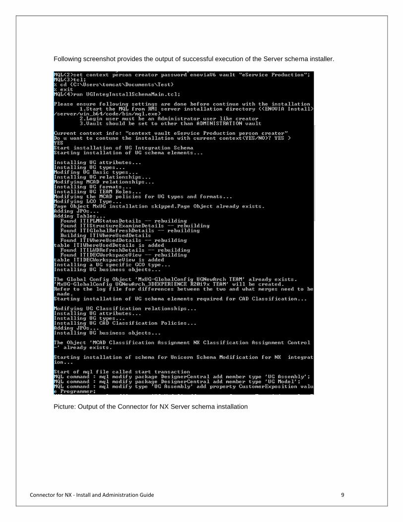
Following screenshot provides the output of successful execution of the Server schema installer.
Picture: Output of the Connector for NX Server schema installation

Connector for NX - Install and Administration Guide 10
The ‘NX User’ Role X-CAD Design creates a new role called ‘NX User’. All users who run this Connector for NX must have the role of ‘NX User’ added to their assignments. The administrator must add this role to every user of the Connector for NX otherwise the user will not be able to use the Connector for NX. Users must be assigned to use the Connector for NX. The administrator, who must have the role of ‘Integration Administrator’, must assign users to the Connector for NX. Please refer to the X-CAD Design
User Guide section for more information.
Connector for NX License
Connector for NX uses Connector for NX license. All users who run Connector for NX must have Connector for NX license. The administrator must assign this license to every user of the Connector for NX; otherwise, the user will not be able to use the Connector for NX. Please refer to the X-CAD Design User Guide for more information.
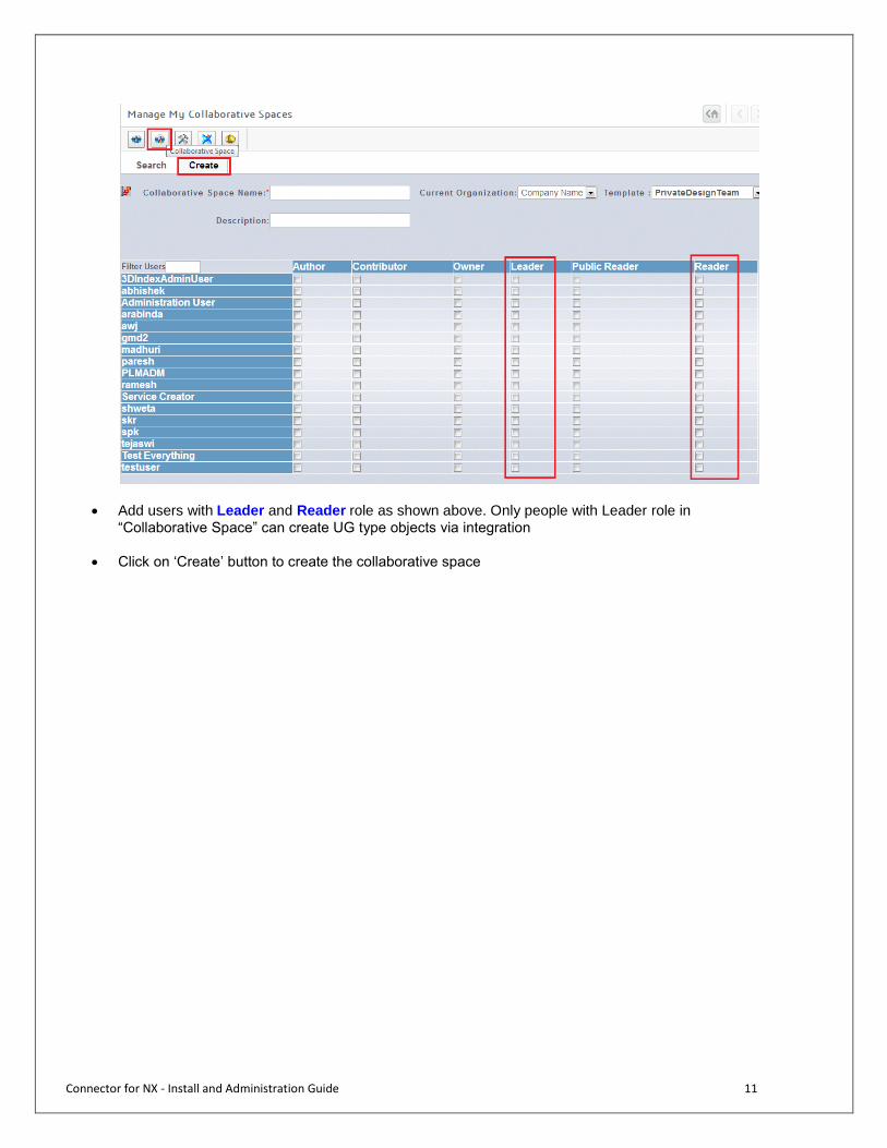
Creating Collaborative Space and assigning user Admin must do following additional steps at server end to make integration work. Step 1: Assign license to PLMADM Login MQL as creator and then execute following statements. modify product CSV add person "PLMADM"; modify product CDR add person "PLMADM"; modify product DEN add person "PLMADM"; modify product IFW add person "PLMADM"; Step 2: Create Collaborative space and assign users with Leader and Reader role
Go to the web browser and login enovia as PLMADM
From the ‘Experience Configuration’ section, select “Manage P&O and Content”
Click on the second icon (As highlighted below) and then create a collaborate space.
Connector for NX - Install and Administration Guide 11
Add users with Leader and Reader role as shown above. Only people with Leader role in
“Collaborative Space” can create UG type objects via integration
Click on ‘Create’ button to create the collaborative space
Connector for NX - Install and Administration Guide 12
3DEXPERIENCE Connector for NX License Key Generation

Connector for NX - Install and Administration Guide 13
Overview The installer ‘ConnectorforNXLicenseKeyGenerator-V6R2019x.AllWindows.zip’ is used for generating the License Key which is required during the install process of the Connector for NX client. For generating the license key for Connector for NX, the machine on which the installation is performed should have access to the NX License Server containing c_p_p_author license. The administrator needs to perform the following install steps to generate the License Key.
Installation of NX License Key generator
Extract installer from ConnectorforNXLicenseKeyGenerator-V6R2019x.AllWindows.zip and run the license key installer on the windows OS machine.
The installer will start a shell and display the 3DEXPERIENCE splash screen.
Connector for NX - Install and Administration Guide 14
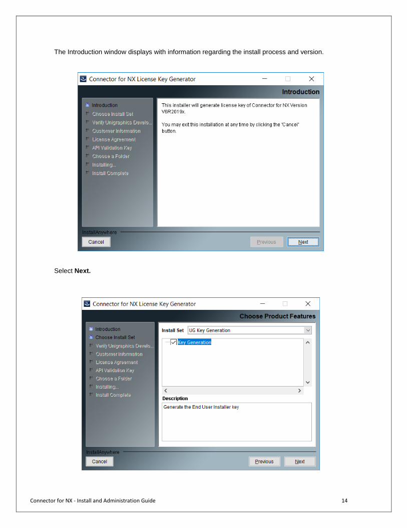
The Introduction window displays with information regarding the install process and version.
Select Next.
Connector for NX - Install and Administration Guide 15
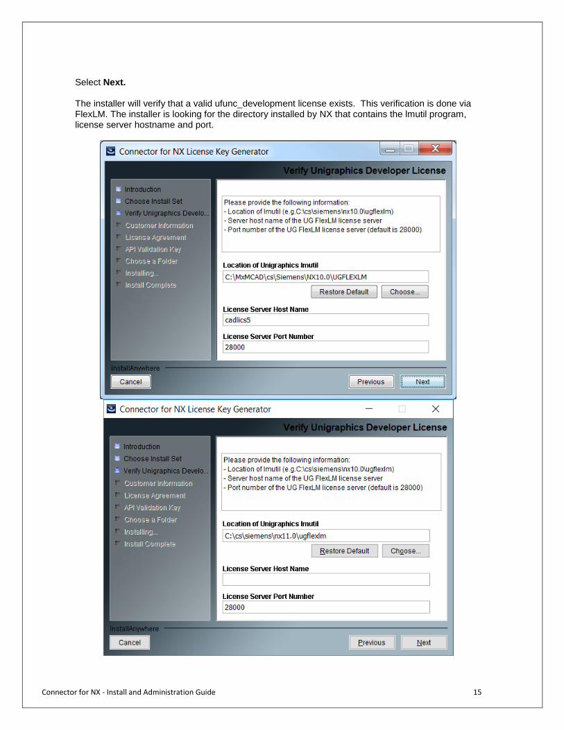
Select Next. The installer will verify that a valid ufunc_development license exists. This verification is done via FlexLM. The installer is looking for the directory installed by NX that contains the lmutil program, license server hostname and port.

Connector for NX - Install and Administration Guide 16
Enter the NX lmutil directory, license server hostname and port and select Next. The installer will verify the licenses.
If no ufunc_development license is available, the following panel is displayed:
Once OK is selected, the installer returns to Verify Unigraphics Developer License screen. The installer cannot find the ufunc_development license. Please verify that it is available and can be accessed by the computer the Connector for NX is being installed on. If problems persist, contact the NX administrator. Your company must have a valid ufunc_development license to install the Connector for NX.
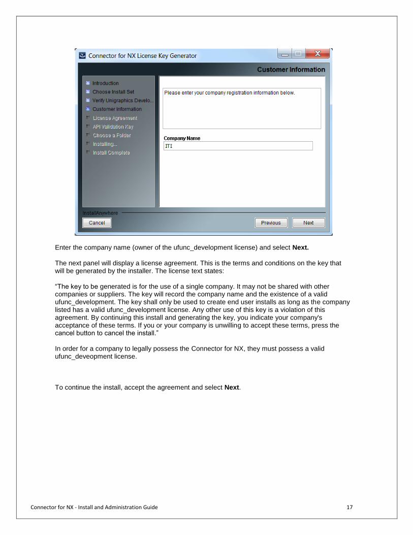
Once the license validity is checked, the installer will prompt for the company name:
Connector for NX - Install and Administration Guide 17
Enter the company name (owner of the ufunc_development license) and select Next. The next panel will display a license agreement. This is the terms and conditions on the key that will be generated by the installer. The license text states: “The key to be generated is for the use of a single company. It may not be shared with other companies or suppliers. The key will record the company name and the existence of a valid ufunc_development. The key shall only be used to create end user installs as long as the company listed has a valid ufunc_development license. Any other use of this key is a violation of this agreement. By continuing this install and generating the key, you indicate your company's acceptance of these terms. If you or your company is unwilling to accept these terms, press the cancel button to cancel the install.” In order for a company to legally possess the Connector for NX, they must possess a valid ufunc_deveopment license.
To continue the install, accept the agreement and select Next.

Connector for NX - Install and Administration Guide 18
The installer will generate a key needed for all end user installs. The key can be copied from this window and emailed to end users. It will also be saved in a file in the validation directory. If at any time there is a question about license validity or the key gets lost, the admin installer can be run to this point to check and generate a new key. Canceling at this point will NOT produce the text file. The install must complete for the text file to be created.

Connector for NX - Install and Administration Guide 19
Select Next to proceed to identify the install folder. On the following panel, choose a folder for the installer output.
If only NX Key Generation was selected as the installer mode, select Install to complete the install process. The installation of the files will commence and on successful completion, the following panel will be displayed:
Select Done to complete the install.
Connector for NX - Install and Administration Guide 20
Install directory contents
The install directory will contain a subset of the following files/directories:
Installer.properties - a starting point file for generating input for a SILENT installer.
installerinput.log- a log of user inputs and messages from the install process.
MXUG_LICENSE.txt- The license key.
Connector for NX - Install and Administration Guide 21
3DEXPERIENCE Connector for NX Client
Connector for NX - Install and Administration Guide 22
Overview
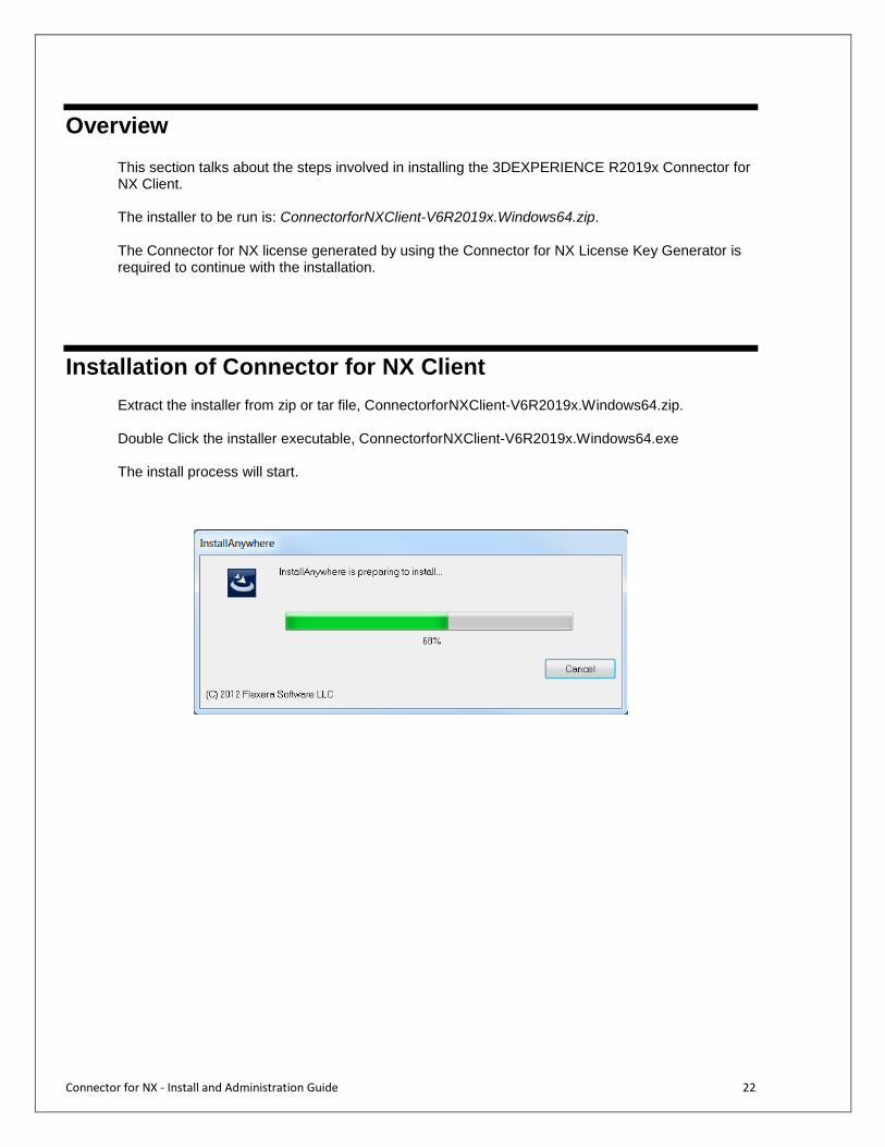
This section talks about the steps involved in installing the 3DEXPERIENCE R2019x Connector for NX Client. The installer to be run is: ConnectorforNXClient-V6R2019x.Windows64.zip.
The Connector for NX license generated by using the Connector for NX License Key Generator is required to continue with the installation.
Installation of Connector for NX Client Extract the installer from zip or tar file, ConnectorforNXClient-V6R2019x.Windows64.zip. Double Click the installer executable, ConnectorforNXClient-V6R2019x.Windows64.exe The install process will start.
Connector for NX - Install and Administration Guide 23
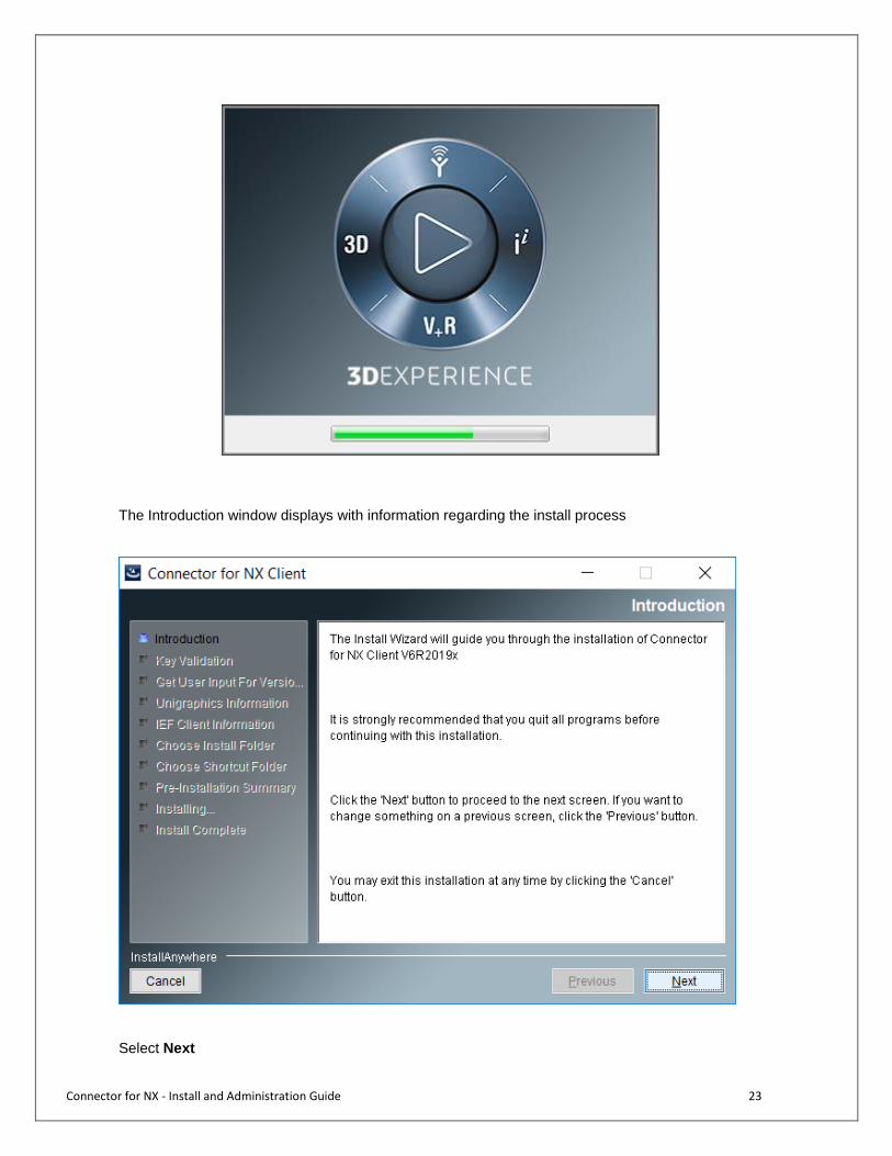
The Introduction window displays with information regarding the install process
Select Next
Connector for NX - Install and Administration Guide 24
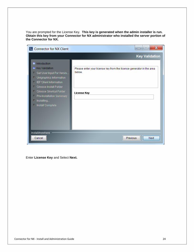
You are prompted for the License Key. This key is generated when the admin installer is run. Obtain this key from your Connector for NX administrator who installed the server portion of the Connector for NX.
Enter License Key and Select Next.

Connector for NX - Install and Administration Guide 25
Select Next. If the key is not valid, an error message is displayed (as shown here). When this occurs, select OK, re-verify and reenter the key. If the error persists, contact the administrator. The end user code cannot be installed without a valid license key.

Connector for NX - Install and Administration Guide 26
Once through the key validation, the installer prompts for the Get User Input for Version of NX. Choose which NX version to be installed.
Select Next. Once through the selection of NX version, the installer prompts for the location of Unigraphics. This is the directory that contains the UGII directory.
Enter the location of NX Select Next.
Connector for NX - Install and Administration Guide 27
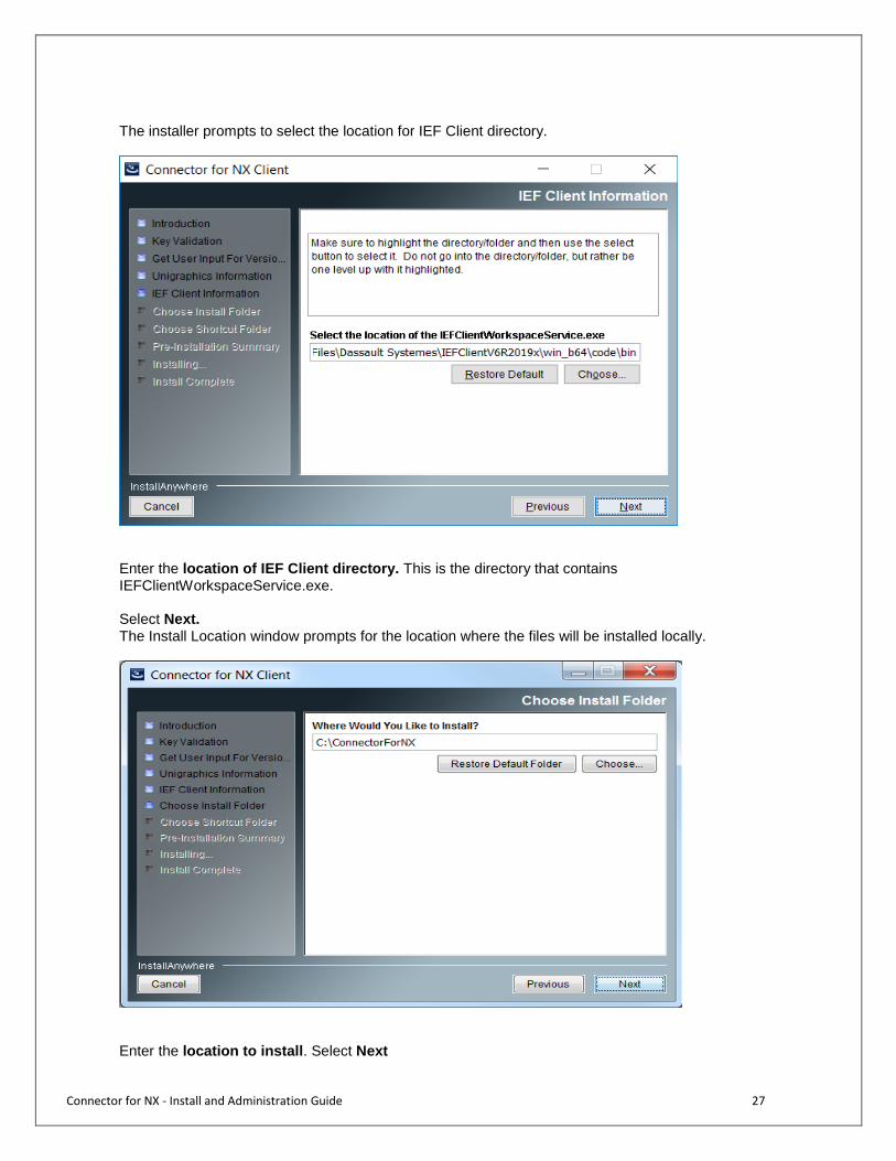
The installer prompts to select the location for IEF Client directory.
Enter the location of IEF Client directory. This is the directory that contains IEFClientWorkspaceService.exe. Select Next. The Install Location window prompts for the location where the files will be installed locally.
Enter the location to install. Select Next
Connector for NX - Install and Administration Guide 28
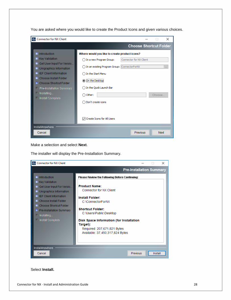
You are asked where you would like to create the Product Icons and given various choices.
Make a selection and select Next. The installer will display the Pre-Installation Summary.
Select Install.
Connector for NX - Install and Administration Guide 29
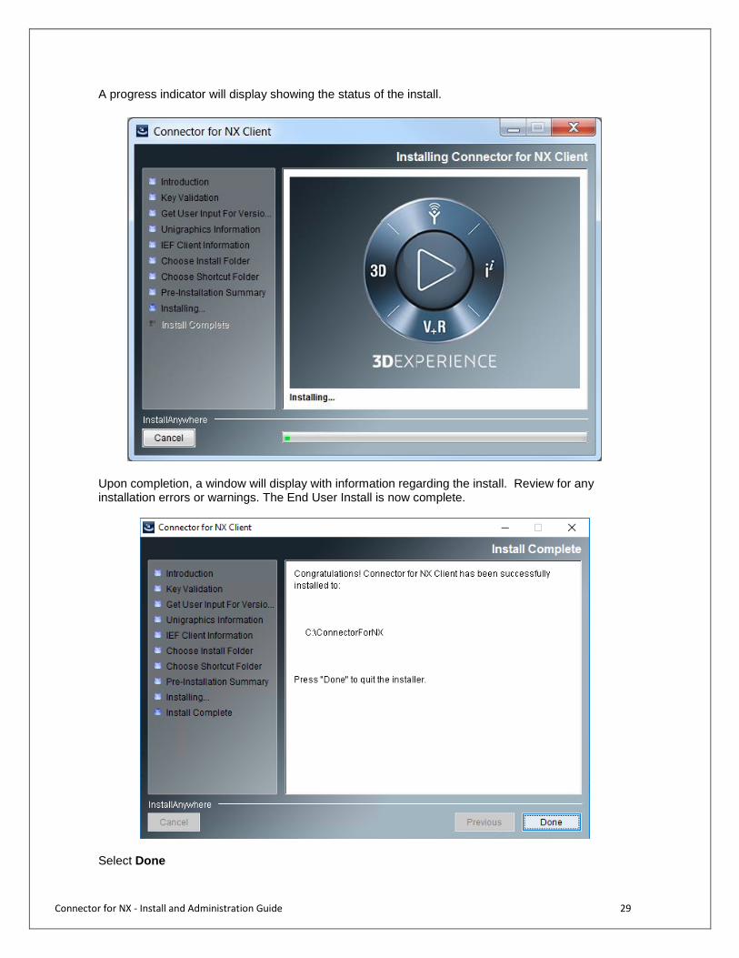
A progress indicator will display showing the status of the install.
Upon completion, a window will display with information regarding the install. Review for any installation errors or warnings. The End User Install is now complete.
Select Done

Connector for NX - Install and Administration Guide 30
Review for any installation errors or warnings. The Connector for NX Client Install is now complete. Upon successful installation of the Connector for NX, a Desktop Shortcut ‘Start MxUG’ is created on the Desktop.
The use the NX integration to be functional, it requires one of the following prerequisites be implemented: Option 1: Point NX application to the license server which has CPP Author license available Option 2: Deploy a signed NX integration DLL file and point to a NX license server with no CPP Author license. (Refer Appendix “Signing the Integration DLL” for more information about how to sign the integration DLL) Launch the Connector for NX client and it will open up NX application by adding the ribbon “3DEXPERIENCE” to the NX menu tabs.

Connector for NX - Install and Administration Guide 31
Connector for NX – Administration and Configuration
Connector for NX - Install and Administration Guide 32
Overview
This section provides information about the administration and configuration of the Connector for NX. It provides detailed information on how to configure various Global Configuration object attribute definitions and respective options to achieve desired behavior of the integration in the context of NX.
The Global Configuration Object
This Connector for NX is one of the suites of X-CAD Design-based integrations designed for use with 3DEXPERIENCE Centrals applications such as Engineering BOM. All X-CAD Design-based integrations are configurable through an object called the global configuration object. The base type is MCADInteg-GlobalConfig. Because the Connector for NX adds attributes specific to the Connector for NX, a subtype, MxUG-GlobalCofig, of the global configuration object type is created. It typically has a name of UGNewArch and with revision of 1. The global configuration object has the following attributes. MCADInteg-EnableHashcodeComputation: (Boolean, Default Value: TRUE)
This flag controls whether or not X-CAD Design will perform hash code computation comparisons on files during checkin and checkout. If this flag is set to true, X-CAD Design will create a hash code computation for the files getting checked in and store this in an attribute with the business object. This is used to determine if the file getting checked in differs from that already in 3DEXPERIENCE. X-CAD Design also uses this hash code on checkout to increase performance by not checking out a file if a file with an identical name and hash code already exists in the checkout directory.
MCADInteg-MxToCADAttribMapping: (Multiline String)
This is the 3DEXPERIENCE to Unigraphics attribute mapping. This is used for synchronizing attributes from 3DEXPERIENCE to Unigraphics as well as the attribute synchronization operation during checkout. The syntax for each attribute mapping from 3DEXPERIENCE to Unigraphics is: Matrix type,Matrix attribute|UG type,UG attribute All user-defined UG attributes are accessible to the Connector for NX. In addition, the Connector for NX can also access 3DEXPERIENCE system attributes (such as description) and user-defined attributes. 3DEXPERIENCE system attributes are denoted with a $$ prefix and postfix. The 3DEXPERIENCE description ($$description$$), owner ($$owner$$), type ($$type$$), name ($$name$$), and revision ($$revision$$) are supported in this mapping.
The names of the valid Unigraphics and 3DEXPERIENCE types are the same as used in the MCADInteg-BusTypeMapping section. Valid names for the supported Unigraphics types are: component, assembly, and drawing. The 3DEXPERIENCE types and attributes specified in the mapping must exist in 3DEXPERIENCE and the attributes must be associated to the 3DEXPERIENCE types. An example mapping from 3DEXPERIENCE to Unigraphics is shown below. This example maps 3DEXPERIENCE attributes to Unigraphics attributes (UG_DESCRIPTION and UG_STRING) for parts, assemblies, and drawings.
Connector for NX - Install and Administration Guide 33
Example: UG Model,UG String|component,UG_STRING UG Model,$$description$$|component,DESCRIPTION UG Assembly,UG String|assembly,UG_STRING UG Assembly,$$description$$|assembly,DESCRIPTION UG Drawing,UG String|drawing,UG_STRING UG Drawing,$$description$$|drawing,DESCRIPTION
MCADInteg-CADToMxAttribMapping: (Multiline String)
This is the Unigraphics to 3DEXPERIENCE attribute mapping. This is used for synchronizing attributes from Unigraphics to 3DEXPERIENCE as well as the attribute synchronization operation during checkin. The syntax for each attribute mapping from Unigraphics to 3DEXPERIENCE is: UG type,UG attribute|Matrix type,Matrix attribute All user-defined NX attributes are accessible to the Connector for NX. In addition, the Connector for NX can also access 3DEXPERIENCE system attributes (such as description) and user-defined attributes. 3DEXPERIENCE system attributes are denoted with a $$ prefix and postfix. Only the 3DEXPERIENCE description ($$description$$) and owner ($$owner$$) are supported in this mapping.
The names of the valid Unigraphics and 3DEXPERIENCE types are the same as used in the MCADInteg-BusTypeMapping section. Valid names for the supported Unigraphics types are: component, assembly, and drawing. The 3DEXPERIENCE types and attributes specified in the mapping must exist in 3DEXPERIENCE and the attributes must be associated to the 3DEXPERIENCE types. An example mapping from Unigraphics to 3DEXPERIENCE is shown below. This example maps Unigraphics attributes (UG_DESCRIPTION and UG_STRING) to 3DEXPERIENCE attributes for parts, assemblies, and drawings. Example: component,UG_STRING|UG Model,UG String component,DESCRIPTION|UG Model,$$description$$ assembly,UG_STRING|UG Assembly,UG String assembly,UG_DESCRIPTION|UG Assembly,$$description$$ drawing,UG_STRING|UG Drawing,UG String drawing,UG_DESCRIPTION|UG Drawing,$$description$$ There are special mappings for the UG part description and UG version. To map the UG part description to an 3DEXPERIENCE attribute use sys:description for the name. To map the UG version to an 3DEXPERIENCE attribute, use ugVersion for the name. Examples: component,sys:description|UG Model,$$description$$ component,ugVersion|UG Model,CADVersion

Connector for NX - Install and Administration Guide 34
MCADInteg-RelationShipClassMapping: (Multiline String) This attribute classifies the relationships. This attribute is generally not altered. This is a system level attribute that tells X-CAD Design how it should treat each relationship. The left side of each entry denotes the Connector for NX-defined relationship and the right side denotes the class of the relationship. The default value for the relationship classes are as follows Default Value: assemblyComponent|AssemblyLike,CADSubComponentLike drawing|AssemblyLike memberOf|AssemblyLike makeFrom|AssemblyLike,ExternalRefereneLike,CircularExternalReferenceLike DerivedOutputOf|DerivedOutputLike ViewableOf|DerivedOutputLike
MCADInteg-TypePolicyMapping: (Multiline String) This attribute defines the policies to use for each type. Each entry is a map of two strings separated by a separator “|”. The left side of the “|” is the type and the right side is the policy that controls it. Note that the types and policies must exist in 3DEXPERIENCE. Default Value:
UG Model|Design TEAM Definition
UG Assembly|Design TEAM Definition
UG Drawing|Design TEAM Definition
UG Model TEAM Template|Design TEAM Resource
UG Assembly TEAM Template|Design TEAM Resource
UG Drawing TEAM Template,drw
Derived Output|Derived Output TEAM Policy
Viewable|Viewable TEAM Policy
CgrViewable|Viewable TEAM Policy
ThumbnailViewable|Viewable TEAM Policy
MCADInteg-RelMapping: (Multiline String) This attribute maps Connector for NX-defined relationships to 3DEXPERIENCE relationships. Each entry is a map of two strings separated by a separator “|”. The string on the left is the Connector for NX-defined relationship. The string on the right is the 3DEXPERIENCE relationship; a comma separated list of two entries. The second entry (e.g. CAD SubComponent) is the name of corresponding relationship in 3DEXPERIENCE. The first entry indicates the direction of arrowhead for the relationship, either to or from. Default Value: assemblyComponent|to, CAD SubComponent drawing|from, Associated Drawing memberOf|to, UGMemberOf makeFrom|to, UGMakeFrom DerivedOutputOf|to, Derived Output ViewableOf|to, Viewable

Connector for NX - Install and Administration Guide 35
MCADInteg-BusTypeMapping: (Multiline String) This maps the business types from Unigraphics to 3DEXPERIENCE. The types on the left side of the separator can’t change but the 3DEXPERIENCE types they are mapped to can be modified.
Default Value: assembly|UG Assembly component|UG Model drawing|UG Drawing image_jpg|Viewable tif|Derived Output gif|Derived Output cgm|Derived Output step203|Derived Output iges|Derived Output pdf|Derived Output xml|Derived Output plt|Derived Output cgr|CgrViewable png|ThumbnailViewable
MCADInteg-EnableMajorRevCreation: (Boolean, Default Value: TRUE) This attribute decides whether or not the Connector for NX should create a major revision during first checkin. If true, the Connector for NX creates a major revision during the first checkin. If false, the Connector for NX does not create major revision during the first checkin. It assumes that the major revision object has already been created and connects the newly created minor version object to it.
MCADInteg-TypeFormatMapping: (Multiline String)
This attribute maps the Connector for NX type to the 3DEXPERIENCE type and format. Each entry is a map of two strings separated by a separator “|”. The string on the left is the Connector for NX. The string on the right is the 3DEXPERIENCE type and its format. For example, if the entry is component|UG Model,prt, then components are checked into the prt format. Default Value: component|UG Model,prt assembly|UG Assembly,asm drawing|UG Drawing,drw component|UG Model Template,prt assembly|UG Assembly Template,asm drawing|UG Drawing Template,drw image_jpg|UG Model,Image image_jpg|UG Assembly,Image image_jpg|Viewable,Image image_jpg|Viewable,THUMBNAIL image_jpg|ThumbnailViewable,THUMBNAIL tif|UG Model,TIF tif|UG Assembly,TIF tif|Derived Output,TIF gif|UG Model,GIF gif|UG Assembly,GIF gif|Derived Output,GIF cgm|UG Drawing,CGMstep203|UG Model,STEP203 step203|UG Assembly,STEP203 iges|UG Model,IGES
Connector for NX - Install and Administration Guide 36
iges|UG Assembly,IGES iges|UG Drawing,IGES pdf|UG Drawing,PDF cgm| Derived Output,CGM step203|Derived Output,STEP203 iges|Derived Output,IGES pdf|Derived Output,PDF xml|Derived Output,xml plt|UG Drawing,PLT plt|Derived Output,PLT cgr|UG Model,CGR cgr|UG Assembly,CGRcgr|CgrViewable,CGR png|UG Model,PNG png|UG Assembly,PNG png|ThumbnailViewable,THUMBNAIL
MCADInteg-CADToMxRelAttribMapping: (Multiline String) This is the Unigraphics to 3DEXPERIENCE attribute mappings for relationships. This is also used for the attribute synchronization operation during checkin but only if the users’ local preference is set up to copy relationships attributes on checkin. Default Value: assemblyComponent,relativeXform|CAD SubComponent,Spatial Location assemblyComponent,componentID|CAD SubComponent,Reference Designator In order for the mappings in this attribute to take effect, the users’ local preference must be set to copy relationship attributes on checkin.
The UG wave link type on a makeFrom relationship can be identified by adding the following line to the MCADInteg-CADToMxRelAttributeMapping attribute: makeFrom,waveLinkType|UGMakeFrom,UGWaveLinkType Setting the attribute for waveLinkType will enable an EBOM sync operation to determine if children related through wave link relationships are relevant to the EBOM structure. The wave link attribute is defined as a range of values LINKED_BODY, MIRROR_BODY, PROMOTED_BODY, and OTHER
MCADInteg-MxToCADRelAttribMapping: (Multiline String)
This is the 3DEXPERIENCE to Pro/ Unigraphics attribute mappings for relationships. This is also used for the attribute synchronization operation during checkout but only if the user’s local preference is set up to copy relationships attributes on checkout. Default Value: CAD SubComponent,Spatial Location|assemblyComponent,relativeXform CAD SubComponent,Reference Designator|assemblyComponent,componentID
MCADInteg-ExpandedSubComponent: (Boolean, Default Value: TRUE)
This flag controls the rolling up behavior for “CAD SubComponent” relationship. If there are shared components in an assembly and if this flag is set to TRUE multiple “CAD SubComponent” relationships are created between the shared component and the assembly. If this attribute is set to FALSE only one “CAD SubComponent” relationship is created between the shared component and the assembly and the “Quantity” attribute on “CAD SubComponent” relationship is set to the number of occurrences of the shared component.

Connector for NX - Install and Administration Guide 37
MCADInteg-NonSupportedCharacters: (Multiline String) This attribute holds the characters that are not supported in file names. If any Unigraphics file getting checked in has any of the characters listed in this attribute a message is shown to the user and checkin is not allowed.
MCADInteg-CreateDerivedOutputObj: (Boolean, Deprecated)
This flag is deprecated by xCAD Design. Now the behavior is to always create separate derived output objects and it cannot be turned off.
MCADInteg-TypeDerivedOutputMapping: (Multiline String)
This attribute contains the mapping between business types and Derived Output types. This mapping determines the type of the Derived Output object that is to be created (if MCADInteg-CreateDerivedOutputObj is true) for mapped business types. Each mapping contains two entries separated by a "|". The entry on the left is a business type in the Connector for NX context and the entry on the right contains Derived Output type(s). If there are multiple Derived Output typestypes, they must be separated by commas.
MCADInteg-FeatureJPOMapping: (Multiline String) This attribute contains the mapping of the feature and the name of the JPO that is to be invoked for that feature. Default Value: EBOMSynchronize|MCAD-EBOMSynchronize Finalize|MCAD-Finalize UndoFinalize|MCAD-UndoFinalize Purge|MCAD-Purge Rename|MCAD-Rename SaveAs|MCAD-SaveAs The string on the left represents the operation, like finalize, EBOM synchronize etc. The value on the right is the name of program, a JPO that gets invoked that has all the logic for the operation implemented. All the programs indicated in the above setting are installed by the out-of-the box installation.
MCADInteg-TypeClassMapping: (Multiline String) This attribute defines the class for business types. This is a system level attribute and this attribute should not be modified. This attribute has two entries separated by a "|". The entry on the left defines the class for the business types, while the entry on the right contains a comma-separated list of Connector for NX types. Default Value: TYPE_CADMODEL_LIKE|assembly,component,drawing TYPE_COMPONENT_LIKE|component TYPE_ASSEMBLY_LIKE|assembly TYPE_FAMILY_LIKE| TYPE_INSTANCE_LIKE| TYPE_DERIVEDOUTPUT_LIKE|image_jpg,tif,gif,step203,iges,cgm,pdf,plt,cgr,png,xml TYPE_COMPONENT_FAMILY_LIKE| TYPE_ASSEMBLY_FAMILY_LIKE|
MCADInteg-RenameFilesInServer: (Boolean, Default Value: FALSE)
This flag tells the Connector for NX whether the files are to be renamed on the server side during the Rename and SaveAs operations. If this flag is set to true, then the files are renamed on the server side during these operations. If the flag is set to false, then no file renaming operation is done on the server side during Rename and SaveAs. This must be set to FALSE for this NX Design Mangement and must not be changed.

Connector for NX - Install and Administration Guide 38
IEF-CSEDisabledCommandsList (String):
This attribute is used to disable NX commands. Add command names in form of comma-separated list. Command names for disabled commands: New,Open,Insert,SaveActive,SaveAll,QuickSave,Lock,Baseline, Properties,WorkspaceLocal,Workspace3DEXPERIENCE,ExploreIn3DEXPERIENCE,Help,About
IEF-PreferencesPageLayoutJPO (String): This attribute holds the name of the program (JPO) to be invoked for creating the page layout for the Preference page. Default Value: IEFPreferencesPageLayout
IEF-CSELaunchBinaryDetails: (String) Connector for NX does not support this attribute.
Default Value:
(UNSUPPORTED)false
IEF-TypeTemplateMapping (Multiline String): This attribute holds the mapping of cad types to template types required for start design. The format for this mapping is: CAD_TYPE|TEMPLATE_TYPE Default Value: component|UG Model Template assembly|UG Assembly Template drawing|UG Drawing Template
IEF-EBOMSync-RegistryTNR (String):
Pipe delimited type|name|revision of the EBOM Synch configuration object. IEF-SourceDetails (String):
This attribute holds the name of the Connector for NX and is currently being used for the start design feature. The CSE version may optionally be provided by appending a “|” to the Connector for NX name. The format for this mapping is: CSE_NAME[|CSE_VERSION] Default Value: MxUG
IEF-CADToMxMandatoryAttrMapping: (Multiline String) This attribute defines the mapping of mandatory attributes from Unigraphics to 3DEXPERIENCE. Attribute mappings in this section are, by definition, required to be copied from Unigraphics to 3DEXPERIENCE on checkin. Attribute mappings in this section must also be defined in the MCADInteg-CADToMxAttribMapping section. Default Value: #CADType|Enovia Attribute Name|Default Value The default value shows the format in which the entry to this GCO setting is to be made:
Connector for NX - Install and Administration Guide 39
CADType: The NX Type supported in 3DEXPERIENCE like component, assembly, Part Family, drawing.
Enovia Attribute name: 3DEXPERIENCE attribute name associated with corresponding 3DEXPERIENCE ProE types
Default Value: This is an optional entry, you can assign a default value for mandatory attribute.
Example: #CADType|Enovia Attribute Name|Default Value component|$$description$$|HEADER, PCB, FRICTION LOCK component|WEIGHT|0.0 component|MATERIAL|04001234(PP,Black) assembly|$$description$$| assembly|WEIGHT| drawing|$$description$$|
IEF-EnableRapidFileAccess: (Boolean, Default Value: FALSE) The Connector for NX provides a caching mechanism referred to as RFA (Rapid File Access). RFA is configured during installation of core 3DEXPERIENCE but can be enabled or disabled through the GCO using the IEF-EnableRapidFileAccess attribute. Setting the value to TRUE will turn on RFA and setting the value to FALSE will turn off RFA. Turning on RFA is not seamless. In additional to setting the IEF-EnableRapidFileAccess=TRUE, each user’s load options must be changed to include the user’s RFA directory and the user’s local checkout directory. If the UG load options are not modified, checkout and lock will not behave properly when RFA is enabled. For more information about RFA refer to the 3DEXPERIENCE install guides.
UGDerivedOutputOptions: (Multiline String) This is an attribute specific to the Connector for NX. This attribute defines the user-configurable options of image file generation. The syntax is: derived output|option=value,<option=value,…> Default Value: image_jpg|width=500,height=500,delete_on_checkin=yes tif|width=500,height=500,delete_on_checkin=yes gif|width=500,height=500,delete_on_checkin=yes cgm|color=as_displayed,width=standard,bannerMsg=,bannerFlag=1, delete_on_checkin=yes,all_sheets=no pdf|color=black_on_white,width=standard,tolerance=0.1,bannerFlag=1,bannerMsg=,delete_on_checkin=no,all_sheets=no xml|delete_on_checkin=yes iges|delete_on_checkin=yes step203|delete_on_checkin=yes plt|bannerMsg=,bannerFlag=1,pentype=1,scale=1,rotation=0,delete_on_checkin=yes cgr|surface_dist_tolerance=0.0,surface_angular_tolerance=0.0,curve_dist_tolerance=0.0, curve_angular_tolerance=0.0,delete_on_checkin=yes png|width=400,height=600,delete_on_checkin=yes Notes: “width” and “height” are the x and y sizes, respectively, of output image in pixels.
Connector for NX - Install and Administration Guide 40
“delete_on_checkin” specifies whether or not to delete the derived output file upon successful completion of the checkin operation. If this is set to ‘yes’ the derived output file will be deleted upon checkin. If this is set to ‘no’ the derived output file will not be deleted.
.plt files are not supported by UGOPEN for NX3, thus .plt files are not supported in the Connector for NX for NX3. As of NX3, the UGOPEN functions to generate CGM files changed. To control the generation of CGM with NX3 (and future versions), use cgm-nx3 derived output options. The legal values for color are “as_displayed”, “part_colors”, “custom_palette”, “black_on_white”, “legacy”. The legal values for width are “standard”, “single”, “custom_3”, and “custom_palette”. When the width is defined as “custom_palette”, the Connector is enhanced to load a custom wdf file that defines pen widths to be used in generating.the PDF file from Drawing sheets.
“all_sheets” specifies whether or not to generate CGM files for all sheets or only the current sheet. If this is set to “no” (default) CGM files will only be generated for the current sheet. If this is set to “yes” a CGM file will be generated for all sheets in the drawing file. When generating CGM for all sheets, the sheet name will be appended to the filename along with an underscore to get the CGM file name. Thus, “SHT1” in MYDRAWING.prt will generate CGM file MYDRAWING_SHT1.cgm. “all_sheets” is only supported for cgm_nx3 (and later versions of NX). “bannerFlag” specifies whether the banner message needs to be put into the PDF file. When “bannerFlag” is enabled by defining its values as “1” (i.e., bannerFlag=1) will put the banner message on the PDF file by altering its size when compared to the drawing sheet size. To turn off banner message on the PDF file generated, the “bannerFlag” configuration needs to be disabled by defining its value as “zero” (i.e., bannerFlag=0) resulting in the PDF generated matching the size of the drawing sheet.
For the CGR derived output, the tighter the tolerance, i.e. smaller number, the greater the file size is going to; however, the resulting NX file and CGR file would also look better. As you loosen the tolerance, the resulting file size will decrease, but you will also see a decrease in the quality of the displayed data.
UGMissingLinksWarning : (Boolean, Default Value: FALSE ) This is an attribute specific to the Connector for NX. The Connector for NX will notify the user of missing links corresponding to non-required relationships when checkin is selected from the 3DEXPERIENCE menu. The user will be able to continue or cancel the checkin operation. If the user chooses to continue the checkin operation the Connector for NX can either prevent those parent models with missing links from being selected for checkin or can ignore the missing links and allow the parent models to be selected for checkin. This behavior is controlled by the GCO attribute UGUnloadedChildRelationshipExceptions.
UGTypeOverrideAttributeName: (String)
This is an attribute specific to the Connector for NX. This attribute defines the name of the Unigraphics attribute that can be used to override the Connector for NX’s default logic of determining if a Unigraphics part file is a part, assembly, or drawing. The value of this attribute in the NX part files, if used, must be either “Component”, “Assembly”, or “Drawing”. During checkin the Connector for NX will look for this part attribute in the NX part file to determine the type. If found in the NX part file, this value will override the logic defined by the UGMasterModelConceptFollowed attribute.
Connector for NX - Install and Administration Guide 41
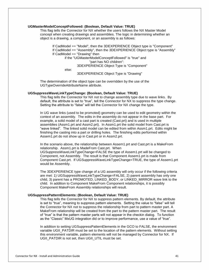
UGMasterModelConceptFollowed: (Boolean, Default Value: TRUE) This flag tells the Connector for NX whether the users follows the NX Master Model concept when creating drawings and assemblies. The logic in determining whether an object is a drawing, a component, or an assembly is as follows:
If CadModel == "Model", then the 3DEXPERIENCE Object type is "Component" If CadModel == "Assembly", then the 3DEXPERIENCE Object type is "Assembly" If CadModel == "Drawing" then
if the "UGMasterModelConceptFollowed" is "true" and "part has NO children":
3DEXPERIENCE Object Type is "Component" else:
3DEXPERIENCE Object Type is "Drawing" The determination of the object type can be overridden by the use of the UGTypeOverrideAttributeName attribute.
UGSuppressWaveLinkTypeChange: (Boolean, Default Value: TRUE) This flag tells the Connector for NX not to change assembly type due to wave links. By default, the attribute is set to “true”, tell the Connector for NX to suppress the type change. Setting the attribute to “false” will tell the Connector for NX change the type. In UG wave links (used to be promoted) geometry can be used to edit geometry within the context of an assembly. The edits in the assembly do not appear in the base part. For example, a solid model of a cast part is created (Cast.prt) and is used in multiple assemblies (Assm1.prt and Assm2.prt). In Assm1.prt the solid model from Cast.prt is “wave linked”. The linked solid model can be edited from within Assm1.prt. Edits might be finishing the casting into a part or drilling holes. The finishing edits performed within Assem1.prt do not show up in Cast.prt or in Assm2.prt. In the scenario above, the relationship between Assem1.prt and Cast.prt is a MakeFrom relationship. Assm1.prt is MadeFrom Cast.prt. When UGSuppressWaveLinkTypeChange=FALSE the type of Assem1.prt will be changed to Component, not Assembly. The result is that Component Assem1.prt is made from Component Cast.prt. If UGSuppressWaveLinkTypeChange=TRUE, the type of Assem1.prt would be Assembly. The 3DEXPERIENCE type change of a UG assembly will only occur if the following criteria are met: 1) UGSuppressWaveLinkTypeChange=FALSE, 2) parent assembly has only one child, 3) parent has a PROMOTED, LINKED_BODY, or LINKED_MIRROR wave link to the child. In addition to Component MakeFrom Component relationships, it is possibly Component MakeFrom Assembly relationships will result.
UGSuppressPatternElements: (Boolean, Default Value: TRUE)
This flag tells the Connector for NX to suppress pattern elements. By default, the attribute is set to “true”, meaning to suppress pattern elements. Setting the value to “false” will tell the Connector for NX not to suppress the relationship from part to pattern master part. A MakeFrom relationship will be created from the part to the pattern master part. The result of “true” is that the pattern master parts will not appear in the checkin dialog. To function as the “Classic” MxUG integration did or to improve performance, use a value of “true”. In addition to setting UGSuppressPatternElements in the GCO to FALSE, the environment variable UGII_PATDIR must be set to the location of the pattern elements. Without setting this environment variable, pattern elements will not be managed by Connector for NX. If UGII_PATDIR is not set, then UGII_UTIL must be set.
Connector for NX - Install and Administration Guide 42
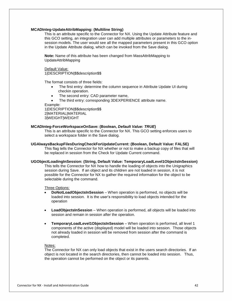
MCADInteg-UpdateAttribMapping: (Multiline String) This is an attribute specific to the Connector for NX. Using the Update Attribute feature and this GCO setting, an integration user can add multiple attributes or parameters to the in-session models. The user would see all the mapped parameters present in this GCO option in the Update Attribute dialog, which can be invoked from the Save dialog. Note: Name of this attribute has been changed from MassAttribMapping to UpdateAttribMapping Default Value: 1|DESCRIPTION|$$description$$ The format consists of three fields:
The first entry: determine the column sequence in Attribute Update UI during checkin operation.
The second entry: CAD parameter name,
The third entry: corresponding 3DEXPERIENCE attribute name. Example:
1|DESCRIPTION|$$description$$ 2|MATERIAL|MATERIAL 3|WEIGHT|WEIGHT
MCADInteg-ForceWorkspaceOnSave: (Boolean, Default Value: TRUE)
This is an attribute specific to the Connector for NX. This GCO setting enforces users to select a workspace folder in the Save dialog.
UGAlwaysBackupFilesDuringCheckForUpdateCurrent: (Boolean, Default Value: FALSE)
This flag tells the Connector for NX whether or not to make a backup copy of files that will be replaced in session from the Check for Update Current command.
UGObjectLoadingInSession: (String, Default Value: TemporaryLoadLevel1ObjectsInSession) This tells the Connector for NX how to handle the loading of objects into the Unigraphics session during Save. If an object and its children are not loaded in session, it is not possible for the Connector for NX to gather the required information for the object to be selectable during the command.
Three Options:
DoNotLoadObjectsInSession – When operation is performed, no objects will be
loaded into session. It is the user’s responsibility to load objects intended for the operation
LoadObjectsInSession – When operation is performed, all objects will be loaded into
session and remain in session after the operation.
TemporaryLoadLevel1ObjectsInSession – When operation is performed, all level 1
components of the active (displayed) model will be loaded into session. Those objects not already loaded in session will be removed from session after the command is completed.
Notes: The Connector for NX can only load objects that exist in the users search directories. If an object is not located in the search directories, then cannot be loaded into session. Thus, the operation cannot be performed on the object or its parents.
Connector for NX - Install and Administration Guide 43
Establish Attribute Mappings
The Global Configuration Object can be configured for Unigraphics parameters to be mapped to 3DEXPERIENCE attributes and for 3DEXPERIENCE attributes to be mapped to Unigraphics parameters. The MCADInteg-MxToCADAttribMapping section establishes the mappings from 3DEXPERIENCE to Unigraphics and the MCADInteg-CADToMxAttribMapping section establishes the mappings from Unigraphics to 3DEXPERIENCE. Refer to the MCADInteg-MxToCADAttribMapping and MCADInteg-CADToMxAttribMapping attributes of The Global Configuration Object section for a complete explanation of establishing attribute mappings.
Derived Output Support
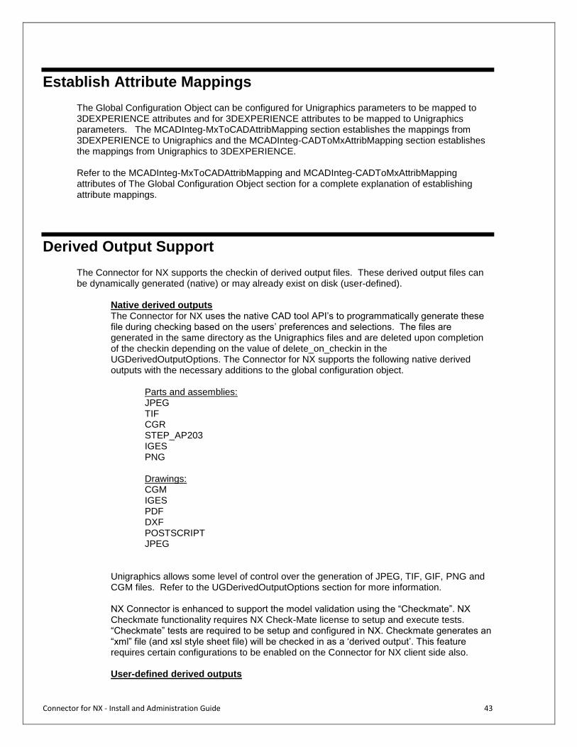
The Connector for NX supports the checkin of derived output files. These derived output files can be dynamically generated (native) or may already exist on disk (user-defined).
Native derived outputs The Connector for NX uses the native CAD tool API’s to programmatically generate these file during checking based on the users’ preferences and selections. The files are generated in the same directory as the Unigraphics files and are deleted upon completion of the checkin depending on the value of delete_on_checkin in the UGDerivedOutputOptions. The Connector for NX supports the following native derived outputs with the necessary additions to the global configuration object.
Parts and assemblies: JPEG TIF CGR STEP_AP203 IGES PNG Drawings: CGM IGES PDF DXF POSTSCRIPT JPEG
Unigraphics allows some level of control over the generation of JPEG, TIF, GIF, PNG and CGM files. Refer to the UGDerivedOutputOptions section for more information. NX Connector is enhanced to support the model validation using the “Checkmate”. NX Checkmate functionality requires NX Check-Mate license to setup and execute tests. “Checkmate” tests are required to be setup and configured in NX. Checkmate generates an “xml” file (and xsl style sheet file) will be checked in as a ‘derived output’. This feature requires certain configurations to be enabled on the Connector for NX client side also. User-defined derived outputs

Connector for NX - Install and Administration Guide 44
The Connector for NX checks for user-defined derived output files in the same directory as the Unigraphics files and will check them in if found. The user-defined file must have the same basename as the CAD file being checked in. The files are deleted upon completion of the checkin. User-defined derived outputs are identified with the syntax of: userfile_<extension> For example, to support zip files the name would be userfile_zip. The user-defined derived outputs must be added to the global configuration object. The MCADInteg-BusTypeMapping, MCADInteg-TypeClassMapping, MCADInteg-TypeDerivedOutputMapping, and MCADInteg-TypeFormatMapping attributes of the global configuration object must be edited. The chosen format may also need to be added to 3DEXPERIENCE and to the allowed formats of the governing policies, and the range for the ‘CAD Type’ attribute will have to be updated. With R2019x all the derived outputs will be checked in separate formats of the same Derived Output Object. The MCADInteg-CreateDerivedOutoutObj flag is deprecated and its behavior is considered as True always and users can’t change the behavior.
Connector for NX - Install and Administration Guide 45
CGR Derived Output for Downstream Applications
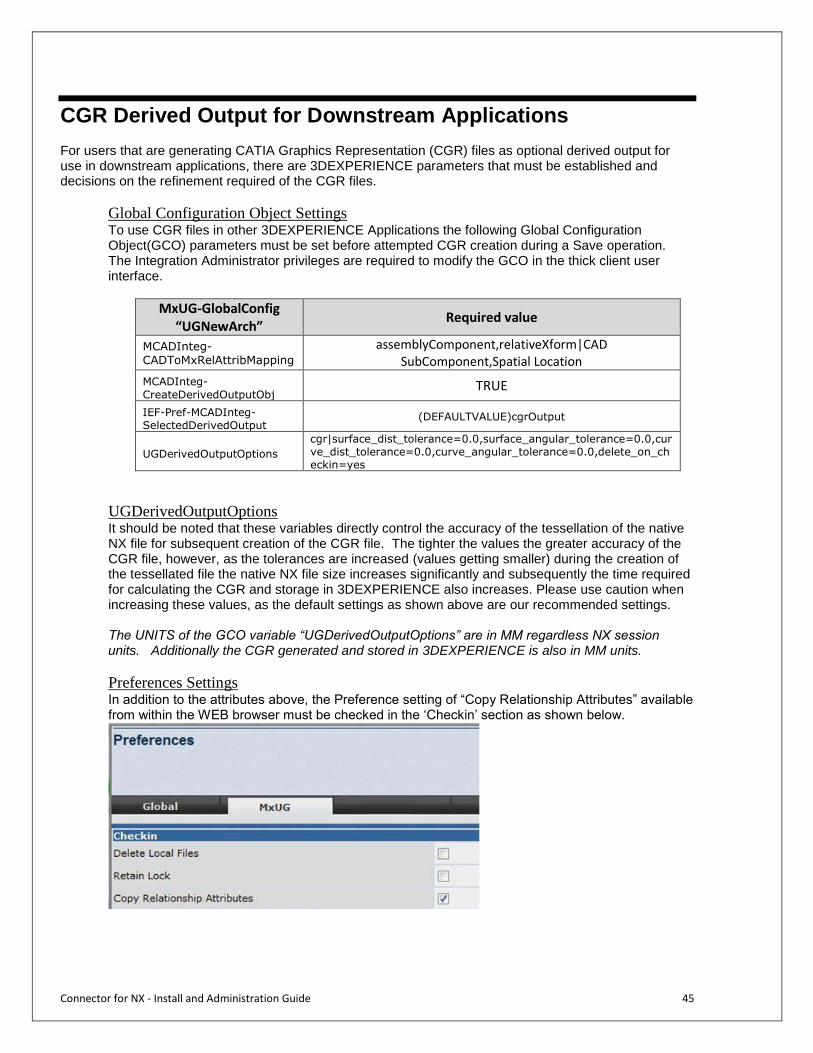
For users that are generating CATIA Graphics Representation (CGR) files as optional derived output for use in downstream applications, there are 3DEXPERIENCE parameters that must be established and decisions on the refinement required of the CGR files.
Global Configuration Object Settings To use CGR files in other 3DEXPERIENCE Applications the following Global Configuration Object(GCO) parameters must be set before attempted CGR creation during a Save operation. The Integration Administrator privileges are required to modify the GCO in the thick client user interface.
MxUG-GlobalConfig “UGNewArch”
Required value
MCADInteg-CADToMxRelAttribMapping
assemblyComponent,relativeXform|CAD SubComponent,Spatial Location
MCADInteg-
CreateDerivedOutputObj TRUE
IEF-Pref-MCADInteg-SelectedDerivedOutput
(DEFAULTVALUE)cgrOutput
UGDerivedOutputOptions
cgr|surface_dist_tolerance=0.0,surface_angular_tolerance=0.0,curve_dist_tolerance=0.0,curve_angular_tolerance=0.0,delete_on_checkin=yes
UGDerivedOutputOptions It should be noted that these variables directly control the accuracy of the tessellation of the native NX file for subsequent creation of the CGR file. The tighter the values the greater accuracy of the CGR file, however, as the tolerances are increased (values getting smaller) during the creation of the tessellated file the native NX file size increases significantly and subsequently the time required for calculating the CGR and storage in 3DEXPERIENCE also increases. Please use caution when increasing these values, as the default settings as shown above are our recommended settings. The UNITS of the GCO variable “UGDerivedOutputOptions” are in MM regardless NX session units. Additionally the CGR generated and stored in 3DEXPERIENCE is also in MM units.
Preferences Settings In addition to the attributes above, the Preference setting of “Copy Relationship Attributes” available from within the WEB browser must be checked in the ‘Checkin’ section as shown below.
Connector for NX - Install and Administration Guide 46
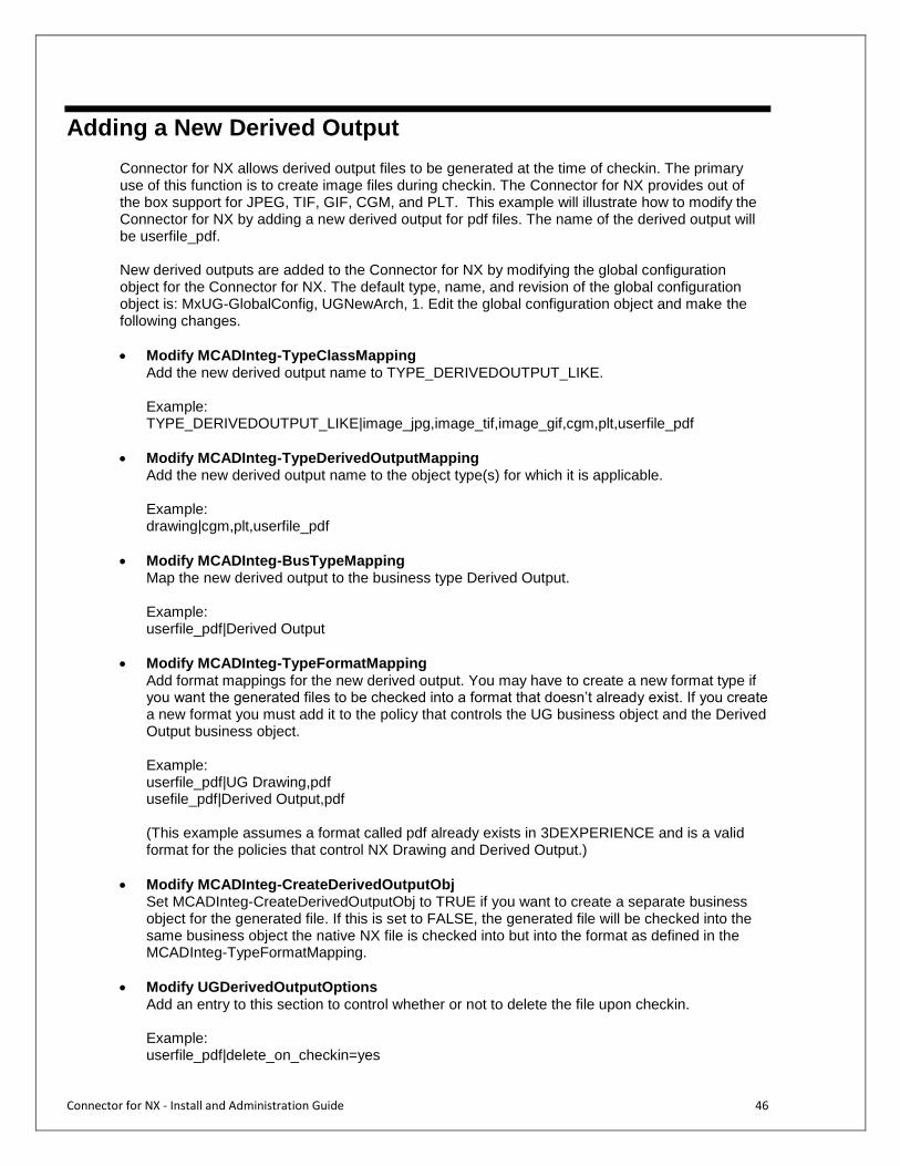
Adding a New Derived Output Connector for NX allows derived output files to be generated at the time of checkin. The primary use of this function is to create image files during checkin. The Connector for NX provides out of the box support for JPEG, TIF, GIF, CGM, and PLT. This example will illustrate how to modify the Connector for NX by adding a new derived output for pdf files. The name of the derived output will be userfile_pdf.
New derived outputs are added to the Connector for NX by modifying the global configuration object for the Connector for NX. The default type, name, and revision of the global configuration object is: MxUG-GlobalConfig, UGNewArch, 1. Edit the global configuration object and make the following changes.
Modify MCADInteg-TypeClassMapping Add the new derived output name to TYPE_DERIVEDOUTPUT_LIKE. Example: TYPE_DERIVEDOUTPUT_LIKE|image_jpg,image_tif,image_gif,cgm,plt,userfile_pdf
Modify MCADInteg-TypeDerivedOutputMapping Add the new derived output name to the object type(s) for which it is applicable. Example: drawing|cgm,plt,userfile_pdf
Modify MCADInteg-BusTypeMapping Map the new derived output to the business type Derived Output. Example: userfile_pdf|Derived Output
Modify MCADInteg-TypeFormatMapping
Add format mappings for the new derived output. You may have to create a new format type if you want the generated files to be checked into a format that doesn’t already exist. If you create a new format you must add it to the policy that controls the UG business object and the Derived Output business object.
Example: userfile_pdf|UG Drawing,pdf usefile_pdf|Derived Output,pdf
(This example assumes a format called pdf already exists in 3DEXPERIENCE and is a valid format for the policies that control NX Drawing and Derived Output.)
Modify MCADInteg-CreateDerivedOutputObj Set MCADInteg-CreateDerivedOutputObj to TRUE if you want to create a separate business object for the generated file. If this is set to FALSE, the generated file will be checked into the same business object the native NX file is checked into but into the format as defined in the MCADInteg-TypeFormatMapping.
Modify UGDerivedOutputOptions
Add an entry to this section to control whether or not to delete the file upon checkin. Example: userfile_pdf|delete_on_checkin=yes

Connector for NX - Install and Administration Guide 47
delete_on_checkin specifies whether or not to delete the derived output file upon successful completion of the checkin operation. If this is set to ‘yes’ the derived output file will be deleted upon checkin. If this is set to ‘no’ the derived output file will not be deleted.
You will now be able to select this new derived output for drawings. You can change your preferences if you wish to always have it pre-selected.
Connector for NX - Install and Administration Guide 48
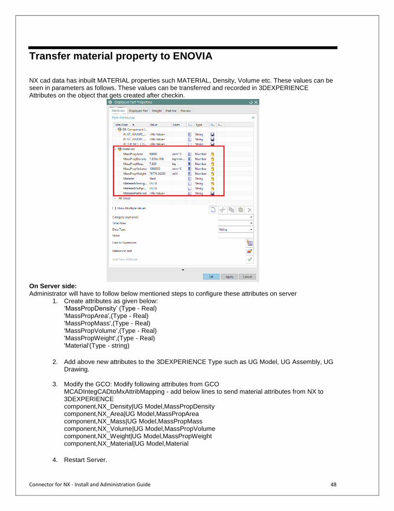
Transfer material property to ENOVIA
NX cad data has inbuilt MATERIAL properties such MATERIAL, Density, Volume etc. These values can be seen in parameters as follows. These values can be transferred and recorded in 3DEXPERIENCE Attributes on the object that gets created after checkin.
On Server side: Administrator will have to follow below mentioned steps to configure these attributes on server
1. Create attributes as given below: ‘MassPropDensity’ (Type - Real) 'MassPropArea',(Type - Real) 'MassPropMass',(Type - Real) 'MassPropVolume',(Type - Real) 'MassPropWeight',(Type - Real) 'Material'(Type - string)
2. Add above new attributes to the 3DEXPERIENCE Type such as UG Model, UG Assembly, UG
Drawing.
3. Modify the GCO: Modify following attributes from GCO MCADIntegCADtoMxAttribMapping - add below lines to send material attributes from NX to 3DEXPERIENCE component,NX_Density|UG Model,MassPropDensity component,NX_Area|UG Model,MassPropArea component,NX_Mass|UG Model,MassPropMass component,NX_Volume|UG Model,MassPropVolume component,NX_Weight|UG Model,MassPropWeight component,NX_Material|UG Model,Material
4. Restart Server.
Connector for NX - Install and Administration Guide 49
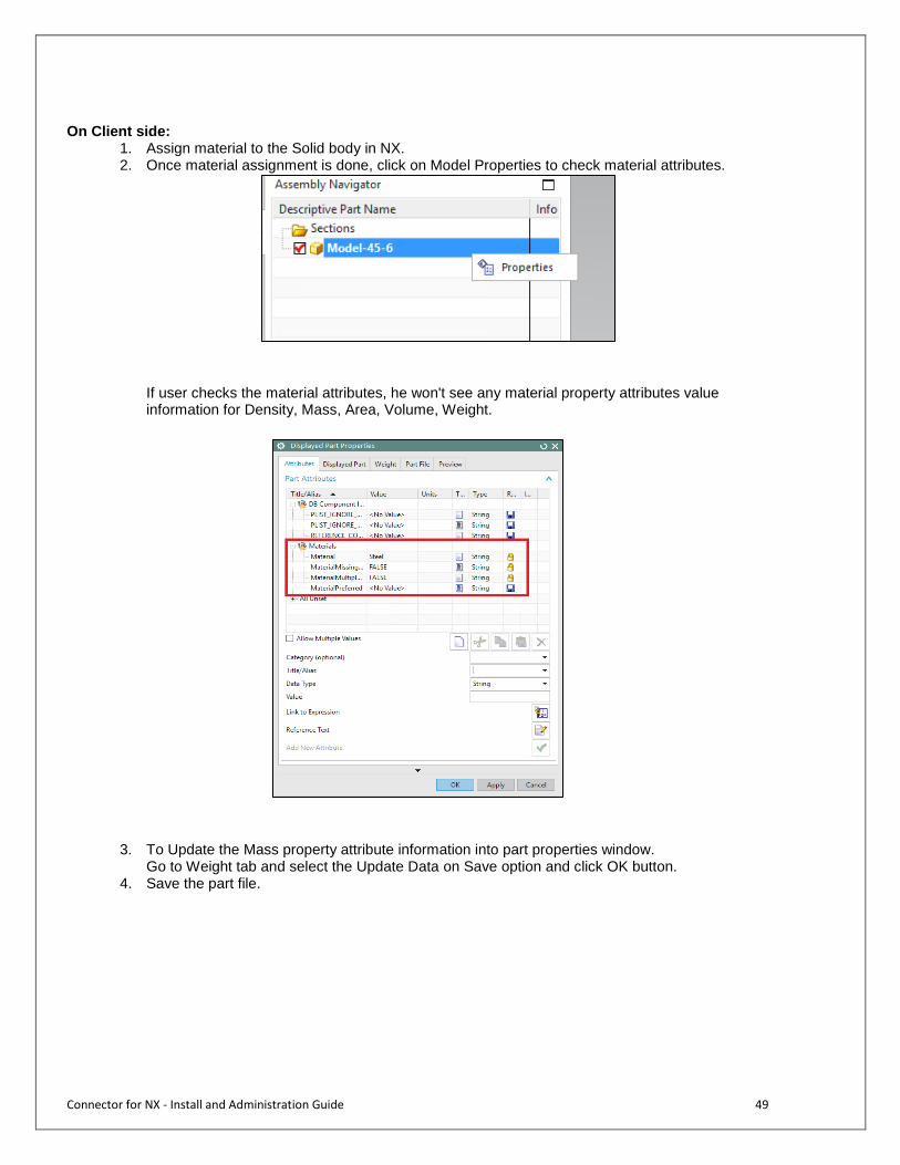
On Client side:
1. Assign material to the Solid body in NX. 2. Once material assignment is done, click on Model Properties to check material attributes.
If user checks the material attributes, he won't see any material property attributes value information for Density, Mass, Area, Volume, Weight.
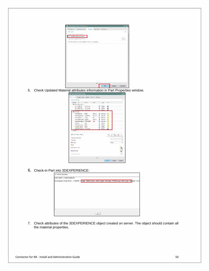
3. To Update the Mass property attribute information into part properties window.
Go to Weight tab and select the Update Data on Save option and click OK button. 4. Save the part file.
Connector for NX - Install and Administration Guide 50
5. Check Updated Material attributes information in Part Properties window.
6. Check-in Part into 3DEXPERIENCE:
7. Check attributes of the 3DEXPERIENCE object created on server. The object should contain all the material properties.

Connector for NX - Install and Administration Guide 51
Type Change Mappings
Sometimes a design may start out as one type of model and later become a different type of model, for example if a component later becomes a drawing. In such cases it may be desirable to continue with the existing revision stream in 3DEXPERIENCE rather than starting as a brand new object. X-CAD Design supports this with a mapping that defines allowable type changes in the GCO attribute called MCADInteg-TypeChangeMapping. For example, to recognize a component that becomes a drawing and vice-versa, add the following to MCADInteg-TypeChangeMapping in the GCO. component|drawing drawing|component

Connector for NX - Install and Administration Guide 52
CAD Classification Schema objects
A new functionality is made available to the users of Library Central to classify and update classification attributes on new NX designs right from the CAD integration session. Please see user guide for more details of the capability. To enable this functionality some server-side components are also delivered which will be installed by the main integrations schema installer if Library Central is already installed. Following are the classification schema objects.
A new JPO called “ITIClassificationAssignment” is installed. This JPO performs all the classification assignment in 3DEXPERIENCE and also communicates with the integration client for the functionality to work properly.
An admin object is installed to manage the Classification Assignment MCAD Classification Assignment Control object. This will help administrators to enforce some of the classification assignment behavior. Type: MCAD Classification Assignment Name: NX Classification Assignment Control
One attribute for defining classification types Attribute1: MCAD-Integ-ClassificationType-Configuration Syntax: Classification Type|One or Many Classification Types|Mandatory(Y/N)|List of Classification objects
For example, user is allowed to assign one Export Control Class mandatorily and optionally assign many IP Control Class
Export Control Class|One|Y|EAR~ITAR~Not Export Controlled IP Control Class|Many|N|Class I~Class II~Class III Generator
In this next example, user is allowed to assign up to 3 Export Control Class optionally by picking any one from the full list of Export Control Class objects and mandatorily pick any one of the configured classes
Export Control Class|3|N|All IP Control Class|One|Y|Class I~Class II~Class III Generator
Another attribute for defining attribute configurations for classification objects. Attribute2: MCAD-Integ-ClassificationAttribute-Configuration Syntax: ClassificationObjectName|AttributeName|Attribute Order in Excel Sheet|Clasification Default Value or Enovia
Attribute Defualt Value|MANDATORY|
Connector for NX - Install and Administration Guide 53
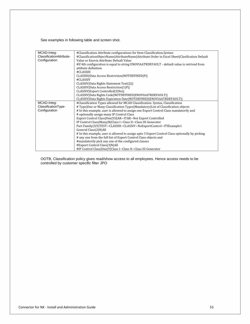
See examples in following table and screen shot.
MCAD-Integ-ClassificationAttribute-Configuration
#Classification Attribute configurations for Item Classification,Syntax: #ClassificationObjectName|AttributeName|Attribute Order in Excel Sheet|Clasification Default Value or Enovia Attribute Defualt Value #If 4th configuration is equal to string ENOVIAATRDEFAULT - default value is retrived from attibute definition #CLASSIII CLASSIII|Data Access Restriction|NOTDEFINED|P|| #CLASSIV CLASSIV|Data Rights Statement Text|2||| CLASSIV|Data Access Restriction|1|P|| CLASSIV|Export Controlled|3|No|| CLASSIV|Data Rights Code|NOTDEFINED|ENOVIAATRDEFAULT|| CLASSIV|Data Rights Expiration Date|NOTDEFINED|ENOVIAATRDEFAULT||
MCAD-Integ-ClassificationType-Configuration
#Classification Types allowed for MCAD Classification. Syntax, Classification # Type|One or Many Classification Types|Mandatory|List of Classification objects # In this example, user is allowed to assign one Export Control Class mandatorily and # optionally assign many IP Control Class Export Control Class|One|Y|EAR~ITAR~Not Export Controlled IP Control Class|Many|N|Class I~Class II~Class III Generator Part Family|3|Y|TEST~CLASSIII~CLASSIV~NoExportControl~ITIExample1 General Class|2|N|All # In this example, user is allowed to assign upto 3 Export Control Class optionally by picking # any one from the full list of Export Control Class objects and #mandatorily pick any one of the configured classes #Export Control Class|3|N|All #IP Control Class|One|Y|Class I~Class II~Class III Generator
OOTB, Classification policy gives read/show access to all employees. Hence access needs to be controlled by customer specific filter JPO

Connector for NX - Install and Administration Guide 54
3DEXPERIENCE Connector for NX UserExits

Connector for NX - Install and Administration Guide 55
Overview
User Exits are function calls that are implemented by the user and then called by the Connector for NX to do specific operations before or after certain Connector for NX functions. The Connector for NX provides user exits for these actions:
ConnectPost
CheckinDialogPre
CheckinStart
CheckinStartAll
CheckinPartPre
CheckinPartPost
OpenPartPre
OpenPartPost
CheckoutPartPre
CheckoutPartPost
ModifyLockPartPre
ModifyLockPartPost
UpdateAttributesInCADPre
UpdateAttributesInCADPost
Only those user exits that have been registered in the GCO will be called. User exits are registered by entering the name of the user exit into the IEF-UserExitEventRegistration attribute in the GCO. Multiple user exits are separated by a space. For example, to register CheckinPartPost, CheckoutPartPre, and CheckoutPartPost you would set IEF-UserExitEventRegistration to “CheckinPartPre CheckinPartPost CheckoutPartPre CheckoutPartPost”. The user exits may return an error code. A return code other than 0 indicates an error occurred in the user exit function. If an error is returned by the user exit function, the Connector for NX operation is cancelled. (Note that this does not mean a transaction is rolled back.) Possible uses for user exits are: image file or plot file generation; setting up attributes or parameters; or communicating with ENOVIA via MQL commands. To assist with user exit communications with ENOVIA, a function that can pass an MQL command through the X-CAD Design interface is exposed by the Connector for NX. The user exits are made available via a dynamically loaded shared library. Sample source code to a default library, a header file, and a sample makefile are provided. The name of the shared library (with its absolute path) must be defined using a new environment variable MXMCAD_USEREXITS_LIB. Edit the Connector for NX startup script in the bin directory to set the proper value for MXMCAD_USEREXITS_LIB. The default setting is: MXMCAD_USEREXITS_LIB= %MXMCAD_HOME%\userexits\userExits\plat-win32\userExits.dll
Connector for NX - Install and Administration Guide 56
Compiling & Linking User Exits Follow the instructions below for setting up an environment for compiling and linking the user exit functions.
Modify buildUg.bat to match your environment. a. set UG_DIR=<to the base NX installation directory> b. set VS_DIR=<to the base visual studio directory> c. set SDK_DIR=<to the base Microsoft SDK directory>
Run buildUg.bat to build the user exit shared library. a. Successful build creates userExits_ug.dll in /userexits/plat-win64 folder
To load the user exits at runtime set the environment variable MXMCAD_USEREXITS_LIB to the name of the shared library (with its full path). The recommendation is to do this in the startup script in <MXMCAD_HOME>\bin.
Connector for NX - Install and Administration Guide 57
User Exit Functions This section defines the function prototypes for each of the user exit functions. Note that all of the user exit function names begin with the prefix UE_. Many of the user exit functions receive from the Connector for NX the CAD part file pointer and the Matrix type, name, and revision of the object being processed. This data is passed in a structure called CAD_PART, whose definition is seen below. Each of the items in the structure can be directly accessed by the user exit function. typedef struct cad_part_struct {
void *cadModelHook; char mxId[80]; char mxType[80]; char mxName[133]; char mxRev[16]; char mxTargetRev[16];
} CAD_PART; cadModelHook is a pointer to UGCadModel structure (defined in UGCadModel.h) that contains the NX part tag. The UGCadModel structure is defined as: typedef struct ugcadmodel { long tag; } UGCadModel; To access the NX part tag do the following:
ugCadModel = (UGCadModel *)current_part.cadModelHook; ugPartTag = ugCadModel->tag;
mxId contains the Matrix ID of the object. It may be blank for some user exits. mxType is the Matrix type of the object. mxName is the Matrix name of the object. mxRev is the Matrix revision of the object. In some cases, the user exit function may need to return an error message to be displayed by the Connector for NX. This message will be displayed to the user upon completion of the operation. If the message string is not null, then the message string will be freed by the Connector for NX. The user exit function must have allocated the string using malloc(). In addition, whenever a user exit function returns an integer value, a non-zero is interpreted as an error by the Connector for NX.
UE_ConnectPost UE_ConnectPost is called after the user logs into ENOVIA and the Connector for NX receives the contents of the GCO and the user’s LCO. Its function prototype is: void UE_ConnectPost();
UE_CheckinDialogPre UE_CheckinDialogPre is called prior to displaying the checkin dialog. Its function prototype is:
int UE_CheckinDialogPre(char **err_msg);

Connector for NX - Install and Administration Guide 58
A non-zero return will cancel the checkin operation.
UE_CheckinStart UE_CheckinStart is called at the start of the checkin process after the user has selected Checkin from the checkin dialog. Its function prototype is: int UE_CheckinStart(CAD_PART current_part, char **err_msg); A non-zero return will cancel the checkin operation.
UE_CheckinStartAll UE_CheckinStartAll is called at the start of the checkin process after the user has selected Checkin from the checkin dialog. The difference between UE_CheckinStartAll and CheckinStart is that UG_CheckinStartAll includes all selected parts in a single user exit function. Its function prototype is: int UE_CheckinStartAll(int num_parts, CAD_PART *current_parts, char **err_msg); A non-zero return will cancel the checkin operation.
UE_CheckinPartPre UE_CheckinPartPre is called after the business object has been created or updated in ENOVIA but before the part file has been transferred. Its function prototype is: int UE_CheckinPartPre(CAD_PART current_part, char **err_msg); A non-zero return will cancel the checkin operation.
UE_CheckinPartPost UE_CheckinPartPost is called after the part file has been transferred to ENOVIA. Its function prototype is:
void UE_CheckinPartPost(CAD_PART current_part, char **err_msg);
UE_OpenPartPre UE_OpenPartPre is called before the model is opened in the CAD system. Its function prototype is: void UE_OpenPartPre(CAD_PART current_part, char *filename, char **ue_error_mesg); The filename is the full path to the part file to be opened.
UE_OpenPartPost UE_OpenPartPost is called after the model is opened in the CAD system. Its function prototype is:
void UE_OpenPartPost(CAD_PART current_part, char **ue_error_mesg);
UE_CheckoutPartPre UE_CheckoutPartPre is called before a part file is checked out of ENOVIA. Its function prototype is: int UE_CheckoutPartPre(CAD_PART current_part, char **ue_error_mesg);

Connector for NX - Install and Administration Guide 59
A non-zero return will cancel the checkout operation.
UE_CheckoutPartPost UE_CheckoutPartPost is called after a part file is checked out of ENOVIA. Its function prototype is:
void UE_CheckoutPartPost(CAD_PART current_part, char **ue_error_mesg);
UE_ModifyLockPartPre UE_ModifyLockPartPre is called before an object is locked or unlocked. Its function prototype is: int UE_ModifyLockPartPre(CAD_PART current_part, int lock_operation, char **ue_error_mesg); The value of lock_operation will be 1 for lock and 0 for unlock.
UE_ModifyLockPartPost UE_ModifyLockPartPost is called after an object is locked or unlocked. Its function prototype is: void UE_ModifyLockPartPost(CAD_PART current_part, int lock_operation, char **ue_error_mesg); The value of lock_operation will be 1 for lock and 0 for unlock.
UE_UpdateAttributesInCADPre UE_UpdateAttributesInCADPre is called before attributes are updated in the CAD session. Its function prototype is: int UE_UpdateAttributesInCadPre(CAD_PART current_part, char **ue_error_mesg); A non-zero return will cancel the attribute update operation.
UE_UpdateAttributesInCADPost UE_UpdateAttributesInCADPre is called after attributes are updated in the CAD session. Its function prototype is: void UE_UpdateAttributesInCadPost(CAD_PART current_part, char **ue_error_mesg);

Connector for NX - Install and Administration Guide 60
External Functions The Connector for NX provides some utility functions that can be called by the user exits. These functions can be used to query for specific information from ENOVIA and provide access to information within the Connector for NX. These functions are defined in MxInterface.h.
MatrixCommand This function sends an MQL command to ENOVIA and returns the output. Any MQL command may be sent to ENOVIA using this command. Its function prototype is: int MatrixCommand(MXIF_APPLET *applet, char *mqlCommand, char **result); Always pass NULL for the applet. This function will return a non-zero value if ENOVIA returns an error attempting to execute the mql command.
debugPrint This macro prints a string in a specified format to the integration.log file and to the screen. The binding for this function is similar to the C/C++ printf function. Its function prototype is: int debugPrint(char *msg, ...); The msg string may include formatting controls as accepted by printf.
This example shows making an MQL call and printing the response using debugPrint. char *response = NULL; MatrixCommand(NULL, "list person *", &response); debugPrint("MQL command: list person *\n"); debugPrint("\tMQL response: %s\n", response);

Connector for NX - Install and Administration Guide 61
Appendix: Signing the Integration DLL
Open command prompt
Add libjam.dll to your path. Eg: set PATH=%PATH%;<NX10 installation directory>\UGII
Navigate to the '<NX10 installation directory>\UGOPEN' folder where the signcpp.exe is located.
Eg:cd D:\cs\ug\nx10\UGOPEN
Run the signup to sign the _csi_ug_nx10.dll located at '<MXUG-integration install
directory>\lib\csi\ug\modules\plat-win64\ug_nx10\startup'.
Eg: D:\cs\ug\nx10\UGOPEN>signcpp C:\MxUGNT\lib\csi\ug\modules\plat-win64\ug_nx10\startup\_csi_ug_nx10.dll ####following statements can be seen on the command prompt which conform that the _csi_ug_nx10.dll is signed ####
Checking for the presence of c_p_p_author license. Signing files... Application C:\MxUGNT\lib\csi\ug\modules\plat-win64\ug_nx10\startup\_csi_ug_nx10.dll has been signed.
Copy the MxInterface.dll from the '<MxUG install>\lib\csi\ug\modules\plat-win64\ug_nx10\startup' to '<NX10
installation directory>\UGII' folder
Note: Same signing process will be applicable for integration with NX11, signcpp will be used from respective CAD installation directories

Connector for NX - Install and Administration Guide 62
Appendix: Schema Diagrams
MCAD Drawing
CAD Drawing
CAD Model
MCAD Model ECAD Model
MCAD Component MCAD Assembly
UG Model UG Assembly
3DEXPERIENCE Live
Collaboration
X-CAD Design
NX Design Management
UG Drawing
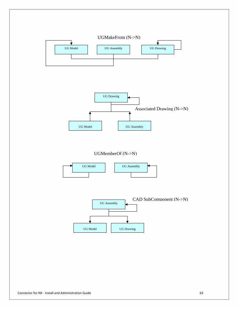
Connector for NX - Install and Administration Guide 63
UG Model UG Assembly
UGMakeFrom (N->N)
UG Drawing
UG Model
UG Drawing
UG Assembly
Associated Drawing (N->N)
UG Model UG Assembly
UGMemberOf (N->N)
UG Model
UG Assembly CAD SubComponent (N->N)
UG Drawing
Connector for NX - Install and Administration Guide 64
Support Support for the Connector for NX is available through 3DEXPERIENCE by phone or email.
North America Tel: +1 (877) 3D 4ALL1 (Toll Free)
+1 (877) 334 2551 (Toll Free)
+1 (704) 935 5690 (International)
Fax: +1 704 264 8888
E-mail: [email protected]
EMEA Austria +43 800 886 687
Belgium +32 2 357 53 03
France 0825 825 819
Germany 08001016391
Italy 02 334 306 306
Sweden 0771 320 710/+46 31 720 5858
Switzerland 0800 101 631
United Kingdom 0871 218 3467
Others countries +33 3 59 30 8419
Fax (EMEA): +33 1 70 73 4405
E-mail: [email protected] Languages: English, German, French
Asia Pacific Supported countries: China PRC, Hong-Kong, Taiwan
Tel : (800)-810-3958
E-mail: [email protected] Languages: Chinese (Mandarin), English
Customer Support Center Korea Supported countries: Korea
Tel : 82-2-3270-7813
E-mail: [email protected] Language: Korean, English
Customer Support Center India Supported countries: Australia, Indonesia, India, Malaysia, New Zealand, Philippines, Singapore,
Thailand, Vietnam
E-mail: [email protected] Language: English

Connector for NX - Install and Administration Guide 65
Customer Support Center Japan Supported countries: Japan
Tel : +81 (0)3 5442 6051
E-mail: [email protected] Language: Japanese, English
The Connector for NX creates a log file to help assess and diagnose problems or unexpected behavior: mxug_debug.log. This file is located in the <user home directory>/mxug_logs directory. It is very helpful to provide support with this file when the Connector for NX produces unexpected results. mxug_debug.log contains Connector for NX debugging statements. This file is only created if the debugPrintLog parameter is set to 1 in the settings.ini file. If the debugPrints parameter is set to 1 then trace statements will be written to the log file and if logSocketData is set to 1 then XML packets will be written to the log file.