connecticut dot br. no. 04288r walk … dot br. no. 04288r walk bridge over norwalk river norwalk,...
TRANSCRIPT

CONNECTICUT DOT BR. NO. 04288R WALK BRIDGE OVER NORWALK RIVER
NORWALK, CONNECTICUT
EMERGENCY REPAIR AND RELIABILITY REPORT
Inspection: June 2014Report Submitted: July 17, 2014 (Final)
Prepared for: Connecticut Department of Transportation
Prepared by:
Short Term Action Team

STAT Report and Recommendations FINAL July 17, 2014
1
Table of Contents 1) Introduction 2
i) Description of Structure and Systems 2
ii) Report of Recent Failure 3
2) Findings of Inspection and Assessment 5
i) Rail Joint Systems 5
ii) Wedge Drive Machinery 6
iii) Motor Meggering 7
iv) Centering Device Machinery 7
v) Span Drive Machinery 7
vi) Center Pivot, Tracks, and Taper Roller Assemblies 8
vii)Bridge Operation Control System 9
3) Recommendations 9
i) Immediate 9
ii) Short Term Repairs 10
iii) Long Term Repairs 11
4) Estimated Costs for Repairs 13
5) Photographs 14
6) Appendix

STAT Report and Recommendations FINAL July 17, 2014
2
INTRODUCTION
A Short Term Action Team (STAT) has been convened by order of the Commissioner to determine the cause of the failures in operation that occurred on the Walk Bridge on two separate incidents within a two week period and determine repairs that can be made to the operating systems to make the systems more reliable. The STAT team has been meeting on a continual basis to discuss the repair work being performed, the observations that occurred during the two incidents, operational behavior of the swing span, adjustments to the operating systems being performed and any operational issues that have arisen.
An inspection was conducted by the STAT team that included personnel from ConnDOT, Metro-North Railroad (MNR) and HNTB Corporation (HNTB) to assess and evaluate the current condition of the operating systems for this swing bridge. This included the span drive, center pivot and roller assemblies, wedge drives, rail lifts and centering devices.
On Saturday June 21st and Sunday June 29th, 2014, the bridge was operated a total of three times to allow the passage of marine vessels. The STAT Team used these opportunities to observe the systems in operation, assess their current condition and reliability, and verify if the systems are functioning as originally intended.
Description of Structure and Systems
The movable portion of the Walk Bridge is classified as a rim-bearing swing span and is located in South Norwalk, Connecticut. The bridge carries four (4) tracks of the Metro-North commuter rail and is also utilized by Amtrak and a freight carrier. The bridge crosses the Norwalk River in an east-west orientation. The swing bridge is a three truss span that has an overall length of 199 feet and a truss depth of 14.5 feet. The four tracks are designated in the following order from north to south Tracks 3, 1, 2, and 4. The track rails are supported between the trusses by floorbeams on that span between the trusses on a spacing of 15 feet.
The span drive machinery is located at the center pier below track level. The machinery is driven through the use of one of two 40hp motors. Each motor drives one set of open spur gears that outputs to an open differential gearset. The differential gearset equalizes torque between two horizontal shafts which drive a set of open bevel gears on either side of the span. The horizontal bevel gears are mounted to vertical rack pinion shafts which have a rack pinion mounted to the lower portion. The pinions engage and rotate about the rack that is secured to the center pier, rotating the span.
The span is supported by a drum girder that distributes the span weight to a series of 90 tapered rollers that roll on a curved track mounted to the pier. Span rotation is guided and stabilized through a center pivot. The tapered rollers are held in place by rods that are connected to the center pivot. The drum girder that is mounted to the underside of the trusses has 8 struts that are also secured to the center pivot hold the span in place also.
STAT Report and Recommendations FINAL July 17, 2014
3
Two lock bar assemblies, located at each end of the swing span, are used to center the span during final seating. Each assembly drives a bar vertically through a guide and receiver ensuring the span is transversely aligned. The east assembly drives first then the west assembly drives for final alignment.
The span is vertically aligned and stabilized in the seated position by six wedge assemblies. One set (three wedges) is located at each end of the three trusses. The wedges are operated through a series of open spur gears, cranks, and links. These wedge assembles lift the ends of the span and remove dead load deflections to align the tops of the rails between the fixed and movable span. The wedge machinery also operates the movable rail joints and catenary joints through a series of linkages and pins that rotate shafts supported by bearings that in turn rotate crank arms that raise the rail joints.
The bridge is currently receiving new rail and ties. Track 1 was replaced last year, track 3 is nearly completed, track 2 has been removed and new ties are in place and track 4 installation to follow.
Report of Recent Failure
In two separate but similar incidents, the bridge failed to properly close and allow the movable span’s track rails to seat. This prevented trains from being allowed to cross the bridge for an extended period of time. The first incident occurred on Thursday, May 29, 2014 while the second occurred on Friday, June 6, 2014.
The following is a brief synopsis of the results as described by Metro-North personnel regarding the occurrences.
Thursday, May 29, 2014
As part of the installation of the new track and ties, adjustment to the rail lift mechanism had to be performed. MNR personnel were adjusting the cam limit switch that controls the east wedge drive motor (which also operates the rail joint machinery). During a test operation to assess the limit switch function, the limit switch failed to stop the motor. This allowed a segmental gear (G4) located on the wedge drive output shaft to over rotate and strike and bend the structural steel supporting the machinery in that area. The striking force from the gear was sufficient to bend the structural steel flange. The gear also continued to rotate and the flange of the steel member meshed/jammed with the last tooth on G4. This locked the gear in place and prevented further operation of the east wedge drive which prevented the swing span from being closed. Once MNR forces were able to cut the flange of the steel member, the gear was able to rotate and the wedge drive was operated to fully close the swing span.
STAT Report and Recommendations FINAL July 17, 2014
4
Friday, June 6, 2014
A bridge opening was performed at 11:00AM without incident. During the 11:00AM opening track 3 was manually blocked up and not relying on the wedge drive to lift it into its raise position for span operation.
The rail lift rollers were installed on track 3 east end and a test opening was attempted at 2:00PM to verify proper operation. The rail joints were lifted but did not appear to be at a sufficient height to clear for a span operation. The bridge operator then attempted to lower the rail joints by operating the wedge drive. During this operation the rail joints did not lower properly and it was determined the segmental gear (G4) had exceeded its travel. However, without the structural steel restraining it (as it was removed after the 5/29/14 incident), the gear was allowed to rotate even farther and exceeded its operational limit. This caused the rail lift mechanism to over rotate and also prevented the machinery lowering the rail joints.
MNR personnel were able to use an emergency hydraulic jacking system to raise and vertically align the east end of the bridge. With the span in place, MNR personnel used a come along to rotate the segmental gear back in engagement with its mating pinion. Once this was achieved the wedge drive was operated to fully drive the wedges and lower the rail joints.
Cause of Failure
Based on discussions with personnel who were present and involved with the work being performed, the primary cause of the failures appears to be the inability to lift the newly installed miter rails to a sufficient height for clearance of adjacent rail in the swing path. The adjustments are necessary to achieve adequate clearance at the new rail joints for span operation. Increasing the rail lift travel entails adjustments to both the mechanical portion of the wedge drive and electrical limit switches that stop the wedge motor operation. The mechanical adjustments are made though a system of machinery that has an extensive amount of gears, linkages, and cranks while the electrical adjustments are performed by repositioning cams within limit switches. The current settings of these components are not ideal and are close to their maximum limits due to the age of the structure, age of the operating system components, existing structure condition, and attempting to utilize existing worn operating systems with the new rail joint systems. Inspections have shown the east wedge machinery gear G4 is closer to its end of limit than the west in the wedge pulled/rail lifted state. It has been on the east side where both incidents have occurred.
In summary, it was not one component that failed but a combination of adjustments and the operating system being close to its maximum limits that resulted in the failures.

STAT Report and Recommendations FINAL July 17, 2014
5
FINDINGS OF INSPECTION AND ASSESSMENT
Summary
On Saturday June 21st and Sunday June 29th, 2014, the bridge was operated a total of three times to allow the passage of marine vessels. The STAT Team used these opportunities to observe the systems in operation, assess their current condition and reliability, and verify if the systems are functioning as originally intended.
The following are descriptions of the observations and measurements of the various portions of the bridge drive system taken during the inspection on June 21, 2014 unless noted otherwise.
Rail Joint Systems
Tracks 3 and 1 (north tracks) have the new Ridex rail joint system as manufactured from CMI-Promex. This system does not pivot about a pin but relies on a lifting system to deflect the rails up. A series of rail guides ensures the deflected rail is lower down in the correct fully seated position. Track 2 was not in service and the rails were removed. Track 4 still has the original Conley/Miter rail joint system that pivots about a pin.
The rail joint machinery was inspected on Monday June 16, 2014 in its static condition to observe any signs of distress and/or deficiencies in the system. Track 3 on the east side was not connected to the drive machinery (See Photo M-3). The lift shaft also display heavy surface rust and section loss on the north side and excessive clearance (1/4”) at the south bearing (See Photo M-2). The lifting machinery on the west side of track 3 has been recently replaced with a new shaft, collar, and roller bearings (See Photo M-1). The lift machinery on track 2, both east and west, displayed surface rust throughout and excessive clearances in the pins and the machinery was not in use. Track 4 rail joint system displayed typical conditions as seen in Conley/Miter rail systems, with the most significant deficiency noted as trains rode on the rails. Excessive deflections and movement was observed at the pivot and rail guides at both the east and west locations.
The rail joint machinery was further inspected on Saturday June 21, 2014 during two (2) span openings to examine joint operation and determine worst case for future design considerations. Clearances were also measured between the guides and rails in order to determine if binding was occurring.
Track 3 on the west side did not lift to an adequate height to permit span operation. This location had to be manually jacked and blocked to provide the required clearance for span rotation. In addition, Tracks 3 and 1 on the east side were also jacked and blocked (See Photo M-4). Measurements were taken at all locations and found that Track 3 on the west side required the greatest lift (8 1/2") for adequate clearance. It should also be noted that Track 3 on the west side did not transversely align when lowered and had to be shifted into its fully seated position with crowbars.

STAT Report and Recommendations FINAL July 17, 2014
6
Clearances between the rail guides and rails all locations indicating binding was not occurring.
CMI-Promex was contacted to verify the required lifting force of the Ridex rail joint system being installed on the Walk bridge. Preliminary calculations using these loads have been performed to verify if the current system is capable of handling this loading.The findings demonstrated the required force and travel to operate four tracks of Ridex rail joints places additional loading into the machinery and will further impede system reliability. This effort will be continued and finalized during the replacement design of the new rail lift system.
Wedge Drive Machinery
The wedge drive and wedge assemblies were inspected on Saturday June 21, 2014 before, during, and after two (2) span operations. The purpose of these inspections was to examine wedge engagement and operation, drive gear positions, and general operating conditions with special emphasis on the segmental gear (G4).
The west wedge segmental gear G4’s engagement was observed in the fully closed position and noted to be on teeth 15/16 (out of 23) when counted from the bottom or east most tooth (See Photo M-5). This gear rotated to gear teeth 5/6 at the fully opened position (See Photo M-6).
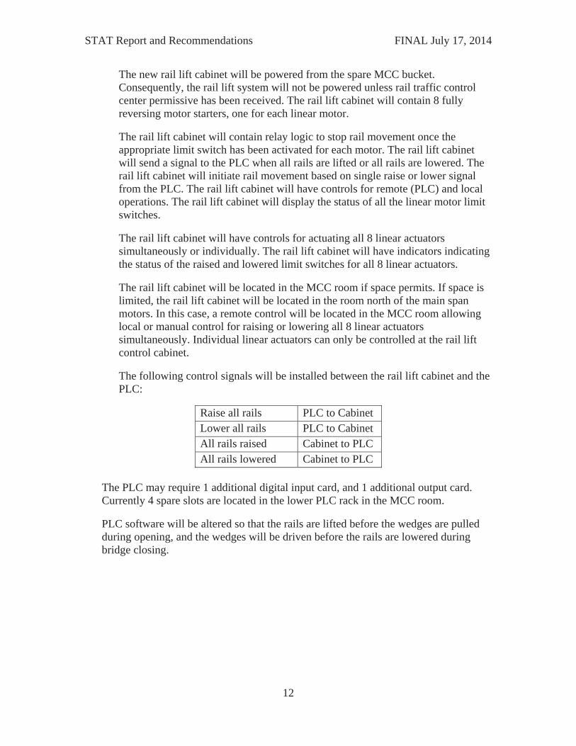
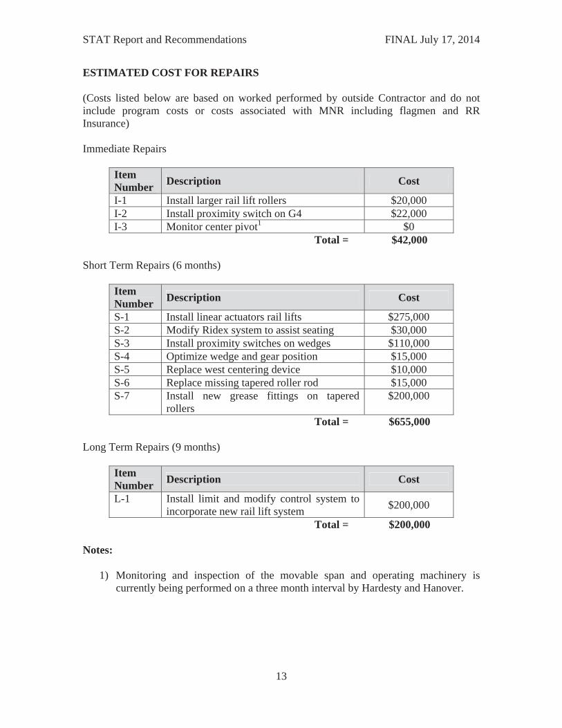
The east wedge segmental gear G4’s engagement was also observed in the fully closed position and noted to be on teeth 12/13 (out of 23) when counted from the bottom or west most tooth (See Photo M-7). This gear rotated to gear teeth 2/3 at the fully opened position (See Photo M-8).
The NW wedge showed the deepest driven position with respect to the wedge seat. This wedge was tight on the stepped section of the wedge/wedge base interface and could not be driven any further. The east center wedge was the least driven, with slight live load deflections observed under live load. All wedges pulled between 13 to 15” during operation and provided adequate clearance for span rotation.
The wedge drive motor brakes were both tested during a span opening on June 29, 2014. In both locations measured brake torques are above the 105 lb-ft name plate rating. Results of the test and further details are included on page App-3 in the Appendix. Operation of the brake and its behavior to the motor was also examined as part of this test. Every time the motor was energized from the MCC panel, power to the brake also occurred releasing the brake. The manual release was also checked for proper operation and it did function properly.
In addition to the wedge inspection, calculations have been made to determine the amount of torque output available from the system. The available bridge lift force is in

STAT Report and Recommendations FINAL July 17, 2014
7
excess than what is needed to raise the bridge ends to the correct vertical alignment. The system is also more than sufficient to move the wedges free when initially retracting.
Motor Meggering
Insulation resistance measurements were taken at the insight electrical disconnects on June 29, 2014 at the wedge motors, wedge brakes, span motors, and span brakes. Results of the megger are included on pages App-1 and App-2 in the Appendix.
Summary of the tests are as follows:
The minimum recommended insulation resistance (NETA and IEEE) corrected to 40C for motors built after 1970, operating at less than 1000 volts is 5Mohm. All motors met this criterion.
All of the wedge brake insulation resistances indicate no insulation resistance problems.
The Main motor 1 1kv measurements are substantially lower than the 500 volt measurement. This measurement is also substantially lower than the main motor 2 1kv measurement. This could be a warning sign of future insulation resistance problems. The main motor 1 insulation resistance should be closely monitored for future trends of dropping insulation resistance.
Centering Device Machinery
In general the centering devices, one mounted at each end of the swing span, functioned as intended. The west centering device worm gear reducer makes louder noise than the east centering device and it is louder than normally anticipated during operation indicating the unit requires rehabilitation or replacement (See Photo M-9).
Alignment of the span was not an issue on both openings and the bar was driven into the receiver both times without any strain or the need to deflect the span.
Based on discussions with MNR personnel, the west centering device worm reducer has been replaced before due to overstress and failure.
Span Drive Machinery
Overall the span operating machinery is operating well and only showing minor areas of deterioration and wear due to age and usage. An abnormal condition observed that is not due to any fault of the operating machinery, but due to the movement of the center pivot is the abnormal meshing of the two rack pinions to the rack.
In the fully closed position, the north rack pinion sits deeper into the rack and the bottom portion of the rack teeth and the bottom land of the rack are being worn by the rack pinion (See Photo M-11). The south rack pinion is separating from the rack causing the tip of the rack pinion to be rounded due to the abnormal wear (See Photo M-10). When

STAT Report and Recommendations FINAL July 17, 2014
8
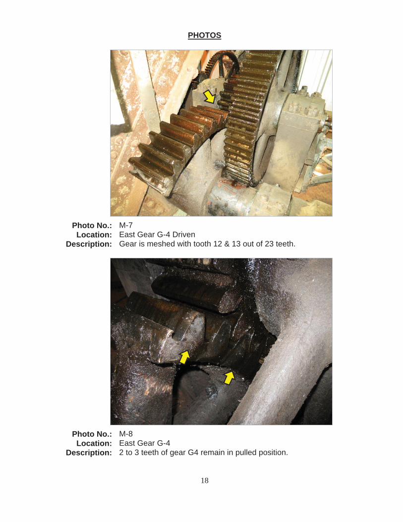
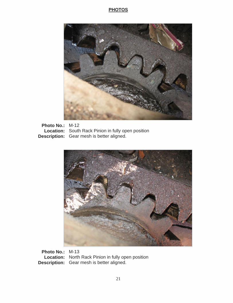
the bridge is in the fully open position, the gear mesh for both rack pinions appears to correct itself, indicating the span is drifting during operation (See Photos M-12 & M-13).
This condition is accelerating the wear on the rack and rack pinion gearing. If the span were to displace more there is the potential of the south pinion completely separating from the rack. If that were to occur, the differential in the span drive machinery would prevent the motor torque from turning the span since the south pinion would be able to freely spin. This would result in span operation ceasing at that point. Based upon visual observation of the gear geometry, it does not appear that separation of the gear teeth is possible since the north pinion will bottom out into the rack before the south pinion were to completely separate. The movement does cause abnormal contact and load distribution between the gearing and which results in overstress of the gearing and the potential for binding and/or tooth breakage.
Center Pivot, Tracks, and Tapered Roller Assemblies
Center Pivot
The center pivot is not secure to the pivot pier. During the two operations, it was observed that the pivot will start to rotate in the same direction of the span rotation until the clearance between the holes in the pivot base and the anchor bolts close, then the movement stops. When the span rotates the opposite direction to close, the pivot will again rotate in the same direction until the clearance between anchor bolt and base hole is closed.
Grease patterns within the center pivot show that the pivot point has been drifting for a long period of time, but it appears the movement has increased. Rough measurement of the grease pattern shows the movement is at least 1 inch (See Photo M-14). Currently in the closed position, the center bearing has drifted to the south – southwest which is also confirmed by the gear mesh of the rack and rack pinions. After the first opening, the grease pattern within the center bearing showed the bridge to be more to the south than the south east
Tapered Roller Assemblies
Observation of the rollers shows that at least 6 of the 90 rollers do not roll freely during operation. All the rollers do roll during the operation, but when the rollers reach a point where they are not in full contact or under lighter load they will stop rolling until coming back into hard contact. This loss of free rolling appears to be due to lack of lubrication between the rod and the roller resulting in additional resistance. This condition has also caused the rods with secure the position of the rollers to twist (See Photo M-15). This repeated twisting has resulted in the failure of at least two rods (See Photo M-16).
During operation the tapered roller assemblies that have the additional resistance shudder, chatter and groan. During the operation, the twisting of the rods changes depending on the direction of roller movement.

STAT Report and Recommendations FINAL July 17, 2014
9
Bridge Operation Control System
All bridge opening and closing operations were conducted from the MCC room on the swing span above the center pier. No control operations were enacted from the control console. The operator was unable to log into the system once MCC operations were initiated. The manual rail locking levers in the control house were operated during openings. The only other top side (rail level) operations were conducted by signals personnel unplugging rail signals lines before opening the bridge, and reconnecting the lines after the bridge was closed. The bridge position indicator on the control room control console is operational. The volt and ammeters on the control console did not appear to be operational.
The east wedge motor brake indication was observed as soon as the RTC permissive was given as determined by the MCC bucket indicator. The MCC relay position was checked and the relay was also receiving electrical power to activate the brake. The PLC output card LED was also indicating east wedge motor brake release. The situation should be investigated since PLC activation is not expected. Bridge personnel verbally indicated this problem only occurs when the wedges are driven. This could not be reconfirmed during the June 29, 2014 inspection since the PLC had been reloaded.
A number of limit switches, as indicated on the PLC input card LED's, never indicated the wedges were fully driven. The wedge driven position was visually checked by bridge personnel. This appears to be a limit switch adjustment issues, since the PLC LED light could be activated by shorting the limit switch at the limit switch location. The bridge control limit switches are in the same enclosure as the rail signals limit switches.
The wedges were pulled by repetitively jogging the wedge motors, then visually checking the wedge (and rail and catenary) position. This prevents wedge pulling operations from being dependent on the wedge limit switches. The wedges were driven until the motors stopped (a single operation). The wedge position was then visually verified.
RECOMMENDATIONS
Immediate
Rail Joint Lift System Modification
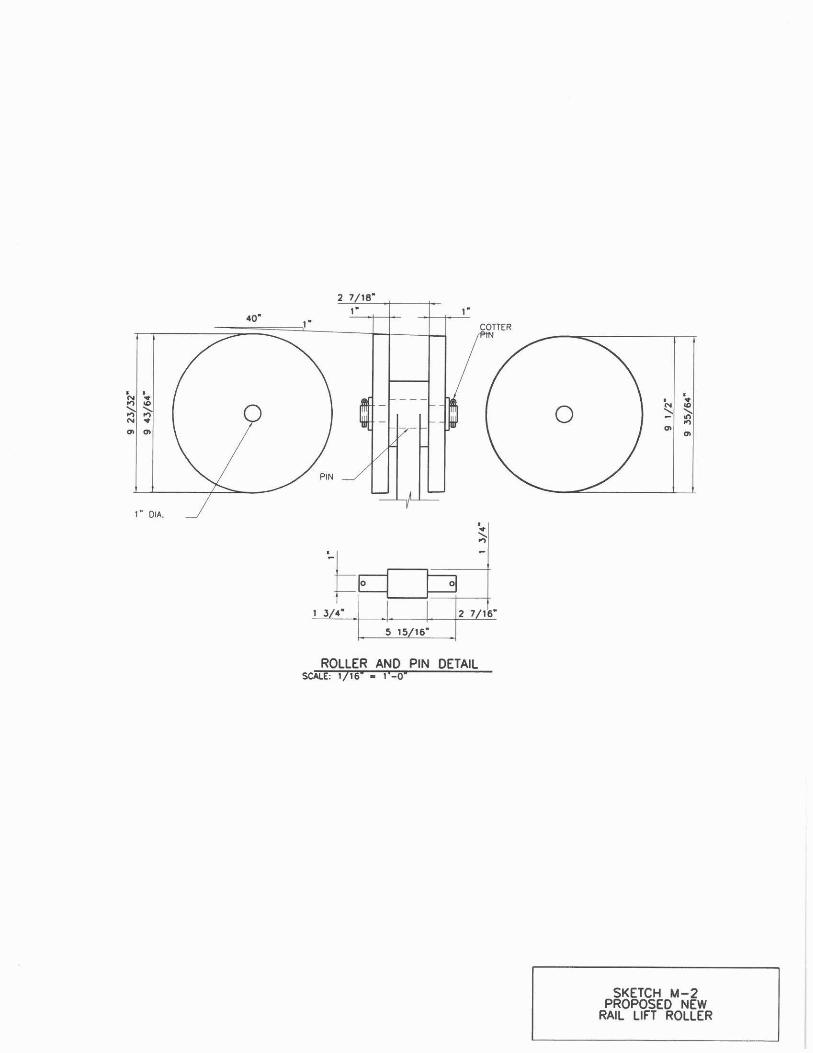
- Replace the existing HDPE rollers with larger diameter rollers at west end of track 3 and the east end of track 1. This repair has been investigated and a sketch showing the lift possible with the current roller along with the lift possible using the new roller is included in Sketch M-1 in the Appendix. Details and dimensions of the proposed roller are included in Sketch M-2. This repair can be implemented immediately and would allow the rail to lift the amount necessary to clear. This would reduce the overall operation since the additional manual jacking of the rail joint would not be necessary.
STAT Report and Recommendations FINAL July 17, 2014
10
- Track personnel should remain at each end of the bridge during an operation to verify adequate clearance exists until repeatability and confidence in the modification has been achieved.
- Install a proximity switch on the segmental gear (G4) to cut power to the wedge drive motor in case the cam limit switch fails. The limit switch will be directly wired back to the MCC, separately from the cam limit switch. The limit switch will be wired in series with the wedge motor starter in the MCC so that when the limit switch is activated, the wedge motor will stop and the wedge motor brake will set. The cam limit switch operation will not be altered other than the new segmental gear G4 limit switch can also stop wedge operations at the MCC. The limit switch should be set so that the cam limit switch should stop the wedge pulling operation before the new limit switch.
Center Pivot and Tracks
- Further securing the center pivot to prevent the span from moving is the preferred option, but it is understood that this is an involved and very costly project that not only entails the center pivot, but also the tracks and roller assemblies. For that reason, it is recommended to inspect the span on a 3 month basis that the movement of the span be monitored to determine if the condition worsens. This inspection would also involve the examination of the two pinions and their meshing with the rack to monitor the gear mesh and make sure the misalignment is not resulting in overstress of the gearing and the abnormal wear is being tracked.
- If the displacement of the center pivot appears to be worsening, then a repair to try and better secure the center pivot to the pier should be implemented. This does not have to completely secure the pivot to the pier, but rather reduce the amount of movement to allow the swing span operating machinery from being overstressed.
Short Term Repairs (within 6 months)
Rail Joint Lift Modifications
- Design and install linear actuator system to remove the rail lift operation from the existing wedge drive machinery. There will be four linear actuators at each end of the bridge. One actuator will raise a pair of rails through a crank and shaft as is currently being done. This will eliminate any excessive loading to the wedge drive machinery and reduce complexity of adjustment needs that is the result of utilizing one drive system for many components. This system will be manually controlled initially, but as part of the long term repairs, the operation and control of the linear actuator system will be incorporated into the bridge control system.

STAT Report and Recommendations FINAL July 17, 2014
11
- Modify the Ridex rail guidance system to provide adequate alignment when seating.
- Replace limit switches at the wedge assemblies with proximity type switches that interface with the existing PLC. The U5 system (CC Boxes) will remain to be used by rail signals. Existing conduit between the PLC and the CC switches will be replaced with new conduit and wiring to the new limit switches. The PLC will use the new proximity switches for wedge pulled and driven indications.
Wedge Drive Modification
- Once the rail lifting has been separated from the wedge drive, the readjustment of the wedge drive system should be performed.
Centering Device Machinery
- Replace the west centering device worm gear reducer.
- Since there is an alternate method of centering the span in case of a centering malfunction or failure further implementation is not required. If it has not been done so already, a test of the alternate system should be performed to see crew size, positions and time to perform the task.
Tapered Roller Assemblies
- Design and install grease fitting on the outside of the tapered rollers; grease fitting to be located in the center of the roller rod
- Institute a repair procedure to get the rollers back to rolling more freely. This may be tried first by getting grease into the rollers that are having trouble. If that does not succeed, disassembly of the rollers one at a time and cleaning and repairing the rod journal and roller bushing should be performed.
- Replace the two missing tapered roller radial rods.
Long Term Repairs (within 9 months)
Bridge Control System
- Modify the bridge electrical system to incorporate the new rail lift system into the bridge control system. The rails will be lifted with 8 linear actuators each with its own motor, one motor for each track on each side (east or west) of the bridge. Each liner actuator will contain 2 limit switches controlling the rail lifting and lowering movement limits. Each actuator will have 2 conduits to the new rail lift cabinet. One conduit will be used for motor power, and one conduit will be used for limit switch wiring.
STAT Report and Recommendations FINAL July 17, 2014
12
The new rail lift cabinet will be powered from the spare MCC bucket. Consequently, the rail lift system will not be powered unless rail traffic control center permissive has been received. The rail lift cabinet will contain 8 fully reversing motor starters, one for each linear motor.
The rail lift cabinet will contain relay logic to stop rail movement once the appropriate limit switch has been activated for each motor. The rail lift cabinet will send a signal to the PLC when all rails are lifted or all rails are lowered. The rail lift cabinet will initiate rail movement based on single raise or lower signal from the PLC. The rail lift cabinet will have controls for remote (PLC) and local operations. The rail lift cabinet will display the status of all the linear motor limit switches.
The rail lift cabinet will have controls for actuating all 8 linear actuators simultaneously or individually. The rail lift cabinet will have indicators indicating the status of the raised and lowered limit switches for all 8 linear actuators.
The rail lift cabinet will be located in the MCC room if space permits. If space is limited, the rail lift cabinet will be located in the room north of the main span motors. In this case, a remote control will be located in the MCC room allowing local or manual control for raising or lowering all 8 linear actuators simultaneously. Individual linear actuators can only be controlled at the rail lift control cabinet.
The following control signals will be installed between the rail lift cabinet and the PLC:
Raise all rails PLC to CabinetLower all rails PLC to CabinetAll rails raised Cabinet to PLCAll rails lowered Cabinet to PLC
The PLC may require 1 additional digital input card, and 1 additional output card. Currently 4 spare slots are located in the lower PLC rack in the MCC room.
PLC software will be altered so that the rails are lifted before the wedges are pulled during opening, and the wedges will be driven before the rails are lowered during bridge closing.
STAT Report and Recommendations FINAL July 17, 2014
13
ESTIMATED COST FOR REPAIRS
(Costs listed below are based on worked performed by outside Contractor and do not include program costs or costs associated with MNR including flagmen and RR Insurance)
Immediate Repairs
ItemNumber Description Cost
I-1 Install larger rail lift rollers $20,000 I-2 Install proximity switch on G4 $22,000 I-3 Monitor center pivot1 $0
Total = $42,000
Short Term Repairs (6 months)
ItemNumber Description Cost
S-1 Install linear actuators rail lifts $275,000 S-2 Modify Ridex system to assist seating $30,000 S-3 Install proximity switches on wedges $110,000 S-4 Optimize wedge and gear position $15,000 S-5 Replace west centering device $10,000 S-6 Replace missing tapered roller rod $15,000 S-7 Install new grease fittings on tapered
rollers $200,000
Total = $655,000
Long Term Repairs (9 months)
ItemNumber Description Cost
L-1 Install limit and modify control system to incorporate new rail lift system $200,000
Total = $200,000
Notes:
1) Monitoring and inspection of the movable span and operating machinery is currently being performed on a three month interval by Hardesty and Hanover.

14
Photographs

PHOTOS
Photo No.: M-1Location: Track 3, Northeast rail lift
Description: New rail lift shaft and bearing.
Photo No.: M-2Location: Track 3, Southwest rail lift bearing
Description: Excessive clearance between bearing and shaft, large gap between rail and roller.
15

PHOTOS
Photo No.: M-3Location: Track 3, Southeast rail lift
Description: Rail lift crank is disconnected from drive machinery.
Photo No.: M-4Location: Track 3 East
Description: Rail is jacked and blocked in raised position.
16

PHOTOS
Photo No.: M-5Location: West Gear G-4 Driven
Description: Gear is meshed with tooth 15 & 16 out of 23 teeth.
Photo No.: M-6Location: West Gear G-4 Pulled
Description: 5 to 6 teeth of gear G4 remain in pulled position.
17
PHOTOS
Photo No.: M-7Location: East Gear G-4 Driven
Description: Gear is meshed with tooth 12 & 13 out of 23 teeth.
Photo No.: M-8Location: East Gear G-4
Description: 2 to 3 teeth of gear G4 remain in pulled position.
18

PHOTOS
Photo No.: M-9Location: West Centering Device
Description: Worm gear reducer displayed operational issues; loud during raise and lower.
19
PHOTOS

Photo No.: M-10Location: South Rack Pinion in fully closed position
Description: Gear mesh is separating.
Photo No.: M-11Location: North Rack Pinion in fully closed position
Description: Gear mesh is binding.
20
PHOTOS
Photo No.: M-12Location: South Rack Pinion in fully open position
Description: Gear mesh is better aligned.
Photo No.: M-13Location: North Rack Pinion in fully open position
Description: Gear mesh is better aligned.
21

PHOTOS
Photo No.: M-14Location: Center Pivot interior looking down
Description: Grease pattern shows at least 1 inch movement of pivot.
Photo No.: M-15Location: Roller Rod
Description: Rod twisted due to wheel not fully turning.
22
PHOTOS

Photo No.: M-16Location: Tapered Roller Assemblies
Description: Two consecutive rods missing.
22

Appendix

App-1
INSULATION RESISTANCE
Insulation resistance measurements were made during the 2014-06-29 site visit. The measurements and calculations were made according to IEEE43-2000 and ANSI-NETA MTS-2007. The results are listed below.
Item Temperature (C) Volts Measured Resistance
(Mohm) Calculated Resistance
(Mohm) 30 sec 60 sec 30 sec 60 sec
Brake motor 1 23.5 250 >1Gohm >1Gohm - - Brake motor 1 23.5 500 >1Gohm >1Gohm - - Brake motor 1 23.5 1000 >1Gohm >1Gohm - - Brake motor 2 26.5 250 >1Gohm >1Gohm - - Brake motor 2 26.5 500 >1Gohm >1Gohm - - Brake motor 2 26.5 1000 >1Gohm >1Gohm - - Brake Wedge e 23.5 250 >1Gohm >1Gohm - - Brake Wedge e 23.5 500 >1Gohm >1Gohm - - Brake Wedge e 23.5 1000 >1Gohm >1Gohm - - Brake Wedge w 23.5 250 >1Gohm >1Gohm - - Brake Wedge w 23.5 500 >1Gohm >1Gohm - - Brake Wedge w 23.5 1000 >1Gohm >1Gohm - - Motor main 1 23.5 250 450 518 210 242 Motor main 1 23.5 500 446 487 208 227 Motor main 1 23.5 1000 22.8 21.5 10.6 10.0 Motor main 2 26.5 250 540 598 289 321 Motor main 2 26.5 500 513 550 275 295 Motor main 2 26.5 1000 457 490 245 263 Motor Wedge e 23.5 250 521 631 243 294 Motor Wedge e 23.5 500 553 642 258 300 Motor Wedge e 23.5 1000 525 598 245 279 Motor Wedge w 23.5 250 342 481 160 224 Motor Wedge w 23.5 500 350 395 163 184 Motor Wedge w 23.5 1000 326 361 152 168
Insulation resistance measurements were taken at the in sight disconnects. An AVO BM223 MEGGAR was used for the measurements. Measurements were taken at 30 and 60 seconds after the test voltages were applied. Measurements were taken at 250, 500 and 1000 volts. Temperature measurements were made with an infrared thermometer on the motor housings. Field measured values (Measured resistance) are corrected to 40C (Calculated Resistance).
All of the Brake insulation resistances were greater than 1 Gohm, which is the upper limit of the AVO BM223. All of these measurements indicate no insulation resistance problems with the Brakes.
The main motor 2 and the brake motor 2 insulation resistance measurements were made about .5 hours after this motor and brake were used for opening and closing the bridge. Consequently the housing temperatures are slightly higher than other equipment.
The minimum recommended insulation resistance (NETA and IEEE) corrected to 40C for motors built after 1970, operating at less than 1000 volts is 5Mohm. All motors meet this criterion
The resistances measured at 60 second are all greater than the 30 second measurements. A lower 60 second measurement would be an indication of problems.

App-2
The Main motor 1 1kv measurements are substantially lower than the 500 volt measurement. This measurement is also substantially lower than the main motor 2 1kv measurement. This could be a warning sign of future insulation resistance problems. The main motor 1 insulation resistance should be closely monitored for future trends of dropping insulation resistance.
WINDING RESISTANCE
Phase to phase winding resistance were measured at the in sight disconnects. The values are listed below.
Phase to Phase
Resistance (ohms)
Item
63 Brake motor 1 66 Brake motor 2 24 Brake Wedge e 24 Brake Wedge w
0.38 Motor main 1 0.36 Motor main 2 0.81 Motor Wedge e
0.82 Motor Wedge w
All resistances are similar between the same equipment. No problems are indicated.
App-3
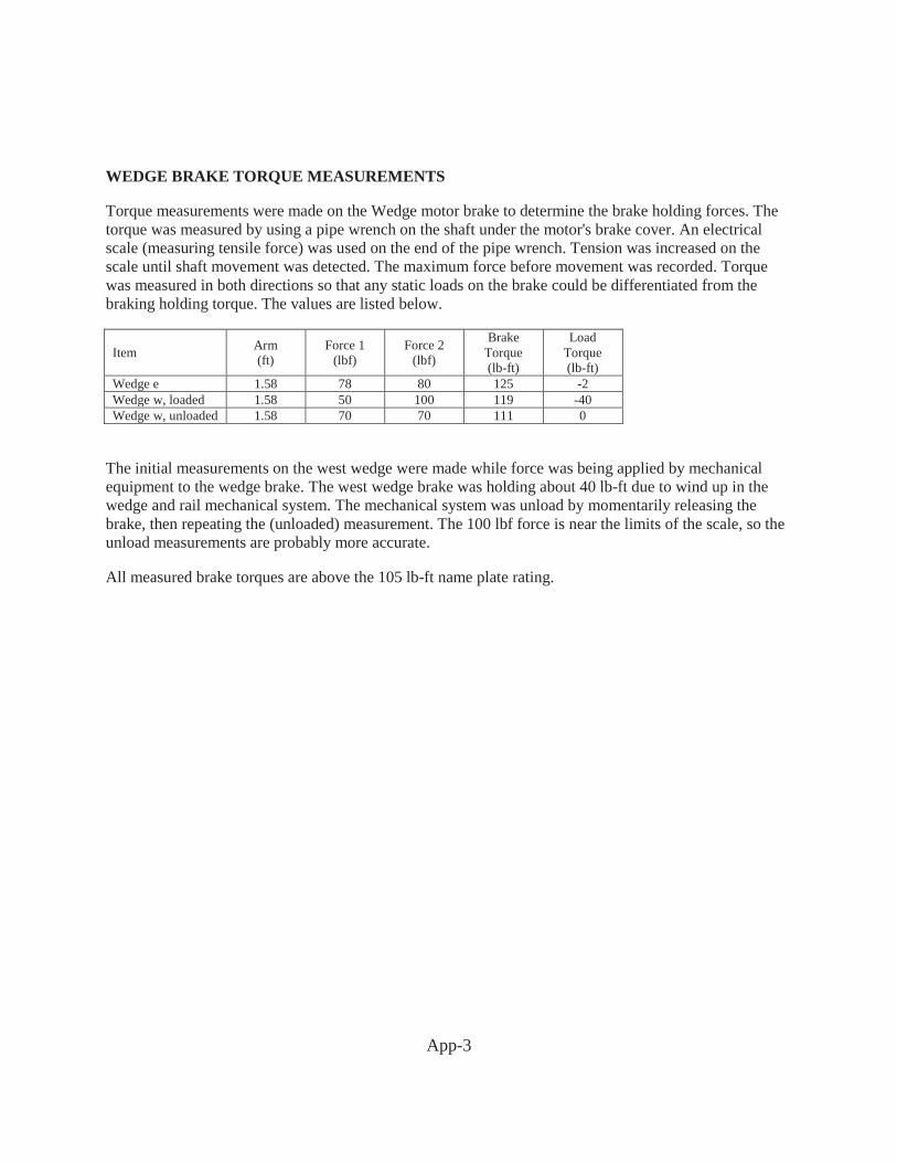
WEDGE BRAKE TORQUE MEASUREMENTS
Torque measurements were made on the Wedge motor brake to determine the brake holding forces. The torque was measured by using a pipe wrench on the shaft under the motor's brake cover. An electrical scale (measuring tensile force) was used on the end of the pipe wrench. Tension was increased on the scale until shaft movement was detected. The maximum force before movement was recorded. Torque was measured in both directions so that any static loads on the brake could be differentiated from the braking holding torque. The values are listed below.
Item Arm (ft)
Force 1 (lbf)
Force 2 (lbf)
Brake Torque (lb-ft)
Load Torque (lb-ft)
Wedge e 1.58 78 80 125 -2 Wedge w, loaded 1.58 50 100 119 -40 Wedge w, unloaded 1.58 70 70 111 0
The initial measurements on the west wedge were made while force was being applied by mechanical equipment to the wedge brake. The west wedge brake was holding about 40 lb-ft due to wind up in the wedge and rail mechanical system. The mechanical system was unload by momentarily releasing the brake, then repeating the (unloaded) measurement. The 100 lbf force is near the limits of the scale, so the unload measurements are probably more accurate.
All measured brake torques are above the 105 lb-ft name plate rating.