connect strain gages to a data acquisition (daq) device - national instruments
TRANSCRIPT

29/07/13 Connect Strain Gages to a Data Acquisition (DAQ) Device - National Instruments
www.ni.com/gettingstarted/setuphardware/dataacquisition/i/straingages.htm#Wiring a Strain Gage to Your Device 1/6
Install Software Connect Hardware Learn LabVIEW Basics Begin Your Application
Connect Strain Gages to a Data Acquisition (DAQ)Device
Personalizza il tuo sito web ni.com. Effettua il Login o Crea un profilo utente.
Before You Begin Back to top
Locating Your DAQ Device Pinout Back to top
Configuring a Strain Measurement Back to top
Included in the Section
Locating Your DAQ Device Pinout
Configuring a Strain Measurement
Wiring a Strain Gage to Your Device
Strain Gage Calibration
Testing the Signal
This document provides step-by-step instructions for wiring and configuring your NI data acquisitiondevice for strain gage measurements. Before you begin using your NI data acquisition hardware, youmust install your application development environment (ADE) and NI-DAQmx driver software. Refer tothe Installing NI LabVIEW and NI-DAQmx document for more information.
View in-depth description
Before connecting any signals, locate your device pinout.
1. Open NI Measurement & Automation Explorer (MAX) and expand Devices and Interfaces.
2. Right-click on your device name, and select “Device Pinouts.”
Figure 16. Device Terminals Help
You can use NI Measurement & Automation Explorer (MAX) to quickly verify the accuracy of yourmeasurement system setup. Using an NI-DAQmx Global Virtual Channel you can configure a strainmeasurement without any programming. A virtual channel is a concept of the NI-DAQmx driver

29/07/13 Connect Strain Gages to a Data Acquisition (DAQ) Device - National Instruments
www.ni.com/gettingstarted/setuphardware/dataacquisition/i/straingages.htm#Wiring a Strain Gage to Your Device 2/6
measurement without any programming. A virtual channel is a concept of the NI-DAQmx driverarchitecture used to represent a collection of device property settings that can include a name, aphysical channel, input terminal connections, the type of measurement or generation, and scalinginformation.
Follow these steps to begin:
3. With NI Measurement & Automation Explorer open, select Data Neighborhood and click
Create New.
4. Select NI-DAQmx Global Virtual Channel and click Next.
5. Select Acquire Signals » Analog Input » Strain
Figure 17. Creating an NI-DAQmx Virtual Channel
6. Select ai0 or whichever physical channel you intend to connect your strain gage. A physical
channel is a terminal or pin at which you can measure or generate an analog or digital signal.
A single physical channel can include more than one terminal or pin, as in the case of a
differential input channel.
Figure 18. Device Physical Channels
7. Click Next and enter a name for the global virtual channel or leave the default.

29/07/13 Connect Strain Gages to a Data Acquisition (DAQ) Device - National Instruments
www.ni.com/gettingstarted/setuphardware/dataacquisition/i/straingages.htm#Wiring a Strain Gage to Your Device 3/6
Wiring a Strain Gage to Your Device Back to top
7. Click Next and enter a name for the global virtual channel or leave the default.
8. Click Finish and you should see the following screen in MAX:
Figure 19. Setting up a Strain Channel in MAX
9. On the Settings tab, type in the minimum and maximum strain values you expect to read from
your strain gage (-1m to 1m by default).
10. Configure the Gage Factor, Gage Resistance, Initial Voltage, VEX Source, VEX Value (V), Lead
Resistance, and Strain Configuration based on your sensor specifications and the
information discussed above in the Strain Measurement Fundamentals section.
The next step is to physically connect the strain gage to your DAQ device.
11. Click the Connection Diagram tab in MAX to continue.
Figure 20. Strain Connection Diagram

29/07/13 Connect Strain Gages to a Data Acquisition (DAQ) Device - National Instruments
www.ni.com/gettingstarted/setuphardware/dataacquisition/i/straingages.htm#Wiring a Strain Gage to Your Device 4/6
Strain Gage Calibration Back to top
The connection diagram above indicates which pins on your DAQ device should be wired accordingto the physical channel you selected. In this example, a full bridge type I configuration uses pins 2, 3,6, and 7, corresponding to AI+, AI-, EX+, and EX- on an NI 9237 C Series module.
When you configure a strain measurement task, you can use the Strain Gage Calibration Wizard tocalibrate your strain gage. Complete the following steps to calibrate the strain gage:
Figure 21. Strain Gage Calibration Wizard
12. Select the Device tab and click Calibrate to launch the Strain Gage Calibration Wizard.
13. Follow the steps on the Setup Hardware window. You can configure the following settings:
i. Enable Offset Nulling Select Enable Offset Nulling to perform an offset nulling calibration
procedure.
ii. Enable Shunt Calibration Select Enable Shunt Calibration to perform a shunt calibration
procedure. If you select this option, configure the following settings:
Shunt Resistor Value—Specify the exact resistor value of the shunt resistor. The default
value is the resistance of the shunt resistor that is the factory shipping default for your
hardware. For the greatest accuracy, use a 6-1/2 digit DMM to measure the res istance
of your entire shunt calibration circuit with the shunt switch engaged and leads
connected. This will increase the accuracy of your measurements by compensating for
the shunt enable switch resistance and any lead resistance caused by long lead wires.
However, since the shunt resistor value is very large, these do not greatly impact the
measurement accuracy.
Shunt Resistor Location—Specify the location on the Wheatstone bridge to which the
shunt resistor is connected. Refer to the figure on the Setup Hardware window for the
relative positions of R1, R2, R3 and R4.
14. Click Next.
29/07/13 Connect Strain Gages to a Data Acquisition (DAQ) Device - National Instruments
www.ni.com/gettingstarted/setuphardware/dataacquisition/i/straingages.htm#Wiring a Strain Gage to Your Device 5/6
Testing the Signal Back to top
Figure 22. Measure and Calibration Window
15. Use the Measure and Calibrate window to measure and calibrate your strain gage. The
software automatically takes the first measurement, and the table displays the results. The
table shows the following information:
i. Channel Information
Channel Name—The name of the virtual channel on which strain calibration is
performed.
Physical Chan—The physical channel to which the strain gage is connected.
ii. Offset Adjustment—This section shows information about the offset error to help you
determine if you should perform an offset null calibration. Perform an offset null calibration
if you perform a shunt calibration.
Meas Val (strain)—The measured offset value with units of strain. Normally, this value
should be close to zero.
Err (%)—Percentage offset error, determined by the equation: Err (%) = [(offset value *
100) / (Max Range Limit – Min Range Limit)] where Max Range Limit and Min Range
Limit are the maximum and minimum strain range values specified for the given virtual
channel.
Gain Adjustment—This section shows values related to gain error and the shunt
calibration procedure:
Sim Val (strain)—The simulated strain value based on the hardware setup and the
shunt resistor value.
Meas Val (strain)—The measured strain value. Normally, this value should be close
to the simulated strain value.
Gain Adj Val—The gain adjust value. This value is the end result of the shunt
calibration and is used to scale strain measurements on this channel. Normally, this
value is close to 1, which implies that the measured value and simulated value are
equal. Your strain channel stores the gain adjust value as the
AI.Bridge.ShuntCal.GainAdjust attribute.
Err (%)—Percentage gain error, determined by the equation: Err (%) = (measured
value – simulated value) * 100 / (Max – Min) where Max and Min are the maximum
and minimum strain values specified for the given virtual channel.
16. Perform your measurement and calibration with the following buttons:
i. Click Measure to make a preliminary measurement using the offset and shunt calibration
data from a previously run strain gage procedure.
ii. Click Reset Data to reset the offset and shunt calibration data and make a measurement
using their default values.
iii. Click Calibrate to perform the offset and/or shunt calibration. The table shows the resulting
measurements.
17. Click Finish when you are done. The calibration data is saved as part of your virtual channel.
On successful completion, the software automatically uses the calibration data when scaling
voltage to strains on this virtual channel.
NI-DAQmx global virtual channels allow you to preview your measurements.
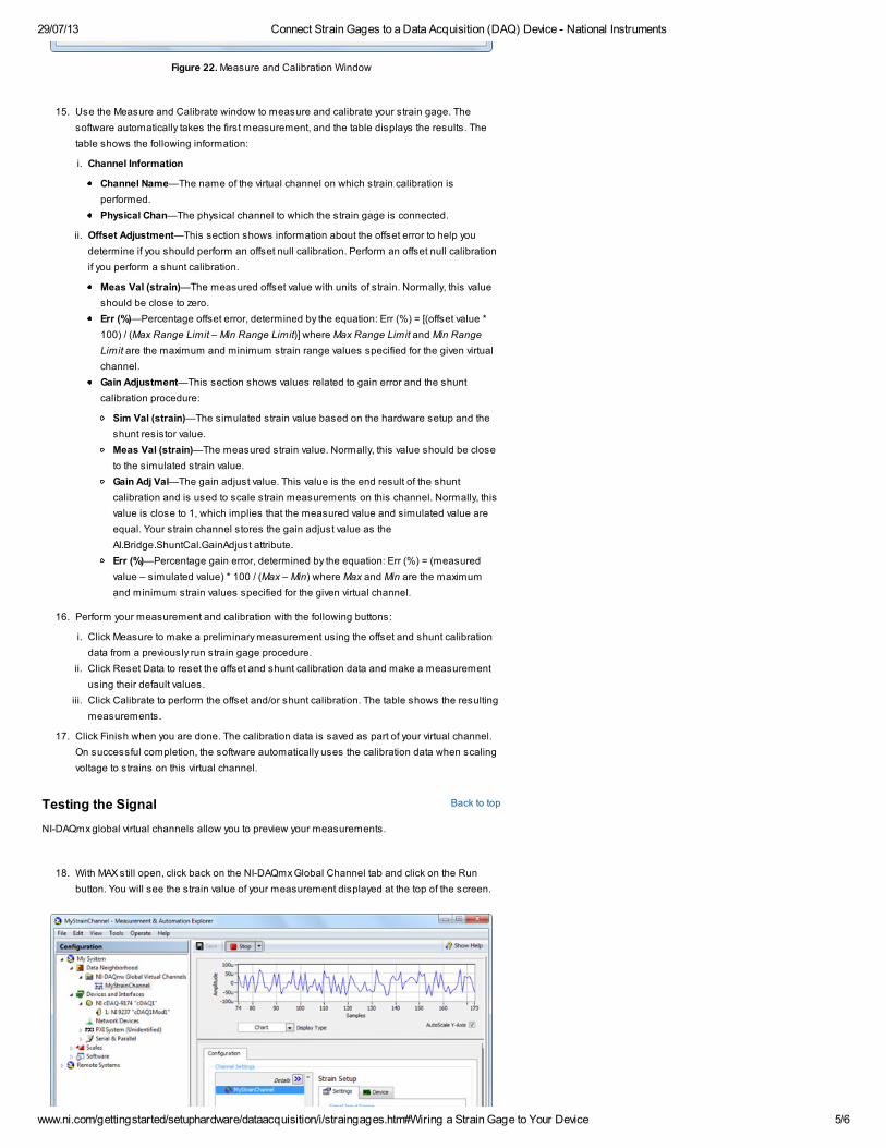
18. With MAX still open, click back on the NI-DAQmx Global Channel tab and click on the Run
button. You will see the strain value of your measurement displayed at the top of the screen.

29/07/13 Connect Strain Gages to a Data Acquisition (DAQ) Device - National Instruments
www.ni.com/gettingstarted/setuphardware/dataacquisition/i/straingages.htm#Wiring a Strain Gage to Your Device 6/6
Previous Step Next Step
Connect and Setup Hardware Introduction to LabVIEW
Figure 23. Previewing a Strain Measurement in MAX
You can choose to view the signal in tabular form or as a graph by selecting Graph from the DisplayType dropdown. You also have the option of saving your NI-DAQmx Global Virtual Channel shouldyou wish to refer to this configuration screen again in the future.
My Profile | RSS | Privacy | Legal | Contact NI© 2012 National Instruments Corporation. All rights reserved. | E-Mail this Page