configuring frame relay - · pdf fileconfiguring frame relay this chapter describes the...
TRANSCRIPT

Configuring Frame Relay IV-153
FINAL DRAFT CISCO CONFIDENTIAL
Configuring Frame Relay
This chapter describes the tasks for configuring Frame Relay on a router or access server. For acomplete description of the commands mentioned in this chapter, refer to the “Frame RelayCommands” chapter in theWide-Area Networking Command Reference.
Although Frame Relay access was originally restricted to leased lines, dial-up access is nowsupported. For more information, see the “Configure DDR over Frame Relay” section in the“Configuring DDR” chapter of this manual.
To install software on a new router or access server by downloading software from a central serverover an interface that supports Frame Relay, see the “Loading System Images, Microcode Images,and Configuration Files” chapter in theConfiguration Fundamentals Configuration Guide.
To configure access between SNA devices over a Frame Relay network, see the “Configuring SNAFrame Relay Access Support” chapter in theBridging and IBM Networking Configuration Guide.
Frame Relay Hardware ConfigurationsOne of the following hardware configurations is possible for Frame Relay connections:
• Routers and access servers can connect directly to the Frame Relay switch.
• Routers and access servers can connect directly to a channel service unit/digital service unit(CSU/DSU), which then connects to a remote Frame Relay switch.
Note A Frame Relay network is not required to support only routers that are connected directly oronly routers connected via CSU/DSUs. Within a network, some routers can connect to a FrameRelay switch through a direct connection and others through connections via CSU/DSUs. However,a single router interface configured for Frame Relay can be only one or the other.
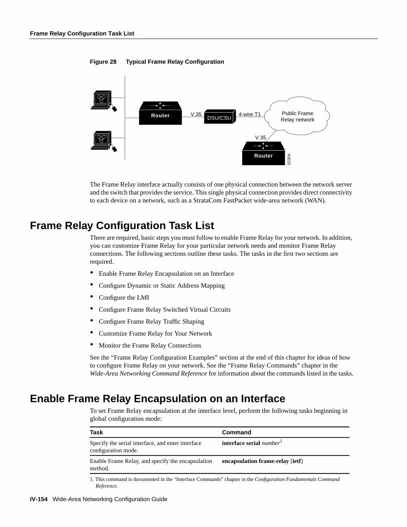
The CSU/DSU converts V.35 or RS-449 signals to the properly coded T1 transmission signal forsuccessful reception by the Frame Relay network. Figure28 illustrates the connections between thedifferent components.
IV-154 Wide-Area Networking Configuration Guide
Frame Relay Configuration Task List
FINAL DRAFT CISCO CONFIDENTIAL
Figure 28 Typical Frame Relay Configuration
The Frame Relay interface actually consists of one physical connection between the network serverand the switch that provides the service. This single physical connection provides direct connectivityto each device on a network, such as a StrataCom FastPacket wide-area network (WAN).
Frame Relay Configuration Task ListThere are required, basic steps you must follow to enable Frame Relay for your network. In addition,you can customize Frame Relay for your particular network needs and monitor Frame Relayconnections. The following sections outline these tasks. The tasks in the first two sections arerequired.
• Enable Frame Relay Encapsulation on an Interface
• Configure Dynamic or Static Address Mapping
• Configure the LMI
• Configure Frame Relay Switched Virtual Circuits
• Configure Frame Relay Traffic Shaping
• Customize Frame Relay for Your Network
• Monitor the Frame Relay Connections
See the “Frame Relay Configuration Examples” section at the end of this chapter for ideas of howto configure Frame Relay on your network. See the “Frame Relay Commands” chapter in theWide-Area Networking Command Reference for information about the commands listed in the tasks.
Enable Frame Relay Encapsulation on an InterfaceTo set Frame Relay encapsulation at the interface level, perform the following tasks beginning inglobal configuration mode:
1. This command is documented in the “Interface Commands” chapter in theConfiguration Fundamentals CommandReference.
Task Command
Specify the serial interface, and enter interfaceconfiguration mode.
interface serialnumber1
Enable Frame Relay, and specify the encapsulationmethod.
encapsulation frame-relay[ietf]
Router DSU/CSUV.35
S23
04
Public Frame Relay network
4-wire T1
Router
V.35

Configure Dynamic or Static Address Mapping
Configuring Frame Relay IV-155
FINAL DRAFT CISCO CONFIDENTIAL
Frame Relay supports encapsulation of all supported protocols in conformance with RFC 1490,allowing interoperability between multiple vendors. Use the Internet Engineering Task Force (IETF)form of Frame Relay encapsulation if your router or access server is connected to another vendor’sequipment across a Frame Relay network. IETF encapsulation is supported either at the interfacelevel or on a per-virtual circuit basis.
For an example of how to enable Frame Relay and set the encapsulation method, see the sections“IETF Encapsulation Examples” and “Static Address Mapping Examples” later in this chapter.
Configure Dynamic or Static Address MappingDynamic address mapping uses Frame Relay Inverse ARP to request the next hop protocol addressfor a specific connection, given its known DLCI. Responses to Inverse ARP requests are entered inan address-to-DLCI mapping table on the router or access server; the table is then used to supply thenext hop protocol address or the DLCI for outgoing traffic.
Inverse ARP is enabled by default for all protocols it supports, but can be disabled for specificprotocol-DLCI pairs. As a result, you can use dynamic mapping for some protocols and staticmapping for other protocols on the same DLCI. You can explicitly disable Inverse ARP for aprotocol-DLCI pair if you know that the protocol is not supported on the other end of the connection.See the “Disable or Reenable Frame Relay Inverse ARP” section later in this chapter for moreinformation.
Configure Dynamic MappingInverse ARP is enabled by default for all protocols enabled on the physical interface. Packets are notsent out for protocols that are not enabled on the interface.
Because Inverse ARP is enabled by default, no additional command is required to configure dynamicmapping on an interface.
Configure Static MappingA static map links a specified next hop protocol address to a specified DLCI. Static mapping removesthe need for Inverse ARP requests; when you supply a static map, Inverse ARP is automaticallydisabled for the specified protocol on the specified DLCI.
You must use static mapping if the router at the other end either does not support Inverse ARP at allor does not support Inverse ARP for a specific protocol that you want to use over Frame Relay.
To establish static mapping according to your network needs, perform one of the following tasks ininterface configuration mode:
Task Command
Define the mapping between a next hopprotocol address and the DLCI used toconnect to the address.
frame-relay map protocol protocol-address dlci[broadcast][ietf] [cisco]
Define a DLCI used to sendInternational Organization forStandardization (ISO) ConnectionlessNetwork Service (CLNS) frames.
frame-relay map clns dlci [broadcast]
Define a DLCI used to connect to abridge.
frame-relay map bridge dlci [broadcast] [ ietf]

IV-156 Wide-Area Networking Configuration Guide
Configure the LMI
FINAL DRAFT CISCO CONFIDENTIAL
The supported protocols and the corresponding keywords to enable them are as follows:
• IP—ip
• DECnet—decnet
• AppleTalk—appletalk
• XNS—xns
• Novell IPX—ipx
• VINES—vines
• ISO CLNS—clns
You can greatly simplify the configuration for the Open Shortest Path First (OSPF) protocol byadding the optionalbroadcast keyword when doing this task. See theframe-relay map commanddescription in theWide-Area Networking Command Reference and the examples at the end of thischapter for more information about using thebroadcastkeyword.
For examples of how to establish static address mapping, see the “Static Address MappingExamples” section later in this chapter.
Configure the LMIBeginning with Cisco IOS Release 11.2, the software supports Local Management Interface (LMI)autosense, which enables the interface to determine the LMI type supported by the switch. Supportfor LMI autosense means that you are no longer required to configure the Local ManagementInterface (LMI) explicitly.
Allow LMI Autosense to OperateLMI autosense is active in the following situations:
• The router is powered up or the interface changes state to up.
• The line protocol is down but the line is up.
• The interface is a Frame Relay DTE.
• The LMI type is not explicitly configured.
When LMI autosense is active, it sends out a full status request, in all 3 LMI flavors, to the switch.The order is ANSI, ITU, cisco but is done in rapid succession. Unlike previous software capability,we can now listen in on both DLCI 0 (cisco LMI) and DLCI 1023 (ANSI and ITU) simultaneously.
One or more of the status requests will elicit a reply (status message) from the switch. The routerwill decode the format of the reply and configure itself automatically. If more than one reply isreceived, the router will configure itself with the type of the last received reply. This is toaccommodate intelligent switches that can handle multiple formats simultaneously.
If LMI autosense is unsuccessful, an intelligent retry scheme is built in. Every N391 interval (defaultis 60 seconds, which is 6 keep exchanges at 10 seconds each), LMI autosense will attempt toascertain the LMI type. For more information about N391, see theframe-relay lmi-n391dtecommand in the “Frame Relay Commands” chapter of the Wide-Area Networking CommandReference.
The only visible indication to the user that LMI autosense is underway is when "debug frame lmi"is turned on. Every N391 interval, the user will now see 3 rapid status enquiries coming out of theserial interface. One in ANSI, one in ITU and one in cisco LMI-type.

Configure the LMI
Configuring Frame Relay IV-157
FINAL DRAFT CISCO CONFIDENTIAL
No configuration options are provided; this is transparent to the user. You can turn off LMI autosenseby explicitly configuring an LMI type. The LMI type must be written into NVRAM so that next timethe router powers up, LMI autosense will be inactive. At the end of autoinstall, a "frame-relaylmi-type xxx" statement is included within the interface configuration. This configuration is notautomatically written to NVRAM; you must do so explicitly.
Explicitly Configure the LMIOur Frame Relay software supports the industry-accepted standards for addressing the LocalManagement Interface (LMI), including the Cisco specification. If you want to configure the LMIand thus deactivate LMI autosense, complete the tasks in the following sections. The tasks in the firsttwo sections are required if you choose to configure the LMI.
• Set the LMI Type
• Set the LMI Keepalive Interval
• Set the LMI Polling and Timer Intervals
Set the LMI TypeIf the router or access server is attached to a public data network (PDN), the LMI type must matchthe type used on the public network. Otherwise, the LMI type can be set to suit the needs of yourprivate Frame Relay network.
You can set one of three types of LMIs on our devices: ANSI T1.617 Annex D, Cisco, and ITU-TQ.933 Annex A. To do so, perform the following task in interface configuration mode:
For an example of how to set the LMI type, see the “Pure Frame Relay DCE Example” section laterin this chapter.
Set the LMI Keepalive IntervalA keepalive interval must be set to configure the LMI. By default, this interval is 10 seconds and, perthe LMI protocol, must be less than the corresponding interval on the switch. To set the keepaliveinterval, perform the following task in interface configuration mode:
For an example of how to specify an LMI keepalive interval, see the “Two Routers in Static ModeExample” section later in this chapter.
1. Use the command form that is appropriate to your router platform. See the “Image and Configuration File LoadCommands” chapter in theConfiguration Fundamentals Command Reference.
Task Command
Set the LMI type. frame-relay lmi-type { ansi | cisco | q933a}
Write the LMI type to NVRAM. copy runnning-configdestination1
Task Command
Set the keepalive interval. keepalivenumber
Turn off keepalives on networks without an LMI. no keepalive

IV-158 Wide-Area Networking Configuration Guide
Configure Frame Relay Switched Virtual Circuits
FINAL DRAFT CISCO CONFIDENTIAL
Set the LMI Polling and Timer IntervalsYou can set various optional counters, intervals, and thresholds to fine-tune the operation of yourLMI DTE and DCE devices. Set these attributes by performing one or more of the following tasksin interface configuration mode:
See the “Frame Relay Commands” chapter in theWide-Area Networking Command Reference fordetails about commands used to set the polling and timing intervals.
Configure Frame Relay Switched Virtual CircuitsCurrently, access to Frame Relay networks is made through private leased lines at speeds rangingfrom 56 kbps to 45 Mbps. Frame Relay is a connection-oriented, packet-transfer mechanism thatestablishes virtual circuits between endpoints.
Switched virtual circuits (SVCs) allow access through a Frame Relay network by setting up a pathto the destination endpoints only when the need arises and tearing down the path when it is no longerneeded.
SVCs can coexist with PVCs in the same sites and routers. For example, routers at remote branchoffices might set up PVCs to the central headquarters for frequent communication, but set up SVCswith each other as needed for intermittent communication. As a result, any-to-any communicationcan be set up without any-to-any PVCs.
On SVCs, quality of service (QOS) elements can be specified on a call-by-call basis to requestnetwork resources.
SVC support is offered in the Enterprise image on Cisco platforms that include a serial or HSSIinterface (Cisco 7000 and 7500 series, Cisco 4500 and 4700, Cisco 4000, Cisco 3000, and Cisco2500 platforms).
You must have the following services before Frame Relay SVCs can operate:
• Frame Relay SVC support by the service provider—The service provider’s switch must becapable of supporting SVC operation.
• Physical loop connection—A leased line or dedicated line must exist between the router (DTE)and the local Frame Relay switch.
SVC operation requires that the Data Link layer (Layer 2) be set up, running ITU-T Q.922 LinkAccess Procedures to Frame mode bearer services (LAPF), prior to signalling for an SVC. Layer 2sets itself up as soon as SVC support is enabled on the interface, if both the line and the line protocolare up. When the SVCs are configured and demand for a path occurs, the Q.933 signalling sequenceis initiated. Once the SVC is set up, data transfer begins.
Task Command
Set the DCE and Network-to-Network Interface(NNI) error threshold.
frame-relay lmi-n392dcethreshold
Set the DCE and NNI monitored events count. frame-relay lmi-n393dceevents
Set the polling verification timer on a DCE or NNIinterface.
frame-relay lmi-t392dcetimer
Set a full status polling interval on a DTE or NNIinterface.
frame-relay lmi-n391dtekeep-exchanges
Set the DTE or NNI error threshold. frame-relay lmi-n392dte threshold
Set the DTE and NNI monitored events count. frame-relay lmi-n393dteevents

Configure Frame Relay Switched Virtual Circuits
Configuring Frame Relay IV-159
FINAL DRAFT CISCO CONFIDENTIAL
Q.922 provides a reliable link layer for Q.933 operation. All Q.933 call control information istransmitted over DLCI 0; this DLCI is also used for the management protocols specified in ANSIT1.617 Annex D or Q.933 Annex A.
You must enable SVC operation at the interface level. Once it is enabled at the interface level, it isenabled on any subinterfaces on that interface. One signalling channel, DLCI 0, is set up for theinterface, and all SVCs are controlled from the physical interface.
To enable Frame Relay SVC service and set up SVCs, complete the tasks in the following sections.The subinterface tasks are not required, but offer additional flexibility for SVC configuration andoperation. The LAPF tasks are not required and not recommended unless you understand thoroughlythe impacts on your network.
• Configure SVCs on a Physical Interface
• Configure SVCs on a Subinterface (optional)
• Configure a Map Class
• Configure a Map Group with E.164 or X.121 Addresses
• Associate the Map Class with Static Protocol Address Maps
• Configure LAPF Parameters
See the “SVC Configuration Examples” section at the end of this chapter.
Configure SVCs on a Physical InterfaceTo enable SVC operation on a Frame Relay interface, perform the following tasks beginning inglobal configuration mode:
Map-group details are specified with the map-list command.
1. This command is documented in the “Interface Commands” chapter in theConfiguration Fundamentals CommandReference.
2. This command is documented in the “IP Commands” chapter in theNetwork Prototols Command Reference, Part 1.
Task Command
Specify the physical interface. interface serialnumber1
Specify the interface IP address, if needed. ip addressip-address mask2
Enable Frame Relay encapsulation on the interface.encapsulation frame-relay
Assign a map group to the interface. map-group group-name
Enable Frame Relay SVC support on the interface.frame-relay svc

IV-160 Wide-Area Networking Configuration Guide
Configure Frame Relay Switched Virtual Circuits
FINAL DRAFT CISCO CONFIDENTIAL
Configure SVCs on a SubinterfaceTo configure Frame Relay SVCs on a subinterface, perform all the tasks in the previous section,except assigning a the map group. After the physical interface is configured, complete the followingtasks beginning in global configuration mode:
Configure a Map ClassTo configure a map class, you can perform the following tasks. Only the first task is required.
• Specify the map class name.
• Specify a custom queue list for the map class.
• Specify a priority queue list for the map class.
• Enable BECN feedback to throttle the output rate on the SVC for the map class.
• Set nondefault QOS values for the map class.
You are not required to set the QOS values; default values are provided.
To configure a map class, perform the following tasks beginning in global configuration mode:
1. This command is documented in the “Interface Commands” chapter in theConfiguration Fundamentals CommandReference.
2. This command is documented in the “IP Commands” chapter in theNetwork Prototols Command Reference, Part 1.
Task Command
Specify a subinterface of the main interfaceconfigured for SVC operation.
interface serialnumber.subinterface-number{ multipoint | point-to-point } 1
Specify the subinterface IP address, if needed. ip addressip-address mask2
Assign a map group to the subinterface. map-group group-name
Task Command
Specify the Frame Relay map class name and entermap class configuration mode.
map-class frame-relaymap-class-name
Specify a custom queue list to be used for themap class.
frame-relay custom-queue-listlist-number
Assign a priority queue to virtual circuitsassociated with the map class.
frame-relay priority-group list-number
Enable BECN feedback to throttle theframe-transmission rate.
frame-relay becn-response-enable
Specify the inbound committed information rate(CIR).
frame-relay cir in bps
Specify the outbound committed information rate(CIR).
frame-relay cir out bps
Set the minimum acceptable incoming CIR frame-relay mincir in bps
Set the minimum acceptable outgoing CIR. frame-relay mincir out bps
Setthe incoming committed burst size (Bc). frame-relay bc in bits
Setthe outgoing committed burst size (Bc). frame-relay bc out bits
Set the incoming excess burst size (Be). frame-relay be inbits

Configure Frame Relay Switched Virtual Circuits
Configuring Frame Relay IV-161
FINAL DRAFT CISCO CONFIDENTIAL
You can define multiple map classes. A map class is associated with a static map, not with theinterface or subinterface itself. Because of the flexibility this association allows, you can definedifferent map classes for different destinations.
Configure a Map Group with E.164 or X.121 AddressesAfter you have defined a map group for an interface, you can associate the map group with a specificsource and destination address to be used. You can specify E.164 addresses or X.121 addresses forthe source and destination. To specify the map group to be associated with a specific interface,perform the following task in global configuration mode:
Associate the Map Class with Static Protocol Address MapsTo define the protocol addresses under amap-list command and associate each protocol addresswith a specified map class, use theclass command. Use this command for each protocol address tobe associated with a map class. To associate a map class with a protocol address, perform thefollowing task in map class configuration mode:
The ietf keyword specifies RFC 1490 encapsulation; thebroadcast keyword specifies thatbroadcasts must be carried. Thetrigger keyword, which can be configured only ifbroadcast is alsoconfigured, enables a broadcast packet to trigger an SVC. If an SVC already exists that uses this mapclass, the SVC will carry the broadcast.
Configure LAPF ParametersFrame RelayLink Access Procedure for Frame Relay (LAPF)commands are used to tune Layer 2 systemparameters to work well with the Frame Relay switch. Normally, you do not need to change thedefault settings.
However, if the Frame Relay network indicates that it does not support the Frame Reject frame(FRMR) at the LAPF Frame Reject procedure, complete the following task in interface configurationmode:
By default, the Frame Reject frame is sent at the LAPF Frame Reject procedure.
Set the outgoing excess burst size (Be). frame-relay be outbits
Set the idle timeout interval. frame-relay idle-timer duration
Specify the map group to be associated with specificsource address and destination address for the SVC.
map-list group-namesource-addr {e164 | x121}source-addressdest-addr {e164 | x121}destination-address
Specify a destination protocol address and a FrameRelay map class name from which to derive QOSinformation.
protocol protocol-addressclassclass-name[ietf][broadcast [trigger ]]
Task Command
Select not to send FRMR frames at the LAPFFrame Reject procedure.
no frame-relay lapf frmr
Task Command

IV-162 Wide-Area Networking Configuration Guide
Configure Frame Relay Traffic Shaping
FINAL DRAFT CISCO CONFIDENTIAL
Note Manipulation of Layer 2 parameters is not recommended if you do not know well theresulting functional change. For more information, refer to the ITU-T Q.922 specification for LAPF.
If you must change Layer 2 parameters for your network environment and you know well theresulting functional change, complete the following tasks as needed:
Configure Frame Relay Traffic ShapingBeginning with Release 11.2, Cisco IOS supports Frame Relay traffic shaping, which provides thefollowing:
• Rate enforcement on a per-virtual circuit basis—The peak rate for outbound traffic can be set tothe CIR or some other user-configurable rate.
• Dynamic traffic throttling on a per-virtual circuit basis—When BECN packets indicatecongestion on the network, the outbound traffic rate is automatically stepped down; whencongestion eases, the outbound traffic rate is stepped up again. This feature is enabled by default.
• Enhanced queuing support on a per-virtual circuit basis—Either custom queuing or priorityqueuing can be configured for individual virtual circuits.
By defining separate virtual circuits for different types of traffic and specifying queuing and anoutbound traffic rate for each virtual circuit, you can provide guaranteed bandwidth for each type oftraffic. By specifying different traffic rates for different virtual circuits over the same line, you canperform virtual time division multiplexing. By throttling outbound traffic from high-speed lines incentral offices to lower-speed lines in remote locations, you can ease congestion and data loss in thenetwork; enhanced queuing also prevents congestion-caused data loss.
Traffic shaping applies to both PVCs and SVCs. For information about creating and configuringSVCs, see the “Configure Frame Relay Switched Virtual Circuits” section of this chapter.
To configure Frame Relay traffic shaping, perform the tasks in the following sections:
• Enable Frame Relay Encapsulation on an Interface (earlier in this chapter)
• Enable Frame Relay Traffic Shaping on the Interface
• Specify a Traffic-Shaping Map Class for the Interface
• Define a Map Class with Queuing and Traffic Shaping Parameters
• Define Access Lists
• Define Priority Queue Lists for the Map Class
• Define Custom Queue Lists for the Map Class
Task Command
Set the LAPF window sizek. frame-relay lapf k number
Set the LAPF maximum retransmission countN200.
frame-relay lapf n200 retries
Set the maximum length of the Information field ofthe LAPF I frameN201.
frame-relay lapf n201number
Set the LAPF retransmission timer valueT200. frame-relay lapf t200 tenths-of-a-second
Set the LAPF link idle timer valueT203 of DLCI 0. frame-relay lapf t203 seconds

Configure Frame Relay Traffic Shaping
Configuring Frame Relay IV-163
FINAL DRAFT CISCO CONFIDENTIAL
Enable Frame Relay Traffic Shaping on the InterfaceEnabling Frame Relay traffic shaping on an interface enables both traffic shaping and per-virtualcircuit queuing on all the interface’s PVCs and SVCs.
To enable Frame Relay traffic shaping on the specified interface, complete the following task ininterface configuration mode:
Specify a Traffic-Shaping Map Class for the InterfaceIf you specify a Frame Relay map class for a main interface, all the virtual circuits on itssubinterfaces inherit all the traffic shaping parameters defined for the class.
To specify a map class for the specified interface, complete the following task in interfaceconfiguration mode:
You can override the default for a specific DLCI on a specific subinterface by using theclass virtualcircuit configuration command to assign the DLCI explicitly to a different class. See the “ConfigureFrame Relay Subinterfaces” section for information about setting up subinterfaces. For an exampleof assigning some subinterface DLCIs to the default class and assigning others explicitly to adifferent class, see the “Frame Relay Traffic Shaping Example” section.
Define a Map Class with Queuing and Traffic Shaping ParametersWhen you define a map class for Frame Relay, you can define the average and peak rates (in bits persecond) allowed on virtual circuits associated with the map class. You can also, optionally, specifyeither a custom queue-list or a priority queue-group to use on virtual circuits associated with the mapclass.
To define a map class, complete the following tasks beginning in global configuration mode:
Define Access ListsYou can specify access lists and associate them with the custom queue-list defined for any map class.The list number specified in the access list and the custom queue list tie them together.
See the appropriate protocol chapters for information about defining access lists for the protocolsyou want to transmit on the Frame Relay network.
Task Command
Enable Frame Relay traffic shaping and per-virtualcircuit queuing.
frame-relay traffic-shaping
Task Command
Specify a Frame Relay map class for the interface.frame-relay classmap-class-name
Task Command
Specify a map class to define. map-class frame-relaymap-class-name
Define the traffic rate for the map class. frame-relay traffic-rate average [peak]
Specify a custom queue-list. frame-relay custom-queue-listnumber
Specify a priority queue-list. frame-relay priority-group number

IV-164 Wide-Area Networking Configuration Guide
Customize Frame Relay for Your Network
FINAL DRAFT CISCO CONFIDENTIAL
Define Priority Queue Lists for the Map ClassYou can define a priority list for a protocol and you can also define a default priority list. The numberused for a specific priority list ties the list to the Frame Relay priority group defined for a specifiedmap class.
For example, if you enter theframe relay priority-gr oup 2 command for the map class fast_vcs andthen you enter thepriority-list 2 protocol decnet high command, that priority list is used for thefast_vcs map class. The average and peak traffic rates defined for thefast_vcs map class are used forDECnet traffic.
Define Custom Queue Lists for the Map ClassYou can define queue list for a protocol and a default queue list. You can also specify the maximumnumber of bytes to be transmitted in any cycle. The number used for a specific queue list ties the listto the Frame Relay custom-queue list defined for a specified map class.
For example, if you enter theframe relay custom-queue-list 1command for the map class slow_vcsand then you enter thequeue-list 1 protocol ip list 100command, that queue list is used for theslow_vcs map class;access-list 100 definition is also used for that map class and queue. The averageand peak traffic rates defined for theslow_vcs map class are used for IP traffic that meets theaccesslist 100 criteria.
Customize Frame Relay for Your NetworkPerform the tasks in the following sections to customize Frame Relay:
• Configure Frame Relay Subinterfaces
• Configure Frame Relay Switching
• Disable or Reenable Frame Relay Inverse ARP (multipoint communication only)
• Create a Broadcast Queue for an Interface
• Configure Payload Compression
• Configure TCP/IP Header Compression
• Configure Discard Eligibility
• Configure DLCI Priority Levels
Configure Frame Relay SubinterfacesTo understand and define Frame Relay Subinterfaces, perform the tasks in the following sections:
• Understand Frame Relay Subinterfaces
• Define Frame Relay Subinterfaces
• Define Subinterface Addressing
After these tasks are completed, you can also perform the following optional tasks:
• Configure Transparent Bridging for Frame Relay
• Configure a Backup Interface for a Subinterface
For an example of how to define a subinterface, see the section “Subinterface Examples” later in thischapter.

Customize Frame Relay for Your Network
Configuring Frame Relay IV-165
FINAL DRAFT CISCO CONFIDENTIAL
Understand Frame Relay SubinterfacesFrame Relay subinterfaces provide a mechanism for supporting partially meshed Frame Relaynetworks. Most protocols assumetransitivity on a logical network; that is, if station A can talk tostation B, and station B can talk to station C, then station A should be able to talk to station C directly.Transitivity is true on LANs, but not on Frame Relay networks unless A is directly connected to C.
Additionally, certain protocols such as AppleTalk and transparent bridging cannot be supported onpartially meshed networks because they require “split horizon,” in which a packet received on aninterface cannot be transmitted out the same interface even if the packet is received and transmittedon different virtual circuits.
Configuring Frame Relay subinterfaces ensures that asingle physical interface is treated asmultiplevirtual interfaces. This capability allows us to overcome split horizon rules. Packets received on onevirtual interface can now be forwarded out another virtual interface, even if they are configured onthe same physical interface.
Subinterfaces address the limitations of Frame Relay networks by providing a way to subdivide apartially meshed Frame Relay network into a number of smaller, fully meshed (or point-to-point)subnetworks. Each subnetwork is assigned its own network number and appears to the protocols asif it is reachable through a separate interface. (Note that point-to-point subinterfaces can beunnumbered for use with IP, reducing the addressing burden that might otherwise result.)
For example, suppose you have a five-node Frame Relay network (see Figure 29) that is partiallymeshed (Network A). If the entire network is viewed as a single subnetwork (with a single networknumber assigned), most protocols assume that node A can transmit a packet directly to node E, whenin fact it must be relayed through nodes C and D. This network can be made to work with certainprotocols (for example, IP) but will not work at all with other protocols (for example, AppleTalk)because nodes C and D will not relay the packet out the same interface on which it was received.One way to make this network work fully is to create a fully meshed network (Network B), but doingso requires a large number of PVCs, which may not be economically feasible.
Using subinterfaces, you can subdivide the Frame Relay network into three smaller subnetworks(Network C) with separate network numbers. Nodes A, B, and C are connected to a fully meshednetwork, and nodes C and D, as well as nodes D and E are connected via point-to-point networks.In this configuration, nodes C and D can access two subinterfaces and can therefore forward packetswithout violating split horizon rules. If transparent bridging is being used, each subinterface isviewed as a separate bridge port.

IV-166 Wide-Area Networking Configuration Guide
Customize Frame Relay for Your Network
FINAL DRAFT CISCO CONFIDENTIAL
Figure 29 Using Subinterfaces to Provide Full Connectivity on a Partially Meshed FrameRelay Network
Define Frame Relay SubinterfacesTo configure subinterfaces on a Frame Relay network, perform the following tasks:
Subinterfaces can be configured for multipoint or point-to-point communication. (There is nodefault.)
1. This command is documented in the “Interface Commands” chapter in theConfiguration Fundamentals ConfigurationGuide.
Task Command
Step 1 Specify a serial interface. interface serialnumber1
Step 2 Configure Frame Relay encapsulationon the serial interface.
encapsulation frame-relay
Step 3 Specify a subinterface. interface serialnumber.subinterface-number{ multipoint | point-to-point } 1
A
B
C
DE
Network B: Fully Meshed Frame Relay Network with Full Connectivity
A
B
C
DE
Network A: Partially Meshed Frame Relay Network without Full Connectivity
Network C: Partially Meshed Frame Relay Network with Full Connectivity (configuring subinterfaces) S
3299
B
A C
DE

Customize Frame Relay for Your Network
Configuring Frame Relay IV-167
FINAL DRAFT CISCO CONFIDENTIAL
Define Subinterface AddressingFor point-to-point subinterfaces, the destination is presumed to be known and is identified or impliedin theframe-relay interface-dlci command. For multipoint subinterfaces, the destinations can bedynamically resolved through the use of Frame Relay Inverse ARP or can be statically mappedthrough the use of theframe-relay map command.
Addressing on Point-to-Point SubinterfacesIf you specified a point-to-point subinterface in Step 3 of the previous procedure, perform thefollowing task in interface configuration mode:
For an explanation of the many available options, refer to this command in theWide-AreaNetworking Command Reference. For an example of how to associate a DLCI with a subinterface,see the section “Subinterface Examples” later in this chapter.
If you define a subinterface for point-to-point communication, you cannot reassign the samesubinterface number to be used for multipoint communication without first rebooting the router oraccess server. Instead, you can simply avoid using that subinterface number and use a differentsubinterface number instead.
Addressing on Multipoint SubinterfacesIf you specified a multipoint subinterface in Step 3 under “Define Frame Relay Subinterfaces,”perform the tasks in one or both of the following sections:
• Accept Inverse ARP for Dynamic Address Mapping on Multipoint Subinterfaces
• Configure Static Address Mapping on Multipoint Subinterfaces
You can configure some protocols for dynamic address mapping and others for static addressmapping.
Accept Inverse ARP for Dynamic Address Mapping on Multipoint SubinterfacesDynamic address mapping uses Frame Relay Inverse ARP to request the next hop protocol addressfor a specific connection, given a DLCI. Responses to Inverse ARP requests are entered in anaddress-to-DLCI mapping table on the router or access server; the table is then used to supply thenext hop protocol address or the DLCI for outgoing traffic.
Since the physical interface is now configured as multiple subinterfaces, you must provideinformation that distinguishes a subinterface from the physical interface and associates a specificsubinterface with a specific DLCI.
To associate a specific multipoint subinterface with a specific DLCI, perform the following task ininterface configuration mode:
Task Command
Associate the selected point-to-point subinterfacewith a DLCI.
frame-relay interface-dlci dlci [option]
Task Command
Associate a specified multipoint subinterface with aDLCI.
frame-relay interface-dlci dlci
IV-168 Wide-Area Networking Configuration Guide
Customize Frame Relay for Your Network
FINAL DRAFT CISCO CONFIDENTIAL
Inverse ARP is enabled by default for all protocols it supports, but can be disabled for specificprotocol-DLCI pairs. As a result, you can use dynamic mapping for some protocols and staticmapping for other protocols on the same DLCI. You can explicitly disable Inverse ARP for aprotocol-DLCI pair if you know the protocol is not supported on the other end of the connection. Seethe “Disable or Reenable Frame Relay Inverse ARP” section later in this chapter for moreinformation.
Because Inverse ARP is enabled by default for all protocols that it supports, no additional commandis required to configure dynamic address mapping on a subinterface.
For an example of configuring Frame Relay multipoint subinterfaces with dynamic addressmapping, see the “Frame Relay Multipoint Subinterface with Dynamic Addressing Example”section.
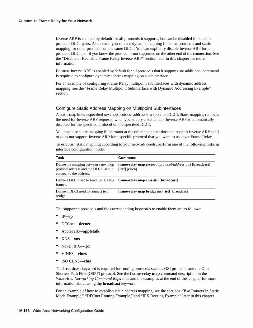
Configure Static Address Mapping on Multipoint SubinterfacesA static map links a specified next hop protocol address to a specified DLCI. Static mapping removesthe need for Inverse ARP requests; when you supply a static map, Inverse ARP is automaticallydisabled for the specified protocol on the specified DLCI.
You must use static mapping if the router at the other end either does not support Inverse ARP at allor does not support Inverse ARP for a specific protocol that you want to use over Frame Relay.
To establish static mapping according to your network needs, perform one of the following tasks ininterface configuration mode:
The supported protocols and the corresponding keywords to enable them are as follows:
• IP—ip
• DECnet—decnet
• AppleTalk—appletalk
• XNS—xns
• Novell IPX—ipx
• VINES—vines
• ISO CLNS—clns
Thebroadcast keyword is required for routing protocols such as OSI protocols and the OpenShortest Path First (OSPF) protocol. See theframe-relay map command description in theWide-Area Networking Command Reference and the examples at the end of this chapter for moreinformation about using thebroadcastkeyword.
For an example of how to establish static address mapping, see the sections “Two Routers in StaticMode Example,” “DECnet Routing Example,” and “IPX Routing Example” later in this chapter.
Task Command
Define the mapping between a next hopprotocol address and the DLCI used toconnect to the address.
frame-relay map protocol protocol-address dlci[broadcast][ietf] [cisco]
Define a DLCI used to send ISO CLNSframes.
frame-relay map clns dlci [broadcast]
Define a DLCI used to connect to abridge.
frame-relay map bridge dlci [ietf] broadcast
Customize Frame Relay for Your Network
Configuring Frame Relay IV-169
FINAL DRAFT CISCO CONFIDENTIAL
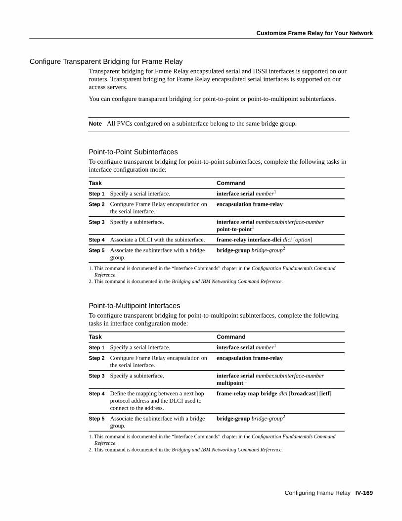
Configure Transparent Bridging for Frame RelayTransparent bridging for Frame Relay encapsulated serial and HSSI interfaces is supported on ourrouters. Transparent bridging for Frame Relay encapsulated serial interfaces is supported on ouraccess servers.
You can configure transparent bridging for point-to-point or point-to-multipoint subinterfaces.
Note All PVCs configured on a subinterface belong to the same bridge group.
Point-to-Point SubinterfacesTo configure transparent bridging for point-to-point subinterfaces, complete the following tasks ininterface configuration mode:
Point-to-Multipoint InterfacesTo configure transparent bridging for point-to-multipoint subinterfaces, complete the followingtasks in interface configuration mode:
1. This command is documented in the “Interface Commands” chapter in theConfiguration Fundamentals CommandReference.
2. This command is documented in theBridging and IBM Networking Command Reference.
1. This command is documented in the “Interface Commands” chapter in theConfiguration Fundamentals CommandReference.
2. This command is documented in theBridging and IBM Networking Command Reference.
Task Command
Step 1 Specify a serial interface. interface serialnumber1
Step 2 Configure Frame Relay encapsulation onthe serial interface.
encapsulation frame-relay
Step 3 Specify a subinterface. interface serialnumber.subinterface-numberpoint-to-point1
Step 4 Associate a DLCI with the subinterface. frame-relay interface-dlci dlci [option]
Step 5 Associate the subinterface with a bridgegroup.
bridge-group bridge-group2
Task Command
Step 1 Specify a serial interface. interface serialnumber1
Step 2 Configure Frame Relay encapsulation onthe serial interface.
encapsulation frame-relay
Step 3 Specify a subinterface. interface serialnumber.subinterface-numbermultipoint 1
Step 4 Define the mapping between a next hopprotocol address and the DLCI used toconnect to the address.
frame-relay map bridge dlci [broadcast] [ ietf]
Step 5 Associate the subinterface with a bridgegroup.
bridge-group bridge-group2

IV-170 Wide-Area Networking Configuration Guide
Customize Frame Relay for Your Network
FINAL DRAFT CISCO CONFIDENTIAL
Configure a Backup Interface for a SubinterfaceBoth point-to-point and multipoint Frame Relay subinterfaces can be configured with a backupinterface. This approach allows individual PVCs to be backed up in case of failure rather thandepending on the entire Frame Relay connection to fail before the backup takes over. You canconfigure a subinterface for backup on failure only, not for backup based on loading of the line.
If the serial interface has a backup interface, it will have precedence over the subinterface’s backupinterface in the case of complete loss of connectivity with the Frame Relay network. As a result, asubinterface backup is activated only if the serial interface is up, or if the serial interface is down anddoes not have a backup interface defined. If a subinterface has failed while its backup is in use, andthen the serial interface goes down, the subinterface backup stays connected.
To configure a backup interface for a Frame Relay subinterface, perform the following tasks,beginning in global configuration mode:
Configure Frame Relay SwitchingFrame Relay switching is a means of switching packets based upon the DLCI, which can be lookedupon as the Frame Relay equivalent of a MAC address. You perform the switching by configuringyour router or access server as a Frame Relay network. There are two parts to a Frame Relaynetwork: a Frame Relay DTE (the router or access server) and a Frame Relay DCE switch. Figure30illustrates this concept.
Figure 30 Frame Relay Switched Network
1. This command is documented in the “Interface Commands” chapter in theConfiguration Fundamentals CommandReference.
Task Command
Step 1 Specify the interface. interface serialnumber1
Step 2 Configure Frame Relay encapsulation. encapsulation frame-relay
Step 3 Configure the subinterface. interface serialnumber.subinterface-numberpoint-to-point1
Step 4 Specify a DLCI for the subinterface. frame-relay interface-dlci dlci
Step 5 Specify a backup interface for thesubinterface.
backup interface serialnumber1
Step 6 Specify backup enable and disable delay.backup delayenable-delay disable-delay1
Router C
Router A Router B
Frame Relay network
S14
63a
Network interface
DLCI 50
DLCI 60DLCI 70
DLCI 80
DTE
DTEDTE
Implements the user interface
Frame Relay DCE switch implements
the network interface

Customize Frame Relay for Your Network
Configuring Frame Relay IV-171
FINAL DRAFT CISCO CONFIDENTIAL
In Figure30, Routers A, B, and C are Frame Relay DTEs connected to each other via a Frame Relaynetwork. Our implementation of Frame Relay switching allows our devices to be used as depictedin this Frame Relay network.
Perform the tasks in the following sections, as necessary, to configure Frame Relay switching:
• Enable Frame Relay Switching
• Configure a Frame Relay DTE Device, DCE Switch, or NNI Support
• Specify the Static Route
These tasks are described in the following sections.
Enable Frame Relay SwitchingYou must enable packet switching before you can configure it on a Frame Relay DTE or DCE, orwith Network-to-Network Interface (NNI) support. Do so by performing the following task in globalconfiguration mode before configuring the switch type:
For an example of how to enable Frame Relay switching, see the switching examples later in thischapter.
Configure a Frame Relay DTE Device, DCE Switch, or NNI SupportYou can configure an interface as a DTE device or a DCE switch, or as a switch connected to a switchto support NNI connections. (DCE is the default.) To do so, perform the following task in interfaceconfiguration mode:
For an example of how to configure a DTE device or DCE switch, see the section “Hybrid DTE/DCEPVC Switching Example” later in this chapter.
For an example of how to configure NNI support, see the section “Pure Frame Relay DCE Example”later in this chapter.
Specify the Static RouteYou must specify a static route for PVC switching. To do so, perform the following task in interfaceconfiguration mode:
For an example of how to specify a static route, see the section “Pure Frame Relay DCE Example”later in this chapter.
Task Command
Enable Frame Relay switching. frame-relay switching
Task Command
Configure a Frame Relay DTE deviceor DCE switch.
frame-relay intf-type [dce | dte | nni]
Task Command
Specify a static route for PVCswitching.
frame-relay route in-dlci out-interface out-dlci
IV-172 Wide-Area Networking Configuration Guide
Customize Frame Relay for Your Network
FINAL DRAFT CISCO CONFIDENTIAL
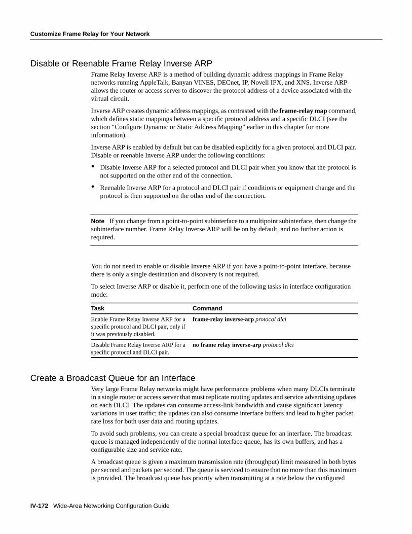
Disable or Reenable Frame Relay Inverse ARPFrame Relay Inverse ARP is a method of building dynamic address mappings in Frame Relaynetworks running AppleTalk, Banyan VINES, DECnet, IP, Novell IPX, and XNS. Inverse ARPallows the router or access server to discover the protocol address of a device associated with thevirtual circuit.
Inverse ARP creates dynamic address mappings, as contrasted with theframe-relay map command,which defines static mappings between a specific protocol address and a specific DLCI (see thesection “Configure Dynamic or Static Address Mapping” earlier in this chapter for moreinformation).
Inverse ARP is enabled by default but can be disabled explicitly for a given protocol and DLCI pair.Disable or reenable Inverse ARP under the following conditions:
• Disable Inverse ARP for a selected protocol and DLCI pair when you know that the protocol isnot supported on the other end of the connection.
• Reenable Inverse ARP for a protocol and DLCI pair if conditions or equipment change and theprotocol is then supported on the other end of the connection.
Note If you change from a point-to-point subinterface to a multipoint subinterface, then change thesubinterface number. Frame Relay Inverse ARP will be on by default, and no further action isrequired.
You do not need to enable or disable Inverse ARP if you have a point-to-point interface, becausethere is only a single destination and discovery is not required.
To select Inverse ARP or disable it, perform one of the following tasks in interface configurationmode:
Create a Broadcast Queue for an InterfaceVery large Frame Relay networks might have performance problems when many DLCIs terminatein a single router or access server that must replicate routing updates and service advertising updateson each DLCI. The updates can consume access-link bandwidth and cause significant latencyvariations in user traffic; the updates can also consume interface buffers and lead to higher packetrate loss for both user data and routing updates.
To avoid such problems, you can create a special broadcast queue for an interface. The broadcastqueue is managed independently of the normal interface queue, has its own buffers, and has aconfigurable size and service rate.
A broadcast queue is given a maximum transmission rate (throughput) limit measured in both bytesper second and packets per second. The queue is serviced to ensure that no more than this maximumis provided. The broadcast queue has priority when transmitting at a rate below the configured
Task Command
Enable Frame Relay Inverse ARP for aspecific protocol and DLCI pair, only ifit was previously disabled.
frame-relay inverse-arpprotocol dlci
Disable Frame Relay Inverse ARP for aspecific protocol and DLCI pair.
no frame relay inverse-arpprotocol dlci

Customize Frame Relay for Your Network
Configuring Frame Relay IV-173
FINAL DRAFT CISCO CONFIDENTIAL
maximum, and hence has a guaranteed minimum bandwidth allocation. The two transmission ratelimits are intended to avoid flooding the interface with broadcasts. The actual transmission rate limitin any second is the first of the two rate limits that is reached.
To create a broadcast queue, complete the following task in interface configuration mode:
Configure Payload CompressionYou can configure payload compression on point-to-point or multipoint interfaces or subinterfaces.Payload compression uses the stac method to predict what the next character in the frame will be.Because the prediction is done packet-by-packet, the dictionary is not conserved across packetboundaries.
Payload compression on each virtual circuit consumes approximately 40 kilobytes for dictionarymemory.
To configure payload compression on a specified multipoint interface or subinterface, complete thefollowing task:
To configure payload compression on a specified point-to-point interface or subinterface, completethe following task:
Configure TCP/IP Header CompressionTCP/IP header compression, as described by RFC 1144, is designed to improve the efficiency ofbandwidth utilization over low-speed serial links. A typical TCP/IP packet includes a 40-bytedatagram header. Once a connection is established, the header information is redundant and need notbe repeated in every packet that is sent. Reconstructing a smaller header that identifies theconnection and indicates the fields that changed and the amount of change reduces the number ofbytes transmitted. The average compressed header is 10 bytes long.
For this algorithm to function, packets must arrive in order. If packets arrive out of order, thereconstruction will appear to create regular TCP/IP packets but the packets will not match theoriginal. Because priority queuing changes the order in which packets are transmitted, enablingpriority queueing on the interface is not recommended.
You can configure TCP/IP header compression in either of two ways, as described in the followingsections:
• Configure an Individual IP Map for TCP/IP Header Compression
• Configure an Interface for TCP/IP Header Compression
The “Disable TCP/IP Header Compression” section describes how to disable this feature.
Task Command
Create a broadcast queue for an interface. frame-relay broadcast-queuesize byte-ratepacket-rate
Task Command
Enable payload compression on a multipointinterface.
frame-relay map protocol protocol-address dlcipayload-compress packet-by-packet
Task Command
Enable payload compression on a point-to-pointinterface.
frame-relay payload-compress packet-by-packet

IV-174 Wide-Area Networking Configuration Guide
Customize Frame Relay for Your Network
FINAL DRAFT CISCO CONFIDENTIAL
Note If you configure an interface with Cisco encapsulation and TCP/IP header compression,Frame Relay IP maps inherit the compression characteristics of the interface. However, if youconfigure the interface with IETF encapsulation, the interface cannot be configured for compression.Frame Relay maps will have to be configured individually to support TCP/IP header compression.
Configure an Individual IP Map for TCP/IP Header CompressionTCP/IP header compression requires Cisco encapsulation. If you need to have IETF encapsulationon an interface as a whole, you can still configure a specific IP map to use Cisco encapsulation andTCP header compression.
In addition, even if you configure the interface to perform TCP/IP header compression, you can stillconfigure a specific IP map not to compress TCP/IP headers.
You can specify whether TCP/IP header compression is active or passive. Active compressionsubjects every outgoing packet to TCP/IP header compression. Passive compression subjects anoutgoing TCP/IP packet to header compression only if the packet had a compressed TCP/IP headerwhen it was received.
To configure an IP map to use Cisco encapsulation and TCP/IP header compression, perform thefollowing task in interface configuration mode:
The default encapsulation iscisco.
Note An interface that is configured to support TCP/IP header compression cannot also supportpriority queuing or custom queuing.
For an example of how to configure TCP header compression on an IP map, see the “TCP/IP HeaderCompression Examples” section later in this chapter.
Configure an Interface for TCP/IP Header CompressionYou can configure the interface with active or passive TCP/IP header compression. Activecompression, the default, subjects all outgoing TCP/IP packets to header compression. Passivecompression subjects an outgoing packet to header compression only if the packet had a compressedTCP/IP header when it was received on that interface.
To apply TCP/IP header compression to an interface, you must perform the following tasks ininterface configuration mode:
Task Command
Configure an IP map to use Cisco encapsulationand TCP/IP header compression.
frame-relay map ip ip-address dlci [broadcast]cisco tcp header-compression {active | passive}
Task Command
Configure Cisco encapsulation on the interface. encapsulation frame-relay
Enable TCP/IP header compression on theinterface.
frame-relay ip tcp header-compression [passive]

Customize Frame Relay for Your Network
Configuring Frame Relay IV-175
FINAL DRAFT CISCO CONFIDENTIAL
Note If an interface configured with Cisco encapsulation is later configured with IETFencapsulation, all TCP/IP header compression characteristics are lost. To apply TCP/IP headercompression over an interface configured with IETF encapsulation, you must configure individualIP maps, as described in the section “Configure an Individual IP Map for TCP/IP HeaderCompression.”
For an example of how to configure TCP header compression on an interface, see the “TCP/IPHeader Compression Examples” section later in this chapter.
Disable TCP/IP Header CompressionYou can disable TCP/IP header compression by using either of two commands that have differenteffects, depending on whether Frame Relay IP maps have been explicitly configured for TCP/IPheader compression or have inherited their compression characteristics from the interface.
Frame Relay IP maps that have explicitly configured TCP/IP header compression must also haveTCP/IP header compression explicitly disabled.
To disable TCP/IP header compression, perform one of the following tasks in interface configurationmode:
For examples of how to turn off TCP/IP header compression, see the section “Disabling InheritedTCP/IP Header Compression Example” and the section “Disabling Explicit TCP/IP HeaderCompression Example.”
Configure Discard EligibilityYou can specify which Frame Relay packets have low priority or low time sensitivity and will be thefirst to be dropped when a Frame Relay switch is congested. The mechanism that allows a FrameRelay switch to identify such packets is the discard eligibility (DE) bit.
This feature requires that the Frame Relay network be able to interpret the DE bit. Some networkstake no action when the DE bit is set. Other networks use the DE bit to determine which packets todiscard. The most desirable interpretation is to use the DE bit to determine which packets should bedropped first and also which packets have lower time sensitivity.
You can define DE lists that identify the characteristics of packets to be eligible for discarding, andyou can also specify DE groups to identify the DLCI that is affected.
Task Command
Disable TCP/IP header compression on all FrameRelay IP maps that are not explicitly configured forTCP header compression.
or
Disable TCP/IP header compression on a specifiedFrame Relay IP map.
no frame-relay ip tcp header-compression
frame-relay map ip ip-address dlcinocompresstcp header-compression

IV-176 Wide-Area Networking Configuration Guide
Customize Frame Relay for Your Network
FINAL DRAFT CISCO CONFIDENTIAL
To define a DE list specifying the packets that can be dropped when the Frame Relay switch iscongested, perform the following task in global configuration mode:
You can specify DE lists based on the protocol or the interface, and on characteristics such asfragmentation of the packet, a specific TCP or User Datagram Protocol (UDP) port, an access listnumber, or a packet size. See theframe-relay de-list command in theWide-Area NetworkingCommand Reference for arguments and other information.
To define a DE group specifying the DE list and DLCI affected, perform the following task ininterface configuration mode:
Configure DLCI Priority LevelsDLCI priority levels allow you to separate different types of traffic and can provide a trafficmanagement tool for congestion problems caused by following situations:
• Mixing batch and interactive traffic over the same DLCI
• Traffic from sites with high-speed access being queued at destination sites with lower speedaccess.
Before you configure the DLCI priority levels, complete the following tasks:
• Define a global priority list.
• Enable Frame Relay encapsulation, as described earlier in this chapter.
• Define static or dynamic address mapping, as described earlier in this chapter.
Make sure that you define each of the DLCIs to which you intend to apply levels. You canassociate priority-level DLCIs with subinterfaces.
• Configure the LMI, as described earlier in this chapter.
Note DLCI priority levels provide a way to define multiple parallel DLCIs for different types oftraffic. DLCI priority levels do not assign priority queues within the router or access server; in fact,they are independent of the device’s priority queues. However, if you enable queuing and use thesame DLCIs for queuing, then high-priority DLCIs can be put into high-priority queues.
To configure DLCI priority levels, perform the following task in interface configuration mode:
Task Command
Define a DE list. frame-relay de-list list-number{ protocolprotocol | interface type number} characteristic
Task Command
Define a DE group. frame-relay de-groupgroup-number dlci
Task Command
Enable multiple parallel DLCIs for different typesof Frame Relay traffic, associate specified DLCIswith the same group, and define their levels.
frame-relay priority-dlci-group group-numberhigh-dlci medium-dlci normal-dlci low-dlci

Monitor the Frame Relay Connections
Configuring Frame Relay IV-177
FINAL DRAFT CISCO CONFIDENTIAL
Note If you do not explicitly specify a DLCI for each of the priority levels, the last DLCI specifiedin the command line is used as the value of the remaining arguments. However, you must provide atleast the high-priority and the medium-priority DLCIs.
Monitor the Frame Relay ConnectionsTo monitor Frame Relay connections, perform any of the following tasks in EXEC mode:
Frame Relay Configuration ExamplesThis section provides examples of Frame Relay configurations. It includes the following sections:
• IETF Encapsulation Examples
• Static Address Mapping Examples
• SVC Configuration Examples
• Frame Relay Traffic Shaping Example
• Subinterface Examples
• Configuration Providing Backward Compatibility Example
• Booting from a Network Server over Frame Relay Example
• Frame Relay Switching Examples
• TCP/IP Header Compression Examples
• Disabling TCP/IP Header Compression Examples
Task Command
Clear dynamically created Frame Relay maps,which are created by the use of Inverse ARP.
clear frame-relay-inarp
Display information about Frame Relay DLCIsand the LMI.
show interfaces serialnumber
Display LMI statistics. show frame-relay lmi [type number]
Display the current Frame Relay map entries. show frame-relay map
Display PVC statistics. show frame-relay pvc[type number[dlci]]
Display configured static routes. show frame-relay route
Display Frame Relay traffic statistics. show frame-relay traffic
Display information about the status of LAPF. show frame-relay lapf
Display all the SVCs under a specified map list. show frame-relay svc maplist

IV-178 Wide-Area Networking Configuration Guide
Frame Relay Configuration Examples
FINAL DRAFT CISCO CONFIDENTIAL
IETF Encapsulation ExamplesThe first example that follows sets IETF encapsulation at the interface level. The second examplesets IETF encapsulation on a per-DLCI basis. In the first example, the keywordietf sets the defaultencapsulation method for all maps to IETF.
encapsulation frame-relay IETFframe-relay map ip 131.108.123.2 48 broadcastframe-relay map ip 131.108.123.3 49 broadcast
In the following example, IETF encapsulation is configured on a per-DLCI basis. This configurationhas the same result as the configuration in the first example.
encapsulation frame-relayframe-relay map ip 131.108.123.2 48 broadcast ietfframe-relay map ip 131.108.123.3 49 broadcast ietf
Static Address Mapping ExamplesThe following sections provide examples of static address mapping for the IP, AppleTalk, DECnet,and IPX protocols.
Two Routers in Static Mode ExampleThe following example illustrates how to configure two routers for static mode.
Configuration for Router 1interface serial 0ip address 131.108.64.2 255.255.255.0encapsulation frame-relaykeepalive 10frame-relay map ip 131.108.64.1 43
Configuration for Router 2interface serial 0ip address 131.108.64.1 255.255.255.0encapsulation frame-relaykeepalive 10frame-relay map ip 131.108.64.2 43
AppleTalk Routing ExampleThe following example illustrates how to configure two routers to communicate with each otherusing AppleTalk over a Frame Relay network. Each router has a Frame Relay static address map forthe other router. The use of theappletalk cable-range command indicates that this is extendedAppleTalk (Phase II).
Configuration for Router 1interface Serial0ip address 172.21.59.24 255.255.255.0encapsulation frame-relayappletalk cable-range 10-20 18.47appletalk zone engframe-relay map appletalk 18.225 100 broadcast

Frame Relay Configuration Examples
Configuring Frame Relay IV-179
FINAL DRAFT CISCO CONFIDENTIAL
Configuration for Router 2interface Serial2/3ip address 172.21.177.18 255.255.255.0encapsulation frame-relayappletalk cable-range 10-20 18.225appletalk zone engclockrate 2000000frame-relay map appletalk 18.47 100 broadcast
DECnet Routing ExampleThe following example sends all DECnet packets destined for address 56.4 out on DLCI 101. Inaddition, any DECnet broadcasts for interface serial 1 will be sent on that DLCI.
decnet routing 32.6!interface serial 1encapsulation frame-relayframe-relay map decnet 56.4 101 broadcast
IPX Routing ExampleThe following example illustrates how to send packets destined for IPX address 200.0000.0c00.7b21out on DLCI 102:
ipx routing 000.0c00.7b3b!interface ethernet 0ipx network 2abc!interface serial 0ipx network 200encapsulation frame-relayframe-relay map ipx 200.0000.0c00.7b21 102 broadcast
Subinterface ExamplesThe following sections provide basic Frame Relay subinterface examples and variations appropriatefor different routed protocols and for bridging.
Basic Subinterface ExamplesIn the following example, subinterface 1 models a point-to-point subnet and subinterface 2 modelsa broadcast subnet. For emphasis, themultipoint keyword is used for serial subinterface 2, eventhough a subinterface is multipoint by default.
interface serial 0encapsulation frame-relayinterface serial 0.1 point-to-pointip address 10.0.1.1 255.255.255.0frame-relay interface-dlci 42
interface serial 0.2 multipointip address 10.0.2.1 255.255.255.0frame-relay map 10.0.2.2 18

IV-180 Wide-Area Networking Configuration Guide
Frame Relay Configuration Examples
FINAL DRAFT CISCO CONFIDENTIAL
Frame Relay Multipoint Subinterface with Dynamic Addressing ExampleThe following example configures two multipoint subinterfaces for dynamic address resolution.Each subinterface is provided with an individual protocol address and subnet mask, and theinterface-dlci command associates the subinterface with a specified DLCI. Addresses of remotedestinations for each multipoint subinterface will be resolved dynamically.
interface Serial0 no ip address encapsulation frame-relay frame-relay lmi-type ansi!interface Serial0.103 multipoint ip address 172.21.177.18 255.255.255.0 frame-relay interface-dlci 300!interface Serial0.104 multipoint ip address 172.21.178.18 255.255.255.0 frame-relay interface-dlci 400
IPX Routes over Frame Relay Subinterfaces ExampleThe following example configures a serial interface for Frame Relay encapsulation and sets upmultiple IPX virtual networks corresponding to Frame Relay subinterfaces:
ipx routing 0000.0c02.5f4f!interface serial 0encapsulation frame-relayinterface serial 0.1 multipointipx network 1frame-relay map ipx 1.000.0c07.d530 200 broadcastipx network 2frame-relay map ipx 2.000.0c07.d530 300 broadcast
For subinterface serial 0.1, the router at the other end might be configured as follows:
ipx routinginterface serial 2 multipointipx network 1frame-relay map ipx 1.000.0c02.5f4f 200 broadcast
Unnumbered IP over a Point-to-Point Subinterface ExampleThe following example sets up unnumbered IP over subinterfaces at both ends of a point-to-pointconnection. In this example, Router A functions as the DTE, and Router B functions as the DCE.Routers A and B are both attached to Token Ring networks.
Configuration for Router Aframe-relay switching!interface token-ring 0ip address 131.108.177.1 255.255.255.0!interface serial 0no ip addressencapsulation frame-relay IETF!

Frame Relay Configuration Examples
Configuring Frame Relay IV-181
FINAL DRAFT CISCO CONFIDENTIAL
interface Serial0.2 point-to-pointip unnumbered TokenRing0ip pim sparse-modeframe-relay interface-dlci 20
Configuration for Router B:frame-relay switching!interface token-ring 0ip address 131.108.178.1 255.255.255.0!interface serial 0no ip addressencapsulation frame-relay IETFbandwidth 384clockrate 4000000frame-relay intf-type dce!interface serial 0.2 point-to-pointip unnumbered TokenRing1ip pim sparse-mode
bandwidth 384frame-relay interface-dlci 20
Transparent Bridging Using Subinterfaces ExampleIn the following example, Frame Relay DLCIs 42, 64, and 73 are to be used as separatepoint-to-point links with transparent bridging running over them. The bridging spanning treealgorithm views each PVC as a separate bridge port, and a frame arriving on the PVC can be relayedback out a separate PVC. Be sure that routing is not enabled when configuring transparent bridgingusing subinterfaces.
interface serial 0encapsulation frame-relayinterface serial 0.1 point-to-pointbridge-group 1frame-relay interface-dlci 42interface serial 0.2 point-to-pointbridge-group 1frame-relay interface-dlci 64interface serial 0.3 point-to-pointbridge-group 1frame-relay interface-dlci 73
SVC Configuration ExamplesThe following examples provide SVC configuration examples for interfaces and subinterfaces.
Interface ExampleThe following example configures a physical interface, applies a map-group to the physicalinterface, and then defines the map-group.
interface serial 0ip address 172.10.8.6encapsulation frame-relaymap-group bermuda
IV-182 Wide-Area Networking Configuration Guide
Frame Relay Configuration Examples
FINAL DRAFT CISCO CONFIDENTIAL
frame-relay lmi-type q933aframe-relay svc
map-list bermuda source-addr E164 123456 dest-addr E164 654321ip 131.108.177.100 class hawaiiappletalk 1000.2 class rainbow
map-class frame-relay rainbowframe-relay idle-timer 60
map-class frame-relay hawaiiframe-relay cir in 64000frame-relay cir out 64000
Subinterface ExampleThe following example configures a point-to-point interface for SVC operation. This exampleassumes that the main serial 0 interface has been configured for signalling, and that SVC operationhas been enabled on the main interface.
int s 0.1 point-point! Define the map-group; details are specified under the map-list holiday command.map-group holiday
! Associate the map-group with a specific source and destination.map-list holiday local-addr X121 <X121-addr> dest-addr E164 <E164-addr>! Specify destination protocol addresses for a map-class.
ip 131.108.177.100 class hawaii IETFappletalk 1000.2 class rainbow IETF broadcast
! Define a map class and its QOS settings.map-class hawaii
frame-relay cir in 2000000frame-relay cir out 56000frame-relay be 9000
! Define another map class and its QOS settings.map-class rainbow
frame-relay cir in 64000frame-relay idle-timer 2000
Frame Relay Traffic Shaping ExampleThe following comprehensive example illustrates a Frame Relay interface with three point-to-pointsubinterfaces.
In this example, the virtual circuits on subinterfaces Serial0.1 and Serial0.2 inherit class parametersfrom the main interface, namely those defined inslow_vcs, but the virtual circuit defined onsubinterface Serial0.2 (DLCI 102) is specifically configured to use map classfast_vcs.
Map classslow_vcs uses a peak rate of 9600 and average rate of 4800 bps. Because BECN feedbackis enabled by default, the output rate will be cut back as low as 4800bps in response to receivedBECNs. This map class is configured to use custom queuing using queue-list 1. In this example,queue-list 1 has 3 queues, with the first two being controlled by access lists 100 and 115.
Map classfast_vcs uses a peak rate of 64000 and average rate of 16000 bps. Because BECNfeedback is enabled by default, the output rate will be cut back as low as 4800bps in response toreceived BECNs. This map class is configured to use priority-queuing using priority-group 2.

Frame Relay Configuration Examples
Configuring Frame Relay IV-183
FINAL DRAFT CISCO CONFIDENTIAL
interface Serial0 no ip address encapsulation frame-relay frame-relay lmi-type ansi frame-relay traffic-shaping frame-relay class slow_vcs!interface Serial0.1 point-to-point ip address 10.128.30.1 255.255.255.248 ip ospf cost 200 bandwidth 10 frame-relay interface-dlci 101!interface Serial0.2 point-to-point ip address 10.128.30.9 255.255.255.248 ip ospf cost 400 bandwidth 10 frame-relay interface-dlci 102 class fast_vcs!interface Serial0.3 point-to-point ip address 10.128.30.17 255.255.255.248 ip ospf cost 200 bandwidth 10 frame-relay interface-dlci 103!map-class frame-relay slow_vcs frame-relay traffic-rate 4800 9600 frame-relay custom-queue-list 1!map-class frame-relay fast_vcs frame-relay traffic-rate 16000 64000 frame-relay priority-group 2!access-list 100 permit tcp any any eq 2065access-list 115 permit tcp any any eq 256!priority-list 2 protocol decnet highpriority-list 2 ip normalpriority-list 2 default medium!queue-list 1 protocol ip 1 list 100queue-list 1 protocol ip 2 list 115queue-list 1 default 3queue-list 1 queue 1 byte-count 1600 limit 200queue-list 1 queue 2 byte-count 600 limit 200queue-list 1 queue 3 byte-count 500 limit 200
Configuration Providing Backward Compatibility ExampleThe following configuration provides backward compatibility and interoperability with earlierversions that are not compliant with RFC 1490. Theietf keyword is used to generate RFC 1490traffic. This configuration is possible because of the flexibility provided by separately defining eachmap entry.
encapsulation frame-relayframe-relay map ip 131.108.123.2 48 broadcast ietf! interoperability is provided by IETF encapsulationframe-relay map ip 131.108.123.3 49 broadcast ietfframe-relay map ip 131.108.123.7 58 broadcast! this line allows the router to connect with a! device running an older version of softwareframe-relay map decnet 21.7 49 broadcast

IV-184 Wide-Area Networking Configuration Guide
Frame Relay Configuration Examples
FINAL DRAFT CISCO CONFIDENTIAL
Configure IETF based on map entries and protocol for more flexibility. Use this method ofconfiguration for backward compatibility and interoperability.
Booting from a Network Server over Frame Relay ExampleWhen booting from a Trivial File Transfer Protocol (TFTP) server over Frame Relay, you cannotboot from a network server via a broadcast. You must boot from a specific TFTP host. Also, aframe-relay map command must exist for the host that you will boot from.
For example, if filegs3-bfx is to be booted from a host with IP address 131.108.126.2, the followingcommands would need to be in the configuration:
boot system gs3-bfx 131.108.126.2
interface Serial 0encapsulation frame-relayframe-relay map IP 131.108.126.2 100 broadcast
Theframe-relay map command is used to map an IP address into a DLCI address. To boot overFrame Relay, you must explicitly give the address of the network server to boot from, and aframe-relay map entry must exist for that site. For example, if filegs3-bfx.83-2.0 is to be bootedfrom a host with IP address 131.108.126.111, the following commands must be in the configuration:
boot system gs3-bfx.83-2.0 131.108.13.111!interface Serial 1ip address 131.108.126.200 255.255.255.0encapsulation frame-relayframe-relay map ip 131.108.126.111 100 broadcast
In this case, 100 is the DLCI that can get to host 131.108.126.111.
The remote router must have the following frame-relay map entry:
frame-relay map ip 131.108.126.200 101 broadcast
This entry allows the remote router to return a boot image (from the network server) to the routerbooting over Frame Relay. Here, 101 is a DLCI of the router being booted.
Frame Relay Switching ExamplesThe following sections provide several examples of configuring one or more routers as Frame Relayswitches:
• PVC Switching Configuration Example—In this example, one router has two interfacesconfigured as DCEs; the router switches frames from the incoming interface to the outgoinginterface on the basis of the DLCI alone.
• Pure Frame Relay DCE Example—In this example, a Frame Relay network is set up with tworouters functioning as switches; standard NNI signaling is used between them.
• Hybrid DTE/DCE PVC Switching Example—In this example, one router is configured with bothDCE and DTE interfaces (a hybrid DTE/DCE Frame Relay switch). It can switch frames betweentwo DCE ports and between a DCE port and a DTE port.
• Switching over an IP Tunnel Example—In this example, two routers are configured to switchFrame Relay PVCs over a point-to-point IP tunnel.
Frame Relay Configuration Examples
Configuring Frame Relay IV-185
FINAL DRAFT CISCO CONFIDENTIAL
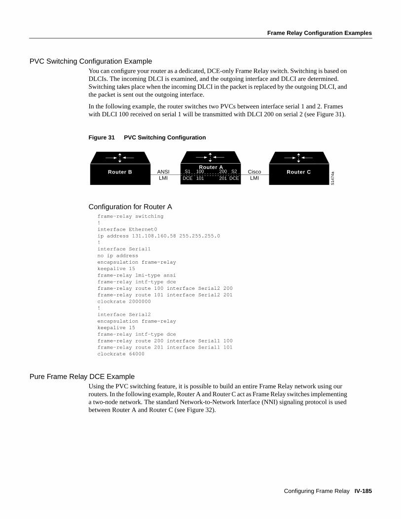
PVC Switching Configuration ExampleYou can configure your router as a dedicated, DCE-only Frame Relay switch. Switching is based onDLCIs. The incoming DLCI is examined, and the outgoing interface and DLCI are determined.Switching takes place when the incoming DLCI in the packet is replaced by the outgoing DLCI, andthe packet is sent out the outgoing interface.
In the following example, the router switches two PVCs between interface serial 1 and 2. Frameswith DLCI 100 received on serial 1 will be transmitted with DLCI 200 on serial 2 (see Figure 31).
Figure 31 PVC Switching Configuration
Configuration for Router Aframe-relay switching!interface Ethernet0ip address 131.108.160.58 255.255.255.0!interface Serial1no ip addressencapsulation frame-relaykeepalive 15frame-relay lmi-type ansiframe-relay intf-type dceframe-relay route 100 interface Serial2 200frame-relay route 101 interface Serial2 201clockrate 2000000!interface Serial2encapsulation frame-relaykeepalive 15frame-relay intf-type dceframe-relay route 200 interface Serial1 100frame-relay route 201 interface Serial1 101clockrate 64000
Pure Frame Relay DCE ExampleUsing the PVC switching feature, it is possible to build an entire Frame Relay network using ourrouters. In the following example, Router A and Router C act as Frame Relay switches implementinga two-node network. The standard Network-to-Network Interface (NNI) signaling protocol is usedbetween Router A and Router C (see Figure 32).
Router BRouter A
S14
74a
DTE
Router CANSI LMI
Cisco LMI
S1
DCE
S2
DCE
100
101
200
201

IV-186 Wide-Area Networking Configuration Guide
Frame Relay Configuration Examples
FINAL DRAFT CISCO CONFIDENTIAL
Figure 32 Frame Relay DCE Configuration
Configuration for Router Aframe-relay switching!interface ethernet 0no ip addressshutdown!interface ethernet 1no ip addressshutdown!interface ethernet 2no ip addressshutdown!interface ethernet 3no ip addressshutdown!interface serial 0ip address 131.108.178.48 255.255.255.0shutdown!interface serial 1no ip addressencapsulation frame-relayframe-relay intf-type dceframe-relay lmi-type ansiframe-relay route 100 interface serial 2 200!interface serial 2no ip addressencapsulation frame-relayframe-relay intf-type nni
Router A Router C
Router B Router D
S23
10
NNINNI
Frame Relay network
DTE DTE
DCE DCE
S1S1
S2S2
100 300
200200
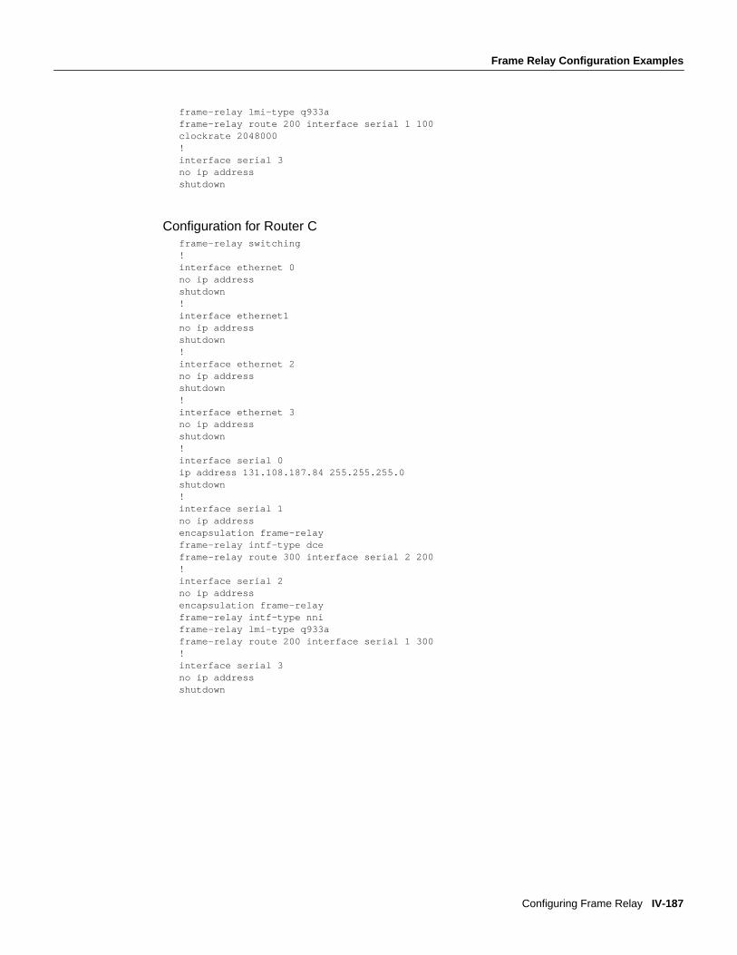
Frame Relay Configuration Examples
Configuring Frame Relay IV-187
FINAL DRAFT CISCO CONFIDENTIAL
frame-relay lmi-type q933aframe-relay route 200 interface serial 1 100clockrate 2048000!interface serial 3no ip addressshutdown
Configuration for Router Cframe-relay switching!interface ethernet 0no ip addressshutdown!interface ethernet1no ip addressshutdown!interface ethernet 2no ip addressshutdown!interface ethernet 3no ip addressshutdown!interface serial 0ip address 131.108.187.84 255.255.255.0shutdown!interface serial 1no ip addressencapsulation frame-relayframe-relay intf-type dceframe-relay route 300 interface serial 2 200!interface serial 2no ip addressencapsulation frame-relayframe-relay intf-type nniframe-relay lmi-type q933aframe-relay route 200 interface serial 1 300!interface serial 3no ip addressshutdown

IV-188 Wide-Area Networking Configuration Guide
Frame Relay Configuration Examples
FINAL DRAFT CISCO CONFIDENTIAL
Hybrid DTE/DCE PVC Switching ExampleRouters can also be configured as hybrid DTE/DCE Frame Relay switches (see Figure 33).
Figure 33 Hybrid DTE/DCE PVC Switching
In the following example, Router B acts as a hybrid DTE/DCE Frame Relay switch. It can switchframes between the two DCE ports and between a DCE port and a DTE port. Traffic from the FrameRelay network can also be terminated locally. In the example, three PVCs are defined, as follows:
• Serial 1, DLCI 102 to serial 2, DLCI 201—DCE switching
• Serial 1, DLCI 103 to serial 3, DLCI 301—DCE/DTE switching
• Serial 2, DLCI 203 to serial 3, DLCI 302—DCE/DTE switching
DLCI 400 is also defined for locally terminated traffic.
Configuration for Router Bframe-relay switching!interface ethernet 0ip address 131.108.123.231 255.255.255.0!interface ethernet 1ip address 131.108.5.231 255.255.255.0!interface serial 0no ip addressshutdown!interface serial 1no ip addressencapsulation frame-relayframe-relay intf-type dce
Router D
Router A Router B
S23
09
DTE
Router C
Frame Relay network
DCEDTEDCE
DTE
DTE
102 201
301103
302
203
S1S2
S3

Frame Relay Configuration Examples
Configuring Frame Relay IV-189
FINAL DRAFT CISCO CONFIDENTIAL
frame-relay route 102 interface serial 2 201frame-relay route 103 interface serial 3 301!interface serial 2no ip addressencapsulation frame-relayframe-relay intf-type dceframe-relay route 201 interface serial 1 102frame-relay route 203 interface serial 3 302!interface serial 3ip address 131.108.111.231encapsulation frame-relayframe-relay lmi-type ansiframe-relay route 301 interface serial 1 103frame-relay route 302 interface serial 1 203frame-relay map ip 131.108.111.4 400 broadcast
Switching over an IP Tunnel ExampleYou can achieve switching over an IP tunnel by creating a point-to-point tunnel across theinternetwork over which PVC switching can take place (see Figure 34).
Figure 34 Frame Relay Switch over IP Tunnel
The following configurations illustrate how to create the IP network depicted in Figure 34.
Configuration for Router Aframe-relay switching!interface Ethernet0ip address 108.131.123.231 255.255.255.0!interface Ethernet1ip address 131.108.5.231 255.255.255.0!
Router A Router D
Router B Router C
IP network
Frame Relay network
S23
08DTE
DTE DTE
DCE
E0 S0
S1S1200
100
200
300

IV-190 Wide-Area Networking Configuration Guide
Frame Relay Configuration Examples
FINAL DRAFT CISCO CONFIDENTIAL
interface Serial0no ip addressshutdown!interface Serial1ip address 131.108.222.231 255.255.255.0encapsulation frame-relayframe-relay map ip 131.108.222.4 400 broadcastframe-relay route 100 interface Tunnel1 200!interface Tunnel1tunnel source Ethernet0tunnel destination 150.150.150.123
Configuration for Router Dframe-relay switching!interface Ethernet0ip address 131.108.231.123 255.255.255.0!interface Ethernet1ip address 131.108.6.123 255.255.255.0!interface Serial0ip address 150.150.150.123 255.255.255.0encapsulation ppp!interface Tunnel1tunnel source Serial0tunnel destination 108.131.123.231!interface Serial1ip address 131.108.7.123 255.255.255.0encapsulation frame-relayframe-relay intf-type dceframe-relay route 300 interface Tunnel1 200
TCP/IP Header Compression ExamplesThe following examples show various combinations of TCP/IP header compression andencapsulation characteristics on the interface and the effect on the inheritance of thosecharacteristics on a Frame Relay IP map.
IP Map with Inherited TCP/IP Header Compression ExampleThe following example shows an interface configured for TCP/IP header compression and an IP mapthat inherits the compression characteristics. Note that the Frame Relay IP map is not explicitlyconfigured for header compression.
interface serial 1encapsulation frame-relayip address 131.108.177.178 255.255.255.0frame-relay map ip 131.108.177.177 177 broadcastframe-relay ip tcp header-compression passive

Frame Relay Configuration Examples
Configuring Frame Relay IV-191
FINAL DRAFT CISCO CONFIDENTIAL
Use of theshow frame-relay map command will display the resulting compression andencapsulation characteristics; the IP map has inherited passive TCP/IP header compression:
Router> show frame-relay mapSerial 1 (administratively down): ip 131.108.177.177 dlci 177 (0xB1,0x2C10), static, broadcast, CISCO TCP/IP Header Compression (inherited), passive (inherited)
Using an IP Map to Override TCP/IP Header Compression ExampleThe following example shows the use of a Frame Relay IP map to override the compression set onthe interface:
interface serial 1encapsulation frame-relayip address 131.108.177.178 255.255.255.0frame-relay map ip 131.108.177.177 177 broadcast nocompressframe-relay ip tcp header-compression passive
Use of theshow frame-relay map command will display the resulting compression andencapsulation characteristics; the IP map has not inherited TCP header compression:
Serial 1 (administratively down): ip 131.108.177.177 dlci 177 (0xB1,0x2C10), static, broadcast, CISCO
Disabling TCP/IP Header Compression ExamplesThe following examples show the use of two different commands to disable TCP/IP headercompression.
Disabling Inherited TCP/IP Header Compression ExampleIn this first example, the initial configuration is the following:
interface serial 1encapsulation frame-relayip address 131.108.177.179 255.255.255.0frame-relay ip tcp header-compression passiveframe-relay map ip 131.108.177.177 177 broadcastframe-relay map ip 131.108.177.178 178 broadcast tcp header-compression
You enter the following commands:
serial interface 1no frame-relay ip tcp header-compression
Use of theshow frame-relay map command will display the resulting compression andencapsulation characteristics:
Router> show frame-relay mapSerial 1 (administratively down): ip 131.108.177.177 177 dlci 177(0xB1, 0x2C10), static, broadcast CISCO
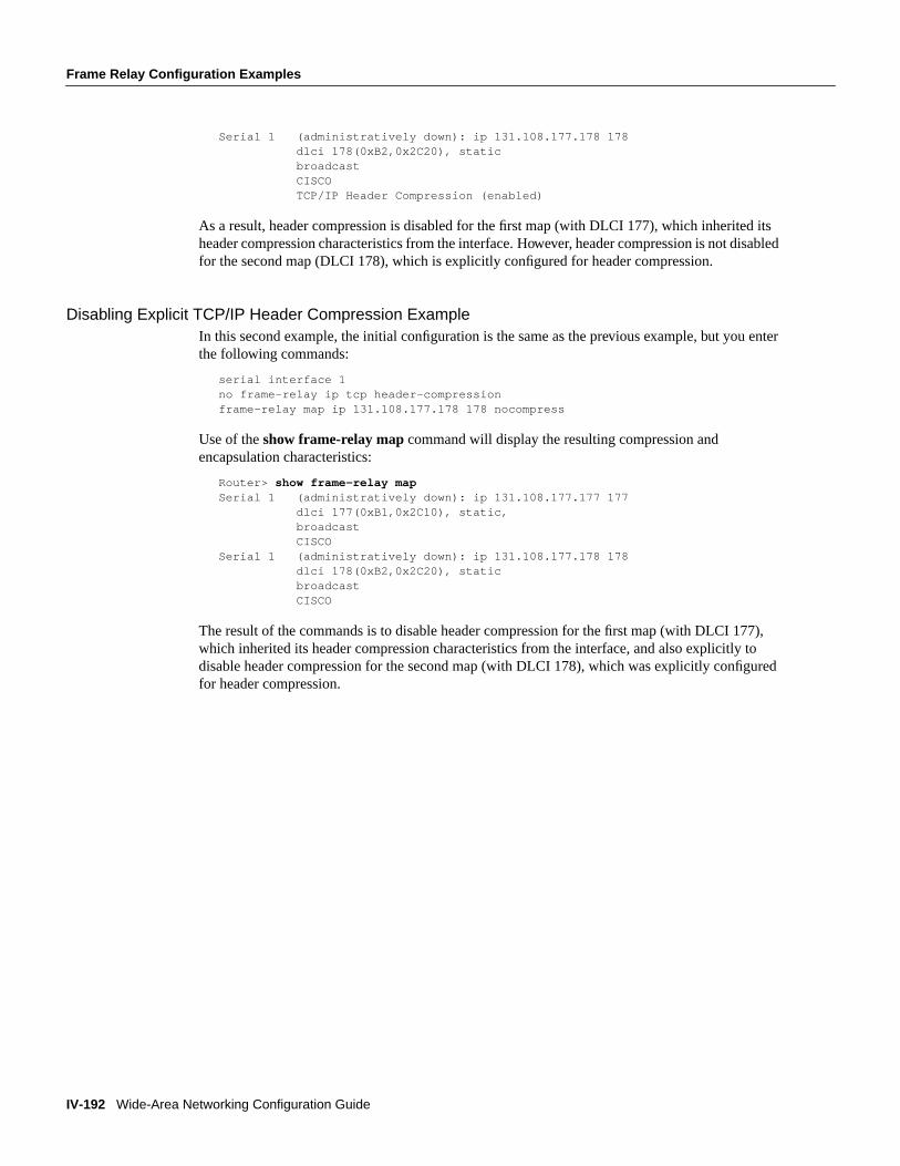
IV-192 Wide-Area Networking Configuration Guide
Frame Relay Configuration Examples
FINAL DRAFT CISCO CONFIDENTIAL
Serial 1 (administratively down): ip 131.108.177.178 178 dlci 178(0xB2,0x2C20), static broadcast CISCO TCP/IP Header Compression (enabled)
As a result, header compression is disabled for the first map (with DLCI 177), which inherited itsheader compression characteristics from the interface. However, header compression is not disabledfor the second map (DLCI 178), which is explicitly configured for header compression.
Disabling Explicit TCP/IP Header Compression ExampleIn this second example, the initial configuration is the same as the previous example, but you enterthe following commands:
serial interface 1no frame-relay ip tcp header-compressionframe-relay map ip 131.108.177.178 178 nocompress
Use of theshow frame-relay map command will display the resulting compression andencapsulation characteristics:
Router> show frame-relay mapSerial 1 (administratively down): ip 131.108.177.177 177 dlci 177(0xB1,0x2C10), static, broadcast CISCOSerial 1 (administratively down): ip 131.108.177.178 178 dlci 178(0xB2,0x2C20), static broadcast CISCO
The result of the commands is to disable header compression for the first map (with DLCI 177),which inherited its header compression characteristics from the interface, and also explicitly todisable header compression for the second map (with DLCI 178), which was explicitly configuredfor header compression.