conga: a conducting gesture analysis frameworkconducting an orchestra is a highly sophisticated art...
TRANSCRIPT
conga: A Conducting GestureAnalysis Framework
DiplomarbeitUniversitat Ulm
Fakultat fur InformatikU
N
IVERSITÄT ULM
· SC
IEN
DO
· DOCENDO · CU
RA
ND
O ·
vorgelegt von
Ingo Grull
1. Gutachter: Prof. Dr. Michael Weber2. Gutachter: Prof. Dr. Jan Borchers
April 2005

Abstract
Conducting an orchestra is a highly sophisticated art form that matured over centuries.In the last few decades, conducting has also become a form of human-computer inter-action, giving conductors different ways to enter conducting input with varying degreesof control and varying levels of success in making the computer perform the way theconductor wants it to.
This diploma thesis describes a framework developed to aid analysis and recognition ofconducting gesture input in form of two-dimensional trajectories of the movement of theconductor’s baton, or of his right hand, if he is conducting without a baton. The thesisexplains the concepts behind the framework, lists some of its characteristic componentsand gives examples how to use it. In addition, the thesis provides an overview of severalcomputer-based systems that enable their users to conduct musical pieces and brieflylooks into other frameworks that have been used to process conducting gesture input insome of the presented systems. It also judges strengths and weaknesses of the frameworkand mentions how the framework could be extended both for its intended applicationdomain as well as for other application domains.
i

Acknowledgements
I would like to express my gratitude to all people who helped me with my work on thispaper and the conga framework. In particular, I thank the following persons:
• Rafael “Tico” Ballagas
• Nils Beck
• Jan Borchers
• Jan Buchholz
• Saskia Dedenbach
• Jonathan Diehl
• Linda Goldschmidt
• Britta Grunberg
• Thorsten Karrer
• Henning Kiel
• Jonathan Klein
• Eric Lee
• Teresa Marrin Nakra
• Guido de Melo
• Michael Plichta
• Wolfgang Samminger
• Tanja Scheffold
• Daniel Spelmezan
• Philipp Stephan
• Michael Weber
• Stefan Werner
• Marius Wolf
• Eugen Yu
Last but not least, I also thank my family: my parents Margit and Bolko Grull and mysister Sascha Grull.
ii

Contents
Abstract . . . . . . . . . . . . . . . . . . . . . . . . . . . . . . . . . . . . . . . . iAcknowledgements . . . . . . . . . . . . . . . . . . . . . . . . . . . . . . . . . . ii
1 Introduction 1
1.1 Background . . . . . . . . . . . . . . . . . . . . . . . . . . . . . . . . . . . 11.2 Motivation . . . . . . . . . . . . . . . . . . . . . . . . . . . . . . . . . . . 11.3 Structure of this Thesis . . . . . . . . . . . . . . . . . . . . . . . . . . . . 2
2 Related Work 3
2.1 Frameworks Used in Computer-Based Conducting Systems . . . . . . . . 32.1.1 LabVIEW . . . . . . . . . . . . . . . . . . . . . . . . . . . . . . . . 32.1.2 EyesWeb . . . . . . . . . . . . . . . . . . . . . . . . . . . . . . . . 42.1.3 Max/MSP . . . . . . . . . . . . . . . . . . . . . . . . . . . . . . . . 5
2.2 Overview of Computer-Based Conducting Systems . . . . . . . . . . . . . 72.2.1 Radio Baton and Predecessors . . . . . . . . . . . . . . . . . . . . 72.2.2 Conduct System . . . . . . . . . . . . . . . . . . . . . . . . . . . . 82.2.3 Conductor Follower . . . . . . . . . . . . . . . . . . . . . . . . . . 92.2.4 MIDI Baton and Successors . . . . . . . . . . . . . . . . . . . . . . 92.2.5 Computer Music System that Follows a Human Conductor . . . . 102.2.6 Light Baton . . . . . . . . . . . . . . . . . . . . . . . . . . . . . . . 102.2.7 Adaptive Conductor Follower and Related Systems . . . . . . . . . 102.2.8 The Ensemble Member and the Conducted Computer /
Extraction of Conducting Gestures in 3D Space . . . . . . . . . . . 112.2.9 WorldBeat, Personal Orchestra and You’re The Conductor . . . . 122.2.10 Digital Baton, Conductor’s Jacket and Gesture Construction . . . 142.2.11 Multi-Modal Conducting Simulator . . . . . . . . . . . . . . . . . . 152.2.12 Virtual Orchestra . . . . . . . . . . . . . . . . . . . . . . . . . . . . 152.2.13 Conductor Following with Artificial Neural Networks . . . . . . . . 162.2.14 Virtual Dance and Music . . . . . . . . . . . . . . . . . . . . . . . 172.2.15 Conducting Audio Files via Computer Vision . . . . . . . . . . . . 182.2.16 Conducting Gesture Recognition, Analysis and Performance System 18
2.3 Comparison of Computer-Based Conducting Systems . . . . . . . . . . . . 20
3 The Context that Led to the Conga Framework 23
iii

Contents
4 The Conga Framework 254.1 Model of Conducting Gestures . . . . . . . . . . . . . . . . . . . . . . . . 254.2 Choice of Platform and Implementation Language . . . . . . . . . . . . . 274.3 Early Approaches and Their Problems . . . . . . . . . . . . . . . . . . . . 274.4 Basic Processing Model . . . . . . . . . . . . . . . . . . . . . . . . . . . . 29
4.4.1 Types of Nodes, Ports and Processed Data . . . . . . . . . . . . . 324.4.2 Implementation-Specific Processing and Initialization Issues . . . . 34
4.5 Some Examples of Basic Processing Nodes . . . . . . . . . . . . . . . . . . 364.5.1 CONGAPassiveValueNode . . . . . . . . . . . . . . . . . . . . . . 364.5.2 CONGAOnePoleFilterNode . . . . . . . . . . . . . . . . . . . . . . 374.5.3 CONGAAdderNode . . . . . . . . . . . . . . . . . . . . . . . . . . 374.5.4 CONGAMaximumNode . . . . . . . . . . . . . . . . . . . . . . . . 384.5.5 CONGASwitchNode . . . . . . . . . . . . . . . . . . . . . . . . . . 384.5.6 CONGAHysteresisNode . . . . . . . . . . . . . . . . . . . . . . . . 394.5.7 CONGADetectZeroCrossingNode . . . . . . . . . . . . . . . . . . . 404.5.8 CONGANotNode . . . . . . . . . . . . . . . . . . . . . . . . . . . . 41
4.6 Beat Pattern Tracking . . . . . . . . . . . . . . . . . . . . . . . . . . . . . 424.6.1 Handling the First Beat . . . . . . . . . . . . . . . . . . . . . . . . 424.6.2 Modeling and Tracking the Cycle of a Beat Pattern . . . . . . . . 444.6.3 How to Enter the Cycle of a Beat Pattern . . . . . . . . . . . . . . 474.6.4 Actual Conga Components for Finite State Machine and States . . 48
5 Using the Framework 535.1 Source Code for Figures 4.3 and 4.4 . . . . . . . . . . . . . . . . . . . . . 535.2 Simple Tracker for 4-Beat Neutral-Legato Pattern . . . . . . . . . . . . . 55
6 Conclusions and Future Work 636.1 Conclusions . . . . . . . . . . . . . . . . . . . . . . . . . . . . . . . . . . . 636.2 Future Work . . . . . . . . . . . . . . . . . . . . . . . . . . . . . . . . . . 65
A Interpolating Beat Times 69A.1 CONGABeatTimeInterpolatorNode . . . . . . . . . . . . . . . . . . . . . . 69
iv
1 Introduction
1.1 Background
Computers are extremely versatile tools that by now have found a use in nearly everyarea of our lives. Due to their ever-increasing speed the limiting factor in applyingcomputers to a task often is not the computational performance but rather the interfacebetween computers and their human users. On the input side, mouse and keyboard maybe convenient for office work and similar tasks but for a lot of areas better alternativesare needed. Thus researchers examine very different forms of input such as recognitionof speech, handwriting or gestures, each with a lot of possible applications and eachwith its own set of problems. In the field of gesture analysis and recognition, it is oftenvery difficult to discern the meaning of a gesture without analyzing the context in whichit occurred. For example, in conversation hand gestures may serve to help understandwhat is being said. It is more difficult but still possible to understand what is being saidwithout the accompanying hand gestures but it is probably impossible to understandthe hand gestures without the accompanying conversation. So gesture recognition inhuman-computer interaction is most promising if used in combination with other formsof input.
But there are areas where gesture alone is able to convey all the information that isneeded. In the area of conducting music, there exists a language of conducting gesturesthat enable a conductor to communicate with an orchestra. These gestures are moreformal than gestures used in everyday human life but they are still very expressive intheir own application domain. Consequently, they are an interesting special case ofcomputer gesture input and as a result a significant amount of research has focused oncomputer-based conducting systems. This thesis also deals with analysis and recognitionof conducting gestures. It does not cover other areas of gesture recognition1.
1.2 Motivation
In order to work, computer-based conducting systems need components that processconducting input. When the number of computer-based conducting systems increasedand some researchers were involved in the creation of more than one such system, therewas not only the need to create these components but also the need to reuse them. Asa consequence, some components for processing of conducting input have been imple-mented using existing frameworks so that they can be used and reused in combination
1An in-depth coverage of the complete field of gesture analysis and recognition is well beyond the scopeof a single diploma thesis.
1
1 Introduction
with other components contained in or implemented with those frameworks. But therewas no framework built specifically for the purpose of conducting gesture analysis andrecognition. This diploma thesis describes the framework conga which was developed asan input hardware independent toolkit to enable and aid the construction of componentsthat can process, analyze, recognize and track conducting gestures of the conductor’sbaton or right hand.
1.3 Structure of this Thesis
Following this introductory chapter, Chapter 2 presents an overview of existing computer-based conducting systems and introduces the frameworks used in some of those systems.After that, Chapter 3 sketches the context that led to the creation of the conga frame-work and Chapter 4 describes the design of conga and its components as well as circum-stances and problems that influenced this design. Next, Chapter 5 gives examples howthe framework can be used and Chapter 6 lists strengths and weaknesses of conga andmentions how it could be extended, in the area of conducting as well as in other appli-cation domains. Finally, Appendix A introduces a component that transforms outputof conga’s gesture tracking components into absolute time values.
2

2 Related Work
Over the last few decades, there have been quite a lot of computer-based systems thattake conducting input in one form or the other. This chapter presents an overview of anumber of such systems, mostly taken from the area of research. Following the overviewit gives an informal comparison of the systems presented in the overview, touching onseveral important aspects and the different ways the systems handle those aspects. Thechapter also includes a section about frameworks that have been used for conducting ges-ture analysis in some of the systems presented in the overview. Because the frameworksthemselves do not place special emphasis on conducting, they are discussed first.
2.1 Frameworks Used in Computer-Based Conducting Systems
Three frameworks appear in this section, LabVIEW, EyesWeb and Max/MSP. LabVIEWis the most general and probably the most powerful of the three, while the other two arebetter suited for developing interactive musical applications and accordingly have oftenbeen used in this area. There are, however, some aspects all three frameworks handlesimilarly.
2.1.1 LabVIEW
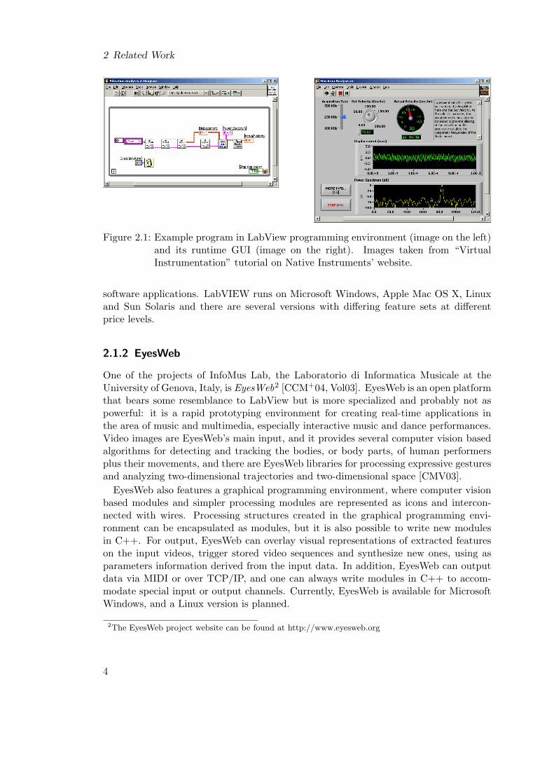
The company Native Instruments1 offers LabVIEW as “a powerful graphical develop-ment environment for signal acquisition, measurement analysis, and data presentation,giving you the flexibility of a programming language without the complexity of tradi-tional development tools” [Ins]. LabVIEW is a rather general framework, suited for, butnot aimed specifically at, creating musical applications. It is a very powerful environ-ment with a wide array of predefined modules for signal acquisition and processing and italso features graphic representations for functionality found in normal programming lan-guages like loop constructs or data structures. Programming consists of connecting theicons representing data sources, data containers and functions or modules with wires plusarranging the graphical user interface elements that are part of some modules, showingoutput and letting the user control the program at runtime. When the program is exe-cuted, data flows along the wires. LabVIEW analyzes the data flow and runs structuresin parallel, if they are independent of each other. After creating a processing structure inLabVIEW, it can be encapsulated as a module and then used like the built-in modules,hiding the internal structure behind a simple icon. Native Instruments also claims thatLabVIEW easily communicates with all kinds of input hardware as well as with other
1The website of Native Instruments can be found at http://www.ni.com
3
2 Related Work
Figure 2.1: Example program in LabView programming environment (image on the left)and its runtime GUI (image on the right). Images taken from “VirtualInstrumentation” tutorial on Native Instruments’ website.
software applications. LabVIEW runs on Microsoft Windows, Apple Mac OS X, Linuxand Sun Solaris and there are several versions with differing feature sets at differentprice levels.
2.1.2 EyesWeb
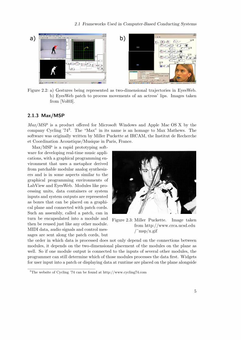
One of the projects of InfoMus Lab, the Laboratorio di Informatica Musicale at theUniversity of Genova, Italy, is EyesWeb2 [CCM+04, Vol03]. EyesWeb is an open platformthat bears some resemblance to LabView but is more specialized and probably not aspowerful: it is a rapid prototyping environment for creating real-time applications inthe area of music and multimedia, especially interactive music and dance performances.Video images are EyesWeb’s main input, and it provides several computer vision basedalgorithms for detecting and tracking the bodies, or body parts, of human performersplus their movements, and there are EyesWeb libraries for processing expressive gesturesand analyzing two-dimensional trajectories and two-dimensional space [CMV03].
EyesWeb also features a graphical programming environment, where computer visionbased modules and simpler processing modules are represented as icons and intercon-nected with wires. Processing structures created in the graphical programming envi-ronment can be encapsulated as modules, but it is also possible to write new modulesin C++. For output, EyesWeb can overlay visual representations of extracted featureson the input videos, trigger stored video sequences and synthesize new ones, using asparameters information derived from the input data. In addition, EyesWeb can outputdata via MIDI or over TCP/IP, and one can always write modules in C++ to accom-modate special input or output channels. Currently, EyesWeb is available for MicrosoftWindows, and a Linux version is planned.
2The EyesWeb project website can be found at http://www.eyesweb.org
4
2.1 Frameworks Used in Computer-Based Conducting Systems
a) b)
Figure 2.2: a) Gestures being represented as two-dimensional trajectories in EyesWeb.b) EyesWeb patch to process movements of an actress’ lips. Images takenfrom [Vol03].
2.1.3 Max/MSP
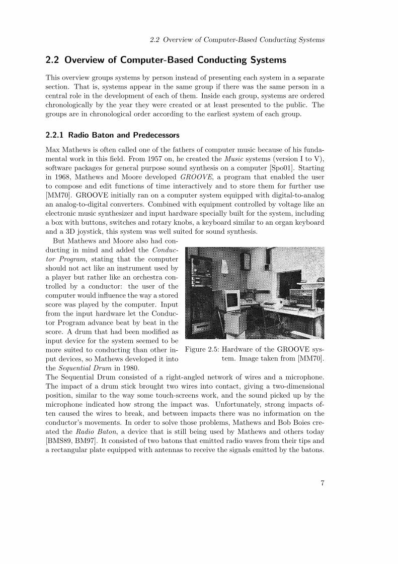
Max/MSP is a product offered for Microsoft Windows and Apple Mac OS X by thecompany Cycling ’743. The “Max” in its name is an homage to Max Mathews. Thesoftware was originally written by Miller Puckette at IRCAM, the Institut de Rechercheet Coordination Acoustique/Musique in Paris, France.
Figure 2.3: Miller Puckette. Image takenfrom http://www.crca.ucsd.edu/˜msp/x.gif
Max/MSP is a rapid prototyping soft-ware for developing real-time music appli-cations, with a graphical programming en-vironment that uses a metaphor derivedfrom patchable modular analog synthesiz-ers and is in some aspects similar to thegraphical programming environments ofLabView and EyesWeb. Modules like pro-cessing units, data containers or systeminputs and system outputs are representedas boxes that can be placed on a graphi-cal plane and connected with patch cords.Such an assembly, called a patch, can inturn be encapsulated into a module andthen be reused just like any other module.MIDI data, audio signals and control mes-sages are sent along the patch cords, butthe order in which data is processed does not only depend on the connections betweenmodules, it depends on the two-dimensional placement of the modules on the plane aswell. So if one module output is connected to the inputs of several other modules, theprogrammer can still determine which of those modules processes the data first. Widgetsfor user input into a patch or displaying data at runtime are placed on the plane alongside
3The website of Cycling ’74 can be found at http://www.cycling74.com
5

2 Related Work
processing modules, thereby mixing graphical user interface design with programming.
Figure 2.4: A Max/MSP example patch.The image was taken fromhttp://www.cycling74.com/images/msp1.gif
While a patch is being executed, only itswidgets are shown. Max/MSP features alot of basic processing units as well as a lotof signal processing and synthesis orientedones and Cycling ’74 offers an add-on,called Jitter, that can handle all kinds ofmatrix data and is optimized for graphicsand video processing, including supportfor hardware-accelerated OpenGL opera-tions. An SDK is also available, makingit possible to write new Max/MSP mod-ules, and there are third parties that offerMax/MSP modules to communicate withspecial input and output hardware.
There exist free software packages re-sembling Max/MSP. One of them, calledPure Data and available for Linux, Mi-crosoft Windows and several unix flavors,including Apple Mac OS X, was createdand is still maintained by Miller Puck-ette4. Another one, called jMax and avail-able for Linux, Microsoft Windows andApple Mac OS X, is supported by theIRCAM5.
4Pure Data software and documentation can be found at http://www.crca.ucsd.edu/˜msp/software.html5jMax software and documentation can be found in the software section of the website of IRCAM at
http://www.ircam.fr/institut.html
6
2.2 Overview of Computer-Based Conducting Systems
2.2 Overview of Computer-Based Conducting Systems
This overview groups systems by person instead of presenting each system in a separatesection. That is, systems appear in the same group if there was the same person in acentral role in the development of each of them. Inside each group, systems are orderedchronologically by the year they were created or at least presented to the public. Thegroups are in chronological order according to the earliest system of each group.
2.2.1 Radio Baton and Predecessors
Max Mathews is often called one of the fathers of computer music because of his funda-mental work in this field. From 1957 on, he created the Music systems (version I to V),software packages for general purpose sound synthesis on a computer [Spo01]. Startingin 1968, Mathews and Moore developed GROOVE, a program that enabled the userto compose and edit functions of time interactively and to store them for further use[MM70]. GROOVE initially ran on a computer system equipped with digital-to-analogan analog-to-digital converters. Combined with equipment controlled by voltage like anelectronic music synthesizer and input hardware specially built for the system, includinga box with buttons, switches and rotary knobs, a keyboard similar to an organ keyboardand a 3D joystick, this system was well suited for sound synthesis.
Figure 2.5: Hardware of the GROOVE sys-tem. Image taken from [MM70].
But Mathews and Moore also had con-ducting in mind and added the Conduc-tor Program, stating that the computershould not act like an instrument used bya player but rather like an orchestra con-trolled by a conductor: the user of thecomputer would influence the way a storedscore was played by the computer. Inputfrom the input hardware let the Conduc-tor Program advance beat by beat in thescore. A drum that had been modified asinput device for the system seemed to bemore suited to conducting than other in-put devices, so Mathews developed it intothe Sequential Drum in 1980.The Sequential Drum consisted of a right-angled network of wires and a microphone.The impact of a drum stick brought two wires into contact, giving a two-dimensionalposition, similar to the way some touch-screens work, and the sound picked up by themicrophone indicated how strong the impact was. Unfortunately, strong impacts of-ten caused the wires to break, and between impacts there was no information on theconductor’s movements. In order to solve those problems, Mathews and Bob Boies cre-ated the Radio Baton, a device that is still being used by Mathews and others today[BMS89, BM97]. It consisted of two batons that emitted radio waves from their tips anda rectangular plate equipped with antennas to receive the signals emitted by the batons.
7

2 Related Work
Figure 2.6: Max Mathews andthe Radio Baton.Image taken fromwww.csounds.com/mathews
Those antennas measured the positions of the batonsabove the plate in three dimensions, but precision ofthe z coordinate declined with growing distance to theplate. The Radio Baton was connected to a computervia MIDI or a serial interface. A version of the Con-ductor Program for the Radio Baton operated on prere-corded scores that contained, among other things, trig-gers linked to notes [Mat00a]. The user conducted withthe Radio Baton by working through the triggers de-fined in the piece. There were two ways for producingtrigger events with the Radio Baton. One was to seta value for the z coordinate above the antenna plateand generate a trigger event every time the baton zposition crossed the imaginary plane defined by thatvalue. The other was to generate a trigger event if thedownward acceleration of a stick decreased to zero af-ter the downward velocity of the stick had increasedbeyond a velocity threshold [Mat00b]. The ConductorProgram provided control over the timing of events ina score with triggers, and control over dynamics, voicebalance and timbre with baton positions. To enhanceexpressive control even further, Johan Sundberg, An-ders Friberg, Max Mathews and Gerald Bennett com-bined the Radio Baton with the Director Musices per-formance grammar, which changes musical expressionaccording to musical context [SFMB01].
2.2.2 Conduct System
Figure 2.7: User interface hardware ofthe conduct system. Imagetaken from [BRF+80].
In 1980, Buxton, Reeves, Fedorkow, Smithand Baecker constructed the conduct system[BRF+80]. It was a conducting system basedon a microcomputer and included a digitalsynthesizer as well as a graphics tablet andswitches plus sliders as input hardware. Thesystem played prerecorded scores and allowedto change pitch, tempo, articulation, ampli-tude (volume) and richness (timbre) of notesplayed by the synthesizer in real time. Theseparameters were controlled by selecting the de-sired parameter on screen with the graphicstablet cursor and then changing its value di-rectly, they were not derived from conductingmovements of the user.
8
2.2 Overview of Computer-Based Conducting Systems
brass tubing
ball contact
spring wire
electricalcontacts
Figure 2.9: Mechanical sensor of the MIDI Baton. Drawing after [KG89].
2.2.3 Conductor Follower
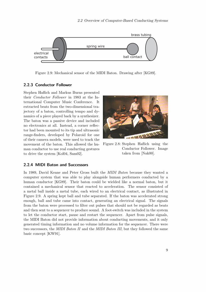
Figure 2.8: Stephen Haflich using theConductor Follower. Imagetaken from [Nak00].
Stephen Haflich and Markus Burns presentedtheir Conductor Follower in 1983 at the In-ternational Computer Music Conference. Itextracted beats from the two-dimensional tra-jectory of a baton, controlling tempo and dy-namics of a piece played back by a synthesizer.The baton was a passive device and includedno electronics at all. Instead, a corner reflec-tor had been mounted to its tip and ultrasonicrange-finders, developed by Polaroid for oneof their camera models, were used to track themovement of the baton. This allowed the hu-man conductor to use real conducting gesturesto drive the system [Kol04, Sam02].
2.2.4 MIDI Baton and Successors
In 1989, David Keane and Peter Gross built the MIDI Baton because they wanted acomputer system that was able to play alongside human performers conducted by ahuman conductor [KG89]. Their baton could be wielded like a normal baton, but itcontained a mechanical sensor that reacted to acceleration. The sensor consisted ofa metal ball inside a metal tube, each wired to an electrical contact, as illustrated inFigure 2.9. A spring kept ball and tube separated. If the baton was accelerated strongenough, ball and tube came into contact, generating an electrical signal. The signalsfrom the baton were processed to filter out pulses that should not be regarded as beatsand then sent to a sequencer to produce sound. A foot-switch was included in the systemto let the conductor start, pause and restart the sequencer. Apart from pulse signals,the MIDI Baton did not provide information about conducting movements, and it onlygenerated timing information and no volume information for the sequencer. There weretwo successors, the MIDI Baton II and the MIDI Baton III, but they followed the samebasic concept [KW91].
9

2 Related Work
2.2.5 Computer Music System that Follows a Human Conductor
Hideyuki Morita, Shuji Hashimoto and Sadamu Ohteru developed their Computer MusicSystem that Follows a Human Conductor in 1989 and, together with Hiroshi Watanabeand Tsutomu Harada, they created an enhanced version of the system one year later[MOH89, MWH+90, MHO91]. The first version tracked either a white marker attachedto the conductor’s baton or the conductor’s hand wearing a white glove, using a CCDcamera and special feature extraction hardware that passed two-dimensional positionvalues to a personal computer. The computer derived tempo and volume informationfrom upper and lower turning points of the trajectory. The final version used an infraredlight source, mounted to the tip of the baton, and a CCD camera with an infrared filter,taking position, velocity and acceleration of the tip of the baton as conducting input. Italso added a VPL Research data glove as input device, to be worn on the conductor’sleft hand. Movements and hand gestures of the left hand were tracked and interpretedby the system to give the conductor more control over the orchestra, for example byselecting an instrument section and then indicating a certain musical expression. Thesystem also included a knowledge database for mapping conducting and hand gesturesto musical expression information and it featured a self-evaluation function that enabledthe conductor to change the mappings in the knowledge database by telling the system,after he conducted a piece, how good the system had interpreted his conducting. Allversions of the system created sound via a MIDI sequencer and MIDI synthesizers.
2.2.6 Light Baton
In 1992, Graziano Bertini and Paolo Carosi created the Light Baton [BC92]. It wasaimed at letting a human conductor conduct musicians in parallel to a computer thatplayed back a prerecorded score. The baton included a battery and a strong LED, whichwas mounted to its tip. A CCD camera recorded the conductor, who could conduct usingnormal conducting gestures. A special image acquisition board extracted the light pointwithout using the CPU of the host computer. The prerecorded score was then adjustedaccording to tempo and volume information derived from the trajectory of the light.
2.2.7 Adaptive Conductor Follower and Related Systems
Michael Lee, Guy Garnett and David Wessel built an Adaptive Conductor Follower inthe year 1992 [LGW92], and Bennett Brecht and Guy Garnett produced an updatedversion just a year later, which they called Conductor Follower [BG95]. A Mattel PowerGlove and a Buchla Lightning baton system served the system as input devices. TheBuchla Lightning used infrared light to determine a two-dimensional position of itsbaton and passed this position via MIDI to the Conductor Follower, which processedsuccessive baton positions with tempo trackers that were implemented in the Max/MSPenvironment. There were three methods of tracking and predicting tempo. The first justused the time between the last detected beat and the beat previous to that to predictthe time of the next beat. The second looked for six characteristic points in a beatcurve, using zero crossings in velocity and acceleration of the baton, and thus allowed
10

2.2 Overview of Computer-Based Conducting Systems
to detect tempo changes between beats. The third method used the same characteristicpoints, but fed them into neural networks, which gave even better tempo control. Theneural networks classified the conducting gestures and predicted the time of the nextdownbeat or half beat, with a downbeat being defined as a local minimum and a halfbeat being defined as a local maximum of the y coordinate of the movement of the tip ofthe baton. To train the neural networks, a conductor conducted along with a metronomefor different tempi and the system adjusted the networks as necessary.
Guy Garnett continued to work on conducting systems and in 1999 he, FernandoMalvar-Ruiz and Fred Stoltzfus presented their Virtual Conducting Practice Environ-ment, where they focused on determining appropriate aural and visual feedback on whatstudent conductors are doing right or wrong and tried to build a system that can em-phasize different aspects of conducting, depending on the skill level and learning goal ofthe student [GMRS99]. This system also used a Buchla Lightning as input device. Itgave graphic representations of simple features, like the position of recognized beats inthe beat plane, or more complex features, like whether a conducting style tended moretowards staccato or more towards legato. It could play sounds every time it recognized abeat or it could play a simple melody that followed the student in tempo and loudness.But in the paper describing their system, the authors concluded that the system couldreplace neither a good teacher nor practice with live musicians.
In 2001, Guy Garnett, Mangesh Jonnalagadda, Ivan Elezovic, Timothy Johnson andKevin Small published a paper about technological advances for their Interactive VirtualEnsemble [GJE+01]. In particular, they noted that the position information given bythe Buchla Lightning baton was insufficient for their needs, and they abandoned it infavor of a sensor system called MotionStar, built by Ascension Technologies. In thissensor system, a pulsed magnetic field was picked up by magnetic sensors that measuredtheir own position and orientation relative to the source of the field and transmitted thevalues wirelessly to a receiver that was connected via ethernet to the host computer.In the Interactive Virtual Ensemble, the sensors were used to track the baton positionin three dimensions and to obtain pitch, yaw and roll of the baton, as well as handand head motion of the conductor. The system followed a distributed processing model,where one computer processed all sensor input, deriving controller data from it, andanother computer requested only the controller data it currently needed from the firstcomputer. The system used neural networks for beat prediction and classification, andinstead of sending out notes to MIDI synthesizers, it featured sound output based onsound analysis and resynthesis, controlled directly by conducting information.
2.2.8 The Ensemble Member and the Conducted Computer /Extraction of Conducting Gestures in 3D Space
In 1995, Forrest Tobey developed a software system that tracked tempo along all pointsof the path of a baton and allowed the conductor to take or release control of musicalphrases [Tob95]. It also included a rehearsal module, so the conductor could train itto his gestures, and it used a Buchla Lightning baton as input device, which yieldedtwo-dimensional position information. Forrest Tobey and Ichiro Fujinaga extended the
11

2 Related Work
Figure 2.10: Der virtuelle Dirigent. Image courtesy of the Media Computing Group atthe RWTH Aachen.
system in the year 1996 [TF96]. The extended version of the system included a secondBuchla Lightning sensor. With two sensors, movement of the baton could be tracked inthree dimensions. This extended system featured tempo control, dynamic control, beatpattern recognition, beat style recognition, accentuation control and timbral balance.
2.2.9 WorldBeat, Personal Orchestra and You’re The Conductor
In 1996, Jan O. Borchers designed the WorldBeat system [Bor97, Bor01]. It was one ofthe exhibits shown in the Ars Electronica Center in Linz, Austria. It featured severalmodules showing visitors how computers could aid interacting with music in new ways,for example by trying to find the titles of songs visitors hummed into a microphone.Apart from the module using the microphone, all user input to the system came froma Buchla Lightning baton system. WorldBeat also included a module that let usersconduct a piece of music, but the algorithm to track conducting movements was notdeveloped originally for WorldBeat. Instead, the system reused components from GuyGarnett’s Conductor Follower. These components were slightly modified to be usableby visitors who had no prior conducting experience.
In 2002, Jan Borchers, Wolfgang Samminger and Max Muhlhauser finished the Per-sonal Orchestra system [Sam02]. It was another museum exhibit, this time for theHouse of Music in Vienna, Austria. The system was developed under the name PersonalOrchestra but the museum called the exhibit Der virtuelle Dirigent (i.e., Virtual Con-ductor), even though the orchestra was virtual and not the conductor. Visitors couldinteract with the exhibit by using a Buchla Lightning baton to first select one of fourmusical pieces and then to conduct the selected piece. An important focus in developingPersonal Orchestra was to use recorded audio and video of the Vienna PhilharmonicOrchestra for output, adjusting playback with the help of manually created beat files
12
2.2 Overview of Computer-Based Conducting Systems
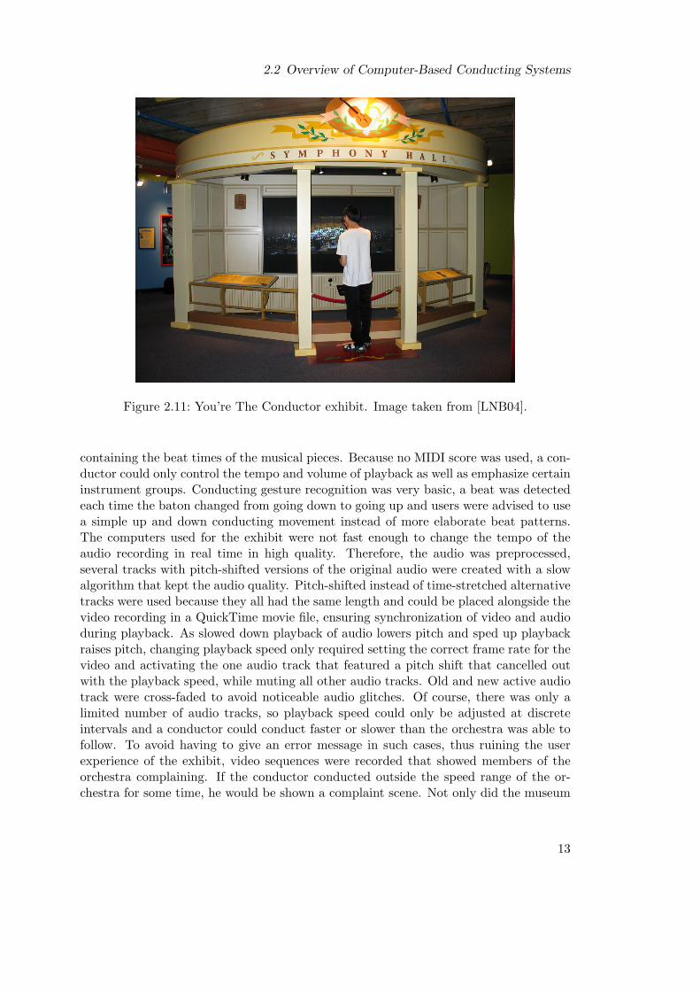
Figure 2.11: You’re The Conductor exhibit. Image taken from [LNB04].
containing the beat times of the musical pieces. Because no MIDI score was used, a con-ductor could only control the tempo and volume of playback as well as emphasize certaininstrument groups. Conducting gesture recognition was very basic, a beat was detectedeach time the baton changed from going down to going up and users were advised to usea simple up and down conducting movement instead of more elaborate beat patterns.The computers used for the exhibit were not fast enough to change the tempo of theaudio recording in real time in high quality. Therefore, the audio was preprocessed,several tracks with pitch-shifted versions of the original audio were created with a slowalgorithm that kept the audio quality. Pitch-shifted instead of time-stretched alternativetracks were used because they all had the same length and could be placed alongside thevideo recording in a QuickTime movie file, ensuring synchronization of video and audioduring playback. As slowed down playback of audio lowers pitch and sped up playbackraises pitch, changing playback speed only required setting the correct frame rate for thevideo and activating the one audio track that featured a pitch shift that cancelled outwith the playback speed, while muting all other audio tracks. Old and new active audiotrack were cross-faded to avoid noticeable audio glitches. Of course, there was only alimited number of audio tracks, so playback speed could only be adjusted at discreteintervals and a conductor could conduct faster or slower than the orchestra was able tofollow. To avoid having to give an error message in such cases, thus ruining the userexperience of the exhibit, video sequences were recorded that showed members of theorchestra complaining. If the conductor conducted outside the speed range of the or-chestra for some time, he would be shown a complaint scene. Not only did the museum
13

2 Related Work
visitors accept this kind of error message, they rather liked it, and a lot of people triedto conduct badly in order to see all of the complaint sequences.
Another museum exhibit was created in 2003 by Eric Lee, Teresa Marrin Nakra andJan Borchers for the Children’s Museum in Boston, USA [LNB04]. While still in de-velopment, it was nicknamed Personal Orchestra 2, but the finished system was calledYou’re The Conductor. Like Personal Orchestra, it output recorded audio and video ofa real orchestra. Faster computers enabled the system to time-stretch the audio in realtime by using an improved phase vocoder algorithm, enabling the system to play backthe recording at any wanted speed. Instead of employing a Buchla Lightning baton forinput, a very rugged baton-like device was developed, which was mainly a light sourceand could stand heavy use. The light point was tracked with a camera, but no real con-ducting gesture recognition took place: any movement of the baton was translated intoplayback speed and volume, so that children of all ages could use the system. If a childmoved the baton faster or slower, the orchestra sped up or slowed down, respectively,and if the child stopped moving the baton, the orchestra slowed to a halt.
2.2.10 Digital Baton, Conductor’s Jacket and Gesture Construction
Figure 2.12: The Digital Baton.Image taken fromweb.media.mit.edu/˜joep/TTT.BO/Baton2.gif
Teresa Marrin and Joseph Paradiso presented theirDigital Baton in 1997 [MP97]. They had developedan input device similar to a baton, which includedthree acceleration sensors to measure movement ofthe baton and five pressure sensors to measure thepressure of each finger of the hand holding the ba-ton as well as an infrared LED at the tip of thebaton. A position-sensitive photodiode was placedbehind a camera lens to track position and inten-sity of the infrared LED. Musical performance ap-plications developed for the Digital Baton allowedthe user to influence the volume of several tracksof a prerecorded MIDI score, to trigger playbackof samples as well as placing the triggered samplesin the stereo panorama and to switch instruments,re-orchestrating the piece. There was no trackingof conducting gestures and no beat information was derived from the input to control thetempo of the piece being played. However, Teresa Marrin’s thesis paper on the DigitalBaton did include a classification and analysis of conducting gestures [Mar96].
Teresa Marrin and Rosalind Picard developed the Conductor’s Jacket in 1998 [MP98].The system used a multitude of sensors built into a jacket to be worn by musicians torecord physiological and motion data. The monitored physiological aspects were muscletension of various muscles on each arm, heart rate, temperature, respiration and skinconductance. Motion data was acquired using an UltraTrak motion capture system fromPolhemus Corporation. The jacket was connected to a computer running utilities writtenin National Instruments’ LabVIEW package, collecting and analyzing the data.
14

2.2 Overview of Computer-Based Conducting Systems
Figure 2.13: Data acquisition setupfor the Conductor’sJacket. Image takenfrom [Nak00].
This first version of the system did not use the ac-quired data to let users conduct a computer. Afteran in-depth analysis of the data sets collected withthe first version, Teresa Marrin created a secondversion that did allow to conduct a prerecorded mu-sical score, generating sound output by using MIDIsynthesizers [Nak00]. She modified the jacket toinclude only the respiration sensor and the sensorsfor muscle tension, placing those at biceps, forearmand hand of each arm, as well as on the right shoul-der. She also wrote the musical software GestureConstruction that detected beats based on maximain muscle tension of left and right biceps. The soft-ware also detected holds, cutoffs and pauses, andenabled the conductor to control tempo, note andchannel volumes, articulations and accents. It alsoallowed the conductor to choose pitch and number of voices, to pan instruments andchange instrument balance, to morph timbres and do several other performance orientedthings, moving beyond what a real orchestra is capable of. Gesture Construction wassplit in two parts running on separate machines. The part for input data acquisition andfiltering was implemented in LabVIEW, while the performance part holding the musicalfunctions and creating the output was written in C++.
2.2.11 Multi-Modal Conducting Simulator
In 1998, Satoshi Usa and Yasunori Mochida built their Multi-Modal Conducting Simu-lator [UM98]. To recognize beat patterns conducted with the right hand, accelerationsensors were used, tracking movement of the baton in two dimensions. Hidden MarkovModels detected the beats and fuzzy logic production rules determined if the detectedbeats were considered to be valid. To give cues to different instrument groups, an eyetracking camera detected which instrument group the conductor was looking at. Abreathing sensor allowed to couple certain passages in the score to breathing patternsof the conductor. The beat patterns used by the conductor determined tempo and vol-ume, and the system could also differentiate between staccato and legato beat patterns.The Multi-Modal Conducting Simulator generated sound output with MIDI synthesiz-ers, taking the notes to be played from a prerecorded score that also contained specialmarkers for cues and for breathing patterns.
2.2.12 Virtual Orchestra
Frederick Bianchi, Jeff Lazarus and David B. Smith founded the company RealtimeMusic Solutions in 1998, to commercialize their Virtual Orchestra system [Sol]. VirtualOrchestra could be conducted exactly like a real orchestra and it sounded very muchlike a real orchestra as well. Human technicians served as interface between conductor
15

2 Related Work
Figure 2.14: Multi-Modal Conducting Simulator. Image taken from [Sam02].
and computer, interpreting the conducting gestures and instructing the computer ac-cordingly in real time. The system used prerecorded pieces to control a synthesizer thatplayed samples taken from real instruments. Musicians playing in real orchestras did notwelcome Virtual Orchestra because they feared to be replaced by a computer. Later thesystem was renamed to Sinfonia, and a simpler variant called OrchExtra was created.
2.2.13 Conductor Following with Artificial Neural Networks
Figure 2.15: DIVA virtual orches-tra. Image was takenfrom www.tml.hut.fi/Research/DIVA/past/imgs/band1.jpg
Tommi Ilmonen and Tapio Takala developed a sys-tem to track conducting gestures with neural net-works, starting development in 1998 and finishingit in 1999 [Ilm98, IT99, Ilm99]. Their publicationsdid not mention an official name for their system,maybe they did not name it because it was partof another system: it served to drive the virtualorchestra of DIVA, the Digital Interactive VirtualAcoustics project group [Ilm]. This virtual orches-tra featured stylized 3D models of musicians ofa band, whose motions were calculated from thenotes of a MIDI score. Sound output of the virtualorchestra was generated from the same MIDI score,simply using a MIDI synthesizer for some of the in-struments and synthesizing others on a computerusing the physical modeling technique.
However, the conductor following system was in itself already very advanced. It usedAscension’s MotionStar magnetic motion tracker as input device, with one sensor placed
16

2.2 Overview of Computer-Based Conducting Systems
at the conductor’s left hand, another one at the right hand or alternatively mounted onthe baton and one at the conductor’s neck as reference point for the other two.
Figure 2.16: DIVA conductor following sys-tem sensor placement. Imagetaken from [Ilm98].
Therefore, input data for the neural net-works consisted of three-dimensional po-sitions of the sensors at the conductor’shands relative to the position of the sen-sor at the conductor’s neck. Ilmonen alsotried using accelerometers placed on thebaton instead, but he found that they weresignificantly less accurate than the mag-netic sensors. The system used the neu-ral networks to classify and predict beats,and they were even able to identify subdi-vided beats. It let conductors mainly con-trol tempo and volume of the DIVA band,but the neural networks could also dis-tinguish between staccato and legato beatpatterns, making the band play accord-ingly.
2.2.14 Virtual Dance and Music
Jakub Segen, Aditi Majumder and Joshua Gluckman created their Virtual Dance andMusic system in the year 2000 [SMG00]. The system had three main parts: a ges-ture recognition system, a music sequencer and a dance sequencer, with the gesturerecognition system driving both sequencers to produce synchronized music and danceas output. The gesture recognition system used computer vision to extract beats fromconducting gestures. Two synchronized cameras acquired a three-dimensional trajectoryof the baton and beats were placed at the locally lowest points of the trajectory. Toreduce latency, the gesture recognition system predicted beats if possible, by using apolynomial predictor that indicated the quality of its predictions. If prediction qualitywas poor, beats were detected instead of predicted, resulting in higher latency. Themusic sequencer played music from a MIDI file, adjusting the tempo to the time inter-vals between beats detected by the gesture recognition system. If the music sequencerhad already played all notes corresponding to the current beat, it just waited until theuser conducted the next beat, and if the user conducted the next beat before the mu-sic sequencer finished playing the notes corresponding to the last beat, it increased thetempo slightly more than indicated in order to catch up with the conductor. The dancesequencer created video output of human avatars dancing to the music, according to thebeats given by the conductor and constrained by a model of possible human motionsand laws like gravity, to prevent unnatural and impossible dance motions.
17
2 Related Work
2.2.15 Conducting Audio Files via Computer Vision
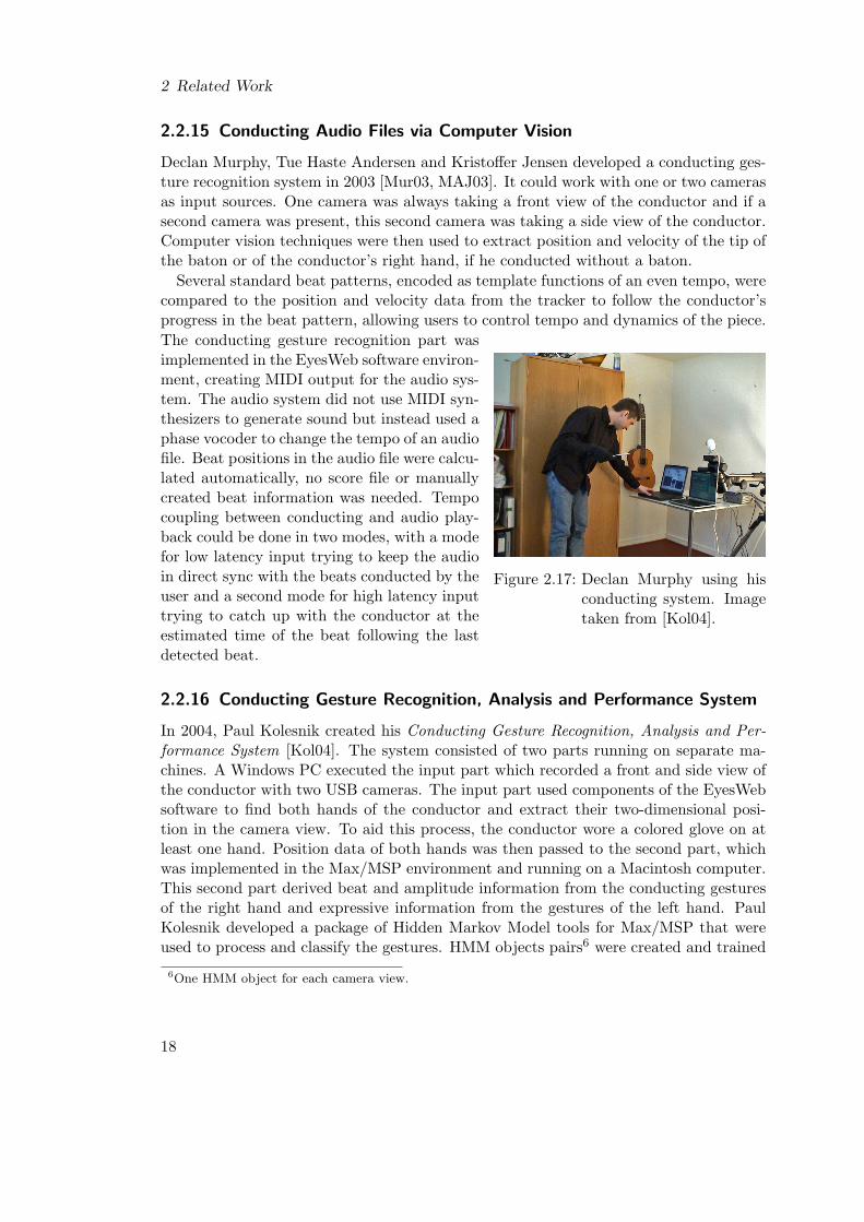
Declan Murphy, Tue Haste Andersen and Kristoffer Jensen developed a conducting ges-ture recognition system in 2003 [Mur03, MAJ03]. It could work with one or two camerasas input sources. One camera was always taking a front view of the conductor and if asecond camera was present, this second camera was taking a side view of the conductor.Computer vision techniques were then used to extract position and velocity of the tip ofthe baton or of the conductor’s right hand, if he conducted without a baton.
Several standard beat patterns, encoded as template functions of an even tempo, werecompared to the position and velocity data from the tracker to follow the conductor’sprogress in the beat pattern, allowing users to control tempo and dynamics of the piece.
Figure 2.17: Declan Murphy using hisconducting system. Imagetaken from [Kol04].
The conducting gesture recognition part wasimplemented in the EyesWeb software environ-ment, creating MIDI output for the audio sys-tem. The audio system did not use MIDI syn-thesizers to generate sound but instead used aphase vocoder to change the tempo of an audiofile. Beat positions in the audio file were calcu-lated automatically, no score file or manuallycreated beat information was needed. Tempocoupling between conducting and audio play-back could be done in two modes, with a modefor low latency input trying to keep the audioin direct sync with the beats conducted by theuser and a second mode for high latency inputtrying to catch up with the conductor at theestimated time of the beat following the lastdetected beat.
2.2.16 Conducting Gesture Recognition, Analysis and Performance System
In 2004, Paul Kolesnik created his Conducting Gesture Recognition, Analysis and Per-formance System [Kol04]. The system consisted of two parts running on separate ma-chines. A Windows PC executed the input part which recorded a front and side view ofthe conductor with two USB cameras. The input part used components of the EyesWebsoftware to find both hands of the conductor and extract their two-dimensional posi-tion in the camera view. To aid this process, the conductor wore a colored glove on atleast one hand. Position data of both hands was then passed to the second part, whichwas implemented in the Max/MSP environment and running on a Macintosh computer.This second part derived beat and amplitude information from the conducting gesturesof the right hand and expressive information from the gestures of the left hand. PaulKolesnik developed a package of Hidden Markov Model tools for Max/MSP that wereused to process and classify the gestures. HMM objects pairs6 were created and trained
6One HMM object for each camera view.
18
2.2 Overview of Computer-Based Conducting Systems
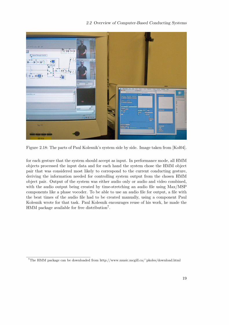
Figure 2.18: The parts of Paul Kolesnik’s system side by side. Image taken from [Kol04].
for each gesture that the system should accept as input. In performance mode, all HMMobjects processed the input data and for each hand the system chose the HMM objectpair that was considered most likely to correspond to the current conducting gesture,deriving the information needed for controlling system output from the chosen HMMobject pair. Output of the system was either audio only or audio and video combined,with the audio output being created by time-stretching an audio file using Max/MSPcomponents like a phase vocoder. To be able to use an audio file for output, a file withthe beat times of the audio file had to be created manually, using a component PaulKolesnik wrote for that task. Paul Kolesnik encourages reuse of his work, he made theHMM package available for free distribution7.
7The HMM package can be downloaded from http://www.music.mcgill.ca/˜pkoles/download.html
19

2 Related Work
2.3 Comparison of Computer-Based Conducting Systems
It is hard to compare the presented computer-based conducting systems because of thevery different approaches that were taken in their development.
There are a lot of parameters a trained conductor can influence when conducting areal orchestra. He can for example indicate when notes will be played and how longthey should be, holding them or cutting them off. He can tell the musicians how loudnotes should be played, how notes should be accentuated and what form transitionsbetween subsequent notes should take. He can influence how notes are grouped orat least perceived as groups. He has control over the whole orchestra as well as thedifferent instrument groups and can dictate when and how they enter the musical piece.He can emphasize an individual instrument group and control this group directly forsome time, while the rest of the orchestra serves as background. Or he can let hisattention jump from instrument group to instrument group, issuing commands to eachgroup, fine-tuning their balance and interplay. Supporting all those parameters in acomputer-based system, and supporting them well, is very hard indeed, and differentsystems pick different subsets of those parameters, with some systems featuring onlythe basics like tempo and volume and others going beyond that in letting the conductorshape the notes in various degrees or giving him control over instrument groups. Howthe parameters present in the respective systems can be influenced by the conductor alsodiffers from system to system. There are systems that just let the conductor enter avalue for each parameter he wants to change. Others derive the parameter values fromconducting gestures, hand gestures or eye contact. Virtual Orchestra even uses humansas transducers for conducting input, in order to capture nuances a machine would miss.
What parameters are supported is also influenced by the intended user group. Somesystems are targeted towards people with no conducting experience whatsoever, someaddress people who are interested in performing music but do not want to learn aninstrument or do not want to have to control all aspects of the sound they generate,as they would have to when using a musical instrument. Some are aimed at trainedconductors and some are aimed at students still learning how to conduct.
The systems also use very different input hardware, ranging from simple keyboardsand switches over cameras and data gloves to all sorts of sophisticated sensors, eachhaving their own characteristics, with latency and accuracy being of special importance.Input data can be video images of the conductor, of body parts like his hands andhis eyes, or of the baton he is wielding. Several enhanced batons are employed in thesystems, some acting as a light source whose position can be tracked, again with differentkinds of sensors to locate the point of light. Other batons provide acceleration values,sometimes only in the form of triggers. Even radio waves are used to locate the baton,or magnetic fields serve to measure position and orientation of the baton and/or theconductor’s hands. Sensor technology from the medical field has been used to monitorbody signals of the conductor. Very different ways of processing the input were tried out,starting with functions to de-noise the signals and rather simple algorithms to extracttriggers from input data and ending with very advanced algorithms like neural networksand hidden markov models. Although the software of the systems varies wildly, there
20
2.3 Comparison of Computer-Based Conducting Systems
have also been cases of reuse of existing components, or components have been built inorder to be reused, facilitated by utilizing frameworks such as Max/MSP.
The output of the systems takes several forms as well. Some play back recordedaudio and video, some output MIDI data and rely on MIDI synthesizers to generatetheir sound. Some incorporate advanced synthesis algorithms like physical modeling ofinstruments into the system in order to be able to control very precisely how the sound ofthe orchestra is generated. The performance based systems do even synthesize graphicsor animations based on the conducting input.
A very important point is that different systems use different definitions of conductinggestures. Some see conducting gestures just as a sequence of beat triggers. Others defineand measure conducting gestures as the movement of the conductor’s baton or hand inone, two or three dimensions, often reducing the properties of the baton to the positionor acceleration of its tip and placing the beats at local minima of its vertical movement.Some of the systems defining conducting gestures as movement of the baton take theform of the trajectory into account, i.e., there are explicit models of beat patterns orcomponents that can be trained to recognize beat patterns. In a completely different ap-proach, the Conductor’s Jacket regards conducting gestures as patterns of physiologicalsignals. Several systems detect special gestures that add to the basic conducting gesturesand model those as posture and orientation of the left hand or direction in which theconductor is looking.
For perfect control of a conductor over a real orchestra, the musicians of the orchestraand the conductor must know each other and rehearse a musical piece before performingit. Only some of the presented systems take this aspect of conducting into account.
21

2 Related Work
22

3 The Context that Led to the CongaFramework
The Media Computing Group at RWTH Aachen, the Rheinisch-Westfalische TechnischeHochschule in Aachen, Germany, was established in the year 2003. With Jan Borchersas head of the group and Eric Lee as research assistant, computer-based conducting sys-tems belong to its history. When the group pondered development of successor systemsto Personal Orchestra and You’re The Conductor, the question arose, how the conduct-ing gesture recognition parts of those systems could be reused and improved. It turnedout that, because the gesture recognition parts had been held simple, they had beenimplemented in a way that made extracting them and encapsulating them for furtherreuse just as hard as re-implementing them from scratch in a new system. In addition,substantial improvements in the way they tracked conducting gestures would have re-quired a redesign anyway. In consequence, it was decided to reuse neither the gesturerecognition code of Personal Orchestra nor the one of You’re The Conductor in succes-sor systems. To avoid running into the same problem in the future, the group startedlooking for components that would allow to create an encapsulated gesture recognitionpart that is isolated from the rest of the system and that would also allow to adapt sucha part to changed requirements. Moreover, these components should accommodate theuse of very different input hardware, as not even Personal Orchestra and You’re TheConductor used the same input devices. They should also enable building conductinggesture trackers that do not depend on the way sound is generated from conductinginput, since different ways of doing so have been implemented in the past and soundsynthesis is still a developing field.
Frameworks like LabVIEW, EyesWeb and Max/MSP meet these demands. Theircomponents are tried and tested, each framework has its own user community and thecommercial frameworks feature additional support by the companies selling them. Theframeworks have been used successfully in several computer-based conducting systems.There are even modules like neural networks or hidden markov models, developed withthese frameworks for such systems, that are available for reuse. But there are drawbacksto using these frameworks as well. The modules for advanced tracking of conductinggestures have been developed precisely because there are no built-in components spe-cializing on conducting. The graphical programming environments are very comfortable,but programmers are forced to use them because the modules of the frameworks cannotbe used easily outside the frameworks. If one wants to combine these modules with codefrom other sources, one is either forced to package that code into external modules forthe framework and use the framework’s programming tools to develop the overall appli-cation, or one has to create two applications, using the framework’s runtime environment
23

3 The Context that Led to the Conga Framework
and an operating system process running in parallel. In the latter case, the applicationborders will be dictated by the types of the parts one wants to combine. Furthermore,one has to insert glue code into both applications so they can communicate with eachother, adding to the complexity of the system. Another drawback might be the way theframeworks handle the flow of data and how data is processed. These are fixed becausethe frameworks have been used by many people to develop a lot of different applica-tions — changing the framework’s core behavior would break those applications. So aprogrammer using the frameworks has to adapt his application logic to fit the framework.
In the end, the group decided that it would be better to create a new frameworkthat specializes on conducting gesture tracking and particularly supports a better setof operators for conducting gestures than the existing frameworks. It should also allowto create processing units that can be mixed with existing code that was developedwith standard development tools. This framework was to be called conga, short for“CONducting Gesture Analysis framework”, and it would first be used in the PersonalOrchestra 3 project of the Media Computing Group. Objective of the project was tocreate an interactive conducting system for The Betty Brinn Children’s Museum1 inMilwaukee, USA, featuring an adaptive gesture recognition that could act like You’reThe Conductor, deriving tempo and volume from any baton movement, but that couldalso track a standard beat pattern giving the conductor finer control than in PersonalOrchestra. Personal Orchestra 3 would also feature audio output using a phase vocoderthat was more advanced than the one that had been used in You’re The Conductor.Thorsten Karrer was working on this part of the project for his diploma thesis[Kar05]2.
Creating a new framework meant to forego the advanced conducting gesture recogni-tion modules available for reuse that have been built with existing frameworks. But thiswas deemed acceptable, because these modules use neural networks or hidden markovmodels and thus rely on being trained to certain beat patterns. The future conductingsystems planned at the Media Computing Group will probably be interactive music ex-hibits. This means they will be used by each user only for a short amount of time andprobably only for a few times or even only once. That makes it impractical to train thesystems to each user. But if one uses general training sets to train the gesture recogni-tion modules, one cannot be sure if the modules really learned the essential propertiesof the gestures. In addition, it is not possible to change the way the module tracks agesture without retraining it.
1A museum installation will not be maintained and operated by computer experts. Therefore, it isdesirable to have a system that only needs a single computer to run on. As the target platformof Personal Orchestra 3 is an Apple computer with MacOS X, this would have ruled out EyesWebanyway.
2Both the Personal Orchestra 3 project and Thorsten Karrer’s diploma thesis were still in progress atthe time this thesis paper was written, so the final title and publishing date of his diploma thesismight differ from the ones given in [Kar05].
24
4 The Conga Framework
This chapter describes the fundamental characteristics of the conga framework, particu-larly the underlying model of what a conducting gesture is plus the important conceptsand structures of the framework and its components. It also mentions some of theproblems in developing conga and the impact they had on the design of the framework.
4.1 Model of Conducting Gestures
In her PhD thesis about the Conductor’s Jacket ([Nak00]), Teresa Marrin shows thatconducting is an activity that involves the conductor’s whole body. But the actual con-ducting gestures mainly rely on the conductor’s hands. According to Paul Kolesnik, whofocused on recognition of expressive gestures in his Master’s thesis ([Kol04]), expressivegestures in conducting can be performed with either hand, but time-beating gesturesare almost always carried out using the right hand. Max Rudolf is even more strict,in his book The Grammar of Conducting: A Comprehensive Guide to Baton Techniqueand Interpretation ([Rud95]) he argues that all important conducting information canand should be conveyed with gestures of the right hand, citing the conductor RichardStrauss: “The left hand and both arms are dispensable, a good wrist is sufficient.” Thebook describes conducting gestures that can be performed with the right hand, both withor without a baton, and these gestures cover musical expression as well as time-beating.It explains the shape of the gestures with illustrations that show the path followed bythe tip of the baton when performing a certain gesture.
The design of the conga framework is based on the model of conducting gesturesgiven in Max Rudolf’s book, i.e., conga models conducting gestures as two-dimensionaltrajectories of a point, with the point corresponding to the tip of the baton, or theconductor’s right hand, if he is conducting without baton. In his book, Max Rudolfdepicts the shapes of the trajectories of several fundamental beat patterns, includingthe placement of the beats. He also supplies information whether or not the batonor right hand should stop on the beats and whether movement should be deliberateand controlled or rather very quick. Figure 4.1 is an example of various beat patternsfor conducting gestures in the graphic notation of Max Rudolf. Properties shared bydifferent beat patterns express themselves in similarities in the trajectories of thosepatterns, for example both neutral-legato pattern trajectories in said figure look similar,although one is a 3-beat pattern trajectory and the other is a 4-beat pattern trajectory.The numbers in the figure are placed at the locations of the beats and give the order inwhich the beats occur when the beat pattern is executed by the conductor. Consequently,each beat marks a point in time as well as a point in the trajectory of its beat pattern.
25

4 The Conga Framework
1
32
4
4-beat; neutral-legato
1
32
4
4-beat; expressive-legato
21
4
3
4-beat; light-staccato
1
4
4-beat; full-staccato
2
STOP
3STOP
the baton passes through without stopping
the baton stops at this point
indicates deliberate, controlled movement
indicates very quick movement
indicates bouncing
1
23
3-beat; neutral-legato
Figure 4.1: Some examples of Max Rudolf’s beat patterns for conducting gestures. Draw-ings after [Rud95].
26
4.2 Choice of Platform and Implementation Language
Conducting an orchestra with a certain beat pattern results in the same pattern beingrepeated over and over again. As long as the conductor sticks to the same beat pattern,he is in essence cycling through this pattern, with the beats marking distinct points in thecycle and the first beat in the pattern marking the boundary between subsequent cycles.Each full beat pattern drawn in The Grammar of Conducting represents one completecycle in executing the beat pattern, showing the shape of the trajectory corresponding tothe beat pattern’s conducting gesture. From the shape of this trajectory follow certainfeatures, such as the speed of the tip of the baton or the direction of its movement andso on. Outstanding features allow to identify a certain beat pattern, e.g., the overallshapes of the neutral-legato and full-staccato 4-beat patterns in Figure 4.1 might lookvery similar, but the stops featuring in the full-staccato pattern’s trajectory allow to tellthe patterns apart. Repetitive occurrences of distinct features make it possible to trackthe execution of a beat pattern, using those and other features to derive conductinginformation like tempo, volume, targeted instrument group, and so forth.
The conga framework provides objects that can be interconnected to process andanalyze input data corresponding to points of the trajectory of the conductor’s baton orright hand sampled at regular time intervals. It also provides the means to build featuredetectors and to model the gesture cycles of beat patterns.
4.2 Choice of Platform and Implementation Language
The Media Computing Group uses mostly Apple Macintosh computers running theMac OS X operating system, and a lot of existing code used and/or developed by thegroup has been implemented either in C++ or in Objective-C. Apple’s development toolsallow to mix Objective-C and C++ code, and the more modern parts of Mac OS X aremostly based on Objective-C, including the Cocoa APIs providing access to much of thefunctionality of Mac OS X. Because of this, conga was implemented as an Objective-C framework for Mac OS X. One additional advantage to Objective-C frameworks inMac OS X is that they do not have to be linked statically. An application can load themat startup, making it easy to give applications depending on such frameworks access toimproved versions, without having to recompile the applications.
4.3 Early Approaches and Their Problems
The conga framework was developed with Apple’s integrated development environmentXCode. Most of the testing and debugging work was done on an Apple PowerMacintoshworkstation with 512 MB of RAM and dual G5 processors running at 2 GHz, using aBuchla Lightning II1 infrared baton system as main input hardware.
1The Buchla Lightning II system consists of two batons that emit infrared light, a sensor unitand a control unit that processes the sensor input, acts as MIDI interface and also contains aGeneral MIDI synthesizer. It is manufactured and sold by the company Buchla and Associates.Their website can be found at http://www.buchla.com with information about the Lightning II athttp://www.buchla.com/lightning/index.html
27
4 The Conga Framework
During the early approaches to create the framework, some rather time-consumingmistakes were made by the author. For example, one mistake was to test the very firstattempts to track conducting gestures by using a mouse and a Wacom graphics tabletas input devices. Only some time later was the Buchla Lightning baton employed asinput hardware instead, with the result that components of the gesture tracker that hadseemed to work ceased functioning properly. This could have been avoided if the inputdevice with the most problematic characteristics had been identified first and then usedfor most of the testing right from the start.
Another mistake in the beginning phases of the framework was to develop frameworkcomponents and code to track conducting gestures depending on the framework in par-allel. The problem of that approach was that changes to the framework’s structure andway of processing data required changing the tracking code as well. But changes werefrequent because the underlying model of what constitutes a conducting gesture keptchanging, as did the way the framework would handle conducting gesture analysis — thedefinitions given in Section 4.1 are only the end result. For instance, an early versionof the framework focused on detecting the presence of certain features from position,velocity and acceleration input, but did not provide the means to assemble new featuredetectors from existing ones. Code depending on this version of the framework had to bereworked substantially every time the framework changed. After that, another approachwas taken: First a simple tracker for the 4-beat neutral legato pattern was built byiteratively adding improvements to the code of one central function. When the trackerwas working reasonably, this central function was decomposed into its building blocksand from then on the next version of the conga framework was developed from scratch,by creating components corresponding to said building blocks.
Yet another unfortunate early decision was to use short sounds to indicate detectedfeatures. A better decision would have been to visualize detected features and the inputdata for the feature detectors. Because progress was a slower than expected, visualizationtools were implemented later on and did provide valuable insight. It turned out thatvelocity and acceleration values calculated from position data delivered by the Buchlasystem were varying wildly because the Buchla system did not deliver data at regulartime intervals, with noise being exaggerated by very short time intervals. Resamplingthe input data at regular time intervals reduced the noise considerably. If visualizationhad been used from the start, important characteristics of the input data would havebeen apparent much earlier.2
Unnecessary complexity was a problem that arose again and again. Several times inthe development process it turned out that a structure or way of processing that hadbeen added to provide certain functionality could be merged with an older counterpart oreven discarded completely by changing the older counterpart slightly. Up to that point,creation and maintenance of the added part consumed time and effort, and dependingsource code is of course more complex when it uses two different concepts instead of
2Incidentally, the first visualization tools worked offline. Later a version was created that ran in parallelto the tracking code, based on Apple’s Cocoa objects for drawing lines. But these Objective-C objectsare optimized for printing and not for fast display on a monitor, so visualization choked off trackinguntil both were decoupled. It would have been better to base the visualization on OpenGL instead.
28
4.4 Basic Processing Model
one unified concept. For instance, as opposed to the final approach described in Sub-section 4.4.1, some earlier versions of the framework distinguished between several typesof data but processed these types in similar ways. In effect, there were several separatecode structures that did basically the same processing. Another example of unnecessarycomplexity were the predecessors of the specialized finite state machine (FSM) and thecorresponding states presented in Section 4.6. These predecessors were based on featuredetection events being generated outside the FSM and then being passed to the FSM tobe analyzed by the FSM’s states. Removing the events altogether resulted in an FSMand states that were less complex and more flexible. Analyzing how existing structuresand ways of processing could be improved to support new functionality before creatingnew ones would have saved a lot of effort, but it is unlikely that this would have beenfeasible in every case. Sometimes one has to work out a concept first in order to see thesimilarities to established concepts. But even then comparing each new concept withthe established ones as soon as it had been fleshed out it would have saved time andeffort later on.
Not a mistake but likewise time-consuming was the fact that by designing conga fromscratch, as opposed to basing it on one of the frameworks introduced in Section 2.1,some functionality that would already have been present in an existing framework hadto be implemented and tested. This could have been avoided by designing the importantparts of conga as a set of modules extending an existing framework. But that wouldhave meant to accept the drawbacks described in Chapter 3.
Because of these circumstances, conga was developed in several iterations. The com-ponents of the first framework attempts were disposed of completely and the followingattempts evolved with concepts being added and refined, occasionally being merged withother concepts and sometimes just being discarded. Even after the fundamental conceptsof the framework had stabilized, components were still added and improved iteratively.As a result, conga has a grown structure and source code and its design is not as clearand elegant as the author had originally hoped for.
4.4 Basic Processing Model
The final version of the conga framework has not only been influenced by the experiencesmade in the context of the earlier approaches. Its basic processing model also incorpo-rates some ideas already present in LabVIEW, EyesWeb and Max/MSP. These existingframeworks feature processing units that can be connected to form a graph with dataflowing along its edges and being processed in its nodes. Similar processing units arepart of conga. In fact, conga consists mostly of components that are either processingunits or used in processing units. Those units are meant to be connected into directedacyclic graphs and are called conga nodes accordingly. As conga graphs are createdin source code and not in a graphical programming environment, objects called congaports, representing the edges of the graph, are used to connect the nodes. Each process-ing node supplies one or more port objects that can be used for outgoing connectionsand accepts a certain number of port objects as connections going into the node. The
29
4 The Conga Framework
represents a conga port
represents a connectionfrom a conga port to aninput port slot of a node
represents a conga nodethat takes two input portsand has one output port
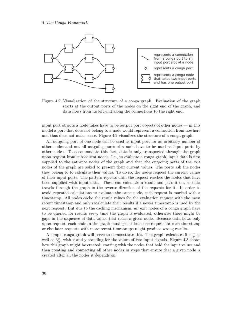
Figure 4.2: Visualization of the structure of a conga graph. Evaluation of the graphstarts at the output ports of the nodes on the right end of the graph, anddata flows from its left end along the connections to the right end.
input port objects a node takes have to be output port objects of other nodes — in thismodel a port that does not belong to a node would represent a connection from nowhereand thus does not make sense. Figure 4.2 visualizes the structure of a conga graph.
An outgoing port of one node can be used as input port for an arbitrary number ofother nodes and not all outgoing ports of a node have to be used as input ports byother nodes. To accommodate this fact, data is only transported through the graphupon request from subsequent nodes. I.e., to evaluate a conga graph, input data is firstsupplied to the entrance nodes of the graph and then the outgoing ports of the exitnodes of the graph are asked to present their current values. The ports ask the nodesthey belong to to calculate their values. To do so, the nodes request the current valuesof their input ports. The pattern repeats until the request reaches the nodes that havebeen supplied with input data. These can calculate a result and pass it on, so datatravels through the graph in the reverse direction of the requests for it. In order toavoid repeated calculations to evaluate the same node, each request is marked with atimestamp. All nodes cache the result values for the evaluation request with the mostrecent timestamp and only recalculate their results if a newer timestamp is used by thenext request. But due to the caching mechanism, all exit nodes of a conga graph haveto be queried for results every time the graph is evaluated, otherwise there might begaps in the sequence of data values that reach a given node. Because data flows onlyupon request, each node in the graph must get at least one request for each timestampor else later requests with more recent timestamps might produce wrong results.
A simple conga graph will serve to demonstrate this. The graph calculates 5 + xy as
well as 3xy , with x and y standing for the values of two input signals. Figure 4.3 shows
how this graph might be created, starting with the nodes that hold the input values andthen creating and connecting all other nodes in steps that ensure that a given node iscreated after all the nodes it depends on.
30

4.4 Basic Processing Model
x
y
a) create input data nodes
x
y
/
b) create and connect processing node
x
y
/
5
3
c) create nodes for constants
x
y
/
5
3
+
*
d) create and connect processing nodes
Figure 4.3: Creation of a simple conga graph. The nodes x and y are of the same typeas the nodes 5 and 3, they are simply marked with characters to clarify thattheir values will be changed between successive graph evaluations.
Figure 4.4 walks through the steps of evaluating this graph:
a) The graph has been created with an initial timestamp of 0 and supplied with thecurrent values of the input signal, x has been set to 4 and y has been set to 2.
b) The evaluation is started by requesting the value of 5 + xy for timestamp 1.
c) The corresponding node has not been evaluated for this timestamp yet and inresponse first requests the value of the node with constant value 5, with no furtherrequests being issued by that node.
d) The node calculating xy is asked next to yield its value for timestamp 1.
e) It requests the value of x, because timestamp 1 is more recent than timestamp 0.
f) It also requests the value of y for timestamp 1.
g) With those values, xy can be resolved to 2 and 5+ x
y can be resolved to 7, which thecorresponding nodes cache alongside the timestamp 1. Then begins the evaluationof the graph’s second output by requesting the value of 3x
y .
h) The associated node has no cached value for timestamp 1 and so requests for thistimestamp the value of the node with constant value 3.
i) Afterwards it requests the value of xy .
j) The corresponding node already has a value for timestamp 1, so 3xy can be resolved
to 6 and cached in the associated node. In addition, the graph gets prepared forthe next round of evaluation at timestamp 2, with new values set for x and y.
31

4 The Conga Framework
Section 5.1 has a short piece of Objective-C source code performing creation and evalu-ation of this graph, according to Figures 4.3 and 4.4.
The aforementioned properties of a conga graph, demonstrated by the given graphexample, explain why conga processing units have to form directed acyclic graphs. Thegraphs have to be directed in order to allow data and requests for data to flow throughthem. They have to be acyclic because a cycle in a graph would result in a processingunit to request data from itself recursively, without an end condition for the recursion:an endless loop is born and the request is never answered.
4.4.1 Types of Nodes, Ports and Processed Data
conga needs basically three types of nodes. The first type just holds a data value andpresents this value when queried for its current value. This type takes no input portsand can consequently be used for entry nodes of a conga graph, because requests fordata reaching this type of node travel no further. The second type simply processesdata presented by its input ports and passes on the results via its output ports. Thethird type is used to analyze data, to detect if a certain feature is present in its inputdata at a certain time or not and maybe to derive some values corresponding to thefeature, if it is present.
Ignoring the node type that simply holds data as exceptional case, different nodes ofeven the same type may still operate on data of different dimensions. As conga is builton the assumption that conducting gestures have two-dimensional shapes, there are alot of conga nodes that take two-dimensional input. But there are other nodes thattake one-dimensional input and some nodes can even take an arbitrary number of inputports. The dimension of the output data of a node does not have to be, and in a lot ofcases is not, the same as the dimension of its input data.
In order to be able to interconnect all types of nodes, all ports have the same interfaceand there is only one type of data that is passed through the ports. The data takesthe form of two simple numbers. One is the value of the port and the other is anestimated time when said value originated. Because different input sources have differentlatencies and processing may, and indeed most of the time will, add further delays,passing the estimated origination time of a value along and modifying it as neededmeans that code using conga graphs can take accumulated latency into account, whichfor example is very useful for determining the actual time when a certain beat was givenby the conductor. Some nodes use the timestamps of evaluation requests to modifythe estimated origination time. Therefore, those timestamps should have a meaningfulrelationship to the origination time values given to the starting nodes of a conga graph.
Going back to the topic of node types and input/output data dimensions, the unifiedinterface for ports means that the data dimension is reflected in the number of ports. Anode taking two-dimensional input and giving one-dimensional output takes two inputports and has one output port, respectively. The unified port interface also means that afeature detecting node has to use numbers to indicate boolean values. For that purpose,conga incorporates the same trick that, for example, is used in the C programminglanguage. A number equal to zero represents the boolean value false and any non-zero
32

4.4 Basic Processing Model
x
y
/
5
3
+
*
a) supply data to graph before evaluation starts
x
y
/
5
3
+
*
get value fortimestamp 1
b) start graph evaluation
x
y
/
5
3
+
*
get value fortimestamp 1
get value fortimestamp 1c)
x
y
/
5
3
+
*
get value fortimestamp 1
get value fortimestamp 1
d)
x
y
/
5
3
+
*
get value fortimestamp 1
get value fortimestamp 1
get value fortimestamp 1
e)
x
y
/
5
3
+
*
get value fortimestamp 1
get value fortimestamp 1
get value fortimestamp 1
f)
x
y
/
5
3
+
*
g)
x
y
/
5
3
+
* get value fortimestamp 1
h)
x
y
/
5
3
+
* get value fortimestamp 1
get value fortimestamp 1
i)
x
y
/
5
3
+
*
j) supply new data for next graph evaluation
get value fortimestamp 1
get value fortimestamp 1
yields 0 fortimestamp 0
yields 0 fortimestamp 0
yields 0 fortimestamp 0
yields 5
yields 3
yields 4
yields 2
yields 0 fortimestamp 0
yields 0 fortimestamp 0
yields 0 fortimestamp 0
yields 5
yields 3
yields 4
yields 2
yields 0 fortimestamp 0
yields 0 fortimestamp 0
yields 0 fortimestamp 0
yields 5
yields 3
yields 4
yields 2
yields 0 fortimestamp 0
yields 0 fortimestamp 0
yields 0 fortimestamp 0
yields 5
yields 3
yields 4
yields 2
yields 0 fortimestamp 0
yields 0 fortimestamp 0
yields 0 fortimestamp 0
yields 5
yields 3
yields 4
yields 2
yields 0 fortimestamp 0
yields 0 fortimestamp 0
yields 0 fortimestamp 0
yields 5
yields 3
yields 4
yields 2
yields 2 fortimestamp 1
yields 7 fortimestamp 1
yields 0 fortimestamp 0
yields 5
yields 3
yields 4
yields 2
yields 2 fortimestamp 1
yields 7 fortimestamp 1
yields 6 fortimestamp 1
yields 5
yields 3
yields 3
yields 8
yields 2 fortimestamp 1
yields 7 fortimestamp 1
yields 0 fortimestamp 0
yields 5
yields 3
yields 4
yields 2
yields 2 fortimestamp 1
yields 7 fortimestamp 1
yields 0 fortimestamp 0
yields 5
yields 3
yields 4
yields 2
Figure 4.4: Sample evaluation of the graph from Figure 4.3 for the first time immediatelyafter the graph was created.
33

4 The Conga Framework
number represents the boolean value true. Just like in C this presents the opportunityto use a node that was not actually intended to be a feature detector in place of agenuine feature detector, if it is convenient, and just like in C this poses the danger ofnot noticing that something is used as a boolean value although it is not appropriateto do so. However, there is an additional benefit to this arrangement: conga can use anumeric value to not only indicate if a feature is present, but also to indicate to whatextent it is present.
To simplify matters, conga has been implemented with a unified basic interface fornodes as well, so that this basic interface depends neither on the number of input portsa node takes nor on the number of output ports it has. Since the behavior of a lotof conga nodes can be configured, those nodes extend the basic node interface withwhatever methods they need to be set up properly.
In order to encapsulate a complete or a partial conga graph into a new conga node,this new node at least has to implement the methods in the basic interface for nodes. Ifthe encapsulated graph does not need to be configurable and does not depend on activityoutside conga (like, say, the input nodes being set to the current input values prior eachgraph evaluation), then all the new node has to do is to create this graph correctly, passprovided input ports to the right nodes of the graph and present the graph’s exit portsas the new node’s output ports. If the encapsulated graph does have to be configurableor or does have to be accessible outside conga’s basic processing model, the new nodealso has to extend the basic node interface in order to provide the needed configurationand access methods.
4.4.2 Implementation-Specific Processing and Initialization Issues
Ports and nodes in conga are implemented as Objective-C classes. To form a congagraph, objects of these classes are instantiated, and for evaluation requests, messagesare sent to the appropriate objects. Objective-C determines at runtime if a given objectimplements a method corresponding to a given message. A message passed to an objectthus results in a method lookup and a subsequent method call. This process takes moretime than a simple function call and because a conga graph might consist of a lot of nodeand port objects, the overhead of this process could impact noticeably the time it takesto evaluate the graph. To avoid this, conga nodes and ports have been implementedso that they construct function pointers to the important methods of their input portsand host nodes whenever those are being set. This makes it possible to circumvent themethod lookup and speed up the evaluation of a conga graph. It also makes the sourcecode of the nodes and ports less elegant and more prone to bugs.
All conga nodes share the same basic interface which is defined as an Objective-Cprotocol. It contains an initialization method taking a timestamp as parameter, so thatduring creation of a conga graph, all of the graph’s nodes can be initialized with thesame specific start time. To keep the interface independent of the number of input portsa node takes, there is a method to set the node’s input ports with an array of congaport objects as parameter. All conga nodes are implemented to take the number ofinput ports they need, starting with the first array element and ignoring surplus array
34
4.4 Basic Processing Model
elements. If a node is provided with less input ports than it needs, it will simply notcarry out the processing it is intended to. To keep the node interface independent of thenumber of output ports a node has, there is a method that reports the concrete numberof output ports of the node plus a method that is given a number as input and returnsthe corresponding output port of the node or nil if there is no corresponding outputport. So the way conga nodes are implemented, input ports are supplied to a node allat once while output ports can only be acquired from a node one by one. Last but notleast, the node interface contains a method that can be called to update all output portsof a node for the current time.
The common interface of all conga ports is defined as an Objective-C protocol as welland is kept very simple, consisting of only one method to evaluate the port. This methodreceives a timestamp of the current time as input and delivers the value of the port andthe estimated origination time of the value as output. For nodes with several outputports, conga provides the CONGASimpleNodeOutputPort class that has to be providedwith a reference to its host node and implements the port evaluation method so that itcauses the host node to update all of its output port values and value origination times assoon as the first output port is evaluated for a new timestamp. As this step of indirectionwould represent unnecessary processing overhead in the case of conga nodes with only oneoutput port, these nodes do not use CONGASimpleNodeOutputPort objects. Instead,they implement the conga port interface and thus serve as their own output port.
One final thing to keep in mind is the fact that conga has been developed for processingdata at regular time intervals. In other words, there are some conga nodes that rely ontheir data input sequence being made up of input values that are more or less evenlyspaced in time. For example, nodes that calculate weighted averages of successive inputvalues might produce meaningless results otherwise. Input data provided to the startingnodes of a conga graph should be resampled, if it is not evenly spaced in time, and thetimestamps of evaluation requests should be evenly spaced as well.
35

4 The Conga Framework
4.5 Some Examples of Basic Processing Nodes
In the previous section, conga’s basic processing model has been discussed. This sectiondemonstrates how the concepts mentioned in the previous section have been realizedin conga by giving some examples of actual conga nodes. Working through all of thenodes contained in the conga framework would require more space than is appropriate,without going beyond the essential insights already provided by the given examples.
The first example, CONGAPassiveValueNode, embodies the first of the three funda-mental node types, the one that just holds data. It is followed by several examples ofthe node type that simply processes data and passes it on, with varying functions andinput and output port counts. CONGADetectZeroCrossingNode serves as an exampleof the third node type, the one that analyzes data for a certain feature and indicates ifthe feature is present. Finally, CONGANotNode shows an example of a node that treatsnumeric values as boolean values. Such logic nodes are needed because conga does nothave a separate data type for boolean values.
4.5.1 CONGAPassiveValueNode
Input ports taken:CONGAPassiveValueNode objects do not take any input ports.
Output ports provided:CONGAPassiveValueNode objects provide only one output port.
Processing carried out:As CONGAPassiveValueNode objects do not take any input ports, they performno processing of input values. They just store a number as well as the estimatedorigination time of that number and present those when being queried for theircurrent values.
Possible use:CONGAPassiveValueNode objects are best suited as starting nodes of a congagraph or as nodes providing constant values needed by other nodes. Code usingconga graphs can change the values stored in a CONGAPassiveValueNode object atany time, but should refrain from doing so while the corresponding graph is beingevaluated. If a CONGAPassiveValueNode object is used as a source for a constantvalue, it can be configured to present the timestamp of the evaluation request asestimated origination time instead of the stored origination time value.
36
4.5 Some Examples of Basic Processing Nodes
4.5.2 CONGAOnePoleFilterNode
Input ports taken:CONGAOnePoleFilterNode objects take one input port.
Output ports provided:CONGAOnePoleFilterNode objects have one output port.
Processing carried out:CONGAOnePoleFilterNode objects represent infinite impulse response one-pole fil-ters [Coo02]. In essence, their output value is calculated as the sum of the currentinput value multiplied with a certain factor and the last output value multipliedwith another factor. The estimated origination time value of the output port issimply set to the current one of the input port.
Possible use:CONGAOnePoleFilterNode objects can be configured by setting the input valueand output value factors. Depending on these factors, they can be used as high-pass filter or as low-pass filters, but with the wrong factor values, they can becomeunstable as well. As low-pass filters they might be applied to reduce noise.
4.5.3 CONGAAdderNode
Input ports taken:CONGAAdderNode objects take two input ports.
Output ports provided:CONGAAdderNode objects provide one output port.
Processing carried out:CONGAAdderNode objects add the current values supplied by their two inputports and set the value of their output port to the resulting sum. They comparethe current origination time values of both input ports and use the older one asorigination time value for their output port.
Possible use:CONGAAdderNode objects are used for the very simple arithmetic operation ofadding two numbers. But even simple arithmetic operations have to be wrappedin the guise of conga nodes so they can be incorporated into a conga graph. Thesimple graph from Section 4.4 that calculates 5 + x
y as one of its results, producesthat result with the aid of a CONGAAdderNode object.
37

4 The Conga Framework
4.5.4 CONGAMaximumNode
Input ports taken:CONGAMaximumNode objects take an arbitrary number of input ports, but be-cause they compare the values of their input ports to produce output, they shouldbe given at least two input ports in order to be useful.
Output ports provided:CONGAMaximumNode objects provide two output ports. The first output portsupplies the maximum of their input port values and the second one holds the indexof the input port carrying said value.
Processing carried out:CONGAMaximumNode objects select the maximum of all the current input portvalues and set the value of their first output port to this maximum value. Thevalue of their second output port is set to the index of the input port that carriesthe maximum value and the estimated origination time value of this input port ispassed on to both output ports. If multiple input ports carry the maximum value,the one with the most recent origination time value gets selected. Index countingstarts with zero, that is, the first input port is assigned an index of zero.
Possible use:CONGAMaximumNode objects can simply be used to determine the maximum ofseveral values. But they can also be used to choose from different alternatives, ifit is possible to represent the quality of each of the alternatives as a characteristicnumber that grows with quality.
4.5.5 CONGASwitchNode
Input ports taken:CONGASwitchNode objects take an arbitrary number of input ports. In order tobe useful they should be supplied with at least three input ports, though.
Output ports provided:CONGASwitchNode objects provide two output ports, with the actual node outputcarried by the first output port and the second output port indicating if this is aregular output.
Processing carried out:CONGASwitchNode objects use the current value of their first input port to selectone of the other input ports and pass the current value and estimated originationtime value of this input port on to their first output port. The value supplied bytheir first input port gets truncated and the result is interpreted as index of one ofthe remaining input ports. That is, an index value of zero selects the second inputport, an index value of one selects the third input port, and so on.
38

4.5 Some Examples of Basic Processing Nodes
If there is no corresponding input port for the index value, the first output portis set to the current value and estimated origination time value of the first inputport. CONGASwitchNode objects indicate with their second output port if theirindex input is valid. That is, if there is an input port corresponding to the indexvalue, the second output port value is set to one and otherwise it is set to zero. Theorigination time value of the second output port is simply set to the same value asthe one of the first output port.
Possible use:CONGASwitchNode objects supplement nodes that choose from alternatives butcannot output all data associated with each alternative. For example if a CON-GAMaximumNode object is used to select an alternative based on a characteristicnumber, as mentioned in CONGAMaximumNode’s description, it can only outputthe characteristic number and the selected index. But needed data of the selectedalternative can still be obtained by feeding the selected index and the data of all thealternatives into a CONGASwitchNode object in the correct order. If multidimen-sional data has to be handled this way, several instances of CONGASwitchNodecan be employed.CONGASwitchNode produces boolean values as part of its output but it is nofeature detection node in the strict sense.
4.5.6 CONGAHysteresisNode
Input ports taken:CONGAHysteresisNode objects take an arbitrary number of input ports.
Output ports provided:CONGAHysteresisNode objects provide one output port for each input port theyhave been supplied with.
Processing carried out:CONGAHysteresisNode objects consider their input port and output port values tobe the values of a vector’s elements. They keep their output steady as long as thecurrent input vector is within a certain distance of the output vector. If the distancebetween input vector and output vector exceeds a preset distance, the output vectoris set to the values and origination times of the current input vector. The distancebetween the two vectors is calculated according to the Euclidean metric.
Possible use:CONGAHysteresisNode objects can be used to reduce noise because they suppresschanges in multidimensional data below a certain threshold. They also work onone-dimensional data, so unlike CONGAMaximumNode objects they do perform auseful function if provided with only one input port.
39
4 The Conga Framework
4.5.7 CONGADetectZeroCrossingNode
Input ports taken:CONGADetectZeroCrossingNode objects take only one input port.
Output ports provided:CONGADetectZeroCrossingNode objects provide two output ports. The first out-put port carries a boolean value, telling if a valid zero crossing has been detected,and the second output port holds the sign of the node’s input prior to the lastdetected valid crossing of zero. Like other feature detection nodes, CONGADe-tectZeroCrossingNode uses the first output port to signal detection of the featureand the remaining output port to deliver additional information. Other featuredetection nodes may have more than one output port providing additional informa-tion — or none, if they merely have to detect whether their corresponding featureis present or not.
Processing carried out:CONGADetectZeroCrossingNode objects analyze the sequence of values of theirinput port and indicate if the values of this sequence cross zero in a certain way.If a valid zero crossing has been detected, the value of the first output port is setto one, otherwise it is set to zero. Whether or not a valid zero crossing has beendetected, the estimated origination time of the first output port is always set to thecurrent one of the input port. The second output port is only updated when a validzero crossing has been detected and carries the sign of the last non-zero input valueprevious to the detected zero crossing as well as the estimated origination time ofthat input value.What CONGADetectZeroCrossingNode objects consider to be a valid zero crossingcan be configured in several ways. It can be set if and for how many consecutivesamples the input may linger on zero. It is also possible to set a threshold value thathas to be exceeded previous to crossing zero in order for the crossing to be valid,and it can be configured whether exceeding this threshold has to happen after thelast crossing or the last grazing of zero, for the next zero crossing to be consideredvalid.
Possible use:CONGADetectZeroCrossingNode objects turn out to be useful in a lot of cases.For example, if the input values are values of one component of the velocity of thetip of the baton, crossing zero indicates a reversal of direction of the baton tip’smovement in this component. But if the tip of the baton is moving mainly along thex axis, noise could trigger a lot of zero crossings in the velocity’s y component. Theconfigurability of CONGADetectZeroCrossingNode objects helps to avoid detectingthese inappropriate zero crossings.
40

4.5 Some Examples of Basic Processing Nodes
4.5.8 CONGANotNode
Input ports taken:CONGANotNode objects take one input port.
Output ports provided:CONGANotNode objects provide a single output port.
Processing carried out:CONGANotNode objects regard the numeric value supplied by their input port asa boolean value, negate this boolean value and output a numeric value representingthe result. That is, if the current input port value is zero, the output port value isset to one. If the current input port value is not zero, the output port value is setto zero. The current estimated origination value of the input port is simply passedon to the output port in both cases.
Possible use:CONGANotNode objects can be used to negate the boolean output of a featuredetector node. Like CONGAAdderNode, CONGANotNode represents a simpleoperation that has to be implemented as a conga node in order to be usable insidea conga graph.
41
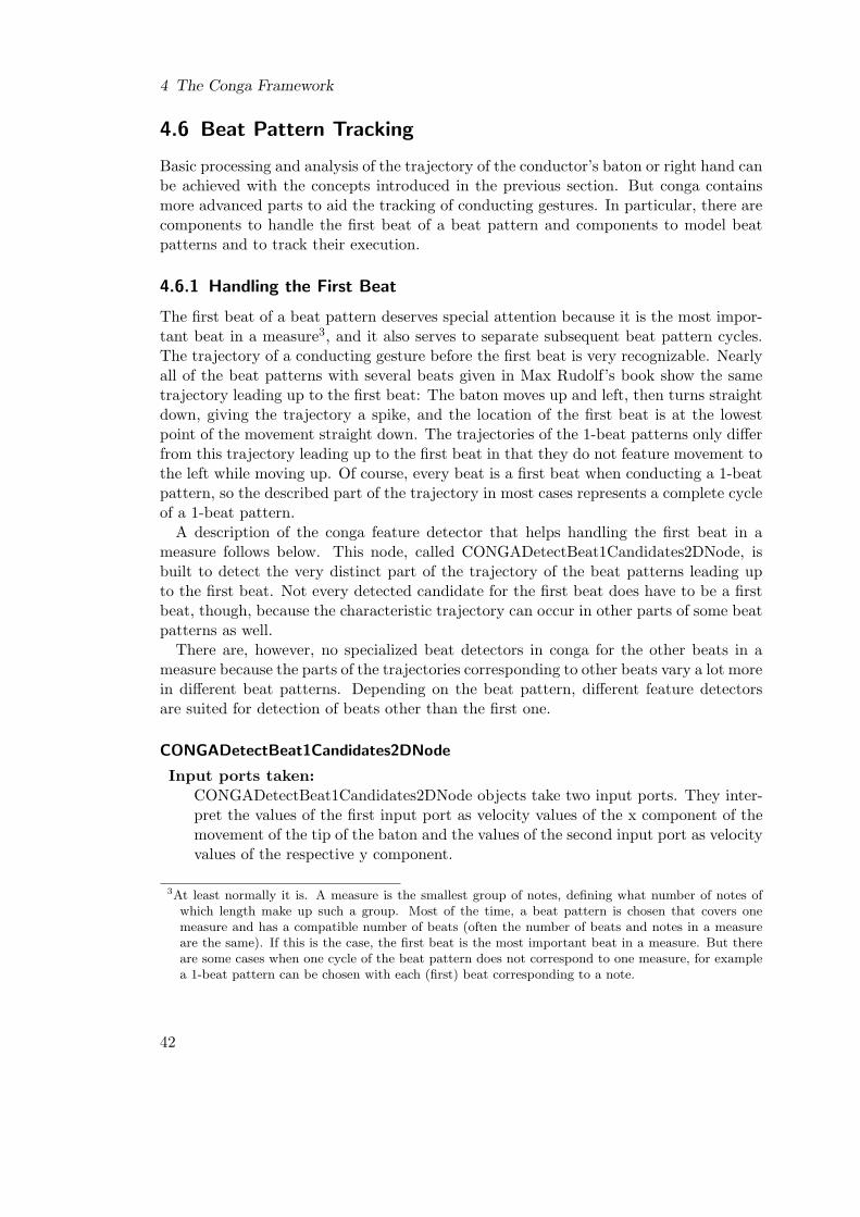
4 The Conga Framework
4.6 Beat Pattern Tracking
Basic processing and analysis of the trajectory of the conductor’s baton or right hand canbe achieved with the concepts introduced in the previous section. But conga containsmore advanced parts to aid the tracking of conducting gestures. In particular, there arecomponents to handle the first beat of a beat pattern and components to model beatpatterns and to track their execution.
4.6.1 Handling the First Beat
The first beat of a beat pattern deserves special attention because it is the most impor-tant beat in a measure3, and it also serves to separate subsequent beat pattern cycles.The trajectory of a conducting gesture before the first beat is very recognizable. Nearlyall of the beat patterns with several beats given in Max Rudolf’s book show the sametrajectory leading up to the first beat: The baton moves up and left, then turns straightdown, giving the trajectory a spike, and the location of the first beat is at the lowestpoint of the movement straight down. The trajectories of the 1-beat patterns only differfrom this trajectory leading up to the first beat in that they do not feature movement tothe left while moving up. Of course, every beat is a first beat when conducting a 1-beatpattern, so the described part of the trajectory in most cases represents a complete cycleof a 1-beat pattern.
A description of the conga feature detector that helps handling the first beat in ameasure follows below. This node, called CONGADetectBeat1Candidates2DNode, isbuilt to detect the very distinct part of the trajectory of the beat patterns leading upto the first beat. Not every detected candidate for the first beat does have to be a firstbeat, though, because the characteristic trajectory can occur in other parts of some beatpatterns as well.
There are, however, no specialized beat detectors in conga for the other beats in ameasure because the parts of the trajectories corresponding to other beats vary a lot morein different beat patterns. Depending on the beat pattern, different feature detectorsare suited for detection of beats other than the first one.
CONGADetectBeat1Candidates2DNode
Input ports taken:CONGADetectBeat1Candidates2DNode objects take two input ports. They inter-pret the values of the first input port as velocity values of the x component of themovement of the tip of the baton and the values of the second input port as velocityvalues of the respective y component.
3At least normally it is. A measure is the smallest group of notes, defining what number of notes ofwhich length make up such a group. Most of the time, a beat pattern is chosen that covers onemeasure and has a compatible number of beats (often the number of beats and notes in a measureare the same). If this is the case, the first beat is the most important beat in a measure. But thereare some cases when one cycle of the beat pattern does not correspond to one measure, for examplea 1-beat pattern can be chosen with each (first) beat corresponding to a note.
42
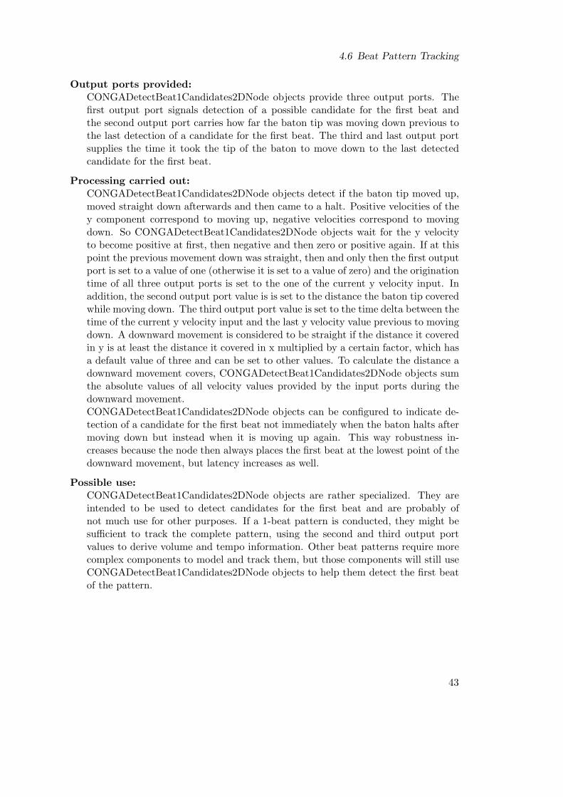
4.6 Beat Pattern Tracking
Output ports provided:CONGADetectBeat1Candidates2DNode objects provide three output ports. Thefirst output port signals detection of a possible candidate for the first beat andthe second output port carries how far the baton tip was moving down previous tothe last detection of a candidate for the first beat. The third and last output portsupplies the time it took the tip of the baton to move down to the last detectedcandidate for the first beat.
Processing carried out:CONGADetectBeat1Candidates2DNode objects detect if the baton tip moved up,moved straight down afterwards and then came to a halt. Positive velocities of they component correspond to moving up, negative velocities correspond to movingdown. So CONGADetectBeat1Candidates2DNode objects wait for the y velocityto become positive at first, then negative and then zero or positive again. If at thispoint the previous movement down was straight, then and only then the first outputport is set to a value of one (otherwise it is set to a value of zero) and the originationtime of all three output ports is set to the one of the current y velocity input. Inaddition, the second output port value is is set to the distance the baton tip coveredwhile moving down. The third output port value is set to the time delta between thetime of the current y velocity input and the last y velocity value previous to movingdown. A downward movement is considered to be straight if the distance it coveredin y is at least the distance it covered in x multiplied by a certain factor, which hasa default value of three and can be set to other values. To calculate the distance adownward movement covers, CONGADetectBeat1Candidates2DNode objects sumthe absolute values of all velocity values provided by the input ports during thedownward movement.CONGADetectBeat1Candidates2DNode objects can be configured to indicate de-tection of a candidate for the first beat not immediately when the baton halts aftermoving down but instead when it is moving up again. This way robustness in-creases because the node then always places the first beat at the lowest point of thedownward movement, but latency increases as well.
Possible use:CONGADetectBeat1Candidates2DNode objects are rather specialized. They areintended to be used to detect candidates for the first beat and are probably ofnot much use for other purposes. If a 1-beat pattern is conducted, they might besufficient to track the complete pattern, using the second and third output portvalues to derive volume and tempo information. Other beat patterns require morecomplex components to model and track them, but those components will still useCONGADetectBeat1Candidates2DNode objects to help them detect the first beatof the pattern.
43
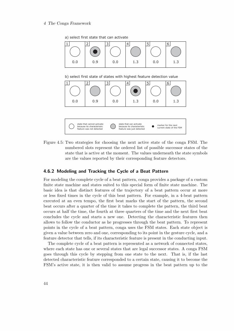
4 The Conga Framework
a) select first state that can activate
state that cannot activatebecause its characteristicfeature was not detected
state that can activatebecause its characteristicfeature was just detected
marker for the nextcurrent state of the FSM
1
0.0
2
0.9
3
0.0
4
1.3
5
0.0
b) select first state of states with highest feature detection value
1
0.0
2
0.9
3
0.0
4
1.3
5
0.0
6
1.3
6
1.3
Figure 4.5: Two strategies for choosing the next active state of the conga FSM. Thenumbered slots represent the ordered list of possible successor states of thestate that is active at the moment. The values underneath the state symbolsare the values reported by their corresponding feature detectors.
4.6.2 Modeling and Tracking the Cycle of a Beat Pattern
For modeling the complete cycle of a beat pattern, conga provides a package of a customfinite state machine and states suited to this special form of finite state machine. Thebasic idea is that distinct features of the trajectory of a beat pattern occur at moreor less fixed times in the cycle of this beat pattern. For example, in a 4-beat patternexecuted at an even tempo, the first beat marks the start of the pattern, the secondbeat occurs after a quarter of the time it takes to complete the pattern, the third beatoccurs at half the time, the fourth at three quarters of the time and the next first beatconcludes the cycle and starts a new one. Detecting the characteristic features thenallows to follow the conductor as he progresses through the beat pattern. To representpoints in the cycle of a beat pattern, conga uses the FSM states. Each state object isgiven a value between zero and one, corresponding to its point in the gesture cycle, and afeature detector that tells, if its characteristic feature is present in the conducting input.
The complete cycle of a beat pattern is represented as a network of connected states,where each state has one or several states that are legal successor states. A conga FSMgoes through this cycle by stepping from one state to the next. That is, if the lastdetected characteristic feature corresponded to a certain state, causing it to become theFSM’s active state, it is then valid to assume progress in the beat pattern up to the
44
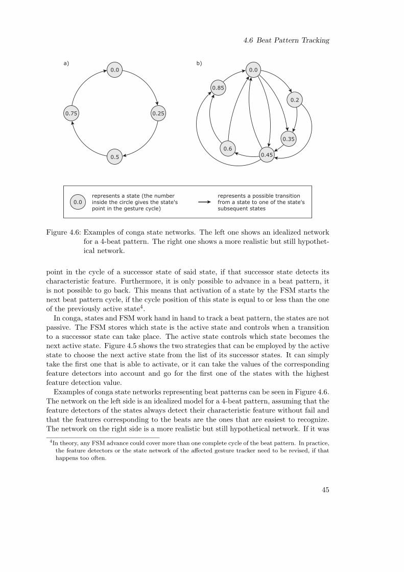
4.6 Beat Pattern Tracking
0.0
0.25
0.5
0.75
0.0represents a state (the numberinside the circle gives the state'spoint in the gesture cycle)
represents a possible transitionfrom a state to one of the state'ssubsequent states
0.0
0.2
0.45
0.35
0.6
0.85
a) b)
Figure 4.6: Examples of conga state networks. The left one shows an idealized networkfor a 4-beat pattern. The right one shows a more realistic but still hypothet-ical network.
point in the cycle of a successor state of said state, if that successor state detects itscharacteristic feature. Furthermore, it is only possible to advance in a beat pattern, itis not possible to go back. This means that activation of a state by the FSM starts thenext beat pattern cycle, if the cycle position of this state is equal to or less than the oneof the previously active state4.
In conga, states and FSM work hand in hand to track a beat pattern, the states are notpassive. The FSM stores which state is the active state and controls when a transitionto a successor state can take place. The active state controls which state becomes thenext active state. Figure 4.5 shows the two strategies that can be employed by the activestate to choose the next active state from the list of its successor states. It can simplytake the first one that is able to activate, or it can take the values of the correspondingfeature detectors into account and go for the first one of the states with the highestfeature detection value.
Examples of conga state networks representing beat patterns can be seen in Figure 4.6.The network on the left side is an idealized model for a 4-beat pattern, assuming that thefeature detectors of the states always detect their characteristic feature without fail andthat the features corresponding to the beats are the ones that are easiest to recognize.The network on the right side is a more realistic but still hypothetical network. If it was
4In theory, any FSM advance could cover more than one complete cycle of the beat pattern. In practice,the feature detectors or the state network of the affected gesture tracker need to be revised, if thathappens too often.
45
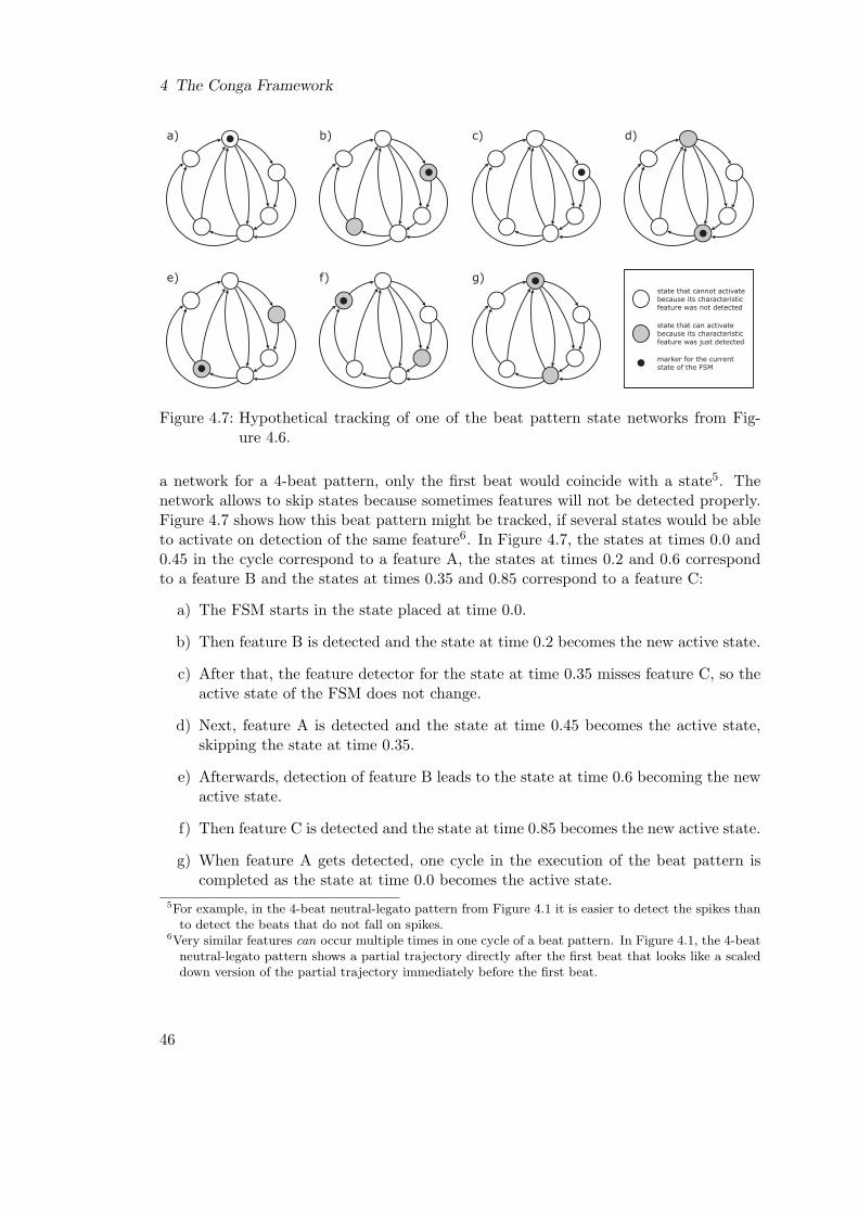
4 The Conga Framework
a) b) c) d)
e) f) g)state that cannot activatebecause its characteristicfeature was not detected
state that can activatebecause its characteristicfeature was just detected
marker for the currentstate of the FSM
Figure 4.7: Hypothetical tracking of one of the beat pattern state networks from Fig-ure 4.6.
a network for a 4-beat pattern, only the first beat would coincide with a state5. Thenetwork allows to skip states because sometimes features will not be detected properly.Figure 4.7 shows how this beat pattern might be tracked, if several states would be ableto activate on detection of the same feature6. In Figure 4.7, the states at times 0.0 and0.45 in the cycle correspond to a feature A, the states at times 0.2 and 0.6 correspondto a feature B and the states at times 0.35 and 0.85 correspond to a feature C:
a) The FSM starts in the state placed at time 0.0.
b) Then feature B is detected and the state at time 0.2 becomes the new active state.
c) After that, the feature detector for the state at time 0.35 misses feature C, so theactive state of the FSM does not change.
d) Next, feature A is detected and the state at time 0.45 becomes the active state,skipping the state at time 0.35.
e) Afterwards, detection of feature B leads to the state at time 0.6 becoming the newactive state.
f) Then feature C is detected and the state at time 0.85 becomes the new active state.
g) When feature A gets detected, one cycle in the execution of the beat pattern iscompleted as the state at time 0.0 becomes the active state.
5For example, in the 4-beat neutral-legato pattern from Figure 4.1 it is easier to detect the spikes thanto detect the beats that do not fall on spikes.
6Very similar features can occur multiple times in one cycle of a beat pattern. In Figure 4.1, the 4-beatneutral-legato pattern shows a partial trajectory directly after the first beat that looks like a scaleddown version of the partial trajectory immediately before the first beat.
46

4.6 Beat Pattern Tracking
1
32
4
b)a)
1
4
ATT
Figure 4.8: a) Trajectory for the start of a piece on the first beat, using the fourth beatin 4-beat legato as preparatory beat. b) Trajectory of the cycle of the 4-beatneutral-legato pattern. Drawings after [Rud95].
4.6.3 How to Enter the Cycle of a Beat Pattern
Conductors start conducting a piece of music by giving a preparatory beat to set thetempo. The baton or the right hand travels to this preparatory beat from a specialposition of attention. As a result, the trajectory leading up to this beat from the positionof attention does not have the same shape as the trajectory leading up to this beat fromthe previous beat when the beat pattern is executed repeatedly. Figure 4.8 gives anexample of this phenomenon for the 4-beat legato patterns, with the piece startingon the first beat and the fourth beat being used as preparatory beat. Comparing thispreparatory beat trajectory with the trajectory of the normal cycle of the 4-beat neutral-legato shows that the trajectory features for a preparatory beat can differ from thetrajectory features of the same beat when the pattern is executed repeatedly. Moreover,conductors do not even have to start or resume conducting a piece on the first beat of ameasure.
To accommodate this, the FSM provides a way to enter the cycle of a beat patternwithout using one of the states that make up this cycle. A state network for a beatpattern can include state chains that lead into the cycle of the beat pattern but cannotbe reached from states that are part of the cycle. The start points of these state chainsare also used by the FSM if it was already tracking a beat pattern, has been stopped andthen should pick up tracking the same beat pattern as conducting resumes. For this, thestart state and pick-up states are assigned a point in time of the beat pattern cycle andthe FSM picks up tracking with the pick-up state whose point in time comes directlybefore the last known position of the FSM in the cycle. Figure 4.9 shows a hypotheticalstate network of a 4-beat pattern, with pick-up states for each beat.
47
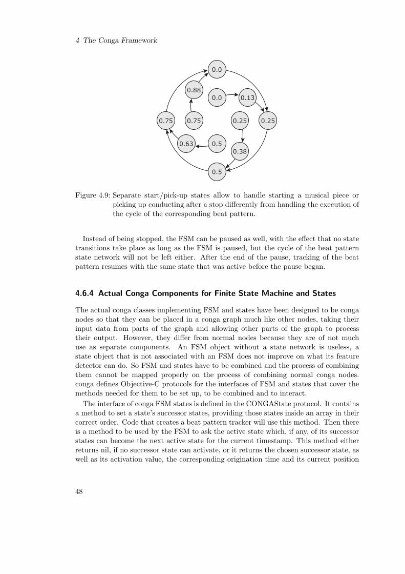
4 The Conga Framework
0.0
0.25
0.5
0.75
0.0
0.5
0.250.75
0.13
0.380.63
0.88
Figure 4.9: Separate start/pick-up states allow to handle starting a musical piece orpicking up conducting after a stop differently from handling the execution ofthe cycle of the corresponding beat pattern.
Instead of being stopped, the FSM can be paused as well, with the effect that no statetransitions take place as long as the FSM is paused, but the cycle of the beat patternstate network will not be left either. After the end of the pause, tracking of the beatpattern resumes with the same state that was active before the pause began.
4.6.4 Actual Conga Components for Finite State Machine and States
The actual conga classes implementing FSM and states have been designed to be conganodes so that they can be placed in a conga graph much like other nodes, taking theirinput data from parts of the graph and allowing other parts of the graph to processtheir output. However, they differ from normal nodes because they are of not muchuse as separate components. An FSM object without a state network is useless, astate object that is not associated with an FSM does not improve on what its featuredetector can do. So FSM and states have to be combined and the process of combiningthem cannot be mapped properly on the process of combining normal conga nodes.conga defines Objective-C protocols for the interfaces of FSM and states that cover themethods needed for them to be set up, to be combined and to interact.
The interface of conga FSM states is defined in the CONGAState protocol. It containsa method to set a state’s successor states, providing those states inside an array in theircorrect order. Code that creates a beat pattern tracker will use this method. Then thereis a method to be used by the FSM to ask the active state which, if any, of its successorstates can become the next active state for the current timestamp. This method eitherreturns nil, if no successor state can activate, or it returns the chosen successor state, aswell as its activation value, the corresponding origination time and its current position
48

4.6 Beat Pattern Tracking
in the cycle of the beat pattern7. To implement this method, states can use anothermethod of the interface that reports for the current timestamp the activation value of astate as given by its feature detector, the corresponding origination time value and thecurrent position in the beat pattern’s cycle. Also included in the interface is a methodthat allows the FSM to tell a state whether it is the active state or not. Finally thereis a method that simply returns the current position in the beat pattern’s cycle for thecurrent timestamp. This method is used by an FSM object to query start and pick-upstates for their cycle position as these states normally do not occur as successors ofother states. CONGAState does not define methods to set a state’s feature detectoror position in the cycle. As states are meant to be conga nodes as well, these will besupplied via input ports to the state nodes.
The interface of conga finite state machines for beat pattern tracking is defined inthe CONGAFiniteStateMachine protocol. It features several methods to configure anFSM and several methods to request information while tracking a beat pattern. On theconfiguration side, there is a method to provide the FSM with an array containing allstate objects needed to track a certain beat pattern. The order of the state objects inthe array does not matter, but states are also nodes and often will be the end points ofa conga graph with no further nodes connected to their output ports. Because of thebasic processing model of conga, all state nodes have to be evaluated each time step, andthe FSM does so. There is also a method to set the first active state of the FSM, i.e.,its start state. Another method supplies the FSM with an array containing all statesthat should serve as pick-up states after a stop. When picking up after a stop, the FSMis meant to select the pick-up state with the cycle position that is closest but after thecycle position of the active state before the stop. In addition, there is a method to set aminimum amount of time that has to pass after a state became active state before thenext state can be activated, based on the origination times of the activation values ofboth states. All other methods of CONGAFiniteStateMachine can be used to requestinformation concerning the tracking of a beat pattern, such as if the tracking did advancefor the current time stamp, if an advance started a new cycle of the pattern, when didthe activation of the active state originate, what is the cycle position of the active state,what was the difference of origination times of the activations of the current active stateand the previous one and what was the corresponding distance of their cycle positions.But as conga FSMs are conga nodes as well, it is not necessary to use those methods inorder to track a beat pattern. A conga FSM node has to provide all tracking informationvia its output ports, and stopping or pausing an FSM node should be done via inputports supplied to it.
A description of the conga nodes implementing the state and FSM protocols follows.
7The position of a feature in the cycle of a beat pattern might vary slightly, for example if the beatpattern is conducted at different speeds or by different conductors. By not fixing the cycle positionof a state, conga allows to build conducting gesture trackers that can be adapted without havingto be reinitialized. Cycle positions that shift too much can pose a problem, though: conga’s FSMmodel assumes that a new cycle has been started, if the current cycle position of the state becomingthe active state marks an earlier point in the cycle than the cycle position the last active state had,when it was activated.
49
4 The Conga Framework
CONGASimpleState
Input ports taken:CONGASimpleState objects take two input ports. As states represent points inbeat pattern trajectories, a CONGASimpleState object needs a feature detector tosignal detection of the characteristic feature of the point it represents. This is donevia the first input port. It also needs the position of the point in the cycle of thebeat pattern, which is supplied by the second input port.
Output ports provided:CONGASimpleState objects provide three output ports. The first output portindicates if the state is the active state of the corresponding FSM, the secondcarries the value the state activated with and the third supplies the cycle positionheld by the state when it became the active state.
Processing carried out:For processing, CONGASimpleState objects need a corresponding FSM, or elsetheir output will never change. When a CONGASimpleState object is evaluated asa conga node, it just queries both input ports and caches the current value providedby its feature detector, the associated origination time and the cycle position value.Each time the corresponding FSM is itself evaluated, it will first evaluate all of itsstate nodes, ignoring their output but causing them to update their cached values,and then decide whether or not to switch the active state. In the process, thecurrent active state requests the cached values of its successor states to determinewhich one of them, if any, it will present to the FSM as possible next active state.If the FSM switches states, it deactivates the old active state and activates thenew one. Only this causes a change in the output of both states. The freshlyactivated state sets the first output port value to one, the second output portvalue to the current value reported by its feature detector and the third outputport value to its current cycle position. The other state only updates the firstoutput port with the value zero. Both states use a time value provided by theFSM as estimated origination time for all output ports that they updated. In thecase of CONGASimpleFiniteStateMachine, this is simply the origination time valuereported by the feature detector of the state that becomes the new active state.To avoid inconsistencies in the caching mechanism of conga’s basic processing, CON-GASimpleState objects change their output port values after being activated or de-activated not until they get evaluated with a more recent timestamp. Because theyare conga nodes, they might have been evaluated for a certain timestamp by othernodes before their corresponding FSM is evaluated for the same timestamp. If theychanged their output port values immediately and were afterwards evaluated againfor the current timestamp, they would have supplied different output for the sametimestamp, thereby violating the basic processing model.
50

4.6 Beat Pattern Tracking
Possible use:CONGASimpleState objects are meant to be used to model and track beat patternsin combination with a conga FSM. They employ the simply strategy to choose thenext possible active state from their successor states by selecting the first one thatcan activate, as shown in part a) of Figure 4.5, and should be used whenever thisstate transition behavior is appropriate.
CONGASelectSuccessorByValueState
Input ports taken:CONGASelectSuccessorByValueState objects take two input ports.
Output ports provided:CONGASelectSuccessorByValueState objects provide three output ports.
Processing carried out:Processing done by CONGASelectSuccessorByValueState and CONGASimpleStateobjects is very similar, only differing in the strategy used to determine the nextpossible active state of the corresponding FSM.
Possible use:CONGASelectSuccessorByValueState objects choose the next possible active FSMstate from their successor states by comparing the feature detection values of thesuccessor states, as shown in part b) of Figure 4.5. They can be used if the featuredetector for a state’s characteristic feature is able to tell how strong this feature isand not only if it is present or not. It is possible to mix CONGASelectSuccessor-ByValueState and CONGASimpleState objects in the state network of an FSM.
CONGASimpleFiniteStateMachine
Input ports taken:A CONGASimpleFiniteStateMachine object takes three input ports. The first inputport indicates if the FSM should be stopped, the second one indicates if it shouldbe paused and the third one indicates if it should be restarted.
Output ports provided:A CONGASimpleFiniteStateMachine object provides seven output ports. The firstoutput port signals if the FSM advanced in the cycle of the beat pattern it models.The second one tells if the last advance started a new cycle. The third one holdsthe feature detection value that caused the active state to be activated. The fourthoutput port carries the current position of the FSM in the cycle. The fifth onesupplies the distance the FSM moved forward in the cycle with the last advance.The sixth one provides the difference of the activation times of the current activestate and the previous one. The final output port tells how many cycles have alreadybeen tracked by the FSM.
51
4 The Conga Framework
Processing carried out:Evaluation of a CONGASimpleFiniteStateMachine causes it to query the inputports and update all its state objects. If the third input port signals a restart, theFSM resets internal values, activates its start state and updates all output ports,using the current timestamp as estimated origination time. Neither does this countas advance in the cycle, nor does it start a new cycle. The activation value of thestart state is defined to be zero. The FSM’s current position in the cycle is set tothe one provided by the start state and the position delta is set to zero. Activationtime delta is set to one, mainly to avoid a division by zero if other components use itto calculate tempo. Finally, the number of cycles already tracked by the FSM is setto minus one, because zero would correspond to the first cycle and the preparatorybeat to start a piece lies outside the first cycle.If no restart takes place but the input ports indicate that the FSM should bestopped or paused, only the first output port is updated. Its value is set to zeroand its origination time is set to the one of the first input port when stopping orof the second input port when pausing the FSM. If the FSM stops, it prepares topick up tracking again by activating the correct pick-up state.In case the FSM does not stop or pause, it requests from the active state a successorstate that could activate. If there is no such successor state, the FSM sets thefirst output port value to zero and the associated origination time to the currenttimestamp. It does the same if the the difference between the origination timevalue provided by the successor state’s feature detector and the activation timevalue of the current active state is less than the FSM’s minimum time betweenadvances. Otherwise the FSM uses the activation value, the associated originationtime value and the current cycle position of said successor state to calculate andstore the relevant information for its output. Then it activates the successor stateand deactivates the previously active state. Finally, the FSM signals an advancein the cycle by setting the first output port value to one and all the other outputports to their appropriate values, passing on to all output ports the origination timevalue reported by the new active state.Start and pick-up states usually correspond to positions of attention, consequentlytheir activation is not considered to be an FSM advance. Normally, their successorstates correspond to a preparatory beat or something like that, so these are stillpositioned outside the cycle of a beat pattern. Therefore, CONGASimpleFiniteS-tateMachine treats their activation as silent advance. A silent advance is handledlike a normal advance, but it cannot start a new cycle and and the first output portdoes not signal it as advance.
Possible use:CONGASimpleFiniteStateMachine is a very specialized conga node, intended tomodel and track beat patterns according to conga’s model of conducting gestures,aided by conga state objects. Appendix A describes a component that transformscycle count and cycle position into an absolute time value inside a musical piece,useful for some forms of output of computer-based conducting systems.
52
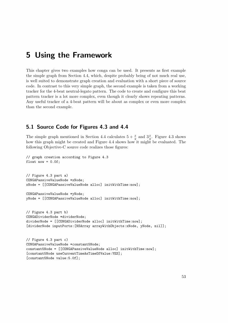
5 Using the Framework
This chapter gives two examples how conga can be used. It presents as first examplethe simple graph from Section 4.4, which, despite probably being of not much real use,is well suited to demonstrate graph creation and evaluation with a short piece of sourcecode. In contrast to this very simple graph, the second example is taken from a workingtracker for the 4-beat neutral-legato pattern. The code to create and configure this beatpattern tracker is a lot more complex, even though it clearly shows repeating patterns.Any useful tracker of a 4-beat pattern will be about as complex or even more complexthan the second example.
5.1 Source Code for Figures 4.3 and 4.4
The simple graph mentioned in Section 4.4 calculates 5 + xy and 3x
y . Figure 4.3 showshow this graph might be created and Figure 4.4 shows how it might be evaluated. Thefollowing Objective-C source code realizes those figures:
// graph creation according to Figure 4.3float now = 0.0f;
// Figure 4.3 part a)CONGAPassiveValueNode *xNode;xNode = [[CONGAPassiveValueNode alloc] initWithTime:now];
CONGAPassiveValueNode *yNode;yNode = [[CONGAPassiveValueNode alloc] initWithTime:now];
// Figure 4.3 part b)CONGADividerNode *dividerNode;dividerNode = [[CONGADividerNode alloc] initWithTime:now];[dividerNode inputPorts:[NSArray arrayWithObjects:xNode, yNode, nil]];
// Figure 4.3 part c)CONGAPassiveValueNode *constant5Node;constant5Node = [[CONGAPassiveValueNode alloc] initWithTime:now];[constant5Node useCurrentTimeAsTimeOfValue:YES];[constant5Node value:5.0f];
53
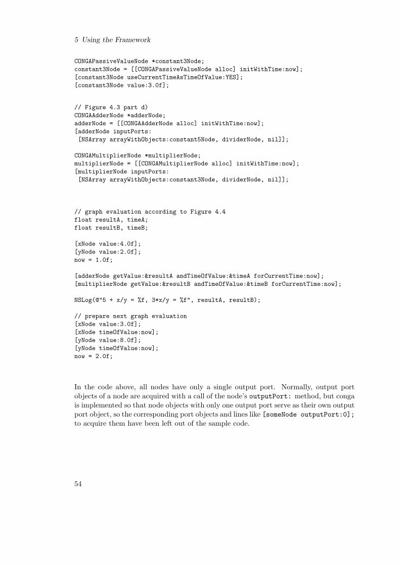
5 Using the Framework
CONGAPassiveValueNode *constant3Node;constant3Node = [[CONGAPassiveValueNode alloc] initWithTime:now];[constant3Node useCurrentTimeAsTimeOfValue:YES];[constant3Node value:3.0f];
// Figure 4.3 part d)CONGAAdderNode *adderNode;adderNode = [[CONGAAdderNode alloc] initWithTime:now];[adderNode inputPorts:[NSArray arrayWithObjects:constant5Node, dividerNode, nil]];
CONGAMultiplierNode *multiplierNode;multiplierNode = [[CONGAMultiplierNode alloc] initWithTime:now];[multiplierNode inputPorts:[NSArray arrayWithObjects:constant3Node, dividerNode, nil]];
// graph evaluation according to Figure 4.4float resultA, timeA;float resultB, timeB;
[xNode value:4.0f];[yNode value:2.0f];now = 1.0f;
[adderNode getValue:&resultA andTimeOfValue:&timeA forCurrentTime:now];[multiplierNode getValue:&resultB andTimeOfValue:&timeB forCurrentTime:now];
NSLog(@"5 + x/y = %f, 3*x/y = %f", resultA, resultB);
// prepare next graph evaluation[xNode value:3.0f];[xNode timeOfValue:now];[yNode value:8.0f];[yNode timeOfValue:now];now = 2.0f;
In the code above, all nodes have only a single output port. Normally, output portobjects of a node are acquired with a call of the node’s outputPort: method, but congais implemented so that node objects with only one output port serve as their own outputport object, so the corresponding port objects and lines like [someNode outputPort:0];to acquire them have been left out of the sample code.
54

5.2 Simple Tracker for 4-Beat Neutral-Legato Pattern
5.2 Simple Tracker for 4-Beat Neutral-Legato Pattern
It is possible to track the 4-beat neutral-legato pattern by using five characteristic fea-tures of its trajectory, as shown in Figure 4.1: The partial trajectory leading to the firstbeat, the baton changing direction in y after going up from the first beat, the batonchanging direction in x after the second and third beat plus the spike after the fourthbeat1. Detecting these features is easier than trying to detect all of the beats directly.Figure 5.1 illustrates the conga graph that analyzes if those features are present in aninput sequence of position values of the tip of the baton. The states present in Figure 5.1get connected to form a state network, and this network is inserted into an FSM objectto track the beat pattern, as depicted in Figure 5.2.All components needed by this simple tracker can be created and configured as follows:
startTime = 0.0f;
// input nodesxNode = [[CONGAPassiveValueNode alloc] initWithTime:startTime];yNode = [[CONGAPassiveValueNode alloc] initWithTime:startTime];
// nodes for smoothing input and calculating velocitiessmoothXNode = [[CONGAHanningSmoothingNode alloc] initWithTime:startTime];[smoothXNode setBufferSize:31];[smoothXNode inputPorts:[NSArray arrayWithObject:xNode]];smoothYNode = [[CONGAHanningSmoothingNode alloc] initWithTime:startTime];[smoothYNode setBufferSize:31];[smoothYNode inputPorts:[NSArray arrayWithObject:yNode]];
smoothDeltaXNode = [[CONGADeltaNode alloc] initWithTime:startTime];[smoothDeltaXNode inputPorts:[NSArray arrayWithObject:smoothXNode]];smoothDeltaYNode = [[CONGADeltaNode alloc] initWithTime:startTime];[smoothDeltaYNode inputPorts:[NSArray arrayWithObject:smoothYNode]];
// partial graph up to feature detector for first beathysteresisNode = [[CONGAHysteresisNode alloc] initWithTime:startTime];[hysteresisNode inputPorts:[NSArray arrayWithObjects:xNode, yNode, nil]];[hysteresisNode distanceThreshold:(2.0f/127.0f)];xPort = [hysteresisNode outputPort:0];yPort = [hysteresisNode outputPort:1];
filteredXNode = [[CONGAOnePoleFilterNode alloc] initWithTime:startTime];[filteredXNode inputPorts:[NSArray arrayWithObject:xPort]];[filteredXNode currentInputValueWeight:0.1f];[filteredXNode previousOutputValueWeight:0.89f];
1This tracker can also track the 4-beat expressive-legato pattern from Figure 4.1 because it does notsearch for spikes in the trajectory after the second and third beat. But the two beat patterns do notposition those features at the very same points in their cycles, so timing will be slightly off if thetracker is configured for one of both patterns and then used to track the other one.
55
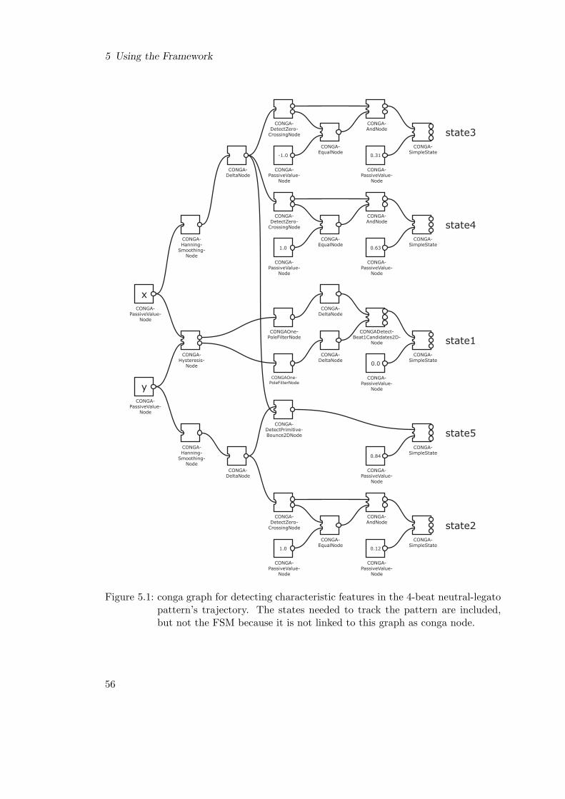
5 Using the Framework
CONGA-SimpleState
0.0
CONGADetect-Beat1Candidates2D-
Node
CONGA-PassiveValue-
Node
CONGA-DeltaNode
CONGA-DeltaNode
CONGA-Hysteresis-
Node
CONGAOne-PoleFilterNode
CONGAOne-PoleFilterNode
x
yCONGA-
PassiveValue-Node
CONGA-PassiveValue-
Node
CONGA-SimpleState
0.12
CONGA-AndNode
CONGA-PassiveValue-
Node
CONGA-DetectZero-
CrossingNode
CONGA-EqualNode
1.0
CONGA-PassiveValue-
Node
CONGA-DeltaNode
CONGA-Hanning-
Smoothing-Node
CONGA-SimpleState
0.84
CONGA-DetectPrimitive-Bounce2DNode
CONGA-PassiveValue-
Node
CONGA-SimpleState
0.31
CONGA-AndNode
CONGA-PassiveValue-
Node
CONGA-DetectZero-
CrossingNode
CONGA-EqualNode
-1.0
CONGA-PassiveValue-
Node
CONGA-DeltaNode
CONGA-SimpleState
0.63
CONGA-AndNode
CONGA-PassiveValue-
Node
CONGA-DetectZero-
CrossingNode
CONGA-EqualNode
1.0
CONGA-PassiveValue-
Node
CONGA-Hanning-
Smoothing-Node
state1
state2
state3
state4
state5
Figure 5.1: conga graph for detecting characteristic features in the 4-beat neutral-legatopattern’s trajectory. The states needed to track the pattern are included,but not the FSM because it is not linked to this graph as conga node.
56

5.2 Simple Tracker for 4-Beat Neutral-Legato Pattern
0CONGAPassive-
ValueNode
0.0
0.84
0.63
0.31
0.12
0CONGAPassive-
ValueNode
0CONGAPassive-
ValueNodeCONGASimpleFiniteStateMachine
Figure 5.2: conga FSM with state network for tracking the 4-beat neutral-legato pattern.
filteredYNode = [[CONGAOnePoleFilterNode alloc] initWithTime:startTime];[filteredYNode inputPorts:[NSArray arrayWithObject:yPort]];[filteredYNode currentInputValueWeight:0.1f];[filteredYNode previousOutputValueWeight:0.89f];
filteredDeltaXNode = [[CONGADeltaNode alloc] initWithTime:startTime];[filteredDeltaXNode inputPorts:[NSArray arrayWithObject:filteredXNode]];filteredDeltaYNode = [[CONGADeltaNode alloc] initWithTime:startTime];[filteredDeltaYNode inputPorts:[NSArray arrayWithObject:filteredYNode]];
detectBeat1Node = [[CONGADetectBeat1Candidates2DNode alloc]initWithTime:startTime];
[detectBeat1Node inputPorts:[NSArray arrayWithObjects:filteredDeltaXNode, filteredDeltaYNode, nil]];[detectBeat1Node waitForUpwardMotionToAcknowledgeBeat1Candidate:YES];detectBeat1Port = [detectBeat1Node outputPort:0];
// partial graph up to feature detector for turnaround in y after first beatdetectZeroCrossingDYNode = [[CONGADetectZeroCrossingNode alloc]
initWithTime:startTime];[detectZeroCrossingDYNode threshold:0.0015f];[detectZeroCrossingDYNode grazingZeroCancelsExceedingThreshold:YES];[detectZeroCrossingDYNode limitStayAtZero:YES];[detectZeroCrossingDYNode maxCountInputStaysAtZero:5];[detectZeroCrossingDYNode inputPorts:[NSArray arrayWithObject:smoothDeltaYNode]];detectZeroCrossingDYPort = [detectZeroCrossingDYNode outputPort:0];signZeroCrossingDYPort = [detectZeroCrossingDYNode outputPort:1];
signValueNodeState2 = [[CONGAPassiveValueNode alloc] initWithTime:startTime];[signValueNodeState2 value:1.0f];[signValueNodeState2 useCurrentTimeAsTimeOfValue:YES];
57
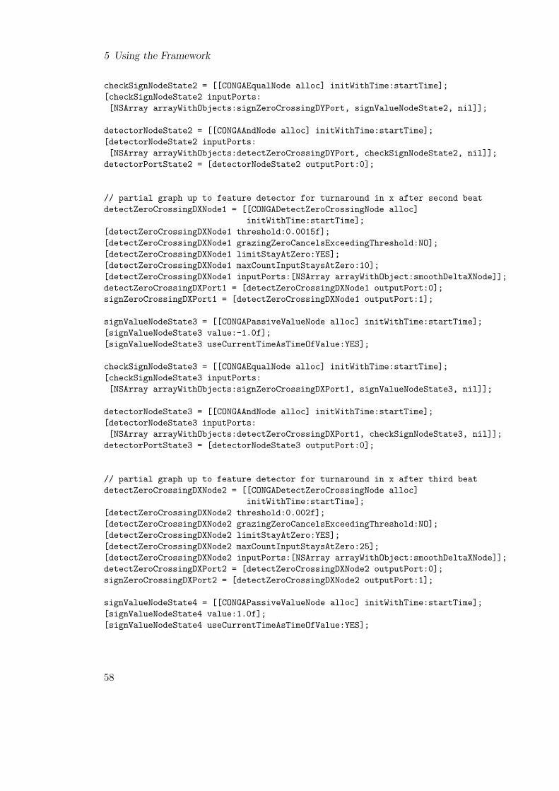
5 Using the Framework
checkSignNodeState2 = [[CONGAEqualNode alloc] initWithTime:startTime];[checkSignNodeState2 inputPorts:[NSArray arrayWithObjects:signZeroCrossingDYPort, signValueNodeState2, nil]];
detectorNodeState2 = [[CONGAAndNode alloc] initWithTime:startTime];[detectorNodeState2 inputPorts:[NSArray arrayWithObjects:detectZeroCrossingDYPort, checkSignNodeState2, nil]];
detectorPortState2 = [detectorNodeState2 outputPort:0];
// partial graph up to feature detector for turnaround in x after second beatdetectZeroCrossingDXNode1 = [[CONGADetectZeroCrossingNode alloc]
initWithTime:startTime];[detectZeroCrossingDXNode1 threshold:0.0015f];[detectZeroCrossingDXNode1 grazingZeroCancelsExceedingThreshold:NO];[detectZeroCrossingDXNode1 limitStayAtZero:YES];[detectZeroCrossingDXNode1 maxCountInputStaysAtZero:10];[detectZeroCrossingDXNode1 inputPorts:[NSArray arrayWithObject:smoothDeltaXNode]];detectZeroCrossingDXPort1 = [detectZeroCrossingDXNode1 outputPort:0];signZeroCrossingDXPort1 = [detectZeroCrossingDXNode1 outputPort:1];
signValueNodeState3 = [[CONGAPassiveValueNode alloc] initWithTime:startTime];[signValueNodeState3 value:-1.0f];[signValueNodeState3 useCurrentTimeAsTimeOfValue:YES];
checkSignNodeState3 = [[CONGAEqualNode alloc] initWithTime:startTime];[checkSignNodeState3 inputPorts:[NSArray arrayWithObjects:signZeroCrossingDXPort1, signValueNodeState3, nil]];
detectorNodeState3 = [[CONGAAndNode alloc] initWithTime:startTime];[detectorNodeState3 inputPorts:[NSArray arrayWithObjects:detectZeroCrossingDXPort1, checkSignNodeState3, nil]];
detectorPortState3 = [detectorNodeState3 outputPort:0];
// partial graph up to feature detector for turnaround in x after third beatdetectZeroCrossingDXNode2 = [[CONGADetectZeroCrossingNode alloc]
initWithTime:startTime];[detectZeroCrossingDXNode2 threshold:0.002f];[detectZeroCrossingDXNode2 grazingZeroCancelsExceedingThreshold:NO];[detectZeroCrossingDXNode2 limitStayAtZero:YES];[detectZeroCrossingDXNode2 maxCountInputStaysAtZero:25];[detectZeroCrossingDXNode2 inputPorts:[NSArray arrayWithObject:smoothDeltaXNode]];detectZeroCrossingDXPort2 = [detectZeroCrossingDXNode2 outputPort:0];signZeroCrossingDXPort2 = [detectZeroCrossingDXNode2 outputPort:1];
signValueNodeState4 = [[CONGAPassiveValueNode alloc] initWithTime:startTime];[signValueNodeState4 value:1.0f];[signValueNodeState4 useCurrentTimeAsTimeOfValue:YES];
58

5.2 Simple Tracker for 4-Beat Neutral-Legato Pattern
checkSignNodeState4 = [[CONGAEqualNode alloc] initWithTime:startTime];[checkSignNodeState4 inputPorts:[NSArray arrayWithObjects:signZeroCrossingDXPort2, signValueNodeState4, nil]];
detectorNodeState4 = [[CONGAAndNode alloc] initWithTime:startTime];[detectorNodeState4 inputPorts:[NSArray arrayWithObjects:detectZeroCrossingDXPort2, checkSignNodeState4, nil]];
detectorPortState4 = [detectorNodeState4 outputPort:0];
// feature detector for spike after fourth beatdetectBounceNode = [[CONGADetectPrimitiveBounce2DNode alloc]
initWithTime:startTime];[detectBounceNode minRatioAccumulationFirstInputToAccumulationSecondInput:4.0f];[detectBounceNode accumulationBufferSize:23];[detectBounceNode threshold:0.001f];[detectBounceNode grazingZeroCancelsExceedingThreshold:YES];[detectBounceNode limitStayAtZero:NO];[detectBounceNode inputPorts:[NSArray arrayWithObjects:smoothDeltaYNode, smoothDeltaXNode, nil]];
// the five states and their position nodescyclePositionNodeState1 = [[CONGAPassiveValueNode alloc] initWithTime:startTime];[cyclePositionNodeState1 value:0.0f];[cyclePositionNodeState1 useCurrentTimeAsTimeOfValue:YES];state1 = [[CONGASimpleState alloc] initWithTime:startTime];[state1 inputPorts:[NSArray arrayWithObjects:detectBeat1Port, cyclePositionNodeState1, nil]];
cyclePositionNodeState2 = [[CONGAPassiveValueNode alloc] initWithTime:startTime];[cyclePositionNodeState2 value:0.12f];[cyclePositionNodeState2 useCurrentTimeAsTimeOfValue:YES];state2 = [[CONGASimpleState alloc] initWithTime:startTime];[state2 inputPorts:[NSArray arrayWithObjects:detectorPortState2, cyclePositionNodeState2, nil]];
cyclePositionNodeState3 = [[CONGAPassiveValueNode alloc] initWithTime:startTime];[cyclePositionNodeState3 value:0.31f];[cyclePositionNodeState3 useCurrentTimeAsTimeOfValue:YES];state3 = [[CONGASimpleState alloc] initWithTime:startTime];[state3 inputPorts:[NSArray arrayWithObjects:detectorPortState3, cyclePositionNodeState3, nil]];
cyclePositionNodeState4 = [[CONGAPassiveValueNode alloc] initWithTime:startTime];[cyclePositionNodeState4 value:0.63f];[cyclePositionNodeState4 useCurrentTimeAsTimeOfValue:YES];state4 = [[CONGASimpleState alloc] initWithTime:startTime];[state4 inputPorts:[NSArray arrayWithObjects:detectorPortState4, cyclePositionNodeState4, nil]];
59

5 Using the Framework
cyclePositionNodeState5 = [[CONGAPassiveValueNode alloc] initWithTime:startTime];[cyclePositionNodeState5 value:0.84f];[cyclePositionNodeState5 useCurrentTimeAsTimeOfValue:YES];state5 = [[CONGASimpleState alloc] initWithTime:startTime];[state5 inputPorts:[NSArray arrayWithObjects:detectBounceNode, cyclePositionNodeState5, nil]];
// state network[state1 subsequentStates:[NSArray arrayWithObjects: state2, nil]];[state2 subsequentStates:[NSArray arrayWithObjects: state3, nil]];[state3 subsequentStates:[NSArray arrayWithObjects: state4, state1, nil]];[state4 subsequentStates:[NSArray arrayWithObjects: state5, state1, nil]];[state5 subsequentStates:[NSArray arrayWithObjects: state1, nil]];
// dummy FSM input nodes - this example has no conga graphs that decide// whether or not the FSM should be stopped, paused or restartedstopFSMNode = [[CONGAPassiveValueNode alloc] initWithTime:startTime];[stopFSMNode value:0.0f];[stopFSMNode useCurrentTimeAsTimeOfValue:YES];
pauseFSMNode = [[CONGAPassiveValueNode alloc] initWithTime:startTime];[pauseFSMNode value:0.0f];[pauseFSMNode useCurrentTimeAsTimeOfValue:YES];
restartFSMNode = [[CONGAPassiveValueNode alloc] initWithTime:startTime];[restartFSMNode value:0.0f];[restartFSMNode useCurrentTimeAsTimeOfValue:YES];
// FSM for tracking the beat patternneutralLegato4BeatPatternFSM = [[CONGASimpleFiniteStateMachine alloc]
initWithTime:startTime];[neutralLegato4BeatPatternFSM inputPorts:[NSArray arrayWithObjects:stopFSMNode, pauseFSMNode, restartFSMNode, nil]];
[neutralLegato4BeatPatternFSM allStates:[NSArray arrayWithObjects:state1, state2, state3, state4, state5, nil]];
[neutralLegato4BeatPatternFSM pickupAfterStopStates:[NSArray arrayWithObject:state4]];
[neutralLegato4BeatPatternFSM startState:state4];[neutralLegato4BeatPatternFSM minimumTimeBetweenAdvances:0.1];fsmDidAdvanceForCurrentTimePort = [neutralLegato4BeatPatternFSM outputPort:0];fsmLastAdvanceStartedNewCyclePort = [neutralLegato4BeatPatternFSM outputPort:1];fsmActivationValueLastAdvancePort = [neutralLegato4BeatPatternFSM outputPort:2];fsmPositionInCyclePort = [neutralLegato4BeatPatternFSM outputPort:3];fsmPositionDeltaLastAdvancePort = [neutralLegato4BeatPatternFSM outputPort:4];fsmTimeDeltaLastAdvancePort = [neutralLegato4BeatPatternFSM outputPort:5];fsmCycleCountPort = [neutralLegato4BeatPatternFSM outputPort:6];
60
5.2 Simple Tracker for 4-Beat Neutral-Legato Pattern
Everything needed for processing conducting gesture input has to be configured in thecode above, making it rather extensive. In contrast to the code creating and setting upall conga components used in the tracker, the code to actually track the beat pattern byrepeatedly evaluating those components is comparatively simple:
now = currentSystemTime - systemTimeAtInitialization;
// feed input data into graph[xNode value:currentBuchlaXInput];[xNode timeOfValue:(now - buchlaLatency)];[yNode value:currentBuchlaYInput];[yNode timeOfValue:(now - buchlaLatency)];
// get tracking output from FSM[fsmDidAdvanceForCurrentTimePort getValue:&didAdvance
andTimeOfValue:&didAdvanceTimeforCurrentTime:now];
[fsmLastAdvanceStartedNewCyclePort getValue:&newCycleandTimeOfValue:&newCycleTimeforCurrentTime:now];
[fsmActivationValueLastAdvancePort getValue:&activationValueandTimeOfValue:&activationValueTimeforCurrentTime:now];
[fsmPositionInCyclePort getValue:&positionInCycleandTimeOfValue:&positionInCycleTimeforCurrentTime:now];
[fsmPositionDeltaLastAdvancePort getValue:&positionDeltaandTimeOfValue:&positionDeltaTimeforCurrentTime:now];
[fsmTimeDeltaLastAdvancePort getValue:&timeDeltaandTimeOfValue:&timeDeltaTimeforCurrentTime:now];
[fsmCycleCountPort getValue:&cycleCountandTimeOfValue:&cycleCountTimeforCurrentTime:now];
The FSM’s tracking output allows to derive the conducting tempo during the lastadvance from positionDelta and timeDelta. To calculate the conducted volume,the second output port of detectBeat1Node could be used: each time an advance ofneutralLegato4BeatPatternFSM starts a new cycle, the value of this output port givesthe height of the last cycle’s conducting gesture, indicating the volume. Also, whena new cycle starts, the output port values of filteredXNode and filteredYNode ap-proximate the position of the first beat in the beating plane, which might be useful todetermine what instrument group the conductor focuses on.
To keep the tracker simple, there are no facilities to stop, pause or restart the FSM.Consequently, there are also no states outside the normal cycle of the beat pattern.
61
5 Using the Framework
All code in this example is taken from a program working on Buchla Lightning II batoninput data, with position values of the baton rescaled to values between zero and one.One thread of this program takes in and stores baton data, while another thread is runrepeatedly every 9 ms, supplying the conga components with the current baton dataand evaluating them in order to track the beat pattern2. All time values that are usedin the code are measured in seconds.
It would be possible to change the resampling rate or to switch to another inputdevice with different noise characteristics, without having to change the structure of thistracker. This allows to encapsulate the whole tracker into a single conga node for laterreuse. But the configuration parameters of the following nodes would probably have tobe changed in order to achieve acceptable tracking results for each input device:
• smoothXNode
• smoothYNode
• hysteresisNode
• filteredXNode
• filteredYNode
• detectZeroCrossingDYNode
• detectZeroCrossingDXNode1
• detectZeroCrossingDXNode2
• detectBounceNode
Thus the interface of the conga node representing the whole tracker would have to includemethods for configuring all of these nodes.
2Resampling at 9 ms and using a one-pole filter as configured in the code are ideas taken from Guy Gar-nett’s Adaptive Conductor Follower (presented in Subsection 2.2.7). The ideas work for this example,because the Adaptive Conductor Follower also used a Buchla baton system as input hardware.
62
6 Conclusions and Future Work
In summary, conga was intended to be an input hardware independent framework thathelps to create and reuse components that can process, analyze, recognize and trackconducting gestures of the conductor’s baton or right hand.
conga uses simple numbers as input data and can pass on associated latency of aninput device. The framework mainly consists of processing nodes that can be connectedto form directed acyclic graphs, which serve to process and analyze conducting input.It includes a special finite state machine and corresponding states to model and trackbeat patterns. Combined with conga graphs that detect characteristic features of thetrajectory of a conducting gesture, they allow recognition and tracking of conductinggestures. Components built with conga can be reused by encapsulating them in a congagraph node or in an Objective-C class, and they can be adapted to changing require-ments by reconfiguring the nodes of their conga graphs or, if that is not sufficient, byrestructuring these graphs. conga components can be mixed with C++ and Objective-Csource code to form a single Mac OS X application.
6.1 Conclusions
The conga framework meets a lot of the goals for its development, but not all of them.
On the positive side, conga as framework is independent of the input hardware thatis used, and it does enable and aid the construction of components to process, analyze,recognize and track conducting gestures of the conductor’s baton or right hand, as long asinput and gestures conform to conga’s model of conducting gestures as two-dimensionaltrajectories of a point. The framework might even be useful for at least processing inputthat does not conform to its conducting gesture model, if the processing can be modeledas directed acyclic graph of processing units and said input consists of simple numbers.
conga also supports reuse of components implemented with it: they can be encapsu-lated as Objective-C classes for direct reuse in other projects, or they can be encapsulatedas conga nodes to make them reusable inside a conga graph. If these container com-ponents provide access to the configuration methods of the encapsulated components,they can be adapted to changed requirements, if these requirements can be met withoutchanging the internal structure of the container components.
One important strength of conga is that it does not force a programer to use it foreverything. If some processing cannot be expressed easily as a directed acyclic graph andconsequently is hard to model with conga, it can be implemented without using congaand then be combined with conga graphs that perform the processing conga is suited
63
6 Conclusions and Future Work
for. Creating glue code to combine conga and non-conga components is comparativelysimple: Either a wrapper node has to be built in order to be able to embed the non-conga component in a conga graph, or the glue code has to split the conga graphs wherenecessary, passing data directly between conga graphs and non-conga components andevaluating all of them in the correct order.
Processing in conga is definitely fast enough to handle real-time conducting input.One of the testing programs created by the author during development of conga readsrecorded Buchla Lightning II baton input data from a file, resamples the recorded dataat time intervals of 9 ms and feeds the resampled data into the simple beat patterntracker presented in Section 5.2. When executed on an Apple iBook notebook with320 MB of RAM and a G3 processor running at 500 MHz, all processing done by thetracker in this simulated tracking of conducting input needs less than two percent ofthe time span covered by the recorded data. Therefore, more recent hardware like aPowerMacintosh with 512 MB of RAM and dual G5 processors running at 2 GHz, asused during development of conga, should be able to run several more complex trackersin parallel plus a demanding algorithm for sound synthesis, like a phase vocoder.
On the negative side, although conga itself is independent of the input hardware thatis used, modules to recognize and track conducting gestures that are implemented withconga components are not. If such a module has been configured for one input hardwareand is then switched to another one, it will probably have to be reconfigured if the newinput hardware differs significantly from the old one in important characteristics likenoise. In some cases it might be possible to preprocess the input of the new hardwareto mimic the characteristics of the old one, for example by trading reduced noise forincreased latency, adjusting the origination times of the values passed on to the originalmodule to reflect the added latency.
Building beat pattern trackers from scratch takes a lot of time. One not only has tofigure out which conga components to use and how to connect them, but also how toconfigure all those components, with each conga node influencing its subsequent nodes ina conga graph. Even a simple tracker like the one from Section 5.2 is complex enough tomake fine-tuning it a lengthy process of trial and error. So conga aids the constructionof components to track conducting gestures, but conga does not make it easy.
conga includes optimizations that improve processing speed. Because these optimiza-tions add complexity to the source code of conga components and also influence howcode is executed, they impede debugging of the framework’s components and they im-pede extending the framework.
Despite the amount of work that has gone into conga, it does not feel finished yet. Sec-tion 4.6 mentions conga components that model conducting-specific concepts, but thereshould be more such components for other conducting-specific concepts. For example, itis possible to use conga to construct gesture trackers that distinguish between staccatoand legato gestures, but there was not enough time to develop and include componentsin conga that correspond to staccato or legato features of the trajectory of a conductinggesture.
64

6.2 Future Work
6.2 Future Work
In the application domain of conducting, conga can be improved in several ways. Thenode to detect candidates for the first beat in a beat pattern can be split up into severalnodes that are more specific to the beat patterns: the trajectory leading to the first beatin patterns with multiple beats differs from the trajectory used in 1-beat patterns andthere is a difference between the staccato and legato version of this trajectory. congamight also benefit from being extended with components incorporating neural networksand hidden markov models. Using neural networks or HMMs to recognize complete beatpatterns will often result in the need to train them to individual conductors. But if theyare applied to distinct features of a beat pattern’s trajectory, it could turn out that thereexist features that do not need to be retrained. Again, the partial trajectory leading tothe first beat is a possible candidate for such an improvement.
The current version of conga focuses on conducting gestures performed with the righthand, which are well suited for time-beating and can indicate musical expression as well.An opportunity for future research would be to expand conga in the direction of lessformal input, like expressive gestures of the left hand or even patterns of physiolog-ical signals, as covered in the research of Paul Kolesnik ([Kol04]) and Teresa Marrin([Nak00]), respectively. Less formal input might give the conductor more expressivecontrol, but the important signals probably vary from person to person. Tracking themwill thus probably require components that can be trained to an individual conductor,like the already mentioned neural networks and HMMs.
Another promising area to extend conga is the handling of latency. A system using theBuchla Lightning II as input hardware can have an overall latency in the range of 100 ms[LWB05]. For conducting, this is quite high, and conga does nothing to reduce latency, itsimply passes on the accumulated latency. Components that predict features instead ofdetecting them could be added to conga to alleviate this problem. If these componentspresent the predicted time when their associated features will occur instead of passing onthe origination time of their current input sample, they can be used in gesture trackerswithout the existing FSM and state classes having to be modified. Furthermore, if such acomponent calculates the prediction value as a probability value, this value will grow asthe time approaches that the corresponding feature actually occurs, making it possibleto use a threshold to balance out latency and reliability. The paper A New ControlParadigm: Software-Based Gesture Analysis for Music by Ben Nevile, Peter Driessenand W. A. Schloss applies similar ideas to the Radio Drum [NDS03].
A more fundamental area of future work on conducting gestures concerns the questionof where exactly conductors place the beats. The placement of some beats in the beatpatterns according to Max Rudolf does not correspond to a position where the trajec-tory of the tip of the baton has reached its lowest point, yet several of the conductingsystems presented in Section 2.2 assume that all beats sit at locally lowest points of theconducting gesture’s trajectory. To find out where trained conductors place the beats,a study could survey conductors either conducting to a metronome or conducting whilesaying out loud which beat they are currently conducting. It would be beneficial, ifdifferent schools of conducting were represented in this study with several conductors
65
6 Conclusions and Future Work
each, to see if the different schools agree on the placement of beats, or if at least allconductors of each school place beats the same way. In addition, the participants shouldconduct a variety of commonly used beat patterns, each in several tempi, and it shouldbe analyzed how this influences beat placement. For optimal results, the study shouldrecord the conductors with input devices that have high temporal and spatial resolutionand precision.
There are also promising extensions to conga that do not focus on conducting. Forexample, LabVIEW, EyesWeb and Max/MSP provide graphical programming environ-ments and allow to do all programming graphically. Because conga graphs and non-congacomponents can be mixed freely in source code, it is not possible to create a graphicalprogramming environment for conga that simply reads in source code that uses congacomponents, allows to change those graphically and then writes the results back tosource code without ever breaking the non-conga components. But it is possible andwould be worthwhile to create a graphical programming environment that handles onlyconga components and includes the ability to transform the graphic representations ofconga graphs into source code. As the sample code in Section 5.2 shows, code to cre-ate and configure a conga graph is rather schematic anyway, so building a source codegenerator for conga graphs should not be too hard. Such a graphical programming envi-ronment could speed up the development of conga graphs, at least up to the point wherenon-conga components have to be added.
Computers still keep getting faster and their performance will increase for at least afew years, a trend that might render the speed optimizations in conga obsolete. The evergrowing processing power could also make it feasible to implement conga in a platform-independent language like Java. But that would only be of interest, if demanding formsof output for computer-based conducting systems could be implemented in the samelanguage, in a platform-independent way, and still be executed without glitches. Other-wise one would be forced to split the handling of input and output of such a system intoseparate applications, something conga was intended to help avoid in the first place.
Some computer-based conducting systems track the conductor’s baton in three dimen-sions, but conga is built to aid tracking of the baton in two dimensions, because mostof the information contained in a baton gesture can be represented in two dimensionsof space and one dimension of time. It would be easy to extend conga to support three-dimensional tracking, so it could be applied in domains where fully three-dimensionalgesture input is useful. Mobile computing might become one of those domains as cellphone makers already plan to equip their phones with sensors to acquire gesture inputfrom three-dimensional movements of the phone1.
Another application domain outside conducting where conga could be useful might bepen computing. conga employs a special variant of a finite state machine because whilea certain beat pattern is being conducted, the same gesture occurs again and againwithout interruption. By turning the FSM into a finite automaton, conga could be
1Samsung Electronics introduced their mobile phone SCH-S310 in January 2005, featuring sen-sors and algorithms to recognize three-dimensional movements. The press release can befound at http://www.samsung.com/AboutSAMSUNG/ELECTRONICSGLOBAL/InvestorRelations/NewsPublicDisclosure/PressRelease/PressRelease.asp?seq=20050112 0000096403
66
6.2 Future Work
used to implement modules that recognize gesture input with the gestures occurring asseparate entities. In pen computing this could be used to interpret each sequence of penpositions between the pen being put down and being lifted up again as a gesture. Severalautomata standing for different input gestures could be evaluated in parallel and theone accepting the complete input sequence would determine which gesture is recognized.Afterwards, conga graphs associated with the recognized gesture could process the sameinput sequence, to derive parameters from it that provide further information to anaction triggered by the recognition of this gesture.
67

6 Conclusions and Future Work
68
A Interpolating Beat Times
conga allows to track a beat pattern using points in the trajectory of the beat patternthat do not correspond to beats, and the output of a conga FSM does not say wherein the cycle of a beat pattern the beats are placed. It does, however, tell where theactive state of the FSM is placed in this cycle and CONGASimpleFiniteStateMachinealso outputs how many cycles have already been completed. With this information, itis easy to calculate which beat of the beat pattern was the last conducted beat and howmany beats have been conducted in total. But some forms of output of a computer-basedconducting system not only need to know how many beats have already been conducted.They need to know the exact time the current position of the gesture tracker correspondsto in the piece being conducted. For example if a score format is used that just storesnotes and the times they are played or if an audio and video recording of a real orchestra isplayed back, each advance of the beat pattern tracker should yield the corresponding timein the score or in the movie. conga provides a node that works on an array containingthe absolute times of all beats in the musical piece and that can interpolate betweenthese times based on the output of CONGASimpleFiniteStateMachine.
A.1 CONGABeatTimeInterpolatorNode
Input ports taken:CONGABeatTimeInterpolatorNode objects take two input ports. The first inputport value is interpreted as the number of complete beat pattern cycles alreadyconducted and the second input port value is interpreted as a position inside thecurrent beat pattern cycle.
Output ports provided:CONGABeatTimeInterpolatorNode objects provide one output port that suppliesthe interpolated absolute time value.
Processing carried out:Before they can be used, CONGABeatTimeInterpolatorNode objects have to beprovided with an array containing the absolute time values of all beats in ascendingorder. Per default, they assume that there are four beats in each cycle, but thiscan and must be changed, if a beat pattern uses a different number of beats. Whena CONGABeatTimeInterpolatorNode object is evaluated, it queries its first inputport for the number of full cycles that have already been conducted and its second
69

A Interpolating Beat Times
input port for the position inside the current cycle, cropping the value if it is lessthan zero or greater than one. These values allow to calculate the index of thelast conducted beat in the array of all beats, as well as the point between thisbeat and the next, assuming all beats to be evenly spaced in time. As the beatsdo not have to be evenly spaced in time according to their absolute time values,CONGABeatTimeInterpolatorNode then uses linear interpolation to transform theideal point between those two beats into an absolute time value between theirabsolute time values. Then it sets its output port value to this interpolated absolutetime value and passes the oldest origination time value of its two input ports onto its output port. If the input values reference a point outside the beat array, theoutput port value is set to the time of either the first or the last beat, whichever isclosest.
Possible use:CONGABeatTimeInterpolatorNode objects can be used the way described at thebeginning of this appendix. They can also be abused as simple linear interpolatorsby setting the number of beats in a cycle to one and filling the array of beat timeswith whatever values one wishes to interpolate. This enables to interpolate twosuccessive array entries by providing the index of the first entry to the first inputport of CONGABeatTimeInterpolatorNode and the point of interpolation to thesecond input port.
70
Bibliography
[BC92] Graziano Bertini and Paolo Carosi: Light baton: A System For Conduct-ing Computer Music Performance. In Proceedings ICMC92, pages 73–76.ICMA, 1992.
[BG95] Bennett Brecht and Guy E. Garnett: Conductor Follower. In ICMC Pro-ceedings 1995, pages 185–186. ICMA, 1995.
[BM97] Richard Boulanger and Max Mathews: The 1997 Radio Baton and impro-visation modes. In Proceedings ICMC97, pages 395–398. ICMA, 1997.
[BMS89] Bob Boie, Max Mathews and Andy Schloss: The Radio Drum as a synthe-sizer controller. In Proceedings ICMC89, pages 42–45. ICMA, 1989.
[Bor97] Jan O. Borchers: WorldBeat: Designing a Baton-Based Interface for anInteractive Music Exhibit. In Proceedings of the SIGCHI Conference onHuman Factors in Computing Systems, pages 131–138. ACM, 1997.
[Bor01] Jan Borchers: A Pattern Approach to Interaction Design. Wiley Series inSoftware Design Patterns. John Wiley & Sons Ltd, May 2001.
[BRF+80] W. Buxton, W. Reeves, G. Fedorkow, K. C. Smith and R. Baecker: AMicrocomputer-based Conducting System. Computer Music Journal, 1/1980,pages 8–21.
[CCM+04] Antonio Camurri, Paolo Coletta, Alberto Massari, Barbara Mazzarino, Mas-similiano Peri, Matteo Ricchetti, Andrea Ricci and Gualtiero Volpe: Towardreal-time multimodal processing: EyesWeb 4.0. In Proc. AISB 2004 Con-vention: Motion, Emotion and Cognition, March 2004.
[CMV03] Antonio Camurri, Barbara Mazzarino and Gualtiero Volpe: Analysis of ex-pressive gestures in human movement: the EyesWeb expressive gesture pro-cessing library. In Proc. XIV Colloquium on Musical Informatics, May 2003.
[Coo02] Perry R. Cook: Human Computer Interface Technology -Digital Signal Processing for HCI.http://soundlab.cs.princeton.edu/learning/tutorials/DSP/DSP.html, Octo-ber 2002.
71

Bibliography
[GJE+01] Guy E. Garnett, Mangesh Jonnalagadda, Ivan Elezovic, Timothy Johnsonand Kevin Small: Technological Advances for Conducting a Virtual Ensem-ble. In ICMC Proceedings 2001, pages 167–169. ICMA, 2001.
[GMRS99] Guy E. Garnett, Fernando Malvar-Ruiz and Fred Stoltzfus: Virtual Con-ducting Practice Environment. In ICMC Proceedings 1999, pages 371–374.ICMA, 1999.
[Ilm] Tommi Ilmonen: DIVA - Digital Interactive Virtual Acoustics.http://www.tml.hut.fi/Research/DIVA/.
[Ilm98] Tommi Ilmonen: Tracking conductor of an orchestra using artificial neu-ral networks. In STeP’98, Human and Artificial Information Processing.Finnish Conference on Artificial Intelligence, 1998.
[Ilm99] Tommi Ilmonen: Tracking conductor of an orchestra using artificial neuralnetworks. Master’s thesis, Helsinki University of Technology, April 1999.
[Ins] Native Instruments: LabVIEW FAQs. http://ni.com/labview/faq.htm.
[IT99] Tommi Ilmonen and Tapio Takala: Conductor Following With ArtificialNeural Networks. In ICMC Proceedings 1999, pages 367–370. ICMA, 1999.
[Kar05] Thorsten Karrer: PhaVoRiT - A Phase Vocoder for Real-Time Interac-tive Time-Stretching. Master’s thesis, Rheinisch-Westfalische TechnischeHochschule Aachen, August 2005.
[KG89] David Keane and Peter Gross: The MIDI Baton. In Proceedings ICMC89,pages 151–154. ICMA, 1989.
[Kol04] Paul Kolesnik: Conducting Gesture Recognition, Analysis and PerformanceSystem. Master’s thesis, McGill University, Montreal, June 2004.
[KW91] David Keane and Kevin Wood: The MIDI Baton III. In ProceedingsICMC91, pages 541–544. ICMA, 1991.
[LGW92] Michael Lee, Guy Garnett and David Wessel: An Adaptive Conductor Fol-lower. In Proceedings ICMC92, pages 454–455. ICMA, 1992.
[LNB04] Eric Lee, Teresa Marrin Nakra and Jan Borchers: You’re The Conductor:A Realistic Interactive Conducting System for Children. In NIME 2004International Conference on New Interfaces for Musical Expression, pages68–73, 2004.
[LWB05] Eric Lee, Marius Wolf and Jan Borchers: Improving Orchestral Conduct-ing Systems in Public Spaces: Examining the Temporal Characteristics andConceptual Models of Conducting Gestures. In Proceedings of the CHI 2005Conference on Human Factors in Computing Systems, pages 731–740. ACM,April 2005.
72

Bibliography
[MAJ03] Declan Murphy, Tue Haste Andersen and Kristoffer Jensen: ConductingAudio Files via Computer Vision. In Proceedings of the 2003 InternationalGesture Workshop, 2003.
[Mar96] Teresa Anne Marrin: Toward an Understanding of Musical Gesture: Map-ping Expressive Intention with the Digital Baton. Master’s thesis, Mas-sachusetts Institute of Technology, June 1996.
[Mat00a] Max Mathews: CONDUCTOR PROGRAM.http://www.csounds.com/mathews, December 2000.
[Mat00b] Max Mathews: RADIO-BATON INSTRUCTION MANUAL.http://www.csounds.com/mathews, December 2000.
[MHO91] Hideyuki Morita, Shuji Hashimoto and Sadamu Ohteru: Computer MusicSystem that Follows a Human Conductor. IEEE Computer, 7/1991, pages44–53.
[MM70] M. V. Mathews and F. R. Moore: GROOVE - A Program to Compose,Store, and Edit Functions of Time. Communications of the ACM, 12/1970,pages 715–721.
[MOH89] H. Morita, S. Ohteru and S. Hashimoto: Computer Music System which Fol-lows a Human Conductor. In Proceedings ICMC89, pages 207–210. ICMA,1989.
[MP97] Teresa Marrin and Joseph Paradiso: The Digital Baton: a Versatile Perfor-mance Instrument. In Proceedings ICMC97, pages 313–316. ICMA, 1997.
[MP98] Teresa Marrin and Rosalind Picard: The Conductor’s Jacket: A Devicefor Recording Expressive Musical Gestures. In Proceedings ICMC98, pages215–219. ICMA, 1998.
[Mur03] Declan Murphy: Tracking a Conductor’s Baton. In Proceedings of the 12thDanish Conference on Pattern Recognition and Image Analysis 2003, 2003.
[MWH+90] Hideyuki Morita, Hiroshi Watanabe, Tsutomu Harada, Shuji Hashimoto andSadamu Ohteru: Knowledge Information Processing in Conducting Com-puter Music Performer. In ICMC Glasgow 1990 Proceedings, pages 332–334.ICMA, 1990.
[Nak00] Teresa Marrin Nakra: Inside the Conductor’s Jacket: Analysis, Interpre-tation and Musical Synthesis of Expressive Gesture. PhD thesis, Mas-sachusetts Institute of Technology, February 2000.
[NDS03] Ben Nevile, Peter Driessen and W. A. Schloss: A New Control Paradigm:Software-Based Gesture Analysis for Music. In IEEE Pacific Rim Confer-ence on Communications, Computers and Signal Processing, Band 1, pages360–363. IEEE, August 2003.
73

Bibliography
[Rud95] Max Rudolf: The Grammar of Conducting: A Comprehensive Guide toBaton Technique and Interpretation. Schirmer Books, 3rd edition, June1995.
[Sam02] Wolfgang Samminger: Personal Orchestra: Interaktive Steuerung syn-chroner Audio- und Videostrome. Master’s thesis, Johannes Kepler Uni-versitat Linz, September 2002.
[SFMB01] Johan Sundberg, Anders Friber, Max V. Mathews and Gerald Bennett: Ex-periences of combining the Radio Baton with the Director Musices perfor-mance grammar. In MOSART - Workshop on Current Research Directionsin Computer Music, 2001.
[SMG00] Jakob Segen, Aditi Majumder and Joshua Gluckman: Virtual Dance andMusic Conducted by a Human Conductor. EUROGRAPHICS ’2000, 3/2000.
[Sol] Realtime Music Solutions: Realtime Music Solutions.http://www.rms.biz/index.htm.
[Spo01] Bruno Spoerri: Dirigieren mit Trommelschlegeln - Max Mathews, Vater derComputermusik. Neue Zurcher Zeitung, Ressort Medien und Informatik,97/2001, page 85.
[TF96] Forrest Tobey and Ichiro Fujinaga: Extraction of Conducting Gestures in3D Space. In ICMC Proceedings 1996, pages 305–307. ICMA, 1996.
[Tob95] Forrest Tobey: The Ensemble Member and the Conducted Computer. InProceedings ICMC95, pages 529–530. ICMA, 1995.
[UM98] Satoshi Usa and Yasunori Mochida: A Multi-Modal Conducting Simulator.In Proceedings ICMC98, pages 25–32. ICMA, 1998.
[Vol03] Gualtiero Volpe: Computational models of expressive gesture in multimediasystems. PhD thesis, University of Genova, April 2003.
All internet URLs given here or anywhere else in this thesis were up to date in April2005. Due to the nature of the internet, there is no guarantee that these URLs stayvalid afterwards, and even if they do, the contents of the corresponding websites maystill change.
74

Application of Tools in the Creation of this Diploma Thesis
Several tools were used to create this diploma thesis. Typesetting was done with LATEX.All illustrations produced for this thesis have been drawn with Adobe Illustrator. Im-ages and illustrations taken from referenced works have been processed using AdobePhotoshop. This processing was done to improve reproduction of said illustrations andimages, including steps like slight changes of coloring or contrast of certain elements orwhole pictures, noise reduction and marginal cropping.No photomontage was done to change the contents of pictures. No elements have been re-moved or added apart from combining images into a single PDF file for easier placementin LATEX.

Name: Ingo Grull Matrikel-Nr.: . . . . . . . . . . . . . . . . . . . . . . . . . . . .
Erklarung
Ich erklare, daß ich die Diplomarbeit selbststandig verfasst und keine anderen als die
angegebenen Quellen und Hilfsmittel verwendet habe.
Ulm, den . . . . . . . . . . . . . . . . . . . . . . . . . . . . . . . . . . . . . . . . . . . . . . . . . . . . . . . . . . . . . . . . . . . . . . . . . .(Unterschrift)