configuring drive parameters 3 - automationdirect · ics–1 1 meter ics–3 3 meters ... •...
TRANSCRIPT
Configuring Drive Parameters
In This Chapter.... page— Choosing a Programming Device ...................................................... 2— Using Keypad Devices....................................................................... 3— “D” Group: Monitoring Functions ....................................................... 6— “F” Group: Main Profile Parameters................................................... 8— “A” Group: Standard Functions .......................................................... 9— “B” Group: Fine-Tuning Functions ................................................... 29— “C” Group: Intelligent Terminal Functions ........................................47— “H” Group: Motor Constants Functions ............................................ 62— “P” Group: Expansion Card Functions ............................................. 65— “U” Group: User-selectable Menu Functions ................................... 67— Programming Error Codes............................................................... 68
3
Choosing a Programming DeviceC
onfig
urin
g D
rive
Par
amet
ers
3–2
Choosing a Programming DeviceIntroduction Hitachi variable frequency drives (inverters) use the latest electronics technology for getting the
right AC waveform to the motor at the right time. The benefits are many, including energy savings and higher machine output or productivity. The flexibility required to handle a broad range of applications has required ever more configurable options and parameters—inverters are now a complex industrial automation component. And this can make a product seem diffi-cult to use, but the goal of this chapter is to make this easier for you.
As the powerup test in Chapter 2 demonstrated, you do not have to program very many param-eters to run the motor. In fact, most applications would benefit only from programming just a few, specific parameters. This chapter will explain the purpose of each set of parameters, and help you choose the ones that are important to your application.
If you are developing a new application for the inverter and a motor, finding the right parame-ters to change is mostly an exercise in optimization. Therefore, it is okay to begin running the motor with a loosely tuned system. By making specific, individual changes and observing their effects, you can achieve a finely tuned system. And, the SJ300 Series inverters have a built-in auto-tuning algorithm to set certain motor parameters.
InverterProgrammingKeypads
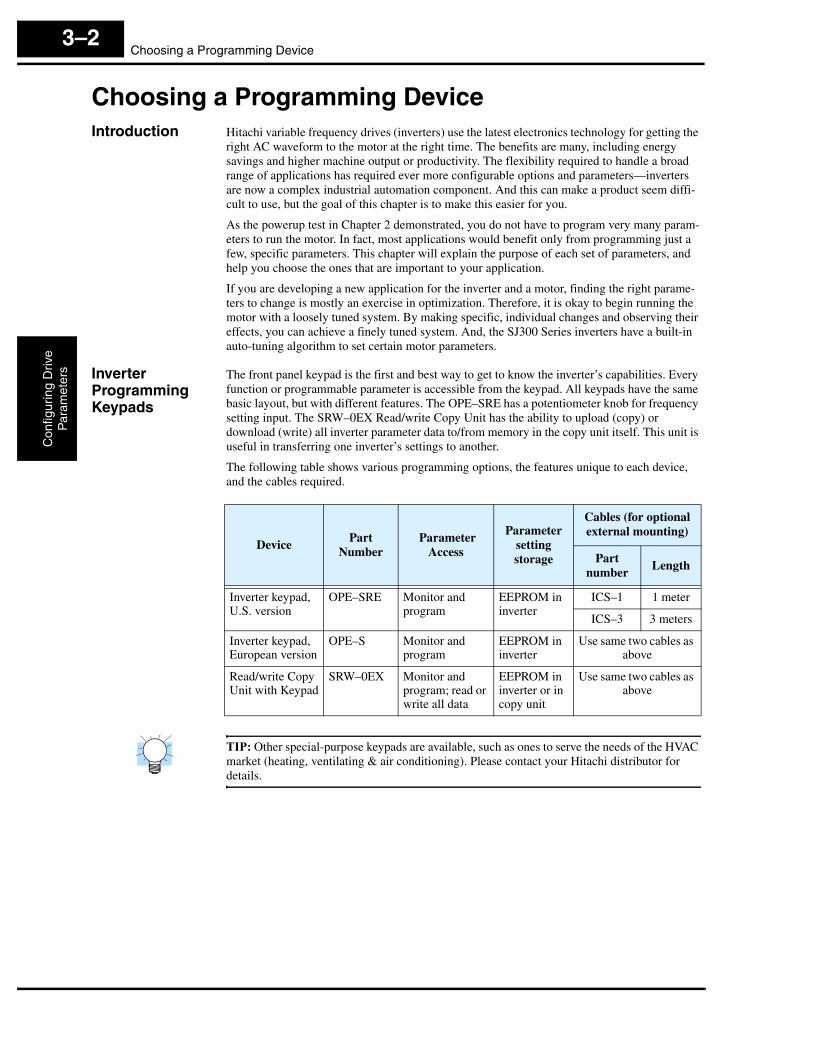
The front panel keypad is the first and best way to get to know the inverter’s capabilities. Every function or programmable parameter is accessible from the keypad. All keypads have the same basic layout, but with different features. The OPE–SRE has a potentiometer knob for frequency setting input. The SRW–0EX Read/write Copy Unit has the ability to upload (copy) or download (write) all inverter parameter data to/from memory in the copy unit itself. This unit is useful in transferring one inverter’s settings to another.
The following table shows various programming options, the features unique to each device, and the cables required.
TIP: Other special-purpose keypads are available, such as ones to serve the needs of the HVAC market (heating, ventilating & air conditioning). Please contact your Hitachi distributor for details.
DevicePart
Number Parameter
Access
Parameter setting storage
Cables (for optional external mounting)
Part number
Length
Inverter keypad,U.S. version
OPE–SRE Monitor and program
EEPROM in inverter
ICS–1 1 meter
ICS–3 3 meters
Inverter keypad,European version
OPE–S Monitor and program
EEPROM in inverter
Use same two cables as above
Read/write Copy Unit with Keypad
SRW–0EX Monitor and program; read or write all data
EEPROM in inverter or in copy unit
Use same two cables as above

SJ300 InverterC
onfiguring Drive
Param
eters
3–3
Using Keypad DevicesInverter Front Panel Keypad
The SJ300 Series inverter front keypad contains all the elements for both monitoring and programming parameters. The keypad layout (OPE–SRE) is shown below. All other program-ming devices for the inverter have a similar key arrangement and function.
Key andIndicator Legend
• Run/Stop LED – ON when the inverter output is ON and the motor is developing torque, and OFF when the inverter output is OFF (Stop Mode).
• Program/Monitor LED – This LED is ON when the inverter is ready for parameter editing (Program Mode). It is normally OFF when the parameter display is monitoring data (Monitor Mode). However, the PRG LED will be ON whenever you are monitoring the value of parameter D001. (When the keypad is enabled as the frequency source via A001=02, you can edit the inverter frequency directly from D001 monitor display by using the Up/Down keys.)
• Run Key – Press this key to run the motor (the Run Enable LED must be ON first). Parame-ter F004, Keypad Run Key Routing, determines whether the Run key generates a Run FWD or Run REV command.
• Run Key Enable LED – is ON when the inverter is ready to respond to the Run key, OFF when the Run key is disabled.
• Stop/Reset Key – Press this key to stop the motor when it is running (uses the programmed deceleration rate). This key will also reset an alarm that has tripped.
• Potentiometer (OPE–SRE only) – allows an operator to directly set the motor speed when the potentiometer is enabled for output frequency control
• Potentiometer Enable LED – ON when the potentiometer is enabled for value entry(OPE–SRE only).
• Parameter Display – a 4-digit, 7-segment display for parameters and function codes.
• Display Units: Hertz/Volts/Amperes/kW/% - These LEDs indicate the units associated with the parameter display. When the display is monitoring a parameter, the appropriate LED is ON. In the case of kW units, both Volts and Amperes LEDs will be ON. An easy way to remember this is that kW = (V x A)/1000.
• Power LED – This LED is ON when the power input to the inverter is ON.
• Alarm LED – This LED is ON when an alarm condition has tripped the inverter. Clearing the alarm will turn this LED OFF again. See Chapter 6 for details on clearing alarms.
• Function Key – This key is used to navigate through the lists of parameters and functions for setting and monitoring parameter values.
• Up/Down ( , ) Keys – Use these keys to alternately move up or down the lists of parameter and functions shown in the display, and increment/decrement values.
• Store ( ) Key – When the unit is in Program Mode and the operator has edited a param-eter value, press the Store key to write the new value to the EEPROM. This parameter is then displayed at powerup by default. If you want to change the powerup default, navigate to a new parameter value and press the Store key.
Run/Stop LED
Program/Monitor LED
Run Key Enable LED
Run Key
Power LED
Alarm LED
Display Units LEDs
HertzVolts or Amperes(kW = both ON)Percent
Parameter Display
Potentiometer Enable LED
PotentiometerStop/Reset Key
Hz
POWER
A
RUN
PRG
RUN STOPRESET
MIN MAX
HITACHI
FUNC 1 2
%
ALARM
STR
V kW5 0.0
1 2
STR

Using Keypad DevicesC
onfig
urin
g D
rive
Par
amet
ers
3–4
KeypadNavigational Map
Whether you use the keypad on the inverter or the read-write copy unit, each navigates the same way. The diagram below shows the basic navigational map of parameters and functions.
NOTE: The inverter 7-segment display shows lower case “b” and “d”, meaning the same as the upper case letters “B” and “D” used in this manual (for uniformity “A to F”).
1 2
Monitor Mode
21
Program Mode
Writedata to
EEPROM, store as powerup default
Increment/decrement
value
21
21
21
21
21
21
2
1
1
Select ParameterSelect FunctionDisplay Data
2
Return to parameter
list
21
21
21
21
21
21
Edit Parameter
FUNC.
FUNC.
FUNC.21
21
21
21
21
21
d o 9 0
U – – –
P – – –
H – – –
C – – –
b – – –
A – – –
U o 1 2
U o 0 1
P o 4 9
P o 0 1
h o 7 2
h o 0 1
c 1 2 3
c o 0 1
b 1 2 6
b o 0 1
a 1 3 2
a o 0 1
1 2 3.4
0.00
d o 0 1
F o 0 4
F o 0 1
FUNC.
FUNC.
FUNC.
21
P o 4 9
d 0 0 1
FUNC.
STR
FUNC.
D002–D090
Edit
0.00D001
Edit
PRG LED
PRG LED
Increment/decrement
value
1 2
FUNC.
Write data to F001,
store D001 as power-up default
STR
FUNC.
STR
Store as powerup default

SJ300 InverterC
onfiguring Drive
Param
eters
3–5
Operational Modes
The RUN and PGM LEDs tell just part of the story; Run Mode and Program Modes are indepen-dent modes, not opposite modes. In the state diagram to the right, Run alternates with Stop, and Program Mode alternates with Monitor Mode. This is a very important ability, for it shows that a technician can approach a running machine and change some parameters without shutting down the machine.
The occurrence of a fault during operation will cause the inverter to enter the Trip Mode as shown. An event such as an output overload will cause the inverter to exit the Run Mode and turn OFF its output to the motor. In the Trip Mode, any request to run the motor is ignored. You must clear the error by pressing the Stop/Reset switch. See “Monitoring Trip Events, History, & Conditions” on page 6–5.
Run Mode Edits The inverter can be in Run Mode (inverter output is controlling motor) and still allow you to edit certain parameters. This is useful in applications that must run continuously, yet need some inverter parameter adjustment.
The parameter tables in this chapter have a column titled “Run Mode Edit.” An Ex mark ✘ means the parameter cannot be edited; a Check mark ✔ means the parameter can be edited. You’ll notice in the table example to the right the two adjacent marks: “✘ ✔”. The two marks (that can also be “✘ ✘” or “✔ ✔”) correspond to these levels of access to editing:
• Low-access level to Run Mode edits (indicated by left-most mark)
• High-access level to Run Mode edits (indicated by right-most mark)
The Software Lock Setting (parameter B031) determines the particular access level that is in effect during Run Mode and access in other conditions, as well. It is the responsibility of the user to choose a useful and safe software lock setting for the inverter operating conditions and personnel. Please refer to “Software Lock Mode” on page 3–36 for more information.
Control Algorithms
The motor control program in the SJ300 inverter has several sinusoidal PWM switching algorithms. The intent is that you select the best algorithm for the motor characteristics in your application. Each algorithm generates the frequency output in a unique way. Once configured, the algorithm is the basis for other parameter settings as well (see “Torque Control Algorithms” on page 3–14). Therefore, choose the best algorithm early in your application design process.
Run Stop
Monitor ProgramFUNC.
RUN
STOPRESET
Run Stop
TripFault
Fault
RUN
STOPRESET
STOPRESET
Run Mode Edit
Lo Hi
✘ ✔
Output
V/f control, constant torque
V/f control,variable torque
V/f control, free-setting curve
Inverter Control Algorithms
Sensorless vector (SLV) control
SLV control,0Hz domain
Vector control with Sensor
“D” Group: Monitoring FunctionsC
onfig
urin
g D
rive
Par
amet
ers
3–6
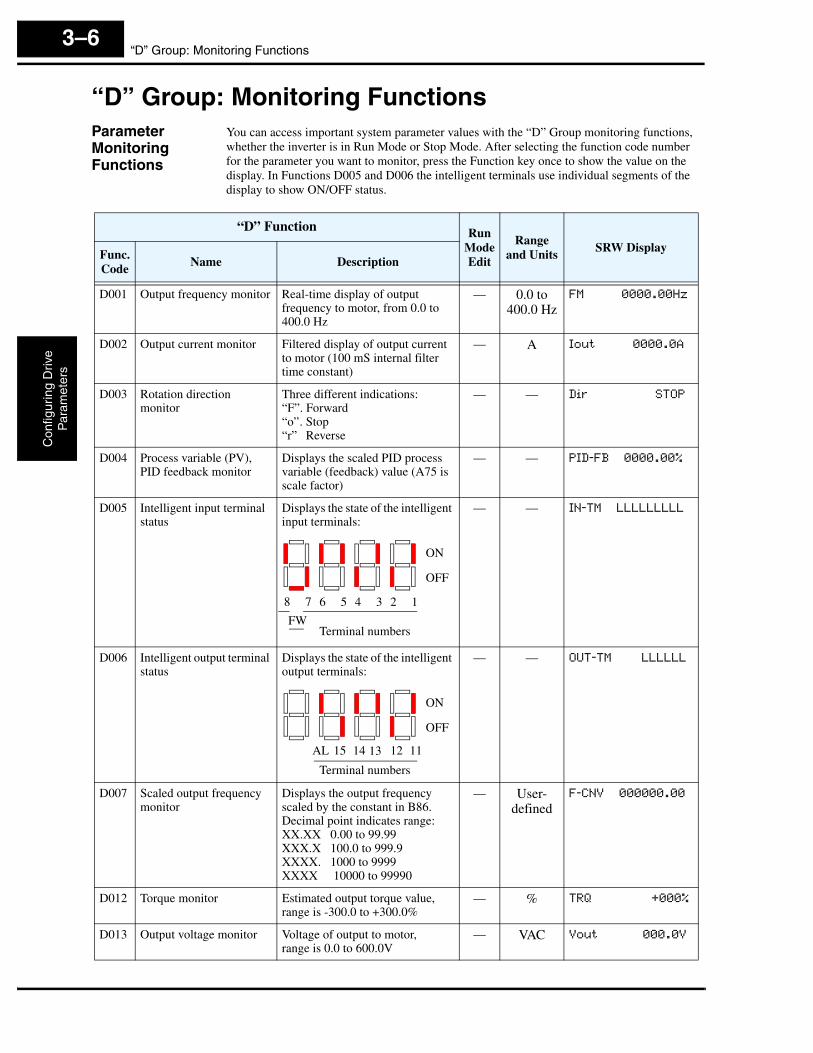
“D” Group: Monitoring FunctionsParameter Monitoring Functions
You can access important system parameter values with the “D” Group monitoring functions, whether the inverter is in Run Mode or Stop Mode. After selecting the function code number for the parameter you want to monitor, press the Function key once to show the value on the display. In Functions D005 and D006 the intelligent terminals use individual segments of the display to show ON/OFF status.
“D” Function Run ModeEdit
Range and Units
SRW DisplayFunc.Code
Name Description
D001 Output frequency monitor Real-time display of output frequency to motor, from 0.0 to 400.0 Hz
— 0.0 to 400.0 Hz
FM 0000.00Hz
D002 Output current monitor Filtered display of output current to motor (100 mS internal filter time constant)
— A Iout 0000.0A
D003 Rotation direction monitor
Three different indications:“F”. Forward“o”. Stop“r” Reverse
— — Dir STOP
D004 Process variable (PV), PID feedback monitor
Displays the scaled PID process variable (feedback) value (A75 is scale factor)
— — PID-FB 0000.00%
D005 Intelligent input terminal status
Displays the state of the intelligent input terminals:
— — IN-TM LLLLLLLLL
D006 Intelligent output terminal status
Displays the state of the intelligent output terminals:
— — OUT-TM LLLLLL
D007 Scaled output frequency monitor
Displays the output frequency scaled by the constant in B86. Decimal point indicates range:XX.XX 0.00 to 99.99XXX.X 100.0 to 999.9XXXX. 1000 to 9999XXXX 10000 to 99990
— User-defined
F-CNV 000000.00
D012 Torque monitor Estimated output torque value, range is -300.0 to +300.0%
— % TRQ +000%
D013 Output voltage monitor Voltage of output to motor,range is 0.0 to 600.0V
— VAC Vout 000.0V
ON
OFF
123456
Terminal numbers
78
FW
ON
OFF
11
Terminal numbers
12131415AL
SJ300 InverterC
onfiguring Drive
Param
eters
3–7
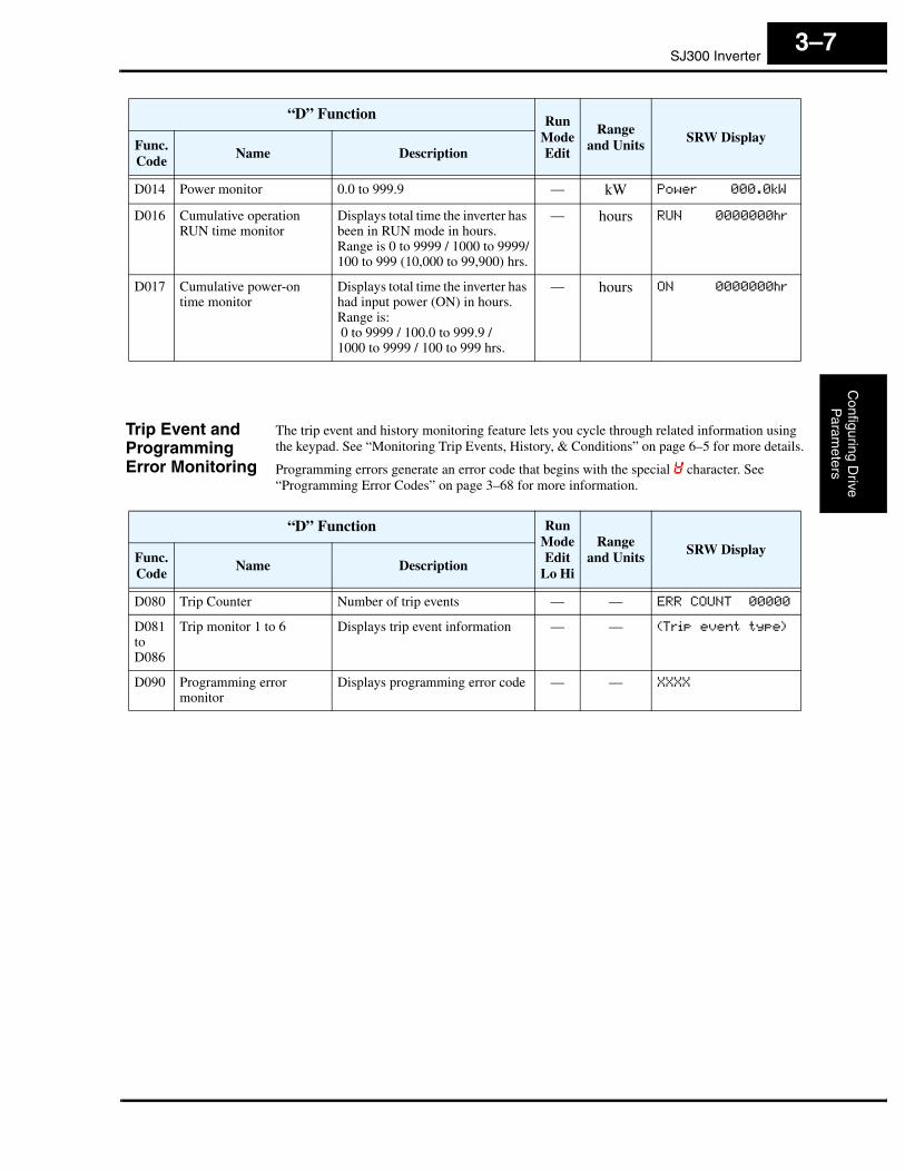
Trip Event and Programming Error Monitoring
The trip event and history monitoring feature lets you cycle through related information using the keypad. See “Monitoring Trip Events, History, & Conditions” on page 6–5 for more details.
Programming errors generate an error code that begins with the special character. See “Programming Error Codes” on page 3–68 for more information.
D014 Power monitor 0.0 to 999.9 — kW Power 000.0kW
D016 Cumulative operation RUN time monitor
Displays total time the inverter has been in RUN mode in hours.Range is 0 to 9999 / 1000 to 9999/100 to 999 (10,000 to 99,900) hrs.
— hours RUN 0000000hr
D017 Cumulative power-on time monitor
Displays total time the inverter has had input power (ON) in hours. Range is: 0 to 9999 / 100.0 to 999.9 / 1000 to 9999 / 100 to 999 hrs.
— hours ON 0000000hr
“D” Function Run ModeEdit
Range and Units
SRW DisplayFunc.Code
Name Description
“D” Function Run ModeEdit
Lo Hi
Range and Units
SRW DisplayFunc.Code
Name Description
D080 Trip Counter Number of trip events — — ERR COUNT 00000
D081toD086
Trip monitor 1 to 6 Displays trip event information — — (Trip event type)
D090 Programming error monitor
Displays programming error code — — XXXX
“F” Group: Main Profile ParametersC
onfig
urin
g D
rive
Par
amet
ers
3–8
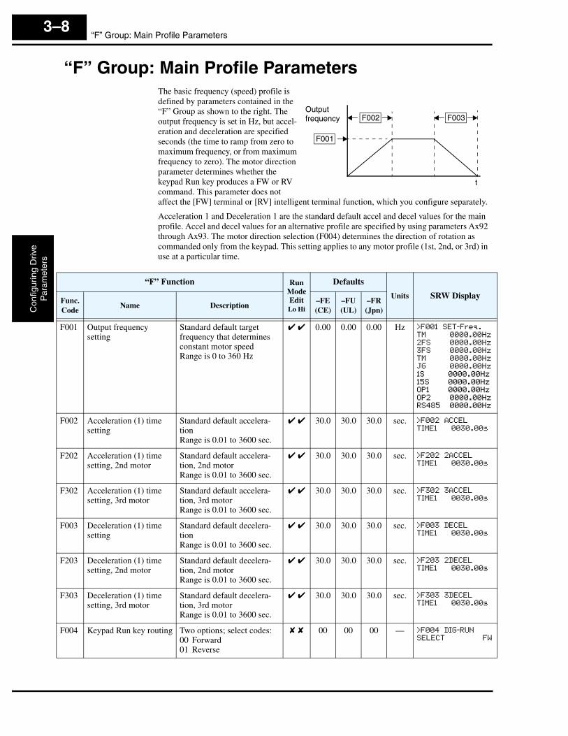
“F” Group: Main Profile ParametersThe basic frequency (speed) profile is defined by parameters contained in the “F” Group as shown to the right. The output frequency is set in Hz, but accel-eration and deceleration are specified seconds (the time to ramp from zero to maximum frequency, or from maximum frequency to zero). The motor direction parameter determines whether the keypad Run key produces a FW or RV command. This parameter does not affect the [FW] terminal or [RV] intelligent terminal function, which you configure separately.
Acceleration 1 and Deceleration 1 are the standard default accel and decel values for the main profile. Accel and decel values for an alternative profile are specified by using parameters Ax92 through Ax93. The motor direction selection (F004) determines the direction of rotation as commanded only from the keypad. This setting applies to any motor profile (1st, 2nd, or 3rd) in use at a particular time.
Outputfrequency
F001
F002 F003
t
“F” Function Run ModeEditLo Hi
Defaults
Units SRW DisplayFunc.Code
Name Description–FE(CE)
–FU(UL)
–FR(Jpn)
F001 Output frequency setting
Standard default target frequency that determines constant motor speedRange is 0 to 360 Hz
✔ ✔ 0.00 0.00 0.00 Hz >F001 SET-Freq.
TM 0000.00Hz
2FS 0000.00Hz
3FS 0000.00Hz
TM 0000.00Hz
JG 0000.00Hz
1S 0000.00Hz
15S 0000.00Hz
OP1 0000.00Hz
OP2 0000.00Hz
RS485 0000.00Hz
F002 Acceleration (1) time setting
Standard default accelera-tionRange is 0.01 to 3600 sec.
✔ ✔ 30.0 30.0 30.0 sec. >F002 ACCEL
TIME1 0030.00s
F202 Acceleration (1) time setting, 2nd motor
Standard default accelera-tion, 2nd motorRange is 0.01 to 3600 sec.
✔ ✔ 30.0 30.0 30.0 sec. >F202 2ACCEL
TIME1 0030.00s
F302 Acceleration (1) time setting, 3rd motor
Standard default accelera-tion, 3rd motorRange is 0.01 to 3600 sec.
✔ ✔ 30.0 30.0 30.0 sec. >F302 3ACCEL
TIME1 0030.00s
F003 Deceleration (1) time setting
Standard default decelera-tionRange is 0.01 to 3600 sec.
✔ ✔ 30.0 30.0 30.0 sec. >F003 DECEL
TIME1 0030.00s
F203 Deceleration (1) time setting, 2nd motor
Standard default decelera-tion, 2nd motorRange is 0.01 to 3600 sec.
✔ ✔ 30.0 30.0 30.0 sec. >F203 2DECEL
TIME1 0030.00s
F303 Deceleration (1) time setting, 3rd motor
Standard default decelera-tion, 3rd motorRange is 0.01 to 3600 sec.
✔ ✔ 30.0 30.0 30.0 sec. >F303 3DECEL
TIME1 0030.00s
F004 Keypad Run key routing Two options; select codes:00 Forward01 Reverse
✘ ✘ 00 00 00 — >F004 DIG-RUN
SELECT FW
SJ300 InverterC
onfiguring Drive
Param
eters
3–9
“A” Group: Standard FunctionsBasic Parameter Settings
These settings affect the most fundamental behavior of the inverter—the outputs to the motor. The frequency of the inverter’s AC output determines the motor speed. You may select from three different sources for the reference speed. During application development you may prefer using the potentiometer, but you may switch to an external source (control terminal setting) in the finished application, for example.
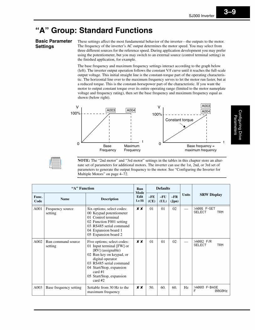
The base frequency and maximum frequency settings interact according to the graph below (left). The inverter output operation follows the constant V/f curve until it reaches the full-scale output voltage. This initial straight line is the constant-torque part of the operating characteris-tic. The horizontal line over to the maximum frequency serves to let the motor run faster, but at a reduced torque. This is the constant-horsepower part of the characteristic. If you want the motor to output constant torque over its entire operating range (limited to the motor nameplate voltage and frequency rating), then set the base frequency and maximum frequency equal as shown (below right).
NOTE: The “2nd motor” and “3rd motor” settings in the tables in this chapter store an alter-nate set of parameters for additional motors. The inverter can use the 1st, 2nd, or 3rd set of parameters to generate the output frequency to the motor. See “Configuring the Inverter for Multiple Motors” on page 4–72.
100%
0
V
Base Frequency
Maximum Frequency
100%
0
V
Base frequency = maximum frequency
Constant torque
A003 A004A003
A004
tt
“A” Function Run ModeEditLo Hi
Defaults
Units SRW DisplayFunc.Code
Name Description–FE(CE)
–FU(UL)
–FR(Jpn)
A001 Frequency source setting
Six options; select codes:00 Keypad potentiometer01 Control terminal02 Function F001 setting03 RS485 serial command04 Expansion board 105 Expansion board 2
✘ ✘ 01 01 02 — >A001 F-SET
SELECT TRM
A002 Run command source setting
Five options; select codes:01 Input terminal [FW] or
[RV] (assignable)02 Run key on keypad, or
digital operator03 RS485 serial command04 Start/Stop, expansion
card #105 Start/Stop, expansion
card #2
✘ ✘ 01 01 02 — >A002 F/R
SELECT TRM
A003 Base frequency setting Settable from 30 Hz to the maximum frequency
✘ ✘ 50. 60. 60. Hz >A003 F-BASE
F 0060Hz

“A” Group: Standard FunctionsC
onfig
urin
g D
rive
Par
amet
ers
3–10
NOTE: The base frequency must be less than or equal to the maximum frequency (ensure that A003 ≤ A004).
A203 Base frequency setting, 2nd motor
Settable from 30 Hz to the maximum frequency
✘ ✘ 50. 60. 60. Hz >A203 2F-BASE
F 0060Hz
A303 Base frequency setting, 3rd motor
Settable from 30 Hz to the maximum frequency
✘ ✘ 50. 60. 60. Hz >A303 3F-BASE
F 0060Hz
A004 Maximum frequency setting
Settable from 30 Hz to400 Hz
✘ ✘ 50. 60. 60. Hz >A004 F-max
F 0060Hz
A204 Maximum frequency setting, 2nd motor
Settable from 30 Hz to400 Hz
✘ ✘ 50. 60. 60. Hz >A204 2F-max
F 0060Hz
A304 Maximum frequency setting, 3rd motor
Settable from 30 Hz to400 Hz
✘ ✘ 50. 60. 60. Hz >A304 3F-max
F 0060Hz
“A” Function Run ModeEditLo Hi
Defaults
Units SRW DisplayFunc.Code
Name Description–FE(CE)
–FU(UL)
–FR(Jpn)

SJ300 InverterC
onfiguring Drive
Param
eters
3–11
Analog Input Settings
The inverter has the capability to accept external analog inputs that can command the output frequency to the motor. Signals including voltage input (0 to +10V) at terminal [O], bipolar input (-10 to +10V) at terminal [O2], and current input (4 to 20mA) at terminal [OI] are avail-able. Terminal [L] serves as signal ground for the three analog inputs. The analog input settings adjust the curve characteristics between the analog input and the frequency output.
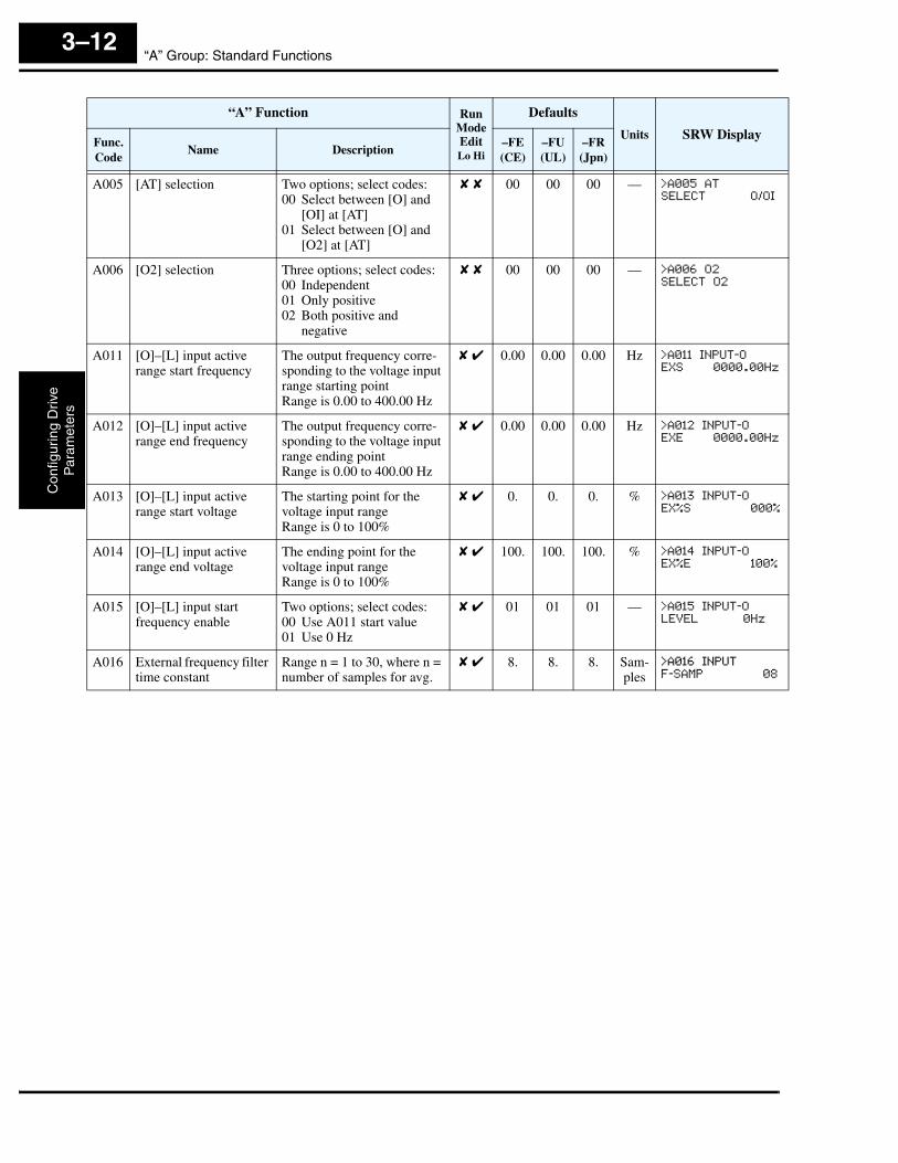
Adjusting [O–L] characteristics – In the graph to the right, A013 and A014 select the active portion of the input voltage range. Parameters A011 and A012 select the start and end frequency of the converted output frequency range, respec-tively. Together, these four parameters define the major line segment as shown. When the line does not begin at the origin (A011 and A013 > 0), then A015 defines whether the inverter outputs 0Hz or the A011-specified frequency when the analog input value is less than the A013 setting. When the input voltage is greater than the A014 ending value, the inverter outputs the ending frequency specified by A012.
Adjusting [OI–L] characteristics – In the graph to the right, A103 and A104 select the active portion of the input current range. Parameters A101 and A102 select the start and end frequency of the converted output frequency range, respec-tively. Together, these four parameters define the major line segment as shown. When the line does not begin at the origin (A101 and A103 > 0), then A105 defines whether the inverter outputs 0Hz or the A101-specified frequency when the analog input value is less than the A103 setting. When the input voltage is greater than the A104 ending value, the inverter outputs the ending frequency specified by A102.
Adjusting [O2–L] characteristics – In the graph to the right, A113 and A144 select the active portion of the input voltage range. Parameters A111 and A112 select the start and end frequency of the converted output frequency range, respectively. Together, these four parame-ters define the major line segment as shown. When the input voltage is less than the A113 input starting value, the inverter outputs the starting frequency specified by A111. When the input voltage is greater than the A114 ending value, the inverter outputs the ending frequency specified by A112.
% input
100%10V
0%0V
fmax. frequency
A013 A014
A012
A011
A015=0
A015=1
% input
100%20mA
0%4mA
A102
fmax. frequency
A101
A103 A104
A105=0
A105=1
% input
+100%+10V
0
A112
f max. fwd frequency
A111
A113
A114
–100%-10V
fmax. rev frequency
“A” Group: Standard FunctionsC
onfig
urin
g D
rive
Par
amet
ers
3–12
“A” Function Run ModeEditLo Hi
Defaults
Units SRW DisplayFunc.Code
Name Description–FE(CE)
–FU(UL)
–FR(Jpn)
A005 [AT] selection Two options; select codes:00 Select between [O] and
[OI] at [AT]01 Select between [O] and
[O2] at [AT]
✘ ✘ 00 00 00 — >A005 AT
SELECT O/OI
A006 [O2] selection Three options; select codes:00 Independent01 Only positive02 Both positive and
negative
✘ ✘ 00 00 00 — >A006 O2
SELECT O2
A011 [O]–[L] input active range start frequency
The output frequency corre-sponding to the voltage input range starting pointRange is 0.00 to 400.00 Hz
✘ ✔ 0.00 0.00 0.00 Hz >A011 INPUT-O
EXS 0000.00Hz
A012 [O]–[L] input active range end frequency
The output frequency corre-sponding to the voltage input range ending pointRange is 0.00 to 400.00 Hz
✘ ✔ 0.00 0.00 0.00 Hz >A012 INPUT-O
EXE 0000.00Hz
A013 [O]–[L] input active range start voltage
The starting point for the voltage input rangeRange is 0 to 100%
✘ ✔ 0. 0. 0. % >A013 INPUT-O
EX%S 000%
A014 [O]–[L] input active range end voltage
The ending point for the voltage input rangeRange is 0 to 100%
✘ ✔ 100. 100. 100. % >A014 INPUT-O
EX%E 100%
A015 [O]–[L] input start frequency enable
Two options; select codes:00 Use A011 start value01 Use 0 Hz
✘ ✔ 01 01 01 — >A015 INPUT-O
LEVEL 0Hz
A016 External frequency filter time constant
Range n = 1 to 30, where n = number of samples for avg.
✘ ✔ 8. 8. 8. Sam-ples
>A016 INPUT
F-SAMP 08

SJ300 InverterC
onfiguring Drive
Param
eters
3–13
Multi-speed and Jog Frequency Settings
The SJ300 inverter has the capability to store and output up to 16 preset frequencies to the motor (A020 to A035). As in traditional motion terminology, we call this multi-speed profile capability. These preset frequencies are selected by means of digital inputs to the inverter. The inverter applies the current acceleration or deceleration setting to change from the current output frequency to the new one. The first multi-speed setting is duplicated for the second motor settings (the remaining 15 multi-speeds apply only to the first motor).
The jog speed setting is used whenever the Jog command is active. The jog speed setting range is arbitrarily limited to 10 Hz to provide safety during manual operation. The acceleration to the jog frequency is instantaneous, but you can choose from six modes for the best method for stopping the jog operation.
“A” Function Run ModeEditLo Hi
Defaults
Units SRW DisplayFunc.Code
Name Description–FE(CE)
–FU(UL)
–FR(Jpn)
A019 Multi-speed operation selection
Two options; select codes:00 Binary; up to 16-stage
speed using 4 intelli-gent terminals
01 Single-bit; up to 8-stage speed using 7 intelligent terminals
✘ ✘ 00 00 00 — >A019 SPEED
SELECT BINARY
A020 Multi-speed frequency setting
Defines the first speed of a multi-speed profile, range is 0 to 360 HzA020 = Speed 1 (1st motor)
✔ ✔ 0.00 0.00 0.00 Hz >A020 SPEED
FS 0000.00Hz
A220 Multi-speed frequency setting, 2nd motor
Defines the first speed of a multi-speed profile for 2nd motor, range is 0 to 360 HzA220 = Speed 1 (2nd motor)
✔ ✔ 0.00 0.00 0.00 Hz >A220 SPEED
2FS 0000.00Hz
A320 Multi-speed frequency setting, 3rd motor
Defines the first speed of a multi-speed profile for 3rd motor, range is 0 to 360 HzA320 = Speed 1 (3rd motor)
✔ ✔ 0.00 0.00 0.00 Hz >A320 SPEED
3FS 0000.00Hz
A021toA035
Multi-speed frequency settings(for both motors)
Defines 15 more speeds,range is 0 to 360 Hz.A021 = Speed 2...A035 = Speed 16
✔ ✔ 0.00 0.00 0.00 Hz >A021 SPEED
01S 0000.00Hz
A038 Jog frequency setting Defines limited speed for jog, range is 0.5 to 9.99 Hz
✔ ✔ 1.00 1.00 1.00 Hz >A038 Jogging
F 01.00Hz
A039 Jog stop mode Define how end of jog stops the motor; six options:00 Free-run stop, jogging
disabled during motor run
01 Controlled deceleration, jogging disabled during motor run
02 DC braking to stop, jogging disabled during motor run
03 Free-run stop, jogging always enabled
04 Controlled deceleration, jogging always enabled
05 DC braking to stop, jogging always enabled
✘ ✔ 00 00 00 — >A039 Jogging
Mode FRS

“A” Group: Standard FunctionsC
onfig
urin
g D
rive
Par
amet
ers
3–14
Torque Control Algorithms
The inverter generates the motor output according to the V/f algorithm or the sensorless vector control algorithm. Param-eter A044 selects the inverter torque control algorithm for generating the frequency output, as shown in the diagram to the right (A244 and A344 for 2nd and 3rd motors, respectively). The factory default is 00 (constant torque V/f control).
Review the following descriptions to help you choose the best torque control algorithm for your application.
• The built-in V/f curves are oriented toward developing constant torque or variable torque characteristics (see graphs below).
• The free-setting curve provides an even more flexible characteristic, but it requires more parameter settings.
• Sensorless vector control calculates an ideal torque vector based on current motor position, winding currents, and so on. It is a more robust control method than the V/f control methods. However, it is more dependent on actual motor parameters and will require you to set these values carefully or to perform the auto-tuning procedure (see “Auto-tuning of Motor Constants” on page 4–67) to obtain optimum performance.
• Sensorless vector control, 0Hz domain increases the low-speed torque performance (0–2.5Hz) via an advanced Hitachi torque control algorithm. However, you will need to size the inverter for one frame size larger than the motor for proper operation.
• Vector control with sensor requires expansion card SJ–FB encoder feedback board and a motor shaft encoder. Choose this method when precise position/velocity control is required.
Constant and Variable Torque – The graph below (left) shows the constant torque character-istic from 0Hz to the base frequency A003. The voltage remains constant for output frequencies higher than the base frequency.
The graph above (right) shows the general characteristic for variable torque. The curve may be best described in three sections, as follows:
a. The range from 0Hz to 10% of the base frequency is the constant torque characteristic. For example, a base frequency of 60Hz ends the constant torque characteristic segment at 6Hz.
b. The range from 10% of the base frequency to the base frequency is the variable (reduced) torque characteristic. The voltage is output in the curve of frequency to the 1.7 power.
Output
V/f control, constant torque
V/f control,variable torque
V/f control, free-setting curve
Inverter Torque Control Algorithms
Sensorless vector (SLV) control
Sensorless vector,0Hz domain
Vector control with sensor
00
05
04
03
02
01
A044
Constant torque
0
Variable torque
0Maximum frequency
Basefrequency
100%100%
Maximum frequency
Basefrequency
Output voltage
Output voltage
10% ofbase
frequency
a. b. c.
SJ300 InverterC
onfiguring Drive
Param
eters
3–15
c. After reaching the base frequency, the characteristic maintains a constant output voltage for higher frequencies.
Using parameter A045 you can modify the voltage gain of the inverter. This is specified as a percentage of the full-scale setting AVR (Automatic Voltage Regulation) in parameter A082. The gain can be set from 20% to 100%. It must be adjusted in accordance with the motor speci-fications.
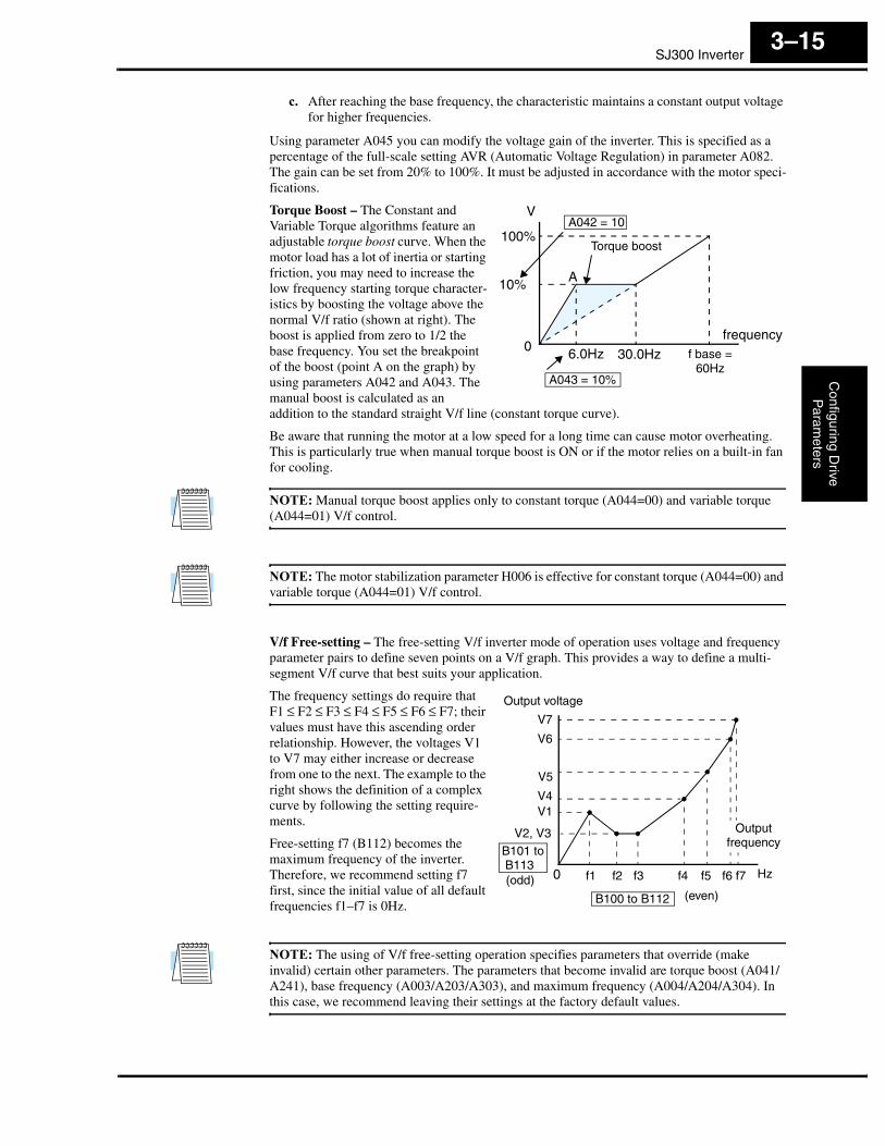
Torque Boost – The Constant and Variable Torque algorithms feature an adjustable torque boost curve. When the motor load has a lot of inertia or starting friction, you may need to increase the low frequency starting torque character-istics by boosting the voltage above the normal V/f ratio (shown at right). The boost is applied from zero to 1/2 the base frequency. You set the breakpoint of the boost (point A on the graph) by using parameters A042 and A043. The manual boost is calculated as an addition to the standard straight V/f line (constant torque curve).
Be aware that running the motor at a low speed for a long time can cause motor overheating. This is particularly true when manual torque boost is ON or if the motor relies on a built-in fan for cooling.
NOTE: Manual torque boost applies only to constant torque (A044=00) and variable torque (A044=01) V/f control.
NOTE: The motor stabilization parameter H006 is effective for constant torque (A044=00) and variable torque (A044=01) V/f control.
V/f Free-setting – The free-setting V/f inverter mode of operation uses voltage and frequency parameter pairs to define seven points on a V/f graph. This provides a way to define a multi-segment V/f curve that best suits your application.
The frequency settings do require that F1 ≤ F2 ≤ F3 ≤ F4 ≤ F5 ≤ F6 ≤ F7; their values must have this ascending order relationship. However, the voltages V1 to V7 may either increase or decrease from one to the next. The example to the right shows the definition of a complex curve by following the setting require-ments.
Free-setting f7 (B112) becomes the maximum frequency of the inverter. Therefore, we recommend setting f7 first, since the initial value of all default frequencies f1–f7 is 0Hz.
NOTE: The using of V/f free-setting operation specifies parameters that override (make invalid) certain other parameters. The parameters that become invalid are torque boost (A041/A241), base frequency (A003/A203/A303), and maximum frequency (A004/A204/A304). In this case, we recommend leaving their settings at the factory default values.
V
f base = 60Hz
100%
frequency6.0Hz0
10%
30.0Hz
Torque boost
A
A042 = 10
A043 = 10%
f10
Output voltage
Outputfrequency
f2 f3 f4 f5 f6 f7
V1
V2, V3
V4
V5
V6
V7
Hz
(even)
B101 to B113(odd)
B100 to B112
“A” Group: Standard FunctionsC
onfig
urin
g D
rive
Par
amet
ers
3–16
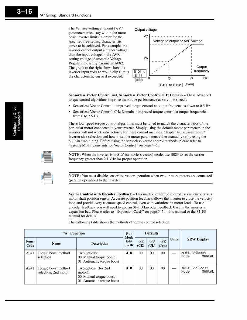
The V/f free-setting endpoint f7/V7 parameters must stay within the more basic inverter limits in order for the specified free-setting characteristic curve to be achieved. For example, the inverter cannot output a higher voltage than the input voltage or the AVR setting voltage (Automatic Voltage Regulation), set by parameter A082. The graph to the right shows how the inverter input voltage would clip (limit) the characteristic curve if exceeded.
Sensorless Vector Control and, Sensorless Vector Control, 0Hz Domain – These advanced torque control algorithms improve the torque performance at very low speeds:
• Sensorless Vector Control – improved torque control at output frequencies down to 0.5 Hz
• Sensorless Vector Control, 0Hz Domain – improved torque control at output frequencies from 0 to 2.5 Hz.
These low-speed torque control algorithms must be tuned to match the characteristics of the particular motor connected to your inverter. Simply using the default motor parameters in the inverter will not work satisfactorily for these control methods. Chapter 4 discusses motor/inverter size selection and how to set the motor parameters either manually or by using the built-in auto-tuning. Before using the sensorless vector control methods, please refer to “Setting Motor Constants for Vector Control” on page 4–65.
NOTE: When the inverter is in SLV (sensorless vector) mode, use B083 to set the carrier frequency greater than 2.1 kHz for proper operation.
NOTE: You must disable sensorless vector operation when two or more motors are connected (parallel operation) to the inverter.
Vector Control with Encoder Feedback – This method of torque control uses an encoder as a motor shaft position sensor. Accurate position feedback allows the inverter to close the velocity loop and provide very accurate speed control, even with variations in motor loads. To use encoder feedback you will need to add an SJ–FB Encoder Feedback Card in the inverter’s expansion bay. Please refer to “Expansion Cards” on page 5–5 in this manual or the SJ–FB manual for details.
The following table shows the methods of torque control selection.
0
Output voltage
Outputfrequency
f6 f7
V6
V7
Hz
(even)
B101 to B113(odd)
Voltage to output or AVR voltage
B100 to B112
“A” Function Run ModeEditLo Hi
Defaults
Units SRW DisplayFunc.Code
Name Description–FE(CE)
–FU(UL)
–FR(Jpn)
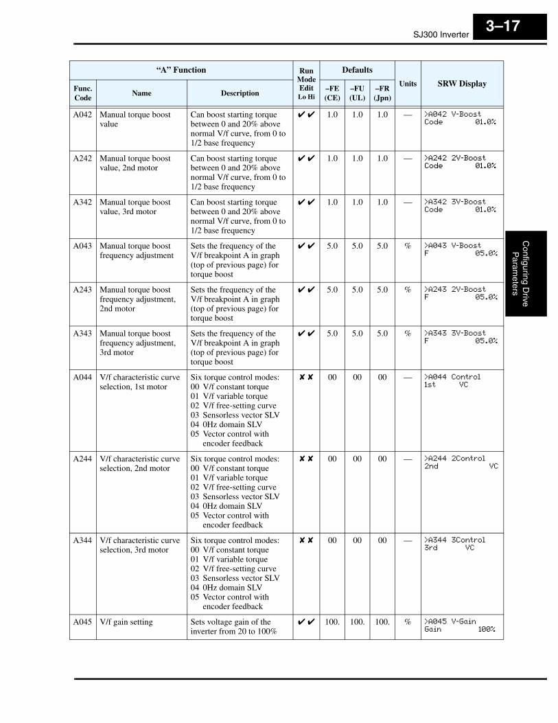
A041 Torque boost method selection
Two options:00 Manual torque boost01 Automatic torque boost
✘ ✘ 00 00 00 — >A041 V-Boost
Mode MANUAL
A241 Torque boost method selection, 2nd motor
Two options (for 2nd motor):00 Manual torque boost01 Automatic torque boost
✘ ✘ 00 00 00 — >A241 2V-Boost
Mode MANUAL
SJ300 InverterC
onfiguring Drive
Param
eters
3–17
A042 Manual torque boost value
Can boost starting torque between 0 and 20% above normal V/f curve, from 0 to1/2 base frequency
✔ ✔ 1.0 1.0 1.0 — >A042 V-Boost
Code 01.0%
A242 Manual torque boost value, 2nd motor
Can boost starting torque between 0 and 20% above normal V/f curve, from 0 to1/2 base frequency
✔ ✔ 1.0 1.0 1.0 — >A242 2V-Boost
Code 01.0%
A342 Manual torque boost value, 3rd motor
Can boost starting torque between 0 and 20% above normal V/f curve, from 0 to1/2 base frequency
✔ ✔ 1.0 1.0 1.0 — >A342 3V-Boost
Code 01.0%
A043 Manual torque boost frequency adjustment
Sets the frequency of theV/f breakpoint A in graph (top of previous page) for torque boost
✔ ✔ 5.0 5.0 5.0 % >A043 V-Boost
F 05.0%
A243 Manual torque boost frequency adjustment, 2nd motor
Sets the frequency of theV/f breakpoint A in graph (top of previous page) for torque boost
✔ ✔ 5.0 5.0 5.0 % >A243 2V-Boost
F 05.0%
A343 Manual torque boost frequency adjustment, 3rd motor
Sets the frequency of theV/f breakpoint A in graph (top of previous page) for torque boost
✔ ✔ 5.0 5.0 5.0 % >A343 3V-Boost
F 05.0%
A044 V/f characteristic curve selection, 1st motor
Six torque control modes:00 V/f constant torque01 V/f variable torque02 V/f free-setting curve03 Sensorless vector SLV04 0Hz domain SLV05 Vector control with
encoder feedback
✘ ✘ 00 00 00 — >A044 Control
1st VC
A244 V/f characteristic curve selection, 2nd motor
Six torque control modes:00 V/f constant torque01 V/f variable torque02 V/f free-setting curve03 Sensorless vector SLV04 0Hz domain SLV05 Vector control with
encoder feedback
✘ ✘ 00 00 00 — >A244 2Control
2nd VC
A344 V/f characteristic curve selection, 3rd motor
Six torque control modes:00 V/f constant torque01 V/f variable torque02 V/f free-setting curve03 Sensorless vector SLV04 0Hz domain SLV05 Vector control with
encoder feedback
✘ ✘ 00 00 00 — >A344 3Control
3rd VC
A045 V/f gain setting Sets voltage gain of the inverter from 20 to 100%
✔ ✔ 100. 100. 100. % >A045 V-Gain
Gain 100%
“A” Function Run ModeEditLo Hi
Defaults
Units SRW DisplayFunc.Code
Name Description–FE(CE)
–FU(UL)
–FR(Jpn)

“A” Group: Standard FunctionsC
onfig
urin
g D
rive
Par
amet
ers
3–18
DC Braking Settings
The DC braking feature can provide additional stopping torque when compared to a normal deceleration to a stop. It can also ensure the motor and load are stopped before acceleration.
When decelerating – DC braking is particularly useful at low speeds when normal deceleration torque is minimal. During deceleration, the inverter injects a DC voltage into the motor windings during deceleration below a frequency you can specify (A052). The braking power (A054) and duration (A055) can both be set. You can optionally specify a wait time before DC braking (A053), during which the motor will free run (coast).
When starting – You can also apply DC braking upon the application of a Run command, specifying both the DC braking force level (A057) and the duration (A058). This will serve to stop the rotation of the motor and the load, when the load is capable of driving the motor. This effect, sometimes called “windmilling,” is common in fan appli-cations. Often, air moving in duct work will drive the fan in a backward direc-tion. If an inverter is started into such a backward-rotating load, over-current trips can occur. Use DC braking as an “anti-windmilling” technique to stop the motor and load, and allow a normal acceleration from a stop. See also the “Acceleration Pause Function” on page 3–21.
You can configure the inverter to apply DC braking at stopping only, at starting only, or both. DC braking power (0–100%) can be set separately for stopping and starting cases.
You can configure DC braking to initiate in one of two ways:
1. Internal DC braking – Set A051=01 to enable internal braking. The inverter automatically applies DC braking as configured (during stopping, starting, or both).
2. External DC braking – Configure an input terminal with option code 7 [DB] (see “Exter-nal Signal for DC Braking” on page 4–17 for more details). Leave A051=00, although this setting is ignored when a [DB] input is configured. The DC braking force settings (A054 and A057) still apply. However, the braking time settings (A055 and A058) do not apply (see level and edge triggered descriptions below). Use A056 to select level or edge detection for the external input.
a. Level triggered – When the [DB] input signal is ON, the inverter immediately applies DC injection braking, whether the inverter is in Run Mode or Stop Mode. You control DC braking time by the duration of the [DB] pulse.
b. Edge triggered – When the [DB] input transitions OFF-to-ON and the inverter is in Run Mode, it will apply DC braking only until the motor stops... then DC braking is OFF. During Stop Mode, the inverter ignores OFF-to-ON transitions. Therefore, do not use edge triggered operation when you need DC braking before acceleration.
CAUTION: Be careful to avoid specifying a braking time that is long enough to cause motor overheating. If you use DC braking, we recommend using a motor with a built-in thermistor and wiring it to the inverter’s thermistor input (see “Thermistor Thermal Protection” on page 4–28). Also refer to the motor manufacturer’s specifications for duty-cycle recommendations during DC braking.
DC brakingFree runRunning+
–
0
Outputvoltage
A053 A055
A054
t
DC braking Running+
–
0
Outputvoltage
A058
A057
t
SJ300 InverterC
onfiguring Drive
Param
eters
3–19
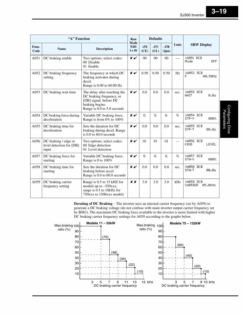
Derating of DC Braking – The inverter uses an internal carrier frequency (set by A059) to generate a DC braking voltage (do not confuse with main inverter output carrier frequency set by B083). The maximum DC braking force available to the inverter is more limited with higher DC braking carrier frequency settings for A059 according to the graphs below.
“A” Function Run ModeEditLo Hi
Defaults
Units SRW DisplayFunc.Code
Name Description–FE(CE)
–FU(UL)
–FR(Jpn)
A051 DC braking enable Two options; select codes:00 Disable01 Enable
✘ ✔ 00 00 00 — >A051 DCB
Mode OFF
A052 DC braking frequency setting
The frequency at which DC braking activates during decel.Range is 0.00 to 60.00 Hz
✘ ✔ 0.50 0.50 0.50 Hz >A052 DCB
F 00.50Hz
A053 DC braking wait time The delay after reaching the DC braking frequency, or [DB] signal, before DC braking begins.Range is 0.0 to 5.0 seconds
✘ ✔ 0.0 0.0 0.0 sec. >A053 DCB
WAIT 0.0s
A054 DC braking force during deceleration
Variable DC braking force. Range is from 0% to 100%
✘ ✔ 0. 0. 0. % >A054 DCB
STP-V 000%
A055 DC braking time for deceleration
Sets the duration for DC braking during decel. Range is 0.0 to 60.0 seconds
✘ ✔ 0.0 0.0 0.0 sec. >A055 DCB
STP-T 00.0s
A056 DC braking / edge or level detection for [DB] input
Two options; select codes:00 Edge detection01 Level detection
✘ ✔ 01 01 01 — >A056 DCB
KIND LEVEL
A057 DC braking force for starting
Variable DC braking force. Range is 0 to 100%
✘ ✔ 0. 0. 0. % >A057 DCB
STA-V 000%
A058 DC braking time for starting
Sets the duration for DC braking before accel.Range is 0.0 to 60.0 seconds
✘ ✔ 0.0 0.0 0.0 sec. >A058 DCB
STA-T 00.0s
A059 DC braking carrier frequency setting
Range is 0.5 to 15 kHZ for models up to –550xxx,range is 0.5 to 10kHz for 750xxx to 1500xxx models
✘ ✘ 3.0 3.0 3.0 kHz >A059 DCB
CARRIER 05.0kHz
Max.braking ratio (%)
10
20
30
40
50
60
70
3 5 7 9 11 13DC braking carrier frequency
10
20
30
40
50
60
70
3 5 7 9
(10)
(22)
(34)
(46)
Max.brakingratio (%)
DC braking carrier frequency
(10)
(20)
(40)
Models 75 – 132kWModels 11 – 55kW
80
90
100
80
90
100
15
(75)
kHz10
(60)
kHz

“A” Group: Standard FunctionsC
onfig
urin
g D
rive
Par
amet
ers
3–20
Frequency-related Functions
Frequency Limits – Upper and lower limits can be imposed on the inverter output frequency. These limits will apply regardless of the source of the speed reference. You can configure the lower frequency limit to be greater than zero as shown in the graph to the right. The upper limit must not exceed the rating of the motor or capability of the machinery.
Jump Frequencies – Some motors or machines exhibit resonances at particular speed(s), which can be destructive for prolonged running at those speeds. The inverter has up to three jump frequencies as shown in the graph. The hysteresis around the jump frequencies causes the inverter output to skip around the sensitive frequency values.
Output frequencyUpperlimit
Frequency command
Lowerlimit
Settablerange
A061
A062
“A” Function Run ModeEditLo Hi
Defaults
Units SRW DisplayFunc.Code
Name Description–FE(CE)
–FU(UL)
–FR(Jpn)
A061 Frequency upper limit setting
Sets a limit on output frequency less than the maximum frequency (A004) Range is 0.50 to 400.0 Hz0.00 setting is disabled>0.10 setting is enabled
✘ ✔ 0.00 0.00 0.00 Hz >A061 LIMIT
HIGH 0000.00Hz
A261 Frequency upper limit setting, 2nd motor
Sets a limit on output frequency less than the maximum frequency (A004) Range is 0.50 to 400.0 Hz0.00 setting is disabled>0.10 setting is enabled
✘ ✔ 0.00 0.00 0.00 Hz >A261 2LIMIT
HIGH 0000.00Hz
A062 Frequency lower limit setting
Sets a limit on output frequency greater than zero Range is 0.50 to 400.0 Hz0.00 setting is disabled>0.1 setting is enabled
✘ ✔ 0.00 0.00 0.00 Hz >A062 LIMIT
LOW 0000.00Hz
A262 Frequency lower limit setting, 2nd motor
Sets a limit on output frequency greater than zero Range is 0.50 to 400.0 Hz0.00 setting is disabled>0.10 setting is enabled
✘ ✔ 0.00 0.00 0.00 Hz >A262 2LIMIT
LOW 0000.00Hz
Frequency command
Jump frequencies
Outputfrequency
Hysteresis values
A067
A065
A063A064
A064
A066
A066
A068
A068

SJ300 InverterC
onfiguring Drive
Param
eters
3–21
Acceleration Pause Function
The acceleration pause function can be used to minimize the occurrence of over-current trips when accelerating high inertia loads. It introduces a dwell or pause in the acceleration ramp. You can control the frequency at which this dwell occurs (A069), and the duration of the pause time (A070). This function can also be used as an anti-windmilling tool, when the load might have a tendency to drive the motor in a reverse direction while the inverter is in a Stop mode. Initiating a normal acceleration in such a situa-tion may result in over-current trips. This function can be used to keep the inverter output frequency and voltage at low levels long enough to bring the load to a stop, and commence turning in the desired direction before the acceleration ramp resumes. See also “DC Braking Settings” on page 3–18.
“A” Function Run ModeEditLo Hi
Defaults
Units SRW DisplayFunc.Code
Name Description–FE(CE)
–FU(UL)
–FR(Jpn)
A063A065A067
Jump (center) frequency setting
Up to 3 output frequencies can be defined for the output to jump past to avoid motor resonances (center frequency)Range is 0.00 to 400.0 Hz
✘ ✔ 0.00 0.00 0.00 Hz >A063 JUMP
F1 0000.00Hz
>A065 JUMP
F2 0000.00Hz
>A067 JUMP
F3 0000.00Hz
A064A066A068
Jump (hysteresis) frequency width setting
Defines the distance from the center frequency at which the jump occursRange is 0.0 to 10.0 Hz
✘ ✔ 0.50 0.50 0.50 Hz >A064 JUMP
W1 00.50Hz
>A066 JUMP
W2 00.50Hz
>A068 JUMP
W3 00.50Hz
Accel pause period
0
Outputfrequency
A070
A069
Set frequency
t
“A” Function Run ModeEditLo Hi
Defaults
Units SRW DisplayFunc.Code
Name Description–FE(CE)
–FU(UL)
–FR(Jpn)
A069 Acceleration pause frequency setting
Range is 0.00 to 400.0Hz ✘ ✔ 0.00 0.00 0.00 Hz >A069 F-STOP
F 0000.00H
A070 Acceleration pause time setting
Range is 0.0 to 60.0 sec. ✘ ✔ 0.0 0.0 0.0 sec. >A070 F-STOP
T 00.0s
“A” Group: Standard FunctionsC
onfig
urin
g D
rive
Par
amet
ers
3–22
PID Control When enabled, the built-in PID loop calculates an ideal inverter output value to cause a loop feedback process variable (PV) to move closer in value to the setpoint (SP). The current frequency command serves as the SP. The PID loop algorithm will read the analog input for the process variable (you specify either current or voltage input) and calculate the output.
• A scale factor in A075 lets you multiply the PV by a factor, converting it into engineering units for the process.
• Proportional, integral, and derivative gains are all adjustable.
• Optional – You can assign an intelligent input terminal the option code 23, PID Disable. When active, this input disables PID operation. See “Intelligent Input Terminal Overview” on page 3–49.
• See “PID Loop Operation” on page 4–71 for more information.
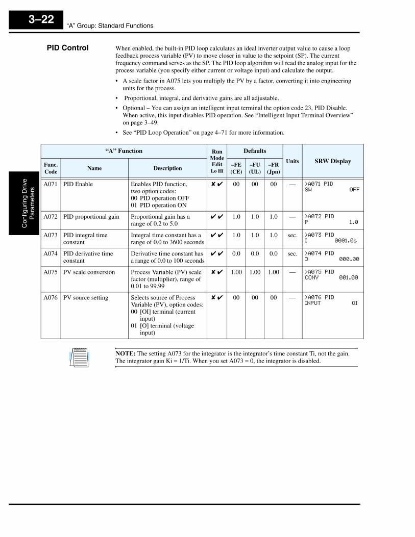
NOTE: The setting A073 for the integrator is the integrator’s time constant Ti, not the gain. The integrator gain Ki = 1/Ti. When you set A073 = 0, the integrator is disabled.
“A” Function Run ModeEditLo Hi
Defaults
Units SRW DisplayFunc.Code
Name Description–FE(CE)
–FU(UL)
–FR(Jpn)
A071 PID Enable Enables PID function,two option codes:00 PID operation OFF01 PID operation ON
✘ ✔ 00 00 00 — >A071 PID
SW OFF
A072 PID proportional gain Proportional gain has a range of 0.2 to 5.0
✔ ✔ 1.0 1.0 1.0 — >A072 PID
P 1.0
A073 PID integral time constant
Integral time constant has a range of 0.0 to 3600 seconds
✔ ✔ 1.0 1.0 1.0 sec. >A073 PID
I 0001.0s
A074 PID derivative time constant
Derivative time constant has a range of 0.0 to 100 seconds
✔ ✔ 0.0 0.0 0.0 sec. >A074 PID
D 000.00
A075 PV scale conversion Process Variable (PV) scale factor (multiplier), range of0.01 to 99.99
✘ ✔ 1.00 1.00 1.00 — >A075 PID
CONV 001.00
A076 PV source setting Selects source of Process Variable (PV), option codes:00 [OI] terminal (current
input)01 [O] terminal (voltage
input)
✘ ✔ 00 00 00 — >A076 PID
INPUT OI
SJ300 InverterC
onfiguring Drive
Param
eters
3–23
Automatic VoltageRegulation (AVR) Function
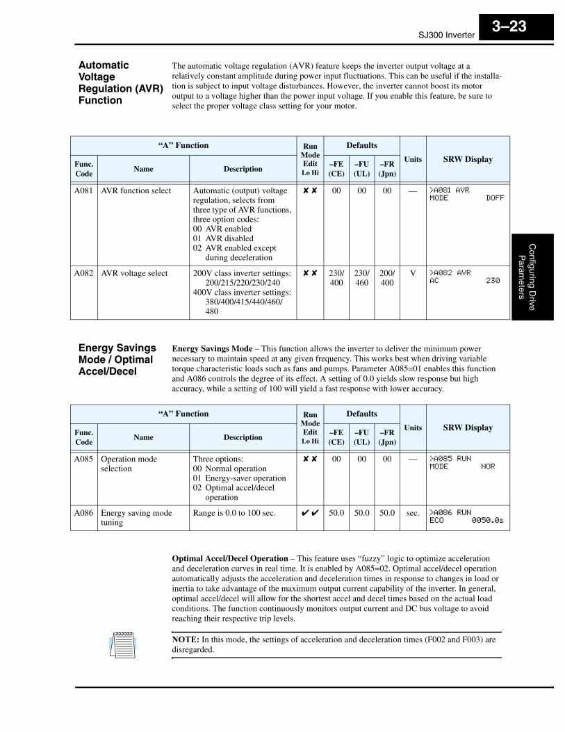
The automatic voltage regulation (AVR) feature keeps the inverter output voltage at a relatively constant amplitude during power input fluctuations. This can be useful if the installa-tion is subject to input voltage disturbances. However, the inverter cannot boost its motor output to a voltage higher than the power input voltage. If you enable this feature, be sure to select the proper voltage class setting for your motor.
Energy Savings Mode / Optimal Accel/Decel
Energy Savings Mode – This function allows the inverter to deliver the minimum power necessary to maintain speed at any given frequency. This works best when driving variable torque characteristic loads such as fans and pumps. Parameter A085=01 enables this function and A086 controls the degree of its effect. A setting of 0.0 yields slow response but high accuracy, while a setting of 100 will yield a fast response with lower accuracy.
Optimal Accel/Decel Operation – This feature uses “fuzzy” logic to optimize acceleration and deceleration curves in real time. It is enabled by A085=02. Optimal accel/decel operation automatically adjusts the acceleration and deceleration times in response to changes in load or inertia to take advantage of the maximum output current capability of the inverter. In general, optimal accel/decel will allow for the shortest accel and decel times based on the actual load conditions. The function continuously monitors output current and DC bus voltage to avoid reaching their respective trip levels.
NOTE: In this mode, the settings of acceleration and deceleration times (F002 and F003) are disregarded.
“A” Function Run ModeEditLo Hi
Defaults
Units SRW DisplayFunc.Code
Name Description–FE(CE)
–FU(UL)
–FR(Jpn)
A081 AVR function select Automatic (output) voltage regulation, selects from three type of AVR functions, three option codes:00 AVR enabled01 AVR disabled02 AVR enabled except
during deceleration
✘ ✘ 00 00 00 — >A081 AVR
MODE DOFF
A082 AVR voltage select 200V class inverter settings:200/215/220/230/240
400V class inverter settings:380/400/415/440/460/480
✘ ✘ 230/400
230/460
200/400
V >A082 AVR
AC 230
“A” Function Run ModeEditLo Hi
Defaults
Units SRW DisplayFunc.Code
Name Description–FE(CE)
–FU(UL)
–FR(Jpn)
A085 Operation modeselection
Three options:00 Normal operation01 Energy-saver operation02 Optimal accel/decel
operation
✘ ✘ 00 00 00 — >A085 RUN
MODE NOR
A086 Energy saving mode tuning
Range is 0.0 to 100 sec. ✔ ✔ 50.0 50.0 50.0 sec. >A086 RUN
ECO 0050.0s

“A” Group: Standard FunctionsC
onfig
urin
g D
rive
Par
amet
ers
3–24
Optimal Accel/Decel Operation, continued...
The acceleration time is controlled to maintain output current below the level set by the Overload Restriction Function if enabled (Parameters B021/B024, B022/B025, and B023/B026). If Overload Restriction is not enabled, then the current limit used is 150% of the inverter’s rated output current.
The deceleration time is controlled so that the output current is maintained below 150% of the inverter’s rated current, and the DC bus voltage is maintained below the OV Trip level (358V or 770V).
NOTE: DO NOT use Optimal Accel/Decel (A085 = 02) when an application...• has a requirement for constant acceleration or deceleration• has a load inertia more than (approx.) 20 times the motor inertia• uses internal or external regenerative braking• uses any of the vector control modes (A044 = 03, 04, or 05). This function is ONLY compatible with V/F control.
NOTE: If the load exceeds the rating of the inverter, the acceleration time may be increased.
NOTE: If using a motor with a capacity that is one size smaller than the inverter rating, enable the Overload Restriction function (B021/B024) and set the Overload Restriction Level (B022/B025) to 1.5 times the motor nameplate current.
NOTE: Be aware that the acceleration and deceleration times will vary, depending on the actual load conditions during each individual operation of the inverter.
SecondAcceleration and Deceleration Functions
The SJ300 inverter features two-stage acceleration and deceleration ramps. This gives flexibil-ity in the profile shape. You can specify the frequency transition point, the point at which the standard acceleration (F002) or deceleration (F003) changes to the second acceleration (A092) or deceleration (A093). These profile options are also available for the second motor settings and third motor settings. All acceleration and deceleration times are time to ramp from zero speed to full speed or full speed to zero speed. Select a transition method via A094 as depicted below. Be careful not to confuse the second acceleration/deceleration settings with settings for the second motor!
Accel 1
0
Accel 2
frequency
10
2CH input
frequency
Accel 1
Accel 2
Frequencytransition pointA095
A094=00 A094=01
t
t
SJ300 InverterC
onfiguring Drive
Param
eters
3–25
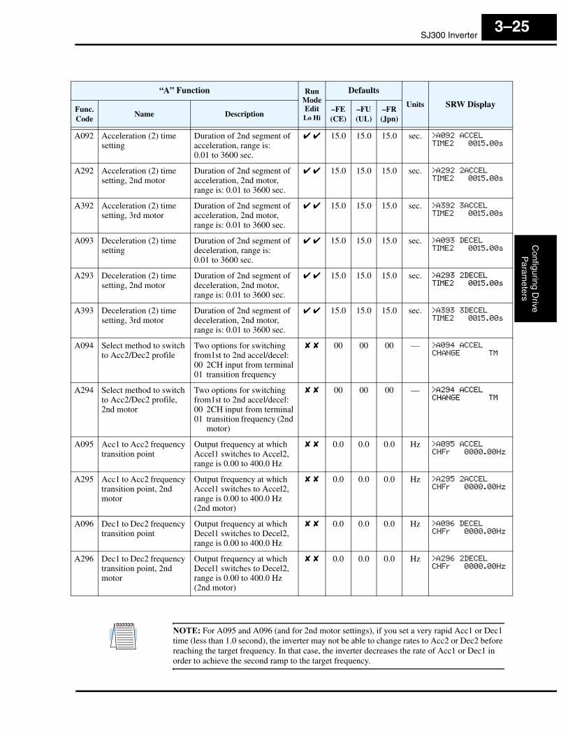
NOTE: For A095 and A096 (and for 2nd motor settings), if you set a very rapid Acc1 or Dec1 time (less than 1.0 second), the inverter may not be able to change rates to Acc2 or Dec2 before reaching the target frequency. In that case, the inverter decreases the rate of Acc1 or Dec1 in order to achieve the second ramp to the target frequency.
“A” Function Run ModeEditLo Hi
Defaults
Units SRW DisplayFunc.Code
Name Description–FE(CE)
–FU(UL)
–FR(Jpn)
A092 Acceleration (2) time setting
Duration of 2nd segment of acceleration, range is:0.01 to 3600 sec.
✔ ✔ 15.0 15.0 15.0 sec. >A092 ACCEL
TIME2 0015.00s
A292 Acceleration (2) time setting, 2nd motor
Duration of 2nd segment of acceleration, 2nd motor,range is: 0.01 to 3600 sec.
✔ ✔ 15.0 15.0 15.0 sec. >A292 2ACCEL
TIME2 0015.00s
A392 Acceleration (2) time setting, 3rd motor
Duration of 2nd segment of acceleration, 2nd motor,range is: 0.01 to 3600 sec.
✔ ✔ 15.0 15.0 15.0 sec. >A392 3ACCEL
TIME2 0015.00s
A093 Deceleration (2) time setting
Duration of 2nd segment of deceleration, range is:0.01 to 3600 sec.
✔ ✔ 15.0 15.0 15.0 sec. >A093 DECEL
TIME2 0015.00s
A293 Deceleration (2) time setting, 2nd motor
Duration of 2nd segment of deceleration, 2nd motor,range is: 0.01 to 3600 sec.
✔ ✔ 15.0 15.0 15.0 sec. >A293 2DECEL
TIME2 0015.00s
A393 Deceleration (2) time setting, 3rd motor
Duration of 2nd segment of deceleration, 2nd motor,range is: 0.01 to 3600 sec.
✔ ✔ 15.0 15.0 15.0 sec. >A393 3DECEL
TIME2 0015.00s
A094 Select method to switch to Acc2/Dec2 profile
Two options for switching from1st to 2nd accel/decel:00 2CH input from terminal01 transition frequency
✘ ✘ 00 00 00 — >A094 ACCEL
CHANGE TM
A294 Select method to switch to Acc2/Dec2 profile, 2nd motor
Two options for switching from1st to 2nd accel/decel:00 2CH input from terminal01 transition frequency (2nd
motor)
✘ ✘ 00 00 00 — >A294 ACCEL
CHANGE TM
A095 Acc1 to Acc2 frequency transition point
Output frequency at which Accel1 switches to Accel2, range is 0.00 to 400.0 Hz
✘ ✘ 0.0 0.0 0.0 Hz >A095 ACCEL
CHFr 0000.00Hz
A295 Acc1 to Acc2 frequency transition point, 2nd motor
Output frequency at which Accel1 switches to Accel2, range is 0.00 to 400.0 Hz (2nd motor)
✘ ✘ 0.0 0.0 0.0 Hz >A295 2ACCEL
CHFr 0000.00Hz
A096 Dec1 to Dec2 frequency transition point
Output frequency at which Decel1 switches to Decel2, range is 0.00 to 400.0 Hz
✘ ✘ 0.0 0.0 0.0 Hz >A096 DECEL
CHFr 0000.00Hz
A296 Dec1 to Dec2 frequency transition point, 2nd motor
Output frequency at which Decel1 switches to Decel2, range is 0.00 to 400.0 Hz(2nd motor)
✘ ✘ 0.0 0.0 0.0 Hz >A296 2DECEL
CHFr 0000.00Hz

“A” Group: Standard FunctionsC
onfig
urin
g D
rive
Par
amet
ers
3–26
Accel/Decel Characteristics
Standard (default) acceleration and deceleration is linear with time. The inverter CPU can also calculate other curves shown in the graphs below. The sigmoid, U-shape, and reverse U-shape curves are useful for favoring the load characteristics in particular applications. Curve settings for acceleration and deceleration are independently selected via parameters A097 and A098, respectively. You can use the same or different curve types for acceleration and deceleration.
time
Output frequency
time
Output frequency
time
Output frequency
time
Output frequency
time
Output frequency
time
Output frequency
time
Output frequency
time
Output frequency
Linear Sigmoid U-shape Reverse U-shape
Accel
A97
Decel
A98
00Set valueCurve
01 02 03
Linear acceleration and deceleration for general-purpose use
Avoid jerk on start/stop for elevators; use for delicate loads on con-veyors
Tension control for winding applications, web presses, roller/accumulatorsTypical
applications
“A” Function Run ModeEditLo Hi
Defaults
Units SRW DisplayFunc.Code
Name Description–FE(CE)
–FU(UL)
–FR(Jpn)
A097 Acceleration curve selection
Set the characteristic curve of Accel1 and Accel2, four options:00 Linear01 S-curve02 U-shape03 Reverse U-shape
✘ ✘ 00 00 00 — >A097 ACCEL
LINE Linear
A098 Deceleration curve selection
Set the characteristic curve of Decel1 and Decel2, four options:00 Linear01 S-curve02 U-shape03 Reverse U-shape
✘ ✘ 00 00 00 — >A098 DECEL
LINE Linear
SJ300 InverterC
onfiguring Drive
Param
eters
3–27
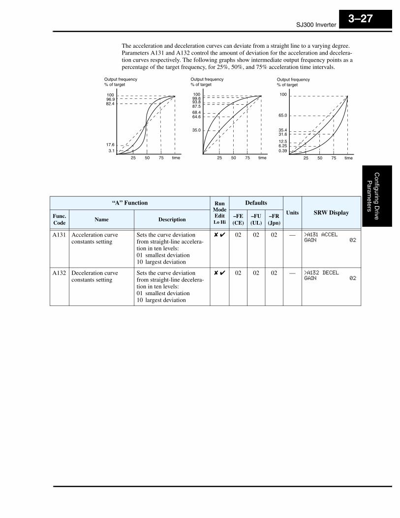
The acceleration and deceleration curves can deviate from a straight line to a varying degree. Parameters A131 and A132 control the amount of deviation for the acceleration and decelera-tion curves respectively. The following graphs show intermediate output frequency points as a percentage of the target frequency, for 25%, 50%, and 75% acceleration time intervals.
time
Output frequency
25 50 75
% of target
time
Output frequency
25 50 75
% of target
time
Output frequency
25 50 75
% of target
3.117.6
82.496.9100 100 100
99.693.887.568.464.6
35.0
65.0
35.431.6
12.56.250.39
“A” Function Run ModeEditLo Hi
Defaults
Units SRW DisplayFunc.Code
Name Description–FE(CE)
–FU(UL)
–FR(Jpn)
A131 Acceleration curve constants setting
Sets the curve deviation from straight-line accelera-tion in ten levels:01 smallest deviation10 largest deviation
✘ ✔ 02 02 02 — >A131 ACCEL
GAIN 02
A132 Deceleration curve constants setting
Sets the curve deviation from straight-line decelera-tion in ten levels:01 smallest deviation10 largest deviation
✘ ✔ 02 02 02 — >A132 DECEL
GAIN 02

“A” Group: Standard FunctionsC
onfig
urin
g D
rive
Par
amet
ers
3–28
Additional Analog Input Settings
The parameters in the following table adjust the input characteristics of the analog inputs. When using the inputs to command the inverter output frequency, these parameters adjust the starting and ending ranges for the voltage or current, as well as the output frequency range. Related characteristic diagrams are located in “Analog Input Settings” on page 3–11.
“A” Function Run ModeEditLo Hi
Defaults
Units SRW DisplayFunc.Code
Name Description–FE(CE)
–FU(UL)
–FR(Jpn)
A101 [OI]–[L] input active range start frequency
The output frequency corre-sponding to the current input range starting point.Range is 0.00 to 400.0 Hz
✘ ✔ 00.0 00.0 00.0 Hz >A101 INPUT-OI
EXS 0000.00Hz
A102 [OI]–[L] input active range end frequency
The output frequency corre-sponding to the current input range ending point.Range is 0.00 to 400.0 Hz
✘ ✔ 00.0 00.0 00.0 Hz >A102 INPUT-OI
EXE 0000.00Hz
A103 [OI]–[L] input active range start current
The starting point for the current input range.Range is 0 to 100%
✘ ✔ 20. 20. 20. % >A103 INPUT-OI
EX%S 020%
A104 [OI]–[L] input active range end current
The ending point for the current input range.Range is 0 to 100%
✘ ✔ 100. 100. 100. % >A104 INPUT-OI
EX%E 100%
A105 [OI]–[L] input start frequency enable
Two options:00 Use A101 start value01 Use 0Hz
✘ ✔ 01 01 01 Hz >A105 INPUT-OI
LEVEL 0Hz
A111 [O2]–[L] input active range start frequency
The output frequency corre-sponding to the bipolar voltage input range starting point.Range is –400. to 400. Hz
✘ ✔ 0.00 0.00 0.00 Hz >A111 INPUT-O2
EXS +000.00Hz
A112 [O2]–[L] input active range end frequency
The output frequency corre-sponding to the bipolar voltage input range ending point.Range is –400. to 400. Hz
✘ ✔ 0.00 0.00 0.00 Hz >A112 INPUT-O2
EXE +000.00Hz
A113 [O2]–[L] input active range start voltage
The starting point for the bipolar voltage input range. Range is –100 to 100%
✘ ✔ -100. -100. -100. % >A113 INPUT-O2
EX%S -100%
A114 [O2]–[L] input active range end voltage
The ending point for the bipolar voltage input range. Range is –100 to 100%
✘ ✔ 100. 100. 100. % >A114 INPUT-O2
EX%E +100%

SJ300 InverterC
onfiguring Drive
Param
eters
3–29
“B” Group: Fine-Tuning FunctionsThe “B” Group of functions and parameters adjust some of the more subtle but useful aspects of motor control and system configuration.
Automatic Restart Mode and Phase Loss
The restart mode determines how the inverter will resume operation after a fault causes a trip event. The four options provide advantages for various situations. Frequency matching allows the inverter to read the motor speed by virtue of its residual magnetic flux and restart the output at the corresponding frequency. The inverter can attempt a restart a certain number of times depending on the particular trip event:
• Over-current trip, restart up to 3 times
• Over-voltage trip, restart up to 3 times
• Under-voltage trip, restart up to 16 times
When the inverter reaches the maximum number of restarts (3 or 16), you must power-cycle the inverter to reset its operation.
Other parameters specify the allowable under-voltage level and the delay time before restarting. The proper settings depend on the typical fault conditions for your application, the necessity of restarting the process in unattended situations, and whether restarting is always safe.
Input power
Motor speed
Power failure
Inverteroutput
Power failure > allowable power fail time (B002), inverter trips
Input power
Motor speed
Inverteroutput
Power failure < allowable power fail time (B002), inverter resumes
Power failure
Retry wait time
Allowablepower fail time
Allowablepower fail time
free-runningfree-running
B002
B003
B002
t t0 0
“B” Function Run ModeEditLo Hi
Defaults
Units SRW DisplayFunc.Code
Name Description–FE(CE)
–FU(UL)
–FR(Jpn)
B001 Selection of automatic restart mode
Select inverter restart method, four option codes:00 Alarm output after trip,
automatic restart disabled
01 Restart at 0Hz02 Resume operation after
frequency matching03 Resume previous freq.
after freq. matching, then decelerate to stop and display trip info
✘ ✔ 00 00 00 — >b001 IPS
POWER ALM
“B” Group: Fine-Tuning FunctionsC
onfig
urin
g D
rive
Par
amet
ers
3–30
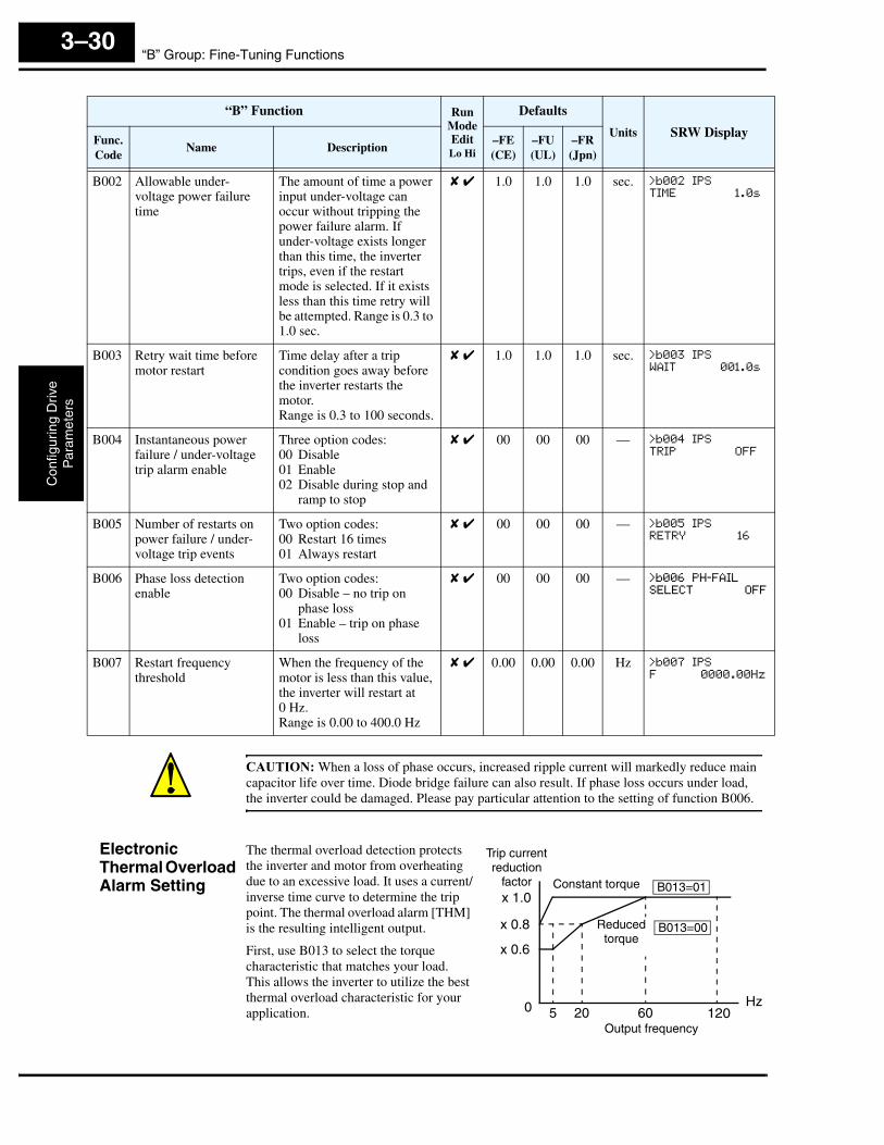
CAUTION: When a loss of phase occurs, increased ripple current will markedly reduce main capacitor life over time. Diode bridge failure can also result. If phase loss occurs under load, the inverter could be damaged. Please pay particular attention to the setting of function B006.
Electronic Thermal Overload Alarm Setting
The thermal overload detection protects the inverter and motor from overheating due to an excessive load. It uses a current/inverse time curve to determine the trip point. The thermal overload alarm [THM] is the resulting intelligent output.
First, use B013 to select the torque characteristic that matches your load. This allows the inverter to utilize the best thermal overload characteristic for your application.
B002 Allowable under-voltage power failure time
The amount of time a power input under-voltage can occur without tripping the power failure alarm. If under-voltage exists longer than this time, the inverter trips, even if the restart mode is selected. If it exists less than this time retry will be attempted. Range is 0.3 to 1.0 sec.
✘ ✔ 1.0 1.0 1.0 sec. >b002 IPS
TIME 1.0s
B003 Retry wait time before motor restart
Time delay after a trip condition goes away before the inverter restarts the motor.Range is 0.3 to 100 seconds.
✘ ✔ 1.0 1.0 1.0 sec. >b003 IPS
WAIT 001.0s
B004 Instantaneous power failure / under-voltage trip alarm enable
Three option codes:00 Disable01 Enable02 Disable during stop and
ramp to stop
✘ ✔ 00 00 00 — >b004 IPS
TRIP OFF
B005 Number of restarts on power failure / under-voltage trip events
Two option codes:00 Restart 16 times01 Always restart
✘ ✔ 00 00 00 — >b005 IPS
RETRY 16
B006 Phase loss detection enable
Two option codes:00 Disable – no trip on
phase loss01 Enable – trip on phase
loss
✘ ✔ 00 00 00 — >b006 PH-FAIL
SELECT OFF
B007 Restart frequency threshold
When the frequency of the motor is less than this value, the inverter will restart at0 Hz.Range is 0.00 to 400.0 Hz
✘ ✔ 0.00 0.00 0.00 Hz >b007 IPS
F 0000.00Hz
“B” Function Run ModeEditLo Hi
Defaults
Units SRW DisplayFunc.Code
Name Description–FE(CE)
–FU(UL)
–FR(Jpn)
x 1.0
0
Output frequency
Hz
x 0.8
x 0.6
5 20 60 120
Constant torque
Reducedtorque
B013=01
B013=00
Trip current reduction
factor
SJ300 InverterC
onfiguring Drive
Param
eters
3–31
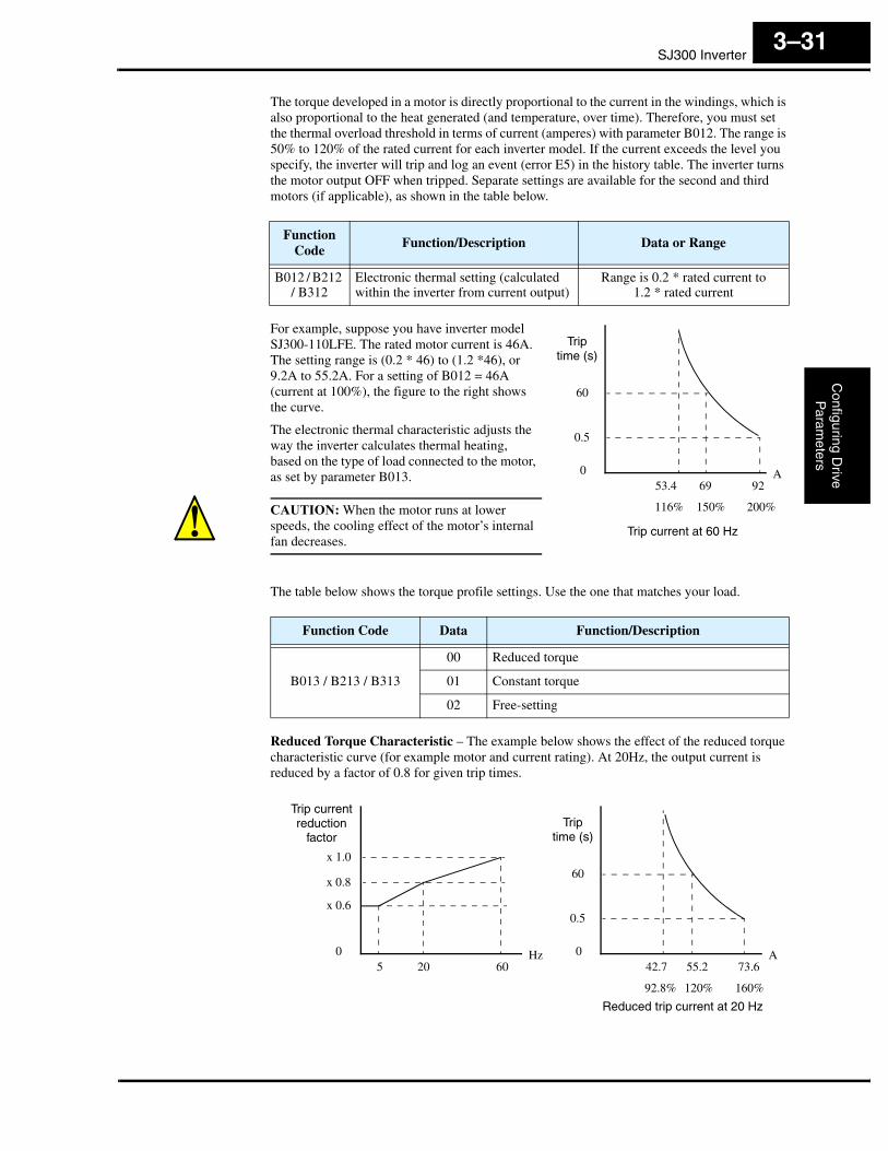
The torque developed in a motor is directly proportional to the current in the windings, which is also proportional to the heat generated (and temperature, over time). Therefore, you must set the thermal overload threshold in terms of current (amperes) with parameter B012. The range is 50% to 120% of the rated current for each inverter model. If the current exceeds the level you specify, the inverter will trip and log an event (error E5) in the history table. The inverter turns the motor output OFF when tripped. Separate settings are available for the second and third motors (if applicable), as shown in the table below.
For example, suppose you have inverter model SJ300-110LFE. The rated motor current is 46A. The setting range is (0.2 * 46) to (1.2 *46), or 9.2A to 55.2A. For a setting of B012 = 46A (current at 100%), the figure to the right shows the curve.
The electronic thermal characteristic adjusts the way the inverter calculates thermal heating, based on the type of load connected to the motor, as set by parameter B013.
CAUTION: When the motor runs at lower speeds, the cooling effect of the motor’s internal fan decreases.
The table below shows the torque profile settings. Use the one that matches your load.
Reduced Torque Characteristic – The example below shows the effect of the reduced torque characteristic curve (for example motor and current rating). At 20Hz, the output current is reduced by a factor of 0.8 for given trip times.
FunctionCode
Function/Description Data or Range
B012 / B212 / B312
Electronic thermal setting (calculated within the inverter from current output)
Range is 0.2 * rated current to1.2 * rated current
Function Code Data Function/Description
B013 / B213 / B313
00 Reduced torque
01 Constant torque
02 Free-setting
Triptime (s)
60
116%
0.5
053.4 69 92
150% 200%
A
Trip current at 60 Hz
Triptime (s)
60
92.8%
0.5
042.7 55.2 73.6
120% 160%
A
x 1.0
x 0.6
05 20 60
Hz
x 0.8
Reduced trip current at 20 Hz
Trip current reduction
factor
“B” Group: Fine-Tuning FunctionsC
onfig
urin
g D
rive
Par
amet
ers
3–32
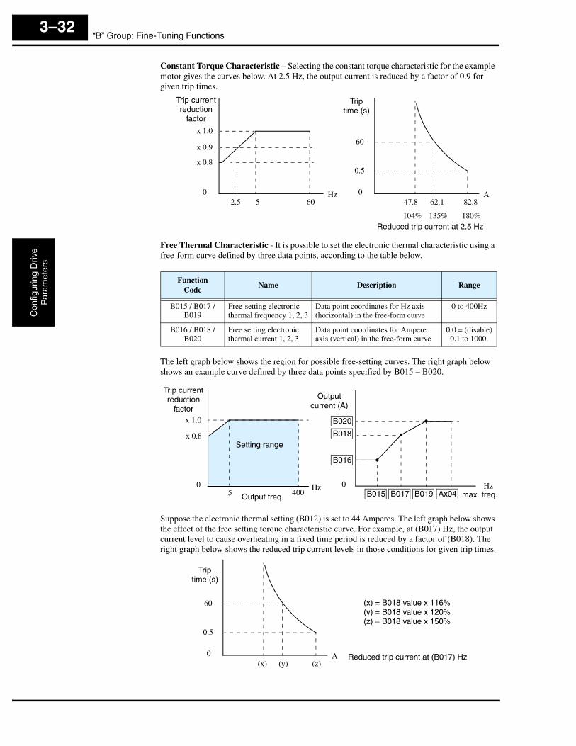
Constant Torque Characteristic – Selecting the constant torque characteristic for the example motor gives the curves below. At 2.5 Hz, the output current is reduced by a factor of 0.9 for given trip times.
Free Thermal Characteristic - It is possible to set the electronic thermal characteristic using a free-form curve defined by three data points, according to the table below.
The left graph below shows the region for possible free-setting curves. The right graph below shows an example curve defined by three data points specified by B015 – B020.
Suppose the electronic thermal setting (B012) is set to 44 Amperes. The left graph below shows the effect of the free setting torque characteristic curve. For example, at (B017) Hz, the output current level to cause overheating in a fixed time period is reduced by a factor of (B018). The right graph below shows the reduced trip current levels in those conditions for given trip times.
FunctionCode
Name Description Range
B015 / B017 /B019
Free-setting electronic thermal frequency 1, 2, 3
Data point coordinates for Hz axis (horizontal) in the free-form curve
0 to 400Hz
B016 / B018 /B020
Free setting electronic thermal current 1, 2, 3
Data point coordinates for Ampere axis (vertical) in the free-form curve
0.0 = (disable)0.1 to 1000.
Triptime (s)
60
104%
0.5
047.8 62.1 82.8
135% 180%
A
x 1.0
x 0.8
02.5 5 60
Hz
x 0.9
Reduced trip current at 2.5 Hz
Trip current reduction
factor
Outputcurrent (A)
0 Hz
x 1.0
0400
Hz
x 0.8Setting range
max. freq.
B020
B018
B016
B015 B017 B019 Ax04
Trip current reduction
factor
5 Output freq.
Triptime (s)
60
0.5
0(x) (y) (z)
A
(x) = B018 value x 116%(y) = B018 value x 120%(z) = B018 value x 150%
Reduced trip current at (B017) Hz

SJ300 InverterC
onfiguring Drive
Param
eters
3–33
Any intelligent output terminal may be programmed to indicate a thermal warning [THM]. Parameter C061 determines the warning threshold. Please see “Thermal Warning Signal” on page 4–55 for more details.
“B” Function Run ModeEditLo Hi
Defaults
Units SRW DisplayFunc.Code
Name Description–FE(CE)
–FU(UL)
–FR(Jpn)
B012 Level of electronic thermal setting
Set a level between 50% and 120% of the inverter rated current
✘ ✔ rated current for each inverter model
% >b012 E-THM
LEVEL 0016.5A
B212 Level of electronic thermal setting, 2nd motor
Set a level between 50% and 120% of the inverter rated current
✘ ✔ rated current for each inverter model
% >b212 2E-THM
LEVEL 0016.5A
B312 Level of electronic thermal setting, 3rd motor
Set a level between 50% and 120% of the inverter rated current
✘ ✔ rated current for each inverter model
% >b312 3E-THM
LEVEL 0016.5A
B013 Electronic thermal characteristic
Select from three curves, option codes:00 Reduced torque01 Constant torque02 V/f free-setting
✘ ✔ 01 01 00 — >b013 E-THM
CHAR CRT
B213 Electronic thermal characteristic, 2nd motor
Select from three curves, option codes:00 Reduced torque01 Constant torque02 V/f free-setting
✘ ✔ 01 01 00 — >b213 2E-THM
CHAR CRT
B313 Electronic thermal characteristic, 3rd motor
Select from three curves, option codes:00 Reduced torque01 Constant torque02 V/f free-setting
✘ ✔ 01 01 00 — >b313 3E-THM
CHAR CRT
B015 Free setting, electronic thermal frequency (1)
Range is 0.0 to 400.0 Hz ✘ ✔ 0. 0. 0. Hz >b015 E-THM
F1 0000Hz
B016 Free setting, electronic thermal current (1)
Range is 0.0 to 1000. A ✘ ✔ 0.0 0.0 0.0 A >b016 E-THM
A1 0000.0A
B017 Free setting, electronic thermal frequency (2)
Range is 0.0 to 400.0 Hz ✘ ✔ 0. 0. 0. Hz >b017 E-THM
F2 0000Hz
B018 Free setting, electronic thermal current (2)
Range is 0.0 to 1000. A ✘ ✔ 0.0 0.0 0.0 A >b018 E-THM
A2 0000.0A
B019 Free setting, electronic thermal frequency (3)
Range is 0.0 to 400.0 Hz ✘ ✔ 0. 0. 0. Hz >b019 E-THM
F3 0000Hz
B020 Free setting, electronic thermal current (3)
Range is 0.0 to 1000. A ✘ ✔ 0.0 0.0 0.0 A >b020 E-THM
A3 0000.0A
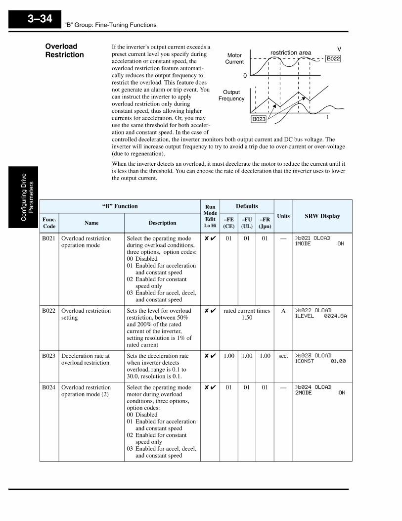
“B” Group: Fine-Tuning FunctionsC
onfig
urin
g D
rive
Par
amet
ers
3–34
OverloadRestriction
If the inverter’s output current exceeds a preset current level you specify during acceleration or constant speed, the overload restriction feature automati-cally reduces the output frequency to restrict the overload. This feature does not generate an alarm or trip event. You can instruct the inverter to apply overload restriction only during constant speed, thus allowing higher currents for acceleration. Or, you may use the same threshold for both acceler-ation and constant speed. In the case of controlled deceleration, the inverter monitors both output current and DC bus voltage. The inverter will increase output frequency to try to avoid a trip due to over-current or over-voltage (due to regeneration).
When the inverter detects an overload, it must decelerate the motor to reduce the current until it is less than the threshold. You can choose the rate of deceleration that the inverter uses to lower the output current.
0
Motor Current
V
OutputFrequency
restriction area
B023
B022
t
“B” Function Run ModeEditLo Hi
Defaults
Units SRW DisplayFunc.Code
Name Description–FE(CE)
–FU(UL)
–FR(Jpn)
B021 Overload restriction operation mode
Select the operating mode during overload conditions, three options, option codes:00 Disabled01 Enabled for acceleration
and constant speed02 Enabled for constant
speed only03 Enabled for accel, decel,
and constant speed
✘ ✔ 01 01 01 — >b021 OLOAD
1MODE ON
B022 Overload restriction setting
Sets the level for overload restriction, between 50% and 200% of the rated current of the inverter, setting resolution is 1% of rated current
✘ ✔ rated current times 1.50
A >b022 OLOAD
1LEVEL 0024.8A
B023 Deceleration rate at overload restriction
Sets the deceleration rate when inverter detects overload, range is 0.1 to 30.0, resolution is 0.1.
✘ ✔ 1.00 1.00 1.00 sec. >b023 OLOAD
1CONST 01.00
B024 Overload restriction operation mode (2)
Select the operating mode motor during overload conditions, three options, option codes:00 Disabled01 Enabled for acceleration
and constant speed02 Enabled for constant
speed only03 Enabled for accel, decel,
and constant speed
✘ ✔ 01 01 01 — >b024 OLOAD
2MODE ON
SJ300 InverterC
onfiguring Drive
Param
eters
3–35
NOTE: Two sets of overload restriction parameters are available. The set that is in use may be selected by means of an intelligent input terminal (see “Overload Restriction” on page 4–35).
B025 Overload restriction setting (2)
Sets the level for overload restriction (2), between 50% and 200% of the rated current of the inverter, setting resolution is 1% of rated current
✘ ✔ rated current times 1.50
A >b025 OLOAD
2LEVEL 0024.8A
B026 Deceleration rate at overload restriction (2)
Sets the deceleration rate (2) when inverter detects overload, range is 0.1 to 30.0, resolution is 0.1.
✘ ✔ 1.00 1.00 1.00 sec. >b026 OLOAD
2CONST 01.00
“B” Function Run ModeEditLo Hi
Defaults
Units SRW DisplayFunc.Code
Name Description–FE(CE)
–FU(UL)
–FR(Jpn)
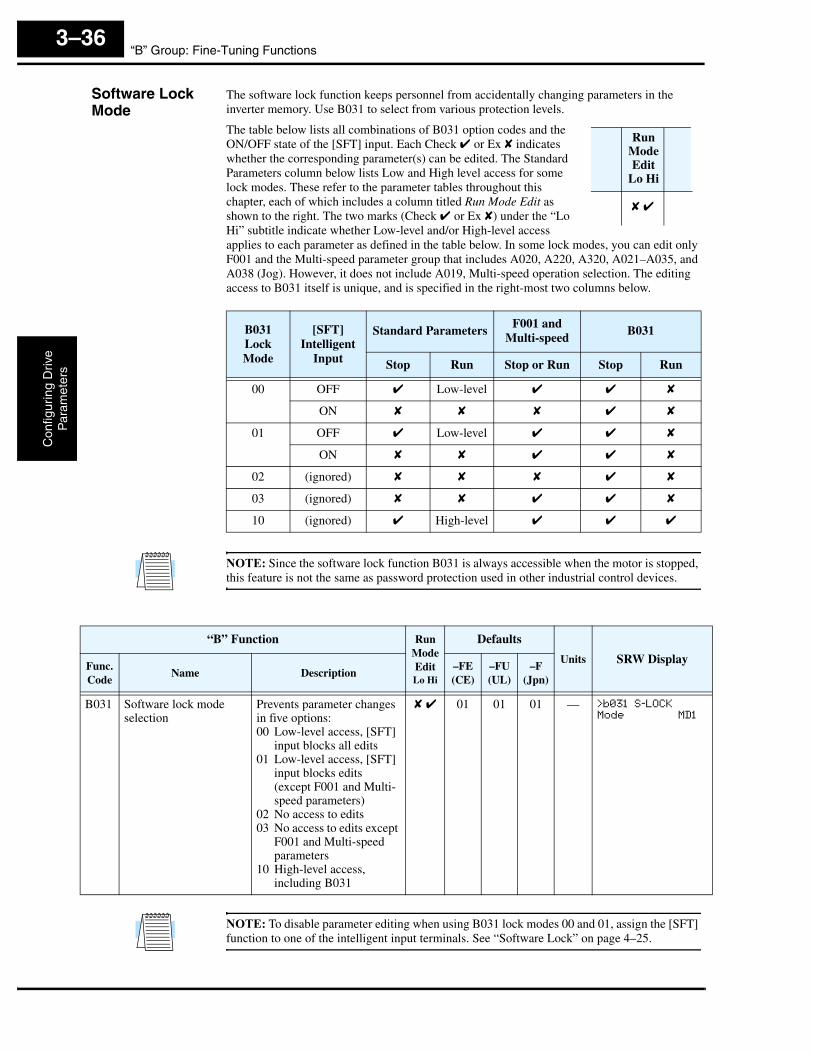
“B” Group: Fine-Tuning FunctionsC
onfig
urin
g D
rive
Par
amet
ers
3–36
Software Lock Mode
The software lock function keeps personnel from accidentally changing parameters in the inverter memory. Use B031 to select from various protection levels.
The table below lists all combinations of B031 option codes and the ON/OFF state of the [SFT] input. Each Check ✔ or Ex ✘ indicates whether the corresponding parameter(s) can be edited. The Standard Parameters column below lists Low and High level access for some lock modes. These refer to the parameter tables throughout this chapter, each of which includes a column titled Run Mode Edit as shown to the right. The two marks (Check ✔ or Ex ✘) under the “Lo Hi” subtitle indicate whether Low-level and/or High-level access applies to each parameter as defined in the table below. In some lock modes, you can edit only F001 and the Multi-speed parameter group that includes A020, A220, A320, A021–A035, and A038 (Jog). However, it does not include A019, Multi-speed operation selection. The editing access to B031 itself is unique, and is specified in the right-most two columns below.
NOTE: Since the software lock function B031 is always accessible when the motor is stopped, this feature is not the same as password protection used in other industrial control devices.
NOTE: To disable parameter editing when using B031 lock modes 00 and 01, assign the [SFT] function to one of the intelligent input terminals. See “Software Lock” on page 4–25.
B031 Lock Mode
[SFT] Intelligent
Input
Standard ParametersF001 and
Multi-speedB031
Stop Run Stop or Run Stop Run
00 OFF ✔ Low-level ✔ ✔ ✘
ON ✘ ✘ ✘ ✔ ✘
01 OFF ✔ Low-level ✔ ✔ ✘
ON ✘ ✘ ✔ ✔ ✘
02 (ignored) ✘ ✘ ✘ ✔ ✘
03 (ignored) ✘ ✘ ✔ ✔ ✘
10 (ignored) ✔ High-level ✔ ✔ ✔
Run Mode Edit
Lo Hi
✘ ✔
“B” Function Run ModeEditLo Hi
Defaults
Units SRW DisplayFunc.Code
Name Description–FE(CE)
–FU(UL)
–F(Jpn)
B031 Software lock mode selection
Prevents parameter changes in five options:00 Low-level access, [SFT]
input blocks all edits01 Low-level access, [SFT]
input blocks edits (except F001 and Multi-speed parameters)
02 No access to edits03 No access to edits except
F001 and Multi-speed parameters
10 High-level access, including B031
✘ ✔ 01 01 01 — >b031 S-LOCK
Mode MD1

SJ300 InverterC
onfiguring Drive
Param
eters
3–37
Miscellaneous Settings
The miscellaneous settings include scaling factors, initialization modes, and others. This section covers some of the most important settings you may need to configure.
Function Code Display Restriction – The inverter has the (optional) capability to suppress the display and editing of certain parameters. Use B037 to select the display options. The purpose of this feature is to hide particular secondary parameters that become unused or not applicable based on more fundamental parameter settings. For example, setting A001 = 01 configures the inverter to get its frequency command from the front keypad potentiometer. In this case, the inverter will not use the analog inputs nor their adjustment parameters for an external frequency command.
For example, you can set B037=01 to have the inverter suppress the displaying of all analog input parameters when A001=01, as shown in the first row of the following table.
“B” Function Run ModeEditLo Hi
Defaults
Units SRW DisplayFunc.Code
Name Description–FE(CE)
–FU(UL)
–FR(Jpn)
B034 Run/power-on warning time
Range is 0 to 65,530 hours ✘ ✔ 0. 0. 0. hrs. >b034 TIME
WARN 00000
B035 Rotational direction restriction
Three option codes:00 Enable for both dir.01 Enable for forward only02 Enable for reverse only
✘ ✘ 00 00 00 — >b035 LIMIT
F/R FREE
B036 Reduced voltage start selection
Seven option codes:00 Short01, 02, 03, 04, 05 (middle)06 Long
✘ ✔ 06 06 06 — >b036 RVS
ADJUST 06
“B” Function Run ModeEditLo Hi
Defaults
Units SRW DisplayFunc.Code
Name Description–FE(CE)
–FU(UL)
–F(Jpn)
B037 Function code display restriction
Three option codes:00 Display all01 Display only utilized
functions (see table below)
02 Display user-selected functions only (con-figure with U01 to U12)
✘ ✔ 00 00 00 — >b037 DISP
Mode ALL
Function Code
DataResulting Non-displayed
Functions (when B37 = 01)Notes
A001 01 A005, A006, A011 – A016, A101 – A114, C081 – C083, C121 – C123
[O], [OI], [O2] terminal functions
A002 01, 03, 04, 05
B087 Stop key function
A019 00 A028 – A035 Multi-speed function
C001 – C008 02, 03, 04, 05
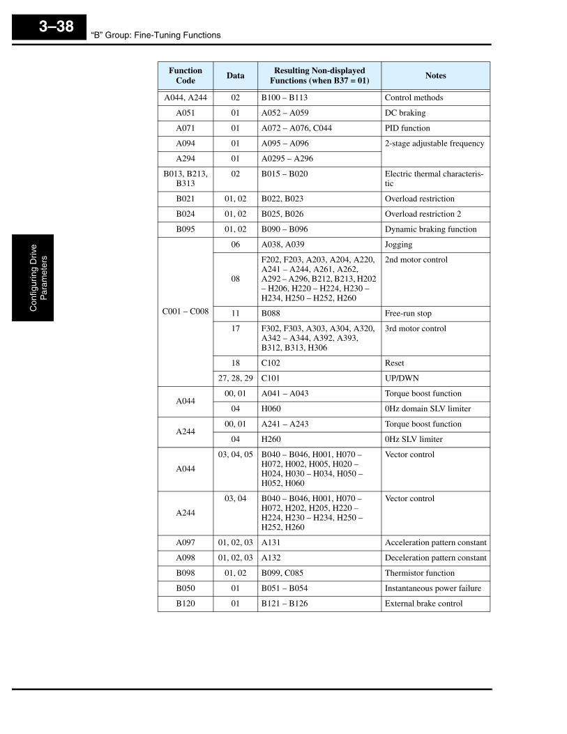
“B” Group: Fine-Tuning FunctionsC
onfig
urin
g D
rive
Par
amet
ers
3–38
Function Code
DataResulting Non-displayed
Functions (when B37 = 01)Notes
A044, A244 02 B100 – B113 Control methods
A051 01 A052 – A059 DC braking
A071 01 A072 – A076, C044 PID function
A094 01 A095 – A096 2-stage adjustable frequency
A294 01 A0295 – A296
B013, B213, B313
02 B015 – B020 Electric thermal characteris-tic
B021 01, 02 B022, B023 Overload restriction
B024 01, 02 B025, B026 Overload restriction 2
B095 01, 02 B090 – B096 Dynamic braking function
C001 – C008
06 A038, A039 Jogging
08
F202, F203, A203, A204, A220, A241 – A244, A261, A262, A292 – A296, B212, B213, H202 – H206, H220 – H224, H230 – H234, H250 – H252, H260
2nd motor control
11 B088 Free-run stop
17 F302, F303, A303, A304, A320, A342 – A344, A392, A393, B312, B313, H306
3rd motor control
18 C102 Reset
27, 28, 29 C101 UP/DWN
A04400, 01 A041 – A043 Torque boost function
04 H060 0Hz domain SLV limiter
A24400, 01 A241 – A243 Torque boost function
04 H260 0Hz SLV limiter
A044
03, 04, 05 B040 – B046, H001, H070 – H072, H002, H005, H020 – H024, H030 – H034, H050 – H052, H060
Vector control
A244
03, 04 B040 – B046, H001, H070 – H072, H202, H205, H220 – H224, H230 – H234, H250 – H252, H260
Vector control
A097 01, 02, 03 A131 Acceleration pattern constant
A098 01, 02, 03 A132 Deceleration pattern constant
B098 01, 02 B099, C085 Thermistor function
B050 01 B051 – B054 Instantaneous power failure
B120 01 B121 – B126 External brake control
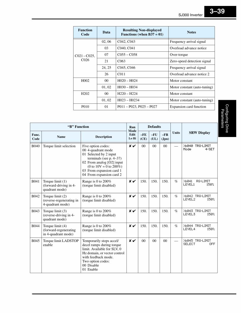
SJ300 InverterC
onfiguring Drive
Param
eters
3–39
C021 – C025, C026
02, 06 C042, C043 Frequency arrival signal
03 C040, C041 Overload advance notice
07 C055 – C058 Over-torque
21 C063 Zero-speed detection signal
24, 25 C045, C046 Frequency arrival signal
26 C011 Overload advance notice 2
H002 00 H020 – H024 Motor constant
01, 02 H030 – H034 Motor constant (auto-tuning)
H202 00 H220 – H224 Motor constant
01, 02 H023 – H0234 Motor constant (auto-tuning)
P010 01 P011 – P023, P025 – P027 Expansion card function
Function Code
DataResulting Non-displayed
Functions (when B37 = 01)Notes
“B” Function Run ModeEditLo Hi
Defaults
Units SRW DisplayFunc.Code
Name Description–FE(CE)
–FU(UL)
–FR(Jpn)
B040 Torque limit selection Five option codes:00 4-quadrant mode01 Selected by 2 input
terminals (see p. 4–37)02 From analog [O2] input
(0 to 10V = 0 to 200%)03 From expansion card 104 From expansion card 2
✘ ✔ 00 00 00 — >b040 TRQ-LIMIT
Mode 4-SET
B041 Torque limit (1) (forward-driving in 4-quadrant mode)
Range is 0 to 200%(torque limit disabled)
✘ ✔ 150. 150. 150. % >b041 RQ-LIMIT
LEVEL1 150%
B042 Torque limit (2) (reverse-regenerating in 4-quadrant mode)
Range is 0 to 200%(torque limit disabled)
✘ ✔ 150. 150. 150. % >b042 TRQ-LIMIT
LEVEL2 150%
B043 Torque limit (3) (reverse-driving in 4-quadrant mode)
Range is 0 to 200%(torque limit disabled)
✘ ✔ 150. 150. 150. % >b043 TRQ-LIMIT
LEVEL3 150%
B044 Torque limit (4) (forward-regenerating in 4-quadrant mode)
Range is 0 to 200%(torque limit disabled)
✘ ✔ 150. 150. 150. % >b044 TRQ-LIMIT
LEVEL4 150%
B045 Torque limit LADSTOP enable
Temporarily stops accel/decel ramps during torque limit. Available for SLV, 0 Hz domain, or vector control with feedback mode.Two option codes:00 Disable01 Enable
✘ ✔ 00 00 00 — >b045 TRQ-LIMIT
SELECT OFF
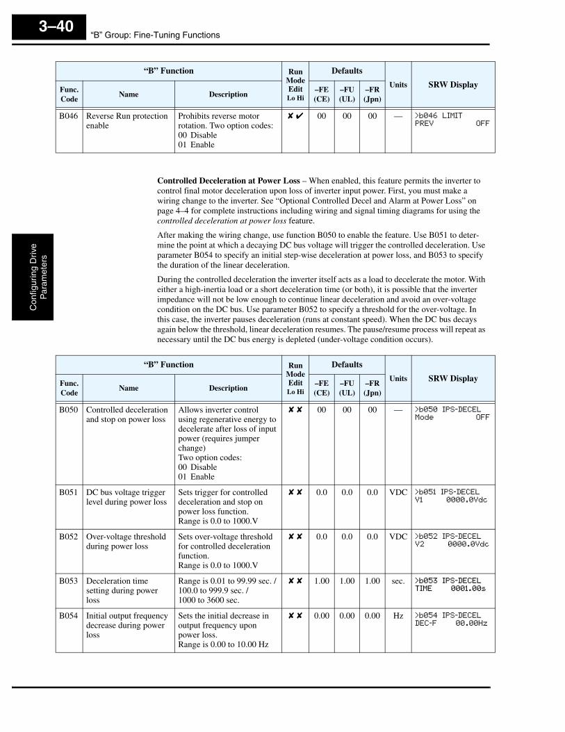
“B” Group: Fine-Tuning FunctionsC
onfig
urin
g D
rive
Par
amet
ers
3–40
Controlled Deceleration at Power Loss – When enabled, this feature permits the inverter to control final motor deceleration upon loss of inverter input power. First, you must make a wiring change to the inverter. See “Optional Controlled Decel and Alarm at Power Loss” on page 4–4 for complete instructions including wiring and signal timing diagrams for using the controlled deceleration at power loss feature.
After making the wiring change, use function B050 to enable the feature. Use B051 to deter-mine the point at which a decaying DC bus voltage will trigger the controlled deceleration. Use parameter B054 to specify an initial step-wise deceleration at power loss, and B053 to specify the duration of the linear deceleration.
During the controlled deceleration the inverter itself acts as a load to decelerate the motor. With either a high-inertia load or a short deceleration time (or both), it is possible that the inverter impedance will not be low enough to continue linear deceleration and avoid an over-voltage condition on the DC bus. Use parameter B052 to specify a threshold for the over-voltage. In this case, the inverter pauses deceleration (runs at constant speed). When the DC bus decays again below the threshold, linear deceleration resumes. The pause/resume process will repeat as necessary until the DC bus energy is depleted (under-voltage condition occurs).
B046 Reverse Run protection enable
Prohibits reverse motor rotation. Two option codes:00 Disable01 Enable
✘ ✔ 00 00 00 — >b046 LIMIT
PREV OFF
“B” Function Run ModeEditLo Hi
Defaults
Units SRW DisplayFunc.Code
Name Description–FE(CE)
–FU(UL)
–FR(Jpn)
“B” Function Run ModeEditLo Hi
Defaults
Units SRW DisplayFunc.Code
Name Description–FE(CE)
–FU(UL)
–FR(Jpn)
B050 Controlled deceleration and stop on power loss
Allows inverter control using regenerative energy to decelerate after loss of input power (requires jumper change)Two option codes:00 Disable01 Enable
✘ ✘ 00 00 00 — >b050 IPS-DECEL
Mode OFF
B051 DC bus voltage trigger level during power loss
Sets trigger for controlled deceleration and stop on power loss function.Range is 0.0 to 1000.V
✘ ✘ 0.0 0.0 0.0 VDC >b051 IPS-DECEL
V1 0000.0Vdc
B052 Over-voltage threshold during power loss
Sets over-voltage threshold for controlled deceleration function.Range is 0.0 to 1000.V
✘ ✘ 0.0 0.0 0.0 VDC >b052 IPS-DECEL
V2 0000.0Vdc
B053 Deceleration time setting during power loss
Range is 0.01 to 99.99 sec. /100.0 to 999.9 sec. /1000 to 3600 sec.
✘ ✘ 1.00 1.00 1.00 sec. >b053 IPS-DECEL
TIME 0001.00s
B054 Initial output frequency decrease during power loss
Sets the initial decrease in output frequency upon power loss.Range is 0.00 to 10.00 Hz
✘ ✘ 0.00 0.00 0.00 Hz >b054 IPS-DECEL
DEC-F 00.00Hz
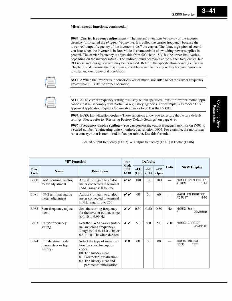
SJ300 InverterC
onfiguring Drive
Param
eters
3–41
Miscellaneous functions, continued...
B083: Carrier frequency adjustment – The internal switching frequency of the inverter circuitry (also called the chopper frequency). It is called the carrier frequency because the lower AC output frequency of the inverter “rides” the carrier. The faint, high-pitched sound you hear when the inverter is in Run Mode is characteristic of switching power supplies in general. The carrier frequency is adjustable from 500 Hz to 15 kHz (the upper limit varies, depending on the inverter rating). The audible sound decreases at the higher frequencies, but RFI noise and leakage current may be increased. Refer to the specification derating curves in Chapter 1 to determine the maximum allowable carrier frequency setting for your particular inverter and environmental conditions.
NOTE: When the inverter is in sensorless vector mode, use B083 to set the carrier frequency greater than 2.1 kHz for proper operation.
NOTE: The carrier frequency setting must stay within specified limits for inverter-motor appli-cations that must comply with particular regulatory agencies. For example, a European CE-approved application requires the inverter carrier to be less than 5 kHz.
B084, B085: Initialization codes – These functions allow you to restore the factory default settings. Please refer to “Restoring Factory Default Settings” on page 6–9.
B086: Frequency display scaling – You can convert the output frequency monitor on D001 to a scaled number (engineering units) monitored at function D007. For example, the motor may run a conveyor that is monitored in feet per minute. Use this formula:
Scaled output frequency (D007) Output frequency (D001) Factor (B086)×=
“B” Function Run ModeEditLo Hi
Defaults
Units SRW DisplayFunc.Code
Name Description–FE(CE)
–FU(UL)
–FR(Jpn)
B080 [AM] terminal analog meter adjustment
Adjust 8-bit gain to analog meter connected to terminal [AM], range is 0 to 255
✔ ✔ 180 180 180 — >b080 AM-MONITOR
ADJUST 180
B081 [FM] terminal analog meter adjustment
Adjust 8-bit gain to analog meter connected to terminal [FM], range is 0 to 255
✔ ✔ 60 60 60 — >b081 FM-MONITOR
ADJUST 060
B082 Start frequency adjust-ment
Sets the starting frequency for the inverter output, range is 0.10 to 9.99 Hz
✘ ✔ 0.50 0.50 0.50 Hz >b082 fmin
F 00.50Hz
B083 Carrier frequency setting
Sets the PWM carrier (inter-nal switching frequency) Range is 0.5 to 15.0 kHz, or 0.5 to 10 kHz when derated
✘ ✔ 5.0 5.0 5.0 kHz >b083 CARRIER
F 05.0kHz
B084 Initialization mode (parameters or trip history)
Select the type of initializa-tion to occur, two option codes:00 Trip history clear01 Parameter initialization02 Trip history clear and
parameter initialization
✘ ✘ 00 00 00 — >b084 INITIAL
MODE TRP
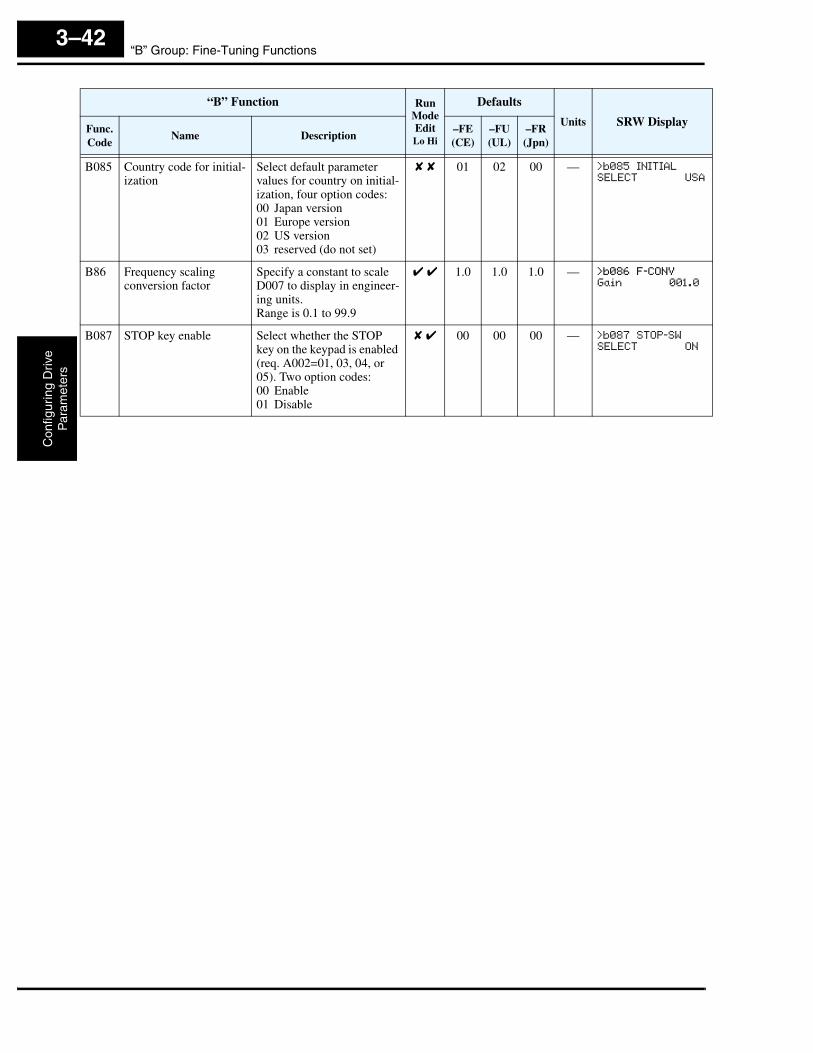
“B” Group: Fine-Tuning FunctionsC
onfig
urin
g D
rive
Par
amet
ers
3–42
B085 Country code for initial-ization
Select default parameter values for country on initial-ization, four option codes:00 Japan version01 Europe version02 US version03 reserved (do not set)
✘ ✘ 01 02 00 — >b085 INITIAL
SELECT USA
B86 Frequency scaling conversion factor
Specify a constant to scale D007 to display in engineer-ing units.Range is 0.1 to 99.9
✔ ✔ 1.0 1.0 1.0 — >b086 F-CONV
Gain 001.0
B087 STOP key enable Select whether the STOP key on the keypad is enabled (req. A002=01, 03, 04, or 05). Two option codes:00 Enable01 Disable
✘ ✔ 00 00 00 — >b087 STOP-SW
SELECT ON
“B” Function Run ModeEditLo Hi
Defaults
Units SRW DisplayFunc.Code
Name Description–FE(CE)
–FU(UL)
–FR(Jpn)

SJ300 InverterC
onfiguring Drive
Param
eters
3–43
B091/B088: Stop Mode / Restart Mode Configuration – You can configure how the inverter performs a standard stop (each time Run FWD and REV signals turn OFF). Setting B091 deter-mines whether the inverter will control the deceleration, or whether it will perform a free-run stop (coast to a stop). When using the free-run stop selection, it is imperative to also configure how you want the inverter to resume control of motor speed. Setting B088 determines whether the inverter will ensure the motor always resumes at 0 Hz, or whether the motor resumes from its current coasting speed (also called frequency matching). The Run command may turn OFF briefly, allowing the motor to coast to a slower speed from which normal operation can resume.
In most applications a controlled deceleration is desirable, corresponding to B091=00. However, applications such as HVAC fan control will often use a free-run stop (B091=01). This practice decreases dynamic stress on system components, prolonging system life. In this case, you will typically set B088=01 in order to resume from the current speed after a free-run stop (see diagram below, right). Note that using the default setting, B088=00, can cause trip events when the inverter attempts to force the load quickly to zero speed.
NOTE: Other events can cause (or be configured to cause) a free-run stop, such as power loss (see “Automatic Restart Mode and Phase Loss” on page 3–29), and inverter trip events in general (see “Miscellaneous Functions” on page 3–61). If all free-run stop behavior is impor-tant to your application (such as HVAC), be sure to configure each event accordingly.
Some additional parameters further configure all instances of a free-run stop. Parameter B003, Retry Wait Time Before Motor Restart, sets the minimum time the inverter will free-run. For example, if B003 = 4 seconds (and B091=01) and the cause of the free-run stop lasts 10 seconds, the inverter will free-run (coast) for a total of 14 seconds before driving the motor again. Parameter B007, Restart Frequency Threshold, sets the motor frequency at which the inverter will no longer resume and accelerate, instead resuming from 0 Hz (complete stop).
Motor speed
[FW, RV]
Zero-frequency startMotor speed
Resume from current speed
wait time
[FW, RV]
B003
B088=01B088=00 Resume from 0Hz
B091=01 Stop Mode = free-run stopB091=01 Stop Mode = free-run stop
t t
“B” Function Run ModeEditLo Hi
Defaults
Units SRW DisplayFunc.Code
Name Description–FE(CE)
–FU(UL)
–FR(Jpn)
B088 Restart mode after FRS Selects how the inverter resumes operation when the free-run stop (FRS) is cancelled, two option codes:00 Restart from 0Hz01 Restart from frequency
detected from actual speed of motor
✘ ✔ 00 00 00 — >b088 RUN
FRS ZST
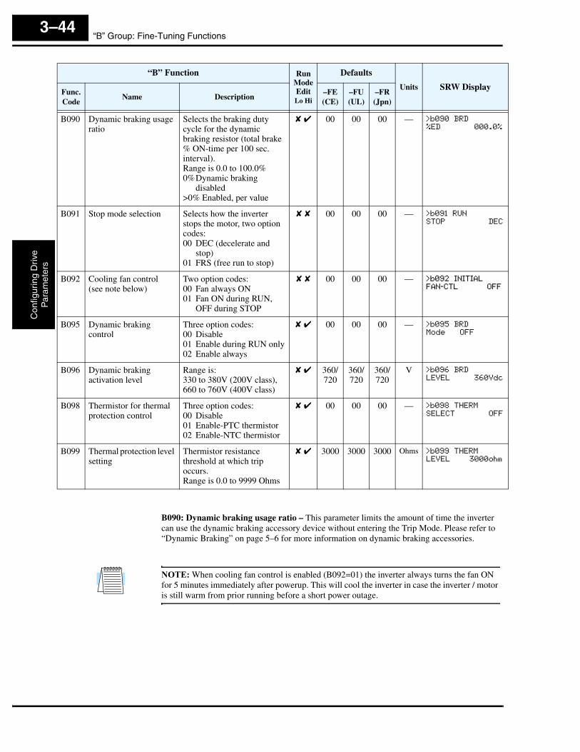
“B” Group: Fine-Tuning FunctionsC
onfig
urin
g D
rive
Par
amet
ers
3–44
B090: Dynamic braking usage ratio – This parameter limits the amount of time the inverter can use the dynamic braking accessory device without entering the Trip Mode. Please refer to “Dynamic Braking” on page 5–6 for more information on dynamic braking accessories.
NOTE: When cooling fan control is enabled (B092=01) the inverter always turns the fan ON for 5 minutes immediately after powerup. This will cool the inverter in case the inverter / motor is still warm from prior running before a short power outage.
B090 Dynamic braking usage ratio
Selects the braking duty cycle for the dynamic braking resistor (total brake % ON-time per 100 sec. interval).Range is 0.0 to 100.0%0%Dynamic braking
disabled>0% Enabled, per value
✘ ✔ 00 00 00 — >b090 BRD
%ED 000.0%
B091 Stop mode selection Selects how the inverter stops the motor, two option codes:00 DEC (decelerate and
stop)01 FRS (free run to stop)
✘ ✘ 00 00 00 — >b091 RUN
STOP DEC
B092 Cooling fan control(see note below)
Two option codes:00 Fan always ON01 Fan ON during RUN,
OFF during STOP
✘ ✘ 00 00 00 — >b092 INITIAL
FAN-CTL OFF
B095 Dynamic braking control
Three option codes:00 Disable01 Enable during RUN only02 Enable always
✘ ✔ 00 00 00 — >b095 BRD
Mode OFF
B096 Dynamic braking activation level
Range is:330 to 380V (200V class),660 to 760V (400V class)
✘ ✔ 360/720
360/720
360/720
V >b096 BRD
LEVEL 360Vdc
B098 Thermistor for thermal protection control
Three option codes:00 Disable01 Enable-PTC thermistor02 Enable-NTC thermistor
✘ ✔ 00 00 00 — >b098 THERM
SELECT OFF
B099 Thermal protection level setting
Thermistor resistance threshold at which trip occurs.Range is 0.0 to 9999 Ohms
✘ ✔ 3000 3000 3000 Ohms >b099 THERM
LEVEL 3000ohm
“B” Function Run ModeEditLo Hi
Defaults
Units SRW DisplayFunc.Code
Name Description–FE(CE)
–FU(UL)
–FR(Jpn)
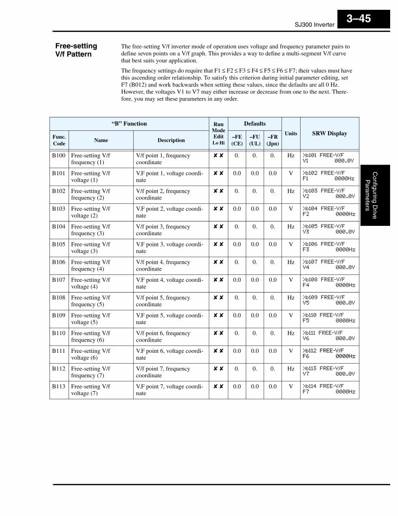
SJ300 InverterC
onfiguring Drive
Param
eters
3–45
Free-settingV/f Pattern
The free-setting V/f inverter mode of operation uses voltage and frequency parameter pairs to define seven points on a V/f graph. This provides a way to define a multi-segment V/f curve that best suits your application.
The frequency settings do require that F1 ≤ F2 ≤ F3 ≤ F4 ≤ F5 ≤ F6 ≤ F7; their values must have this ascending order relationship. To satisfy this criterion during initial parameter editing, set F7 (B012) and work backwards when setting these values, since the defaults are all 0 Hz. However, the voltages V1 to V7 may either increase or decrease from one to the next. There-fore, you may set these parameters in any order.
“B” Function Run ModeEditLo Hi
Defaults
Units SRW DisplayFunc.Code
Name Description–FE(CE)
–FU(UL)
–FR(Jpn)
B100 Free-setting V/ffrequency (1)
V/f point 1, frequency coordinate
✘ ✘ 0. 0. 0. Hz >b101 FREE-V/F
V1 000.0V
B101 Free-setting V/fvoltage (1)
V.F point 1, voltage coordi-nate
✘ ✘ 0.0 0.0 0.0 V >b102 FREE-V/F
F1 0000Hz
B102 Free-setting V/ffrequency (2)
V/f point 2, frequency coordinate
✘ ✘ 0. 0. 0. Hz >b103 FREE-V/F
V2 000.0V
B103 Free-setting V/fvoltage (2)
V.F point 2, voltage coordi-nate
✘ ✘ 0.0 0.0 0.0 V >b104 FREE-V/F
F2 0000Hz
B104 Free-setting V/ffrequency (3)
V/f point 3, frequency coordinate
✘ ✘ 0. 0. 0. Hz >b105 FREE-V/F
V3 000.0V
B105 Free-setting V/fvoltage (3)
V.F point 3, voltage coordi-nate
✘ ✘ 0.0 0.0 0.0 V >b106 FREE-V/F
F3 0000Hz
B106 Free-setting V/ffrequency (4)
V/f point 4, frequency coordinate
✘ ✘ 0. 0. 0. Hz >b107 FREE-V/F
V4 000.0V
B107 Free-setting V/fvoltage (4)
V.F point 4, voltage coordi-nate
✘ ✘ 0.0 0.0 0.0 V >b108 FREE-V/F
F4 0000Hz
B108 Free-setting V/ffrequency (5)
V/f point 5, frequency coordinate
✘ ✘ 0. 0. 0. Hz >b109 FREE-V/F
V5 000.0V
B109 Free-setting V/fvoltage (5)
V.F point 5, voltage coordi-nate
✘ ✘ 0.0 0.0 0.0 V >b110 FREE-V/F
F5 0000Hz
B110 Free-setting V/ffrequency (6)
V/f point 6, frequency coordinate
✘ ✘ 0. 0. 0. Hz >b111 FREE-V/F
V6 000.0V
B111 Free-setting V/fvoltage (6)
V.F point 6, voltage coordi-nate
✘ ✘ 0.0 0.0 0.0 V >b112 FREE-V/F
F6 0000Hz
B112 Free-setting V/ffrequency (7)
V/f point 7, frequency coordinate
✘ ✘ 0. 0. 0. Hz >b113 FREE-V/F
V7 000.0V
B113 Free-setting V/fvoltage (7)
V.F point 7, voltage coordi-nate
✘ ✘ 0.0 0.0 0.0 V >b114 FREE-V/F
F7 0000Hz
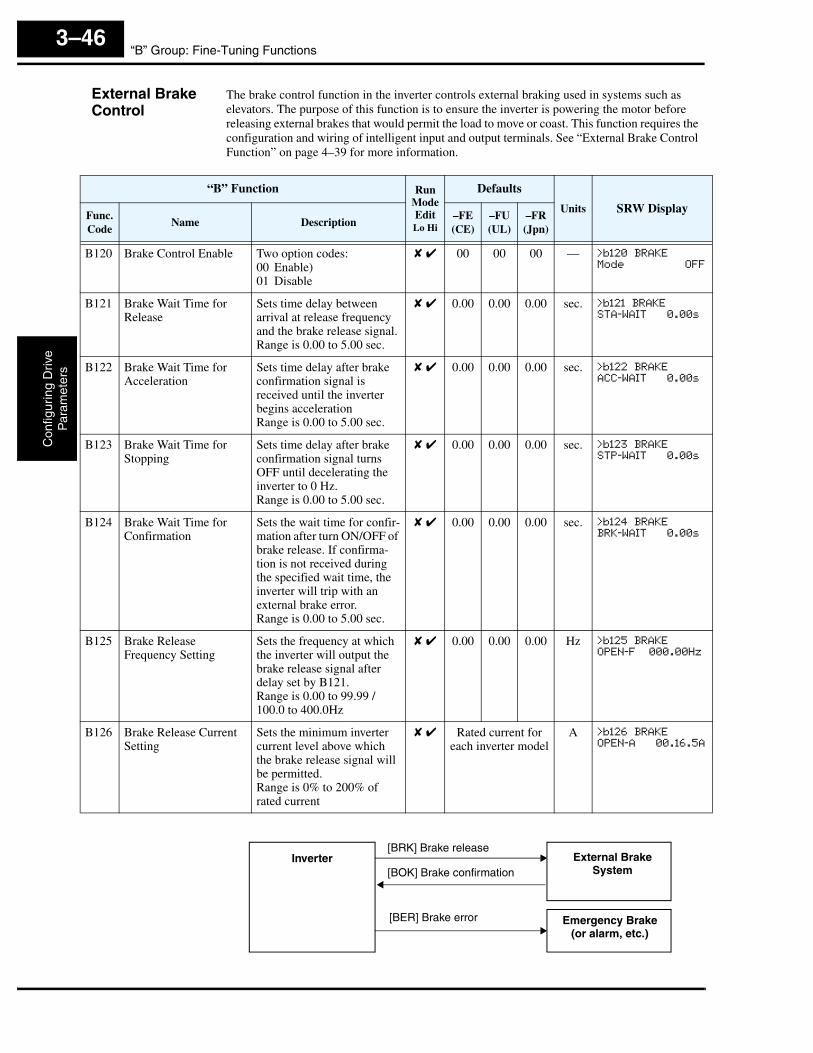
“B” Group: Fine-Tuning FunctionsC
onfig
urin
g D
rive
Par
amet
ers
3–46
External Brake Control
The brake control function in the inverter controls external braking used in systems such as elevators. The purpose of this function is to ensure the inverter is powering the motor before releasing external brakes that would permit the load to move or coast. This function requires the configuration and wiring of intelligent input and output terminals. See “External Brake Control Function” on page 4–39 for more information.
“B” Function Run ModeEditLo Hi
Defaults
Units SRW DisplayFunc.Code
Name Description–FE(CE)
–FU(UL)
–FR(Jpn)
B120 Brake Control Enable Two option codes:00 Enable)01 Disable
✘ ✔ 00 00 00 — >b120 BRAKE
Mode OFF
B121 Brake Wait Time for Release
Sets time delay between arrival at release frequency and the brake release signal.Range is 0.00 to 5.00 sec.
✘ ✔ 0.00 0.00 0.00 sec. >b121 BRAKE
STA-WAIT 0.00s
B122 Brake Wait Time for Acceleration
Sets time delay after brake confirmation signal is received until the inverter begins accelerationRange is 0.00 to 5.00 sec.
✘ ✔ 0.00 0.00 0.00 sec. >b122 BRAKE
ACC-WAIT 0.00s
B123 Brake Wait Time for Stopping
Sets time delay after brake confirmation signal turns OFF until decelerating the inverter to 0 Hz.Range is 0.00 to 5.00 sec.
✘ ✔ 0.00 0.00 0.00 sec. >b123 BRAKE
STP-WAIT 0.00s
B124 Brake Wait Time for Confirmation
Sets the wait time for confir-mation after turn ON/OFF of brake release. If confirma-tion is not received during the specified wait time, the inverter will trip with an external brake error.Range is 0.00 to 5.00 sec.
✘ ✔ 0.00 0.00 0.00 sec. >b124 BRAKE
BRK-WAIT 0.00s
B125 Brake Release Frequency Setting
Sets the frequency at which the inverter will output the brake release signal after delay set by B121.Range is 0.00 to 99.99 /100.0 to 400.0Hz
✘ ✔ 0.00 0.00 0.00 Hz >b125 BRAKE
OPEN-F 000.00Hz
B126 Brake Release Current Setting
Sets the minimum inverter current level above which the brake release signal will be permitted.Range is 0% to 200% of rated current
✘ ✔ Rated current for each inverter model
A >b126 BRAKE
OPEN-A 00.16.5A
[BRK] Brake release
[BOK] Brake confirmationInverter External Brake
System
Emergency Brake(or alarm, etc.)
[BER] Brake error

SJ300 InverterC
onfiguring Drive
Param
eters
3–47
“C” Group: Intelligent Terminal FunctionsThe eight input terminals [1], [2], [3], [4], [5], [6], [7], and [8] can be configured for any of 44 different functions. The next two tables show how to configure the eight terminals. The inputs are logical, in that they are either OFF or ON. We define these states as OFF=0, and ON=1.
The inverter comes with default options for the eight terminals. These default settings are initially unique, each one having its own setting. Note that European and US versions have different default settings. You can use any option on any terminal, and even use the same option twice to create a logical OR (though usually not required).
Input Terminal Configuration
Functions and Options –The function codes in the following table let you assign one of 44 options to any of the eight logic inputs for the SJ300 inverters. The functions C001 through C008 configure the terminals [1] through [8] respectively. The “value” of these particular parameters is not a scalar value, but it is a discrete number that selects one option from many available options.
For example, if you set function C001=01, you have assigned option 01 (Reverse Run) to terminal [1]. The option codes and the specifics of how each one works are in Chapter 4.
“C” Function Run ModeEditLo Hi
Defaults
Units SRW DisplayFunc.Code
Name Description–FE(CE)
–FU(UL)
–FR(Jpn)
C001 Terminal [1] function
44 programmable functions available for terminals (see next section)
✘ ✔ 18[RS]
18[RS]
18[RS]
— >C001 IN-TM
1 RS
C002 Terminal [2] function ✘ ✔ 16[AT]
16[AT]
16[AT]
— >C002 IN-TM
2 AT
C003 Terminal [3] function ✘ ✔ 06[JG]
06[JG]
06[JG]
— >C003 IN-TM
3 JG
C004 Terminal [4] function ✘ ✔ 11[FRS]
11[FRS]
11[FRS]
— >C004 IN-TM
4 FRS
C005 Terminal [5] function ✘ ✔ 09[2CH]
09[2CH]
09[2CH]
— >C005 IN-TM
5 2CH
C006 Terminal [6] function ✘ ✔ 03[CF2]
13[USP]
03[CF2]
— >C006 IN-TM
6 USP
C007 Terminal [7] function ✘ ✔ 02[CF1]
02[CF1]
02[CF1]
— >C007 IN-TM
7 CF1
C008 Terminal [8] function ✘ ✔ 01[RV]
01[RV]
01[RV]
— >C008 IN-TM
8 RV
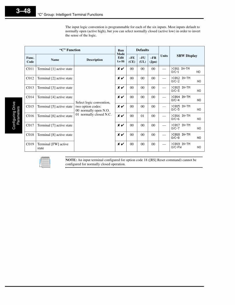
“C” Group: Intelligent Terminal FunctionsC
onfig
urin
g D
rive
Par
amet
ers
3–48
The input logic convention is programmable for each of the six inputs. Most inputs default to normally open (active high), but you can select normally closed (active low) in order to invert the sense of the logic.
NOTE: An input terminal configured for option code 18 ([RS] Reset command) cannot be configured for normally closed operation.
“C” Function Run ModeEditLo Hi
Defaults
Units SRW DisplayFunc.Code
Name Description–FE(CE)
–FU(UL)
–FR(Jpn)
C011 Terminal [1] active state
Select logic convention, two option codes:00 normally open N.O.01 normally closed N.C.
✘ ✔ 00 00 00 — >C011 IN-TM
O/C-1 NO
C012 Terminal [2] active state ✘ ✔ 00 00 00 — >C012 IN-TM
O/C-2 NO
C013 Terminal [3] active state ✘ ✔ 00 00 00 — >C013 IN-TM
O/C-3 NO
C014 Terminal [4] active state ✘ ✔ 00 00 00 — >C014 IN-TM
O/C-4 NO
C015 Terminal [5] active state ✘ ✔ 00 00 00 — >C015 IN-TM
O/C-5 NO
C016 Terminal [6] active state ✘ ✔ 00 01 00 — >C016 IN-TM
O/C-6 NO
C017 Terminal [7] active state ✘ ✔ 00 00 00 — >C017 IN-TM
O/C-7 NO
C018 Terminal [8] active state ✘ ✔ 00 00 00 — >C018 IN-TM
O/C-8 NO
C019 Terminal [FW] active state
✘ ✔ 00 00 00 — >C019 IN-TM
O/C-FW NO
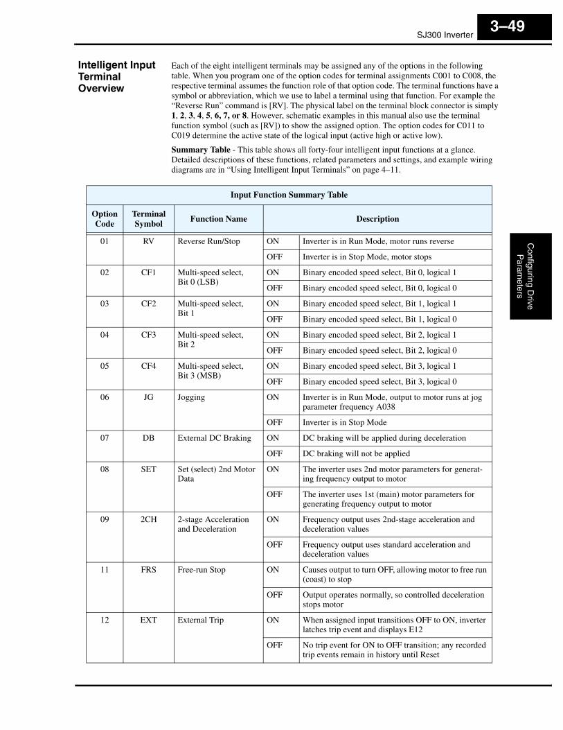
SJ300 InverterC
onfiguring Drive
Param
eters
3–49
Intelligent Input Terminal Overview
Each of the eight intelligent terminals may be assigned any of the options in the following table. When you program one of the option codes for terminal assignments C001 to C008, the respective terminal assumes the function role of that option code. The terminal functions have a symbol or abbreviation, which we use to label a terminal using that function. For example the “Reverse Run” command is [RV]. The physical label on the terminal block connector is simply 1, 2, 3, 4, 5, 6, 7, or 8. However, schematic examples in this manual also use the terminal function symbol (such as [RV]) to show the assigned option. The option codes for C011 to C019 determine the active state of the logical input (active high or active low).
Summary Table - This table shows all forty-four intelligent input functions at a glance. Detailed descriptions of these functions, related parameters and settings, and example wiring diagrams are in “Using Intelligent Input Terminals” on page 4–11.
Input Function Summary Table
OptionCode
Terminal Symbol
Function Name Description
01 RV Reverse Run/Stop ON Inverter is in Run Mode, motor runs reverse
OFF Inverter is in Stop Mode, motor stops
02 CF1 Multi-speed select,Bit 0 (LSB)
ON Binary encoded speed select, Bit 0, logical 1
OFF Binary encoded speed select, Bit 0, logical 0
03 CF2 Multi-speed select,Bit 1
ON Binary encoded speed select, Bit 1, logical 1
OFF Binary encoded speed select, Bit 1, logical 0
04 CF3 Multi-speed select,Bit 2
ON Binary encoded speed select, Bit 2, logical 1
OFF Binary encoded speed select, Bit 2, logical 0
05 CF4 Multi-speed select,Bit 3 (MSB)
ON Binary encoded speed select, Bit 3, logical 1
OFF Binary encoded speed select, Bit 3, logical 0
06 JG Jogging ON Inverter is in Run Mode, output to motor runs at jog parameter frequency A038
OFF Inverter is in Stop Mode
07 DB External DC Braking ON DC braking will be applied during deceleration
OFF DC braking will not be applied
08 SET Set (select) 2nd Motor Data
ON The inverter uses 2nd motor parameters for generat-ing frequency output to motor
OFF The inverter uses 1st (main) motor parameters for generating frequency output to motor
09 2CH 2-stage Acceleration and Deceleration
ON Frequency output uses 2nd-stage acceleration and deceleration values
OFF Frequency output uses standard acceleration and deceleration values
11 FRS Free-run Stop ON Causes output to turn OFF, allowing motor to free run (coast) to stop
OFF Output operates normally, so controlled deceleration stops motor
12 EXT External Trip ON When assigned input transitions OFF to ON, inverter latches trip event and displays E12
OFF No trip event for ON to OFF transition; any recorded trip events remain in history until Reset
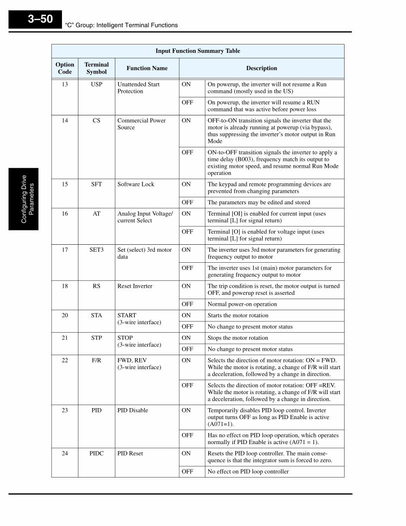
“C” Group: Intelligent Terminal FunctionsC
onfig
urin
g D
rive
Par
amet
ers
3–50
13 USP Unattended Start Protection
ON On powerup, the inverter will not resume a Run command (mostly used in the US)
OFF On powerup, the inverter will resume a RUN command that was active before power loss
14 CS Commercial Power Source
ON OFF-to-ON transition signals the inverter that the motor is already running at powerup (via bypass), thus suppressing the inverter’s motor output in Run Mode
OFF ON-to-OFF transition signals the inverter to apply a time delay (B003), frequency match its output to existing motor speed, and resume normal Run Mode operation
15 SFT Software Lock ON The keypad and remote programming devices are prevented from changing parameters
OFF The parameters may be edited and stored
16 AT Analog Input Voltage/current Select
ON Terminal [OI] is enabled for current input (uses terminal [L] for signal return)
OFF Terminal [O] is enabled for voltage input (uses terminal [L] for signal return)
17 SET3 Set (select) 3rd motor data
ON The inverter uses 3rd motor parameters for generating frequency output to motor
OFF The inverter uses 1st (main) motor parameters for generating frequency output to motor
18 RS Reset Inverter ON The trip condition is reset, the motor output is turned OFF, and powerup reset is asserted
OFF Normal power-on operation
20 STA START(3-wire interface)
ON Starts the motor rotation
OFF No change to present motor status
21 STP STOP(3-wire interface)
ON Stops the motor rotation
OFF No change to present motor status
22 F/R FWD, REV(3-wire interface)
ON Selects the direction of motor rotation: ON = FWD.While the motor is rotating, a change of F/R will start a deceleration, followed by a change in direction.
OFF Selects the direction of motor rotation: OFF =REV.While the motor is rotating, a change of F/R will start a deceleration, followed by a change in direction.
23 PID PID Disable ON Temporarily disables PID loop control. Inverter output turns OFF as long as PID Enable is active (A071=1).
OFF Has no effect on PID loop operation, which operates normally if PID Enable is active (A071 = 1).
24 PIDC PID Reset ON Resets the PID loop controller. The main conse-quence is that the integrator sum is forced to zero.
OFF No effect on PID loop controller
Input Function Summary Table
OptionCode
Terminal Symbol
Function Name Description
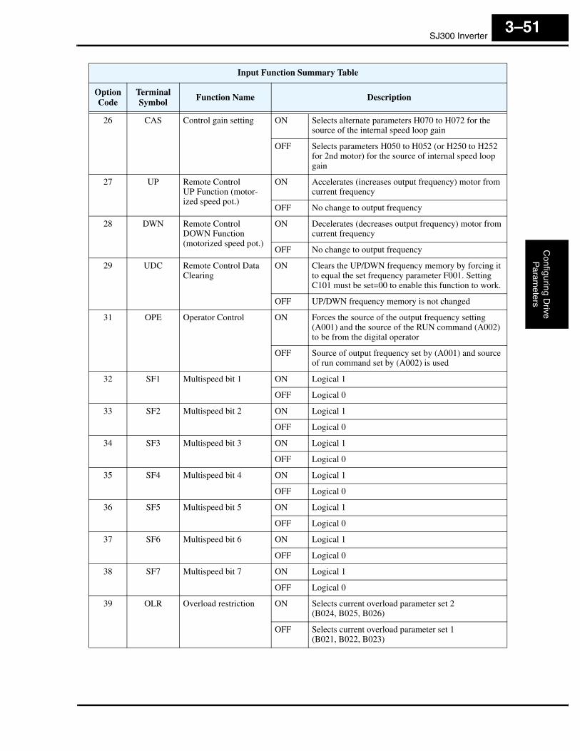
SJ300 InverterC
onfiguring Drive
Param
eters
3–51
26 CAS Control gain setting ON Selects alternate parameters H070 to H072 for the source of the internal speed loop gain
OFF Selects parameters H050 to H052 (or H250 to H252 for 2nd motor) for the source of internal speed loop gain
27 UP Remote Control UP Function (motor-ized speed pot.)
ON Accelerates (increases output frequency) motor from current frequency
OFF No change to output frequency
28 DWN Remote Control DOWN Function (motorized speed pot.)
ON Decelerates (decreases output frequency) motor from current frequency
OFF No change to output frequency
29 UDC Remote Control Data Clearing
ON Clears the UP/DWN frequency memory by forcing it to equal the set frequency parameter F001. Setting C101 must be set=00 to enable this function to work.
OFF UP/DWN frequency memory is not changed
31 OPE Operator Control ON Forces the source of the output frequency setting (A001) and the source of the RUN command (A002) to be from the digital operator
OFF Source of output frequency set by (A001) and source of run command set by (A002) is used
32 SF1 Multispeed bit 1 ON Logical 1
OFF Logical 0
33 SF2 Multispeed bit 2 ON Logical 1
OFF Logical 0
34 SF3 Multispeed bit 3 ON Logical 1
OFF Logical 0
35 SF4 Multispeed bit 4 ON Logical 1
OFF Logical 0
36 SF5 Multispeed bit 5 ON Logical 1
OFF Logical 0
37 SF6 Multispeed bit 6 ON Logical 1
OFF Logical 0
38 SF7 Multispeed bit 7 ON Logical 1
OFF Logical 0
39 OLR Overload restriction ON Selects current overload parameter set 2(B024, B025, B026)
OFF Selects current overload parameter set 1(B021, B022, B023)
Input Function Summary Table
OptionCode
Terminal Symbol
Function Name Description
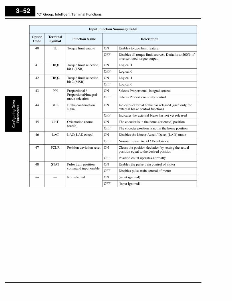
“C” Group: Intelligent Terminal FunctionsC
onfig
urin
g D
rive
Par
amet
ers
3–52
40 TL Torque limit enable ON Enables torque limit feature
OFF Disables all torque limit sources. Defaults to 200% of inverter rated torque output.
41 TRQ1 Torque limit selection, bit 1 (LSB)
ON Logical 1
OFF Logical 0
42 TRQ2 Torque limit selection, bit 2 (MSB)
ON Logical 1
OFF Logical 0
43 PPI Proportional / Proportional/Integral mode selection
ON Selects Proportional-Integral control
OFF Selects Proportional-only control
44 BOK Brake confirmation signal
ON Indicates external brake has released (used only for external brake control function)
OFF Indicates the external brake has not yet released
45 ORT Orientation (home search)
ON The encoder is in the home (oriented) position
OFF The encoder position is not in the home position
46 LAC LAC: LAD cancel ON Disables the Linear Accel / Decel (LAD) mode
OFF Normal Linear Accel / Decel mode
47 PCLR Position deviation reset ON Clears the position deviation by setting the actual position equal to the desired position
OFF Position count operates normally
48 STAT Pulse train position command input enable
ON Enables the pulse train control of motor
OFF Disables pulse train control of motor
no — Not selected ON (input ignored)
OFF (input ignored)
Input Function Summary Table
OptionCode
Terminal Symbol
Function Name Description

SJ300 InverterC
onfiguring Drive
Param
eters
3–53
Output Terminal Configuration
The inverter provides configuration for logic (discrete) and analog outputs, shown in the table below.
NOTE: *Terminals [11] – [13] or [11] – [14] are automatically configured as AC0 – AC2 orAC0 – AC3 when C62 is configured to enable alarm code output.
The output logic convention is programmable for terminals [11] – [15], and the alarm relay terminals. The open-collector output terminals [11] – [15] default to normally open (active low), but you can select normally closed (active high) for the terminals in order to invert the sense of the logic. You can invert the logical sense of the alarm relay output as well.
“C” Function Run ModeEditLo Hi
Defaults
Units SRW DisplayFunc.Code
Name Description–FE(CE)
–FU(UL)
–FR(Jpn)
C021 Terminal [11] function *
22 programmable functions available for logic (discrete) outputs (see next section)
✘ ✔ 01[FA1]
01[FA1]
01[FA1]
— >C021 OUT-TM
11 FA1
C022 Terminal [12] function * ✘ ✔ 00[RUN]
00[RUN]
00[RUN]
— >C022 OUT-TM
12 RUN
C023 Terminal [13] function * ✘ ✔ 03[OL]
03[OL]
03[OL]
— >C023 OUT-TM
13 OL
C024 Terminal [14] function * ✘ ✔ 07[OTQ]
07[OTQ]
07[OTQ]
— >C024 OUT-TM
14 OTQ
C025 Terminal [15] function ✘ ✔ 08[IP]
08[IP]
08[IP]
— >C025 OUT-TM
15 IP
C026 Alarm relay terminal function
✘ ✔ 05[AL]
05[AL]
05[AL]
— >C026 OUT-TM
AL AL
C027 [FM] signal selection
8 programmable functions available for analog outputs(see after next section)
✘ ✔ 00outputfreq.
00outputfreq.
00outputfreq.
— >C027 FM-MONITOR
KIND A-F
C028 [AM] signal selection ✘ ✔ 00outputfreq.
00outputfreq.
00outputfreq.
— >C028 AM-MONITOR
KIND A-F
C029 [AMI] signal selection ✘ ✔ 00outputfreq.
00outputfreq.
00outputfreq.
— >C029 AMI-MON
KIND A-F
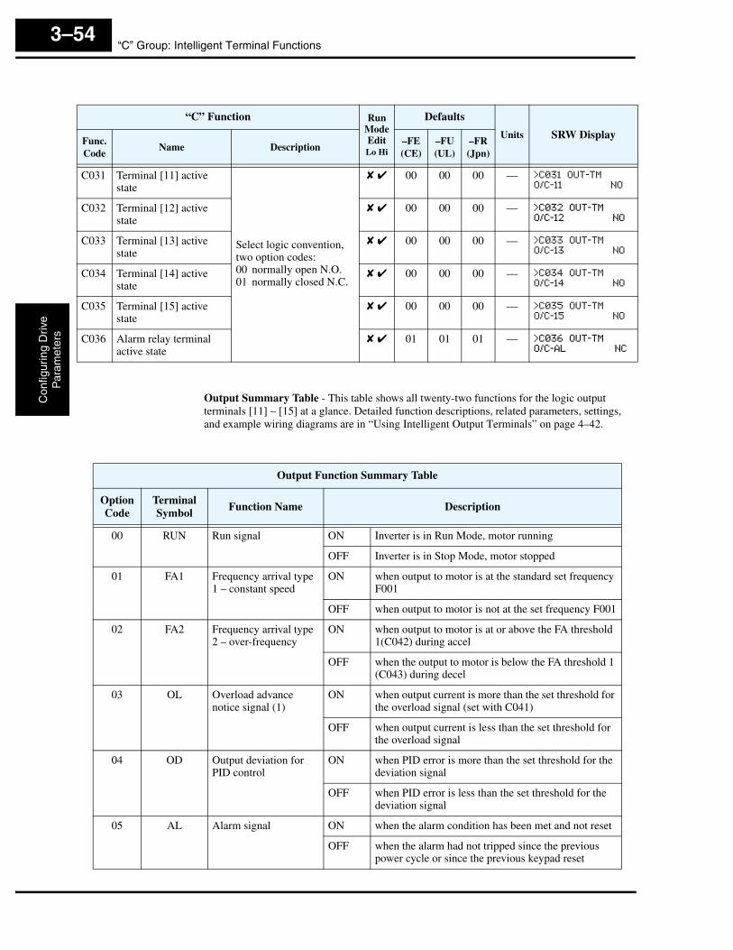
“C” Group: Intelligent Terminal FunctionsC
onfig
urin
g D
rive
Par
amet
ers
3–54
Output Summary Table - This table shows all twenty-two functions for the logic output terminals [11] – [15] at a glance. Detailed function descriptions, related parameters, settings, and example wiring diagrams are in “Using Intelligent Output Terminals” on page 4–42.
“C” Function Run ModeEditLo Hi
Defaults
Units SRW DisplayFunc.Code
Name Description–FE(CE)
–FU(UL)
–FR(Jpn)
C031 Terminal [11] active state
Select logic convention, two option codes:00 normally open N.O.01 normally closed N.C.
✘ ✔ 00 00 00 — >C031 OUT-TM
O/C-11 NO
C032 Terminal [12] active state
✘ ✔ 00 00 00 — >C032 OUT-TM
O/C-12 NO
C033 Terminal [13] active state
✘ ✔ 00 00 00 — >C033 OUT-TM
O/C-13 NO
C034 Terminal [14] active state
✘ ✔ 00 00 00 — >C034 OUT-TM
O/C-14 NO
C035 Terminal [15] active state
✘ ✔ 00 00 00 — >C035 OUT-TM
O/C-15 NO
C036 Alarm relay terminal active state
✘ ✔ 01 01 01 — >C036 OUT-TM
O/C-AL NC
Output Function Summary Table
OptionCode
Terminal Symbol
Function Name Description
00 RUN Run signal ON Inverter is in Run Mode, motor running
OFF Inverter is in Stop Mode, motor stopped
01 FA1 Frequency arrival type 1 – constant speed
ON when output to motor is at the standard set frequency F001
OFF when output to motor is not at the set frequency F001
02 FA2 Frequency arrival type 2 – over-frequency
ON when output to motor is at or above the FA threshold 1(C042) during accel
OFF when the output to motor is below the FA threshold 1 (C043) during decel
03 OL Overload advance notice signal (1)
ON when output current is more than the set threshold for the overload signal (set with C041)
OFF when output current is less than the set threshold for the overload signal
04 OD Output deviation for PID control
ON when PID error is more than the set threshold for the deviation signal
OFF when PID error is less than the set threshold for the deviation signal
05 AL Alarm signal ON when the alarm condition has been met and not reset
OFF when the alarm had not tripped since the previous power cycle or since the previous keypad reset
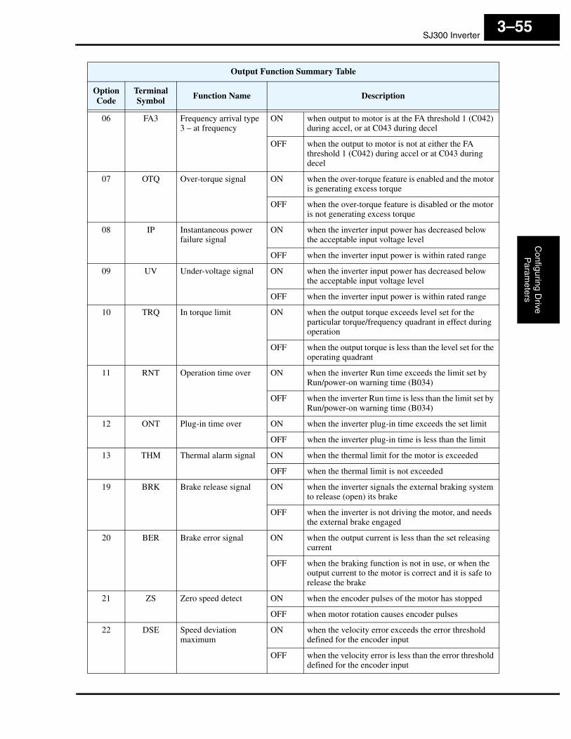
SJ300 InverterC
onfiguring Drive
Param
eters
3–55
06 FA3 Frequency arrival type 3 – at frequency
ON when output to motor is at the FA threshold 1 (C042) during accel, or at C043 during decel
OFF when the output to motor is not at either the FA threshold 1 (C042) during accel or at C043 during decel
07 OTQ Over-torque signal ON when the over-torque feature is enabled and the motor is generating excess torque
OFF when the over-torque feature is disabled or the motor is not generating excess torque
08 IP Instantaneous power failure signal
ON when the inverter input power has decreased below the acceptable input voltage level
OFF when the inverter input power is within rated range
09 UV Under-voltage signal ON when the inverter input power has decreased below the acceptable input voltage level
OFF when the inverter input power is within rated range
10 TRQ In torque limit ON when the output torque exceeds level set for the particular torque/frequency quadrant in effect during operation
OFF when the output torque is less than the level set for the operating quadrant
11 RNT Operation time over ON when the inverter Run time exceeds the limit set by Run/power-on warning time (B034)
OFF when the inverter Run time is less than the limit set by Run/power-on warning time (B034)
12 ONT Plug-in time over ON when the inverter plug-in time exceeds the set limit
OFF when the inverter plug-in time is less than the limit
13 THM Thermal alarm signal ON when the thermal limit for the motor is exceeded
OFF when the thermal limit is not exceeded
19 BRK Brake release signal ON when the inverter signals the external braking system to release (open) its brake
OFF when the inverter is not driving the motor, and needs the external brake engaged
20 BER Brake error signal ON when the output current is less than the set releasing current
OFF when the braking function is not in use, or when the output current to the motor is correct and it is safe to release the brake
21 ZS Zero speed detect ON when the encoder pulses of the motor has stopped
OFF when motor rotation causes encoder pulses
22 DSE Speed deviation maximum
ON when the velocity error exceeds the error threshold defined for the encoder input
OFF when the velocity error is less than the error threshold defined for the encoder input
Output Function Summary Table
OptionCode
Terminal Symbol
Function Name Description
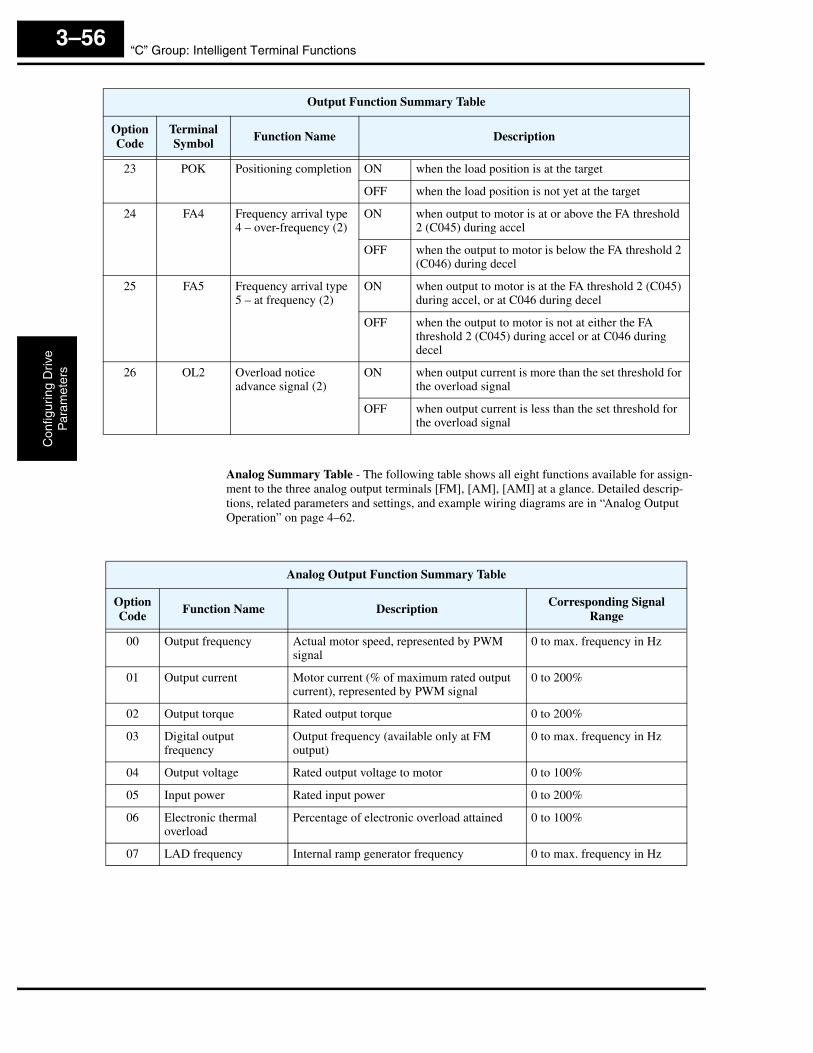
“C” Group: Intelligent Terminal FunctionsC
onfig
urin
g D
rive
Par
amet
ers
3–56
Analog Summary Table - The following table shows all eight functions available for assign-ment to the three analog output terminals [FM], [AM], [AMI] at a glance. Detailed descrip-tions, related parameters and settings, and example wiring diagrams are in “Analog Output Operation” on page 4–62.
23 POK Positioning completion ON when the load position is at the target
OFF when the load position is not yet at the target
24 FA4 Frequency arrival type 4 – over-frequency (2)
ON when output to motor is at or above the FA threshold 2 (C045) during accel
OFF when the output to motor is below the FA threshold 2 (C046) during decel
25 FA5 Frequency arrival type 5 – at frequency (2)
ON when output to motor is at the FA threshold 2 (C045) during accel, or at C046 during decel
OFF when the output to motor is not at either the FA threshold 2 (C045) during accel or at C046 during decel
26 OL2 Overload notice advance signal (2)
ON when output current is more than the set threshold for the overload signal
OFF when output current is less than the set threshold for the overload signal
Output Function Summary Table
OptionCode
Terminal Symbol
Function Name Description
Analog Output Function Summary Table
OptionCode
Function Name DescriptionCorresponding Signal
Range
00 Output frequency Actual motor speed, represented by PWM signal
0 to max. frequency in Hz
01 Output current Motor current (% of maximum rated output current), represented by PWM signal
0 to 200%
02 Output torque Rated output torque 0 to 200%
03 Digital output frequency
Output frequency (available only at FM output)
0 to max. frequency in Hz
04 Output voltage Rated output voltage to motor 0 to 100%
05 Input power Rated input power 0 to 200%
06 Electronic thermal overload
Percentage of electronic overload attained 0 to 100%
07 LAD frequency Internal ramp generator frequency 0 to max. frequency in Hz

SJ300 InverterC
onfiguring Drive
Param
eters
3–57
Output Function Adjustment Parameters
The following parameters work in conjunction with the intelligent output function, when configured. The overload level parameter (C041) sets the motor current level at which the overload signal [OL] turns ON. The range of settings is from 0% to 200% of the rated current for the inverter. This function is for generating an early warning logic output, without causing either a trip event or a restriction of the motor current (those effects are avail-able on other functions).
The frequency arrival signal, [FA1] to [FA5], is intended to indicate when the inverter output has reached (arrived at) the target frequency. You can adjust the timing of the leading and trailing edges of the signal via two parameters specific to acceleration and deceleration ramps, C042 and C043.
The Error for the PID loop is the magni-tude (absolute value) of the difference between the Setpoint (desired value) and Process Variable (actual value). The PID output deviation signal [OD] (output terminal function option code 04) indicates when the error magnitude has exceeded a magnitude you define.
0
Motor current
Overload signal
1
C041
t
0
Outputfrequency
Arrival signal
1
C042C043
t
0
PID Error(PV-SP)
Deviation Signal
1
SP
C044
t
“C” Function Run ModeEditLo Hi
Defaults
Units SRW DisplayFunc.Code
Name Description–FE(CE)
–FU(UL)
–FR(Jpn)
C040 Overload signal output mode
Choose when the overload signal is enabled; two option codes:00 During accel/decel01 During constant speed
✘ ✔ 01 01 01 — >CO40 OL
Mode CRT
C041 Overload level setting Range is 0.00 * rated current to 2.00 * rated current
✘ ✔ Rated current for each inverter
A >C041 OL
LEVEL 0016.5A
C042 Frequency arrival setting for acceleration
Sets the frequency arrival setting threshold for the output frequency during acceleration
✘ ✔ 0.00 0.00 0.00 Hz >C042 ARV
ACC 0000.00Hz
C043 Arrival frequency setting for deceleration
Sets the frequency arrival setting threshold for the output frequency during deceleration
✘ ✔ 0.00 0.00 0.00 Hz >C043 ARV
DEC 0000.00Hz
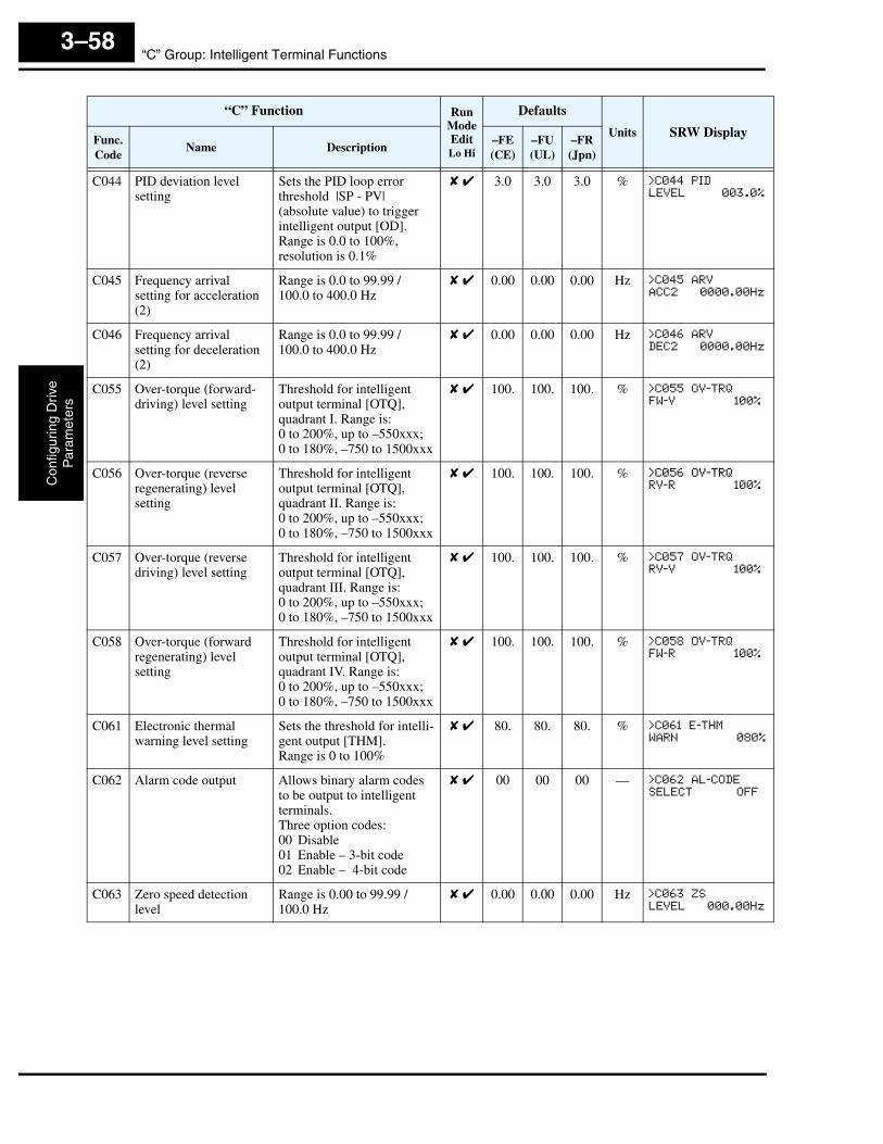
“C” Group: Intelligent Terminal FunctionsC
onfig
urin
g D
rive
Par
amet
ers
3–58
C044 PID deviation level setting
Sets the PID loop error threshold |SP - PV| (absolute value) to trigger intelligent output [OD]. Range is 0.0 to 100%, resolution is 0.1%
✘ ✔ 3.0 3.0 3.0 % >C044 PID
LEVEL 003.0%
C045 Frequency arrival setting for acceleration (2)
Range is 0.0 to 99.99 / 100.0 to 400.0 Hz
✘ ✔ 0.00 0.00 0.00 Hz >C045 ARV
ACC2 0000.00Hz
C046 Frequency arrival setting for deceleration (2)
Range is 0.0 to 99.99 / 100.0 to 400.0 Hz
✘ ✔ 0.00 0.00 0.00 Hz >C046 ARV
DEC2 0000.00Hz
C055 Over-torque (forward-driving) level setting
Threshold for intelligent output terminal [OTQ], quadrant I. Range is:0 to 200%, up to –550xxx;0 to 180%, –750 to 1500xxx
✘ ✔ 100. 100. 100. % >C055 OV-TRQ
FW-V 100%
C056 Over-torque (reverse regenerating) level setting
Threshold for intelligent output terminal [OTQ], quadrant II. Range is:0 to 200%, up to –550xxx;0 to 180%, –750 to 1500xxx
✘ ✔ 100. 100. 100. % >C056 OV-TRQ
RV-R 100%
C057 Over-torque (reverse driving) level setting
Threshold for intelligent output terminal [OTQ], quadrant III. Range is:0 to 200%, up to –550xxx;0 to 180%, –750 to 1500xxx
✘ ✔ 100. 100. 100. % >C057 OV-TRQ
RV-V 100%
C058 Over-torque (forward regenerating) level setting
Threshold for intelligent output terminal [OTQ], quadrant IV. Range is:0 to 200%, up to –550xxx;0 to 180%, –750 to 1500xxx
✘ ✔ 100. 100. 100. % >C058 OV-TRQ
FW-R 100%
C061 Electronic thermal warning level setting
Sets the threshold for intelli-gent output [THM].Range is 0 to 100%
✘ ✔ 80. 80. 80. % >C061 E-THM
WARN 080%
C062 Alarm code output Allows binary alarm codes to be output to intelligent terminals.Three option codes:00 Disable01 Enable – 3-bit code02 Enable – 4-bit code
✘ ✔ 00 00 00 — >C062 AL-CODE
SELECT OFF
C063 Zero speed detection level
Range is 0.00 to 99.99 / 100.0 Hz
✘ ✔ 0.00 0.00 0.00 Hz >C063 ZS
LEVEL 000.00Hz
“C” Function Run ModeEditLo Hi
Defaults
Units SRW DisplayFunc.Code
Name Description–FE(CE)
–FU(UL)
–FR(Jpn)

SJ300 InverterC
onfiguring Drive
Param
eters
3–59
SerialCommunications
The following table configures the communications port of the SJ300 inverter. You can have up to thirty-two devices on the serial communications network. The inverters are slaves and the computer or digital operator is the master. Thus, all inverters on the serial connection must use the same baud rate, data length, parity, and stop bits. However, each device on the serial network must have a unique node address. Please see Appendix B for more information.
“C” Function Run ModeEditLo Hi
Defaults
Units SRW DisplayFunc.Code
Name Description–FE(CE)
–FU(UL)
–FR(Jpn)
C070 Data command method Four option codes:02 Digital operator03 RS48504 Expansion card #105 Expansion card #2
✘ ✘ 02 02 02 — >C070 PARAM
SELECT REM
C071 Communication speed selection
Five option codes:02 (Test)03 2400bps04 4800bps05 9600bps06 19200bps
✘ ✔ 04 04 04 bps >C071 RS485
BAU 4800bps
C072 Node allocation Set the address of the inverter on the network. Range is 1 to 32.
✘ ✔ 1. 1. 1. — >C072 RS485
ADDRESS 01
C073 Communication data length selection
Two option codes:07 7-bit data08 8-bit data
✘ ✔ 7 7 7 — >C073 RS485
BIT 7BIT
C074 Communication parity selection
Three option codes:00 No parity01 Even parity02 Odd parity
✘ ✔ 00 00 00 — >C074 RS485
PARITY NO
C075 Communication stop bit selection
Two option codes:01 1 stop bit02 2 stop bits
✘ ✔ 1 1 1 — >C075 RS485
STOPBIT 1BIT
C078 Communication wait time
Time the inverter waits after receiving a message before it transmits. Range is 0.0 to 1000 ms
✘ ✔ 0. 0. 0. — >C078 RS485
WAIT 0000ms

“C” Group: Intelligent Terminal FunctionsC
onfig
urin
g D
rive
Par
amet
ers
3–60
Analog Signal Calibration Settings
The functions in the following table configure the signals for the analog output terminals. Note that these settings do not change the current/voltage or sink/source characteristics – only the zero and span (scaling) of the signals.
NOTE: Settings C081, C082, C083, C121, C122, C123 are factory-calibrated for each inverter. Do not change these settings unless absolutely necessary. Note that if you restore factory defaults for all parameters, these settings will not change.
“C” Function Run ModeEditLo Hi
Defaults
Units SRW DisplayFunc.Code
Name Description–FE(CE)
–FU(UL)
–FR(Jpn)
C081 [O] input span calibra-tion
Range is 0 to 65530 ✔ ✔ Factory-calibrated — >C081 O-ADJUST
TOP 02119
C082 [OI] input span calibra-tion
Range is 0 to 65530 ✔ ✔ Factory-calibrated — >C082 OI-ADJUST
TOP 02512
C083 [O2] input span calibra-tion
Range is 0 to 65530 ✔ ✔ Factory-calibrated — >C083 O2-ADJUST
TOP 02818
C085 Thermistor input tuning Range is 0.0 to 1000 ✔ ✔ 105.0 105.0 105.0 — >C085 THERM
ADJUST 0105.0
C086 [AM] terminal offset tuning
Range is 0.0 to 10.0V ✔ ✔ 0.0 0.0 0.0 V >C086 AM-MONITOR
OFFSET 00.0V
C087 [AMI] terminal meter tuning
Range is 0.0 to 250% ✔ ✔ 80. 80. 80. % >C087 AMI-MON
ADJUST 080
C088 [AMI] terminal offset tuning
Range is 0 to 20mA ✔ ✔ Factory-calibrated mA >C088 AMI-MON
OFFSET 04.0mA
C121 [O] input zero calibra-tion
Range is 0 to 6553 (65530) ✔ ✔ Factory-calibrated — >C121 O-ADJUST
ZERO 00000
C122 [OI] input zero calibra-tion
Range is 0 to 6553 (65530) ✔ ✔ Factory-calibrated — >C122 OI-ADJUST
ZERO 00000
C123 [O2] input zero calibra-tion
Range is 0 to 6553 (65530) ✔ ✔ Factory-calibrated — >C123 O2-ADJUST
ZERO 03622
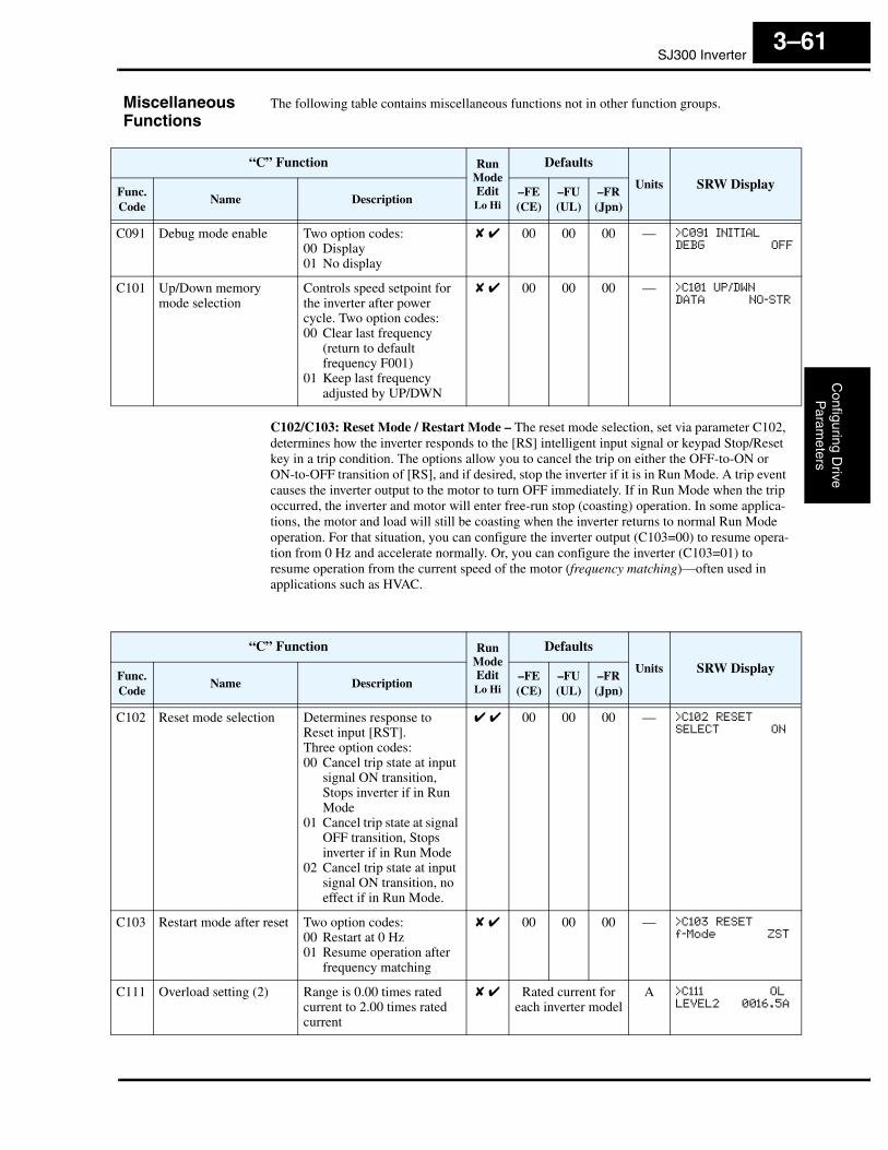
SJ300 InverterC
onfiguring Drive
Param
eters
3–61
Miscellaneous Functions
The following table contains miscellaneous functions not in other function groups.
C102/C103: Reset Mode / Restart Mode – The reset mode selection, set via parameter C102, determines how the inverter responds to the [RS] intelligent input signal or keypad Stop/Reset key in a trip condition. The options allow you to cancel the trip on either the OFF-to-ON or ON-to-OFF transition of [RS], and if desired, stop the inverter if it is in Run Mode. A trip event causes the inverter output to the motor to turn OFF immediately. If in Run Mode when the trip occurred, the inverter and motor will enter free-run stop (coasting) operation. In some applica-tions, the motor and load will still be coasting when the inverter returns to normal Run Mode operation. For that situation, you can configure the inverter output (C103=00) to resume opera-tion from 0 Hz and accelerate normally. Or, you can configure the inverter (C103=01) to resume operation from the current speed of the motor (frequency matching)—often used in applications such as HVAC.
“C” Function Run ModeEditLo Hi
Defaults
Units SRW DisplayFunc.Code
Name Description–FE(CE)
–FU(UL)
–FR(Jpn)
C091 Debug mode enable Two option codes:00 Display01 No display
✘ ✔ 00 00 00 — >C091 INITIAL
DEBG OFF
C101 Up/Down memory mode selection
Controls speed setpoint for the inverter after power cycle. Two option codes:00 Clear last frequency
(return to default frequency F001)
01 Keep last frequency adjusted by UP/DWN
✘ ✔ 00 00 00 — >C101 UP/DWN
DATA NO-STR
“C” Function Run ModeEditLo Hi
Defaults
Units SRW DisplayFunc.Code
Name Description–FE(CE)
–FU(UL)
–FR(Jpn)
C102 Reset mode selection Determines response to Reset input [RST].Three option codes:00 Cancel trip state at input
signal ON transition, Stops inverter if in Run Mode
01 Cancel trip state at signal OFF transition, Stops inverter if in Run Mode
02 Cancel trip state at input signal ON transition, no effect if in Run Mode.
✔ ✔ 00 00 00 — >C102 RESET
SELECT ON
C103 Restart mode after reset Two option codes:00 Restart at 0 Hz01 Resume operation after
frequency matching
✘ ✔ 00 00 00 — >C103 RESET
f-Mode ZST
C111 Overload setting (2) Range is 0.00 times rated current to 2.00 times rated current
✘ ✔ Rated current for each inverter model
A >C111 OL
LEVEL2 0016.5A
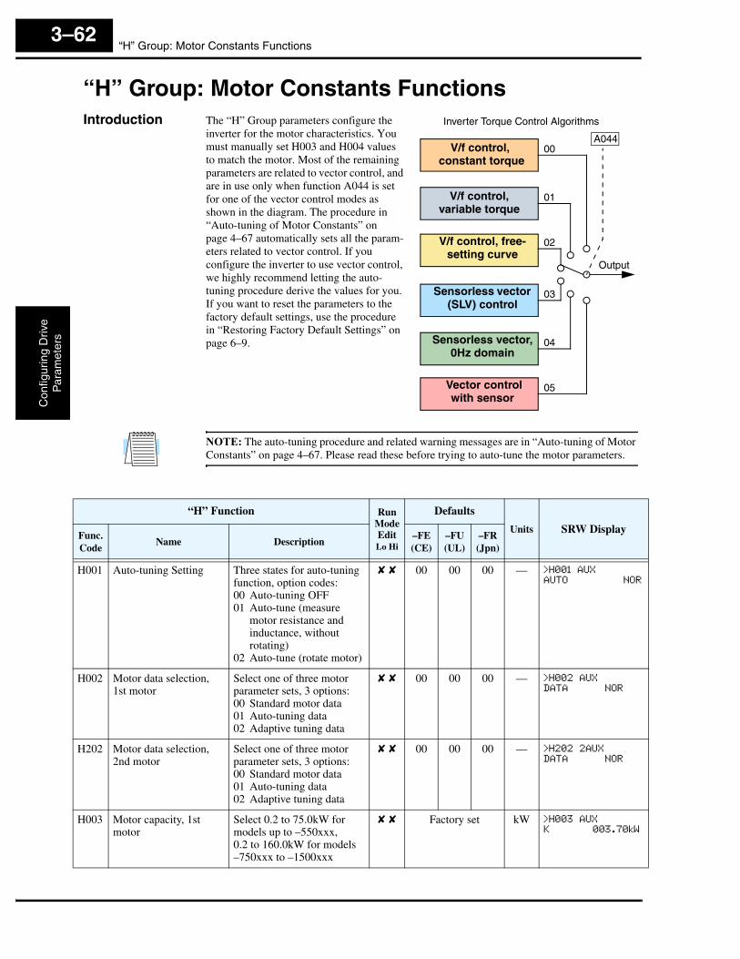
“H” Group: Motor Constants FunctionsC
onfig
urin
g D
rive
Par
amet
ers
3–62
“H” Group: Motor Constants FunctionsIntroduction The “H” Group parameters configure the
inverter for the motor characteristics. You must manually set H003 and H004 values to match the motor. Most of the remaining parameters are related to vector control, and are in use only when function A044 is set for one of the vector control modes as shown in the diagram. The procedure in “Auto-tuning of Motor Constants” on page 4–67 automatically sets all the param-eters related to vector control. If you configure the inverter to use vector control, we highly recommend letting the auto-tuning procedure derive the values for you. If you want to reset the parameters to the factory default settings, use the procedure in “Restoring Factory Default Settings” on page 6–9.
NOTE: The auto-tuning procedure and related warning messages are in “Auto-tuning of Motor Constants” on page 4–67. Please read these before trying to auto-tune the motor parameters.
Output
V/f control, constant torque
V/f control,variable torque
V/f control, free-setting curve
Inverter Torque Control Algorithms
Sensorless vector (SLV) control
Sensorless vector,0Hz domain
Vector control with sensor
00
05
04
03
02
01
A044
“H” Function Run ModeEditLo Hi
Defaults
Units SRW DisplayFunc.Code
Name Description–FE(CE)
–FU(UL)
–FR(Jpn)
H001 Auto-tuning Setting Three states for auto-tuning function, option codes:00 Auto-tuning OFF01 Auto-tune (measure
motor resistance and inductance, without rotating)
02 Auto-tune (rotate motor)
✘ ✘ 00 00 00 — >H001 AUX
AUTO NOR
H002 Motor data selection, 1st motor
Select one of three motor parameter sets, 3 options:00 Standard motor data01 Auto-tuning data02 Adaptive tuning data
✘ ✘ 00 00 00 — >H002 AUX
DATA NOR
H202 Motor data selection, 2nd motor
Select one of three motor parameter sets, 3 options:00 Standard motor data01 Auto-tuning data02 Adaptive tuning data
✘ ✘ 00 00 00 — >H202 2AUX
DATA NOR
H003 Motor capacity, 1st motor
Select 0.2 to 75.0kW for models up to –550xxx,0.2 to 160.0kW for models–750xxx to –1500xxx
✘ ✘ Factory set kW >H003 AUX
K 003.70kW
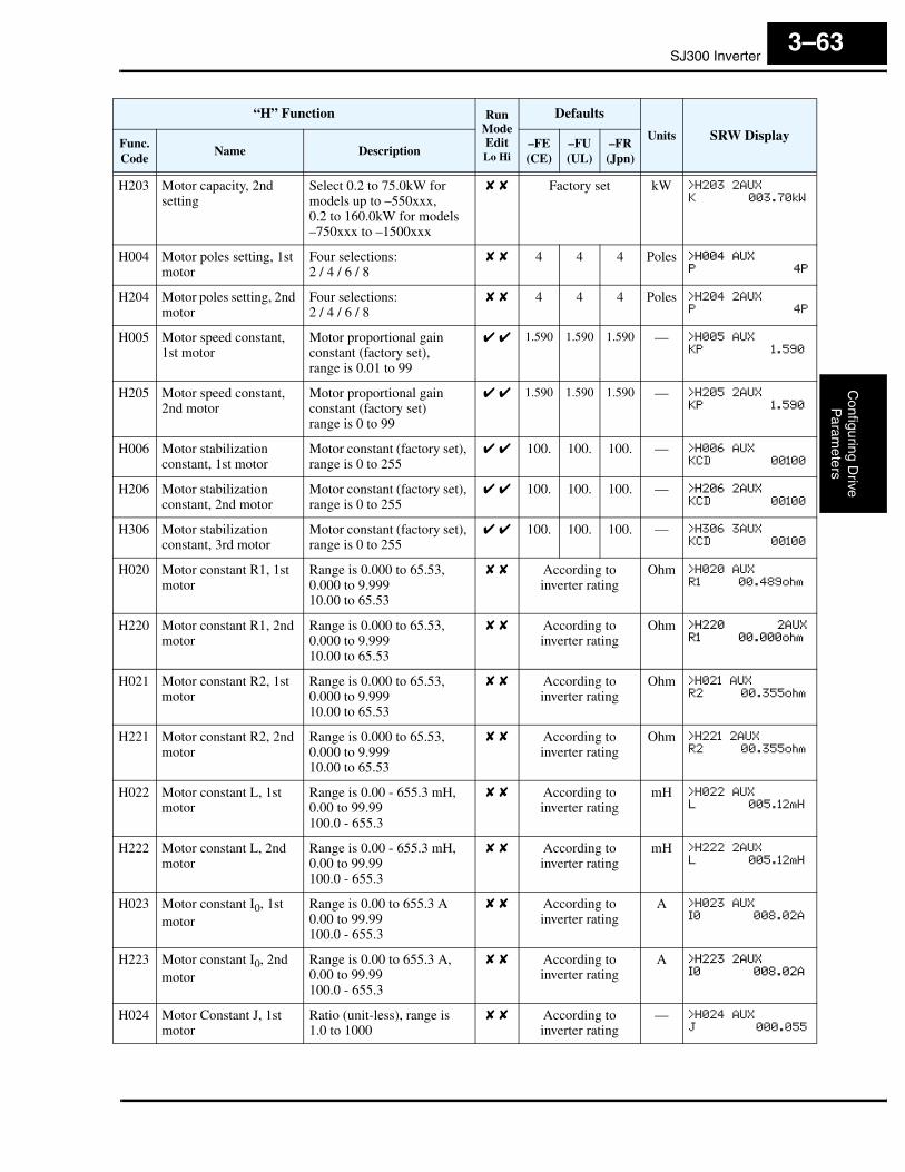
SJ300 InverterC
onfiguring Drive
Param
eters
3–63
“H” Function Run ModeEditLo Hi
Defaults
Units SRW DisplayFunc.Code
Name Description–FE(CE)
–FU(UL)
–FR(Jpn)
H203 Motor capacity, 2nd setting
Select 0.2 to 75.0kW for models up to –550xxx,0.2 to 160.0kW for models–750xxx to –1500xxx
✘ ✘ Factory set kW >H203 2AUX
K 003.70kW
H004 Motor poles setting, 1st motor
Four selections:2 / 4 / 6 / 8
✘ ✘ 4 4 4 Poles >H004 AUX
P 4P
H204 Motor poles setting, 2nd motor
Four selections:2 / 4 / 6 / 8
✘ ✘ 4 4 4 Poles >H204 2AUX
P 4P
H005 Motor speed constant, 1st motor
Motor proportional gain constant (factory set),range is 0.01 to 99
✔ ✔ 1.590 1.590 1.590 — >H005 AUX
KP 1.590
H205 Motor speed constant, 2nd motor
Motor proportional gain constant (factory set)range is 0 to 99
✔ ✔ 1.590 1.590 1.590 — >H205 2AUX
KP 1.590
H006 Motor stabilization constant, 1st motor
Motor constant (factory set), range is 0 to 255
✔ ✔ 100. 100. 100. — >H006 AUX
KCD 00100
H206 Motor stabilization constant, 2nd motor
Motor constant (factory set), range is 0 to 255
✔ ✔ 100. 100. 100. — >H206 2AUX
KCD 00100
H306 Motor stabilization constant, 3rd motor
Motor constant (factory set), range is 0 to 255
✔ ✔ 100. 100. 100. — >H306 3AUX
KCD 00100
H020 Motor constant R1, 1st motor
Range is 0.000 to 65.53,0.000 to 9.99910.00 to 65.53
✘ ✘ According to inverter rating
Ohm >H020 AUX
R1 00.489ohm
H220 Motor constant R1, 2nd motor
Range is 0.000 to 65.53,0.000 to 9.99910.00 to 65.53
✘ ✘ According to inverter rating
Ohm >H220 2AUX
R1 00.000ohm
H021 Motor constant R2, 1st motor
Range is 0.000 to 65.53,0.000 to 9.99910.00 to 65.53
✘ ✘ According to inverter rating
Ohm >H021 AUX
R2 00.355ohm
H221 Motor constant R2, 2nd motor
Range is 0.000 to 65.53,0.000 to 9.99910.00 to 65.53
✘ ✘ According to inverter rating
Ohm >H221 2AUX
R2 00.355ohm
H022 Motor constant L, 1st motor
Range is 0.00 - 655.3 mH,0.00 to 99.99100.0 - 655.3
✘ ✘ According to inverter rating
mH >H022 AUX
L 005.12mH
H222 Motor constant L, 2nd motor
Range is 0.00 - 655.3 mH,0.00 to 99.99100.0 - 655.3
✘ ✘ According to inverter rating
mH >H222 2AUX
L 005.12mH
H023 Motor constant I0, 1st motor
Range is 0.00 to 655.3 A0.00 to 99.99100.0 - 655.3
✘ ✘ According to inverter rating
A >H023 AUX
I0 008.02A
H223 Motor constant I0, 2nd motor
Range is 0.00 to 655.3 A,0.00 to 99.99100.0 - 655.3
✘ ✘ According to inverter rating
A >H223 2AUX
I0 008.02A
H024 Motor Constant J, 1st motor
Ratio (unit-less), range is1.0 to 1000
✘ ✘ According to inverter rating
— >H024 AUX
J 000.055
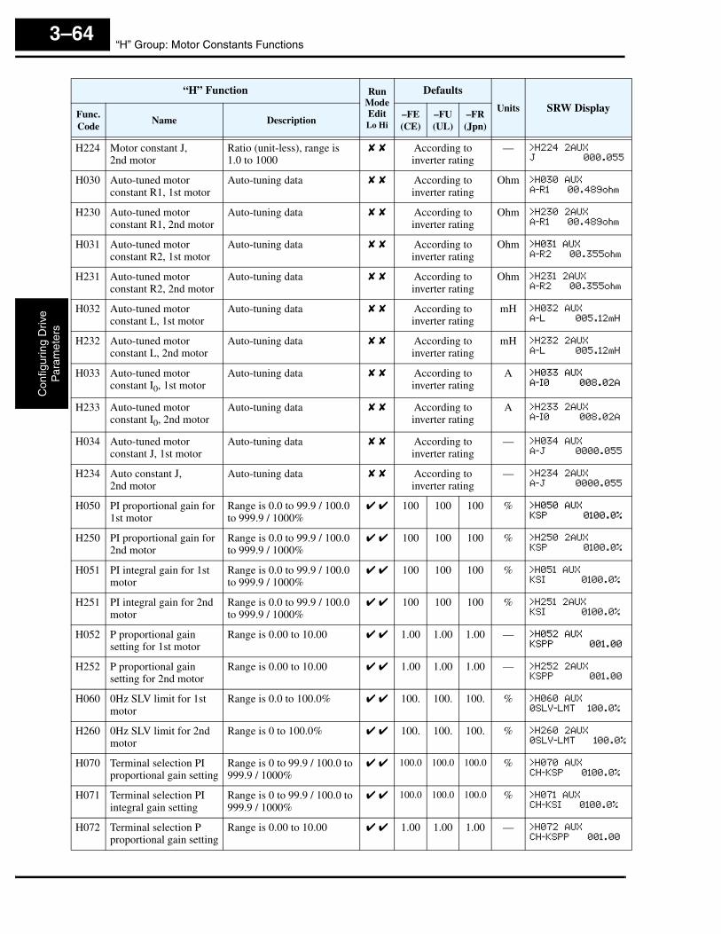
“H” Group: Motor Constants FunctionsC
onfig
urin
g D
rive
Par
amet
ers
3–64
H224 Motor constant J,2nd motor
Ratio (unit-less), range is1.0 to 1000
✘ ✘ According to inverter rating
— >H224 2AUX
J 000.055
H030 Auto-tuned motor constant R1, 1st motor
Auto-tuning data ✘ ✘ According to inverter rating
Ohm >H030 AUX
A-R1 00.489ohm
H230 Auto-tuned motor constant R1, 2nd motor
Auto-tuning data ✘ ✘ According to inverter rating
Ohm >H230 2AUX
A-R1 00.489ohm
H031 Auto-tuned motor constant R2, 1st motor
Auto-tuning data ✘ ✘ According to inverter rating
Ohm >H031 AUX
A-R2 00.355ohm
H231 Auto-tuned motor constant R2, 2nd motor
Auto-tuning data ✘ ✘ According to inverter rating
Ohm >H231 2AUX
A-R2 00.355ohm
H032 Auto-tuned motor constant L, 1st motor
Auto-tuning data ✘ ✘ According to inverter rating
mH >H032 AUX
A-L 005.12mH
H232 Auto-tuned motor constant L, 2nd motor
Auto-tuning data ✘ ✘ According to inverter rating
mH >H232 2AUX
A-L 005.12mH
H033 Auto-tuned motor constant I0, 1st motor
Auto-tuning data ✘ ✘ According to inverter rating
A >H033 AUX
A-I0 008.02A
H233 Auto-tuned motor constant I0, 2nd motor
Auto-tuning data ✘ ✘ According to inverter rating
A >H233 2AUX
A-I0 008.02A
H034 Auto-tuned motor constant J, 1st motor
Auto-tuning data ✘ ✘ According to inverter rating
— >H034 AUX
A-J 0000.055
H234 Auto constant J,2nd motor
Auto-tuning data ✘ ✘ According to inverter rating
— >H234 2AUX
A-J 0000.055
H050 PI proportional gain for 1st motor
Range is 0.0 to 99.9 / 100.0 to 999.9 / 1000%
✔ ✔ 100 100 100 % >H050 AUX
KSP 0100.0%
H250 PI proportional gain for 2nd motor
Range is 0.0 to 99.9 / 100.0 to 999.9 / 1000%
✔ ✔ 100 100 100 % >H250 2AUX
KSP 0100.0%
H051 PI integral gain for 1st motor
Range is 0.0 to 99.9 / 100.0 to 999.9 / 1000%
✔ ✔ 100 100 100 % >H051 AUX
KSI 0100.0%
H251 PI integral gain for 2nd motor
Range is 0.0 to 99.9 / 100.0 to 999.9 / 1000%
✔ ✔ 100 100 100 % >H251 2AUX
KSI 0100.0%
H052 P proportional gain setting for 1st motor
Range is 0.00 to 10.00 ✔ ✔ 1.00 1.00 1.00 — >H052 AUX
KSPP 001.00
H252 P proportional gain setting for 2nd motor
Range is 0.00 to 10.00 ✔ ✔ 1.00 1.00 1.00 — >H252 2AUX
KSPP 001.00
H060 0Hz SLV limit for 1st motor
Range is 0.0 to 100.0% ✔ ✔ 100. 100. 100. % >H060 AUX
0SLV-LMT 100.0%
H260 0Hz SLV limit for 2nd motor
Range is 0 to 100.0% ✔ ✔ 100. 100. 100. % >H260 2AUX
0SLV-LMT 100.0%
H070 Terminal selection PI proportional gain setting
Range is 0 to 99.9 / 100.0 to 999.9 / 1000%
✔ ✔ 100.0 100.0 100.0 % >H070 AUX
CH-KSP 0100.0%
H071 Terminal selection PI integral gain setting
Range is 0 to 99.9 / 100.0 to 999.9 / 1000%
✔ ✔ 100.0 100.0 100.0 % >H071 AUX
CH-KSI 0100.0%
H072 Terminal selection P proportional gain setting
Range is 0.00 to 10.00 ✔ ✔ 1.00 1.00 1.00 — >H072 AUX
CH-KSPP 001.00
“H” Function Run ModeEditLo Hi
Defaults
Units SRW DisplayFunc.Code
Name Description–FE(CE)
–FU(UL)
–FR(Jpn)
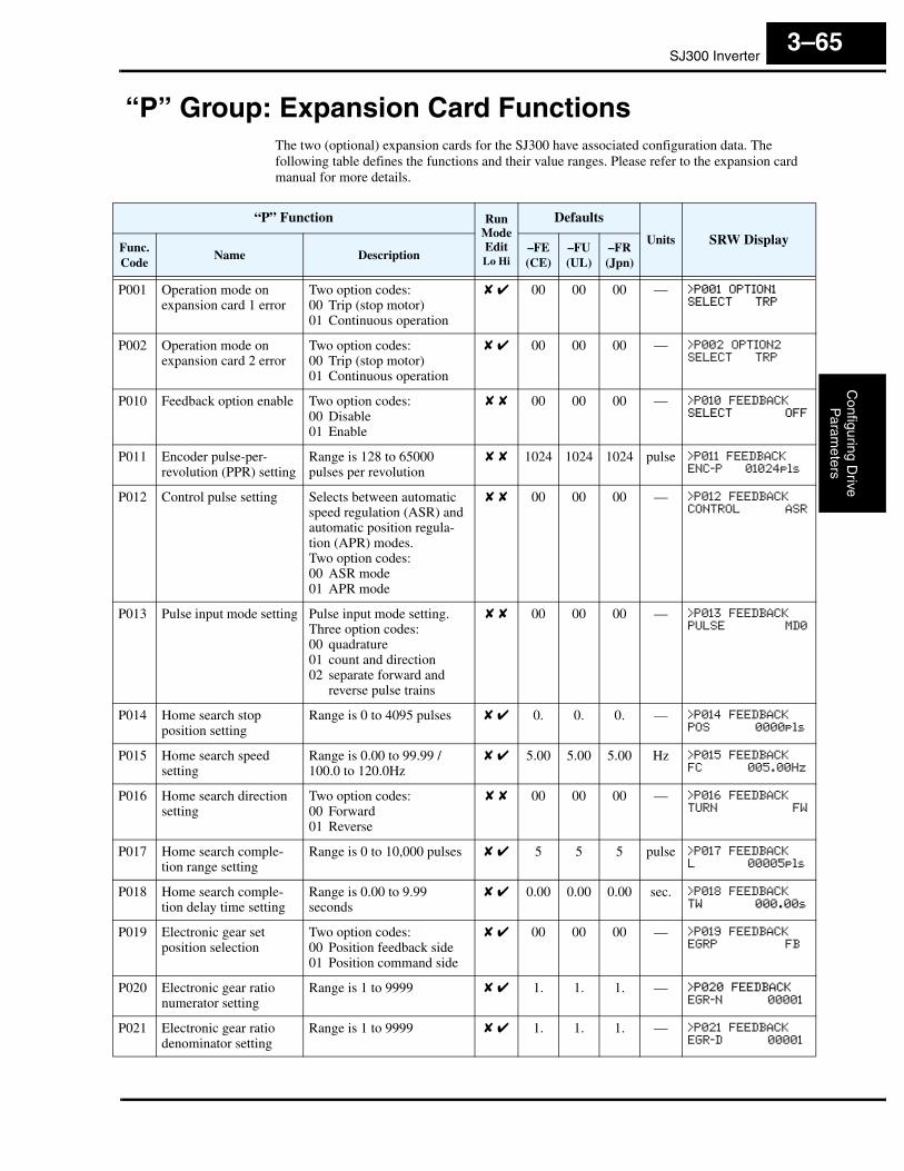
SJ300 InverterC
onfiguring Drive
Param
eters
3–65
“P” Group: Expansion Card FunctionsThe two (optional) expansion cards for the SJ300 have associated configuration data. The following table defines the functions and their value ranges. Please refer to the expansion card manual for more details.
“P” Function Run ModeEditLo Hi
Defaults
Units SRW DisplayFunc.Code
Name Description–FE(CE)
–FU(UL)
–FR(Jpn)
P001 Operation mode on expansion card 1 error
Two option codes:00 Trip (stop motor)01 Continuous operation
✘ ✔ 00 00 00 — >P001 OPTION1
SELECT TRP
P002 Operation mode on expansion card 2 error
Two option codes:00 Trip (stop motor)01 Continuous operation
✘ ✔ 00 00 00 — >P002 OPTION2
SELECT TRP
P010 Feedback option enable Two option codes:00 Disable01 Enable
✘ ✘ 00 00 00 — >P010 FEEDBACK
SELECT OFF
P011 Encoder pulse-per-revolution (PPR) setting
Range is 128 to 65000 pulses per revolution
✘ ✘ 1024 1024 1024 pulse >P011 FEEDBACK
ENC-P 01024pls
P012 Control pulse setting Selects between automatic speed regulation (ASR) and automatic position regula-tion (APR) modes.Two option codes:00 ASR mode01 APR mode
✘ ✘ 00 00 00 — >P012 FEEDBACK
CONTROL ASR
P013 Pulse input mode setting Pulse input mode setting.Three option codes:00 quadrature01 count and direction02 separate forward and
reverse pulse trains
✘ ✘ 00 00 00 — >P013 FEEDBACK
PULSE MD0
P014 Home search stop position setting
Range is 0 to 4095 pulses ✘ ✔ 0. 0. 0. — >P014 FEEDBACK
POS 0000pls
P015 Home search speed setting
Range is 0.00 to 99.99 /100.0 to 120.0Hz
✘ ✔ 5.00 5.00 5.00 Hz >P015 FEEDBACK
FC 005.00Hz
P016 Home search direction setting
Two option codes:00 Forward01 Reverse
✘ ✘ 00 00 00 — >P016 FEEDBACK
TURN FW
P017 Home search comple-tion range setting
Range is 0 to 10,000 pulses ✘ ✔ 5 5 5 pulse >P017 FEEDBACK
L 00005pls
P018 Home search comple-tion delay time setting
Range is 0.00 to 9.99 seconds
✘ ✔ 0.00 0.00 0.00 sec. >P018 FEEDBACK
TW 000.00s
P019 Electronic gear set position selection
Two option codes:00 Position feedback side01 Position command side
✘ ✔ 00 00 00 — >P019 FEEDBACK
EGRP FB
P020 Electronic gear ratio numerator setting
Range is 1 to 9999 ✘ ✔ 1. 1. 1. — >P020 FEEDBACK
EGR-N 00001
P021 Electronic gear ratio denominator setting
Range is 1 to 9999 ✘ ✔ 1. 1. 1. — >P021 FEEDBACK
EGR-D 00001
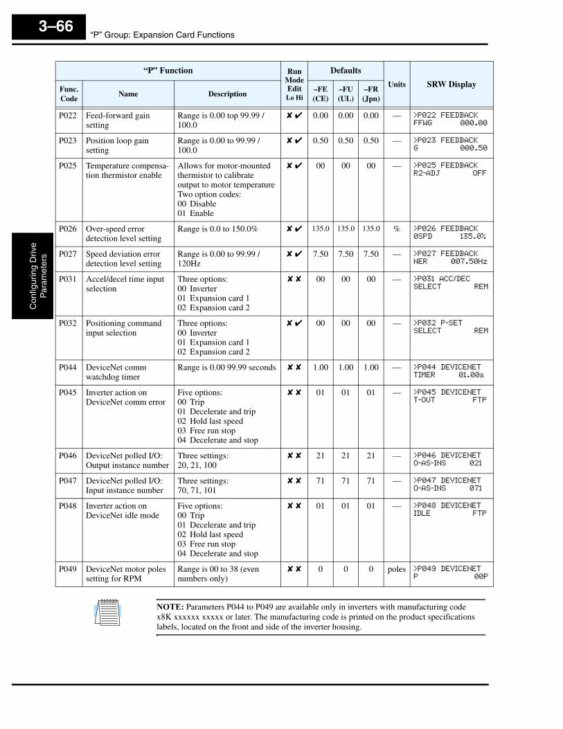
“P” Group: Expansion Card FunctionsC
onfig
urin
g D
rive
Par
amet
ers
3–66
NOTE: Parameters P044 to P049 are available only in inverters with manufacturing code x8K xxxxxx xxxxx or later. The manufacturing code is printed on the product specifications labels, located on the front and side of the inverter housing.
P022 Feed-forward gain setting
Range is 0.00 top 99.99 / 100.0
✘ ✔ 0.00 0.00 0.00 — >P022 FEEDBACK
FFWG 000.00
P023 Position loop gain setting
Range is 0.00 to 99.99 / 100.0
✘ ✔ 0.50 0.50 0.50 — >P023 FEEDBACK
G 000.50
P025 Temperature compensa-tion thermistor enable
Allows for motor-mounted thermistor to calibrate output to motor temperatureTwo option codes:00 Disable01 Enable
✘ ✔ 00 00 00 — >P025 FEEDBACK
R2-ADJ OFF
P026 Over-speed errordetection level setting
Range is 0.0 to 150.0% ✘ ✔ 135.0 135.0 135.0 % >P026 FEEDBACK
0SPD 135.0%
P027 Speed deviation error detection level setting
Range is 0.00 to 99.99 / 120Hz
✘ ✔ 7.50 7.50 7.50 — >P027 FEEDBACK
NER 007.50Hz
P031 Accel/decel time input selection
Three options:00 Inverter01 Expansion card 102 Expansion card 2
✘ ✘ 00 00 00 — >P031 ACC/DEC
SELECT REM
P032 Positioning command input selection
Three options:00 Inverter01 Expansion card 102 Expansion card 2
✘ ✔ 00 00 00 — >P032 P-SET
SELECT REM
P044 DeviceNet comm watchdog timer
Range is 0.00 99.99 seconds ✘ ✘ 1.00 1.00 1.00 — >P044 DEVICENET
TIMER 01.00s
P045 Inverter action on DeviceNet comm error
Five options:00 Trip01 Decelerate and trip02 Hold last speed03 Free run stop04 Decelerate and stop
✘ ✘ 01 01 01 — >P045 DEVICENET
T-OUT FTP
P046 DeviceNet polled I/O: Output instance number
Three settings:20, 21, 100
✘ ✘ 21 21 21 — >P046 DEVICENET
O-AS-INS 021
P047 DeviceNet polled I/O: Input instance number
Three settings:70, 71, 101
✘ ✘ 71 71 71 — >P047 DEVICENET
O-AS-INS 071
P048 Inverter action on DeviceNet idle mode
Five options:00 Trip01 Decelerate and trip02 Hold last speed03 Free run stop04 Decelerate and stop
✘ ✘ 01 01 01 — >P048 DEVICENET
IDLE FTP
P049 DeviceNet motor poles setting for RPM
Range is 00 to 38 (even numbers only)
✘ ✘ 0 0 0 poles >P049 DEVICENET
P 00P
“P” Function Run ModeEditLo Hi
Defaults
Units SRW DisplayFunc.Code
Name Description–FE(CE)
–FU(UL)
–FR(Jpn)

SJ300 InverterC
onfiguring Drive
Param
eters
3–67
“U” Group: User-selectable Menu FunctionsThe user-selectable menu functions allow you to configure (select) any twelve of the other functions in the inverter and place them together in a convenient list. This feature provides quick access for the most-used functions needed for your application. Each U Group function can serve as a pointer to any of the other parameters. You do not have to use the Store key to retain each association; just scroll to the desired standard parameter for each U Group function and leave it. The setting can point to a monitor-only parameter (such as D001), or point to editable parameters (such as A001). In the case of pointing to an editable functions, you use the Up/Down keys to change the value and the Store key to accept the change into memory—the same procedure as a normal parameter edit.
TIP: Function B037 selects which parameter groups are displayed. If you want to limit the displayed parameters to only the U Group functions, set B037=02.
“U” Function Run ModeEditLo Hi
Defaults
Units SRW DisplayFunc.Code
Name Description–FE(CE)
–FU(UL)
–FR(Jpn)
U001
User-selected function “no” (disabled), or any of the functions D001 to P049
✘ ✔ no no no — >U001 USER
1 no
U002 ✘ ✔ no no no — >U002 USER
2 no
U003 ✘ ✔ no no no — >U003 USER
3 no
U004 ✘ ✔ no no no — >U004 USER
4 no
U005 ✘ ✔ no no no — >U005 USER
5 no
U006 ✘ ✔ no no no — >U006 USER
6 no
U007 ✘ ✔ no no no — >U007 USER
7 no
U008 ✘ ✔ no no no — >U008 USER
8 no
U009 ✘ ✔ no no no — >U009 USER
9 no
U010 ✘ ✔ no no no — >U010 USER
10 no
U011 ✘ ✔ no no no — >U011 USER
11 no
U012 ✘ ✔ no no no — >U012 USER
12 no
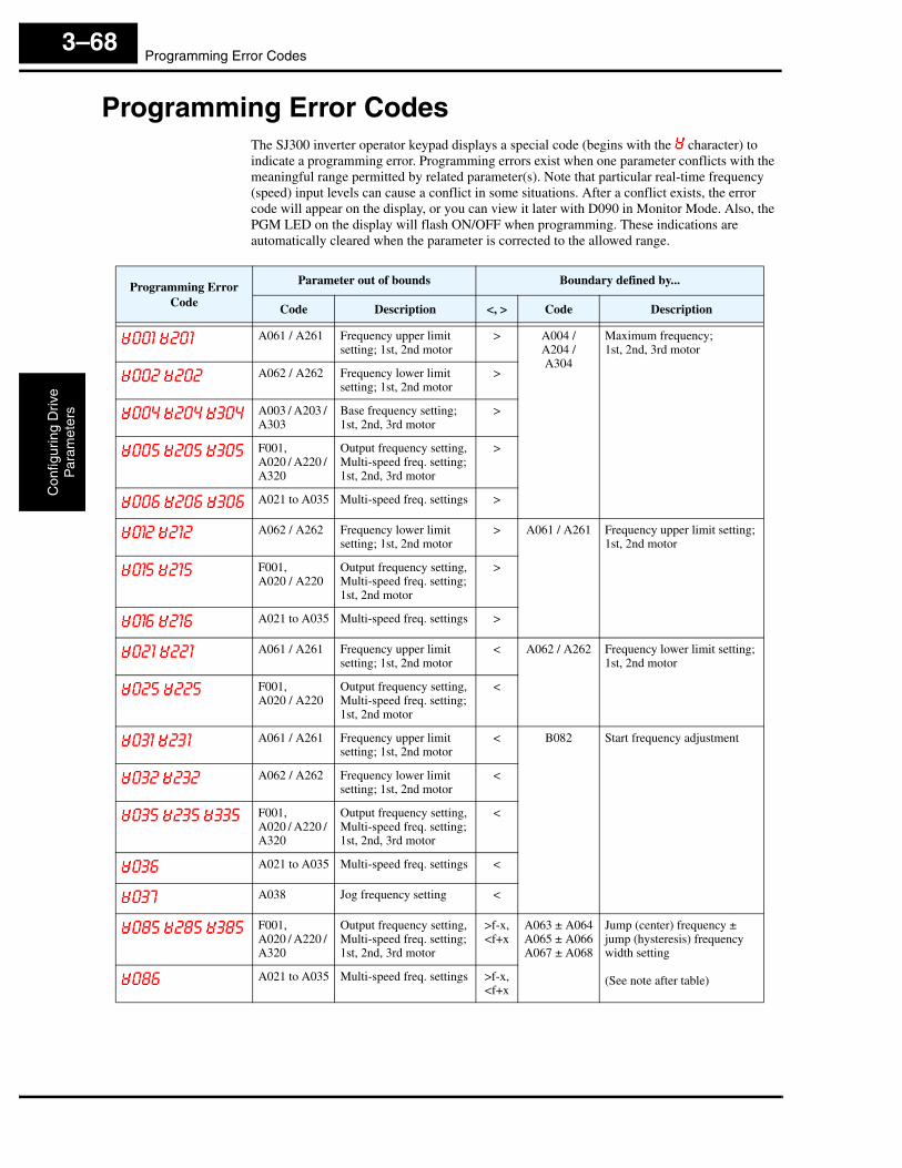
Programming Error CodesC
onfig
urin
g D
rive
Par
amet
ers
3–68
Programming Error CodesThe SJ300 inverter operator keypad displays a special code (begins with the character) to indicate a programming error. Programming errors exist when one parameter conflicts with the meaningful range permitted by related parameter(s). Note that particular real-time frequency (speed) input levels can cause a conflict in some situations. After a conflict exists, the error code will appear on the display, or you can view it later with D090 in Monitor Mode. Also, the PGM LED on the display will flash ON/OFF when programming. These indications are automatically cleared when the parameter is corrected to the allowed range.
Programming Error Code
Parameter out of bounds Boundary defined by...
Code Description <, > Code Description
001 201 A061 / A261 Frequency upper limit setting; 1st, 2nd motor
> A004 / A204 / A304
Maximum frequency;1st, 2nd, 3rd motor
002 202 A062 / A262 Frequency lower limit setting; 1st, 2nd motor
>
004 204 304 A003 / A203 / A303
Base frequency setting; 1st, 2nd, 3rd motor
>
005 205 305 F001,A020 / A220 / A320
Output frequency setting, Multi-speed freq. setting; 1st, 2nd, 3rd motor
>
006 206 306 A021 to A035 Multi-speed freq. settings >
012 212 A062 / A262 Frequency lower limit setting; 1st, 2nd motor
> A061 / A261 Frequency upper limit setting; 1st, 2nd motor
015 215 F001,A020 / A220
Output frequency setting, Multi-speed freq. setting; 1st, 2nd motor
>
016 216 A021 to A035 Multi-speed freq. settings >
021 221 A061 / A261 Frequency upper limit setting; 1st, 2nd motor
< A062 / A262 Frequency lower limit setting; 1st, 2nd motor
025 225 F001,A020 / A220
Output frequency setting, Multi-speed freq. setting; 1st, 2nd motor
<
031 231 A061 / A261 Frequency upper limit setting; 1st, 2nd motor
< B082 Start frequency adjustment
032 232 A062 / A262 Frequency lower limit setting; 1st, 2nd motor
<
035 235 335 F001,A020 / A220 / A320
Output frequency setting, Multi-speed freq. setting; 1st, 2nd, 3rd motor
<
036 A021 to A035 Multi-speed freq. settings <
037 A038 Jog frequency setting <
085 285 385 F001,A020 / A220 / A320
Output frequency setting, Multi-speed freq. setting; 1st, 2nd, 3rd motor
>f-x,<f+x
A063 ± A064A065 ± A066A067 ± A068
Jump (center) frequency ± jump (hysteresis) frequency width setting
(See note after table)086 A021 to A035 Multi-speed freq. settings >f-x,<f+x

SJ300 InverterC
onfiguring Drive
Param
eters
3–69
NOTE: Set frequency (speed) values are not permitted to be inside the jump frequency ranges, if defined. When a frequency reference value from a real-time source (such as keypad potenti-ometer or analog input) are inside a jump frequency range, the actual speed is automatically forced to equal the lowest point of the jump range.
091 291 A061 / A261 Frequency upper limit setting; 1st, 2nd motor
> B112 Free-setting V/f frequency (7)
092 292 A062 / A262 Frequency lower limit setting; 1st, 2nd motor
>
095 295 F001,A020 / A220
Output frequency setting, Multi-speed freq. setting; 1st, 2nd motor
>
096 A021 to A035 Multi-speed freq. settings >
110 B100, B102, B104, B106, B108, B110
Free V/f frequency >
B102, B104, B106, B108, B110
Free V/f frequency > B100 Free-setting V/f frequency (1)
B100 Free V/f frequency < B102 Free-setting V/f frequency (2)
B104, B106, B108, B110
Free V/f frequency >
B100, B102 Free V/f frequency < B104 Free-setting V/f frequency (3)
B106, B108, B110
Free V/f frequency >
B100, B102, B104
Free V/f frequency < B106 Free-setting V/f frequency (4)
B108, B110 Free V/f frequency >
B100, B102, B104, B106
Free V/f frequency < B108 Free-setting V/f frequency (5)
B110 Free V/f frequency >
B100, B102, B104, B106, B108
Free V/f frequency < B110 Free-setting V/f frequency (6)
120 B017, B019 Free-setting electronic thermal frequency
< B015 Free-setting, electronic thermal frequency (1)
B015 Free-setting electronic thermal frequency
> B017 Free-setting, electronic thermal frequency (2)
B019 Free-setting electronic thermal frequency
<
B015, B017 Free-setting electronic thermal frequency
> B019 Free-setting, electronic thermal frequency (3)
Programming Error Code
Parameter out of bounds Boundary defined by...
Code Description <, > Code Description
