configuring backup data lines and remote … backup data lines and remote management configuring...
TRANSCRIPT

Configuring Backup Data Lines and RemoteManagement
The Cisco 819 series and Cisco 880 Series Integrated Services Routers (ISRs) support backup data connectivitywith a backup data line that enables them to mitigate WAN downtime.
Voice backup is available on router models C881SRST and C888SRST. For information on configuringvoice backup, see Configuring Voice Functionality
Note
Cisco 880 ISRs also support remote management functions as follows:
• Through the auxiliary port on Cisco 880 series ISRs
• Through the ISDN S/T port on the Cisco 880 series ISRs
Cisco 819 ISRs a support remote management functions through the auxiliary port on any Cisco 819 seriesISRs.
On Cisco 819 sries and Cisco880 series ISRs, the console port and the auxiliary port are on the samephysical RJ-45 port; therefore, the two ports cannot be activated simultaneously. You must use the CLIto enable the desired function.
Note
Cisco 892F ISRs have a Gigabit Ethernet (GE) port that supports copper connections or a small-form-factorpluggable (SFP) port that supports fiber connections and can be configured for failover redundancy whenthe network goes down.
Note
This chapter describes configuring backup data lines and remote management in the following sections:
• Configuring Backup Interfaces, page 2
• Configuring Cellular Dial-on-Demand Routing Backup, page 3
• Configuring Dial Backup and Remote Management Through the Console or Auxiliary Port, page 9
• Configuring Data Line Backup and Remote Management Through the ISDN S/T Port, page 15
• Configuring Gigabit Ethernet Failover Media, page 21
Cisco 800 Series Integrated Services Routers Software Configuration Guide 1

• Configuring Third-Party SFPs, page 23
Configuring Backup InterfacesWhen the router receives an indication that the primary interface is down, the backup interface becomesenabled. After the primary connection has been restored for a specified period, the backup interface is disabled.
Even if the backup interface comes out of standby mode, the router does not enable the backup interface unlessthe router receives the traffic specified for that backup interface.
Table below shows the backup interfaces for Cisco 810, Cisco 880 and Cisco 890 series ISRs, along withtheir port designations. Basic configurations for these interfaces are given in the ConfiguringWAN Interfaces
Table 1: Model Numbers and Data Line Backup Capabilities
V.923GISDNRouter Model Number
—Yes—881G, 886G, 887G,887VG, 888G
——Yes886, 886VA, 887, 887V,888, 888E
Yes——891
——Yes892, 892F
Yes819
To configure your router with a backup interface, perform these steps, beginning in global configuration mode:
SUMMARY STEPS
1. interface type number2. backup interface interface-type interface-number3. exit
DETAILED STEPS
PurposeCommand or Action
Enters interface configuration mode for the interface for which you wantto configure the backup.
interface type number
Example:
Router(config)# interface atm 0
Step 1
This interface can be a serial, ISDN, or asynchronous.
The example shows the configuration of a backup interface for an ATMWAN connection.
Cisco 800 Series Integrated Services Routers Software Configuration Guide2
Configuring Backup Data Lines and Remote ManagementConfiguring Backup Interfaces

PurposeCommand or Action
Assigns an interface as the secondary, or backup interface.backup interface interface-typeinterface-number
Step 2
This can be a serial interface or asynchronous interface. For example, aserial 1 interface could be configured to back up a serial 0 interface.
Example:
Router(config-if)# backup interfacebri 0
The example shows a BRI interface configured as the backup interfacefor the ATM 0 interface.
Exits the configuration interface mode.exit
Example:
Router(config-if)# exit
Router(config)#
Step 3
Configuring Cellular Dial-on-Demand Routing BackupTomonitor the primary connection and initiate the backup connection over the cellular interface when needed,the router can use one of the following methods:
• Backup Interface—Backup interface that stays in standby mode until the primary interface line protocolis detected as down and then is brought up. See the Configuring Backup Interfaces, on page 2.
• DialerWatch—Backup feature that integrates dial backup with routing capabilities. See the ConfiguringDDR Backup Using Dialer Watch, on page 3.
• Floating Static Route—Route through the backup interface has an administrative distance that is greaterthan the administrative distance of the primary connection route and therefore would not be in the routingtable until the primary interface goes down. When the primary interaface goes down, the floating staticroute is used. See the Configuring DDR Backup Using Floating Static Route, on page 5.
You cannot configure a backup interface for the cellular interface and any other asynchronous serialinterface.
Note
Configuring DDR Backup Using Dialer WatchTo initiate dialer watch, you must configure the interface to perform dial-on-demand routing (DDR) andbackup. Use traditional DDR configuration commands, such as dialer maps, for DDR capabilities. To enabledialer watch on the backup interface and create a dialer list, use the following commands in interfaceconfiguration mode.
or
dialer group dialer group number
Cisco 800 Series Integrated Services Routers Software Configuration Guide 3
Configuring Backup Data Lines and Remote ManagementConfiguring Cellular Dial-on-Demand Routing Backup

SUMMARY STEPS
1. configure terminal2. interface type number3. dialer watch-group group-number4. dialer watch-list group-number ip ip-address address-mask5. dialer-list dialer-group protocol protocol-name {permit | deny | list access-list-number | access-group}6. ip access-list access-list-number permit ip source address7. interface cellular 08. Do one of the following:
• dialer string string
• or
• dialer group dialer group number
DETAILED STEPS
PurposeCommand or Action
Enters global configuration mode.configure terminal
Example:
Router# configure terminal
Step 1
Specifies the interface.interface type number
Example:
Router (config)# interface ATM0
Step 2
Enables dialer watch on the backup interface.dialer watch-group group-number
Example:
Router(config-if)# dialer watch-group 2
Step 3
Defines a list of all IP addresses to be watched.dialer watch-list group-number ip ip-address address-mask
Example:
Router(config-if)# dialer watch-list 2 ip 10.4.0.254255.255.0.0
Step 4
Creates a dialer list for traffic of interest and permitsaccess to an entire protocol.
dialer-list dialer-group protocol protocol-name {permit | deny| list access-list-number | access-group}
Example:
Router(config)# dialer-list 2 protocol ip permit
Step 5
Cisco 800 Series Integrated Services Routers Software Configuration Guide4
Configuring Backup Data Lines and Remote ManagementConfiguring DDR Backup Using Dialer Watch

PurposeCommand or Action
Defines traffic of interest.ip access-list access-list-number permit ip source addressStep 6
Example:
Router(config)# access list 2 permit 10.4.0.0
Do not use the access list permit all command toavoid sending traffic to the IP network. This mayresult in call termination.
Specifies the cellular interface.interface cellular 0
Example:
Router (config)# interface cellular 0
Step 7
CDMA only. Specifies the dialer script (definedusing the chat script command).
Do one of the following:Step 8
• dialer string stringGSM only. Maps a dialer list to the dialer interface.
• or
• dialer group dialer group number
Example:
Router (config-if)# dialer string cdma *** cdma ***or
Router (config-if)# dialer group 2 *** gsm ***
Configuring DDR Backup Using Floating Static RouteTo configure a floating static default route on the secondary interface, use the following commands, beginningin the global configuration mode.
Make sure you have ip classless enabled on your router.Note
SUMMARY STEPS
1. configure terminal2. ip route network-number network-mask {ip address | interface} [administrative distance] [name name]
Cisco 800 Series Integrated Services Routers Software Configuration Guide 5
Configuring Backup Data Lines and Remote ManagementConfiguring DDR Backup Using Floating Static Route
DETAILED STEPS
PurposeCommand or Action
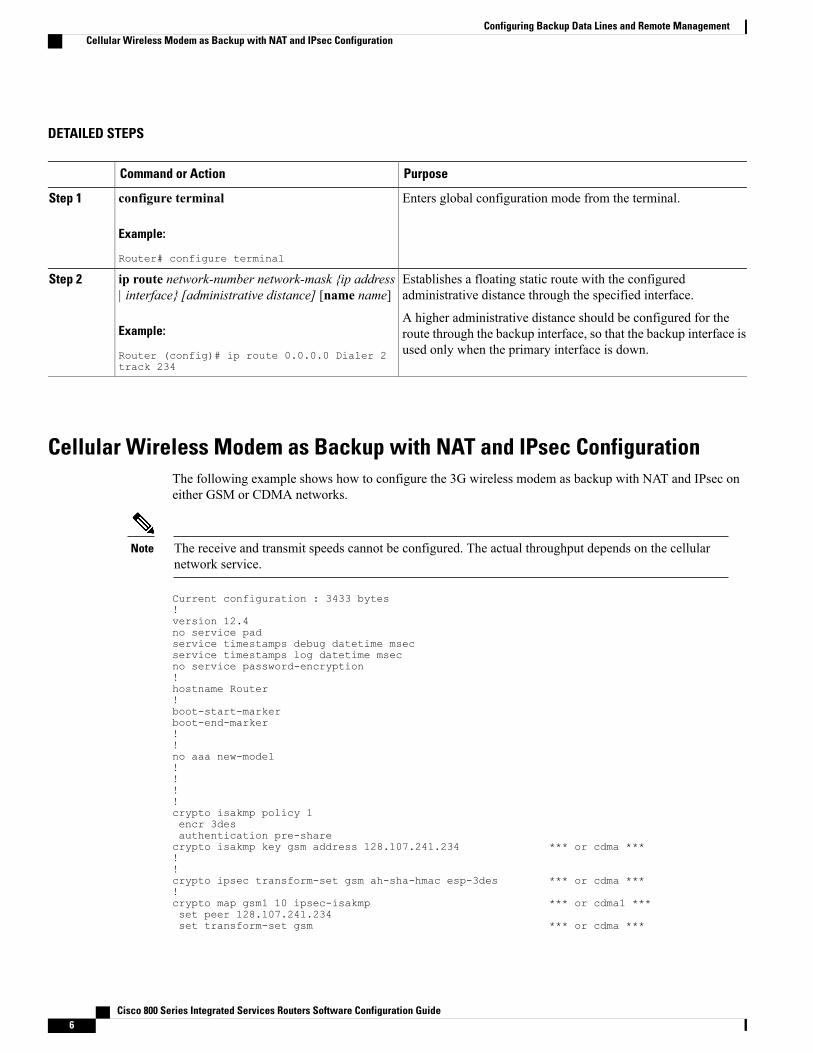
Enters global configuration mode from the terminal.configure terminal
Example:
Router# configure terminal
Step 1
Establishes a floating static route with the configuredadministrative distance through the specified interface.
ip route network-number network-mask {ip address| interface} [administrative distance] [name name]
Step 2
Example:
Router (config)# ip route 0.0.0.0 Dialer 2track 234
A higher administrative distance should be configured for theroute through the backup interface, so that the backup interface isused only when the primary interface is down.
Cellular Wireless Modem as Backup with NAT and IPsec ConfigurationThe following example shows how to configure the 3G wireless modem as backup with NAT and IPsec oneither GSM or CDMA networks.
The receive and transmit speeds cannot be configured. The actual throughput depends on the cellularnetwork service.
Note
Current configuration : 3433 bytes!version 12.4no service padservice timestamps debug datetime msecservice timestamps log datetime msecno service password-encryption!hostname Router!boot-start-markerboot-end-marker!!no aaa new-model!!!!crypto isakmp policy 1encr 3desauthentication pre-sharecrypto isakmp key gsm address 128.107.241.234 *** or cdma ***!!crypto ipsec transform-set gsm ah-sha-hmac esp-3des *** or cdma ***!crypto map gsm1 10 ipsec-isakmp *** or cdma1 ***set peer 128.107.241.234set transform-set gsm *** or cdma ***
Cisco 800 Series Integrated Services Routers Software Configuration Guide6
Configuring Backup Data Lines and Remote ManagementCellular Wireless Modem as Backup with NAT and IPsec Configuration

match address 103!!!no ip dhcp use vrf connectedip dhcp excluded-address 10.4.0.254!ip dhcp pool gsmpool *** or cdmapool ***
network 10.4.0.0 255.255.0.0dns-server 66.209.10.201 66.102.163.231default-router 10.4.0.254
!!ip cef!no ipv6 cefmultilink bundle-name authenticatedchat-script gsm "" "atdt*98*1#" TIMEOUT 30 "CONNECT" *** or cdma ***!!archivelog confighidekeys
!!controller DSL 0mode atmline-term cpeline-mode 4-wire standardline-rate 4608!!!!interface ATM0no ip addressip virtual-reassemblyload-interval 30no atm ilmi-keepalive!interface ATM0.1 point-to-pointbackup interface Cellular0ip nat outsideip virtual-reassemblypvc 0/35pppoe-client dial-pool-number 2!!interface FastEthernet0!interface FastEthernet1!interface FastEthernet2!interface FastEthernet3!interface Cellular0ip address negotiatedip nat outsideip virtual-reassemblyencapsulation pppno ip mroute-cachedialer in-banddialer idle-timeout 0dialer string gsm *** or cdma ***dialer-group 1async mode interactiveno ppp lcp fast-startppp chap hostname [email protected] chap password 0 B7uhestacrppp ipcp dns requestcrypto map gsm1 *** or cdma1 ***!
Cisco 800 Series Integrated Services Routers Software Configuration Guide 7
Configuring Backup Data Lines and Remote ManagementCellular Wireless Modem as Backup with NAT and IPsec Configuration

interface Vlan1description used as default gateway address for DHCP clientsip address 10.4.0.254 255.255.0.0ip nat insideip virtual-reassembly!interface Dialer2ip address negotiatedip mtu 1492ip nat outsideip virtual-reassemblyencapsulation pppload-interval 30dialer pool 2dialer-group 2ppp authentication chap callinppp chap hostname [email protected] chap password 0 ciscoppp ipcp dns requestcrypto map gsm1 *** or cdma1 ***!ip local policy route-map track-primary-ifip forward-protocol ndip route 0.0.0.0 0.0.0.0 Dialer2 track 234ip route 0.0.0.0 0.0.0.0 Cellular0 254no ip http serverno ip http secure-server!!ip nat inside source route-map nat2cell interface Cellular0 overloadip nat inside source route-map nat2dsl interface Dialer2 overload!ip sla 1icmp-echo 209.131.36.158 source-interface Dialer2timeout 1000frequency 2ip sla schedule 1 life forever start-time nowaccess-list 1 permit anyaccess-list 2 permit 10.4.0.0 0.0.255.255access-list 3 permit anyaccess-list 101 permit ip 10.4.0.0 0.0.255.255 anyaccess-list 102 permit icmp any host 209.131.36.158access-list 103 permit ip host 166.136.225.89 128.107.0.0 0.0.255.255access-list 103 permit ip host 75.40.113.246 128.107.0.0 0.0.255.255dialer-list 1 protocol ip list 1dialer-list 2 protocol ip permit!!!route-map track-primary-if permit 10match ip address 102set interface Dialer2!route-map nat2dsl permit 10match ip address 101match interface Dialer2!route-map nat2cell permit 10match ip address 101match interface Cellular0!!control-plane!!line con 0no modem enableline aux 0line 3exec-timeout 0 0script dialer gsm *** or cdma ***loginmodem InOut
Cisco 800 Series Integrated Services Routers Software Configuration Guide8
Configuring Backup Data Lines and Remote ManagementCellular Wireless Modem as Backup with NAT and IPsec Configuration

no execline vty 0 4login!scheduler max-task-time 5000
!webvpn cefend
Configuring Dial Backup and Remote Management Through theConsole or Auxiliary Port
When customer premises equipment, such as a Cisco 880 series ISR or Cisco 819 series ISR, is connected toan ISP, an IP address is dynamically assigned to the router, or the IP address may be assigned by the routerpeer through the centrally managed function. The dial backup feature can be added to provide a failover routein case the primary line fails. The Cisco 880 series ISRs can use the auxiliary port for dial backup and remotemanagement.
Figure below shows the network configuration used for remote management access and for providing backupto the primary WAN line.
Figure 1: Dial Backup and Remote Management Through the Auxiliary Port
Main WAN link; primaryconnection to Internetservice provider
ACisco 880 series router1
Dial backup; serves as afailover link for Cisco880 routers when theprimary line goes down
BModem2
Cisco 800 Series Integrated Services Routers Software Configuration Guide 9
Configuring Backup Data Lines and Remote ManagementConfiguring Dial Backup and Remote Management Through the Console or Auxiliary Port

Remote management;serves as dial-in access toallow changes or updatesto Cisco IOSconfigurations
CPC3
To configure dial backup and remote management for these routers, perform these steps, beginning in globalconfiguration mode:
SUMMARY STEPS
1. ip name-server server-address2. ip dhcp pool name3. exit4. chat-script script-name expect-send5. interface type number6. exit7. interface type number8. dialer watch-group group-number9. exit10. ip nat inside source {list access-list-number} {interface type number | pool name} [overload]11. ip route prefix mask {ip-address | interface-type interface-number [ip-address]12. access-list access-list-number {deny | permit} source [source-wildcard]13. dialerwatch-list group-number {ipip-address address-mask | delay route-check initial seconds14. line [aux | console | tty | vty] line-number [ending-line-number]15. modem enable16. exit17. line [aux | console | tty | vty] line-number [ending-line-number]18. flowcontrol {none | software [lock] [in | out] | hardware [in | out]}
DETAILED STEPS
PurposeCommand or Action
Enters your ISP DNS IP address.ip name-server server-addressStep 1
Example:
Router(config)# ip name-server 192.168.28.12
You may add multiple server addresses ifavailable.
Tip
Creates a DHCP address pool on the router and enters DHCPpool configuration mode. The name argument can be a stringor an integer.
ip dhcp pool name
Example:
Router(config)# ip dhcp pool 1
Step 2
Configure the DHCP address pool. For sample commandsthat you can use in DHCP pool configuration mode, see the
Cisco 800 Series Integrated Services Routers Software Configuration Guide10
Configuring Backup Data Lines and Remote ManagementConfiguring Dial Backup and Remote Management Through the Console or Auxiliary Port

PurposeCommand or Action
Example for specifying an IP address for the ATM interfacethrough PPP and IPCP address negotiation and dial backup,on page 13.
Exits config-dhcpmode and enters global configurationmode.exit
Example:
Router(config-dhcp)#exit
Step 3
Configures a chat script used in dial-on-demand routing(DDR) to give commands for dialing a modem and for
chat-script script-name expect-send
Example:
Router(config)#
Step 4
logging in to remote systems. The defined script is used toplace a call over a modem connected to the PSTN.
chat-script Dialout ABORT ERROR ABORT BUSY “““AT” OK “ATDT 5555102 T” TIMEOUT 45 CONNECT \c
Creates and enters configuration mode for the asynchronousinterface.
interface type number
Example:
Router(config)#interface Async 1
Step 5
Configure the asynchronous interface. For sample commandsthat you can use in asynchronous interface configurationmode, see the Example for specifying an IP address for theATM interface through PPP and IPCP address negotiationand dial backup, on page 13.
Enters global configuration mode.exit
Example:
Router(config-if)# exit
Step 6
Creates and enters configurationmode for the dilaer interface.interface type number
Example:
Router(config)#interface Dialer 3
Step 7
Specifies the group number for the watch list.dialer watch-group group-number
Example:
Router(config-if)# dialer watch-group 1
Step 8
Exits the interface configuration mode.exit
Example:
Router(config-if)#exit
Step 9
Cisco 800 Series Integrated Services Routers Software Configuration Guide 11
Configuring Backup Data Lines and Remote ManagementConfiguring Dial Backup and Remote Management Through the Console or Auxiliary Port
PurposeCommand or Action
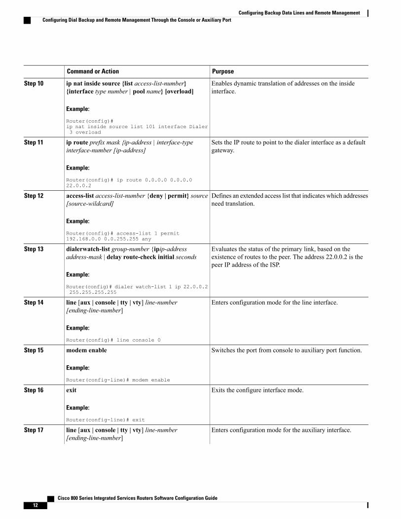
Enables dynamic translation of addresses on the insideinterface.
ip nat inside source {list access-list-number}{interface type number | pool name} [overload]
Example:
Router(config)#
Step 10
ip nat inside source list 101 interface Dialer3 overload
Sets the IP route to point to the dialer interface as a defaultgateway.
ip route prefix mask {ip-address | interface-typeinterface-number [ip-address]
Example:
Router(config)# ip route 0.0.0.0 0.0.0.022.0.0.2
Step 11
Defines an extended access list that indicates which addressesneed translation.
access-list access-list-number {deny | permit} source[source-wildcard]
Example:
Router(config)# access-list 1 permit192.168.0.0 0.0.255.255 any
Step 12
Evaluates the status of the primary link, based on theexistence of routes to the peer. The address 22.0.0.2 is thepeer IP address of the ISP.
dialerwatch-list group-number {ipip-addressaddress-mask | delay route-check initial seconds
Example:
Router(config)# dialer watch-list 1 ip 22.0.0.2255.255.255.255
Step 13
Enters configuration mode for the line interface.line [aux | console | tty | vty] line-number[ending-line-number]
Step 14
Example:
Router(config)# line console 0
Switches the port from console to auxiliary port function.modem enable
Example:
Router(config-line)# modem enable
Step 15
Exits the configure interface mode.exit
Example:
Router(config-line)# exit
Step 16
Enters configuration mode for the auxiliary interface.line [aux | console | tty | vty] line-number[ending-line-number]
Step 17
Cisco 800 Series Integrated Services Routers Software Configuration Guide12
Configuring Backup Data Lines and Remote ManagementConfiguring Dial Backup and Remote Management Through the Console or Auxiliary Port

PurposeCommand or Action
Example:
Router(config)# line aux 0
Enables hardware signal flow control.flowcontrol {none | software [lock] [in | out] |hardware [in | out]}
Step 18
Example:
Router(config)# flowcontrol hardware
Example for specifying an IP address for the ATM interface through PPP andIPCP address negotiation and dial backup
The following configuration example specifies an IP address for the ATM interface through PPP and IPCPaddress negotiation and dial backup over the console port.
!ip name-server 192.168.28.12ip dhcp excluded-address 192.168.1.1!ip dhcp pool 1import allnetwork 192.168.1.0 255.255.255.0default-router 192.168.1.1!! Need to use your own correct ISP phone number.modemcap entry MY-USER_MODEM:MSC=&F1S0=1chat-script Dialout ABORT ERROR ABORT BUSY ““ “AT” OK “ATDT 5555102\T”TIMEOUT 45 CONNECT \c!!!!interface vlan 1ip address 192.168.1.1 255.255.255.0ip nat insideip tcp adjust-mss 1452hold-queue 100 out!! Dial backup and remote management physical interface.interface Async1no ip addressencapsulation pppdialer in-banddialer pool-member 3async default routingasync dynamic routingasync mode dedicatedppp authentication pap callin!interface ATM0mtu 1492no ip addressno atm ilmi-keepalivepvc 0/35
Cisco 800 Series Integrated Services Routers Software Configuration Guide 13
Configuring Backup Data Lines and Remote ManagementExample for specifying an IP address for the ATM interface through PPP and IPCP address negotiation and dial
backup

pppoe-client dial-pool-number 1!dsl operating-mode auto!! Primary WAN link.interface Dialer1ip address negotiatedip nat outsideencapsulation pppdialer pool 1ppp authentication pap callinppp pap sent-username account password 7 passppp ipcp dns requestppp ipcp wins requestppp ipcp mask request!! Dialer backup logical interface.interface Dialer3ip address negotiatedip nat outsideencapsulation pppno ip route-cacheno ip mroute-cachedialer pool 3dialer idle-timeout 60dialer string 5555102 modem-script Dialoutdialer watch-group 1!! Remote management PC IP address.peer default ip address 192.168.2.2no cdp enable!! Need to use your own ISP account and password.ppp pap sent-username account password 7 passppp ipcp dns requestppp ipcp wins requestppp ipcp mask request!! IP NAT over Dialer interface using route-map.ip nat inside source route-map main interface Dialer1 overloadip nat inside source route-map secondary interface Dialer3 overloadip classless!! When primary link is up again, distance 50 will override 80 if dial backup! has not timed out. Use multiple routes because peer IP addresses are alternated! among them when the CPE is connected.ip route 0.0.0.0 0.0.0.0 64.161.31.254 50ip route 0.0.0.0 0.0.0.0 66.125.91.254 50ip route 0.0.0.0 0.0.0.0 64.174.91.254 50ip route 0.0.0.0 0.0.0.0 63.203.35.136 80ip route 0.0.0.0 0.0.0.0 63.203.35.137 80ip route 0.0.0.0 0.0.0.0 63.203.35.138 80ip route 0.0.0.0 0.0.0.0 63.203.35.139 80ip route 0.0.0.0 0.0.0.0 63.203.35.140 80ip route 0.0.0.0 0.0.0.0 63.203.35.141 80ip route 0.0.0.0 0.0.0.0 Dialer1 150no ip http serverip pim bidir-enable!! PC IP address behind CPE.access-list 101 permit ip 192.168.0.0 0.0.255.255 anyaccess-list 103 permit ip 192.168.0.0 0.0.255.255 any!! Watch multiple IP addresses because peers are alternated! among them when the CPE is connected.dialer watch-list 1 ip 64.161.31.254 255.255.255.255dialer watch-list 1 ip 64.174.91.254 255.255.255.255dialer watch-list 1 ip 64.125.91.254 255.255.255.255!! Dial backup will kick in if primary link is not available! 5 minutes after CPE starts up.dialer watch-list 1 delay route-check initial 300dialer-list 1 protocol ip permit
Cisco 800 Series Integrated Services Routers Software Configuration Guide14
Configuring Backup Data Lines and Remote ManagementExample for specifying an IP address for the ATM interface through PPP and IPCP address negotiation and dialbackup

!! Direct traffic to an interface only if the dialer is assigned an IP address.route-map main permit 10match ip address 101match interface Dialer1!route-map secondary permit 10match ip address 103match interface Dialer3!! Change console to aux function.line con 0exec-timedout 0 0modem enablestopbits 1line aux 0exec-timeout 0 0! To enable and communicate with the external modem properly.script dialer Dialoutmodem InOutmodem autoconfigure discoverytransport input allstopbits 1speed 115200flowcontrol hardwareline vty 0 4exec-timeout 0 0password ciscologin!scheduler max-task-time 5000end
Configuring Data Line Backup and Remote Management Throughthe ISDN S/T Port
Cisco 880 series routers can use the ISDN S/T port for remote management. Figure 2: Data Line BackupThrough CPE Splitter, DSLAM, and CO Splitter, on page 16 and Figure 3: Data Line Backup Directly fromRouter to ISDN Switch, on page 17 show two typical network configurations that provide remote managementaccess and backup for the primaryWAN line. In Figure 2: Data Line Backup Through CPE Splitter, DSLAM,and CO Splitter, on page 16, the dial backup link goes through a customer premises equipment (CPE) splitter,a digital subscriber line access multiplexer (DSLAM), and a central office (CO) splitter before connecting to
Cisco 800 Series Integrated Services Routers Software Configuration Guide 15
Configuring Backup Data Lines and Remote ManagementConfiguring Data Line Backup and Remote Management Through the ISDN S/T Port

the ISDN switch. In Figure 3: Data Line Backup Directly from Router to ISDN Switch, on page 17, the dialbackup link goes directly from the router to the ISDN switch.
Figure 2: Data Line Backup Through CPE Splitter, DSLAM, and CO Splitter
Primary DSL interface,FE interface (Cisco 881router)
ACisco 880 series router1
Dial backup and remotemanagement through theISDN interface (ISDNS/T port); serves as afailover link when theprimary line goes down
BDSLAM2
ATM aggregator3
ISDN switch4
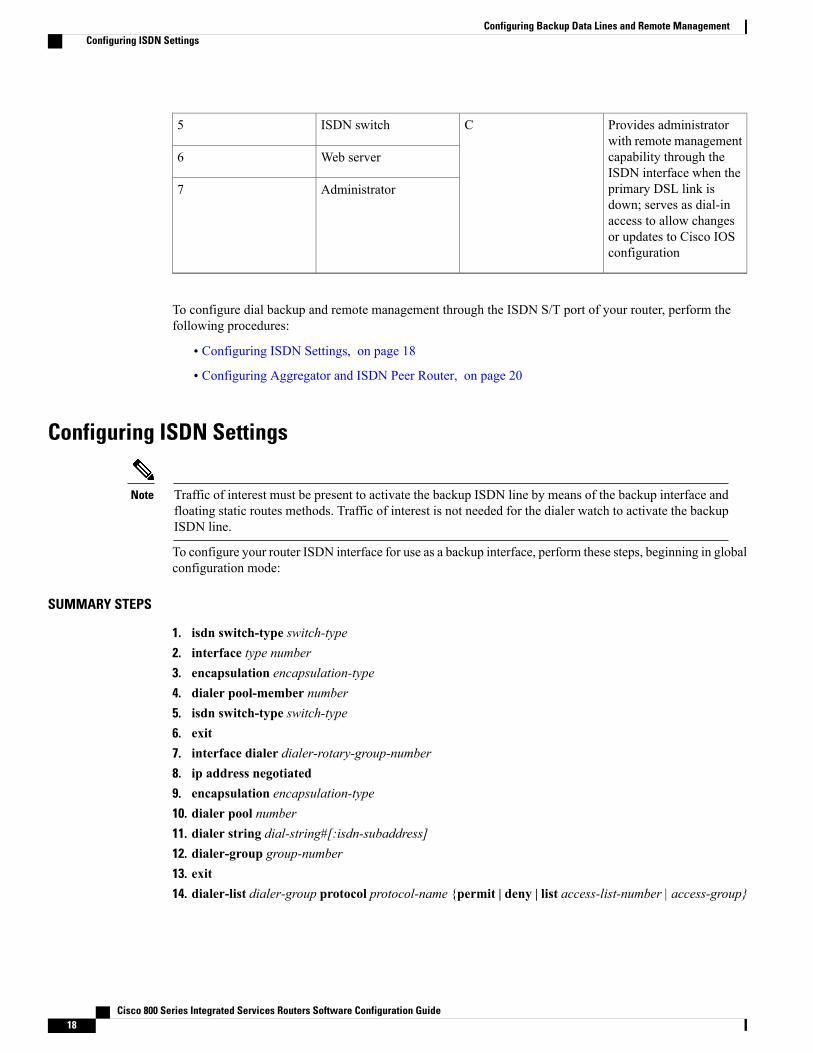
Provides administratorwith remote managementcapability through theISDN interface when theprimary DSL link isdown; serves as dial-inaccess to allow changesor updates to Cisco IOSconfiguration
CISDN5
ISDN peer router6
Web server7
——Administrator8
Cisco 800 Series Integrated Services Routers Software Configuration Guide16
Configuring Backup Data Lines and Remote ManagementConfiguring Data Line Backup and Remote Management Through the ISDN S/T Port

Figure 3: Data Line Backup Directly from Router to ISDN Switch
Primary DSL interfaceAPC1
Dial backup and remotemanagement through theISDN interface (ISDNS/T port); serves as afailover link when theprimary line goes down
BCisco 880 series ISR2
DSLAM3
Aggregator4
Cisco 800 Series Integrated Services Routers Software Configuration Guide 17
Configuring Backup Data Lines and Remote ManagementConfiguring Data Line Backup and Remote Management Through the ISDN S/T Port
Provides administratorwith remote managementcapability through theISDN interface when theprimary DSL link isdown; serves as dial-inaccess to allow changesor updates to Cisco IOSconfiguration
CISDN switch5
Web server6
Administrator7
To configure dial backup and remote management through the ISDN S/T port of your router, perform thefollowing procedures:
• Configuring ISDN Settings, on page 18
• Configuring Aggregator and ISDN Peer Router, on page 20
Configuring ISDN Settings
Traffic of interest must be present to activate the backup ISDN line by means of the backup interface andfloating static routes methods. Traffic of interest is not needed for the dialer watch to activate the backupISDN line.
Note
To configure your router ISDN interface for use as a backup interface, perform these steps, beginning in globalconfiguration mode:
SUMMARY STEPS
1. isdn switch-type switch-type2. interface type number3. encapsulation encapsulation-type4. dialer pool-member number5. isdn switch-type switch-type6. exit7. interface dialer dialer-rotary-group-number8. ip address negotiated9. encapsulation encapsulation-type10. dialer pool number11. dialer string dial-string#[:isdn-subaddress]12. dialer-group group-number13. exit14. dialer-list dialer-group protocol protocol-name {permit | deny | list access-list-number | access-group}
Cisco 800 Series Integrated Services Routers Software Configuration Guide18
Configuring Backup Data Lines and Remote ManagementConfiguring ISDN Settings

DETAILED STEPS
PurposeCommand or Action
Specifies the ISDN switch type.isdn switch-type switch-typeStep 1
Example:
Router(config)# isdn switch-type basic-net3
The example specifies a switch type used in Australia, Europe,and the United Kingdom. For details on other supported switchtypes, see the Cisco IOS Dial Technologies CommandReference .
Enters configuration mode for the ISDN BRI.interface type number
Example:
Router(config)# interface bri 0
Step 2
Sets the BRI0 interface encapsulation type.encapsulation encapsulation-type
Example:
Router(config-if)# encapsulation ppp
Step 3
Specifies the dialer pool membership.dialer pool-member number
Example:
Router(config-if)# dialer pool-member 1
Step 4
Specifies the ISDN switch type.isdn switch-type switch-type
Example:
Router(config-if)# isdn switch-typebasic-net3
Step 5
Exits configuration interface mode and enters globalconfiguration mode.
exit
Example:
Router(config-if)# exit
Step 6
Creates a dialer interface (numbered 0 to 255) and entersinterface configuration mode.
interface dialer dialer-rotary-group-number
Example:
Router(config)# interface dialer 0
Step 7
Specifies that the IP address for the interface is obtainedthrough PPP/IPCP (IP Control Protocol) address negotiation.The IP address is obtained from the peer.
ip address negotiated
Example:
Router(config-if)# ip address negotiated
Step 8
Cisco 800 Series Integrated Services Routers Software Configuration Guide 19
Configuring Backup Data Lines and Remote ManagementConfiguring ISDN Settings

PurposeCommand or Action
Sets the encapsulation type to PPP for the interface.encapsulation encapsulation-type
Example:
Router(config-if)# encapsulation ppp
Step 9
Specifies the dialer pool to be used.dialer pool numberStep 10
Example:
Router(config-if)# dialer pool 1
In the example, the dialer pool 1 setting associates the dialer0 interface with the BRI0 interface because the BRI0 dialerpool-member value is 1.
Specifies the telephone number to be dialed.dialer string dial-string#[:isdn-subaddress]
Example:
Router(config-if)# dialer string 384040
Step 11
Assigns the dialer interface to a dialer group (1–10).dialer-group group-number
Example:
Router(config-if)# dialer group 1
Step 12
Exits dialer 0 interface configuration mode, and enters globalconfiguration mode.
exit
Example:
Router(config-if)# exit
Step 13
Creates a dialer list for packets of interest to be forwardedthrough the specified interface dialer group.
dialer-list dialer-group protocol protocol-name{permit | deny | list access-list-number |access-group}
Step 14
In the example, dialer-list 1 corresponds to dialer-group 1.
Example:
Router(config)# dialer-list 1 protocol ippermit
For details about this command and additional parameters thatcan be set, see Cisco IOS Dial Technologies CommandReference .
Configuring Aggregator and ISDN Peer RouterThe ISDN peer router is any router that has an ISDN interface and can communicate through a public ISDNnetwork to reach your Cisco router ISDN interface. The ISDN peer router provides Internet access for yourCisco router during the ATM network downtime.
The aggregator is typically a concentrator router where your Cisco router ATM PVC terminates. In thefollowing configuration example, the aggregator is configured as a PPPoE server.
! This portion of the example configures the aggregator.vpdn enableno vpdn logging!
Cisco 800 Series Integrated Services Routers Software Configuration Guide20
Configuring Backup Data Lines and Remote ManagementConfiguring Aggregator and ISDN Peer Router

vpdn-group 1accept-dialinprotocol pppoevirtual-template 1!interface Ethernet3description “4700ref-1”ip address 40.1.1.1 255.255.255.0media-type 10BaseT!interface Ethernet4ip address 30.1.1.1 255.255.255.0media-type 10BaseT!interface Virtual-Template1ip address 22.0.0.2 255.255.255.0ip mtu 1492peer default ip address pool adsl!interface ATM0no ip addresspvc 1/40encapsulation aal5snapprotocol pppoe!no atm limi-keepalive!ip local pool adsl 22.0.0.1ip classlessip route 0.0.0.0 0.0.0.0 22.0.0.1 50ip route 0.0.0.0 0.0.0.0 30.1.1.2.80! This portion of the example configures the ISDN peer.isdn switch-type basic-net3!interface Ethernet0ip address 30.1.1.2 255.0.0.0!interface BRI0description “to 836-dialbackup”no ip addressencapsulation pppdialer pool-member 1isdn switch-type basic-net3!interface Dialer0ip address 192.168.2.2 255.255.255.0encapsulation pppdialer pool 1dialer string 384020dialer-group 1peer default ip address pool isdn!ip local pool isdn 192.168.2.1ip http serverip classlessip route 0.0.0.0 0.0.0.0 192.168.2.1ip route 40.0.0.0 255.0.0.0 30.1.1.1!dialer-list 1 protocol ip permit!
Configuring Gigabit Ethernet Failover MediaCisco 892F routers have a Gigabit Ethernet (GE) port that supports copper connections or a small-form-factorpluggable (SFP) port that supports fiber connections. Media can be configured for failover redundancy whenthe network goes down.
To assign primary and secondary failover media on the GE-SFP port, perform these steps, beginning in globalconfiguration mode.
Cisco 800 Series Integrated Services Routers Software Configuration Guide 21
Configuring Backup Data Lines and Remote ManagementConfiguring Gigabit Ethernet Failover Media

SUMMARY STEPS
1. hostname name2. enable secret password3. interface gigabitethernet slot/port4. media-type {sfp | rj45} auto-failover5. exit
DETAILED STEPS
PurposeCommand or Action
Specifies the name for the router.hostname name
Example:
Router(config)# hostname Router
Step 1
Specifies an encrypted password to prevent unauthorizedaccess to the router.
enable secret password
Example:
Router(config)# enable secret cr1ny5ho
Step 2
Enters interface configuration mode.interface gigabitethernet slot/port
Example:
Router(config)# interface gigabitethernet 0/1
Step 3
Configures the port with SFP as the primary media forautomatic failover from SFP to RJ-45.
media-type {sfp | rj45} auto-failover
Example:
Router(config-if)# media-type sfp auto-failover
Step 4
Or
Configures the port with RJ-45 as the primary media forautomatic failover from RJ-45 to SFP.Or
Router(config-if)# media-type rj45 auto-failover
Exits interface configuration mode and returns to globalconfiguration mode.
exit
Example:
Router(config-if)# exit
Step 5
OrRouter(config)#
Configuring Auto-DetectThe Auto-Detect feature is enabled if media-type is not configured. This feature automatically detects whichmedia is connected and links up. If both media are connected, whichever media comes up first is linked up.
Cisco 800 Series Integrated Services Routers Software Configuration Guide22
Configuring Backup Data Lines and Remote ManagementConfiguring Auto-Detect
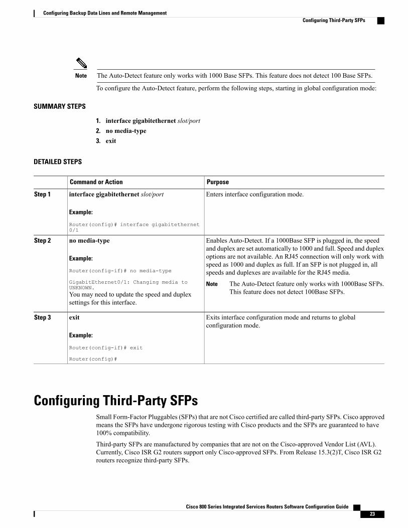
The Auto-Detect feature only works with 1000 Base SFPs. This feature does not detect 100 Base SFPs.Note
To configure the Auto-Detect feature, perform the following steps, starting in global configuration mode:
SUMMARY STEPS
1. interface gigabitethernet slot/port2. no media-type3. exit
DETAILED STEPS
PurposeCommand or Action
Enters interface configuration mode.interface gigabitethernet slot/port
Example:
Router(config)# interface gigabitethernet0/1
Step 1
Enables Auto-Detect. If a 1000Base SFP is plugged in, the speedand duplex are set automatically to 1000 and full. Speed and duplex
no media-type
Example:
Router(config-if)# no media-type
GigabitEthernet0/1: Changing media toUNKNOWN.
Step 2
options are not available. An RJ45 connection will only work withspeed as 1000 and duplex as full. If an SFP is not plugged in, allspeeds and duplexes are available for the RJ45 media.
The Auto-Detect feature only works with 1000Base SFPs.This feature does not detect 100Base SFPs.
Note
You may need to update the speed and duplexsettings for this interface.
Exits interface configuration mode and returns to globalconfiguration mode.
exit
Example:
Router(config-if)# exit
Router(config)#
Step 3
Configuring Third-Party SFPsSmall Form-Factor Pluggables (SFPs) that are not Cisco certified are called third-party SFPs. Cisco approvedmeans the SFPs have undergone rigorous testing with Cisco products and the SFPs are guaranteed to have100% compatibility.
Third-party SFPs are manufactured by companies that are not on the Cisco-approved Vendor List (AVL).Currently, Cisco ISR G2 routers support only Cisco-approved SFPs. From Release 15.3(2)T, Cisco ISR G2routers recognize third-party SFPs.
Cisco 800 Series Integrated Services Routers Software Configuration Guide 23
Configuring Backup Data Lines and Remote ManagementConfiguring Third-Party SFPs

Cisco does not provide any kind of support for the third-party SFPs because they are not validated byCisco.
Note
Note • Supports only 100BASE SFPs and 1000BASE SFPs under two speed configurations:
• 100 Mbps speed for 100BASE SFPs
• 1000 Mbps speed for 1000BASE SFPs
• Only the following routers and modules support third-party SFPs:
• Cisco 2921 Integrated Services Router
• Cisco 2951 Integrated Services Router
• Cisco 3900 Integrated Services Router
• Cisco 3900E Series Integrated Services Routers
• Cisco 892-F Gigabit Ethernet Security Router
• Cisco 898-EA Gigabit Ethernet Security Router
• EHWIC-1GE-SFP
SUMMARY STEPS
1. enable2. configure terminal3. service unsupported-transceiver4. interface type slot/subslot/port number5. media-type sfp6. speed value7. shutdown8. no shutdown9. exit
DETAILED STEPS
PurposeCommand or Action
Enables the privileged EXEC mode.enableStep 1
Example:
Router> enable
Enter your password if prompted.
Cisco 800 Series Integrated Services Routers Software Configuration Guide24
Configuring Backup Data Lines and Remote ManagementConfiguring Third-Party SFPs

PurposeCommand or Action
Enters the global configuration mode.configure terminal
Example:
Router# configure terminal
Step 2
Enables third-party SFP support.service unsupported-transceiver
Example:
Router(config)# serviceunsupported-transceiver
Step 3
Selects an interface to configure.interface type slot/subslot/port number
Example:
Router(config)# interface ethernet 0/3/0
Step 4
Changes media type to SFP.media-type sfp
Example:
Router(config-if)# media-type sfp
Step 5
Configures the speed of the interface.speed valueStep 6
Example:
Router(config-if)# speed 100
For 100BASE SFPs, configure the speed to 100Mbps only. Similarly, for 1000BASE SFPs,configure the speed to 1000 Mbps only.
Note
Disables the interface, changing its state from administrativelyUP to administratively DOWN.
shutdown
Example:
Router(config-if)# shutdown
Step 7
Enables the interface, changing its state from administrativelyDOWN to administratively UP.
no shutdown
Example:
Router(config-if)# no shutdown
Step 8
Exits the configuration mode and returns the globalconfiguration mode.
exit
Example:
Router(config-if)# exit
Router(config)#
Step 9
Cisco 800 Series Integrated Services Routers Software Configuration Guide 25
Configuring Backup Data Lines and Remote ManagementConfiguring Third-Party SFPs

Example for Configuring Third-Party SFPsThis example shows how to configure a third-party SFP on a Cisco ISR G2 Series Router:
Router# configure terminalRouter(config-if)# service unsupported-transceiverRouter(config)# interface ethernet 0/3/0Router(config-if)# media-type sfpRouter(config-if)# speed 100Router(config-if)# shutdownRouter(config-if)# no shutdownRouter(config-if)# exitRouter(config)# exit
Cisco 800 Series Integrated Services Routers Software Configuration Guide26
Configuring Backup Data Lines and Remote ManagementExample for Configuring Third-Party SFPs