configuring and commissioning s7 cps for industrial … · this manual... configuring and...
TRANSCRIPT

Configuring and commissioning S7 CPs
for Industrial Ethernet
___________________ ___________________ ___________________ ___________________ ___________________ ___________________ ___________________ ___________________ ___________________ ___________________
___________________ ___________________ ___________________ ___________________ ___________________ ___________________ ___________________
SIMATIC NET
S7-300/400 - Industrial Ethernet / PROFINET Configuring and commissioning S7 CPs for Industrial Ethernet Configuration Manual
Part A - General application
09/2013 C79000-G8976-C182-13
This manual...
Communication via Ethernet CPs in S7 stations
1 Characteristics of the Ethernet CPs
2 Configuring the Ethernet CP with STEP 7
3 SEND/RECEIVE interface in the user program
4 Configuring communications connections
5 CP as PROFINET IO controller
6 Intelligent PROFINET IO device with S7-300 CP
7 Sending process messages by email
8 File management and file access with FTP/FTPS
9 S7-CP Advanced as Web server: HTML process control
10
Web diagnostics 11
STEP 7 special diagnostics 12
Downloading firmware 13
Connector pinout A
References B
Linking to other systems with FETCH/WRITE
C
Document history D

Siemens AG Industry Sector Postfach 48 48 90026 NÜRNBERG GERMANY
Order number: C79000-G8976-C182 Ⓟ 09/2013 Technical data subject to change
Copyright © Siemens AG 2001 - 2013. All rights reserved
Legal information Warning notice system
This manual contains notices you have to observe in order to ensure your personal safety, as well as to prevent damage to property. The notices referring to your personal safety are highlighted in the manual by a safety alert symbol, notices referring only to property damage have no safety alert symbol. These notices shown below are graded according to the degree of danger.
DANGER indicates that death or severe personal injury will result if proper precautions are not taken.
WARNING indicates that death or severe personal injury may result if proper precautions are not taken.
CAUTION indicates that minor personal injury can result if proper precautions are not taken.
NOTICE indicates that property damage can result if proper precautions are not taken.
If more than one degree of danger is present, the warning notice representing the highest degree of danger will be used. A notice warning of injury to persons with a safety alert symbol may also include a warning relating to property damage.
Qualified Personnel The product/system described in this documentation may be operated only by personnel qualified for the specific task in accordance with the relevant documentation, in particular its warning notices and safety instructions. Qualified personnel are those who, based on their training and experience, are capable of identifying risks and avoiding potential hazards when working with these products/systems.
Proper use of Siemens products Note the following:
WARNING Siemens products may only be used for the applications described in the catalog and in the relevant technical documentation. If products and components from other manufacturers are used, these must be recommended or approved by Siemens. Proper transport, storage, installation, assembly, commissioning, operation and maintenance are required to ensure that the products operate safely and without any problems. The permissible ambient conditions must be complied with. The information in the relevant documentation must be observed.
Trademarks All names identified by ® are registered trademarks of Siemens AG. The remaining trademarks in this publication may be trademarks whose use by third parties for their own purposes could violate the rights of the owner.
Disclaimer of Liability We have reviewed the contents of this publication to ensure consistency with the hardware and software described. Since variance cannot be precluded entirely, we cannot guarantee full consistency. However, the information in this publication is reviewed regularly and any necessary corrections are included in subsequent editions.
Configuring and commissioning S7 CPs for Industrial Ethernet Configuration Manual, 09/2013, C79000-G8976-C182-13 3
This manual...
● ... supports you when commissioning your SIMATIC NET CP modules in an S7 station.
● ... supports you so that your applications can communicate successfully and effectively via the SIMATIC NET CPs.
● ... expands the description in the online documentation of the STEP 7 configuration software. You should always read the instructions on the individual topics available there.
Audience This manual is intended for commissioning engineers, programmers of STEP 7 programs and service personnel.
Scope of this manual
Note
Note that the availability of the functions described here for the device type you are using depends on the firmware version of the CP and the version of STEP 7. You can check which functions your module supports in the description of the properties dialog for the module in STEP 7.
Note STEP 7
In this manual, the name STEP 7 is used for all the available versions of STEP 7.
This manual is valid for the following versions of the configuration software:
● STEP 7 V5.5 SP2 Hotfix 4
In addition to this, for CP modules with integrated Industrial Ethernet security functionality: Security Configuration Tool (SCT) version V3.1
● STEP 7 Professional V12.0 SP1
Description of the STEP 7 functions This manual takes into account the expanded information in the help systems and information systems of the STEP 7 configuration tools. Explicit screenshots and explanations of input dialogs have therefore been largely avoided in this manual.
If specific properties relate to the version of STEP 7, this is indicated in the text.

This manual...
Configuring and commissioning S7 CPs for Industrial Ethernet 4 Configuration Manual, 09/2013, C79000-G8976-C182-13
New in this release Editorial revisions
Note
You should also read the history of this manual in the appendix in Chapter Document history (Page 241).
Replaced documentation This manual replaces the manual release 10/2012.
Abbreviations / short forms The following abbreviations or short forms for CP groups are used in this manual:
● "Advanced CP"
The term "Advanced CP" stands for CP modules with e-mail, FTP or Web functions and PROFINET CBA. The term "Advanced" is used in the product name of the relevant modules (for example CP 343–1 Advanced).
● "Security CP"
In the context of the description of CP modules, the term "security CP" means CPs with integrated Industrial Ethernet security functionality (CP x43–1 Advanced as of V3.0).
The documentation for SIMATIC NET S7 CPs The documentation for SIMATIC NET S7 CPs consists of the following parts:
● Manual Part A - Configuration manual "Configuring and Commissioning S7 CPs for PROFIBUS" (this document)
● Manual Part B - "S7-CPs for Industrial Ethernet - CPxxx"
Refer to /1/ (Page 227).
● SIMATIC NET Industrial Ethernet Security – Basics and Application - configuration manual
Refer to /16/ (Page 232).
● Program blocks for SIMATIC NET S7 CPs - programming manual
Refer to /10/ (Page 230).
Contains the detailed description of the program blocks for the following services:
– Open communications services
– Access coordination with FETCH/WRITE
– Connection and system diagnostics
– FTP services
– Programmed connections and IP configuration
This manual...
Configuring and commissioning S7 CPs for Industrial Ethernet Configuration Manual, 09/2013, C79000-G8976-C182-13 5
CP documentation in the Manual Collection (order no. A5E00069051) The "SIMATIC NET Manual Collection" DVD contains the device manuals and descriptions of all SIMATIC NET products current at the time it was created. It is updated at regular intervals.
Version History / Current Downloads for the SIMATIC NET S7 CPs The "Version History/Current Downloads for SIMATIC NET S7 CPs" provides information on all CPs available up to now for SIMATIC S7 (Industrial Ethernet, PROFIBUS and IE/PB Link).
An up-to-date version of this document can be found at on the Internet under the entry ID:
9836605 (http://support.automation.siemens.com/WW/view/en/9836605)
FAQs on the Internet You will find detailed information (FAQs) on using the CPs on the Internet under the following entry number (entry type "FAQ"):
17844971 (http://support.automation.siemens.com/WW/news/en/17844971)
Information on the current program block versions (FCs/FBs) You should always use the latest block versions for new user programs. You will find information on the current block versions and the current blocks for downloading on the Internet under the entry ID:
8797900 (http://support.automation.siemens.com/WW/view/en/8797900)
When replacing a CP, follow the instructions in the device-specific Part B of this manual.
SIMATIC NET Quick Start CD: Examples relating to communication The Quick Start CD that can be ordered separately is a treasure-trove of sample programs and configurations.
You can order this directly via the Internet under the entry ID:
21827955 (http://support.automation.siemens.com/WW/view/en/21827955)
Additional information on SIMATIC S7 You will find additional information on SIMATIC automation systems on the Quick Start CD and from the Customer Support Online services at:
General information on SIMATIC NET (http://www.automation.siemens.com/net/index_00.htm)
or
Product information and downloads (http://support.automation.siemens.com/WW/view/en)

This manual...
Configuring and commissioning S7 CPs for Industrial Ethernet 6 Configuration Manual, 09/2013, C79000-G8976-C182-13
References /.../ References to other documentation are shown in slashes /.../. Based on these numbers, you can find the title of the documentation in the references at the end of the manual.
See also Web diagnostics (Page 167)
Downloading firmware (Page 217)
Industrial Ethernet Security (Page 14)
SIMATIC NET glossary Explanations of the specialist terms used in this documentation can be found in the SIMATIC NET glossary.
You will find the SIMATIC NET glossary here:
● SIMATIC NET Manual Collection
The DVD ships with certain SIMATIC NET products.
● On the Internet under the following entry ID:
50305045 (http://support.automation.siemens.com/WW/view/en/50305045)

Configuring and commissioning S7 CPs for Industrial Ethernet Configuration Manual, 09/2013, C79000-G8976-C182-13 7
Table of contents
This manual... ......................................................................................................................................... 3
1 Communication via Ethernet CPs in S7 stations .................................................................................... 13
1.1 Industrial Ethernet ........................................................................................................................ 13
1.2 Industrial Ethernet Security .......................................................................................................... 14
1.3 SIMATIC S7 communication options with Ethernet CPs ............................................................. 16 1.3.1 Types of communication .............................................................................................................. 16 1.3.2 The communications services of the Ethernet CPs ..................................................................... 20 1.3.3 Operation using a configured or programmed database ............................................................. 21
1.4 PG/OP communication via Industrial Ethernet ............................................................................ 21 1.4.1 PG communication with STEP 7 over Industrial Ethernet ........................................................... 23 1.4.2 OP mode: Connecting HMI/ monitoring devices via Industrial Ethernet ...................................... 24
1.5 S7 communication via Industrial Ethernet ................................................................................... 24
1.6 Open communications services (SEND/RECEIVE interface) ...................................................... 28
1.7 FETCH/WRITE services (server) ................................................................................................. 30
1.8 Networking stations with STEP 7 ................................................................................................. 31
2 Characteristics of the Ethernet CPs ....................................................................................................... 33
2.1 Communications processors for S7300 ....................................................................................... 33
2.2 Communications processors for S7400 ....................................................................................... 34
2.3 Slot rules for SIMATIC S7300 ...................................................................................................... 35 2.3.1 Permitted slots ............................................................................................................................. 35 2.3.2 Number of SIMATIC NET CPs being operated at the same time ................................................ 35 2.3.3 Multicomputing ............................................................................................................................. 35 2.3.4 Removing/inserting (module replacement) .................................................................................. 35 2.3.5 Note on S7300 CPU: Connection resources ............................................................................... 36
2.4 Slot rules for SIMATIC S7400 ...................................................................................................... 36 2.4.1 Permitted slots ............................................................................................................................. 36 2.4.2 Number of SIMATIC NET CPs being operated at the same time ................................................ 36 2.4.3 Multicomputing ............................................................................................................................. 37 2.4.4 Removing/inserting (module replacement) .................................................................................. 37 2.4.5 Note on S7400 CPU: Connection resources ............................................................................... 38
3 Configuring the Ethernet CP with STEP 7 ............................................................................................. 39
3.1 How to commission an Ethernet CP ............................................................................................ 39
3.2 Configuring - follow the steps below ............................................................................................ 39 3.2.1 Overview ...................................................................................................................................... 39 3.2.2 Networking Ethernet CP .............................................................................................................. 40
3.3 Setting further CP properties ....................................................................................................... 42 3.3.1 Overview ...................................................................................................................................... 42
Table of contents
Configuring and commissioning S7 CPs for Industrial Ethernet 8 Configuration Manual, 09/2013, C79000-G8976-C182-13
3.3.2 "General" parameter group ......................................................................................................... 44 3.3.3 Parameter / function "Module addresses" ................................................................................... 45 3.3.4 "Options / Settings" parameter group ......................................................................................... 46 3.3.5 "Time-of-day synchronization" parameter group - mode ............................................................ 50 3.3.6 "IP access protection" parameter group ..................................................................................... 52 3.3.7 "IP configuration" parameter group ............................................................................................. 55 3.3.8 "User management" parameter group ........................................................................................ 57 3.3.9 "Symbols / Tag declaration" parameter group ............................................................................ 57 3.3.10 "DNS configuration" parameter group ......................................................................................... 58 3.3.11 "FTP" parameter group ............................................................................................................... 58 3.3.12 Parameter group "SNMP" ........................................................................................................... 61 3.3.13 "Port parameters" parameter group ............................................................................................ 61 3.3.14 "PROFINET" parameter group .................................................................................................... 63 3.3.15 "Security" parameter group (STEP 7 V5.5) ................................................................................. 63 3.3.16 "Web" parameter group ............................................................................................................... 64
3.4 Sending entries for the IP access protection to the Advanced CP using HTTP/HTTPS ............ 66
3.5 Media redundancy ....................................................................................................................... 70 3.5.1 Media redundancy in ring topologies .......................................................................................... 70 3.5.2 MRP ............................................................................................................................................ 72 3.5.3 MRP configuration ....................................................................................................................... 74
3.6 Assigning addresses the first time .............................................................................................. 76 3.6.1 Addressing by selecting the target system ................................................................................. 78 3.6.2 Addressing by adopting the configured address parameters ..................................................... 78
3.7 Downloading the configuration data to the target system ........................................................... 79
4 SEND/RECEIVE interface in the user program ...................................................................................... 83
4.1 How the SEND/RECEIVE interface works on the CPU .............................................................. 83
4.2 Programming the SEND/RECEIVE interface .............................................................................. 85
4.3 Data exchange S7 CPU − Ethernet CP ...................................................................................... 87
4.4 Additional information .................................................................................................................. 88 4.4.1 Programming data transfer via TCP connections ....................................................................... 88 4.4.2 Recommendations for use with a high communications load ..................................................... 89
5 Configuring communications connections .............................................................................................. 91
5.1 Procedure and connection properties ......................................................................................... 92
5.2 Connections to partners in other projects ................................................................................... 94
5.3 Inconsistent connections - connections without assignment ...................................................... 96
5.4 Configuring ISO transport connection properties ........................................................................ 99 5.4.1 Specifying ISO transport addresses ........................................................................................... 99 5.4.2 Specifying ISO transport dynamics properties .......................................................................... 100
5.5 Configuring ISO-on-TCP connection properties ....................................................................... 101 5.5.1 Specifying ISO-on-TCP addresses ........................................................................................... 101
5.6 Configuring TCP connection properties .................................................................................... 103 5.6.1 Specifying TCP addresses ........................................................................................................ 103
5.7 Configuring UDP connection properties .................................................................................... 105 5.7.1 Specifying UDP addresses ....................................................................................................... 105

Table of contents
Configuring and commissioning S7 CPs for Industrial Ethernet Configuration Manual, 09/2013, C79000-G8976-C182-13 9
5.7.2 UDP with broadcast and multicast ............................................................................................. 107 5.7.3 Free UDP connection ................................................................................................................. 110
5.8 FETCH/WRITE mode ................................................................................................................ 111
6 CP as PROFINET IO controller ........................................................................................................... 115
6.1 Project engineering .................................................................................................................... 115 6.1.1 PROFINET IO system in STEP 7 .............................................................................................. 115 6.1.2 PROFINET IO with IRT communication (STEP 7 V5.5) ............................................................ 116
6.2 IO controller mode with S7-300 ................................................................................................. 117 6.2.1 Programming .............................................................................................................................. 117 6.2.2 Reading and writing data records with program block PNIO_RW_REC .................................... 118 6.2.3 Alarm evaluation with program block PNIO_Alarm .................................................................... 118
6.3 IO controller mode with S7-400 ................................................................................................. 119 6.3.1 Multicomputing mode - assigning the CP to the CPU (STEP 7 V5.5) ....................................... 119 6.3.2 Programming .............................................................................................................................. 119
6.4 Further information on operation with PROFINET IO ................................................................ 120 6.4.1 Effects of multicast communication on RT communication ....................................................... 120
7 Intelligent PROFINET IO device with S7-300 CP ................................................................................. 121
7.1 Principle of data exchange in IO device mode .......................................................................... 122
7.2 Configuration (STEP 7 V5.5) ..................................................................................................... 123 7.2.1 Principle of IO device coupling ................................................................................................... 123 7.2.2 Enabling the CPU as a PROFINET IO device in the S7 station ................................................ 124 7.2.3 Configuring the CP as an IO device with IRT communication ................................................... 124 7.2.4 Assigning a PROFINET IO device to a PROFINET I/O system ................................................ 125
7.3 Configuration (STEP 7 Professional) ......................................................................................... 128
7.4 Programming .............................................................................................................................. 128 7.4.1 Interface for programming on the PROFINET IO device ........................................................... 129 7.4.2 Initialization and configuration .................................................................................................... 129
7.5 Shared device ............................................................................................................................ 131
7.6 Example of configuration and programming .............................................................................. 131
8 Sending process messages by email .................................................................................................. 135
8.1 Overview of the functions ........................................................................................................... 135 8.1.1 Authentication and other features of the Advanced CP ............................................................. 136
8.2 Project engineering .................................................................................................................... 138 8.2.1 Options of mail server mode ...................................................................................................... 138 8.2.2 Configuring a mail server and addressing recipients ................................................................. 138
8.3 Setting up an e-mail connection ................................................................................................. 139
8.4 Sending an e-mail ...................................................................................................................... 141
8.5 Testing the email function .......................................................................................................... 143
9 File management and file access with FTP/FTPS ................................................................................ 145
9.1 FTP functions in an S7 station with the Advanced CP .............................................................. 145
9.2 Advanced CP as FTP server for the file system on the CP ....................................................... 147
Table of contents
Configuring and commissioning S7 CPs for Industrial Ethernet 10 Configuration Manual, 09/2013, C79000-G8976-C182-13
9.2.1 Procedure .................................................................................................................................. 147 9.2.2 File system - structure and features .......................................................................................... 148
9.3 Advanced CP as FTP server for the S7 CPU data ................................................................... 150 9.3.1 Procedure .................................................................................................................................. 150 9.3.2 FTP commands on the FTP client ............................................................................................ 151 9.3.3 File allocation table ................................................................................................................... 153
9.4 The Advanced CP as FTP client for S7 CPU data ................................................................... 157 9.4.1 Procedure .................................................................................................................................. 157 9.4.2 Setting up FTP connections ...................................................................................................... 159
9.5 Program blocks for FTP services .............................................................................................. 160
10 S7-CP Advanced as Web server: HTML process control ...................................................................... 161
10.1 Overview of HTML process control ........................................................................................... 161
10.2 Security when accessing process data ..................................................................................... 162 10.2.1 Opening ports on the Advanced CP during configuration ......................................................... 163 10.2.2 Operation with firewall and proxy server ................................................................................... 163 10.2.3 Scaled password protection with security ................................................................................. 164
10.3 Accessing the Advanced CP via a Web browser ...................................................................... 165
11 Web diagnostics .................................................................................................................................. 167
11.1 Requirements ............................................................................................................................ 167
11.2 Setup and operation .................................................................................................................. 169
11.3 Diagnostics pages of the CP ..................................................................................................... 172 11.3.1 Start page .................................................................................................................................. 172 11.3.2 Identification .............................................................................................................................. 174 11.3.3 Diagnostics buffer ..................................................................................................................... 174 11.3.4 Module status / rack configuration ............................................................................................ 175 11.3.5 Industrial Ethernet ..................................................................................................................... 179 11.3.6 SEND/RECEIVE communication / configured connections ...................................................... 181 11.3.7 S7 communication ..................................................................................................................... 183 11.3.8 Media redundancy ..................................................................................................................... 185 11.3.9 IP access protection .................................................................................................................. 185 11.3.10 Security ..................................................................................................................................... 187 11.3.11 Topology.................................................................................................................................... 187 11.3.11.1 Topology - "Graphic view" tab .............................................................................................. 189 11.3.11.2 Topology - "Table view" tab ................................................................................................. 192 11.3.11.3 Topology - "Status overview" tab ......................................................................................... 194 11.3.12 Update center ............................................................................................................................ 194 11.3.12.1 Update center - "Firmware" tab ............................................................................................ 194 11.3.12.2 Update center - "IP access control list" tab .......................................................................... 195 11.3.12.3 Update center - "Diagnostics messages" tab ...................................................................... 196
12 STEP 7 special diagnostics .................................................................................................................. 199
12.1 Overview ................................................................................................................................... 199
12.2 Functions ................................................................................................................................... 200 12.2.1 Installation and startup .............................................................................................................. 200 12.2.2 Setup and operation .................................................................................................................. 201 12.2.3 Menu commands ....................................................................................................................... 202

Table of contents
Configuring and commissioning S7 CPs for Industrial Ethernet Configuration Manual, 09/2013, C79000-G8976-C182-13 11
12.3 Starting diagnostics .................................................................................................................... 204 12.3.1 Online path: Establishing a connection to the CP...................................................................... 204 12.3.2 Use as PC station - setting the gateway for "PC internal" ......................................................... 209 12.3.3 Other ways of starting diagnostics (STEP 7 V5.5) ..................................................................... 210
12.4 How to use diagnostics .............................................................................................................. 211
12.5 Starting diagnostics functions explicitly ..................................................................................... 212
12.6 Checklist for "typical problems" in a system .............................................................................. 213 12.6.1 Checklist for general CP functions ............................................................................................. 214 12.6.2 Communications connection checklist ....................................................................................... 214
12.7 Diagnostics messages from e-mail connections with authentication ......................................... 215
13 Downloading firmware ......................................................................................................................... 217
13.1 Loading using the Firmware Loader .......................................................................................... 217
13.2 Loading from the Download Center ........................................................................................... 219
A Connector pinout ................................................................................................................................. 223
A.1 24 VDC connector ...................................................................................................................... 223
A.2 RJ-45 jack for twisted pair Ethernet ........................................................................................... 223
A.3 Connector for Industrial Ethernet ............................................................................................... 224
A.4 Connector for PROFIBUS .......................................................................................................... 225
B References ......................................................................................................................................... 227
C Linking to other systems with FETCH/WRITE ...................................................................................... 237
D Document history ................................................................................................................................ 241
Index................................................................................................................................................... 243

Table of contents
Configuring and commissioning S7 CPs for Industrial Ethernet 12 Configuration Manual, 09/2013, C79000-G8976-C182-13
Configuring and commissioning S7 CPs for Industrial Ethernet Configuration Manual, 09/2013, C79000-G8976-C182-13 13
Communication via Ethernet CPs in S7 stations 1
The Ethernet CP for SIMATIC S7 provides a series of communications services for different tasks.
This section explains the following topics:
● The types of communication possible with the Ethernet CP on Industrial Ethernet
● The tasks handled by the Ethernet CP for the various services
● How to create the conditions for your communications requirements
There, you will find further information:
● When installing the Ethernet CP, follow the instructions in the device manual of the relevant Ethernet CP. This also contains further information about the performance of the Ethernet CP. /1/ (Page 227)
● For the functions and use of the STEP 7 configuration software, some of which are used to configure the CP (such as hardware configuration), refer to /5/ (Page 229).
● For using, structuring and handling Industrial Ethernet, you will find detailed information in /23/ (Page 234).
1.1 Industrial Ethernet
Industrial Ethernet Industrial Ethernet is the network for the process control level and the cell level of the vendor-independent SIMATIC NET open communications system. Physically, Industrial Ethernet is an electrical network based on shielded, coaxial cable, twisted pair cable or an optical network of fiber-optic cables (FO cable).
Industrial Ethernet is defined by the international standard IEEE 802.3 (see /10/).

Communication via Ethernet CPs in S7 stations 1.2 Industrial Ethernet Security
Configuring and commissioning S7 CPs for Industrial Ethernet 14 Configuration Manual, 09/2013, C79000-G8976-C182-13
Allround communication in the industrial sector Industrial Ethernet is integrated in the SIMATIC NET concept that allows comprehensive networking of the management, cell and field levels along with PROFINET / PROFIBUS and the ASInterface (ASi).
Network access Industrial Ethernet is accessed using the CSMA/CD (Carrier Sense Multiple Access with Collision Detection) network access technique specified in IEEE 802.3.
1.2 Industrial Ethernet Security
Cell protection concept with Industrial Ethernet Security With Industrial Ethernet Security, individual devices, automation cells or network segments of an Ethernet network can be protected. In addition to this, data transmission can be protected by a combination of different security measures such as a firewall, NAT/NAPT routers and VPN (Virtual Private Network) via an IPsec Tunnel:
● Data espionage
● Data manipulation
● Unauthorized access
The security functions of the security CPs are configured with the Security Configuration Tool configuration tool integrated in STEP 7.

Communication via Ethernet CPs in S7 stations 1.2 Industrial Ethernet Security
Configuring and commissioning S7 CPs for Industrial Ethernet Configuration Manual, 09/2013, C79000-G8976-C182-13 15
You will find detailed information on the topic of Industrial Ethernet Security and configuration with the Security Configuration Tool in /16/ (Page 232).

Communication via Ethernet CPs in S7 stations 1.3 SIMATIC S7 communication options with Ethernet CPs
Configuring and commissioning S7 CPs for Industrial Ethernet 16 Configuration Manual, 09/2013, C79000-G8976-C182-13
1.3 SIMATIC S7 communication options with Ethernet CPs
1.3.1 Types of communication The Ethernet CP for SIMATIC S7 supports the following types of communication depending on the CP type:
Possible types of communication / mechanisms
Interfaces / services / protocols
PG/OP communication S7 communication
With the protocols • ISO • TCP/IP (RFC 1006)
Open communications services With the SEND / RECEIVE interface and the protocols • ISO transport • ISOonTCP (TCP/IP with RFC 1006) • TCP • UDP
With FETCH / WRITE services and the protocols • ISO transport • ISO-on-TCP • TCP
PROFINET IO and PROFINET CBA With the protocols • TCP • UDP • RT (PROFINET IO and CBA) • IRT (PROFINET IO) • DCOM (PROFINET CBA)
HTML process control with Web browser With the protocols • HTTP or HTTPS
File management and file access with FTP With the protocols • FTP or FTPS 1)

Communication via Ethernet CPs in S7 stations 1.3 SIMATIC S7 communication options with Ethernet CPs
Configuring and commissioning S7 CPs for Industrial Ethernet Configuration Manual, 09/2013, C79000-G8976-C182-13 17
Possible types of communication / mechanisms
Interfaces / services / protocols
Email communication With the protocols • SMTP / ESMTP
Security functionality • Firewall • VPN • SNMPv3 • Syslog • NAT / NAPT • NTP (secured)
1) Where the term "FTPS" is used in this documentation, FTPS in the explicit mode is meant (PTPES).
Types of communication ● PG/OP communication
PG/OP communication is used to download programs and configuration data, to run tests and diagnostics functions, and to control and monitor a plant from OPs.
● S7 communication
S7 communication forms a simple and efficient interface between SIMATIC S7 stations and PGs/PCs using communication function blocks.
● Open communications services (SEND/ RECEIVE)
Depending on the CP type, the SEND/RECEIVE interface allows programcontrolled communication on a configured connection from a SIMATIC S7 PLC to another SIMATIC S7 PLC, to a SIMATIC S5 PLC, to PCs/PGs, and to third-party stations.
Depending on the CP type, the following communications services are available on the SEND/RECEIVE interface:
– ISO transport
Optimized for top performance at the selfcontained manufacturing level.
– IP-based services for internetwork communication
This includes:
ISOonTCP connections (RFC 1006), TCP connections and UDP datagram service (including broadcast / multicast).
Communication via Ethernet CPs in S7 stations 1.3 SIMATIC S7 communication options with Ethernet CPs
Configuring and commissioning S7 CPs for Industrial Ethernet 18 Configuration Manual, 09/2013, C79000-G8976-C182-13
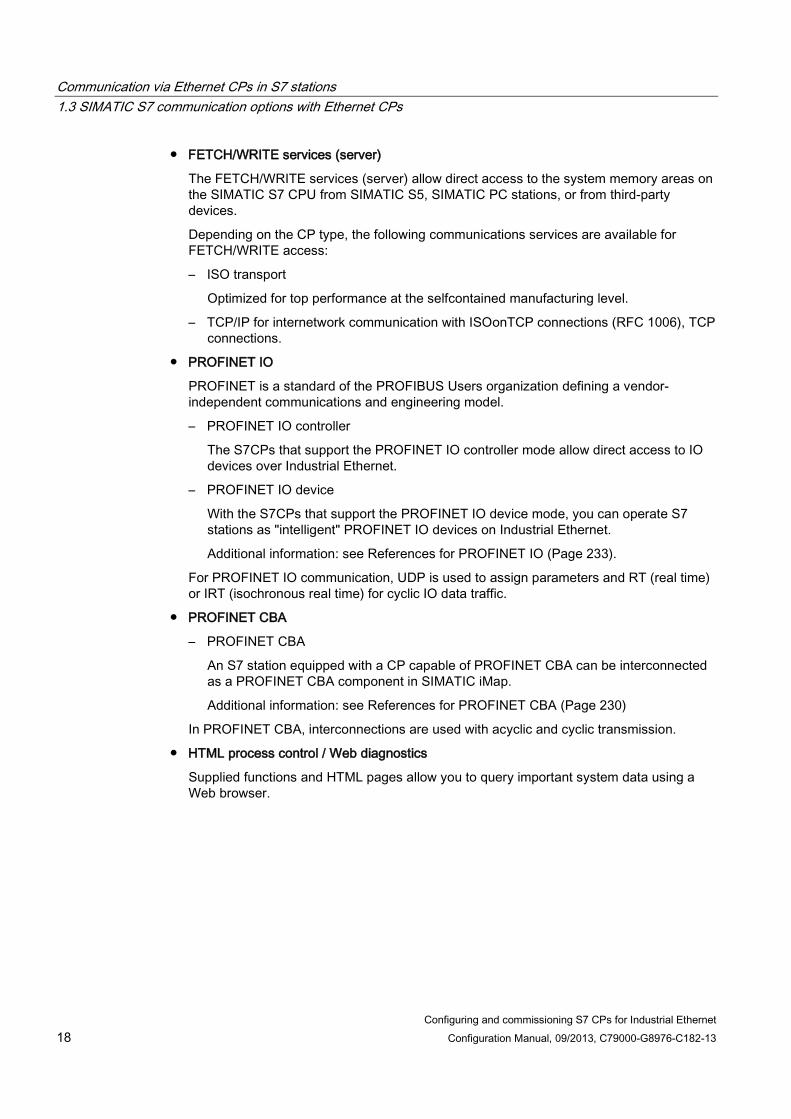
● FETCH/WRITE services (server)
The FETCH/WRITE services (server) allow direct access to the system memory areas on the SIMATIC S7 CPU from SIMATIC S5, SIMATIC PC stations, or from third-party devices.
Depending on the CP type, the following communications services are available for FETCH/WRITE access:
– ISO transport
Optimized for top performance at the selfcontained manufacturing level.
– TCP/IP for internetwork communication with ISOonTCP connections (RFC 1006), TCP connections.
● PROFINET IO
PROFINET is a standard of the PROFIBUS Users organization defining a vendor-independent communications and engineering model.
– PROFINET IO controller
The S7CPs that support the PROFINET IO controller mode allow direct access to IO devices over Industrial Ethernet.
– PROFINET IO device
With the S7CPs that support the PROFINET IO device mode, you can operate S7 stations as "intelligent" PROFINET IO devices on Industrial Ethernet.
Additional information: see References for PROFINET IO (Page 233).
For PROFINET IO communication, UDP is used to assign parameters and RT (real time) or IRT (isochronous real time) for cyclic IO data traffic.
● PROFINET CBA
– PROFINET CBA
An S7 station equipped with a CP capable of PROFINET CBA can be interconnected as a PROFINET CBA component in SIMATIC iMap.
Additional information: see References for PROFINET CBA (Page 230)
In PROFINET CBA, interconnections are used with acyclic and cyclic transmission.
● HTML process control / Web diagnostics
Supplied functions and HTML pages allow you to query important system data using a Web browser.
Communication via Ethernet CPs in S7 stations 1.3 SIMATIC S7 communication options with Ethernet CPs
Configuring and commissioning S7 CPs for Industrial Ethernet Configuration Manual, 09/2013, C79000-G8976-C182-13 19
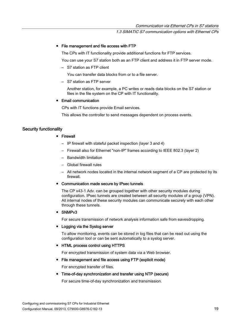
● File management and file access with FTP
The CPs with IT functionality provide additional functions for FTP services.
You can use your S7 station both as an FTP client and address it in FTP server mode.
– S7 station as FTP client
You can transfer data blocks from or to a file server.
– S7 station as FTP server
Another station, for example, a PC writes or reads data blocks on the S7 station or files in the file system on the CP with IT functionality.
● Email communication
CPs with IT functions provide Email services.
This allows the controller to send messages dependent on process events.
Security functionality ● Firewall
– IP firewall with stateful packet inspection (layer 3 and 4)
– Firewall also for Ethernet "non-IP" frames according to IEEE 802.3 (layer 2)
– Bandwidth limitation
– Global firewall rules
– All network nodes located in the internal network segment of a CP are protected by its firewall.
● Communication made secure by IPsec tunnels
The CP x43-1 Adv. can be grouped together with other security modules during configuration. IPsec tunnels are created between all security modules of a group (VPN). All internal nodes of these security modules can communicate securely with each other through these tunnels.
● SNMPv3
For secure transmission of network analysis information safe from eavesdropping.
● Logging via the Syslog server
To allow monitoring, events can be stored in log files that can be read out using the configuration tool or can be sent automatically to a syslog server.
● HTML process control using HTTPS
For encrypted transmission of system data via a Web browser.
● File management and file access using FTP (explicit mode)
For encrypted transfer of files.
● Time-of-day synchronization and transfer using NTP (secure)
For secure time-of-day synchronization and transmission.
Communication via Ethernet CPs in S7 stations 1.3 SIMATIC S7 communication options with Ethernet CPs
Configuring and commissioning S7 CPs for Industrial Ethernet 20 Configuration Manual, 09/2013, C79000-G8976-C182-13
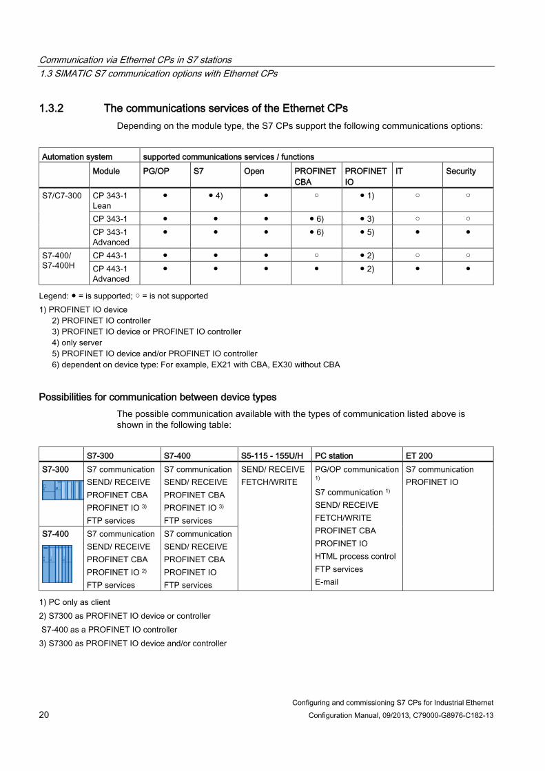
1.3.2 The communications services of the Ethernet CPs Depending on the module type, the S7 CPs support the following communications options:
Automation system supported communications services / functions Module PG/OP S7 Open PROFINET
CBA PROFINET IO
IT Security
S7/C7-300 CP 343-1 Lean
● ● 4) ● ○ ● 1) ○ ○
CP 343-1 ● ● ● ● 6) ● 3) ○ ○ CP 343-1 Advanced
● ● ● ● 6) ● 5) ● ●
S7-400/ S7-400H
CP 443-1 ● ● ● ○ ● 2) ○ ○ CP 443-1 Advanced
● ● ● ● ● 2) ● ●
Legend: ● = is supported; ○ = is not supported 1) PROFINET IO device
2) PROFINET IO controller 3) PROFINET IO device or PROFINET IO controller 4) only server 5) PROFINET IO device and/or PROFINET IO controller 6) dependent on device type: For example, EX21 with CBA, EX30 without CBA
Possibilities for communication between device types The possible communication available with the types of communication listed above is shown in the following table:
S7-300 S7-400 S5-115 - 155U/H PC station ET 200 S7-300
S7 communication SEND/ RECEIVE PROFINET CBA PROFINET IO 3) FTP services
S7 communication SEND/ RECEIVE PROFINET CBA PROFINET IO 3) FTP services
SEND/ RECEIVE FETCH/WRITE
PG/OP communication 1) S7 communication 1) SEND/ RECEIVE FETCH/WRITE PROFINET CBA PROFINET IO HTML process control FTP services E-mail
S7 communication PROFINET IO
S7-400
S7 communication SEND/ RECEIVE PROFINET CBA PROFINET IO 2) FTP services
S7 communication SEND/ RECEIVE PROFINET CBA PROFINET IO FTP services
1) PC only as client 2) S7300 as PROFINET IO device or controller S7-400 as a PROFINET IO controller 3) S7300 as PROFINET IO device and/or controller

Communication via Ethernet CPs in S7 stations 1.4 PG/OP communication via Industrial Ethernet
Configuring and commissioning S7 CPs for Industrial Ethernet Configuration Manual, 09/2013, C79000-G8976-C182-13 21
1.3.3 Operation using a configured or programmed database
Configuration and diagnostics The STEP 7 configuration software is required to connect and configure the Ethernet CP.
With its special diagnostics and Web diagnostics, STEP 7 provides a wide range of diagnostics options for the various types of communication via Industrial Ethernet.
To configure the security functionality, use the Security Configuration Tool SCT integrated in STEP 7.
To configure PROFINET CBA communication, you also require the SIMATIC iMap engineering tool.
Programmed communication connections In some situations, it is an advantage to set up communication connections not using the configuration data but programcontrolled by specific applications.
Program block IP_CONFIG is available for these applications and allows flexible transfer of data blocks with configuration data to an Ethernet CP. For information on the interfaces of the CP for which this is possible, refer to the manual of the relevant device.
1.4 PG/OP communication via Industrial Ethernet
Application PG/OP communication provides functions that are already integrated in every SIMATIC S7/M7/C7 device.
PG/OP communication distinguishes between the two function types:
● PG communication
PG communication with STEP 7 on Industrial Ethernet allows the complete range of functions of STEP 7 on Industrial Ethernet. All modules in the SIMATIC S7 PLC are available for:
– programming
– diagnostics
– operator control and monitoring
● OP mode
PG/OP communication on Industrial Ethernet allows the operator control and monitoring of all modules in a SIMATIC S7 PLC using HMI and monitoring devices (TD/OP).
The Ethernet CP acts as a "communications relay" that relays the PG/OP communication via Industrial Ethernet.
The following schematic illustrates how PG/OP communication can be used locally or remotely:

Communication via Ethernet CPs in S7 stations 1.4 PG/OP communication via Industrial Ethernet
Configuring and commissioning S7 CPs for Industrial Ethernet 22 Configuration Manual, 09/2013, C79000-G8976-C182-13
● local via Ethernet modules on the PG;
● remote via Ethernet modules on the PG and via routers.
● (the option of a PGPLC remote link with TeleService over a TS adapter is also shown)
Figure 1-1 Configuration for PG/OP mode - local and remote
Communication via Ethernet CPs in S7 stations 1.4 PG/OP communication via Industrial Ethernet
Configuring and commissioning S7 CPs for Industrial Ethernet Configuration Manual, 09/2013, C79000-G8976-C182-13 23
1.4.1 PG communication with STEP 7 over Industrial Ethernet
Requirements for PG communication PG communication is possible when the following requirements are met:
● An Ethernet CP is installed in the PG or engineering station or there is a modem/ISDN interface set up for remote access.
● The Ethernet CP must have an address (use default MAC address or set the IP address).
With CPs that have several independent interfaces, for example 1 PROFINET interface and 1 gigabit interface, you can connect your PG or engineering station to the gigabit interface when networking the PROFINET interface with your plant. You can access the subnet of one interface from the other interface.
Networking the PG / engineering station Depending on the configuration of the PG or Engineering Station, the following two situations are possible when using PG communication:
● PG / engineering station in configured mode
If you select this configuration when you commission the PG / engineering station, the interfaces of the communication modules you are using are already known. The option in "Set PG/PC Interface" is automatically set to "PCinternal".
Once you have downloaded this configuration to your PG / engineering station, you can exchange PG functions with the accessible nodes in the network with STEP 7 without requiring any further settings.
● PG / engineering station in PG mode
If your PG or engineering station is configured for this mode, specify the interface on the PG or engineering station explicitly with "Set PG/PC Interface".
Follow the steps outlined below:
1. Open the "Set PG/PC Interface" dialog box in the Windows Control Panel.
2. Set the PG/PC interface according to the CPs available on your PG and according to the bus attachment (interface parameter assignment used).
For more detailed information on the PG mode and engineering station, refer to /4/ (Page 229).

Communication via Ethernet CPs in S7 stations 1.5 S7 communication via Industrial Ethernet
Configuring and commissioning S7 CPs for Industrial Ethernet 24 Configuration Manual, 09/2013, C79000-G8976-C182-13
1.4.2 OP mode: Connecting HMI/ monitoring devices via Industrial Ethernet
Requirement Operation allowing operator control/monitoring is possible when the following conditions are met:
● The following are installed in the HMI/monitoring device:
– an Ethernet CP;
– SOFTNET S7 for Ind. Ethernet or software from the SIMATIC NET CD.
● The CPs in the S7 stations are supplied with a MAC/IP address (use the default MAC address or set an IP address).
With CPs that have several independent interfaces, for example 1 PROFINET interface and 1 gigabit interface, you can connect your PG or engineering station to the gigabit interface when networking the PROFINET interface with your plant. You can access the subnet of one interface from the other interface.
Procedure To be able to use S7 communication, address the required module in the SIMATIC S7 PLC on your HMI/monitoring device.
For more detailed information on the OP mode, refer to /4/ (Page 229).
1.5 S7 communication via Industrial Ethernet
Application S7 communication via Industrial Ethernet permits program-controlled communication using program blocks for S7 communication via configured S7 connections. The amount of user data per job is as follows for communication via Ethernet CPs:
● up to 64 Kbytes for S7-400
● up to 32 Kbytes for S7-300
The Ethernet CP acts as an "S7 communication relay" by forwarding the S7 functions via Industrial Ethernet. Depending on the configuration of the Ethernet CP, data transfer is on the basis of the ISO transport or the ISOonTCP protocol (TCP/IP with RFC 1006).
From a user perspective, S7 communication via PROFIBUS and Industrial Ethernet is identical.

Communication via Ethernet CPs in S7 stations 1.5 S7 communication via Industrial Ethernet
Configuring and commissioning S7 CPs for Industrial Ethernet Configuration Manual, 09/2013, C79000-G8976-C182-13 25
Nodes Two situations must be distinguished depending on the device type and plant configuration:
● Client and server functionality at both ends
S7 connections can be operated between the following nodes with the entire functionality of S7 communication:
– between S7 stations S7300 and S7400;
– between S7 stations and PC/PG stations with an Ethernet CP.
Figure 1-2 Nodes communicating on S7 connections over Industrial Ethernet
● Client and server functionality at one end only (S7 connections configured at one end)
In the following situations, write and read functions can be implemented with PUT / GET on S7 connections configured at one end:
– S7 communication over routers
PG/PC stations can access S7 stations connected to a different subnet or subnet type (PROFIBUS / Ethernet). This is only possible if the subnets are connected via routers (for example IE/PB Link); in this case, S7 stations are servers.
S7 communication is possible via a gateway.

Communication via Ethernet CPs in S7 stations 1.5 S7 communication via Industrial Ethernet
Configuring and commissioning S7 CPs for Industrial Ethernet 26 Configuration Manual, 09/2013, C79000-G8976-C182-13
Figure 1-3 PC/PG station communicates via a gateway with S7 station on an underlying PROFIBUS
or Ethernet
Configuring S7 connections Create S7 connections to use S7 communication for data exchange between two SIMATIC S7 stations.
You will find more detailed information in the online help in STEP 7.
Note
S7 connections via routers are supported only within a STEP 7 project but not between partners in different STEP 7 projects of a multiproject!

Communication via Ethernet CPs in S7 stations 1.5 S7 communication via Industrial Ethernet
Configuring and commissioning S7 CPs for Industrial Ethernet Configuration Manual, 09/2013, C79000-G8976-C182-13 27
Interface in the user program of the S7 station You use the following program blocks in the user program:
Block type / instruction Client Server Described in SFB / FB12 BSEND x - Online help in STEP 7 SFB / FB13 BRCV - x SFB / FB15 PUT x - 1) SFB / FB14 GET x - 1) SFB / FB8 USEND x - SFB / FB9 URCV - x SFC / FC62 CONTROL (S7-400) /
C_CNTRL (S7-300) x x 2)
1) you do not need to configure a connection on the server 2) for S7300
Note Remember word boundaries
Remember the following points regarding data consistency in your user program:
In the CPU of the S7 station, the read or written information is taken from the S7 user program into the operating system or copied from the operating system to the S7 user program in blocks of 8 or 32 bytes (depending on the firmware version).
If information in the word or doubleword format is located across such boundaries, data inconsistency may arise during transfer using S7 communication!
Notes on S7 communication between PC/PG station and S7 station Applications in a PC/PG station communicate with the S7 station via an OPC interface or SAPIS7 interface for operator intervention, monitoring and control.
The S7 stations use the integrated program blocks (client and server functionality at both ends).
The following general requirements must be met by a PC/PG station for S7 communication:
● The following are installed in the PC/PG:
– an Ethernet CP;
– an interface for S7 communication: SOFTNET S7 for Industrial Ethernet or software from the SIMATIC NET CD.
● The CPs in the S7 stations are supplied with a MAC/IP address (use the default MAC address or set an IP address).
To be able to use S7 communication with the SIMATIC S7 PLC from the PC, address the CPU module as the target in the SIMATIC S7 station in your PC application.
Communication via Ethernet CPs in S7 stations 1.6 Open communications services (SEND/RECEIVE interface)
Configuring and commissioning S7 CPs for Industrial Ethernet 28 Configuration Manual, 09/2013, C79000-G8976-C182-13
S7 communication via routers (oneended client and server functionality) It is possible to reach the S7 station from an application (OPC server) of the PC/PG station that is attached to another subnet. The two subnets must be connected via a router such as the IE/PB Link. An S7 station or a PC connected to both subnets can also serve as a router.
In this configuration, the S7 station can only be addressed by the PC/PG station as a communications server on S7 connections configured at one end.
The requirements for the configuration of the PC/PG station are identical to those for operation in the same subnet (see above); the CP in the PC/PG station must also have routing capability.
In this situation, configure a one-ended S7 connection to the S7 stations in the other subnet for the PC/PG station in STEP 7. You can then read and write data in the S7 station in your user program using the services for S7 communication.
Access from a PC/PG to PROFINET via a CP with 2 interfaces acting as a router In an S7 station, you can use a CP with two interfaces as a router. When you connect the PC/PG to the gigabit interface of the CP, you have access to the subnet in the PROFINET interface of the CP. Enter the CP as a router on the PC/PG.
1.6 Open communications services (SEND/RECEIVE interface)
Application Using the SEND/RECEIVE interface, your S7 user program has access to the open communications services with configured connections.
Note
Due to compatibility with the S5S5 connections in SIMATIC S5, the previous name of the open communications services was "S5-compatible communication".
Data transmission over a configured connection is suitable for the following types of data transfer:
● the reliable transfer of related blocks of data between two Ethernet nodes using
– ISO transport connection (not for PROFINET CBA standard components).
– TCP or ISOonTCP connection;
● Datagram service / User Datagram Protocol
Simple unacknowledged transfer of related blocks of data between two Ethernet nodes with UDP on IP.
The SEND/RECEIVE interface is also used for sending email.

Communication via Ethernet CPs in S7 stations 1.6 Open communications services (SEND/RECEIVE interface)
Configuring and commissioning S7 CPs for Industrial Ethernet Configuration Manual, 09/2013, C79000-G8976-C182-13 29
ISO transport connection ISO transport provides services for the reliable transfer of data on configured connections. Due to segmentation (packetoriented segmentation - the completeness of the message is detected) large amounts of data can be transmitted.
Transmission reliability is extremely high due to automatic repetition and additional field check mechanisms. The communications partner confirms reception of data and the sender receives a return value on the SEND/RECEIVE interface.
ISO transport is operated only on Industrial Ethernet and is optimized for highperformance operation at the selfcontained manufacturing level.
IP (Internet Protocol) The following methods are available for internetwork data transfer:
● ISO-on-TCP connection
ISOonTCP is intended for reliable, internetwork data transfer.
The ISOonTCP service corresponds to the TCP/IP standard (Transmission Control Protocol/Internet Protocol) with the RFC 1006 extension according to layer 4 of the ISO reference model (see /18/).
RFC 1006 extends the TCP protocol by allowing the transfer of blocks of data ("messages"). This requires that both partners support RFC 1006.
Transmission reliability is extremely high due to automatic repetition and additional field check mechanisms. The communications partner confirms reception of data and the sender receives a return value on the SEND/RECEIVE interface.
● TCP connection
When using the SEND/RECEIVE interface on TCP connections, the Ethernet CP supports the socket interface (for example, Winsock.dll) to TCP/IP found on almost every system (PC or other system).
TCP is intended for reliable internetwork data transfer.
The TCP service complies with the TCP/IP standard (Transmission Control Protocol/Internet Protocol).
● UDP connection
UDP is intended for simple internetwork data transfer without confirmation.
If the connection is suitably configured, broadcast and multicast frames can also be sent on UDP connections.
To avoid overload due to high broadcast load, the CP does not allow reception of UDP broadcasts. As an alternative, use the multicast function over a UDP connection. This allows you to register the CP as a node in a multicast group.
SEND/RECEIVE interface Data transfer is triggered by the user program. The interface to the user program in the SIMATIC S7 is formed by special SIMATIC S7 program blocks.

Communication via Ethernet CPs in S7 stations 1.7 FETCH/WRITE services (server)
Configuring and commissioning S7 CPs for Industrial Ethernet 30 Configuration Manual, 09/2013, C79000-G8976-C182-13
Nodes The SEND/RECEIVE interface allows programcontrolled communication on Industrial Ethernet between the SIMATIC S7 PLC and the following:
● SIMATIC S7 with an Ethernet CP
● SIMATIC S5 with an Ethernet CP
● PC/PG with an Ethernet CP
● Stations with Ethernet attachment
Figure 1-4 SIMATIC S7 PLC with possible communications partners on the SEND/RECEIVE
interface
1.7 FETCH/WRITE services (server)
Application The FETCH/WRITE functionality on the SEND/RECEIVE interface provides further services on configured transport connections.
The FETCH/WRITE interface is used primarily to connect SIMATIC S7 to SIMATIC S5 and to other nonS7 stations (for example PCs).
● FETCH
The partner on the connection (SIMATIC S5 or nonS7 station) can read system data on the SIMATIC S7 PLC.
● WRITE
The partner on the connection (SIMATIC S5 or nonS7 station) can write system data to the SIMATIC S7 PLC.

Communication via Ethernet CPs in S7 stations 1.8 Networking stations with STEP 7
Configuring and commissioning S7 CPs for Industrial Ethernet Configuration Manual, 09/2013, C79000-G8976-C182-13 31
From the point of view of the SIMATIC S7 PLC, this is a passive communication function that simply needs to be configured, the communications partner initiates connection establishment.
For further information, refer to the system documentation of the SIMATIC S5 PLC or the nonS7 station you are using.
Connection types To access a station with FETCH or WRITE functions, a connection with FETCH passive or WRITE passive mode must be configured on the SIMATIC S7. The following connection types are possible:
● ISO transport
● ISO-on-TCP
● TCP
Coordinating access using the user program You can use the program blocks AG_LOCK and AG_UNLOCK to coordinate access.
With these program blocks, you can coordinate access to system data areas by enabling and disabling the connections so that no inconsistent data is created and transferred.
SIMATIC S5 On the SIMATIC S5 station, the FETCH/WRITE services are configured and addresses by the READ ACTIVE/PASSIVE and WRITE ACTIVE/PASSIVE service types.
See also Linking to other systems with FETCH/WRITE (Page 237)
1.8 Networking stations with STEP 7
Configuring To allow stations to communicate with each other the networks must be configured in the STEP 7 projects.
Configuring a network or subnet involves the following:
1. You create one or more subnets of the required subnet type in the project;
2. You select the properties of the subnet. Normally the default settings are adequate;
3. You connect the station "logically" to the subnet;
4. You set up connections for communication.

Communication via Ethernet CPs in S7 stations 1.8 Networking stations with STEP 7
Configuring and commissioning S7 CPs for Industrial Ethernet 32 Configuration Manual, 09/2013, C79000-G8976-C182-13
Tools STEP 7 provides convenient tools for configuring and documenting networks graphically.
Configuring networks is explained in the online help of STEP 7.

Configuring and commissioning S7 CPs for Industrial Ethernet Configuration Manual, 09/2013, C79000-G8976-C182-13 33
Characteristics of the Ethernet CPs 2 2.1 Communications processors for S7300
The module was designed to match the components of the S7-300/C7300 programmable logic controller and has the following features:
● Compact modules (single or doublewidth) for simple installation on the S7 standard rail;
● Can be used in central or expansion racks;
● The display elements are all located on the front panel;
● No fan necessary;
● Direct backplane bus connection via the supplied bus connector;
● Interfaces wide design: 2 x RJ45 jack as 2port switch PROFINET for attachment to twistedpair Ethernet, 1 x RJ45 jack for attachment to gigabit Ethernet
● Interfaces narrow design:
2 x RJ−45 jack as 2−port switch PROFINET for connection to twisted-pair Ethernet
● The configuration of the CP is possible over MPI or LAN/Industrial Ethernet. The version of STEP 7 must be released for the device type necessary.
Legend: 1) LEDs 2) PROFINET interface: 2 x 8pin RJ45 jack 3) X = placeholder for hardware product version
Characteristics of the Ethernet CPs 2.2 Communications processors for S7400
Configuring and commissioning S7 CPs for Industrial Ethernet 34 Configuration Manual, 09/2013, C79000-G8976-C182-13
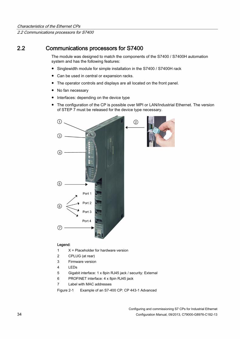
2.2 Communications processors for S7400 The module was designed to match the components of the S7400 / S7400H automation system and has the following features:
● Singlewidth module for simple installation in the S7400 / S7400H rack
● Can be used in central or expansion racks.
● The operator controls and displays are all located on the front panel.
● No fan necessary
● Interfaces: depending on the device type
● The configuration of the CP is possible over MPI or LAN/Industrial Ethernet. The version of STEP 7 must be released for the device type necessary.
Legend: 1 X = Placeholder for hardware version 2 CPLUG (at rear) 3 Firmware version 4 LEDs 5 Gigabit interface: 1 x 8pin RJ45 jack / security: External 6 PROFINET interface: 4 x 8pin RJ45 jack 7 Label with MAC addresses Figure 2-1 Example of an S7-400 CP: CP 443-1 Advanced

Characteristics of the Ethernet CPs 2.3 Slot rules for SIMATIC S7300
Configuring and commissioning S7 CPs for Industrial Ethernet Configuration Manual, 09/2013, C79000-G8976-C182-13 35
2.3 Slot rules for SIMATIC S7300
2.3.1 Permitted slots In the SIMATIC S7300, there is no set slot assignment for the SIMATIC NET CPs. Slots 4 to 11 are permissible (1, 2 and 3 cannot be used for CPs).
The SIMATIC NET CPs can be installed both in the central rack and in an expansion rack, linked to the central rack via an IM 360/IM 361 (Kbus connection).
2.3.2 Number of SIMATIC NET CPs being operated at the same time The number of SIMATIC NET CPs that can be operated is not limited by the system (for example S7300 CPU, slot rules etc.), but by the application (maximum cycle time of the application). The following components must be added into the calculation of the cycle time on top of the existing S7 user program:
● Execution time of the FCs:
For communication between the S7300 CPU and SIMATIC NET CPs, blocks (FCs/FBs) are necessary. How often these blocks are called depends on the number of connections or the number of SIMATIC NET CPs. Depending on the amount of data transferred, every block call extends the time required by the user program.
● Data conversion:
It may also be necessary for the information to be converted before transfer or after reception.
Please refer to the information in the relevant device manual.
2.3.3 Multicomputing This functionality is not supported by the SIMATIC S7300.
2.3.4 Removing/inserting (module replacement)
Note
Removing and inserting the SIMATIC NET CPs for the SIMATIC S7300 while the power is on is not permitted.
You should also remember that by removing a module from the rack, all modules on the other side of it will be disconnected from the CPU.

Characteristics of the Ethernet CPs 2.4 Slot rules for SIMATIC S7400
Configuring and commissioning S7 CPs for Industrial Ethernet 36 Configuration Manual, 09/2013, C79000-G8976-C182-13
A PG is required to download the configuration after replacing a module. If the CP supports the option of saving the configuration data on the CPU, it is also possible to replace a module without a PG (see CPspecific description).
2.3.5 Note on S7300 CPU: Connection resources Note that when using older S7300 CPUs (≤ CPU 316), a maximum of 4 S7 type connections for CP communication are supported. Of these 4 connections, one is reserved for a PG and another for an OP (HMI = Human Machine Interface). (The newer CPUs (from 10/99 onwards) support 12 and the CPU 3182DP supports 32 S7 connections.)
As a result, the older S7300 CPUs have only 2 "free" S7 connections available. These 2 connections can be used for S7 communication, for PROFIBUSFMS, for longer data or FETCH, WRITE and TCP connections with Industrial Ethernet.
If you use CPs that support multiplexing of OP connections and S7 communication using loadable communications blocks, only 1 connection resource is occupied if you use both services.
Note
Depending on the CP type installed and the services being used, there may be other restrictions (see CPspecific description in this manual).
2.4 Slot rules for SIMATIC S7400
2.4.1 Permitted slots An S7400 CP can be inserted both in the central rack and in the expansion rack with a K bus interface. For information about the number of CPs you can use in total, refer to the information on the relevant CP in the section "Properties".
In the SIMATIC S7400, there is no set slot assignment for the SIMATIC NET CPs. Slots 2 to 18 are permitted. Remember, however, that slot 1 and, depending on the power supply module used, also slots 2-3 (and 4 in redundant mode), are occupied by the power supply modules.
2.4.2 Number of SIMATIC NET CPs being operated at the same time The number of SIMATIC NET CPs that can be operated simultaneously is limited by the specific characteristics of the CPU. The exact number can be found in the CPspecific section of this manual.

Characteristics of the Ethernet CPs 2.4 Slot rules for SIMATIC S7400
Configuring and commissioning S7 CPs for Industrial Ethernet Configuration Manual, 09/2013, C79000-G8976-C182-13 37
There may be a further restriction resulting from the maximum current consumption depending on the power supply used. You should also note any requirements resulting from the interface types used (for example RJ45 or AUI).
2.4.3 Multicomputing The communication load can be distributed by installing several SIMATIC NET CPs (load balancing). If, however, you want to increase the number of available connection resources, you can insert several CPUs in a rack (multicomputing). All S7400 CPUs in a rack can communicate via one or more SIMATIC NET CPs.
The following communications services support multicomputing:
● ISO transport connections
● ISO-on-TCP connections
● S7 functions
● TCP connections
● UDP connections
● Email connections
2.4.4 Removing/inserting (module replacement) Removing and inserting the SIMATIC NET CPs for the S7400 while the power is on is possible without damaging the modules.
If a CP is replaced with a new CP with the same order number, the configuration data simply needs to be downloaded again if it is not stored on the CPU (see also CPspecific sections of this manual).
Characteristics of the Ethernet CPs 2.4 Slot rules for SIMATIC S7400
Configuring and commissioning S7 CPs for Industrial Ethernet 38 Configuration Manual, 09/2013, C79000-G8976-C182-13
2.4.5 Note on S7400 CPU: Connection resources Note that in the S7400 CPU, one S7 connection is reserved for a PG and a further one for an OP (HMI = Human Machine Interface).
● Attaching the PG over MPI:
To run ONLINE functions from a PG (for example module diagnostics) on for, example an S7400 CP, via the MPI interface, two connection resources (addressing of the interface and the K bus) are required on the S7400 CPU. These two connection resources should be taken into account in the number of S7 connections.
Example: The CPU 4121 has 16 free resources for S7 functions available. If a PG is to be used for diagnostics on the S7400 CP and is connected to the MPI interface, two connection resources are required on the S7400 CPU, so that 14 connection resources remain available.
● PG connection via PROFIBUS or Industrial Ethernet
If the PG is connected to the LAN (PROFIBUS or Industrial Ethernet), to execute PG functions on the S7400 CPU and diagnostics on an S7400 CP, only one connection resource on the S7400 CPU is necessary.
Configuring and commissioning S7 CPs for Industrial Ethernet Configuration Manual, 09/2013, C79000-G8976-C182-13 39
Configuring the Ethernet CP with STEP 7 3 3.1 How to commission an Ethernet CP
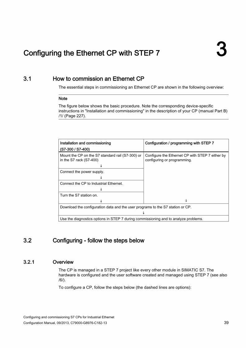
The essential steps in commissioning an Ethernet CP are shown in the following overview:
Note
The figure below shows the basic procedure. Note the corresponding device-specific instructions in "Installation and commissioning" in the description of your CP (manual Part B) /1/ (Page 227).
Installation and commissioning (S7-300 / S7-400)
Configuration / programming with STEP 7
Mount the CP on the S7 standard rail (S7-300) or in the S7 rack (S7-400)
↓
Configure the Ethernet CP with STEP 7 either by configuring or programming.
↓
Connect the power supply. ↓
Connect the CP to Industrial Ethernet. ↓
Turn the S7 station on. ↓
Download the configuration data and the user programs to the S7 station or CP. ↓
Use the diagnostics options in STEP 7 during commissioning and to analyze problems.
3.2 Configuring - follow the steps below
3.2.1 Overview The CP is managed in a STEP 7 project like every other module in SIMATIC S7. The hardware is configured and the user software created and managed using STEP 7 (see also /6/).
To configure a CP, follow the steps below (the dashed lines are options):

Configuring the Ethernet CP with STEP 7 3.2 Configuring - follow the steps below
Configuring and commissioning S7 CPs for Industrial Ethernet 40 Configuration Manual, 09/2013, C79000-G8976-C182-13
3.2.2 Networking Ethernet CP
Procedure By installing and assigning the Ethernet CP in the rack of a SIMATIC station, you establish the logical connection between the Ethernet CP and the subnet.
1. In your project, select the station you want to connect via the Ethernet CP.
2. Place the CP in the S7 station like any other module by selecting it from the hardware catalog.
You can select CPs from the catalog based on a brief descriptive text and the order number.
Result: The CP is assigned to the SIMATIC station.

Configuring the Ethernet CP with STEP 7 3.2 Configuring - follow the steps below
Configuring and commissioning S7 CPs for Industrial Ethernet Configuration Manual, 09/2013, C79000-G8976-C182-13 41
3. Network the CP according to the instructions in STEP 7.
4. Check the module name and the addresses and change them if necessary. The addresses are entered automatically by identifying the next free address.
Note the following additional information:
– MAC address
The current Ethernet CPs are supplied with one or more default MAC addresses depending on the number of interfaces (refer to the address printed on the module). To ensure a unique address assignment, do not enter a MAC address in the configuration (the option is disabled). This means that the module automatically uses the address entered in the factory.
If you want to use the ISO services, we recommend that you use the MAC addresses printed on the module for module configuration. This ensures that you assign a unique MAC address in the subnet!
If you replace a module, the MAC address of the predecessor is adopted when you load the configuration data. Configured ISO transport connections remain operable.
Note
If you change the CP modules regularly in your plant, when using ISO services you can avoid double assignment of MAC addresses by, for example, by following the steps outlined below: 1. Enter the first 3 manufacturer-specific bytes of the printed MAC address in the
configuration. 2. For the last 3 bytes, enter application-specific IDs for your CP (in the example "ik",
"nm", "yx" with a range of values in each case from 0 to 255 decimal). Example: 00:0E:8C:ik:nm:xy
– IP address
With CPs with an additional gigabit interface, the IP address of the PROFINET interface must not be in the same IP subnet as the IP address of the gigabit interface.
Note
The "IP address" and "Subnet mask" input boxes have no significance for ISO transport (option "IP protocol is used").
Address setting in the configuration and initial addressing The address settings described here only reach the CP when the configuration data is downloaded to it.
The following applies to the current Ethernet CPs:
To be able to reach the CP using these addresses even before the download, it is possible to address the CP using the default MAC address and to supply it with further address information.
The procedure for this initial address assignment is described in the section Assigning addresses the first time (Page 76).

Configuring the Ethernet CP with STEP 7 3.3 Setting further CP properties
Configuring and commissioning S7 CPs for Industrial Ethernet 42 Configuration Manual, 09/2013, C79000-G8976-C182-13
3.3 Setting further CP properties
3.3.1 Overview In addition to the network connection, you can also make other module-specific settings or call up functions.
The following lists show you an overview of the additional parameters that can be set or functions that can be called. With both product variants of STEP 7, you will receive information about where these parameters or functions are available. The following sections contain detailed information.
The parameters are assigned according to the following criteria:
● Object properties of the device
● Object properties of the interface (Ethernet/gigabit and PROFINET)
The following lists are structured accordingly
Table 3- 1 Object properties of the device
Parameter group / function STEP 7 V5.5 Tabs in the "Object properties" dialog of the device
STEP 7 Professional Parameter group under "Properties > General"
Networking Ethernet CP (Page 40) Module name > General > General
Plant designation, location identifier
> General > Identification & Maintenance
Parameter / function "Module addresses" (Page 45) Interface parameters for the
user program > Addresses > I/O addresses
"Options / Settings" parameter group (Page 46) Module access protection
(protection level) Options / settings Customize
Module replacement without a PG (S7-300)
Options / settings Customize
Ethernet profile for faulttolerant connections
Options / settings Customize
Sending keepalives for connections
Options / settings PROFINET interface > Interface options
Multiplex OP connections / Occupy internal CPU connection resource
Options / settings Customize
UDP buffering Options / settings Customize File system (case-sensitive) *) Options / settings Customize
"Time-of-day synchronization" parameter group - mode (Page 50)

Configuring the Ethernet CP with STEP 7 3.3 Setting further CP properties
Configuring and commissioning S7 CPs for Industrial Ethernet Configuration Manual, 09/2013, C79000-G8976-C182-13 43
Parameter group / function STEP 7 V5.5 Tabs in the "Object properties" dialog of the device
STEP 7 Professional Parameter group under "Properties > General"
Activate time synchronization with: • SIMATIC mode • NTP • NTP (secured) **)
• Options / settings • Time-of-day synchronization
PROFINET interface > Time synchronization
"IP access protection" parameter group (Page 52) IP access protection
• Edit IP access control list • Start firewall configuration **)
• IP access protection IP access protection
"User management" parameter group (Page 57) • Specifying user rights for IT
functions. • Starting security user
management. **)
Users **) User management **)
"Symbols / Tag declaration" parameter group (Page 57) Symbolic variable/tag access
with IT functions Symbols **) Tag declaration **)
"DNS configuration" parameter group (Page 58) Specifying the address of the
DNS server for e-mail services (up to 32 addresses).
DNS parameters **) DNS configuration **)
"FTP" parameter group (Page 58) FTP configuration
• Enable / disable FTP server • Create / change file
allocation table • Enable access only with
FTPS **)
• FTP *) • IP access protection
FTP configuration
Parameter group "SNMP" (Page 61) Enable SNMP service SNMP SNMP "Security" parameter group (STEP 7 V5.5) (Page 63) Activating / setting up security
function Security -
"Web" parameter group (Page 64) • Activating / deactivating Web
server • Enable access only with
HTTPS **)
• Web • IP access protection
-
*) Only with Advanced CPs (CP 343-1 Advanced/IT, CP 443-1 Advanced/IT) **) Only when the security function is enabled

Configuring the Ethernet CP with STEP 7 3.3 Setting further CP properties
Configuring and commissioning S7 CPs for Industrial Ethernet 44 Configuration Manual, 09/2013, C79000-G8976-C182-13
Table 3- 2 Object properties of the interface (Ethernet/gigabit and PROFINET)
Parameter group / function STEP 7 V5.5 Tabs in the "Object properties" dialog of the interface
STEP 7 Professional Parameter group under "Properties > General" > ...Interface
Networking Ethernet CP (Page 40) Networking the interface > General > Interface networked with "Port parameters" parameter group (Page 61) Interface (port properties)
Individual network settings / transmission rate / duplex *)
> Options > Advanced options
"Options / Settings" parameter group (Page 46) Communications interrupts > Options > Settings "IP configuration" parameter group (Page 55) • Configuration of the IP address
setting • Configuration method for configuring
IP address
> IP configuration > IP protocol
"PROFINET" parameter group (Page 63) Set properties for PROFINET IO and
PROFINET CBA PROFINET interface > PROFINET
PROFINET interface
I device Configure device as intelligent
PROFINET IO device PROFINET interface > I device
PROFINET interface > I device
Synchronization Configuring synchronization properties of
the device as a PROFINET IO controller PROFINET interface > synchronization
PROFINET interface > synchronization
Media redundancy (Page 70) Configuring the device as a node in a
ring topology with the media redundancy method MRP
PROFINET interface > media redundancy
PROFINET interface > Advanced options > Media redundancy
3.3.2 "General" parameter group
Function of the I&M data Among other things, in this area, you can configure identification data for modules that support I&M data (I&M = Identification & Maintenance). These are the plant designation and the location designation. With the I&M data, for example, standardized identification systems for devices are supported in the power station sector. Regardless of this, you can use the I&M data for an additional device identifier you require.

Configuring the Ethernet CP with STEP 7 3.3 Setting further CP properties
Configuring and commissioning S7 CPs for Industrial Ethernet Configuration Manual, 09/2013, C79000-G8976-C182-13 45
I&M data can be called using information functions, for example using the Web diagnostics of the device.
Devices that can be used as PROFINET IO devices can also be assigned the identifications by the PROFINET IO controller. This uses the "write data record" function (program block PNIO_RW_REC). This is done using the maintenance data record "IM1" with index AFF1H. If the plant designation and location designation are configured using STEP 7, it is not possible to override them using data record I&M1 with index AFF1H.
The "Write data record" function is described in /10/ (Page 230) with the program blocks for PROFINET IO.
Plant designation Plant designation of the module. Here, enter an identifier for the module that is unique in your plant. Length: max. 32 characters
Location identifier Location identifier of the module. Enter an identifier that indicates the location of the module in your plant. Length: max. 22 characters
3.3.3 Parameter / function "Module addresses"
Meaning The I/O addresses parameter group shows the address at which the module can be addressed by the user program. You can also set this address here. You require this address when calling all SIMATIC NET program blocks.
Note
Remember the following note regarding S7-300 stations:
If you select the "Update OB1 process image cyclically" option in the CPU configuration, you will have to set the module start address outside the process image (start addresses in the "Addresses" tab. Example: If the process image selected for the CPU has a size of 1024 (0... 1023), an address >= 1024 must be selected for the Ethernet CP.

Configuring the Ethernet CP with STEP 7 3.3 Setting further CP properties
Configuring and commissioning S7 CPs for Industrial Ethernet 46 Configuration Manual, 09/2013, C79000-G8976-C182-13
Use ● Inputs, outputs
Assign a start address to the module. (Outputs only if the option "Address setting for LOCK/UNLOCK with FETCH/WRITE" is selected)
● "Address setting for LOCK/UNLOCK with FETCH/WRITE" option
Select this option if you want to use the access coordination function with the FCs LOCK/UNLOCK in FETCH/WRITE mode.
This function uses process output via the backplane/P bus. As a result, the output addresses can be set as soon as this option is selected.
3.3.4 "Options / Settings" parameter group
Options tab Depending on your CP type, you can make the following settings:
Table 3- 3 Possible settings for the "Options" parameter group
Option / input area Meaning / effect
• Module access protection (protection level)
With this function, you can protect the CP from accidental access during productive operation. The following options are available: • Not locked • Status-dependent
With this setting, only write access to the CP is possible when the CPU is in STOP mode.
This is the recommended setting. The default is "Not locked".

Configuring the Ethernet CP with STEP 7 3.3 Setting further CP properties
Configuring and commissioning S7 CPs for Industrial Ethernet Configuration Manual, 09/2013, C79000-G8976-C182-13 47
Option / input area Meaning / effect
• Module replacement without a PG (S7-300)
With this option, you can decide whether or not the configuration data of the CP is stored on the CPU. If you replace the CP, the configuration data for the CP is transferred automatically from the CPU to the CP when it starts up. If you select this option, the configuration data is stored in non-volatile memory on the CPU instead of in the EEPROM of the CP. Remember, however, that long-term storage on the CPU is only safe from power outages if the CPU is protected by battery backup or by using an S7 memory card. Note If you store the configuration data on the CPU, read the note below. The configuration data on the CPU is not modified by the following functions: • Reset module memory • Reset to factory settings • Assign IP address 1) If you subsequently upload the configuration data from the CPU to a PG you will always object the configuration data that was previously on the CP (with parameters, connections, IP address). 1) Note: The assign IP address function should only be used during commissioning and not before downloading the configuration data.
• Ethernet profile for fault-tolerant connections
Select this profile if you use faulttolerant communication in your system. Faulttolerant communication means that Industrial Ethernet has been set up with redundancy and that you have configured faulttolerant S7 connections. If you select the Ethernet profile for faulttolerant connections here, the time response of the S7 connections is adapted. As a result, breakdowns of a connection are detected more quickly and the failover to redundant connections is faster. Note Select the Ethernet profile for faulttolerant connections only when you actually use faulttolerant S7 connections. Otherwise you must expect your system to be more susceptible to problems since, for example, the number of transfer or connection establishment attempts is reduced compared with nonredundant systems.
• Individual network settings Here, you can make fixed network settings, when necessary. The "Automatic setting" is selected by default. In normal situations, this guarantees problem-free communication. Where possible, leave the "Automatic setting" unchanged. If problems do occur in communication (such as when connections cannot be established or frequent network disruptions occur), this may be the result of unsuitable network settings, either selected or automatic. In this case, you should select a network setting that is suitable for your network configuration.
Configuring the Ethernet CP with STEP 7 3.3 Setting further CP properties
Configuring and commissioning S7 CPs for Industrial Ethernet 48 Configuration Manual, 09/2013, C79000-G8976-C182-13
Option / input area Meaning / effect
• Sending keepalives for connections
Here, you can set the interval at which keepalives are sent to the partner of a communications connection. With this interval, you specify the latest time after which the failure of a communications partner will be detected. For all connectionoriented services, the Ethernet CP is configured so that keepalives are sent. This guarantees that connections are terminated if a communications partner fails and that the connection resources are released. The setting made here applies to all TCP and ISO-on-TCP connections operated via the CP; a connection-specific setting is not possible. Range of values: Default setting: 30 seconds Disable keepalive: 0 seconds Maximum value: 65535 seconds Notes / recommendations: • Remember that the keepalive mechanism can keep underlying
connections established (for example, an ISDN telephone connection) although no user data is actually being transmitted. If you do not want this, set the interval so high that the underlying connection is terminated before a keepalive is sent when there is no data traffic.
• Avoid disabling keepalives using the setting "0". Otherwise you risk connections remaining established when the partner station has failed that can no longer be terminated or re-established.
• File system (case-sensitive) On CPs with IT functions, activating this option allows you to specify that the CP distinguishes between uppercase and lowercase characters in the names of files for the RAM area.

Configuring the Ethernet CP with STEP 7 3.3 Setting further CP properties
Configuring and commissioning S7 CPs for Industrial Ethernet Configuration Manual, 09/2013, C79000-G8976-C182-13 49
Option / input area Meaning / effect
• Multiplex OP connections / Occupy internal CPU connection resource
To connect TD/OPs and/or HMI devices, you can optimize the connection resources in the S7-300 CPU by allowing up to 16 such devices to communicate on a single CPU connection resource (multiplex mode). If you do not use this option, the number of TD/OPs and/or HMI devices that can be used will depend on the number of available connection resources of the CPU used. As default, this option is deactivated. This means that a CPU connection resource is used for multiplex only when necessary. Configured S7 connections over the CP use the same multiplex channel as you use for multiplexing the HMI connections. If you configure S7 connections, this means that one CPU connection resource is already used. Please note: PG connections are not operated over the multiplexer. When operating a PG, a connection resource is always occupied. Note on programming: When you use the multiplex mode, specify the rack/slot assignment of the CP for addressing on TD/OP/HMI connections instead of the rack/slot assignment of the CPU! Applications (for example ProAgent) that require block-related alarms (Alarm_S: SFC17-19) are not supported in multiplex mode.
• Disable UDP frame buffering With this option, you can choose between the following reactions: • Disabled (default setting)
All the UDP frames received by the CP are buffered until they can be transferred to the CPU or the internal buffer overflows.
Following a buffer overflow, newly arriving frames are discarded.
The characteristics associated with disabling the option can be critical in certain applications with high frame traffic. Buffering of a lot of frames may result in an undesired time offset between the frames accumulated in the CPU and the current frame at the Ethernet interface.
• Enabled
The CP always transfers the last received, in other words, the current frame to the CPU. As long as no new UDP frame can be transferred between the CP and the CPU due to the current communication load, only the last frame received is buffered in the CP (memory size = 1).
Enabling achieves the shortest possible reaction time between the arrival of the UDP frame and its evaluation on the CPU.

Configuring the Ethernet CP with STEP 7 3.3 Setting further CP properties
Configuring and commissioning S7 CPs for Industrial Ethernet 50 Configuration Manual, 09/2013, C79000-G8976-C182-13
3.3.5 "Time-of-day synchronization" parameter group - mode
Method for time-of-day synchronization The CP provides the following methods for time-of-day synchronization and these are described below:
● SIMATIC mode
● NTP mode (NTP: Network Time Protocol)
How it works ● SIMATIC mode
When the CP receives MMS time messages, its local time is synchronized provided that the NTP mode was not configured (MMS = Manufacturing Message Specification).
The advantage of this mode is that it is generally more accurate than the NTP mode.
The time messages are received either from an S7-41x CPU or from the LAN.
You can choose whether or not the CP simply adopts the time or also forwards it. If a different instance is set up to forward the time, do not select forwarding.
The two following situations are possible depending on where the time-of-day master is located:
– Case a) Time messages come from the subnet (LAN) and are forwarded to the station. In this case, the CPU's time synchronization must be configured as a slave.
– Case b) Time messages come from the station and are forwarded to the subnet (LAN). In this case, a time-of-day synchronization of the CPU must be configured as the master or another CP forwards time messages to the K bus.
If you have several CPs in your station, take into account the flow of time-of-day messages depending on the time-of-day master. It is possible to transfer time-of-day messages from one network to another network using the function described here. There may, however, only be one time master in your station.
If there are several CPs that are connected to the same network in a station, only one of these CPs may forward the time messages.
Note
During configuration, there is no consistency check relating to this option when configuring several CPs.

Configuring the Ethernet CP with STEP 7 3.3 Setting further CP properties
Configuring and commissioning S7 CPs for Industrial Ethernet Configuration Manual, 09/2013, C79000-G8976-C182-13 51
● NTP mode (NTP: Network Time Protocol)
In NTP mode, the CP sends time queries (in client mode) at regular intervals to NTP servers on the subnet (LAN). Based on the replies from the server, the most reliable and most accurate time is calculated and the time of day on the station is synchronized.
The advantage of this mode is that it allows the time to be synchronized across subnets.
In this case, any MMS time messages that are received will be ignored.
Note
Note the following about timeofday synchronization in NTP mode:
If an NTP frame is detected by the CP as "not exact" (example: NTP server is not synchronized externally), the CP does not synchronize itself and does not forward the time on the communication bus (K bus). If this problem occurs, none of the NTP servers is displayed as “NTP master" in the diagnostics; but rather all NTP servers are displayed only as being "accessible".
The IP addresses of up to four NTP servers need to be configured. The update interval defines the interval between the time queries (in seconds). The value of the interval ranges between 10 seconds and one day.
In NTP mode, it is generally UTC (Universal Time Coordinated) that is transferred; this corresponds to GMT (Greenwich Mean Time). The time offset from UTC can be set by configuring the local time zone.
Note
No automatic changeover to daylight saving is defined in NTP. As a result, you may need to implement this changeover using a program application.
Special features - CPU requests time of day Some CPUs provide the option of requesting the time of day automatically from an NTP server. If this option is used on the CPU, you should disable the forwarding of the time of day to the station on the CP. This avoids the time of day acquired by the CPU from the NTP server being overwritten again by the time of day received by the CP. Forwarding over the CP might result in a lower degree of accuracy.
Security enabled In the extended NTP configuration, you can create and manage additional NTP servers including those of the type NTP (secure).
Note Ensuring a valid time of day
If you have enabled security, a valid time of day is extremely important. If you do not obtain the time-of-day from the station (CPU), we therefore recommend that you use an NTP server of the type NTP (secure).

Configuring the Ethernet CP with STEP 7 3.3 Setting further CP properties
Configuring and commissioning S7 CPs for Industrial Ethernet 52 Configuration Manual, 09/2013, C79000-G8976-C182-13
3.3.6 "IP access protection" parameter group
Function Using IP access protection gives you the opportunity of restricting communication over the CP of the local S7 station to partners with specific IP addresses. Partners you have not authorized therefore have no access to data of the S7 station using the IP protocol (S7 connections) via the CP configured in this way.
IP access protection relates to all messages handled by the IP protocol (TCP, ISO-on-TCP, UDP, ICMP).
In this parameter group, you can activate or deactivate IP access protection and can enter specific IP addresses in an IP access control list (IP-ACL).
With Advanced CPs, it is possible to send entries for the IP access control list to the CP using HTTP (see section Sending entries for the IP access protection to the Advanced CP using HTTP/HTTPS (Page 66)).
Blocked access attempts are registered on the CP and can be viewed with special diagnostics in the "IP access protection" diagnostic object. If the CP has IT functionality, a LOG file is also created in the file system of the CP that you can view with a WEB browser.
Note Security enabled
As soon as you enable security, IP access protection is effective only on the interface to the external network.
To achieve effective IP access protection within the local subnet when security is enabled, you need to make special firewall settings.
following descriptions apply to the situation when security is disabled. You will find further information relating to the situation when security is enabled at the end of the chapter.
IP access protection for configured communication partners To restrict access so that only the communication partners you specified in the configuration have access, you simply need to enable access protection. In this case, you do not need to enter any IP addresses in the list.
These communication partners include:
● Stations to which communication connections are configured;
These include (except with S7 connections) connections on which the connection partner is located in a different subnet.
The following types of access are not taken into account and therefore rejected:

Configuring the Ethernet CP with STEP 7 3.3 Setting further CP properties
Configuring and commissioning S7 CPs for Industrial Ethernet Configuration Manual, 09/2013, C79000-G8976-C182-13 53
– Configured connections with an unspecified partner
All partners on unspecified connections (with unconfigured IP addresses) are rejected.
– Connections in PROFINET CBA will be treated as unspecified connections. You will need to enter the IP addresses of such connections explicitly in the IP access control list.
– Access by connection partners specified in the user program with the program block IP_CONFIG (FB55) do not automatically have permission and are rejected.
● PROFINET IO devices when the Ethernet CP is used as a PROFINET IO controller
The CP enters the IP addresses of PROFINET IO devices dynamically in the IP access control list when the CPU is in RUN mode.
If the CPU changes to STOP mode, the IP addresses of the PROFINET IO devices are deleted from the access list.
● NTP servers, SMTP servers, DNS servers and DHCP servers.
The IP addresses of NTP servers, SMTP servers, DNS servers and DHCP servers are also entered and removed dynamically when there are requests to these servers. This may mean that IP addresses only appear temporarily in the display of the STEP 7 special diagnostics.
IP access protection relates to all connection types that use the IP protocol (TCP, ISO-on-TCP, UDP, S7)
Note on dynamically assigned IP addresses: Since each service manages its dynamic entry in the ACL itself, it is perfectly possible for the same IP address to appear several times in module diagnostics.
Note PING command - no dynamic adoption of the IP address
IP addresses accessed using a PING command are not entered dynamically in the IP access control list.
IP access protection for partners with specific IP addresses To allow access only by certain IP addresses, enter these IP addresses in the IP access control list. These can, for example, be the IP addresses of connection partners that remained unspecified in the connection configuration, of individual programming devices or of connection partners on PROFINET CBA.
The IP addresses you have specified in the connection configuration always belong to the permitted IP addresses. This means that you do not need to enter these IP addresses explicitly in the IP-ACL.

Configuring the Ethernet CP with STEP 7 3.3 Setting further CP properties
Configuring and commissioning S7 CPs for Industrial Ethernet 54 Configuration Manual, 09/2013, C79000-G8976-C182-13
IP access protection enabled in the configuration - no further entry in the IP-ACL In this case the behavior depends on whether IP addresses were transferred to the IP access control list via HTTP.
● Case a) There are entries
Access protection is effective for the specified IP addresses. Access with other IP addresses is denied.
● Case b) There are no entries
The configured IP access protection is not effective and in practical terms disabled.
Registering blocked access attempts Blocked access attempts are registered on the CP. You can view these entries using STEP 7 special diagnostics in the "IP access protection" diagnostics object. On CPs with Web diagnostics, the information is also available there.
● Viewing the LOG file with a Web browser
With Advanced CPs up to the CP 343-1 Advanced (GX21) and CP 443-1 Advanced (EX41), the behavior is as follows: Blocked access attempts are stored in an archive file (LOG file) in the CP's own file system. This LOG file can be viewed using a Web browser.
You will find the LOG file as an HTML file in the file system of the CP in the following directory:
- ram/security/IPLogFile.htm
The LOG file is available only after activating IP access protection the first time.
Further properties:
The LOG file is created as a ring buffer. When more than 512 entries have been recorded, the oldest entries are then overwritten.
The entries are strictly chronological. There is no further criterion for sorting.
With Advanced CPs as of CP 343–1 Advanced (GX30) and CP 443–1 Advanced (GX20) the LOG file is not created. On these CPs, you can view the blocked access attempts directly with Web diagnostics.
Note
Locking IP communication
To block IP communication with HTTP (port 80) or FTP (port 20/21) with an advanced CP, follow the steps below:
Disable the "Activate Web server" or "Activate FTP server" option. As default, both functions are enabled.

Configuring the Ethernet CP with STEP 7 3.3 Setting further CP properties
Configuring and commissioning S7 CPs for Industrial Ethernet Configuration Manual, 09/2013, C79000-G8976-C182-13 55
Enable security - effects If IP access protection is enabled for IP communication, when the security function is enabled, the firewall is activated automatically regardless of the entries. The IP-ACL entries created in STEP 7 are adopted with the corresponding rights as firewall rules. These firewall rules derived from the ACL entries when security is enabled apply only on the interface to the external network.
Note IP-ACL without entries when security is enabled
If you adopt an IP-ACL without entries, the firewall is enabled and it is no longer possible to access the CP from external. To make CP available, configure suitable firewall rules in the advanced mode of SCT.
Note Behavior in the internal subnet
When you enable security, there are initially no access restrictions between communications partners connected in the internal network.
The following therefore applies to internal subnets: Previously existing entries in the IP-ACL that restricted communication to certain partners are not initially effective when security is enabled.
When security is enabled, it is then possible to make detailed firewall settings for individual nodes. With specified connections to external partners, firewall rules are automatically created in SCT that allow connection establishment. With unspecified connections, you must first configure the relevant firewall rules.
Stateful packet inspection The firewall and NAT/NAPT router supports the "Stateful Packet Inspection" mechanism. As a result, reply frames can pass through the NAT/NAPT router and firewall without it being necessary for their addresses to be included in the firewall rule and the NAT/NAPT address conversion. IP addresses that would appear temporarily in the ACL if security were disabled can be detected by the mechanism of Stateful Packet Inspection. Such IP addresses are then not visible in the corresponding pages of diagnostics.
3.3.7 "IP configuration" parameter group
Meaning You can decide the route and the method with which the IP address of the local interface is obtained and assigned.
With the options available here, it is possible to assign IP addresses "dynamically" outside the configuration.

Configuring the Ethernet CP with STEP 7 3.3 Setting further CP properties
Configuring and commissioning S7 CPs for Industrial Ethernet 56 Configuration Manual, 09/2013, C79000-G8976-C182-13
The selection you make also decides whether communication connections are set up by the project engineering or via the interface in the user program (IP_CONFIG instruction).
The following options are available:
● Set IP address in the project
This is the default setting for PLCs. You specify the IP address when the device is networked. The IP address CP is therefore fixed.
With this option, you must configure communications connections.
● Obtain an IP address from a DHCP server
If you select this option, the IP address is obtained from a DHCP server when the device starts up.
The DHCP server is informed of the MAC address of the interface or the client ID that can be entered in the configuration.
The client ID is a string with a maximum of 63 characters. Only the following characters can be used:
– a-z, A-Z, 0-9, - (hyphen)
Requirements / restrictions:
If you select this option, it is initially not possible to create a fully specified connection in the project because the local IP address is not known.
You therefore select "unspecified" with passive connection establishment as the connection type.
● Set IP address in the user program
With this option, you specify that the IP address is set over the user program interface (function block IP_CONFIG). This allows the IP address to be supplied dynamically during operation.
In this use case, communications connections are set up only via the interface of the user program. Connection configuration is no longer possible (relates to connections via: TCP, ISO-on-TCP, UDP, ISO transport ).
● Set IP address using a different method
With this option, you specify that the IP address is set by other services outside the configuration.
In this case, connection configuration is no longer possible (relates to connections via: TCP, ISO-on-TCP, UDP, ISO transport ).
Note
Communications connections have already been configured
In the following situation, you receive the message that the configured connections no longer work:
You have already configured communications connections via the interface configured here and select a different setting from "Set IP address in the project".

Configuring the Ethernet CP with STEP 7 3.3 Setting further CP properties
Configuring and commissioning S7 CPs for Industrial Ethernet Configuration Manual, 09/2013, C79000-G8976-C182-13 57
3.3.8 "User management" parameter group
Meaning of user management In user management, you specify which users have which permissions when accessing the S7 station.
In the alphabetical list, you will find the users that have already been entered under user name for which passwords have been stored.
The "Everybody" entry is a default entry and is always present. This cannot be modified. It is also not possible to assign a password to this entry.
User entries are always linked to a password. Exception: The "Everybody" entry is not password protected.
Note
As default, no permissions whatsoever are assigned under the "Everybody" entry. For service purposes, however, it is possible to assign permissions.
You should, however, remember that any permissions assigned to the "Everybody" user are also available to every other user. If you do assign permissions for service purposes, remember to cancel these again afterwards! Otherwise, you allow services to be executed without authorization with every access.
If an access right is set for "Everybody" users, the corresponding check boxes are selected and visible when you assign permissions to other users.
Security enabled In security user management, you can create users, roles and rights (configuration- and module-specific).
3.3.9 "Symbols / Tag declaration" parameter group
Meaning of the tag declaration To access tags of the CPU using a Web browser and Java applet, the CP must be aware of the names, addresses, and access rights of these tags.
The tags defined for the CPU are shown in a list. From this list, you select the tags accessible for Web access.
Assigning access rights As default, only read-only rights are assigned for the tags. Where necessary, assign write permissions.
Configuring the Ethernet CP with STEP 7 3.3 Setting further CP properties
Configuring and commissioning S7 CPs for Industrial Ethernet 58 Configuration Manual, 09/2013, C79000-G8976-C182-13
3.3.10 "DNS configuration" parameter group
Meaning When configuring an e-mail connection, the address of the e-mail server via which the e-mails are sent must be specified. This address can be specified in absolute or symbolic form. If you use a symbolic address, the absolute address is obtained by querying the DNS server you specify in the DNS configuration.
3.3.11 "FTP" parameter group The FTP server mode of the CP requires settings in the configuration. This affects the following modes:
● Advanced CP as FTP server for the file system on the CP (Page 147)
● Advanced CP as FTP server for the S7 CPU data (Page 150)
Project engineering ● "Enable FTP server" option
Select this option if you want to allow FTP access to the S7 station via Port 20/21 of the CP.
This must also be enabled if you want to use FTP access to file DBs on the CPU.
FTP server access via Port 20/21 is enabled by default.
● "Use FTP server for S7 CPU data" option
If you select this option, the file allocation table configured here is created on the CP when you download the project engineering data and store it in the /config folder of the file system of the CP.
An existing file_db.txt file is overwritten.
● "Allow access only via FTPS" option:
The option can be set when security is enabled and has the following effects: The files are transferred encrypted.
Requirements:
– For the user, the rights "FTP: Read files (DBs) from the S7 CPU" or "FTP: Write files (DBs) from the S7 CPU" must be activated.
– If the firewall is activated, the FTP/FTPS protocols must be allowed.
Ethernet CP as FTP server for the S7 CPU data To transfer data with FTP, create data blocks on the CPU of your S7 station. Due to their special structure, these are known as file DBs.
In the S7 station, the data blocks used for file transfer are mapped to files. As an FTP server, the Ethernet CP uses the file assignment table (file_db.txt) to map an FTP command.

Configuring the Ethernet CP with STEP 7 3.3 Setting further CP properties
Configuring and commissioning S7 CPs for Industrial Ethernet Configuration Manual, 09/2013, C79000-G8976-C182-13 59
You can create the file allocation table as follows and transfer it to the CP:
● With an entry in the parameter group "Properties > FTP configuration" described here
The file allocation table is then downloaded on the CP automatically along with the project engineering data.
● By creating a file_db.txt file directly.
You will need to download the file allocation table created in this way to the CP using an FTP command.
The file allocation table file_db.txt is stored in the file system of the Ethernet CP in the /config folder.
"FTP Configuration" input area ● Layout and structure of the file allocation table
The file allocation table has two areas in which the allocations are stored row-oriented according to the scheme shown in the following example:
Rack/slot assignment of the CPU Example:
# CPU Rack Slot # ---------------------------------------------------------------- cpu1 cpu2
0 0
4 7
DB assignment Example:
# File Name File DB Number # ------------------------------------------------------------------ cpu1bd20 cpu1db35 cpu2_test.dat
20 35 5

Configuring the Ethernet CP with STEP 7 3.3 Setting further CP properties
Configuring and commissioning S7 CPs for Industrial Ethernet 60 Configuration Manual, 09/2013, C79000-G8976-C182-13
● Note on syntax:
– The following applies to both areas:
Relevant rows can be recognized by the "cpux" string (where x = characters "1-4"). This applies to both areas.
Valid delimiters for the entries are "blanks".
All other characters are interpreted as comment characters and start a comment up to the end of the row
Row length: maximum 256 characters
– The following applies to the file name of a file DB:
The file name begins with "cpuX" (where X=1, 2, 3, or 4);
"cpuX" must first be defined in the rack/slot assignment of the CPU;
Length: maximum 64 characters (including "cpuX");
Maximum of 100 entries;
Permitted characters: letters "A-Z,a-z"; digits "0-9", "_", "."
● Mixing entries
You can also mix the entries for rack/slot assignment of the CPU and DB assignment. The DB assignment must, however, always come after the rack/slot assignment of the relevant CPU.
You could therefore enter the example as follows:
cpu1 cpu1db20 cpu1db35 cpu2 cpu2_test.dat
0 0
4 4
20 35 5
The following entry is, however, not permitted and would be rejected with an error message:
cpu1bd20 cpu1db35 cpu1
0
4
20 35
Note Remember the notation: • Please note the capitalization (lower case for "cpu" and no leading blanks at the
beginning of the row). Otherwise the files will not be recognized. • The tabulator is not permitted as separator.

Configuring the Ethernet CP with STEP 7 3.3 Setting further CP properties
Configuring and commissioning S7 CPs for Industrial Ethernet Configuration Manual, 09/2013, C79000-G8976-C182-13 61
See also "Security" parameter group (STEP 7 V5.5) (Page 63)
3.3.12 Parameter group "SNMP"
Industrial Ethernet CP contains an SNMP agent Industrial Ethernet CPs support the network management protocol SNMP as SNMP agents.
Depending on the CP type it is possible to enable or disable the SNMP function. As default, the SNMP function is not activated.
SNMP configuration Depending on the device type and the configuration, the following versions of SNMP are supported:
● SNMPv1
All CPs support SNMPv1 if no security function is enabled.
● SNMPv3
With a suitable setting, CPs with a configurable security function support the SNMP function SNMPv3
Security configuration The module acts as an SNMPv3 agent only if SNMPv3 is selected for the SNMP configuration. In the rights administration expanded for security, specify which users or roles on the module have which access to SNMP data.
3.3.13 "Port parameters" parameter group
Individual network settings for each port When necessary, you can make fixed network settings for the transmission characteristics of each available interface (port). The "Automatic setting" is selected by default. In normal situations, this guarantees problem-free communication.
If problems do occur in communication (such as when connections cannot be established or frequent network disruptions occur), this may be the result of unsuitable network settings, either selected or automatic. In this case, you should select a network setting that is suitable for your network configuration.

Configuring the Ethernet CP with STEP 7 3.3 Setting further CP properties
Configuring and commissioning S7 CPs for Industrial Ethernet 62 Configuration Manual, 09/2013, C79000-G8976-C182-13
Functional description of the automatic switchover All ports of the CP provide a 10/100 Mbps full duplex connection with autosensing and autonegotiation of the network settings. These functions run as follows after turning on the CP:
● The CP attempts to detect the transmission speed used by the partner.
● If detection is possible, the CP attempts to negotiate the optimum duplex mode with the partner.
● If no negotiation is possible, the CP uses the previously detected transmission speed and half duplex.
This takes approximately 2 seconds.
The "Automatic setting" also includes an autocrossing mechanism; this means that you can use a crossover or straight-through cable for the connection regardless of the properties of the partner device.
Note on the CP with a gigabit port: The gigabit port can be set to 10 Mbps or 100 Mbps. With an automatic switchover, the CP can achieve a setting of 1000 Mbps full duplex.
Changing to individual network settings If you create any configuration manually, automatic switchover is no longer effective. This also applies to the autocrossing mechanism integrated in the CP. If the connected partner device does not support the autocrossing mechanism, you will need to use a crossover cable (for a switch) or a straight-through cable (for an end device).
Note on the CP with a gigabit port:
The gigabit port can be set to 10 Mbps or 100 Mbps. Note the following behavior:
● "Disable autonegotiation" option is not selected
Despite individual network settings, there may be negotiation with the communications partner resulting in a transmission speed different from the one selected.
● "Disable autonegotiation" option is selected
The set type of transmission is used.
"Disable" port option: Depending on the module type, the drop-down list includes the "- Disable -" option. This option, for example, allows you to prevent access to an unused port for security reasons.
Further information Read the manual of the relevant CP for further information; see /1/ (Page 227)

Configuring the Ethernet CP with STEP 7 3.3 Setting further CP properties
Configuring and commissioning S7 CPs for Industrial Ethernet Configuration Manual, 09/2013, C79000-G8976-C182-13 63
3.3.14 "PROFINET" parameter group
"PROFINET" Tab Here, you specify the properties of the Ethernet CP for PROFINET IO and PROFINET CBA.
Table 3- 4 Options / input area of the "PROFINET" parameter group
Option / input area Meaning / effect
• Operating mode *) Depending on the CP device type, you can select the possible modes here in which the S7 station can be operated on PROFINET. • PROFINET IO controller
With this option, you specify whether or not the Ethernet CP will be operated as a PROFINET IO controller. You can also specify this by assigning a PROFINET IO system to the CP in HW Config using the shortcut menu of the right mouse button.
• PROFINET IO device
With this option, you specify whether or not the Ethernet CP will be operated as a PROFINET IO device. In a further step, you assign the CP to the PROFINET IO system as a PROFINET IO device.
• Device name Name of the device (acc. to DNS conventions). The device name must be unique on the Ethernet subnet. When the CP is operating as a PROFINET IO controller, the device name is derived from the short name. STEP 7 allows you to add the name of the IO system to the device name automatically. If you require this, select the "Use name in device/controller" option in the properties of the PROFINET IO system.
• CBA communication To be able to use the S7 station with PROFINET CBA, specify the CP to be used for the componentization for PROFINET CBA or SIMATIC iMap.
*) For CPs with configurable ports, set the "PROFINET IO controller" mode in the parameter assignment of the interface slot.
3.3.15 "Security" parameter group (STEP 7 V5.5) In this parameter group, you can activate the security functions for certain Ethernet CPs.
Requirement for activating Security: ● The Security Configuration Tool (SCT) configuration tool is installed.
● The gigabit interface is networked.

Configuring the Ethernet CP with STEP 7 3.3 Setting further CP properties
Configuring and commissioning S7 CPs for Industrial Ethernet 64 Configuration Manual, 09/2013, C79000-G8976-C182-13
Security configuration The selectable parameters / options are explained below:
● Enable security
As default, the buttons for security configuration are disabled in the individual tabs. To be able to make security settings, select the "Enable security" check box.
Result:
– The security functions in the individual tabs become active.
– The " Edit > Security Configuration Tool" menu becomes active if, for example, you create VPN groups or add modules that cannot be configured in STEP 7.
– The "Data migration for security-relevant project data" window opens in which you can migrate existing access control lists, device users and settings for the time-of-day synchronization to SCT.
● Start of security configuration
Click the "Run" button to open SCT in an overview mode. Make the security settings you require.
● Reloading firewall rules
If you click the "Run" button, the reloadable data is generated and loaded on the CP without causing a stop on the module.
Note
Loss of the security configuration
If you disable the "Enable security" check box again, all the security settings you have made are lost and you will need to make them again if you enable the check box again. The CP is no longer shown in SCT and is removed from the existing VPN groups. The settings prior to activating security for access control lists, device users and time-of-day synchronization are restored.
Further information You will find detailed information in the manual /16/ (Page 232) on configuring the security function
3.3.16 "Web" parameter group
Meaning The CP provides you with the functionality of a web server for access by means of a web browser. Certain HTML pages with CP information and diagnostic functions are stored in a memory area of the CP for this.

Configuring the Ethernet CP with STEP 7 3.3 Setting further CP properties
Configuring and commissioning S7 CPs for Industrial Ethernet Configuration Manual, 09/2013, C79000-G8976-C182-13 65
"Enable web server" option Enable this option in order to be granted access to the HTML pages on the CP. Port 80 of the CP is thereby enabled.
Web server access is enabled by default.
Options of Web diagnostics
Table 3- 5 Options / input area for the "Web" parameter group
Option / input area Meaning / effect Topology display The option allows the display of topology information for the
networked PROFINET IO interfaces of the CP in the Web server. To collect and store the topology information, additional memory is taken up on the CP. With complex project configurations making high demands on the memory resources, it may therefore be advisable to activate the option only temporarily for service purposes. With a large number of devices in a PROFINET IO system, the size of the configuration data can exceed the maximum permitted value. In this case, you need to deactivate the topology display.
Download firmware via Web By enabling the option, the function for downloading the firmware of the CP from the download center is enabled in the Web server. This option is not restricted by the user administration if security is disabled. It is therefore recommended that the option is enabled only when required.
Reload of language files for the diagnostics displays via Web
Diagnostics displays of the CPs are shown in plain language in the Web diagnostics buffer. These displays are language-specific. If you enable the option, the function for reloading missing language files from the download center is enabled in the Web server.

Configuring the Ethernet CP with STEP 7 3.4 Sending entries for the IP access protection to the Advanced CP using HTTP/HTTPS
Configuring and commissioning S7 CPs for Industrial Ethernet 66 Configuration Manual, 09/2013, C79000-G8976-C182-13
Note Topology display in STEP 7 V5.5
To be able to use the full range of the topology display, the "Report system errors" function needs to be used.
This is automatically taken into account by STEP 7 and has no effect on the "Report System Error" function of other devices in the S7 station.
This is only possible if you execute the function "Save and compile" in HW Config after enabling the "Topology display" option. Due to the "Report system errors" function that is enabled automatically, "Save and compile" then requires more time.
Note the language settings for display. You can configure the language settings in the SIMATIC Manager (menu command "Options > Language for display devices"). During compilation, you receive an error message if the language currently being used in STEP 7 is not included in the languages installed on the project for the display devices.
Automatic update / "Update interval" If you select the "Enable" option, the CP updates the displayed Web pages at the selected intervals.
Range of values for the update interval 1 to 999 s
Security configuration - HTTPS (HyperText Transfer Protocol Secure) Enabling security has the following effects:
● With the "Allow access only via HTTPS" option, Web data is transferred encrypted. This option opens port 443 of the CP. Port 80, on the other hand, is blocked for access.
● In the rights administration of the user administration, specify which users or roles for this module have which Web access. If the "Allow access only via HTTPS" option is enabled, the entries apply to HTTPS otherwise to HTTP.
See also section "Security" parameter group (STEP 7 V5.5) (Page 63).
3.4 Sending entries for the IP access protection to the Advanced CP using HTTP/HTTPS
Significance and how it works The IP access protection in the IP access control list or in the firewall rules can be supplemented by dynamic entries in CP operation. The behavior must be distinguished as follows:

Configuring the Ethernet CP with STEP 7 3.4 Sending entries for the IP access protection to the Advanced CP using HTTP/HTTPS
Configuring and commissioning S7 CPs for Industrial Ethernet Configuration Manual, 09/2013, C79000-G8976-C182-13 67
● CP operation without enabled security - IP-ACL is effective
Communications partners can send entries for the IP-ACL to the CP using HTTP. These communications partners must be entered in the IP-ACL during configuration with the "Modify" access right.
● CP operation with enabled security - firewall rules are effective
If the CP is operated with security enabled, its behavior is as follows:
– The right to transfer additional IP access rights is set in the role assignment in user administration.
For the intended user, enable the entry "Web: Expand IP access control list" in the rights list.
– Communications partners entered with this right can send entries for IP Access protection to the CP using HTTP or HTTPS.
– The transferred entries are transformed into corresponding firewall rules by the CP.
Enabling security when IP-ACL is already configured - effect By enabling security, an additional, user-related security level is added to dynamic access to the IP access protection. Access is then only possible in the context of the user administration and with the assignment of suitable rights.
The CP configuration reacts as follows when security is enabled:
Entries with the "Modify" access right in the IP-ACL are always linked to the "Access" access right. When you enable security, the entries with the "Access" access right are transformed from the IP-ACL into firewall rules. This makes access using the relevant IP address possible.
The previous "Modify" access right intended for an IP address must, however, be assigned explicitly to a user in the user administration with the entry "Web: Expand IP access control list".
Note Online view – security enabled
The online view of the security configuration of the CP in STEP 7 displays the dynamically updated firewall rules.
Transfer methods for additional IP access rights Several methods are available for the transfer and these are explained below:
● Transfer in the update center of Web diagnostics
● Call using POST request
● Other transfer methods using software tools

Configuring the Ethernet CP with STEP 7 3.4 Sending entries for the IP access protection to the Advanced CP using HTTP/HTTPS
Configuring and commissioning S7 CPs for Industrial Ethernet 68 Configuration Manual, 09/2013, C79000-G8976-C182-13
Effects of transferring additional access rights The transfer has the following effects in the IP access control list of the addressed CP:
● The access permissions sent using HTTP/HTTPS can be added to STEP 7 configured entries, but they cannot be deleted.
● With each list transferred using HTTP/HTTPS, a previous list sent using HTTP/HTTPS becomes invalid.
Note
A list transferred using HTTP is deleted if there is a loss of power on the CP (power OFF).
Transfer in the update center of Web diagnostics The most convenient option for the transfer is to use the update center; see section Update center (Page 194). There, you can download a file of the type "<Accesslist>.txt" directly to the CP.
Name of the file <Accesslist>.txt The syntax to be used in the file is as follows:
● Syntax
Make the entries for the transfer to the IP access control list according to the following syntax:
<IP address>[<-IP address>][<access attribute1>][<access attribute2>][<access
attribute3>]
● Character coding
The character coding must comply with the following standard: ISO/IEC 8859 (ANSI X 3.4-1968)
● Access attribute
Access attribute Meaning A (access) Access to the station is authorized. M (modify) Modifying the IP access control list by HTTP is
permitted. R (routing) There is access to the subnet connected to the
other interface of the CP.
● Example of notation of entries in a file <Accesslist>.txt
– Assignment of rights for an IP address:
192.168.1.44 a r m
192.168.1.45 a
192.168.1.46 a r

Configuring the Ethernet CP with STEP 7 3.4 Sending entries for the IP access protection to the Advanced CP using HTTP/HTTPS
Configuring and commissioning S7 CPs for Industrial Ethernet Configuration Manual, 09/2013, C79000-G8976-C182-13 69
– Assignment of rights for an IP address range:
192.168.1.47-192.168.1.58 a
– Deleting dynamically transferred entries:
0.0.0.0
– Comments:
# this is a comment
Configuration limits of the file <Accesslist>.txt The following can be entered:
● up to 16 IP addresses, of these up to 4 IP address ranges
● length of the file: Maximum of 1024 characters
Call using POST request To transfer additional access control entries using HTTP, use the POST method.
The structure of such a POST request is as follows:
POST /ACL HTTP/1.0\r\n
Host: 192.168.1.11\r\n
Content type: application/x-www-form-urlencoded\r\n
Content length: ....\r\n
\r\n
192.168.1.55 a r m\r\n
The last line contains the actual entry for the IP-ACL according to the syntax and meaning of the access attributes described above.
Simplified transfer using the cURL program The cURL command line program, for example, that is available as open source software allows a simpler notation and allows entries to be made in a list in a text file.
For example, to transfer the <Accesslist>.txt file to a CP with the IP address 172.16.1.180, you can use entries in the Windows command line as described below. Note the distinction between the protocol variants HTTP and HTTPS.
● HTTP is enabled on the CP
curl -0 --url 172.16.1.180/ACL --data-urlencode @AccessList.txt
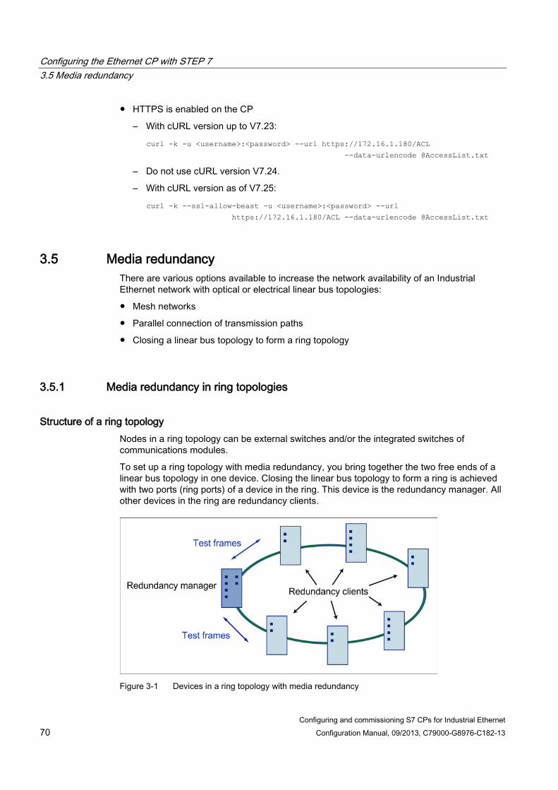
Configuring the Ethernet CP with STEP 7 3.5 Media redundancy
Configuring and commissioning S7 CPs for Industrial Ethernet 70 Configuration Manual, 09/2013, C79000-G8976-C182-13
● HTTPS is enabled on the CP
– With cURL version up to V7.23:
curl -k -u <username>:<password> --url https://172.16.1.180/ACL --data-urlencode @AccessList.txt
– Do not use cURL version V7.24.
– With cURL version as of V7.25:
curl -k --ssl-allow-beast -u <username>:<password> --url
https://172.16.1.180/ACL --data-urlencode @AccessList.txt
3.5 Media redundancy There are various options available to increase the network availability of an Industrial Ethernet network with optical or electrical linear bus topologies:
● Mesh networks
● Parallel connection of transmission paths
● Closing a linear bus topology to form a ring topology
3.5.1 Media redundancy in ring topologies
Structure of a ring topology Nodes in a ring topology can be external switches and/or the integrated switches of communications modules.
To set up a ring topology with media redundancy, you bring together the two free ends of a linear bus topology in one device. Closing the linear bus topology to form a ring is achieved with two ports (ring ports) of a device in the ring. This device is the redundancy manager. All other devices in the ring are redundancy clients.
Figure 3-1 Devices in a ring topology with media redundancy

Configuring the Ethernet CP with STEP 7 3.5 Media redundancy
Configuring and commissioning S7 CPs for Industrial Ethernet Configuration Manual, 09/2013, C79000-G8976-C182-13 71
The two ring ports of a device are the ports that establish the connection to its two neighboring devices in the ring topology. The ring ports are selected and set in the configuration of the relevant device. In STEP 7 and on the S7 Ethernet CP modules themselves, the ring ports are indicated by an "R" after the port number.
Note
Before physically closing the ring, download the configuration of your STEP 7 project to the individual devices.
How media redundancy works in a ring topology When using media redundancy, the data paths between the individual devices are reconfigured if the ring is interrupted at one point. Following reconfiguration of the topology, the devices can once again be reached in the resulting new topology.
In the redundancy manager, the 2 ring ports are disconnected from each other if the network is uninterrupted. This prevents circulating data frames. In terms of data transmission, the ring topology is a linear bus topology. The redundancy manager monitors the ring topology. It does this by sending test frames both from ring port 1 and ring port 2. The test frames run round the ring in both directions until they arrive at the other ring port of the redundancy manager.
An interruption of the ring can be caused by loss of the connection between two devices or by failure of a device in the ring.
If the test frames of the redundancy manager no longer arrive at the other ring port, the redundancy manager connects its two ring ports. This substitute path once again restores a functioning connection between all remaining devices in the form of a linear bus topology.
As soon as the interruption is eliminated, the original transmission paths are established again, the two ring ports of the redundancy manager are disconnected and the redundancy clients informed of the change. The redundancy clients then use the new paths to the other devices.
The time between the ring interruption and restoration of a functional linear topology is known as the reconfiguration time.
If the redundancy manager fails, the ring becomes a functional linear bus.
Media redundancy methods The following media redundancy methods are supported by SIMATIC NET products:
● HRP (High Speed Redundancy Protocol)
Reconfiguration time: 0.3 seconds
● MRP (Media Redundancy Protocol)
Reconfiguration time: 0.2 seconds
The mechanisms of these methods are similar. HRP and MRP cannot be used in the ring at the same time.

Configuring the Ethernet CP with STEP 7 3.5 Media redundancy
Configuring and commissioning S7 CPs for Industrial Ethernet 72 Configuration Manual, 09/2013, C79000-G8976-C182-13
3.5.2 MRP The "MRP" method conforms to the Media Redundancy Protocol (MRP) specified in the following standard:
IEC 62439-2 Edition 1.0 (2010-02) Industrial communication networks - High availability automation networks Part 2: Media Redundancy Protocol (MRP)
The reconfiguration time after an interruption of the ring is a maximum of 0.2 seconds.
Requirements Requirements for problem-free operation with the MRP media redundancy protocol are as follows:
● MRP is supported in ring topologies with up to 50 devices. In topologies with X300 IE switches, up to 100 nodes are supported.
Exceeding this number of devices can lead to a loss of data traffic.
● The ring in which you want to use MRP may only consist of devices that support this function.
These include, for example, some of the Industrial Ethernet SCALANCE X switches, some of the communications processors (CPs) for SIMATIC S7 and PG/PC or non-Siemens devices that support this function.
● All devices must be interconnected via their ring ports.
● "MRP" must be activated on all devices in the ring (see section "MRP configuration (Page 74)").
● The connection settings (transmission medium / duplex) must be set to full duplex and at least 100 Mbps for all ring ports. Otherwise there may be a loss of data traffic.
– STEP 7: Set all the ports involved in the ring to "Automatic settings" in the "Options" tab of the properties dialog.
– WBM: If you configure with Web Based Management, the ring ports are set automatically to autonegotiation.

Configuring the Ethernet CP with STEP 7 3.5 Media redundancy
Configuring and commissioning S7 CPs for Industrial Ethernet Configuration Manual, 09/2013, C79000-G8976-C182-13 73
Topology The following schematic shows a possible topology for devices in a ring with MRP.
Figure 3-2 Example of a ring topology with the MRP media redundancy protocol
The following rules apply to a ring topology with media redundancy using MRP:
● All the devices connected within the ring topology are members of the same redundancy domain.
● One device in the ring is acting as redundancy manager.
● All other devices in the ring are redundancy clients.
Non MRP-compliant devices can be connected to the ring via a SCALANCE X switch or via a PC with a CP 1616.
Prioritized startup If you configure MRP in a ring, you cannot use the "prioritized startup" function in PROFINET applications on the devices involved.
If you want to use the "prioritized startup" function, then disable MRP in the configuration.
In the STEP 7 configuration, set the role to "Not a node in the ring".

Configuring the Ethernet CP with STEP 7 3.5 Media redundancy
Configuring and commissioning S7 CPs for Industrial Ethernet 74 Configuration Manual, 09/2013, C79000-G8976-C182-13
3.5.3 MRP configuration
Configuration in STEP 7 To create the configuration in STEP 7, select the parameter group "Media redundancy" on the PROFINET interface.
Set the following parameters for the MRP configuration of the device:
● Domain
● Role
● Ring port
● Diagnostic interrupts
These settings are described below.
Note Prioritized startup
If you configure MRP in a ring, you cannot use the "prioritized startup" function in PROFINET applications on the devices involved.
If you want to use the "prioritized startup" function, then disable MRP in the configuration.
In the STEP 7 configuration, set the role of the relevant device to "Not a node in the ring".
Domain Leave the default entry "mrpdomain 1" from the factory settings in the "Domain" drop-down list.
All devices configured in a ring with MRP must belong to the same redundancy domain. A device cannot belong to more than one redundancy domain.
If you leave the setting for "Domain" as the factory set "mrpdomain-1", the defaults for "Role" and "Ring ports" also remain active.
The MRP settings remain in effect following a restart of the device or following a power down and hot restart.
Role The choice of role depends on the following use cases.
● You want to use MRP in a ring topology only with Siemens devices and without monitoring diagnostic interrupts:
Assign all devices to the "mrpdomain-1" domain and the role "Manager (Auto)".
The device that actually takes over the role of redundancy manager, is negotiated by Siemens devices automatically.
Configuring the Ethernet CP with STEP 7 3.5 Media redundancy
Configuring and commissioning S7 CPs for Industrial Ethernet Configuration Manual, 09/2013, C79000-G8976-C182-13 75
● You want to use MRP in a ring topology that also includes non-Siemens devices or you want to receive diagnostic interrupts relating to the MRP status from a device (see "Diagnostic interrupts"):
– Assign precisely one device in the ring the role of "redundancy manager".
– For all other devices in the ring topology, select the role of "Client".
Note
To ensure problem-free operation when using a non-Siemens device as the redundancy manager in the ring, make sure that you assign the fixed role of "Client" to all other devices in the ring, before you close the ring. Otherwise, there may be circulating data frames that will cause a failure in the network.
● You want to disable MRP:
Select the option "Not node in the ring" if you do not want to operate the device within a ring topology with MRP.
Note
Role after resetting to factory settings
Brand new Siemens devices and those reset to the factory settings have the MRP role "Manager (Auto)" (CPs) or "Automatic Redundancy Detection" (SCALANCE X). If you are operating a non-Siemens device as the redundancy manager in the ring, this may cause loss of the data traffic.
Ring port 1 / ring port 2 Here, select the port you want to configure as ring port 1 and ring port 2.
With devices with more than 8 ports, not all ports can be selected as ring port.
The drop-down list shows the selection of possible ports for each device type. If the ports are specified in the factory, the boxes are grayed out.
NOTICE
Ring ports after resetting to factory settings
If you reset to the factory settings, the ring port settings are also reset. • CPs adopt the "Manager (Auto)" MRP role. • With switches, the redundancy method Automatic Redundancy Detection (ARD) is
activated.
If other ports were used previously as ring ports before resetting, with the appropriate attachment, a previously correctly configured device can cause circulating frames and therefore the failure of the data traffic.
Configuring the Ethernet CP with STEP 7 3.6 Assigning addresses the first time
Configuring and commissioning S7 CPs for Industrial Ethernet 76 Configuration Manual, 09/2013, C79000-G8976-C182-13
Diagnostic interrupts Enable the "Diagnostic interrupts" option, if you want diagnostic interrupts relating to the MRP status on the local CPU to be output.
The following diagnostic interrupts can be generated:
● Wiring or port error
Diagnostic interrupts are generated if the following errors occur at the ring ports:
– Connection abort on a ring port
– A neighbor of the ring port does not support MRP.
– A ring port is connected to a non-ring port.
– A ring port is connected to the ring port of another MRP domain.
● Interruption / return (redundancy manager only)
If the ring is interrupted and when the original configuration returns, diagnostic interrupts are generated.
The occurrence of both interrupts within 0.2 seconds indicates an interruption in the ring.
Parameter assignment of the redundancy is not set by STEP 7 (redundancy alternatives) This option only affects switches. Select this option if you want to set the properties for media redundancy using alternative mechanism or tools such as Web based Management (WBM), CLI or SNMP.
If you enable this option, existing redundancy settings from WBM, CLI or SNMP, are retained and are not overwritten. The parameters in the "MRP configuration" box are then reset and grayed out. The entries then have no meaning.
3.6 Assigning addresses the first time
Meaning of the address assignment - MAC address and IP address Depending on the device type, the CP ships with one or two fixed MAC addresses. Without further configuration, the device can only be reached via the Ethernet connection using these MAC addresses.
In this status "as shipped", you can already use the following functions via the CP with the ISO protocol by using the default MAC address:
● Downloading the configuration to the CP or the CPU;
● Diagnostics of the CP or CPU.
Before you can download the configuration data to the device using an IP address, you must first assign an IP address to the CP.

Configuring the Ethernet CP with STEP 7 3.6 Assigning addresses the first time
Configuring and commissioning S7 CPs for Industrial Ethernet Configuration Manual, 09/2013, C79000-G8976-C182-13 77
Variants and recommendation for the address assignment There are 3 ways of making this address assignment in STEP 7:
● Addressing by selecting the target system in the SIMATIC Manager
This variant allows the address assignment without needing to create a STEP 7 project. This, for example, is useful if you want to download configuration data created offline to the S7 station.
This variant is described in section.Addressing by selecting the target system (Page 78).
● Addressing by adopting the configured address parameters
This variant assumes a CP networked in STEP 7. The advantage of this method is that the IP parameters specified during networking in STEP 7 are adopted directly.
In an initial step, you assign the CP the previously configured IP address and the IP parameters of the Ethernet or PROFINET interface.
Only then can the configuration data be downloaded to the CP using a PG/PC via Ethernet.
This variant is described in section.Addressing by adopting the configured address parameters (Page 78).
● Downloading configuration data using the ISO protocol
Another variant is to download configuration data with a defined IP address using the ISO protocol; this applies to CPs that support the ISO protocol. In this case, you address the CP using its MAC address.
Requirement To be able to address the CP as described here, the CP must be available online; in other words:
● The connection to the Ethernet LAN must be established; there must be no subnet transition (router) in between.
● The Ethernet interface of your PG/PC must be available from within STEP 7.
Note
The options for assigning addresses as described here, are only possible with a module that can be reached via a default MAC address; to allow this, the module must support the PST function (Primary Setup Tool). For more information, refer to the relevant device manual /1/ (Page 227).
With older CPs (CPs with a firmware version < V3) with an additional gigabit interface, the PST tool can only be used on the PROFINET interface.

Configuring the Ethernet CP with STEP 7 3.6 Assigning addresses the first time
Configuring and commissioning S7 CPs for Industrial Ethernet 78 Configuration Manual, 09/2013, C79000-G8976-C182-13
3.6.1 Addressing by selecting the target system
Follow the steps below to assign an IP address the first time: 1. Use the STEP 7 function "Display Accessible Nodes" to display the nodes that can be
reached via Industrial Ethernet.
2. Select the required node in the list that then appears.
3. Then select the "PLC > Ethernet Address" menu command.
Result: The previously selected node is then adopted directly in the "Addressing" dialog. The MAC address of the node cannot be changed.
4. Enter the required IP parameters and assign these to the CP.
Result: The CP is now available on Industrial Ethernet using the IP address.
Note
In principle, the description applies equally to STEP 7 V5.5 and STEP 7 Professional.
You will find further, more detailed information on the procedures in the online help in STEP 7. There, you will also find further information and alternative methods.
3.6.2 Addressing by adopting the configured address parameters
Follow the steps below to configure the IP address for a newly inserted CP: 1. Insert the required CP in the S7 station open in STEP 7.
2. Edit the MAC address and, if required, the IP parameters in the parameter group of the Ethernet interface.
3. In the "Subnet" box, select the Ethernet subnet with which you want to connect the CP.
4. Save your project.
5. Using the appropriate STEP 7 function, start the network search function for accessible modules.
With CPs that have multiple interfaces, only the PROFINET interface is displayed.
6. Select the CP with the matching MAC address from the available components.
The configured IP address is displayed.
7. Assign the CP the IP parameters adopted from the networking.
8. Then download the configuration data to the target system.
Result: After downloading the configuration data, the CP can be accessed on Industrial Ethernet using the IP address.

Configuring the Ethernet CP with STEP 7 3.7 Downloading the configuration data to the target system
Configuring and commissioning S7 CPs for Industrial Ethernet Configuration Manual, 09/2013, C79000-G8976-C182-13 79
Note
In principle, the description applies equally to STEP 7 V5.5 and STEP 7 Professional.
You will find further, more detailed information on the procedures in the online help in STEP 7. There, you will also find further information and alternative methods.
3.7 Downloading the configuration data to the target system
Downloading configuration data The configuration data of the Ethernet CP is downloaded from the hardware configuration. All the configuration data of the S7 station is downloaded including the configuration of the central structure and all parameter assignments.
The data of the connection configuration must also be downloaded; see below.
Note
With CPs that have two interfaces (gigabit interface), note the information in the manual about the interface you can use to download the configuration data.
Connection type You can download the configuration data to the S7 station in the following ways or using the following connections:
● MPI connection
You can use this connection to download the configuration data or for the initial assignment of a MAC/IP address (node initialization - for details on this, refer to the manual /2/ in the section "Assigning addresses for the first time").
● Industrial Ethernet
Here, you use the PG mode of the Ethernet CP in the S7 station (see also the section PG/OP communication via Industrial Ethernet (Page 21)).
Depending on the PG/PC interface of your engineering station, you can download the configuration data via the TCP/IP interface or via the ISO interface of STEP 7 to the S7 station.
– If you download via the IP interface, the CP must first be supplied with an IP address; see also the section Setting further CP properties (Page 42).
– If you download via the ISO interface, the default MAC address can be used. Please note, however:

Configuring the Ethernet CP with STEP 7 3.7 Downloading the configuration data to the target system
Configuring and commissioning S7 CPs for Industrial Ethernet 80 Configuration Manual, 09/2013, C79000-G8976-C182-13
Note
If you want to download the configuration data via the ISO interface for a CP with an unchanged, factory-set MAC address and have planned a different MAC address in the STEP 7 project, you will need to initiate the download in NetPro or HW Config; only here are you requested to enter the current MAC address. The SIMATIC Manager, in contrast, aborts the download if the target station is not accessible.
Procedure To download the configuration data to the S7 station, follow the steps below:
1. Open the "Set PG/PC Interface" dialog box in the Windows Control Panel.
2. Set the PG/PC interface according to the CPs available on your PG and according to the bus attachment (interface parameter assignment used).
You will find more detailed information in the integrated help.
3. Change the CPU to STOP mode (regardless of the type of connection - see above).
4. Select the "PLC > Download to Module" menu command
STEP 7 then guides you to the required result in dialog boxes. Note the extra information in the "STEP 7 User Manual", section "Configuring and assigning parameters to modules" in /6/;
Disabling the ISO protocol in the configuration (MAC address invisible) If you disable the use of the ISO protocol in the properties dialog of the Ethernet interface when configuring the CP, the CP is still accessible via the default MAC address. However, you can then no longer use any ISO transport connections and you cannot configure any S7 connections via ISO connections. If the ISO protocol is disabled, the configured MAC address is no longer visible in the properties dialog.
Non-volatile storage of the configuration data (on CPs with data storage) During the download, you can decide whether or not to download the entire configuration data or only for selected modules. If you choose to download selectively, you will be requested to start the download for each module. Select this procedure if you want the configuration data to be stored in non-volatile storage on the Ethernet CP. To do this, select the "Copy to ROM" button in the "Download" dialog for the CP.

Configuring the Ethernet CP with STEP 7 3.7 Downloading the configuration data to the target system
Configuring and commissioning S7 CPs for Industrial Ethernet Configuration Manual, 09/2013, C79000-G8976-C182-13 81
Downloading the connection configuration To download configured connections, you will need to make a download in the connection configuration (NetPro).
Note
If you have assigned a new address to the Ethernet CP, you always need to download the connection configuration again.
Note that you will need to make address adaptations even for the other stations or "substitute objects".
Moving the CP in the hardware configuration If you use communication services with configured connections, these connections are linked to the slot of the CP based on connection IDs. You should therefore note the following information if you move a CP that has already been configured by "dragging" it to a different slot.
Note
If the CP has been moved to a different slot by "dragging", the data of the connection configuration is automatically updated. The data of the connection configuration nevertheless needs to be downloaded again!

Configuring the Ethernet CP with STEP 7 3.7 Downloading the configuration data to the target system
Configuring and commissioning S7 CPs for Industrial Ethernet 82 Configuration Manual, 09/2013, C79000-G8976-C182-13

Configuring and commissioning S7 CPs for Industrial Ethernet Configuration Manual, 09/2013, C79000-G8976-C182-13 83
SEND/RECEIVE interface in the user program 4
This section explains the following topics:
● How is data sent and received for the open communication services?
● Which data areas can be used on the S7 CPU?
● How do you program the SEND/RECEIVE interface in the user program?
There, you will find further information:
● The program blocks for programming the connections are described in /10/ (Page 230).
Configuration and program examples are available for the SEND/RECEIVE interface described here:
● Program examples with the program blocks FC5 (AG_SEND) and FC6 (AG_RECV) for S7-300 can be found under the following entry ID:
17853532 (http://support.automation.siemens.com/WW/view/en/17853532)
● Program examples with the program blocks FC50 (AG_LSEND) and FC60 (AG_LRECV) for S7-400 can be found under the following entry ID:
18513371 (http://support.automation.siemens.com/WW/view/en/18513371)
There, you will also find a collection of further entries as well as project and programming examples for S7 CPs for Industrial Ethernet.
● You will find sample programs and configurations in the Quick Start Collection on the Internet under the following entry ID:
21827955 (http://support.automation.siemens.com/WW/view/en/21827955)
4.1 How the SEND/RECEIVE interface works on the CPU
Program blocks To handle communication via connections, the following program blocks of the type FC are available:
● AG_SEND (FC 5) / AG_LSEND (FC 50) / AG_SSEND (FC 53)
The program block transfers the user data from the specified user data area for transfer to the Ethernet CP.
● AG_RECV (FC 6) / AG_LRECV (FC 60) / AG_SRECV (FC 63)
The program block enters the received user data in the user data area specified in the call.

SEND/RECEIVE interface in the user program 4.1 How the SEND/RECEIVE interface works on the CPU
Configuring and commissioning S7 CPs for Industrial Ethernet 84 Configuration Manual, 09/2013, C79000-G8976-C182-13
The diagram below illustrates what happens: Using AG_SEND / AG_LSEND / AG_SSEND and AG_RECV / AG_LRECV / AG_SRECV, the user program instructs the Ethernet CP to send or receive data on the configured connection.
Amounts of data and configuration limits The Ethernet CP can transfer (send or receive) the following amounts of data per job:
Program block ISO-Transport ISO-on-TCP TCP UDP
Send AG_SEND *)
AG_LSEND **) AG_SSEND ***)
8192 bytes 8192 bytes 1452 bytes
8192 bytes 8192 bytes 1452 bytes
8192 bytes 8192 bytes 1452 bytes
2048 bytes 2048 bytes 1452 bytes
Received AG_RECV *)
AG_LRECV **) AG_SRECV ***)
8192 bytes 8192 bytes 1452 bytes
8192 bytes 8192 bytes 1452 bytes
8192 bytes 8192 bytes 1452 bytes
2048 bytes 2048 bytes 1452 bytes
*) - With older versions of AG_SEND / AG_RECV (up to V3.0), the data area is always restricted to a maximum of 240 bytes.
- With the S7-400, the data area of AG_SEND / AG_RECV is always restricted to a maximum of 240 bytes.
**) S7-400 only ***) Only with the S7-400 with CPUs as of version V5.1 and the following CPs:
- CP 443-1 (as of 6GK7 443-1EX20.../ EX30) - CP 443-1 Advanced (as of 6GK7 443-1GX20.../ GX30)

SEND/RECEIVE interface in the user program 4.2 Programming the SEND/RECEIVE interface
Configuring and commissioning S7 CPs for Industrial Ethernet Configuration Manual, 09/2013, C79000-G8976-C182-13 85
4.2 Programming the SEND/RECEIVE interface
Principle of job and data transfer With the program block calls, the user program initiates the transfer of the user data areas and monitors execution of the transfer by evaluating the condition codes of the FCs.
Among other things, the following parameters are transferred during the call:
● The connection number of the connection (ID);
● The location of the user data area on the CPU.
Task of the program blocks Calling the program blocks brings about the following action:
● The user data area is transferred to the Ethernet CP or is accepted from the Ethernet CP.
● The execution of the job is only confirmed in the positive or negative status.
Follow the steps below Program the SEND/RECEIVE interface in the user program as follows:
1. Use the following program blocks for data transfer with connections:
– AG_SEND / AG_LSEND / AG_SSEND for transferring the user data area to the Ethernet CP;
– AG_RECV / AG_LRECV / AG_SRECV for adopting the data received from the Ethernet CP in the user data area;
2. Evaluate the condition codes of the program blocks:
– With AG_SEND / AG_LSEND / AG_SSEND, the parameters DONE, ERROR, STATUS;
– With AG_RECV / AG_LRECV / AG_SRECV, the parameters NDR, ERROR, STATUS;
Note
Connection numbers (IDs) must be adopted in the programming from the configuration.
To ensure correct parameter assignment for the block calls, STEP 7 provides the option of adopting relevant parameters from the CP configuration automatically in the LAD/STL/FBD editor. For more detailed information, refer to the online help in STEP 7.

SEND/RECEIVE interface in the user program 4.2 Programming the SEND/RECEIVE interface
Configuring and commissioning S7 CPs for Industrial Ethernet 86 Configuration Manual, 09/2013, C79000-G8976-C182-13
Calling program blocks in the CPU program One possible sequence for the program blocks along with the organization and program blocks in the CPU cycle is shown below:
The following situation can be recognized:
● The user program that can consist of any number of program blocks (OBs, FBs or FCs - see also /5/ (Page 229)) accesses multiple connections. The figure above shows 3 connections.

SEND/RECEIVE interface in the user program 4.3 Data exchange S7 CPU − Ethernet CP
Configuring and commissioning S7 CPs for Industrial Ethernet Configuration Manual, 09/2013, C79000-G8976-C182-13 87
● The user program sends data via a connection using an AG_SEND call at any point, in other words event and program-driven.
● At any point in the CPU cycle, the user program accepts data received via a connection using an AG_RECV call.
Note
The program blocks can also be called more than once in a cycle for a single communication connection.
4.3 Data exchange S7 CPU − Ethernet CP The Ethernet CP processes the send and receive jobs regardless of the CPU cycle and requires a certain transfer time. The interface with the program blocks to the user program is synchronized with an acknowledgement. 2 cases must be distinguished:
● The CPU cycle is faster than the transfer time.
● The CPU cycle is slower than the transfer time.
Note
Refer to the flow diagrams for the program blocks in /10/ (Page 230). These diagrams show how you need to supply and handle the SEND/RECEIVE interface in the user program for problem-free data exchange.
Consider the following information relating to the CPU cycle and the transfer time as additional information.
FC calls faster than the transfer time If a program block is called again in the user program before the data has been completely sent or received, the reaction on the interface of the program blocks is as follows:
● AG_SEND / AG_LSEND / AG_SSEND: No further job is accepted until the transfer of the data via the connection has been acknowledged by the Ethernet node. The user program receives the condition code "Job running" until the Ethernet CP can accept the next job on the same connection.
● AG_RECV / AG_LRECV: The job is acknowledged with the condition code " No data yet" if there is no data to be received on the Ethernet CP. The user program receives this condition code in the CPU cycle until the Ethernet CP has received the data completely via the connection.
SEND/RECEIVE interface in the user program 4.4 Additional information
Configuring and commissioning S7 CPs for Industrial Ethernet 88 Configuration Manual, 09/2013, C79000-G8976-C182-13
FC calls slower than the transfer time If a program block is called again before the data has been completely sent or received, the reaction on the interface of the program blocks is as follows:
● AG_SEND / AG_LSEND / AG_SSEND: The job is positively acknowledged; the Ethernet CP is ready to accept a new send job (at the earliest, however, with the next call).
● AG_RECV / AG_LRECV / AG_SRECV: The job is acknowledged with "New data accepted" if the data has been accepted in the user program. Following this, the FC can be called again.
Note
Note that if there are different processing speeds (sender faster than receiver), resource bottlenecks can occur at the send and receive end.
If this is the case, the sender receives feedback from the program blocks (condition code "No receive resources on the target station"). (Not with AG_SRECV)
4.4 Additional information
4.4.1 Programming data transfer via TCP connections
Purpose of TCP connections TCP connections should be used primarily to link third-party systems if these do not support the protocol extension RFC1006.
For the communication between devices of the SIMATIC family, ISO-on-TCP connections should be used because these are more convenient. The following section points out certain special features.

SEND/RECEIVE interface in the user program 4.4 Additional information
Configuring and commissioning S7 CPs for Industrial Ethernet Configuration Manual, 09/2013, C79000-G8976-C182-13 89
Special Features ● Only use the following program block types for data transfer:
– AG_SEND (FC 5), AG_LSEND (FC 50) oder AG_SSEND (FC 53)
– AG_RECV (FC 6), AG_LRECV (FC 60) oder AG_SRECV (FC 63)
● Frame length
On TCP connections, there is no information in the protocol about the end of a message or the start of a new message. This means that the receiving station needs to know how many bytes belong to a message. The station transfers an ANY pointer with exactly this length when AG_RECV / AG_LRECV is called.
Note: This does not apply to the AG_SRECV program block; AG-SRECV is always called with the maximum length.
Example of an ANY pointer for receiving 100 bytes of data:
– P#DB100.DBX 0.0 Byte 100.
To receive data with a variable length, follow the steps below:
1. Include information in the frame before the actual user data indicating the length of the user data.
2. First evaluate only the length information on the receiving station.
3. Fetch the corresponding amount of user data in a further receive job. To do this specify an ANY pointer with a suitable length for fetching the actual user data.
4.4.2 Recommendations for use with a high communications load
Reason To avoid an overload situation on the CPU you are using, note the following information about the Ethernet CPs.
Check your application for the following recommendations, in particular if you replace a CP with a new CP and encounter overload problems.
Known problems ● Very often, the program blocks for sending (AG_SEND / AG_LSEND / AG_SSEND) and
receiving (AG_RECV / AG_LRECV) are called cyclically in OB1. This leads to constant communication between the CPU and CP. As a result, other types of communication such as PG functions cannot be executed or only very slowly.
● HMI systems access data of the CPU too often using S7 functions. This slows down communication in general and resource bottlenecks can occur if SEND/RECEIVE program blocks are called cyclically by OB1.

SEND/RECEIVE interface in the user program 4.4 Additional information
Configuring and commissioning S7 CPs for Industrial Ethernet 90 Configuration Manual, 09/2013, C79000-G8976-C182-13
Solution Note the following recommendations:
● Do not call communication program blocks cyclically in OB1!
Call up communication time-controlled in a suitable time OB. The call interval of this OB should be significantly higher than the average cycle time of OB1.
● Set a minimum cycle time that is higher than the average runtime of OB1. This frees resources for communication on the CPU. This is, for example, a solution for existing applications when communication already takes place cyclically in OB1.
● If necessary, reduce the time taken for communication processing on the CPU by changing the parameter "Scan cycle load from communication" of the CPU.
Configuring and commissioning S7 CPs for Industrial Ethernet Configuration Manual, 09/2013, C79000-G8976-C182-13 91
Configuring communications connections 5
This section explains the following topics:
● General information on configuring communications connections;
● Configuring special properties with ISO transport, ISO-on-TCP, UDP and TCP connections;
● How you specify the communications partners exchanging data using UDP with the functions for connection configuration.
There, you will find further information:
● In some situations, it is an advantage to set up communication connections not over the configuration interface of STEP 7 but programcontrolled by specific applications; you will find information on this in /10/ (Page 230)
● You will find information about the properties of the configurable e-mail connection type in the section Sending process messages by email (Page 135)
● You will find information on configuring connections in the online help integrated in STEP 7. The steps for creating and configuring connections are explained in detail there.

Configuring communications connections 5.1 Procedure and connection properties
Configuring and commissioning S7 CPs for Industrial Ethernet 92 Configuration Manual, 09/2013, C79000-G8976-C182-13
5.1 Procedure and connection properties
Setting up connections and using them in the user program The following steps are necessary to operate connections in the SIMATIC S7 PLC with the Ethernet CP:
Properties of the connection A communications connection allows program-controlled communication between two nodes on Industrial Ethernet with the following properties:
● Data transfer is bi-directional; in other words it is possible to send and receive on the connection at the same time.
● Both nodes have the same rights, in other words each node can trigger the send or receive procedure dependent on events.
● The address of the communication partner is specified in the configuration.
The following is an exception:
– The free UDP connection
Here, the address is specified at the FC interface in the user program.
– The communications connection programmed with FB55 in the user program (see /10/ (Page 230))
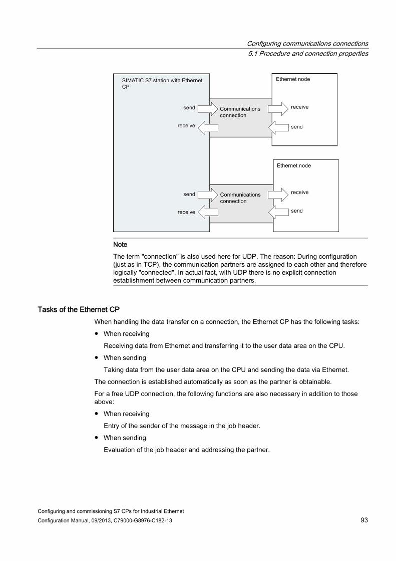
Configuring communications connections 5.1 Procedure and connection properties
Configuring and commissioning S7 CPs for Industrial Ethernet Configuration Manual, 09/2013, C79000-G8976-C182-13 93
Note
The term "connection" is also used here for UDP. The reason: During configuration (just as in TCP), the communication partners are assigned to each other and therefore logically "connected". In actual fact, with UDP there is no explicit connection establishment between communication partners.
Tasks of the Ethernet CP When handling the data transfer on a connection, the Ethernet CP has the following tasks:
● When receiving
Receiving data from Ethernet and transferring it to the user data area on the CPU.
● When sending
Taking data from the user data area on the CPU and sending the data via Ethernet.
The connection is established automatically as soon as the partner is obtainable.
For a free UDP connection, the following functions are also necessary in addition to those above:
● When receiving
Entry of the sender of the message in the job header.
● When sending
Evaluation of the job header and addressing the partner.

Configuring communications connections 5.2 Connections to partners in other projects
Configuring and commissioning S7 CPs for Industrial Ethernet 94 Configuration Manual, 09/2013, C79000-G8976-C182-13
Requirements for configuring connections ● The Ethernet CP was configured in the S7 station with STEP 7 and networked with an
Ethernet subnet.
● As a bus node, the Ethernet CP has an address.
Note
All stations not in the current STEP 7 project must be configured with substitute objects (for example as "SIMATIC S5" or "Other stations");
or
Use the "unspecified" partner type when you create the connection.
See also /1/ (Page 227)
5.2 Connections to partners in other projects There are various ways of creating connections to partners configured in other STEP 7 projects or with other tools outside the current STEP 7 project:
● Connection using substitute objects such as "SIMATIC S7", "PC/PG" , "SIMATIC PC Station".
● Unspecified connections
Unspecified connections Connections to an as yet unknown device (for example a diagnostics unit) are configured as "unspecified" connections. They can be specified later in the Properties dialog.
You can create an unspecified connection simply by selecting station "unspecified" for the connection partner when you create the connection. The unspecified connection can be used in various ways (explained below based on the example of an ISO-on-TCP connection; ISO transport and TCP connections are analogous):

Configuring communications connections 5.2 Connections to partners in other projects
Configuring and commissioning S7 CPs for Industrial Ethernet Configuration Manual, 09/2013, C79000-G8976-C182-13 95
● Declare readiness for communication - passive connection establishment
The connection establishment is set to "passive" for this situation.
The address setting for the ISO-on-TCP connection is then as follows: The remote IP address and the remote TSAP are empty because they are not relevant for the CP. When the connection is established, any partner is accepted (partner = connection name) that addresses the CP with the correct IP address and TSAP.
It is also possible to use a partial specification; in other words, communication is permitted with any partner that matches the specified TSAP.
● Connection to a specific station in any project
The address setting for the ISO-on-TCP connection is then as follows: You can specify the remote IP address and the port of any destination station. The destination station can be in the current STEP 7 project or in another project.
Use this method if you have not created a substitute object for the partner station, for example SIMATIC S5, in the current project.
● Connection without specified port
TCP connections are unspecified in the following situations:
– The local port is not specified (active connection establishment).
– The remote port is not specified (no active connection establishment).
● IP addressing using DHCP
If you select the option to obtain the IP address from a DHCP server, it is initially not possible to create a fully specified connection in the STEP 7 project because the local IP address is not known. You must therefore select "unspecified" without active connection establishment as the connection type.
The following table lists the possible options.
Table 5- 1 Setting the "remote" address parameters
Meaning for connection establishment
IP address / MAC address (remote)
TSAP / port (remote)
Active connection establishment
by any partner empty empty no by any partner via specific TSAP empty specified no to or by a specific partner specified specified Yes
The local port can remain unspecified (but not necessarily).
to or by a specific partner specified unspecified no
The free UDP connection is another variant. With this type of connection, the address of the connection partner is left open during configuration. The communication nodes are identified by address information in the communication job in the user program.

Configuring communications connections 5.3 Inconsistent connections - connections without assignment
Configuring and commissioning S7 CPs for Industrial Ethernet 96 Configuration Manual, 09/2013, C79000-G8976-C182-13
For further information, refer to the sections dealing with specific connections.
Note
To check how many connections are possible per Ethernet CP, please refer to the manual that ships with the CP /1/ (Page 227).
If several CPs are installed in a station, there is an automatic switchover to the next CP if this limit is exceeded. The connections can be routed in the Properties dialog of the connection.
Security enabled To be able to establish the connection to unspecified nodes, you must first configure suitable firewall rules in the advanced mode of SCT.
For specified connections, the firewall rules are created automatically.
5.3 Inconsistent connections - connections without assignment An inconsistent connection is one in which the connection data is incomplete or inconsistent; the connection is not functional in the context with the project.
Inconsistent connections cannot be loaded - operation is not possible with such connections.
Possible causes for inconsistent connections ● Deletion or change of the hardware configuration.
● Missing interface network links in the project, which are necessary for a connection.
● Connection resources are exceeded
● Connections to an unspecified connection partner without partner address information.
You will find detailed information about the cause of the inconsistency in STEP 7.
Examples of and remedies for inconsistencies associated with typical configuration actions Actions are explained below that can cause configured connections to lose their assignment or be deleted.
Note ID adaptation in the user program
Note that as opposed to the S7 connections, a CP-dependent ID is assigned to the connections of the SEND/RECEIVE interface. Consequently the actions described below may require customizing of the ID, which means that the interface must also be customized in the user program.

Configuring communications connections 5.3 Inconsistent connections - connections without assignment
Configuring and commissioning S7 CPs for Industrial Ethernet Configuration Manual, 09/2013, C79000-G8976-C182-13 97
Note CP replacement
If a CP is replaced by a different CP then it must provide at least the same services and have at least the same version. This is the only way to ensure that the connections configured via the CP remain consistent and can be used.
behavior in STEP 7 V5.5
Table 5- 2 Actions for a CP interface that can cause changes in configured connections
Action Consequence for the connections What you must do to restore the connection The CP (module) is moved to a different location in the hardware configuration (drag and drop)
The connections are retained. The connection IDs are automatically updated.
- no action required -
Delete the CP (module) in the hardware configuration. You receive the message: "CP has n connections; the assignment will be lost in the connection table".
The connections remain intact in the connection table without assignment to a CP. In the "Overview" tab of the Properties dialog, the connections are identified with "!".
After you have placed and networked a CP in the hardware configuration: 1. Assign the CP to the connection in the
properties dialog for the connection in the "Addresses" tab;
or
reassign the connection with the Edit > Connection partner function.
2. Check the module start address LADDR and customize if necessary in the user program.
3. Customize the connection IDs in the user program.
4. Reload the connection configuration into the CP.
Delete the SIMATIC S7 station. All the connections to this station are deleted in the project. Note: does not apply to connections on the partner if this uses a router.
Reconfigure the station and connections.
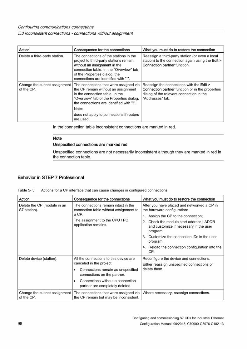
Configuring communications connections 5.3 Inconsistent connections - connections without assignment
Configuring and commissioning S7 CPs for Industrial Ethernet 98 Configuration Manual, 09/2013, C79000-G8976-C182-13
Action Consequence for the connections What you must do to restore the connection Delete a third-party station. The connections of the stations in the
project to third-party stations remain without an assignment in the connection table. In the "Overview" tab of the Properties dialog, the connections are identified with "!".
Reassign a third-party station (or even a local station) to the connection again using the Edit > Connection partner function.
Change the subnet assignment of the CP.
The connections that were assigned via the CP remain without an assignment in the connection table. In the "Overview" tab of the Properties dialog, the connections are identified with "!". Note: does not apply to connections if routers are used.
Reassign the connections with the Edit > Connection partner function or in the properties dialog of the relevant connection in the "Addresses" tab.
In the connection table inconsistent connections are marked in red.
Note Unspecified connections are marked red
Unspecified connections are not necessarily inconsistent although they are marked in red in the connection table.
Behavior in STEP 7 Professional
Table 5- 3 Actions for a CP interface that can cause changes in configured connections
Action Consequence for the connections What you must do to restore the connection Delete the CP (module in an S7 station).
The connections remain intact in the connection table without assignment to a CP. The assignment to the CPU / PC application remains.
After you have placed and networked a CP in the hardware configuration: 1. Assign the CP to the connection; 2. Check the module start address LADDR
and customize if necessary in the user program.
3. Customize the connection IDs in the user program.
4. Reload the connection configuration into the CP.
Delete device (station). All the connections to this device are canceled in the project. • Connections remain as unspecified
connections on the partner. • Connections without a connection
partner are completely deleted.
Reconfigure the device and connections. Either reassign unspecified connections or delete them.
Change the subnet assignment of the CP.
The connections that were assigned via the CP remain but may be inconsistent.
Where necessary, reassign connections.

Configuring communications connections 5.4 Configuring ISO transport connection properties
Configuring and commissioning S7 CPs for Industrial Ethernet Configuration Manual, 09/2013, C79000-G8976-C182-13 99
5.4 Configuring ISO transport connection properties
5.4.1 Specifying ISO transport addresses
Address parameters An ISO connection is specified by the local and remote connection endpoint.
● Local addresses: Local MAC address and local TSAP (Transport Service Access Point)
● Remote addresses: Remote MAC address and remote TSAP
Note
The TSAPs of an ISO transport connection must match up as follows:
Remote TSAP (on Ethernet CP) = local TSAP (in destination station);
Local TSAP (on Ethernet CP) = remote TSAP (in destination station);
Configuring addresses STEP 7 displays proposed values for the relevant local and remote address information. If necessary, you can set the TSAPs individually.
TSAP format ISO transport connections have a TSAP length of 1 to 16 bytes. When you are entering values, the current length is displayed automatically (visible display: 16 ASCII characters). Local and remote TSAPs can be entered as hexadecimal values or as an ASCII string.
● If you enter the TSAP as an ASCII string, the characters are also displayed in hexadecimal format.

Configuring communications connections 5.4 Configuring ISO transport connection properties
Configuring and commissioning S7 CPs for Industrial Ethernet 100 Configuration Manual, 09/2013, C79000-G8976-C182-13
● If you make your entries in hexadecimal, printable characters are displayed as an ASCII value (8 hexadecimal characters are visible). If you enter non-printable characters, the ASCII display changes to gray (ASCII input no longer possible) and the non-printable characters are displayed as a period.
Note
Use at least 3 bytes to ensure unique addressing.
Local and remote TSAPs Remote and local TSAPs can be identical since the connection is uniquely identified by the different MAC addresses. If more than one connection is required between two stations, the TSAPs must be different.
Default TSAPs During configuration of the local and remote TSAPs, default values (modifiable) are proposed (for example ISO-1 for the first connection between two partners). If new connections are configured between the same partners, the default values are automatically incremented (for example ISO-2 etc.). With a new connection to a new partner, the value ISO-1 is used again.
5.4.2 Specifying ISO transport dynamics properties
"Dynamics" parameter group In the "Dynamics" parameter group, you will see the relevant timers and counters of the connection. You can adopt these default values.
When necessary (for example when linking to third-party systems), the timers and counters and therefore the dynamic response of the connection can also be set individually.
Attributes Description Access Connection establishment Retransmission time The retransmission time specifies the time after which
connection establishment is started again (range: 1… 60 s; default: 5 s).
• If connection establishment is active • If connection establishment is passive
• modifiable • (irrelevant)
Exception: If an existing partner rejects the connection establishment using a Disconnect Request, the connection establishment is repeated after 5 seconds (default value).
Data transfer Retransmission time This parameter specifies the time after which a failed send
attempt is started again (100 - 30000 ms, DEFAULT 1000 ms). modifiable

Configuring communications connections 5.5 Configuring ISO-on-TCP connection properties
Configuring and commissioning S7 CPs for Industrial Ethernet Configuration Manual, 09/2013, C79000-G8976-C182-13 101
Max. count Max. Count is the number of send attempts including the first send attempt (1 - 100, DEFAULT 5).
modifiable
Inactivity time The Inactivity Time specifies the time after which the connection is terminated if no further sign of life is received from the partner station (6 - 180 s, DEFAULT 30 s).
modifiable
Window time The Window Time specifies the interval at which sign of life frames are sent. For SIMATIC NET CPs, the Window Time is fixed at 1/3 of the Inactivity Time (2 - 60 s, DEFAULT 10 s). Sign of life frames are sent to be able to check the connection with frames during times when there is no data traffic.
readonly
Note
Window Time and Inactivity Time Sign of life frames are replied to by the partner station with a frame. For this reason, they are sent at the intervals of the Window Time. To avoid unwanted connection aborts, the Inactivity Time should be at least three times as long as the Window Time.
5.5 Configuring ISO-on-TCP connection properties
5.5.1 Specifying ISO-on-TCP addresses
Address parameters A connection is specified by the local and remote connection endpoint.
● Local addresses: Local IP address and local TSAP (Transport Service Access Point)
● Remote addresses: Remote IP address and remote TSAP

Configuring communications connections 5.5 Configuring ISO-on-TCP connection properties
Configuring and commissioning S7 CPs for Industrial Ethernet 102 Configuration Manual, 09/2013, C79000-G8976-C182-13
The address parameters are configured with NCM S7 and saved in the CP database. Modifications and extensions to the Industrial Ethernet network topology do not therefore have any effect on the CPU user program.
Note
When you configure the Ethernet CP and the Ethernet destination station, the TSAPs of an ISO-on-TCP connection must cross match: Remote TSAP (in Ethernet CP) = local TSAP (in destination station); Local TSAP (in Ethernet CP) = remote TSAP (in destination station);
Configuring addresses STEP 7 displays proposed values for the relevant local and remote address information. If necessary, you can set the TSAPs individually.
TSAP format ISO-on-TCP connections have a TSAP length of 1 to 16 bytes. When you are entering values, the current length is displayed automatically (visible display: 16 ASCII characters). Local and remote TSAPs can be entered as hexadecimal values or as an ASCII string.
● If you enter the TSAP as an ASCII string, the characters are also displayed in hexadecimal format.
● If you make your entries in hexadecimal, printable characters are displayed as an ASCII value (8 hexadecimal characters are visible). If you enter non-printable characters, the ASCII display changes to gray (ASCII input no longer possible) and the non-printable characters are displayed as a period.
Note
Use at least 3 bytes to ensure unique addressing.
Local and remote TSAPs Remote and local TSAPs can be identical since the connection is uniquely identified by the different IP addresses. If more than one connection is required between two stations, the TSAPs must also be different.
Default TSAPs When configuring the local and remote TSAPs, there is a default value "TCP-1" for the first connection between the two partners (can be changed). For a new connection between the two partners, the default value "TCP-2" is proposed. With a new connection to a new partner, the value TCP-1 is used again.

Configuring communications connections 5.6 Configuring TCP connection properties
Configuring and commissioning S7 CPs for Industrial Ethernet Configuration Manual, 09/2013, C79000-G8976-C182-13 103
5.6 Configuring TCP connection properties
5.6.1 Specifying TCP addresses
Address parameters and connection types With TCP, the communication partners are addressed by the local and remote endpoints as follows:
● Local addresses: Local IP address and local port
● Remote addresses: Remote IP address and remote port
Depending on the required connection type, the remote address parameters are either specified or left open during configuration.
● Specified TCP connection
You specified a destination station when you created the connection.
● Unspecified TCP connection
You entered "unspecified" for the connection partner when you created the connection.
Configuring addresses STEP 7 displays proposed values for the relevant local and remote address information. If necessary, you can set the ports individually.
Ports The ports or port addresses define the access point to the user program within the station / CPU. They must be unique within the station / CPU!
The following table shows the range of values:

Configuring communications connections 5.6 Configuring TCP connection properties
Configuring and commissioning S7 CPs for Industrial Ethernet 104 Configuration Manual, 09/2013, C79000-G8976-C182-13
Port addresses Application / note
0 Fixed; must not be modified! 1..1023 Default assignment; should not be used (well-
known ports) 1024...49151 Ports for application-specific protocols
2000...5000 Range used by the configuration tool in which a free port address is searched for and assigned. You can set the port address individually in this
range. 5001...49151 Port addresses as of 5000 are used by the
system! Note:
If the partner uses a port in this area for active connection establishment, change the port of the
partner where possible in a range <5000. 49152...65535 Dynamically assigned ports
It is not advisable to use these ports.
The following local port numbers are reserved. You should not use this in the connection configuration.
Table 5- 4 Reserved port numbers
Port number Protocol Service 20, 21 TCP FTP
25 TCP SMTP 80 TCP HTTP
102 TCP RFC1006 135 TCP RPC-DCOM 443 TCP HTTPS 502 TCP ASA application protocol

Configuring communications connections 5.7 Configuring UDP connection properties
Configuring and commissioning S7 CPs for Industrial Ethernet Configuration Manual, 09/2013, C79000-G8976-C182-13 105
5.7 Configuring UDP connection properties
5.7.1 Specifying UDP addresses
Address parameters and connection types With UDP, the communication partners are addressed by the local and remote endpoints as follows:
● Local addresses: Local IP address and local port
● Remote addresses: Remote IP address and remote port
Note
The term "connection" is also used here for UDP. The reason: During configuration (just as in TCP), the communications partners are assigned to each other and therefore logically "connected". In actual fact, with UDP there is no explicit connection establishment between communication partners.
Depending on the required connection type, the remote address parameters are either specified or left open during configuration.
● Specified UDP connection
You specified a destination station when you created the connection.
Configuring broadcast or multicast provides you with a further option (see Section UDP with broadcast and multicast (Page 107)).
● Unspecified UDP connection
You entered "unspecified" for the connection partner when you created the connection.
Configuring addresses STEP 7 displays proposed values for the relevant local and remote address information. If necessary, you can set the ports individually.

Configuring communications connections 5.7 Configuring UDP connection properties
Configuring and commissioning S7 CPs for Industrial Ethernet 106 Configuration Manual, 09/2013, C79000-G8976-C182-13
Ports The ports or port addresses define the access point to the user program within the station / CPU. They must be unique within the station / CPU!
The following table shows the range of values:
Application / note Port addresses Fixed; must not be modified! 0 Default assignment; should not be used (well-known ports) 1..1024 Range used by STEP 7 in which a free port address is searched for and assigned.
2000 or higher
The following local port numbers are reserved. Do not use this in the connection configuration.
Table 5- 5 Reserved port numbers
Port number Protocol Service 161 UDP SNMP_REQUEST 500 UDP ISAKMP (Internet Security Association and Key
Management Protocol) 3820 UDP SCP (Security Configuration Protocol) 4500 UDP IPSec NAT Traversal
34964 UDP PN IO 65532 UDP NTP 65533 UDP NTP 65534 UDP NTP 65535 UDP NTP
Unspecified UDP connection An unspecified UDP connection can be used in two ways:
● Free UDP connection
To configure a free UDP connection, select the "Address assignment in block" check box. The input boxes for the remote IP address and the remote port are then deactivated since the destination addresses are now specified by the user program.
● Connection to a "remote station" in a different project
You can specify the remote IP address and the port for any destination station. The destination station can be in the current STEP 7 project or in another project.
Note the following: Since there is no connection establishment with UDP (datagram service), communication via the configured UDP connection is only possible if the partner addresses (IP address and port) are specified.
Configuring communications connections 5.7 Configuring UDP connection properties
Configuring and commissioning S7 CPs for Industrial Ethernet Configuration Manual, 09/2013, C79000-G8976-C182-13 107
5.7.2 UDP with broadcast and multicast
Application With UDP, the frames are received without acknowledgment because the UDP protocol has no provision for acknowledgments. This is intentional so that a higher speed at lower network load is achieved. This has advantages particularly when using multicast. If, for example, frames are sent to 100 partners, 100 acknowledgments (1 per partner) would arrive at the same time at the sender.
When you select the connection partner, you have the following two extra options on UDP connections:
● Connection to all broadcast nodes
If you select "broadcast / all broadcast nodes" as the partner, you specify that UDP frames are sent to all reachable broadcast nodes.
Note
When using broadcast, you can only send with S7 CPs; reception is not possible (see below)!
● Connection to all multicast nodes
If you select "multicast / all multicast nodes" as the partner, you specify that UDP frames are sent to all nodes of a multicast group and that multicast frames can be received.
Multicast is a special, configurable connection option that is supported by Industrial Ethernet CPs only on UDP connections.
When do you use multicast instead of broadcast? To allow the simultaneous transfer of a frame to a number of partners, the connection option Multicast for UDP connections was introduced.
In contrast to the broadcast connection option, it is also possible to receive frames sent to several nodes in the multicast circle on this connection type.
By specifying a particular group of recipients (multicast circle), load on recipients for which the message is not intended is prevented. Multicast therefore represents a better solution than broadcast when frames need to be sent to groups of partner stations.
Why does an S7 CP prevent reception on broadcast connections? It is often necessary for one station to send frames to a number of partner stations. It is important that the frames are sent at the same time and arrive at practically the same time. In such situations, the use of broadcast may well be suitable. A broadcast message is received by all nodes in the network.
A typical application is the sending of broadcast frames to find a MAC address for an IP address (ARP request).
Configuring communications connections 5.7 Configuring UDP connection properties
Configuring and commissioning S7 CPs for Industrial Ethernet 108 Configuration Manual, 09/2013, C79000-G8976-C182-13
For this reason, a communications module must accept broadcast frames and evaluate them in its software. A major disadvantage of this is that network performance sinks significantly if there are too many broadcast frames. The reason for this is that each individual module needs to process all the broadcast frames to find out whether a frame is intended for it.
To avoid these disadvantages, S7 CPs handle broadcast as follows:
● Following reception, the broadcast frames are filtered out with high priority by all Ethernet CPs. This means that frames that cannot be interpreted are discarded immediately. Only frames that can be interpreted, for example an ARP request, are forwarded via the LAN controller and evaluated. This prevents a negative influence on the other connections by broadcast frames.
● For the application, this means that the S7 CP cannot receive broadcast frames intended for the transfer of user data. It is, however, possible for the module to send broadcast frames within the network.
Configuring a connection to all broadcast nodes If you select "broadcast / all broadcast nodes" as the connection partner, you specify that UDP frames are sent to all reachable broadcast nodes.
STEP 7 proposes a valid broadcast address in the network for the partner under the IP address (IP).
You enter a PORT address suitable for all partners you want to reach under PORT.
Configuring a connection to all multicast nodes By selecting "multicast / all multicast nodes" as the connection partner, you specify that
● sent UDP frames are delivered to all multicast nodes of the multicast group;
● Local devices in the specified multicast group are ready to receive multicast frames.
The multicast group is specified using the IP address and the port addresses.
STEP 7 proposes a valid IP address for multicast groups in the network for the partner under the IP address (IP). When using multicast, the partner is always a group of recipients (multicast group).
Important: You enter a PORT address suitable for all partners you want to reach under PORT.
In principle, is it possible to address several multicast groups with one IP address. To achieve this, you can create several UDP connections with the same IP address but different PORT addresses.
Note
The port used for multicast frames must be different from the port addresses of any UDP connections that may have been configured.
If a configured UDP connection uses the same port address, the multicast frame of another node that uses this port number may cause these connections to be terminated. Note: Data is assigned to a configured connection based on the port number!

Configuring communications connections 5.7 Configuring UDP connection properties
Configuring and commissioning S7 CPs for Industrial Ethernet Configuration Manual, 09/2013, C79000-G8976-C182-13 109
Note
Within a multicast group, assign identical port addresses for the local port and the partner port. This is the only way that frames can be sent and also received by the CP within a multicast group!
Note the following example of three nodes in the multicast group:
IP addresses for IP multicast ● Range of values
IP addresses from 224.0.0.0 to 239.255.255.255 can be used for IP multicast.
Since the IP addresses from 224.0.0.0 to 224.0.0.255 are reserved for special purposes, we recommend that you use IP addresses starting at 224.0.1.0 (default) for IP multicast.
● Clear identification of the multicast group
On Ethernet (Internet protocol), the IP addresses of the multicast group are converted to MAC addresses by a special mechanism.
When it receives a frame, the CP, however, checks the complete multicast IP address.
This ensures clear identification of the addressed multicast group.
– Background information for obtaining the resulting MAC address
A multicast group is not identified initially using the entire IP address; the first address byte and the most significant bit of the second address byte are ignored. As illustrated in the following example, seemingly different IP addresses can address the same multicast group due to the resulting MAC address.

Configuring communications connections 5.7 Configuring UDP connection properties
Configuring and commissioning S7 CPs for Industrial Ethernet 110 Configuration Manual, 09/2013, C79000-G8976-C182-13
The following IP addresses address the same multicast group.
① IP address ② Resulting multicast address
The resulting MAC addresses are:
01.00.5E.XX.XX.XX
The filtering on the CP as described above ensures, however, clear identification of the addressed multicast group. Due to the check, it is not possible, for example, to receive frames in a configured multicast group with the address 224.0.1.0 that are sent to the address 225.0.1.0.
5.7.3 Free UDP connection
Program-controlled addressing A free UDP connection allows program-controlled addressing of the communications partner. Communication between two nodes on Industrial Ethernet has the following properties:
● Data transfer is bi-directional; in other words it is possible to send and receive on the UDP connection at the same time.
● The local node is specified in the configuration. The remote node is entered in the job header of the job buffer by the user program when it calls AG_SEND. This allows any node on Ethernet/LAN/WAN to be reached.
● The IP address and the port of the sender can be read from the job header of AG_RECV.
For information on the structure of the job header, refer to "Program blocks for the SEND/RECEIVE interface" in /10/ (Page 230).

Configuring communications connections 5.8 FETCH/WRITE mode
Configuring and commissioning S7 CPs for Industrial Ethernet Configuration Manual, 09/2013, C79000-G8976-C182-13 111
Amounts of data and configuration limits Refer to the manual supplied with the Ethernet CP /2/ for the number of UDP connections supported by the specific Ethernet CP. The number of connections per station can be increased by adding more CPs.
Up to 2042 bytes of user data can be transferred per job buffer. The job header occupies an additional 6 bytes.
5.8 FETCH/WRITE mode
FETCH/WRITE The FETCH/WRITE services allow direct access to the system memory areas on the SIMATIC S7 CPU from SIMATIC S5, SIMATIC PC stations, or from third-party devices:
● FETCH: Read data directly
● Write: Write data directly
Connection types The FETCH/WRITE services can be configured and used in SIMATIC S7 on the following connection types:
● ISO transport connections
● ISO-on-TCP connections
● TCP connections
Project engineering The mode is configured in the "Options" tab of the properties dialog of the connection.
Depending on the station type, the following modes can be configured for the connection endpoint of a station:

Configuring communications connections 5.8 FETCH/WRITE mode
Configuring and commissioning S7 CPs for Industrial Ethernet 112 Configuration Manual, 09/2013, C79000-G8976-C182-13
● SIMATIC S7 station:
– SEND / RECV
– SSEND / SRECV
– FETCH PASSIVE / WRITE PASSIVE
If you select the FETCH PASSIVE or WRITE PASSIVE mode for the ISO transport connection, you can access the system areas on a SIMATIC S7 PLC from a SIMATIC S5 station or other third-party station (unspecified connection).
The connection can be used only for this mode. Sending or receiving using the FCs AG_SEND/AG_LSEND/AG_SSEND or AG_RECV/AG_LRECV/AG_SRECV is then no longer possible.
The connection is established passively; in other words, only the partner station (SIMATIC S5 station, a PC station, or a non-SIMATIC station) can establish the connection. The setting is made automatically in the "General" tab and cannot be changed.
Note
With the S7-300 series, remember that this configuration uses one connection resource (free connection for S7 functions) on the S7-300 CPU. CPU connection resources are also used, for example, by S7-300 CPs, in the FMS mode or by PGs and OPs. For more detailed information about the maximum number of connection resources, refer to /1/ (Page 227).
● SIMATIC PC station: FETCH ACTIVE / WRITE ACTIVE
If you select the FETCH ACTIVE or WRITE ACTIVE mode for the ISO transport connection, you can access the system areas on a SIMATIC S7 PLC or a SIMATIC S5 station from the PC station.
The connection establishment is active; in other words, the partner station must wait for connection establishment (passive connection establishment on the partner).
"S7 Addressing Mode" option When you configure the FETCH ACTIVE / WRITE ACTIVE modes, you can select the addressing mode. This specifies how the addresses will be interpreted in the FETCH/WRITE call in the SIMATIC S7 station when accessing DBs:
● S7 addressing mode: byte address
● S5 addressing mode: word address
This makes it possible for applications to access S5 or S7 stations without adapting the addresses. This is, for example, interesting for existing S5 applications that can now be used unchanged to access S7 stations.
As default, the addressing mode for access to SIMATIC S7 is set (option selected).

Configuring communications connections 5.8 FETCH/WRITE mode
Configuring and commissioning S7 CPs for Industrial Ethernet Configuration Manual, 09/2013, C79000-G8976-C182-13 113
System memory You can access the following address areas in the system memory on the SIMATIC S7 PLC using FETCH or WRITE:
● Data blocks (DB)
(for DB access, note the following restriction: the highest DB number is 255)
● Bit memory (M)
● Process input image (I)
● Process output image (Q)
● I/O area inputs (PIW, PID, PIB)
● I/O area outputs (PQW, PQD, PQB)
● Counters (C)
● Timers (T)
Links to other systems The FETCH and WRITE modes supported on ISO transport connections and ISO-on-TCP or TCP connections can be used with any other device to access the S7 system memory areas.
To be able to use this type of access, for example for PC applications, you need to know the PDU structure of the jobs. The required S7 or S5 header for request and response frames are 16 bytes long.
For information on the PDU structure, see Linking to other systems with FETCH/WRITE (Page 237).
Messages in the diagnostics buffer As a result of FETCH/WRITE access, negative acknowledgments from the S7 CPU are possible. This then leads to corresponding connection-oriented entries in the diagnostics buffer that you can read out with STEP 7 special diagnostics.
Table 5- 6 Message coding in the diagnostics buffer with FETCH/WRITE
Coding Meaning 01H Hardware error 03H Object access is not permitted. 05H Invalid address (syntax ID, area, type, bit number) 06H Data type not supported. 07H Data type is not consistent. 0AH The object does not exist or the end of the area has been exceeded. FFH Internal protocol error

Configuring communications connections 5.8 FETCH/WRITE mode
Configuring and commissioning S7 CPs for Industrial Ethernet 114 Configuration Manual, 09/2013, C79000-G8976-C182-13

Configuring and commissioning S7 CPs for Industrial Ethernet Configuration Manual, 09/2013, C79000-G8976-C182-13 115
CP as PROFINET IO controller 6
S7-300/400 station with CP in PROFINET IO controller mode The PROFINET IO controller allows direct access to PROFINET IO devices over Industrial Ethernet.
To access the field devices connected to PROFIBUS DP, there are gateways available that are used as PROFINET IO proxies (for example the IE/PB Link PN IO).
With certain CPs for S7-300, you have the option of operating the CP additionally or alternatively as a PROFINET IO device.
Further information on PROFINET IO When setting up a PROFINET IO system, read the comprehensive system documentation:
● PROFINET system description /20/ (Page 233)
● From PROFIBUS DP to PROFINET IO /21/ (Page 234)
This manual contains more information on the structure and function of the supported data records.
6.1 Project engineering
6.1.1 PROFINET IO system in STEP 7 The basic procedure to configure the CP as a PROFINET IO controller is as follows:
1. You create a PROFINET IO system in STEP 7. You can either assign an existing or a new Ethernet subnet to the CP as the PROFINET IO system.
For information on configuring an IO device from this point on, refer to section Intelligent PROFINET IO device with S7-300 CP (Page 121).
2. Then add the PROFINET IO devices to the PROFINET IO system.
STEP 7 automatically assigns addresses that you can modify if necessary. The address information is stored in the database of the CP. When the system starts up, the PROFINET IO controller (CP) then transfers this address information to the IO devices (Note: the I/O and diagnostics addresses remain on the IO controller).
If the IO device is a device that is configured in an S7 station or PC station, note the description of the IO device coupling in the section Intelligent PROFINET IO device with S7-300 CP (Page 121).
CP as PROFINET IO controller 6.1 Project engineering
Configuring and commissioning S7 CPs for Industrial Ethernet 116 Configuration Manual, 09/2013, C79000-G8976-C182-13
6.1.2 PROFINET IO with IRT communication (STEP 7 V5.5)
Configuring IRT Use the following functions to configure IRT:
● PROFINET IO domain management
With domain management, you manage the synchronization role, the names of the sync domain and other characteristics.
● Topology editor
The Topology editor supports the graphic interconnection of the devices involved in IRT communication. On this basis, STEP 7 calculates the optimized flow of IRT communication.
You can use these functions HW Config by selecting the menu command Edit > PROFINET IO... > ...
Follow the procedure as described in the STEP 7 basic help in the section "Configuring IRT Communication".
Configuring the limits of the sync domain If you use the CP for IRT communication, you will need to configure the limits of the sync domain for the relevant ports.
You can make the following settings in the "Boundaries" box in the parameter group for the port properties:
● End of sync domain
Sync frames transferred to allow synchronization of nodes within a sync domain are not forwarded to communications partners outside the sync domain.
● End of detection of accessible nodes
Select the option, if you do not want frames to be sent or received via the port to locate IRT-compliant modules in the network.
If the option is disabled, information according to the DCP protocol is sent and received to allow discovery of the IRT-compliant modules in the network.
● End of topology discovery
Select this option if you do not want frames for discovery of the neighborhood as part of topology planning to be sent via the port.
If the option is disabled, information according to the LLDP protocol is sent to allow neighborhood discovery.

CP as PROFINET IO controller 6.2 IO controller mode with S7-300
Configuring and commissioning S7 CPs for Industrial Ethernet Configuration Manual, 09/2013, C79000-G8976-C182-13 117
Mode of the CP in PROFINET IO with IRT communication - simultaneous operation as IO device and IO controller
If you use the CP for IRT communication (Isochronous Real Time), remember the following when you select the mode of the CP:
● You can configure the CP as IRT controller and RT device or as IRT device and RT controller at the same time.
● It is not possible to operate the CP as IRT controller and IRT device at the same time.
6.2 IO controller mode with S7-300
6.2.1 Programming
Process data transfer with program blocks To write and read process data, use the following program blocks in your user program:
● PNIO_SEND (FC11), send process data
● PNIO_RECV (FC12), receive process data
Optimized data transfer - response after failure of an IO device In PROFINET IO controller mode, it is possible to optimize data transfer on the PROFINET IO interface.
This optimization is achieved by calling the program blocks with a length (LEN parameter) that it is shorter than the configured total length of the IO data on the PNIO line.
You can use this so that timecritical data is transferred in every CPU cycle whereas non critical data is not transferred in every cycle.
Example:
You could, for example, transfer only the first data area (timecritical data) in every cycle and the total length of the configured IO data in every second cycle. To do this, place the time-critical data in the lower area (starting at IO address 0) during configuration.
● Response after failure of an IO device
If you do without transferring the total length of the configured IO data in certain cycles, the following situation may arise:
– Following a device failure and hot restart, an IO device does not output any process data.
Reason:
An IO device only outputs data again following a device failure after the IO controller (here the CP) has transferred the entire output data area!

CP as PROFINET IO controller 6.2 IO controller mode with S7-300
Configuring and commissioning S7 CPs for Industrial Ethernet 118 Configuration Manual, 09/2013, C79000-G8976-C182-13
6.2.2 Reading and writing data records with program block PNIO_RW_REC When the CP is acting as PROFINET IO controller, acyclic data exchange is supported by writing and reading data records with the program block PNIO_RW_REC (FB52).
FB52 supports both functions "write data record" and "Read data record". It can, however, only be used for data transfer in one direction at any one time, either for "read data record" or "write data record".
6.2.3 Alarm evaluation with program block PNIO_Alarm Using the function block PNIO_Alarm (FB54), you can acquire, evaluate and acknowledge PROFINET IO alarms in the user program of the controller CPU.
As long as FB54 is not called in the user program, all alarms are acknowledged internally by the CP in the role of PROFINET IO controller. you will not receive any further information on the alarms.
With certain alarms, you can use PNIO_Alarm to obtain additional information such as the alarm type or the module address.
These include, for example:
● Removing/inserting alarms
● Alarms generated on return of a station that are mapped to the IOPS or IOCS bit arrays in the program blocks PNIO_SEND and PNIO_RECV.
All other PROFINET IO process alarms and diagnostics alarms can also be evaluated with PNIO_Alarm.
Note Call sequence for PNIO_Alarm
If PNIO_Alarm has been called (at least) once in the user program, it must continue to be called to acknowledge pending alarms. Alarms are pending when PNIO_RECV signals a value not equal to "0" in the ADD_INFO parameter.
If PNIO_Alarm is no longer called after it has been called once or more in the user program, alarms are not acknowledged. There is then no guarantee that the IO image will be updated correctly. The can occur, for example, following a station return alarm.
The need for continued calling of PNIO_Alarm remains until the next restart on the module.

CP as PROFINET IO controller 6.3 IO controller mode with S7-400
Configuring and commissioning S7 CPs for Industrial Ethernet Configuration Manual, 09/2013, C79000-G8976-C182-13 119
6.3 IO controller mode with S7-400
6.3.1 Multicomputing mode - assigning the CP to the CPU (STEP 7 V5.5) If you use the CP in an S7 station with several CPUs (multicomputing) for PROFINET IO operation, you must assign the CP to a CPU in the configuration.
Note Note the following points: • CP slot in PROFINET IO mode
PROFINET IO operation is possible only with one CP located in the central rack. • CPU "startup" configuration when using the IE/PB Link PN IO
If you use the IE/PB Link PN IO as a PROFINET IO device, select the option: "Startup when expected/actual config. differ" for the CPU in the "Startup" parameter group. Otherwise your system will not start up automatically after power up or following a power outage.
6.3.2 Programming No special program blocks are required for the basic functions of the PROFINET IO mode.
For acyclic communication with the PROFINET IO devices using data records and for special additional functions, the following program blocks are available on the CPU:
Meaning
RDREC (SFB 52) Read data record WRREC (SFB 53) Write data record RALRM (SFB 54) Receive alarm RD_DPAR (SFB 81) Read predefined parameters GEO_LOG (SFC 70) Identify the start address of a module LOG_GEO (SFC 71) Identify the slot belonging to a logical address
For a detailed description of these program blocks, refer to the "System Software for S7-300/400 System and Standard Functions" manual /13/ (Page 231).
Assignment of an initial value with consistent PROFINET IO user data > 32 bytes If you have consistent PROFINET IO user data areas > 32 bytes, the system does not assign initial values. You should therefore set the initial value for all PROFINET IO user data areas > 32 bytes using the corresponding error OBs.
CP as PROFINET IO controller 6.4 Further information on operation with PROFINET IO
Configuring and commissioning S7 CPs for Industrial Ethernet 120 Configuration Manual, 09/2013, C79000-G8976-C182-13
6.4 Further information on operation with PROFINET IO
6.4.1 Effects of multicast communication on RT communication
PROFINET IO RT communication at the same time as broadcast (BC) or multicast (MC)
Note
Note the effects when PROFINET IO communication (RT frames) are used at the same time as broadcast (BC) or multicast (MC) in an Industrial Ethernet subnet. In this case, RT frames may be delayed by long BC frames or MC frames.
These frames can, for example, be generated by the program blocks AG_SEND or AG_RECV.
With certain constellations, this can lead to a PROFINET RT communication abort. The factors that influence this are the switch configurations ("switch depth"), the update time and the MC/BC frame lengths.
See also You will find more detailed information on the influencing factors and possible solutions on the Internet under the following entry ID:
29104898 (http://support.automation.siemens.com/WW/view/en/29104898)

Configuring and commissioning S7 CPs for Industrial Ethernet Configuration Manual, 09/2013, C79000-G8976-C182-13 121
Intelligent PROFINET IO device with S7-300 CP 7
"Intelligent" PROFINET IO device The CP can be configured so that the SIMATIC 300 station can be addressed as a PROFINET IO device. Due to the programmability of the SIMATIC 300 station, we speak of an "intelligent" PROFINET IO device (I-Device).
Process data can be further processed before it is forwarded to the PROFINET IO controller or after it has been accepted from the controller and output to the process IO.
In the following, the name "I-device" is also used for the CP located in the S7 station that is configured as an I-device.
Configuration in STEP 7 V5.5 and STEP 7 Professional The configuration of CPs as an intelligent PROFINET IO device differs in STEP 7 V5.5 and STEP 7 Professional.
● STEP 7 V5.5
In STEP 7 V5.5, two objects need to be configured for the CP as an I-device:
– On the one hand, you configure the CP as a component of an S7 station with its properties in HW Config;
– On the other hand, you add the CP to a PROFINET IO system as a PROFINET IO device.
This two-part configuration requires a link between the two objects that you create for the CP in HW Config.
● STEP 7 Professional
The CP is networked with the PROFINET IO system. It is adequate to simply set the properties of the CP to the IO device mode.
You will find details in the description below.
Further information on PROFINET IO When setting up a PROFINET IO system, read the comprehensive system documentation:
● PROFINET system description /20/ (Page 233)
● From PROFIBUS DP to PROFINET IO /21/ (Page 234)
This manual contains more information on the structure and function of the supported data records.

Intelligent PROFINET IO device with S7-300 CP 7.1 Principle of data exchange in IO device mode
Configuring and commissioning S7 CPs for Industrial Ethernet 122 Configuration Manual, 09/2013, C79000-G8976-C182-13
7.1 Principle of data exchange in IO device mode
Data exchange between controller and CP as I-Device The data exchange between PROFINET IO controller and intelligent PROFINET IO device is handled as follows:
● For a PROFINET IO controller
The data exchange is triggered by the PROFINET IO controller that writes output data to the configured output area (Q addresses) and fetches the input data from the configured input area (I addresses).
● With a PROFINET IO device (I-Device)
Data from the CP in the I-Device is processed on the interface to the PROFINET IO controller.
Communication within the I-Device is handled by calling the PNIO_RECV and PNIO_SEND program blocks in the user program of the CPU.
Figure 7-1 Interaction of the PROFINET IO device and PROFINET IO controller
Note Transfer of the entire IO data area
In the CPU of the I-Device, the IO data area for input data and output data is always transferred as a complete area into or out of the data areas (DB, bit memory) including any gaps.
Intelligent PROFINET IO device with S7-300 CP 7.2 Configuration (STEP 7 V5.5)
Configuring and commissioning S7 CPs for Industrial Ethernet Configuration Manual, 09/2013, C79000-G8976-C182-13 123
7.2 Configuration (STEP 7 V5.5)
Configuration with STEP 7 V5.5 The configuration of the CP as an I-device includes the two following procedures in STEP 7:
● Enabling the CPU as a PROFINET IO device in the S7 station
The CP is inserted in a SIMATIC S7-300 station and enabled for PROFINET IO device mode in the properties dialog.
● Inserting the CP as a PROFINET IO device in the IO system
The CP is assigned as a PROFINET IO device to the IO system of a PROFINET IO controller.
These activities can be performed in any order. On completion of the two activities, there is a coupling between the configured IO device and the module configured in the S7 station.
7.2.1 Principle of IO device coupling The coupling between the configured IO device and the module configured in the S7 station is supported as an "explicit" link in STEP 7 as of version V5.4 SP4. With older STEP 7 versions, support of this link is simply implied by having identically configured device names for the IO device and the module.
"Explicit" coupling of the PROFINET IO device in the PROFINET IO system and in the station IO device coupling means the fixed assignment of an IO device configured with STEP 7 in a PROFINET IO system to a module that is configured in an S7 station or in a PC station (hardware-oriented assignment).
The consistency between the device names and IP addresses in the IO device and the module in the station can be established by STEP 7 based on the "explicit" coupling and can be checked during the consistency check.
Previously: "implicit" coupling Modules configured as IO devices in a station with older STEP 7 versions (prior to V5.4 SP4) use implicit coupling. These modules achieved a logical assignment to an IO device configured in a PROFINET IO system by using identically configured device names and IP addresses.
Disadvantage: Here, the consistency check in STEP 7 only detects that device names and IP addresses have been assigned more than once and can output a warning. It is not possible to recognize existing couplings based on these messages. Intended couplings that are not established due to incorrectly entered device names cannot be detected for implicit couplings during the consistency check.

Intelligent PROFINET IO device with S7-300 CP 7.2 Configuration (STEP 7 V5.5)
Configuring and commissioning S7 CPs for Industrial Ethernet 124 Configuration Manual, 09/2013, C79000-G8976-C182-13
7.2.2 Enabling the CPU as a PROFINET IO device in the S7 station The CP is enabled for PROFINET IO device mode in the properties dialog and coupled explicitly with the IO device.
Requirement: The CP has been inserted in the S7 station in HW Config.
Follow the steps below in STEP 7 / HW Config:
Note
The IP address of the PROFINET IO device and the IP address of the PROFINET IO controller must be located in the same IP subnet.
1. Open the "PROFINET" tab in the properties dialog of the CP.
For CPs with an Ethernet ERTEC interface, you will find the tab described here in the properties dialog of the "PN IO" interface.
2. Assign the CP a unique device name as a PROFINET node. This name may only be assigned once on the PROFINET IO line.
3. Select the "Enable IO device mode" option.
4. If you have already configured the IO device in a PROFINET IO system, click the "IO Device Coupling" button. Follow the instructions in the online help of the displayed dialog.
5. If you do not want to use the CP as an IRT device, close the dialog with OK.
If you want to use the CP as an IRT device, first to continue with the steps in section 7.2.3.
6. Download the configuration data to the S7-300 station.
7.2.3 Configuring the CP as an IO device with IRT communication The following steps are only necessary if you want to use the CP as a PROFINET IO device for IRT communication. Follow the steps below in HW Config.
In the station of the IO device:
1. Open the properties dialog of the PROFINET interface of the CP by double clicking on the row "X2 (PN-IO)" and open the "PROFINET" tab.
2. In the "IO device" box, deselect the "Enable parallel operation as IRT controller" option.
Note: You can configure the CP as an IRT controller or IRT device but not both at the same time.
3. Close the dialog with "OK" and save the project.
In the station of the IO controller:
1. Open the station window of the controller station in HW Config.
2. Open the properties dialog of the IO controller and create the IRT configuration in the "Synchronization" tab.

Intelligent PROFINET IO device with S7-300 CP 7.2 Configuration (STEP 7 V5.5)
Configuring and commissioning S7 CPs for Industrial Ethernet Configuration Manual, 09/2013, C79000-G8976-C182-13 125
3. Close the dialog with "OK".
4. Open the properties dialog of a port submodule (for example "X2P1") and specify the partners for IRT communication and the cable data.
5. Close the dialog with "OK".
6. Select an IO device in the PROFINET IO system and open the properties dialog of the PROFINET interface (for example "X2 (PN-IO)).
7. Configure IRT in the "Synchronization" tab and close the dialog with "OK".
Repeat the last two steps for all IO devices in the PROFINET IO system that communicate as sync slaves with the controller.
For information about the further configuration of the IO controller or the sync domain, refer to section PROFINET IO with IRT communication (STEP 7 V5.5) (Page 116).
8. Save the project and download the configuration data to the S7-300 station.
Note
As soon as a CP is coupled with a PROFINET IO device, only the settings on the IO controller are relevant for the IRT configuration.
If you make synchronization settings in the properties dialog of the CP, these are the settings for its role as IO controller.
7.2.4 Assigning a PROFINET IO device to a PROFINET I/O system The following section describes the assignment of the PROFINET IO device to a PROFINET IO controller with STEP 7.
If you do not configure your system with STEP 7, you will need to use the GSDML file of the CP in your configuration system to configure the CP.
You will find the GSDML file under the following entry ID: 19698639 (http://support.automation.siemens.com/WW/view/en/19698639)
PROFINET IO controller PROFINET IO controllers can be the following:
● Stations of the type SIMATIC 300 and SIMATIC 400
– CPU with integrated PROFINET IO controller (for example CPU 317-2 PN/DP)
– CPU with external PROFINET IO controller (for example CP 343-1).
● SIMATIC PC station
– For example with CP 1616

Intelligent PROFINET IO device with S7-300 CP 7.2 Configuration (STEP 7 V5.5)
Configuring and commissioning S7 CPs for Industrial Ethernet 126 Configuration Manual, 09/2013, C79000-G8976-C182-13
Note
The IP address of the PROFINET IO device and the IP address of the PROFINET IO controller must be located in the same IP subnet.
Requirement for configuration in STEP 7 ● A PROFINET IO controller must exist in the STEP 7 project.
● The I/O system must have been created already:
Beside the PROFINET IO controller module, you can see the connector symbol for the PROFINET IO system:
Step 1: Configuring the PROFINET IO device in the I/O system 1. From the "PROFINET IO" > "I/O" > "SIMATIC S7-CP" > ... folder in the hardware catalog,
select the CP type you want to configure as an IO device.
2. Select the device version according to the information in the device-specific part of the manual for your CP type.
Note
With the Advanced CP, you will need to select different versions depending on the intended mode (RT or IRT communication).
3. Connect the CP to the PROFINET IO system (drag & drop).
4. Insert input and output modules with the required IO data length (1 to a maximum of 240 bytes) in the PROFINET IO device.
The following figure shows the configuration table of an S7-400 station as a PROFINET IO controller. Here, for example, the PROFINET IO device was fitted with 3 modules for process inputs (I address) and 3 modules for process outputs (Q address).

Intelligent PROFINET IO device with S7-300 CP 7.2 Configuration (STEP 7 V5.5)
Configuring and commissioning S7 CPs for Industrial Ethernet Configuration Manual, 09/2013, C79000-G8976-C182-13 127
Figure 7-2 SIMATIC station with PROFINET IO system
Step 2: Assigning the device name to the CP as a PROFINET IO device Continue with the configuration in HW Config as follows:
1. Open the properties dialog of the PROFINET IO device inserted in the PROFINET IO system.
2. In the "General" tab, assign the same device name that you entered for the PROFINET port of the module in the S7 station (see section Enabling the CPU as a PROFINET IO device in the S7 station (Page 124)).
3. Disable the "Assign IP address via IO Controller" option.
This procedure is a recommendation!
Note:
With IO devices that are coupled with a module in a station in the configuration, the IP address is specified by the settings on the module.
With this "explicit" coupling (as of STEP 7 V5.4 SP4), the consistency check in STEP 7 ensures that the IP addresses configured on the module and on the IO device match. The "IP address assigned by IO controller" can therefore be enabled or disabled without any functional effect.
With the procedure used up to now for these IO devices, the coupling of the IO device with the module in the station using identical device names (implicit coupling), it is generally recommended that you disable the "IP address assigned by IO controller" option.
If the IP address configured in the S7 station happens to be overwritten, any configured connections (S7, ISO-on-TCP, TCP) will no longer be established.

Intelligent PROFINET IO device with S7-300 CP 7.3 Configuration (STEP 7 Professional)
Configuring and commissioning S7 CPs for Industrial Ethernet 128 Configuration Manual, 09/2013, C79000-G8976-C182-13
More extensive parameter assignment for the module is not necessary.
Note
By selecting suitable network components and setting the network properties, make sure that the PROFINET line can be operated at 100 Mbps full duplex without any gaps in PROFINET IO mode.
7.3 Configuration (STEP 7 Professional)
Configuration with STEP 7 Professional The configuration of the CP as an intelligent PROFINET IO device (I-Device) involves the following procedures in STEP 7 Professional:
● Inserting the CP in the S7 station and enabling it as a PROFINET IO device
The CP is inserted in a SIMATIC S7-300 station and enabled for PROFINET IO device mode in the "Properties" parameter group.
● Assign parameters to the PROFINET IO device for data exchange with the IO controller.
This includes configuration of the transfer areas. Transfer areas are the IO areas via which the I-device exchanges data with the higher-level IO controller.
Further information The procedure is described in detail in the information system of STEP 7 Professional.
7.4 Programming With the programming, you specify the sequence of the user program for the CPU and therefore access to the IO data.
To write and read process data use program blocks PNIO_SEND (FC11) or PNIO_RECV (FC12) in the user program.
How you use existing functions in your user program for I-device mode is described in the following sections of this chapter.

Intelligent PROFINET IO device with S7-300 CP 7.4 Programming
Configuring and commissioning S7 CPs for Industrial Ethernet Configuration Manual, 09/2013, C79000-G8976-C182-13 129
7.4.1 Interface for programming on the PROFINET IO device
Process data transfer using FC11 and FC12 To exchange data using the STEP 7 user program, there are 2 program blocks available:
● PNIO_SEND (FC11)
PNIO_SEND reads the pre-processed process inputs of the CPU and transfers them to the PROFINET IO controller (configured I addresses).
The pre-processed process inputs are available in a DB or bit memory area.
● PNIO_RECV (FC12)
PNIO_RECV writes the data transferred by the PROFINET IO controller (configured Q addresses) to the data areas of the CPU reserved for the process outputs.
Note:
The direction of transfer of PNIO_SEND / PNIO_RECV described here applies only for use on the PROFINET IO device. On the PROFINET IO controller, the direction of transfer (CP-CPU) is the opposite.
As of program block version V2.0, PNIO_SEND / PNIO_RECV can also be used when the CP is operating as both PROFINET IO device and PROFINET IO controller at the same time.
Data consistency The length information in the program block call must be identical to the total length of the input or output data configured for this PROFINET IO device.
The entire input or output data area of the PROFINET IO controller is transferred completely and therefore consistently between the CP and CPU.
Note Data consistency only within the individual IO slots
You should, however, bear in mind that in terms of the "IO user data" within a PROFINET IO system, data consistency can only be guaranteed within the individual IO slots. It does not matter whether or not consistent data transfer between CPU and CP is guaranteed for the program blocks described here.
7.4.2 Initialization and configuration The initialization and configuration of the CP by the PROFINET IO controller described below is only relevant for the CP in I-device mode.

Intelligent PROFINET IO device with S7-300 CP 7.4 Programming
Configuring and commissioning S7 CPs for Industrial Ethernet 130 Configuration Manual, 09/2013, C79000-G8976-C182-13
Initialization The CP is configured by the PROFINET IO controller as a PROFINET IO device. For the configuration, the CP requires the following information in the user program each time it starts up:
● Length of the input data (with a PNIO_SEND (FC11) call)
● Length of the output data (with a PNIO_RECV (FC12) call)
When the connection between the PROFINET IO controller and the PROFINET IO devices of a PROFINET IO line is established, the total length of the input and output data is checked. For each PROFINET IO device, the PROFINET IO controller checks the configured total length of the input and output data. The total length is compared with the LEN parameter of the PNIO_SEND and PNIO_RECV program blocks in the user program of the I-device.
If there is a discrepancy in the length information for the input/output data, the relevant program block is ended with an error.
During this initialization phase, the two program blocks must be called until PNIO_SEND sets the DONE parameter to 1 and PNIO_RECV sets the NDR parameter to 1.
Note
Note that successful configuration by the PROFINET IO controller is possible only after local initialization by the program block calls PNIO_SEND (FC11) for the input data and PNIO_RECV (FC12) for the output data.
Note
During the initialization, the data of PNIO_SEND (FC11) is not evaluated and the data of PNIO_RECV (FC12) is set to default values.
The PNIO_SEND and PNIO_RECV program blocks only transfer valid data with the subsequent calls.
Causes that make reinitialization necessary Under certain circumstances, the PROFINET IO device demands renewed initialization by the user program:
● The length information of the input and output areas transferred to the program blocks does not match the information configured in the PROFINET IO system for this PROFINET IO device. A change in length in the program block calls in the user program corresponds to a configuration change.
● The CPU or the CP changes to STOP.
● The watchdog was exceeded (see below).
● Following a connection abort between the PROFINET IO controller and PROFINET IO device (for example caused by turning off the PROFINET IO controller).

Intelligent PROFINET IO device with S7-300 CP 7.5 Shared device
Configuring and commissioning S7 CPs for Industrial Ethernet Configuration Manual, 09/2013, C79000-G8976-C182-13 131
Watchdog PNIO_SEND and PNIO_RECV each have their own watchdog. Depending on the average CPU cycle time, the connection to the PROFINET IO controller is terminated if one of the two program blocks is no longer called following the initialization phase.
7.5 Shared device
Configuration of submodules with the "shared device" functionality The "shared device" functionality allows submodules of one IO device to be distributed among different I/O controllers to save one or more interface modules.
The access to the submodules of the shared device is distributed among the individual I/O controllers. Each submodule of the shared device can also be assigned exclusively to one IO controller. The assignment of the individual submodules is made in the configuration.
The function can be configured as of firmware version 3.0 of the S7-300 CPs, as of CPU version 5.3 and only in STEP 7 V5.5.
You will find detailed information on the requirements and constraints of using and configuring shared devices in the manual "PROFINET System Description", see references /20/ (Page 233).
7.6 Example of configuration and programming You access the configured input/output modules with program blocks in the user program of the I-device. The program blocks make the process data pre-processed in the user program of the I-device available on the interface to the PROFINET IO controller (PNIO_SEND) or fetch the data transferred by the PROFINET IO controller for further processing in the user program of the PROFINET IO device (PNIO_RECV).
The following example shows the configuration in HW Config and excerpts from the user program of the CPU.
Configured I addresses and Q addresses on the PROFINET IO controller (STEP 7 V5.5) The figure shows the CP configured in the PROFINET IO system as a PROFINET IO device with 3 modules for process inputs and 3 for process outputs.
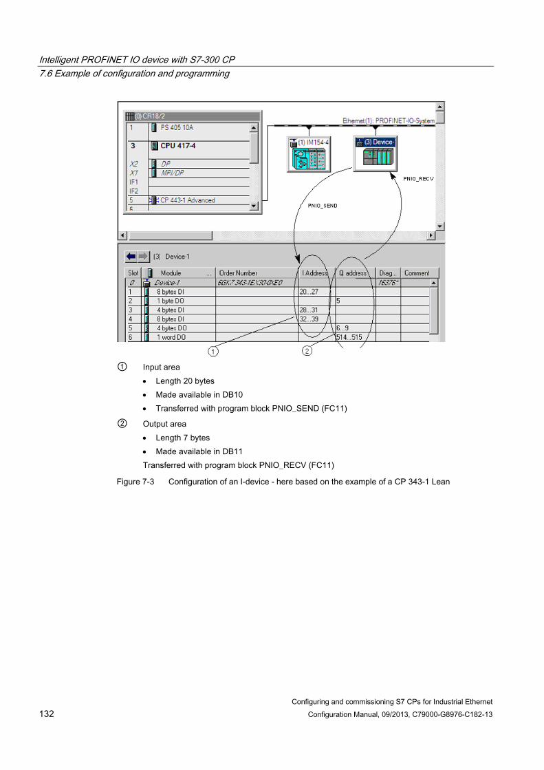
Intelligent PROFINET IO device with S7-300 CP 7.6 Example of configuration and programming
Configuring and commissioning S7 CPs for Industrial Ethernet 132 Configuration Manual, 09/2013, C79000-G8976-C182-13
① Input area
• Length 20 bytes • Made available in DB10 • Transferred with program block PNIO_SEND (FC11)
② Output area • Length 7 bytes • Made available in DB11 Transferred with program block PNIO_RECV (FC11)
Figure 7-3 Configuration of an I-device - here based on the example of a CP 343-1 Lean

Intelligent PROFINET IO device with S7-300 CP 7.6 Example of configuration and programming
Configuring and commissioning S7 CPs for Industrial Ethernet Configuration Manual, 09/2013, C79000-G8976-C182-13 133
Transferring the process inputs (DB10) to the I addresses using PNIO_SEND For the configured I addresses, you need to make data areas (for example in a DB) available on the PROFINET IO devices, in this example in a DB10 that has not only data areas for the process data but also for the status information IOCS.
Figure 7-4 Data structure for PNIO_SEND on the PROFINET IO device
The PNIO_SEND call interface in the user program AWL Explanation call fc 11 //PNIO_SEND block call //(transfer inputs to the IO controller) CPLADDR:= W#16#0100 //Module address from hardware configuration CPLADDR:= W#16#0100 //IO controller mode (0) or IO device mode (1) LEN := 20 //No. of log. I addresses to transf. in bytes IOCS := P#DB10.DBX20.0 BYTE 3 //One status bit in DB10 per send data byte DONE := M 70.0 //Address for return parameter DONE ERROR := M 70.1 //Address for return parameter ERROR STATUS := MW 72 //Address for return parameter STATUS CHECK_IOCS := M 70.2 //Address for return parameter CHECK_IOCS SEND := P#DB10.DBX0.0 BYTE 20 //Data area from DB10 to be transferred //(20 bytes)

Intelligent PROFINET IO device with S7-300 CP 7.6 Example of configuration and programming
Configuring and commissioning S7 CPs for Industrial Ethernet 134 Configuration Manual, 09/2013, C79000-G8976-C182-13
Transferring the Q addresses to the process outputs (DB11) with PNIO_RECV For the configured Q addresses, you need to make data areas (for example in a DB) available on the PROFINET IO devices, in this example in a DB11 that has not only data areas for the process data but also for the status information IOPS.
Figure 7-5 Data structure for PNIO_RECV on the PROFINET IO device
The PNIO_RECV call interface in the user program AWL Explanation call fc 12 //PNIO_RECV block call //(read outputs from IO controller) CPLADDR:= W#16#0100 //Module address from hardware configuration MODE: = 0 //IO device mode not both modes at same time LEN := 7 //No. of log. Q addresses to transf. in bytes IOPS := P#DB11.DBX7.0 BYTE 1 //One status bit in DB11 per receive data byte NDR := M 74.0 //Address for return parameter NDR ERROR := M 74.1 //Address for return parameter ERROR STATUS := MW76 //Address for return parameter STATUS CHECK_IOPS := M74.2 //Address for return parameter CHECK_IOPS RECV := P#DB11.DBX0.0 BYTE 7 //Received data in DB11 (7 bytes) ADD_INFO:= MW 26 //Diagnostic information

Configuring and commissioning S7 CPs for Industrial Ethernet Configuration Manual, 09/2013, C79000-G8976-C182-13 135
Sending process messages by email 8
This chapter contains instructions on the e-mail functions of the Advanced CP. The following topics are covered:
● What preparations need to be made?
● What options are there for sending e-mails from the Advanced CP?
● How can you test the e-mail function?
You can see an outline of the procedures in the flowchart in section Authentication and other features of the Advanced CP (Page 136).
8.1 Overview of the functions
The controller signals process events With the email function of the Advanced CP, the automation system can send messages containing process information either processdependent or at specific times.
As usual with electronic mail, a message can be sent alone or with attachments. The form you choose depends on the amount of data and the properties of the email recipient you are using. It is sometimes necessary to send emails with attachments, for example to transfer binarycoded information from the controller for evaluation.
Sending process messages by email 8.1 Overview of the functions
Configuring and commissioning S7 CPs for Industrial Ethernet 136 Configuration Manual, 09/2013, C79000-G8976-C182-13
8.1.1 Authentication and other features of the Advanced CP
Features of the CP ● The Advanced CP operates as an email client. It supports the SMTP service (Simple Mail
Transfer Protocol).
● As of device type CP 343-1 Advanced (GX30/GX31) and CP 443-1 Advanced (GX20/GX30), ESMTP with authentication is supported.
● E-mails can be sent from the automation system, but they cannot be received.
To send an e-mail in the user program of the S7-CPU, use the send call of the SEND/RECEIVE interface (program blocks AG_SEND / AG_LSEND).
● Mechanisms are available for sending test mails; refer to section Testing the email function (Page 143)
Authentication Advanced CPs that use ESMTP with authentication support the following authentication methods:
● PLAIN
● LOGIN
● CRAM−MD5
● DIGEST−MD5
In terms of authentication for communication between the CP and mail server, the following situations are possible:
● CP and mail server use authentication - with the same method
Once the CP has established a connection to the mail server, the mail server sends a list of the authentication methods it supports. The CP searches through the received list for the supported authentication method. The authentication methods are searched for in the order shown above. The first method found in the list is then used. The CP informs the mail server of this.
You enter the data required for authentication (user name and password) in the e-mail data block (see section Sending an e-mail (Page 141)). The user name and password correspond to the login data at the mail service provider.
If you do not specify a user name and password in the DB, there will be no authentication.
● CP and mail server use authentication - with different methods
If the CP does not find a suitable authentication method, it aborts the transmission and generates a diagnostics message (see section Diagnostics messages from e-mail connections with authentication (Page 215)).

Sending process messages by email 8.1 Overview of the functions
Configuring and commissioning S7 CPs for Industrial Ethernet Configuration Manual, 09/2013, C79000-G8976-C182-13 137
● The CP uses authentication, the mail server does not
If you use a CP that supports authentication and you want to work without authentication, do not store a user name or password in the e-mail data block (see section Sending an e-mail (Page 141)). In this situation, the CP transfers data using SMTP.
● The mail server uses authentication, the CP does not
The mail server aborts the attempt to send.
Procedure Follow the basic steps below to send e-mails:
Clarify mail server mode: • Is there already a mail server in your network environment? • Who can set up access for the CP?
↓
• Configure the email connection
By configuring an email connection you allow establishment of a connection between the S7 CPU and the Advanced CP for sending emails.
See section Setting up an e-mail connection (Page 139). ↓
• Check availability: Start/send a test mail
You can check the availability of the email function at any time by initiating a test mail on the Advanced CP.
See section Testing the email function (Page 143)
↓
↓ • Send emails from the user program
The information to be sent by email including the address information is stored in a data block (DB). The information is sent via the user program using an FC AG_SEND/AG_LSEND.
See section Sending an e-mail (Page 141) (Use FC AG_SEND /AG_LSEND)
↓
Receive e-mail on receiving device.

Sending process messages by email 8.2 Project engineering
Configuring and commissioning S7 CPs for Industrial Ethernet 138 Configuration Manual, 09/2013, C79000-G8976-C182-13
8.2 Project engineering
8.2.1 Options of mail server mode In principle there are three ways of operating the required mail server. The following table explains the advantages and special features:
Table 8- 1 Options of mail server mode
Mail server mode Advantage Special features necessary steps Internal/local You use the mail server software on a PC available in your LAN.
• Fast installation • Cost-effective
• Email reception only within the company
• Use of mail server software
Internal with external connection You use a mail server set up in your intranet that can forward mails to the outside.
• Use of an existing infrastructure
• Output to external devices such as mobile phones, fax possible 1)
• Administrative tasks involved
External You address a mail server outside your intranet.
• Inexpensive if you do not have your own infrastructure
• Output to external devices such as mobile phones, fax possible 1)
• Registration with provider • Making a router available
1) Sending e-mails to mobile phones or to fax devices is possible using "SMS/Fax Gateway". How to address the gateway and to enable the recipient depends on the particular service provider.
8.2.2 Configuring a mail server and addressing recipients Addressing the recipient takes two stages:
● Configured mail server address
You specify the address of the mail server during configuration of the connection. For this configuration, you must know the IP address (absolute or symbolic) of the mail server.
In the following schematic, one possibility, namely that of a mail server connected to your intranet is assumed (see Table Table 8-1 Options of mail server mode (Page 138); Mail server operation "internal with external connection").
Example: server.local
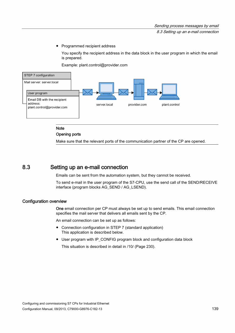
Sending process messages by email 8.3 Setting up an e-mail connection
Configuring and commissioning S7 CPs for Industrial Ethernet Configuration Manual, 09/2013, C79000-G8976-C182-13 139
● Programmed recipient address
You specify the recipient address in the data block in the user program in which the email is prepared.
Example: [email protected]
Note Opening ports
Make sure that the relevant ports of the communication partner of the CP are opened.
8.3 Setting up an e-mail connection Emails can be sent from the automation system, but they cannot be received.
To send e-mail in the user program of the S7-CPU, use the send call of the SEND/RECEIVE interface (program blocks AG_SEND / AG_LSEND).
Configuration overview One email connection per CP must always be set up to send emails. This email connection specifies the mail server that delivers all emails sent by the CP.
An email connection can be set up as follows:
● Connection configuration in STEP 7 (standard application) This application is described below.
● User program with IP_CONFIG program block and configuration data block
This situation is described in detail in /10/ (Page 230).

Sending process messages by email 8.3 Setting up an e-mail connection
Configuring and commissioning S7 CPs for Industrial Ethernet 140 Configuration Manual, 09/2013, C79000-G8976-C182-13
How to configure an e-mail connection Follow the steps below to configure an e-mail connection in STEP 7:
1. Select the connection type, e-mail connection. The connection partner is initially unspecified.
2. In the "Properties" parameter group, specify the address parameters of the e-mail server according to the information in the following table.
Table 8- 2 Connection parameters e-mail connection
Parameters Description Example E-mail server (SMTP)
Address of the mail server via which the e-mails are sent. The IP address can be specified absolutely or symbolically. The following applies to symbolic names: A valid name has 1 to 64 characters of which at least one character must be a letter. If one or more "." characters are used, the following constraint also applies: A valid name has 1 to 3 characters behind the last "."; at least one of these characters must be a letter. A symbolic name can only be used if the Internet CP knows the address of the Domain Name System (DNS). Make an appropriate entry when configuring the Internet CP in the DNS configuration. A maximum of 64 characters can be entered.
absolute: 140.80.0.4 symbolic name: t-online.de
Default sender name Specification of an address that is always inserted in the email as sender address, if the sender specification (FROM parameter) is empty in the header of the email. This information is normally irrelevant for delivery of the mail. It is simply information for the mail recipient. Since some mail servers do not forward jobs if there is no sender information, it is advisable to enter information here! A maximum of 126 characters can be entered. Note: Remember that a default sender name must be specified if you want a test mail to be initiated by special diagnostics.
Using an OPC server as an SMTP server Instead of an unspecified connection, you can select an OPC server as an SMTP server as the connection partner. This means that the IP address of the SMTP interface of the PC station it is entered in the partner's address details.
Note The PC interface must support the SMTP protocol
The e-mail connection via the OPC server is only created consistently when an interface with SMTP protocol support is enabled on the PC station. Read the documentation of the module your using.

Sending process messages by email 8.4 Sending an e-mail
Configuring and commissioning S7 CPs for Industrial Ethernet Configuration Manual, 09/2013, C79000-G8976-C182-13 141
8.4 Sending an e-mail
Procedure Proceed as follows to send an e-mail:
1. Make the e-mail data available in a data block.
2. Use the AG_SEND or AG_LSEND program block in the user program.
Requirement You can send email if the email connection has been set up via the connection configuration. Use the specified ID to call AG_SEND/AG_LSEND in the connection configuration.
Data block The entire email, meaning the address information and the message itself, will be set up in any data block. The example in STL notation below shows the appropriate information for the required DB structure.
Table 8- 3 Email data block in STL notation
Address Name Type Start value Comment Entry 0.0 STRUCT +0.0 TO1) STRING[40] "TO:[email protected];" Recipient Mandatory +42.0 CC1) STRING[40] "CC:[email protected];" CC recipient Optional +84.0 FROM STRING[40] "FROM:plant.werk2@xyz-
online.de;" Sender Optional
+126.0 SUB STRING[40] 'SUB:Status Station 7;' Subject Optional +168.0 Text STRING[100] 'TXT:Fault in plant section 2;' Mail text Mandatory +270.0 Attachm
ent STRING[4] 'BNY:' Here the attachment is
initiated3) Optional
+276.0 Value1 BYTE B#16#272) Attachment/binary value3)
Optional
+277.0 Value2 BYTE B#16#032) Attachment/binary value3)
Optional
=278.0 END_STRUCT 1) Multiple recipients can be specified. The information must then be separated by a comma. 2) The information in bold will be delivered to the recipient as attachment 3) Data can also be supplied dynamically.

Sending process messages by email 8.4 Sending an e-mail
Configuring and commissioning S7 CPs for Industrial Ethernet 142 Configuration Manual, 09/2013, C79000-G8976-C182-13
Comments on the table ● Structure and syntax of the data in the email DB
The structure suggested here with multiple STRINGs is one of several variants. Crucial are the entries in the column "Initial value" with the IDs contained therein (TO:, SUB:, CC:, FROM:, TXT:, BNY:) which must be used in the DB in precisely this notation to identify the mail content! All entries must end with a semicolon; only the last entry does not need a semicolon.
The string length is only shown in the table as an example; it can be customized to the actual character count (exception: The string length for identifying the attachment must be specified with [4]).
For example, another variant would be using only one STRING in total, and assigning the entire text to this string with the identifiers.
● If you encounter a problem entering the "@" symbol, try the input ALT+64 instead.
● Attachments
The user data entered in the email DB can also be delivered to the recipient entirely or partially as attachment. For this the sender must give the data the identifier "BNY:" .
The data specified after this identifier will then be delivered to the recipient as attachment.
In the table the attachment is 2 bytes; this is only an example however. You can enter attachments that are as complex as you like.
● Data length
The data length specified in the call AG_SEND/AG_LSEND must at least include the length of the data in the DB; note the specifications in the address column of the programming editor (Note: The specification corresponds to the number of bytes).
Sending an email with AG_SEND/AG_LSEND 1) Use the FC AG_SEND program block to send an e-mail or with data lengths >240 bytes, use AG_LSEND. A detailed description of call parameters is available in the online help for the program blocks.
See also /10/ (Page 230)
Example:
STL Explanation
call fc 50 //AG_LSEND block call
ACT := M 10.0 //Bit for job trigger
ID := MW 12 //Connection ID (connection configuration)
LADDR := W#16#0100 //Module address 256Dec. in hardware configuration
SEND := P#db99.dbx10.0 byte 278, //Address of the data block; DB length
LEN := MW 14 //Length of the data range to be sent
DONE := M 10.6 //Address for return parameter DONE
ERROR := M 10.7 //Address for return parameter ERROR
STATUS := MW 16 //Address for return parameter STATUS

Sending process messages by email 8.5 Testing the email function
Configuring and commissioning S7 CPs for Industrial Ethernet Configuration Manual, 09/2013, C79000-G8976-C182-13 143
8.5 Testing the email function
Purpose and options With email functionality, you make your automation system capable of sending specific upto-date information from the process at any time.
To allow you to check that email is functioning correctly at any time, you can initiate a test mail. The following mechanisms are available:
● Test mail via Web browser
● Test mail using STEP 7 special diagnostics
Both tests are triggered on the CP which means that the tests do not indicate whether or not there is an e-mail connection between the CPU and CP. If this was configured incorrectly, it is not possible to send e-mails from the user program.
Conclusions drawn from receiving a test mail If the test mail is received, you can draw the following conclusions:
● The Advanced CP is operational for sending e-mails;
● An e-mail connection exists that can be used by the user program;
● The recipient specified in the request is obtainable.
You cannot infer the following:
● That the user programs are in a status in which the sending of e-mails will be triggered by calling FC AG_SEND/AG_LSEND;
● The time required from a mail being sent until it is received.
Note:
E-mail is an unreliable service. It is therefore possible that an e-mail does not arrive. The receipt of a test e-mail is only a temporary indication that the connection is working and is no guarantee that it will work at other times.
Triggering a test mail with the Web browser Web diagnostics provides the option of sending a test mail from your CP.
For more detailed information, see section SEND/RECEIVE communication / configured connections (Page 181)

Sending process messages by email 8.5 Testing the email function
Configuring and commissioning S7 CPs for Industrial Ethernet 144 Configuration Manual, 09/2013, C79000-G8976-C182-13
Requesting a test mail using STEP 7 special diagnostics In the "Email" tab of special diagnostics, you can also specify and trigger a test mail. To do this, you require an online connection between your PC/PG and your S7 station.
When sending a test mail using special diagnostics, authentication is supported if required by the mail server. Special diagnostics provides the input boxes for a login and password.
When you select the menu command Options > Send E-mail, a test mail is sent to the specified address.
For more detailed information on special diagnostics, refer to section STEP 7 special diagnostics (Page 199).

Configuring and commissioning S7 CPs for Industrial Ethernet Configuration Manual, 09/2013, C79000-G8976-C182-13 145
File management and file access with FTP/FTPS 9
With its file transfer functions (FTP), the Advanced CP provides a useful tool for transferring files to and from your S7 station.
Files can be transferred both from the PG/PC to the S7 station or initiated by the S7 station to an FTP server; this could be, for example, a PC/PG station or another S7 station. With the Security CPs, this can be transferred encrypted with FTPES (explicit mode).
This section will familiarize you with the FTP client and FTP server functionality of the Advanced CP in the S7 station. The description also applies to FTPS.
Note FTPS / FTPES
Where the term "FTPS" is used in this documentation, FTPS in the explicit mode is meant (FTPES).
For a detailed description of the program blocks that you require for file transfer from your S7 station, refer to /10/ (Page 230).
Note Opening ports
In FTP server mode, make sure that the relevant ports of the CP and the communication partner of the CP are opened. For more details on this topic and on configured access rights and security aspects, refer to section Security when accessing process data (Page 162).
Note Files only in binary format
When using FTP, always transfer the files in binary format.
9.1 FTP functions in an S7 station with the Advanced CP
Range of functions The FTP functions of the Advanced CP support both FTP client and FTP server functionality on the S7 station.

File management and file access with FTP/FTPS 9.2 Advanced CP as FTP server for the file system on the CP
Configuring and commissioning S7 CPs for Industrial Ethernet 146 Configuration Manual, 09/2013, C79000-G8976-C182-13
S7 station with an Advanced CP in the role of FTP server The server role can be divided into two distinct functions:
● The Advanced CP as FTP server for the file system on the Advanced CP
You can access the files of the file system on the Advanced CP (CP 443-1 IT / CP 343-1 IT) from an FTP client, for example a PG/PC. These files are made up mainly of the HTML pages intended for display in the Web browser.
● The Advanced CP as FTP server for CPU data
When working on FTP client, for example a PG/PC, you can access the data blocks on the CPU of the S7 stations via the Advanced CP.
S7 station with Advanced CP in the FTP client role for CPU data The user program on the CPU can access the Advanced CP as an FTP client for the transfer of data blocks from or to an FTP server.
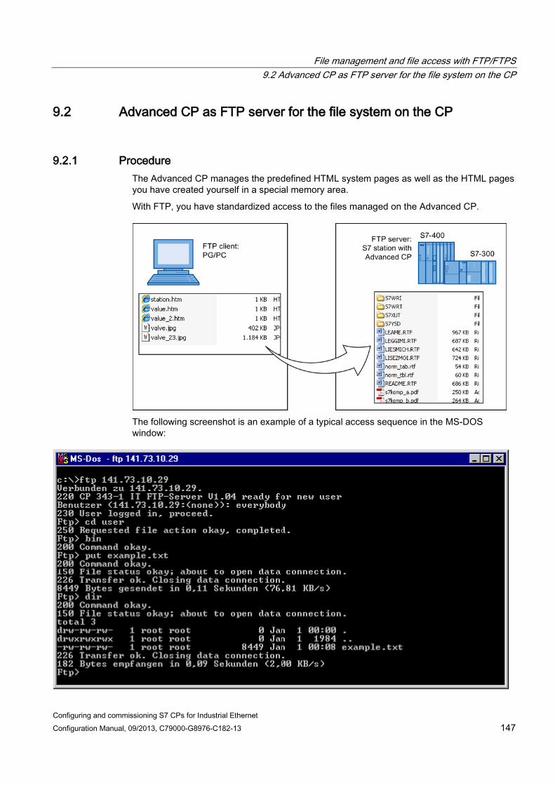
File management and file access with FTP/FTPS 9.2 Advanced CP as FTP server for the file system on the CP
Configuring and commissioning S7 CPs for Industrial Ethernet Configuration Manual, 09/2013, C79000-G8976-C182-13 147
9.2 Advanced CP as FTP server for the file system on the CP
9.2.1 Procedure The Advanced CP manages the predefined HTML system pages as well as the HTML pages you have created yourself in a special memory area.
With FTP, you have standardized access to the files managed on the Advanced CP.
The following screenshot is an example of a typical access sequence in the MS-DOS window:

File management and file access with FTP/FTPS 9.2 Advanced CP as FTP server for the file system on the CP
Configuring and commissioning S7 CPs for Industrial Ethernet 148 Configuration Manual, 09/2013, C79000-G8976-C182-13
9.2.2 File system - structure and features
Structure of the file system on the Advanced CP as shipped With access using an FTP tool, the file system of the Advanced CP appears as follows:
Figure 9-1 The file system on the Advanced CP
Memory areas and configuration limits On the current Advanced CPs, the file system is divided into 2 areas:
● Flash area (nonvolatile memory):
The flash area allows data to be stored and retained if there is a power down.
Since the number of times it is possible to write to this area is restricted, you should avoid repetitive write operations to this area. Ideally you should use the RAM area for such requirements.
● RAM area (volatile memory):
In contrast to the flash area, the RAM can be written to and read from any number of times. The data in the RAM is retained as long as the Advanced CP is supplied with power.
The RAM is intended to store data that changes during operation and needs to be recorded (data recording services). The RAM is also suitable for temporary storage.
The RAM area is located in the file system below the "/ram" folder. All files and folders below this folder are lost when there is a power down.
Available storage space The Web diagnostics of your Advanced CP (start page/file system) and the device manual for your Advanced CP /1/ (Page 227) contain information about the total memory area available in the entire file system, the memory space still available in the flash area and in the RAM area of the file system as well as other operational data.
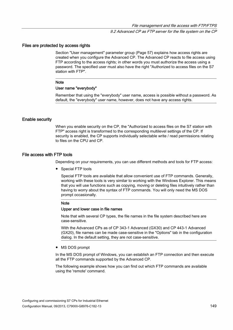
File management and file access with FTP/FTPS 9.2 Advanced CP as FTP server for the file system on the CP
Configuring and commissioning S7 CPs for Industrial Ethernet Configuration Manual, 09/2013, C79000-G8976-C182-13 149
Files are protected by access rights Section "User management" parameter group (Page 57) explains how access rights are created when you configure the Advanced CP. The Advanced CP reacts to file access using FTP according to the access rights; in other words you must authorize the access using a password. The specified user must also have the right "Authorized to access files on the S7 station with FTP".
Note User name "everybody"
Remember that using the "everybody" user name, access is possible without a password. As default, the "everybody" user name, however, does not have any access rights.
Enable security When you enable security on the CP, the "Authorized to access files on the S7 station with FTP" access right is transformed to the corresponding multilevel settings of the CP. If security is enabled, the CP supports individually selectable write / read permissions relating to files on the CPU and CP.
File access with FTP tools Depending on your requirements, you can use different methods and tools for FTP access:
● Special FTP tools
Special FTP tools are available that allow convenient use of FTP commands. Generally, working with these tools is very similar to working with the Windows Explorer. This means that you will use functions such as copying, moving or deleting files intuitively rather than having to worry about the syntax of FTP commands. You will only need the MS DOS prompt occasionally.
Note
Upper and lower case in file names
Note that with several CP types, the file names in the file system described here are case-sensitive.
With the Advanced CPs as of CP 343-1 Advanced (GX30) and CP 443-1 Advanced (GX20), file names can be made case-sensitive in the "Options" tab in the configuration dialog. In the default setting, they are not case-sensitive.
● MS DOS prompt
In the MS DOS prompt of Windows, you can establish an FTP connection and then execute all the FTP commands supported by the Advanced CP.
The following example shows how you can find out which FTP commands are available using the 'remote' command.
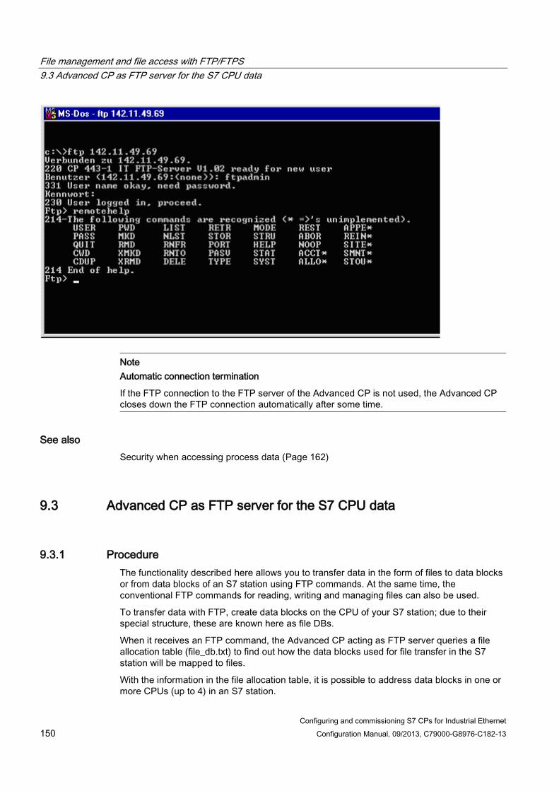
File management and file access with FTP/FTPS 9.3 Advanced CP as FTP server for the S7 CPU data
Configuring and commissioning S7 CPs for Industrial Ethernet 150 Configuration Manual, 09/2013, C79000-G8976-C182-13
Note Automatic connection termination
If the FTP connection to the FTP server of the Advanced CP is not used, the Advanced CP closes down the FTP connection automatically after some time.
See also Security when accessing process data (Page 162)
9.3 Advanced CP as FTP server for the S7 CPU data
9.3.1 Procedure The functionality described here allows you to transfer data in the form of files to data blocks or from data blocks of an S7 station using FTP commands. At the same time, the conventional FTP commands for reading, writing and managing files can also be used.
To transfer data with FTP, create data blocks on the CPU of your S7 station; due to their special structure, these are known here as file DBs.
When it receives an FTP command, the Advanced CP acting as FTP server queries a file allocation table (file_db.txt) to find out how the data blocks used for file transfer in the S7 station will be mapped to files.
With the information in the file allocation table, it is possible to address data blocks in one or more CPUs (up to 4) in an S7 station.

File management and file access with FTP/FTPS 9.3 Advanced CP as FTP server for the S7 CPU data
Configuring and commissioning S7 CPs for Industrial Ethernet Configuration Manual, 09/2013, C79000-G8976-C182-13 151
Further information For more detailed information on the structure of the file DB, refer to the documentation on the SIMATIC NET program blocks /10/ (Page 230).
9.3.2 FTP commands on the FTP client
Example of access The following figure shows an example of a typical access sequence in the MS-DOS window.

File management and file access with FTP/FTPS 9.3 Advanced CP as FTP server for the S7 CPU data
Configuring and commissioning S7 CPs for Industrial Ethernet 152 Configuration Manual, 09/2013, C79000-G8976-C182-13
How typical FTP functions use the permitted FTP commands The following table shows which FTP commands can be executed to access file DBs on the CPU. The table also shows which FTP functions are used for these FTP commands in typical input consoles such as the MS-DOS prompt.
Table 9- 1 FTP commands
Typical FTP functions FTP command Meaning open dir put get close del x User Logging on x Pass Authorization by
password x x x Port Specifies the port via
which the client wants to transfer.
x List Lists the file DBs in the addressed CPU.
x Dele Deletes a file DB by setting the EXIST bit in the file DB header to "0".
x Retr Reads the user data in the specified file DB into the specified file on the FTP client.
x Stor Transfers the specified file from the FTP client to the user data area in the specified file DB.
x quit Closes down the current FTP connection.
Note
You cannot use the FTP commands "rename", "append", "rnfr" and "rnto" with the file DBs.
How FTP commands are executed on the Advanced CP To illustrate how the FTP interface to the file DBs on the CPU works, the execution sequence is explained below based on the example of the stor command.
The FTP server on the Advanced CP executes the sequence shown below:

File management and file access with FTP/FTPS 9.3 Advanced CP as FTP server for the S7 CPU data
Configuring and commissioning S7 CPs for Industrial Ethernet Configuration Manual, 09/2013, C79000-G8976-C182-13 153
1. Identifies the addressed file DB based on the entry in the file allocation table.
2. Checks the bits in the file DB header (see /10/ (Page 230)); the write function is executed only when the following applies:
LOCKED bit = 0
NEW bit = 0
WRITEACCESS bit = 1
3. Writes the file content to the user data area of the file DB on the CPU. At the beginning of the write function, the LOCKED bit is set and reset when writing is completed.
4. When the write function is completed, the NEW bit is also set in the file DB header and the current date entered in the DATE_TIME field.
5. The FTP server sends a message about the file transfer event to the FTP client.
Note
If you specify a file for the transfer that is not included in the file allocation table, the requested file system operation is executed on the current folder.
Transfer mode for file transfer File transfer only uses the binary mode. To change to this mode, enter the command "binary" in the input console after logging on.
9.3.3 File allocation table
Meaning In the FTP server role, the Advanced CP requires information on how the data blocks used in the S7 station for file transfer are mapped to files. You store this file assignment table in the file_db.txt file in the file system of the Advanced CP.
Structure The file allocation table has two areas in which the allocations are stored row-oriented according to the scheme shown in the following example:
● Rack/slot assignment of the CPU
● DB assignment

File management and file access with FTP/FTPS 9.3 Advanced CP as FTP server for the S7 CPU data
Configuring and commissioning S7 CPs for Industrial Ethernet 154 Configuration Manual, 09/2013, C79000-G8976-C182-13
Notes on the syntax ● Relevant rows can be recognized by the "cpux" string (where x = characters "1−4"); this
applies to both areas.
Note
Notation • Note the use of lower-case letters. Otherwise the files will not be recognized. • Use a text editor that does not create invisible control characters or save the data in
the TXT mode so that no invisible control characters are stored.
● Valid delimiters for the entries are "blanks".
● All other characters are interpreted as comment characters.
● The following applies to the file name of a file DB:
– Length: maximum 64 characters;
– Permitted characters: letters "A−Z,a−z"; digits "0−9", "_", "."
● Row length: maximum 256 characters
Example
In the example shown here, the FTP command C:> PUT s7daten.txt cpu1db35 is used to transfer the s7daten.txt file to DB35 (file DB) that must be located on CPU1.

File management and file access with FTP/FTPS 9.3 Advanced CP as FTP server for the S7 CPU data
Configuring and commissioning S7 CPs for Industrial Ethernet Configuration Manual, 09/2013, C79000-G8976-C182-13 155
How to create and manage the file allocation table The file file_db.txt is located in the file system of your Advanced CP in the folder /config. You can upload the file as originally shipped with your CP to your PG/PC and use it as a template for your application. You will also find the sample text in the properties dialog of the CP in the "FTP" tab.
You can manage this file with the normal FTP commands as described in Section 10.2 for the IT file system.
If the file file_db.txt does not exist, it is not possible to access file DBs using the FTP server of the Advanced CP. After editing the file and transferring it to the file system of the Advanced CP, you should therefore make sure that the transfer was successful.
If both the transfer and syntax were correct, the following message is displayed:
"226 Transfer ok; closing data connection"
If the syntax is incorrect, a message similar to the one shown below will be displayed:
"450 Requested action aborted - configuration file error in line 16"
If an error was reported, check your system configuration and repeat the transfer. You can check your configuration with the following command:
ftp> dir cpux (where x = 1-4)
Note
Note the use of lower-case letters. Otherwise the files will not be recognized.

File management and file access with FTP/FTPS 9.3 Advanced CP as FTP server for the S7 CPU data
Configuring and commissioning S7 CPs for Industrial Ethernet 156 Configuration Manual, 09/2013, C79000-G8976-C182-13
Example
With the configured CPU directories, the file name is displayed. This can include the number of the corresponding file DB.
Meaning of the flags of "cpu" folders with the dir command: ● −r− −r− −r− − (read flag) :
If this flag is displayed, the EXIST bit is set in the file DB. It is possible to read this file DB as long as the LOCKED bit is not set.
● − −w− −w− −w− (write flag):
If this flag is displayed, the NEW bit is not set in the file DB and the WRITEACCESS bit is set. It is possible to write this file DB as long as the LOCKED bit is not set.
● l− − − − − − − − − (locked flag):
If this flag is displayed, the LOCKED bit is set in the file DB. Neither reading nor writing the file DB is possible. If the "r" or "w" flags are set in addition to this flag, this means that reading or writing will be possible if the LOCKED bit is cleared.

File management and file access with FTP/FTPS 9.4 The Advanced CP as FTP client for S7 CPU data
Configuring and commissioning S7 CPs for Industrial Ethernet Configuration Manual, 09/2013, C79000-G8976-C182-13 157
If a file DB does not physically exist but is configured in the file allocation table "file_db.txt", all the flags are reset in the display (display: − − − − − − − − − −) and the file size is indicated as 0 bytes.
Note
It is possible to change from one folder to another on the CPU. However, only the commands listed table Table 9-1 FTP commands (Page 152) can be executed.
See also FTP commands on the FTP client (Page 151)
9.4 The Advanced CP as FTP client for S7 CPU data
9.4.1 Procedure To transfer data with FTP, create data blocks (file DBs) on the CPU of your S7 station.
The user program sends FTP jobs that are executed by the Advanced CP as an FTP client. In the user program, use the program block FTP_CMD (FB40); see also section Program blocks for FTP services (Page 160).
The data is transferred on FTP connections. FTP connections are special TCP connections that you configure in STEP 7.
In the job, among other things, you specify the IP address of the FTP server, the storage location of the file on the FTP server and the file name along with access information.
The following schematics illustrate how the function works when using FC40...44 or FB40.

File management and file access with FTP/FTPS 9.4 The Advanced CP as FTP client for S7 CPU data
Configuring and commissioning S7 CPs for Industrial Ethernet 158 Configuration Manual, 09/2013, C79000-G8976-C182-13
Figure 9-2 How FTP data transmission works when using FC40...44
Figure 9-3 How FTP data transmission works when using FB40
Further information For more detailed information on the structure of the file DB and the program blocks for FTP, refer to the documentation on the SIMATIC NET program blocks /10/ (Page 230).

File management and file access with FTP/FTPS 9.4 The Advanced CP as FTP client for S7 CPU data
Configuring and commissioning S7 CPs for Industrial Ethernet Configuration Manual, 09/2013, C79000-G8976-C182-13 159
9.4.2 Setting up FTP connections
Meaning To run an FTP job sequence between the S7 station acting as the FTP client and an FTP server, the Advanced CP must establish a connection to the S7 CPU. This connection is known as an FTP connection.
You can set up an FTP connection as follows:
● During connection configuration in STEP 7 (standard application)
This situation is described below.
● In the user program with FB CP_CONFIG and the configuration data block.
There are situations in which it is an advantage to set up the communication connections not over the configuration interface of STEP 7 but rather program-controlled by specific applications.
This use case is described in detail in Chapter 8 and in /5/.
How to configure FTP connections To use FTP functionality, you require TCP connections with special properties. Follow the steps outlined below to configure the connection in STEP 7 / NetPro:
1. Create a TCP connection with an unspecified connection partner for the CPU in your S7 station, see also section Configuring TCP connection properties (Page 103).
2. Select the option "Use for FTP protocol"
Selecting this option has the following consequences:
– The TCP connection is now used as an FTP connection.
– "Addresses" tab: The addresses are specified automatically (Port=21)
– "Options" tab: The mode is set permanently to FTP.

File management and file access with FTP/FTPS 9.5 Program blocks for FTP services
Configuring and commissioning S7 CPs for Industrial Ethernet 160 Configuration Manual, 09/2013, C79000-G8976-C182-13
9.5 Program blocks for FTP services
Using the program blocks Use the following program block in the user program for data transfer using FTP/FTPS:
● FTP_CMD (FB40)
The program block FTP_CMD can be used for FTP/FTPS with the following module types:
– As of CP 343-1 Advanced (GX30)
– As of CP 443-1 Advanced (GX20)
● FTP program blocks FC40-FC44
All module types continue to support the following program blocks for FTP (not for FTPS):
FTP_CONNECT (FC40) FTP_STORE (FC41) FTP_RETRIEVE (FC42) FTP_DELETE (FC43) FTP_QUIT (FC44)
The module types listed below, on the other hand, do not support FTP_CMD (FB40):
– Advanced CPs up to CP 343–1 Advanced (GX21)
– Advanced-CPs up to CP 443–1 Advanced (EX41)
Advantages with FTP_CMD FTP_CMD has the following advantages compared with the previous program blocks (FC40...FC44):
● Simplification in the user program by using a command variable instead of different function calls
● Additional function "APPEND"
"APPEND" allows data to be appended to an existing file.
● Additional function "RETR_PART"
"RETR_PART" allows selected data areas to be retrieved from a file.
● Additional function "CONNECT_TLS_PRIVATE"
You set up SSL FTP connections (FTPS) for CP operation with security enabled. CHECK
Further information For more detailed information on the structure of the file DB and the program blocks for FTP, refer to the documentation on the SIMATIC NET program blocks /10/ (Page 230).

Configuring and commissioning S7 CPs for Industrial Ethernet Configuration Manual, 09/2013, C79000-G8976-C182-13 161
S7-CP Advanced as Web server: HTML process control 10
The Advanced CP provides you with the functionality of a Web server for access by means of a Web browser.
For this purpose, the Advanced CP has a storage area for files.
When supplied, the Advanced CP has HTML system files, S7 beans and other information in the file system.
This section answers the following questions:
● How are the HTML pages supplied with the Advanced CP used to access information on the S7 station?
● What options exist to adapt HTML process control to my individual requirements?
● What security measures can I take or do I need to take to prevent unauthorized access to process data?
● How do I store my own HTML pages?
Note
CP file system - using security functions
Protect the CP from write access by unauthorized persons and the associated security risks. We strongly advise that you make the relevant FTP functions available only to authorized persons in the user administration. Information should be transferred using FTPS/HTTPS.
10.1 Overview of HTML process control
Concept With the S7 beans, the Advanced CP provides you with the means to implement an HTML process control using individually created HTML pages.
Individual solutions with S7 beans You want to use graphics options adapted to your application and create more complex applets.
You not only want to display your process data in the plant pictures but also want to use the data, for example, for evaluation in a database.
You can achieve this with the following options:

S7-CP Advanced as Web server: HTML process control 10.2 Security when accessing process data
Configuring and commissioning S7 CPs for Industrial Ethernet 162 Configuration Manual, 09/2013, C79000-G8976-C182-13
● Create applicationspecific applets and use the supplied S7 beans.
● Create Java source code; use applicationspecific applets, Java beans and the supplied S7 beans.
You will find a detailed description in the manual on the S7 applets / beans /22/ (Page 234).
Extended access and display options - The Java Beans concept The Java Beans concept allows you to create objects (Java components) and to link them simply to executable programs.
There is an S7 beans class library available for the Advanced CP (S7BeansAPI). The object classes contained in this library can be used for objectoriented access to a variety of information on the SIMATIC S7 and for graphic display of process variables.
The S7 beans class library provides an open interface allowing you to extend process data evaluation for example with databases, table calculation or management information systems.
Organizing files - resources of the IT CP The Advanced CP has memory available for storing your HTML pages. You will find information on this topic in the device manual of the Advanced CP /1/ (Page 227).
Please note the information in the "readme.htm" file on the Advanced CP.
This contains information about the meaning and purpose of the shipped files. You can then decide which files might be useful for your application. Using FTP functions, you can organize the files on the Advanced CP to suit your requirements.
10.2 Security when accessing process data
Guaranteeing information security The access to process data by the Advanced CP via the Internet brings with it the danger of misuse. You should therefore not only protect the process data with passwords. If passwords are transferred unencrypted, simple password protection using FTP does not provide adequate security.
Make sure that access to your network is protected by suitable security measures. The SIMATIC NET components with security functionality provide the required protective functions.
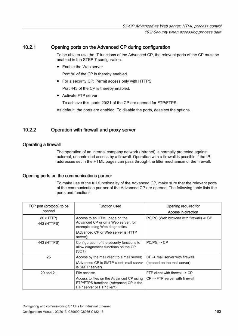
S7-CP Advanced as Web server: HTML process control 10.2 Security when accessing process data
Configuring and commissioning S7 CPs for Industrial Ethernet Configuration Manual, 09/2013, C79000-G8976-C182-13 163
10.2.1 Opening ports on the Advanced CP during configuration To be able to use the IT functions of the Advanced CP, the relevant ports of the CP must be enabled in the STEP 7 configuration.
● Enable the Web server
Port 80 of the CP is thereby enabled.
● For a security CP: Permit access only with HTTPS
Port 443 of the CP is thereby enabled.
● Activate FTP server
To achieve this, ports 20/21 of the CP are opened for FTP/FTPS.
As default, the ports are enabled. To disable the ports, deselect the options.
10.2.2 Operation with firewall and proxy server
Operating a firewall The operation of an internal company network (Intranet) is normally protected against external, uncontrolled access by a firewall. Operation with a firewall is possible if the IP addresses set in the HTML pages can pass through the filter mechanism of the firewall.
Opening ports on the communications partner To make use of the full functionality of the Advanced CP, make sure that the relevant ports of the communication partner of the Advanced CP are opened. The following table lists the ports and functions:
TCP port (protocol) to be
opened Function used Opening required for
Access in direction 80 (HTTP)
443 (HTTPS) Access to an HTML page on the Advanced CP or on a Web server, for example using Web diagnostics. (Advanced CP or Web server is HTTP server);
PC/PG (Web browser with firewall) -> CP
443 (HTTPS) Configuration of the security functions to allow diagnostics functions on the CP. (SCT)
PC/PG -> CP
25 Access by the mail client to a mail server; (Advanced CP is SMTP client, mail server is SMTP server)
CP -> mail server with firewall (opened on the mail server)
20 and 21 File access: Access to files on the Advanced CP using FTP/FTPS functions (Advanced CP is the FTP server or FTP client).
FTP client with firewall -> CP CP -> FTP server with firewall

S7-CP Advanced as Web server: HTML process control 10.2 Security when accessing process data
Configuring and commissioning S7 CPs for Industrial Ethernet 164 Configuration Manual, 09/2013, C79000-G8976-C182-13
TCP port (protocol) to be opened
Function used Opening required for Access in direction
102 (S7) Configuration with STEP 7 via ISO-on-TCP
PC/PG -> CP
161 SNMP Network management PC/PG <-> CP
Security activated - firewall on CP By operating the firewall of the CP, the required ports of the CP are opened automatically.
10.2.3 Scaled password protection with security It is generally the case that different groups of people require different types of access to process data. To protect your process data from unauthorized access, you can restrict access to the process data to authorized users when you configure the CP.
This access protection also works when accessing via a Web server.
Security enabled With security enabled, the user administration allows further assignment of roles and rights. There are system-defined roles that cannot be modified or you can create new user-defined roles and assign rights to them.
Users that have already been set up are migrated to the expanded user administration when the security function is enabled. In a migration dialog, you control how the existing entries are adopted; you will find details in /16/ (Page 232)
Project engineering In the STEP 7 configuration of the CP you can set scaled access rights for individual users according to functions in the user administration (see section "User management" parameter group (Page 57)).
When data on the CP is accessed, there is then a password query.
Note Renewed logon following CP STOP/START
After changing the mode to STOP/START, it is necessary to log on again on the Web server.

S7-CP Advanced as Web server: HTML process control 10.3 Accessing the Advanced CP via a Web browser
Configuring and commissioning S7 CPs for Industrial Ethernet Configuration Manual, 09/2013, C79000-G8976-C182-13 165
10.3 Accessing the Advanced CP via a Web browser
How to access the Advanced CP via a Web browser The basis of communication via an intranet or the Internet is the Internet TCP/IP protocol that is implemented on the Advanced CP. In principle, the following few steps are all that is necessary to make your plant accessible via your intranet or the Internet:
● For intranet and Internet communication
– Connect the Advanced CP to Industrial Ethernet.
– During configuration of the hardware, assign an IP address to the Advanced CP.
● In addition, for Internet communication
You connect your manufacturing network to public transmission facilities using suitable connectivity devices, for example a router. You can implement the necessary protection mechanisms on the interface to the Internet (firewall) by using the Advanced CPs with the security function enabled or with the SIMATIC NET security modules.
For information on opening ports, see section Security when accessing process data (Page 162).
Web browser - requirements profile To access the HTML pages on the Advanced CP as a Web server, you require a Web browser on your PG/PC/smart phone/tablet PC, for example Internet Explorer. The Web browser must meet the following requirements:
● JDK (Java Development Kit) 1.1.X is supported.
The Internet Explorer meets these requirements. Other Web browsers with the same range of functions can also be used. You will find the supported Web browsers in the device manual of your CP,see /1/ (Page 227).
Note
JDK 1.2.x, 1.3.x and 1.4.x are also supported. To use applets created specially for these JDK versions with the Microsoft Internet Explorer, you do, however require a plug-in.
Other Web browsers may only meet these requirements with certain restrictions. With these Web browsers, you also require a plugin component corresponding to the Java reference implementation of a SUN Java Virtual Machine.
Special settings need to be made in the Web browser when the S7 beans are used. Refer to the documentation of the S7 beans /22/ (Page 234) for more information on the requirements listed above.

S7-CP Advanced as Web server: HTML process control 10.3 Accessing the Advanced CP via a Web browser
Configuring and commissioning S7 CPs for Industrial Ethernet 166 Configuration Manual, 09/2013, C79000-G8976-C182-13
URL: Uniform Resource Locator In the World Wide Web, addressing using URLs has become standard. You can also access the Advanced CP with your Web browser using the URL. This URL can have almost any complexity but consists in principle of four essential parts. The following schematic illustrates the structure (typical URL) and shows the contents for calling Advanced CPs.
Legend URL URL (CP Advanced) ① -> "http://" protocol -> "http://" protocol ② Server name [:port] ->
"www.ad.siemens.de" IP address -> "142.80.00.01"
③ [File directory] -> "/net" [File directory] -> "//" ④ File name -> "/page.html" Name of the HTML page -> "index.htm"
When shipped, the Advanced CP does not have an HTML page "index.htm". As a substitute, you then reach the Web diagnostics of the CP with this URL.
When you access the Advanced CP using a Web browser, use the HTTP or HTTPS protocol to address the Web server on the Advanced CP:
You inform the CP of the IP address during configuration with STEP 7 (see Section Setting further CP properties (Page 42)). If you have an attachment from Industrial Ethernet to your intranet or to the Internet, the CP can be contacted using the IP address in the intranet or Internet.
A detailed description of the structure of the IP address and the options of creating subnets or subnet masks is beyond the scope of this manual. You will find information on this in the online help of STEP 7 and in the references in the appendix.
Setting a proxy server on the PG/PC For more information, check with your system administrator.

Configuring and commissioning S7 CPs for Industrial Ethernet Configuration Manual, 09/2013, C79000-G8976-C182-13 167
Web diagnostics 11
With Web diagnostics, the CP provides you with the option of querying and displaying the most important settings of a connected station. You can also call up the statuses of your network connections and communications partners from a HTTP client on a PG/PC. It is also possible to query the diagnostics buffer entries of the modules of the rack in which the CP is located.
Note Depending on the CP type
The diagnostics pages or parameters described below are not all available for every CP type.
Depending on the CP type, you will find, for example, information on the device as PROFINET IO controller or PROFINET IO device in the navigation panel under "PROFINET IO". If the CP supports various PROFINET IO modes, this depends on the specific configuration of the device.
Note Module replacement - display of the Web pages
When replacing modules, they can be replaced by newer modules without adapting the configuration data to the new module type.
In such situations, the newly used CP shows the Web pages that match the range of functions of the replaced module in Web diagnostics.
The CP 443-1 Advanced (GX20), for example, does not support the firmware download functionality via Web diagnostics. If you replace this CP with a CP 443-1 Advanced (GX30), the update center will not be displayed although the new module type would support this function. The full range of functions in Web diagnostics is only available after updating the configuration data to the new CP type.
11.1 Requirements
Web browser To access the HTML pages on the CP, you require a Web browser. The following Web browsers are suitable for communication with the CP (other browsers also possible):
● Internet Explorer (recommended version: as of 8.0)
● Opera (recommended version: as of 9.2)
● Firefox (recommended version: 4.0 or higher

Web diagnostics 11.1 Requirements
Configuring and commissioning S7 CPs for Industrial Ethernet 168 Configuration Manual, 09/2013, C79000-G8976-C182-13
Note
Station or device names configured in STEP 7 with special characters (for example umlauts ä, ü etc.) may not be correctly interpreted in Web diagnostics.
Settings for access to diagnostics data Check the following settings that are necessary for access to the diagnostics data:
● To load diagnostics data, JavaScript must be enabled in the Internet browser.
● The browser must support frames.
● Cookies must be accepted.
● The browser should be set so that it downloads the current data from the server automatically each time it accesses a page.
In Internet Explorer, you will find these settings in the "Tools" menu > "Internet Options" > "General" tab > "Temporary Internet Files" > "Settings" button.
● When using a firewall on your PG/PC, the following port must be enabled for Web diagnostics: "http port 80/TCP"
● Activating Web server functionality
The Web server functionality must be activated in the STEP 7 configuration: refer to Configuring the Ethernet CP with STEP 7 (Page 39)
As default, the Web server is activated and therefore port 80 of the CP is opened for HTTP access.
If you want to block port 80, disable the "Activate Web server function" option. This option is not available in STEP 7 for all CPs.
Security activated - different settings for access to diagnostics data In addition to or in contrast to the settings listed above, the following requirements must be kept in mind if security is enabled:
● When using a firewall on your PG/PC, the following port must be enabled for Web diagnostics: "https port 443/TCP"
● Activating Web server functionality
The Web server functionality must be activated in the STEP 7 configuration.
As default, the "Allow access only via HTTPS" option is enabled and port 443 is therefore opened for HTTPS.
If you want to block port 443 of the CP, disable the "Allow access only via HTTPS" option.
● Current time-of-day and date on the S7 station
The CP needs to access the current date and current time-of-day. Otherwise, there will be conflicts in the certificate checks and no Web access will be possible.

Web diagnostics 11.2 Setup and operation
Configuring and commissioning S7 CPs for Industrial Ethernet Configuration Manual, 09/2013, C79000-G8976-C182-13 169
● Importing a certificate
In your Web browser, you should import the certificate generated by the security CP. Otherwise, when you call up Web diagnostics, you will receive a warning about the absence of a security certificate.
To do this, export the required certificate during security configuration of the CP using the certificate manager in STEP 7. You import using the specific import functions of the relevant Web browser.
● Access rights
When accessed, the CP requires a user name and password to be entered. The specified user must be assigned relevant Web access rights in user administration.
See also Scaled password protection with security (Page 164)
Security when accessing process data (Page 162)
11.2 Setup and operation
Starting and working with Web diagnostics As an alternative, you can start Web diagnostics as follows:
● Direct access using the Web browser
● Access using STEP 7 (with certain CP types)
Direct access using the Web browser Follow the steps outlined below to start Web diagnostics:
1. Connect your PG/PC with the LAN to which the CP is connected.
2. Start your Internet browser
3. Depending on the configuration, enter the following address in the address bar of your Internet browser:
– Security not enabled:
http:\\<IP address of the CP>
– Security and HTTPS enabled:
https:\\<IP address of the CP>
Result: Web diagnostics opens with the "Start Page". Note: With this information, the standard Web page is accessed. For this reason, Web diagnostics is only displayed in this way if no user page with the name index.htm is stored on the CP.

Web diagnostics 11.2 Setup and operation
Configuring and commissioning S7 CPs for Industrial Ethernet 170 Configuration Manual, 09/2013, C79000-G8976-C182-13
Access using STEP 7 (STEP 7 V5.5) Follow the steps outlined below to start Web diagnostics:
1. Connect your PG/PC with the LAN to which the CP is connected.
2. Open the properties dialog of the CP
3. On the "Diagnostics" tab, under "Web Diagnostics", select the interface via which you can reach the CP.
4. Click the "Web diagnostics" button.
Result: Web diagnostics opens with the "Start Page".
Access using STEP 7 (STEP 7 Professional) Follow the steps outlined below to start Web diagnostics:
1. Connect your PG/PC with the LAN to which the CP is connected.
2. Select the CP and select "Properties > General > Web diagnostics" in the group of parameters
3. Select the interface via which you can reach the CP.
4. Click the "Web diagnostics" button.
Result: Web diagnostics opens with the "Start Page".

Web diagnostics 11.2 Setup and operation
Configuring and commissioning S7 CPs for Industrial Ethernet Configuration Manual, 09/2013, C79000-G8976-C182-13 171
Layout of the diagnostics pages
① Title bar
The title bar of each Web diagnostics page displays the STEP 7 station name of the S7 station in which the CP is located.
② Area for making settings • Display language
Select the display language you require from the "Language" dropdown list at the top right. The following languages are available: – English – German – Français – Español – Italiano
• Automatic update The icon is used to cyclically update Web diagnostics. If you click on the icon, the contents of the pages are updated at the configured intervals (default every 30 seconds).
• Setting the print view With the printer icon, you enable a print view of the content area.

Web diagnostics 11.3 Diagnostics pages of the CP
Configuring and commissioning S7 CPs for Industrial Ethernet 172 Configuration Manual, 09/2013, C79000-G8976-C182-13
③ Navigation area The navigation area contains the links to the Web pages of Web diagnostics; known below as the diagnostics pages. The type of module is displayed in the header line of the navigation area (here: "SIMATIC S7 CP"). If security is enabled, the login name and the "Logout" button are displayed.
④ Content area Contains information, parameters and buttons for the function selected in the navigation area. With certain functions or parameters, extra information is displayed in the lower section of the content area. When necessary, further function groups can be selected using the individual tabs.
Note The language file and language setting for Web diagnostics are independent of each other
The language file used for the diagnostics buffer texts is used regardless of the language setting for Web diagnostics. The loaded language file is therefore valid for all selected language settings.
Downloading the language file in the update center (Page 194)
11.3 Diagnostics pages of the CP
Note Displayed diagnostics pages and parameters - how this depends on the CP type
The diagnostics pages or parameters described below are not all available for every CP type.
Depending on the CP type, you will find, for example, information on the device as PROFINET IO controller and/or PROFINET IO device in the navigation panel under "PROFINET IO". If the CP supports various PROFINET IO modes, this depends on the specific configuration of the device.
11.3.1 Start page The configured name of the CP is displayed below the title bar of the start page.
"General" tab / contents area This page displays general device data and the status of the connected CP.
Parameters Function General Station name Configured name of the station in which the CP is installed.

Web diagnostics 11.3 Diagnostics pages of the CP
Configuring and commissioning S7 CPs for Industrial Ethernet Configuration Manual, 09/2013, C79000-G8976-C182-13 173
Parameters Function Module name Configured name of the module Module type Name of the module type Status Operating mode • Current mode of the CP:
• Starting (CP starts up) • RUN (CP in productive mode) • Stopping • STOP • Stopped with error
Module access protection Protection level Name of the protection level configured in STEP 7 Cause Specifies the measure taken to set the protection level. Meaning Description of the effects for the selected protection level.
"File System" tab (Advanced CP) On this page, you will find information on the file system.
With the links shown in the table, you can go directly to the relevant area of the file system.
Parameters Function
Customize File system Displays the setting of "Match case (case sensitive)" Flash file system ( / ) <--- directly selectable link to the flash file system Total capacity Total capacity of the non-volatile flash memory area Usable capacity Usable capacity of the non-volatile flash memory area Free memory Free space in the flash file system Number of Inodes Maximum number of storable files Free Inodes Number of locations still free for files Defective blocks of data Number of defective (unusable) blocks of data Volatile RAM file system ( /ram <--- directly selectable link to the RAM file system) Total capacity Total capacity of the volatile RAM memory area Usable capacity Usable capacity of the volatile RAM memory area Free memory Free space in the RAM file system Number of Inodes Maximum number of storable files Free Inodes Number of locations still free for files
In contrast to the flash area, the RAM can be written to and read from any number of times. The data in the RAM is retained as long as the CP is supplied with power.
The RAM is intended to store data that changes during operation and needs to be recorded (data recording services). The RAM is also suitable for temporary storage.

Web diagnostics 11.3 Diagnostics pages of the CP
Configuring and commissioning S7 CPs for Industrial Ethernet 174 Configuration Manual, 09/2013, C79000-G8976-C182-13
11.3.2 Identification
Here, you can see a variety of information on the CP for identification and maintenance.
Parameter Function Identification Plant designation 1) Plant designation of the CP if this was configured. Location identifier 1) Location identifier of the CP if this was configured. Serial number Serial number of the CP Order number Order number of the CP Version Hardware Hardware version of the module Firmware Version of the firmware currently running Bootstrap Version of the bootloader currently being used Module certificate Version The information allows the module to be identified if service is required. Copyright entry Issuer Date created Re Public key Vendor certificate MD5
1) For more detailed information, see section "General" parameter group (Page 44).
11.3.3 Diagnostics buffer The entries in the diagnostics buffers of the CPU, CP modules and other modules or in up to 7 expansion racks are displayed here.
By clicking on the various tabs above the table, you can select the individual modules in the rack.
This table lists the events in the chronological order in which they were received. The latest entry is at the start and the oldest entry at the end of the table. The maximum number of displayed events depends on the device type.
Parameter Function Events Number Consecutive number of the entry Time of day Time at which the event occurred.
Note The time-of-day is obtained by the module according to the configured mechanisms for time-of-day synchronization.

Web diagnostics 11.3 Diagnostics pages of the CP
Configuring and commissioning S7 CPs for Industrial Ethernet Configuration Manual, 09/2013, C79000-G8976-C182-13 175
Parameter Function Date Date on which the event occurred.
Note If there is no time-of-day/date synchronization, 01.01.1984 is taken as the default date for the module startup
Event (language switchover not possible)
Display of the diagnostics buffer entry in plain language. The display is made in the language specified by the loaded text file. When the CP ships, the English language file is loaded as default. The "Language switchover not possible" information indicates that the language file used for the diagnostics buffer texts is not dependent on the language setting for Web diagnostics. For information on downloading the language file, refer to the section Update center (Page 194). For Advanced CPs, the downloading of the language file using FTP is also described. Note: If text entries are missing for some events, reloading a language file may remedy the situation.
Details with "number" (information in an additional tab at the end of the table)
The number identifies the entry in the list. Depending on the module type, additional information about the diagnostics event can appear here. Note that there may be additional information on the entries. You can reach these additional help texts via the display of the diagnostics buffer in STEP 7 special diagnostics.
Event ID Event ID Event ID of the diagnostics buffer entry
11.3.4 Module status / rack configuration
Note Module type
Depending on the module type used for Web diagnostics, the number and arrangement of the parameters may differ from the following description. The meaning of the parameters is unaffected.

Web diagnostics 11.3 Diagnostics pages of the CP
Configuring and commissioning S7 CPs for Industrial Ethernet 176 Configuration Manual, 09/2013, C79000-G8976-C182-13
Overview page A higher-level table view displays the station racks and any existing subsystems (PROFINET IO system, DP Master system).
Parameters Function Status (display only when the topology display is enabled)
Symbolic status display of the station rack or the subsystem. For the meaning of these symbols, refer to the following table.
Name Name of the station rack or subsystem specified in the configuration. By clicking on the name, you go to the corresponding Web page with the details of the configuration.
Comment (display only when the topology display is enabled)
Description of the station rack or subsystem entered in the configuration.
Meaning of the symbols in the "Status" column of the overview page Symbol Color Meaning
green Component is OK
gray Disabled PROFIBUS DP slaves or PROFINET IO devices
Condition for support: • CPU31x PN/DP ≥ V3.2.1 and STEP 7 V5.5 + possibly HSP required for the CPU • Enabling/disabling the PROFIBUS DP slaves and PROFINET IO devices using SFC12 mode 3/4 • In the "Report system errors" dialog, "Diagnostics support" tab, "Status enabled/disabled" area,
the check mark must be set in the "Query device status enabled/disabled" check box after CPU startup and optionally in the "Output message at status change" check box.
black Component cannot be accessed/Status cannot be determined
• For example, "Status cannot be determined" is always displayed while the CPU is in STOP mode, or during startup evaluation of "Report system error" for all the configured I/O modules and I/O systems after a CPU restart.
• However, this status can also be displayed temporarily during operation if a diagnostic interrupt burst occurs at all modules.
• It is not possible to determine the status of modules on a subsystem that is connected to a CP.
green Maintenance required
yellow Maintenance requested
red Error - component failed or faulty
- Error in a lower module level

Web diagnostics 11.3 Diagnostics pages of the CP
Configuring and commissioning S7 CPs for Industrial Ethernet Configuration Manual, 09/2013, C79000-G8976-C182-13 177
Rack configuration / subsystem configuration The components configured in the station rack or in the subsystem are displayed here.
Slots of the station as well as general data and the status of the devices are displayed.
Note Display topology enabled / disabled
The configurable "Topology display" option influences the displays described below. • "Display topology" option enabled
The display is as described below with the additional "Status" and "Identification" tabs. • "Display topology" option disabled
Web diagnostics has less information than when the topology display is enabled. The display is adapted accordingly.
Parameters Function Rack configuration (rack name, rack number) Slot Slot of the individual modules in the rack Status Status display of the relevant module:
• Green (OK, module in operation) • Red (a problem has occurred) • Yellow (module changed to STOP) The "Status" tab contains further information.
Module name / name Name of the module specified in the configuration Order number Order number of the module I address Configured start address of the module for inputs Q address Configured start address of the module for outputs
Topology The two web pages, "Topology" and "Module information", are linked. A click on "Topology" of the selected module automatically takes you to this module in the graphic view of the target topology on the "Topology" Web page. The module appears in the visible area of the "Topology" web page and the device head of the selected module flashes for a few seconds.

Web diagnostics 11.3 Diagnostics pages of the CP
Configuring and commissioning S7 CPs for Industrial Ethernet 178 Configuration Manual, 09/2013, C79000-G8976-C182-13
"Status" tab Shows the status and the LED status of the module
Display area Function Left Status display of the relevant module:
• Green (OK, module in operation) • Red (a problem has occurred) • Yellow (module changed to STOP)
Listing of the LEDs LED display of the module with the following status: • Gray (inactive LED, the LED is off) • Colored (active LED, the LED is lit) The number and type of the LEDs depends on the particular module type. You will find an explanation of the significance of the LEDs in the documentation for the particular module.
"Identification" Tab This tab only displays the following module parameters configured offline, no online data of modules:
● Vendor
● Firmware version
● Device class
● Plant designation
● Location identifier
● Installation date
● Description
PROFINET IO systems If the connected device is part of a PROFINET IO system, the mode (device/controller), PROFINET device name, IP address and status information of the device is displayed.
With an IO controller, the connected IO devices are displayed.
With an IO device, the submodules with their status and the IO controller with its status are displayed.
Note Shared device
In the case of a shared device, both IO controllers are displayed.
In the table of the submodules, the "IO controller" column shows the IO controller to which the submodule is assigned.

Web diagnostics 11.3 Diagnostics pages of the CP
Configuring and commissioning S7 CPs for Industrial Ethernet Configuration Manual, 09/2013, C79000-G8976-C182-13 179
11.3.5 Industrial Ethernet The "Industrial Ethernet" entry in the navigation panel provides information on the Ethernet interfaces.
Interface setting If the device has several interfaces, the interface number (for example "Interface X1") is displayed in a drop-down list in the title bar.
Select the required interface from the drop-down list. The setting applies to the "Parameters" and "Statistics" tabs of the "Industrial Ethernet" entry in the navigation panel.
"Parameter" tab This page shows you the various parameters of the MAC address, the IP address and the LAN attachments.
Parameters Function Network attachment MAC address (active)
Active MAC address of the CP
MAC address (set in the factory)
MAC address set in the factory
Device name PROFINET device name configured in STEP 7 (X1 or X2 interface) IP parameters IP address IP address of the CP (or of the interface) Subnet mask Configured subnet mask Default router IP address of a configured router Router used IP address of the router used IP settings How the IP address is assigned (for example, STEP 7, DHCP ...) Physical properties Port number Port number of the LAN interface Link status Status of the LAN port:
• OK • no link • disabled
Setting Display of the individual network settings configured in STEP 7: • Configured • automatic (automatic setting / autonegotiation)
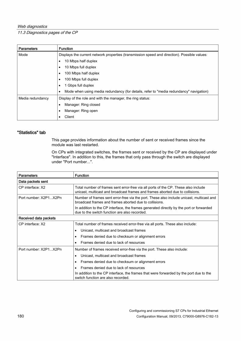
Web diagnostics 11.3 Diagnostics pages of the CP
Configuring and commissioning S7 CPs for Industrial Ethernet 180 Configuration Manual, 09/2013, C79000-G8976-C182-13
Parameters Function Mode Displays the current network properties (transmission speed and direction). Possible values:
• 10 Mbps half duplex • 10 Mbps full duplex • 100 Mbps half duplex • 100 Mbps full duplex • 1 Gbps full duplex • Mode when using media redundancy (for details, refer to "media redundancy" navigation)
Media redundancy Display of the role and with the manager, the ring status: • Manager: Ring closed • Manager: Ring open • Client
"Statistics" tab This page provides information about the number of sent or received frames since the module was last restarted.
On CPs with integrated switches, the frames sent or received by the CP are displayed under "Interface". In addition to this, the frames that only pass through the switch are displayed under "Port number...".
Parameters Function Data packets sent CP interface: X2 Total number of frames sent error-free via all ports of the CP. These also include
unicast, multicast and broadcast frames and frames aborted due to collisions. Port number: X2P1...X2Pn Number of frames sent error-free via the port. These also include unicast, multicast and
broadcast frames and frames aborted due to collisions. In addition to the CP interface, the frames generated directly by the port or forwarded due to the switch function are also recorded.
Received data packets CP interface: X2 Total number of frames received error-free via all ports. These also include:
• Unicast, multicast and broadcast frames • Frames denied due to checksum or alignment errors • Frames denied due to lack of resources
Port number: X2P1...X2Pn Number of frames received error-free via the port. These also include: • Unicast, multicast and broadcast frames • Frames denied due to checksum or alignment errors • Frames denied due to lack of resources In addition to the CP interface, the frames that were forwarded by the port due to the switch function are also recorded.

Web diagnostics 11.3 Diagnostics pages of the CP
Configuring and commissioning S7 CPs for Industrial Ethernet Configuration Manual, 09/2013, C79000-G8976-C182-13 181
"TCP Connections" tab This page informs you about the status of TCP connections.
Parameters Function Number Consecutive number of the TCP connection Local IP address IP address of the CP Local port Number of the port used for the TCP connection Partner IP address Partner IP address Partner port Number of the port on the partner used for the TCP connection Status Connection status of the TCP connection, for example:
• LISTEN (waiting for connection) • ESTABLISHED (existing connection) • TIME WAIT (wait state prior to connection termination) and • other interim statuses such as SYN SENT, SYN RECV, CLOSING etc.)
"UDP Connections" tab This page informs you about set up UDP connections.
Parameters Function Number Consecutive number of the UDP connection Local IP address IP address of the CP Local port Number of the port used for the UDP connection Partner IP address Cannot be obtained with UDP. Therefore displayed with "*" Partner port Cannot be obtained with UDP. Therefore displayed with "*"
11.3.6 SEND/RECEIVE communication / configured connections The "SEND/RECEIVE communication" entry in the navigation panel contains information about the status of the connections in the tabs for the relevant connection type.
Statistics relating to the mode and the frames transferred since the last module restart are also displayed. The statistics are connection-specific. Select a connection in the connection table at the top of the page.
A test e-mail can be sent in the "SMTP" tab.
Display dependent on the configuration / programming Whether or not the tabs described below are displayed depends on whether corresponding connection types have been configured.

Web diagnostics 11.3 Diagnostics pages of the CP
Configuring and commissioning S7 CPs for Industrial Ethernet 182 Configuration Manual, 09/2013, C79000-G8976-C182-13
Note: Connections can be configured by configuration in STEP 7 or by programming in the user program (program block IP_CONFIG).
Note PROFINET IO
When using PROFINET IO, UDP ports are open due to the system.
"ISO Transport", "ISO-on-TCP", "TCP", "UDP", "SMTP" tabs Parameters Function Relevant protocol Connection type (ISO transport, ISO-on-TCP, TCP, UDP, SMTP, S7) Conn no. Connection number from the configuration All Conn. name Connection name from the configuration All Local IP address IP address of the local interface ISO-on-TCP, TCP, UDP, S7, SMTP Local MAC address MAC address of the local interface ISO Transport, S7 Remote MAC address MAC address of the connection partner ISO Transport, S7 Partner IP address IP address of the connection partner ISO-on-TCP, TCP, UDP, S7 Local TSAP Local TSAP from the configuration ISO Transport, ISO-on-TCP, S7 Partner TSAP TSAP of the connection partner ISO Transport, ISO-on-TCP, S7 Local port Local port from the configuration TCP, UDP Partner port Port of the connection partner TCP, UDP, SMTP Assigned CPU The CPU assigned in the configuration SMTP E-mail server IP address of the e-mail server SMTP Connection status Current connection status:
• Established • Terminated • Active connection establishment running • Passive connection establishment running
All
Interface Specifies the connection path on the local station. All Statistics (of the selected connection)
• Mode • Messages sent
successfully • Messages not sent
successfully • Receive messages
Statistical information on the particular entry ISO transport, ISO-on-TCP, TCP, UDP
Messages blocked due to the access LOCK
Number of messages locked by the AG_LOCK program block
TCP

Web diagnostics 11.3 Diagnostics pages of the CP
Configuring and commissioning S7 CPs for Industrial Ethernet Configuration Manual, 09/2013, C79000-G8976-C182-13 183
Sending a test e-mail in the "SMTP" tab The "SMTP" tab has a box at the bottom of the dialog with which you can send a test e-mail from the CP.
The maximum total length of the message is 260 characters (sum of all characters entered in the rows "From", "To", "Subject" and "Text").
Line Entry / function
Testing the e-mail connection (max. 260 characters in total) From Enter a valid sender address here. As default, the row contains the address of
the CP from the connection configuration. Maximum of 60 characters
To Enter an address for the e-mail recipient. Maximum of 60 characters
Subject Enter a subject here (optional). Maximum of 60 characters
Text Enter the text here (optional). Maximum of 80 characters
User If you configured your e-mail server with authentication, enter the user name
here. Password If you configured your e-mail server with authentication, enter the password
here.
To send the e-mail click the "Send E-Mail" button.
Note Security enabled - required user rights
Sending a test e-mail requires the following user rights: • Web: Send test mail • Web: Access Web diagnostics and CP file system
See also S7 communication (Page 183)
11.3.7 S7 communication The "S7 communication" entry in the navigation panel shows connection tables with address and status information in protocol-specific tabs.
From the drop-down list above the connection table, select the types of connection to be displayed:
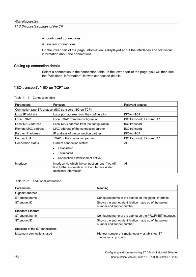
Web diagnostics 11.3 Diagnostics pages of the CP
Configuring and commissioning S7 CPs for Industrial Ethernet 184 Configuration Manual, 09/2013, C79000-G8976-C182-13
● configured connections
● system connections
On the lower part of the page, information is displayed about the interfaces and statistical information about the connections.
Calling up connection details Select a connection in the connection table. In the lower part of the page, you will then see the "Additional information" list with connection details.
"ISO transport", "ISO-on-TCP" tab
Table 11- 1 Connection table
Parameters Function Relevant protocol Connection type S7; protocol (ISO transport, ISO-on-TCP) Local IP address Local port address from the configuration ISO-on-TCP, Local TSAP Local TSAP from the configuration ISO transport, ISO-on-TCP, Local MAC address Local MAC address from the configuration ISO transport Remote MAC address MAC address of the connection partner ISO transport Partner IP address IP address of the connection partner ISO-on-TCP Partner TSAP TSAP of the connection partner ISO transport, ISO-on-TCP Connection status Current connection status:
• Established • Terminated • Connection establishment active
All
Interface interface via which the connection runs. You will find further information on the interface under additional information.
All
Table 11- 2 Additional information
Parameters Meaning Gigabit Ethernet S7 subnet name Configured name of the subnet on the gigabit interface. S7 subnet ID Shows the subnet identification made up of the project
number and subnet number. Standard Ethernet S7 subnet name Configured name of the subnet on the PROFINET interface. S7 subnet ID Shows the subnet identification made up of the project
number and subnet number. Statistics of the S7 connections Maximum connections used Highest number of simultaneously established S7
connections up to now.

Web diagnostics 11.3 Diagnostics pages of the CP
Configuring and commissioning S7 CPs for Industrial Ethernet Configuration Manual, 09/2013, C79000-G8976-C182-13 185
Parameters Meaning Connections currently in use Currently reached number of simultaneously established S7
connections. Denied connection establishment attempts Number of events recorded since the CP startup or since
the counter was reset. Note: The counter can be reset with STEP 7 special diagnostics.
Error due to lack of resources
11.3.8 Media redundancy The "Media redundancy" entry in the navigation panel provides information about the status of ports that can be configured for media redundancy.
Parameters Function
Role • Manager • Client • disabled
Domain Name of the configured redundancy domain Status Status of the ring on the redundancy manager:
• open • closed
Link status <port> Px Link status <port> Py
Status of the two ring ports of the CP: • OK (the port is connected to a partner, the ring is not
closed) • blocked (the ring port is disconnected from the second
ring port, in other words, the ring is closed) • No link (the ports is not connected to a partner)
11.3.9 IP access protection The following tabs are only active if you have enabled IP access protection in the configuration.
Note Security enabled - navigation panel "Security"
The navigation panel "IP Access Protection" only exists if security is disabled. If security is enabled, you can obtain corresponding information from the "Security" navigation panel.
"IP access protection" parameter group (Page 52)
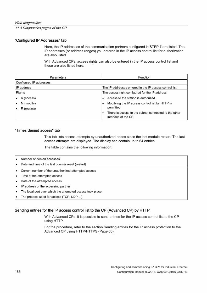
Web diagnostics 11.3 Diagnostics pages of the CP
Configuring and commissioning S7 CPs for Industrial Ethernet 186 Configuration Manual, 09/2013, C79000-G8976-C182-13
"Configured IP Addresses" tab Here, the IP addresses of the communication partners configured in STEP 7 are listed. The IP addresses (or address ranges) you entered in the IP access control list for authorization are also listed.
With Advanced CPs, access rights can also be entered in the IP access control list and these are also listed here.
Parameters Function
Configured IP addresses IP address The IP addresses entered in the IP access control list Rights • A (access) • M (modify) • R (routing)
The access right configured for the IP address: • Access to the station is authorized. • Modifying the IP access control list by HTTP is
permitted. • There is access to the subnet connected to the other
interface of the CP.
"Times denied access" tab This tab lists access attempts by unauthorized nodes since the last module restart. The last access attempts are displayed. The display can contain up to 64 entries.
The table contains the following information:
• Number of denied accesses • Date and time of the last counter reset (restart)
• Current number of the unauthorized attempted access • Time of the attempted access • Date of the attempted access • IP address of the accessing partner • The local port over which the attempted access took place. • The protocol used for access (TCP, UDP ...)
Sending entries for the IP access control list to the CP (Advanced CP) by HTTP With Advanced CPs, it is possible to send entries for the IP access control list to the CP using HTTP.
For the procedure, refer to the section Sending entries for the IP access protection to the Advanced CP using HTTP/HTTPS (Page 66)

Web diagnostics 11.3 Diagnostics pages of the CP
Configuring and commissioning S7 CPs for Industrial Ethernet Configuration Manual, 09/2013, C79000-G8976-C182-13 187
11.3.10 Security The "Security" entry in the navigation panel provides information about the configured security functions.
Note Security enabled - navigation panel "IP Access Protection"
The navigation panel "Security" only exists if security is enabled. If security is disabled, you can obtain corresponding information from the "IP Access Protection" navigation panel.
Parameters Function
Project information Author Name of the user who last loaded the configuration data. Date created Date and time of the last configuration Project name Initially configured name of the STEP 7 project. Last changes Entries exist here if changes have been made. Author Name of the user who made the current change. Date created Date and time of the change. Project name Current name of the STEP 7 project. Operating modes Display of the current statuses of the individually listed security functions Level 2 firewall Possible operating modes are:
• Not configured • Configuration was adopted • Error in configuration
Level 3 firewall Level 2 VPN Level 3 VPN Certificate Signature check User management Logging
11.3.11 Topology
Topology of the PROFINET nodes The "Topology" Web page provides information about the topological configuration and status of the PROFINET devices on your PROFINET IO system.
There are three tabs for the following views:

Web diagnostics 11.3 Diagnostics pages of the CP
Configuring and commissioning S7 CPs for Industrial Ethernet 188 Configuration Manual, 09/2013, C79000-G8976-C182-13
● Graphic view
● Table view
● Status overview (excluding topological correlations)
The views and status overview can be printed. Before printing out, use the print preview of your browser. If necessary, correct the format.
From the drop-down list in the header bar, select the display mode:
● Display mode "Set topology"
● Display mode "Actual topology"
Display mode "Set topology" Display of the topological layout configured in the topology editor of STEP 7 with corresponding status displays. The topological layout contains the configured PROFINET devices of a PROFINET IO system. The display includes neighboring PROFINET devices, provided their topological layout is configured as well. There is, however, no status display for neighboring PROFINET devices.
The view identifies the topological assignment of PROFINET devices that have failed, the differences between the target and actual topology, and interchanged ports.
Note Special feature
The configured target topology is always displayed in the following scenarios: • When the "Topology" web page is called via the navigation bar • When you change from the overview of PROFINET IO devices on the "Module
information" Web page to the "Topology" Web page by means of "Topology" link
If no target topology was configured, the actual topology is called by default.
Display mode "Actual topology" The actual status detected in the PROFINET IO system is displayed. The display is based on the system configuration but shows differences relating to the components as well as the port interconnections.
The reachable directly neighboring but unconfigured PROFINET devices are also displayed; there is however no status display for these neighboring PROFINET devices.
Requirement For error-free operation of the topology, the following conditions must be met:
● You completed the language settings.
● The topological interconnection of the ports is configured in the topology editor of STEP 7
● The project is compiled in STEP 7.

Web diagnostics 11.3 Diagnostics pages of the CP
Configuring and commissioning S7 CPs for Industrial Ethernet Configuration Manual, 09/2013, C79000-G8976-C182-13 189
● "Report System Error" has been generated (occurs automatically when compiling in STEP 7)
● The configuration has been loaded.
Note
PROFINET IO system - no display if the line is empty
If no PROFINET IO device is configured in the PROFINET IO system of the CP, there is no display in the topology view. In this case, the display indicates a disabled topology display.
11.3.11.1 Topology - "Graphic view" tab
Meaning The Web page in the "Graphic view" tab shows the port interconnection of the components in the PROFINET IO system.
Example: The expected topology is compared with the actual topology The figure below shows the view of an expected topology and an actual topology in a STEP 7 project. This is an example of the configuration with an S7-300 CPU and interconnected PROFINET IO devices. The figure illustrates the possible status information in the graphic view.
Based on the position numbers, you will find the explanations below the figure. The explanations can be transferred to any other configuration.

Web diagnostics 11.3 Diagnostics pages of the CP
Configuring and commissioning S7 CPs for Industrial Ethernet 190 Configuration Manual, 09/2013, C79000-G8976-C182-13
Table 11- 3 Meaning of the colored connections in the target/actual topology:
Connection Meaning
Target topology Actual topology green The current actual connection matches the configured target
connection. Connections detected
red Mismatch between the current actual connection and the configured target connection (e.g., port interchanged).
-
yellow Connection diagnostics not possible. Causes: • Malfunction of communication with a device (e.g. cable
was removed) • Connection to a passive component • Connection to devices/PROFINET devices on a different
IO controller or IO subsystem.
-
① Configured and accessible PROFINET nodes Configured and accessible PROFINET nodes are displayed in dark gray. Display the ports used to connect the PROFINET nodes of a station.

Web diagnostics 11.3 Diagnostics pages of the CP
Configuring and commissioning S7 CPs for Industrial Ethernet Configuration Manual, 09/2013, C79000-G8976-C182-13 191
② Configured but inaccessible PROFINET nodes Configured but inaccessible PROFINET nodes are indicated in pink color with red frame (e.g. device failure, cable disconnected)
③ Deactivated nodes All disabled configured PROFINET nodes are indicated in light gray.
④ Interchanged ports Interchanged ports are highlighted in red color in the target topology view. The actual topology view indicates the actually connected ports, while the target topology view displays the configured target connections.
⑤ PROFINET devices of a different PROFINET IO subsystem ● In the target topology:
A PROFINET device of a different PROFINET IO subsystem is identified by means of a green link (or red link for interchanged ports) if available on the bus and directly adjacent to an accessible configured PROFINET device ①. A PROFINET device that cannot be accessed from a different PROFINET IO subsystem is identified by means of a yellow link. The connection between two PROFINET devices which belong to a different PROFINET IO subsystem cannot be identified and is always indicated in yellow color.
● In the actual topology:
The PROFINET device of a different PROFINET IO subsystem is not displayed unless directly adjacent to a configured PROFINET device. This device is indicated by means of a light gray dashed line.
The status of PROFINET devices of a different PROFINET IO subsystem is not displayed in the device header.
⑥ Displaying faulty neighbor relationships Nodes whose relation data could not be read completely or with error are highlighted in light gray with a red frame.
Note Displaying faulty neighbor relationships
A firmware update of the affected component is required.
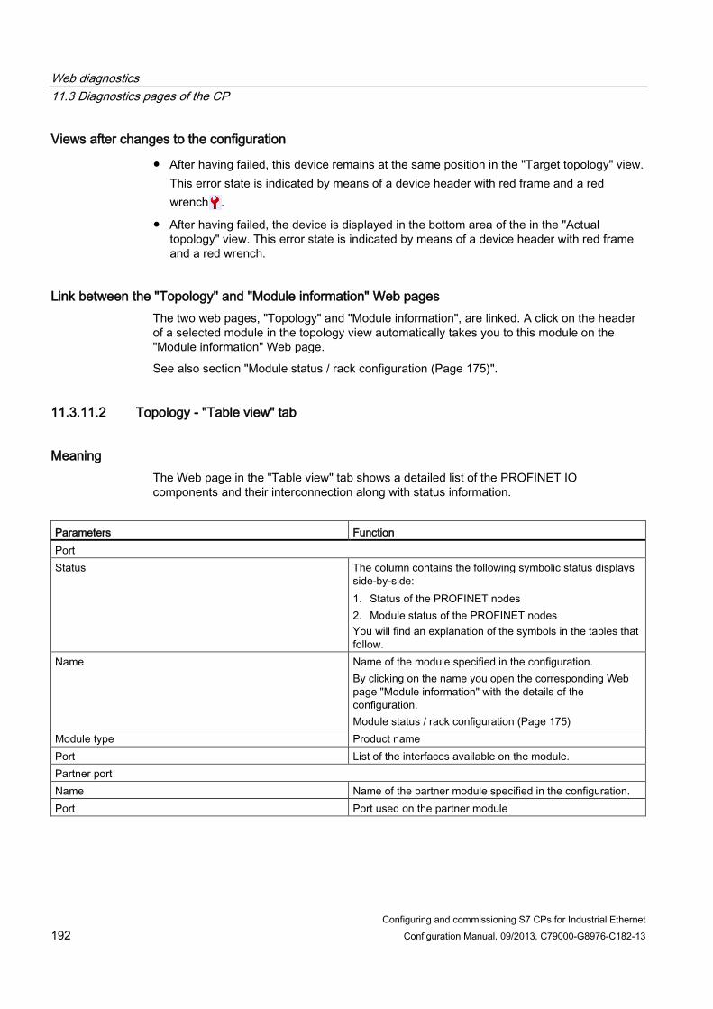
Web diagnostics 11.3 Diagnostics pages of the CP
Configuring and commissioning S7 CPs for Industrial Ethernet 192 Configuration Manual, 09/2013, C79000-G8976-C182-13
Views after changes to the configuration
● After having failed, this device remains at the same position in the "Target topology" view. This error state is indicated by means of a device header with red frame and a red wrench .
● After having failed, the device is displayed in the bottom area of the in the "Actual topology" view. This error state is indicated by means of a device header with red frame and a red wrench.
Link between the "Topology" and "Module information" Web pages The two web pages, "Topology" and "Module information", are linked. A click on the header of a selected module in the topology view automatically takes you to this module on the "Module information" Web page.
See also section "Module status / rack configuration (Page 175)".
11.3.11.2 Topology - "Table view" tab
Meaning The Web page in the "Table view" tab shows a detailed list of the PROFINET IO components and their interconnection along with status information.
Parameters Function Port Status The column contains the following symbolic status displays
side-by-side: 1. Status of the PROFINET nodes 2. Module status of the PROFINET nodes You will find an explanation of the symbols in the tables that follow.
Name Name of the module specified in the configuration. By clicking on the name you open the corresponding Web page "Module information" with the details of the configuration. Module status / rack configuration (Page 175)
Module type Product name Port List of the interfaces available on the module. Partner port Name Name of the partner module specified in the configuration. Port Port used on the partner module

Web diagnostics 11.3 Diagnostics pages of the CP
Configuring and commissioning S7 CPs for Industrial Ethernet Configuration Manual, 09/2013, C79000-G8976-C182-13 193
Table 11- 4 Meaning of the icons indicating the status of the PROFINET nodes
Symbol Meaning
Configured and accessible PROFINET nodes
Unconfigured and accessible PROFINET nodes
Configured but inaccessible PROFINET nodes
Nodes for which neighbor relations cannot be determined or for which the neighbor relationship could not be read out completely or only with errors
Table 11- 5 Meaning of the icons indicating the module status of the PROFINET nodes
Symbol Color Meaning
green Component is OK
gray Disabled PROFIBUS slaves or PROFINET devices
Support conditions: • CPU31x PN/DP ≥ V3.2.1 and STEP 7 V5.5 + possibly required HSP for the
CPU • Enabling/disabling the PROFIBUS slaves and PROFINET IO devices using
SFC12 mode 3/4. • In the "Report system errors" dialog, "Diagnostics support" tab, "Status
enabled/disabled" area, the check mark must be set in the "Request device status enabled/disabled" check box after CPU startup and optionally in the "Output message on status transition" check box.
black Component cannot be accessed/Status cannot be determined
• For example, "Status cannot be determined" is always displayed while the CPU is in STOP mode, or during startup evaluation of "Report system error" for all the configured I/O modules and I/O systems after a CPU restart.
• However, this status can also be displayed temporarily during operation if a diagnostic interrupt burst occurs at all modules.
• It is not possible to determine the status of modules on a subsystem that is connected to a CP.
green Maintenance required
yellow Maintenance requested
red Error - component failed or faulty
- Error in a lower module level

Web diagnostics 11.3 Diagnostics pages of the CP
Configuring and commissioning S7 CPs for Industrial Ethernet 194 Configuration Manual, 09/2013, C79000-G8976-C182-13
11.3.11.3 Topology - "Status overview" tab
Meaning The "Status overview" tab provides a clear presentation of all PROFINET IO devices/PROFINET devices (without connection relations) on one page. A quick error diagnostics is possible based on the symbols that show the module statuses.
For the meaning of the status symbols, refer to the tables in section Topology - "Table view" tab (Page 192)
Status information as tooltip If you place the mouse pointer on the module symbol, you will see information about the status in plain language.
Link between the "Topology Status overview" and "Module information" Web pages The two web pages, "Topology" and "Module information", are linked. A click on the displayed module in the status overview automatically takes you to this module on the "Module information" Web page.
"Module status / rack configuration (Page 175)".
11.3.12 Update center On the following tabs, the "Update center" entry in the navigation panel provides functions for transferring data to the CP:
● "Firmware" tab
● "Access control list" tab
● "Diagnostics messages" tab
Note
CP with security function
With the security function enabled, the functions described below assume that the following right is always set in the rights list alongside the other listed rights:
"Web: Access Web diagnostics and CP file system"
11.3.12.1 Update center - "Firmware" tab
Meaning The update center allows reloading, management and activation of firmware versions on the CP. For a description, see section Loading from the Download Center (Page 219)
Requirement: The tab exists if the "Firmware download via Web" option is selected on the CP.

Web diagnostics 11.3 Diagnostics pages of the CP
Configuring and commissioning S7 CPs for Industrial Ethernet Configuration Manual, 09/2013, C79000-G8976-C182-13 195
Requirement: The tab exists if the following conditions are met on the CP:
● Case a: Security disabled:
– The "Firmware download via Web" option is selected;
● Case b: Security enabled:
– The "Firmware download via Web" option is selected;
– The following right is also set in the rights list: "Web: Update firmware"
Note
Module access protection
Note the settings for the module access protection of the CP. Depending on the current protection level, write access to the CP and therefore also the activation of the reloaded firmware can be blocked.
"Flash" button - identify module If you click the "Flash" button, the port LEDs of the module all flash three times. The diagnosed module can therefore be recognized quickly in the station rack.
11.3.12.2 Update center - "IP access control list" tab
Meaning The update center allows the reloading of the file with additional entries for the IP access control list.
Note CP with security function
The behavior differs depending on whether security is enabled or disabled. Note the following chapter reference.
You will find a description of the function and syntax of the file in the section Sending entries for the IP access protection to the Advanced CP using HTTP/HTTPS (Page 66)
Requirement: The tab exists if the following conditions are met on the CP:
● Case a: Security disabled:
– The "Enable access protection for IP communication" option is selected;
● Case b: Security enabled:
– The following right is also set in the rights list: "Web: Load diagnostics texts later".
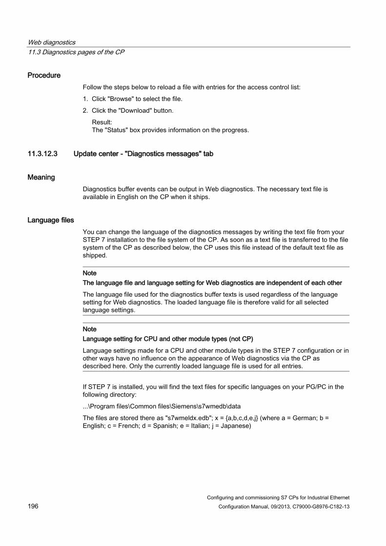
Web diagnostics 11.3 Diagnostics pages of the CP
Configuring and commissioning S7 CPs for Industrial Ethernet 196 Configuration Manual, 09/2013, C79000-G8976-C182-13
Procedure Follow the steps below to reload a file with entries for the access control list:
1. Click "Browse" to select the file.
2. Click the "Download" button.
Result: The "Status" box provides information on the progress.
11.3.12.3 Update center - "Diagnostics messages" tab
Meaning Diagnostics buffer events can be output in Web diagnostics. The necessary text file is available in English on the CP when it ships.
Language files You can change the language of the diagnostics messages by writing the text file from your STEP 7 installation to the file system of the CP. As soon as a text file is transferred to the file system of the CP as described below, the CP uses this file instead of the default text file as shipped.
Note The language file and language setting for Web diagnostics are independent of each other
The language file used for the diagnostics buffer texts is used regardless of the language setting for Web diagnostics. The loaded language file is therefore valid for all selected language settings.
Note Language setting for CPU and other module types (not CP)
Language settings made for a CPU and other module types in the STEP 7 configuration or in other ways have no influence on the appearance of Web diagnostics via the CP as described here. Only the currently loaded language file is used for all entries.
If STEP 7 is installed, you will find the text files for specific languages on your PG/PC in the following directory:
...\Program files\Common files\Siemens\s7wmedb\data
The files are stored there as "s7wmeldx.edb"; x = {a,b,c,d,e,j} (where a = German; b = English; c = French; d = Spanish; e = Italian; j = Japanese)

Web diagnostics 11.3 Diagnostics pages of the CP
Configuring and commissioning S7 CPs for Industrial Ethernet Configuration Manual, 09/2013, C79000-G8976-C182-13 197
Requirement: A language file can be downloaded if the following conditions are met on the CP:
● Case a: Security disabled:
– "Reload of language files for the diagnostics displays via Web" option is selected;
● Case b: Security enabled:
– "Reload of language files for the diagnostics displays via Web" option is enabled;
– The following right is also set in the rights list: "Web: Load diagnostics texts later".
Downloading language files using Web diagnostics Follow the steps below to load a language file:
1. Click "Browse" to select the language-specific file.
2. Click the "Download" button.
Result: The "Status" box provides information on the progress. If the download is successful, the previously used language file for diagnostics buffer events is replaced by the newly downloaded file. The plain language display in the diagnostics buffer appears immediately in the newly selected language.
Downloading language files using FTP With Advanced CPs, the language file can also be transferred using FTP, with older Advanced CPs only using FTP.
Change the name of the file with the required language for the FTP transfer to <s7wmeld.edb>.
Keep in mind the configured settings relating to case sensitivity.
Transfer the file by FTP and store it in binary mode in the file system of the CP in:
\config\s7wmeld.edb

Web diagnostics 11.3 Diagnostics pages of the CP
Configuring and commissioning S7 CPs for Industrial Ethernet 198 Configuration Manual, 09/2013, C79000-G8976-C182-13

Configuring and commissioning S7 CPs for Industrial Ethernet Configuration Manual, 09/2013, C79000-G8976-C182-13 199
STEP 7 special diagnostics 12
The STEP 7 special diagnostics (special diagnostics / NCM S7 Diagnostics) described here provides dynamic information on the operating state of the communication functions of online CPs.
This chapter provides a general overview of the individual diagnostic functions.
The following checklist will help you to recognize several typical problems and their possible causes and shows how you can use the STEP 7 special diagnostics tool to remedy the situation.
● When you are working with the diagnostic tool, the integrated help system provides you with contextrelated support.
Note
STEP 7 special diagnostics supports not only diagnostics for CPs (communications modules) but also other module types such as the IE/PB Link. In the sections below, the term CP is therefore synonymous with all modules with which you can run NCM S7 diagnostics functions.
12.1 Overview
Diagnostics options in STEP 7 STEP 7 provides you with a graded concept allowing you to query information about the status of your SIMATIC S7 components and functions and to sort out problems in a variety of different situations. You will find:
● Hardware diagnostics and troubleshooting with STEP 7 Hardware diagnostics provides dynamic information on the operating mode of modules including CPs when the S7 station is online. You can recognize the existence of diagnostics information for a module based on the diagnostics icons. Diagnostic icons show the status of the corresponding module and also the operating mode of CPUs.
● Communication diagnostics with STEP 7 special diagnostics The STEP 7 special diagnostics described here provides dynamic information on the operating state of the communications functions of online CPs or modules.
● Diagnostics of the communication and the status of modules of an S7 station For details, see section Web diagnostics (Page 167)
● Diagnostics of security-relevant data with SCT online diagnostics The SCT online diagnostics via HTTPS provides dynamic information about security-relevant data of online security CPs or modules. You will find more detailed information in /16/ (Page 232)

STEP 7 special diagnostics 12.2 Functions
Configuring and commissioning S7 CPs for Industrial Ethernet 200 Configuration Manual, 09/2013, C79000-G8976-C182-13
12.2 Functions
Functions The following must be distinguished:
● General diagnostics and statistical functions
● Type and modedependent diagnostics functions
General diagnostics and statistical functions Regardless of the configured mode of the Ethernet CP, the following diagnostics functions are possible:
● Querying the operating mode on Ethernet;
● Querying the event messages recorded on the Ethernet CP (diagnostics buffer);
Modedependent functions Depending on the configured mode of the Ethernet CP, the following diagnostics functions are possible:
● Diagnostics of ISO transport connections
● Diagnostics of ISOonTCP connections
● Diagnostics of TCP connections
● Diagnostics of UDP connections
● Diagnostics of email connections
● Diagnostics of TCP connections for PROFINET CBA
12.2.1 Installation and startup
Installation STEP 7 special diagnostics is integrated in STEP 7.
SCT online diagnostics is an integrated part of the Security Configuration Tool installed for the security configuration.
Startup (STEP 7 V5.5) There are several ways in which you can start the diagnostics tool, for example:
● From the standard Start menu of Windows, you can select the SIMATIC > STEP 7 > NCM S7 > Diagnostics program group.
Use this method if the STEP 7 project in which the CP was configured is not available on your PG (for service purposes).
● From the Properties dialog of the CP within your STEP 7 project.

STEP 7 special diagnostics 12.2 Functions
Configuring and commissioning S7 CPs for Industrial Ethernet Configuration Manual, 09/2013, C79000-G8976-C182-13 201
Startup (STEP 7 Professional) You start STEP 7 special diagnostics as follows after selecting a module in the network view:
1. Select the "Online" > "Online & Diagnostics" menu command.
2. Under the "Functions > Special diagnostics" entry, click the "Special diagnostics" button.
12.2.2 Setup and operation
Structure STEP 7 special diagnostics is displayed as a separate application window in two parts with a menu bar and toolbar:
① In the navigation area on the lefthand side, you will find the hierarchically arranged diagnostics objects.
You have an overview of the available diagnostics functions at all times. The object structure displayed in the navigation area is adapted to the type of CP you are currently checking and the functions and connections configured for the CP.
② In the Content Area, on the right-hand side, you will see the result of the diagnostics function you selected in the navigation area.

STEP 7 special diagnostics 12.2 Functions
Configuring and commissioning S7 CPs for Industrial Ethernet 202 Configuration Manual, 09/2013, C79000-G8976-C182-13
Operation ● By selecting a diagnostics object in the navigation area with the mouse, you execute the
diagnostics function.
● Using the menu bar and toolbar, you control the sequence of the diagnostics with context-sensitive menu commands.
12.2.3 Menu commands
Overview When running diagnostics, the following menu commands have general functions. Depending on the context, other functions may be available; for more detailed information refer to the individual diagnostics topics in the online help.
Menu Meaning Diagnostics > Open Online Connection... Diagnostics > Close Online Connection...
Using these menu commands, you can open a connection to a different module you want to check without having to close and restart the diagnostics tool. The current diagnostics connection is closed. If you want to use more than one diagnostics connection at the same time, you can start special diagnostics more than once.
Operating mode > *) • Stop module • Start module
You can control the module as follows: • Stop the module. • You can start the module if the RUN/STOP selector is
set to RUN.
Mode > *) Reset module memory *)
On certain modules, a module memory reset is possible. This function must be confirmed before it is executed. Following this memory reset, the CP retains the preset MAC address and the retentive parameters. The CP is therefore immediately ready for downloads. The retentive parameters include: • IP address and IP parameters • Newly set MAC address • LAN settings Note: On CPs with the security function, the VPN configuration is deleted and the CP can no longer be reached via VPN. Note: This function has different effects depending on the CPU version being used. The response also depends on whether or not the CP is used with PROFINET functionality. You will find further information as an FAQ on the Internet; refer to the section This manual... (Page 3) and the manual /1/ (Page 227) of the relevant CP.

STEP 7 special diagnostics 12.2 Functions
Configuring and commissioning S7 CPs for Industrial Ethernet Configuration Manual, 09/2013, C79000-G8976-C182-13 203
Menu Meaning Mode > *) Reset to Factory Settings *)
With certain modules, it is possible to reset to the factory settings. When you reset to the factory settings, the retentive parameters are also deleted. Following this, the module only has the default MAC address (as supplied).
Operating Mode > *) Format C-PLUG for this Module *)
With modules operating with a C-PLUG, you can reformat the C-PLUG. The C-PLUG is supplied with module data of the current module. Configuration data is adopted for the specific device.
Diagnostic buffer > • Details on the Entry... • Delete Entries • Filter Display >
– Set – Enable
• Save... • Save Cyclically...
Control options for the "Diagnostics buffer" diagnostics object You will find details of the control functions in the online help for the "Diagnostics buffer" diagnostics object.
View > Update
Each time you activate this menu command, the displayed diagnostics and status information is updated once.
View > Update cyclically on / off
With this menu command, you can toggle the automatic (cyclic) updating of the displayed diagnostics and status information on and off. You can set the interval between update points with the menu command Options > Customize.
Options > Customize Here, you make the general settings for your diagnostics session. • Dialog update time
This sets the cycle time at which the diagnostics data is updated in the content area during cyclic updating.
• Maximum size of the diagnostic buffer log file See menu command Diagnostic Buffer > Save Cyclically... for the "diagnostic buffer" diagnostics object
Options > Set PG/PC Interface You close the interface to the network on the PG/PC for the diagnostics session.
Options > Assign Ethernet Address You open the "Edit Ethernet node" dialog. You can then, for example, search the network for the accessible nodes. The menu command is active if special diagnostics is in "Offline" mode.
Options > Reset Counter On diagnostics pages with statistical information, you reset the counters to "0". The menu command is active if diagnostics pages contain statistical information with counter values.
Options > Send E-mail You enable the sending of a test mail. The menu command is active if the "E-mail" diagnostics object is selected.

STEP 7 special diagnostics 12.3 Starting diagnostics
Configuring and commissioning S7 CPs for Industrial Ethernet 204 Configuration Manual, 09/2013, C79000-G8976-C182-13
Menu Meaning Options > Ping Check the reachability of a device or a device interface. Help >.... You obtain help on the current diagnostics function. You can
also obtain help with the F1 key. Remember that with some diagnostics functions, context-sensitive help is also available for individual output boxes. To use these functions, position the cursor on the output box and press the F1 key.
*) The functions are only executed if "Not locked" was configured for the module access protection: Refer to the "Properties > Options" parameter group (not available for every CP).
Note Re-establishing an aborted connection
If the connection to the module is terminated during the diagnostics session, the following message is displayed: "The online connection was terminated".
You re-establish the connection to the module by acknowledging the displayed dialog box. If possible, the connection is then re-established.
12.3 Starting diagnostics
12.3.1 Online path: Establishing a connection to the CP
Requirements First, establish a physical connection between the PG and the SIMATIC S7 station. You can make this connection via one of the following:
● MPI
● PROFIBUS
● Industrial Ethernet (ISO protocol)
● Industrial Ethernet TCP/IP (IP protocol)
Establishing a connection to the CP If you call special diagnostics for a specific module within a project, STEP 7 attempts to establish a connection to the CP directly based on the project data. The path is set automatically according to the current attachment in STEP 7.
If the connection cannot be established due to missing parameters, set the interface and address parameters for access to the CP according to the descriptions below.

STEP 7 special diagnostics 12.3 Starting diagnostics
Configuring and commissioning S7 CPs for Industrial Ethernet Configuration Manual, 09/2013, C79000-G8976-C182-13 205
Procedure In the "Online Path" dialog box, select the interface corresponding to your hardware configuration.
Depending on the selected type of attachment, you will be prompted to enter address parameters.
For details, refer to the following table; further information on setting gateways and examples can be found below.
Attachment of the destination station
Node address Position of the module Rack / slot
MPI MPI address of the CP if this has its own MPI address. Otherwise specify the MPI address of the CPU.
Rack/slot no. of the CP to be checked. If you specify the MPI address of the CP, you can simply use the setting "0/0". With this setting, the CP whose address was specified as the node address is accessed.
PROFIBUS PROFIBUS address of the CP via which the S7 station is reached.
Rack/slot no. of the CP to be checked. If the CP on which you require diagnostics information is a PROFIBUS CP, the following applies: If you specify "0/0", the CP with the node address is addressed directly.
Industrial Ethernet MAC address of the Ethernet CP via which the S7 station is reached. The input is in hexadecimal format. Example: MAC address 80.00.06.A1.B2.3D
Rack/slot no. of the CP to be checked. If the CP on which you require diagnostics information is an Ethernet CP, the following applies: If you specify "0/0", the CP with the node address is addressed directly.
TCP/IP IP address of the Industrial Ethernet CP via which the S7 station is reached. The input is in decimal format. Example: IP address 142.120.9.134
Rack/slot no. of the CP to be checked. If the CP on which you require diagnostics information is an Ethernet CP, the following applies: If you specify "0/0", the CP with the node address is addressed directly.

STEP 7 special diagnostics 12.3 Starting diagnostics
Configuring and commissioning S7 CPs for Industrial Ethernet 206 Configuration Manual, 09/2013, C79000-G8976-C182-13
Examples of setting the online path without a gateway
Figure 12-1 CP requiring diagnostics can be reached directly
Figure 12-2 The CP requiring diagnostics is accessible indirectly over another CP
Attachment of the destination station using the device name With an Ind.Ethernet (MAC address) or Ind.Ethernet TCP/IP attachment, you can also specify the module you want to reach by selecting the device name:
1. Select the "Connection via device name" option; when this option is enabled, it is no longer possible to enter a node address.
2. Enter the device name or click the "Browse network" button.
If more than one module is found with the same device name, select the relevant module in the dialog that opens.
Note on the "Browse network" dialog: Depending on the device type, in the "Browse network" dialog, you may see a module name or even no entry in the "Name" column instead of the device name (PROFINET IO device name). If it is not a device name, the connection cannot be assigned to the target station using the device name. If this is the case, the entry in the "Destination station" area remains unchanged. If this is the case, disable the "Connection via device name" option. If you select the destination station again with "Browse network", the node address will then be updated.

STEP 7 special diagnostics 12.3 Starting diagnostics
Configuring and commissioning S7 CPs for Industrial Ethernet Configuration Manual, 09/2013, C79000-G8976-C182-13 207
Using the gateway If the CP you are checking can only be accessed via a gateway, you will need to select this specifically and specify its node address on the local network.
You also specify the S7 subnet ID of the destination network.
The subnet ID is made up of two numbers separated by a hyphen:
● One number for the project
● One number for the subnet
You can check the subnet ID in the Object Properties of the subnet in the STEP 7 project. The subnet ID is also printed out when you print the network configuration.
You will find examples here:
Example - case a: Using a gateway - one gateway
Figure 12-3 Example of the parameter settings for the online path with one gateway
Example - case b: Using a gateway (several gateways)
If the CP to be diagnosed needs to be accessible via more than one gateway, only the first gateway needs to be specified.
The routing via the other gateways is determined automatically.

STEP 7 special diagnostics 12.3 Starting diagnostics
Configuring and commissioning S7 CPs for Industrial Ethernet 208 Configuration Manual, 09/2013, C79000-G8976-C182-13
Figure 12-4 Example of the parameter settings for the online path with multiple gateways
Example - case c: IP subnet gateway via an Advanced CP with 2 interfaces In the following situation, the CP to be diagnosed is in a different IP subnet from your PG/PC (but in the same S7 subnet). The IP subnet gateway is on an Advanced CP with 1 PROFINET interface and 1 gigabit interface.
Figure 12-5 Example of a gateway via an Advanced CP
In this case, the CP to be diagnosed is then not accessible if the interface is set to ISO on your PG/PC. In this case, follow the steps below in HW Config:

STEP 7 special diagnostics 12.3 Starting diagnostics
Configuring and commissioning S7 CPs for Industrial Ethernet Configuration Manual, 09/2013, C79000-G8976-C182-13 209
1. Set the interface of your PG/PG to TCP/IP.
2. In the STEP 7 project for the network attachment of your PG/PC, enter the use of a default router.
3. As the address of the default router, enter the IP address of the interface of the Advanced CP that is accessible in your own subnet (in the figure 157.55.80.1).
4. Start STEP 7 special diagnostics as described above.
The connection is established from the PG/PC to the destination node via the two interfaces of the Advanced CP.
12.3.2 Use as PC station - setting the gateway for "PC internal" If you use your device as a PC station (PC internal), you need to make settings in the dialog section "Gateway". You will need to set parameters for the gateway even if do not need to pass through any further gateway to reach the destination station.
Select the following settings:
● Gateway attachment: MPI/PROFIBUS/AUTO
● Node address (gateway)
Enter the index of the module here.
The index is the virtual slot address of the component (can be displayed using the Station Configuration Editor). The index is identical to the slot number selected during configuration of the PC station in STEP 7!
● S7 subnet ID of target network
You will find an example here:
Figure 12-6 Example of settings with "PC internal"

STEP 7 special diagnostics 12.3 Starting diagnostics
Configuring and commissioning S7 CPs for Industrial Ethernet 210 Configuration Manual, 09/2013, C79000-G8976-C182-13
Note
You do not need to make these settings for the gateway if you select one of the following options: • Start STEP 7 special diagnostics from the properties dialog of the CP. • When setting up your module, do not select the interface as PC internal (local) in "Set
PG/PC Interface".
12.3.3 Other ways of starting diagnostics (STEP 7 V5.5)
Starting in the properties dialog of the connections 1. Select the PLC ▶ Activate Connection Status menu command to activate online access.
2. Select the "Special Diagnostics" button in the "Status Information" tab.
Starting in the hardware configuration tool HW Config 1. With the S7 station online, select the PLC ▶ Module Information menu command;
2. Select the "Special Diagnostics" button in the dialog that is opened.
Note
To operate several diagnostic connections at the same time, you can start STEP 7 special diagnostics more than once.
You can also start STEP 7 special diagnostics twice with an online connection to the same CP; this can, for example, be useful if you want to monitor the diagnostic buffer at the same time as running diagnostic functions on a connection.
Requirement: You have an online connection available via the LAN (ISO or TCP/IP) on the one hand and an online connection via the communication (K) bus on the other (alternatively via the CPU or via PG channel routing via a further CP).

STEP 7 special diagnostics 12.4 How to use diagnostics
Configuring and commissioning S7 CPs for Industrial Ethernet Configuration Manual, 09/2013, C79000-G8976-C182-13 211
12.4 How to use diagnostics
Procedure To use diagnostics efficiently, particularly when working with the diagnostic tool for the first time, the following procedure can be recommended.
1. Use the sequence shown below as a basis for using diagnostics:
2. Clarify your problem or task using the check list in Checklist for "typical problems" in a
system (Page 213) and select the diagnostic function based on the recommendation there.

STEP 7 special diagnostics 12.5 Starting diagnostics functions explicitly
Configuring and commissioning S7 CPs for Industrial Ethernet 212 Configuration Manual, 09/2013, C79000-G8976-C182-13
12.5 Starting diagnostics functions explicitly The following table shows the diagnostics options that exist in the available functions.
Table 12- 1 General diagnostics and statistical functions
Diagnostics function / diagnostics object
Diagnostics purpose Special features
CP information The aim is to identify the CP to which STEP 7 special diagnostics is connected and to find out the current mode.
Operating mode Here, the aim is to find out the current operating mode of the Ethernet CP as a module in the S7300/400 and as a node on Industrial Ethernet and, if necessary, to modify the mode (menu command Operating Mode > Stop Module / Start Module / Reset Memory / Reset to Factory Settings).
Diagnostics buffer General error diagnostics using diagnostics buffers: To display and decode event messages registered on the CP in detail. The diagnostics buffer provides you with useful information about all the communication services of the CP.
On the CP, event messages are registered in a ring buffer. The ring buffer can contain up to 50 entries. In STEP 7, on the other hand, up to 500 messages can be stored. All the CP functions can generate event messages. When you call the diagnostic object, the messages are read out and displayed. The latest message is displayed with the highest consecutive number in the top row. If you doubleclick a previously selected event message, you display a help text explaining the message in greater detail.
Note
The event messages in the circulating buffer of the CP are lost after cycling the power (on S7 CPs) or after booting (on PC stations).
If necessary, you have the option of logging in a file if you want to review the history of the event messages later.
You will find further information in the online help of the diagnostics object "Diagnostics buffer"

STEP 7 special diagnostics 12.6 Checklist for "typical problems" in a system
Configuring and commissioning S7 CPs for Industrial Ethernet Configuration Manual, 09/2013, C79000-G8976-C182-13 213
Table 12- 2 Modedependent functions
Diagnostics function / diagnostics object
Diagnostics purpose Special features
To display and monitor the communication connections. You obtain an overview or detailed information in the contents area depending on the diagnostics object you select. Connections • Overview of all connection types
used; By doubleclicking the objects in the contents area, you can display detailed information.
Connections " Type
• Overview of all the communication connections of a particular type, for example all TCP connections;
• Information on the connection status
Connections " Type " Typeconnectionn
• Detailed information about the status of a communications connection.
12.6 Checklist for "typical problems" in a system
Meaning The following lists contain several typical problems and their possible causes and how you can use the STEP 7 special diagnostics tool to remedy the situation.
The checklists deal with the following topics:
1. Checklist for general CP functions
2. Communications connection checklist
Note In the column "Identifying the cause and remedy", you will see the diagnostics function recommended for dealing with the problem shown in bold face.

STEP 7 special diagnostics 12.6 Checklist for "typical problems" in a system
Configuring and commissioning S7 CPs for Industrial Ethernet 214 Configuration Manual, 09/2013, C79000-G8976-C182-13
12.6.1 Checklist for general CP functions
Table 12- 3 Checklist for typical problems when operating a CP in a system
Problem Possible cause Identifying the cause and remedy The Ethernet CP will not change to the RUN mode.
Invalid configuration loaded on the Ethernet CP.
Yellow STOP LED and red SF LED lit continuously. Request for the diagnostics buffer in special diagnostics. Example of an entry: CP STOP due to invalid CP parameter assignment What to do: Correct the configuration of the Ethernet CP.
Switch set to STOP on the Ethernet CP (only CPs with RUN/STOP switch)
Request for the operating mode in special diagnostics. Operating mode: STOP, cause: switch set to STOP What to do: Change the switch to RUN on the Ethernet CP
12.6.2 Communications connection checklist
Table 12- 4 Checklist for typical problems with ISO transport / ISOonTCP / UDP connections in a system
Problem Possible cause Identifying the cause and remedy No data transfer on an ISO transport connection / ISOonTCP connection or only in one direction.
AGSEND and AGRECV are not called in the user program. or Receive or send buffer too small or incorrect.
Check the user program. Evaluate status bytes in AGSEND and AGRECV. What to do: If necessary, configure program blocks. If necessary, correct ANY pointer.
The connection is not established.
Evaluate status bytes of the program blocks or evaluate diagnostics buffer. What to do: Change the address parameters (MAC/IP address, TSAP).
Data transfer too slow Receiving device too slow Evaluate diagnostic buffer. Entry: "No receive resources on destination station XX". What to do: Delay the send trigger or check the destination station and optimize reception.
The complete data field is not sent on an ISO transport / ISOonTCP/UDP connection.
LEN parameter for AGSEND is set to the wrong value.
What to do: Set the LEN parameter to the required size.
The complete data field is not sent on an ISO transport / ISOonTCP/UDP connection.
The buffer specified with the ANY pointer is too small.
What to do: Correct the LEN parameter and the ANY pointer.

STEP 7 special diagnostics 12.7 Diagnostics messages from e-mail connections with authentication
Configuring and commissioning S7 CPs for Industrial Ethernet Configuration Manual, 09/2013, C79000-G8976-C182-13 215
12.7 Diagnostics messages from e-mail connections with authentication Some Advanced CPs can operate with authentication on an e-mail server (refer to the device manual and the section Authentication and other features of the Advanced CP (Page 136)).
If the authentication is incorrect, the sending of the e-mail is aborted and a diagnostics message is entered in the diagnostics buffer of the CP.
If there is a second attempt to send an e-mail with an incorrect authentication, the following two situations must be distinguished:
● User name or password wrong:
A further diagnostics message is output.
● The authentication method of the e-mail server is not supported:
No further diagnostics message is output.
The diagnostics messages due to authentication errors are displayed with the ID "SMTP_RESP_ERROR_AUTH_SEQUENCE", an error number and an SMTP status:
The error number and SMTP status specify the cause of the error in greater detail:
Table 12- 5 Diagnostics messages resulting from authentication errors: Error numbers
Error number
Meaning SMTP status *)
Authentication method
1 Error in the transfer of the start sequence with EHLO yes all **) 2 The authentication method proposed by the mail server
is not supported by the CP. - - - all **)
3 Error in the transfer of the user name yes LOGIN 4 Error in the transfer of the password yes LOGIN 5 Error in the transfer of the coded logon string yes CRAM-MD5 6 Error in the transfer of the coded logon string yes DIGEST-MD5 7 An error occurred generating the reply to the request of
the mail server. - - - DIGEST-MD5
8 Error in the transfer of the coded response string yes DIGEST-MD5 9 Authentication unsuccessful yes all **) *) The SMTP status is not output with all messages. **) Authentication methods: PLAIN, LOGIN, CRAM-MD5, DIGEST-MD5

STEP 7 special diagnostics 12.7 Diagnostics messages from e-mail connections with authentication
Configuring and commissioning S7 CPs for Industrial Ethernet 216 Configuration Manual, 09/2013, C79000-G8976-C182-13
Table 12- 6 Diagnostics messages resulting from authentication errors: SMTP status
SMTP status
Meaning
1xx The mail server has accepted the request but is itself not yet active. A confirmation message is required.
2xx Mail server executed request without error. 3xx The mail server understood the request but requires further information for processing. 4xx Mail server has detected a temporary error. If the request is repeated without being
modified, processing may possibly be completed. 5xx Mail server has detected a fatal error. The request cannot be processed.
Configuring and commissioning S7 CPs for Industrial Ethernet Configuration Manual, 09/2013, C79000-G8976-C182-13 217
Downloading firmware 13
This section familiarizes you with the options available for supplying your module with up-to-date firmware versions.
Depending on the module type, you have the following options for downloading the firmware:
● Firmware Loader
● Update center in Web diagnostics
If the security function is enabled on modules that support security functions, new firmware versions can only be loaded using HTTPS access via the update center in the Web diagnostics.
Please read the information in the manual of the CP /1/ (Page 227)
Firmware Here, firmware means the system programs in the SIMATIC NET modules.
13.1 Loading using the Firmware Loader
Uses of the Firmware Loader The Firmware Loader allows you to download more recent firmware versions to the SIMATIC NET modules. It is used for the following:
● PROFIBUS modules
● Industrial Ethernet modules
● Modules for gateways (for example, IE/PB Link)
With modules that support the storage of multiple firmware versions, the currently downloaded firmware version will be activated automatically. To control the use of the loaded firmware versions, use the firmware download function of Web diagnostics; see Loading from the Download Center (Page 219).
Downloading firmware 13.1 Loading using the Firmware Loader
Configuring and commissioning S7 CPs for Industrial Ethernet 218 Configuration Manual, 09/2013, C79000-G8976-C182-13
Note Security enabled
If security is enabled on modules, it is not possible to load firmware using the Firmware Loader.
Instead, we recommend that you load the firmware when necessary using the update center in Web diagnostics.
To load the firmware on the module using the Firmware Loader, the module must be in the "security disabled" status. Where necessary, one of the following steps is therefore necessary: • Reset the module to the factory settings;
or • Download the configuration data to the module without security enabled.
Installation The firmware loader is available when you have installed STEP 7 on your PG/PC.
Load files The firmware loader supports the following file types:
● <file>.FWL
A file form that contains extra information that can be displayed in the dialogs of the firmware loader in addition to the actual firmware. Based on this information, the firmware loader can check the firmware for compatibility with the device.
For detailed information, read the documentation, for example, the README file that ships with the load file.
This information is displayed even after reading in the FWL file into the firmware loader.
Working with the Firmware Loader Depending on the module type, the downloading is prepared and executed in three or four steps.
You will find further information in the dialog boxes and in the online help.
Starting to load firmware (STEP 7 V5.5) Open the Windows Start menu and select the menu command "SIMATIC" "STEP 7" > "NCM S7" > "Firmware Loader".

Downloading firmware 13.2 Loading from the Download Center
Configuring and commissioning S7 CPs for Industrial Ethernet Configuration Manual, 09/2013, C79000-G8976-C182-13 219
Starting to load firmware (STEP 7 Professional) After selecting a module in the network view, you start the Firmware Loader as follows:
1. Select the "Online" > "Online & Diagnostics" menu command.
2. Under the entry "Functions > Firmware update", select the "Run update of the firmware" button.
User interface
Select the Next button and follow the instructions displayed in the dialog.
CAUTION
Make sure that the load file you are using is intended as an update for the version of the firmware contained on your module. If you are in any doubt, contact your local Siemens advisor.
Remember that interrupting the download can lead to an inconsistent state on the module!
For more information, read the description of the relevant device in Part B of this manual.
For more detailed information on the various load options, refer to the integrated help.
13.2 Loading from the Download Center
Uses of the firmware download functions in the Update Center The firmware download functions in the Download Center allow you to download more recent firmware versions to the SIMATIC NET modules. The function is used for modules on which Web diagnostics is supported.
With modules that support the storage of multiple firmware versions, you can activate the required firmware version.
Call You can access the Update Center using the Web diagnostics of the CP.

Downloading firmware 13.2 Loading from the Download Center
Configuring and commissioning S7 CPs for Industrial Ethernet 220 Configuration Manual, 09/2013, C79000-G8976-C182-13
Load files The firmware download functions support the following file types:
● <file>.udp or <file>.fwl
A file form that contains extra information that can be displayed by the firmware download functions in addition to the actual firmware. Based on this information, the firmware download function can check the firmware for compatibility with the device.
For detailed information, read the documentation, for example, the README file that ships with the load file.
Requirement: The "Firmware" tab exists if the following conditions are met on the CP:
● Case a: Security disabled:
– The "Firmware download via Web" option is selected;
● Case b: Security enabled:
– The "Firmware download via Web" option is selected;
– The following right is also set in the rights list: "Web: Update firmware"
Note
Module access protection
Note the settings for the module access protection of the CP. Depending on the current protection level, write access to the CP and therefore also the activation of the reloaded firmware can be blocked.
Parameters / functions of the firmware download function Parameters Function Firmware status Activated firmware Version of the firmware currently being used.
• "Signature" button
Display of the digital signature stored for the firmware version. The signature allows you to establish the genuineness of the firmware version being used. You can obtain information about the signature information stored by Siemens for this firmware as a comparison via the Internet in the firmware descriptions.
Activated on Date and time for activation of the firmware version currently being used.

Downloading firmware 13.2 Loading from the Download Center
Configuring and commissioning S7 CPs for Industrial Ethernet Configuration Manual, 09/2013, C79000-G8976-C182-13 221
Parameters Function Deactivated firmware With CPs capable of storing 2 firmware versions, the version of the other firmware version in the
firmware memory is displayed here. You activate/deactivate the firmware versions available in the firmware memory using the functions described below. • "Signature" button
Display of the digital signature stored for the firmware version. The signature allows you to establish the genuineness of the firmware version being used. You can obtain information about the signature information stored by Siemens for this firmware as a comparison via the Internet in the firmware descriptions.
Bootstrap Version of the bootstrap loader currently being used Activated on Date and time for activation of the bootloader version currently being used. Firmware update Download file Display of the selected firmware file
• "Browse" button / "Download" button
Here, select the firmware file to be loaded and activate the download. The download progress is displayed.
Firmware transferred Version of the latest downloaded firmware; this is displayed on completion of the download. • "Signature" button
Enable Select the required firmware version from the list box and click the "Activate" button. • Deactivated firmware
Selection of the last deactivated firmware version. This makes it possible, when necessary, to changeover between the two firmware versions available on the CP.
• Loaded firmware
Selection of the last downloaded firmware version.
The loaded firmware version is initially in a temporary memory. This firmware is activated with the function used here. The firmware in the temporary memory is overwritten if you download again.
The progress of the activation is displayed. Once activation is completed, the "Restart" button appears. Requirements: • The firmware file must have a valid signature; • The firmware file could be decrypted.

Downloading firmware 13.2 Loading from the Download Center
Configuring and commissioning S7 CPs for Industrial Ethernet 222 Configuration Manual, 09/2013, C79000-G8976-C182-13

Configuring and commissioning S7 CPs for Industrial Ethernet Configuration Manual, 09/2013, C79000-G8976-C182-13 223
Connector pinout A A.1 24 VDC connector
Terminal Function L+ +24 V
Ground M
A.2 RJ-45 jack for twisted pair Ethernet
CPs with a single connection Pin no. Signal name Function 1 TD TP- / Transmit + 2 TD_N TP- / Transmit - 3 RD TP- / Receive + 4 - - 5 - - 6 RD_N TP- / Receive - 7 - - 8 - -
The pin assignment of the RJ-45 jack corresponds to the IEEE802.3 twisted pair interface.
Multiport switch of the PROFINET interface Pin no. Signal name Function 1 RD TP- / Receive + 2 RD_N TP- / Receive - 3 TD TP- / Transmit + 4 - - 5 - - 6 TD_N TP- / Transmit - 7 - - 8 - -

Connector pinout A.3 Connector for Industrial Ethernet
Configuring and commissioning S7 CPs for Industrial Ethernet 224 Configuration Manual, 09/2013, C79000-G8976-C182-13
Gigabit interface
Pin no. Designation / signal Function 1 2
P0-P TD+ / RD+ P0-N TD- / RD-
Transmit + / Receive + Transmit - / Receive -
3 4
P1-P TD+ / RD+ P2-P TD+ / RD+
Transmit + / Receive + Transmit + / Receive +
5 6
P2-N TD- / RD- P1-N TD- / RD-
Transmit - / Receive - Transmit - / Receive -
7 8
P3-P TD+ / RD+ P3-N TD- / RD-
Transmit + / Receive + Transmit - / Receive -
All four pairs of wires (P0, P1, P2, P3) can be operated with duplex.
A.3 Connector for Industrial Ethernet
Connector pinout - 15-pin D-sub female connector Pin no. Signal name Function 1 MEXT External chassis ground, shield 2 CLSN Collision + 3 TRMT / TPETXD Transmit + / TPE Transmit Data + 4 Ground 5 V ground 5 RCV / TPERXD Receive + / TPE Receive Data + 6 M 15 V 15 V ground 7 TPE_SEL Switchover AUI/ITP 8 Ground 5 V ground 9 CLSN_N Collision - 10 TRMT_N / TPEXTXD_N Transmit - / TPE Transmit Data - 11 Ground 5 V ground 12 RCV_N / TPERXD_N Receive - / TPE Receive Data - 13 P15 V +15 V 14 Ground 5 V ground 15 - -
The pin assignment corresponds to the IEEE 802.3 AUI interface.
The signals TPETXD / TPETXD_N and TPERXD / TPERXD_N form the ITP interface.

Connector pinout A.4 Connector for PROFIBUS
Configuring and commissioning S7 CPs for Industrial Ethernet Configuration Manual, 09/2013, C79000-G8976-C182-13 225
A.4 Connector for PROFIBUS
9-pin D-sub female connector for PROFIBUS (used with IE/PB Link) Pin no. Signal name PROFIBUS name Used with RS-485 1 PI Protective earth yes 2 - - - 3 RxD/TxD-P Data line B yes 4 RTS (AG) Control A - 5 M5V2 Data reference
potential yes
6 P5V2 Supply plus yes 7 BATT - - 8 RxD/TxD-N Data line A yes 9 - - -

Connector pinout A.4 Connector for PROFIBUS
Configuring and commissioning S7 CPs for Industrial Ethernet 226 Configuration Manual, 09/2013, C79000-G8976-C182-13

Configuring and commissioning S7 CPs for Industrial Ethernet Configuration Manual, 09/2013, C79000-G8976-C182-13 227
References B B.1 Introduction to the documentation
Where to find Siemens documentation ● You will find the article numbers for the Siemens products of relevance here in the
following catalogs:
– SIMATIC NET Industrial Communication / Industrial Identification, catalog IK PI
– SIMATIC Products for Totally Integrated Automation and Micro Automation, catalog ST 70
You can request the catalogs and additional information from your Siemens representative.
● You will find SIMATIC NET manuals on the Internet pages of Siemens Automation Customer Support:
(http://support.automation.siemens.com/WW/view/en)
Enter the entry ID of the relevant manual as the search item. The ID is listed below some of the reference entries in brackets.
As an alternative, you will find the SIMATIC NET documentation on the pages of Product Support:
10805878 (http://support.automation.siemens.com/WW/view/en/10805878)
Go to the required product group and make the following settings:
"Entry list" tab, Entry type "Manuals / Operating Instructions"
● You will find the documentation for the SIMATIC NET products relevant here on the data medium that ships with some products:
– Product CD / product DVD or
– SIMATIC NET Manual Collection
B.2 On configuring, commissioning and using the CP
/1/ SIMATIC NET S7 CPs for Industrial Ethernet Manual Part B manual Siemens AG (SIMATIC NET Manual Collection)
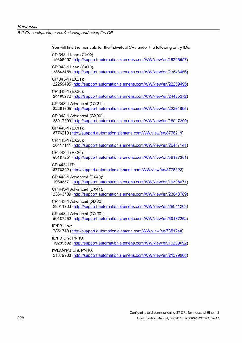
References B.2 On configuring, commissioning and using the CP
Configuring and commissioning S7 CPs for Industrial Ethernet 228 Configuration Manual, 09/2013, C79000-G8976-C182-13
You will find the manuals for the individual CPs under the following entry IDs:
CP 343-1 Lean (CX00): 19308657 (http://support.automation.siemens.com/WW/view/en/19308657)
CP 343-1 Lean (CX10): 23643456 (http://support.automation.siemens.com/WW/view/en/23643456)
CP 343-1 (EX21): 22259495 (http://support.automation.siemens.com/WW/view/en/22259495)
CP 343-1 (EX30): 24485272 (http://support.automation.siemens.com/WW/view/en/24485272)
CP 343-1 Advanced (GX21): 22261695 (http://support.automation.siemens.com/WW/view/en/22261695)
CP 343-1 Advanced (GX30): 28017299 (http://support.automation.siemens.com/WW/view/en/28017299)
CP 443-1 (EX11): 8776219 (http://support.automation.siemens.com/WW/view/en/8776219)
CP 443-1 (EX20): 26417141 (http://support.automation.siemens.com/WW/view/en/26417141)
CP 443-1 (EX30): 59187251 (http://support.automation.siemens.com/WW/view/en/59187251)
CP 443-1 IT: 8776322 (http://support.automation.siemens.com/WW/view/en/8776322)
CP 443-1 Advanced (EX40): 19308871 (http://support.automation.siemens.com/WW/view/en/19308871)
CP 443-1 Advanced (EX41): 23643789 (http://support.automation.siemens.com/WW/view/en/23643789)
CP 443-1 Advanced (GX20): 28011203 (http://support.automation.siemens.com/WW/view/en/28011203)
CP 443-1 Advanced (GX30): 59187252 (http://support.automation.siemens.com/WW/view/en/59187252)
IE/PB Link: 7851748 (http://support.automation.siemens.com/WW/view/en/7851748)
IE/PB Link PN IO: 19299692 (http://support.automation.siemens.com/WW/view/en/19299692)
IWLAN/PB Link PN IO: 21379908 (http://support.automation.siemens.com/WW/view/en/21379908)

References B.3 For configuration with STEP 7 / NCM S7
Configuring and commissioning S7 CPs for Industrial Ethernet Configuration Manual, 09/2013, C79000-G8976-C182-13 229
/2/ SIMATIC NET S7 CPs for Industrial Ethernet Configuring and Commissioning Manual Part - General Application Configuration Manual Siemens AG
(SIMATIC NET Manual Collection)
On the Internet under the following entry ID: 30374198 (http://support.automation.siemens.com/WW/view/en/30374198)
/3/ SIMATIC NET Version History/Current Downloads for the SIMATIC NET S7CPs History document Siemens AG
(SIMATIC NET Manual Collection)
On the Internet under the following entry ID: 9836605 (http://support.automation.siemens.com/WW/view/en/9836605)
B.3 For configuration with STEP 7 / NCM S7
/4/ SIMATIC NET Commissioning PC Stations - Manual and Quick Start Configuration Manual Siemens AG
(SIMATIC NET Manual Collection)
On the Internet under the following entry ID: 13542666 (http://support.automation.siemens.com/WW/view/en/13542666)
/5/ SIMATIC Configuring Hardware and Connections with STEP 7 Siemens AG Part of the documentation package "STEP 7 Basic Knowledge" (Part of the online documentation in STEP 7)

References B.4 On configuration of PROFINET CBA (components and systems)
Configuring and commissioning S7 CPs for Industrial Ethernet 230 Configuration Manual, 09/2013, C79000-G8976-C182-13
B.4 On configuration of PROFINET CBA (components and systems)
/6/ SIMATIC Component Based Automation - configuring systems with SIMATIC iMap manual Siemens AG On the Internet under the following entry ID: 18404678 (http://support.automation.siemens.com/WW/view/en/18404678)
/7/ Basic help in the engineering tool SIMATIC iMap (online help) Siemens AG
/8/ SIMATIC Component Based Automation - configuring systems with SIMATIC iMap Siemens AG On the Internet under the following entry ID: 22762190 (http://support.automation.siemens.com/WW/view/en/22762190)
/9/ You will find more detailed information on SIMATIC iMap on the Internet under the following entry ID: 10805413 (http://support.automation.siemens.com/WW/view/en/10805413)
B.5 On programming (S7 CPs / OPC)
/10/ SIMATIC NET Program blocks for SIMATIC NET S7 CPs Programming Manual Siemens AG (SIMATIC NET Manual Collection) On the Internet under the following entry ID: 30564821 (http://support.automation.siemens.com/WW/view/en/30564821)

References B.5 On programming (S7 CPs / OPC)
Configuring and commissioning S7 CPs for Industrial Ethernet Configuration Manual, 09/2013, C79000-G8976-C182-13 231
/11/ SIMATIC NET Version History of the SIMATIC NET Function Blocks and Functions for SIMATIC S7 Reference Manual Siemens AG
(SIMATIC NET Manual Collection)
On the Internet under the following entry ID: 9836605 (http://support.automation.siemens.com/WW/view/de/9836605)
/12/ SIMATIC Programming with STEP 7 Siemens AG (Part of the STEP 7 documentation package STEP 7 Basic Knowledge) (Part of the online documentation in STEP 7)
On the Internet under the following entry ID: 18652056 (http://support.automation.siemens.com/WW/view/de/18652056)
/13/ SIMATIC System and Standard Functions for S7-300/400 - Volume 1/2 Reference manual Siemens AG (Part of the STEP 7 documentation package STEP 7 Basic Knowledge) (Part of the online documentation in STEP 7)
On the Internet under the following entry ID: 1214574 (http://support.automation.siemens.com/WW/view/de/1214574)
/14/ SIMATIC NET Industrial Communication with PG/PC Volume 1 - Basics System manual Siemens AG (SIMATIC NET Manual Collection)
On the Internet under the following entry ID: 42783968 (http://support.automation.siemens.com/WW/view/de/42783968)
References B.6 SIMATIC NET Security
Configuring and commissioning S7 CPs for Industrial Ethernet 232 Configuration Manual, 09/2013, C79000-G8976-C182-13
SIMATIC NET Industrial Communication with PG/PC Volume 2 - Interfaces programming manual Siemens AG (SIMATIC NET Manual Collection)
On the Internet under the following entry ID: 42783660 (http://support.automation.siemens.com/WW/view/de/42783660)
/15/ Automatisieren mit STEP 7 in AWL und SCL (ISBN: 978-3-89578-280-0) / Automating with STEP 7 in STL and SCL (ISBN: 978-3-89578-295-4)
User manual, programming manual Berger, Hans Publicis KommunikationsAgentur GmbH, GWA, 2006
B.6 SIMATIC NET Security
/16/ SIMATIC NET Industrial Ethernet Security Basics and Application configuration manual Siemens AG
(SIMATIC NET Manual Collection)
On the Internet under the following entry ID: 56577508 (http://support.automation.siemens.com/WW/view/en/56577508)
/17/ You will find further information on IT security and on data security in industrial communication on the following Internet pages of Siemens AG: (http://www.automation.siemens.com/mcms/industrial-communication/en/ie/industrial-ethernet-security)
References B.7 S7 CPs On installing and commissioning the CP
Configuring and commissioning S7 CPs for Industrial Ethernet Configuration Manual, 09/2013, C79000-G8976-C182-13 233
B.7 S7 CPs On installing and commissioning the CP
/18/ SIMATIC S7 Automation System S7-300 Siemens AG
● CPU 31xC and 31x Installation: Operating Instructions On the Internet under the following entry ID:
13008499 (http://support.automation.siemens.com/WW/view/en/13008499)
● Module Data: Reference manual On the Internet under the following entry ID:
8859629 (http://support.automation.siemens.com/WW/view/en/8859629)
/19/ SIMATIC S7 Automation System S7-400, M7-400 Siemens AG
● Installation: Installation manual Entry ID: 1117849 (http://support.automation.siemens.com/WW/view/en/1117849)
● Module Data: Reference manual Entry ID: 1117740 (http://support.automation.siemens.com/WW/view/en/1117740)
B.8 For application and configuration of PROFINET IO
/20/ SIMATIC PROFINET System Description system manual Siemens AG (SIMATIC NET Manual Collection)

References B.9 On the IT functions of the CPs
Configuring and commissioning S7 CPs for Industrial Ethernet 234 Configuration Manual, 09/2013, C79000-G8976-C182-13
/21/ SIMATIC From PROFIBUS DP to PROFINET IO Programming manual Siemens AG (SIMATIC NET Manual Collection)
B.9 On the IT functions of the CPs
/22/ S7Beans / Applets for IT-CPs programming aid Siemens AG (SIMATIC NET Manual Collection)
On the Internet under the following entry ID: 24843906 (http://support.automation.siemens.com/WW/view/en/24843906)
B.10 On setting up and operating an Industrial Ethernet network
/28/ SIMATIC NET Industrial Ethernet - Network Manual system manual Siemens AG Entry ID: 27069465 (http://support.automation.siemens.com/WW/view/en/27069465)
/23/ SIMATIC NET Twisted-Pair and Fiber-Optic Networks Manual Siemens AG
(SIMATIC NET Manual Collection)

References B.11 SIMATIC and STEP 7 basics
Configuring and commissioning S7 CPs for Industrial Ethernet Configuration Manual, 09/2013, C79000-G8976-C182-13 235
/24/ SIMATIC NET Manual for Triaxial Networks
(SIMATIC NET Manual Collection)
B.11 SIMATIC and STEP 7 basics
/25/ CPU 31xC and CPU 31x: Technical Specifications Manual Siemens AG
On the Internet under the following entry ID: 12996906 (http://support.automation.siemens.com/WW/view/en/12996906)
/26/ Communication with SIMATIC System Manual Siemens AG
On the Internet under the following entry ID: 25074283 (http://support.automation.siemens.com/WW/view/en/25074283)
/27/ Documentation package "STEP 7 Basic Knowledge"
● Working with STEP 7 Getting Started (ID: 18652511)
● Programming with STEP 7 (ID: 18652056)
● Configuring Hardware and Connections with STEP 7 (ID: 18652631)
● From S5 to S7, Converter Manual (ID: 1118413)
Siemens AG Order number 6ES7 810-4CA08-8AW0
(part of the online documentation in STEP 7)

References B.11 SIMATIC and STEP 7 basics
Configuring and commissioning S7 CPs for Industrial Ethernet 236 Configuration Manual, 09/2013, C79000-G8976-C182-13

Configuring and commissioning S7 CPs for Industrial Ethernet Configuration Manual, 09/2013, C79000-G8976-C182-13 237
Linking to other systems with FETCH/WRITE C
The FETCH and WRITE modes supported on ISO transport connections, TCP, and ISOon-TCP connections can be used with any other device to access the S7 system memory areas.
To be able to use this type of access, for example for PC applications, you need to know the PDU structure of the jobs. The required S7 or S5 headers for request and response frames are 16 bytes long and their structure is described in this chapter.
a) Structure of WRITE frames The meaning and values of parameters shown without values in the following table can be found in the section "Parameter values".
WRITE request frame WRITE acknowledgment frame 0 System ID ="S" 0 System ID ="S" 1 ="5" 1 ="5" 2 Length of header in bytes =16d. 2 Length of header =16d. 3 ID OP code =01 3 ID OP code =01 4 Length OP code =03 4 Length OP code =03 5 OP code =03 5 OP code =04 6 ORG field =03 6 Ack field =0Fh 7 Length ORG field =08 7 Length ack field =03 8 ORG ID 8 Error field =No 9 DBNR 9 Empty field =FFh A Start address High byte A Length empty field =07 B Low byte B C Length High byte C D Low byte D free I Empty field =FFh. I F Length empty field =02 F Data field up to 64 K
a) Structure of FETCH frames The meaning and values of parameters shown without values in the following table can be found in the section "Parameter values".
FETCH request frame FETCH response frame 0 System ID ="S" 0 System ID ="S" 1 ="5" 1 ="5" 2 Length of header =0x10 2 Length of header =0x10

Linking to other systems with FETCH/WRITE
Configuring and commissioning S7 CPs for Industrial Ethernet 238 Configuration Manual, 09/2013, C79000-G8976-C182-13
3 ID OP code =0x01 3 ID OP code =0x01 4 Length OP code =0x03 4 Length OP code =0x03 5 OP code =0x05 5 OP code =0x06 6 ORG field =0x03 6 Ack field =0x0F 7 Length ORG field =0x08 7 Length ack field =0x03 8 ORG ID 8 Error field =No 9 DBNR 9 Empty field =0xFF A Start address High byte A Length empty field =0x07 B Low byte B free C Length High byte C D Low byte D I Empty field =0xFF I F Length empty field =0x02 F Data up to 64 K but only if
Error no. =0
Parameter values S7 address area DB M I A ORG ID 01H 02H 03H 04H Source/dest.
data from/to data block in main memory
Source/dest. data from/to bit memory area
Source/dest. data from/to process image of the inputs (PII)
Source/dest. data from/to process image of the outputs (PIQ)
DBNR DB, from which the source data is taken or to which the dest data is transferred
irrelevant irrelevant irrelevant
permitted range 1...255 Start address DW number
from which the data is taken or written to
Memory byte no., from which the data is taken or written to
Input byte no. from which the data is taken or written to
Output byte no., from which the data is taken or written to
permitted range 0...2047 All memory bytes made available by a CPU.
0...127 0...127
Length Length of the source/dest. data field in words
Length of the source/dest. data field in bytes
Length of the source/dest. data field in bytes
Length of the source/dest. data field in bytes
permitted range Up to 8192 bytes
Up to 8192 bytes
1...128 1...128

Linking to other systems with FETCH/WRITE
Configuring and commissioning S7 CPs for Industrial Ethernet Configuration Manual, 09/2013, C79000-G8976-C182-13 239
S7 address area
PI/PQ C T
ORG ID 05H 06H 07H Source/dest. data
from/to I/O modules. With source data input modules, with dest data output modules
Source/dest data from/to counter cells
Source/dest data from/to timer cells
DBNR irrelevant irrelevant irrelevant Start address I/O byte no., from
which the data is taken or written to
Number of the counter cell from which the data is taken or written to
Number of the timer cell from which the data is taken or written to
permitted range 0...127 digital I/O 128...255 analog I/O
0...255 0...255
Quantity Length of the source/dest. data field in bytes
Length of the source/dest. data field in words (counter cell = 1 word)
Length of the source/dest. data field in words (counter cell = 1 word)
permitted range 1...256 1 1

Linking to other systems with FETCH/WRITE
Configuring and commissioning S7 CPs for Industrial Ethernet 240 Configuration Manual, 09/2013, C79000-G8976-C182-13

Configuring and commissioning S7 CPs for Industrial Ethernet Configuration Manual, 09/2013, C79000-G8976-C182-13 241
Document history D
This section provides an overview of the previous releases of this manual.
This was new in release 10/2012 (C79000-G8900-C182-12) ● Editorial adaptations to the currently available devices and the current versions of the
configuration tools
This was new in release 03/2012 (C79000-G8900-C182-11) ● Editorial revision
Adaptation of the description of the parameter groups to match the configuration in STEP 7 V5.5 and V12.
● Technical innovations / new content
– Industrial Ethernet Security: New advanced CPs
– Expanded Web diagnostics for new CPs: Topology view, update center
– Downloading firmware via the update center in Web diagnostics on newer CPs
This was new in release 07/2010 (C79000-G8900-C182-10) ● Structural innovations in the documentation
The section "Programmed communications connections" is now in the manual./10/ (Page 230)
● Technical innovations / new content
Apart from various adaptations to the currently supplied devices and the current version of STEP 7 / NCM S7 V5.5, the following features were included:
– The information about unspecified connections relating to S7 connections was expanded in the section "Configuring communications connections".
– The previous name "S5-compatible communication" has been replaced by the name "Open communications services".
– The section "CP as Web server: HTML process control" takes into account that S7 applets can only be created by individual use of the supplied S7 beans; the CP does not provide any pre-programmed specific S7 applets.

Document history
Configuring and commissioning S7 CPs for Industrial Ethernet 242 Configuration Manual, 09/2013, C79000-G8976-C182-13

Configuring and commissioning S7 CPs for Industrial Ethernet Configuration Manual, 09/2013, C79000-G8976-C182-13 243
Index
" "IP access protection" tab, 52 "IP configuration" tab, 55 "Port parameters" tab, 61
A Access control lists, 64 Activating Web server functionality, 168 Actual topology, 188 Address parameters
Broadcast, 108 Unspecified UDP connection, 106
Advanced CP, 4 Amounts of data and configuration limits, 92 Area for making settings, 171 AS-Interface, 14
B Broadcast
with UDP, 107
C Cell protection concept, 14 Client ID (with DHCP), 56 Commissioning, 39 Communications processors; structure
for S7300, for S7400,
Configuration data Downloading to the target system, 79
Connection Properties, 92
Connection and system diagnostics, 4 Connection resources
S7-300, 36 Connector pinout
15-pin D-sub female connector, 224 RJ-45 jack, 223
CP configuration data Save, 80
CP file system - using security functions, 161
C-PLUG, 203 CSMA/CD, 13
D Data espionage, 14 Data manipulation, 14 Data packets sent, 180 Device name, 206 DHCP, 56 Diagnostic buffer, 174 Diagnostics
Special diagnostics, 21 Web diagnostics, 21
Dialog update time, 203 DNS configuration, 58 Downloading, 79 Downloading language files
Using FTP, 197 Via update center, 197
Downloads, 5 Dynamics properties, 100
E E-mail
Sending, 141 Email communication, E-mail connection, 58
Configuring, 139 E-mail DB, 142 E-mail function, 135 E-mail server, 140 Engineering station, 23 Establishing a connection to the CP, 204 Ethernet
Overview, 13 Ethernet CP
Commissioning: Procedure, 39 Further CP properties, 42 Further CP properties:Time of day, 46 Hardware configuration, 40
F Factory settings, 203 FETCH/WRITE

Index
Configuring and commissioning S7 CPs for Industrial Ethernet 244 Configuration Manual, 09/2013, C79000-G8976-C182-13
Access coordination, 4 FETCH/WRITE services
Configuring for ISO transport, 111 Overview, 18, 30
File allocation table, 58 File management and file access with FTP, 19 File system, 148 Firewall, 19, 163 Firmware Loader
Downloading firmware, 218 Field of application, 217
Flash area, 148 Flash file system, 173 FTP, 16 FTP configuration, 58
File allocation table, 58 FTP services, 4 FTP tools, 149 FTPS / FTPES, 145
G Gateway, 207 Gigabit Ethernet, 184 Glossary, 6
H Hardware diagnostics, 199 HMI, 38 HMI/monitoring devices, 24 HTML pages, 162 HTML process control
TCP port to be opened, 163 HTML process control / Web diagnostics, 18 HTML process control using HTTPS, 19 HTML process control with Web browser, 16 HTTPS, 66
I Industrial Ethernet, 205
Overview, 13 Industrial Ethernet; user interface to, IP (Internet Protocol), 29 IP access protection
IP access control list, 53 IP addressing using DHCP, 95 IP configuration, 4 IP parameters, 179 IP-ACL (IP access control list), 52
IPsec tunnel, 19 IRT, 116 ISO transport connection, 29
CPU cycle, 87 Dynamics properties, 100
ISO-on-TCP connection, 29 Addresses,
J JavaBeans concept, 162
L Language file and language setting, 172 Language selection, 196 Link status, 179 Logging via the Syslog server, 19
M Manual Collection, 5 Manual Part A, 4 Media redundancy, 180, 185 Memory reset, 202 Menu command, 202 Module
Identify, 195 Module access protection, 173, 195, 220 Module certificate, 174 Module replacement
S7-300, 35 S7-400, 37
Module replacement - display of the Web pages, 167 MPI, 205 Multicast
with UDP, 107, 108 Multicast circle, 108 Multicast group, 108 Multicomputing
S7-300, 35 S7-400, 37
N NCM S7 Diagnostics, Network access, 14

Index
Configuring and commissioning S7 CPs for Industrial Ethernet Configuration Manual, 09/2013, C79000-G8976-C182-13 245
O Online path, 204 OP mode, 21 OPC server
Using as SMTP server, 140 Open communications services, 4, 16
P PC internal, 209 PG communication, 21
in configured mode, 23 in PG mode, 23 with STEP 7 via Ind. Ethernet, 23
PG mode with STEP 7 via Ethernet, 21
PG/OP communication, 16 PG/PC Interface, 24 Ports, 163 Possibilities for communication between device types, 20 PROFIBUS, 14, 205 PROFINET CBA, 16 PROFINET communication, 18 PROFINET IO
Overview, 18 PROFINET IO controller, 63, 115 PROFINET IO device
Intelligent, 121 PROFINET IO domain management, 116 PROFINET IO systems, 178 Program block versions, 5 Program blocks
AG_SEND / AG_RECV, 85 AG-RECV, 83 AG-SEND, 83
Programmed communication connections, 21 Programmed connections and IP configuration, 4 Protection level, 173
Q Quick Start CD, 5
R Rack configuration / subsystem configuration, 177 RAM area, 148, 173 Received data packets, 180
S S5S5 connections, 28 S7 beans, 161 S7 communication, 16 S7 communication via Ethernet, 24 S7 communications relay, 24 S7 connections
S7-400, 38 SCT online diagnostics, 199 Security, 64, 66, 187
Enable security, 64 Reloading firewall rules, 64
Security Configuration Tool, 14 Security CP, 4 Security functionality, 17 SEND/RECEIVE interface, 29
Data exchange, 83 Overview, 28 User program, 85
Sending a test e-mail in the "SMTP" tab, 183 Shared device, 178 SIMATIC NET, 14 SIMATIC NET glossary, 6 SIMATIC NET Manual Collection, 5 Simultaneous operation
of CPs; S7-300, of CPs; S7-400,
Slots S7-300, 35 S7-400, 36
SNMP, 61 Configuration, 61
SNMP agent, 61 SNMPv1, 61 SNMPv3, 19, 61 Special diagnostics, 199
Overview, 199 Standard Ethernet, 184 Starting, 202 Statistics of the S7 connections, 184 STEP 7, 21 STEP 7 special diagnostics, Stopping, 202 Sync domain, 116 System memory
Access using FETCH/WRITE, 113
T Target topology, 188 TCP connection, 29

Index
Configuring and commissioning S7 CPs for Industrial Ethernet 246 Configuration Manual, 09/2013, C79000-G8976-C182-13
Addresses, 103 TCP/IP, 205 Test e-mail
User rights, 183 Time-of-day synchronization and transfer using NTP (secure), 19 Topology, 177 Topology display, 177 Topology editor, 116
U UDP, 28 UDP connection, 29
Addresses, 105 Unspecified connection, 94 Update cyclically, 203 User management, 57
Advanced, 61
V Version history, 5 Volatile RAM file system ( /ram ), 173
W Web diagnostics, 167
"Access control list" tab, 195 "Diagnostics messages" tab, 196 "Firmware" tab, 194 "ISO Transport", "ISO-on-TCP", "TCP", "UDP", "SMTP" tabs, 182 Access using STEP 7 (STEP 7 Professional), 170 Access using STEP 7 (STEP 7 V5.5), 170 Content area, 172 Direct access using the Web browser, 169 Industrial Ethernet - "Parameters" tab, 179 Industrial Ethernet - "Statistics" tab, 180 Industrial Ethernet - "UDP Connections" tab, 181 IP Access protection - "Configured IP addresses" tab, 186 IP access protection - "Times denied access" tab, 186 Layout of the diagnostics pages, 171 Module status - "Identification" tab, 178 Module status - "Status" tab, 178 Navigation area, 172 S7 communication - "ISO Transport", "ISO-on-TCP" tab, 184 Security enabled, 168
Startup and operation, 169 Topology, 187 Topology - "Graphic view" tab, 189 Topology - "Status overview" tab, 194 Topology - "Table view" tab, 192