configuration guide - ip routing(v100r002c00 04)
TRANSCRIPT

Quidway S9300 Terabit Routing Switch
V100R002C00
Configuration Guide - IP Routing
Issue 04
Date 2010-01-08
Huawei Proprietary and ConfidentialCopyright © Huawei Technologies Co., Ltd.

Huawei Technologies Co., Ltd. provides customers with comprehensive technical support and service. For anyassistance, please contact our local office or company headquarters.
Huawei Technologies Co., Ltd.Address: Huawei Industrial Base
Bantian, LonggangShenzhen 518129People's Republic of China
Website: http://www.huawei.com
Email: [email protected]
Copyright © Huawei Technologies Co., Ltd. 2010. All rights reserved.No part of this document may be reproduced or transmitted in any form or by any means without prior writtenconsent of Huawei Technologies Co., Ltd. Trademarks and Permissions
and other Huawei trademarks are the property of Huawei Technologies Co., Ltd.All other trademarks and trade names mentioned in this document are the property of their respective holders. NoticeThe purchased products, services and features are stipulated by the contract made between Huawei and thecustomer. All or part of the products, services and features described in this document may not be within thepurchase scope or the usage scope. Unless otherwise specified in the contract, all statements, information,and recommendations in this document are provided "AS IS" without warranties, guarantees or representationsof any kind, either express or implied.
The information in this document is subject to change without notice. Every effort has been made in thepreparation of this document to ensure accuracy of the contents, but all statements, information, andrecommendations in this document do not constitute the warranty of any kind, express or implied.
Huawei Proprietary and ConfidentialCopyright © Huawei Technologies Co., Ltd.
Contents
About This Document.....................................................................................................................1
1 Static Route Configuration.......................................................................................................1-11.1 Introduction to Static Routes...........................................................................................................................1-21.2 Static Route Features Supported by the S9300...............................................................................................1-31.3 S9300 Interfaces That Support Static Routes..................................................................................................1-31.4 Configuring an IPv4 Static Route...................................................................................................................1-3
1.4.1 Establishing the Configuration Task......................................................................................................1-41.4.2 Configuring an IPv4 Static Route..........................................................................................................1-41.4.3 (Optional) Setting the Default Priority of an IPv4 Static Route............................................................1-51.4.4 (Optional) Configuring Static Route Selection Based on Relay Depth.................................................1-51.4.5 Checking the Configuration...................................................................................................................1-6
1.5 Configuring an IPv6 Static Route...................................................................................................................1-61.5.1 Establishing the Configuration Task......................................................................................................1-71.5.2 Configuring an IPv6 Static Route..........................................................................................................1-71.5.3 (Optional) Configuring the Default Preference of the IPv6 Static Route..............................................1-81.5.4 Checking the Configuration...................................................................................................................1-8
1.6 Configuring BFD for Static Routes.................................................................................................................1-81.6.1 Establishing the Configuration Task......................................................................................................1-91.6.2 Configuring a Static Route.....................................................................................................................1-91.6.3 Configuring a BFD Session..................................................................................................................1-101.6.4 Binding a Static Route to a BFD Session.............................................................................................1-101.6.5 Checking the Configuration.................................................................................................................1-11
1.7 Configuration Examples................................................................................................................................1-111.7.1 Example for Configuring IPv4 Static Routes.......................................................................................1-111.7.2 Example for Configuring IPv6 Static Routes.......................................................................................1-151.7.3 Example for Configuring BFD for IPv4 Static Routes........................................................................1-20
2 RIP Configuration......................................................................................................................2-12.1 Introduction to RIP..........................................................................................................................................2-32.2 RIP Features Supported by the S9300.............................................................................................................2-32.3 Configuring Basic RIP Functions...................................................................................................................2-3
2.3.1 Establishing the Configuration Task......................................................................................................2-42.3.2 Enabling RIP..........................................................................................................................................2-4
Quidway S9300 Terabit Routing SwitchConfiguration Guide - IP Routing Contents
Issue 04 (2010-01-08) Huawei Proprietary and ConfidentialCopyright © Huawei Technologies Co., Ltd.
i

2.3.3 Enabling RIP on a Specified Network Segment....................................................................................2-52.3.4 (Optional) Specifying the RIP Version..................................................................................................2-62.3.5 Checking the Configuration...................................................................................................................2-6
2.4 Configuring RIP Route Attributes...................................................................................................................2-72.4.1 Establishing the Configuration Task......................................................................................................2-82.4.2 Setting the Additional Metric of an Interface.........................................................................................2-82.4.3 Setting the Preference of RIP.................................................................................................................2-92.4.4 Setting the Maximum Number of Equal-Cost Routes...........................................................................2-92.4.5 Checking the Configuration.................................................................................................................2-10
2.5 Controlling the Advertisement of RIP Routing Information........................................................................2-102.5.1 Establishing the Configuration Task....................................................................................................2-112.5.2 Advertising a Default Route.................................................................................................................2-112.5.3 Disabling an Interface from Sending RIP Update Packets...................................................................2-122.5.4 Configuring RIP to Import Routes.......................................................................................................2-132.5.5 Checking the Configuration.................................................................................................................2-14
2.6 Controlling Received RIP Routing Information...........................................................................................2-142.6.1 Establishing the Configuration Task....................................................................................................2-142.6.2 Disabling an Interface from Receiving RIP Update Packets...............................................................2-152.6.3 Configuring RIP to Deny Host Routes.................................................................................................2-162.6.4 Configuring RIP to Filter Received Routes.........................................................................................2-162.6.5 Checking the Configuration.................................................................................................................2-17
2.7 Configuring RIPv2 Features..........................................................................................................................2-172.7.1 Establishing the Configuration Task....................................................................................................2-182.7.2 Configuring Route Aggregation of RIPv2...........................................................................................2-182.7.3 Setting the Authentication Mode of RIPv2 Packets.............................................................................2-192.7.4 Checking the Configuration.................................................................................................................2-20
2.8 Adjusting and Optimizing the RIP Network.................................................................................................2-202.8.1 Establishing the Configuration Task....................................................................................................2-212.8.2 Configuring RIP Timers.......................................................................................................................2-212.8.3 Setting the Interval of Update Packets and Maximum Number of Packets Sent at a Time.................2-232.8.4 Configuring Split Horizon and Poison Reverse...................................................................................2-232.8.5 Configuring RIP to Check the Validity of Update Packets..................................................................2-242.8.6 Configuring a RIP Neighbor................................................................................................................2-252.8.7 Checking the Configuration.................................................................................................................2-25
2.9 Configuring the Network Management Function of RIP..............................................................................2-262.9.1 Establishing the Configuration Task....................................................................................................2-262.9.2 Binding a RIP Process to the MIB.......................................................................................................2-262.9.3 Checking the Configuration.................................................................................................................2-27
2.10 Maintaining RIP..........................................................................................................................................2-272.11 Configuration Examples..............................................................................................................................2-28
2.11.1 Example for Configuring the RIP Version.........................................................................................2-282.11.2 Example for Configuring RIP to Import Routes................................................................................2-32
ContentsQuidway S9300 Terabit Routing Switch
Configuration Guide - IP Routing
ii Huawei Proprietary and ConfidentialCopyright © Huawei Technologies Co., Ltd.
Issue 04 (2010-01-08)

3 RIPng Configuration.................................................................................................................3-13.1 RIPng Overview..............................................................................................................................................3-23.2 Features Supported by the S9300....................................................................................................................3-33.3 Configuring Basic RIPng Functions...............................................................................................................3-3
3.3.1 Establishing the Configuration Task......................................................................................................3-33.3.2 Enabling RIPng and Entering the RIPng View......................................................................................3-43.3.3 Enabling RIPng in the Interface View...................................................................................................3-43.3.4 Checking the Configuration...................................................................................................................3-5
3.4 Configuring RIPng Route Attributes...............................................................................................................3-63.4.1 Establishing the Configuration Task......................................................................................................3-63.4.2 Configuring RIPng Protocol Preference................................................................................................3-73.4.3 Configuring Additional Metrics of an Interface.....................................................................................3-73.4.4 Configuring the Maximum Number of Equal-Cost Routes...................................................................3-83.4.5 Checking the Configuration...................................................................................................................3-8
3.5 Controlling the Advertising of RIPng Routing Information...........................................................................3-83.5.1 Establishing the Configuration Task......................................................................................................3-93.5.2 Configuring RIPng Route Aggregation..................................................................................................3-93.5.3 Configuring RIPng to Advertise the Default Routes...........................................................................3-103.5.4 Configuring the Default Cost for External Routes Imported by RIPng...............................................3-113.5.5 Configuring RIPng to Import External Routes....................................................................................3-113.5.6 Checking the Configuration.................................................................................................................3-12
3.6 Controlling the Receiving of RIPng Routing Information............................................................................3-123.6.1 Establishing the Configuration Task....................................................................................................3-123.6.2 Configuring RIPng to Filter the Received Routes...............................................................................3-133.6.3 Checking the Configuration.................................................................................................................3-13
3.7 Optimizing a RIPng Network........................................................................................................................3-143.7.1 Establishing the Configuration Task....................................................................................................3-143.7.2 Configuring RIPng Timers...................................................................................................................3-143.7.3 Configuring Split Horizon and Poison Reverse...................................................................................3-153.7.4 Enabling Zero Field Check of the RIPng Packets................................................................................3-163.7.5 Checking the Configuration.................................................................................................................3-16
3.8 Maintaining RIPng........................................................................................................................................3-163.9 Configuration Examples................................................................................................................................3-17
3.9.1 Example for Configuring RIPng to Filter the Received Routes...........................................................3-17
4 OSPF Configuration..................................................................................................................4-14.1 Introduction to OSPF......................................................................................................................................4-34.2 OSPF Features Supported by the S9300.........................................................................................................4-64.3 Configuring Basic OSPF Functions................................................................................................................4-8
4.3.1 Establishing the Configuration Task......................................................................................................4-84.3.2 Starting an OSPF Process and Entering the OSPF View.......................................................................4-94.3.3 Configuring a Network Segment That Belongs to an Area..................................................................4-104.3.4 Checking the Configuration.................................................................................................................4-11
Quidway S9300 Terabit Routing SwitchConfiguration Guide - IP Routing Contents
Issue 04 (2010-01-08) Huawei Proprietary and ConfidentialCopyright © Huawei Technologies Co., Ltd.
iii

4.4 Establishing and Maintaining OSPF Adjacencies.........................................................................................4-114.4.1 Establishing the Configuration Task....................................................................................................4-124.4.2 Setting the Interval for Sending Hello Packets on an Interface...........................................................4-134.4.3 Setting the Dead Interval of Neighbors................................................................................................4-134.4.4 Setting the Interval for Retransmitting LSAs.......................................................................................4-144.4.5 Restricting Retransmission of OSPF Packets.......................................................................................4-154.4.6 Suppressing OSPF Packets on an Interface..........................................................................................4-154.4.7 Checking the Configuration.................................................................................................................4-16
4.5 Configuring OSPF Area Attributes...............................................................................................................4-174.5.1 Establishing the Configuration Task....................................................................................................4-174.5.2 Configuring an OSPF Stub Area..........................................................................................................4-184.5.3 Configuring an NSSA Area..................................................................................................................4-184.5.4 Configuring an OSPF Virtual Link......................................................................................................4-194.5.5 Checking the Configuration.................................................................................................................4-20
4.6 Configuring OSPF Attributes on Networks of Different Types...................................................................4-214.6.1 Establishing the Configuration Task....................................................................................................4-214.6.2 Setting the Network Type of an OSPF Interface..................................................................................4-224.6.3 (Optional) Setting the DR Priority of an OSPF Interface....................................................................4-224.6.4 Specifying a Neighbor for an NBMA Network...................................................................................4-234.6.5 (Optional) Setting the Interval for Sending Polling Packets on the NBMA Network.........................4-234.6.6 Checking the Configuration.................................................................................................................4-24
4.7 Configuring OSPF Route Attributes.............................................................................................................4-254.7.1 Establishing the Configuration Task....................................................................................................4-254.7.2 Setting the Link Cost of an OSPF Interface.........................................................................................4-264.7.3 Setting the Preference of OSPF............................................................................................................4-274.7.4 Setting the Maximum Number of Equal-Cost Routes.........................................................................4-274.7.5 Checking the Configuration.................................................................................................................4-28
4.8 Configuring OSPF Route Aggregation.........................................................................................................4-284.8.1 Establishing the Configuration Task....................................................................................................4-294.8.2 Configuring Route Aggregation on the ABR.......................................................................................4-294.8.3 Configuring Route Aggregation on the ASBR....................................................................................4-304.8.4 Checking the Configuration.................................................................................................................4-30
4.9 Configuring Filtering of OSPF Routing Information....................................................................................4-314.9.1 Establishing the Configuration Task....................................................................................................4-314.9.2 Configuring the ABR to Filter Type 3 LSAs.......................................................................................4-324.9.3 Configuring OSPF to Filter Received Routes......................................................................................4-334.9.4 Configuring OSPF to Import External Routes.....................................................................................4-334.9.5 Checking the Configuration.................................................................................................................4-35
4.10 Adjusting and Optimizing the OSPF Network............................................................................................4-354.10.1 Establishing the Configuration Task..................................................................................................4-364.10.2 Setting the Delay for Transmitting LSAs on an Interface..................................................................4-374.10.3 Setting the Interval for Updating and Receiving LSAs......................................................................4-37
ContentsQuidway S9300 Terabit Routing Switch
Configuration Guide - IP Routing
iv Huawei Proprietary and ConfidentialCopyright © Huawei Technologies Co., Ltd.
Issue 04 (2010-01-08)

4.10.4 Setting the Interval of the SPF Calculation........................................................................................4-384.10.5 Configuring a Stub Router.................................................................................................................4-394.10.6 Enabling an Interface to Add the Actual MTU in DD Packets..........................................................4-404.10.7 Setting the Maximum Number of External LSAs in an LSDB..........................................................4-404.10.8 Configuring OSPF to Be Compatible with the Route Selection Rule of RFC 1583..........................4-414.10.9 Checking the Configuration...............................................................................................................4-41
4.11 Configuring OSPF GR................................................................................................................................4-424.11.1 Establishing the Configuration Task..................................................................................................4-434.11.2 Enabling the Opaque-LSA Capability of OSPF.................................................................................4-434.11.3 Enabling OSPF GR............................................................................................................................4-444.11.4 (Optional) Setting Session Parameters of GR on the Restarter..........................................................4-444.11.5 (Optional) Setting Session Parameters of GR on the Helper.............................................................4-454.11.6 (Optional) Configuring the S9300 Not to Work in Helper Mode......................................................4-464.11.7 Checking the Configuration...............................................................................................................4-46
4.12 Configuring BFD for OSPF........................................................................................................................4-474.12.1 Establishing the Configuration Task..................................................................................................4-474.12.2 Configuring Global BFD....................................................................................................................4-484.12.3 Configuring BFD for OSPF...............................................................................................................4-484.12.4 Disabling an Interface from Dynamically Creating BFD Sessions....................................................4-494.12.5 Configuring the BFD Feature for a Specified Interface.....................................................................4-494.12.6 Checking the Configuration...............................................................................................................4-50
4.13 Configuring the Authentication Function on an OSPF Network................................................................4-514.13.1 Establishing the Configuration Task..................................................................................................4-514.13.2 Configuring the Area Authentication Mode.......................................................................................4-514.13.3 Configuring the Interface Authentication Mode................................................................................4-524.13.4 Checking the Configuration...............................................................................................................4-53
4.14 Configuring Network Management Functions of OSPF.............................................................................4-544.14.1 Establishing the Configuration Task..................................................................................................4-544.14.2 Binding an OSPF Process to the MIB................................................................................................4-544.14.3 Configuring OSPF to Send Trap Messages........................................................................................4-554.14.4 Enabling OSPF to Record Logs.........................................................................................................4-554.14.5 Checking the Configuration...............................................................................................................4-56
4.15 Maintaining OSPF.......................................................................................................................................4-574.15.1 Restarting an OSPF Process...............................................................................................................4-574.15.2 Clearing OSPF Information...............................................................................................................4-574.15.3 Debugging OSPF................................................................................................................................4-58
4.16 Configuration Examples..............................................................................................................................4-584.16.1 Configuring Basic OSPF Functions...................................................................................................4-594.16.2 Example for Configuring an OSPF Stub Area...................................................................................4-654.16.3 Example for Configuring an NSSA Area...........................................................................................4-714.16.4 Example for Configuring DR Election of OSPF................................................................................4-754.16.5 Example for Configuring an OSPF virtual link.................................................................................4-81
Quidway S9300 Terabit Routing SwitchConfiguration Guide - IP Routing Contents
Issue 04 (2010-01-08) Huawei Proprietary and ConfidentialCopyright © Huawei Technologies Co., Ltd.
v

4.16.6 Example for Configuring Load Balancing Among OSPF Routes.....................................................4-854.16.7 Example for Configuring OSPF GR..................................................................................................4-904.16.8 Example for Configuring BFD for OSPF..........................................................................................4-93
5 OSPFv3 Configuration..............................................................................................................5-15.1 OSPFv3........................................................................................................................................................... 5-35.2 OSPFv3 Features Supported by S9300...........................................................................................................5-35.3 Configuring Basic OSPFv3 Functions............................................................................................................5-4
5.3.1 Establishing the Configuration Task......................................................................................................5-45.3.2 Enabling OSPFv3...................................................................................................................................5-45.3.3 Enabling OSPFv3 on an Interface..........................................................................................................5-55.3.4 Entering the OSPFv3 Area View...........................................................................................................5-65.3.5 Checking the Configuration...................................................................................................................5-6
5.4 Establishing or Maintaining OSPFv3 Neighbor Relationship........................................................................ 5-75.4.1 Establishing the Configuration Task......................................................................................................5-75.4.2 Configuring the Interval for Sending Hello Packets..............................................................................5-85.4.3 Configuring Dead Time of Neighbor Relationship................................................................................5-85.4.4 Configuring the Interval for Retransmitting LSAs to Neighboring S9300s.......................................... 5-95.4.5 Configuring the Delay for Transmitting LSAs on the Interface..........................................................5-105.4.6 Checking the Configuration.................................................................................................................5-10
5.5 Configuring OSPFv3 Areas..........................................................................................................................5-105.5.1 Establishing the Configuration Task....................................................................................................5-115.5.2 Configuring OSPFv3 Stub Areas.........................................................................................................5-115.5.3 Configuring OSPFv3 Virtual Links.....................................................................................................5-125.5.4 Checking the Configuration.................................................................................................................5-12
5.6 Configuring OSPFv3 Route Attributes.........................................................................................................5-135.6.1 Establishing the Configuration Task....................................................................................................5-135.6.2 Setting the Cost of the OSPFv3 Interface............................................................................................5-145.6.3 Setting the Maximum Number of Equal-Cost Routes.........................................................................5-145.6.4 Checking the Configuration.................................................................................................................5-15
5.7 Controlling OSPFv3 Routing Information....................................................................................................5-155.7.1 Establishing the Configuration Task....................................................................................................5-155.7.2 Configuring OSPFv3 Route Aggregation............................................................................................5-165.7.3 Configuring OSPFv3 to Filter the Received Routes............................................................................5-175.7.4 Configuring OSPFv3 to Import External Routes.................................................................................5-175.7.5 Checking the Configuration.................................................................................................................5-18
5.8 Optimizing an OSPF Network......................................................................................................................5-195.8.1 Establishing the Configuration Task....................................................................................................5-195.8.2 Configuring the SPF Timer..................................................................................................................5-205.8.3 Suppressing an Interface from Sending and Receiving OSPFv3 Packets............................................5-205.8.4 Configuring DR Priority of an Interface..............................................................................................5-215.8.5 Configuring Stub Routers.....................................................................................................................5-225.8.6 Ignoring MTU Check on DD Packets..................................................................................................5-22
ContentsQuidway S9300 Terabit Routing Switch
Configuration Guide - IP Routing
vi Huawei Proprietary and ConfidentialCopyright © Huawei Technologies Co., Ltd.
Issue 04 (2010-01-08)

5.8.7 Checking the Configuration.................................................................................................................5-235.9 Configuring OSPFv3 GR..............................................................................................................................5-23
5.9.1 Establishing the Configuration Task....................................................................................................5-235.9.2 Enabling OSPFv3 GR..........................................................................................................................5-245.9.3 Enabling the Helper of OSPFv3 Helper...............................................................................................5-245.9.4 Check the Configuration......................................................................................................................5-25
5.10 Maintaining OSPFv3...................................................................................................................................5-255.10.1 Resetting OSPFv3..............................................................................................................................5-265.10.2 Debugging OSPFv3............................................................................................................................5-26
5.11 Configuration Examples..............................................................................................................................5-275.11.1 Example for Configuring OSPFv3 Areas...........................................................................................5-275.11.2 Example for Configuring DR Election Through OSPFv3.................................................................5-335.11.3 Example for Configuring the OSPFv3 Virtual Link..........................................................................5-385.11.4 Example for Configuring OSPFv3 GR..............................................................................................5-42
6 IS-IS Configuration...................................................................................................................6-16.1 Concepts of IS-IS............................................................................................................................................6-36.2 IS-IS Features Supported by the S9300..........................................................................................................6-46.3 Configuring Basic IS-IS Functions.................................................................................................................6-9
6.3.1 Establishing the Configuration Task......................................................................................................6-96.3.2 Starting an IS-IS Process......................................................................................................................6-106.3.3 Configuring a NET...............................................................................................................................6-106.3.4 (Optional) Setting the Level of the S9300...........................................................................................6-116.3.5 Enabling an IS-IS Process on an Interface...........................................................................................6-126.3.6 Checking the Configuration.................................................................................................................6-12
6.4 Establishing and Maintaining IS-IS Adjacencies..........................................................................................6-136.4.1 Establishing the Configuration Task....................................................................................................6-136.4.2 (Optional) Setting Timers of IS-IS Packets..........................................................................................6-146.4.3 Setting LSP Parameters........................................................................................................................6-166.4.4 (Optional) Disabling the Padding of Hello Packets on an Interface....................................................6-196.4.5 Checking the Configuration.................................................................................................................6-20
6.5 Configuring IS-IS Attributes on Networks of Different Types.....................................................................6-216.5.1 Establishing the Configuration Task....................................................................................................6-216.5.2 Setting the Network Type of an IS-IS Interface...................................................................................6-226.5.3 (Optional) Setting the DIS Priority of an Interface..............................................................................6-226.5.4 Setting the Neighbor Relationship Negotiation Mode on P2P Links...................................................6-236.5.5 Configuring an IS-IS Interface Not to Check IP Addresses of the Received Hello Packets...............6-246.5.6 Checking the Configuration.................................................................................................................6-24
6.6 Setting the Attributes of IS-IS Routes...........................................................................................................6-256.6.1 Establishing the Configuration Task....................................................................................................6-256.6.2 Setting the Cost of an IS-IS Interface...................................................................................................6-266.6.3 Setting the Preference of IS-IS.............................................................................................................6-286.6.4 Checking the Configuration.................................................................................................................6-30
Quidway S9300 Terabit Routing SwitchConfiguration Guide - IP Routing Contents
Issue 04 (2010-01-08) Huawei Proprietary and ConfidentialCopyright © Huawei Technologies Co., Ltd.
vii

6.7 Controlling the Advertisement of IS-IS Routing Information......................................................................6-316.7.1 Establishing the Configuration Task....................................................................................................6-316.7.2 Configuring IS-IS Route Aggregation.................................................................................................6-326.7.3 Configuring IS-IS to Generate Default Routes....................................................................................6-326.7.4 Configuring IS-IS Route Leaking (Controlling Level-2 Routes Imported to Level-1 Areas).............6-336.7.5 Configuring IS-IS Route Leaking (Controlling Level-1 Routes Imported to Level-2 Areas).............6-336.7.6 Checking the Configuration.................................................................................................................6-34
6.8 Controlling the Received IS-IS Routing Information...................................................................................6-356.8.1 Establishing the Configuration Task....................................................................................................6-356.8.2 Configuring IS-IS to Filter the Received Routing Information...........................................................6-366.8.3 Configuring IS-IS to Import External Routes......................................................................................6-366.8.4 Checking the Configuration.................................................................................................................6-37
6.9 Adjusting and Optimizing the IS-IS Network...............................................................................................6-376.9.1 Establishing the Configuration Task....................................................................................................6-386.9.2 (Optional) Setting the Level of an IS-IS Interface...............................................................................6-386.9.3 Suppressing an IS-IS Interface.............................................................................................................6-396.9.4 Setting SPF Parameters........................................................................................................................6-406.9.5 Enabling LSP Fast Flooding................................................................................................................6-416.9.6 Configuring IS-IS Dynamic Host Name Mapping...............................................................................6-416.9.7 Configuring the LSP Overload Bit.......................................................................................................6-436.9.8 Enabling Output of the Adjacency Status............................................................................................6-436.9.9 Checking the Configuration.................................................................................................................6-44
6.10 Configuring IS-IS GR.................................................................................................................................6-446.10.1 Establishing the Configuration Task..................................................................................................6-456.10.2 Enabling IS-IS GR.............................................................................................................................6-456.10.3 Setting Parameters of an IS-IS GR Session.......................................................................................6-466.10.4 Checking the Configuration...............................................................................................................6-47
6.11 Configuring BFD for IS-IS.........................................................................................................................6-476.11.1 Establishing the Configuration Task..................................................................................................6-486.11.2 Configuring Single-Hop BFD............................................................................................................6-486.11.3 Enabling IS-IS Fast Detection............................................................................................................6-496.11.4 Enabling the BFD Feature Globally...................................................................................................6-506.11.5 Configuring Dynamic BFD of an IS-IS Process................................................................................6-506.11.6 Disabling Dynamic Creation of BFD Sessions..................................................................................6-516.11.7 Configuring the BFD Feature for a Specified Interface.....................................................................6-526.11.8 Checking the Configuration...............................................................................................................6-52
6.12 Configuring IS-IS IPv6...............................................................................................................................6-536.12.1 Establishing the Configuration Task..................................................................................................6-536.12.2 Enabling IPv6 on an IS-IS Process....................................................................................................6-546.12.3 Enabling IPv6 on an IS-IS Interface..................................................................................................6-546.12.4 Configuring the IPv6 Route Cost on an Interface..............................................................................6-556.12.5 Configuring the Attributes of IS-IS IPv6 Routes...............................................................................6-55
ContentsQuidway S9300 Terabit Routing Switch
Configuration Guide - IP Routing
viii Huawei Proprietary and ConfidentialCopyright © Huawei Technologies Co., Ltd.
Issue 04 (2010-01-08)

6.12.6 Checking the Configuration...............................................................................................................6-586.13 Configuring IS-IS Authentication...............................................................................................................6-59
6.13.1 Establishing the Configuration Task..................................................................................................6-596.13.2 Configuring Area Authentication and Routing Domain Authentication............................................6-596.13.3 Configuring the Interface Authentication...........................................................................................6-606.13.4 Checking the Configuration...............................................................................................................6-61
6.14 Maintaining IS-IS........................................................................................................................................6-616.14.1 Clearing Data of an IS-IS Process......................................................................................................6-616.14.2 Resetting a Specific IS-IS Neighbor..................................................................................................6-626.14.3 Debugging IS-IS.................................................................................................................................6-62
6.15 Configuration Examples..............................................................................................................................6-646.15.1 Example for Configuring Basic IS-IS Functions...............................................................................6-646.15.2 Example for Configuring IS-IS Route Aggregation..........................................................................6-716.15.3 Example for Configuring the DIS Election........................................................................................6-756.15.4 Example for Configuring IS-IS Load Balancing................................................................................6-806.15.5 Example for Configuring IS-IS GR...................................................................................................6-866.15.6 Example for Configuring BFD for IS-IS............................................................................................6-896.15.7 Example for Configuring Basic IS-IS IPv6 Functions.......................................................................6-96
7 BGP Configuration....................................................................................................................7-17.1 Introduction to BGP........................................................................................................................................7-37.2 BGP Features Supported by the S9300...........................................................................................................7-37.3 Configuring Basic BGP Functions..................................................................................................................7-8
7.3.1 Establishing the Configuration Task......................................................................................................7-87.3.2 Starting a BGP Process.......................................................................................................................... 7-97.3.3 Configuring a BGP Peer.......................................................................................................................7-107.3.4 (Optional) Configuring a Local Interface for a BGP Connection........................................................7-117.3.5 Checking the Configuration.................................................................................................................7-12
7.4 Configuring BGP Route Attributes...............................................................................................................7-127.4.1 Establishing the Configuration Task....................................................................................................7-137.4.2 Setting the Preference of BGP.............................................................................................................7-147.4.3 Setting the PrefVal for BGP Routes.....................................................................................................7-147.4.4 Setting the Default Local_Pref for the Local Device...........................................................................7-157.4.5 Setting the MED...................................................................................................................................7-157.4.6 Configuring the Next_Hop...................................................................................................................7-177.4.7 Setting the AS_Path.............................................................................................................................7-197.4.8 Checking the Configuration.................................................................................................................7-20
7.5 Configuring BGP Filters...............................................................................................................................7-217.5.1 Establishing the Configuration Task....................................................................................................7-217.5.2 Configuring a Policy for Advertising BGP Routes..............................................................................7-227.5.3 Configuring a Policy for Receiving BGP Routes.................................................................................7-247.5.4 Configuring BGP Soft Resetting..........................................................................................................7-267.5.5 Checking the Configuration.................................................................................................................7-27
Quidway S9300 Terabit Routing SwitchConfiguration Guide - IP Routing Contents
Issue 04 (2010-01-08) Huawei Proprietary and ConfidentialCopyright © Huawei Technologies Co., Ltd.
ix

7.6 Controlling Advertisement of BGP Routes...................................................................................................7-287.6.1 Establishing the Configuration Task....................................................................................................7-287.6.2 Configuring BGP to Advertise Local Routes.......................................................................................7-297.6.3 Configuring BGP Route Aggregation..................................................................................................7-297.6.4 Configuring BGP to Advertise Default Routes to the Peers................................................................7-307.6.5 Configuring Split Horizon Between EBGP Peers................................................................................7-317.6.6 Checking the Configuration.................................................................................................................7-31
7.7 Controlling Routes Imported by BGP...........................................................................................................7-327.7.1 Establishing the Configuration Task....................................................................................................7-327.7.2 Configuring BGP to Import Default Routes........................................................................................7-327.7.3 Configuring BGP to Import Protocol Routes.......................................................................................7-337.7.4 Checking the Configuration.................................................................................................................7-33
7.8 Configuring BGP Route Dampening............................................................................................................7-347.8.1 Establishing the Configuration Task....................................................................................................7-347.8.2 Configuring BGP Route Dampening...................................................................................................7-357.8.3 Checking the Configuration.................................................................................................................7-35
7.9 Setting Parameters of a BGP Connection.....................................................................................................7-367.9.1 Establishing the Configuration Task....................................................................................................7-367.9.2 Configuring BGP Timers.....................................................................................................................7-377.9.3 Setting the Interval for Sending Update Packets..................................................................................7-387.9.4 Enabling Fast Resetting for EBGP Connections..................................................................................7-387.9.5 Checking the Configuration.................................................................................................................7-39
7.10 Configuring BFD for BGP..........................................................................................................................7-397.10.1 Establishing the Configuration Task..................................................................................................7-397.10.2 Configuring BFD for BGP on a Public Network...............................................................................7-407.10.3 Configuring BFD for BGP on a Private Network..............................................................................7-417.10.4 Preventing a Peer from Inheriting BFD of Its Peer Group.................................................................7-417.10.5 Checking the Configuration...............................................................................................................7-42
7.11 Configuring BGP Load Balancing..............................................................................................................7-427.11.1 Establishing the Configuration Task..................................................................................................7-437.11.2 Setting the Number of Routes for Load Balancing............................................................................7-437.11.3 Checking the Configuration...............................................................................................................7-44
7.12 Configuring a BGP Peer Group..................................................................................................................7-447.12.1 Establishing the Configuration Task..................................................................................................7-447.12.2 Creating an IBGP Peer Group............................................................................................................7-457.12.3 Creating a Pure EBGP Peer Group....................................................................................................7-457.12.4 Creating a Mixed EBGP Peer Group.................................................................................................7-467.12.5 Checking the Configuration...............................................................................................................7-47
7.13 Configuring a BGP RR...............................................................................................................................7-477.13.1 Establishing the Configuration Task..................................................................................................7-477.13.2 Configuring an RR and Specifying the Clients..................................................................................7-487.13.3 (Optional) Disabling Route Reflection Between Clients...................................................................7-48
ContentsQuidway S9300 Terabit Routing Switch
Configuration Guide - IP Routing
x Huawei Proprietary and ConfidentialCopyright © Huawei Technologies Co., Ltd.
Issue 04 (2010-01-08)

7.13.4 (Optional) Setting the Cluster ID of an RR........................................................................................7-497.13.5 Checking the Configuration...............................................................................................................7-49
7.14 Configuring a BGP Confederation..............................................................................................................7-507.14.1 Establishing the Configuration Task..................................................................................................7-507.14.2 Configuring a BGP Confederation.....................................................................................................7-507.14.3 Checking the Configuration...............................................................................................................7-51
7.15 Configuring BGP Accounting.....................................................................................................................7-527.15.1 Establishing the Configuration Task..................................................................................................7-527.15.2 Configuring a Route-Policy to Set the Traffic Index.........................................................................7-527.15.3 Applying a Route-Policy Configured with the Traffic Index.............................................................7-537.15.4 Applying BGP Accounting on an Interface.......................................................................................7-547.15.5 Checking the Configuration...............................................................................................................7-54
7.16 Configuring BGP GR..................................................................................................................................7-547.16.1 Establishing the Configuration Task..................................................................................................7-557.16.2 Enabling BGP GR..............................................................................................................................7-557.16.3 Configuring Parameters for a BGP GR Session.................................................................................7-567.16.4 Checking the Configuration...............................................................................................................7-56
7.17 Configuring BGP Security..........................................................................................................................7-577.17.1 Establishing the Configuration Task..................................................................................................7-577.17.2 Configuring the MD5 Authentication................................................................................................7-587.17.3 Configuring the BGP GTSM Function..............................................................................................7-587.17.4 Checking the Configuration...............................................................................................................7-59
7.18 Maintaining BGP.........................................................................................................................................7-597.18.1 Resetting BGP Connections...............................................................................................................7-607.18.2 Clearing BGP Statistics......................................................................................................................7-607.18.3 Debugging BGP.................................................................................................................................7-61
7.19 Configuration Examples..............................................................................................................................7-617.19.1 Example for Configuring Basic BGP Functions................................................................................7-627.19.2 Example for Configuring BGP to Interact With an IGP....................................................................7-687.19.3 Example for Configuring BFD for BGP............................................................................................7-727.19.4 Example for Configuring BGP Load Balancing and Setting the MED.............................................7-787.19.5 Example for Configuring a BGP RR..................................................................................................7-827.19.6 Example for Configuring a BGP Confederation................................................................................7-88
8 BGP4+ Configuration................................................................................................................8-18.1 BGP4+ Overview............................................................................................................................................8-38.2 BGP4+ Features Supported by the S9300.......................................................................................................8-38.3 Configuring Basic BGP4+ Functions..............................................................................................................8-3
8.3.1 Establishing the Configuration Task......................................................................................................8-48.3.2 Starting a BGP Process.......................................................................................................................... 8-48.3.3 Configuring an IPv6 Peer.......................................................................................................................8-58.3.4 (Optional) Configuring the Local Interfaces Used for BGP4+ Connections.........................................8-78.3.5 Checking the Configuration...................................................................................................................8-8
Quidway S9300 Terabit Routing SwitchConfiguration Guide - IP Routing Contents
Issue 04 (2010-01-08) Huawei Proprietary and ConfidentialCopyright © Huawei Technologies Co., Ltd.
xi

8.4 (Optional) Configuring BGP4+ Route Attributes...........................................................................................8-88.4.1 Establishing the Configuration Task......................................................................................................8-88.4.2 Configuring the BGP4+ Preference.......................................................................................................8-98.4.3 Configuring BGP4+ Preferred Value for Routing Information...........................................................8-108.4.4 Configuring the Default Local_Pref Attribute of the Local S9300......................................................8-108.4.5 Configuring the MED Attribute...........................................................................................................8-118.4.6 Configuring the Next_Hop Attribute...................................................................................................8-128.4.7 Configuring the AS-Path Attribute......................................................................................................8-128.4.8 Configuring the BGP4+ Community attribute.....................................................................................8-148.4.9 Checking the Configuration.................................................................................................................8-15
8.5 (Optional) Controlling the Advertising and Receiving of BGP4+ Routing Information..............................8-168.5.1 Establishing the Configuration Task....................................................................................................8-168.5.2 Configuring BGP4+ to Advertise Local IPv6 Routes..........................................................................8-178.5.3 Configuring BGP4+ to Import and Filter External Routes..................................................................8-178.5.4 Configuring S9300s to Advertise Default Routes to Peers..................................................................8-188.5.5 Configuring the Policy for Advertising BGP4+ Routing Information.................................................8-198.5.6 Configuring the Policy for Receiving BGP4+ Routing Information...................................................8-208.5.7 Configuring BGP4+ Soft Resetting......................................................................................................8-218.5.8 Checking the Configuration.................................................................................................................8-22
8.6 (Optional) Setting Parameters of a Connection Between BGP4+ Peers.......................................................8-228.6.1 Establishing the Configuration Task....................................................................................................8-238.6.2 Configuring BGP4+ Timers.................................................................................................................8-238.6.3 Configuring the Interval for Sending Update Packets..........................................................................8-248.6.4 Checking the Configuration.................................................................................................................8-25
8.7 (Optional) Configuring BGP4+ Route Dampening......................................................................................8-258.7.1 Establishing the Configuration Task....................................................................................................8-258.7.2 Configuring BGP4+ Route Dampening...............................................................................................8-268.7.3 Checking the Configuration.................................................................................................................8-26
8.8 (Optional) Configuring BGP4+ Load Balancing..........................................................................................8-268.8.1 Establishing the Configuration Task....................................................................................................8-278.8.2 Setting the Number of Routes for BGP4+ Load Balancing.................................................................8-278.8.3 Checking the Configuration.................................................................................................................8-28
8.9 (Optional) Configuring a BGP4+ Peer Group...............................................................................................8-288.9.1 Establishing the Configuration Task....................................................................................................8-288.9.2 Creating an IBGP Peer Group..............................................................................................................8-298.9.3 Creating a Pure EBGP Peer Group......................................................................................................8-298.9.4 Creating a Mixed EBGP Peer Group...................................................................................................8-308.9.5 Checking the Configuration.................................................................................................................8-31
8.10 (Optional) Configuring a BGP4+ Route Reflector.....................................................................................8-318.10.1 Establishing the Configuration Task..................................................................................................8-328.10.2 Configuring a Route Reflector and Specifying Clients......................................................................8-328.10.3 (Optional) Disabling a Route Reflection Between Clients................................................................8-33
ContentsQuidway S9300 Terabit Routing Switch
Configuration Guide - IP Routing
xii Huawei Proprietary and ConfidentialCopyright © Huawei Technologies Co., Ltd.
Issue 04 (2010-01-08)
8.10.4 (Optional) Configuring the Cluster ID for a Route Reflector............................................................8-338.10.5 Checking the Configuration...............................................................................................................8-34
8.11 (Optional) Configuring a BGP4+ Confederation........................................................................................8-348.11.1 Establishing the Configuration Task..................................................................................................8-348.11.2 Configuring a BGP Confederation.....................................................................................................8-358.11.3 Checking the Configuration...............................................................................................................8-36
8.12 (Optional) Configuring BGP4+ 6PE...........................................................................................................8-368.12.1 Establishing the Configuration Task..................................................................................................8-368.12.2 Configuring a 6PE Peer......................................................................................................................8-378.12.3 Checking the Configuration...............................................................................................................8-37
8.13 Maintaining BGP4+....................................................................................................................................8-388.13.1 Debugging BGP4+.............................................................................................................................8-388.13.2 Resetting BGP4+ Connections...........................................................................................................8-398.13.3 Clearing BGP4+ Statistics..................................................................................................................8-39
8.14 Configuration Examples..............................................................................................................................8-408.14.1 Example for Configuring Basic BGP4+ Functions............................................................................8-408.14.2 Example for Configuring BGP4+ Route Reflectors..........................................................................8-468.14.3 Example for Configuring the BGP 6PE.............................................................................................8-51
9 MBGP Configuration................................................................................................................9-19.1 Introduction to MBGP.....................................................................................................................................9-29.2 MBGP Features Supported by the S9300.......................................................................................................9-29.3 Configuring Basic BGP Functions..................................................................................................................9-2
9.3.1 Establishing the Configuration Task......................................................................................................9-29.3.2 Configuring a BGP Peer.........................................................................................................................9-39.3.3 Configuring a BGP Peer.........................................................................................................................9-49.3.4 (Optional) Configuring the MBGP RR..................................................................................................9-59.3.5 Configuring MBGP to Import Local Routes..........................................................................................9-69.3.6 Checking the Configuration...................................................................................................................9-6
9.4 Configuring a Policy for Advertising MBGP Routes.....................................................................................9-79.4.1 Establishing the Configuration Task......................................................................................................9-79.4.2 Configuring the Next Hop in the Route as the Local Address...............................................................9-89.4.3 Configuring Local Route Aggregation of MBGP..................................................................................9-99.4.4 Configuring the Local Peer to Advertise the Default Route................................................................9-109.4.5 Configuring the Local Peer to Advertise the Community Attributes and Extended Community Attributes.......................................................................................................................................................................9-109.4.6 Configuring the Update Message Not to Contain the Private AS Number..........................................9-119.4.7 Checking the Configuration.................................................................................................................9-12
9.5 Configuring the Routing Policy Between MBGP Peers...............................................................................9-129.5.1 Establishing the Configuration Task....................................................................................................9-139.5.2 Configuring the Routing Policy in the Global MBGP View...............................................................9-149.5.3 Configuring the Routing Policy Based on Route-Policy.....................................................................9-159.5.4 Configuring the Routing Policy Based on IP ACL..............................................................................9-15
Quidway S9300 Terabit Routing SwitchConfiguration Guide - IP Routing Contents
Issue 04 (2010-01-08) Huawei Proprietary and ConfidentialCopyright © Huawei Technologies Co., Ltd.
xiii

9.5.5 Configuring the Routing Policy Based on the AS-Path List................................................................9-169.5.6 Configuring a Routing Policy Based on the IP Prefix List..................................................................9-179.5.7 Setting the Maximum Number of Routes Received from an MBGP Peer...........................................9-189.5.8 Configuring BGP Route Dampening................................................................................................... 9-199.5.9 Checking the Configuration.................................................................................................................9-19
9.6 Configuring MBGP Route Attributes........................................................................................................... 9-209.6.1 Establishing the Configuration Task....................................................................................................9-209.6.2 Setting the Preferred Value for the Route Received from an MBGP Peer.......................................... 9-219.6.3 Setting the Preference of an MBGP Route...........................................................................................9-229.6.4 Setting Local_Pref of an MBGP Route................................................................................................9-239.6.5 Configuring the MED of an MBGP Route...........................................................................................9-239.6.6 Checking the Configuration.................................................................................................................9-24
9.7 Maintaining MBGP.......................................................................................................................................9-259.7.1 Resetting MBGP Connections............................................................................................................. 9-259.7.2 Clearing MBGP Statistics.................................................................................................................... 9-259.7.3 Debugging MBGP................................................................................................................................9-26
9.8 Configuration Examples................................................................................................................................9-269.8.1 Example for Configuring Basic MSDP Functions...............................................................................9-26
10 Routing Policy Configuration..............................................................................................10-110.1 Introduction to the Routing Policy..............................................................................................................10-310.2 Routing Policy Features Supported by the S9300.......................................................................................10-410.3 Configuring an IP Prefix List......................................................................................................................10-5
10.3.1 Establishing the Configuration Task..................................................................................................10-510.3.2 Configuring an IPv4 Prefix List.........................................................................................................10-610.3.3 Configuring an IPv6 Prefix List.........................................................................................................10-710.3.4 Checking the Configuration...............................................................................................................10-7
10.4 Configuring a Route-Policy........................................................................................................................ 10-810.4.1 Establishing the Configuration Task..................................................................................................10-810.4.2 Creating a Route-Policy.....................................................................................................................10-910.4.3 (Optional) Setting an if-match Clause................................................................................................10-910.4.4 (Optional) Setting an apply Clause..................................................................................................10-1110.4.5 Checking the Configuration.............................................................................................................10-12
10.5 Applying Filters to the Received Routes...................................................................................................10-1210.5.1 Establishing the Configuration Task................................................................................................10-1310.5.2 Filtering the Routes Received by RIP..............................................................................................10-1410.5.3 Filtering the Routes Received by OSPF...........................................................................................10-1410.5.4 Filtering the Routes Received by IS-IS............................................................................................10-1410.5.5 Filtering the Routes Received by BGP............................................................................................10-1510.5.6 Checking the Configuration.............................................................................................................10-16
10.6 Applying Filters to the Advertised Routes................................................................................................10-1610.6.1 Establishing the Configuration Task................................................................................................10-1610.6.2 Filtering the Routes Advertised by RIP...........................................................................................10-17
ContentsQuidway S9300 Terabit Routing Switch
Configuration Guide - IP Routing
xiv Huawei Proprietary and ConfidentialCopyright © Huawei Technologies Co., Ltd.
Issue 04 (2010-01-08)

10.6.3 Filtering the Routes Advertised by OSPF........................................................................................10-1810.6.4 Filtering the Routes Advertised by IS-IS.........................................................................................10-1810.6.5 Filtering the Routes Advertised by BGP..........................................................................................10-1910.6.6 Checking the Configuration.............................................................................................................10-20
10.7 Applying Filters to the Imported Routes...................................................................................................10-2010.7.1 Establishing the Configuration Task................................................................................................10-2010.7.2 Applying a Route-Policy to the Routes Imported by RIP................................................................10-2110.7.3 Applying a Route-Policy to the Routes Imported by OSPF.............................................................10-2210.7.4 Applying a Route-Policy to the External Routes Imported by IS-IS...............................................10-2210.7.5 Applying a Route-Policy to the Routes Imported by BGP..............................................................10-2310.7.6 Checking the Configuration.............................................................................................................10-23
10.8 Controlling the Valid Time of a Routing Policy.......................................................................................10-2310.8.1 Establishing the Configuration Task................................................................................................10-2410.8.2 Setting the Delay for Applying the Routing Policy.........................................................................10-2410.8.3 Checking the Configuration.............................................................................................................10-25
10.9 Configuring IP FRR on a Public Network................................................................................................10-2510.9.1 Establishing the Configuration Task................................................................................................10-2610.9.2 Configuring a Route-Policy.............................................................................................................10-2610.9.3 Enabling IP FRR on a Public Network............................................................................................10-2710.9.4 Checking the Configuration.............................................................................................................10-27
10.10 Configuring IP FRR on a Private Network.............................................................................................10-2810.10.1 Establishing the Configuration Task..............................................................................................10-2810.10.2 Configuring a Route-Policy...........................................................................................................10-2810.10.3 Enabling IP FRR on a Private Network.........................................................................................10-2910.10.4 Checking the Configuration...........................................................................................................10-29
10.11 Maintaining the Routing Policy..............................................................................................................10-3010.12 Configuration Examples..........................................................................................................................10-30
10.12.1 Example for Filtering the Received and Advertised Routes..........................................................10-3110.12.2 Example for Applying a Routing Policy to the Imported Routes..................................................10-3610.12.3 Example for Configuring IP FRR on a Public Network................................................................10-4110.12.4 Example for Configuring IP FRR on a Private Network...............................................................10-45
Quidway S9300 Terabit Routing SwitchConfiguration Guide - IP Routing Contents
Issue 04 (2010-01-08) Huawei Proprietary and ConfidentialCopyright © Huawei Technologies Co., Ltd.
xv

Figures
Figure 1-1 Networking diagram for configuring static routes............................................................................1-12Figure 1-2 Networking diagram for configuring IPv6 static routes...................................................................1-16Figure 1-3 Networking diagram for configuring BFD for static routes.............................................................1-20Figure 2-1 Networking diagram for configuring the RIP version......................................................................2-28Figure 2-2 Network diagram of configuring RIP to import external route........................................................2-32Figure 3-1 Networking diagram for configuring RIPng to filter the received routes........................................3-18Figure 4-1 OSPF areas.........................................................................................................................................4-4Figure 4-2 OSPF device types..............................................................................................................................4-5Figure 4-3 Change of the state machine of a neighbor.........................................................................................4-7Figure 4-4 Networking diagram for configuring the basic OSPF functions......................................................4-59Figure 4-5 Networking diagram for configuring a stub area..............................................................................4-66Figure 4-6 Networking diagram for configuring an NSSA area........................................................................4-71Figure 4-7 Networking diagram for configuring DR election of an OSPF process...........................................4-75Figure 4-8 Networking for configuring an OSPF virtual link............................................................................4-81Figure 4-9 Networking diagram for configuring load balancing among OSPF routes......................................4-85Figure 4-10 Networking diagram for configuring OSPF GR.............................................................................4-91Figure 4-11 Networking diagram for configuring BFD for OSPF.....................................................................4-94Figure 5-1 Networking diagram for configuring an OSPFv3 area.....................................................................5-28Figure 5-2 Networking diagram for configuring DR election through OSPFv3................................................5-33Figure 5-3 Networking diagram for configuring OSPFv3 virtual links.............................................................5-38Figure 5-4 Networking diagram for configuring OSPFv3 GR...........................................................................5-43Figure 6-1 IS-IS topology I..................................................................................................................................6-3Figure 6-2 IS-IS typology II.................................................................................................................................6-4Figure 6-3 Networking diagram for configuring basic functions of IS-IS.........................................................6-65Figure 6-4 Networking diagram for configuring IS-IS route aggregation.........................................................6-71Figure 6-5 Networking diagram for configuring the DIS election.....................................................................6-75Figure 6-6 Networking diagram for configuring IS-IS load balancing..............................................................6-81Figure 6-7 Networking diagram of IS-IS GR configuration..............................................................................6-86Figure 6-8 Networking diagram for configuring BFD for IS-IS........................................................................6-90Figure 6-9 Networking diagram for configuring basic IS-IS IPv6 functions.....................................................6-96Figure 7-1 Networking diagram for configuring basic BGP functions..............................................................7-62Figure 7-2 Networking diagram for configuring BGP to interact with an IGP..................................................7-68Figure 7-3 Networking diagram for configuring BFD for BGP........................................................................7-73
Quidway S9300 Terabit Routing SwitchConfiguration Guide - IP Routing Figures
Issue 04 (2010-01-08) Huawei Proprietary and ConfidentialCopyright © Huawei Technologies Co., Ltd.
xvii

Figure 7-4 Networking diagram of BGP route selection....................................................................................7-78Figure 7-5 Networking diagram for configuring a BGP RR..............................................................................7-83Figure 7-6 Networking diagram for configuring a BGP confederation.............................................................7-89Figure 8-1 Networking diagram for configuring basic BGP4+ functions..........................................................8-40Figure 8-2 Networking diagram for configuring the BGP4+ route reflectors...................................................8-46Figure 8-3 Networking diagram for configuring the BGP 6PE.........................................................................8-52Figure 9-1 Networking diagram of MBGP configuration..................................................................................9-27Figure 10-1 Networking diagram for filtering the received and advertised routes..........................................10-31Figure 10-2 Networking diagram for applying a routing policy to the imported routes..................................10-36Figure 10-3 Networking diagram for configuring IP FRR on a public network..............................................10-41Figure 10-4 Networking diagram for configuring IP FRR on a private network.............................................10-46
FiguresQuidway S9300 Terabit Routing Switch
Configuration Guide - IP Routing
xviii Huawei Proprietary and ConfidentialCopyright © Huawei Technologies Co., Ltd.
Issue 04 (2010-01-08)

Tables
Table 6-1 Mapping between interface costs and the bandwidth.........................................................................6-28Table 10-1 Difference between the routing policy and PBR..............................................................................10-3
Quidway S9300 Terabit Routing SwitchConfiguration Guide - IP Routing Tables
Issue 04 (2010-01-08) Huawei Proprietary and ConfidentialCopyright © Huawei Technologies Co., Ltd.
xix


About This Document
PurposeThis document describes the IP routing features of the S9300, including static routes, routingprotocols (RIP, RIPng, OSPF, OSPFv3, IS-IS, BGP, BGP4+, MBGP), and routing policies. Thedocument provides the configuration procedures and configuration examples of the IP routingfeatures.
This document covers the following topics:l Feature description
l Data preparation
l Pre-configuration tasks
l Operation procedures
l Checking the configuration
l Configuration examples
This document guides you through the configuration and the applicable environment of IProuting features of the S9300.
Related VersionsThe following table lists the product versions related to this document.
Product Name Version
S9300 V100R002C00
Intended AudienceThis document is intended for:
l Commissioning engineer
l Data configuration engineer
l Network monitoring engineer
Quidway S9300 Terabit Routing SwitchConfiguration Guide - IP Routing About This Document
Issue 04 (2010-01-08) Huawei Proprietary and ConfidentialCopyright © Huawei Technologies Co., Ltd.
1

l System maintenance engineer
l Network administrator
OrganizationThis document is organized as follows.
Chapter Description
1 Static RouteConfiguration
Describes the concepts of static routes and the procedure forconfiguring static routes, and provides examples forconfiguring static routes.
2 RIP Configuration Describes the concepts of RIP and the procedure forconfiguring RIP, and provides configuration examples ofRIP.
3 RIPng Configuration Describes the concepts of RIPng and the procedure forconfiguring RIPng, and provides configuration examples ofRIPng.
4 OSPF Configuration Describes the concepts of OSPF and the procedure forconfiguring OSPF, and provides configuration examples ofOSPF.
5 OSPFv3 Configuration Describes the concepts of OSPFv3 and the procedure forconfiguring OSPFv3, and provides configuration examplesof OSPFv3.
6 IS-IS Configuration Describes the concepts of IS-IS and the procedure forconfiguring IS-IS, and provides configuration examples ofIS-IS.
7 BGP Configuration Describes the concepts of BGP and the procedure forconfiguring BGP, and provides configuration examples ofBGP.
8 BGP4+ Configuration Describes the concepts of BGP4+ and the procedure forconfiguring BGP4+, and provides configuration examples ofBGP4+.
9 MBGP Configuration Describes the concepts of MBGP and the procedure forconfiguring MBGP, and provides configuration examples ofMBGP.
10 Routing PolicyConfiguration
Describes the concepts of routing policies and the procedurefor configuring routing policies, and provides configurationexamples of routing policies.
About This DocumentQuidway S9300 Terabit Routing Switch
Configuration Guide - IP Routing
2 Huawei Proprietary and ConfidentialCopyright © Huawei Technologies Co., Ltd.
Issue 04 (2010-01-08)

Conventions
Symbol ConventionsThe symbols that may be found in this document are defined as follows.
Symbol Description
DANGERIndicates a hazard with a high level of risk, which if notavoided, will result in death or serious injury.
WARNINGIndicates a hazard with a medium or low level of risk, whichif not avoided, could result in minor or moderate injury.
CAUTIONIndicates a potentially hazardous situation, which if notavoided, could result in equipment damage, data loss,performance degradation, or unexpected results.
TIP Indicates a tip that may help you solve a problem or savetime.
NOTE Provides additional information to emphasize or supplementimportant points of the main text.
General ConventionsThe general conventions that may be found in this document are defined as follows.
Convention Description
Times New Roman Normal paragraphs are in Times New Roman.
Boldface Names of files, directories, folders, and users are inboldface. For example, log in as user root.
Italic Book titles are in italics.
Courier New Examples of information displayed on the screen are inCourier New.
Command ConventionsThe command conventions that may be found in this document are defined as follows.
Convention Description
Boldface The keywords of a command line are in boldface.
Italic Command arguments are in italics.
Quidway S9300 Terabit Routing SwitchConfiguration Guide - IP Routing About This Document
Issue 04 (2010-01-08) Huawei Proprietary and ConfidentialCopyright © Huawei Technologies Co., Ltd.
3

Convention Description
[ ] Items (keywords or arguments) in brackets [ ] are optional.
{ x | y | ... } Optional items are grouped in braces and separated byvertical bars. One item is selected.
[ x | y | ... ] Optional items are grouped in brackets and separated byvertical bars. One item is selected or no item is selected.
{ x | y | ... }* Optional items are grouped in braces and separated byvertical bars. A minimum of one item or a maximum of allitems can be selected.
[ x | y | ... ]* Optional items are grouped in brackets and separated byvertical bars. Several items or no item can be selected.
&<1-n> The parameter before the & sign can be repeated 1 to n times.
# A line starting with the # sign is comments.
GUI ConventionsThe GUI conventions that may be found in this document are defined as follows.
Convention Description
Boldface Buttons, menus, parameters, tabs, window, and dialog titlesare in boldface. For example, click OK.
> Multi-level menus are in boldface and separated by the ">"signs. For example, choose File > Create > Folder.
Keyboard OperationsThe keyboard operations that may be found in this document are defined as follows.
Format Description
Key Press the key. For example, press Enter and press Tab.
Key 1+Key 2 Press the keys concurrently. For example, pressing Ctrl+Alt+A means the three keys should be pressed concurrently.
Key 1, Key 2 Press the keys in turn. For example, pressing Alt, A meansthe two keys should be pressed in turn.
Mouse OperationsThe mouse operations that may be found in this document are defined as follows.
About This DocumentQuidway S9300 Terabit Routing Switch
Configuration Guide - IP Routing
4 Huawei Proprietary and ConfidentialCopyright © Huawei Technologies Co., Ltd.
Issue 04 (2010-01-08)

Action Description
Click Select and release the primary mouse button without movingthe pointer.
Double-click Press the primary mouse button twice continuously andquickly without moving the pointer.
Drag Press and hold the primary mouse button and move thepointer to a certain position.
Update HistoryUpdates between document issues are cumulative. Therefore, the latest document issue containsall updates made in previous issues.
Updates in Issue 04 (2010-01-08)Based on issue 03 (2009-11-10), the document is updated as follows:
The following content is modified:
l 10.4.4 (Optional) Setting an apply Clause
Updates in Issue 03 (2009-11-10)Based on issue 02 (2009-09-30), the document is updated as follows:
The following content is modified:
l 10.3.3 Configuring an IPv6 Prefix List
Updates in Issue 02 (2009-09-30)Based on issue 01 (2009-07-29), the document is updated as follows:
The following content is modified:
l 10.12.4 Example for Configuring IP FRR on a Private Network
Updates in Issue 01 (2009-07-29)Initial commercial release.
Quidway S9300 Terabit Routing SwitchConfiguration Guide - IP Routing About This Document
Issue 04 (2010-01-08) Huawei Proprietary and ConfidentialCopyright © Huawei Technologies Co., Ltd.
5


1 Static Route Configuration
About This Chapter
This chapter describes the concepts of static routes and the procedure for configuring staticroutes, and provides configuration examples of static routes.
1.1 Introduction to Static RoutesThis section describes the principle and concepts of the static route.
1.2 Static Route Features Supported by the S9300This section describes the static route features supported by the S9300.
1.3 S9300 Interfaces That Support Static RoutesThis section describes the S9300 interfaces that support static routes.
1.4 Configuring an IPv4 Static RouteThis section describes how to configure an IPv4 static route.
1.5 Configuring an IPv6 Static RouteThis section describes how to configure IPv6 static route.
1.6 Configuring BFD for Static RoutesThis section describes how to bind a static route to a BFD session.
1.7 Configuration ExamplesThis section provides configuration examples of static routes and BFD for static routes.
Quidway S9300 Terabit Routing SwitchConfiguration Guide - IP Routing 1 Static Route Configuration
Issue 04 (2010-01-08) Huawei Proprietary and ConfidentialCopyright © Huawei Technologies Co., Ltd.
1-1

1.1 Introduction to Static RoutesThis section describes the principle and concepts of the static route.
IPv4 Static RoutesA static route is a route that is configured manually.
When a network is simple or the topology seldom changes, you need to configure only staticroutes to ensure normal operation of the network. A proper configuration and usage of staticroutes can improve the network performance and provide fixed routes for important applications.
The advantages of static routes are as follows:
l Static routes can be easily implemented.
l Static routes occupy a few network resources.
l Static routes can be used to control route selection.
The disadvantage of static routes is as follows:
l When a fault occurs on the network or the topology changes, static routes cannotautomatically change and must be changed by an administrator.
IPv6 Static RoutesAn IPv6 static route is similar to an IPv4 static route and needs to be configured manually byan administrator. The IPv6 static route is applicable to simple IPv6 networks.
The main difference between an IPv6 static route and an IPv4 static route lies in the destinationaddress and the next hop address. IPv6 static routes use IPv6 addresses as the next hops, whereasthe IPv4 static routes use IPv4 addresses as the next hops. Currently, only IPv4 static routessupport VPN instances.
When an IPv6 static route is configured, if the specified destination address is ::/0 (the masklength is 0), it indicates that a default IPv6 route is configured.
If the destination address of a packet fails to match any entry in the routing table, the routerselects a default IPv6 route to forward the IPv6 packet.
Default Static RoutesA default static route is a special route. Generally, an administrator can manually configure adefault route. The default route, however, can also be generated through dynamic routingprotocols, such as the Open Shortest Path First (OSPF) and Intermediate System-to-IntermediateSystem (IS-IS) protocols.
The default route is used when no matching routing entry can be found. In a routing table, thedestination address of the default route is 0.0.0.0 with the mask being 0.0.0.0. You can run thedisplay ip routing-table command to check whether the default route is configured.
If the destination IP address of a packet does not match any entry in the routing table, the defaultroute is chosen. If neither the default route nor the destination address of the packet exists in therouting table, the packet is discarded. An Internet Control Message Protocol (ICMP) packet isthen sent, reporting that the destination address or the destination network is unreachable.
1 Static Route ConfigurationQuidway S9300 Terabit Routing Switch
Configuration Guide - IP Routing
1-2 Huawei Proprietary and ConfidentialCopyright © Huawei Technologies Co., Ltd.
Issue 04 (2010-01-08)

1.2 Static Route Features Supported by the S9300This section describes the static route features supported by the S9300.
The S9300 can check the reachability of a static route through Bidirectional ForwardingDetection (BFD).
Compared with dynamic routing protocols, static routes do not have a detection mechanism.When a fault occurs on the network, the administrator needs to reconfigure static routes. BFDfor static routes can check the reachability of a static route of the public network by binding thestatic route to a BFD session.
Each static route can be bound to a BFD session.
l When the BFD session that is bound to a static route detects a fault, that is, the route statuschanges from Up to Down, the BFD session notifies the route management (RM) moduleon the S9300 of the fault. The RM module then sets the route status to inactive. That is, theroute becomes unavailable and is deleted from the routing table.
l When the BFD session that is bound to a static route is established, that is, the route statuschanges from Down to Up, the BFD session notifies the RM system. The RM system thensets the route status to active. That is, the route becomes available and is added to the routingtable.
1.3 S9300 Interfaces That Support Static RoutesThis section describes the S9300 interfaces that support static routes.
Before configuring static routes, you need to assign an IP address to each interface so that thenodes can be interconnected through the network. The physical interfaces of the S9300 exceptthe management network interface are Layer 2 interfaces; therefore, they cannot be assigned IPaddresses directly. In this case, you can configure an IP address for a Layer 2 interface on theS9300 through the following methods:
l Creating a VLAN that the Layer 2 interface belongs to and assigning an IP address to theVLANIF interface of the VLAN
l Assigning an IP address to the loopback interface
NOTE
For details about the Layer 2 interface configuration, see the Quidway S9300 Terabit Routing SwitchConfiguration Guide - Ethernet.
1.4 Configuring an IPv4 Static RouteThis section describes how to configure an IPv4 static route.
1.4.1 Establishing the Configuration Task
1.4.2 Configuring an IPv4 Static Route
1.4.3 (Optional) Setting the Default Priority of an IPv4 Static Route
1.4.4 (Optional) Configuring Static Route Selection Based on Relay Depth
Quidway S9300 Terabit Routing SwitchConfiguration Guide - IP Routing 1 Static Route Configuration
Issue 04 (2010-01-08) Huawei Proprietary and ConfidentialCopyright © Huawei Technologies Co., Ltd.
1-3

1.4.5 Checking the Configuration
1.4.1 Establishing the Configuration Task
Applicable Environment
When a network is simple and the topology seldom change, you can configure static routes toensure normal operation of the network.
Different static routes can be set with different preferences, and you can thus flexibly use routingpolicies. For example, if you specify the same priority for the routes to the same destination, theroutes work in load balancing mode. If you specify different priorities for the routes, the routeswork in backup mode.
A default route usually exists in a routing table. If no matching routing entry is found for a packet,the packet is forwarded through the default route and is not discarded.
Pre-configuration Tasks
Before configuring a static route, complete the following tasks:
l Configuring the physical parameters of related interfaces to ensure that the status of thephysical layer of each interface is Up
l Creating VLANs and adding corresponding interfaces to the VLANs
l Assigning IP addresses to VLANIF interfaces to ensure that neighboring nodes can beinterconnected through the network
Data Preparation
To configure a static route, you need the following data.
No. Data
1 (Optional) Default priority of a static route
2 Destination IP address and subnet mask, IP address of the next hop, or local outgoinginterface
1.4.2 Configuring an IPv4 Static Route
Context
It is recommended that you specify the next hop address when configuring a static route on theS9300. The reason is that the physical interfaces of the S9300 are Ethernet interfaces of thebroadcast type and one outgoing interface can be associated with multiple next hop addresses.The next hop thus cannot be identified. If the outbound interface is specified, you must specifythe next hop address of the interface.
Do as follows on the S9300 that forwards packets to other network segments.
1 Static Route ConfigurationQuidway S9300 Terabit Routing Switch
Configuration Guide - IP Routing
1-4 Huawei Proprietary and ConfidentialCopyright © Huawei Technologies Co., Ltd.
Issue 04 (2010-01-08)

Procedure
Step 1 Run:system-view
The system view is displayed.
Step 2 Run:ip route-static ipv4-address { mask | mask-length } { nexthop-address | interface-type interface-number [ nexthop-address ] } [ preference preference | tag tag ] *[ description text ]
A static route is configured.
NOTEIf you run the ip route-static command to configure a static route and set the destination address and maskto 0.0.0.0/0.0.0.0, this route is the default route.
----End
1.4.3 (Optional) Setting the Default Priority of an IPv4 Static Route
ContextDo as follows on the S9300.
Procedure
Step 1 Run:system-view
The system view is displayed.
Step 2 Run:ip route-static default-preference preference
The default priority of a static route is set.
By default, the priority of a static route is 60.
If the priority of a static route is not specified, the default priority is used for the static route. Ifyou change the default priority, the new default priority is valid only for new static routes.
----End
1.4.4 (Optional) Configuring Static Route Selection Based on RelayDepth
ContextDo as follows on the router configured with static routes:
Procedure
Step 1 Run:
Quidway S9300 Terabit Routing SwitchConfiguration Guide - IP Routing 1 Static Route Configuration
Issue 04 (2010-01-08) Huawei Proprietary and ConfidentialCopyright © Huawei Technologies Co., Ltd.
1-5

system-view
The system view is displayed.
Step 2 Run:ip route-static selection-rule relay-depth
Static route selection based on relay depths is configured.
By default, static routes are not selected according to relay depths.
After static routes are configured, multiple static routes with the same prefix and preference butdifferent relay depths exist. After static route selection based on relay depths is configured, thestatic route module selects the route with the smallest relay depth as the active route and sendsit to the Forwarding Information Base (FIB) table. Other routes become inactive.
----End
1.4.5 Checking the Configuration
PrerequisiteAll parameters of a static route are set.
Procedurel Run the display ip routing-table command to check the summary of the routing table.l Run the display ip routing-table verbose command to check detailed information about
the routing table.
----End
Example# Run the display ip routing-table command, and you can view information about the routingtable and the configured static routes in the routing table.
<Quidway> display ip routing-tableRoute Flags: R - relay, D - download to fib------------------------------------------------------------------------------Routing Tables: Public Destinations : 8 Routes : 8 Destination/Mask Proto Pre Cost Flags NextHop Interface 0.0.0.0/0 Static 60 0 RD 1.1.4.2 Vlanif10 1.1.1.0/24 Direct 0 0 D 1.1.1.1 Vlanif30 1.1.1.1/32 Direct 0 0 D 127.0.0.1 InLoopBack0 1.1.4.0/30 Direct 0 0 D 1.1.4.1 Vlanif10 1.1.4.1/32 Direct 0 0 D 127.0.0.1 InLoopBack0 1.1.4.2/32 Direct 0 0 D 1.1.4.2 Vlanif10 127.0.0.0/8 Direct 0 0 D 127.0.0.1 InLoopBack0 127.0.0.1/32 Direct 0 0 D 127.0.0.1 InLoopBack0
1.5 Configuring an IPv6 Static RouteThis section describes how to configure IPv6 static route.
1.5.1 Establishing the Configuration Task
1 Static Route ConfigurationQuidway S9300 Terabit Routing Switch
Configuration Guide - IP Routing
1-6 Huawei Proprietary and ConfidentialCopyright © Huawei Technologies Co., Ltd.
Issue 04 (2010-01-08)

1.5.2 Configuring an IPv6 Static Route
1.5.3 (Optional) Configuring the Default Preference of the IPv6 Static Route
1.5.4 Checking the Configuration
1.5.1 Establishing the Configuration Task
Applicable EnvironmentIn a small IPv6 network, you can interconnect networks by configuring IPv6 static routes.Compared with dynamic routing protocol, using static routes saves the bandwidth.
Pre-configuration TasksBefore configuring an IPv6 static route, complete the following task:
l Configuring link layer protocol parameters and assigning IP addresses to the interfaces toensure that the status of the link layer protocol of the interface is Up
Data PreparationTo configure an IPv6 static route, you need the following data.
No. Data
1 Destination address and mask
2 Outbound interface or the next hop IPv6 address
3 Preference of the IPv6 static route
1.5.2 Configuring an IPv6 Static Route
ContextDo as follows on the S9300 configured with static routes:
Procedure
Step 1 Run:system-view
The system view is displayed.
Step 2 Run:ipv6 route-static ipv6-address prefix-length { interface-type interface-number | nexthop-address } [ preference preference ] [ tag tag ] [ description text ]
An IPv6 static route is configured.
When configuring a static route, you need to specify either the outbound interface or the nexthop address according to the actual situation.
Quidway S9300 Terabit Routing SwitchConfiguration Guide - IP Routing 1 Static Route Configuration
Issue 04 (2010-01-08) Huawei Proprietary and ConfidentialCopyright © Huawei Technologies Co., Ltd.
1-7

If preference is not specified, the default preference is 60.
By default, no IPv6 static route is configured.
----End
1.5.3 (Optional) Configuring the Default Preference of the IPv6Static Route
ContextDo as follows on the S9300 configured with an IPv6 static route:
Procedure
Step 1 Run:system-view
The system view is displayed.
Step 2 Run:ipv6 route-static default-preference preference
The default preference of an IPv6 static route is set.
By default, the default preference of the IPv6 static route is 60.
When an IPv6 static route is configured, the default preference is used if the preference of thestatic route is not explicitly specified. After the default preference of the IPv6 static route is reset,the default preference is valid for the newly added IPv6 static routes only.
----End
1.5.4 Checking the Configuration
PrerequisiteThe configurations of an IPv6 static route are complete.
Procedurel Run the display ipv6 routing-table command to check the brief information about the
IPv6 routing table.l Run the display ipv6 routing-table verbose command to check the details about the IPv6
routing table.
----End
1.6 Configuring BFD for Static RoutesThis section describes how to bind a static route to a BFD session.
1.6.1 Establishing the Configuration Task
1.6.2 Configuring a Static Route
1 Static Route ConfigurationQuidway S9300 Terabit Routing Switch
Configuration Guide - IP Routing
1-8 Huawei Proprietary and ConfidentialCopyright © Huawei Technologies Co., Ltd.
Issue 04 (2010-01-08)
1.6.3 Configuring a BFD Session
1.6.4 Binding a Static Route to a BFD Session
1.6.5 Checking the Configuration
1.6.1 Establishing the Configuration Task
Applicable Environment
When the link changes, a static route cannot be dynamically adjusted because the change cannotbe detected in the static routing mechanism. In this case, the static route becomes unreachable,which causes packet loss or route loop.
BFD for static routes provides a mechanism for checking link connectivity of static routesquickly on the public network. The BFD session can detect connectivity of the networkautomatically. You can bind a static route to a BFD session. When BFD detects a link failure,it sets the static route bound to the BFD session as invalid. After the link recovers, the staticroute bound to the BFD session is enabled automatically.
Pre-configuration Tasks
Before configuring BFD for static routes, complete the following tasks:
l Configuring the physical parameters of related interfaces to ensure that the status of thephysical layer of each interface is Up
l Creating VLANs and adding corresponding interfaces to the VLANs
l Assigning IP addresses to VLANIF interfaces to ensure that neighboring nodes can beinterconnected through the network
Data Preparation
To configure BFD for static routes, you need the following data.
No. Data
1 Destination network address and mask, IP address of the next hop, or local outgoinginterface
2 Peer IP address, local discriminator, and remote discriminator of the BFD session
1.6.2 Configuring a Static Route
Context
Before running a BFD session, make sure that a reachable forwarding path exists in the routingtable. To set up a BFD session between two networks that are indirectly connected, configure astatic route between the networks first. Then, the BFD session can run normally. If a BFD sessionis set up between directly connected networks, you do not need to configure a static route.
Quidway S9300 Terabit Routing SwitchConfiguration Guide - IP Routing 1 Static Route Configuration
Issue 04 (2010-01-08) Huawei Proprietary and ConfidentialCopyright © Huawei Technologies Co., Ltd.
1-9

Procedure
Step 1 Run:system-view
The system view is displayed.
Step 2 Run:ip route-static ipv4-address { mask | mask-length } { nexthop-address | interface-type interface-number [ nexthop-address ] } [ preference preference | tag tag ] *[ description text ]
A static route is configured.
NOTEIf you run the ip route-static command to configure a static route and set the destination address and maskto 0.0.0.0/0.0.0.0, this route is the default route.
----End
1.6.3 Configuring a BFD Session
Procedure
Step 1 Configure a BFD session according to Quidway S9300 Terabit Routing Switch ConfigurationGuide - Reliability.
----End
1.6.4 Binding a Static Route to a BFD Session
Context
Before binding a static route to a BFD session, ensure that the BFD session and the static routereside on the same link. A static route can be bound only to one BFD session.
Do as follows on the S9300s on both ends of the link that needs to be bound to the BFD session.
Procedure
Step 1 Run:system-view
The system view is displayed.
Step 2 Run:ip route-static ipv4-address { mask | mask-length } { nexthop-address | interface-type interface-number [ nexthop-address ] } [ preference preference | tag tag ] *track bfd-session cfg-name [ description text ]
A static route on the public network is bound to a BFD session.
----End
1 Static Route ConfigurationQuidway S9300 Terabit Routing Switch
Configuration Guide - IP Routing
1-10 Huawei Proprietary and ConfidentialCopyright © Huawei Technologies Co., Ltd.
Issue 04 (2010-01-08)

1.6.5 Checking the Configuration
PrerequisiteAll parameters of BFD for static routes are set.
Procedurel Run the display bfd session { all | discriminator discriminator | peer-ip peer-ip }
[ verbose ] command to check information about a BFD session.
l Run the display current-configuration | include bfd command to check the configurationof BFD for static routes.
----End
Example
You can view information about a BFD session only after the parameters of the BFD sessionare set and the BFD session is set up. If the State field is Up, it means that the configuration iscorrect.
<Quidway> display bfd session all--------------------------------------------------------------------------------Local Remote PeerIPAddress Interface Name State Type--------------------------------------------------------------------------------10 20 1.1.1.2 -- Up S_IP-------------------------------------------------------------------------------- Total UP/DOWN Session Number : 1/0
Run the display current-configuration | include bfd command in the system view, and youcan find that the BFD session is bound to the static route.
<Quidway> display current-configuration | include bfd bfdbfd aa bind peer-ip 1.1.1.2 ip route-static 0.0.0.0 0.0.0.0 1.1.1.2 track bfd-session aa
1.7 Configuration ExamplesThis section provides configuration examples of static routes and BFD for static routes.
1.7.1 Example for Configuring IPv4 Static Routes
1.7.2 Example for Configuring IPv6 Static Routes
1.7.3 Example for Configuring BFD for IPv4 Static Routes
1.7.1 Example for Configuring IPv4 Static Routes
Networking Requirements
Hosts in different network segments are connected through several S9300s. You are required toconfigure static routes enable each two hosts in different network segments to communicate witheach other.
Quidway S9300 Terabit Routing SwitchConfiguration Guide - IP Routing 1 Static Route Configuration
Issue 04 (2010-01-08) Huawei Proprietary and ConfidentialCopyright © Huawei Technologies Co., Ltd.
1-11

Figure 1-1 Networking diagram for configuring static routes
S9300-AGE1/0/1
GE1/0/1 GE1/0/2
GE1/0/1
GE1/0/2GE1/0/2
GE1/0/3
PC2
PC1 PC3
1.1.2.2/24
1.1.1.2/24 1.1.3.2/24
S9300-CS9300-B
S9300 Interface VLANIF interface IP address
S9300-A GigabitEthernet1/0/1 VLANIF 10 1.1.4.1/30
S9300-A GigabitEthernet1/0/2 VLANIF 30 1.1.1.1/24
S9300-B GigabitEthernet1/0/1 VLANIF 10 1.1.4.2/30
S9300-B GigabitEthernet1/0/2 VLANIF 20 1.1.4.5/30
S9300-B GigabitEthernet1/0/3 VLANIF 40 1.1.2.1/24
S9300-C GigabitEthernet1/0/1 VLANIF 20 1.1.4.6/30
S9300-C GigabitEthernet1/0/1 VLANIF 50 1.1.3.1/24
Configuration Roadmap
The configuration roadmap is as follows:
1. Create VLANs and add corresponding interfaces to the VLANs.
2. Assign an IP address to each VLANIF interface.
3. Configure a default IP gateway on each host.
4. Configure static routes and default routes on the S9300s.
Data Preparation
To complete the configuration, you need the following data:
l IDs of the VLANs that the interfaces belong to, as shown in Figure 1-1
l VLANIF interfaces and the IP addresses of the hosts, as shown in Figure 1-1
l Default route of S9300-A, whose next hop address is 1.1.4.2
l Static route of S9300-B, whose destination address is 1.1.1.0, and the next hop address is1.1.4.1
1 Static Route ConfigurationQuidway S9300 Terabit Routing Switch
Configuration Guide - IP Routing
1-12 Huawei Proprietary and ConfidentialCopyright © Huawei Technologies Co., Ltd.
Issue 04 (2010-01-08)

l Static route of S9300-B, whose destination address is 1.1.3.0, and the next hop address is1.1.4.6
l Default route of S9300-C, whose next hop address is 1.1.4.5
Procedure
Step 1 Configure VLANs that interfaces belong to.<Quidway>system-view[Quidway]sysname S9300-A[S9300-A]vlan 10[S9300-A-vlan10]quit[S9300-A]vlan 30[S9300-A-vlan30]quit[S9300-A]interface GigabitEthernet 1/0/1[S9300-A-GigabitEthernet1/0/1]port hybrid pvid vlan 10[S9300-A-GigabitEthernet1/0/1]port hybrid untagged vlan 10[S9300-A-GigabitEthernet1/0/1]quit[S9300-A]interface GigabitEthernet 1/0/2[S9300-A-GigabitEthernet1/0/1]port link-type access[S9300-A-GigabitEthernet1/0/1]port default vlan 30[S9300-A-GigabitEthernet1/0/1]quit
The configurations of S9300-B and S9300-C are similar to the configuration of S9300-A, andare not mentioned here.
Step 2 Assign an IP address to each VLANIF interface.[S9300-A]interface vlanif 10[S9300-A-Vlanif10]ip address 1.1.4.1 30[S9300-A-Vlanif10]quit[S9300-A]interface vlanif 30[S9300-A-Vlanif30]ip address 1.1.1.1 24[S9300-A-Vlanif30]quit
The configurations of S9300-B and S9300-C are similar to the configuration of S9300-A, andare not mentioned here.
Step 3 Configure the hosts.
Configure the default gateway addresses of PC1, PC2, and PC3 to 1.1.1.1, 1.1.2.1, and 1.1.3.1respectively.
Step 4 Configure static routes.
# Configure a default route on S9300-A.
<S9300-A>system-view[S9300-A] ip route-static 0.0.0.0 0.0.0.0 1.1.4.2
# Configure two static routes on S9300-B.
<S9300-B> system-view[S9300-B] ip route-static 1.1.1.0 255.255.255.0 1.1.4.1[S9300-B] ip route-static 1.1.3.0 255.255.255.0 1.1.4.6
# Configure a default route on S9300-C.
<S9300-C> system-view[S9300-C] ip route-static 0.0.0.0 0.0.0.0 1.1.4.5
Step 5 Verify the configuration.
# Check the routing table of S9300-A.
[S9300-A] display ip routing-tableRoute Flags: R - relay, D - download to fib
Quidway S9300 Terabit Routing SwitchConfiguration Guide - IP Routing 1 Static Route Configuration
Issue 04 (2010-01-08) Huawei Proprietary and ConfidentialCopyright © Huawei Technologies Co., Ltd.
1-13

------------------------------------------------------------------------------Routing Tables: Public Destinations : 8 Routes : 8 Destination/Mask Proto Pre Cost Flags NextHop Interface 0.0.0.0/0 Static 60 0 RD 1.1.4.2 Vlanif10 1.1.1.0/24 Direct 0 0 D 1.1.1.1 Vlanif30 1.1.1.1/32 Direct 0 0 D 127.0.0.1 InLoopBack0 1.1.4.0/30 Direct 0 0 D 1.1.4.1 Vlanif10 1.1.4.1/32 Direct 0 0 D 127.0.0.1 InLoopBack0 1.1.4.2/32 Direct 0 0 D 1.1.4.2 Vlanif10 127.0.0.0/8 Direct 0 0 D 127.0.0.1 InLoopBack0 127.0.0.1/32 Direct 0 0 D 127.0.0.1 InLoopBack0
# Run the ping command to verify the connectivity.[S9300-A] ping 1.1.3.1 PING 1.1.3.1: 56 data bytes, press CTRL_C to break Reply from 1.1.3.1: bytes=56 Sequence=1 ttl=254 time=62 ms Reply from 1.1.3.1: bytes=56 Sequence=2 ttl=254 time=63 ms Reply from 1.1.3.1: bytes=56 Sequence=3 ttl=254 time=63 ms Reply from 1.1.3.1: bytes=56 Sequence=4 ttl=254 time=62 ms Reply from 1.1.3.1: bytes=56 Sequence=5 ttl=254 time=62 ms --- 1.1.3.1 ping statistics --- 5 packet(s) transmitted 5 packet(s) received 0.00% packet loss round-trip min/avg/max = 62/62/63 ms
# Run the tracert command to verify the connectivity.[S9300-A] tracert 1.1.3.1 traceroute to 1.1.3.1(1.1.3.1) 30 hops max,40 bytes packet 1 1.1.4.2 31 ms 32 ms 31 ms 2 1.1.4.6 62 ms 63 ms 62 ms
----End
Configuration Filesl Configuration file of S9300-A
#sysname S9300-A# vlan batch 10 30#interface Vlanif10 ip address 1.1.4.1 255.255.255.252#interface Vlanif30 ip address 1.1.1.1 255.255.255.0#interface GigabitEthernet1/0/1 port hybrid pvid vlan 10 port hybrid untagged vlan 10#interface GigabitEthernet1/0/2 port link-type access port default vlan 30#ip route-static 0.0.0.0 0.0.0.0 1.1.4.2#return
l Configuration file of S9300-B#sysname S9300-B
1 Static Route ConfigurationQuidway S9300 Terabit Routing Switch
Configuration Guide - IP Routing
1-14 Huawei Proprietary and ConfidentialCopyright © Huawei Technologies Co., Ltd.
Issue 04 (2010-01-08)

# vlan batch 10 20 40#interface Vlanif10 ip address 1.1.4.2 255.255.255.252#interface Vlanif20 ip address 1.1.4.5 255.255.255.252#interface Vlanif40 ip address 1.1.2.1 255.255.255.0#interface GigabitEthernet1/0/1 port hybrid pvid vlan 10 port hybrid untagged vlan 10#interface GigabitEthernet1/0/2 port hybrid pvid vlan 20 port hybrid untagged vlan 20#interface GigabitEthernet1/0/3 port hybrid pvid vlan 40 port hybrid untagged vlan 40#ip route-static 1.1.1.0 255.255.255.0 1.1.4.1ip route-static 1.1.3.0 255.255.255.0 1.1.4.6#return
l Configuration file of S9300-C# sysname S9300-C# vlan batch 20 50#interface Vlanif20 ip address 1.1.4.6 255.255.255.252#interface Vlanif40 ip address 1.1.3.1 255.255.255.0#interface GigabitEthernet1/0/1 port hybrid pvid vlan 20 port hybrid untagged vlan 20#interface GigabitEthernet1/0/2 port link-type acess port default vlan 50#ip route-static 0.0.0.0 0.0.0.0 1.1.4.5#return
1.7.2 Example for Configuring IPv6 Static Routes
Networking RequirementsAs shown in Figure 1-2, the prefix length of all the IPv6 addresses is 64 bits. You need toconfigure IPv6 static routes between the S9300s to ensure that all the PCs and S9300s cancommunicate with each other. The VLANIF interfaces connecting the S9300s to PCs need tobe configured with IPv6 global unicast addresses. The VLANIF interfaces connecting theS9300s need to be configured with IPv6 link-local addresses.
Quidway S9300 Terabit Routing SwitchConfiguration Guide - IP Routing 1 Static Route Configuration
Issue 04 (2010-01-08) Huawei Proprietary and ConfidentialCopyright © Huawei Technologies Co., Ltd.
1-15

Figure 1-2 Networking diagram for configuring IPv6 static routes
S9300-AGE1/0/0
GE1/0/0 GE2/0/0
GE1/0/0
GE2/0/0GE2/0/0
GE3/0/0
PC2
PC1 PC3
2::2/64
S9300-CS9300-B
2::1/64
1::1/64 3::1/64
1::2/64 3::2/64
VLANIF10 VLANIF50
VLANIF40
VLANIF20
VLANIF20
VLANIF30
VLANIF40
FE80::218:20FF:FE00:83FE80::218:20FF:FE00:80
FE80::218:20FF:FE00:81
FE80::218:20FF:FE00:82
Device name Interface VLANIF interface IP address
S9300-A GE2/0/0 VLANIF 10 1::1/64
S9300-A GE1/0/0 VLANIF 20 Generated automatically
S9300-B GE1/0/0 VLANIF 20 Generated automatically
S9300-B GE2/0/0 VLANIF 40 Generated automatically
S9300-B GE3/0/0 VLANIF 30 2::1/64
S9300-C GE1/0/0 VLANIF 40 Generated automatically
S9300-C GE2/0/0 VLANIF 50 3::1/64
Configuration Roadmap
The configuration roadmap is as follows:
1. Configure the VLAN that each interface belongs to.
2. Assign IPv6 addresses to the VLANIF interfaces on the S9300s so that the devices on thenetwork can communicate with each other.
3. Configure an IPv6 static route to the destination address and the default route on eachS9300.
4. Configure the IPv6 default gateway on each PC so that any two PCs can communicate witheach other.
Data Preparation
To complete the configuration, you need the following data:
l IDs of the VLANs that the interfaces belong to, as shown in Figure 1-2
l Default route of S9300-A with the outgoing interface being VLANIF 20
1 Static Route ConfigurationQuidway S9300 Terabit Routing Switch
Configuration Guide - IP Routing
1-16 Huawei Proprietary and ConfidentialCopyright © Huawei Technologies Co., Ltd.
Issue 04 (2010-01-08)

l Static route of S9300-B with the destination address being 1:: 64 and outgoing interfacebeing VLANIF 20
l Static route of S9300-B with the destination address being 3:: 64 and outgoing interfacebeing VLANIF 40
l Default route of S9300-C with the outgoing interface being VLANIF 40
l Default gateway address (1::1) of PC1, default gateway address (2::1) of PC2, and defaultgateway address (3::1) of PC3
Procedure
Step 1 Add interfaces to VLANs.<Quidway> system-view[Quidway] sysname S9300-A[S9300-A] vlan 10[S9300-A-vlan10] quit[S9300-A] interface GigabitEthernet 2/0/0[S9300-A-GigabitEthernet2/0/0] port hybrid pvid vlan 10[S9300-A-GigabitEthernet2/0/0] port hybrid untagged vlan 10[S9300-A-GigabitEthernet2/0/0] quit[S9300-A] vlan 20[S9300-A-vlan20] quit[S9300-A] interface GigabitEthernet 1/0/0[S9300-A-GigabitEthernet1/0/0] port hybrid pvid vlan 20[S9300-A-GigabitEthernet1/0/0] port hybrid untagged vlan 20[S9300-A-GigabitEthernet1/0/0] quit
The configurations of S9300-B and S9300-C are similar to the configuration of S9300-A andare not mentioned here.
Step 2 Assign IP addresses to the VLANIF interfaces.[S9300-A] ipv6[S9300-A] interface vlanif 10[S9300-A-Vlanif10] ipv6 enable[S9300-A-Vlanif10] ipv6 address 1::1/64[S9300-A-Vlanif10] quit[S9300-A] interface vlanif 20[S9300-A-Vlanif20] ipv6 enable[S9300-A-Vlanif20] ipv6 address auto link-local[S9300-A-Vlanif20] quit
The configurations of S9300-B and S9300-C are similar to the configuration of S9300-A andare not mentioned here.
Step 3 Configure the PCs.
Configure the default gateway addresses of PC1, PC2, and PC3 to 1.1.1.1, 1.1.2.1, and 1.1.3.1respectively.
Step 4 Configure the IPv6 static routes.
# Configure a default IPv6 route on S9300-A.
[S9300-A] ipv6 route-static :: 0 vlanif20 FE80::218:20FF:FE00:80
# Configure two IPv6 static routes on S9300-B.
[S9300-B] ipv6 route-static 1:: 64 vlanif20 FE80::218:20FF:FE00:81[S9300-B] ipv6 route-static 3:: 64 vlanif40 FE80::218:20FF:FE00:82
# Configure a default IPv6 route on S9300-C.
[S9300-C] ipv6 route-static :: 0 vlanif40 FE80::218:20FF:FE00:83
Quidway S9300 Terabit Routing SwitchConfiguration Guide - IP Routing 1 Static Route Configuration
Issue 04 (2010-01-08) Huawei Proprietary and ConfidentialCopyright © Huawei Technologies Co., Ltd.
1-17

Step 5 Configure the addresses and the gateway addresses on the PCs.
Assign the IPv6 addresses to the PCs according to the networking diagram. Set the defaultgateway address on PC1 to 1::1, the default gateway address on PC2 to 2::1, and the defaultgateway address on PC3 to 3::1.
Step 6 Verify the configuration.
# Check the IPv6 routing table of S9300-A.
[S9300-A] display ipv6 routing-tableRouting Table : Destinations : 5 Routes : 5
Destination : :: PrefixLength : 0 NextHop : FE80::218:20FF:FE00:80 Preference : 60 Interface : Vlanif20 Protocol : Static State : Active Adv Cost : 0 Tunnel ID : 0x0 Label : NULL Age : 685270sec
Destination : ::1 PrefixLength : 128 NextHop : ::1 Preference : 0 Interface : InLoopBack0 Protocol : Direct State : Active NoAdv Cost : 0 Tunnel ID : 0x0 Label : NULL Age : 523sec
Destination : 1:: PrefixLength : 64 NextHop : 1::1 Preference : 0 Interface : Vlanif10 Protocol : Direct State : Active Adv Cost : 0 Tunnel ID : 0x0 Label : NULL Age : 523sec
Destination : 1::1 PrefixLength : 128 NextHop : ::1 Preference : 0 Interface : InLoopBack0 Protocol : Direct State : Active NoAdv Cost : 0 Tunnel ID : 0x0 Label : NULL Age : 357sec
Destination : FE80:: PrefixLength : 10 NextHop : :: Preference : 0 Interface : NULL0 Protocol : Direct State : Active NoAdv Cost : 0 Tunnel ID : 0x0 Label : NULL Age : 407sec
# Run the ping command to verify the configuration.
[S9300-A] ping ipv6 3::1 PING 3::1 : 56 data bytes, press CTRL_C to break Reply from 3::1 bytes=56 Sequence=1 hop limit=254 time = 63 ms Reply from 3::1 bytes=56 Sequence=2 hop limit=254 time = 62 ms Reply from 3::1 bytes=56 Sequence=3 hop limit=254 time = 62 ms Reply from 3::1 bytes=56 Sequence=4 hop limit=254 time = 63 ms Reply from 3::1 bytes=56 Sequence=5 hop limit=254 time = 63 ms
--- 3::1 ping statistics --- 5 packet(s) transmitted 5 packet(s) received 0.00% packet loss round-trip min/avg/max = 62/62/63 ms
1 Static Route ConfigurationQuidway S9300 Terabit Routing Switch
Configuration Guide - IP Routing
1-18 Huawei Proprietary and ConfidentialCopyright © Huawei Technologies Co., Ltd.
Issue 04 (2010-01-08)

# Run the tracert command to verify the configuration.
[S9300-A] tracert ipv6 3::1 traceroute to 3::1 30 hops max,60 bytes packet 1 2::1 31 ms 32 ms 31 ms 2 3::1 62 ms 63 ms 62 ms
----End
Configuration Filesl Configuration file of S9300-A
# sysname S9300-A# ipv6# vlan batch 10 20#interface Vlanif10 ipv6 enable ipv6 address 1::1/64#interface Vlanif20 ipv6 enable ipv6 address auto link-local#interface GigabitEthernet1/0/0 port hybrid pvid vlan 20 port hybrid untagged vlan 20# interface GigabitEthernet2/0/0 port hybrid pvid vlan 10 port hybrid untagged vlan 10#ipv6 route-static :: 0 vlanif20#return
l Configuration file of S9300-B# sysname S9300-B# ipv6# vlan batch 20 30 40#interface Vlanif20 ipv6 enable ipv6 address auto link-local#interface Vlanif30 ipv6 enable ipv6 address 2::1/64#interface Vlanif40 ipv6 enable ipv6 address auto link-local#interface GigabitEthernet1/0/0 port hybrid pvid vlan 20 port hybrid untagged vlan 20#interface GigabitEthernet2/0/0 port hybrid pvid vlan 40 port hybrid untagged vlan 40#interface GigabitEthernet3/0/0
Quidway S9300 Terabit Routing SwitchConfiguration Guide - IP Routing 1 Static Route Configuration
Issue 04 (2010-01-08) Huawei Proprietary and ConfidentialCopyright © Huawei Technologies Co., Ltd.
1-19

port hybrid pvid vlan 30 port hybrid untagged vlan 30#ipv6 route-static 1:: 64 Vlanif20ipv6 route-static 3:: 64 Vlanif40#return
l Configuration file of S9300-C# sysname S9300-C# ipv6# vlan batch 40 50#interface Vlanif40 ipv6 enable ipv6 address auto link-local#interface Vlanif50 ipv6 enable ipv6 address 3::1/64#interface GigabitEthernet1/0/0 port hybrid pvid vlan 40 port hybrid untagged vlan 40#interface GigabitEthernet2/0/0 port hybrid pvid vlan 50 port hybrid untagged vlan 50#ipv6 route-static :: 0 Vlanif40#return
1.7.3 Example for Configuring BFD for IPv4 Static Routes
Networking Requirements
As shown in Figure 1-3, S9300-A is connected to the network management system (NMS)through S9300-B. You need to configure static routes on S9300-A so that S9300-A cancommunicate with the NMS. In addition, configure a BFD session between S9300-A andS9300-B to detect link failure.
Figure 1-3 Networking diagram for configuring BFD for static routes
GE1/0/1
GE1/0/1
GE1/0/2
S9300-A NMS
2.2.2.1/24S9300-B
S9300 Interface VLANIF interface IP address
S9300-A GigabitEthernet1/0/1 VLANIF 10 1.1.1.1/24
S9300-B GigabitEthernet1/0/1 VLANIF 10 1.1.1.2/24
S9300-B GigabitEthernet1/0/2 VLANIF 20 2.2.2.2/24
1 Static Route ConfigurationQuidway S9300 Terabit Routing Switch
Configuration Guide - IP Routing
1-20 Huawei Proprietary and ConfidentialCopyright © Huawei Technologies Co., Ltd.
Issue 04 (2010-01-08)
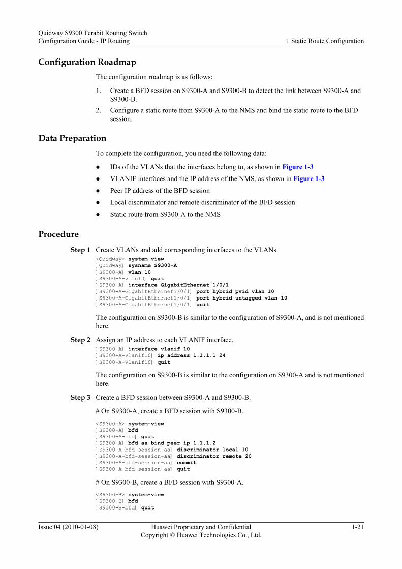
Configuration RoadmapThe configuration roadmap is as follows:
1. Create a BFD session on S9300-A and S9300-B to detect the link between S9300-A andS9300-B.
2. Configure a static route from S9300-A to the NMS and bind the static route to the BFDsession.
Data PreparationTo complete the configuration, you need the following data:
l IDs of the VLANs that the interfaces belong to, as shown in Figure 1-3l VLANIF interfaces and the IP address of the NMS, as shown in Figure 1-3l Peer IP address of the BFD session
l Local discriminator and remote discriminator of the BFD session
l Static route from S9300-A to the NMS
Procedure
Step 1 Create VLANs and add corresponding interfaces to the VLANs.<Quidway> system-view[Quidway] sysname S9300-A[S9300-A] vlan 10[S9300-A-vlan10] quit[S9300-A] interface GigabitEthernet 1/0/1[S9300-A-GigabitEthernet1/0/1] port hybrid pvid vlan 10[S9300-A-GigabitEthernet1/0/1] port hybrid untagged vlan 10[S9300-A-GigabitEthernet1/0/1] quit
The configuration on S9300-B is similar to the configuration of S9300-A, and is not mentionedhere.
Step 2 Assign an IP address to each VLANIF interface.[S9300-A] interface vlanif 10[S9300-A-Vlanif10] ip address 1.1.1.1 24[S9300-A-Vlanif10] quit
The configuration on S9300-B is similar to the configuration on S9300-A and is not mentionedhere.
Step 3 Create a BFD session between S9300-A and S9300-B.
# On S9300-A, create a BFD session with S9300-B.
<S9300-A> system-view[S9300-A] bfd[S9300-A-bfd] quit[S9300-A] bfd aa bind peer-ip 1.1.1.2[S9300-A-bfd-session-aa] discriminator local 10[S9300-A-bfd-session-aa] discriminator remote 20[S9300-A-bfd-session-aa] commit[S9300-A-bfd-session-aa] quit
# On S9300-B, create a BFD session with S9300-A.
<S9300-B> system-view[S9300-B] bfd[S9300-B-bfd] quit
Quidway S9300 Terabit Routing SwitchConfiguration Guide - IP Routing 1 Static Route Configuration
Issue 04 (2010-01-08) Huawei Proprietary and ConfidentialCopyright © Huawei Technologies Co., Ltd.
1-21

[S9300-B] bfd bb bind peer-ip 1.1.1.1[S9300-B-bfd-session-bb] discriminator local 20[S9300-B-bfd-session-bb] discriminator remote 10[S9300-B-bfd-session-bb] commit[S9300-B-bfd-session-bb] quit
Step 4 Configure a static route and bind the route to the BFD session.
# On S9300-A, configure a default static route to the external network and bind the default staticroute to the BFD session named aa.
[S9300-A]ip route-static 2.2.2.1 24 1.1.1.2 track bfd-session aa[S9300-A]quit
Step 5 Verify the configuration.
# After the configuration is complete, run the display bfd session all command on S9300-A andS9300-B, and you can find that the BFD session is set up and its status is Up.
Take S9300-A for example. The display is as follows:
<S9300-A> display bfd session all--------------------------------------------------------------------------------LocalRemote PeerIPAddressInterface NameStateType--------------------------------------------------------------------------------10201.1.1.2--UpS_IP-------------------------------------------------------------------------------- Total UP/DOWN Session Number : 1/0
# Check the IP routing table on S9300-A, and you can find that the static route exists in therouting table.
<S9300-A> display ip routing-tableRoute Flags: R - relay, D - download to fib------------------------------------------------------------------------------Routing Tables: Public Destinations : 6 Routes : 6 Destination/Mask Proto Pre Cost Flags NextHop Interface 1.1.1.0/24 Direct 0 0 D 1.1.1.1 Vlanif10 1.1.1.1/32 Direct 0 0 D 127.0.0.1 InLoopBack0 1.1.1.2/32 Direct 0 0 D 1.1.1.2 Vlanif10 2.2.2.0/24 Static 60 0 RD 1.1.1.2 Vlanif10 127.0.0.0/8 Direct 0 0 D 127.0.0.1 InLoopBack0 127.0.0.1/32 Direct 0 0 D 127.0.0.1 InLoopBack0
# On S9300-A, enable debugging of the terminal.
<S9300-A> terminal monitor<S9300-A> terminal debugging
# Run the shutdown command on VLANIF 10 of S9300-B to simulate a link fault.
[S9300-B] interface vlanif 10[S9300-B-Vlanif10] shutdown
# The following debugging information is displayed on S9300-A, indicating that BFD detectsa link fault.
<S9300-A> *0.27708400 S9300-A RM/3/RMDEBUG: RM_USR_BFDRefreshRT_H: BfdSessionID = 10 BfdEvent = 0X0 USR : UsrDbID = 0X6, DestAdd = 0X0, Mask = 0X0, NextHop = 0X1010102 URT : TableID = 0X1, EntryID = 0XB, ProcID = 0X2, FLAG = 0X8114000
1 Static Route ConfigurationQuidway S9300 Terabit Routing Switch
Configuration Guide - IP Routing
1-22 Huawei Proprietary and ConfidentialCopyright © Huawei Technologies Co., Ltd.
Issue 04 (2010-01-08)

# Check the routing table on S9300-A, and you can find that default route 2.2.2.0/24 does notexist. The reason is that the default static route is bound to a BFD session, and BFD immediatelynotifies that the bound static route is unavailable when a fault is detected.
<S9300-A> display ip routing-tableRoute Flags: R - relay, D - download to fib------------------------------------------------------------------------------Routing Tables: Public Destinations : 5 Routes : 5 Destination/Mask Proto Pre Cost Flags NextHop Interface 1.1.1.0/24 Direct 0 0 D 1.1.1.1 Vlanif10 1.1.1.1/32 Direct 0 0 D 127.0.0.1 InLoopBack0 1.1.1.2/32 Direct 0 0 D 1.1.1.2 Vlanif10 127.0.0.0/8 Direct 0 0 D 127.0.0.1 InLoopBack0 127.0.0.1/32 Direct 0 0 D 127.0.0.1 InLoopBack0
# Run the undo shutdown command on VLANIF 10 of S9300-B to simulate link recovery.
[S9300-B-Vlanif10]undo shutdown
# Check the routing table on S9300-A, and you can find default route 2.2.2.0/24 in the routingtable. After BFD detects link recovery, it immediately notifies that the bound static route isreachable.
<S9300-A> display ip routing-tableRoute Flags: R - relay, D - download to fib------------------------------------------------------------------------------Routing Tables: Public Destinations : 6 Routes : 6 Destination/Mask Proto Pre Cost Flags NextHop Interface 1.1.1.0/24 Direct 0 0 D 1.1.1.1 Vlanif10 1.1.1.1/32 Direct 0 0 D 127.0.0.1 InLoopBack0 1.1.1.2/32 Direct 0 0 D 1.1.1.2 Vlanif10 2.2.2.0/24 Static 60 0 RD 1.1.1.2 Vlanif10 127.0.0.0/8 Direct 0 0 D 127.0.0.1 InLoopBack0 127.0.0.1/32 Direct 0 0 D 127.0.0.1 InLoopBack0
----End
Configuration Filesl Configuration file of S9300-A
# sysname S9300-A# vlan batch 10# bfd#interface Vlanif10 ip address 1.1.1.1 255.255.255.0#interface GigabitEthernet1/0/1 port hybrid pvid vlan 10 port hybrid untagged vlan 10#bfd aa bind peer-ip 1.1.1.2 discriminator local 10 discriminator remote 20 commit# ip route-static 2.2.2.0 255.255.255.0 1.1.1.2 track bfd-session aa
Quidway S9300 Terabit Routing SwitchConfiguration Guide - IP Routing 1 Static Route Configuration
Issue 04 (2010-01-08) Huawei Proprietary and ConfidentialCopyright © Huawei Technologies Co., Ltd.
1-23

#return
l Configuration file of S9300-B# sysname S9300-B# vlan batch 10 20# bfd#interface Vlanif10 ip address 1.1.1.2 255.255.255.0#interface Vlanif20 ip address 2.2.2.2 255.255.255.0#interface GigabitEthernet1/0/1 port hybrid pvid vlan 10 port hybrid untagged vlan 10#interface GigabitEthernet1/0/2 port hybrid pvid vlan 20 port hybrid untagged vlan 20#bfd bb bind peer-ip 1.1.1.1 discriminator local 20 discriminator remote 10 commit#return
1 Static Route ConfigurationQuidway S9300 Terabit Routing Switch
Configuration Guide - IP Routing
1-24 Huawei Proprietary and ConfidentialCopyright © Huawei Technologies Co., Ltd.
Issue 04 (2010-01-08)

2 RIP Configuration
About This Chapter
This chapter describes the principle and configuration procedures of the Routing InformationProtocol (RIP) and, provides configuration examples of RIP.
2.1 Introduction to RIPThis section describes the principle and concepts of RIP.
2.2 RIP Features Supported by the S9300This section describes the RIP features supported by the S9300.
2.3 Configuring Basic RIP FunctionsThis section describes how to enable RIP and configure the basic RIP functions.
2.4 Configuring RIP Route AttributesThis section describes how to change the routing policy of RIP by configuring route attributes.
2.5 Controlling the Advertisement of RIP Routing InformationThis section describes how to precisely control the advertisement of RIP routing information tomeet the requirements of a complicated networking environment.
2.6 Controlling Received RIP Routing InformationThis section describes how to precisely control the received RIP routes to meet requirements ofa complicated networking environment.
2.7 Configuring RIPv2 FeaturesThis section describes how to configure the functions of route aggregation and packetauthentication in RIPv2.
2.8 Adjusting and Optimizing the RIP NetworkThis section describes how to configure RIP features in a special networking environment andhow to optimize the RIP network.
2.9 Configuring the Network Management Function of RIPThis section describes how to bind a RIP process to the Management Information Base (MIB).
2.10 Maintaining RIPThis section describes how to debug RIP.
2.11 Configuration Examples
Quidway S9300 Terabit Routing SwitchConfiguration Guide - IP Routing 2 RIP Configuration
Issue 04 (2010-01-08) Huawei Proprietary and ConfidentialCopyright © Huawei Technologies Co., Ltd.
2-1

This section provides several configuration examples of RIP.
2 RIP ConfigurationQuidway S9300 Terabit Routing Switch
Configuration Guide - IP Routing
2-2 Huawei Proprietary and ConfidentialCopyright © Huawei Technologies Co., Ltd.
Issue 04 (2010-01-08)

2.1 Introduction to RIPThis section describes the principle and concepts of RIP.
The Routing Information Protocol (RIP) is an Interior Gateway Protocol (IGP) that is used in asmall-scale network, such as a campus network and a simple regional network. Generally, RIPis not used in a complicated or a large-scale network.
RIP is based on the Distance-Vector (DV) algorithm and it exchanges the routing informationthrough User Datagram Protocol (UDP) packets. The port number used by RIP is 520.
RIP measures the distance from the local end to the destination by hop count. The hop count isalso called the metric. RIP specifies that the hop count from a router to a directly connectednetwork is 0, and the hop count from a router to a network that can be reached through anotherrouter is 1. The hop count increases with the number of routers between the local router and thedestination network. To restrict the route convergence time, RIP specifies that the hop countmust be an integer ranging from 0 to 15. A hop count of 16 or greater is defined as infinite. Thatis, the destination network or host is unreachable. RIP cannot be used in large networks becauseof this restriction.
To improve system performance and to avoid routing loops, RIP supports the split horizon andpoison reverse functions.
The implementation of RIP is simple, and RIP is much easier to configure and maintain thanOSPF and IS-IS. RIP, therefore, is widely used in actual networks.
RIP has two versions: RIPv1 and RIPv2. RIPv1 is a classful routing protocol, and RIPv2 is aclassless routing protocol. In RIPv2, RIP routers use 224.0.0.9 as the multicast address.
2.2 RIP Features Supported by the S9300This section describes the RIP features supported by the S9300.
Currently, the S9300 supports the following RIP features:
l RIPv1 and RIPv2
l RIP multi-instance, which functions as the internal routing protocol of the virtual privatenetwork (VPN) and runs between CE and PE routers in the Multiprotocol Label Switching(MPLS) L3VPN
NOTE
For the configuration of VPN instances, see "BGP/MPLS IP VPN Configuration" in the Quidway S9300Terabit Routing Switch Configuration Guide - VPN.
2.3 Configuring Basic RIP FunctionsThis section describes how to enable RIP and configure the basic RIP functions.
2.3.1 Establishing the Configuration Task
2.3.2 Enabling RIP
2.3.3 Enabling RIP on a Specified Network Segment
Quidway S9300 Terabit Routing SwitchConfiguration Guide - IP Routing 2 RIP Configuration
Issue 04 (2010-01-08) Huawei Proprietary and ConfidentialCopyright © Huawei Technologies Co., Ltd.
2-3

2.3.4 (Optional) Specifying the RIP Version
2.3.5 Checking the Configuration
2.3.1 Establishing the Configuration Task
Applicable Environment
After configuring the basic RIP functions, you can use the RIP features.
Pre-configuration Tasks
Before configuring the basic RIP functions, complete the following tasks:
l Configuring the link layer protocol
l Creating VLANs and adding corresponding interfaces to the VLANs
l Assigning IP addresses to VLANIF interfaces to ensure network reachability betweenneighboring nodes
NOTE
To create the VLAN that each interface belongs to, you can add interfaces to the VLAN in default modeor by running the port trunk allow-pass vlan command or port hybrid { tagged |untagged } vlancommand. The same method, however, must be used on the interfaces at both ends of a link.
If you run the port trunk allow-pass command or port hybrid tagged vlan command to add interfacesto a VLAN, add the directly connected physical interfaces in the same network segment to the same VLAN.In this manner, the corresponding VLANIF interfaces can be directly connected at the network layer. Fordetails, see the Quidway S9300 Terabit Routing Switch Configuration Guide - Ethernet.
Data Preparation
To configure the basic RIP functions, you need the following data.
No. Data
1 RIP process ID
2 Network segment where the RIP interface is located
3 RIP version number
2.3.2 Enabling RIP
Context
Do as follows on the S9300s that need to run RIP.
NOTE
If you run the RIP commands in the interface view before enabling RIP, the configurations take effect onlywhen the RIP process is enabled.
2 RIP ConfigurationQuidway S9300 Terabit Routing Switch
Configuration Guide - IP Routing
2-4 Huawei Proprietary and ConfidentialCopyright © Huawei Technologies Co., Ltd.
Issue 04 (2010-01-08)

Procedure
Step 1 Run:system-view
The system view is displayed.
Step 2 Run: rip [process-id ]
A RIP process is started and the RIP view is displayed.
----End
PostrequisiteRIP supports multi-instance. That is, RIP processes can be bound to VPN instances. To bind aRIP process to a VPN instance, run the rip [ process-id ] vpn-instance vpn-instance-namecommand.
NOTEFor the configuration of VPN instances, see Chapter 4 "BGP/MPLS IP VPN Configuration" in the QuidwayS9300 Terabit Routing Switch Configuration Guide - VPN.
2.3.3 Enabling RIP on a Specified Network Segment
ContextDo as follows on the S9300s that need to run RIP.
Procedure
Step 1 Run:system-view
The system view is displayed.
Step 2 Run:rip [ process-id ]
A RIP process is started and the RIP view is displayed.
Step 3 Run:network network-address
RIP is enabled on the specified network segment.
RIP runs only on the interfaces of the specified network segment. RIP does not receive or sendroutes for other interfaces, and does not forward their routes. Thus, after enabling RIP, you mustspecify network-address, which is the address of a natural network segment.
By default, after RIP is enabled, it is disabled on all interfaces.
NOTE
The same network segment of a VLANIF interface cannot be specified for different RIP processes;otherwise, only the address of one RIP process takes effect.
----End
Quidway S9300 Terabit Routing SwitchConfiguration Guide - IP Routing 2 RIP Configuration
Issue 04 (2010-01-08) Huawei Proprietary and ConfidentialCopyright © Huawei Technologies Co., Ltd.
2-5

2.3.4 (Optional) Specifying the RIP Version
ContextDo as follows on the S9300s that run RIP.
Procedurel Specifying the global RIP version
1. Run:system-view
The system view is displayed.2. Run:
rip [ process-id]
A RIP process is started and the RIP view is displayed.3. Run:
version { 1 | 2 }
The global RIP version is specified.l Specifying the RIP version on an interface
1. Run:system-view
The system view is displayed.2. Run:
interface interface-type interface-number
The interface view is displayed.3. Run:
rip version { 1 | 2 [ broadcast | multicast ] }
The version of RIP packets that can be received by the interface is specified.
By default, an interface can receive packets of RIPv1 and RIPv2 but can send onlypackets of RIPv1. If the RIP version is set to RIPv2, you can specify the mode ofsending packets on the interface. If the RIP version is not specified on the interface,the global RIP version takes effect on the interface.
----End
2.3.5 Checking the Configuration
PrerequisiteThe basic RIP functions are configured.
Procedurel Run the display rip [ process-id | vpn-instance vpn-instance-name ] command to check
the status and configuration of a RIP process.
2 RIP ConfigurationQuidway S9300 Terabit Routing Switch
Configuration Guide - IP Routing
2-6 Huawei Proprietary and ConfidentialCopyright © Huawei Technologies Co., Ltd.
Issue 04 (2010-01-08)

l Run the display rip process-id route command to check all the active and inactive RIProutes.
----End
Example
Run the display rip [ process-id | vpn-instance vpn-instance-name ], and you can view thestatus and configuration of the specified RIP process.
<Quidway> display rip Public VPN-instance RIP process : 1 RIP version : 1 Preference : 100 Checkzero : Enabled Default-cost : 0 Summary : Enabled Hostroutes : Enabled Maximum number of balanced paths : 16 Update time : 30 sec Age time : 180 sec Suppress time : 0 sec Garbage-collect time : 120 sec Silent interfaces : None Default Route : Disabled Verify-source : Enabled Networks : 192.168.1.0 Configured peers : None Number of routes in database : 2 Number of interfaces enabled : 1 Triggered updates sent : 0 Number of route changes : 2 Number of replies to queries : 1 Total Number of routes : 2 Total Number of routes in ADV DB is : 2
Total count for 1 process : Number of routes in database : 2 Number of interfaces enabled : 1 Number of routes sendable in a periodic update : 2 Number of routes sent in last periodic update : 0
Run the display rip process-id route, and you can view all active and inactive routes of thespecified RIP process.
<Quidway> display rip 1 routeRoute Flags: R - RIP A - Aging, S - Suppressed, G - Garbage-collect ---------------------------------------------------------------------------- Peer 192.168.1.2 on Vlanif10 Destination/Mask Nexthop Cost Tag Flags Sec 192.168.1.0/24 192.168.1.2 1 0 RA 24 192.168.2.0/24 192.168.1.2 1 0 RA 24
2.4 Configuring RIP Route AttributesThis section describes how to change the routing policy of RIP by configuring route attributes.
2.4.1 Establishing the Configuration Task
2.4.2 Setting the Additional Metric of an Interface
2.4.3 Setting the Preference of RIP
Quidway S9300 Terabit Routing SwitchConfiguration Guide - IP Routing 2 RIP Configuration
Issue 04 (2010-01-08) Huawei Proprietary and ConfidentialCopyright © Huawei Technologies Co., Ltd.
2-7

2.4.4 Setting the Maximum Number of Equal-Cost Routes
2.4.5 Checking the Configuration
2.4.1 Establishing the Configuration Task
Applicable EnvironmentTo meet the requirements of a complicated networking environment, you can change RIP routingpolicies by configuring RIP route attributes. Through the following procedures, you can:
l Determine route selection by adjusting the additional metric of a RIP interface.
l Change the matching order of routing protocols by configuring the RIP priority whenvarious routing protocols discover routes to the same destination.
l Implement load balancing among several equal-cost routes.
Pre-configuration TasksBefore configuring RIP route attributes, complete the following tasks:
l Configuring the IP addresses of interfaces to ensure that neighboring nodes can beinterconnected through the network
l 2.3 Configuring Basic RIP Functions
Data PreparationTo configure RIP route attributes, you need the following data.
No. Data
1 Additional metric of each interface
2 RIP priority
3 Maximum number of equal-cost routes
2.4.2 Setting the Additional Metric of an Interface
ContextDo as follows on the S9300s that run RIP.
Procedure
Step 1 Run:system-view
The system view is displayed.
Step 2 Run:interface interface-type interface-number
2 RIP ConfigurationQuidway S9300 Terabit Routing Switch
Configuration Guide - IP Routing
2-8 Huawei Proprietary and ConfidentialCopyright © Huawei Technologies Co., Ltd.
Issue 04 (2010-01-08)
The interface view is displayed.
Step 3 Run: rip metricin value
The metric that is added to a route received on the interface is set.
Step 4 Run:
rip metricout value The additional metric that is added to a route advertised from the interfaceis set.
The additional metric is an increment (hop count) added to the original metric of a RIP route.After you run the rip metricin command, the S9300 adds an additional metric to a receivedroute, and then adds the route to the routing table. Then, the metric of the route changes in therouting table. After you run the rip metricout command, the S9300 adds an additional metricto a route when advertising the route. The metric of the route, however, does not change in therouting table.
----End
2.4.3 Setting the Preference of RIP
ContextDo as follows on the S9300s that run RIP.
Procedure
Step 1 Run:system-view
The system view is displayed.
Step 2 Run:rip [ process-id ]
A RIP process is started and the RIP view is displayed.
Step 3 Run:preference { preference | route-policy route-policy-name }*
The preference of RIP is set.
----End
2.4.4 Setting the Maximum Number of Equal-Cost Routes
ContextDo as follows on the S9300s that run RIP.
Procedure
Step 1 Run:system-view
Quidway S9300 Terabit Routing SwitchConfiguration Guide - IP Routing 2 RIP Configuration
Issue 04 (2010-01-08) Huawei Proprietary and ConfidentialCopyright © Huawei Technologies Co., Ltd.
2-9

The system view is displayed.
Step 2 Run: rip [ process-id ]
A RIP process is started and the RIP view is displayed.
Step 3 Run:maximum load-balancing number
The maximum number of equal-cost routes is set.
By default,the maximum number of equal-cost is 16.
----End
2.4.5 Checking the Configuration
PrerequisiteAll the route attributes of RIP are set.
Procedurel Run the display rip [ process-id | vpn-instance vpn-instance-name ] command to check
the status and configuration of a RIP process.l Run the display rip process-id database command to check all the active routes in the RIP
database.l Run the display rip process-id route command to check all the active and inactive RIP
routes.
----End
ExampleRun the display rip process-id database command, and you can view information about thedatabase of the specified RIP process.
<Quidway> display rip 100 database 10.0.0.0/8, cost 1, ClassfulSumm 10.0.0.0/24, cost 1, nexthop 10.0.0.1, Rip-interface 11.0.0.0/8, cost 1, ClassfulSumm 11.0.0.0/24, cost 1, nexthop 10.0.0.1, Imported
2.5 Controlling the Advertisement of RIP RoutingInformation
This section describes how to precisely control the advertisement of RIP routing information tomeet the requirements of a complicated networking environment.
2.5.1 Establishing the Configuration Task
2.5.2 Advertising a Default Route
2.5.3 Disabling an Interface from Sending RIP Update Packets
2.5.4 Configuring RIP to Import Routes
2 RIP ConfigurationQuidway S9300 Terabit Routing Switch
Configuration Guide - IP Routing
2-10 Huawei Proprietary and ConfidentialCopyright © Huawei Technologies Co., Ltd.
Issue 04 (2010-01-08)

2.5.5 Checking the Configuration
2.5.1 Establishing the Configuration Task
Applicable EnvironmentIn certain applications, you need to control the advertisement of RIP routing informationprecisely to meet requirements of a complicated networking environment. Through the followingprocedures, you can:
l Configure the S9300 to advertise default routes to neighbors.
l Disable interfaces from sending RIP update packets.
l Configure the S9300 to import external routes from other routing protocols and filter routesbefore advertising routes.
Pre-configuration TasksBefore controlling the advertisement of RIP routing information, complete the following tasks:
l Configuring the IP addresses of interfaces to ensure that neighboring nodes can beinterconnected through the network
l 2.3 Configuring Basic RIP Functions
Data PreparationTo control the advertisement of RIP routing information, you need the following data.
No. Data
1 Metric of the default route to be advertised
2 Protocol name and process ID of the imported route
2.5.2 Advertising a Default Route
ContextDo as follows on the S9300s that run RIP.
Procedure
Step 1 Run:system-view
The system view is displayed.
Step 2 Run:rip [ process-id ]
A RIP process is started and the RIP view is displayed.
Quidway S9300 Terabit Routing SwitchConfiguration Guide - IP Routing 2 RIP Configuration
Issue 04 (2010-01-08) Huawei Proprietary and ConfidentialCopyright © Huawei Technologies Co., Ltd.
2-11

Step 3 Run:default-route originate [ cost cost ]
The S9300 is configured to advertise a default route.
The preceding commands configure the S9300 to advertise a default route with the specifiedmetric to the RIP neighbor.
----End
2.5.3 Disabling an Interface from Sending RIP Update Packets
ContextDo as follows on the S9300s that run RIP.
Procedurel In the RIP view (with a high priority)
1. Run:system-view
The system view is displayed.2. Run:
rip [ process-id ]
A RIP process is started and the RIP view is displayed.3. Disable a specified interface or all the interfaces from sending RIP update packets.
– Run:silent-interface all
All interfaces are disabled from sending RIP update packets.– Run:
silent-interface interface-type interface-number
The specified interface is disabled from sending RIP update packets.
You can set an interface to be in the silent state so that the interface can only receiveRIP update packets to update the routing table, but cannot send RIP packets. Thesilent-interface command has a higher priority than the rip input and rip outputcommands. By default, an interface is not suppressed.
l In the interface view (with a low priority)1. Run:
system-view
The system view is displayed.2. Run:
interface interface-type interface-number
The interface view is displayed.3. Run:
undo rip output
The interface is disabled from sending RIP update packets.
2 RIP ConfigurationQuidway S9300 Terabit Routing Switch
Configuration Guide - IP Routing
2-12 Huawei Proprietary and ConfidentialCopyright © Huawei Technologies Co., Ltd.
Issue 04 (2010-01-08)

You can allow an interface to send or receive RIP update packets. The undo ripoutput command has a lower priority than the silent-interface command. By default,an interface can send RIP update packets.
----End
2.5.4 Configuring RIP to Import Routes
ContextDo as follows on the S9300s that run RIP.
Procedure
Step 1 Run:system-view
The system view is displayed.
Step 2 Run:rip [ process-id ]
A RIP process is started and the RIP view is displayed.
Step 3 Run:default-cost cost
The default metric of the imported routes is set.
Step 4 Run:import-route protocol [ process-id ] [ cost cost ] [ route-policy route-policy-name ]
RIP is configured to import external routes.
Step 5 Run:filter-policy { acl-number | ip-prefix ip-prefix-name } export [ protocol | interface-type interface-number ]
RIP is configured to filter the imported routes when advertising them.
Step 3 is optional. If the metric of imported routes is not specified in Step 4, the default metricis used.
Step 5 is optional. The routing information advertised by RIP may contain the routinginformation imported from other protocols. In this case, you can set the protocol parameter tofilter the routing information imported from a specified routing protocol. If the protocol is notset, all the routes advertised by RIP are filtered, including the imported routes and the localroutes (direct routes).
NOTE
For the configuration of the ACL, see the Quidway S9300 Terabit Routing Switch Configuration Guide -Basic Configuration.
For the configuration of the address prefix list, see Configuring an IP Prefix List.
----End
Quidway S9300 Terabit Routing SwitchConfiguration Guide - IP Routing 2 RIP Configuration
Issue 04 (2010-01-08) Huawei Proprietary and ConfidentialCopyright © Huawei Technologies Co., Ltd.
2-13

2.5.5 Checking the Configuration
PrerequisiteThe configuration for controlling the advertisement of RIP routing information is complete.
Procedurel Run the display rip [ process-id | vpn-instance vpn-instance-name ] command to check
the status and configuration of a RIP process.l Run the display rip process-id database command to check all the active routes in the RIP
database.l Run the display rip process-id route command to check all the active and inactive RIP
routes.
----End
Example
Run the display rip process-id database command, and you can view information in thedatabase of the specified RIP process.
<Quidway> display rip 100 database 172.4.0.0/16, cost 1, ClassfulSumm 172.4.0.0/16, cost 1, nexthop 192.13.14.1 192.4.5.0/24, cost 2, ClassfulSumm 192.4.5.0/24, cost 2, nexthop 192.13.14.1 192.13.14.0/24, cost 0, ClassfulSumm 192.13.14.0/24, cost 0, Rip-interface
2.6 Controlling Received RIP Routing InformationThis section describes how to precisely control the received RIP routes to meet requirements ofa complicated networking environment.
2.6.1 Establishing the Configuration Task
2.6.2 Disabling an Interface from Receiving RIP Update Packets
2.6.3 Configuring RIP to Deny Host Routes
2.6.4 Configuring RIP to Filter Received Routes
2.6.5 Checking the Configuration
2.6.1 Establishing the Configuration Task
Applicable Environment
In certain applications, you need to control the received RIP routing information precisely tomeet requirements of a complicated networking environment. Through the followingprocedures, you can:
l Disable an interface from accepting RIP update packets.
2 RIP ConfigurationQuidway S9300 Terabit Routing Switch
Configuration Guide - IP Routing
2-14 Huawei Proprietary and ConfidentialCopyright © Huawei Technologies Co., Ltd.
Issue 04 (2010-01-08)

l Filter the received routing information.
l Configure the S9300 to import external routes from other routing protocols and filter thereceived routes.
Pre-configuration Tasks
Before controlling the received RIP routing information, complete the following tasks:
l Configuring the IP addresses of interfaces to ensure that neighboring nodes can beinterconnected through the network
l Configuring Basic RIP Functions
Data Preparation
To control the received RIP routing information, you need the following data.
No. Data
1 ACL used to filter routing information
2.6.2 Disabling an Interface from Receiving RIP Update Packets
Context
Do as follows on the S9300s that run RIP.
Procedure
Step 1 Run:system-view
The system view is displayed.
Step 2 Run:interface interface-type interface-number
The interface view is displayed.
Step 3 Run:undo rip input
The interface is disabled from receiving RIP update packets.
You can use this command to allow a specified interface to send or receive RIP update packets.The undo rip input command has a lower priority than the silent-interface command. Bydefault, an interface can receive RIP update packets.
----End
Quidway S9300 Terabit Routing SwitchConfiguration Guide - IP Routing 2 RIP Configuration
Issue 04 (2010-01-08) Huawei Proprietary and ConfidentialCopyright © Huawei Technologies Co., Ltd.
2-15

2.6.3 Configuring RIP to Deny Host Routes
Context
Do as follows on the S9300s that run RIP.
Procedure
Step 1 Run:system-view
The system view is displayed.
Step 2 Run:rip [ process-id ]
A RIP process is started and the RIP view is displayed.
Step 3 Run:undo host-route
The RIP process is configured to deny received host routes.
In certain cases, the S9300 receives a large number of host routes from the same networksegment. These host routes are unnecessary for routing, and they waste network resources. Ifyou run the undo host-route command, the S9300 rejects all the host routes it receives.
----End
2.6.4 Configuring RIP to Filter Received Routes
Context
Do as follows on the S9300s that run RIP.
Procedure
Step 1 Run:system-view
The system view is displayed.
Step 2 Run:rip [ process-id ]
A RIP process is started and the RIP view is displayed.
Step 3 Configure a route filtering policy as required.l Run:
filter-policy acl-number import
The routing information that is learned from other protocols is filtered based on an ACL.l Run:
filter-policy gateway ip-prefix-name import
2 RIP ConfigurationQuidway S9300 Terabit Routing Switch
Configuration Guide - IP Routing
2-16 Huawei Proprietary and ConfidentialCopyright © Huawei Technologies Co., Ltd.
Issue 04 (2010-01-08)

The routing information that is advertised by neighbors is filtered based on the prefix ofthe destination addresses.
l Run:filter-policy ip-prefix ip-prefix-name[ gateway ip-prefix-name]import [interface-type interface-number ]The routing information that is learned from a specified interface is filtered based on theneighbors and the prefix of the destination addresses.
A router can filter routing information. You can specify an ACL or an address prefix list toconfigure an inbound or outbound route filtering policy. Then the router can filter the routinginformation that it receives or advertises.
You can also configure the router to accept RIP packets only from a specified neighbor.
----End
2.6.5 Checking the Configuration
PrerequisiteThe configuration for controlling the receiving of RIP routing information is complete.
Procedurel Run the display rip [ process-id | vpn-instance vpn-instance-name ] command to check
the status and configuration of a RIP process.l Run the display rip process-id database [ verbose ] command to check all the active routes
in the RIP database.l Run the display rip process-id interface [ interface-type interface-number ] [ verbose ]
command to check information about the interface that runs RIP.l Run the display rip process-id neighbor [ verbose ] command to check information about
the RIP neighbors.l Run the display rip process-id route command to check all the active and inactive RIP
routes.
----End
ExampleRun the display rip process-id database command, and you can view information in thedatabase of the specified RIP process.
<Quidway> display rip 100 database 172.4.0.0/16, cost 1, ClassfulSumm 172.4.0.0/16, cost 1, nexthop 192.13.14.1 192.4.5.0/24, cost 2, ClassfulSumm 192.4.5.0/24, cost 2, nexthop 192.13.14.1 192.13.14.0/24, cost 0, ClassfulSumm 192.13.14.0/24, cost 0, Rip-interface
2.7 Configuring RIPv2 FeaturesThis section describes how to configure the functions of route aggregation and packetauthentication in RIPv2.
Quidway S9300 Terabit Routing SwitchConfiguration Guide - IP Routing 2 RIP Configuration
Issue 04 (2010-01-08) Huawei Proprietary and ConfidentialCopyright © Huawei Technologies Co., Ltd.
2-17

2.7.1 Establishing the Configuration Task
2.7.2 Configuring Route Aggregation of RIPv2
2.7.3 Setting the Authentication Mode of RIPv2 Packets
2.7.4 Checking the Configuration
2.7.1 Establishing the Configuration Task
Applicable EnvironmentFeatures specific to RIPv2 are as follows:
l Route aggregation
l Authentication of RIPv2 packets
Pre-configuration TasksBefore configuring the features of RIPv2, complete the following tasks:
l Configuring the link layer protocol
l Configuring IP addresses of the relevant interfaces to ensure network reachability betweenneighboring nodes
Data PreparationTo configure the features of RIPv2, you need the following data.
No. Data
1 RIPv2 process ID
2 Network segment where the RIPv2 interface is located
2.7.2 Configuring Route Aggregation of RIPv2
ContextDo as follows on the S9300s that run RIPv2.
Procedurel Enabling automatic route aggregation
1. Run:system-view
The system view is displayed.2. Run:
rip [ process-id ]
2 RIP ConfigurationQuidway S9300 Terabit Routing Switch
Configuration Guide - IP Routing
2-18 Huawei Proprietary and ConfidentialCopyright © Huawei Technologies Co., Ltd.
Issue 04 (2010-01-08)

A RIP process is started and the RIP view is displayed.3. Run:
summary
Route aggregation of RIPv2 is enabled.
Route aggregation is a function of aggregating the routes in different subnets of anatural network segment into a route with a natural mask and sending the aggregatedroute to other network segments. This function reduces the size of the routing table,and thus reduces the traffic volume on the network.
RIPv1 does not support route aggregation. RIPv2 supports the Variable Length SubnetMask (VLSM) and Classless Inter-Domain Routing (CIDR) protocols. When a routerneeds to broadcast all the subnet routes, run the undo summary command to disableautomatic route aggregation of RIPv2.
l Configuring RIPv2 to advertise the aggregated address1. Run:
system-view
The system view is displayed.2. Run:
interface interface-type interface-number
The interface view is displayed.3. Run:
rip summary-address ip-address mask [ avoid-feedback ]
RIPv2 is configured to advertise the aggregated local IP address.
----End
2.7.3 Setting the Authentication Mode of RIPv2 Packets
ContextDo as follows on the S9300s that run RIPv2.
Procedure
Step 1 Run:system-view
The system view is displayed.
Step 2 Run:interface interface-type interface-number
The interface view is displayed.
Step 3 Configure the authentication mode of RIPv2 packets.l Run:
rip authentication-mode simple password
The authentication mode of RIPv2 packets is set to simple authentication, which uses apassword in plain text.
Quidway S9300 Terabit Routing SwitchConfiguration Guide - IP Routing 2 RIP Configuration
Issue 04 (2010-01-08) Huawei Proprietary and ConfidentialCopyright © Huawei Technologies Co., Ltd.
2-19

l Run:rip authentication-mode md5 { nonstandard password-key key-id | usual password-key }The authentication mode of RIPv2 packets is set to MD5 authentication, which uses apassword in cipher text.
RIPv2 supports the following authentication modes:
l Simple authentication
l MD5 authentication
The simple authentication cannot guarantee security because the password is sent with the packetwithout encryption. For this reason, simple authentication cannot be used in the application thatrequires high security.
If the MD authentication is adopted, you must configure the format of MD5 authenticationpackets. If the usual keyword is specified, the authentication packets adopt the standard formatspecified by the IETF. If the nonstandard keyword is specified, the authentication packets adoptthe non-standard format .
----End
2.7.4 Checking the Configuration
PrerequisiteThe configuration of RIPv2 features is complete.
Procedurel Run the display rip [ process-id | vpn-instance vpn-instance-name ] command to check
the status and configuration of a RIP process.l Run the display rip process-id database [ verbose ] command to check all the active routes
in the RIP database.l Run the display rip process-id route command to check all the active and inactive RIP
routes.
----End
2.8 Adjusting and Optimizing the RIP NetworkThis section describes how to configure RIP features in a special networking environment andhow to optimize the RIP network.
2.8.1 Establishing the Configuration Task
2.8.2 Configuring RIP Timers
2.8.3 Setting the Interval of Update Packets and Maximum Number of Packets Sent at a Time
2.8.4 Configuring Split Horizon and Poison Reverse
2.8.5 Configuring RIP to Check the Validity of Update Packets
2.8.6 Configuring a RIP Neighbor
2 RIP ConfigurationQuidway S9300 Terabit Routing Switch
Configuration Guide - IP Routing
2-20 Huawei Proprietary and ConfidentialCopyright © Huawei Technologies Co., Ltd.
Issue 04 (2010-01-08)

2.8.7 Checking the Configuration
2.8.1 Establishing the Configuration Task
Applicable Environment
In special networking environments, RIP features need to be configured and the performance ofthe RIP network needs to be improved. Through the following procedures, you can:
l Change the convergence speed of the RIP network by adjusting the RIP timer.
l Improve the performance of the RIP network by changing the number of update packetsthat an interface can send and the interval for sending update packets.
l Configure split horizon and poison reverse to prevent routing loops.
l Check validity of packets and authenticate packets in the networking environment thatrequires high security.
l Configure special RIP features on an interface or a link.
Pre-configuration Tasks
Before adjusting and optimizing the RIP network, complete the configuration tasks:
l Configuring the IP addresses of interfaces to ensure that neighboring nodes can beinterconnected through the network
l 2.3 Configuring Basic RIP Functions
Data Preparation
To adjust and optimize the RIP network, you need the following data.
No. Data
1 Values of timers
2 Number of update packets that an interface sends each time and the interval forsending update packets
3 Maximum number of equal-cost routes
4 Authentication method of packets and passwords used in authentication
5 IP addresses of RIP neighbors
2.8.2 Configuring RIP Timers
Context
Do as follows on the S9300s that run RIP.
Quidway S9300 Terabit Routing SwitchConfiguration Guide - IP Routing 2 RIP Configuration
Issue 04 (2010-01-08) Huawei Proprietary and ConfidentialCopyright © Huawei Technologies Co., Ltd.
2-21

Procedure
Step 1 Run:system-view
The system view is displayed.
Step 2 Run:rip [ process-id ]
A RIP process is started and the RIP view is displayed.
Step 3 Run:timers rip update age suppress garbage-collect
The RIP timers are set.
RIP uses four timers: Update timer, Age timer, Suppress timer, and Garbage-collect timer.Changing the values of the timers affects the convergence speed of RIP routes.
The new value of a RIP timer takes effect immediately after you change the value.
CAUTIONImproper setting of the four timers causes route flapping. The relation between the values of thetimers is as follows:update < age, suppress < garbage-collectFor example, if the value of the Update timer is greater than the value of the Age timer, theS9300 cannot notify the neighbors when a RIP route changes within the update period.
By default, the Update timer is 30 seconds; the Age timer is 180 seconds; the Suppress timer is0 seconds; the Garbage-collect timer is four times the value of Update timer, namely, 120seconds.
Actually, the Garbage-collect timer is not fixed. When the Update timer is set to 30 seconds, theGarbage-collect timer may range from 90 seconds to 120 seconds.
Before deleting an unreachable route from the routing table, RIP sends update packets four timesto advertise the route. The metric of the route is set to 16 in the update packets. In this manner,all the neighbors learn that the route is unreachable. A route does not always become unreachableat the beginning of an update cycle; therefore, the value of the Garbage-collect timer is three orfour times the value of the update timer.
NOTE
When setting the RIP timers, consider the network performance. In addition, you must set the same timerson all the S9300s that run RIP to avoid unnecessary network traffic and route flapping.
----End
2 RIP ConfigurationQuidway S9300 Terabit Routing Switch
Configuration Guide - IP Routing
2-22 Huawei Proprietary and ConfidentialCopyright © Huawei Technologies Co., Ltd.
Issue 04 (2010-01-08)

2.8.3 Setting the Interval of Update Packets and Maximum Numberof Packets Sent at a Time
ContextDo as follows on the S9300s that run RIP.
Procedure
Step 1 Run:system-view
The system view is displayed.
Step 2 Run:interface interface-type interface-number
The interface view is displayed.
Step 3 Run:rip pkt-transmit { interval interval | number pkt-count }*
The interval for sending RIP update packets on the interface and the maximum number of packetsthat are sent each time are set.
----End
2.8.4 Configuring Split Horizon and Poison Reverse
ContextIf you configure split horizon and poison reverse simultaneously, only the poison reversefunction takes effect.
Do as follows on the S9300s that run RIP.
Procedure
Step 1 Run:system-view
The system view is displayed.
Step 2 Run:interface interface-type interface-number
The interface view is displayed.
Step 3 Run:rip split-horizon
Split horizon is enabled.
Step 4 Run:rip poison-reverse
Poison reverse is enabled.
Quidway S9300 Terabit Routing SwitchConfiguration Guide - IP Routing 2 RIP Configuration
Issue 04 (2010-01-08) Huawei Proprietary and ConfidentialCopyright © Huawei Technologies Co., Ltd.
2-23

In a non-broadcast multi-access (NBMA) network that uses the Frame Relay or X.25 protocol,if no sub-interfaces are used, disable split horizon to ensure normal exchange of routinginformation.
----End
2.8.5 Configuring RIP to Check the Validity of Update Packets
Context
Do as follows on the S9300s that run RIP.
Procedurel Checking the zero fields in RIPv1 packets
1. Run:system-view
The system view is displayed.2. Run:
rip [ process-id ]
A RIP process is started and the RIP view is displayed.3. Run:
checkzero
The RIP process is configured to check the zero fields of RIPv1 packets.
In a RIPv1 packet, certain fields must be zero. These fields are zero fields. Whenreceiving a packet, the RIPv1 process checks the zero fields of the packet. The RIPv1process does not process the packet if the value of a zero field is not 0.
The concept of zero field is not applicable to RIPv2 packets; therefore, thecheckzero command is invalid for RIPv2 packets.
l Checking the source IP addresses of RIP update packets1. Run:
system-view
The system view is displayed.2. Run:
rip [ process-id ]
A RIP process is started and the RIP view is displayed.3. Run:
verify-source
The RIP process is configured to check the source IP addresses of update packets.
RIP checks the source IP address of a received update packet and does not process thepacket if the packet does not pass the check. By default, RIP checks the source IPaddresses of update packets.
----End
2 RIP ConfigurationQuidway S9300 Terabit Routing Switch
Configuration Guide - IP Routing
2-24 Huawei Proprietary and ConfidentialCopyright © Huawei Technologies Co., Ltd.
Issue 04 (2010-01-08)

2.8.6 Configuring a RIP Neighbor
Context
Do as follows on the S9300s that run RIP.
Context
Generally, RIP uses a broadcast or a multicast address to send packets. If RIP runs on a link thatdoes not support broadcast or multicast packets, you must specify RIP neighbors manually.
Procedure
Step 1 Run:system-view
The system view is displayed.
Step 2 Run:rip [ process-id ]
A RIP process is started and the RIP view is displayed.
Step 3 Run:peer ipv4-address
A RIP neighbor is configured.
----End
2.8.7 Checking the Configuration
PrerequisiteAll the configurations for optimizing the RIP network are complete.
Procedurel Run the display rip [ process-id | vpn-instance vpn-instance-name ] command to check
the status and configuration of a RIP process.
l Run the display rip process-id database [ verbose command to check all the active routesin the RIP database.
l Run the display rip process-id interface [ interface-type interface-number ] [ verbose ]command to check information about the interface that runs RIP.
l Run the display rip process-id neighbor [ verbose ] command to check information aboutthe RIP neighbors.
l Run the display rip process-id route command to check all the active and inactive RIProutes.
----End
Quidway S9300 Terabit Routing SwitchConfiguration Guide - IP Routing 2 RIP Configuration
Issue 04 (2010-01-08) Huawei Proprietary and ConfidentialCopyright © Huawei Technologies Co., Ltd.
2-25

ExampleRun the display rip process-id interface [ interface-type interface-number ] [ verbose ]command, and you can view information about a RIP interface. The information indicates thatthe interface status is Up.
<Quidway> display rip 1 interface Vlanif10 ------------------------------------------------------------------ Interface IP Address State Protocol MTU ------------------------------------------------------------------ Vlanif10 1.1.1.2 UP RIPv1 Compatible 500
2.9 Configuring the Network Management Function of RIPThis section describes how to bind a RIP process to the Management Information Base (MIB).
2.9.1 Establishing the Configuration Task
2.9.2 Binding a RIP Process to the MIB
2.9.3 Checking the Configuration
2.9.1 Establishing the Configuration Task
Applicable EnvironmentThrough the following procedures, you can bind a RIP process to the MIB in the networkingenvironment that uses the NMS.
Pre-configuration TasksBefore configuring the network management function of RIP, complete the following tasks:
l Configuring the IP addresses of interfaces to ensure that neighboring nodes can beinterconnected through the network
l 2.3 Configuring Basic RIP Functions
Data PreparationNone.
2.9.2 Binding a RIP Process to the MIB
ContextDo as follows on the S9300s that run RIP.
Procedure
Step 1 Run:system-view
The system view is displayed.
2 RIP ConfigurationQuidway S9300 Terabit Routing Switch
Configuration Guide - IP Routing
2-26 Huawei Proprietary and ConfidentialCopyright © Huawei Technologies Co., Ltd.
Issue 04 (2010-01-08)

Step 2 Run:rip mib-binding process-id
A RIP process is bound to the MIB.
This command specifies the RIP process ID that is bound to the MIB, that is, the ID of the RIPprocess that receives packets of the Simple Network Management Protocol (SNMP).
----End
2.9.3 Checking the Configuration
PrerequisiteThe network management function of RIP is configured.
Procedurel Run the display current-configuration command to check the configuration parameters
of the S9300.
----End
2.10 Maintaining RIPThis section describes how to debug RIP.
Context
CAUTIONDebugging affects the performance of the system. So, after debugging, run the undo debuggingall command to disable it immediately.
When a RIP fault occurs, run the following debugging commands in the user view to locate thefault. For how to enable debugging, see Chapter 1 "Information Center Configuration" in theQuidway S9300 Terabit Routing Switch Configuration Guide - System Management.
For the description of the debugging commands, see the Quidway S9300 Terabit RoutingSwitch Debugging Reference.
Procedurel Run the debugging rip process-id [ brief | error | event | job | packet | receive | route-
processing | send | timer ] command to enable debugging of RIP packets.
l Run the debugging rip backup command to enable debugging of RIP backup information.
----End
Quidway S9300 Terabit Routing SwitchConfiguration Guide - IP Routing 2 RIP Configuration
Issue 04 (2010-01-08) Huawei Proprietary and ConfidentialCopyright © Huawei Technologies Co., Ltd.
2-27

2.11 Configuration ExamplesThis section provides several configuration examples of RIP.
2.11.1 Example for Configuring the RIP Version
2.11.2 Example for Configuring RIP to Import Routes
2.11.1 Example for Configuring the RIP Version
Networking Requirements
As shown in Figure 2-1, RIP needs to be enabled on all the interfaces of S9300-A, S9300-B,S9300-C, and S9300-D. The S9300s are interconnected through RIPv2.
Figure 2-1 Networking diagram for configuring the RIP version
S9300-A S9300-BGE1/0/0
GE1/0/0GE1/0/2
GE1/0/1
GE1/0/2
GE1/0/1
S9300-D
S9300-C
S9300 Interface VLANIF interface IP address
S9300-A GigabitEthernet1/0/0 VLANIF 10 192.168.1.1/24
S9300-B GigabitEthernet1/0/0 VLANIF 10 192.168.1.2/24
S9300-B GigabitEthernet1/0/1 VLANIF 20 172.16.1.1/24
S9300-B GigabitEthernet1/0/2 VLANIF 30 10.1.1.1/24
S9300-C GigabitEthernet1/0/1 VLANIF 20 172.16.1.2/24
S9300-D GigabitEthernet1/0/2 VLANIF 30 10.1.1.2/24
Configuration Roadmap
The configuration roadmap is as follows:
1. Assign IP addresses to all the interfaces to ensure network reachability.2. Enable RIP on each S9300 and configure the basic RIP functions.3. Configure RIPv2 on each S9300 and check the accurate subnet masks.
2 RIP ConfigurationQuidway S9300 Terabit Routing Switch
Configuration Guide - IP Routing
2-28 Huawei Proprietary and ConfidentialCopyright © Huawei Technologies Co., Ltd.
Issue 04 (2010-01-08)

Data PreparationTo complete the configuration, you need the following data:
l IDs of the VLANs that the interfaces belong to, as shown in Figure 2-1
l IP addresses of VLANIF interfaces, as shown in Figure 2-1
l RIP version on the S9300s, namely, RIPv2
Procedure
Step 1 Configure VLANs that the related interfaces belong to.<Quidway> system-view[Quidway] sysname S9300-A[S9300-A] vlan 10S9300-A-vlan10] quit[S9300-A] interface GigabitEthernet 1/0/0[S9300-A-GigabitEthernet1/0/0] port hybrid pvid vlan 10[S9300-A-GigabitEthernet1/0/0] port hybrid untagged vlan 10[S9300-A-GigabitEthernet1/0/0] quit
The configurations of S9300-B, S9300-C, and S9300-D are similar to the configuration ofS9300-A, and are not mentioned here.
Step 2 Assign an IP address to each VLANIF interface.[S9300-A] interface vlanif 10[S9300-A-Vlanif10] ip address 192.168.1.1 24[S9300-A-Vlanif10] quit
The configurations of S9300-B, S9300-C, and S9300-D are similar to the configuration ofS9300-A, and are not mentioned here.
Step 3 Configure the basic RIP functions.
Configure S9300-A.
[S9300-A] rip[S9300-A-rip-1] network 192.168.1.0[S9300-A-rip-1] quit
Configure S9300-B.
[S9300-B] rip[S9300-B-rip-1] network 192.168.1.0[S9300-B-rip-1] network 172.16.0.0[S9300-B-rip-1] network 10.0.0.0[S9300-B-rip-1] quit
Configure S9300-C.
[S9300-C] rip[S9300-C-rip-1] network 172.16.0.0[S9300-C-rip-1] quit
Configure S9300-D.
[S9300-D] rip[S9300-D-rip-1] network 10.0.0.0[S9300-D-rip-1] quit
# Check the RIP routing table of S9300-A.
[S9300-A] display rip 1 route Route Flags: R - RIP A - Aging, S - Suppressed, G - Garbage-collect
Quidway S9300 Terabit Routing SwitchConfiguration Guide - IP Routing 2 RIP Configuration
Issue 04 (2010-01-08) Huawei Proprietary and ConfidentialCopyright © Huawei Technologies Co., Ltd.
2-29

------------------------------------------------------------------------- Peer 192.168.1.2 on Vlanif10 Destination/Mask Nexthop Cost Tag Flags Sec 10.0.0.0/8 192.168.1.2 1 0 RA 14 172.16.0.0/16 192.168.1.2 1 0 RA 14 192.168.1.0/24 192.168.1.2 1 0 RA 14
From the routing table, you can find that the routes advertised by RIPv1 use natural masks.
Step 4 Configure the RIP version.
# Configure RIPv2 on S9300-A.
[S9300-A] rip[S9300-A-rip-1] version 2[S9300-A-rip-1] quit
# Configure RIPv2 on S9300-B.
[S9300-B] rip[S9300-B-rip-1] version 2[S9300-B-rip-1] quit
# Configure RIPv2 on S9300-C.
[S9300-C] rip[S9300-C-rip-1] version 2[S9300-C-rip-1] quit
# Configure RIPv2 on S9300-D.
[S9300-D] rip[S9300-D-rip-1] version 2[S9300-D-rip-1] quit
Step 5 Verify the configuration.
# Check the RIP routing table of S9300-A.
[S9300-A] display rip 1 route Route Flags: R - RIP A - Aging, S - Suppressed, G - Garbage-collect------------------------------------------------------------------------- Peer 192.168.1.2 on Vlanif10 Destination/Mask Nexthop Cost Tag Flags Sec 10.1.1.0/24 192.168.1.2 1 0 RA 32 172.16.1.0/24 192.168.1.2 1 0 RA 32 192.168.1.0/24 192.168.1.2 1 0 RA 14
From the routing table, you can find that the routes advertised by RIPv2 contain more accuratesubnet masks.
----End
Configuration Filesl Configuration file of S9300-A
# sysname S9300-A# vlan 10#interface Vlanif10 ip address 192.168.1.1 255.255.255.0#interface GigabitEthernet1/0/0 port hybrid pvid vlan 10 port hybrid untagged vlan 10
2 RIP ConfigurationQuidway S9300 Terabit Routing Switch
Configuration Guide - IP Routing
2-30 Huawei Proprietary and ConfidentialCopyright © Huawei Technologies Co., Ltd.
Issue 04 (2010-01-08)

#rip 1 version 2 network 192.168.1.0#return
l Configuration file of S9300-B# sysname S9300-B# vlan batch 10 20 30#interface Vlanif10 ip address 192.168.1.2 255.255.255.0#interface Vlanif20 ip address 172.16.1.1 255.255.255.0#interface Vlanif30 ip address 10.1.1.1 255.255.255.0#interface GigabitEthernet1/0/0 port hybrid pvid vlan 10 port hybrid untagged vlan 10#interface GigabitEthernet1/0/1 port hybrid pvid vlan 20 port hybrid untagged vlan 20#interface GigabitEthernet1/0/2 port hybrid pvid vlan 30 port hybrid untagged vlan 30#rip 1 version 2 network 192.168.1.0 network 172.16.0.0 network 10.0.0.0#return
l Configuration file of S9300-C# sysname S9300-C# vlan batch 20#interface Vlanif20 ip address 172.16.1.2 255.255.255.0#interface GigabitEthernet1/0/1 port hybrid pvid vlan 20 port hybrid untagged vlan 20#rip 1 version 2 network 172.16.0.0#return
l Configuration file of S9300-D# sysname S9300-D# vlan batch 30#interface Vlanif30 ip address 10.1.1.2 255.255.255.0#
Quidway S9300 Terabit Routing SwitchConfiguration Guide - IP Routing 2 RIP Configuration
Issue 04 (2010-01-08) Huawei Proprietary and ConfidentialCopyright © Huawei Technologies Co., Ltd.
2-31

interface GigabitEthernet1/0/2 port hybrid pvid vlan 30 port hybrid untagged vlan 30#rip 1 version 2 network 10.0.0.0#return
2.11.2 Example for Configuring RIP to Import Routes
Networking Requirements
As shown in Figure 2-2, two RIP processes, RIP100 and RIP200, run on S9300-B. S9300-Bexchanges routing information with S9300-A through RIP100 and exchanges routinginformation with S9300-C through RIP200.
You must configure route import on S9300-B so that the two RIP processes can import RIProutes of each other. By default, the metric of the imported routes of RIP200 is set to 3. Inaddition, you must configure a filtering policy on S9300-B. Thus, S9300-B can filter out a routeimported from RIP200 (route to 192.168.4.0/24) and does not advertise the route to S9300-A.
Figure 2-2 Network diagram of configuring RIP to import external route
S9300-AGE1/0/0
GE1/0/0 GE1/0/1
RIP 100 RIP 200
GE2/0/0 GE1/0/2
GE1/0/3GE1/0/1
S9300-B S9300-C
S9300 Interface VLANIF interface IP address
S9300-A GigabitEthernet1/0/0 VLANIF 10 192.168.1.1/24
S9300-A GigabitEthernet2/0/0 VLANIF 50 192.168.0.1/24
S9300-B GigabitEthernet1/0/0 VLANIF 10 192.168.1.2/24
S9300-B GigabitEthernet1/0/1 VLANIF 20 192.168.2.1/24
S9300-C GigabitEthernet1/0/1 VLANIF 20 192.168.2.2/24
S9300-C GigabitEthernet1/0/2 VLANIF 30 192.168.3.1/24
S9300-C GigabitEthernet1/0/3 VLANIF 40 192.168.4.1/24
Configuration Roadmap
The configuration roadmap is as follows:
1. Enable RIP100 and RIP200 on S9300 and specify the network segment.
2 RIP ConfigurationQuidway S9300 Terabit Routing Switch
Configuration Guide - IP Routing
2-32 Huawei Proprietary and ConfidentialCopyright © Huawei Technologies Co., Ltd.
Issue 04 (2010-01-08)

2. Configure S9300-B to import routes of a RIP process into the routing table of the other RIPprocess, and set the default metric of the routes imported from RIP200 to 3.
3. Configure an ACL on S9300-B to filter the routes imported from RIP200.
Data PreparationTo complete the configuration, you need the following data:
l IDs of the VLANs that the interfaces belong to, as shown in Figure 2-2
l IP addresses of VLANIF interfaces, as shown in Figure 2-2
l RIP100 enabled network segments on S9300-A: 192.168.1.0 and 192.168.1.0
l Network segments with RIP100 and RIP200 enabled on S9300-B: 192.168.1.0 and192.168.2.0.
l RIP200 enabled network segments on S9300-C: 192.168.2.0, 192.168.3.0, and 192.168.4.0
l Default metric of routes that are imported to RIP100 from RIP200: 3
l ACL 2000 for the routes that are imported to RIP100 from RIP200, which denies the routesof network segment 192.168.4.0
Procedure
Step 1 Configure VLANs that the related interfaces belong to.<Quidway> system-view[Quidway] sysname S9300-A[S9300-A] vlan 10[S9300-A-Vlan10] quit[S9300-A] interface GigabitEthernet 1/0/0[S9300-A-GigabitEthernet1/0/0] port hybrid pvid vlan 10[S9300-A-GigabitEthernet1/0/0] port hybrid untagged vlan 10[S9300-A-GigabitEthernet1/0/0] quit[S9300-A] vlan 50[S9300-A-Vlans0] quit[S9300-A]interface GigabitEthernet 2/0/0[S9300-A-GigabitEthernet2/0/0] port hybrid pvid vlan 50[S9300-A-GigabitEthernet2/0/0] port hybrid untaged vlan 50[S9300-A-GigabitEthernet2/0/0] quit
The configurations of S9300-B and S9300-C are similar to the configuration of S9300-A, andare not mentioned here.
Step 2 Assign an IP address to each VLANIF interface.[S9300] interface vlanif 10[S9300-Vlanif10] ip address 192.168.1.1 24[S9300-Vlanif10] quit[S9300] interface vlanif 50[S9300-vlanif50] ip address 192.168.0.1 24[S9300-vlanif50] quit
The configurations of S9300-B and S9300-C are similar to the configuration of S9300-A, andare not mentioned here.
Step 3 Configure the basic RIP functions.
# Enable RIP process 100 on S9300-A.
[S9300-A] rip 100[S9300-A-rip-100] network 192.168.0.0[S9300-A-rip-100] network 192.168.1.0[S9300-A-rip-1] quit
Quidway S9300 Terabit Routing SwitchConfiguration Guide - IP Routing 2 RIP Configuration
Issue 04 (2010-01-08) Huawei Proprietary and ConfidentialCopyright © Huawei Technologies Co., Ltd.
2-33
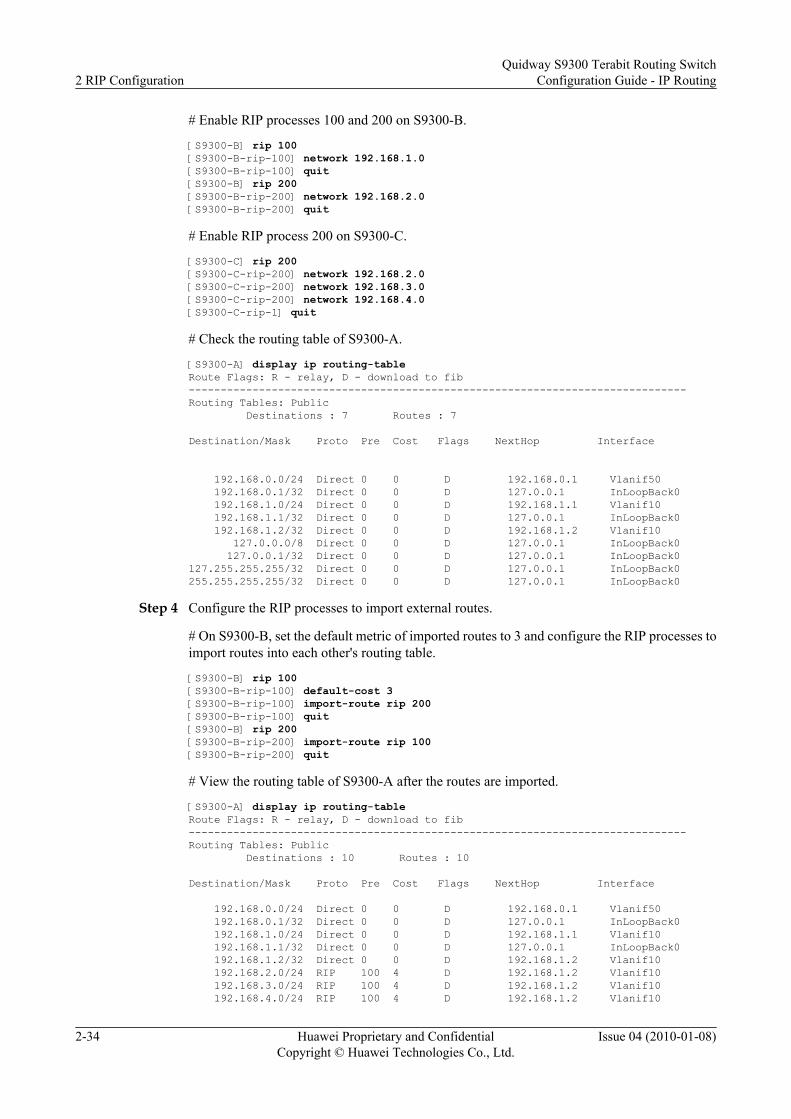
# Enable RIP processes 100 and 200 on S9300-B.
[S9300-B] rip 100[S9300-B-rip-100] network 192.168.1.0[S9300-B-rip-100] quit[S9300-B] rip 200[S9300-B-rip-200] network 192.168.2.0[S9300-B-rip-200] quit
# Enable RIP process 200 on S9300-C.
[S9300-C] rip 200[S9300-C-rip-200] network 192.168.2.0[S9300-C-rip-200] network 192.168.3.0[S9300-C-rip-200] network 192.168.4.0[S9300-C-rip-1] quit
# Check the routing table of S9300-A.
[S9300-A] display ip routing-tableRoute Flags: R - relay, D - download to fib------------------------------------------------------------------------------Routing Tables: Public Destinations : 7 Routes : 7
Destination/Mask Proto Pre Cost Flags NextHop Interface
192.168.0.0/24 Direct 0 0 D 192.168.0.1 Vlanif50 192.168.0.1/32 Direct 0 0 D 127.0.0.1 InLoopBack0 192.168.1.0/24 Direct 0 0 D 192.168.1.1 Vlanif10 192.168.1.1/32 Direct 0 0 D 127.0.0.1 InLoopBack0 192.168.1.2/32 Direct 0 0 D 192.168.1.2 Vlanif10 127.0.0.0/8 Direct 0 0 D 127.0.0.1 InLoopBack0 127.0.0.1/32 Direct 0 0 D 127.0.0.1 InLoopBack0127.255.255.255/32 Direct 0 0 D 127.0.0.1 InLoopBack0255.255.255.255/32 Direct 0 0 D 127.0.0.1 InLoopBack0
Step 4 Configure the RIP processes to import external routes.
# On S9300-B, set the default metric of imported routes to 3 and configure the RIP processes toimport routes into each other's routing table.
[S9300-B] rip 100[S9300-B-rip-100] default-cost 3[S9300-B-rip-100] import-route rip 200[S9300-B-rip-100] quit[S9300-B] rip 200[S9300-B-rip-200] import-route rip 100[S9300-B-rip-200] quit
# View the routing table of S9300-A after the routes are imported.
[S9300-A] display ip routing-tableRoute Flags: R - relay, D - download to fib------------------------------------------------------------------------------Routing Tables: Public Destinations : 10 Routes : 10
Destination/Mask Proto Pre Cost Flags NextHop Interface
192.168.0.0/24 Direct 0 0 D 192.168.0.1 Vlanif50 192.168.0.1/32 Direct 0 0 D 127.0.0.1 InLoopBack0 192.168.1.0/24 Direct 0 0 D 192.168.1.1 Vlanif10 192.168.1.1/32 Direct 0 0 D 127.0.0.1 InLoopBack0 192.168.1.2/32 Direct 0 0 D 192.168.1.2 Vlanif10 192.168.2.0/24 RIP 100 4 D 192.168.1.2 Vlanif10 192.168.3.0/24 RIP 100 4 D 192.168.1.2 Vlanif10 192.168.4.0/24 RIP 100 4 D 192.168.1.2 Vlanif10
2 RIP ConfigurationQuidway S9300 Terabit Routing Switch
Configuration Guide - IP Routing
2-34 Huawei Proprietary and ConfidentialCopyright © Huawei Technologies Co., Ltd.
Issue 04 (2010-01-08)

127.0.0.0/8 Direct 0 0 D 127.0.0.1 InLoopBack0 127.0.0.1/32 Direct 0 0 D 127.0.0.1 InLoopBack0127.255.255.255/32 Direct 0 0 D 127.0.0.1 InLoopBack0255.255.255.255/32 Direct 0 0 D 127.0.0.1 InLoopBack0
Step 5 Configure S9300-B to filter imported routes.
# Configure an ACL on S9300-B and add a rule to the ACL. The rule denies the packets sentfrom 192.168.4.0/24.
[S9300-B] acl 2000[S9300-B-acl-basic-2000] rule deny souce 192.168.4.0 0.0.0.255[S9300-B-acl-basic-2000] rule permit[S9300-B-acl-basic-2000] quit
# Configure S9300-B to filter the route to 192.168.4.0/24 that is imported from RIP200 accordingto the ACL rule.
[S9300-B] rip 100[S9300-B-rip-100] filter-policy 2000 export[S9300-B-rip-1] quit
Step 6 Verify the configuration.
# View the RIP routing table of S9300-A after the routes are filtered.
[S9300-A] display ip routing-tableRoute Flags: R - relay, D - download to fib------------------------------------------------------------------------------Routing Tables: Public Destinations : 9 Routes : 9
Destination/Mask Proto Pre Cost Flags NextHop Interface
192.168.0.0/24 Direct 0 0 D 192.168.0.1 Vlanif50 192.168.0.1/32 Direct 0 0 D 127.0.0.1 InLoopBack0 192.168.1.0/24 Direct 0 0 D 192.168.1.1 Vlanif10 192.168.1.1/32 Direct 0 0 D 127.0.0.1 InLoopBack0 192.168.1.2/32 Direct 0 0 D 192.168.1.2 Vlanif10 192.168.2.0/24 RIP 100 4 D 192.168.1.2 Vlanif10 192.168.3.0/24 RIP 100 4 D 192.168.1.2 Vlanif10 127.0.0.0/8 Direct 0 0 D 127.0.0.1 InLoopBack0 127.0.0.1/32 Direct 0 0 D 127.0.0.1 InLoopBack0127.255.255.255/32 Direct 0 0 D 127.0.0.1 InLoopBack0255.255.255.255/32 Direct 0 0 D 127.0.0.1 InLoopBack0
----End
Configuration Filesl Configuration file of S9300-A
# sysname S9300-A# vlan batch 10 50#interface Vlanif50 ip address 192.168.0.1 255.255.255.0#interface Vlanif10 ip address 192.168.1.1 255.255.255.0#interface GigabitEthernet1/0/0 port hybrid pvid vlan 10 port hybrid untagged vlan 10#interface GigabitEthernet2/0/0 port hybrid pvid vlan 50
Quidway S9300 Terabit Routing SwitchConfiguration Guide - IP Routing 2 RIP Configuration
Issue 04 (2010-01-08) Huawei Proprietary and ConfidentialCopyright © Huawei Technologies Co., Ltd.
2-35

port hybrid untagged vlan 50#rip 100 network 192.168.0.0 network 192.168.1.0#return
l Configuration file of S9300-B# sysname S9300-B# vlan batch 10 20#acl number 2000 rule 5 deny source 192.168.4.0 0.0.0.255 rule 10 permit#interface Vlanif10 ip address 192.168.1.2 255.255.255.0#interface Vlanif20 ip address 192.168.2.1 255.255.255.0#interface GigabitEthernet1/0/0 port hybrid pvid vlan 10 port hybrid untagged vlan 10#interface GigabitEthernet1/0/1 port hybrid pvid vlan 10 port hybrid untagged vlan 20#rip 100 default-cost 3 network 192.168.1.0 filter-policy 2000 export import-route rip 200#rip 200 network 192.168.2.0 import-route rip 100#return
l Configuration file of S9300-C# sysname S9300-C#vlan batch 20 30 40#interface Vlanif30 ip address 192.168.3.1 255.255.255.0#interface Vlanif40 ip address 192.168.4.1 255.255.255.0#interface Vlanif20 ip address 192.168.2.2 255.255.255.0#interface GigabitEthernet1/0/1 port hybrid pvid vlan 20 port hybrid untagged vlan 20#interface GigabitEthernet1/0/2 port hybrid pvid vlan 30 port hybrid untagged vlan 30#interface GigabitEthernet1/0/3 port hybrid pvid vlan 40 port hybrid untagged vlan 40
2 RIP ConfigurationQuidway S9300 Terabit Routing Switch
Configuration Guide - IP Routing
2-36 Huawei Proprietary and ConfidentialCopyright © Huawei Technologies Co., Ltd.
Issue 04 (2010-01-08)

#rip 200 network 192.168.2.0 network 192.168.3.0 network 192.168.4.0#return
Quidway S9300 Terabit Routing SwitchConfiguration Guide - IP Routing 2 RIP Configuration
Issue 04 (2010-01-08) Huawei Proprietary and ConfidentialCopyright © Huawei Technologies Co., Ltd.
2-37

3 RIPng Configuration
About This Chapter
This chapter describes the RIPng fundamentals and configuration steps for basic RIPngfunctions, controlling RIPng routing information, and adjusting and optimizing RIPng networks,along with typical examples.
3.1 RIPng OverviewThe Routing Information Protocol Next Generation (RIPng) protocol is an extension of RIP-2in an IPv4 network. Most RIP-related concepts can apply to RIPng.
3.2 Features Supported by the S9300In the S9300, you can modify the routing policy of RIPng by configuring RIPng route attributes.You can also control the advertising and receiving of RIPng routing information to meet therequirements of a complex network. In particular networking environments, you are required toconfigure certain features of RIPng to optimize the performance of a RIPng network.
3.3 Configuring Basic RIPng FunctionsThis section describes how to configure basic RIPng functions.
3.4 Configuring RIPng Route AttributesThis section describes how to change route selection by configuring RIPng route attributes.
3.5 Controlling the Advertising of RIPng Routing InformationThis section describes how to control the advertising of RIPng routing information in thecomplicated networking environment.
3.6 Controlling the Receiving of RIPng Routing InformationThis section describes how to control the receiving of RIPng routing information in thecomplicated networking environment.
3.7 Optimizing a RIPng NetworkThis section describes how to adjust and optimize RIPng networks.
3.8 Maintaining RIPngThis section describes how to maintain RIPng.
3.9 Configuration ExamplesThis section provides a configuration example of RIPng.
Quidway S9300 Terabit Routing SwitchConfiguration Guide - IP Routing 3 RIPng Configuration
Issue 04 (2010-01-08) Huawei Proprietary and ConfidentialCopyright © Huawei Technologies Co., Ltd.
3-1

3.1 RIPng OverviewThe Routing Information Protocol Next Generation (RIPng) protocol is an extension of RIP-2in an IPv4 network. Most RIP-related concepts can apply to RIPng.
Extension of RIPFor IPv6 applications, RIPng extends RIP as follows:
l UDP port number: uses UDP port number 521 to send and receive routing information.
l Multicast address: uses FF02::9 as the multicast address of a RIPng router in the local scopeof the links.
l Prefix length: uses a 128-bit (the mask length) prefix in the destination address.
l Next hop address: uses a 128-bit IPv6 address.
l Source address: uses the local link address FE80::/10 as the source address to send RIPngUpdate packets.
Operation Principle of RIPngRIPng is a protocol based on the Distance-Vector (DV) algorithm. It exchanges the routinginformation through User Datagram Protocol (UDP) packets. The number of the port used byRIPng is 521.
RIPng employs hop count to measure the distance to the destination. The distance is called themetric value. In RIPng, the hop count from a S9300 to its directly connected network is 0, andthat to a network, which can be reached through another S9300, is 1, and so on. The hop countthat is equal to or exceeds 16 is defined as infinity, that is, the destination network or the host isunreachable.
By default, RIPng sends an Update packet every 30 seconds. If no Update packet is receivedfrom a neighbor in 180 seconds, RIPng marks all routes learnt from the neighbor unreachable.If no Update packet is received from a neighbor in 300 seconds, RIPng deletes the routes of theneighbor from the routing table.
To improve the performance and to prevent routing loops, RIPng supports both split horizonand poison reverse. In addition, RIPng can import routes from other routing protocols.
Each S9300 running RIPng manages a routing database, which contains the routing entries toall the accessible destinations in a network. These routing entries contain the followinginformation:
l Destination address: indicates the IPv6 address of a host or a network.
l Next hop address: indicates the address of the next S9300 to the destination.
l Interface: indicates the interface through which an IP packet is forwarded.
l Cost: indicates the hop count to the destination. The value is an integer that ranges from 0to 16. When the value is 16, the network or the host is unreachable.
l Timer: indicates the time since a routing entry was last updated. The timer is reset to 0when a routing entry is updated.
l Route tag: indicates a label that differentiates the routes of internal routing protocols andthose of external routing protocols.
3 RIPng ConfigurationQuidway S9300 Terabit Routing Switch
Configuration Guide - IP Routing
3-2 Huawei Proprietary and ConfidentialCopyright © Huawei Technologies Co., Ltd.
Issue 04 (2010-01-08)

3.2 Features Supported by the S9300In the S9300, you can modify the routing policy of RIPng by configuring RIPng route attributes.You can also control the advertising and receiving of RIPng routing information to meet therequirements of a complex network. In particular networking environments, you are required toconfigure certain features of RIPng to optimize the performance of a RIPng network.
3.3 Configuring Basic RIPng FunctionsThis section describes how to configure basic RIPng functions.
3.3.1 Establishing the Configuration Task
3.3.2 Enabling RIPng and Entering the RIPng View
3.3.3 Enabling RIPng in the Interface View
3.3.4 Checking the Configuration
3.3.1 Establishing the Configuration Task
Applicable Environment
The configuration of basic RIPng functions involves the configuration of basic RIPng features.After the configuration, the RIPng features are available.
During the RIPng configuration, you should first enable RIPng. If you run RIPng-relatedcommands in the interface view, these commands take effect only after RIPng is enabled in thesystem view.
Pre-configuration Tasks
Before configuring basic RIPng functions, complete the following tasks:
l Enabling IPv6 on the S9300
l Configuring the IP addresses of the interfaces to keep the network layers accessible
Data Preparation
To configure basic RIPng functions, you need the following data.
No. Data
1 RIPng process ID
2 Interfaces on which RIPng is enabled
Quidway S9300 Terabit Routing SwitchConfiguration Guide - IP Routing 3 RIPng Configuration
Issue 04 (2010-01-08) Huawei Proprietary and ConfidentialCopyright © Huawei Technologies Co., Ltd.
3-3

3.3.2 Enabling RIPng and Entering the RIPng View
Context
Do as follows on the RIPng router:
Procedure
Step 1 Run:system-view
The system view is displayed.
Step 2 Run:ripng [ process-id ]
RIPng is enabled and the RIPng view is displayed.
When only one RIPng process is run, process-id is not specified. That is, process-id defaults to1.
When the process is cancelled, the ripng enable command on the interface need to bereconfigured.
----End
3.3.3 Enabling RIPng in the Interface View
Context
Do as follows on the RIPng router:
Procedure
Step 1 Run:system-view
The system view is displayed.
Step 2 Run:interface interface-type interface-number
The interface view is displayed.
The interface is at the network side of the S9300. To enable the S9300 to learn the routes of thenetwork segment where the interface resides, ensure that the link status of the interface is Up.
Step 3 Run:ripng process-id enable
RIPng is enabled on the specified interface.
NOTE
In the interface view, this command is invalid if no IPv6 address is configured.
3 RIPng ConfigurationQuidway S9300 Terabit Routing Switch
Configuration Guide - IP Routing
3-4 Huawei Proprietary and ConfidentialCopyright © Huawei Technologies Co., Ltd.
Issue 04 (2010-01-08)

If multiple interfaces on an S9300 connect other devices, repetitively perform Step 2 and Step3.
----End
3.3.4 Checking the Configuration
Procedurel Run display ripng [ process-id ] command to check the configuration of the RIPng process.
l Run display ripng process-id route command to check all activated and inactivated RIPngroutes.
----End
Example
Run the display ripng [ process-id ] command, and you can view the configuration of thespecified RIPng process.
<Quidway> display ripng 100 Public vpn6-instance name : RIPng process : 100 Preference : 100 Checkzero : Enabled Default Cost : 0 Maximum number of balanced paths : 6 Update time : 30 sec Age time : 180 sec Suppress time : 0 sec Garbage-Collect time : 120 sec Number of periodic updates sent : 0 Number of trigger updates sent : 1 Number of routes in database : 1 Number of interfaces enabled : 1
Run the display ripng process-id route command, and you can view all activated and inactivatedRIPng routes of the specified RIPng process.
<Quidway> display ripng 100 route Route Flags: A - Aging, S - Suppressed, G - Garbage-collect ---------------------------------------------------------------- Peer FE80::200:5EFF:FE04:B602 on Vlanif10 Dest 3FFE:C00:C18:1::/64, via FE80::200:5EFF:FE04:B602, cost 2, tag 0, A, 34 Sec Dest 3FFE:C00:C18:2::/64, via FE80::200:5EFF:FE04:B602, cost 2, tag 0, A, 34 Sec Peer FE80::200:5EFF:FE04:B601 on Vlanif10 Dest 3FFE:C00:C18:1::/64, via FE80::200:5EFF:FE04:B601, cost 2, tag 0, A, 13 Sec Dest 3FFE:C00:C18:3::/64, via FE80::200:5EFF:FE04:B601, cost 2, tag 0, A, 13 Sec Peer FE80::200:5EFF:FE04:3302 on Vlanif10 Dest 100::/32, via FE80::200:5EFF:FE04:3302, cost 2, tag 0, A, 6 Sec Dest 4000:1::/64, via FE80::200:5EFF:FE04:3302, cost 2, tag 0, A, 6 Sec Dest 4000:2::/64, via FE80::200:5EFF:FE04:3302, cost 2, tag 0, A, 6 Sec Dest 4000:3::/64, via FE80::200:5EFF:FE04:3302, cost 2, tag 0, A, 6 Sec Dest 4000:4::/64,
Quidway S9300 Terabit Routing SwitchConfiguration Guide - IP Routing 3 RIPng Configuration
Issue 04 (2010-01-08) Huawei Proprietary and ConfidentialCopyright © Huawei Technologies Co., Ltd.
3-5

3.4 Configuring RIPng Route AttributesThis section describes how to change route selection by configuring RIPng route attributes.
3.4.1 Establishing the Configuration Task
3.4.2 Configuring RIPng Protocol Preference
3.4.3 Configuring Additional Metrics of an Interface
3.4.4 Configuring the Maximum Number of Equal-Cost Routes
3.4.5 Checking the Configuration
3.4.1 Establishing the Configuration Task
Applicable EnvironmentIn actual applications, to meet the requirements of a complicated networking environment, youcan change RIPng routing policies by configuring RIPng route attributes. After performing theconfiguration procedures in this section, you can realize the following:
l Change route selection by adjusting the additional metric of a RIPng interface.
l Change the matching order of routing protocols by configuring the RIPng preference whenmultiple routing protocols contain routes to the same destination.
l Configure load balancing among multiple equal-cost routes.
Pre-configuration TasksBefore configuring RIPng route attributes, complete the following tasks:
l Configuring the IP addresses of interfaces to make the network layers accessible
l 3.3 Configuring Basic RIPng Functions
Data PreparationTo configure RIPng route attributes, you need the following data.
No. Data
1 Additional metric of the interface
2 RIPng preference
3 Maximum number of equal-cost routes
3 RIPng ConfigurationQuidway S9300 Terabit Routing Switch
Configuration Guide - IP Routing
3-6 Huawei Proprietary and ConfidentialCopyright © Huawei Technologies Co., Ltd.
Issue 04 (2010-01-08)

3.4.2 Configuring RIPng Protocol Preference
ContextDo as follows on the RIPng router:
Procedure
Step 1 Run:system-view
The system view is displayed.
Step 2 Run:ripng [ process-id ]
The RIPng process is enabled and the RIPng view is displayed.
Step 3 Run:preference { preference | route-policy route-policy-name }*
The RIPng preference is set.
Each routing protocol has its preference, according to which the routing policy selects the optimalroute. The RIPng preference can be set manually. The greater the value is, the lower thepreference is.
----End
3.4.3 Configuring Additional Metrics of an Interface
ContextDo as follows on the RIPng router:
Procedure
Step 1 Run:system-view
The system view is displayed.
Step 2 Run:interface interface-type interface-number
The interface view is displayed.
Step 3 Run:ripng metricin value
The metric added to a received route is set.
Step 4 Run:ripng metricout value
The metric added to a sent route is set.
Quidway S9300 Terabit Routing SwitchConfiguration Guide - IP Routing 3 RIPng Configuration
Issue 04 (2010-01-08) Huawei Proprietary and ConfidentialCopyright © Huawei Technologies Co., Ltd.
3-7

Using the ripng metricin command, you can add an additional metric to a received route, andthen add the route to the routing table. As a result, the metric in the routing table changes. Theripng metricout command is used for route advertisement. When a route is advertised, anadditional metric is added, but the metric in the routing table does not change.
NOTE
If the S9300 is connected to other devices that run RIPng through multiple interfaces, repeat Step 2 to Step4 to configure the metrics of all interfaces.
----End
3.4.4 Configuring the Maximum Number of Equal-Cost Routes
ContextDo as follows on the RIPng router:
Procedure
Step 1 Run:system-view
The system view is displayed.
Step 2 Run:ripng [ process-id ]
The RIPng process is enabled and the RIPng view is displayed.
Step 3 Run:maximum load-balancing number
The maximum number of equal-cost routes is set.
----End
3.4.5 Checking the Configuration
Procedurel Run display ripng [ process-id ] command to check the configuration of the RIPng process.l Run display ripng process-id database command to check routes in the RIPng database.l Run display ripng process-id route command to check all activated and inactivated RIPng
routes.
----End
3.5 Controlling the Advertising of RIPng RoutingInformation
This section describes how to control the advertising of RIPng routing information in thecomplicated networking environment.
3 RIPng ConfigurationQuidway S9300 Terabit Routing Switch
Configuration Guide - IP Routing
3-8 Huawei Proprietary and ConfidentialCopyright © Huawei Technologies Co., Ltd.
Issue 04 (2010-01-08)

3.5.1 Establishing the Configuration Task
3.5.2 Configuring RIPng Route Aggregation
3.5.3 Configuring RIPng to Advertise the Default Routes
3.5.4 Configuring the Default Cost for External Routes Imported by RIPng
3.5.5 Configuring RIPng to Import External Routes
3.5.6 Checking the Configuration
3.5.1 Establishing the Configuration Task
Applicable EnvironmentIn actual applications, to meet the requirements of a complicated networking environment, it isrequired to control the advertising of RIPng routing information. Through the configurationprocedures in this section, the following can be implemented:
l Advertise default routes to neighbors.
l Restrict interfaces from sending RIPng Update packets.
l Import external routes from various routing protocols and filter routes to be advertised.
Pre-configuration TasksBefore configuring a S9300 to control the advertising of RIPng routing information, completethe following tasks:
l Configuring the IP addresses of interfaces to make the network layers accessible
l 3.3 Configuring Basic RIPng Functions
Data PreparationTo control the advertising of RIPng routing information, you need the following data.
No. Data
1 Metric of the default route to be advertised
2 Protocol name and process ID of the external route to be imported
3.5.2 Configuring RIPng Route Aggregation
ContextDo as follows on the RIPng router:
Procedure
Step 1 Run:system-view
Quidway S9300 Terabit Routing SwitchConfiguration Guide - IP Routing 3 RIPng Configuration
Issue 04 (2010-01-08) Huawei Proprietary and ConfidentialCopyright © Huawei Technologies Co., Ltd.
3-9

The system view is displayed.
Step 2 Run:interface interface-type interface-number
The interface view is displayed.
Step 3 Run:ripng summary-address ipv6-address prefix-length [ avoid-feedback ]
RIPng route aggregation is configured.
This command is used to configure the RIPng router to advertise the IPv6 prefixes aggregatedon an interface instead of the specific route.
----End
3.5.3 Configuring RIPng to Advertise the Default Routes
Context
Do as follows on the RIPng router:
Procedure
Step 1 Run:system-view
The system view is displayed.
Step 2 Run:interface interface-type interface-number
The interface view is displayed.
Step 3 Run:ripng default-route { only | originate } [ cost cost ]
RIPng is enabled to advertise a default route.
Configure RIPng to advertise the default routes according to the actual networking:
l only: only the IPv6 default routes (::/0) are advertised, and the advertising of other routes issuppressed.
l originate: only the IPv6 default routes (::/0) are advertised, but the advertising of other routesis not affected.
The RIPng default routes are forcibly advertised by the Update packets through the specifiedinterface, regardless of whether the route exists in the IPv6 routing table.
----End
3 RIPng ConfigurationQuidway S9300 Terabit Routing Switch
Configuration Guide - IP Routing
3-10 Huawei Proprietary and ConfidentialCopyright © Huawei Technologies Co., Ltd.
Issue 04 (2010-01-08)

3.5.4 Configuring the Default Cost for External Routes Imported byRIPng
ContextDo as follows on the RIPng router:
Procedure
Step 1 Run:system-view
The system view is displayed.
Step 2 Run:ripng [ process-id ]
The RIPng view is displayed.
Step 3 Run:default-cost cost
The default cost for external routes imported by RIPng is set.
When no metric is specified, the command sets the default cost for external routes imported byRIPng from other routing protocols.
----End
3.5.5 Configuring RIPng to Import External Routes
ContextDo as follows on the RIPng router:
Procedure
Step 1 Run:system-view
The system view is displayed.
Step 2 Run:ripng [ process-id ]
The RIPng view is displayed.
Step 3 (Optional) Run:default-cost cost
The default cost for imported external routes is set.
If no route cost is specified for imported routes, the default cost is used.
Step 4 Run:import-route protocol [ process-id ] [ cost cost ] [ route-policy route-policy-name ]
Quidway S9300 Terabit Routing SwitchConfiguration Guide - IP Routing 3 RIPng Configuration
Issue 04 (2010-01-08) Huawei Proprietary and ConfidentialCopyright © Huawei Technologies Co., Ltd.
3-11

External routes are imported.
Step 5 (Optional) Run:filter-policy { acl6-number | ipv6-prefix ipv6-prefix-name } export [ protocol [ process-id ] ]
RIPng is configured to filter the imported and advertised routing information.
RIPng can filter the imported routes based on the ACL6 or IPv6 prefix list. Only the routesmatching the rules are advertised. If protocol is not specified in the command, all the routinginformation to be advertised is filtered, including the imported routes and the local RIPng routes(equivalent to the directly connected routes).
----End
3.5.6 Checking the Configuration
Procedurel Run display ripng process-id database command to check the routes in the RIPng
database.l Run display ripng process-id route command to check all activated and inactivated RIPng
routes.
----End
3.6 Controlling the Receiving of RIPng Routing InformationThis section describes how to control the receiving of RIPng routing information in thecomplicated networking environment.
3.6.1 Establishing the Configuration Task
3.6.2 Configuring RIPng to Filter the Received Routes
3.6.3 Checking the Configuration
3.6.1 Establishing the Configuration Task
Applicable EnvironmentIn actual applications, to meet the requirements of a complicated networking environment, it isrequired to control the receiving of RIPng routing information accurately. Through theconfiguration procedures in this section, the following can be implemented:
l Disable an interface from receiving RIPng Update packets.
l Filter the received routing information.
l Import external routes from various routing protocols and filter the imported routes.
Pre-configuration TasksBefore configuring a S9300 to control the receiving of RIPng routing information, complete thefollowing tasks:
3 RIPng ConfigurationQuidway S9300 Terabit Routing Switch
Configuration Guide - IP Routing
3-12 Huawei Proprietary and ConfidentialCopyright © Huawei Technologies Co., Ltd.
Issue 04 (2010-01-08)

l Configuring the IP addresses of interfaces to make the network layers accessible
l Configuring Basic RIPng Functions
Data Preparation
To control the receiving of RIPng routing information, you need the following data.
No. Data
1 ACL used to filter the routing information
3.6.2 Configuring RIPng to Filter the Received Routes
Context
Do as follows on the RIPng router:
Procedure
Step 1 Run:system-view
The system view is displayed.
Step 2 Run:ripng [ process-id ]
The RIPng view is displayed.
Step 3 Run:filter-policy { acl6-number | ipv6-prefix ipv6-prefix-name } import
The imported routes are filtered.
You can specify the ACL6 or IPv6 prefix list to filter the imported routes. Only the routes passingthe filter can be added to the RIPng routing table.
----End
3.6.3 Checking the Configuration
Procedurel Run display ripng process-id database command to check the routes in the RIPng
database.
l Run display ripng process-id route command to check all activated and inactivated RIPngroutes.
----End
Quidway S9300 Terabit Routing SwitchConfiguration Guide - IP Routing 3 RIPng Configuration
Issue 04 (2010-01-08) Huawei Proprietary and ConfidentialCopyright © Huawei Technologies Co., Ltd.
3-13

3.7 Optimizing a RIPng NetworkThis section describes how to adjust and optimize RIPng networks.
3.7.1 Establishing the Configuration Task
3.7.2 Configuring RIPng Timers
3.7.3 Configuring Split Horizon and Poison Reverse
3.7.4 Enabling Zero Field Check of the RIPng Packets
3.7.5 Checking the Configuration
3.7.1 Establishing the Configuration Task
Applicable EnvironmentIn particular networking environments, you need to configure RIPng features and optimize theperformance of a RIPng network. Through the configuration procedures in this section, thefollowing can be implemented:
l Change the convergence speed of the RIPng network by adjusting RIPng timers.
l Configure split horizon and poison reverse to avoid routing loops.
Pre-configuration TasksBefore optimizing a RIPng network, complete the following tasks:
l Configuring the IP addresses of interfaces to make the network layers accessible
l Configuring Basic RIPng Functions
Data PreparationTo optimize a RIPng network, you need the following data.
No. Data
1 Values of timers
3.7.2 Configuring RIPng Timers
ContextDo as follows on the RIPng router:
Procedure
Step 1 Run:
3 RIPng ConfigurationQuidway S9300 Terabit Routing Switch
Configuration Guide - IP Routing
3-14 Huawei Proprietary and ConfidentialCopyright © Huawei Technologies Co., Ltd.
Issue 04 (2010-01-08)

system-view
The system view is displayed.
Step 2 Run:ripng [ process-id ]
The RIPng view is displayed.
Step 3 Run:timers ripng update age suppress garbage-collect
The RIPng timers are configured.
Note that the route flapping occurs if the values of these four timers are not configured properly.The relationship of the values is: update<age, suppress<garbage-collect. For example, if theupdate time is longer than the aging time, and if RIPng routes change, during the update time,S9300s cannot inform their neighbors immediately.
NOTE
The configured suppress timer does not take effect on the local system.
----End
3.7.3 Configuring Split Horizon and Poison Reverse
Context
Do as follows on the RIPng router:
Procedure
Step 1 Run:system-view
The system view is displayed.
Step 2 Run:interface interface-type interface-number
The interface view is displayed.
Step 3 Run:ripng split-horizon
Split horizon is enabled.
Step 4 Run:ripng poison-reverse
Poison reverse is enabled.
Split horizon means that the route received through an interface is not sent through this interfaceagain. Routing loops are thus avoided. But in NBMA networks such as Frame Relay and X.25,if no sub-interface is configured, split horizon must be disabled to ensure the accurateadvertisement of the routes.
Quidway S9300 Terabit Routing SwitchConfiguration Guide - IP Routing 3 RIPng Configuration
Issue 04 (2010-01-08) Huawei Proprietary and ConfidentialCopyright © Huawei Technologies Co., Ltd.
3-15

Poison reverse means that the routes learned from an interface are also sent through the sameinterface. However, the metric of this route is set to 16. That means the route is unreachable.
----End
3.7.4 Enabling Zero Field Check of the RIPng Packets
Context
Do as follows on the RIPng router:
Procedure
Step 1 Run:system-view
The system view is displayed.
Step 2 Run:ripng [ process-id ]
The RIPng view is displayed.
Step 3 Run:checkzero
The zero field check is configured for RIPng packets.
Certain fields in a RIPng packet must be 0s, and they are called zero fields. If the value of anyzero field is not 0, the packet is not processed.
----End
3.7.5 Checking the Configuration
Procedurel Run display ripng [ process-id ] command to check the configuration of the RIPng process.l Run display ripng process-id database [ verbose ] command to check the routes in the
RIPng database.l Run display ripng process-id interface [ interface-type interface-number ] [ verbose ]
command to check information about RIPng interfaces.l Run display ripng process-id neighbor [ verbose ] command to check information about
RIPng neighbors.l Run display ripng process-id route command to check all activated and inactivated RIPng
routes.
----End
3.8 Maintaining RIPngThis section describes how to maintain RIPng.
3 RIPng ConfigurationQuidway S9300 Terabit Routing Switch
Configuration Guide - IP Routing
3-16 Huawei Proprietary and ConfidentialCopyright © Huawei Technologies Co., Ltd.
Issue 04 (2010-01-08)

Context
CAUTIONDebugging affects the performance of the system. So, after debugging, run the undo debuggingall command to disable it immediately.
When a RIPng fault occurs, run the following debugging commands in the user view to debugRIPng and locate the fault.
For the procedure of displaying the debugging information, refer to the chapter "InformationCenter Configuration" in the Quidway S9300Terabit Routing SwitchConfiguration Guide -Device Management.
For the related debugging command, refer to the Quidway S9300Terabit RoutingSwitchDebugging Reference.
Action Command
Debug the specified RIPngprocess.
debugging ripng process-id [ brief | error | event | job |packet | receive | route-processing | send | timer ]
Debug the specified RIPnginterface.
debugging ripng interface-type interface-number[ packet | receive | send ]
3.9 Configuration ExamplesThis section provides a configuration example of RIPng.
3.9.1 Example for Configuring RIPng to Filter the Received Routes
3.9.1 Example for Configuring RIPng to Filter the Received Routes
Networking RequirementsAs shown in Figure 3-1, the prefix length of all the IPv6 addresses is 64 bits. In addition, theVLANIF interfaces between the neighboring S9300s are assigned IPv6 link-local addresses.
All the S9300s must learn IPv6 routing information on the network through RIPng. S9300-Bshould filter the routes received from S9300-C (3::/64). That is, S9300-B does not add the routesto its own routing table or advertise the routes to S9300-A.
Quidway S9300 Terabit Routing SwitchConfiguration Guide - IP Routing 3 RIPng Configuration
Issue 04 (2010-01-08) Huawei Proprietary and ConfidentialCopyright © Huawei Technologies Co., Ltd.
3-17

Figure 3-1 Networking diagram for configuring RIPng to filter the received routes
S9300-AGE1/0/0
GE1/0/0 GE2/0/0
GE1/0/0GE2/0/0
GE2/0/0
S9300-CS9300-B
1::1/64 3::1/64VLANIF10 VLANIF50
VLANIF30
VLANIF20
VLANIF20
VLANIF302::1/64
GE3/0/0
VLANIF40
Device name Interface VLANIF interface IP address
S9300-A GE2/0/0 VLANIF 10 1::1/64
S9300-A GE1/0/0 VLANIF 20 Generated automatically
S9300-B GE1/0/0 VLANIF 20 Generated automatically
S9300-B GE2/0/0 VLANIF 30 Generated automatically
S9300-C GE1/0/0 VLANIF 30 Generated automatically
S9300-C GE2/0/0 VLANIF 40 2::1/64
S9300-C GE3/0/0 VLANIF 50 3::1/64
Configuration RoadmapThe configuration roadmap is as follows:
1. Enable RIPng on each S9300 so that the S9300s can communicate with each other.2. Configure an ACL on S9300-B to filter the received routes.
Data PreparationTo complete the configuration, you need the following data:
l IDs of the VLANs that the interfaces belong to, as shown in Figure 3-1
l RIPng1 enabled on each S9300
l ACL6 2000 on S9300-B, which rejects the routes from network segment 3::/64
Procedure
Step 1 Add interfaces to VLANs.<Quidway> system-view[Quidway] sysname S9300-A[S9300-A] vlan 10[S9300-A-vlan10] quit[S9300-A] interface GigabitEthernet 2/0/0[S9300-A-GigabitEthernet2/0/0] port hybrid pvid vlan 10[S9300-A-GigabitEthernet2/0/0] port hybrid untagged vlan 10[S9300-A-GigabitEthernet2/0/0] quit[S9300-A] vlan 20[S9300-A-vlan20] quit
3 RIPng ConfigurationQuidway S9300 Terabit Routing Switch
Configuration Guide - IP Routing
3-18 Huawei Proprietary and ConfidentialCopyright © Huawei Technologies Co., Ltd.
Issue 04 (2010-01-08)

[S9300-A] interface GigabitEthernet 1/0/0[S9300-A-GigabitEthernet1/0/0] port hybrid pvid vlan 20[S9300-A-GigabitEthernet1/0/0] port hybrid untagged vlan 20[S9300-A-GigabitEthernet1/0/0] quit
The configurations of S9300-B and S9300-C are similar to the configuration of S9300-A andare not mentioned here.
Step 2 Assign IP addresses to the VLANIF interfaces.[S9300-A] ipv6[S9300-A] interface vlanif 10[S9300-A-Vlanif10] ipv6 enable[S9300-A-Vlanif10] ipv6 address 1::1/64[S9300-A-Vlanif10] quit[S9300-A] interface vlanif 20[S9300-A-Vlanif20] ipv6 enable[S9300-A-Vlanif20] ipv6 address auto link-local[S9300-A-Vlanif20] quit
The configurations of S9300-B and S9300-C are similar to the configuration of S9300-A andare not mentioned here.
Step 3 Configure the basic RIPng functions.
# Configure S9300-A.
[S9300-A] ripng 1[S9300-A-ripng-1] quit[S9300-A] interface vlanif 10[S9300-A-Vlanif10] ripng 1 enable[S9300-A-Vlanif10] quit[S9300-A] interface vlanif 20[S9300-A-Vlanif20] ripng 1 enable[S9300-A-Vlanif20] quit
# Configure S9300-B.
[S9300-B] ripng 1[S9300-B-ripng-1] quit[S9300-B] interface vlaif 20[S9300-B-Vlanif20] ripng 1 enable[S9300-B-Vlanif20] quit[S9300-B] interface vlanif 30[S9300-B-Vlanif30] ripng 1 enable[S9300-B-Vlanif30] quit
# Configure S9300-C.
[S9300-C] ripng 1[S9300-C-ripng-1] quit[S9300-C] interface vlanif 30[S9300-C-Vlanif30] ripng 1 enable[S9300-C-Vlanif30] quit[S9300-C] interface vlanif 40[S9300-C-Vlanif40] ripng 1 enable[S9300-C-Vlanif40] quit[S9300-C] interface vlanif 50[S9300-C-Vlanif50] ripng 1 enable[S9300-C-Vlanif50] quit
# Display the RIPng routing table of S9300-B.
[S9300-B] display ripng 1 route Route Flags: A - Aging, S - Suppressed, G - Garbage-collect ----------------------------------------------------------------
Peer FE80::F54C:0:9FDB:1 on Vlanif30 Dest 2::/64, via FE80::F54C:0:9FDB:1, cost 1, tag 0, A, 3 Sec
Quidway S9300 Terabit Routing SwitchConfiguration Guide - IP Routing 3 RIPng Configuration
Issue 04 (2010-01-08) Huawei Proprietary and ConfidentialCopyright © Huawei Technologies Co., Ltd.
3-19

Dest 3::/64, via FE80::F54C:0:9FDB:1, cost 1, tag 0, A, 3 Sec
Peer FE80::D472:0:3C23:1 on Vlanif20 Dest 1::/64, via FE80::D472:0:3C23:1, cost 1, tag 0, A, 4 Sec
The preceding information shows that the RIPng routing table of S9300-B contains the routesof network segment 3::/64.
# Display the RIPng routing table of S9300-A.
[S9300-A] display ripng 1 route Route Flags: A - Aging, S - Suppressed, G - Garbage-collect ----------------------------------------------------------------
Peer FE80::476:0:3624:1 on Vlanif20 Dest 2::/64, via FE80::476:0:3624:1, cost 2, tag 0, A, 21 Sec Dest 3::/64, via FE80::476:0:3624:1, cost 2, tag 0, A, 21 Sec
The preceding information shows that the RIPng routing table of S9300-A contains the routesof network segment 3::/64 advertised by S9300-B.
Step 4 Configure S9300-B to filter the received routes.[S9300-B] acl ipv6 number 2000[S9300-B-acl6-basic-2000] rule deny source 3:: 64[S9300-B-acl6-basic-2000] rule permit[S9300-B-acl6-basic-2000] quit[S9300-B] ripng 1[S9300-B-ripng-1] filter-policy 2000 import[S9300-B-ripng-1] quit
Step 5 Verify the configuration.
# Check the RIPng routing table of S9300-B. The RIPng routing table should not contain theroutes of network segment 3::/64.
[S9300-B] display ripng 1 route Route Flags: A - Aging, S - Suppressed, G - Garbage-collect ----------------------------------------------------------------
Peer FE80::F54C:0:9FDB:1 on Vlanif30 Dest 2::/64, via FE80::F54C:0:9FDB:1, cost 1, tag 0, A, 14 Sec
Peer FE80::D472:0:3C23:1 on Vlanif20 Dest 1::/64, via FE80::D472:0:3C23:1, cost 1, tag 0, A, 25 Sec
# Check the RIPng routing table of S9300-A. The RIPng routing table should not contain theroutes of network segment 3::/64.
[S9300-A] display ripng 1 route Route Flags: A - Aging, S - Suppressed, G - Garbage-collect ----------------------------------------------------------------
Peer FE80::476:0:3624:1 on Vlanif20 Dest 2::/64, via FE80::476:0:3624:1, cost 2, tag 0, A, 7 Sec
----End
3 RIPng ConfigurationQuidway S9300 Terabit Routing Switch
Configuration Guide - IP Routing
3-20 Huawei Proprietary and ConfidentialCopyright © Huawei Technologies Co., Ltd.
Issue 04 (2010-01-08)
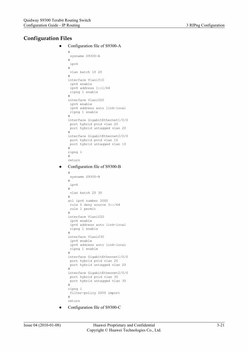
Configuration Filesl Configuration file of S9300-A
# sysname S9300-A# ipv6# vlan batch 10 20#interface Vlanif10 ipv6 enable ipv6 address 1::1/64 ripng 1 enable#interface Vlanif20 ipv6 enable ipv6 address auto link-local ripng 1 enable#interface GigabitEthernet1/0/0 port hybrid pvid vlan 20 port hybrid untagged vlan 20#interface GigabitEthernet2/0/0 port hybrid pvid vlan 10 port hybrid untagged vlan 10#ripng 1#return
l Configuration file of S9300-B# sysname S9300-B# ipv6# vlan batch 20 30#acl ipv6 number 2000 rule 0 deny source 3::/64 rule 1 permit#interface Vlanif20 ipv6 enable ipv6 address auto link-local ripng 1 enable#interface Vlanif30 ipv6 enable ipv6 address auto link-local ripng 1 enable#interface GigabitEthernet1/0/0 port hybrid pvid vlan 20 port hybrid untagged vlan 20#interface GigabitEthernet2/0/0 port hybrid pvid vlan 30 port hybrid untagged vlan 30#ripng 1 filter-policy 2000 import#return
l Configuration file of S9300-C
Quidway S9300 Terabit Routing SwitchConfiguration Guide - IP Routing 3 RIPng Configuration
Issue 04 (2010-01-08) Huawei Proprietary and ConfidentialCopyright © Huawei Technologies Co., Ltd.
3-21

# sysname S9300-C# ipv6# vlan batch 30 40 50#interface Vlanif30 ipv6 enable ipv6 address auto link-local ripng 1 enable#interface Vlanif40 ipv6 enable ipv6 address 2::1/64 ripng 1 enable#interface Vlanif50 ipv6 enable ipv6 address 3::1/64 ripng 1 enable#interface GigabitEthernet1/0/0 port hybrid pvid vlan 30 port hybrid untagged vlan 30#interface GigabitEthernet2/0/0 port hybrid pvid vlan 40 port hybrid untagged vlan 40#interface GigabitEthernet3/0/0 port hybrid pvid vlan 50 port hybrid untagged vlan 50#ripng 1#return
3 RIPng ConfigurationQuidway S9300 Terabit Routing Switch
Configuration Guide - IP Routing
3-22 Huawei Proprietary and ConfidentialCopyright © Huawei Technologies Co., Ltd.
Issue 04 (2010-01-08)

4 OSPF Configuration
About This Chapter
This chapter describes the concepts of OSPF and the procedure for configuring OSPF, andprovides configuration examples of OSPF.
4.1 Introduction to OSPFThis section describes the principle and concepts of OSPF.
4.2 OSPF Features Supported by the S9300This section describes the OSPF features supported by the S9300.
4.3 Configuring Basic OSPF FunctionsThis section describes how to enable OSPF and configure the basic OSPF functions.
4.4 Establishing and Maintaining OSPF AdjacenciesThis section describes how to set parameters related to packet transmission between adjacentOSPF devices.
4.5 Configuring OSPF Area AttributesThis section describes how to configure a stub area, an NSSA area, and a virtual link in an OSPFdomain.
4.6 Configuring OSPF Attributes on Networks of Different TypesThis section describes how to use certain commands to change the network type of an interfaceto meet the requirements of the network, how to configure the DR election function in a broadcastnetwork or an NBMA network, and how to configure OSPF features in an NBMA network.
4.7 Configuring OSPF Route AttributesThis section describes how to set the link cost, priority of OSPF routes, and maximum numberof equal-cost routes.
4.8 Configuring OSPF Route AggregationThis section describes how to configure the OSPF route aggregation function.
4.9 Configuring Filtering of OSPF Routing InformationThis section describes how to configure the S9300 to filter the OSPF routing information andimport routes learned by other protocols.
4.10 Adjusting and Optimizing the OSPF Network
Quidway S9300 Terabit Routing SwitchConfiguration Guide - IP Routing 4 OSPF Configuration
Issue 04 (2010-01-08) Huawei Proprietary and ConfidentialCopyright © Huawei Technologies Co., Ltd.
4-1

This section describes how to adjust and optimize the OSPF network according to the actualnetworking environment.
4.11 Configuring OSPF GRThis section describes how to configure OSPF GR to prevent inaccurate route calculation andpacket loss after the S9300 restarts.
4.12 Configuring BFD for OSPFThis section describes how to implement fast convergence on an OSPF network through BFD.
4.13 Configuring the Authentication Function on an OSPF NetworkThis section describes how to configure the OSPF area authentication mode and interfaceauthentication mode.
4.14 Configuring Network Management Functions of OSPFThis section describes how to bind an OSPF process to the Management Information Base (MIB)and configure the OSPF trap function and log function.
4.15 Maintaining OSPFThis section describes how to restart an OSPF process, delete the OSPF information, and debugOSPF.
4.16 Configuration ExamplesThis section provides several configuration examples of OSPF.
4 OSPF ConfigurationQuidway S9300 Terabit Routing Switch
Configuration Guide - IP Routing
4-2 Huawei Proprietary and ConfidentialCopyright © Huawei Technologies Co., Ltd.
Issue 04 (2010-01-08)

4.1 Introduction to OSPFThis section describes the principle and concepts of OSPF.
The Open Shortest Path First (OSPF) protocol, developed by the Internet Engineering Task Force(IETF), is an interior gateway protocol based on the link status. Currently, OSPF version 2, asexplained in RFC 2328, is used for IPv4.
NOTE
In this chapter, OSPF refers to OSPFv2, unless otherwise specified.
Features of OSPF
OSPF has the following features:
l Wide usage: OSPF can run on a large-scale network.
l Fast convergence: When the network topology changes, the OSPF process sends updatepackets to synchronize the link state databases (LSDBs) of all the devices in an autonomoussystem (AS).
l Loop-free: According to the collected link status, OSPF calculates routes by using theshortest path first (SPT) algorithm. This algorithm prevents routing loops.
l Area partitioning: An AS is partitioned into areas to simplify AS management. Theaggregated routing information is exchanged between areas, which saves networkbandwidth.
l Equal-cost routes: OSPF allows multiple equal-cost routes to the same destination.
l Routing hierarchy: Four types of routes are available. They are listed in a descending orderof IP precedence: intra-area routes, inter-area routes, Type 1 external routes, and Type 2external routes.
l Support for authentication: Packets are authenticated based on areas and interfaces to ensurethe security of packet exchange.
l Multicast: Protocol packets are sent in multicast mode on certain types of links. This reducesthe interference to the devices that are not enabled with OSPF.
Calculation of OSPF Routes
The calculation of OSPF routes is described as follows:
l Based on the surrounding network topology, each OSPF device generates a link stateadvertisement (LSA). The OSPF device sends update packets containing the LSA to otherOSPF devices.
l Each OSPF device collects the LSAs from other devices in the same AS, and all these LSAsconstitute the LSDB. An LSA describes the network topology around an S9300, whereasan LSDB describes the network topology of the entire AS.
l OSPF devices transform the LSDB into a directed map with costs. The directed maprepresents the topology of an area. All devices in the same area have the same map.
l According to the directed map, each S9300 uses the SPF algorithm to calculate the shortestpath tree with itself being the root. The tree shows the routes to every node in the area.
Quidway S9300 Terabit Routing SwitchConfiguration Guide - IP Routing 4 OSPF Configuration
Issue 04 (2010-01-08) Huawei Proprietary and ConfidentialCopyright © Huawei Technologies Co., Ltd.
4-3
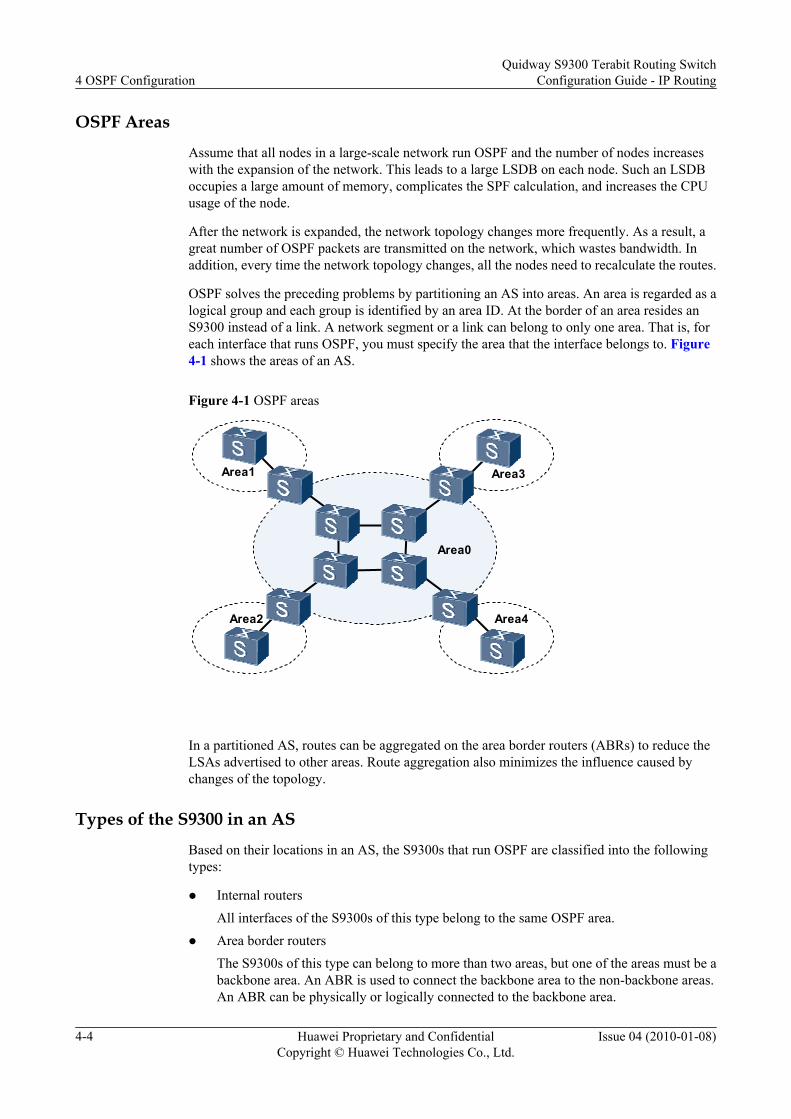
OSPF Areas
Assume that all nodes in a large-scale network run OSPF and the number of nodes increaseswith the expansion of the network. This leads to a large LSDB on each node. Such an LSDBoccupies a large amount of memory, complicates the SPF calculation, and increases the CPUusage of the node.
After the network is expanded, the network topology changes more frequently. As a result, agreat number of OSPF packets are transmitted on the network, which wastes bandwidth. Inaddition, every time the network topology changes, all the nodes need to recalculate the routes.
OSPF solves the preceding problems by partitioning an AS into areas. An area is regarded as alogical group and each group is identified by an area ID. At the border of an area resides anS9300 instead of a link. A network segment or a link can belong to only one area. That is, foreach interface that runs OSPF, you must specify the area that the interface belongs to. Figure4-1 shows the areas of an AS.
Figure 4-1 OSPF areas
Area1
Area0
Area3
Area2 Area4
In a partitioned AS, routes can be aggregated on the area border routers (ABRs) to reduce theLSAs advertised to other areas. Route aggregation also minimizes the influence caused bychanges of the topology.
Types of the S9300 in an AS
Based on their locations in an AS, the S9300s that run OSPF are classified into the followingtypes:
l Internal routersAll interfaces of the S9300s of this type belong to the same OSPF area.
l Area border routersThe S9300s of this type can belong to more than two areas, but one of the areas must be abackbone area. An ABR is used to connect the backbone area to the non-backbone areas.An ABR can be physically or logically connected to the backbone area.
4 OSPF ConfigurationQuidway S9300 Terabit Routing Switch
Configuration Guide - IP Routing
4-4 Huawei Proprietary and ConfidentialCopyright © Huawei Technologies Co., Ltd.
Issue 04 (2010-01-08)

l Backbone routersA minimum of one interface on the S9300 of this type belongs to the backbone area.Therefore, all ABRs and the internal nodes in Area 0 are backbone routers.
l Autonomous system boundary routers (ASBRs)The S9300 that exchanges routing information with other ASs is called an ASBR. TheASBR may not be located on the boundary of an AS. It can be an internal router or an ABR.When an OSPF device imports the external routing information, the device becomes anASBR.
Figure 4-2 shows various types of OSPF devices.
Figure 4-2 OSPF device types
Area1
Area0
Area3
Area4
ASBROSPF
BackboneRouter
Internal Router
ABR
Area2
OSPF Network TypesBased on the types of the link layer protocol, OSPF classifies networks into the following types:
l Broadcast: If the link layer protocol is Ethernet or Fiber Distributed Digital Interface(FDDI), OSPF considers the network type as broadcast by default. In a broadcast network,Hello packets, Link State Update (LSU) packets, and Link State Acknowledgement(LSAck) packets are transmitted in multicast mode, and Database Description (DD) packetsand Link State Request (LSR) packets are transmitted in unicast mode. In multicast mode,224.0.0.5 is the reserved multicast IP address of the OSPF device; 224.0.0.6 is the reservedmulticast IP address of the OSPF Designated Router (DR).
l NBMA: If the link layer protocol is Frame Relay (FR), ATM, or X.25, OSPF considers thenetwork type as NBMA by default. In an NBMA network, the protocol packets, includingHello packets, DD packets, LSR packets, LSU packets, and LSAck packets, are transmittedin unicast mode.
l Point-to-multipoint (P2MP): OSPF does not consider the network type as P2MP by default,regardless of link layer protocols. A P2MP network must be forcibly changed from othernetwork types. Generally, a non-full-mesh NBMA network is changed to a P2MP network.In a P2MP network, the protocol packets, including Hello packets, DD packets, LSR
Quidway S9300 Terabit Routing SwitchConfiguration Guide - IP Routing 4 OSPF Configuration
Issue 04 (2010-01-08) Huawei Proprietary and ConfidentialCopyright © Huawei Technologies Co., Ltd.
4-5

packets, LSU packets, and LSAck packets, are transmitted to the multicast IP address224.0.0.5.
l Point-to-point (P2P): If the link layer protocol is the Point-to-Point Protocol (PPP), HighLevel Data Link Control (HDLC), or Link Access Procedure Balanced (LAPB), OSPFconsiders the network type as P2P by default. In a P2P network, the protocol packets,including Hello packets, DD packets, LSR packets, LSU packets, and LSAck packets, aretransmitted to the multicast address 224.0.0.5.
The link layer protocol of the physical interface of the S9300 is Ethernet. Therefore, OSPFconsiders the network type of the S9300 interface as broadcast by default.
4.2 OSPF Features Supported by the S9300This section describes the OSPF features supported by the S9300.
Interfaces That Support OSPFThe creation of OSPF routing tables and configurations of OSPF functions must be performedon Layer 3 interfaces. Except the management network interface, the physical interfaces on theS9300, however, are Layer 2 interfaces. To solve this problem, do as follows on the S9300:
l Create a VLAN and add a Layer 2 interface to the VLAN to define a VLANIF interface.Then, assign an IP address to the VLANIF interface and enable OSPF functions on theVLANIF interface.
l Set the IP address of the loopback interface and enable OSPF functions.
NOTE
In the following configuration tasks, the configurations in the interface view must be completed on theVLANIF interface or loopback interface unless otherwise specified.For details about the Layer 2 interface configuration, see the Quidway S9300 Terabit Routing SwitchConfiguration Guide - Ethernet.
Multi-ProcessOSPF supports multi-process. Up to OSPF 150 processes can run on the same S9300, they areindependent of each other. The routing exchange between different OSPF processes is similarto the interaction between different routing protocols.
An interface of an S9300 can belong to only one OSPF process.
AuthenticationOSPF supports packet authentication. Only the OSPF packets that pass the authentication areaccepted; otherwise, the neighbor relationship cannot be established. The S9300 supports thefollowing authentication modes:
l Area authenticationl Interface authentication
If both modes are available, interface authentication is preferred.
OSPF Hot StandbyThe S9300 supports the hot standby feature of OSPF. OSPF backs up necessary data of themaster main control board to the slave main control board. Whenever the master main control
4 OSPF ConfigurationQuidway S9300 Terabit Routing Switch
Configuration Guide - IP Routing
4-6 Huawei Proprietary and ConfidentialCopyright © Huawei Technologies Co., Ltd.
Issue 04 (2010-01-08)
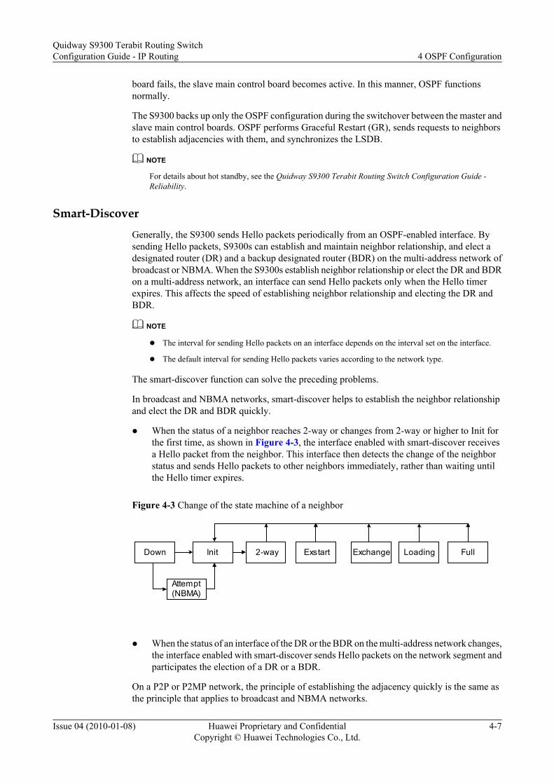
board fails, the slave main control board becomes active. In this manner, OSPF functionsnormally.
The S9300 backs up only the OSPF configuration during the switchover between the master andslave main control boards. OSPF performs Graceful Restart (GR), sends requests to neighborsto establish adjacencies with them, and synchronizes the LSDB.
NOTE
For details about hot standby, see the Quidway S9300 Terabit Routing Switch Configuration Guide -Reliability.
Smart-DiscoverGenerally, the S9300 sends Hello packets periodically from an OSPF-enabled interface. Bysending Hello packets, S9300s can establish and maintain neighbor relationship, and elect adesignated router (DR) and a backup designated router (BDR) on the multi-address network ofbroadcast or NBMA. When the S9300s establish neighbor relationship or elect the DR and BDRon a multi-address network, an interface can send Hello packets only when the Hello timerexpires. This affects the speed of establishing neighbor relationship and electing the DR andBDR.
NOTE
l The interval for sending Hello packets on an interface depends on the interval set on the interface.
l The default interval for sending Hello packets varies according to the network type.
The smart-discover function can solve the preceding problems.
In broadcast and NBMA networks, smart-discover helps to establish the neighbor relationshipand elect the DR and BDR quickly.
l When the status of a neighbor reaches 2-way or changes from 2-way or higher to Init forthe first time, as shown in Figure 4-3, the interface enabled with smart-discover receivesa Hello packet from the neighbor. This interface then detects the change of the neighborstatus and sends Hello packets to other neighbors immediately, rather than waiting untilthe Hello timer expires.
Figure 4-3 Change of the state machine of a neighbor
Down FullLoadingExchange Exstart 2-wayInit
Attempt(NBMA)
l When the status of an interface of the DR or the BDR on the multi-address network changes,
the interface enabled with smart-discover sends Hello packets on the network segment andparticipates the election of a DR or a BDR.
On a P2P or P2MP network, the principle of establishing the adjacency quickly is the same asthe principle that applies to broadcast and NBMA networks.
Quidway S9300 Terabit Routing SwitchConfiguration Guide - IP Routing 4 OSPF Configuration
Issue 04 (2010-01-08) Huawei Proprietary and ConfidentialCopyright © Huawei Technologies Co., Ltd.
4-7

OSPF GRGR is a function that is used to restart a device gracefully. GR ensures uninterrupted trafficforwarding and prevent route flapping that will occur if the S9300 restarts within a short periodof time.
If the S9300 does not restart OSPF in GR mode, the adjacent device removes the S9300 fromthe neighbor list and notifies other devices. This leads to SPF recalculation. If OSPF restarts ina short period of time, route flapping may occur.
To prevent unnecessary SPF calculation, when the S9300 restarts OSPF in GR mode, theS9300 notifies the adjacent node that it will recover within a few seconds. The adjacent node,therefore, does not delete the S9300 from the neighbor list. Other devices do not detect that theS9300 restarts. This avoids the route flapping caused by the changes of the neighbor relationship.
NOTE
Unless otherwise specified, protocol restart in this document means restarting OSPF in GR mode.
When the S9300 restarts OSPF, the GR restarter does not age the forwarding information. Atthe same time, the GR helper retains the topology information or routes obtained from the GRrestarter for a certain period. This ensures that the traffic forwarding is not interrupted whenOSPF is restarted.
NOTE
The S9300 supports OSPF GR. For details about OSPF GR, see "OSPF" in the Quidway S9300 TerabitRouting Switch Feature Description - IP Routing.
4.3 Configuring Basic OSPF FunctionsThis section describes how to enable OSPF and configure the basic OSPF functions.
4.3.1 Establishing the Configuration Task
4.3.2 Starting an OSPF Process and Entering the OSPF View
4.3.3 Configuring a Network Segment That Belongs to an Area
4.3.4 Checking the Configuration
4.3.1 Establishing the Configuration Task
Applicable EnvironmentIf OSPF needs to be configured on the S9300s on the network, configure the basic OSPFfunctions on each device. That is, you must enable OSPF, and specify the interface that runsOSPF and the area number on each device. Then, you can configure other functions of OSPF.
When multiple devices are configured in the same area, most configuration data, such as thetimer, filter, and aggregation, must be kept consistent in the area. Incorrect configuration maymake neighboring nodes fail to send messages to each other, and even lead to path congestionor self-loop.
Pre-configuration TasksBefore configuring the basic OSPF functions, complete the following tasks:
4 OSPF ConfigurationQuidway S9300 Terabit Routing Switch
Configuration Guide - IP Routing
4-8 Huawei Proprietary and ConfidentialCopyright © Huawei Technologies Co., Ltd.
Issue 04 (2010-01-08)
l Configuring the link layer protocol
l Creating VLANs and adding corresponding interfaces to the VLANs
l Assigning IP addresses to VLANIF interfaces to ensure network reachability betweenneighboring nodes
NOTE
To create the VLAN that each interface belongs to, you can add interfaces to the VLAN in default modeor by running the port trunk allow-pass vlan command. Use the same method to add interfaces to a VLANon both ends of a link.
If you run the port trunk allow-pass command to add interfaces to a VLAN, add the directly connectedphysical interfaces in the same network segment to the same VLAN. In this manner, the correspondingVLANIF interfaces can be directly connected at the network layer. For details, see the Quidway S9300Terabit Routing Switch Configuration Guide - Ethernet.
Data PreparationTo configure the basic OSPF functions, you need the following data.
No. Data
1 Router ID
2 OSPF process ID
3 Area that each interface belongs to
4.3.2 Starting an OSPF Process and Entering the OSPF View
ContextThe S9300 supports multiple OSPF processes. When multiple OSPF processes are enabled onan S9300, you need to specify different process IDs. An OSPF process ID is valid in the localarea and does not affect packet exchange with other devices. Different S9300s, therefore, canexchange packets even if their process IDs are different.
The OSPF commands that you run in the interface view are not affected regardless of whetherOSPF is enabled or disabled. When OSPF is disabled, the commands in the interface view stillwork.
Do as follows on each S9300 in an area.
Procedure
Step 1 Run:system-view
The system view is displayed.
Step 2 Run:ospf [ process-id | router-id router-id ] *
An OSPF process is started and the OSPF view is displayed.
Quidway S9300 Terabit Routing SwitchConfiguration Guide - IP Routing 4 OSPF Configuration
Issue 04 (2010-01-08) Huawei Proprietary and ConfidentialCopyright © Huawei Technologies Co., Ltd.
4-9

To ensure the stability of OSPF, determine the router ID of each device during network planning.Manually configure the router ID for each device by running the ospf [ process-id | router-idrouter-id ] * command. When you manually configure the router ID of an S9300, ensure that therouter ID is unique in the AS.
TIP
Generally, the configured router ID is the same as the IP address of a specific Loopback interface on theS9300.
----End
4.3.3 Configuring a Network Segment That Belongs to an Area
ContextDo as follows on each S9300 in an area.
Procedure
Step 1 Run:system-view
The system view is displayed.
Step 2 Run:ospf [ process-id ]
An OSPF process is started and the OSPF view is displayed.
Step 3 Run:area area-id
The OSPF area view is displayed.
Step 4 Run:network ip-address wildcard-mask
A network segment is specified for the area.
This command sets the network segment that an OSPF interface belongs to.
A network segment belongs to only one area. That is, you must specify a specific area for eachOSPF interface.
OSPF can run on an interface if the following conditions are met:
l The mask length of the interface address is longer than or equal to the mask length specifiedby the network command.
l The primary IP address of the interface must be in network segment specified by thenetwork command.
For a loopback interface, OSPF advertises the IP address of the loopback interface as a 32-bithost route by default, which is irrelevant to the mask length configured on the interface. If theroute of the network segment of the loopback interface needs to be advertised, you need to setthe network to a non-broadcast type such as P2P, in the interface view. For details, see 4.6.2Setting the Network Type of an OSPF Interface.
----End
4 OSPF ConfigurationQuidway S9300 Terabit Routing Switch
Configuration Guide - IP Routing
4-10 Huawei Proprietary and ConfidentialCopyright © Huawei Technologies Co., Ltd.
Issue 04 (2010-01-08)

4.3.4 Checking the Configuration
PrerequisiteAll the basic OSPF functions are configured.
Procedurel Run the display ospf [ process-id ] cumulative command to check the statistics of an OSPF
process.l Run the display ospf [ process-id ] lsdb [ brief ] or display ospf [ process-id ] lsdb [ router
| network | summary | asbr | ase | nssa | opaque-link | opaque-area | opaque-as ] [ link-state-id ] [ originate-router [ advertising-router-id ] | self-originate ] command to checkinformation about the LSDB of an OSPF process.
l Run the display ospf [ process-id ] peer [ { [ interface-type interface-number ] [ neighbor-id ] } | brief | last-nbr-down ] command to check information about an OSPF neighbor.
l Run the display ospf [ process-id ] routing [ ipv4-address [ mask | mask-length ] ][ interface interface-type interface-number ] [ nexthop nexthop-address ] or displayospf [ process-id ] routing router-id [ router-id ] command to check the OSPF routingtable.
----End
ExampleRun the display ospf peer command. If the OSPF neighbor is in Full state, it means that theOSPF neighbor relationship is established.
<Quidway> display ospf peer OSPF Process 1 with Router ID 10.1.1.2 Neighbors Area 0.0.0.0 interface 10.1.1.2(Vlanif10)'s neighbors Router ID: 10.1.1.1 Address: 10.1.1.1 GR State: Normal State: Full Mode:Nbr is Slave Priority: 1 DR: 10.1.1.1 BDR: None MTU: 0 Dead timer due in 35 sec Neighbor is up for 00:00:05 Authentication Sequence: [ 0 ]
4.4 Establishing and Maintaining OSPF AdjacenciesThis section describes how to set parameters related to packet transmission between adjacentOSPF devices.
4.4.1 Establishing the Configuration Task
4.4.2 Setting the Interval for Sending Hello Packets on an Interface
4.4.3 Setting the Dead Interval of Neighbors
4.4.4 Setting the Interval for Retransmitting LSAs
4.4.5 Restricting Retransmission of OSPF Packets
4.4.6 Suppressing OSPF Packets on an Interface
Quidway S9300 Terabit Routing SwitchConfiguration Guide - IP Routing 4 OSPF Configuration
Issue 04 (2010-01-08) Huawei Proprietary and ConfidentialCopyright © Huawei Technologies Co., Ltd.
4-11

4.4.7 Checking the Configuration
4.4.1 Establishing the Configuration Task
Applicable EnvironmentAfter an OSPF process is started, OSPF interfaces periodically send Hello packets to discoverand maintain the OSPF neighbor relationship. After receiving these Hello packets, an OSPFdevice checks parameters carried in the packets. If the parameters of the two neighboring routersare consistent, they establish the neighbor relationship. If the S9300 does not receive any Hellopacket from the neighbor within the dead interval, the S9300 considers the neighbor invalid.
By setting the Hello interval and dead interval, you can speed up the network convergence andutilize network bandwidth resources effectively.
After the adjacency is established, both peers send LSU packets to synchronize the LSDB. Whenan S9300 sends an LSA to its neighbor, it waits for the LSAck packet from the neighbor. If theS9300 does not receive the LSAck packet within the interval for retransmitting LSAs, itretransmits the LSA. You can set a proper LSA retransmission interval to improve theconvergence speed of the OSPF network.
You can restrict the number of times the OSPF packet is retransmitted by setting theretransmission limitation for OSPF (RL-OSPF). If the S9300 retransmits the LSA specified timeswithout receiving the LSAck packet, it disconnects the neighbor. This avoids the infinite loopcaused by consecutive retransmission when the neighbor does not receive the packet.
To isolate an interface of the S9300 from an OSPF process, you can suppress sending andaccepting of OSPF packets on the interface.
Pre-configuration TasksBefore configuring the OSPF neighbor or adjacency relationship, complete the following task:
l 4.3 Configuring Basic OSPF Functions
Data PreparationTo configure the OSPF neighbor or adjacency relationship, you need the following data.
No. Data
1 Interval for sending Hello packets
2 Dead interval of the neighbor
3 Interval for retransmitting OSPF packets
4 Maximum retransmission count of OSPF packets
4 OSPF ConfigurationQuidway S9300 Terabit Routing Switch
Configuration Guide - IP Routing
4-12 Huawei Proprietary and ConfidentialCopyright © Huawei Technologies Co., Ltd.
Issue 04 (2010-01-08)
4.4.2 Setting the Interval for Sending Hello Packets on an Interface
ContextSet the interval for sending Hello packets according to the topology change rate and bandwidthutilization. Do as follows on the S9300.
Procedure
Step 1 Run:system-view
The system view is displayed.
Step 2 Run:interface interface-type interface-number
The interface view is displayed.
Step 3 Run:ospf timer hello interval
The interval for sending Hello packets is set.
By default, an interface of the S9300 sends Hello packets at an interval of 30 seconds.
A smaller value of interval means faster detection of topology changes and higher bandwidthconsumption on the network.
The value of interval must be the same on the directly connected interfaces of two neighboringrouters.
----End
PostrequisiteIf the network type is changed, the default interval for sending Hello packets on the interface isrestored.
4.4.3 Setting the Dead Interval of Neighbors
ContextDo as follows on the S9300 to set the dead interval of neighbors according to the rate of topologychanges and interval of Hello packets.
Procedure
Step 1 Run:system-view
The system view is displayed.
Step 2 Run:interface interface-type interface-number
Quidway S9300 Terabit Routing SwitchConfiguration Guide - IP Routing 4 OSPF Configuration
Issue 04 (2010-01-08) Huawei Proprietary and ConfidentialCopyright © Huawei Technologies Co., Ltd.
4-13

The interface view is displayed.
Step 3 Run:ospf timer dead interval
The dead interval of the neighbors of the interface is set.
By default, the dead interval of a neighbor of the S9300 is 40 seconds.
If the S9300 does not receive Hello packets from a neighbor within the dead interval, theS9300 considers the neighbor as invalid.
The dead interval must be at least four times of the interval for sending Hello packets. Theneighbors on the same network segment must use the same dead interval.
----End
PostrequisiteIf the network type is changed, the default dead interval of the neighbor is restored.
4.4.4 Setting the Interval for Retransmitting LSAs
Context
When an S9300 sends an LSA to its neighbor, the S9300 needs to wait for the LSAck packetfrom the neighbor. If the S9300 does not receive the LSAck packet within the interval forretransmitting LSAs, the S9300 retransmits the LSA.
On a low-speed network, set a relatively long interval for retransmitting LSAs on an interfacebecause a short retransmission interval may cause unnecessary retransmission. The interval isusually longer than the duration of a round trip of a packet between two nodes.
Do as follows on the S9300 to set the retransmission interval according to the bandwidth of thenetwork.
Procedure
Step 1 Run:system-view
The system view is displayed.
Step 2 Run:interface interface-type interface-number
The interface view is displayed.
Step 3 Run:ospf timer retransmit interval
The interval for transmitting LSAs is set on the interface.
By default, the interval for retransmitting LSAs on an interface is 5 seconds.
----End
4 OSPF ConfigurationQuidway S9300 Terabit Routing Switch
Configuration Guide - IP Routing
4-14 Huawei Proprietary and ConfidentialCopyright © Huawei Technologies Co., Ltd.
Issue 04 (2010-01-08)
4.4.5 Restricting Retransmission of OSPF Packets
ContextThe retransmission mechanism applies to DD packets, update packets, and Request packets.When an S9300 sends these packets to its neighbor, the S9300 needs to wait for the LSAckpacket from the neighbor. If the S9300 does not receive the LSAck packet, it retransmits thepacket. After you enable the retransmission restriction function and set the maximum numberof retransmission attempts, the S9300 disconnects the neighbor after the number ofretransmission attempts reaches the maximum value. This prevents unnecessary retransmission.
Do as follows on the S9300 to set the retransmission restriction according to the bandwidth ofthe network.
Procedure
Step 1 Run:system-view
The system view is displayed.
Step 2 Run:ospf [ process-id ]
The OSPF view is displayed.
Step 3 Run:retransmission-limit [ max-number ]
The retransmission restriction function is enabled and the maximum number of retransmissionattempts is set.
If you run the retransmission-limit command without setting optional parameter max-number, the maximum number of retransmission attempts is 30.
By default, retransmission restriction is not enabled for OSPF processes.
----End
4.4.6 Suppressing OSPF Packets on an Interface
ContextAfter an OSPF interface is set to be in the silent state, the interface can still advertise its directroute. The Hello packets on the interface, however, are blocked, and neighbor relationship cannotbe set up on the interface. In this manner, the OSPF network becomes more adaptive and networkresources are saved.
Do as follows on the S9300 according to the networking requirement.
Procedure
Step 1 Run:system-view
The system view is displayed.
Quidway S9300 Terabit Routing SwitchConfiguration Guide - IP Routing 4 OSPF Configuration
Issue 04 (2010-01-08) Huawei Proprietary and ConfidentialCopyright © Huawei Technologies Co., Ltd.
4-15

Step 2 Run:ospf [ process-id ]
The OSPF view is displayed.
Step 3 Run:silent-interface { all | interface-type interface-number }
OSPF packets are suppressed on the interface.
If OSPF routing information does not need to be obtained by the devices of a certain networkand the local S9300 does not accept routing update information from other devices, you can runthe silent-interface command to disable the interface from sending and accepting OSPF packets.
Different processes can disable the same interface from sending and accepting OSPF packets,but the silent-interface command is valid only for the OSPF interface where the specified OSPFprocess is started.
----End
4.4.7 Checking the Configuration
PrerequisiteAll the configurations for establishing and maintaining OSPF neighbors and OSPF adjacenciesare complete.
Procedurel Run the display ospf [ process-id ] interface [ all | interface-type interface-number ]
[ verbose ] command to check information about an OSPF interface.l Run the display ospf [ process-id ] peer [ { [ interface-type interface-number ] [ neighbor-
id ] } | brief | last-nbr-down ] command to check information about an OSPF neighbor.l Run the display ospf [ process-id ] retrans-queue [ interface-type interface-number ]
[ neighbor-id ] command to check information about the retransmission queue.l Run the display ospf [ process-id ] brief command to check brief information about an
OSPF process.l Run the display ospf [ process-id ] cumulative command to check the statistics of an OSPF
process.
----End
ExampleRun the display ospf interface command, and you can view detailed information about thetimers of OSPF packets and the interval for retransmitting LSAs.
<Quidway> display ospf interface vlanif 40 OSPF Process 1 with Router ID 192.168.32.11 Interfaces Interface: 40.0.0.2 (Vlanif40) Cost: 100 State: DR Type: Broadcast MTU: 1430 Priority: 1 Designated Router: 40.0.0.2
4 OSPF ConfigurationQuidway S9300 Terabit Routing Switch
Configuration Guide - IP Routing
4-16 Huawei Proprietary and ConfidentialCopyright © Huawei Technologies Co., Ltd.
Issue 04 (2010-01-08)

Backup Designated Router: 40.0.0.1 Timers: Hello 10 , Dead 40 , Poll 120 , Retransmit 5 , Transmit Delay 1
4.5 Configuring OSPF Area AttributesThis section describes how to configure a stub area, an NSSA area, and a virtual link in an OSPFdomain.
4.5.1 Establishing the Configuration Task
4.5.2 Configuring an OSPF Stub Area
4.5.3 Configuring an NSSA Area
4.5.4 Configuring an OSPF Virtual Link
4.5.5 Checking the Configuration
4.5.1 Establishing the Configuration Task
Applicable EnvironmentAfter an AS is partitioned into areas, the OSPF routes between non-backbone areas are updatedthrough the backbone area. Therefore, OSPF requires the connectivity between the non-backbone networks and the backbone networks, and between the backbone networks.
In actual application, however, the physical connectivity cannot be ensured. You can configurean OSPF virtual link to solve the problem.
After an AS is partitioned, the number of LSAs on the network is reduced and the expansibilityof OSPF is enhanced. To further reduce the size of routing tables and the number of LSAs, youcan configure the non-backbone areas at the AS border as stub areas.
The concept of NSSA areas is introduced because stub areas cannot import external routes. Type7 LSAs can be transmitted in an NSSA area. A Type 7 LSA is generated by the ASBR in theNSSA area. When the Type 7 LSA arrives at the ABR of the NSSA area, the ABR converts theType 7 LSA to a Type 5 LSA (AS-external-LSA), and advertises the Type 5 LSA to other areas.
Pre-configuration TasksBefore configuring an OSPF area, complete the following task:
l 4.3 Configuring Basic OSPF Functions
Data PreparationTo configure an OSPF area, you need the following data.
No. Data
1 Type of the area
2 Cost of default route advertised to the area
Quidway S9300 Terabit Routing SwitchConfiguration Guide - IP Routing 4 OSPF Configuration
Issue 04 (2010-01-08) Huawei Proprietary and ConfidentialCopyright © Huawei Technologies Co., Ltd.
4-17

4.5.2 Configuring an OSPF Stub Area
ContextDo as follows on the S9300 in the area that does not need to import external routes.
Procedure
Step 1 Run:system-view
The system view is displayed.
Step 2 Run:ospf [ process-id ]
The OSPF view is displayed.
Step 3 Run:area area-id
The OSPF area view is displayed.
Step 4 Run:stub [ no-summary ]
The area is configured as a stub area.
You must run the stub command on all the nodes connected to the stub area.
When you run the stub command on the ABR, you can specify the no-summary keyword inthe command. By specifying the no-summary keyword, you can restrict Type 3 LSAs (Network-Summary-LSAs) except the default route to enter the stub area connected to the ABR. Therouting entries of the devices in the stub area are thus reduced.
Step 5 (Optional) Run:default-cost cost
The cost of a default route sent to the stub area is set.
By default, the cost of the default route sent to the stub area is 1.
The command is valid only on the ABR that is connected to the stub area.
----End
4.5.3 Configuring an NSSA Area
ContextDo as follows on the S9300 in the area that denies the Type 5 LSAs (AS-External-LSA).
Procedure
Step 1 Run:system-view
4 OSPF ConfigurationQuidway S9300 Terabit Routing Switch
Configuration Guide - IP Routing
4-18 Huawei Proprietary and ConfidentialCopyright © Huawei Technologies Co., Ltd.
Issue 04 (2010-01-08)

The system view is displayed.
Step 2 Run:ospf [ process-id ]
The OSPF view is displayed.
Step 3 Run:area area-id
The OSPF area view is displayed.
Step 4 Run:nssa [ default-route-advertise | no-import-route | no-summary | set-n-bit ] *
The OSPF area is configured as an NSSA area.
You must run the nssa command on all the nodes connected to the NSSA area.
You can specify the optional keywords in the nssa command.
Step 5 (Optional) Run:default-cost cost
The cost of the default route sent to the NSSA area is set.
By default, the cost of the default route sent to the NSSA area is 1.
The command is valid only on the ABR that is connected to the NSSA area.
----End
4.5.4 Configuring an OSPF Virtual Link
ContextDo as follows on the S9300s that function as ABRs at both ends of the transit area.
Procedure
Step 1 Run:system-view
The system view is displayed.
Step 2 Run:ospf [ process-id ]
The OSPF view is displayed.
Step 3 Run:area area-id
The OSPF area view is displayed.
Step 4 Run:vlink-peer router-id [ dead dead-interval | hello hello-interval | retransmit retransmit-interval | trans-delay trans-delay-interval | smart-discover | { simple [ cipher | plain ] password | { hmac-md5 | md5 } [ key-id [ cipher | plain ] password-key ] | authentication-null } ] *
Quidway S9300 Terabit Routing SwitchConfiguration Guide - IP Routing 4 OSPF Configuration
Issue 04 (2010-01-08) Huawei Proprietary and ConfidentialCopyright © Huawei Technologies Co., Ltd.
4-19

A virtual link is configured.
According to actual network speed, you can select the hello, retransmit, trans-delay, deadkeywords and set the relevant parameters. For details about the parameters, see 4.4 Establishingand Maintaining OSPF Adjacencies.
According to the requirements for network security, you can select the simple, hmac-md5, andmd5 keywords to specify the authentication mode and set the password.
You must run this command on the other end of the virtual link.
----End
4.5.5 Checking the Configuration
PrerequisiteAll the configuration related to OSPF areas are complete.
Procedurel Run the display ospf [ process-id ] lsdb [ brief ] or display ospf [ process-id ] lsdb
[ router | network | summary | asbr | ase | nssa | opaque-link | opaque-area | opaque-as ] [ link-state-id ] [ originate-router [ advertising-router-id ] | self-originate ] commandto check information about the LSDB of an OSPF process.
l Run the display ospf [ process-id ] routing [ interface interface-type interface-number ][ nexthop nexthop-address ] or display ospf [ process-id ] routing router-id [ router-id ] command to check the OSPF routing table.
l Run the display ospf [ process-id ] vlink command to check the statistics of an OSPFvirtual link.
l Run the display ospf [ process-id ] abr-asbr command to check the statistics of the OSPFABR and ASBR.
l Run the display ospf [ process-id ] interface [ all | interface-type interface-numbercommand to check information about an OSPF interface.
----End
ExampleRun the display ospf vlink command. If the virtual link is created, you can find that the statusof the local virtual link is Full.
<Quidway> display ospf vlink OSPF Process 100 with Router ID 1.1.1.1 Virtual Links Virtual-link Neighbor-id -> 2.2.2.2, Neighbor-State: Full Interface: 192.168.1.1 (Vlanif10) Cost: 1 State: Down Type: Virtual Transit Area: 0.0.0.1 Timers: Hello 10, Dead 40, Retransmit 5, Transmit Delay 1 GR State: Normal
4 OSPF ConfigurationQuidway S9300 Terabit Routing Switch
Configuration Guide - IP Routing
4-20 Huawei Proprietary and ConfidentialCopyright © Huawei Technologies Co., Ltd.
Issue 04 (2010-01-08)

4.6 Configuring OSPF Attributes on Networks of DifferentTypes
This section describes how to use certain commands to change the network type of an interfaceto meet the requirements of the network, how to configure the DR election function in a broadcastnetwork or an NBMA network, and how to configure OSPF features in an NBMA network.
4.6.1 Establishing the Configuration Task
4.6.2 Setting the Network Type of an OSPF Interface
4.6.3 (Optional) Setting the DR Priority of an OSPF Interface
4.6.4 Specifying a Neighbor for an NBMA Network
4.6.5 (Optional) Setting the Interval for Sending Polling Packets on the NBMA Network
4.6.6 Checking the Configuration
4.6.1 Establishing the Configuration Task
Applicable EnvironmentAccording to the link layer protocol, OSPF divides networks into four types. The link layerprotocol of the physical interfaces of the S9300 is Ethernet and the default type of the interfacesis broadcast; therefore, you may need to change the network type forcibly through certaincommands when the S9300 interconnects with routers.
On an NBMA network, if no reachable link exists between two nodes, set the interface type toP2MP. If the S9300 has only one peer on the NBMA network, you can set the interface type toP2P.
In addition, when configuring a broadcast network or an NBMA network, you can set the DRpriority of each interface to determine the election of the DR or BDR on the network. Generally,the device with high performance and reliability should be elected as the DR and BDR.
Pre-configuration TasksBefore configuring OSPF attributes, complete the following task:
l 4.3 Configuring Basic OSPF Functions
Data PreparationTo configure OSPF network attributes, you need the following data.
No. Data
1 Network type
2 IP address of the neighbor
3 (Optional) DR priority of the interface
Quidway S9300 Terabit Routing SwitchConfiguration Guide - IP Routing 4 OSPF Configuration
Issue 04 (2010-01-08) Huawei Proprietary and ConfidentialCopyright © Huawei Technologies Co., Ltd.
4-21

No. Data
4 (Optional) Interval for sending polling packets on the NBMA network
4.6.2 Setting the Network Type of an OSPF Interface
ContextIf the OSPF interfaces that set up the neighbor relationship are of different network types, thelocal S9300 may not learn correct routes. After you configure a new network type for an interface,the previous network type is cancelled automatically.
Do as follows on the S9300.
Procedure
Step 1 Run:system-view
The system view is displayed.
Step 2 Run:interface interface-type interface-number
The interface view is displayed.
Step 3 Run:ospf network-type { broadcast | nbma | p2mp | p2p }
The network type of the OSPF interface is set.
----End
4.6.3 (Optional) Setting the DR Priority of an OSPF Interface
ContextFor a broadcast network or an NBMA network, you can set the DR priority of each interface todetermine the election of the DR and the BDR. A greater value indicates a higher priority.
Do as follows on the S9300 that needs to change the DR priority.
Procedure
Step 1 Run:system-view
The system view is displayed.
Step 2 Run:interface interface-type interface-number
The interface view is displayed.
4 OSPF ConfigurationQuidway S9300 Terabit Routing Switch
Configuration Guide - IP Routing
4-22 Huawei Proprietary and ConfidentialCopyright © Huawei Technologies Co., Ltd.
Issue 04 (2010-01-08)

Step 3 Run:ospf dr-priority priority
The DR priority of the OSPF interface is set.
By default, the DR priority of an OSPF interface is 1.
----End
PostrequisiteAfter setting the DR priority, you need to run the reset ospf [ process-id ] process command torestart the OSPF process for the new configuration to take effect.
4.6.4 Specifying a Neighbor for an NBMA Network
ContextAn interface of the NBMA type needs to be specially configured. Such an interface cannotdiscover neighboring nodes by broadcasting Hello packets; therefore, you must manually specifythe IP address of a neighboring node and determine whether the neighboring node has the electionright.
Do as follows on the S9300 on an NBMA network.
Procedure
Step 1 Run:system-view
The system view is displayed.
Step 2 Run:ospf [ process-id ]
The OSPF view is displayed.
Step 3 Run:peer ipv4-address [ dr-priority priority ]
A neighbor is specified for the NBMA network.
----End
4.6.5 (Optional) Setting the Interval for Sending Polling Packets onthe NBMA Network
ContextOn the NBMA network, after a neighbor becomes invalid, the local device sends Hello packetsperiodically according to the polling interval set by the ospf timer poll command. The pollinginterval must be at least four times the Hello interval.
Do as follows on the S9300 on the NBMA network to set the polling interval according to thespeed of topology discovery.
Quidway S9300 Terabit Routing SwitchConfiguration Guide - IP Routing 4 OSPF Configuration
Issue 04 (2010-01-08) Huawei Proprietary and ConfidentialCopyright © Huawei Technologies Co., Ltd.
4-23

Procedure
Step 1 Run:system-view
The system view is displayed.
Step 2 Run:interface interface-type interface-number
The interface view is displayed.
Step 3 Run:ospf timer poll interval
The interval for sending polling Hello packets on the NBMA network is set.
By default, the interval for sending polling Hello packets 120 seconds.
----End
4.6.6 Checking the Configuration
PrerequisiteAll the OSPF attributes for different network types are configured.
Procedurel Run the display ospf [ process-id ] lsdb [ brief ] or display ospf [ process-id ] lsdb [ router
| network | summary | asbr | ase | nssa | opaque-link | opaque-area | opaque-as ] [ link-state-id ] [ originate-router [ advertising-router-id ] | self-originate ] command to checkinformation about the LSDB of an OSPF process.
l Run the display ospf [ process-id ] peer [ { [ interface-type interface-number ] [ neighbor-id ] } | brief | last-nbr-down ] command to check information about an OSPF neighbor.
l Run the display ospf [ process-id ] nexthop command to check the statistics of the nexthop.
l Run the display ospf [ process-id ] routing [ interface interface-type interface-number ][ nexthop nexthop-address ] or display ospf [ process-id ] routing router-id [ router-id ] command to check the OSPF routing table.
l Run the display ospf [ process-id ] interface [ all | interface-type interface-numbercommand to check information about an OSPF interface.
l Run the display ospf [ process-id ] brief command to check brief information about anOSPF process.
----End
ExampleRun the display ospf interface command, and you can check the OSPF attributes on different types of networks.<Quidway> display ospf 2 interface verbose
OSPF Process 2 with Router ID 192.168.32.13 Interfaces
Area: 0.0.0.0 (MPLS TE not enabled)
4 OSPF ConfigurationQuidway S9300 Terabit Routing Switch
Configuration Guide - IP Routing
4-24 Huawei Proprietary and ConfidentialCopyright © Huawei Technologies Co., Ltd.
Issue 04 (2010-01-08)

Area: 0.0.0.2 (MPLS TE not enabled)
Interface: 100.0.0.2 (Vlanif100) Cost: 1 State: BDR Type: Broadcast MTU: 1430 Priority: 3 Designated Router: 100.0.0.1 Backup Designated Router: 100.0.0.2 Timers: Hello 10 , Dead 40 , Poll 120 , Retransmit 5 , Transmit Delay 1 ALLSPF GROUP OpaqueId: 0 PrevState: Waiting
4.7 Configuring OSPF Route AttributesThis section describes how to set the link cost, priority of OSPF routes, and maximum numberof equal-cost routes.
4.7.1 Establishing the Configuration Task
4.7.2 Setting the Link Cost of an OSPF Interface
4.7.3 Setting the Preference of OSPF
4.7.4 Setting the Maximum Number of Equal-Cost Routes
4.7.5 Checking the Configuration
4.7.1 Establishing the Configuration Task
Applicable Environment
In a complicated network topology, there may be multiple different routes to the samedestination. The routes can be discovered by the same or different routing protocols. Throughthe following procedures, you can determine the method of selecting a route among the routesto the same destination.
Pre-configuration Tasks
Before configuring OSPF route attributes, complete the following task:
l 4.3 Configuring Basic OSPF Functions
Data Preparation
To configure OSPF route attributes, you need the following data.
No. Data
1 Link cost
2 Priority of the OSPF protocol
3 Maximum number of equal-cost routes
Quidway S9300 Terabit Routing SwitchConfiguration Guide - IP Routing 4 OSPF Configuration
Issue 04 (2010-01-08) Huawei Proprietary and ConfidentialCopyright © Huawei Technologies Co., Ltd.
4-25

4.7.2 Setting the Link Cost of an OSPF Interface
ContextDo as follows on each S9300 in an area.
Procedurel Setting the cost of an OSPF interface
1. Run:system-view
The system view is displayed.2. Run:
interface interface-type interface-number
The interface view is displayed.3. Run:
ospf cost cost
The cost of the OSPF interface is set.
If the cost of an interface is not set, OSPF calculates the cost according to thebandwidth of the interface.
During the configuration, ensure that the cost of interfaces of all the S9300s in thearea is the same. Otherwise, routing loop occurs.
l Setting the bandwidth reference value1. Run:
system-view
The system view is displayed.2. Run:
ospf [ process-id ]
The OSPF view is displayed.3. Run:
bandwidth-reference value
The bandwidth reference value is set. By default, the bandwidth reference value is100 Mbit/s.
If you do not set the cost of an interface by running the ospf cost command in theinterface view, OSPF calculates the cost of an interface according to the bandwidthof the interface. The calculation formula is as follows: Cost of the interface =Bandwidth reference value/Interface bandwidth. The integer portion of the calculationresult is taken as the cost of the interface. If the value is smaller than 1, OSPF takes 1as the interface cost. You can change the cost of an interface by changing thebandwidth reference value.
During the configuration, ensure that the bandwidth reference value of the S9300s inthe area is the same. Otherwise, routing loop occurs.
----End
4 OSPF ConfigurationQuidway S9300 Terabit Routing Switch
Configuration Guide - IP Routing
4-26 Huawei Proprietary and ConfidentialCopyright © Huawei Technologies Co., Ltd.
Issue 04 (2010-01-08)

4.7.3 Setting the Preference of OSPF
ContextDo as follows on the S9300s that run OSPF.
Procedurel Setting the priority of OSPF
1. Run:system-view
The system view is displayed.2. Run:
ospf [ process-id ]
The OSPF view is displayed.3. Run:
preference [ ase ] [ route-policy route-policy-name ] preference
The preference of OSPF is set.
Multiple routing protocols can be enabled on an S9300. Thus, the problem of routinginformation sharing and choice among routing protocols arises. To solve this problem,you can set the preference for each routing protocol. When different routing protocolsdiscover routes to the same destination, the route with the highest preference ispreferred. A smaller value indicates a higher preference.
l Setting the weight of equal-cost routes1. Run:
system-view
The system view is displayed.2. Run:
ospf [ process-id ]
The OSPF view is displayed.3. Run:
nexthop ipv4-address weight value
The load balancing weight of an OSPF route is set.
When equal-cost routes exist, OSPF chooses the route with the highest weightaccording to the setting of the nexthop command. The smaller the weight of the nexthop, the higher the priority of the route. By default, the weight is 255, indicating thatload-balancing is performed among the equal-cost routes regardless of the priority.
----End
4.7.4 Setting the Maximum Number of Equal-Cost Routes
ContextDo as follows on each S9300 in an area.
Quidway S9300 Terabit Routing SwitchConfiguration Guide - IP Routing 4 OSPF Configuration
Issue 04 (2010-01-08) Huawei Proprietary and ConfidentialCopyright © Huawei Technologies Co., Ltd.
4-27

Procedure
Step 1 Run:system-view
The system view is displayed.
Step 2 Run:ospf [ process-id ]
The OSPF view is displayed.
Step 3 Run:maximum load-balancing number
The maximum number of equal-cost routes is set. By default, the maximum number of equal-cost routes is 6.
----End
4.7.5 Checking the Configuration
PrerequisiteThe configuration of the route attributes of OSPF is complete.
Procedurel Run the display ospf [ process-id ] routing [ ip-address [ mask | mask-length ] ] [ interface
interface-type interface-number ] [ nexthop nexthop-address ] or display ospf [ process-id ] routing router-id [ router-id ] command to check the OSPF routing table.
l Run the display ospf [ process-id ] interface [ all | interface-type interface-number ][ verbose ] command to check information about an OSPF interface.
----End
ExampleRun the display ospf interface command, and you can view information about an OSPFinterface, such as the cost and priority.
<Quidway> display ospf interface vlanif 40 OSPF Process 1 with Router ID 192.168.32.11 Interfaces Interface: 40.0.0.2 (Vlanif40) Cost: 100 State: DR Type: Broadcast MTU: 1430 Priority: 1 Designated Router: 40.0.0.2 Backup Designated Router: 40.0.0.1 Timers: Hello 10 , Dead 40 , Poll 120 , Retransmit 5 , Transmit Delay 1
4.8 Configuring OSPF Route AggregationThis section describes how to configure the OSPF route aggregation function.
4 OSPF ConfigurationQuidway S9300 Terabit Routing Switch
Configuration Guide - IP Routing
4-28 Huawei Proprietary and ConfidentialCopyright © Huawei Technologies Co., Ltd.
Issue 04 (2010-01-08)
4.8.1 Establishing the Configuration Task
4.8.2 Configuring Route Aggregation on the ABR
4.8.3 Configuring Route Aggregation on the ASBR
4.8.4 Checking the Configuration
4.8.1 Establishing the Configuration Task
Applicable EnvironmentTo maintain the routes to all network segments, a network device must have sufficient storageand calculation capacity. To reduce the burden of storage and calculation of network devices,you can configure route aggregation on the ABR and ASBR. The advertised routing informationis reduced without affecting the forwarding path.
Pre-configuration TasksBefore configuring OSPF route aggregation, complete the following task:
l 4.3 Configuring Basic OSPF Functions
Data PreparationTo configure OSPF route aggregation, you need the following data.
No. Data
1 Destination address and mask of the aggregated route
2 (Optional) Cost of the aggregated route and label of the external LSA
4.8.2 Configuring Route Aggregation on the ABR
ContextThis task is performed to aggregate the routes that need to be advertised to a certain area. TheABR advertises only an aggregated route to this area after you configure the route aggregationfunction.
The routes received from an indirectly connected area are not aggregated.
Do as follows on the ABR that needs to reduce the advertised route entries.
Procedure
Step 1 Run:system-view
The system view is displayed.
Step 2 Run:
Quidway S9300 Terabit Routing SwitchConfiguration Guide - IP Routing 4 OSPF Configuration
Issue 04 (2010-01-08) Huawei Proprietary and ConfidentialCopyright © Huawei Technologies Co., Ltd.
4-29

ospf [ process-id ]
The OSPF view is displayed.
Step 3 Run:area area-id
The OSPF area view is displayed.
Step 4 Run:abr-summary ipv4-address mask [ { advertise | not-advertise } | cost cost ] *
OSPF route aggregation is configured on the ABR.
You can determine whether to advertise the aggregated route and set the cost of the aggregatedroute through the optional parameters.
----End
4.8.3 Configuring Route Aggregation on the ASBR
Context
This task is performed to aggregate the routes that need to be advertised to a certain AS.
Do as follows on the ASBR that needs to reduce the advertised route entries.
Procedure
Step 1 Run:system-view
The system view is displayed.
Step 2 Run:ospf [ process-id ]
The OSPF view is displayed.
Step 3 Run:asbr-summary ipv4-address mask [ cost cost | distribute-delay interval | not-advertise | tag tag ] *
OSPF route aggregation is configured on the ASBR.
You can set the cost of the aggregated route and the label of the external LSA through the optionalparameters.
----End
4.8.4 Checking the Configuration
PrerequisiteThe configuration of OSPF route aggregation is complete.
4 OSPF ConfigurationQuidway S9300 Terabit Routing Switch
Configuration Guide - IP Routing
4-30 Huawei Proprietary and ConfidentialCopyright © Huawei Technologies Co., Ltd.
Issue 04 (2010-01-08)

Procedurel Run the display ospf [ process-id ] routing [ ipv4-address [ mask | mask-length ] ]
[ interface interface-type interface-number ] [ nexthop nexthop-address ] or displayospf [ process-id ] routing router-id [ router-id ] command to check the OSPF routingtable.
l Run the display ospf [ process-id ] asbr-summary [ ipv4-address mask ] command tocheck information about OSPF route aggregation on the ASBR.
----End
ExampleRun the display ospf asbr-summary command, and you can view information about theaggregated route imported by OSPF.
<Quidway> display ospf asbr-summary OSPF Process 1 with Router ID 192.168.32.11 Summary Addresses Total summary address count: 1 Summary Address net : 10.0.0.0 mask : 255.0.0.0 tag : 0 (Not Configured) status : Advertise Cost : 0 (Not Configured) delay : 0 (Not Configured) The Count of Route is : 2 Destination Net Mask Proto Process Type Metric 10.0.0.0 255.255.255.0 Static 1 2 1 10.1.0.0 255.255.255.0 Static 1 2 1
4.9 Configuring Filtering of OSPF Routing InformationThis section describes how to configure the S9300 to filter the OSPF routing information andimport routes learned by other protocols.
4.9.1 Establishing the Configuration Task
4.9.2 Configuring the ABR to Filter Type 3 LSAs
4.9.3 Configuring OSPF to Filter Received Routes
4.9.4 Configuring OSPF to Import External Routes
4.9.5 Checking the Configuration
4.9.1 Establishing the Configuration Task
Applicable EnvironmentTo maintain routes to all network segments, a network device must have sufficient storage andcalculation capacity. To reduce the burden of storage and calculation of network devices, you
Quidway S9300 Terabit Routing SwitchConfiguration Guide - IP Routing 4 OSPF Configuration
Issue 04 (2010-01-08) Huawei Proprietary and ConfidentialCopyright © Huawei Technologies Co., Ltd.
4-31

can configure filtering rules for inbound or outbound routes on the S9300. In this manner, theS9300 can filter the routers that do not need to be accepted or sent and reduce the maintainedrouting entries.
Pre-configuration TasksBefore configuring the function of filtering the OSPF routing information, complete thefollowing tasks:
l Configuring an ACL
l Configuring an IP Prefix List
l Configuring a Route-Policy
l Configuring Basic OSPF Functions
Data PreparationTo configure the function of filtering the OSPF routing information, you need the followingdata.
No. Data
1 ACL number, name of the IP address prefix list, and name of the routing policy
2 Name and process ID of the routing protocol of which the routes need to be imported,and default values of the parameters of the imported route
4.9.2 Configuring the ABR to Filter Type 3 LSAs
ContextDo as follows on the ABR to configure the required filtering rule.
Procedure
Step 1 Run:system-view
The system view is displayed.
Step 2 Run:ospf [ process-id ]
The OSPF view is displayed.
Step 3 Run:area area-id
The OSPF area view is displayed.
Step 4 Run:filter { acl-number | ip-prefix ip-prefix-name | route-policy route-policy-name } { export | import }
4 OSPF ConfigurationQuidway S9300 Terabit Routing Switch
Configuration Guide - IP Routing
4-32 Huawei Proprietary and ConfidentialCopyright © Huawei Technologies Co., Ltd.
Issue 04 (2010-01-08)
The ABR is configured to filter Type 3 LSAs.
----End
4.9.3 Configuring OSPF to Filter Received Routes
ContextDo as follows on the S9300 to configure the filtering rule.
Procedure
Step 1 Run:system-view
The system view is displayed.
Step 2 Run:ospf [ process-id ]
The OSPF view is displayed.
Step 3 Run:filter-policy { acl-number | ip-prefix ip-prefix-name } import
The OSPF process is configured to filter the received routes.
OSPF cannot filter the advertised and received LSAs because OSPF is a dynamic routingprotocol based on the link state and the routing information is hidden in the link state. The filter-policy import command is used to filter the routes calculated by OSPF. Only the routes thatmeet the filtering conditions are added to the routing table.
This command filters only the routes that are added to the local routing table through OSPF, andit does not affect the OSPF routing table and the advertised routes.
----End
4.9.4 Configuring OSPF to Import External Routes
ContextThis task is performed to configure an OSPF process on the ASBR to import routes of otherprotocols.
Do as follows on the S9300 that runs OSPF to configure OSPF to import external routes and setthe parameters related to route import.
Procedurel Configuring OSPF to import routes of other protocols
1. Run:system-view
The system view is displayed.2. Run:
ospf [ process-id ]
Quidway S9300 Terabit Routing SwitchConfiguration Guide - IP Routing 4 OSPF Configuration
Issue 04 (2010-01-08) Huawei Proprietary and ConfidentialCopyright © Huawei Technologies Co., Ltd.
4-33
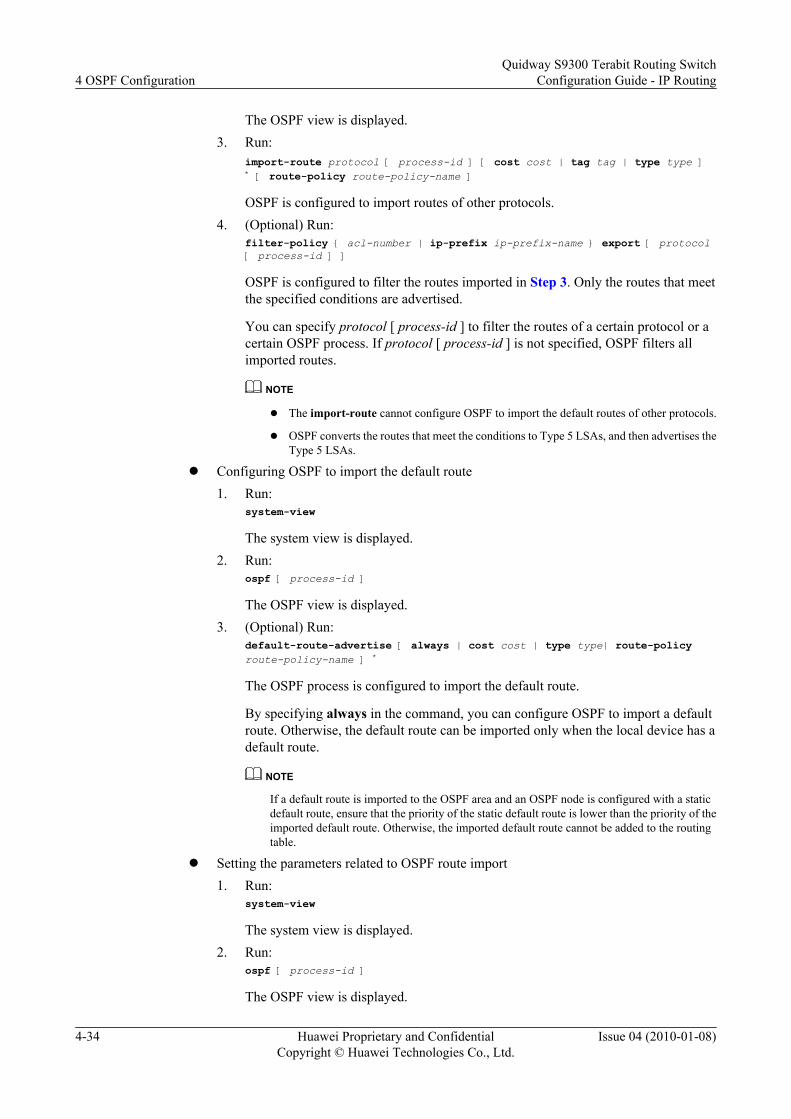
The OSPF view is displayed.3. Run:
import-route protocol [ process-id ] [ cost cost | tag tag | type type ] * [ route-policy route-policy-name ]
OSPF is configured to import routes of other protocols.4. (Optional) Run:
filter-policy { acl-number | ip-prefix ip-prefix-name } export [ protocol [ process-id ] ]
OSPF is configured to filter the routes imported in Step 3. Only the routes that meetthe specified conditions are advertised.
You can specify protocol [ process-id ] to filter the routes of a certain protocol or acertain OSPF process. If protocol [ process-id ] is not specified, OSPF filters allimported routes.
NOTE
l The import-route cannot configure OSPF to import the default routes of other protocols.
l OSPF converts the routes that meet the conditions to Type 5 LSAs, and then advertises theType 5 LSAs.
l Configuring OSPF to import the default route1. Run:
system-view
The system view is displayed.2. Run:
ospf [ process-id ]
The OSPF view is displayed.3. (Optional) Run:
default-route-advertise [ always | cost cost | type type| route-policy route-policy-name ] *
The OSPF process is configured to import the default route.
By specifying always in the command, you can configure OSPF to import a defaultroute. Otherwise, the default route can be imported only when the local device has adefault route.
NOTE
If a default route is imported to the OSPF area and an OSPF node is configured with a staticdefault route, ensure that the priority of the static default route is lower than the priority of theimported default route. Otherwise, the imported default route cannot be added to the routingtable.
l Setting the parameters related to OSPF route import1. Run:
system-view
The system view is displayed.2. Run:
ospf [ process-id ]
The OSPF view is displayed.
4 OSPF ConfigurationQuidway S9300 Terabit Routing Switch
Configuration Guide - IP Routing
4-34 Huawei Proprietary and ConfidentialCopyright © Huawei Technologies Co., Ltd.
Issue 04 (2010-01-08)

3. Run:default { cost cost | limit limit | tag tag | type type } *
The default values of the parameters used for imported routes are set. The parametersare the route cost, number of routes, route tag, and route type.
When configuring OSPF to import external routes, you can set the optional parameters,such as the route cost, number of routes, route tag, and route type. The imported routesuse the set values as the default values. The route tag identifies information about animported route, which depends on the protocol. For example, for BGP routes importedby OSPF, the route tag identify the AS ID.
----End
4.9.5 Checking the Configuration
PrerequisiteThe configuration of OSPF route filtering is complete.
Procedurel Run the display ospf [ process-id ] routing [ ipv4-address [ mask | mask-length ] ]
[ interface interface-type interface-number ] [ nexthop nexthop-address ] or displayospf [ process-id ] routing router-id [ router-id ] command to check the OSPF routingtable.
----End
Example
Run the display ospf routing command, and you can view information about the routes thatpass the filtering and are imported from other routing protocols.
<Quidway> display ospf routing OSPF Process 1 with Router ID 192.168.32.10 Routing Tables Routing for Network Destination Cost Type NextHop AdvRouter Area 30.1.0.0/24 1 Transit 30.1.0.1 192.168.32.10 0.0.0.1 50.0.0.0/24 2 Inter-area 30.1.0.2 192.168.32.11 0.0.0.1 Routing for ASEs Destination Cost Type Tag NextHop AdvRouter 10.0.0.0/24 1 Type2 1 30.1.0.2 192.168.32.11 Total Nets: 3 Intra Area: 1 Inter Area: 1 ASE: 1 NSSA: 0
4.10 Adjusting and Optimizing the OSPF NetworkThis section describes how to adjust and optimize the OSPF network according to the actualnetworking environment.
Quidway S9300 Terabit Routing SwitchConfiguration Guide - IP Routing 4 OSPF Configuration
Issue 04 (2010-01-08) Huawei Proprietary and ConfidentialCopyright © Huawei Technologies Co., Ltd.
4-35
ContextNOTEThe configuration tasks of adjusting and optimizing the OSPF network is optional. You can perform theconfiguration tasks as required.
4.10.1 Establishing the Configuration Task
4.10.2 Setting the Delay for Transmitting LSAs on an Interface
4.10.3 Setting the Interval for Updating and Receiving LSAs
4.10.4 Setting the Interval of the SPF Calculation
4.10.5 Configuring a Stub Router
4.10.6 Enabling an Interface to Add the Actual MTU in DD Packets
4.10.7 Setting the Maximum Number of External LSAs in an LSDB
4.10.8 Configuring OSPF to Be Compatible with the Route Selection Rule of RFC 1583
4.10.9 Checking the Configuration
4.10.1 Establishing the Configuration Task
Applicable Environment
An LSA in the LSDB on the S9300 ages with the time. The age of the LSA increases by 1 everysecond, but the age does increase during transmission of the LSA. To reduce the differencebetween the age and lifetime of LSAs, you can set the delay for transmitting LSAs on an interface.The delay is then added to the age of LSAs.
The delay for transmitting LSAs depends on the network, and the configuration is important fora low-speed network.
To avoid high usage of network bandwidth and device resources due to the network connectionor frequent route flapping, the S9300 sets the interval for updating and receiving LSAs. Byadjusting the interval for updating and receiving LSAs, you can improve the convergence speedof the OSPF network.
The OSPF process calculates the LSDB through the SPF algorithm. By adjusting the interval ofSPF calculation, you can reduce the usage of resources due to frequent network changes.
If the S9300 needs to restrict the traffic, you can configure a stub router to increase the link costand reduce the forwarding traffic.
Pre-configuration Tasks
Before adjusting and optimizing an OSPF network, complete the configuration task:
l 4.3 Configuring Basic OSPF Functions
Data Preparation
To adjust and optimize an OSPF network, you need the following data.
4 OSPF ConfigurationQuidway S9300 Terabit Routing Switch
Configuration Guide - IP Routing
4-36 Huawei Proprietary and ConfidentialCopyright © Huawei Technologies Co., Ltd.
Issue 04 (2010-01-08)

No. Data
1 Delay for transmitting LSAs
2 LSA interval
3 Interval of the SPF calculation
4 Maximum number of external LSAs in an LSDB
4.10.2 Setting the Delay for Transmitting LSAs on an Interface
ContextAn LSA in the LSDB on the S9300 ages with the time. The age of the LSA increases by 1 everysecond, but the age does not increase during transmission of the LSA. To reduce the differencebetween the age and lifetime of LSAs, you can set the delay for transmitting LSAs on an interface.The delay is then added to the age of LSAs.
The delay for transmitting LSAs depends on the network, and the configuration is important fora low-speed network.
Do as follows on the S9300 to set the delay for transmitting LSAs according to the bandwidthof the network.
Procedure
Step 1 Run:system-view
The system view is displayed.
Step 2 Run:interface interface-type interface-number
The interface view is displayed.
Step 3 Run:ospf trans-delay interval
The delay for transmitting LSAs on the interface is set.
By default, the delay for transmitting LSAs on an interface is 1 second.
----End
4.10.3 Setting the Interval for Updating and Receiving LSAs
ContextOSPF specifies that the interval for updating LSAs is 5 seconds. This prevents high usage ofnetwork bandwidth and device resource due to network connections or frequent route flapping.
For a stable network that requires short route convergence time, you can set the interval forupdating LSAs to 0 to cancel the interval. In this manner, changes of the topology or routes can
Quidway S9300 Terabit Routing SwitchConfiguration Guide - IP Routing 4 OSPF Configuration
Issue 04 (2010-01-08) Huawei Proprietary and ConfidentialCopyright © Huawei Technologies Co., Ltd.
4-37

be advertised to the network through the LSAs immediately. The route convergence speed inthe network is thus increased.
In such a network, you can set the interval for accepting LSAs to 0. In this manner, changes ofthe topology or routes can be detected immediately.
Do as follows on the S9300s in the area to set the LSA interval according to the networkbandwidth.
Procedurel Setting the interval for updating LSAs
1. Run:system-view
The system view is displayed.2. Run:
ospf [ process-id ]
The OSPF view is displayed.3. Run:
lsa-originate-interval 0
The interval for updating LSAs is set to 0.
By default, the interval for updating LSAs is 5 seconds.l Setting the interval for receiving LSAs
1. Run:system-view
The system view is displayed.2. Run:
ospf [ process-id ]
The OSPF view is displayed.3. Run:
lsa-arrival-interval 0
The interval for receiving LSAs.
By default, the interval for receiving LSAs is 1 second.
----End
4.10.4 Setting the Interval of the SPF Calculation
ContextWhen the LSDB of an OSPF process changes, the shortest path tree needs to be recalculated. Ifthe network changes frequently and the shortest path is calculated immediately after each change,many system resources are occupied and the efficiency of the S9300 is decreased. By adjustingthe interval of the SPF calculation, you can reduce the impact caused by frequent networkchanges.
By default, the interval of the SPF calculation is 5 seconds.
4 OSPF ConfigurationQuidway S9300 Terabit Routing Switch
Configuration Guide - IP Routing
4-38 Huawei Proprietary and ConfidentialCopyright © Huawei Technologies Co., Ltd.
Issue 04 (2010-01-08)

Do as follows on each S9300 in the area to set the interval of the SPF calculation according tothe change rate of network topology.
Procedure
Step 1 Run:system-view
The system view is displayed.
Step 2 Run:ospf [ process-id ]
The OSPF view is displayed.
Step 3 Run:spf-schedule-interval { interval1 | millisecond interval2 }
The interval of the SPF calculation is set.
----End
4.10.5 Configuring a Stub Router
Context
A stub router can control the traffic and informs other OSPF devices that it is a stub router.Generally, other routers do not use the stub router to forward data, but they have routes to thestub router.
In the Router-LSAs generated by the stub router, the metric of all the links is 65535.
Do as follows on the S9300.
Procedure
Step 1 Run:system-view
The system view is displayed.
Step 2 Run:ospf [ process-id ]
The OSPF view is displayed.
Step 3 Run:stub-router
The router is configured as a stub router.
NOTE
Stub router and stub area are concepts independent of each other. That is, their configurations do not affecteach other.
----End
Quidway S9300 Terabit Routing SwitchConfiguration Guide - IP Routing 4 OSPF Configuration
Issue 04 (2010-01-08) Huawei Proprietary and ConfidentialCopyright © Huawei Technologies Co., Ltd.
4-39

4.10.6 Enabling an Interface to Add the Actual MTU in DD Packets
ContextDifferent device manufacturers may use different default MTUs. The MTU is usually set to 0for DD packets to ensure consistency of the MTU on devices of different manufacturers. Bydefault, an interface uses 0, rather than the actual MTU, as the MTU in DD packets.
This task is performed to configure an interface to add the actual MTU in the Interface MTUfiled of DD packets.
Do as follows on the S9300.
Procedure
Step 1 Run:system-view
The system view is displayed.
Step 2 Run:interface interface-type interface-number
The interface view is displayed.
Step 3 Run:ospf mtu-enable
The interface is configured to fill the actual MTU in DD packets when sending DD packets.
----End
4.10.7 Setting the Maximum Number of External LSAs in an LSDB
ContextThis task is performed to control the number of external LSAs in an LSDB, and thus to reducethe burden of storage and calculation of the S9300. By default, the maximum number of externalLSAs in an LSDB is 1000000.
Do as follows on the S9300.
Procedure
Step 1 Run:system-view
The system view is displayed.
Step 2 Run:ospf [ process-id ]
The OSPF view is displayed.
Step 3 Run:lsdb-overflow-limit number
4 OSPF ConfigurationQuidway S9300 Terabit Routing Switch
Configuration Guide - IP Routing
4-40 Huawei Proprietary and ConfidentialCopyright © Huawei Technologies Co., Ltd.
Issue 04 (2010-01-08)

The maximum number of external LSAs in an LSDB is set.
----End
4.10.8 Configuring OSPF to Be Compatible with the Route SelectionRule of RFC 1583
ContextIf multiple AS-External-LSAs advertise routes to the same destination, OSPF can select theoptimal route according to the rule defined by RFC 1583.
By default, this rule is not used.
Do as follows on the S9300.
Procedure
Step 1 Run:system-view
The system view is displayed.
Step 2 Run:ospf [ process-id ]
The OSPF view is displayed.
Step 3 Run:rfc1583 compatible
OSPF is compatible with the route selection rule specified by RFC 1583.
----End
4.10.9 Checking the Configuration
PrerequisiteAll the configurations for optimizing the OSPF network are complete.
Procedurel Run the display ospf [ process-id ] brief command to check brief information about an
OSPF process.l Run the display ospf [ process-id ] cumulative command to check the statistics of an OSPF
process.
----End
ExampleRun the display ospf brief command, and you can find that the interface is suppressed.
<Quidway> display ospf brief OSPF Process 1 with Router ID 192.168.32.11
Quidway S9300 Terabit Routing SwitchConfiguration Guide - IP Routing 4 OSPF Configuration
Issue 04 (2010-01-08) Huawei Proprietary and ConfidentialCopyright © Huawei Technologies Co., Ltd.
4-41

OSPF Protocol Information RouterID: 192.168.32.11 Border Router: AREA Route Tag: 0 Multi-VPN-Instance is not enabled Graceful-restart capability: disabled Helper support capability : not configured Applications Supported: MPLS Traffic-Engineering Spf-schedule-interval: 5 s Default ASE parameters: Metric: 1 Tag: 1 Type: 2 Route Preference: 10 ASE Route Preference: 150 SPF Computation Count: 20 RFC 1583 Compatible Retransmission limitation is disabled OSPF is in protocol hot standby state: Real-Time Backup Area Count: 2 Nssa Area Count: 0 ExChange/Loading Neighbors: 0 Area: 0.0.0.0 (MPLS TE not enabled) Authtype: None Area flag: Normal SPF scheduled Count: 20 ExChange/Loading Neighbors: 0 Interface: 50.0.0.1 (Vlanif50) Cost: 1 State: DR Type: Broadcast MTU: 1430 Priority: 1 Designated Router: 50.0.0.1 Backup Designated Router: 0.0.0.0 Timers: Hello 10 , Dead 40 , Poll 120 , Retransmit 5 , Transmit Delay 1 Silent interface, No hellos Area: 0.0.0.1 (MPLS TE not enabled) Authtype: None Area flag: Normal SPF scheduled Count: 20 ExChange/Loading Neighbors: 0 Interface: 30.1.0.2 (Vlanif40) Cost: 1 State: BDR Type: Broadcast MTU: 1430 Priority: 1 Designated Router: 30.1.0.1 Backup Designated Router: 30.1.0.2 Timers: Hello 10 , Dead 40 , Poll 120 , Retransmit 5 , Transmit Delay 1
4.11 Configuring OSPF GRThis section describes how to configure OSPF GR to prevent inaccurate route calculation andpacket loss after the S9300 restarts.
4.11.1 Establishing the Configuration Task
4.11.2 Enabling the Opaque-LSA Capability of OSPF
4.11.3 Enabling OSPF GR
4.11.4 (Optional) Setting Session Parameters of GR on the Restarter
4.11.5 (Optional) Setting Session Parameters of GR on the Helper
4.11.6 (Optional) Configuring the S9300 Not to Work in Helper Mode
4.11.7 Checking the Configuration
4 OSPF ConfigurationQuidway S9300 Terabit Routing Switch
Configuration Guide - IP Routing
4-42 Huawei Proprietary and ConfidentialCopyright © Huawei Technologies Co., Ltd.
Issue 04 (2010-01-08)

4.11.1 Establishing the Configuration Task
Applicable EnvironmentTo prevent route flapping due to the failover between the master and slave main control boardson the S9300, you can enable OSPF GR.
After the active/standby switchover, the restarter and helper continue to maintain the neighborrelationship, exchange routing information and synchronize the database, and update routingtable and forwarding table, to implement OSPF fast convergence and keep networking stable.
Pre-configuration TasksBefore configuring OSPF GR, complete the following task:
l 4.3 Configuring Basic OSPF Functions
Data PreparationTo configure OSPF GR, you need the following data.
No. Data
1 OSPF process ID
2 (Optional) Duration for graceful restart of the restarter
4.11.2 Enabling the Opaque-LSA Capability of OSPF
ContextOSPF supports GR through Type 9 LSAs; therefore, you need to enable the Opaque-LSAcapability of OSPF before enabling OSPF GR.
Do as follows on the S9300 on which GR needs to be enabled.
Procedure
Step 1 Run:system-view
The system view is displayed.
Step 2 Run:ospf process-id
The OSPF view is displayed.
Step 3 Run:opaque-capability enable
The Opaque-LSA capability is enabled.
----End
Quidway S9300 Terabit Routing SwitchConfiguration Guide - IP Routing 4 OSPF Configuration
Issue 04 (2010-01-08) Huawei Proprietary and ConfidentialCopyright © Huawei Technologies Co., Ltd.
4-43

4.11.3 Enabling OSPF GR
ContextDo as follows on the S9300 on which GR needs to be enabled.
Procedure
Step 1 Run:system-view
The system view is displayed.
Step 2 Run:ospf process-id
The OSPF view is displayed.
Step 3 Run:graceful-restart
OSPF GR is enabled.
----End
4.11.4 (Optional) Setting Session Parameters of GR on the Restarter
ContextDo as follows on the restarter.
Procedure
Step 1 Run:system-view
The system view is displayed.
Step 2 Run:ospf process-id
The OSPF view is displayed.
Step 3 (Optional) Run:graceful-restart period period
The duration of graceful start on the restarter is set.
By default, the duration of graceful restart is 120 seconds.
Step 4 (Optional) Run:graceful-restart planned-only
The restarter is configured to support only planned GR.
By default, the restarter supports planned GR and unplanned GR.
4 OSPF ConfigurationQuidway S9300 Terabit Routing Switch
Configuration Guide - IP Routing
4-44 Huawei Proprietary and ConfidentialCopyright © Huawei Technologies Co., Ltd.
Issue 04 (2010-01-08)

Step 5 (Optional) Run:graceful-restart partial
The restarter is configured to support only partial GR.
By default, the restarter supports only totally GR.
----End
Postrequisite
To set multiple parameters at the same time, run thegraceful-restart [ period period | planned-only | partial ] * command.
4.11.5 (Optional) Setting Session Parameters of GR on the Helper
Context
Do as follows on the helper.
Procedure
Step 1 Run:system-view
The system view is displayed.
Step 2 Run:ospf process-id
The OSPF view is displayed.
Step 3 (Optional) Run:graceful-restart helper-role { ip-prefix ip-prefix-name | acl-number acl-number }
The condition for setting a helper is set. A neighbor works in helper mode only if it meets thecondition set by the ip-prefix or acl parameter.
Step 4 (Optional) Run:graceful-restart helper-role ignore-external-lsa
The helper is configured not to check the external LSAs.
By default, the helper checks the external LSAs.
Step 5 (Optional) Run:graceful-restart helper-role planned-only
The helper is configured to support only the planned GR.
By default, the helper supports planned GR and unplanned GR.
----End
Quidway S9300 Terabit Routing SwitchConfiguration Guide - IP Routing 4 OSPF Configuration
Issue 04 (2010-01-08) Huawei Proprietary and ConfidentialCopyright © Huawei Technologies Co., Ltd.
4-45

PostrequisiteTo set multiple parameters at the same time, run the graceful-restart helper-role { [ ip-prefix ip-prefix-name | acl-number acl-number ] | ignore-external-lsa | planned-only } *command.
4.11.6 (Optional) Configuring the S9300 Not to Work in HelperMode
ContextDo as follows on the S9300 that does not need to work in helper mode.
Procedure
Step 1 Run:system-view
The system view is displayed.
Step 2 Run:ospf process-id
The OSPF view is displayed.
Step 3 Run:graceful-restart helper-role never
The S9300 is configured not to work in helper mode.
----End
4.11.7 Checking the Configuration
PrerequisiteAll the configurations of OSPF GR are complete.
NOTE
If an MPLS TE tunnel is configured on the S9300 and the S9300 learns the route to the destination addressof the tunnel through OSPF, then you need to configure the RSVP GR function on the tunnel.
Procedurel Run the display ospf [ process-id ] graceful-restart [ verbose ] command to check the
status of OSPF GR.l Run the display ospf [ process-id ] brief command to check information about an OSPF
process.
----End
ExampleRun the display ospf graceful-restart, and you can check the status of OSPF GR.
4 OSPF ConfigurationQuidway S9300 Terabit Routing Switch
Configuration Guide - IP Routing
4-46 Huawei Proprietary and ConfidentialCopyright © Huawei Technologies Co., Ltd.
Issue 04 (2010-01-08)

<Quidway> display ospf graceful-restart OSPF Process 1 with Router ID 1.1.1.1 Graceful-restart capability : enabled Graceful-restart support : planned and un-planned, totally Helper-policy support : planned and un-planned, strict lsa check Current GR state : normal Graceful-restart period : 120 seconds Number of neighbors under helper: Normal neighbors : 0 Virtual neighbors : 0 Sham-link neighbors : 0 Total neighbors : 0 Number of restarting neighbors : 0 Last exit reason: On graceful restart : successful exit On Helper : none
4.12 Configuring BFD for OSPFThis section describes how to implement fast convergence on an OSPF network through BFD.
4.12.1 Establishing the Configuration Task
4.12.2 Configuring Global BFD
4.12.3 Configuring BFD for OSPF
4.12.4 Disabling an Interface from Dynamically Creating BFD Sessions
4.12.5 Configuring the BFD Feature for a Specified Interface
4.12.6 Checking the Configuration
4.12.1 Establishing the Configuration Task
Applicable EnvironmentTo ensure high quality of data transmission and speed up convergence of OSPF routes when thelink status changes, you can configure the BFD feature for the links that run OSPF.
Pre-configuration TasksBefore configuring BFD for OSPF, complete the following tasks:
l 4.3 Configuring Basic OSPF Functions
l Enabling the BFD feature globally
Data PreparationTo configure BFD for OSPF, you need the following data.
No. Data
1 ID of the OSPF process for which BFD is enabled
Quidway S9300 Terabit Routing SwitchConfiguration Guide - IP Routing 4 OSPF Configuration
Issue 04 (2010-01-08) Huawei Proprietary and ConfidentialCopyright © Huawei Technologies Co., Ltd.
4-47

No. Data
2 Type and number of the interface where BFD is enabled
3 Parameters of the BFD session
4.12.2 Configuring Global BFD
ContextOSPF can create a BFD session only after BFD is enabled globally. Do as follows on theS9300.
Procedure
Step 1 Run:system-view
The system view is displayed.
Step 2 Run:bfd
BFD is enabled globally.
----End
4.12.3 Configuring BFD for OSPF
ContextTo configure the BFD feature for all the interfaces that run an OSPF process, do as follows onthe S9300s on which the BFD session needs to be established.
Procedure
Step 1 Run:system-view
The system view is displayed.
Step 2 Run:ospf [ process-id ]
The OSPF view is displayed.
Step 3 Run:bfd all-interfaces enable
The BFD feature is enabled and a BFD session is established.
When the BFD feature is configured globally, the OSPF protocol establish a BFD session on allthe interfaces whose neighbor is in Full state by using the default BFD parameters.
4 OSPF ConfigurationQuidway S9300 Terabit Routing Switch
Configuration Guide - IP Routing
4-48 Huawei Proprietary and ConfidentialCopyright © Huawei Technologies Co., Ltd.
Issue 04 (2010-01-08)

Step 4 (Optional) Run:bfd all-interfaces { min-rx-interval receive-interval | min-tx-interval transmit-interval | detect-multiplier multiplier-value } *
The parameters of the BFD session are set.
NOTE
If you set the BFD parameters but do not run the bfd all-interfaces enable command, the BFD featuredoes not take effect.
----End
4.12.4 Disabling an Interface from Dynamically Creating BFDSessions
ContextAfter you run the bfd all-interfaces enable command in an OSPF process, all the OSPF-enabledinterfaces connected to neighbors in Full state create BFD sessions. If you do not want to enableBFD on an interface, do as follows on the S9300.
Procedure
Step 1 Run:system-view
The system view is displayed.
Step 2 Run:interface interface-type interface-number
The interface view is displayed.
Step 3 Run:ospf bfd block
The interface is disabled from creating BFD sessions dynamically.
----End
4.12.5 Configuring the BFD Feature for a Specified Interface
ContextIf you want to configure the BFD feature for certain interfaces but do not want to enable BFDfor OSPF, or if you have enabled BFD for OSPF but want certain interfaces to detect a linkfailure faster, do as follows on the S9300 to configure the interfaces.
Procedure
Step 1 Run:system-view
The system view is displayed.
Quidway S9300 Terabit Routing SwitchConfiguration Guide - IP Routing 4 OSPF Configuration
Issue 04 (2010-01-08) Huawei Proprietary and ConfidentialCopyright © Huawei Technologies Co., Ltd.
4-49

Step 2 Run:interface interface-type interface-number
The interface view is displayed.
Step 3 Run:ospf bfd enable
The BFD feature is enabled on the interface and a BFD session is created.
If the BFD feature is configured globally and the neighbors are in Full state, the default valuesof the BFD parameters are adopted to create the BFD session.
Step 4 (Optional) Run:ospf bfd { min-rx-interval receive-interval | min-tx-interval transmit- interval | detect-multiplier multiplier-value } *
The parameters of the BFD session are set.
NOTE
l The BFD parameters set on an interface take precedence over the BFD parameters set in the OSPFprocess. That is, the BFD session established on an interface use the parameters set on the interface.
l If you set the BFD parameters but do not run the ospf bfd enable command, the BFD feature does nottake effect.
----End
4.12.6 Checking the Configuration
PrerequisiteAll the configurations of BFD for OSPF are complete.
Procedurel Run the display ospf [process-id ] bfd session interface-type interface-number [ router-
id ] display ospf [process-id ] bfd session { router-id | all } command to check informationabout the BFD session.
----End
Example
Run the display ospf bfd session all command. If the BFD session is in Up state on theS9300, it indicates that the BFD session is established successfully.
<Quidway> display ospf bfd session all
OSPF Process 1 with Router ID 21.21.21.21 Area 0.0.0.0 interface 128.0.0.2(Vlanif1000)'s BFD Sessions
NeighborId:2.2.2.2 AreaId:0.0.0.0 Interface:Vlanif10 BFDState:up rx :1000 tx :100 Multiplier:3 BFD Local Dis:8194 LocalIpAdd:100.2.1.2 RemoteIpAdd:100.2.1.1 Diagnostic Info: Init
4 OSPF ConfigurationQuidway S9300 Terabit Routing Switch
Configuration Guide - IP Routing
4-50 Huawei Proprietary and ConfidentialCopyright © Huawei Technologies Co., Ltd.
Issue 04 (2010-01-08)

4.13 Configuring the Authentication Function on an OSPFNetwork
This section describes how to configure the OSPF area authentication mode and interfaceauthentication mode.
4.13.1 Establishing the Configuration Task
4.13.2 Configuring the Area Authentication Mode
4.13.3 Configuring the Interface Authentication Mode
4.13.4 Checking the Configuration
4.13.1 Establishing the Configuration Task
Applicable Environment
To improve security of an OSPF network, you can configure OSPF authentication.
Pre-configuration Tasks
Before improving security of an OSPF network, complete the following task:
l 4.3 Configuring Basic OSPF Functions
Data Preparation
To improve security of an OSPF network, you need the following data:
No. Data
1 Authentication type and password
4.13.2 Configuring the Area Authentication Mode
Context
OSPF supports packet authentication. Only the OSPF packets passing the authentication areaccepted; otherwise, the neighbor relationship cannot be set up.
When you use area authentication, all the devices in an area must use the same authenticationmode and password. For example, the authentication mode of all the devices in Area 0 is simpleauthentication and the password is abc.
Do as follows on all the S9300s in an area.
Quidway S9300 Terabit Routing SwitchConfiguration Guide - IP Routing 4 OSPF Configuration
Issue 04 (2010-01-08) Huawei Proprietary and ConfidentialCopyright © Huawei Technologies Co., Ltd.
4-51

Procedure
Step 1 Run:system-view
The system view is displayed.
Step 2 Run:ospf [ process-id ]
The OSPF view is displayed.
Step 3 Run:area area-id
The OSPF area view is displayed.
Step 4 Run the following commands as required.l Run:
authentication-mode simple { [ plain ] plain-text | cipher cipher-text }
The authentication mode for the OSPF area is set to simple authentication.l Run:
authentication-mode { md5 | hmac-md5 } [ key-id { plain plain-text | [ cipher ] cipher-text } ]
The authentication mode for the OSPF area is configured to MD5 configuration.
----End
4.13.3 Configuring the Interface Authentication Mode
Context
This task is performed to configure the authentication mode and password used betweenneighboring devices. Interface authentication takes precedence over area authentication.
The authentication mode and password of all the interfaces in the same area must be the same.
Do as follows on interfaces of all S9300s in an area.
Procedure
Step 1 Run:system-view
The system view is displayed.
Step 2 Run:interface interface-type interface-number
The interface view is displayed.
Step 3 Configure the authentication mode for the interface as required.l Run:
ospf authentication-mode simple { [ plain ] plain-text | cipher cipher-text }
4 OSPF ConfigurationQuidway S9300 Terabit Routing Switch
Configuration Guide - IP Routing
4-52 Huawei Proprietary and ConfidentialCopyright © Huawei Technologies Co., Ltd.
Issue 04 (2010-01-08)
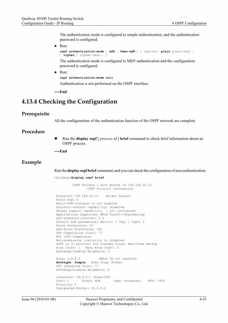
The authentication mode is configured to simple authentication, and the authenticationpassword is configured.
l Run:ospf authentication-mode { md5 | hmac-md5 } [ key-id { plain plain-text | [ cipher ] cipher-text } ]The authentication mode is configured to MD5 authentication and the configurationpassword is configured.
l Run:ospf authentication-mode nullAuthentication is not performed on the OSPF interface.
----End
4.13.4 Checking the Configuration
PrerequisiteAll the configurations of the authentication function of the OSPF network are complete.
Procedurel Run the display ospf [ process-id ] brief command to check brief information about an
OSPF process.
----End
ExampleRun the display ospf brief command, and you can check the configuration of area authentication.
<Quidway>display ospf brief OSPF Process 1 with Router ID 192.168.32.11 OSPF Protocol Information RouterID: 192.168.32.11 Border Router: Route Tag: 0 Multi-VPN-Instance is not enabled Graceful-restart capability: disabled Helper support capability : not configured Applications Supported: MPLS Traffic-Engineering Spf-schedule-interval: 5 s Default ASE parameters: Metric: 1 Tag: 1 Type: 2 Route Preference: 10 ASE Route Preference: 150 SPF Computation Count: 77 RFC 1583 Compatible Retransmission limitation is disabled OSPF is in protocol hot standby state: Real-Time Backup Area Count: 1 Nssa Area Count: 0 ExChange/Loading Neighbors: 0 Area: 0.0.0.0 (MPLS TE not enabled) Authtype: Simple Area flag: Normal SPF scheduled Count: 77 ExChange/Loading Neighbors: 0 Interface: 20.0.0.1 (Vlanif20) Cost: 1 State: BDR Type: Broadcast MTU: 1430 Priority: 1 Designated Router: 20.0.0.2
Quidway S9300 Terabit Routing SwitchConfiguration Guide - IP Routing 4 OSPF Configuration
Issue 04 (2010-01-08) Huawei Proprietary and ConfidentialCopyright © Huawei Technologies Co., Ltd.
4-53

Backup Designated Router: 20.0.0.1 Timers: Hello 10 , Dead 40 , Poll 120 , Retransmit 5 , Transmit Delay 1
4.14 Configuring Network Management Functions of OSPFThis section describes how to bind an OSPF process to the Management Information Base (MIB)and configure the OSPF trap function and log function.
4.14.1 Establishing the Configuration Task
4.14.2 Binding an OSPF Process to the MIB
4.14.3 Configuring OSPF to Send Trap Messages
4.14.4 Enabling OSPF to Record Logs
4.14.5 Checking the Configuration
4.14.1 Establishing the Configuration Task
Applicable Environment
OSPF supports the network management functions. You can bind the OSPF MIB to an OSPFprocess, and configure the OSPF device to send trap messages and record logs.
Pre-configuration Tasks
Before configuring the network management functions of OSPF, complete the following task:
l 4.3 Configuring Basic OSPF Functions
Data Preparation
To configure the network management functions of OSPF, you need the following data.
No. Data
1 ID of the OSPF process bound to the MIB
2 (Optional) Parameters of trap messages
4.14.2 Binding an OSPF Process to the MIB
Context
When multiple OSPF processes are enabled, you can bind an OSPF process to the MIB so thatthe MIB processes only the bound process.
Do as follows on the S9300.
4 OSPF ConfigurationQuidway S9300 Terabit Routing Switch
Configuration Guide - IP Routing
4-54 Huawei Proprietary and ConfidentialCopyright © Huawei Technologies Co., Ltd.
Issue 04 (2010-01-08)

Procedure
Step 1 Run:system-view
The system view is displayed.
Step 2 Run:ospf mib-binding process-id
An OSPF process is bound to the MIB.
----End
4.14.3 Configuring OSPF to Send Trap Messages
ContextDo as follows on the S9300.
Procedure
Step 1 Run:system-view
The system view is displayed.
Step 2 Run:snmp-agent trap enable ospf [ process-id ] [ ifauthfail | ifcfgerror | ifrxbadpkt | ifstatechange | lsdbapproachoverflow | lsdboverflow | maxagelsa | nbrrestarthelperchange | nbrstatechange | originatelsa | restartstatuschange | txretransmit | vifauthfail | vifcfgerror | virifrxbadpkt | virifstatechange | viriftxretransmit | virnbrstatechange | vnbrrestarthelperchange ] *
The OSPF process is configured to send trap messages.
You can configure OSPF to send the SNMP trap messages of different types and specify a certainOSPF process to send them.
If the OSPF process ID is not specified, all OSPF processes send trap messages.
----End
4.14.4 Enabling OSPF to Record Logs
ContextDo as follows on the S9300.
Procedure
Step 1 Run:system-view
The system view is displayed.
Step 2 Run:
Quidway S9300 Terabit Routing SwitchConfiguration Guide - IP Routing 4 OSPF Configuration
Issue 04 (2010-01-08) Huawei Proprietary and ConfidentialCopyright © Huawei Technologies Co., Ltd.
4-55

ospf [ process-id ]
The OSPF view is displayed.
Step 3 Run:enable log [ config | state | error ]
OSPF is configured to record logs.
----End
4.14.5 Checking the Configuration
PrerequisiteThe network management function of OSPF is configured.
Procedurel Run the display ospf [ process-id ] brief command to check brief information about an
OSPF process.
----End
Example
Run the display ospf brief command, and you can check the configuration of the networkmanagement function of OSPF.
<Quidway> display ospf brief OSPF Process 1 with Router ID 192.168.32.11 OSPF Protocol Information RouterID: 192.168.32.11 Border Router: Route Tag: 0 Multi-VPN-Instance is not enabled Graceful-restart capability: disabled Helper support capability : not configured Applications Supported: MPLS Traffic-Engineering Spf-schedule-interval: 5 s Default ASE parameters: Metric: 1 Tag: 1 Type: 2 Route Preference: 10 ASE Route Preference: 150 SPF Computation Count: 87 RFC 1583 Compatible Retransmission limitation is disabled This process is currently bound to MIB This process is currently bound to SNMP trap Area Count: 1 Nssa Area Count: 0 ExChange/Loading Neighbors: 0 Area: 0.0.0.0 (MPLS TE not enabled) Authtype: None Area flag: Normal SPF scheduled Count: 87 ExChange/Loading Neighbors: 0 Interface: 20.0.0.1 (Vlanif20) Cost: 1 State: BDR Type: Broadcast MTU: 1430 Priority: 1 Designated Router: 20.0.0.2 Backup Designated Router: 20.0.0.1 Timers: Hello 10 , Dead 40 , Poll 120 , Retransmit 5 , Transmit Delay 1
4 OSPF ConfigurationQuidway S9300 Terabit Routing Switch
Configuration Guide - IP Routing
4-56 Huawei Proprietary and ConfidentialCopyright © Huawei Technologies Co., Ltd.
Issue 04 (2010-01-08)

4.15 Maintaining OSPFThis section describes how to restart an OSPF process, delete the OSPF information, and debugOSPF.
4.15.1 Restarting an OSPF Process
4.15.2 Clearing OSPF Information
4.15.3 Debugging OSPF
4.15.1 Restarting an OSPF Process
Context
CAUTIONThe OSPF adjacency between the S9300s may be torn down after you run the reset ospfcommand to restart the OSPF process. So, confirm the action before you run the command.
After the OSPF routing policy or protocol changes, you need to restart the OSPF process for thenew configuration to take effect. Perform either of the following steps to restart the OSPFprocess.
Procedurel Run the reset ospf [ process-id ] process command in the user view to restart an OSPF
process.l Run the reset ospf [ process-id ] process graceful-restart command in the user view to
restart an OSPF process in GR mode.
----End
4.15.2 Clearing OSPF Information
Context
CAUTIONOSPF information cannot be restored after you clear it. So, confirm the action before you runthe command.
Procedurel Run the reset ospf [ process-id ] counters [ neighbor [ interface-type interface-number ]
[ router-id ] ] command in the user view to clear the OSPF counter.
Quidway S9300 Terabit Routing SwitchConfiguration Guide - IP Routing 4 OSPF Configuration
Issue 04 (2010-01-08) Huawei Proprietary and ConfidentialCopyright © Huawei Technologies Co., Ltd.
4-57

l Run the reset ospf [ process-id ] redistribution command in the user view to clear theroutes imported by OSPF.
----End
4.15.3 Debugging OSPF
Context
CAUTIONDebugging affects the performance of the system. So, after debugging, run the undo debuggingall command to disable it immediately.
When an OSPF fault occurs, run the following debugging commands in the user view to locatethe fault. For the procedure for enabling debugging, see the chapter "Monitoring and Debugging"in the Quidway S9300 Terabit Routing Switch Configuration Guide - Device Management.
Procedurel Run the debugging ospf [ process-id ] packet [ ack | dd | hello | request | update ]
[ brief ] [ filter { src | nbr } { acl-number | ip-prefix ip-prefix-name } ]debugging ospfpacket [ rcv-dump [ error ] | snd-dump ] [ filter { src | nbr } { acl-number | ip-prefixip-prefix-name } ]debugging ospf [ process-id ] packet grace command to enable debuggingof OSPF packets.
l Run the debugging ospf [ process-id ] hot-standby command to enable debugging ofOSPF hot standby.
l Run the debugging ospf [ process-id ] event command to enable debugging of OSPFevents.
l Run the debugging ospf [ process-id ] lsa-originate command to enable debugging ofOSPF OSPF LSAs.
l Run the debugging ospf [ process-id ] spf { all | brief | intra }debugging ospf [ process-id ] spf { asbr-summary | ase | net-summary | nssa } [ filter { acl acl-number | ip-prefix ip-prefix-name } ] command to enable debugging of SPF calculation of OSPF.
----End
4.16 Configuration ExamplesThis section provides several configuration examples of OSPF.
4.16.1 Configuring Basic OSPF Functions
4.16.2 Example for Configuring an OSPF Stub Area
4.16.3 Example for Configuring an NSSA Area
4.16.4 Example for Configuring DR Election of OSPF
4.16.5 Example for Configuring an OSPF virtual link
4 OSPF ConfigurationQuidway S9300 Terabit Routing Switch
Configuration Guide - IP Routing
4-58 Huawei Proprietary and ConfidentialCopyright © Huawei Technologies Co., Ltd.
Issue 04 (2010-01-08)

4.16.6 Example for Configuring Load Balancing Among OSPF Routes
4.16.7 Example for Configuring OSPF GR
4.16.8 Example for Configuring BFD for OSPF
4.16.1 Configuring Basic OSPF Functions
Networking RequirementsAs shown in Figure 4-4, all S9300s run OSPF, and the entire AS is partitioned into three areas.S9300-A and S9300-B function as ABRs to forward routes between areas.
You must ensure that every S9300 can learn the routes to all network segments in the AS.
Figure 4-4 Networking diagram for configuring the basic OSPF functions
S9300-AArea 0
Area 1 Area 2GE1/0/1GE1/0/1
GE1/0/1 GE1/0/1
GE1/0/1GE1/0/1GE1/0/2 GE1/0/2
GE1/0/2GE1/0/2
S9300-B
S9300-D
S9300-FS9300-E
S9300-C
S9300 Interface VLANIF interface IP address
S9300-A GigabitEthernet1/0/1 VLANIF 10 192.168.0.1/24
S9300-A GigabitEthernet1/0/2 VLANIF 20 192.168.1.1/24
S9300-B GigabitEthernet1/0/1 VLANIF 10 192.168.0.2/24
S9300-B GigabitEthernet1/0/2 VLANIF 30 192.168.2.1/24
S9300-C GigabitEthernet1/0/1 VLANIF 20 192.168.1.2/24
S9300-C GigabitEthernet1/0/2 VLANIF 40 172.16.1.1/24
S9300-D GigabitEthernet1/0/1 VLANIF 30 192.168.2.2/24
S9300-D GigabitEthernet1/0/2 VLANIF 50 172.17.1.1/24
S9300-E GigabitEthernet1/0/1 VLANIF 40 172.16.1.2/24
S9300-F GigabitEthernet1/0/1 VLANIF 50 172.17.1.2/24
Configuration RoadmapThe configuration roadmap is as follows:
Quidway S9300 Terabit Routing SwitchConfiguration Guide - IP Routing 4 OSPF Configuration
Issue 04 (2010-01-08) Huawei Proprietary and ConfidentialCopyright © Huawei Technologies Co., Ltd.
4-59

1. Create VLANs and add corresponding interfaces to the VLANs.2. Assign an IP address to each VLANIF interface.3. Enable OSPF on each S9300 and specify network segments in different areas.4. View the routing table and database information.
Data Preparationl ID of the VLAN that each interface belongs to, as shown in Figure 4-4
l IP address of each VLANIF interface, as shown in Figure 4-4
l Router ID and OSPF process ID of each S9300 and the area that each interface belongs to:– On S9300-A, the router ID is 1.1.1.1; the OSPF process ID is 1; the network segment
of Area 0 is 192.168.0.0/24; the network segment of Area 1 is 192.168.1.0/24.– On S9300-B, the router ID is 2.2.2.2; the OSPF process ID is 1; the network segment
of Area 0 is 192.168.0.0/24; the network segment of Area 2 is 192.168.2.0/24.– On S9300-C, the router ID is 3.3.3.3; the OSPF process ID is 1; the network segments
of Area 1 are 192.168.1.0/24 and 172.16.1.0/24.– On S9300-D, the router ID is 4.4.4.4; the OSPF process ID is 1; the network segments
of Area 2 are 192.168.2.0/24 and 172.17.1.0/24.– On S9300-E, the router ID is 5.5.5.5; the OSPF process ID is 1; the network segment
of Area 1 is 172.16.1.0/24.– On S9300-F, the router ID is 6.6.6.6; the OSPF process ID is 1; the network segment
of Area 2 is 172.17.1.0/24.
Procedure
Step 1 Configure VLANs that the related interfaces belong to.<Quidway> system-view[Quidway] sysname S9300-A[S9300-A] vlan batch 10 20[S9300-A] interface gigabitEthernet 1/0/1[S9300-A-GigabitEthernet1/0/1] port hybrid pvid vlan 10[S9300-A-GigabitEthernet1/0/1] port hybrid untagged vlan 10[S9300-A-GigabitEthernet1/0/1] quit[S9300-A] interface gigabitEthernet 1/0/2[S9300-A-GigabitEthernet1/0/2] port hybrid pvid vlan 20[S9300-A-GigabitEthernet1/0/2] port hybrid untagged vlan 20[S9300-A-GigabitEthernet1/0/2] quit
The configurations of S9300-B, S9300-C, S9300-E, and S9300-F are similar to the configurationof S9300-A, and are not mentioned here.
Step 2 Assign an IP address to each VLANIF interface.[S9300-A] interface vlanif 10[S9300-A-Vlanif10] ip address 192.168.0.1 24[S9300-A-Vlanif10] quit[S9300-A] interface vlanif 20[S9300-A-Vlanif20] ip address 192.168.1.1 24[S9300-A-Vlanif20] quit
The configurations on S9300-B, S9300-C, S9300-E, and S9300-F are similar to the configurationof S9300-A, and are not mentioned here.
Step 3 Configure the basic OSPF functions.
# Configure S9300-A.
4 OSPF ConfigurationQuidway S9300 Terabit Routing Switch
Configuration Guide - IP Routing
4-60 Huawei Proprietary and ConfidentialCopyright © Huawei Technologies Co., Ltd.
Issue 04 (2010-01-08)

[S9300-A] router id 1.1.1.1[S9300-A] ospf[S9300-A-ospf-1] area 0[S9300-A-ospf-1-area-0.0.0.0] network 192.168.0.0 0.0.0.255[S9300-A-ospf-1-area-0.0.0.0] quit[S9300-A-ospf-1] area 1[S9300-A-ospf-1-area-0.0.0.1] network 192.168.1.0 0.0.0.255[S9300-A-ospf-1-area-0.0.0.1] quit[S9300-A-ospf-1] quit
# Configure S9300-B.
[S9300-B] router id 2.2.2.2[S9300-B] ospf[S9300-B-ospf-1] area 0[S9300-B-ospf-1-area-0.0.0.0] network 192.168.0.0 0.0.0.255[S9300-B-ospf-1-area-0.0.0.0] quit[S9300-B-ospf-1] area 2[S9300-B-ospf-1-area-0.0.0.2] network 192.168.2.0 0.0.0.255[S9300-B-ospf-1-area-0.0.0.2] quit[S9300-B-ospf-1] quit
# Configure S9300-C.
[S9300-C] router id 3.3.3.3[S9300-C] ospf[S9300-C-ospf-1] area 1[S9300-C-ospf-1-area-0.0.0.1] network 192.168.1.0 0.0.0.255[S9300-C-ospf-1-area-0.0.0.1] network 172.16.1.0 0.0.0.255[S9300-C-ospf-1-area-0.0.0.1] quit[S9300-C-ospf-1] quit
# Configure S9300-D.
[S9300-D] router id 4.4.4.4[S9300-D] ospf[S9300-D-ospf-1] area 2[S9300-D-ospf-1-area-0.0.0.2] network 192.168.2.0 0.0.0.255[S9300-D-ospf-1-area-0.0.0.2] network 172.17.1.0 0.0.0.255[S9300-D-ospf-1-area-0.0.0.2] quit[S9300-D-ospf-1] quit
# Configure S9300-E.
[S9300-E] router id 5.5.5.5[S9300-E] ospf[S9300-E-ospf-1] area 1[S9300-E-ospf-1-area-0.0.0.1] network 172.16.1.0 0.0.0.255[S9300-E-ospf-1-area-0.0.0.1] quit[S9300-E-ospf-1] quit
# Configure S9300-F.
[S9300-F] router id 6.6.6.6[S9300-F] ospf[S9300-F-ospf-1] area 2[S9300-F-ospf-1-area-0.0.0.2] network 172.17.1.0 0.0.0.255[S9300-F-ospf-1-area-0.0.0.2] quit[S9300-F-ospf-1] quit
Step 4 Verify the configuration.
# View information about OSPF neighbors of S9300-A.
[S9300-A] display ospf peer OSPF Process 1 with Router ID 1.1.1.1 Neighbors Area 0.0.0.0 interface 192.168.0.1(Vlanif10)'s neighbors
Quidway S9300 Terabit Routing SwitchConfiguration Guide - IP Routing 4 OSPF Configuration
Issue 04 (2010-01-08) Huawei Proprietary and ConfidentialCopyright © Huawei Technologies Co., Ltd.
4-61

Router ID: 2.2.2.2 Address: 192.168.0.2 GR State: Normal State: Full Mode:Nbr is Master Priority: 1 DR: 192.168.0.1 BDR: 192.168.0.2 MTU: 0 Dead timer due in 36 sec Neighbor is up for 00:15:04 Authentication Sequence: [ 0 ] Neighbors Area 0.0.0.1 interface 192.168.1.1(Vlanif20)'s neighbors Router ID: 3.3.3.3 Address: 192.168.1.2 GR State: Normal State: Full Mode:Nbr is Master Priority: 1 DR: 192.168.1.1 BDR: 192.168.1.2 MTU: 0 Dead timer due in 39 sec Neighbor is up for 00:07:32 Authentication Sequence: [ 0 ]
# Check the OSPF routing table of S9300-A.
[S9300-A] display ospf routing OSPF Process 1 with Router ID 1.1.1.1 Routing Tables Routing for Network Destination Cost Type NextHop AdvRouter Area 172.16.1.0/24 2 Transit 192.168.1.2 3.3.3.3 0.0.0.1 172.17.1.0/24 3 Inter-area 192.168.0.2 2.2.2.2 0.0.0.0 192.168.0.0/24 1 Transit 192.168.0.1 1.1.1.1 0.0.0.0 192.168.1.0/24 1 Transit 192.168.1.1 1.1.1.1 0.0.0.1 192.168.2.0/24 2 Inter-area 192.168.0.2 2.2.2.2 0.0.0.0 Total Nets: 5 Intra Area: 3 Inter Area: 2 ASE: 0 NSSA: 0
# View the LSDB of S9300-A.
[S9300-A] display ospf lsdb OSPF Process 1 with Router ID 1.1.1.1 Link State Database Area: 0.0.0.0 Type LinkState ID AdvRouter Age Len Sequence Metric Router 2.2.2.2 2.2.2.2 317 48 80000003 1 Router 1.1.1.1 1.1.1.1 316 48 80000002 1 Network 192.168.0.1 1.1.1.1 316 32 80000001 0 Sum-Net 172.16.1.0 1.1.1.1 250 28 80000001 2 Sum-Net 172.17.1.0 2.2.2.2 203 28 80000001 2 Sum-Net 192.168.2.0 2.2.2.2 237 28 80000002 1 Sum-Net 192.168.1.0 1.1.1.1 295 28 80000002 1 Area: 0.0.0.1Type LinkState ID AdvRouter Age Len Sequence Metric Router 192.168.1.2 192.168.1.2 188 48 80000002 1 Router 5.5.5.5 5.5.5.5 214 36 80000004 1 Router 3.3.3.3 3.3.3.3 217 60 80000008 1 Router 1.1.1.1 1.1.1.1 289 48 80000002 1 Network 172.16.1.1 3.3.3.3 670 32 80000001 0 Sum-Net 172.17.1.0 1.1.1.1 202 28 80000001 3 Sum-Net 192.168.2.0 1.1.1.1 242 28 80000001 2 Sum-Net 192.168.0.0 1.1.1.1 300 28 80000001 1
# View the routing table of S9300-D and run the ping command to check the networkconnectivity.
[S9300-D] display ospf routing OSPF Process 1 with Router ID 4.4.4.4 Routing Tables
4 OSPF ConfigurationQuidway S9300 Terabit Routing Switch
Configuration Guide - IP Routing
4-62 Huawei Proprietary and ConfidentialCopyright © Huawei Technologies Co., Ltd.
Issue 04 (2010-01-08)
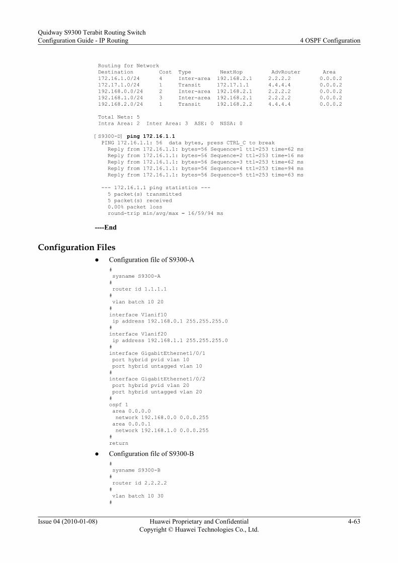
Routing for Network Destination Cost Type NextHop AdvRouter Area 172.16.1.0/24 4 Inter-area 192.168.2.1 2.2.2.2 0.0.0.2 172.17.1.0/24 1 Transit 172.17.1.1 4.4.4.4 0.0.0.2 192.168.0.0/24 2 Inter-area 192.168.2.1 2.2.2.2 0.0.0.2 192.168.1.0/24 3 Inter-area 192.168.2.1 2.2.2.2 0.0.0.2 192.168.2.0/24 1 Transit 192.168.2.2 4.4.4.4 0.0.0.2 Total Nets: 5 Intra Area: 2 Inter Area: 3 ASE: 0 NSSA: 0 [S9300-D] ping 172.16.1.1 PING 172.16.1.1: 56 data bytes, press CTRL_C to break Reply from 172.16.1.1: bytes=56 Sequence=1 ttl=253 time=62 ms Reply from 172.16.1.1: bytes=56 Sequence=2 ttl=253 time=16 ms Reply from 172.16.1.1: bytes=56 Sequence=3 ttl=253 time=62 ms Reply from 172.16.1.1: bytes=56 Sequence=4 ttl=253 time=94 ms Reply from 172.16.1.1: bytes=56 Sequence=5 ttl=253 time=63 ms --- 172.16.1.1 ping statistics --- 5 packet(s) transmitted 5 packet(s) received 0.00% packet loss round-trip min/avg/max = 16/59/94 ms
----End
Configuration Filesl Configuration file of S9300-A
# sysname S9300-A# router id 1.1.1.1# vlan batch 10 20#interface Vlanif10 ip address 192.168.0.1 255.255.255.0 #interface Vlanif20 ip address 192.168.1.1 255.255.255.0#interface GigabitEthernet1/0/1 port hybrid pvid vlan 10 port hybrid untagged vlan 10#interface GigabitEthernet1/0/2 port hybrid pvid vlan 20 port hybrid untagged vlan 20 #ospf 1 area 0.0.0.0 network 192.168.0.0 0.0.0.255 area 0.0.0.1 network 192.168.1.0 0.0.0.255#return
l Configuration file of S9300-B# sysname S9300-B# router id 2.2.2.2# vlan batch 10 30#
Quidway S9300 Terabit Routing SwitchConfiguration Guide - IP Routing 4 OSPF Configuration
Issue 04 (2010-01-08) Huawei Proprietary and ConfidentialCopyright © Huawei Technologies Co., Ltd.
4-63

interface Vlanif10 ip address 192.168.0.2 255.255.255.0#interface Vlanif30 ip address 192.168.2.1 255.255.255.0#interface GigabitEthernet1/0/1 port hybrid pvid vlan 10 port hybrid untagged vlan 10 #interface GigabitEthernet1/0/2 port hybrid pvid vlan 30 port hybrid untagged vlan 30 #ospf 1 area 0.0.0.0 network 192.168.0.0 0.0.0.255 area 0.0.0.2 network 192.168.2.0 0.0.0.255#return
l Configuration file of S9300-C# sysname S9300-C# router id 3.3.3.3# vlan batch 20 40#interface Vlanif20 ip address 192.168.1.2 255.255.255.0#interface Vlanif40 ip address 172.16.1.1 255.255.255.0#interface GigabitEthernet1/0/1 port hybrid pvid vlan 20 port hybrid untagged vlan 20 #interface GigabitEthernet1/0/2 port hybrid pvid vlan 40 port hybrid untagged vlan 40 #ospf 1 area 0.0.0.1 network 192.168.1.0 0.0.0.255 network 172.16.1.0 0.0.0.255#return
l Configuration file of S9300-D# sysname S9300-D# router id 4.4.4.4# vlan batch 30 50#interface Vlanif30 ip address 192.168.2.2 255.255.255.0#interface Vlanif50 ip address 172.17.1.1 255.255.255.0#interface GigabitEthernet1/0/1 port hybrid pvid vlan 30 port hybrid untagged vlan 30 #interface GigabitEthernet1/0/2
4 OSPF ConfigurationQuidway S9300 Terabit Routing Switch
Configuration Guide - IP Routing
4-64 Huawei Proprietary and ConfidentialCopyright © Huawei Technologies Co., Ltd.
Issue 04 (2010-01-08)

port hybrid pvid vlan 50 port hybrid untagged vlan 50 #ospf 1 area 0.0.0.2 network 192.168.2.0 0.0.0.255 network 172.17.1.0 0.0.0.255#return
l Configuration file of S9300-E# sysname S9300-E#router id 5.5.5.5# vlan batch 40#interface Vlanif40 ip address 172.16.1.2 255.255.255.0#interface GigabitEthernet1/0/1 port hybrid pvid vlan 40 port hybrid untagged vlan 40 #ospf 1 area 0.0.0.1 network 172.16.1.0 0.0.0.255#return
l Configuration file of S9300-F# sysname S9300-F# router id 6.6.6.6# vlan batch 50#interface Vlanif50 ip address 172.17.1.2 255.255.255.0#interface GigabitEthernet1/0/1 port hybrid pvid vlan 40 port hybrid untagged vlan 40#ospf 1 area 0.0.0.2 network 172.17.1.0 0.0.0.255#return
4.16.2 Example for Configuring an OSPF Stub Area
Networking RequirementsAs shown in Figure 4-5, OSPF is enabled on all S9300s and the AS is divided into three areas.S9300-A and S9300-B function as ABRs to forward routes between areas; S9300-D functionsas the ASBR to import external routes, that is, static routes.
You need to configure Area 1 as a stub area. The LSAs advertised to this area can thus be reduced,without affecting the route reachability.
Quidway S9300 Terabit Routing SwitchConfiguration Guide - IP Routing 4 OSPF Configuration
Issue 04 (2010-01-08) Huawei Proprietary and ConfidentialCopyright © Huawei Technologies Co., Ltd.
4-65

Figure 4-5 Networking diagram for configuring a stub area
S9300-AArea 0
Area 1 Area 2GE1/0/1GE1/0/1
GE1/0/1 GE1/0/1
GE1/0/1GE1/0/1GE1/0/2 GE1/0/2
GE1/0/2GE1/0/2
S9300-B
S9300-D
S9300-FS9300-E
S9300-C
S9300 Interface VLANIF interface IP address
S9300-A GigabitEthernet1/0/1 VLANIF 10 192.168.0.1/24
S9300-A GigabitEthernet1/0/2 VLANIF 20 192.168.1.1/24
S9300-B GigabitEthernet1/0/1 VLANIF 10 192.168.0.2/24
S9300-B GigabitEthernet1/0/2 VLANIF 30 192.168.2.1/24
S9300-C GigabitEthernet1/0/1 VLANIF 20 192.168.1.2/24
S9300-C GigabitEthernet1/0/2 VLANIF 40 172.16.1.1/24
S9300-D GigabitEthernet1/0/1 VLANIF 30 192.168.2.2/24
S9300-D GigabitEthernet1/0/2 VLANIF 50 172.17.1.1/24
S9300-E GigabitEthernet1/0/1 VLANIF 40 172.16.1.2/24
S9300-F GigabitEthernet1/0/1 VLANIF 50 172.17.1.2/24
Configuration Roadmap
The configuration roadmap is as follows:
1. Enable OSPF on each S9300 and configure the basic OSPF functions.2. Configure static routes on S9300-D and import them into OSPF.3. Configure Area 1 as a stub area by running the stub command on all S9300s in Area 1.4. Configure S9300-A not to advertise Type 3 LSAs to the stub area.
Data Preparation
To complete the configuration, you need the following data:
l ID of the VLAN that each interface belongs to, as shown in Figure 4-5
l IP address of each VLANIF interface, as shown in Figure 4-5
4 OSPF ConfigurationQuidway S9300 Terabit Routing Switch
Configuration Guide - IP Routing
4-66 Huawei Proprietary and ConfidentialCopyright © Huawei Technologies Co., Ltd.
Issue 04 (2010-01-08)

l Router ID and OSPF process ID of each S9300 and area that each interface belongs to:– On S9300-A, the router ID is 1.1.1.1; the OSPF process ID is 1; the network segment
of Area 0 is 192.168.0.0/24, the network segment of Area 1 is 192.168.1.0/24.– On S9300-B, the router ID is 2.2.2.2; the OSPF process ID is 1; the network segment
of Area 0 is 192.168.0.0/24; the network segment of Area 2 is 192.168.2.0/24.– On S9300-C, the router ID is 3.3.3.3; the OSPF process ID is 1; the network segments
of Area 1 are 192.168.1.0/24 and 172.16.1.0/24.– On S9300-D, the router ID is 4.4.4.4; the OSPF process ID is 1; the network segments
of Area 2 are 192.168.2.0/24 and 172.17.1.0/24.– On S9300-E, the router ID is 5.5.5.5; the OSPF process ID is 1; the network segment
of Area 1 is 172.16.1.0/24.– On S9300-F, the router ID is 6.6.6.6; the OSPF process ID is 1; the network segment
of Area 2 is 172.17.1.0/24.
Procedure
Step 1 Configure the basic OSPF functions. See 4.16.1 Configuring Basic OSPF Functions.
Step 2 Configure S9300-D to import static routes.
# Import static routes on S9300-D.
[S9300-D] ip route-static 200.0.0.0 8 null 0[S9300-D] ospf[S9300-D-ospf-1] import-route static type 1[S9300-D-ospf-1] quit
# View information about the ABR or ASBR on S9300-C.
[S9300-C] display ospf abr-asbr OSPF Process 1 with Router ID 3.3.3.3 Routing Table to ABR and ASBR Type Destination Area Cost Nexthop RtType Intra-area 1.1.1.1 0.0.0.1 1 192.168.1.1 ABR Inter-area 4.4.4.4 0.0.0.1 3 192.168.1.1 ASBR
# View the OSPF routing table of S9300-C.
[S9300-C] display ospf routing OSPF Process 1 with Router ID 3.3.3.3 Routing Tables Routing for Network Destination Cost Type NextHop AdvRouter Area 172.16.1.0/24 1 Transit 172.16.1.1 3.3.3.3 0.0.0.1 172.17.1.0/24 4 Inter-area 192.168.1.1 1.1.1.1 0.0.0.1 192.168.0.0/24 2 Inter-area 192.168.1.1 1.1.1.1 0.0.0.1 192.168.1.0/24 1 Transit 192.168.1.2 3.3.3.3 0.0.0.1 192.168.2.0/24 3 Inter-area 192.168.1.1 1.1.1.1 0.0.0.1 Routing for ASEs Destination Cost Type Tag NextHop AdvRouter 200.0.0.0/8 4 Type1 1 192.168.1.1 4.4.4.4 Total Nets: 6 Intra Area: 2 Inter Area: 3 ASE: 1 NSSA: 0
If S9300-C resides in a common area, you can find AS external routes in the routing table.
Quidway S9300 Terabit Routing SwitchConfiguration Guide - IP Routing 4 OSPF Configuration
Issue 04 (2010-01-08) Huawei Proprietary and ConfidentialCopyright © Huawei Technologies Co., Ltd.
4-67

Step 3 Configure Area 1 as a stub area.
# Configure S9300-A.
[S9300-A] ospf[S9300-A-ospf-1] area 1[S9300-A-ospf-1-area-0.0.0.1] stub[S9300-A-ospf-1-area-0.0.0.1] quit[S9300-A-ospf-1] quit
# Configure S9300-C.
[S9300-C] ospf[S9300-C-ospf-1] area 1[S9300-C-ospf-1-area-0.0.0.1] stub[S9300-C-ospf-1-area-0.0.0.1] quit[S9300-C-ospf-1] quit
# Configure S9300-E.
[S9300-E] ospf[S9300-E-ospf-1] area 1[S9300-E-ospf-1-area-0.0.0.1] stub[S9300-E-ospf-1-area-0.0.0.1] quit[S9300-E-ospf-1] quit
# View the routing table of S9300-C.
[S9300-C] display ospf routing OSPF Process 1 with Router ID 3.3.3.3 Routing Tables Routing for Network Destination Cost Type NextHop AdvRouter Area 0.0.0.0/0 2 Inter-area 192.168.1.1 1.1.1.1 0.0.0.1 172.16.1.0/24 1 Transit 172.16.1.1 3.3.3.3 0.0.0.1 172.17.1.0/24 4 Inter-area 192.168.1.1 1.1.1.1 0.0.0.1 192.168.0.0/24 2 Inter-area 192.168.1.1 1.1.1.1 0.0.0.1 192.168.1.0/24 1 Transit 192.168.1.2 3.3.3.3 0.0.0.1 192.168.2.0/24 3 Inter-area 192.168.1.1 1.1.1.1 0.0.0.1 Total Nets: 6 Intra Area: 2 Inter Area: 4 ASE: 0 NSSA: 0
When the area where S9300-C resides is configured as a stub area, you cannot find the ASexternal route but a default route out of the AS.
# Disable S9300-A from advertising Type 3 LSAs to the stub area.
[S9300-A] ospf[S9300-A-ospf-1] area 1[S9300-A-ospf-1-area-0.0.0.1] stub no-summary[S9300-A-ospf-1-area-0.0.0.1] quit[S9300-A-ospf-1] quit
Step 4 Verify the configuration.
# View the OSPF routing table of S9300-C.
[S9300-C] display ospf routing OSPF Process 1 with Router ID 3.3.3.3 Routing Tables Routing for Network Destination Cost Type NextHop AdvRouter Area 0.0.0.0/0 2 Inter-area 192.168.1.1 1.1.1.1 0.0.0.1 172.16.1.0/24 1 Transit 172.16.1.1 3.3.3.3 0.0.0.1
4 OSPF ConfigurationQuidway S9300 Terabit Routing Switch
Configuration Guide - IP Routing
4-68 Huawei Proprietary and ConfidentialCopyright © Huawei Technologies Co., Ltd.
Issue 04 (2010-01-08)

192.168.1.0/24 1 Transit 192.168.1.2 3.3.3.3 0.0.0.1 Total Nets: 3Intra Area: 2 Inter Area: 1 ASE: 0 NSSA: 0
After the advertisement of summary LSA to the stub area is disabled, the route entries are furtherreduced. External routes are not found in the routing table. Instead, there is a default route outof the AS.
----End
Configuration Filesl Configuration file of S9300-A
# sysname S9300-A# router id 1.1.1.1# vlan batch 10 20#interface Vlanif10 ip address 192.168.0.1 255.255.255.0#interface Vlanif20 ip address 192.168.1.1 255.255.255.0#interface GigabitEthernet1/0/1 port hybrid pvid vlan 10 port hybrid untagged vlan 10#interface GigabitEthernet1/0/2 port hybrid pvid vlan 20 port hybrid untagged vlan 20#ospf 1 area 0.0.0.0 network 192.168.0.0 0.0.0.255 area 0.0.0.1 network 192.168.1.0 0.0.0.255 stub no-summary#return
NOTE
Configuration files of S9300-B and S9300-F are similar to the configuration file of S9300-A, andare not mentioned here.
l Configuration file of S9300-C# sysname S9300-C# router id 3.3.3.3# vlan batch 20 40#interface Vlanif20 ip address 192.168.1.2 255.255.255.0#interface Vlanif40 ip address 172.16.1.1 255.255.255.0#interface GigabitEthernet1/0/1 port hybrid pvid vlan 20 port hybrid untagged vlan 20#interface GigabitEthernet1/0/2
Quidway S9300 Terabit Routing SwitchConfiguration Guide - IP Routing 4 OSPF Configuration
Issue 04 (2010-01-08) Huawei Proprietary and ConfidentialCopyright © Huawei Technologies Co., Ltd.
4-69

port hybrid pvid vlan 40 port hybrid untagged vlan 40#ospf 1area 0.0.0.1 network 192.168.1.0 0.0.0.255 network 172.16.1.0 0.0.0.255 stub#return
l Configuration file of S9300-D# sysname S9300-D# vlan batch 30 50# router id 4.4.4.4#interface Vlanif30 ip address 192.168.2.2 255.255.255.0#interface Vlanif50 ip address 172.17.1.1 255.255.255.0#interface GigabitEthernet1/0/1 port hybrid pvid vlan 30 port hybrid untagged vlan 30#interface GigabitEthernet1/0/2 port hybrid pvid vlan 30 port hybrid untagged vlan 30#ospf 1 import-route static type 1 area 0.0.0.2 network 192.168.2.0 0.0.0.255 network 172.17.1.0 0.0.0.255# ip route-static 200.0.0.0 255.0.0.0 NULL0#return
l Configuration file of S9300-E# sysname S9300-E# router id 5.5.5.5# vlan batch 40#interface Vlanif40 ip address 172.16.1.2 255.255.255.0#interface GigabitEthernet1/0/1 port hybrid pvid vlan 40 port hybrid untagged vlan 40#ospf 1 area 0.0.0.1 network 172.16.1.0 0.0.0.255 stub#return
4 OSPF ConfigurationQuidway S9300 Terabit Routing Switch
Configuration Guide - IP Routing
4-70 Huawei Proprietary and ConfidentialCopyright © Huawei Technologies Co., Ltd.
Issue 04 (2010-01-08)

4.16.3 Example for Configuring an NSSA Area
Networking Requirements
As shown in Figure 4-6, OSPF is enabled on all S9300s and the AS is divided into three areas.S9300-A and S9300-B function as ABRs to forward routes between areas; S9300-D functionsas the ASBR to import external routes, that is, static routes.
You need to configure Area 1 as an NSSA area and configure Figure 4-6-C as an ASBR toimport external routes (static routes). The routing information can be transmitted correctly inthe AS.
Figure 4-6 Networking diagram for configuring an NSSA area
S9300-AArea 0
Area 1 Area 2GE1/0/1GE1/0/1
GE1/0/1 GE1/0/1
GE1/0/1GE1/0/1GE1/0/2 GE1/0/2
GE1/0/2GE1/0/2
S9300-B
S9300-D
S9300-FS9300-E
S9300-C
S9300 Interface VLANIF interface IP address
S9300-A GigabitEthernet1/0/1 VLANIF 10 192.168.0.1/24
S9300-A GigabitEthernet1/0/2 VLANIF 20 192.168.1.1/24
S9300-B GigabitEthernet1/0/1 VLANIF 10 192.168.0.2/24
S9300-B GigabitEthernet1/0/2 VLANIF 30 192.168.2.1/24
S9300-C GigabitEthernet1/0/1 VLANIF 20 192.168.1.2/24
S9300-C GigabitEthernet1/0/2 VLANIF 40 172.16.1.1/24
S9300-D GigabitEthernet1/0/1 VLANIF 30 192.168.2.2/24
S9300-D GigabitEthernet1/0/2 VLANIF 50 172.17.1.1/24
S9300-E GigabitEthernet1/0/1 VLANIF 40 172.16.1.2/24
S9300-F GigabitEthernet1/0/1 VLANIF 50 172.17.1.2/24
Configuration Roadmap
The configuration roadmap is as follows:
Quidway S9300 Terabit Routing SwitchConfiguration Guide - IP Routing 4 OSPF Configuration
Issue 04 (2010-01-08) Huawei Proprietary and ConfidentialCopyright © Huawei Technologies Co., Ltd.
4-71

1. Enable OSPF on each S9300 and configure the basic OSPF functions.2. Configure static routes on S9300-D and import them into OSPF.3. Configure Area 1 as an NSSA area and check the OSPF routing information of S9300-C.
You must run the nssa command on all the devices in Area 1.4. Configure static routes on S9300-C, import them into OSPF, and check the OSPF routing
information of S9300-D.
Data PreparationTo complete the configuration, you need the following data:
l ID of the VLAN that each interface belongs to, as shown in Figure 4-6l IP address of each VLANIF interface, as shown in Figure 4-6l Router ID and OSPF process ID of each S9300 and the area that each interface belongs to:
– On S9300-A, the router ID is 1.1.1.1; the OSPF process ID is 1; the network segmentof Area 0 is 192.168.0.0/24, and the network segment of Area 1 is 192.168.1.0/24.
– On S9300-B, the router ID is 2.2.2.2; the OSPF process ID is 1; the network segmentof Area 0 is 192.168.0.0/24; the network segment of Area 2 is 192.168.2.0/24.
– On S9300-C, the router ID is 3.3.3.3; the OSPF process ID is 1; the network segmentsof Area 1 are 192.168.1.0/24 and 172.16.1.0/24.
– On S9300-D, the router ID is 4.4.4.4; the OSPF process ID is 1; the network segmentsof Area 2 are 192.168.2.0/24 and 172.17.1.0/24.
– On S9300-E, the router ID is 5.5.5.5; the OSPF process ID is 1; the network segmentof Area 1 is 172.16.1.0/24.
– On S9300-F, the router ID is 6.6.6.6; the OSPF process ID is 1; the network segmentof Area 2 is 172.17.1.0/24.
Procedure
Step 1 Configure the basic OSPF functions. See 4.16.1 Configuring Basic OSPF Functions.
Step 2 Configure S9300-D to import static routes. See 4.16.2 Example for Configuring an OSPFStub Area.
Step 3 Configure Area 1 as an NSSA area.
# Configure S9300-A.
[S9300-A] ospf[S9300-A-ospf-1] area 1[S9300-A-ospf-1-area-0.0.0.1] nssa default-route-advertise no-summary[S9300-A-ospf-1-area-0.0.0.1] quit[S9300-A-ospf-1] quit
# Configure S9300-C.
[S9300-C] ospf[S9300-C-ospf-1] area 1[S9300-C-ospf-1-area-0.0.0.1] nssa[S9300-C-ospf-1-area-0.0.0.1] quit[S9300-C-ospf-1] quit
# Configure S9300-E.
[S9300-E] ospf[S9300-E-ospf-1] area 1
4 OSPF ConfigurationQuidway S9300 Terabit Routing Switch
Configuration Guide - IP Routing
4-72 Huawei Proprietary and ConfidentialCopyright © Huawei Technologies Co., Ltd.
Issue 04 (2010-01-08)

[S9300-E-ospf-1-area-0.0.0.1] nssa[S9300-E-ospf-1-area-0.0.0.1] quit[S9300-E-ospf-1] quit
NOTE
The default-route-advertise and no-summary keywords are recommend on the ABR (S9300-A). In thismanner, the size of the routing table of devices in an NSSA area can be reduced. For the other devices inthe NSSA area, you need to run only the nssa command.
# View the OSPF routing table of S9300-C.
[S9300-C] display ospf routing OSPF Process 1 with Router ID 3.3.3.3 Routing Tables Routing for Network Destination Cost Type NextHop AdvRouter Area 0.0.0.0/0 2 Inter-area 192.168.1.1 1.1.1.1 0.0.0.1 172.16.1.0/24 1 Transit 172.16.1.1 3.3.3.3 0.0.0.1 192.168.1.0/24 1 Transit 192.168.1.2 3.3.3.3 0.0.0.1 Total Nets: 3 Intra Area: 2 Inter Area: 1 ASE: 0 NSSA: 0
Step 4 Configure S9300-C to import static routes.
# Import static routes on S9300-C.
[S9300-C] ip route-static 100.0.0.0 8 null 0[S9300-C] ospf[S9300-C-ospf-1] import-route static[S9300-C-ospf-1] quit
Step 5 Verify the configuration.
# View the OSPF routing table of S9300-D.
[S9300-D] display ospf routing OSPF Process 1 with Router ID 4.4.4.4 Routing Tables Routing for Network Destination Cost Type NextHop AdvRouter Area 172.16.1.0/24 4 Inter-area 192.168.2.1 2.2.2.2 0.0.0.2 172.17.1.0/24 1 Transit 172.17.1.1 4.4.4.4 0.0.0.2 192.168.0.0/24 2 Inter-area 192.168.2.1 2.2.2.2 0.0.0.2 192.168.1.0/24 3 Inter-area 192.168.2.1 2.2.2.2 0.0.0.2 192.168.2.0/24 1 Transit 192.168.2.2 4.4.4.4 0.0.0.2 Routing for ASEs Destination Cost Type Tag NextHop AdvRouter 100.0.0.0/8 1 Type2 1 192.168.2.1 1.1.1.1 Total Nets: 6 Intra Area: 2 Inter Area: 3 ASE: 1 NSSA: 0
From the routing table of S9300-D, you can find that an AS external route is imported to theNSSA area.
----End
Configuration Filesl Configuration file of S9300-A
# sysname S9300-A
Quidway S9300 Terabit Routing SwitchConfiguration Guide - IP Routing 4 OSPF Configuration
Issue 04 (2010-01-08) Huawei Proprietary and ConfidentialCopyright © Huawei Technologies Co., Ltd.
4-73

# router id 1.1.1.1# vlan batch 10 20#interface Vlanif10 ip address 192.168.0.1 255.255.255.0#interface Vlanif20 ip address 192.168.1.1 255.255.255.0#interface GigabitEthernet1/0/1 port hybrid pvid vlan 10 port hybrid untagged vlan 10#interface GigabitEthernet1/0/2 port hybrid pvid vlan 20 port hybrid untagged vlan 20#ospf 1 area 0.0.0.0 network 192.168.0.0 0.0.0.255 area 0.0.0.1 network 192.168.1.0 0.0.0.255 nssa default-route-advertise no-summary#return
NOTE
Configuration files of S9300-B, S9300-D, and S9300-F are similar to the configuration file ofS9300-A, and are not mentioned here.
l Configuration file of S9300-C# sysname S9300-C# router id 3.3.3.3# vlan batch 20 40#interface Vlanif20 ip address 192.168.1.2 255.255.255.0#interface Vlanif40 ip address 172.16.1.1 255.255.255.0#interface GigabitEthernet1/0/1 port hybrid pvid vlan 20 port hybrid untagged vlan 20#interface GigabitEthernet1/0/2 port hybrid pvid vlan 40 port hybrid untagged vlan 40#ospf 1 import-route static area 0.0.0.1 network 192.168.1.0 0.0.0.255 network 172.16.1.0 0.0.0.255 nssa# ip route-static 100.0.0.0 255.0.0.0 NULL0#return
l Configuration file of S9300-E# sysname S9300-E#
4 OSPF ConfigurationQuidway S9300 Terabit Routing Switch
Configuration Guide - IP Routing
4-74 Huawei Proprietary and ConfidentialCopyright © Huawei Technologies Co., Ltd.
Issue 04 (2010-01-08)

router id 5.5.5.5# vlan batch 40#interface Vlanif40 ip address 172.16.1.2 255.255.255.0#interface GigabitEthernet1/0/1 port hybrid pvid vlan 40 port hybrid untagged vlan 40#ospf 1 area 0.0.0.1 network 172.16.1.0 0.0.0.255 nssa#return
4.16.4 Example for Configuring DR Election of OSPF
Networking RequirementsAs shown in Figure 4-7, S9300-A has the highest priority of 100 on the network and is electedas the DR; S9300-C has the second highest priority and is elected as the BDR; The priority ofS9300-B is 0 and therefore cannot be elected as a DR or a BDR; the priority of S9300-D is notset, so S9300-D uses the default value 1.
Figure 4-7 Networking diagram for configuring DR election of an OSPF process
S9300-A
GE1/0/1GE1/0/1
GE1/0/1GE1/0/1
S9300-B
S9300-C S9300-D
S9300 Interface VLANIF interface IP address
S9300-A GigabitEthernet1/0/1 VLANIF 10 192.168.1.1/24
S9300-B GigabitEthernet1/0/1 VLANIF 10 192.168.1.2/24
S9300-C GigabitEthernet1/0/1 VLANIF 10 192.168.1.3/24
S9300-D GigabitEthernet1/0/1 VLANIF 10 192.168.1.4/24
Configuration RoadmapThe configuration roadmap is as follows:
1. Configure the ID of the VLAN that each interface belongs to.2. Assign an IP address to each VLANIF interface.
Quidway S9300 Terabit Routing SwitchConfiguration Guide - IP Routing 4 OSPF Configuration
Issue 04 (2010-01-08) Huawei Proprietary and ConfidentialCopyright © Huawei Technologies Co., Ltd.
4-75

3. Configure the router ID, enable OSPF, and specify network segments on each S9300.4. Check whether an S9300 is the DR or BDR with its default DR priority.5. Set the DR priority of the interface on each S9300 and check whether the S9300 becomes
the DR or BDR.
Data PreparationTo complete the configuration, you need the following data:
l ID of the VLAN that each interface belongs to, as shown in Figure 4-7
l IP address of each VLANIF interface, as shown in Figure 4-7
l Router ID, OSPF process ID, and DR priority of each S9300, and area that each interfacebelongs to:– On S9300-A, the router ID is 1.1.1.1; the OSPF process ID is 1; the network segment
of Area 0 is 192.168.1.0/24; the DR priority is 100.– On S9300-B, the router ID is 2.2.2.2; the OSPF process ID is 1; the network segment
of Area 0 is 192.168.1.0/24; the DR priority is 0.– On S9300-C, the router ID is 3.3.3.3; the OSPF process ID is 1; the network segment
of Area 0 is 192.168.1.0/24; the DR priority is 2.– On S9300-D, the router ID is 4.4.4.4; the OSPF process ID is 1; the network segment
of Area 0 is 192.168.1.0/24; the DR priority is 1.
Procedure
Step 1 Configure the VLAN that the each interface belongs to.<Quidway> system-view[Quidway] sysname S9300-A[S9300-A] vlan 10[S9300-A-vlan10] quit[S9300-A] interface GigabitEthernet 1/0/1[S9300-A-GigabitEthernet1/0/1] port hybrid pvid vlan 10[S9300-A-GigabitEthernet1/0/1] port hybrid untagged vlan 10[S9300-A-GigabitEthernet1/0/1] quit
The configurations of S9300-B, S9300-C, and S9300-D are similar to the configuration ofS9300-A, and are not mentioned here.
Step 2 Assign an IP address to each VLANIF interface.[S9300-A] interface vlanif 10[S9300-A-Vlanif10] ip address 192.168.1.1 24
The configurations of S9300-B, S9300-C, and S9300-D are similar to the configuration ofS9300-A, and are not mentioned here.
Step 3 Configure the basic OSPF functions.
# Configure S9300-A.
[S9300-A] router id 1.1.1.1[S9300-A] ospf[S9300-A-ospf-1] area 0[S9300-A-ospf-1-area-0.0.0.0] network 192.168.1.0 0.0.0.255[S9300-A-ospf-1-area-0.0.0.0] quit[S9300-A-ospf-1] quit
# Configure S9300-B.
4 OSPF ConfigurationQuidway S9300 Terabit Routing Switch
Configuration Guide - IP Routing
4-76 Huawei Proprietary and ConfidentialCopyright © Huawei Technologies Co., Ltd.
Issue 04 (2010-01-08)

[S9300-B] router id 2.2.2.2[S9300-B] ospf[S9300-B-ospf-1] area 0[S9300-B-ospf-1-area-0.0.0.0] network 192.168.1.0 0.0.0.255 [S9300-B-ospf-1-area-0.0.0.0] quit[S9300-B-ospf-1] quit
# Configure S9300-C.
[S9300-C] router id 3.3.3.3[S9300-C] ospf[S9300-C-ospf-1] area 0[S9300-C-ospf-1-area-0.0.0.0] network 192.168.1.0 0.0.0.255 [S9300-C-ospf-1-area-0.0.0.0] quit[S9300-C-ospf-1] quit
# Configure S9300-D.
[S9300-D] router id 4.4.4.4[S9300-D] ospf[S9300-D-ospf-1] area 0[S9300-D-ospf-1-area-0.0.0.0] network 192.168.1.0 0.0.0.255 [S9300-D-ospf-1-area-0.0.0.0] quit[S9300-D-ospf-1] quit
# Check information about neighbors of S9300-A to find the DR and BDR.
[S9300-A] display ospf peer OSPF Process 1 with Router ID 1.1.1.1 Neighbors Area 0.0.0.0 interface 192.168.1.1(Vlanif10)'s neighbors Router ID: 2.2.2.2 Address: 192.168.1.2 GR State: Normal State: 2-Way Mode:Nbr is Master Priority: 1 DR: 192.168.1.4 BDR: 192.168.1.3 MTU: 0 Dead timer due in 32 sec Neighbor is up for 00:00:00 Authentication Sequence: [ 0 ] Router ID: 3.3.3.3 Address: 192.168.1.3 GR State: Normal State: Full Mode:Nbr is Master Priority: 1 DR: 192.168.1.4 BDR: 192.168.1.3 MTU: 0 Dead timer due in 37 sec Neighbor is up for 00:04:06 Authentication Sequence: [ 0 ] Router ID: 4.4.4.4 Address: 192.168.1.4 GR State: Normal State: Full Mode:Nbr is Master Priority: 1 DR: 192.168.1.4 BDR: 192.168.1.3 MTU: 0 Dead timer due in 37 sec Neighbor is up for 00:03:53 Authentication Sequence: [ 0 ]
Check the neighbors of S9300-A. You can view the DR priority and the neighbor status. Bydefault, the DR priority is 1. Now S9300-D functions as the DR and S9300-C functions as theBDR.
NOTE
When two routers have the save priority, the router with a greater router ID is elected as the DR. If anEthernet interface of an S9300 becomes the DR, the other broadcast interfaces of the S9300 have a highpriority in the future DR election. That is, the S9300 is still elected as the DR in later election and the DRcannot be preempted.
Step 4 Set the DR priority on each VLAN IF interface.
# Configure S9300-A.
Quidway S9300 Terabit Routing SwitchConfiguration Guide - IP Routing 4 OSPF Configuration
Issue 04 (2010-01-08) Huawei Proprietary and ConfidentialCopyright © Huawei Technologies Co., Ltd.
4-77

[S9300-A] interface vlanif 10[S9300-A-Vlanif10] ospf dr-priority 100[S9300-A-Vlanif10] quit
Configure S9300-B.
[S9300-B] interface vlanif 10[S9300-B-Vlanif10] ospf dr-priority 0[S9300-B-Vlanif10] quit
# Configure S9300-C.
[S9300-C] interface vlanif 10[S9300-C-Vlanif10] ospf dr-priority 2[S9300-C-Vlanif10] quit
# Check the status of the DR or BDR.
[S9300-D] display ospf peer OSPF Process 1 with Router ID 4.4.4.4 Neighbors Area 0.0.0.0 interface 192.168.1.4(Vlanif10)'s neighbors Router ID: 1.1.1.1 Address: 192.168.1.1 GR State: Normal State: Full Mode:Nbr is Slave Priority: 100 DR: 192.168.1.4 BDR: 192.168.1.3 MTU: 0 Dead timer due in 31 sec Neighbor is up for 00:11:17 Authentication Sequence: [ 0 ] Router ID: 2.2.2.2 Address: 192.168.1.2 GR State: Normal State: Full Mode:Nbr is Slave Priority: 0 DR: 192.168.1.4 BDR: 192.168.1.3 MTU: 0 Dead timer due in 35 sec Neighbor is up for 00:11:19 Authentication Sequence: [ 0 ] Router ID: 3.3.3.3 Address: 192.168.1.3 GR State: Normal State: Full Mode:Nbr is Slave Priority: 2 DR: 192.168.1.4 BDR: 192.168.1.3 MTU: 0 Dead timer due in 33 sec Neighbor is up for 00:11:15 Authentication Sequence: [ 0 ]
NOTE
The DR priorities configured on the interfaces do not take effect immediately.
Step 5 Restart the OSPF process.
In the user view of each S9300, run the reset ospf 1 process command to restart the OSPFprocess.
Step 6 Verify the configuration.
# Check the status of OSPF neighbors.
[S9300-D] display ospf peer OSPF Process 1 with Router ID 4.4.4.4 Neighbors Area 0.0.0.0 interface 192.168.1.4(Vlanif10)'s neighbors Router ID: 1.1.1.1 Address: 192.168.1.1 GR State: Normal State: Full Mode:Nbr is Slave Priority: 100 DR: 192.168.1.1 BDR: 192.168.1.3 MTU: 0 Dead timer due in 35 sec Neighbor is up for 00:07:19 Authentication Sequence: [ 0 ]
4 OSPF ConfigurationQuidway S9300 Terabit Routing Switch
Configuration Guide - IP Routing
4-78 Huawei Proprietary and ConfidentialCopyright © Huawei Technologies Co., Ltd.
Issue 04 (2010-01-08)

Router ID: 2.2.2.2 Address: 192.168.1.2 GR State: Normal State: 2-Way Mode:Nbr is Master Priority: 0 DR: 192.168.1.1 BDR: 192.168.1.3 MTU: 0 Dead timer due in 35 sec Neighbor is up for 00:00:00 Authentication Sequence: [ 0 ] Router ID: 3.3.3.3 Address: 192.168.1.3 GR State: Normal State: Full Mode:Nbr is Slave Priority: 2 DR: 192.168.1.1 BDR: 192.168.1.3 MTU: 0 Dead timer due in 37 sec Neighbor is up for 00:07:17 Authentication Sequence: [ 0 ]
# Check the status of OSPF interfaces.
[S9300-A] display ospf interface OSPF Process 1 with Router ID 1.1.1.1 Interfaces Area: 0.0.0.0 (MPLS TE not enabled) IP Address Type State Cost Pri DR BDR 192.168.1.1 Broadcast DR 1 100 192.168.1.1 192.168.1.3 [S9300-B] display ospf interface OSPF Process 1 with Router ID 2.2.2.2 Interfaces Area: 0.0.0.0 (MPLS TE not enabled) IP Address Type State Cost Pri DR BDR 192.168.1.2 Broadcast DROther 1 0 192.168.1.1 192.168.1.3
If all neighbors are in Full state, it indicates that the local device establishes adjacencies with allits neighbors. If a neighbor stays in 2-Way state, it indicates the local S9300 and the neighborare not the DR or BDR. Therefore, they do not need to exchange LSAs.
If the status of an OSPF interface is DROther, it indicates that the router is neither the DR northe BDR.
----End
Configuration Filesl Configuration file of S9300-A
# sysname S9300-A# router id 1.1.1.1# vlan batch 10#interface Vlanif10 ip address 192.168.1.1 255.255.255.0 ospf dr-priority 100#interface GigabitEthernet1/0/1 port hybrid pvid vlan 10 port hybrid untagged vlan 10 #ospf 1 area 0.0.0.0 network 192.168.1.0 0.0.0.255#return
Quidway S9300 Terabit Routing SwitchConfiguration Guide - IP Routing 4 OSPF Configuration
Issue 04 (2010-01-08) Huawei Proprietary and ConfidentialCopyright © Huawei Technologies Co., Ltd.
4-79

l Configuration file of S9300-B# sysname S9300-B# router id 2.2.2.2# vlan batch 10#interface Vlanif10 ip address 192.168.1.2 255.255.255.0 ospf dr-priority 0#interface GigabitEthernet1/0/1 port hybrid pvid vlan 10 port hybrid untagged vlan 10 #ospf 1 area 0.0.0.0 network 192.168.1.0 0.0.0.255#return
l Configuration file of S9300-C# sysname S9300-C# router id 3.3.3.3# vlan batch 10#interface Vlanif10 ip address 192.168.1.3 255.255.255.0 ospf dr-priority 2#interface GigabitEthernet1/0/1 port hybrid pvid vlan 10 port hybrid untagged vlan 10 #ospf 1 area 0.0.0.0 network 192.168.1.0 0.0.0.255#return
l Configuration file of S9300-D# sysname S9300-D# router id 4.4.4.4# vlan batch 10#interface Vlanif10 ip address 192.168.1.4 255.255.255.0#interface GigabitEthernet1/0/1 port hybrid pvid vlan 10 port hybrid untagged vlan 10 #ospf 1 area 0.0.0.0 network 192.168.1.0 0.0.0.255#return
4 OSPF ConfigurationQuidway S9300 Terabit Routing Switch
Configuration Guide - IP Routing
4-80 Huawei Proprietary and ConfidentialCopyright © Huawei Technologies Co., Ltd.
Issue 04 (2010-01-08)

4.16.5 Example for Configuring an OSPF virtual link
Networking Requirements
As shown in Figure 4-8, Area 2 is not directly connected to the backbone area. Area 1 functionsas a transit area to connect Area 2 to Area 0. A virtual link is set up between S9300-A and S9300-B.
Figure 4-8 Networking for configuring an OSPF virtual link
S9300-C
Area 0
Area 1
Area 2
Virtual LinkGE1/0/2
GE1/0/1GE1/0/2
GE1/0/1
GE1/0/1
GE1/0/1
S9300-A S9300-B
S9300-D
S9300 Interface VLANIF interface IP address
S9300-A GigabitEthernet1/0/1 VLANIF 10 192.168.1.1/24
S9300-A GigabitEthernet1/0/2 VLANIF 20 10.1.1.1/8
S9300-B GigabitEthernet1/0/1 VLANIF 10 192.168.1.2/24
S9300-B GigabitEthernet1/0/2 VLANIF 30 172.16.1.1/16
S9300-C GigabitEthernet1/0/1 VLANIF 20 10.1.1.2/8
S9300-D GigabitEthernet1/0/1 VLANIF 30 172.16.1.2/16
Configuration Roadmap
The configuration roadmap is as follows:
1. Enable OSPF on each S9300 and configure the basic OSPF functions.2. Configure a virtual link between S9300-A and S9300-B to connect the non-backbone areas
and the backbone area.
Data Preparation
To complete the configuration, you need the following data:
l ID of the VLAN that each interface belongs to, as shown in Figure 4-8
l IP address of each VLANIF interface, as shown in Figure 4-8
l Router ID and OSPF process ID of each S9300 and area that each interface belongs to:– On S9300-A, the router ID is 1.1.1.1; OSPF process ID is 1; the network segment of
Area 1 is 192.168.1.0/24; the network segment of Area 0 is 10.0.0.0/8.
Quidway S9300 Terabit Routing SwitchConfiguration Guide - IP Routing 4 OSPF Configuration
Issue 04 (2010-01-08) Huawei Proprietary and ConfidentialCopyright © Huawei Technologies Co., Ltd.
4-81
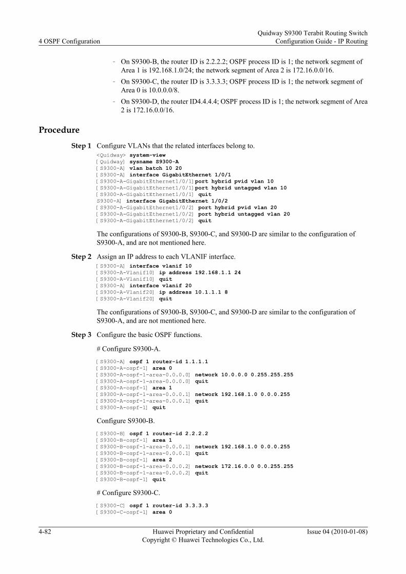
– On S9300-B, the router ID is 2.2.2.2; OSPF process ID is 1; the network segment ofArea 1 is 192.168.1.0/24; the network segment of Area 2 is 172.16.0.0/16.
– On S9300-C, the router ID is 3.3.3.3; OSPF process ID is 1; the network segment ofArea 0 is 10.0.0.0/8.
– On S9300-D, the router ID4.4.4.4; OSPF process ID is 1; the network segment of Area2 is 172.16.0.0/16.
Procedure
Step 1 Configure VLANs that the related interfaces belong to.<Quidway> system-view[Quidway] sysname S9300-A[S9300-A] vlan batch 10 20[S9300-A] interface GigabitEthernet 1/0/1[S9300-A-GigabitEthernet1/0/1]port hybrid pvid vlan 10[S9300-A-GigabitEthernet1/0/1]port hybrid untagged vlan 10[S9300-A-GigabitEthernet1/0/1] quitS9300-A] interface GigabitEthernet 1/0/2[S9300-A-GigabitEthernet1/0/2] port hybrid pvid vlan 20[S9300-A-GigabitEthernet1/0/2] port hybrid untagged vlan 20[S9300-A-GigabitEthernet1/0/2] quit
The configurations of S9300-B, S9300-C, and S9300-D are similar to the configuration ofS9300-A, and are not mentioned here.
Step 2 Assign an IP address to each VLANIF interface.[S9300-A] interface vlanif 10[S9300-A-Vlanif10] ip address 192.168.1.1 24[S9300-A-Vlanif10] quit[S9300-A] interface vlanif 20[S9300-A-Vlanif20] ip address 10.1.1.1 8[S9300-A-Vlanif20] quit
The configurations of S9300-B, S9300-C, and S9300-D are similar to the configuration ofS9300-A, and are not mentioned here.
Step 3 Configure the basic OSPF functions.
# Configure S9300-A.
[S9300-A] ospf 1 router-id 1.1.1.1 [S9300-A-ospf-1] area 0[S9300-A-ospf-1-area-0.0.0.0] network 10.0.0.0 0.255.255.255 [S9300-A-ospf-1-area-0.0.0.0] quit[S9300-A-ospf-1] area 1[S9300-A-ospf-1-area-0.0.0.1] network 192.168.1.0 0.0.0.255 [S9300-A-ospf-1-area-0.0.0.1] quit[S9300-A-ospf-1] quit
Configure S9300-B.
[S9300-B] ospf 1 router-id 2.2.2.2[S9300-B-ospf-1] area 1[S9300-B-ospf-1-area-0.0.0.1] network 192.168.1.0 0.0.0.255 [S9300-B-ospf-1-area-0.0.0.1] quit[S9300-B-ospf-1] area 2[S9300-B-ospf-1-area-0.0.0.2] network 172.16.0.0 0.0.255.255[S9300-B-ospf-1-area-0.0.0.2] quit[S9300-B-ospf-1] quit
# Configure S9300-C.
[S9300-C] ospf 1 router-id 3.3.3.3 [S9300-C-ospf-1] area 0
4 OSPF ConfigurationQuidway S9300 Terabit Routing Switch
Configuration Guide - IP Routing
4-82 Huawei Proprietary and ConfidentialCopyright © Huawei Technologies Co., Ltd.
Issue 04 (2010-01-08)

[S9300-C-ospf-1-area-0.0.0.0] network 10.0.0.0 0.255.255.255 [S9300-C-ospf-1-area-0.0.0.0] quit[S9300-C-ospf-1] quit
# Configure S9300-D.
[S9300-D] ospf 1 router-id 4.4.4.4[S9300-D-ospf-1] area 2[S9300-D-ospf-1-area-0.0.0.2] network 172.16.0.0 0.0.255.255 [S9300-D-ospf-1-area-0.0.0.2] quit[S9300-D-ospf-1] quit
# View the OSPF routing table of S9300-C.
[S9300-A] display ospf routing OSPF Process 1 with Router ID 1.1.1.1 Routing Tables Routing for Network Destination Cost Type NextHop AdvRouter Area 10.0.0.0/8 1 Transit 10.1.1.1 3.3.3.3 0.0.0.0 192.168.1.0/24 1 Transit 192.168.1.1 2.2.2.2 0.0.0.1 Total Nets: 2 Intra Area: 2 Inter Area: 0 ASE: 0 NSSA: 0
Area 2 is not directly connected to Area 0. Therefore, the routing table of S9300-A does notcontain any route to Area 2.
Step 4 Configure a virtual link.
# Configure S9300-A.
[S9300-A] ospf [S9300-A-ospf-1] area 1[S9300-A-ospf-1-area-0.0.0.1] vlink-peer 2.2.2.2[S9300-A-ospf-1-area-0.0.0.1] quit[S9300-A-ospf-1] quit
# Configure S9300-B.
[S9300-B] ospf 1[S9300-B-ospf-1] area 1[S9300-B-ospf-1-area-0.0.0.1] vlink-peer 1.1.1.1 [S9300-B-ospf-1-area-0.0.0.1] quit[S9300-B-ospf-1] quit
Step 5 Verify the configuration.
# View the OSPF routing table of S9300-C.
[S9300-A] display ospf routing OSPF Process 1 with Router ID 1.1.1.1 Routing Tables Routing for Network Destination Cost Type NextHop AdvRouter Area 172.16.0.0/16 2 Inter-area 192.168.1.2 2.2.2.2 0.0.0.0 10.0.0.0/8 1 Transit 10.1.1.1 1.1.1.1 0.0.0.0 192.168.1.0/24 1 Transit 192.168.1.1 2.2.2.2 0.0.0.1 Total Nets: 3 Intra Area: 2 Inter Area: 1 ASE: 0 NSSA: 0
----End
Quidway S9300 Terabit Routing SwitchConfiguration Guide - IP Routing 4 OSPF Configuration
Issue 04 (2010-01-08) Huawei Proprietary and ConfidentialCopyright © Huawei Technologies Co., Ltd.
4-83

Configuration Filesl Configuration file of S9300-A
# sysname S9300-A# vlan batch 10 20#interface Vlanif10 ip address 192.168.1.1 255.255.255.0#interface Vlanif20 ip address 10.1.1.1 255.0.0.0#interface GigabitEthernet1/0/1 port hybrid pvid vlan 10 port hybrid untagged vlan 10 #interface GigabitEthernet1/0/2 port hybrid pvid vlan 20 port hybrid untagged vlan 20 #ospf 1 router-id 1.1.1.1 area 0.0.0.0 network 10.0.0.0 0.255.255.255 area 0.0.0.1 network 192.168.1.0 0.0.0.255 vlink-peer 2.2.2.2#return
l Configuration file of S9300-B# sysname S9300-B# vlan batch 10 30#interface Vlanif10 ip address 192.168.1.2 255.255.255.0#interface Vlanif30 ip address 172.16.1.1 255.255.0.0#interface GigabitEthernet1/0/1 port hybrid pvid vlan 10 port hybrid untagged vlan 10 #interface GigabitEthernet1/0/2 port hybrid pvid vlan 30 port hybrid untagged vlan 30 #ospf 1 router-id 2.2.2.2 area 0.0.0.1 network 192.168.1.0 0.0.0.255 vlink-peer 1.1.1.1 area 0.0.0.2 network 172.16.0.0 0.0.255.255#return
l Configuration file of S9300-C# sysname S9300-C# vlan 20#interface Vlanif20 ip address 10.1.1.2 255.0.0.0#
4 OSPF ConfigurationQuidway S9300 Terabit Routing Switch
Configuration Guide - IP Routing
4-84 Huawei Proprietary and ConfidentialCopyright © Huawei Technologies Co., Ltd.
Issue 04 (2010-01-08)

interface GigabitEthernet1/0/1 port hybrid pvid vlan 20 port hybrid untagged vlan 20 #ospf 1 router-id 3.3.3.3 area 0.0.0.0 network 10.0.0.0 0.255.255.255#return
l Configuration file of S9300-D# sysname S9300-D# vlan 30#interface Vlanif30 ip address 172.16.1.2 255.255.0.0#interface GigabitEthernet1/0/1 port hybrid pvid vlan 30 port hybrid untagged vlan 30 #ospf 1 router-id 4.4.4.4 area 0.0.0.2 network 172.16.0.0 0.0.255.255#return
4.16.6 Example for Configuring Load Balancing Among OSPFRoutes
Networking Requirements
As shown in Figure 4-9, the networking requirements are as follows:
l S9300-A, S9300-B, S9300-C, and S9300-D connect to each other through OSPF.
l S9300-A, S9300-B, S9300-C, and S9300-D belong to Area 0.
l Load balancing needs is configured so that the traffic of S9300-A can be sent to S9300-Dthrough S9300-B and S9300-C.
Figure 4-9 Networking diagram for configuring load balancing among OSPF routes
Area0
S9300-A
S9300-C
S9300-B
S9300-D
GE1/0/1
GE1/0/2
GE1/0/2
GE1/0/2
GE1/0/2
GE1/0/1 GE1/0/1
GE1/0/1
GE1/0/3 GE1/0/3
S9300 Interface VLANIF interface IP address
Quidway S9300 Terabit Routing SwitchConfiguration Guide - IP Routing 4 OSPF Configuration
Issue 04 (2010-01-08) Huawei Proprietary and ConfidentialCopyright © Huawei Technologies Co., Ltd.
4-85

S9300-A GigabitEthernet1/0/1 VLANIF 10 10.1.1.1/24
S9300-A GigabitEthernet1/0/2 VLANIF 20 10.1.2.1/24
S9300-A GigabitEthernet1/0/3 VLANIF 50 172.16.1.1/24
S9300-B GigabitEthernet1/0/1 VLANIF 10 10.1.1.2/24
S9300-B GigabitEthernet1/0/2 VLANIF 30 192.168.0.1/24
S9300-C GigabitEthernet1/0/1 VLANIF 20 10.1.2.2./24
S9300-C GigabitEthernet1/0/2 VLANIF 40 192.168.1.1/24
S9300-D GigabitEthernet1/0/1 VLANIF 30 192.168.0.2/24
S9300-D GigabitEthernet1/0/2 VLANIF 40 192.168.1.2/24
S9300-D GigabitEthernet1/0/3 VLANIF 60 172.17.1.1/24
Configuration RoadmapThe configuration roadmap is as follows:
1. Configure the basic OSPF functions on each S9300 to implement interconnection.2. Disable load balancing on S9300-A and check the routing table of S9300-A.3. (Optional) Set the weight of equal-cost routes on S9300-A.
Data PreparationTo complete the configuration, you need the following data:
l ID of the VLAN that each interface belongs to, as shown in Figure 4-9
l IP address of each VLANIF interface, as shown in Figure 4-9
l Router ID and OSPF process ID of each S9300 and area that each interface belongs to:– On S9300-A, the router ID is 1.1.1.1; the OSPF process ID is 1; the network segments
of Area 1 are 10.1.1.0/24, 10.1.2.0/24, and 172.16.1.0/24.– On S9300-B, the router ID is 2.2.2.2; the OSPF process ID is 1; the network segments
of Area 0 are 10.1.1.0/24 and 192.168.0.0/24.– The router ID of S9300-C is 3.3.3.3; the OSPF process ID is 1; the network segments
of Area 0 are 10.1.2.0/24 and 192.168.1.0/24.– On S9300-D, the router ID is 4.4.4.4; the OSPF process ID is 1; the network segments
of Area 0 are 172.17.1.0/24, 192.168.0.0/24, and 192.168.1.0/24.l Number of routes for load balancing on S9300-A: 1
l Weight of the equal-cost route whose next hop is S9300-C: 1
Procedure
Step 1 Configure VLANs that the related interfaces belong to.<Quidway> system-view[Quidway] sysname S9300-A[S9300-A] vlan batch 10 20 50[S9300-A] interface GigabitEthernet 1/0/1
4 OSPF ConfigurationQuidway S9300 Terabit Routing Switch
Configuration Guide - IP Routing
4-86 Huawei Proprietary and ConfidentialCopyright © Huawei Technologies Co., Ltd.
Issue 04 (2010-01-08)

[S9300-A-GigabitEthernet1/0/1] port hybrid pvid vlan 10[S9300-A-GigabitEthernet1/0/1] port hybrid untagged vlan 10[S9300-A-GigabitEthernet1/0/1] quit[S9300-A] interface GigabitEthernet 1/0/2[S9300-A-GigabitEthernet1/0/2] port hybrid pvid vlan 20[S9300-A-GigabitEthernet1/0/2] port hybrid untagged vlan 20[S9300-A-GigabitEthernet1/0/2] quitS9300-A] interface GigabitEthernet 1/0/3[S9300-A-GigabitEthernet1/0/3] port hybrid pvid vlan 50[S9300-A-GigabitEthernet1/0/3] port hybrid untagged vlan 50[S9300-A-GigabitEthernet1/0/3] quit
The configurations of S9300-B, S9300-C, and S9300-D are similar to the configuration ofS9300-A, and are not mentioned here.
Step 2 Assign an IP address to each VLANIF interface.[S9300-A] interface vlanif 10[S9300-A-Vlanif10] ip address 10.1.1.1 24[S9300-A-Vlanif10] quit[S9300-A] interface vlanif 20[S9300-A-Vlanif20] ip address 10.1.2.1 24[S9300-A-Vlanif20] quit
The configurations of S9300-B, S9300-C, and S9300-D are similar to the configuration ofS9300-A, and are not mentioned here.
Step 3 Configure the basic OSPF functions. See 4.16.1 Configuring Basic OSPF Functions.
Step 4 Disable load balancing on S9300-A.[S9300-A] ospf[S9300-A-ospf-1] maximum load-balancing 1[S9300-A-ospf-1] quit
# View the routing table of S9300-A.
[S9300-A] display ip routing-tableRoute Flags: R - relay, D - download to fib------------------------------------------------------------------------------Routing Tables: Public Destinations : 11 Routes : 11 Destination/Mask Proto Pre Cost Flags NextHop Interface 10.1.1.0/24 Direct 0 0 D 10.1.1.1 Vlanif10 10.1.1.1/32 Direct 0 0 D 127.0.0.1 InLoopBack0 10.1.2.0/24 Direct 0 0 D 10.1.2.1 Vlanif20 10.1.2.1/32 Direct 0 0 D 127.0.0.1 InLoopBack0 127.0.0.0/8 Direct 0 0 D 127.0.0.1 InLoopBack0 127.0.0.1/32 Direct 0 0 D 127.0.0.1 InLoopBack0 172.16.1.0/24 Direct 0 0 D 172.16.1.1 Vlanif50 172.16.1.1/32 Direct 0 0 D 127.0.0.1 InLoopBack0 172.17.1.0/24 OSPF 10 3 D 10.1.1.2 Vlanif10 192.168.0.0/24 OSPF 10 2 D 10.1.1.2 Vlanif10 192.168.1.0/24 OSPF 10 2 D 10.1.2.2 Vlanif20
As shown in the routing table, when the maximum number of equal-cost routes for load balancingis set to 1, OSPF selects 10.1.1.2 as the next hop to the destination network 172.17.1.0.
NOTE
In the preceding example, 10.1.1.2 is selected as the optimal next hop. This is because OSPF selects thenext hop randomly among equal-cost routes.
Step 5 Restore the default number of equal-cost routes for load balancing on S9300-A.[S9300-A] ospf[S9300-A-ospf-1] undo maximum load-balancing[S9300-A-ospf-1] quit
Quidway S9300 Terabit Routing SwitchConfiguration Guide - IP Routing 4 OSPF Configuration
Issue 04 (2010-01-08) Huawei Proprietary and ConfidentialCopyright © Huawei Technologies Co., Ltd.
4-87

# View the routing table of S9300-A.
[S9300-A] display ip routing-tableRoute Flags: R - relay, D - download to fib----------------------------------------------------------------------------Routing Tables: Public Destinations : 11 Routes : 12 Destination/Mask Proto Pre Cost Flags NextHop Interface 10.1.1.0/24 Direct 0 0 D 10.1.1.1 Vlanif10 10.1.1.1/32 Direct 0 0 D 127.0.0.1 InLoopBack0 10.1.2.0/24 Direct 0 0 D 10.1.2.1 Vlanif20 10.1.2.1/32 Direct 0 0 D 127.0.0.1 InLoopBack0 127.0.0.0/8 Direct 0 0 D 127.0.0.1 InLoopBack0 127.0.0.1/32 Direct 0 0 D 127.0.0.1 InLoopBack0 172.16.1.0/24 Direct 0 0 D 172.16.1.1 Vlanif50 172.16.1.1/32 Direct 0 0 D 127.0.0.1 InLoopBack0 172.17.1.0/24 OSPF 10 3 D 10.1.1.2 Vlanif10 OSPF 10 3 D 10.1.2.2 Vlanif20 192.168.0.0/24 OSPF 10 2 D 10.1.1.2 Vlanif10 192.168.1.0/24 OSPF 10 2 D 10.1.2.2 Vlanif20
As shown in the routing table, when the default setting of load balancing is restored, the nexthops of S9300-A, that is, 10.1.1.2 (S9300-B) and 10.1.2.2 (S9300-C), become valid routes. Thisis because the default number of equal-cost routes is 6.
Step 6 (Optional) Set the weight of equal-cost routes on S9300-A.
If you do not want to implement load balancing between S9300-B and S9300-C, set the weightof equal-cost routes to specify the next hop.
[S9300-A] ospf[S9300-A-ospf-1] nexthop 10.1.2.2 weight 1[S9300-A-ospf-1] quit
# View the routing table of S9300-A.
[S9300-A] display ip routing-tableRoute Flags: R - relay, D - download to fib------------------------------------------------------------------------------Routing Tables: Public Destinations : 11 Routes : 11 Destination/Mask Proto Pre Cost Flags NextHop Interface 10.1.1.0/24 Direct 0 0 D 10.1.1.1 Vlanif10 10.1.1.1/32 Direct 0 0 D 127.0.0.1 InLoopBack0 10.1.2.0/24 Direct 0 0 D 10.1.2.1 Vlanif20 10.1.2.1/32 Direct 0 0 D 127.0.0.1 InLoopBack0 127.0.0.0/8 Direct 0 0 D 127.0.0.1 InLoopBack0 127.0.0.1/32 Direct 0 0 D 127.0.0.1 InLoopBack0 172.16.1.0/24 Direct 0 0 D 172.16.1.1 Vlanif50 172.16.1.1/32 Direct 0 0 D 127.0.0.1 InLoopBack0 172.17.1.0/24 OSPF 10 3 D 10.1.2.2 Vlanif20 192.168.0.0/24 OSPF 10 2 D 10.1.1.2 Vlanif10 192.168.1.0/24 OSPF 10 2 D 10.1.2.2 Vlanif20
As shown in the routing table, the priority of the next hop 10.1.2.2 (S9300-C) with the weightas 1 is higher than that of 10.1.1.2 (S9300-B), after the weight is set for equal-cost routes. Thus,OSPF selects the route with the next hop 10.1.2.2 as the optimal route.
----End
Configuration Filesl Configuration file of S9300-A
4 OSPF ConfigurationQuidway S9300 Terabit Routing Switch
Configuration Guide - IP Routing
4-88 Huawei Proprietary and ConfidentialCopyright © Huawei Technologies Co., Ltd.
Issue 04 (2010-01-08)

# sysname S9300-A# vlan batch 10 20 50#interface Vlanif10 ip address 10.1.1.1 255.255.255.0#interface Vlanif20 ip address 10.1.2.1 255.255.255.0#interface Vlanif50 ip address 172.16.1.1 255.255.255.0#interface GigabitEthernet1/0/1 port hybrid pvid vlan 10 port hybrid untagged vlan 10 #interface GigabitEthernet1/0/2 port hybrid pvid vlan 20 port hybrid untagged vlan 20 #interface GigabitEthernet1/0/3 port hybrid pvid vlan 50 port hybrid untagged vlan 50 #ospf 1 router-id 1.1.1.1 area 0.0.0.0 network 10.1.1.0 0.0.0.255 network 10.1.2.0 0.0.0.255 network 172.16.1.0 0.0.0.255#return
l Configuration file of S9300-Bsysname S9300-B# vlan batch 10 30#interface Vlanif10 ip address 10.1.1.2 255.255.255.0#interface Vlanif30 ip address 192.168.0.1 255.255.255.0#interface GigabitEthernet1/0/1 port link-type access port default vlan 10#interface GigabitEthernet1/0/2 port link-type access port default vlan 30#ospf 1 router-id 2.2.2.2 area 0.0.0.0 network 10.1.1.0 0.0.0.255 network 192.168.0.0 0.0.0.255#return
l Configuration file of S9300-C# sysname S9300-C# vlan batch 20 40#interface Vlanif20 ip address 10.1.2.2 255.255.255.0#interface Vlanif40
Quidway S9300 Terabit Routing SwitchConfiguration Guide - IP Routing 4 OSPF Configuration
Issue 04 (2010-01-08) Huawei Proprietary and ConfidentialCopyright © Huawei Technologies Co., Ltd.
4-89
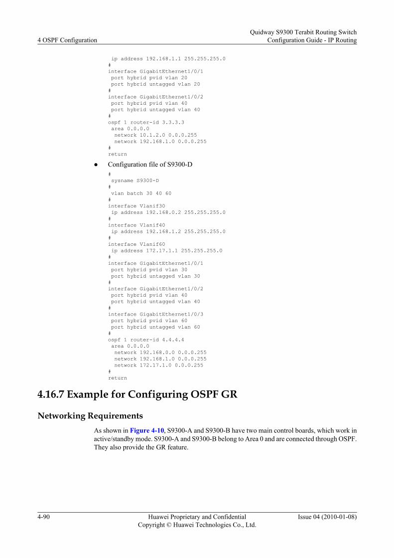
ip address 192.168.1.1 255.255.255.0#interface GigabitEthernet1/0/1 port hybrid pvid vlan 20 port hybrid untagged vlan 20 #interface GigabitEthernet1/0/2 port hybrid pvid vlan 40 port hybrid untagged vlan 40 #ospf 1 router-id 3.3.3.3 area 0.0.0.0 network 10.1.2.0 0.0.0.255 network 192.168.1.0 0.0.0.255#return
l Configuration file of S9300-D# sysname S9300-D# vlan batch 30 40 60#interface Vlanif30 ip address 192.168.0.2 255.255.255.0#interface Vlanif40 ip address 192.168.1.2 255.255.255.0#interface Vlanif60 ip address 172.17.1.1 255.255.255.0#interface GigabitEthernet1/0/1 port hybrid pvid vlan 30 port hybrid untagged vlan 30 #interface GigabitEthernet1/0/2 port hybrid pvid vlan 40 port hybrid untagged vlan 40#interface GigabitEthernet1/0/3 port hybrid pvid vlan 60 port hybrid untagged vlan 60 #ospf 1 router-id 4.4.4.4 area 0.0.0.0 network 192.168.0.0 0.0.0.255 network 192.168.1.0 0.0.0.255 network 172.17.1.0 0.0.0.255#return
4.16.7 Example for Configuring OSPF GR
Networking RequirementsAs shown in Figure 4-10, S9300-A and S9300-B have two main control boards, which work inactive/standby mode. S9300-A and S9300-B belong to Area 0 and are connected through OSPF.They also provide the GR feature.
4 OSPF ConfigurationQuidway S9300 Terabit Routing Switch
Configuration Guide - IP Routing
4-90 Huawei Proprietary and ConfidentialCopyright © Huawei Technologies Co., Ltd.
Issue 04 (2010-01-08)

Figure 4-10 Networking diagram for configuring OSPF GR
S9300-A S9300-B
Area 0
GE1/0/1GE1/0/1
S9300 Interface VLANIF interface IP address
S9300-A GigabitEthernet1/0/1 VLANIF 10 1.1.1.1/24
S9300-B GigabitEthernet1/0/1 VLANIF 10 1.1.1.2/24
Configuration RoadmapThe configuration roadmap is as follows:
1. Configure the basic OSPF functions on each S9300 to implement interconnection.2. Enable the Opaque LSA function.3. Configure GR on each S9300.
Data PreparationTo complete the configuration, you need the following data:
l ID of the VLAN that each interface belongs to, as shown in Figure 4-10
l IP address of each VLANIF interface, as shown in Figure 4-10
l Router ID and OSPF process ID of each S9300 and area that each interface belongs to:– On S9300-A, the router ID is 1.1.1.1; the OSPF process ID is 1;the network segment
of Area 0 is 1.1.1.0/24.– On S9300-B, the router ID is 2.2.2.2; OSPF process ID is 1; the network segment of
Area 0 is 1.1.1.0/24.
Procedure
Step 1 Configure the basic OSPF functions. See 4.16.1 Configuring Basic OSPF Functions.
Step 2 Configure the Opaque LSA function.[S9300-A] ospf[S9300-A-ospf-1] opaque-capability enable
# Configure S9300-B.
[S9300-B] ospf[S9300-B-ospf-1] opaque-capability enable
Step 3 Configure the OSPF GR feature.
Quidway S9300 Terabit Routing SwitchConfiguration Guide - IP Routing 4 OSPF Configuration
Issue 04 (2010-01-08) Huawei Proprietary and ConfidentialCopyright © Huawei Technologies Co., Ltd.
4-91

# Configure S9300-A.
[S9300-A] ospf[S9300-A-ospf-1] graceful-restart
# Configure S9300-B.
[S9300-B] ospf[S9300-B-ospf-1] graceful-restart
Step 4 Verify the configuration.
# View the GR status of S9300-A.
[S9300-A] display ospf graceful-restart OSPF Process 1 with Router ID 1.1.1.1 Graceful-restart capability : enabled Graceful-restart support : planned and un-planned, totally Helper-policy support : planned and un-planned, strict lsa check Current GR state : normal Graceful-restart period : 120 seconds Number of neighbors under helper: Normal neighbors : 0 Virtual neighbors : 0 Sham-link neighbors : 0 Total neighbors : 0 Number of restarting neighbors : 0 Last exit reason: On graceful restart : none On Helper : none
# Verify the GR feature of S9300-A.
[S9300-A] quit<S9300-A> reset ospf process graceful-restart
# View the neighbor status on S9300-B.
[S9300-B] display ospf peer OSPF Process 1 with Router ID 1.1.1.2 Neighbors Area 0.0.0.0 interface 1.1.1.2(Vlanif10)'s neighbors Router ID: 1.1.1.1 Address: 1.1.1.1 GR State: Doing GR State: Full Mode:Nbr is Slave Priority: 1 DR: 1.1.1.2 BDR: 1.1.1.1 MTU: 0 Dead timer due in 29 sec Neighbor is up for 00:01:01 Authentication Sequence: [ 0 ]
The status of the neighbor is Full.
----End
Configuration Filesl Configuration file of S9300-A
# sysname S9300-A# router id 1.1.1.1# vlan batch 10
4 OSPF ConfigurationQuidway S9300 Terabit Routing Switch
Configuration Guide - IP Routing
4-92 Huawei Proprietary and ConfidentialCopyright © Huawei Technologies Co., Ltd.
Issue 04 (2010-01-08)

#interface Vlanif10 ip address 1.1.1.1 255.255.255.0#interface GigabitEthernet1/0/1 port hybrid pvid vlan 10 port hybrid untagged vlan 10 #ospf 1 opaque-capability enable graceful-restart area 0.0.0.0 network 1.1.1.0 0.0.0.255#return
l Configuration file of S9300-B# sysname S9300-B# router id 2.2.2.2# vlan batch 10#interface Vlanif10 ip address 1.1.1.2 255.255.255.0#interface GigabitEthernet1/0/1 port hybrid pvid vlan 10 port hybrid untagged vlan 10 #ospf 1 opaque-capability enable graceful-restart area 0.0.0.0 network 1.1.1.0 0.0.0.255#return
4.16.8 Example for Configuring BFD for OSPF
Networking RequirementsAs shown in Figure 4-11, the networking requirement are as follows:
l S9300-A, S9300-B, and S9300-C run OSPF.
l BFD for OSPF is enabled on S9300-A, S9300-B, and S9300-C.
l Service traffic is transmitted on the main link S9300-A→S9300-B. Link S9300-A→S9300-C→S9300-B is a backup link.
l BFD is configured on the interfaces between S9300-A and S9300-B. When a fault occurson the link between the S9300s, BFD can quickly detect the fault and notify OSPF of thefault. Then, the service flow is transmitted on the backup link.
Quidway S9300 Terabit Routing SwitchConfiguration Guide - IP Routing 4 OSPF Configuration
Issue 04 (2010-01-08) Huawei Proprietary and ConfidentialCopyright © Huawei Technologies Co., Ltd.
4-93

Figure 4-11 Networking diagram for configuring BFD for OSPF
S9300-A S9300-B
S9300-C
GE1/0/0
GE3/0/0GE2/0/0
GE1/0/0GE1/0/0GE1/0/0
GE2/0/0
GE1/0/0
GE1/0/0 GE2/0/0
S9300 Interface VLANIF interface IP address
S9300-A GigabitEthernet1/0/0 VLANIF 10 1.1.1.1/24
S9300-A GigabitEthernet2/0/0 VLANIF 20 3.3.3.1/24
S9300-B GigabitEthernet1/0/0 VLANIF 30 2.2.2.2/24
S9300-B GigabitEthernet2/0/0 VLANIF 20 3.3.3.2/24
S9300-B GigabitEthernet3/0/0 VLANIF 40 172.16.1.1/24
S9300-C GigabitEthernet1/0/0 VLANIF 10 1.1.1.2/24
S9300-C GigabitEthernet2/0/0 VLANIF 30 2.2.2.1/24
Configuration RoadmapThe configuration roadmap is as follows:
1. Configure the basic OSPF functions on the S9300s.2. Enable the BFD feature globally.3. Enable BFD for OSPF on S9300-A and S9300-B.
Data PreparationTo complete the configuration, you need the following data:
l ID of the VLAN that each interface belongs to, as shown in Figure 4-11
l IP address of each VLANIF interface, as shown in Figure 4-11
l Router ID and OSPF process ID of each S9300 and network segments that OSPF interfacesbelong to:– On S9300-A, the router ID is 1.1.1.1; OSPF process ID is 1; the network segments of
Area 0 are 3.1.1.0/24 and 1.1.1.0/24.– On S9300-B, the router ID is 2.2.2.2; OSPF process ID is 1; the network segments of
Area 0 are 3.1.1.0/24, 2.2.2.0/24, and 172.16.1.0/24.
4 OSPF ConfigurationQuidway S9300 Terabit Routing Switch
Configuration Guide - IP Routing
4-94 Huawei Proprietary and ConfidentialCopyright © Huawei Technologies Co., Ltd.
Issue 04 (2010-01-08)

– On S9300-C, the router ID is 3.3.3.3; the OSPF process ID is 1; the network segmentsof Area 0 are 192.168.1.0/24 and 172.16.1.0/24.
l Minimum interval for sending the BFD packets, minimum interval for receiving the BFDpackets, and local detection time multiplier on S9300-A and S9300-B
Procedure
Step 1 Create VLANs and add corresponding interfaces to the VLANs.<Quidway> system-view[Quidway] sysname S9300-A[S9300-A] vlan 10S9300-A-vlan10] quit[S9300-A] vlan 20[S9300-A-vlan20] quit[S9300-A] interface GigabitEthernet 1/0/0[S9300-A-GigabitEthernet1/0/0] port hybrid pvid vlan 10 [S9300-A-GigabitEthernet1/0/0] port hybrid untagged vlan 10[S9300-A-GigabitEthernet1/0/0] quitS9300-A] interface GigabitEthernet 2/0/0[S9300-A-GigabitEthernet2/0/0] port hybrid pvid vlan 20[S9300-A-GigabitEthernet1/0/0] port hybrid untagged vlan 20[S9300-A-GigabitEthernet2/0/0] quit
The configurations of S9300-B and S9300-C are similar to the configuration of S9300-A, andare not mentioned here.
Step 2 Assign an IP address to each VLANIF interface.[S9300-A] interface vlanif 10[S9300-A-Vlanif10] ip address 1.1.1.1 24[S9300-A-Vlanif10] quit[S9300-A] interface vlanif 20[S9300-A-Vlanif20] ip address 3.3.3.1 24[S9300-A-Vlanif20] quit
The configurations of S9300-B and S9300-C are similar to the configuration of S9300-A, andare not mentioned here.
Step 3 Configure the basic OSPF functions. See 4.16.1 Configuring Basic OSPF Functions.
Step 4 Configure BFD for OSPF.
# Enable BFD globally on S9300-A.
[S9300-A] bfd[S9300-A-bfd] quit[S9300-A] ospf[S9300-A-ospf-1] bfd all-interfaces enable[S9300-A-ospf-1] quit
# Enable BFD globally on S9300-B.
[S9300-B] bfd[S9300-B-bfd] quit[S9300-B] ospf[S9300-B-ospf-1] bfd all-interfaces enable[S9300-B-ospf-1] quit
# Run the display ospf bfd session all command on S9300-A or S9300-B. You can see that theBFD state is Up.
Take S9300-A for example. The display is as follows:
[S9300-A] display ospf bfd session all OSPF Process 1 with Router ID 1.1.1.1
Quidway S9300 Terabit Routing SwitchConfiguration Guide - IP Routing 4 OSPF Configuration
Issue 04 (2010-01-08) Huawei Proprietary and ConfidentialCopyright © Huawei Technologies Co., Ltd.
4-95

Area 0.0.0.0 interface 3.3.3.1(Vlanif20)'s BFD Sessions
NeighborId:2.2.2.2 AreaId:0.0.0.0 Interface:Vlanif20 BFDState:up rx :1000 tx :1000 Multiplier:3 BFD Local Dis:8195 LocalIpAdd:3.3.3.1 RemoteIpAdd:3.3.3.2 Diagnostic Info:No diagnostic information
Area 0.0.0.0 interface 1.1.1.1(Vlanif10)'s BFD Sessions
NeighborId:3.3.3.3 AreaId:0.0.0.0 Interface:Vlanif10 BFDState:up rx :1000 tx :1000 Multiplier:3 BFD Local Dis:8194 LocalIpAdd1:1.1.1.1 RemoteIpAdd:1.1.1.2 Diagnostic Info:No diagnostic information
Step 5 Configure the BFD feature of interfaces.
# Configure BFD on VLANIF 20 of S9300-A, set the minimum interval for sending the packetsand the minimum interval for receiving the packets to 100 ms, and set the local detection timemultiplier to 4.
[S9300-A] interface vlanif 20[S9300-A-Vlanif20] ospf bfd enable[S9300-A-Vlanif20] ospf bfd min-tx-interval 100 min-rx-interval 100 detect-multiplier 4[S9300-A-Vlanif20] quit
# Configure BFD on VLANIF20 of S9300-B and set the minimum interval for sending thepackets and the minimum interval for receiving the packets to 100 ms and the local detectiontime multiplier to 4.
[S9300-B] bfd[S9300-B-bfd] quit[S9300-B] interface vlanif 20[S9300-B-Vlanif20] ospf bfd enable[S9300-B-Vlanif20] ospf bfd min-tx-interval 100 min-rx-interval 100 detect-multiplier 4[S9300-B-Vlanif20] quit
# Run the display ospf bfd session all command on S9300-A or S9300-B. You can see that theBFD state is Up.
Take S9300-B for example. The display is as follows:
[S9300-B] display ospf bfd session all
OSPF Process 1 with Router ID 2.2.2.2 Area 0.0.0.0 interface 3.3.3.2(Vlanif20)'s BFD Sessions
NeighborId:1.1.1.1 AreaId:0.0.0.0 Interface: Vlanif20 BFDState:up rx :100 tx :100 Multiplier:4 BFD Local Dis:8198 LocalIpAdd:3.3.3.2 RemoteIpAdd:3.3.3.1 Diagnostic Info:No diagnostic information
Area 0.0.0.0 interface 2.2.2.2(Vlanif30)'s BFD Sessions
NeighborId:3.3.3.3 AreaId:0.0.0.0 Interface: Vlanif30 BFDState:up rx :1000 tx :1000 Multiplier:3 BFD Local Dis:8199 LocalIpAdd:2.2.2.2 RemoteIpAdd:2.2.2.1 Diagnostic Info:No diagnostic information
Step 6 Verify the configuration.
# Run the shutdown command on VLANIF 20 of S9300-B to simulate a link fault.
[S9300-B] interface vlanif 20[S9300-B-Vlanif20] shutdown
# View the routing table of S9300-A.
4 OSPF ConfigurationQuidway S9300 Terabit Routing Switch
Configuration Guide - IP Routing
4-96 Huawei Proprietary and ConfidentialCopyright © Huawei Technologies Co., Ltd.
Issue 04 (2010-01-08)

<S9300-A> display ospf routing
OSPF Process 1 with Router ID 1.1.1.1 Routing Tables
Routing for Network Destination Cost Type NextHop AdvRouter Area 172.16.1.1/24 3 Stub 1.1.1.2 2.2.2.2 0.0.0.0 3.3.3.0/24 1 Stub 3.3.3.1 1.1.1.1 0.0.0.0 2.2.2.0/24 2 Transit 1.1.1.2 3.3.3.3 0.0.0.0 1.1.1.0/24 1 Transit 1.1.1.1 1.1.1.1 0.0.0.0
Total Nets: 4 Intra Area: 4 Inter Area: 0 ASE: 0 NSSA: 0
As shown in the OSPF routing table, the backup link S9300-A→S9300-C→S9300-B takes effectafter the main link fails. The next hop address of the route to 172.16.1.0/24 becomes 1.1.1.2.
----End
Configuration Filesl Configuration file of S9300-A
# sysname S9300-A# router id 1.1.1.1# vlan batch 10 20# bfd#interface Vlanif10 ip address 1.1.1.1 255.255.255.0#interface Vlanif20 ip address 3.3.3.1 255.255.255.0 ospf bfd enable ospf bfd min-tx-interval 100 min-rx-interval 100 detect-multiplier 4#interface GigabitEthernet1/0/0 port hybrid pvid vlan 10 port hybrid untagged vlan 10#interface GigabitEthernet2/0/0 port hybrid pvid vlan 20 port hybrid untagged vlan 20#ospf 1 bfd all-interface enable area 0.0.0.0 network 3.3.3.0 0.0.0.255 network 1.1.1.0 0.0.0.255#return
l Configuration file of S9300-B# sysname S9300-B# router id 2.2.2.2#vlan batch 20 30 40# bfd#interface Vlanif20 ip address 3.3.3.2 255.255.255.0 ospf bfd enable ospf bfd min-tx-interval 100 min-rx-interval 100 detect-multiplier 4
Quidway S9300 Terabit Routing SwitchConfiguration Guide - IP Routing 4 OSPF Configuration
Issue 04 (2010-01-08) Huawei Proprietary and ConfidentialCopyright © Huawei Technologies Co., Ltd.
4-97

#interface Vlanif30 ip address 2.2.2.2 255.255.255.0#interface Vlanif40 ip address 172.16.1.1 255.255.255.0#interface GigabitEthernet1/0/0 port hybrid pvid vlan 30 port hybrid untagged vlan 30#interface GigabitEthernet2/0/0 port link-type access port default vlan 20#interface GigabitEthernet3/0/0 port hybrid pvid vlan 40 port hybrid untagged vlan 40#ospf 1 bfd all-interface enable area 0.0.0.0 network 3.3.3.0 0.0.0.255 network 2.2.2.0 0.0.0.255 network 172.16.1.0 0.0.0.255#return
l Configuration file of S9300 C# sysname S9300-C# router id 3.3.3.3# vlan batch 10 30# bfd#interface Vlanif10 ip address 1.1.1.2 255.255.255.0#interface Vlanif30 ip address 2.2.2.1 255.255.255.0 ospf bfd enable ospf bfd min-tx-interval 100 min-rx-interval 100 detect-multiplier 4#interface GigabitEthernet1/0/0 port hybrid pvid vlan 10 port hybrid untagged vlan 10#interface GigabitEthernet2/0/0 port hybrid pvid vlan 30 port hybrid untagged vlan 30#ospf 1 bfd all-interface enable area 0.0.0.0 network 1.1.1.0 0.0.0.255 network 2.2.2.0 0.0.0.255#return
4 OSPF ConfigurationQuidway S9300 Terabit Routing Switch
Configuration Guide - IP Routing
4-98 Huawei Proprietary and ConfidentialCopyright © Huawei Technologies Co., Ltd.
Issue 04 (2010-01-08)

5 OSPFv3 Configuration
About This Chapter
This chapter describes the OSPFv3 fundamentals and configuration steps for basic OSPFv3functions, OSPFv3 area features, OSPFv3 routing information and adjusting and optimizingOSPFv3 networks, along with typical examples.
5.1 OSPFv3The Open Shortest Path First Version 3.0 (OSPFv3) supports the version 6 of the InternetProtocol (IPv6). OSPFv3 conforms to RFC 2740 (OSPF for IPv6).
5.2 OSPFv3 Features Supported by S9300For the features that are provided by both OSPFv3 and OSPFv2, see "OSPF Configuration" inthe Quidway S9300 Terabit Routing Switch Configuration Guide - IP Routing. This sectiondescribes the features exclusively provided by OSPFv3.
5.3 Configuring Basic OSPFv3 FunctionsThis section describes how to configure basic OSPFv3 functions.
5.4 Establishing or Maintaining OSPFv3 Neighbor RelationshipThis section describes how to establish and maintain OSPFv3 neighbor relationship or adjacencyrelationship to establish an OSPFv3 network.
5.5 Configuring OSPFv3 AreasThis section describes how to configure the OSPFv3 stub areas and virtual links.
5.6 Configuring OSPFv3 Route AttributesThis section describes how to configure OSPF route attributes to change OSPFv3 routing polices,thus meeting the requirements of complex networking.
5.7 Controlling OSPFv3 Routing InformationThis section describes how to advertise and receive OSPFv3 routes and import external routes.
5.8 Optimizing an OSPF NetworkThis section describes how to configure special features of OSPFv3 to adjust and optimize anOSPFv3 network.
5.9 Configuring OSPFv3 GRThis section describes how to configure OSPFv3 GR to avoid the inaccurate route calculationand packet loss after an OSPF device restarts.
Quidway S9300 Terabit Routing SwitchConfiguration Guide - IP Routing 5 OSPFv3 Configuration
Issue 04 (2010-01-08) Huawei Proprietary and ConfidentialCopyright © Huawei Technologies Co., Ltd.
5-1

5.10 Maintaining OSPFv3This section describes how to debug the OSPFv3 functions.
5.11 Configuration ExamplesThis section provides several configuration examples of OSPFv3.
5 OSPFv3 ConfigurationQuidway S9300 Terabit Routing Switch
Configuration Guide - IP Routing
5-2 Huawei Proprietary and ConfidentialCopyright © Huawei Technologies Co., Ltd.
Issue 04 (2010-01-08)

5.1 OSPFv3The Open Shortest Path First Version 3.0 (OSPFv3) supports the version 6 of the InternetProtocol (IPv6). OSPFv3 conforms to RFC 2740 (OSPF for IPv6).
OSPFv3 and OSPFv2 have the following in common:
l 32-bit Router ID, Area ID, and Link State Advertisement (LSA) link-state ID
l Five types of packets such as Hello, Database Description (DD), Link State Request (LSR),Link State Update (LSU), and Link State Acknowledgement (LSAck) packets
l Neighbor discovery and adjacency establishment mechanisms
l Flooding and aging mechanisms of LSAs
l LSA types
OSPFv3 and OSPFv2 differ as follows:
l OSPFv3 runs based on a link; OSPFv2 runs based on a network segment.
l OSPFv3 can run multiple instances on the same link.
l The topology of OSPFv3 is independent of IPv6 address prefixes.
l OSPFv3 identifies its neighbors with the IPv6 link-local addresses.
l According to the flooding scope, OSPFv3 LSA flooding is classified into three types: LSAflooding on a link, LSA flooding within an area, LSA flooding between areas. Accordingto the flooding scope, OSPFv2 LSA flooding is classified into two types: LSA floodingwithin an area and LSA flooding between areas.
5.2 OSPFv3 Features Supported by S9300For the features that are provided by both OSPFv3 and OSPFv2, see "OSPF Configuration" inthe Quidway S9300 Terabit Routing Switch Configuration Guide - IP Routing. This sectiondescribes the features exclusively provided by OSPFv3.
The S9300 supports the following OSPFv3 features:
l Basic features stipulated in RFC 2740
l OSPFv3 stub areas
l OSFPv3 multi-process
l Multiple OSPFv3 processes can run on a device.
l OSPFv3 GR
If a device restarts or performs the active/standby switchover, it directly ages all the entriesin the Forward Information Base (FIB). This interrupts the routing. The neighboring devicesremove the device from the neighbor list and inform other devices of the device failure.Then, SPF needs to be calculated again. If the device recovers after a short period of time,the neighbor relationship becomes unstable. This results in route flapping.
If a device restarts because of abnormalities, you can enable OSPFv3 Graceful Restart (GR)to avoid service interruption during the restart of the device.
Quidway S9300 Terabit Routing SwitchConfiguration Guide - IP Routing 5 OSPFv3 Configuration
Issue 04 (2010-01-08) Huawei Proprietary and ConfidentialCopyright © Huawei Technologies Co., Ltd.
5-3

5.3 Configuring Basic OSPFv3 FunctionsThis section describes how to configure basic OSPFv3 functions.
5.3.1 Establishing the Configuration Task
5.3.2 Enabling OSPFv3
5.3.3 Enabling OSPFv3 on an Interface
5.3.4 Entering the OSPFv3 Area View
5.3.5 Checking the Configuration
5.3.1 Establishing the Configuration Task
Applicable EnvironmentEnable the OSPFv3 process and specify its Router ID before configuring OSPFv3; otherwise,other functions cannot take effect.
You must enable OSPFv3 and specify the interface and area ID before configuring otherfunctions. OSPFv3 configurations, however, are independent of interface-related features.
Pre-configuration TasksBefore configuring basic OSFPv3 functions, complete the following tasks:
l Making the network layers of the adjacent nodes accessible
l Enabling IPv6 capabilities
Data PreparationTo configure basic OSPFv3 functions, you need the following data.
No. Data
1 Router ID
2 OSPFv3 process ID
3 Interfaces on which OSPFv3 needs to be enabled and their areas
5.3.2 Enabling OSPFv3
ContextOSPFv3 supports multiple processes. Multiple OSPFv3 processes running on one S9300 aredifferentiated by process IDs. OSPFv3 process ID is set when OSPFv3 is enabled and is onlylocally valid. It does not affect the packet exchange with other S9300s.
5 OSPFv3 ConfigurationQuidway S9300 Terabit Routing Switch
Configuration Guide - IP Routing
5-4 Huawei Proprietary and ConfidentialCopyright © Huawei Technologies Co., Ltd.
Issue 04 (2010-01-08)

In the format of an IPv4 address, a router ID is a 32-bit unsigned integer that uniquely identifiesa S9300 within an AS. The router ID of OSPFv3 must be manually set. If no router ID is set,OSPFv3 fails to run normally.
When manually setting the router ID, ensure that the router IDs of any two S9300s in an AS aredifferent. When multiple processes are enabled on a S9300, it is necessary to specify a uniqueroute ID for each process.
To ensure the stable running of OSPFv3, you need to allocate router IDs and set them in networkplanning.
Do as follows on the S9300 that runs OSPFv3:
Procedure
Step 1 Run:system-view
The system view is displayed.
Step 2 Run:ospfv3 [ process-id ]
OSPFv3 is enabled and the OSPFv3 view is displayed.
Step 3 Run:router-id router-id
A router ID is set.
----End
5.3.3 Enabling OSPFv3 on an Interface
ContextBecause an interface has multiple instances, you need to specify the instance ID after OSPFv3is enabled on the interface. If no instance ID is specified, the value defaults to 0. The sameinstance must be enabled on the interfaces between which the neighbor relationship is set up.
Do as follows on the S9300 that runs OSPFv3:
Procedure
Step 1 Run:system-view
The system view is displayed.
Step 2 Run:interface interface-type interface-number
The interface view is displayed.
Step 3 Run:ospfv3 process-id area area-id [ instance instance-id ]
OSPFv3 is enabled on the interface.
Quidway S9300 Terabit Routing SwitchConfiguration Guide - IP Routing 5 OSPFv3 Configuration
Issue 04 (2010-01-08) Huawei Proprietary and ConfidentialCopyright © Huawei Technologies Co., Ltd.
5-5

After enabling OSPFv3 in the system view by using the ospfv3 command, you need to enableOSPFv3 on the interface.
The area ID can be a decimal integer or in the IPv4 address format, but it is displayed in the IPv4address format.
----End
5.3.4 Entering the OSPFv3 Area View
Context
You must configure the devices in the same area based on the area. Otherwise, the neighbordevices cannot exchange information with each other. The congestion of routing information orrouting loop is thus caused.
Do as follows on the S9300 that runs OSPFv3:
Procedure
Step 1 Run:system-view
The system view is displayed.
Step 2 Run:ospfv3 [ process-id ]
The OSPFv3 view is displayed.
Step 3 Run:area area-id
The OSPFv3 area view is displayed.
The area ID can be a decimal integer or in the IPv4 address format, but it is displayed in the IPv4address format.
An OSPFv3 area cannot be deleted directly. Only after all the configurations in the area vieware removed and the related interfaces in this area become Down, this area is automaticallyremoved.
----End
5.3.5 Checking the Configuration
PrerequisiteThe configurations of the Basic OSPFv3 Functions are complete.
Procedurel Run the display ospfv3 [ process-id ] command to check the summary information about
the OSPFv3 process.l Run the commands as follow to check the LSDB information about OSPFv3.
5 OSPFv3 ConfigurationQuidway S9300 Terabit Routing Switch
Configuration Guide - IP Routing
5-6 Huawei Proprietary and ConfidentialCopyright © Huawei Technologies Co., Ltd.
Issue 04 (2010-01-08)

– display ospfv3 [ process-id ] lsdb [ external | grace | inter-prefix | inter-S9300 | intra-prefix | link | network | S9300 ] [ link-state-id ] [ originate-S9300 advertising-S9300-id ]
– display ospfv3 [ process-id ] lsdb statistics
l Run the display ospfv3 [ process-id ] [ area area-id ] peer [ interface-type interface-number [ verbose ] | neighbor-id ] command to check the information about the OSPFv3neighbor.
l Run the display ospfv3 [ process-id ] routing [ [ ipv6-address prefix-length | ipv6-address/prefix-length ] | abr-routes | asbr-routes | all | statistics ] command to check theinformation about the OSPFv3 routing table.
----End
5.4 Establishing or Maintaining OSPFv3 NeighborRelationship
This section describes how to establish and maintain OSPFv3 neighbor relationship or adjacencyrelationship to establish an OSPFv3 network.
5.4.1 Establishing the Configuration Task
5.4.2 Configuring the Interval for Sending Hello Packets
5.4.3 Configuring Dead Time of Neighbor Relationship
5.4.4 Configuring the Interval for Retransmitting LSAs to Neighboring S9300s
5.4.5 Configuring the Delay for Transmitting LSAs on the Interface
5.4.6 Checking the Configuration
5.4.1 Establishing the Configuration Task
Applicable Environment
In applications, establishing or maintaining the OSPFv3 neighbor relationship is a premise forthe construction of an OSPFv3 network. After the configuration in this section, you can:
l Adjust the convergence speed of the OSPFv3 network and network load caused by protocolpackets by modifying OSPFv3 timers.
l Enable OSPFv3 to be disconnected from its neighbor when the number of OSPFv3 packetretransmissions exceeds the threshold by configuring Retransmission Limitation for OSPF(RL-OSPF) of OSPFv3. This prevents non-stop packet retransmissions if the neighbor doesnot receive packets.
l Speed up the convergence of an OSPFv3 network by adjusting the intervals for updatingand receiving LSAs.
Pre-configuration Tasks
Before establishing or maintaining the OSPFv3 neighbor relationship, complete the followingtasks:
Quidway S9300 Terabit Routing SwitchConfiguration Guide - IP Routing 5 OSPFv3 Configuration
Issue 04 (2010-01-08) Huawei Proprietary and ConfidentialCopyright © Huawei Technologies Co., Ltd.
5-7

l Configuring the IP addresses of interfaces to make the network layers accessible
l Configuring Basic OSPFv3 Functions
Data PreparationTo establish or maintain the OSPFv3 neighbor relationship, you need the following data.
No. Data
1 Interval for sending Hello packets
2 Dead time of the neighbor relationship
3 Interval for retransmitting LSAs to adjacent S9300s
4 Delay in sending LSAs
5.4.2 Configuring the Interval for Sending Hello Packets
ContextHello packets are periodically sent to the neighbor S9300 to detect and maintain the neighborrelationship and to elect the DR and the BDR. RFC 2328 requires that the Hello timer values ofneighbors should be consistent. The value of the Hello timer is inversely proportional to theroute convergence speed and network load.
Do as follows on the S9300 that runs OSPFv3:
ProcedureStep 1 Run:
system-view
The system view is displayed.
Step 2 Run:interface interface-type interface-number
The interface view is displayed.
Step 3 Run:ospfv3 timer hello interval [ instance instance-id ]
The interval for sending Hello packets is set on the interface.
----End
5.4.3 Configuring Dead Time of Neighbor Relationship
ContextIf a S9300 does not receive any Hello packet from its neighbor during a specified period, theneighbor S9300 is considered invalid. The specified period is called the dead time of the neighborrelationship. The dead time must be at least four times the Hello interval on an interface.
5 OSPFv3 ConfigurationQuidway S9300 Terabit Routing Switch
Configuration Guide - IP Routing
5-8 Huawei Proprietary and ConfidentialCopyright © Huawei Technologies Co., Ltd.
Issue 04 (2010-01-08)
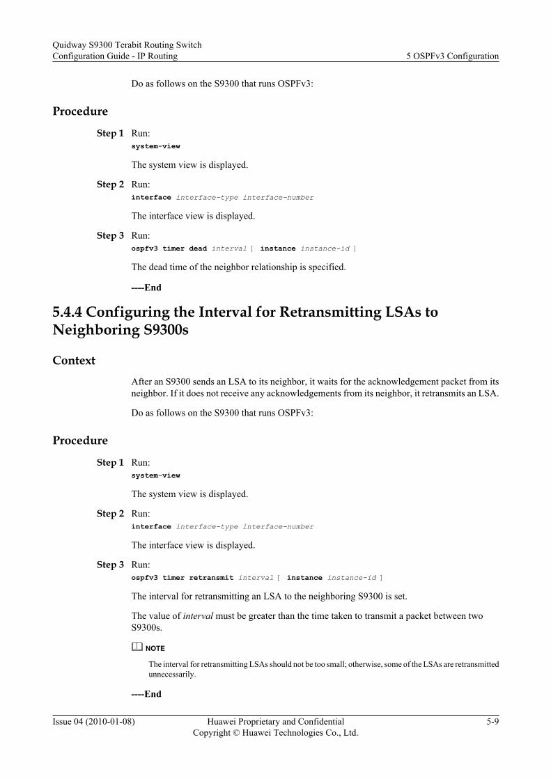
Do as follows on the S9300 that runs OSPFv3:
Procedure
Step 1 Run:system-view
The system view is displayed.
Step 2 Run:interface interface-type interface-number
The interface view is displayed.
Step 3 Run:ospfv3 timer dead interval [ instance instance-id ]
The dead time of the neighbor relationship is specified.
----End
5.4.4 Configuring the Interval for Retransmitting LSAs toNeighboring S9300s
ContextAfter an S9300 sends an LSA to its neighbor, it waits for the acknowledgement packet from itsneighbor. If it does not receive any acknowledgements from its neighbor, it retransmits an LSA.
Do as follows on the S9300 that runs OSPFv3:
Procedure
Step 1 Run:system-view
The system view is displayed.
Step 2 Run:interface interface-type interface-number
The interface view is displayed.
Step 3 Run:ospfv3 timer retransmit interval [ instance instance-id ]
The interval for retransmitting an LSA to the neighboring S9300 is set.
The value of interval must be greater than the time taken to transmit a packet between twoS9300s.
NOTE
The interval for retransmitting LSAs should not be too small; otherwise, some of the LSAs are retransmittedunnecessarily.
----End
Quidway S9300 Terabit Routing SwitchConfiguration Guide - IP Routing 5 OSPFv3 Configuration
Issue 04 (2010-01-08) Huawei Proprietary and ConfidentialCopyright © Huawei Technologies Co., Ltd.
5-9

5.4.5 Configuring the Delay for Transmitting LSAs on the Interface
Context
The LSA ages out in the LSDB of a local S9300 instead of in the transmission process. Youneed to set the delay for an LSA before sending it. For a low-speed network, this configurationis necessary.
Do as follows on the S9300 that runs OSPFv3:
Procedure
Step 1 Run:system-view
The system view is displayed.
Step 2 Run:interface interface-type interface-number
The interface view is displayed.
Step 3 Run:ospfv3 trans-delay seconds [ instance instance-id ]
The delay in transmitting LSAs on the interface is set.
----End
5.4.6 Checking the Configuration
PrerequisiteThe configurations of the Establishing or Maintaining OSPFv3 Neighbor Relationship arecomplete.
Procedurel Run the display ospfv3 interface [ interface-type interface-number ] command to check
the information about OSPFv3 interfaces.
----End
5.5 Configuring OSPFv3 AreasThis section describes how to configure the OSPFv3 stub areas and virtual links.
5.5.1 Establishing the Configuration Task
5.5.2 Configuring OSPFv3 Stub Areas
5.5.3 Configuring OSPFv3 Virtual Links
5.5.4 Checking the Configuration
5 OSPFv3 ConfigurationQuidway S9300 Terabit Routing Switch
Configuration Guide - IP Routing
5-10 Huawei Proprietary and ConfidentialCopyright © Huawei Technologies Co., Ltd.
Issue 04 (2010-01-08)
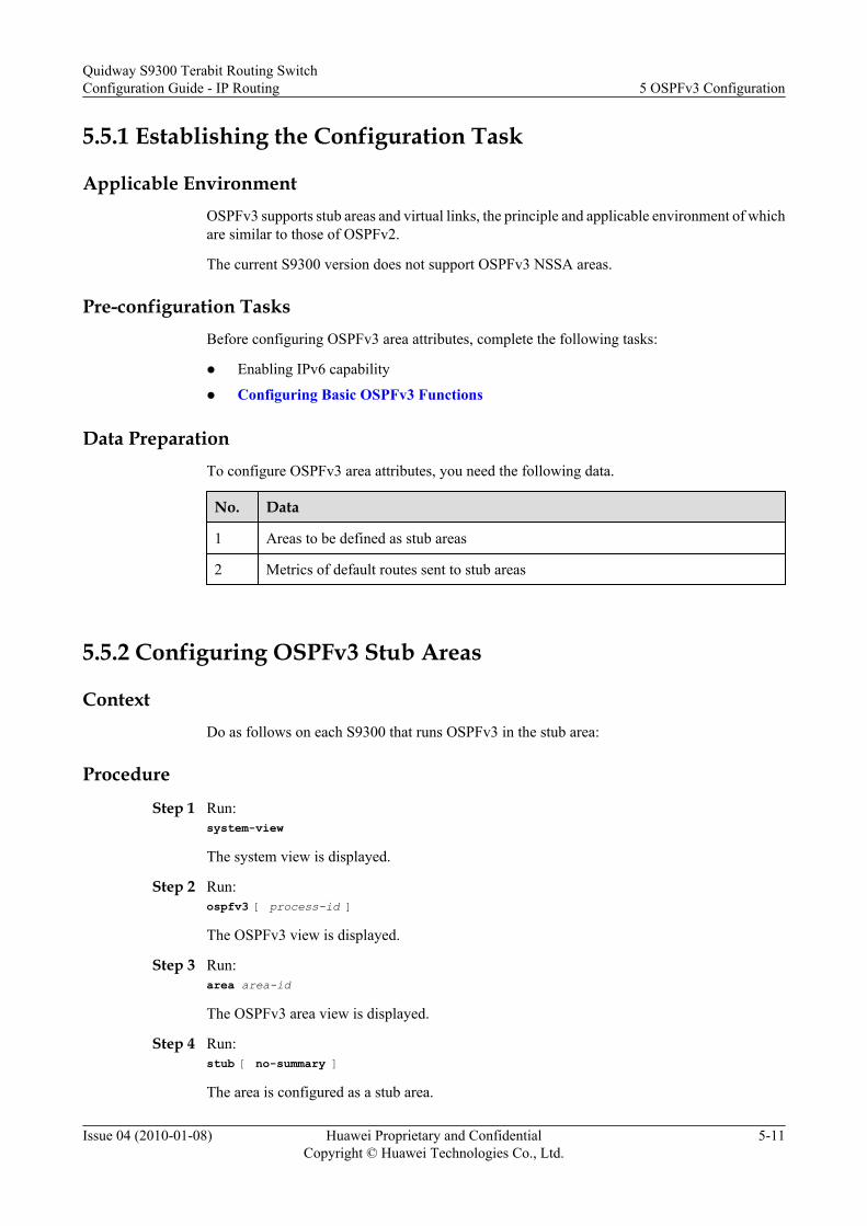
5.5.1 Establishing the Configuration Task
Applicable EnvironmentOSPFv3 supports stub areas and virtual links, the principle and applicable environment of whichare similar to those of OSPFv2.
The current S9300 version does not support OSPFv3 NSSA areas.
Pre-configuration TasksBefore configuring OSPFv3 area attributes, complete the following tasks:
l Enabling IPv6 capability
l Configuring Basic OSPFv3 Functions
Data PreparationTo configure OSPFv3 area attributes, you need the following data.
No. Data
1 Areas to be defined as stub areas
2 Metrics of default routes sent to stub areas
5.5.2 Configuring OSPFv3 Stub Areas
ContextDo as follows on each S9300 that runs OSPFv3 in the stub area:
Procedure
Step 1 Run:system-view
The system view is displayed.
Step 2 Run:ospfv3 [ process-id ]
The OSPFv3 view is displayed.
Step 3 Run:area area-id
The OSPFv3 area view is displayed.
Step 4 Run:stub [ no-summary ]
The area is configured as a stub area.
Quidway S9300 Terabit Routing SwitchConfiguration Guide - IP Routing 5 OSPFv3 Configuration
Issue 04 (2010-01-08) Huawei Proprietary and ConfidentialCopyright © Huawei Technologies Co., Ltd.
5-11

Step 5 (Optional) Run:default-cost cost
The cost of the default route sent to the stub area is set.
By default, the cost of the default route sent to the stub area is 1.
This command is configured on the ABR of the stub area only to set the cost of the default routeto be sent to the stub area. This command does not need to be configured on other S9300s in thestub area. In addition, the parameter no-summary takes effect only when the stub command isconfigured on the ABR. If this parameter is configured, the ABR only sends the summary-LSAof a default route to the stub area without originating other summary-LSAs.
----End
5.5.3 Configuring OSPFv3 Virtual Links
Context
Do as follows on the S9300 that runs OSPFv3:
Procedure
Step 1 Run:system-view
The system view is displayed.
Step 2 Run:ospfv3 [ process-id ]
The OSPFv3 view is displayed.
Step 3 Run:area area-id
The OSPFv3 area view is displayed.
Step 4 Run:vlink-peer S9300-id [ hello seconds ] [ retransmit seconds ] [ trans-delay seconds ] [ dead seconds ] [ instance instance-id ]
A virtual link is created and configured.
The concept of OSPFv3 virtual links is the same as that of OSPFv2. A virtual link must beconfigured at both ends of the link; otherwise, it does not take effect.
----End
5.5.4 Checking the Configuration
PrerequisiteThe configurations of the OSPFv3 Areas are complete.
5 OSPFv3 ConfigurationQuidway S9300 Terabit Routing Switch
Configuration Guide - IP Routing
5-12 Huawei Proprietary and ConfidentialCopyright © Huawei Technologies Co., Ltd.
Issue 04 (2010-01-08)
Procedurel Run the commands as follow to check the information about the OSPFv3 LSDB.
– display ospfv3 [ process-id ] lsdb [ external | grace | inter-prefix | inter-S9300 | intra-prefix | link | network | S9300 ] [ link-state-id ] [ originate-S9300 advertising-S9300-id ]
– display ospfv3 [ process-id ] lsdb statistics
l Run the display ospfv3 [ process-id ] routing [ [ ipv6-address prefix-length | ipv6-address/prefix-length ] | abr-routes | asbr-routes | all | statistics ] command to check theinformation about the OSPFv3 routing table.
l Run the display ospfv3 [ process-id ] vlink command to check the information aboutOSPFv3 virtual links.
----End
5.6 Configuring OSPFv3 Route AttributesThis section describes how to configure OSPF route attributes to change OSPFv3 routing polices,thus meeting the requirements of complex networking.
5.6.1 Establishing the Configuration Task
5.6.2 Setting the Cost of the OSPFv3 Interface
5.6.3 Setting the Maximum Number of Equal-Cost Routes
5.6.4 Checking the Configuration
5.6.1 Establishing the Configuration Task
Applicable Environment
In actual applications, to meet the requirements of a complicated networking environment, youcan change OSPFv3 routing policies by configuring OSPFv3 route attributes. Through thefollowing procedures, you can:
l Set the cost on the OSPFv3 interface.
l Configure load balancing among equal-cost routes.
Pre-configuration Tasks
Before configuring OSPFv3 route attributes, complete the following tasks:
l Configuring the IP addresses of interfaces to make network layers accessible
l Configuring Basic OSPFv3 Functions
Data Preparation
To configure OSPFv3 route attributes, you need the following data.
Quidway S9300 Terabit Routing SwitchConfiguration Guide - IP Routing 5 OSPFv3 Configuration
Issue 04 (2010-01-08) Huawei Proprietary and ConfidentialCopyright © Huawei Technologies Co., Ltd.
5-13

No. Data
1 Link cost
2 Maximum number of equal-cost routes
5.6.2 Setting the Cost of the OSPFv3 Interface
ContextDo as follows on the S9300 that runs OSPFv3:
Procedure
Step 1 Run:system-view
The system view is displayed.
Step 2 Run:interface interface-type interface-number
The interface view is displayed.
Step 3 Run:ospfv3 cost cost [ instance instance-id ]
The cost is set on the OSPFv3 interface.
You can control route calculation by setting the link cost of OSPFv3 on different interfaces. Bydefault, the link cost on an OSPFv3 interface is 1.
----End
5.6.3 Setting the Maximum Number of Equal-Cost Routes
ContextDo as follows on the S9300 that runs OSPFv3:
Procedure
Step 1 Run:system-view
The system view is displayed.
Step 2 Run:ospfv3 [ process-id ]
The OSPFv3 view is displayed.
Step 3 Run:maximum load-balancing number
5 OSPFv3 ConfigurationQuidway S9300 Terabit Routing Switch
Configuration Guide - IP Routing
5-14 Huawei Proprietary and ConfidentialCopyright © Huawei Technologies Co., Ltd.
Issue 04 (2010-01-08)

The maximum number of equal-cost routes is set.
----End
5.6.4 Checking the Configuration
PrerequisiteThe configurations of the OSPFv3 Route Attributes are complete.
Procedurel Run the display ospfv3 interface [ interface-type interface-number ] command to check
the information about OSPFv3 interfaces.l Run the commands as follow to check the information about the OSPFv3 LSDB.
– display ospfv3 [ process-id ] lsdb [ external | grace | inter-prefix | inter-S9300 | intra-prefix | link | network | S9300 ] [ link-state-id ] [ originate-S9300 advertising-S9300-id ]
– display ospfv3 [ process-id ] lsdb statistics
l Run the display ospfv3 [ process-id ] routing [ [ ipv6-address prefix-length | ipv6-address/prefix-length ] | abr-routes | asbr-routes | all | statistics ] command to check theinformation about the OSPFv3 routing table.
----End
5.7 Controlling OSPFv3 Routing InformationThis section describes how to advertise and receive OSPFv3 routes and import external routes.
5.7.1 Establishing the Configuration Task
5.7.2 Configuring OSPFv3 Route Aggregation
5.7.3 Configuring OSPFv3 to Filter the Received Routes
5.7.4 Configuring OSPFv3 to Import External Routes
5.7.5 Checking the Configuration
5.7.1 Establishing the Configuration Task
Applicable Environment
Through the configuration in this section, you can control the advertising and receiving ofOSPFv3 routing information and configure OSPFv3 to import external routes as follows:
Routing information control is classified into the following types:
l Control of routes in non-areasThis function can be configured on any S9300 that runs OSPFv3. For example, you canenable the S9300 to filter the imported routes and set the maximum number of equal-costroutes.
Quidway S9300 Terabit Routing SwitchConfiguration Guide - IP Routing 5 OSPFv3 Configuration
Issue 04 (2010-01-08) Huawei Proprietary and ConfidentialCopyright © Huawei Technologies Co., Ltd.
5-15

l Control of routes in areasThis function can be configured only on ABRs. For example, when an ABR has multipleroutes to the destination in the area to which the ABR is connected, you can configure theABR to aggregate routes by 5.7.2 Configuring OSPFv3 Route Aggregation in the currentarea. In this manner, only an aggregate LSA is sent to the backbone area.
Pre-configuration TasksBefore controlling OSPFv3 routing information, complete the following tasks:
l Enabling IPv6 capability
l Configuring Basic OSPFv3 Functions
Data PreparationTo control OSPFv3 routing information, you need the following data.
No. Data
1 Prefix of IPv6 routes after aggregation
2 Filtering list or name used to filter routing information
3 Link cost on an OSPFv3 interface
4 Maximum number of equal-cost routes
5 Name, process ID, and metric of external routes to be imported
5.7.2 Configuring OSPFv3 Route Aggregation
ContextIf multiple continuous network segments exist in this area, you can use the abr-summarycommand to aggregate them into one network segment. In this way, the ABR only sends an LSAafter aggregation. No LSA that belongs to the aggregate network segment is separatelytransmitted, thus reducing the LSDB size of other areas.
Do as follows on the ABR that runs OSPFv3:
Procedure
Step 1 Run:system-view
The system view is displayed.
Step 2 Run:ospfv3 [ process-id ]
The OSPFv3 view is displayed.
Step 3 Run:
5 OSPFv3 ConfigurationQuidway S9300 Terabit Routing Switch
Configuration Guide - IP Routing
5-16 Huawei Proprietary and ConfidentialCopyright © Huawei Technologies Co., Ltd.
Issue 04 (2010-01-08)

area area-id
The OSPFv3 area view is displayed.
Step 4 Run:abr-summary ipv6-address prefix-length [ not-advertise ]
OSPFv3 route aggregation is configured.
If the keyword not-advertise is used, the routes of the specified network segment are notadvertised.
----End
5.7.3 Configuring OSPFv3 to Filter the Received Routes
Context
After receiving LSAs, OSPFv3 determines whether to add the calculated routes to the localrouting table according to the filtering policy.
Do as follows on the S9300 that runs OSPFv3:
Procedure
Step 1 Run:system-view
The system view is displayed.
Step 2 Run:ospfv3 [ process-id ]
The OSPFv3 view is displayed.
Step 3 Run:filter-policy { acl6-number | ipv6-prefix ipv6-prefix-name } import
OSPFv3 is configured to filter the imported routes.
The filter-policy import command filters only the routes calculated by OSPFv3. The routes thatdo not pass the filtering are not added to the local routing table, and thus cannot be used forpacket forwarding.
----End
5.7.4 Configuring OSPFv3 to Import External Routes
Context
Because OSPFv3 is a link state-based routing protocol and cannot directly filter the advertisedLSAs, OSPFv3 must filter the routes when importing them. Then, only the routes that pass thefiltering can be advertised.
Do as follows on the S9300 that runs OSPFv3:
Quidway S9300 Terabit Routing SwitchConfiguration Guide - IP Routing 5 OSPFv3 Configuration
Issue 04 (2010-01-08) Huawei Proprietary and ConfidentialCopyright © Huawei Technologies Co., Ltd.
5-17

Procedure
Step 1 Run:system-view
The system view is displayed.
Step 2 Run:ospfv3 [ process-id ]
The OSPFv3 view is displayed.
Step 3 Run:default cost cost-value
The default cost of the imported route is set.
Step 4 Run:import-route protocol [ process-id ] [ cost cost | type type ]* [ route-policy route-policy-name ]
External routes are imported.
Step 5 (Optional) Run:filter-policy { acl6-number | ipv6-prefix ipv6-prefix-name } export [ protocol [ process-id ] ]
The imported external routes are filtered.
After you run the import-route command on a S9300 to import external routes, the S9300becomes an ASBR.
You can configure OSPFv3 to filter a certain type of routing information by specifying theprotocol. If protocol is not specified, OSPFv3 filters all the imported routes.
NOTE
The filter-policy export command takes effect only on the routes imported through the import-routecommand by the ASBR, that is, filters the imported routes. The routes that are filtered out do not generateLSAs and cannot be advertised by OSPFv3. If the import-route command is not configured to importother external routes (including OSPFv3 routes in different processes), the filter-policy export commanddoes not takes effect.
----End
5.7.5 Checking the Configuration
PrerequisiteThe configurations of Controlling OSPFv3 Routing Information are complete.
Procedurel Run the commands as follow to check the information about the OSPFv3 LSDB.
– display ospfv3 [ process-id ] lsdb [ external | grace | inter-prefix | inter-S9300 | intra-prefix | link | network | S9300 ] [ link-state-id ] [ originate-S9300 advertising-S9300-id ]
– display ospfv3 [ process-id ] lsdb statistics
5 OSPFv3 ConfigurationQuidway S9300 Terabit Routing Switch
Configuration Guide - IP Routing
5-18 Huawei Proprietary and ConfidentialCopyright © Huawei Technologies Co., Ltd.
Issue 04 (2010-01-08)
l Run the display ospfv3 [ process-id ] [ area area-id ] peer [ interface-type interface-number [ verbose ] | neighbor-id ] command to check the information about OSPFv3neighbors.
l Run the display ospfv3 [ process-id ] routing [ [ ipv6-address prefix-length | ipv6-address/prefix-length ] | abr-routes | asbr-routes | all | statistics ] command to check theinformation about the OSPFv3 routing table.
----End
5.8 Optimizing an OSPF NetworkThis section describes how to configure special features of OSPFv3 to adjust and optimize anOSPFv3 network.
5.8.1 Establishing the Configuration Task
5.8.2 Configuring the SPF Timer
5.8.3 Suppressing an Interface from Sending and Receiving OSPFv3 Packets
5.8.4 Configuring DR Priority of an Interface
5.8.5 Configuring Stub Routers
5.8.6 Ignoring MTU Check on DD Packets
5.8.7 Checking the Configuration
5.8.1 Establishing the Configuration Task
Applicable EnvironmentBy adjusting the OSPFv3 timer, you can change the convergence speed of an OSPFv3 networkand the network overload caused by protocol packets. On low-speed links, you need to considerthe delay in transmitting LSAs on the interface. By adjusting the SPF calculation interval, youcan mitigate resource consumption due to frequent network changes.
You can specify the DR priority of an interface to affect the DR/BDR election in a broadcastnetwork.
Pre-configuration TasksBefore optimizing an OSPFv3 network, complete the configuration tasks:
l Enabling IPv6 capability
l Configuring Basic OSPFv3 Functions
Data PreparationTo optimize an OSPF network, you need the following data.
No. Data
1 Values of OSPFv3 timers
Quidway S9300 Terabit Routing SwitchConfiguration Guide - IP Routing 5 OSPFv3 Configuration
Issue 04 (2010-01-08) Huawei Proprietary and ConfidentialCopyright © Huawei Technologies Co., Ltd.
5-19

No. Data
2 Values of SPF timers
3 DR priority of the interface
5.8.2 Configuring the SPF Timer
ContextDo as follows on the S9300 that runs OSPFv3:
ProcedureStep 1 Run:
system-view
The system view is displayed.
Step 2 Run:ospfv3 [ process-id ]
The OSPFv3 view is displayed.
Step 3 Run:spf timers delay-interval hold-interval
The SPF timer is configured.
Whenever the LSDB of OSPFv3 changes, the shortest path should be recalculated. Calculatingthe shortest path each time the LSDB changes consumes enormous resources and lowers theefficiency of a S9300.
Adjusting the SPF delay and hold interval can suppress frequent network changes to avoidresource consumption.
----End
5.8.3 Suppressing an Interface from Sending and Receiving OSPFv3Packets
ContextTo prevent an S9300 from advertising routes to other S9300s on a certain network and fromimporting the routes of other S9300s, you can suppress the interface on which OSPFv3 is enabledfrom receiving and sending OSPFv3 packets.
Different processes can suppress the same interface from sending and receiving OSPFv3 packets,but the silent-interface command is valid only for the OSPFv3 interface on which the specifiedprocess is enabled, and does not take effect on the interface of other processes.
After an OSPFv3 interface is set to be silent, the interface can still advertise its direct routesthrough the Intra-Area-Prefix-LSA of the same S9300. No OSPFv3 neighbor relationship canbe set up on the interface. Therefore, the OSPFv3 adaptability is enhanced.
5 OSPFv3 ConfigurationQuidway S9300 Terabit Routing Switch
Configuration Guide - IP Routing
5-20 Huawei Proprietary and ConfidentialCopyright © Huawei Technologies Co., Ltd.
Issue 04 (2010-01-08)

Do as follows on the S9300 that runs OSPFv3:
Procedure
Step 1 Run:system-view
The system view is displayed.
Step 2 Run:ospfv3 [ process-id ]
The OSPFv3 view is displayed.
Step 3 Run:silent-interface interface-type interface-number
The interface is suppressed from sending and receiving OSPFv3 packets.
----End
5.8.4 Configuring DR Priority of an Interface
Context
Do as follows on the S9300 that runs OSPFv3:
Procedure
Step 1 Run:system-view
The system view is displayed.
Step 2 Run:interface interface-type interface-number
The interface view is displayed.
Step 3 Run:ospfv3 dr-priority priority [ instance instance-id ]
The DR priority of the interface is set.
Step 4 After the priority is changed, the DR/BDR re-election is performed in either of the followingways:
l Restarting all devices
l Running the shutdown and undo shutdown commands on the interface on which theOSPFv3 neighbor relationship is set up
----End
Quidway S9300 Terabit Routing SwitchConfiguration Guide - IP Routing 5 OSPFv3 Configuration
Issue 04 (2010-01-08) Huawei Proprietary and ConfidentialCopyright © Huawei Technologies Co., Ltd.
5-21

5.8.5 Configuring Stub Routers
ContextA stub router is used to control traffic. It notifies OSPFv3 routers not to forward data by the stubrouter, but they can have a route to the stub router.
Do as follows on the S9300 that runs OSPFv3:
ProcedureStep 1 Run:
system-view
The system view is displayed.
Step 2 Run:Ospfv3 [ process-id ]
The OSPFv3 process view is displayed.
Step 3 Run:stub-S9300 [ on-startup [ interval ] ]
The stub router is configured.
NOTE
There is no correlation between the stub router configured through this command and the S9300 in the stubarea.
----End
5.8.6 Ignoring MTU Check on DD Packets
ContextDo as follows on the S9300 that runs OSPFv3:
ProcedureStep 1 Run:
system-view
The system view is displayed.
Step 2 Run:interface interface-type interface-number
The interface view is displayed.
Step 3 Run:ospfv3 mtu-ignore [ instance instance-id ]
The MTU check on DD packets is ignored.
After the command is used, the interface does not check the MTU field of a received DD packet.
----End
5 OSPFv3 ConfigurationQuidway S9300 Terabit Routing Switch
Configuration Guide - IP Routing
5-22 Huawei Proprietary and ConfidentialCopyright © Huawei Technologies Co., Ltd.
Issue 04 (2010-01-08)

5.8.7 Checking the Configuration
PrerequisiteThe configurations of Optimizing an OSPFv3 Network are complete.
Procedurel Run the display ospfv3 interface [ interface-type interface-number ] command to check
the information about OSPFv3 interfaces.
l Run the commands as follow to check the information about the OSPFv3 LSDB.
– display ospfv3 [ process-id ] lsdb [ external | grace | inter-prefix | inter-S9300 | intra-prefix | link | network | S9300 ] [ link-state-id ] [ originate-S9300 advertising-S9300-id ]
– display ospfv3 [ process-id ] lsdb statistics
l Run the display ospfv3 [ process-id ] routing [ [ ipv6-address prefix-length | ipv6-address/prefix-length ] | abr-routes | asbr-routes | all | statistics ] command to check theinformation about the OSPFv3 routing table.
----End
5.9 Configuring OSPFv3 GRThis section describes how to configure OSPFv3 GR to avoid the inaccurate route calculationand packet loss after an OSPF device restarts.
5.9.1 Establishing the Configuration Task
5.9.2 Enabling OSPFv3 GR
5.9.3 Enabling the Helper of OSPFv3 Helper
5.9.4 Check the Configuration
5.9.1 Establishing the Configuration Task
Applicable Environment
To prevent route flapping and service interruption due to the restart of OSPFv3, you can enableOSPFv3 GR.
After OSPFv3 restarts, the GR restarter and the GR helper keep the neighbor relationship,exchange routing information, synchronize the database, and update the routing table and theforwarding table. OSPFv3 fast convergence is thus realized.
Pre-configuration Tasks
Before configuring OSPFv3 GR, complete the following task:
l Configuring Basic OSPFv3 Functions
Quidway S9300 Terabit Routing SwitchConfiguration Guide - IP Routing 5 OSPFv3 Configuration
Issue 04 (2010-01-08) Huawei Proprietary and ConfidentialCopyright © Huawei Technologies Co., Ltd.
5-23

Data PreparationTo optimize an OSPF network, you need the following data.
No. Data
1 OSPFv3 process ID
2 Filtering rule of the helper mode of OSPFv3 peers
5.9.2 Enabling OSPFv3 GR
ContextDo as follows on the S9300 that runs OSPFv3:
Procedure
Step 1 Run:system-view
The system view is displayed.
Step 2 Run:ospfv3 process-id
The OSPFv3 view is displayed.
Step 3 Run:graceful-restart [ period period ] [ack-time time ] [retransmit-interval interval ] [ lsa-checking-ignore] [ planned-only ]
OSPFv3 GR is enabled.
By default, OSPFv3 GR is disabled.
ack-time is optional. After ack-time is specified, the restarter can discover more neighbors inthe time period.
----End
5.9.3 Enabling the Helper of OSPFv3 Helper
ContextDo as follows on the S9300 that runs OSPFv3:
Procedure
Step 1 Run:system-view
The system view is displayed.
5 OSPFv3 ConfigurationQuidway S9300 Terabit Routing Switch
Configuration Guide - IP Routing
5-24 Huawei Proprietary and ConfidentialCopyright © Huawei Technologies Co., Ltd.
Issue 04 (2010-01-08)

Step 2 Run:ospfv3 process-id
The OSPFv3 view is displayed.
Step 3 Run:helper-role [ ip-prefix ip-prefix-name | acl-number acl-number ] [ max-grace-period period ] [ planned-only ] [ lsa-checking-ignore ]
The helper of OSPFv3 GR is enabled.
By default, the helper of OSPFv3 GR is disabled.
----End
5.9.4 Check the Configuration
PrerequisiteThe configurations of OSPFv3 GR are complete.
Procedurel Run the display ospfv3 graceful-restart-information command to check the status of
OSPFv3 GR.
----End
ExampleRun the display ospfv3 graceful-restart-information command, and you can view that thelocal S9300 is enabled with GR.
<Quidway> display ospfv3 graceful-restart-information OSPFv3 Router with ID (0.0.0.0) (Process 1) Graceful-restart capability : enabled Graceful-restart support : planned and unplanned, strict lsa check Grace-Period Configured : 120 Sec Last Restart-exit Reason : none Helper capability : disabled Last Helper-exit Reason : none
5.10 Maintaining OSPFv3This section describes how to debug the OSPFv3 functions.
5.10.1 Resetting OSPFv3
5.10.2 Debugging OSPFv3
Quidway S9300 Terabit Routing SwitchConfiguration Guide - IP Routing 5 OSPFv3 Configuration
Issue 04 (2010-01-08) Huawei Proprietary and ConfidentialCopyright © Huawei Technologies Co., Ltd.
5-25

5.10.1 Resetting OSPFv3
Context
CAUTIONThe OSPFv3 adjacency is removed when you reset the OSPFv3 connection by using the resetospfv3 command. So, confirm the action before you use the command.
After modifying the OSPFv3 routing policy or protocol parameters, reset the OSPFv3 connectionto validate the modification. To reset OSPFv3 connections, run the following reset commandin the user view.
Procedurel To validate the new configuration, run the reset ospfv3 { process-id | all } [ graceful-
restart [ extend-period value ] ] command in the user view to reset OSPFv3 process.
----End
5.10.2 Debugging OSPFv3
Context
CAUTIONDebugging affects the performance of the system. So, after debugging, run the undo debuggingall command to disable it immediately.
When an OSPFv3 fault occurs, run the following debugging commands in the user view todebug OSPFv3 and locate the fault.
For the procedure of displaying the debugging information, refer to the chapter "InformationCenter Configuration" in the Quidway S9300 Terabit Routing SwitchConfiguration Guide -Device Management.
For the related debugging command, refer to the Quidway S9300 Terabit RoutingSwitchDebugging Reference.
Procedurel Run the debugging ospfv3 [ process-id ] event { abr | asbr | vlink | all } command in the
user view to debug OSPFv3 events.l Run the debugging ospfv3 [ process-id ] ifsm [ status | event | timer ] command in the user
view to debug the OSPFv3 interface status.l Run the debugging ospfv3 [ process-id ] lsa { all | flooding | generate | install | maxage
| refresh | verbose } command in the user view to debug OSPFv3 LSAs.
5 OSPFv3 ConfigurationQuidway S9300 Terabit Routing Switch
Configuration Guide - IP Routing
5-26 Huawei Proprietary and ConfidentialCopyright © Huawei Technologies Co., Ltd.
Issue 04 (2010-01-08)

l Run the debugging ospfv3 [ process-id ] nfsm [ status | event | timer ] command in theuser view to debug the OSPFv3 neighbor status.
l Run the any command in the user view to debug OSPFv3 packets.– debugging ospfv3 [ process-id ] packet all [ verbose ]
– debugging ospfv3 [ process-id ] { hello | dd | request | update | ack }* [ verbose ]
l Run the debugging ospfv3 [ process-id ] route [ ase | install | spf | ia ] command in theuser view to debug the OSPFv3 route calculation.
----End
5.11 Configuration ExamplesThis section provides several configuration examples of OSPFv3.
5.11.1 Example for Configuring OSPFv3 Areas
5.11.2 Example for Configuring DR Election Through OSPFv3
5.11.3 Example for Configuring the OSPFv3 Virtual Link
5.11.4 Example for Configuring OSPFv3 GR
5.11.1 Example for Configuring OSPFv3 Areas
Networking RequirementsAs shown in Figure 5-1, OSPFv3 is enabled on all S9300s and the AS is divided into three areas.S9300-B and S9300-C serve as ABRs to forward the inter-area routes.
You need to configure Area 2 as a stub area. The LSAs advertised to this area can thus be reduced,without affecting the reachability of routes.
Quidway S9300 Terabit Routing SwitchConfiguration Guide - IP Routing 5 OSPFv3 Configuration
Issue 04 (2010-01-08) Huawei Proprietary and ConfidentialCopyright © Huawei Technologies Co., Ltd.
5-27
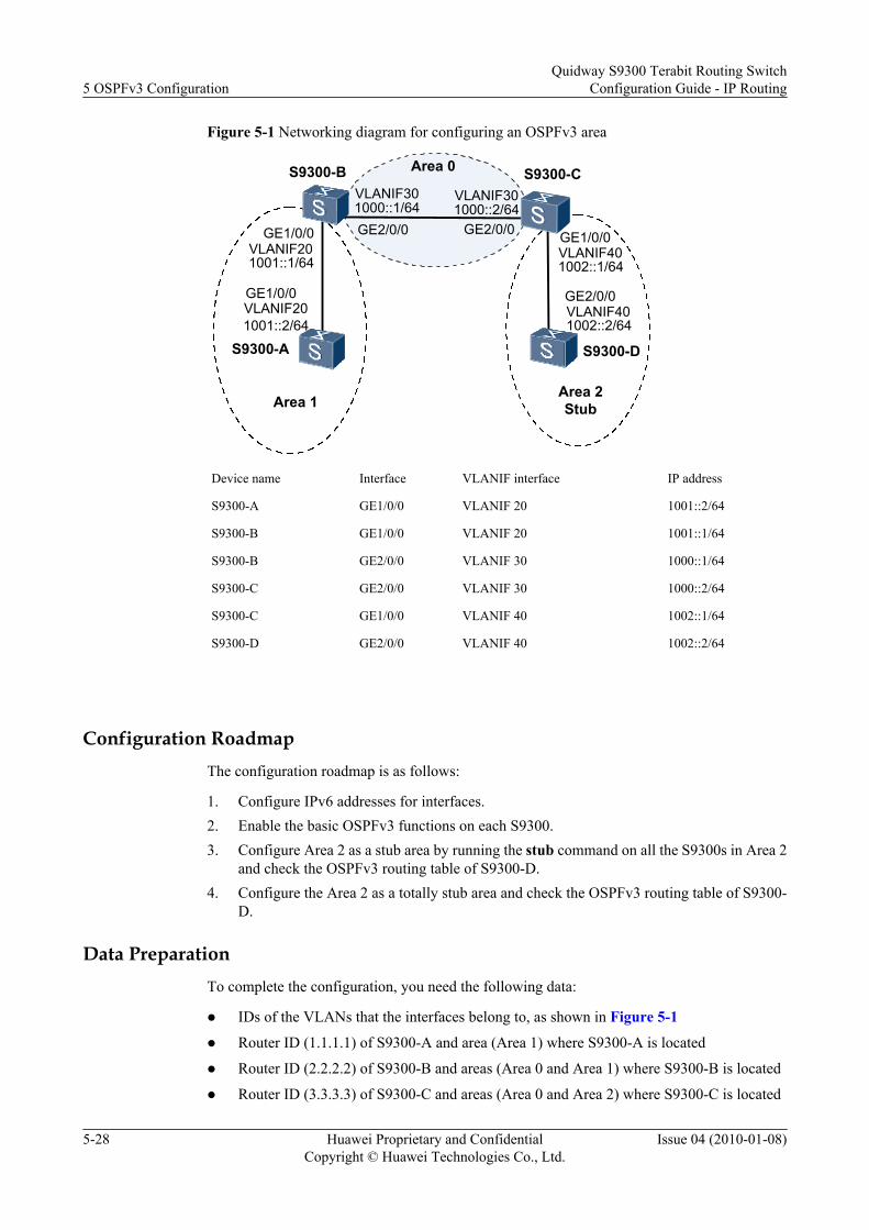
Figure 5-1 Networking diagram for configuring an OSPFv3 area
S9300-A
GE1/0/0
GE1/0/0 GE2/0/0 GE1/0/0
GE2/0/0
S9300-D
S9300-BVLANIF30
VLANIF20
VLANIF20 VLANIF40
1002::2/64VLANIF40
S9300-CArea 0
Area 1Area 2Stub
1001::2/64
1001::1/64
1000::1/64GE2/0/0
VLANIF301000::2/64
1002::1/64
Device name Interface VLANIF interface IP address
S9300-A GE1/0/0 VLANIF 20 1001::2/64
S9300-B GE1/0/0 VLANIF 20 1001::1/64
S9300-B GE2/0/0 VLANIF 30 1000::1/64
S9300-C GE2/0/0 VLANIF 30 1000::2/64
S9300-C GE1/0/0 VLANIF 40 1002::1/64
S9300-D GE2/0/0 VLANIF 40 1002::2/64
Configuration RoadmapThe configuration roadmap is as follows:
1. Configure IPv6 addresses for interfaces.2. Enable the basic OSPFv3 functions on each S9300.3. Configure Area 2 as a stub area by running the stub command on all the S9300s in Area 2
and check the OSPFv3 routing table of S9300-D.4. Configure the Area 2 as a totally stub area and check the OSPFv3 routing table of S9300-
D.
Data PreparationTo complete the configuration, you need the following data:
l IDs of the VLANs that the interfaces belong to, as shown in Figure 5-1
l Router ID (1.1.1.1) of S9300-A and area (Area 1) where S9300-A is located
l Router ID (2.2.2.2) of S9300-B and areas (Area 0 and Area 1) where S9300-B is located
l Router ID (3.3.3.3) of S9300-C and areas (Area 0 and Area 2) where S9300-C is located
5 OSPFv3 ConfigurationQuidway S9300 Terabit Routing Switch
Configuration Guide - IP Routing
5-28 Huawei Proprietary and ConfidentialCopyright © Huawei Technologies Co., Ltd.
Issue 04 (2010-01-08)

l Router ID (4.4.4.4) of S9300-D and area (Area 2) where S9300-D is located
Procedure
Step 1 Add interfaces to VLANs.<Quidway> system-view[Quidway] sysname S9300-A[S9300-A] vlan 20[S9300-A-vlan20] quit[S9300-A] interface GigabitEthernet 1/0/0[S9300-A-GigabitEthernet1/0/0] port hybrid pvid vlan 20[S9300-A-GigabitEthernet1/0/0] port hybrid untagged vlan 20[S9300-A-GigabitEthernet1/0/0] quit
The configurations of S9300-B, S9300-C, S9300-D are similar to the configuration of S9300-A and are not mentioned here.
Step 2 Assign IPv6 addresses to the VLANIF interfaces.[S9300-A] ipv6[S9300-A] interface vlanif 20[S9300-A-Vlanif20] ipv6 enable[S9300-A-Vlanif20] ipv6 address 1001::2/64[S9300-A-Vlanif20] quit
The configurations of S9300-B, S9300-C, S9300-D are similar to the configuration of S9300-A and are not mentioned here.
Step 3 Configure the basic OSPFv3 functions.
# Configure S9300-A.
[S9300-A] ospfv3[S9300-A-ospfv3-1] router-id 1.1.1.1[S9300-A-ospfv3-1] quit[S9300-A] interface vlanif 10[S9300-A-Vlanif10] ospfv3 1 area 1[S9300-A-Vlanif10] quit[S9300-A] interface vlanif 20[S9300-A-Vlanif20] ospfv3 1 area 1[S9300-A-Vlanif20] quit
# Configure S9300-B.
[S9300-B] ospfv3[S9300-B-ospfv3-1] router-id 2.2.2.2[S9300-B-ospfv3-1] quit[S9300-B] interface vlanif 20[S9300-B-Vlanif20] ospfv3 1 area 0[S9300-B-Vlanif20] quit[S9300-B] interface vlanif 30[S9300-B-Vlanif30] ospfv3 1 area 1[S9300-B-Vlanif30] quit
# Configure S9300-C.
[S9300-C] ospfv3[S9300-C-ospfv3-1] router-id 3.3.3.3[S9300-C-ospfv3-1] quit[S9300-C] interface vlanif 30[S9300-C-Vlanif30] ospfv3 1 area 0[S9300-C-Vlanif30] quit[S9300-C] interface vlanif 40[S9300-C-Vlanif40] ospfv3 1 area 2[S9300-C-Vlanif40] quit
# Configure S9300-D.
Quidway S9300 Terabit Routing SwitchConfiguration Guide - IP Routing 5 OSPFv3 Configuration
Issue 04 (2010-01-08) Huawei Proprietary and ConfidentialCopyright © Huawei Technologies Co., Ltd.
5-29

[S9300-D] ospfv3[S9300-D-ospfv3-1] router-id 4.4.4.4[S9300-D-ospfv3-1] quit[S9300-D] interface vlanif 40[S9300-D-Vlanif40] ospfv3 1 area 2[S9300-D-Vlanif40] quit
# View the status of the OSPFv3 neighbors of S9300-B.
[S9300-B] display ospfv3 peer
OSPFv3 Process (1)OSPFv3 Area (0.0.0.1)Neighbor ID Pri State Dead Time Interface Instance ID 1.1.1.1 1 Full/ - 00:00:34 Vlanif20 0OSPFv3 Area (0.0.0.0)Neighbor ID Pri State Dead Time Interface Instance ID3.3.3.3 1 Full/ - 00:00:32 Vlanif30 0
# View the status of the OSPFv3 neighbors of S9300-C.
[S9300-C] display ospfv3 peer
OSPFv3 Process (1)OSPFv3 Area (0.0.0.0)Neighbor ID Pri State Dead Time Interface Instance ID2.2.2.2 1 Full/ - 00:00:37 Vlanif30 0OSPFv3 Area (0.0.0.2)Neighbor ID Pri State Dead Time Interface Instance ID4.4.4.4 1 Full/ - 00:00:33 Vlanif40 0
# View the OSPFv3 routing table of S9300-D.
[S9300-D] display ospfv3 routing
OSPFv3 Process (1) Destination Metric Next-hop IA 1000::/64 2 via FE80::1572:0:5EF4:1, Vlanif40 IA 1001::/64 3 via FE80::1572:0:5EF4:1, Vlanif40 1002::/64 1 directly-connected, Vlanif40 IA 2000::/64 4 via FE80::1572:0:5EF4:1, Vlanif40
Step 4 Configure the stub areas.
# Configure the stub area of S9300-D.
[S9300-D] ospfv3[S9300-D-ospfv3-1] area 2[S9300-D-ospfv3-1-area-0.0.0.2] stub[S9300-D-ospfv3-1-area-0.0.0.2] quit
# Configure the stub area of S9300-C, and set the cost of the default route advertised to the stubarea to 10.
[S9300-C] ospfv3[S9300-C-ospfv3-1] area 2[S9300-C-ospfv3-1-area-0.0.0.2] stub[S9300-C-ospfv3-1-area-0.0.0.2] default-cost 10[S9300-C-ospfv3-1-area-0.0.0.2] quit
# View the OSPFv3 routing table of S9300-D, and you can see a new default route in the routingtable. The cost of the default route is the sum of the cost of the directly connected routes and theconfigured cost.
5 OSPFv3 ConfigurationQuidway S9300 Terabit Routing Switch
Configuration Guide - IP Routing
5-30 Huawei Proprietary and ConfidentialCopyright © Huawei Technologies Co., Ltd.
Issue 04 (2010-01-08)

[S9300-D] display ospfv3 routing
OSPFv3 Process (1) Destination Metric Next-hop IA ::/0 11 via FE80::1572:0:5EF4:1, vlanif40 IA 1000::/64 2 via FE80::1572:0:5EF4:1, vlanif40 IA 1001::/64 3 via FE80::1572:0:5EF4:1, vlanif40 1002::/64 1 directly-connected, vlanif40 IA 2000::/64 4 via FE80::1572:0:5EF4:1, vlanif40
Step 5 Configure the totally sub area.
# On S9300-C, configure Area 2 as the totally stub area.
[S9300-C] ospfv3[S9300-C-ospfv3-1] area 2[S9300-C-ospfv3-1-area-0.0.0.2] stub no-summary[S9300-C-ospfv3-1-area-0.0.0.2] quit
Step 6 Verify the configuration.
# View the OSPFv3 routing table of S9300-D, and you can see that the entries in the routingtable are reduced; other non-directly connected routes are suppressed; only the default route isreserved.
[S9300-D] display ospfv3 routing
OSPFv3 Process (1) Destination Metric Next-hop IA ::/0 11 via FE80::1572:0:5EF4:1, vlanif40 1002::/64 1 directly-connected, vlanif40
----End
Configuration Filesl Configuration file of S9300-A
# sysname S9300-A# ipv6# vlan batch 20#interface Vlanif20 ipv6 enable ipv6 address 1001::2/64 ospfv3 1 area 0.0.0.1#interface GigabitEthernet1/0/0 port hybrid pvid vlan 20 port hybrid untagged vlan 20#ospfv3 1 router-id 1.1.1.1 area 0.0.0.1#return
Quidway S9300 Terabit Routing SwitchConfiguration Guide - IP Routing 5 OSPFv3 Configuration
Issue 04 (2010-01-08) Huawei Proprietary and ConfidentialCopyright © Huawei Technologies Co., Ltd.
5-31

l Configuration file of S9300-B# sysname S9300-B# ipv6# vlan batch 20 30#interface Vlanif20 ipv6 enable ipv6 address 1001::1/64 ospfv3 1 area 0.0.0.1#interface Vlanif30 ipv6 enable ipv6 address 1000::1/64 ospfv3 1 area 0.0.0.0#interface GigabitEthernet1/0/0 port hybrid pvid vlan 20 port hybrid untagged vlan 20# interface GigabitEthernet2/0/0 port hybrid pvid vlan 30 port hybrid untagged vlan 30#ospfv3 1 router-id 2.2.2.2 area 0.0.0.0 area 0.0.0.1#return
l Configuration file of S9300-C# sysname S9300-C# ipv6# vlan batch 30 40#interface Vlanif30 ipv6 enable ipv6 address 1000::2/64 ospfv3 1 area 0.0.0.0# interface Vlanif40 ipv6 enable ipv6 address 1002::1/64 ospfv3 1 area 0.0.0.2#interface GigabitEthernet1/0/0 port hybrid pvid vlan 40 port hybrid untagged vlan 40# interface GigabitEthernet2/0/0 port hybrid pvid vlan 30 port hybrid untagged vlan 30#ospfv3 1 router-id 3.3.3.3 area 0.0.0.0 area 0.0.0.2 stub no-summary default-cost 10#return
l Configuration file of S9300-D
5 OSPFv3 ConfigurationQuidway S9300 Terabit Routing Switch
Configuration Guide - IP Routing
5-32 Huawei Proprietary and ConfidentialCopyright © Huawei Technologies Co., Ltd.
Issue 04 (2010-01-08)

# sysname S9300-D# ipv6# vlan batch 40#interface Vlanif40 ipv6 enable ipv6 address 1002::2/64 ospfv3 1 area 0.0.0.2#interface GigabitEthernet2/0/0 port hybrid pvid vlan 40 port hybrid untagged vlan 40#ospfv3 1 router-id 4.4.4.4 area 0.0.0.2 stub#return
5.11.2 Example for Configuring DR Election Through OSPFv3
Networking RequirementsAs shown in Figure 5-2, the priority of S9300-A is 100, which is the highest priority on thenetwork; therefore, S9300-A is elected as the DR. S9300-C, which has the second highestpriority, is elected as the BDR. The priority of S9300-B is 0, which means that it cannot becomethe DR. S9300-D is not configured with a priority, that is, S9300-D uses the default priority,namely, 1.
Figure 5-2 Networking diagram for configuring DR election through OSPFv3
S9300-A
GE1/0/0
GE1/0/0 GE1/0/0
GE1/0/0
S9300-D
S9300-B
VLANIF10
VLANIF10 VLANIF10
1001::4/64VLANIF10
S9300-C
1001::3/64
1001::1/64 1001::2/64
Device name Interface VLANIF interface IP address
S9300-A GE1/0/0 VLANIF 10 1001::1/64
S9300-B GE1/0/0 VLANIF 10 1001::2/64
S9300-C GE1/0/0 VLANIF 10 1001::3/64
S9300-D GE1/0/0 VLANIF 10 1001::4/64
Quidway S9300 Terabit Routing SwitchConfiguration Guide - IP Routing 5 OSPFv3 Configuration
Issue 04 (2010-01-08) Huawei Proprietary and ConfidentialCopyright © Huawei Technologies Co., Ltd.
5-33

Configuration RoadmapThe configuration roadmap is as follows:
1. Configure IPv6 addresses for interfaces.2. Configure the router ID of each S9300, enable OSPFv3, and specify the network segments.3. Check the DR/BDR status of each S9300 when the default priority is used.4. Set the DR priority of the interface on each S9300 and check whether the S9300 becomes
the DR or BDR.
Data PreparationTo complete the configuration, you need the following data:
l Router ID (1.1.1.1) and DR priority (100) of S9300-A
l Router ID (2.2.2.2) and DR priority (0) of S9300-B
l Router ID (3.3.3.3) and DR priority (2) of S9300-C
l Router ID (4.4.4.4) and DR priority (1) of S9300-D
Procedure
Step 1 Add interfaces to VLANs.<Quidway> system-view[Quidway] sysname S9300-A[S9300-A] vlan 10[S9300-A-vlan10] quit[S9300-A] interface GigabitEthernet 1/0/0[S9300-A-GigabitEthernet1/0/0] port hybrid pvid vlan 10[S9300-A-GigabitEthernet1/0/0] port hybrid untagged vlan 10[S9300-A-GigabitEthernet1/0/0] quit
The configurations of S9300-B, S9300-C, S9300-D are similar to the configuration of S9300-A and are not mentioned here.
Step 2 Assign IPv6 addresses to the VLANIF interfaces.[S9300-A] ipv6[[S9300-A] interface vlanif 10[S9300-A-Vlanif10] ipv6 enable[S9300-A-Vlanif10] ipv6 address 1001::1/64[S9300-A-Vlanif10] quit
The configurations of S9300-B, S9300-C, S9300-D are similar to the configuration of S9300-A and are not mentioned here.
Step 3 Configure the basic OSPFv3 functions.
# On S9300-A, enable OSPFv3 and set the router ID to 1.1.1.1.
[S9300-A] ospfv3[S9300-A-ospfv3-1] router-id 1.1.1.1[S9300-A-ospfv3-1] quit[S9300-A] interface vlanif 10[S9300-A-Vlanif10] ospfv3 1 area 0[S9300-A-Vlanif10] quit
# On S9300-B, enable OSPFv3 and set the router ID to 2.2.2.2.
[S9300-B] ospfv3[S9300-B-ospfv3-1] router-id 2.2.2.2
5 OSPFv3 ConfigurationQuidway S9300 Terabit Routing Switch
Configuration Guide - IP Routing
5-34 Huawei Proprietary and ConfidentialCopyright © Huawei Technologies Co., Ltd.
Issue 04 (2010-01-08)

[S9300-B-ospfv3-1] quit[S9300-B] interface vlanif 10[S9300-B-Vlanif10] ospfv3 1 area 0[S9300-B-Vlanif10] quit
# On S9300-C, enable OSPFv3 and set the router ID to 3.3.3.3.[S9300-C] ospfv3[S9300-C-ospfv3-1] router-id 3.3.3.3[S9300-C-ospfv3-1] quit[S9300-C] interface vlanif 10[S9300-C-Vlanif10] ospfv3 1 area 0[S9300-C-Vlanif10] quit
# On S9300-D, enable OSPFv3 and set the router ID to 4.4.4.4.[S9300-D] ospfv3[S9300-D-ospfv3-1] router-id 4.4.4.4[S9300-D-ospfv3-1] quit[S9300-D] interface vlanif 10[S9300-D-Vlanif10] ospfv3 1 area 0[S9300-D-Vlanif10] quit
Check the neighbors of S9300-A. You can view the DR priority and the neighbor status. Bydefault, the DR priority is 1. Now S9300-D functions as the DR and S9300-C functions as theBDR.
NOTE
When the priorities of two S9300s are the same, the S9300 that has a greater router ID is elected as the DR.If the VLANIF interface of an S9300 becomes the DR, the other broadcast interfaces of this S9300 havea high priority in the future DR election. That is, the S9300 still functions as the DR. The DR cannot bepreempted.
[S9300-A] display ospfv3 peer
OSPFv3 Process (1)OSPFv3 Area (0.0.0.0)Neighbor ID Pri State Dead Time Interface Instance ID2.2.2.2 1 2-Way/DROther 00:00:32 Vlanif10 03.3.3.3 1 Full/Backup 00:00:36 Vlanif10 04.4.4.4 1 Full/DR 00:00:38 Vlanif10 0
# View the neighbors of S9300-D, and you can see that the status of the neighbor relation betweenS9300-D and other devices is Full.[S9300-D] display ospfv3 peer
OSPFv3 Process (1)OSPFv3 Area (0.0.0.0)Neighbor ID Pri State Dead Time Interface Instance ID1.1.1.1 1 Full/DROther 00:00:32 Vlanif10 02.2.2.2 1 Full/DROther 00:00:35 Vlanif10 03.3.3.3 1 Full/Backup 00:00:30 Vlanif10 0
Step 4 Configure the DR priorities of interfaces.
# Configure the DR priority of S9300-A to 100.[S9300-A] interface vlanif 10[S9300-A-Vlanif10] ospfv3 dr-priority 100[S9300-A-Vlanif10] quit
# Configure the DR priority of S9300-B to 0.[S9300-B] interface vlanif 10[S9300-B-Vlanif10] ospfv3 dr-priority 0[S9300-B-Vlanif10] quit
# Configure the DR priority of S9300-C to 2.
Quidway S9300 Terabit Routing SwitchConfiguration Guide - IP Routing 5 OSPFv3 Configuration
Issue 04 (2010-01-08) Huawei Proprietary and ConfidentialCopyright © Huawei Technologies Co., Ltd.
5-35
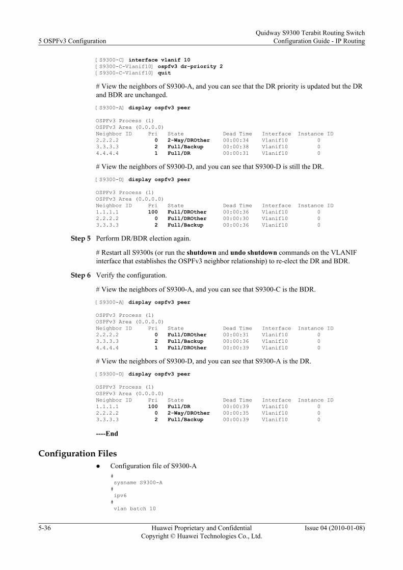
[S9300-C] interface vlanif 10[S9300-C-Vlanif10] ospfv3 dr-priority 2[S9300-C-Vlanif10] quit
# View the neighbors of S9300-A, and you can see that the DR priority is updated but the DRand BDR are unchanged.
[S9300-A] display ospfv3 peer
OSPFv3 Process (1)OSPFv3 Area (0.0.0.0)Neighbor ID Pri State Dead Time Interface Instance ID2.2.2.2 0 2-Way/DROther 00:00:34 Vlanif10 03.3.3.3 2 Full/Backup 00:00:38 Vlanif10 04.4.4.4 1 Full/DR 00:00:31 Vlanif10 0
# View the neighbors of S9300-D, and you can see that S9300-D is still the DR.
[S9300-D] display ospfv3 peer
OSPFv3 Process (1)OSPFv3 Area (0.0.0.0)Neighbor ID Pri State Dead Time Interface Instance ID1.1.1.1 100 Full/DROther 00:00:36 Vlanif10 02.2.2.2 0 Full/DROther 00:00:30 Vlanif10 03.3.3.3 2 Full/Backup 00:00:36 Vlanif10 0
Step 5 Perform DR/BDR election again.
# Restart all S9300s (or run the shutdown and undo shutdown commands on the VLANIFinterface that establishes the OSPFv3 neighbor relationship) to re-elect the DR and BDR.
Step 6 Verify the configuration.
# View the neighbors of S9300-A, and you can see that S9300-C is the BDR.
[S9300-A] display ospfv3 peer
OSPFv3 Process (1)OSPFv3 Area (0.0.0.0)Neighbor ID Pri State Dead Time Interface Instance ID2.2.2.2 0 Full/DROther 00:00:31 Vlanif10 03.3.3.3 2 Full/Backup 00:00:36 Vlanif10 04.4.4.4 1 Full/DROther 00:00:39 Vlanif10 0
# View the neighbors of S9300-D, and you can see that S9300-A is the DR.
[S9300-D] display ospfv3 peer
OSPFv3 Process (1)OSPFv3 Area (0.0.0.0)Neighbor ID Pri State Dead Time Interface Instance ID1.1.1.1 100 Full/DR 00:00:39 Vlanif10 02.2.2.2 0 2-Way/DROther 00:00:35 Vlanif10 03.3.3.3 2 Full/Backup 00:00:39 Vlanif10 0
----End
Configuration Filesl Configuration file of S9300-A
# sysname S9300-A# ipv6# vlan batch 10
5 OSPFv3 ConfigurationQuidway S9300 Terabit Routing Switch
Configuration Guide - IP Routing
5-36 Huawei Proprietary and ConfidentialCopyright © Huawei Technologies Co., Ltd.
Issue 04 (2010-01-08)

#interface Vlanif10 ipv6 enable ipv6 address 1001::1/64 ospfv3 1 area 0.0.0.0 ospfv3 dr-priority 100#interface GigabitEthernet1/0/0 port hybrid pvid vlan 10 port hybrid untagged vlan 10#ospfv3 1 router-id 1.1.1.1 area 0.0.0.0#return
l Configuration file of S9300-B# sysname S9300-B# ipv6# vlan batch 10#interface Vlanif10 ipv6 enable ipv6 address 1001::2/64 ospfv3 1 area 0.0.0.0 ospfv3 dr-priority 0#interface GigabitEthernet1/0/0 port hybrid pvid vlan 10 port hybrid untagged vlan 10#ospfv3 1 router-id 2.2.2.2 area 0.0.0.0#return
l Configuration file of S9300-C# sysname S9300-C# ipv6# vlan batch 10#interface Vlanif10 ipv6 enable ipv6 address 1001::3/64 ospfv3 1 area 0.0.0.0 ospfv3 dr-priority 2#interface GigabitEthernet1/0/0 port hybrid pvid vlan 10 port hybrid untagged vlan 10#ospfv3 1 router-id 3.3.3.3 area 0.0.0.0#return
l Configuration file of S9300-D# sysname S9300-D# ipv6
Quidway S9300 Terabit Routing SwitchConfiguration Guide - IP Routing 5 OSPFv3 Configuration
Issue 04 (2010-01-08) Huawei Proprietary and ConfidentialCopyright © Huawei Technologies Co., Ltd.
5-37
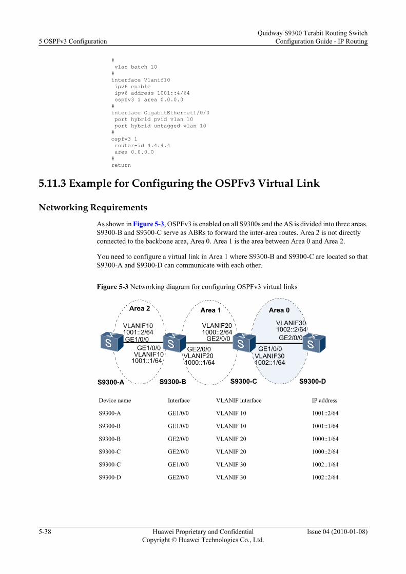
# vlan batch 10#interface Vlanif10 ipv6 enable ipv6 address 1001::4/64 ospfv3 1 area 0.0.0.0#interface GigabitEthernet1/0/0 port hybrid pvid vlan 10 port hybrid untagged vlan 10#ospfv3 1 router-id 4.4.4.4 area 0.0.0.0#return
5.11.3 Example for Configuring the OSPFv3 Virtual Link
Networking Requirements
As shown in Figure 5-3, OSPFv3 is enabled on all S9300s and the AS is divided into three areas.S9300-B and S9300-C serve as ABRs to forward the inter-area routes. Area 2 is not directlyconnected to the backbone area, Area 0. Area 1 is the area between Area 0 and Area 2.
You need to configure a virtual link in Area 1 where S9300-B and S9300-C are located so thatS9300-A and S9300-D can communicate with each other.
Figure 5-3 Networking diagram for configuring OSPFv3 virtual links
S9300-A
GE1/0/0GE1/0/0 GE2/0/0 GE1/0/0
GE2/0/0
S9300-DS9300-B
VLANIF20
VLANIF10
VLANIF10 VLANIF30
1002::2/64VLANIF30
S9300-C
Area 0Area 2
1001::2/64
1001::1/64 1000::1/64
GE2/0/0
VLANIF201000::2/64
1002::1/64
Area 1
Device name Interface VLANIF interface IP address
S9300-A GE1/0/0 VLANIF 10 1001::2/64
S9300-B GE1/0/0 VLANIF 10 1001::1/64
S9300-B GE2/0/0 VLANIF 20 1000::1/64
S9300-C GE2/0/0 VLANIF 20 1000::2/64
S9300-C GE1/0/0 VLANIF 30 1002::1/64
S9300-D GE2/0/0 VLANIF 30 1002::2/64
5 OSPFv3 ConfigurationQuidway S9300 Terabit Routing Switch
Configuration Guide - IP Routing
5-38 Huawei Proprietary and ConfidentialCopyright © Huawei Technologies Co., Ltd.
Issue 04 (2010-01-08)

Configuration RoadmapThe configuration roadmap is as follows:
1. Configure IPv6 addresses for interfaces.2. Enable the basic OSPFv3 functions on each S9300.3. Configure a virtual link between S9300-B and S9300-C to connect the non-backbone areas
to the backbone area.
Data PreparationTo complete the configuration, you need the following data:
l Router ID (1.1.1.1) of S9300-A and area (Area 2) where S9300-A is located
l Router ID (2.2.2.2) of S9300-B and areas (Area 1 and Area 2) where S9300-B is located
l Router ID (3.3.3.3) of S9300-C and areas (Area 1 and Area 0) where S9300-C is located
l Router ID (4.4.4.4) of S9300-D and area (Area 0) where S9300-D is located
Procedure
Step 1 Add interfaces to VLANs.<Quidway> system-view[Quidway] sysname S9300-A[S9300-A] vlan 10[S9300-A-vlan10] quit[S9300-A] interface GigabitEthernet 1/0/0[S9300-A-GigabitEthernet1/0/0] port hybrid pvid vlan 10[S9300-A-GigabitEthernet1/0/0] port hybrid untagged vlan 10[S9300-A-GigabitEthernet1/0/0] quit
The configurations of S9300-B, S9300-C, S9300-D are similar to the configuration of S9300-A and are not mentioned here.
Step 2 Assign IPv6 addresses to the VLANIF interfaces.[S9300-A] ipv6[S9300-A] interface vlanif 10[S9300-A-Vlanif10] ipv6 enable[S9300-A-Vlanif10] ipv6 address 1001::2/64[S9300-A-Vlanif10] quit
The configurations of S9300-B, S9300-C, S9300-D are similar to the configuration of S9300-A and are not mentioned here.
Step 3 Configure the basic OSPFv3 functions.
# On S9300-A, enable OSPFv3 and set the router ID to 1.1.1.1.
[S9300-A] ospfv3[S9300-A-ospfv3-1] router-id 1.1.1.1[S9300-A-ospfv3-1] quit[S9300-A] interface Vlanif 10[S9300-A-Vlanif10] ospfv3 1 area 2[S9300-A-Vlanif10] quit
# On S9300-B, enable OSPFv3 and set the router ID to 2.2.2.2.
[S9300-B] ospfv3[S9300-B-ospfv3-1] router-id 2.2.2.2[S9300-B-ospfv3-1] quit[S9300-B] interface vlanif 10
Quidway S9300 Terabit Routing SwitchConfiguration Guide - IP Routing 5 OSPFv3 Configuration
Issue 04 (2010-01-08) Huawei Proprietary and ConfidentialCopyright © Huawei Technologies Co., Ltd.
5-39

[S9300-B-Vlanif10] ospfv3 1 area 2[S9300-B-Vlanif10] quit[S9300-B] interface vlanif 20[S9300-B-Vlanif20] ospfv3 1 area 1[S9300-B-Vlanif20] quit
# On S9300-C, enable OSPFv3 and set the router ID to 3.3.3.3.
[S9300-C] ospfv3[S9300-C-ospfv3-1] router-id 3.3.3.3[S9300-C-ospfv3-1] quit[S9300-C] interface vlanif 20[S9300-C-Vlanif20] ospfv3 1 area 1[S9300-C-Vlanif20] quit[S9300-C] interface vlanif 30[S9300-C-Vlanif30] ospfv3 1 area 0[S9300-C-Vlanif30] quit
# On S9300-D, enable OSPFv3 and set the router ID to 4.4.4.4.
[S9300-D] ospfv3[S9300-D-ospfv3-1] router-id 4.4.4.4[S9300-D-ospfv3-1] quit[S9300-D] interface vlanif 30[S9300-D-Vlanif30] ospfv3 1 area 0[S9300-D-Vlanif30] quit
# View the OSPFv3 routing table of S9300-C, and you can see that the routing table of S9300-C does not contain the routes of Area 2 because Area 2 is not directly connected to Area 0.
[S9300-C] display ospfv3 routing
OSPFv3 Process (1) Destination Metric Next-hop 1000::/64 1 directly-connected, Vlanif20 1002::/64 1 directly-connected, Vlanif30
Step 4 Configure a vritual link in Area 1 where S9300-B and S9300-C are located.
# Configure S9300-B.
[S9300-B] ospfv3[S9300-B-ospfv3-1] area 1[S9300-B-ospfv3-1-area-0.0.0.1] vlink-peer 3.3.3.3[S9300-B-ospfv3-1-area-0.0.0.1] quit
# Configure S9300-C.
[S9300-C] ospfv3[S9300-C-ospfv3-1] area 1[S9300-C-ospfv3-1-area-0.0.0.1] vlink-peer 2.2.2.2[S9300-C-ospfv3-1-area-0.0.0.1] quit
Step 5 Verify the configuration.
# Check the OSPFv3 routing table of S9300-C.
[S9300-C] display ospfv3 routing
OSPFv3 Process (1) Destination Metric Next-hop 1000::/64 1 directly-connected, Vlanif20 1000::1/128 1 via FE80::4D67:0:EB7D:2, Vlanif20 1000::2/128 1
5 OSPFv3 ConfigurationQuidway S9300 Terabit Routing Switch
Configuration Guide - IP Routing
5-40 Huawei Proprietary and ConfidentialCopyright © Huawei Technologies Co., Ltd.
Issue 04 (2010-01-08)

directly-connected, Vlanif20 IA 1001::/64 2 via FE80::4D67:0:EB7D:2, Vlanif20 1002::/64 1 directly-connected, Vlanif30
----End
Configuration Filesl Configuration file of S9300-A
# sysname S9300-A# ipv6# vlan batch 10#interface Vlanif10 ipv6 enable ipv6 address 1001::2/64 ospfv3 1 area 0.0.0.2#interface GigabitEthernet1/0/0 port hybrid pvid vlan 10 port hybrid untagged vlan 10#ospfv3 1 router-id 1.1.1.1 area 0.0.0.2#return
l Configuration file of S9300-B# sysname S9300-B# ipv6# vlan batch 10 20#interface Vlanif10 ipv6 enable ipv6 address 1001::1/64 ospfv3 1 area 0.0.0.2#interface Vlanif20 ipv6 enable ipv6 address 1000::1/64 ospfv3 1 area 0.0.0.1#interface GigabitEthernet1/0/0 port hybrid pvid vlan 10 port hybrid untagged vlan 10# interface GigabitEthernet2/0/0 port hybrid pvid vlan 20 port hybrid untagged vlan 20#ospfv3 1 router-id 2.2.2.2 area 0.0.0.0 area 0.0.0.1 vlink-peer 3.3.3.3 area 0.0.0.2# return
Quidway S9300 Terabit Routing SwitchConfiguration Guide - IP Routing 5 OSPFv3 Configuration
Issue 04 (2010-01-08) Huawei Proprietary and ConfidentialCopyright © Huawei Technologies Co., Ltd.
5-41

l Configuration file of S9300-C# sysname S9300-C# ipv6# vlan batch 20 30#interface Vlanif20 ipv6 enable ipv6 address 1000::2/64 ospfv3 1 area 0.0.0.1#interface Vlanif30 ipv6 enable ipv6 address 1002::1/64 ospfv3 1 area 0.0.0.0#interface GigabitEthernet1/0/0 port hybrid pvid vlan 30 port hybrid untagged vlan 30# interface GigabitEthernet2/0/0 port hybrid pvid vlan 20 port hybrid untagged vlan 20#ospfv3 1 router-id 3.3.3.3 area 0.0.0.0 area 0.0.0.1 vlink-peer 2.2.2.2#return
l Configuration file of S9300-D# sysname S9300-D# ipv6# vlan batch 30#interface Vlanif30 ipv6 enable ipv6 address 1002::2/64 ospfv3 1 area 0.0.0.0#interface GigabitEthernet2/0/0 port hybrid pvid vlan 30 port hybrid untagged vlan 30#ospfv3 1 router-id 4.4.4.4 area 0.0.0.0#return
5.11.4 Example for Configuring OSPFv3 GR
Networking RequirementsAs shown in Figure 5-4, S9300-A, S9300-B, and S9300-C belong to the same OSPFv3 area.They communicate with each other through the OSPFv3 protocol and are enabled with GR.
5 OSPFv3 ConfigurationQuidway S9300 Terabit Routing Switch
Configuration Guide - IP Routing
5-42 Huawei Proprietary and ConfidentialCopyright © Huawei Technologies Co., Ltd.
Issue 04 (2010-01-08)

When OSPFv3 adjacencies are established between S9300-A, S9300-C, and S9300-B, the threeS9300s can exchange routing information. If the OSPFv3 protocol restarts on S9300-A,S9300-A synchronizes data with the neighboring S9300s through GR.
Figure 5-4 Networking diagram for configuring OSPFv3 GR
S9300-A
GE1/0/0 GE1/0/0 GE2/0/0
S9300-B
VLANIF20VLANIF10 VLANIF10
S9300-C1.1.1.1
1000::1/64 1000::2/64 2000::1/64GE1/0/0
VLANIF202000::2/64
2.2.2.2 3.3.3.3
Device name Interface VLANIF interface IP address
S9300-A GE1/0/0 VLANIF 10 1000::1/64
S9300-B GE1/0/0 VLANIF 10 1000::2/64
S9300-B GE2/0/0 VLANIF 20 2000::1/64
S9300-C GE1/0/0 VLANIF 20 2000::2/64
Configuration RoadmapThe configuration roadmap is as follows:
1. Configure IPv6 addresses for interfaces.2. Enable the basic OSPFv3 functions on each S9300.3. Enable the OSPFv3 helper in the OSPFv3 view of S9300-B.4. Enable the OSPFv3 GR in the OSPFv3 view of S9300-A.
Data PreparationTo complete the configuration, you need the following data:
l IPv6 addresses of the interfaces
l Process ID of the OSPFv3 protocol
l Router ID (1.1.1.1) of S9300-A and area (Area 0) where S9300-A is located
l Router ID (2.2.2.2) of S9300-B and area (Area 0) where S9300-B is located
l Router ID (3.3.3.3) of S9300-C and area (Area 0) where S9300-C is located
Procedure
Step 1 Add interfaces to VLANs.<Quidway> system-view[Quidway] sysname S9300-A[S9300-A] vlan 10[S9300-A-vlan10] quit[S9300-A] interface GigabitEthernet 1/0/0[S9300-A-GigabitEthernet1/0/0] port hybrid pvid vlan 10[S9300-A-GigabitEthernet1/0/0] port hybrid untagged vlan 10[S9300-A-GigabitEthernet1/0/0] quit
Quidway S9300 Terabit Routing SwitchConfiguration Guide - IP Routing 5 OSPFv3 Configuration
Issue 04 (2010-01-08) Huawei Proprietary and ConfidentialCopyright © Huawei Technologies Co., Ltd.
5-43

The configurations of S9300-B and S9300-C are similar to the configuration of S9300-A andare not mentioned here.
Step 2 Assign IPv6 addresses to the VLANIF interfaces.[S9300-A] ipv6[S9300-A] interface vlanif 10[S9300-A-Vlanif10] ipv6 enable[S9300-A-Vlanif10] ipv6 address 1000::1/64[S9300-A-Vlanif10] quit
The configurations of S9300-B and S9300-C are similar to the configuration of S9300-A andare not mentioned here.
Step 3 Configure the basic OSPFv3 functions.
# On S9300-A, enable OSPFv3 and set the router ID to 1.1.1.1.
[S9300-A] ospfv3 100[S9300-A-ospfv3-100] router-id 1.1.1.1[S9300-A-ospfv3-100] quit[S9300-A] interface Vlanif 10[S9300-A-Vlanif10] ospfv3 100 area 0[S9300-A-Vlanif10] quit
# On S9300-B, enable OSPFv3 and set the router ID to 2.2.2.2.
[S9300-B] ospfv3 100[S9300-B-ospfv3-100] router-id 2.2.2.2[S9300-B-ospfv3-100] quit[S9300-B] interface vlanif 10[S9300-B-Vlanif10] ospfv3 100 area 0[S9300-B-Vlanif10] quit[S9300-B] interface vlanif 20[S9300-B-Vlanif20] ospfv3 100 area 0[S9300-B-Vlanif20] quit
# On S9300-C, enable OSPFv3 and set the router ID to 3.3.3.3.
[S9300-C] ospfv3 100[S9300-C-ospfv3-100] router-id 3.3.3.3[S9300-C-ospfv3-100] quit[S9300-C] interface vlanif 20[S9300-C-Vlanif20] ospfv3 100 area 0[S9300-C-Vlanif20] quit
Step 4 Enable OSPFv3 GR for S9300-A.[S9300-A] ospfv3 100[S9300-A-ospfv3-100] graceful-restart[S9300-A-ospfv3-100] quit
Step 5 Enable OSPFv3 helper for S9300-B.[S9300-B] ospfv3 100[S9300-B-ospfv3-100] helper-role[S9300-B-ospfv3-100] quit
Step 6 Verify the configuration.
# Run the display ipv6 fib 1 command on S9300-A to view the FIB information.
<S9300-A> display ipv6 fib 1 FIB Table: Total number of Routes : 2
Destination: 1000:: PrefixLength: 64NextHop : 1000::1 Flag : ULabel : NULL Tunnel ID : 0TimeStamp : Date- 25:6:2007, Time- 17:31:46 reference : 1
5 OSPFv3 ConfigurationQuidway S9300 Terabit Routing Switch
Configuration Guide - IP Routing
5-44 Huawei Proprietary and ConfidentialCopyright © Huawei Technologies Co., Ltd.
Issue 04 (2010-01-08)

Interface : Vlanif10
Destination: 2000:: PrefixLength : 64NextHop : FE80::200:1FF:FE00:200 Flag : DGULabel : NULL Tunnel ID : 0TimeStamp : Date- 26:6:2007, Time- 14:6:3 reference : 1Interface : Vlanif10
# Restart OSPFv3 process 100 on S9300-A without using the GR mechanism.
<S9300-A> reset ospfv3 100
# Run the display ipv6 fib 1 command on S9300-A immediately to view the FIB information.
<S9300-A> display ipv6 fib 1 FIB Table: Total number of Routes : 1
Destination: 1000:: PrefixLength :64NextHop : 1000::1 Flag : ULabel : NULL Tunnel ID : 0TimeStamp : Date- 25:6:2007, Time- 17:31:46 reference : 1Interface : Vlanif10
The preceding information shows that the FIB information on S9300-A is modified and theforwarding service is affected.
# Restart OSPFv3 process 100 on S9300-A by using the GR mechanism.
<S9300-A> reset ospfv3 100 graceful-restart
# Run the display ipv6 fib 1 command on S9300-A immediately to view the FIB information.Check whether GR functions normally. If GR functions normally, the FIB information is notmodified and the forwarding is not affected when you restart the OSPFv3 process through GRon S9300-A.
<S9300-A> display ipv6 fib 1 FIB Table: Total number of Routes : 2
Destination: 1000:: PrefixLength : 64NextHop : 1000::1 Flag : ULabel : NULL Tunnel ID : 0TimeStamp : Date- 25:6:2007, Time- 17:31:46 reference : 1Interface : Vlanif10
Destination: 2000:: PrefixLength : 64NextHop : FE80::200:1FF:FE00:200 Flag : DGULabel : NULL Tunnel ID : 0TimeStamp : Date- 26:6:2007, Time- 14:6:3 reference : 1Interface : Vlanif10
The preceding information shows that the FIB information on S9300-A is not modified and theforwarding is not affected.
----End
Configuration Filesl Configuration file of S9300-A
# sysname S9300-A# ipv6# vlan batch 10#
Quidway S9300 Terabit Routing SwitchConfiguration Guide - IP Routing 5 OSPFv3 Configuration
Issue 04 (2010-01-08) Huawei Proprietary and ConfidentialCopyright © Huawei Technologies Co., Ltd.
5-45

interface Vlanif10 ipv6 enable ipv6 address 1000::1/64 ospfv3 100 area 0.0.0.0#interface GigabitEthernet1/0/0 port hybrid pvid vlan 10 port hybrid untagged vlan 10#ospfv3 100 router-id 1.1.1.1 graceful-restart area 0.0.0.0 # return
l Configuration file of S9300-B# sysname S9300-B# ipv6# vlan batch 10 20#interface Vlanif10 ipv6 enable ipv6 address 1000::2/64 ospfv3 100 area 0.0.0.0#interface Vlanif20 ipv6 enable ipv6 address 2000::1/64 ospfv3 100 area 0.0.0.0#interface GigabitEthernet1/0/0 port hybrid pvid vlan 10 port hybrid untagged vlan 10# interface GigabitEthernet2/0/0 port hybrid pvid vlan 20 port hybrid untagged vlan 20
#ospfv3 100 router-id 2.2.2.2 helper-role area 0.0.0.0 # return
l Configuration file of S9300-C# sysname S9300-C# ipv6# vlan batch 20#interface Vlanif20 ipv6 enable ipv6 address 2000::2/64 ospfv3 100 area 0.0.0.0#interface GigabitEthernet1/0/0 port hybrid pvid vlan 20 port hybrid untagged vlan 20
#ospfv3 100 router-id 3.3.3.3
5 OSPFv3 ConfigurationQuidway S9300 Terabit Routing Switch
Configuration Guide - IP Routing
5-46 Huawei Proprietary and ConfidentialCopyright © Huawei Technologies Co., Ltd.
Issue 04 (2010-01-08)

area 0.0.0.0 #return
Quidway S9300 Terabit Routing SwitchConfiguration Guide - IP Routing 5 OSPFv3 Configuration
Issue 04 (2010-01-08) Huawei Proprietary and ConfidentialCopyright © Huawei Technologies Co., Ltd.
5-47


6 IS-IS Configuration
About This Chapter
This chapter describes the concepts of IS-IS and the procedure for configuring IS-IS, andprovides configuration examples of IS-IS.
6.1 Concepts of IS-ISThis section describes the principle and concepts of IS-IS.
6.2 IS-IS Features Supported by the S9300This section describes the IS-IS features supported by the S9300.
6.3 Configuring Basic IS-IS FunctionsThis section describes how to enable IS-IS to ensure that the S9300 can select routes throughIS-IS.
6.4 Establishing and Maintaining IS-IS AdjacenciesThis section describes how to set the timers for IS-IS packets and parameters of LSPs to maintainIS-IS adjacencies.
6.5 Configuring IS-IS Attributes on Networks of Different TypesThis section describes how to change the network type of an IS-IS interface and configure IS-IS attributes on networks of in different types.
6.6 Setting the Attributes of IS-IS RoutesThis section describes how to set the parameters of IS-IS routes, and set the cost and priority ofIS-IS links.
6.7 Controlling the Advertisement of IS-IS Routing InformationThis section describes how to configure IS-IS to generate routes according to the specified rulesand configure the route filtering rules.
6.8 Controlling the Received IS-IS Routing InformationThis section describes how to distinguish routing information inside and outside an IS-ISdomain.
6.9 Adjusting and Optimizing the IS-IS NetworkThis section describes how to configure the status of an IS-IS interface and set the LSPparameters.
Quidway S9300 Terabit Routing SwitchConfiguration Guide - IP Routing 6 IS-IS Configuration
Issue 04 (2010-01-08) Huawei Proprietary and ConfidentialCopyright © Huawei Technologies Co., Ltd.
6-1
6.10 Configuring IS-IS GRThis section describes how to enable IS-IS GR and set parameters of the GR session.
6.11 Configuring BFD for IS-ISThis section describes how to implement fast convergence of the IS-IS network by using BFD.
6.12 Configuring IS-IS IPv6This section describes how to interconnect the IPv6 networks through IS-IS.
6.13 Configuring IS-IS AuthenticationThis section describes how to configure the authentication mode and authentication passwordfor an IS-IS network.
6.14 Maintaining IS-ISThis section describes how to clear data of an IS-IS process and debugging the IS-IS process.
6.15 Configuration ExamplesThis section provides examples of IS-IS configuration.
6 IS-IS ConfigurationQuidway S9300 Terabit Routing Switch
Configuration Guide - IP Routing
6-2 Huawei Proprietary and ConfidentialCopyright © Huawei Technologies Co., Ltd.
Issue 04 (2010-01-08)

6.1 Concepts of IS-ISThis section describes the principle and concepts of IS-IS.
The Intermediate System-to-Intermediate System (IS-IS) protocol is initially issued by theInternational Organization for Standardization (ISO) for its Connectionless Network Protocol(CLNP).
To support IP routing, the International Engineering Task Force (IETF) extends and modifiesIS-IS in RFC 1195. Thus, IS-IS can be applied to both the TCP/IP and OSI environments. Thistype of IS-IS is called the Integrated IS-IS or Dual IS-IS.
IS-IS is an Interior Gateway Protocol (IGP) and is used within an AS. IS-IS is a link stateprotocol. It uses the Shortest Path First (SPF) algorithm to calculate routes. IS-IS resembles theOSPF protocol.
IS-IS Areas
To support large-scale routing networks, IS-IS adopts a two-level structure in a routing domain.A large routing domain is divided into one or more areas. The intra-area routes are managed byLevel-1 devices, whereas the inter-area routes are managed by Level-2 devices.
Figure 6-1 shows a network that runs IS-IS. The network is similar to an OSPF typology withmultiple areas. Area 1 is the backbone area. All nodes in the area are Level-2 devices. The otherfour areas are non-backbone areas. They are connected to Area 1 through Level-1-2 devices.
Figure 6-1 IS-IS topology I
Area 4L1
L1
L1L1
L1
L1
L1/2 L1/2
L1/2L1/2
L2 L2
L2L2Area 1
Area 5
Area 3
Area 2
Figure 6-2 shows another type of IS-IS topology. The Level-1-2 devices are used to connectthe Level-1 devices to the Level-2 devices. In addition, the Level-1-2 devices constitute thebackbone network with the Level-2 devices. In this topology, no area is specified as the backbonearea. All the Level-2 devices constitute the IS-IS backbone network. The Level-2 devices maybelong to different areas, but they must be on contiguous network segments.
Quidway S9300 Terabit Routing SwitchConfiguration Guide - IP Routing 6 IS-IS Configuration
Issue 04 (2010-01-08) Huawei Proprietary and ConfidentialCopyright © Huawei Technologies Co., Ltd.
6-3

Figure 6-2 IS-IS typology II
L2 L2
L1 L2L1
L1
L1/2L1/2
Area 1
Area 2 Area 3 Area 4
NOTE
An IS-IS backbone network does not refer to a specific area.
This networking scheme shows the difference between IS-IS and OSPF. For OSPF, the inter-area routes are forwarded through the backbone area, and the SPF algorithm is used only in thesame area. For IS-IS, both Level-1 and Level-2 devices use the SPF algorithm to generate theshortest path tree (SPT).
Network TypeIS-IS supports only two types of networks based on physical links:
l Broadcast links such as Ethernet links
l Point-to-point (P2P) links
6.2 IS-IS Features Supported by the S9300This section describes the IS-IS features supported by the S9300.
IS-IS InterfacesThe creation of IS-IS routing tables and configurations of IS-IS features must be done on Layer3 interfaces. Physical interfaces on the S9300 except the management network interface,however, are Layer 2 interfaces. In this case, you can configure Layer 2 interfaces on theS9300 as follows:l Configure the VLAN that the Layer 2 interfaces belong to, assign an IP address to the
corresponding VLANIF interface, and enable IS-IS functions on the VLANIF interface.l Assign an IP address to the loopback interface and enable IS-IS functions on the loopback
interface.
NOTE
In the following configuration tasks, the configurations in the interface view must be completed onthe VLANIF interface and loopback interface unless otherwise specified.
For details about the Layer 2 interface configuration, see the Quidway S9300 Terabit RoutingSwitch Configuration Guide - Ethernet.
6 IS-IS ConfigurationQuidway S9300 Terabit Routing Switch
Configuration Guide - IP Routing
6-4 Huawei Proprietary and ConfidentialCopyright © Huawei Technologies Co., Ltd.
Issue 04 (2010-01-08)

The S9300 adds a 3-bit Logical-Link Control (LLC) field to the beginning of an IS-IS PDUbefore encapsulating the PDU into an Ethernet frame. Then the S9300 transmits the Ethernetframe. The LLC field does not belong to the header of the Ethernet frame but functions as a datafield in the Ethernet frame. Therefore, the maximum length of an IS-IS PDU that can betransmitted by the S9300 equals the MTU size of a VLANIF interface minus 3. That is, the MTUvalue of an IS-IS interface equals the MTU value of a physical interface minus 3. The MTUvalue of a VLANIF interface on the S9300 is 1500. Therefore, the MTU value of an IS-ISinterface on the S9300 is 1497.
Multi-ProcessFor easy management and effective control, IS-IS provides the multi-process feature. The multi-process feature allows a group of interfaces to be associated with a specified IS-IS process. Thisensures that the specific IS-IS process performs all the protocol operations only on the group ofinterfaces. Thus, multiple IS-IS processes can work on a single S9300 and each process isresponsible for a unique group of interfaces.
IS-IS Hot StandbyThe S9300 supports the IS-IS hot standby feature. IS-IS backs up important data of the mastermain control board to the slave main control board. Whenever the master main control boardfails, the slave main control board becomes active. In this manner, IS-IS is not affected andfunctions normally.
The S9300 backs up only the IS-IS configuration during the switchover between the master andslave main control boards. IS-IS performs graceful restart (GR), sends requests to neighbors toestablish adjacencies with the neighbors, and synchronizes the LSDB.
NOTE
For details about hot standby, see the Quidway S9300 Terabit Routing Switch Configuration Guide -Reliability.
IS-IS GRGR ensures continuous forwarding of traffic. Restarting a device within a short period of timedoes not cause route flapping on the network.
If IS-IS is not restarted in GR mode, IS-IS sessions are reset and Link State PDUs (LSPs) areregenerated and flooded. This triggers the SPF calculation in the entire area, which causes routeflapping and forwarding interruption in the area. In this case, IETF works out an IS-IS GRstandard (RFC 3847). The standard deals with restart of protocols with or without FIB tables.
NOTE
The S9300 supports IS-IS GR. For details about IS-IS GR, see the chapter "IS-IS" in the Quidway S9300Terabit Routing Switch Feature Description - IP Routing.
IS-IS TEThe IS-IS Traffic Engineering (TE) applies when MPLS establishes and maintains label switchedpaths (LSPs).
When constructing the constraint-based routed LSP (CR-LSP), MPLS needs to learn the trafficattributes of all the links in an area. MPLS can acquire the TE information about the links throughIS-IS.
Quidway S9300 Terabit Routing SwitchConfiguration Guide - IP Routing 6 IS-IS Configuration
Issue 04 (2010-01-08) Huawei Proprietary and ConfidentialCopyright © Huawei Technologies Co., Ltd.
6-5

NOTE
For details about the IS-IS TE, see the Quidway S9300 Terabit Routing Switch Configuration Guide -MPLS.
Administrative Tag
The use of administrative tags simplifies management. Administrative tags can be controlledthrough the advertisement of IP prefixes in the IS-IS domain. The administrative tag carries theadministrative information about an IP address prefix. The administrative tag is used to controlthe routes of different levels and routes imported from different areas, different routing protocols,and multiple IS-IS instances running on a device. In addition, the administrative tag carries theBGP standard community attributes or the extended community attributes.
The value of an administrative tag is associated with certain attributes. When IS-IS advertisesan IP address prefix with the attributes, it adds the administrative tag to the type-length-value(TLV) in the prefix. In this manner, the tag is advertised with the prefix throughout the routingdomain.
LSP Fragments Extension
When an LSP to be advertised by IS-IS contains a lot of information, the LSP is fragmented.Each LSP fragment is identified by the LSP identifier field of an LSP. The length of the LSPidentifier field is one byte. Therefore, the maximum number of fragments that can be generatedby an IS-IS process is 256.
The IS-IS fragments extension feature allows an IS-IS router to generate more LSP fragments.To implement this feature, you can enable the network manager to configure the S9300 withadditional system IDs. Each system ID represents a virtual system that can generate 256 LSPfragments. With more additional system IDs (up to 50 virtual systems), the IS-IS router cangenerate a maximum of 13056 LSP fragments.
l Related terms– Originating system
The originating system is the device that actually runs the IS-IS protocol. With the LSPfragments extension function, an LSP of an IS-IS node can be sliced into multiple LSPsof pseudonodes before being advertised. The originating system refers to the real IS-ISprocess.
– Normal system IDIt is the system ID of the originating system.
– Virtual systemThe virtual system is used to generate extended LSP fragments. When an LSP is slicedinto more than 256 fragments, the extra LSP fragments are advertised to the networkby virtual systems. These fragments carry additional system IDs in their LSP ID fields.
– Additional system IDIt is the system ID of a virtual system. The network manager assigns additional systemIDs. Each additional system ID can generate up to 256 additional or extended LSPfragments. Like a normal system ID, an additional system ID must be unique in a routingdomain.
l Operation modesThe S9300 can implement the LSP fragments extension feature in the following modes:
6 IS-IS ConfigurationQuidway S9300 Terabit Routing Switch
Configuration Guide - IP Routing
6-6 Huawei Proprietary and ConfidentialCopyright © Huawei Technologies Co., Ltd.
Issue 04 (2010-01-08)

– Mode-1: The mode is used when certain nodes in the network do not support this feature.In this mode, the originating system advertises a link to each virtual system of whichthe additional system ID is in the LSPs. Similarly, each virtual system advertises a linkto the originating system. The virtual systems are equivalent to the nodes that areconnected to the originating system on the network. One restriction in this mode is thatonly the leaf information can be advertised in the LSPs of the virtual systems.
– Mode-2: The mode is used when all the nodes in the network support this feature. Inthis mode, all the routers on the network know that the LSPs generated by the virtualsystems belong to the originating system. There is no restriction to the link stateinformation carried in the LSPs that are advertised by the virtual systems.
Dynamic Host Name Exchange MechanismThe dynamic host name exchange mechanism is introduced to conveniently manage andmaintain IS-IS networks. The mechanism provides the service of mapping host names to systemIDs for the IS-IS nodes. This dynamic name information is advertised in a dynamic host nameTLV.
The dynamic host name exchange mechanism can also associate a host name with the designatedIS (DIS) on the broadcast network. Then, this association is advertised in the dynamic host nameTLV of a pseudonode LSP.
The host name is easier to maintain and memorize than the system ID. After this function isconfigured, the output of the display commands related to IS-IS running on the S9300 displaysthe host name rather than the system ID of the S9300.
Fast Convergence of IS-IS Networkl I-SPF
Incremental SPF (I-SPF) calculates only the changed routes rather than all the routes at atime.In ISO-10589, the Dijkstra algorithm is adopted to calculate routes. If the Dijkstra algorithmis adopted, all routes need to be recalculated when a node changes on the network. Thecalculation takes a long time and consumes too many CPU resources, which affects theconvergence speed.I-SPF improves this algorithm. Except for the first time, only changed nodes instead of allnodes are involved in calculation. The SPT generated at last is the same as the SPT generatedby the previous algorithm. This lowers the CPU usage and speeds up the networkconvergence.
l PRCSimilar to I-SPF, partial route calculation (PRC) involves only changed nodes. PRC,however, does not calculate the shortest path. Instead, it updates leaf routes based on theSPT calculated by I-SPF.In route calculation, a leaf represents a route, and a node represents a device. If the SPTchanges after I-SPF calculation, PRC processes all the leaves only on that changed node.If the SPT remains unchanged, PRC processes only the changed leaves.For example, if IS-IS is enabled on an interface of a node, the SPT calculated by I-SPFremains unchanged. In this case, PRC updates only the routes of this node, thus consumingless CPU resources.PRC working with I-SPF further improves the convergence performance of the network.As an improvement to the original SPF algorithm, PRC and I-SPF replace the originalalgorithm.
Quidway S9300 Terabit Routing SwitchConfiguration Guide - IP Routing 6 IS-IS Configuration
Issue 04 (2010-01-08) Huawei Proprietary and ConfidentialCopyright © Huawei Technologies Co., Ltd.
6-7

NOTE
In S9300 implementation, only I-SPF and PRC are used to calculate IS-IS routes.
l LSP fast floodingAs specified by RFC, when the S9300 receives new LSPs from other nodes, it floods theLSPs in its own LSDB periodically according to a timer. This can speed up the networkconvergence, but the LSDB is synchronized slowly.LSP fast flooding solves the problem. When the S9300 configured with this feature receivesone or more LSPs, it floods the LSPs fewer than the specified number before routecalculation. Thus, LSDB can be synchronized quickly. This improves the networkconvergence speed significantly.
l Intelligent timerAlthough the route calculation algorithm is improved, the long interval for triggering theroute calculation affects the convergence speed. You can shorten the interval by using amillisecond-level timer. Frequent network changes, however, also consume too many CPUresources. An SPF intelligent timer responds to network changes quickly but consumesfewer CPU resources.An IS-IS network running normally is stable and frequent changes on a network rarelyoccur. In such a network, the S9300 does not calculate routes very often. Therefore, youcan set a short period (in milliseconds) for triggering the route calculation for the first time.If the topology of the network changes frequently, the value of the intelligent timer increaseswith the number of calculation events to avoid high CPU usage.The LSP generation intelligent timer is similar to the SPF intelligent timer. When the LSPgeneration intelligent timer expires, the system generates a new LSP based on the currenttopology. The original mechanism adopts a timer with a constant interval, and fastconvergence and low CPU usage cannot be achieved at the same time. To solve thisproblem, the LSP generation timer is designed as an intelligent timer to respond to the burstevents (for example, the interface becomes Up or Down) quickly and speed up the networkconvergence. In addition, when the network changes frequently, the value of the intelligenttimer increases with the calculation count to avoid high CPU usage.
NOTE
Set the intelligent timer with caution according to the network environment.
BFD for IS-ISThe S9300 supports Bidirectional Forwarding Detection (BFD), which is used to detect IS-ISneighbor relationship. BFD can rapidly detect the faults of a link between IS-IS neighbors andreport the faults to the IS-IS protocol. The fast convergence of IS-IS is thus implemented.
To configure BFD, run certain commands to manually set the parameters of BFD sessions,including the local discriminator and remote discriminator, and then send requests to set up BFDsessions.
NOTE
BFD detects only the one-hop link between IS-IS neighbors because IS-IS establishes only one-hopadjacencies.For details about BFD for IS-IS, see the chapter "IS-IS" in the Quidway S9300 Terabit Routing SwitchFeature Description - IP Routing.
Three-Way HandshakeA reliable link layer protocol is required if IS-IS runs on P2P links. According to ISO 10589,the two-way handshake mechanism of IS-IS uses Hello packets to set up P2P adjacencies
6 IS-IS ConfigurationQuidway S9300 Terabit Routing Switch
Configuration Guide - IP Routing
6-8 Huawei Proprietary and ConfidentialCopyright © Huawei Technologies Co., Ltd.
Issue 04 (2010-01-08)

between neighbors. Once the S9300 receives a Hello packet from its peer, it regards the statusof the peer as Up and sets an adjacency with the peer.
This mechanism has distinct disadvantages. For example, unstable link status causes the loss ofcomplete sequence number packets (CSNPs) after an adjacency is set up. As a result, the LSDBfails to be synchronized during the update period of an LSP. If two or more links exist betweentwo neighbors, an adjacency can still be set up when one link is Down and the other is Up in thesame direction. The parameters of the fault link, however, are also used in SPF calculation. Thedevice that does not detect any faults still tries to forward packets through the link that is inDown state.
The three-way handshake mechanism solves this problem on P2P links. In the three-wayhandshake mode, the S9300 regards the neighbor as Up and then sets up an adjacency with theneighbor only after confirming that the neighbor receives the packet that S9300 sends .
In addition, the three-way handshake mechanism adopts the 32-bit extended circuit ID. Thisextends the original 8-bit Circuit ID field and thus more than 255 P2P links can be set up.
6.3 Configuring Basic IS-IS FunctionsThis section describes how to enable IS-IS to ensure that the S9300 can select routes throughIS-IS.
6.3.1 Establishing the Configuration Task
6.3.2 Starting an IS-IS Process
6.3.3 Configuring a NET
6.3.4 (Optional) Setting the Level of the S9300
6.3.5 Enabling an IS-IS Process on an Interface
6.3.6 Checking the Configuration
6.3.1 Establishing the Configuration Task
Applicable EnvironmentConfigure the basic IS-IS functions on each S9300 on a network if IS-IS is required so that theS9300s can select routes normally.
Pre-configuration TasksBefore configuring basic functions of IS-IS, complete the following tasks:l Configuring a link layer protocol
l Configuring the VLAN that each physical interface belongs to
l Assigning an IP address to each VLANIF interface to ensure network reachability betweenneighboring nodes
Quidway S9300 Terabit Routing SwitchConfiguration Guide - IP Routing 6 IS-IS Configuration
Issue 04 (2010-01-08) Huawei Proprietary and ConfidentialCopyright © Huawei Technologies Co., Ltd.
6-9

NOTE
To create the VLAN for each interface, you can add interfaces to the VLAN in default mode or by usingthe port trunk allow-pass vlan command. Use the same method to add interfaces to a VLAN on both endsof a link.
If you run the port trunk allow-pass vlan command to add interfaces to a VLAN, the directly connectedphysical interfaces in the same network segment should be added to the same VLAN. In this manner, thecorresponding VLANIF interfaces can be directly connected at the network layer. For details, see theQuidway S9300 Terabit Routing Switch Configuration Guide - Ethernet.
Data PreparationTo configure basic functions of IS-IS , you need the following data.
No. Data
1 IS-IS process ID.
2 Network entity title (NET)
3 (Optional) Level of the S9300
6.3.2 Starting an IS-IS Process
ContextTo enable IS-IS, you must create an IS-IS process and run the isis enable command to activatethe IS-IS process on the interface that may be connected to other IS-IS nodes.
Do as follows on the S9300s that need to run IS-IS.
Procedure
Step 1 Run:system-view
The system view is displayed.
Step 2 Run:isis [ process-id ]
An IS-IS process is started and the IS-IS view is displayed.
Theprocess-id parameter specifies an IS-IS process. If no process ID is specified, IS-IS process1 is started by default.
----End
6.3.3 Configuring a NET
ContextA NET specifies the current IS-IS area address and the system ID of the S9300.
6 IS-IS ConfigurationQuidway S9300 Terabit Routing Switch
Configuration Guide - IP Routing
6-10 Huawei Proprietary and ConfidentialCopyright © Huawei Technologies Co., Ltd.
Issue 04 (2010-01-08)

You can configure up to three NETs for an IS-IS process on an S9300. The system IDs of thethree NETs must be the same.
Do as follows on the S9300s that need to run IS-IS.
Procedure
Step 1 Run:system-view
The system view is displayed.
Step 2 Run:isis [ process-id ]
The IS-IS view is displayed.
Step 3 Run:network-entity net
A NET is configured.
----End
6.3.4 (Optional) Setting the Level of the S9300
Context
An S9300 that runs IS-IS generates an LSDB for each level. If the level of the S9300 is Level-1-2,the S9300 generates a Level-1 LSDB and a Level-2 LSDB. If the level of the S9300 is Level-1or Level-2, the S9300 generates an LSDB for the corresponding level. Creating and maintainingtwo LSDBs simultaneously consumes many system resources. Therefore, after the networkstructure is layered, set a proper level for the S9300 according to its position in the network.
Do as follows on each S9300 of which the level needs to be specified.
Procedure
Step 1 Run:system-view
The system view is displayed.
Step 2 Run:isis [ process-id ]
The IS-IS view is displayed.
Step 3 Run:is-level { level-1 | level-1-2 | level-2 }
The level of the S9300 is set.
By default, the level of the S9300 is Level-1-2.
----End
Quidway S9300 Terabit Routing SwitchConfiguration Guide - IP Routing 6 IS-IS Configuration
Issue 04 (2010-01-08) Huawei Proprietary and ConfidentialCopyright © Huawei Technologies Co., Ltd.
6-11

6.3.5 Enabling an IS-IS Process on an Interface
ContextOnly one IS-IS process can be enabled on an interface.
Do as follows on each S9300 that needs to run IS-IS.
Procedure
Step 1 Run:system-view
The system view is displayed.
Step 2 Run:interface interface-type interface-number
The interface view is displayed.
Step 3 Run:isis enable [ process-id ]
An IS-IS process is started on the interface.
NOTEYou can configure an IP address for a VLANIF interface or a loopback interface on the S9300 and enableIS-IS on this interface. All the configurations performed in the interface view are performed on this twotypes of interfaces.
----End
6.3.6 Checking the Configuration
PrerequisiteAll the basic IS-IS functions are configured.
Procedurel Run the display isis interface [ verbose | process-id ] * command to check information
about the interface on which IS-IS is enabled.l Run the display isis lsdb [ { level-1 | level-2 } | { local | lsp-id | is-name symbolic-
name } | process-id | verbose ] * command to check the IS-IS LSDB.l Run the display isis peer [ verbose ] [ process-id ] command to check information about
the IS-IS neighbors.l Run the display isis route [ process-id ] [ ipv4 ] [ {ipv4-address [ mask | mask-length ] }
| { level-1 | level-2 } | verbose ] *display isis process-id route [ ipv4 ] [ {ipv4-address[ mask | mask-length ] } | { level-1 | level-2 } | verbose ] * command to check the IS-ISrouting table.
l Run the display isis statistics [ level-1 | level-2 | level-1-2 ] [ process-id ] command toview the statistics of an IS-IS process.
----End
6 IS-IS ConfigurationQuidway S9300 Terabit Routing Switch
Configuration Guide - IP Routing
6-12 Huawei Proprietary and ConfidentialCopyright © Huawei Technologies Co., Ltd.
Issue 04 (2010-01-08)

Example
Run the display isis interface command, and you can find that the IPv4 neighbors of the localS9300 are in the Up state.
<Quidway> display isis interface Interface information for ISIS(1) --------------------------------- Interface Id IPV4.State IPV6.State MTU Type DIS Vlanif10 001 Up Down 1497 L1/L2 No/No
6.4 Establishing and Maintaining IS-IS AdjacenciesThis section describes how to set the timers for IS-IS packets and parameters of LSPs to maintainIS-IS adjacencies.
6.4.1 Establishing the Configuration Task
6.4.2 (Optional) Setting Timers of IS-IS Packets
6.4.3 Setting LSP Parameters
6.4.4 (Optional) Disabling the Padding of Hello Packets on an Interface
6.4.5 Checking the Configuration
6.4.1 Establishing the Configuration Task
Applicable Environment
After an IS-IS process is started, the S9300 sends IS-IS packets to neighbors through IS-ISinterfaces. This section describes how to set the parameters of IS-IS packets. You can modifythe parameters according to the actual situation of the network. You can:l Adjust timers for various IS-IS packets such as Hello packets, CSNP packets, and LSPs.
l Adjust LSP parameters.
l Disable the padding of Hello packets on the specified interface.
When setting the timers of IS-IS packets, note that smaller values of the timers mean fasterconvergence of the network after a topology change, and therefore higher costs of network links.Set the timers properly to balance the network convergence speed and bandwidth consumption.
Pre-configuration Tasks
Before establishing or maintaining an IS-IS neighbor or adjacency relationship, perform thefollowing task:
l 6.3 Configuring Basic IS-IS Functions
Data Preparation
To establish or maintain an IS-IS neighbor or adjacency relationship, you need the followingdata.
Quidway S9300 Terabit Routing SwitchConfiguration Guide - IP Routing 6 IS-IS Configuration
Issue 04 (2010-01-08) Huawei Proprietary and ConfidentialCopyright © Huawei Technologies Co., Ltd.
6-13
No. Data
1 (Optional) Values of packet timers
2 Values of LSP parameters
6.4.2 (Optional) Setting Timers of IS-IS Packets
ContextDo as follows on the S9300.
Procedurel Setting the interval for sending Hello packets
Level-1 and Level-2 hello packets are sent on broadcast links. You can set different intervalsfor the two levels. If no level is specified, the interval that you set applies to both the Level-1and Level-2 Hello packets. On point-to-point links, Hello packets are not differentiated onthe basis of levels. Therefore, you do not need to specify the level.
1. Run:system-view
The system view is displayed.2. Run:
interface interface-type interface-number
The interface view is displayed.3. Run:
isis timer hello hello-interval [ level-1 | level-2 ]
The interval for sending Hello packets is set.
By default, Hello packets are sent every 10 seconds.l Setting the Hello multiplier
The IS-IS protocol maintains the neighbor relationship between the neighbors throughHello packets. If the local device does not receive any Hello packet from its peer within acertain period, that is, within the specified number of Hello intervals, it considers theneighbor invalid. The specified number of Hello intervals is called the Hello multiplier.
In IS-IS, you can set the Hello interval and the Hello multiplier to control the holding timeof the neighbor relationship between two neighbors.
1. Run:system-view
The system view is displayed.2. Run:
interface interface-type interface-number
The interface view is displayed.
6 IS-IS ConfigurationQuidway S9300 Terabit Routing Switch
Configuration Guide - IP Routing
6-14 Huawei Proprietary and ConfidentialCopyright © Huawei Technologies Co., Ltd.
Issue 04 (2010-01-08)

3. Run:isis timer holding-multiplier number [ level-1 | level-2 ]
The Hello multiplier is set.
By default, the Hello multiplier is 3. If level of packets is not specified, the set Hellomultiplier applies to both Level-1 and Level-2 Hello packets.
l Setting the interval for sending CSNPs
CSNPs are transmitted by the DIS over the broadcast network to synchronize the LSDBs.If level of packets is not specified, the interval that you set applies to both Level-1 andLevel-2 Hello packets.
1. Run:system-view
The system view is displayed.2. Run:
interface interface-type interface-number
The interface view is displayed.3. Run:
isis timer csnp csnp-interval [ level-1 | level-2 ]
The interval for sending CSNPs is set.
By default, CSNPs are sent every 10 seconds.l Setting the interval for retransmitting LSPs
On a P2P link, if the S9300 does not receive any response to an LSP within a certain period,it considers that this LSP is lost or discarded. To ensure reliable transmission, the localS9300 retransmits the LSP.
The LSPs sent over broadcast links do not need response. Therefore, do not perform thisconfiguration on broadcast links.
If the type of an interface is changed to non-P2P, this configuration is deleted at the sametime.
1. Run:system-view
The system view is displayed.2. Run:
interface interface-type interface-number
The interface view is displayed.3. Run:
isis circuit-type p2p
The network type of the interface is set to P2P.4. Run:
isis timer lsp-retransmit retransmit-interval
The interval for retransmitting LSPs on P2P links is set.
By default, the interval for retransmitting LSPs on a P2P link is 5 seconds.
Quidway S9300 Terabit Routing SwitchConfiguration Guide - IP Routing 6 IS-IS Configuration
Issue 04 (2010-01-08) Huawei Proprietary and ConfidentialCopyright © Huawei Technologies Co., Ltd.
6-15

l Setting the minimum interval for sending LSPs1. Run:
system-view
The system view is displayed.2. Run:
interface interface-type interface-number
The interface view is displayed.3. Run:
isis timer lsp-throttle throttle-interval [ count count ]
The minimum interval for sending LSPs is set.
If LSPs are too large, LSP fragments increase accordingly. In this case, you canconfigure the S9300 to send LSP fragments in batches. The throttle-interval parameterspecifies the minimum interval between two batches. The optional parameter countspecifies the number of LSP fragments that can be sent in each batch.
----End
6.4.3 Setting LSP Parameters
ContextDo as follows on the S9300.
Procedurel (Optional) Configuring the LSP refresh interval
To synchronize all LSPs in the entire area, an IS-IS system periodically sends all LSPs toits neighbors. When setting the LSP refresh interval, ensure that this interval is shorter thanthe lifetime of LSPs.
1. Run:system-view
The system view is displayed.2. Run:
isis [ process-id ]
The IS-IS view is displayed.3. Run:
timer lsp-refresh refresh-interval
The LSP refresh interval is set.
By default, the LSP refresh interval is 900 seconds.l (Optional) Setting the lifetime of LSPs
When the S9300 generates an LSP, it fills in the lifetime field in the LSP. When this LSPis received by other intermediate systems, its lifetime decreases as time elapses. If anintermediate system does not receive any updated LSP before the lifetime of this LSPdecreases to 0, the LSP is deleted from the LSDB of the intermediate system.
6 IS-IS ConfigurationQuidway S9300 Terabit Routing Switch
Configuration Guide - IP Routing
6-16 Huawei Proprietary and ConfidentialCopyright © Huawei Technologies Co., Ltd.
Issue 04 (2010-01-08)

1. Run:system-view
The system view is displayed.2. Run:
isis [ process-id ]
The IS-IS view is displayed.3. Run:
timer lsp-max-age age-time
The LSP lifetime is set.
By default, the maximum lifetime of an LSP is 1200 seconds.l (Optional) Setting the intelligent timer for generating LSPs
In IS-IS, when the local routing information changes, an intermediate system needs togenerate new LSPs to advertise the change. When the local routing information changesfrequently, the new LSP should be sent after a delay. This prevents degradation of systemperformance due to high consumption of system resources.
If the delay is too long, changes of the local routing information cannot be advertised tothe neighbors in time, and thus the network converges slowly.
The intelligent timer mitigates this problem by adjusting the delay according to thefrequency of changes on the network. The initial interval for generating the first LSP isinitial-interval. Then, the interval increases by incremental-interval every time the networkchanges until the interval reaches the value of max-interval. When the interval reaches thevalue of max-interval three times, it drops to initial-interval.
1. Run:system-view
The system view is displayed.2. Run:
isis [ process-id ]
The IS-IS view is displayed.3. Run:
timer lsp-generation max-interval [ init-interval [ incr-interval ] ] [ level-1 | level-2 ]
The intelligent timer used for generating LSPs is set.l (Optional) Setting the maximum size of LSPs sent and received
The value of max-size specified in the lsp-length originate command must be smaller thanor equal to the value of max-size specified in the lsp-length receive command.
When enabling IS-IS on an interface, ensure that the value of max-size specified in the lsp-length originate command is smaller than or equal to the MTU value of the IS-IS interface.Otherwise, the interface is considered in the MTU down state and the neighbor relationshipcannot be set up.
The default MTU of an IS-IS interface on the S9300 is 1497 bytes. If the S9300 and otherproducts are used on the same IS-IS network, ensure that LSPs generated by otherintermediate systems contain no more than 1497 bytes. Otherwise, the network cannotoperate normally.
Quidway S9300 Terabit Routing SwitchConfiguration Guide - IP Routing 6 IS-IS Configuration
Issue 04 (2010-01-08) Huawei Proprietary and ConfidentialCopyright © Huawei Technologies Co., Ltd.
6-17

1. Run:system-view
The system view is displayed.2. Run:
isis [ process-id ]
The IS-IS view is displayed.3. Run:
lsp-length originate max-size
The maximum size of the generated LSPs is set.4. (Optional) Run:
lsp-length receive max-size
The maximum size of the received LSPs is set.
By default, the maximum size of an LSP that can be received or sent is 1497 bytes.l Configuring the mesh group of an interface
On a network with a higher connectivity, an interface on the S9300 floods a received LSPto other interfaces on the S9300. This flooding method causes repeated LSP flooding andwastes bandwidth.
To avoid such a problem, you can add certain interfaces to a mesh group. These interfacesdo not flood the LSPs received from this group to other interfaces of the same group, butfloods them out of the group. When the mesh-blocked keyword is configured on aninterface, the interface is blocked and cannot flood LSPs. All the interfaces that join a meshgroup synchronize the LSDBs in the entire network segment by using the CSNP and PartialSequence Number Packet (PSNP) mechanisms.
1. Run:system-view
The system view is displayed.2. Run:
interface interface-type interface-number
The interface view is displayed.3. Run:
isis mesh-group { mesh-group-number | mesh-blocked }
The interface is added to a mesh group.l Configuring LSP fragments extension
1. Run:system-view
The system view is displayed.2. Run:
isis [ process-id ]
The IS-IS view is displayed.3. Run:
lsp-fragments-extend [ [ level-1 | level-2 | level-1-2 ] | [ mode-1 | mode-2 ] ] *
6 IS-IS ConfigurationQuidway S9300 Terabit Routing Switch
Configuration Guide - IP Routing
6-18 Huawei Proprietary and ConfidentialCopyright © Huawei Technologies Co., Ltd.
Issue 04 (2010-01-08)

LSP fragments extension is enabled.4. Run:
virtual-system virtual-system-id
A virtual system is configured.
At least one virtual system ID must be configured so that the S9300 can generate extendedLSP fragments. The virtual system IDs must be unique in the entire area and routing domain.
An IS-IS process can be configured with up to 50 virtual system IDs.
NOTE
l If all the intermediate systems on a network support the LSP fragments extension, specifymode-2 in the lsp-fragments-extend command. If certain intermediate systems do not supportthe LSP fragments extension, specify mode-1 in the lsp-fragments-extend command.
l The LSP fragments extension takes effect only after you run the reset isis process-id allcommand. After the IS-IS data is cleared, all the previous topology information and theadjacencies are reestablished.
----End
6.4.4 (Optional) Disabling the Padding of Hello Packets on anInterface
ContextThe intermediate systems that run IS-IS set up and maintain the neighbor relationship throughHello packets. By default, an interface on the S9300 adds a type-8 TLV to a Hello packet beforesending the packet to the peer. In this manner, the length of the Hello packet becomes the sameas the depth of the buffer on the local S9300. By sending Hello packets, the S9300 can checkwhether the MTU of the peer interface is the same as the depth of the local buffer. If the MTUof the peer interface is smaller than the depth of the local buffer, the neighbor relationship cannotbe set up.
The IS-IS small-hello command reduces the size of Hello packets considerably, thus savingnetwork bandwidth.
If the MTU of the peer interface is greater than the MTU of the local interface, disable the paddingof Hello packets on the local S9300. Otherwise, IS-IS the neighbor relationship cannot be setup.
Do as follows on each S9300 that runs IS-IS.
Procedure
Step 1 Run:system-view
The system view is displayed.
Step 2 Run:interface interface-type interface-number
The interface view is displayed.
Step 3 Run:
Quidway S9300 Terabit Routing SwitchConfiguration Guide - IP Routing 6 IS-IS Configuration
Issue 04 (2010-01-08) Huawei Proprietary and ConfidentialCopyright © Huawei Technologies Co., Ltd.
6-19

isis small-hello
The Hello packet padding function is disabled.
----End
6.4.5 Checking the Configuration
PrerequisiteAll the configurations for establishing and maintaining IS-IS adjacencies are complete.
Procedurel Run the display isis interface [ verbose | process-id ] * command to check information
about the interfaces on which IS-IS is enabled.l Run the display isis mesh-group [ process-id ] command to check information about the
mesh group for IS-IS interfaces.l Run the display isis statistics [ level-1 | level-2 | level-1-2 ] [ process-id ] command to
view the statistics of an IS-IS process.
----End
ExampleSet the Hello interval to 15 seconds, the Hello multiplier to 10, the CSNP interval to 123 seconds,and the minimum interval for sending LSPs to 159 seconds. Then run the display isis interfaceverbose command. The following information is displayed:
<Quidway> display isis interface verbose Interface information for ISIS(1) --------------------------------- Interface Id IPV4.State IPV6.State MTU Type DIS Vlanif10 001 Up Down 1497 L1/L2 No/No Circuit Parameters : small-hello Description : HUAWEI, Quidway Series, Vlanif10 Interface SNPA Address : 00e0-095b-4201 IP Address : 123.1.1.1 IPV6 Link Local Address : IPV6 Global Address(es) : Csnp Timer Value : L1 123 L2 10 Hello Timer Value : L1 15 L2 15 DIS Hello Timer Value : L1 5 L2 5 Hello Multiplier Value : L1 10 L2 10 Retransmit-Throttle Timer : L12 159 Cost : L1 10 L2 10 Ipv6 Cost : L1 10 L2 10 Priority : L1 64 L2 64 Retransmit Timer Value : L12 5 Bandwidth-Value : Low 100000000 High 0 Static Bfd : NO Dynamic Bfd : NO Fast-Sense Rpr : NO
6 IS-IS ConfigurationQuidway S9300 Terabit Routing Switch
Configuration Guide - IP Routing
6-20 Huawei Proprietary and ConfidentialCopyright © Huawei Technologies Co., Ltd.
Issue 04 (2010-01-08)

6.5 Configuring IS-IS Attributes on Networks of DifferentTypes
This section describes how to change the network type of an IS-IS interface and configure IS-IS attributes on networks of in different types.
6.5.1 Establishing the Configuration Task
6.5.2 Setting the Network Type of an IS-IS Interface
6.5.3 (Optional) Setting the DIS Priority of an Interface
6.5.4 Setting the Neighbor Relationship Negotiation Mode on P2P Links
6.5.5 Configuring an IS-IS Interface Not to Check IP Addresses of the Received Hello Packets
6.5.6 Checking the Configuration
6.5.1 Establishing the Configuration Task
Applicable Environment
IS-IS attributes vary according to network types. This section describes how to configure IS-ISattributes on networks of different types. You can perform the following configurations tocontrol and optimize various networks:
l Change the link type of an Ethernet interface to P2P to simulate a P2P interface.
l Control the DIS election.
l Set the negotiation mode in which the neighbor relationship can be set up between neighborson P2P links.
l Configuring two P2P interfaces in the different network segments to ignore IP addresscheck so that they can establish a neighbor relationship.
Pre-configuration Tasks
Before configuring OSPF attributes on a network, complete the following task:
l 6.3 Configuring Basic IS-IS Functions
Data Preparation
To configure IS-IS attributes on a network, you need the following data.
No. Data
1 Network type of an interface
2 (Optional) DIS priority of an interface
Quidway S9300 Terabit Routing SwitchConfiguration Guide - IP Routing 6 IS-IS Configuration
Issue 04 (2010-01-08) Huawei Proprietary and ConfidentialCopyright © Huawei Technologies Co., Ltd.
6-21

6.5.2 Setting the Network Type of an IS-IS Interface
ContextIf the network types of two neighboring IS-IS interfaces are different, the local S9300 may notlearn correct routes. In this case, perform this configuration. By default, the network type of aninterface is determined by the type of the physical interface.
Do as follows on the S9300 as required.
Procedure
Step 1 Run:system-view
The system view is displayed.
Step 2 Run:interface interface-type interface-number
The interface view is displayed.
Step 3 Run:isis circuit-type p2p
The network type of the interface is set to P2P.
----End
6.5.3 (Optional) Setting the DIS Priority of an Interface
ContextDo as follows on the S9300.
Procedure
Step 1 Run:system-view
The system view is displayed.
Step 2 Run:interface interface-type interface-number
The interface view is displayed.
Step 3 Run:isis dis-priority priority [ level-1 | level-2 ]
The DIS priority of the interface is set. A larger value indicates a higher priority.
By default, the DIS priority of an IS-IS interface is 64.
Level-1 DISs and Level-2 DISs are elected respectively, and you can set different priorities forthem. If no level is specified in the command, the DIS priority applies to both Level-1 andLevel-2.
6 IS-IS ConfigurationQuidway S9300 Terabit Routing Switch
Configuration Guide - IP Routing
6-22 Huawei Proprietary and ConfidentialCopyright © Huawei Technologies Co., Ltd.
Issue 04 (2010-01-08)
The DIS is elected based on the DIS priority. The intermediate system where the interface withthe highest DIS priority resides is elected as the DIS. For the interfaces with the same priority,the interface with the greatest MAC address is elected. An interface with the DIS priority of 0participates in the DIS election, which is different from OSPF.
NOTE
l The DIS priority is valid for only broadcast networks.
l If you run the isis circuit-type command to change the network type of an Ethernet interface to P2P,IS-IS regards this interface as a P2P interface. In this case, the isis dis-priority command does not takeeffect.
----End
6.5.4 Setting the Neighbor Relationship Negotiation Mode on P2PLinks
ContextDo as follows on the S9300.
Procedure
Step 1 Run:system-view
The system view is displayed.
Step 2 Run:interface interface-type interface-number
The interface view is displayed.
Step 3 Run:isis ppp-negotiation { 2-way | 3-way [ only ] }
The neighbor relationship negotiation mode is set for the interface.
By default, an interface adopts the 3-way handshake mode.
The isis ppp-negotiation command applies to P2P links only. To set up the neighbor relationshipon broadcast links, you can run the isis circuit-type command to change the link type to P2Pand then run the isis ppp-negotiation command to configure the negotiation mode.
The isis ppp-negotiation command specifies the negotiation mode in which the neighborrelationship can be set up on P2P links. Using the three-way handshake model, the S9300 candetect faults of unidirectional links and the unreliable peer status of P2P interfaces caused byother link defects.
----End
Quidway S9300 Terabit Routing SwitchConfiguration Guide - IP Routing 6 IS-IS Configuration
Issue 04 (2010-01-08) Huawei Proprietary and ConfidentialCopyright © Huawei Technologies Co., Ltd.
6-23

6.5.5 Configuring an IS-IS Interface Not to Check IP Addresses ofthe Received Hello Packets
ContextDo as follows on the S9300.
ProcedureStep 1 Run:
system-view
The system view is displayed.
Step 2 Run:interface interface-type interface-number
The interface view is displayed.
Step 3 Run:isis peer-ip-ignore
The interface is configured not to check the IP address of the received Hello packets.
This command applies to only P2P links. In general, an IS-IS interface checks the IP address ofa received Hello packet. The neighbor relationship can be set up only when the IP address carriedin the Hello packet and the address of the IS-IS interface belong to the same network segment.
If you run the isis peer-ip-ignore command on the interfaces at both ends of a link, the neighborrelationship can be set up even if the addresses of the interfaces belong to different networksegments. If the link is a real P2P link, the interfaces at both ends can ping each other successfullyeven if their addresses belong to different network segments. If the link is a P2P link simulatedby an Ethernet link, the neighbor relationship can be set up between the devices on both endsbut they cannot ping each other.
----End
6.5.6 Checking the Configuration
PrerequisiteThe IS-IS attributes are configured.
Procedurel Run the display isis interface [ verbose | process-id ] * command to check information
about the interface on which IS-IS is enabled.
----End
ExampleSet the network type to P2P and the DIS priority to 100 on interface VLANIF 10. Run the displayisis interface command. The following information is displayed.<Quidway> display isis interface verbose
6 IS-IS ConfigurationQuidway S9300 Terabit Routing Switch
Configuration Guide - IP Routing
6-24 Huawei Proprietary and ConfidentialCopyright © Huawei Technologies Co., Ltd.
Issue 04 (2010-01-08)

Interface information for ISIS(1) --------------------------------- Interface Id IPV4.State IPV6.State MTU Type DIS Vlanif10 002 Up Down 1497 L1/L2 -- Circuit Parameters : p2p Description : HUAWEI, Quidway Series, Vlanif10 Interface SNPA Address : 00e0-095b-4201 IP Address : 123.1.1.1 IPV6 Link Local Address : IPV6 Global Address(es) : Csnp Timer Value : L1 10 L2 10 Hello Timer Value : 15 DIS Hello Timer Value : Hello Multiplier Value : 10 Cost : L1 10 L2 10 Ipv6 Cost : L1 10 L2 10 Priority : L1 100 L2 100 Retransmit Timer Value : L12 5 Retransmit-Throttle Timer : L12 50 Bandwidth-Value : Low 100000000 High 0 Static Bfd : NO Dynamic Bfd : NO Fast-Sense Rpr : NO Extended-Circuit-Id Value : 0000000001
6.6 Setting the Attributes of IS-IS RoutesThis section describes how to set the parameters of IS-IS routes, and set the cost and priority ofIS-IS links.
6.6.1 Establishing the Configuration Task
6.6.2 Setting the Cost of an IS-IS Interface
6.6.3 Setting the Preference of IS-IS
6.6.4 Checking the Configuration
6.6.1 Establishing the Configuration Task
Applicable EnvironmentBy changing attributes of IS-IS routes, such as the cost and priority, you can modify the routingtable and forwarding table. Thus, the optimal routes can be selected during the routing.
Pre-configuration TasksBefore setting IS-IS route attributes, complete the following task:
l 6.3 Configuring Basic IS-IS Functions
Data PreparationTo set IS-IS route attributes, you need the following data.
No. Data
1 Cost of the IS-IS interface
Quidway S9300 Terabit Routing SwitchConfiguration Guide - IP Routing 6 IS-IS Configuration
Issue 04 (2010-01-08) Huawei Proprietary and ConfidentialCopyright © Huawei Technologies Co., Ltd.
6-25

No. Data
2 Priority of the IS-IS protocol
6.6.2 Setting the Cost of an IS-IS Interface
Context
Do as follows on the S9300.
Procedurel Setting the IS-IS cost type
1. Run:system-view
The system view is displayed.2. Run:
isis [ process-id ]
The IS-IS view is displayed.3. Run:
cost-style { narrow | wide | wide-compatible | { narrow-compatible | compatible } [ relax-spf-limit ] }
The IS-IS cost type is set.
The cost range of an interface and cost range of a received route vary according to thecost type.
– If the cost type is narrow, the cost of an interface ranges from 1 to 63. The maximumcost of a received route is 1023.
– If the cost type is narrow-compatible or compatible, the cost of an interface rangesfrom 1 to 63. The cost of a received route is related to relax-spf-limit.– If relax-spf-limit is not specified, the following situations occur:
– If the cost of the route is smaller than or equal to 1023 and the link costs ofall the interfaces that the route passes through are smaller than 63, the routeis accepted and the actual cost of the route is adopted.
– If the cost of the route is smaller than or equal to 1023 but the link cost ofan interface that the route passes through is greater than 63, the S9300 canlearn only the routes of the network segment where this interface is locatedand the route imported by the interface. The actual cost of the route isadopted. The routes behind the interface are discarded.
– If the cost of the route is greater than 1023, the S9300 can learn only theroutes of the first interface whose link cost exceeds 1023. That is, the linkcost of every interface before this interface is not more than 63. The routesof the network segment where the interface is located and routes importedby the interface can be learned by the S9300. The cost of the route is 1023.The routes behind the interface are discarded.
6 IS-IS ConfigurationQuidway S9300 Terabit Routing Switch
Configuration Guide - IP Routing
6-26 Huawei Proprietary and ConfidentialCopyright © Huawei Technologies Co., Ltd.
Issue 04 (2010-01-08)

– If relax-spf-limit is specified, there is no limit to the link costs of interfaces orroute costs. The actual cost of the route is adopted.
– If the cost type is wide-compatible or wide, the cost of an interface ranges from 1to 16777215. If the cost is 16777215, the neighbor TLV (with the cost of 16777215)generated on the link cannot be used in the route calculation. Instead, this neighborTLV can only be used to deliver TE information. The maximum cost of the receivedroutes is 0 x FFFFFFFF.
l Setting the cost of an IS-IS interface1. Run:
system-view
The system view is displayed.2. Run:
interface interface-type interface-number
The interface view is displayed.3. Run:
isis cost cost [ level-1 | level-2 ]
The cost of the IS-IS interface is set.
If no level is specified, the set cost applies to both Level-1 and Level-2.
By default, the link cost of an IS-IS interface is 10.
You can use the command to set the cost of a particular interface.l Setting the global cost for all IS-IS interfaces
1. Run:system-view
The system view is displayed.2. Run:
isis [ process-id ]
The IS-IS view is displayed.3. Run:
circuit-cost cost [ level-1 | level-2 ]
The cost of all the IS-IS interfaces is set.
If no level is specified, the link cost is set for Level-1-2 interfaces.
You can use the command to change the cost of all interfaces at a time.l Enabling automatic cost calculation
1. Run:system-view
The system view is displayed.2. Run:
isis [ process-id ]
The IS-IS view is displayed.3. Run:
bandwidth-reference value
Quidway S9300 Terabit Routing SwitchConfiguration Guide - IP Routing 6 IS-IS Configuration
Issue 04 (2010-01-08) Huawei Proprietary and ConfidentialCopyright © Huawei Technologies Co., Ltd.
6-27
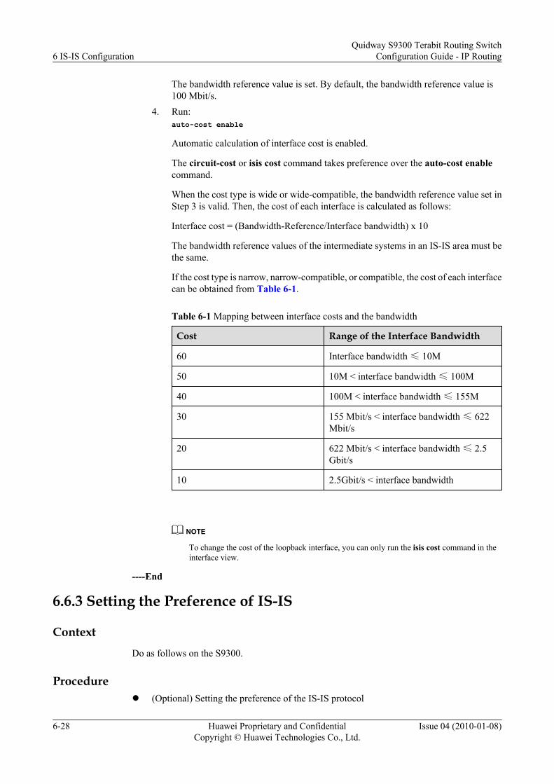
The bandwidth reference value is set. By default, the bandwidth reference value is100 Mbit/s.
4. Run:auto-cost enable
Automatic calculation of interface cost is enabled.
The circuit-cost or isis cost command takes preference over the auto-cost enablecommand.
When the cost type is wide or wide-compatible, the bandwidth reference value set inStep 3 is valid. Then, the cost of each interface is calculated as follows:
Interface cost = (Bandwidth-Reference/Interface bandwidth) x 10
The bandwidth reference values of the intermediate systems in an IS-IS area must bethe same.
If the cost type is narrow, narrow-compatible, or compatible, the cost of each interfacecan be obtained from Table 6-1.
Table 6-1 Mapping between interface costs and the bandwidth
Cost Range of the Interface Bandwidth
60 Interface bandwidth ≤ 10M
50 10M < interface bandwidth ≤ 100M
40 100M < interface bandwidth ≤ 155M
30 155 Mbit/s < interface bandwidth ≤ 622Mbit/s
20 622 Mbit/s < interface bandwidth ≤ 2.5Gbit/s
10 2.5Gbit/s < interface bandwidth
NOTE
To change the cost of the loopback interface, you can only run the isis cost command in theinterface view.
----End
6.6.3 Setting the Preference of IS-IS
ContextDo as follows on the S9300.
Procedurel (Optional) Setting the preference of the IS-IS protocol
6 IS-IS ConfigurationQuidway S9300 Terabit Routing Switch
Configuration Guide - IP Routing
6-28 Huawei Proprietary and ConfidentialCopyright © Huawei Technologies Co., Ltd.
Issue 04 (2010-01-08)

1. Run:system-view
The system view is displayed.2. Run:
isis [ process-id ]
The IS-IS view is displayed.3. Run:
preference preference
The preference of IS-IS is set.
This command is used to set the preference of the IS-IS protocol. A smaller valueindicates a higher preference.
By default, the priority of the IS-IS protocol is 15.
The S9300 can run multiple routing protocols at the same time. When multiple routingprotocols discover routes to the same destination, the route discovered by the protocolwith the highest preference is adopted.
l Setting the preference of specific IS-IS routes1. Run:
system-view
The system view is displayed.2. Run:
isis [ process-id ]
The IS-IS view is displayed.3. Run:
preference route-policy route-policy-name
The route preference is determined by the specified routing policy.
After the configuration, the specified routing policy determines the priority of specificroutes. If the apply preference clause is included in the routing policy, the priorityof routes is as follows:– Matching routes: Their preference is set by the apply preference clause.
– Unmatching routes: Their preference is set by the preference preferencecommand.
If the apply preference clause is not included in the routing policy, the preference ofall routes is set by the preference preference command.
l Setting the weight of IS-IS equal-cost routes1. Run:
system-view
The system view is displayed.2. Run:
isis [ process-id ]
The IS-IS view is displayed.3. Run:
Quidway S9300 Terabit Routing SwitchConfiguration Guide - IP Routing 6 IS-IS Configuration
Issue 04 (2010-01-08) Huawei Proprietary and ConfidentialCopyright © Huawei Technologies Co., Ltd.
6-29

nexthop ipv4-address weight value
The weight of an equal-cost route of IS-IS is set.
After IS-IS uses the SPF algorithm to calculate the equal-cost routes, you can run thenexthop command to choose the route with the highest weight among the equal-costroutes. The smaller the weight, the higher the priority of the route. By default, theweight is 255. It indicates that load balancing is carried out among equal-cost routesregardless of their priorities.
----End
6.6.4 Checking the Configuration
PrerequisiteThe configuration of IS-IS route attributes is complete.
Procedurel Run the display isis interface [ verbose | process-id ] * command to check information
about the interface on which IS-IS is enabled.l Run the display isis route [ process-id ] [ ipv4 ] [ {ipv4-address [ mask | mask-length ] }
| { level-1 | level-2 } | verbose ] * or display isis process-id route [ ipv4 ] [ {ipv4-address [ mask | mask-length ] } | { level-1 | level-2 } | verbose ] * command to check theIS-IS routing table.
l Run the display isis traffic-eng { statistics | sub-tlvs | { advertisements [ local | lsp-id ]| link [ verbose ] | network } [ level-1 | level-2 | level-1-2 ] } [ process-id ] command tocheck the statistics of traffic engineering.
----End
Example
Set the cost of interface VLANIF 10 to 20 and run the display isis interface verbose command.The following information is displayed.
<Quidway> display isis interface verbose Interface information for ISIS(1) --------------------------------- Interface Id IPV4.State IPV6.State MTU Type DIS Vlanif10 001 Up Down 1497 L1/L2 No/No Circuit Parameters : small-hello Description : HUAWEI, Quidway Series, Vlanif10 Interface SNPA Address : 00e0-c72d-da01 IP Address : 123.1.1.1 IPV6 Link Local Address : IPV6 Global Address(es) : Csnp Timer Value : L1 10 L2 10 Hello Timer Value : L1 10 L2 10 DIS Hello Timer Value : L1 3 L2 3 Hello Multiplier Value : L1 3 L2 3 Retransmit-Throttle Timer : L12 50 Cost : L1 20 L2 20 Ipv6 Cost : L1 20 L2 20 Priority : L1 64 L2 64 Retransmit Timer Value : L12 5 Bandwidth-Value : Low 100000000 High 0
6 IS-IS ConfigurationQuidway S9300 Terabit Routing Switch
Configuration Guide - IP Routing
6-30 Huawei Proprietary and ConfidentialCopyright © Huawei Technologies Co., Ltd.
Issue 04 (2010-01-08)

Static Bfd : NO Dynamic Bfd : NO Fast-Sense Rpr : NO
6.7 Controlling the Advertisement of IS-IS RoutingInformation
This section describes how to configure IS-IS to generate routes according to the specified rulesand configure the route filtering rules.
6.7.1 Establishing the Configuration Task
6.7.2 Configuring IS-IS Route Aggregation
6.7.3 Configuring IS-IS to Generate Default Routes
6.7.4 Configuring IS-IS Route Leaking (Controlling Level-2 Routes Imported to Level-1 Areas)
6.7.5 Configuring IS-IS Route Leaking (Controlling Level-1 Routes Imported to Level-2 Areas)
6.7.6 Checking the Configuration
6.7.1 Establishing the Configuration Task
Applicable Environment
To maintain the routes to all network segments, an intermediate system must have high storageand route calculation capacities. To reduce the load brought by calculation and storage on theS9300, you can set certain filtering rules on the S9300 and enable route aggregation. In thismanner, fewer routes are advertised. The routing entries maintained by the local S9300 and otherintermediate systems in the network decrease accordingly.
This configuration task is performed to control the advertisement of IS-IS routing information,for example, advertise aggregated routes, generate default routes, and configure route leaking.
Pre-configuration Tasks
Before controlling the advertisement of IS-IS routing information, complete the following task:
l 6.3 Configuring Basic IS-IS Functions
Data Preparation
To control the advertisement of IS-IS routing information, you need the following data.
No. Data
1 Aggregated route
2 Type of route leaking
Quidway S9300 Terabit Routing SwitchConfiguration Guide - IP Routing 6 IS-IS Configuration
Issue 04 (2010-01-08) Huawei Proprietary and ConfidentialCopyright © Huawei Technologies Co., Ltd.
6-31

6.7.2 Configuring IS-IS Route Aggregation
Context
Do as follows on the S9300.
Procedure
Step 1 Run:system-view
The system view is displayed.
Step 2 Run:isis [ process-id ]
The IS-IS view is displayed.
Step 3 Run:summary ipv4-address mask [ avoid-feedback | generate_null0_route | tag tag | [ level-1 | level-1-2 | level-2 ] ] *
IS-IS route aggregation is configured.
Routes with the same next hop can be aggregated into one route, thus reducing the number ofIS-IS route entries in the routing table.
----End
6.7.3 Configuring IS-IS to Generate Default Routes
Context
Do as follows on the S9300.
Procedure
Step 1 Run:system-view
The system view is displayed.
Step 2 Run:isis [ process-id ]
The IS-IS view is displayed.
Step 3 Run:default-route-advertise [ always | match default | route-policy route-policy-name ] [ cost cost ] [ tag tag ] [ level-1 | level-1-2 | level-2 ] [ avoid-learning ]
IS-IS is configured to generate default routes.
The level of the S9300 determines the level of the default routes. After the default-route-advertise command is run, the generated default routes are advertised to only devices of the
6 IS-IS ConfigurationQuidway S9300 Terabit Routing Switch
Configuration Guide - IP Routing
6-32 Huawei Proprietary and ConfidentialCopyright © Huawei Technologies Co., Ltd.
Issue 04 (2010-01-08)

same level. You can use the routing policy to configure IS-IS to generate default routes when aroute in the routing table matches the policy.
----End
6.7.4 Configuring IS-IS Route Leaking (Controlling Level-2 RoutesImported to Level-1 Areas)
ContextThe import-route isis level-2 into level-1 command is used on the Level-1-2 device that isconnected to an external area. By default, Level-2 routing information is not advertised toLevel-1 areas.
Through the IS-IS route leaking function, a Level-1-2 can import Level-2 routing informationto the Level-1 routing table, and advertise the Level-2 routing information to the Level-1 areathrough LSPs.
Do as follows on the S9300 of Level-1-2.
Procedure
Step 1 Run:system-view
The system view is displayed.
Step 2 Run:isis [ process-id ]
The IS-IS view is displayed.
Step 3 Run:import-route isis level-2 into level-1 [ filter-policy { acl-number | ip-prefix ip-prefix-name | route-policy route-policy-name } ] [ tag tag ]
IS-IS route leaking is enabled. Routes of the backbone area and other Level-1 areas can leak tothe Level-1 area where the S9300 is located. Other intermediate systems in this Level-1 area canthen generates more a accurate routing table.
----End
6.7.5 Configuring IS-IS Route Leaking (Controlling Level-1 RoutesImported to Level-2 Areas)
ContextThe command is used on the Level-1-2 S9300 that is connected to an external area. By default,Level-1 routing information is advertised to Level-2 areas.
Using the import-route isis level-1 into level-2 command, you can control the Level-1 routinginformation advertised to Level-2 areas. This command facilitates route management andreduces the number of Level-2 route entries.
Do as follows on the S9300 of Level-1-2.
Quidway S9300 Terabit Routing SwitchConfiguration Guide - IP Routing 6 IS-IS Configuration
Issue 04 (2010-01-08) Huawei Proprietary and ConfidentialCopyright © Huawei Technologies Co., Ltd.
6-33

Procedure
Step 1 Run:system-view
The system view is displayed.
Step 2 Run:isis [ process-id ]
The IS-IS view is displayed.
Step 3 Run:import-route isis level-1 into level-2 filter-policy { acl-number | ip-prefix ip-prefix-name | route-policy route-policy-name } [ tag tag ]
A routing policy is specified to control the routes advertised from a Level-1 area to a Level-2area.
If you do not want to advertise Level-1 routes to Level-2 areas, run the undo import-route isislevel-1 into level-2 command.
----End
6.7.6 Checking the Configuration
PrerequisiteAll the configurations for controlling IS-IS route advertisement are complete.
Procedurel Run the display isis lsdb [ { level-1 | level-2 } | { local | lsp-id | is-name symbolic-
name } | process-id | verbose ] * command to check the IS-IS LSDB.l Run the display isis route [ process-id ] [ ipv4 ] [ {ip-address [ mask | mask-length ] } |
{ level-1 | level-2 } | verbose ] * or display isis process-id route [ ipv4 ] [ {ip-address[ mask | mask-length ] } | { level-1 | level-2 } | verbose ] * command to check the IS-ISrouting table.
----End
ExampleEnable IS-IS process 1 to import Level-1 routes into the Level-2 areas. The leaked routes canbe displayed in Level-1 and Level-2 routing tables. The routing information is displayed asfollows:
<Quidway> display isis route Route information for ISIS(1) ----------------------------- ISIS(1) Level-1 Forwarding Table -------------------------------- IPV4 Destination IntCost ExtCost ExitInterface NextHop Flags-------------------------------------------------------------------------------- 123.1.1.0/24 10 NULL Vlanif10 Direct D/-/L/-
6 IS-IS ConfigurationQuidway S9300 Terabit Routing Switch
Configuration Guide - IP Routing
6-34 Huawei Proprietary and ConfidentialCopyright © Huawei Technologies Co., Ltd.
Issue 04 (2010-01-08)
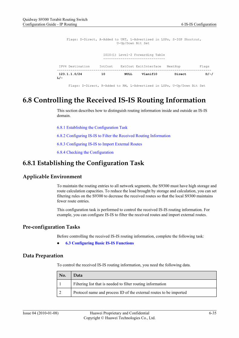
Flags: D-Direct, A-Added to URT, L-Advertised in LSPs, S-IGP Shortcut, U-Up/Down Bit Set ISIS(1) Level-2 Forwarding Table -------------------------------- IPV4 Destination IntCost ExtCost ExitInterface NextHop Flags-------------------------------------------------------------------------------- 123.1.1.0/24 10 NULL Vlanif10 Direct D/-/L/- Flags: D-Direct, R-Added to RM, L-Advertised in LSPs, U-Up/Down Bit Set
6.8 Controlling the Received IS-IS Routing InformationThis section describes how to distinguish routing information inside and outside an IS-ISdomain.
6.8.1 Establishing the Configuration Task
6.8.2 Configuring IS-IS to Filter the Received Routing Information
6.8.3 Configuring IS-IS to Import External Routes
6.8.4 Checking the Configuration
6.8.1 Establishing the Configuration Task
Applicable Environment
To maintain the routing entries to all network segments, the S9300 must have high storage androute calculation capacities. To reduce the load brought by storage and calculation, you can setfiltering rules on the S9300 to decrease the received routes so that the local S9300 maintainsfewer route entries.
This configuration task is performed to control the received IS-IS routing information. Forexample, you can configure IS-IS to filter the received routes and import external routes.
Pre-configuration Tasks
Before controlling the received IS-IS routing information, complete the following task:l 6.3 Configuring Basic IS-IS Functions
Data Preparation
To control the received IS-IS routing information, you need the following data.
No. Data
1 Filtering list that is needed to filter routing information
2 Protocol name and process ID of the external routes to be imported
Quidway S9300 Terabit Routing SwitchConfiguration Guide - IP Routing 6 IS-IS Configuration
Issue 04 (2010-01-08) Huawei Proprietary and ConfidentialCopyright © Huawei Technologies Co., Ltd.
6-35

6.8.2 Configuring IS-IS to Filter the Received Routing Information
ContextDo as follows on the S9300.
Procedure
Step 1 Run:system-view
The system view is displayed.
Step 2 Run:isis [ process-id ]
The IS-IS view is displayed.
Step 3 Run:filter-policy { acl-number | ip-prefix ip-prefix-name | route-policy route-policy-name } import
IS-IS is configured to filter the received routing information.
----End
6.8.3 Configuring IS-IS to Import External Routes
ContextIS-IS processes the routes discovered by other routing protocols as external routes. When IS-ISimports routes from other protocols, you can specify the default cost of the imported routes.
If the route level is not specified in the import-route command, routes are imported to Level-2routing tables by default.
Do as follows on the S9300.
Procedure
Step 1 Run:system-view
The system view is displayed.
Step 2 Run:isis [ process-id ]
The IS-IS view is displayed.
Step 3 Run:import-route protocol [ process-id ] [ cost-type { external | internal } | cost cost |tag tag | route-policy route-policy-name | [ level-1 | level-2 | level-1-2 ] ] *
IS-IS is configured to import routes from other routing protocols.
6 IS-IS ConfigurationQuidway S9300 Terabit Routing Switch
Configuration Guide - IP Routing
6-36 Huawei Proprietary and ConfidentialCopyright © Huawei Technologies Co., Ltd.
Issue 04 (2010-01-08)

Step 4 Run:filter-policy { acl-number | ip-prefix ip-prefix -name | route-policy route-policy-name } export [ protocol [ process-id ] ]
IS-IS is configured to filter the imported routes before advertising them.
----End
6.8.4 Checking the Configuration
PrerequisiteAll the configuration for controlling the receiving of IS-IS routing information are complete.
Procedurel Run the display isis lsdb [ { level-1 | level-2 } | { local | lsp-id | is-name symbolic-
name } | process-id | verbose ] * command to check the IS-IS LSDB.l Run the display isis route [ process-id ] [ ipv4 ] [ {ip-address [ mask | mask-length ] } |
{ level-1 | level-2 } | verbose ] * or display isis process-id route [ ipv4 ] [ {ip-address[ mask | mask-length ] } | { level-1 | level-2 } | verbose ] * command to check the IS-ISrouting table.
----End
ExampleRun the display isis route command, and you can find that the global cost of IS-IS process 1on the local S9300 changes to 30 and the process imports a static route pointing to 169.1.1.0/24.
<Quidway> display isis route ISIS(1) Level-2 Forwarding Table -------------------------------- IPV4 Destination IntCost ExtCost ExitInterface NextHop Flags-------------------------------------------------------------------------------- 123.1.1.0/24 30 NULL Vlanif10 Direct D/-/L/- 20.0.0.0/24 30 NULL Vlanif20 Direct D/-/L/- Flags: D-Direct, A-Added to URT, L-Advertised in LSPs, S-IGP Shortcut, U-Up/Down Bit Set ISIS(1) Level-2 Redistribute Table ---------------------------------- Type IPV4 Destination IntCost ExtCost Tag-------------------------------------------------------------------------------- S 169.1.1.0/24 0 NULL Type: D-Direct, I-ISIS, S-Static, O-OSPF, B-BGP, R-RIP
6.9 Adjusting and Optimizing the IS-IS NetworkThis section describes how to configure the status of an IS-IS interface and set the LSPparameters.
6.9.1 Establishing the Configuration Task
6.9.2 (Optional) Setting the Level of an IS-IS Interface
Quidway S9300 Terabit Routing SwitchConfiguration Guide - IP Routing 6 IS-IS Configuration
Issue 04 (2010-01-08) Huawei Proprietary and ConfidentialCopyright © Huawei Technologies Co., Ltd.
6-37

6.9.3 Suppressing an IS-IS Interface
6.9.4 Setting SPF Parameters
6.9.5 Enabling LSP Fast Flooding
6.9.6 Configuring IS-IS Dynamic Host Name Mapping
6.9.7 Configuring the LSP Overload Bit
6.9.8 Enabling Output of the Adjacency Status
6.9.9 Checking the Configuration
6.9.1 Establishing the Configuration Task
Applicable EnvironmentThis section describes how to optimize IS-IS networks. Optimizing an IS-IS network involves:l Setting the level and status of IS-IS interfaces to decrease the flooding of broadcast packets
on the networkl Adjusting SPF parameters to lower resource consumption caused by frequent changes on
the networkl Configuring the LSP fast flooding and overload bit to increase the convergence speed of
the network and reduce the packets lost during the convergencel Configuring IS-IS dynamic host name mapping to meet users' requirements on easy
maintenance
Pre-configuration TasksBefore adjusting and optimizing the IS-IS network, complete the following task:l 6.3 Configuring Basic IS-IS Functions
Data PreparationTo adjusting and optimize the IS-IS network, you need the following data.
No. Data
1 Level of the IS-IS interface
2 Parameters of the SPF timer
3 Mapping between the system ID and host name
6.9.2 (Optional) Setting the Level of an IS-IS Interface
ContextDo as follows on the S9300.
6 IS-IS ConfigurationQuidway S9300 Terabit Routing Switch
Configuration Guide - IP Routing
6-38 Huawei Proprietary and ConfidentialCopyright © Huawei Technologies Co., Ltd.
Issue 04 (2010-01-08)

ProcedureStep 1 Run:
system-view
The system view is displayed.
Step 2 Run:interface interface-type interface-number
The interface view is displayed.
Step 3 Run:isis circuit-level [ level-1 | level-1-2 | level-2 ]
The level of the interface is set.
By default, the level of an interface is Level-1-2.
If the local S9300 is a Level-1-2 device and needs to establish a Level-1 or Level-2 relationshipwith the peer, this command can be used to configure the interface to send and receive only theHello packets at this level. Only one type of Hello packets are sent and received on the point-to-point (P2P) link. In this manner, excessive packets prevented and bandwidth is also saved.
NOTE
Changing the level of an IS-IS interface is valid only when the level of the IS-IS process is Level-1-2. Ifthe process is not Level-1-2, the level of the IS-IS process determines the level of the established adjacency.
----End
6.9.3 Suppressing an IS-IS Interface
ContextDo as follows on the S9300.
ProcedureStep 1 Run:
system-view
The system view is displayed.
Step 2 Run:interface interface-type interface-number
The interface view is displayed.
Step 3 Run:isis silent
The interface is suppressed.
----End
PostrequisiteWhen an IS-IS AS is connected to other ASs, you need to enable IS-IS on the border interfaceso that the S9300s within the AS can learn the routes destined for the border interface. The
Quidway S9300 Terabit Routing SwitchConfiguration Guide - IP Routing 6 IS-IS Configuration
Issue 04 (2010-01-08) Huawei Proprietary and ConfidentialCopyright © Huawei Technologies Co., Ltd.
6-39

interface, however, sends IS-IS Hello packets to the network segment where it is located, whichis unnecessary. To solve this problem, you can run the isis silent command to suppress the IS-IS interface.
When an IS-IS interface is configured as a silent interface, the interface does not receive or sendIS-IS packets. The routes within the network segment of the interface, however, can still beadvertised to other intermediate systems in the domain.
NOTE
If the status of the IS-IS protocol on the interfaces in the area is Down, the intermediate systems within thearea cannot learn the outbound routes.
6.9.4 Setting SPF Parameters
ContextDo as follows on the S9300.
Procedurel Setting the SPF intelligent timer
According to the IS-IS protocol, the S9300 needs to recalculate the optimal route when theLSDB changes. Frequent route calculation consumes a lot of system resources and lowersthe system performance. Delaying SPF calculation improves the efficiency of routecalculation to a certain extent and reduces the resource consumption. A long delay,however, slows down the network convergence.
The SPF intelligent timer is a solution to the problem. It can adjust the delay according tothe frequency of changes in the LSDB. The interval for generating the first LSP is initial-interval. Then, the interval increases by incremental-interval every time the networkchanges until the interval reaches the value of max-interval. When the interval reaches thevalue of max-interval three times, it drops to initial-interval.
1. Run:system-view
The system view is displayed.2. Run:
isis [ process-id ]
The IS-IS view is displayed.3. Run:
timer spf max-interval [ init-interval [ incr-interval ] ]
The SPF intelligent timer is set.l Setting the duration of SPF calculation
When a large number of route entries (more than 150000) exist in a routing table, the SPFcalculation of IS-IS occupies the CPU for a long time. To avoid this, you can configure IS-IS to complete the SPF calculation in several times. You can also set the duration for eachSPF calculation. If an SPF calculation does not process all the routing information, thecalculation continues one second later.
1. Run:system-view
6 IS-IS ConfigurationQuidway S9300 Terabit Routing Switch
Configuration Guide - IP Routing
6-40 Huawei Proprietary and ConfidentialCopyright © Huawei Technologies Co., Ltd.
Issue 04 (2010-01-08)

The system view is displayed.2. Run:
isis [ process-id ]
The IS-IS view is displayed.3. Run:
spf-slice-size duration-time
The duration of SPF calculation is set.
----End
6.9.5 Enabling LSP Fast Flooding
ContextYou can run the flash-flood command to speed up the LSP flooding. You can specify the numberof LSPs flooded each time for all the interfaces that run the IS-IS process. If the number of LSPsto be sent is greater than the specified number, the LSPs of the specified number are floodedeach time. If you run the max-timer-interval command, the LSPs are flooded when the timerexpires.
Do as follows on the S9300.
Procedure
Step 1 Run:system-view
The system view is displayed.
Step 2 Run:isis [ process-id ]
The IS-IS view is displayed.
Step 3 Run:flash-flood [ { level-1 | level-2 } | lsp-count | max-timer-interval interval ] *
LSP fast flooding is enabled.
----End
6.9.6 Configuring IS-IS Dynamic Host Name Mapping
ContextDo as follows on the S9300.
Procedurel Configuring the host name for the S9300
You can run the is-name command configures a host name for the local IS-IS process andalso to enable the mapping of the system ID to the host name. The name configured isadvertised to neighbors through LSPs.
Quidway S9300 Terabit Routing SwitchConfiguration Guide - IP Routing 6 IS-IS Configuration
Issue 04 (2010-01-08) Huawei Proprietary and ConfidentialCopyright © Huawei Technologies Co., Ltd.
6-41

If you do not run this command, the system ID rather than the host name is displayed whenyou run display commands to display the IS-IS information.
1. Run:system-view
The system view is displayed.2. Run:
isis [ process-id ]
The IS-IS view is displayed.3. Run:
is-name symbolic-name
The host name of the local S9300 is configured.l Configuring the host name for the remote intermediate system
The is-name map command is used to configure a host name for a remote intermediatesystem on the S9300. Each system ID matches only one host name.
If the remote intermediate system is already configured with the dynamic host namemapping, the configuration on the remote intermediate system is adopted.
1. Run:system-view
The system view is displayed.2. Run:
isis [ process-id ]
The IS-IS view is displayed.3. Run:
is-name map system-id symbolic-name
The host name of the remote intermediate system is configured.l Configuring the host name for the DIS
1. Run:system-view
The system view is displayed.2. Run:
interface interface-type interface-number
The interface view is displayed.3. Run:
isis dis-name symbolic-name
The host name of the DIS is configured.
This configuration takes effect only on the DIS.
After you run the isis dis-name command on an interface, the configured host nameis added to LSPs of the pseudo node of the local S9300 and advertised to the networkconnected to the interface. In this manner, the configured host name is associated withthe system ID of the DIS.
6 IS-IS ConfigurationQuidway S9300 Terabit Routing Switch
Configuration Guide - IP Routing
6-42 Huawei Proprietary and ConfidentialCopyright © Huawei Technologies Co., Ltd.
Issue 04 (2010-01-08)

This command does not take effect on P2P interfaces.
----End
6.9.7 Configuring the LSP Overload Bit
ContextDo as follows on the S9300.
Procedure
Step 1 Run:system-view
The system view is displayed.
Step 2 Run:isis [ process-id ]
The IS-IS view is displayed.
Step 3 Run:set-overload [ on-startup [wait-for-bgp | start-from-nbr system-id ] [ timeout ] ] [ allow { interlevel | external } *]
The overload bit is set.
Although the LSPs configured with the overload bit are flooded in the network, the LSPs arenot used by other intermediate system to calculate the routes that pass through the intermediatesystem configured with the overload bit. After the S9300 is configured with the overload bit,other intermediate systems do not forward the packets to this S9300. The packets destined forthe S9300, however, are still sent to it.
If an intermediate system in an IS-IS area fails, the calculated routes in the entire area may beincorrect. To troubleshoot the intermediate system, you can set the overload flag bit for thisintermediate system to isolate it from the IS-IS network temporarily. Then, you can locate thefault easily.
----End
6.9.8 Enabling Output of the Adjacency Status
ContextWhen the terminal monitor is started, changes of IS-IS adjacencies are displayed on theconfiguration terminal if the output of the IS-IS adjacency status is enabled. When the output ofthe adjacency status is disabled, changes of IS-IS adjacencies are not displayed.
Do as follows on the S9300.
Procedure
Step 1 Run:system-view
Quidway S9300 Terabit Routing SwitchConfiguration Guide - IP Routing 6 IS-IS Configuration
Issue 04 (2010-01-08) Huawei Proprietary and ConfidentialCopyright © Huawei Technologies Co., Ltd.
6-43
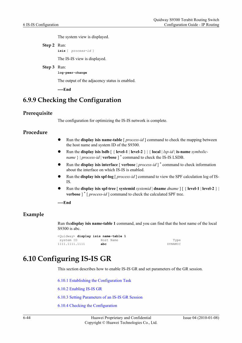
The system view is displayed.
Step 2 Run:isis [ process-id ]
The IS-IS view is displayed.
Step 3 Run:log-peer-change
The output of the adjacency status is enabled.
----End
6.9.9 Checking the Configuration
PrerequisiteThe configuration for optimizing the IS-IS network is complete.
Procedurel Run the display isis name-table [ process-id ] command to check the mapping between
the host name and system ID of the S9300.l Run the display isis lsdb [ { level-1 | level-2 } | { local | lsp-id | is-name symbolic-
name } | process-id | verbose ] * command to check the IS-IS LSDB.
l Run the display isis interface [ verbose | process-id ] * command to check informationabout the interface on which IS-IS is enabled.
l Run the display isis spf-log [ process-id ] command to view the SPF calculation log of IS-IS.
l Run the display isis spf-tree [ systemid systemid | dname dname ] [ { level-1 | level-2 } |verbose ] * [ process-id ] command to check the calculated SPF tree.
----End
ExampleRun thedisplay isis name-table 1 command, and you can find that the host name of the localS9300 is abc.
<Quidway> display isis name-table 1 system ID Host Name Type1111.1111.1111 abc DYNAMIC
6.10 Configuring IS-IS GRThis section describes how to enable IS-IS GR and set parameters of the GR session.
6.10.1 Establishing the Configuration Task
6.10.2 Enabling IS-IS GR
6.10.3 Setting Parameters of an IS-IS GR Session
6.10.4 Checking the Configuration
6 IS-IS ConfigurationQuidway S9300 Terabit Routing Switch
Configuration Guide - IP Routing
6-44 Huawei Proprietary and ConfidentialCopyright © Huawei Technologies Co., Ltd.
Issue 04 (2010-01-08)

6.10.1 Establishing the Configuration Task
Applicable EnvironmentWhen the IS-IS process on the local S9300 is restarted, the adjacencies between the S9300 andits neighbors are torn down. The LSPs of the S9300 are deleted from the LSDBs of otherintermediate systems, which causes route flapping and even temporary interruption. Thisincreases the load brought by route calculation and leads to the loss of packets.
You can configure IS-IS GR to solve this problem. Enabled with IS-IS GR, the S9300 canadvertise its restart status to neighbors and permit neighbors to maintain the adjacencies so thatpackets can be forwarded continuously.
The advantages of IS-IS GR are as follows:l When IS-IS is restarted, the S9300 resend connection requests to its neighbors. The
adjacencies are retained.l Before LSPs are generated, GR minimizes the interference brought to the network by the
delay for synchronizing LSDBs.l If the S9300 is started for the first time, the S9300 sets the overload bit in LSPs until the
LSDB synchronization is complete. This prevents loops on the network.
Pre-configuration TasksBefore configuring IS-IS GR, complete the following task:l 6.3 Configuring Basic IS-IS Functions
Data PreparationTo configure IS-IS GR, you need the following data.
No. Data
1 IS-IS process ID
2 Interval for re-establishing GR sessions
3 Whether to suppress the advertisement of adjacency status when the GR restarter isrestarted
6.10.2 Enabling IS-IS GR
ContextDo as follows on the S9300 on which GR needs to be enabled.
Procedure
Step 1 Run:system-view
Quidway S9300 Terabit Routing SwitchConfiguration Guide - IP Routing 6 IS-IS Configuration
Issue 04 (2010-01-08) Huawei Proprietary and ConfidentialCopyright © Huawei Technologies Co., Ltd.
6-45

The system view is displayed.
Step 2 Run:isis [ process-id ]
The IS-IS view is displayed.
Step 3 Run:graceful-restart
IS-IS GR is enabled.
By default, IS-IS GR is disabled.
----End
6.10.3 Setting Parameters of an IS-IS GR Session
Context
Do as follows on the S9300 on which GR needs to be enabled.
Procedure
Step 1 Run:system-view
The system view is displayed.
Step 2 Run:isis [ process-id ]
The IS-IS view is displayed.
Step 3 (Optional) Run:graceful-restart interval timer
The interval for re-establishing a GR session is set.
By default, the interval for re-establishing a GR session is 300 seconds.
Step 4 Run:graceful-restart suppress-sa
The GR restarter is configured not to advertise the adjacency status.
The GR restarter, namely the S9300, sets the Suppress-Advertisement (SA) bit in Hello packets,requesting neighbors not to advertise the adjacency status during a specified time period. Afterthe LSDB of the S9300 is synchronized, the SA bit is deleted from Hello packets. This featurecan effectively avoid the black hole effect caused by the received or sent LSPs during the GR.
If you do not want the S9300 to set the SA bit in Hello packets, run the undo graceful-restartsuppress-sa command.
By default, the SA bit is not suppressed.
----End
6 IS-IS ConfigurationQuidway S9300 Terabit Routing Switch
Configuration Guide - IP Routing
6-46 Huawei Proprietary and ConfidentialCopyright © Huawei Technologies Co., Ltd.
Issue 04 (2010-01-08)

6.10.4 Checking the Configuration
Prerequisite
The configuration of IS-IS GR is complete.
NOTE
If an MPLS TE tunnel is configured on the S9300 and the S9300 learns the route to the destination addressof the tunnel through IS-IS, then you need to configure the RSVP GR function on the tunnel.
Procedurel Run the display isis graceful-restart status [ level-1 | level-2 ] [ process-id ] command to
check the status of IS-IS GR.
----End
Example
Run the display isis graceful-restart status command, and you can find that GR is enabled forIS-IS process 1 and all GR parameters adopt default values.
<Quidway> display isis graceful-restart status Restart information for ISIS(1) ------------------------------- IS-IS(1) Level-1 Restart StatusRestart Interval: 300SA Bit Supported Total Number of Interfaces = 1 Restart Status: RESTART COMPLETE IS-IS(1) Level-2 Restart StatusRestart Interval: 300SA Bit Supported Total Number of Interfaces = 1 Restart Status: RESTART COMPLETE
6.11 Configuring BFD for IS-ISThis section describes how to implement fast convergence of the IS-IS network by using BFD.
6.11.1 Establishing the Configuration Task
6.11.2 Configuring Single-Hop BFD
6.11.3 Enabling IS-IS Fast Detection
6.11.4 Enabling the BFD Feature Globally
6.11.5 Configuring Dynamic BFD of an IS-IS Process
6.11.6 Disabling Dynamic Creation of BFD Sessions
6.11.7 Configuring the BFD Feature for a Specified Interface
6.11.8 Checking the Configuration
Quidway S9300 Terabit Routing SwitchConfiguration Guide - IP Routing 6 IS-IS Configuration
Issue 04 (2010-01-08) Huawei Proprietary and ConfidentialCopyright © Huawei Technologies Co., Ltd.
6-47

6.11.1 Establishing the Configuration Task
Applicable EnvironmentTo increase IS-IS convergence speed when the link status changes, you can configure the BFDfeature on the IS-IS link.
Configure BFD according to the actual network environment. If the time parameters are notcorrectly set, network flapping may occur.
Pre-configuration TasksBefore configuring BFD for IS-IS, complete the following task:
l Configuring Basic IS-IS Functions
Data PreparationTo configure BFD for IS-IS, you need the following data.
No. Data
1 ID of the IS-IS process that is enabled with BFD
2 Type and ID of the interface where the BFD feature is enabled
3 Value of the BFD session parameters
6.11.2 Configuring Single-Hop BFD
ContextNOTE
Before configuring BFD for IS-IS, enable BFD one-hop detection.
Do as follows on both S9300s between which the BFD session is established:
Procedure
Step 1 Run:system-view
The system view is displayed.
Step 2 Run:bfd
BFD is enabled on the local S9300.
Step 3 Run:quit
The system view is displayed.
6 IS-IS ConfigurationQuidway S9300 Terabit Routing Switch
Configuration Guide - IP Routing
6-48 Huawei Proprietary and ConfidentialCopyright © Huawei Technologies Co., Ltd.
Issue 04 (2010-01-08)

Step 4 Run:interface interface-type interface-number
The interface view is displayed.
Step 5 Run:isis enable
IS-IS is enabled on the interface.
Step 6 Run:isis bfd static
BFD is enabled on the interface.
Step 7 Run:quit
The system view is displayed.
Step 8 Run:bfd cfg-name bind peer-ip ip-address [ interface interface-type interface-number ]
The BFD binding is configured.
This command specifies the peer IP address and the local interface. BFD detects a single-hoplink, that is, the route with the specified interface as the outgoing interface and the peer addressas the next hop address.
Step 9 Run the following commands to set BFD discriminators:l Run:
discriminator local discr-valueThe local discriminator is set.
l Run:discriminator remote discr-valueThe remote discriminator is set.
The local discriminator of one device must be the same as the remote discriminator of the peerdevice; otherwise, the BFD session cannot be established. In addition, discriminators cannot bechanged after being set.
NOTE
The local discriminator of the local router is the same as the remote discriminator of the remote router, andthe remote discriminator of the local router is the same as the local discriminator of the remote router.
Step 10 Run:commit
The configuration is submitted.
----End
6.11.3 Enabling IS-IS Fast Detection
ContextDo as follows on the S9300 that requires IS-IS fast detection.
Quidway S9300 Terabit Routing SwitchConfiguration Guide - IP Routing 6 IS-IS Configuration
Issue 04 (2010-01-08) Huawei Proprietary and ConfidentialCopyright © Huawei Technologies Co., Ltd.
6-49

Procedure
Step 1 Run:system-view
The system view is displayed.
Step 2 Run:interface interface-type interface-number
The interface view is displayed.
Step 3 Enable IS-IS fast detection as required:
l Run the isis bfd static command to enable static BFD. Then, run the isis fast-sense rprcommand to enable resilient packet ring (RPR) fast detection on an IS-IS interface.
l Run the isis fast-sense command to enable IS-IS fast detection.
NOTE
l The effect of the isis fast-sense command is equal to the effect of the isis bfd static command plus theisis fast-sense rpr command.
l The isis fast-sense rpr command is required only on the RPR interface.
----End
6.11.4 Enabling the BFD Feature Globally
Context
To dynamically set up a BFD session, you need to enable BFD globally. Do as follows on theS9300.
Procedure
Step 1 Run:system-view
The system view is displayed.
Step 2 Run:bfd
BFD is enabled globally.
----End
6.11.5 Configuring Dynamic BFD of an IS-IS Process
Context
To configure the BFD feature for all the interfaces that run an OSPF process, do as follows onboth the S9300s on which the BFD session needs to be established.
6 IS-IS ConfigurationQuidway S9300 Terabit Routing Switch
Configuration Guide - IP Routing
6-50 Huawei Proprietary and ConfidentialCopyright © Huawei Technologies Co., Ltd.
Issue 04 (2010-01-08)

Procedure
Step 1 Run:system-view
The system view is displayed.
Step 2 Run:isis [ process-id]
The IS-IS view is displayed.
Step 3 Run:bfd all-interfaces enable
The BFD feature is enabled to establish a BFD session.
When the BFD feature is enabled globally, IS-IS sets up a BFD session on all the interfaceswhose neighbor is in Up state by using default values of BFD parameters.
Step 4 (Optional) Run:bfd all-interfaces { min-rx-interval receive interval | min-tx-interval transmit interval | detect-multiplier multiplier value } *
BFD parameters are set.
----End
6.11.6 Disabling Dynamic Creation of BFD Sessions
Context
After you run the bfd all-interfaces enable command for an IS-IS process, On a broadcastnetwork, all IS-IS interfaces whose neighbor status is Up set up dynamic sessions between theDISs and the non-DISs. If you do not want to set up dynamic BFD sessions on an interface, doas follows on the S9300.
Procedure
Step 1 Run:system-view
The system view is displayed.
Step 2 Run:interface interface-type interface-number
The interface view is displayed.
Step 3 Run:isis bfd block
The interface cannot create BFD sessions dynamically.
----End
Quidway S9300 Terabit Routing SwitchConfiguration Guide - IP Routing 6 IS-IS Configuration
Issue 04 (2010-01-08) Huawei Proprietary and ConfidentialCopyright © Huawei Technologies Co., Ltd.
6-51

6.11.7 Configuring the BFD Feature for a Specified Interface
ContextTo configure dynamic BFD only on certain interfaces and not to enable dynamic BFD for IS-IS, or to configure the interfaces to fast detect link faults by using different dynamic BFD sessionparameters after dynamic BFD for IS-IS is configured, do as follows on the S9300s at both endsof the link.
Procedure
Step 1 Run:system-view
The system view is displayed.
Step 2 Run:interface interface-type interface-number
The interface view is displayed.
Step 3 Run:isis bfd enable
The BFD feature is enabled on the interface and a BFD session is established.
When global BFD is configured and the neighbor status is Up (on the broadcast network, DISis in the Up state), the default values of BFD parameters are used to dynamically set up a BFDsession.
Step 4 (Optional) Run:isis bfd { min-rx-interval receive-interval | min-tx-interval transmit-interval | detect-multiplier multiplier-value } *
BFD parameters are set.
NOTE
The BFD feature configured on an interface has a higher priority than the BFD feature configured for anIS-IS process. That is, the BFD session established on an interface uses the parameters set on the interface.
----End
6.11.8 Checking the Configuration
PrerequisiteThe configuration of BFD for IS-IS is complete.
Procedurel Run the display isis [ process-id | vpn-instance vpn-instance-name ] bfd session { peer
ipaddress | all } command to check information about a BFD session.l Run the display isis [ process-id ] bfd interface command to check the configuration of
the BFD feature configured on an interface.
----End
6 IS-IS ConfigurationQuidway S9300 Terabit Routing Switch
Configuration Guide - IP Routing
6-52 Huawei Proprietary and ConfidentialCopyright © Huawei Technologies Co., Ltd.
Issue 04 (2010-01-08)

ExampleAfter enabling BFD on both ends of the link, run the display isis [ process-id | vpn-instancevpn-instance-name ] bfd session { peer ipaddress | all } command. You can see that the BFDstatus is Up. The following is an example.
<Quidway> display isis bfd session all
BFD session information for ISIS(1) -----------------------------------
Peer System ID : 0000.0000.0002 Interface : Vlanif10TX : 1000 BFD State : up Peer IP Address : 1.1.1.2RX : 1000 LocDis : 8192 Local IP Address: 1.1.1.1Multiplier : 3 RemDis : 8192 Type : L2Diag : No diagnostic information
Run the display isis [ process-id ] bfd interface command, and you can view all the interfacesenabled with BFD and the values of the BFD session parameters on the interface.
<Quidway> display isis bfd interface
BFD information of interface for ISIS(1) ----------------------------------------- Interface BFD.State Min-Tx Min-Rx Mul Vlanif10 enable 1000 1000 3 Total interfaces: 1 Total bfd enabled interfaces: 1
6.12 Configuring IS-IS IPv6This section describes how to interconnect the IPv6 networks through IS-IS.
6.12.1 Establishing the Configuration Task
6.12.2 Enabling IPv6 on an IS-IS Process
6.12.3 Enabling IPv6 on an IS-IS Interface
6.12.4 Configuring the IPv6 Route Cost on an Interface
6.12.5 Configuring the Attributes of IS-IS IPv6 Routes
6.12.6 Checking the Configuration
6.12.1 Establishing the Configuration Task
Applicable EnvironmentIS-IS supports multiple types networking layer protocols, including IPv6. In an IPv6 network,you can implement interconnection by configuring IS-IS.
The functions and configurations of most attributes of IS-IS IPv6 routes are similar to those ofIS-IS IPv4 routes. This section describes only the configuration procedures.
Pre-configuration TasksBefore configure IS-IS IPv6, complete the following tasks:
l Enabling global IPv6 in the system view
Quidway S9300 Terabit Routing SwitchConfiguration Guide - IP Routing 6 IS-IS Configuration
Issue 04 (2010-01-08) Huawei Proprietary and ConfidentialCopyright © Huawei Technologies Co., Ltd.
6-53

l Configuring IPv6 addresses of interfaces to make neighboring nodes reachable
l 6.3.2 Starting an IS-IS Processl 6.3.3 Configuring a NET
Data PreparationTo configure IS-IS IPv6, you need the following data.
No. Data
1 Preference value of IS-IS
2 Aggregated IS-IS route
3 The filtering list that is needed to filter the IS-IS routing information and the nameof the routing policy
4 The name and the process number of the external IPv6 routing protocol to be imported
6.12.2 Enabling IPv6 on an IS-IS Process
ContextTo enable IS-IS, you must first create an IS-IS process and then enable IPv6.
Do as follows on the S9300 that runs IS-IS:
ProcedureStep 1 Run:
system-view
The system view is displayed.
Step 2 Run:isis [ process-id ]
An IS-IS process is enabled and the IS-IS view is displayed.
Step 3 Run:ipv6 enable
IPv6 is enabled on the IS-IS process.
----End
6.12.3 Enabling IPv6 on an IS-IS Interface
ContextAfter IPv6 is enabled in the IS-IS process, you also need to enable IPv6 of a specified IS-ISinterface.
Do as follows on the S9300 that runs IS-IS:
6 IS-IS ConfigurationQuidway S9300 Terabit Routing Switch
Configuration Guide - IP Routing
6-54 Huawei Proprietary and ConfidentialCopyright © Huawei Technologies Co., Ltd.
Issue 04 (2010-01-08)

Procedure
Step 1 Run:system-view
The system view is displayed.
Step 2 Run:interface interface-type interface-number
The interface view is displayed.
Step 3 Run:isis ipv6 enable [ process-id ]
IS-IS IPv6 is enabled on the interfaces.
----End
6.12.4 Configuring the IPv6 Route Cost on an Interface
ContextDo as follows on the S9300s that runs IS-IS:
Procedure
Step 1 Run:system-view
The system view is displayed.
Step 2 Run:interface interface-type interface-number
The interface view is displayed.
Step 3 Run:isis ipv6 cost cost-value
The IPv6 route cost of the link is set.
The cost is used for SPF calculation in an IPv6 topology.
----End
6.12.5 Configuring the Attributes of IS-IS IPv6 Routes
ContextTo perform IPv6-related configurations, you must enable IPv6.
Do as follows on the S9300 that runs IS-IS:
Procedurel Configuring the Preference of IS-IS IPv6 Routes
Quidway S9300 Terabit Routing SwitchConfiguration Guide - IP Routing 6 IS-IS Configuration
Issue 04 (2010-01-08) Huawei Proprietary and ConfidentialCopyright © Huawei Technologies Co., Ltd.
6-55

1. Run:system-view
The system view is displayed.2. Run:
isis [ process-id ]
The IS-IS view is displayed.3. Run:
ipv6 preference { preference | route-policy route-policy-name } *
The preference of IS-IS IPv6 routes is set.l Configuring IS-IS IPv6 Route Aggregation
1. Run:system-view
The system view is displayed.2. Run:
isis [ process-id ]
The IS-IS view is displayed.3. Run:
ipv6 summary ipv6-address prefix-length [ avoid-feedback | generate_null0_route | tag tag | [ level-1 | level-1-2 | level-2 ]] *
IS-IS IPv6 route aggregation is configured.l Configuring IS-IS to Generate Default IPv6 Routes
1. Run:system-view
The system view is displayed.2. Run:
isis [ process-id ]
The IS-IS view is displayed.3. Run:
ipv6 default-route-advertise [ always | match default | route-policy route-policy-name ] [ cost cost ] [ tag tag ] [ level-1 | level-2 | level-1-2 ] [ avoid-learning ]
IS-IS is configured to generate default IPv6 routes.
After this command is used, IS-IS generates default IPv6 routes and advertises themto IS-IS S9300s of related levels.
When IS-IS is configured to generate default IPv6 routes, the level of default IPv6routes is Level-2 if no level is specified.
l Configuring IS-IS to Filter the Received Routes to Determine Which Routes Are to BeAdded to the IP Routing Table1. Run:
system-view
The system view is displayed.2. Run:
6 IS-IS ConfigurationQuidway S9300 Terabit Routing Switch
Configuration Guide - IP Routing
6-56 Huawei Proprietary and ConfidentialCopyright © Huawei Technologies Co., Ltd.
Issue 04 (2010-01-08)

isis [ process-id ]
The IS-IS view is displayed.3. Run:
ipv6 filter-policy { acl6-number | ipv6-prefix ipv6-prefix-name | route-policy route-policy-name } import
IS-IS is configured to filter received IPv6 routes to determine which routes to be addedto the IPv6 routing table.
l Configuring IS-IS to Import IPv6 Routes of Other Protocols1. Run:
system-view
The system view is displayed.2. Run:
isis [ process-id ]
The IS-IS view is displayed.3. Run:
ipv6 import-route protocol [ process-id ] [ cost cost ] [ tag tag ] [ route-policy route-policy-name ] [ level-1 | level-2 | level-1-2 ]
IS-IS is configured to import IPv6 routes of other protocols.4. Run:
ipv6 filter-policy { acl6-number | ipv6-prefix ipv6-prefix-name | route-policy route-policy-name } export [ protocol [ process-id ] ]
IS-IS is enabled to filter imported IPv6 routes when advertising them to other S9300s.
The ipv6 filter-policy export command usually works with the ipv6 import-routecommand. It filters only imported IPv6 routes to be advertised to other S9300s. Ifprotocol is not specified, the command filters the IPv6 routes imported from all theprotocols. If protocol is specified, it filters only the IPv6 routes imported from a certainprotocol.
If no level is specified in the ipv6 import-route command, IPv6 routes are importedto the Level-2 routing table.
l Configuring IS-IS Route Leaking1. Run:
system-view
The system view is displayed.2. Run:
isis [ process-id ]
The IS-IS view is displayed.3. Run:
ipv6 import-route isis level-2 into level-1 [ filter-policy { acl6-number | ipv6-prefix ipv6-prefix-name | route-policy route-policy-name } ] [ tag tag ]
IS-IS IPv6 route leaking is enabled. IPv6 routes in Level-2 areas and other Level-1areas are leaked to Level-1 area where the Level-1-2 S9300 resides. This commandis used on Level-1-2 S9300s connected to Level-2 areas.
Quidway S9300 Terabit Routing SwitchConfiguration Guide - IP Routing 6 IS-IS Configuration
Issue 04 (2010-01-08) Huawei Proprietary and ConfidentialCopyright © Huawei Technologies Co., Ltd.
6-57

NOTE
By default, IS-IS IPv6 routes in Level-1 areas are leaked to Level-2 areas.
----End
6.12.6 Checking the Configuration
Procedurel Run display isis interface [ [ verbose | traffic-eng ] * | tunnel ] [ process-id | [ vpn-
instance { vpn-instance-name | default } | vpn6-instance { vpn6-instance-name |default } ] * ] command to check information about the IS-IS interface.
l Run display isis lsdb [ level-1 | level-2 ] [ verbose ] [ local | lsp-id | is-name symbolic-name ] [ process-id | [ vpn-instance { vpn-instance-name | default } | vpn6-instance{ vpn6-instance-name | default } ] * ] command to check information about the LSDB.
l Run display isis peer [ verbose ] [ process-id | [ vpn-instance { vpn-instance-name |default } | vpn6-instance { vpn6-instance-name | default } ] * ] command to checkinformation about the IS-IS neighbor.
l Run display isis route [ process-id | [ vpn-instance { vpn-instance-name | default } | vpn6-instance { vpn6-instance-name | default } ] * ] [ [ [ ipv4 ] [ verbose | [ level-1 | level-2 ] |ip-address [ mask | mask-length ] ] * ] | [ ipv6 [ verbose | [ level-1 | level-2 ] | ipv6-addressprefix-length ] * ] ] command to check the IS-IS routing information.
l Check the statistics of the IS-IS process.– display isis statistics [ level-1 | level-2 | level-1-2 ] [ process-id | [ vpn-instance { vpn-
instance-name | default } | vpn6-instance { vpn6-instance-name | default } ] * ]– display isis statistics packet [ interface interface-type interface-number ]
– display isis process-id statistics [ level-1 | level-2 | level-1-2 | packet ]
----End
ExampleRun the display isis interface verbose command, and you can find that the cost of the IPv6route on GigabitEthernet 6/0/0 is 15.
<Quidway> display isis interface verbose Interface information for ISIS(1) --------------------------------- Interface Id IPV4.State IPV6.State MTU Type DIS GigabitEthernet6/0/0 001 Down Up 1497 L1/L2 No/No Description : HUAWEI, Quidway Series, GigabitEthernet6/0/0 Interface Circuit MT State : Standard SNPA Address : 00e0-c72d-da01 IP Address : IPV6 Link Local Address : FF80::FFE0:FFFF:FE2D:DA01 IPV6 Global Address(es) : 2001::1/64 Csnp Timer Value : L1 10 L2 10 Hello Timer Value : L1 10 L2 10 DIS Hello Timer Value : L1 3 L2 3 Hello Multiplier Value : L1 3 L2 3 LSP-Throttle Timer : L12 50 Cost : L1 10 L2 10 Ipv6 Cost : L1 15 L2 15 Priority : L1 64 L2 64 Retransmit Timer Value : L12 5
6 IS-IS ConfigurationQuidway S9300 Terabit Routing Switch
Configuration Guide - IP Routing
6-58 Huawei Proprietary and ConfidentialCopyright © Huawei Technologies Co., Ltd.
Issue 04 (2010-01-08)

Bandwidth-Value : Low 100000000 High 0 Static Bfd : NO Dynamic Bfd : NO Fast-Sense Rpr : NO
6.13 Configuring IS-IS AuthenticationThis section describes how to configure the authentication mode and authentication passwordfor an IS-IS network.
6.13.1 Establishing the Configuration Task
6.13.2 Configuring Area Authentication and Routing Domain Authentication
6.13.3 Configuring the Interface Authentication
6.13.4 Checking the Configuration
6.13.1 Establishing the Configuration Task
Applicable EnvironmentOn a network that requires high security, you can configure the IS-IS authentication functions.Authentication improves security of the network to meet users' requirements on security. TheIS-IS authentication functions are classified into area authentication, routing domainauthentication, and interface authentication.
Pre-configuration TasksBefore improving security of an IS-IS network, complete the following task:l 6.3 Configuring Basic IS-IS Functions
Data PreparationTo improve security of an IS-IS network, you need the following data.
No. Data
1 Authentication mode and password
6.13.2 Configuring Area Authentication and Routing DomainAuthentication
ContextIf area authentication is required, the password for area authentication is encapsulated into theLevel-1 LSP, CSNP and PSNP packets in the specified mode. The intermediate systems in anarea must adopt the same area authentication mode and password so that IS-IS packets can benormally flooded.
Similarly, for routing domain authentication, the password is encapsulated into the Level-2 LSP,CSNP and PSNP packets in the specified mode. The intermediate systems in a domain must
Quidway S9300 Terabit Routing SwitchConfiguration Guide - IP Routing 6 IS-IS Configuration
Issue 04 (2010-01-08) Huawei Proprietary and ConfidentialCopyright © Huawei Technologies Co., Ltd.
6-59

adopt the same domain authentication mode and password so that IS-IS packets can be normallyflooded.
Whether IS-IS packets pass the area or domain authentication does not affect the creation ofLevel-1 or Level-2 adjacencies.
Do as follows on the S9300 on a network that requires high security.
Procedure
Step 1 Run:system-view
The system view is displayed.
Step 2 Run:isis [ process-id ]
The IS-IS view is displayed.
Step 3 Run:area-authentication-mode { simple password | md5 password-key } [ ip | osi ]
The area authentication mode is configured.
Step 4 Run:domain-authentication-mode { simple password | md5 password-key } [ ip | osi ]
The routing domain authentication mode is configured.
----End
6.13.3 Configuring the Interface Authentication
ContextDo as follows on the S9300 on a network that requires high security.
The authentication function configured on an interface applies to Hello packets to confirm thevalidity and correctness of the neighbor relationship. The neighbor relationship can beestablished only after the Hello packets pass the authentication.
Procedure
Step 1 Run:system-view
The system view is displayed.
Step 2 Run:interface interface-type interface-number
The interface view is displayed.
Step 3 Run:isis authentication-mode { simple password | md5 password-key } [ level-1 | level-2 ] [ ip | osi ]
The authentication mode and password are configured for the interface.
6 IS-IS ConfigurationQuidway S9300 Terabit Routing Switch
Configuration Guide - IP Routing
6-60 Huawei Proprietary and ConfidentialCopyright © Huawei Technologies Co., Ltd.
Issue 04 (2010-01-08)

NOTE
The level-1 and level-2 keywords are displayed only on Ethernet interfaces. If no level is specified, thesame authentication mode and password are adopted for Level-1 and Level-2 Hello packets by default.
----End
6.13.4 Checking the Configuration
PrerequisiteThe authentication function is configured for the IS-IS network.
Procedurel Run the display isis peer [ verbose ] [ process-id ] command to check information about
the IS-IS neighbors.
l Run the display isis brief [ process-id ] command to check brief information about an IS-IS process.
----End
6.14 Maintaining IS-ISThis section describes how to clear data of an IS-IS process and debugging the IS-IS process.
6.14.1 Clearing Data of an IS-IS Process
6.14.2 Resetting a Specific IS-IS Neighbor
6.14.3 Debugging IS-IS
6.14.1 Clearing Data of an IS-IS Process
Context
CAUTIONAfter you clear data of an IS-IS process, all the previous topology information and adjacenciesare cleared. So, confirm the action before you run the command.
To clear the IS-IS data, run the following reset command in the user view.
Procedurel Run the reset isis all [ process-id ] command to clear data of the IS-IS process.
----End
Quidway S9300 Terabit Routing SwitchConfiguration Guide - IP Routing 6 IS-IS Configuration
Issue 04 (2010-01-08) Huawei Proprietary and ConfidentialCopyright © Huawei Technologies Co., Ltd.
6-61

6.14.2 Resetting a Specific IS-IS Neighbor
Context
CAUTIONThe specified IS-IS neighbor relationship is terminated after you run the reset isis command toreset a specific IS-IS neighbor. So, confirm the action before you run the command.
After modifying the IS-IS routing policy, you need to reset the specified IS-IS neighbor to makethe modification take effect. To reset a specified IS-IS neighbor, run the following resetcommand in the user view.
Procedurel Run thereset isis peer system-id [ process-id ] command to reset an IS-IS neighbor.
----End
6.14.3 Debugging IS-IS
Context
CAUTIONDebugging affects the performance of the system. So, after debugging, run the undo debuggingall command to disable it immediately.
When an IS-IS fault occurs, run the following debugging commands in the user view to debugIS-IS and locate the fault.
Procedurel Run the debugging isis all [ process-id ] command to enable all types of debugging.l Run the debugging isis adjacency [ process-id ] command to enable debugging of IS-IS
adjacencies.l Run the debugging isis authentication-error [ process-id ] command to enable debugging
of authentication errors.l Run the debugging isis checksum-error [ process-id ] command to enable debugging of
checksum errors.l Run the debugging isis circuit-information [ process-id ] command to enable debugging
of links of IS-IS interfaces.l Run the debugging isis configuration-error [ process-id ] command to enable debugging
of configuration errors.l Run the debugging isis datalink-receiving-packet [ process-id ] command to enable
debugging of packet receiving on the link layer.
6 IS-IS ConfigurationQuidway S9300 Terabit Routing Switch
Configuration Guide - IP Routing
6-62 Huawei Proprietary and ConfidentialCopyright © Huawei Technologies Co., Ltd.
Issue 04 (2010-01-08)

l Run the debugging isis datalink-sending-packet [ process-id ] command to enabledebugging of packet sending on the link layer.
l Run the debugging isis event [ process-id ] command to enable debugging of IS-IS events.
l Run the debugging isis general-error [ process-id ] command to enable debugging ofgeneral errors of IS-IS.
l Run the debugging isis graceful-restart [ process-id ] command to enable debugging ofIS-IS GR events.
l Run the debugging isis ha-events [ process-id ] command to enable debugging of IS-ISHA events.
l Run the debugging isis interface-information [ process-id ] command to enabledebugging of IS-IS interfaces.
l Run the debugging isis memory-allocating [ process-id ] command to enable debuggingof memory allocation.
l Run the debugging isis miscellaneous-errors command to enable debugging ofmiscellaneous errors of IS-IS.
l Run the debugging isis receiving-packet-content [ process-id ] command to enabledebugging of contents of received packets.
l Run the debugging isis receiving-packet-regular-content [ process-id ] command toenable debugging of contents of received packets (displaying debugging information basedon the packet format).
l Run the debugging isis self-originate-update [ process-id ] command to enable debuggingof local update packets.
l Run the debugging isis sending-packet-content [ process-id ] command to enabledebugging of contents of sent packets.
l Run the debugging isis sending-packet-regular-content [ process-id ] command toenable debugging of contents of sent packets (displaying debugging information based onthe packet format).
l Run the debugging isis snp-packet [ process-id ] command to enable debugging of SNPpackets of IS-IS.
l Run the debugging isis spf-event [ process-id ] command to enable debugging of IS-ISSPF events.
l Run the debugging isis spf-prc [ process-id ] command to enable debugging of SPFprocesses during SPF calculation.
l Run the debugging isis spf-summary [ process-id ] command to enable debugging of SPFsummary.
l Run the debugging isis spf-timer [ process-id ] command to enable debugging of IS-ISSPF timers.
l Run the debugging isis task-error [ process-id ] command to enable debugging of taskerrors of IS-IS.
l Run the debugging isis timer [ process-id ] command to enable debugging of IS-IS timers.
l Run the debugging isis traffic-eng { advertisement | event } [ process-id ] command toenable debugging of TE.
l Run the debugging isis update-packet [ process-id ] command to enable debugging of IS-IS update packets.
Quidway S9300 Terabit Routing SwitchConfiguration Guide - IP Routing 6 IS-IS Configuration
Issue 04 (2010-01-08) Huawei Proprietary and ConfidentialCopyright © Huawei Technologies Co., Ltd.
6-63

l Run the debugging isis update-process [ process-id | ipv4-acl acl-number [ process-id ] ]command to enable debugging of the IS-IS update process.
----End
6.15 Configuration ExamplesThis section provides examples of IS-IS configuration.
6.15.1 Example for Configuring Basic IS-IS Functions
6.15.2 Example for Configuring IS-IS Route Aggregation
6.15.3 Example for Configuring the DIS Election
6.15.4 Example for Configuring IS-IS Load Balancing
6.15.5 Example for Configuring IS-IS GR
6.15.6 Example for Configuring BFD for IS-IS
6.15.7 Example for Configuring Basic IS-IS IPv6 Functions
6.15.1 Example for Configuring Basic IS-IS Functions
Networking RequirementsAs shown in Figure 6-3, the networking requirements are as follows:l S9300-A, S9300-B, S9300-C, and S9300-D belong to the same AS. The IS-IS protocol
runs on them to ensure connectivity on an IP network.l The area IDs of S9300-A, S9300-B, and S9300-C are all 10, and the area ID of S9300-D
is 20.l S9300-A and S9300X-B are Level-1 devices. S9300-C is a Level-1-2 device. S9300-D is
the Level-2 device.
6 IS-IS ConfigurationQuidway S9300 Terabit Routing Switch
Configuration Guide - IP Routing
6-64 Huawei Proprietary and ConfidentialCopyright © Huawei Technologies Co., Ltd.
Issue 04 (2010-01-08)

Figure 6-3 Networking diagram for configuring basic functions of IS-IS
IS-ISArea 10
IS-ISArea 20
S9300-AL1
L1
L1/2
L2
GE1/0/1
GE1/0/1
GE1/0/1GE1/0/3
GE1/0/2
GE1/0/2GE1/0/1
S9300-C
S9300-B
S9300-D
S9300 Interface VLANIF interface IP address
S9300-A GigabitEthernet1/0/1 VLANIF 10 10.1.1.2/24
S9300-B GigabitEthernet1/0/1 VLANIF 20 10.1.2.2/24
S9300-C GigabitEthernet1/0/1 VLANIF 10 10.1.1.1/24
S9300-C GigabitEthernet1/0/2 VLANIF 20 10.1.2.1/24
S9300-C GigabitEthernet1/0/3 VLANIF 30 192.168.0.1/24
S9300-D GigabitEthernet1/0/1 VLANIF 30 192.168.0.2/24
S9300-D GigabitEthernet1/0/2 VLANIF 40 172.16.1.1/24
Configuration Roadmap
The configuration roadmap is as follows:
1. Configure the VLANs that the physical interfaces belong to.2. Assign an IP address to each VLANIF interface.3. Run the IS-IS progress on each S9300, specify the network entity title, and configure the
level.4. Check the IS-IS database and routing table of each S9300.
Data Preparation
To complete the configuration, you need the following data:l ID of the VLAN that each interface belongs to, as shown in Figure 6-3
l IP address of each VLANIF interface, as shown in Figure 6-3
Quidway S9300 Terabit Routing SwitchConfiguration Guide - IP Routing 6 IS-IS Configuration
Issue 04 (2010-01-08) Huawei Proprietary and ConfidentialCopyright © Huawei Technologies Co., Ltd.
6-65

l System ID, level, and area ID of each S9300:– S9300-A: The system ID is 0000.0000.0001; the area ID is 10; the level is Level-1.
– S9300-B: The system ID is 0000.0000.0002; the area ID is 10; the level is Level-1.
– S9300-C: The system ID is 0000.0000.0003; the area ID is 10; the level is Level-1-2.
– S9300-D: The system ID is 0000.0000.0004; the area ID is 20; the level is Level-2.
Procedure
Step 1 Create VLANs and add corresponding interfaces to the VLANs.<Quidway> system-view[Quidway] sysname S9300-A[S9300-A] vlan 10[S9300-A-vlan10] quit[S9300-A] interface GigabitEthernet 1/0/1[S9300-A-GigabitEthernet1/0/1] port hybrid pvid vlan 10[S9300-A-GigabitEthernet1/0/1] port hybrid untagged vlan 10[S9300-A-GigabitEthernet1/0/1] quit
The configurations of S9300-B, S9300-C, and S9300-D are similar to the configuration ofS9300-A, and are not mentioned here.
Step 2 Assign an IP address to each VLANIF interface.[S9300-A] interface vlanif 10[S9300-A-Vlanif10] ip address 10.1.1.2 24[S9300-A-Vlanif10] quit
The configurations of S9300-B, S9300-C, and S9300-D are similar to the configuration ofS9300-A, and are not mentioned here.
Step 3 Run the IS-IS progress on each S9300, specify the network entity title, and configure the level.
# Configure S9300-A.[S9300-A] isis 1[S9300-A-isis-1] is-level level-1[S9300-A-isis-1] network-entity 10.0000.0000.0001.00[S9300-A-isis-1] quit
# Configure S9300-B.[S9300-B] isis 1[S9300-B-isis-1] is-level level-1[S9300-B-isis-1] network-entity 10.0000.0000.0002.00[S9300-B-isis-1] quit
# Configure S9300-C.[S9300-C] isis 1[S9300-C-isis-1] network-entity 10.0000.0000.0003.00[S9300-C-isis-1] quit
# Configure S9300-D.[S9300-D] isis 1[S9300-D-isis-1] is-level level-2[S9300-D-isis-1] network-entity 20.0000.0000.0004.00[S9300-D-isis-1] quit
Step 4 Enable the IS-IS progress on each interface.
# Configure S9300-A.[S9300-A] interface vlanif 10[S9300-A-Vlanif10] isis enable 1[S9300-A-Vlanif10] quit
# Configure S9300-B.
6 IS-IS ConfigurationQuidway S9300 Terabit Routing Switch
Configuration Guide - IP Routing
6-66 Huawei Proprietary and ConfidentialCopyright © Huawei Technologies Co., Ltd.
Issue 04 (2010-01-08)

[S9300-B] interface vlanif 20[S9300-B-Vlanif20] isis enable 1[S9300-B-Vlanif20] quit
# Configure S9300-C.[S9300-C] interface vlanif 10[S9300-C-Vlanif10] isis enable 1[S9300-C-Vlanif10] quit[S9300-C] interface vlanif 20[S9300-C-Vlanif20] isis enable 1[S9300-C-Vlanif20] quit[S9300-C] interface vlanif 30[S9300-C-Vlanif30] isis enable 1[S9300-C-Vlanif30] quit
# Configure S9300-D.[S9300-D] interface vlanif 30[S9300-D-Vlanif30] isis enable 1[S9300-D-Vlanif30] quit[S9300-D] interface vlanif 40[S9300-D-Vlanif40] isis enable 1[S9300-D-Vlanif40] quit
Step 5 Verify the configuration.
# View the IS-IS LSDB of each S9300.[S9300-A] display isis lsdb Database information for ISIS(1) -------------------------------- Level-1 Link State Database LSPID Seq Num Checksum Holdtime Length ATT/P/OL-------------------------------------------------------------------------0000.0000.0001.00-00* 0x00000006 0xbf7d 649 68 0/0/00000.0000.0002.00-00 0x00000003 0xef4d 545 68 0/0/00000.0000.0003.00-00 0x00000008 0x3340 582 111 1/0/00000.0000.0003.01-00 0x00000004 0xa7dd 582 55 0/0/00000.0000.0003.02-00 0x00000002 0xc0c4 524 55 0/0/0 *(In TLV)-Leaking Route, *(By LSPID)-Self LSP, +-Self LSP(Extended), ATT-Attached, P-Partition, OL-Overload[S9300-B] display isis lsdb Database information for ISIS(1) -------------------------------- Level-1 Link State Database LSPID Seq Num Checksum Holdtime Length ATT/P/OL-------------------------------------------------------------------------0000.0000.0001.00-00 0x00000006 0xbf7d 642 68 0/0/00000.0000.0002.00-00* 0x00000003 0xef4d 538 68 0/0/00000.0000.0003.00-00 0x00000008 0x3340 574 111 1/0/0 *(In TLV)-Leaking Route, *(By LSPID)-Self LSP, +-Self LSP(Extended), ATT-Attached, P-Partition, OL-Overload[S9300-C] display isis lsdb Database information for ISIS(1) -------------------------------- Level-1 Link State Database LSPID Seq Num Checksum Holdtime Length ATT/P/OL-------------------------------------------------------------------------0000.0000.0001.00-00 0x00000006 0xbf7d 638 68 0/0/00000.0000.0002.00-00 0x00000003 0xef4d 533 68 0/0/0
Quidway S9300 Terabit Routing SwitchConfiguration Guide - IP Routing 6 IS-IS Configuration
Issue 04 (2010-01-08) Huawei Proprietary and ConfidentialCopyright © Huawei Technologies Co., Ltd.
6-67

0000.0000.0003.00-00* 0x00000008 0x3340 569 111 1/0/00000.0000.0003.01-00* 0x00000005 0xa5de 569 55 0/0/00000.0000.0003.02-00* 0x00000003 0xbec5 569 55 0/0/0 *(In TLV)-Leaking Route, *(By LSPID)-Self LSP, +-Self LSP(Extended), ATT-Attached, P-Partition, OL-Overload Level-2 Link State Database LSPID Seq Num Checksum Holdtime Length ATT/P/OL-------------------------------------------------------------------------0000.0000.0003.00-00* 0x00000008 0x55bb 650 100 0/0/00000.0000.0003.03-00* 0x00000003 0xef91 650 55 0/0/00000.0000.0004.00-00 0x00000005 0x651 629 84 0/0/0 *(In TLV)-Leaking Route, *(By LSPID)-Self LSP, +-Self LSP(Extended), ATT-Attached, P-Partition, OL-Overload [S9300-D] display isis lsdb Database information for ISIS(1) -------------------------------- Level-2 Link State Database LSPID Seq Num Checksum Holdtime Length ATT/P/OL-------------------------------------------------------------------------0000.0000.0003.00-00 0x00000008 0x55bb 644 100 0/0/00000.0000.0003.03-00 0x00000003 0xef91 644 55 0/0/00000.0000.0004.00-00* 0x00000005 0x651 624 84 0/0/0 *(In TLV)-Leaking Route, *(By LSPID)-Self LSP, +-Self LSP(Extended), ATT-Attached, P-Partition, OL-Overload
# View the IS-IS routing table of each S9300. A default route is available in the routing table ofthe Level-1 S9300s and the next hop is a Level-1-2 S9300. The routing table of the Level-2S9300 contains all Level-1 and Level-2 routes.[S9300-A] display isis route Route information for ISIS(1) ----------------------------- ISIS(1) Level-1 Forwarding Table -------------------------------- IPV4 Destination IntCost ExtCost ExitInterface NextHop Flags------------------------------------------------------------------------- 0.0.0.0/0 10 NULL Vlanif10 10.1.1.1 A/-/-/- 10.1.1.0/24 10 NULL Vlanif10 Direct D/-/L/- 10.1.2.0/24 20 NULL Vlanif10 10.1.1.1 A/-/-/- 192.168.0.0/24 20 NULL Vlanif10 10.1.1.1 A/-/-/- Flags: D-Direct, A-Added to URT, L-Advertised in LSPs, S-IGP Shortcut, U-Up/Down Bit Set[S9300-C] display isis route Route information for ISIS(1) ----------------------------- ISIS(1) Level-1 Forwarding Table -------------------------------- IPV4 Destination IntCost ExtCost ExitInterface NextHop Flags------------------------------------------------------------------------- 10.1.1.0/24 10 NULL Vlanif10 Direct D/-/L/- 10.1.2.0/24 10 NULL Vlanif20 Direct D/-/L/- 192.168.0.0/24 10 NULL Vlanif30 Direct D/-/L/- Flags: D-Direct, A-Added to URT, L-Advertised in LSPs, S-IGP Shortcut, U-Up/Down Bit Set
6 IS-IS ConfigurationQuidway S9300 Terabit Routing Switch
Configuration Guide - IP Routing
6-68 Huawei Proprietary and ConfidentialCopyright © Huawei Technologies Co., Ltd.
Issue 04 (2010-01-08)
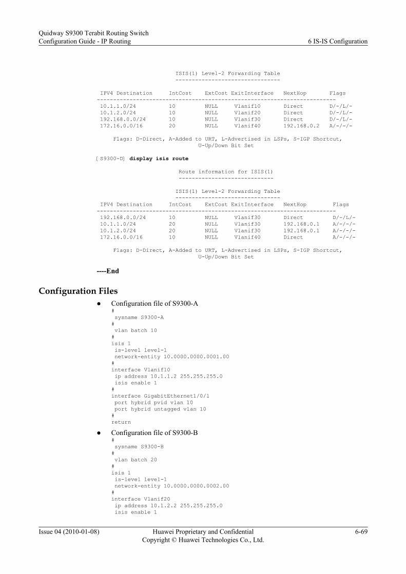
ISIS(1) Level-2 Forwarding Table -------------------------------- IPV4 Destination IntCost ExtCost ExitInterface NextHop Flags------------------------------------------------------------------------- 10.1.1.0/24 10 NULL Vlanif10 Direct D/-/L/- 10.1.2.0/24 10 NULL Vlanif20 Direct D/-/L/- 192.168.0.0/24 10 NULL Vlanif30 Direct D/-/L/- 172.16.0.0/16 20 NULL Vlanif40 192.168.0.2 A/-/-/- Flags: D-Direct, A-Added to URT, L-Advertised in LSPs, S-IGP Shortcut, U-Up/Down Bit Set [S9300-D] display isis route Route information for ISIS(1) ----------------------------- ISIS(1) Level-2 Forwarding Table -------------------------------- IPV4 Destination IntCost ExtCost ExitInterface NextHop Flags------------------------------------------------------------------------- 192.168.0.0/24 10 NULL Vlanif30 Direct D/-/L/- 10.1.1.0/24 20 NULL Vlanif30 192.168.0.1 A/-/-/- 10.1.2.0/24 20 NULL Vlanif30 192.168.0.1 A/-/-/- 172.16.0.0/16 10 NULL Vlanif40 Direct A/-/-/- Flags: D-Direct, A-Added to URT, L-Advertised in LSPs, S-IGP Shortcut, U-Up/Down Bit Set
----End
Configuration Filesl Configuration file of S9300-A
# sysname S9300-A# vlan batch 10#isis 1 is-level level-1 network-entity 10.0000.0000.0001.00#interface Vlanif10 ip address 10.1.1.2 255.255.255.0 isis enable 1#interface GigabitEthernet1/0/1 port hybrid pvid vlan 10 port hybrid untagged vlan 10#return
l Configuration file of S9300-B# sysname S9300-B# vlan batch 20#isis 1 is-level level-1 network-entity 10.0000.0000.0002.00#interface Vlanif20 ip address 10.1.2.2 255.255.255.0 isis enable 1
Quidway S9300 Terabit Routing SwitchConfiguration Guide - IP Routing 6 IS-IS Configuration
Issue 04 (2010-01-08) Huawei Proprietary and ConfidentialCopyright © Huawei Technologies Co., Ltd.
6-69

#interface GigabitEthernet1/0/1 port hybrid pvid vlan 20 port hybrid untagged vlan 20#return
l Configuration file of S9300-C# sysname S9300-C# vlan batch 10 20 30#isis 1 network-entity 10.0000.0000.0003.00#interface Vlanif10 ip address 10.1.1.1 255.255.255.0 isis enable 1#interface Vlanif20 ip address 10.1.2.1 255.255.255.0 isis enable 1#interface Vlanif30 ip address 192.168.0.1 255.255.255.0 isis enable 1#interface GigabitEthernet1/0/1 port hybrid pvid vlan 10 port hybrid untagged vlan 10#interface GigabitEthernet1/0/2 port hybrid pvid vlan 20 port hybrid untagged vlan 20#interface GigabitEthernet1/0/3 port hybrid pvid vlan 30 port hybrid untagged vlan 30#return
l Configuration file of S9300-D# sysname S9300-D# vlan batch 30 40#isis 1 is-level level-2 network-entity 20.0000.0000.0004.00#interface Vlanif30 ip address 192.168.0.2 255.255.255.0 isis enable 1#interface Vlanif40 ip address 172.16.1.1 255.255.0.0 isis enable 1#interface GigabitEthernet1/0/1 port hybrid pvid vlan 30 port hybrid untagged vlan 30#interface GigabitEthernet1/0/2 port hybrid pvid vlan 40 port hybrid untagged vlan 40#Return
6 IS-IS ConfigurationQuidway S9300 Terabit Routing Switch
Configuration Guide - IP Routing
6-70 Huawei Proprietary and ConfidentialCopyright © Huawei Technologies Co., Ltd.
Issue 04 (2010-01-08)

6.15.2 Example for Configuring IS-IS Route Aggregation
Networking RequirementsAs shown in Figure 6-4, the networking requirements are as follows:l S9300-A, S9300-B, and S9300-C run the IS-IS protocol to communicate with each other.
l S9300-A belongs to Area 20. S9300-B and S9300-C belong to Area 10.
l S9300-A is a Level-2 device. S9300-B is a Level-1-2 device. S9300-C is a Level-1 device.
l The addresses in Area 10 can be summarized as 172.1.0.0/16.
Figure 6-4 Networking diagram for configuring IS-IS route aggregation
L1/L2 L1
S9300-AL2
Area 10
Area 20
172.1.1.0/24network 1
172.1.3.0/24network 3
172.1.2.0/24network 2GE1/0/1
GE1/0/2GE1/0/1
GE1/0/1
GE1/0/2
GE1/0/3
GE1/0/4S9300-B S9300-C
S9300 Interface VLANIF interface IP address
S9300-A GigabitEthernet1/0/1 VLANIF 50 172.2.1.1/24
S9300-B GigabitEthernet1/0/1 VLANIF 10 172.1.4.2/24
S9300-B GigabitEthernet1/0/2 VLANIF 50 172.2.1.2/24
S9300-C GigabitEthernet1/0/1 VLANIF 10 172.1.4.1/24
S9300-C GigabitEthernet1/0/2 VLANIF 20 172.1.1.1/24
S9300-C GigabitEthernet1/0/3 VLANIF 30 172.1.2.1/24
S9300-C GigabitEthernet1/0/4 VLANIF 40 172.1.3.1/24
Configuration RoadmapThe configuration roadmap is as follows:
1. Enable IS-IS on each S9300 so that the S9300s can be interconnected.2. Check the IS-IS routing table of S9300-A.3. Configure route aggregation on S9300-B.
Quidway S9300 Terabit Routing SwitchConfiguration Guide - IP Routing 6 IS-IS Configuration
Issue 04 (2010-01-08) Huawei Proprietary and ConfidentialCopyright © Huawei Technologies Co., Ltd.
6-71

Data PreparationTo complete the configuration, you need the following data:l ID of the VLAN that each interface belongs to, as shown in Figure 6-4
l IP address of each VLANIF interface, as shown in Figure 6-4
l System ID, level, and area ID of each S9300:
l S9300-A: The system ID is 0000.0000.0001; the area ID is 10; the level is Level-2.
l S9300-B: The system ID is 0000.0000.0002; the area ID is 10; the level is Level-1.
l S9300-C: The system ID is 0000.0000.0003; the area ID is 10; the level is Level-1.
Procedure
Step 1 Create VLANs and add corresponding interfaces to the VLANs.<Quidway> system-view[Quidway] sysname S9300-A[S9300-A] interface GigabitEthernet 1/0/1[S9300-A-GigabitEthernet1/0/1] port link-type access[S9300-A-GigabitEthernet1/0/1] quit[S9300-A] vlan 50[S9300-A-vlan50] port GigabitEthernet 1/0/1[S9300-A-vlan50] quit
The configurations of S9300-B and S9300-C are similar to the configuration of S9300-A, andare not mentioned here.
Step 2 Assign an IP address to each VLANIF interface.[S9300-A] interface vlanif 50[S9300-A-Vlanif50] ip address 172.2.1.1 24[S9300-A-Vlanif50] quit
The configurations of S9300-B and S9300-C are similar to the configuration of S9300-A, andare not mentioned here.
Step 3 Configure the basic IS-IS functions.
# Configure S9300-A.
[S9300-A] isis 1[S9300-A-isis-1] is-level level-2[S9300-A-isis-1] network-entity 20.0000.0000.0001.00[S9300-A-isis-1] quit[S9300-A] interface vlanif 50[S9300-A-Vlanif50] isis enable 1[S9300-A-Vlanif50] quit
# Configure S9300-B.
[S9300-B] isis 1[S9300-B-isis-1] network-entity 10.0000.0000.0002.00[S9300-B-isis-1] quit[S9300-B] interface vlanif 10[S9300-B-Vlanif10] isis enable 1[S9300-B-Vlanif10] quit[S9300-B] interface vlanif 50[S9300-B-Vlanif50] isis enable 1[S9300-B-Vlanif50] quit
# Configure S9300-C.
[S9300-C] isis 1[S9300-C-isis-1] is-level level-1
6 IS-IS ConfigurationQuidway S9300 Terabit Routing Switch
Configuration Guide - IP Routing
6-72 Huawei Proprietary and ConfidentialCopyright © Huawei Technologies Co., Ltd.
Issue 04 (2010-01-08)

[S9300-C-isis-1] network-entity 10.0000.0000.0003.00[S9300-C-isis-1] quit[S9300-C] interface vlanif 10[S9300-C-Vlanif10] isis enable 1[S9300-C-Vlanif10] quit
The configurations of the VLANIF 20, VLANIF 30, and VLANIF 40 interfaces are similar tothe configuration of VLANIF 10, and are not mentioned here.
Step 4 Check the IS-IS routing table of S9300-A.[S9300-A]display isis route Route information for ISIS(1) ----------------------------- ISIS(1) Level-2 Forwarding Table -------------------------------- IPV4 Destination IntCost ExtCost ExitInterface NextHop Flags------------------------------------------------------------------------- 172.1.1.0/24 20 NULL Vlanif50 172.2.1.2 A/-/-/- 172.1.2.0/24 20 NULL Vlanif50 172.2.1.2 A/-/-/- 172.1.3.0/24 20 NULL Vlanif50 172.2.1.2 A/-/-/- 172.1.4.0/24 20 NULL Vlanif50 172.2.1.2 A/-/-/- 172.2.1.0/24 10 NULL Vlanif50 Direct D/-/L/- Flags: D-Direct, A-Added to URT, L-Advertised in LSPs, S-IGP Shortcut, U-Up/Down Bit Set
Step 5 Configure route aggregation on S9300-B.
# Aggregate 172.1.1.0/24, 172.1.2.0/24, 172.1.3.0./24, and 172.1.4.0/24 as 172.1.0.0/16 onS9300-B.
[S9300-B] isis 1[S9300-B-isis-1] summary 172.1.0.0 255.255.0.0 level-1-2[S9300-B-isis-1] quit
Step 6 Verify the configuration.
# Check the routing table of S9300-A, and you can find that 172.1.1.0/24, 172.1.2.0/24,172.1.3.0./24 and 172.1.4.0/24 are aggregated as 172.1.0.0/16.
[S9300-A] display isis route Route information for ISIS(1) ----------------------------- ISIS(1) Level-2 Forwarding Table -------------------------------- IPV4 Destination IntCost ExtCost ExitInterface NextHop Flags------------------------------------------------------------------------- 172.1.0.0/16 20 NULL Vlanif50 172.2.1.2 A/-/-/- 172.2.1.0/24 10 NULL Vlanif50 Direct D/-/L/- Flags: D-Direct, A-Added to URT, L-Advertised in LSPs, S-IGP Shortcut, U-Up/Down Bit Set
----End
Configuration Filesl Configuration file of S9300-A
# sysname S9300-A#
Quidway S9300 Terabit Routing SwitchConfiguration Guide - IP Routing 6 IS-IS Configuration
Issue 04 (2010-01-08) Huawei Proprietary and ConfidentialCopyright © Huawei Technologies Co., Ltd.
6-73

vlan batch 50#isis 1 is-level level-2 network-entity 20.0000.0000.0001.00#interface Vlanif50 ip address 172.2.1.1 255.255.255.0 isis enable 1#interface GigabitEthernet1/0/1 port link-type access port default vlan 50#return
l Configuration file of S9300-B# sysname S9300-B# vlan batch 10 50#isis 1 network-entity 10.0000.0000.0002.00 summary 172.1.0.0 255.255.0.0 level-1-2#interface Vlanif10 ip address 172.1.4.2 255.255.255.0 isis enable 1#interface Vlanif50 ip address 172.2.1.2 255.255.255.0 isis enable 1#interface GigabitEthernet1/0/1 port link-type access port default vlan 10#interface GigabitEthernet1/0/2 port link-type access port default vlan 50#return
l Configuration file of S9300-C# sysname S9300-C# vlan batch 10 20 30 40#isis 1 is-level level-1 network-entity 10.0000.0000.0003.00#interface Vlanif10 ip address 172.1.4.1 255.255.255.0 isis enable 1#interface Vlanif20 ip address 172.1.1.1 255.255.255.0 isis enable 1#interface Vlanif30 ip address 172.1.2.1 255.255.255.0 isis enable 1#interface Vlanif40 ip address 172.1.3.1 255.255.255.0 isis enable 1#
6 IS-IS ConfigurationQuidway S9300 Terabit Routing Switch
Configuration Guide - IP Routing
6-74 Huawei Proprietary and ConfidentialCopyright © Huawei Technologies Co., Ltd.
Issue 04 (2010-01-08)

interface GigabitEthernet1/0/1 port link-type access port default vlan 10#interface GigabitEthernet1/0/2 port link-type access port default vlan 20#interface GigabitEthernet1/0/3 port link-type access port default vlan 30#interface GigabitEthernet1/0/4 port link-type access port default vlan 40#return
6.15.3 Example for Configuring the DIS Election
Networking RequirementsAs shown in Figure 6-5, the networking requirements are as follows:l S9300-A, S9300-B, S9300-C, and S9300-D run the IS-IS protocol to communicate with
each other.l S9300-A, S9300-B, S9300-C, and S9300-D belong to Area 10.
l S9300-A and S9300-B are Level-1-2 devices. S9300-C is a Level-1 device. S9300-D is aLevel-2 device.
l You need to change the DIS priority of the related interface to configure S9300-A to aLevel-1-2 DIS.
Figure 6-5 Networking diagram for configuring the DIS election
S9300-AL1/L2 L1/L2
L1 L2
GE1/0/1
GE1/0/1 GE1/0/1
GE1/0/1
S9300-B
S9300-C S9300-D
S9300 Interface VLANIF interface IP address
S9300-A GigabitEthernet1/0/1 VLANIF 10 10.1.1.1/24
S9300-B GigabitEthernet1/0/1 VLANIF 10 10.1.1.2/24
S9300-C GigabitEthernet1/0/1 VLANIF 10 10.1.1.3/24
S9300-D GigabitEthernet1/0/1 VLANIF 10 10.1.1.4/24
Quidway S9300 Terabit Routing SwitchConfiguration Guide - IP Routing 6 IS-IS Configuration
Issue 04 (2010-01-08) Huawei Proprietary and ConfidentialCopyright © Huawei Technologies Co., Ltd.
6-75

Configuration RoadmapThe configuration roadmap is as follows:
1. Enable IS-IS on each S9300 so that the S9300s can be interconnected.2. Check information about the IS-IS interface on each S9300 with the default priority.3. Configure the DIS priority on S9300-A.
Data PreparationTo complete the configuration, you need the following data:l ID of the VLAN that each interface belongs to, as shown in Figure 6-5
l IP address of each VLANIF interface, as shown in Figure 6-5
l System ID, level, and area ID of each S9300:– S9300-A: The system ID is 0000.0000.0001; the area ID is 10; the DIS priority is 100;
the level is Level-1-2.– S9300-B: The system ID is 0000.0000.0002; the area ID is 10; the level is Level-1.
– S9300-C: The system ID is 0000.0000.0003; the area ID is 10; the level is Level-1.
– S9300-D: The system ID is 0000.0000.0004; the area ID is 10; the level is Level-2.
Procedure
Step 1 Create VLANs and add corresponding interfaces to the VLANs.<Quidway> system-view[Quidway] sysname S9300-A[S9300-A] vlan 10S9300-A-vlan10] quit[S9300-A] interface GigabitEthernet 1/0/1[S9300-A-GigabitEthernet1/0/1] port hybrid pvid vlan 10[S9300-A-GigabitEthernet1/0/1] port hybrid untagged vlan 10[S9300-A-GigabitEthernet1/0/1] quit
The configurations of S9300-B, S9300-C, and S9300-D are similar to the configuration ofS9300-A, and are not mentioned here.
Step 2 Assign an IP address to each VLANIF interface.[S9300-A] interface vlanif 50[S9300-A-Vlanif10] ip address 10.1.1.1 24[S9300-A-Vlanif10] quit
The configurations of S9300-B, S9300-C, and S9300-D are similar to the configuration ofS9300-A, and are not mentioned here.
Step 3 View the MAC address of the VLANIF 10 interface on each S9300.
# View the MAC address of the VLANIF 10 interface on S9300-A.[S9300-A] display arp interface vlanif 10IP ADDRESS MAC ADDRESS EXPIRE(M) TYPE INTERFACE VPN-INSTANCE VLAN/CEVLAN PVC------------------------------------------------------------------------------10.1.1.1 00e0-fc10-afec I - Vlanif10------------------------------------------------------------------------------Total:1 Dynamic:0 Static:0 Interface:1
# View the MAC address of the VLANIF 10 interface on S9300-B.[S9300-B] display arp interface vlanif 10IP ADDRESS MAC ADDRESS EXPIRE(M) TYPE INTERFACE VPN-INSTANCE
6 IS-IS ConfigurationQuidway S9300 Terabit Routing Switch
Configuration Guide - IP Routing
6-76 Huawei Proprietary and ConfidentialCopyright © Huawei Technologies Co., Ltd.
Issue 04 (2010-01-08)
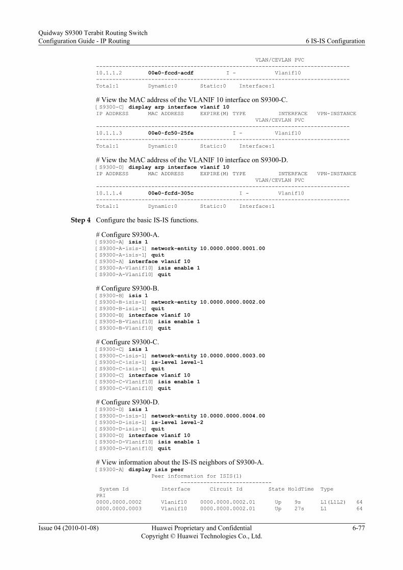
VLAN/CEVLAN PVC------------------------------------------------------------------------------10.1.1.2 00e0-fccd-acdf I - Vlanif10------------------------------------------------------------------------------Total:1 Dynamic:0 Static:0 Interface:1
# View the MAC address of the VLANIF 10 interface on S9300-C.[S9300-C] display arp interface vlanif 10IP ADDRESS MAC ADDRESS EXPIRE(M) TYPE INTERFACE VPN-INSTANCE VLAN/CEVLAN PVC------------------------------------------------------------------------------10.1.1.3 00e0-fc50-25fe I - Vlanif10------------------------------------------------------------------------------Total:1 Dynamic:0 Static:0 Interface:1
# View the MAC address of the VLANIF 10 interface on S9300-D.[S9300-D] display arp interface vlanif 10IP ADDRESS MAC ADDRESS EXPIRE(M) TYPE INTERFACE VPN-INSTANCE VLAN/CEVLAN PVC------------------------------------------------------------------------------10.1.1.4 00e0-fcfd-305c I - Vlanif10------------------------------------------------------------------------------Total:1 Dynamic:0 Static:0 Interface:1
Step 4 Configure the basic IS-IS functions.
# Configure S9300-A.[S9300-A] isis 1[S9300-A-isis-1] network-entity 10.0000.0000.0001.00[S9300-A-isis-1] quit[S9300-A] interface vlanif 10[S9300-A-Vlanif10] isis enable 1[S9300-A-Vlanif10] quit
# Configure S9300-B.[S9300-B] isis 1[S9300-B-isis-1] network-entity 10.0000.0000.0002.00[S9300-B-isis-1] quit[S9300-B] interface vlanif 10[S9300-B-Vlanif10] isis enable 1[S9300-B-Vlanif10] quit
# Configure S9300-C.[S9300-C] isis 1[S9300-C-isis-1] network-entity 10.0000.0000.0003.00[S9300-C-isis-1] is-level level-1[S9300-C-isis-1] quit[S9300-C] interface vlanif 10[S9300-C-Vlanif10] isis enable 1[S9300-C-Vlanif10] quit
# Configure S9300-D.[S9300-D] isis 1[S9300-D-isis-1] network-entity 10.0000.0000.0004.00[S9300-D-isis-1] is-level level-2[S9300-D-isis-1] quit[S9300-D] interface vlanif 10[S9300-D-Vlanif10] isis enable 1[S9300-D-Vlanif10] quit
# View information about the IS-IS neighbors of S9300-A.[S9300-A] display isis peer Peer information for ISIS(1) ---------------------------- System Id Interface Circuit Id State HoldTime Type PRI0000.0000.0002 Vlanif10 0000.0000.0002.01 Up 9s L1(L1L2) 640000.0000.0003 Vlanif10 0000.0000.0002.01 Up 27s L1 64
Quidway S9300 Terabit Routing SwitchConfiguration Guide - IP Routing 6 IS-IS Configuration
Issue 04 (2010-01-08) Huawei Proprietary and ConfidentialCopyright © Huawei Technologies Co., Ltd.
6-77

0000.0000.0002 Vlanif10 0000.0000.0004.01 Up 28s L2(L1L2) 640000.0000.0004 Vlanif10 0000.0000.0004.01 Up 8s L2 64
# View information about the IS-IS interface of S9300-A.[S9300-A] display isis interface Interface information for ISIS(1) --------------------------------- Interface Id IPV4.State IPV6.State MTU Type DR Vlanif10 001 Up Down 1497 L1/L2 No/No
# View information about the IS-IS interface of S9300-B.[S9300-B] display isis interface Interface information for ISIS(1) --------------------------------- Interface Id IPV4.State IPV6.State MTU Type DR Vlanif10 001 Up Down 1497 L1/L2 Yes/No
# View information about the IS-IS interface of S9300-D.[S9300-D] display isis interface Interface information for ISIS(1) --------------------------------- Interface Id IPV4.State IPV6.State MTU Type DR Vlanif10 001 Up Down 1497 L1/L2 No/Yes
NOTE
When the default DIS priority is used, the interface on S9300-B has the greatest MAC address among allthe interfaces on the Level-1 S9300s. Therefore, S9300-B is elected as the Level-1 DIS. The interface onS9300-D has the greatest MAC address among all the interfaces on the Level-2 S9300s. Therefore, S9300-D is elected as the Level-2 DIS. The Level-1 pseudonode is 0000.0000.0002.01. The Level-2 pseudonodeis 0000.0000.0004.01.
Step 5 Set the DIS priority of S9300-A.[S9300-A] interface vlanif 10[S9300-A-Vlanif10] isis dis-priority 100[S9300-A-Vlanif10] quit
# View information about the IS-IS neighbors of S9300-A.[S9300-A] display isis peer Peer information for ISIS(1) ----------------------------System Id Interface Circuit Id State HoldTime Type PRI0000.0000.0002 Vlanif10 0000.0000.0001.01 Up 21s L1(L1L2) 640000.0000.0003 Vlanif10 0000.0000.0001.01 Up 27s L1 640000.0000.0002 Vlanif10 0000.0000.0001.01 Up 28s L2(L1L2) 640000.0000.0004 Vlanif10 0000.0000.0001.01 Up 30s L2 64
Step 6 Verify the configuration.
# View information about the IS-IS interface of S9300-A.[S9300-A] display isis interface Interface information for ISIS(1) --------------------------------- Interface Id IPV4.State IPV6.State MTU Type DR Vlanif10 001 Up Down 1497 L1/L2 Yes/Yes
As shown in the output information, after the DIS priority of the IS-IS interface is changed,S9300-A immediately becomes a Level-1 and Level-2 DIS and its pseudonode is0000.0000.0001.01.
# View information about the IS-IS neighbors and IS-IS interfaces on S9300-B.
6 IS-IS ConfigurationQuidway S9300 Terabit Routing Switch
Configuration Guide - IP Routing
6-78 Huawei Proprietary and ConfidentialCopyright © Huawei Technologies Co., Ltd.
Issue 04 (2010-01-08)

[S9300-B] display isis peer Peer information for ISIS(1) ----------------------------System Id Interface Circuit Id State HoldTime Type PRI0000.0000.0001 Vlanif10 0000.0000.0001.01 Up 7s L1(L1L2) 1000000.0000.0003 Vlanif10 0000.0000.0001.01 Up 25s L1 640000.0000.0001 Vlanif10 0000.0000.0001.01 Up 7s L2(L1L2) 1000000.0000.0004 Vlanif10 0000.0000.0001.01 Up 25s L2 64[S9300-B] display isis interface Interface information for ISIS(1) --------------------------------- Interface Id IPV4.State IPV6.State MTU Type DR Vlanif10 001 Up Down 1497 L1/L2 No/No
# View information about the IS-IS neighbors and IS-IS interfaces on S9300-D.[S9300-D] display isis peer Peer information for ISIS(1) ----------------------------System Id Interface Circuit Id State HoldTime Type PRI0000.0000.0001 Vlanif10 0000.0000.0001.01 Up 9s L2 1000000.0000.0002 Vlanif10 0000.0000.0001.01 Up 28s L2 64[S9300-D] display isis interface Interface information for ISIS(1) --------------------------------- Interface Id IPV4.State IPV6.State MTU Type DR Vlanif10 001 Up Down 1497 L1/L2 No/No
----End
Configuration Filesl Configuration file of S9300-A
## sysname S9300-A# vlan batch 10#isis 1 network-entity 10.0000.0000.0001.00#interface Vlanif10 ip address 10.1.1.1 255.255.255.0 isis enable 1 isis dis-priority 100#interface GigabitEthernet1/0/1 port hybrid pvid vlan 10 port hybrid untagged vlan 10#return
l Configuration file of S9300-B# # sysname S9300-B# vlan batch 10#isis 1
Quidway S9300 Terabit Routing SwitchConfiguration Guide - IP Routing 6 IS-IS Configuration
Issue 04 (2010-01-08) Huawei Proprietary and ConfidentialCopyright © Huawei Technologies Co., Ltd.
6-79

network-entity 10.0000.0000.0002.00#interface Vlanif10 ip address 10.1.1.2 255.255.255.0 isis enable 1#interface GigabitEthernet1/0/1 port hybrid pvid vlan 10 port hybrid untagged vlan 10#return
l Configuration file of S9300-C
# sysname S9300-C# vlan batch 10#isis 1 is-level level-1 network-entity 10.0000.0000.0003.00#interface Vlanif10 ip address 10.1.1.3 255.255.255.0 isis enable 1#interface GigabitEthernet1/0/1 port hybrid pvid vlan 10 port hybrid untagged vlan 10#return
l Configuration file of S9300-D# sysname S9300-D# vlan batch 10#isis 1 is-level level-2 network-entity 10.0000.0000.0004.00#interface Vlanif10 ip address 10.1.1.4 255.255.255.0 isis enable 1#interface GigabitEthernet1/0/1 port hybrid pvid vlan 10 port hybrid untagged vlan 10#return
6.15.4 Example for Configuring IS-IS Load Balancing
Networking RequirementsAs shown in Figure 6-6, the networking requirements are as follows:l S9300-A, S9300-B, S9300-C, and S9300-D run IS-IS to communicate with each other.
l S9300-A, S9300-B, S9300-C, and S9300-D are Level-2 devices in Area 10.
l Load balancing needs to be configured so that the traffic of S9300-A is sent to S9300-Dthrough S9300-B and S9300-C.
6 IS-IS ConfigurationQuidway S9300 Terabit Routing Switch
Configuration Guide - IP Routing
6-80 Huawei Proprietary and ConfidentialCopyright © Huawei Technologies Co., Ltd.
Issue 04 (2010-01-08)

Figure 6-6 Networking diagram for configuring IS-IS load balancing
Area 10
S9300-AL2
L2
L2
L2
GE1/0/1
GE1/0/1
GE1/0/1
GE1/0/1 GE1/0/2
GE1/0/2
GE1/0/2
GE1/0/2
GE1/0/3 GE1/0/3
S9300-B
S9300-D
S9300-C
S9300 Interface VLANIF interface IP address
S9300-A GigabitEthernet1/0/1 VLANIF 10 10.1.1.1/24
S9300-A GigabitEthernet1/0/2 VLANIF 20 10.1.2.1/24
S9300-A GigabitEthernet1/0/3 VLANIF 50 172.16.1.1/24
S9300-B GigabitEthernet1/0/1 VLANIF 10 10.1.1.2/24
S9300-B GigabitEthernet1/0/2 VLANIF 30 192.168.0.1/24
S9300-C GigabitEthernet1/0/1 VLANIF 20 10.1.2.2./24
S9300-C GigabitEthernet1/0/2 VLANIF 40 192.168.1.1/24
S9300-D GigabitEthernet1/0/1 VLANIF 30 192.168.0.2/24
S9300-D GigabitEthernet1/0/2 VLANIF 40 192.168.1.2/24
S9300-D GigabitEthernet1/0/3 VLANIF 60 172.17.1.1/24
Configuration RoadmapThe configuration roadmap is as follows:
1. Enable IS-IS on each S9300 so that the S9300s can be interconnected.2. Set the number of equal-cost routes to 1 and check the routing table.3. Configure load balancing on S9300-A and check the routing table.4. (Optional) Set the weight of equal-cost routes on S9300-A.
Data PreparationTo complete the configuration, you need the following data:
l ID of the VLAN that each interface belongs to, as shown in Figure 6-6
l IP address of each VLANIF interface, as shown in Figure 6-6
l System ID, level, and area ID of each S9300:– S9300-A: The system ID is 0000.0000.0001; the area ID is 10; the level is Level-2.
Quidway S9300 Terabit Routing SwitchConfiguration Guide - IP Routing 6 IS-IS Configuration
Issue 04 (2010-01-08) Huawei Proprietary and ConfidentialCopyright © Huawei Technologies Co., Ltd.
6-81

– S9300-B: The system ID is 0000.0000.0002; the area ID is 10; the level is Level-2.
– S9300-C: The system ID is 0000.0000.0003; the area ID is 10; the level is Level-2.
– S9300-D: The system ID is 0000.0000.0004; the area ID is 10; the level is Level-2.
l Number of routes for load balancing on S9300-A: 1
l Load balancing mode on S9300-A
l Weight of the equal-cost route with S9300-C as the next hop: 1
ProcedureStep 1 Configure VLANs that the related interfaces belong to.
<Quidway> system-view[Quidway] sysname S9300-A[Quidway] vlan batch 10 20 50[S9300-A] interface GigabitEthernet 1/0/1[S9300-A-GigabitEthernet1/0/1] port hybrid pvid vlan 10[S9300-A-GigabitEthernet1/0/1] port hybrid untagged vlan 10[S9300-A-GigabitEthernet1/0/1] quit[S9300-A] interface GigabitEthernet 1/0/2[S9300-A-GigabitEthernet1/0/2] port hybrid pvid vlan 20[S9300-A-GigabitEthernet1/0/2] port hybrid untagged vlan 20[S9300-A-GigabitEthernet1/0/2] quit[S9300-A] interface GigabitEthernet 1/0/3[S9300-A-GigabitEthernet1/0/3] port hybrid pvid vlan 50[S9300-A-GigabitEthernet1/0/3] port hybrid untagged vlan 50[S9300-A-GigabitEthernet1/0/3] quit
The configurations of S9300-B, S9300-C, and S9300-D are similar to the configuration ofS9300-A, and are not mentioned here.
Step 2 Assign an IP address to each VLANIF interface.[S9300-A] interface vlanif 10[S9300-A-Vlanif10] ip address 10.1.1.1 24[S9300-A-Vlanif10] quit[S9300-A] interface vlanif 20[S9300-A-Vlanif20] ip address 10.1.2.1 24[S9300-A-Vlanif20] quit[S9300-A] interface vlanif 50[S9300-A-Vlanif50] ip address 172.16.1.1 24[S9300-A-Vlanif50] quit
The configurations of S9300-B, S9300-C, and S9300-D are similar to the configuration ofS9300-A, and are not mentioned here.
Step 3 Configure the basic function of IS-IS. The configuration procedure is not mentioned here.
Step 4 Set the number of equal-cost routes for load balancing to 1 on S9300-A.[S9300-A] isis 1[S9300-A-isis-1] maximum load-balancing 1[S9300-A-isis-1] quit
# View the routing table of S9300-A.[S9300-A] display isis route Route information for ISIS(1) ----------------------------- ISIS(1) Level-2 Forwarding Table -------------------------------- IPV4 Destination IntCost ExtCost ExitInterface NextHop Flags------------------------------------------------------------------------- 192.168.1.0/24 20 NULL Vlanif20 10.1.2.2 A/-/-/-
6 IS-IS ConfigurationQuidway S9300 Terabit Routing Switch
Configuration Guide - IP Routing
6-82 Huawei Proprietary and ConfidentialCopyright © Huawei Technologies Co., Ltd.
Issue 04 (2010-01-08)

10.1.1.0/24 10 NULL Vlanif10 Direct D/-/L/- 172.16.1.0/24 10 NULL Vlanif50 Direct D/-/L/- 172.17.1.0/24 30 NULL Vlanif10 10.1.1.2 A/-/-/- 10.1.2.0/24 10 NULL Vlanif20 Direct D/-/L/- 192.168.0.0/24 20 NULL Vlanif10 10.1.1.2 A/-/-/- Flags: D-Direct, R-Added to RM, L-Advertised in LSPs, U-Up/Down Bit Set
As shown in the routing table, when the maximum number of equal-cost routes for load balancingis set to 1, IS-IS selects 10.1.1.2 as the next hop to the destination network 172.17.1.0. This isbecause S9300-B has a smaller system ID.
Step 5 Restore the default number of equal-cost routes for load balancing on S9300-A.[S9300-A] isis 1[S9300-A-isis-1] undo maximum load-balancing[S9300-A-isis-1] quit
# View the routing table of S9300-A.[S9300-A] display isis route Route information for ISIS(1) ----------------------------- ISIS(1) Level-2 Forwarding Table -------------------------------- IPV4 Destination IntCost ExtCost ExitInterface NextHop Flags------------------------------------------------------------------------- 192.168.1.0/24 20 NULL Vlanif20 10.1.2.2 A/-/-/- 10.1.1.0/24 10 NULL Vlanif10 Direct D/-/L/- 172.16.1.0/24 10 NULL Vlanif50 Direct D/-/L/- 172.17.1.0/24 30 NULL Vlanif10 10.1.1.2 A/-/-/- Vlanif20 10.1.2.2 10.1.2.0/24 10 NULL Vlanif20 Direct D/-/L/- 192.168.0.0/24 20 NULL Vlanif10 10.1.1.2 A/-/-/- Flags: D-Direct, R-Added to RM, L-Advertised in LSPs, U-Up/Down Bit Set
As shown in the routing table, the number of equal-cost routes for load balancing is restored tothe default value 6. Both the next hops of S9300-A, 10.1.1.2 (S9300-B) and 10.1.2.2 (S9300-C)now become valid.
Step 6 (Optional) Set the preference for equal-cost routes on S9300-A.[S9300-A] isis[S9300-A-isis-1] nexthop 10.1.2.2 weight 1[S9300-A-isis-1] quit
Step 7 Verify the configuration.
# View the routing table of S9300-A.[S9300-A] display isis route Route information for ISIS(1) ----------------------------- ISIS(1) Level-2 Forwarding Table -------------------------------- IPV4 Destination IntCost ExtCost ExitInterface NextHop Flags-------------------------------------------------------------------------------- 192.168.1.0/24 20 NULL Vlanif20 10.1.2.2 A/-/-/- 10.1.1.0/24 10 NULL Vlanif10 Direct D/-/L/- 172.16.1.0/24 10 NULL Vlanif50 Direct D/-/L/- 172.17.1.0/24 30 NULL Vlanif20 10.1.2.2 A/-/-/- 10.1.2.0/24 10 NULL Vlanif20 Direct D/-/L/- 192.168.0.0/24 20 NULL Vlanif10 10.1.1.2 A/-/-/- Flags: D-Direct, R-Added to RM, L-Advertised in LSPs, U-Up/Down Bit Set
Quidway S9300 Terabit Routing SwitchConfiguration Guide - IP Routing 6 IS-IS Configuration
Issue 04 (2010-01-08) Huawei Proprietary and ConfidentialCopyright © Huawei Technologies Co., Ltd.
6-83

As shown in the routing table, the preference of the next hop 10.1.2.2 (S9300-C) with the weightas 1, is higher than that of 10.1.1.2 (S9300-B), after the weight is set for equal-cost routes.Therefore, IS-IS selects route with the next hop 10.1.2.2 as the optimal route.
----End
Configuration Filesl Configuration file of S9300-A
# sysname S9300-A# vlan batch 10 20 50#isis 1 is-level level-2 network-entity 10.0000.0000.0001.00 nexthop 10.1.2.2 weight 1#interface Vlanif10 ip address 10.1.1.1 255.255.255.0 isis enable 1#interface Vlanif20 ip address 10.1.2.1 255.255.255.0 isis enable 1#interface Vlanif50 ip address 172.16.1.1 255.255.255.0 isis enable 1#interface GigabitEthernet1/0/1 port hybrid pvid vlan 10 port hybrid untagged vlan 10#interface GigabitEthernet1/0/2 port hybrid pvid vlan 20 port hybrid untagged vlan 20#interface GigabitEthernet1/0/3 port hybrid pvid vlan 50 port hybrid untagged vlan 50#return
l Configuration file of S9300-B# sysname S9300-B# vlan batch 10 30#isis 1 is-level level-2 network-entity 10.0000.0000.0002.00#interface Vlanif10 ip address 10.1.1.2 255.255.255.0 isis enable 1#interface Vlanif30 ip address 192.168.0.1 255.255.255.0 isis enable 1#interface GigabitEthernet1/0/1 port hybrid pvid vlan 10 port hybrid untagged vlan 10#interface GigabitEthernet1/0/2
6 IS-IS ConfigurationQuidway S9300 Terabit Routing Switch
Configuration Guide - IP Routing
6-84 Huawei Proprietary and ConfidentialCopyright © Huawei Technologies Co., Ltd.
Issue 04 (2010-01-08)

port hybrid pvid vlan 30 port hybrid untagged vlan 30#return
l Configuration file of S9300-C# sysname S9300-C# vlan batch 20 40#isis 1 is-level level-2 network-entity 10.0000.0000.0003.00#interface Vlanif20 ip address 10.1.2.2 255.255.255.0 isis enable 1#interface Vlanif40 ip address 192.168.1.1 255.255.255.0 isis enable 1#interface GigabitEthernet1/0/1 port hybrid pvid vlan 20 port hybrid untagged vlan 20#interface GigabitEthernet1/0/2 port hybrid pvid vlan 40 port hybrid untagged vlan 40#return
l Configuration file of S9300-D# sysname S9300-D# vlan batch 30 40 60#isis 1 is-level level-2 network-entity 10.0000.0000.0004.00#interface Vlanif30 ip address 192.168.0.2 255.255.255.0 isis enable 1#interface Vlanif40 ip address 192.168.1.2 255.255.255.0 isis enable 1#interface Vlanif60 ip address 172.17.1.1 255.255.255.0isis enable 1#interface GigabitEthernet1/0/1 port hybrid pvid vlan 30 port hybrid untagged vlan 30#interface GigabitEthernet1/0/2 port hybrid pvid vlan 40 port hybrid untagged vlan 40#interface GigabitEthernet1/0/3 port hybrid pvid vlan 60 port hybrid untagged vlan 60#return
Quidway S9300 Terabit Routing SwitchConfiguration Guide - IP Routing 6 IS-IS Configuration
Issue 04 (2010-01-08) Huawei Proprietary and ConfidentialCopyright © Huawei Technologies Co., Ltd.
6-85
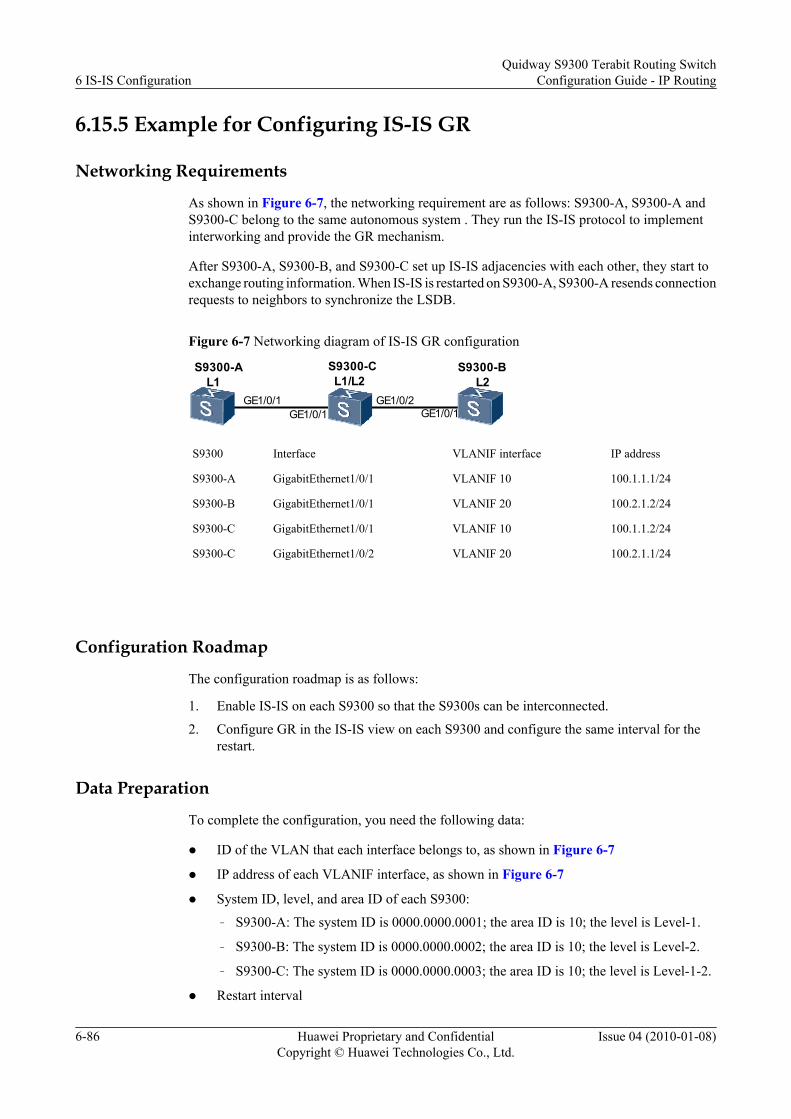
6.15.5 Example for Configuring IS-IS GR
Networking Requirements
As shown in Figure 6-7, the networking requirement are as follows: S9300-A, S9300-A andS9300-C belong to the same autonomous system . They run the IS-IS protocol to implementinterworking and provide the GR mechanism.
After S9300-A, S9300-B, and S9300-C set up IS-IS adjacencies with each other, they start toexchange routing information. When IS-IS is restarted on S9300-A, S9300-A resends connectionrequests to neighbors to synchronize the LSDB.
Figure 6-7 Networking diagram of IS-IS GR configuration
S9300-AL1 L2
S9300-CL1/L2
GE1/0/1 GE1/0/2GE1/0/1 GE1/0/1
S9300-B
S9300 Interface VLANIF interface IP address
S9300-A GigabitEthernet1/0/1 VLANIF 10 100.1.1.1/24
S9300-B GigabitEthernet1/0/1 VLANIF 20 100.2.1.2/24
S9300-C GigabitEthernet1/0/1 VLANIF 10 100.1.1.2/24
S9300-C GigabitEthernet1/0/2 VLANIF 20 100.2.1.1/24
Configuration Roadmap
The configuration roadmap is as follows:
1. Enable IS-IS on each S9300 so that the S9300s can be interconnected.
2. Configure GR in the IS-IS view on each S9300 and configure the same interval for therestart.
Data Preparation
To complete the configuration, you need the following data:
l ID of the VLAN that each interface belongs to, as shown in Figure 6-7
l IP address of each VLANIF interface, as shown in Figure 6-7
l System ID, level, and area ID of each S9300:
– S9300-A: The system ID is 0000.0000.0001; the area ID is 10; the level is Level-1.
– S9300-B: The system ID is 0000.0000.0002; the area ID is 10; the level is Level-2.
– S9300-C: The system ID is 0000.0000.0003; the area ID is 10; the level is Level-1-2.
l Restart interval
6 IS-IS ConfigurationQuidway S9300 Terabit Routing Switch
Configuration Guide - IP Routing
6-86 Huawei Proprietary and ConfidentialCopyright © Huawei Technologies Co., Ltd.
Issue 04 (2010-01-08)

Procedure
Step 1 Configure VLANs that the related interfaces belong to.<Quidway> system-view[Quidway] sysname S9300-A[S9300-A] vlan 10[S9300-A-Vlan10] quit[S9300-A] interface GigabitEthernet 1/0/1[S9300-A-GigabitEthernet1/0/1] port hybrid pvid vlan 10[S9300-A-GigabitEthernet1/0/1] port hybrid untagged vlan 10[S9300-A-GigabitEthernet1/0/1] quit
The configurations of S9300-B and S9300 are similar to the configuration of S9300-A, and arenot mentioned here.
Step 2 Assign an IP address to each VLANIF interface.[S9300-A] interface vlanif10[S9300-A-Vlanif10] ip address 100.1.1.1 24[S9300-A-Vlanif10] quit
The configurations of S9300-B and S9300 are similar to the configuration of S9300-A, and arenot mentioned here.
Step 3 Configure the basic function of IS-IS. The configuration procedure is not mentioned here.
Step 4 Configure IS-IS GR.
# Enable IS-IS GR on S9300-A and set the restart interval. The configurations on S9300-B andS9300-C are the same as the configurations on S9300-A. S9300-A is taken as an example here.[S9300-A] isis 1[S9300-A-isis-1] graceful-restart[S9300-A-isis-1] graceful-restart interval 150[S9300-A-isis-1] quit
Step 5 Verify the configuration.
# Run the display fib command on S9300-A to view the Forwarding Information Base (FIB)table.<S9300-A> display fibFIB Table: Total number of Routes : 5 Destination/Mask Nexthop Flag TimeStamp Interface TunnelID127.0.0.1/32 127.0.0.1 HU t[21] InLoop0 0x0127.0.0.0/8 127.0.0.1 U t[21] InLoop0 0x0100.1.1.1/32 127.0.0.1 HU t[20678] InLoop0 0x0100.1.1.0/24 100.1.1.1 U t[20678] Vlanif10 0x0100.2.1.0/24 100.1.1.2 DGU t[79388] Vlanif10 0x0
# Reset the IS-IS process by using the GR method on S9300-A.<S9300-A> reset isis all
NOTE
The S9300 restarts an IS-IS process in GR mode only when GR is enabled for the IS-IS process.
# Run the display fib command on S9300-A and view the FIB table to check whether GR worksnormally. If GR works normally, the FIB table does not change and the forwarding service isnot affected when S9300-A restarts the IS-IS process in GR mode.
<S9300-A> display fibFIB Table: Total number of Routes : 5 Destination/Mask Nexthop Flag TimeStamp Interface TunnelID
Quidway S9300 Terabit Routing SwitchConfiguration Guide - IP Routing 6 IS-IS Configuration
Issue 04 (2010-01-08) Huawei Proprietary and ConfidentialCopyright © Huawei Technologies Co., Ltd.
6-87

127.0.0.1/32 127.0.0.1 HU t[21] InLoop0 0x0127.0.0.0/8 127.0.0.1 U t[21] InLoop0 0x0100.1.1.1/32 127.0.0.1 HU t[20678] InLoop0 0x0100.1.1.0/24 100.1.1.1 U t[20678] Vlanif10 0x0100.2.1.0/24 100.1.1.2 DGU t[79388] Vlanif10 0x0
As shown in the display, the FIB table on S9300-A does not change and the forwarding serviceis not affected.
# Disable IS-IS GR on S9300-A.
[S9300-A] isis 1[S9300-A-isis-1] undo graceful-restart[S9300-A-isis-1] quit
# Reset the IS-IS process on S9300-A.
<S9300-A> reset isis all
# Run the display fib command on S9300-A to view the FIB table.
<S9300-A> display fibFIB Table: Total number of Routes : 4 Destination/Mask Nexthop Flag TimeStamp Interface TunnelID127.0.0.1/32 127.0.0.1 HU t[21] InLoop0 0x0127.0.0.0/8 127.0.0.1 U t[21] InLoop0 0x0100.1.1.1/32 127.0.0.1 HU t[20678] InLoop0 0x0100.1.1.0/24 100.1.1.1 U t[20678] Vlanif10 0x0
As shown in the display, the FIB table on S9300-A changes and the forwarding service isaffected.
----End
Configuration Filesl Configuration file of S9300-A
# sysname S9300-A# vlan batch 10#isis 1 graceful-restart graceful-restart interval 150 is-level level-1 network-entity 10.0000.0000.0001.00#interface Vlanif10 ip address 100.1.1.1 255.255.255.0 isis enable 1#interface GigabitEthernet1/0/1 port hybrid pvid vlan 10 port hybrid untagged vlan 10#return
l Configuration file of S9300-B# sysname S9300-B# vlan batch 20#isis 1
6 IS-IS ConfigurationQuidway S9300 Terabit Routing Switch
Configuration Guide - IP Routing
6-88 Huawei Proprietary and ConfidentialCopyright © Huawei Technologies Co., Ltd.
Issue 04 (2010-01-08)

graceful-restart graceful-restart interval 150 is-level level-2 network-entity 10.0000.0000.0002.00#interface Vlanif20 ip address 100.2.1.2 255.255.255.0 isis enable 1#interface GigabitEthernet1/0/1 port hybrid pvid vlan 20 port hybrid untagged vlan 20#return
l Configuration file of S9300-C# sysname S9300-C# vlan batch 10 20#isis 1 graceful-restart graceful-restart interval 150 network-entity 10.0000.0000.0003.00#interface Vlanif10 ip address 100.1.1.2 255.255.255.0 isis enable 1#interface Vlanif20 ip address 100.2.1.1 255.255.255.0 isis enable 1#interface GigabitEthernet1/0/1 port hybrid pvid vlan 10 port hybrid untagged vlan 10#interface GigabitEthernet1/0/2 port hybrid pvid vlan 20 port hybrid untagged vlan 20#return
6.15.6 Example for Configuring BFD for IS-IS
Networking RequirementsAs shown in Figure 6-8, the networking requirement are as follows:
l S9300-A, S9300-B, S9300-C run IS-IS to communicate with each other.
l BFD for IS-IS is enabled on S9300-A, S9300-B, and S9300-C.
l Service traffic is transmitted on the main link S9300-A→S9300-B. Link S9300-A→S9300-C→S9300-B is a backup link.
l BFD is configured on the interfaces between S9300-A and S9300-B. When a fault occurson the link between the S9300-A and S9300-B, BFD can quickly detect the fault and notifyIS-IS of the fault. Then, the service flow is transmitted through the backup link.
Quidway S9300 Terabit Routing SwitchConfiguration Guide - IP Routing 6 IS-IS Configuration
Issue 04 (2010-01-08) Huawei Proprietary and ConfidentialCopyright © Huawei Technologies Co., Ltd.
6-89

Figure 6-8 Networking diagram for configuring BFD for IS-IS
S9300-A S9300-B
S9300-C
GE3/0/0GE2/0/0
GE1/0/0
GE2/0/0
GE1/0/0
GE1/0/0 GE2/0/0
S9300 Interface VLANIF interface IP address
S9300-A GigabitEthernet1/0/0 VLANIF 10 1.1.1.1/24
S9300-A GigabitEthernet2/0/0 VLANIF 20 3.3.3.1/24
S9300-B GigabitEthernet1/0/0 VLANIF 30 2.2.2.2/24
S9300-B GigabitEthernet2/0/0 VLANIF 20 3.3.3.2/24
S9300-B GigabitEthernet3/0/0 VLANIF 40 172.16.1.1/24
S9300-C GigabitEthernet1/0/0 VLANIF 10 1.1.1.2/24
S9300-C GigabitEthernet2/0/0 VLANIF 30 2.2.2.1/24
Configuration Roadmap
The configuration roadmap is as follows:
1. Enable IS-IS on each S9300 to ensure the reachability of the routes.
2. Set the cost of IS-IS interfaces to control the route selection.
3. Enable global BFD.
4. Enable the BFD for the IS-IS process on S9300-A, S9300-A, and S9300-C.
5. Enable BFD on interfaces of S9300-A and S9300-B.
Data Preparation
To complete the configuration, you need the following data:
l Process ID of the IS-IS protocol
l Area IDs of S9300-A, S9300-B, and S9300-C
l Interface cost of S9300-A and S9300-A
l Number and type of the BFD-enabled interfaces on S9300-A, S9300-B, and S9300-C
6 IS-IS ConfigurationQuidway S9300 Terabit Routing Switch
Configuration Guide - IP Routing
6-90 Huawei Proprietary and ConfidentialCopyright © Huawei Technologies Co., Ltd.
Issue 04 (2010-01-08)

l Minimum interval for sending the BFD packets, the minimum interval for receiving theBFD packets, and the local detection time multiplier on S9300-A and S9300-B
Procedure
Step 1 Configure IP addresses of all interfaces. The configuration procedure is not mentioned here.
Step 2 Configure the basic IS-IS functions.
# Configure S9300-A.
[S9300-A] isis[S9300-A-isis-1] is-level level-2[S9300-A-isis-1] network-entity 10.0000.0000.0001.00[S9300-A-isis-1] quit[S9300-A] interface vlanif 10[S9300-A-Vlanif10] isis enable 1[S9300-A-Vlanif10] quit[S9300-A] interface vlanif 20[S9300-A-Vlanif20] isis enable 1[S9300-A-Vlanif20] quit
# Configure S9300-B.
[S9300-B] isis[S9300-B-isis-1] is-level level-2[S9300-B-isis-1] network-entity 10.0000.0000.0002.00[S9300-B-isis-1] quit[S9300-B] interface vlanif 30[S9300-B-Vlanif30] isis enable 1[S9300-B-Vlanif30] quit[S9300-B] interface vlanif 20[S9300-B-Vlanif20] isis enable 1[S9300-B-Vlanif20] quit[S9300-B] interface vlanif 40[S9300-B-Vlanif40] isis enable 1[S9300-B-Vlanif40] quit
# Configure S9300-C.
[S9300-C] isis[S9300-C-isis-1] is-level level-2[S9300-C-isis-1] network-entity 10.0000.0000.0003.00[S9300-C-isis-1] quit[S9300-C] interface vlanif 10[S9300-C-Vlanif10] isis enable 1[S9300-C-Vlanif10] quit[S9300-C] interface vlanif 30[S9300-C-Vlanif30] isis enable 1[S9300-C-Vlanif30] quit
# After the preceding configurations are complete, run the display isis peer command. You canview the neighbor relationship set up between S9300-A and S9300-B, and the neighborrelationship between S9300-A and S9300-C. Take S9300-A for example. The display is asfollows:
[S9300-A] display isis peer Peer information for ISIS(1) ---------------------------- System Id interface circuit Id State HoldTime Type PRI0000.0000.0002 Vlanif20 0000.0000.0002.01 Up 9s L2 640000.0000.0003 Vlanif10 0000.0000.0001.02 Up 21s L2 64Total Peer(s): 2
# S9300s learn routes from each other. Take S9300-A for example. The routing table is asfollows:
Quidway S9300 Terabit Routing SwitchConfiguration Guide - IP Routing 6 IS-IS Configuration
Issue 04 (2010-01-08) Huawei Proprietary and ConfidentialCopyright © Huawei Technologies Co., Ltd.
6-91

[S9300-A] display ip routing-tableRoute Flags: R - relied, D - download to fib------------------------------------------------------------------------------Routing Tables: Public Destin-Ations : 8 Routes : 9
Destin-Ation/Mask Proto Pre Cost FlAgs NextHop interface 1.1.1.0/24 Direct 0 0 D 1.1.1.1 Vlanif10 1.1.1.1/32 Direct 0 0 D 127.0.0.1 InLoopback0 2.2.2.0/24 ISIS 15 20 D 1.1.1.2 Vlanif10 ISIS 15 20 D 3.3.3.2 Vlanif20 3.3.3.0/24 Direct 0 0 D 3.3.3.1 Vlanif20 3.3.3.1/32 Direct 0 0 D 127.0.0.1 InLoopback0 127.0.0.0/8 Direct 0 0 D 127.0.0.1 InLoopback0 127.0.0.1/32 Direct 0 0 D 127.0.0.1 InLoopback0 172.16.1.0/24 ISIS 15 20 D 3.3.3.2 Vlanif20
As shown in the routing table, the next hop address of the route to 172.16.1.0/24 is 3.3.3.2 andservice flows are transferred on the main link S9300-A→S9300-B.
Step 3 Set the interface cost.
# Configure S9300-A.
[S9300-A] interface vlanif 20[S9300-A-Vlanif20] isis cost 5[S9300-A-Vlanif20] quit
# Configure S9300-B.
[S9300-B] interface vlanif 20[S9300-B-Vlanif20] isis cost 5[S9300-B-Vlanif20] quit
Step 4 Configure BFD for the IS-IS process.
# Enable BFD for the IS-IS process on S9300-A.
[S9300-A] bfd[S9300-A-bfd] quit[S9300-A] isis[S9300-A-isis-1] bfd all-interfaces enable[S9300-A-isis-1] quit
# Enable BFD for the IS-IS process on S9300-B.
[S9300-B] bfd[S9300-B-bfd] quit[S9300-B] isis[S9300-B-isis-1] bfd all-interfaces enable[S9300-B-isis-1] quit
# Enable BFD for the IS-IS process on S9300-C.
[S9300-C] bfd[S9300-C-bfd] quit[S9300-C] isis[S9300-C-isis-1] bfd all-interfaces enable[S9300-C-isis-1] quit
# Run the display isis bfd session all command on S9300-A, S9300-B, or S9300-C. You cansee that the BFD state is Up.
Take S9300-A for example. The display is as follows:
[S9300-A] display isis bfd session all
BFD session information for ISIS(1) -----------------------------------
6 IS-IS ConfigurationQuidway S9300 Terabit Routing Switch
Configuration Guide - IP Routing
6-92 Huawei Proprietary and ConfidentialCopyright © Huawei Technologies Co., Ltd.
Issue 04 (2010-01-08)

Peer System ID : 0000.0000.0003 interface : Vlanif10TX : 100 bfd State : up Peer IP address : 1.1.1.2RX : 100 LocDis : 8193 Local IP address: 1.1.1.1Multiplier : 3 RemDis : 8192 Type : L2Diag : No diagnostic information
From the preceding display, you can find that the status of the BFD session between S9300-Aand S9300-B and the BFD session between S9300-A and S9300-C are Up.
Step 5 Configure the BFD feature on interfaces.
# Configure BFD on VLANIF 20 of S9300-A and set the minimum interval for sending thepackets and the minimum interval for receiving the packets to 10 ms and the local detection timemultiplier to 4.
[S9300-A] interface vlanif 20[S9300-A-Vlanif20] isis bfd enable[S9300-A-Vlanif20] isis bfd min-tx-interval 100 min-rx-interval 100 detect-multiplier 4[S9300-A-Vlanif20] quit
# Configure BFD on VLANIF 20 of S9300-B and set the minimum interval for sending thepackets and the minimum interval for receiving the packets to 100 ms and the local detectiontime multiplier to 4.
[S9300-B] bfd[S9300-B-bfd] quit[S9300-B] interface vlanif 20[S9300-B-Vlanif20] isis bfd enable[S9300-B-Vlanif20] isis bfd min-tx-interval 100 min-rx-interval 100 detect-multiplier 4[S9300-B-Vlanif20] quit
# Run the display ospf bfd session all command on S9300-A or S9300-B. You can see that theBFD parameters take effect. Take S9300-B for example. The display is as follows:
[S9300-B] display isis bfd session all
bfd session information for ISIS(1) -----------------------------------
Peer System ID : 0000.0000.0001 interface : Vlanif20TX : 100 bfd State : up Peer IP address : 3.3.3.1RX : 100 LocDis : 8192 Local IP address: 3.3.3.2Multiplier : 4 RemDis : 8192 Type : L2Diag : No diagnostic information
Step 6 Verify the configuration.
# Run the shutdown command on VLANIF 20 of S9300-B to simulate a link fault.
[S9300-B] interface vlanif 20[S9300-B-Vlanif20] shutdown
# View the routing table of S9300-A.
[S9300-A] display ip routing-tableRoute Flags: R - relied, D - download to fib------------------------------------------------------------------------------Routing Tables: Public Destinations : 8 Routes : 8 Destination/Mask Proto Pre -Cost Flags NextHop interface 1.1.1.0/24 Direct 0 0 D 1.1.1.1 Vlanif10
Quidway S9300 Terabit Routing SwitchConfiguration Guide - IP Routing 6 IS-IS Configuration
Issue 04 (2010-01-08) Huawei Proprietary and ConfidentialCopyright © Huawei Technologies Co., Ltd.
6-93

1.1.1.1/32 Direct 0 0 D 127.0.0.1 InLoopback0 2.2.2.0/24 ISIS 15 20 D 1.1.1.2 Vlanif10 3.3.3.0/24 Direct 0 0 D 3.3.3.1 Vlanif10 3.3.3.1/32 Direct 0 0 D 127.0.0.1 InLoopback0 127.0.0.0/8 Direct 0 0 D 127.0.0.1 InLoopback0 127.0.0.1/32 Direct 0 0 D 127.0.0.1 InLoopback0 172.16.1.0/24 ISIS 15 20 D 1.1.1.2 Vlanif10
As shown in the routing table, the backup link S9300-A→S9300-C→S9300-B takes effect afterthe main link fails. The next hop address of the route to 172.16.1.0/24 becomes 1.1.1.2.
# Run the display isis bfd session all command on S9300-A. You can see that only the BFDsession between S9300-A and S9300-C is Up.
[S9300-A] display isis bfd session all
bfd session information for ISIS(1) -----------------------------------
Peer System ID : 0000.0000.0003 interface : Vlanif10TX : 100 bfd State : up Peer IP address : 1.1.1.2RX : 100 Lo-CDis : 8193 Lo-C-Al IP address: 1.1.1.1Multiplier : 3 RemDis : 8192 Type : L2diag : No diagnostic information
----End
Configuration Filesl Configuration file of S9300-A
# sysname S9300-A# vlan batch 10 20# bfd#isis 1 is-level level-2 bfd all-interfaces enable network-entity 10.0000.0000.0001.00#interface Vlanif10 ip address 1.1.1.1 255.255.255.0 isis enable 1#interface Vlanif20 ip address 3.3.3.1 255.255.255.0 isis enable 1 isis cost 5 isis bfd enable isis bfd min-tx-interval 100 min-rx-interval 100 detect-multiplier 4#interface GigabitEthernet1/0/0 port hybrid pvid vlan 10 port hybrid untagged vlan 10#interface GigabitEthernet2/0/0 port hybrid pvid vlan 20 port hybrid untagged vlan 20#
return
l Configuration file of S9300-B# sysname S9300-B
6 IS-IS ConfigurationQuidway S9300 Terabit Routing Switch
Configuration Guide - IP Routing
6-94 Huawei Proprietary and ConfidentialCopyright © Huawei Technologies Co., Ltd.
Issue 04 (2010-01-08)

# bfd# vlan batch 20 30 40#isis 1 is-level level-2 bfd all-interfaces enable network-entity 10.0000.0000.0002.00#interface Vlanif20 ip address 3.3.3.2 255.255.255.0 isis enable 1 isis cost 5 isis bfd enable isis bfd min-tx-interval 100 min-rx-interval 100 detect-multiplier 4#interface Vlanif30 ip address 2.2.2.2 255.255.255.0 isis enable 1#interface Vlanif40 ip address 172.16.1.1 255.255.255.0 isis enable 1#interface GigabitEthernet1/0/0 port hybrid pvid vlan 30 port hybrid untagged vlan 30#interface GigabitEthernet2/0/0 port hybrid pvid vlan 20 port hybrid untagged vlan 20#interface GigabitEthernet3/0/0 port hybrid pvid vlan 40 port hybrid untagged vlan 40#
returnl Configuration file of S9300-C
# sysname S9300-C# vlan batch 10 30# bfd#isis 1 is-level level-2 bfd all-interfaces enable network-entity 10.0000.0000.0003.00#interface vlanif10 ip address 1.1.1.2 255.255.255.0 isis enable 1#interface Vlanif30 ip address 2.2.2.1 255.255.255.0 isis enable 1#interface GigabitEthernet1/0/0 port hybrid pvid vlan 10 port hybrid untagged vlan 10#interface GigabitEthernet2/0/0 port hybrid pvid vlan 30 port hybrid untagged vlan 30#
Quidway S9300 Terabit Routing SwitchConfiguration Guide - IP Routing 6 IS-IS Configuration
Issue 04 (2010-01-08) Huawei Proprietary and ConfidentialCopyright © Huawei Technologies Co., Ltd.
6-95

return
6.15.7 Example for Configuring Basic IS-IS IPv6 Functions
Networking Requirements
As shown in Figure 6-9:
l S9300-A, S9300-B, S9300-C, and S9300-D belong to the same AS. The IS-IS protocolruns on the S9300s to ensure connectivity on an IPv6 network.
l The area IDs of S9300-A, S9300-B, and S9300-C are all 10, and the area ID of S9300-Dis 20.
l S9300-A and S9300-B are Level-1 devices. S9300-C is a Level-1-2 device. S9300-D is aLevel-2 device.
Figure 6-9 Networking diagram for configuring basic IS-IS IPv6 functions
S9300-A L1GE1/0/0
GE1/0/0
GE2/0/0GE3/0/0
GE2/0/0
S9300-D L2
S9300-B L1
VLANIF10
VLANIF20
VLANIF10VLANIF30
30::2/64VLANIF30
S9300-C L1/L2
IS-ISArea 10
10:1::2/64
10:2::2/6410:2::1/64
GE1/0/0
VLANIF20
10:1::1/64
30::1/64
IS-ISArea 20
GE1/0/020::1/64
VLANIF40
Device name Interface VLANIF interface IP address
S9300-A GE1/0/0 VLANIF 20 10:1::2/64
S9300-B GE1/0/0 VLANIF 10 10:2::2/64
S9300-C GE1/0/0 VLANIF 20 10:1::1/64
S9300-C GE2/0/0 VLANIF 10 10:2::1/64
S9300-C GE3/0/0 VLANIF 30 30::1/64
S9300-D GE1/0/0 VLANIF 30 30::2/64
S9300-D GE2/0/0 VLANIF 40 20::1/64
6 IS-IS ConfigurationQuidway S9300 Terabit Routing Switch
Configuration Guide - IP Routing
6-96 Huawei Proprietary and ConfidentialCopyright © Huawei Technologies Co., Ltd.
Issue 04 (2010-01-08)

Configuration RoadmapThe configuration roadmap is as follows:
1. Enable the IPv6 forwarding capability on each S9300 and assign an IPv6 address to eachinterface.
2. Enable IS-IS on each S9300, specify the level, and specify the network entity.
Data PreparationTo complete the configuration, you need the following data:
l IPv6 addresses of the interfaces
l Area ID of each S9300
l Level of each S9300
Procedure
Step 1 Add interfaces to VLANs.<Quidway> system-view[Quidway] sysname S9300-A[S9300-A] vlan 20[S9300-A-vlan10] quit[S9300-A] interface GigabitEthernet 1/0/0[S9300-A-GigabitEthernet1/0/0] port hybrid pvid vlan 20[S9300-A-GigabitEthernet1/0/0] port hybrid untagged vlan 20[S9300-A-GigabitEthernet1/0/0] quit
The configurations of S9300-B, S9300-C, S9300-D are similar to the configuration of S9300-A and are not mentioned here.
Step 2 Enable the IPv6 forwarding capability, and assign an IPv6 address for each interface. Thefollowing is the configuration of S9300-A. The configurations of other S9300s are similar to theconfiguration of S9300-A and are not mentioned here.<Quidway> system-view[S9300-A] ipv6[S9300-A] interface vlanif 20[S9300-A-Vlanif20] ipv6 enable[S9300-A-Vlanif20] ipv6 address 10:1::2/64
Step 3 Configure IS-IS.
# Configure S9300-A.
[S9300-A] isis 1[S9300-A-isis-1] is-level level-1[S9300-A-isis-1] network-entity 10.0000.0000.0001.00[S9300-A-isis-1] ipv6 enable[S9300-A-isis-1] quit[S9300-A] interface vlanif 20[S9300-A-Vlanif20] isis ipv6 enable 1[S9300-A-Vlanif20] quit
# Configure S9300-B.
[S9300-B] isis 1 [S9300-B-isis-1] is-level level-1[S9300-B-isis-1] network-entity 10.0000.0000.0002.00[S9300-B-isis-1] ipv6 enable
Quidway S9300 Terabit Routing SwitchConfiguration Guide - IP Routing 6 IS-IS Configuration
Issue 04 (2010-01-08) Huawei Proprietary and ConfidentialCopyright © Huawei Technologies Co., Ltd.
6-97

[S9300-B-isis-1] quit[S9300-B] interface vlanif 10[S9300-B-Vlanif10] isis ipv6 enable 1[S9300-B-Vlanif10] quit
# Configure S9300-C.
[S9300-C] isis 1[S9300-C-isis-1] network-entity 10.0000.0000.0003.00[S9300-C-isis-1] ipv6 enable[S9300-C-isis-1] quit[S9300-C] interface vlanif 10[S9300-C-Vlanif10] isis ipv6 enable 1[S9300-C-Vlanif10] quit[S9300-C] interface vlanif 20[S9300-C-Vlanif20] isis ipv6 enable 1[S9300-C-Vlanif20] quit[S9300-C] interface vlanif 30[S9300-C-Vlanif30] isis ipv6 enable 1[S9300-C-Vlanif30] isis circuit-level level-2[S9300-C-Vlanif30] quit
# Configure S9300-D.
[S9300-D] isis 1 [S9300-D-isis-1] is-level level-2[S9300-D-isis-1] network-entity 20.0000.0000.0004.00[S9300-D-isis-1] ipv6 enable[S9300-D-isis-1] quit[S9300-D] interface vlanif 30[S9300-D-Vlanif30] isis ipv6 enable 1[S9300-D-Vlanif30] quit[S9300-D] interface vlanif 40[S9300-D-Vlanif40] isis ipv6 enable 1[S9300-D-Vlanif40] quit
Step 4 Verify the configuration.
# Display the IS-IS routing table of S9300-A.
[S9300-A] display isis route
Route information for ISIS(1) -----------------------------
ISIS(1) Level-1 Forwarding Table --------------------------------
IPV6 Dest. ExitInterface NextHop Cost Flags---------------------------------------------------------------------------- ::/0 Vlanif20 FE80::A83E:0:3ED2:1 10 A/-/- 10:1::/64 Vlanif20 Direct 10 D/L/- 10:2::/64 Vlanif20 FE80::A83E:0:3ED2:1 20 A/-/-
Flags: D-Direct, A-Added to URT, L-Advertised in LSPs, S-IGP Shortcut,
# View information about the IS-IS neighbors of S9300-C.
[S9300-C] display isis peer verbose
Peer information for ISIS(1) ---------------------------- System Id Interface Circuit Id State HoldTime Type PRI0000.0000.0001 Vlanif20 0000000001 Up 24s L1 -- MT IDs supported : 0(UP) Area Address(es) : 10 Peer IPv6 Address(es): FE80::996B:0:9419:1 Uptime : 00:44:43 Adj Protocol : IPV6 Restart Capable : YES
6 IS-IS ConfigurationQuidway S9300 Terabit Routing Switch
Configuration Guide - IP Routing
6-98 Huawei Proprietary and ConfidentialCopyright © Huawei Technologies Co., Ltd.
Issue 04 (2010-01-08)

Suppressed Adj : NO
0000.0000.0002 Vlanif10 0000000001 Up 28s L1 -- MT IDs supported : 0(UP) Area Address(es) : 10 Peer IPv6 Address(es): FE80::DC40:0:47A9:1 Uptime : 00:46:13 Adj Protocol : IPV6 Restart Capable : YES Suppressed Adj : NO
0000.0000.0004 Vlanif30 0000000001 Up 24s L2 -- MT IDs supported : 0(UP) Area Address(es) : 20 Peer IPv6 Address(es): FE80::F81D:0:1E24:2 Uptime : 00:53:18 Adj Protocol : IPV6 Restart Capable : YES Suppressed Adj : NO
Total Peer(s): 3
# View information about the IS-IS LSDB of S9300-C.
[S9300-C] display isis lsdb verbose
Database information for ISIS(1) -------------------------------- Level-1 Link State Database
LSPID Seq Num Checksum Holdtime Length ATT/P/OL-------------------------------------------------------------------------
0000.0000.0001.00-00 0x0000000c 0x4e06 1117 113 0/0/0 SOURCE 0000.0000.0001.00 NLPID IPV6 AREA ADDR 10 INTF ADDR V6 10:1::2 Topology Standard NBR ID 0000.0000.0003.00 COST: 10 IPV6 10:1::/64 COST: 10
0000.0000.0002.00-00 0x00000009 0x738c 1022 83 0/0/0 SOURCE 0000.0000.0002.00 NLPID IPV6 AREA ADDR 10 INTF ADDR V6 10:2::2 Topology Standard NBR ID 0000.0000.0003.00 COST: 10 IPV6 10:2::/64 COST: 10
0000.0000.0003.00-00* 0x00000020 0x6b10 771 140 1/0/0 SOURCE 0000.0000.0003.00 NLPID IPV6 AREA ADDR 10 INTF ADDR V6 30::1 INTF ADDR V6 10:2::1 INTF ADDR V6 10:1::1 Topology Standard NBR ID 0000.0000.0002.00 COST: 10 NBR ID 0000.0000.0001.00 COST: 10 IPV6 10:2::/64 COST: 10 IPV6 10:1::/64 COST: 10
Level-2 Link State Database
LSPID Seq Num Checksum Holdtime Length ATT/P/OL-------------------------------------------------------------------------
Quidway S9300 Terabit Routing SwitchConfiguration Guide - IP Routing 6 IS-IS Configuration
Issue 04 (2010-01-08) Huawei Proprietary and ConfidentialCopyright © Huawei Technologies Co., Ltd.
6-99

0000.0000.0003.00-00* 0x00000017 0x61b4 771 157 0/0/0 SOURCE 0000.0000.0003.00 NLPID IPV6 AREA ADDR 10 INTF ADDR V6 30::1 INTF ADDR V6 10:2::1 INTF ADDR V6 10:1::1 Topology Standard NBR ID 0000.0000.0004.00 COST: 10 IPV6 30::/64 COST: 10 IPV6 10:2::/64 COST: 10 IPV6 10:1::/64 COST: 10
0000.0000.0004.00-00 0x0000000b 0x6dfa 1024 124 0/0/0 SOURCE 0000.0000.0004.00 NLPID IPV6 AREA ADDR 20 INTF ADDR V6 30::2 INTF ADDR V6 20::1 Topology Standard NBR ID 0000.0000.0003.00 COST: 10 NBR ID 0000.0000.0005.00 COST: 10 IPV6 30::/64 COST: 10 IPV6 20::/64 COST: 10
----End
Configuration Filesl Configuration file of S9300-A
# sysname S9300-A# ipv6# vlan batch 20#isis 1 is-level level-1 network-entity 10.0000.0000.0001.00# ipv6 enable topology standard#interface Vlanif20 ipv6 enable ipv6 address 10:1::2/64 isis ipv6 enable 1#interface GigabitEthernet1/0/0 port hybrid pvid vlan 20 port hybrid untagged vlan 20#return
l Configuration file of S9300-B# sysname S9300-B# ipv6# vlan batch 10#isis 1 is-level level-1 network-entity 10.0000.0000.0002.00# ipv6 enable topology standard#
6 IS-IS ConfigurationQuidway S9300 Terabit Routing Switch
Configuration Guide - IP Routing
6-100 Huawei Proprietary and ConfidentialCopyright © Huawei Technologies Co., Ltd.
Issue 04 (2010-01-08)

interface Vlanif10 ipv6 enable ipv6 address 10:2::2/64 isis ipv6 enable 1#interface GigabitEthernet1/0/0 port hybrid pvid vlan 10 port hybrid untagged vlan 10#return
l Configuration file of S9300-C# sysname S9300-C# ipv6# vlan batch 10 20 30#isis 1 network-entity 10.0000.0000.0003.00# ipv6 enable topology standard#interface Vlanif10 ipv6 enable ipv6 address 10:2::1/64 isis ipv6 enable 1#interface Vlanif20 ipv6 enable ipv6 address 10:1::1/64 isis ipv6 enable 1#interface Vlanif30 ipv6 enable ipv6 address 30::1/64 isis ipv6 enable 1 isis circuit-level level-2#interface GigabitEthernet1/0/0 port hybrid pvid vlan 20 port hybrid untagged vlan 20#interface GigabitEthernet2/0/0 port hybrid pvid vlan 10 port hybrid untagged vlan 10#interface GigabitEthernet3/0/0 port hybrid pvid vlan 30 port hybrid untagged vlan 30#return
l Configuration file of S9300-D# sysname S9300-D# ipv6#isis 1 is-level level-2 network-entity 20.0000.0000.0004.00# ipv6 enable topology standard#interface Vlanif30 ipv6 enable ipv6 address 30::2/64 isis ipv6 enable 1
Quidway S9300 Terabit Routing SwitchConfiguration Guide - IP Routing 6 IS-IS Configuration
Issue 04 (2010-01-08) Huawei Proprietary and ConfidentialCopyright © Huawei Technologies Co., Ltd.
6-101

#interface Vlanif40 ipv6 enable ipv6 address 20::1/64 isis ipv6 enable 1#interface GigabitEthernet1/0/0 port hybrid pvid vlan 30 port hybrid untagged vlan 30#interface GigabitEthernet2/0/0 port hybrid pvid vlan 40 port hybrid untagged vlan 40#return
6 IS-IS ConfigurationQuidway S9300 Terabit Routing Switch
Configuration Guide - IP Routing
6-102 Huawei Proprietary and ConfidentialCopyright © Huawei Technologies Co., Ltd.
Issue 04 (2010-01-08)

7 BGP Configuration
About This Chapter
This chapter describes the basic concepts of the Border Gateway Protocol (BGP) and theprocedure for configuring BGP, and provides several configuration examples of BGP.
7.1 Introduction to BGPThis section describes the principle and concepts of BGP.
7.2 BGP Features Supported by the S9300This section describes the BGP features supported by the S9300.
7.3 Configuring Basic BGP FunctionsThis section describes how to start a BGP process, and configure a BGP peer or a peer group.
7.4 Configuring BGP Route AttributesThis section describes how to configure BGP route attributes to change BGP route selectionpolicies.
7.5 Configuring BGP FiltersThis section describes how to configure BGP filters.
7.6 Controlling Advertisement of BGP RoutesThis section describes how to configure BGP to advertise routes.
7.7 Controlling Routes Imported by BGPThis section describes how to configure BGP to import external routes.
7.8 Configuring BGP Route DampeningThis section describes how to configure BGP route dampening to suppress unstable routes.
7.9 Setting Parameters of a BGP ConnectionThis section describes how to set parameters of a BGP connection to adjust and optimize theperformance of a BGP network.
7.10 Configuring BFD for BGPThis section describes how to configure BFD for BGP to provide faster fault detection and speedup route convergence.
7.11 Configuring BGP Load BalancingThis section describes how to configure attributes to implement BGP load balancing.
Quidway S9300 Terabit Routing SwitchConfiguration Guide - IP Routing 7 BGP Configuration
Issue 04 (2010-01-08) Huawei Proprietary and ConfidentialCopyright © Huawei Technologies Co., Ltd.
7-1

7.12 Configuring a BGP Peer GroupThis section describes how to configure a BGP peer group to simplify the management of routingpolicies and improve the efficiency in advertising routes on a large-scale BGP network.
7.13 Configuring a BGP RRThis section describes how to configure a BGP RR to simplify the management of routingpolicies and increase the efficiency in advertising routes in a large-scale BGP network.
7.14 Configuring a BGP ConfederationThis section describes how to configure a BGP confederation to simplify the management ofrouting policies and increase the efficiency in advertising routes in a large-scale BGP network.
7.15 Configuring BGP AccountingThis section describes how to configure BGP accounting to charge the incoming and outgoingBGP traffic of an AS.
7.16 Configuring BGP GRThis section describes how to configure BGP GR to prevent traffic interruption because ofprotocol restart.
7.17 Configuring BGP SecurityThis section describes how to enhance BGP security.
7.18 Maintaining BGPThis section describes how to maintain BGP.
7.19 Configuration ExamplesThis section provides several configuration examples of BGP.
7 BGP ConfigurationQuidway S9300 Terabit Routing Switch
Configuration Guide - IP Routing
7-2 Huawei Proprietary and ConfidentialCopyright © Huawei Technologies Co., Ltd.
Issue 04 (2010-01-08)

7.1 Introduction to BGPThis section describes the principle and concepts of BGP.
BGP is a dynamic routing protocol used between Autonomous Systems (ASs). BGP has threeearly versions, that is, BGP-1 defined in RFC 1105, BGP-2 defined in RFC 1163, and BGP-3defined in RFC 1267. The present version of BGP is BGP-4 defined in RFC 1771.
BGP-4 as an exterior routing protocol on the Internet is widely used among Internet ServiceProviders (ISPs).
NOTE
BGP stated in this manual refers to BGP-4, unless otherwise stated.
The characteristics of BGP are as follows:
l BGP is an Exterior Gateway Protocol (EGP). Unlike Interior Gateway Protocols (IGPs)such as OSPF and RIP, BGP is used to control the route advertisement and select the optimalroute rather than discover and calculate routes.
l BGP uses the Transmission Control Protocol (TCP) with the port number being 179 as thetransport layer protocol. This enhances the reliability of BGP.
l BGP supports Classless Inter-Domain Routing (CIDR).
l BGP transmits only the updated routes. This reduces the bandwidth occupied by BGP totransmit routes. BGP is applicable to the Internet where a large amount of routes aretransmitted.
l BGP eliminates routing loops by adding the AS_Path to BGP routes.
l BGP provides rich routing policies to select and filter routes flexibly.
l BGP can expand easily to adapt to the new development of networks.
BGP runs on the S9300 in either of the following modes:
l IBGP
l EBGP
BGP is called Internal BGP (IBGP) when it runs within an AS; it is called External BGP (EBGP)when it runs between ASs.
7.2 BGP Features Supported by the S9300This section describes the BGP features supported by the S9300.
Interfaces That Support BGP
The BGP routing tables must be created and BGP functions must be configured on Layer 3interfaces. Except for the MEth interface, the physical interfaces on the S9300, however, areLayer 2 interfaces. To implement the configurations, do as follows on the S9300:
l Create a VLAN that a Layer 2 interface belongs to, assign an IP address to a VLANIFinterface, and enable BGP functions on the VLANIF interface.
Quidway S9300 Terabit Routing SwitchConfiguration Guide - IP Routing 7 BGP Configuration
Issue 04 (2010-01-08) Huawei Proprietary and ConfidentialCopyright © Huawei Technologies Co., Ltd.
7-3

l Assign an IP address to a loopback interface and enable BGP functions on the loopbackinterface.
NOTE
For the following configuration tasks, the configurations in the interface view are performed on theVLANIF interface or the loopback interface, unless otherwise stated.
For details about the Layer 2 interface configuration, see the Quidway S9300 Terabit Routing SwitchConfiguration Guide - Ethernet.
Main Route AttributesThe S9300 enabled with BGP supports the following attributes:l Origin
l AS_Path
l Next_Hop
l Multi-Exit-Discriminator (MED)
l Local_Pref
Route Selection Policies of BGPOn the S9300, when multiple routes are available to the same destination, BGP selects routesaccording to the following policies:
1. Select a locally generated route with a lower preference value. You can run the display iprouting-table command to view the preference value of various routes, including directroutes and static routes in the IP routing table. The smaller the preference value is, thehigher the preference is. The route whose preference value is the smallest has the highestpreference.
NOTE
The locally generated routes refer to the routes imported by BGP through the import and networkcommands or the routes aggregated through the aggregate and summary automatic commands.The locally generated routes are defined against the routes received from BGP peers.
2. Select a protocol route in the following order if different protocol routes have the samepreference value: Open Shortest Path First (OSPF), Intermediate System-to-IntermediateSystem (IS-IS) Level-1, IS-IS Level-2, EBGP (including aggregated BGP routes), static,RIP, OSPF_ASE, and IBGP.
NOTE
BGP prefers direct routes when there are direct routes among locally generated routes, because thepreference value of direct routes is 0.
3. Discard the routes with the unreachable Next_Hop first.4. Prefer the labeled IPv4 routes unconditionally.5. Prefer the route with the greatest PreVal.6. Prefer the route with the highest Local_Pref.7. Prefer the aggregated route. The preference of an aggregated route is higher than the
preference of a non-aggregated route.8. Prefer the route with the shortest AS_Path.9. Compare the Origin attributes of routes and selecting the routes whose Origin attributes
are IGP, EGP, and Incomplete in order.
7 BGP ConfigurationQuidway S9300 Terabit Routing Switch
Configuration Guide - IP Routing
7-4 Huawei Proprietary and ConfidentialCopyright © Huawei Technologies Co., Ltd.
Issue 04 (2010-01-08)

10. Prefer the route with the smallest MED.11. Prefer the routes learned from EBGP peers. The preference of an EBGP route is higher
than the preference of an IBPG route.12. Prefer the route of an IGP with the smallest metric in an AS. Multiple routes are selected
to perform load balancing according to the number of configured routes, if load balancingis configured and there are multiple external routes with the same AS_Path.
13. Prefer the route with the shortest Cluster_List.14. Prefer the route with the smallest Originator_ID.15. Prefer the route advertised by the S9300 with the smallest router ID.16. Compare IP addresses of the peers and preferring the route that is learnt from the peer with
a smaller IP address.
Route Selection Policies During Applications of BGP Load BalancingIn the BGP routing table, the next hop address of a route may not be the address of the neighbordirectly connected to the local S9300. This is because BGP does not change the next hop of aroute when a BGP speaker advertises routes learned from an EBGP peer to an IBGP peer. Inthis case, to ensure that a packet is correctly forwarded, the S9300 must find a reachable address,and then forwards the packet to the next hop of this address according to the routing table. Inthis process, the route to the reachable address is called a dependent route. BGP forwards packetsaccording to dependent routes. The process of finding a dependent route according to the nexthop address is called route iteration.
The S9300 supports BGP load balancing based on route iteration. That is, if the dependent routeis configured for load balancing (assume that there are three next hop addresses), BGP generatesthe same number of next hop addresses to guide the forwarding of packets. The iteration basedBGP load balancing need not be configured through commands. This feature is always enabledon the S9300.
BGP load balancing is different from load balancing of an IGP in the following implementationways:l For different routes to a destination address, an IGP calculates the metrics of routes
according to its routing algorithm. Load balancing is performed among the routes with thesame metric.
l BGP does not have a routing algorithm; therefore, it cannot determine whether to performload balancing among routes according to the metrics. BGP, however, has many routeattributes with different priorities in route selection principles. BGP performs loadbalancing according to route selection policies. That is, load balancing is performedaccording to the maximum number of equal-cost routes when all the routes have the samehigh preference.
NOTE
l BGP load balancing is performed only among the routes with the same AS_Path.
l BGP load balancing also applies to the ASs in a confederation.
Policies for BGP Route AdvertisementOn the S9300, BGP advertises routes according to the following policies:l The BGP speaker advertises only the optimal route to its peer when multiple valid routes
are available.
Quidway S9300 Terabit Routing SwitchConfiguration Guide - IP Routing 7 BGP Configuration
Issue 04 (2010-01-08) Huawei Proprietary and ConfidentialCopyright © Huawei Technologies Co., Ltd.
7-5

l The BGP speaker sends only the routes in use to its peer.
l The BGP speaker advertises the routes learned from EBGP peers to all BGP peers(including EBGP peers and IBGP peers) except for the peers that advertise the routes.
l The BGP speaker does not advertise the routes learned from IBGP peers to its IBGP peers.
l The BGP speaker advertises the routes learned from IBGP peers to its EBGP peers whenthe synchronization function between BGP and an IGP is disabled.
l The BGP speaker advertises all BGP routes to the new peers when the connections withnew peers are established.
Route Aggregation
In a large-scale network, the BGP routing table is large. You can configure route aggregation toreduce the size of the routing table.
Route aggregation refers to the process of aggregating multiple routes. BGP advertises only theaggregated route rather than all the specific routes to their peers.
The S9300 supports automatic aggregation and manual aggregation. Manual aggregation can beused to control the attributes of the aggregated route and determine whether to advertise thespecific routes.
BGP Route Dampening
Route dampening solves the problem of route instability. The route instability is presented onroute flapping. That is, routes disappear and reappear frequently in the routing table.
When route flapping occurs, the routing protocol sends an Update packet to the neighbors. Thenode that receives the Update packet needs to recalculate routes and modify its routing table.Frequent route flapping consumes lots of bandwidths and CPU resources and even affects thenormal operation of a network.
In most situations, BGP is applied to complex networks where routes change frequently. Tominimize the affect of frequent route flapping, BGP uses route dampening to suppress unstableroutes.
Synchronizing IBGP and an IGP
IBGP and an IGP is synchronized so that unreachable routes are not advertised to the nodes ofexternal ASs.
If the synchronization function is configured, the S9300 checks the IGP routing table beforeadding an IBGP route to the routing table and advertising it to EBGP peers. The IBGP route isadded to the routing table and advertised to the EBGP peers only when the IGP also learns thisIBGP route.
The synchronization function can be disabled in the following cases:
l The local AS is not a transit AS.
l IBGP peer relationships are established between all BGP speakers in the local AS and thenetwork is fully meshed.
7 BGP ConfigurationQuidway S9300 Terabit Routing Switch
Configuration Guide - IP Routing
7-6 Huawei Proprietary and ConfidentialCopyright © Huawei Technologies Co., Ltd.
Issue 04 (2010-01-08)
Peer GroupA peer group is a group of peers with the same attributes. When a peer is added to a peer group,this peer is configured to be the same as this group. The configuration of the peers in the groupvaries according to the configuration of the peer group.
In a large-scale BGP network, there are a large number of peers and most of them have the samepolicies. You need to repeatedly use some commands when configuring these policies. In mostsituations, you can simplify the configurations by using a peer group.
In addition, you can speed up route advertisement by adding peers to a peer group.
RRTo ensure the connectivity between IBGP peers, you need to establish IBGP connectionsbetween all IBGP peers. If there are n nodes in an AS, n (n-1)/2 IBGP connections need to beestablished. When there are a large number of IBGP peers, a lot of network and CPU resourcesare consumed.
Route reflection solves the preceding problem. In an AS, one node functions as a Route Reflector(RR) and other nodes function as clients. IBGP connections are established between the clientsand the RR. The RR transmits or reflects routes among clients, but the clients need not establishBGP connections.
A node which is neither an RR nor a client is a non-client. The peer relationships must be set upbetween non-clients and the RR, and all other non-clients.
ConfederationConfederation is another method of solving problems of increasing IBGP connections in an AS.It divides an AS into several sub-ASs. The peer relationships are established between IBGPpeers in each sub-AS, and EBGP peer relationships are established between sub-ASs.
For BGP speakers outside the confederation, the sub-ASs in the same confederation are integral.The external devices do not need to know the topology of internal sub-ASs. The confederationID is the AS number identifying the entire confederation.
The confederation has disadvantages. For example, the devices need to be reconfigured when anetwork in non-confederation mode switches to the network in confederation mode. The logicaltypology also changes.
In large-scale BGP networks, RR and confederation can be used together.
BGP AccountingBGP accounting sets the traffic index by matching BGP attributes to identify and classify routes,and then charges services according to the traffic.
l The transmitter of BGP routes can set the community, MED, and Local_Pref for BGP routesby matching routing policies.
l The receiver of BGP routes can set the BGP traffic index based on BGP route attributes.l After BGP accounting is enabled on an interface, the traffic index table is generated for
statistics collection. The statistics can be collected on the basis of the destination addressor the source address.
BGP accounting can collect the traffic of the local AS and inter-ASs, and collect the incomingand outgoing traffic of an AS. BGP accounting is valid only when the S9300 needs to search
Quidway S9300 Terabit Routing SwitchConfiguration Guide - IP Routing 7 BGP Configuration
Issue 04 (2010-01-08) Huawei Proprietary and ConfidentialCopyright © Huawei Technologies Co., Ltd.
7-7

the forwarding table. For example, if BGP accounting is configured for the outgoing traffic onan originating interface, BGP accounting is invalid.
BFD for BGPThe S9300 supports Bidirectional Forwarding Detection (BFD) for BGP, providing fastdetection of faults on links.
BFD can fast detect the faults on links between BGP peers and reports the faults to BGP. Fastconvergence of BGP routes is thus implemented.
BGP GRWhen BGP restarts, the peer relationship is re-established and the forwarding is interrupted.After the Graceful Restart (GR) function is enabled, traffic interruption can be prevented.
7.3 Configuring Basic BGP FunctionsThis section describes how to start a BGP process, and configure a BGP peer or a peer group.
7.3.1 Establishing the Configuration Task
7.3.2 Starting a BGP Process
7.3.3 Configuring a BGP Peer
7.3.4 (Optional) Configuring a Local Interface for a BGP Connection
7.3.5 Checking the Configuration
7.3.1 Establishing the Configuration Task
Applicable EnvironmentBGP uses TCP connections; therefore, you need to specify the IP address of the peer whenconfiguring BGP. The BGP peer may not be the neighboring node, but the BGP peer relationshipcan be established through logical links. To enhance the stability of BGP connections, theloopback interface addresses are used to set up the connections.
To configure BGP to advertise and import routes, see 7.6.2 Configuring BGP to AdvertiseLocal Routes and 7.7.2 Configuring BGP to Import Default Routes after this configurationis performed.
Most commands in the BGP extended address family view are the same as the commands in theBGP view. The commands used in the extended address family view, however, are valid onlyin related applications.
NOTE
The commands in the BGP-IPv4 unicast address family view can be run in the BGP view. These commands,however, are described in the BGP-IPv4 unicast address family view in configuration files.
Pre-configuration TasksBefore configuring basic BGP functions, complete the following tasks:
7 BGP ConfigurationQuidway S9300 Terabit Routing Switch
Configuration Guide - IP Routing
7-8 Huawei Proprietary and ConfidentialCopyright © Huawei Technologies Co., Ltd.
Issue 04 (2010-01-08)

l Configuring the link layer protocol
l Creating a VLAN that each interface belongs to and assigning an IP address to eachVLANIF interface
NOTE
To create a VLAN that each interface belongs to, you can add interfaces to the VLAN in default mode orby using the port trunk allow-pass vlan command or port hybrid { tagged |untagged } vlan command.Ensure that both ends of the link adopt the same mode of adding interfaces to a VLAN.
If you run the port trunk allow-pass command or port hybrid tagged vlan command to add interfacesto a VLAN, the directly connected physical interfaces in the same network segment should be added to thesame VLAN. In this manner, the corresponding VLANIF interfaces can be directly connected at the networklayer. For details, see the Quidway S9300 Terabit Routing Switch Configuration Guide - Ethernet.
Data Preparation
To configure basic BGP functions, you need the following data.
No. Data
1 Local AS number and router ID
2 IPv4 address of the peer and AS number
3 (Optional) Source address of the Update packet
7.3.2 Starting a BGP Process
Context
Do as follows on the S9300s on which BGP connections need to be set up.
Procedure
Step 1 Run:system-view
The system view is displayed.
Step 2 Run:bgp as-number
A BGP process is enabled (the local AS number is specified) and the BGP view is displayed.
Step 3 Run:router-id router-id
The router ID of BGP is set.
Configuring or changing the router ID of BGP results in the resetting of the BGP peerrelationship.
Quidway S9300 Terabit Routing SwitchConfiguration Guide - IP Routing 7 BGP Configuration
Issue 04 (2010-01-08) Huawei Proprietary and ConfidentialCopyright © Huawei Technologies Co., Ltd.
7-9

TIP
To enhance the reliability of a network, you can configure the address of the loopback interface as therouter ID manually. If the router ID is not set, BGP automatically selects the router ID in the system viewas the router ID of BGP. For the selection of the router ID in the system view, see "router-id (system view)"in the Quidway S9300 Terabit Routing Switch Command Reference - IP Routing Commands.
----End
7.3.3 Configuring a BGP Peer
Procedurel Configuring an IBGP Peer
The routers that send BGP packets are BGP speakers. When a BGP speaker exchangeinformation with other BGP speakers, other BGP spearkers function as its peers.
Do as follows on the S9300s on which IBGP connections need to be set up.
1. Run:system-view
The system view is displayed.2. Run:
bgp as-number
The BGP view is displayed.3. Run:
peer ipv4-address as-number as-number
The IP address and the number of the AS where a peer resides are specified.
The number of the AS where the specified peer resides should be the same as thenumber of the local AS.
The IP address of the specified peer can be one of the following types:
– IP address of a VLANIF interface on a directly connected peer
– IP address of a loopback interface on a reachable peer
If the IP address of a specified peer is a loopback address, a sub-interface address, oran IP address of another non-directly-connected network, you need to perform 7.3.4(Optional) Configuring a Local Interface for a BGP Connection to ensure thecorrect establishment of the peer.
4. (Optional) Run:peer { ipv4-address | group-name } description description-text
The description of a peer or a peer group is set.
Configuring the description facilitates the management of a network.l Configuring an EBGP Peer
Do as follows on the S9300s on which EBGP connections need to be set up.
1. Run:system-view
7 BGP ConfigurationQuidway S9300 Terabit Routing Switch
Configuration Guide - IP Routing
7-10 Huawei Proprietary and ConfidentialCopyright © Huawei Technologies Co., Ltd.
Issue 04 (2010-01-08)
The system view is displayed.2. Run:
bgp as-number
The BGP view is displayed.3. Run:
peer ipv4-address as-number as-number
The IP address and the number of the AS where a peer resides are specified.
The number of the AS where the specified peer resides must be different from that ofthe local AS.
The IP address of the specified peer can be one of the following types:
– IP address of a VLANIF interface on a directly connected peer
– IP address of a loopback interface on a reachable peer
If the IP address of a specified peer is a loopback address, a sub-interface address, oran IP address of another non-directly-connected network, you need to perform 7.3.4(Optional) Configuring a Local Interface for a BGP Connection to ensure thecorrect establishment of the peer.
4. Run:peer { ipv4-address | group-name } ebgp-max-hop [ number ]
The maximum number of hops for EBGP connections is set.
A directly connected physical link must be available between EBGP peers. If therequirement is not met, you must use the peer ebgp-max-hop command to configureEBGP peers to establish TCP connections through multiple hops.
5. (Optional) Run:peer { ipv4-address | group-name } description description-text
The description of a peer or a peer group is set.
Configuring the description facilitates the management of a network.
----End
7.3.4 (Optional) Configuring a Local Interface for a BGP Connection
ContextWhen IP addresses of the specified peers belong to a non-directly connected network, do asfollows on the S9300s.
Procedure
Step 1 Run:system-view
The system view is displayed.
Step 2 Run:bgp as-number
Quidway S9300 Terabit Routing SwitchConfiguration Guide - IP Routing 7 BGP Configuration
Issue 04 (2010-01-08) Huawei Proprietary and ConfidentialCopyright © Huawei Technologies Co., Ltd.
7-11

The BGP view is displayed.
Step 3 Run:peer { ipv4-address | group-name } connect-interface interface-type interface-number
A local interface used for establishing a BGP connection is configured.
To improve the reliability and stability of BGP connections, you can configure the local interfaceused for BGP connections as the loopback interface. Therefore, when redundant links areavailable in the network, the BGP connections are not torn down, if an interface or a link fails.
NOTE
When establishing multiple peers between two S9300s through multiple networks, you should run the peerconnect-interface command to specify the interface for establishing a BGP connection.
----End
7.3.5 Checking the Configuration
PrerequisiteConfiguring basic BGP functions is complete.
Procedure
Step 1 Run the display tcp status command to check information about the TCP connection.
Step 2 Run the display bgp peer [ verbose ]display bgp peer ipv4-address { log-info | verbose }command to check information about a BGP peer.
----End
7.4 Configuring BGP Route AttributesThis section describes how to configure BGP route attributes to change BGP route selectionpolicies.
7.4.1 Establishing the Configuration Task
7.4.2 Setting the Preference of BGP
7.4.3 Setting the PrefVal for BGP Routes
7.4.4 Setting the Default Local_Pref for the Local Device
7.4.5 Setting the MED
7.4.6 Configuring the Next_Hop
7.4.7 Setting the AS_Path
7.4.8 Checking the Configuration
7 BGP ConfigurationQuidway S9300 Terabit Routing Switch
Configuration Guide - IP Routing
7-12 Huawei Proprietary and ConfidentialCopyright © Huawei Technologies Co., Ltd.
Issue 04 (2010-01-08)

7.4.1 Establishing the Configuration Task
Applicable EnvironmentBGP has many route attributes. You can change route selection policies by configuring thefollowing attributes:
l BGP preferenceSetting the BGP preference affects route selection between BGP and other routing protocolson the S9300.
l PrefVal of BGP routesAfter the PrefVal of BGP routes is set, the route with the largest PrefVal is preferred whenmultiple routes to the same destination exist in the BGP routing table.
l Local_PrefWhen the S9300 obtains multiple routes with the same destination address and differentnext hop addresses through IBGP peers, it determines the optimal route when traffic is sentout from the AS by setting Local_Pref.
l MEDAfter the MED is set, BGP can notify other ASs of selecting the route with the smallestMED when traffic is transmitted into the AS.
l Next_HopThe Next_Hop of BGP is different from the Next_Hop of an IGP. It may not be the IPaddress of the neighboring node. On the S9300, you can run the peer next-hop-localcommand to set the next hop of a route to its IP address when BGP advertises the route toits BGP peers or peer groups.
l AS_PathThe AS_Path is used to record all ASs that a route passes through from the local end to thedestination in the Distance-Vector (DV) order. By configuring the AS_Path, you cancontrol route selection. The route with the shortest AS_Path is selected if other attributesare the same.
Pre-configuration TasksBefore configuring BGP route attributes, complete the following task:
l 7.3 Configuring Basic BGP Functions
Data PreparationTo configure BGP route attributes, you need the following data.
No. Data
1 AS number
2 BGP preference
3 Local_Pref
4 MED
Quidway S9300 Terabit Routing SwitchConfiguration Guide - IP Routing 7 BGP Configuration
Issue 04 (2010-01-08) Huawei Proprietary and ConfidentialCopyright © Huawei Technologies Co., Ltd.
7-13

7.4.2 Setting the Preference of BGP
ContextDo as follows on the S9300s that run BGP.
Procedure
Step 1 Run:system-view
The system view is displayed.
Step 2 Run:bgp as-number
The BGP view is displayed.
Step 3 (Optional) Run:ipv4-family unicast
The IPv4 unicast address family view is displayed.
Step 4 Run:preference { external internal local | route-policy route-policy-name }
The preference of BGP is set.
BGP provides the following types of routes:
l Routes learned from EBGP peers
l Routes learned from IBGP peers
l Routes originated locally (Local Originated)
You can set the preference for these three types of routes by setting the external, internal, andlocal parameters.
You can also apply routing policies to set the preferences for the specified routes that meetmatching rules. You can set the default preferences for the routes that do not meet matchingrules.
NOTE
You cannot use the peer route-policy command to apply routing policies to set the BGP preference.
----End
7.4.3 Setting the PrefVal for BGP Routes
ContextDo as follows on the S9300s that run BGP.
Procedure
Step 1 Run:
7 BGP ConfigurationQuidway S9300 Terabit Routing Switch
Configuration Guide - IP Routing
7-14 Huawei Proprietary and ConfidentialCopyright © Huawei Technologies Co., Ltd.
Issue 04 (2010-01-08)

system-view
The system view is displayed.
Step 2 Run:bgp as-number
The BGP view is displayed.
Step 3 Run:peer { group-name | ipv4-address } preferred-value value
The PrefVal is set for a peer.
By default, the original PrefVal of a route learned from a peer is 0.
----End
7.4.4 Setting the Default Local_Pref for the Local Device
Context
Do as follows on the S9300s that run BGP.
Procedure
Step 1 Run:system-view
The system view is displayed.
Step 2 Run:bgp as-number
The BGP view is displayed.
Step 3 (Optional) Run:ipv4-family unicast
The IPv4 unicast address family view is displayed.
Step 4 Run:default local-preference preference
The default Local_Pref is set for the local device.
By default, the Local_Pref of BGP is 100.
----End
7.4.5 Setting the MED
Context
Do as follows on the S9300s that run BGP.
Quidway S9300 Terabit Routing SwitchConfiguration Guide - IP Routing 7 BGP Configuration
Issue 04 (2010-01-08) Huawei Proprietary and ConfidentialCopyright © Huawei Technologies Co., Ltd.
7-15

Procedurel Setting the default MED for the local device
1. Run:system-view
The system view is displayed.2. Run:
bgp as-number
The BGP view is displayed.3. (Optional) Run:
ipv4-family unicast
The IPv4 unicast address family view is displayed.4. Run:
default med med
The default MED is set.l Comparing the MEDs of the routes from different ASs
1. Run:system-view
The system view is displayed.2. Run:
bgp as-number
The BGP view is displayed.3. (Optional) Run:
ipv4-family unicast
The IPv4 unicast address family view is displayed.4. Run:
compare-different-as-med
The MEDs of the routes from different ASs are compared.
Generally, the S9300 compares only the MEDs of the routes of different peers fromthe same AS. After this command is run, BGP can compare the MEDs of the routesfrom different ASs.
l (Optional) Configuring the processing method when the MED is not set1. Run:
system-view
The system view is displayed.2. Run:
bgp as-number
The BGP view is displayed.3. (Optional) Run:
ipv4-family unicast
The IPv4 unicast address family view is displayed.
7 BGP ConfigurationQuidway S9300 Terabit Routing Switch
Configuration Guide - IP Routing
7-16 Huawei Proprietary and ConfidentialCopyright © Huawei Technologies Co., Ltd.
Issue 04 (2010-01-08)

4. Run:bestroute med-none-as-maximum
The MED is taken as the maximum value 4294967295 when the MED is not set.
By default, the MED is 0 if the MED is not set.l Comparing the MEDs of the routes in a confederation
1. Run:system-view
The system view is displayed.2. Run:
bgp as-number
The BGP view is displayed.3. (Optional) Run:
ipv4-family unicast
The IPv4 unicast address family view is displayed.4. Run:
bestroute med-confederation
The MEDs of the routes in a confederation are compared.
----End
7.4.6 Configuring the Next_Hop
Procedurel Changing the next hop when the S9300 advertises a route to an IBGP peer
Do as follows on the S9300s that run BGP.
1. Run:system-view
The system view is displayed.2. Run:
bgp as-number
The BGP view is displayed.3. (Optional) Run:
ipv4-family unicast
The IPv4 unicast address family view is displayed.4. Run:
peer { ipv4-address | group-name } next-hop-local
The address of the S9300 is configured as the next hop for route advertisement.
On certain networks, to ensure that an IBGP peer can find the correct next hop, youcan configure the local S9300 to change the next hop of a route as its address whenthe local S9300 advertises the route to its IBGP peer. By default, the S9300 does notchange the next hop address when advertising a route to its IBGP peer.
Quidway S9300 Terabit Routing SwitchConfiguration Guide - IP Routing 7 BGP Configuration
Issue 04 (2010-01-08) Huawei Proprietary and ConfidentialCopyright © Huawei Technologies Co., Ltd.
7-17

NOTE
If BGP load balancing is configured, the local S9300 modifies the next hop address as itsaddress when advertising routes to IBGP peer groups, regardless of whether the peer next-hop-local command is used.
l Not changing the next hop when the S9300 advertises a route learned from an IGP to anIBGP peer
Do as follows on the S9300s that import IGP routes.
1. Run:system-view
The system view is displayed.2. Run:
bgp as-number
The BGP view is displayed.3. (Optional) Run:
ipv4-family unicast
The IPv4 unicast address family view is displayed.4. Run:
peer { ipv4-address | group-name } next-hop-invariable
The S9300 is configured not to change the next hop address of an IGP route whenadvertising the imported IGP route.
By default, when a peer advertises an imported IGP route, the peer changes the nexthop address to the address of the interface connecting the local S9300 and the remotepeer.
l Not changing the next hop when the S9300 advertises a route to an EBGP peer
Do as follows on the PEs.
1. Run:system-view
The system view is displayed.2. Run:
bgp as-number
The BGP view is displayed.3. (Optional) Run:
ipv4-family unicast
The IPv4 unicast address family view is displayed.4. Run:
peer { group-name | ipv4-address } next-hop-invariable
The S9300 is configured not to change the next hop address when advertising routesto EBGP peers.
By default, PEs of different ASs set up EBGP peers, and change the next hop addresswhen advertising routes.
----End
7 BGP ConfigurationQuidway S9300 Terabit Routing Switch
Configuration Guide - IP Routing
7-18 Huawei Proprietary and ConfidentialCopyright © Huawei Technologies Co., Ltd.
Issue 04 (2010-01-08)

7.4.7 Setting the AS_Path
ContextDo as follows on the S9300s that run BGP.
Procedurel Allowing the local AS number to be repeated
1. Run:system-view
The system view is displayed.2. Run:
bgp as-number
The BGP view is displayed.3. (Optional) Run:
ipv4-family unicast
The IPv4 unicast address family view is displayed.4. Run:
peer { ipv4-address | group-name } allow-as-loop [ number ]
The local AS numbers can be repeated.
Generally, BGP checks the AS_Path of a route sent from the peer. If the local ASnumber already exists, BGP ignores this route to avoid routing loops.
In certain special applications such as the L3VPN configuration, you can use thecommand to allow the AS_Path of the routes sent from the peers to carry the local ASnumber. You can also set the number of times when the local AS numbers are repeated.
l Configuring the S9300 not to use AS_Path a route selection rule1. Run:
system-view
The system view is displayed.2. Run:
bgp as-number
The BGP view is displayed.3. (Optional) Run:
ipv4-family unicast
The IPv4 unicast address family view is displayed.4. Run:
bestroute as-path-neglect
The AS_Path is not configured as one of the route selection rules.
After this command is used, BGP does not compare lengths of AS_Paths. By default,the AS_Path with the smallest length is preferred.
l Configuring a fake AS number
Quidway S9300 Terabit Routing SwitchConfiguration Guide - IP Routing 7 BGP Configuration
Issue 04 (2010-01-08) Huawei Proprietary and ConfidentialCopyright © Huawei Technologies Co., Ltd.
7-19

1. Run:system-view
The system view is displayed.2. Run:
bgp as-number
The BGP view is displayed.3. Run:
peer { ipv4-address | group-name } fake-as fake-as-number
A fake AS number is set.
You can hide the actual AS number by using this command. EBGP peers in other ASscan only learn this fake AS number. That is, the peers in other ASs use the fake ASnumber as the AS number of the local device.
This command is applicable to only EBGP peers.l Configuring the AS_Path to carry only the public AS number
1. Run:system-view
The system view is displayed.2. Run:
bgp as-number
The BGP view is displayed.3. (Optional) Run:
ipv4-family unicast
The IPv4 unicast address family view is displayed.4. Run:
peer { ipv4-address | group-name } public-as-only
The AS_Path is configured to carry only the public AS number.
The AS number ranges from 1 to 65535. The public AS number ranges from 1 to64511 and the private AS number ranges from 64512 to 65534. 65535 is used as thereserved AS number in certain applications.
Public AS numbers are managed and assigned by the Internet Assigned NumberAuthority (IANA) and can be used on the Internet. The private AS number cannot beadvertised to the Internet and is used only in the internal routing domain.
BGP carries an AS number (either public or private) when advertising routes. In certainsituations, the private AS number does not need to be transmitted. You can then usethe command to configure the AS_Path to carry only the public AS number.
This command is applicable to only EBGP peers.
----End
7.4.8 Checking the Configuration
PrerequisiteConfiguring BGP route attributes is complete.
7 BGP ConfigurationQuidway S9300 Terabit Routing Switch
Configuration Guide - IP Routing
7-20 Huawei Proprietary and ConfidentialCopyright © Huawei Technologies Co., Ltd.
Issue 04 (2010-01-08)

Procedurel Run the display bgp paths [ as-regular-expression ] command to check information about
the AS_Path.l Run the display bgp routing-table different-origin-as command to check the routes with
different source ASs, but with the same destination address.l Run the display bgp routing-table regular-expression as-regular-expression command
to check routes matching the regular expression of the AS.l Run the display bgp routing-table [ network ] [ mask | mask-length ] [ longer-prefixes ]
command to check the BGP routing table.l Run the display bgp routing-table community [ aa:nn &<1-13> ] [ internet | no-
advertise | no-export | no-export-subconfed ] * [ whole-match ] command to checkrouting information about the specified BGP community.
l Run the display bgp routing-table community-filter community-filter-number [ whole-match ] command to check the routes matching the specified BGP community filter.
----End
7.5 Configuring BGP FiltersThis section describes how to configure BGP filters.
7.5.1 Establishing the Configuration Task
7.5.2 Configuring a Policy for Advertising BGP Routes
7.5.3 Configuring a Policy for Receiving BGP Routes
7.5.4 Configuring BGP Soft Resetting
7.5.5 Checking the Configuration
7.5.1 Establishing the Configuration Task
Applicable EnvironmentThrough powerful functions of filters, BGP can flexibly send and receive specific routes.
l Applying the Route-PolicyThe Route-Policy is used to match the routes or certain attributes of the routes, and changethe attributes if the routes satisfy matching rules.A Route-Policy comprises multiple nodes and each node contains the following clauses:– if-match clauses: define the matching rules that the routes satisfy. The matching objects
are certain attributes of the routes.– apply clauses: specify actions, that is, configuration commands that are run after a route
satisfies the matching rules specified by the if-match clauses. The apply clauses canchange some attributes of the route.
l Controlling the received routesBGP can use the routing policy for or filter the received global routes and only the routesreceived from a peer or a peer group.When BGP receives routes from peers, BGP may be vulnerable to service attacks andreceive a large number of attack routes. As a result, the resources of the S9300 are
Quidway S9300 Terabit Routing SwitchConfiguration Guide - IP Routing 7 BGP Configuration
Issue 04 (2010-01-08) Huawei Proprietary and ConfidentialCopyright © Huawei Technologies Co., Ltd.
7-21

consumed. In the case of a large number of BGP routes caused by malicious attacks orincorrect configurations, the administrator must limit the resources consumed by theS9300 according to the network planning and performance of the S9300. BGP can controlpeers to limit the number of routes sent by peers.
l Resetting BGP connectionsAfter changing BGP route selection policies, you must reset the BGP connection to makethe new configuration effective. The BGP connection is thus interrupted temporarily. BGPsupports the Route-Refresh capability on the S9300. When the policies change, the systemrefreshes the BGP routing table dynamically. So, the BGP connection is not interrupted.If the peer supports the Route-Refresh capability, you can run the refresh bgp commandto manually soft reset the BGP connection. The routing table is thus refreshed.If a peer does not support the Route-Refresh capability, you can run the peer keep-all-routes command. In this manner, the BGP routing table can be refreshed.
Pre-configuration TasksBefore configuring BGP filters, complete the following task:
l 7.3 Configuring Basic BGP Functions
Data PreparationTo configure BGP filters, you need the following data.
No. Data
1 Inbound interface, outbound interface, and name of the routing policy
7.5.2 Configuring a Policy for Advertising BGP Routes
ContextDo as follows on the S9300s that run BGP.
Procedurel Configuring BGP to filter the globally imported routes
1. Run:system-view
The system view is displayed.2. Run:
bgp as-number
The BGP view is displayed.3. (Optional) Run:
ipv4-family unicast
The IPv4 unicast address family view is displayed.
7 BGP ConfigurationQuidway S9300 Terabit Routing Switch
Configuration Guide - IP Routing
7-22 Huawei Proprietary and ConfidentialCopyright © Huawei Technologies Co., Ltd.
Issue 04 (2010-01-08)

4. Run:filter-policy { acl-number | ip-prefix ip-prefix-name } export [ protocol [ process-id ] ]
The imported routes are filtered.
After BGP filters the imported routes, only the routes that meet the matching rules areadded to the local BGP routing table and advertised to BGP peers. If protocol isspecified, you can filter the routes of a specific routing protocol. If protocol is notspecified, all the routes that need to be advertised are filtered, including the routesimported and the local routes advertised through the network command.
NOTE
For the configuration of Access Control Lists (ACLs), see the chapter "Configuring ACLs" inthe Quidway S9300 Terabit Routing Switch Configuration Guide - Basic Configuration.For the configuration of address prefix lists, see 10.3 Configuring an IP Prefix List.
l Applying a routing policy to the routes advertised by specified BGP peers1. Run:
system-view
The system view is displayed.2. Run:
bgp as-number
The BGP view is displayed.3. (Optional) Run:
ipv4-family unicast
The IPv4 unicast address family view is displayed.4. Run:
peer { ipv4-address | group-name } route-policy route-policy-name export
A routing policy is configured on the outbound interface.
NOTEThe routing policy applied in the peer route-policy export command does not support a certaininterface as one of the matching rules. That is, the routing policy does not support the if-matchinterface command.
l Applying a filter to the routes advertised by specified BGP peers1. Run:
system-view
The system view is displayed.2. Run:
bgp as-number
The BGP view is displayed.3. (Optional) Run:
ipv4-family unicast
The IPv4 unicast address family view is displayed.4. Run the following command as required.
– Run:peer { ipv4-address | group-name } filter-policy acl-number export
Quidway S9300 Terabit Routing SwitchConfiguration Guide - IP Routing 7 BGP Configuration
Issue 04 (2010-01-08) Huawei Proprietary and ConfidentialCopyright © Huawei Technologies Co., Ltd.
7-23

BGP is configured to filter routes according to the ACL.– Run:
peer { ipv4-address | group-name } as-path-filter as-path-filter-number export
BGP is configured to filter routes according to the AS_Path.– Run:
peer { ipv4-address | group-name } ip-prefix ip-prefix-name export
BGP is configured to filter routes according to the prefix list.
The members of a peer group and the peer group can use different policies to filterroutes on the outbound interface. That is, each peer group can select its policy whenadvertising routes.
----End
7.5.3 Configuring a Policy for Receiving BGP Routes
ContextDo as follows on the S9300s that run BGP.
Procedurel Configuring BGP to filter the globally received routes
1. Run:system-view
The system view is displayed.2. Run:
bgp as-number
The BGP view is displayed.3. (Optional) Run:
ipv4-family unicast
The IPv4 unicast address family view is displayed.4. Run:
filter-policy { acl-number | ip-prefix ip-prefix-name } import
All the received routes are filtered.
The routes received by BGP are filtered. Only those routes that meet the matchingrules are received by BGP and are added to the routing table.
l Applying a routing policy to the routes received by specified BGP peers1. Run:
system-view
The system view is displayed.2. Run:
bgp as-number
The BGP view is displayed.
7 BGP ConfigurationQuidway S9300 Terabit Routing Switch
Configuration Guide - IP Routing
7-24 Huawei Proprietary and ConfidentialCopyright © Huawei Technologies Co., Ltd.
Issue 04 (2010-01-08)
3. (Optional) Run:ipv4-family unicast
The IPv4 unicast address family view is displayed.4. Run:
peer { ipv4-address | group-name } route-policy route-policy-name import
A routing policy is configured for the received routes.
NOTE
The routing policy applied in the peer route-policy import command does not support a certaininterface as one of the matching rules. That is, the routing policy does not support the if-matchinterface command.
l Applying a filter to the routes received by specified BGP peers1. Run:
system-view
The system view is displayed.2. Run:
bgp as-number
The BGP view is displayed.3. (Optional) Run:
ipv4-family unicast
The IPv4 unicast address family view is displayed.4. Run the following command as required:
– Run:peer { ipv4-address | group-name } filter-policy acl-number importBGP is configured to filter routes according to the ACL.
– Run:peer { ipv4-address | group-name } as-path-filter as-path-filter-number importBGP is configured to filter routes according to the AS_Path.
– Run:peer { ipv4-address | group-name } ip-prefix ip-prefix-name importBGP is configured to filter routes according to the prefix list.
The members of a peer group and the peer group can use different policies to filterroutes on the inbound interface. That is, each peer group can select its policy whenreceiving routes.
l Limiting the number of routes received from a peer1. Run:
system-view
The system view is displayed.2. Run:
bgp as-number
The BGP view is displayed.3. Run:
Quidway S9300 Terabit Routing SwitchConfiguration Guide - IP Routing 7 BGP Configuration
Issue 04 (2010-01-08) Huawei Proprietary and ConfidentialCopyright © Huawei Technologies Co., Ltd.
7-25

peer { group-name | ipv4-address } route-limit limit [ percentage ] [ alert-only | idle-forever | idle-timeout times ]
The number of routes received from the peer or peer group is set.
The command provides the control of peer level. You can configure specificparameters as required to control BGP after the number of the routes received from apeer exceeds the threshold.
– alert-only: The peer does not receive any routes that exceed the threshold, and analarm is generated and recorded in the log.
– idle-forever: The peer relationship is ended. The S9300 does not retry setting upa connection. An alarm is generated and recorded in the log. Run the display bgppeer verbose command, and you can view that the status of the peer is Idle. Torestore the BGP connection, run the reset bgp command.
– idle-timeout: The peer relationship is disconnected. The S9300 retries setting upa connection after the timer expires. An alarm is generated and recorded in the log.Run the display bgp peer verbose command, and you can view that the status ofthe peer is Idle. To restore the BGP connection before the timer expires, run thereset bgp command.
– If the preceding parameters are not set, the peer relationship is torn down. TheS9300 retries setting up a connection after 30 seconds. An alarm is generated andrecorded in the log.
----End
7.5.4 Configuring BGP Soft Resetting
PrerequisiteDo as follows on the S9300s that run BGP.
Procedurel Enabling the Route-Refresh capability
1. Run:system-view
The system view is displayed.2. Run:
bgp as-number
The BGP view is displayed.3. Run:
peer { ipv4-address | group-name } capability-advertise { route-refresh | conventional }
The Route-Refresh capability is enabled.
When all BGP speakers are enabled with the Route-Refresh capability, the localS9300 sends Route-Refresh messages to peers, if the routing policy of BGP changes.After receiving the messages, the peers send the messages to the local S9300. In thiscase, the BGP routing table is dynamically refreshed and the new routing policy isapplied without interrupting BGP connections.
7 BGP ConfigurationQuidway S9300 Terabit Routing Switch
Configuration Guide - IP Routing
7-26 Huawei Proprietary and ConfidentialCopyright © Huawei Technologies Co., Ltd.
Issue 04 (2010-01-08)

l Retaining all the routing updates of the peers1. Run:
system-view
The system view is displayed.2. Run:
bgp as-number
The BGP view is displayed.3. (Optional) Run:
ipv4-family unicast
The IPv4 unicast address family view is displayed.4. Run:
peer { ipv4-address | group-name } keep-all-routes
All the routing updates of the peers are kept.
After this command is used, all routing updates sent by the specified peer are keptregardless of whether the filtering policy is used. When the local routing policychanges, such information can be used to generate BGP routes again.
l Soft resetting BGP connections1. Run:
refresh bgp { all | ipv4-address | group group-name | external | internal } { export | import }
BGP connections are soft reset.
Run the refresh bgp command in the user view.
NOTE
If the S9300 supports the Route-Refresh capability, running this command does not result in re-establishment of the sessions between the S9300 and its peers. After the command is run, however,the Route-Refresh capability does not take effect on this S9300. If the S9300 supports the Route-Refresh capability, the peer keep-all-routes command need not be run on this S9300.
----End
7.5.5 Checking the Configuration
PrerequisiteConfiguring BGP filters is complete.
Procedurel Run the display bgp network command to check the routes advertised by BGP.l Run the display bgp network command to check the routes matching the specified
AS_Path filter.l Run the display bgp routing-table community-filter community-filter-number [ whole-
match ] command to check the routes matching the specified BGP community filter.l Run the display bgp routing-table peer ipv4-address { advertised-routes | received-
routes } [ statistics ] command to check the routes advertised or received by BGP peers.
----End
Quidway S9300 Terabit Routing SwitchConfiguration Guide - IP Routing 7 BGP Configuration
Issue 04 (2010-01-08) Huawei Proprietary and ConfidentialCopyright © Huawei Technologies Co., Ltd.
7-27
7.6 Controlling Advertisement of BGP RoutesThis section describes how to configure BGP to advertise routes.
7.6.1 Establishing the Configuration Task
7.6.2 Configuring BGP to Advertise Local Routes
7.6.3 Configuring BGP Route Aggregation
7.6.4 Configuring BGP to Advertise Default Routes to the Peers
7.6.5 Configuring Split Horizon Between EBGP Peers
7.6.6 Checking the Configuration
7.6.1 Establishing the Configuration Task
Applicable Environmentl BGP route aggregation
In medium- or large-scale BGP networks, route aggregation needs to be configured whenthe routes are advertised to the peers. This reduces the size of the routing tables of the peers.BGP supports automatic aggregation and manual aggregation.– Automatic aggregation
Aggregates the subnet routes imported by BGP. After automatic aggregation isconfigured, BGP aggregates routes according to the natural network segment and sendsthe aggregated route to only the peers. For example, 10.1.1.1/24 and 10.2.1.1/24 areaggregated to 10.0.0.0/8, which is a Class A address.
– Manual aggregationAggregates routes in the local BGP routing table. Generally, manual aggregation takesprecedence over automatic aggregation.
l Split horizon between EBGP peersIf multiple EBGP peers are set up between two ASs, the routes received from the peers ofan AS are advertised to peers of the AS through other EBGP peers. When the routes reachan EBGP peer, the EBGP peer discards the route according to the AS_Path, if the EBGPpeer is not configured to permit AS loops. This results in the waste of resources.You can run the as-split-horizon command to prohibit the route received from the peersof an AS from being forwarded to the peers of the AS. This can reduce unnecessary routeadvertisement.
l Controlling the advertised routesBGP can filter or use routing policies for the routes advertised by a certain peer or a peergroup.
Pre-configuration Tasks
Before controlling the route advertisement, complete the following task:
l 7.3 Configuring Basic BGP Functions
7 BGP ConfigurationQuidway S9300 Terabit Routing Switch
Configuration Guide - IP Routing
7-28 Huawei Proprietary and ConfidentialCopyright © Huawei Technologies Co., Ltd.
Issue 04 (2010-01-08)

Data Preparation
To control the route advertisement, you need the following data.
No. Data
1 Aggregation mode and route aggregated
7.6.2 Configuring BGP to Advertise Local Routes
Context
Do as follows on the S9300s that run BGP.
Procedure
Step 1 Run:system-view
The system view is displayed.
Step 2 Run:bgp as-number
The BGP view is displayed.
Step 3 (Optional) Run:ipv4-family unicast
The IPv4 unicast address family view is displayed.
Step 4 Run:network ipv4-address [ mask | mask-length ] [ route-policy route-policy-name ]
BGP is configured to advertise local routes.
The local routes to be advertised must exist in the local routing table. Using routing policies cancontrol the routes to be advertised more flexibly.
----End
7.6.3 Configuring BGP Route Aggregation
Context
Do as follows on the S9300s that run BGP.
Procedurel Configuring automatic aggregation
1. Run:system-view
Quidway S9300 Terabit Routing SwitchConfiguration Guide - IP Routing 7 BGP Configuration
Issue 04 (2010-01-08) Huawei Proprietary and ConfidentialCopyright © Huawei Technologies Co., Ltd.
7-29

The system view is displayed.2. Run:
bgp as-number
The BGP view is displayed.3. (Optional) Run:
ipv4-family unicast
The IPv4 unicast address family view is displayed.4. Run:
summary automatic
BGP is configured to aggregate subnet routes automatically.
The command is used to aggregate the routes imported by BGP. These routes can bedirect routes, static routes, Routing Information Protocol (RIP) routes, Open ShortestPath First (OSPF) routes, or Intermediate System-to-Intermediate System (IS-IS)routes. The command, however, is invalid for the routes imported through thenetwork command.
l Configuring manual aggregation1. Run:
system-view
The system view is displayed.2. Run:
bgp as-number
The BGP view is displayed.3. (Optional) Run:
ipv4-family unicast
The IPv4 unicast address family view is displayed.4. Run:
aggregate ipv4-address { mask | mask-length } [ as-set | attribute-policy route-policy-name1 | detail-suppressed | origin-policy route-policy-name2 | suppress-policy route-policy-name3 ] *
Manual aggregation is configured.
Manual aggregation is valid for the routing entries in the local BGP routing table. Forexample, if 10.1.1.1/24 does not exist in the BGP routing table, BGP does not advertisethe aggregated route after the aggregate 10.1.1.1 16 command is used to aggregateroutes.
You can apply various routing policies and set the route attributes when using manualaggregation.
----End
7.6.4 Configuring BGP to Advertise Default Routes to the Peers
Procedure
Step 1 Run:system-view
7 BGP ConfigurationQuidway S9300 Terabit Routing Switch
Configuration Guide - IP Routing
7-30 Huawei Proprietary and ConfidentialCopyright © Huawei Technologies Co., Ltd.
Issue 04 (2010-01-08)

The system view is displayed.
Step 2 Run:bgp as-number
The BGP view is displayed.
Step 3 (Optional) Run:ipv4-family unicast
The IPv4 unicast address family view is displayed.
Step 4 Run:peer { group-name | ipv4-address } default-route-advertise [ route-policy route-policy-name ] [ conditional-route-match-all ipv4-address1 { mask1 | mask-length1 } &<1-4> | conditional-route-match-any ipv4-address2 { mask2 | mask-length2 } &<1-4> ]
BGP is configured to advertise default routes to the peers or peer groups.
NOTE
After the peer default-route-advertise command is used, BGP sends a default route with the local addressas the next hop address to the specified peer, regardless of whether there are default routes in the routingtable.
----End
7.6.5 Configuring Split Horizon Between EBGP Peers
Procedure
Step 1 Run:system-view
The system view is displayed.
Step 2 Run:bgp as-number
The BGP view is displayed.
Step 3 Run:as-split-horizon
Split horizon between EBGP peers is configured.
When multiple EBGP peers are set up between two ASs, the as-split-horizon command is used.
After the command is used, the route received from the peers of an AS is not forwarded to thepeers of the AS. This reduces unnecessary route advertisement.
----End
7.6.6 Checking the Configuration
PrerequisiteControlling the route advertisement is complete.
Quidway S9300 Terabit Routing SwitchConfiguration Guide - IP Routing 7 BGP Configuration
Issue 04 (2010-01-08) Huawei Proprietary and ConfidentialCopyright © Huawei Technologies Co., Ltd.
7-31

Procedurel Run the display bgp network command to check the routes advertised by BGP.l Run the display bgp routing-table cidr command to check the routes of CIDR.l Run the display bgp routing-table peer ipv4-address { advertised-routes | received-
routes } [ statistics ] command to check the routes advertised or received by BGP peers.
----End
7.7 Controlling Routes Imported by BGPThis section describes how to configure BGP to import external routes.
7.7.1 Establishing the Configuration Task
7.7.2 Configuring BGP to Import Default Routes
7.7.3 Configuring BGP to Import Protocol Routes
7.7.4 Checking the Configuration
7.7.1 Establishing the Configuration Task
Applicable EnvironmentBGP can send the routes of the local AS to its neighboring ASs, but it does not discover routeswithin the AS. Instead, BGP imports IGP routes to the BGP routing table and advertises themto the peers. When importing IGP routes, BGP filters routes according to different routingprotocols.
Pre-configuration TasksBefore controlling BGP to import routes, complete the following task:
l 7.3 Configuring Basic BGP Functions
Data PreparationNone.
7.7.2 Configuring BGP to Import Default Routes
ContextDo as follows on the S9300s that run BGP.
Procedure
Step 1 Run:system-view
The system view is displayed.
7 BGP ConfigurationQuidway S9300 Terabit Routing Switch
Configuration Guide - IP Routing
7-32 Huawei Proprietary and ConfidentialCopyright © Huawei Technologies Co., Ltd.
Issue 04 (2010-01-08)
Step 2 Run:bgp as-number
The BGP view is displayed.
Step 3 (Optional) Run:ipv4-family unicast
The IPv4 unicast address family view is displayed.
Step 4 Run:default-route imported
BGP is configured to import default routes.
----End
7.7.3 Configuring BGP to Import Protocol Routes
ContextDo as follows on the S9300s that run BGP.
Procedure
Step 1 Run:system-view
The system view is displayed.
Step 2 Run:bgp as-number
The BGP view is displayed.
Step 3 (Optional) Run:ipv4-family unicast
The IPv4 unicast address family view is displayed.
Step 4 Run:import-route protocol [ process-id ] [ med med | route-policy route-policy-name ] *
BGP is configured to import routes discovered by other routing protocols.
NOTE
When importing routes discovered by dynamic routing protocols, you need to specify the protocol number.
If the default-route imported command is not used, BGP cannot import default routes whenyou run the import-route command to import routes of other protocols.
----End
7.7.4 Checking the Configuration
PrerequisiteControlling BGP to import routes is complete.
Quidway S9300 Terabit Routing SwitchConfiguration Guide - IP Routing 7 BGP Configuration
Issue 04 (2010-01-08) Huawei Proprietary and ConfidentialCopyright © Huawei Technologies Co., Ltd.
7-33

Procedurel Run the display bgp routing-table as-path-filter as-path-filter-number command to
check the routes matching the specified AS_Path filter.
l Run the display bgp routing-table cidr command to check the routes of CIDR.
l Run the display bgp routing-table community-filter community-filter-number [ whole-match ] command to check the routes matching the specified BGP community filter.
----End
7.8 Configuring BGP Route DampeningThis section describes how to configure BGP route dampening to suppress unstable routes.
7.8.1 Establishing the Configuration Task
7.8.2 Configuring BGP Route Dampening
7.8.3 Checking the Configuration
7.8.1 Establishing the Configuration Task
Applicable Environment
Route dampening can suppress unstable routes. After route dampening is configured, theunstable routes are neither added to the BGP routing table nor advertised to other BGP peers.
Pre-configuration Tasks
Before configuring BGP route dampening, complete the following task:
l 7.3 Configuring Basic BGP Functions
Data Preparation
To configure BGP route dampening, you need the following data.
No. Data
1 Parameters of route dampening:l Half-life of a reachable route
l Half-life of an unreachable route
l Threshold for a route to be unsuppressed
l Threshold for a route to be suppressed
l Ceiling of the penalty
7 BGP ConfigurationQuidway S9300 Terabit Routing Switch
Configuration Guide - IP Routing
7-34 Huawei Proprietary and ConfidentialCopyright © Huawei Technologies Co., Ltd.
Issue 04 (2010-01-08)

7.8.2 Configuring BGP Route Dampening
Context
Do as follows on the S9300s that run BGP.
Procedure
Step 1 Run:system-view
The system view is displayed.
Step 2 Run:bgp as-number
The BGP view is displayed.
Step 3 (Optional) Run:ipv4-family unicast
The IPv4 unicast address family view is displayed.
Step 4 Run:dampening [ half-life-reach half-life-unreach reuse suppress ceiling | route-policy route-policy-name ] *
Parameters of BGP route dampening are set.
When you configure BGP route dampening, the values of reuse, suppress, and ceiling shouldmeet the following condition: reuse < suppress < ceiling.
The dampening command is valid for only EBGP routes.
----End
7.8.3 Checking the Configuration
PrerequisiteSetting BGP route dampening parameters is complete.
Procedurel Run the display bgp routing-table dampened command to check BGP dampened routes.
l Run the display bgp routing-table dampening parameter command to check parametersof BGP route dampening.
l Run the display bgp routing-table flap-info [ regular-expression as-regular-expression | as-path-filter as-path-filter-number | network-address [ { mask | mask-length } [ longer-match ] ] ] command to check the statistics on flapping routes.
----End
Quidway S9300 Terabit Routing SwitchConfiguration Guide - IP Routing 7 BGP Configuration
Issue 04 (2010-01-08) Huawei Proprietary and ConfidentialCopyright © Huawei Technologies Co., Ltd.
7-35

7.9 Setting Parameters of a BGP ConnectionThis section describes how to set parameters of a BGP connection to adjust and optimize theperformance of a BGP network.
7.9.1 Establishing the Configuration Task
7.9.2 Configuring BGP Timers
7.9.3 Setting the Interval for Sending Update Packets
7.9.4 Enabling Fast Resetting for EBGP Connections
7.9.5 Checking the Configuration
7.9.1 Establishing the Configuration Task
Applicable Environment
By configuring BGP timers, you can adjust the convergence speed of the network and changethe network bandwidth occupied by BGP packets.
After a BGP connection is set up between peers, the peers periodically send Keepalive messagesto each other. In this case, the BGP connection is not regarded as interrupted by the peers. If theS9300 does not receive any Keepalive message or any other types of packets from the peer withinthe hold time, the S9300 considers that the BGP connection is interrupted and thus ends the BGPconnection.
When the S9300 sets up a BGP connection with its peer, it compares its hold time with the holdtime of the peer. The shorter hold time is taken as the negotiated hold time. If the negotiationresult is 0, no Keepalive message is transmitted and whether the hold time expires is not detected.
If the timer value changes, the BGP connection is interrupted for a short time. This is becausethe peers need to negotiate the hold time again.
Pre-configuration Tasks
Before configuring BGP timers, complete the following task:
l 7.3 Configuring Basic BGP Functions
Data Preparation
To configure BGP timers, you need the following data.
No. Data
1 Values of BGP timers
2 Interval for sending Update packets
7 BGP ConfigurationQuidway S9300 Terabit Routing Switch
Configuration Guide - IP Routing
7-36 Huawei Proprietary and ConfidentialCopyright © Huawei Technologies Co., Ltd.
Issue 04 (2010-01-08)

7.9.2 Configuring BGP Timers
ContextDo as follows on the S9300s that run BGP.
Procedurel Configuring the global timer
1. Run:system-view
The system view is displayed.2. Run:
bgp as-number
The BGP view is displayed.3. Run:
timer keepalive keepalive-time hold hold-time
The BGP timers are configured.
The proper maximum interval for sending Keepalive messages is one third of the holdtime and is not less than one second. Therefore, if the hold time is not set to 0, it mustbe 3 seconds at least. By default, the lifetime is 60 seconds and the hold time is 180seconds.
When setting the values of keepalive-time and hold-time, note the following:
– The values of keepalive-time and hold-time cannot be 0 at the same time.Otherwise, BGP timers become invalid. That is, BGP does not detect link faultsaccording to the timers.
– The value of hold-time is much greater than the value of keepalive-time, such as,timer keepalive 1 hold 65535. If the hold time is too long, BGP cannot detect linkfaults in time.
After connections are set up between peers, the values of keepalive-time and hold-time are negotiated by both peers. The smaller value of hold-time contained in Openmessages of both peers is taken as the value of hold-time. The smaller value betweenone third of the hold time and the lifetime is used as the value of keepalive-time.
l Configuring a timer for a peer1. Run:
system-view
The system view is displayed.2. Run:
bgp as-number
The BGP view is displayed.3. Run:
peer { ipv4-address | group-name } timer keepalive keepalive-time hold hold-time
The lifetime and the hold time are set for a peer or a peer group.
Quidway S9300 Terabit Routing SwitchConfiguration Guide - IP Routing 7 BGP Configuration
Issue 04 (2010-01-08) Huawei Proprietary and ConfidentialCopyright © Huawei Technologies Co., Ltd.
7-37

The proper lifetime is one third of the hold time.
The peer timer takes precedence over the global timer.
----End
7.9.3 Setting the Interval for Sending Update Packets
ContextDo as follows on the S9300s that run BGP.
Procedure
Step 1 Run:system-view
The system view is displayed.
Step 2 Run:bgp as-number
The BGP view is displayed.
Step 3 Run:peer { ipv4-address | group-name } route-update-interval interval
The interval for sending Update packets is set.
----End
7.9.4 Enabling Fast Resetting for EBGP Connections
ContextDo as follows on the S9300s that run BGP.
Procedure
Step 1 Run:system-view
The system view is displayed.
Step 2 Run:bgp as-number
The BGP view is displayed.
Step 3 Run:ebgp-interface-sensitive
Fast resetting of EBGP connections is enabled.
l After this function is enabled, BGP can detect the fault on an EBGP link rapidly and thenresets BGP connections on the interface immediately.
7 BGP ConfigurationQuidway S9300 Terabit Routing Switch
Configuration Guide - IP Routing
7-38 Huawei Proprietary and ConfidentialCopyright © Huawei Technologies Co., Ltd.
Issue 04 (2010-01-08)

l Disabling this function can prevent repeated setup and deletion of BGP connections causedby route flapping. The network bandwidth is saved to a certain extent.
----End
7.9.5 Checking the Configuration
PrerequisiteConfiguring parameters for a BGP connection is complete.
Procedurel Run the display bgp peer [ verbose ] command to check information about a BGP peer.l Run the display bgp group [ group-name ] command to check information about a BGP
peer group.
----End
7.10 Configuring BFD for BGPThis section describes how to configure BFD for BGP to provide faster fault detection and speedup route convergence.
7.10.1 Establishing the Configuration Task
7.10.2 Configuring BFD for BGP on a Public Network
7.10.3 Configuring BFD for BGP on a Private Network
7.10.4 Preventing a Peer from Inheriting BFD of Its Peer Group
7.10.5 Checking the Configuration
7.10.1 Establishing the Configuration Task
Applicable EnvironmentBGP periodically sends Keepalive messages to peers to detect faults on the peers. Thismechanism, however, takes more than one second to detect a fault. When the data rate reachesGbit/s, the detection mechanism causes a great packet loss and fails to meet the requirement onthe reliability of carrier-class networks.
BGP introduces BFD for BGP. By using the fast detection mechanism of BFD, BGP fast detectsfaults on the links between BGP peers. The route convergence of networks is thus sped up.
Pre-configuration TasksBefore configuring BFD for BGP, complete the following task:
l 7.3 Configuring Basic BGP Functions
Data PreparationTo configure BFD for BGP, you need the following data.
Quidway S9300 Terabit Routing SwitchConfiguration Guide - IP Routing 7 BGP Configuration
Issue 04 (2010-01-08) Huawei Proprietary and ConfidentialCopyright © Huawei Technologies Co., Ltd.
7-39

No. Data
1 Type and number of the interface enabled with BFD
2 Detection parameters of BFD: minimum interval for receiving BFD packets,maximum interval for sending BFD packets, and local detection multiplier
7.10.2 Configuring BFD for BGP on a Public Network
Context
Do as follows on the S9300s where a BFD session needs to be set up on both ends of the link.
Procedure
Step 1 Run:system-view
The system view is displayed.
Step 2 Run:bfd
Global BFD is enabled on the node.
Step 3 Run:bgp as-number
The BGP view is displayed.
Step 4 Run:peer { group-name | ipv4-address } bfd enable
BFD is configured for a peer or a peer group and default values of BFD parameters are used toset up the BFD session.
Step 5 Run:peer { group-name | ipv4-address } bfd { min-tx-interval min-tx-interval | min-rx-interval min-rx-interval | detect-multiplier multiplier }*
The values of parameters used to set up a BFD session are set.
If BFD is configured on a peer group, peers that belong to the group set up BFD sessions whenthe peer bfd block command is not used on the peers.
NOTE
l A BFD session is set up only when the BFD session is in the Established state.
l If BFD parameters are set on a peer, the BFD session is set up by using the BFD parameters of thepeer.
----End
7 BGP ConfigurationQuidway S9300 Terabit Routing Switch
Configuration Guide - IP Routing
7-40 Huawei Proprietary and ConfidentialCopyright © Huawei Technologies Co., Ltd.
Issue 04 (2010-01-08)

7.10.3 Configuring BFD for BGP on a Private Network
ContextDo as follows on the S9300s where a BFD session needs to be set up on both ends of the link.
Procedure
Step 1 Run:system-view
The system view is displayed.
Step 2 Run:bfd
Global BFD is enabled on the node.
Step 3 Run:bgp as-number
The BGP view is displayed.
Step 4 Run:ipv4-family vpn-instance vpn-instance-name
The BGP-VPN instance view is displayed.
Step 5 Run:peer { group-name | ipv4-address } bfd enable
BFD is configured for a peer or a peer group and default values of BFD parameters are used toset up the BFD session.
Step 6 Run:peer { group-name | ipv4-address } bfd { min-tx-interval min-tx-interval | min-rx-interval min-rx-interval | detect-multiplier multiplier }*
The values of parameters used to set up a BFD session are set.
----End
7.10.4 Preventing a Peer from Inheriting BFD of Its Peer Group
ContextWhena peer joins a group enabled with BFD, the peer inherits BFD of the group and creates aBFD session. If you do not want the peer to inherit BFD of the group, do as follows on the peer.
Procedure
Step 1 Run:system-view
The system view is displayed.
Step 2 Run:
Quidway S9300 Terabit Routing SwitchConfiguration Guide - IP Routing 7 BGP Configuration
Issue 04 (2010-01-08) Huawei Proprietary and ConfidentialCopyright © Huawei Technologies Co., Ltd.
7-41

bfd
Global BFD is enabled on the node.
Step 3 Run:bgp as-number
The BGP view is displayed.
Step 4 Run:peer ipv4-address bfd block
The peer is prevented from inheriting BFD of its group.
NOTE
The peer ipv4-address bfd block command and the peer { group-name | ipv4-address } bfd enablecommand are mutually exclusive. After the bfd block command is used, the BFD session is automaticallydeleted.
----End
7.10.5 Checking the Configuration
PrerequisiteConfiguring BFD for BGP is complete.
Procedurel Run the display bgp bfd session { [ vpnv4 vpn-instance vpn-instance-name ] peer ipv4-
address |all } command to check the BFD session established by BGP.l Run the display bgp [ vpnv4 vpn-instance vpn-instance-name ] peer [ ipv4-address ]
[ verbose ] command to check BGP peers.l Run the display bgp group [ group-name ] command or the display bgp vpnv4 { all |
vpn-instance vpn-instance-name } group [ group-name ] command to check BGP peergroups.
----End
7.11 Configuring BGP Load BalancingThis section describes how to configure attributes to implement BGP load balancing.
7.11.1 Establishing the Configuration Task
7.11.2 Setting the Number of Routes for Load Balancing
7.11.3 Checking the Configuration
7 BGP ConfigurationQuidway S9300 Terabit Routing Switch
Configuration Guide - IP Routing
7-42 Huawei Proprietary and ConfidentialCopyright © Huawei Technologies Co., Ltd.
Issue 04 (2010-01-08)

7.11.1 Establishing the Configuration Task
Applicable EnvironmentIn route attributes, BGP routes become equal-cost BGP routes for load balancing only when thefirst ten attributes described in Route Selection Policies of BGP are the same and the BGProutes have the same AS_Path attribute.
Pre-configuration TasksBefore configuring BGP load balancing, complete the following task:
l 7.3 Configuring Basic BGP Functions
Data PreparationTo configure BGP load balancing, you need the following data.
No. Data
1 Number of routes for load balancing
7.11.2 Setting the Number of Routes for Load Balancing
ContextDo as follows on the S9300s that run BGP.
Procedure
Step 1 Run:system-view
The system view is displayed.
Step 2 Run:bgp as-number
The BGP view is displayed.
Step 3 (Optional) Run:ipv4-family unicast
The IPv4 unicast address family view is displayed.
Step 4 Run:maximum load-balancing number
The number of routes for load balancing is set.
By default, the number of routes for load balancing is 1.
----End
Quidway S9300 Terabit Routing SwitchConfiguration Guide - IP Routing 7 BGP Configuration
Issue 04 (2010-01-08) Huawei Proprietary and ConfidentialCopyright © Huawei Technologies Co., Ltd.
7-43

7.11.3 Checking the Configuration
PrerequisiteConfiguring BGP load balancing is complete.
Procedurel Run the display bgp routing-table [ network ] [ mask | mask-length ] [ longer-prefixes ]
command to check the BGP routing table.l Run the display ip routing-table [ verbose ] command to check the routing table.
----End
7.12 Configuring a BGP Peer GroupThis section describes how to configure a BGP peer group to simplify the management of routingpolicies and improve the efficiency in advertising routes on a large-scale BGP network.
7.12.1 Establishing the Configuration Task
7.12.2 Creating an IBGP Peer Group
7.12.3 Creating a Pure EBGP Peer Group
7.12.4 Creating a Mixed EBGP Peer Group
7.12.5 Checking the Configuration
7.12.1 Establishing the Configuration Task
Applicable EnvironmentIn a large-scale BGP network, there are a large number of peers; therefore, it is difficult toconfigure and maintain them. In this case, you can configure peer groups to simplify themanagement and improve the efficiency in advertising routes. According to the AS where thepeers reside, you can classify peer groups into IBGP peer groups and EBGP peer groups. ForEBGP peer groups, you can classify them into pure EBGP peer groups and mixed EBGP peergroups according to whether the peers reside in the same external AS.
Pre-configuration TasksBefore configuring a BGP peer group, complete the following task:
l 7.3 Configuring Basic BGP Functions
Data PreparationTo configure a BGP peer group, you need the following data.
No. Data
1 Type and name of the peer group, and peers in the peer group
7 BGP ConfigurationQuidway S9300 Terabit Routing Switch
Configuration Guide - IP Routing
7-44 Huawei Proprietary and ConfidentialCopyright © Huawei Technologies Co., Ltd.
Issue 04 (2010-01-08)

7.12.2 Creating an IBGP Peer Group
ContextDo as follows on the S9300s that run BGP.
Procedure
Step 1 Run:system-view
The system view is displayed.
Step 2 Run:bgp as-number
The BGP view is displayed.
Step 3 Run:group group-name [ internal ]
An IBGP peer group is created.
If internal is not specified, an IBGP peer group is created by default.
Step 4 Run:peer ipv4-address group group-name
The peer is added to the peer group.
When creating an IBGP peer group, you do not need to specify the AS number.
NOTEYou can add multiple peers to a peer group by repeating step Step 4. The system creates a peer in the BGPview automatically, and sets its AS number to the local AS number.
----End
7.12.3 Creating a Pure EBGP Peer Group
ContextDo as follows on the S9300s that run BGP.
Procedure
Step 1 Run:system-view
The system view is displayed.
Step 2 Run:bgp as-number
Quidway S9300 Terabit Routing SwitchConfiguration Guide - IP Routing 7 BGP Configuration
Issue 04 (2010-01-08) Huawei Proprietary and ConfidentialCopyright © Huawei Technologies Co., Ltd.
7-45

The BGP view is displayed.
Step 3 Run:group group-name [ external ]
A pure EBGP peer group is created.
Step 4 Run:peer group-name as-number as-number
The number of the AS where this peer group resides is set.
Step 5 Run:peer ipv4-address group group-name
The peer is added to the peer group.
NOTE
You can add multiple peers to a peer group by repeating step Step 5. The system creates a peer in the BGPview automatically, and sets its AS number to the local AS number of the peer group.
If peers already exist in a peer group, you can neither change the AS number of the peer group nor deletethe specified AS number by using the undo command.
----End
7.12.4 Creating a Mixed EBGP Peer Group
Context
Do as follows on the S9300s that run BGP.
Procedure
Step 1 Run:system-view
The system view is displayed.
Step 2 Run:bgp as-number
The BGP view is displayed.
Step 3 Run:group group-name [ external ]
An EBGP peer group is created.
Step 4 Run:peer ipv4-address as-number as-number
A peer is created and its AS number is set.
Step 5 Run:peer ipv4-address group group-name
The peer is added to the peer group.
7 BGP ConfigurationQuidway S9300 Terabit Routing Switch
Configuration Guide - IP Routing
7-46 Huawei Proprietary and ConfidentialCopyright © Huawei Technologies Co., Ltd.
Issue 04 (2010-01-08)
NOTE
You can add multiple peers to a peer group by repeating Step 4 and Step 5.
In a mixed EBGP peer group, you need to specify the AS number of each peer.
----End
7.12.5 Checking the Configuration
PrerequisiteConfiguring a BGP peer group is complete.
Procedurel Run the display bgp peer ipv4-address [verbose] or display bgp peer verbosecommand
to check detailed information about BGP peers.l Run the display bgp group [ group-name ] command to check information about BGP
peer groups.
----End
7.13 Configuring a BGP RRThis section describes how to configure a BGP RR to simplify the management of routingpolicies and increase the efficiency in advertising routes in a large-scale BGP network.
7.13.1 Establishing the Configuration Task
7.13.2 Configuring an RR and Specifying the Clients
7.13.3 (Optional) Disabling Route Reflection Between Clients
7.13.4 (Optional) Setting the Cluster ID of an RR
7.13.5 Checking the Configuration
7.13.1 Establishing the Configuration Task
Applicable EnvironmentTo ensure the connectivity between IBGP peers in an AS, you need to establish IBGP peerrelationships between all IBGP peers. When there are a large number of IBGP peers, establishinga fully meshed network is costly. You can use the RR or confederation to solve the problem.
Pre-configuration TasksBefore configuring a BGP RR, complete the following task:
l 7.3 Configuring Basic BGP Functions
Data PreparationTo configure a BGP RR, you need the following data.
Quidway S9300 Terabit Routing SwitchConfiguration Guide - IP Routing 7 BGP Configuration
Issue 04 (2010-01-08) Huawei Proprietary and ConfidentialCopyright © Huawei Technologies Co., Ltd.
7-47

No. Data
1 Role of each node (RR, client, and non-client)
7.13.2 Configuring an RR and Specifying the Clients
PrerequisiteDo as follows on the BGP RR.
Procedure
Step 1 Run:system-view
The system view is displayed.
Step 2 Run:bgp as-number
The BGP view is displayed.
Step 3 (Optional) Run:ipv4-family unicast
The IPv4 unicast address family view is displayed.
Step 4 Run:peer { ipv4-address | group-name } reflect-client
An RR is configured and its clients are specified.
The S9300 where the command is run serves as the RR and the peers are specified as clients.
----End
7.13.3 (Optional) Disabling Route Reflection Between Clients
ContextDo as follows on the BGP RR.
Procedure
Step 1 Run:system-view
The system view is displayed.
Step 2 Run:bgp as-number
The BGP view is displayed.
7 BGP ConfigurationQuidway S9300 Terabit Routing Switch
Configuration Guide - IP Routing
7-48 Huawei Proprietary and ConfidentialCopyright © Huawei Technologies Co., Ltd.
Issue 04 (2010-01-08)

Step 3 (Optional) Run:ipv4-family unicast
The IPv4 unicast address family view is displayed.
Step 4 Run:undo reflect between-clients
Route reflection between clients is disabled.
If peer relationships are established between all the clients of the RR, you can use the undoreflect between-clients command to disable route reflection between the clients. The cost isthus reduced. By default, route reflection is enabled between the clients.
This command is applicable to only the RR.
----End
7.13.4 (Optional) Setting the Cluster ID of an RR
Context
Do as follows on the BGP RR.
Procedure
Step 1 Run:system-view
The system view is displayed.
Step 2 Run:bgp as-number
The BGP view is displayed.
Step 3 (Optional) Run:ipv4-family unicast
The IPv4 unicast address family view is displayed.
Step 4 Run:reflector cluster-id cluster-id
The cluster ID of the RR is set.
If there are multiple RRs in a cluster, you can use this command to set the same cluster ID forthese RRs to prevent routing loops.
----End
7.13.5 Checking the Configuration
PrerequisiteConfiguring a BGP RR is complete.
Quidway S9300 Terabit Routing SwitchConfiguration Guide - IP Routing 7 BGP Configuration
Issue 04 (2010-01-08) Huawei Proprietary and ConfidentialCopyright © Huawei Technologies Co., Ltd.
7-49

Procedurel Run the display bgp group [ group-name ] command to check information about BGP
peer groups.
----End
7.14 Configuring a BGP ConfederationThis section describes how to configure a BGP confederation to simplify the management ofrouting policies and increase the efficiency in advertising routes in a large-scale BGP network.
7.14.1 Establishing the Configuration Task
7.14.2 Configuring a BGP Confederation
7.14.3 Checking the Configuration
7.14.1 Establishing the Configuration Task
Applicable Environment
Confederation is another method of solving problems of increasing IBGP connections in an AS.It divides an AS into several sub-ASs. IBGP peer relationships are set up between all IBGP peersin each sub-AS or the RR is configured in each sub-AS, and EBGP peer relationships areestablished between sub-ASs.
Pre-configuration Tasks
Before configuring a BGP confederation, complete the following task:
l 7.3 Configuring Basic BGP Functions
Data Preparation
To configure a BGP confederation, you need the following data.
No. Data
1 Confederation ID and numbers of sub-ASs
7.14.2 Configuring a BGP Confederation
Context
Do as follows on the S9300s that run BGP.
Procedurel Configuring a BGP confederation
7 BGP ConfigurationQuidway S9300 Terabit Routing Switch
Configuration Guide - IP Routing
7-50 Huawei Proprietary and ConfidentialCopyright © Huawei Technologies Co., Ltd.
Issue 04 (2010-01-08)

1. Run:system-view
The system view is displayed.2. Run:
bgp as-number
The BGP view is displayed.3. Run:
confederation id as-number
The confederation ID is set.4. Run:
confederation peer-as as-number &<1-32>
The number of the sub-AS where other EBGP peers connected to the local AS resideis set.
A confederation can contain up to 32 sub-ASs. The parameter as-number is valid inthe confederation when the sub-ASs of the confederation are configured.
You must run the confederation id and confederation peer-as commands for all theEBGP peers in the same confederation, and set the same confederation ID for them.
l Configuring the compatibility of the confederation1. Run:
system-view
The system view is displayed.2. Run:
bgp as-number
The BGP view is displayed.3. Run:
confederation nonstandard
The compatibility of the confederation is configured.
Other devices may implement the confederation that does not comply with the RFCstandard. In this case, you can use this command to make standard devices compatiblewith nonstandard devices.
----End
7.14.3 Checking the Configuration
PrerequisiteConfiguring a BGP confederation is complete.
Procedurel Run the display bgp peer [ ipv4-address ] [verbose] command to check detailed
information about BGP peers.
----End
Quidway S9300 Terabit Routing SwitchConfiguration Guide - IP Routing 7 BGP Configuration
Issue 04 (2010-01-08) Huawei Proprietary and ConfidentialCopyright © Huawei Technologies Co., Ltd.
7-51

7.15 Configuring BGP AccountingThis section describes how to configure BGP accounting to charge the incoming and outgoingBGP traffic of an AS.
7.15.1 Establishing the Configuration Task
7.15.2 Configuring a Route-Policy to Set the Traffic Index
7.15.3 Applying a Route-Policy Configured with the Traffic Index
7.15.4 Applying BGP Accounting on an Interface
7.15.5 Checking the Configuration
7.15.1 Establishing the Configuration Task
Applicable EnvironmentFor BGP accounting, routes are classified according to the BGP traffic index, and traffic ischarged on the basis of the classification. BGP accounting is valid only when the S9300 needsto search the forwarding table. For example, if BGP accounting is configured for the outgoingtraffic on an originating interface, BGP accounting is invalid.
Pre-configuration TasksBefore configuring BGP accounting, complete the following tasks:
l 7.3 Configuring Basic BGP Functions
l 7.6.2 Configuring BGP to Advertise Local Routes
l 7.3.4 (Optional) Configuring a Local Interface for a BGP Connection
l 7.4 Configuring BGP Route Attributes
Data PreparationTo configure BGP accounting, you need the following data.
No. Data
1 Defined types
2 ACL number, MAC address, interface type and number, DSCP value, IP preference,RTP protocol port number, IP protocol type, MPLS EXP, and 802.1p priority
7.15.2 Configuring a Route-Policy to Set the Traffic Index
ContextDo as follows on the S9300s that run BGP.
7 BGP ConfigurationQuidway S9300 Terabit Routing Switch
Configuration Guide - IP Routing
7-52 Huawei Proprietary and ConfidentialCopyright © Huawei Technologies Co., Ltd.
Issue 04 (2010-01-08)

Procedure
Step 1 Run:system-view
The system view is displayed.
Step 2 Run:route-policy route-policy-name { permit | deny } node node
A Route-Policy node is created and the Route-Policy view is displayed.
Step 3 Run the following command as required:l Run:
if-match acl acl-numberThe ACL is matched.
l Run:if-match cost costThe cost of the route is matched.
l Run:if-match ip-prefix ip-prefix-nameThe IP prefix list is matched.
Step 4 Run:apply traffic-index traffic-index
The traffic index is set.
----End
7.15.3 Applying a Route-Policy Configured with the Traffic Index
ContextDo as follows on the S9300s that run BGP.
Procedure
Step 1 Run:system-view
The system view is displayed.
Step 2 Run:bgp as-number
BGP is enabled and the BGP view is displayed.
Step 3 Run:peer ipv4-address as-number as-number
A BGP peer is created.
Step 4 Run:peer ipv4-address route-policy route-policy-name import
Quidway S9300 Terabit Routing SwitchConfiguration Guide - IP Routing 7 BGP Configuration
Issue 04 (2010-01-08) Huawei Proprietary and ConfidentialCopyright © Huawei Technologies Co., Ltd.
7-53

A Route-Policy is configured for receiving BGP routes.
----End
7.15.4 Applying BGP Accounting on an Interface
ContextDo as follows on the S9300s that run BGP.
Procedure
Step 1 Run:system-view
The system view is displayed.
Step 2 Run:interface interface-type interface-number
The interface view is displayed.
Step 3 Run:ip bgp-accounting { inbound | outbound }* [ source ]
BGP accounting is applied on the interface.
By default, BGP accounting matches the destination address. If source is configured, BGPaccounting matches the source address.
Currently, BGP accounting supports only the statistics of packets on the public network, andmust be configured first on the inbound interface.
----End
7.15.5 Checking the Configuration
PrerequisiteConfiguring BGP accounting is complete.
Procedurel Run the display ip bgp-accounting [ inbound | outbound ] interface [ interface-type
interface-number ] command to check information about BGP accounting.
----End
7.16 Configuring BGP GRThis section describes how to configure BGP GR to prevent traffic interruption because ofprotocol restart.
7.16.1 Establishing the Configuration Task
7.16.2 Enabling BGP GR
7 BGP ConfigurationQuidway S9300 Terabit Routing Switch
Configuration Guide - IP Routing
7-54 Huawei Proprietary and ConfidentialCopyright © Huawei Technologies Co., Ltd.
Issue 04 (2010-01-08)
7.16.3 Configuring Parameters for a BGP GR Session
7.16.4 Checking the Configuration
7.16.1 Establishing the Configuration Task
Applicable Environment
To prevent the interruption of services because of BGP restart, you need to enable BGP GR andset up BGP GR sessions between the GR restarter and its peers.
Pre-configuration Tasks
Before configuring BGP GR, complete the following task:
l 7.3 Configuring Basic BGP Functions
Data Preparation
To configure BGP GR, you need the following data.
No. Data
1 AS number
2 Maximum period for re-establishing a BGP session
3 Period for waiting for the End-Of-RIB messages
7.16.2 Enabling BGP GR
Context
Do as follows on the S9300 that needs to be enabled with BGP GR.
Procedure
Step 1 Run:system-view
The system view is displayed.
Step 2 Run:bgp as-number
The BGP view is displayed.
Step 3 Run:graceful-restart
BGP GR is enabled.
Quidway S9300 Terabit Routing SwitchConfiguration Guide - IP Routing 7 BGP Configuration
Issue 04 (2010-01-08) Huawei Proprietary and ConfidentialCopyright © Huawei Technologies Co., Ltd.
7-55

By default, BGP GR is disabled.
----End
7.16.3 Configuring Parameters for a BGP GR Session
Context
Do as follows on the S9300 that needs to be enabled with BGP GR.
Procedure
Step 1 Run:system-view
The system view is displayed.
Step 2 Run:bgp as-number
The BGP view is displayed.
Step 3 Run:graceful-restart timer restart timer
The maximum period for re-establishing a BGP session is set.
The restart period is the maximum period for performing GR on the S9300. That is, the maximumwaiting period from the receiving speaker discovering that the peer restarts to the re-establishment of the BGP session. By default, the restart period is 150 seconds.
NOTE
Modifying the maximum period for re-establishing a BGP session leads to the re-establishment of the BGPpeer relationship.
Step 4 Run:graceful-restart timer wait-for-rib timer
The period during which the restarting speaker and receiving speaker wait for End-Of-RIBmessages is set.
By default, the period for waiting for End-Of-RIB messages is 600 seconds.
NOTE
You can change parameters of a BGP GR session as required. Generally, the default values arerecommended.
----End
7.16.4 Checking the Configuration
Prerequisite
Configuring BGP GR is complete.
7 BGP ConfigurationQuidway S9300 Terabit Routing Switch
Configuration Guide - IP Routing
7-56 Huawei Proprietary and ConfidentialCopyright © Huawei Technologies Co., Ltd.
Issue 04 (2010-01-08)
NOTE
If an MPLS TE tunnel is configured on the S9300 and the S9300 learns the route to the destination addressof the tunnel through BGP, then you need to configure the RSVP GR function on the tunnel.
Procedurel Run the display bgp peer verbose command to check the status of BGP GR.
----End
7.17 Configuring BGP SecurityThis section describes how to enhance BGP security.
7.17.1 Establishing the Configuration Task
7.17.2 Configuring the MD5 Authentication
7.17.3 Configuring the BGP GTSM Function
7.17.4 Checking the Configuration
7.17.1 Establishing the Configuration Task
Applicable Environmentl BGP authentication
BGP uses TCP as the transport layer protocol. To enhance BGP security, you can performthe Message Digest 5 (MD5) authentication when a TCP connection is set up. The MD5authentication, however, does not authenticate BGP packets. Instead, it sets an MD5authentication password for the TCP connection, and the authentication is then completedby TCP. If the authentication fails, the TCP connection cannot be established.
l BGP GTSMThe Generalized TTL Security Mechanism (GTSM) prevents attacks by using the TTLdetection. For example, an attacker keeps sending simulated packets to the S9300. Afterreceiving these packets, the S9300 sends them to the control plane for BGP processing,without checking the validity of the packets. As a result, the system is busy and the CPUusage is high.
l The GTSM function protects the S9300 by checking whether the TTL value in the IP packetheader is in a predefined range. This improves the system security.
NOTE
l The S9300 supports IPv4 BGP GTSM.
l The GTSM function supports only unicast addresses; therefore, the GTSM function must be configuredon all the nodes configured with routing protocols.
Pre-configuration Tasks
Before configuring BGP security, complete the following task:
l 7.3 Configuring Basic BGP Functions
Quidway S9300 Terabit Routing SwitchConfiguration Guide - IP Routing 7 BGP Configuration
Issue 04 (2010-01-08) Huawei Proprietary and ConfidentialCopyright © Huawei Technologies Co., Ltd.
7-57

Data PreparationTo configure BGP security, you need the following data.
No. Data
1 MD5 authentication password
2 Process ID of the routing protocol running on each S9300
3 IP addresses of BGP peers or names of the peer groups for each S9300
7.17.2 Configuring the MD5 Authentication
ContextDo as follows on the S9300s that run BGP.
Procedure
Step 1 Run:system-view
The system view is displayed.
Step 2 Run:bgp as-number
The BGP view is displayed.
Step 3 Run:peer { ipv4-address | group-name } password { cipher cipher-password | simple simple-password }
An MD5 authentication password is configured.
----End
7.17.3 Configuring the BGP GTSM Function
ContextDo as follows on the peers at both ends.
Procedure
Step 1 Run:system-view
The system view is displayed.
Step 2 Run:bgp as-number
7 BGP ConfigurationQuidway S9300 Terabit Routing Switch
Configuration Guide - IP Routing
7-58 Huawei Proprietary and ConfidentialCopyright © Huawei Technologies Co., Ltd.
Issue 04 (2010-01-08)

The BGP view is displayed.
Step 3 Run:peer { group-name | ipv4-address } valid-ttl-hops [ hops ]
The BGP GTSM function is configured.
To apply the GTSM function, you need to enable GTSM on the two ends of a BGP connection.
The valid TTL range of the detected packet is [255 - hops + 1, 255]. By default, the valid TTLrange is [1, 255], that is, the value of hops is 255. For example, for EBGP direct routes, the valueof hops is 1, that is, the valid TTL value is 255.
NOTE
The GTSM and EBGP-MAX-HOP functions affect the TTL values of the sent BGP packets and theyconflict with each other. For any peers and peer groups, use either of them.
----End
7.17.4 Checking the Configuration
PrerequisiteConfiguring BGP security is complete.
Procedurel Run the display bgp peer [ ipv4-address ] [verbose] command to check information about
GTSM of BGP peers.l Run the display bgp group [ group-name ] command to check information about GTSM
of the BGP peer groups.
----End
ExampleRun the display bgp peer verbose command and the display bgp group command, and youcan view that the GTSM function is enabled on the BGP peers and peer groups, and theconfigured maximum valid number of TTL hops.
7.18 Maintaining BGPThis section describes how to maintain BGP.
7.18.1 Resetting BGP Connections
7.18.2 Clearing BGP Statistics
7.18.3 Debugging BGP
Quidway S9300 Terabit Routing SwitchConfiguration Guide - IP Routing 7 BGP Configuration
Issue 04 (2010-01-08) Huawei Proprietary and ConfidentialCopyright © Huawei Technologies Co., Ltd.
7-59

7.18.1 Resetting BGP Connections
Context
CAUTIONThe BGP peer relationship is interrupted after you reset BGP connections by using the resetbgp command. So, confirm the action before you use the command.
When the BGP routing policy or the configuration changes, you need to reset BGP connectionsto make the configuration take effect. To reset BGP connections, run the following resetcommands in the user view. To reset BGP connections, run the following reset commands inthe user view.
Procedurel Run the reset bgp all command to reset all BGP connections.l Run the reset bgp as-number command to reset the BGP connection between the specified
AS.l Run the reset bgp ipv4-address command to reset the BGP connection with a specified
peer.l Run the reset bgp external command to reset all EBGP connections.l Run the reset bgp group group-name command to reset the BGP connection with the
specified peer groups.l Run the reset bgp internal command to reset all IBGP connections.
----End
7.18.2 Clearing BGP Statistics
Context
CAUTIONBGP statistics cannot be restored after you clear it. So, confirm the action before you use thecommand.
To clear BGP statistics, run the following reset commands in the user view.
Procedurel Run the reset bgp flap-info [ regexp as-path-regexp | as-path-filter as-path-filter-
number | ipv4-address [ mask | mask-length ] ] command to clear the statistics on flappingroutes.
l Run the reset bgp dampening [ ipv4-address [ mask | mask-length ] ] command to clearthe dampened routes and advertise the suppressed routes.
7 BGP ConfigurationQuidway S9300 Terabit Routing Switch
Configuration Guide - IP Routing
7-60 Huawei Proprietary and ConfidentialCopyright © Huawei Technologies Co., Ltd.
Issue 04 (2010-01-08)

l Run the reset bgp ipv4-address flap-info command to clear the statistics on flapping routesof the specified peer.
----End
7.18.3 Debugging BGP
Context
CAUTIONDebugging affects the performance of the system. So, after debugging, run the undo debuggingall command to disable it immediately.
When a BGP fault occurs, run the following debugging commands in the user view to locate thefault.
Procedurel Run the debugging bgp all command to enable all the debugging of BGP.l Run the debugging bgp event command to enable the debugging of BGP events.l Run the debugging bgp { keepalive | open | packet | route-refresh } [ receive | send ]
[ verbose ] command to enable the debugging of BGP packets.l Run the debugging bgp update [ acl acl-number | label-route | ipv4 | l2vpn ] [ peer
{ ipv4-address | group-name } | ip-prefix ip-prefix-name ] [ receive | send ] [ verbose ]command to enable the debugging of BGP Update packets.
----End
7.19 Configuration ExamplesThis section provides several configuration examples of BGP.
7.19.1 Example for Configuring Basic BGP Functions
7.19.2 Example for Configuring BGP to Interact With an IGP
7.19.3 Example for Configuring BFD for BGP
7.19.4 Example for Configuring BGP Load Balancing and Setting the MED
7.19.5 Example for Configuring a BGP RR
7.19.6 Example for Configuring a BGP Confederation
Quidway S9300 Terabit Routing SwitchConfiguration Guide - IP Routing 7 BGP Configuration
Issue 04 (2010-01-08) Huawei Proprietary and ConfidentialCopyright © Huawei Technologies Co., Ltd.
7-61

7.19.1 Example for Configuring Basic BGP Functions
Networking Requirements
As shown in Figure 7-1, all S9300s run BGP; an EBGP connection is established betweenS9300-A and S9300-B; IBGP connections are set up between S9300-B, S9300-C, and S9300-D.
Figure 7-1 Networking diagram for configuring basic BGP functions
GE1/0/1
GE1/0/1GE1/0/1
GE1/0/1
GE1/0/2
GE1/0/2GE1/0/2 GE1/0/2
GE1/0/3S9300-AS9300-B
AS65009
AS65008
S9300-C
S9300-D
S9300 Interface VLANIF interface IP address
S9300-A GigabitEthernet1/0/1 VLANIF 10 200.1.1.2/24
S9300-A GigabitEthernet1/0/2 VLANIF 50 8.1.1.1/8
S9300-B GigabitEthernet1/0/1 VLANIF 10 200.1.1.1/24
S9300-B GigabitEthernet1/0/2 VLANIF 20 9.1.3.1/24
S9300-B GigabitEthernet1/0/3 VLANIF 30 9.1.1.1/24
S9300-C GigabitEthernet1/0/1 VLANIF 20 9.1.3.2/24
S9300-C GigabitEthernet1/0/2 VLANIF 40 9.1.2.1/24
S9300-D GigabitEthernet1/0/1 VLANIF 30 9.1.1.2/24
S9300-D GigabitEthernet1/0/2 VLANIF 40 9.1.2.2/24
Configuration Roadmap
The configuration roadmap is as follows:
1. Configure IBGP connections between S9300-B, S9300-C and S9300-D.
2. Configure an EBGP connection between S9300-A and S9300-B.
3. Advertise routes through the network command on Figure 7-1-A and check the routingtables of S9300-A, S9300-B, and S9300-C.
4. Configure BGP on S9300-B to import direct routes, and check the routing tables ofS9300-A and S9300-C.
7 BGP ConfigurationQuidway S9300 Terabit Routing Switch
Configuration Guide - IP Routing
7-62 Huawei Proprietary and ConfidentialCopyright © Huawei Technologies Co., Ltd.
Issue 04 (2010-01-08)

Data PreparationTo complete the configuration, you need the following data:
l ID of the VLAN that each interface belongs to, as shown in Figure 7-1
l IP address of each VLANIF interface, as shown in Figure 7-1
l Router ID of S9300-A being 1.1.1.1 and number of the AS where S9300-A resides being65008
l Router IDs of S9300-B, S9300-C, and S9300-D being 2.2.2.2, 3.3.3.3. and 4.4.4.4, andnumber of the AS where they reside being 65009
Procedure
Step 1 Create VLANs and add interfaces to the corresponding VLANs.<Quidway> system-view[Quidway] sysname S9300-A[Quidway] vlan batch 10 50[S9300-A] interface GigabitEthernet 1/0/1[S9300-A-GigabitEthernet1/0/1] port hybrid pvid vlan 10[S9300-A-GigabitEthernet1/0/1] port hybrid untagged vlan 10[S9300-A-GigabitEthernet1/0/1] quit[S9300-A] interface GigabitEthernet 1/0/2[S9300-A-GigabitEthernet1/0/2] port hybrid pvid vlan 50[S9300-A-GigabitEthernet1/0/2] port hybrid untagged vlan 50[S9300-A-GigabitEthernet1/0/2] quit
The configurations of S9300-B, S9300-C, and S9300-D are the same as the configuration ofS9300-A, and are not mentioned here.
Step 2 Assign an IP address to each VLANIF interface.[S9300-A] interface vlanif 10[S9300-A-Vlanif10] ip address 200.1.2.1 24[S9300-A-Vlanif10] quit[S9300-A] interface vlanif 50[S9300-A-Vlanif50] ip address 8.1.1.1 8[S9300-A-Vlanif50] quit
The configurations of S9300-B, S9300-C, and S9300-D are the same as the configuration ofS9300-A, and are not mentioned here.
Step 3 Configure IBGP connections.
# Configure S9300-B.
[S9300-B] bgp 65009[S9300-B-bgp] router-id 2.2.2.2[S9300-B-bgp] peer 9.1.1.2 as-number 65009[S9300-B-bgp] peer 9.1.3.2 as-number 65009
# Configure S9300-C.
[S9300-C] bgp 65009[S9300-C-bgp] router-id 3.3.3.3[S9300-C-bgp] peer 9.1.3.1 as-number 65009[S9300-C-bgp] peer 9.1.2.2 as-number 65009[S9300-C-bgp] quit
# Configure S9300-D.
[S9300-D] bgp 65009[S9300-D-bgp] router-id 4.4.4.4[S9300-D-bgp] peer 9.1.1.1 as-number 65009
Quidway S9300 Terabit Routing SwitchConfiguration Guide - IP Routing 7 BGP Configuration
Issue 04 (2010-01-08) Huawei Proprietary and ConfidentialCopyright © Huawei Technologies Co., Ltd.
7-63

[S9300-D-bgp] peer 9.1.2.1 as-number 65009[S9300-D-bgp] quit
Step 4 Configure EBGP connections.
# Configure S9300-A.
[S9300-A] bgp 65008[S9300-A-bgp] router-id 1.1.1.1[S9300-A-bgp] peer 200.1.1.1 as-number 65009
# Configure S9300-B.
[S9300-B-bgp] peer 200.1.1.2 as-number 65008[S9300-B-bgp] quit
# Check the status of BGP connections.
[S9300-B] display bgp peer BGP local router ID : 2.2.2.2 Local AS number : 65009 Total number of peers : 3 Peers in established state : 3 Peer V AS MsgRcvd MsgSent OutQ Up/Down State PrefRcv 9.1.1.2 4 65009 49 62 0 00:44:58 Established 0 9.1.3.2 4 65009 56 56 0 00:40:54 Established 0 200.1.1.2 4 65008 49 65 0 00:44:03 Established 1
You can view that the BGP connections between S9300-B and all the other S9300s are set up.
Step 5 Configure S9300-A to advertise route 8.0.0.0/8.
# Configure S9300-A to advertise routes.
[S9300-A-bgp] ipv4-family unicast[S9300-A-bgp-af-ipv4] network 8.0.0.0 255.0.0.0[S9300-A-bgp-af-ipv4] quit[S9300-A-bgp] quit
# Check the routing table of S9300-A.
[S9300-A] display bgp routing-table Total Number of Routes: 1 BGP Local router ID is 1.1.1.1 Status codes: * - valid, > - best, d - damped, h - history, i - internal, s - suppressed, S - Stale Origin : i - IGP, e - EGP, ? - incomplete Network NextHop MED LocPrf PrefVal Path/Ogn *> 8.0.0.0/8 0.0.0.0 0 0 i
# Check the routing table of S9300-B.
[S9300-B] display bgp routing-table Total Number of Routes: 1 BGP Local router ID is 2.2.2.2 Status codes: * - valid, > - best, d - damped, h - history, i - internal, s - suppressed, S - Stale Origin : i - IGP, e - EGP, ? - incomplete Network NextHop MED LocPrf PrefVal Path/Ogn *> 8.0.0.0/8 200.1.1.2 0 0 65008i
# Check the routing table of S9300-C.
7 BGP ConfigurationQuidway S9300 Terabit Routing Switch
Configuration Guide - IP Routing
7-64 Huawei Proprietary and ConfidentialCopyright © Huawei Technologies Co., Ltd.
Issue 04 (2010-01-08)

[S9300-C] display bgp routing-table Total Number of Routes: 1 BGP Local router ID is 3.3.3.3 Status codes: * - valid, > - best, d - damped, h - history, i - internal, s - suppressed, S - Stale Origin : i - IGP, e - EGP, ? - incomplete Network NextHop MED LocPrf PrefVal Path/Ogn i 8.0.0.0/8 200.1.1.2 0 100 0 65008i
According to the routing table, you can view that S9300-C has learned the route to the destination8.0.0.0 in AS 65008, but the next hop 200.1.1.2 is unreachable. Therefore, this route is invalid.
Step 6 Configure BGP to import direct routes.
# Configure S9300-B.
[S9300-B] bgp 65009[S9300-B-bgp] ipv4-family unicast[S9300-B-bgp-af-ipv4] import-route direct[S9300-B-bgp-af-ipv4] quit[S9300-B-bgp] quit
# Check the BGP routing table of S9300-A.
[S9300-A] display bgp routing-table Total Number of Routes: 4 BGP Local router ID is 1.1.1.1 Status codes: * - valid, > - best, d - damped, h - history, i - internal, s - suppressed, S - Stale Origin : i - IGP, e - EGP, ? - incomplete Network NextHop MED LocPrf PrefVal Path/Ogn *> 8.0.0.0/8 0.0.0.0 0 0 i *> 9.1.1.0/24 200.1.1.1 0 0 65009? *> 9.1.3.0/24 200.1.1.1 0 0 65009? * 200.1.1.0/24 200.1.1.1 0 0 65009?
# Check the routing table of S9300-C.
[S9300-C] display bgp routing-table Total Number of Routes: 4 BGP Local router ID is 3.3.3.3 Status codes: * - valid, > - best, d - damped, h - history, i - internal, s - suppressed, S - Stale Origin : i - IGP, e - EGP, ? - incomplete Network NextHop MED LocPrf PrefVal Path/Ogn * i 8.0.0.0/8 200.1.1.2 0 100 0 65008i *>i 9.1.1.0/24 9.1.3.1 0 100 0 ? i 9.1.3.0/24 9.1.3.1 0 100 0 ? *>i 200.1.1.0/24 9.1.3.1 0 100 0 ?
You can view that the route destined for 8.0.0.0 becomes valid, and the next hop is the addressof S9300-A.
# Perform the ping operation to verify the configuration.
[S9300-C] ping 8.1.1.1 PING 8.1.1.1: 56 data bytes, press CTRL_C to break Reply from 8.1.1.1: bytes=56 Sequence=1 ttl=254 time=31 ms Reply from 8.1.1.1: bytes=56 Sequence=2 ttl=254 time=47 ms Reply from 8.1.1.1: bytes=56 Sequence=3 ttl=254 time=31 ms Reply from 8.1.1.1: bytes=56 Sequence=4 ttl=254 time=16 ms Reply from 8.1.1.1: bytes=56 Sequence=5 ttl=254 time=31 ms
Quidway S9300 Terabit Routing SwitchConfiguration Guide - IP Routing 7 BGP Configuration
Issue 04 (2010-01-08) Huawei Proprietary and ConfidentialCopyright © Huawei Technologies Co., Ltd.
7-65

--- 8.1.1.1 ping statistics --- 5 packet(s) transmitted 5 packet(s) received 0.00% packet loss round-trip min/avg/max = 16/31/47 ms
----End
Configuration Filesl Configuration file of S9300-A
# sysname S9300-A# vlan batch 10 50#interface Vlanif10 ip address 200.1.1.2 255.255.255.0#interface Vlanif50 ip address 8.1.1.1 255.0.0.0#interface GigabitEthernet1/0/1 port hybrid pvid vlan 10 port hybrid untagged vlan 10 #interface GigabitEthernet1/0/2 port hybrid pvid vlan 50 port hybrid untagged vlan 50 #bgp 65008 router-id 1.1.1.1 peer 200.1.1.1 as-number 65009 # ipv4-family unicast undo synchronization network 8.0.0.0 peer 200.1.1.1 enable#return
l Configuration file of S9300-B# sysname S9300-B# vlan batch 10 20 30#interface Vlanif10 ip address 200.1.1.1 255.255.255.0#interface Vlanif20 ip address 9.1.3.1 255.255.255.0#interface Vlanif30 ip address 9.1.1.1 255.255.255.0#interface GigabitEthernet1/0/1 port hybrid pvid vlan 10 port hybrid untagged vlan 10#interface GigabitEthernet1/0/2 port hybrid pvid vlan 20 port hybrid untagged vlan 20#interface GigabitEthernet1/0/3 port hybrid pvid vlan 30 port hybrid untagged vlan 30#
7 BGP ConfigurationQuidway S9300 Terabit Routing Switch
Configuration Guide - IP Routing
7-66 Huawei Proprietary and ConfidentialCopyright © Huawei Technologies Co., Ltd.
Issue 04 (2010-01-08)

bgp 65009 router-id 2.2.2.2 peer 9.1.1.2 as-number 65009 peer 9.1.3.2 as-number 65009 peer 200.1.1.2 as-number 65008# ipv4-family unicast undo synchronization import-route direct peer 9.1.1.2 enable peer 9.1.3.2 enable peer 200.1.1.2 enable#return
l Configuration file of S9300-C# sysname S9300-C# vlan batch 20 40#interface Vlanif20 ip address 9.1.3.2 255.255.255.0#interface Vlanif40 ip address 9.1.2.1 255.255.255.0#interface GigabitEthernet1/0/1 port hybrid pvid vlan 20 port hybrid untagged vlan 20#interface GigabitEthernet1/0/2 port hybrid pvid vlan 40 port hybrid untagged vlan 40#bgp 65009 router-id 3.3.3.3 peer 9.1.2.2 as-number 65009 peer 9.1.3.1 as-number 65009 # ipv4-family unicast undo synchronization peer 9.1.2.2 enable peer 9.1.3.1 enable#return
l Configuration file of S9300-D# sysname S9300-D# vlan batch 30 40#interface Vlanif30 ip address 9.1.1.2 255.255.255.0#interface Vlanif40 ip address 9.1.2.2 255.255.255.0#interface GigabitEthernet1/0/1 port hybrid pvid vlan 30 port hybrid untagged vlan 30#interface GigabitEthernet1/0/2 port hybrid pvid vlan 40 port hybrid untagged vlan 40#bgp 65009 router-id 4.4.4.4 peer 9.1.1.1 as-number 65009 peer 9.1.2.1 as-number 65009
Quidway S9300 Terabit Routing SwitchConfiguration Guide - IP Routing 7 BGP Configuration
Issue 04 (2010-01-08) Huawei Proprietary and ConfidentialCopyright © Huawei Technologies Co., Ltd.
7-67

# ipv4-family unicast undo synchronization peer 9.1.1.1 enable peer 9.1.2.1 enable#return
7.19.2 Example for Configuring BGP to Interact With an IGP
Networking RequirementsAs shown in Figure 7-2, OSPF is used inside AS 65009. An EBGP connection is set up betweenS9300-A and S9300-B. S9300-C runs OSPF instead of BGP.
Figure 7-2 Networking diagram for configuring BGP to interact with an IGP
GE1/0/2GE1/0/1
GE1/0/1 GE1/0/1GE1/0/2 GE1/0/2
S9300-A S9300-B
AS 65008 AS 65009
S9300-C
S9300 Interface VLANIF interface IP address
S9300-A GigabitEthernet1/0/1 VLANIF 10 3.1.1.2/24
S9300-A GigabitEthernet1/0/2 VLANIF 30 8.1.1.1/24
S9300-B GigabitEthernet1/0/1 VLANIF 10 3.1.1.1/24
S9300-B GigabitEthernet1/0/2 VLANIF 20 9.1.1.1/24
S9300-C GigabitEthernet1/0/1 VLANIF 20 9.1.1.2/24
S9300-C GigabitEthernet1/0/2 VLANIF 40 9.1.2.1/24
Configuration RoadmapThe configuration roadmap is as follows:
1. Configure OSPF on S9300-B and S9300-C.2. Configure an EBGP connection on S9300-A and S9300-B.3. Configure BGP to interact with OSPF on S9300-B and check the routes.4. Configure BGP route aggregation on S9300-B to simplify the BGP routing table.
Data PreparationTo complete the configuration, you need the following data:
7 BGP ConfigurationQuidway S9300 Terabit Routing Switch
Configuration Guide - IP Routing
7-68 Huawei Proprietary and ConfidentialCopyright © Huawei Technologies Co., Ltd.
Issue 04 (2010-01-08)

l ID of the VLAN that each interface belongs to, as shown in Figure 7-2l IP address of each VLANIF interface, as shown in Figure 7-2l Router ID of S9300-A being 1.1.1.1 and number of the AS where it resides being 65008
l Router IDs of S9300-B and S9300-C being 2.2.2.2 and 3.3.3.3, and number of the AS wherethey reside being 65009
ProcedureStep 1 Create VLANs and add interfaces to the corresponding VLANs.
<Quidway> system-view[Quidway] sysname S9300-A[S9300-A] vlan 10[S9300-A-vlan10] quit[S9300-A] vlan 30S9300-A-vlan30] quit[S9300-A] interface GigabitEthernet 1/0/1[S9300-A-GigabitEthernet1/0/1] port hybrid pvid vlan 10[S9300-A-GigabitEthernet1/0/1] port hybrid untagged vlan 10[S9300-A-GigabitEthernet1/0/1] quit[S9300-A] interface GigabitEthernet 1/0/2[S9300-A-GigabitEthernet1/0/2] port hybrid pvid vlan 30[S9300-A-GigabitEthernet1/0/2] port hybrid untagged vlan 30[S9300-A-GigabitEthernet1/0/2] quit
The configurations of S9300-B and S9300-C are the same as the configuration of S9300-A, andare not mentioned here.
Step 2 Assign an IP address to each VLANIF interface.[S9300-A] interface vlanif 10[S9300-A-Vlanif10] ip address 3.1.1.2 24[S9300-A-Vlanif10] quit[S9300-A] interface vlanif 30[S9300-A-Vlanif30] ip address 8.1.1.1 24[S9300-A-Vlanif30] quit
The configurations of S9300-B and S9300-C are the same as the configuration of S9300-A, andare not mentioned here.
Step 3 Configure OSPF.
# Configure S9300-B.
[S9300-B] ospf 1[S9300-B-ospf-1] area 0[S9300-B-ospf-1-area-0.0.0.0] network 9.1.1.0 0.0.0.255[S9300-B-ospf-1-area-0.0.0.0] quit[S9300-B-ospf-1] quit
# Configure S9300-C.
[S9300-C] ospf 1[S9300-C-ospf-1] area 0[S9300-C-ospf-1-area-0.0.0.0] network 9.1.1.0 0.0.0.255[S9300-C-ospf-1-area-0.0.0.0] network 9.1.2.0 0.0.0.255[S9300-C-ospf-1-area-0.0.0.0] quit[S9300-C-ospf-1] quit
Step 4 Configure an EBGP connection.
# Configure S9300-A.
[S9300-A] bgp 65008[S9300-A-bgp] router-id 1.1.1.1[S9300-A-bgp] peer 3.1.1.1 as-number 65009
Quidway S9300 Terabit Routing SwitchConfiguration Guide - IP Routing 7 BGP Configuration
Issue 04 (2010-01-08) Huawei Proprietary and ConfidentialCopyright © Huawei Technologies Co., Ltd.
7-69

[S9300-A-bgp] ipv4-family unicast[S9300-A-bgp-af-ipv4] network 8.1.1.0 255.255.255.0[S9300-A-bgp-af-ipv4] quit[S9300-A-bgp] quit
# Configure S9300-B.
[S9300-B] bgp 65009[S9300-B-bgp] router-id 2.2.2.2[S9300-B-bgp] peer 3.1.1.2 as-number 65008
Step 5 Configure BGP to interact with an IGP.
# On S9300-B, configure BGP to import OSPF routes.
[S9300-B-bgp] ipv4-family unicast[S9300-B-bgp-af-ipv4] import-route ospf 1[S9300-B-bgp-af-ipv4] quit[S9300-B-bgp] quit
# Check the routing table of S9300-A.
[S9300-A] display bgp routing-table Total Number of Routes: 3 BGP Local router ID is 1.1.1.1 Status codes: * - valid, > - best, d - damped, h - history, i - internal, s - suppressed, S - Stale Origin : i - IGP, e - EGP, ? - incomplete Network NextHop MED LocPrf PrefVal Path/Ogn *> 8.1.1.0/24 0.0.0.0 0 0 i *> 9.1.1.0/24 3.1.1.1 0 0 65009? *> 9.1.2.0/24 3.1.1.1 2 0 65009?
# On S9300-B, configure OSPF to import BGP routes.
[S9300-B] ospf[S9300-B-ospf-1] import-route bgp[S9300-B-ospf-1] quit
# Check the routing table of S9300-C.
[S9300-C] display ip routing-tableRoute Flags: R - relay, D - download to fib------------------------------------------------------------------------------Routing Tables: Public Destinations : 7 Routes : 7 Destination/Mask Proto Pre Cost Flags NextHop Interface 8.1.1.0/24 O_ASE 150 1 D 9.1.1.1 Vlanif20 9.1.1.0/24 Direct 0 0 D 9.1.1.2 Vlanif20 9.1.1.2/32 Direct 0 0 D 127.0.0.1 InLoopBack0 9.1.2.0/24 Direct 0 0 D 9.1.2.1 Vlanif40 9.1.2.1/32 Direct 0 0 D 127.0.0.1 InLoopBack0 127.0.0.0/8 Direct 0 0 D 127.0.0.1 InLoopBack0 127.0.0.1/32 Direct 0 0 D 127.0.0.1 InLoopBack0
Step 6 Configure automatic aggregation.
# Configure S9300-B.
[S9300-B] bgp 65009[S9300-B-bgp] ipv4-family unicast[S9300-B-bgp-af-ipv4] summary automatic[S9300-B-bgp-af-ipv4] quit[S9300-B-bgp] quit
# Check the BGP routing table of S9300-A.
7 BGP ConfigurationQuidway S9300 Terabit Routing Switch
Configuration Guide - IP Routing
7-70 Huawei Proprietary and ConfidentialCopyright © Huawei Technologies Co., Ltd.
Issue 04 (2010-01-08)

[S9300-A] display bgp routing-table Total Number of Routes: 2 BGP Local router ID is 1.1.1.1 Status codes: * - valid, > - best, d - damped, h - history, i - internal, s - suppressed, S - Stale Origin : i - IGP, e - EGP, ? - incomplete Network NextHop MED LocPrf PrefVal Path/Ogn *> 8.1.1.0/24 0.0.0.0 0 0 i *> 9.0.0.0 3.1.1.1 0 65009?
# Perform the ping operation to verify the configuration.
[S9300-A] ping -a 8.1.1.1 9.1.2.1 PING 9.1.2.1: 56 data bytes, press CTRL_C to break Reply from 9.1.2.1: bytes=56 Sequence=1 ttl=254 time=15 ms Reply from 9.1.2.1: bytes=56 Sequence=2 ttl=254 time=31 ms Reply from 9.1.2.1: bytes=56 Sequence=3 ttl=254 time=47 ms Reply from 9.1.2.1: bytes=56 Sequence=4 ttl=254 time=46 ms Reply from 9.1.2.1: bytes=56 Sequence=5 ttl=254 time=47 ms --- 9.1.2.1 ping statistics --- 5 packet(s) transmitted 5 packet(s) received 0.00% packet loss round-trip min/avg/max = 15/37/47 ms
----End
Configuration Filesl Configuration file of S9300-A
# sysname S9300-A# vlan batch 10 30#interface Vlanif10 ip address 3.1.1.2 255.255.255.0#interface Vlanif30 ip address 8.1.1.1 255.255.255.0#interface GigabitEthernet1/0/1 port hybrid pvid vlan 10 port hybrid untagged vlan 10#interface GigabitEthernet1/0/2 port hybrid pvid vlan 30 port hybrid untagged vlan 30#bgp 65008 router-id 1.1.1.1 peer 3.1.1.1 as-number 65009 # ipv4-family unicast undo synchronization network 8.1.1.0 255.255.255.0 peer 3.1.1.1 enable#return
l Configuration file of S9300-B# sysname S9300-B# vlan batch 10 20
Quidway S9300 Terabit Routing SwitchConfiguration Guide - IP Routing 7 BGP Configuration
Issue 04 (2010-01-08) Huawei Proprietary and ConfidentialCopyright © Huawei Technologies Co., Ltd.
7-71

#interface Vlanif10 ip address 3.1.1.1 255.255.255.0#interface Vlanif20 ip address 9.1.1.1 255.255.255.0#interface GigabitEthernet1/0/1 port hybrid pvid vlan 10 port hybrid untagged vlan 10#interface GigabitEthernet1/0/2 port hybrid pvid vlan 20 port hybrid untagged vlan 20#bgp 65009 router-id 2.2.2.2 peer 3.1.1.2 as-number 65008 # ipv4-family unicast undo synchronization summary automatic import-route ospf 1 peer 3.1.1.2 enable#ospf 1 import-route bgp area 0.0.0.0 network 9.1.1.0 0.0.0.255return
l Configuration file of S9300-C# sysname S9300-C# vlan batch 20 40#interface Vlanif20 ip address 9.1.1.2 255.255.255.0#interface Vlanif40 ip address 9.1.2.1 255.255.255.0#interface GigabitEthernet1/0/1 port hybrid pvid vlan 20 port hybrid untagged vlan 20#interface GigabitEthernet1/0/2 port hybrid pvid vlan 40 port hybrid untagged vlan 40#ospf 1 area 0.0.0.0 network 9.1.1.0 0.0.0.255 network 9.1.2.0 0.0.0.255#return
7.19.3 Example for Configuring BFD for BGP
Networking Requirements
As shown in Figure 7-3, S9300-A belongs to AS 100, and S9300-B and S9300-C belong to AS200. EBGP connections are established between S9300-A and S9300-B and between S9300-Aand S9300-C.
7 BGP ConfigurationQuidway S9300 Terabit Routing Switch
Configuration Guide - IP Routing
7-72 Huawei Proprietary and ConfidentialCopyright © Huawei Technologies Co., Ltd.
Issue 04 (2010-01-08)

Service flow is transmitted on the active link S9300-A → S9300-B. The link S9300-A →S9300-C → S9300-B acts as the standby link.
Use BFD to detect the BGP peer relationship between S9300-A and S9300-B. When the linkbetween S9300-A and S9300-B fails, BFD can rapidly detect the fault and notify BGP. Serviceflows are transmitted on the standby link.
Figure 7-3 Networking diagram for configuring BFD for BGP
S9300-A
GE1/0/0
GE2/0/0
AS 200
AS 100
GE2/0/0GE3/0/0
GE1/0/0
GE1/0/0 GE2/0/0
EBGP
EBGP
IBGP
S9300-B
S9300-C
S9300 Interface VLANIF interface IP address
S9300-A GigabitEthernet1/0/0 VLANIF 10 200.1.2.1/24
S9300-A GigabitEthernet2/0/0 VLANIF 20 200.1.1.1/24
S9300-B GigabitEthernet1/0/0 VLANIF 30 9.1.1.1/24
S9300-B GigabitEthernet2/0/0 VLANIF 20 200.1.1.2/24
S9300-B GigabitEthernet3/0/0 VLANIF 40 172.16.1.1/24
S9300-C GigabitEthernet1/0/0 VLANIF 10 200.1.2.2/24
S9300-C GigabitEthernet2/0/0 VLANIF 30 9.1.1.2/24
Configuration RoadmapThe configuration roadmap is as follows:
1. Configure basic BGP functions on each S9300.2. Configure MED attributes to control the route selection.3. Enable BFD on S9300-A and S9300-B.
Data PreparationTo complete the configuration, you need the following data:
l Router IDs and AS numbers of S9300-A S9300-B, and S9300-C
Quidway S9300 Terabit Routing SwitchConfiguration Guide - IP Routing 7 BGP Configuration
Issue 04 (2010-01-08) Huawei Proprietary and ConfidentialCopyright © Huawei Technologies Co., Ltd.
7-73

l Peer IP address detected by BFD
l Minimum interval for sending BFD control packets, minimum interval for receiving BFDcontrol packets, and local detection multiplier
Procedure
Step 1 Assign IP addresses to the interfaces of S9300s. The configuration details are not mentionedhere.
Step 2 Configure basic BGP functions, establish EBGP connections between S9300-A and S9300-Band between S9300-A and S9300-C, and establish an IBGP connection S9300-B and S9300-C.
# Configure S9300-A.
[S9300-A] bgp 100[S9300-A-bgp] router-id 1.1.1.1[S9300-A-bgp] peer 200.1.1.2 as-number 200[S9300-A-bgp] peer 200.1.2.2 as-number 200[S9300-A-bgp] quit
# Configure S9300-B.
[S9300-B] bgp 200[S9300-B-bgp] router-id 2.2.2.2[S9300-B-bgp] peer 200.1.1.1 as-number 100[S9300-B-bgp] peer 9.1.1.2 as-number 200[S9300-B-bgp] network 9.1.1.0 255.255.255.0[S9300-B-bgp] quit
# Configure S9300-C.
[S9300-C] bgp 200[S9300-C-bgp] router-id 3.3.3.3[S9300-C-bgp] peer 200.1.2.1 as-number 100[S9300-C-bgp] peer 9.1.1.1 as-number 200[S9300-C-bgp] network 9.1.1.0 255.255.255.0[S9300-C-bgp] network 172.16.1.0 255.255.255.0[S9300-C-bgp] quit
# On S9300-A, you can view that the BGP peer is established.
<S9300-A> display bgp peer
BGP local router ID : 1.1.1.1 Local AS number : 100 Total number of peers : 2 Peers in established state : 2
Peer V AS MsgRcvd MsgSent OutQ Up/Down State PrefRcv
200.1.1.2 4 200 2 5 0 00:01:25 Established 0 200.1.2.2 4 200 2 4 0 00:00:55 Established 0
Step 3 Set the MED.
Set the MED sent from S9300-B to S9300-C through the policy.
# Configure S9300-B.
[S9300-B] route-policy 10 permit node 10[S9300-B-route-policy] apply cost 100[S9300-B-route-policy] quit[S9300-B] bgp 200[S9300-B-bgp] peer 200.1.1.2 route-policy 10 export
# Configure S9300-C.
7 BGP ConfigurationQuidway S9300 Terabit Routing Switch
Configuration Guide - IP Routing
7-74 Huawei Proprietary and ConfidentialCopyright © Huawei Technologies Co., Ltd.
Issue 04 (2010-01-08)

[S9300-C] route-policy 10 permit node 10[S9300-C-route-policy] apply cost 150[S9300-C-route-policy] quit[S9300-C] bgp 200[S9300-C-bgp] peer 200.1.2.2 route-policy 10 export
# View all BGP routing information on S9300-A.
<S9300-A> display bgp routing-table
Total Number of Routes: 2
BGP Local router ID is 1.1.1.1 Status codes: * - valid, > - best, d - damped, h - history, i - internal, s - suppressed, S - Stale Origin : i - IGP, e - EGP, ? - incomplete Network NextHop MED LocPrf PrefVal Path/Ogn
*> 172.16.1.0/24 200.1.1.2 100 0 200i * 200.1.2.2 150 0 200i
According to the BGP routing table, the next hop address of the route destined for 172.16.1.0/24is 200.1.1.2 and service flow is transmitted on the active link S9300-A → S9300-B.
Step 4 Enable BFD, and set the interval for sending packets, the interval for receiving packets, and thelocal detection multiplier.
# Enable BFD on S9300-A and set the minimum interval for sending packets and the minimuminterval for receiving packets to 100 ms and the local detection multiplier to 4.
[S9300-A] bfd[S9300-A-bfd] quit[S9300-A] bgp 100[S9300-A-bgp] peer 200.1.1.2 bfd enable[S9300-A-bgp] peer 200.1.1.2 bfd min-tx-interval 100 min-rx-interval 100 detect-multiplier 4
# Enable BFD on S9300-B and set the minimum interval for sending packets and the minimuminterval for receiving packets to 100 ms and the local detection multiplier to 4.
[S9300-B] bfd[S9300-B-bfd] quit[S9300-B] bgp 200[S9300-B-bgp] peer 200.1.1.1 bfd enable[S9300-B-bgp] peer 200.1.1.1 bfd min-tx-interval 100 min-rx-interval 100 detect-multiplier 4
# Display all BFD sessions set up by BGP on S9300-A.
<S9300-A> display bgp bfd session all-------------------------------------------------------------------------------- Local_Address Peer_Address LD/RD Interface 200.1.1.1 200.1.1.2 8201/8201 Vlanif20 Tx-interval(ms) Rx-interval(ms) Multiplier Session-State 100 100 4 Up--------------------------------------------------------------------------------
Step 5 Verify the configuration.
# Run the shutdown command on VLANIF20 of S9300-B to simulate faults on the active link.
[S9300-B] interface vlanif 20[S9300-B-Vlanif20] shutdown
# Check the BGP routing table on S9300-A.
<S9300-A> display bgp routing-table
Quidway S9300 Terabit Routing SwitchConfiguration Guide - IP Routing 7 BGP Configuration
Issue 04 (2010-01-08) Huawei Proprietary and ConfidentialCopyright © Huawei Technologies Co., Ltd.
7-75
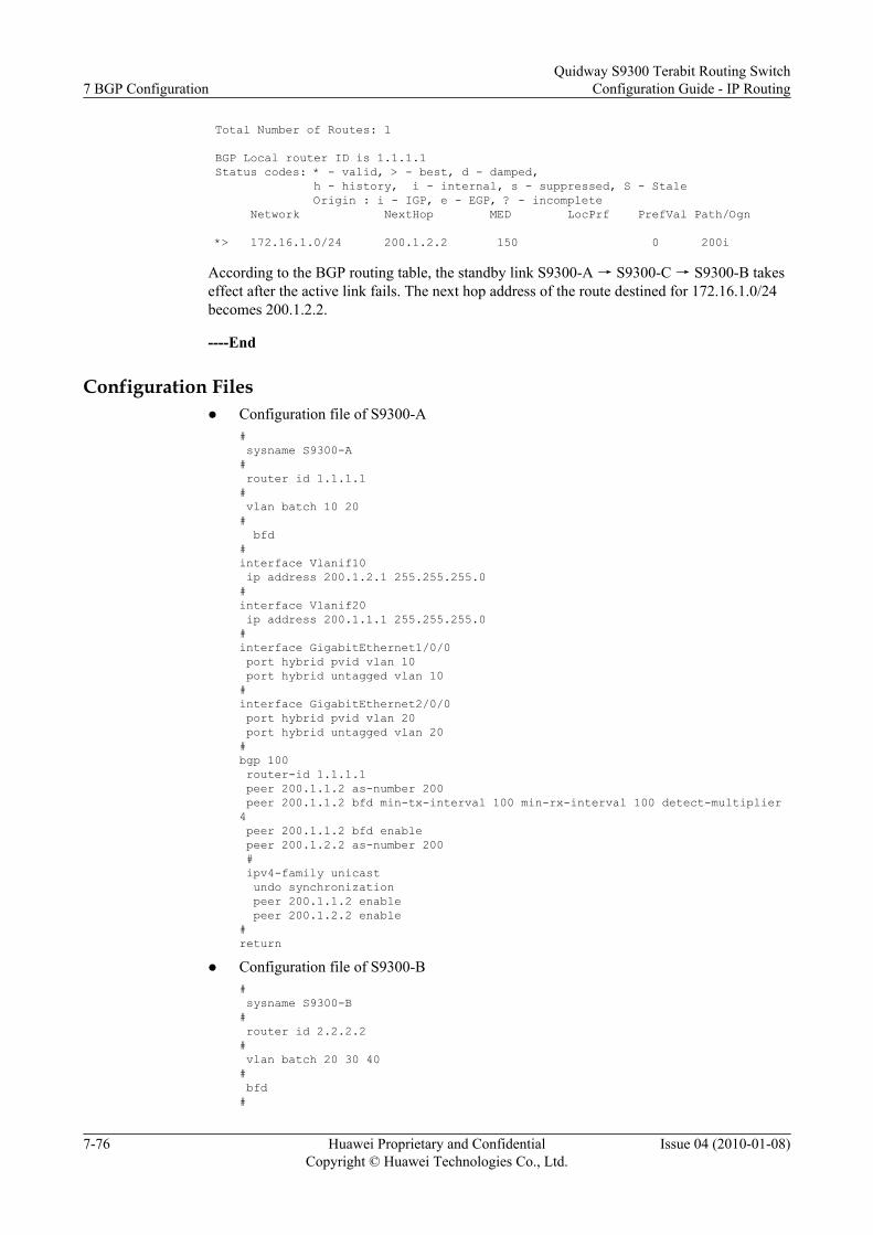
Total Number of Routes: 1
BGP Local router ID is 1.1.1.1 Status codes: * - valid, > - best, d - damped, h - history, i - internal, s - suppressed, S - Stale Origin : i - IGP, e - EGP, ? - incomplete Network NextHop MED LocPrf PrefVal Path/Ogn
*> 172.16.1.0/24 200.1.2.2 150 0 200i
According to the BGP routing table, the standby link S9300-A → S9300-C → S9300-B takeseffect after the active link fails. The next hop address of the route destined for 172.16.1.0/24becomes 200.1.2.2.
----End
Configuration Filesl Configuration file of S9300-A
# sysname S9300-A# router id 1.1.1.1# vlan batch 10 20# bfd#interface Vlanif10 ip address 200.1.2.1 255.255.255.0#interface Vlanif20 ip address 200.1.1.1 255.255.255.0#interface GigabitEthernet1/0/0 port hybrid pvid vlan 10 port hybrid untagged vlan 10#interface GigabitEthernet2/0/0 port hybrid pvid vlan 20 port hybrid untagged vlan 20#bgp 100 router-id 1.1.1.1 peer 200.1.1.2 as-number 200 peer 200.1.1.2 bfd min-tx-interval 100 min-rx-interval 100 detect-multiplier 4 peer 200.1.1.2 bfd enable peer 200.1.2.2 as-number 200 # ipv4-family unicast undo synchronization peer 200.1.1.2 enable peer 200.1.2.2 enable#return
l Configuration file of S9300-B# sysname S9300-B# router id 2.2.2.2# vlan batch 20 30 40# bfd#
7 BGP ConfigurationQuidway S9300 Terabit Routing Switch
Configuration Guide - IP Routing
7-76 Huawei Proprietary and ConfidentialCopyright © Huawei Technologies Co., Ltd.
Issue 04 (2010-01-08)

interface Vlanif30 ip address 9.1.1.1 255.255.255.0#interface Vlanif20 ip address 200.1.1.2 255.255.255.0#interface Vlanif40 ip address 172.16.1.1 255.255.255.0#interface GigabitEthernet1/0/0 port hybrid pvid vlan 30 port hybrid untagged vlan 30#interface GigabitEthernet2/0/0 port hybrid pvid vlan 20 port hybrid untagged vlan 20#interface GigabitEthernet3/0/0 port hybrid pvid vlan 40 port hybrid untagged vlan 40#bgp 200 router-id 2.2.2.2 peer 9.1.1.2 as-number 200 peer 200.1.1.1 as-number 100 peer 200.1.1.1 bfd min-tx-interval 100 min-rx-interval 100 detect-multiplier 4 peer 200.1.1.1 bfd enable # ipv4-family unicast undo synchronization network 172.16.1.0 255.255.255.0 peer 9.1.1.2 enable peer 200.1.1.1 enable peer 200.1.1.1 route-policy toa export#route-policy toa permit node 10 apply cost 100#return
l Configuration file of S9300-C# sysname S9300-C# router id 3.3.3.3# vlan batch 10 30# bfd#interface Vlanif10 ip address 200.1.2.2 255.255.255.0#interface Vlanif30 ip address 9.1.1.2 255.255.255.0#interface GigabitEthernet1/0/0 port hybrid pvid vlan 10 port hybrid untagged vlan 10#interface GigabitEthernet2/0/0 port hybrid pvid vlan 30 port hybrid untagged vlan 30#bgp 200 router-id 3.3.3.3 peer 9.1.1.1 as-number 200 peer 200.1.2.1 as-number 100 #
Quidway S9300 Terabit Routing SwitchConfiguration Guide - IP Routing 7 BGP Configuration
Issue 04 (2010-01-08) Huawei Proprietary and ConfidentialCopyright © Huawei Technologies Co., Ltd.
7-77

ipv4-family unicast undo synchronization peer 9.1.1.1 enable peer 200.1.2.1 enable peer 200.1.2.1 route-policy c2a export#route-policy c2a permit node 10 apply cost 150#return
7.19.4 Example for Configuring BGP Load Balancing and Settingthe MED
Networking RequirementsAs shown in Figure 7-4, all S9300s run BGP. S9300-A resides in AS 65008. Both S9300-B andS9300-C reside in AS 65009. EBGP runs among S9300-A, S9300-B, and S9300-C. IBGP runsbetween S9300-B and S9300-C.
Figure 7-4 Networking diagram of BGP route selection
S9300-A
EBGP
GE1/0/1
GE1/0/1
GE1/0/1
GE1/0/2
GE1/0/2
GE1/0/2
EBGP
AS 65008
AS 65009 IBGP
S9300-B
S9300-C
S9300 Interface VLANIF interface IP address
S9300-A GigabitEthernet1/0/1 VLANIF 10 200.1.1.2/24
S9300-A GigabitEthernet1/0/2 VLANIF 20 200.1.2.2/24
S9300-B GigabitEthernet1/0/1 VLANIF 10 200.1.1.1/24
S9300-B GigabitEthernet1/0/2 VLANIF 30 9.1.1.1/24
S9300-C GigabitEthernet1/0/1 VLANIF 20 200.1.2.1/24
S9300-C GigabitEthernet1/0/2 VLANIF 30 9.1.1.2/24
Configuration RoadmapThe configuration roadmap is as follows:
7 BGP ConfigurationQuidway S9300 Terabit Routing Switch
Configuration Guide - IP Routing
7-78 Huawei Proprietary and ConfidentialCopyright © Huawei Technologies Co., Ltd.
Issue 04 (2010-01-08)

1. Establish EBGP connections between S9300-A and S9300-B, and between S9300-A andS9300-C; establish an IBGP connection between S9300-B and S9300-C.
2. Configure load balancing and set the MED on S9300-A and check the routing table.
ContextTo complete the configuration, you need the following data:
l ID of the VLAN that each interface belongs to, as shown in Figure 7-4
l IP address of each VLANIF interface, as shown in Figure 7-4
l Router IDs of S9300-A being 1.1.1.1, number of the AS where it resides being 65008, andnumber of routes for load balancing being 2
l Router IDs of S9300-B and S9300-C being 2.2.2.2 and 3.3.3.3, number of the AS wherethey reside being 65008, and default MED of S9300-B being 100
Procedure
Step 1 Create VLANs and add interfaces to the corresponding VLANs.<Quidway> system-view[Quidway] sysname S9300-A[S9300-A] vlan batch 10 20[S9300-A] interface GigabitEthernet 1/0/1[S9300-A-GigabitEthernet1/0/1] port hybrid pvid vlan 10[S9300-A-GigabitEthernet1/0/1] port hybrid untagged vlan 10[S9300-A-GigabitEthernet1/0/1] quit[S9300-A] interface GigabitEthernet 1/0/2[S9300-A-GigabitEthernet1/0/2]port hybrid pvid vlan 20[S9300-A-GigabitEthernet1/0/2]port hybrid untagged vlan 20[S9300-A-GigabitEthernet1/0/2] quit
The configurations of S9300-B and S9300-C are the same as the configuration of S9300-A, andare not mentioned here.
Step 2 Assign an IP address to each VLANIF interface.[S9300-A] interface vlanif 10[S9300-A-Vlanif10] ip address 200.1.1.2 24[S9300-A-Vlanif10] quit[S9300-A] interface vlanif 20[S9300-A-Vlanif20] ip address 200.1.2.2 24[S9300-A-Vlanif20] quit
The configurations of S9300-B and S9300-C are the same as the configuration of S9300-A, andare not mentioned here.
Step 3 Establish an EBGP connection.
# Configure S9300-A.
[S9300-A] bgp 65008[S9300-A-bgp] router-id 1.1.1.1[S9300-A-bgp] peer 200.1.1.1 as-number 65009[S9300-A-bgp] peer 200.1.2.1 as-number 65009[S9300-A-bgp] quit
# Configure S9300-B.
[S9300-B] bgp 65009[S9300-B-bgp] router-id 2.2.2.2[S9300-B-bgp] peer 200.1.1.2 as-number 65008[S9300-B-bgp] peer 9.1.1.2 as-number 65009[S9300-B-bgp] ipv4-family unicast
Quidway S9300 Terabit Routing SwitchConfiguration Guide - IP Routing 7 BGP Configuration
Issue 04 (2010-01-08) Huawei Proprietary and ConfidentialCopyright © Huawei Technologies Co., Ltd.
7-79

[S9300-B-bgp-af-ipv4] network 9.1.1.0 255.255.255.0[S9300-B-bgp-af-ipv4] quit[S9300-B-bgp] quit
# Configure S9300-C.
[S9300-C] bgp 65009[S9300-C-bgp] router-id 3.3.3.3[S9300-C-bgp] peer 200.1.2.2 as-number 65008[S9300-C-bgp] peer 9.1.1.1 as-number 65009[S9300-C-bgp] ipv4-family unicast[S9300-C-bgp-af-ipv4] network 9.1.1.0 255.255.255.0[S9300-C-bgp-af-ipv4] quit[S9300-C-bgp] quit
# Check the routing table of S9300-A.
[S9300-A] display bgp routing-table Total Number of Routes: 2 BGP Local router ID is 1.1.1.1 Status codes: * - valid, > - best, d - damped, h - history, i - internal, s - suppressed, S - Stale Origin : i - IGP, e - EGP, ? - incomplete Network NextHop MED LocPrf PrefVal Path/Ogn *> 9.1.1.0/24 200.1.1.1 0 0 65009i * 200.1.2.1 0 0 65009i
According to the routing table, you can view that there are two valid routes destined for9.1.1.0/24. The route whose next hop is 200.1.1.1 is the optimal route because the router ID ofS9300-B is smaller.
Step 4 Configure load balancing.
# Configure S9300-A.
[S9300-A] bgp 65008[S9300-A-bgp] ipv4-family unicast [S9300-A-bgp-af-ipv4] maximum load-balancing 2[S9300-A-bgp-af-ipv4] quit[S9300-A-bgp] quit
# Check the routing table of S9300-A.
[S9300-A] display bgp routing-table Total Number of Routes: 2 BGP Local router ID is 1.1.1.1 Status codes: * - valid, > - best, d - damped, h - history, i - internal, s - suppressed, S - Stale Origin : i - IGP, e - EGP, ? - incomplete Network NextHop MED LocPrf PrefVal Path/Ogn *> 9.1.1.0/24 200.1.1.1 0 0 65009i *> 200.1.2.1 0 0 65009i
According to the routing table, you can view that the BGP route 9.1.1.0/24 has two next hopsthat are 200.1.1.1 and 200.1.2.1. Both of them are optimal routes.
Step 5 Set the MED.
# Set the MED sent from S9300-B to S9300-A through the policy.
[S9300-B] route-policy 10 permit node 10[S9300-B-route-policy] apply cost 100[S9300-B-route-policy] quit
7 BGP ConfigurationQuidway S9300 Terabit Routing Switch
Configuration Guide - IP Routing
7-80 Huawei Proprietary and ConfidentialCopyright © Huawei Technologies Co., Ltd.
Issue 04 (2010-01-08)

[S9300-B] bgp 65009[S9300-B-bgp] peer 200.1.1.2 route-policy 10 export
# Check the routing table of S9300-A.[S9300-A] display bgp routing-table Total Number of Routes: 2 BGP Local router ID is 1.1.1.1 Status codes: * - valid, > - best, d - damped, h - history, i - internal, s - suppressed, S - Stale Origin : i - IGP, e - EGP, ? - incomplete Network NextHop MED LocPrf PrefVal Path/Ogn *> 9.1.1.0/24 200.1.2.1 0 0 65009i * 200.1.1.1 100 0 65009i
According to the routing table, you can view that the MED of the next hop 200.1.1.1 (S9300-B) is 100, and that of the next hop 200.1.2.1 is 0. Therefore, the route with the smaller MED isselected.
----End
Configuration Filesl Configuration file of S9300-A
# sysname S9300-A# vlan batch 10 20#interface Vlanif10 ip address 200.1.1.2 255.255.255.0#interface Vlanif20 ip address 200.1.2.2 255.255.255.0#interface GigabitEthernet1/0/1 port hybrid pvid vlan 10 port hybrid untagged vlan 10#interface GigabitEthernet1/0/2 port hybrid pvid vlan 20 port hybrid untagged vlan 20#bgp 65008 router-id 1.1.1.1 peer 200.1.1.1 as-number 65009 peer 200.1.2.1 as-number 65009 # ipv4-famlily unicast undo synchronization maximum load-balancing 2 peer 200.1.1.1 enable peer 200.1.2.1 enable#return
l Configuration file of S9300-B# sysname S9300-B# vlan batch 10 30#interface Vlanif10 ip address 200.1.1.1 255.255.255.0#
Quidway S9300 Terabit Routing SwitchConfiguration Guide - IP Routing 7 BGP Configuration
Issue 04 (2010-01-08) Huawei Proprietary and ConfidentialCopyright © Huawei Technologies Co., Ltd.
7-81

interface Vlanif30 ip address 9.1.1.1 255.255.255.0#interface GigabitEthernet1/0/1 port hybrid pvid vlan 10 port hybrid untagged vlan 10#interface GigabitEthernet1/0/2 port hybrid pvid vlan 30 port hybrid untagged vlan 30#bgp 65009 router-id 2.2.2.2 peer 9.1.1.2 as-number 65009 peer 200.1.1.2 as-number 65008 # ipv4-family unicast undo synchronization default med 100 network 9.1.1.0 255.255.255.0 peer 9.1.1.2 enable peer 200.1.1.2 enable peer 200.1.1.2 route-policy 10 export#route-policy 10 permit node 10 apply cost 100#return
l Configuration file of S9300-C# sysname S9300-C# vlan batch 20 30#interface Vlanif10 ip address 200.1.2.1 255.255.255.0#interface Vlanif30 ip address 9.1.1.2 255.255.255.0#interface GigabitEthernet1/0/1 port hybrid pvid vlan 20 port hybrid untagged vlan 20#interface GigabitEthernet1/0/2 port hybrid pvid vlan 30 port hybrid untagged vlan 30#bgp 65009 router-id 3.3.3.3 peer 9.1.1.1 as-number 65009 peer 200.1.2.2 as-number 65008 # ipv4-family unicast undo synchronization network 9.1.1.0 255.255.255.0 peer 9.1.1.1 enable peer 200.1.2.2 enable#return
7.19.5 Example for Configuring a BGP RR
Networking RequirementsAs shown in Figure 7-5, S9300-A is a non-client. S9300-B is the RR of cluster 1. S9300-D andS9300-E are two clients of cluster 1. Because the IBGP connection is created between S9300-
7 BGP ConfigurationQuidway S9300 Terabit Routing Switch
Configuration Guide - IP Routing
7-82 Huawei Proprietary and ConfidentialCopyright © Huawei Technologies Co., Ltd.
Issue 04 (2010-01-08)

D and S9300-E, they do not need an RR. S9300-C is the RR of cluster 2. S9300-F, S9300-G,and S9300-H are the clients of cluster 2.
It is required that the peer groups be used to simplify configuration and management.
Figure 7-5 Networking diagram for configuring a BGP RR
S9300-A
S9300-B
S9300-D
GE1/0/1
GE1/0/1
GE1/0/2GE1/0/3
GE1/0/2
GE1/0/3
GE1/0/1
GE1/0/2GE1/0/4GE1/0/4 GE1/0/3
GE1/0/1GE1/0/2
GE1/0/1
GE1/0/2
GE2/0/1GE1/0/1
GE1/0/1GE1/0/1
AS 65010
Cluster1 Cluster2
S9300-E S9300-F S9300-G
S9300-HS9300-C
S9300 Interface VLANIF interface IP address
S9300-A GigabitEthernet1/0/1 VLANIF 10 10.1.1.2/24
S9300-A GigabitEthernet1/0/2 VLANIF 30 10.1.3.2/24
S9300-A GigabitEthernet1/0/3 VLANIF 100 9.1.1.1/24
S9300-B GigabitEthernet1/0/1 VLANIF 10 10.1.1.1/24
S9300-B GigabitEthernet1/0/2 VLANIF 20 10.1.2.1/24
S9300-B GigabitEthernet1/0/3 VLANIF 40 10.1.4.1/24
S9300-B GigabitEthernet1/0/4 VLANIF 50 10.1.5.1/24
S9300-C GigabitEthernet1/0/1 VLANIF 30 10.1.3.1/24
S9300-C GigabitEthernet1/0/2 VLANIF 20 10.1.2.2/24
S9300-C GigabitEthernet1/0/3 VLANIF 70 10.1.7.1/24
S9300-C GigabitEthernet1/0/4 VLANIF 80 10.1.8.1/24
S9300-C GigabitEthernet2/0/1 VLANIF 90 10.1.9.1/24
S9300-D GigabitEthernet1/0/1 VLANIF 40 10.1.4.2/24
S9300-D GigabitEthernet1/0/2 VLANIF 60 10.1.6.1/24
S9300-E GigabitEthernet1/0/1 VLANIF 50 10.1.5.2/24
S9300-E GigabitEthernet1/0/2 VLANIF 60 10.1.6.2/24
S9300-F GigabitEthernet1/0/1 VLANIF 70 10.1.7.2/24
S9300-G GigabitEthernet1/0/1 VLANIF 80 10.1.8.2/24
S9300-H GigabitEthernet1/0/1 VLANIF 90 10.1.9.2/24
Quidway S9300 Terabit Routing SwitchConfiguration Guide - IP Routing 7 BGP Configuration
Issue 04 (2010-01-08) Huawei Proprietary and ConfidentialCopyright © Huawei Technologies Co., Ltd.
7-83

Configuration RoadmapThe configuration roadmap is as follows:
1. Establish IBGP connections between the client and the RR, and between the non-client andthe RR.
2. Configure route reflection on S9300-B and S9300-C, specify the client, and check theroutes.
Data PreparationTo complete the configuration, you need the following data:
l ID of the VLAN that each interface belongs to, as shown in Figure 7-5
l IP address of each VLANIF interface, as shown in Figure 7-5
l Number of the AS where all S9300s reside being 65010
l Router IDs of S9300-A, S9300-B, S9300-C, S9300-D, S9300-E, S9300-F, S9300-G, andS9300-H being 1.1.1.1, 2.2.2.2, 3.3.3.3, 4.4.4.4, 5.5.5.5, 6.6.6.6, 7.7.7.7, and 8.8.8.8
l ID of the cluster where S9300-B resides being 1 and ID of the cluster where S9300-C residesbeing 2
Procedure
Step 1 Create VLANs and add interfaces to the corresponding VLANs.<Quidway> system-view[Quidway] sysname S9300-A[Quidway] vlan batch 10 30 100[S9300-A] interface GigabitEthernet 1/0/1[S9300-A-GigabitEthernet1/0/1] port hybrid pvid vlan 10[S9300-A-GigabitEthernet1/0/1] port hybrid untagged vlan 10[S9300-A-GigabitEthernet1/0/1] quit[S9300-A] interface GigabitEthernet 1/0/2[S9300-A-GigabitEthernet1/0/2] port hybrid pvid vlan 30[S9300-A-GigabitEthernet1/0/2] port hybrid untagged vlan 30[S9300-A-GigabitEthernet1/0/2] quit[S9300-A] interface GigabitEthernet 1/0/3[S9300-A-GigabitEthernet1/0/3] port hybrid pvid vlan 100[S9300-A-GigabitEthernet1/0/3] port hybrid untagged vlan 100[S9300-A-GigabitEthernet1/0/3] quit
The configurations of S9300-B, S9300-C, S9300-D, S9300-E, S9300-F, S9300-G, and S9300-H are the same as the configuration of S9300-A, and are not mentioned here.
Step 2 Assign an IP address to each VLANIF interface.[S9300-A] interface vlanif 10[S9300-A-Vlanif10] ip address 10.1.1.2 24[S9300-A-Vlanif10] quit[S9300-A] interface vlanif 30[S9300-A-Vlanif30] ip address 10.1.3.2 24[S9300-A-Vlanif30] quit[S9300-A] interface vlanif 100[S9300-A-Vlanif100] ip address 9.1.1.1 24[S9300-A-Vlanif100] quit
Step 3 Establish IBGP connections between the clients and the RR, and between the non-clients andthe RR. The configuration details are not mentioned here.
7 BGP ConfigurationQuidway S9300 Terabit Routing Switch
Configuration Guide - IP Routing
7-84 Huawei Proprietary and ConfidentialCopyright © Huawei Technologies Co., Ltd.
Issue 04 (2010-01-08)

Step 4 Configure S9300-A to advertise the local network route 9.1.1.0/24. The configuration detailsare not mentioned here.
Step 5 Configure the RR.
# Configure S9300-B.
[S9300-B] bgp 65010[S9300-B-bgp] router-id 2.2.2.2[S9300-B-bgp] group in_rr internal[S9300-B-bgp] peer 10.1.4.2 group in_rr[S9300-B-bgp] peer 10.1.5.2 group in_rr[S9300-B-bgp] ipv4-family unicast[S9300-B-bgp-af-ipv4] peer in_rr reflect-client[S9300-B-bgp-af-ipv4] undo reflect between-clients[S9300-B-bgp-af-ipv4] reflector cluster-id 1[S9300-B-bgp-af-ipv4] quit[S9300-B-bgp] quit
# Configure S9300-C.
[S9300-C] bgp 65010[S9300-C-bgp] router-id 3.3.3.3[S9300-C-bgp] group in_rr internal[S9300-C-bgp] peer 10.1.7.2 group in_rr [S9300-C-bgp] peer 10.1.8.2 group in_rr[S9300-C-bgp] peer 10.1.9.2 group in_rr[S9300-C-bgp] ipv4-family unicast [S9300-C-bgp-af-ipv4] peer in_rr reflect-client[S9300-C-bgp-af-ipv4] reflector cluster-id 2[S9300-C-bgp-af-ipv4] quit[S9300-C-bgp] quit
# Check the routing table of S9300-D.
[S9300-D] display bgp routing-table 9.1.1.0 BGP local router ID : 4.4.4.4 Local AS number : 65010 Paths: 1 available, 0 best BGP routing table entry information of 9.1.1.0/24: From: 10.1.4.1 (2.2.2.2) Original nexthop: 10.1.1.2 Convergence Priority: AS-path Nil, origin igp, MED 0, localpref 100, pref-val 0, internal, pre 255 Originator: 1.1.1.1 Cluster list: 0.0.0.1 Not advertised to any peers yet
According to the routing table, you can view that S9300-D has learned the route advertised byS9300-A from S9300-B. You can also view the Originator and Cluster_ID of the route.
----End
Configuration Filesl Configuration file of S9300-A
# sysname S9300-A# vlan batch 10 30 100#interface Vlanif10 ip address 10.1.1.2 255.255.255.0#
Quidway S9300 Terabit Routing SwitchConfiguration Guide - IP Routing 7 BGP Configuration
Issue 04 (2010-01-08) Huawei Proprietary and ConfidentialCopyright © Huawei Technologies Co., Ltd.
7-85

interface Vlanif30 ip address 10.1.3.2 255.255.255.0#interface Vlanif100 ip address 9.1.1.1 255.255.255.0#interface GigabitEthernet1/0/1 port hybrid pvid vlan 10 port hybrid untagged vlan 10#interface GigabitEthernet1/0/2 port hybrid pvid vlan 30 port hybrid untagged vlan 30#interface GigabitEthernet1/0/3 port hybrid pvid vlan 100 port hybrid untagged vlan 100#bgp 65010 router-id 1.1.1.1 peer 10.1.1.1 as-number 65010 peer 10.1.3.1 as-number 65010 # ipv4-family unicast undo synchronization network 9.1.1.0 255.255.255.0 peer 10.1.1.1 enable peer 10.1.3.1 enable#return
l Configuration file of S9300-B# sysname S9300-B# vlan batch 10 20 40 50#interface Vlanif10 ip address 10.1.1.1 255.255.255.0#interface Vlanif20 ip address 10.1.2.1 255.255.255.0#interface Vlanif40 ip address 10.1.4.1 255.255.255.0#interface Vlanif50 ip address 10.1.5.1 255.255.255.0#interface GigabitEthernet1/0/1 port hybrid pvid vlan 10 port hybrid untagged vlan 10#interface GigabitEthernet1/0/2 port hybrid pvid vlan 20 port hybrid untagged vlan 20#interface GigabitEthernet1/0/3 port hybrid pvid vlan 40 port hybrid untagged vlan 40#interface GigabitEthernet1/0/4 port hybrid pvid vlan 50 port hybrid untagged vlan 50#bgp 65010 router-id 2.2.2.2 peer 10.1.1.2 as-number 65010 peer 10.1.2.2 as-number 65010 group in_rr internal
7 BGP ConfigurationQuidway S9300 Terabit Routing Switch
Configuration Guide - IP Routing
7-86 Huawei Proprietary and ConfidentialCopyright © Huawei Technologies Co., Ltd.
Issue 04 (2010-01-08)

peer 10.1.4.2 as-number 65010 peer 10.1.4.2 group in_rr peer 10.1.5.2 as-number 65010 peer 10.1.5.2 group in_rr # ipv4-family unicast undo synchronization undo reflect between-clients reflector cluster-id 1 peer 10.1.1.2 enable peer 10.1.2.2 enable peer in_rr enable peer in_rr reflect-client peer 10.1.4.2 enable peer 10.1.4.2 group in_rr peer 10.1.5.2 enable peer 10.1.5.2 group in_rr #return
l Configuration file of S9300-C# sysname S9300-C# vlan batch 20 30 70 80 90#interface Vlanif20 ip address 10.1.2.2 255.255.255.0#interface Vlanif30 ip address 10.1.3.1 255.255.255.0#interface Vlanif70 ip address 10.1.7.1 255.255.255.0#interface Vlanif80 ip address 10.1.8.1 255.255.255.0#interface Vlanif90 ip address 10.1.9.1 255.255.255.0#interface GigabitEthernet1/0/1 port hybrid pvid vlan 30 port hybrid untagged vlan 30#interface GigabitEthernet1/0/2 port hybrid pvid vlan 20 port hybrid untagged vlan 20#interface GigabitEthernet1/0/3 port hybrid pvid vlan 70 port hybrid untagged vlan 70#interface GigabitEthernet1/0/4 port hybrid pvid vlan 80 port hybrid untagged vlan 80#interface GigabitEthernet2/0/1 port hybrid pvid vlan 90 port hybrid untagged vlan 90#bgp 65010 router-id 3.3.3.3 peer 10.1.2.1 as-number 65010 peer 10.1.3.2 as-number 65010 group in_rr internal peer 10.1.7.2 as-number 65010 peer 10.1.7.2 group in_rr peer 10.1.8.2 as-number 65010 peer 10.1.8.2 group in_rr
Quidway S9300 Terabit Routing SwitchConfiguration Guide - IP Routing 7 BGP Configuration
Issue 04 (2010-01-08) Huawei Proprietary and ConfidentialCopyright © Huawei Technologies Co., Ltd.
7-87

peer 10.1.9.2 as-number 65010 peer 10.1.9.2 group in_rr # ipv4-family unicast undo synchronization reflector cluster-id 2 peer 10.1.2.1 enable peer 10.1.3.2 enable peer in_rr enable peer in_rr reflect-client peer 10.1.7.2 enable peer 10.1.7.2 group in_rr peer 10.1.8.2 enable peer 10.1.8.2 group in_rr peer 10.1.9.2 enable peer 10.1.9.2 group in_rr#return
l Configuration file of S9300-D# sysname S9300-D# vlan batch 40 60#interface Vlanif40 ip address 10.1.4.2 255.255.255.0#interface Vlanif60 ip address 10.1.6.1 255.255.255.0#interface GigabitEthernet1/0/1 port hybrid pvid vlan 40 port hybrid untagged vlan 40#interface GigabitEthernet1/0/2 port hybrid pvid vlan 60 port hybrid untagged vlan 60#bgp 65010 router-id 4.4.4.4 peer 10.1.4.1 as-number 65010 peer 10.1.6.2 as-number 65010 # ipv4-family unicast undo synchronization peer 10.1.4.1 enable peer 10.1.6.2 enable#return
NOTE
The configuration files of other S9300s are similar to the configuration file of S9300-D, and are notmentioned here.
7.19.6 Example for Configuring a BGP Confederation
Networking RequirementsAs shown in Figure 7-6, several S9300s run BGP in AS 200. To reduce the number of IBGPconnections, divide AS 200 into three sub-ASs, namely AS 65001, AS 65002, and AS 65003.In addition, IBGP connections are set up between the three S9300s in AS 65001.
7 BGP ConfigurationQuidway S9300 Terabit Routing Switch
Configuration Guide - IP Routing
7-88 Huawei Proprietary and ConfidentialCopyright © Huawei Technologies Co., Ltd.
Issue 04 (2010-01-08)

Figure 7-6 Networking diagram for configuring a BGP confederation
S9300-E
GE1/0/4GE1/0/3
GE1/0/1GE1/0/2
GE2/0/1
GE1/0/1 GE1/0/1
GE1/0/1
GE1/0/1 GE1/0/2
GE1/0/2
GE1/0/1
GE1/0/2
S9300-AS9300-F
AS 100
AS 200
AS 65002
AS 65003
AS 65001
S9300-B S9300-C
S9300-D
S9300 Interface VLANIF interface IP address
S9300-A GigabitEthernet1/0/1 VLANIF 10 10.1.1.1/24
S9300-A GigabitEthernet1/0/2 VLANIF 20 10.1.2.1/24
S9300-A GigabitEthernet1/0/3 VLANIF 30 10.1.3.1/24
S9300-A GigabitEthernet1/0/4 VLANIF 40 10.1.4.1/24
S9300-A GigabitEthernet2/0/1 VLANIF 60 200.1.1.1/24
S9300-B GigabitEthernet1/0/1 VLANIF 10 10.1.1.2/24
S9300-C GigabitEthernet1/0/1 VLANIF 20 10.1.2.2/24
S9300-D GigabitEthernet1/0/1 VLANIF 30 10.1.3.2/24
S9300-D GigabitEthernet1/0/2 VLANIF 50 10.1.5.1/24
S9300-E GigabitEthernet1/0/1 VLANIF 40 10.1.4.2/24
S9300-E GigabitEthernet1/0/2 VLANIF 50 10.1.5.2/24
S9300-F GigabitEthernet1/0/1 VLANIF 60 200.1.1.2/24
S9300-F GigabitEthernet1/0/2 VLANIF 70 9.1.1.1/24
Configuration Roadmap
The configuration roadmap is as follows:
1. Configure the BGP confederation on each S9300 in AS 200.2. Establish IBGP connections in AS 65001.3. Establish EBGP connections between AS 100 and AS 200, and check the routes.
Quidway S9300 Terabit Routing SwitchConfiguration Guide - IP Routing 7 BGP Configuration
Issue 04 (2010-01-08) Huawei Proprietary and ConfidentialCopyright © Huawei Technologies Co., Ltd.
7-89

Data PreparationTo complete the configuration, you need the following data:
l ID of the VLAN that each interface belongs to, as shown in Figure 7-6
l IP address of each VLANIF interface, as shown in Figure 7-6
l Router IDs of S9300-A, S9300-B, S9300-C, S9300-D, S9300-E, and S9300-F being1.1.1.1, 2.2.2.2, 3.3.3.3, 4.4.4.4, 5.5.5.5, and 6.6.6.6
l AS 100, AS 200, and three sub-AS numbers of AS 200 are 65001, 65002, and 65003
Procedure
Step 1 Create VLANs and add interfaces to the corresponding VLANs.<Quidway> system-view[Quidway] sysname S9300-A[S9300-A] vlan batch 10 20 30 40 60[S9300-A] interface GigabitEthernet 1/0/1[S9300-A-GigabitEthernet1/0/1] port hybrid pvid vlan 10[S9300-A-GigabitEthernet1/0/1] port hybrid untagged vlan 10[S9300-A-GigabitEthernet1/0/1] quit[S9300-A] interface GigabitEthernet 1/0/2[S9300-A-GigabitEthernet1/0/2] port hybrid pvid vlan 20[S9300-A-GigabitEthernet1/0/2] port hybrid untagged vlan 20[S9300-A-GigabitEthernet1/0/2] quit[S9300-A] interface GigabitEthernet 1/0/3[S9300-A-GigabitEthernet1/0/3] port hybrid pvid vlan 30[S9300-A-GigabitEthernet1/0/3] port hybrid untagged vlan 30[S9300-A-GigabitEthernet1/0/3] quit[S9300-A] interface GigabitEthernet 1/0/4[S9300-A-GigabitEthernet1/0/4] port hybrid pvid vlan 40[S9300-A-GigabitEthernet1/0/4] port hybrid untagged vlan 40[S9300-A-GigabitEthernet1/0/4] quit[S9300-A] interface GigabitEthernet 2/0/1[S9300-A-GigabitEthernet2/0/1] port hybrid pvid vlan 60[S9300-A-GigabitEthernet2/0/1] port hybrid untagged vlan 60[S9300-A-GigabitEthernet2/0/1] quit
The configurations of S9300-B, S9300-C, S9300-D, S9300-E, and S9300-F are the same as theconfiguration of S9300-A, and are not mentioned here.
Step 2 Assign an IP address to each VLANIF interface.[S9300-A] interface vlanif 10[S9300-A-Vlanif10] ip address 10.1.1.1 24[S9300-A-Vlanif10] quit[S9300-A] interface vlanif 20[S9300-A-Vlanif20] ip address 10.1.2.1 24[S9300-A-Vlanif20] quit[S9300-A] interface vlanif 30[S9300-A-Vlanif30] ip address 10.1.3.1 24[S9300-A-Vlanif30] quit[S9300-A] interface vlanif 40[S9300-A-Vlanif40] ip address 10.1.4.1 24[S9300-A-Vlanif40] quit[S9300-A] interface vlanif 60[S9300-A-Vlanif60] ip address 200.1.1.1 24[S9300-A-Vlanif60] quit
The configurations of S9300-B, S9300-C, S9300-D, S9300-E, and S9300-F are the same as theconfiguration of S9300-A, and are not mentioned here.
Step 3 Configure the BGP confederation.
# Configure S9300-A.
7 BGP ConfigurationQuidway S9300 Terabit Routing Switch
Configuration Guide - IP Routing
7-90 Huawei Proprietary and ConfidentialCopyright © Huawei Technologies Co., Ltd.
Issue 04 (2010-01-08)

[S9300-A] bgp 65001[S9300-A-bgp] router-id 1.1.1.1[S9300-A-bgp] confederation id 200[S9300-A-bgp] confederation peer-as 65002 65003[S9300-A-bgp] peer 10.1.1.2 as-number 65002 [S9300-A-bgp] peer 10.1.2.2 as-number 65003[S9300-A-bgp] ipv4-family unicast [S9300-A-bgp-af-ipv4] peer 10.1.1.2 next-hop-local[S9300-A-bgp-af-ipv4] peer 10.1.2.2 next-hop-local [S9300-A-bgp-af-ipv4] quit[S9300-A-bgp] quit
# Configure S9300-B.
[S9300-B] bgp 65002[S9300-B-bgp] router-id 2.2.2.2[S9300-B-bgp] confederation id 200[S9300-B-bgp] confederation peer-as 65001 65003[S9300-B-bgp] peer 10.1.1.1 as-number 65001[S9300-B-bgp] quit
# Configure S9300-C.
[S9300-C] bgp 65003[S9300-C-bgp] router-id 3.3.3.3[S9300-C-bgp] confederation id 200[S9300-C-bgp] confederation peer-as 65001 65002[S9300-C-bgp] peer 10.1.2.1 as-number 65001[S9300-C-bgp] quit
Step 4 Establish IBGP connection in AS 65001.
# Configure S9300-A.
[S9300-A] bgp 65001[S9300-A-bgp] peer 10.1.3.2 as-number 65001[S9300-A-bgp] peer 10.1.4.2 as-number 65001[S9300-A-bgp] ipv4-family unicast[S9300-A-bgp-af-ipv4] peer 10.1.3.2 next-hop-local[S9300-A-bgp-af-ipv4] peer 10.1.4.2 next-hop-local[S9300-A-bgp-af-ipv4] quit
# Configure S9300-D.
[S9300-D] bgp 65001[S9300-D-bgp] router-id 4.4.4.4[S9300-D-bgp] peer 10.1.3.1 as-number 65001[S9300-D-bgp] peer 10.1.5.2 as-number 65001 [S9300-D-bgp] quit
# Configure S9300-E.
[S9300-E] bgp 65001[S9300-E-bgp] router-id 5.5.5.5[S9300-E-bgp] peer 10.1.4.1 as-number 65001[S9300-E-bgp] peer 10.1.5.1 as-number 65001 [S9300-E-bgp] quit
Step 5 Establish an EBGP connection between AS 100 and AS 200.
# Configure S9300-A.
[S9300-A] bgp 65001[S9300-A-bgp] peer 200.1.1.2 as-number 100 [S9300-A-bgp] quit
# Configure S9300-F.
[S9300-F] bgp 100[S9300-F-bgp] router-id 6.6.6.6
Quidway S9300 Terabit Routing SwitchConfiguration Guide - IP Routing 7 BGP Configuration
Issue 04 (2010-01-08) Huawei Proprietary and ConfidentialCopyright © Huawei Technologies Co., Ltd.
7-91

[S9300-F-bgp] peer 200.1.1.1 as-number 200 [S9300-F-bgp] ipv4-family unicast [S9300-F-bgp-af-ipv4] network 9.1.1.0 255.255.255.0[S9300-F-bgp-af-ipv4] quit[S9300-F-bgp] quit
Step 6 Verify the configuration.
# Check the BGP routing table of S9300-B.
[S9300-B] display bgp routing-table Total Number of Routes: 1 BGP Local router ID is 2.2.2.2 Status codes: * - valid, > - best, d - damped, h - history, i - internal, s - suppressed, S - Stale Origin : i - IGP, e - EGP, ? - incomplete Network NextHop MED LocPrf PrefVal Path/Ogn *>i 9.1.1.0/24 10.1.1.1 0 100 0 (65001) 100i[S9300-B] display bgp routing-table 9.1.1.0 BGP local router ID : 2.2.2.2 Local AS number : 65002 Paths: 1 available, 1 best BGP routing table entry information of 9.1.1.0/24: From: 10.1.1.1 (1.1.1.1) Relay Nexthop: 0.0.0.0 Original nexthop: 10.1.1.1 Convergence Priority: 0 AS-path (65001) 100, origin igp, MED 0, localpref 100, pref-val 0, valid, exter nal-confed, best, pre 255 Not advertised to any peers yet
# Check the BGP routing table of S9300-D.
[S9300-D] display bgp routing-table Total Number of Routes: 1 BGP Local router ID is 4.4.4.4 Status codes: * - valid, > - best, d - damped, h - history, i - internal, s - suppressed, S - Stale Origin : i - IGP, e - EGP, ? - incomplete Network NextHop MED LocPrf PrefVal Path/Ogn *>i 9.1.1.0/24 10.1.3.1 0 100 0 100i[S9300-D] display bgp routing-table 9.1.1.0 BGP local router ID : 4.4.4.4 Local AS number : 65001 Paths: 1 available, 1 best BGP routing table entry information of 9.1.1.0/24: From: 10.1.3.1 (1.1.1.1) Relay Nexthop: 0.0.0.0 Original nexthop: 10.1.3.1 Convergence Priority: 0 AS-path 100, origin igp, MED 0, localpref 100, pref-val 0, valid, internal, best, pre 255 Not advertised to any peers yet
----End
7 BGP ConfigurationQuidway S9300 Terabit Routing Switch
Configuration Guide - IP Routing
7-92 Huawei Proprietary and ConfidentialCopyright © Huawei Technologies Co., Ltd.
Issue 04 (2010-01-08)

Configuration Filesl Configuration file of S9300-A
# sysname S9300-A# vlan batch 10 20 30 40 60#interface Vlanif10 ip address 10.1.1.1 255.255.255.0#interface Vlanif20 ip address 10.1.2.1 255.255.255.0#interface Vlanif30 ip address 10.1.3.1 255.255.255.0#interface Vlanif40 ip address 10.1.4.1 255.255.255.0#interface Vlanif60 ip address 200.1.1.1 255.255.255.0#interface GigabitEthernet1/0/1 port hybrid pvid vlan 10 port hybrid untagged vlan 10#interface GigabitEthernet1/0/2 port hybrid pvid vlan 20 port hybrid untagged vlan 20#interface GigabitEthernet1/0/3 port hybrid pvid vlan 30 port hybrid untagged vlan 30#interface GigabitEthernet1/0/4 port hybrid pvid vlan 40 port hybrid untagged vlan 40#interface GigabitEthernet2/0/1 port hybrid pvid vlan 60 port hybrid untagged vlan 60#bgp 65001 router-id 1.1.1.1 confederation id 200 confederation peer-as 65002 65003 peer 10.1.1.2 as-number 65002 peer 10.1.2.2 as-number 65003 peer 10.1.3.2 as-number 65001 peer 10.1.4.2 as-number 65001 peer 200.1.1.2 as-number 100 # ipv4-family unicast undo synchronization peer 10.1.1.2 enable peer 10.1.1.2 next-hop-local peer 10.1.2.2 enable peer 10.1.2.2 next-hop-local peer 10.1.3.2 enable peer 10.1.3.2 next-hop-local peer 10.1.4.2 enable peer 10.1.4.2 next-hop-local peer 200.1.1.2 enable#return
l Configuration file of S9300-B
Quidway S9300 Terabit Routing SwitchConfiguration Guide - IP Routing 7 BGP Configuration
Issue 04 (2010-01-08) Huawei Proprietary and ConfidentialCopyright © Huawei Technologies Co., Ltd.
7-93

# sysname S9300-B# vlan batch 10#interface Vlanif10 ip address 10.1.1.2 255.255.255.0#interface GigabitEthernet1/0/1 port hybrid pvid vlan 10 port hybrid untagged vlan 10#bgp 65002 router-id 2.2.2.2 confederation id 200 confederation peer-as 65001 65003 peer 10.1.1.1 as-number 65001 # ipv4-family unicast undo synchronization peer 10.1.1.1 enable#return
7 BGP ConfigurationQuidway S9300 Terabit Routing Switch
Configuration Guide - IP Routing
7-94 Huawei Proprietary and ConfidentialCopyright © Huawei Technologies Co., Ltd.
Issue 04 (2010-01-08)
8 BGP4+ Configuration
About This Chapter
This chapter describes the implementation and configuration procedures of the BGP4+ protocoland provides configuration examples of BGP4+.
8.1 BGP4+ OverviewBGP4+ is a dynamic routing protocol used between Autonomous Systems (ASs). It is anextension of BGP.
8.2 BGP4+ Features Supported by the S9300Most of BGP4+ features supported by the S9300 are similar to those of BGP supported by theS9300.For details, refer to the chapter "BGP Configuration" in the Quidway S9300TerabitRouting Switch Configuration Guide - IP Routing.BGP4+ does not support route aggregationor MP-BGP.
8.3 Configuring Basic BGP4+ FunctionsThis section describes how to start BGP4+ and configure BGP4+ peers.
8.4 (Optional) Configuring BGP4+ Route AttributesThis section describes how to configure BGP4+ route attributes to change BGP4+ routingpolicies.
8.5 (Optional) Controlling the Advertising and Receiving of BGP4+ Routing InformationThis section describes how to filter the BGP4+ routes and apply routing policies.
8.6 (Optional) Setting Parameters of a Connection Between BGP4+ PeersThis section describes how to set the parameters of the BGP4+ peer relation to adjust andoptimize the performance of a BGP network.
8.7 (Optional) Configuring BGP4+ Route DampeningThis section describes how to configure BGP4+ route dampening to suppress unstable routes.
8.8 (Optional) Configuring BGP4+ Load BalancingThis section describes how to configure certain attributes to implement BGP4+ load balancing.
8.9 (Optional) Configuring a BGP4+ Peer GroupThis section describes how to simplify the management of routing policies and improve theefficiency of advertising routes on a large-scale BGP4+ network.
Quidway S9300 Terabit Routing SwitchConfiguration Guide - IP Routing 8 BGP4+ Configuration
Issue 04 (2010-01-08) Huawei Proprietary and ConfidentialCopyright © Huawei Technologies Co., Ltd.
8-1

8.10 (Optional) Configuring a BGP4+ Route ReflectorThis section describes how to simplify the management of routing policies and improve theefficiency of advertising routes on a large-scale IBGP network.
8.11 (Optional) Configuring a BGP4+ ConfederationThis section describes how to simplify the management of routing policies and improve theefficiency of advertising routes on a large-scale BGP network.
8.12 (Optional) Configuring BGP4+ 6PEAfter the 6PE function is enabled, the separated IPv6 networks can be connected through theMulti-Protocol Label Switch (MPLS) tunnel technology.
8.13 Maintaining BGP4+This section describes how to reset BGP4+ connections, clear BGP4+ statistics, and debug BGP4+.
8.14 Configuration ExamplesThis section provides several configuration examples of BGP4+.
8 BGP4+ ConfigurationQuidway S9300 Terabit Routing Switch
Configuration Guide - IP Routing
8-2 Huawei Proprietary and ConfidentialCopyright © Huawei Technologies Co., Ltd.
Issue 04 (2010-01-08)

8.1 BGP4+ OverviewBGP4+ is a dynamic routing protocol used between Autonomous Systems (ASs). It is anextension of BGP.
The traditional BGP4 can manage only the IPv4 routing information. For other network layerprotocols such as IPv6, the traditional BGP4 has a limited capability to transmit routinginformation.
The IETF introduces BGP4+ as a supplement to BGP4 to support multiple network layerprotocols. The RFC for BGP4+ is RFC 2858 (Multiprotocol Extensions for BGP4).
To support IPv6, BGP4 needs to reflect the IPv6 protocol information to the Network LayerReachable Information (NLRI) attribute and the Next_Hop attribute.
BGP4+ introduces two NLRI attributes:
l Multiprotocol Reachable NLRI (MP_REACH_NLRI): advertises the reachable routes andthe next hop information.
l Multiprotocol Unreachable NLRI (MP_UNREACH_NLRI): withdraws the unreachableroutes.
The Next_Hop attribute of BGP4+ is in the format of an IPv6 address. It can be an IPv6 globalunicast address or the link-local address of the next hop.
BGP4+ can be applied to an IPv6 network by using the BGP attribute of multiple protocolextension. The message and routing mechanisms of BGP remain unaltered.
8.2 BGP4+ Features Supported by the S9300Most of BGP4+ features supported by the S9300 are similar to those of BGP supported by theS9300.For details, refer to the chapter "BGP Configuration" in the Quidway S9300TerabitRouting Switch Configuration Guide - IP Routing.BGP4+ does not support route aggregationor MP-BGP.
6PEAfter the 6PE function is enabled, the separated IPv6 networks can be connected through theMulti-Protocol Label Switch (MPLS) tunnel technology. The tunnel in 6PE mode implementsthe dual protocol suite of IPv4/IPv6 on PEs of the Internet Service Provider (ISP). It identifiesIPv6 routes by using the label assigned by the Multiprotocol Border Gateway Protocol (MP-BGP), and implements IPv6 interworking through LSPs between PEs.
8.3 Configuring Basic BGP4+ FunctionsThis section describes how to start BGP4+ and configure BGP4+ peers.
8.3.1 Establishing the Configuration Task
8.3.2 Starting a BGP Process
8.3.3 Configuring an IPv6 Peer
Quidway S9300 Terabit Routing SwitchConfiguration Guide - IP Routing 8 BGP4+ Configuration
Issue 04 (2010-01-08) Huawei Proprietary and ConfidentialCopyright © Huawei Technologies Co., Ltd.
8-3

8.3.4 (Optional) Configuring the Local Interfaces Used for BGP4+ Connections
8.3.5 Checking the Configuration
8.3.1 Establishing the Configuration Task
Applicable EnvironmentBGP4+ is configured in an IPv6 network.
Pre-configuration TasksBefore configuring basic BGP4+ functions, complete the following tasks:
l Enabling IPv6
l Configuring link layer protocol parameters and IP addresses for interfaces to make linklayers of the interfaces Up
Data PreparationTo configure BGP4+, you need the following data.
No. Data
1 Local AS number and router ID
2 IPv6 address and AS number of the peer
3 Interface that sets up the BGP4+ session
8.3.2 Starting a BGP Process
ContextDo as follows on the S9300 on which the BGP4+ connection needs to be set up:
Procedure
Step 1 Run:system-view
The system view is displayed.
Step 2 Run:bgp as-number
BGP is enabled (the local AS number is specified) and the BGP view is displayed.
Step 3 (Optional) Run:router-id ipv4-address
The router ID is set.
Setting or changing the router ID of BGP resets the BGP peer relationship between S9300s.
8 BGP4+ ConfigurationQuidway S9300 Terabit Routing Switch
Configuration Guide - IP Routing
8-4 Huawei Proprietary and ConfidentialCopyright © Huawei Technologies Co., Ltd.
Issue 04 (2010-01-08)

TIP
l To enhance the network reliability, you can manually configure the address of a loopback interface asthe router ID. If the router ID is not set, BGP uses the router ID in the system view. To select the routerID in the system view, refer to the Quidway S9300Terabit Routing Switch Command Reference.
l If no interface of a S9300 is configured with an IPv4 address, you must set a router ID for the S9300.
----End
8.3.3 Configuring an IPv6 Peer
Procedurel Configuring an IBGP Peer
Do as follows on the S9300 on which the IBGP connection needs to be set up:
1. Run:system-view
The system view is displayed.
2. Run:bgp as-number
The BGP view is displayed.
3. Run:peer ipv6-address as-number as-number
The peer address and the AS where the peer resides are configured.
The AS number of the specified peer must be the same as the local AS number.
The IP address of the specified peer can be either of the following types:
– The IPv6 address of an interface on a directly connected peer
– The address of a loopback interface on a reachable peer
– The IPv6 address of a sub-interface on a directly connected peer
– Link-local interface address of a directly connected peer
When the IPv6 address of a specified peer is the IP address of a loopback interface orthe IPv6 address of a sub-interface, you need to perform 8.3.4 (Optional) Configuringthe Local Interfaces Used for BGP4+ Connections to ensure the establishment ofthe peer.
4. (Optional) Run:peer { ipv6-addres | group-name } listen-only
A peer group is configured only to listen to connection requests, but not to sendconnection requests.
After this command is used, the existing peer relationship is torn down. The peer onwhich this command is used waits for the connection request from its peer toreestablish the neighbor relationship. This configuration can prevent the conflict ofsending connection requests.
Quidway S9300 Terabit Routing SwitchConfiguration Guide - IP Routing 8 BGP4+ Configuration
Issue 04 (2010-01-08) Huawei Proprietary and ConfidentialCopyright © Huawei Technologies Co., Ltd.
8-5

NOTE
This command can be used on only one of two peers. If this command is used on the two peers,the connection between the two peers cannot be established.
5. Run:ipv6-family unicast
The BGP IPv6 unicast address family view is displayed.6. Run:
peer ipv6-address enable
The IPv6 peers are enabled.
After configuring the BGP4+ peers in the BGP view, you need to enable these peersin the BGP IPv6 unicast address family view.
l Configuring an EBGP Peer
Do as follows on the S9300 on which the EBGP connection needs to be set up:
1. Run:system-view
The system view is displayed.2. Run:
bgp as-number
The BGP view is displayed.3. Run:
peer ipv6-address as-number as-number
The IP address and the AS number of a specified BGP peer are specified.
The AS number of the specified BGP peer should be different from the local ASnumber.
The IP address of the specified peer can be either of the following types:
– IP address of the directly connected peer
– IP address of the loopback interface on the reachable peer
– IP address of the sub-interface on the directly connected peer
– Link-local interface address of a directly connected peer
If the IP address of the specified peer is that of a loopback interface on the reachablepeer or that of a sub-interface on the directly connected peer, you need to completethe task of 8.3.4 (Optional) Configuring the Local Interfaces Used for BGP4+Connections to ensure that the peer is correctly established.
4. Run:peer { ipv6-address | group-name } ebgp-max-hop [ number ]
The maximum number of hops in the EBGP connections is set.
Usually, a direct physical link should be available between the EBGP peers. If thisrequirement cannot be met, you can use the peer ebgp-max-hop command toconfigure the EBGP peers to establish the TCP connections through multiple hops.
5. (Optional) Run:peer { ipv6-addres | group-name } listen-only
8 BGP4+ ConfigurationQuidway S9300 Terabit Routing Switch
Configuration Guide - IP Routing
8-6 Huawei Proprietary and ConfidentialCopyright © Huawei Technologies Co., Ltd.
Issue 04 (2010-01-08)

The peer or peer group is configured only to listen to connection requests, but not tosend any connection request.
After this command is used, the existing peer relationship is removed. The peer onwhich this command is used reestablishes the peer relationship after receiving theconnection request from its peer. After this configuration is done, the conflict ofconnection requests is avoided.
NOTE
This command can be used on only one of two peers. If this command is used on the two peers,the connection between the two peers cannot be established.
6. Run:ipv6-family unicast
The BGP IPv6 unicast address family view is displayed.7. Run:
peer ipv6-address enable
An IPv6 peer is enabled.
After configuring a BGP4+ peer in the BGP view, enable the peer in the BGP IPv6unicast address family view.
----End
8.3.4 (Optional) Configuring the Local Interfaces Used for BGP4+Connections
ContextDo as follows on the S9300 on which the BGP4+ connection needs to be set up:
Procedure
Step 1 Run:system-view
The system view is displayed.
Step 2 Run:bgp as-number
The BGP view is displayed.
Step 3 Run:peer { ipv6-address | group-name } connect-interface interface-type interface-number [ ipv6-source-address ]
The source interface and source address used to set up a TCP connection are specified.
To increase the reliability and stability of the BGP4+ connections, configure the local interfaceused for the BGP4+ connection as the loopback interface. In this way, when there are redundantlinks on the network, the BGP4+ connections are not torn down due to the failure of a certaininterface or a link.
----End
Quidway S9300 Terabit Routing SwitchConfiguration Guide - IP Routing 8 BGP4+ Configuration
Issue 04 (2010-01-08) Huawei Proprietary and ConfidentialCopyright © Huawei Technologies Co., Ltd.
8-7

8.3.5 Checking the Configuration
PrerequisiteThe configurations of basic BGP4+ functions are complete.
Procedurel Run the display bgp ipv6 peer ipv4-address verbose command to check information about
the BGP4+ peers.
l Run the display bgp ipv6 peer ipv6-address { log-info | verbose } command to checkinformation about the BGP4+ peers.
----End
8.4 (Optional) Configuring BGP4+ Route AttributesThis section describes how to configure BGP4+ route attributes to change BGP4+ routingpolicies.
8.4.1 Establishing the Configuration Task
8.4.2 Configuring the BGP4+ Preference
8.4.3 Configuring BGP4+ Preferred Value for Routing Information
8.4.4 Configuring the Default Local_Pref Attribute of the Local S9300
8.4.5 Configuring the MED Attribute
8.4.6 Configuring the Next_Hop Attribute
8.4.7 Configuring the AS-Path Attribute
8.4.8 Configuring the BGP4+ Community attribute
8.4.9 Checking the Configuration
8.4.1 Establishing the Configuration Task
Applicable Environment
You can change the BGP4+ routing policies by configuring the route attributes.
l BGP4+ priority
After the BGP4+ priority is configured, Route Management (RM) is affected in routingbetween BGP4+ and the other routing protocols.
l Preferred value of BGP4+ routing information
After the preferred value of BGP4+ routing information is configured, the route with thegreatest preferred value is selected when multiple routes to the same destination exist inthe BGP4+ routing table.
l Local_Pref attribute
8 BGP4+ ConfigurationQuidway S9300 Terabit Routing Switch
Configuration Guide - IP Routing
8-8 Huawei Proprietary and ConfidentialCopyright © Huawei Technologies Co., Ltd.
Issue 04 (2010-01-08)

The function of the Local_Pref attribute is similar to that of the preferred value of BGP4+routing information. The preferred value of BGP4+ routing information takes precedenceover the Local_Pref attribute.
l MED attributeAfter the MED attribute is configured, EBGP peers select the route with the smallest MEDvalue when the traffic enters an AS.
l Next_Hop attributeA route with an unreachable next hop is ignored.
l Community attributeThe community attribute can simplify the management of routing policies. Themanagement range of the community attribute is wider than that of the peer group. Thecommunity attribute can control the routing policies of multiple BGP4+ routers.
l AS_Path attributeAfter the AS_Path attribute is configured, the route with a shorter AS path is selected.
Pre-configuration TasksBefore configuring BGP4+ route attributes, complete the following tasks:
l Configuring Basic BGP4+ Functions
Data PreparationTo configure BGP4+ route attributes, you need the following data.
No. Data
1 AS number
2 Protocol priority
3 Local_Pref attribute
4 MED attribute
5 Name of the routing policy for using the community attribute
8.4.2 Configuring the BGP4+ Preference
ContextDo as follows on the BGP4+ router:
Procedure
Step 1 Run:system-view
The system view is displayed.
Quidway S9300 Terabit Routing SwitchConfiguration Guide - IP Routing 8 BGP4+ Configuration
Issue 04 (2010-01-08) Huawei Proprietary and ConfidentialCopyright © Huawei Technologies Co., Ltd.
8-9

Step 2 Run:bgp as-number
The BGP view is displayed.
Step 3 Run:ipv6-family unicast
The BGP IPv6 unicast address family view is displayed.
Step 4 Run:preference { external internal local | route-policy route-policy-name }
The BGP4+ priority is set.
----End
8.4.3 Configuring BGP4+ Preferred Value for Routing Information
Context
Do as follows on the BGP4+ router:
Procedure
Step 1 Run:system-view
The system view is displayed.
Step 2 Run:bgp as-number
The BGP view is displayed.
Step 3 Run:ipv6-family unicast
The BGP IPv6 unicast address family view is displayed.
Step 4 Run:peer { group-name | ipv4-address | ipv6-address } preferred-value value
The preferred value of a peer is configured.
By default, the preferred value of the route learned from a neighbor is 0.
----End
8.4.4 Configuring the Default Local_Pref Attribute of the LocalS9300
Context
Do as follows on the S9300:
8 BGP4+ ConfigurationQuidway S9300 Terabit Routing Switch
Configuration Guide - IP Routing
8-10 Huawei Proprietary and ConfidentialCopyright © Huawei Technologies Co., Ltd.
Issue 04 (2010-01-08)

Procedure
Step 1 Run:system-view
The system view is displayed.
Step 2 Run:bgp as-number
The BGP view is displayed.
Step 3 Run:ipv6-family unicast
The BGP IPv6 unicast address family view is displayed.
Step 4 Run:default local-preference preference-value
The default Local_Pref attribute of the local S9300 is configured.
----End
8.4.5 Configuring the MED Attribute
ContextDo as follows on the BGP4+ router:
Procedure
Step 1 Run:system-view
The system view is displayed.
Step 2 Run:bgp as-number
The BGP view is displayed.
Step 3 Run:ipv6-family unicast
The BGP IPv6 unicast address family view is displayed.
Step 4 Run the following commands to configure the BGP4+ MED attribute:l Run:
default med medThe default MED attribute is configured.
l Run:compare-different-as-medThe MED values from different ASs are configured.
l Run:bestroute med-none-as-maximum
Quidway S9300 Terabit Routing SwitchConfiguration Guide - IP Routing 8 BGP4+ Configuration
Issue 04 (2010-01-08) Huawei Proprietary and ConfidentialCopyright © Huawei Technologies Co., Ltd.
8-11

The maximum MED value is used when the current MED is not available.l Run:
bestroute med-confederationThe MED values of routes advertised in the local confederation are compared.The commands in Step 4 can be used regardless of the order.
----End
8.4.6 Configuring the Next_Hop Attribute
ContextDo as follows on the BGP4+ router:
Procedure
Step 1 Run:system-view
The system view is displayed.
Step 2 Run:bgp as-number
The BGP view is displayed.
Step 3 Run:ipv6-family unicast
The BGP IPv6 unicast address family view is displayed.
Step 4 Run:peer { ipv6-address | group-name } next-hop-local
The local address is configured as the next hop when routes are advertised.
In some networking environments, to ensure that the IBGP neighbors find the correct next hop,configure the next hop address as its own address when routes are advertised to the IBGP peers.
NOTE
If BGP load balancing is configured, the local S9300 changes the next hop address to its own address whenadvertising routes to the IBGP peer groups, regardless of whether the peer next-hop-local command isused.
----End
8.4.7 Configuring the AS-Path Attribute
Procedurel Configuring the AS_Path Attribute in the IPv6 Address Family View
Do as follows on the BGP4+ router:
1. Run:system-view
8 BGP4+ ConfigurationQuidway S9300 Terabit Routing Switch
Configuration Guide - IP Routing
8-12 Huawei Proprietary and ConfidentialCopyright © Huawei Technologies Co., Ltd.
Issue 04 (2010-01-08)

The system view is displayed.2. Run:
bgp as-number
The BGP view is displayed.3. Run:
ipv6-family unicast
The BGP IPv6 unicast address family view is displayed.4. Run the following commands to configure the AS-Path attribute:
– Run:peer { ipv4-address | ipv6-address | group-name } allow-as-loop [ number ]
The local AS number can be used repeatedly.– Run:
bestroute as-path-neglect
The AS-Path attribute is not configured as one of the route selection rules.– Run:
peer { ipv6-address | group-name } public-as-only
The AS-Path attribute is configured to carry only the public AS number.The commands in Step 4 can be used regardless of the order.
l Configuring the Fake AS Number
Do as follows on the BGP4+ router:
1. Run:system-view
The system view is displayed.2. Run:
bgp as-number
The BGP view is displayed.3. Run:
peer { ipv6-address | group-name } fake-as as-number
The fake AS number is set.
You can hide the actual AS number of the local S9300 by using this command. EBGPpeers in other ASs can only see this fake AS number. That is, peers in other ASs needto specify the number of the AS where the local peer resides as this fake AS number.
NOTE
This command is applicable only to EBGP peers.
l Substituting the AS Number in the AS-Path Attribute
Do as follows on the BGP4+ router:
1. Run:system-view
The system view is displayed.
Quidway S9300 Terabit Routing SwitchConfiguration Guide - IP Routing 8 BGP4+ Configuration
Issue 04 (2010-01-08) Huawei Proprietary and ConfidentialCopyright © Huawei Technologies Co., Ltd.
8-13

2. Run:bgp as-number
The BGP view is displayed.3. Run:
ipv6-family vpn6-instance vpn6-instance-name
The VPNv6 instance view is displayed.4. Run:
peer { ipv6-address | group-name } substitute-as
The AS number in the AS-Path attribute is substituted.
After this command is used, if the AS-Path attribute contains the AS number of thepeer, you can substitute the local AS number for the AS number of the peer beforeadvertising routes to the peer.
CAUTIONIf the configuration is not correct, the command may cause routing loops.
----End
8.4.8 Configuring the BGP4+ Community attribute
ContextDo as follows on the BGP4+ router:
Procedurel Configuring the S9300s to Advertise the Community Attribute to the Peers
1. Run:system-view
The system view is displayed.2. Run:
bgp as-number
The BGP view is displayed.3. Run:
ipv6-family unicast
The BGP IPv6 unicast address family view is displayed.4. Run the following commands to advertise community attributes to the peer group:
– Run:peer { ipv4-address | ipv6-address | group-name } advertise-community
S9300s are configured to advertise the standard community attribute to a peergroup.
– Run:
8 BGP4+ ConfigurationQuidway S9300 Terabit Routing Switch
Configuration Guide - IP Routing
8-14 Huawei Proprietary and ConfidentialCopyright © Huawei Technologies Co., Ltd.
Issue 04 (2010-01-08)

peer { ipv4-address | ipv6-address | group-name } advertise-ext-community
S9300s are configured to advertise the extended community attribute to a peergroup.
l Applying the Routing Policies to the Advertised Routing Information1. Run:
system-view
The system view is displayed.2. Run:
bgp as-number
The BGP view is displayed.3. Run:
ipv6-family unicast
The BGP IPv6 unicast address family view is displayed.4. Run:
peer { ipv4-address | ipv6-address | group-name } route-policy route-policy-name export
The outbound routing policies are configured.
NOTE
l When configuring a BGP4+ community, you should define the specific communityattribute by using the routing policies. Then, apply these routing policies to theadvertisement of routing information.
l For the configuration of routing policies, refer to the chapter "Routing PolicyConfiguration." For the configuration of community attributes, refer to the chapter "BGPConfiguration."
----End
8.4.9 Checking the Configuration
PrerequisiteThe configurations of BGP4+ route attributes are complete.
Procedurel Run the display bgp ipv6 paths [ as-regular-expression ] command to check the AS-Path
information.l Run the display bgp ipv6 routing-table different-origin-as command to check the route
with the different source AS.l Run the display bgp ipv6 routing-table regular-expression as-regular-expression
command to check the routing information matching the regular expression of the AS.l Run the display bgp ipv6 routing-table community [ aa:nn &<1-13> ] [ internet | no-
advertise | no-export | no-export-subconfed ]* [ whole-match ] command to checkrouting information about the specified BGP4+ community.
l Run the display bgp ipv6 routing-table community-filter { { community-filter-name |basic-community-filter-number } [ whole-match ] | advanced-community-filter-number }
Quidway S9300 Terabit Routing SwitchConfiguration Guide - IP Routing 8 BGP4+ Configuration
Issue 04 (2010-01-08) Huawei Proprietary and ConfidentialCopyright © Huawei Technologies Co., Ltd.
8-15

command to check information about the routes matching the specified BGP4+ communityattribute filter.
----End
8.5 (Optional) Controlling the Advertising and Receiving ofBGP4+ Routing Information
This section describes how to filter the BGP4+ routes and apply routing policies.
8.5.1 Establishing the Configuration Task
8.5.2 Configuring BGP4+ to Advertise Local IPv6 Routes
8.5.3 Configuring BGP4+ to Import and Filter External Routes
8.5.4 Configuring S9300s to Advertise Default Routes to Peers
8.5.5 Configuring the Policy for Advertising BGP4+ Routing Information
8.5.6 Configuring the Policy for Receiving BGP4+ Routing Information
8.5.7 Configuring BGP4+ Soft Resetting
8.5.8 Checking the Configuration
8.5.1 Establishing the Configuration Task
Applicable EnvironmentThis section describes the following:
l Controlling the advertising and receiving of BGP4+ routing information, which includesthe filtering of routing information and the application of the routing policies.
l Soft resetting the BGP4+ connectionsIn the S9300, BGP4+ supports the route-refresh capability. When the policies are changed,the system can refresh the BGP4+ routing table automatically without interrupting theBGP4+ connections.If there are routers that do not support route-refresh in the network, you can run the peerkeep-all-routes command to save all route refreshment locally. Then, you can run therefresh bgp command to soft reset the BGP4+ connections manually.
Pre-configuration TasksBefore controlling the advertising and receiving of BGP4+ routing information, complete thefollowing tasks:
l Configuring Basic BGP4+ Functions
Data PreparationTo control the advertising and receiving of BGP4+ routing information, you need the followingdata.
8 BGP4+ ConfigurationQuidway S9300 Terabit Routing Switch
Configuration Guide - IP Routing
8-16 Huawei Proprietary and ConfidentialCopyright © Huawei Technologies Co., Ltd.
Issue 04 (2010-01-08)

No. Data
1 Name and process ID of the external route to be imported
2 Name of the filtering list used in the routing policies
3 Various parameters of route dampening, including half-life of a reachable route, half-life of an unreachable route, threshold for freeing suppressed routes, threshold forsuppressing routes, and upper limit of the penalty
8.5.2 Configuring BGP4+ to Advertise Local IPv6 Routes
ContextDo as follows on the BGP4+ router:
Procedure
Step 1 Run:system-view
The system view is displayed.
Step 2 Run:bgp as-number
The BGP view is displayed.
Step 3 Run:ipv6-family unicast
The BGP IPv6 unicast address family view is displayed.
Step 4 Run:network ipv6-address prefix-length [ route-policy route-policy-name ]
The local IPv6 routes are advertised.
You can use the network command to statically inject the IPv6 routes to the BGP4+ routingtable.
----End
8.5.3 Configuring BGP4+ to Import and Filter External Routes
ContextDo as follows on the BGP4+ router:
Procedure
Step 1 Run:system-view
Quidway S9300 Terabit Routing SwitchConfiguration Guide - IP Routing 8 BGP4+ Configuration
Issue 04 (2010-01-08) Huawei Proprietary and ConfidentialCopyright © Huawei Technologies Co., Ltd.
8-17
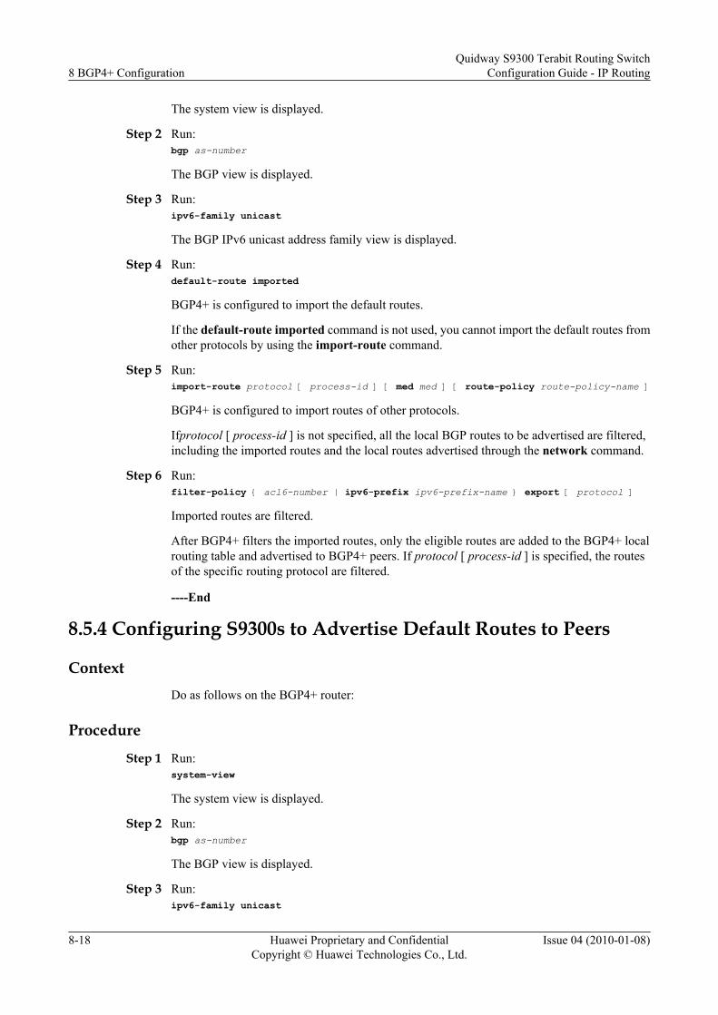
The system view is displayed.
Step 2 Run:bgp as-number
The BGP view is displayed.
Step 3 Run:ipv6-family unicast
The BGP IPv6 unicast address family view is displayed.
Step 4 Run:default-route imported
BGP4+ is configured to import the default routes.
If the default-route imported command is not used, you cannot import the default routes fromother protocols by using the import-route command.
Step 5 Run:import-route protocol [ process-id ] [ med med ] [ route-policy route-policy-name ]
BGP4+ is configured to import routes of other protocols.
Ifprotocol [ process-id ] is not specified, all the local BGP routes to be advertised are filtered,including the imported routes and the local routes advertised through the network command.
Step 6 Run:filter-policy { acl6-number | ipv6-prefix ipv6-prefix-name } export [ protocol ]
Imported routes are filtered.
After BGP4+ filters the imported routes, only the eligible routes are added to the BGP4+ localrouting table and advertised to BGP4+ peers. If protocol [ process-id ] is specified, the routesof the specific routing protocol are filtered.
----End
8.5.4 Configuring S9300s to Advertise Default Routes to Peers
ContextDo as follows on the BGP4+ router:
Procedure
Step 1 Run:system-view
The system view is displayed.
Step 2 Run:bgp as-number
The BGP view is displayed.
Step 3 Run:ipv6-family unicast
8 BGP4+ ConfigurationQuidway S9300 Terabit Routing Switch
Configuration Guide - IP Routing
8-18 Huawei Proprietary and ConfidentialCopyright © Huawei Technologies Co., Ltd.
Issue 04 (2010-01-08)
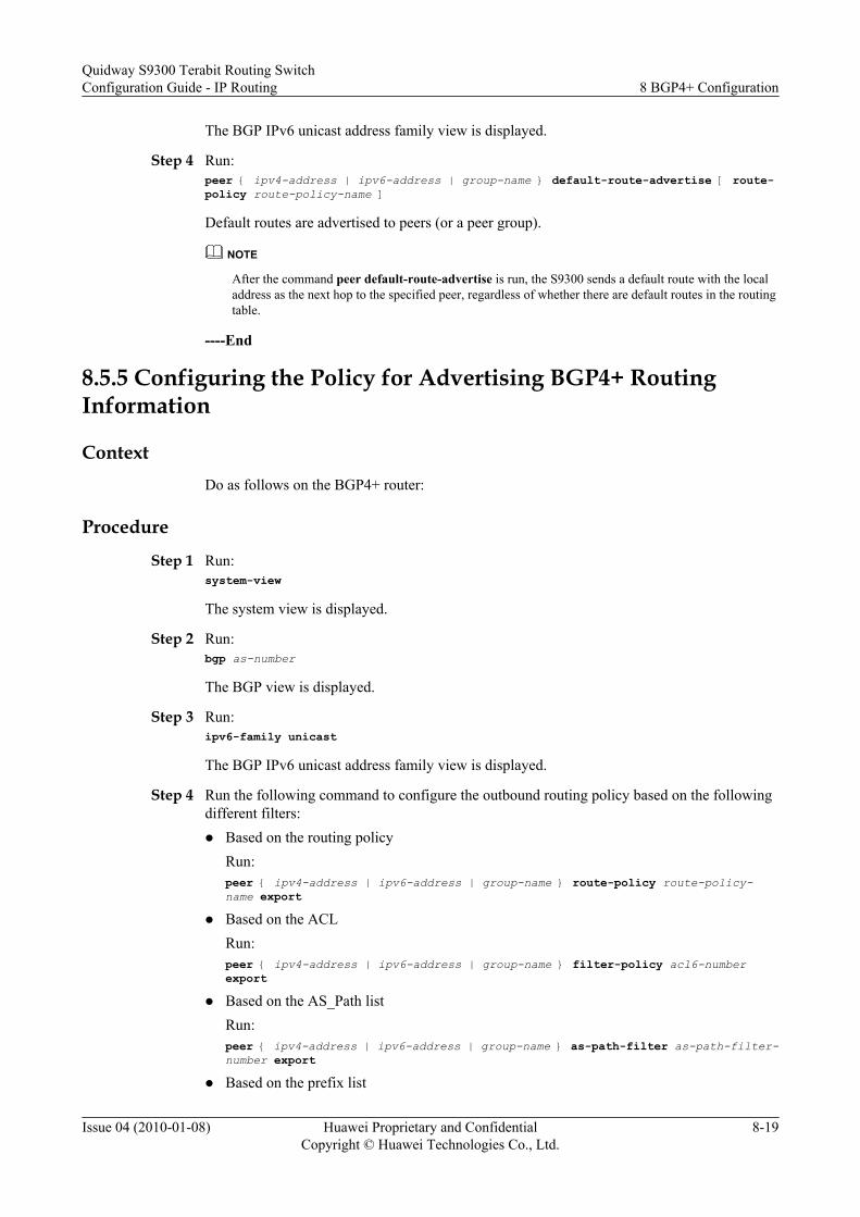
The BGP IPv6 unicast address family view is displayed.
Step 4 Run:peer { ipv4-address | ipv6-address | group-name } default-route-advertise [ route-policy route-policy-name ]
Default routes are advertised to peers (or a peer group).
NOTE
After the command peer default-route-advertise is run, the S9300 sends a default route with the localaddress as the next hop to the specified peer, regardless of whether there are default routes in the routingtable.
----End
8.5.5 Configuring the Policy for Advertising BGP4+ RoutingInformation
ContextDo as follows on the BGP4+ router:
Procedure
Step 1 Run:system-view
The system view is displayed.
Step 2 Run:bgp as-number
The BGP view is displayed.
Step 3 Run:ipv6-family unicast
The BGP IPv6 unicast address family view is displayed.
Step 4 Run the following command to configure the outbound routing policy based on the followingdifferent filters:l Based on the routing policy
Run:peer { ipv4-address | ipv6-address | group-name } route-policy route-policy-name export
l Based on the ACLRun:peer { ipv4-address | ipv6-address | group-name } filter-policy acl6-number export
l Based on the AS_Path listRun:peer { ipv4-address | ipv6-address | group-name } as-path-filter as-path-filter-number export
l Based on the prefix list
Quidway S9300 Terabit Routing SwitchConfiguration Guide - IP Routing 8 BGP4+ Configuration
Issue 04 (2010-01-08) Huawei Proprietary and ConfidentialCopyright © Huawei Technologies Co., Ltd.
8-19

Run:peer { ipv4-address | ipv6-address | group-name } ipv6-prefix ip-prefix-name export
The commands in Step 4 can be run regardless of the order.The outbound routing updates policies used by the members of a peer group can be differentfrom that used by the group. That is, members of each peer group can select their policieswhen advertising routes externally.
----End
8.5.6 Configuring the Policy for Receiving BGP4+ RoutingInformation
ContextDo as follows on the BGP4+ router:
Procedure
Step 1 Run:system-view
The system view is displayed.
Step 2 Run:bgp as-number
The BGP view is displayed.
Step 3 Run:ipv6-family unicast
The BGP IPv6 unicast address family view is displayed.
Step 4 Choose the following operations to filter the received routes based on different policies:l Run:
filter-policy { acl6-number | ipv6-prefix ipv6-prefix-name } import
The imported global routes are filtered.l Run:
peer { ipv4-address | ipv6-address | group-name } route-policy policy-name import
BGP is configured to filter the routes imported from the specified peers.l Run:
peer { ipv4-address | ipv6-address | group-name } filter-policy import
BGP is configured to filter the routes based on the ACL.l Run:
peer { ipv4-address | ipv6-address | group-name } as-path-filter as-path-filter-number import
BGP is configured to filter the routes based on the AS path list.l Run:
peer { ipv4-address | ipv6-address | group-name } ipv6-prefix ipv6-prefix-name import
8 BGP4+ ConfigurationQuidway S9300 Terabit Routing Switch
Configuration Guide - IP Routing
8-20 Huawei Proprietary and ConfidentialCopyright © Huawei Technologies Co., Ltd.
Issue 04 (2010-01-08)

BGP is configured to filter the routes based on the prefix list.
The commands in Steps 4 to 8 can be run regardless of the order.
The routes imported by BGP can be filtered, and only those routes that meet certain conditionsare received by BGP and added to the routing table.
The inbound routing policies used by the members in a peer group can be different from thatused by the group. That is, each peer can select its policy when importing routes.
----End
8.5.7 Configuring BGP4+ Soft Resetting
Procedurel Enabling the Route-refresh Capability
Do as follows on the BGP4+ router:
1. Run:system-view
The system view is displayed.2. Run:
bgp as-number
The BGP view is displayed.3. Run:
peer { ipv4-address | ipv6-address | group-name } capability-advertise route-refresh
The route-refresh capability is enabled.
By default, this command is configured.
If the route-refresh capability is enabled on all the BGP4+ routers, the local S9300advertises the route-refresh messages to its peer if the BGP4+ route policies change.The peer receiving this message sends its routing information to the local S9300 again.In this way, the BGP4+ routing table is updated dynamically and the new policies areapplied without interrupting the BGP4+ connections.
l Keeping All Route Updates of Peers
Do as follows on the BGP4+ router:
1. Run:system-view
The system view is displayed.2. Run:
bgp as-number
The BGP view is displayed.3. Run:
ipv6-family unicast
The BGP IPv6 unicast address family view is displayed.
Quidway S9300 Terabit Routing SwitchConfiguration Guide - IP Routing 8 BGP4+ Configuration
Issue 04 (2010-01-08) Huawei Proprietary and ConfidentialCopyright © Huawei Technologies Co., Ltd.
8-21

4. Run:peer { ipv4-address | ipv6-address | group-name } keep-all-routes
All route updates of the peers are kept.
After this command is run, all the route updates of the specified peer are kept regardlessof whether the filtering policies are used. When the BGP connections are soft reset,this information can be used to generate the BGP4+ routes.
l Soft Resetting a BGP4+ Connection Manually
Do as follows on the BGP4+ router:
1. Run:refresh bgp ipv6 { ipv4-address | ipv6-address | all | external | group group-name | internal } { export | import }
A BGP4+ connection is soft reset.
A BGP4+ connection must be soft reset in the user view.
----End
8.5.8 Checking the Configuration
PrerequisiteThe configurations of controlling the advertising and receiving of BGP4+ routing informationare complete.
Procedurel Run the display bgp ipv6 network command to check the routes advertised through the
network command.l Run the display bgp ipv6 routing-table as-path-filter as-path-filter-number command to
check the routes matching the specified AS-Path filter.l Run the display bgp ipv6 routing-table community-filter { { community-filter-name |
basic-community-filter-number } [ whole-match ] | advanced-community-filter-number }command to check the routes matching the specified BGP4+ community filter.
l Run the display bgp ipv6 routing-table peer { ipv4-address | ipv6-address } { advertised-routes | received-routes } [ statistics ] command to check the routing informationadvertised or received by the BGP4+ peers.
----End
8.6 (Optional) Setting Parameters of a Connection BetweenBGP4+ Peers
This section describes how to set the parameters of the BGP4+ peer relation to adjust andoptimize the performance of a BGP network.
8.6.1 Establishing the Configuration Task
8.6.2 Configuring BGP4+ Timers
8.6.3 Configuring the Interval for Sending Update Packets
8 BGP4+ ConfigurationQuidway S9300 Terabit Routing Switch
Configuration Guide - IP Routing
8-22 Huawei Proprietary and ConfidentialCopyright © Huawei Technologies Co., Ltd.
Issue 04 (2010-01-08)

8.6.4 Checking the Configuration
8.6.1 Establishing the Configuration Task
Applicable EnvironmentAfter a BGP4+ connection is set up between peers, the peers periodically send Keepalivemessages to each other. This prevents the S9300s from considering that the BGP4+ connectionis closed. If a S9300 does not receive any Keepalive message or any type of packets from thepeer within the specified Hold time, the BGP4+ connection is considered as closed.
When a S9300 sets up a BGP4+ connection with its peer, the S9300 and the peer need negotiationwith each other. The Hold time after negotiation is the shorter one between the Hold time of theS9300 and that of its peer. If the negotiation result is 0, no Keepalive message is transmitted andwhether the Hold timer expires is not detected.
If the value of the timer changes, the BGP4+ connection is interrupted for a short time as theS9300 and its peer need negotiate again.
Pre-configuration TasksBefore configuring the parameters of a connection between BGP4+ peers, complete thefollowing tasks:
l Enabling IPv6
l Configuring Basic BGP4+ Functions
Data PreparationTo configure the parameters of a connection between BGP4+ peers, you need the following data.
No. Data
1 Values of the BGP4+ timers
2 Interval for sending the update packets
8.6.2 Configuring BGP4+ Timers
Context
CAUTIONAs the change of the timer (with the peer timer command) tears down the BGP peer relationshipbetween S9300s. So, confirm the action before you use the command.
Do as follows on the BGP4+ router:
Quidway S9300 Terabit Routing SwitchConfiguration Guide - IP Routing 8 BGP4+ Configuration
Issue 04 (2010-01-08) Huawei Proprietary and ConfidentialCopyright © Huawei Technologies Co., Ltd.
8-23

ProcedureStep 1 Run:
system-view
The system view is displayed.
Step 2 Run:bgp as-number
The BGP view is displayed.
Step 3 Run:peer { ipv6-address | group-name } timer keepalive keepalive-time hold hold-time
The interval for sending Keepalive messages and the Hold time of a peer (or peer group) are set.
In actual applications, the value of hold-time is at least three times that of keepalive-time.
By default, the Keepalive time is 60s and the Hold time is 180s.
NOTE
Note the following when you set the values of keepalive-time and hold-time:
l When the values of keepalive-time and hold-time are 0 at the same time, the BGP timer becomes invalid.That is, BGP does not detect link faults according to the timer.
l The value of hold-time is far greater than that of keepalive-time, such as, timer keepalive 1 hold65535. If the Hold time is too long, the link fault cannot be detected on time.
----End
8.6.3 Configuring the Interval for Sending Update Packets
ContextDo as follows on the BGP4+ router:
ProcedureStep 1 Run:
system-view
The system view is displayed.
Step 2 Run:bgp as-number
The BGP view is displayed.
Step 3 Run:ipv6-family unicast
The BGP IPv6 unicast address family view is displayed.
Step 4 Run:peer ipv6-address route-update-interval interval
The interval for sending update packets is set.
----End
8 BGP4+ ConfigurationQuidway S9300 Terabit Routing Switch
Configuration Guide - IP Routing
8-24 Huawei Proprietary and ConfidentialCopyright © Huawei Technologies Co., Ltd.
Issue 04 (2010-01-08)

8.6.4 Checking the Configuration
PrerequisiteThe configurations of parameters of a connection between BGP4+ peers are complete.
Procedurel Run the display bgp ipv6 peer ipv4-address verbose command to check information about
the BGP4+ peers.
l Run the display bgp ipv6 peer ipv6-address { log-info | verbose } command to checkinformation about the BGP4+ peers.
----End
8.7 (Optional) Configuring BGP4+ Route DampeningThis section describes how to configure BGP4+ route dampening to suppress unstable routes.
8.7.1 Establishing the Configuration Task
8.7.2 Configuring BGP4+ Route Dampening
8.7.3 Checking the Configuration
8.7.1 Establishing the Configuration Task
Applicable Environment
BGP4+ dampening can suppress unstable routes. BGP4+ neither adds the unstable routes to therouting table nor advertises them to other BGP peers.
Pre-configuration Tasks
Before configuring BGP4+ route dampening, complete the following task:
l 8.3 Configuring Basic BGP4+ Functions
Data Preparation
To configure BGP4+ route dampening, you need the following data.
No. Data
1 Various parameters of dampening, including half-life of a reachable route, half-lifeof an unreachable route, threshold for freeing the suppressed routes, threshold forsuppressing routes, and upper limit of the penalty
Quidway S9300 Terabit Routing SwitchConfiguration Guide - IP Routing 8 BGP4+ Configuration
Issue 04 (2010-01-08) Huawei Proprietary and ConfidentialCopyright © Huawei Technologies Co., Ltd.
8-25

8.7.2 Configuring BGP4+ Route Dampening
ContextDo as follows on the BGP4+ router:
Procedure
Step 1 Run:system-view
The system view is displayed.
Step 2 Run:bgp as-number
The BGP view is displayed.
Step 3 Run:ipv6-family unicast
The BGP IPv6 unicast address family view is displayed.
Step 4 Run:dampening [ half-life-reach half-life-unreach reuse suppress ceiling | route-policy route-policy-name ]*
The parameters are configured for BGP4+ route dampening.
----End
8.7.3 Checking the Configuration
PrerequisiteThe configurations of BGP4+ route dampening are complete.
Procedurel Run the display bgp ipv6 routing-table dampened command to check BGP4+ dampened
routes.l Run the display bgp ipv6 routing-table dampening parameter command to check the
configuration parameters of BGP4+ dampening.l Run the display bgp ipv6 routing-table flap-info [ regular-expression as-regular-
expression | as-path-filter as-path-filter-number | ipv6-address [ prefix-length ] [ longer-match ] ] command to check the statistics of BGP4+ route flapping.
----End
8.8 (Optional) Configuring BGP4+ Load BalancingThis section describes how to configure certain attributes to implement BGP4+ load balancing.
8.8.1 Establishing the Configuration Task
8 BGP4+ ConfigurationQuidway S9300 Terabit Routing Switch
Configuration Guide - IP Routing
8-26 Huawei Proprietary and ConfidentialCopyright © Huawei Technologies Co., Ltd.
Issue 04 (2010-01-08)

8.8.2 Setting the Number of Routes for BGP4+ Load Balancing
8.8.3 Checking the Configuration
8.8.1 Establishing the Configuration Task
Applicable EnvironmentEqual-cost routes can be generated for BGP4+ load balancing only when the first nine rulesdescribed in 8.3 Configuring Basic BGP4+ Functions are the same and the BGP4+ routes havethe same AS-Path attribute.
Pre-configuration TasksBefore configuring BGP4+ load balancing, complete the following task:
l Configuring Basic BGP4+ Functions
Data PreparationTo configure BGP4+ load balancing, you need the following data.
No. Data
1 The number of routes for load balancing
8.8.2 Setting the Number of Routes for BGP4+ Load Balancing
ContextDo as follows on the BGP4+ router:
Procedure
Step 1 Run:system-view
The system view is displayed.
Step 2 Run:bgp as-number
The BGP view is displayed.
Step 3 Run:ipv6-family unicast
The BGP IPv6 unicast address family view is displayed.
Step 4 Run:maximum load-balancing number
The maximum number of equal-cost routes for BGP4+ load balancing is set.
Quidway S9300 Terabit Routing SwitchConfiguration Guide - IP Routing 8 BGP4+ Configuration
Issue 04 (2010-01-08) Huawei Proprietary and ConfidentialCopyright © Huawei Technologies Co., Ltd.
8-27

By default, the number of equal-cost routes for BGP4+ load balancing is 1.
----End
8.8.3 Checking the Configuration
PrerequisiteThe configurations of BGP4+ load balancing are complete.
Procedurel Run the display bgp ipv6 routing-table [ ipv6-address prefix-length ] command to check
information about the BGP4+ routing table.l Run the display ipv6 routing-table [ verbose ] command to check information about the
routing table.
----End
8.9 (Optional) Configuring a BGP4+ Peer GroupThis section describes how to simplify the management of routing policies and improve theefficiency of advertising routes on a large-scale BGP4+ network.
8.9.1 Establishing the Configuration Task
8.9.2 Creating an IBGP Peer Group
8.9.3 Creating a Pure EBGP Peer Group
8.9.4 Creating a Mixed EBGP Peer Group
8.9.5 Checking the Configuration
8.9.1 Establishing the Configuration Task
Applicable EnvironmentA great number of peers exist in a large-scale BGP4+ network, which is not convenient forconfiguration and maintenance. In this case, you can configure peer groups to simplify themanagement and improve the efficiency of route advertisement. According to the AS where thepeers reside, you can classify peer groups into IBGP peer groups and EBGP peer groups. Youcan classify EBGP peer groups into pure EBGP peer groups and mixed EBGP peer groups. Thisclassification is performed according to the position of the peers in the same external AS.
Pre-configuration TasksBefore configuring a BGP4+ peer group, complete the following task:
l Configuring Basic BGP4+ Functions
Data PreparationTo configure a BGP4+ peer group, you need the following data.
8 BGP4+ ConfigurationQuidway S9300 Terabit Routing Switch
Configuration Guide - IP Routing
8-28 Huawei Proprietary and ConfidentialCopyright © Huawei Technologies Co., Ltd.
Issue 04 (2010-01-08)
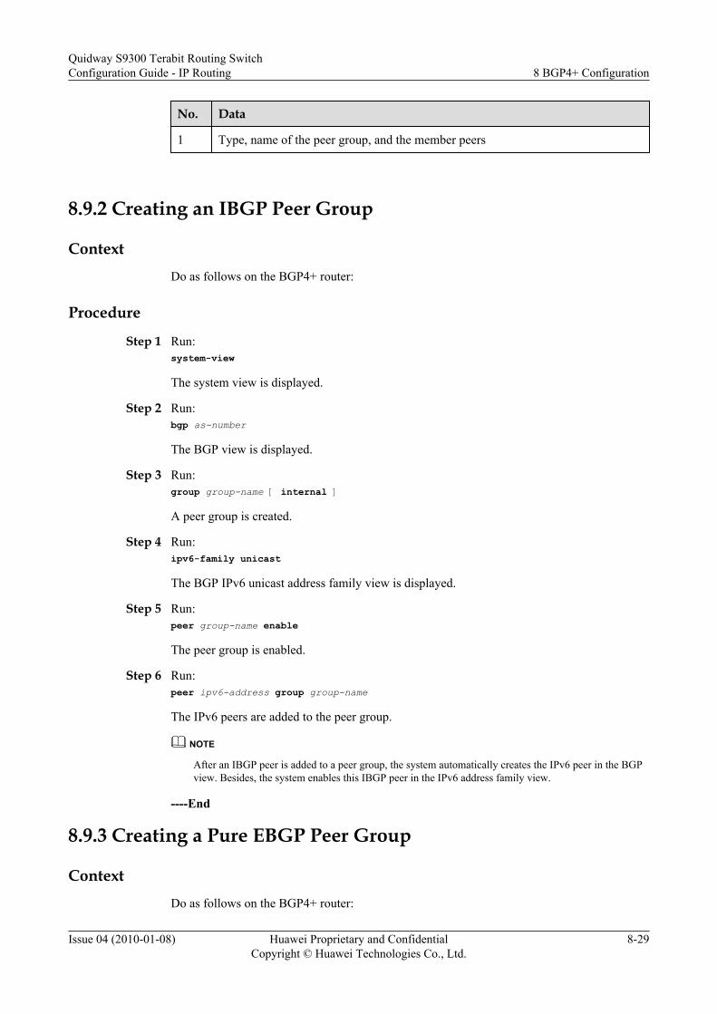
No. Data
1 Type, name of the peer group, and the member peers
8.9.2 Creating an IBGP Peer Group
ContextDo as follows on the BGP4+ router:
Procedure
Step 1 Run:system-view
The system view is displayed.
Step 2 Run:bgp as-number
The BGP view is displayed.
Step 3 Run:group group-name [ internal ]
A peer group is created.
Step 4 Run:ipv6-family unicast
The BGP IPv6 unicast address family view is displayed.
Step 5 Run:peer group-name enable
The peer group is enabled.
Step 6 Run:peer ipv6-address group group-name
The IPv6 peers are added to the peer group.
NOTE
After an IBGP peer is added to a peer group, the system automatically creates the IPv6 peer in the BGPview. Besides, the system enables this IBGP peer in the IPv6 address family view.
----End
8.9.3 Creating a Pure EBGP Peer Group
ContextDo as follows on the BGP4+ router:
Quidway S9300 Terabit Routing SwitchConfiguration Guide - IP Routing 8 BGP4+ Configuration
Issue 04 (2010-01-08) Huawei Proprietary and ConfidentialCopyright © Huawei Technologies Co., Ltd.
8-29

Procedure
Step 1 Run:system-view
The system view is displayed.
Step 2 Run:bgp as-number
The BGP view is displayed.
Step 3 Run:group group-name external
A pure EBGP peer group is configured.
Step 4 Run:peer group-name as-number as-number
The AS number of the peer group is set.
Step 5 Run:ipv6-family unicast
The BGP IPv6 unicast address family view is displayed.
Step 6 Run:peer group-name enable
The peer group is enabled.
Step 7 Run:peer ipv6-address group group-name
The IPv6 peer is added to the peer group.
After an EBGP peer is added to the peer group, the system automatically creates the EBGP peerin the BGP view. Besides, the system enables this EBGP peer in the IPv6 address family view.
When creating a pure EBGP peer group, you need to specify the AS number of the peer group.
If there are peers in the peer group, you cannot specify the AS number for this peer group.
----End
8.9.4 Creating a Mixed EBGP Peer Group
ContextDo as follows on the BGP4+ router:
Procedure
Step 1 Run:system-view
The system view is displayed.
8 BGP4+ ConfigurationQuidway S9300 Terabit Routing Switch
Configuration Guide - IP Routing
8-30 Huawei Proprietary and ConfidentialCopyright © Huawei Technologies Co., Ltd.
Issue 04 (2010-01-08)

Step 2 Run:bgp as-number
The BGP view is displayed.
Step 3 Run:group group-name external
A mixed EBGP peer group is created.
Step 4 Run:peer ipv6-address as-number as-number
The AS number of the IPv6 peer is set.
Step 5 Run:ipv6-family unicast
The BGP IPv6 unicast address family view is displayed.
Step 6 Run:peer group-name enable
The peer group is enabled.
Step 7 Run:peer ipv6-address group group-name
The IPv6 peers created are added to this peer group.
After an EBGP peer is added to the peer group, the system automatically enables each EBGPpeer in the IPv6 address family view.
When creating a mixed EBGP peer group, you need to create peers separately, and you canconfigure different AS numbers for them, but cannot configure the AS number for the peer group.
----End
8.9.5 Checking the Configuration
PrerequisiteThe configurations of a BGP4+ peer group are complete.
Procedurel Run the display bgp ipv6 group [ group-name ] command to check information about the
peer group.
----End
8.10 (Optional) Configuring a BGP4+ Route ReflectorThis section describes how to simplify the management of routing policies and improve theefficiency of advertising routes on a large-scale IBGP network.
8.10.1 Establishing the Configuration Task
Quidway S9300 Terabit Routing SwitchConfiguration Guide - IP Routing 8 BGP4+ Configuration
Issue 04 (2010-01-08) Huawei Proprietary and ConfidentialCopyright © Huawei Technologies Co., Ltd.
8-31

8.10.2 Configuring a Route Reflector and Specifying Clients
8.10.3 (Optional) Disabling a Route Reflection Between Clients
8.10.4 (Optional) Configuring the Cluster ID for a Route Reflector
8.10.5 Checking the Configuration
8.10.1 Establishing the Configuration Task
Applicable Environment
To ensure the connectivity between IBGP peers inside an AS, you need to establish full-meshedIBGP peers. When there are many IBGP peers, establishing a full-meshed network costs a lot.The route reflector or the confederation can be used to solve this problem.
Pre-configuration Tasks
Before configuring a BGP4+ route reflector, complete the following task:
l 8.3 Configuring Basic BGP4+ Functions
Data Preparation
To configure a BGP4+ route reflector, you need the following data.
No. Data
1 Roles of each S9300 (reflector, client, and non-client)
8.10.2 Configuring a Route Reflector and Specifying Clients
Context
Do as follows on the BGP4+ router:
Procedure
Step 1 Run:system-view
The system view is displayed.
Step 2 Run:bgp as-number
The BGP view is displayed.
Step 3 Run:ipv6-family unicast
The BGP IPv6 unicast address family view is displayed.
8 BGP4+ ConfigurationQuidway S9300 Terabit Routing Switch
Configuration Guide - IP Routing
8-32 Huawei Proprietary and ConfidentialCopyright © Huawei Technologies Co., Ltd.
Issue 04 (2010-01-08)

Step 4 Run:peer { ipv4-address | ipv6-address | group-name } reflect-client
The route reflector and its clients are configured.
The S9300 on which this command is run serves as the route reflector. In addition, this commandspecifies the peers that serve as its clients.
----End
8.10.3 (Optional) Disabling a Route Reflection Between Clients
ContextDo as follows on the BGP4+ router:
Procedure
Step 1 Run:system-view
The system view is displayed.
Step 2 Run:bgp as-number
The BGP view is displayed.
Step 3 Run:ipv6-family unicast
The BGP IPv6 unicast address family view is displayed.
Step 4 Run:undo reflect between-clients
Route reflection between clients is disabled.
If the clients of the route reflector are full-meshed, you can use the undo reflect between-clientscommand to disable the route reflection between the clients. This reduces cost.
By default, the route reflection between clients is enabled.
This command is used only on the reflector.
----End
8.10.4 (Optional) Configuring the Cluster ID for a Route Reflector
ContextDo as follows on the BGP4+ router:
Procedure
Step 1 Run:system-view
Quidway S9300 Terabit Routing SwitchConfiguration Guide - IP Routing 8 BGP4+ Configuration
Issue 04 (2010-01-08) Huawei Proprietary and ConfidentialCopyright © Huawei Technologies Co., Ltd.
8-33

The system view is displayed.
Step 2 Run:bgp as-number
The BGP view is displayed.
Step 3 Run:ipv6-family unicast
The BGP IPv6 unicast address family view is displayed.
Step 4 Run:reflector cluster-id cluster-id
The cluster ID of the route reflector is set.
TIP
When there are multiple route reflectors in a cluster, you can use the command to configure all the routereflectors in this cluster with the same cluster ID. This avoids routing loops.
----End
8.10.5 Checking the Configuration
PrerequisiteThe configurations of a BGP4+ route reflector are complete.
Procedurel Run the display bgp ipv6 peer [ verbose ] command to check information about BGP4+
peers.l Run the display bgp ipv6 peer ipv4-address verbose command to check information about
BGP4+ peers.l Run the display bgp ipv6 peer ipv6-address { log-info | verbose } command to check
information about BGP4+ peers.
----End
8.11 (Optional) Configuring a BGP4+ ConfederationThis section describes how to simplify the management of routing policies and improve theefficiency of advertising routes on a large-scale BGP network.
8.11.1 Establishing the Configuration Task
8.11.2 Configuring a BGP Confederation
8.11.3 Checking the Configuration
8.11.1 Establishing the Configuration Task
Applicable EnvironmentThe confederation is a method of handling the abrupt increase of IBGP connections in an AS.The confederation divides an AS into multiple sub-ASs. In each sub-AS, IBGP peers can be
8 BGP4+ ConfigurationQuidway S9300 Terabit Routing Switch
Configuration Guide - IP Routing
8-34 Huawei Proprietary and ConfidentialCopyright © Huawei Technologies Co., Ltd.
Issue 04 (2010-01-08)

full-meshed or be configured with a route reflector. EBGP connections are set up between sub-ASs.
Pre-configuration TasksBefore configuring a BGP4+ confederation, complete the following task:
l Configuring Basic BGP4+ Functions
Data PreparationTo configure a BGP4+ confederation, you need the following data.
No. Data
1 Confederation ID and the sub-AS number
8.11.2 Configuring a BGP Confederation
Procedurel Configuring a BGP Confederation
Do as follows on the BGP4+ router:
1. Run:system-view
The system view is displayed.2. Run:
bgp as-number
The BGP view is displayed.3. Run:
confederation id as-number
The confederation ID is set.4. Run:
confederation peer-as as-number &<1-32>
The sub-AS number of other EBGP peers connected with the local AS is set.
A confederation includes up to 32 sub-ASs. as-number is valid for the confederationthat it belongs to.
You must run the confederation id and confederation peer-as commands for all theEBGP peers that belong to a confederation, and specify the same confederation ID forthem.
l Configuring the Compatibility of a Confederation
Do as follows on the BGP4+ router:
1. Run:system-view
Quidway S9300 Terabit Routing SwitchConfiguration Guide - IP Routing 8 BGP4+ Configuration
Issue 04 (2010-01-08) Huawei Proprietary and ConfidentialCopyright © Huawei Technologies Co., Ltd.
8-35

The system view is displayed.2. Run:
bgp as-number
The BGP view is displayed.3. Run:
confederation nonstandard
The compatibility of the confederation is configured.
When the confederation of other S9300s does not conform to the RFC, you can usethis command to make standard devices be compatible with nonstandard devices.
----End
8.11.3 Checking the Configuration
PrerequisiteThe configurations of a BGP4+ confederation are complete.
Procedurel Run the display bgp ipv6 peer [ verbose ] command to check detailed information about
peers.
----End
8.12 (Optional) Configuring BGP4+ 6PEAfter the 6PE function is enabled, the separated IPv6 networks can be connected through theMulti-Protocol Label Switch (MPLS) tunnel technology.
8.12.1 Establishing the Configuration Task
8.12.2 Configuring a 6PE Peer
8.12.3 Checking the Configuration
8.12.1 Establishing the Configuration Task
Applicable Environment6PE interconnects separated IPv6 networks at different locations by using the MPLS technologyin an IPv4 network. Multiple modes are used to connect separated IPv6 networks by using thetunnel technology. The tunnel in 6PE mode supports the IPv4/IPv6 dual stacks on PEs of theISP. It identifies IPv6 routes by using the label assigned by MP-BGP, and implements IPv6interworking through LSPs between PEs.
Pre-configuration TasksBefore configuring BGP4+ 6PE, complete the following task:
l Establishing LSPs between PEs
8 BGP4+ ConfigurationQuidway S9300 Terabit Routing Switch
Configuration Guide - IP Routing
8-36 Huawei Proprietary and ConfidentialCopyright © Huawei Technologies Co., Ltd.
Issue 04 (2010-01-08)

Data Preparation
To configure BGP4+ 6PE, you need the following data.
No. Data
1 IP address and AS number of a PE
8.12.2 Configuring a 6PE Peer
Context
Do as follows on the PE supporting the IPv4/IPv6 dual stacks:
Procedure
Step 1 Run:system-view
The system view is displayed.
Step 2 Run:bgp as-number
The BGP view is displayed.
Step 3 Run:peer ipv4-address as-number as-number
The IP address and AS number of a PE that needs to be configured with 6PE are specified.
Step 4 Run:ipv6-family unicast
The BGP IPv6 unicast address family view is displayed.
Step 5 Run:peer ipv4-address enable
A 6PE peer is configured in the IPv6 unicast address family view.
Step 6 Run:peer ipv4-address label-route-capability
The capability of sending labeled routes is enabled.
----End
8.12.3 Checking the Configuration
PrerequisiteThe configurations of BGP4+ 6PE are complete.
Quidway S9300 Terabit Routing SwitchConfiguration Guide - IP Routing 8 BGP4+ Configuration
Issue 04 (2010-01-08) Huawei Proprietary and ConfidentialCopyright © Huawei Technologies Co., Ltd.
8-37

Procedurel Run the display bgp ipv6 peer [ verbose ] command to check detailed information about
BGP peers.
----End
8.13 Maintaining BGP4+This section describes how to reset BGP4+ connections, clear BGP4+ statistics, and debug BGP4+.
8.13.1 Debugging BGP4+
8.13.2 Resetting BGP4+ Connections
8.13.3 Clearing BGP4+ Statistics
8.13.1 Debugging BGP4+
Context
CAUTIONDebugging affects the performance of the system. So, after debugging, run the undo debuggingall command to disable it immediately.
When a BGP4+ fault occurs, run the following debugging commands in the user view to debugand locate the fault.
For the procedure of displaying the debugging information, refer to the chapter "Debugging andDiagnosis" in the Quidway S9300 Terabit Routing Switch Configuration Guide - DeviceManagement.
For the related debugging command, refer to the Quidway S9300 Terabit Routing SwitchDebugging Reference.
Procedurel Run the debugging bgp update ipv6 [ peer { ipv4-address | ipv6-address } | ipv6-
prefix ipv6-prefix-name | acl acl-number ] [ receive | send ] [ verbose ] command in theuser view to debug the BGP4+ update packets.
l Run the debugging bgp [ ipv6-address ] all command in the user view to debug all theBGP4+.
l Run the debugging bgp [ ipv6-address ] event command in the user view to debug theBGP4+ events.
l Run the debugging bgp [ ipv6-address ] { keepalive | open | packet | route-refresh }[ receive | send ] [ verbose ] command in the user view to debug the BGP4+ packets.
----End
8 BGP4+ ConfigurationQuidway S9300 Terabit Routing Switch
Configuration Guide - IP Routing
8-38 Huawei Proprietary and ConfidentialCopyright © Huawei Technologies Co., Ltd.
Issue 04 (2010-01-08)

8.13.2 Resetting BGP4+ Connections
Context
CAUTIONThe peer relationship is broken after you reset the BGP4+ connections with the reset bgp ipv6command. So, confirm the action before you use the command.
To reset the BGP4+ connections, run the following reset command in the user view.
Procedurel To validate the new configuration, run the reset bgp ipv6 all command in the user view to
reset all the BGP4+ connections.l To validate the new configuration, run the reset bgp ipv6 as-number command in the user
view to reset the BGP+4 connections between the peers in a specified AS.l To validate the new configuration, run the reset bgp ipv6 { ipv4-address | ipv6-address |
group group-name } command in the user view to reset the BGP+4 connections with thespecified peer (or peer group).
l To validate the new configuration, run the reset bgp ipv6 external command in the userview to reset the external BGP4+ connections.
l To validate the new configuration, run the reset bgp ipv6 internal command in the userview to reset the internal BGP4+ connections.
----End
8.13.3 Clearing BGP4+ Statistics
Context
CAUTIONThe BGP4+ statistics cannot be restored after you clear it. So, confirm the action before you usethe command.
Procedurel Run the reset bgp ipv6 dampening [ ipv6-address prefix-length ] command in the user
view to clear information about route dampening and release the suppressed routes.l Run the reset bgp ipv6 flap-info [ ipv6-address prefix-length | regexp regexp | as-path-
filter as-path-filter-number ] command in the user view to clear the statistics of routeflapping.
----End
Quidway S9300 Terabit Routing SwitchConfiguration Guide - IP Routing 8 BGP4+ Configuration
Issue 04 (2010-01-08) Huawei Proprietary and ConfidentialCopyright © Huawei Technologies Co., Ltd.
8-39

8.14 Configuration ExamplesThis section provides several configuration examples of BGP4+.
8.14.1 Example for Configuring Basic BGP4+ Functions
8.14.2 Example for Configuring BGP4+ Route Reflectors
8.14.3 Example for Configuring the BGP 6PE
8.14.1 Example for Configuring Basic BGP4+ Functions
Networking RequirementsAs shown in Figure 8-1, there are two ASs: 65008 and 65009. S9300-A belongs to AS 65008,and S9300-B, S9300-C, and S9300-D belong to AS 65009. BGP4+ is required to be used toexchange routing information between the two ASs.
Figure 8-1 Networking diagram for configuring basic BGP4+ functions
S9300-A
GE2/0/0VLANIF20
8::1/64
S9300-B
S9300-C
S9300-D
AS 65008
AS 65009
GE1/0/0
VLANIF10
10::2/64 10::1/64VLANIF20
GE2/0/0 GE1/0/0
GE3
/0/0
GE3
/0/0 GE2/0/0
GE2/0/0GE1/0/0
VLAN
IF30
VLAN
IF30
VLANIF40 VLANIF40
VLANIF50
VLANIF50
9:3:
:1/6
49:
3::2
/64 9:2::1/64
9:2::2/64
9:1::1/64 9:1::2/64
Device name Interface VLANIF interface IP address
S9300-A GE1/0/0 VLANIF 10 8::1/64
S9300-A GE2/0/0 VLANIF 20 10::2/64
S9300-B GE2/0/0 VLANIF 20 10::1/64
S9300-B GE3/0/0 VLANIF 30 9:3::1/64
S9300-B GE1/0/0 VLANIF 40 9:1::1/64
S9300-C GE3/0/0 VLANIF 30 9:3::2/64
S9300-C GE2/0/0 VLANIF 50 9:2::1/64
S9300-D GE1/0/0 VLANIF 40 9:1::2/64
S9300-D GE2/0/0 VLANIF 50 9:2::2/64
8 BGP4+ ConfigurationQuidway S9300 Terabit Routing Switch
Configuration Guide - IP Routing
8-40 Huawei Proprietary and ConfidentialCopyright © Huawei Technologies Co., Ltd.
Issue 04 (2010-01-08)

Configuration RoadmapThe configuration roadmap is as follows:
1. Configure IBGP connections between S9300-B, S9300-C, and S9300-D.2. Configure an EBGP connection between S9300-A and S9300-B.
Data PreparationTo complete the configuration, you need the following data:
l The router ID of S9300-A is 1.1.1.1 and the AS ID is 65008.
l The router IDs of S9300-B, S9300-C, and S9300-D are 2.2.2.2, 3.3.3.3, and 4.4.4.4, andthe ID of the AS where they are located is 65009.
ProcedureStep 1 Add interfaces to VLANs.
<Quidway> system-view[Quidway] sysname S9300-A[S9300-A] vlan batch 10 20[S9300-A] interface GigabitEthernet 1/0/0[S9300-A-GigabitEthernet1/0/0] port hybrid pvid vlan 10[S9300-A-GigabitEthernet1/0/0] port hybrid untagged vlan 10[S9300-A-GigabitEthernet1/0/0] quit[S9300-A] interface GigabitEthernet 2/0/0[S9300-A-GigabitEthernet2/0/0] port hybrid pvid vlan 20[S9300-A-GigabitEthernet2/0/0] port hybrid untagged vlan 20[S9300-A-GigabitEthernet2/0/0] quit
The configurations of S9300-B, S9300-C, and S9300-D are similar to the configuration ofS9300-A and are not mentioned here.
Step 2 Enable the IPv6 forwarding capability, and assign an IPv6 address for each interface. Thefollowing is the configuration of S9300-A. The configurations of other S9300s are similar to theconfiguration of S9300-A and are not mentioned here.<Quidway> system-view[S9300-A] ipv6[S9300-A] interface vlanif 10[S9300-A-Vlanif10] ipv6 enable[S9300-A-Vlanif10] ipv6 address 8::1/64[S9300-A] interface vlanif 20[S9300-A-Vlanif20] ipv6 enable[S9300-A-Vlanif20] ipv6 address 10::2/64
Step 3 Configure IBGP.
# Configure S9300-B.
[S9300-B] bgp 65009[S9300-B-bgp] router-id 2.2.2.2[S9300-B-bgp] peer 9:1::2 as-number 65009[S9300-B-bgp] peer 9:3::2 as-number 65009[S9300-B-bgp] ipv6-family unicast[S9300-B-bgp-af-ipv6] peer 9:1::2 enable[S9300-B-bgp-af-ipv6] peer 9:3::2 enable[S9300-B-bgp-af-ipv6] network 9:1:: 64[S9300-B-bgp-af-ipv6] network 9:3:: 64
# Configure S9300-C.
[S9300-C] bgp 65009[S9300-C-bgp] router-id 3.3.3.3
Quidway S9300 Terabit Routing SwitchConfiguration Guide - IP Routing 8 BGP4+ Configuration
Issue 04 (2010-01-08) Huawei Proprietary and ConfidentialCopyright © Huawei Technologies Co., Ltd.
8-41
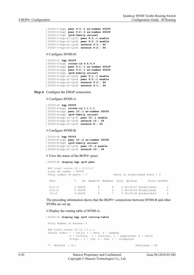
[S9300-C-bgp] peer 9:3::1 as-number 65009[S9300-C-bgp] peer 9:2::2 as-number 65009[S9300-C-bgp] ipv6-family unicast[S9300-C-bgp-af-ipv6] peer 9:3::1 enable[S9300-C-bgp-af-ipv6] peer 9:2::2 enable[S9300-C-bgp-af-ipv6] network 9:3:: 64[S9300-C-bgp-af-ipv6] network 9:2:: 64
# Configure S9300-D.
[S9300-D] bgp 65009[S9300-D-bgp] router-id 4.4.4.4[S9300-D-bgp] peer 9:1::1 as-number 65009[S9300-D-bgp] peer 9:2::1 as-number 65009[S9300-D-bgp] ipv6-family unicast[S9300-D-bgp-af-ipv6] peer 9:1::1 enable[S9300-D-bgp-af-ipv6] peer 9:2::1 enable[S9300-D-bgp-af-ipv6] network 9:2:: 64[S9300-D-bgp-af-ipv6] network 9:1:: 64
Step 4 Configure the EBGP connection.
# Configure S9300-A.
[S9300-A] bgp 65008[S9300-A-bgp] router-id 1.1.1.1[S9300-A-bgp] peer 10::1 as-number 65009[S9300-A-bgp] ipv6-family unicast[S9300-A-bgp-af-ipv6] peer 10::1 enable[S9300-A-bgp-af-ipv6] network 10:: 64[S9300-A-bgp-af-ipv6] network 8:: 64
# Configure S9300-B.
[S9300-B] bgp 65009[S9300-B-bgp] peer 10::2 as-number 65008[S9300-B-bgp] ipv6-family unicast[S9300-B-bgp-af-ipv6] peer 10::2 enable[S9300-B-bgp-af-ipv6] network 10:: 64
# View the status of the BGP4+ peers.
[S9300-B] display bgp ipv6 peer
BGP local router ID : 2.2.2.2 Local AS number : 65009 Total number of peers : 3 Peers in established state : 3
Peer V AS MsgRcvd MsgSent OutQ Up/Down State PrefRcv
9:1::2 4 65009 8 9 0 00:05:37 Established 2 9:3::2 4 65009 2 2 0 00:00:09 Established 2 10::2 4 65008 9 7 0 00:05:38 Established 2
The preceding information shows that the BGP4+ connections between S9300-B and otherS9300s are set up.
# Display the routing table of S9300-A.
[S9300-A] display bgp ipv6 routing-table
Total Number of Routes: 6
BGP Local router ID is 1.1.1.1 Status codes: * - valid, > - best, d - damped, h - history, i - internal, s - suppressed, S - Stale Origin : i - IGP, e - EGP, ? - incomplete
*> Network : 8:: PrefixLen : 64
8 BGP4+ ConfigurationQuidway S9300 Terabit Routing Switch
Configuration Guide - IP Routing
8-42 Huawei Proprietary and ConfidentialCopyright © Huawei Technologies Co., Ltd.
Issue 04 (2010-01-08)

NextHop : :: LocPrf : MED : 0 PrefVal : 0 Label : Path/Ogn : i
*> Network : 9:1:: PrefixLen : 64 NextHop : 10::1 LocPrf : MED : 0 PrefVal : 0 Label : Path/Ogn : 65009 i
*> Network : 9:2:: PrefixLen : 64 NextHop : 10::1 LocPrf : MED : PrefVal : 0 Label : Path/Ogn : 65009 i
*> Network : 9:3:: PrefixLen : 64 NextHop : 10::1 LocPrf : MED : 0 PrefVal : 0 Label : Path/Ogn : 65009 i
*> Network : 10:: PrefixLen : 64 NextHop : :: LocPrf : MED : 0 PrefVal : 0 Label : Path/Ogn : i
*> NextHop : 10::1 LocPrf : MED : 0 PrefVal : 0 Label : Path/Ogn : 65009 i
The routing table shows that S9300-A has learned the route from AS 65009. AS 65008 and AS65009 can exchange their routing information.
----End
Configuration Filesl Configuration file of S9300-A
# sysname S9300-A# ipv6# vlan batch 10 20#interface Vlanif10 ipv6 enable ipv6 address 8::1/64#interface Vlanif20 ipv6 enable ipv6 address 10::2/64#interface GigabitEthernet1/0/0 port hybrid pvid vlan 10 port hybrid untagged vlan 10#interface GigabitEthernet2/0/0 port hybrid pvid vlan 20 port hybrid untagged vlan 20#bgp 65008 router-id 1.1.1.1 peer 10::1 as-number 65009
Quidway S9300 Terabit Routing SwitchConfiguration Guide - IP Routing 8 BGP4+ Configuration
Issue 04 (2010-01-08) Huawei Proprietary and ConfidentialCopyright © Huawei Technologies Co., Ltd.
8-43

# ipv4-family unicast undo synchronization# ipv6-family unicast network 8:: 64 network 10:: 64 peer 10::1 enable#return
l Configuration file of S9300-B# sysname S9300-B# ipv6# vlan batch 10 20 30#interface Vlanif20 ipv6 enable ipv6 address 10::1/64#interface Vlanif30 ipv6 enable ipv6 address 9:3::1/64#interface Vlanif40 ipv6 enable ipv6 address 9:1::1/64#interface GigabitEthernet1/0/0 port hybrid pvid vlan 40 port hybrid untagged vlan 40#interface GigabitEthernet2/0/0 port hybrid pvid vlan 20 port hybrid untagged vlan 20#interface GigabitEthernet3/0/0 port hybrid pvid vlan 30 port hybrid untagged vlan 30#bgp 65009 router-id 2.2.2.2 peer 9:1::2 as-number 65009 peer 9:3::2 as-number 65009 peer 10::2 as-number 65008# ipv4-family unicast undo synchronization# ipv6-family unicast network 9:1:: 64 network 9:3:: 64 network 10:: 64 peer 9:1::2 enable peer 9:3::2 enable peer 10::2 enable#return
l Configuration file of S9300-C# sysname S9300-C# ipv6# vlan batch 30 50#
8 BGP4+ ConfigurationQuidway S9300 Terabit Routing Switch
Configuration Guide - IP Routing
8-44 Huawei Proprietary and ConfidentialCopyright © Huawei Technologies Co., Ltd.
Issue 04 (2010-01-08)

interface Vlanif30 ipv6 enable ipv6 address 9:3::2/64#interface Vlanif50 ipv6 enable ipv6 address 9:2::1/64#interface GigabitEthernet2/0/0 port hybrid pvid vlan 50 port hybrid untagged vlan 50#interface GigabitEthernet3/0/0 port hybrid pvid vlan 30 port hybrid untagged vlan 30#bgp 65009 router-id 3.3.3.3 peer 9:2::2 as-number 65009 peer 9:3::1 as-number 65009# ipv4-family unicast undo synchronization# ipv6-family unicast network 9:2:: 64 network 9:3:: 64 peer 9:2::2 enable peer 9:3::1 enable#return
l Configuration file of S9300-D# sysname S9300-D# ipv6# vlan batch 40 50#interface Vlanif40 ipv6 enable ipv6 address 9:1::2/64#interface Vlanif50 ipv6 enable ipv6 address 9:2::2/64#interface GigabitEthernet1/0/0 port hybrid pvid vlan 40 port hybrid untagged vlan 40#interface GigabitEthernet2/0/0 port hybrid pvid vlan 50 port hybrid untagged vlan 50#bgp 65009 router-id 4.4.4.4 peer 9:1::1 as-number 65009 peer 9:2::1 as-number 65009# ipv4-family unicast undo synchronization# ipv6-family unicast network 9:1:: 64 network 9:2:: 64 peer 9:1::1 enable peer 9:2::1 enable
Quidway S9300 Terabit Routing SwitchConfiguration Guide - IP Routing 8 BGP4+ Configuration
Issue 04 (2010-01-08) Huawei Proprietary and ConfidentialCopyright © Huawei Technologies Co., Ltd.
8-45

#return
8.14.2 Example for Configuring BGP4+ Route Reflectors
Networking Requirements
As shown in Figure 8-2, S9300-B receives an update packet from S9300-A through EBGP andforwards the packet to S9300-C. S9300-C is configured as a route reflector and it has two clients,namely, S9300-B and S9300-D.
S9300-B and S9300-D do not need to set up an IBGP connection. After receiving a route updatepacket from S9300-B, S9300-C reflects the packet to S9300-D. Similarly, after receiving a routeupdate packet from S9300-D, S9300-C reflects the packet to S9300-B.
Figure 8-2 Networking diagram for configuring the BGP4+ route reflectors
S9300-A
GE2/0/0VLANIF20
1::1/64
S9300-B
S9300-C
S9300-D
AS 100
AS 200
GE1/0/0
VLANIF10
100::1/96 100::2/96VLANIF20
GE2/0/0
GE1
/0/0
GE2
/0/0 GE1/0/0
GE1/0/0
VLAN
IF30
VLAN
IF30
VLANIF40
VLANIF40
101:
:2/9
610
1::1
/96 102::1/96
102::2/96
Device name Interface VLANIF interface IP address
S9300-A GE1/0/0 VLANIF 10 1::1/64
S9300-A GE2/0/0 VLANIF 20 100::1/96
S9300-B GE2/0/0 VLANIF 20 100::2/96
S9300-B GE1/0/0 VLANIF 30 101::2/96
S9300-C GE2/0/0 VLANIF 30 101::1/96
S9300-C GE1/0/0 VLANIF 40 102::1/96
S9300-D GE1/0/0 VLANIF 40 102::2/96
Configuration Roadmap
The configuration roadmap is as follows:
1. Establish IBGP connections between the clients and the route reflector.
2. Configure S9300-C as the route reflector.
8 BGP4+ ConfigurationQuidway S9300 Terabit Routing Switch
Configuration Guide - IP Routing
8-46 Huawei Proprietary and ConfidentialCopyright © Huawei Technologies Co., Ltd.
Issue 04 (2010-01-08)

Data PreparationTo complete the configuration, you need the following data:
l The ASs are AS 100 and AS 200.
l The router IDs of S9300-A, S9300-B, S9300-C, and S9300-D are 1.1.1.1, 2.2.2.2, 3.3.3.3,and 4.4.4.4.
ProcedureStep 1 Add interfaces to VLANs.
<Quidway> system-view[Quidway] sysname S9300-A[S9300-A] vlan batch 10 20[S9300-A] interface GigabitEthernet 1/0/0[S9300-A-GigabitEthernet1/0/0] port hybrid pvid vlan 10[S9300-A-GigabitEthernet1/0/0] port hybrid untagged vlan 10[S9300-A-GigabitEthernet1/0/0] quit[S9300-A] interface GigabitEthernet 2/0/0[S9300-A-GigabitEthernet2/0/0] port hybrid pvid vlan 20[S9300-A-GigabitEthernet2/0/0] port hybrid untagged vlan 20[S9300-A-GigabitEthernet2/0/0] quit
The configurations of S9300-B, S9300-C, S9300-D are similar to the configuration of S9300-A and are not mentioned here.
Step 2 Enable the IPv6 forwarding capability, and assign an IPv6 address for each interface. Thefollowing is the configuration of S9300-A. The configurations of other S9300s are similar to theconfiguration of S9300-A and are not mentioned here.<Quidway> system-view[S9300-A] ipv6[S9300-A] interface vlanif 10[S9300-A-Vlanif10] ipv6 enable[S9300-A-Vlanif10] ipv6 address 8::1/64[S9300-A] interface vlanif 20[S9300-A-Vlanif20] ipv6 enable[S9300-A-Vlanif20] ipv6 address 100::1/96
Step 3 Configure the basic BGP4+ functions.
# Configure S9300-A.
[S9300-A] bgp 100[S9300-A-bgp] router-id 1.1.1.1[S9300-A-bgp] peer 100::2 as-number 200[S9300-A-bgp] ipv6-family unicast[S9300-A-bgp-af-ipv6] peer 100::2 enable[S9300-A-bgp-af-ipv6] network 1:: 64[S9300-A-bgp-af-ipv6] quit
# Configure S9300-B.
[S9300-B] ipv6[S9300-B] bgp 200[S9300-B-bgp] router-id 2.2.2.2[S9300-B-bgp] peer 100::1 as-number 100[S9300-B-bgp] peer 101::1 as-number 200[S9300-B-bgp] ipv6-family unicast[S9300-B-bgp-af-ipv6] peer 100::1 enable[S9300-B-bgp-af-ipv6] peer 101::1 enable
# Configure S9300-C.
[S9300-C] bgp 200[S9300-C-bgp] router-id 3.3.3.3
Quidway S9300 Terabit Routing SwitchConfiguration Guide - IP Routing 8 BGP4+ Configuration
Issue 04 (2010-01-08) Huawei Proprietary and ConfidentialCopyright © Huawei Technologies Co., Ltd.
8-47

[S9300-C-bgp] peer 101::2 as-number 200[S9300-C-bgp] peer 102::2 as-number 200[S9300-C-bgp] ipv6-family unicast[S9300-C-bgp-af-ipv6] peer 101::2 enable[S9300-C-bgp-af-ipv6] peer 102::2 enable
# Configure S9300-D.
[S9300-D] bgp 200[S9300-D-bgp] router-id 4.4.4.4[S9300-D-bgp] peer 102::1 as-number 200[S9300-D-bgp] ipv6-family unicast[S9300-D-bgp-af-ipv6] peer 102::1 enable
Step 4 Configure the route reflector.
# Configure S9300-C as the route reflector and S9300-B and S9300-D as the clients.
[S9300-C-bgp] ipv6-family unicast[S9300-C-bgp-af-ipv6] peer 101::2 reflect-client[S9300-C-bgp-af-ipv6] peer 102::2 reflect-client
# View the routing table of S9300-B.
[S9300-B] display bgp ipv6 routing-table
Total Number of Routes: 6
BGP Local router ID is 2.2.2.2 Status codes: * - valid, > - best, d - damped, h - history, i - internal, s - suppressed, S - Stale Origin : i - IGP, e - EGP, ? - incomplete *> Network : 1:: PrefixLen : 64 NextHop : 100::1 LocPrf : MED : 0 PrefVal : 0 Label : Path/Ogn : 100 i
*> Network : 100:: PrefixLen : 96 NextHop : :: LocPrf : MED : 0 PrefVal : 0 Label : Path/Ogn : i
* NextHop : 100::1 LocPrf : MED : 0 PrefVal : 0 Label : Path/Ogn : 100 i
*> Network : 101:: PrefixLen : 96 NextHop : :: LocPrf : MED : 0 PrefVal : 0 Label : Path/Ogn : i
i NextHop : 101::1 LocPrf : 100 MED : 0 PrefVal : 0 Label : Path/Ogn : i
*>i Network : 102:: PrefixLen : 96 NextHop : 101::1 LocPrf : 100 MED : 0 PrefVal : 0 Label : Path/Ogn : i
# View the routing table of S9300-D.
8 BGP4+ ConfigurationQuidway S9300 Terabit Routing Switch
Configuration Guide - IP Routing
8-48 Huawei Proprietary and ConfidentialCopyright © Huawei Technologies Co., Ltd.
Issue 04 (2010-01-08)

[S9300-D] display bgp ipv6 routing-table
Total Number of Routes: 5
BGP Local router ID is 4.4.4.4 Status codes: * - valid, > - best, d - damped, h - history, i - internal, s - suppressed, S - Stale Origin : i - IGP, e - EGP, ? - incomplete
*>i Network : 1:: PrefixLen : 64 NextHop : 100::1 LocPrf : 100 MED : 0 PrefVal : 0 Label : Path/Ogn : 100 i
*>i Network : 100:: PrefixLen : 96 NextHop : 101::2 LocPrf : 100 MED : 0 PrefVal : 0 Label : Path/Ogn : i
*>i Network : 101:: PrefixLen : 96 NextHop : 102::1 LocPrf : 100 MED : 0 PrefVal : 0 Label : Path/Ogn : i
*> Network : 102:: PrefixLen : 96 NextHop : :: LocPrf : MED : 0 PrefVal : 0 Label : Path/Ogn : i
i NextHop : 102::1 LocPrf : 100 MED : 0 PrefVal : 0 Label : Path/Ogn : i
The routing tables show that S9300-D and S9300-B have learned the routing informationadvertised by S9300-A from S9300-C.
----End
Configuration Filesl Configuration file of S9300-A
# sysname S9300-A# ipv6# vlan batch 10 20#interface Vlanif10 ipv6 enable ipv6 address 1::1/64#interface Vlanif20 ipv6 enable ipv6 address 100::1/96#interface GigabitEthernet1/0/0 port hybrid pvid vlan 10 port hybrid untagged vlan 10#interface GigabitEthernet2/0/0 port hybrid pvid vlan 20
Quidway S9300 Terabit Routing SwitchConfiguration Guide - IP Routing 8 BGP4+ Configuration
Issue 04 (2010-01-08) Huawei Proprietary and ConfidentialCopyright © Huawei Technologies Co., Ltd.
8-49

port hybrid untagged vlan 20#bgp 100 router-id 1.1.1.1 peer 100::2 as-number 200# ipv6-family unicast undo synchronization network 1:: 64 network 100:: 96 peer 100::2 enable#return
l Configuration file of S9300-B# sysname S9300-B# ipv6# vlan batch 20 30#interface Vlanif20 ipv6 enable ipv6 address 100::2/96#interface Vlanif30 ipv6 enable ipv6 address 101::2/96#interface GigabitEthernet1/0/0 port hybrid pvid vlan 30 port hybrid untagged vlan 30#interface GigabitEthernet2/0/0 port hybrid pvid vlan 20 port hybrid untagged vlan 20#bgp 200 router-id 2.2.2.2 peer 100::1 as-number 100 peer 101::1 as-number 200# ipv6-family unicast undo synchronization network 100:: 96 network 101:: 96 peer 100::1 enable peer 101::1 enable#return
l Configuration file of S9300-C# sysname S9300-C# ipv6# vlan batch 30 40#interface Vlanif30 ipv6 enable ipv6 address 101::1/96#interface Vlanif40 ipv6 enable ipv6 address 102::1/96#interface GigabitEthernet1/0/0 port hybrid pvid vlan 40
8 BGP4+ ConfigurationQuidway S9300 Terabit Routing Switch
Configuration Guide - IP Routing
8-50 Huawei Proprietary and ConfidentialCopyright © Huawei Technologies Co., Ltd.
Issue 04 (2010-01-08)

port hybrid untagged vlan 40#interface GigabitEthernet2/0/0 port hybrid pvid vlan 30 port hybrid untagged vlan 30#bgp 200 router-id 3.3.3.3 peer 101::2 as-number 200 peer 102::2 as-number 200# ipv6-family unicast undo synchronization network 101:: 96 network 102:: 96 peer 101::2 enable peer 101::2 reflect-client peer 102::2 enable peer 102::2 reflect-client#return
l Configuration file of S9300-D# sysname S9300-D# ipv6# vlan batch 40#interface Vlanif40 ipv6 enable ipv6 address 102::2/96#interface GigabitEthernet1/0/0 port hybrid pvid vlan 40 port hybrid untagged vlan 40#bgp 200 router-id 4.4.4.4 peer 102::1 as-number 200 # ipv4-family unicast undo synchronization # ipv6-family unicast undo synchronization network 102:: 96 peer 102::1 enable#return
8.14.3 Example for Configuring the BGP 6PE
Networking RequirementsAs shown in Figure 8-3, the link between CE1 and PE1 is an IPv6 link, the link between PE1and PE2 is an IPv4 link, and the link between PE2 and CE2 is an IPv6 link. BGP4+ runs betweenCE1 and PE1 and between PE2 and CE2. MPLS runs between PE1 and PE2. 6PE is configuredto connect IPv6 networks.
Quidway S9300 Terabit Routing SwitchConfiguration Guide - IP Routing 8 BGP4+ Configuration
Issue 04 (2010-01-08) Huawei Proprietary and ConfidentialCopyright © Huawei Technologies Co., Ltd.
8-51

Figure 8-3 Networking diagram for configuring the BGP 6PE
PE1
GE1/0/0VLANIF10
1::1/64
CE1 CE2
AS 100
AS 200
GE1/0/0
VLANIF10
1::2/64
GE1/0/0
GE1/0/0GE2/0/0 GE2/0/0
VLANIF30
VLANIF30
VLANIF20 VLANIF20
2::1/64
2::2/6410.0.0.1/30 10.0.0.2/30
PE2
AS 300
Loopback 02.2.2.2
Loopback 03.3.3.3
Loopback 01.1.1.1
Loopback 04.4.4.4
MPLS tunnel
Loopback 1 Loopback 15::5/64 6::6/64
Device name Interface VLANIF interface IP address
CE1 Loopback0 - 1.1.1.1/32
CE1 Loopback1 - 5::5/64
CE1 GE1/0/0 VLANIF 10 1::1/64
PE1 Loopback0 - 2.2.2.2/32
PE1 GE1/0/0 VLANIF 10 1::2/64
PE1 GE2/0/0 VLANIF 20 10.0.0.1/30
PE2 GE2/0/0 VLANIF 20 10.0.0.2/30
PE2 Loopback0 - 3.3.3.3/32
PE2 GE1/0/0 VLANIF 30 2::2/64
CE2 Loopback0 - 4.4.4.4/32
CE2 Loopback1 - 6::6/64
CE2 GE1/0/0 VLANIF 30 2::1/64
8 BGP4+ ConfigurationQuidway S9300 Terabit Routing Switch
Configuration Guide - IP Routing
8-52 Huawei Proprietary and ConfidentialCopyright © Huawei Technologies Co., Ltd.
Issue 04 (2010-01-08)

Configuration RoadmapThe configuration roadmap is as follows:
1. Configure OSPF on the link between PE1 and PE2 to ensure that PE1 and PE2 can learnthe loopback interface addresses from each other.
2. Configure BGP4+ on the links between CE1 and PE1 and between PE2 and CE2.3. Configure MPLS on the link between PE1 and PE2 and set up an LSP.4. Configure 6PE on the link between PE1 and PE2.
Data PreparationTo complete the configuration, you need the following data:
l Router IDs of CE1, PE1, PE2, and CE2: 1.1.1.1, 2.2.2.2, 3.3.3.3, and 4.4.4.4
l AS ID of each S9300
Procedure
Step 1 Add interfaces to VLANs.<Quidway> system-view[Quidway] sysname PE1[PE1] vlan batch 10 20[PE1] interface GigabitEthernet 1/0/0[PE1-GigabitEthernet1/0/0] port hybrid pvid vlan 10[PE1-GigabitEthernet1/0/0] port hybrid untagged vlan 10[PE1-GigabitEthernet1/0/0] quit[PE1-A] interface GigabitEthernet 2/0/0[PE1-A-GigabitEthernet2/0/0] port hybrid pvid vlan 20[PE1-A-GigabitEthernet2/0/0] port hybrid untagged vlan 20[PE1-A-GigabitEthernet2/0/0] quit
The configurations of CE1, PE2, and CE2 are similar to the configuration of PE1 and are notmentioned here.
Step 2 Assign IPv4 or IPv6 addresses to interfaces. The following is the configuration of PE1. Theconfigurations of other devices are similar to the configuration of PE1 and are not mentionedhere.<Quidway> system-view[PE1] ipv6[PE1] interface vlanif 10[PE1-Vlanif10] ipv6 enable[PE1-Vlanif10] ipv6 address 1::2/64[PE1-Vlanif10] quit[PE1] interface vlanif 20[PE1-Vlanif20] ip address 10.0.0.1 30[PE1-Vlanif20] quit[PE1] interface loopback 0[PE1-LoopBack0] ip address 2.2.2.2 32[PE1-LoopBack0] quit
Step 3 Configure OSPF on the link between PE1 and PE2 to ensure that PE1 and PE2 can learn theroutes from each other. The configuration procedure is not mentioned here.
Step 4 Configure MPLS on the link between PE1 and PE2 and set up an LSP.
# Configure PE1.
[PE1] mpls lsr-id 2.2.2.2[PE1] mpls
Quidway S9300 Terabit Routing SwitchConfiguration Guide - IP Routing 8 BGP4+ Configuration
Issue 04 (2010-01-08) Huawei Proprietary and ConfidentialCopyright © Huawei Technologies Co., Ltd.
8-53

[PE1-mpls] lsp-trigger all[PE1-mpls] quit[PE1] mpls ldp[PE1-mpls-ldp] quit[PE1] interface vlanif 20[PE1-Vlanif20] mpls[PE1-Vlanif20] mpls ldp[PE1-Vlanif20] quit
# Configure PE2.
[PE2] mpls lsr-id 3.3.3.3[PE2] mpls[PE2-mpls] lsp-trigger all[PE2-mpls] quit[PE2] mpls ldp[PE2-mpls-ldp] quit[PE2] interface vlanif 20[PE2-Vlanif20] mpls[PE2-Vlanif20] mpls ldp[PE2-Vlanif20] quit
# View information about the LSP on PE1, and you can see that the LSP is set up.
[PE1] display mpls lsp---------------------------------------------------------------------- LSP Information: LDP LSP----------------------------------------------------------------------FEC In/Out Label In/Out IF Vrf Name2.2.2.2/32 3/NULL -/-3.3.3.3/32 NULL/3 -/Vlanif20---------------------------------------------------------------------- LSP Information: BGP IPV6 LSP---------------------------------------------------------------------- FEC : 1::/64 In Label : 15360 Out Label : ----- In Interface : ----- OutInterface : ----- Vrf Name : FEC : 5::/64 In Label : 15361 Out Label : ----- In Interface : ----- OutInterface : ----- Vrf Name :
Step 5 Configure BGP4+.
# Configure CE1.
[CE1] bgp 100[CE1-bgp] peer 1::2 as-number 200[CE1-bgp] ipv6-family unicast[CE1-bgp-af-ipv6] peer 1::2 enable[CE1-bgp-af-ipv6] network 5::5 64[CE1-bgp-af-ipv6] quit[CE1-bgp] quit
# Configure PE1.
[PE1] bgp 200[PE1-bgp] peer 1::1 as-number 100[PE1-bgp] ipv6-family unicast[PE1-bgp-af-ipv6] peer 1::1 enable[PE1-bgp-af-ipv6] quit[PE1-bgp] quit
# Configure PE2.
[PE2] bgp 200[PE2-bgp] peer 2::1 as-number 300[PE2-bgp] ipv6-family unicast[PE2-bgp-af-ipv6] peer 2::1 enable
8 BGP4+ ConfigurationQuidway S9300 Terabit Routing Switch
Configuration Guide - IP Routing
8-54 Huawei Proprietary and ConfidentialCopyright © Huawei Technologies Co., Ltd.
Issue 04 (2010-01-08)

[PE2-bgp-af-ipv6] quit[PE2-bgp] quit
# Configure CE2.
[CE2] bgp 300[CE2-bgp] peer 2::2 as-number 200[CE2-bgp] ipv6-family unicast[CE2-bgp-af-ipv6] peer 2::2 enable[CE2-bgp-af-ipv6] network 6::6 64[CE2-bgp-af-ipv6] quit[CE2-bgp] quit
# Check information about the peers on PE1 and PE2, and you can see that the peer relationbetween PE1 and PE2 is set up.
[PE1] display bgp ipv6 peer
BGP local router ID : 2.2.2.2 Local AS number : 200 Total number of peers : 1 Peers in established state : 1
Peer V AS MsgRcvd MsgSent OutQ Up/Down State PrefRcv
1::1 4 100 32 35 0 00:27:20 Established 1[PE2] display bgp ipv6 peer
BGP local router ID : 3.3.3.3 Local AS number : 200 Total number of peers : 1 Peers in established state : 1
Peer V AS MsgRcvd MsgSent OutQ Up/Down State PrefRcv
2::1 4 300 31 37 0 00:28:08 Established 1
Step 6 Configure 6PE.
# Configure PE1.
[PE1] bgp 200[PE1-bgp] peer 3.3.3.3 as-number 200[PE1-bgp] peer 3.3.3.3 connect-interface LoopBack0[PE1-bgp] ipv6-family unicast[PE1-bgp-af-ipv6] peer 3.3.3.3 enable[PE1-bgp-af-ipv6] peer 3.3.3.3 label-route-capability[PE1-bgp-af-ipv6] import-route direct[PE1-bgp-af-ipv6] quit[PE1-bgp] quit
# Configure PE2.
[PE2] bgp 200[PE2-bgp] peer 2.2.2.2 as-number 200[PE2-bgp] peer 2.2.2.2 connect-interface LoopBack0[PE2-bgp] ipv6-family unicast[PE2-bgp-af-ipv6] peer 2.2.2.2 enable[PE2-bgp-af-ipv6] peer 2.2.2.2 label-route-capability[PE2-bgp-af-ipv6] import-route direct[PE2-bgp-af-ipv6] quit[PE2-bgp] quit
# View the status of the 6PE peers.
[PE1] display bgp ipv6 peer
BGP local router ID : 2.2.2.2 Local AS number : 200 Total number of peers : 2 Peers in established state : 2
Peer V AS MsgRcvd MsgSent OutQ Up/Down State PrefRcv
Quidway S9300 Terabit Routing SwitchConfiguration Guide - IP Routing 8 BGP4+ Configuration
Issue 04 (2010-01-08) Huawei Proprietary and ConfidentialCopyright © Huawei Technologies Co., Ltd.
8-55

3.3.3.3 4 200 1248 1342 0 18:06:28 Established 1 1::1 4 100 32 35 0 00:27:20 Established 1
You can see that the BGP 6PE connection is set up between PE1 and PE2.
Step 7 Verify the configuration.
Take CE1 as an example. CE1 can learn the loopback1 address from CE2. CE1 and CE2 canping each other.[CE1] display ipv6 routing-tableRouting Table : Public Destinations : 8 Routes : 8
Destination : ::1 PrefixLength : 128 NextHop : ::1 Preference : 0 Interface : InLoopBack0 Protocol : Direct State : Active NoAdv Cost : 0 Tunnel ID : 0x0 Label : NULL Age : 70874sec
Destination : 1:: PrefixLength : 64 NextHop : 1::1 Preference : 0 Interface : Vlanif10 Protocol : Direct State : Active Adv Cost : 0 Tunnel ID : 0x0 Label : NULL Age : 68957sec
Destination : 1::1 PrefixLength : 128 NextHop : ::1 Preference : 0 Interface : InLoopBack0 Protocol : Direct State : Active NoAdv Cost : 0 Tunnel ID : 0x0 Label : NULL Age : 68957sec
Destination : 2:: PrefixLength : 64 NextHop : 1::2 Preference : 255 Interface : Vlanif10 Protocol : BGP State : Active Adv Cost : 0 Tunnel ID : 0x0 Label : NULL Age : 49sec
Destination : 5:: PrefixLength : 64 NextHop : 5::5 Preference : 0 Interface : LoopBack1 Protocol : Direct State : Active Adv Cost : 0 Tunnel ID : 0x0 Label : NULL Age : 68600sec
Destination : 5::5 PrefixLength : 128 NextHop : ::1 Preference : 0 Interface : InLoopBack0 Protocol : Direct State : Active NoAdv Cost : 0 Tunnel ID : 0x0 Label : NULL Age : 68600sec
Destination : 6:: PrefixLength : 64 NextHop : 1::2 Preference : 255 Interface : Vlanif10 Protocol : BGP State : Active Adv Cost : 0 Tunnel ID : 0x0 Label : NULL Age : 3005sec
Destination : FF80:: PrefixLength : 10 NextHop : :: Preference : 0 Interface : NULL0 Protocol : Direct State : Active NoAdv Cost : 0 Tunnel ID : 0x0 Label : NULL Age : 68961sec
8 BGP4+ ConfigurationQuidway S9300 Terabit Routing Switch
Configuration Guide - IP Routing
8-56 Huawei Proprietary and ConfidentialCopyright © Huawei Technologies Co., Ltd.
Issue 04 (2010-01-08)

Ping loopback1 address of CE2 on CE1.[CE1] ping ipv6 -c 5 6::6 PING 6::6 : 56 data bytes, press CTRL_C to break Reply from 6::6 bytes=56 Sequence=1 hop limit=62 time = 80 ms Reply from 6::6 bytes=56 Sequence=2 hop limit=62 time = 80 ms Reply from 6::6 bytes=56 Sequence=3 hop limit=62 time = 90 ms Reply from 6::6 bytes=56 Sequence=4 hop limit=62 time = 90 ms Reply from 6::6 bytes=56 Sequence=5 hop limit=62 time = 60 ms
--- 6::6 ping statistics --- 5 packet(s) transmitted 5 packet(s) received 0.00% packet loss round-trip min/avg/max = 60/80/90 ms
The preceding information shows that 6PE connects separated IPv6 networks and implementsinterworking.
----End
Configuration Filesl Configuration file of CE1
# sysname CE1# ipv6# vlan batch 10#interface Vlanif10 ipv6 enable ipv6 address 1::1/64#interface GigabitEthernet1/0/0 port hybrid pvid vlan 10 port hybrid untagged vlan 10#interface LoopBack0 ip address 1.1.1.1 255.255.255.255#interface LoopBack1 ipv6 enable ipv6 address 5::5/64#bgp 100 peer 1::2 as-number 200 # ipv4-family unicast undo synchronization # ipv6-family unicast undo synchronization network 5:: 64 peer 1::2 enable#return
l Configuration file of PE1# sysname PE1#
Quidway S9300 Terabit Routing SwitchConfiguration Guide - IP Routing 8 BGP4+ Configuration
Issue 04 (2010-01-08) Huawei Proprietary and ConfidentialCopyright © Huawei Technologies Co., Ltd.
8-57

ipv6# vlan batch 10 20# mpls lsr-id 2.2.2.2 mpls lsp-trigger all#mpls ldp#interface Vlanif10 ipv6 enable ipv6 address 1::2/64#interface Vlanif20 ip address 10.0.0.1 255.255.255.252 mpls mpls ldp#interface GigabitEthernet1/0/0 port hybrid pvid vlan 10 port hybrid untagged vlan 10#interface GigabitEthernet2/0/0 port hybrid pvid vlan 20 port hybrid untagged vlan 20#interface LoopBack0 ip address 2.2.2.2 255.255.255.255#bgp 200 peer 3.3.3.3 as-number 200 peer 3.3.3.3 connect-interface LoopBack0 peer 1::1 as-number 100# ipv4-family unicast undo synchronization peer 3.3.3.3 enable # ipv6-family unicast undo synchronization import-route direct peer 3.3.3.3 enable peer 3.3.3.3 label-route-capability peer 1::1 enable#ospf 1 area 0.0.0.0 network 2.2.2.2 0.0.0.0 network 10.0.0.0 0.0.0.3#return
l Configuration file of PE2# sysname PE2# ipv6# vlan batch 20 30# mpls lsr-id 3.3.3.3 mpls lsp-trigger all#mpls ldp#interface Vlanif20 ip address 10.0.0.2 255.255.255.252 mpls
8 BGP4+ ConfigurationQuidway S9300 Terabit Routing Switch
Configuration Guide - IP Routing
8-58 Huawei Proprietary and ConfidentialCopyright © Huawei Technologies Co., Ltd.
Issue 04 (2010-01-08)
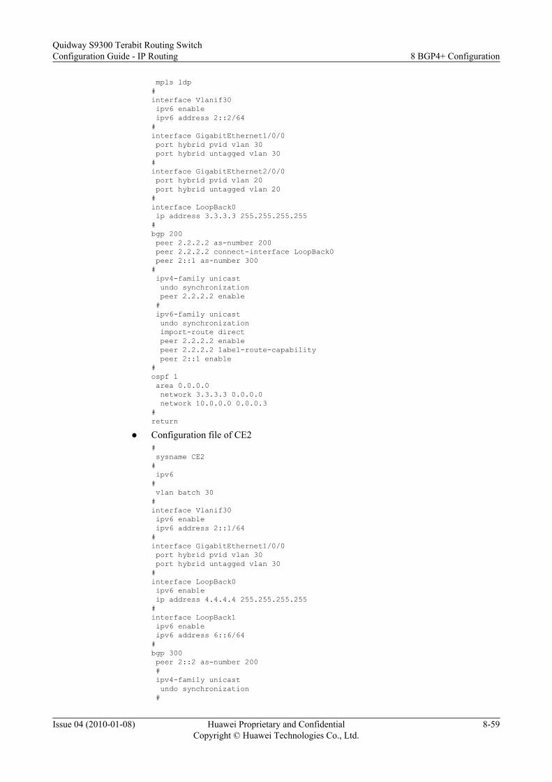
mpls ldp#interface Vlanif30 ipv6 enable ipv6 address 2::2/64#interface GigabitEthernet1/0/0 port hybrid pvid vlan 30 port hybrid untagged vlan 30#interface GigabitEthernet2/0/0 port hybrid pvid vlan 20 port hybrid untagged vlan 20#interface LoopBack0 ip address 3.3.3.3 255.255.255.255#bgp 200 peer 2.2.2.2 as-number 200 peer 2.2.2.2 connect-interface LoopBack0 peer 2::1 as-number 300# ipv4-family unicast undo synchronization peer 2.2.2.2 enable # ipv6-family unicast undo synchronization import-route direct peer 2.2.2.2 enable peer 2.2.2.2 label-route-capability peer 2::1 enable#ospf 1 area 0.0.0.0 network 3.3.3.3 0.0.0.0 network 10.0.0.0 0.0.0.3#return
l Configuration file of CE2# sysname CE2# ipv6# vlan batch 30#interface Vlanif30 ipv6 enable ipv6 address 2::1/64#interface GigabitEthernet1/0/0 port hybrid pvid vlan 30 port hybrid untagged vlan 30#interface LoopBack0 ipv6 enable ip address 4.4.4.4 255.255.255.255#interface LoopBack1 ipv6 enable ipv6 address 6::6/64#bgp 300 peer 2::2 as-number 200 # ipv4-family unicast undo synchronization #
Quidway S9300 Terabit Routing SwitchConfiguration Guide - IP Routing 8 BGP4+ Configuration
Issue 04 (2010-01-08) Huawei Proprietary and ConfidentialCopyright © Huawei Technologies Co., Ltd.
8-59

ipv6-family unicast undo synchronization network 6:: 64 peer 2::2 enable#return
8 BGP4+ ConfigurationQuidway S9300 Terabit Routing Switch
Configuration Guide - IP Routing
8-60 Huawei Proprietary and ConfidentialCopyright © Huawei Technologies Co., Ltd.
Issue 04 (2010-01-08)

9 MBGP Configuration
About This Chapter
This chapter describes the procedure for configuring MBGP and commands for maintainingMBGP, and provides configuration examples.
9.1 Introduction to MBGPThis section describes the principle and concepts of MBGP.
9.2 MBGP Features Supported by the S9300This section describes MBGP features supported by the S9300.
9.3 Configuring Basic BGP FunctionsThis section describes how to configure and apply MBGP.
9.4 Configuring a Policy for Advertising MBGP RoutesThis section describes how to configure a policy for advertising MBGP routes.
9.5 Configuring the Routing Policy Between MBGP PeersThis section describes how to configure the routing policy between MBGP peers.
9.6 Configuring MBGP Route AttributesThis section describes how to configure a policy for selecting MBGP routes.
9.7 Maintaining MBGPThis section describes how to clear the statistics on MBGP and how to debug MBGP.
9.8 Configuration ExamplesThis section provides a configuration example of MBGP.
Quidway S9300 Terabit Routing SwitchConfiguration Guide - IP Routing 9 MBGP Configuration
Issue 04 (2010-01-08) Huawei Proprietary and ConfidentialCopyright © Huawei Technologies Co., Ltd.
9-1

9.1 Introduction to MBGPThis section describes the principle and concepts of MBGP.
When multicast sources and receivers are located in different ASs, the multicast forwarding treeneeds to be configured across ASs. The Multiprotocol Border Gateway Protocol (MP-BGP) canbe dedicated to transmit routing information across ASs for multicast.
MP-BGP is the multiprotocol extension of BGP. Currently, BGP4 is applicable only to unicast.Based on BGP4, MP-BGP provides advanced functions. Therefore, BGP can provide routinginformation for multiple routing protocols including multicast routing protocoal.
l MP-BGP can maintain routing information for both unicast and multicast. MP-BGP storesthe routing information in different routing tables, which ensures that unicast routinginformation and multicast routing information are separated.
l MP-BGP supports both unicast and multicast modes. MP-BGP can create different networktopologies for the two modes.
l The most of the unicast routing policies and configuration methods supported by BGP4 areapplicable to the multicast mode. Therefore, MP-BGP can maintain unicast and multicastroutes according to different routing policies.
The application of MP-BGP to multicast is called the Multicast BGP (MBGP). The followingsections describe the configuration items used by MP-BGP for multicast application, that is,MBGP configuration items. For details about MP-BGP, see the Quidway S9300 Terabit RoutingSwitch Configuration Guide - IP Routing.
9.2 MBGP Features Supported by the S9300This section describes MBGP features supported by the S9300.
For details, see "Configuring the BGP" in the Quidway S9300 Terabit Routing SwitchConfiguration Guide-IP Routing.
9.3 Configuring Basic BGP FunctionsThis section describes how to configure and apply MBGP.
9.3.1 Establishing the Configuration Task
9.3.2 Configuring a BGP Peer
9.3.3 Configuring a BGP Peer
9.3.4 (Optional) Configuring the MBGP RR
9.3.5 Configuring MBGP to Import Local Routes
9.3.6 Checking the Configuration
9.3.1 Establishing the Configuration Task
9 MBGP ConfigurationQuidway S9300 Terabit Routing Switch
Configuration Guide - IP Routing
9-2 Huawei Proprietary and ConfidentialCopyright © Huawei Technologies Co., Ltd.
Issue 04 (2010-01-08)

Applicable EnvironmentThe multicast packets are checked according to:
l Multicast static route
l Unicast route
l MBGP route
The MBGP connection established in the multicast address family view provides useful routinginformation for RPF check.
Pre-configuration TasksBefore configuring basic MBGP functions, complete the following task:l Configuring the unicast routing protocol to ensure that the IP routes between nodes are
reachable
Data PreparationTo configure basic MBGP functions, you need the following data.
No. Data
1 Local AS number
2 Address of the remote peer or name of thepeer group
3 Cluster ID
4 Routing information to be advertised
9.3.2 Configuring a BGP Peer
Context
CAUTIONIf the BGP connection is already established between two S9300s for which the MBGP peerrelation needs to be established, skip this configuration.
Procedure
Step 1 Run:system-view
The system view is displayed.
Quidway S9300 Terabit Routing SwitchConfiguration Guide - IP Routing 9 MBGP Configuration
Issue 04 (2010-01-08) Huawei Proprietary and ConfidentialCopyright © Huawei Technologies Co., Ltd.
9-3
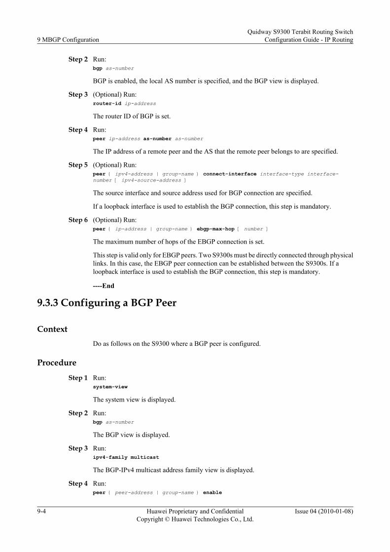
Step 2 Run:bgp as-number
BGP is enabled, the local AS number is specified, and the BGP view is displayed.
Step 3 (Optional) Run:router-id ip-address
The router ID of BGP is set.
Step 4 Run:peer ip-address as-number as-number
The IP address of a remote peer and the AS that the remote peer belongs to are specified.
Step 5 (Optional) Run:peer { ipv4-address | group-name } connect-interface interface-type interface-number [ ipv4-source-address ]
The source interface and source address used for BGP connection are specified.
If a loopback interface is used to establish the BGP connection, this step is mandatory.
Step 6 (Optional) Run:peer { ip-address | group-name } ebgp-max-hop [ number ]
The maximum number of hops of the EBGP connection is set.
This step is valid only for EBGP peers. Two S9300s must be directly connected through physicallinks. In this case, the EBGP peer connection can be established between the S9300s. If aloopback interface is used to establish the BGP connection, this step is mandatory.
----End
9.3.3 Configuring a BGP Peer
ContextDo as follows on the S9300 where a BGP peer is configured.
Procedure
Step 1 Run:system-view
The system view is displayed.
Step 2 Run:bgp as-number
The BGP view is displayed.
Step 3 Run:ipv4-family multicast
The BGP-IPv4 multicast address family view is displayed.
Step 4 Run:peer { peer-address | group-name } enable
9 MBGP ConfigurationQuidway S9300 Terabit Routing Switch
Configuration Guide - IP Routing
9-4 Huawei Proprietary and ConfidentialCopyright © Huawei Technologies Co., Ltd.
Issue 04 (2010-01-08)

MBGP is enabled for the original BGP peer or peer group. The original BGP peer or peer groupbecomes the MBGP peer.
l group-name: specifies the original BGP peer group.
l peer-address: specifies the IP address of the original remote BGP peer.
----End
9.3.4 (Optional) Configuring the MBGP RR
Context
CAUTIONThe route reflector (RR) is valid only for IBGP peers. Before performing this configuration, youmust set up the IBGP peer relation between the MBGP RR and the client.
Do as follows on the S9300.
Procedure
Step 1 Run:system-view
The system view is displayed.
Step 2 Run:bgp as-number
The BGP view is displayed.
Step 3 Run:ipv4-family multicast
The BGP-IPv4 multicast address family view is displayed.
Step 4 Run:peer { group-name | peer-address } reflect-client
The S9300 is configured as an RR, and the peer or peer group is specified as the client of theRR.
l group-name: specifies the name of an MBGP peer group.
l peer-address: specifies the IP address of a remote MBGP peer.
Step 5 (Optional) Run:reflector cluster-id { decimal-value | ipv4-address }
The cluster ID of the RR is set.
By default, the RR uses its router ID as the cluster ID.
l decimal-value: specifies the cluster ID in the form of integer.
Quidway S9300 Terabit Routing SwitchConfiguration Guide - IP Routing 9 MBGP Configuration
Issue 04 (2010-01-08) Huawei Proprietary and ConfidentialCopyright © Huawei Technologies Co., Ltd.
9-5

l ipv4-address: specifies the cluster ID in the form of IPv4 address.
----End
9.3.5 Configuring MBGP to Import Local Routes
ContextMBGP routes have two sources: routes statically imported with the network command androutes imported with the import-route command. You must import at least one local routeaccording to the actual network situation.
Do as follows on the S9300 where an MBGP peer is configured.
Procedure
Step 1 Run:system-view
The system view is displayed.
Step 2 Run:bgp as-number
The BGP view is displayed.
Step 3 Run:ipv4-family multicast
The BGP-IPv4 multicast address family view is displayed.
Step 4 Run:network network-address [ mask-length | mask ] [ route-policy route-policy-name ]
The S9300 is configured to advertise the route of the directly connected network segment.
Step 5 Run:import-route protocol [ process-id ] [ med med-value | route-policy route-policy-name ]*
The IGP route is imported to MBGP.
Step 6 (Optional) Run:default-route imported
The default route is imported to the MBGP routing table.
This command is run in special cases. By default, default routes are not imported.
To import a default route, you need to run the default-route imported command and the import-route command. The import-route command cannot be used to import default routes, and thedefault-route imported command is used to import only default routes in the local routing table.
----End
9.3.6 Checking the Configuration
9 MBGP ConfigurationQuidway S9300 Terabit Routing Switch
Configuration Guide - IP Routing
9-6 Huawei Proprietary and ConfidentialCopyright © Huawei Technologies Co., Ltd.
Issue 04 (2010-01-08)

PrerequisiteThe configuration of basic MBGP functions is complete.
Procedurel Run the display bgp multicast peer [ [ peer-address ] verbose ] command to check the
information about an MBGP peer.l Run the display bgp multicast group [ group-name ] command to check the information
about an MBGP peer group.l Run the display bgp multicast network command to check the information about the
routes advertised by MBGP.l Run the display bgp multicast routing-table [ network-address [ mask-length [ longer-
prefixes ] | mask [ longer-prefixes ] ] ] command to check the information about the MBGProuting table.
----End
9.4 Configuring a Policy for Advertising MBGP RoutesThis section describes how to configure a policy for advertising MBGP routes.
ContextNOTE
The following configuration tasks are optional. You can perform the configuration tasks as required.
9.4.1 Establishing the Configuration Task
9.4.2 Configuring the Next Hop in the Route as the Local Address
9.4.3 Configuring Local Route Aggregation of MBGP
9.4.4 Configuring the Local Peer to Advertise the Default Route
9.4.5 Configuring the Local Peer to Advertise the Community Attributes and ExtendedCommunity Attributes
9.4.6 Configuring the Update Message Not to Contain the Private AS Number
9.4.7 Checking the Configuration
9.4.1 Establishing the Configuration Task
Applicable EnvironmentThe S9300 configured with an MBGP peer advertises the information about local routes to theremote peer. Based on the actual situation, you can adopt the matching policy and determine:
l Whether to change the next hop in the route when MBGP advertises routes to the IBGPpeer.
l Whether MBGP advertises all the local routes or only the aggregated local routes.
l Whether MBGP advertises the default route.
Quidway S9300 Terabit Routing SwitchConfiguration Guide - IP Routing 9 MBGP Configuration
Issue 04 (2010-01-08) Huawei Proprietary and ConfidentialCopyright © Huawei Technologies Co., Ltd.
9-7

l Whether MBGP advertises the community attributes or the extended community attribute.
l Whether the BGP Update messages sent by the MBGP peer contains the private AS number.
Pre-configuration TasksBefore configuring the policy for advertising MBGP routes, complete the following task:l 9.3 Configuring Basic BGP Functions
Data PreparationTo configure the policy for advertising MBGP routes, you need the following data.
No. Data
1 AS number
2 Address of the remote peer or name of thepeer group
3 Routing policy name
4 Aggregated IP address and mask of the localroute
9.4.2 Configuring the Next Hop in the Route as the Local Address
ContextDo as follows on the S9300 where an MBGP peer is configured.
Procedure
Step 1 Run:system-view
The system view is displayed.
Step 2 Run:bgp as-number
The BGP view is displayed.
Step 3 Run:ipv4-family multicast
The BGP-IPv4 multicast address family view is displayed.
Step 4 Run:peer { group-name | peer-address } next-hop-local
The next hop in the route is configured as the local address when the S9300 advertises routes tothe MBGP peer group or remote MBGP peer.
9 MBGP ConfigurationQuidway S9300 Terabit Routing Switch
Configuration Guide - IP Routing
9-8 Huawei Proprietary and ConfidentialCopyright © Huawei Technologies Co., Ltd.
Issue 04 (2010-01-08)

This configuration is valid only for the IBGP peer or peer group.
l group-name: specifies the name of an MBGP peer group.
l peer-address: specifies the IP address of a remote MBGP peer.
----End
9.4.3 Configuring Local Route Aggregation of MBGP
ContextMBGP supports local route aggregation in the following modes:
l Automatic aggregation: MBGP automatically aggregates routes imported locally.
l Manual aggregation: MBGP automatically aggregates routes in the local MBGP routingtable. The preference of manual aggregation is higher than the preference of automaticaggregation.
Do as follows on the S9300 where an MBGP peer is configured. By default, MBGP does notaggregate local routes.
Procedure
Step 1 Run:system-view
The system view is displayed.
Step 2 Run:bgp as-number
The BGP view is displayed.
Step 3 Run:ipv4-family multicast
The BGP-IPv4 multicast address family view is displayed.
Step 4 Run:summary automatic
The automatic aggregation of the subnet route is configured.
Step 5 Run:aggregate ip-address { mask | mask-length } [ as-set | attribute-policy route-policy-name1 | detail-suppressed | origin-policy route-policy-name2 | suppress-policy route-policy-name3 ]*
The local routes are aggregated, and MBGP advertises aggregated local routes.
l ip-address: specifies the IP address of the aggregated routes. The value is in dotted decimalnotation.
l mask: specifies the network mask of the aggregated routes. The value is in dotted decimalnotation.
l mask-length: specifies the length of the mask of the IPv4 address. The value is an integerthat ranges from 0 to 32.
Quidway S9300 Terabit Routing SwitchConfiguration Guide - IP Routing 9 MBGP Configuration
Issue 04 (2010-01-08) Huawei Proprietary and ConfidentialCopyright © Huawei Technologies Co., Ltd.
9-9

l as-set: generates a route with AS-SET. Use this parameter with caution when many AS pathsare aggregated.
l attribute-policy: is used to set the attributes of the aggregation routes.
l detail-suppressed: indicates that only the aggregated route is advertised.
l origin-policy: is used to filter the specific routes in route aggregation.
l suppress-policy: is used to suppress the advertisements of a specific route.
l route-policy-name: specifies the name of the routing policy.
----End
9.4.4 Configuring the Local Peer to Advertise the Default Route
Context
Do as follows on the S9300 where an MBGP peer is configured. By default, the default route isnot advertised.
Procedure
Step 1 Run:system-view
The system view is displayed.
Step 2 Run:bgp as-number
The BGP view is displayed.
Step 3 Run:ipv4-family multicast
The BGP-IPv4 multicast address family view is displayed.
Step 4 Run:peer { group-name | peer-address } default-route-advertise [ route-policy route-policy-name ]
The default route is advertised to the MBGP peer group or remote MBGP peer.
l group-name: specifies the name of an MBGP peer group.
l peer-address: specifies the IP address of a remote MBGP peer.
l route-policy route-policy-name: specifies the routing policy for controlling the routes to beadvertised.
----End
9.4.5 Configuring the Local Peer to Advertise the CommunityAttributes and Extended Community Attributes
9 MBGP ConfigurationQuidway S9300 Terabit Routing Switch
Configuration Guide - IP Routing
9-10 Huawei Proprietary and ConfidentialCopyright © Huawei Technologies Co., Ltd.
Issue 04 (2010-01-08)

Context
Do as follows on the S9300 where an MBGP peer is configured. By default, the communityattributes and extended community attributes are not advertised.
Procedure
Step 1 Run:system-view
The system view is displayed.
Step 2 Run:bgp as-number
The BGP view is displayed.
Step 3 Run:ipv4-family multicast
The BGP-IPv4 multicast address family view is displayed.
Step 4 Run:peer { group-name | peer-address } { advertise-community | advertise-ext-community }
The community attributes and extended community attributes are advertised to the MBGP peergroup or the remote MBGP peer.
l group-name: specifies the name of an MBGP peer group.
l peer-address: specifies the IP address of a remote MBGP peer.
l advertise-community: specifies the community attributes.
l advertise-ext-community: specifies the extended community attributes.
----End
9.4.6 Configuring the Update Message Not to Contain the PrivateAS Number
Context
Do as follows on the S9300 where an MBGP peer is configured. This configuration is valid onlyfor EBGP peers. By default, the Update message contains the private AS number.
Procedure
Step 1 Run:system-view
The system view is displayed.
Step 2 Run:bgp as-number
Quidway S9300 Terabit Routing SwitchConfiguration Guide - IP Routing 9 MBGP Configuration
Issue 04 (2010-01-08) Huawei Proprietary and ConfidentialCopyright © Huawei Technologies Co., Ltd.
9-11
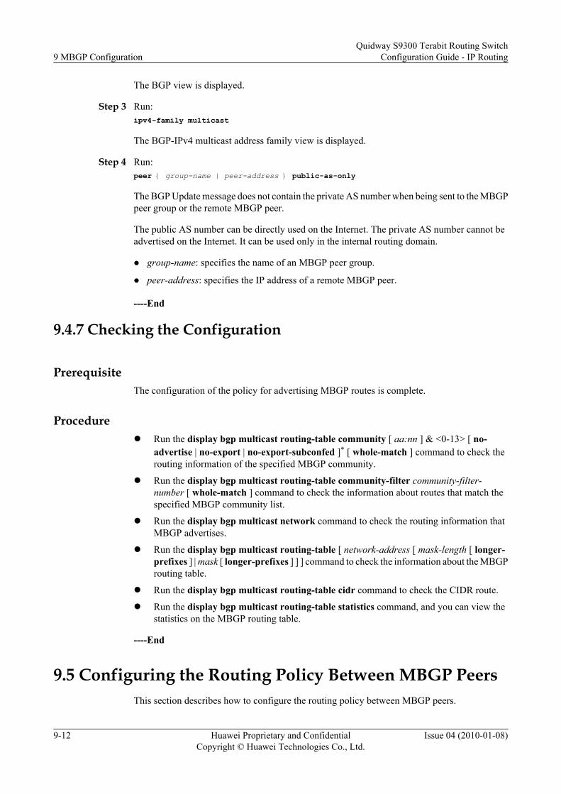
The BGP view is displayed.
Step 3 Run:ipv4-family multicast
The BGP-IPv4 multicast address family view is displayed.
Step 4 Run:peer { group-name | peer-address } public-as-only
The BGP Update message does not contain the private AS number when being sent to the MBGPpeer group or the remote MBGP peer.
The public AS number can be directly used on the Internet. The private AS number cannot beadvertised on the Internet. It can be used only in the internal routing domain.
l group-name: specifies the name of an MBGP peer group.
l peer-address: specifies the IP address of a remote MBGP peer.
----End
9.4.7 Checking the Configuration
PrerequisiteThe configuration of the policy for advertising MBGP routes is complete.
Procedurel Run the display bgp multicast routing-table community [ aa:nn ] & <0-13> [ no-
advertise | no-export | no-export-subconfed ]* [ whole-match ] command to check therouting information of the specified MBGP community.
l Run the display bgp multicast routing-table community-filter community-filter-number [ whole-match ] command to check the information about routes that match thespecified MBGP community list.
l Run the display bgp multicast network command to check the routing information thatMBGP advertises.
l Run the display bgp multicast routing-table [ network-address [ mask-length [ longer-prefixes ] | mask [ longer-prefixes ] ] ] command to check the information about the MBGProuting table.
l Run the display bgp multicast routing-table cidr command to check the CIDR route.
l Run the display bgp multicast routing-table statistics command, and you can view thestatistics on the MBGP routing table.
----End
9.5 Configuring the Routing Policy Between MBGP PeersThis section describes how to configure the routing policy between MBGP peers.
9 MBGP ConfigurationQuidway S9300 Terabit Routing Switch
Configuration Guide - IP Routing
9-12 Huawei Proprietary and ConfidentialCopyright © Huawei Technologies Co., Ltd.
Issue 04 (2010-01-08)

ContextNOTE
The following configuration tasks are optional. You can perform the configuration tasks as required.
9.5.1 Establishing the Configuration Task
9.5.2 Configuring the Routing Policy in the Global MBGP View
9.5.3 Configuring the Routing Policy Based on Route-Policy
9.5.4 Configuring the Routing Policy Based on IP ACL
9.5.5 Configuring the Routing Policy Based on the AS-Path List
9.5.6 Configuring a Routing Policy Based on the IP Prefix List
9.5.7 Setting the Maximum Number of Routes Received from an MBGP Peer
9.5.8 Configuring BGP Route Dampening
9.5.9 Checking the Configuration
9.5.1 Establishing the Configuration Task
Applicable EnvironmentAccording to the actual network situation, you can configure the proper routing policy to controlthe route information transmitted between MBGP peers.
For an S9300 configured with MBGP, the route interaction between peers has two directions:
l import: specifies the incoming direction. By configuring the command, the S9300 canfilter the routes from the specified peer. Only the routes that meet the requirements areaccepted.
l export: specifies the outgoing direction. By configuring the command, the S9300 can filterthe routes sent to the specified peer or group. Only the routes that meet the requirementsare advertised.
MBGP dampening can suppress unstable routing information. After MBGP dampening isconfigured, unstable routing information is not added to the MBGP routing table or advertisedto other MBGP peers.
Pre-configuration TasksBefore configuring the routing policy for MBGP peers, complete the following task:l 9.3 Configuring Basic BGP Functions
Data PreparationTo configure the routing policy for MBGP peers, you need the following data.
No. Data
1 Number of the AS where the peer is located.
Quidway S9300 Terabit Routing SwitchConfiguration Guide - IP Routing 9 MBGP Configuration
Issue 04 (2010-01-08) Huawei Proprietary and ConfidentialCopyright © Huawei Technologies Co., Ltd.
9-13

No. Data
2 Address of the peer or name of the peer group
3 Policy for filtering routes based on Route-Policy
4 Policy for filtering routes based on IP ACL
5 Policy for filtering routes based on as-path-filter
6 Policy for filtering routes based on ip-prefix
7 Value of route-limit
8 Dampening parameters, including the halflife and threshold
9.5.2 Configuring the Routing Policy in the Global MBGP View
Context
Do as follows on the S9300 where an MBGP peer is configured. This configuration is applicableto the route interaction between the S9300 and any remote peer.
Procedure
Step 1 Run:system-view
The system view is displayed.
Step 2 Run:bgp as-number
The BGP view is displayed.
Step 3 Run:ipv4-family multicast
The BGP-IPv4 multicast address family view is displayed.
Step 4 Run:filter-policy { basic-acl-number | ip-prefix ip-prefix-name } { import | export [ protocol process-id ] }
The MBGP routing policy is configured. The S9300 can control the route interaction with anyremote MBGP peer.
l basic-acl-number: specifies the number of the list used for filtering addresses.
l ip-prefix-name: specifies the name of the IP prefix list.
9 MBGP ConfigurationQuidway S9300 Terabit Routing Switch
Configuration Guide - IP Routing
9-14 Huawei Proprietary and ConfidentialCopyright © Huawei Technologies Co., Ltd.
Issue 04 (2010-01-08)

l import: is used to filter routes from any MBGP peer. Only the routes that meet therequirements are accepted.
l export [ protocol process-id ]: is used to filter the routes advertised to any MBGP peer.Routes advertised to any MBGP peer are filtered when the local routes are imported to theMBGP routing table. Only the local routes that meet the requirements are imported to theMBGP routing table. Then the routing information in the MBGP routing table is advertised.
----End
9.5.3 Configuring the Routing Policy Based on Route-Policy
Context
Do as follows on the S9300 where an MBGP peer is configured.
Procedure
Step 1 Run:system-view
The system view is displayed.
Step 2 Run:bgp as-number
The BGP view is displayed.
Step 3 Run:ipv4-family multicast
The BGP-IPv4 multicast address family view is displayed.
Step 4 Run:peer { group-name | peer-address } route-policy route-policy-name { import | export }
The policy for filtering MBGP routes is configured based on the Route-Policy. The S9300 cancontrol the route interaction with the specified remote MBGP peer.
l group-name: specifies the name of an MBGP peer group.
l peer-address: specifies the IP address of a remote MBGP peer.
l route-policy-name: specifies the name of the routing policy.
l import: filters the routes from the specified remote MBGP peer or the MBGP peer group.Only the routes that meet the requirements are accepted.
l export: filters the routes sent to the specified remote MBGP peer or the MBGP peer group.Only the routes that meet the requirements are advertised.
----End
9.5.4 Configuring the Routing Policy Based on IP ACL
Quidway S9300 Terabit Routing SwitchConfiguration Guide - IP Routing 9 MBGP Configuration
Issue 04 (2010-01-08) Huawei Proprietary and ConfidentialCopyright © Huawei Technologies Co., Ltd.
9-15

ContextDo as follows on the S9300 where an MBGP peer is configured. This configuration is optional.By default, no routing policy based on IP ACL is configured.
Procedure
Step 1 Run:system-view
The system view is displayed.
Step 2 Run:bgp as-number
The BGP view is displayed.
Step 3 Run:ipv4-family multicast
The BGP-IPv4 multicast address family view is displayed.
Step 4 Run:peer { group-name | peer-address } filter-policy basic-acl-number { import | export }
The policy for filtering MBGP routes is configured based on IP ACL. You can control the routeinteraction between the S9300 and the specified remote MBGP peer.
l group-name: specifies the name of an MBGP peer group.
l peer-address: specifies the IP address of a remote MBGP peer.
l basic-acl-number: specifies the routing policy.
l import: filters the routes from the specified remote MBGP peer or the MBGP peer group.Only the routes meet the requirements are accepted.
l export: filters the routes sent to the specified remote MBGP peer or the MBGP peer group.Only the routes that meet the requirements are advertised.
----End
9.5.5 Configuring the Routing Policy Based on the AS-Path List
ContextDo as follows on the S9300 where an MBGP peer is configured. By default, the routing policyis not configured based on the AS-Path list.
Procedure
Step 1 Run:system-view
The system view is displayed.
Step 2 Run:bgp as-number
9 MBGP ConfigurationQuidway S9300 Terabit Routing Switch
Configuration Guide - IP Routing
9-16 Huawei Proprietary and ConfidentialCopyright © Huawei Technologies Co., Ltd.
Issue 04 (2010-01-08)
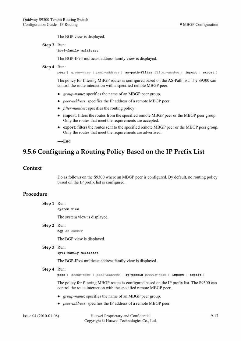
The BGP view is displayed.
Step 3 Run:ipv4-family multicast
The BGP-IPv4 multicast address family view is displayed.
Step 4 Run:peer { group-name | peer-address } as-path-filter filter-number { import | export }
The policy for filtering MBGP routes is configured based on the AS-Path list. The S9300 cancontrol the route interaction with a specified remote MBGP peer.
l group-name: specifies the name of an MBGP peer group.
l peer-address: specifies the IP address of a remote MBGP peer.
l filter-number: specifies the routing policy.
l import: filters the routes from the specified remote MBGP peer or the MBGP peer group.Only the routes that meet the requirements are accepted.
l export: filters the routes sent to the specified remote MBGP peer or the MBGP peer group.Only the routes that meet the requirements are advertised.
----End
9.5.6 Configuring a Routing Policy Based on the IP Prefix List
ContextDo as follows on the S9300 where an MBGP peer is configured. By default, no routing policybased on the IP prefix list is configured.
Procedure
Step 1 Run:system-view
The system view is displayed.
Step 2 Run:bgp as-number
The BGP view is displayed.
Step 3 Run:ipv4-family multicast
The BGP-IPv4 multicast address family view is displayed.
Step 4 Run:peer { group-name | peer-address } ip-prefix prefix-name { import | export }
The policy for filtering MBGP routes is configured based on the IP prefix list. The S9300 cancontrol the route interaction with the specified remote MBGP peer.
l group-name: specifies the name of an MBGP peer group.
l peer-address: specifies the IP address of a remote MBGP peer.
Quidway S9300 Terabit Routing SwitchConfiguration Guide - IP Routing 9 MBGP Configuration
Issue 04 (2010-01-08) Huawei Proprietary and ConfidentialCopyright © Huawei Technologies Co., Ltd.
9-17

l prefix-name: specifies the routing policy.
l import: is used to filter the routes from the specified remote MBGP peer or the MBGP peergroup. Only the routes that meet the requirements are accepted.
l export: is used to filter the routes sent to the specified remote MBGP peer or the MBGP peergroup. Only the routes that meet the requirements are advertised.
----End
9.5.7 Setting the Maximum Number of Routes Received from anMBGP Peer
Context
Do as follows on the S9300 where an MBGP peer is configured.
Procedure
Step 1 Run:system-view
The system view is displayed.
Step 2 Run:bgp as-number
The BGP view is displayed.
Step 3 Run:ipv4-family multicast
The BGP-IPv4 multicast address family view is displayed.
Step 4 Run:peer { group-name | peer-address } route-limit maximum-limit [ threshold ] [ alert-only | idle-forever | idle-timeout value ]
The maximum number of address prefixes of routes learned from the specified remote peer isset. If the number of address prefixes reaches the maximum number, the S9300 ends the peerrelation.
l group-name: specifies the name of an MBGP peer group.
l peer-address: specifies the IP address of a remote MBGP peer.
l maximum-limit: specifies the maximum number of IP prefixes.
l threshold: specifies the threshold for generating an alarm. The value is the number of routesto the maximum number of IP prefixes.
l alert-only: indicates that an alarm is generated when the number of routes exceeds thethreshold.
l idle-forever: indicates that the S9300 does not establish connections when the number ofroutes reaches the threshold until the reset bgp command is run.
9 MBGP ConfigurationQuidway S9300 Terabit Routing Switch
Configuration Guide - IP Routing
9-18 Huawei Proprietary and ConfidentialCopyright © Huawei Technologies Co., Ltd.
Issue 04 (2010-01-08)

l idle-timeout value: indicates that the S9300 triggers the timer for automatically establishingconnections when the number of routes reaches the threshold. The value parameter indicatesthe timeout interval.
----End
9.5.8 Configuring BGP Route Dampening
ContextDo as follows on the S9300 where an MBGP peer is configured. This configuration is valid onlyfor EBGP routes. By default, the S9300 uses the default values of dampening parameters.
Procedure
Step 1 Run:system-view
The system view is displayed.
Step 2 Run:bgp as-number
The BGP view is displayed.
Step 3 Run:ipv4-family multicast
The BGP-IPv4 multicast address family view is displayed.
Step 4 Run:dampening [ half-life-time-reachable half-life-time-unreachable route-reuse-value route-suppress-value max-ceiling-value | route-policy route-policy-name ]*
The parameters of MBGP route dampening are set.
l half-life-time-reachable: specifies the half life of a reachable route.
l half-life-time-unreachable: specifies the half life of an unreachable route.
l route-reuse-value: specifies the threshold of freeing suppressed routes. When the penaltyvalue becomes smaller than the threshold for freeing suppressed routes, the routes can beused again.
l route-suppress-value: specifies the threshold for suppressing routes. The value of route-suppress-value must be greater than the value of route-reuse-value. When the penalty valueexceeds the threshold for suppressing routes, routes are suppressed.
l max-ceiling-value: specifies the upper limit of the penalty value. The value of max-ceiling-value must be greater than the value of route-suppress-value.
l route-policy route-policy-name: specifies the name of a Rout-Policy that is applied to theroutes that meet the matching rules.
----End
9.5.9 Checking the Configuration
Quidway S9300 Terabit Routing SwitchConfiguration Guide - IP Routing 9 MBGP Configuration
Issue 04 (2010-01-08) Huawei Proprietary and ConfidentialCopyright © Huawei Technologies Co., Ltd.
9-19
PrerequisiteThe configuration of the route interaction policy between MBGP peers is complete.
Procedurel Run the display bgp multicast routing-table different-origin-as command to check the
information about the routing table containing routes with different source ASs.
l Run the display bgp multicast routing-table regular-expression [ as-regular-expression ] to check the information about routes that match the AS regular expression.
l Run the display bgp multicast paths as-regular-expression command to check theinformation about AS paths.
l Run the display bgp multicast routing-table as-path-filter as-path-filter-numbercommand to check the information about routes that match the filtering list.
l Run the display bgp multicast routing-table community-filter community-filter-number [ whole-match ] command to check the route that matches the specified MBGPcommunity list.
l Run the display bgp multicast routing-table peer peer-address { advertised-routes |received-routes } [ statistics ] command to check the information about routes that aresent by and received from the specified MBGP peer.
l Run the display bgp multicast network command to check the information about routesadvertised through the network command.
l Run the display bgp multicast routing-table dampened command to check the dampenedMBGP routes.
l Run the display bgp multicast routing-table dampening parameter command to checkthe parameters of MBGP route dampening.
l Run the display bgp multicast routing-table flap-info [ network-address [ mask [ longer-match ] | mask-length [ longer-match ] ] | as-path-filter as-path-filter-number | regular-expression as-regular-expression ] command to check the statistics on flapping MBGProutes.
----End
9.6 Configuring MBGP Route AttributesThis section describes how to configure a policy for selecting MBGP routes.
9.6.1 Establishing the Configuration Task
9.6.2 Setting the Preferred Value for the Route Received from an MBGP Peer
9.6.3 Setting the Preference of an MBGP Route
9.6.4 Setting Local_Pref of an MBGP Route
9.6.5 Configuring the MED of an MBGP Route
9.6.6 Checking the Configuration
9.6.1 Establishing the Configuration Task
9 MBGP ConfigurationQuidway S9300 Terabit Routing Switch
Configuration Guide - IP Routing
9-20 Huawei Proprietary and ConfidentialCopyright © Huawei Technologies Co., Ltd.
Issue 04 (2010-01-08)

Applicable Environment
To select the optimal path, MBGP needs to check the following information:
l Preferred value of an MBGP route
l Preference of MBGP routes
l Local preference of MBGP peers, that is, the values of Local_Pref of MBGP peers
l MEDs of MBGP routes
l MBGP route dampening parameters
According to the actual network situation, you can adopt a policy to determine the election ofroutes.
Pre-configuration Tasks
Before configuring the policy for selecting MBGP routes, complete the following task:
l 9.3 Configuring Basic BGP Functions
Data Preparation
To configure the policy for selecting MBGP routes, you need the following data.
No. Data
1 AS number
2 MBGP peer group and remote MBGP peer
3 Preferred value of the MBGP route
4 Preference of external, internal, and localroutes, and Route-Policy
5 Value of Default Local-preference of thelocal S9300
6 MEDs of MBGP routes
7 Values of the route dampening parameters
9.6.2 Setting the Preferred Value for the Route Received from anMBGP Peer
Context
Do as follows on the S9300 where an MBGP peer is configured. By default, the preferred valueis 0.
Quidway S9300 Terabit Routing SwitchConfiguration Guide - IP Routing 9 MBGP Configuration
Issue 04 (2010-01-08) Huawei Proprietary and ConfidentialCopyright © Huawei Technologies Co., Ltd.
9-21

Procedure
Step 1 Run:system-view
The system view is displayed.
Step 2 Run:bgp as-number
The BGP view is displayed.
Step 3 Run:ipv4-family multicast
The BGP-IPv4 multicast address family view is displayed.
Step 4 Run:peer { group-name | peer-address } preferred-value preference-value
The preferred value is set for the route learned from MBGP peer group or remote MBGP peer.
The route with the largest preferred value is selected as the route to the specified network.
l group-name: specifies the name of an MBGP peer group.
l peer-address: specifies the IP address of a remote MBGP peer.
----End
9.6.3 Setting the Preference of an MBGP Route
ContextDo as follows on the S9300 where an MBGP peer is configured. By default, the preference ofEBGP external routes, IBGP internal routes, and local routes is 255.
Procedure
Step 1 Run:system-view
The system view is displayed.
Step 2 Run:bgp as-number
The BGP view is displayed.
Step 3 Run:ipv4-family multicast
The BGP-IPv4 multicast address family view is displayed.
Step 4 Run:preference { external-preference internal-preference local-preference | route-policy route-policy-name }
The preferences of external, internal, and local routes are configured.
9 MBGP ConfigurationQuidway S9300 Terabit Routing Switch
Configuration Guide - IP Routing
9-22 Huawei Proprietary and ConfidentialCopyright © Huawei Technologies Co., Ltd.
Issue 04 (2010-01-08)

l external-preference: specifies the preference of routes learned from the EBGP peer.
l internal-preference: specifies the preference of routes learned from the IBGP peer.
l local-preference: specifies the preference of the locally generated route.
l route-policy route-policy-name: specifies the name of a Routing-Policy that is applied tothe routes that meet the matching rules.
----End
9.6.4 Setting Local_Pref of an MBGP Route
ContextDo as follows on the S9300 where an MBGP peer is configured. By default, the Local_Prefvalue is 100.
Procedure
Step 1 Run:system-view
The system view is displayed.
Step 2 Run:bgp as-number
The BGP view is displayed.
Step 3 Run:ipv4-family multicast
The BGP-IPv4 multicast address family view is displayed.
Step 4 Run:default local-preference preference-value
The Local_Pref value is set for the local S9300.
When a BGP-enabled S9300 obtains multiple routes with the same destination address but withdifferent next hops through IBGP peers, the route with the largest Local_Pref value is selected.
----End
9.6.5 Configuring the MED of an MBGP Route
ContextDo as follows on the S9300 where an MBGP peer is configured. When a BGP-enabled S9300obtains multiple routes to the same destination address but with different next hops throughEBGP peers, the route with the smallest MED is selected as the optimal route.
Procedure
Step 1 Run:
Quidway S9300 Terabit Routing SwitchConfiguration Guide - IP Routing 9 MBGP Configuration
Issue 04 (2010-01-08) Huawei Proprietary and ConfidentialCopyright © Huawei Technologies Co., Ltd.
9-23

system-view
The system view is displayed.
Step 2 Run:bgp as-number
The BGP view is displayed.
Step 3 Run:ipv4-family multicast
The BGP-IPv4 multicast address family view is displayed.
Step 4 Run:default med med-value
The default MED is set for the S9300.
Step 5 Run:compare-different-as-med
The MEDs of the routes from different ASs are compared.
By default, the S9300 that runs BGP compares the MEDs only from different peers in the sameAS.
Step 6 Run:bestroute med-none-as-maximum
The MED is set to the maximum value when the MED is not set.
By default, the MED is 0.
Step 7 Run:bestroute med-confederation
The S9300 is configured to compare MEDs of the routes in a confederation.
By default, BGP compares the MEDs of only the routes from the same AS.
----End
9.6.6 Checking the Configuration
PrerequisiteThe configuration on MBGP route attributes is complete.
Procedurel Run the display bgp multicast routing-table as-path-filter as-path-filter-number
command to check the information about routes that match the filtering list.l Run the display bgp multicast routing-table statistics command to check the statistics
on the MBGP routing table.
----End
9 MBGP ConfigurationQuidway S9300 Terabit Routing Switch
Configuration Guide - IP Routing
9-24 Huawei Proprietary and ConfidentialCopyright © Huawei Technologies Co., Ltd.
Issue 04 (2010-01-08)
9.7 Maintaining MBGPThis section describes how to clear the statistics on MBGP and how to debug MBGP.
9.7.1 Resetting MBGP Connections
9.7.2 Clearing MBGP Statistics
9.7.3 Debugging MBGP
9.7.1 Resetting MBGP Connections
Context
CAUTIONThe MBGP peer relation between S9300s is ended after you reset MBGP relations by runningthe reset bgp multicast command. So, confirm the action before you run the command.
After the MBGP routing policy or protocol is changed, you can run the following commands inthe user view if you want to make the new configuration take effect by resetting MBGP relations
Procedurel Run the reset bgp multicast peer-address command to reset the MBGP relation between
specified peers.l Run the reset bgp multicast all command to reset all MBGP connections.l Run the reset bgp multicast group group-name command to reset the MBGP relations
between peers in the same peer group.l Run the reset bgp multicast external command to reset all external connections.l Run the reset bgp multicast internal command to reset internal connections.
----End
9.7.2 Clearing MBGP Statistics
Context
CAUTIONMBGP statistics cannot be restored after you clear them. So, confirm the action before you runthe command.
Quidway S9300 Terabit Routing SwitchConfiguration Guide - IP Routing 9 MBGP Configuration
Issue 04 (2010-01-08) Huawei Proprietary and ConfidentialCopyright © Huawei Technologies Co., Ltd.
9-25

Procedurel Run the reset bgp multicast dampening [ network-address [ mask | mask-length ] ]
command to clear the MBGP route dampening information.l Run the reset bgp multicast flap-info [ network-address [ mask-length | mask ] | as-path-
filter as-path-list-number | regrexp regrexp ] command to clear the statistics on theflapping routes.
----End
9.7.3 Debugging MBGP
Context
CAUTIONDebugging affects the performance of the system. So, after debugging, run the undo debuggingall command to disable it immediately.
When an MBGP fault occurs, run the following debugging commands in the user view to locatethe fault.
Procedurel Run the debugging bgp all command to enable debugging of all BGP features.l Run the debugging bgp event command to enable debugging of BGP events.l Run the debugging bgp { keepalive | open | packet | route-refresh } [ receive | send ]
[ verbose ] command to enable debugging of BGP packets.l Run the debugging bgp update multicast [ acl acl-number | ip-prefix ip-prefix-name |
peer peer-address ] [ receive | send] [ verbose ] command to enable debugging of MBGPUpdate messages.
----End
9.8 Configuration ExamplesThis section provides a configuration example of MBGP.
9.8.1 Example for Configuring Basic MSDP Functions
9.8.1 Example for Configuring Basic MSDP Functions
Networking RequirementsAs shown in Figure 9-1, the receiver receives VOD information in multicast mode. The receiverand the source reside in different ASs. The MBGP peer relation is established between ASs totransmit multicast routing information.
9 MBGP ConfigurationQuidway S9300 Terabit Routing Switch
Configuration Guide - IP Routing
9-26 Huawei Proprietary and ConfidentialCopyright © Huawei Technologies Co., Ltd.
Issue 04 (2010-01-08)

Figure 9-1 Networking diagram of MBGP configuration
MBGP peers
S9300-A
AS100
GE1/0/0
S9300-B
S9300-D
S9300-C
AS200
GE2/0/0
GE1/0/0
GE2/0/0
GE2/0/0
GE1/0/0
Source
Receiver
GE2/0/0
GE3/0/0
GE3/0/0
GE1/0/0
Loopback0
Loopback0
Loopback0
Loopback0
Switch Interface VLANIF interface IP addressS9300-A GE 1/0/0 VLANIF100 192.1.1.1/24
GE 2/0/0 VLANIF101 10.10.10.1/24Loopback0 1.1.1.1/32
S9300-B GE 1/0/0 VLANIF100 192.1.1.2/24GE 2/0/0 VLANIF200 194.1.1.2/24GE 3/0/0 VLANIF300 193.1.1.2/24Loopback0 2.2.2.2/32
S9300-C GE 1/0/0 VLANIF400 195.1.1.1/24GE 2/0/0 VLANIF102 22.22.22.1/24GE 3/0/0 VLANIF300 193.1.1.1/24Loopback0 3.3.3.3/32
S9300-D GE 1/0/0 VLANIF400 195.1.1.2/24GE 2/0/0 VLANIF200 194.1.1.1/24Loopback0 4.4.4.4/32
Configuration Roadmap
The configuration roadmap is as follows:
1. Configure the IP addresses for the interfaces on each S9300 to ensure internetworkingwithin the AS in unicast mode.
2. Configure the MBGP peer and set up inter-AS multicast routes.
Quidway S9300 Terabit Routing SwitchConfiguration Guide - IP Routing 9 MBGP Configuration
Issue 04 (2010-01-08) Huawei Proprietary and ConfidentialCopyright © Huawei Technologies Co., Ltd.
9-27

3. Configure the MBGP routes to be advertised.4. Enable multicast on each S9300.5. Configure basic PIM-SM functions in each AS and enable the IGMP function on the
interfaces at the host side.6. Configure the BSR boundary on the interfaces connecting two ASs.7. Configure the MSDP peers to transfer inter-AS multicast information.
Data PreparationTo complete the configuration, you need the following data:
l AS number of S9300-A: 100
l AS number of S9300-B, S9300-C, and S9300-D: 200
l Address of the multicast group (225.1.1.1) and address of the multicast source(10.10.10.10/24)
NOTE
This configuration example describes only the commands used to configure MBGP.
Procedure
Step 1 Configure the IP addresses for the interfaces on each S9300 and the OSPF protocol in the ASs.
# Configure the IP addresses and masks of the interfaces on each S9300 according to Figure9-1. Connect the S9300s through OSPF and ensure that S9300-B, S9300-C, and S9300-D cancommunicate with each other through the network layer and can learn the routes on the loopbackinterfaces of each other. Configure the S9300s to dynamically update routes through a unicastrouting protocol. OSPF process 1 is adopted in the configuration and the procedure is notmentioned here.
Step 2 Configure BGP, enable the MBGP protocol, and configure the MBGP peers.
# Configure BGP and the MBGP peer on S9300-A.
[S9300-A] bgp 100[S9300-A-bgp] peer 192.1.1.2 as-number 200[S9300-A-bgp] ipv4-family multicast[S9300-A-bgp-af-multicast] peer 192.1.1.2 enable[S9300-A-bgp-af-multicast] quit[S9300-A-bgp] quit
# Configure BGP and the MBGP peer on S9300-B.
[S9300-B] bgp 200[S9300-B-bgp] peer 192.1.1.1 as-number 100[S9300-B-bgp] peer 193.1.1.1 as-number 200[S9300-B-bgp] peer 194.1.1.1 as-number 200[S9300-B-bgp] ipv4-family multicast[S9300-B-bgp-af-multicast] peer 192.1.1.1 enable[S9300-B-bgp-af-multicast] peer 193.1.1.1 enable[S9300-B-bgp-af-multicast] peer 194.1.1.1 enable[S9300-B-bgp-af-multicast] quit[S9300-B-bgp] quit
# Configure BGP and the MBGP peer on S9300-C.
[S9300-C] bgp 200[S9300-C-bgp] peer 193.1.1.2 as-number 200[S9300-C-bgp] peer 195.1.1.2 as-number 200
9 MBGP ConfigurationQuidway S9300 Terabit Routing Switch
Configuration Guide - IP Routing
9-28 Huawei Proprietary and ConfidentialCopyright © Huawei Technologies Co., Ltd.
Issue 04 (2010-01-08)

[S9300-C-bgp] ipv4-family multicast[S9300-C-bgp-af-multicast] peer 193.1.1.2 enable[S9300-C-bgp-af-multicast] peer 195.1.1.2 enable[S9300-C-bgp-af-multicast] quit[S9300-C-bgp] quit
# Configure BGP and the MBGP peer on S9300-D.
[S9300-D] bgp 200[S9300-D-bgp] peer 194.1.1.2 as-number 200[S9300-D-bgp] peer 195.1.1.1 as-number 200[S9300-D-bgp] ipv4-family multicast[S9300-D-bgp-af-multicast] peer 194.1.1.2 enable[S9300-D-bgp-af-multicast] peer 195.1.1.1 enable[S9300-D-bgp-af-multicast] quit[S9300-D-bgp] quit
Step 3 Configure the routes to be advertised.
# Configure the routes to be advertised on S9300-A.
[S9300-A] bgp 100[S9300-A-bgp] import-route direct [S9300-A-bgp] ipv4-family multicast[S9300-A-bgp-af-multicast] import-route direct[S9300-A-bgp-af-multicast] quit[S9300-A-bgp] quit
# Configure the routes to be advertised on S9300-B.
[S9300-B] bgp 200[S9300-B-bgp] import-route direct [S9300-B-bgp] import-route ospf 1[S9300-B-bgp] ipv4-family multicast[S9300-B-bgp-af-multicast] import-route direct[S9300-B-bgp-af-multicast] import-route ospf 1[S9300-B-bgp-af-multicast] quit[S9300-B-bgp] quit
# Configure the routes to be advertised on S9300-C. The configuration of S9300-D is similar tothe configuration of S9300-C, and is not mentioned here.
[S9300-C] bgp 200[S9300-C-bgp] import-route direct [S9300-C-bgp] ipv4-family multicast[S9300-C-bgp-af-multicast] import-route direct[S9300-C-bgp-af-multicast] import-route ospf 1[S9300-C-bgp-af-multicast] quit[S9300-C-bgp] quit
Step 4 Enable multicast on each S9300 and the interfaces that are connected.
# Configure S9300-A.
[S9300-A] multicast routing-enable[S9300-A] interface vlanif 100[S9300-A-Vlanif100] pim sm[S9300-A-Vlanif100] quit[S9300-A] interface vlanif 101[S9300-A-Vlanif101] pim sm[S9300-A-Vlanif101] quit
# Configure S9300-B.
[S9300-B] multicast routing-enable[S9300-B] interface vlanif 100[S9300-B-Vlanif100] pim sm[S9300-B-Vlanif100] quit[S9300-B] interface vlanif 200[S9300-B-Vlanif200] pim sm
Quidway S9300 Terabit Routing SwitchConfiguration Guide - IP Routing 9 MBGP Configuration
Issue 04 (2010-01-08) Huawei Proprietary and ConfidentialCopyright © Huawei Technologies Co., Ltd.
9-29

[S9300-B-Vlanif200] quit[S9300-B] interface vlanif 300[S9300-B-Vlanif300] pim sm[S9300-B-Vlanif300] quit
# Configure S9300-C.
[S9300-C] multicast routing-enable[S9300-C] interface vlanif 400[S9300-C-Vlanif400] pim sm[S9300-C-Vlanif400] quit[S9300-C] interface vlanif 102[S9300-C-Vlanif102] pim sm[S9300-C-Vlanif102] igmp enable[S9300-C-Vlanif102] quit[S9300-C] interface vlanif 300[S9300-C-Vlanif300] pim sm[S9300-C-Vlanif300] quit
# Configure S9300-D.
[S9300-D] multicast routing-enable[S9300-D] interface vlanif 400[S9300-D-Vlanif400] pim sm[S9300-D-Vlanif400] quit[S9300-D] interface vlanif 200[S9300-D-Vlanif200] pim sm[S9300-D-Vlanif200] quit
Step 5 Configure BSR and RP within each AS.
# Configure S9300-A.
[S9300-A] interface loopback 0[S9300-A-LoopBack0] ip address 1.1.1.1 255.255.255.255[S9300-A-LoopBack0] pim sm[S9300-A-LoopBack0] quit[S9300-A] pim[S9300-A-pim] c-bsr loopback 0[S9300-A-pim] c-rp loopback 0[S9300-A-pim] quit
# Configure S9300-B.
[S9300-B] interface loopback 0[S9300-B-LoopBack0] ip address 2.2.2.2 255.255.255.255[S9300-B-LoopBack0] pim sm[S9300-B-LoopBack0] quit[S9300-B] pim[S9300-B-pim] c-bsr loopback 0[S9300-B-pim] c-rp loopback 0[S9300-B] quit
Step 6 Configure the BSR boundary on the interfaces connecting two ASs.
# Configure S9300-A.
[S9300-A] interface vlanif 100[S9300-A-Vlanif100] pim bsr-boundary[S9300-A-Vlanif100] quit
# Configure S9300-B.
[S9300-B] interface vlanif 100[S9300-B-Vlanif100] pim bsr-boundary[S9300-B-Vlanif100] quit
Step 7 Configure MSDP peers.
# Configure S9300-A.
9 MBGP ConfigurationQuidway S9300 Terabit Routing Switch
Configuration Guide - IP Routing
9-30 Huawei Proprietary and ConfidentialCopyright © Huawei Technologies Co., Ltd.
Issue 04 (2010-01-08)

[S9300-A] msdp[S9300-A-msdp] peer 192.1.1.2 connect-interface vlanif100[S9300-A-msdp] quit
# Configure S9300-B.
[S9300-B] msdp[S9300-B-msdp] peer 192.1.1.1 connect-interface vlanif100[S9300-B-msdp] quit
Step 8 Verify the configuration.
# Run the display bgp multicast peer command to view the MBGP peer relation betweenS9300s. For example, the following information shows the MBGP peer relation on S9300-A:
[S9300-A] display bgp multicast peerBGP local router ID : 1.1.1.1 Local AS number : 100 Total number of peers : 1 Peers in established state : 1 Peer V AS MsgRcvd MsgSent OutQ Up/Down State PrefRcv 192.1.1.2 4 200 82 75 0 00:30:29 Established 17
# Run the display msdp brief command to view information about the MSDP peer relationbetween S9300s. For example, the following information shows the MBGP peer relation onS9300-B:
[S9300-B] display msdp briefMSDP Peer Brief Information of VPN-Instance: public net Configured Up Listen Connect Shutdown Down 1 1 0 0 0 0 Peer's Address State Up/Down time AS SA Count Reset Count 192.1.1.1 Up 00:07:17 100 1 0
----End
Configuration Filesl Configuration file of S9300-A
#sysname S9300-A# vlan batch 100 101# multicast routing-enable#interface vlanif 100 ip address 192.1.1.1 255.255.255.0 pim bsr-boundary pim sm#interface vlanif 101 ip address 10.10.10.1 255.255.255.0 pim sm#interface GigabitEthernet1/0/0 port hybrid tagged vlan 100#interface GigabitEthernet2/0/0 port hybrid untagged vlan 101#interface loopback 0 ip address 1.1.1.1 255.255.255.255 pim sm#pim c-bsr loopback 0
Quidway S9300 Terabit Routing SwitchConfiguration Guide - IP Routing 9 MBGP Configuration
Issue 04 (2010-01-08) Huawei Proprietary and ConfidentialCopyright © Huawei Technologies Co., Ltd.
9-31

c-rp loopback 0#bgp 100 peer 192.1.1.2 as-number 200# ipv4-family unicast undo synchronization peer 192.1.1.2 enable# ipv4-family multicast undo synchronization import-route direct peer 192.1.1.2 enable#msdp peer 192.1.1.2 connect-interface vlanif100#return
l Configuration file of S9300-B# sysname S9300-B# vlan batch 100 200 300# multicast routing-enable#interface vlanif 100 ip address 192.1.1.2 255.255.255.0 pim bsr-boundary pim sm#interface vlanif 200 ip address 194.1.1.2 255.255.255.0 pim sm#interface vlanif 300 ip address 193.1.1.2 255.255.255.0 pim sm#interface GigabitEthernet1/0/0 port hybrid tagged vlan 100#interface GigabitEthernet2/0/0 port hybrid tagged vlan 200#interface GigabitEthernet3/0/0 port hybrid tagged vlan 300#interface loopback 0 ip address 2.2.2.2 255.255.255.255 pim sm#pim c-bsr loopback 0 c-rp loopback 0#ospf 1 area 0.0.0.0 network 193.1.1.0 0.0.0.255 network 194.1.1.0 0.0.0.255 network 2.2.2.2 0.0.0.0#bgp 200 peer 192.1.1.1 as-number 100 peer 193.1.1.1 as-number 200 peer 194.1.1.1 as-number 200# ipv4-family unicast undo synchronization
9 MBGP ConfigurationQuidway S9300 Terabit Routing Switch
Configuration Guide - IP Routing
9-32 Huawei Proprietary and ConfidentialCopyright © Huawei Technologies Co., Ltd.
Issue 04 (2010-01-08)

peer 192.1.1.1 enable peer 193.1.1.1 enable peer 194.1.1.1 enable# ipv4-family multicast undo synchronization import-route direct import-route ospf 1 peer 192.1.1.1 enable peer 193.1.1.1 enable peer 194.1.1.1 enable#msdp peer 192.1.1.1 connect-interface vlanif100#return
l Configuration file of S9300-C# sysname S9300-C# vlan batch 102 300 400# multicast routing-enable#interface vlanif 102 ip address 22.22.22.1 255.255.255.0 pim sm igmp enable#interface vlanif 300 ip address 193.1.1.1 255.255.255.0 pim sm#interface vlanif 400 ip address 195.1.1.1 255.255.255.0 pim sm#interface GigabitEthernet1/0/0 port hybrid tagged vlan 400#interface GigabitEthernet2/0/0 port hybrid untagged vlan 102#interface GigabitEthernet3/0/0 port hybrid tagged vlan 300#interface loopback 0 ip address 3.3.3.3 255.255.255.255 pim sm#pim c-bsr loopback 0 c-rp loopback 0#ospf 1 area 0.0.0.0 network 193.1.1.0 0.0.0.255 network 195.1.1.0 0.0.0.255 network 3.3.3.3 0.0.0.0#bgp 200 peer 193.1.1.2 as-number 100 peer 195.1.1.2 as-number 200# ipv4-family unicast undo synchronization peer 193.1.1.2 enable peer 195.1.1.2 enable#
Quidway S9300 Terabit Routing SwitchConfiguration Guide - IP Routing 9 MBGP Configuration
Issue 04 (2010-01-08) Huawei Proprietary and ConfidentialCopyright © Huawei Technologies Co., Ltd.
9-33

ipv4-family multicast undo synchronization import-route direct import-route ospf 1 peer 193.1.1.2 enable peer 195.1.1.2 enable#return
l Configuration file of S9300-D# sysname S9300-D# vlan batch 200 400# multicast routing-enable#interface vlanif 200 ip address 194.1.1.1 255.255.255.0 pim sm#interface vlanif 400 ip address 195.1.1.2 255.255.255.0 pim sm#interface GigabitEthernet1/0/0 port hybrid tagged vlan 400#interface GigabitEthernet2/0/0 port hybrid tagged vlan 200#interface loopback 0 ip address 4.4.4.4 255.255.255.255 pim sm#ospf 1 area 0.0.0.0 network 194.1.1.0 0.0.0.255 network 195.1.1.0 0.0.0.255 network 4.4.4.4 0.0.0.0#bgp 200 peer 194.1.1.2 as-number 200 peer 195.1.1.1 as-number 200# ipv4-family unicast undo synchronization peer 194.1.1.2 enable peer 195.1.1.1 enable# ipv4-family multicast undo synchronization import-route direct import-route ospf 1 peer 194.1.1.2 enable peer 195.1.1.1 enable#return
9 MBGP ConfigurationQuidway S9300 Terabit Routing Switch
Configuration Guide - IP Routing
9-34 Huawei Proprietary and ConfidentialCopyright © Huawei Technologies Co., Ltd.
Issue 04 (2010-01-08)

10 Routing Policy Configuration
About This Chapter
This chapter describes the concepts of the routing policy and the procedure for configuring therouting policy, and provides examples for configuring the routing policy.
10.1 Introduction to the Routing PolicyThis section describes the principle and concepts of routing policy.
10.2 Routing Policy Features Supported by the S9300This section describes the routing policy features supported by the S9300.
10.3 Configuring an IP Prefix ListThis section describes how to configure an IP prefix list.
10.4 Configuring a Route-PolicyThis section describes how to configure a Route-Policy, define a group of matching rules, andchange the route attributes when the matching rules are met.
10.5 Applying Filters to the Received RoutesThis section describes how to apply filters in routing protocols to filter the received routes.
10.6 Applying Filters to the Advertised RoutesThis section describes how to apply filters in routing protocols to filter the advertised routes.
10.7 Applying Filters to the Imported RoutesThis section describes how to apply filters in routing protocols to filter the imported routes.
10.8 Controlling the Valid Time of a Routing PolicyThis section describes how to control the valid time of a routing policy.
10.9 Configuring IP FRR on a Public NetworkThis section describes how to configure IP FRR on a public network.
10.10 Configuring IP FRR on a Private NetworkThis section describes how to configure IP FRR on a private network.
10.11 Maintaining the Routing PolicyThis section describes how to maintain the routing policy.
10.12 Configuration Examples
Quidway S9300 Terabit Routing SwitchConfiguration Guide - IP Routing 10 Routing Policy Configuration
Issue 04 (2010-01-08) Huawei Proprietary and ConfidentialCopyright © Huawei Technologies Co., Ltd.
10-1

This section provides several configuration examples of the routing policy.
10 Routing Policy ConfigurationQuidway S9300 Terabit Routing Switch
Configuration Guide - IP Routing
10-2 Huawei Proprietary and ConfidentialCopyright © Huawei Technologies Co., Ltd.
Issue 04 (2010-01-08)

10.1 Introduction to the Routing PolicyThis section describes the principle and concepts of routing policy.
Routing PolicyThe routing policy is used to change the path that a packet passes through. By changing routeattributes such as reachability, you can change the path that the traffic passes through.
When advertising or receiving routes, the S9300 may use policies to filter routes. The policiesare used in the following situations:l The S9300 receives or advertises only certain routes that meet the matching rules.
l A routing protocol may import routes discovered by other routing protocols such as theBorder Gateway Protocol (BGP) to enrich routing information. When importing routesfrom other routing protocols, the S9300 may import certain routes that meet the matchingrules, and set attributes for the routes imported to meet the requirements of the local routingprotocol.
To implement a routing policy, you must:l Define the route attributes, that is, a group of matching rules.
You can use the route attributes, such as the destination address and the address of the hostadvertising routes, as matching rules.
l Apply the matching rules to advertise, receive, and import routes.
Differences Between the Routing Policy and PBRA packet is often forwarded according to the destination address of the packet in the routingtable, whereas policy-based routing (RBR) is used to search the previous packet forwardingprocedure. PBR selects routes based on the source address and the length of packets and thedefined routing policy. PBR is applicable to security and load balancing.
Routing policies and PBR are different mechanisms. Table 10-1 shows the difference betweenthe two mechanisms.
Table 10-1 Difference between the routing policy and PBR
Routing Policy PBR
Forwards packets based on thedestination address in the routing table.
Forwards packets based on the policy. If packetsfail to be forwarded, the device forwards packetsby searching the routing table.
Is based on the control plane and servesthe routing protocol and routing table.
Is based on the forwarding plane and serves for theforwarding policy.
Combines with the routing policy. Needs to be manually configured hop by hop toensure that the packet is forwarded through thepolicy.
The route-policy command is used. The policy-based-route command is used.
Quidway S9300 Terabit Routing SwitchConfiguration Guide - IP Routing 10 Routing Policy Configuration
Issue 04 (2010-01-08) Huawei Proprietary and ConfidentialCopyright © Huawei Technologies Co., Ltd.
10-3

10.2 Routing Policy Features Supported by the S9300This section describes the routing policy features supported by the S9300.
FiltersThe S9300 provides several types of filters for routing protocols, such as access control lists(ACLs), IP prefix lists, and Route-Policies. The following describes them in detail.
ACLThe S9300 provides ACLs for IPv4 routes and IPv6 routes. Based on the usage, ACLs areclassified into three types, that is, MAC address ACLs, basic ACLs, and advanced ACLs. Whendefining an ACL, you can specify the IP address and subnet range to match the destinationnetwork segment address or the next hop address of a route.
For the configuration of ACLs, see the chapter "Configuring ACLs" in the Quidway S9300Terabit Routing Switch Configuration Guide - Security Configuration.
IP Prefix ListThe S9300 provides IP prefix lists for IPv4 routes and IPv6 prefix list.
An IP prefix list is identified by its name. Each prefix list contains multiple entries. Each entrycan independently specify the matching range in the form of a network prefix. The matchingrange is identified by an index number that designates the matching sequence.
During the matching, the S9300 checks entries identified by the index number in ascendingorder. If a route matches an entry, it indicates that the matching is complete. In addition, theS9300 does not match the next entry.
Route-PolicyA Route-Policy is a complex filter. It is used to match the route attributes, and to change theroute attributes when matching rules are met. The Route-Policy uses the preceding filters todefine the matching rules.
A Route-Policy consists of multiple nodes and the relation between these nodes is "OR". Thesystem checks the nodes according to the index number. When a route matches a node in theRoute-Policy, it indicates that the route matches the Route-Policy. In addition, the S9300 doesnot match the next node.
Each node comprises a set of if-match and apply clauses.l The if-match clauses define the matching rules and the matching objects are the route
attributes. The relation between if-match clauses in a node is "AND". A matching succeedsonly when all the matching rules specified by the if-match clauses are matched.
l The apply clauses specify actions. When a route matches a node, the apply clauses set someattributes for the route.
Application of the Route-PolicyThe routing policy is used in the following situations:
10 Routing Policy ConfigurationQuidway S9300 Terabit Routing Switch
Configuration Guide - IP Routing
10-4 Huawei Proprietary and ConfidentialCopyright © Huawei Technologies Co., Ltd.
Issue 04 (2010-01-08)

l When importing routes discovered by other protocols, a routing protocol imports routesthat meet the matching rules by using filters.
l When advertising or receiving the routes discovered by a routing protocol itself, the routingprotocol advertises or receives only the routes that meet the matching rules by filteringthem through the filters.
For details of the routing policy configuration, see the related routing protocol configurations.
FRR
In traditional IP networks, after a forwarding device such as a router detects a fault on the linkat the lower layer, the system completes the routing convergence in several seconds.
A convergence time of several seconds may seriously affect certain services that are sensitiveto the delay or packet loss. It may lead to service interruption. For example, the maximumconvergence time of VoIP services is about 50 ms when network interruption occurs.
To prevent the service from being affected by the faults on the link, ensure that the forwardingsystem can detect the faults and rectify them quickly.
Fast Reroute (FRR) works when a lower layer detects a fault. The lower layer reports the messageabout the fault to the upper-layer routing system; at the same time, the lower layer forwardspackets through a backup link immediately. This minimizes the impact of a fault on servicestransmitted on a link.
10.3 Configuring an IP Prefix ListThis section describes how to configure an IP prefix list.
10.3.1 Establishing the Configuration Task
10.3.2 Configuring an IPv4 Prefix List
10.3.3 Configuring an IPv6 Prefix List
10.3.4 Checking the Configuration
10.3.1 Establishing the Configuration Task
Applicable Environment
Before using a routing policy, you should configure matching rules, that is, filters. Comparedwith an ACL, an IP prefix list is more flexible. When being used to filter routes, the IP prefixlist matches the destination address of a route.
Pre-configuration Tasks
None.
Data Preparation
To configure an IP prefix list, you need the following data.
Quidway S9300 Terabit Routing SwitchConfiguration Guide - IP Routing 10 Routing Policy Configuration
Issue 04 (2010-01-08) Huawei Proprietary and ConfidentialCopyright © Huawei Technologies Co., Ltd.
10-5

No. Data
1 Name of the IP prefix list
2 Matched address range
10.3.2 Configuring an IPv4 Prefix List
Context
An IPv4 prefix list is identified by its name. Each prefix list contains multiple entries. Each entrycan specify the matching range in the form of a network prefix, and is identified by an indexnumber. For example, the following shows an IPv4 prefix list named abcd.
#ip ip-prefix abcd index 10 permit 1.0.0.0 8ip ip-prefix abcd index 20 permit 2.0.0.0 8
During the matching, the system checks the entries identified by the index numbers in ascendingorder. If a route matches an entry, it indicates that the route passes the prefix list. In addition,the route does not match the next entry.
Do as follows on the S9300s to which the IP prefix list is applied.
Procedure
Step 1 Run:system-view
The system view is displayed.
Step 2 Run:ip ip-prefix ip-prefix-name [ index index-number ] { permit | deny } ip-address mask-length [ greater-equal greater-equal-value ] [ less-equal less-equal-value ]
An IPv4 prefix list is configured.
The range of the length is mask-length <= greater-equal-value <= less-equal-value <= 32. Ifonly greater-equal is specified, the range of the prefix is [greater-equal-value, 32]; if only less-equal is specified, the range of the prefix is [mask-length, less-equal-value].
On the S9300, all unmatched routes are filtered out by default. If all entries are set to be indeny mode, none of the routes can pass this prefix list. By defining an entry of permit 0.0.0.00 less-equal 32 following multiple entries in deny mode, you can permit all the other IPv4 routesto pass through.
NOTE
If more than one IP prefix entry is defined, at least one entry must be set in permit mode.
----End
10 Routing Policy ConfigurationQuidway S9300 Terabit Routing Switch
Configuration Guide - IP Routing
10-6 Huawei Proprietary and ConfidentialCopyright © Huawei Technologies Co., Ltd.
Issue 04 (2010-01-08)

10.3.3 Configuring an IPv6 Prefix List
Context
An IPv6 prefix list is identified by its list name. Each prefix list can include multiple entries.Each entry can independently specify the matching range in the form of the network prefix andidentify it with an index number. For example, the following shows an IPv6 prefix list namedabcd:
#ip ipv6-prefix abcd index 10 permit 1:: 64ip ipv6-prefix abcd index 20 permit 2:: 64
During the matching, the system checks the entries identified by the index numbers in anascending order. When a route matches an entry, it does not match other entries.
In S9300, all unmatched routes are filtered. If all entries are in deny mode, all routes are filtered.It is recommended that you define a permit :: 0 less-equal 128 after multiple entries in denymode, thus allowing all the other IPv6 routes to pass the IP prefix list.
NOTE
l If multiple entries are configured in the prefix list, at least one entry must be in permit mode.
l The G24SA , X12SA and G24CA boards do not support the route with the prefix length ranging between64 and 128.
Do as follows on the S9300 to which the IP prefix list is applied:
Procedure
Step 1 Run:system-view
The system view is displayed.
Step 2 Run:ip ipv6-prefix ipv6-prefix-name [ index index-number ] { permit | deny } ipv6-address prefix-length [ greater-equal greater-equal-value ] [ less-equal less-equal-value ]
An IPv6 prefix list is configured.
----End
10.3.4 Checking the Configuration
PrerequisiteConfiguring an IP prefix list is complete.
Procedure
Step 1 Run the display ip ip-prefix [ ip-prefix-name ] command to check the information about theIPv4 prefix list.
Quidway S9300 Terabit Routing SwitchConfiguration Guide - IP Routing 10 Routing Policy Configuration
Issue 04 (2010-01-08) Huawei Proprietary and ConfidentialCopyright © Huawei Technologies Co., Ltd.
10-7
Step 2 Run the display ipv6 ip-prefix [ ipv6-prefix-name ]command to check the information aboutthe IPv6 prefix list.
----End
ExampleRun the display ip ip-prefix p1 command, and you can view information about the prefix listnamed p1.
<Quidway> display ip ip-prefix p1Prefix-list plPermitted 5Denied 2 index: 10 permit 192.168.0.0/16 ge 17 le 18
10.4 Configuring a Route-PolicyThis section describes how to configure a Route-Policy, define a group of matching rules, andchange the route attributes when the matching rules are met.
10.4.1 Establishing the Configuration Task
10.4.2 Creating a Route-Policy
10.4.3 (Optional) Setting an if-match Clause
10.4.4 (Optional) Setting an apply Clause
10.4.5 Checking the Configuration
10.4.1 Establishing the Configuration Task
Applicable EnvironmentA Route-Policy is used to match routes or attributes of routes, and to change the attributes whenthe matching rules are met. The preceding filters can be used.
A Route-Policy consists of multiple nodes and each node is classified into the following clauses:l if-match clauses: define the matching rules that the routes meet. The matching objects are
certain attributes of the route.l apply clauses: specify actions, that is, configuration commands used to modify certain
attributes of the route.
Pre-configuration TasksBefore configuring a Route-Policy, complete the following tasks:l 10.3 Configuring an IP Prefix List
l Configuring the routing protocol
Data PreparationTo configure a Route-Policy, you need the following data.
10 Routing Policy ConfigurationQuidway S9300 Terabit Routing Switch
Configuration Guide - IP Routing
10-8 Huawei Proprietary and ConfidentialCopyright © Huawei Technologies Co., Ltd.
Issue 04 (2010-01-08)

No. Data
1 Name and node number of the Route-Policy
2 Matching rule
3 Route attributes to be changed
10.4.2 Creating a Route-Policy
Context
Do as follows on the S9300s to which the Route-Policy is applied.
Procedure
Step 1 Run:system-view
The system view is displayed.
Step 2 Run:route-policy route-policy-name { permit | deny } node node
A Route-Policy node is created and the Route-Policy view is displayed.
The parameter permit sets the matching mode for a node in a Route-Policy to be in permitmode. If a routing entry matches the node, the S9300 performs the actions specified by theapply clauses and the matching is complete. If the routing entry fails to match the node, therouting entry matches the next node.
The parameter deny specifies the matching mode for a node in a Route-Policy to be in denymode. If a routing entry matches all the if-match clauses of the node, the routing entry is deniedby the node and the next node is not matched. If the entry does not match the if-match clauses,the next node is matched.
If multiple nodes are defined in a Route-Policy, at least one of them should be in permit mode.When the route-policy is used to filter routes, note the following:
l If a route does not match any node, it indicates that the routing entry fails to pass the Route-Policy.
l If all the nodes of a Route-Policy are set to be in deny mode, no routing entry can pass theRoute-Policy.
----End
10.4.3 (Optional) Setting an if-match Clause
Context
Do as follows on the S9300s to which the Route-Policy is applied.
Quidway S9300 Terabit Routing SwitchConfiguration Guide - IP Routing 10 Routing Policy Configuration
Issue 04 (2010-01-08) Huawei Proprietary and ConfidentialCopyright © Huawei Technologies Co., Ltd.
10-9

Procedure
Step 1 Run:system-view
The system view is displayed.
Step 2 Run:route-policy route-policy-name { permit | deny } node node
The Route-Policy view is displayed.
Step 3 Run the following command as required:l Run:
if-match acl acl-number
The ACL is matchedl Run:
if-match cost
The cost of the route is matched.l Run:
if-match interface interface-type interface-number
The outbound interface of the route is matched.l Run:
if-match ip { next-hop | route-source} { acl acl-number | ip-prefix ip-prefix-name }
The next hop or source address of the IPv4 route is matched.l Run:
if-match ip-prefix ip-prefix-name
The IP prefix list is matched.
NOTE
For the same Route-Policy node, the if-match acl command and the if-match ip-prefix commandcannot be used at the same time because the latest configuration overrides the previous one.
l Run:if-match ipv6 { address | next-hop | route-source } prefix-list ipv6-prefix-name
The IPv6 route is matched.l Run the following command as required:
– Run:if-match route-type { external-type1 | external-type1or2 | external-type2 | internal | nssa-external-type1 | nssa-external-type1or2 | nssa-external-type2 }
The Open Shortest Path First (OSPF) route is matched.– Run:
if-match route-type { is-is-level-1 | is-is-level-2 }
The Intermediate System-to-Intermediate System (IS-IS) route is matched.l Run:
if-match tag tag
The tag of the route is matched.
10 Routing Policy ConfigurationQuidway S9300 Terabit Routing Switch
Configuration Guide - IP Routing
10-10 Huawei Proprietary and ConfidentialCopyright © Huawei Technologies Co., Ltd.
Issue 04 (2010-01-08)

The commands in this step can be used as required. A node can have either multiple or no if-match clauses.
NOTE
l For the same node in a Route-Policy, the relation between the if-match clauses is "AND" during thematching. That is, the route must meet all the matching rules before the actions defined by the applyclauses are performed. In the if-match route-type and if-match interface commands, the relationbetween the if-match clauses is "OR". In other commands, the relation between the if-match clausesis "AND."
l If no if-match clause is specified, all the routes are matched.
----End
10.4.4 (Optional) Setting an apply Clause
ContextDo as follows on the S9300s to which the Route-Policy is applied.
ProcedureStep 1 Run:
system-view
The system view is displayed.
Step 2 Run:route-policy route-policy-name { permit | deny } node node
The Route-Policy view is displayed.
Step 3 Run the following command as required:l Run:
apply backup-interface interface-type interface-numberThe backup outbound interface is set.
l Run:apply backup-nexthop { ip-address | auto }The backup next hop is set.
l Run:apply cost [ + | - ] costThe cost of the route is set.
l Set the cost type of the route.– Run the apply cost-type { external | internal } command to set the cost type of an IS-
IS route.– Run the apply cost-type { type-1 | type-2 } command to set the cost type of an OSPF
route.l Run:
apply ip-address next-hop ipv4-addressThe next hop address of the IPv4 route is set.
l Run:apply ipv6 next-hop ipv6-address
Quidway S9300 Terabit Routing SwitchConfiguration Guide - IP Routing 10 Routing Policy Configuration
Issue 04 (2010-01-08) Huawei Proprietary and ConfidentialCopyright © Huawei Technologies Co., Ltd.
10-11

The next hop address of the IPv6 route is set.l Run:
apply isis { level-1 | level-1-2 | level-2 }The route level of IS-IS is set.
l Run:apply ospf { backbone | stub-area }The area of the OSPF route is set.
l Run:apply preference preferenceThe preference of the routing protocol is set.
l Run:apply tag tagThe tag of the route is set.
The commands in Step 3 can be used regardless of the order.
----End
10.4.5 Checking the Configuration
PrerequisiteConfiguring a Route-Policy is complete.
Procedurel Run the display route-policy [ route-policy-name ] command to check the Route-Policy.
----End
ExampleRun the display route-policy command, and you can view information about the prefix listnamed exp1.
<Quidway> display route-policyRoute-policy : exp1permit : 10
10.5 Applying Filters to the Received RoutesThis section describes how to apply filters in routing protocols to filter the received routes.
10.5.1 Establishing the Configuration Task
10.5.2 Filtering the Routes Received by RIP
10.5.3 Filtering the Routes Received by OSPF
10.5.4 Filtering the Routes Received by IS-IS
10.5.5 Filtering the Routes Received by BGP
10.5.6 Checking the Configuration
10 Routing Policy ConfigurationQuidway S9300 Terabit Routing Switch
Configuration Guide - IP Routing
10-12 Huawei Proprietary and ConfidentialCopyright © Huawei Technologies Co., Ltd.
Issue 04 (2010-01-08)

10.5.1 Establishing the Configuration Task
Applicable Environment
After defining filters including the IP prefix list, ACL, and Route-Policy related to a routingpolicy, you need to import the filters to the protocols.
You can use the filter-policy command in the protocol view and apply an ACL and an IP prefixlist to filter the received routes. Only the routes that satisfy the matching rules are received.
The filter-policy import command is used to filter the received routes.
For a distance-vector (DV) protocol and a link state protocol, the procedures are different afterthe filter-policy command is run.
l DV protocol
A DV protocol generates routes based on the routing table; therefore, the filters affect theroutes received from the neighbor and the routes advertised to the neighbor.
l Link state protocol
A link state protocol generates routes based on the Link State Database (LSDB). The filter-policy command does not affect the Link State Advertisements (LSAs) or integrity of theLSDBs. The filter-policy import and filter-policy export commands are different.
When a route is received, the filter-policy command can only identify the route that isadded to a local core routing table from a protocol routing table. That is, the command takeseffect on the local core routing table without affecting the protocol routing table.
NOTE
l BGP has powerful filtering functions. For details of BGP configuration, see 7 BGP Configuration.
l For details of the filter-policy and import-route commands and their applications in the RoutingInformation Protocol (RIP), OSPF, IS-IS, and BGP, see related configurations.
Pre-configuration Tasks
Before applying filters to the received routes, complete the following tasks:
l 10.3 Configuring an IP Prefix List
l Configuring an ACL
Data Preparation
To apply filters to the received routes, you need the following data.
No. Data
1 Name of the IP prefix list
2 Name of the ACL
Quidway S9300 Terabit Routing SwitchConfiguration Guide - IP Routing 10 Routing Policy Configuration
Issue 04 (2010-01-08) Huawei Proprietary and ConfidentialCopyright © Huawei Technologies Co., Ltd.
10-13

10.5.2 Filtering the Routes Received by RIP
ContextDo as follows on the S9300s that run RIP.
Procedure
Step 1 Run:system-view
The system view is displayed.
Step 2 Run:rip [ process-id ]
A RIP process is started and the RIP view is displayed.
Step 3 Run:filter-policy { acl-number | ip-prefix ip-prefix-name[ gateway ip-prefix-name ] } import [ interface-type interface-number ]
The received routes are filtered.
----End
10.5.3 Filtering the Routes Received by OSPF
ContextDo as follows on the S9300s that run OSPF.
Procedure
Step 1 Run:system-view
The system view is displayed.
Step 2 Run:ospf [ process-id ]
An OSPF process is started and the OSPF view is displayed.
Step 3 Run:filter-policy { acl-number | ip-prefix ip-prefix-name } import
The received routes are filtered.
----End
10.5.4 Filtering the Routes Received by IS-IS
ContextDo as follows on the S9300s that run IS-IS.
10 Routing Policy ConfigurationQuidway S9300 Terabit Routing Switch
Configuration Guide - IP Routing
10-14 Huawei Proprietary and ConfidentialCopyright © Huawei Technologies Co., Ltd.
Issue 04 (2010-01-08)

Procedure
Step 1 Run:system-view
The system view is displayed.
Step 2 Run:isis [ process-id ]
An IS-IS process is started and the IS-IS view is displayed.
Step 3 Run:filter-policy { acl-number | ip-prefix ip-prefix-name | route-policy route-policy-name } import
The received routes are filtered.
----End
10.5.5 Filtering the Routes Received by BGP
ContextDo as follows on the S9300s that run BGP.
Procedurel Filter the globally received routes.
1. Run:system-view
The system view is displayed.2. Run:
bgp [ process-id ]
A BGP process is started and the BGP view is displayed.3. Run:
filter-policy { acl-number | ip-prefix ip-prefix-name } import
The received routes are filtered.l Filter the routes received from the peers.
1. Run:system-view
The system view is displayed.2. Run:
bgp [ process-id ]
A BGP process is started and the BGP view is displayed.3. (Optional) Run:
ipv4-family unicast
The IPv4 unicast address family view is displayed.4. Run:
Quidway S9300 Terabit Routing SwitchConfiguration Guide - IP Routing 10 Routing Policy Configuration
Issue 04 (2010-01-08) Huawei Proprietary and ConfidentialCopyright © Huawei Technologies Co., Ltd.
10-15

peer { group-name | ipv4-address } filter-policy acl-number import
The routes received from the peers are filtered.
----End
10.5.6 Checking the Configuration
PrerequisiteApplying filters to the received routes is complete.
Procedurel Run the command of display ospf [ process-id ] routing, display isis [ process-id ]
route, or display bgp routing-table to check the protocol routing table.l Run the display ip routing-table command to check the routing table.
----End
ExampleRun the display ip routing-table command on the local S9300, and you can view that the routesthat meet the matching rules are filtered out or the actions defined by the apply clauses areperformed.
10.6 Applying Filters to the Advertised RoutesThis section describes how to apply filters in routing protocols to filter the advertised routes.
10.6.1 Establishing the Configuration Task
10.6.2 Filtering the Routes Advertised by RIP
10.6.3 Filtering the Routes Advertised by OSPF
10.6.4 Filtering the Routes Advertised by IS-IS
10.6.5 Filtering the Routes Advertised by BGP
10.6.6 Checking the Configuration
10.6.1 Establishing the Configuration Task
Applicable EnvironmentAfter defining filters including the IP prefix list, ACL, and Route-Policy related to a routingpolicy, you need to import the filters to the protocols.
You can use the filter-policy command in the protocol view and import an ACL and an IP prefixlist to filter the advertised routes. Only the routes that meet the matching rules are advertised.
The filter-policy export command is used to filter the advertised routes.
For a DV protocol and a link state protocol, the procedures are different after the filter-policycommand is run.
10 Routing Policy ConfigurationQuidway S9300 Terabit Routing Switch
Configuration Guide - IP Routing
10-16 Huawei Proprietary and ConfidentialCopyright © Huawei Technologies Co., Ltd.
Issue 04 (2010-01-08)

l DV protocolA DV protocol generates routes based on the routing table; therefore, the filters affect theroutes received from the neighbor and the routes advertised to the neighbor.
l Link state protocolA link state protocol generates routes based on the LSDB. The filter-policy command doesnot affect the LSAs or integrity of the LSDBs. The filter-policy import and filter-policyexport commands are thus different.To advertise routes, you can run the filter-policy export command to advertise the routesimported by protocols, such as the imported static routes. Only the LSAs or Link SwitchedPaths (LSPs) that are imported by using the filter-policy import command are added tothe LSDB, but this does not affect the LSAs advertised to other nodes.
NOTE
l BGP has powerful filtering functions. For details of BGP configuration, see 7 BGP Configuration.
l For details of the filter-policy and import-route commands and their applications in the RoutingInformation Protocol (RIP), OSPF, IS-IS, and BGP, see related configurations.
Pre-configuration Tasks
Before applying filters to the advertised routes, complete the following tasks:
l 10.3 Configuring an IP Prefix List
l Configuring an ACL
Data Preparation
To apply filters to the advertised routes, you need the following data.
No. Data
1 Name of the IP prefix list
2 Name of the ACL
10.6.2 Filtering the Routes Advertised by RIP
Context
Do as follows on the S9300s that run RIP.
Procedure
Step 1 Run:system-view
The system view is displayed.
Step 2 Run:rip [ process-id ]
Quidway S9300 Terabit Routing SwitchConfiguration Guide - IP Routing 10 Routing Policy Configuration
Issue 04 (2010-01-08) Huawei Proprietary and ConfidentialCopyright © Huawei Technologies Co., Ltd.
10-17

A RIP process is started and the RIP view is displayed.
Step 3 Run:filter-policy { acl-number | ip-prefix ip-prefix-name } export [ protocol [ process-id ] | interface-type interface-number ]
The advertised routes are filtered.
----End
10.6.3 Filtering the Routes Advertised by OSPF
ContextDo as follows on the S9300s that run OSPF.
Procedure
Step 1 Run:system-view
The system view is displayed.
Step 2 Run:ospf [ process-id ]
An OSPF process is started and the OSPF view is displayed.
Step 3 Run:filter-policy { acl-number | ip-prefix ip-prefix-name } export [ protocol [ process-id ] ]
The advertised routes are filtered.
----End
10.6.4 Filtering the Routes Advertised by IS-IS
ContextDo as follows on the S9300s that run IS-IS.
Procedure
Step 1 Run:system-view
The system view is displayed.
Step 2 Run:isis [ process-id ]
An IS-IS process is started and the IS-IS view is displayed.
Step 3 Run:filter-policy { acl-number | ip-prefix ip-prefix-name | route-policy route-policy-name } export[ protocol [ process-id ] ]
10 Routing Policy ConfigurationQuidway S9300 Terabit Routing Switch
Configuration Guide - IP Routing
10-18 Huawei Proprietary and ConfidentialCopyright © Huawei Technologies Co., Ltd.
Issue 04 (2010-01-08)

The advertised route are filtered.
----End
10.6.5 Filtering the Routes Advertised by BGP
ContextFor the routes imported by BGP, only the routes that meet matching rules can be added to theBGP local routing table and advertised to the BGP peers.
Do as follows on the S9300s that run BGP.
Procedurel Filter the global routes.
1. Run:system-view
The system view is displayed.2. Run:
bgp as-number
The BGP view is displayed.3. (Optional) Run:
ipv4-family unicast
The IPv4 unicast address family view is displayed.4. Run:
filter-policy { acl-number | ip-prefix ip-prefix-name } export [ protocol [ process-id ] ]
The advertised routes are filtered.
– If the parameter protocol is specified, only the routes of a specified protocol arefiltered.
– If the parameter protocol is not specified, all the routes advertised by BGP arefiltered, including the imported routes and the local routes advertised by using thenetwork command.
NOTE
The filter-policy export command functions differently in different protocol views:
l For the link state protocol, only the imported routes are filtered.
l For the DV protocol, the imported routes and routes discovered by the protocol are filtered.
l Filter the routes advertised to the peers.1. Run:
system-view
The system view is displayed.2. Run:
bgp as-number
The BGP view is displayed.
Quidway S9300 Terabit Routing SwitchConfiguration Guide - IP Routing 10 Routing Policy Configuration
Issue 04 (2010-01-08) Huawei Proprietary and ConfidentialCopyright © Huawei Technologies Co., Ltd.
10-19

3. (Optional) Run:ipv4-family unicast
The IPv4 unicast address family view is displayed.4. Run:
peer { group-name | ipv4-address } filter-policy acl-number import
The routes advertised to the peers are filtered.
----End
10.6.6 Checking the Configuration
PrerequisiteApplying filters to the advertised routes is complete.
Procedurel Run the display ospf [ process-id ] routing, display isis [ process-id ] route, or display
bgp routing-table command to check the protocol routing table.l Run the display ip routing-table command to check the routing table.
----End
Example
Run the display ip routing-table command on the neighboring router, and you can view thatthe routes that meet the matching rules set on the neighboring node are filtered out or the actionsdefined by the apply clauses are performed.
10.7 Applying Filters to the Imported RoutesThis section describes how to apply filters in routing protocols to filter the imported routes.
10.7.1 Establishing the Configuration Task
10.7.2 Applying a Route-Policy to the Routes Imported by RIP
10.7.3 Applying a Route-Policy to the Routes Imported by OSPF
10.7.4 Applying a Route-Policy to the External Routes Imported by IS-IS
10.7.5 Applying a Route-Policy to the Routes Imported by BGP
10.7.6 Checking the Configuration
10.7.1 Establishing the Configuration Task
Applicable Environment
After defining filters including the IP prefix list, ACL, and Route-Policy related to a routingpolicy, you need to import the filters to the protocols.
10 Routing Policy ConfigurationQuidway S9300 Terabit Routing Switch
Configuration Guide - IP Routing
10-20 Huawei Proprietary and ConfidentialCopyright © Huawei Technologies Co., Ltd.
Issue 04 (2010-01-08)

l You can use the import-route command in the protocol view, import the required externalroutes to the protocols, and apply a Route-Policy to the imported routes.
l After external routes are imported, run the filter-policy export command to filter theimported external routes. Only the routes that meet the matching rules are advertised.
NOTE
l BGP has powerful filtering functions. For details of BGP configuration, see 7 BGP Configuration.
l For details of the filter-policy and import-route commands and their applications in the RoutingInformation Protocol (RIP), OSPF, IS-IS, and BGP, see related configurations.
Pre-configuration TasksBefore applying filters to the imported routes, complete the following tasks:
l 7.3.2 Starting a BGP Process
l Configuring an ACL
l 7.4 Configuring BGP Route Attributes
Data PreparationTo apply filters to the imported routes, you need the following data.
No. Data
1 Name of the IP prefix list
2 Name of the ACL
3 Name and number of the Route-Policy
10.7.2 Applying a Route-Policy to the Routes Imported by RIP
ContextDo as follows on the S9300s that run RIP.
Procedure
Step 1 Run:system-view
The system view is displayed.
Step 2 Run:rip [ process-id ]
A RIP process is started and the RIP view is displayed.
Step 3 Run:import-route protocol [ process-id ] [ cost cost ] [ route-policy route-policy-name ]
Quidway S9300 Terabit Routing SwitchConfiguration Guide - IP Routing 10 Routing Policy Configuration
Issue 04 (2010-01-08) Huawei Proprietary and ConfidentialCopyright © Huawei Technologies Co., Ltd.
10-21

External routes are imported.
----End
10.7.3 Applying a Route-Policy to the Routes Imported by OSPF
ContextDo as follows on the S9300s that run OSPF.
Procedure
Step 1 Run:system-view
The system view is displayed.
Step 2 Run:ospf [ process-id ]
An OSPF process is started and the OSPF view is displayed.
Step 3 Run:import-route protocol [ process-id ] [ cost cost ] [ route-policy route-policy-name ]
External routes are imported.
----End
10.7.4 Applying a Route-Policy to the External Routes Imported byIS-IS
ContextDo as follows on the S9300s that run IS-IS.
Procedure
Step 1 Run:system-view
The system view is displayed.
Step 2 Run:isis [ process-id ]
An IS-IS process is started and the IS-IS view is displayed.
Step 3 Run:import-route protocol [ process-id ] [ cost cost ] [ route-policy route-policy-name ]
External routes are imported.
----End
10 Routing Policy ConfigurationQuidway S9300 Terabit Routing Switch
Configuration Guide - IP Routing
10-22 Huawei Proprietary and ConfidentialCopyright © Huawei Technologies Co., Ltd.
Issue 04 (2010-01-08)
10.7.5 Applying a Route-Policy to the Routes Imported by BGP
ContextDo as follows on the S9300s that run BGP.
Procedure
Step 1 Run:system-view
The system view is displayed.
Step 2 Run:bgp [ process-id ]
A BGP process is started and the BGP view is displayed.
Step 3 (Optional) Run:ipv4-family unicast
The IPv4 unicast address family view is displayed.
Step 4 Run:import-route protocol [ process-id ] [ cost cost ] [ route-policy route-policy-name ]
External routes are imported.
----End
10.7.6 Checking the Configuration
PrerequisiteApplying filters to the imported routes is complete.
Procedurel Run the display ospf [ process-id ] routing, display isis [ process-id ] route, or display
bgp routing-table command to check the protocol routing table.l Run the display ip routing-table command to check the routing table.
----End
ExampleRun the display ip routing-table command on the local S9300, and you can view that the routesthat meet the matching rules are filtered out or the actions defined by the apply clauses areperformed.
10.8 Controlling the Valid Time of a Routing PolicyThis section describes how to control the valid time of a routing policy.
Quidway S9300 Terabit Routing SwitchConfiguration Guide - IP Routing 10 Routing Policy Configuration
Issue 04 (2010-01-08) Huawei Proprietary and ConfidentialCopyright © Huawei Technologies Co., Ltd.
10-23

10.8.1 Establishing the Configuration Task
10.8.2 Setting the Delay for Applying the Routing Policy
10.8.3 Checking the Configuration
10.8.1 Establishing the Configuration Task
Applicable EnvironmentIn actual applications, when the configurations of multiple routing polices that are used togetherchange, the Routing Management Module (RM) immediately notifies the protocols of applyinga new routing policy, after the configuration of a routing policy is complete. An incompleterouting policy causes route flapping, a waste of time during packet processing, and instabilityof the network.
The S9300 processes the change of a routing policy according to the following rules:
l If the valid time of a routing policy is set, the S9300 does not notify the protocol ofprocessing the changes immediately when the commands used to configure the routingpolicy change. Instead, the RM waits for a period (0 seconds by default), and then notifiesthe protocol of applying the changed routing policy.
l If the configuration of the routing policy changes again during the delay, the S9300 resetsthe timer and the timer counts again.
You can run related commands to set the waiting time as required.
Pre-configuration TasksNone.
Data PreparationBefore setting the valid time of a routing policy, you need the following data.
No. Data
1 Delay in applying the routing policy
10.8.2 Setting the Delay for Applying the Routing Policy
ContextDo as follows on the S9300s on which the delay for applying the routing policy needs to bechanged.
Procedure
Step 1 Run:system-view
The system view is displayed.
10 Routing Policy ConfigurationQuidway S9300 Terabit Routing Switch
Configuration Guide - IP Routing
10-24 Huawei Proprietary and ConfidentialCopyright © Huawei Technologies Co., Ltd.
Issue 04 (2010-01-08)

Step 2 Run:route-policy-change notify-delay delay-time
The delay for applying the routing policy is set.
The delay ranges from 0 to 180, in seconds. By default, it is 0 seconds. If the delay is 0 seconds,the S9300 immediately notifies the protocol of applying a new routing policy when the routingpolicy changes.
The policies affected by the timer are ACLs, IP prefix lists, and Route-Policies.
Step 3 (Optional) Run:refresh bgp all
BGP is configured to apply a new policy immediately.
After using the command, you can view how the policy takes effect. You can run the commandto configure BGP to apply a new policy immediately.
----End
10.8.3 Checking the Configuration
PrerequisiteControlling the valid time of a routing policy is complete.
Procedurel Run the display current-configuration | include notify-delay command to check the
delay for applying a routing policy.
----End
Example
Run the display current-configuration command, and you can view the delay for applying therouting policy, for example:
<Quidway> display current-configuration | include notify-delayroute-policy-change notify-delay 10
10.9 Configuring IP FRR on a Public NetworkThis section describes how to configure IP FRR on a public network.
10.9.1 Establishing the Configuration Task
10.9.2 Configuring a Route-Policy
10.9.3 Enabling IP FRR on a Public Network
10.9.4 Checking the Configuration
Quidway S9300 Terabit Routing SwitchConfiguration Guide - IP Routing 10 Routing Policy Configuration
Issue 04 (2010-01-08) Huawei Proprietary and ConfidentialCopyright © Huawei Technologies Co., Ltd.
10-25

10.9.1 Establishing the Configuration Task
Applicable Environment
IP FRR is applied to the services that are sensitive to packet loss or delay on a public network.
Pre-configuration Tasks
Before configuring IP FRR on a public network, complete the following tasks:
l Configuring static routes or an Interior Gateway Protocol (IGP) to ensure that the nodesare routable
l Generating two non-equal-cost routes by setting different costs
Data Preparation
To configure IP FRR on a public network, you need the following data.
No. Data
1 Name of the Route-Policy and number of the node
2 Outbound interface of the backup route
3 (Optional) Next hop of the backup route
10.9.2 Configuring a Route-Policy
Context
Do as follows on the S9300s to which the Route-Policy is applied.
Procedure
Step 1 Run:system-view
The system view is displayed.
Step 2 Run:route-policy route-policy-name { permit | deny } node node
A Route-Policy node is created and the Route-Policy view is displayed.
Step 3 (Optional) Run:if-match
The matching rule is set and is used to filter the routes to be backed up.
If the matching rule is not set, IP FRR backs up the outbound interfaces and next hops for allroutes on the S9300. Certain routes that do not need to be backed up are configured with backups.
10 Routing Policy ConfigurationQuidway S9300 Terabit Routing Switch
Configuration Guide - IP Routing
10-26 Huawei Proprietary and ConfidentialCopyright © Huawei Technologies Co., Ltd.
Issue 04 (2010-01-08)

You need to correctly set the relations between routes to be backed up and the backup routes. Itis recommended that you use the matching rule to specify the routes to be backed up.
Step 4 Run:apply backup-interface interface-type interface-number
The backup outbound interface is set.
Step 5 Run:apply backup-nexthop interface-type interface-number
The backup next hop is set.
If the backup next hop is specified, you must specify the backup outbound interface.
If the backup outbound interface is specified on a point-to-point (P2P) link, you may not specifythe backup next hop.
If the backup outbound interface is specified on a non-P2P link, you must specify the backupnext hop.
----End
10.9.3 Enabling IP FRR on a Public Network
ContextDo as follows on the S9300s to which IP FRR on a public network is applied.
Procedure
Step 1 Run:system-view
The system view is displayed.
Step 2 Run:ip frr route-policy route-policy-name
The IP FRR function is enabled.
Before applying the IP FRR function, you must enable the IP FRR function. In this case, thepolicy used to set the outbound interface and the next hop takes effect.
----End
10.9.4 Checking the Configuration
PrerequisiteConfiguring IP FRR on a public network is complete.
Procedurel Run the display route-policy [ route-policy-name ] command to check the Route-Policy.l Run the command of display ip routing-table verbose, display ip routing-table ip-
address [ mask | mask-length ] [ longer-match ] verbose, or display ip routing-table ip-
Quidway S9300 Terabit Routing SwitchConfiguration Guide - IP Routing 10 Routing Policy Configuration
Issue 04 (2010-01-08) Huawei Proprietary and ConfidentialCopyright © Huawei Technologies Co., Ltd.
10-27

address1 { mask1 | mask-length1 } ip-address2 { mask2 | mask-length2 } verbose to checkthe backup outbound interface and the backup next hop in the routing table.
----End
10.10 Configuring IP FRR on a Private NetworkThis section describes how to configure IP FRR on a private network.
10.10.1 Establishing the Configuration Task
10.10.2 Configuring a Route-Policy
10.10.3 Enabling IP FRR on a Private Network
10.10.4 Checking the Configuration
10.10.1 Establishing the Configuration Task
Applicable EnvironmentIP FRR is applied to the services that are sensitive to the packet loss and delay on a privatenetwork.
Pre-configuration TasksBefore configuring IP FRR on a private network, complete the following tasks:
l Creating a virtual private network (VPN) instance
l Generating two non-equal-cost routes by binding the VPN instance to a routing protocol
l Binding the VPN instance to the interface
Data PreparationTo configure IP FRR on a private network, you need the following data.
No. Data
1 Name of the routing policy
2 Name of the VPN instance
3 Outbound interface or next hop of the backup route
10.10.2 Configuring a Route-Policy
Procedure
Step 1 Run:system-view
10 Routing Policy ConfigurationQuidway S9300 Terabit Routing Switch
Configuration Guide - IP Routing
10-28 Huawei Proprietary and ConfidentialCopyright © Huawei Technologies Co., Ltd.
Issue 04 (2010-01-08)

The system view is displayed.
Step 2 Run:route-policy route-policy-name { permit | deny } node node
A Route-Policy node is created and the Route-Policy view is displayed.
Step 3 (Optional) Run:if-match
The matching rule is set and is used to filter the routes to be backed up.
If the matching rule is not set, IP FRR backs up the outbound interfaces and next hops for allroutes on the S9300. Certain routes that do not need to be backed up are configured with backups.You need to correctly set the relations between routes to be backed up and the backup routes. Itis recommended that you use the matching rule to specify the routes to be backed up.
Step 4 Run:apply backup-interface interface-type interface-number
The backup outbound interface is set.
Step 5 Run:apply backup-nexthop { ip-address | auto }
The backup next hop is set.
----End
10.10.3 Enabling IP FRR on a Private Network
Procedure
Step 1 Run:system-view
The system view is displayed.
Step 2 Run:ip vpn-instance vpn-instance-name
The VPN instance view is displayed.
Step 3 Run:ip frr route-policy route-policy-name
The IP FRR function is enabled on a private network.
----End
10.10.4 Checking the Configuration
PrerequisiteConfiguring IP FRR on a private network is complete.
Quidway S9300 Terabit Routing SwitchConfiguration Guide - IP Routing 10 Routing Policy Configuration
Issue 04 (2010-01-08) Huawei Proprietary and ConfidentialCopyright © Huawei Technologies Co., Ltd.
10-29

Procedurel Run the display route-policy [ route-policy-name ] command to check the Route-Policy.
l Run the command of display ip routing-table vpn-instance vpn-instance-name[ verbose ], display ip routing-table vpn-instance vpn-instance-name ip-address [ mask| mask-length ] [ longer-match ] [ verbose ], or display ip routing-table vpn-instancevpn-instance-name ip-address1 { mask1 | mask-length1 } ip-address2 { mask2 | mask-length2 } [ verbose ] to check the backup outbound interface and backup next hop in therouting table.
----End
10.11 Maintaining the Routing PolicyThis section describes how to maintain the routing policy.
Context
CAUTIONThe statistics on IP prefix lists cannot be restored after you clear them. So, confirm the actionbefore you use the command.
To clear the statistics on IP prefix lists, run the following reset command in the user view.
Procedurel Run the reset ip ip-prefix [ ip-prefix-name ] command to clear the statistics on IPv4 prefix
lists.
By default, the statistics on IP prefix lists are not cleared.
l Run the reset ip ipv6-prefix [ ipv6-prefix-name ] command to clear the statistics on IPv6prefix lists.
By default, the statistics on IP prefix lists are not cleared.
----End
10.12 Configuration ExamplesThis section provides several configuration examples of the routing policy.
10.12.1 Example for Filtering the Received and Advertised Routes
10.12.2 Example for Applying a Routing Policy to the Imported Routes
10.12.3 Example for Configuring IP FRR on a Public Network
10.12.4 Example for Configuring IP FRR on a Private Network
10 Routing Policy ConfigurationQuidway S9300 Terabit Routing Switch
Configuration Guide - IP Routing
10-30 Huawei Proprietary and ConfidentialCopyright © Huawei Technologies Co., Ltd.
Issue 04 (2010-01-08)

10.12.1 Example for Filtering the Received and Advertised Routes
Networking Requirements
As shown in Figure 10-1, S9300-A receives routes from the Internet, and provides some of theroutes for S9300-B on the network where OSPF runs. It is required that:l S9300-A should provide 172.1.17.0/24, 172.1.18.0/24, and 172.1.19.0/24 for S9300-B.
l S9300-C should receive only 172.1.18.0/24. S9300-D should receive all routes providedby S9300-B.
Figure 10-1 Networking diagram for filtering the received and advertised routes
172.1.16.0/24172.1.17.0/24172.1.18.0/24172.1.19.0/24172.1.20.0/24
GE1/0/1GE1/0/1
GE1/0/2
GE1/0/3
GE1/0/1
GE1/0/1
S9300-B
S9300-C
S9300-D
OSPFS9300-A
S9300 Interface VLANIF interface IP address
S9300-A GigabitEthernet1/0/1 VLANIF 10 192.168.1.1/24
S9300-B GigabitEthernet1/0/1 VLANIF 10 192.168.1.2/24
S9300-B GigabitEthernet1/0/2 VLANIF 20 192.168.2.1/24
S9300-B GigabitEthernet1/0/3 VLANIF 30 192.168.3.1/24
S9300-C GigabitEthernet1/0/1 VLANIF 20 192.168.2.2/24
S9300-D GigabitEthernet1/0/1 VLANIF 30 192.168.3.2/24
Configuration Roadmap
The configuration roadmap is as follows:
1. Specify the ID of the VLAN that each interface belongs to.2. Assign an IP address to each VLANIF interface.3. Configure basic OSPF functions on S9300-A, S9300-B, S9300-C, and S9300-D.4. Configure static routes on S9300-A and import these routes into OSPF.5. Configure a routing policy for advertising routes on S9300-A and check the filtering result
on S9300-B.6. Configure a routing policy for receiving routes on S9300-C and check the filtering result
on S9300-C.
Quidway S9300 Terabit Routing SwitchConfiguration Guide - IP Routing 10 Routing Policy Configuration
Issue 04 (2010-01-08) Huawei Proprietary and ConfidentialCopyright © Huawei Technologies Co., Ltd.
10-31

Data PreparationTo complete the configuration, you need the following data:
l Five static routes imported by S9300-A
l S9300-A, S9300-B, S9300-C, and S9300-D located in Area 0, that is, the backbone area
l Name of the IP prefix list and routes to be filtered
Procedure
Step 1 Create VLANs and add interfaces to the corresponding VLANs.<Quidway> system-view[Quidway] sysname S9300-A[S9300-A] vlan 10[S9300-A-vlan10] quit[S9300-A] interface GigabitEthernet 1/0/1[S9300-A-GigabitEthernet1/0/1] port hybrid pvid vlan 10[S9300-A-GigabitEthernet1/0/1] port hybrid untagged vlan 10[S9300-A-GigabitEthernet1/0/1] quit
The configurations of S9300-B, S9300-C, and S9300-D are the same as the configuration ofS9300-A, and are not mentioned here.
Step 2 Assign an IP address to each VLANIF interface.[S9300-A] interface vlanif 10[S9300-A-Vlanif10] ip address 192.168.1.1 24[S9300-A-Vlanif10] quit
The configurations of S9300-B, S9300-C, and S9300-D are the same as the configuration ofS9300-A, and are not mentioned here.
Step 3 Configure basic OSPF functions.
# Configure S9300-A.
[S9300-A] ospf[S9300-A-ospf-1] area 0[S9300-A-ospf-1-area-0.0.0.0] network 192.168.1.0 0.0.0.255[S9300-A-ospf-1-area-0.0.0.0] quit[S9300-A-ospf-1] quit
# Configure S9300-B.
[S9300-B] ospf[S9300-B-ospf-1] area 0[S9300-B-ospf-1-area-0.0.0.0] network 192.168.1.0 0.0.0.255[S9300-B-ospf-1-area-0.0.0.0] network 192.168.2.0 0.0.0.255[S9300-B-ospf-1-area-0.0.0.0] network 192.168.3.0 0.0.0.255[S9300-B-ospf-1-area-0.0.0.0] quit[S9300-B-ospf-1] quit
# Configure S9300-C.
[S9300-C] ospf[S9300-C-ospf-1] area 0[S9300-C-ospf-1-area-0.0.0.0] network 192.168.2.0 0.0.0.255[S9300-C-ospf-1-area-0.0.0.0] quit[S9300-C-ospf-1] quit
# Configure S9300-D.
[S9300-D] ospf[S9300-D-ospf-1] area 0[S9300-D-ospf-1-area-0.0.0.0] network 192.168.3.0 0.0.0.255
10 Routing Policy ConfigurationQuidway S9300 Terabit Routing Switch
Configuration Guide - IP Routing
10-32 Huawei Proprietary and ConfidentialCopyright © Huawei Technologies Co., Ltd.
Issue 04 (2010-01-08)

[S9300-D-ospf-1-area-0.0.0.0] quit[S9300-D-ospf-1] quit
Step 4 Configure five static routes on S9300-A, and import these routes into OSPF.[S9300-A] ip route-static 172.1.16.0 24 NULL0[S9300-A] ip route-static 172.1.17.0 24 NULL0[S9300-A] ip route-static 172.1.18.0 24 NULL0[S9300-A] ip route-static 172.1.19.0 24 NULL0[S9300-A] ip route-static 172.1.20.0 24 NULL0[S9300-A] ospf[S9300-A-ospf-1] import-route static[S9300-A-ospf-1] quit
# Check the routing table on S9300-B. You can view that the five static routes are imported intoOSPF.
[S9300-B] display ip routing-tableRoute Flags: R - relay, D - download to fib------------------------------------------------------------------------------Routing Tables: Public Destinations : 13 Routes : 13 Destination/Mask Proto Pre Cost Flags NextHop Interface 127.0.0.0/8 Direct 0 0 D 127.0.0.1 InLoopBack0 127.0.0.1/32 Direct 0 0 D 127.0.0.1 InLoopBack0 192.168.1.0/24 Direct 0 0 D 192.168.1.2 Vlanif10 192.168.1.2/32 Direct 0 0 D 127.0.0.1 InLoopBack0 192.168.2.0/24 Direct 0 0 D 192.168.2.1 Vlanif30 192.168.2.1/32 Direct 0 0 D 127.0.0.1 InLoopBack0 192.168.3.0/24 Direct 0 0 D 192.168.3.1 Vlanif20 192.168.3.1/32 Direct 0 0 D 127.0.0.1 InLoopBack0 172.1.16.0/24 O_ASE 150 1 D 192.168.1.1 Vlanif10 172.1.17.0/24 O_ASE 150 1 D 192.168.1.1 Vlanif10 172.1.18.0/24 O_ASE 150 1 D 192.168.1.1 Vlanif10 172.1.19.0/24 O_ASE 150 1 D 192.168.1.1 Vlanif10 172.1.20.0/24 O_ASE 150 1 D 192.168.1.1 Vlanif10
Step 5 Configure a routing policy for advertising routes.
# Configure an IP prefix list named a2b on S9300-A.
[S9300-A] ip ip-prefix a2b index 10 permit 172.1.17.0 24[S9300-A] ip ip-prefix a2b index 20 permit 172.1.18.0 24[S9300-A] ip ip-prefix a2b index 30 permit 172.1.19.0 24
# Configure a routing policy for advertising routes on S9300-A and use IP prefix list a2b to filterroutes.
[S9300-A] ospf[S9300-A-ospf-1] filter-policy ip-prefix a2b export static
# Check the routing table on S9300-B, and you can find that S9300-B receives only three routesdefined in IP prefix list a2b.
[S9300-B] display ip routing-tableRoute Flags: R - relay, D - download to fib------------------------------------------------------------------------------Routing Tables: Public Destinations : 11 Routes : 11 Destination/Mask Proto Pre Cost Flags NextHop Interface 127.0.0.0/8 Direct 0 0 D 127.0.0.1 InLoopBack0 127.0.0.1/32 Direct 0 0 D 127.0.0.1 InLoopBack0 192.168.1.0/24 Direct 0 0 D 192.168.1.2 Vlanif10 192.168.1.2/32 Direct 0 0 D 127.0.0.1 InLoopBack0 192.168.2.0/24 Direct 0 0 D 192.168.2.1 Vlanif30 192.168.2.1/32 Direct 0 0 D 127.0.0.1 InLoopBack0
Quidway S9300 Terabit Routing SwitchConfiguration Guide - IP Routing 10 Routing Policy Configuration
Issue 04 (2010-01-08) Huawei Proprietary and ConfidentialCopyright © Huawei Technologies Co., Ltd.
10-33

192.168.3.0/24 Direct 0 0 D 192.168.3.1 Vlanif20 192.168.3.1/32 Direct 0 0 D 127.0.0.1 InLoopBack0 172.1.17.0/24 O_ASE 150 1 D 192.168.1.1 Vlanif10 172.1.18.0/24 O_ASE 150 1 D 192.168.1.1 Vlanif10 172.1.19.0/24 O_ASE 150 1 D 192.168.1.1 Vlanif10
Step 6 Configure a routing policy for receiving routes.
# Configure an IP prefix list named in on S9300-C.
[S9300-C] ip ip-prefix in index 10 permit 172.1.18.0 24
# Configure a routing policy for receiving routes on S9300-C, and use IP prefix list in to filterroutes.
[S9300-C] ospf[S9300-C-ospf-1] filter-policy ip-prefix in import
# Check the routing table on S9300-C, and you can find that S9300-C in the local core routingtable receives only one route defined in IP prefix list in.
[S9300-C] display ip routing-tableRoute Flags: R - relay, D - download to fib------------------------------------------------------------------------------Routing Tables: Public Destinations : 6 Routes : 6 Destination/Mask Proto Pre Cost Flags NextHop Interface 127.0.0.0/8 Direct 0 0 D 127.0.0.1 InLoopBack0 127.0.0.1/32 Direct 0 0 D 127.0.0.1 InLoopBack0 192.168.2.0/24 Direct 0 0 D 192.168.2.2 Vlanif20 192.168.2.2/32 Direct 0 0 D 127.0.0.1 InLoopBack0 172.1.18.0/24 O_ASE 150 1 D 192.168.2.1 Vlanif20
----End
Configuration Filesl Configuration file of S9300-A
# sysname S9300-A# vlan batch 10#interface Vlanif10 ip address 192.168.1.1 255.255.255.0#interface GigabitEthernet1/0/1 port hybrid pvid vlan 10 port hybrid untagged vlan 10#ospf 1 filter-policy ip-prefix a2b export static import-route static area 0.0.0.0 network 192.168.1.0 0.0.0.255# ip ip-prefix a2b index 10 permit 172.1.17.0 24 ip ip-prefix a2b index 20 permit 172.1.18.0 24 ip ip-prefix a2b index 30 permit 172.1.19.0 24# ip route-static 172.1.16.0 255.255.255.0 NULL0 ip route-static 172.1.17.0 255.255.255.0 NULL0 ip route-static 172.1.18.0 255.255.255.0 NULL0 ip route-static 172.1.19.0 255.255.255.0 NULL0 ip route-static 172.1.20.0 255.255.255.0 NULL0
10 Routing Policy ConfigurationQuidway S9300 Terabit Routing Switch
Configuration Guide - IP Routing
10-34 Huawei Proprietary and ConfidentialCopyright © Huawei Technologies Co., Ltd.
Issue 04 (2010-01-08)

#return
l Configuration file of S9300-B# sysname S9300-B# vlan batch 10 20 30#interface Vlanif10 ip address 192.168.1.2 255.255.255.0#interface Vlanif20 ip address 192.168.2.1 255.255.255.0#interface Vlanif30 ip address 192.168.3.1 255.255.255.0#interface GigabitEthernet1/0/1 port hybrid pvid vlan 10 port hybrid untagged vlan 10#interface GigabitEthernet1/0/2 port hybrid pvid vlan 20 port hybrid untagged vlan 20#interface GigabitEthernet1/0/3 port hybrid pvid vlan 30 port hybrid untagged vlan 30#ospf 1 area 0.0.0.0 network 192.168.1.0 0.0.0.255 network 192.168.2.0 0.0.0.255 network 192.168.3.0 0.0.0.255#return
l Configuration file of S9300-C# sysname S9300-C# vlan batch 20#interface Vlanif20 ip address 192.168.2.2 255.255.255.0#interface GigabitEthernet1/0/1 port hybrid pvid vlan 20 port hybrid untagged vlan 20#ospf 1 filter-policy ip-prefix in import area 0.0.0.0 network 192.168.2.0 0.0.0.255# ip ip-prefix in index 10 permit 172.1.18.0 24#return
l Configuration file of S9300-D# sysname S9300-D# vlan batch 30#interface Vlanif30 ip address 192.168.3.2 255.255.255.0#interface GigabitEthernet1/0/1 port hybrid pvid vlan 30
Quidway S9300 Terabit Routing SwitchConfiguration Guide - IP Routing 10 Routing Policy Configuration
Issue 04 (2010-01-08) Huawei Proprietary and ConfidentialCopyright © Huawei Technologies Co., Ltd.
10-35

port hybrid untagged vlan 30#ospf 1 area 0.0.0.0 network 192.168.3.0 0.0.0.255#return
10.12.2 Example for Applying a Routing Policy to the ImportedRoutes
Networking RequirementsAs shown in Figure 10-2, S9300-B and S9300-A exchange the routing information throughOSPF; S9300-B and S9300-C exchange the routing information through IS-IS.
S9300-B is required to import IS-IS routes into OSPF and to use the routing policy to set theroute attributes. The cost of the route 172.17.1.0/24 is set to 100, and the tag of the route172.17.2.0/24 is set to 20.
Figure 10-2 Networking diagram for applying a routing policy to the imported routes
S9300-AGE1/0/1
GE1/0/1GE1/0/2
GE1/0/1
GE1/0/1
GE1/0/2
GE1/0/3OSPF IS-IS
S9300-CS9300-B
S9300 Interface VLANIF interface IP address
S9300-A GigabitEthernet1/0/1 VLANIF 10 192.168.1.1/24
S9300-B GigabitEthernet1/0/1 VLANIF 10 192.168.1.2/24
S9300-B GigabitEthernet1/0/2 VLANIF 20 192.168.2.2/24
S9300-C GigabitEthernet1/0/1 VLANIF 20 192.168.2.1/24
S9300-C GigabitEthernet1/0/2 VLANIF 30 172.17.1.1/24
S9300-C GigabitEthernet1/0/3 VLANIF 40 172.17.2.1/24
S9300-C GigabitEthernet1/0/4 VLANIF 50 172.17.3.1/24
Configuration RoadmapThe configuration roadmap is as follows:
1. Specify the ID of the VLAN that each interface belongs to.2. Assign an IP address to each VLANIF interface.3. Configure basic IS-IS functions on S9300-B and S9300-C.4. Configure OSPF on S9300-A and S9300-B and import IS-IS routes.
10 Routing Policy ConfigurationQuidway S9300 Terabit Routing Switch
Configuration Guide - IP Routing
10-36 Huawei Proprietary and ConfidentialCopyright © Huawei Technologies Co., Ltd.
Issue 04 (2010-01-08)

5. Configure a routing policy on S9300-B and apply the routing policy when OSPF importsIS-IS routes, and check the routes.
Data PreparationTo complete the configuration, you need the following data.
l IS-IS level of S9300-C being Level-2 and system ID being 0000.0000.0001, IS-IS level ofS9300-B being Level-2, system ID being 0000.0000.0002, and number of the area whereS9300-B and S9300-C reside being 10
l S9300-A and S9300-B located in Area 0, that is, the backbone area
l Names of the filtering list and IP prefix list, cost of the route 172.17.1.0/24 being 100, andtag of the route 172.17.2.0/24 being 20
Procedure
Step 1 Create a VLAN and add the corresponding interface to the VLAN.<Quidway> system-view[Quidway] sysname S9300-A[S9300-A] interface GigabitEthernet 1/0/1[S9300-A-GigabitEthernet1/0/1] port link-type access[S9300-A-GigabitEthernet1/0/1] quit[S9300-A] vlan 10[S9300-A-vlan10] port GigabitEthernet 1/0/1[S9300-A-vlan10] quit
The configurations of S9300-B, S9300-C, and S9300-D are the same as the configuration ofS9300-A, and are not mentioned here.
Step 2 Assign an IP address to each VLANIF interface.[S9300-A] interface vlanif 10[S9300-A-Vlanif10] ip address 192.168.1.1 24[S9300-A-Vlanif10] quit
The configurations of S9300-B, S9300-C, and S9300-D are the same as the configuration ofS9300-A, and are not mentioned here.
Step 3 Configure IS-IS.
# Configure S9300-C.
[S9300-C] isis[S9300-C-isis-1] is-level level-2[S9300-C-isis-1] network-entity 10.0000.0000.0001.00[S9300-C-isis-1] quit[S9300-C] interface vlanif 20[S9300-C-Vlanif20] isis enable[S9300-C-Vlanif20] quit[S9300-C] interface vlanif 30[S9300-C-Vlanif30] isis enable[S9300-C-Vlanif30] quit[S9300-C] interface vlanif 40[S9300-C-Vlanif30] isis enable[S9300-C-Vlanif30] quit[S9300-C] interface vlanif 50[S9300-C-Vlanif30] isis enable[S9300-C-Vlanif30] quit
# Configure S9300-B.
[S9300-B] isis[S9300-B-isis-1] is-level level-2
Quidway S9300 Terabit Routing SwitchConfiguration Guide - IP Routing 10 Routing Policy Configuration
Issue 04 (2010-01-08) Huawei Proprietary and ConfidentialCopyright © Huawei Technologies Co., Ltd.
10-37

[S9300-B-isis-1] network-entity 10.0000.0000.0002.00[S9300-B-isis-1] quit[S9300-B] interface vlanif 20[S9300-B-Vlanif20] isis enable[S9300-B-Vlanif20] quit
Step 4 Configure OSPF and import routes.
# Configure S9300-A and enable OSPF.
[S9300-A] ospf[S9300-A-ospf-1] area 0[S9300-A-ospf-1-area-0.0.0.0] network 192.168.1.0 0.0.0.255[S9300-A-ospf-1-area-0.0.0.0] quit[S9300-A-ospf-1] quit
# Configure S9300-B, enable OSPF, and import IS-IS routes.
[S9300-B] ospf[S9300-B-ospf-1] area 0[S9300-B-ospf-1-area-0.0.0.0] network 192.168.1.0 0.0.0.255[S9300-B-ospf-1-area-0.0.0.0] quit[S9300-B-ospf-1] import-route isis 1[S9300-B-ospf-1] quit
# Check the OSPF routing table of S9300-A, and you can view the imported routes.
[S9300-A] display ospf routing OSPF Process 1 with Router ID 192.168.1.1 Routing Tables Routing for Network Destination Cost Type NextHop AdvRouter Area 192.168.1.0/24 1 Stub 192.168.1.1 192.168.1.1 0.0.0.0 Routing for ASEs Destination Cost Type Tag NextHop AdvRouter 192.168.2.0/24 1 Type2 1 192.168.1.2 192.168.1.2 172.17.1.0/24 1 Type2 1 192.168.1.2 192.168.1.2 172.17.2.0/24 1 Type2 1 192.168.1.2 192.168.1.2 172.17.3.0/24 1 Type2 1 192.168.1.2 192.168.1.2 Routing for NSSAs Destination Cost Type Tag NextHop AdvRouter Total Nets: 5 Intra Area: 1 Inter Area: 0 ASE: 4 NSSA: 0
Step 5 Set the filtering list.
# Set ACL 2002 to match 172.17.2.0/24.
[S9300-B] acl number 2002[S9300-B-acl-basic-2002] rule permit source 172.17.2.0 0.0.0.255[S9300-B-acl-basic-2002] quit
# Set an IP prefix list named prefix-a to match 172.17.1.0/24.
[S9300-B] ip ip-prefix prefix-a index 10 permit 172.17.1.0 24
Step 6 Configure a Route-Policy.[S9300-B] route-policy isis2ospf permit node 10[S9300-B-route-policy] if-match ip-prefix prefix-a[S9300-B-route-policy] apply cost 100[S9300-B-route-policy] quit[S9300-B] route-policy isis2ospf permit node 20[S9300-B-route-policy] if-match acl 2002[S9300-B-route-policy] apply tag 20
10 Routing Policy ConfigurationQuidway S9300 Terabit Routing Switch
Configuration Guide - IP Routing
10-38 Huawei Proprietary and ConfidentialCopyright © Huawei Technologies Co., Ltd.
Issue 04 (2010-01-08)

[S9300-B-route-policy] quit[S9300-B] route-policy isis2ospf permit node 30 [S9300-B-route-policy] quit
Step 7 Apply the Route-Policy when routes are imported.
# Configure S9300-B and apply the Route-Policy when routes are imported.
[S9300-B] ospf[S9300-B-ospf-1] import-route isis 1 route-policy isis2ospf[S9300-B-ospf-1] quit
# Check the OSPF routing table of S9300-A, and you can view that the cost of the route withthe destination address as 172.17.1.0/24 is 100, and that the tag of the route destined for172.17.2.0/24 is 20. Other routing attributes, however, do not change.
[S9300-A] display ospf routing OSPF Process 1 with Router ID 192.168.1.1 Routing Tables Routing for Network Destination Cost Type NextHop AdvRouter Area 192.168.1.0/24 1 Stub 192.168.1.1 192.168.1.1 0.0.0.0 Routing for ASEs Destination Cost Type Tag NextHop AdvRouter 192.168.2.0/24 1 Type2 1 192.168.1.2 192.168.1.2 172.17.1.0/24 100 Type2 1 192.168.1.2 192.168.1.2 172.17.2.0/24 1 Type2 20 192.168.1.2 192.168.1.2 172.17.3.0/24 1 Type2 1 192.168.1.2 192.168.1.2 Routing for NSSAs Destination Cost Type Tag NextHop AdvRouter Total Nets: 5 Intra Area: 1 Inter Area: 0 ASE: 4 NSSA: 0
----End
Configuration Filesl Configuration file of S9300-A
# sysname S9300-A# vlan batch 10#interface Vlanif10 ip address 192.168.1.1 255.255.255.0#interface GigabitEthernet1/0/1 port hybrid pvid vlan 10 port hybrid untagged vlan 10#ospf 1 area 0.0.0.0 network 192.168.1.0 0.0.0.255#return
l Configuration file of S9300-B# sysname S9300-B# vlan batch 10 20#acl number 2002 rule 5 permit source 172.17.2.0 0.0.0.255
Quidway S9300 Terabit Routing SwitchConfiguration Guide - IP Routing 10 Routing Policy Configuration
Issue 04 (2010-01-08) Huawei Proprietary and ConfidentialCopyright © Huawei Technologies Co., Ltd.
10-39

#isis 1 is-level level-2 network-entity 10.0000.0000.0002.00#interface Vlanif10 ip address 192.168.1.2 255.255.255.0#interface Vlanif20 ip address 192.168.2.2 255.255.255.0 isis enable 1#interface GigabitEthernet1/0/1 port hybrid pvid vlan 10 port hybrid untagged vlan 10#interface GigabitEthernet1/0/2 port hybrid pvid vlan 20 port hybrid untagged vlan 20#ospf 1 import-route isis 1 route-policy isis2ospf area 0.0.0.0 network 192.168.1.0 0.0.0.255#route-policy isis2ospf permit node 10 if-match ip-prefix prefix-a apply cost 100#route-policy isis2ospf permit node 20 if-match acl 2002 apply tag 20#route-policy isis2ospf permit node 30#ip ip-prefix prefix-a index 10 permit 172.17.1.0 24#return
l Configuration file of S9300-C# sysname S9300-C# vlan batch 20 30 40 50#isis 1 is-level level-2 network-entity 10.0000.0000.0001.00#interface Vlanif20 ip address 192.168.2.1 255.255.255.0 isis enable 1#interface Vlanif30 ip address 172.17.1.1 255.255.255.0 isis enable 1#interface Vlanif40 ip address 172.17.2.1 255.255.255.0 isis enable 1#interface Vlanif50 ip address 172.17.3.1 255.255.255.0 isis enable 1#interface GigabitEthernet1/0/1 port hybrid pvid vlan 20 port hybrid untagged vlan 20#interface GigabitEthernet1/0/2
10 Routing Policy ConfigurationQuidway S9300 Terabit Routing Switch
Configuration Guide - IP Routing
10-40 Huawei Proprietary and ConfidentialCopyright © Huawei Technologies Co., Ltd.
Issue 04 (2010-01-08)

port hybrid pvid vlan 30 port hybrid untagged vlan 30#interface GigabitEthernet1/0/3 port hybrid pvid vlan 40 port hybrid untagged vlan 40#interface GigabitEthernet1/0/4 port hybrid pvid vlan 50 port hybrid untagged vlan 50#return
10.12.3 Example for Configuring IP FRR on a Public Network
Networking RequirementsAs shown in Figure 10-3, the backup outbound interface and the IP address of the backup nexthop need to be configured on S9300-T so that link B is configured as the backup of link A. Whenlink A fails, the traffic is quickly switched to link B.
Figure 10-3 Networking diagram for configuring IP FRR on a public network
S9300-A
S9300-BS9300-C
Router-BRouter-C
192.168.1.1/24 100.55.1.1/24
GE1/0/0VLANIF30
GE1/0/3VLANIF50
GE1/0/1VLANIF 40
GE1/0/2VALNIF70
GE1/0/0VLANIF 10
GE1/0/1VLANIF 20
GE1/0/2VLANIF70 GE1/0/3
VLANIF60
GE1/0/0VLANIF50
GE1/0/1VLANIF60
Internet
S9300 Interface VLANIF interface IP address
S9300-A GigabitEthernet1/0/0 VLANIF 10 192.168.10.2/24
S9300-A GigabitEthernet2/0/0 VLANIF 20 192.168.11.2/24
S9300-B GigabitEthernet1/0/0 VLANIF 30 192.168.20.2/24
Quidway S9300 Terabit Routing SwitchConfiguration Guide - IP Routing 10 Routing Policy Configuration
Issue 04 (2010-01-08) Huawei Proprietary and ConfidentialCopyright © Huawei Technologies Co., Ltd.
10-41

S9300-B GigabitEthernet2/0/0 VLANIF 40 192.168.21.2/24
S9300-C GigabitEthernet1/0/0 VLANIF 60 172.17.1.1/24
S9300-C GigabitEthernet2/0/0 VLANIF 20 192.168.11.1/24
S9300-C GigabitEthernet3/0/0 VLANIF 40 192.168.21.1/24
S9300-T GigabitEthernet1/0/0 VLANIF 50 172.16.1.1/24
S9300-T GigabitEthernet2/0/0 VLANIF 10 192.168.10.1/24
S9300-T GigabitEthernet3/0/0 VLANIF 30 192.168.20.2/24
Configuration Roadmap
The configuration roadmap is as follows:
1. Configure basic OSPF functions on each S9300.2. Set greater costs on VLANIF 30 of S9300-T and VLANIF 40 of S9300-C so that OSPF
preferentially selects link A.3. Configure a routing policy on S9300-T, configure the nexthop and backup outbound
interface, enable the IP FRR function on a public network, and check the information aboutthe backup outbound interface and the backup nexthop.
4. Check the information about the backup outbound interface and the backup next hop afterIP FRR is disabled.
Data Preparation
To complete the configuration, you need the following data:
l Cost of the OSPF interface being 100
l Name of the routing policy, IP address of the backup next hop 192.168.20.2, and backupoutbound interface VLANIF 30
Procedure
Step 1 Assign an IP address to each interface.
The configuration details are not mentioned here.
Step 2 Configure OSPF on S9300-T, S9300-A, S9300-B, and S9300-C.
The configuration details are not mentioned here.
Step 3 Set the costs of OSPF interfaces.
# Set the cost on VLANIF 30 of S9300-T so that OSPF preferentially selects link A.
<S9300-T> system-view[S9300-T] interface vlanif 30[S9300-T-Vlanif30] ospf cost 100
# Set the cost on VLANIF 40 of S9300-C so that OSPF preferentially selects link A.
10 Routing Policy ConfigurationQuidway S9300 Terabit Routing Switch
Configuration Guide - IP Routing
10-42 Huawei Proprietary and ConfidentialCopyright © Huawei Technologies Co., Ltd.
Issue 04 (2010-01-08)

<S9300-C> system-view[S9300-C] interface vlanif 40[S9300-C-Vlanif40] ospf cost 100
Step 4 Configure a routing policy and enable the IP FRR function.
# Configure a Route-Policy, an IP address of the backup next hop, and a backup outboundinterface on S9300-T.
<S9300-T> system-view[S9300-T] route-policy ip_frr_rp permit node 10[S9300-T-route-policy] apply backup-nexthop 192.168.20.2[S9300-T-route-policy] apply backup-interface vlanif 30
# Enable IP FRR on a public network.
[S9300-T] ip frr route-policy ip_frr_rp
Step 5 Check the information about a backup outbound interface and the IP address of the backup nexthop.
# Check the information about the backup outbound interface and the IP address of the backupnext hop on S9300-T.
<S9300-T> display ip routing-table verboseDestination: 172.17.1.0/24 Protocol: OSPF Process ID: 1 Preference: 10 Cost: 3 NextHop: 192.168.10.2 Interface: Vlanif10 RelyNextHop: 0.0.0.0 Neighbour: 0.0.0.0 Label: NULL Tunnel ID: 0x0 SecTunnel ID: 0x0 BkNextHop: 192.168.20.2 BkInterface: Vlanif30 BkLabel: 0 Tunnel ID: 0x0 SecTunnel ID: 0x0 State: Active Adv Age: 01h16m46s Tag: 0
Step 6 When the IP FRR function is not required, run the undo ip frr command to disable the function.[S9300-T] undo ip frr
Step 7 Check information about the backup outbound interface and the IP address of the backup nexthop after the IP FRR function is disabled.<S9300-T> display ip routing-table verboseDestination: 172.17.1.0/24 Protocol: OSPF Process ID: 1 Preference: 10 Cost: 3 NextHop: 192.168.10.2 Interface: Vlanif10 RelyNextHop: 0.0.0.0 Neighbour: 0.0.0.0 Label: NULL Tunnel ID: 0x0 SecTunnel ID: 0x0 BkNextHop: 0.0.0.0 BkInterface: BkLabel: 0 Tunnel ID: 0x0 SecTunnel ID: 0x0 State: Active Adv Age: 01h16m46s Tag: 0
----End
Configuration Filesl Configuration file of S9300-T
# sysname S9300-T# vlan batch 10 30 50
Quidway S9300 Terabit Routing SwitchConfiguration Guide - IP Routing 10 Routing Policy Configuration
Issue 04 (2010-01-08) Huawei Proprietary and ConfidentialCopyright © Huawei Technologies Co., Ltd.
10-43

# ip frr route-policy ip_frr_rp# interface Vlanif50 ip address 172.16.1.1 255.255.255.0 # interface Vlanif10 ip address 192.168.10.1 255.255.255.0#interface Vlanif30 ip address 192.168.20.1 255.255.255.0 ospf cost 100 # interface GigabitEthernet1/0/0 port link-type access port defult vlan 50#interface GigabitEthernet2/0/0 port link-type access port defult vlan 10#interface GigabitEthernet3/0/0 port link-type access port defult vlan 30#ospf 1 area 0.0.0.0 network 192.168.10.0 0.0.0.255 network 192.168.20.0 0.0.0.255area 0.0.0.1 network 172.16.1.0 0.0.0.255#route-policy ip_frr_rp permit node 10 apply backup-nexthop 192.168.20.2 apply backup-interface GigabitEthernet3/0/0#return
l Configuration file of S9300-A# sysname S9300-A# vlan batch 10 20#interface Vlanif10 ip address 192.168.10.2 255.255.255.0#interface Vlanif20 ip address 192.168.11.2 255.255.255.0#interface GigabitEthernet1/0/0 port hybrid pvid vlan 10 port hybrid untagged vlan 10#interface GigabitEthernet2/0/0 port hybrid pvid vlan 20 port hybrid untagged vlan 20#ospf 1 area 0.0.0.0 network 192.168.10.0 0.0.0.255 network 192.168.11.0 0.0.0.255#return
l Configuration file of S9300-B# sysname- S9300-B# vlan batch 30 40
10 Routing Policy ConfigurationQuidway S9300 Terabit Routing Switch
Configuration Guide - IP Routing
10-44 Huawei Proprietary and ConfidentialCopyright © Huawei Technologies Co., Ltd.
Issue 04 (2010-01-08)

#
interface Vlanif30 ip address 192.168.20.2 255.255.255.0#interface Vlanif40 ip address 192.168.21.2 255.255.255.0#interface GigabitEthernet1/0/0 port hybrid pvid vlan 30 port hybrid untagged vlan 30#interface GigabitEthernet2/0/0 port hybrid pvid vlan 40 port hybrid untagged vlan 40#ospf 1 area 0.0.0.0 network 192.168.20.0 0.0.0.255 network 192.168.21.0 0.0.0.255#return
l Configuration file of S9300-C# sysname S9300-C# vlan batch 20 40 60#interface Vlanif60 ip address 172.17.1.1 255.255.255.0#interface Vlanif20 ip address 192.168.11.1 255.255.255.0#interface Vlanif40 ip address 192.168.21.1 255.255.255.0 ospf cost 100#interface GigabitEthernet1/0/0 port hybrid pvid vlan 60 port hybrid untagged vlan 60#interface GigabitEthernet2/0/0 port hybrid pvid vlan 20 port hybrid untagged vlan 20#interface GigabitEthernet3/0/0 port hybrid pvid vlan 40 port hybrid untagged vlan 40#ospf 1 area 0.0.0.0 network 192.168.11.0 0.0.0.255 network 192.168.21.0 0.0.0.255area 0.0.0.2 network 172.17.1.0 0.0.0.255#return
10.12.4 Example for Configuring IP FRR on a Private Network
Networking RequirementsAs shown in Figure 10-4, the backup outbound interface and the IP address of the backup nexthop need to be configured on S9300-T so that link B is configured as the backup of link A. Whenlink A fails, the traffic is quickly switched to link B.
Quidway S9300 Terabit Routing SwitchConfiguration Guide - IP Routing 10 Routing Policy Configuration
Issue 04 (2010-01-08) Huawei Proprietary and ConfidentialCopyright © Huawei Technologies Co., Ltd.
10-45

Figure 10-4 Networking diagram for configuring IP FRR on a private network
S9300-T
S9300-B
S9300-A
S9300-CGE1/0/0 GE1/0/0
GE2/0/0
GE1/0/0 GE2/0/0
GE3/0/0
GE2/0/0
GE2/0/0
GE3/0/0
GE1/0/0
LinkA
LinkB
S9300 Interface VLANIF interface IP address
S9300-A GigabitEthernet1/0/0 VLANIF 10 192.168.10.2/24
S9300-A GigabitEthernet2/0/0 VLANIF 20 192.168.11.2/24
S9300-B GigabitEthernet1/0/0 VLANIF 30 192.168.20.2/24
S9300-B GigabitEthernet2/0/0 VLANIF 40 192.168.21.2/24
S9300-C GigabitEthernet1/0/0 VLANIF 60 172.17.1.1/24
S9300-C GigabitEthernet2/0/0 VLANIF 20 192.168.11.1/24
S9300-C GigabitEthernet3/0/0 VLANIF 40 192.168.21.1/24
S9300-T GigabitEthernet1/0/0 VLANIF 50 172.16.1.1/24
S9300-T GigabitEthernet2/0/0 VLANIF 10 192.168.10.1/24
S9300-T GigabitEthernet3/0/0 VLANIF 30 192.168.20.1/24
Configuration RoadmapThe configuration roadmap is as follows:
1. Configure basic OSPF functions on each S9300.2. Create VPN 1 on S9300-T and bind VLANIF 10 and VLANIF 30 to VPN1; configure
OSPF multi-instance.3. Set greater costs on VLANIF 30 of S9300-T and VLANIF 40 of S9300-C so that OSPF
preferentially selects link A.4. Enable the IP FRR function for S9300-T on a private network.
Data PreparationTo complete the configuration, you need the following data:
l VPN instance name being VPN 1 on S9300-T, route-distinguisher being 100:1, VPN-targetbeing 111:1, and area 0 and area 1 where OSPF is enabled
l OSPF costs of VLANIF 30 on S9300-T and VLANIF 40 on S9300-C being 100
10 Routing Policy ConfigurationQuidway S9300 Terabit Routing Switch
Configuration Guide - IP Routing
10-46 Huawei Proprietary and ConfidentialCopyright © Huawei Technologies Co., Ltd.
Issue 04 (2010-01-08)

Procedure
Step 1 Assign an IP address to each interface.
The configuration details are not mentioned here.
Step 2 Configure OSPF on S9300-A, S9300-B, and S9300-C.
The configuration details are not mentioned here.
Step 3 Create VPN 1 and OSPF multi-instance on S9300-T.
# Create VPN 1 on S9300-T and bind VLANIF 10 and VLANIF 30 to VPN 1.
<S9300-T> system-view[S9300-T] ip vpn-instance vpn1[S9300-T-vpn-instance-vpn1] route-distinguisher 100:1[S9300-T-vpn-instance-vpn1] vpn-target 111:1[S9300-T-vpn-instance-vpn1] quit[S9300-T] interface vlanif 10[S9300-T-Vlanif10] ip binding vpn-instance vpn1[S9300-T-Vlanif10] ip address 192.168.10.1 24[S9300-T-Vlanif10] quit[S9300-T] interface vlanif 30[S9300-T-Vlanif30] ip binding vpn-instance vpn1[S9300-T-Vlanif30] ip address 192.168.20.1 24
# Configure OSPF on S9300-T.
[S9300-T] ospf vpn-instance vpn1[S9300-T-ospf-1] area 0[S9300-T-ospf-1-area-0.0.0.0] network 192.168.10.0 0.0.0.255[S9300-T-ospf-1-area-0.0.0.0] network 192.168.20.0 0.0.0.255[S9300-T-ospf-1] area 1 [S9300-T-ospf-1-area-0.0.0.1] network 172.16.1.0 0.0.0.255
Step 4 Set the costs of OSPF interfaces.
# Set the cost on VLANIF 30 of S9300-T so that OSPF preferentially selects link A.
[S9300-T] interface vlanif 30[S9300-T-Vlanif30] ospf cost 100
# Set the cost on VLANIF 40 of S9300-C so that OSPF preferentially selects link A.
[S9300-C] interface vlanif 40[S9300-C-Vlanif40] ospf cost 100
# Configure a Route-Policy, an IP address of the backup next hop, and a backup outboundinterface on S9300-T.
[S9300-T] route-policy ip_frr_rp permit node 10[S9300-T-route-policy] apply backup-nexthop 192.168.20.2[S9300-T-route-policy] apply backup-interface vlanif 30
Step 5 Enable IP FRR on a private network.[S9300-T] ip vpn-instance vpn1[S9300-T-vpn-instance-vpn1] ip frr route-policy ip_frr_rp
# Check information about the backup outbound interface and the IP address of the backup nexthop.
<S9300-T> display ip routing-table vpn-instance vpn1 verboseDestination: 172.17.1.0/24 Protocol: OSPF Process ID: 1 Preference: 10 Cost: 3 NextHop: 192.168.10.2 Interface: Vlanif20
Quidway S9300 Terabit Routing SwitchConfiguration Guide - IP Routing 10 Routing Policy Configuration
Issue 04 (2010-01-08) Huawei Proprietary and ConfidentialCopyright © Huawei Technologies Co., Ltd.
10-47

RelyNextHop: 0.0.0.0 Neighbour: 0.0.0.0 Label: NULL Tunnel ID: 0x0 SecTunnel ID: 0x0 BkNextHop: 192.168.20.2 BkInterface: Vlanif30 BkLabel: 0 Tunnel ID: 0x0 SecTunnel ID: 0x0 State: Active Adv Age: 01h16m46s Tag: 0
Step 6 When the IP FRR function is not required, run the undo ip frr command to disable it.[S9300-T-vpn-instance-vpn1] undo ip frr
Step 7 Check information about the backup outbound interface and the IP address of the backup nexthop after the IP FRR function is disabled.<S9300-T> display ip routing-table vpn-instance vpn1 verboseDestination: 172.17.1.0/24 Protocol: OSPF Process ID: 1 Preference: 10 Cost: 3 NextHop: 192.168.10.2 Interface: Vlanif10 RelyNextHop: 0.0.0.0 Neighbour: 0.0.0.0 Label: NULL Tunnel ID: 0x0 SecTunnel ID: 0x0 BkNextHop: 0.0.0.0 BkInterface: BkLabel: 0 Tunnel ID: 0x0 SecTunnel ID: 0x0 State: Active Adv Age: 01h16m46s Tag: 0
----End
Configuration Filesl Configuration file of S9300-T
# sysname S9300-T# vlan batch 10 30 50#
ip vpn-instance vpn1 route-distinguisher 100:1 ip frr route-policy ip_frr_rp vpn-target 111:1 export-extcommunity vpn-target 111:1 import-extcommunity#interface Vlanif50 ip address 172.16.1.1 255.255.255.0#interface Vlanif10 ip binding vpn-instance vpn1 ip address 192.168.10.1 255.255.255.0#interface Vlanif30 ip binding vpn-instance vpn1 ip address 192.168.20.1 255.255.255.0 ospf cost 100#interface GigabitEthernet1/0/0 port link-type access port defult vlan 50#interface GigabitEthernet2/0/0 port link-type access port defult vlan 10#interface GigabitEthernet3/0/0 port link-type access
10 Routing Policy ConfigurationQuidway S9300 Terabit Routing Switch
Configuration Guide - IP Routing
10-48 Huawei Proprietary and ConfidentialCopyright © Huawei Technologies Co., Ltd.
Issue 04 (2010-01-08)

port defult vlan 30#ospf 1 vpn-instance vpn1area 0.0.0.0 network 192.168.10.0 0.0.0.255 network 192.168.20.0 0.0.0.255#route-policy ip_frr_rp permit node 10 apply backup-nexthop 192.168.20.2 apply backup-interface GigabitEthernet 3/0/0
l Configuration file of S9300-A# sysname S9300-A# vlan batch 10 20#interface Vlanif10 ip address 192.168.10.2 255.255.255.0#interface Vlanif20 ip address 192.168.11.2 255.255.255.0#interface GigabitEthernet1/0/0 port hybrid pvid vlan 10 port hybrid untagged vlan 10#interface GigabitEthernet2/0/0 port hybrid pvid vlan 20 port hybrid untagged vlan 20#ospf 1 area 0.0.0.0 network 192.168.10.0 0.0.0.255 network 192.168.11.0 0.0.0.255#return
l Configuration file of S9300-B# sysname S9300-B# vlan batch 30 40#
interface Vlanif30 ip address 192.168.20.2 255.255.255.0#interface Vlanif40 ip address 192.168.21.2 255.255.255.0#interface GigabitEthernet1/0/0 port hybrid pvid vlan 30 port hybrid untagged vlan 30#interface GigabitEthernet2/0/0 port hybrid pvid vlan 40 port hybrid untagged vlan 40#ospf 1 area 0.0.0.0 network 192.168.20.0 0.0.0.255 network 192.168.21.0 0.0.0.255#return
l Configuration file of S9300-C# sysname S9300-C#
Quidway S9300 Terabit Routing SwitchConfiguration Guide - IP Routing 10 Routing Policy Configuration
Issue 04 (2010-01-08) Huawei Proprietary and ConfidentialCopyright © Huawei Technologies Co., Ltd.
10-49

vlan batch 20 60 40#
interface vlanif60 ip address 172.17.1.1 255.255.255.0#interface Vlanif20 ip address 192.168.11.1 255.255.255.0#interface vlanif40 ip address 192.168.21.1 255.255.255.0 ospf cost 100#interface GigabitEthernet1/0/0 port hybrid pvid vlan 60 port hybrid untagged vlan 60#interface GigabitEthernet2/0/0 port hybrid pvid vlan 20 port hybrid untagged vlan 20#interface GigabitEthernet3/0/0 port hybrid pvid vlan 40 port hybrid untagged vlan 40#ospf 1 area 0.0.0.0 network 192.168.11.0 0.0.0.255 network 192.168.21.0 0.0.0.255 area 0.0.0.2 network 172.17.1.0 0.0.0.255#return
10 Routing Policy ConfigurationQuidway S9300 Terabit Routing Switch
Configuration Guide - IP Routing
10-50 Huawei Proprietary and ConfidentialCopyright © Huawei Technologies Co., Ltd.
Issue 04 (2010-01-08)