configuration and use manual - emerson...configuration and use manual mmi-20029970, rev ab january...
TRANSCRIPT

Configuration and Use ManualMMI-20029970, Rev AB
January 2018
Micro Motion® Model 5700 Transmitters withFOUNDATION™ Fieldbus
Configuration and Use Manual
Safety messages
Safety messages are provided throughout this manual to protect personnel and equipment. Read each safety message carefullybefore proceeding to the next step.
Other information
Full product specifications can be found in the product data sheet. Troubleshooting information can be found in the configurationmanual. Product data sheets and manuals are available from the Micro Motion web site at www.emerson.com.
Return policy
Follow Micro Motion procedures when returning equipment. These procedures ensure legal compliance with governmenttransportation agencies and help provide a safe working environment for Micro Motion employees. Micro Motion will not acceptyour returned equipment if you fail to follow Micro Motion procedures.
Return procedures and forms are available on our web support site at www.emerson.com, or by phoning the Micro Motion CustomerService department.
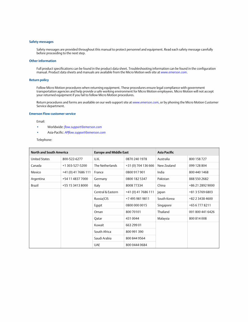
Emerson Flow customer service
Email:
• Worldwide: [email protected]
• Asia-Pacific: [email protected]
Telephone:
North and South America Europe and Middle East Asia Pacific
United States 800-522-6277 U.K. 0870 240 1978 Australia 800 158 727
Canada +1 303-527-5200 The Netherlands +31 (0) 704 136 666 New Zealand 099 128 804
Mexico +41 (0) 41 7686 111 France 0800 917 901 India 800 440 1468
Argentina +54 11 4837 7000 Germany 0800 182 5347 Pakistan 888 550 2682
Brazil +55 15 3413 8000 Italy 8008 77334 China +86 21 2892 9000
Central & Eastern +41 (0) 41 7686 111 Japan +81 3 5769 6803
Russia/CIS +7 495 981 9811 South Korea +82 2 3438 4600
Egypt 0800 000 0015 Singapore +65 6 777 8211
Oman 800 70101 Thailand 001 800 441 6426
Qatar 431 0044 Malaysia 800 814 008
Kuwait 663 299 01
South Africa 800 991 390
Saudi Arabia 800 844 9564
UAE 800 0444 0684

Contents
Part I Getting startedChapter 1 Before you begin ............................................................................................................. 3
1.1 About this manual ......................................................................................................................... 31.2 Communication methods ..............................................................................................................31.3 Additional documentation and resources ...................................................................................... 4
Chapter 2 Quick start .......................................................................................................................52.1 Power up the transmitter ...............................................................................................................52.2 Check meter status ........................................................................................................................62.3 Determine the FOUNDATION fieldbus unique device ID using the display .....................................62.4 Commissioning wizards .................................................................................................................62.5 Make a startup connection to the transmitter ................................................................................72.6 Set the transmitter clock ............................................................................................................... 72.7 View the licensed features ............................................................................................................. 82.8 Set informational parameters ........................................................................................................ 82.9 Characterize the meter (if required) ...............................................................................................9
2.9.1 Sample sensor tags ....................................................................................................... 112.9.2 Flow calibration parameters (FCF, FT) ........................................................................... 122.9.3 Density calibration parameters (D1, D2, K1, K2, FD, DT, TC) ......................................... 12
2.10 Verify mass flow measurement ....................................................................................................132.11 Verify the zero ............................................................................................................................. 14
Part II Configuration and commissioningChapter 3 Introduction to configuration and commissioning ......................................................... 19
3.1 Security and write protection ...................................................................................................... 193.1.1 Lock or unlock the transmitter ...................................................................................... 193.1.2 Enable or disable the service port ..................................................................................213.1.3 Enable or disable software write-protection .................................................................. 223.1.4 Configure security for the display ..................................................................................223.1.5 Enable or disable fieldbus write lock ..............................................................................23
3.2 Work with configuration files .......................................................................................................243.2.1 Save a configuration file using the display ..................................................................... 243.2.2 Save a configuration file using ProLink III ...................................................................... 253.2.3 Save a configuration file using a basic FF host ................................................................273.2.4 Load a configuration file using the display .....................................................................273.2.5 Load a configuration file using ProLink III ......................................................................293.2.6 Load a configuration file using a basic FF host ............................................................... 313.2.7 Restore the factory configuration ................................................................................. 313.2.8 Replicate a transmitter configuration ............................................................................32
Chapter 4 Configure process measurement ................................................................................... 334.1 Configure Sensor Flow Direction Arrow .......................................................................................334.2 Configure mass flow measurement ............................................................................................. 35
Contents
Configuration and Use Manual i
4.2.1 Configure Mass Flow Measurement Unit ...................................................................... 354.2.2 Configure Flow Damping ..............................................................................................374.2.3 Configure Mass Flow Cutoff ..........................................................................................39
4.3 Configure volume flow measurement for liquid applications ....................................................... 404.3.1 Configure Volume Flow Type for liquid applications ......................................................414.3.2 Configure Volume Flow Measurement Unit for liquid applications ................................ 414.3.3 Configure Volume Flow Cutoff ..................................................................................... 44
4.4 Configure Gas Standard Volume (GSV) flow measurement ..........................................................464.4.1 Configure Volume Flow Type for gas applications ......................................................... 464.4.2 Configure Standard Gas Density ...................................................................................474.4.3 Configure Gas Standard Volume Flow Measurement Unit ............................................ 474.4.4 Configure Gas Standard Volume Flow Cutoff ................................................................50
4.5 Configure density measurement ................................................................................................. 524.5.1 Configure Density Measurement Unit .......................................................................... 524.5.2 Configure Density Damping ......................................................................................... 534.5.3 Configure Density Cutoff ..............................................................................................54
4.6 Configure temperature measurement .........................................................................................554.6.1 Configure Temperature Measurement Unit ..................................................................554.6.2 Configure Temperature Damping ................................................................................ 56
4.7 Configure Pressure Measurement Unit ....................................................................................... 574.7.1 Options for Pressure Measurement Unit .......................................................................58
4.8 Configure Velocity Measurement Unit ........................................................................................ 594.8.1 Options for Velocity Measurement Unit ....................................................................... 59
Chapter 5 Configure process measurement applications ................................................................615.1 Set up the API referral application ............................................................................................... 61
5.1.1 Set up the API referral application using the display ...................................................... 615.1.2 Set up the API referral application using ProLink III ....................................................... 645.1.3 Set up the API referral application using an enhanced FF host .......................................675.1.4 Set up the API referral application using a basic FF host ................................................. 715.1.5 API tables supported by the API referral application ..................................................... 745.1.6 Process variables from the API referral application ........................................................ 75
5.2 Set up concentration measurement ............................................................................................ 765.2.1 Preparing to set up concentration measurement .......................................................... 765.2.2 Set up concentration measurement using the display ...................................................785.2.3 Set up concentration measurement using ProLink III .................................................... 845.2.4 Set up concentration measurement using an enhanced FF host ................................... 905.2.5 Set up concentration measurement using a basic FF host ............................................. 93
Chapter 6 Configure advanced options for process measurement .................................................. 976.1 Configure Response Time ........................................................................................................... 976.2 Detect and report two-phase flow ............................................................................................... 98
6.2.1 Detect two-phase flow using density ............................................................................ 986.2.2 Detect two-phase flow using sensor diagnostics ........................................................... 99
6.3 Configure Flow Rate Switch ...................................................................................................... 1006.4 Configure events ....................................................................................................................... 101
6.4.1 Configure an enhanced event ..................................................................................... 1016.5 Configure totalizers and inventories .......................................................................................... 103
6.5.1 Default settings for totalizers and inventories ............................................................. 1066.6 Configure logging for totalizers and inventories ........................................................................ 1066.7 Configure Process Variable Fault Action ....................................................................................107
6.7.1 Options for Process Variable Fault Action ................................................................... 1086.7.2 Interaction between Process Variable Fault Action and other fault actions .................. 109
Contents
ii Micro Motion Model 5700 Transmitters with FOUNDATION Fieldbus

Chapter 7 Configure device options and preferences ................................................................... 1117.1 Configure the transmitter display .............................................................................................. 111
7.1.1 Configure the language used on the display ................................................................1117.1.2 Configure the process variables shown on the display .................................................1127.1.3 Configure the number of decimal places (precision) shown on the display ..................1147.1.4 Turn on and turn off automatic scrolling through the display variables ....................... 1157.1.5 Configure the display backlight ...................................................................................1157.1.6 Configure totalizer and inventory control from the display ......................................... 1167.1.7 Configure security for the display ................................................................................117
7.2 Configure the transmitter's response to alerts ........................................................................... 1187.2.1 Configure the transmitter's response to alerts using the display ..................................1187.2.2 Configure the transmitter's response to alerts using ProLink III ...................................1197.2.3 Configure Fault Timeout ............................................................................................ 1217.2.4 Alerts, conditions, and configuration options ..............................................................122
Chapter 8 Integrate the meter with the control system ................................................................1278.1 Configure FOUNDATION Fieldbus Channel A ............................................................................. 1278.2 Configure mA output Channel B ................................................................................................ 127
8.2.1 Configure the mA output ............................................................................................1288.3 Configure FO/DO Channel C ...................................................................................................... 138
8.3.1 Configure the frequency output .................................................................................1388.3.2 Configure the discrete output .................................................................................... 144
Chapter 9 Complete the configuration .........................................................................................1499.1 Test or tune the system using sensor simulation ........................................................................149
9.1.1 Sensor simulation ....................................................................................................... 1509.2 Save the transmitter configuration to a backup file ....................................................................1519.3 Enable or disable software write-protection .............................................................................. 151
Part III Operations, maintenance, and troubleshootingChapter 10 Transmitter operation ................................................................................................. 155
10.1 View process and diagnostic variables ....................................................................................... 15510.1.1 View process and diagnostic variables using the display ..............................................15510.1.2 View process variables and other data using ProLink III ...............................................15510.1.3 Effect of Sensor Flow Direction Arrow on digital communications ...............................156
10.2 View and acknowledge status alerts .......................................................................................... 15610.2.1 View and acknowledge alerts using the display ........................................................... 15610.2.2 View and acknowledge alerts using ProLink III ............................................................ 157
10.3 Read totalizer and inventory values ........................................................................................... 15810.4 Start, stop, and reset totalizers and inventories ......................................................................... 158
10.4.1 Start, stop, and reset totalizers using the display ........................................................ 15810.4.2 Start, stop, and reset totalizers using ProLink III ..........................................................15910.4.3 Start, stop, and reset totalizers using an enhanced FF host .........................................160
10.5 Enable or disable fieldbus simulation mode ............................................................................... 161
Chapter 11 Measurement support ................................................................................................. 16511.1 Use Smart Meter Verification (SMV) .......................................................................................... 165
11.1.1 Run an SMV test ..........................................................................................................16511.1.2 View SMV test results ..................................................................................................16911.1.3 Set up SMV automatic execution ................................................................................ 171
Contents
Configuration and Use Manual iii
11.2 Zero the meter .......................................................................................................................... 17311.2.1 Terminology used with zero verification and zero calibration ......................................175
11.3 Set up pressure compensation .................................................................................................. 17611.3.1 Set up pressure compensation using the display ......................................................... 17611.3.2 Set up pressure compensation using ProLink III .......................................................... 17811.3.3 Configure pressure compensation using an enhanced FF host ....................................179
11.4 Validate the meter .....................................................................................................................18111.4.1 Alternate method for calculating the meter factor for volume flow .............................183
11.5 Perform a (standard) D1 and D2 density calibration ...................................................................18311.5.1 Perform a D1 and D2 density calibration using the display .......................................... 18411.5.2 Perform a D1 and D2 density calibration using ProLink III ........................................... 18511.5.3 Perform a D1 and D2 density calibration using an enhanced FF host ........................... 185
11.6 Adjust concentration measurement with Trim Slope and Trim Offset ....................................... 186
Chapter 12 Maintenance ............................................................................................................... 18912.1 Install a new transmitter license ................................................................................................ 18912.2 Upgrade the transmitter firmware .............................................................................................191
12.2.1 Upgrade the transmitter firmware using the display ................................................... 19112.2.2 Upgrade the transmitter firmware using ProLink III .................................................... 192
12.3 Reboot the transmitter ..............................................................................................................19212.4 Battery replacement ..................................................................................................................193
Chapter 13 Log files, history files, and service files ......................................................................... 19513.1 Generate history log files ........................................................................................................... 195
13.1.1 Historian data and log .................................................................................................19613.1.2 SMV history and SMV log ............................................................................................ 19813.1.3 Totalizer history and log ..............................................................................................199
13.2 Generate service files .................................................................................................................20013.2.1 Alert history and log ....................................................................................................20213.2.2 Configuration audit history and log .............................................................................20313.2.3 Assert history and log ..................................................................................................20513.2.4 Security log .................................................................................................................205
Chapter 14 Troubleshooting .......................................................................................................... 20714.1 Status LED and device status ..................................................................................................... 20814.2 Status alerts, causes, and recommendations ............................................................................. 20814.3 Flow measurement problems .................................................................................................... 22214.4 Density measurement problems ............................................................................................... 22414.5 Temperature measurement problems .......................................................................................22514.6 Velocity measurement problems ...............................................................................................22614.7 API referral problems .................................................................................................................22814.8 Concentration measurement problems .....................................................................................22814.9 Milliamp output problems ......................................................................................................... 22914.10 Frequency output problems ...................................................................................................... 23114.11 Discrete output problems ..........................................................................................................23214.12 Check power supply wiring ........................................................................................................23214.13 Check sensor-to-transmitter wiring ........................................................................................... 23314.14 Check grounding ....................................................................................................................... 23414.15 Perform loop tests ..................................................................................................................... 234
14.15.1 Perform loop tests using the display ........................................................................... 23414.15.2 Perform loop tests using ProLink III .............................................................................23614.15.3 Perform loop tests using an enhanced FF host ............................................................237
14.16 Trim mA output .........................................................................................................................238
Contents
iv Micro Motion Model 5700 Transmitters with FOUNDATION Fieldbus

14.16.1 Trim mA using the display ...........................................................................................23814.16.2 Trim mA output using ProLink III ................................................................................ 23814.16.3 Trim mA outputs using an enhanced FF host ...............................................................23914.16.4 Trim mA outputs using a basic FF host ........................................................................ 239
14.17 Using sensor simulation for troubleshooting ............................................................................. 23914.18 Check Lower Range Value and Upper Range Value ....................................................................24014.19 Check mA Output Fault Action ..................................................................................................24014.20 Check the scaling of the frequency output .................................................................................24014.21 Check Frequency Output Fault Action .......................................................................................24014.22 Check the direction parameters .................................................................................................24114.23 Check the cutoffs ...................................................................................................................... 24114.24 Check for two-phase flow (slug flow) ......................................................................................... 24114.25 Check for radio frequency interference (RFI) ..............................................................................24214.26 Check the drive gain .................................................................................................................. 24214.27 Check the pickoff voltage .......................................................................................................... 24314.28 Check for internal electrical problems ....................................................................................... 244
14.28.1 Check the sensor coils .................................................................................................24414.29 Perform a core processor resistance test ................................................................................... 246
Appendices and referenceAppendix A FOUNDATION
™ fieldbus resource block and transducer blocks ..................................... 249
A.1 Resource block .......................................................................................................................... 249A.2 Transducer blocks and views ..................................................................................................... 254
A.2.1 Measurement transducer block .................................................................................. 256A.2.2 Device Information transducer block .......................................................................... 274A.2.3 Totalizers and inventories transducer block ................................................................ 299A.2.4 Meter verification transducer block .............................................................................313A.2.5 API Referral transducer block ..................................................................................... 326A.2.6 Concentration Measurement transducer block ........................................................... 329A.2.7 Advanced Phase Measurement transducer block ........................................................ 336
A.3 Fieldbus channel references ...................................................................................................... 344
Appendix B FOUNDATION™
fieldbus function blocks ....................................................................... 349B.1 Analog Input (AI) function block ................................................................................................ 349
B.1.1 AI block configuration parameters .............................................................................. 349B.1.2 AI block modes ........................................................................................................... 350B.1.3 AI block simulation ..................................................................................................... 350B.1.4 AI block configuration .................................................................................................351B.1.5 AI block filtering ..........................................................................................................352B.1.6 AI block signal conversion ........................................................................................... 353B.1.7 AI block alarm detection ............................................................................................. 353B.1.8 AI block status handling .............................................................................................. 354B.1.9 AI block default configuration ..................................................................................... 354
B.2 Analog Output (AO) function block ........................................................................................... 355B.2.1 AO block configuration parameters ............................................................................ 355B.2.2 AO block modes ..........................................................................................................356B.2.3 AO block errors ........................................................................................................... 356B.2.4 AO block simulation ....................................................................................................356B.2.5 AO block status handling ............................................................................................ 357B.2.6 AO block default configuration ................................................................................... 357
B.3 Integrator (INT) Function Block ..................................................................................................358
Contents
Configuration and Use Manual v

B.3.1 INT block configuration parameters ............................................................................359B.3.2 INT block other parameters ........................................................................................ 360B.3.3 INT block modes ......................................................................................................... 361B.3.4 INT block errors ...........................................................................................................361B.3.5 INT block status handling ............................................................................................361B.3.6 INT block special mode ............................................................................................... 362B.3.7 INT block default configuration ...................................................................................362
B.4 Discrete Input (DI) function block .............................................................................................. 363B.4.1 DI block common configuration parameters ...............................................................363B.4.2 DI block modes ........................................................................................................... 363B.4.3 DI block errors ............................................................................................................ 364B.4.4 DI block simulation ..................................................................................................... 364B.4.5 DI block status handling ..............................................................................................364B.4.6 DI block default configuration .....................................................................................364
B.5 Discrete Output (DO) function block ......................................................................................... 365B.5.1 DO block configuration ...............................................................................................365B.5.2 DO block modes ......................................................................................................... 366B.5.3 DO block errors ...........................................................................................................366B.5.4 DO block simulation ................................................................................................... 367B.5.5 DO block status handling ............................................................................................ 367B.5.6 DO block default configuration ................................................................................... 367
Appendix C Using the transmitter display .......................................................................................369C.1 Components of the transmitter display ..................................................................................... 369C.2 Access and use the display menus ............................................................................................. 371
Appendix D Using ProLink III with the transmitter ...........................................................................375D.1 Connect with ProLink III ............................................................................................................ 375
D.1.1 ProLink III Connection types ........................................................................................375D.1.2 Make a service port connection from ProLink III to the transmitter ..............................375
Appendix E Using a Field Communicator with the transmitter ........................................................ 377E.1 Basic information about the Field Communicator ..................................................................... 377E.2 Connect with a Field Communicator ..........................................................................................378
Appendix F Concentration measurement matrices, derived variables, and process variables ..........381F.1 Standard matrices for the concentration measurement application .......................................... 381F.2 Derived variables and calculated process variables .................................................................... 382
Appendix G Environmental compliance .......................................................................................... 385G.1 RoHS and WEEE ......................................................................................................................... 385
Appendix H Software history (NAMUR recommendation NE53) ...................................................... 387
Contents
vi Micro Motion Model 5700 Transmitters with FOUNDATION Fieldbus

Part IGetting started
Chapters covered in this part:
• Before you begin
• Quick start
Getting started
Configuration and Use Manual 1

Getting started
2 Micro Motion Model 5700 Transmitters with FOUNDATION Fieldbus

1 Before you beginTopics covered in this chapter:
• About this manual
• Communication methods
• Additional documentation and resources
1.1 About this manualThis manual helps you configure, commission, use, maintain, and troubleshootMicro Motion Model 5700 transmitters with FOUNDATION™fieldbus.
ImportantThis manual assumes that the following conditions apply:
• The transmitter has been installed correctly and completely according to the instructions inthe transmitter installation manual
• The installation complies with all applicable safety requirements
• The user is trained in local and corporate safety standards
1.2 Communication methodsYou can use several different communications methods to interface with the transmitter.You may use different methods in different locations or for different tasks.
Interface Tool
Display Infrared-sensitive buttons
Universal Service Port ProLink III
FOUNDATION Fieldbus channel FOUNDATION fieldbus (FF) host.• On an enhanced FF host, the transmitter parameters are dis-
played either in the form of a menu tree (for example, the475 Field Communicator) or in the form of UIRD (for exam-ple, the AMS Intelligent Device Manager with DeltaV™ Sys-tem). Both the menu tree and UIRD are provided as part ofthe Device Description.
• A basic FF host displays the transmitter parameters in theform of a list under the Resource block and transducerblocks.
The configuration sections contain information for both types ofhost.
Before you begin
Configuration and Use Manual 3
For information about how to use the communication tools, see the appendices in thismanual.
TipYou may be able to use other communications tools, such as AMS Suite: Intelligent Device Manager,or the Smart Wireless THUM™ Adapter. Use of AMS or the Smart Wireless THUM Adapter is notdiscussed in this manual. For more information on the Smart Wireless THUM Adapter, refer to thedocumentation available at www.emerson.com.
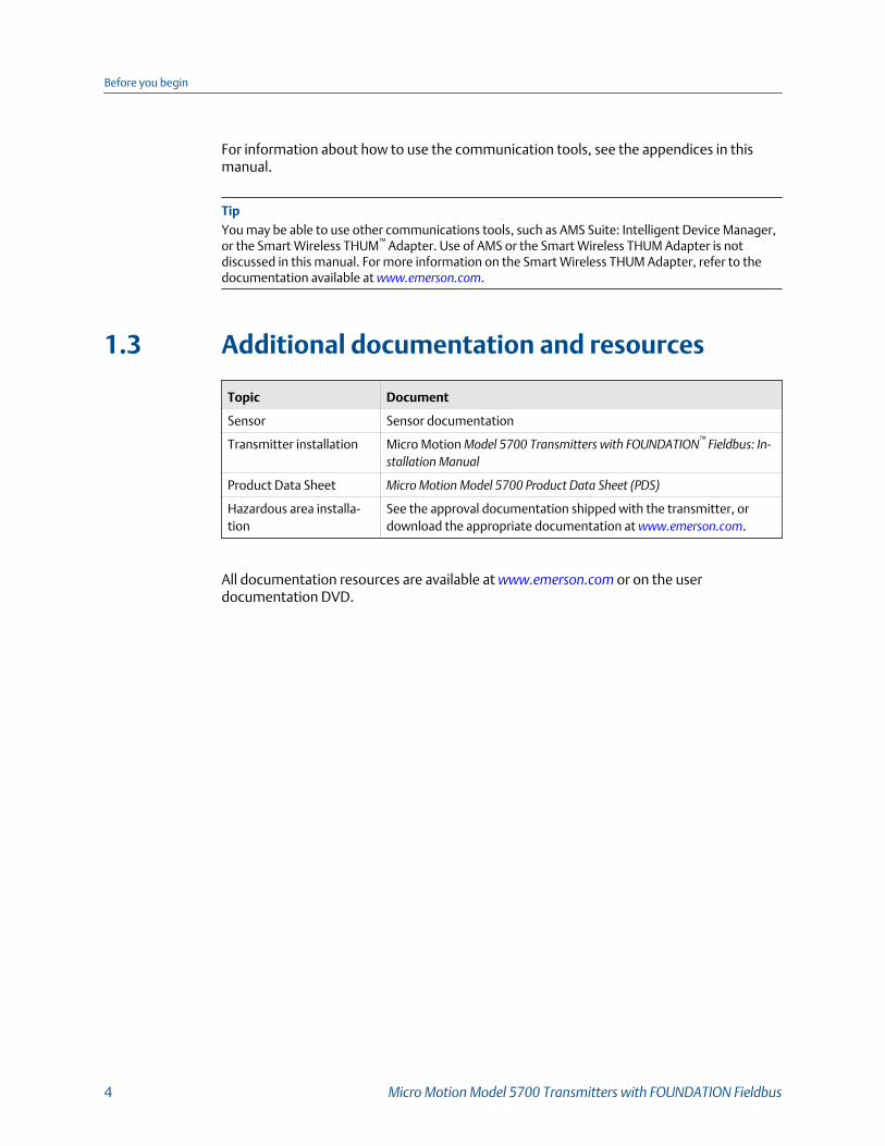
1.3 Additional documentation and resources
Topic Document
Sensor Sensor documentation
Transmitter installation Micro Motion Model 5700 Transmitters with FOUNDATION™ Fieldbus: In‐stallation Manual
Product Data Sheet Micro Motion Model 5700 Product Data Sheet (PDS)
Hazardous area installa-tion
See the approval documentation shipped with the transmitter, ordownload the appropriate documentation at www.emerson.com.
All documentation resources are available at www.emerson.com or on the userdocumentation DVD.
Before you begin
4 Micro Motion Model 5700 Transmitters with FOUNDATION Fieldbus

2 Quick startTopics covered in this chapter:
• Power up the transmitter
• Check meter status
• Determine the FOUNDATION fieldbus unique device ID using the display
• Commissioning wizards
• Make a startup connection to the transmitter
• Set the transmitter clock
• View the licensed features
• Set informational parameters
• Characterize the meter (if required)
• Verify mass flow measurement
• Verify the zero
2.1 Power up the transmitterThe transmitter must be powered up for all configuration and commissioning tasks, or forprocess measurement.
1. Verify that all transmitter and sensor covers and seals are closed.
WARNING!
To prevent ignition of flammable or combustible atmospheres, ensure that all coversand seals are tightly closed. For hazardous area installations, applying power whilehousing covers are removed or loose can cause an explosion.
2. Turn on the electrical power at the power supply.
Postrequisites
Although the sensor is ready to receive process fluid shortly after power-up, the electronicscan take up to 10 minutes to reach thermal equilibrium. Therefore, if this is the initialstartup, or if power has been off long enough to allow components to reach ambienttemperature, allow the electronics to warm up for approximately 10 minutes beforerelying on process measurements. During this warm-up period, you may observe minormeasurement instability or inaccuracy.
Quick start
Configuration and Use Manual 5
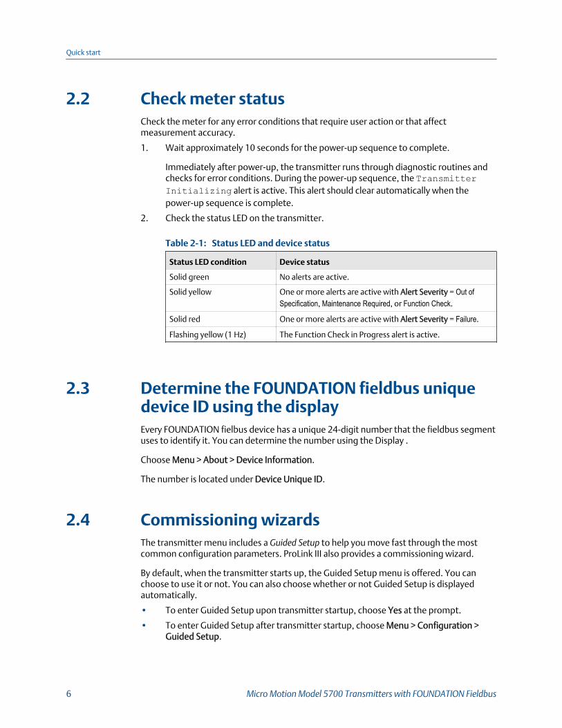
2.2 Check meter statusCheck the meter for any error conditions that require user action or that affectmeasurement accuracy.
1. Wait approximately 10 seconds for the power-up sequence to complete.
Immediately after power-up, the transmitter runs through diagnostic routines andchecks for error conditions. During the power-up sequence, the TransmitterInitializing alert is active. This alert should clear automatically when thepower-up sequence is complete.
2. Check the status LED on the transmitter.
Status LED and device statusTable 2-1:
Status LED condition Device status
Solid green No alerts are active.
Solid yellow One or more alerts are active with Alert Severity = Out ofSpecification, Maintenance Required, or Function Check.
Solid red One or more alerts are active with Alert Severity = Failure.
Flashing yellow (1 Hz) The Function Check in Progress alert is active.
2.3 Determine the FOUNDATION fieldbus uniquedevice ID using the displayEvery FOUNDATION fielbus device has a unique 24-digit number that the fieldbus segmentuses to identify it. You can determine the number using the Display .
Choose Menu > About > Device Information.
The number is located under Device Unique ID.
2.4 Commissioning wizardsThe transmitter menu includes a Guided Setup to help you move fast through the mostcommon configuration parameters. ProLink III also provides a commissioning wizard.
By default, when the transmitter starts up, the Guided Setup menu is offered. You canchoose to use it or not. You can also choose whether or not Guided Setup is displayedautomatically.
• To enter Guided Setup upon transmitter startup, choose Yes at the prompt.
• To enter Guided Setup after transmitter startup, choose Menu > Configuration >Guided Setup.
Quick start
6 Micro Motion Model 5700 Transmitters with FOUNDATION Fieldbus
• To control the automatic display of Guided Setup, choose Menu > Configuration >Guided Setup.
For information on the ProLink III commissioning wizard, see the ProLink III manual.
This manual does not document the commissioning wizards in detail.
2.5 Make a startup connection to the transmitterFor all configuration tools except the display, you must have an active connection to thetransmitter to configure the transmitter.
Identify the connection type to use, and follow the instructions for that connection type inthe appropriate appendix.
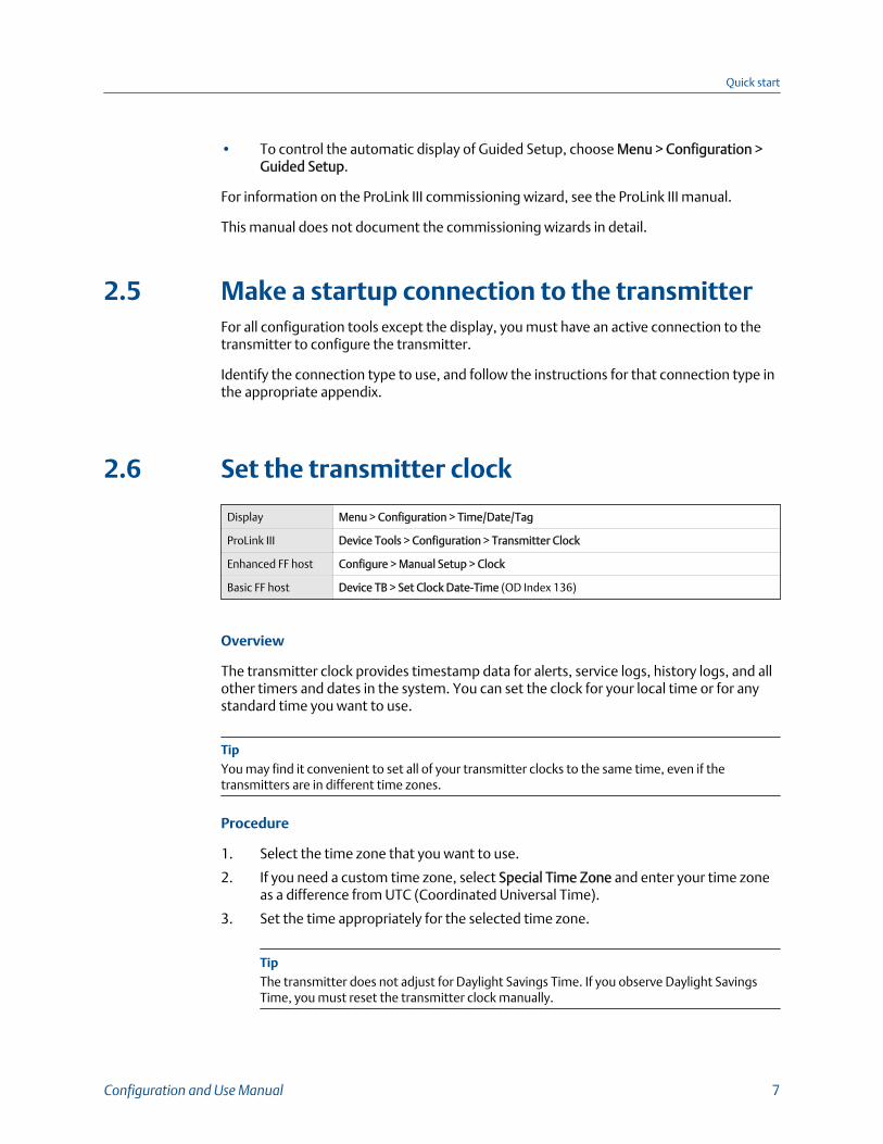
2.6 Set the transmitter clock
Display Menu > Configuration > Time/Date/Tag
ProLink III Device Tools > Configuration > Transmitter Clock
Enhanced FF host Configure > Manual Setup > Clock
Basic FF host Device TB > Set Clock Date-Time (OD Index 136)
Overview
The transmitter clock provides timestamp data for alerts, service logs, history logs, and allother timers and dates in the system. You can set the clock for your local time or for anystandard time you want to use.
TipYou may find it convenient to set all of your transmitter clocks to the same time, even if thetransmitters are in different time zones.
Procedure
1. Select the time zone that you want to use.
2. If you need a custom time zone, select Special Time Zone and enter your time zoneas a difference from UTC (Coordinated Universal Time).
3. Set the time appropriately for the selected time zone.
TipThe transmitter does not adjust for Daylight Savings Time. If you observe Daylight SavingsTime, you must reset the transmitter clock manually.
Quick start
Configuration and Use Manual 7

4. Set the month, day, and year.
The transmitter tracks the year and automatically adds a day for leap years.
2.7 View the licensed features
Display Menu > About > Licenses > Licensed Features
ProLink III Device Tools > Device Information > Licensed Features
Enhanced FF host Overview > Device Information > Licenses
Basic FF host Device TB > Permanent Feature (OD Index 142)
Device TB > Temporary Feature (OD Index 140)
Overview
You can view the licensed features to ensure that the transmitter was ordered with therequired features.
Licensed features have been purchased and are available for permanent use. The optionsmodel code represents the licensed features.
A trial license allows you to explore features before purchasing. The trial license enablesthe specified features for a limited number of days. This number is displayed for reference.At the end of this period, the feature will no longer be available.
To purchase additional features or request a trial license, contact customer service. Toenable the additional features or request a trial license, you must install the new license.
2.8 Set informational parameters
Display Menu > Configuration > Device Information
ProLink III Device Tools > Configuration > Informational Parameters
Enhanced FF host Configure > Manual Setup > Device
Basic FF host Device TB > Transmitter Information (OD Index 14–21)
Device TB > Core Processor Information (OD Index 22–25)
Device TB > Sensor Information (OD Index 28–33)
Overview
You can set several parameters that identify or describe the transmitter and sensor. Theseparameters are not used in processing and are not required.
Procedure
1. Set informational parameters for the transmitter.
Quick start
8 Micro Motion Model 5700 Transmitters with FOUNDATION Fieldbus

a. Set Transmitter Serial Number to the serial number of your transmitter.
The transmitter serial number is provided on the metal tag that is attached to thetransmitter housing.
b. Set Descriptor to any desired description of this transmitter or measurementpoint.
c. Set Message to any desired message.
d. Verify that Model Code (Base) is set to the base model code of the transmitter.
The base model code completely describes your transmitter, except for thefeatures that can be licensed independently. The base model code is set at thefactory.
e. Set Model Code (Options) to the options model code of the transmitter.
The options model code describes the independent features that have beenlicensed for this transmitter. The original options model code is set at thefactory. If you license additional options for this transmitter, Micro Motion willsupply an updated options model code.
For the Field Communicator, configuring model code options is not available forthis release.
2. Set informational parameters for the sensor.
a. Set Sensor Serial Number to the serial number of the sensor connected to thistransmitter.
The sensor serial number is provided on the metal tag that is attached to thesensor case.
b. Set Sensor Material to the material used for the sensor.
c. Set Sensor Liner to the material used for the sensor liner.
d. Set Flange Type to the type of flange that was used to install the sensor.
Do not set Sensor Type. Sensor Type is set or derived during characterization.
2.9 Characterize the meter (if required)
Display Menu > Configuration > Sensor Parameters
ProLink III Device Tools > Calibration Data
Enhanced FF host Configure > Manual Setup > Characterization
Basic FF host Measurement TB > Device Calibration (OD Index 95–113)
Quick start
Configuration and Use Manual 9
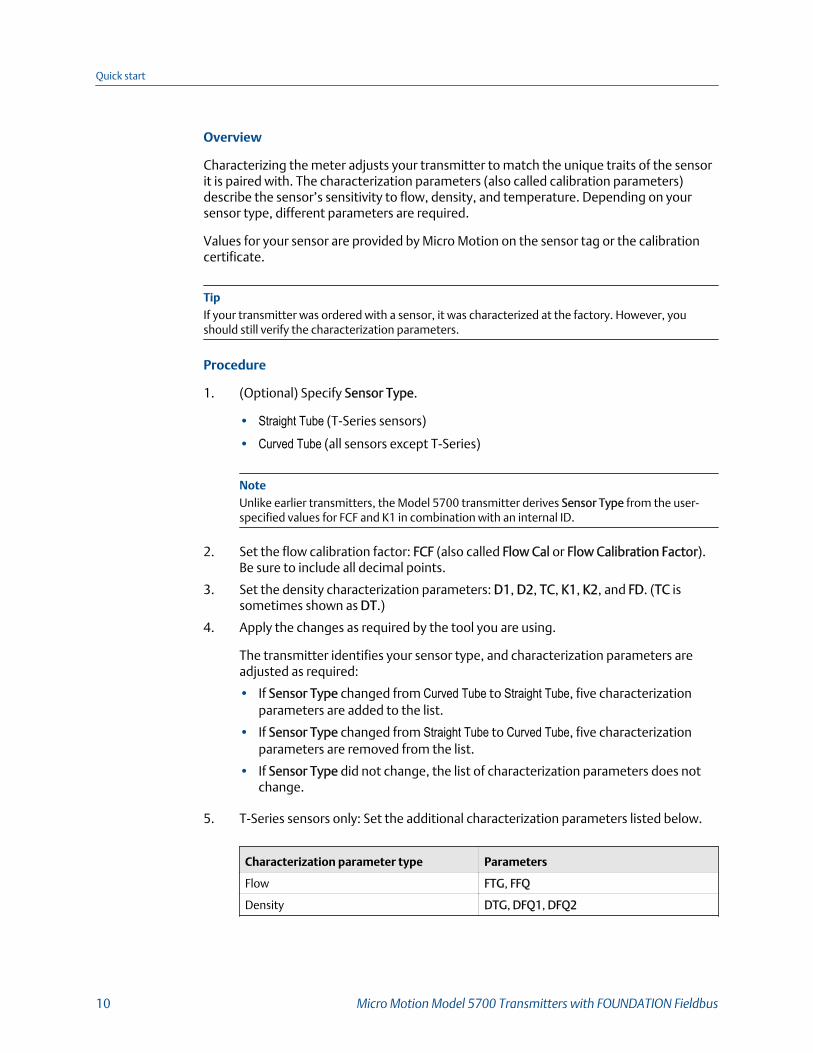
Overview
Characterizing the meter adjusts your transmitter to match the unique traits of the sensorit is paired with. The characterization parameters (also called calibration parameters)describe the sensor’s sensitivity to flow, density, and temperature. Depending on yoursensor type, different parameters are required.
Values for your sensor are provided by Micro Motion on the sensor tag or the calibrationcertificate.
TipIf your transmitter was ordered with a sensor, it was characterized at the factory. However, youshould still verify the characterization parameters.
Procedure
1. (Optional) Specify Sensor Type.
• Straight Tube (T-Series sensors)
• Curved Tube (all sensors except T-Series)
NoteUnlike earlier transmitters, the Model 5700 transmitter derives Sensor Type from the user-specified values for FCF and K1 in combination with an internal ID.
2. Set the flow calibration factor: FCF (also called Flow Cal or Flow Calibration Factor).Be sure to include all decimal points.
3. Set the density characterization parameters: D1, D2, TC, K1, K2, and FD. (TC issometimes shown as DT.)
4. Apply the changes as required by the tool you are using.
The transmitter identifies your sensor type, and characterization parameters areadjusted as required:
• If Sensor Type changed from Curved Tube to Straight Tube, five characterizationparameters are added to the list.
• If Sensor Type changed from Straight Tube to Curved Tube, five characterizationparameters are removed from the list.
• If Sensor Type did not change, the list of characterization parameters does notchange.
5. T-Series sensors only: Set the additional characterization parameters listed below.
Characterization parameter type Parameters
Flow FTG, FFQ
Density DTG, DFQ1, DFQ2
Quick start
10 Micro Motion Model 5700 Transmitters with FOUNDATION Fieldbus
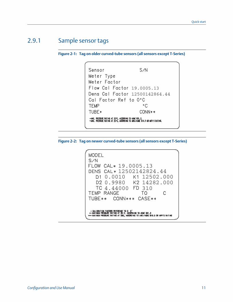
2.9.1 Sample sensor tags
Tag on older curved-tube sensors (all sensors except T-Series)Figure 2-1:
Tag on newer curved-tube sensors (all sensors except T-Series)Figure 2-2:
Quick start
Configuration and Use Manual 11
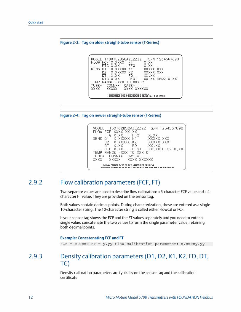
Tag on older straight-tube sensor (T-Series)Figure 2-3:
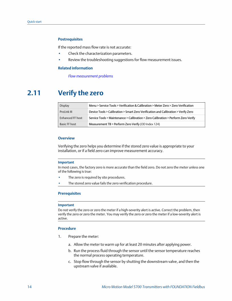
Tag on newer straight-tube sensor (T-Series)Figure 2-4:
2.9.2 Flow calibration parameters (FCF, FT)Two separate values are used to describe flow calibration: a 6-character FCF value and a 4-character FT value. They are provided on the sensor tag.
Both values contain decimal points. During characterization, these are entered as a single10-character string. The 10-character string is called either Flowcal or FCF.
If your sensor tag shows the FCF and the FT values separately and you need to enter asingle value, concatenate the two values to form the single parameter value, retainingboth decimal points.
Example: Concatenating FCF and FTFCF = x.xxxx FT = y.yy Flow calibration parameter: x.xxxxy.yy
2.9.3 Density calibration parameters (D1, D2, K1, K2, FD, DT,TC)Density calibration parameters are typically on the sensor tag and the calibrationcertificate.
Quick start
12 Micro Motion Model 5700 Transmitters with FOUNDATION Fieldbus

If your sensor tag does not show a D1 or D2 value:
• For D1, enter the Dens A or D1 value from the calibration certificate. This value is theline-condition density of the low-density calibration fluid. Micro Motion uses air. Ifyou cannot find a Dens A or D1 value, enter 0.001 g/cm3 .
• For D2, enter the Dens B or D2 value from the calibration certificate. This value is theline-condition density of the high-density calibration fluid. Micro Motion uses water.If you cannot find a Dens B or D2 value, enter 0.998g/cm3 .
If your sensor tag does not show a K1 or K2 value:
• For K1, enter the first 5 digits of the density calibration factor. In this sample tag, thisvalue is shown as 12500.
• For K2, enter the second 5 digits of the density calibration factor. In this sample tag,this value is shown as 14286.
K1, K2, and TC values in the density calibration factorFigure 2-5:
If your sensor does not show an FD value, contact customer service.
If your sensor tag does not show a DT or TC value, enter the last 4 characters of the densitycalibration factor. In the sample tag shown above, the value is shown as 4.44.
2.10 Verify mass flow measurementCheck to see that the mass flow rate reported by the transmitter is accurate. You can useany available method.
• Read the value for Mass Flow Rate on the transmitter display.
• Connect to the transmitter with ProLink III and read the value for Mass Flow Rate inthe Process Variables panel.
Quick start
Configuration and Use Manual 13
Postrequisites
If the reported mass flow rate is not accurate:
• Check the characterization parameters.
• Review the troubleshooting suggestions for flow measurement issues.
Related information
Flow measurement problems
2.11 Verify the zero
Display Menu > Service Tools > Verification & Calibration > Meter Zero > Zero Verification
ProLink III Device Tools > Calibration > Smart Zero Verification and Calibration > Verify Zero
Enhanced FF host Service Tools > Maintenance > Calibration > Zero Calibration > Perform Zero Verify
Basic FF host Measurement TB > Perform Zero Verify (OD Index 124)
Overview
Verifying the zero helps you determine if the stored zero value is appropriate to yourinstallation, or if a field zero can improve measurement accuracy.
ImportantIn most cases, the factory zero is more accurate than the field zero. Do not zero the meter unless oneof the following is true:
• The zero is required by site procedures.
• The stored zero value fails the zero verification procedure.
Prerequisites
ImportantDo not verify the zero or zero the meter if a high-severity alert is active. Correct the problem, thenverify the zero or zero the meter. You may verify the zero or zero the meter if a low-severity alert isactive.
Procedure
1. Prepare the meter:
a. Allow the meter to warm up for at least 20 minutes after applying power.
b. Run the process fluid through the sensor until the sensor temperature reachesthe normal process operating temperature.
c. Stop flow through the sensor by shutting the downstream valve, and then theupstream valve if available.
Quick start
14 Micro Motion Model 5700 Transmitters with FOUNDATION Fieldbus
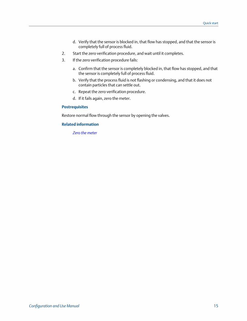
d. Verify that the sensor is blocked in, that flow has stopped, and that the sensor iscompletely full of process fluid.
2. Start the zero verification procedure, and wait until it completes.
3. If the zero verification procedure fails:
a. Confirm that the sensor is completely blocked in, that flow has stopped, and thatthe sensor is completely full of process fluid.
b. Verify that the process fluid is not flashing or condensing, and that it does notcontain particles that can settle out.
c. Repeat the zero verification procedure.
d. If it fails again, zero the meter.
Postrequisites
Restore normal flow through the sensor by opening the valves.
Related information
Zero the meter
Quick start
Configuration and Use Manual 15

Quick start
16 Micro Motion Model 5700 Transmitters with FOUNDATION Fieldbus
Part IIConfiguration and commissioning
Chapters covered in this part:
• Introduction to configuration and commissioning
• Configure process measurement
• Configure process measurement applications
• Configure advanced options for process measurement
• Configure device options and preferences
• Integrate the meter with the control system
• Complete the configuration
Configuration and commissioning
Configuration and Use Manual 17

Configuration and commissioning
18 Micro Motion Model 5700 Transmitters with FOUNDATION Fieldbus

3 Introduction to configuration andcommissioningTopics covered in this chapter:
• Security and write protection
• Work with configuration files
3.1 Security and write protectionThe transmitter has several features that can help to protect it against intentional orunintentional access and configuration changes.
• When locked, the mechanical lock switch on the front of the display prevents anyconfiguration changes to the transmitter from any local or remote configurationtool. A transmitter without a display does not have a lock switch.
• If the Universal Service Port (USP) is disabled, the port cannot be used by any servicetool to communicate with or make changes to the transmitter.
• When enabled, the software setting Write Protection prevents any configurationchanges. The setting can only be enabled if the transmitter does not have a display.
• When enabled, the display Configuration Security prevents any configurationchanges being made from the display unless the display password is entered.
• When enabled, the fieldbus write lock prevents any configuration changes beingwritten from the fieldbus segment.
3.1.1 Lock or unlock the transmitterIf the transmitter has a display, a mechanical switch on the display can be used to lock orunlock the transmitter. When locked, no configuration changes can be made using anyconfiguration tool.
Introduction to configuration and commissioning
Configuration and Use Manual 19
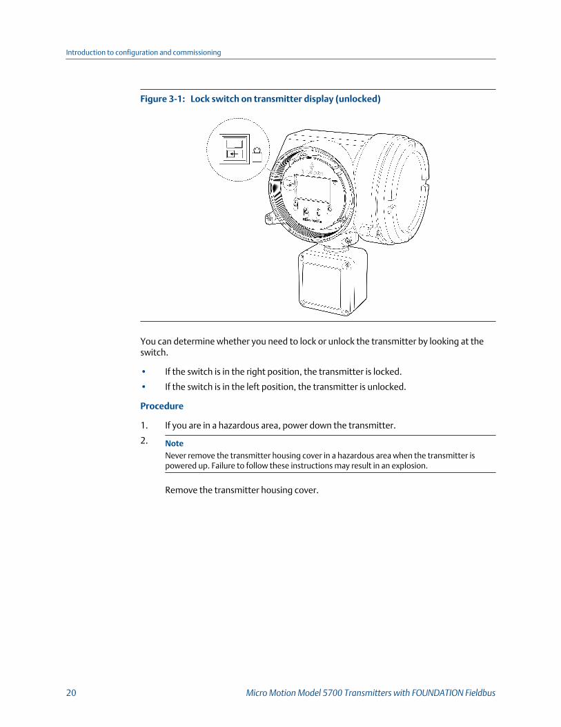
Lock switch on transmitter display (unlocked)Figure 3-1:
You can determine whether you need to lock or unlock the transmitter by looking at theswitch.
• If the switch is in the right position, the transmitter is locked.
• If the switch is in the left position, the transmitter is unlocked.
Procedure
1. If you are in a hazardous area, power down the transmitter.
2. NoteNever remove the transmitter housing cover in a hazardous area when the transmitter ispowered up. Failure to follow these instructions may result in an explosion.
Remove the transmitter housing cover.
Introduction to configuration and commissioning
20 Micro Motion Model 5700 Transmitters with FOUNDATION Fieldbus

Removing the transmitter housing coverFigure 3-2:
3. Using a fine-pointed tool, move the switch to the desired position.
4. Replace the transmitter housing cover.
5. If necessary, power up the transmitter.
3.1.2 Enable or disable the service port
Display Menu > Configuration > Security > Service Port
ProLink III Not available
Enhanced FF host Configure > Manual Setup > Security > Enable/Disable Service Port
Basic FF host Device TB > Enable Service Port (OD Index 146)
Overview
The service port is enabled by default, so you can use it for transferring files or connect to itwith ProLink III. If you want to completely prevent it from being used, you can disable it.
NoteEnabling or disabling the service port will not take effect until power has been cycled to thetransmitter.
Introduction to configuration and commissioning
Configuration and Use Manual 21

CAUTION!
Do not use the service port if the transmitter is in a hazardous area. To use the service port, youmust open the transmitter wiring compartment. Opening the wiring compartment in ahazardous area, while the transmitter is powered up, can cause an explosion.
3.1.3 Enable or disable software write-protection
Display Not available
ProLink III Device Tools > Configuration > Write-Protection
Enhanced FF host Configure > Manual Setup > Security > FOUNDATION Fieldbus > Write Lock
Basic FF host Resource Block > Write Lock (OD Index 34)
Overview
When enabled, the software setting Write-Protection prevents changes to the transmitterconfiguration. You can perform all other functions, and you can view the transmitterconfiguration parameters.
NoteThe write-protection setting is only available on transmitters without a display.
NoteWrite-protecting the transmitter primarily prevents accidental changes to configuration, notintentional changes. Any user who can make changes to the configuration can disable writeprotection.
3.1.4 Configure security for the display
Display Menu > Configuration > Security > Configuration Security
ProLink III Device Tools > Configuration > Transmitter Display > Display Security
Enhanced FF host Configure > Manual Setup > Display > Display Menus
Basic FF host Device TB > Offline Menu Passcode Required (OD Index 67)
Device TB > Passcode (4 Digits alphanumeric) (OD Index 68)
Device TB > Alert Passcode (OD Index 89)
Overview
You can configure a display password, and require the operator to enter the password tomake any changes to configuration through the display, or to access alert data throughthe display.
The operator always has read-only access to the configuration menus.
Introduction to configuration and commissioning
22 Micro Motion Model 5700 Transmitters with FOUNDATION Fieldbus

Procedure
1. Enable or disable configuration security as desired.
Option Description
Enabled When an operator chooses an action that leads to a configuration change, theyare prompted to enter the display password.
Disabled When an operator chooses an action that leads to a configuration change, theyare prompted to activate ⇦⇧⇩⇨. This is designed to protect against accidentalchanges to configuration. It is not a security measure.
2. If you enabled configuration security, enable or disable alert security as desired.
Option Description
Enabled If an alert is active, the alert symbol ⓘ is shown in the upper right corner of thedisplay but the alert banner is not displayed. If the operator attempts to enter thealert menu, they are prompted to enter the display password.
Disabled If an alert is active, the alert symbol ⓘ is shown in the upper right corner of thedisplay and the alert banner is displayed automatically. No password or confirma-tion is required to enter the alert menu.
RestrictionYou cannot disable configuration security and enable alert security.
• If you did not enable configuration security, alert security is disabled and cannot beenabled.
• If both configuration security and alert security are enabled, and you disable configurationsecurity, alert security is disabled automatically.
3. Set the display password to the desired value.
• Default: AAAA
• Range: Any four alphanumeric characters
ImportantIf you enable configuration security but you do not change the display password, thetransmitter will post a Configuration alert.
3.1.5 Enable or disable fieldbus write lockWhen locked, the fieldbus write lock prevents any configuration changes being writtenfrom the fieldbus segment.
Set the Write Lock paramater (OD index 34) of the Resource block to Locked (1) orUnlocked (0).
Introduction to configuration and commissioning
Configuration and Use Manual 23
3.2 Work with configuration files• Save a configuration file using the display (Section 3.2.1)• Save a configuration file using ProLink III (Section 3.2.2)• Load a configuration file using the display (Section 3.2.4)• Load a configuration file using ProLink III (Section 3.2.5)• Save a configuration file using a basic FF host (Section 3.2.3)• Restore the factory configuration (Section 3.2.7)• Replicate a transmitter configuration (Section 3.2.8)
3.2.1 Save a configuration file using the displayYou can save the current transmitter configuration in two forms: a backup file and areplication file. You can save it to the SD card on your transmitter or to a USB drive.
Backup files Contain all parameters. They are used to restore the current device ifrequired. The .spare extension is used to identify backup files.
Replicationfiles
Contain all parameters except the device-specific parameters, e.g.,calibration factors or meter factors. They are used to replicate thetransmitter configuration to other devices. The .xfer extension is usedto identify replication files.
TipYou can use a saved configuration file to change the nature of the transmitter quickly. This might beconvenient if the transmitter is used for different applications or different process fluids.
Prerequisites
If you are planning to use the USB drive, the service port must be enabled. It is enabled bydefault. However, if you need to enable it, choose Menu > Configuration > Security and setService Port to On.
Procedure
• To save the current configuration to the transmitter's SD card as a backup file:
1. Choose Menu > Configuration > Save/Restore Config > Save Config to Memory.
2. Enter the name for this configuration file.
The configuration file is saved to the transmitter's SD card as yourname.spare.
• To save the current configuration to a USB drive, as either a backup file or areplication file:
1. Open the wiring compartment on the transmitter and insert a USB drive into theservice port.
Introduction to configuration and commissioning
24 Micro Motion Model 5700 Transmitters with FOUNDATION Fieldbus
CAUTION!
If the transmitter is in a hazardous area, do not open the wiring compartment whilethe transmitter is powered up. Opening the wiring compartment while thetransmitter is powered up could cause an explosion. Save or load configuration filesusing a method that does not require opening the wiring compartment.
2. Choose Menu > USB Options > Transmitter --> USB Drive > Save Active Config toUSB Drive.
3. Choose Backup or Replicate.
4. Enter the name for this configuration file.
The configuration file is saved to the USB drive as yourname.spare or yourname.xfer.• To copy a configuration file from the transmitter's SD card to the USB drive:
1. Open the wiring compartment on the transmitter and insert a USB drive into theservice port.
CAUTION!
If the transmitter is in a hazardous area, do not open the wiring compartment whilethe transmitter is powered up. Opening the wiring compartment while thetransmitter is powered up could cause an explosion. Save or load configuration filesusing a method that does not require opening the wiring compartment.
2. Choose Menu > USB Options > Transmitter --> USB Drive > Transfer Config File toUSB Drive.
3. Choose Backup or Replicate.
4. Select the file that you want to transfer.
The configuration file is copied to the USB drive, using its existing name.
3.2.2 Save a configuration file using ProLink IIIYou can save the current transmitter configuration in two forms: a backup file and areplication file. You can save it to the SD card on your transmitter or to your PC. Two PC fileformats are supported: the Model 5700 format and the ProLink III format.
Backup files Contain all parameters. They are used to restore the current device ifrequired. The .spare extension is used to identify backup files.
Replicationfiles
Contain all parameters except the device-specific parameters, e.g.,calibration factors or meter factors. They are used to replicate thetransmitter configuration to other devices. The .xfer extension is usedto identify replication files.
TipYou can use a saved configuration file to change the nature of the transmitter quickly. This might beconvenient if the transmitter is used for different applications or different process fluids.
Introduction to configuration and commissioning
Configuration and Use Manual 25

NoteWhen you use ProLink III format for configuration files, you can specify configuration parametersindividually or by groups. Therefore, you can use this format for both backup and replication.
Procedure
• To save the current configuration to the transmitter's SD card:
1. Choose Device Tools > Configuration Transfer > Save Configuration.
2. Select On my 5700 Device Internal Memory and click Next.
3. Click Save.
4. Enter the name for this configuration file.
5. Set the file type.
- To save a backup file, set the file type to Backup.
- To save a replication file, set the file type to Transfer.6. Click Save.
The configuration file is saved to the transmitter's SD card as yourname.spare oryourname.xfer.
• To save the current configuration to your PC, in Model 5700 format:
1. Choose Device Tools > Configuration Transfer > Save Configuration.
2. Select On my computer in 5700 device file format and click Next.
3. Click Save.
4. Browse to the desired location, then enter the name for this configuration file.
5. Set the file type.
- To save a backup file, set the file type to Backup.
- To save a replication file, set the file type to Transfer.6. Click Save.
The configuration file is saved to the specified location as yourname.spare oryourname.xfer.
• To save the current configuration to your PC, in ProLink III format:
1. Choose Device Tools > Configuration Transfer > Save Configuration.
2. Select On my computer in ProLink III file format and click Next.
3. Click Save.
4. Select the configuration parameters to be included in this file.
- To save a backup file, select all parameters.
- To save a replication file, select all parameters except device-specificparameters.
5. Click Save.
Introduction to configuration and commissioning
26 Micro Motion Model 5700 Transmitters with FOUNDATION Fieldbus

6. Browse to the desired location, then enter the name for this configuration file.
7. Set the file type to ProLink configuration file.
8. Click Start Save.
The configuration file is saved to the specified location as yourname.pcfg.
3.2.3 Save a configuration file using a basic FF hostYou can save the current transmitter configuration onto the SD card on your transmitter. Ifyou need to save to a USB drive, you must use ProLink III or the display.
Backup (spare)files
Contain all parameters. They are used to restore the current device ifrequired. The .spare extension is used to identify backup files.
Replication(transfer) files
Contain all parameters except the device-specific parameters, e.g.,calibration factors or meter factors. They are used to replicate thetransmitter configuration to other devices. The .xfer extension is usedto identify replication files.
TipYou can use a saved configuration file to change the nature of the transmitter quickly. This might beconvenient if the transmitter is used for different applications or different process fluids.
Procedure
To save the current configuration to the transmitter's SD card as a backup or replicationfile:
1. Verify or write the appropriate value to the Config file type parameter of the Device TBfor the type of file you want to save.
- 1 for a backup (spare) file.
- 3 for a replication file.
2. Enter the name for the configuration file in the File Name parameter of the Device TB.
3. Write a 1 to the Save Config File parameter of the Device TB.
The configuration file is saved to the transmitter's SD card as yourname.spare or yourname.xfer,depending on the type.
3.2.4 Load a configuration file using the displayYou can load a configuration file to the transmitter's working memory or to thetransmitter's SD card. You can load either a backup file or a replication file.
Backup files Contain all parameters. They are used to restore the current device ifrequired. The .spare extension is used to identify backup files.
Introduction to configuration and commissioning
Configuration and Use Manual 27

Replicationfiles
Contain all parameters except the device-specific parameters, e.g.,calibration factors or meter factors. They are used to replicate thetransmitter configuration to other devices. The .xfer extension is usedto identify replication files.
Prerequisites
You must have a backup file or a replication file available for use.
If you are planning to use the USB drive, the service port must be enabled. It is enabled bydefault. However, if you need to enable it, choose Menu > Configuration > Security and setService Port to On.
Procedure
• To load either a backup file or a replication file from the transmitter's SD card:
1. Choose Menu > Configuration > Save/Restore Config > Restore Config fromMemory.
2. Select Backup or Replicate.
3. Select the file that you want to load.
The file is loaded to working memory and becomes active immediately.
• To load a either a backup file or a replication file from a USB drive:
1. Open the wiring compartment on the transmitter and insert the USB drivecontaining the backup file or replication file into the service port.
CAUTION!
If the transmitter is in a hazardous area, do not open the wiring compartment whilethe transmitter is powered up. Opening the wiring compartment while thetransmitter is powered up could cause an explosion. Save or load configuration filesusing a method that does not require opening the wiring compartment.
2. Choose Menu > USB Options > USB Drive --> Transmitter > Upload ConfigurationFile.
3. Select Backup or Replicate.
4. Select the file that you want to load.
5. Choose Yes or No when prompted to apply the settings.
- Yes: The file is loaded to working memory and becomes active immediately.
- No: The file is loaded to the transmitter's SD card but not to working memory.You can load it from the SD card to working memory at a later time.
Introduction to configuration and commissioning
28 Micro Motion Model 5700 Transmitters with FOUNDATION Fieldbus
3.2.5 Load a configuration file using ProLink IIIYou can load a configuration file to the transmitter's working memory. You can load abackup file or a replication file. Two PC file formats are supported: the Model 5700 formatand the ProLink III format.
Backup files Contain all parameters. They are used to restore the current device ifrequired. The .spare extension is used to identify backup files.
Replicationfiles
Contain all parameters except the device-specific parameters, e.g.,calibration factors or meter factors. They are used to replicate thetransmitter configuration to other devices. The .xfer extension is usedto identify replication files.
TipYou can use a saved configuration file to change the nature of the transmitter quickly. This might beconvenient if the transmitter is used for different applications or different process fluids.
NoteWhen you use ProLink III format for configuration files, you can specify configuration parametersindividually or by groups. Therefore, you can use this format for both backup and replication.
Procedure
• To load a backup file or replication file from the transmitter's SD card:
1. Choose Device Tools > Configuration Transfer > Load Configuration.
2. Select On my 5700 Device Internal Memory and click Next.
3. Click Restore.
4. Set the file type.
- To load a backup file, set the file type to Backup.
- To load a replication file, set the file type to Transfer.5. Select the file that you want to load and click Load.
The parameters are written to working memory, and the new settings becomeeffectively immediately.
• To load a backup file or replication file in Model 5700 format from the PC:
1. Choose Device Tools > Configuration Transfer > Load Configuration.
2. Select On my computer in 5700 device file format and click Next.
3. Click Restore.
4. Set the file type.
- To load a backup file, set the file type to Backup.
- To load a replication file, set the file type to Transfer.5. Navigate to the file you want to load, and select it.
Introduction to configuration and commissioning
Configuration and Use Manual 29

The parameters are written to working memory, and the new settings becomeeffectively immediately.
• To load a file in ProLink III format from the PC:
1. Choose Device Tools > Configuration Transfer > Load Configuration.
2. Select On my computer in ProLink III file format and click Next.
3. Select the parameters that you want to load.
4. Click Load.
5. Set the file type to Configuration file.
6. Navigate to the file you want to load, and select it.
7. Click Start Load.
The parameters are written to working memory, and the new settings becomeeffectively immediately.
Introduction to configuration and commissioning
30 Micro Motion Model 5700 Transmitters with FOUNDATION Fieldbus

3.2.6 Load a configuration file using a basic FF hostYou can load a backup or replication configuration file to the transmitter's workingmemory from the SD card using a basic FF host. If you need to load a file from a USB drive,you must use ProLink III or the Display .
Backup (spare)files
Contain all parameters. They are used to restore the current device ifrequired. The .spare extension is used to identify backup files.
Replication(transfer) files
Contain all parameters except the device-specific parameters, e.g.,calibration factors or meter factors. They are used to replicate thetransmitter configuration to other devices. The .xfer extension is usedto identify replication files.
Prerequisites
You must have a backup file or a replication file available for use.
Procedure
To load either a backup file or a replication file from the transmitter's SD card:
1. Verify or write the appropriate value to the Config file type parameter of the Device TBfor the type of file you want to load.
- 1 for a backup (spare) file.
- 3 for a replication file.
2. Enter the name of the file you want to restore in the File Name parameter of the DeviceTB.
3. Write a 1 to the Restore Config File parameter of the Device TB.
The file is loaded to working memory and becomes active immediately.
3.2.7 Restore the factory configuration
Display Menu > Configuration > Save/Restore Configuration > Restore Config from Memory
ProLink III Device Tools > Configuration Transfer > Restore Factory Configuration
Enhanced FF host Service Tools > Maintenance > Reset/Restore > Restore Factory Configuration
Basic FF host Measurement TB > Restore Factory Configuration (OD Index 122)
Overview
A file containing the factory configuration is always saved in the transmitter's internalmemory, and is available for use.
This action is typically used for error recovery or for repurposing a transmitter.
If you restore the factory configuration, the real-time clock, the audit trail, the historian,and other logs are not reset.
Introduction to configuration and commissioning
Configuration and Use Manual 31

NoteUsing a web browser, you can download the factory (.cfg) configuration file and view it with a texteditor, but you must use ProLink III or the display to restore the factory configuration.
3.2.8 Replicate a transmitter configurationReplicating a transmitter configuration is a fast method to set up similar or identicalmeasurement points.
1. Configure a transmitter and verify its operation and performance.
2. Use any available method to save a replication file from that transmitter.
3. Use any available method to load the replication file to another transmitter.
4. At the replicated transmitter, set device-specific parameters and perform device-specific procedures:
a. Set the clock.
b. Set the tag and related parameters.
c. Set the tag, long tag, HART address, Modbus address, and related parameters.
d. Characterize the transmitter.
e. Perform zero validation and take any recommended actions.
f. Perform loop tests and take any recommended actions, including mA outputtrim.
g. Use sensor simulation to verify transmitter response.
5. At the replicated transmitter, make any other configuration changes.
6. Follow your standard procedures to ensure that the replicated transmitter isperforming as desired.
Related information
Save a configuration file using the displaySave a configuration file using ProLink IIILoad a configuration file using the displayLoad a configuration file using ProLink III
Introduction to configuration and commissioning
32 Micro Motion Model 5700 Transmitters with FOUNDATION Fieldbus

4 Configure process measurementTopics covered in this chapter:
• Configure Sensor Flow Direction Arrow
• Configure mass flow measurement
• Configure volume flow measurement for liquid applications
• Configure Gas Standard Volume (GSV) flow measurement
• Configure density measurement
• Configure temperature measurement
• Configure Pressure Measurement Unit
• Configure Velocity Measurement Unit
4.1 Configure Sensor Flow Direction Arrow
Display Menu > Configuration > Process Measurement > Flow Variables > Flow Direction
ProLink III Device Tools > Configuration > Process Measurement > Flow > Sensor Direction
Enhanced FF host Configure > Manual Setup > Measurements > Flow > Sensor Direction
Basic FF host Measurement TB > Flow Direction (OD Index 30)
Overview
Sensor Flow Direction Arrow is used to accommodate installations in which the Flow arrowon the sensor does not match the majority of the process flow. This typically happenswhen the sensor is accidentally installed backwards.
Sensor Flow Direction Arrow interacts with mA Output Direction, Frequency OutputDirection, and Totalizer Direction to control how flow is reported by the outputs andaccumulated by the totalizers and inventories.
Sensor Flow Direction Arrow also affects how flow is reported on the transmitter displayand via digital communications. This includes ProLink III, the , and all other user interfaces.
Configure process measurement
Configuration and Use Manual 33
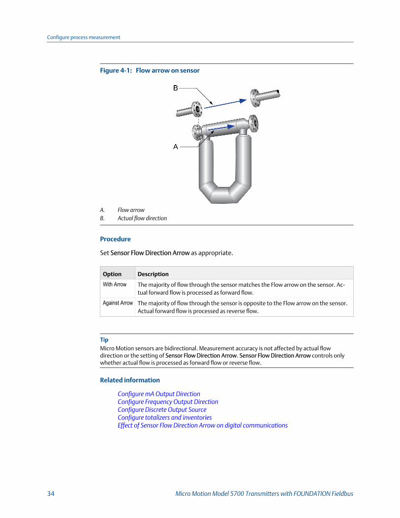
Flow arrow on sensorFigure 4-1:
A. Flow arrowB. Actual flow direction
Procedure
Set Sensor Flow Direction Arrow as appropriate.
Option Description
With Arrow The majority of flow through the sensor matches the Flow arrow on the sensor. Ac-tual forward flow is processed as forward flow.
Against Arrow The majority of flow through the sensor is opposite to the Flow arrow on the sensor.Actual forward flow is processed as reverse flow.
TipMicro Motion sensors are bidirectional. Measurement accuracy is not affected by actual flowdirection or the setting of Sensor Flow Direction Arrow. Sensor Flow Direction Arrow controls onlywhether actual flow is processed as forward flow or reverse flow.
Related information
Configure mA Output DirectionConfigure Frequency Output DirectionConfigure Discrete Output SourceConfigure totalizers and inventoriesEffect of Sensor Flow Direction Arrow on digital communications
Configure process measurement
34 Micro Motion Model 5700 Transmitters with FOUNDATION Fieldbus

4.2 Configure mass flow measurementThe mass flow measurement parameters control how mass flow is measured and reported.The mass total and mass inventory are derived from the mass flow data.
• Configure Mass Flow Measurement Unit (Section 4.2.1)• Configure Flow Damping (Section 4.2.2)• Configure Mass Flow Cutoff (Section 4.2.3)
4.2.1 Configure Mass Flow Measurement Unit
Display Menu > Configuration > Process Measurement > Flow Variables > Mass Flow Settings >
Units
ProLink III Device Tools > Configuration > Process Measurement > Flow > Mass Flow Rate Unit
Enhanced FF host Configure > Manual Setup > Measurements > Flow > Mass Flow Unit
Basic FF host Measurement TB > Mass Flow Unit (OD Index 19)
Overview
Mass Flow Measurement Unit specifies the unit of measure that will be used for the massflow rate. The default unit used for mass total and mass inventory is derived from this unit.
Procedure
Set Mass Flow Measurement Unit to the unit you want to use.
• Default: g/sec (grams per second)
TipIf the measurement unit you want to use is not available, you can define a special measurement unit.
Options for Mass Flow Measurement UnitThe transmitter provides a standard set of measurement units for Mass Flow MeasurementUnit, plus one user-defined special measurement unit. Different communications toolsmay use different labels for the units.
Options for Mass Flow Measurement Unit Table 4-1:
Unit description
Label
Display ProLink III Enhanced FF host Basic FF host code
Grams per second gram/s g/sec g/s 1318
Grams per minute gram/min g/min g/min 1319
Grams per hour gram/h g/hr g/h 1320
Kilograms per second kg/s kg/sec kg/s 1322
Configure process measurement
Configuration and Use Manual 35
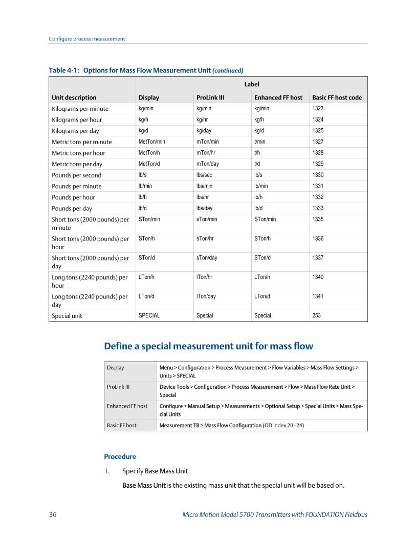
Options for Mass Flow Measurement Unit (continued)Table 4-1:
Unit description
Label
Display ProLink III Enhanced FF host Basic FF host code
Kilograms per minute kg/min kg/min kg/min 1323
Kilograms per hour kg/h kg/hr kg/h 1324
Kilograms per day kg/d kg/day kg/d 1325
Metric tons per minute MetTon/min mTon/min t/min 1327
Metric tons per hour MetTon/h mTon/hr t/h 1328
Metric tons per day MetTon/d mTon/day t/d 1329
Pounds per second lb/s lbs/sec lb/s 1330
Pounds per minute lb/min lbs/min lb/min 1331
Pounds per hour lb/h lbs/hr lb/h 1332
Pounds per day lb/d lbs/day lb/d 1333
Short tons (2000 pounds) perminute
STon/min sTon/min STon/min 1335
Short tons (2000 pounds) perhour
STon/h sTon/hr STon/h 1336
Short tons (2000 pounds) perday
STon/d sTon/day STon/d 1337
Long tons (2240 pounds) perhour
LTon/h lTon/hr LTon/h 1340
Long tons (2240 pounds) perday
LTon/d lTon/day LTon/d 1341
Special unit SPECIAL Special Special 253
Define a special measurement unit for mass flow
Display Menu > Configuration > Process Measurement > Flow Variables > Mass Flow Settings >
Units > SPECIAL
ProLink III Device Tools > Configuration > Process Measurement > Flow > Mass Flow Rate Unit >
Special
Enhanced FF host Configure > Manual Setup > Measurements > Optional Setup > Special Units > Mass Spe-
cial Units
Basic FF host Measurement TB > Mass Flow Configuration (OD index 20–24)
Procedure
1. Specify Base Mass Unit.
Base Mass Unit is the existing mass unit that the special unit will be based on.
Configure process measurement
36 Micro Motion Model 5700 Transmitters with FOUNDATION Fieldbus

2. Specify Base Time Unit.
Base Time Unit is the existing time unit that the special unit will be based on.
3. Calculate Mass Flow Conversion Factor as follows:
a. x base units = y special units
b. Mass Flow Conversion Factor = x ÷ y
4. Enter Mass Flow Conversion Factor.
The original mass flow rate value is divided by this value.
5. Set Mass Flow Label to the name you want to use for the mass flow unit.
6. Set Mass Total Label to the name you want to use for the mass total and massinventory unit.
The special measurement unit is stored in the transmitter. You can configure thetransmitter to use the special measurement unit at any time.
Example: Defining a special measurement unit for mass flow
You want to measure mass flow in ounces per second (oz/sec).
1. Set Base Mass Unit to Pounds (lb).
2. Set Base Time Unit to Seconds (sec).
3. Calculate Mass Flow Conversion Factor:
a. 1 lb/sec = 16 oz/sec
b. Mass Flow Conversion Factor = 1 ÷ 16 = 0.0625
4. Set Mass Flow Conversion Factor to 0.0625.
5. Set Mass Flow Label to oz/sec.
6. Set Mass Total Label to oz.
4.2.2 Configure Flow Damping
Display Menu > Configuration > Process Measurement > Flow Variables > Flow Damping
ProLink III Device Tools > Configuration > Process Measurement > Flow > Flow Rate Damping
Enhanced FF host Configure > Manual Setup > Measurements > Flow > Flow Damping
Basic FF host Measurment TB > Flow Damping (OD Index 29)
Overview
Flow Damping controls the amount of damping that will be applied to the measured massflow rate. It affects flow rate process variables that are based on the measured mass flowrate. This includes volume flow rate and gas standard volume flow rate.
Configure process measurement
Configuration and Use Manual 37

Flow Damping also affects specialized flow rate variables such as temperature-correctedvolume flow rate (API referral) and net mass flow rate (concentration measurement). It isnot applied to the flow rate received via the frequency input.
Damping is used to smooth out small, rapid fluctuations in process measurement. Thedamping value specifies the time period, in seconds, over which the transmitter will spreadchanges in the process variable. At the end of the interval, the internal value of the processvariable (the damped value) will reflect 63% of the change in the actual measured value.
Procedure
Set Flow Damping to the value you want to use.
• Default: 0.64 seconds
• Range: 0 seconds to 60 seconds
NoteIf a number greater than 60 is entered, it is automatically changed to 60.
Tips
• A high damping value makes the process variable appear smoother because the reported valuechanges slowly.
• A low damping value makes the process variable appear more erratic because the reported valuechanges more quickly.
• The combination of a high damping value and rapid, large changes in flow rate can result inincreased measurement error.
• Whenever the damping value is non-zero, the reported measurement will lag the actualmeasurement because the reported value is being averaged over time.
• In general, lower damping values are preferable because there is less chance of data loss, and lesslag time between the actual measurement and the reported value.
• The transmitter automatically rounds off any entered damping value to the nearest valid value.Therefore, the recommended damping value for gas applications should be 3.2 seconds. If youenter 2.56, the transmitter will round it off to 3.2.
Effect of flow damping on volume measurementFlow damping affects volume measurement for liquid volume data. Flow damping alsoaffects volume measurement for gas standard volume data. The transmitter calculatesvolume data from the damped mass flow data.
Interaction between Flow Damping and mA OutputDampingIn some circumstances, both Flow Damping and mA Output Damping are applied to thereported mass flow value.
Configure process measurement
38 Micro Motion Model 5700 Transmitters with FOUNDATION Fieldbus

Flow Damping controls the rate of change in flow process variables. mA Output Dampingcontrols the rate of change reported via the mA output. If mA Output Process Variable isset to Mass Flow Rate, and both Flow Damping and mA Output Damping are set to non-zerovalues, flow damping is applied first, and the added damping calculation is applied to theresult of the first calculation.
4.2.3 Configure Mass Flow Cutoff
Display Menu > Configuration > Process Measurement > Flow Variables > Mass Flow Settings >
Low Flow Cutoff
ProLink III Device Tools > Configuration > Process Measurement > Flow > Mass Flow Cutoff
Enhanced FF host Configure > Manual Setup > Measurements > Flow > Mass Flow Cutoff
Basic FF host Measurement TB > Mass Flow Cutoff (OD Index 26)
Overview
Mass Flow Cutoff specifies the lowest mass flow rate that will be reported as measured. Allmass flow rates below this cutoff will be reported as 0.
Procedure
Set Mass Flow Cutoff to the value you want to use.
• Default: A sensor-specific value set at the factory. If your transmitter was orderedwithout a sensor, the default may be 0.0.
• Recommendation: 0.5% of maximum flow rate of the attached sensor. See the sensorspecifications.
ImportantDo not use your meter for measurement with Mass Flow Cutoff set to 0.0 g/sec. Ensure that MassFlow Cutoff is set to the value that is appropriate for your sensor.
Effect of Mass Flow Cutoff on volume measurementMass Flow Cutoff does not affect volume measurement. Volume data is calculated fromthe actual mass data rather than the reported value.
Interaction between Mass Flow Cutoff and mA Output CutoffMass Flow Cutoff defines the lowest mass flow value that the transmitter will report asmeasured. mA Output Cutoff defines the lowest flow rate that will be reported via the mAoutput. If mA Output Process Variable is set to Mass Flow Rate, the mass flow rate reportedvia the mA output is controlled by the higher of the two cutoff values.
Mass Flow Cutoff affects all reported values and values used in other transmitter behavior(e.g., events defined on mass flow).
mA Output Cutoff affects only mass flow values reported via the mA output.
Configure process measurement
Configuration and Use Manual 39

Example: Cutoff interaction with mA Output Cutoff lower than Mass Flow Cutoff
Configuration:
• mA Output Process Variable: Mass Flow Rate• Frequency Output Process Variable: Mass Flow Rate• mA Output Cutoff: 10 g/sec
• Mass Flow Cutoff: 15 g/sec
Result: If the mass flow rate drops below 15 g/sec, mass flow will be reported as 0, and 0will be used in all internal processing.
Example: Cutoff interaction with mA Output Cutoff higher than Mass Flow Cutoff
Configuration:
• mA Output Process Variable: Mass Flow Rate• Frequency Output Process Variable: Mass Flow Rate• mA Output Cutoff: 15 g/sec
• Mass Flow Cutoff: 10 g/sec
Result:
• If the mass flow rate drops below 15 g/sec but not below 10 g/sec:
- The mA output will report zero flow.
- The frequency output will report the actual flow rate, and the actual flow rate willbe used in all internal processing.
• If the mass flow rate drops below 10 g/sec, both outputs will report zero flow, and 0will be used in all internal processing.
4.3 Configure volume flow measurement for liquidapplicationsThe volume flow measurement parameters control how liquid volume flow is measuredand reported. The volume total and volume inventory are derived from volume flow data.
RestrictionYou cannot implement both liquid volume flow and gas standard volume flow at the same time.Choose one or the other.
• Configure Volume Flow Type for liquid applications (Section 4.3.1)• Configure Volume Flow Measurement Unit for liquid applications (Section 4.3.2)• Configure Volume Flow Cutoff (Section 4.3.3)
Configure process measurement
40 Micro Motion Model 5700 Transmitters with FOUNDATION Fieldbus

4.3.1 Configure Volume Flow Type for liquid applications
Display Menu > Configuration > Process Measurement > Flow Variables > Volume Flow Settings >
Flow Type > Liquid
ProLink III Device Tools > Configuration > Process Measurement > Flow > Volume Flow Type > Liq-
uid Volume
Enhanced FF host Configure > Manual Setup > Measurements > Volume Flow > Type
Basic FF host Measurement TB > Volume Flow Type (OD Index 52)
Overview
Volume Flow Type controls whether liquid or gas standard volume flow measurement willbe used.
RestrictionIf you are using the API referral application, you must set Volume Flow Type to Liquid. Gas standardvolume measurement is incompatible with the API referral application.
RestrictionIf you are using the concentration measurement application, you must set Volume Flow Type toLiquid.
Gas standard volume measurement is incompatible with the following applications:
• Concentration measurement
RestrictionIf you are using the advance phase measurement application with the Liquid with Gas or Net Oiloption selected, you must set Volume Flow Type to Liquid.
Procedure
Set Volume Flow Type to Liquid.
4.3.2 Configure Volume Flow Measurement Unit for liquidapplications
Display Menu > Configuration > Process Measurement > Flow Variables > Volume Flow Settings >
Units
ProLink III Device Tools > Configuration > Process Measurement > Flow > Volume Flow Rate Unit
Enhanced FF host Configure > Manual Setup > Measurements > Flow > Volume Flow Unit
Basic FF host Measurement TB > Volume Flow Unit (OD Index 31)
Configure process measurement
Configuration and Use Manual 41

Overview
Volume Flow Measurement Unit specifies the unit of measurement that will be displayedfor the volume flow rate. The unit used for the volume total and volume inventory is basedon this unit.
Prerequisites
Before you configure Volume Flow Measurement Unit, be sure that Volume Flow Type isset to Liquid.
Procedure
Set Volume Flow Measurement Unit to the unit you want to use.
• Default: l/sec (liters per second)
TipIf the measurement unit you want to use is not available, you can define a special measurement unit.
Options for Volume Flow Measurement Unit for liquidapplicationsThe transmitter provides a standard set of measurement units for Volume FlowMeasurement Unit, plus one user-defined measurement unit. Different communicationstools may use different labels for the units.
Options for Volume Flow Measurement Unit for liquid applicationsTable 4-2:
Unit description
Label
Display ProLink III Enhanced FF host Basic FF host code
Cubic feet per second ft3/s ft3/sec CFS 1356
Cubic feet per minute ft3/min ft3/min CFM 1357
Cubic feet per hour ft3/h ft3/hr CFH 1358
Cubic feet per day ft3/d ft3/day ft³/d 1359
Cubic meters per second m3/s m3/sec m³/s 1347
Cubic meters per minute m3/min m3/min m³/min 1348
Cubic meters per hour m3/h m3/hr m³/h 1349
Cubic meters per day m3/d m3/day m³/d 1350
U.S. gallons per second gal/s US gal/sec gal/s 1362
U.S. gallons per minute gal/m US gal/min GPM 1363
U.S. gallons per hour gal/h US gal/hr gal/h 1364
U.S. gallons per day gal/d US gal/day gal/d 1365
Million U.S. gallons per day MMgal/d mil US gal/day Mgal/d 1366
Liters per second L/s l/sec L/s 1351
Configure process measurement
42 Micro Motion Model 5700 Transmitters with FOUNDATION Fieldbus
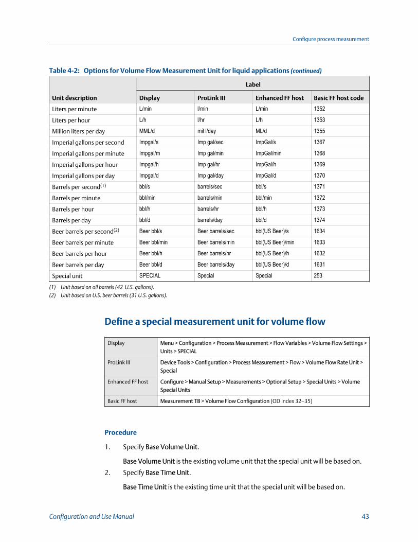
Options for Volume Flow Measurement Unit for liquid applications (continued)Table 4-2:
Unit description
Label
Display ProLink III Enhanced FF host Basic FF host code
Liters per minute L/min l/min L/min 1352
Liters per hour L/h l/hr L/h 1353
Million liters per day MML/d mil l/day ML/d 1355
Imperial gallons per second Impgal/s Imp gal/sec ImpGal/s 1367
Imperial gallons per minute Impgal/m Imp gal/min ImpGal/min 1368
Imperial gallons per hour Impgal/h Imp gal/hr ImpGal/h 1369
Imperial gallons per day Impgal/d Imp gal/day ImpGal/d 1370
Barrels per second(1) bbl/s barrels/sec bbl/s 1371
Barrels per minute bbl/min barrels/min bbl/min 1372
Barrels per hour bbl/h barrels/hr bbl/h 1373
Barrels per day bbl/d barrels/day bbl/d 1374
Beer barrels per second(2) Beer bbl/s Beer barrels/sec bbl(US Beer)/s 1634
Beer barrels per minute Beer bbl/min Beer barrels/min bbl(US Beer)/min 1633
Beer barrels per hour Beer bbl/h Beer barrels/hr bbl(US Beer)/h 1632
Beer barrels per day Beer bbl/d Beer barrels/day bbl(US Beer)/d 1631
Special unit SPECIAL Special Special 253
(1) Unit based on oil barrels (42 U.S. gallons).
(2) Unit based on U.S. beer barrels (31 U.S. gallons).
Define a special measurement unit for volume flow
Display Menu > Configuration > Process Measurement > Flow Variables > Volume Flow Settings >
Units > SPECIAL
ProLink III Device Tools > Configuration > Process Measurement > Flow > Volume Flow Rate Unit >
Special
Enhanced FF host Configure > Manual Setup > Measurements > Optional Setup > Special Units > Volume
Special Units
Basic FF host Measurement TB > Volume Flow Configuration (OD Index 32–35)
Procedure
1. Specify Base Volume Unit.
Base Volume Unit is the existing volume unit that the special unit will be based on.
2. Specify Base Time Unit.
Base Time Unit is the existing time unit that the special unit will be based on.
Configure process measurement
Configuration and Use Manual 43

3. Calculate Volume Flow Conversion Factor as follows:
a. x base units = y special units
b. Volume Flow Conversion Factor = x ÷ y
4. Enter Volume Flow Conversion Factor.
The original volume flow rate value is divided by this conversion factor.
5. Set Volume Flow Label to the name you want to use for the volume flow unit.
6. Set Volume Total Label to the name you want to use for the volume total andvolume inventory unit.
The special measurement unit is stored in the transmitter. You can configure thetransmitter to use the special measurement unit at any time.
Example: Defining a special measurement unit for volume flow
You want to measure volume flow in pints per second (pints/sec).
1. Set Base Volume Unit to Gallons (gal).
2. Set Base Time Unit to Seconds (sec).
3. Calculate the conversion factor:
a. 1 gal/sec = 8 pints/sec
b. Volume Flow Conversion Factor = 1 ÷ 8 = 0.1250
4. Set Volume Flow Conversion Factor to 0.1250.
5. Set Volume Flow Label to pints/sec.
6. Set Volume Total Label to pints.
4.3.3 Configure Volume Flow Cutoff
Display Menu > Configuration > Process Measurement > Flow Variables > Volume Flow Settings >
Low Flow Cutoff
ProLink III Device Tools > Configuration > Process Measurement > Flow > Volume Flow Cutoff
Enhanced FF host Configure > Manual Setup > Measurements > Flow > Volume Flow Cutoff
Basic FF host Measurement TB > Volume Flow Cutoff (OD Index 38)
Overview
Volume Flow Cutoff specifies the lowest volume flow rate that will be reported asmeasured. All volume flow rates below this cutoff are reported as 0.
Procedure
Set Volume Flow Cutoff to the value you want to use.
• Default: 0.0 l/sec (liters per second)
Configure process measurement
44 Micro Motion Model 5700 Transmitters with FOUNDATION Fieldbus

• Range: 0 l/sec to x l/sec, where x is the sensor’s flow calibration factor, in units of l/sec,multiplied by 0.2
Interaction between Volume Flow Cutoff and mAO CutoffVolume Flow Cutoff defines the lowest liquid volume flow value that the transmitter willreport as measured. mAO Cutoff defines the lowest flow rate that will be reported via themA output. If mA Output Process Variable is set to Volume Flow Rate, the volume flow ratereported via the mA output is controlled by the higher of the two cutoff values.
Volume Flow Cutoff affects both the volume flow values reported via the outputs and thevolume flow values used in other transmitter behavior (e.g., events defined on the volumeflow).
mAO Cutoff affects only flow values reported via the mA output.
Example: Cutoff interaction with mAO Cutoff lower than Volume Flow Cutoff
Configuration:
• mA Output Process Variable: Volume Flow Rate• Frequency Output Process Variable: Volume Flow Rate• AO Cutoff: 10 l/sec
• Volume Flow Cutoff: 15 l/sec
Result: If the volume flow rate drops below 15 l/sec, volume flow will be reported as 0, and0 will be used in all internal processing.
Example: Cutoff interaction with mAO Cutoff higher than Volume Flow Cutoff
Configuration:
• mA Output Process Variable: Volume Flow Rate• Frequency Output Process Variable: Volume Flow Rate• AO Cutoff: 15 l/sec
• Volume Flow Cutoff: 10 l/sec
Result:
• If the volume flow rate drops below 15 l/sec but not below 10 l/sec:
- The mA output will report zero flow.
- The frequency output will report the actual flow rate, and the actual flow rate willbe used in all internal processing.
• If the volume flow rate drops below 10 l/sec, both outputs will report zero flow, and0 will be used in all internal processing.
Configure process measurement
Configuration and Use Manual 45

4.4 Configure Gas Standard Volume (GSV) flowmeasurementThe gas standard volume (GSV) flow measurement parameters control how gas standardvolume flow is measured and reported.
RestrictionYou cannot implement both liquid volume flow and gas standard volume flow at the same time.Choose one or the other.
• Configure Volume Flow Type for gas applications (Section 4.4.1)• Configure Standard Gas Density (Section 4.4.2)• Configure Gas Standard Volume Flow Measurement Unit (Section 4.4.3)• Configure Gas Standard Volume Flow Cutoff (Section 4.4.4)
4.4.1 Configure Volume Flow Type for gas applications
Display Menu > Configuration > Process Measurement > Flow Variables > Volume Flow Settings >
Flow Type > Gas
ProLink III Device Tools > Configuration > Process Measurement > Flow > Volume Flow Type > Gas
Standard Volume
Enhanced FF host Configure > Manual Setup > Measurement > Volume Flow > Type
Basic FF host Measurement TB > Volume Flow Type (OD Index 52)
Overview
Volume Flow Type controls whether liquid or gas standard volume flow measurement willbe used.
RestrictionIf you are using the API referral application, you must set Volume Flow Type to Liquid. Gas standardvolume measurement is incompatible with the API referral application.
RestrictionIf you are using the concentration measurement application, you must set Volume Flow Type toLiquid.
Gas standard volume measurement is incompatible with the following applications:
• Concentration measurement
RestrictionIf you are using the advanced phase measurement application with the Liquid with Gas or Net Oiloption selected, you must set Volume Flow Type to Liquid.
Configure process measurement
46 Micro Motion Model 5700 Transmitters with FOUNDATION Fieldbus
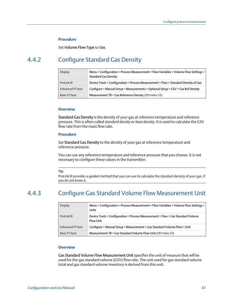
Procedure
Set Volume Flow Type to Gas.
4.4.2 Configure Standard Gas Density
Display Menu > Configuration > Process Measurement > Flow Variables > Volume Flow Settings >
Standard Gas Density
ProLink III Device Tools > Configuration > Process Measurement > Flow > Standard Density of Gas
Enhanced FF host Configure > Manual Setup > Measurements > Optional Setup > GSV > Gas Ref Density
Basic FF host Measurement TB > Gas Reference Density (OD Index 53)
Overview
Standard Gas Density is the density of your gas at reference temperature and referencepressure. This is often called standard density or base density. It is used to calculate the GSVflow rate from the mass flow rate.
Procedure
Set Standard Gas Density to the density of your gas at reference temperature andreference pressure.
You can use any reference temperature and reference pressure that you choose. It is notnecessary to configure these values in the transmitter.
TipProLink III provides a guided method that you can use to calculate the standard density of your gas, ifyou do not know it.
4.4.3 Configure Gas Standard Volume Flow Measurement Unit
Display Menu > Configuration > Process Measurement > Flow Variables > Volume Flow Settings >
Units
ProLink III Device Tools > Configuration > Process Measurement > Flow > Gas Standard Volume
Flow Unit
Enhanced FF host Configure > Manual Setup > Measurement > Gas Standard Volume Flow > Unit
Basic FF host Measurement TB > Gas Standard Volume Flow Unit (OD Index 55)
Overview
Gas Standard Volume Flow Measurement Unit specifies the unit of measure that will beused for the gas standard volume (GSV) flow rate. The unit used for gas standard volumetotal and gas standard volume inventory is derived from this unit.
Configure process measurement
Configuration and Use Manual 47
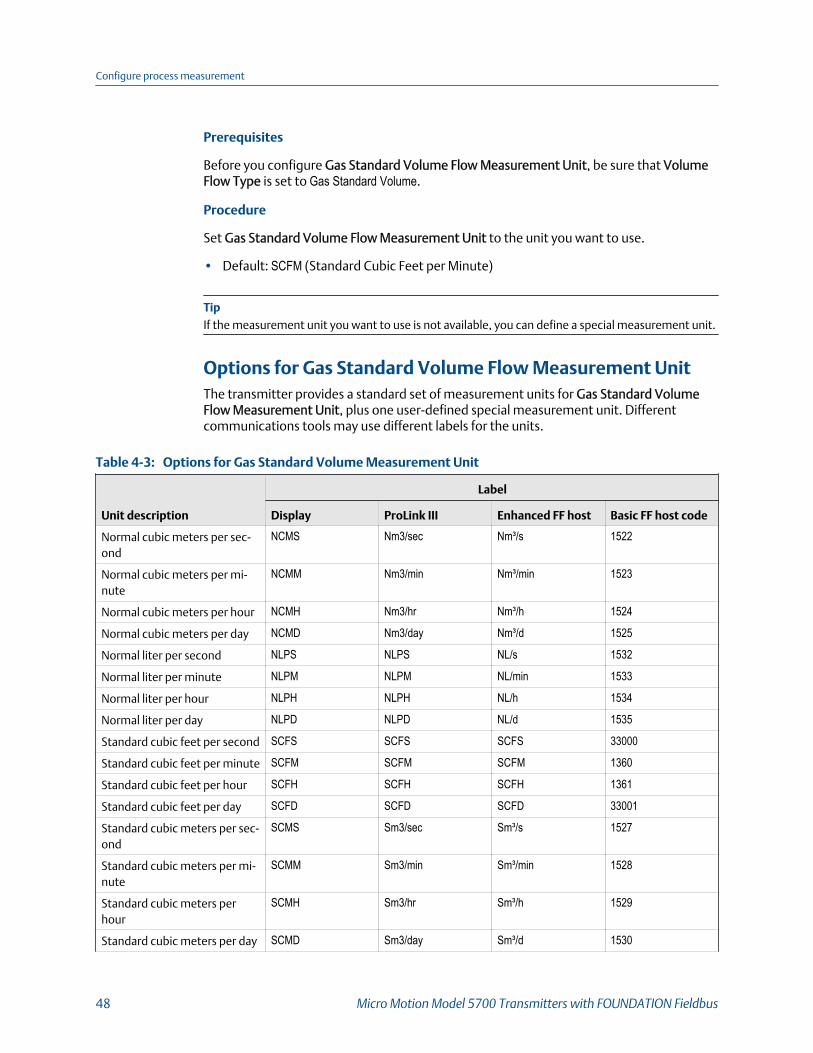
Prerequisites
Before you configure Gas Standard Volume Flow Measurement Unit, be sure that VolumeFlow Type is set to Gas Standard Volume.
Procedure
Set Gas Standard Volume Flow Measurement Unit to the unit you want to use.
• Default: SCFM (Standard Cubic Feet per Minute)
TipIf the measurement unit you want to use is not available, you can define a special measurement unit.
Options for Gas Standard Volume Flow Measurement UnitThe transmitter provides a standard set of measurement units for Gas Standard VolumeFlow Measurement Unit, plus one user-defined special measurement unit. Differentcommunications tools may use different labels for the units.
Options for Gas Standard Volume Measurement Unit Table 4-3:
Unit description
Label
Display ProLink III Enhanced FF host Basic FF host code
Normal cubic meters per sec-ond
NCMS Nm3/sec Nm³/s 1522
Normal cubic meters per mi-nute
NCMM Nm3/min Nm³/min 1523
Normal cubic meters per hour NCMH Nm3/hr Nm³/h 1524
Normal cubic meters per day NCMD Nm3/day Nm³/d 1525
Normal liter per second NLPS NLPS NL/s 1532
Normal liter per minute NLPM NLPM NL/min 1533
Normal liter per hour NLPH NLPH NL/h 1534
Normal liter per day NLPD NLPD NL/d 1535
Standard cubic feet per second SCFS SCFS SCFS 33000
Standard cubic feet per minute SCFM SCFM SCFM 1360
Standard cubic feet per hour SCFH SCFH SCFH 1361
Standard cubic feet per day SCFD SCFD SCFD 33001
Standard cubic meters per sec-ond
SCMS Sm3/sec Sm³/s 1527
Standard cubic meters per mi-nute
SCMM Sm3/min Sm³/min 1528
Standard cubic meters perhour
SCMH Sm3/hr Sm³/h 1529
Standard cubic meters per day SCMD Sm3/day Sm³/d 1530
Configure process measurement
48 Micro Motion Model 5700 Transmitters with FOUNDATION Fieldbus

Options for Gas Standard Volume Measurement Unit (continued)Table 4-3:
Unit description
Label
Display ProLink III Enhanced FF host Basic FF host code
Standard liter per second SLPS SLPS SL/s 1537
Standard liter per minute SLPM SLPM SL/min 1538
Standard liter per hour SLPH SLPH SL/h 1539
Standard liter per day SLPD SLPD SL/d 1540
Special measurement unit SPECIAL Special Special 253
Define a special measurement unit for gas standard volumeflow
Display Menu > Configuration > Process Measurement > Flow Variables > Volume Flow Settings >
Units > SPECIAL
ProLink III Device Tools > Configuration > Process Measurement > Flow > Gas Standard Volume
Flow Unit > Special
Enhanced FF host Configure > Manual Setup > Measurements > Optional Setup > Special Units > Special
Gas Standard Volume Units
Basic FF host Measurement TB > Gas Process Variables (OD Index 56–59, 61)
Procedure
1. Specify Base Gas Standard Volume Unit.
Base Gas Standard Volume Unit is the existing gas standard volume unit that thespecial unit will be based on.
2. Specify Base Time Unit.
Base Time Unit is the existing time unit that the special unit will be based on.
3. Calculate Gas Standard Volume Flow Conversion Factor as follows:
a. x base units = y special units
b. Gas Standard Volume Flow Conversion Factor = x ÷ y
4. Enter the Gas Standard Volume Flow Conversion Factor.
The original gas standard volume flow value is divided by this conversion factor.
5. Set Gas Standard Volume Flow Label to the name you want to use for the gasstandard volume flow unit.
6. Set Gas Standard Volume Total Label to the name you want to use for the gasstandard volume total and gas standard volume inventory unit.
Configure process measurement
Configuration and Use Manual 49

The special measurement unit is stored in the transmitter. You can configure thetransmitter to use the special measurement unit at any time.
Example: Defining a special measurement unit for gas standard volume flow
You want to measure gas standard volume flow in thousands of standard cubic feet perminute.
1. Set Base Gas Standard Volume Unit to SCFM.
2. Set Base Time Unit to minutes (min).
3. Calculate the conversion factor:
a. 1 thousands of standard cubic feet per minute = 1000 cubic feet per minute
b. Gas Standard Volume Flow Conversion Factor = 1 ÷ 1000 = 0.001
4. Set Gas Standard Volume Flow Conversion Factor to 0.001.
5. Set Gas Standard Volume Flow Label to KSCFM.
6. Set Gas Standard Volume Total Label to KSCF.
4.4.4 Configure Gas Standard Volume Flow Cutoff
Display Menu > Configuration > Process Measurement > Flow Variables > Volume Flow Settings >
Low Flow Cutoff
ProLink III Device Tools > Configuration > Process Measurement > Flow > Gas Standard Volume
Flow Cutoff
Enhanced FF host Configure > Manual Setup > Measurements > Optional Setup > Gas Standard Volume
Flow > Cutoff
Basic FF host Measurement TB > Gas Standard Volume Cutoff (OD Index 60)
Overview
Gas Standard Volume Flow Cutoff specifies the lowest gas standard volume flow rate thatwill reported as measured. All gas standard volume flow rates below this cutoff will bereported as 0.
Procedure
Set Gas Standard Volume Flow Cutoff to the value you want to use.
• Default: 0.0
• Range: 0.0 to any positive value
Configure process measurement
50 Micro Motion Model 5700 Transmitters with FOUNDATION Fieldbus

Interaction between Gas Standard Volume Flow Cutoff andmA Output CutoffGas Standard Volume Flow Cutoff defines the lowest Gas Standard Volume flow value thatthe transmitter will report as measured. mA Output Cutoff defines the lowest flow ratethat will be reported via the mA output. If mA Output Process Variable is set to Gas StandardVolume Flow Rate, the volume flow rate reported via the mA output is controlled by thehigher of the two cutoff values.
Gas Standard Volume Flow Cutoff affects both the gas standard volume flow valuesreported via outputs and the gas standard volume flow values used in other transmitterbehavior (e.g., events defined on gas standard volume flow).
mA Output Cutoff affects only flow values reported via the mA output.
Example: Cutoff interaction with mA Output Cutoff lower than Gas Standard VolumeFlow Cutoff
Configuration:
• mA Output Process Variable for the primary mA output: Gas Standard Volume Flow Rate• Frequency Output Process Variable: Gas Standard Volume Flow Rate• mA Output Cutoff for the primary mA output: 10 SLPM (standard liters per minute)
• Gas Standard Volume Flow Cutoff: 15 SLPM
Result: If the gas standard volume flow rate drops below 15 SLPM, the volume flow will bereported as 0, and 0 will be used in all internal processing.
Example: Cutoff interaction with mA Output Cutoff higher than Gas Standard VolumeFlow Cutoff
Configuration:
• mA Output Process Variable for the primary mA output: Gas Standard Volume Flow Rate• Frequency Output Process Variable: Gas Standard Volume Flow Rate• mA Output Cutoff for the primary mA output: 15 SLPM (standard liters per minute)
• Gas Standard Volume Flow Cutoff: 10 SLPM
Result:
• If the gas standard volume flow rate drops below 15 SLPM but not below 10 SLPM:
- The primary mA output will report zero flow.
- The frequency output will report the actual flow rate, and the actual flow rate willbe used in all internal processing.
• If the gas standard volume flow rate drops below 10 SLPM, both outputs will reportzero flow, and 0 will be used in all internal processing.
Configure process measurement
Configuration and Use Manual 51

4.5 Configure density measurementThe density measurement parameters control how density is measured and reported.Density measurement is used with mass flow rate measurement to determine liquidvolume flow rate.
• Configure Density Measurement Unit (Section 4.5.1)• Configure Density Damping (Section 4.5.2)• Configure Density Cutoff (Section 4.5.3)
4.5.1 Configure Density Measurement Unit
Display Menu > Configuration > Process Measurement > Density > Units
ProLink III Device Tools > Configuration > Process Measurement > Density > Density Unit
Enhanced FF host Configure > Manual Setup > Measurements > Density > Density Unit
Basic FF host Measurement TB > Density Unit (OD Index 45)
Overview
Density Measurement Unit controls the measurement units that will be used in densitycalculations and reporting.
RestrictionIf the API referral application is enabled, you cannot change the density measurement unit here. Thedensity measurement unit is controlled by the API table selection.
Procedure
Set Density Measurement Unit to the option you want to use.
• Default: g/cm³ (grams per cubic centimeter)
Options for Density Measurement UnitThe transmitter provides a standard set of measurement units for Density MeasurementUnit. Different communications tools may use different labels.
Options for Density Measurement Unit Table 4-4:
Unit description
Label
Display ProLink III Enhanced FF host Basic FF host code
Specific gravity(1) SGU SGU SGU 1114
Grams per cubic centimeter g/cm3 g/cm3 g/cm³ 1100
Grams per liter g/L g/l g/L 1105
Grams per milliliter g/mL g/ml g/ml 1104
Configure process measurement
52 Micro Motion Model 5700 Transmitters with FOUNDATION Fieldbus

Options for Density Measurement Unit (continued)Table 4-4:
Unit description
Label
Display ProLink III Enhanced FF host Basic FF host code
Kilograms per liter kg/L kg/l kg/L 1103
Kilograms per cubic meter kg/m3 kg/m3 kg/m³ 1097
Pounds per U.S. gallon lb/gal lbs/USgal lb/gal 1108
Pounds per cubic foot lb/ft3 lbs/ft3 lb/ft³ 1107
Pounds per cubic inch lb/in3 lbs/in3 lb/in³ 1106
Degrees API API API degAPI 1113
Short ton per cubic yard STon/yd3 sT/yd3 STon/yd³ 1109
(1) Non‐standard calculation. This value represents line density divided by the density of water at 60 °F.
4.5.2 Configure Density Damping
Display Menu > Configuration > Process Measurement > Density > Damping
ProLink III Device Tools > Configuration > Process Measurement > Density > Density Damping
Enhanced FF host Configure > Manual Setup > Measurements > Density > Density Damping
Basic FF host Measurement TB > Density Damping (OD Index 49)
Overview
Density Damping controls the amount of damping that will be applied to density data.
Damping is used to smooth out small, rapid fluctuations in process measurement. Thedamping value specifies the time period, in seconds, over which the transmitter will spreadchanges in the process variable. At the end of the interval, the internal value of the processvariable (the damped value) will reflect 63% of the change in the actual measured value.
Procedure
Set Density Damping to the desired value.
• Default: 1.28 seconds
• Range: 0.0 to 60 seconds
Tips
• A high damping value makes the process variable appear smoother because the reported valuechanges slowly.
• A low damping value makes the process variable appear more erratic because the reported valuechanges more quickly.
• The combination of a high damping value and rapid, large changes in density can result inincreased measurement error.
Configure process measurement
Configuration and Use Manual 53
• Whenever the damping value is non-zero, the damped value will lag the actual measurementbecause the damped value is being averaged over time.
• In general, lower damping values are preferable because there is less chance of data loss, and lesslag time between the actual measurement and the damped value.
• If a number greater than 60 is entered, it is automatically changed to 60.
Effect of Density Damping on volume measurementDensity Damping affects liquid volume measurement. Liquid volume values are calculatedfrom the damped density value rather than the measured density value. Density Dampingdoes not affect gas standard volume measurement.
Interaction between Density Damping and mA OutputDampingWhen the mA output is configured to report density, both Density Damping and mAOutput Damping are applied to the reported density value.
Density Damping controls the rate of change in the value of the process variable intransmitter memory. mA Output Damping controls the rate of change reported via the mAoutput.
If mA Output Source is set to Density, and both Density Damping and mA Output Dampingare set to non-zero values, density damping is applied first, and the mA output dampingcalculation is applied to the result of the first calculation. This value is reported over themA output.
4.5.3 Configure Density Cutoff
Display Menu > Configuration > Process Measurement > Density > Cutoff
ProLink III Device Tools > Configuration > Process Measurement > Density > Density Cutoff
Enhanced FF host Configure > Manual Setup > Measurements > Density > Density Cutoff
Basic FF host Measurement TB > Density Cutoff (OD Index 50)
Overview
Density Cutoff specifies the lowest density value that will be reported as measured. Alldensity values below this cutoff will be reported as 0.
Procedure
Set Density Cutoff to the value you want to use.
• Default: 0.2 g/cm³
• Range: 0.0 g/cm³ to 0.5 g/cm³
Configure process measurement
54 Micro Motion Model 5700 Transmitters with FOUNDATION Fieldbus
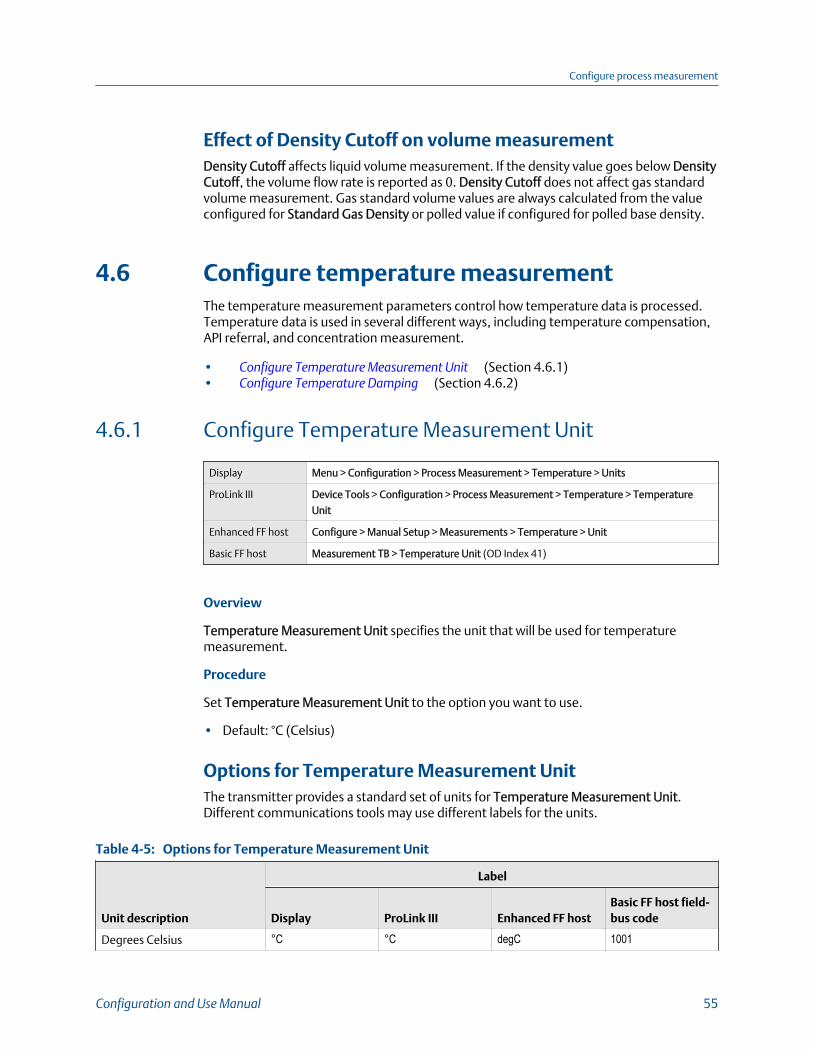
Effect of Density Cutoff on volume measurementDensity Cutoff affects liquid volume measurement. If the density value goes below DensityCutoff, the volume flow rate is reported as 0. Density Cutoff does not affect gas standardvolume measurement. Gas standard volume values are always calculated from the valueconfigured for Standard Gas Density or polled value if configured for polled base density.
4.6 Configure temperature measurementThe temperature measurement parameters control how temperature data is processed.Temperature data is used in several different ways, including temperature compensation,API referral, and concentration measurement.
• Configure Temperature Measurement Unit (Section 4.6.1)• Configure Temperature Damping (Section 4.6.2)
4.6.1 Configure Temperature Measurement Unit
Display Menu > Configuration > Process Measurement > Temperature > Units
ProLink III Device Tools > Configuration > Process Measurement > Temperature > Temperature
Unit
Enhanced FF host Configure > Manual Setup > Measurements > Temperature > Unit
Basic FF host Measurement TB > Temperature Unit (OD Index 41)
Overview
Temperature Measurement Unit specifies the unit that will be used for temperaturemeasurement.
Procedure
Set Temperature Measurement Unit to the option you want to use.
• Default: °C (Celsius)
Options for Temperature Measurement UnitThe transmitter provides a standard set of units for Temperature Measurement Unit.Different communications tools may use different labels for the units.
Options for Temperature Measurement Unit Table 4-5:
Unit description
Label
Display ProLink III Enhanced FF hostBasic FF host field-bus code
Degrees Celsius °C °C degC 1001
Configure process measurement
Configuration and Use Manual 55

Options for Temperature Measurement Unit (continued)Table 4-5:
Unit description
Label
Display ProLink III Enhanced FF hostBasic FF host field-bus code
Degrees Fahrenheit °F °F degF 1002
Degrees Rankine °R °R degR 1003
Kelvin °K °K K 1000
4.6.2 Configure Temperature Damping
Display Menu > Configuration > Process Measurement > Temperature > Damping
ProLink III Device Tools > Configuration > Process Measurement > Temperature > Temperature
Damping
Enhanced FF host Configure > Manual Setup > Measurements > Temperature > Damping
Basic FF host Measurement TB > Temperature Damping (OD Index 44)
Overview
Temperature Damping controls the amount of damping that will be applied totemperature data from the sensor. Temperature Damping is not applied to externaltemperature data.
Damping is used to smooth out small, rapid fluctuations in process measurement. Thedamping value specifies the time period, in seconds, over which the transmitter will spreadchanges in the process variable. At the end of the interval, the internal value of the processvariable (the damped value) will reflect 63% of the change in the actual measured value.
Procedure
Set Temperature Damping to the desired value.
• Default: 4.8 seconds
• Range: 0.0 to 80 seconds
NoteIf a number greater than 80 is entered, it is automatically changed to 80.
Tips
• A high damping value makes the process variable appear smoother because the reported valuechanges slowly.
• A low damping value makes the process variable appear more erratic because the reported valuechanges more quickly.
Configure process measurement
56 Micro Motion Model 5700 Transmitters with FOUNDATION Fieldbus
• The combination of a high damping value and rapid, large changes in temperature can result inincreased measurement error.
• Whenever the damping value is non-zero, the damped value will lag the actual measurementbecause the damped value is being averaged over time.
• In general, lower damping values are preferable because there is less chance of data loss, and lesslag time between the actual measurement and the damped value.
Effect of Temperature Damping on process measurementTemperature Damping affects all processes and algorithms that use temperature datafrom the internal sensor RTD.
Temperature compensation
Temperature compensation adjusts process measurement to compensate for the effect oftemperature on the sensor tubes.
API referral
Temperature Damping affects API referral process variables only if the transmitter isconfigured to use temperature data from the sensor. If an external temperature value isused for API referral, Temperature Damping does not affect API referral process variables.
Concentration measurement
Temperature Damping affects concentration measurement process variables only if thetransmitter is configured to use temperature data from the sensor. If an externaltemperature value is used for concentration measurement, Temperature Damping doesnot affect concentration measurement process variables.
4.7 Configure Pressure Measurement Unit
Display Menu > Configuration > Process Measurement > Pressure > Units
ProLink III Device Tools > Configuration > Process Measurement > Pressure Compensation > Pres-
sure Unit
Enhanced FF host Configure > Manual Setup > Measurements > Optional Setup > External Pressure/Tem-
perature > Pressure > Unit
Basic FF host Measurement TB > Pressure Unit (OD Index 63)
Overview
Pressure Measurement Unit controls the measurement unit used for pressure. This unitmust match the unit used by the external pressure device.
Pressure data is used for pressure compensation and for API referral. The device does notmeasure pressure directly. You must set up a pressure input.
Configure process measurement
Configuration and Use Manual 57
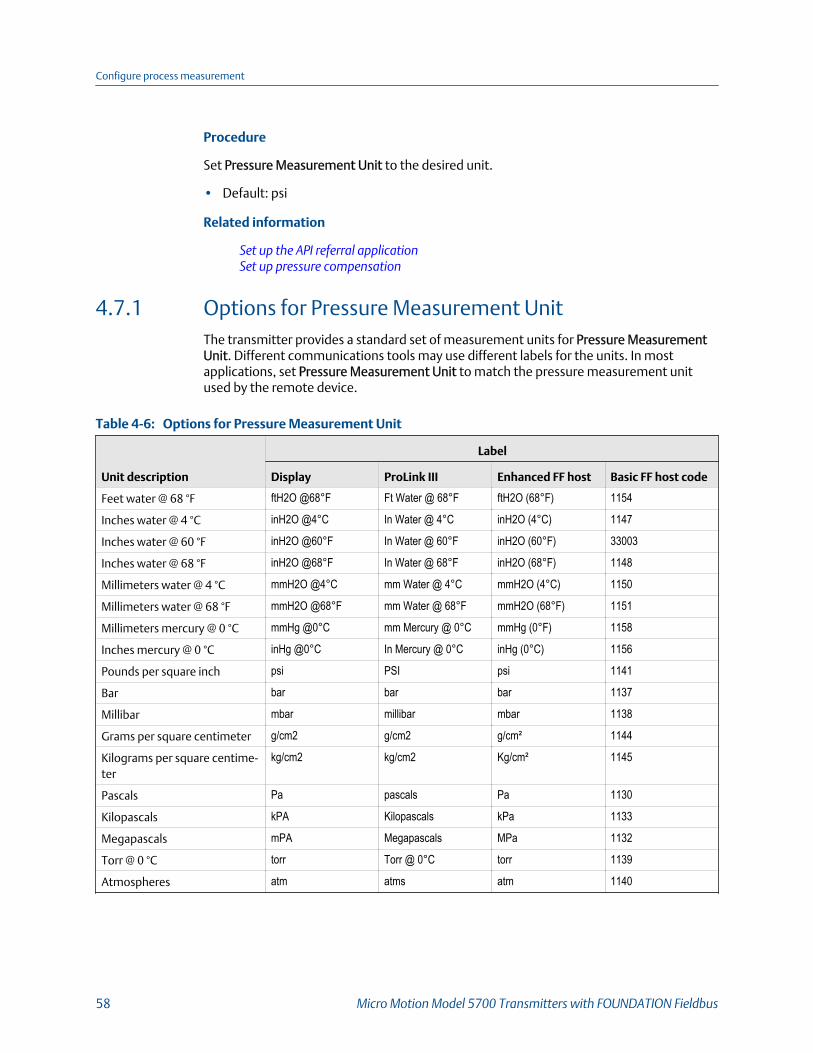
Procedure
Set Pressure Measurement Unit to the desired unit.
• Default: psi
Related information
Set up the API referral applicationSet up pressure compensation
4.7.1 Options for Pressure Measurement UnitThe transmitter provides a standard set of measurement units for Pressure MeasurementUnit. Different communications tools may use different labels for the units. In mostapplications, set Pressure Measurement Unit to match the pressure measurement unitused by the remote device.
Options for Pressure Measurement Unit Table 4-6:
Unit description
Label
Display ProLink III Enhanced FF host Basic FF host code
Feet water @ 68 °F ftH2O @68°F Ft Water @ 68°F ftH2O (68°F) 1154
Inches water @ 4 °C inH2O @4°C In Water @ 4°C inH2O (4°C) 1147
Inches water @ 60 °F inH2O @60°F In Water @ 60°F inH2O (60°F) 33003
Inches water @ 68 °F inH2O @68°F In Water @ 68°F inH2O (68°F) 1148
Millimeters water @ 4 °C mmH2O @4°C mm Water @ 4°C mmH2O (4°C) 1150
Millimeters water @ 68 °F mmH2O @68°F mm Water @ 68°F mmH2O (68°F) 1151
Millimeters mercury @ 0 °C mmHg @0°C mm Mercury @ 0°C mmHg (0°F) 1158
Inches mercury @ 0 °C inHg @0°C In Mercury @ 0°C inHg (0°C) 1156
Pounds per square inch psi PSI psi 1141
Bar bar bar bar 1137
Millibar mbar millibar mbar 1138
Grams per square centimeter g/cm2 g/cm2 g/cm² 1144
Kilograms per square centime-ter
kg/cm2 kg/cm2 Kg/cm² 1145
Pascals Pa pascals Pa 1130
Kilopascals kPA Kilopascals kPa 1133
Megapascals mPA Megapascals MPa 1132
Torr @ 0 °C torr Torr @ 0°C torr 1139
Atmospheres atm atms atm 1140
Configure process measurement
58 Micro Motion Model 5700 Transmitters with FOUNDATION Fieldbus

4.8 Configure Velocity Measurement Unit
Display Menu > Configuration > Process Measurement > Velocity > Units
ProLink III Device Tools > Configuration > Process Measurement > Velocity > Unit
Enhanced FF host Configure > Manual Setup > Measurements > Approximate Velocity > Velocity Unit
Basic FF host Measurement TB > Velocity Unit (OD Index 51)
Overview
Velocity Measurement Unit controls the measurement unit used to report velocity.
Procedure
Set Velocity Measurement Unit to the desired unit.
• Default: m/sec
4.8.1 Options for Velocity Measurement UnitThe transmitter provides a standard set of measurement units for Velocity MeasurementUnit. Different communications tools may use different labels.
Options for Velocity Measurement Unit Table 4-7:
Unit description
Label
Display ProLink III Enhanced FF host Basic FF host code
Feet per minute ft/min ft/min ft/min 1070
Feet per second ft/s ft/sec ft/s 1067
Inches per minute in/min in/min in/min 1069
Inches per second in/s in/sec in/s 1066
Meters per hour m/h m/hr m/h 1063
Meters per second m/s m/sec m/s 1061
Configure process measurement
Configuration and Use Manual 59

Configure process measurement
60 Micro Motion Model 5700 Transmitters with FOUNDATION Fieldbus
5 Configure process measurementapplicationsTopics covered in this chapter:
• Set up the API referral application
• Set up concentration measurement
5.1 Set up the API referral applicationThe API referral application corrects line density to reference temperature and referencepressure according to American Petroleum Institute (API) standards. The resulting processvariable is referred density.
RestrictionThe API referral application is not compatible with the following applications:
• Gas Standard Volume Measurement (GSV)
• Advanced Phase Measurement
• Concentration Measurement
• Set up the API referral application using the display (Section 5.1.1)• Set up the API referral application using ProLink III (Section 5.1.2)• Set up the API referral application using an enhanced FF host (Section 5.1.3)• Set up the API referral application using a basic FF host (Section 5.1.4)• API tables supported by the API referral application (Section 5.1.5)• Process variables from the API referral application (Section 5.1.6)
5.1.1 Set up the API referral application using the displayThis section guides you through the tasks required to set up and implement the APIreferral application.
1. Enable the API referral application using the display2. Configure API referral using the display3. Set up temperature and pressure data for API referral using the display
Enable the API referral application using the displayThe API referral application must be enabled before you can perform any setup. If the APIreferral application was enabled at the factory, you do not need to enable it now.
Prerequisites
The API referral application must be licensed on your transmitter.
Configure process measurement applications
Configuration and Use Manual 61
Procedure
1. Choose Menu > Configuration > Process Measurement.
2. Choose Flow Variables > Volume Flow Settings and ensure that Flow Type is set toLiquid.
3. Return to the Process Measurement menu.
4. If the concentration measurement application is displayed in the list, chooseConcentration Measurement and ensure that Enabled/Disabled is set to Disabled.
The concentration measurement application and the API referral application cannotbe enabled simultaneously.
5. Enable API referral.
a. Choose Menu > Configuration > Process Measurement > API Referral.
b. Set Enabled/Disabled to Enabled.
Related information
View the licensed features
Configure API referral using the displayThe API referral parameters specify the API table, measurement units, and reference valuesto be used in referred density calculations.
Prerequisites
You will need API documentation for the API table that you select.
Depending on your API table, you may need to know the thermal expansion coefficient(TEC) for your process fluid.
You must know the reference temperature and reference pressure that you want to use.
Procedure
1. Choose Menu > Configure > Process Measurement > API Referral.
2. Set API Table to the API table that you want to use to calculate referred density.
Each API table is associated with a specific set of equations. Choose your API tablebased on your process fluid and the measurement unit that you want to use forreferred density.
Your choice also determines the API table that will be used to calculate thecorrection factor for volume (CTPL or CTL).
3. Refer to the API documentation and confirm your table selection.
a. Verify that your process fluid falls within range for line density, line temperature,and line pressure.
b. Verify that the referred density range of the selected table is adequate for yourapplication.
Configure process measurement applications
62 Micro Motion Model 5700 Transmitters with FOUNDATION Fieldbus

4. If you chose a C table, enter Thermal Expansion Coefficient (TEC) for your processfluid.
5. If required, set Reference Temperature to the temperature to which density will becorrected in referred density calculations.
The default reference temperature is determined by the selected API table.
6. If required, set Reference Pressure to the pressure to which density will be correctedin referred density calculations.
The default reference pressure is determined by the selected API table.
Related information
API tables supported by the API referral application
Set up temperature and pressure data for API referral usingthe displayThe API referral application uses temperature and, optionally, pressure data in itscalculations. You must decide how to provide this data, then perform the requiredconfiguration and setup.
TipFixed values for temperature or pressure are not recommended. Using a fixed temperature orpressure value may produce inaccurate process data.
Prerequisites
The pressure measurement must be gauge pressure, not atmospheric pressure.
The pressure device must use the pressure unit that is configured in the transmitter.
If you are using an external temperature device, it must use the temperature unit that isconfigured in the transmitter.
Procedure
1. Choose the method to be used to supply temperature data, and perform therequired setup.
Method Description Setup
Internaltemperature
Temperature data from the on-board temperature sensor(RTD) will be used for all meas-urements and calculations. Noexternal temperature data willbe available.
a. Choose Menu > Configuration > Process Measurement >Temperature .
b. Set External Temperature to Off.
Configure process measurement applications
Configuration and Use Manual 63

Method Description Setup
Digitalcommunications
A host writes temperature datato the meter at appropriate in-tervals. This data will be availa-ble in addition to the internaltemperature data.
a. Choose Menu > Configuration > Process Measurement >Temperature .
b. Set External Temperature to On.c. Perform the necessary host programming and communica-
tions setup to write temperature data to the transmitter atappropriate intervals.
2. (A, B, C, and D tables only) Choose the method to be used to supply pressure data,and perform the required setup.
Method Description Setup
Digital communica-tions
A host writes pressure data tothe meter at appropriate inter-vals.
a. Choose Menu > Configuration > Process Measurement >Pressure > External Pressure .
b. Set External Pressure to On.c. Perform the necessary host programming and communica-
tions setup to write pressure data to the transmitter at ap-propriate intervals.
Postrequisites
Choose Menu > Service Tools > Service Data > View Process Variables and verify the valuesfor External Temperature and External Pressure.
Need help? If the value is not correct:
• Ensure that the external device and the meter are using the same measurement unit.
• For digital communications:
- Verify that the host has access to the required data.
- Verify that the output variable is being correctly received and processed by thetransmitter.
5.1.2 Set up the API referral application using ProLink IIIThis section guides you through the tasks required to set up and implement the APIreferral application.
1. Enable the API referral application using ProLink III2. Configure API referral using ProLink III3. Set up temperature and pressure data for API referral using ProLink III
Enable the API referral application using ProLink IIIThe API referral application must be enabled before you can perform any setup. If the APIreferral application was enabled at the factory, you do not need to enable it now.
Configure process measurement applications
64 Micro Motion Model 5700 Transmitters with FOUNDATION Fieldbus

Prerequisites
The API referral application must be licensed on your transmitter.
Procedure
1. Choose Device Tools > Configuration > Process Measurement > Flow and ensure thatVolume Flow Type is set to Liquid Volume.
2. Choose Device Tools > Configuration > Transmitter Options.
3. If the concentration measurement application is enabled, disable it and click Apply.
The concentration measurement application and the API referral application cannotbe enabled simultaneously.
4. Enable API Referral and click Apply.
Related information
View the licensed features
Configure API referral using ProLink IIIThe API referral parameters specify the API table, measurement units, and reference valuesto be used in referred density calculations.
Prerequisites
You will need API documentation for the API table that you select.
Depending on your API table, you may need to know the thermal expansion coefficient(TEC) for your process fluid.
You must know the reference temperature and reference pressure that you want to use.
Procedure
1. Choose Device Tools > Configuration > Process Measurement > API Referral.
2. Specify the API table to use to calculate referred density.
Each API table is associated with a specific set of equations.
a. Set Process Fluid to the API table group that your process fluid belongs to.
API table group Process fluids
A tables Generalized crude and JP4
B tables Generalized products: Gasoline, jet fuel, aviation fuel, kerosene,heating oils, fuel oils, diesel, gas oil
C tables Liquids with a constant base density or known thermal expansioncoefficient (TEC). You will be required to enter the TEC for yourprocess fluid.
D tables Lubricating oils
Configure process measurement applications
Configuration and Use Manual 65

API table group Process fluids
E tables NGL (Natural Gas Liquids) and LPG (Liquid Petroleum Gas)
b. Set Referred Density Measurement Unit to the measurement units that you wantto use for referred density.
c. Click Apply.
These parameters uniquely identify the API table to be used to calculate referreddensity. The selected API table is displayed, and the meter automatically changesthe density unit, temperature unit, pressure unit, and reference pressure to matchthe API table.
Your choice also determines the API table that will be used to calculate thecorrection factor for volume (CTPL or CTL).
RestrictionNot all combinations are supported by the API referral application. See the list of API tables inthis manual.
3. Refer to the API documentation and confirm your table selection.
a. Verify that your process fluid falls within range for line density, line temperature,and line pressure.
b. Verify that the referred density range of the selected table is adequate for yourapplication.
4. If you chose a C table, enter Thermal Expansion Coefficient (TEC) for your processfluid.
5. Set Reference Temperature to the temperature to which density will be corrected inreferred density calculations. If you choose Other, select the temperaturemeasurement unit and enter the reference temperature.
6. Set Reference Pressure to the pressure to which density will be corrected in referreddensity calculations.
Related information
API tables supported by the API referral application
Set up temperature and pressure data for API referral usingProLink IIIThe API referral application uses temperature and, optionally, pressure data in itscalculations. You must decide how to provide this data, then perform the requiredconfiguration and setup.
TipFixed values for temperature or pressure are not recommended. Using a fixed temperature orpressure value may produce inaccurate process data.
Configure process measurement applications
66 Micro Motion Model 5700 Transmitters with FOUNDATION Fieldbus

Prerequisites
The pressure measurement must be gauge pressure, not atmospheric pressure.
The pressure device must use the pressure unit that is configured in the transmitter.
If you are using an external temperature device, it must use the temperature unit that isconfigured in the transmitter.
Procedure
1. Choose Device Tools > Configuration > Process Measurement > API Referral.
2. Choose the method to be used to supply temperature data, and perform therequired setup.
Option Description Setup
Internal RTDtemperaturedata
Temperature data from the on-board temperature sensor(RTD) is used.
a. Set Line Temperature Source to Internal RTD.b. Click Apply.
Digitalcommunications
A host writes temperature datato the meter at appropriate in-tervals. This data will be availa-ble in addition to the internalRTD temperature data.
a. Set Line Temperature Source to Fixed Value or Digital Communi-cations.
b. Click Apply.c. Perform the necessary host programming and communica-
tions setup to write temperature data to the meter at appro-priate intervals.
Postrequisites
If you are using external temperature data, verify the external temperature value displayedin the Inputs group on the ProLink III main window.
The current pressure value is displayed in the External Pressure field. Verify that the value iscorrect.
Need help? If the value is not correct:
• Ensure that the external device and the meter are using the same measurement unit.
• For digital communications:
- Verify that the host has access to the required data.
- Verify that the output variable is being correctly received and processed by thetransmitter.
5.1.3 Set up the API referral application using an enhanced FFhostThis section guides you through the tasks required to set up and implement the APIreferral application.
Configure process measurement applications
Configuration and Use Manual 67

1. Enable the API referral application using an enhanced FF host2. Configure API referral using an enhanced FF host3. Set up temperature and pressure data for API referral using an enhanced FF host
Enable the API referral application using an enhanced FF hostThe API referral application must be enabled before you can perform any setup. If the APIreferral application was enabled at the factory, you do not need to enable it now.
Prerequisites
The API referral application must be licensed on your transmitter.
Volume Flow Type must be set to Liquid.
Procedure
1. Choose Overview > Device Information > Licenses > Enable/Disable Application >Volume Flow Type and ensure that it is set to Liquid.
2. If the concentration measurement application is enabled, disable it.
The concentration measurement application and the API referral application cannotbe enabled simultaneously.
3. Enable the API referral application.
Configure API referral using an enhanced FF hostThe API referral parameters specify the API table, measurement units, and reference valuesto be used in referred density calculations.
Prerequisites
You will need API documentation for the API table that you select.
Depending on your API table, you may need to know the thermal expansion coefficient(TEC) for your process fluid.
You must know the reference temperature and reference pressure that you want to use.
Procedure
1. Choose Configure > Manual Setup > Measurements > Optional Setup > API Referral.
2. Choose API Referral Setup.
3. Specify the API table that you want to use to calculate referred density.
Each API table is associated with a specific set of equations.
a. Set API Table Number to the number that matches the API table units that youwant to use for referred density.
Your choice also determines the measurement unit to be used for temperatureand pressure, and the default values for reference temperature and referencepressure.
Configure process measurement applications
68 Micro Motion Model 5700 Transmitters with FOUNDATION Fieldbus
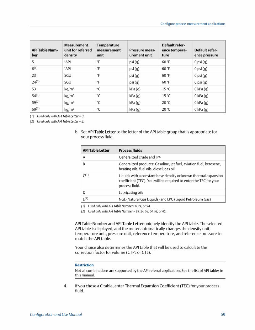
API Table Num-ber
Measurementunit for referreddensity
Temperaturemeasurementunit
Pressure meas-urement unit
Default refer-ence tempera-ture
Default refer-ence pressure
5 °API °F psi (g) 60 °F 0 psi (g)
6(1) °API °F psi (g) 60 °F 0 psi (g)
23 SGU °F psi (g) 60 °F 0 psi (g)
24(1) SGU °F psi (g) 60 °F 0 psi (g)
53 kg/m³ °C kPa (g) 15 °C 0 kPa (g)
54(1) kg/m³ °C kPa (g) 15 °C 0 kPa (g)
59(2) kg/m³ °C kPa (g) 20 °C 0 kPa (g)
60(2) kg/m³ °C kPa (g) 20 °C 0 kPa (g)
(1) Used only with API Table Letter = C.
(2) Used only with API Table Letter = E.
b. Set API Table Letter to the letter of the API table group that is appropriate foryour process fluid.
API Table Letter Process fluids
A Generalized crude and JP4
B Generalized products: Gasoline, jet fuel, aviation fuel, kerosene,heating oils, fuel oils, diesel, gas oil
C(1) Liquids with a constant base density or known thermal expansioncoefficient (TEC). You will be required to enter the TEC for yourprocess fluid.
D Lubricating oils
E(2) NGL (Natural Gas Liquids) and LPG (Liquid Petroleum Gas)
(1) Used only with API Table Number= 6, 24, or 54.
(2) Used only with API Table Number = 23, 24, 53, 54, 59, or 60.
API Table Number and API Table Letter uniquely identify the API table. The selectedAPI table is displayed, and the meter automatically changes the density unit,temperature unit, pressure unit, reference temperature, and reference pressure tomatch the API table.
Your choice also determines the API table that will be used to calculate thecorrection factor for volume (CTPL or CTL).
RestrictionNot all combinations are supported by the API referral application. See the list of API tables inthis manual.
4. If you chose a C table, enter Thermal Expansion Coefficient (TEC) for your processfluid.
Configure process measurement applications
Configuration and Use Manual 69

5. Refer to the API documentation and confirm your table selection.
a. Verify that your process fluid falls within range for line density, line temperature,and line pressure.
b. Verify that the referred density range of the selected table is adequate for yourapplication.
6. If required, set Reference Temperature to the temperature to which density will becorrected in referred density calculations.
The default reference temperature is determined by the selected API table.
7. If required, set Reference Pressure to the pressure to which density will be correctedin referred density calculations.
The default reference pressure is determined by the selected API table. API referralrequires gauge pressure.
Related information
API tables supported by the API referral application
Set up temperature and pressure data for API referral usingan enhanced FF hostThe API referral application uses temperature and, optionally, pressure data in itscalculations. You must decide how to provide this data, then perform the requiredconfiguration and setup.
TipFixed values for temperature or pressure are not recommended. Using a fixed temperature orpressure value may produce inaccurate process data.
Procedure
1. Choose the method to be used to supply temperature data, and perform therequired setup.
Method Description Setup
Digitalcommunications
A host writes temperature datato the meter at appropriate in-tervals. This data will be availa-ble in addition to the internalRTD temperature data.
a. Choose Configure > Manual Setup > Measurements > Op-tional Setup > External Variables > External Temperature .
b. Set Temperature Compensation to Enable.c. Perform the necessary host programming and communica-
tions setup to write temperature data to the meter at appro-priate intervals.
2. (A, B, C, and D tables only) Choose the method to be used to supply pressure data,and perform the required setup.
Configure process measurement applications
70 Micro Motion Model 5700 Transmitters with FOUNDATION Fieldbus

Method Description Setup
Digitalcommunications
A host writes pressure data tothe meter at appropriate inter-vals.
a. Choose Configure > Manual Setup > Measurements > Op-tional Setup > External Variables > External Pressure .
b. Set Pressure Compensation to Enable.c. Perform the necessary host programming and communica-
tions setup to write pressure data to the transmitter at ap-propriate intervals.
Postrequisites
Need help? If the value is not correct:
• Ensure that the external device and the meter are using the same measurement unit.
• For digital communications:
- Verify that the host has access to the required data.
- Verify that the output variable is being correctly received and processed by thetransmitter.
5.1.4 Set up the API referral application using a basic FF hostThis section guides you through the tasks required to set up and implement the APIreferral application.
1. Enable the API referral application using a basic FF host2. Configure API referral using a basic FF host3. Set up temperature and pressure data for API referral using a basic FF host
Enable the API referral application using a basic FF hostThe API referral application must be enabled before you can perform any setup. If the APIreferral application was enabled at the factory, you do not need to enable it now.
1. If necessary, disable the concentration measurement application: Write 0 to DeviceTB > Concentration Measurement.
The concentration measurement application and the API referral application cannotbe enabled simultaneously.
2. Enable the API referral application: Write 1 to Device TB > API Referral.
Configure API referral using a basic FF hostThe API referral parameters specify the API table, measurement units, and reference valuesto be used in referred density calculations.
Prerequisites
You will need API documentation for the API table that you select.
Configure process measurement applications
Configuration and Use Manual 71

Depending on your API table, you may need to know the thermal expansion coefficient(TEC) for your process fluid.
You must know the reference temperature and reference pressure that you want to use.
Procedure
1. Specify the API table to use: API Referral TB > 2540 CTL Table Type.
Each API table is associated with a specific set of equations. Your choice alsodetermines the measurement unit to be used for temperature and pressure, and thedefault values for reference temperature and reference pressure.
The meter automatically changes the density unit, temperature unit, pressure unit,and reference pressure to match the API table.
2. Refer to the API documentation and confirm your table selection.
a. Verify that your process fluid falls within range for line density, line temperature,and line pressure.
b. Verify that the referred density range of the selected table is adequate for yourapplication.
3. If you chose a C table, enter the Thermal Expansion Coefficient (TEC) for yourprocess fluid: API Referral TB > Thermal Expansion Coefficient.
4. If required, set the temperature to which density will be corrected in referreddensity calculations: API Referral TB > Reference Temp.
The default reference temperature is determined by the selected API table.
5. If required, set the reference pressure to the pressure to which density will becorrected in referred density calculations: API Referral TB > Reference Pressure.
The default reference pressure is determined by the selected API table. API referralrequires gauge pressure.
Related information
API tables supported by the API referral application
Set up temperature and pressure data for API referral using abasic FF hostThe API referral application uses line temperature and line pressure data in its calculations.You must decide how to provide this data, then perform the required configuration andsetup.
TipFixed values for temperature or pressure are not recommended. Using a fixed temperature orpressure value may produce inaccurate process data.
Configure process measurement applications
72 Micro Motion Model 5700 Transmitters with FOUNDATION Fieldbus

ImportantLine temperature data is used in several different measurements and calculations. It is possible touse the internal RTD temperature in some areas and an external temperature in others. Thetransmitter stores the internal RTD temperature and the external temperature separately. However,the transmitter stores only one alternate temperature value, which may be either the externaltemperature or the configured fixed value. Accordingly, if you choose a fixed temperature for someuses, and an external temperature for others, the external temperature will overwrite the fixed value
ImportantLine pressure data is used in several different measurements and calculations. The transmitter storesonly one pressure value, which may be either the external pressure or the configured fixed value.Accordingly, if you choose a fixed pressure for some uses, and an external pressure for others, theexternal pressure will overwrite the fixed value.
Prerequisites
The pressure measurement must be gauge pressure, not atmospheric pressure.
The pressure device must use the pressure unit that is configured in the transmitter.
If you are using an external temperature device, it must use the temperature unit that isconfigured in the transmitter.
Procedure
1. Choose the method to be used to supply temperature data, and perform therequired setup.
Option Description Setup
Internal RTD tem-perature data
Temperature data from the on-board temperature sensor(RTD) is used.
a. Write 0 to Measurement TB > Temperature Compensation .
Fieldbus AO func-tion block
Temperature from an externaldevice is used, supplied via theAO function block.
a. Write 1 to Measurement TB > Temperature Compensation .b. Ensure that the AO function block is set up as a temperature
source.c. Connect the AO function block of the transmitter to the AI
function block of the external temperature device.
Digital communica-tions
A host writes temperature datato the meter at appropriate in-tervals. This data will be availa-ble in addition to the internalRTD temperature data.
a. Perform the necessary host programming and communica-tions setup to write temperature data to the meter at appro-priate intervals.
2. Set up the pressure input.
a. Ensure that the AO function block is set up as a pressure source.
b. Connect the AO function block of the transmitter to the AI function block of theexternal pressure device.
Configure process measurement applications
Configuration and Use Manual 73
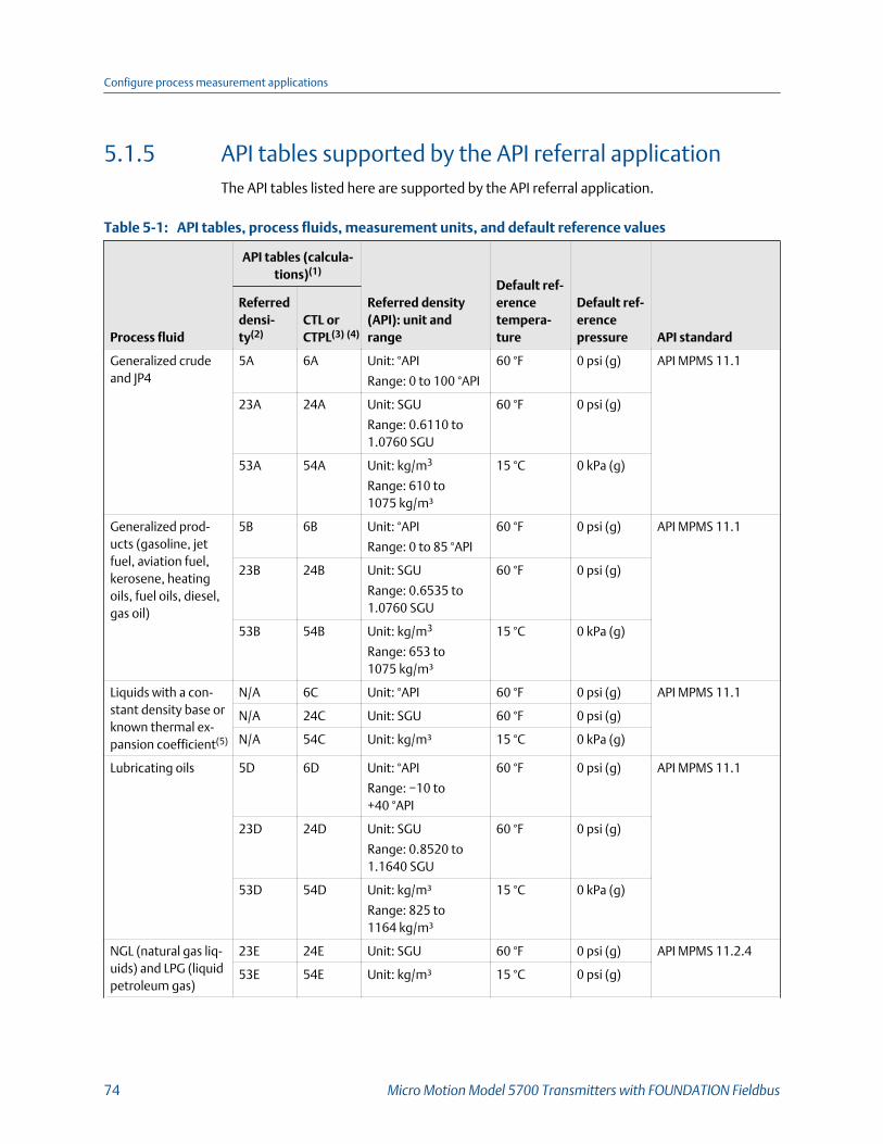
5.1.5 API tables supported by the API referral applicationThe API tables listed here are supported by the API referral application.
API tables, process fluids, measurement units, and default reference valuesTable 5-1:
Process fluid
API tables (calcula-tions)(1)
Referred density(API): unit andrange
Default ref-erencetempera-ture
Default ref-erencepressure API standard
Referreddensi-ty(2)
CTL orCTPL(3) (4)
Generalized crudeand JP4
5A 6A Unit: °API
Range: 0 to 100 °API
60 °F 0 psi (g) API MPMS 11.1
23A 24A Unit: SGU
Range: 0.6110 to1.0760 SGU
60 °F 0 psi (g)
53A 54A Unit: kg/m3
Range: 610 to1075 kg/m³
15 °C 0 kPa (g)
Generalized prod-ucts (gasoline, jetfuel, aviation fuel,kerosene, heatingoils, fuel oils, diesel,gas oil)
5B 6B Unit: °API
Range: 0 to 85 °API
60 °F 0 psi (g) API MPMS 11.1
23B 24B Unit: SGU
Range: 0.6535 to1.0760 SGU
60 °F 0 psi (g)
53B 54B Unit: kg/m3
Range: 653 to1075 kg/m³
15 °C 0 kPa (g)
Liquids with a con-stant density base orknown thermal ex-pansion coefficient(5)
N/A 6C Unit: °API 60 °F 0 psi (g) API MPMS 11.1
N/A 24C Unit: SGU 60 °F 0 psi (g)
N/A 54C Unit: kg/m³ 15 °C 0 kPa (g)
Lubricating oils 5D 6D Unit: °API
Range: −10 to+40 °API
60 °F 0 psi (g) API MPMS 11.1
23D 24D Unit: SGU
Range: 0.8520 to1.1640 SGU
60 °F 0 psi (g)
53D 54D Unit: kg/m³
Range: 825 to1164 kg/m³
15 °C 0 kPa (g)
NGL (natural gas liq-uids) and LPG (liquidpetroleum gas)
23E 24E Unit: SGU 60 °F 0 psi (g) API MPMS 11.2.4
53E 54E Unit: kg/m³ 15 °C 0 psi (g)
Configure process measurement applications
74 Micro Motion Model 5700 Transmitters with FOUNDATION Fieldbus

API tables, process fluids, measurement units, and default reference values (continued)Table 5-1:
Process fluid
API tables (calcula-tions)(1)
Referred density(API): unit andrange
Default ref-erencetempera-ture
Default ref-erencepressure API standard
Referreddensi-ty(2)
CTL orCTPL(3) (4)
59E 60E Unit: kg/m³ 20 °C 0 psi (g)
(1) Each API table represents a specialized equation defined by the American Petroleum Institute for a specific combination of processfluid, line conditions, and output.
(2) Referred density is calculated from line density. You must specify this table, either directly or by selecting the process fluid and basedensity measurement unit.
(3) You do not need to specify this table. It is invoked automatically as a result of the previous table selection.
(4) CTL or CTPL is calculated from the result of the referred density calculation. A, B, C, and D tables calculate CTPL, which is a correctionfactor based on both line pressure and line temperature. E tables calculate CTL, which is a correction factor based on line temperatureand pressure at saturation conditions (bubble point or saturation vapor pressure).
(5) The Thermal Expansion Coefficient (TEC) replaces the referred density calculation. Use the CTL/CTPL table instead.
5.1.6 Process variables from the API referral applicationThe API referral application calculates several different process variables according to APIstandards.
CTPL Correction factor based on line temperature and line pressure. CTPLis applied when the API referral application is configured for an A, B,C, or D table.
CTL Correction factor based on line temperature and pressure atsaturation conditions. CTL is applied when the API referralapplication is configured for an E table.
Referred density The measured density after CTL or CTPL has been applied.
API volume flow The measured volume flow rate after CTL or CTPL has been applied.Also called temperature‐corrected volume flow.
Batch-weightedaverage density
One density value is recorded for each unit of flow (e.g., barrel, liter).The average is calculated from these values. The average is resetwhen the API totalizer is reset. Not available unless a totalizer hasbeen configured with Source set to Temperature-Corrected Volume Flow.
Batch-weightedaveragetemperature
One temperature value is recorded for each unit of flow (e.g., barrel,liter). The average is calculated from these values. The average isreset when the API totalizer is reset. Not available unless a totalizerhas been configured with Source set to Temperature-Corrected VolumeFlow.
API volume total The total API volume measured by the transmitter since the last APItotalizer reset. Also called temperature‐corrected volume total. Notavailable unless a totalizer has been configured with Source set toTemperature-Corrected Volume Flow.
Configure process measurement applications
Configuration and Use Manual 75
API volumeinventory
The total API volume measured by the transmitter since the last APIinventory reset. Also called temperature‐corrected volume inventory.Not available unless an inventory has been configured with Sourceset to Temperature-Corrected Volume Flow.
5.2 Set up concentration measurementThe concentration measurement application calculates concentration from line densityand line temperature.
• Preparing to set up concentration measurement (Section 5.2.1)• Set up concentration measurement using the display (Section 5.2.2)• Set up concentration measurement using ProLink III (Section 5.2.3)• Set up concentration measurement using an enhanced FF host (Section 5.2.4)• Set up concentration measurement using a basic FF host (Section 5.2.5)
5.2.1 Preparing to set up concentration measurementThe procedure for setting up concentration measurement application depends on howyour device was ordered and how you want to use the application. Review this informationbefore you begin.
Requirements for concentration measurement
To use the concentration measurement application, the following conditions must be met:
• The concentration measurement application must be enabled.
• The API Referral application must be disabled.
• The advanced phase measurement application must be disabled.
• A concentration matrix must be loaded into one of the six slots on the transmitter.
TipIn most cases, the concentration matrix that you ordered was loaded at the factory. If it wasnot, you have several options for loading a matrix. You can also build a matrix.
• Temperature Source must be configured and set up.
• One matrix must be selected as the active matrix (the matrix used formeasurement).
Requirements for matrices
A matrix is the set of coefficients used to convert process data to concentration, plusrelated parameters. The matrix can be saved as a file.
The transmitter requires all matrices to be in .matrix format. You can use ProLink III to loadmatrices in other formats:
• .edf (used by ProLink II)
Configure process measurement applications
76 Micro Motion Model 5700 Transmitters with FOUNDATION Fieldbus

• .xml (used by ProLink III)
The transmitter can store matrices in two locations:
• One of the six slots in memory
• The transmitter's SD card
Any matrix in a slot is available for use. In other words, it can be selected as the activematrix and used for measurement. Matrices on the SD card are not available for use. Theymust be loaded into a slot before they can be used for measurement.
All matrices in slots must use the same derived variable. Matrices on the SD card have norequirement for their derived variables to match.
See the following table for the different ways that you can load matrices.
Requirements for derived variables
A derived variable is the process variable that a concentration matrix measures. All otherprocess variables are calculated from the derived variable. There are eight possible derivedvariables. Each matrix is designed for one specific derived variable.
The transmitter can store up to six matrices in six slots, and additional matrices on thetransmitter's SD card. All matrices in the six slots must use the same derived variable. If youchange the setting of Derived Variable, all matrices are deleted from the six slots. Anymatrices on the transmitter's SD card are not affected.
TipAlways ensure that Derived Variable is set correctly before loading matrices into slots.
Derived variables and net flow rate
If you want the transmitter to calculate Net Mass Flow Rate, the derived variable must beset to Mass Concentration (Density). If your matrix is not designed for Mass Concentration(Density), contact Micro Motion for assistance.
If you want the transmitter to calculate Net Volume Flow Rate, the derived variable mustbe set to Volume Concentration (Density). If your matrix is not designed for Volume Concentration(Density), contact Micro Motion for assistance.
Derived variables based on specific gravity
The following derived variables are based on specific gravity:
• Specific Gravity
• Concentration (Specific Gravity)
• Mass Concentration (Specific Gravity)
• Volume Concentration (Specific Gravity)
If you are using one of these derived variables, two additional parameters can beconfigured:
• Reference Temperature of Water (default setting: 4 °C)
Configure process measurement applications
Configuration and Use Manual 77

• Water Density at Reference Temperature(default setting: 999.99988 kg/m³)
These two parameters are used to calculate specific gravity.
You cannot set these parameters from the display. If the default values are notappropriate, you must use another method to set them.
Optional tasks in setting up concentration measurement
The following tasks are optional:
• Modifying names and labels
• Configuring extrapolation alerts
5.2.2 Set up concentration measurement using the displayThis section guides you through most of the tasks related to setting up and implementingthe concentration measurement application.
RestrictionThis section does not cover building a concentration matrix. See Micro Motion Enhanced DensityApplication: Theory, Configuration, and Use for detailed information on building a matrix.
• Enable the concentration measurement application using the display• Load a concentration matrix from a USB drive using the display• Load a concentration matrix from the SD card using the display• Set up temperature data for concentration measurement using the display• Modify matrix names and labels using the display• Modify extrapolation alerts for concentration measurement using the display• Select the active concentration matrix using the display
Enable the concentration measurement application usingthe displayThe concentration measurement application must be enabled before you can perform anysetup. If the concentration measurement application was enabled at the factory, you donot need to enable it now.
Prerequisites
The concentration measurement application must be licensed on your transmitter.
Procedure
1. Choose Menu > Configuration > Process Measurement.
2. Choose Flow Variables > Volume Flow Settings and ensure that Flow Type is set toLiquid.
3. Return to the Process Measurement menu.
4. If the API referral application is displayed in the menu, choose API Referral andensure that Enabled/Disabled is set to Disabled.
Configure process measurement applications
78 Micro Motion Model 5700 Transmitters with FOUNDATION Fieldbus
The concentration measurement application and the API referral application cannotbe enabled simultaneously.
5. If the advanced phase measurement application is displayed in the menu, chooseAdvanced Phase Measurement > Application Setup and ensure that Enabled/Disabled is set to Disabled.
The concentration measurement application and the advanced phase measurementapplication cannot be enabled simultaneously.
6. Enable concentration measurement.
a. Choose Menu > Configuration > Process Measurement > ConcentrationMeasurement.
b. Set Enabled/Disabled to Enabled.
Load a concentration matrix from a USB drive using thedisplayAt least one concentration matrix must be loaded into one of the six slots on yourtransmitter. You can load up to six matrices into slots. You can also copy matrices to thetransmitter's SD card, and load them into slots at a later time.
TipIn many cases, concentration matrices were ordered with the device and loaded at the factory. Youmay not need to load any matrices.
WARNING!
If the transmitter is in a hazardous area, do not use this method to load matrices. This methodrequires opening the transmitter's wiring compartment while the transmitter is powered up,and this can cause an explosion. If the transmitter is in a hazardous area, you must use anothermethod to load matrices.
Prerequisites
The concentration measurement application must be enabled on your device.
For each concentration matrix that you want to load, you need a file containing the matrixdata. The transmitter's SD card and the ProLink III installation include a set of standardconcentration matrices. Other matrices are available from Micro Motion.
Each concentration matrix file must be in .matrix format.
Tips
• If you have a custom matrix on another device, you can save it to a file, then load it to thecurrent device.
• If you have a matrix file in a different format, you can load it using ProLink III.
The .matrix files must be copied to the root directory of a USB drive.
Configure process measurement applications
Configuration and Use Manual 79
You must know the derived variable that the matrix is designed to calculate.
Important
• All concentration matrices on your transmitter must use the same derived variable.
• If you change the setting of Derived Variable, all existing concentration matrices will bedeleted from the six slots on the transmitter, but not from the SD card. Set Derived Variablebefore loading concentration matrices.
Procedure
1. Choose Menu > Configuration > Process Measurement > ConcentrationMeasurement > Configure Application and ensure that the setting of DerivedVariable matches the derived variable used by your matrix. If it does not, change itas required and click Apply.
ImportantIf you change the setting of Derived Variable, all existing concentration matrices will bedeleted from the six slots, but not from the transmitter's SD card. Verify the setting of DerivedVariable before continuing.
2. Load the matrix.
a. Remove the cover from the transmitter's wiring compartment, open the snapflap to access the service port, and insert the USB drive into the service port.
b. Choose Menu > USB Options > USB Drive --> Transmitter > Upload ConfigurationFile.
c. Set Config File Type to Concentration Measurement Matrix.
d. Select the .matrix file that you want to load, and wait for the transfer tocomplete.
3. Choose Yes or No when you are asked if you want to apply the settings.
The transmitter has six slots that are used to store concentration matrices. Any oneof these can be used for measurement. The transmitter also has the capability tostore multiple concentration matrices on its SD card. These cannot be used formeasurement until they are moved to a slot.
Option Description
Yes The matrix is saved to the SD card, and the loading process continues with loadingthe matrix into one of the slots.
No The matrix is saved to the SD card, and the loading process ends. You must load amatrix into a slot before you can use it for measurement.
4. If you chose Yes, select the slot to load this matrix into, and wait until the load iscomplete.
You can load the matrix into any empty slot, or you can overwrite an existing matrix.
Configure process measurement applications
80 Micro Motion Model 5700 Transmitters with FOUNDATION Fieldbus

Postrequisites
If you loaded the matrix into a slot, choose Menu > Configuration > Process Measurement> Concentration Measurement > Configure Application > Active Matrix and ensure that thematrix is listed.
If you loaded the matrix onto the SD card only, choose Menu > Configuration > ProcessMeasurement > Concentration Measurement > Load Matrix and ensure that the matrix islisted.
Load a concentration matrix from the SD card using thedisplayIf you have a concentration matrix on the transmitter's SD card, you can load it into one ofthe six slots on your transmitter. You cannot use the matrix for measurement until it hasbeen loaded into a slot. You can load up to six matrices into slots.
Prerequisites
You must have one or more concentration matrices stored on the transmitter's SD card.The standard matrices are loaded to the SD card at the factory.
You must know the derived variable that the matrix is designed to calculate.
Procedure
1. Choose Menu > Configuration > Process Measurement > ConcentrationMeasurement and ensure that the setting of Derived Variable matches the derivedvariable used by your matrix. If it does not, change it as required and click Apply.
ImportantIf you change the setting of Derived Variable, all existing concentration matrices will bedeleted from the six slots, but not from the transmitter's SD card. Verify the setting of DerivedVariable before continuing.
2. Choose Menu > Configuration > Process Measurement > ConcentrationMeasurement > Load Matrix.
The transmitter displays a list of all matrices that are on the SD card.
3. Select the matrix that you want to load.
4. Select the slot that you want to load it into.
You can load the matrix into any empty slot, or you can overwrite an existing matrix.
Postrequisites
Choose Menu > Configuration > Process Measurement > Concentration Measurement >Configure Application > Active Matrix and ensure that the matrix is listed.
Configure process measurement applications
Configuration and Use Manual 81

Set up temperature data for concentration measurementusing the displayThe concentration measurement application uses line temperature data in its calculations.You must decide how to provide this data, then perform the required configuration andsetup. Temperature data from the on-board temperature sensor (RTD) is always available.You can set up an external temperature device and use external temperature data if youwant to.
The temperature setup that you establish here will be used for all concentrationmeasurement matrices on this meter.
ImportantLine temperature data is used in several different measurements and calculations. It is possible touse the internal RTD temperature in some areas and an external temperature in others. Thetransmitter stores the internal RTD temperature and the external temperature separately. However,the transmitter stores only one alternate temperature value, which may be either the externaltemperature or the configured fixed value. Accordingly, if you choose a fixed temperature for someuses, and an external temperature for others, the external temperature will overwrite the fixed value
Procedure
Choose the method to be used to supply temperature data, and perform the requiredsetup.
Method Description Setup
Internaltemperature
Temperature data from the on-board temperature sensor(RTD) will be used for all meas-urements and calculations. Noexternal temperature data willbe available.
a. Choose Menu > Configuration > Process Measurement >Temperature .
b. Set External Temperature to Off.
Digitalcommunications
A host writes temperature datato the meter at appropriate in-tervals. This data will be availa-ble in addition to the internaltemperature data.
a. Choose Menu > Configuration > Process Measurement >Temperature .
b. Set External Temperature to On.c. Perform the necessary host programming and communica-
tions setup to write temperature data to the transmitter atappropriate intervals.
Postrequisites
Choose Menu > Service Tools > Service Data > View Process Variables and verify the valuefor External Temperature.
Need help? If the value is not correct:
• Ensure that the external device and the meter are using the same measurement unit.
• For digital communications:
- Verify that the host has access to the required data.
Configure process measurement applications
82 Micro Motion Model 5700 Transmitters with FOUNDATION Fieldbus

- Verify that the output variable is being correctly received and processed by thetransmitter.
Modify matrix names and labels using the displayFor convenience, you can change the name of a concentration matrix and the label usedfor its measurement unit. This does not affect measurement.
1. Choose Menu > Configuration > Process Measurement > ConcentrationMeasurement > Configure Matrix.
2. Select the matrix that you want to modify.
3. Set Matrix Name to the name that will be used for this matrix.
4. Set Concentration Unit to the label that will be used for the concentration unit.
If you want to use a custom label, you can use the display to select Special. However,you cannot use the display to configure the custom label. You must use another toolto change the label from Special to a user-defined string.
Modify extrapolation alerts for concentration measurementusing the displayYou can enable and disable extrapolation alerts, and set extrapolation alert limits. Theseparameters control the behavior of the concentration measurement application but donot affect measurement directly.
Each concentration matrix is built for a specific density range and a specific temperaturerange. If line density or line temperature goes outside the range, the transmitter willextrapolate concentration values. However, extrapolation may affect accuracy.Extrapolation alerts are used to notify the operator that extrapolation is occurring.
Each concentration matrix has its own extrapolation alert limits.
Procedure
1. Choose Menu > Configuration > Process Measurement > ConcentrationMeasurement > Configure Matrix.
2. Select the matrix that you want to modify.
3. Set Extrapolation Limit to the point, in percent, at which an extrapolation alert willbe posted.
4. Choose Menu > Configuration > Process Measurement > ConcentrationMeasurement > Configure Application > Extrapolation Alerts.
5. Enable or disable the high and low limit alerts for temperature and density asdesired.
Example: Extrapolation alerts in action
If Extrapolation Limit is set to 5%, High Limit (Temp) is enabled, and the active matrix isbuilt for a temperature range of 40 °F to 80 °F, a high-temperature extrapolation alert willbe posted if line temperature goes above 82 °F.
Configure process measurement applications
Configuration and Use Manual 83
Select the active concentration matrix using the displayYou must select the concentration matrix to be used for measurement. Although thetransmitter can store up to six concentration matrices, only one matrix can be used formeasurement at any one time.
1. Choose Menu > Configuration > Process Measurement > ConcentrationMeasurement > Configure Application.
2. Set Active Matrix to the matrix you want to use.
5.2.3 Set up concentration measurement using ProLink IIIThis section guides you through the tasks required to set up, configure, and implementconcentration measurement.
• Enable the concentration measurement application using ProLink III• Load a concentration matrix using ProLink III• Set reference temperature values for specific gravity using ProLink III• Set up temperature data for concentration measurement using ProLink III• Modify matrix names and labels using ProLink III• Modify extrapolation alerts for concentration measurement using ProLink III• Select the active concentration matrix using ProLink III
Enable the concentration measurement application usingProLink IIIThe concentration measurement application must be enabled before you can perform anysetup. If the concentration measurement application was enabled at the factory, you donot need to enable it now.
Prerequisites
• The concentration measurement application must be licensed on your transmitter.
• The concentration measurement application cannot be enabled at the same time asthe API referral application or the Advanced Phase Measurement application. Theymust be disabled first.
Procedure
1. Choose Device Tools > Configuration > Process Measurement > Flow and ensure thatVolume Flow Type is set to Liquid Volume.
2. Choose Device Tools > Configuration > Transmitter Options.
3. Set Concentration Measurement to Enabled and click Apply.
Load a concentration matrix using ProLink IIIAt least one concentration matrix must be loaded onto your transmitter. You can load upto six.
Configure process measurement applications
84 Micro Motion Model 5700 Transmitters with FOUNDATION Fieldbus
TipIn many cases, concentration matrices were ordered with the device and loaded at the factory. Youmay not need to load any matrices.
RestrictionYou cannot use ProLink III to load a matrix to the transmitter's SD card. ProLink III loads matricesdirectly to one of the transmitter's six slots.
Prerequisites
The concentration measurement application must be enabled on your device.
For each concentration matrix that you want to load, you need a file containing the matrixdata. The ProLink III installation includes a set of standard concentration matrices. Othermatrices are available from Micro Motion. The file can be on your computer or in thetransmitter's internal memory.
The file must be in one of the formats that ProLink III supports. This includes:
• .xml (ProLink III)
• .matrix (Model 5700)
If you are loading an .xml file, you must know the following information for your matrix:
• The derived variable that the matrix is designed to calculate
• The density unit that the matrix was built with
• The temperature unit that the matrix was built with
If you are loading a .matrix file, you must know the derived variable that the matrix isdesigned to calculate.
Important
• All concentration matrices on your transmitter must use the same derived variable.
• If you change the setting of Derived Variable, all existing concentration matrices will bedeleted from the six slots on the transmitter, but not from the transmitter's SD card. SetDerived Variable before loading concentration matrices.
Procedure
1. If you are loading an .xml file, choose Device Tools > Configuration > ProcessMeasurement > Line Density and set Density Unit to the density unit used by yourmatrix.
ImportantWhen you load a matrix in one of these formats, if the density unit is not correct,concentration data will be incorrect. The density units must match at the time of loading. Youcan change the density unit after the matrix is loaded.
Configure process measurement applications
Configuration and Use Manual 85
2. If you are loading an .xml file, choose Device Tools > Configuration > ProcessMeasurement > Line Temperatureand set Temperature Unit to the temperature unitused by your matrix.
ImportantWhen you load a matrix in one of these formats, if the temperature unit is not correct,concentration data will be incorrect. The temperature units must match at the time ofloading. You can change the temperature unit after the matrix is loaded.
3. Choose Device Tools > Configuration > Process Measurement > ConcentrationMeasurement.
The Concentration Measurement window is displayed. It is organized into steps thatallow you to perform several different setup and configuration tasks. For this task,you will not use all the steps.
4. In Step 1, ensure that the setting of Derived Variable matches the derived variableused by your matrix. If it does not, change it as required and click Apply.
ImportantIf you change the setting of Derived Variable, all existing concentration matrices will bedeleted from the six slots. Verify the setting of Derived Variable before continuing.
5. Load one or more matrices.
a. In Step 2, set Matrix Being Configured to the location (slot) to which the matrixwill be loaded.
b. To load a .xml file from your computer, click Load Matrix from File, navigate tothe file, and load it.
c. To load a .matrix file from your computer, click Load Matrix from My Computer,navigate to the file, and load it.
d. To load a .matrix file from the transmitter's internal memory, click Load Matrixfrom 5700 Device Memory, navigate to the file on the transmitter, and load it.
e. Repeat until all required matrices are loaded.
6. (Optional) If you loaded an .xml file, set the density and temperature units to theunits you want to use for measurement.
Set reference temperature values for specific gravity usingProLink IIIWhen Derived Variable is set to any option based on specific gravity, you must set thereference temperature for water, then verify the density of water at the configuredreference temperature. These values affect specific gravity measurement.
This requirement applies to the following derived variables:
• Specific Gravity
• Concentration (Specific Gravity)
Configure process measurement applications
86 Micro Motion Model 5700 Transmitters with FOUNDATION Fieldbus

• Mass Concentration (Specific Gravity)
• Volume Concentration (Specific Gravity)
Procedure
1. Choose Device Tools > Configuration > Process Measurement > ConcentrationMeasurement.
The Concentration Measurement window is displayed. It is organized into steps thatallow you to perform several different setup and configuration tasks. For this task,you will not use all the steps.
2. Scroll to Step 2, set Matrix Being Configured to the matrix you want to modify, andclick Change Matrix.
3. Scroll to Step 3, then perform the following actions:
a. Set Reference Temperature for Referred Density to the temperature to whichline density will be corrected for use in the specific gravity calculation.
b. Set Reference Temperature for Water to the water temperature that will be usedin the specific gravity calculation.
c. Set Water Density at Reference Temperature to the density of water at thespecified reference temperature.
The transmitter automatically calculates the density of water at the specifiedtemperature. The new value will be displayed the next time that transmittermemory is read. You can enter a different value if you want to.
4. Click the Apply button at the bottom of Step 3.
Set up temperature data for concentration measurementusing ProLink IIIThe concentration measurement application uses line temperature data in its calculations.You must decide how to provide this data, then perform the required configuration andsetup. Temperature data from the on-board temperature sensor (RTD) is always available.You can set up an external temperature device and use external temperature data if youwant to.
The temperature setup that you establish here will be used for all concentrationmeasurement matrices on this meter.
ImportantLine temperature data is used in several different measurements and calculations. It is possible touse the internal RTD temperature in some areas and an external temperature in others. Thetransmitter stores the internal RTD temperature and the external temperature separately. However,the transmitter stores only one alternate temperature value, which may be either the externaltemperature or the configured fixed value. Accordingly, if you choose a fixed temperature for someuses, and an external temperature for others, the external temperature will overwrite the fixed value
Configure process measurement applications
Configuration and Use Manual 87
Procedure
1. Choose Device Tools > Configuration > Process Measurement > ConcentrationMeasurement.
The Concentration Measurement window is displayed. It is organized into steps thatallow you to perform several different setup and configuration tasks. For this task,you will not use all the steps.
2. Scroll to Step 4.
3. Choose the method to be used to supply temperature data, and perform therequired setup.
Option Description Setup
Internaltemperature
Temperature data from the on-board temperature sensor(RTD) will be used for all meas-urements and calculations. Noexternal temperature data willbe available.
a. Set Line Temperature Source to Internal.b. Click Apply.
Digitalcommunications
A host writes temperature datato the meter at appropriate in-tervals. This data will be availa-ble in addition to the internalRTD temperature data.
a. Set Line Temperature Source to Fixed Value or Digital Communi-cations.
b. Click Apply.c. Perform the necessary host programming and communica-
tions setup to write temperature data to the meter at appro-priate intervals.
Postrequisites
If you are using external temperature data, verify the external temperature value displayedin the Inputs group on the ProLink III main window.
Need help? If the value is not correct:
• Ensure that the external device and the meter are using the same measurement unit.
• For digital communications:
- Verify that the host has access to the required data.
- Verify that the output variable is being correctly received and processed by thetransmitter.
Modify matrix names and labels using ProLink IIIFor convenience, you can change the name of a concentration matrix and the label usedfor its measurement unit. This does not affect measurement.
1. Choose Device Tools > Configuration > Process Measurement > ConcentrationMeasurement.
Configure process measurement applications
88 Micro Motion Model 5700 Transmitters with FOUNDATION Fieldbus
The Concentration Measurement window is displayed. It is organized into steps thatallow you to perform several different setup and configuration tasks. For this task,you will not use all the steps.
2. Scroll to Step 2, set Matrix Being Configured to the matrix you want to modify, andclick Change Matrix.
3. Scroll to Step 3, then perform the following actions:
a. Set Concentration Units Label to the label that will be used for the concentrationunit.
b. If you set Concentration Units Label to Special, enter the custom label in User-Defined Label.
c. In Matrix Name, enter the name to be used for the matrix.
4. Click the Apply button at the bottom of Step 3.
Modify extrapolation alerts for concentration measurementusing ProLink IIIYou can enable and disable extrapolation alerts, and set extrapolation alert limits. Theseparameters control the behavior of the concentration measurement application but donot affect measurement directly.
Each concentration matrix is built for a specific density range and a specific temperaturerange. If line density or line temperature goes outside the range, the transmitter willextrapolate concentration values. However, extrapolation may affect accuracy.Extrapolation alerts are used to notify the operator that extrapolation is occurring.
Each concentration matrix has its own extrapolation alert limits.
Procedure
1. Choose Device Tools > Configuration > Process Measurement > ConcentrationMeasurement.
The Concentration Measurement window is displayed. It is organized into steps thatallow you to perform several different setup and configuration tasks. For this task,you will not use all the steps.
2. Scroll to Step 2, set Matrix Being Configured to the matrix you want to modify, andclick Change Matrix.
3. Scroll to Step 4.
4. Set Extrapolation Alert Limit to the point, in percent, at which an extrapolation alertwill be posted.
5. Enable or disable the high and low limit alerts for temperature and density, asdesired, and click Apply.
Configure process measurement applications
Configuration and Use Manual 89
Example: Extrapolation alerts in action
If Extrapolation Limit is set to 5%, High Limit (Temp) is enabled, and the active matrix isbuilt for a temperature range of 40 °F to 80 °F, a high-temperature extrapolation alert willbe posted if line temperature goes above 82 °F.
Select the active concentration matrix using ProLink IIIYou must select the concentration matrix to be used for measurement. Although thetransmitter can store up to six concentration matrices, only one matrix can be used formeasurement at any one time.
1. Choose Device Tools > Configuration > Process Measurement > ConcentrationMeasurement.
2. Scroll to Step 2, set Active Matrix to the matrix you want to use and click ChangeMatrix.
5.2.4 Set up concentration measurement using an enhancedFF hostThis section guides you through most of the tasks related to setting up and implementingthe concentration measurement application.
• Enable the concentration measurement application using an enhanced FF host• Set reference temperature values for specific gravity using an enhanced FF host• Provide temperature data for concentration measurement using an enhanced FF host• Modify matrix names and labels using an enhanced FF host• Modify extrapolation alerts for concentration measurement using an enhanced FF host• Select the active concentration matrix using an enhanced FF host
Enable the concentration measurement application using anenhanced FF hostThe concentration measurement application must be enabled before you can perform anysetup. If the concentration measurement application was enabled at the factory, you donot need to enable it now.
Prerequisites
• The concentration measurement application must be licensed on your transmitter.
• The concentration measurement application cannot be enabled at the same time asthe API referral application or the Advanced Phase Measurement application. Theymust be disabled first.
Procedure
1. Choose Overview > Device Information > Licenses > Enable/Disable Applications andensure that Volume Flow Type is set to Liquid.
2. Choose Overview > Device Information > Licenses > Enable/Disable Applications.
3. Enable the concentration measurement application.
Configure process measurement applications
90 Micro Motion Model 5700 Transmitters with FOUNDATION Fieldbus

Set reference temperature values for specific gravity usingan enhanced FF hostWhen Derived Variable is set to any option based on specific gravity, you must set thereference temperature for water, then verify the density of water at the configuredreference temperature. These values affect specific gravity measurement.
To check the setting of Derived Variable, choose Configure > Manual Setup >Measurements > Optional Setup > Concentration Measurement > ConcentrationMeasurement Configuration.
ImportantDo not change the setting of Derived Variable. If you change the setting of Derived Variable, allexisting concentration matrices will be deleted from transmitter memory.
Procedure
1. Choose Configure > Manual Setup > Measurements > Optional Setup >Concentration Measurement > Matrix Configuration.
2. Set Matrix Being Configured to the matrix you want to modify.
3. Choose Reference Conditions, then perform the following actions:
a. Set Reference Temperature to the temperature to which line density will becorrected for use in the specific gravity calculation.
b. Set Water Reference Temperature to the water temperature that will be used inthe specific gravity calculation.
c. Set Water Reference Density to the density of water at the specified referencetemperature.
The transmitter automatically calculates the density of water at the specifiedtemperature. The new value will be displayed the next time that transmittermemory is read. You can enter a different value if you want to.
Provide temperature data for concentration measurementusing an enhanced FF hostThe concentration measurement application uses line temperature data in its calculations.You must decide how to provide this data, then perform the required configuration andsetup. Temperature data from the on-board temperature sensor (RTD) is always available.You can set up an external temperature device and use external temperature data if youwant to.
The temperature setup that you establish here will be used for all concentrationmeasurement matrices on this meter.
Procedure
Choose the method to be used to supply temperature data, and perform the requiredsetup.
Configure process measurement applications
Configuration and Use Manual 91

Method Description Setup
Internal RTDtemperaturedata
Temperature data from the on-board temperature sensor(RTD) is used.
a. Choose Configure > Manual Setup > Measurements > Op-tional Setup > External Variables .
b. Set Temperature Compensation to Disable.
Digitalcommunications
A host writes temperature datato the meter at appropriate in-tervals. This data will be availa-ble in addition to the internalRTD temperature data.
a. Choose Configure > Manual Setup > Measurements > Op-tional Setup > External Variables .
b. Set Temperature Compensation to Enable.c. Perform the necessary host programming and communica-
tions setup to write temperature data to the meter at appro-priate intervals.
Postrequisites
Choose Service Tools > Variables > Variable Summary > External Temperature and verifythe value for External Temperature.
Need help? If the value is not correct:
• Ensure that the external device and the meter are using the same measurement unit.
• For digital communications:
- Verify that the host has access to the required data.
- Verify that the output variable is being correctly received and processed by thetransmitter.
Modify matrix names and labels using an enhanced FF hostFor convenience, you can change the name of a concentration matrix and the label usedfor its measurement unit. This does not affect measurement.
1. Choose Configure > Manual Setup > Measurements > Optional Setup >Concentration Measurement > Matrix Configuration > Matrix Selection.
2. Set Matrix Being Configured to the matrix you want to modify.
3. Set Matrix Name to the name to be used for the matrix.
4. Choose Configure > Manual Setup > Measurements > Optional Setup >Concentration Measurement > Matrix Configuration > Concentration.
5. Set Concentration Unit to the label that will be used for the concentration unit.
6. If you set Concentration Unit to Special, choose Label and enter the custom label.
Modify extrapolation alerts for concentration measurementusing an enhanced FF hostYou can enable and disable extrapolation alerts, and set extrapolation alert limits. Theseparameters control the behavior of the concentration measurement application but donot affect measurement directly.
Configure process measurement applications
92 Micro Motion Model 5700 Transmitters with FOUNDATION Fieldbus
Each concentration matrix is built for a specific density range and a specific temperaturerange. If line density or line temperature goes outside the range, the transmitter willextrapolate concentration values. However, extrapolation may affect accuracy.Extrapolation alerts are used to notify the operator that extrapolation is occurring.
Each concentration matrix has its own extrapolation alert limits.
Procedure
1. Choose Configure > Manual Setup > Measurements > Optional Setup >Concentration Measurement > Matrix Configuration > Matrix Selection.
2. Set Matrix Being Configured to the matrix you want to modify.
3. Choose Configure > Manual Setup > Measurements > Optional Setup >Concentration Measurement > Matrix Configuration > Extrapolation.
4. Set Extrapolation Alert Limit to the point, in percent, at which an extrapolation alertwill be posted.
5. Choose Configure > Alert Setup > Concentration Measurement Alerts.
6. Enable or disable the high and low alerts for temperature and density, as desired.
Example: Extrapolation alerts in action
If Extrapolation Limit is set to 5%, High Limit (Temp) is enabled, and the active matrix isbuilt for a temperature range of 40 °F to 80 °F, a high-temperature extrapolation alert willbe posted if line temperature goes above 82 °F.
Select the active concentration matrix using an enhanced FFhostYou must select the concentration matrix to be used for measurement. Although thetransmitter can store up to six concentration matrices, only one matrix can be used formeasurement at any one time.
1. Choose Configure > Manual Setup > Measurements > Optional Setup >Concentration Measurement > Concentration Measurement.
2. Set Active Matrix to the matrix you want to use.
5.2.5 Set up concentration measurement using a basic FF hostThis section guides you through most of the tasks related to setting up and implementingthe concentration measurement application.
RestrictionThis section does not cover building a concentration matrix. See Micro Motion Enhanced DensityApplication: Theory, Configuration, and Use for detailed information on building a matrix.
• Enable the concentration measurement application using a basic FF host• Set reference temperature values for specific gravity using a basic FF host
Configure process measurement applications
Configuration and Use Manual 93
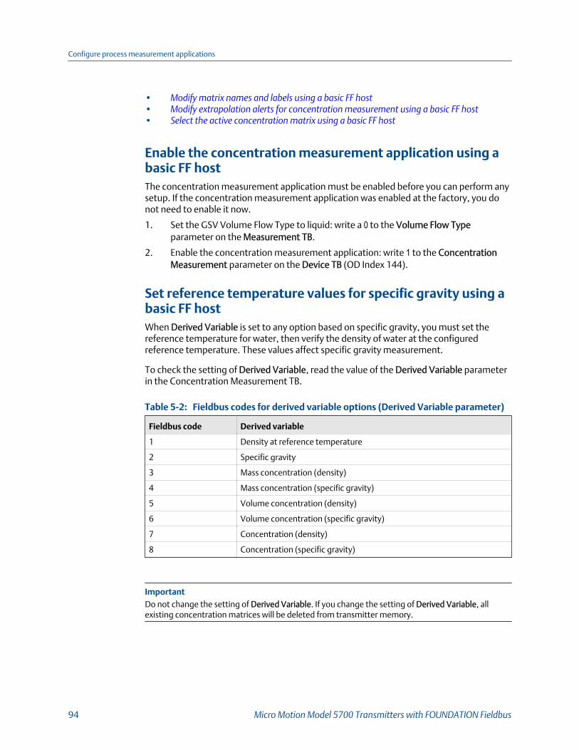
• Modify matrix names and labels using a basic FF host• Modify extrapolation alerts for concentration measurement using a basic FF host• Select the active concentration matrix using a basic FF host
Enable the concentration measurement application using abasic FF hostThe concentration measurement application must be enabled before you can perform anysetup. If the concentration measurement application was enabled at the factory, you donot need to enable it now.
1. Set the GSV Volume Flow Type to liquid: write a 0 to the Volume Flow Typeparameter on the Measurement TB.
2. Enable the concentration measurement application: write 1 to the ConcentrationMeasurement parameter on the Device TB (OD Index 144).
Set reference temperature values for specific gravity using abasic FF hostWhen Derived Variable is set to any option based on specific gravity, you must set thereference temperature for water, then verify the density of water at the configuredreference temperature. These values affect specific gravity measurement.
To check the setting of Derived Variable, read the value of the Derived Variable parameterin the Concentration Measurement TB.
Fieldbus codes for derived variable options (Derived Variable parameter)Table 5-2:
Fieldbus code Derived variable
1 Density at reference temperature
2 Specific gravity
3 Mass concentration (density)
4 Mass concentration (specific gravity)
5 Volume concentration (density)
6 Volume concentration (specific gravity)
7 Concentration (density)
8 Concentration (specific gravity)
ImportantDo not change the setting of Derived Variable. If you change the setting of Derived Variable, allexisting concentration matrices will be deleted from transmitter memory.
Configure process measurement applications
94 Micro Motion Model 5700 Transmitters with FOUNDATION Fieldbus

Procedure
Write the desired values into the appropriate parameters in the ConcentrationMeasurement TB for Reference Temperature, Water Reference Temperature, and WaterReference Density.
The transmitter automatically calculates the density of water at the specified temperature.The new value will be displayed the next time that transmitter memory is read. You canenter a different value if you want to.
Modify matrix names and labels using a basic FF hostFor convenience, you can change the name of a concentration matrix and the label usedfor its measurement unit. This does not affect measurement.
1. Choose the matrix you want to modify by writing to the Matrix Being Configuredparameter in the Concentration Measurement TB. Each saved matrix has a uniquevalue of 0 through 5.
2. Write the desired values into the Matrix Name and Concentration Unit parameters inthe Concentration Measurement TB.
Concentration unit codesTable 5-3:
Fieldbus code Unit
1110 degTwad
1426 degBrix
1111 degBaum hv
1112 degBaum It
1343 % sol/wt
1344 % sol/vol
1427 degBall
1428 proof/vol
1429 proof/mass
33004 deg plato
253 special
3. Write a value into the Special Concentration Unit Label parameter if ConcentrationUnit is set to code 253 (special).
Modify extrapolation alerts for concentration measurementusing a basic FF hostYou can enable and disable extrapolation alerts, and set extrapolation alert limits. Theseparameters control the behavior of the concentration measurement application but donot affect measurement directly.
Configure process measurement applications
Configuration and Use Manual 95

Each concentration matrix is built for a specific density range and a specific temperaturerange. If line density or line temperature goes outside the range, the transmitter willextrapolate concentration values. However, extrapolation may affect accuracy.Extrapolation alerts are used to notify the operator that extrapolation is occurring.
Each concentration matrix has its own extrapolation alert limits.
Procedure
1. Choose the matrix you want to configure using the Matrix Being Configuredparameter in the Concentration Measurement TB. Each saved matrix has a uniquevalue of 0 through 5.
2. Write the desired values into the appropriate parameters in the ConcentrationMeasurement TB.
Parameter name Description
Extrapolation Limit Extrapolation Alert Limit The point, in percent, at whichan extrapolation alert will be posted.
Density Low Enable low density extrapolation alarm (write 1 to ena-ble; 0 to disable).
Density High Enable high density extrapolation alarm (write 1 to en-able; 0 to disable).
Temperature Low Enable low temperature extrapolation alarm (write 1to enable; 0 to disable).
Temperature High Enable high temperature extrapolation alarm (write 1to enable; 0 to disable).
Example: Extrapolation alert in action
If the following conditions exist, the high temperature extrapolation alert will be postedwhen the line temperature exceeds 82 °F:
• The Extrapolation Alert Limit is set to 5%
• The high temperature alarm is enabled
• The active matrix is built for a temperature range of 40 °F to 80 °F
Select the active concentration matrix using a basic FF hostYou must select the concentration matrix to be used for measurement. Although thetransmitter can store up to six concentration matrices, only one matrix can be used formeasurement at any one time.
Choose the matrix you want to use by writing to the Matrix Being Configured parameter inthe Concentration Measurement TB. Each saved matrix has a unique value of 0 through 5.
Configure process measurement applications
96 Micro Motion Model 5700 Transmitters with FOUNDATION Fieldbus

6 Configure advanced options forprocess measurementTopics covered in this chapter:
• Configure Response Time
• Detect and report two‐phase flow
• Configure Flow Rate Switch
• Configure events
• Configure totalizers and inventories
• Configure logging for totalizers and inventories
• Configure Process Variable Fault Action
6.1 Configure Response Time
Display Menu > Configuration > Process Measurement > Response Time
ProLink III Device Tools > Configuration > Process Measurement > Response Time
Enhanced FF host Not available
Basic FF host Not available
Overview
Response Time controls the speed of various internal processes that are involved inretrieving electronic data from the sensor and converting it to process data.
Response Time affects all process and diagnostic variables.
RestrictionResponse Time is configurable only if you are using the enhanced core processor. If you are using thestandard core processor, Response Time is set to Low Filtering and cannot be changed.
Procedure
Set Response Time as desired.
Option Description
Normal Appropriate for typical applications.
High Filtering Slower response. Appropriate for applications with significant amount of entrainedgas or process noise.
Low Filtering Fastest response. Appropriate for proving or filling applications.
Configure advanced options for process measurement
Configuration and Use Manual 97

Option Description
Service Do not select unless directed by Micro Motion personnel.
6.2 Detect and report two-phase flowTwo-phase flow (gas in a liquid process or liquid in a gas process) can cause a variety ofprocess control issues. The transmitter provides two methods to detect and report orrespond to two-phase flow.
• Detect two‐phase flow using density (Section 6.2.1)• Detect two‐phase flow using sensor diagnostics (Section 6.2.2)
6.2.1 Detect two-phase flow using density
Display Menu > Configuration > Process Measurement > Density
ProLink III Device Tools > Configuration > Process Measurement > Density
Enhanced FF host Configure > Manual Setup > Measurements > Two-Phase Flow > Low Limit
Configure > Manual Setup > Measurements > Two-Phase Flow > High Limit
Configure > Manual Setup > Measurements > Two-Phase Flow > Duration
Basic FF host Measurement TB > Two Phase Flow Setup (OD Index 91–94)
Overview
The transmitter can use line density data to detect two-phase flow (gas in a liquid processor liquid in a gas process). The density limits are user-specified. When two-phase flow isdetected, an alert is posted.
Procedure
1. Set Two-Phase Flow Low Limit to the lowest density value that is considered normalin your process.
Values below this will cause the transmitter to post a Process Aberration alert.
TipGas entrainment can cause your process density to drop temporarily. To reduce theoccurrence of two-phase flow alerts that are not significant to your process, set Two-PhaseFlow Low Limit slightly below your expected lowest process density.
You must enter Two-Phase Flow Low Limit in g/cm³, even if you configured anotherunit for density measurement.
• Default: 0 g/cm³
• Range: 0 g/cm³ to the sensor limit
Configure advanced options for process measurement
98 Micro Motion Model 5700 Transmitters with FOUNDATION Fieldbus
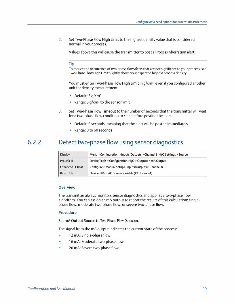
2. Set Two-Phase Flow High Limit to the highest density value that is considerednormal in your process.
Values above this will cause the transmitter to post a Process Aberration alert.
TipTo reduce the occurrence of two-phase flow alerts that are not significant to your process, setTwo-Phase Flow High Limit slightly above your expected highest process density.
You must enter Two-Phase Flow High Limit in g/cm³, even if you configured anotherunit for density measurement.
• Default: 5 g/cm³
• Range: 5 g/cm³ to the sensor limit
3. Set Two-Phase Flow Timeout to the number of seconds that the transmitter will waitfor a two-phase flow condition to clear before posting the alert.
• Default: 0 seconds, meaning that the alert will be posted immediately
• Range: 0 to 60 seconds
6.2.2 Detect two-phase flow using sensor diagnostics
Display Menu > Configuration > Inputs/Outputs > Channel B > I/O Settings > Source
ProLink III Device Tools > Configuration > I/O > Outputs > mA Output
Enhanced FF host Configure > Manual Setup > Inputs/Outputs > Channel B
Basic FF host Device TB > mAO Source Variable (OD Index 94)
Overview
The transmitter always monitors sensor diagnostics and applies a two-phase flowalgorithm. You can assign an mA output to report the results of this calculation: single-phase flow, moderate two-phase flow, or severe two-phase flow.
Procedure
Set mA Output Source to Two-Phase Flow Detection.
The signal from the mA output indicates the current state of the process:
• 12 mA: Single-phase flow
• 16 mA: Moderate two-phase flow
• 20 mA: Severe two-phase flow
Configure advanced options for process measurement
Configuration and Use Manual 99
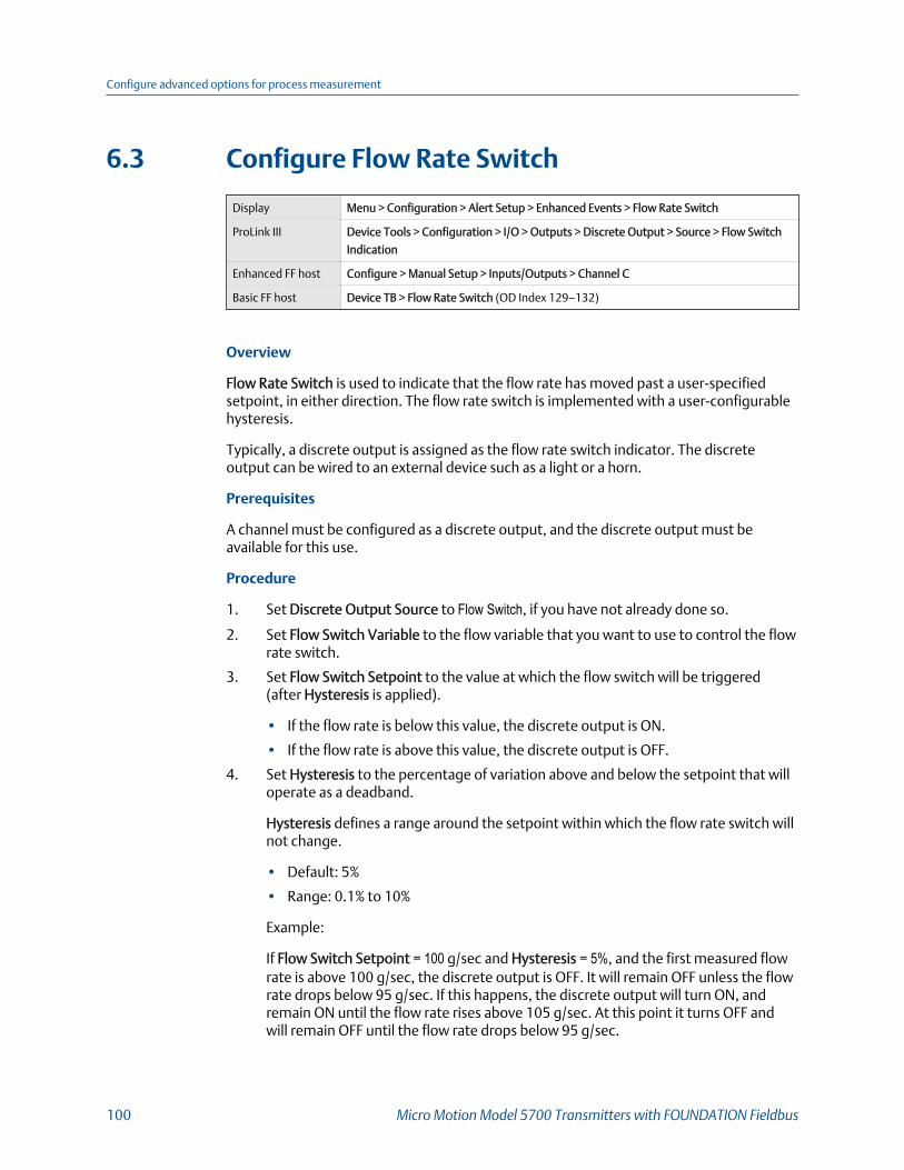
6.3 Configure Flow Rate Switch
Display Menu > Configuration > Alert Setup > Enhanced Events > Flow Rate Switch
ProLink III Device Tools > Configuration > I/O > Outputs > Discrete Output > Source > Flow Switch
Indication
Enhanced FF host Configure > Manual Setup > Inputs/Outputs > Channel C
Basic FF host Device TB > Flow Rate Switch (OD Index 129–132)
Overview
Flow Rate Switch is used to indicate that the flow rate has moved past a user-specifiedsetpoint, in either direction. The flow rate switch is implemented with a user-configurablehysteresis.
Typically, a discrete output is assigned as the flow rate switch indicator. The discreteoutput can be wired to an external device such as a light or a horn.
Prerequisites
A channel must be configured as a discrete output, and the discrete output must beavailable for this use.
Procedure
1. Set Discrete Output Source to Flow Switch, if you have not already done so.
2. Set Flow Switch Variable to the flow variable that you want to use to control the flowrate switch.
3. Set Flow Switch Setpoint to the value at which the flow switch will be triggered(after Hysteresis is applied).
• If the flow rate is below this value, the discrete output is ON.
• If the flow rate is above this value, the discrete output is OFF.
4. Set Hysteresis to the percentage of variation above and below the setpoint that willoperate as a deadband.
Hysteresis defines a range around the setpoint within which the flow rate switch willnot change.
• Default: 5%
• Range: 0.1% to 10%
Example:
If Flow Switch Setpoint = 100 g/sec and Hysteresis = 5%, and the first measured flowrate is above 100 g/sec, the discrete output is OFF. It will remain OFF unless the flowrate drops below 95 g/sec. If this happens, the discrete output will turn ON, andremain ON until the flow rate rises above 105 g/sec. At this point it turns OFF andwill remain OFF until the flow rate drops below 95 g/sec.
Configure advanced options for process measurement
100 Micro Motion Model 5700 Transmitters with FOUNDATION Fieldbus

Related information
Configure the discrete output
6.4 Configure eventsAn event occurs when the real-time value of a user-specified process variable moves past auser-defined setpoint. Events are used to provide notification of process changes or toperform specific transmitter actions if a process change occurs.
• Configure an enhanced event (Section 6.4.1)
6.4.1 Configure an enhanced event
Display Menu > Configuration > Alert Setup > Enhanced Events
ProLink III Device Tools > Configuration > Events > Enhanced Events
Enhanced FF host Configure > Manual Setup > Events > Configure Events
Basic FF host Device TB > Discrete Events (OD Index 153–159)
Overview
An enhanced event is used to provide notification of process changes and, optionally, toperform specific transmitter actions if the event occurs. An enhanced event occurs (is ON)if the real-time value of a user-specified process variable moves above (HI) or below (LO) auser-defined setpoint, or in range (IN) or out of range (OUT) with respect to two user-defined setpoints. Event status can be queried via digital communications, and a discreteoutput can be configured to report event status.
You can define up to five enhanced events. For each enhanced event, you can assign oneor more actions that the transmitter will perform if the enhanced event occurs.
Procedure
1. Select the event that you want to configure.
2. Assign a process variable to the event.
3. Specify Event Type.
Option Description
HI x > A
The event occurs when the value of the assigned process variable (x) isgreater than the setpoint (Setpoint A), endpoint not included.
LO x < A
The event occurs when the value of the assigned process variable (x) isless than the setpoint (Setpoint A), endpoint not included.
Configure advanced options for process measurement
Configuration and Use Manual 101
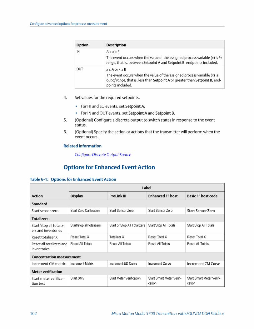
Option Description
IN A ≤ x ≤ B
The event occurs when the value of the assigned process variable (x) is inrange, that is, between Setpoint A and Setpoint B, endpoints included.
OUT x ≤ A or x ≥ B
The event occurs when the value of the assigned process variable (x) isout of range, that is, less than Setpoint A or greater than Setpoint B, end-points included.
4. Set values for the required setpoints.
• For HI and LO events, set Setpoint A.
• For IN and OUT events, set Setpoint A and Setpoint B.
5. (Optional) Configure a discrete output to switch states in response to the eventstatus.
6. (Optional) Specify the action or actions that the transmitter will perform when theevent occurs.
Related information
Configure Discrete Output Source
Options for Enhanced Event Action
Options for Enhanced Event Action Table 6-1:
Action
Label
Display ProLink III Enhanced FF host Basic FF host code
Standard
Start sensor zero Start Zero Calibration Start Sensor Zero Start Sensor Zero Start Sensor Zero
Totalizers
Start/stop all totaliz-ers and inventories
Start/stop all totalizers Start or Stop All Totalizers Start/Stop All Totals Start/Stop All Totals
Reset totalizer X Reset Total X Totalizer X Reset Total X Reset Total X
Reset all totalizers andinventories
Reset All Totals Reset All Totals Reset All Totals Reset All Totals
Concentration measurement
Increment CM matrix Increment Matrix Increment ED Curve Increment Curve Increment CM Curve
Meter verification
Start meter verifica-tion test
Start SMV Start Meter Verification Start Smart Meter Verifi-cation
Start Smart Meter Verifi-cation
Configure advanced options for process measurement
102 Micro Motion Model 5700 Transmitters with FOUNDATION Fieldbus

6.5 Configure totalizers and inventories
Display Menu > Configuration > Process Measurement > Totalizers & Inventories
ProLink III Device Tools > Totalizer Control > Totalizers
Enhanced FF host Configure > Manual Setup > Measurements > Optional Setup > Configure Totalizers/In-
ventories
Basic FF host Totalizers and Inventories TB
Overview
The transmitter provides seven configurable totalizers and seven configurable inventories.Each totalizer and each inventory can be configured independently.
Totalizers track the process since the last totalizer reset. Inventories track the process sincethe last inventory reset. Inventories are typically used to track the process across totalizerresets.
TipThe default configurations cover the most typical uses of totalizers and inventories. You may notneed to change any configurations.
Prerequisites
Before configuring the totalizers and inventories, ensure that the process variables youplan to track are available on the transmitter.
Procedure
1. Select the totalizer or inventory that you want to configure.
2. Set Totalizer Source or Inventory Source to the process variable that the totalizer orinventory will track.
Option Description
Mass flow The totalizer or inventory will track Mass Flow Rate and calculate totalmass since the last reset.
Volume flow The totalizer or inventory will track Volume Flow Rate and calculate to-tal volume since the last reset.
Gas standardvolume flow
The totalizer or inventory will track Gas Standard Volume Flow Rate andcalculate total volume since the last reset.
Temperature-cor-rected volumeflow
The totalizer or inventory will track Temperature-Corrected VolumeFlow Rate and calculate total volume since the last reset.
Standard volumeflow
The totalizer or inventory will track Standard Volume Flow Rate and cal-culate total volume since the last reset.
Configure advanced options for process measurement
Configuration and Use Manual 103
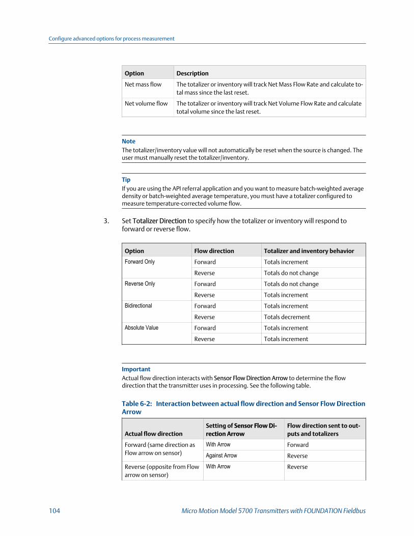
Option Description
Net mass flow The totalizer or inventory will track Net Mass Flow Rate and calculate to-tal mass since the last reset.
Net volume flow The totalizer or inventory will track Net Volume Flow Rate and calculatetotal volume since the last reset.
NoteThe totalizer/inventory value will not automatically be reset when the source is changed. Theuser must manually reset the totalizer/inventory.
TipIf you are using the API referral application and you want to measure batch-weighted averagedensity or batch-weighted average temperature, you must have a totalizer configured tomeasure temperature-corrected volume flow.
3. Set Totalizer Direction to specify how the totalizer or inventory will respond toforward or reverse flow.
Option Flow direction Totalizer and inventory behavior
Forward Only Forward Totals increment
Reverse Totals do not change
Reverse Only Forward Totals do not change
Reverse Totals increment
Bidirectional Forward Totals increment
Reverse Totals decrement
Absolute Value Forward Totals increment
Reverse Totals increment
ImportantActual flow direction interacts with Sensor Flow Direction Arrow to determine the flowdirection that the transmitter uses in processing. See the following table.
Interaction between actual flow direction and Sensor Flow DirectionArrow Table 6-2:
Actual flow directionSetting of Sensor Flow Di-rection Arrow
Flow direction sent to out-puts and totalizers
Forward (same direction asFlow arrow on sensor)
With Arrow Forward
Against Arrow Reverse
Reverse (opposite from Flowarrow on sensor)
With Arrow Reverse
Configure advanced options for process measurement
104 Micro Motion Model 5700 Transmitters with FOUNDATION Fieldbus

Interaction between actual flow direction and Sensor Flow DirectionArrow (continued)Table 6-2:
Actual flow directionSetting of Sensor Flow Di-rection Arrow
Flow direction sent to out-puts and totalizers
Against Arrow Forward
4. (Optional) Set User Name to the name you want to use for the inventory or totalizer.
User Name can have a maximum of 16 characters.
The transmitter automatically generates a name for each totalizer and inventory,based on its source, direction, and type.
Example:
• Totalizer Source=Mass Flow• Totalizer Direction=Forward Only• Totalizer name=Mass Fwd Total
Example:
• Inventory Source=Gas Standard Volume Flow• Inventory Direction=Bidirectional• Inventory name=GSV Bidir Inv
The specified name is used on the transmitter display and on all interfaces thatsupport it. If User Name contains only spaces, the transmitter-generated name isused. Not all interfaces support totalizer and inventory names.
Example: Checking for backflow
You suspect that there is a significant amount of backflow through the sensor. To collectdata, configure two totalizers as follows:
• Source=Mass Flow, Direction=Forward Only• Source=Mass Flow, Direction=Reverse Only
Reset both totalizers, allow them to run for an appropriate period, then look at the amountof reverse flow as a percentage of forward flow.
Example: Tracking three different process fluids
Three tanks are connected to a loading dock through a single meter. Each tank contains adifferent process fluid. You want to track each process fluid separately.
1. Set up three totalizers, one for each tank.
2. Name the totalizers Tank 1, Tank 2, and Tank 3.
3. Configure each totalizer as required for the corresponding process fluid.
Configure advanced options for process measurement
Configuration and Use Manual 105
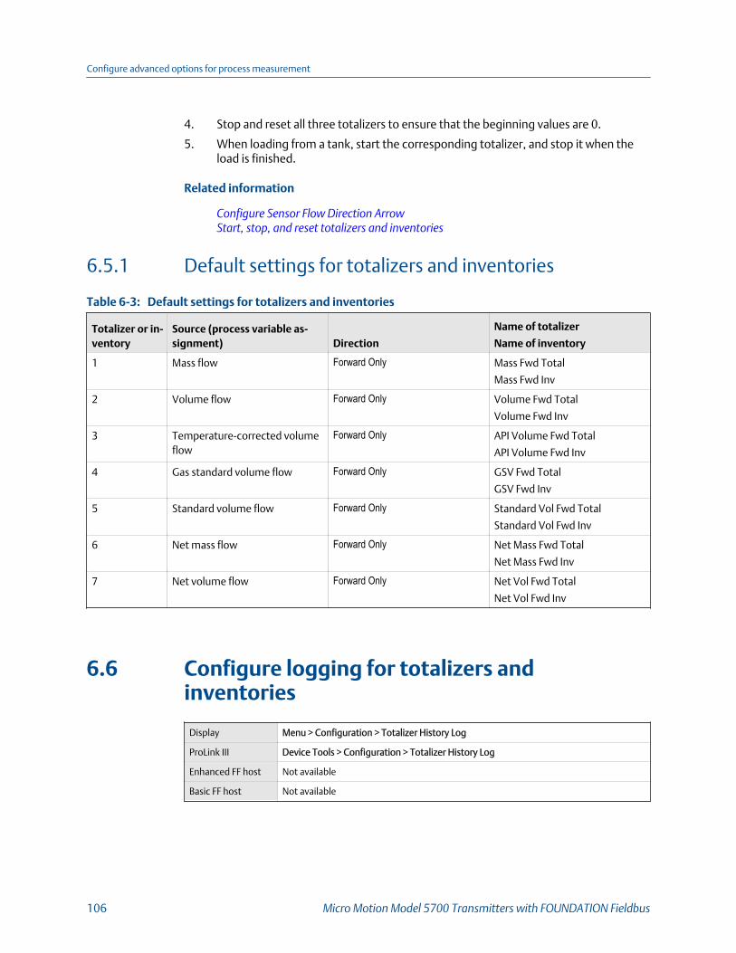
4. Stop and reset all three totalizers to ensure that the beginning values are 0.
5. When loading from a tank, start the corresponding totalizer, and stop it when theload is finished.
Related information
Configure Sensor Flow Direction ArrowStart, stop, and reset totalizers and inventories
6.5.1 Default settings for totalizers and inventories
Default settings for totalizers and inventoriesTable 6-3:
Totalizer or in-ventory
Source (process variable as-signment) Direction
Name of totalizer
Name of inventory
1 Mass flow Forward Only Mass Fwd Total
Mass Fwd Inv
2 Volume flow Forward Only Volume Fwd Total
Volume Fwd Inv
3 Temperature-corrected volumeflow
Forward Only API Volume Fwd Total
API Volume Fwd Inv
4 Gas standard volume flow Forward Only GSV Fwd Total
GSV Fwd Inv
5 Standard volume flow Forward Only Standard Vol Fwd Total
Standard Vol Fwd Inv
6 Net mass flow Forward Only Net Mass Fwd Total
Net Mass Fwd Inv
7 Net volume flow Forward Only Net Vol Fwd Total
Net Vol Fwd Inv
6.6 Configure logging for totalizers andinventories
Display Menu > Configuration > Totalizer History Log
ProLink III Device Tools > Configuration > Totalizer History Log
Enhanced FF host Not available
Basic FF host Not available
Configure advanced options for process measurement
106 Micro Motion Model 5700 Transmitters with FOUNDATION Fieldbus

Overview
The transmitter can write the current value of four totalizers or inventories to a log, atuser-specified intervals. You can generate a log file from this data for viewing and analysis.
Procedure
1. Specify the date on which totalizer logging will begin.
You must specify a future date. If you try to specify the current date, the transmitterwill reject the setting.
2. Specify the time at which totalizer logging will begin.
3. Specify the number of hours between records.
4. Select up to four totalizers or inventories to be logged.
Related information
Totalizer history and logGenerate history log files
6.7 Configure Process Variable Fault Action
Display Menu > Configuration > Alert Setup > Output Fault Actions
ProLink III Device Tools > Configuration > Fault Processing
Enhanced FF host Configure > Alert Setup > Output Fault Actions > Fault Setting
Basic FF host Device TB > Fault Limit (OD Index 47)
Overview
Process Variable Fault Action specifies the values that will be reported via the display anddigital communications if the device encounters a fault condition. The values are also sentto the outputs for processing against their configured fault actions.
Procedure
Set Process Variable Fault Action as desired.
• Default: None
RestrictionIf you set Process Variable Fault Action to NAN, you cannot set mA Output Fault Action or FrequencyOutput Fault Action to None. If you try to do this, the transmitter will not accept the configuration.
Configure advanced options for process measurement
Configuration and Use Manual 107

Important
• If you want the mA output to continue reporting process data during fault conditions, you mustset both Process Variable Fault Action and mA Output Fault Action to None. If mA Output FaultAction is set to None and Process Variable Fault Action is set to any other option, the mA outputwill produce the signal associated with the selection.
• If you want the frequency output to continue reporting process data during fault conditions, youmust set both Process Variable Fault Action and Frequency Output Fault Action to None. IfFrequency Output Fault Action is set to None and Process Variable Fault Action is set to any otheroption, the frequency output will produce the signal associated with the selection.
6.7.1 Options for Process Variable Fault Action
Options for Process Variable Fault Action Table 6-4:
Label
DescriptionDisplay ProLink III Fieldbus host
Upscale Upscale Upscale • Process variable values indicate that thevalue is greater than the upper sensor lim-it.
• Totalizers stop incrementing.
Downscale Downscale Downscale • Process variable values indicate that thevalue is lower than the lower sensor limit.
• Totalizers stop incrementing.
Zero Zero Zero • Flow rate variables go to the value thatrepresents a flow rate of 0 (zero).
• Density is reported as 0.
• Temperature is reported as 0 °C , or the
equivalent if other units are used (e.g.,32 °F .
• Drive gain is reported as measured.• Totalizers stop incrementing.
Not-a-Number (NAN) Not a Number NAN • Process variables are reported as IEEENAN.
• Drive gain is reported as measured.• Modbus scaled integers are reported as
Max Int.
• Totalizers stop incrementing.
Flow to Zero Flow to Zero Flow goes to zero • Flow rates are reported as 0.
• Other process variables are reported asmeasured.
• Totalizers stop incrementing.
None (default) None None • All process variables are reported as meas-ured.
• Totalizers increment if they are running.
Configure advanced options for process measurement
108 Micro Motion Model 5700 Transmitters with FOUNDATION Fieldbus

6.7.2 Interaction between Process Variable Fault Action andother fault actionsThe setting of Process Variable Fault Action affects the operation of the mA outputs,frequency outputs, and discrete outputs if the corresponding output fault actions are setto None.
Interaction between Process Variable Fault Action and mA Output Fault Action
If mA Output Fault Action is set to None, the mA output signal depends on the setting ofProcess Variable Fault Action.
If the device detects a fault condition:
1. Process Variable Fault Action is evaluated and applied.
2. mA Output Fault Action is evaluated.
• If it is set to None, the output reports the value associated with the setting ofProcess Variable Fault Action.
• If it is set to any other option, the output performs the specified fault action.
If you want the mA output to continue to report process data during fault conditions, youmust set both mA Output Fault Action and Process Variable Fault Action to None.
Interaction between Process Variable Fault Action and Frequency Output Fault Action
If Frequency Output Fault Action is set to None, the frequency output signal depends on thesetting of Process Variable Fault Action.
If the device detects a fault condition:
1. Process Variable Fault Action is evaluated and applied.
2. Frequency Output Fault Action is evaluated.
• If it is set to None, the output reports the value associated with the setting ofProcess Variable Fault Action.
• If it is set to any other option, the output performs the specified fault action.
If you want the frequency output to continue to report process data during faultconditions, you must set both Frequency Output Fault Action and Process Variable FaultAction to None.
Interaction between Process Variable Fault Action and Discrete Output Fault Action
If Discrete Output Fault Action is set to None and Discrete Output Source is set to Flow RateSwitch, the discrete output state during a fault depends on the setting of Process VariableFault Action.
If the device detects a fault condition:
1. Process Variable Fault Action is evaluated and applied.
2. Discrete Output Fault Action is evaluated.
Configure advanced options for process measurement
Configuration and Use Manual 109

• If it is set to None, and Discrete Output Source is set to Flow Rate Switch, thediscrete output will use the value determined by the current setting of ProcessVariable Fault Action to determine if a flow rate switch has occurred.
• If Discrete Output Source is set to any other option, the setting of ProcessVariable Fault Action is irrelevant to the behavior of the discrete output duringfault conditions. The discrete output is set to the specified fault action.
If you want the discrete output to report a flow rate switch appropriately during faultconditions, you must set both Discrete Output Fault Action and Process Variable FaultAction to None.
Related information
Configure mA Output Fault ActionConfigure Frequency Output Fault ActionConfigure Discrete Output Fault Action
Configure advanced options for process measurement
110 Micro Motion Model 5700 Transmitters with FOUNDATION Fieldbus

7 Configure device options andpreferencesTopics covered in this chapter:
• Configure the transmitter display
• Configure the transmitter's response to alerts
7.1 Configure the transmitter displayYou can control the language used on the display, the process variables shown on thedisplay, and a variety of display behaviors.
• Configure the language used on the display (Section 7.1.1)• Configure the process variables shown on the display (Section 7.1.2)• Configure the number of decimal places (precision) shown on the display
(Section 7.1.3)• Turn on and turn off automatic scrolling through the display variables (Section 7.1.4)• Configure the display backlight (Section 7.1.5)• Configure totalizer and inventory control from the display (Section 7.1.6)• Configure security for the display (Section 3.1.4) (Section 7.1.7)
7.1.1 Configure the language used on the display
Display Menu > Configuration > Display Settings > Language
ProLink III Device Tools > Configuration > Local Display Settings > Transmitter Display > General >
Language
Enhanced FF host Configure > Manual Setup > Display > Language
Basic FF host Device TB > Language (OD Index 61)
Overview
Language controls the language that the display uses for process data, menus, andinformation.
The languages available depend on your transmitter model and version.
Procedure
Set Language to the desired language.
Configure device options and preferences
Configuration and Use Manual 111
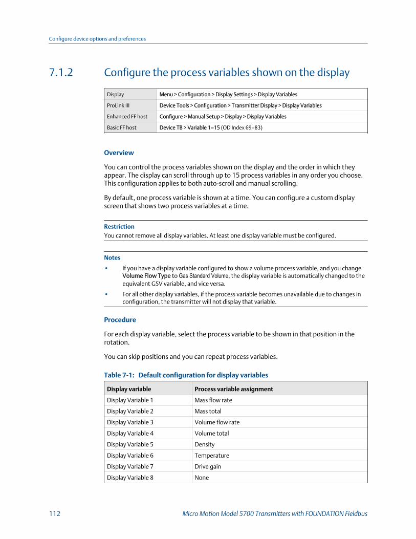
7.1.2 Configure the process variables shown on the display
Display Menu > Configuration > Display Settings > Display Variables
ProLink III Device Tools > Configuration > Transmitter Display > Display Variables
Enhanced FF host Configure > Manual Setup > Display > Display Variables
Basic FF host Device TB > Variable 1–15 (OD Index 69–83)
Overview
You can control the process variables shown on the display and the order in which theyappear. The display can scroll through up to 15 process variables in any order you choose.This configuration applies to both auto-scroll and manual scrolling.
By default, one process variable is shown at a time. You can configure a custom displayscreen that shows two process variables at a time.
RestrictionYou cannot remove all display variables. At least one display variable must be configured.
Notes
• If you have a display variable configured to show a volume process variable, and you changeVolume Flow Type to Gas Standard Volume, the display variable is automatically changed to theequivalent GSV variable, and vice versa.
• For all other display variables, if the process variable becomes unavailable due to changes inconfiguration, the transmitter will not display that variable.
Procedure
For each display variable, select the process variable to be shown in that position in therotation.
You can skip positions and you can repeat process variables.
Default configuration for display variablesTable 7-1:
Display variable Process variable assignment
Display Variable 1 Mass flow rate
Display Variable 2 Mass total
Display Variable 3 Volume flow rate
Display Variable 4 Volume total
Display Variable 5 Density
Display Variable 6 Temperature
Display Variable 7 Drive gain
Display Variable 8 None
Configure device options and preferences
112 Micro Motion Model 5700 Transmitters with FOUNDATION Fieldbus
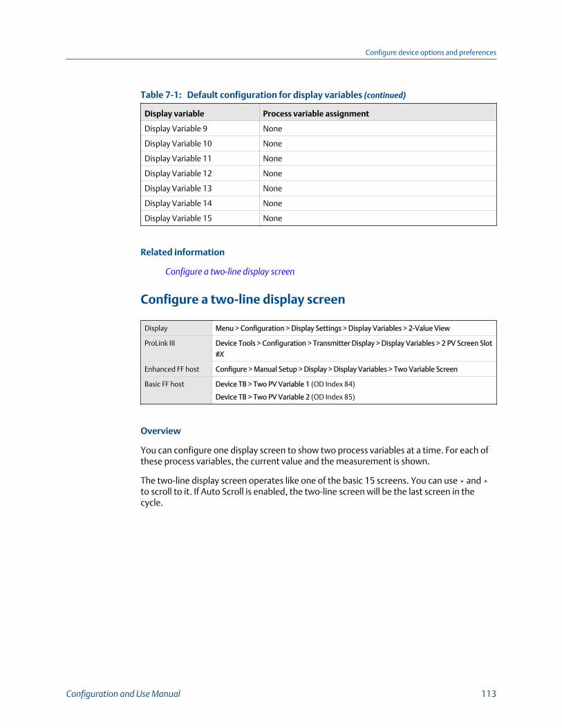
Default configuration for display variables (continued)Table 7-1:
Display variable Process variable assignment
Display Variable 9 None
Display Variable 10 None
Display Variable 11 None
Display Variable 12 None
Display Variable 13 None
Display Variable 14 None
Display Variable 15 None
Related information
Configure a two‐line display screen
Configure a two-line display screen
Display Menu > Configuration > Display Settings > Display Variables > 2-Value View
ProLink III Device Tools > Configuration > Transmitter Display > Display Variables > 2 PV Screen Slot
#X
Enhanced FF host Configure > Manual Setup > Display > Display Variables > Two Variable Screen
Basic FF host Device TB > Two PV Variable 1 (OD Index 84)
Device TB > Two PV Variable 2 (OD Index 85)
Overview
You can configure one display screen to show two process variables at a time. For each ofthese process variables, the current value and the measurement is shown.
The two-line display screen operates like one of the basic 15 screens. You can use ⌄ and ⌃to scroll to it. If Auto Scroll is enabled, the two-line screen will be the last screen in thecycle.
Configure device options and preferences
Configuration and Use Manual 113

7.1.3 Configure the number of decimal places (precision)shown on the display
Display Menu > Configuration > Display Settings > Decimals on Display
ProLink III Device Tools > Configuration > Transmitter Display > Display Variables > Decimal Places
for x
Enhanced FF host Configure > Manual Setup > Display > Decimal Places
Basic FF host Device TB > Process Variable (OD Index 86)
Device TB > Decimal Places (OD Index 87)
Overview
You can specify the precision (the number of decimal places) that the display uses for eachdisplay variable. You can set the precision independently for each display variable.
The display precision does not affect the actual value of the variable, the value used incalculations, or the value reported via outputs or digital communications.
Procedure
1. Select a process variable or a diagnostic variable.
You can configure the precision for all variables, whether or not they are assigned asdisplay variables. The configured precision will be stored and used when applicable.
2. Set Number of Decimal Places to the number of decimal places to be used when thisvariable is shown on the display.
• Default:
- Temperature variables: 2
- All other variables: 4
• Range: 0 to 5
TipThe lower the precision, the greater the change must be for it to be reflected on the display.Do not set Number of Decimal Places too low to be useful.
Configure device options and preferences
114 Micro Motion Model 5700 Transmitters with FOUNDATION Fieldbus
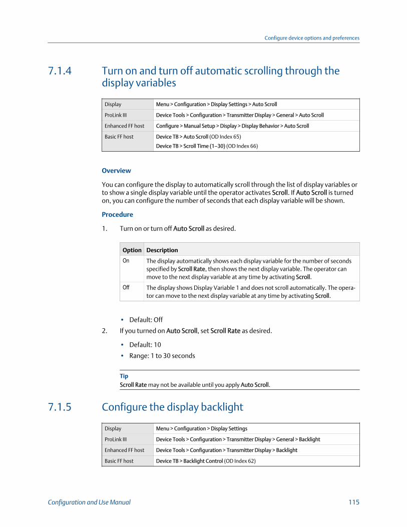
7.1.4 Turn on and turn off automatic scrolling through thedisplay variables
Display Menu > Configuration > Display Settings > Auto Scroll
ProLink III Device Tools > Configuration > Transmitter Display > General > Auto Scroll
Enhanced FF host Configure > Manual Setup > Display > Display Behavior > Auto Scroll
Basic FF host Device TB > Auto Scroll (OD Index 65)
Device TB > Scroll Time (1–30) (OD Index 66)
Overview
You can configure the display to automatically scroll through the list of display variables orto show a single display variable until the operator activates Scroll. If Auto Scroll is turnedon, you can configure the number of seconds that each display variable will be shown.
Procedure
1. Turn on or turn off Auto Scroll as desired.
Option Description
On The display automatically shows each display variable for the number of secondsspecified by Scroll Rate, then shows the next display variable. The operator canmove to the next display variable at any time by activating Scroll.
Off The display shows Display Variable 1 and does not scroll automatically. The opera-tor can move to the next display variable at any time by activating Scroll.
• Default: Off
2. If you turned on Auto Scroll, set Scroll Rate as desired.
• Default: 10
• Range: 1 to 30 seconds
TipScroll Rate may not be available until you apply Auto Scroll.
7.1.5 Configure the display backlight
Display Menu > Configuration > Display Settings
ProLink III Device Tools > Configuration > Transmitter Display > General > Backlight
Enhanced FF host Device Tools > Configuration > Transmitter Display > Backlight
Basic FF host Device TB > Backlight Control (OD Index 62)
Configure device options and preferences
Configuration and Use Manual 115

Overview
You can control the intensity and contrast of the backlight on the display's LCD panel.
Procedure
1. Set Intensity as desired.
• Default: 50
• Range: 0 to 100
2. Set Contrast as desired.
• Default: 50
• Range: 0 to 100
7.1.6 Configure totalizer and inventory control from thedisplay
Display Menu > Configuration > Security > Totalizer Reset
ProLink III Device Tools > Configuration > Totalizer Control Methods
Enhanced FF host Configure > Manual Setup > Display > Display Behavior
Basic FF host Device TB > Totalizer Reset (OD Index 63)
Device TB > Start/Stop Totalizers (OD Index 64)
Overview
You can enable or disable the operator's ability to start, stop, or reset totalizers orinventories from the display.
This parameter is applied to both totalizers and inventories.
This parameter does not affect the operator's ability to start, stop, or reset totalizers orinventories using another tool.
Procedure
1. Enable or disable Reset Totalizers, as desired.
2. Enable or disable Start/Stop Totalizers, as desired.
Configure device options and preferences
116 Micro Motion Model 5700 Transmitters with FOUNDATION Fieldbus

7.1.7 Configure security for the display
Display Menu > Configuration > Security > Configuration Security
ProLink III Device Tools > Configuration > Transmitter Display > Display Security
Enhanced FF host Configure > Manual Setup > Display > Display Menus
Basic FF host Device TB > Offline Menu Passcode Required (OD Index 67)
Device TB > Passcode (4 Digits alphanumeric) (OD Index 68)
Device TB > Alert Passcode (OD Index 89)
Overview
You can configure a display password, and require the operator to enter the password tomake any changes to configuration through the display, or to access alert data throughthe display.
The operator always has read-only access to the configuration menus.
Procedure
1. Enable or disable configuration security as desired.
Option Description
Enabled When an operator chooses an action that leads to a configuration change, theyare prompted to enter the display password.
Disabled When an operator chooses an action that leads to a configuration change, theyare prompted to activate ⇦⇧⇩⇨. This is designed to protect against accidentalchanges to configuration. It is not a security measure.
2. If you enabled configuration security, enable or disable alert security as desired.
Option Description
Enabled If an alert is active, the alert symbol ⓘ is shown in the upper right corner of thedisplay but the alert banner is not displayed. If the operator attempts to enter thealert menu, they are prompted to enter the display password.
Disabled If an alert is active, the alert symbol ⓘ is shown in the upper right corner of thedisplay and the alert banner is displayed automatically. No password or confirma-tion is required to enter the alert menu.
RestrictionYou cannot disable configuration security and enable alert security.
• If you did not enable configuration security, alert security is disabled and cannot beenabled.
• If both configuration security and alert security are enabled, and you disable configurationsecurity, alert security is disabled automatically.
Configure device options and preferences
Configuration and Use Manual 117
3. Set the display password to the desired value.
• Default: AAAA
• Range: Any four alphanumeric characters
ImportantIf you enable configuration security but you do not change the display password, thetransmitter will post a Configuration alert.
7.2 Configure the transmitter's response to alerts• Configure the transmitter's response to alerts using the display (Section 7.2.1)• Configure the transmitter's response to alerts using ProLink III (Section 7.2.2)• Configure Fault Timeout (Section 7.2.3)
7.2.1 Configure the transmitter's response to alerts using thedisplayFor some alerts, you can change the transmitter's response to an alert by setting the alertseverity. You can also configure the transmitter to ignore some alerts and conditions.
The transmitter implements the NAMUR NE 107 specification for alerts. NAMUR NE 107categorizes alerts by the suggested operator action, not by cause or symptom. Each alerthas one or more associated conditions.
ImportantThe transmitter reports all the process and device conditions that were reported by previoustransmitters. However, the transmitter does not report them as individual alerts. Instead, thetransmitter reports them as conditions associated with alerts.
Procedure
• To change the severity of an alert:
1. Choose Menu > Configuration > Alert Setup > Response to Alerts.
2. Select the alert.
3. Set Alert Severity as desired.
Option Description
Failure The event is serious enough to require fault actions by the transmitter. Theevent may be either device-related or process-related. Operator action isstrongly recommended.
Function Check Configuration change or device testing. No fault actions are performed. Theoperator may need to complete a procedure.
Configure device options and preferences
118 Micro Motion Model 5700 Transmitters with FOUNDATION Fieldbus

Option Description
Out ofSpecification
The process is outside user-specified limits or device limits. No fault actionsare performed. The operator should check the process.
MaintenanceRequired
Device maintenance is recommended, either near-term or mid-term.
• To ignore an alert:
1. Choose Menu > Configuration > Alert Setup > Response to Alerts
2. Select the alert.
3. Set Alert Detection to Ignore.
If an alert is ignored, any occurrence of this alert is not posted to the alert list and thestatus LED on the transmitter does not change color. The occurrence is posted toalert history.
• To ignore a condition:
1. Choose Menu > Configuration > Alert Setup > Response to Alerts
2. Select the alert associated with the condition.
3. Select Condition Detection.
4. Select the condition and set it to Ignore.
If a condition is ignored, any occurrence of this condition is not posted to the alertlist and the status LED on the transmitter does not change color. The occurrence isposted to alert history.
Related information
Alerts, conditions, and configuration options
7.2.2 Configure the transmitter's response to alerts usingProLink IIIFor some alerts, you can change the transmitter's response to an alert by setting the alertseverity. You can also configure the transmitter to ignore some alerts and conditions.
The transmitter implements the NAMUR NE 107 specification for alerts. NAMUR NE 107categorizes alerts by the suggested operator action, not by cause or symptom. Each alerthas one or more associated conditions.
ImportantThe transmitter reports all the process and device conditions that were reported by previoustransmitters. However, the transmitter does not report them as individual alerts. Instead, thetransmitter reports them as conditions associated with alerts.
Configure device options and preferences
Configuration and Use Manual 119

Procedure
• To change the severity of an alert:
1. Choose Device Tools > Configuration > Alert Severity.
2. Select the alert.
3. Set the severity as desired.
Option Description
Failure The event is serious enough to require fault actions by the transmitter. Theevent may be either device-related or process-related. Operator action isstrongly recommended.
Function Check Configuration change or device testing. No fault actions are performed. Theoperator may need to complete a procedure.
Out ofSpecification
The process is outside user-specified limits or device limits. No fault actionsare performed. The operator should check the process.
MaintenanceRequired
Device maintenance is recommended, either near-term or mid-term.
• To ignore an alert:
1. Choose Device Tools > Configuration > Alert Severity.
2. Select the alert.
3. Set the severity to Ignore.
If an alert is ignored, any occurrence of this alert is not posted to the alert list and thestatus LED on the transmitter does not change color. The occurrence is posted toalert history.
• To ignore a condition:
1. Choose Menu > Configuration > Alert Setup > Response to Alerts.
2. Select the alert associated with the condition and expand it.
3. Select the condition and set it to Ignore.
If a condition is ignored, any occurrence of this condition is not posted to the alertlist and the status LED on the transmitter does not change color. The occurrence isposted to alert history.
Related information
Alerts, conditions, and configuration options
Configure device options and preferences
120 Micro Motion Model 5700 Transmitters with FOUNDATION Fieldbus

7.2.3 Configure Fault Timeout
Display Menu > Configuration > Alert Setup > Output Fault Actions > Fault Timeout (sec)
ProLink III Device Tools > Configuration > Fault Processing > Fault Timeout
Enhanced FF host Configure > Alert Setup > Output Fault Actions > Fault Timeout
Basic FF host Device TB > Fault Timeout (OD Index 48)
Overview
Fault Timeout controls the delay before fault actions are performed.
The fault timeout period begins when the transmitter detects an alert condition.
• During the fault timeout period, the transmitter continues to report its last validmeasurements.
• If the fault timeout period expires while the alert is still active, the fault actions areperformed.
• If the alert condition clears before the fault timeout expires, no fault actions areperformed.
Restrictions
• Fault Timeout is not applied to all alerts. For some alerts, fault actions are performed as soonas the alert condition is detected. See the list of alerts and conditions for details.
• Fault Timeout is applicable only when Alert Severity = Failure. For all other settings of AlertSeverity, Fault Timeout is irrelevant.
Procedure
Set Fault Timeout as desired.
• Default: 0 seconds
• Range: 0 to 60 seconds
If you set Fault Timeout to 0, fault actions are performed as soon as the alert condition isdetected.
Related information
Alerts, conditions, and configuration options
Configure device options and preferences
Configuration and Use Manual 121

7.2.4 Alerts, conditions, and configuration options
Status alerts, causes, and recommendationsTable 7-2:
Alert
Conditions
Name Description Ignorable
Function check Out of service One of the transducer blocksshas been placed out of serv-ice.
No
FC in progress Calibration in Progress(104)
A calibration procedure is inprocess.
No
Smart MeterVerificationin Progress (131)
Smart Meter verification is inprogress.
Yes
Sensor being simulated Sensor Simulation On(132)
• Simulation mode is ena-bled.
• Device simulation is ac-tive.
No
Output fixed mA Output Fixed (114) Output simulation (loop test-ing) is enabled or mA outputtrim is in progress.
Yes
Frequency Output Fixed(111)
Totalizers have been stoppedor output simulation (looptesting) is enabled.
No
Discrete Output Fixed(119)
Output simulation (loop test-ing) is enabled.
No
Process aberration Two-Phase Flow (105) The density has exceeded theuser-defined slug (density)limits.
Yes
No Input (115) No response received frompolled device.
Yes
Temperature Out ofRange (116)
The measured temperature isoutside the range of the APItable.
Yes
Density Out of Range(117)
The measured density is be-low 0 g/cm3 or above 10 g/cm3.
Yes
Pressure Out of Range(123)
The line pressure is outsidethe range of the API table.
Yes
Extrapolation Alert(121)
The line density or line tem-perature is outside the rangeof the concentration matrixplus the configured extrapo-lation limit.
Yes
Configure device options and preferences
122 Micro Motion Model 5700 Transmitters with FOUNDATION Fieldbus
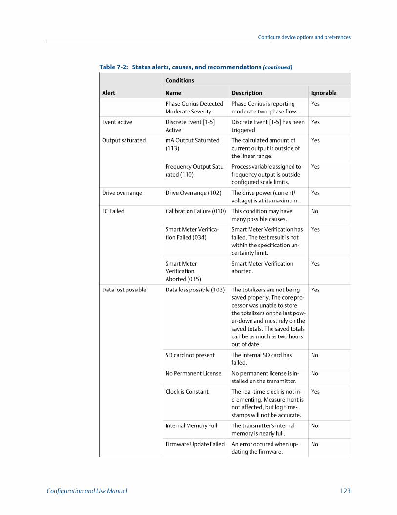
Status alerts, causes, and recommendations (continued)Table 7-2:
Alert
Conditions
Name Description Ignorable
Phase Genius DetectedModerate Severity
Phase Genius is reportingmoderate two-phase flow.
Yes
Event active Discrete Event [1-5]Active
Discrete Event [1-5] has beentriggered
Yes
Output saturated mA Output Saturated(113)
The calculated amount ofcurrent output is outside ofthe linear range.
Yes
Frequency Output Satu-rated (110)
Process variable assigned tofrequency output is outsideconfigured scale limits.
Yes
Drive overrange Drive Overrange (102) The drive power (current/voltage) is at its maximum.
Yes
FC Failed Calibration Failure (010) This condition may havemany possible causes.
No
Smart Meter Verifica-tion Failed (034)
Smart Meter Verification hasfailed. The test result is notwithin the specification un-certainty limit.
Yes
Smart MeterVerificationAborted (035)
Smart Meter Verificationaborted.
Yes
Data lost possible Data loss possible (103) The totalizers are not beingsaved properly. The core pro-cessor was unable to storethe totalizers on the last pow-er-down and must rely on thesaved totals. The saved totalscan be as much as two hoursout of date.
Yes
SD card not present The internal SD card hasfailed.
No
No Permanent License No permanent license is in-stalled on the transmitter.
No
Clock is Constant The real-time clock is not in-crementing. Measurement isnot affected, but log time-stamps will not be accurate.
Yes
Internal Memory Full The transmitter's internalmemory is nearly full.
No
Firmware Update Failed An error occured when up-dating the firmware.
No
Configure device options and preferences
Configuration and Use Manual 123
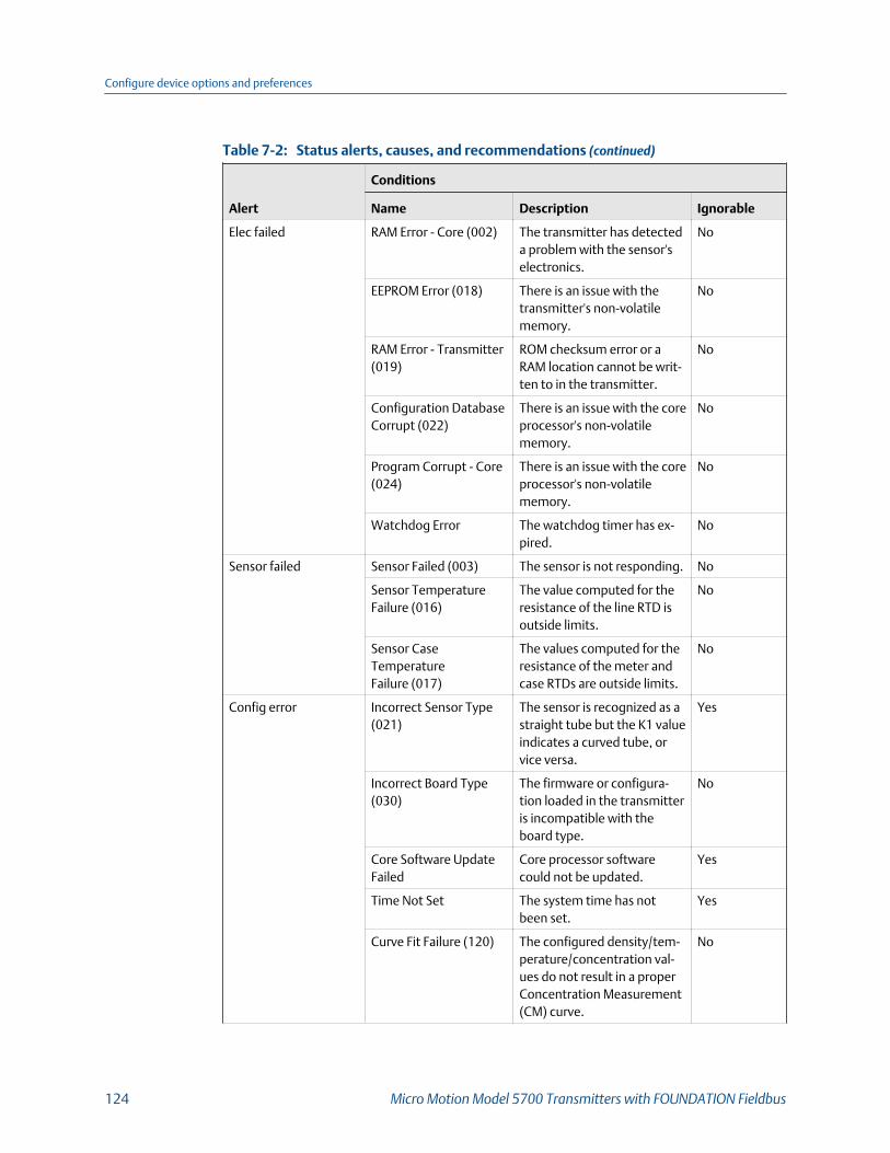
Status alerts, causes, and recommendations (continued)Table 7-2:
Alert
Conditions
Name Description Ignorable
Elec failed RAM Error - Core (002) The transmitter has detecteda problem with the sensor'selectronics.
No
EEPROM Error (018) There is an issue with thetransmitter's non-volatilememory.
No
RAM Error - Transmitter(019)
ROM checksum error or aRAM location cannot be writ-ten to in the transmitter.
No
Configuration DatabaseCorrupt (022)
There is an issue with the coreprocessor's non-volatilememory.
No
Program Corrupt - Core(024)
There is an issue with the coreprocessor's non-volatilememory.
No
Watchdog Error The watchdog timer has ex-pired.
No
Sensor failed Sensor Failed (003) The sensor is not responding. No
Sensor TemperatureFailure (016)
The value computed for theresistance of the line RTD isoutside limits.
No
Sensor CaseTemperatureFailure (017)
The values computed for theresistance of the meter andcase RTDs are outside limits.
No
Config error Incorrect Sensor Type(021)
The sensor is recognized as astraight tube but the K1 valueindicates a curved tube, orvice versa.
Yes
Incorrect Board Type(030)
The firmware or configura-tion loaded in the transmitteris incompatible with theboard type.
No
Core Software UpdateFailed
Core processor softwarecould not be updated.
Yes
Time Not Set The system time has notbeen set.
Yes
Curve Fit Failure (120) The configured density/tem-perature/concentration val-ues do not result in a properConcentration Measurement(CM) curve.
No
Configure device options and preferences
124 Micro Motion Model 5700 Transmitters with FOUNDATION Fieldbus

Status alerts, causes, and recommendations (continued)Table 7-2:
Alert
Conditions
Name Description Ignorable
Core Has IncompatibleETO
The core processor has anETO installed which is incom-patible with this device. Thecore can be updated but theETO will be overwritten.
No
Watercut Limited at100%
Watercut at Line calculationis greater than 105% basedon input density. WatercutOutput is limited to 100%
Yes
Watercut Limited at 0% Watercut at Line calculationis less than -5% based on in-put density. Watercut Outputis limited to 0%
Yes
Core low power Low Power - Core (031) The core processor is not re-ceiving sufficient power.
No
Sens Xmtr Comm Error Sensor CommunicationsFailure (026)
There is a communication er-ror between the transmitterand core processor.
No
Core Write Failure (028) An attempt to write data tothe core processor has failed.
No
Fieldbus BridgeCommunicationFailure
The transmitter is detectingtoo many communication er-rors with the Fieldbus bridge.
No
Tube not full Tube Not Full (033) The sensor is not responding. No
Extreme PPV Mass Flow Overrange(005)
The measured flow rate is outof range for the sensor.
Yes
Density Out of Range(008)
The measured density is be-low 0 g/cm3 or above 10 g/cm3.
Yes
Flowmeter Init Transmitter Initializing(009)
Transmitter is in power-upmode.
No
Configure device options and preferences
Configuration and Use Manual 125

Configure device options and preferences
126 Micro Motion Model 5700 Transmitters with FOUNDATION Fieldbus
8 Integrate the meter with the controlsystemTopics covered in this chapter:
• Configure FOUNDATION Fieldbus Channel A
• Configure mA output Channel B
• Configure FO/DO Channel C
8.1 Configure FOUNDATION Fieldbus Channel A
Display Menu > Configuration > Fieldbus Settings > Function Block > Analog Input [1–4]
ProLink III Device Tools > Configuration > Communications > Communications (Foundation Field-
bus)
Enhanced FF host For information about setting up function blocks, see Appendix B.
Basic FF host AI Block [1–4]
Overview
Channel A is exclusively used for FOUNDATION Fieldbus communication. The four AIfunction blocks function as independent channels, each of them able to report a differentprocess variable.
8.2 Configure mA output Channel B
Display Menu > Configuration > Inputs/Outputs > Channel B > I/O Type
ProLink III Device Tools > Configuration > I/O > Channels
Enhanced FF host Configure > Manual Setup > Inputs/Outputs > Channel B
Basic FF host Device TB > Channel B Assigment (OD Index 92)
Overview
Channel B is exclusively used for a mA output. It can be disabled using a fieldbus host orProLink III.
Integrate the meter with the control system
Configuration and Use Manual 127

8.2.1 Configure the mA outputThe mA output is used to report the current value of the process variable. The mA signalvaries between 4 mA and 20 mA in proportion to the current value of the assigned processvariable.
• Configure mA Output Source• Configure Lower Range Value (LRV) and Upper Range Value (URV) for the mA output• Configure mA Output Direction• Configure mA Output Cutoff• Configure mA Output Damping• Configure mA Output Fault Action
Configure mA Output Source
Display Menu > Configuration > Inputs/Outputs > Channel B > I/O Settings > Source
ProLink III Device Tools > Configuration > I/O > Outputs > mA Output
Enhanced FF host Configure > Manual Setup > Inputs/Outputs > Channel B
Basic FF host Device TB > mAO Source Variable (OD Index 94)
Overview
mA Output Source specifies the process variable that is reported by the mA output.
Prerequisites
• If you plan to configure the output to report volume flow, ensure that you have setVolume Flow Type as desired: Liquid or Gas Standard Volume.
• If you plan to configure an output to report a concentration measurement processvariable, ensure that the concentration measurement application is configured sothat the desired variable is available.
Procedure
Set mA Output Process Variable as desired.
Defaults:
• mA Output 1: Mass Flow Rate
Postrequisites
If you change the configuration of mA Output Source, verify the settings of Lower RangeValue and Upper Range Value. The transmitter automatically loads a set of values, andthese values may not be appropriate for your application.
Related information
Configure Lower Range Value (LRV) and Upper Range Value (URV) for the mA output
Integrate the meter with the control system
128 Micro Motion Model 5700 Transmitters with FOUNDATION Fieldbus
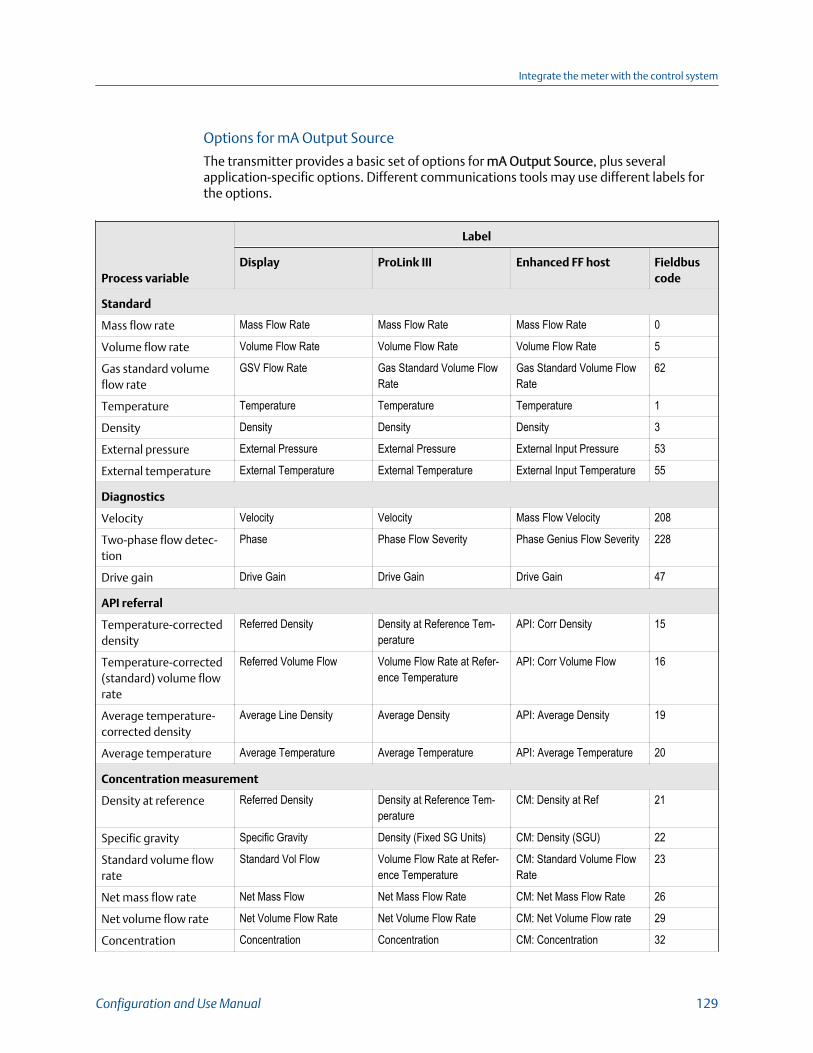
Options for mA Output Source
The transmitter provides a basic set of options for mA Output Source, plus severalapplication-specific options. Different communications tools may use different labels forthe options.
Process variable
Label
Display ProLink III Enhanced FF host Fieldbuscode
Standard
Mass flow rate Mass Flow Rate Mass Flow Rate Mass Flow Rate 0
Volume flow rate Volume Flow Rate Volume Flow Rate Volume Flow Rate 5
Gas standard volumeflow rate
GSV Flow Rate Gas Standard Volume FlowRate
Gas Standard Volume FlowRate
62
Temperature Temperature Temperature Temperature 1
Density Density Density Density 3
External pressure External Pressure External Pressure External Input Pressure 53
External temperature External Temperature External Temperature External Input Temperature 55
Diagnostics
Velocity Velocity Velocity Mass Flow Velocity 208
Two-phase flow detec-tion
Phase Phase Flow Severity Phase Genius Flow Severity 228
Drive gain Drive Gain Drive Gain Drive Gain 47
API referral
Temperature-correcteddensity
Referred Density Density at Reference Tem-perature
API: Corr Density 15
Temperature-corrected(standard) volume flowrate
Referred Volume Flow Volume Flow Rate at Refer-ence Temperature
API: Corr Volume Flow 16
Average temperature-corrected density
Average Line Density Average Density API: Average Density 19
Average temperature Average Temperature Average Temperature API: Average Temperature 20
Concentration measurement
Density at reference Referred Density Density at Reference Tem-perature
CM: Density at Ref 21
Specific gravity Specific Gravity Density (Fixed SG Units) CM: Density (SGU) 22
Standard volume flowrate
Standard Vol Flow Volume Flow Rate at Refer-ence Temperature
CM: Standard Volume FlowRate
23
Net mass flow rate Net Mass Flow Net Mass Flow Rate CM: Net Mass Flow Rate 26
Net volume flow rate Net Volume Flow Rate Net Volume Flow Rate CM: Net Volume Flow rate 29
Concentration Concentration Concentration CM: Concentration 32
Integrate the meter with the control system
Configuration and Use Manual 129

Process variable
Label
Display ProLink III Enhanced FF host Fieldbuscode
Baume Baume Baume CM: Density (Baume) 56
Advanced Phase Measurement
Net oil flow at line NetOilFlow @ Line Net Oil Flow @ Line APM: Net Oil Flow at Line 73
Water cut at line Watercut @ Line Watercut @ Line APM: Watercut at Line 74
Net water flow at line NetWaterFlow @ Line Net Water Flow @ Line APM: Net Water Flow at Line 75
Net oil flow at reference NetOilFlow @ Ref Net Oil Flow @ Ref APM: Net Oil Flow at Refer-ence
78
Water cut at reference Watercut @ Ref Watercut @ Ref APM: Watercut at Ref 79
Net water flow at refer-ence
NetWaterFlow @ Ref Net Water Flow @ Ref Net Flow Water at Ref 81
Gas void fraction Gas Void Fraction Gas Void Fraction APM: Gas Void Fraction 205
Configure Lower Range Value (LRV) and Upper Range Value(URV) for the mA output
Display Menu > Configuration > Inputs/Outputs > Channel B > I/O Settings > Lower Range Value
Menu > Configuration > Inputs/Outputs > Channel B > I/O Settings > Upper Range Value
ProLink III Device Tools > Configuration > I/O > Outputs > mA Output > Lower Range Value
Device Tools > Configuration > I/O > Outputs > mA Output > Upper Range Value
Enhanced FF host Configure > Manual Setup > Inputs/Outputs > Channel B
Basic FF host Device TB > mAO Lower Range Value (OD Index 97)
Device TB > mAO Upper Range Value (OD Index 98)
Overview
The Lower Range Value (LRV) and Upper Range Value (URV) are used to scale the mAoutput, that is, to define the relationship between mA Output Process Variable and the mAoutput signal.
LRV is the value of mA Output Source represented by an output of 4 mA. URV is the valueof mA Output Source represented by an output of 20 mA. Between LRV and URV, the mAoutput is linear with the process variable. If the process variable drops below LRV or risesabove URV, the transmitter posts an output saturation alert.
Procedure
Set LRV and URV as desired.
Enter LRV and URV in the measurement units used for mA Output Source.
Integrate the meter with the control system
130 Micro Motion Model 5700 Transmitters with FOUNDATION Fieldbus
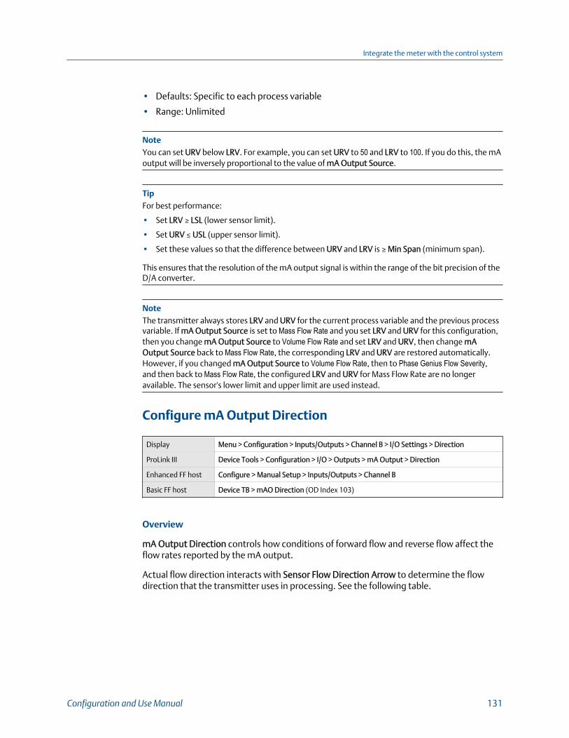
• Defaults: Specific to each process variable
• Range: Unlimited
NoteYou can set URV below LRV. For example, you can set URV to 50 and LRV to 100. If you do this, the mAoutput will be inversely proportional to the value of mA Output Source.
TipFor best performance:
• Set LRV ≥ LSL (lower sensor limit).
• Set URV ≤ USL (upper sensor limit).
• Set these values so that the difference between URV and LRV is ≥ Min Span (minimum span).
This ensures that the resolution of the mA output signal is within the range of the bit precision of theD/A converter.
NoteThe transmitter always stores LRV and URV for the current process variable and the previous processvariable. If mA Output Source is set to Mass Flow Rate and you set LRV and URV for this configuration,then you change mA Output Source to Volume Flow Rate and set LRV and URV, then change mAOutput Source back to Mass Flow Rate, the corresponding LRV and URV are restored automatically.However, if you changed mA Output Source to Volume Flow Rate, then to Phase Genius Flow Severity,and then back to Mass Flow Rate, the configured LRV and URV for Mass Flow Rate are no longeravailable. The sensor's lower limit and upper limit are used instead.
Configure mA Output Direction
Display Menu > Configuration > Inputs/Outputs > Channel B > I/O Settings > Direction
ProLink III Device Tools > Configuration > I/O > Outputs > mA Output > Direction
Enhanced FF host Configure > Manual Setup > Inputs/Outputs > Channel B
Basic FF host Device TB > mAO Direction (OD Index 103)
Overview
mA Output Direction controls how conditions of forward flow and reverse flow affect theflow rates reported by the mA output.
Actual flow direction interacts with Sensor Flow Direction Arrow to determine the flowdirection that the transmitter uses in processing. See the following table.
Integrate the meter with the control system
Configuration and Use Manual 131
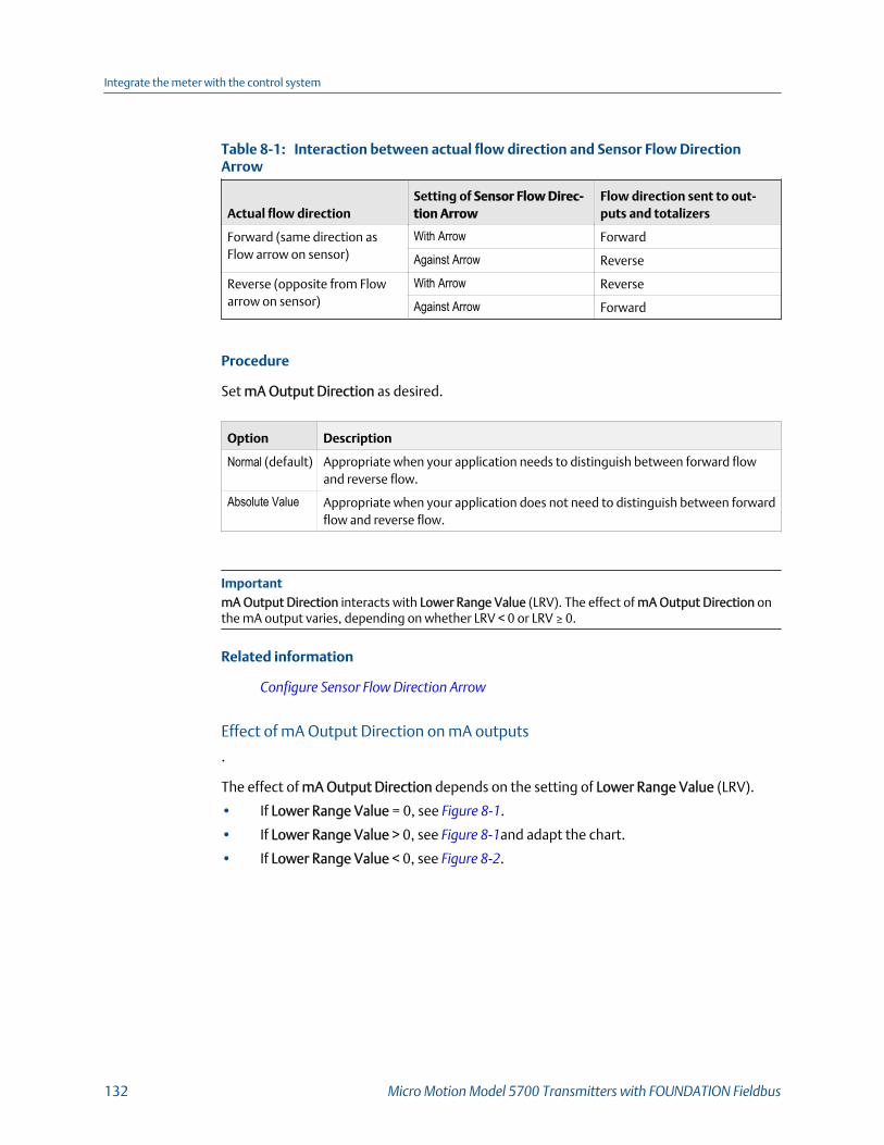
Interaction between actual flow direction and Sensor Flow DirectionArrow Table 8-1:
Actual flow directionSetting of Sensor Flow Direc-tion Arrow
Flow direction sent to out-puts and totalizers
Forward (same direction asFlow arrow on sensor)
With Arrow Forward
Against Arrow Reverse
Reverse (opposite from Flowarrow on sensor)
With Arrow Reverse
Against Arrow Forward
Procedure
Set mA Output Direction as desired.
Option Description
Normal (default) Appropriate when your application needs to distinguish between forward flowand reverse flow.
Absolute Value Appropriate when your application does not need to distinguish between forwardflow and reverse flow.
ImportantmA Output Direction interacts with Lower Range Value (LRV). The effect of mA Output Direction onthe mA output varies, depending on whether LRV < 0 or LRV ≥ 0.
Related information
Configure Sensor Flow Direction Arrow
Effect of mA Output Direction on mA outputs
.
The effect of mA Output Direction depends on the setting of Lower Range Value (LRV).
• If Lower Range Value = 0, see Figure 8‐1.
• If Lower Range Value > 0, see Figure 8‐1and adapt the chart.
• If Lower Range Value < 0, see Figure 8‐2.
Integrate the meter with the control system
132 Micro Motion Model 5700 Transmitters with FOUNDATION Fieldbus

Effect of mA Output Direction on the mA output: Lower Range Value = 0Figure 8-1:
mA Output Direction = Normal
mA
out
put
-x 0 xReverse flow Forward flow
20
12
4
mA Output Direction = Absolute Value
mA
out
put
-x 0 xReverse flow Forward flow
20
12
4
• Lower Range Value = 0• Upper Range Value = x
Effect of mA Output Direction on the mA output: Lower Range Value < 0Figure 8-2:
mA Output Direction = Normal
mA
out
put
-x 0 xReverse flow Forward flow
20
12
4
mA Output Direction = Absolute Value
mA
out
put
-x 0 xReverse flow Forward flow
20
12
4
• Lower Range Value = −x• Upper Range Value = x
Example: mA Output Direction = Normal and Lower Range Value = 0
Configuration:
Integrate the meter with the control system
Configuration and Use Manual 133
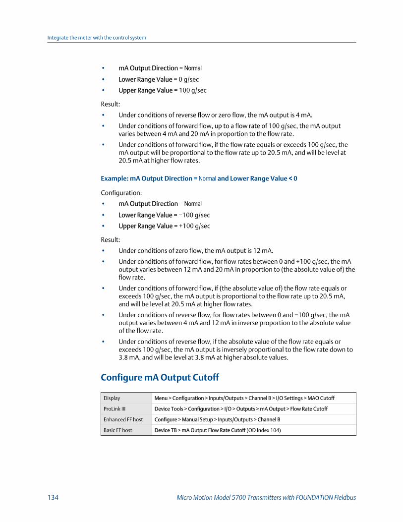
• mA Output Direction = Normal• Lower Range Value = 0 g/sec
• Upper Range Value = 100 g/sec
Result:
• Under conditions of reverse flow or zero flow, the mA output is 4 mA.
• Under conditions of forward flow, up to a flow rate of 100 g/sec, the mA outputvaries between 4 mA and 20 mA in proportion to the flow rate.
• Under conditions of forward flow, if the flow rate equals or exceeds 100 g/sec, themA output will be proportional to the flow rate up to 20.5 mA, and will be level at20.5 mA at higher flow rates.
Example: mA Output Direction = Normal and Lower Range Value < 0
Configuration:
• mA Output Direction = Normal• Lower Range Value = −100 g/sec
• Upper Range Value = +100 g/sec
Result:
• Under conditions of zero flow, the mA output is 12 mA.
• Under conditions of forward flow, for flow rates between 0 and +100 g/sec, the mAoutput varies between 12 mA and 20 mA in proportion to (the absolute value of) theflow rate.
• Under conditions of forward flow, if (the absolute value of) the flow rate equals orexceeds 100 g/sec, the mA output is proportional to the flow rate up to 20.5 mA,and will be level at 20.5 mA at higher flow rates.
• Under conditions of reverse flow, for flow rates between 0 and −100 g/sec, the mAoutput varies between 4 mA and 12 mA in inverse proportion to the absolute valueof the flow rate.
• Under conditions of reverse flow, if the absolute value of the flow rate equals orexceeds 100 g/sec, the mA output is inversely proportional to the flow rate down to3.8 mA, and will be level at 3.8 mA at higher absolute values.
Configure mA Output Cutoff
Display Menu > Configuration > Inputs/Outputs > Channel B > I/O Settings > MAO Cutoff
ProLink III Device Tools > Configuration > I/O > Outputs > mA Output > Flow Rate Cutoff
Enhanced FF host Configure > Manual Setup > Inputs/Outputs > Channel B
Basic FF host Device TB > mA Output Flow Rate Cutoff (OD Index 104)
Integrate the meter with the control system
134 Micro Motion Model 5700 Transmitters with FOUNDATION Fieldbus
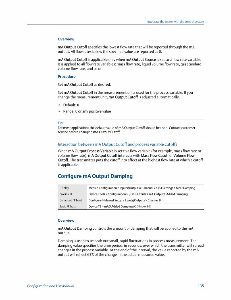
Overview
mA Output Cutoff specifies the lowest flow rate that will be reported through the mAoutput. All flow rates below the specified value are reported as 0.
mA Output Cutoff is applicable only when mA Output Source is set to a flow rate variable.It is applied to all flow rate variables: mass flow rate, liquid volume flow rate, gas standardvolume flow rate, and so on.
Procedure
Set mA Output Cutoff as desired.
Set mA Output Cutoff in the measurement units used for the process variable. If youchange the measurement unit, mA Output Cutoff is adjusted automatically.
• Default: 0
• Range: 0 or any positive value
TipFor most applications the default value of mA Output Cutoff should be used. Contact customerservice before changing mA Output Cutoff.
Interaction between mA Output Cutoff and process variable cutoffs
When mA Output Process Variable is set to a flow variable (for example, mass flow rate orvolume flow rate), mA Output Cutoff interacts with Mass Flow Cutoff or Volume FlowCutoff. The transmitter puts the cutoff into effect at the highest flow rate at which a cutoffis applicable.
Configure mA Output Damping
Display Menu > Configuration > Inputs/Outputs > Channel x > I/O Settings > MAO Damping
ProLink III Device Tools > Configuration > I/O > Outputs > mA Output > Added Damping
Enhanced FF host Configure > Manual Setup > Inputs/Outputs > Channel B
Basic FF host Device TB > mAO Added Damping (OD Index 96)
Overview
mA Output Damping controls the amount of damping that will be applied to the mAoutput.
Damping is used to smooth out small, rapid fluctuations in process measurement. Thedamping value specifies the time period, in seconds, over which the transmitter will spreadchanges in the process variable. At the end of the interval, the value reported by the mAoutput will reflect 63% of the change in the actual measured value.
Integrate the meter with the control system
Configuration and Use Manual 135
mA Output Damping affects a process variable only when it is reported via the mA output.If the process variable is read from the display or digitally, mA Output Damping is notapplied.
Procedure
Set mA Output Damping to the desired value.
• Default: 0.0 seconds
• Range: 0.0 to 440 seconds
Tips
• A high damping value makes the process variable appear smoother because the reported valuechanges slowly.
• A low damping value makes the process variable appear more erratic because the reported valuechanges more quickly.
• The combination of a high damping value and rapid, large changes in the process variableassigned to the mA output can result in increased measurement error.
• Whenever the damping value is non-zero, the damped value will lag the actual measurementbecause the damped value is being averaged over time.
• In general, lower damping values are preferable because there is less chance of data loss, and lesslag time between the actual measurement and the damped value.
Interaction between mA Output Damping and process variable damping
When mA Output Source is set to a flow rate variable, density, or temperature, mA OutputDamping interacts with Flow Damping, Density Damping, or Temperature Damping. Ifmultiple damping parameters are applicable, the effect of damping the process variable iscalculated first, and the mA output damping calculation is applied to the result of thatcalculation.
Example: Damping interaction
Configuration:
• Flow Damping = 1 second
• mA Output Source = Mass Flow Rate• mA Output Damping = 2 seconds
Result: A change in the mass flow rate will be reflected in the mA output over a time periodthat is greater than 3 seconds. The exact time period is calculated by the transmitteraccording to internal algorithms which are not configurable.
Integrate the meter with the control system
136 Micro Motion Model 5700 Transmitters with FOUNDATION Fieldbus
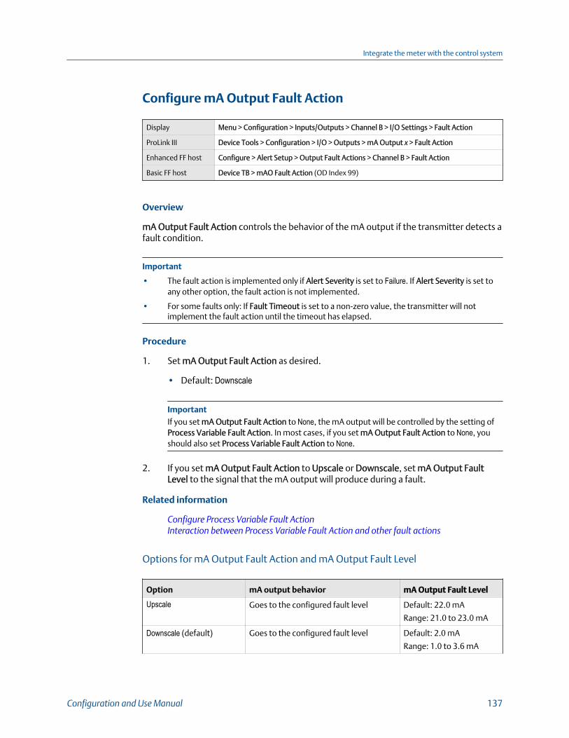
Configure mA Output Fault Action
Display Menu > Configuration > Inputs/Outputs > Channel B > I/O Settings > Fault Action
ProLink III Device Tools > Configuration > I/O > Outputs > mA Output x > Fault Action
Enhanced FF host Configure > Alert Setup > Output Fault Actions > Channel B > Fault Action
Basic FF host Device TB > mAO Fault Action (OD Index 99)
Overview
mA Output Fault Action controls the behavior of the mA output if the transmitter detects afault condition.
Important
• The fault action is implemented only if Alert Severity is set to Failure. If Alert Severity is set toany other option, the fault action is not implemented.
• For some faults only: If Fault Timeout is set to a non-zero value, the transmitter will notimplement the fault action until the timeout has elapsed.
Procedure
1. Set mA Output Fault Action as desired.
• Default: Downscale
ImportantIf you set mA Output Fault Action to None, the mA output will be controlled by the setting ofProcess Variable Fault Action. In most cases, if you set mA Output Fault Action to None, youshould also set Process Variable Fault Action to None.
2. If you set mA Output Fault Action to Upscale or Downscale, set mA Output FaultLevel to the signal that the mA output will produce during a fault.
Related information
Configure Process Variable Fault ActionInteraction between Process Variable Fault Action and other fault actions
Options for mA Output Fault Action and mA Output Fault Level
Option mA output behavior mA Output Fault Level
Upscale Goes to the configured fault level Default: 22.0 mA
Range: 21.0 to 23.0 mA
Downscale (default) Goes to the configured fault level Default: 2.0 mA
Range: 1.0 to 3.6 mA
Integrate the meter with the control system
Configuration and Use Manual 137
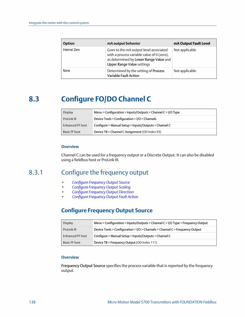
Option mA output behavior mA Output Fault Level
Internal Zero Goes to the mA output level associatedwith a process variable value of 0 (zero),as determined by Lower Range Value andUpper Range Value settings
Not applicable
None Determined by the setting of ProcessVariable Fault Action
Not applicable
8.3 Configure FO/DO Channel C
Display Menu > Configuration > Inputs/Outputs > Channel C > I/O Type
ProLink III Device Tools > Configuration > I/O > Channels
Enhanced FF host Configure > Manual Setup > Inputs/Outputs > Channel C
Basic FF host Device TB > Channel C Assignment (OD Index 93)
Overview
Channel C can be used for a frequency output or a Discrete Output. It can also be disabledusing a fieldbus host or ProLink III.
8.3.1 Configure the frequency output• Configure Frequency Output Source• Configure Frequency Output Scaling• Configure Frequency Output Direction• Configure Frequency Output Fault Action
Configure Frequency Output Source
Display Menu > Configuration > Inputs/Outputs > Channel C > I/O Type > Frequency Output
ProLink III Device Tools > Configuration > I/O > Channels > Channel C > Frequency Output
Enhanced FF host Configure > Manual Setup > Inputs/Outputs > Channel C
Basic FF host Device TB > Frequency Output (OD Index 111)
Overview
Frequency Output Source specifies the process variable that is reported by the frequencyoutput.
Integrate the meter with the control system
138 Micro Motion Model 5700 Transmitters with FOUNDATION Fieldbus
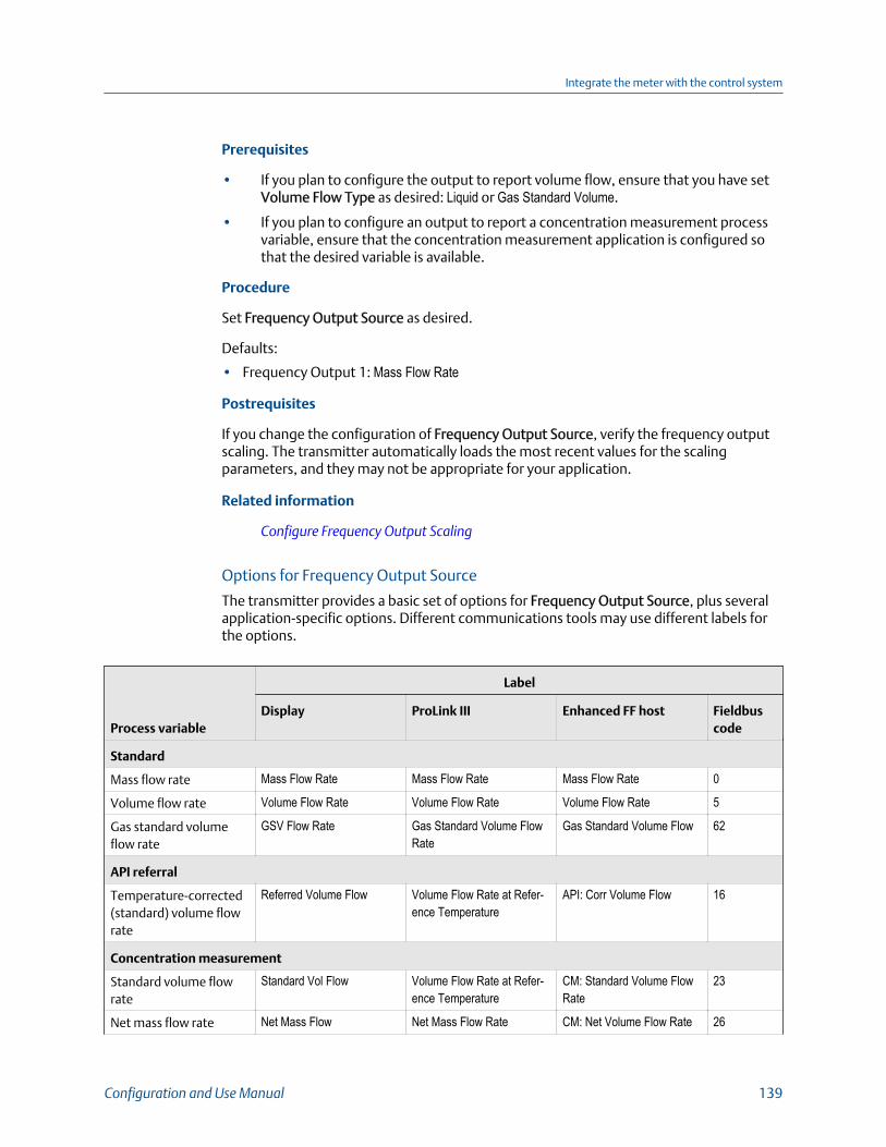
Prerequisites
• If you plan to configure the output to report volume flow, ensure that you have setVolume Flow Type as desired: Liquid or Gas Standard Volume.
• If you plan to configure an output to report a concentration measurement processvariable, ensure that the concentration measurement application is configured sothat the desired variable is available.
Procedure
Set Frequency Output Source as desired.
Defaults:
• Frequency Output 1: Mass Flow Rate
Postrequisites
If you change the configuration of Frequency Output Source, verify the frequency outputscaling. The transmitter automatically loads the most recent values for the scalingparameters, and they may not be appropriate for your application.
Related information
Configure Frequency Output Scaling
Options for Frequency Output Source
The transmitter provides a basic set of options for Frequency Output Source, plus severalapplication-specific options. Different communications tools may use different labels forthe options.
Process variable
Label
Display ProLink III Enhanced FF host Fieldbuscode
Standard
Mass flow rate Mass Flow Rate Mass Flow Rate Mass Flow Rate 0
Volume flow rate Volume Flow Rate Volume Flow Rate Volume Flow Rate 5
Gas standard volumeflow rate
GSV Flow Rate Gas Standard Volume FlowRate
Gas Standard Volume Flow 62
API referral
Temperature-corrected(standard) volume flowrate
Referred Volume Flow Volume Flow Rate at Refer-ence Temperature
API: Corr Volume Flow 16
Concentration measurement
Standard volume flowrate
Standard Vol Flow Volume Flow Rate at Refer-ence Temperature
CM: Standard Volume FlowRate
23
Net mass flow rate Net Mass Flow Net Mass Flow Rate CM: Net Volume Flow Rate 26
Integrate the meter with the control system
Configuration and Use Manual 139
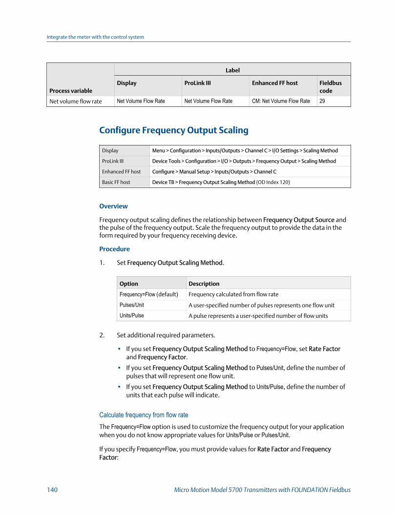
Process variable
Label
Display ProLink III Enhanced FF host Fieldbuscode
Net volume flow rate Net Volume Flow Rate Net Volume Flow Rate CM: Net Volume Flow Rate 29
Configure Frequency Output Scaling
Display Menu > Configuration > Inputs/Outputs > Channel C > I/O Settings > Scaling Method
ProLink III Device Tools > Configuration > I/O > Outputs > Frequency Output > Scaling Method
Enhanced FF host Configure > Manual Setup > Inputs/Outputs > Channel C
Basic FF host Device TB > Frequency Output Scaling Method (OD Index 120)
Overview
Frequency output scaling defines the relationship between Frequency Output Source andthe pulse of the frequency output. Scale the frequency output to provide the data in theform required by your frequency receiving device.
Procedure
1. Set Frequency Output Scaling Method.
Option Description
Frequency=Flow (default) Frequency calculated from flow rate
Pulses/Unit A user-specified number of pulses represents one flow unit
Units/Pulse A pulse represents a user-specified number of flow units
2. Set additional required parameters.
• If you set Frequency Output Scaling Method to Frequency=Flow, set Rate Factorand Frequency Factor.
• If you set Frequency Output Scaling Method to Pulses/Unit, define the number ofpulses that will represent one flow unit.
• If you set Frequency Output Scaling Method to Units/Pulse, define the number ofunits that each pulse will indicate.
Calculate frequency from flow rateThe Frequency=Flow option is used to customize the frequency output for your applicationwhen you do not know appropriate values for Units/Pulse or Pulses/Unit.
If you specify Frequency=Flow, you must provide values for Rate Factor and FrequencyFactor:
Integrate the meter with the control system
140 Micro Motion Model 5700 Transmitters with FOUNDATION Fieldbus

Rate Factor The maximum flow rate that you want the frequency output to report.
FrequencyFactor
A value calculated as follows:
FrequencyFactor = x NRateFactorT
where:
T Factor to convert selected time base to seconds
N Number of pulses per flow unit, as configured in the receivingdevice
The resulting Frequency Factor must be within the range of the frequency output ( :
• If Frequency Factor is less than1 Hz, reconfigure the receiving device for a higherpulses/unit setting.
• If Frequency Factor is greater than 10,000 Hz, reconfigure the receiving device for alower pulses/unit setting.
TipIf Frequency Output Scale Method is set to Frequency=Flow, and Frequency Output Maximum PulseWidth is set to a non-zero value, set Frequency Factor to a value below 200 Hz.
Example: Configure Frequency=Flow
You want the frequency output to report all flow rates up to 2000 kg/min.
The frequency receiving device is configured for 10 pulses/kg.
Solution:
FrequencyFactor = x 10200060
333.33FrequencyFactor =
FrequencyFactor = x NRateFactorT
Set parameters as follows:
• Rate Factor: 2000• Frequency Factor: 333.33
Integrate the meter with the control system
Configuration and Use Manual 141

Configure Frequency Output Direction
Display Device Tools > Configuration > I/O > Outputs > Frequency Output > Direction
ProLink III Device Tools > Configuration > I/O > Outputs > Frequency Output x > Direction
Enhanced FF host Configure > Manual Setup > Inputs/Outputs > Channel C
Basic FF host Device TB > Frequency Output Direction (OD Index 119)
Overview
Frequency Output Direction controls how conditions of forward flow and reverse flowaffect the flow rates reported by the frequency output.
Actual flow direction interacts with Sensor Flow Direction Arrow to determine the flowdirection that the transmitter uses in processing. See the following table.
Interaction between actual flow direction and Sensor Flow DirectionArrow Table 8-2:
Actual flow directionSetting of Sensor Flow Direc-tion Arrow
Flow direction sent to out-puts and totalizers
Forward (same direction asFlow arrow on sensor)
With Arrow Forward
Against Arrow Reverse
Reverse (opposite from Flowarrow on sensor)
With Arrow Reverse
Against Arrow Forward
Procedure
Set Frequency Output Direction as desired.
Option Description
Positive FlowOnly
• Forward flow: The frequency output reports the flow rate according to the con-figured scaling method.
• Reverse flow: The frequency output is 0 Hz.
Negative FlowOnly
• Forward flow: The frequency output is 0 Hz.• Reverse flow: The frequency output reports the absolute value of the flow rate
according to the configured scaling method.
Both Positiveand NegativeFlow
The frequency output reports the absolute value of the flow rate according to theconfigured scaling method. It is not possible to distinguish between forward flowand reverse flow from the frequency output alone. This setting is typically used incombination with a discrete output configured to report flow direction.
Related information
Configure Sensor Flow Direction ArrowConfigure Discrete Output Source
Integrate the meter with the control system
142 Micro Motion Model 5700 Transmitters with FOUNDATION Fieldbus

Configure Frequency Output Fault Action
Display Menu > Configuration > Inputs/Outputs > Channel C > I/O Settings > Fault Action
ProLink III Device Tools > Configuration > I/O > Outputs > Frequency Output x > Fault Action
Enhanced FF host Configure > Alert Setup > Output Fault Actions > Channel C
Basic FF host Device TB > FO Fault Action (OD Index 117)
Overview
Frequency Output Fault Action controls the behavior of the frequency output if thetransmitter detects a fault condition.
Important
• The fault action is implemented only if Alert Severity is set to Failure. If Alert Severity is set toany other option, the fault action is not implemented.
• For some faults only: If Fault Timeout is set to a non-zero value, the transmitter will notimplement the fault action until the timeout has elapsed.
Procedure
1. Set Frequency Output Fault Action as desired.
• Default: Downscale
ImportantIf you set Frequency Output Fault Action to None, the frequency output will be controlled bythe setting of Process Variable Fault Action. In most cases, if you set Frequency Output FaultAction to None, you should also set Process Variable Fault Action to None.
2. If you set Frequency Output Fault Action to Upscale, set Frequency Fault Level to thedesired value.
• Default: 14500 Hz
• Range: 10 Hz to 14500 Hz
Related information
Configure Process Variable Fault Action
Options for Frequency Output Fault Action
Label Frequency output behavior
Upscale Goes to configured Upscale value:• Default: 14500 Hz• Range: 10 Hz to 14500 Hz
Integrate the meter with the control system
Configuration and Use Manual 143

Label Frequency output behavior
Downscale 0 Hz
Internal Zero 0 Hz
None (default) Determined by the setting of Process Variable Fault Action
8.3.2 Configure the discrete outputThe discrete output is used to report specific meter or process conditions.
• Configure Discrete Output Source• Configure Discrete Output Polarity• Configure Discrete Output Fault Action
Configure Discrete Output Source
Display Menu > Configuration > Inputs/Outputs > Channel C > I/O Settings > Source
ProLink III Device Tools > Configuration > I/O > Outputs > Discrete Output > Source
Enhanced FF host Configure > Manual Setup > Inputs/Outputs > Channel C
Use method.
Basic FF host Device TB > DO Source (OD Index 124)
Overview
Discrete Output Source specifies the process condition or device condition that is reportedby the discrete output.
Procedure
Set Discrete Output Source to the desired option.
• Default: Forward/Reverse
Postrequisites
If you set Discrete Output Source to Flow Switch, additional configuration is required.
Related information
Configure Flow Rate Switch
Integrate the meter with the control system
144 Micro Motion Model 5700 Transmitters with FOUNDATION Fieldbus

Options for Discrete Output Source
Option
Label
State Discrete output voltageDisplay ProLink IIIEnhanced FFhost
Basic FF hostcode
Enhanced Event1–5 (1)
Enhanced Eventx
Enhanced Eventx
Discrete Event x 57–61 ON • Externally powered: Site-specific
OFF 0 V
Flow RateSwitch
Flow RateSwitch
Flow Switch In-dicator
Flow Switch In-dicator
101 ON • Externally powered: Site-specific
OFF 0 V
Forward/Re-verse Indicator
Flow Direction Forward Re-verse Indicator
Forward/Re-verse Indication
102 For-wardflow
0 V
Re-verseflow
• Externally powered: Site-specific
Calibration inProgress
Zero in Progress Calibration inProgress
Zero Calibrationis in Progress
103 ON • Externally powered: Site-specific
OFF 0 V
Fault Fault Fault Indication Fault ConditionIndication
104 ON • Externally powered: Site-specific
OFF 0 V
Meter Verifica-tion Failure
Meter Verifica-tion Fail
Meter Verifica-tion Failure
Meter Verifica-tion Failure
216 ON • Externally powered: Site-specific
OFF 0 V
(1) Events configured using the enhanced event model.
ImportantThis table assumes that Discrete Output Polarity is set to Active High. If Discrete Output Polarity is setto Active Low, reverse the voltage values.
ImportantActual flow direction interacts with Sensor Flow Direction Arrow to determine the flow direction thatthe transmitter uses in processing. See the following table.
Interaction between actual flow direction and Sensor Flow DirectionArrow Table 8-3:
Actual flow directionSetting of Sensor Flow Direc-tion Arrow
Flow direction sent to out-puts and totalizers
Forward (same direction asFlow arrow on sensor)
With Arrow Forward
Integrate the meter with the control system
Configuration and Use Manual 145
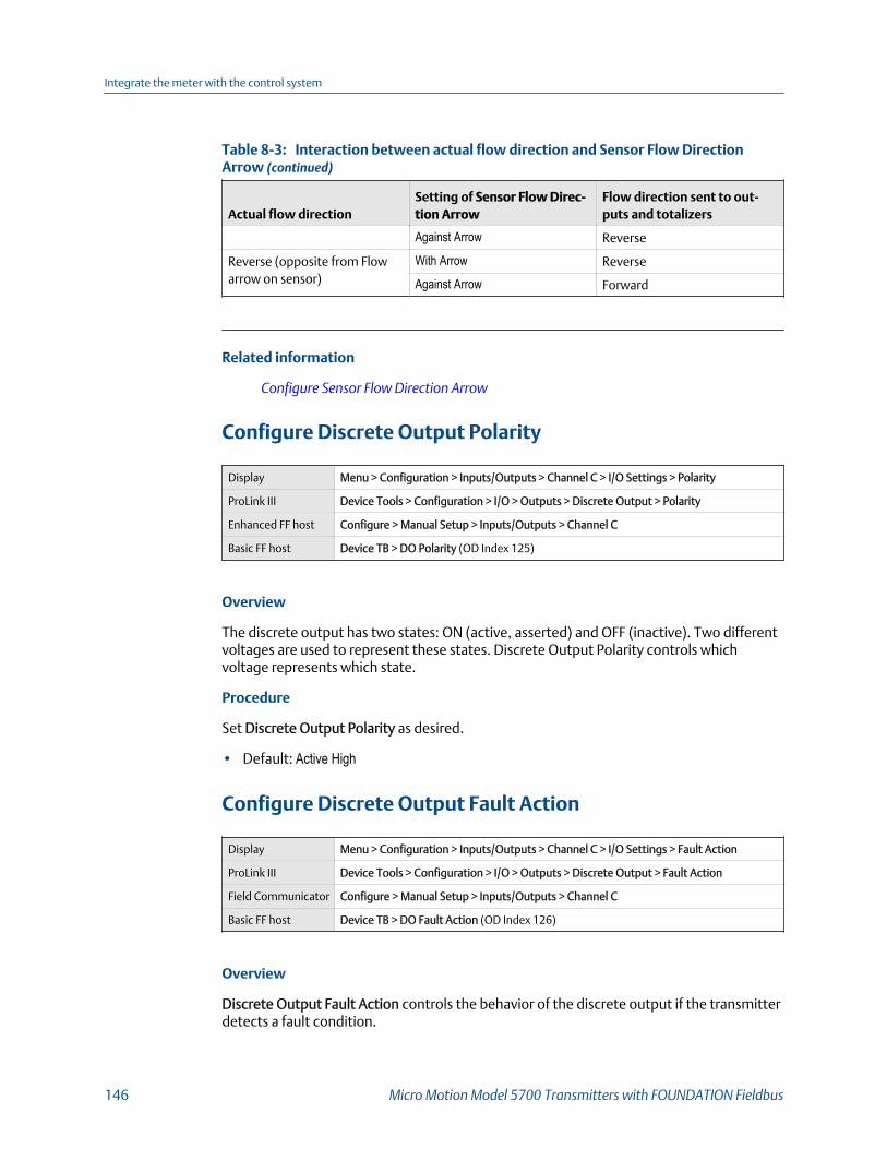
Interaction between actual flow direction and Sensor Flow DirectionArrow (continued)Table 8-3:
Actual flow directionSetting of Sensor Flow Direc-tion Arrow
Flow direction sent to out-puts and totalizers
Against Arrow Reverse
Reverse (opposite from Flowarrow on sensor)
With Arrow Reverse
Against Arrow Forward
Related information
Configure Sensor Flow Direction Arrow
Configure Discrete Output Polarity
Display Menu > Configuration > Inputs/Outputs > Channel C > I/O Settings > Polarity
ProLink III Device Tools > Configuration > I/O > Outputs > Discrete Output > Polarity
Enhanced FF host Configure > Manual Setup > Inputs/Outputs > Channel C
Basic FF host Device TB > DO Polarity (OD Index 125)
Overview
The discrete output has two states: ON (active, asserted) and OFF (inactive). Two differentvoltages are used to represent these states. Discrete Output Polarity controls whichvoltage represents which state.
Procedure
Set Discrete Output Polarity as desired.
• Default: Active High
Configure Discrete Output Fault Action
Display Menu > Configuration > Inputs/Outputs > Channel C > I/O Settings > Fault Action
ProLink III Device Tools > Configuration > I/O > Outputs > Discrete Output > Fault Action
Field Communicator Configure > Manual Setup > Inputs/Outputs > Channel C
Basic FF host Device TB > DO Fault Action (OD Index 126)
Overview
Discrete Output Fault Action controls the behavior of the discrete output if the transmitterdetects a fault condition.
Integrate the meter with the control system
146 Micro Motion Model 5700 Transmitters with FOUNDATION Fieldbus
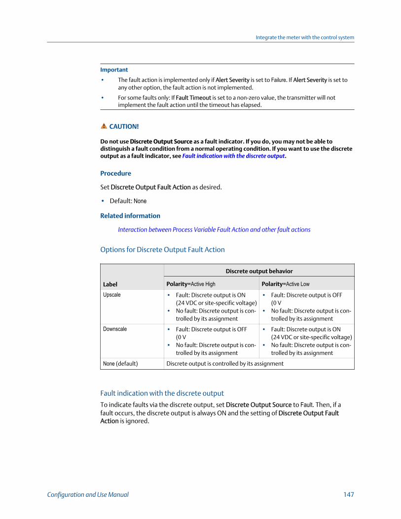
Important
• The fault action is implemented only if Alert Severity is set to Failure. If Alert Severity is set toany other option, the fault action is not implemented.
• For some faults only: If Fault Timeout is set to a non-zero value, the transmitter will notimplement the fault action until the timeout has elapsed.
CAUTION!
Do not use Discrete Output Source as a fault indicator. If you do, you may not be able todistinguish a fault condition from a normal operating condition. If you want to use the discreteoutput as a fault indicator, see Fault indication with the discrete output.
Procedure
Set Discrete Output Fault Action as desired.
• Default: None
Related information
Interaction between Process Variable Fault Action and other fault actions
Options for Discrete Output Fault Action
Label
Discrete output behavior
Polarity=Active High Polarity=Active Low
Upscale • Fault: Discrete output is ON(24 VDC or site-specific voltage)
• No fault: Discrete output is con-trolled by its assignment
• Fault: Discrete output is OFF(0 V
• No fault: Discrete output is con-trolled by its assignment
Downscale • Fault: Discrete output is OFF(0 V
• No fault: Discrete output is con-trolled by its assignment
• Fault: Discrete output is ON(24 VDC or site-specific voltage)
• No fault: Discrete output is con-trolled by its assignment
None (default) Discrete output is controlled by its assignment
Fault indication with the discrete output
To indicate faults via the discrete output, set Discrete Output Source to Fault. Then, if afault occurs, the discrete output is always ON and the setting of Discrete Output FaultAction is ignored.
Integrate the meter with the control system
Configuration and Use Manual 147

Integrate the meter with the control system
148 Micro Motion Model 5700 Transmitters with FOUNDATION Fieldbus
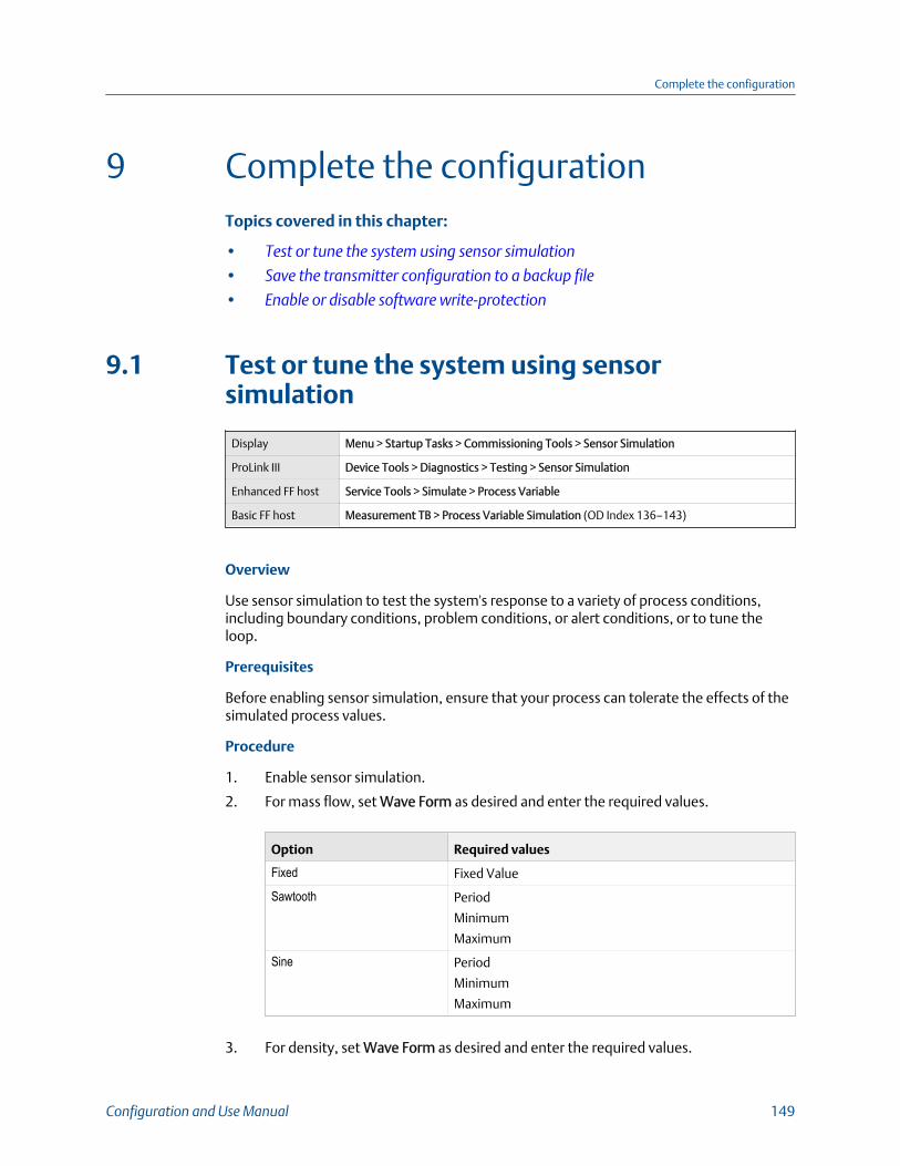
9 Complete the configurationTopics covered in this chapter:
• Test or tune the system using sensor simulation
• Save the transmitter configuration to a backup file
• Enable or disable software write‐protection
9.1 Test or tune the system using sensorsimulation
Display Menu > Startup Tasks > Commissioning Tools > Sensor Simulation
ProLink III Device Tools > Diagnostics > Testing > Sensor Simulation
Enhanced FF host Service Tools > Simulate > Process Variable
Basic FF host Measurement TB > Process Variable Simulation (OD Index 136–143)
Overview
Use sensor simulation to test the system's response to a variety of process conditions,including boundary conditions, problem conditions, or alert conditions, or to tune theloop.
Prerequisites
Before enabling sensor simulation, ensure that your process can tolerate the effects of thesimulated process values.
Procedure
1. Enable sensor simulation.
2. For mass flow, set Wave Form as desired and enter the required values.
Option Required values
Fixed Fixed Value
Sawtooth Period
Minimum
Maximum
Sine Period
Minimum
Maximum
3. For density, set Wave Form as desired and enter the required values.
Complete the configuration
Configuration and Use Manual 149

Option Required values
Fixed Fixed Value
Sawtooth Period
Minimum
Maximum
Sine Period
Minimum
Maximum
4. For temperature, set Wave Form as desired and enter the required values.
Option Required values
Fixed Fixed Value
Sawtooth Period
Minimum
Maximum
Sine Period
Minimum
Maximum
5. Observe the system response to the simulated values and make any appropriatechanges to the transmitter configuration or to the system.
6. Modify the simulated values and repeat.
7. When you have finished testing or tuning, disable sensor simulation.
9.1.1 Sensor simulationSensor simulation allows you to test the system or tune the loop without having to createthe test conditions in your process. When sensor simulation is enabled, the transmitterreports the simulated values for mass flow, density, and temperature, and takes allappropriate actions. For example, the transmitter might apply a cutoff, activate an event,or post an alert.
When sensor simulation is enabled, the simulated values are stored in the same memorylocations used for process data from the sensor. The simulated values are then usedthroughout transmitter functioning. For example, sensor simulation will affect:
• All mass flow rate, temperature, and density values displayed or reported viaoutputs or digital communications
• The mass total and mass inventory values
• All volume calculations and data, including reported values, volume totals, andvolume inventories
• All mass, temperature, density, or volume values logged to Data Logger
Sensor simulation does not affect any diagnostic values.
Complete the configuration
150 Micro Motion Model 5700 Transmitters with FOUNDATION Fieldbus

Unlike actual mass flow rate and density values, the simulated values are not temperature-compensated (adjusted for the effect of temperature on the sensor’s flow tubes).
9.2 Save the transmitter configuration to a backupfileA backup file allows you to return the transmitter to a known state.
Related information
Save a configuration file using the displaySave a configuration file using ProLink III
9.3 Enable or disable software write-protection
Display Not available
ProLink III Device Tools > Configuration > Write-Protection
Enhanced FF host Configure > Manual Setup > Security > FOUNDATION Fieldbus > Write Lock
Basic FF host Resource Block > Write Lock (OD Index 34)
Overview
When enabled, the software setting Write-Protection prevents changes to the transmitterconfiguration. You can perform all other functions, and you can view the transmitterconfiguration parameters.
NoteThe write-protection setting is only available on transmitters without a display.
NoteWrite-protecting the transmitter primarily prevents accidental changes to configuration, notintentional changes. Any user who can make changes to the configuration can disable writeprotection.
Complete the configuration
Configuration and Use Manual 151

Complete the configuration
152 Micro Motion Model 5700 Transmitters with FOUNDATION Fieldbus

Part IIIOperations, maintenance, andtroubleshooting
Chapters covered in this part:
• Transmitter operation
• Measurement support
• Maintenance
• Log files, history files, and service files
• Troubleshooting
Operations, maintenance, and troubleshooting
Configuration and Use Manual 153

Operations, maintenance, and troubleshooting
154 Micro Motion Model 5700 Transmitters with FOUNDATION Fieldbus
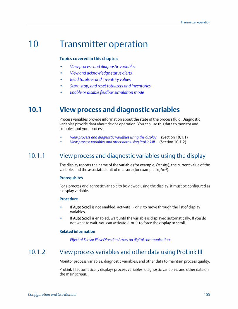
10 Transmitter operationTopics covered in this chapter:
• View process and diagnostic variables
• View and acknowledge status alerts
• Read totalizer and inventory values
• Start, stop, and reset totalizers and inventories
• Enable or disable fieldbus simulation mode
10.1 View process and diagnostic variablesProcess variables provide information about the state of the process fluid. Diagnosticvariables provide data about device operation. You can use this data to monitor andtroubleshoot your process.
• View process and diagnostic variables using the display (Section 10.1.1)• View process variables and other data using ProLink III (Section 10.1.2)
10.1.1 View process and diagnostic variables using the displayThe display reports the name of the variable (for example, Density), the current value of thevariable, and the associated unit of measure (for example, kg/m3).
Prerequisites
For a process or diagnostic variable to be viewed using the display, it must be configured asa display variable.
Procedure
• If Auto Scroll is not enabled, activate ⇩ or ⇧ to move through the list of displayvariables.
• If Auto Scroll is enabled, wait until the variable is displayed automatically. If you donot want to wait, you can activate ⇩ or ⇧ to force the display to scroll.
Related information
Effect of Sensor Flow Direction Arrow on digital communications
10.1.2 View process variables and other data using ProLink IIIMonitor process variables, diagnostic variables, and other data to maintain process quality.
ProLink III automatically displays process variables, diagnostic variables, and other data onthe main screen.
Transmitter operation
Configuration and Use Manual 155

TipProLink III allows you to choose the process variables that appear on the main screen. You can alsochoose whether to view data in Analog Gauge view or digital view, and you can customize the gaugesettings. For more information, see the ProLink III user manual.
Related information
Effect of Sensor Flow Direction Arrow on digital communications
10.1.3 Effect of Sensor Flow Direction Arrow on digitalcommunicationsFlow rates on the transmitter display or reported via digital communications are shown aspositive or negative. The sign depends on the interaction between Sensor Flow DirectionArrow and the actual flow direction.
This interaction affects flow rates shown on the transmitter display, ProLink III, and allother user interfaces.
Actual flow directionSetting of Sensor FlowDirection Arrow
Flow rate value
Transmitter display Digital communications
Forward (same directionas Flow arrow on sensor)
With Arrow Positive (no sign) Positive
Against Arrow Negative Negative
Reverse (opposite fromFlow arrow on sensor)
With Arrow Negative Negative
Against Arrow Positive (no sign) Positive
10.2 View and acknowledge status alertsThe transmitter posts a status alert whenever one of the specified conditions occurs. Youcan view active alerts and you can acknowledge alerts. You do not have to acknowledgealerts: The transmitter will perform normal measurement and reporting functions withunacknowledged alerts.
• View and acknowledge alerts using the display (Section 10.2.1)• View and acknowledge alerts using ProLink III (Section 10.2.2)
10.2.1 View and acknowledge alerts using the displayYou can view information about all active or unacknowledged alerts, and you canacknowledge alerts.
The display uses the alert banner and the alert symbol ⓘ to provide information aboutalerts.
Transmitter operation
156 Micro Motion Model 5700 Transmitters with FOUNDATION Fieldbus

Alert information on displayTable 10-1:
Display status Cause User action
Alert banner One or more alerts areactive.
Resolve the conditions to clear the alert. Whenthe alert is cleared or acknowledged, the bannerwill be removed.
Alert symbol ⓘ One or more alerts areunacknowledged.
Acknowledge the alert. When all alerts are ac-knowledged, the alert icon will be removed.
If alert security is enabled, the alert banner is never displayed. To view detailedinformation, you must use the alert menu: Menu > (i) Alert List.
NoteCertain alerts do not clear until the transmitter is rebooted.
Procedure
• If the alert banner appears:
1. Activate Info to view information about the alert.
2. Take appropriate steps to clear the alert.
3. Activate Ack to acknowledge the alert.
• If ⓘ appears:
1. Choose Menu > (i) Alert List.
2. Select an alert to view more information about the specific alert or toacknowledge it individually.
3. Choose Acknowledge All Alerts to acknowledge all alerts on the list.
Related information
Generate service files
10.2.2 View and acknowledge alerts using ProLink IIIYou can view a list containing all alerts that are active, or inactive but unacknowledged.From this list, you can acknowledge individual alerts or choose to acknowledge all alerts atonce.
NoteCertain alerts do not clear until the transmitter is rebooted.
Procedure
1. View alerts on the ProLink III main screen under Alerts.
Transmitter operation
Configuration and Use Manual 157
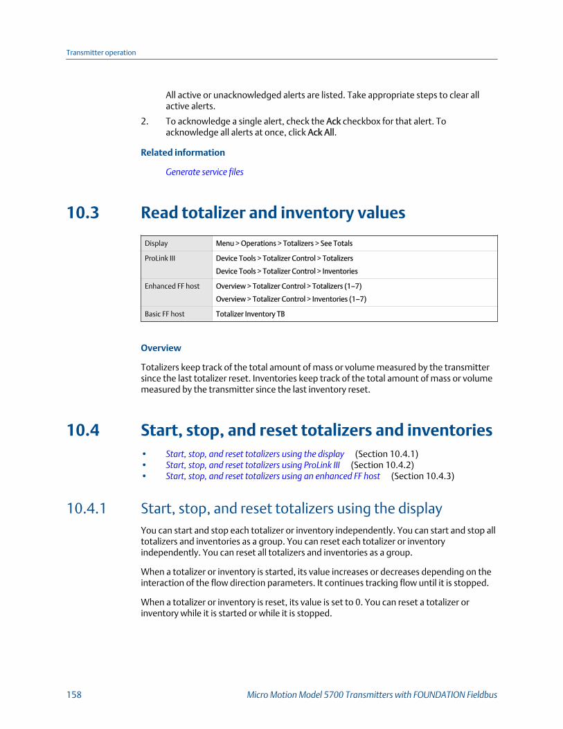
All active or unacknowledged alerts are listed. Take appropriate steps to clear allactive alerts.
2. To acknowledge a single alert, check the Ack checkbox for that alert. Toacknowledge all alerts at once, click Ack All.
Related information
Generate service files
10.3 Read totalizer and inventory values
Display Menu > Operations > Totalizers > See Totals
ProLink III Device Tools > Totalizer Control > Totalizers
Device Tools > Totalizer Control > Inventories
Enhanced FF host Overview > Totalizer Control > Totalizers (1–7)
Overview > Totalizer Control > Inventories (1–7)
Basic FF host Totalizer Inventory TB
Overview
Totalizers keep track of the total amount of mass or volume measured by the transmittersince the last totalizer reset. Inventories keep track of the total amount of mass or volumemeasured by the transmitter since the last inventory reset.
10.4 Start, stop, and reset totalizers and inventories• Start, stop, and reset totalizers using the display (Section 10.4.1)• Start, stop, and reset totalizers using ProLink III (Section 10.4.2)• Start, stop, and reset totalizers using an enhanced FF host (Section 10.4.3)
10.4.1 Start, stop, and reset totalizers using the displayYou can start and stop each totalizer or inventory independently. You can start and stop alltotalizers and inventories as a group. You can reset each totalizer or inventoryindependently. You can reset all totalizers and inventories as a group.
When a totalizer or inventory is started, its value increases or decreases depending on theinteraction of the flow direction parameters. It continues tracking flow until it is stopped.
When a totalizer or inventory is reset, its value is set to 0. You can reset a totalizer orinventory while it is started or while it is stopped.
Transmitter operation
158 Micro Motion Model 5700 Transmitters with FOUNDATION Fieldbus
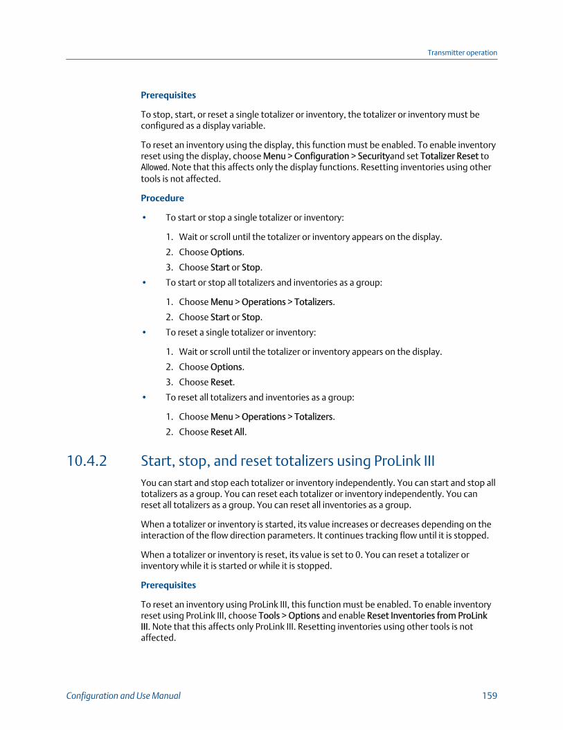
Prerequisites
To stop, start, or reset a single totalizer or inventory, the totalizer or inventory must beconfigured as a display variable.
To reset an inventory using the display, this function must be enabled. To enable inventoryreset using the display, choose Menu > Configuration > Securityand set Totalizer Reset toAllowed. Note that this affects only the display functions. Resetting inventories using othertools is not affected.
Procedure
• To start or stop a single totalizer or inventory:
1. Wait or scroll until the totalizer or inventory appears on the display.
2. Choose Options.
3. Choose Start or Stop.
• To start or stop all totalizers and inventories as a group:
1. Choose Menu > Operations > Totalizers.
2. Choose Start or Stop.
• To reset a single totalizer or inventory:
1. Wait or scroll until the totalizer or inventory appears on the display.
2. Choose Options.
3. Choose Reset.
• To reset all totalizers and inventories as a group:
1. Choose Menu > Operations > Totalizers.
2. Choose Reset All.
10.4.2 Start, stop, and reset totalizers using ProLink IIIYou can start and stop each totalizer or inventory independently. You can start and stop alltotalizers as a group. You can reset each totalizer or inventory independently. You canreset all totalizers as a group. You can reset all inventories as a group.
When a totalizer or inventory is started, its value increases or decreases depending on theinteraction of the flow direction parameters. It continues tracking flow until it is stopped.
When a totalizer or inventory is reset, its value is set to 0. You can reset a totalizer orinventory while it is started or while it is stopped.
Prerequisites
To reset an inventory using ProLink III, this function must be enabled. To enable inventoryreset using ProLink III, choose Tools > Options and enable Reset Inventories from ProLinkIII. Note that this affects only ProLink III. Resetting inventories using other tools is notaffected.
Transmitter operation
Configuration and Use Manual 159

Procedure
• To start or stop a single totalizer:
1. Choose Device Tools > Totalizer Control > Totalizers.
2. Scroll to the totalizer that you want to start or stop, and click Start or Stop.
• To start or stop a single inventory:
1. Choose Device Tools > Totalizer Control > Inventories.
2. Scroll to the inventory that you want to start or stop, and click Start or Stop.
• To start or stop all totalizers as a group:
1. Choose Device Tools > Totalizer Control > Totalizers or Device Tools > TotalizerControl > Inventories.
2. Click Start All Totals or Stop All Totals.
• To reset a single totalizer:
1. Choose Device Tools > Totalizer Control > Totalizers.
2. Scroll to the totalizer that you want to reset, and click Reset.
• To reset a single inventory:
1. Choose Device Tools > Totalizer Control > Inventories.
2. Scroll to the inventory that you want to reset, and click Reset.
• To reset all totalizers as a group:
1. Choose Device Tools > Totalizer Control > Totalizers.
2. Click Reset All Totals.
• To reset all inventories as a group:
1. Choose Device Tools > Totalizer Control > Inventories.
2. Click Reset All Inventories.
10.4.3 Start, stop, and reset totalizers using an enhanced FFhostYou can start and stop each totalizer or inventory independently. You can start and stop alltotalizers and inventories as a group. You can reset each totalizer or inventoryindependently. You can reset all totalizers as a group. You can reset all inventories as agroup.
When a totalizer or inventory is started, its value increases or decreases depending on theinteraction of the flow direction parameters. It continues tracking flow until it is stopped.
When a totalizer or inventory is reset, its value is set to 0. You can reset a totalizer orinventory while it is started or while it is stopped.
Transmitter operation
160 Micro Motion Model 5700 Transmitters with FOUNDATION Fieldbus

Procedure
• To start or stop a single totalizer:
1. Choose Overview > Totalizer Control > Totalizers 1-7.
2. Select the totalizer that you want to start or stop.
3. Choose Start or Stop.
• To start or stop a single inventory:
1. Choose Overview > Totalizer Control > Inventories 1-7.
2. Select the inventory that you want to start or stop.
3. Choose Start or Stop.
• To start or stop all totalizers and inventories as a group:
1. Choose Overview > Totalizer Control.
2. Click Start Totalizers or Stop Totalizers.
• To reset a single totalizer:
1. Choose Overview > Totalizer Control > Totalizers 1-7.
2. Select the totalizer that you want to reset.
3. Choose Reset.
• To reset a single totalizer:
1. Choose Overview > Totalizer Control > Inventories 1-7.
2. Select the inventory that you want to reset.
3. Choose Reset.
• To reset all totalizers as a group, choose Overview > Totalizer Control > Reset AllTotals.
• To reset all inventories as a group, choose Overview > Totalizer Control > Reset AllInventories.
10.5 Enable or disable fieldbus simulation modeThe transmitter has a mechanical switch on the display that permits the transmitter tofunction in simulation mode as defined in the FOUNDATION Fieldbus function blockspecification. When the switch is in the left position, simulation mode is disabled. Whenthe switch is in the right position, simulation mode is enabled.
Transmitter operation
Configuration and Use Manual 161

Fieldbus simulate switch on transmitter display (enabled)Figure 10-1:
Procedure
1. If you are in a hazardous area, power down the transmitter.
2. CAUTION!
Never remove the transmitter housing cover in a hazardous area when the transmitter ispowered up. Failure to follow these instructions may result in an explosion.
Remove the transmitter housing cover.
Transmitter operation
162 Micro Motion Model 5700 Transmitters with FOUNDATION Fieldbus
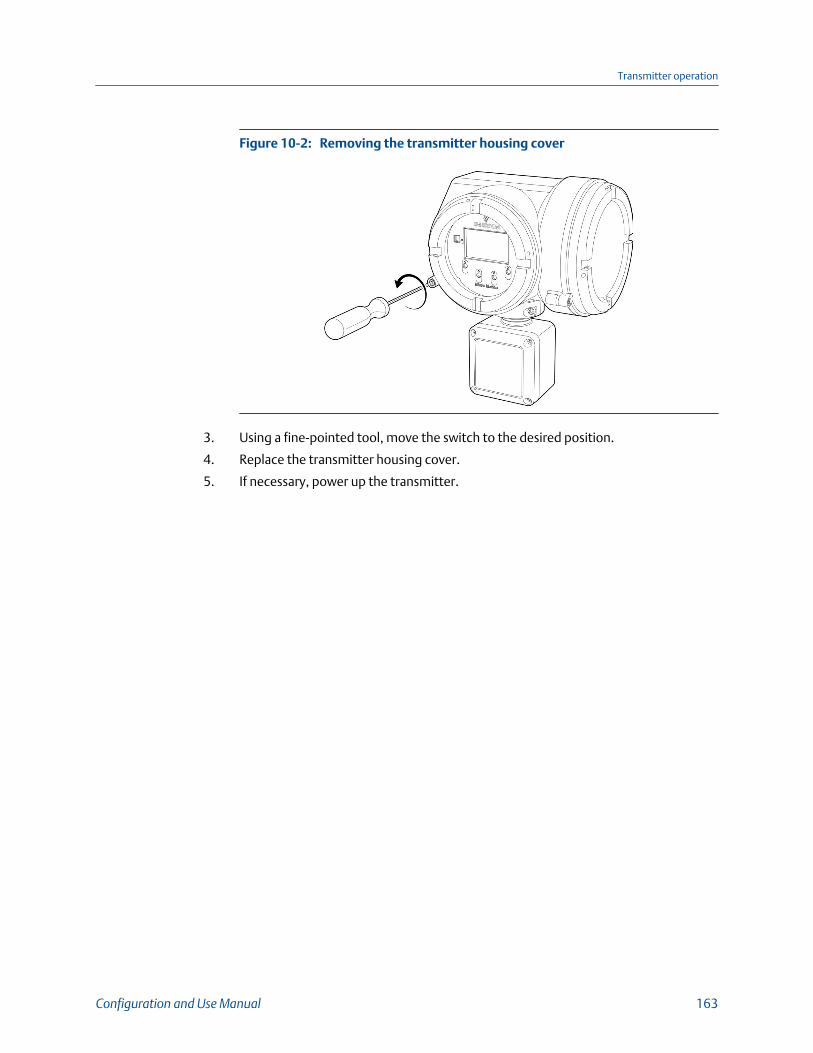
Removing the transmitter housing coverFigure 10-2:
3. Using a fine-pointed tool, move the switch to the desired position.
4. Replace the transmitter housing cover.
5. If necessary, power up the transmitter.
Transmitter operation
Configuration and Use Manual 163

Transmitter operation
164 Micro Motion Model 5700 Transmitters with FOUNDATION Fieldbus

11 Measurement supportTopics covered in this chapter:
• Use Smart Meter Verification (SMV)
• Zero the meter
• Set up pressure compensation
• Validate the meter
• Perform a (standard) D1 and D2 density calibration
• Adjust concentration measurement with Trim Slope and Trim Offset
11.1 Use Smart Meter Verification (SMV)You can run an SMV test, view and interpret the results, and set up automatic execution.
• Run an SMV test (Section 11.1.1)• View SMV test results (Section 11.1.2)• Set up SMV automatic execution (Section 11.1.3)
11.1.1 Run an SMV testRun an SMV test to ensure that your sensor has not experienced coating, corrosion,erosion, or any other physical or mechanical damage that affects measurement accuracy.
• If SMV results show that the meter has passed, then measurements meetspecifications.
• If SMV results show that the meter has failed, measurement may be affected.
• If SMV results show that the meter has aborted, then either a problem occurred withthe meter verification test (e.g., process instability) or you stopped the testmanually.
Prerequisites
For full capabilities, SMV must be licensed on your transmitter. If no license is active, youcan still initiate SMV; you will receive an indication as to whether the meter has passed orfailed the SMV run.
If you have a remote core processor (4-wire remote installations or remote core processorwith remote transmitter installations), you must be using the enhanced core processor,v3.6 or later (v4.4 or later to detect coating). The standard core processor does notsupport SMV. (For other installation types, the enhanced core processor is always used.)
The SMV test runs best when process conditions are stable. If conditions are too unstable,the test will abort. To maximize process stability:
• Maintain a constant fluid temperature and pressure.
• Maintain a constant flow rate. If possible, stop flow through the sensor.
Measurement support
Configuration and Use Manual 165
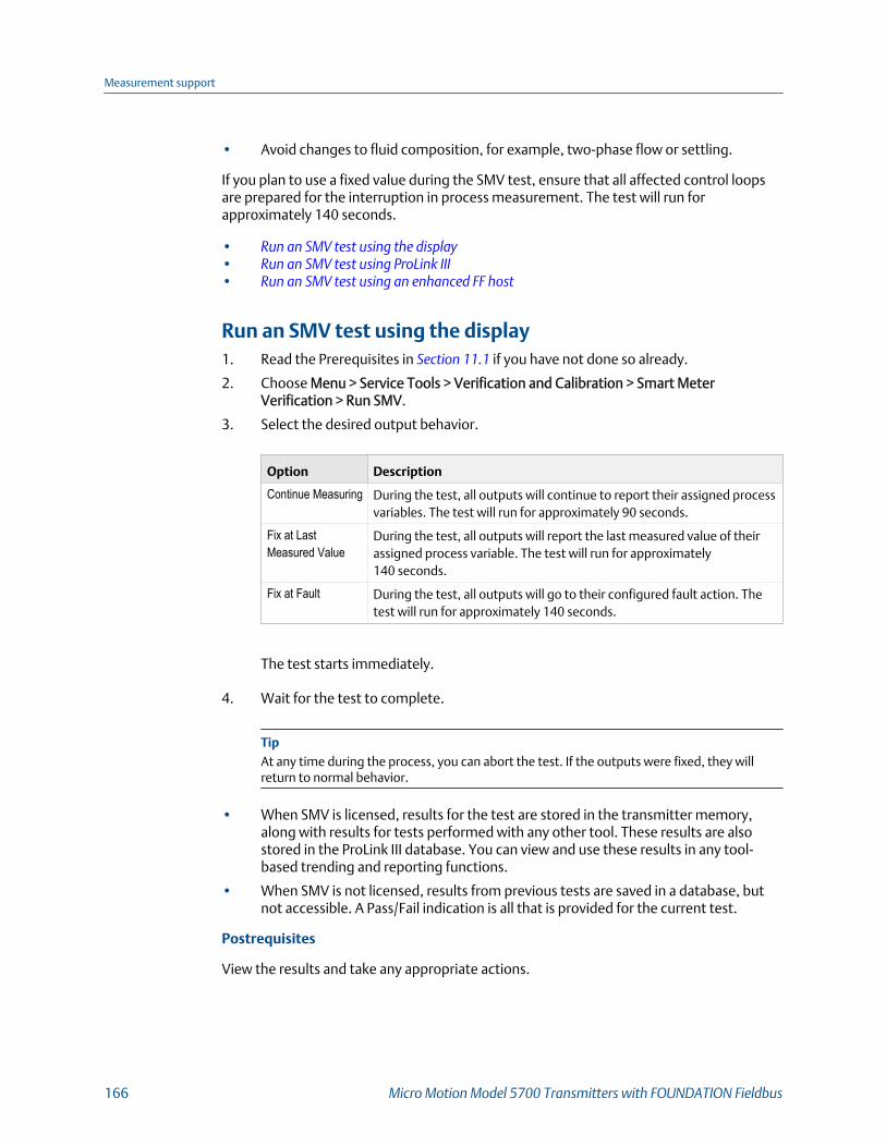
• Avoid changes to fluid composition, for example, two-phase flow or settling.
If you plan to use a fixed value during the SMV test, ensure that all affected control loopsare prepared for the interruption in process measurement. The test will run forapproximately 140 seconds.
• Run an SMV test using the display• Run an SMV test using ProLink III• Run an SMV test using an enhanced FF host
Run an SMV test using the display1. Read the Prerequisites in Section 11.1 if you have not done so already.
2. Choose Menu > Service Tools > Verification and Calibration > Smart MeterVerification > Run SMV.
3. Select the desired output behavior.
Option Description
Continue Measuring During the test, all outputs will continue to report their assigned processvariables. The test will run for approximately 90 seconds.
Fix at LastMeasured Value
During the test, all outputs will report the last measured value of theirassigned process variable. The test will run for approximately140 seconds.
Fix at Fault During the test, all outputs will go to their configured fault action. Thetest will run for approximately 140 seconds.
The test starts immediately.
4. Wait for the test to complete.
TipAt any time during the process, you can abort the test. If the outputs were fixed, they willreturn to normal behavior.
• When SMV is licensed, results for the test are stored in the transmitter memory,along with results for tests performed with any other tool. These results are alsostored in the ProLink III database. You can view and use these results in any tool-based trending and reporting functions.
• When SMV is not licensed, results from previous tests are saved in a database, butnot accessible. A Pass/Fail indication is all that is provided for the current test.
Postrequisites
View the results and take any appropriate actions.
Measurement support
166 Micro Motion Model 5700 Transmitters with FOUNDATION Fieldbus

Run an SMV test using ProLink III1. Read the Prerequisites in Section 11.1 if you have not done so already.
2. Choose Device Tools > Diagnostics > Meter Verification > Run Test.
TipIf Smart Meter Verification is licensed in the Model 5700 transmitter, you can also scroll to thebottom of the ProLink III main screen and choose from the shortcut buttons: Smart MeterVerification Overview > Meter Verification > Run Verification.
ProLink III automatically compares the contents of its SMV database to the SMVdatabase on the device, and uploads test data as required. You may need to wait fora few seconds until this process is complete.
3. In the SMV Test Definition window, enter any desired information and click Next.
None of this information is required. It does not affect SMV processing.
ProLink III stores this information in the SMV database on the PC. It is not saved tothe transmitter.
4. Select the desired output behavior.
Option Description
Continue Measuring During the test, all outputs will continue to report their assigned processvariables. The test will run for approximately 90 seconds.
Fix at LastMeasured Value
During the test, all outputs will report the last measured value of theirassigned process variable. The test will run for approximately140 seconds.
Fix at Fault During the test, all outputs will go to their configured fault action. Thetest will run for approximately 140 seconds.
5. Click Start and wait for the test to complete.
TipAt any time during the process, you can abort the test. If the outputs were fixed, they willreturn to normal behavior.
• When SMV is licensed, results for the test are stored in the transmitter memory,along with results for tests performed with any other tool. These results are alsostored in the ProLink III database. You can view and use these results in any tool-based trending and reporting functions.
• When SMV is not licensed, results from previous tests are saved in a database, butnot accessible. A Pass/Fail indication is all that is provided for the current test.
Postrequisites
View the results and take any appropriate actions.
Measurement support
Configuration and Use Manual 167
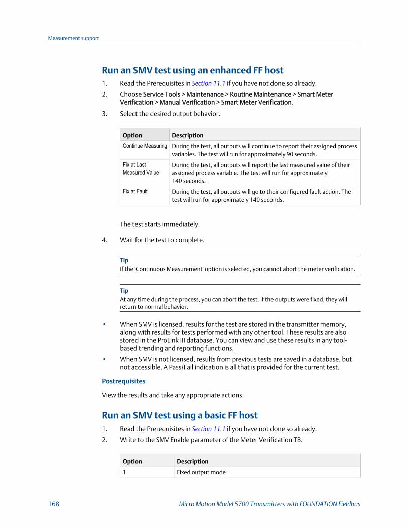
Run an SMV test using an enhanced FF host1. Read the Prerequisites in Section 11.1 if you have not done so already.
2. Choose Service Tools > Maintenance > Routine Maintenance > Smart MeterVerification > Manual Verification > Smart Meter Verification.
3. Select the desired output behavior.
Option Description
Continue Measuring During the test, all outputs will continue to report their assigned processvariables. The test will run for approximately 90 seconds.
Fix at LastMeasured Value
During the test, all outputs will report the last measured value of theirassigned process variable. The test will run for approximately140 seconds.
Fix at Fault During the test, all outputs will go to their configured fault action. Thetest will run for approximately 140 seconds.
The test starts immediately.
4. Wait for the test to complete.
TipIf the 'Continuous Measurement' option is selected, you cannot abort the meter verification.
TipAt any time during the process, you can abort the test. If the outputs were fixed, they willreturn to normal behavior.
• When SMV is licensed, results for the test are stored in the transmitter memory,along with results for tests performed with any other tool. These results are alsostored in the ProLink III database. You can view and use these results in any tool-based trending and reporting functions.
• When SMV is not licensed, results from previous tests are saved in a database, butnot accessible. A Pass/Fail indication is all that is provided for the current test.
Postrequisites
View the results and take any appropriate actions.
Run an SMV test using a basic FF host1. Read the Prerequisites in Section 11.1 if you have not done so already.
2. Write to the SMV Enable parameter of the Meter Verification TB.
Option Description
1 Fixed output mode
Measurement support
168 Micro Motion Model 5700 Transmitters with FOUNDATION Fieldbus

Option Description
6 Continue measurement mode
3. Wait for the test to complete.
TipAt any time during the process, you can abort the test. If the outputs were fixed, they willreturn to normal behavior.
• When SMV is licensed, results for the test are stored in the transmitter memory,along with results for tests performed with any other tool. These results are alsostored in the ProLink III database. You can view and use these results in any tool-based trending and reporting functions.
• When SMV is not licensed, results from previous tests are saved in a database, butnot accessible. A Pass/Fail indication is all that is provided for the current test.
Postrequisites
View the test results and take any appropriate actions.
11.1.2 View SMV test resultsAfter each SMV test, the pass/fail result is displayed automatically. Detailed results are alsoavailable for licensed versions.
• View SMV test results using the display• View SMV test results using ProLink III• View SMV test results using an enhanced FF host
View SMV test results using the display• For licensed and unlicensed versions of SMV, results of the current test are displayed
automatically.
• For licensed versions of SMV only, to view results of previous tests for this meter:
1. Choose Menu > Service Tools > Verification & Calibration > Smart MeterVerification > Read SMV History.
Pass/Fail results of all tests in the transmitter's SMV database are displayed.
2. To view detailed data for an individual test, select it from the list.
Related information
Understanding SMV results
View SMV test results using ProLink III• For licensed and unlicensed versions of SMV, results of the current test are displayed
automatically.
Measurement support
Configuration and Use Manual 169

• For licensed versions of SMV only, to view results of previous tests for this meter:
1. Choose Device Tools > Diagnostics > Meter Verification > Run Test.
2. In the SMV Test Definition window, click View Previous Test Results.
3. Click Next.
ProLink III displays a report containing details of the most recent test. The reportis automatically saved to the SMV database. You can print or export the report.
4. To view details of previous tests, click View previous test report.
Related information
Understanding SMV results
View SMV test results using an enhanced FF host
In addition to test results, the provides a trend chart.
Procedure
• For licensed and unlicensed versions of SMV, results of the current test are displayedautomatically.
• For licensed versions of SMV only, to view detailed results for the current test,choose Service Tools > Maintenance > Routine Maintenance > SMV > ManualVerification > Most Recent Test Results.
• For licensed versions of SMV only, to view results of previous tests:
1. Choose Service Tools > Maintenance > Routine Maintenance > Smart MeterVerification > Manual Verification.
2. Choose Most Recent Test Result.
This displays the result of previous meter verification run.
• For licensed versions of SMV only, to view the trend of the last 20 SMV test runs:
1. Choose Service Tools > Maintenance > Routine Maintenance > Smart MeterVerification > Manual Verification.
2. Choose Show Last 20 Results.
Related information
Understanding SMV results
Understanding SMV resultsWhen the SMV test is completed, the result is reported as Pass, Fail, or Abort. (Some toolsreport the Fail result as Advisory instead.)
Pass Smart Meter Verification does a statistical check between the factory baselinevalue and the current Smart Meter Verification result. Pass indicates that the twovalues are statistically the same.
Measurement support
170 Micro Motion Model 5700 Transmitters with FOUNDATION Fieldbus

Fail The current SMV value is statistically different than the factory baseline value.
• If the meter passes the second test, the first result can be ignored.
• If the meter fails the second test, the flow tubes may be damaged orcoated. Use your process knowledge to determine the possibilities fordamage and the appropriate actions for each. These actions might includeremoving the meter from service and physically inspecting the tubes. Atminimum, you should perform a flow validation and a density calibration.
Abort A problem occurred with the meter verification test (such as process instability)or you stopped the test manually. See Table 11‐1 for a list of abort codes, adescription of each code, and possible actions you can take in response.
SMV abort codesTable 11-1:
Code Description Recommended actions
1 User-initiated abort None required. Wait 15 seconds before starting an-other test.
3 Frequency drift Ensure that temperature, flow, and density are sta-ble, and rerun the test.
5 High drive gain Ensure that flow is stable, minimize entrained gas,and rerun the test.
8 Unstable flow Check factors that could cause process instability,then rerun the test. To maximize process stability:• Maintain a constant fluid pressure and tempera-
ture.• Avoid changes to fluid composition, such as
two-phase flow or settling.• Maintain a constant flow rate.
12 There is a fault present andSMV cannot run
View the Alerts present on the device and take anynecessary actions to clear them.
13 No factory reference data formeter verification test per-formed on air
Contact customer service.
14 No factory reference data formeter verification test per-formed on water
Contact customer service.
15 No configuration data formeter verification
Contact customer service.
Other General abort Repeat the test. If the test aborts again, contactcustomer service.
11.1.3 Set up SMV automatic executionYou can set up and run a single test at a user-defined future time. You can also set up andrun tests automatically on a regular schedule.
Measurement support
Configuration and Use Manual 171

Automatic execution of SMV is managed from the transmitter. You do not need aconnection from an external configuration tool.
TipThe time between test runs must be between 1 and 1000 hours. The time to the first test run can beany positive floating number.
ImportantOnly the 20 most recent SMV results are stored. For SMV Basic versions, the last automatic executionresult can be viewed, while all 20 results can be viewed with SMV licensed. To view or chart theseresults using an external tool, you must upload them from the transmitter.
• Set up SMV automatic execution using the display• Set up SMV automatic execution using ProLink III• Set up SMV automatic execution using an enhanced FF host
Set up SMV automatic execution using the display1. Choose Menu > Service Tools > Verification & Calibration > Smart Meter Verification
> Schedule SMV.
2. To schedule a single test:
a. Set Hours to 1st Run to the number of hours to elapse before the test is run.
b. Set Hours Between to 0.
3. To schedule a recurring execution:
a. Set Specify Time Until Next Run to the number of days, hours, and minutes toelapse before the first test is run.
b. Set Specify Time Between Recurring Runs to the number of days, hours, andminutes to elapse between runs.
4. To disable scheduled execution:
a. Set Specify Time Until Next Run to 0 days, 0 hours, and 0 minutes.
b. Set Specify Time Between Recurring Runs to 0 days, 0 hours, and 0 minutes.
Set up SMV automatic execution using ProLink III1. Select one of the following paths to access the SMV scheduler .
• Choose Device Tools > Diagnostics > Meter Verification > Meter VerificationScheduler.
• Choose Smart Meter Verification Overview > Tools > Schedule Smart MeterVerification.
2. To schedule a single test:
a. Set Specify Time Until Next Run to the number of days, hours, and minutes toelapse before the test is run.
Measurement support
172 Micro Motion Model 5700 Transmitters with FOUNDATION Fieldbus

b. Set Specify Time Between Recurring Runs to 0 days, 0 hours, and 0 minutes.
3. To schedule a recurring execution:
a. Set Specify Time Until Next Run to the number of days, hours, and minutes toelapse before the first test is run.
b. Set Specify Time Between Recurring Runs to the number of days, hours, andminutes to elapse between runs.
4. To disable scheduled execution:
a. Set Specify Time Until Next Run to 0 days, 0 hours, and 0 minutes.
b. Set Specify Time Between Recurring Runs to 0 days, 0 hours, and 0 minutes.
Set up SMV automatic execution using an enhanced FF host1. Choose Service Tools > Maintenance > Routine Maintenance > Smart Meter
Verification > Automatic Verification > Schedule.
2. To schedule a single test:
a. Set Hours Until Next Run to the number of hours to elapse before the test is run.
b. Set Recurring Hours to 0.
3. To schedule a recurring execution:
a. Set Specify Time Until Next Run to the number of days, hours, and minutes toelapse before the first test is run.
b. Set Specify Time Between Recurring Runs to the number of days, hours, andminutes to elapse between runs.
4. To disable scheduled execution:
a. Set Specify Time Until Next Run to 0 days, 0 hours, and 0 minutes.
b. Set Specify Time Between Recurring Runs to 0 days, 0 hours, and 0 minutes.
11.2 Zero the meter
Display Menu > Service Tools > Verification & Calibration > Meter Zero > Zero Calibration
ProLink III Device Tools > Calibration > Smart Zero Verification and Calibration > Calibrate Zero
Enhanced FF host Service Tools > Maintenance > Calibration > Zero Calibration > Setting > Perform Auto
Zero
Basic FF host Measurement TB > Zero Calibration
Overview
Zeroing the meter establishes a baseline for process measurement by analyzing thesensor's output when there is no flow through the sensor tubes.
Measurement support
Configuration and Use Manual 173

ImportantIn most cases, the factory zero is more accurate than the field zero. Do not zero the meter unless oneof the following is true:
• The zero is required by site procedures.
• The stored zero value fails the zero verification procedure.
Prerequisites
Before performing a field zero, execute the Zero Verification procedure to see whether ornot a field zero can improve measurement accuracy.
ImportantDo not verify the zero or zero the meter if a high-severity alert is active. Correct the problem, thenverify the zero or zero the meter. You may verify the zero or zero the meter if a low-severity alert isactive.
Procedure
1. Prepare the meter:
a. Allow the meter to warm up for at least 20 minutes after applying power.
b. Run the process fluid through the sensor until the sensor temperature reachesthe normal process operating temperature.
c. Stop flow through the sensor by shutting the downstream valve, and then theupstream valve if available.
d. Verify that the sensor is blocked in, that flow has stopped, and that the sensor iscompletely full of process fluid.
e. Observe the drive gain, temperature, and density readings. If they are stable,check the Live Zero or Field Verification Zero value. If the average value is close to0, you should not need to zero the meter.
2. Modify Zero Time, if desired.
Zero Time controls the amount of time the transmitter takes to determine its zero-flow reference point. The default Zero Time is 20 seconds. For most applications, thedefault Zero Time is appropriate.
3. Start the zero procedure and wait until it completes.
When the calibration is complete:
• If the zero procedure was successful, a Calibration Success message and anew zero value are displayed.
• If the zero procedure failed, a Calibration Failed message is displayed.
Postrequisites
Restore normal flow through the sensor by opening the valves.
Need help? If the zero fails:
Measurement support
174 Micro Motion Model 5700 Transmitters with FOUNDATION Fieldbus
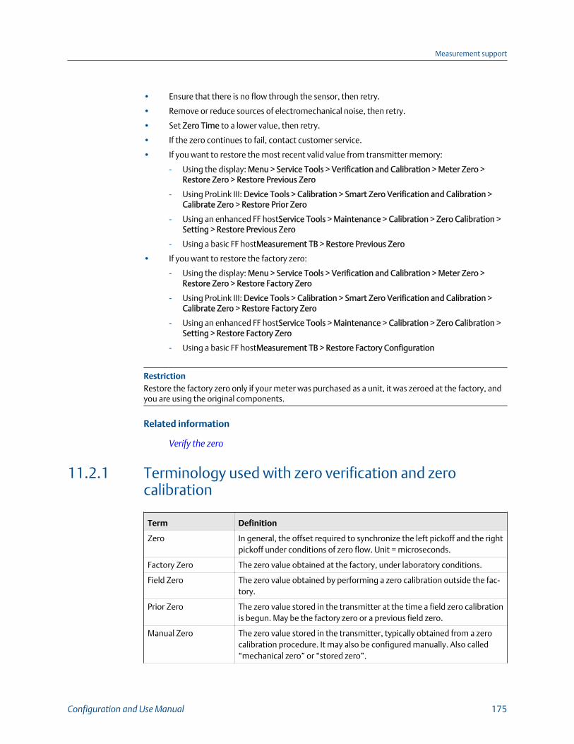
• Ensure that there is no flow through the sensor, then retry.
• Remove or reduce sources of electromechanical noise, then retry.
• Set Zero Time to a lower value, then retry.
• If the zero continues to fail, contact customer service.
• If you want to restore the most recent valid value from transmitter memory:
- Using the display: Menu > Service Tools > Verification and Calibration > Meter Zero >Restore Zero > Restore Previous Zero
- Using ProLink III: Device Tools > Calibration > Smart Zero Verification and Calibration >Calibrate Zero > Restore Prior Zero
- Using an enhanced FF hostService Tools > Maintenance > Calibration > Zero Calibration >Setting > Restore Previous Zero
- Using a basic FF hostMeasurement TB > Restore Previous Zero
• If you want to restore the factory zero:
- Using the display: Menu > Service Tools > Verification and Calibration > Meter Zero >Restore Zero > Restore Factory Zero
- Using ProLink III: Device Tools > Calibration > Smart Zero Verification and Calibration >Calibrate Zero > Restore Factory Zero
- Using an enhanced FF hostService Tools > Maintenance > Calibration > Zero Calibration >Setting > Restore Factory Zero
- Using a basic FF hostMeasurement TB > Restore Factory Configuration
RestrictionRestore the factory zero only if your meter was purchased as a unit, it was zeroed at the factory, andyou are using the original components.
Related information
Verify the zero
11.2.1 Terminology used with zero verification and zerocalibration
Term Definition
Zero In general, the offset required to synchronize the left pickoff and the rightpickoff under conditions of zero flow. Unit = microseconds.
Factory Zero The zero value obtained at the factory, under laboratory conditions.
Field Zero The zero value obtained by performing a zero calibration outside the fac-tory.
Prior Zero The zero value stored in the transmitter at the time a field zero calibrationis begun. May be the factory zero or a previous field zero.
Manual Zero The zero value stored in the transmitter, typically obtained from a zerocalibration procedure. It may also be configured manually. Also called“mechanical zero” or “stored zero”.
Measurement support
Configuration and Use Manual 175
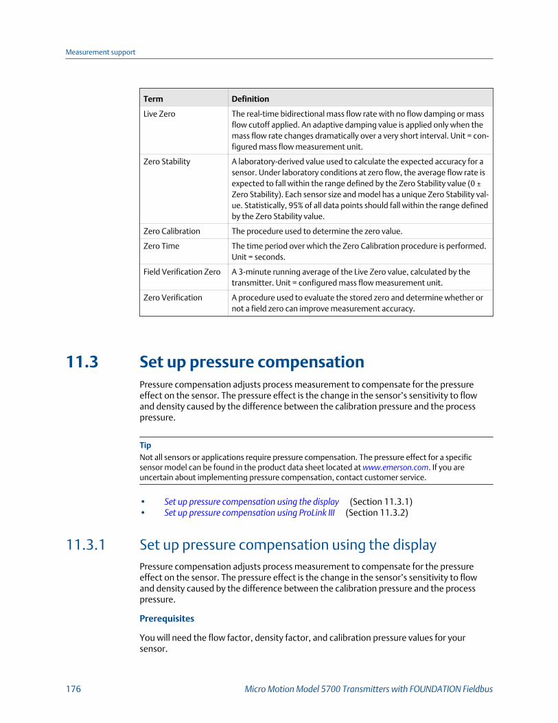
Term Definition
Live Zero The real-time bidirectional mass flow rate with no flow damping or massflow cutoff applied. An adaptive damping value is applied only when themass flow rate changes dramatically over a very short interval. Unit = con-figured mass flow measurement unit.
Zero Stability A laboratory-derived value used to calculate the expected accuracy for asensor. Under laboratory conditions at zero flow, the average flow rate isexpected to fall within the range defined by the Zero Stability value (0 ±Zero Stability). Each sensor size and model has a unique Zero Stability val-ue. Statistically, 95% of all data points should fall within the range definedby the Zero Stability value.
Zero Calibration The procedure used to determine the zero value.
Zero Time The time period over which the Zero Calibration procedure is performed.Unit = seconds.
Field Verification Zero A 3-minute running average of the Live Zero value, calculated by thetransmitter. Unit = configured mass flow measurement unit.
Zero Verification A procedure used to evaluate the stored zero and determine whether ornot a field zero can improve measurement accuracy.
11.3 Set up pressure compensationPressure compensation adjusts process measurement to compensate for the pressureeffect on the sensor. The pressure effect is the change in the sensor’s sensitivity to flowand density caused by the difference between the calibration pressure and the processpressure.
TipNot all sensors or applications require pressure compensation. The pressure effect for a specificsensor model can be found in the product data sheet located at www.emerson.com. If you areuncertain about implementing pressure compensation, contact customer service.
• Set up pressure compensation using the display (Section 11.3.1)• Set up pressure compensation using ProLink III (Section 11.3.2)
11.3.1 Set up pressure compensation using the displayPressure compensation adjusts process measurement to compensate for the pressureeffect on the sensor. The pressure effect is the change in the sensor’s sensitivity to flowand density caused by the difference between the calibration pressure and the processpressure.
Prerequisites
You will need the flow factor, density factor, and calibration pressure values for yoursensor.
Measurement support
176 Micro Motion Model 5700 Transmitters with FOUNDATION Fieldbus
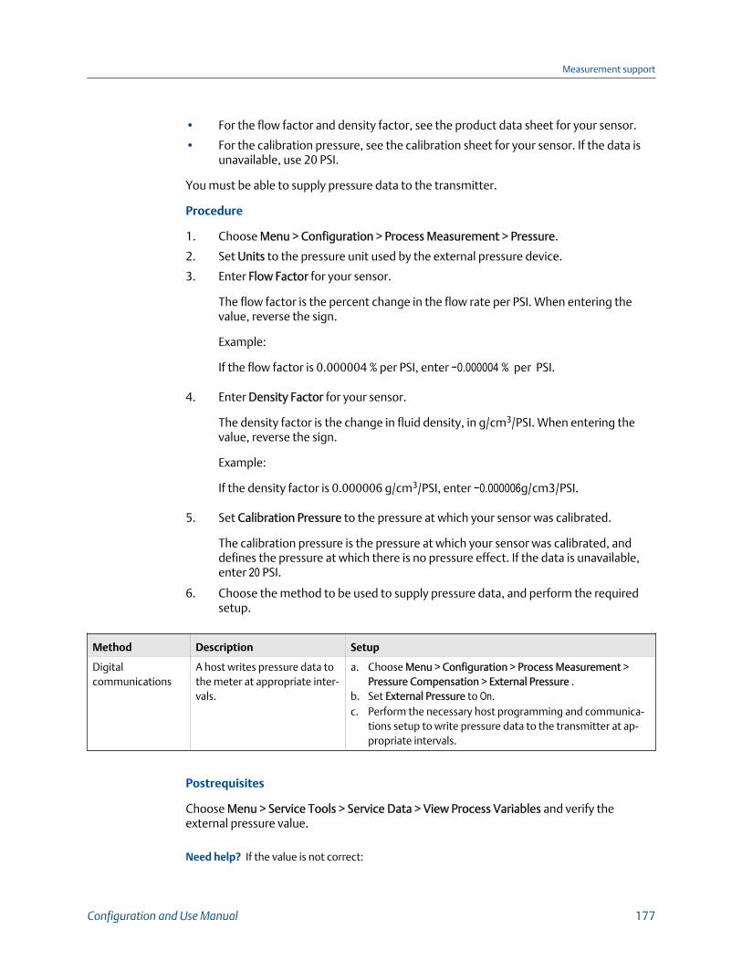
• For the flow factor and density factor, see the product data sheet for your sensor.
• For the calibration pressure, see the calibration sheet for your sensor. If the data isunavailable, use 20 PSI.
You must be able to supply pressure data to the transmitter.
Procedure
1. Choose Menu > Configuration > Process Measurement > Pressure.
2. Set Units to the pressure unit used by the external pressure device.
3. Enter Flow Factor for your sensor.
The flow factor is the percent change in the flow rate per PSI. When entering thevalue, reverse the sign.
Example:
If the flow factor is 0.000004 % per PSI, enter −0.000004 % per PSI.
4. Enter Density Factor for your sensor.
The density factor is the change in fluid density, in g/cm3/PSI. When entering thevalue, reverse the sign.
Example:
If the density factor is 0.000006 g/cm3/PSI, enter −0.000006g/cm3/PSI.
5. Set Calibration Pressure to the pressure at which your sensor was calibrated.
The calibration pressure is the pressure at which your sensor was calibrated, anddefines the pressure at which there is no pressure effect. If the data is unavailable,enter 20 PSI.
6. Choose the method to be used to supply pressure data, and perform the requiredsetup.
Method Description Setup
Digitalcommunications
A host writes pressure data tothe meter at appropriate inter-vals.
a. Choose Menu > Configuration > Process Measurement >Pressure Compensation > External Pressure .
b. Set External Pressure to On.c. Perform the necessary host programming and communica-
tions setup to write pressure data to the transmitter at ap-propriate intervals.
Postrequisites
Choose Menu > Service Tools > Service Data > View Process Variables and verify theexternal pressure value.
Need help? If the value is not correct:
Measurement support
Configuration and Use Manual 177
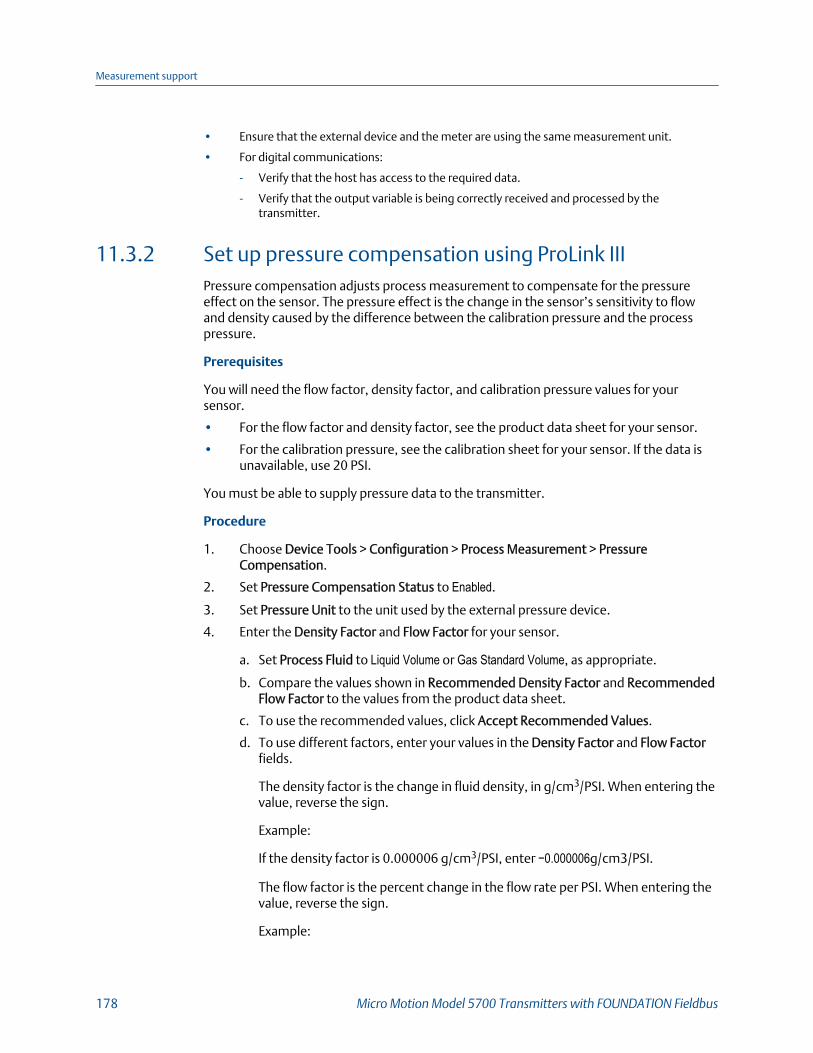
• Ensure that the external device and the meter are using the same measurement unit.
• For digital communications:
- Verify that the host has access to the required data.
- Verify that the output variable is being correctly received and processed by thetransmitter.
11.3.2 Set up pressure compensation using ProLink IIIPressure compensation adjusts process measurement to compensate for the pressureeffect on the sensor. The pressure effect is the change in the sensor’s sensitivity to flowand density caused by the difference between the calibration pressure and the processpressure.
Prerequisites
You will need the flow factor, density factor, and calibration pressure values for yoursensor.
• For the flow factor and density factor, see the product data sheet for your sensor.
• For the calibration pressure, see the calibration sheet for your sensor. If the data isunavailable, use 20 PSI.
You must be able to supply pressure data to the transmitter.
Procedure
1. Choose Device Tools > Configuration > Process Measurement > PressureCompensation.
2. Set Pressure Compensation Status to Enabled.
3. Set Pressure Unit to the unit used by the external pressure device.
4. Enter the Density Factor and Flow Factor for your sensor.
a. Set Process Fluid to Liquid Volume or Gas Standard Volume, as appropriate.
b. Compare the values shown in Recommended Density Factor and RecommendedFlow Factor to the values from the product data sheet.
c. To use the recommended values, click Accept Recommended Values.
d. To use different factors, enter your values in the Density Factor and Flow Factorfields.
The density factor is the change in fluid density, in g/cm3/PSI. When entering thevalue, reverse the sign.
Example:
If the density factor is 0.000006 g/cm3/PSI, enter −0.000006g/cm3/PSI.
The flow factor is the percent change in the flow rate per PSI. When entering thevalue, reverse the sign.
Example:
Measurement support
178 Micro Motion Model 5700 Transmitters with FOUNDATION Fieldbus

If the flow factor is 0.000004 % per PSI, enter −0.000004 % per PSI.
5. Set Flow Calibration Pressure to the pressure at which your sensor was calibrated.
The calibration pressure is the pressure at which your sensor was calibrated, anddefines the pressure at which there is no pressure effect. If the data is unavailable,enter 20 PSI.
6. Choose the method you will use to supply pressure data, and perform the requiredsetup.
Option Description Setup
Digitalcommunications
A host writes pressure data tothe meter at appropriate inter-vals.
a. Set Pressure Source to Fixed Value or Digital Communications.b. Perform the necessary host programming and communica-
tions setup to write pressure data to the meter at appropri-ate intervals.
Postrequisites
The current pressure value is displayed in the External Pressure field. Verify that the value iscorrect.
Need help? If the value is not correct:
• Ensure that the external device and the meter are using the same measurement unit.
• For digital communications:
- Verify that the host has access to the required data.
- Verify that the output variable is being correctly received and processed by thetransmitter.
11.3.3 Configure pressure compensation using an enhanced FFhostPressure compensation adjusts process measurement to compensate for the pressureeffect on the sensor. The pressure effect is the change in the sensor’s sensitivity to flowand density caused by the difference between the calibration pressure and the processpressure.
Prerequisites
You will need the flow factor, density factor, and calibration pressure values for yoursensor.
• For the flow factor and density factor, see the product data sheet for your sensor.
• For the calibration pressure, see the calibration sheet for your sensor. If the data isunavailable, use 20 PSI.
You must be able to supply pressure data to the transmitter.
Measurement support
Configuration and Use Manual 179

Procedure
1. Choose Configure > Manual Setup > Measurements > Optional Setup > ExternalVariables > Pressure.
2. Set Pressure Unit to the unit used by the external pressure device.
3. Enable Pressure Compensation.
4. Set Flow Calibration Pressure to the pressure at which your sensor was calibrated.
The calibration pressure is the pressure at which your sensor was calibrated, anddefines the pressure at which there is no pressure effect. If the data is unavailable,enter 20 PSI.
5. Enter Flow Press Factor for your sensor.
The flow factor is the percent change in the flow rate per PSI. When entering thevalue, reverse the sign.
Example:
If the flow factor is 0.000004 % per PSI, enter −0.000004 % per PSI.
6. Enter Density Pressure Factor for your sensor.
The density factor is the change in fluid density, in g/cm3/PSI. When entering thevalue, reverse the sign.
Example:
If the density factor is 0.000006 g/cm3/PSI, enter −0.000006g/cm3/PSI.
7. Choose the method to be used to supply pressure data, and perform the requiredsetup.
Method Description Setup
Digital communica-tions
A host writes pressure data tothe meter at appropriate inter-vals.
a. Choose Configure > Manual Setup > Measurements > Op-tional Setup > External Variables > Pressure .
b. Set Pressure Compensation to Enable.c. Perform the necessary host programming and communica-
tions setup to write pressure data to the transmitter at ap-propriate intervals.
Measurement support
180 Micro Motion Model 5700 Transmitters with FOUNDATION Fieldbus

11.4 Validate the meter
Display Menu > Configuration > Process Measurement > Flow Variables > Mass Flow Settings >
Meter Factor
Menu > Configuration > Process Measurement > Flow Variables > Volume Flow Settings >
Meter Factor
Menu > Configuration > Process Measurement > Density > Meter Factor
ProLink III Device Tools > Configuration > Process Measurement > Flow > Mass Flow Rate Meter
Factor
Device Tools > Configuration > Process Measurement > Flow > Volume Flow Rate Meter
Factor
Device Tools > Configuration > Process Measurement > Density > Density Meter Factor
Enhanced FF host Configure > Manual Setup > Measurements > Mass Flow > Factor
Configure > Manual Setup > Measurements > Volume Flow > Factor
Configure > Manual Setup > Measurements > Density > Factor
Basic FF host Measurement TB > Mass Flow Factor
Measurement TB > Volume Flow Factor
Measurement TB > Density Factor
Overview
Meter validation compares flowmeter measurements reported by the transmitter to anexternal measurement standard. If the transmitter value for mass flow, volume flow, ordensity measurement is significantly different from the external measurement standard,you may want to adjust the corresponding meter factor. The flowmeter’s actualmeasurement is multiplied by the meter factor, and the resulting value is reported andused in further processing.
Prerequisites
Identify the meter factor(s) that you will calculate and set. You may set any combination ofthe three meter factors: mass flow, volume flow, and density. Note that all three meterfactors are independent:
• The meter factor for mass flow affects only the value reported for mass flow.
• The meter factor for density affects only the value reported for density.
• The meter factor for volume flow affects only the value reported for volume flow orgas standard volume flow.
ImportantTo adjust volume flow, you must set the meter factor for volume flow. Setting a meter factor formass flow and a meter factor for density will not produce the desired result. The volume flowcalculations are based on original mass flow and density values, before the corresponding meterfactors have been applied.
Measurement support
Configuration and Use Manual 181

If you plan to calculate the meter factor for volume flow, be aware that validating volumein the field may be expensive, and the procedure may be hazardous for some processfluids. Therefore, because volume is inversely proportional to density, an alternative todirect measurement is to calculate the meter factor for volume flow from the meter factorfor density. See Section 11.4.1 for instructions on this method.
Obtain a reference device (external measurement device) for the appropriate processvariable.
ImportantFor good results, the reference device must be highly accurate.
Procedure
1. Determine the meter factor as follows:
a. Use the flowmeter to take a sample measurement.
b. Measure the same sample using the reference device.
c. Calculate the meter factor using the following formula:
NewMeterFactor = ConfiguredMeterFactorReferenceMeasurementFlowmeterMeasurement
2. Ensure that the calculated meter factor does not fall outside 0.98 and 1.02. If themeter factor is outside these limits, contact customer service.
3. Configure the meter factor in the transmitter.
Example: Calculating the meter factor for mass flow
The flowmeter is installed and validated for the first time. The mass flow measurementfrom the transmitter is 250.27 lb. The mass flow measurement from the reference deviceis 250 lb. The mass flow meter factor is calculated as follows:
MeterFactorMassFlow = 1250
250.27= 0.9989
The first meter factor for mass flow is 0.9989.
One year later, the flowmeter is validated again. The mass flow measurement from thetransmitter is 250.07 lb. The mass flow measurement from the reference device is250.25 lb. The new mass flow meter factor is calculated as follows:
MeterFactorMassFlow = 0.9989250.25250.07
= 0.9996
The new meter factor for mass flow is 0.9996.
Measurement support
182 Micro Motion Model 5700 Transmitters with FOUNDATION Fieldbus
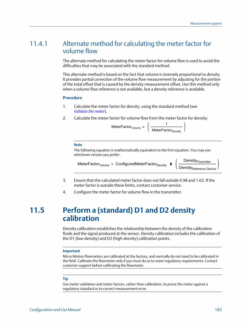
11.4.1 Alternate method for calculating the meter factor forvolume flowThe alternate method for calculating the meter factor for volume flow is used to avoid thedifficulties that may be associated with the standard method.
This alternate method is based on the fact that volume is inversely proportional to density.It provides partial correction of the volume flow measurement by adjusting for the portionof the total offset that is caused by the density measurement offset. Use this method onlywhen a volume flow reference is not available, but a density reference is available.
Procedure
1. Calculate the meter factor for density, using the standard method (see Validate the meter).
2. Calculate the meter factor for volume flow from the meter factor for density:
MeterFactorVolume =1
MeterFactorDensity
NoteThe following equation is mathematically equivalent to the first equation. You may usewhichever version you prefer.
MeterFactorVolume = ConfiguredMeterFactorDensityDensityFlowmeter
DensityReference Device
3. Ensure that the calculated meter factor does not fall outside 0.98 and 1.02. If themeter factor is outside these limits, contact customer service.
4. Configure the meter factor for volume flow in the transmitter.
11.5 Perform a (standard) D1 and D2 densitycalibrationDensity calibration establishes the relationship between the density of the calibrationfluids and the signal produced at the sensor. Density calibration includes the calibration ofthe D1 (low-density) and D2 (high-density) calibration points.
ImportantMicro Motion flowmeters are calibrated at the factory, and normally do not need to be calibrated inthe field. Calibrate the flowmeter only if you must do so to meet regulatory requirements. Contactcustomer support before calibrating the flowmeter.
TipUse meter validation and meter factors, rather than calibration, to prove the meter against aregulatory standard or to correct measurement error.
Measurement support
Configuration and Use Manual 183

Prerequisites
• During density calibration, the sensor must be completely filled with the calibrationfluid, and flow through the sensor must be at the lowest rate allowed by yourapplication. This is usually accomplished by closing the shutoff valve downstreamfrom the sensor, then filling the sensor with the appropriate fluid.
• D1 and D2 density calibration require a D1 (low-density) fluid and a D2 (high-density) fluid. You may use air and water.
• The calibrations must be performed without interruption, in the order shown. Makesure that you are prepared to complete the process without interruption.
• Before performing the calibration, record your current calibration parameters. Youcan do this by saving the current configuration to a file on the PC. If the calibrationfails, restore the known values.
RestrictionFor T-Series sensors, the D1 calibration must be performed on air and the D2 calibration must beperformed on water.
• Perform a D1 and D2 density calibration using the display (Section 11.5.1)• Perform a D1 and D2 density calibration using ProLink III (Section 11.5.2)
11.5.1 Perform a D1 and D2 density calibration using thedisplay1. Read page 184 if you have not already done so.
2. Close the shutoff valve downstream from the sensor.
3. Fill the sensor with the D1 fluid and allow the sensor to achieve thermal equilibrium.
4. Choose Menu > Service Tools > Verification and Calibration > Density Calibration.
5. Perform the D1 calibration.
a. Choose D1 (Air).
b. Enter the density of your D1 fluid.
c. Choose Start Calibration.
d. Wait for the calibration to complete.
e. Choose Finished.
6. Fill the sensor with the D2 fluid and allow the sensor to achieve thermal equilibrium.
7. Perform the D2 calibration.
a. Choose D2 (Water).
b. Enter the density of your D2 fluid.
c. Choose Start Calibration.
d. Wait for the calibration to complete.
e. Choose Finished.
Measurement support
184 Micro Motion Model 5700 Transmitters with FOUNDATION Fieldbus

8. Open the shutoff valve.
11.5.2 Perform a D1 and D2 density calibration using ProLink III1. Read page 184 if you have not already done so.
2. See the following figure.
11.5.3 Perform a D1 and D2 density calibration using anenhanced FF host1. Read the Prerequistes on page 184 if you have not already done so.
2. See the following figure.
Measurement support
Configuration and Use Manual 185

D1 and D2 density calibration using an enhanced FF hostFigure 11-1:
11.6 Adjust concentration measurement with TrimSlope and Trim OffsetTrim Slope and Trim Offset adjust the meter's concentration measurement to match areference value.
TipYou can adjust concentration measurement by applying the trim offset only, or by applying both thetrim offset and the trim slope. For most applications, the trim offset is sufficient.
Measurement support
186 Micro Motion Model 5700 Transmitters with FOUNDATION Fieldbus
Prerequisites
Ensure that the active matrix is the one that you want to trim. You can set the offset andslope separately for each matrix on your transmitter.
You must be able to take measurements of your process fluid at two differentconcentrations.
You must be able to take a sample of your process fluid at each of these concentrations.
For each sample, you must be able to obtain a laboratory concentration value at linedensity and line temperature.
Procedure
1. Collect data for Comparison 1.
a. Take a concentration reading from the meter and record line density and linetemperature.
b. Take a sample of the process fluid at the current concentration.
c. Obtain a laboratory value for concentration at line density and line temperature,in the units used by the meter.
2. Collect data for Comparison 2.
a. Change the concentration of your process fluid.
b. Take a concentration reading from the meter and record line density and linetemperature.
c. Take a sample of the process fluid at the current concentration.
d. Obtain a laboratory value for concentration at line density and line temperature,in the units used by the meter.
3. Populate the following equation with values from each comparison.ConcentrationLab = � × ConcentrationMeter + �4. Solve for A (slope).
5. Solve for B (offset), using the calculated slope and one set of values.
6. Enter the results as the trim slope and the trim offset.
• Using ProLink III: Choose Device Tools > Configuration > Process Measurement >Concentration Measurement, set Matrix Being Configured to your matrix, andenter Trim Slope and Trim Offset.
• Using an enhanced FF host: Choose Configure > Manual Setup > Measurement >Optional Setup > Concentration Measurement > Trim CM Process Variables andset Matrix Being Configured to your matrix, and enter Trim Slope and TrimOffset.
• Using a basic FF host:
- Concentration Measurement TB > Slope Trim
- Concentration Measurement TB > Offset Trim
Measurement support
Configuration and Use Manual 187

7. Take another concentration reading from the meter, and compare it to thelaboratory value.
• If the two values are acceptably close, the trim is complete.
• If the two values are not acceptably close, repeat this procedure.
Example: Calculating the trim slope and the trim offset
Comparison 1 Laboratory value 50.00%
Meter value 49.98%
Comparison 2 Laboratory value 16.00%
Meter value 15.99%
Populate the equations: 50 = � × 49.98 + �16 = � × 15.99 + �Solve for A: 50.00− 16.00 = 34.0049.98− 15.99 = 39.9934 = � × 33.99� = 1.00029Solve for B: 50.00 = 1.00029 × 49.98 + �50.00 = 49.99449 + �� = 0.00551Concentration slope (A): 1.00029
Concentration offset (B): 0.00551
Measurement support
188 Micro Motion Model 5700 Transmitters with FOUNDATION Fieldbus

12 MaintenanceTopics covered in this chapter:
• Install a new transmitter license
• Upgrade the transmitter firmware
• Reboot the transmitter
• Battery replacement
12.1 Install a new transmitter license
Display Menu > Service Tools > License Manager
ProLink III Device Tools > Configuration > Feature License
Enhanced FF host Overview > Device Information > Licenses
Basic FF host Device TB > Permanent License Key (OD Index 138)
Device TB > Temporary License Key (OD Index 139)
Overview
Whenever you purchase additional features or request a trial license, you must install anew transmitter license. The new license makes the new features available on yourtransmitter. For concentration measurement and API referral, you may still need to enablethe application.
Prerequisites
You must have a license file provided by Micro Motion:
• perm.lic: Permanent license file
• temp.lic: Temporary license file
If you are planning to use the USB drive, the service port must be enabled. It is enabled bydefault. However, if you need to enable it, choose Menu > Configuration > Security and setService Port to On.
Procedure
• To install a license using the display:
1. Copy the license file to a folder on a USB drive.
ImportantYou must copy the license file to a folder. You cannot put it in the root.
Maintenance
Configuration and Use Manual 189

2. Open the wiring compartment on the transmitter and insert the USB drive intothe service port.
CAUTION!
If the transmitter is in a hazardous area, do not open the wiring compartment whilethe transmitter is powered up. Opening the wiring compartment while thetransmitter is powered up could cause an explosion. Install the license using amethod that does not require opening the wiring compartment.
3. Choose Menu > USB Options > USB Drive > Transmitter > Load License File.
4. Select the folder containing the license file and follow the prompts.
• To install a license using ProLink III:
1. Open the license file.
2. Choose Device Tools > Configuration > Feature License.
3. Copy the license from the file to the approprate License Key field.
• To install a license using an enhanced FF host:
1. Choose Overview > Device Information > Licenses > Upload License.
2. Select the license feature to upload, Permanent Feature or Temporary Feature.
3. Write the license key.
• To install a license using a basic FF host, write the 16 digit license key into theappropriate parameter on the Device TB.
The features supported by the new license are displayed.
If you installed a temporary license, the transmitter will revert to its original feature setwhen the license period has expired. To purchase a feature for permanent use, contactcustomer support.
Postrequisites
If you installed a permanent license, update the options model code to match the newlicense. The options model code represents the installed features.
Related information
Set informational parameters
Maintenance
190 Micro Motion Model 5700 Transmitters with FOUNDATION Fieldbus
12.2 Upgrade the transmitter firmwareYou can upgrade the transmitter firmware to stay current with development and to takeadvantage of any new features.
• Upgrade the transmitter firmware using the display (Section 12.2.1)• Upgrade the transmitter firmware using ProLink III (Section 12.2.2)
12.2.1 Upgrade the transmitter firmware using the displayYou can upgrade the transmitter firmware to stay current with development and to takeadvantage of any new features.
Prerequisites
You must have the firmware upgrade files provided by Micro Motion.
The service port must be enabled. It is enabled by default. However, if you need to enableit, choose Menu > Configuration > Security and set Service Port to On.
Procedure
1. Copy the folder containing the firmware upgrade files to a USB drive.
2. Open the wiring compartment and insert the USB drive into the service port.
CAUTION!
If the transmitter is in a hazardous area, do not open the wiring compartment. Contactcustomer support.
3. Choose Menu > USB Options > USB Drive --> Transmitter > Update Device Software.
4. Select the firmware upgrade folder and follow the prompts.
NoteIf required, the transmitter upgrade procedure automatically includes an upgrade to the coreprocessor software.
If you chose to reboot the transmitter at a later date, you can reboot it from themenu, or you can power-cycle it.
5. Verify the transmitter configuration and all safety parameters.
6. Enable write-protection.
Related information
Reboot the transmitter
Maintenance
Configuration and Use Manual 191

12.2.2 Upgrade the transmitter firmware using ProLink IIIYou can upgrade the transmitter firmware to stay current with development and to takeadvantage of any new features.
Prerequisites
You must have the firmware upgrade files provided by Micro Motion.
Procedure
1. Choose Device Tools > Transmitter Software Update.
2. Navigate to the folder containing the firmware upgrade files.
3. Click Update.
NoteIf required, the transmitter upgrade procedure automatically includes an upgrade to the coreprocessor software.
If you chose to reboot the transmitter at a later date, you can reboot it from thedisplay, or you can power-cycle it.
4. Verify the transmitter configuration and all safety parameters.
5. Enable write-protection.
Related information
Reboot the transmitter
12.3 Reboot the transmitter
Display Menu > Menu > Service Tools > Reboot Transmitter
ProLink III Not available
Enhanced FF host Service Tools > Maintenance > Reset/Restore > Device Reset
Basic FF host Not available
Overview
For certain configuration changes to take effect, the transmitter must be rebooted. Youmust also reboot the transmitter in order to clear certain status alerts.
Rebooting the transmitter has the same effect as power-cycling the transmitter.
Prerequisites
Follow appropriate procedures to select the appropriate time for rebooting thetransmitter. The reboot typically takes about 10 seconds.
Maintenance
192 Micro Motion Model 5700 Transmitters with FOUNDATION Fieldbus

Postrequisites
Check the transmitter clock. During the reboot, the transmitter clock is powered by thebattery, therefore the transmitter clock and all timestamps should be accurate. If thetransmitter clock is not correct, the battery may need replacement.
Related information
Battery replacement
12.4 Battery replacementThe transmitter contains a battery that is used to power the clock when the transmitter isnot powered up. Users cannot service or replace the battery. If the battery requiresreplacement, contact customer support.
If the battery is non-functional and the transmitter is powered down, then powered up, theclock will restart from the time of the power-down. All timestamps will be affected. Youcan correct the issue by resetting the transmitter clock. For a permanent resolution, thebattery must be replaced.
Related information
RoHS and WEEE
Maintenance
Configuration and Use Manual 193

Maintenance
194 Micro Motion Model 5700 Transmitters with FOUNDATION Fieldbus

13 Log files, history files, and service filesTopics covered in this chapter:
• Generate history log files
• Generate service files
13.1 Generate history log files
Display Menu > USB Options > Transmitter --> USB Drive > Download Historical Files
ProLink III Device Tools > Configuration Transfer > Download Historical Files
Enhanced FF host Not available
Basic FF host Not available
Overview
The transmitter automatically saves historical data of several types, including process anddiagnostic variables, Smart Meter Verification test results, and totalizer values. To accessthe historical data, you can generate a log file, then view it on your PC.
Prerequisites
If you want to generate a totalizer history log, you must have previously configured thetransmitter to record totalizer history. Totalizer history is not saved automatically.
If you plan to use the transmitter display:
• The service port must be enabled. It is enabled by default. However, if you need toenable it, choose Menu > Configuration > Security and set Service Port to On.
• You must have a USB drive.
Procedure
1. If you are using the transmitter display, open the wiring compartment and insert theUSB drive into the service port.
CAUTION!
If the transmitter is in a hazardous area, do not open the wiring compartment while thetransmitter is powered up. Opening the wiring compartment while the transmitter ispowered up could cause an explosion.
2. Select the type of log file that you want to generate.
3. If you selected historian data (process and diagnostic variables):
a. Set the date and time for the first entry in the historian log file.
Log files, history files, and service files
Configuration and Use Manual 195
b. Set the number of days that the log file will include.
c. Select the record type.
Option Description
1 Second Raw Data The current values of process and diagnostic variables, recorded at1-second intervals.
5 Min Average Data The minimum and maximum values of the 1-second raw data overthe last 5 minutes, plus the average and the standard deviation, re-corded at 5-minute intervals.
The system provides an estimated file size or transfer time.
4. Specify the location where the log file will be saved.
• If you are using the display, the log file is written to the USB drive.
• If you are using ProLink III, the log file is written to a folder on your PC.
The log file is written to the specified location. File names are assigned as follows:
• Historian files: The file name is based on the transmitter tag, the starting date of thelog contents, and the record type. The record type is shown as F or S:
- F=Fast, for 1-second raw data
- S=Slow, for 5-minute average data
• SMV files:
- SmvLast20Data.csv- SmvLongTermData.csv
• Totalizer history files: TotLog.txt
13.1.1 Historian data and logThe transmitter automatically saves information about specific process and diagnosticvariables to its working memory. You can generate a log from this data. The historian log isan ASCII file in .csv format.
Contents of the historian log
There are two types of historian records:
1-second raw data The current values of process and diagnostic variables, recordedat 1-second intervals.
5-minute averagedata
The minimum and maximum values of the 1-second raw data,plus the average and the standard deviation, calculated andrecorded at 5-minute intervals.
When you generate the log, you can specify which type of record you want to see.
The historian in the transmitter's working memory contains a minimum of 4 weeks of 1-second raw data and 10 years of 5-minute average data.
Log files, history files, and service files
196 Micro Motion Model 5700 Transmitters with FOUNDATION Fieldbus

Each record contains data for the following process and diagnostic variables:
• Timestamp
- Format: Military time
- Time and time zone: Transmitter clock
• Mass flow rate (kg/sec)
• Volume flow rate (l/sec) or GSV flow rate
• Density (g/cm³)
• Line temperature (°C)
• External temperature (if available)
• Pressure (if available)
• If concentration measurement is enabled:
- Standard volume flow rate
- Net mass flow rate
- Net volume flow rate
- Referred density
- Concentration
• If API referral is enabled:
- CTPL or CTL
- Corrected density
- Corrected volume flow rate
• Alert status registers (hexadecimal format)
• Live zero (kg/sec)
• Tube frequency (Hz)
• Drive gain (%)
• Left pickoff (filtered) (V)
• Right pickoff (filtered (V)
• Left pickoff (raw) (V)
• Delta T
• Case temperature (°C)
• Voltage applied to the core processor (V)
• Temperature of the core processor board (°C)
• Temperature of the transmitter electronics (°C)
Historian data and power-cycles
Historian data is maintained across transmitter reboots and power-cycles.
Historian data and configuration files
If you restore the factory configuration or upload a configuration file, existing historiandata is not affected.
Log files, history files, and service files
Configuration and Use Manual 197
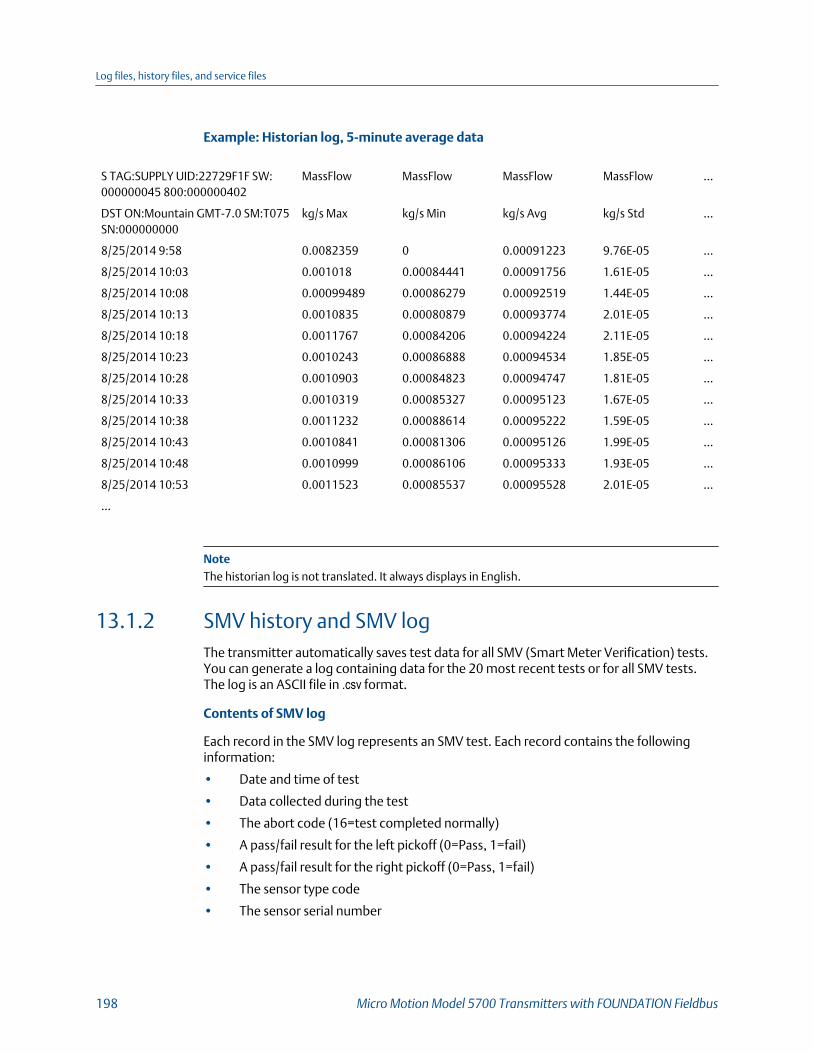
Example: Historian log, 5-minute average data
S TAG:SUPPLY UID:22729F1F SW:000000045 800:000000402
MassFlow MassFlow MassFlow MassFlow …
DST ON:Mountain GMT-7.0 SM:T075SN:000000000
kg/s Max kg/s Min kg/s Avg kg/s Std …
8/25/2014 9:58 0.0082359 0 0.00091223 9.76E-05 …
8/25/2014 10:03 0.001018 0.00084441 0.00091756 1.61E-05 …
8/25/2014 10:08 0.00099489 0.00086279 0.00092519 1.44E-05 …
8/25/2014 10:13 0.0010835 0.00080879 0.00093774 2.01E-05 …
8/25/2014 10:18 0.0011767 0.00084206 0.00094224 2.11E-05 …
8/25/2014 10:23 0.0010243 0.00086888 0.00094534 1.85E-05 …
8/25/2014 10:28 0.0010903 0.00084823 0.00094747 1.81E-05 …
8/25/2014 10:33 0.0010319 0.00085327 0.00095123 1.67E-05 …
8/25/2014 10:38 0.0011232 0.00088614 0.00095222 1.59E-05 …
8/25/2014 10:43 0.0010841 0.00081306 0.00095126 1.99E-05 …
8/25/2014 10:48 0.0010999 0.00086106 0.00095333 1.93E-05 …
8/25/2014 10:53 0.0011523 0.00085537 0.00095528 2.01E-05 …
…
NoteThe historian log is not translated. It always displays in English.
13.1.2 SMV history and SMV logThe transmitter automatically saves test data for all SMV (Smart Meter Verification) tests.You can generate a log containing data for the 20 most recent tests or for all SMV tests.The log is an ASCII file in .csv format.
Contents of SMV log
Each record in the SMV log represents an SMV test. Each record contains the followinginformation:
• Date and time of test
• Data collected during the test
• The abort code (16=test completed normally)
• A pass/fail result for the left pickoff (0=Pass, 1=fail)
• A pass/fail result for the right pickoff (0=Pass, 1=fail)
• The sensor type code
• The sensor serial number
Log files, history files, and service files
198 Micro Motion Model 5700 Transmitters with FOUNDATION Fieldbus

SMV history and power-cycles
If the transmitter is rebooted or power-cycled, SMV history is not affected.
SMV history and configuration files
If you restore the factory configuration or upload a configuration file, SMV history is notaffected.
Example: SMV log
Device UID: 577937183
Device Tag: SUPPLY
Time Zone: GMT -7.00
Date Time LPO Stiff RPO Stiff LPO Mass RPO Mass Damping Drv mA …
8/13/2014 19:27 0.285876 0.289738 0.155294 0.158114 4.41E-05 1.301 …
8/14/2014 7:27 -0.06137 -0.05808 0.154748 0.157556 4.02E-05 1.304 …
8/14/2014 19:27 0.204754 0.20932 0.155185 0.158004 4.35E-05 1.308 …
8/15/2014 7:27 -0.15382 -0.15216 0.154612 0.157416 3.93E-05 1.307 …
8/18/2014 16:27 0.251067 0.251782 0.155217 0.158031 4.34E-05 1.308 …
8/19/2014 19:27 -0.13654 -0.14112 0.154602 0.157396 3.89E-05 1.287 …
8/20/2014 16:27 -0.20837 -0.20671 0.154502 0.157304 3.85E-05 1.291 …
8/21/2014 17:10 -0.11062 -0.11566 0.154641 0.157435 3.84E-05 1.288 …
8/22/2014 10:40 -0.15852 -0.16036 0.154512 0.157308 3.86E-05 1.284 …
8/25/2014 15:40 -0.00172 0.002301 0.154788 0.157599 4E-05 1.295 …
8/27/2014 23:16 0.132787 0.13684 0.155034 0.15785 4.08E-05 1.275 …
8/28/2014 11:16 0.04456 0.046158 0.154845 0.157653 3.99E-05 1.277 …
…
NoteThe SMV log is not translated. It always displays in English.
13.1.3 Totalizer history and logYou can configure the transmitter to save totalizer and inventory values at a user-specifiedinterval. You can then generate a totalizer log. The totalizer log is a ASCII file.
Contents of totalizer log
The totalizer log contains one record for each logged totalizer or inventory value. Eachrecord contains the following information:
• Default totalizer or inventory name (user-specified names are not used)
• Value and measurement unit
Log files, history files, and service files
Configuration and Use Manual 199
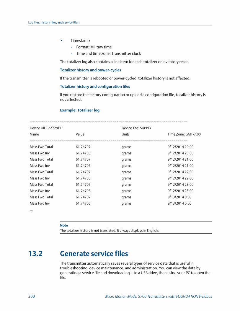
• Timestamp
- Format: Military time
- Time and time zone: Transmitter clock
The totalizer log also contains a line item for each totalizer or inventory reset.
Totalizer history and power-cycles
If the transmitter is rebooted or power-cycled, totalizer history is not affected.
Totalizer history and configuration files
If you restore the factory configuration or upload a configuration file, totalizer history isnot affected.
Example: Totalizer log
================================================================================
Device UID: 22729F1F Device Tag: SUPPLY
Name Value Units Time Zone: GMT-7.00
================================================================================
Mass Fwd Total 61.74707 grams 9/12/2014 20:00
Mass Fwd Inv 61.74705 grams 9/12/2014 20:00
Mass Fwd Total 61.74707 grams 9/12/2014 21:00
Mass Fwd Inv 61.74705 grams 9/12/2014 21:00
Mass Fwd Total 61.74707 grams 9/12/2014 22:00
Mass Fwd Inv 61.74705 grams 9/12/2014 22:00
Mass Fwd Total 61.74707 grams 9/12/2014 23:00
Mass Fwd Inv 61.74705 grams 9/12/2014 23:00
Mass Fwd Total 61.74707 grams 9/13/2014 0:00
Mass Fwd Inv 61.74705 grams 9/13/2014 0:00
…
NoteThe totalizer history is not translated. It always displays in English.
13.2 Generate service filesThe transmitter automatically saves several types of service data that is useful introubleshooting, device maintenance, and administration. You can view the data bygenerating a service file and downloading it to a USB drive, then using your PC to open thefile.
Log files, history files, and service files
200 Micro Motion Model 5700 Transmitters with FOUNDATION Fieldbus

Prerequisites
The service port must be enabled. It is enabled by default. However, if you need to enableit, choose Menu > Configuration > Security and set Service Port to On.
You must have a USB drive.
Procedure
1. Open the wiring compartment on the transmitter and insert the USB drive into theservice port.
CAUTION!
If the transmitter is in a hazardous area, do not open the wiring compartment while thetransmitter is powered up. Opening the wiring compartment while the transmitter ispowered up could cause an explosion.
2. Choose Menu > USB Options > Transmitter --> USB > Download Service Files.
3. Select the service file that you want to generate.
Service file Description File name
ConfigurationAudit Log
All changes to configuration, includingchanges made by procedures such as zerocalibration or density calibration.
ConfgAuditLog.txt
Alert History All occurrences of alerts and conditions, in-dependent of alert severity.
AlertLog.txt
Historian: 30Days
Values of selected process and diagnosticvariables for the last 30 days, recorded at 1-second intervals.
Concatenated fromtransmitter tagand date
Historian: 1 Day Values of selected process and diagnosticvariables for the last 24 hours, recorded at 1-second intervals.
Concatenated fromtransmitter tagand date
SMV: 20 Runs Test data from the 20 most recent SMVtests.
SmvLast20Data.csv
Service Snap-shot
An ASCII file containing a snapshot of thetransmitter's internal database. This file isused by customer service.
service.dump
Factory ConfigFile
The configuration file created for this trans-mitter at the factory.
FactoryConfig.cfg
Assert Log A troubleshooting file used by customerservice.
AssertLog.txt
Support Contact A PDF file containing information for con-tacting customer service.
SupportContact.pdf
Security Log A record of events that might indicate tam-pering.
SecurityLog.txt
Log files, history files, and service files
Configuration and Use Manual 201

4. Specify the folder on the USB drive where the log file will be saved.
13.2.1 Alert history and logThe transmitter automatically saves information about all alert occurrences to its workingmemory, and periodically updates an alert history file on its SD card. The alert history log isan ASCII file.
Contents of alert history
The alert history in the transmitter's working memory contains the 1000 most recent alertrecords. Each alert record contains the following information:
• Name of alert or condition
• Category:
- F=Failure
- FC=Function Check
- M=Maintenance Required
- OOS=Out of Specification
- I=Ignore
• Action:
- Active=Transition from inactive to active
- Inactive=Transition from active to inactive
- Toggling=More than 2 transitions in the last 60 seconds
• Timestamp
- Format: Military time
- Time and time zone: Transmitter clock
- Not displayed if Action=Toggling
Alert history and power-cycles
If the transmitter is rebooted or power-cycled, the 20 most recent records in alert historyare retained in the transmitter's working memory. All earlier records are cleared fromworking memory. The alert history file on the SD card is not cleared.
Alert history and configuration files
If you restore the factory configuration or upload a configuration file, alert history is notaffected.
Log files, history files, and service files
202 Micro Motion Model 5700 Transmitters with FOUNDATION Fieldbus

Example: Alert history log
================================================================================
Device UID: 22729F1F Device Tag: SUPPLY
Name Cat Action Time Zone: GMT-7.00
================================================================================
[100] MAO1 Saturated OOS Toggling
[110] FO1 Saturated OOS Toggling
[105] Two-Phase Flow OOS Inactive 15/SEP/2014 16:33:30
[105] Two-Phase Flow OOS Toggling
[035] SMV Aborted M Active 15/SEP/2014 16:33:44
[100] MAO1 Saturated OOS Active 15/SEP/2014 16:34:23
[110] FO1 Saturated OOS Active 15/SEP/2014 16:34:23
[100] MAO1 Saturated OOS Toggling
[110] FO1 Saturated OOS Toggling
[105] Two-Phase Flow OOS Inactive 15/SEP/2014 16:34:23
[105] Two-Phase Flow OOS Toggling
[100] MAO1 Saturated OOS Inactive 15/SEP/2014 16:35:48
[110] FO1 Saturated OOS Inactive 15/SEP/2014 16:35:48
…
NoteThe alert history is not translated. It always displays in English.
13.2.2 Configuration audit history and logThe transmitter automatically saves information about all configuration events to itsworking memory. The configuration audit log is an ASCII file.
Contents of configuration audit log
The configuration audit log contains a record for every change to transmitterconfiguration, including changes resulting from zero calibration, density calibration, etc.Each record contains:
• Modbus location in transmitter memory
- Cnnn=Coil
- Rnnn=Register
- Rnnn xxx=Array, indexed by register xxx
• Name of Modbus location
• Original value
• New value
Log files, history files, and service files
Configuration and Use Manual 203
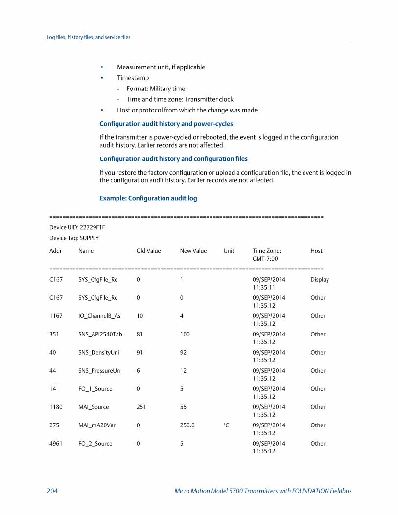
• Measurement unit, if applicable
• Timestamp
- Format: Military time
- Time and time zone: Transmitter clock
• Host or protocol from which the change was made
Configuration audit history and power-cycles
If the transmitter is power-cycled or rebooted, the event is logged in the configurationaudit history. Earlier records are not affected.
Configuration audit history and configuration files
If you restore the factory configuration or upload a configuration file, the event is logged inthe configuration audit history. Earlier records are not affected.
Example: Configuration audit log
====================================================================================
Device UID: 22729F1F
Device Tag: SUPPLY
Addr Name Old Value New Value Unit Time Zone:GMT-7:00
Host
====================================================================================
C167 SYS_CfgFile_Re 0 1 09/SEP/201411:35:11
Display
C167 SYS_CfgFile_Re 0 0 09/SEP/201411:35:12
Other
1167 IO_ChannelB_As 10 4 09/SEP/201411:35:12
Other
351 SNS_API2540Tab 81 100 09/SEP/201411:35:12
Other
40 SNS_DensityUni 91 92 09/SEP/201411:35:12
Other
44 SNS_PressureUn 6 12 09/SEP/201411:35:12
Other
14 FO_1_Source 0 5 09/SEP/201411:35:12
Other
1180 MAI_Source 251 55 09/SEP/201411:35:12
Other
275 MAI_mA20Var 0 250.0 °C 09/SEP/201411:35:12
Other
4961 FO_2_Source 0 5 09/SEP/201411:35:12
Other
Log files, history files, and service files
204 Micro Motion Model 5700 Transmitters with FOUNDATION Fieldbus
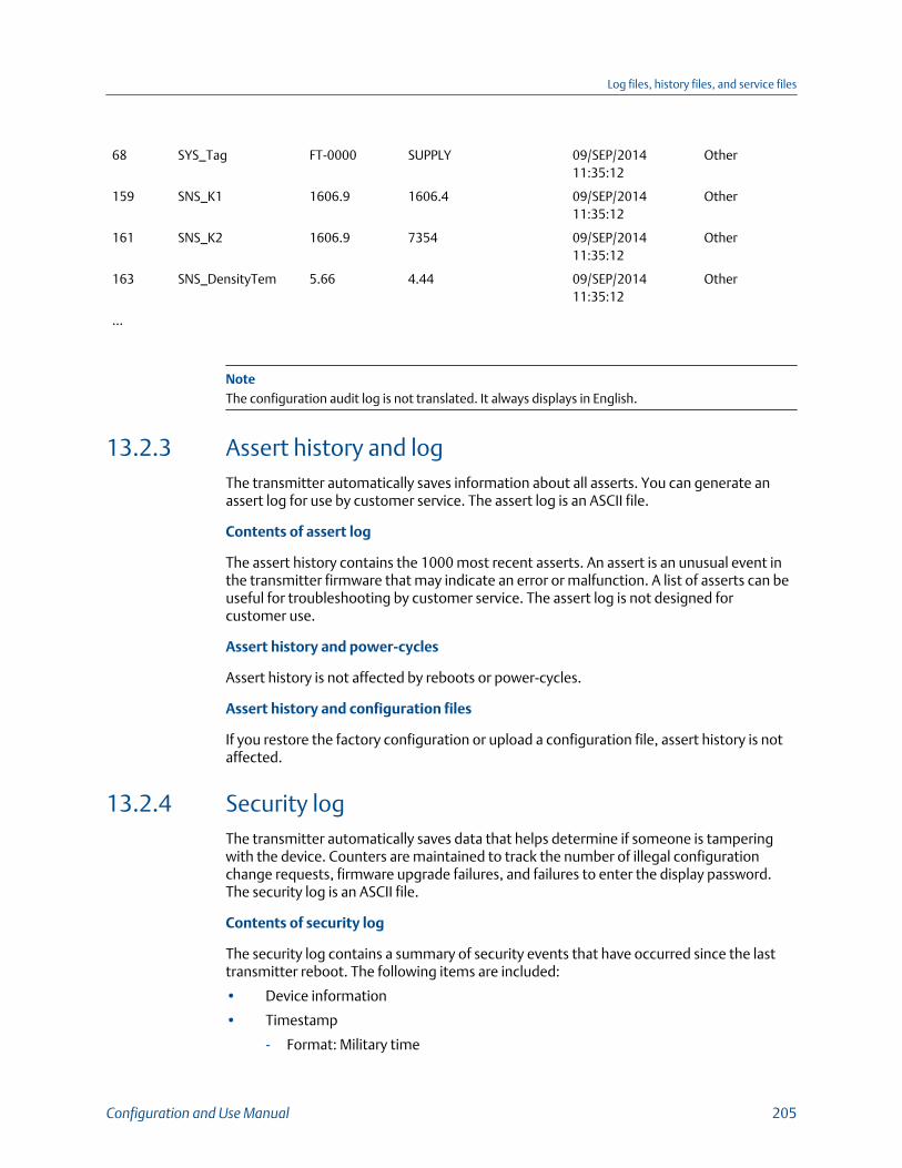
68 SYS_Tag FT-0000 SUPPLY 09/SEP/201411:35:12
Other
159 SNS_K1 1606.9 1606.4 09/SEP/201411:35:12
Other
161 SNS_K2 1606.9 7354 09/SEP/201411:35:12
Other
163 SNS_DensityTem 5.66 4.44 09/SEP/201411:35:12
Other
…
NoteThe configuration audit log is not translated. It always displays in English.
13.2.3 Assert history and logThe transmitter automatically saves information about all asserts. You can generate anassert log for use by customer service. The assert log is an ASCII file.
Contents of assert log
The assert history contains the 1000 most recent asserts. An assert is an unusual event inthe transmitter firmware that may indicate an error or malfunction. A list of asserts can beuseful for troubleshooting by customer service. The assert log is not designed forcustomer use.
Assert history and power-cycles
Assert history is not affected by reboots or power-cycles.
Assert history and configuration files
If you restore the factory configuration or upload a configuration file, assert history is notaffected.
13.2.4 Security logThe transmitter automatically saves data that helps determine if someone is tamperingwith the device. Counters are maintained to track the number of illegal configurationchange requests, firmware upgrade failures, and failures to enter the display password.The security log is an ASCII file.
Contents of security log
The security log contains a summary of security events that have occurred since the lasttransmitter reboot. The following items are included:
• Device information
• Timestamp
- Format: Military time
Log files, history files, and service files
Configuration and Use Manual 205

- Time and time zone: Transmitter clock
• Number of password entry failures
• Number of transmitter firmware upgrade failures
• Number of database write failures
Security log and power-cycles
If the transmitter is rebooted or power-cycled, the security log is not affected.
Security log and configuration files
If you attempt to restore the factory configuration or upload a configuration file whenwrite-protection is enabled, the Database Write Failures counter is increased.
Example: Security log file
TAG:SUPPLY UID:22729F1F SW:0045 DATE:23/SEP/201414:42:58
Device:Config I/O GMT-7.0 DST:DST Zone:(UTC-7:00) Denver
Addr Name Value
---------------------------------------------------------------------------------------------------------------------------------------------------
5851 Password Failures 0
5852 SW Upgrade Failures 0
5853 Database Write Failures 25636
NoteThe security log is not translated. It always displays in English.
Log files, history files, and service files
206 Micro Motion Model 5700 Transmitters with FOUNDATION Fieldbus

14 TroubleshootingTopics covered in this chapter:
• Status LED and device status
• Status alerts, causes, and recommendations
• Flow measurement problems
• Density measurement problems
• Temperature measurement problems
• Velocity measurement problems
• API referral problems
• Concentration measurement problems
• Milliamp output problems
• Frequency output problems
• Discrete output problems
• Check power supply wiring
• Check sensor‐to‐transmitter wiring
• Check grounding
• Perform loop tests
• Trim mA output
• Using sensor simulation for troubleshooting
• Check Lower Range Value and Upper Range Value
• Check mA Output Fault Action
• Check the scaling of the frequency output
• Check Frequency Output Fault Action
• Check the direction parameters
• Check the cutoffs
• Check for two‐phase flow (slug flow)
• Check for radio frequency interference (RFI)
• Check the drive gain
• Check the pickoff voltage
• Check for internal electrical problems
• Perform a core processor resistance test
Troubleshooting
Configuration and Use Manual 207

14.1 Status LED and device statusThe status LED (MOD STATUS) on the transmitter display provides a quick indication ofdevice status by changing color and flashing. If the transmitter was ordered without adisplay, the LEDs on the outputs board inside the transmitter provide the sameinformation.
Status LED and device statusTable 14-1:
Status LED condition Device status
Solid green No alerts are active.
Solid yellow One or more alerts are active with Alert Severity = Out of Specifica-tion, Maintenance Required, or Function Check.
Solid red One or more alerts are active with Alert Severity = Failure.
Flashing yellow (1 Hz) The Function Check in Progress alert is active.
14.2 Status alerts, causes, and recommendations
Status alerts, causes, and recommendationsTable 14-2:
Alert
Conditions
Name (code) Cause Recommended actions
Function check Out of service One of the transducerblockss has been placedout of service.
• Return block to Auto mode toresume normal operation
FC in progress Calibration inProgress (104)
A calibration procedureis in process.
• Allow the procedure to com-plete
• For zero calibration proce-dures, you may abort the cali-bration, set the zero time pa-rameter to a lower value, andrestart the calibration.
Smart MeterVerificationin Progress (131)
Smart Meter verifica-tion is in progress.
• Allow the procedure to com-plete.
Sensor beingsimulated
Sensor SimulationOn (132)
• Simulation mode isenabled.
• Device simulation isactive.
• Disable sensor simulation.
Troubleshooting
208 Micro Motion Model 5700 Transmitters with FOUNDATION Fieldbus

Status alerts, causes, and recommendations (continued)Table 14-2:
Alert
Conditions
Name (code) Cause Recommended actions
Output fixed mA Output Fixed(114)
Output simulation(loop testing) is ena-bled or mA output trimis in progress.
• Disable output simulation, ifapplicable.
• Exit mA output trim, if appli-cable.
• Check whether the outputhas been set to a constantvalue via digital communica-tion.
Frequency OutputFixed (111)
Totalizers have beenstopped or output sim-ulation (loop testing) isenabled.
• Stopping the totalizer will setthe frequency output to zero.Cycling power to the trans-mitter or restarting the total-izer will restore the frequencyoutput to normal operation.
• Disable output simulation, ifapplicable.
• Check if the output has beenset to a constant value viadigital communication.
Discrete OutputFixed (119)
Output simulation(loop testing) is ena-bled.
• Disable output simulation.
Processaberration
Two-Phase Flow(105)
The density has excee-ded the user-definedslug (density) limits.
• Check for two-phase flow.
No Input (115) No response receivedfrom polled device.
• Verify that the external de-vice is operating correctly.
• Verify the wiring between thetransmitter and the externaldevice.
Temperature Outof Range (116)
The measured temper-ature is outside therange of the API table.
• Check your process condi-tions against the values re-ported by the device.
• Verify the configuration ofthe API referral applicationand related parameters.
Troubleshooting
Configuration and Use Manual 209
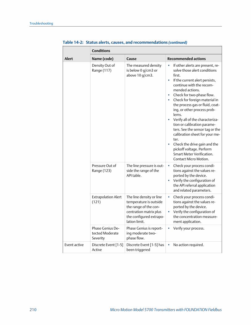
Status alerts, causes, and recommendations (continued)Table 14-2:
Alert
Conditions
Name (code) Cause Recommended actions
Density Out ofRange (117)
The measured densityis below 0 g/cm3 orabove 10 g/cm3.
• If other alerts are present, re-solve those alert conditionsfirst.
• If the current alert persists,continue with the recom-mended actions.
• Check for two-phase flow.• Check for foreign material in
the process gas or fluid, coat-ing, or other process prob-lems.
• Verify all of the characteriza-tion or calibration parame-ters. See the sensor tag or thecalibration sheet for your me-ter.
• Check the drive gain and thepickoff voltage. PerformSmart Meter Verification.Contact Micro Motion.
Pressure Out ofRange (123)
The line pressure is out-side the range of theAPI table.
• Check your process condi-tions against the values re-ported by the device.
• Verify the configuration ofthe API referral applicationand related parameters.
Extrapolation Alert(121)
The line density or linetemperature is outsidethe range of the con-centration matrix plusthe configured extrapo-lation limit.
• Check your process condi-tions against the values re-ported by the device.
• Verify the configuration ofthe concentration measure-ment application.
Phase Genius De-tected ModerateSeverity
Phase Genius is report-ing moderate two-phase flow.
• Verify your process.
Event active Discrete Event [1-5]Active
Discrete Event [1-5] hasbeen triggered
• No action required.
Troubleshooting
210 Micro Motion Model 5700 Transmitters with FOUNDATION Fieldbus

Status alerts, causes, and recommendations (continued)Table 14-2:
Alert
Conditions
Name (code) Cause Recommended actions
Outputsaturated
mA OutputSaturated (113)
The calculated amountof current output is out-side of the linear range.
• Verify that Upper Range Val-ue and Lower Range Valueare set correctly for the proc-ess variable and the process.
• Check your process condi-tions against the values re-ported by the meter.
• Verify that the measurementunits are configured correctlyfor your application.
• Purge the flow tubes.• Verify process conditions,
checking especially for air inthe flow tubes, tubes not fil-led, foreign material in thetubes, or coating in thetubes.
Frequency OutputSaturated (110)
Process variable as-signed to frequencyoutput is outside con-figured scale limits.
• Check the Frequency OutputScaling Method parameter.
• Check your process condi-tions against the values re-ported by the meter.
• Verify process conditions,checking especially for air inthe flow tubes, tubes not fil-led, foreign material in thetubes, or coating in thetubes.
• Verify that the measurementunits are configured correctlyfor your application.
• Purge the flow tubes
Troubleshooting
Configuration and Use Manual 211
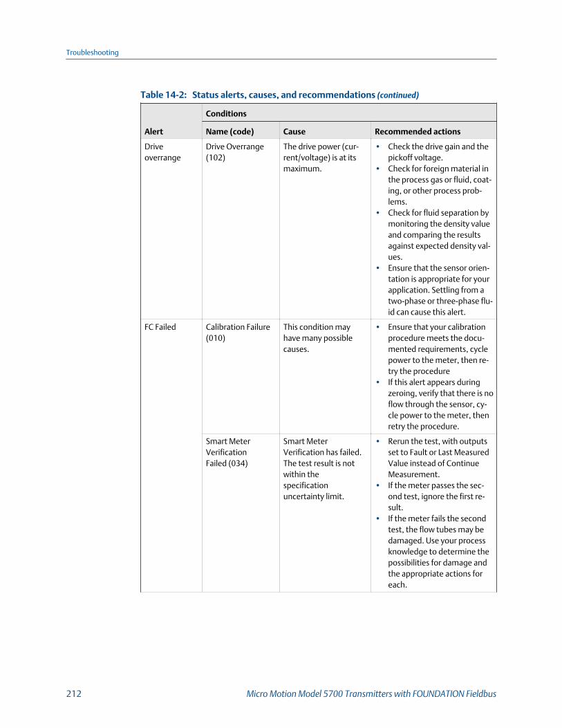
Status alerts, causes, and recommendations (continued)Table 14-2:
Alert
Conditions
Name (code) Cause Recommended actions
Driveoverrange
Drive Overrange(102)
The drive power (cur-rent/voltage) is at itsmaximum.
• Check the drive gain and thepickoff voltage.
• Check for foreign material inthe process gas or fluid, coat-ing, or other process prob-lems.
• Check for fluid separation bymonitoring the density valueand comparing the resultsagainst expected density val-ues.
• Ensure that the sensor orien-tation is appropriate for yourapplication. Settling from atwo-phase or three-phase flu-id can cause this alert.
FC Failed Calibration Failure(010)
This condition mayhave many possiblecauses.
• Ensure that your calibrationprocedure meets the docu-mented requirements, cyclepower to the meter, then re-try the procedure
• If this alert appears duringzeroing, verify that there is noflow through the sensor, cy-cle power to the meter, thenretry the procedure.
Smart MeterVerificationFailed (034)
Smart MeterVerification has failed.The test result is notwithin thespecificationuncertainty limit.
• Rerun the test, with outputsset to Fault or Last MeasuredValue instead of ContinueMeasurement.
• If the meter passes the sec-ond test, ignore the first re-sult.
• If the meter fails the secondtest, the flow tubes may bedamaged. Use your processknowledge to determine thepossibilities for damage andthe appropriate actions foreach.
Troubleshooting
212 Micro Motion Model 5700 Transmitters with FOUNDATION Fieldbus

Status alerts, causes, and recommendations (continued)Table 14-2:
Alert
Conditions
Name (code) Cause Recommended actions
Smart MeterVerificationAborted (035)
Smart MeterVerification aborted.
• Abort code 1- Reason: user initiated
abort- Recommended action:
wait for 15 seconds be-fore starting Smart MeterVerification again.
• Abort code 3- Reason: frequency drift- Recommended actions:
ensure temperature, flowand density are stable andrun Smart Meter Verifica-tion again.
• Abort code 5- Reason: high drive gain- Recommended actions:
ensure flow is steady,minimized entrained gas,and run Smart Meter Veri-fication again.
• Abort code 8- Reason: unstable flow- Recommended actions:
reduce flow rate and runSmart Meter Verificationagain.
• Abort code 13- Reason: no air reference- Recommended action:
perform factory calibra-tion on air.
• Abort code 14- Reason: no water refer-
ence- Recommended action:
perform factory calibra-tion on water.
• Abort code 15- Reason: missing configu-
ration- Recommended action:
load verification parame-ter registers with propervalues.
• Abort code: other- Reason : other
Troubleshooting
Configuration and Use Manual 213

Status alerts, causes, and recommendations (continued)Table 14-2:
Alert
Conditions
Name (code) Cause Recommended actions
- Recommended actions:- Run Smart Meter Veri-
fication again.- If abort persists, call
Micro Motion custom-er support.
Data lostpossible
Data loss possible(103)
The totalizers are notbeing saved properly.The core processor wasunable to store the to-talizers on the last pow-er-down and must relyon the saved totals. Thesaved totals can be asmuch as two hours outof date.
• Make sure the transmitterand core processor are re-ceiving sufficient power.
• Check the power supply andpower supply wiring.
SD card not present The internal SD cardhas failed.
• Open the transmitter andverify that an SD card ispresent.
• If the problem persists, con-tact Micro Motion.
No PermanentLicense
No permanent license isinstalled on the trans-mitter.
• If you have a permanent li-cense, install it.
• If you do not have a perma-nent license, contact MicroMotion to obtain one.
Clock is Constant The real-time clock isnot incrementing.Measurement is not af-fected, but log time-stamps will not be accu-rate.
• Contact Micro Motion.
Internal MemoryFull
The transmitter's inter-nal memory is nearlyfull.
• Contact Micro Motion.
Firmware UpdateFailed
An error occurred whenupdating the firmware.
• Verify that the correct hex fileis loaded onto the SD card.
• Contact Micro Motion
Elec failed RAM Error - Core(002)
The transmitter has de-tected a problem withthe sensor's electronics.
• 1. Cycle power to the meter.2. If the problem persists,contact Micro Motion.
Troubleshooting
214 Micro Motion Model 5700 Transmitters with FOUNDATION Fieldbus

Status alerts, causes, and recommendations (continued)Table 14-2:
Alert
Conditions
Name (code) Cause Recommended actions
EEPROM Error (018) There is an issue withthe transmitter's non-volatile memory.
This alert will not clear until youcycle power to the meter.• Evaluate the environment for
sources of high electromag-netic interference (EMI) andrelocate the transmitter orwiring as necessary.
• Cycle power to the meter.• If the problem persists, re-
place the transmitter.
RAM Error- Transmitter (019)
ROM checksum error ora RAM location cannotbe written to in thetransmitter.
This alert will not clear until youcycle power to the meter.• Evaluate the environment for
sources of high electromag-netic interference (EMI) andrelocate the transmitter orwiring as necessary.
• Cycle power to the meter.• If the problem persists, re-
place the transmitter.
ConfigurationDatabaseCorrupt (022)
There is an issue withthe core processor'snon-volatile memory.
• Cycle power to the meter.• If the alert persists, replace
the core processor.
Program Corrupt -Core (024)
There is an issue withthe core processor'snon-volatile memory.
• Cycle power to the meter.• If the problem persists, re-
place the core processor.
Watchdog Error The watchdog timerhas expired.
• Contact Micro Motion.
Sensor failed Sensor Failed (003) The sensor is not re-sponding.
• Check for two-phase flow.• Verify wiring between the
transmitter and the sensor.• Check the test points and
sensor coils.• Purge the sensor tubes.
Troubleshooting
Configuration and Use Manual 215
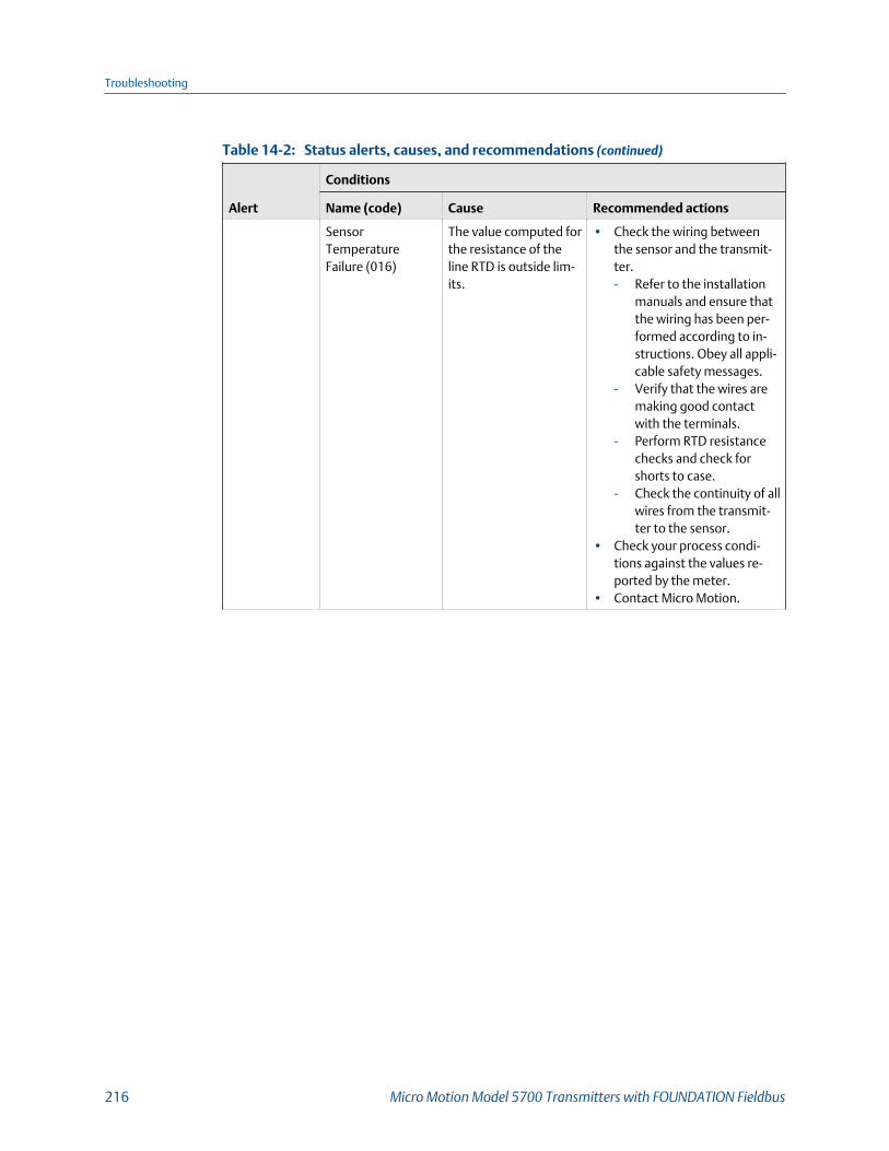
Status alerts, causes, and recommendations (continued)Table 14-2:
Alert
Conditions
Name (code) Cause Recommended actions
SensorTemperatureFailure (016)
The value computed forthe resistance of theline RTD is outside lim-its.
• Check the wiring betweenthe sensor and the transmit-ter.- Refer to the installation
manuals and ensure thatthe wiring has been per-formed according to in-structions. Obey all appli-cable safety messages.
- Verify that the wires aremaking good contactwith the terminals.
- Perform RTD resistancechecks and check forshorts to case.
- Check the continuity of allwires from the transmit-ter to the sensor.
• Check your process condi-tions against the values re-ported by the meter.
• Contact Micro Motion.
Troubleshooting
216 Micro Motion Model 5700 Transmitters with FOUNDATION Fieldbus

Status alerts, causes, and recommendations (continued)Table 14-2:
Alert
Conditions
Name (code) Cause Recommended actions
Sensor CaseTemperatureFailure (017)
The values computedfor the resistance of themeter and case RTDsare outside limits.
• Check the wiring betweenthe sensor and the transmit-ter.- Refer to the installation
manuals and ensure thatthe wiring has been per-formed according to in-structions. Obey all appli-cable safety messages.
- Verify that the wires aremaking good contactwith the terminals.
- Perform RTD resistancechecks and check forshorts to case.
- Check the continuity of allwires from the transmit-ter to the sensor.
• Check your process condi-tions against the values re-ported by the meter. Tem-perature should be between–200 °F and +400 °F.
• Verify that all of the charac-terization parameters matchthe data on the sensor tag.
• Contact Micro Motion.
Config error Incorrect SensorType (021)
The sensor is recog-nized as a straight tubebut the K1 value indi-cates a curved tube, orvice versa.
• If Sensor Case TemperatureFailure is active, resolve itfirst.
• Check the characterizationagainst the sensor tag. Spe-cifically, verify the Flow FCF,K1 and K2 values.
• Check the sensor RTD circui-try
• If the problem persists, con-tact Micro Motion.
Troubleshooting
Configuration and Use Manual 217

Status alerts, causes, and recommendations (continued)Table 14-2:
Alert
Conditions
Name (code) Cause Recommended actions
Incorrect BoardType (030)
The firmware or config-uration loaded in thetransmitter is incom-patible with the boardtype.
• If this alarm occurred in con-junction with an effort to loada configuration into thetransmitter, confirm that thetransmitter is of the samemodel as the one the config-uration came from.
• Cycle power to the meter.• If the problem persists, con-
tact Micro Motion.
Core SoftwareUpdate Failed
Core processor soft-ware could not be up-dated.
• Retry.• Contact Micro Motion.
Time Not Set The system time hasnot been set.
• Set the time and time zone.
Curve Fit Failure(120)
The configured density/temperature/concen-tration values do not re-sult in a proper Concen-tration Measurement(CM) curve.
• Verify the configuration ofthe concentration measure-ment application.
Core HasIncompatible ETO
The core processor hasan ETO installed whichis incompatible withthis device. The corecan be updated but theETO will be overwritten.
• Contact Micro Motion to dis-cuss options for reserving theETO.
Watercut Limited at100%
Watercut at Line calcu-lation is greater than105% based on inputdensity. Watercut Out-put is limited to 100%
• Check base water density.• If the problem persists, con-
tact Micro Motion.
Watercut Limited at0%
Watercut at Line calcu-lation is less than -5%based on input density.Watercut Output islimited to 0%
• Check base oil density.• If the problem persists, con-
tact Micro Motion.
Troubleshooting
218 Micro Motion Model 5700 Transmitters with FOUNDATION Fieldbus
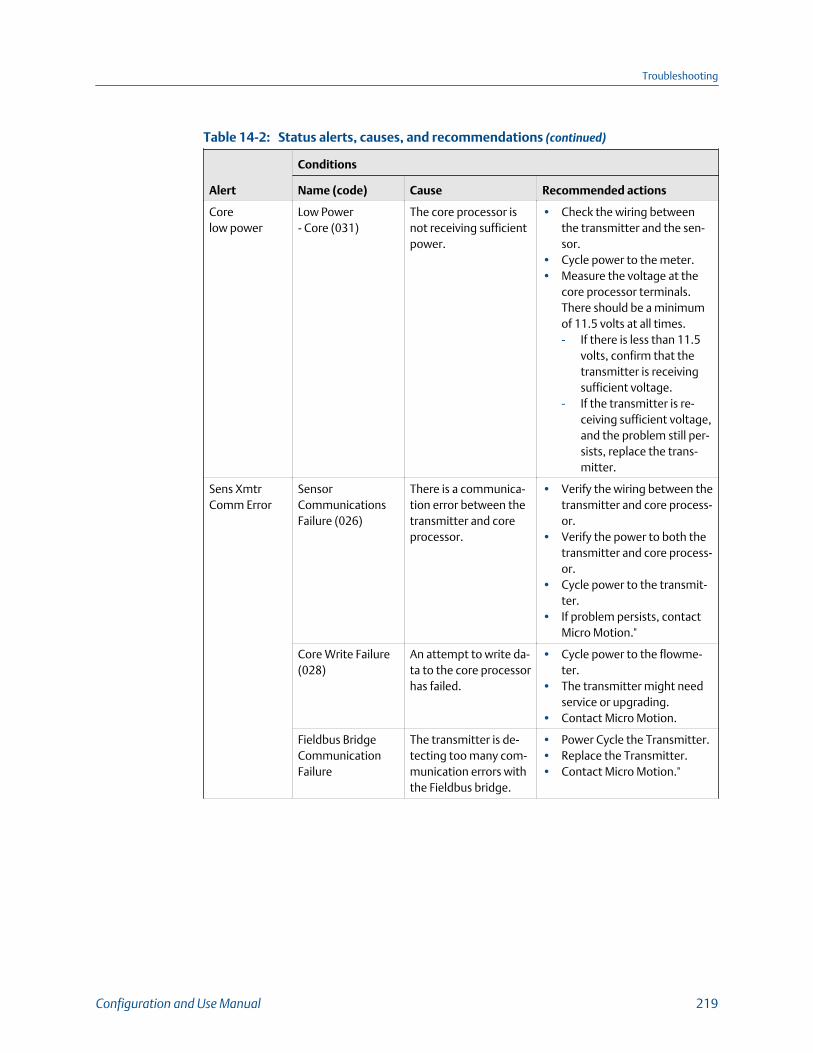
Status alerts, causes, and recommendations (continued)Table 14-2:
Alert
Conditions
Name (code) Cause Recommended actions
Corelow power
Low Power- Core (031)
The core processor isnot receiving sufficientpower.
• Check the wiring betweenthe transmitter and the sen-sor.
• Cycle power to the meter.• Measure the voltage at the
core processor terminals.There should be a minimumof 11.5 volts at all times.- If there is less than 11.5
volts, confirm that thetransmitter is receivingsufficient voltage.
- If the transmitter is re-ceiving sufficient voltage,and the problem still per-sists, replace the trans-mitter.
Sens XmtrComm Error
SensorCommunicationsFailure (026)
There is a communica-tion error between thetransmitter and coreprocessor.
• Verify the wiring between thetransmitter and core process-or.
• Verify the power to both thetransmitter and core process-or.
• Cycle power to the transmit-ter.
• If problem persists, contactMicro Motion."
Core Write Failure(028)
An attempt to write da-ta to the core processorhas failed.
• Cycle power to the flowme-ter.
• The transmitter might needservice or upgrading.
• Contact Micro Motion.
Fieldbus BridgeCommunicationFailure
The transmitter is de-tecting too many com-munication errors withthe Fieldbus bridge.
• Power Cycle the Transmitter.• Replace the Transmitter.• Contact Micro Motion."
Troubleshooting
Configuration and Use Manual 219
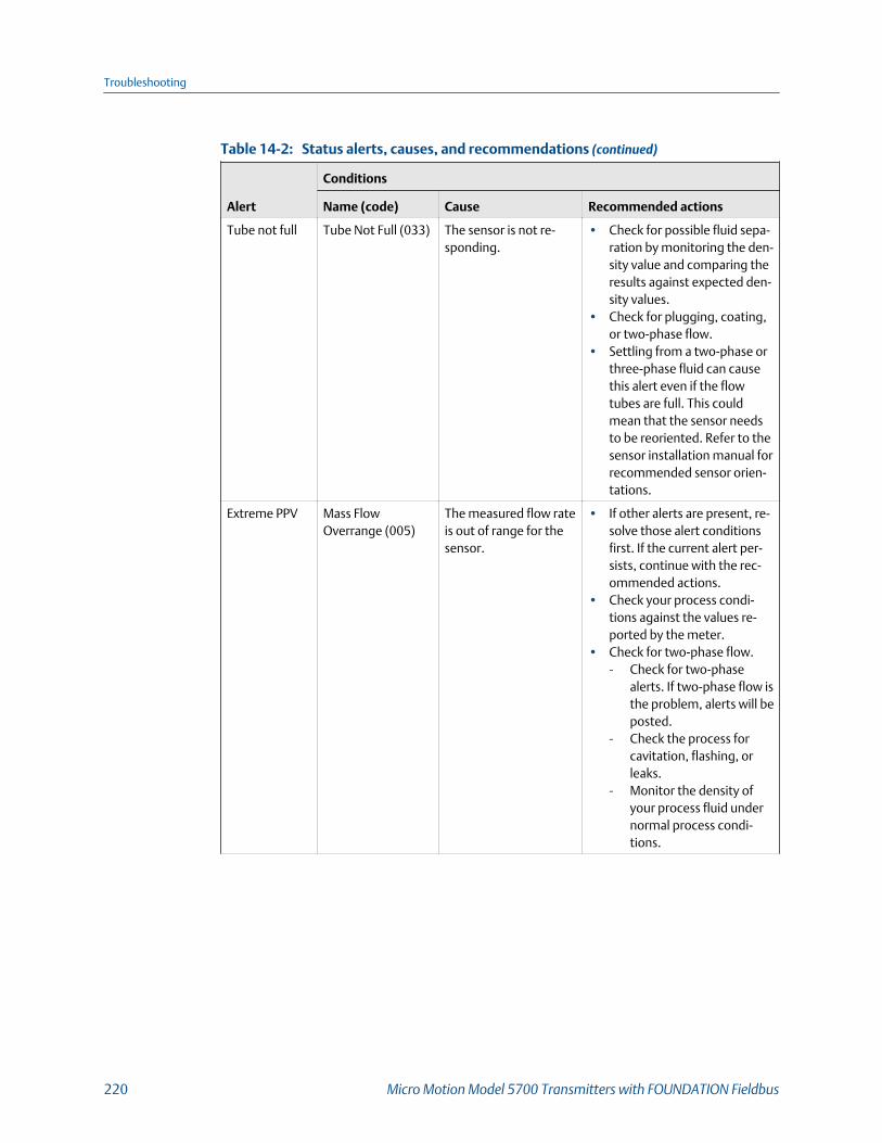
Status alerts, causes, and recommendations (continued)Table 14-2:
Alert
Conditions
Name (code) Cause Recommended actions
Tube not full Tube Not Full (033) The sensor is not re-sponding.
• Check for possible fluid sepa-ration by monitoring the den-sity value and comparing theresults against expected den-sity values.
• Check for plugging, coating,or two-phase flow.
• Settling from a two-phase orthree-phase fluid can causethis alert even if the flowtubes are full. This couldmean that the sensor needsto be reoriented. Refer to thesensor installation manual forrecommended sensor orien-tations.
Extreme PPV Mass FlowOverrange (005)
The measured flow rateis out of range for thesensor.
• If other alerts are present, re-solve those alert conditionsfirst. If the current alert per-sists, continue with the rec-ommended actions.
• Check your process condi-tions against the values re-ported by the meter.
• Check for two-phase flow.- Check for two-phase
alerts. If two-phase flow isthe problem, alerts will beposted.
- Check the process forcavitation, flashing, orleaks.
- Monitor the density ofyour process fluid undernormal process condi-tions.
Troubleshooting
220 Micro Motion Model 5700 Transmitters with FOUNDATION Fieldbus

Status alerts, causes, and recommendations (continued)Table 14-2:
Alert
Conditions
Name (code) Cause Recommended actions
Density Out ofRange (008)
The measured densityis below 0 g/cm3 orabove 10 g/cm3.
• If other alerts are present, re-solve those alert conditionsfirst. If the current alert per-sists, continue with the rec-ommended actions.
• Check for two-phase flow.• Check or foreign material in
the process gas or fluid, coat-ing, or other process prob-lems.
• Verify all of the characteriza-tion or calibration parame-ters. See the sensor tag or thecalibration sheet for your me-ter.
• Check the drive gain and thepickoff voltage.
• Perform Smart Meter Verifi-cation.
• Contact Micro Motion.
Flowmeter Init TransmitterInitializing (009)
Transmitter is in power-up mode.
Allow the meter to complete itspower-up sequence. The alertshould clear automatically. If thealert does not clear:• If other alerts are present, re-
solve those alert conditionsfirst.
• Verify that the transmitter isreceiving sufficient power.- If it is not, correct the
problem and cycle powerto the meter.
- If it is, this suggests thatthe transmitter has an in-ternal power issue. Re-place the transmitter.
Troubleshooting
Configuration and Use Manual 221

14.3 Flow measurement problems
Flow measurement problems and recommended actionsTable 14-3:
Problem Possible causes Recommended actions
Flow rate reported aszero when flow ispresent
Process condition below cutoff Verify the cutoffs.
Flow indication at noflow conditions orzero offset
• Misaligned piping (especially in new instal-lations)
• Open or leaking valve• Incorrect sensor zero
• Verify all of the characterization or calibra-tion parameters. See the sensor tag or thecalibration sheet for your meter.
• If the reading is not excessively high, re-view the live zero. You may need to restorethe factory zero.
• Check for open or leaking valves or seals.• Check for mounting stress on the sensor
(e.g., sensor being used to support piping,misaligned piping).
• Contact customer service.
Erratic non-zero flowrate at no-flowconditions
• Leaking valve or seal• Two-phase flow• Plugged or coated sensor tube• Incorrect sensor orientation• Wiring problem• Vibration in pipeline at rate close to sensor
tube frequency• Damping value too low• Mounting stress on sensor
• Verify that the sensor orientation is appro-priate for your application. See the installa-tion manual for your sensor.
• Check the drive gain and the pickoff volt-age.
• If the wiring between the sensor and thetransmitter includes a 9-wire segment,verify that the 9-wire cable shields are cor-rectly grounded.
• Check the wiring between the sensor andthe transmitter.
• For sensors with a junction box, check formoisture in the junction box.
• Purge the sensor tubes.• Check for open or leaking valves or seals.• Check for sources of vibration.• Verify damping configuration.• Verify that the measurement units are con-
figured correctly for your application.• Check for two-phase flow.• Check for radio frequency interference.• Contact customer service.
Troubleshooting
222 Micro Motion Model 5700 Transmitters with FOUNDATION Fieldbus

Flow measurement problems and recommended actions (continued)Table 14-3:
Problem Possible causes Recommended actions
Erratic non-zero flowrate when flow issteady
• Two-phase flow• Damping value too low• Plugged or coated sensor tube• Output wiring problem• Problem with receiving device• Wiring problem
• Verify that the sensor orientation is appro-priate for your application. See the installa-tion manual for your sensor.
• Check the drive gain and the pickoff volt-age.
• If the wiring between the sensor and thetransmitter includes a 9-wire segment,verify that the 9-wire cable shields are cor-rectly grounded.
• Check for air entrainment, tube fouling,flashing, or tube damage.
• Check the wiring between the sensor andthe transmitter.
• For sensors with a junction box, check formoisture in the junction box.
• Purge the sensor tubes.• Check for open or leaking valves or seals.• Check for sources of vibration.• Verify damping configuration.• Verify that the measurement units are con-
figured correctly for your application.• Check for two-phase flow.• Check for radio frequency interference.• Contact customer service.
Inaccurate flow rate • Wiring problem• Inappropriate measurement unit• Incorrect flow calibration factor• Incorrect meter factor• Incorrect density calibration factors• Incorrect grounding• Two-phase flow• Problem with receiving device• Incorrect sensor zero
• Check the wiring between the sensor andthe transmitter.
• Verify that the measurement units are con-figured correctly for your application.
• Verify all of the characterization or calibra-tion parameters. See the sensor tag or thecalibration sheet for your meter.
• Zero the meter.• Check the grounding of all components.• Check for two-phase flow.• Verify the receiving device, and the wiring
between the transmitter and the receivingdevice.
• Check the sensor coils for electrical shorts.If you find problems, replace the sensor.
• Replace the core processor or transmitter.
Troubleshooting
Configuration and Use Manual 223
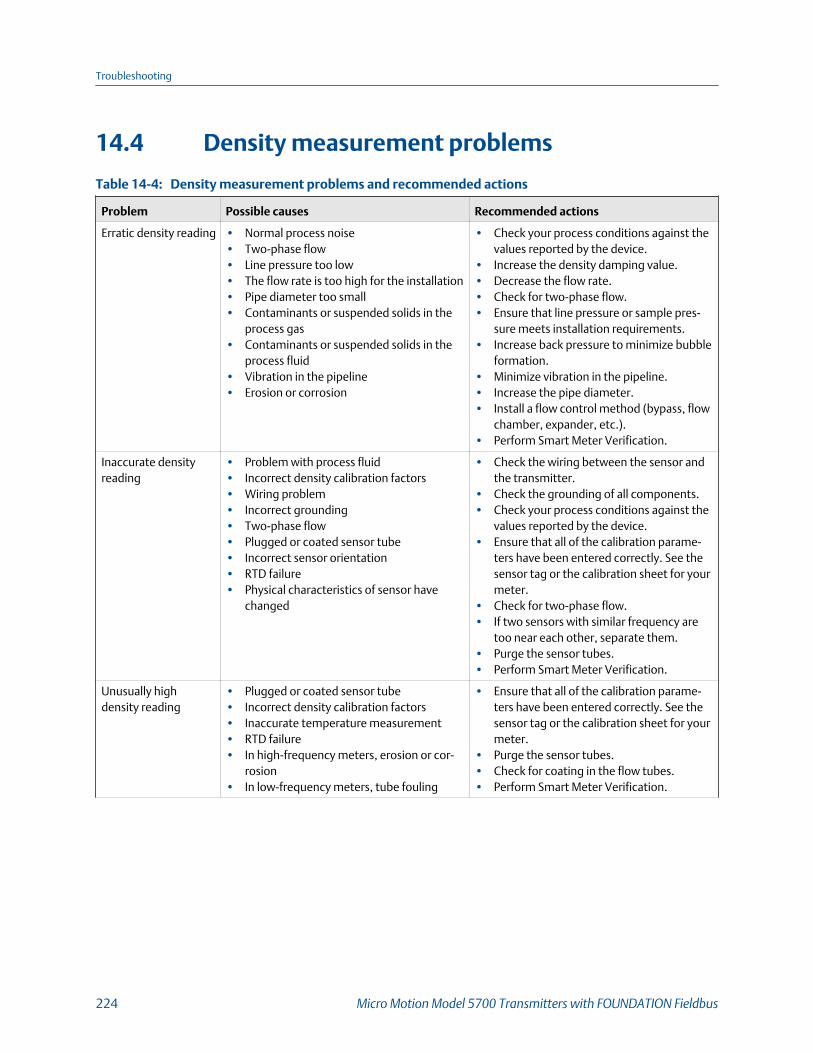
14.4 Density measurement problems
Density measurement problems and recommended actionsTable 14-4:
Problem Possible causes Recommended actions
Erratic density reading • Normal process noise• Two-phase flow• Line pressure too low• The flow rate is too high for the installation• Pipe diameter too small• Contaminants or suspended solids in the
process gas• Contaminants or suspended solids in the
process fluid• Vibration in the pipeline• Erosion or corrosion
• Check your process conditions against thevalues reported by the device.
• Increase the density damping value.• Decrease the flow rate.• Check for two-phase flow.• Ensure that line pressure or sample pres-
sure meets installation requirements.• Increase back pressure to minimize bubble
formation.• Minimize vibration in the pipeline.• Increase the pipe diameter.• Install a flow control method (bypass, flow
chamber, expander, etc.).• Perform Smart Meter Verification.
Inaccurate densityreading
• Problem with process fluid• Incorrect density calibration factors• Wiring problem• Incorrect grounding• Two-phase flow• Plugged or coated sensor tube• Incorrect sensor orientation• RTD failure• Physical characteristics of sensor have
changed
• Check the wiring between the sensor andthe transmitter.
• Check the grounding of all components.• Check your process conditions against the
values reported by the device.• Ensure that all of the calibration parame-
ters have been entered correctly. See thesensor tag or the calibration sheet for yourmeter.
• Check for two-phase flow.• If two sensors with similar frequency are
too near each other, separate them.• Purge the sensor tubes.• Perform Smart Meter Verification.
Unusually highdensity reading
• Plugged or coated sensor tube• Incorrect density calibration factors• Inaccurate temperature measurement• RTD failure• In high-frequency meters, erosion or cor-
rosion• In low-frequency meters, tube fouling
• Ensure that all of the calibration parame-ters have been entered correctly. See thesensor tag or the calibration sheet for yourmeter.
• Purge the sensor tubes.• Check for coating in the flow tubes.• Perform Smart Meter Verification.
Troubleshooting
224 Micro Motion Model 5700 Transmitters with FOUNDATION Fieldbus
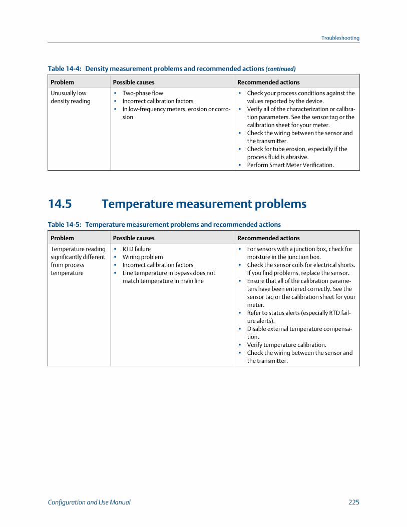
Density measurement problems and recommended actions (continued)Table 14-4:
Problem Possible causes Recommended actions
Unusually lowdensity reading
• Two-phase flow• Incorrect calibration factors• In low-frequency meters, erosion or corro-
sion
• Check your process conditions against thevalues reported by the device.
• Verify all of the characterization or calibra-tion parameters. See the sensor tag or thecalibration sheet for your meter.
• Check the wiring between the sensor andthe transmitter.
• Check for tube erosion, especially if theprocess fluid is abrasive.
• Perform Smart Meter Verification.
14.5 Temperature measurement problems
Temperature measurement problems and recommended actionsTable 14-5:
Problem Possible causes Recommended actions
Temperature readingsignificantly differentfrom processtemperature
• RTD failure• Wiring problem• Incorrect calibration factors• Line temperature in bypass does not
match temperature in main line
• For sensors with a junction box, check formoisture in the junction box.
• Check the sensor coils for electrical shorts.If you find problems, replace the sensor.
• Ensure that all of the calibration parame-ters have been entered correctly. See thesensor tag or the calibration sheet for yourmeter.
• Refer to status alerts (especially RTD fail-ure alerts).
• Disable external temperature compensa-tion.
• Verify temperature calibration.• Check the wiring between the sensor and
the transmitter.
Troubleshooting
Configuration and Use Manual 225

Temperature measurement problems and recommended actions (continued)Table 14-5:
Problem Possible causes Recommended actions
Temperature readingslightly different fromprocess temperature
• Sensor temperature not yet equalized• Sensor leaking heat
• If the error is within the temperature speci-fication for the sensor, there is no prob-lem. If the temperature measurement isoutside the specification, contact custom-er service.
• The temperature of the fluid may bechanging rapidly. Allow sufficient time forthe sensor to equalize with the process flu-id.
• Install thermal installation, up to but notover, the transmitter housing.
• Check the sensor coils for electrical shorts.If you find problems, replace the sensor.
• The RTD may not be making good contactwith the sensor. The sensor may need tobe replaced.
Inaccurate tempera-ture data from exter-nal device
• Wiring problem• Problem with input configuration• Problem with external device
• Verify the wiring between the transmitterand the external device.
• Verify that the external device is operatingcorrectly.
• Verify the configuration of the tempera-ture input.
• Ensure that both devices are using thesame measurement unit.
14.6 Velocity measurement problems
ImportantIf you are measuring gas, minor inaccuracy in velocity readings is expected. If this is an issue for yourapplication, contact customer support.
Velocity measurement problems and recommended actionsTable 14-6:
Problem Possible causes Recommended actions
Non-zero velocityreading at no-flowconditions or at zerooffset
• Misaligned piping (especially in new instal-lations)
• Open or leaking valve• Incorrect sensor zero
• Zero the meter.• Check for open or leaking valves or seals.• Check for mounting stress on the sensor
(for example, the sensor being used tosupport piping, misaligned piping).
• Contact customer service.
Troubleshooting
226 Micro Motion Model 5700 Transmitters with FOUNDATION Fieldbus
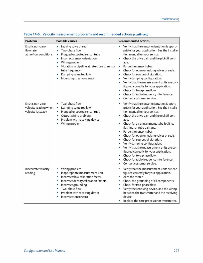
Velocity measurement problems and recommended actions (continued)Table 14-6:
Problem Possible causes Recommended actions
Erratic non-zeroflow rateat no-flow conditions
• Leaking valve or seal• Two-phase flow• Plugged or coated sensor tube• Incorrect sensor orientation• Wiring problem• Vibration in pipeline at rate close to sensor
tube frequency• Damping value too low• Mounting stress on sensor
• Verify that the sensor orientation is appro-priate for your application. See the installa-tion manual for your sensor.
• Check the drive gain and the pickoff volt-age.
• Purge the sensor tubes.• Check for open or leaking valves or seals.• Check for sources of vibration.• Verify damping configuration.• Verify that the measurement units are con-
figured correctly for your application.• Check for two-phase flow.• Check for radio frequency interference.• Contact customer service.
Erratic non-zerovelocity reading whenvelocity is steady
• Two-phase flow• Damping value too low• Plugged or coated sensor tube• Output wiring problem• Problem with receiving device• Wiring problem
• Verify that the sensor orientation is appro-priate for your application. See the installa-tion manual for your sensor.
• Check the drive gain and the pickoff volt-age.
• Check for air entrainment, tube fouling,flashing, or tube damage.
• Purge the sensor tubes.• Check for open or leaking valves or seals.• Check for sources of vibration.• Verify damping configuration.• Verify that the measurement units are con-
figured correctly for your application.• Check for two-phase flow.• Check for radio frequency interference.• Contact customer service.
Inaccurate velocityreading
• Wiring problem• Inappropriate measurement unit• Incorrect flow calibration factor• Incorrect density calibration factors• Incorrect grounding• Two-phase flow• Problem with receiving device• Incorrect sensor zero
• Verify that the measurement units are con-figured correctly for your application.
• Zero the meter.• Check the grounding of all components.• Check for two-phase flow.• Verify the receiving device, and the wiring
between the transmitter and the receivingdevice.
• Replace the core processor or transmitter.
Troubleshooting
Configuration and Use Manual 227

14.7 API referral problems
API referral problems and recommended actionsTable 14-7:
Problem Possible causes Recommended actions
Extrapolation alert isactive
Line pressure, line temperature, or line densityis outside the range of the configured API table
• Check your process conditions against thevalues reported by the device.
• Verify the configuration of the API referralapplication and related parameters.
Inaccurate referreddensity reading
• Inaccurate density measurement• Inaccurate temperature measurement• Incorrect reference conditions• Incorrect API table selection
• Verify the line density value.• Verify the line temperature value.• Ensure that the application is configured to
use the appropriate temperature source.• Ensure that the pressure source is config-
ured correctly, that the external pressuredevice is operating correctly, and that bothdevices are using the same measurementunits.
• Ensure that reference temperature and ref-erence pressure, if applicable, are config-ured correctly.
• Ensure that the selected API table is appro-priate for the process fluid.
14.8 Concentration measurement problems
Concentration measurement problems and recommended actionsTable 14-8:
Problem Possible causes Recommended actions
Significantly incorrectconcentrationmeasurementafter loading matrix
The wrong temperature or density unit wasconfigured when the matrix was loaded
Set the temperature and density units to theunits used when the matrix was built, then re-load the matrix. For custom matrices, contactcustomer support.
Troubleshooting
228 Micro Motion Model 5700 Transmitters with FOUNDATION Fieldbus

Concentration measurement problems and recommended actions (continued)Table 14-8:
Problem Possible causes Recommended actions
Inaccurateconcentrationmeasurementreading
• Inaccurate density measurement• Inaccurate temperature measurement• Incorrect reference conditions• Incorrect matrix data• Inappropriate trim values
• Verify the line density value.• Verify the line temperature value.• Ensure that the application is configured to
use the appropriate temperature source.• Ensure that reference temperature is con-
figured correctly.• Ensure that the appropriate matrix is ac-
tive.• Ensure that the matrix is configured cor-
rectly.• Adjust the extrapolation limits for the ac-
tive matrix.• Adjust measurement with a concentration
offset trim.
14.9 Milliamp output problems
Milliamp output problems and recommended actionsTable 14-9:
Problem Possible causes Recommended actions
No mA output • Output not powered• Power supply problem• Wiring problem• Circuit failure• Channel not configured for desired output
• If applicable, check the output wiring toverify that the output is powered.
• Check the power supply and power supplywiring.
• Verify the output wiring.• Check the Fault Action settings.• Verify channel configuration for the affec-
ted mA output.• Measure DC voltage across output termi-
nals to verify that the output is active.• Contact customer service.
Loop test failed • Output not powered• Power supply problem• Wiring problem• Circuit failure• Channel not configured for desired output
• Check the power supply and power supplywiring.
• Verify the output wiring.• Check the Fault Action settings.• Verify channel configuration for the affec-
ted mA output.• Contact customer service.
Troubleshooting
Configuration and Use Manual 229

Milliamp output problems and recommended actions (continued)Table 14-9:
Problem Possible causes Recommended actions
mA output below4 mA
• Incorrect internal/external power configu-ration
• Output not powered• Open in wiring• Bad output circuit• Process condition below LRV• LRV and URV are not set correctly• Fault condition if Fault Action is set to Inter-
nal Zero or Downscale• Bad mA receiving device
• Check your process conditions against thevalues reported by the device.
• Verify the receiving device, and the wiringbetween the transmitter and the receivingdevice.
• Check the settings of Upper Range Valueand Lower Range Value.
• Check the Fault Action settings.• Verify channel configuration for the affec-
ted mA output.
Constant mA output • Incorrect process variable assigned to theoutput
• Fault condition exists• A loop test is in progress• Zero calibration failure• mA Output Direction not set correctly
• Verify the output variable assignments.• View and resolve any existing alert condi-
tions.• Check the direction parameters.• Check to see if a loop test is in process (the
output is fixed).• If related to a zero calibration failure, re-
boot or power-cycle the transmitter and re-try the zeroing procedure.
mA outputconsistentlyout of range
• Incorrect process variable or units as-signed to output
• Fault condition if Fault Action is set to Up-scale or Downscale
• LRV and URV are not set correctly
• Verify the output variable assignments.• Verify the measurement units configured
for the output.• Check the Fault Action settings.• Check the settings of Upper Range Value
and Lower Range Value.• Check the mA output trim.
Consistently incorrectmA measurement
• Loop problem• Output not trimmed correctly• Incorrect measurement unit configured
for process variable• Incorrect process variable configured• LRV and URV are not set correctly• mA Output Direction not set correctly
• Check the mA output trim.• Verify the measurement units configured
for the output.• Verify the process variable assigned to the
mA output.• Check the direction parameters.• Check the settings of Upper Range Value
and Lower Range Value.
mA output correctat lower current,but incorrectat higher current
• mA loop resistance may be set too high Verify that the mA output load resistance is be-low the maximum supported load. See the in-stallation manual for your transmitter.
mA output goes inand out of faultconditions
• Interaction between the Output Saturatedalert and the fault action configured forthe output
• Change the severity of the Output Satura-ted alert from Fault to another option.
• Configure the transmitter to ignore theOutput Saturated alert or the relevant con-ditions.
• Change the configuration of Fault Actionfrom Downscale to another option.
Troubleshooting
230 Micro Motion Model 5700 Transmitters with FOUNDATION Fieldbus

14.10 Frequency output problems
Frequency output problems and recommended actionsTable 14-10:
Problem Possible causes Recommended actions
No frequency output • Stopped totalizer• Process condition below cutoff• Fault condition if Fault Action is set to Inter-
nal Zero or Downscale• Two-phase flow• Flow in reverse direction from configured
flow direction parameter• Frequency Output Direction not set cor-
rectly• Bad frequency receiving device• Output level not compatible with receiving
device• Bad output circuit• Incorrect internal/external power configu-
ration• Incorrect pulse width configuration• Output not powered• Wiring problem• Channel not configured for desired output
or input
• Verify that the process conditions are be-low the low-flow cutoff. Reconfigure thelow-flow cutoff if necessary.
• Check the Fault Action settings.• Verify that the totalizers are not stopped.
A stopped totalizer will cause the frequen-cy output to be locked.
• Check for two-phase flow.• Check flow direction.• Check the direction parameters.• Verify the receiving device, and the wiring
between the transmitter and the receivingdevice.
• Verify that the channel is wired and config-ured as a frequency output.
• Check the pulse width.• Perform a loop test.
Consistently incorrectfrequencymeasurement
• Output not scaled correctly• Incorrect measurement unit configured for
process variable
• Check the scaling of the frequency output.• Verify that the measurement units are con-
figured correctly for your application.
Erratic frequencyoutput
Radio frequency interference (RFI) from envi-ronment
Check for radio frequency interference.
Frequency outputgoes in and outof fault conditions
Interaction between the Output Saturatedalert and the fault action configured for theoutput
• Change the severity of the Output Satura-ted alert from Fault to another option.
• Configure the transmitter to ignore theOutput Saturated alert or the relevant con-ditions.
• Change the configuration of Fault Actionfrom Downscale to another option.
Troubleshooting
Configuration and Use Manual 231
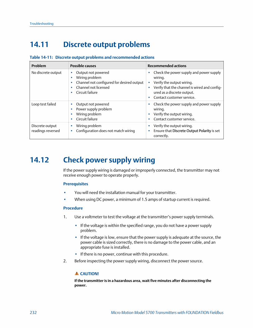
14.11 Discrete output problems
Discrete output problems and recommended actionsTable 14-11:
Problem Possible causes Recommended actions
No discrete output • Output not powered• Wiring problem• Channel not configured for desired output• Channel not licensed• Circuit failure
• Check the power supply and power supplywiring.
• Verify the output wiring.• Verify that the channel is wired and config-
ured as a discrete output.• Contact customer service.
Loop test failed • Output not powered• Power supply problem• Wiring problem• Circuit failure
• Check the power supply and power supplywiring.
• Verify the output wiring.• Contact customer service.
Discrete outputreadings reversed
• Wiring problem• Configuration does not match wiring
• Verify the output wiring.• Ensure that Discrete Output Polarity is set
correctly.
14.12 Check power supply wiringIf the power supply wiring is damaged or improperly connected, the transmitter may notreceive enough power to operate properly.
Prerequisites
• You will need the installation manual for your transmitter.
• When using DC power, a minimum of 1.5 amps of startup current is required.
Procedure
1. Use a voltmeter to test the voltage at the transmitter’s power supply terminals.
• If the voltage is within the specified range, you do not have a power supplyproblem.
• If the voltage is low, ensure that the power supply is adequate at the source, thepower cable is sized correctly, there is no damage to the power cable, and anappropriate fuse is installed.
• If there is no power, continue with this procedure.
2. Before inspecting the power supply wiring, disconnect the power source.
CAUTION!
If the transmitter is in a hazardous area, wait five minutes after disconnecting thepower.
Troubleshooting
232 Micro Motion Model 5700 Transmitters with FOUNDATION Fieldbus

3. Ensure that the terminals, wires, and wiring compartment are clean and dry.
4. Ensure that the power supply wires are connected to the correct terminals.
5. Ensure that the power supply wires are making good contact, and are not clampedto the wire insulation.
6. Reapply power to the transmitter.
CAUTION!
If the transmitter is in a hazardous area, do not reapply power to the transmitter withthe housing cover removed. Reapplying power to the transmitter while the housingcover is removed could cause an explosion.
7. Test the voltage at the terminals.
If there is no power, contact customer service.
14.13 Check sensor-to-transmitter wiringA number of power-supply and output problems may occur if the wiring between thesensor and the transmitter is improperly connected, or if the wiring becomes damaged.
Be sure to check all wiring segments:
• If you have a 4-wire transmitter, check the wiring between the transmitter and thecore processor.
• If you have a 9-wire transmitter, check the wiring between the transmitter and thesensor junction box.
• If you have a remote transmitter with remote core processor, check the wiringbetween the transmitter and the core processor and the wiring between the coreprocessor and the sensor junction box.
Prerequisites
You will need the installation manual for your transmitter.
Procedure
1. Before opening the wiring compartments, disconnect the power source.
DANGER!
If the transmitter is in a hazardous area, wait five minutes after disconnecting thepower.
2. Verify that the transmitter is connected to the sensor according to the informationprovided in your transmitter installation manual.
3. Verify that the wires are making good contact with the terminals.
4. Check the continuity of all wires from the transmitter to the sensor.
Troubleshooting
Configuration and Use Manual 233
14.14 Check groundingA sensor and the transmitter must be grounded.
Prerequisites
You will need an:
• Installation manual for your sensor
• Installation manual for your transmitter (remote-mount installations only)
Procedure
Refer to the sensor and transmitter installation manuals for grounding requirements andinstructions.
14.15 Perform loop testsA loop test is a way to verify that the transmitter and the remote device arecommunicating properly. A loop test also helps you know whether you need to trim mAoutputs.
Prerequisites
• Before performing a loop test, configure the channels for the transmitter outputsthat will be used in your application.
• Follow appropriate procedures to ensure that loop testing will not interfere withexisting measurement and control loops.
• Perform loop tests using the display (Section 14.15.1)• Perform loop tests using ProLink III (Section 14.15.2)
14.15.1 Perform loop tests using the display1. Test the mA output(s).
a. Choose Menu > Service Tools > Output Simulation and select the mA output totest.
b. Set Simulation Value to 4.
c. Start the simulation.
d. Read the mA current at the receiving device and compare it to the transmitteroutput.
The readings do not need to match exactly. If the values are slightly different,you can correct the discrepancy by trimming the output.
e. Choose New Value.
f. Set Simulation Value to 20.
Troubleshooting
234 Micro Motion Model 5700 Transmitters with FOUNDATION Fieldbus
g. Start the simulation.
h. Read the mA current at the receiving device and compare it to the transmitteroutput.
The readings do not need to match exactly. If the values are slightly different,you can correct the discrepancy by trimming the output.
i. Choose Exit.
2. Test the frequency output(s).
a. Choose Menu > Service Tools > Output Simulation and select the frequencyoutput to test.
b. Set Simulation Value to 1.
c. Start the simulation.
d. Read the frequency signal at the receiving device and compare it to thetransmitter output.
e. Choose New Value.
f. Set Simulation Value to 14500.
g. Start the simulation.
h. Read the frequency signal at the receiving device and compare it to thetransmitter output.
i. Choose Exit.
3. Test the discrete output(s).
a. Choose Menu > Service Tools > Output Simulation and select the discrete outputto test.
b. Set Simulation Value to ON.
c. Start the simulation.
d. Verify the signal at the receiving device.
e. Choose New Value.
f. Set Simulation Value to OFF.
g. Start the simulation.
h. Verify the signal at the receiving device.
i. Choose Exit.
Postrequisites
• If the mA output readings are within 20 microamps of the expected values, you cancorrect this discrepancy by trimming the output.
• If the discrepancy between the mA output readings is greater than 20 microamps,or if at any step the reading was faulty, verify the wiring between the transmitterand the remote device, and try again.
Troubleshooting
Configuration and Use Manual 235
14.15.2 Perform loop tests using ProLink III1. Test the mA output(s).
a. Choose Device Tools > Diagnostics > Testing and select the mA output to test.
b. Enter 4 in Fix to:.
c. Click Fix mA.
d. Read the mA current at the receiving device and compare it to the transmitteroutput.
The readings do not need to match exactly. If the values are slightly different,you can correct the discrepancy by trimming the output.
e. Click UnFix mA.
f. Enter 20 in Fix to:.
g. Click Fix mA.
h. Read the mA current at the receiving device and compare it to the transmitteroutput.
The readings do not need to match exactly. If the values are slightly different,you can correct the discrepancy by trimming the output.
i. Click UnFix mA.
2. Test the frequency output(s).
a. Choose Device Tools > Diagnostics > Testing and select the frequency output totest.
b. Enter the frequency output value in Fix to.
c. Click Fix FO.
d. Read the frequency signal at the receiving device and compare it to thetransmitter output.
e. Click UnFix FO.
3. Test the discrete output(s).
a. Choose Device Tools > Diagnostics > Testing > Discrete Output Test.
b. Set Fix To: to ON.
c. Verify the signal at the receiving device.
d. Set Fix To: to OFF.
e. Verify the signal at the receiving device.
f. Click UnFix.
Postrequisites
• If the mA output readings are within 20 microamps of the expected values, you cancorrect this discrepancy by trimming the output.
Troubleshooting
236 Micro Motion Model 5700 Transmitters with FOUNDATION Fieldbus

• If the discrepancy between the mA output readings is greater than 20 microamps,or if at any step the reading was faulty, verify the wiring between the transmitterand the remote device, and try again.
14.15.3 Perform loop tests using an enhanced FF hostProcedure
1. Test the mA output(s).
a. Choose Service Tools > Simulate > Simulate Outputs and select the mA output totest.
b. Select 4 mA.
c. Read the mA current at the receiving device and compare it to the transmitteroutput.
The readings do not need to match exactly. If the values are slightly different,you can correct the discrepancy by trimming the output.
d. Press OK.
e. Select 20 mA.
f. Read the mA current at the receiving device and compare it to the transmitteroutput.
The readings do not need to match exactly. If the values are slightly different,you can correct the discrepancy by trimming the output.
g. Press OK.
h. Choose End.
2. Test the frequency output(s).
a. Choose Service Tools > Simulate > Simulate Outputs and select the frequencyoutput to test.
b. Select the frequency output level.
c. Press OK.
d. Choose End.
3. Test the discrete output(s).
a. Choose Service Tools > Simulate > Simulate Outputs and select the discreteoutput to test.
b. Choose Off.
c. Verify the signal at the receiving device.
d. Press OK.
e. Choose On.
f. Verify the signal at the receiving device.
g. Press OK.
Troubleshooting
Configuration and Use Manual 237

h. Choose End.
Postrequisites
• If the mA output readings are within 20 microamps of the expected values, you cancorrect this discrepancy by trimming the output.
• If the discrepancy between the mA output readings is greater than 20 microamps,or if at any step the reading was faulty, verify the wiring between the transmitterand the remote device, and try again.
14.16 Trim mA outputTrimming an mA output calibrates the transmitter's mA output to the receiving device. Ifthe current trim value is inaccurate, the transmitter will under-compensate or over-compensate the output.
• Trim mA using the display (Section 14.16.1)• Trim mA output using ProLink III (Section 14.16.2)
14.16.1 Trim mA using the displayTrimming the mA output establishes a common measurement range between thetransmitter and the device that receives the mA output.
Prerequisites
Ensure that the mA output is wired to the receiving device that will be used in production.
Procedure
1. Choose Menu > Service Tools > mA Output Trim and select the output to trim.
2. Follow the instructions in the guided method.
3. Check the trim results. If any trim result is less than −20 microamps or greater than+20 microamps, contact customer service.
14.16.2 Trim mA output using ProLink IIITrimming the mA output establishes a common measurement range between thetransmitter and the device that receives the mA output.
Prerequisites
Ensure that the mA output is wired to the receiving device that will be used in production.
Procedure
1. Follow the instructions in the guided method.
2. Check the trim results. If any trim result is less than −20 microamps or greater than+20 microamps, contact customer service.
Troubleshooting
238 Micro Motion Model 5700 Transmitters with FOUNDATION Fieldbus

14.16.3 Trim mA outputs using an enhanced FF hostTrimming the mA output establishes a common measurement range between thetransmitter and the device that receives the mA output.
Prerequisites
Ensure that the mA output is wired to the receiving device that will be used in production.
Procedure
1. Choose Menu > Service Tools > Maintenance > Routine Maintenance > Trim mAOutput.
2. Follow the instructions in the guided method.
3. Check the trim results. If any trim result is less than −20 microamps or greater than+20 microamps, contact customer service.
14.16.4 Trim mA outputs using a basic FF hostTrimming the mA output establishes a common measurement range between thetransmitter and the device that receives the mA output.
Prerequisites
Ensure that the mA output is wired to the receiving device that will be used in production.
Procedure
Check the trim results. If any trim result is less than −20 microamps or greater than+20 microamps, contact customer service.
14.17 Using sensor simulation for troubleshootingWhen sensor simulation is enabled, the transmitter reports user-specified values for basicprocess variables. This allows you to reproduce various process conditions or to test thesystem.
You can use sensor simulation to help distinguish between legitimate process noise andexternally caused variation. For example, consider a receiving device that reports anunexpectedly erratic density value. If sensor simulation is enabled and the observeddensity value does not match the simulated value, the source of the problem is likely to besomewhere between the transmitter and the receiving device.
Sensor simulation requires an Enhanced Core and a communication device.
Troubleshooting
Configuration and Use Manual 239
ImportantWhen sensor simulation is active, the simulated value is used in all transmitter outputs andcalculations, including totals and inventories, volume flow calculations, and concentrationcalculations. Disable all automatic functions related to the transmitter outputs and place the loop inmanual operation. Do not enable simulation mode unless your application can tolerate these effects,and be sure to disable simulation mode when you have finished testing.
14.18 Check Lower Range Value and Upper RangeValue1. Record your current process conditions.
2. Check the configuration of the LRV and URV.
14.19 Check mA Output Fault ActionmA Output Fault Action controls the behavior of the mA output if the transmitterencounters an internal fault condition. If the mA output is reporting a constant valuebelow 4 mA or above 20 mA, the transmitter may be in a fault condition.
1. Check the status alerts for active fault conditions.
2. If there are active fault conditions, the transmitter is performing correctly. If youwant to change its behavior, consider the following options:
• Change the setting of mA Output Fault Action.
3. If there are no active fault conditions, continue troubleshooting.
14.20 Check the scaling of the frequency outputIf the process variable assigned to the frequency output goes to a value that would set thefrequency output to a signal below 0 Hz or above 12500 Hz, the meter will post an OutputSaturated alert for the affected output, then perform the configured fault action.
1. Record your current process conditions.
2. Adjust the scaling of the frequency output.
14.21 Check Frequency Output Fault ActionThe Frequency Output Fault Action controls the behavior of the frequency output if thetransmitter encounters an internal fault condition. If the frequency output is reporting aconstant value, the transmitter may be in a fault condition.
1. Check the status alerts for active fault conditions.
Troubleshooting
240 Micro Motion Model 5700 Transmitters with FOUNDATION Fieldbus

2. If there are active fault conditions, the transmitter is performing correctly. If youwant to change its behavior, consider the following options:
• Change the setting of Frequency Output Fault Action.
3. If there are no active fault conditions, continue troubleshooting.
14.22 Check the direction parametersIf the direction parameters are set incorrectly, flow rate may be reported as reverse when itis actually forward, or vice versa. Totalizers and inventories may increment when theyshould decrement, or vice versa.
The reported flow rate and flow totals depend on the interaction of four factors: the flowdirection arrow on the sensor, actual flow direction, the Sensor Flow Direction Arrowparameter, the Direction parameter for the mA output or the frequency output, and theTotalizer Direction parameter.
Procedure
1. Ensure that Sensor Flow Direction Arrow is set correctly for your sensor installationand your process.
2. Verify the configuration of mA Output Direction, Frequency Output Direction, andTotalizer Direction.
14.23 Check the cutoffsIf the transmitter cutoffs are configured incorrectly, the transmitter may report zero flowwhen flow is present, or very small amounts of flow under no-flow conditions.
Procedure
Verify the configuration of all cutoffs.
14.24 Check for two-phase flow (slug flow)Two-phase flow can cause rapid changes in the drive gain. This can cause a variety ofmeasurement issues.
1. Check for two-phase flow alerts (e.g., A105).
If the transmitter is not generating two-phase flow alerts, verify that two-phase flowlimits have been set. If limits are set, two-phase flow is not the source of yourproblem.
2. Check the process for cavitation, flashing, or leaks.
3. Monitor the density of your process fluid output under normal process conditions.
Troubleshooting
Configuration and Use Manual 241
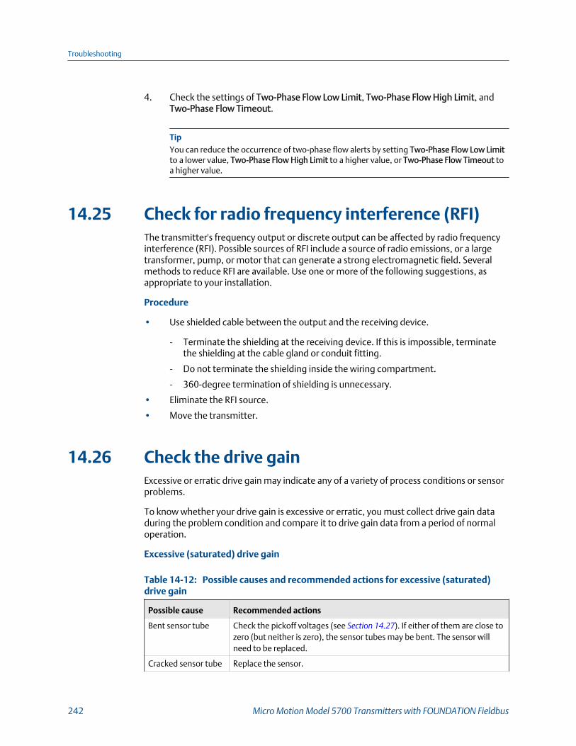
4. Check the settings of Two-Phase Flow Low Limit, Two-Phase Flow High Limit, andTwo-Phase Flow Timeout.
TipYou can reduce the occurrence of two-phase flow alerts by setting Two-Phase Flow Low Limitto a lower value, Two-Phase Flow High Limit to a higher value, or Two-Phase Flow Timeout toa higher value.
14.25 Check for radio frequency interference (RFI)The transmitter's frequency output or discrete output can be affected by radio frequencyinterference (RFI). Possible sources of RFI include a source of radio emissions, or a largetransformer, pump, or motor that can generate a strong electromagnetic field. Severalmethods to reduce RFI are available. Use one or more of the following suggestions, asappropriate to your installation.
Procedure
• Use shielded cable between the output and the receiving device.
- Terminate the shielding at the receiving device. If this is impossible, terminatethe shielding at the cable gland or conduit fitting.
- Do not terminate the shielding inside the wiring compartment.
- 360-degree termination of shielding is unnecessary.
• Eliminate the RFI source.
• Move the transmitter.
14.26 Check the drive gainExcessive or erratic drive gain may indicate any of a variety of process conditions or sensorproblems.
To know whether your drive gain is excessive or erratic, you must collect drive gain dataduring the problem condition and compare it to drive gain data from a period of normaloperation.
Excessive (saturated) drive gain
Possible causes and recommended actions for excessive (saturated)drive gainTable 14-12:
Possible cause Recommended actions
Bent sensor tube Check the pickoff voltages (see Section 14.27). If either of them are close tozero (but neither is zero), the sensor tubes may be bent. The sensor willneed to be replaced.
Cracked sensor tube Replace the sensor.
Troubleshooting
242 Micro Motion Model 5700 Transmitters with FOUNDATION Fieldbus
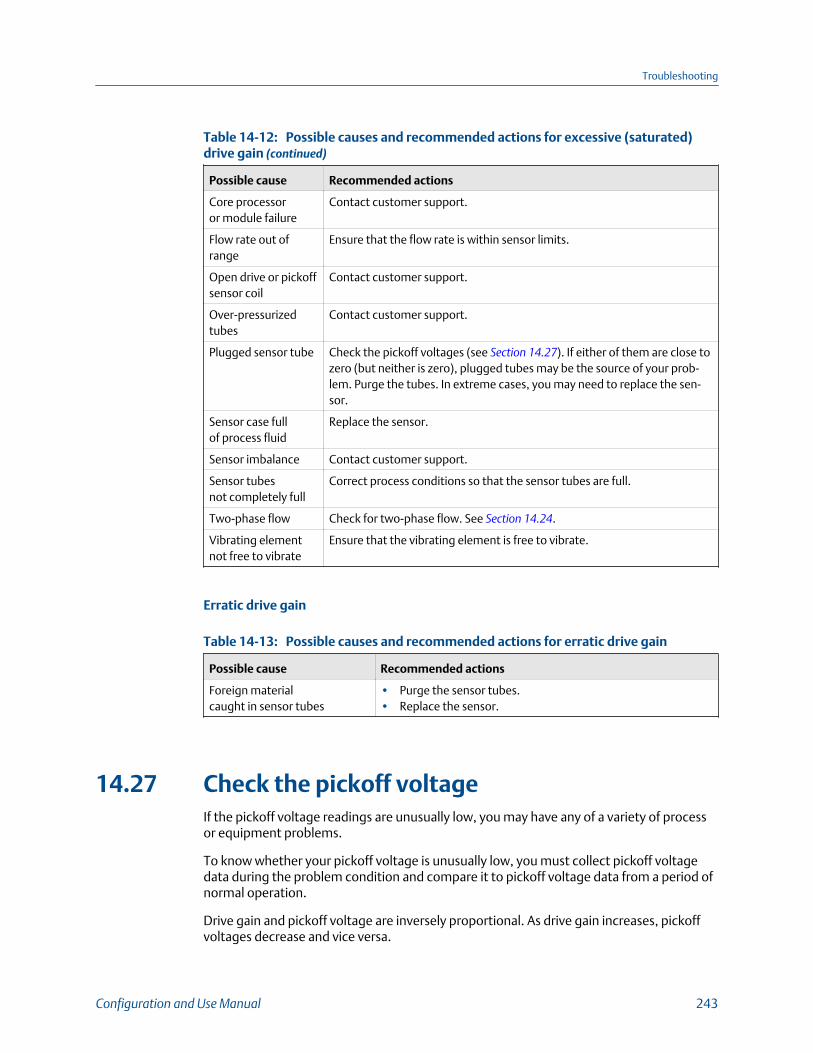
Possible causes and recommended actions for excessive (saturated)drive gain (continued)Table 14-12:
Possible cause Recommended actions
Core processoror module failure
Contact customer support.
Flow rate out ofrange
Ensure that the flow rate is within sensor limits.
Open drive or pickoffsensor coil
Contact customer support.
Over-pressurizedtubes
Contact customer support.
Plugged sensor tube Check the pickoff voltages (see Section 14.27). If either of them are close tozero (but neither is zero), plugged tubes may be the source of your prob-lem. Purge the tubes. In extreme cases, you may need to replace the sen-sor.
Sensor case fullof process fluid
Replace the sensor.
Sensor imbalance Contact customer support.
Sensor tubesnot completely full
Correct process conditions so that the sensor tubes are full.
Two-phase flow Check for two-phase flow. See Section 14.24.
Vibrating elementnot free to vibrate
Ensure that the vibrating element is free to vibrate.
Erratic drive gain
Possible causes and recommended actions for erratic drive gainTable 14-13:
Possible cause Recommended actions
Foreign materialcaught in sensor tubes
• Purge the sensor tubes.• Replace the sensor.
14.27 Check the pickoff voltageIf the pickoff voltage readings are unusually low, you may have any of a variety of processor equipment problems.
To know whether your pickoff voltage is unusually low, you must collect pickoff voltagedata during the problem condition and compare it to pickoff voltage data from a period ofnormal operation.
Drive gain and pickoff voltage are inversely proportional. As drive gain increases, pickoffvoltages decrease and vice versa.
Troubleshooting
Configuration and Use Manual 243
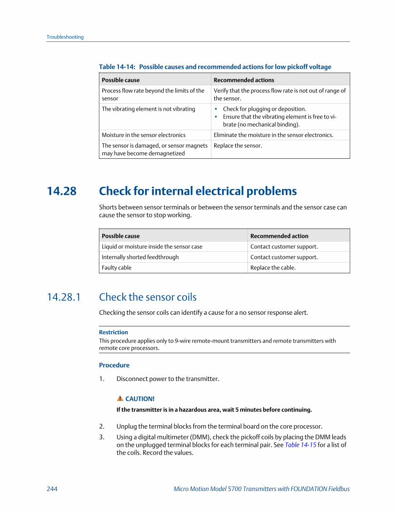
Possible causes and recommended actions for low pickoff voltageTable 14-14:
Possible cause Recommended actions
Process flow rate beyond the limits of thesensor
Verify that the process flow rate is not out of range ofthe sensor.
The vibrating element is not vibrating • Check for plugging or deposition.• Ensure that the vibrating element is free to vi-
brate (no mechanical binding).
Moisture in the sensor electronics Eliminate the moisture in the sensor electronics.
The sensor is damaged, or sensor magnetsmay have become demagnetized
Replace the sensor.
14.28 Check for internal electrical problemsShorts between sensor terminals or between the sensor terminals and the sensor case cancause the sensor to stop working.
Possible cause Recommended action
Liquid or moisture inside the sensor case Contact customer support.
Internally shorted feedthrough Contact customer support.
Faulty cable Replace the cable.
14.28.1 Check the sensor coilsChecking the sensor coils can identify a cause for a no sensor response alert.
RestrictionThis procedure applies only to 9-wire remote-mount transmitters and remote transmitters withremote core processors.
Procedure
1. Disconnect power to the transmitter.
CAUTION!
If the transmitter is in a hazardous area, wait 5 minutes before continuing.
2. Unplug the terminal blocks from the terminal board on the core processor.
3. Using a digital multimeter (DMM), check the pickoff coils by placing the DMM leadson the unplugged terminal blocks for each terminal pair. See Table 14‐15 for a list ofthe coils. Record the values.
Troubleshooting
244 Micro Motion Model 5700 Transmitters with FOUNDATION Fieldbus

Coils and test terminal pairsTable 14-15:
Coil Sensor model Terminal colors
Drive coil All Brown to red
Left pickoff coil (LPO) All Green to white
Right pickoff coil (RPO) All Blue to gray
Resistance temperature detector(RTD)
All Yellow to violet
Lead length compensator (LLC) All except T-Series and CMF400 (seenote)
Yellow to orange
Composite RTD CMFS025-150 and T-Series Yellow to orange
Fixed resistor (see note) CMFS007, CMFS010, CMFS015,CMF400, and F300
Yellow to orange
NoteThe CMF400 fixed resistor applies only to certain specific CMF400 releases. Contact customersupport for more information.
There should be no open circuits, that is, no infinite resistance readings. The leftpickoff and right pickoff readings should be the same or very close (±5 Ω). If thereare any unusual readings, repeat the coil resistance tests at the sensor junction boxto eliminate the possibility of faulty cable. The readings for each coil pair shouldmatch at both ends.
4. Test the terminals in the sensor junction box for shorts to case.
a. Leave the terminal blocks disconnected.
b. Remove the lid of the junction box.
c. Testing one terminal at a time, place a DMM lead on the terminal and the otherlead on the sensor case.
With the DMM set to its highest range, there should be infinite resistance oneach lead. If there is any resistance at all, there is a short to case.
5. Test the resistance of junction box terminal pairs.
a. Test the brown terminal against all other terminals except the red one.
b. Test the red terminal against all other terminals except the brown one.
c. Test the green terminal against all other terminals except the white one.
d. Test the white terminal against all other terminals except the green one.
e. Test the blue terminal against all other terminals except the gray one.
f. Test the gray terminal against all other terminals except the blue one.
g. Test the orange terminal against all other terminals except the yellow and violetones.
Troubleshooting
Configuration and Use Manual 245
h. Test the yellow terminal against all other terminals except the orange and violetones.
i. Test the violet terminal against all other terminals except the yellow and orangeones.
There should be infinite resistance for each pair. If there is any resistance at all, thereis a short between terminals.
Postrequisites
To return to normal operation:
1. Plug the terminal blocks into the terminal board.
2. Replace the lid on the sensor junction box.
ImportantWhen reassembling the meter components, be sure to grease all O-rings.
14.29 Perform a core processor resistance testThis procedure measures the resistance between the core processor terminals in thetransmitter junction box. The procedure applies only to 4-wire remote installations andremote core processor with remote transmitter installations.
NoteAlthough you can perform the same test on the terminals at the core processor, the transmitterjunction box is typically easier to access.
Procedure
1. Power down the transmitter.
2. Remove the cover of the junction box on the transmitter to access the coreprocessor terminals.
Troubleshooting
246 Micro Motion Model 5700 Transmitters with FOUNDATION Fieldbus

Removing the cover of the junction boxFigure 14-1:
3. Disconnect the 4-wire cable between the transmitter and the sensor.
4. Identify the core processor terminals inside the transmitter junction box.
Troubleshooting
Configuration and Use Manual 247

Core processor terminals inside the transmitter junction boxFigure 14-2:
5. For the 700 core processor only, measure the resistance between the terminal pairslisted here.
Terminal pair (trans-mitter)
Terminal pair (coreprocessor) Function Expected resistance
White – green 3–4 RS-485/A and RS-485/B 29 kΩ to 33 kΩ
Black – white 2–3 VDC– and RS-485/A 29 kΩ to 33 kΩ
Black – green 2–4 VDC– and RS-485/B 16 kΩ to 18 kΩ
6. If any resistance measurements are lower than specified, contact customer service.
7. If the resistance measurements fall within the expected ranges, return thetransmitter to normal operation and check the wiring between the transmitter andthe core processor. If that does not resolve the problem, contact customer service.
Postrequisites
To return to normal operation:
1. Reconnect the 4-wire cable from the sensor to the core processor terminals.
2. Replace the junction box cover.
3. Restore power to the transmitter.
Troubleshooting
248 Micro Motion Model 5700 Transmitters with FOUNDATION Fieldbus

Appendix AFOUNDATION™ fieldbus resource block andtransducer blocks
Topics covered in this appendix:
• Resource block
• Transducer blocks and views
• Fieldbus channel references
A.1 Resource blockThe following table lists the parameters contained in the resource block.
Seven views are defined for the resource block. The table also shows the applicable viewsfor each parameter, and the size of the parameter in that view, in bytes.
Many of the parameters are common to all fieldbus devices. Definitions for theseparameters are available in the referenced fieldbus specification.
Resource blockTable A-1:
Index Name
View
Description1 2 3 3_1 4 4_1 4_2
1 ST_REV 2 2 2 2 2 2 2 Refer to the FF-891 specification.
2 TAG_DESC Refer to the FF-891 specification.
3 STRATEGY 2 Refer to the FF-891 specification.
4 ALERT_KEY 1 Refer to the FF-891 specification.
5 MODE_BLK 4 4 Refer to the FF-891 specification.
6 BLOCK_ERR 2 2 Refer to the FF-891 specification.
7 RS_STATE 1 1 Refer to the FF-891 specification.
8 TEST_RW Refer to the FF-891 specification.
9 DD_RESOURCE Refer to the FF-891 specification.
10 MANUFAC_ID 4 Refer to the FF-891 specification.
11 DEV_TYPE 2 Refer to the FF-891 specification.
12 DEV_REV 1 Refer to the FF-891 specification.
13 DD_REV 1 Refer to the FF-891 specification.
14 GRANT_DENY 2 Refer to the FF-891 specification.
15 HARD_TYPES 2 Refer to the FF-891 specification.
FOUNDATION™
fieldbus resource block and transducer blocks
Configuration and Use Manual 249
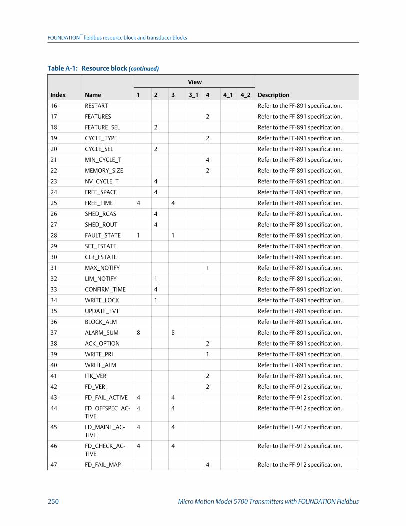
Resource block (continued)Table A-1:
Index Name
View
Description1 2 3 3_1 4 4_1 4_2
16 RESTART Refer to the FF-891 specification.
17 FEATURES 2 Refer to the FF-891 specification.
18 FEATURE_SEL 2 Refer to the FF-891 specification.
19 CYCLE_TYPE 2 Refer to the FF-891 specification.
20 CYCLE_SEL 2 Refer to the FF-891 specification.
21 MIN_CYCLE_T 4 Refer to the FF-891 specification.
22 MEMORY_SIZE 2 Refer to the FF-891 specification.
23 NV_CYCLE_T 4 Refer to the FF-891 specification.
24 FREE_SPACE 4 Refer to the FF-891 specification.
25 FREE_TIME 4 4 Refer to the FF-891 specification.
26 SHED_RCAS 4 Refer to the FF-891 specification.
27 SHED_ROUT 4 Refer to the FF-891 specification.
28 FAULT_STATE 1 1 Refer to the FF-891 specification.
29 SET_FSTATE Refer to the FF-891 specification.
30 CLR_FSTATE Refer to the FF-891 specification.
31 MAX_NOTIFY 1 Refer to the FF-891 specification.
32 LIM_NOTIFY 1 Refer to the FF-891 specification.
33 CONFIRM_TIME 4 Refer to the FF-891 specification.
34 WRITE_LOCK 1 Refer to the FF-891 specification.
35 UPDATE_EVT Refer to the FF-891 specification.
36 BLOCK_ALM Refer to the FF-891 specification.
37 ALARM_SUM 8 8 Refer to the FF-891 specification.
38 ACK_OPTION 2 Refer to the FF-891 specification.
39 WRITE_PRI 1 Refer to the FF-891 specification.
40 WRITE_ALM Refer to the FF-891 specification.
41 ITK_VER 2 Refer to the FF-891 specification.
42 FD_VER 2 Refer to the FF-912 specification.
43 FD_FAIL_ACTIVE 4 4 Refer to the FF-912 specification.
44 FD_OFFSPEC_AC-TIVE
4 4 Refer to the FF-912 specification.
45 FD_MAINT_AC-TIVE
4 4 Refer to the FF-912 specification.
46 FD_CHECK_AC-TIVE
4 4 Refer to the FF-912 specification.
47 FD_FAIL_MAP 4 Refer to the FF-912 specification.
FOUNDATION™
fieldbus resource block and transducer blocks
250 Micro Motion Model 5700 Transmitters with FOUNDATION Fieldbus
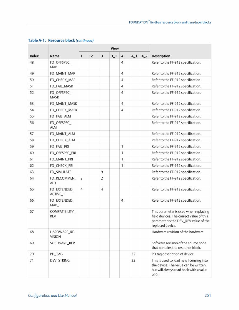
Resource block (continued)Table A-1:
Index Name
View
Description1 2 3 3_1 4 4_1 4_2
48 FD_OFFSPEC_MAP
4 Refer to the FF-912 specification.
49 FD_MAINT_MAP 4 Refer to the FF-912 specification.
50 FD_CHECK_MAP 4 Refer to the FF-912 specification.
51 FD_FAIL_MASK 4 Refer to the FF-912 specification.
52 FD_OFFSPEC_MASK
4 Refer to the FF-912 specification.
53 FD_MAINT_MASK 4 Refer to the FF-912 specification.
54 FD_CHECK_MASK 4 Refer to the FF-912 specification.
55 FD_FAIL_ALM Refer to the FF-912 specification.
56 FD_OFFSPEC_ALM
Refer to the FF-912 specification.
57 FD_MAINT_ALM Refer to the FF-912 specification.
58 FD_CHECK_ALM Refer to the FF-912 specification.
59 FD_FAIL_PRI 1 Refer to the FF-912 specification.
60 FD_OFFSPEC_PRI 1 Refer to the FF-912 specification.
61 FD_MAINT_PRI 1 Refer to the FF-912 specification.
62 FD_CHECK_PRI 1 Refer to the FF-912 specification.
63 FD_SIMULATE 9 Refer to the FF-912 specification.
64 FD_RECOMMEN_ACT
2 2 Refer to the FF-912 specification.
65 FD_EXTENDED_ACTIVE_1
4 4 Refer to the FF-912 specification.
66 FD_EXTENDED_MAP_1
4 Refer to the FF-912 specification.
67 COMPATIBILITY_REV
This parameter is used when replacingfield devices. The correct value of thisparameter is the DEV_REV value of thereplaced device.
68 HARDWARE_RE-VISION
Hardware revision of the hardware.
69 SOFTWARE_REV Software revision of the source codethat contains the resource block.
70 PD_TAG 32 PD tag description of device
71 DEV_STRING 32 This is used to load new licensing intothe device. The value can be writtenbut will always read back with a valueof 0.
FOUNDATION™
fieldbus resource block and transducer blocks
Configuration and Use Manual 251

Resource block (continued)Table A-1:
Index Name
View
Description1 2 3 3_1 4 4_1 4_2
72 DEV_OPTIONS 4 Indicates which device licensing op-tions are enabled.
73 OUTPUT_BOARD_SN
4 Output board serial number.
74 FINAL_ASSY_NUM
4 The same final assembly numberplaced on the neck label.
75 DOWNLOAD_MODE
Gives access to the boot block codefor over the wire downloads 0=Unini-tialized 1=Run mode 2=Downloadmode
76 HEALTH_INDEX 1 Parameter representing the overallhealth of the device. 100=Perfect.
77 FAILED_PRI 1 Designates the alerting priority of theFAILED_ALM and also used as switchb/w Field Diagnostics and legacyPlantWeb alerts. If value is greaterthan or equal to 1, PlantWeb alerts willbe active in device; otherwise, devicewill use Field Diagnostics alerts.
78 RECOMMENDED_ACTION
2 Enumerated list of recommended ac-tions displayed with a device alert.
79 FAILED_ALM Alert indicating a failure within a de-vice which makes the device non-op-erational.
80 MAINT _ALM Alert indicating that the device needsmaintenance soon. If the condition isignored, the device will eventually fail.
81 ADVISE _ALM Alert indicating advisory alerts. Theseconditions do not have a direct impacton the process or device integrity.
82 FAILED_ENABLE 4 Enabled FAILED_ALM alert conditions.Corresponds bit for bit to FAILED_AC-TIVE. A bit on means that the corre-sponding alert condition is enabledand will be detected. A bit off meansthe corresponding alert condition isdisabled and will not be detected. Thisparameter is the Read Only copy ofFD_FAIL_MAP.
FOUNDATION™
fieldbus resource block and transducer blocks
252 Micro Motion Model 5700 Transmitters with FOUNDATION Fieldbus

Resource block (continued)Table A-1:
Index Name
View
Description1 2 3 3_1 4 4_1 4_2
83 FAILED_MASK 4 Mask of Failure Alert. Corresponds bitfor bit to the FAILED_ACTIVE. A bit onmeans that the failure is masked outfrom alerting. This parameter is theRead Only copy of FD_FAIL_MASK.
84 FAILED_ACTIVE 4 Enumerated list of advisory conditionswithin a device. All open bits are freeto be used as appropriate for each spe-cific device. This parameter is the ReadOnly copy of FD_FAIL_ACTIVE.
85 MAINT_PRI 1 Designates the alerting priority of theMAINT_ALM.
86 MAINT_ENABLE 4 Enabled MAINT_ALM alert conditions.Corresponds bit for bit to MAINT_AC-TIVE. A bit on means that the corre-sponding alert condition is enabledand will be detected. A bit off meansthe corresponding alert condition isdisabled and will not be detected. Thisparameter is the Read Only copy ofFD_OFFSPEC_MAP
87 MAINT _MASK 4 Mask of Maintenance Alert. Corre-sponds bit for bit to MAINT_ACTIVE. Abit on means that the failure is maskedout from alerting. This parameter isthe Read Only copy of FD_OFFSPEC_MASK
88 MAINT _ACTIVE 4 Enumerated list of advisory conditionswithin a device. All open bits are freeto be used as appropriate for each spe-cific device. This parameter is the ReadOnly copy of FD_OFFSPEC_ACTIVE
89 ADVISE_PRI 1 Designates the alerting priority of theADVISE_ALM.
90 ADVISE_ENABLE 4 Enabled ADVISE_ALM alert conditions.Corresponds bit for bit to ADVISE_AC-TIVE. A bit on means that the corre-sponding alert condition is enabledand will be detected. A bit off meansthe corresponding alert condition isdisabled and will not be detected. Thisparameter is the Read Only copy ofFD_MAINT_MAP & FD_CHECK_MAP
FOUNDATION™
fieldbus resource block and transducer blocks
Configuration and Use Manual 253
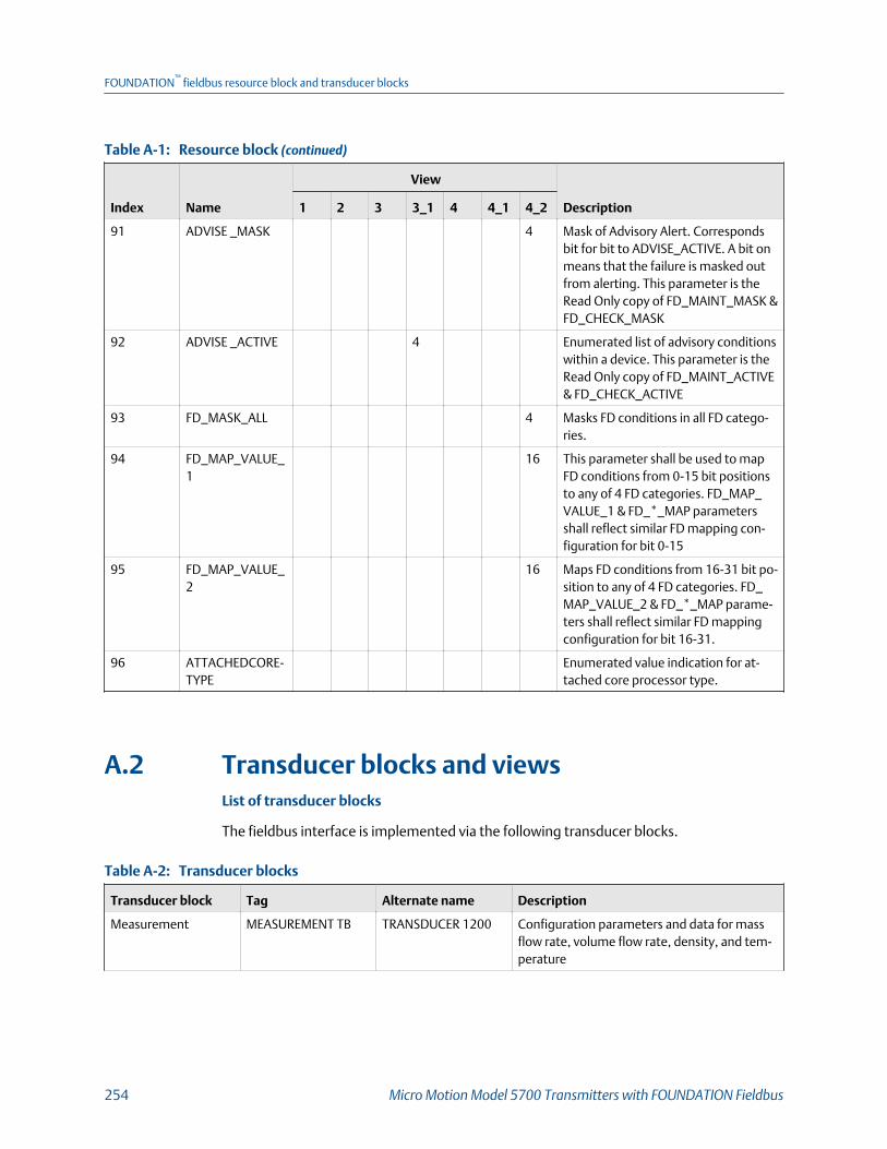
Resource block (continued)Table A-1:
Index Name
View
Description1 2 3 3_1 4 4_1 4_2
91 ADVISE _MASK 4 Mask of Advisory Alert. Correspondsbit for bit to ADVISE_ACTIVE. A bit onmeans that the failure is masked outfrom alerting. This parameter is theRead Only copy of FD_MAINT_MASK &FD_CHECK_MASK
92 ADVISE _ACTIVE 4 Enumerated list of advisory conditionswithin a device. This parameter is theRead Only copy of FD_MAINT_ACTIVE& FD_CHECK_ACTIVE
93 FD_MASK_ALL 4 Masks FD conditions in all FD catego-ries.
94 FD_MAP_VALUE_1
16 This parameter shall be used to mapFD conditions from 0-15 bit positionsto any of 4 FD categories. FD_MAP_VALUE_1 & FD_*_MAP parametersshall reflect similar FD mapping con-figuration for bit 0-15
95 FD_MAP_VALUE_2
16 Maps FD conditions from 16-31 bit po-sition to any of 4 FD categories. FD_MAP_VALUE_2 & FD_*_MAP parame-ters shall reflect similar FD mappingconfiguration for bit 16-31.
96 ATTACHEDCORE-TYPE
Enumerated value indication for at-tached core processor type.
A.2 Transducer blocks and viewsList of transducer blocks
The fieldbus interface is implemented via the following transducer blocks.
Transducer blocksTable A-2:
Transducer block Tag Alternate name Description
Measurement MEASUREMENT TB TRANSDUCER 1200 Configuration parameters and data for massflow rate, volume flow rate, density, and tem-perature
FOUNDATION™
fieldbus resource block and transducer blocks
254 Micro Motion Model 5700 Transmitters with FOUNDATION Fieldbus

Transducer blocks (continued)Table A-2:
Transducer block Tag Alternate name Description
Device DEVICE TB TRANSDUCER 1400 Contains informational static data such as soft-ware revisions, serial numbers, calibration da-ta, LDO configuration data and physical IOconfiguration data
Totalizer & Inventory TOTAL INVENTORY TB TRANSDUCER 1600 Contains 7 configurable totals and inventoriesdata along with their configuration
Meter Verification METER VERIFICATIONTB
TRANSDUCER 1800 Contains the meter verification configurationand process
Petroleum Measure-ment (API)
PETRO MEAS TB TRANSDUCER 2000 Contains PM process variables and configura-tion data
Concentration Meas-urement
CONC MEAS TB TRANSDUCER 2200 Contains concentration measurement processvariables and configuration data
Advance Phase Meas-urement (APM)
APM MEAS TB TRANSDUCER 2400 Contains advance phase measurement varia-bles and configuration data.
Definitions for transducer block details
Use the following definitions for the transducer block "details" tables:
# Index of the FF parameter in the object dictionary
Name Name used in code
Label Name as it appears in most configuration tools
Msg type One of the following:
VAR A value
ENUM (ENUM1,ENUM2)
A value from an enumeration
METHOD Initiates an action in the device
STR A set of ASCII characters
ARRAY A set of values
REC A data structure defined by the FieldbusFoundation
Data type(size inbytes)
The data type of the parameter, and the size in bytes, when required
Store Class of memory required, and the update rate in Hz if applicable:
D Dynamic store (cyclic data, parameter updated periodically)
S Static store (acyclic data, parameter changed on a deliberate write)
N Nonvolatile parameter (saved across power cycles)
Access The type of access allowed for the parameter:
FOUNDATION™
fieldbus resource block and transducer blocks
Configuration and Use Manual 255

R Read-only
RW (Any) Read/write, with the transducer block in any mode
RW (OOS) Read/write, with the transducer block in Out of Service(OOS) mode
RW (Auto) Read/write, with the transducer block in Auto mode
Definitions for transducer block views
Four views are defined for each transducer block.
Views of transducer blocksTable A-3:
View Description
VIEW 1 Access to the dynamic operating parameters of the transducer block
VIEW 2 Access to the static operating parameters of the transducer block
VIEW 3 Access to all the dynamic parameters of the transducer block
VIEW 4 Access to static parameters not included in VIEW 2
The maximum size of a view is 122 bytes.
Use the following definitions for the transducer block "views" tables:
View and sizein view
The views that contain the parameter, and the size of the parameter inthe view, in bytes. The number in the cell indicates that the variable iscontained in that particular view. The number is the size of theparameter in bytes.
Release The firmware release number in which the parameter first appears.
A.2.1 Measurement transducer block
Fieldbus standardTable A-4:
# Name (Label)Msgtype
Data type (size inbytes) Store Access Enumerated list of values
Fieldbus standard
0 BLOCK_STRUCTURE VAR DS_64 S RW (Any) N/A
1 ST_REV VAR Unsigned16 (2) S R N/A
2 TAG_DESC STR OCTET STRING (32) S RW (Any) Any 32 Characters
3 STRATEGY VAR Unsigned16 (2) S RW (Any) N/A
4 ALERT_KEY VAR Unsigned8 (1) S RW (Any) 1 to 255
5 MODE_BLK REC DS-69 (4) mix RW (Any) See section 2/6 of FF-891
6 BLOCK_ERR STR BIT STRING (2) D RO See section 4.8 of FF-903
7 UPDATE_EVT REC DS-73 D RW (Any)
FOUNDATION™
fieldbus resource block and transducer blocks
256 Micro Motion Model 5700 Transmitters with FOUNDATION Fieldbus

Fieldbus standard (continued)Table A-4:
# Name (Label)Msgtype
Data type (size inbytes) Store Access Enumerated list of values
8 BLOCK_ALM REC DS-72 D RW (Any)
9 TRANSDUCER_DIRECTORY VAR Unsigned16 (2) RO
10 TRANSDUCER_TYPE VAR Unsigned16 (2) RO
11 TRANSDUCER_TYPE_VER VAR Unsigned16 (2) RO
12 XD_ERROR VAR Unsigned8 (1) D RO 0 = No Error
18 = Calibration Error
19 = Configuration Error
20 = Electronics Failure
21 = Sensor Failure
26 = Process Error
27 = Calibration In Progress
13 COLLECTION_DIRECTORY VAR Unsigned32 S RO
Process variablesTable A-5:
# Name (Label)Msgtype
Data type (size inbytes) Store Access Enumerated list of values
14 MASS_FLOW
(Mass Flow Rate)
VAR DS-65 (5) D RO MFLOW_LOW_LIMIT ≤ x ≤MFLOW_HIGH_LIMIT
15 VOLUME_FLOW
(Volume Flow Rate)
VAR DS-65 (5) D RO VFLOW_LOW_LIMIT ≤ x ≤VFLOW_HIGH_LIMIT
16 TEMPERATURE
(Temperature)
VAR DS-65 (5) D RO TEMP_LOW_LIMIT ≤ x ≤TEMP_HIGH_LIMIT
17 DENSITY
(Density)
VAR DS-65 (5) D RO DENSITY_LOW_LIMIT ≤ x ≤DENSITY_HIGH_LIMIT
Measurement TB detailsTable A-6:
# Name (Label)Msgtype
Data type (size inbytes) Store Access Enumerated list of values
Process variables
14 MASS_FLOW
(Mass Flow Rate )
VAR DS-65 (5) D RO MFLOW_LOW_LIMIT ≤ x ≤MFLOW_HIGH_LIMIT
15
15 VOLUME_FLOW
(Volume Flow Rate )
VAR DS-65 (5) D RO VFLOW_LOW_LIMIT ≤ x ≤VFLOW_HIGH_LIMIT
FOUNDATION™
fieldbus resource block and transducer blocks
Configuration and Use Manual 257

Measurement TB details (continued)Table A-6:
# Name (Label)Msgtype
Data type (size inbytes) Store Access Enumerated list of values
16 TEMPERATURE
(Temperature)
VAR DS-65 (5) D RO TEMP_LOW_LIMIT ≤ x ≤TEMP_HIGH_LIMIT
17 DENSITY
(Density)
VAR DS-65 (5) D RO DENSITY_LOW_LIMIT ≤ x ≤DENSITY_HIGH_LIMIT
Mass flow configuration
18 ACTUAL_FLOW_DIRECTION
(Flow Direction )
VAR DS-66 (2) D RO Value part of DS-66 (2)
0 = Forward/Zero Flow
1=Reverse Flow"
19 MFLOW_UNIT
(Mass Flow Unit )
ENUM2 Unsigned16 (2) S R/W(OOS)
See Table A‐7.
Codes for Mass Flow UnitTable A-7:
1318 = g/s 1324 = kg/h 1330 = lb/s 1336 = STon/h
1319 = g/min 1325 = kg/d 1331 = lb/min 1337 = Ston/d
1320 = g/h 1327 = t/min 1332 = lb/h 1340 = LTon/h
1322 = Kg/s 1328 = t/h 1333 = lb/d 1341 = LTon/d
1323 = kg/min 1329 = t/d 1335 = STon/min 253 = Special
20 MFLOW_SPL_UNIT_BASE
(Mass Flow Base Unit)
ENUM2 Unsigned16 (2) S R/W(OOS)
1089 = g
1088 = Kg
1092 = t
1094 = lb
1095 = STon
1096 = LTon
21 MFLOW_SPL_UNIT_TIME
(Mass Flow Base Time )
ENUM2 Unsigned16 (2) S R/W(OOS)
1058 = min
1054 = s
1059 = h
1060 = d
22 MFLOW_SPL_UNIT_CON
(Mass Flow Conversion Fac-tor )
VAR FLOAT (4) S R/W(OOS)
x > 0.0
23 MFLOW_SPL_UNIT_STR
(Mass Flow Special Label )
STR VISIBLE STRING (8) S R/W(OOS)
Any 8 characters
24 MFLOW_TOTINV_SPL_UNIT_STR
(Mass Flow Total Special La-bel )
VAR VISIBLE STRING (8) S R/W(OOS)
Any 8 characters
FOUNDATION™
fieldbus resource block and transducer blocks
258 Micro Motion Model 5700 Transmitters with FOUNDATION Fieldbus

Measurement TB details (continued)Table A-6:
# Name (Label)Msgtype
Data type (size inbytes) Store Access Enumerated list of values
25 MFLOW_M_FCATOR
(Mass Flow Factor )
VAR FLOAT (4) S R/W(OOS)
0.8 ≤ x ≤ 1.2
26 MFLOW_LOW_CUTOFF
(Mass Flow Cutoff )
VAR FLOAT (4) S R/W(OOS)
0 ≤ x ≤ MFLOW_HIGH_LIMIT
27 MFLOW_LOW_LIMIT
(Mass Flow Low Limit )
VAR FLOAT (4) S RO N/A
28 MFLOW_HIGH_LIMIT
(Mass Flow High Limit )
VAR FLOAT (4) S RO N/A
29 FLOW_DAMPING
(Flow Damping )
VAR FLOAT (4) S R/W(OOS)
"0.0 ≤ x ≤ 60.0 (rounded to60 if x > 60)"
30 FLOW_DIRCTION
(Flow Direction )
ENUM Unsigned8 (1) S R/W(Any)
0 = Forward
1 = Backward
Volume flow configuration
31 VFLOW_UNIT
(Volume Flow Unit )
ENUM2 Unsigned16 (2) S R/W(OOS)
See Table A‐8.
Codes for Volume Flow UnitTable A-8:
1347 = m3/s 1356 = CFS 1366 = Mgal/d 1374 = bbl/d
1348 = m3/min 1357 = CFM 1367 = ImpGal/s 1631 = bbl(US Beer)/d
1349 = m3/h 1358 = CFH 1368 = ImpGal/min 1632 = bbl(US Beer)/h
1350 = m3/d 1359 = ft³/d 1369 = ImpGal/h 1633 = bbl(US Beer)/min
1351 = L/s 1362 = gal/s 1370 = Impgal/d 1634 = bbl(US Beer)/s
1352 = L/min 1363 = GPM 1371 = bbl/s 253 = Special
1353 = L/h 1364 = gal/h 1372 = bbl/min
1355 = ML/d 1365 = gal/d 1373 = bbl/h
32 VFLOW_SPL_UNIT_BASE(Volume Flow Base Unit )
ENUM2 Unsigned16 (2) S R/W(OOS)
1048 = gallon
1038 = L
1049 = ImpGal
1043 = ft³
1034 = m³
1051 = bbl
33002 = beer bbl
33 VFLOW_SPL_UNIT_TIME(Volume Flow Base Time )
ENUM2 Unsigned16 (2) S R/W(OOS)
1058 = min
1054 = s
1059 = h
1060 = d
FOUNDATION™
fieldbus resource block and transducer blocks
Configuration and Use Manual 259

Measurement TB details (continued)Table A-6:
# Name (Label)Msgtype
Data type (size inbytes) Store Access Enumerated list of values
34 VFLOW_SPL_UNIT_COVN(Volume Flow ConversionFactor )
VAR FLOAT (4) S R/W(OOS)
> 0.0
35 VFLOW_SPL_UNIT_STR(Volume Flow Label )
STR VISIBLE STRING (8) S R/W(OOS)
Any 8 characters
36 VFLOW_TOTINV_SPL_UNIT_STR (Volume Flow To-tal Special Label )
STR VISIBLE STRING (8) S R/W(OOS)
Any 8 characters
37 VFLOW_M_FACTOR (Vol-ume Flow Factor )
VAR FLOAT (4) S R/W(OOS)
0.8 ≤ x ≤ 1.2
38 VFLOW_LOW_CUTOFF (Vol-ume Flow Cutoff )
VAR FLOAT (4) S R/W(OOS)
0 ≤ x ≤ VFLOW_HIGH_LIMIT
39 VFLOW_LOW_LIMIT (Vol-ume Low Limit )
VAR FLOAT (4) S RO N/A
40 VFLOW_HIGH_LIMIT (Vol-ume High Limit )
VAR FLOAT (4) S RO N/A
Temperature configuration
41 TEMP_UNIT (TemperatureUnit)
ENUM2 Unsigned16 (2) S R/W(OOS)
1000 = K
1001 = deg C
1002 = deg F
1003 = deg R
42 TEMP_LOW_LIMIT (Temper-ature Low Limit )
VAR FLOAT (4) S RO N/A
43 TEMP_HIGH_LIMIT (Tem-perature High Limit )
VAR FLOAT (4) S RO N/A
44 TEMP_DAMPING (Tempera-ture Damping )
VAR FLOAT (4) S R/W(OOS)
0.0 ≤ x ≤ 80.0 (rounded to80 if x > 80)
Density configuration
45 DENSITY_UNIT (DensityUnit)
ENUM2 Unsigned16 (2) S R/W(OOS)
See Table A‐9.
Codes for Density UnitTable A-9:
1097 = kg/m3 1104 = g/ml 1107 = lb/ft3 1113 = degAPI
1100 = g/cm3 1105 = g/L 1108 = lb/gal 1114 = SGU"
1103 = kg/L 1106 = lb/in3 1109 = STon/yd³
46 DENSITY_LOW_LIMIT (Den-sity Low Limit)
VAR FLOAT (4) S RO N/A
FOUNDATION™
fieldbus resource block and transducer blocks
260 Micro Motion Model 5700 Transmitters with FOUNDATION Fieldbus

Measurement TB details (continued)Table A-6:
# Name (Label)Msgtype
Data type (size inbytes) Store Access Enumerated list of values
47 DENSITY_HIGH_LIMIT (Den-sity High Limit)
VAR FLOAT (4) S RO N/A
48 DENSITY_M_FACTOR (Den-sity Factor)
VAR FLOAT (4) S R/W(OOS)
0.8 ≤ x ≤ 1.2
49 DENSITY_DAMPING (Densi-ty Damping)
VAR FLOAT (4) S R/W(OOS)
0.0 ≤ x ≤ 60.0 (rounded to60 if x > 60)
50 DENSITY_LOW_CUTOFF(Density Cutoff)
VAR FLOAT (4) S R/W(OOS)
0.0 ≤ x ≤ 0.5 (g/cm3)
Flow velocity configuration
51 FLOW_VELOCITY_UNIT (Ve-locity Unit)
ENUM2 Unsigned16 (2) S R/W(OOS)
1067 = ft/s
1061 = m/s
1066 = in/s 1069 = in/min
1070 = ft/min
1063 = m/h
Gas process variables
52 VOL_FLOW_TYPE (VolumeFlow Type)
ENUM Unsigned8 (1) S R/W(OOS)
0 = Liquid
1 = Gas
53 GSV_GAS_DENSITY (GasReference Density)
VAR FLOAT (4) S R/W(OOS)
Density Lo Limit ≤ x ≤ Densi-ty Hi Limit
54 GSV_VOL_FLOW (GasStandard Volume Flow)
ENUM2 DS-65 (5) D RO VFLOW_LOW_LIMIT ≤ x ≤VFLOW_HIGH_LIMIT
55 GSV_FLOW_UNITS (GasStandard Volume Flow Unit)
ENUM2 Unsigned16 (2) S R/W(OOS)
See Table A‐10.
Codes for Gas Standard Volume Flow UnitTable A-10:
1360 = SCFM 1527 = Sm³/s 1534 = NL/h 33000 = SCFS
1361 = SCFH 1528 = Sm³/min 1535 = NL/d 33001 = SCFD
1522 = Nm³/s 1529 = Sm³/h 1537 = SL/s 253 = Special
1523 = Nm³/min 1530 = Sm³/d 1538 = SL/min
1524 = Nm³/h 1532 = NL/s 1539 = SL/h
1525 = Nm³/d 1533 = NL/min 1540 = SL/d
56 GSV_FLOW_BASEUNIT (GasStandard Volume Flow BaseUnit)
ENUM2 Unsigned16 (2) S R/W(OOS)
1521 = Nm³
1531 = NL
1053 = SCF
1536 = SL
1526 = Sm³
FOUNDATION™
fieldbus resource block and transducer blocks
Configuration and Use Manual 261

Measurement TB details (continued)Table A-6:
# Name (Label)Msgtype
Data type (size inbytes) Store Access Enumerated list of values
57 GSV_FLOW_BASETIME (GasStandard Volume Flow BaseTime)
ENUM2 Unsigned16 (2) S R/W(OOS)
1058 = min
1054 = s 1059 = h
1060 = d
58 GSV_FLOWFACTOR (GasStandard Volume Flow Con-version Factor)
VAR FLOAT (4) S R/W(OOS)
> 0.0
59 GSV_FLOWTEXT (GasStandard Volume Flow La-bel)
STR VISIBLE STRING (8) S R/W(OOS)
Any 8 characters
60 GSV_CUTOFF (Gas StandardVolume Cutoff)
VAR FLOAT (4) S R/W(OOS)
≥ 0.0
61 GSV_TOTINV_SPL_UNIT_STR (Gas Standard VolumeFlow Total Special Unit La-bel)
STR VISIBLE STRING (8) S R/W(OOS)
Any 8 characters
Pressure compensation
62 PRESSURE_COMP (ExternalPressure )
VAR DS-65 (5) D R/W(Any)
-1.5 BAR ≤ x ≤ 10000.0 BAR
63 PRESSURE_UNITS (PressureUnit)
ENUM2 Unsigned16 (2) S R/W(OOS)
See Table A‐11.
Codes for Pressure UnitTable A-11:
1148 = inH2O (68 deg F) 1141 = psi 1130 = Pa 1132 = MPa 1150 = mm H2O (4 deg C)
1156 = inHg (0 deg C) 1137 = bar 1133 = KPa 33003 = in H2O (60 deg F)
1154 = ftH2O (68 deg F) 1138 = mbar 1139 = torr
1151 = mmH2O (68 deg F) 1144 =g/cm² 1140 = atm
1158 = mmHg (0 deg C) 1145 = Kg/cm² 1147 = in H2O (4 deg C)
64 PRESSURE_COMP_EN (Pres-sure Compensation)
ENUM Unsigned8 (1) S R/W(OOS)
0= disabled
1 = enabled
65 PRESSURE_FACTOR_FLOW(Flow Pressure Factor)
VAR FLOAT (4) S R/W(OOS)
-0.1 ≤ x ≤ 0.1
66 PRESSURE_FACTOR_DENS(Density Pressure Factor)
VAR FLOAT (4) S R/W(OOS)
-0.1 ≤ x ≤ 0.1
67 PRESSURE_FLOW_CAL(Flow Calibration Pressure)
VAR FLOAT (4) S R/W(OOS)
≥ 0.0
FOUNDATION™
fieldbus resource block and transducer blocks
262 Micro Motion Model 5700 Transmitters with FOUNDATION Fieldbus

Measurement TB details (continued)Table A-6:
# Name (Label)Msgtype
Data type (size inbytes) Store Access Enumerated list of values
Temperature Compensation
68 TEMPERATURE_COMP (Ex-ternal Temperature)
VARIA-BLE
DS-65 (5) D R/W(any)
TEMP_LOW_LIMIT ≤ x ≤TEMP_HIGH_LIMIT
69 TEMPERATURE_COMP_EN(Temperature Compensa-tion)
Method Unsigned8 (1) S R/W(OOS)
0 = Disabled
1 = Enabled
Device Diagnostics
70 DRIVE_GAIN (Drive Gain) VAR DS-65 (5) D RO 0% ≤ x ≤ 100%
71 TUBE_FREQ (Tube Frequen-cy)
VAR FLOAT (4) D RO
72 LIVE_ZERO (Live Zero FlowRate)
VAR FLOAT (4) D RO
73 LEFT_PICKUP_VOL (LeftPickoff Amplitude)
VAR FLOAT (4) D RO 0.0 V ≤ x ≤ +5.0 V
74 RIGHT_PICKUP_VOL (RightPickoff Amplitude)
VAR FLOAT (4) D RO 0.0 V ≤ x ≤ +5.0 V
75 FLOW_VELOCITY (Approxi-mate Velocity)
VAR DS-65 (5) D RO -700 m/s ≤ x ≤ +700 m/s
76 CORE_BOARD_TEMP (CoreBoard Temperature)
VAR FLOAT (4) D RO -200 C ≤ x ≤ +200 C
77 ELECT_TEMP_MAX (MaxElectronic Temperature)
VAR FLOAT (4) D RO N/A
78 ELECT_TEMP_MIN (MinElectronic Temperature)
VAR FLOAT (4) D RO N/A
79 ELECT_TEMP_AVG (AverageElectronic Temperature)
VAR FLOAT (4) D RO N/A
80 SENSOR_TEMP_MAX (MaxSensor Temperature)
VAR FLOAT (4) D RO N/A
81 SENSOR_TEMP_MIN (MinSensor Temperature)
VAR FLOAT (4) D RO N/A
82 SENSOR_TEMP_AVG (Aver-age Sensor Temperature)
VAR FLOAT (4) D RO N/A
83 RTD_RESIS_CABLE RTD Re-sistance Cable
VAR FLOAT (4) D RO N/A
84 RTD_RESIS_METER (MeterResistance)
VAR FLOAT (4) D RO N/A
85 CP_POWER_CYCLE (CoreProcessor Power Cycles)
VAR Unsigned16 (2) D RO N/A
86 POWER_ONTIME (Power OnTime)
VAR UnsignedI32 D RO N/A
FOUNDATION™
fieldbus resource block and transducer blocks
Configuration and Use Manual 263
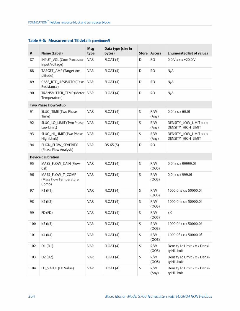
Measurement TB details (continued)Table A-6:
# Name (Label)Msgtype
Data type (size inbytes) Store Access Enumerated list of values
87 INPUT_VOL (Core ProcessorInput Voltage)
VAR FLOAT (4) D RO 0.0 V ≤ x ≤ +20.0 V
88 TARGET_AMP (Target Am-plitude)
VAR FLOAT (4) D RO N/A
89 CASE_RTD_RESIS RTD (CaseResistance)
VAR FLOAT (4) D RO N/A
90 TRANSMITTER_TEMP (MeterTemperature)
VAR FLOAT (4) D RO N/A
Two Phase Flow Setup
91 SLUG_TIME (Two PhaseTime)
VAR FLOAT (4) S R/W(Any)
0.0f ≤ x ≤ 60.0f
92 SLUG_LO_LIMIT (Two PhaseLow Limit)
VAR FLOAT (4) S R/W(Any)
DENSITY_LOW_LIMIT ≤ x ≤DENSITY_HIGH_LIMIT
93 SLUG_HI_LIMIT (Two PhaseHigh Limit)
VAR FLOAT (4) S R/W(Any)
DENSITY_LOW_LIMIT ≤ x ≤DENSITY_HIGH_LIMIT
94 PHGN_FLOW_SEVERITY(Phase Flow Analysis)
VAR DS-65 (5) D RO
Device Calibration
95 MASS_FLOW_GAIN (Flow-Cal)
VAR FLOAT (4) S R/W(OOS)
0.0f ≤ x ≤ 99999.0f
96 MASS_FLOW_T_COMP(Mass Flow TemperatureComp)
VAR FLOAT (4) S R/W(OOS)
0.0f ≤ x ≤ 999.0f
97 K1 (K1) VAR FLOAT (4) S R/W(OOS)
1000.0f ≤ x ≤ 50000.0f
98 K2 (K2) VAR FLOAT (4) S R/W(OOS)
1000.0f ≤ x ≤ 50000.0f
99 FD (FD) VAR FLOAT (4) S R/W(OOS)
≥ 0
100 K3 (K3) VAR FLOAT (4) S R/W(OOS)
1000.0f ≤ x ≤ 50000.0f
101 K4 (K4) VAR FLOAT (4) S R/W(OOS)
1000.0f ≤ x ≤ 50000.0f
102 D1 (D1) VAR FLOAT (4) S R/W(OOS)
Density Lo Limit ≤ x ≤ Densi-ty Hi Limit
103 D2 (D2) VAR FLOAT (4) S R/W(OOS)
Density Lo Limit ≤ x ≤ Densi-ty Hi Limit
104 FD_VALUE (FD Value) VAR FLOAT (4) S R/W(Any)
Density Lo Limit ≤ x ≤ Densi-ty Hi Limit
FOUNDATION™
fieldbus resource block and transducer blocks
264 Micro Motion Model 5700 Transmitters with FOUNDATION Fieldbus

Measurement TB details (continued)Table A-6:
# Name (Label)Msgtype
Data type (size inbytes) Store Access Enumerated list of values
105 D3 (D3) VAR FLOAT (4) S R/W(OOS)
Density Lo Limit ≤ x ≤ Densi-ty Hi Limit
106 D4 (D4) VAR FLOAT (4) S R/W(OOS)
Density Lo Limit ≤ x ≤ Densi-ty Hi Limit
107 DENS_T_COEFF (TC/DT) VAR FLOAT (4) S R/W(OOS)
-20.0f ≤ x ≤ 20.0f
108 T_FLOW_TG_COEFF (FTG) VAR FLOAT (4) S R/W(OOS)
N/A
109 T_FLOW_FQ_COEFF (FFQ) VAR FLOAT (4) S R/W(OOS)
N/A
110 T_DENSITY_TG_COEFF(DTG)
VAR FLOAT (4) S R/W(OOS)
N/A
111 T_DENSITY_FQ_COEFF1(DFQ1)
VAR FLOAT (4) S R/W(OOS)
N/A
112 T_DENSITY_FQ_COEFF2(DFQ2)
VAR FLOAT (4) S R/W(OOS)
N/A
113 SENSOR_CODE_MEASURE(Sensor Type)
ENUM2 Unsigned16 (2) S R/W(Any)
0 = Curve Tube
1 = Straight Tube
Tempature Calibration
114 TEMP_OFFSET (Tempera-ture Offset)
VAR FLOAT (4) S RO/W(OOS)
-9999.0f ≤ x ≤ 99999.0f
115 TEMP_SLOPE TemperatureSlope
VAR FLOAT (4) S R/W(OOS)
0.0f ≤ x ≤ 999999.0f
Zero Calibration
116 ZERO_CAL (Zero Calibra-tion)
VAR DS-66 (2) S R/W(OOS)
Value part of DS-66 (2)
0 = Abort Zero Cal
1 = Start Zero Cal
117 ZERO_TIME (Zero Time) VAR Unsigned16 (2) S R/W(OOS)
5 ≤ x ≤ 300
118 ZERO_STD_DEV (StandardDeviation)
VAR FLOAT (4) S RO N/A
119 ZERO_OFFSET (Zero Offset) VAR FLOAT (4) S R/W(OOS)
-5.0f ≤ x ≤ 5.0f
120 ZERO_FAILCM_VAULE (ZeroCalibration Failed)
VAR FLOAT (4) S RO N/A
121 ZERO_IN_PROGRESS (Zeroin Progress)
VAR DS-66 (2) D RO Value part of DS-66 (2)
0 = Not Running
1 = Calibration Running
FOUNDATION™
fieldbus resource block and transducer blocks
Configuration and Use Manual 265
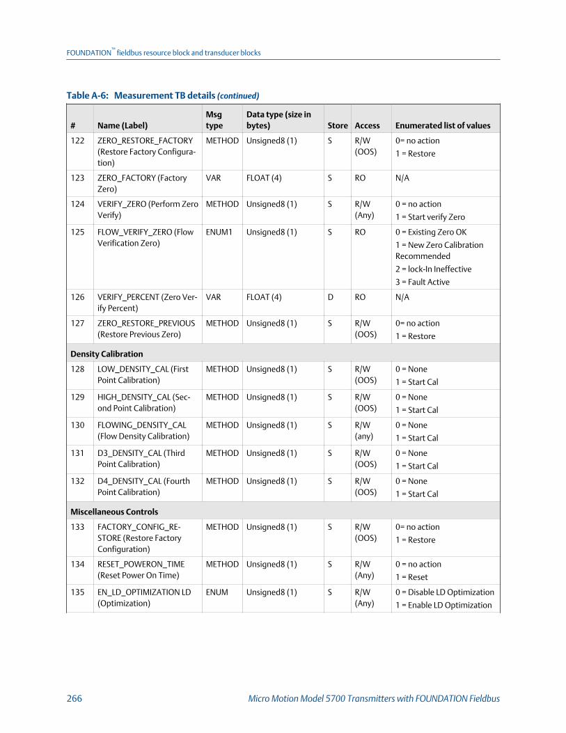
Measurement TB details (continued)Table A-6:
# Name (Label)Msgtype
Data type (size inbytes) Store Access Enumerated list of values
122 ZERO_RESTORE_FACTORY(Restore Factory Configura-tion)
METHOD Unsigned8 (1) S R/W(OOS)
0= no action
1 = Restore
123 ZERO_FACTORY (FactoryZero)
VAR FLOAT (4) S RO N/A
124 VERIFY_ZERO (Perform ZeroVerify)
METHOD Unsigned8 (1) S R/W(Any)
0 = no action
1 = Start verify Zero
125 FLOW_VERIFY_ZERO (FlowVerification Zero)
ENUM1 Unsigned8 (1) S RO 0 = Existing Zero OK
1 = New Zero CalibrationRecommended
2 = lock-In Ineffective
3 = Fault Active
126 VERIFY_PERCENT (Zero Ver-ify Percent)
VAR FLOAT (4) D RO N/A
127 ZERO_RESTORE_PREVIOUS(Restore Previous Zero)
METHOD Unsigned8 (1) S R/W(OOS)
0= no action
1 = Restore
Density Calibration
128 LOW_DENSITY_CAL (FirstPoint Calibration)
METHOD Unsigned8 (1) S R/W(OOS)
0 = None
1 = Start Cal
129 HIGH_DENSITY_CAL (Sec-ond Point Calibration)
METHOD Unsigned8 (1) S R/W(OOS)
0 = None
1 = Start Cal
130 FLOWING_DENSITY_CAL(Flow Density Calibration)
METHOD Unsigned8 (1) S R/W(any)
0 = None
1 = Start Cal
131 D3_DENSITY_CAL (ThirdPoint Calibration)
METHOD Unsigned8 (1) S R/W(OOS)
0 = None
1 = Start Cal
132 D4_DENSITY_CAL (FourthPoint Calibration)
METHOD Unsigned8 (1) S R/W(OOS)
0 = None
1 = Start Cal
Miscellaneous Controls
133 FACTORY_CONFIG_RE-STORE (Restore FactoryConfiguration)
METHOD Unsigned8 (1) S R/W(OOS)
0= no action
1 = Restore
134 RESET_POWERON_TIME(Reset Power On Time)
METHOD Unsigned8 (1) S R/W(Any)
0 = no action
1 = Reset
135 EN_LD_OPTIMIZATION LD(Optimization)
ENUM Unsigned8 (1) S R/W(Any)
0 = Disable LD Optimization
1 = Enable LD Optimization
FOUNDATION™
fieldbus resource block and transducer blocks
266 Micro Motion Model 5700 Transmitters with FOUNDATION Fieldbus

Measurement TB details (continued)Table A-6:
# Name (Label)Msgtype
Data type (size inbytes) Store Access Enumerated list of values
Process Variable Simulation
136 PROC_VAR_SIMULATION(Process Variable Simula-tion)
ENUM1 Unsigned8 (1) S R/W(Any)
0 = None
1 = Enable
137 SIMU_VAR_SEL (SimulationVariable)
ENUM1 Unsigned8 (1) S R/W(Any)
0 = Mass Flow
1 = Density
2 = Temeperature
138 SIMU_VAR_WAVEFORM_SEL (Simulation WaveformSelection)
ENUM1 Unsigned8 (1) S R/W(Any)
1 = fixed value
2 = sawtooth
3 = sine wave
139 SIMU_VAR_FIXED_VALUE(Simulation Fixed Value)
VAR FLOAT (4) S R/W(Any)
Any
140 SIMU_VAR_MIN_AMP (Sim-ulation Minimum Value)
VAR FLOAT (4) S R/W(Any)
Any
141 SIMU_VAR_MAX_AMP (Sim-ulation Maximum Value)
VAR FLOAT (4) S R/W(Any)
Any
142 SIMU_VAR_PERIOD (Simula-tion Period)
VAR FLOAT (4) S R/W(Any)
Any
143 SIMU_VAR_UNITS (Simula-tion Variable Units)
ENUM2 Unsigned16 (2) S RO MFLOW_UNIT,TEMP_UNIT,DENSITY_UNIT
Device Features
144 MEASUREMENT_FEATURES(Device Features)
VAR BIT STRING (2) D RO See Table A‐12.
Codes for Device FeaturesTable A-12:
0x0000 = FKEY_NO_FEATURE 0x0008 = TBR 0x0080 = API 0x4000 = APM Var Flow
0x0001 = APM Cont Flow 0x0010 = SMV 0x0800 = CAL FAIL 0x8000 = APM Cont NOC
0x0002 = TMR 0x0020 = GSV 0x1000 = APM TMR
0x0004 = PVR 0x0040 = ED 0x2000 = APM Var NOC
Measurement TB viewsTable A-13:
# Name (Label)
View listRe-lease1 2 3_1 3_2 4_1 4_2 4_3 4_4
Fieldbus standard
0 BLOCK_STRUCTURE 1.0
FOUNDATION™
fieldbus resource block and transducer blocks
Configuration and Use Manual 267

Measurement TB views (continued)Table A-13:
# Name (Label)
View listRe-lease1 2 3_1 3_2 4_1 4_2 4_3 4_4
1 ST_REV 2 2 2 2 2 2 2 2 1.0
2 TAG_DESC 1.0
3 STRATEGY 2 1.0
4 ALERT_KEY 1 1.0
5 MODE_BLK 4 4 4 1.0
6 BLOCK_ERR 2 2 1.0
7 UPDATE_EVT 1.0
8 BLOCK_ALM 1.0
9 TRANSDUCER_DIRECTORY 1.0
10 TRANSDUCER_TYPE 2 2 2 2 1.0
11 TRANSDUCER_TYPE_VER 2 2 2 2 1.0
12 XD_ERROR 1 1 1.0
13 COLLECTION_DIRECTORY 1.0
Process Variables
14 MASS_FLOW (Mass Flow Rate ) 5 5 1.0
15 VOLUME_FLOW (Volume Flow Rate ) 5 5 1.0
16 TEMPERATURE (Temperature) 5 5 1.0
17 DENSITY (Density) 5 5 1.0
Mass flow configuration
18 ACTUAL_FLOW_DIRECTION (Flow Di-rection )
2 1.0
19 MFLOW_UNIT (Mass Flow Unit ) 2 1.0
20 MFLOW_SPL_UNIT_BASE (Mass FlowBase Unit)
2 1.0
21 MFLOW_SPL_UNIT_TIME (Mass FlowBase Time )
2 1.0
22 MFLOW_SPL_UNIT_CON (Mass FlowConversion Factor )
4 1.0
23 MFLOW_SPL_UNIT_STR (Mass FlowSpecial Label )
8 1.0
24 MFLOW_TOTINV_SPL_UNIT_STR (MassFlow Total Special Label )
8 1.0
25 MFLOW_M_FCATOR (Mass Flow Fac-tor )
4 1.0
26 MFLOW_LOW_CUTOFF (Mass FlowCutoff )
4 1.0
FOUNDATION™
fieldbus resource block and transducer blocks
268 Micro Motion Model 5700 Transmitters with FOUNDATION Fieldbus
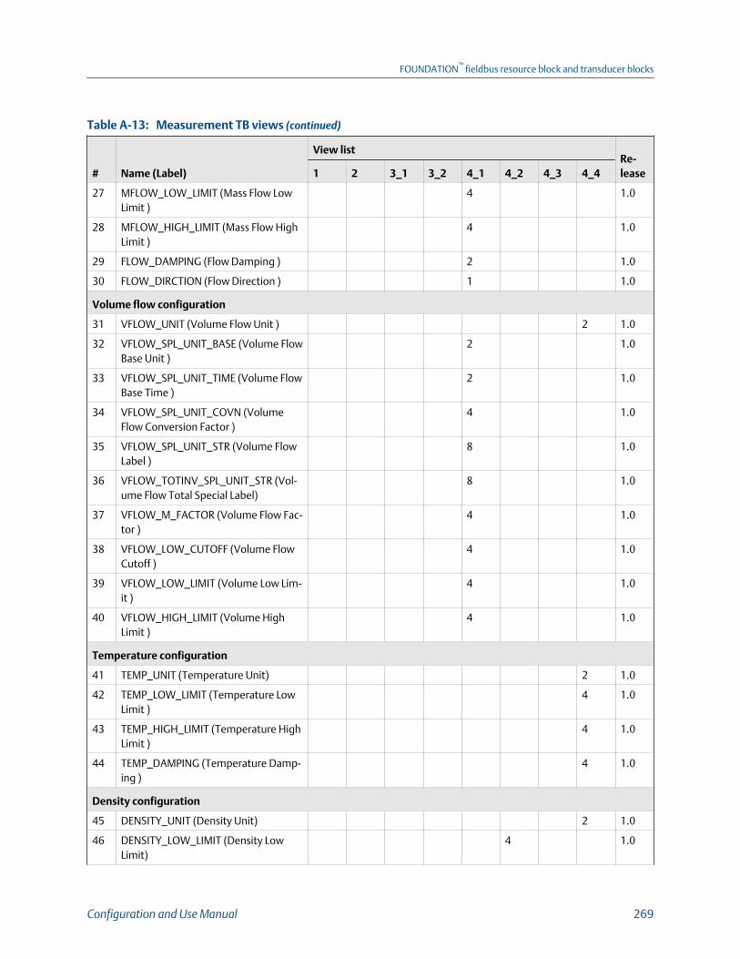
Measurement TB views (continued)Table A-13:
# Name (Label)
View listRe-lease1 2 3_1 3_2 4_1 4_2 4_3 4_4
27 MFLOW_LOW_LIMIT (Mass Flow LowLimit )
4 1.0
28 MFLOW_HIGH_LIMIT (Mass Flow HighLimit )
4 1.0
29 FLOW_DAMPING (Flow Damping ) 2 1.0
30 FLOW_DIRCTION (Flow Direction ) 1 1.0
Volume flow configuration
31 VFLOW_UNIT (Volume Flow Unit ) 2 1.0
32 VFLOW_SPL_UNIT_BASE (Volume FlowBase Unit )
2 1.0
33 VFLOW_SPL_UNIT_TIME (Volume FlowBase Time )
2 1.0
34 VFLOW_SPL_UNIT_COVN (VolumeFlow Conversion Factor )
4 1.0
35 VFLOW_SPL_UNIT_STR (Volume FlowLabel )
8 1.0
36 VFLOW_TOTINV_SPL_UNIT_STR (Vol-ume Flow Total Special Label)
8 1.0
37 VFLOW_M_FACTOR (Volume Flow Fac-tor )
4 1.0
38 VFLOW_LOW_CUTOFF (Volume FlowCutoff )
4 1.0
39 VFLOW_LOW_LIMIT (Volume Low Lim-it )
4 1.0
40 VFLOW_HIGH_LIMIT (Volume HighLimit )
4 1.0
Temperature configuration
41 TEMP_UNIT (Temperature Unit) 2 1.0
42 TEMP_LOW_LIMIT (Temperature LowLimit )
4 1.0
43 TEMP_HIGH_LIMIT (Temperature HighLimit )
4 1.0
44 TEMP_DAMPING (Temperature Damp-ing )
4 1.0
Density configuration
45 DENSITY_UNIT (Density Unit) 2 1.0
46 DENSITY_LOW_LIMIT (Density LowLimit)
4 1.0
FOUNDATION™
fieldbus resource block and transducer blocks
Configuration and Use Manual 269

Measurement TB views (continued)Table A-13:
# Name (Label)
View listRe-lease1 2 3_1 3_2 4_1 4_2 4_3 4_4
47 DENSITY_HIGH_LIMIT (Density HighLimit)
4 1.0
48 DENSITY_M_FACTOR (Density Factor) 4 1.0
49 DENSITY_DAMPING (Density Damp-ing)
4 1.0
50 DENSITY_LOW_CUTOFF (Density Cut-off)
4 1.0
Flow velocity configuration
51 FLOW_VELOCITY_UNIT (Velocity Unit) 2 1.0
Gas process variables
52 VOL_FLOW_TYPE (Volume Flow Type) 1 1.0
53 GSV_GAS_DENSITY (Gas ReferenceDensity)
4 1.0
54 GSV_VOL_FLOW (Gas Standard Vol-ume Flow)
5 5 1.0
55 GSV_FLOW_UNITS (Gas Standard Vol-ume Flow Unit)
2 1.0
56 GSV_FLOW_BASEUNIT (Gas StandardVolume Flow Base Unit)
2 1.0
57 GSV_FLOW_BASETIME (Gas StandardVolume Flow Base Time)
2 1.0
58 GSV_FLOWFACTOR (Gas Standard Vol-ume Flow Conversion Factor)
4 1.0
59 GSV_FLOWTEXT (Gas Standard Vol-ume Flow Label)
8 1.0
60 GSV_CUTOFF (Gas Standard VolumeCutoff)
4 1.0
61 GSV_TOTINV_SPL_UNIT_STR (GasStandard Volume Flow Total SpecialUnit Label)
8 1.0
Pressure compensation1.0
62 PRESSURE_COMP (External Pressure ) 5 5 1.0
63 PRESSURE_UNITS (Pressure Unit) 2 1.0
64 PRESSURE_COMP_EN (Pressure Com-pensation)
1 1.0
65 PRESSURE_FACTOR_FLOW (Flow Pres-sure Factor)
4 1.0
FOUNDATION™
fieldbus resource block and transducer blocks
270 Micro Motion Model 5700 Transmitters with FOUNDATION Fieldbus

Measurement TB views (continued)Table A-13:
# Name (Label)
View listRe-lease1 2 3_1 3_2 4_1 4_2 4_3 4_4
66 PRESSURE_FACTOR_DENS (DensityPressure Factor)
4 1.0
67 PRESSURE_FLOW_CAL (Flow Calibra-tion Pressure)
4 1.0
Temperature Compensation
68 TEMPERATURE_COMP (External Tem-perature)
5 5 1.0
69 TEMPERATURE_COMP_EN (Tempera-ture Compensation)
1 1.0
Device Diagnostics
70 DRIVE_GAIN (Drive Gain) 5 5 1.0
71 TUBE_FREQ (Tube Frequency) 4 4 1.0
72 LIVE_ZERO (Live Zero Flow Rate) 4 4 1.0
73 LEFT_PICKUP_VOL (Left Pickoff Ampli-tude)
4 4 1.0
74 RIGHT_PICKUP_VOL (Right Pickoff Am-plitude)
4 4 1.0
75 FLOW_VELOCITY (Approximate Veloci-ty)
5 5 1.0
76 CORE_BOARD_TEMP (Core Board Tem-perature)
4 1.0
77 ELECT_TEMP_MAX (Max ElectronicTemperature)
4 1.0
78 ELECT_TEMP_MIN (Min ElectronicTemperature)
4 1.0
79 ELECT_TEMP_AVG (Average ElectronicTemperature)
4 1.0
80 SENSOR_TEMP_MAX (Max SensorTemperature)
4 1.0
81 SENSOR_TEMP_MIN (Min Sensor Tem-perature)
4 1.0
82 SENSOR_TEMP_AVG (Average SensorTemperature)
4 1.0
83 RTD_RESIS_CABLE RTD Resistance Ca-ble
4 1.0
84 RTD_RESIS_METER (Meter Resistance) 4 1.0
85 CP_POWER_CYCLE (Core ProcessorPower Cycles)
2 1.0
FOUNDATION™
fieldbus resource block and transducer blocks
Configuration and Use Manual 271

Measurement TB views (continued)Table A-13:
# Name (Label)
View listRe-lease1 2 3_1 3_2 4_1 4_2 4_3 4_4
86 POWER_ONTIME (Power On Time) 4 1.0
87 INPUT_VOL (Core Processor Input Volt-age)
4 1.0
88 TARGET_AMP (Target Amplitude) 4 1.0
89 CASE_RTD_RESIS RTD (Case Resist-ance)
4 1.0
90 TRANSMITTER_TEMP (Meter Tempera-ture)
4 1.0
Two Phase Flow Setup
91 SLUG_TIME (Two Phase Time) 4 1.0
92 SLUG_LO_LIMIT (Two Phase Low Limit) 4 1.0
93 SLUG_HI_LIMIT (Two Phase High Limit) 4 1.0
94 PHGN_FLOW_SEVERITY (Phase FlowAnalysis)
5 5 1.0
Device Calibration
95 MASS_FLOW_GAIN (FlowCal) 4 1.0
96 MASS_FLOW_T_COMP (Mass FlowTemperature Comp)
4 1.0
97 K1 (K1) 4 1.0
98 K2 (K2) 4 1.0
99 FD (FD) 4 1.0
100 K3 (K3) 4 1.0
101 K4 (K4) 4 1.0
102 D1 (D1) 4 1.0
103 D2 (D2) 4 1.0
104 FD_VALUE (FD Value) 4 1.0
105 D3 (D3) 4 1.0
106 D4 (D4) 4 1.0
107 DENS_T_COEFF (TC/DT) 4 1.0
108 T_FLOW_TG_COEFF (FTG) 4 1.0
109 T_FLOW_FQ_COEFF (FFQ) 4 1.0
110 T_DENSITY_TG_COEFF (DTG) 4 1.0
111 T_DENSITY_FQ_COEFF1 (DFQ1) 4 1.0
112 T_DENSITY_FQ_COEFF2 (DFQ2) 4 1.0
113 SENSOR_CODE_MEASURE (SensorType)
2 1.0
FOUNDATION™
fieldbus resource block and transducer blocks
272 Micro Motion Model 5700 Transmitters with FOUNDATION Fieldbus
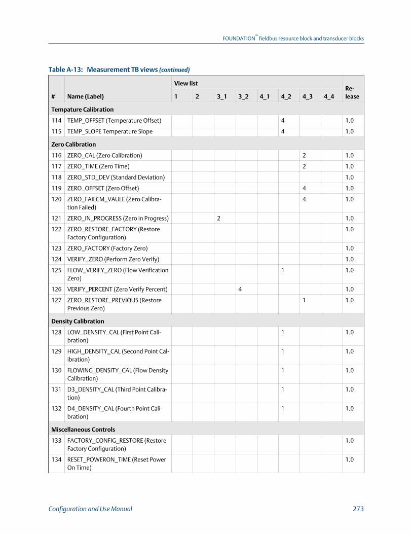
Measurement TB views (continued)Table A-13:
# Name (Label)
View listRe-lease1 2 3_1 3_2 4_1 4_2 4_3 4_4
Tempature Calibration
114 TEMP_OFFSET (Temperature Offset) 4 1.0
115 TEMP_SLOPE Temperature Slope 4 1.0
Zero Calibration
116 ZERO_CAL (Zero Calibration) 2 1.0
117 ZERO_TIME (Zero Time) 2 1.0
118 ZERO_STD_DEV (Standard Deviation) 1.0
119 ZERO_OFFSET (Zero Offset) 4 1.0
120 ZERO_FAILCM_VAULE (Zero Calibra-tion Failed)
4 1.0
121 ZERO_IN_PROGRESS (Zero in Progress) 2 1.0
122 ZERO_RESTORE_FACTORY (RestoreFactory Configuration)
1.0
123 ZERO_FACTORY (Factory Zero) 1.0
124 VERIFY_ZERO (Perform Zero Verify) 1.0
125 FLOW_VERIFY_ZERO (Flow VerificationZero)
1 1.0
126 VERIFY_PERCENT (Zero Verify Percent) 4 1.0
127 ZERO_RESTORE_PREVIOUS (RestorePrevious Zero)
1 1.0
Density Calibration
128 LOW_DENSITY_CAL (First Point Cali-bration)
1 1.0
129 HIGH_DENSITY_CAL (Second Point Cal-ibration)
1 1.0
130 FLOWING_DENSITY_CAL (Flow DensityCalibration)
1 1.0
131 D3_DENSITY_CAL (Third Point Calibra-tion)
1 1.0
132 D4_DENSITY_CAL (Fourth Point Cali-bration)
1 1.0
Miscellaneous Controls
133 FACTORY_CONFIG_RESTORE (RestoreFactory Configuration)
1.0
134 RESET_POWERON_TIME (Reset PowerOn Time)
1.0
FOUNDATION™
fieldbus resource block and transducer blocks
Configuration and Use Manual 273
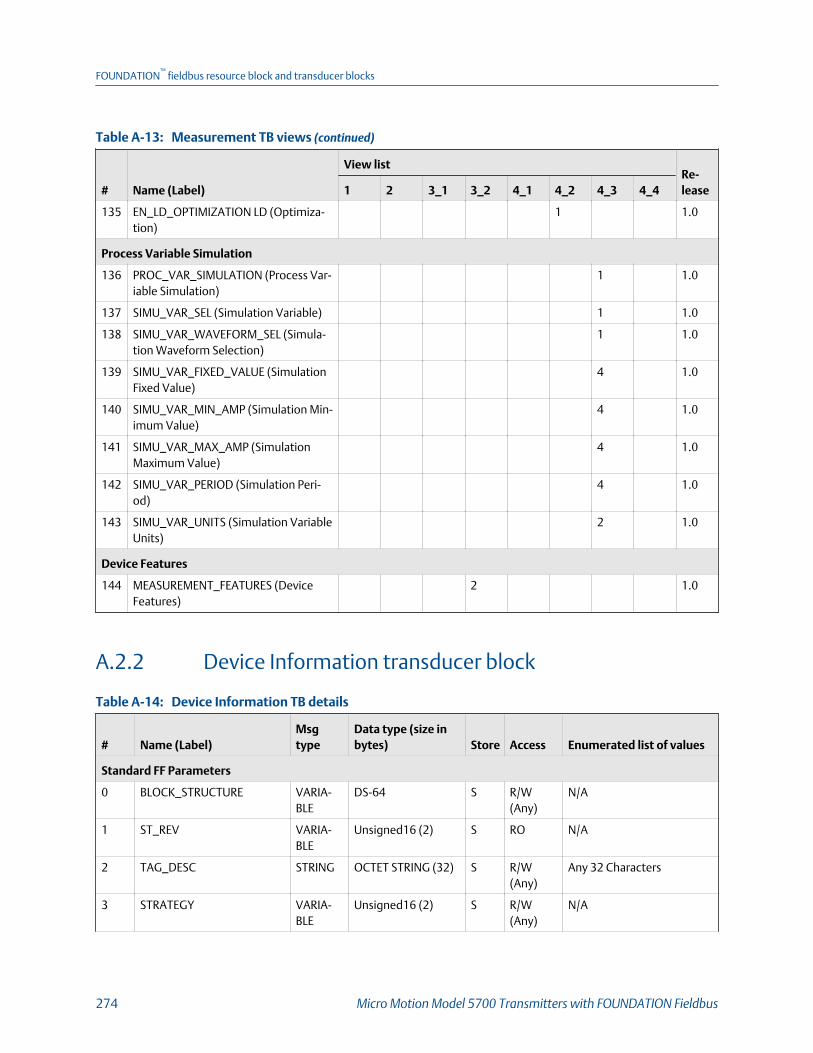
Measurement TB views (continued)Table A-13:
# Name (Label)
View listRe-lease1 2 3_1 3_2 4_1 4_2 4_3 4_4
135 EN_LD_OPTIMIZATION LD (Optimiza-tion)
1 1.0
Process Variable Simulation
136 PROC_VAR_SIMULATION (Process Var-iable Simulation)
1 1.0
137 SIMU_VAR_SEL (Simulation Variable) 1 1.0
138 SIMU_VAR_WAVEFORM_SEL (Simula-tion Waveform Selection)
1 1.0
139 SIMU_VAR_FIXED_VALUE (SimulationFixed Value)
4 1.0
140 SIMU_VAR_MIN_AMP (Simulation Min-imum Value)
4 1.0
141 SIMU_VAR_MAX_AMP (SimulationMaximum Value)
4 1.0
142 SIMU_VAR_PERIOD (Simulation Peri-od)
4 1.0
143 SIMU_VAR_UNITS (Simulation VariableUnits)
2 1.0
Device Features
144 MEASUREMENT_FEATURES (DeviceFeatures)
2 1.0
A.2.2 Device Information transducer block
Device Information TB detailsTable A-14:
# Name (Label)Msgtype
Data type (size inbytes) Store Access Enumerated list of values
Standard FF Parameters
0 BLOCK_STRUCTURE VARIA-BLE
DS-64 S R/W(Any)
N/A
1 ST_REV VARIA-BLE
Unsigned16 (2) S RO N/A
2 TAG_DESC STRING OCTET STRING (32) S R/W(Any)
Any 32 Characters
3 STRATEGY VARIA-BLE
Unsigned16 (2) S R/W(Any)
N/A
FOUNDATION™
fieldbus resource block and transducer blocks
274 Micro Motion Model 5700 Transmitters with FOUNDATION Fieldbus
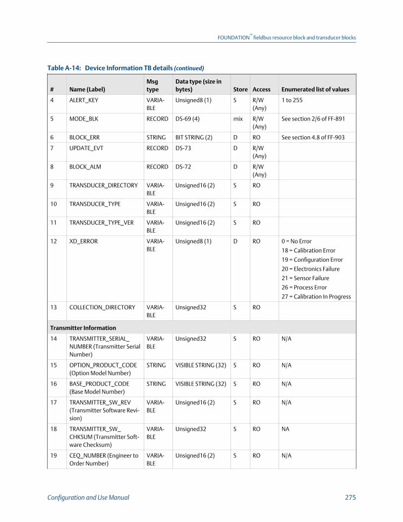
Device Information TB details (continued)Table A-14:
# Name (Label)Msgtype
Data type (size inbytes) Store Access Enumerated list of values
4 ALERT_KEY VARIA-BLE
Unsigned8 (1) S R/W(Any)
1 to 255
5 MODE_BLK RECORD DS-69 (4) mix R/W(Any)
See section 2/6 of FF-891
6 BLOCK_ERR STRING BIT STRING (2) D RO See section 4.8 of FF-903
7 UPDATE_EVT RECORD DS-73 D R/W(Any)
8 BLOCK_ALM RECORD DS-72 D R/W(Any)
9 TRANSDUCER_DIRECTORY VARIA-BLE
Unsigned16 (2) S RO
10 TRANSDUCER_TYPE VARIA-BLE
Unsigned16 (2) S RO
11 TRANSDUCER_TYPE_VER VARIA-BLE
Unsigned16 (2) S RO
12 XD_ERROR VARIA-BLE
Unsigned8 (1) D RO 0 = No Error
18 = Calibration Error
19 = Configuration Error
20 = Electronics Failure
21 = Sensor Failure
26 = Process Error
27 = Calibration In Progress
13 COLLECTION_DIRECTORY VARIA-BLE
Unsigned32 S RO
Transmitter Information
14 TRANSMITTER_SERIAL_NUMBER (Transmitter SerialNumber)
VARIA-BLE
Unsigned32 S RO N/A
15 OPTION_PRODUCT_CODE(Option Model Number)
STRING VISIBLE STRING (32) S RO N/A
16 BASE_PRODUCT_CODE(Base Model Number)
STRING VISIBLE STRING (32) S RO N/A
17 TRANSMITTER_SW_REV(Transmitter Software Revi-sion)
VARIA-BLE
Unsigned16 (2) S RO N/A
18 TRANSMITTER_SW_CHKSUM (Transmitter Soft-ware Checksum)
VARIA-BLE
Unsigned32 S RO NA
19 CEQ_NUMBER (Engineer toOrder Number)
VARIA-BLE
Unsigned16 (2) S RO N/A
FOUNDATION™
fieldbus resource block and transducer blocks
Configuration and Use Manual 275

Device Information TB details (continued)Table A-14:
# Name (Label)Msgtype
Data type (size inbytes) Store Access Enumerated list of values
20 DESCRIPTION (Description) STRING VISIBLE STRING (16) S R/W(Any)
21 TRANSMIITER_DEVICE_TYPE (Model)
VARIA-BLE
Unsigned16 (2) S RO 73 = 5700 FOUNDATIONFieldbus
Core Processor Information
22 CORE_SERIAL_NUMBER(Core Processor Serial Num-ber)
VARIA-BLE
Unsigned32 S RO
23 CORE_SW_REV (Core Pro-cessor Software Revision)
VARIA-BLE
Unsigned16 (2) S RO
24 CORE_SW_CHKSUM (CoreProcessor Software Check-sum)
VARIA-BLE
Unsigned32 S RO
25 CORE_DEVICE_TYPE (CoreDevice Type)
ENUM2 Unsigned16 (2) S RO 40 = 700 CP
50 = 800 ECP
1000 = No Core
Protocol Processor Information
26 PROTO_SW_REV (ProtocolProcessor Software Revi-sion)
VARIA-BLE
Unsigned16 (2) S RO
27 PROTO_SW_CHKSUM (Pro-tocol Processor SoftwareChecksum)
VARIA-BLE
Unsigned32 S RO
Sensor Information
28 SENSOR_SN (Sensor SerialNumber)
VARIA-BLE
Unsigned32 S R/W(Any)
0 ≤ x ≤ 16777215
29 SENSOR_TYPE (Sensor Mod-el)
STRING VISIBLE STRING (16) S RO
30 SENSOR_CODE (SensorType)
ENUM2 Unsigned16 (2) S R/W(Any)
0 = Curve Tube
1 = Straight Tube
31 SENSOR_MATERIAL (TubeWetted Material )
ENUM2 Unsigned16 (2) S R/W(Any)
003 = Hastelloy C-22
004 = Monel
005 = Tantalum
006 = Titanium
019 = 316L stainless steel
023 = Inconel
050 = 304 Stainless Steel
252 = Unknown
253 = Special
FOUNDATION™
fieldbus resource block and transducer blocks
276 Micro Motion Model 5700 Transmitters with FOUNDATION Fieldbus
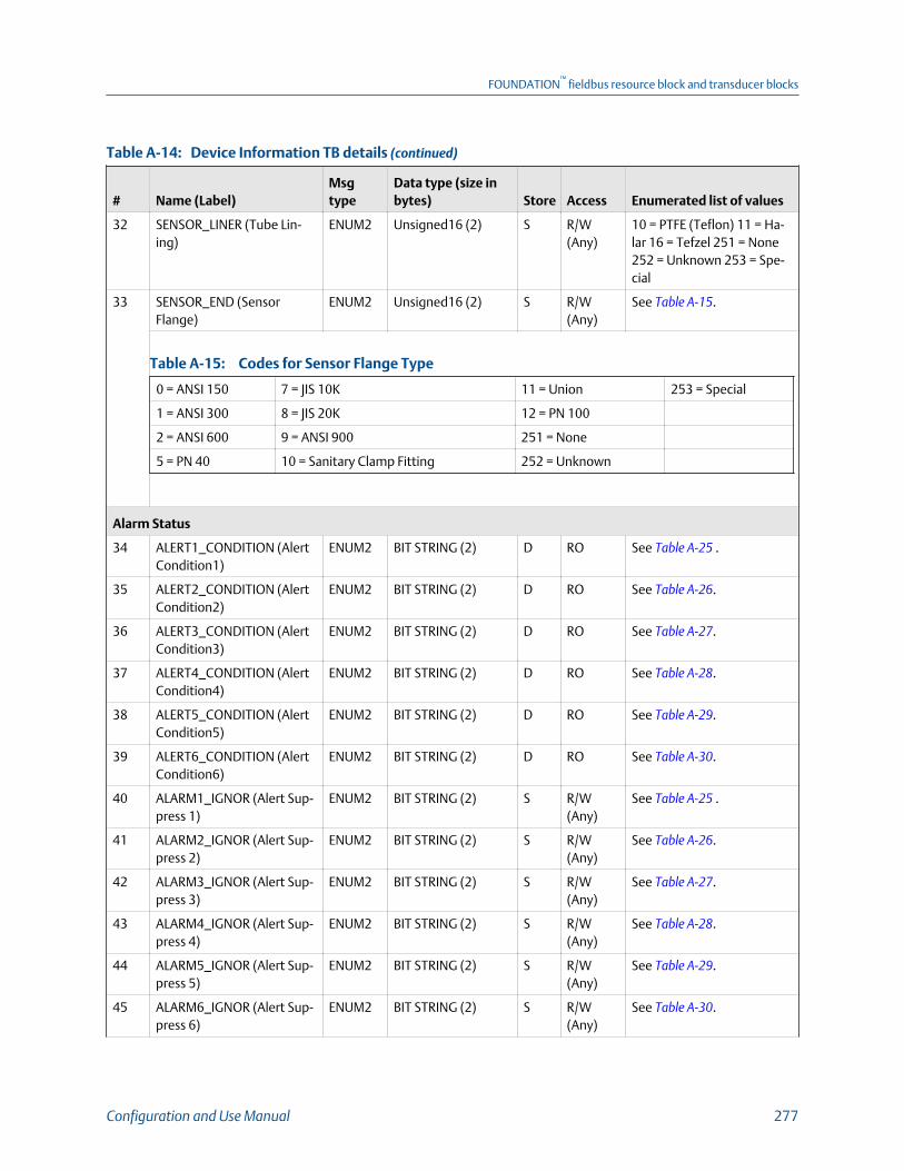
Device Information TB details (continued)Table A-14:
# Name (Label)Msgtype
Data type (size inbytes) Store Access Enumerated list of values
32 SENSOR_LINER (Tube Lin-ing)
ENUM2 Unsigned16 (2) S R/W(Any)
10 = PTFE (Teflon) 11 = Ha-lar 16 = Tefzel 251 = None252 = Unknown 253 = Spe-cial
33 SENSOR_END (SensorFlange)
ENUM2 Unsigned16 (2) S R/W(Any)
See Table A‐15.
Codes for Sensor Flange TypeTable A-15:
0 = ANSI 150 7 = JIS 10K 11 = Union 253 = Special
1 = ANSI 300 8 = JIS 20K 12 = PN 100
2 = ANSI 600 9 = ANSI 900 251 = None
5 = PN 40 10 = Sanitary Clamp Fitting 252 = Unknown
Alarm Status
34 ALERT1_CONDITION (AlertCondition1)
ENUM2 BIT STRING (2) D RO See Table A‐25 .
35 ALERT2_CONDITION (AlertCondition2)
ENUM2 BIT STRING (2) D RO See Table A‐26.
36 ALERT3_CONDITION (AlertCondition3)
ENUM2 BIT STRING (2) D RO See Table A‐27.
37 ALERT4_CONDITION (AlertCondition4)
ENUM2 BIT STRING (2) D RO See Table A‐28.
38 ALERT5_CONDITION (AlertCondition5)
ENUM2 BIT STRING (2) D RO See Table A‐29.
39 ALERT6_CONDITION (AlertCondition6)
ENUM2 BIT STRING (2) D RO See Table A‐30.
40 ALARM1_IGNOR (Alert Sup-press 1)
ENUM2 BIT STRING (2) S R/W(Any)
See Table A‐25 .
41 ALARM2_IGNOR (Alert Sup-press 2)
ENUM2 BIT STRING (2) S R/W(Any)
See Table A‐26.
42 ALARM3_IGNOR (Alert Sup-press 3)
ENUM2 BIT STRING (2) S R/W(Any)
See Table A‐27.
43 ALARM4_IGNOR (Alert Sup-press 4)
ENUM2 BIT STRING (2) S R/W(Any)
See Table A‐28.
44 ALARM5_IGNOR (Alert Sup-press 5)
ENUM2 BIT STRING (2) S R/W(Any)
See Table A‐29.
45 ALARM6_IGNOR (Alert Sup-press 6)
ENUM2 BIT STRING (2) S R/W(Any)
See Table A‐30.
FOUNDATION™
fieldbus resource block and transducer blocks
Configuration and Use Manual 277

Device Information TB details (continued)Table A-14:
# Name (Label)Msgtype
Data type (size inbytes) Store Access Enumerated list of values
46 ALERT_RESTORE_FACTORY(Restore Alert Factory)
ENUM Unsigned8 (1) S R/W(OOS)
0= No
1 = Restore
47 FAULT_LIMIT (Fault Limit ) ENUM2 Unsigned16 (2) S R/W(OOS)
0 = Upscale
1 = Downscale 2 = Zero
3 = NAN
4 = Flow goes to zero
5 = None
48 LMV_FLT_TIMEOUT (FaultTimeout)
VARIA-BLE
Unsigned16 (2) S R/W(Any)
0 ≤ x ≤ 60 sec
49 ALERT_TIMEOUT FOUNDA-TION Fieldbus Alert Timeout
VARIA-BLE
Unsigned16 (2) S R/W(Any)
0 ≤ x ≤ 300 sec
50 ANALOG_OUTPUT_FAULT(Analog Output Fault)
VARIA-BLE
DS-66 (2) D RO Value part of DS-66 (2)
0 = No Critical Fault
1 = Critical Fault Present
Alert Condition Simulation
51 SIMULATE_ALERT_CONDI-TION (Alert Condition Simu-lation)
VARIA-BLE
Unsigned8 (1) S R/W(Any)
0 = Disable
1 = Enable
52 ALERT1_SIMULATE (AlertSimulation 1)
ENUM2 BIT STRING (2) S R/W(Any)
See Table A‐25 .
53 ALERT2_SIMULATE (AlertSimulation 2)
ENUM2 BIT STRING (2) S R/W(Any)
See Table A‐26.
54 ALERT3_SIMULATE (AlertSimulation 3)
ENUM2 BIT STRING (2) S R/W(Any)
See Table A‐27.
55 ALERT4_SIMULATE (AlertSimulation 4)
ENUM2 BIT STRING (2) S R/W(Any)
See Table A‐28.
56 ALERT5_SIMULATE (AlertSimulation 5)
ENUM2 BIT STRING (2) S R/W(Any)
See Table A‐29.
57 ALERT6_SIMULATE (AlertSimulation 6)
ENUM2 BIT STRING (2) S R/W(Any)
See Table A‐30.
FF Simulation
58 FF_SIMULATION (Alert Sim-ulation Lock)
ENUM Unsigned8 (1) S R/W(Any)
0 = Disable
1 = Enable
Local Display
59 LDO_BACKLIGHT_INTEN(Intensity (0-100))
VARIA-BLE
Unsigned16 (2) S R/W(Any)
0 ≤ x ≤ 100
60 LDO_CONTRAST (Contrast(0-100))
VARIA-BLE
Unsigned16 (2) S R/W(Any)
0 ≤ x ≤ 100
FOUNDATION™
fieldbus resource block and transducer blocks
278 Micro Motion Model 5700 Transmitters with FOUNDATION Fieldbus
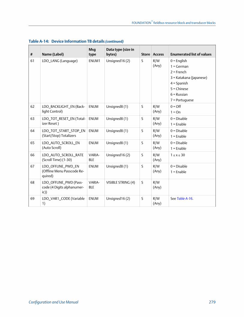
Device Information TB details (continued)Table A-14:
# Name (Label)Msgtype
Data type (size inbytes) Store Access Enumerated list of values
61 LDO_LANG (Language) ENUM1 Unsigned16 (2) S R/W(Any)
0 = English
1 = German
2 = French
3 = Katakana (Japanese)
4 = Spanish
5 = Chinese
6 = Russian
7 = Portuguese
62 LDO_BACKLIGHT_EN (Back-light Control)
ENUM Unsigned8 (1) S R/W(Any)
0 = Off
1 = On
63 LDO_TOT_RESET_EN (Total-izer Reset )
ENUM Unsigned8 (1) S R/W(Any)
0 = Disable
1 = Enable
64 LDO_TOT_START_STOP_EN(Start/Stop) Totalizers
ENUM Unsigned8 (1) S R/W(Any)
0 = Disable
1 = Enable
65 LDO_AUTO_SCROLL_EN(Auto Scroll)
ENUM Unsigned8 (1) S R/W(Any)
0 = Disable
1 = Enable
66 LDO_AUTO_SCROLL_RATE(Scroll Time) (1-30)
VARIA-BLE
Unsigned16 (2) S R/W(Any)
1 ≤ x ≤ 30
67 LDO_OFFLINE_PWD_EN(Offline Menu Passcode Re-quired)
ENUM Unsigned8 (1) S R/W(Any)
0 = Disable
1 = Enable
68 LDO_OFFLINE_PWD (Pass-code (4 Digits alphanumer-ic))
VARIA-BLE
VISIBLE STRING (4) S R/W(Any)
69 LDO_VAR1_CODE (Variable1)
ENUM Unsigned16 (2) S R/W(Any)
See Table A‐16.
FOUNDATION™
fieldbus resource block and transducer blocks
Configuration and Use Manual 279

Device Information TB details (continued)Table A-14:
# Name (Label)Msgtype
Data type (size inbytes) Store Access Enumerated list of values
Codes for display variablesTable A-16:
0 = Mass Flow Rate 21 = ED: Density At Ref 47 = Drive Gain 73 = APM: Net Flow Oil At Line
1 = Temperature 22 = ED: Density (SGU) 48 = Case Temperature 74 = APM: Water Cut At Line
2 = Cfg Total 1 23 = ED: Std Vol FlowRate
49 = LPO Amplitude 75 = APM: Net Flow Water AtLine
3 = Density 24 = Cfg Total 5 50 = RPO Amplitude 78 = APM: Net Flow Oil At Ref
4 = Cfg Inv 1 25 = Cfg Inv 5 51 = Board Temperature 79 = APM: Water Cut At Ref
5 = Volume Flow Rate 26 = ED: Net MassFlow
52 = Input Voltage, 81 = APM: Net Flow Water At Ref
6 = Cfg Total 2 27 = Cfg Total 6 53 = Ext. Input Pressure 101 = Flow Switch Indicator
7 = Cfg Inv 2 28 = Cfg Inv 6 55 = Ext. Input Temp 187 = APM: Net Oil Density atLine(Fixed API Units)
15 = API: Corr Density 29 = ED: Net Vol FlowRate
56 = ED: Density(Baume)
205 = APM: Gas Void Fraction
16 = API: Corr VolFlow
30 = Cfg Total 7 62 = Gas Std Vol Flow 208 = Mass Flow Velocity
17 = Cfg Total 3 31 = Cfg Inv 7 63 = Cfg Total 4 228 = Phage Genius Flow Severi-ty
18 = Cfg Inv 3 32 = ED: Concentra-tion
64 = Cfg Inv 4 251 = None. Not available forVariable 1 (OD Index 69) orProcess Variable (OD Index 86)
19 = API: Avg Density 33 = API: CTL 68 = Field VerificationZero
20 = API: Avg Temp 46 = Raw Tube Fre-quency
69 = Live Zero
70 LDO_VAR2_CODE (Variable2)
ENUM2 Unsigned16 (2) S R/W(Any)
See Table A‐16.
71 LDO_VAR3_CODE (Variable3)
ENUM2 Unsigned16 (2) S R/W(Any)
See Table A‐16.
72 LDO_VAR4_CODE (Variable4)
ENUM2 Unsigned16 (2) S R/W(Any)
See Table A‐16.
73 LDO_VAR5_CODE (Variable5)
ENUM2 Unsigned16 (2) S R/W(Any)
See Table A‐16.
74 LDO_VAR6_CODE (Variable6)
ENUM2 Unsigned16 (2) S R/W(Any)
See Table A‐16.
75 LDO_VAR7_CODE (Variable7)
ENUM2 Unsigned16 (2) S R/W(Any)
See Table A‐16.
FOUNDATION™
fieldbus resource block and transducer blocks
280 Micro Motion Model 5700 Transmitters with FOUNDATION Fieldbus

Device Information TB details (continued)Table A-14:
# Name (Label)Msgtype
Data type (size inbytes) Store Access Enumerated list of values
76 LDO_VAR8_CODE (Variable8)
ENUM2 Unsigned16 (2) S R/W(Any)
See Table A‐16.
77 LDO_VAR9_CODE (Variable9)
ENUM2 Unsigned16 (2) S R/W(Any)
See Table A‐16.
78 LDO_VAR10_CODE (Varia-ble 10)
ENUM2 Unsigned16 (2) S R/W(Any)
See Table A‐16.
79 LDO_VAR11_CODE (Varia-ble 11)
ENUM2 Unsigned16 (2) S R/W(Any)
See Table A‐16.
80 LDO_VAR12_CODE (Varia-ble 12)
ENUM2 Unsigned16 (2) S R/W(Any)
See Table A‐16.
81 LDO_VAR13_CODE (Varia-ble 13)
ENUM2 Unsigned16 (2) S R/W(Any)
See Table A‐16.
82 LDO_VAR14_CODE (Varia-ble 14)
ENUM2 Unsigned16 (2) S R/W(Any)
See Table A‐16.
83 LDO_VAR15_CODE (Varia-ble 15)
ENUM2 Unsigned16 (2) S R/W(Any)
See Table A‐16.
84 LDO_2PV_VAR1_CODE(Two PV Variable 1)
ENUM2 Unsigned16 (2) S R/W(Any)
See Table A‐16.
85 LDO_2PV_VAR2_CODE(Two PV Variable 2)
ENUM2 Unsigned16 (2) S R/W(Any)
See Table A‐16.
86 LDO_PROC_VAR_INDEX(Process Variable)
ENUM2 Unsigned16 (2) S R/W(Any)
See Table A‐16.
87 LDO_NUM_DECIMALS (Dec-imal Places )
VARIA-BLE
Unsigned16 (2) S R/W(Any)
0 ≤ x ≤ 5
88 LDO_UPDATE_PERIOD (Var-iable Update Rate)
VARIA-BLE
Unsigned16 (2) S R/W(Any)
100 ≤ x ≤ 10000.
89 LDO_PASSWORD_EN (AlertPasscode)
ENUM Unsigned8 (1) S R/W(Any)
0 = Disable
1 = Enable
90 LDO_FF_SIMULATE (Simula-tion Switch)
ENUM1 Unsigned8 (1) S RO 0 = Disable
1 = Enable
91 LDO_WL_STATUS (WriteLock Switch)
ENUM1 Unsigned8 (1) S RO 0 = Disable
1 = Enable
Channels Assignments
92 CH_SEL_B (Channel B As-signment)
ENUM2 Unsigned16 (2) S R/W(OOS)
3 = mAO Output
6 = None
93 CH_SEL_C (Channel C As-signment)
ENUM2 Unsigned16 (2) S R/W(OOS)
1 = Frequency Output
11 = Discrete Output
6 = None
FOUNDATION™
fieldbus resource block and transducer blocks
Configuration and Use Manual 281
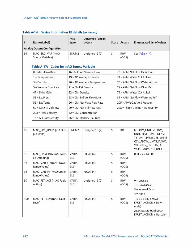
Device Information TB details (continued)Table A-14:
# Name (Label)Msgtype
Data type (size inbytes) Store Access Enumerated list of values
Analog Output Configuration
94 MAO_SRC_VAR (mAOSource Variable)
ENUM2 Unsigned16 (2) S R/W(OOS)
See Table A‐17.
Codes for mAO Source VariableTable A-17:
0 = Mass Flow Rate 16 =API Corr Volume Flow 73 = APM: Net Flow Oil At Line
1 = Temperature 19 = API Average Density 74 = APM: Water Cut At Line
3 = Density 20 = API Average Temperature 75 = APM: Net Flow Water At Line
5 = Volume Flow Rate 21 = CM Ref Density 78 = APM: Net Flow Oil At Ref
47 = Drive Gain 22 = CM: Density 79 = APM: Water Cut At Ref
53 = Ext Press 23 = CM: Std Vol Flow Rate 81 = APM: Net Flow Water At Ref
55 = Ext Temp 26 = CM: Net Mass Flow Rate 205 = APM: Gas Void Fraction
62 = Gas Std Vol Flow 29 = CM: Net Vol Flow Rate 228 = Phage Genius Flow Severity
208 = Flow Velocity 32 = CM: Concentration
15 = API Corr Density 56 = CM: Density (Baume)
95 MAO_SRC_UNITS (mA Out-put Units)
ENUM2 Unsigned16 (2) S RO MFLOW_UNIT, VFLOW_UNIT, TEMP_UNIT, DENSI-TY_UNIT, PRESSURE_UNITS,GSV_FLOW_UNITS, FLOW_VELOCITY_UNIT, Hz, %,Volts, BAUM, NO_UNIT
96 MAO_DAMPING (mAO Add-ed Damping)
VARIA-BLE
FLOAT (4) S R/W(OOS)
0.0f ≤ x ≤ 440.0f
97 MAO_VAR_LO (mAO LowerRange Value)
VARIA-BLE
FLOAT (4) S R/W(OOS)
98 MAO_VAR_HI (mAO UpperRange Value)
VARIA-BLE
FLOAT (4) S R/W(OOS)
99 MAO_FLT_ACT (mAO FaultAction)
VARIA-BLE
Unsigned16 (2) S R/W(OOS)
0 = Upscale
1 = Downscale
3 = Internal Zero
4 = None
100 MAO_FLT_LEV (mAO FaultLevel)
VARIA-BLE
FLOAT (4) S R/W(OOS)
1.0 ≤ x ≤ 3.6(if MAO_FAULT_ACTION is Down-scale)
21.0 ≤ x ≤ 23.00(if MAO_FAULT_ACTION is Upscale)
FOUNDATION™
fieldbus resource block and transducer blocks
282 Micro Motion Model 5700 Transmitters with FOUNDATION Fieldbus
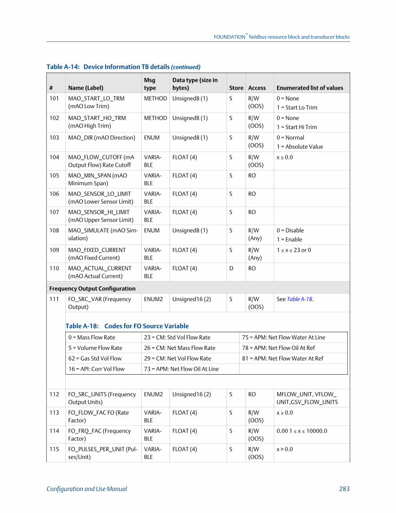
Device Information TB details (continued)Table A-14:
# Name (Label)Msgtype
Data type (size inbytes) Store Access Enumerated list of values
101 MAO_START_LO_TRM(mAO Low Trim)
METHOD Unsigned8 (1) S R/W(OOS)
0 = None
1 = Start Lo Trim
102 MAO_START_HO_TRM(mAO High Trim)
METHOD Unsigned8 (1) S R/W(OOS)
0 = None
1 = Start Hi Trim
103 MAO_DIR (mAO Direction) ENUM Unsigned8 (1) S R/W(OOS)
0 = Normal
1 = Absolute Value
104 MAO_FLOW_CUTOFF (mAOutput Flow) Rate Cutoff
VARIA-BLE
FLOAT (4) S R/W(OOS)
x ≥ 0.0
105 MAO_MIN_SPAN (mAOMinimum Span)
VARIA-BLE
FLOAT (4) S RO
106 MAO_SENSOR_LO_LIMIT(mAO Lower Sensor Limit)
VARIA-BLE
FLOAT (4) S RO
107 MAO_SENSOR_HI_LIMIT(mAO Upper Sensor Limit)
VARIA-BLE
FLOAT (4) S RO
108 MAO_SIMULATE (mAO Sim-ulation)
ENUM Unsigned8 (1) S R/W(Any)
0 = Disable
1 = Enable
109 MAO_FIXED_CURRENT(mAO Fixed Current)
VARIA-BLE
FLOAT (4) S R/W(Any)
1 ≤ x ≤ 23 or 0
110 MAO_ACTUAL_CURRENT(mAO Actual Current)
VARIA-BLE
FLOAT (4) D RO
Frequency Output Configuration
111 FO_SRC_VAR (FrequencyOutput)
ENUM2 Unsigned16 (2) S R/W(OOS)
See Table A‐18.
Codes for FO Source VariableTable A-18:
0 = Mass Flow Rate 23 = CM: Std Vol Flow Rate 75 = APM: Net Flow Water At Line
5 = Volume Flow Rate 26 = CM: Net Mass Flow Rate 78 = APM: Net Flow Oil At Ref
62 = Gas Std Vol Flow 29 = CM: Net Vol Flow Rate 81 = APM: Net Flow Water At Ref
16 = API: Corr Vol Flow 73 = APM: Net Flow Oil At Line
112 FO_SRC_UNITS (FrequencyOutput Units)
ENUM2 Unsigned16 (2) S RO MFLOW_UNIT, VFLOW_UNIT,GSV_FLOW_UNITS
113 FO_FLOW_FAC FO (RateFactor)
VARIA-BLE
FLOAT (4) S R/W(OOS)
x ≥ 0.0
114 FO_FRQ_FAC (FrequencyFactor)
VARIA-BLE
FLOAT (4) S R/W(OOS)
0.00 1 ≤ x ≤ 10000.0
115 FO_PULSES_PER_UNIT (Pul-ses/Unit)
VARIA-BLE
FLOAT (4) S R/W(OOS)
x > 0.0
FOUNDATION™
fieldbus resource block and transducer blocks
Configuration and Use Manual 283

Device Information TB details (continued)Table A-14:
# Name (Label)Msgtype
Data type (size inbytes) Store Access Enumerated list of values
116 FO_UNITS_PER_PULSE(Units/Pulse)
VARIA-BLE
FLOAT (4) S R/W(OOS)
x > 0.0
117 FO_FLT_ACT (FO Fault Ac-tion)
VARIA-BLE
Unsigned16 (2) S R/W(OOS)
0 = Upscale
1 = Downscale
3 = Internal Zero
4 = None
118 FO_FLT_LEV (FO Fault Level) VARIA-BLE
FLOAT (4) S R/W(OOS)
10 ≤ x ≤ 15000
119 FO_DIR (Frequency OutputDirection)
ENUM2 Unsigned16 (2) S R/W(OOS)
0 = Pulse on Positive FlowOnly
1 = Pulse on Negative FlowOnly
2 = Pulse on both Positiveand Negative Flow
120 FO_SCALING_METHOD(Frequency Output ScalingMethod)
ENUM2 Unsigned16 (2) S R/W(OOS)
0 = Frequency = Flow
1 = Pulses/Unit
2 = Units/Pulse
121 FO_SIMULATE (FO Simula-tion)
ENUM1 Unsigned8 (1) S R/W(Any)
0 = Disable
1 = Enable
122 FO_FIXED_VALUE (FO FixedFrequency)
VARIA-BLE
FLOAT (4) S R/W(Any)
0.0 ≤ x ≤ 14500.0
123 FO_OUT (FO Actual Fre-quency)
VARIA-BLE
FLOAT (4) D RO 0.0 ≤ x ≤ 14500.0
Discrete Output Configuration
124 DO_VAR (DO Source) ENUM2 Unsigned16 (2) S R/W(OOS)
See Table A‐19.
Codes for DO Source VariableTable A-19:
57 = Discrete Event 1 61 = Discrete Event 5 104 = Fault Condition Indication
58 = Discrete Event 2 101 = Flow Switch Indicator 216 = Meter Verification Failure
59 = Discrete Event 3 102 = Forward/Reverse Indication
60 = Discrete Event 4 103 = Zero Calibration in Progress
125 DO_POLARITY (DO Polarity) ENUM2 Unsigned16 (2) S R/W(OOS)
0 = Active Low
1 = Active High
126 DO_FLT_ACT (DO Fault Ac-tion)
ENUM2 Unsigned16 (2) S R/W(OOS)
0 = Upscale
1 = Downscale
4 = None
FOUNDATION™
fieldbus resource block and transducer blocks
284 Micro Motion Model 5700 Transmitters with FOUNDATION Fieldbus

Device Information TB details (continued)Table A-14:
# Name (Label)Msgtype
Data type (size inbytes) Store Access Enumerated list of values
127 DO_FIX_STATE (DO Fix) ENUM1 Unsigned8 (1) S R/W(Any)
0 = Off
1 = On
255 = Unfix
128 DO_SIMULATE (DO Simula-tion)
ENUM1 Unsigned8 (1) S R/W(Any)
0 = Disable
1 = Enable
Flow Rate Switch
129 FLW_RATE_SW_SOURCE(Flow Source)
ENUM2 Unsigned16 (2) S R/W(OOS)
See Table A‐18.
130 FLW_RATE_SW_SETPOINT(Flow Setpoint)
VARIA-BLE
FLOAT (4) S R/W(OOS)
x ≥ 0.0
131 FLW_RATE_SW_HYS (FlowRate Hysteresis (0.1-10.0))
VARIA-BLE
FLOAT (4) S R/W(OOS)
0.1 ≤ x ≤ 10.0
132 FLW_RATE_SOURCE_UNITS(Flow Rate Source)
ENUM2 Unsigned16 (2) S RO MFLOW_UNIT, VFLOW_UNIT,GSV_FLOW_UNITS
System Time
133 RTC_TIME_ZONE (TimeZone)
ENUM2 Unsigned16 (2) S R/W(OOS)
See Table A‐20.
Codes for Time ZoneTable A-20:
0 = Dateline (-12.0) 11 = MidAtlantic (-2.0) 22 = Nepal (+5.75)
1 = Soma (-11.0) 12 = Azores (-1.0) 23 = Central Asia (+6.0)
2 = Hawaii (-10.0) 13 = Greenwich (0.0) 24 = Myanmar (+6.5)
3 = Alaska (-9.0) 14 = Central EU (+1.0) 25 = South East Asia (+7.0)
4 = Pacific (-8.0) 15 = Europe (+2.0) 26 = China (+8.0)
5 = Mountain (-7.0) 16 = Russian (+3.0) 27 = Korea (+9.0)
6 = Central (-6.0) 17 = Iran (+3.5) 28 = Central Australia (+9.5)
7 = Eastern (-5.0) 18 = Arabian (+4.0) 29 = East Australia (+10.0)
8 = Atlantic (-4.0) 19 = Afghan (+4.5) 30 = Central Pacific (+11.0)
9 = New Foundland (-3.5) 20 = West Asia (+5.0) 31 = Fiji (+12.0) 32 = Tonga (+13.0)
10 = saEastern (-3.0) 21 = India (+5.5) 33 = special
134 RTC_TIME_ZONE_OFFSET(Time Zone Offset fromUTC)
VARIA-BLE
FLOAT (4) S R/W(OOS)
-24.0f ≤ x ≤ 24.0f
135 RTC_DAY_LIGHT_SAVING(Day Light Savings)
ENUM1 Unsigned8 (1) S R/W(OOS)
0 = Disable
1 = Enable
FOUNDATION™
fieldbus resource block and transducer blocks
Configuration and Use Manual 285

Device Information TB details (continued)Table A-14:
# Name (Label)Msgtype
Data type (size inbytes) Store Access Enumerated list of values
136 RTC_DATE_TIME (Set ClockDate-Time)
VARIA-BLE
DATE (7) D R/W(OOS)
Device Feature Control
137 DEVICE_UNIQUE_ID (DeviceUnique ID)
VARIA-BLE
Unsigned32 S RO
138 PERM_LICENSE_KEY (Per-manent License Key)
VARIA-BLE
VISIBLE STRING (16) S R/W(OOS)
16 ASCIIl characters thatrepresent Hexidecimal val-ues (0-9, A-F)
139 TEMP_LICENSE_KEY (Tem-porary License Key)
VARIA-BLE
VISIBLE STRING (16) S R/W(OOS)
16 ASCIIl characters thatrepresent Hexidecimal val-ues (0-9, A-F)
140 DEVICE_TEMP_LICENSE(Temporary Feature)
VARIA-BLE
BIT STRING (4) S RO See Table A‐21.
Codes for Temporary and Permanent Feature License (OD Index 140 and 142)Table A-21:
0x00008000 = APM for Single Liquidand Gas
0x00000800 = APM for Wet Gas 0x00001000 = Meter Verifi-cation
0x00000010 = API Referrel 0x00002000 = APM for 3 Phase Flowand NOC
0x00000008 = Concentration Measure-ment
0x00004000 = Historian download
141 DEV_TEMP_LICS_EXPIRY(Days Until Expiration)
VARIA-BLE
Unsigned16 (2) S RO
142 DEVICE_PERM_LICENSE(Permanent Feature)
VARIA-BLE
BIT STRING (4) S RO See Table A‐21.
143 DEV_PERM_LICS_EXPIRY(Device Permanent LicenseExpiry)
VARIA-BLE
Unsigned16 (2) S RO
144 CM_EN (ConcentrationMeasurement)
ENUM Unsigned8 (1) S R/W(OOS)
0 = Disable
1 = Enable
145 PM_EN (API Referral) ENUM Unsigned8 (1) S R/W(OOS)
0 = Disable
1 = Enable
146 USB_PORT_EN (Enable Serv-ice Port)
ENUM Unsigned8 (1) S R/W(Any)
0 = Disable
1 = Enable
FOUNDATION™
fieldbus resource block and transducer blocks
286 Micro Motion Model 5700 Transmitters with FOUNDATION Fieldbus

Device Information TB details (continued)Table A-14:
# Name (Label)Msgtype
Data type (size inbytes) Store Access Enumerated list of values
Configuration File Operations
147 CONF_FILE_TYPE (Configu-ration File Type)
ENUM2 Unsigned16 (2) S R/W(OOS)
1 = Spare File
3 = Transfer File
5 = ED Matrix File
255 = None
148 CONF_FILE_SAVE (SaveConfiguration File)
ENUM Unsigned8 (1) S R/W(OOS)
0 = None
1 = Save Config File
149 CONF_FILE_RESTORE (Re-store Configuration File)
ENUM Unsigned8 (1) S R/W(OOS)
0 = None
1 = Restore Config File
150 CONF_FILE_NAME (FileName)
VARIA-BLE
VISIBLE STRING (20) S R/W(OOS)
151 CONF_FILE_STATUS (ConfigFile)
ENUM2 Unsigned16 (2) S RO 0 = Done
1 = Error/Aborted
2 = In progress
152 CONF_FILE_CURVE_NUM(Select the Matrix)
VARIA-BLE
Unsigned16 (2) S R/W(OOS)
0 ≤ x ≤ 5
Discrete Events
153 DIS_EVENT_INDEX (DiscreteEvent)
ENUM1 Unsigned8 (1) S R/W(Any)
0 ≤ x ≤ 4
154 DIS_EVENT_ACTION (Dis-crete Event Action)
ENUM2 Unsigned8 (1) S R/W(OOS)
0 = > set-point A (processvalue > A)
1 = < set-point A (processvalue < A)
2 = In Range (A < processvalue < B)
3 = Out of Range (processvalue < A or proc value > B)
155 DIS_EVENT_SETPOINTA(Setpoint A)
VARIA-BLE
FLOAT (4) S R/W(OOS)
156 DIS_EVENT_SETPOINTB(Setpoint B)
VARIA-BLE
FLOAT (4) S R/W(OOS)
157 DIS_EVENT_PV (EnhancedEvent PV)
ENUM1 Unsigned8 (1) S R/W(OOS)
See Table A‐22.
FOUNDATION™
fieldbus resource block and transducer blocks
Configuration and Use Manual 287

Device Information TB details (continued)Table A-14:
# Name (Label)Msgtype
Data type (size inbytes) Store Access Enumerated list of values
Codes for Enhanced Event PVTable A-22:
0 = Mass Flow Rate 20 = API: Avg Temp 33 = API: CTL 68 = Field Verification Zero
1 = Temperature 21 = ED: Density At Ref 46 = Raw Tube Frequency 69 = Live Zero
2 = Cfg Total 1 22 = ED: Density ( SGU) 47 = Drive Gain 73 = APM: Net Flow Oil AtLine
3 = Density 23 = ED: Std Vol FlowRate
48 = Case Temperature 74 = APM: Water Cut At Line
4 = Cfg Inv 1 24 = Cfg Total 5 49 = LPO Amplitude 75 = APM: Net Flow WaterAt Line
5 = Volume Flow Rate 25 = Cfg Inv 5 50 = RPO Amplitude 78 = APM: Net Flow Oil AtRef
6 = Cfg Total 2 26 = ED: Net Mass Flow 51 = Board Temperature 79 = APM: Water Cut At Ref
7 = Cfg Inv 2 27 = Cfg Total 6 53 = Ext. Input Pressure 81 = APM: Net Flow WaterAt Ref
15 = API: Corr Density 28 = Cfg Inv 6 55 = Ext. Input Temp 187 = APM: Dens Oil at Line
16 = API: Corr Vol Flow 29 = ED: Net Vol FlowRate
56 = ED: Density (Baume) 205 = APM: Gas Void Frac-tion
17 = Cfg Total 3 30 = Cfg Total 7 62 = Gas Std Vol Flow 208 = Mass Flow Velocity
18 = Cfg Inv 3 31 = Cfg Inv 7 63 = Cfg Total 4 228 = Phage Genius Flow Se-verity
19 = API: Avg Density 32 = ED: Concentration 64 = Cfg Inv 4 251 = None
158 DIS_ENENT_TRIGGER (En-hanced Event Trigger)
ENUM2 BIT STRING (2) S R/W(OOS)
See Table A‐23.
Codes for Enhanced Event TriggerTable A-23:
0x0001 = Reset All Totals 0x0010 = Reset Total 3 0x0100 = Reset Total 7
0x0002 = Start/Stop Totals 0x0020 = Reset Total 4 0x0200 = Start Sensor Zero
0x0004 = Reset Total 1 0x0040 = Reset Total 5 0x0400 = Increment ED Curve
0x0008 = Reset Total 2 0x0080 = Reset Total 6 0x0800 = Start Smart Meter Verification
FOUNDATION™
fieldbus resource block and transducer blocks
288 Micro Motion Model 5700 Transmitters with FOUNDATION Fieldbus
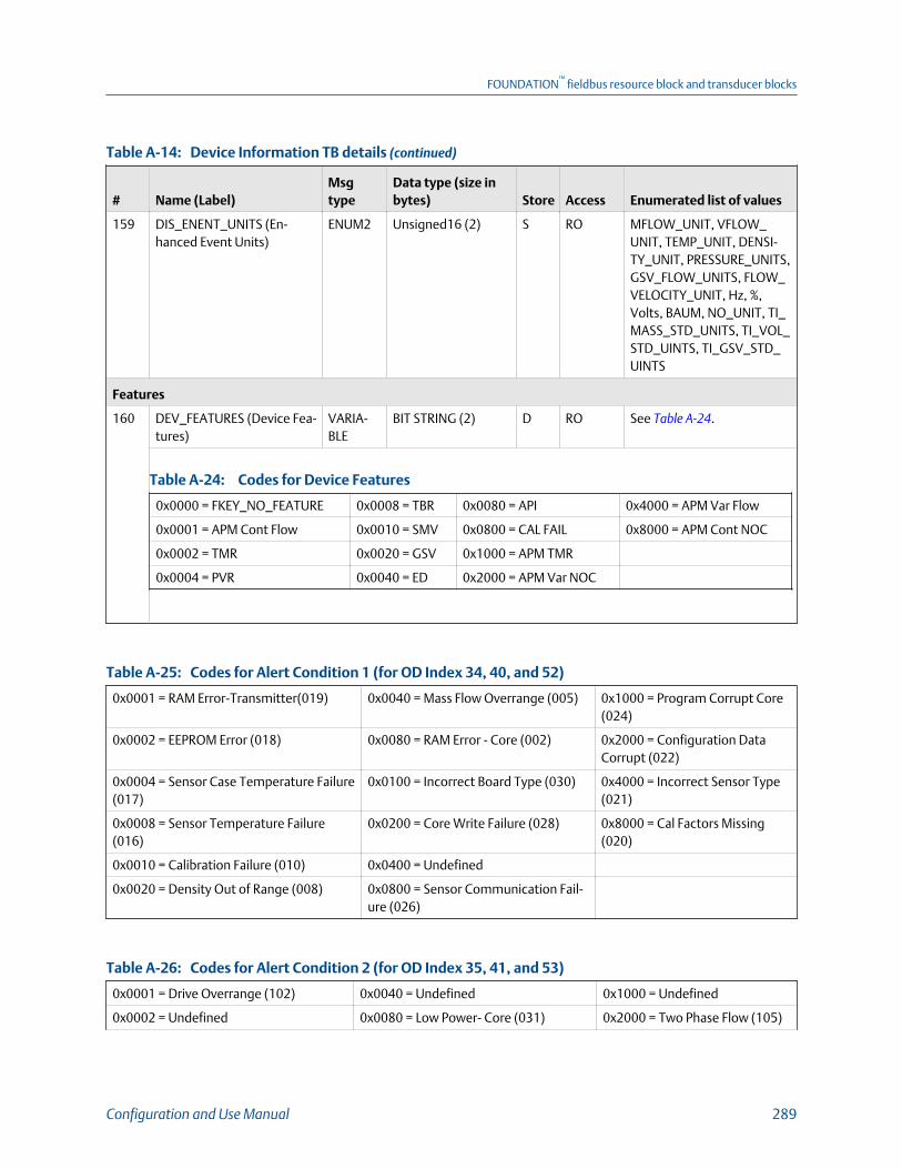
Device Information TB details (continued)Table A-14:
# Name (Label)Msgtype
Data type (size inbytes) Store Access Enumerated list of values
159 DIS_ENENT_UNITS (En-hanced Event Units)
ENUM2 Unsigned16 (2) S RO MFLOW_UNIT, VFLOW_UNIT, TEMP_UNIT, DENSI-TY_UNIT, PRESSURE_UNITS,GSV_FLOW_UNITS, FLOW_VELOCITY_UNIT, Hz, %,Volts, BAUM, NO_UNIT, TI_MASS_STD_UNITS, TI_VOL_STD_UINTS, TI_GSV_STD_UINTS
Features
160 DEV_FEATURES (Device Fea-tures)
VARIA-BLE
BIT STRING (2) D RO See Table A‐24.
Codes for Device FeaturesTable A-24:
0x0000 = FKEY_NO_FEATURE 0x0008 = TBR 0x0080 = API 0x4000 = APM Var Flow
0x0001 = APM Cont Flow 0x0010 = SMV 0x0800 = CAL FAIL 0x8000 = APM Cont NOC
0x0002 = TMR 0x0020 = GSV 0x1000 = APM TMR
0x0004 = PVR 0x0040 = ED 0x2000 = APM Var NOC
Codes for Alert Condition 1 (for OD Index 34, 40, and 52)Table A-25:
0x0001 = RAM Error-Transmitter(019) 0x0040 = Mass Flow Overrange (005) 0x1000 = Program Corrupt Core(024)
0x0002 = EEPROM Error (018) 0x0080 = RAM Error - Core (002) 0x2000 = Configuration DataCorrupt (022)
0x0004 = Sensor Case Temperature Failure(017)
0x0100 = Incorrect Board Type (030) 0x4000 = Incorrect Sensor Type(021)
0x0008 = Sensor Temperature Failure(016)
0x0200 = Core Write Failure (028) 0x8000 = Cal Factors Missing(020)
0x0010 = Calibration Failure (010) 0x0400 = Undefined
0x0020 = Density Out of Range (008) 0x0800 = Sensor Communication Fail-ure (026)
Codes for Alert Condition 2 (for OD Index 35, 41, and 53)Table A-26:
0x0001 = Drive Overrange (102) 0x0040 = Undefined 0x1000 = Undefined
0x0002 = Undefined 0x0080 = Low Power- Core (031) 0x2000 = Two Phase Flow (105)
FOUNDATION™
fieldbus resource block and transducer blocks
Configuration and Use Manual 289

Codes for Alert Condition 2 (for OD Index 35, 41, and 53) (continued)Table A-26:
0x0004 = Undefined 0x0100 = Frequency Output Satura-ted(110)
0x4000 = Calibration in progress(104)
0x0008 = Meter Verification Aborted(035)
0x0200 = Undefined 0x8000 = Data Loss Possible(103)
0x0010 = Meter Verification Failed (034) 0x0400 = Undefined
0x0020 =Tube Not Full (033) 0x0800 = Power Reset (107)
Codes for Alert Condition 3 (for OD Index 36, 42, and 54)Table A-27:
0x0001 = Discrite Outout Fixed (119) 0x0040 = mA Output Saturated (113) 0x1000 = Smart Meter Verificationin progress (131)
0x0002 = Undefined 0x0080 = Frequency Ouput Fixed (111) 0x2000 = Undefined
0x0004 = API-Density Out of Range(117)
0x0100 = Discrete Output Present Value 0x4000 = Extrapolation Alert (121)
0x0008 = Temperature Out range (116) 0x0200 = Undefined 0x8000 = Curve Fit Failure(120)
0x0010 = No Input (115) 0x0400 = Undefined
0x0020 =mA Output Fixed (114) 0x0800 = Sensor Simulation On (132)
Codes for Alert Condition 4 (for OD Index 37, 43, and 55)Table A-28:
0x0001 = Enhanced Event 3 Active 0x0040 = Undefined 0x1000 = Core Software updateFailed
0x0002 = Enhanced Event 2 Active 0x0080 = Undefined 0x2000 = Programming CoreProcessor
0x0004 = Enhanced Event 1 Active 0x0100 = Watchdog Error 0x4000 = Enhanced Event 5 Ac-tive
0x0008 = Transmitter Initializing (009) 0x0200 = Configuration Changed 0x8000 = Enhanced Event 4 Ac-tive
0x0010 = Sensor Failed (003) 0x0400 = Undefined
0x0020 = Flow Direction (on=forward/zero,off=reverse)
0x0800 = Core Processor Communicat-ing with Transmitter
Codes for Alert Condition 5 (for OD Index 38, 44, and 56)Table A-29:
0x0001 = Pressure Out of Range (123) 0x0040 = Undefined 0x1000 = Phase Genius detected Moderate Se-verity
0x0002 = SD Card not Present 0x0080 = System is in fault 0x2000 = Firmware Update failed
0x0004 = Undefined 0x0100 = Undefined 0x4000 = No Permanent License
0x0008 = Undefined 0x0200 = Undefined 0x8000 = Time Not Set
0x0010 = Undefined 0x0400 = Clock is Constant
FOUNDATION™
fieldbus resource block and transducer blocks
290 Micro Motion Model 5700 Transmitters with FOUNDATION Fieldbus

Codes for Alert Condition 5 (for OD Index 38, 44, and 56) (continued)Table A-29:
0x0020 = Undefined 0x0800 = Severe Two-Phase
Codes for Alert Condition 6 (for OD Index 39, 45, and 57)Table A-30:
0x0001 = Undefined 0x0040 = Internal Memory Full 0x1000 = Undefined
0x0002 = Undefined 0x0080 = No Password 0x2000 = Watercut Unavailable
0x0004 = Undefined 0x0100 = Undefined 0x4000 = Watercut Limited to 0%
0x0008 = Undefined 0x0200 = Undefined 0x8000 = Watercut Limited to100%
0x0010 = New Core Processor detected 0x0400 = Fieldbus Bridge Comm Error
0x0020 = Core Processor has incompati-ble ETO
0x0800 = Undefined
Device Information TB viewsTable A-31:
# Name (Label)
View listRe-lease1 2 3 4_1 4_2 4_3 4_4 4_5 4_6
Standard FF Parameters
0 BLOCK_STRUCTURE 1.0
1 ST_REV 2 2 2 2 2 2 2 2 2 1.0
2 TAG_DESC 1.0
3 STRATEGY 1.0
4 ALERT_KEY 1 1.0
5 MODE_BLK 4 4 4 1.0
6 BLOCK_ERR 2 2 1.0
7 UPDATE_EVT 1.0
8 BLOCK_ALM 1.0
9 TRANSDUCER_DIRECTORY 1.0
10 TRANSDUCER_TYPE 2 2 2 2 1.0
11 TRANSDUCER_TYPE_VER 2 2 2 2 1.0
12 XD_ERROR 1 1 1.0
13 COLLECTION_DIRECTORY 1.0
Transmitter Information
14 TRANSMITTER_SERIAL_NUMBER(Transmitter Serial Number)
1.0
15 OPTION_PRODUCT_CODE (Op-tion Model Number)
1.0
FOUNDATION™
fieldbus resource block and transducer blocks
Configuration and Use Manual 291
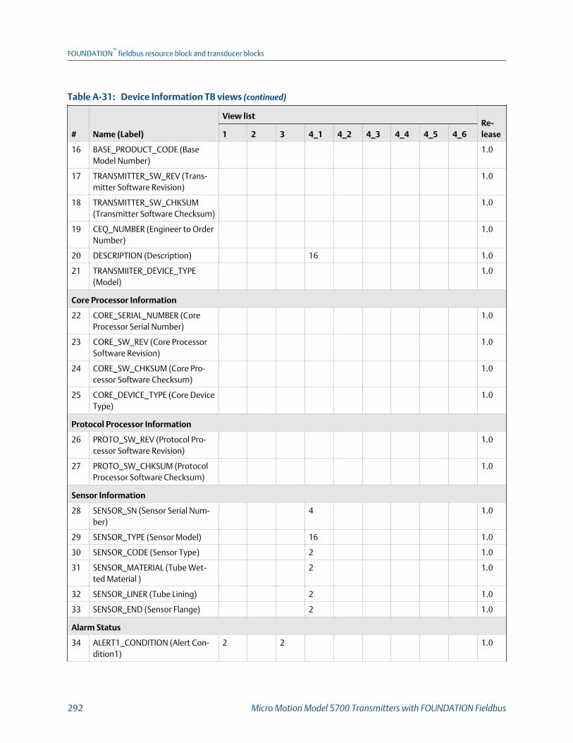
Device Information TB views (continued)Table A-31:
# Name (Label)
View listRe-lease1 2 3 4_1 4_2 4_3 4_4 4_5 4_6
16 BASE_PRODUCT_CODE (BaseModel Number)
1.0
17 TRANSMITTER_SW_REV (Trans-mitter Software Revision)
1.0
18 TRANSMITTER_SW_CHKSUM(Transmitter Software Checksum)
1.0
19 CEQ_NUMBER (Engineer to OrderNumber)
1.0
20 DESCRIPTION (Description) 16 1.0
21 TRANSMIITER_DEVICE_TYPE(Model)
1.0
Core Processor Information
22 CORE_SERIAL_NUMBER (CoreProcessor Serial Number)
1.0
23 CORE_SW_REV (Core ProcessorSoftware Revision)
1.0
24 CORE_SW_CHKSUM (Core Pro-cessor Software Checksum)
1.0
25 CORE_DEVICE_TYPE (Core DeviceType)
1.0
Protocol Processor Information
26 PROTO_SW_REV (Protocol Pro-cessor Software Revision)
1.0
27 PROTO_SW_CHKSUM (ProtocolProcessor Software Checksum)
1.0
Sensor Information
28 SENSOR_SN (Sensor Serial Num-ber)
4 1.0
29 SENSOR_TYPE (Sensor Model) 16 1.0
30 SENSOR_CODE (Sensor Type) 2 1.0
31 SENSOR_MATERIAL (Tube Wet-ted Material )
2 1.0
32 SENSOR_LINER (Tube Lining) 2 1.0
33 SENSOR_END (Sensor Flange) 2 1.0
Alarm Status
34 ALERT1_CONDITION (Alert Con-dition1)
2 2 1.0
FOUNDATION™
fieldbus resource block and transducer blocks
292 Micro Motion Model 5700 Transmitters with FOUNDATION Fieldbus

Device Information TB views (continued)Table A-31:
# Name (Label)
View listRe-lease1 2 3 4_1 4_2 4_3 4_4 4_5 4_6
35 ALERT2_CONDITION (Alert Con-dition2)
2 2 1.0
36 ALERT3_CONDITION (Alert Con-dition3)
2 2 1.0
37 ALERT4_CONDITION (Alert Con-dition4)
2 2 1.0
38 ALERT5_CONDITION (Alert Con-dition5)
2 2 1.0
39 ALERT6_CONDITION (Alert Con-dition6)
2 2 1.0
40 ALARM1_IGNOR (Alert Suppress1)
2 1.0
41 ALARM2_IGNOR (Alert Suppress2)
2 1.0
42 ALARM3_IGNOR (Alert Suppress3)
2 1.0
43 ALARM4_IGNOR (Alert Suppress4)
2 1.0
44 ALARM5_IGNOR (Alert Suppress5)
2 1.0
45 ALARM6_IGNOR (Alert Suppress6)
2 1.0
46 ALERT_RESTORE_FACTORY (Re-store Alert Factory)
1 1.0
47 FAULT_LIMIT (Fault Limit ) 2 1.0
48 LMV_FLT_TIMEOUT (Fault Time-out)
2 1.0
49 ALERT_TIMEOUT FOUNDATIONFieldbus Alert Timeout
2 1.0
50 ANALOG_OUTPUT_FAULT (Ana-log Output Fault)
2 2 1.0
Alert Condition Simulation
51 SIMULATE_ALERT_CONDITION(Alert Condition Simulation)
1 1.0
52 ALERT1_SIMULATE (Alert Simula-tion 1)
2 1.0
53 ALERT2_SIMULATE (Alert Simula-tion 2)
2 1.0
FOUNDATION™
fieldbus resource block and transducer blocks
Configuration and Use Manual 293

Device Information TB views (continued)Table A-31:
# Name (Label)
View listRe-lease1 2 3 4_1 4_2 4_3 4_4 4_5 4_6
54 ALERT3_SIMULATE (Alert Simula-tion 3)
2 1.0
55 ALERT4_SIMULATE (Alert Simula-tion 4)
2 1.0
56 ALERT5_SIMULATE (Alert Simula-tion 5)
2 1.0
57 ALERT6_SIMULATE (Alert Simula-tion 6)
2 1.0
FF Simulation
58 FF_SIMULATION (Alert SimulationLock)
1 1.0
Local Display
59 LDO_BACKLIGHT_INTEN (Intensi-ty (0-100))
2 1.0
60 LDO_CONTRAST (Contrast(0-100))
2 1.0
61 LDO_LANG (Language) 2 1.0
62 LDO_BACKLIGHT_EN (BacklightControl)
1 1.0
63 LDO_TOT_RESET_EN (TotalizerReset )
1 1.0
64 LDO_TOT_START_STOP_EN(Start/Stop) Totalizers
1 1.0
65 LDO_AUTO_SCROLL_EN (AutoScroll)
1 1.0
66 LDO_AUTO_SCROLL_RATE (ScrollTime) (1-30)
2 1.0
67 LDO_OFFLINE_PWD_EN (OfflineMenu Passcode Required)
1 1.0
68 LDO_OFFLINE_PWD (Passcode (4Digits alphanumeric))
4 1.0
69 LDO_VAR1_CODE (Variable 1) 2 1.0
70 LDO_VAR2_CODE (Variable 2) 2 1.0
71 LDO_VAR3_CODE (Variable 3) 2 1.0
72 LDO_VAR4_CODE (Variable 4) 2 1.0
73 LDO_VAR5_CODE (Variable 5) 2 1.0
74 LDO_VAR6_CODE (Variable 6) 2 1.0
75 LDO_VAR7_CODE (Variable 7) 2 1.0
FOUNDATION™
fieldbus resource block and transducer blocks
294 Micro Motion Model 5700 Transmitters with FOUNDATION Fieldbus

Device Information TB views (continued)Table A-31:
# Name (Label)
View listRe-lease1 2 3 4_1 4_2 4_3 4_4 4_5 4_6
76 LDO_VAR8_CODE (Variable 8) 2 1.0
77 LDO_VAR9_CODE (Variable 9) 2 1.0
78 LDO_VAR10_CODE (Variable 10) 2 1.0
79 LDO_VAR11_CODE (Variable 11) 2 1.0
80 LDO_VAR12_CODE (Variable 12) 2 1.0
81 LDO_VAR13_CODE (Variable 13) 2 1.0
82 LDO_VAR14_CODE (Variable 14) 2 1.0
83 LDO_VAR15_CODE (Variable 15) 2 1.0
84 LDO_2PV_VAR1_CODE Two PVVariable 1
2 1.0
85 LDO_2PV_VAR2_CODE (Two PVVariable 2)
2 1.0
86 LDO_PROC_VAR_INDEX (ProcessVariable)
2 1.0
87 LDO_NUM_DECIMALS (DecimalPlaces )
2 1.0
88 LDO_UPDATE_PERIOD (VariableUpdate Rate)
2 1.0
89 LDO_PASSWORD_EN (Alert Pass-code)
1 1.0
90 LDO_FF_SIMULATE (SimulationSwitch)
1 1.0
91 LDO_WL_STATUS (Write LockSwitch)
1 1.0
Channels Assignments
92 CH_SEL_B (Channel B Assign-ment)
2 1.0
93 CH_SEL_C (Channel C Assign-ment)
2 1.0
Analog Output Configuration
94 MAO_SRC_VAR (mAO SourceVariable)
2 1.0
95 MAO_SRC_UNITS (mA OutputUnits)
2 1.0
96 MAO_DAMPING (mAO AddedDamping)
4 1.0
97 MAO_VAR_LO (mAO LowerRange Value)
4 1.0
FOUNDATION™
fieldbus resource block and transducer blocks
Configuration and Use Manual 295

Device Information TB views (continued)Table A-31:
# Name (Label)
View listRe-lease1 2 3 4_1 4_2 4_3 4_4 4_5 4_6
98 MAO_VAR_HI (mAO Upper RangeValue)
4 1.0
99 MAO_FLT_ACT (mAO Fault Ac-tion)
2 1.0
100 MAO_FLT_LEV (mAO Fault Level) 4 1.0
101 MAO_START_LO_TRM (mAO LowTrim)
1 1.0
102 MAO_START_HO_TRM (mAOHigh Trim)
1 1.0
103 MAO_DIR (mAO Direction) 1 1.0
104 MAO_FLOW_CUTOFF (mA Out-put Flow) Rate Cutoff
4 1.0
105 MAO_MIN_SPAN (mAO MinimumSpan)
4 1.0
106 MAO_SENSOR_LO_LIMIT (mAOLower Sensor Limit)
4 1.0
107 MAO_SENSOR_HI_LIMIT (mAOUpper Sensor Limit)
4 1.0
108 MAO_SIMULATE (mAO Simula-tion)
1 1.0
109 MAO_FIXED_CURRENT (mAOFixed Current)
4 1.0
110 MAO_ACTUAL_CURRENT (mAOActual Current)
4 1.0
Frequency Output Configuration
111 FO_SRC_VAR (Frequency Output) 2 1.0
112 FO_SRC_UNITS (Frequency Out-put Units)
2 1.0
113 FO_FLOW_FAC FO (Rate Factor) 4 1.0
114 FO_FRQ_FAC (Frequency Factor) 4 1.0
115 FO_PULSES_PER_UNIT (Pulses/Unit)
4 1.0
116 FO_UNITS_PER_PULSE (Units/Pulse)
4 1.0
117 FO_FLT_ACT (FO Fault Action) 1 1.0
118 FO_FLT_LEV (FO Fault Level) 4 1.0
119 FO_DIR (Frequency Output Direc-tion)
2 1.0
FOUNDATION™
fieldbus resource block and transducer blocks
296 Micro Motion Model 5700 Transmitters with FOUNDATION Fieldbus

Device Information TB views (continued)Table A-31:
# Name (Label)
View listRe-lease1 2 3 4_1 4_2 4_3 4_4 4_5 4_6
120 FO_SCALING_METHOD (Frequen-cy Output Scaling Method)
2 1.0
121 FO_SIMULATE (FO Simulation) 1 1.0
122 FO_FIXED_VALUE (FO Fixed Fre-quency)
4 1.0
123 FO_OUT (FO Actual Frequency) 4 1.0
Discrete Output Configuration
124 DO_VAR (DO Source) 2 1.0
125 DO_POLARITY (DO Polarity) 2 1.0
126 DO_FLT_ACT (DO Fault Action) 2 1.0
127 DO_FIX_STATE (DO Fix) 1 1.0
128 DO_SIMULATE (DO Simulation) 1 1.0
Flow Rate Switch
129 FLW_RATE_SW_SOURCE (FlowSource)
2 1.0
130 FLW_RATE_SW_SETPOINT (FlowSetpoint)
4 1.0
131 FLW_RATE_SW_HYS (Flow RateHysteresis (0.1-10.0))
4 1.0
132 FLW_RATE_SOURCE_UNITS (FlowRate Source)
2 1.0
System Time
133 RTC_TIME_ZONE (Time Zone) 2 1.0
134 RTC_TIME_ZONE_OFFSET (TimeZone Offset from UTC)
4 1.0
135 RTC_DAY_LIGHT_SAVING (DayLight Savings)
1 1.0
136 RTC_DATE_TIME (Set Clock Date-Time)
7 1.0
Device Feature Control
137 DEVICE_UNIQUE_ID (DeviceUnique ID)
1.0
138 PERM_LICENSE_KEY (PermanentLicense Key)
16 1.0
139 TEMP_LICENSE_KEY (TemporaryLicense Key)
16 1.0
FOUNDATION™
fieldbus resource block and transducer blocks
Configuration and Use Manual 297

Device Information TB views (continued)Table A-31:
# Name (Label)
View listRe-lease1 2 3 4_1 4_2 4_3 4_4 4_5 4_6
140 DEVICE_TEMP_LICENSE (Tempo-rary Feature)
4 1.0
141 DEV_TEMP_LICS_EXPIRY (DaysUntil Expiration)
2 1.0
142 DEVICE_PERM_LICENSE (Perma-nent Feature)
4 1.0
143 DEV_PERM_LICS_EXPIRY (DevicePermanent License Expiry)
2 1.0
144 CM_EN (Concentration Measure-ment)
1 1.0
145 PM_EN (API Referral) 1 1.0
146 USB_PORT_EN (Enable ServicePort)
1 1.0
Configuration File Operations
147 CONF_FILE_TYPE (ConfigurationFile Type)
2 1.0
148 CONF_FILE_SAVE (Save Configu-ration File)
1 1.0
149 CONF_FILE_RESTORE (RestoreConfiguration File)
1 1.0
150 CONF_FILE_NAME (File Name) 20 1.0
151 CONF_FILE_STATUS (Config File) 2 1.0
152 CONF_FILE_CURVE_NUM (Selectthe Matrix)
2 1.0
Discrete Events
153 DIS_EVENT_INDEX (DiscreteEvent)
1 1.0
154 DIS_EVENT_ACTION (DiscreteEvent Action)
2 1.0
155 DIS_EVENT_SETPOINTA (SetpointA)
4 1.0
156 DIS_EVENT_SETPOINTB (SetpointB)
4 1.0
157 DIS_EVENT_PV (Enhanced EventPV)
2 1.0
158 DIS_ENENT_TRIGGER (EnhancedEvent Trigger)
2 1.0
159 DIS_ENENT_UNITS (EnhancedEvent Units)
2 1.0
FOUNDATION™
fieldbus resource block and transducer blocks
298 Micro Motion Model 5700 Transmitters with FOUNDATION Fieldbus
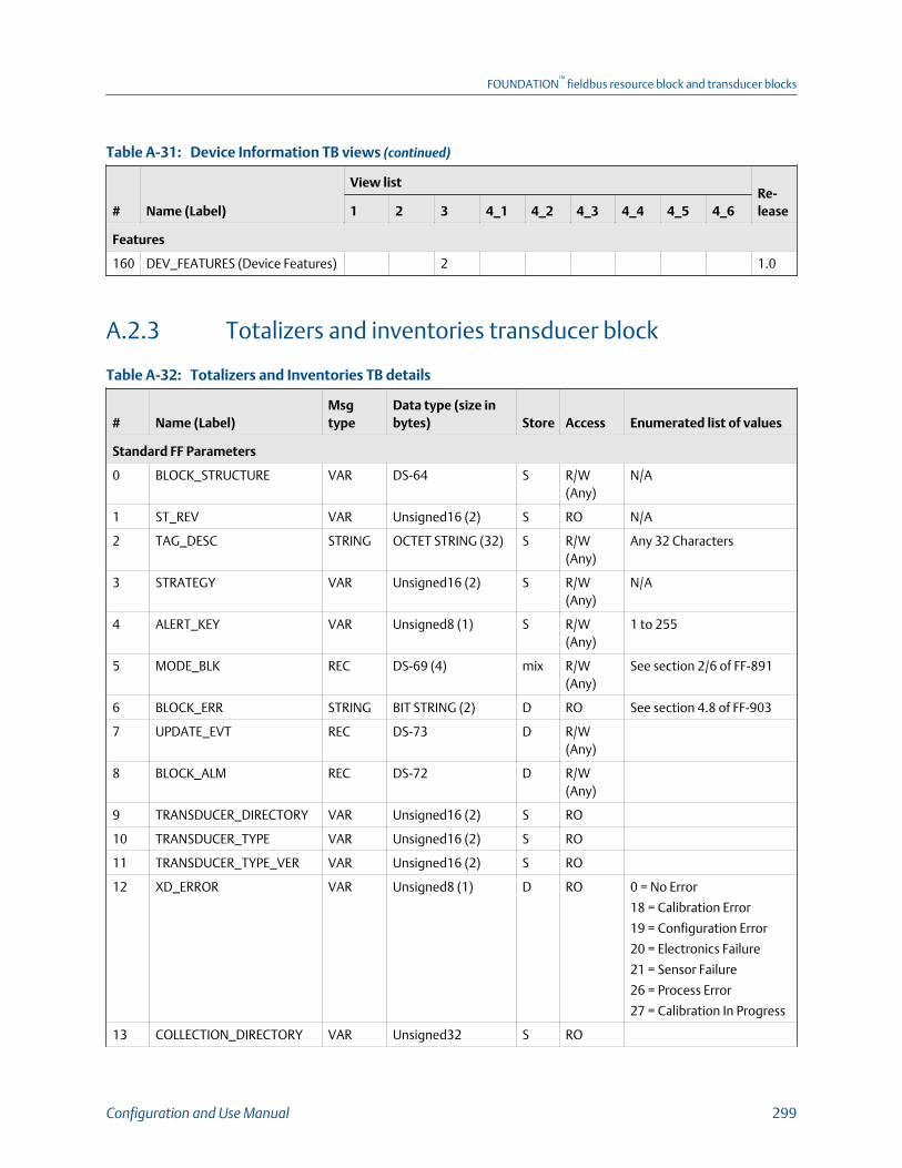
Device Information TB views (continued)Table A-31:
# Name (Label)
View listRe-lease1 2 3 4_1 4_2 4_3 4_4 4_5 4_6
Features
160 DEV_FEATURES (Device Features) 2 1.0
A.2.3 Totalizers and inventories transducer block
Totalizers and Inventories TB detailsTable A-32:
# Name (Label)Msgtype
Data type (size inbytes) Store Access Enumerated list of values
Standard FF Parameters
0 BLOCK_STRUCTURE VAR DS-64 S R/W(Any)
N/A
1 ST_REV VAR Unsigned16 (2) S RO N/A
2 TAG_DESC STRING OCTET STRING (32) S R/W(Any)
Any 32 Characters
3 STRATEGY VAR Unsigned16 (2) S R/W(Any)
N/A
4 ALERT_KEY VAR Unsigned8 (1) S R/W(Any)
1 to 255
5 MODE_BLK REC DS-69 (4) mix R/W(Any)
See section 2/6 of FF-891
6 BLOCK_ERR STRING BIT STRING (2) D RO See section 4.8 of FF-903
7 UPDATE_EVT REC DS-73 D R/W(Any)
8 BLOCK_ALM REC DS-72 D R/W(Any)
9 TRANSDUCER_DIRECTORY VAR Unsigned16 (2) S RO
10 TRANSDUCER_TYPE VAR Unsigned16 (2) S RO
11 TRANSDUCER_TYPE_VER VAR Unsigned16 (2) S RO
12 XD_ERROR VAR Unsigned8 (1) D RO 0 = No Error
18 = Calibration Error
19 = Configuration Error
20 = Electronics Failure
21 = Sensor Failure
26 = Process Error
27 = Calibration In Progress
13 COLLECTION_DIRECTORY VAR Unsigned32 S RO
FOUNDATION™
fieldbus resource block and transducer blocks
Configuration and Use Manual 299

Totalizers and Inventories TB details (continued)Table A-32:
# Name (Label)Msgtype
Data type (size inbytes) Store Access Enumerated list of values
Configurable Totalizer
14 INTEGRATOR1_FB_CONFIG(Integrator1 Configuration)
ENUM1 Unsigned8 (1) S R/W(Any)
See Table A‐33.
Codes for Integrator1 and Integrator2 ConfigurationTable A-33:
0 = Standard 5 = Total 4 10= Inventory 5
1 = Total 1 6 = Inventory 3 11= Total 6
2 = Total 2 7 = Total 3 12= Inventory 6
3 = Inventory 1 8 = Inventory 4 13= Total 7
4 = Inventory 2 9 = Total 5 14= Inventory 7
15 INTEGRATOR2_FB_CONFIG(Integrator2 Configuration)
ENUM1 Unsigned8 (1) S R/W(Any)
See Table A‐33.
16 TOT_INV_CON (Totalizerand Inventory Control Co-des)
ENUM1 Unsigned8 (1) S R/W(Any)
See Table A‐34.
Codes for Totalizer and Inventory Control Table A-34:
00 = None 12 = Inventory1 Start 24 = Totalizer6 Stop 36 = Totalizer4 Reset
01 = Start All Totalizers 13 = Inventory2 Start 25 = Totalizer7 Stop 37 = Totalizer5 Reset
02 = Stop All Totalizers 14 = Inventory3 Start 26 = Inventory1 Stop 38 = Totalizer6 Reset
03 = Reset All Totalizers 15 = Inventory4 Start 27 = Inventory2 Stop 39 = Totalizer7 Reset
04 = Reset All Inventories 16 = Inventory5 Start 28 = Inventory3 Stop 40 = Inventory1 Reset
05 = Totalizer1 Start 17 = Inventory6 Start 29 = Inventory4 Stop 41 = Inventory2 Reset
06 = Totalizer2 Start 18 = Inventory7 Start 30 = Inventory5 Stop 42 = Inventory3 Reset
07 = Totalizer3 Start 19 = Totalizer1 Stop 31 = Inventory6 Stop 43 = Inventory4 Reset
08 = Totalizer4 Start 20 = Totalizer2 Stop 32 = Inventory7 Stop 44 = Inventory5 Reset
09 = Totalizer5 Start 21 = Totalizer3 Stop 33 = Totalizer1 Reset 45 = Inventory6 Reset
10 = Totalizer6 Start 22 = Totalizer4 Stop 34 = Totalizer2 Reset 46 = Inventory7 Reset
11 = Totalizer7 Start 23 = Totalizer5 Stop 35 = Totalizer3 Reset
17 CFG_TOT1 (Total 1) VAR DS-65 (5) D RO N/A
18 CFG_TOT1_SRC (Total 1Source Variable)
ENUM1 Unsigned8 (1) S R/W(OOS)
See Table A‐37
19 CFG_TOT1_UNIT_SRC (To-tal 1 Unit Source)
ENUM1 Unsigned8 (1) S R/W(OOS)
See Table A‐39.
FOUNDATION™
fieldbus resource block and transducer blocks
300 Micro Motion Model 5700 Transmitters with FOUNDATION Fieldbus
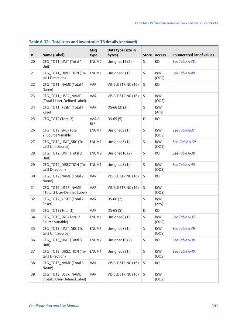
Totalizers and Inventories TB details (continued)Table A-32:
# Name (Label)Msgtype
Data type (size inbytes) Store Access Enumerated list of values
20 CFG_TOT1_UNIT (Total 1Unit)
ENUM2 Unsigned16 (2) S RO See Table A‐38.
21 CFG_TOT1_DIRECTION (To-tal 1 Direction)
ENUM1 Unsigned8 (1) S R/W(OOS)
See Table A‐40.
22 CFG_TOT1_NAME (Total 1Name)
VAR VISIBLE STRING (16) S RO
23 CFG_TOT1_USER_NAME(Total 1 User-Defined Label)
VAR VISIBLE STRING (16) S R/W(OOS)
24 CFG_TOT1_RESET (Total 1Reset)
VAR DS-66 (2) (2) S R/W(Any)
25 CFG_TOT2 (Total 2) VARIA-BLE
DS-65 (5) D RO
26 CFG_TOT2_SRC (Total2 )Source Variable
ENUM1 Unsigned8 (1) S R/W(OOS)
See Table A‐37
27 CFG_TOT2_UNIT_SRC (To-tal 2 Unit Source)
ENUM1 Unsigned8 (1) S R/W(OOS)
See .Table A‐39
28 CFG_TOT2_UNIT (Total 2Unit)
ENUM2 Unsigned16 (2) S RO See Table A‐38.
29 CFG_TOT2_DIRECTION (To-tal 2 Direction)
ENUM1 Unsigned8 (1) S R/W(OOS)
See Table A‐40.
30 CFG_TOT2_NAME (Total 2Name)
VAR VISIBLE STRING (16) S RO
31 CFG_TOT2_USER_NAME( Total 2 User-Defined Label)
VAR VISIBLE STRING (16) S R/W(OOS)
32 CFG_TOT2_RESET (Total 2Reset)
VAR DS-66 (2) S R/W(Any)
33 CFG_TOT3 (Total 3) VAR DS-65 (5) D RO
34 CFG_TOT3_SRC (Total 3Source Variable)
ENUM1 Unsigned8 (1) S R/W(OOS)
See Table A‐37
35 CFG_TOT3_UNIT_SRC (To-tal 3 Unit Source)
ENUM1 Unsigned8 (1) S R/W(OOS)
See Table A‐39.
36 CFG_TOT3_UNIT (Total 3Unit)
ENUM2 Unsigned16 (2) S RO See Table A‐38.
37 CFG_TOT3_DIRECTION (To-tal 3 Direction)
ENUM1 Unsigned8 (1) S R/W(OOS)
See Table A‐40.
38 CFG_TOT3_NAME (Total 3Name)
VAR VISIBLE STRING (16) S RO
39 CFG_TOT3_USER_NAME(Total 3 User-Defined Label)
VAR VISIBLE STRING (16) S R/W(OOS)
FOUNDATION™
fieldbus resource block and transducer blocks
Configuration and Use Manual 301
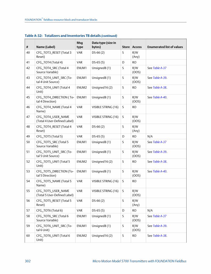
Totalizers and Inventories TB details (continued)Table A-32:
# Name (Label)Msgtype
Data type (size inbytes) Store Access Enumerated list of values
40 CFG_TOT3_RESET (Total 3Reset)
VAR DS-66 (2) S R/W(Any)
41 CFG_TOT4 (Total 4) VAR DS-65 (5) D RO
42 CFG_TOT4_SRC (Total 4Source Variable)
ENUM1 Unsigned8 (1) S R/W(OOS)
See Table A‐37
43 CFG_TOT4_UNIT_SRC (To-tal 4 Unit Source)
ENUM1 Unsigned8 (1) S R/W(OOS)
See Table A‐39.
44 CFG_TOT4_UNIT (Total 4Unit)
ENUM2 Unsigned16 (2) S RO See Table A‐38.
45 CFG_TOT4_DIRECTION ( To-tal 4 Direction)
ENUM1 Unsigned8 (1) S R/W(OOS)
See Table A‐40.
46 CFG_TOT4_NAME (Total 4Name)
VAR VISIBLE STRING (16) S RO
47 CFG_TOT4_USER_NAME(Total 4 User-Defined Label)
VAR VISIBLE STRING (16) S R/W(OOS)
48 CFG_TOT4_RESET (Total 4Reset)
VAR DS-66 (2) S R/W(Any)
49 CFG_TOT5 (Total 5) VAR DS-65 (5) D RO N/A
50 CFG_TOT5_SRC (Total 5Source Variable)
ENUM1 Unsigned8 (1) S R/W(OOS)
See Table A‐37
51 CFG_TOT5_UNIT_SRC (To-tal 5 Unit Source)
ENUM1 Unsigned8 (1) S R/W(OOS)
See Table A‐39.
52 CFG_TOT5_UNIT (Total 5Unit)
ENUM2 Unsigned16 (2) S RO See Table A‐38.
53 CFG_TOT5_DIRECTION (To-tal 5 Direction)
ENUM1 Unsigned8 (1) S R/W(OOS)
See Table A‐40.
54 CFG_TOT5_NAME (Total 5Name)
VAR VISIBLE STRING (16) S RO
55 CFG_TOT5_USER_NAME(Total 5 User-Defined Label)
VAR VISIBLE STRING (16) S R/W(OOS)
56 CFG_TOT5_RESET (Total 5Reset)
VAR DS-66 (2) S R/W(Any)
57 CFG_TOT6 (Total 6) VAR DS-65 (5) D RO N/A
58 CFG_TOT6_SRC (Total 6Source Variable)
ENUM1 Unsigned8 (1) S R/W(OOS)
See Table A‐37
59 CFG_TOT6_UNIT_SRC (To-tal 6 Unit)
ENUM1 Unsigned8 (1) S R/W(OOS)
See Table A‐39.
60 CFG_TOT6_UNIT (Total 6Unit)
ENUM2 Unsigned16 (2) S RO See Table A‐38.
FOUNDATION™
fieldbus resource block and transducer blocks
302 Micro Motion Model 5700 Transmitters with FOUNDATION Fieldbus

Totalizers and Inventories TB details (continued)Table A-32:
# Name (Label)Msgtype
Data type (size inbytes) Store Access Enumerated list of values
61 CFG_TOT6_DIRECTION (To-tal 6 Direction)
ENUM1 Unsigned8 (1) S R/W(OOS)
See Table A‐40.
62 CFG_TOT6_NAME (Total 6Name)
VAR VISIBLE STRING (16) S RO
63 CFG_TOT6_USER_NAME( Total 6 User-Defined Label)
VAR VISIBLE STRING (16) S R/W(OOS)
64 CFG_TOT6_RESET (Total 6Reset)
VAR DS-66 (2) S R/W(Any)
65 CFG_TOT7 (Total 7) VARIA-BLE
DS-65 (5) D RO N/A
66 CFG_TOT7_SRC (Total 7Source variable)
ENUM1 Unsigned8 (1) S R/W(OOS)
See Table A‐37
67 CFG_TOT7_UNIT_SRC (To-tal 7 Unit Source)
ENUM1 Unsigned8 (1) S R/W(OOS)
See Table A‐39.
68 CFG_TOT7_UNIT (Total 7Unit)
ENUM2 Unsigned16 (2) S RO See Table A‐38.
69 CFG_TOT7_DIRECTION (To-tal 7 Direction)
ENUM1 Unsigned8 (1) S R/W(OOS)
See Table A‐40.
70 CFG_TOT7_NAME (Total 7Name)
VAR VISIBLE STRING (16) S RO
71 CFG_TOT7_USER_NAME(Total 7 User-Defined Label)
VAR VISIBLE STRING (16) S R/W(OOS)
72 CFG_TOT7_RESET (Total 7Reset)
VAR DS-66 (2) S R/W(Any)
73 ALL_TOT_RESET ( Reset AllTotalizers)
VAR DS-66 (2) S R/W(Any)
Value part of DS-66 (2)
1 = Reset All Totals.
0 = None.
74 START_STOP_ALL_TOTALS(Start/Stop all Totalizers)
VAR DS-66 (2) S R/W(Any)
Value part of DS-66 (2)
0 = Stop Totalizers
1 = Start Totalizers
Configurable Inventory
75 CFG_INV1 (Inventory 1) VAR DS-65 (5) D RO N/A
76 CFG_INV1_DIRECTION (In-ventory 1 Direction)
ENUM1 Unsigned8 (1) S R/W(OOS)
See Table A‐40.
77 CFG_INV1_SRC (Inventory 1Source Variable)
ENUM1 Unsigned8 (1) S R/W(OOS)
See Table A‐37
78 CFG_INV1_UNIT_SRC (In-ventory 1 Unit Source)
ENUM1 Unsigned8 (1) S R/W(OOS)
See Table A‐39.
79 CFG_INV1_UNIT (Inventory1 Unit)
ENUM2 Unsigned16 (2) S RO See Table A‐38.
FOUNDATION™
fieldbus resource block and transducer blocks
Configuration and Use Manual 303
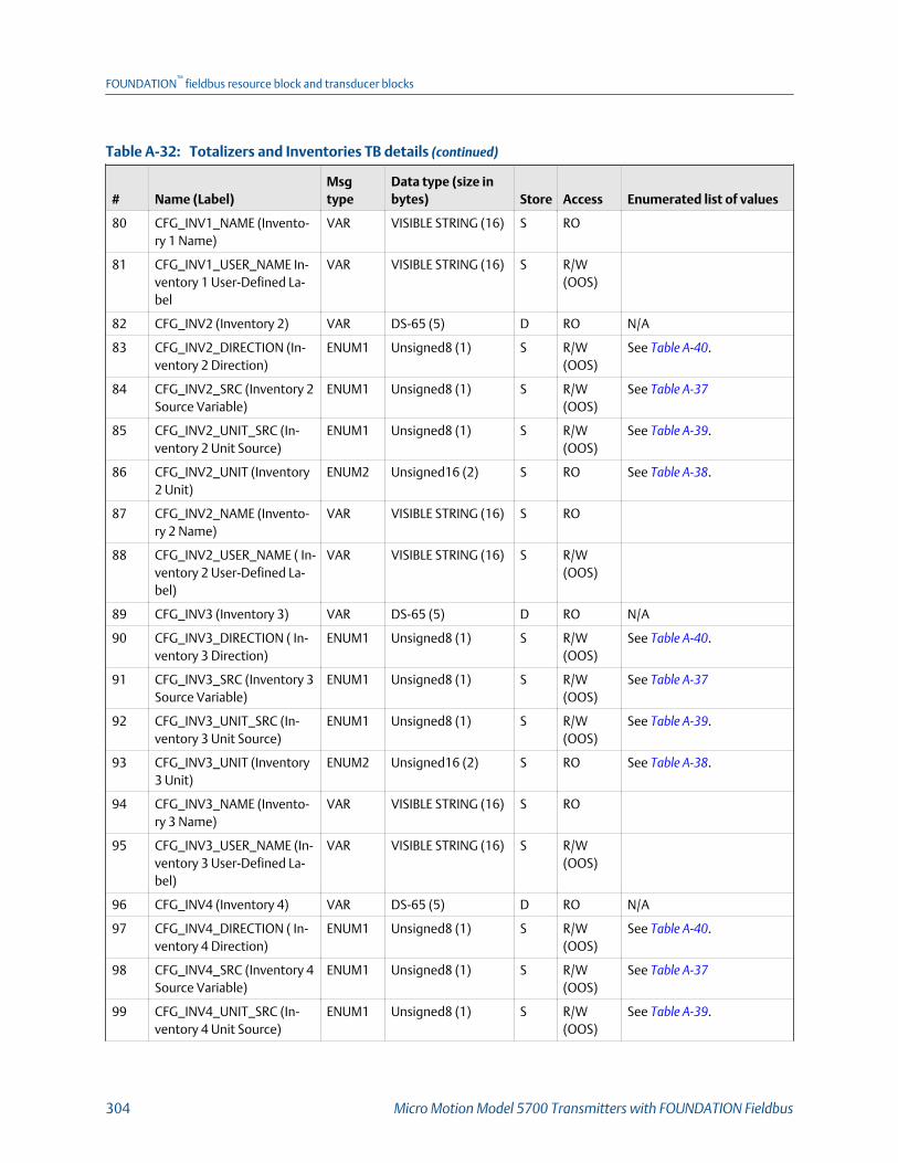
Totalizers and Inventories TB details (continued)Table A-32:
# Name (Label)Msgtype
Data type (size inbytes) Store Access Enumerated list of values
80 CFG_INV1_NAME (Invento-ry 1 Name)
VAR VISIBLE STRING (16) S RO
81 CFG_INV1_USER_NAME In-ventory 1 User-Defined La-bel
VAR VISIBLE STRING (16) S R/W(OOS)
82 CFG_INV2 (Inventory 2) VAR DS-65 (5) D RO N/A
83 CFG_INV2_DIRECTION (In-ventory 2 Direction)
ENUM1 Unsigned8 (1) S R/W(OOS)
See Table A‐40.
84 CFG_INV2_SRC (Inventory 2Source Variable)
ENUM1 Unsigned8 (1) S R/W(OOS)
See Table A‐37
85 CFG_INV2_UNIT_SRC (In-ventory 2 Unit Source)
ENUM1 Unsigned8 (1) S R/W(OOS)
See Table A‐39.
86 CFG_INV2_UNIT (Inventory2 Unit)
ENUM2 Unsigned16 (2) S RO See Table A‐38.
87 CFG_INV2_NAME (Invento-ry 2 Name)
VAR VISIBLE STRING (16) S RO
88 CFG_INV2_USER_NAME ( In-ventory 2 User-Defined La-bel)
VAR VISIBLE STRING (16) S R/W(OOS)
89 CFG_INV3 (Inventory 3) VAR DS-65 (5) D RO N/A
90 CFG_INV3_DIRECTION ( In-ventory 3 Direction)
ENUM1 Unsigned8 (1) S R/W(OOS)
See Table A‐40.
91 CFG_INV3_SRC (Inventory 3Source Variable)
ENUM1 Unsigned8 (1) S R/W(OOS)
See Table A‐37
92 CFG_INV3_UNIT_SRC (In-ventory 3 Unit Source)
ENUM1 Unsigned8 (1) S R/W(OOS)
See Table A‐39.
93 CFG_INV3_UNIT (Inventory3 Unit)
ENUM2 Unsigned16 (2) S RO See Table A‐38.
94 CFG_INV3_NAME (Invento-ry 3 Name)
VAR VISIBLE STRING (16) S RO
95 CFG_INV3_USER_NAME (In-ventory 3 User-Defined La-bel)
VAR VISIBLE STRING (16) S R/W(OOS)
96 CFG_INV4 (Inventory 4) VAR DS-65 (5) D RO N/A
97 CFG_INV4_DIRECTION ( In-ventory 4 Direction)
ENUM1 Unsigned8 (1) S R/W(OOS)
See Table A‐40.
98 CFG_INV4_SRC (Inventory 4Source Variable)
ENUM1 Unsigned8 (1) S R/W(OOS)
See Table A‐37
99 CFG_INV4_UNIT_SRC (In-ventory 4 Unit Source)
ENUM1 Unsigned8 (1) S R/W(OOS)
See Table A‐39.
FOUNDATION™
fieldbus resource block and transducer blocks
304 Micro Motion Model 5700 Transmitters with FOUNDATION Fieldbus
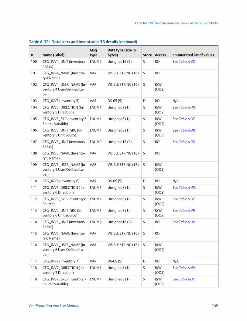
Totalizers and Inventories TB details (continued)Table A-32:
# Name (Label)Msgtype
Data type (size inbytes) Store Access Enumerated list of values
100 CFG_INV4_UNIT (Inventory4 Unit)
ENUM2 Unsigned16 (2) S RO See Table A‐38.
101 CFG_INV4_NAME (Invento-ry 4 Name)
VAR VISIBLE STRING (16) S RO
102 CFG_INV4_USER_NAME (In-ventory 4 User-Defined La-bel)
VAR VISIBLE STRING (16) S R/W(OOS)
103 CFG_INV5 (Inventory 5) VAR DS-65 (5) D RO N/A
104 CFG_INV5_DIRECTION (In-ventory 5 Direction)
ENUM1 Unsigned8 (1) S R/W(OOS)
See Table A‐40.
105 CFG_INV5_SRC (Inventory 5Source Variable)
ENUM1 Unsigned8 (1) S R/W(OOS)
See Table A‐37
106 CFG_INV5_UNIT_SRC (In-ventory 5 Unit Source)
ENUM1 Unsigned8 (1) S R/W(OOS)
See Table A‐39.
107 CFG_INV5_UNIT (Inventory5 Unit)
ENUM2 Unsigned16 (2) S RO See Table A‐38.
108 CFG_INV5_NAME (Invento-ry 5 Name)
VAR VISIBLE STRING (16) S RO
109 CFG_INV5_USER_NAME (In-ventory 5 User-Defined La-bel)
VAR VISIBLE STRING (16) S R/W(OOS)
110 CFG_INV6 (Inventory 6) VAR DS-65 (5) D RO N/A
111 CFG_INV6_DIRECTION ( In-ventory 6 Direction)
ENUM1 Unsigned8 (1) S R/W(OOS)
See Table A‐40.
112 CFG_INV6_SRC (Inventory 6Source)
ENUM1 Unsigned8 (1) S R/W(OOS)
See Table A‐37
113 CFG_INV6_UNIT_SRC (In-ventory 6 Unit Source)
ENUM1 Unsigned8 (1) S R/W(OOS)
See Table A‐39.
114 CFG_INV6_UNIT (Inventory6 Unit)
ENUM2 Unsigned16 (2) S RO See Table A‐38.
115 CFG_INV6_NAME (Invento-ry 6 Name)
VAR VISIBLE STRING (16) S RO
116 CFG_INV6_USER_NAME (In-ventory 6 User-Defined La-bel)
VAR VISIBLE STRING (16) S R/W(OOS)
117 CFG_INV7 (Inventory 7) VAR DS-65 (5) D RO N/A
118 CFG_INV7_DIRECTION ( In-ventory 7 Direction)
ENUM1 Unsigned8 (1) S R/W(OOS)
See Table A‐40.
119 CFG_INV7_SRC (Inventory 7Source Variable)
ENUM1 Unsigned8 (1) S R/W(OOS)
See Table A‐37
FOUNDATION™
fieldbus resource block and transducer blocks
Configuration and Use Manual 305

Totalizers and Inventories TB details (continued)Table A-32:
# Name (Label)Msgtype
Data type (size inbytes) Store Access Enumerated list of values
120 CFG_INV7_UNIT_SRC (In-ventory 7 Unit Source)
ENUM1 Unsigned8 (1) S R/W(OOS)
See Table A‐39.
121 CFG_INV7_UNIT (Inventory7 Unit)
ENUM2 Unsigned16 (2) S RO See Table A‐38.
122 CFG_INV7_NAME (Invento-ry 7 Name)
VAR VISIBLE STRING (16) S RO
123 CFG_INV7_USER_NAME (In-ventory 7 User-Defined La-bel)
VAR VISIBLE STRING (16) S R/W(OOS)
Total \ Inventory Units
124 TI_MASS_STD_UNITS (Tot/Inv Mass Standard Unit)
ENUM2 Unsigned16 (2) S R/W(OOS)
1089 = g
1088 = kg
1092 = t
1094 = lb
1095 = STon
1096 = Lton
125 TI_MASS_ALT_UNITS ( Tot/Inv Mass Alternate Unit)
ENUM2 Unsigned16 (2) S R/W(OOS)
126 TI_VOL_STD_UINTS (Tot/InvVolume Standard Unit)
ENUM2 Unsigned16 (2) S R/W(OOS)
See Table A‐35.
Codes for Tot/Inv Volume Standard and Alternate UnitTable A-35:
1048 = gallon 1043 = ft³ 1053 = SCF 1531 = NL
1038 = L 1034 = m³ 1521 = Nm³ 1536 = SL
1049 = ImpGal 1051 = bbl 1526 = Sm³ 253 = Special units
127 TI_VOL_ALT_UINTS (Tot/InvVolume Alternate Unit)
ENUM2 Unsigned16 (2) S R/W(OOS)
See Table A‐35.
Total \ Inventory Features
128 TI_FEATURES (Device Fea-tures)
VAR BIT STRING (2) D RO See Table A‐36.
Codes for Device FeaturesTable A-36:
0x0000 = FKEY_NO_FEATURE 0x0008 = TBR 0x0080 = API 0x4000 = APM Var Flow
0x0001 = APM Cont Flow 0x0010 = SMV 0x0800 = CAL FAIL 0x8000 = APM Cont NOC
0x0002 = TMR 0x0020 = GSV 0x1000 = APM TMR
0x0004 = PVR 0x0040 = ED 0x2000 = APM Var NOC
FOUNDATION™
fieldbus resource block and transducer blocks
306 Micro Motion Model 5700 Transmitters with FOUNDATION Fieldbus

Codes for Totalizer and Inventory Source Variables Table A-37:
00 = Mass Flow Rate 26 = CM:Net Mass Flow Rate 75 = APM: Net Flow Water AtLine
212 = APM: Un-remediated VolFlow
05 = Line (Gross) Volume FlowRate
29 = CM:Net Volume FlowRate
78 = APM: Net Flow Oil At Ref
16 = PM: Temp Corrected(Standard) Volume Flow
62 = Gas Standard VolumeFlow Rate
81 = APM: Net Flow Water At Ref
23 = CM: Standard Volume FlowRate
73 = APM: Net Flow Oil At Line 210 = APM: Unremediated MassFlow
Codes for Totalizer and Inventory UnitsTable A-38:
1089 = Grams 1096 = long tons 1034 = Cubic Meters 1531 = NL
1088 = Kilograms 1048 = Gallons 1051 = Barrels 1536 = SL
1092 = Metric Tons 1038 = Liters 1053 = SCF 253 = Special units
1094 = Pounds 1049 = Imperial Gallons 1521 = Nm3
1095 = Short tons 1043 = Cubic Feet 1526 = Sm3
Codes for Totalizer and Inventory Units SourceTable A-39:
224 = Mass Total Units 226 = Alt Volume Total Units
225 = Volume Total Units 227 = Alt Mass Total Units
Codes for Totalizer and Inventory DirectionTable A-40:
0 = Forward Only (Totalizers Increment for PositiveFlow)
2 = Bi-Directional (Totalizers Increment for Positive Flow Decre-ment for Negative Flow)
1 = Reverse Only (Totalizers Increment for NegativeFlow)
3 = Absolute (Totalizers Increment for Positive and NegativeFlow)
Totalizers and Inventories TB viewsTable A-41:
# Name (Label)
View listRe-lease1 2 3 4_1 4_2 4_3 4_4 4_5 4_6
Standard FF Parameters
0 BLOCK_STRUCTURE 1.0
1 ST_REV 2 2 2 2 2 2 2 2 2 1.0
2 TAG_DESC 1.0
3 STRATEGY
4 ALERT_KEY 1 1.0
FOUNDATION™
fieldbus resource block and transducer blocks
Configuration and Use Manual 307

Totalizers and Inventories TB views (continued)Table A-41:
# Name (Label)
View listRe-lease1 2 3 4_1 4_2 4_3 4_4 4_5 4_6
5 MODE_BLK 4 4 4 1.0
6 BLOCK_ERR 2 2 1.0
7 UPDATE_EVT 1.0
8 BLOCK_ALM 1.0
9 TRANSDUCER_DIRECTORY 1.0
10 TRANSDUCER_TYPE 2 2 2 2 1.0
11 TRANSDUCER_TYPE_VER 2 2 2 2 1.0
12 XD_ERROR 1 1 1.0
13 COLLECTION_DIRECTORY 1.0
Configurable Totalizer
14 INTEGRATOR1_FB_CONFIG (Inte-grator1 Configuration)
1 1.0
15 INTEGRATOR2_FB_CONFIG (Inte-grator2 Configuration)
1 1.0
16 TOT_INV_CON (Totalizer and In-ventory Control Codes)
1 1 1 1 1 1.0
17 CFG_TOT1 (Total 1) 5 5 1.0
18 CFG_TOT1_SRC (Total 1 SourceVariable)
1 1.0
19 CFG_TOT1_UNIT_SRC (Total 1Unit Source)
1 1.0
20 CFG_TOT1_UNIT (Total 1 Unit) 2 1.0
21 CFG_TOT1_DIRECTION (Total 1Direction)
1 1.0
22 CFG_TOT1_NAME (Total 1 Name) 16 1.0
23 CFG_TOT1_USER_NAME (Total 1User-Defined Label)
16 1.0
24 CFG_TOT1_RESET (Total 1 Reset) 2 1.0
25 CFG_TOT2 (Total 2) 5 5 1.0
26 CFG_TOT2_SRC (Total 2 )SourceVariable
1 1.0
27 CFG_TOT2_UNIT_SRC (Total 2Unit Source)
1 1.0
28 CFG_TOT2_UNIT (Total 2 Unit) 2 1.0
29 CFG_TOT2_DIRECTION (Total 2Direction)
1 1.0
30 CFG_TOT2_NAME (Total 2 Name) 16 1.0
FOUNDATION™
fieldbus resource block and transducer blocks
308 Micro Motion Model 5700 Transmitters with FOUNDATION Fieldbus
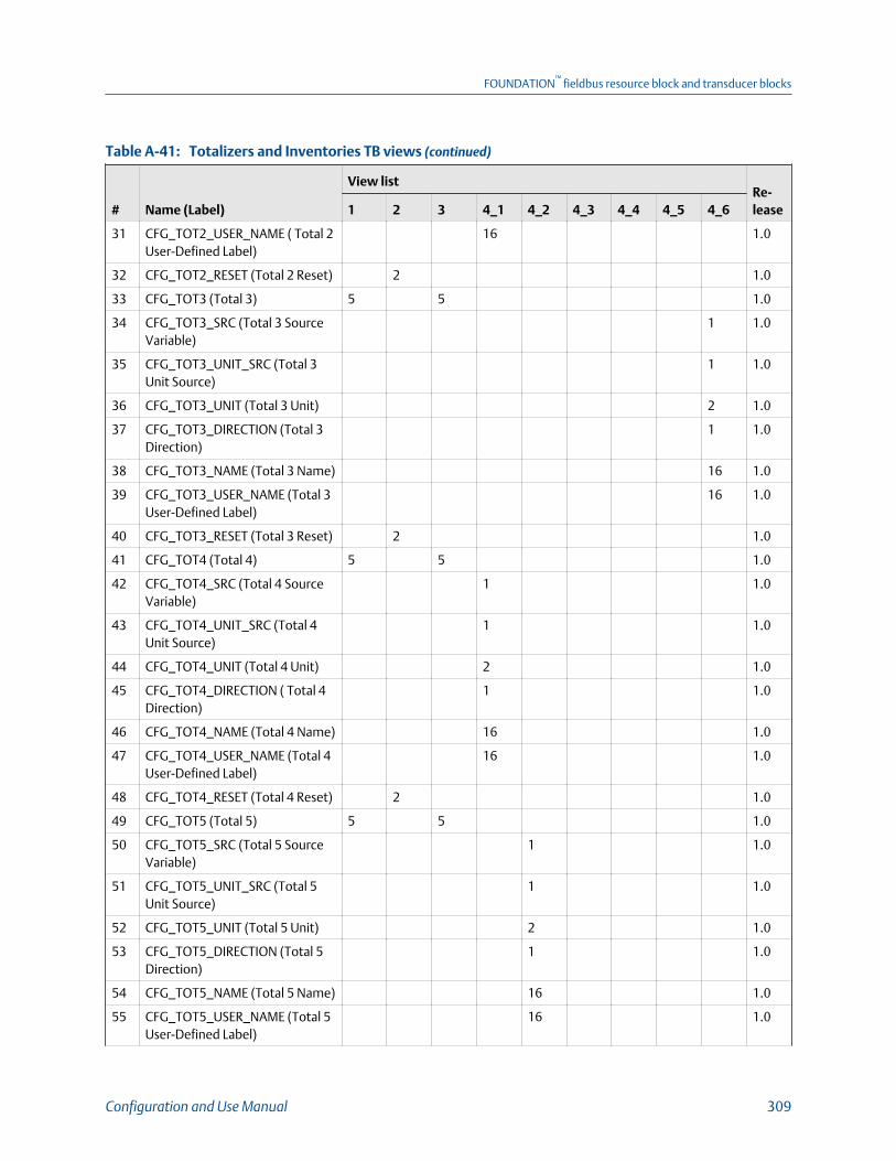
Totalizers and Inventories TB views (continued)Table A-41:
# Name (Label)
View listRe-lease1 2 3 4_1 4_2 4_3 4_4 4_5 4_6
31 CFG_TOT2_USER_NAME ( Total 2User-Defined Label)
16 1.0
32 CFG_TOT2_RESET (Total 2 Reset) 2 1.0
33 CFG_TOT3 (Total 3) 5 5 1.0
34 CFG_TOT3_SRC (Total 3 SourceVariable)
1 1.0
35 CFG_TOT3_UNIT_SRC (Total 3Unit Source)
1 1.0
36 CFG_TOT3_UNIT (Total 3 Unit) 2 1.0
37 CFG_TOT3_DIRECTION (Total 3Direction)
1 1.0
38 CFG_TOT3_NAME (Total 3 Name) 16 1.0
39 CFG_TOT3_USER_NAME (Total 3User-Defined Label)
16 1.0
40 CFG_TOT3_RESET (Total 3 Reset) 2 1.0
41 CFG_TOT4 (Total 4) 5 5 1.0
42 CFG_TOT4_SRC (Total 4 SourceVariable)
1 1.0
43 CFG_TOT4_UNIT_SRC (Total 4Unit Source)
1 1.0
44 CFG_TOT4_UNIT (Total 4 Unit) 2 1.0
45 CFG_TOT4_DIRECTION ( Total 4Direction)
1 1.0
46 CFG_TOT4_NAME (Total 4 Name) 16 1.0
47 CFG_TOT4_USER_NAME (Total 4User-Defined Label)
16 1.0
48 CFG_TOT4_RESET (Total 4 Reset) 2 1.0
49 CFG_TOT5 (Total 5) 5 5 1.0
50 CFG_TOT5_SRC (Total 5 SourceVariable)
1 1.0
51 CFG_TOT5_UNIT_SRC (Total 5Unit Source)
1 1.0
52 CFG_TOT5_UNIT (Total 5 Unit) 2 1.0
53 CFG_TOT5_DIRECTION (Total 5Direction)
1 1.0
54 CFG_TOT5_NAME (Total 5 Name) 16 1.0
55 CFG_TOT5_USER_NAME (Total 5User-Defined Label)
16 1.0
FOUNDATION™
fieldbus resource block and transducer blocks
Configuration and Use Manual 309

Totalizers and Inventories TB views (continued)Table A-41:
# Name (Label)
View listRe-lease1 2 3 4_1 4_2 4_3 4_4 4_5 4_6
56 CFG_TOT5_RESET (Total 5 Reset) 2 1.0
57 CFG_TOT6 (Total 6) 5 5 1.0
58 CFG_TOT6_SRC (Total 6 SourceVariable)
1 1 1.0
59 CFG_TOT6_UNIT_SRC (Total 6Unit)
1 1 1.0
60 CFG_TOT6_UNIT (Total 6 Unit) 2 1.0
61 CFG_TOT6_DIRECTION (Total 6Direction)
1 1.0
62 CFG_TOT6_NAME (Total 6 Name) 16 1.0
63 CFG_TOT6_USER_NAME ( Total 6User-Defined Label)
16 1.0
64 CFG_TOT6_RESET (Total 6 Reset) 2 1.0
65 CFG_TOT7 (Total 7) 5 5 1.0
66 CFG_TOT7_SRC (Total 7 Sourcevariable)
1 1.0
67 CFG_TOT7_UNIT_SRC (Total 7Unit Source)
1 1.0
68 CFG_TOT7_UNIT (Total 7 Unit) 2 1.0
69 CFG_TOT7_DIRECTION (Total 7Direction)
1 1.0
70 CFG_TOT7_NAME (Total 7 Name) 16 1.0
71 CFG_TOT7_USER_NAME (Total 7User-Defined Label)
16 1.0
72 CFG_TOT7_RESET (Total 7 Reset) 2 1.0
73 ALL_TOT_RESET ( Reset All Total-izers)
2 1.0
74 START_STOP_ALL_TOTALS (Start/Stop all Totalizers)
2 1.0
Configurable Inventory
75 CFG_INV1 (Inventory 1) 5 5 1.0
76 CFG_INV1_DIRECTION (Inventory1 Direction)
1 1.0
77 CFG_INV1_SRC (Inventory 1Source Variable)
1 1.0
78 CFG_INV1_UNIT_SRC (Inventory1 Unit Source)
1 1.0
FOUNDATION™
fieldbus resource block and transducer blocks
310 Micro Motion Model 5700 Transmitters with FOUNDATION Fieldbus

Totalizers and Inventories TB views (continued)Table A-41:
# Name (Label)
View listRe-lease1 2 3 4_1 4_2 4_3 4_4 4_5 4_6
79 CFG_INV1_UNIT (Inventory 1Unit)
2 1.0
80 CFG_INV1_NAME (Inventory 1Name)
16 1.0
81 CFG_INV1_USER_NAME Invento-ry 1 User-Defined Label
16 1.0
82 CFG_INV2 (Inventory 2) 5 5 1.0
83 CFG_INV2_DIRECTION (Inventory2 Direction)
1 1.0
84 CFG_INV2_SRC (Inventory 2Source Variable)
1 1.0
85 CFG_INV2_UNIT_SRC (Inventory2 Unit Source)
1 1.0
86 CFG_INV2_UNIT (Inventory 2Unit)
2 1.0
87 CFG_INV2_NAME (Inventory 2Name)
16 1.0
88 CFG_INV2_USER_NAME ( Inven-tory 2 User-Defined Label)
16 1.0
89 CFG_INV3 (Inventory 3) 5 5 1.0
90 CFG_INV3_DIRECTION ( Invento-ry 3 Direction)
1 1.0
91 CFG_INV3_SRC (Inventory 3Source Variable)
1 1.0
92 CFG_INV3_UNIT_SRC (Inventory3 Unit Source)
1 1.0
93 CFG_INV3_UNIT (Inventory 3Unit)
2 1.0
94 CFG_INV3_NAME (Inventory 3Name)
16 1.0
95 CFG_INV3_USER_NAME (Invento-ry 3 User-Defined Label)
16 1.0
96 CFG_INV4 (Inventory 4) 5 5 1.0
97 CFG_INV4_DIRECTION ( Invento-ry 4 Direction)
1 1.0
98 CFG_INV4_SRC (Inventory 4Source Variable)
1 1.0
99 CFG_INV4_UNIT_SRC (Inventory4 Unit Source)
1 1.0
FOUNDATION™
fieldbus resource block and transducer blocks
Configuration and Use Manual 311

Totalizers and Inventories TB views (continued)Table A-41:
# Name (Label)
View listRe-lease1 2 3 4_1 4_2 4_3 4_4 4_5 4_6
100 CFG_INV4_UNIT (Inventory 4Unit)
2 1.0
101 CFG_INV4_NAME (Inventory 4Name)
16 1.0
102 CFG_INV4_USER_NAME (Invento-ry 4 User-Defined Label)
16 1.0
103 CFG_INV5 (Inventory 5) 5 5 1.0
104 CFG_INV5_DIRECTION (Inventory5 Direction)
1 1.0
105 CFG_INV5_SRC (Inventory 5Source Variable)
1 1.0
106 CFG_INV5_UNIT_SRC (Inventory5 Unit Source)
1 1.0
107 CFG_INV5_UNIT (Inventory 5Unit)
2 1.0
108 CFG_INV5_NAME (Inventory 5Name)
16 1.0
109 CFG_INV5_USER_NAME (Invento-ry 5 User-Defined Label)
16 1.0
110 CFG_INV6 (Inventory 6) 5 5 1.0
111 CFG_INV6_DIRECTION ( Invento-ry 6 Direction)
1 1.0
112 CFG_INV6_SRC (Inventory 6Source)
1 1.0
113 CFG_INV6_UNIT_SRC (Inventory6 Unit Source)
1 1.0
114 CFG_INV6_UNIT (Inventory 6Unit)
2 1.0
115 CFG_INV6_NAME (Inventory 6Name)
16 1.0
116 CFG_INV6_USER_NAME (Invento-ry 6 User-Defined Label)
16 1.0
117 CFG_INV7 (Inventory 7) 5 5 1.0
118 CFG_INV7_DIRECTION ( Invento-ry 7 Direction)
1 1.0
119 CFG_INV7_SRC (Inventory 7Source Variable)
1 1.0
120 CFG_INV7_UNIT_SRC (Inventory7 Unit Source)
1 1.0
FOUNDATION™
fieldbus resource block and transducer blocks
312 Micro Motion Model 5700 Transmitters with FOUNDATION Fieldbus
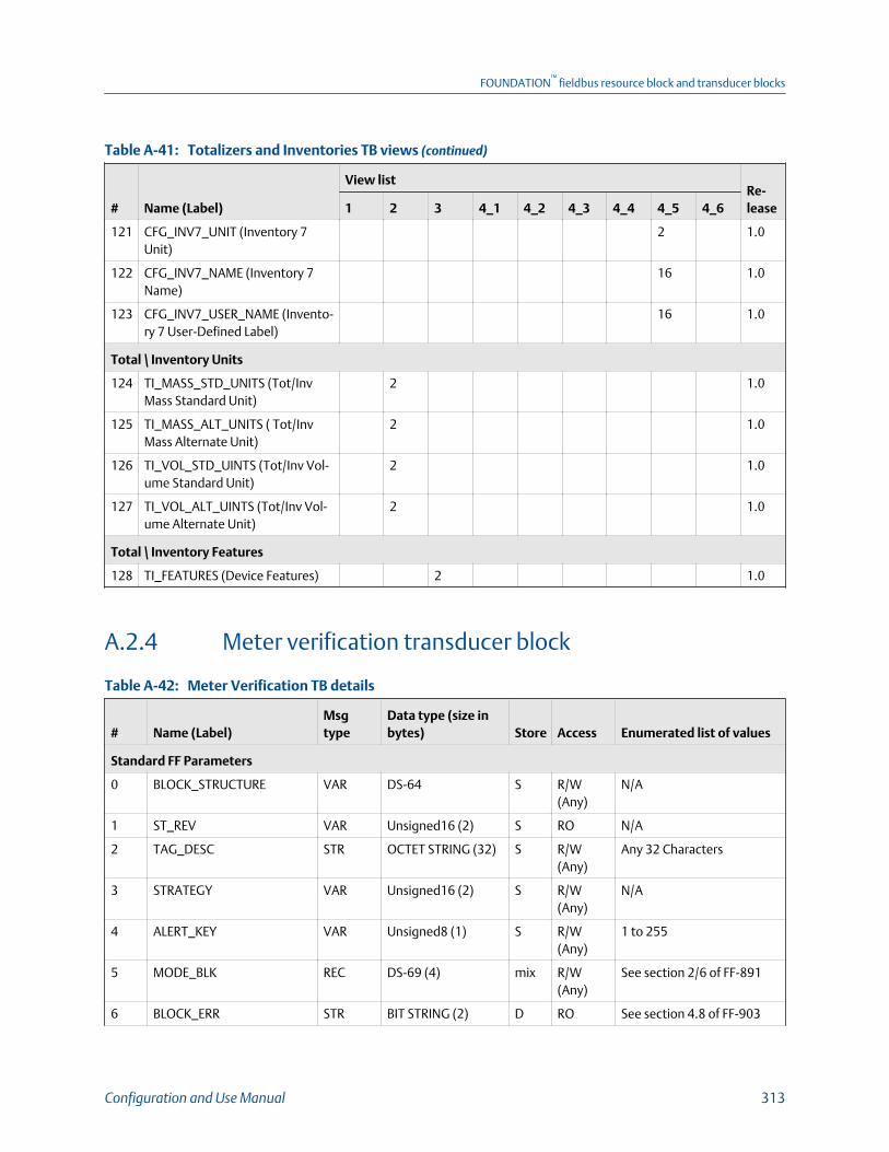
Totalizers and Inventories TB views (continued)Table A-41:
# Name (Label)
View listRe-lease1 2 3 4_1 4_2 4_3 4_4 4_5 4_6
121 CFG_INV7_UNIT (Inventory 7Unit)
2 1.0
122 CFG_INV7_NAME (Inventory 7Name)
16 1.0
123 CFG_INV7_USER_NAME (Invento-ry 7 User-Defined Label)
16 1.0
Total \ Inventory Units
124 TI_MASS_STD_UNITS (Tot/InvMass Standard Unit)
2 1.0
125 TI_MASS_ALT_UNITS ( Tot/InvMass Alternate Unit)
2 1.0
126 TI_VOL_STD_UINTS (Tot/Inv Vol-ume Standard Unit)
2 1.0
127 TI_VOL_ALT_UINTS (Tot/Inv Vol-ume Alternate Unit)
2 1.0
Total \ Inventory Features
128 TI_FEATURES (Device Features) 2 1.0
A.2.4 Meter verification transducer block
Meter Verification TB detailsTable A-42:
# Name (Label)Msgtype
Data type (size inbytes) Store Access Enumerated list of values
Standard FF Parameters
0 BLOCK_STRUCTURE VAR DS-64 S R/W(Any)
N/A
1 ST_REV VAR Unsigned16 (2) S RO N/A
2 TAG_DESC STR OCTET STRING (32) S R/W(Any)
Any 32 Characters
3 STRATEGY VAR Unsigned16 (2) S R/W(Any)
N/A
4 ALERT_KEY VAR Unsigned8 (1) S R/W(Any)
1 to 255
5 MODE_BLK REC DS-69 (4) mix R/W(Any)
See section 2/6 of FF-891
6 BLOCK_ERR STR BIT STRING (2) D RO See section 4.8 of FF-903
FOUNDATION™
fieldbus resource block and transducer blocks
Configuration and Use Manual 313

Meter Verification TB details (continued)Table A-42:
# Name (Label)Msgtype
Data type (size inbytes) Store Access Enumerated list of values
7 UPDATE_EVT REC DS-73 D R/W(Any)
8 BLOCK_ALM REC DS-72 D R/W(Any)
9 TRANSDUCER_DIRECTORY VAR Unsigned16 (2) S RO
10 TRANSDUCER_TYPE VAR Unsigned16 (2) S RO
11 TRANSDUCER_TYPE_VER VAR Unsigned16 (2) S RO
12 XD_ERROR VAR Unsigned8 (1) D RO 0 = No Error
18 = Calibration Error
19 = Configuration Error
20 = Electronics Failure
21 = Sensor Failure
26 = Process Error
27 = Calibration In Progress
13 COLLECTION_DIRECTORY VAR Unsigned32 S RO
Meter Verification
14 FRF_EN (SMV Enable ) METHOD Unsigned16 (2) S R/W(OOS)
0= Disabled
1 =Fixed Output Mode
2=Factory Air Verification
3=Factory Water Verifica-tion
4=Special debug mode
5=Abort
6=Continue MeasurementMode
7= Single Point Baseline(takes the place of factoryair and factory water)
15 FRF_ONLINE_MV_START(Online Meter Verification )
VAR DS-66 (2) D R/W(Any)
Value part of DS-66 (2)
0 = no action
1 = Start Meter Verificationin continue measurementmode
16 FRF_MV_FAULT_ALARM(Meter Verification FaultAlarm )
ENUM2 Unsigned16 (2) S R/W(Any)
0 = Last Value 1 = Fault
17 FRF_RUN_COUNT (RunCounter)
VAR Unsigned16 (2) S RO N/A
18 FRF_MV_INPROGRESS (FCFstatus)
ENUM Unsigned8 (1) D RO 0 = None
1 = MV In Progress
FOUNDATION™
fieldbus resource block and transducer blocks
314 Micro Motion Model 5700 Transmitters with FOUNDATION Fieldbus
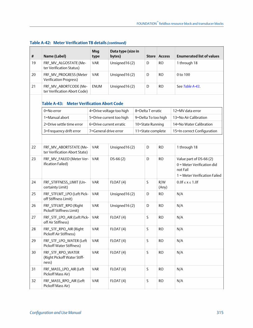
Meter Verification TB details (continued)Table A-42:
# Name (Label)Msgtype
Data type (size inbytes) Store Access Enumerated list of values
19 FRF_MV_ALGOSTATE (Me-ter Verification Status)
VAR Unsigned16 (2) D RO 1 through 18
20 FRF_MV_PROGRESS (MeterVerification Progress)
VAR Unsigned16 (2) D RO 0 to 100
21 FRF_MV_ABORTCODE (Me-ter Verification Abort Code)
ENUM Unsigned16 (2) D RO See Table A‐43.
Meter Verification Abort CodeTable A-43:
0=No error 4=Drive voltage too high 8=Delta T erratic 12=MV data error
1=Manual abort 5=Drive current too high 9=Delta To too high 13=No Air Calibration
2=Drive settle time error 6=Drive current erratic 10=State Running 14=No Water Calibration
3=Frequency drift error 7=General drive error 11=State complete 15=In correct Configuration
22 FRF_MV_ABORTSTATE (Me-ter Verification Abort State)
VAR Unsigned16 (2) D RO 1 through 18
23 FRF_MV_FAILED (Meter Ver-ification Failed)
VAR DS-66 (2) D RO Value part of DS-66 (2)
0 = Meter Verification didnot Fail
1 = Meter Verification Failed
24 FRF_STIFFNESS_LIMIT (Un-certainty Limit)
VAR FLOAT (4) S R/W(Any)
0.0f ≤ x ≤ 1.0f
25 FRF_STFLMT_LPO (Left Pick-off Stiffness Limit)
VAR Unsigned16 (2) D RO N/A
26 FRF_STFLMT_RPO (RightPickoff Stiffness Limit)
VAR Unsigned16 (2) D RO N/A
27 FRF_STF_LPO_AIR (Left Pick-off Air Stiffness)
VAR FLOAT (4) S RO N/A
28 FRF_STF_RPO_AIR (RightPickoff Air Stiffness)
VAR FLOAT (4) S RO N/A
29 FRF_STF_LPO_WATER (LeftPickoff Water Stiffness)
VAR FLOAT (4) S RO N/A
30 FRF_STF_RPO_WATER(Right Pickoff Water Stiff-ness)
VAR FLOAT (4) S RO N/A
31 FRF_MASS_LPO_AIR (LeftPickoff Mass Air)
VAR FLOAT (4) S RO N/A
32 FRF_MASS_RPO_AIR (LeftPickoff Mass Air)
VAR FLOAT (4) S RO N/A
FOUNDATION™
fieldbus resource block and transducer blocks
Configuration and Use Manual 315

Meter Verification TB details (continued)Table A-42:
# Name (Label)Msgtype
Data type (size inbytes) Store Access Enumerated list of values
33 FRF_MASS_LPO_WATER(Left Pickoff Mass Water)
VAR FLOAT (4) S RO N/A
34 FRF_MASS_RPO_WATER(Right Pickoff Mass Water)
VAR FLOAT (4) S RO N/A
35 FRF_DAMPING_AIR (AirDamping)
VAR FLOAT (4) S RO N/A
36 FRF_DAMPING_WATER(Water Damping)
VAR FLOAT (4) S RO N/A
37 MV_CORE_DEVICE_TYPE(Core Device Type)
ENUM2 Unsigned16 (2) S RO 40 = 700 CP
50 = 800 ECP
1000 = No CP
38 FRF_MV_PASSCOUNTER(MV Pass counter)
VAR Unsigned16 (2) S RO N/A
39 FRF_DRIVE_CURRENT (DriveCurrent)
VAR FLOAT (4) S RO N/A
40 FRF_DL_T (Delta T) VAR FLOAT (4) S RO N/A
41 FRF_TEMP (Temperature) VAR FLOAT (4) S RO N/A
42 FRF_DENSITY (Density) VAR FLOAT (4) S RO N/A
43 FRF_DRIVE_FREQ (Drive Fre-quency)
VAR FLOAT (4) S RO N/A
44 FRF_LPO_FILTER (Left Pick-off Filter)
VAR FLOAT (4) S RO N/A
45 FRF_RPO_FILTER (RightPickoff Filter)
VAR FLOAT (4) S RO N/A
46 FRF_MV_FIRSTRUN_TIME(Hours Until Next Run)
VAR FLOAT (4) S R/W(Any)
N/A
47 FRF_MV_ELAPSE_TIME(Hours Between RecurringRuns)
VAR FLOAT (4) S R/W(Any)
N/A
48 FRF_MV_TIME_LEFT (HoursRemaining Until Next Run)
VAR FLOAT (4) D RO N/A
49 FRF_TONE_LEVEL MV (ToneLevel)
VAR FLOAT (4) S R/W(OOS)
N/A
50 FRF_TONE_RAMP_TIME (MVTone Ramp Time)
VAR FLOAT (4) S R/W(OOS)
N/A
51 FRF_BL_COE (BL. Coeffi-cient)
VAR FLOAT (4) S R/W(OOS)
N/A
52 FRF_DRIVE_TARGET (DriveTarget)
VAR FLOAT (4) S R/W(OOS)
N/A
FOUNDATION™
fieldbus resource block and transducer blocks
316 Micro Motion Model 5700 Transmitters with FOUNDATION Fieldbus

Meter Verification TB details (continued)Table A-42:
# Name (Label)Msgtype
Data type (size inbytes) Store Access Enumerated list of values
53 FRF_DRIVE_PCOE (Drive PCoefficient)
VAR FLOAT (4) S R/W(OOS)
N/A
54 FRF_TONE_SPACING_MUL(Tone Space Multiplier)
VAR FLOAT (4) S R/W(OOS)
N/A
55 FRF_FREQ_DRIFT_LMT (Fre-quency Drift Limit)
VAR FLOAT (4) S R/W(OOS)
N/A
56 FRF_MAX_CURRENT_MA(Max. Sensor Current)
VAR FLOAT (4) S R/W(OOS)
N/A
57 FRF_KFQ2 (KFQ2) VAR FLOAT (4) S R/W(OOS)
N/A
58 FRF_COEFF_INDEX (Coeffi-cient Index)
ENUM Unsigned16 (2) S R/W(Any)
0 = T1
1 = T2
2 = T3
3 = T4
4 = DR
59 FRF_LPO_COEFF_REAL (LeftPickoff Coefficient Real)
VAR FLOAT (4) S RO N/A
60 FRF_LPO_CEOFF_IMAG (LeftPickoff Coefficient Imagina-ry)
VAR FLOAT (4) S RO N/A
61 FRF_RPO_COEFF_REAL(Right Pickoff CoefficientReal)
VAR FLOAT (4) S RO N/A
62 FRF_RPO_CEOFF_IMAG(Right Pickoff CoefficientImaginary)
VAR FLOAT (4) S RO N/A
63 FRF_CAL_AMPL_REAL (CalAmplitude Real)
VAR FLOAT (4) S RO N/A
64 FRF_CAL_AMPL_IMAG (CalAmplitude Imaginary)
VAR FLOAT (4) S RO N/A
65 FRF_TONE_FREQUENCY(Tone Frequency)
VAR FLOAT (4) S RO N/A
66 FRF_POLE_REAL (Pole Real) VAR FLOAT (4) S RO N/A
67 FRF_POLE_IMAG (PoleImaginary)
VAR FLOAT (4) S RO N/A
68 FRF_RESIDUAL_LPO_REAL(Residual Left Pickoff Real)
VAR FLOAT (4) S RO N/A
69 FRF_RESIDUAL_LPO_IMAG(Residual Left Pickoff Imagi-nary)
VAR FLOAT (4) S RO N/A
FOUNDATION™
fieldbus resource block and transducer blocks
Configuration and Use Manual 317

Meter Verification TB details (continued)Table A-42:
# Name (Label)Msgtype
Data type (size inbytes) Store Access Enumerated list of values
70 FRF_RESIDUAL_RPO_REAL(Residual Right Pickoff Real)
VAR FLOAT (4) S RO N/A
71 FRF_RESIDUAL_RPO_IMAG( Residual Right PickoffImaginary)
VAR FLOAT (4) S RO N/A
72 FRF_LPO_IMPORT_BIAS Left(Pickoff Import Bias)
VAR FLOAT (4) S RO N/A
73 FRF_LPO_EXPORT_BIAS(Left Pickoff Export Bias)
VAR FLOAT (4) S RO N/A
74 FRF_RPO_IMPORT_BIAS(Right Pickoff Import Bias)
VAR FLOAT (4) S RO N/A
75 FRF_RPO_EXPORT_BIAS(Right Pickoff Export Bias)
VAR FLOAT (4) S RO N/A
76 FRF_LPO_FILTER_AVG (LeftPickoff Filter Average)
VAR FLOAT (4) S RO N/A
77 FRF_RPO_FILTER_AVG(Right Pickoff Filter Aver-age)
VAR FLOAT (4) S RO N/A
78 FRF_SENSOR_ID (Sensor ID) VAR Unsigned16 (2) S RO N/A
79 FRF_DATA_SEL (MV DataSelection)
VAR Unsigned16 (2) S R/W(Any)
N/A
80 FRF_LPO_STIFFNESS (LeftPickoff Stiffness)
VAR FLOAT (4) S RO NA
81 FRF_RPO_STIFFNESS (RightPickoff Stiffnes(Left PickoffStiffness)
VAR FLOAT (4) S RO NA
82 FRF_DAMPING (Damping) VAR FLOAT (4) S RO NA
83 FRF_DATA_MASS_LPO (LeftPickoff Mass)
VAR FLOAT (4) S RO NA
84 FRF_DATA_MASS_RPO(Right Pickoff Mass)
VAR FLOAT (4) S RO NA
85 FRF_DATA_RESO_FREQ_ES-TIMATED (Estimated Reso-nant Frequency)
VAR FLOAT (4) S RO NA
86 FRF_DATA_DRIVE_CUR-RENT (Drive Current)
VAR FLOAT (4) S RO NA
87 FRF_DATA_DELTA_T (DeltaT)
VAR FLOAT (4) S RO NA
88 FRF_DATA_TEMPERATURE(Temperature)
VAR FLOAT (4) S RO NA
FOUNDATION™
fieldbus resource block and transducer blocks
318 Micro Motion Model 5700 Transmitters with FOUNDATION Fieldbus

Meter Verification TB details (continued)Table A-42:
# Name (Label)Msgtype
Data type (size inbytes) Store Access Enumerated list of values
89 FRF_DATA_DENSITY (Densi-ty)
VAR FLOAT (4) S RO NA
90 FRF_DATA_FREQUENCY(Frequency)
VAR FLOAT (4) S RO NA
91 FRF_DATA_LPO_FILTER(Left Pickoff Filter)
VAR FLOAT (4) S RO NA
92 FRF_DATA_RPO_FILTER(Right Pickoff Filter)
VAR FLOAT (4) S RO NA
Meter Verification History
93 FRF_DS-INDEX (MV datastorage Index)
VAR Unsigned16 (2) S R/W(Any)
0 ≤ x < 20
94 FRF_DS-TIME (TransmitterRunning Seconds at Test)
VAR Unsigned32 S RO N/A
95 FRF_DS-LPO_STIFF (LeftPickoff Normal Stiffness)
VAR FLOAT (4) S RO N/A
96 FRF_DS-RPO_STIFF (RightPickoff Stiffness)
VAR FLOAT (4) S RO N/A
97 FRF_DS-LPO_MASS (LeftPickoff Mass Data)
VAR FLOAT (4) S RO N/A
98 FRF_DS-RPO_MASS (RightPickoff Mass Data)
VAR FLOAT (4) S RO N/A
99 FRF_DS-DAMPING (Damp-ing)
VAR FLOAT (4) S RO N/A
100 FRF_DS-DRIVE_MA (DriveCurrent in mA)
VAR FLOAT (4) S RO N/A
101 FRF_DS-DELTA_T (Delta T) VAR FLOAT (4) S RO N/A
102 FRF_DS-TEMPERATURE(Temperature)
VAR FLOAT (4) S RO N/A
103 FRF_DS-DENSITY (Density) VAR FLOAT (4) S RO N/A
104 FRF_DS-LPO_AMP (LeftPickoff Amplitude)
VAR FLOAT (4) S RO N/A
105 FRF_DS-RPO_AMP (RightPickoff Amplitude)
VAR FLOAT (4) S RO N/A
106 FRF_DS-DRV_FREQ (DriveFrequency)
VAR FLOAT (4) S RO N/A
107 FRF_DS-LPO_EXP (Left Pick-off Export)
VAR FLOAT (4) S RO N/A
108 FRF_DS-RPO_EXP (RightPickoff Export)
VAR FLOAT (4) S RO N/A
FOUNDATION™
fieldbus resource block and transducer blocks
Configuration and Use Manual 319

Meter Verification TB details (continued)Table A-42:
# Name (Label)Msgtype
Data type (size inbytes) Store Access Enumerated list of values
109 FRF_DS-LPO_CONF (LeftPickoff Configure)
VAR FLOAT (4) S RO N/A
110 FRF_DS-RPO_CONF (RightPickoff Configure)
VAR FLOAT (4) S RO N/A
111 FRF_DS-LPO_FLEX (LeftPickoff Flex)
VAR FLOAT (4) S RO N/A
112 FRF_DS-RPO_FLEX (RightPickoff Flex)
VAR FLOAT (4) S RO N/A
113 FRF_DS-ABORT_CODE(Abort Code)
VAR Unsigned16 (2) S RO N/A
114 FRF_DS-ABORT_STATE(Abort State)
VAR Unsigned16 (2) S RO N/A
115 FRF_DS-LPO_P_F (Left Pick-off P/F)
VAR Unsigned16 (2) S RO N/A
116 FRF_DS-RPO_P_F (RightPickoff P/F)
VAR Unsigned16 (2) S RO N/A
117 FRF_DS-SENSOR_CD (Sen-sor Type Code)
VAR Unsigned16 (2) S RO N/A
118 FRF_DS-SENSOR_SN (Sen-sor Serial Number)
VAR Unsigned32 S RO N/A
119 FRF_LAST_RUN_INDEX (LastRun Index)
VAR Unsigned16 (2) D RO N/A
120 MV_FEATURE_KEY (DeviceFeatures)
STR BIT STRING D RO See Table A‐44.
Codes for Device FeaturesTable A-44:
0x0000 = FKEY_NO_FEATURE 0x0008 = TBR 0x0080 = API 0x4000 = APM Var Flow
0x0001 = APM Cont Flow 0x0010 = SMV 0x0800 = CAL FAIL 0x8000 = APM Cont NOC
0x0002 = TMR 0x0020 = GSV 0x1000 = APM TMR
0x0004 = PVR 0x0040 = ED 0x2000 = APM Var NOC
Meter Verification TB viewsTable A-45:
# Name (Label)
View listRe-lease1 2 3 4__1 4_2 4_3 4_4 4_5
Standard FF Parameters
0 BLOCK_STRUCTURE 1.0
FOUNDATION™
fieldbus resource block and transducer blocks
320 Micro Motion Model 5700 Transmitters with FOUNDATION Fieldbus
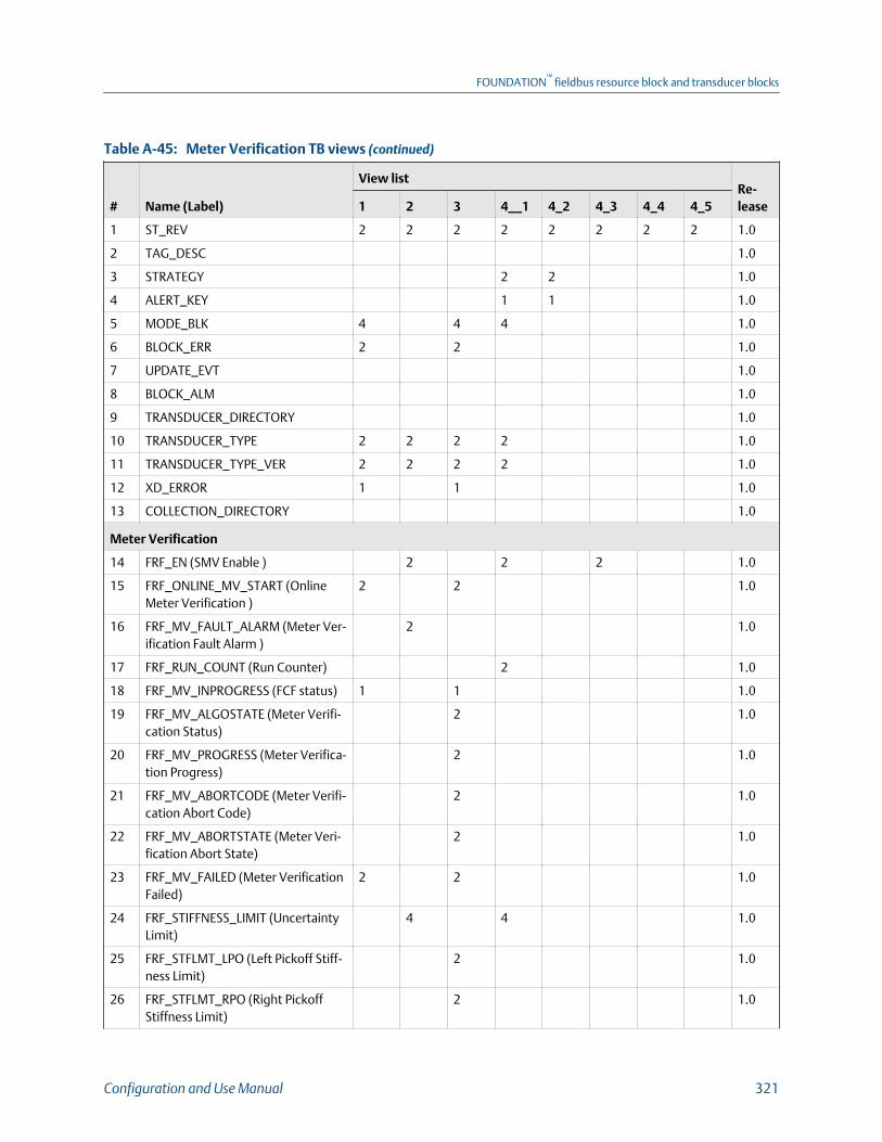
Meter Verification TB views (continued)Table A-45:
# Name (Label)
View listRe-lease1 2 3 4__1 4_2 4_3 4_4 4_5
1 ST_REV 2 2 2 2 2 2 2 2 1.0
2 TAG_DESC 1.0
3 STRATEGY 2 2 1.0
4 ALERT_KEY 1 1 1.0
5 MODE_BLK 4 4 4 1.0
6 BLOCK_ERR 2 2 1.0
7 UPDATE_EVT 1.0
8 BLOCK_ALM 1.0
9 TRANSDUCER_DIRECTORY 1.0
10 TRANSDUCER_TYPE 2 2 2 2 1.0
11 TRANSDUCER_TYPE_VER 2 2 2 2 1.0
12 XD_ERROR 1 1 1.0
13 COLLECTION_DIRECTORY 1.0
Meter Verification
14 FRF_EN (SMV Enable ) 2 2 2 1.0
15 FRF_ONLINE_MV_START (OnlineMeter Verification )
2 2 1.0
16 FRF_MV_FAULT_ALARM (Meter Ver-ification Fault Alarm )
2 1.0
17 FRF_RUN_COUNT (Run Counter) 2 1.0
18 FRF_MV_INPROGRESS (FCF status) 1 1 1.0
19 FRF_MV_ALGOSTATE (Meter Verifi-cation Status)
2 1.0
20 FRF_MV_PROGRESS (Meter Verifica-tion Progress)
2 1.0
21 FRF_MV_ABORTCODE (Meter Verifi-cation Abort Code)
2 1.0
22 FRF_MV_ABORTSTATE (Meter Veri-fication Abort State)
2 1.0
23 FRF_MV_FAILED (Meter VerificationFailed)
2 2 1.0
24 FRF_STIFFNESS_LIMIT (UncertaintyLimit)
4 4 1.0
25 FRF_STFLMT_LPO (Left Pickoff Stiff-ness Limit)
2 1.0
26 FRF_STFLMT_RPO (Right PickoffStiffness Limit)
2 1.0
FOUNDATION™
fieldbus resource block and transducer blocks
Configuration and Use Manual 321
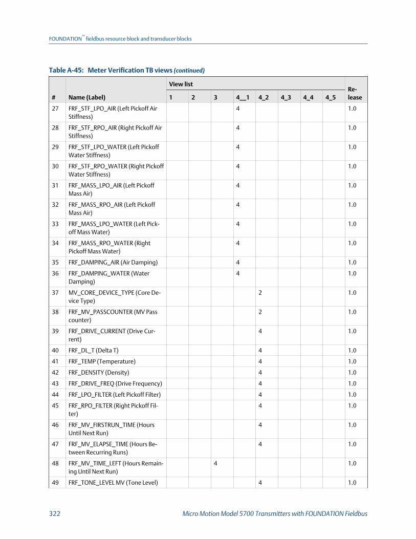
Meter Verification TB views (continued)Table A-45:
# Name (Label)
View listRe-lease1 2 3 4__1 4_2 4_3 4_4 4_5
27 FRF_STF_LPO_AIR (Left Pickoff AirStiffness)
4 1.0
28 FRF_STF_RPO_AIR (Right Pickoff AirStiffness)
4 1.0
29 FRF_STF_LPO_WATER (Left PickoffWater Stiffness)
4 1.0
30 FRF_STF_RPO_WATER (Right PickoffWater Stiffness)
4 1.0
31 FRF_MASS_LPO_AIR (Left PickoffMass Air)
4 1.0
32 FRF_MASS_RPO_AIR (Left PickoffMass Air)
4 1.0
33 FRF_MASS_LPO_WATER (Left Pick-off Mass Water)
4 1.0
34 FRF_MASS_RPO_WATER (RightPickoff Mass Water)
4 1.0
35 FRF_DAMPING_AIR (Air Damping) 4 1.0
36 FRF_DAMPING_WATER (WaterDamping)
4 1.0
37 MV_CORE_DEVICE_TYPE (Core De-vice Type)
2 1.0
38 FRF_MV_PASSCOUNTER (MV Passcounter)
2 1.0
39 FRF_DRIVE_CURRENT (Drive Cur-rent)
4 1.0
40 FRF_DL_T (Delta T) 4 1.0
41 FRF_TEMP (Temperature) 4 1.0
42 FRF_DENSITY (Density) 4 1.0
43 FRF_DRIVE_FREQ (Drive Frequency) 4 1.0
44 FRF_LPO_FILTER (Left Pickoff Filter) 4 1.0
45 FRF_RPO_FILTER (Right Pickoff Fil-ter)
4 1.0
46 FRF_MV_FIRSTRUN_TIME (HoursUntil Next Run)
4 1.0
47 FRF_MV_ELAPSE_TIME (Hours Be-tween Recurring Runs)
4 1.0
48 FRF_MV_TIME_LEFT (Hours Remain-ing Until Next Run)
4 1.0
49 FRF_TONE_LEVEL MV (Tone Level) 4 1.0
FOUNDATION™
fieldbus resource block and transducer blocks
322 Micro Motion Model 5700 Transmitters with FOUNDATION Fieldbus

Meter Verification TB views (continued)Table A-45:
# Name (Label)
View listRe-lease1 2 3 4__1 4_2 4_3 4_4 4_5
50 FRF_TONE_RAMP_TIME (MV ToneRamp Time)
4 1.0
51 FRF_BL_COE (BL. Coefficient) 4 1.0
52 FRF_DRIVE_TARGET (Drive Target) 4 1.0
53 FRF_DRIVE_PCOE (Drive P Coeffi-cient)
4 1.0
54 FRF_TONE_SPACING_MUL (ToneSpace Multiplier)
4 1.0
55 FRF_FREQ_DRIFT_LMT (FrequencyDrift Limit)
4 1.0
56 FRF_MAX_CURRENT_MA (Max. Sen-sor Current)
4 1.0
57 FRF_KFQ2 (KFQ2) 4 1.0
58 FRF_COEFF_INDEX (Coefficient In-dex)
2 1.0
59 FRF_LPO_COEFF_REAL (Left PickoffCoefficient Real)
4 1.0
60 FRF_LPO_CEOFF_IMAG (Left PickoffCoefficient Imaginary)
4 1.0
61 FRF_RPO_COEFF_REAL (Right Pick-off Coefficient Real)
4 1.0
62 FRF_RPO_CEOFF_IMAG (Right Pick-off Coefficient Imaginary)
4 1.0
63 FRF_CAL_AMPL_REAL (Cal Ampli-tude Real)
4 1.0
64 FRF_CAL_AMPL_IMAG (Cal Ampli-tude Imaginary)
4 1.0
65 FRF_TONE_FREQUENCY (Tone Fre-quency)
4 1.0
66 FRF_POLE_REAL (Pole Real) 4 1.0
67 FRF_POLE_IMAG (Pole Imaginary) 4 1.0
68 FRF_RESIDUAL_LPO_REAL (ResidualLeft Pickoff Real)
4 1.0
69 FRF_RESIDUAL_LPO_IMAG (ResidualLeft Pickoff Imaginary)
4 1.0
70 FRF_RESIDUAL_RPO_REAL (ResidualRight Pickoff Real)
4 1.0
71 FRF_RESIDUAL_RPO_IMAG ( Residu-al Right Pickoff Imaginary)
4 1.0
FOUNDATION™
fieldbus resource block and transducer blocks
Configuration and Use Manual 323

Meter Verification TB views (continued)Table A-45:
# Name (Label)
View listRe-lease1 2 3 4__1 4_2 4_3 4_4 4_5
72 FRF_LPO_IMPORT_BIAS Left (PickoffImport Bias)
4 1.0
73 FRF_LPO_EXPORT_BIAS (Left PickoffExport Bias)
4 1.0
74 FRF_RPO_IMPORT_BIAS (Right Pick-off Import Bias)
4 1.0
75 FRF_RPO_EXPORT_BIAS (Right Pick-off Export Bias)
4 1.0
76 FRF_LPO_FILTER_AVG (Left PickoffFilter Average)
4 1.0
77 FRF_RPO_FILTER_AVG (Right PickoffFilter Average)
4 1.0
78 FRF_SENSOR_ID (Sensor ID) 2 1.0
79 FRF_DATA_SEL (MV Data Selection) 2 1.0
80 FRF_LPO_STIFFNESS (Left PickoffStiffness)
4 1.0
81 FRF_RPO_STIFFNESS (Right PickoffStiffnes(Left Pickoff Stiffness)
4 1.0
82 FRF_DAMPING (Damping) 4 1.0
83 FRF_DATA_MASS_LPO (Left PickoffMass)
4 1.0
84 FRF_DATA_MASS_RPO (Right Pick-off Mass)
4 1.0
85 FRF_DATA_RESO_FREQ_ESTIMA-TED (Estimated Resonant Frequen-cy)
4 1.0
86 FRF_DATA_DRIVE_CURRENT (DriveCurrent)
4 1.0
87 FRF_DATA_DELTA_T (Delta T) 4 1.0
88 FRF_DATA_TEMPERATURE (Temper-ature)
4 1.0
89 FRF_DATA_DENSITY (Density) 4 1.0
90 FRF_DATA_FREQUENCY (Frequen-cy)
4 1.0
91 FRF_DATA_LPO_FILTER (Left PickoffFilter)
4 1.0
92 FRF_DATA_RPO_FILTER (Right Pick-off Filter)
4 1.0
FOUNDATION™
fieldbus resource block and transducer blocks
324 Micro Motion Model 5700 Transmitters with FOUNDATION Fieldbus
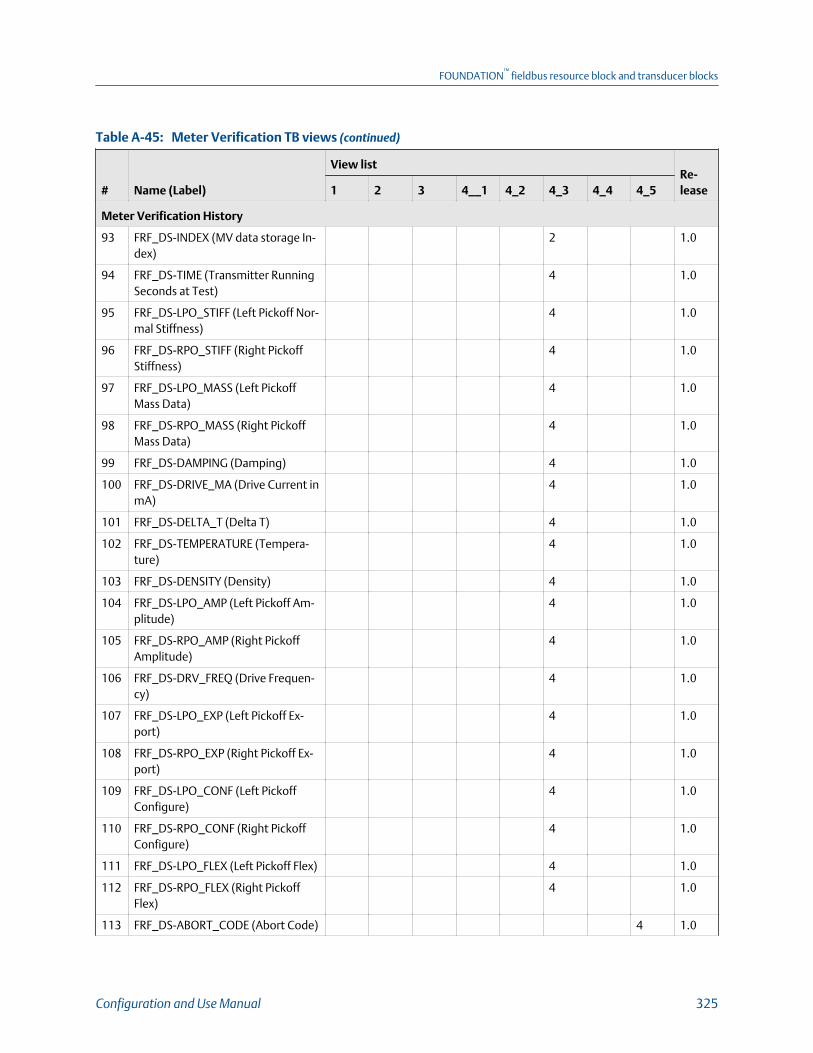
Meter Verification TB views (continued)Table A-45:
# Name (Label)
View listRe-lease1 2 3 4__1 4_2 4_3 4_4 4_5
Meter Verification History
93 FRF_DS-INDEX (MV data storage In-dex)
2 1.0
94 FRF_DS-TIME (Transmitter RunningSeconds at Test)
4 1.0
95 FRF_DS-LPO_STIFF (Left Pickoff Nor-mal Stiffness)
4 1.0
96 FRF_DS-RPO_STIFF (Right PickoffStiffness)
4 1.0
97 FRF_DS-LPO_MASS (Left PickoffMass Data)
4 1.0
98 FRF_DS-RPO_MASS (Right PickoffMass Data)
4 1.0
99 FRF_DS-DAMPING (Damping) 4 1.0
100 FRF_DS-DRIVE_MA (Drive Current inmA)
4 1.0
101 FRF_DS-DELTA_T (Delta T) 4 1.0
102 FRF_DS-TEMPERATURE (Tempera-ture)
4 1.0
103 FRF_DS-DENSITY (Density) 4 1.0
104 FRF_DS-LPO_AMP (Left Pickoff Am-plitude)
4 1.0
105 FRF_DS-RPO_AMP (Right PickoffAmplitude)
4 1.0
106 FRF_DS-DRV_FREQ (Drive Frequen-cy)
4 1.0
107 FRF_DS-LPO_EXP (Left Pickoff Ex-port)
4 1.0
108 FRF_DS-RPO_EXP (Right Pickoff Ex-port)
4 1.0
109 FRF_DS-LPO_CONF (Left PickoffConfigure)
4 1.0
110 FRF_DS-RPO_CONF (Right PickoffConfigure)
4 1.0
111 FRF_DS-LPO_FLEX (Left Pickoff Flex) 4 1.0
112 FRF_DS-RPO_FLEX (Right PickoffFlex)
4 1.0
113 FRF_DS-ABORT_CODE (Abort Code) 4 1.0
FOUNDATION™
fieldbus resource block and transducer blocks
Configuration and Use Manual 325
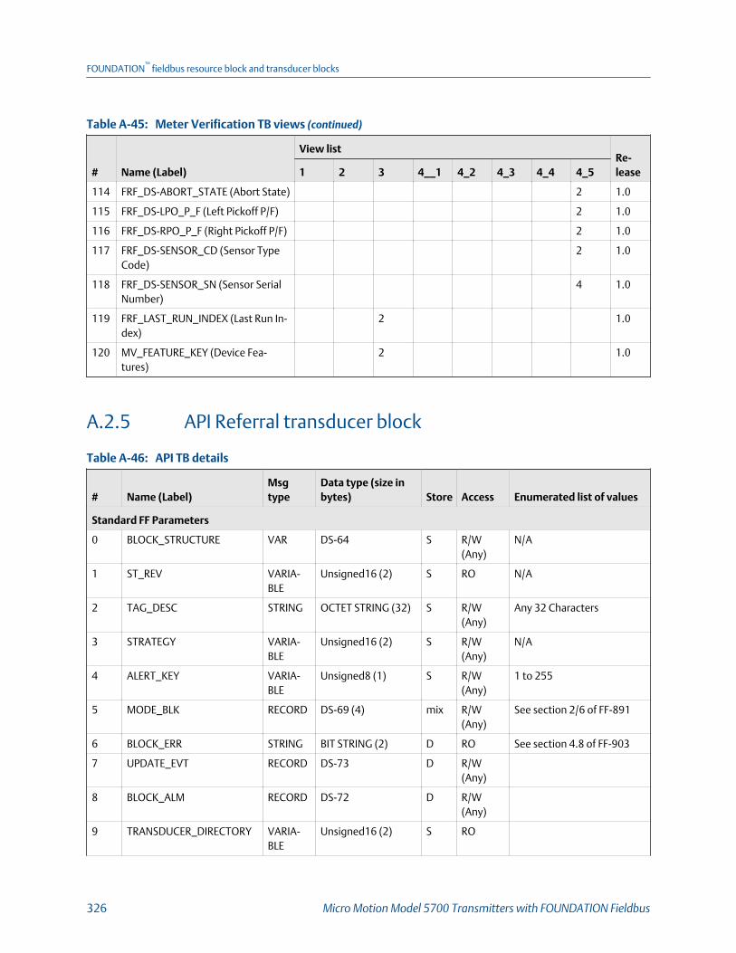
Meter Verification TB views (continued)Table A-45:
# Name (Label)
View listRe-lease1 2 3 4__1 4_2 4_3 4_4 4_5
114 FRF_DS-ABORT_STATE (Abort State) 2 1.0
115 FRF_DS-LPO_P_F (Left Pickoff P/F) 2 1.0
116 FRF_DS-RPO_P_F (Right Pickoff P/F) 2 1.0
117 FRF_DS-SENSOR_CD (Sensor TypeCode)
2 1.0
118 FRF_DS-SENSOR_SN (Sensor SerialNumber)
4 1.0
119 FRF_LAST_RUN_INDEX (Last Run In-dex)
2 1.0
120 MV_FEATURE_KEY (Device Fea-tures)
2 1.0
A.2.5 API Referral transducer block
API TB detailsTable A-46:
# Name (Label)Msgtype
Data type (size inbytes) Store Access Enumerated list of values
Standard FF Parameters
0 BLOCK_STRUCTURE VAR DS-64 S R/W(Any)
N/A
1 ST_REV VARIA-BLE
Unsigned16 (2) S RO N/A
2 TAG_DESC STRING OCTET STRING (32) S R/W(Any)
Any 32 Characters
3 STRATEGY VARIA-BLE
Unsigned16 (2) S R/W(Any)
N/A
4 ALERT_KEY VARIA-BLE
Unsigned8 (1) S R/W(Any)
1 to 255
5 MODE_BLK RECORD DS-69 (4) mix R/W(Any)
See section 2/6 of FF-891
6 BLOCK_ERR STRING BIT STRING (2) D RO See section 4.8 of FF-903
7 UPDATE_EVT RECORD DS-73 D R/W(Any)
8 BLOCK_ALM RECORD DS-72 D R/W(Any)
9 TRANSDUCER_DIRECTORY VARIA-BLE
Unsigned16 (2) S RO
FOUNDATION™
fieldbus resource block and transducer blocks
326 Micro Motion Model 5700 Transmitters with FOUNDATION Fieldbus

API TB details (continued)Table A-46:
# Name (Label)Msgtype
Data type (size inbytes) Store Access Enumerated list of values
10 TRANSDUCER_TYPE VARIA-BLE
Unsigned16 (2) S RO
11 TRANSDUCER_TYPE_VER VARIA-BLE
Unsigned16 (2) S RO
12 XD_ERROR VARIA-BLE
Unsigned8 (1) D RO 0 = No Error
18 = Calibration Error
19 = Configuration Error
20 = Electronics Failure
21 = Sensor Failure
26 = Process Error
27 = Calibration In Progress
13 COLLECTION_DIRECTORY VARIA-BLE
Unsigned32 S RO
PM Process Variables
14 PM_CORR_DENSITY (Densi-ty at Reference Tempera-ture)
VARIA-BLE
DS-65 (5) D RO DENSITY_LOW_LIMIT ≤ x ≤DENSITY_HIGH_LIMIT
15 PM_CORR_VOL_FLOW (Re-ferred Volume Flow Rate)
VARIA-BLE
DS-65 (5) D RO VFLOW_LOW_LIMIT ≤ x ≤VFLOW_HIGH_LIMIT
16 PM_AVG_CORR_DENSITY(Average Observed Density)
VARIA-BLE
DS-65 (5) D RO DENSITY_LOW_LIMIT ≤ x ≤DENSITY_HIGH_LIMIT
17 PM_AVG_CORR_TEMP(Average Temperature)
VARIA-BLE
DS-65 (5) D RO TEMP_LOW_LIMIT ≤ x ≤TEMP_HIGH_LIMIT
18 PM_CTPL (CTPL) VARIA-BLE
DS-65 (5) D RO 0.0f ≤ x ≤ 2.0f
PM Setup Data
19 PM_REF_TEMP (ReferenceTemperature)
VARIA-BLE
FLOAT (4) S R/W(OOS)
-50.0f ≤ x ≤ 150.0f deg C.
20 PM_TEC (Thermal ExpansionCoefficient)
VARIA-BLE
FLOAT (4) S R/W(OOS)
0.000485ff ≤ x ≤ 0.001675f
21 PM_TABLE_TYPE (2540 CTLTable Type)
ENUM2 Unsigned16 (2) S R/W(OOS)
See Table A‐47.
FOUNDATION™
fieldbus resource block and transducer blocks
Configuration and Use Manual 327

API TB details (continued)Table A-46:
# Name (Label)Msgtype
Data type (size inbytes) Store Access Enumerated list of values
Codes for 2540 CTL Table TypeTable A-47:
17 = Table 5A 50 = Table 23B 81 = Table 53A 101 = Table 54E
18 = Table 5B 51 = Table 23D 82 = Table 53B 117 = Table 59E
19 = Table 5D 53 = Table 23E 83 = Table 53D 133 = Table 60E
36 = Table 6C 68 = Table 24C 85 = Table 53E
49 = Table 23A 69 = Table 24E 100 = Table 54C
22 PM_REF_PRESSURE (Refer-ence Pressure)
VARIA-BLE
FLOAT (4) S R/W(OOS)
0.0f ≤ x ≤ 1500.0f PSI
23 PM_TEMP_UNITS (Tempera-ture Unit)
ENUM2 Unsigned16 (2) S R/W(OOS)
1000 = K
1001 = deg C
1002 = deg F
1003 = deg R
24 PM_DENSITY_UNITS (Densi-ty Unit)
ENUM2 Unsigned16 (2) S R/W(OOS)
See Table A‐9.
25 PM_VOL_FLOW_UNITS(Volume Flow Unit)
ENUM2 Unsigned16 (2) S R/W(OOS)
See Table A‐8.
26 PM_PRESSURE_UNITS (Pres-sure) Unit
ENUM2 Unsigned16 (2) S R/W(OOS)
See Table A‐11.
27 PM_FEATURE (API Referral) ENUM Unsigned8 (1) D RO 0 =API Disabled
1 = API Enabled
API TB viewsTable A-48:
# Name (Label)
View list
Release1 2 3 4
Standard FF Parameters
0 BLOCK_STRUCTURE
1 ST_REV 2 2 2 2 2
2 TAG_DESC
3 STRATEGY 2 2
4 ALERT_KEY 1 1
5 MODE_BLK 4 4 4
6 BLOCK_ERR 2 2
7 UPDATE_EVT
FOUNDATION™
fieldbus resource block and transducer blocks
328 Micro Motion Model 5700 Transmitters with FOUNDATION Fieldbus

API TB views (continued)Table A-48:
# Name (Label)
View list
Release1 2 3 4
8 BLOCK_ALM
9 TRANSDUCER_DIRECTORY
10 TRANSDUCER_TYPE 2 2 2 2
11 TRANSDUCER_TYPE_VER 2 2 2 2
12 XD_ERROR 1 1
13 COLLECTION_DIRECTORY
PM Process Variables
14 PM_CORR_DENSITY (Density at Reference Temperature) 5 5 1.0
15 PM_CORR_VOL_FLOW (Referred Volume Flow Rate) 5 5 1.0
16 PM_AVG_CORR_DENSITY (Average Observed Density) 5 5 1.0
17 PM_AVG_CORR_TEMP (Average Temperature) 5 5 1.0
18 PM_CTPL (CTPL) 5 5 1.0
PM Setup Data
19 PM_REF_TEMP (Reference Temperature) 4 1.0
20 PM_TEC (Thermal Expansion Coefficient) 4 1.0
21 PM_TABLE_TYPE (2540 CTL Table Type) 2 1.0
22 PM_REF_PRESSURE (Reference Pressure) 1.0
23 PM_TEMP_UNITS (Temperature Unit) 2 1.0
24 PM_DENSITY_UNITS (Density Unit) 2 1.0
25 PM_VOL_FLOW_UNITS (Volume Flow Unit) 2 1.0
26 PM_PRESSURE_UNITS (Pressure) Unit 2 1.0
27 PM_FEATURE (API Referral) 1 1 1.0
A.2.6 Concentration Measurement transducer block
Concentration Measurement TB detailsTable A-49:
# Name (Label)Msgtype
Data type (size inbytes) Store Access Enumerated list of values
Standard FF Parameters
0 BLOCK_STRUCTURE VARIA-BLE
DS-64 S R/W(Any)
N/A
1 ST_REV VARIA-BLE
Unsigned16 (2) S RO N/A
FOUNDATION™
fieldbus resource block and transducer blocks
Configuration and Use Manual 329
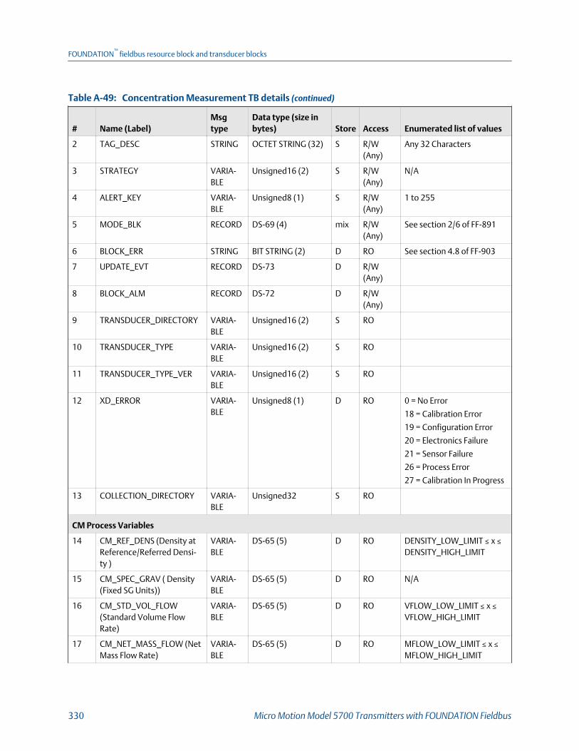
Concentration Measurement TB details (continued)Table A-49:
# Name (Label)Msgtype
Data type (size inbytes) Store Access Enumerated list of values
2 TAG_DESC STRING OCTET STRING (32) S R/W(Any)
Any 32 Characters
3 STRATEGY VARIA-BLE
Unsigned16 (2) S R/W(Any)
N/A
4 ALERT_KEY VARIA-BLE
Unsigned8 (1) S R/W(Any)
1 to 255
5 MODE_BLK RECORD DS-69 (4) mix R/W(Any)
See section 2/6 of FF-891
6 BLOCK_ERR STRING BIT STRING (2) D RO See section 4.8 of FF-903
7 UPDATE_EVT RECORD DS-73 D R/W(Any)
8 BLOCK_ALM RECORD DS-72 D R/W(Any)
9 TRANSDUCER_DIRECTORY VARIA-BLE
Unsigned16 (2) S RO
10 TRANSDUCER_TYPE VARIA-BLE
Unsigned16 (2) S RO
11 TRANSDUCER_TYPE_VER VARIA-BLE
Unsigned16 (2) S RO
12 XD_ERROR VARIA-BLE
Unsigned8 (1) D RO 0 = No Error
18 = Calibration Error
19 = Configuration Error
20 = Electronics Failure
21 = Sensor Failure
26 = Process Error
27 = Calibration In Progress
13 COLLECTION_DIRECTORY VARIA-BLE
Unsigned32 S RO
CM Process Variables
14 CM_REF_DENS (Density atReference/Referred Densi-ty )
VARIA-BLE
DS-65 (5) D RO DENSITY_LOW_LIMIT ≤ x ≤DENSITY_HIGH_LIMIT
15 CM_SPEC_GRAV ( Density(Fixed SG Units))
VARIA-BLE
DS-65 (5) D RO N/A
16 CM_STD_VOL_FLOW(Standard Volume FlowRate)
VARIA-BLE
DS-65 (5) D RO VFLOW_LOW_LIMIT ≤ x ≤VFLOW_HIGH_LIMIT
17 CM_NET_MASS_FLOW (NetMass Flow Rate)
VARIA-BLE
DS-65 (5) D RO MFLOW_LOW_LIMIT ≤ x ≤MFLOW_HIGH_LIMIT
FOUNDATION™
fieldbus resource block and transducer blocks
330 Micro Motion Model 5700 Transmitters with FOUNDATION Fieldbus
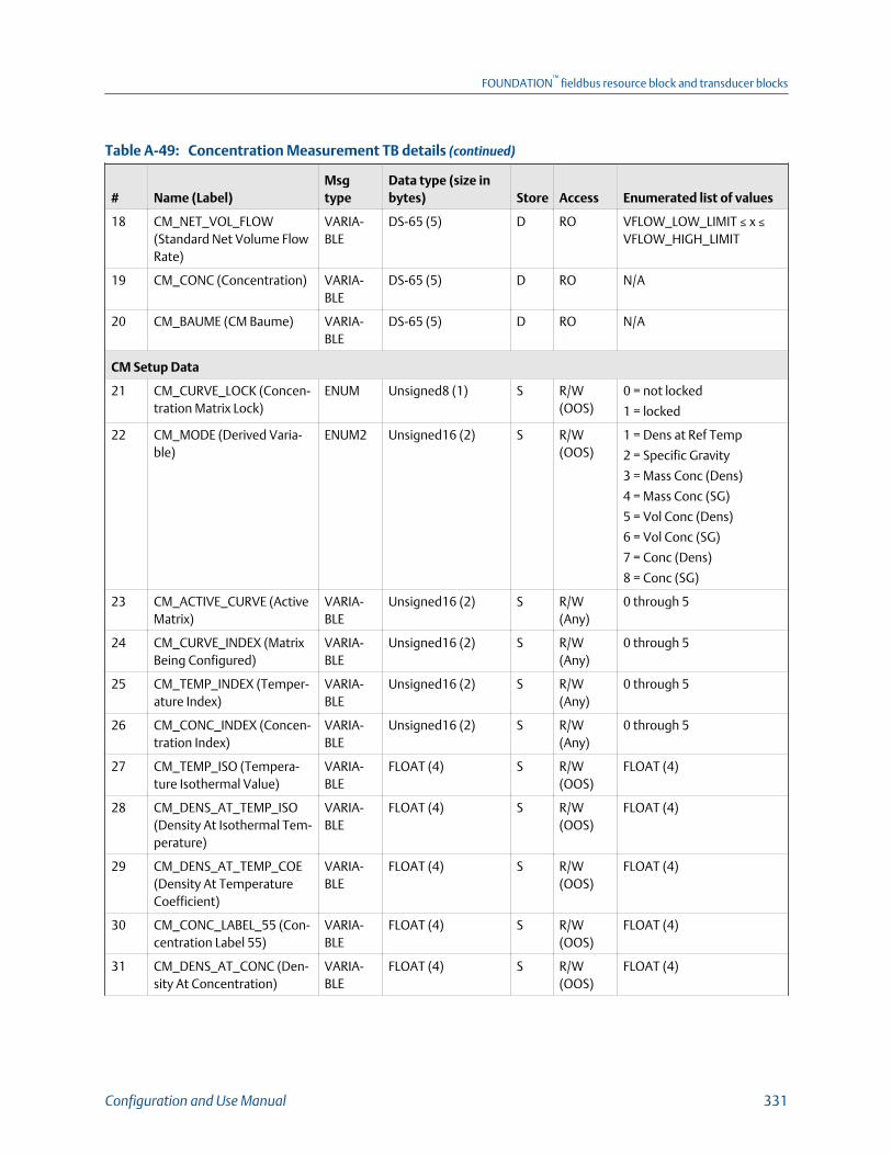
Concentration Measurement TB details (continued)Table A-49:
# Name (Label)Msgtype
Data type (size inbytes) Store Access Enumerated list of values
18 CM_NET_VOL_FLOW(Standard Net Volume FlowRate)
VARIA-BLE
DS-65 (5) D RO VFLOW_LOW_LIMIT ≤ x ≤VFLOW_HIGH_LIMIT
19 CM_CONC (Concentration) VARIA-BLE
DS-65 (5) D RO N/A
20 CM_BAUME (CM Baume) VARIA-BLE
DS-65 (5) D RO N/A
CM Setup Data
21 CM_CURVE_LOCK (Concen-tration Matrix Lock)
ENUM Unsigned8 (1) S R/W(OOS)
0 = not locked
1 = locked
22 CM_MODE (Derived Varia-ble)
ENUM2 Unsigned16 (2) S R/W(OOS)
1 = Dens at Ref Temp
2 = Specific Gravity
3 = Mass Conc (Dens)
4 = Mass Conc (SG)
5 = Vol Conc (Dens)
6 = Vol Conc (SG)
7 = Conc (Dens)
8 = Conc (SG)
23 CM_ACTIVE_CURVE (ActiveMatrix)
VARIA-BLE
Unsigned16 (2) S R/W(Any)
0 through 5
24 CM_CURVE_INDEX (MatrixBeing Configured)
VARIA-BLE
Unsigned16 (2) S R/W(Any)
0 through 5
25 CM_TEMP_INDEX (Temper-ature Index)
VARIA-BLE
Unsigned16 (2) S R/W(Any)
0 through 5
26 CM_CONC_INDEX (Concen-tration Index)
VARIA-BLE
Unsigned16 (2) S R/W(Any)
0 through 5
27 CM_TEMP_ISO (Tempera-ture Isothermal Value)
VARIA-BLE
FLOAT (4) S R/W(OOS)
FLOAT (4)
28 CM_DENS_AT_TEMP_ISO(Density At Isothermal Tem-perature)
VARIA-BLE
FLOAT (4) S R/W(OOS)
FLOAT (4)
29 CM_DENS_AT_TEMP_COE(Density At TemperatureCoefficient)
VARIA-BLE
FLOAT (4) S R/W(OOS)
FLOAT (4)
30 CM_CONC_LABEL_55 (Con-centration Label 55)
VARIA-BLE
FLOAT (4) S R/W(OOS)
FLOAT (4)
31 CM_DENS_AT_CONC (Den-sity At Concentration)
VARIA-BLE
FLOAT (4) S R/W(OOS)
FLOAT (4)
FOUNDATION™
fieldbus resource block and transducer blocks
Configuration and Use Manual 331

Concentration Measurement TB details (continued)Table A-49:
# Name (Label)Msgtype
Data type (size inbytes) Store Access Enumerated list of values
32 CM_DENS_AT_CONC_COE(Density At ConcentrationCoefficient)
VARIA-BLE
FLOAT (4) S R/W(OOS)
FLOAT (4)
33 CM_CONC_LABLE_51 (Con-centration Label 51)
VARIA-BLE
FLOAT (4) S R/W(OOS)
FLOAT (4)
34 CM_REF_TEMP (ReferenceTemperature)
VARIA-BLE
FLOAT (4) S R/W(OOS)
FLOAT (4)
35 CM_SG_WATER_REF_TEMP(Water Reference Tempera-ture)
VARIA-BLE
FLOAT (4) S R/W(OOS)
TEMP_LOW_LIMIT ≤ x ≤TEMP_HIGH_LIMIT
36 CM_SG_WATER_REF_DENS(Water Reference Density)
VARIA-BLE
FLOAT (4) S R/W(OOS)
Density Lo Limit ≤ x ≤ Densi-ty Hi Limit
37 CM_SLOPE_TRIME (SlopeTrim)
VARIA-BLE
FLOAT (4) S R/W(OOS)
0.8f ≤ x ≤ 1.2f
38 CM_SLOPE_OFFSET (OffsetTrim)
VARIA-BLE
FLOAT (4) S R/W(OOS)
FLOAT (4)
39 CM_EXTRAP_ALARM_LIMIT(Extrapolation Limit)
VARIA-BLE
FLOAT (4) S R/W(Any)
0.0f ≤ x ≤ 270.0f
40 CM_CURVE_NAME (MatrixName)
VARIA-BLE
VISIBLE STRING (12) S R/W(Any)
41 CM_MAX_FIT_ORDER (MaxFit Order)
VARIA-BLE
Unsigned16 (2) S R/W(OOS)
2, 3, 4, 5 ( Shall accept onlyenum values)
42 CM_FIT_RESULT (Curve FitResult)
ENUM2 Unsigned16 (2) S RO 0 = Good
1 = Poor
2 = Failed
3 = Empty
43 CM_EXPECTED_ACC (Expec-ted Accuracy)
VARIA-BLE
FLOAT (4) S RO
44 CM_CONC_UNITS (Concen-tration Units)
ENUM2 Unsigned16 (2) S R/W(OOS)
See Table A‐50.
Concentration Unit CodesTable A-50:
1110 = degTwad 1112 = degBaum lt 1427 = degBall 33004 = deg plato
1426 = degBrix 1343 = % sol/wt 1428 = proof/vol 253 = Special Unit
1111 = degBaum hv 1344 = % sol/vol 1429 = proof/mass
45 CM_CONC_SPEC_TEXT(Concentration Label)
STRING Visible String (8) S R/W(OOS)
FOUNDATION™
fieldbus resource block and transducer blocks
332 Micro Motion Model 5700 Transmitters with FOUNDATION Fieldbus

Concentration Measurement TB details (continued)Table A-49:
# Name (Label)Msgtype
Data type (size inbytes) Store Access Enumerated list of values
46 CM_CURVE_RESET (ResetMatrix Data)
METHOD Unsigned8 (1) S R/W(OOS)
1 = Reset
0 = None
47 CM_DENS_LO_EXTRAP_EN(Density Low)
ENUM Unsigned8 (1) S R/W(Any)
1 = Reset
0 = None
48 CM_DENS_HI_EXTRAP_EN(Density High)
ENUM Unsigned8 (1) S R/W(Any)
1 = Reset
0 = None
49 CM_TEMP_LO_EXTRAP_EN(Temperature Low)
ENUM Unsigned8 (1) S R/W(Any)
1 = Reset
0 = None
50 CM_TEMP_HI_EXTRAP_EN(Temperature High)
ENUM Unsigned8 (1) S R/W(Any)
1 = Reset
0 = None
51 CM_INC_CURVE (Curve In-crement)
VARIA-BLE
DS-66 (2) S R/W(Any)
Value part of DS-66 (2)
0 = None
1 = Increment
52 CM_TEMP_UNITS (Temper-ature Unit)
ENUM2 Unsigned16 (2) S R/W(OOS)
1000 = K
1001 = deg C
1002 = deg F
1003 = deg R
53 CM_DENS_UNITS (DensityUnit)
ENUM2 Unsigned16 (2) S R/W(OOS)
See Table A‐9.
54 CM_VFLOW_UNITS (Vol-ume Flow Unit)
ENUM2 Unsigned16 (2) S R/W(OOS)
See Table A‐8.
55 CM_MFLOW_UNITS (MassFlow Unit)
ENUM2 Unsigned16 (2) S R/W(OOS)
See Table A‐7.
56 CM_ACT_CUR_CONC_UNITS (Active Curve Con-centration Units)
ENUM2 Unsigned16 (2) S RO See Table A‐50.
57 CM_FEATURE (Concentra-tion Measurement)
ENUM Unsigned8 (1) D RO 0 = Disabled
1 = Enabled
Concentration Measurement TB viewsTable A-51:
# Name (Label)
View list
Release1 2 3 4_1 4_2
Standard FF Parameters
0 BLOCK_STRUCTURE 1.0
1 ST_REV 2 2 2 2 2 1.0
2 TAG_DESC 1.0
3 STRATEGY 2 1.0
FOUNDATION™
fieldbus resource block and transducer blocks
Configuration and Use Manual 333
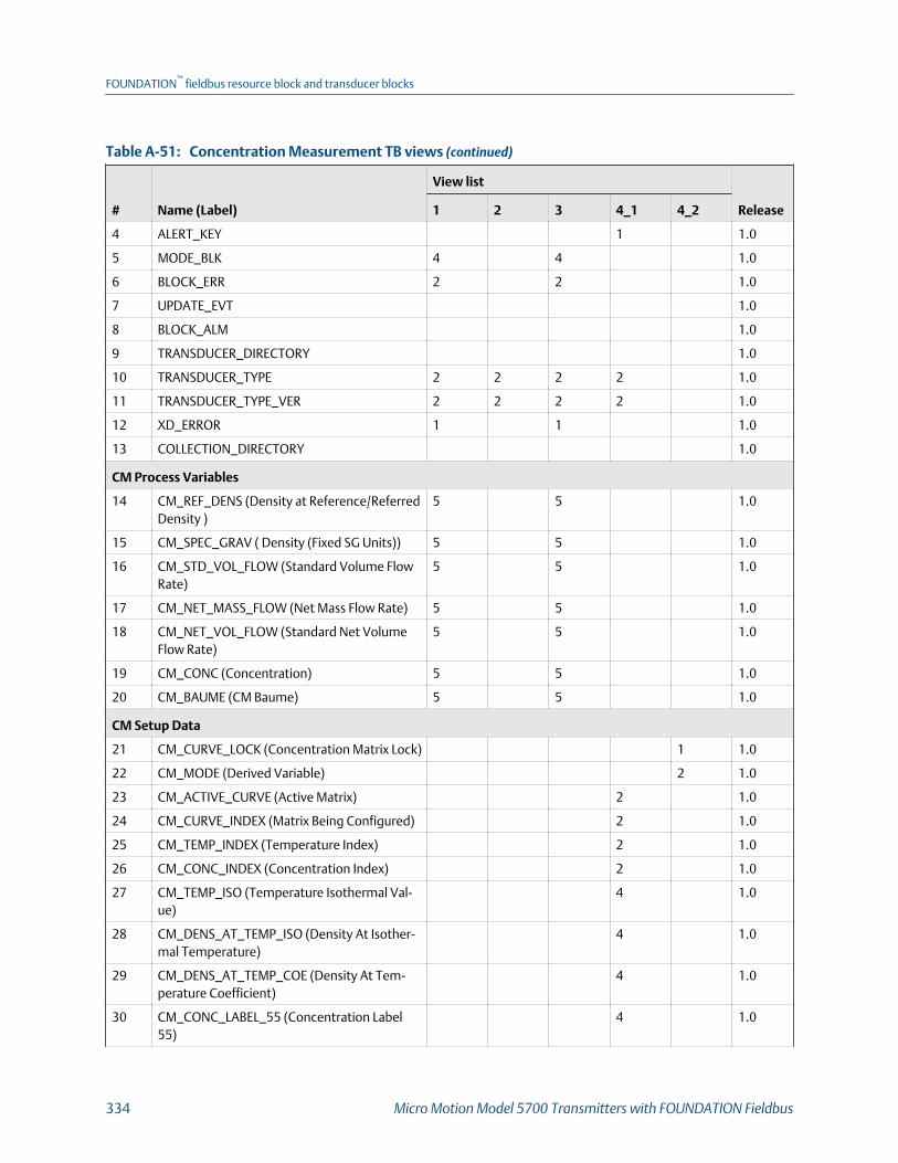
Concentration Measurement TB views (continued)Table A-51:
# Name (Label)
View list
Release1 2 3 4_1 4_2
4 ALERT_KEY 1 1.0
5 MODE_BLK 4 4 1.0
6 BLOCK_ERR 2 2 1.0
7 UPDATE_EVT 1.0
8 BLOCK_ALM 1.0
9 TRANSDUCER_DIRECTORY 1.0
10 TRANSDUCER_TYPE 2 2 2 2 1.0
11 TRANSDUCER_TYPE_VER 2 2 2 2 1.0
12 XD_ERROR 1 1 1.0
13 COLLECTION_DIRECTORY 1.0
CM Process Variables
14 CM_REF_DENS (Density at Reference/ReferredDensity )
5 5 1.0
15 CM_SPEC_GRAV ( Density (Fixed SG Units)) 5 5 1.0
16 CM_STD_VOL_FLOW (Standard Volume FlowRate)
5 5 1.0
17 CM_NET_MASS_FLOW (Net Mass Flow Rate) 5 5 1.0
18 CM_NET_VOL_FLOW (Standard Net VolumeFlow Rate)
5 5 1.0
19 CM_CONC (Concentration) 5 5 1.0
20 CM_BAUME (CM Baume) 5 5 1.0
CM Setup Data
21 CM_CURVE_LOCK (Concentration Matrix Lock) 1 1.0
22 CM_MODE (Derived Variable) 2 1.0
23 CM_ACTIVE_CURVE (Active Matrix) 2 1.0
24 CM_CURVE_INDEX (Matrix Being Configured) 2 1.0
25 CM_TEMP_INDEX (Temperature Index) 2 1.0
26 CM_CONC_INDEX (Concentration Index) 2 1.0
27 CM_TEMP_ISO (Temperature Isothermal Val-ue)
4 1.0
28 CM_DENS_AT_TEMP_ISO (Density At Isother-mal Temperature)
4 1.0
29 CM_DENS_AT_TEMP_COE (Density At Tem-perature Coefficient)
4 1.0
30 CM_CONC_LABEL_55 (Concentration Label55)
4 1.0
FOUNDATION™
fieldbus resource block and transducer blocks
334 Micro Motion Model 5700 Transmitters with FOUNDATION Fieldbus

Concentration Measurement TB views (continued)Table A-51:
# Name (Label)
View list
Release1 2 3 4_1 4_2
31 CM_DENS_AT_CONC (Density At Concentra-tion)
4 1.0
32 CM_DENS_AT_CONC_COE (Density At Con-centration Coefficient)
4 1.0
33 CM_CONC_LABLE_51 (Concentration Label51)
4 1.0
34 CM_REF_TEMP (Reference Temperature) 4 1.0
35 CM_SG_WATER_REF_TEMP (Water ReferenceTemperature)
4 1.0
36 CM_SG_WATER_REF_DENS (Water ReferenceDensity)
4 1.0
37 CM_SLOPE_TRIME (Slope Trim) 4 1.0
38 CM_SLOPE_OFFSET (Offset Trim) 4 1.0
39 CM_EXTRAP_ALARM_LIMIT (ExtrapolationLimit)
4 1.0
40 CM_CURVE_NAME (Matrix Name) 12 1.0
41 CM_MAX_FIT_ORDER (Max Fit Order) 2 1.0
42 CM_FIT_RESULT (Curve Fit Result) 2 1.0
43 CM_EXPECTED_ACC (Expected Accuracy) 4 1.0
44 CM_CONC_UNITS (Concentration Units) 2 1.0
45 CM_CONC_SPEC_TEXT (Concentra-tion Label)
8 1.0
46 CM_CURVE_RESET (Reset Matrix Data) 1 1.0
47 CM_DENS_LO_EXTRAP_EN (Density Low) 1 1.0
48 CM_DENS_HI_EXTRAP_EN (Density High) 1 1.0
49 CM_TEMP_LO_EXTRAP_EN (TemperatureLow)
1 1.0
50 CM_TEMP_HI_EXTRAP_EN (TemperatureHigh)
1 1.0
51 CM_INC_CURVE (Curve Increment) 2 1.0
52 CM_TEMP_UNITS (Temperature Unit) 2 1.0
53 CM_DENS_UNITS (Density Unit) 2 1.0
54 CM_VFLOW_UNITS (Volume Flow Unit) 2 1.0
55 CM_MFLOW_UNITS (Mass Flow Unit) 2 1.0
56 CM_ACT_CUR_CONC_UNITS (Active CurveConcentration Units)
2 1.0
FOUNDATION™
fieldbus resource block and transducer blocks
Configuration and Use Manual 335

Concentration Measurement TB views (continued)Table A-51:
# Name (Label)
View list
Release1 2 3 4_1 4_2
57 CM_FEATURE (Concentration Measurement) 1 1 1.0
A.2.7 Advanced Phase Measurement transducer block
Advanced Phase Measurement TB detailsTable A-52:
# Name (Label)Msgtype
Data type (size inbytes) Store Access Enumerated list of values
Standard FF Parameters
0 BLOCK_STRUCTURE VAR DS-64 S R/W(Any)
N/A
1 ST_REV VAR Unsigned16 (2) S RO N/A
2 TAG_DESC STR OCTET STRING (32) S R/W(Any)
Any 32 Characters
3 STRATEGY VAR Unsigned16 (2) S R/W(Any)
N/A
4 ALERT_KEY VAR Unsigned8 (1) S R/W(Any)
1 to 255
5 MODE_BLK REC DS-69 (4) mix R/W(Any)
See section 2/6 of FF-891
6 BLOCK_ERR STR BIT STRING (2) D RO See section 4.8 of FF-903
7 UPDATE_EVT REC DS-73 D R/W(Any)
8 BLOCK_ALM RECORD DS-72 D R/W(Any)
9 TRANSDUCER_DIRECTORY VAR Unsigned16 (2) S RO
10 TRANSDUCER_TYPE VAR Unsigned16 (2) S RO
11 TRANSDUCER_TYPE_VER VAR Unsigned16 (2) S RO
12 XD_ERROR VAR Unsigned8 (1) D RO 0 = No Error
18 = Calibration Error
19 = Configuration Error
20 = Electronics Failure
21 = Sensor Failure
26 = Process Error
27 = Calibration In Progress
13 COLLECTION_DIRECTORY VAR Unsigned32 S RO
FOUNDATION™
fieldbus resource block and transducer blocks
336 Micro Motion Model 5700 Transmitters with FOUNDATION Fieldbus

Advanced Phase Measurement TB details (continued)Table A-52:
# Name (Label)Msgtype
Data type (size inbytes) Store Access Enumerated list of values
Net Oil Variables
14 NET_OIL_FLOW_REF (NetOil Flow at Reference)
VAR DS-65 (5) D RO
15 NET_WATER_FLOW_REF(Net Water Flow at Refer-ence)
VAR DS-65 (5) D RO
16 NET_OIL_FLOW_LINE (NetOil Flow at Line)
VAR DS-65 (5) D RO
17 WATERCUT_LINE (Watercutat Line)
VAR DS-65 (5) D RO
18 WATERCUT_REF (Watercutat Reference)
VAR DS-65 (5) D RO
19 WATER_FLOW_LINE (NetWater Flow at Line)
VAR DS-65 (5) D RO
20 GAS_VOID_FRACTION (GasVoid Fraction)
VAR DS-65 (5) D RO
21 OIL_DENSITY_LINE_SGU(Density Oil at Line (Fixed SGUnits))
VAR DS-65 (5) D RO
22 OIL_DENSITY_LINE_API( Density Oil at Line (FixedAPI Units))
VAR DS-65 (5) D RO
Net Oil Configuration
23 PAO_ACTION (Net Oil Ac-tion)
ENUM2 Unsigned16 (2) S R/W(OOS)
0 = Liquid Density
1 = Oil Density@Line
24 PAO_FLUID_TYPE (FluidType)
ENUM2 Unsigned16 (2) S R/W(OOS)
0 = Disable
1 = Liquid with Gas
2 = NetOil 3 = Gas with Liq-uid
25 PAO_PRODUCTION_TYPE(Production Type)
ENUM2 Unsigned16 (2) S R/W(OOS)
0 = Continueous Flow
1 = Variable Flow
26 PAO_PERIOD (Interval) VAR Unsigned16 (2) S R/W(OOS)
1 ≤ x ≤ 1440
27 DRY_OIL_DENSITY_REF (DryOil Density at Reference)
VAR FLOAT (4) S R/W(Any)
0.2 ≤ x ≤ 1.5
28 WATER_DENSITY_REF (Wa-ter Density at Reference)
VAR FLOAT (4) S R/W(Any)
0.5 ≤ x ≤ 1.5
29 REF_TEMPERATURE (Refer-ence Temperature)
VAR FLOAT (4) S R/W(Any)
-50 ≤ x ≤ 150 degC
FOUNDATION™
fieldbus resource block and transducer blocks
Configuration and Use Manual 337
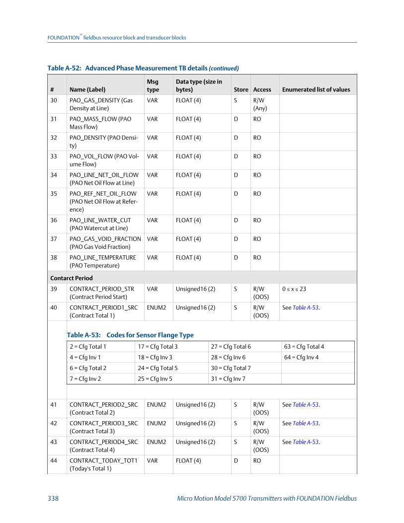
Advanced Phase Measurement TB details (continued)Table A-52:
# Name (Label)Msgtype
Data type (size inbytes) Store Access Enumerated list of values
30 PAO_GAS_DENSITY (GasDensity at Line)
VAR FLOAT (4) S R/W(Any)
31 PAO_MASS_FLOW (PAOMass Flow)
VAR FLOAT (4) D RO
32 PAO_DENSITY (PAO Densi-ty)
VAR FLOAT (4) D RO
33 PAO_VOL_FLOW (PAO Vol-ume Flow)
VAR FLOAT (4) D RO
34 PAO_LINE_NET_OIL_FLOW(PAO Net Oil Flow at Line)
VAR FLOAT (4) D RO
35 PAO_REF_NET_OIL_FLOW(PAO Net Oil Flow at Refer-ence)
VAR FLOAT (4) D RO
36 PAO_LINE_WATER_CUT(PAO Watercut at Line)
VAR FLOAT (4) D RO
37 PAO_GAS_VOID_FRACTION(PAO Gas Void Fraction)
VAR FLOAT (4) D RO
38 PAO_LINE_TEMPERATURE(PAO Temperature)
VAR FLOAT (4) D RO
Contarct Period
39 CONTRACT_PERIOD_STR(Contract Period Start)
VAR Unsigned16 (2) S R/W(OOS)
0 ≤ x ≤ 23
40 CONTRACT_PERIOD1_SRC(Contract Total 1)
ENUM2 Unsigned16 (2) S R/W(OOS)
See Table A‐53.
Codes for Sensor Flange TypeTable A-53:
2 = Cfg Total 1 17 = Cfg Total 3 27 = Cfg Total 6 63 = Cfg Total 4
4 = Cfg Inv 1 18 = Cfg Inv 3 28 = Cfg Inv 6 64 = Cfg Inv 4
6 = Cfg Total 2 24 = Cfg Total 5 30 = Cfg Total 7
7 = Cfg Inv 2 25 = Cfg Inv 5 31 = Cfg Inv 7
41 CONTRACT_PERIOD2_SRC(Contract Total 2)
ENUM2 Unsigned16 (2) S R/W(OOS)
See Table A‐53.
42 CONTRACT_PERIOD3_SRC(Contract Total 3)
ENUM2 Unsigned16 (2) S R/W(OOS)
See Table A‐53.
43 CONTRACT_PERIOD4_SRC(Contract Total 4)
ENUM2 Unsigned16 (2) S R/W(OOS)
See Table A‐53.
44 CONTRACT_TODAY_TOT1(Today's Total 1)
VAR FLOAT (4) D RO
FOUNDATION™
fieldbus resource block and transducer blocks
338 Micro Motion Model 5700 Transmitters with FOUNDATION Fieldbus

Advanced Phase Measurement TB details (continued)Table A-52:
# Name (Label)Msgtype
Data type (size inbytes) Store Access Enumerated list of values
45 CONTRACT_TODAY_TOT2(Today's Total 2)
VAR FLOAT (4) D RO
46 CONTRACT_TODAY_TOT3(Today's Total 3)
VAR FLOAT (4) D RO
47 CONTRACT_TODAY_TOT4(Today's Total 4)
VAR FLOAT (4) D RO
48 CONTRACT_YESTERDAY_TOT1 (Yesterday's Total 1)
VAR FLOAT (4) S RO
49 CONTRACT_YESTERDAY_TOT2 (Yesterday's Total 2)
VAR FLOAT (4) S RO
50 CONTRACT_YESTERDAY_TOT3 (Yesterday's Total 3)
VAR FLOAT (4) S RO
51 CONTRACT_YESTERDAY_TOT4 (Yesterday's Total 4)
VAR FLOAT (4) S RO
52 CONTRACT_TOT1_UNITS(Total1 Unit)
ENUM2 Unsigned16 (2) S RO
53 CONTRACT_TOT2_UNITS(Total2 Unit)
ENUM2 Unsigned16 (2) S RO
54 CONTRACT_TOT3_UNITS(Total3 Unit)
ENUM2 Unsigned16 (2) S RO
55 CONTRACT_TOT4_UNITS(Total4 Unit)
ENUM2 Unsigned16 (2) S RO
TMR
56 PRE_EVENT_PERIOD (Pre-Mist Average Period)
VAR Unsigned16 (2) S R/W(OOS)
(2 ≤ x ≤ 128)
57 POST_EVENT_PERIOD (Post-Mist Average Period)
VAR Unsigned16 (2) S R/W(OOS)
(2 ≤ x ≤ 128)
58 TMR_ACTIVE_TIME (MistDuration)
VAR Unsigned32 D RO
Units
59 APM_MASS_FLOW_UNITS(Mass Flow Units)
ENUM2 Unsigned16 (2) S R/W(OOS)
See Table A‐7.
60 APM_VOL_FLOW_UNITS(Volume Flow Units)
ENUM2 Unsigned16 (2) S R/W(OOS)
See Table A‐8.
61 APM_DENSITY_UNITS (Den-sity Units)
ENUM2 Unsigned16 (2) S R/W(OOS)
See Table A‐9.
FOUNDATION™
fieldbus resource block and transducer blocks
Configuration and Use Manual 339
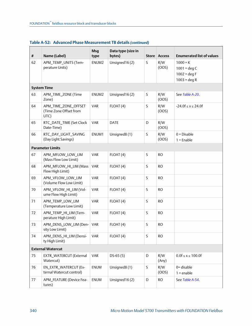
Advanced Phase Measurement TB details (continued)Table A-52:
# Name (Label)Msgtype
Data type (size inbytes) Store Access Enumerated list of values
62 APM_TEMP_UNITS (Tem-perature Units)
ENUM2 Unsigned16 (2) S R/W(OOS)
1000 = K
1001 = deg C
1002 = deg F
1003 = deg R
System Time
63 APM_TIME_ZONE (TimeZone)
ENUM2 Unsigned16 (2) S R/W(OOS)
See Table A‐20.
64 APM_TIME_ZONE_OFFSET(Time Zone Offset fromUTC)
VAR FLOAT (4) S R/W(OOS)
-24.0f ≤ x ≤ 24.0f
65 RTC_DATE_TIME (Set ClockDate-Time)
VAR DATE D R/W(OOS)
66 RTC_DAY_LIGHT_SAVING(Day Light Savings)
ENUM1 Unsigned8 (1) S R/W(OOS)
0 = Disable
1 = Enable
Parameter Limits
67 APM_MFLOW_LOW_LIM(Mass Flow Low Limit)
VAR FLOAT (4) S RO
68 APM_MFLOW_HI_LIM (MassFlow High Limit)
VAR FLOAT (4) S RO
69 APM_VFLOW_LOW_LIM(Volume Flow Low Limit)
VAR FLOAT (4) S RO
70 APM_VFLOW_HI_LIM (Vol-ume Flow High Limit)
VAR FLOAT (4) S RO
71 APM_TEMP_LOW_LIM(Temperature Low Limit)
VAR FLOAT (4) S RO
72 APM_TEMP_HI_LIM (Tem-perature High Limit)
VAR FLOAT (4) S RO
73 APM_DENS_LOW_LIM (Den-sity Low Limit)
VAR FLOAT (4) S RO
74 APM_DENS_HI_LIM (Densi-ty High Limit)
VAR FLOAT (4) S RO
External Watercut
75 EXTR_WATERCUT (ExternalWatercut)
VAR DS-65 (5) D R/W(Any)
0.0f ≤ x ≤ 100.0f
76 EN_EXTR_WATERCUT (Ex-ternal Watercut control)
ENUM Unsigned8 (1) S R/W(OOS)
0= disable
1 = enable
77 APM_FEATURE (Device Fea-tures)
ENUM Unsigned16 (2) D RO See Table A‐54.
FOUNDATION™
fieldbus resource block and transducer blocks
340 Micro Motion Model 5700 Transmitters with FOUNDATION Fieldbus
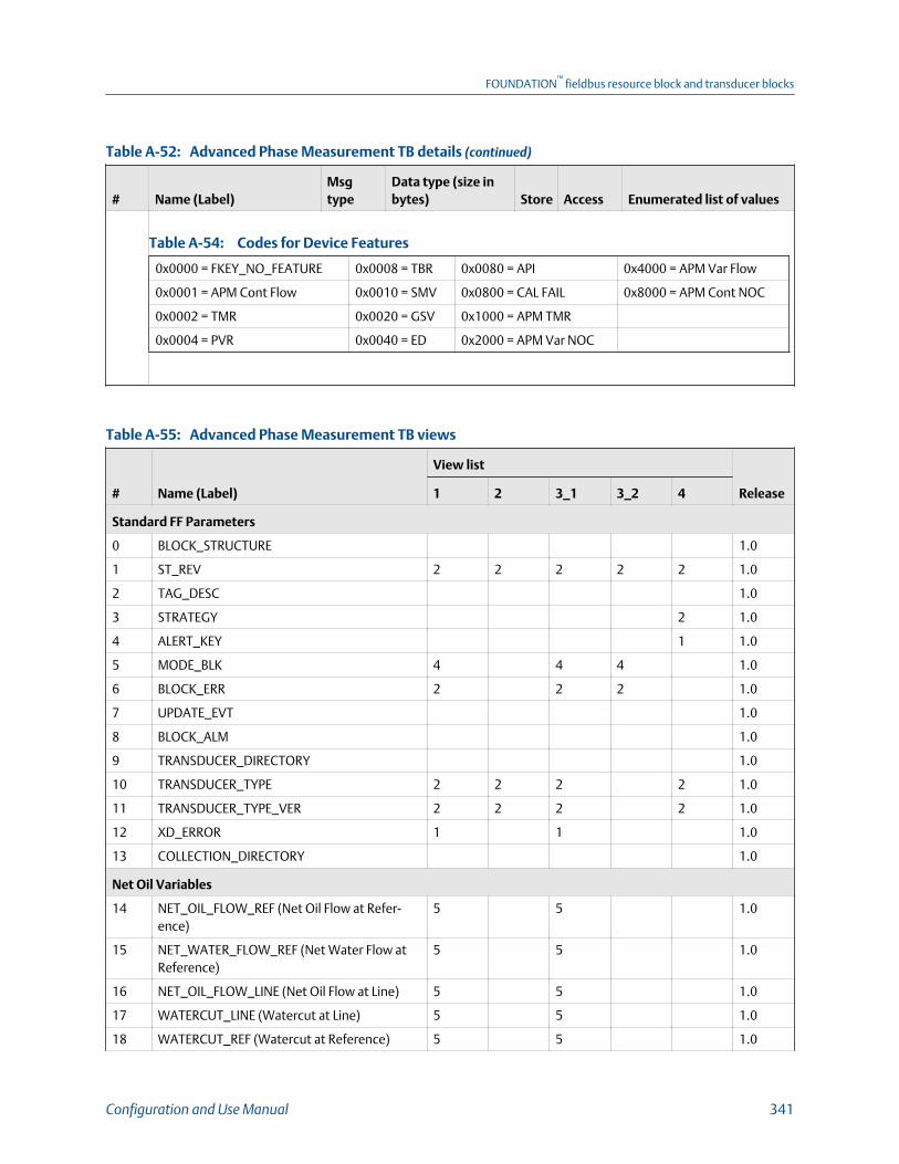
Advanced Phase Measurement TB details (continued)Table A-52:
# Name (Label)Msgtype
Data type (size inbytes) Store Access Enumerated list of values
Codes for Device FeaturesTable A-54:
0x0000 = FKEY_NO_FEATURE 0x0008 = TBR 0x0080 = API 0x4000 = APM Var Flow
0x0001 = APM Cont Flow 0x0010 = SMV 0x0800 = CAL FAIL 0x8000 = APM Cont NOC
0x0002 = TMR 0x0020 = GSV 0x1000 = APM TMR
0x0004 = PVR 0x0040 = ED 0x2000 = APM Var NOC
Advanced Phase Measurement TB viewsTable A-55:
# Name (Label)
View list
Release1 2 3_1 3_2 4
Standard FF Parameters
0 BLOCK_STRUCTURE 1.0
1 ST_REV 2 2 2 2 2 1.0
2 TAG_DESC 1.0
3 STRATEGY 2 1.0
4 ALERT_KEY 1 1.0
5 MODE_BLK 4 4 4 1.0
6 BLOCK_ERR 2 2 2 1.0
7 UPDATE_EVT 1.0
8 BLOCK_ALM 1.0
9 TRANSDUCER_DIRECTORY 1.0
10 TRANSDUCER_TYPE 2 2 2 2 1.0
11 TRANSDUCER_TYPE_VER 2 2 2 2 1.0
12 XD_ERROR 1 1 1.0
13 COLLECTION_DIRECTORY 1.0
Net Oil Variables
14 NET_OIL_FLOW_REF (Net Oil Flow at Refer-ence)
5 5 1.0
15 NET_WATER_FLOW_REF (Net Water Flow atReference)
5 5 1.0
16 NET_OIL_FLOW_LINE (Net Oil Flow at Line) 5 5 1.0
17 WATERCUT_LINE (Watercut at Line) 5 5 1.0
18 WATERCUT_REF (Watercut at Reference) 5 5 1.0
FOUNDATION™
fieldbus resource block and transducer blocks
Configuration and Use Manual 341
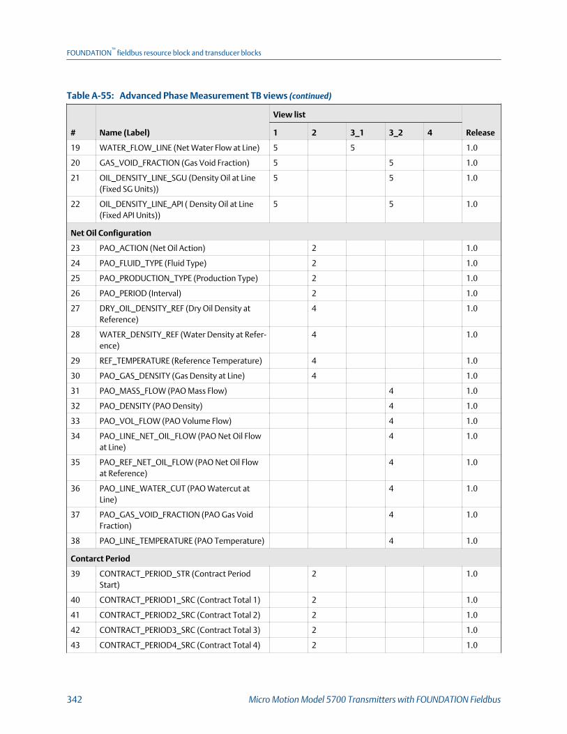
Advanced Phase Measurement TB views (continued)Table A-55:
# Name (Label)
View list
Release1 2 3_1 3_2 4
19 WATER_FLOW_LINE (Net Water Flow at Line) 5 5 1.0
20 GAS_VOID_FRACTION (Gas Void Fraction) 5 5 1.0
21 OIL_DENSITY_LINE_SGU (Density Oil at Line(Fixed SG Units))
5 5 1.0
22 OIL_DENSITY_LINE_API ( Density Oil at Line(Fixed API Units))
5 5 1.0
Net Oil Configuration
23 PAO_ACTION (Net Oil Action) 2 1.0
24 PAO_FLUID_TYPE (Fluid Type) 2 1.0
25 PAO_PRODUCTION_TYPE (Production Type) 2 1.0
26 PAO_PERIOD (Interval) 2 1.0
27 DRY_OIL_DENSITY_REF (Dry Oil Density atReference)
4 1.0
28 WATER_DENSITY_REF (Water Density at Refer-ence)
4 1.0
29 REF_TEMPERATURE (Reference Temperature) 4 1.0
30 PAO_GAS_DENSITY (Gas Density at Line) 4 1.0
31 PAO_MASS_FLOW (PAO Mass Flow) 4 1.0
32 PAO_DENSITY (PAO Density) 4 1.0
33 PAO_VOL_FLOW (PAO Volume Flow) 4 1.0
34 PAO_LINE_NET_OIL_FLOW (PAO Net Oil Flowat Line)
4 1.0
35 PAO_REF_NET_OIL_FLOW (PAO Net Oil Flowat Reference)
4 1.0
36 PAO_LINE_WATER_CUT (PAO Watercut atLine)
4 1.0
37 PAO_GAS_VOID_FRACTION (PAO Gas VoidFraction)
4 1.0
38 PAO_LINE_TEMPERATURE (PAO Temperature) 4 1.0
Contarct Period
39 CONTRACT_PERIOD_STR (Contract PeriodStart)
2 1.0
40 CONTRACT_PERIOD1_SRC (Contract Total 1) 2 1.0
41 CONTRACT_PERIOD2_SRC (Contract Total 2) 2 1.0
42 CONTRACT_PERIOD3_SRC (Contract Total 3) 2 1.0
43 CONTRACT_PERIOD4_SRC (Contract Total 4) 2 1.0
FOUNDATION™
fieldbus resource block and transducer blocks
342 Micro Motion Model 5700 Transmitters with FOUNDATION Fieldbus

Advanced Phase Measurement TB views (continued)Table A-55:
# Name (Label)
View list
Release1 2 3_1 3_2 4
44 CONTRACT_TODAY_TOT1 (Today's Total 1) 4 1.0
45 CONTRACT_TODAY_TOT2 (Today's Total 2) 4 1.0
46 CONTRACT_TODAY_TOT3 (Today's Total 3) 4 1.0
47 CONTRACT_TODAY_TOT4 (Today's Total 4) 4 1.0
48 CONTRACT_YESTERDAY_TOT1 (Yesterday'sTotal 1)
4 1.0
49 CONTRACT_YESTERDAY_TOT2 (Yesterday'sTotal 2)
4 1.0
50 CONTRACT_YESTERDAY_TOT3 (Yesterday'sTotal 3)
4 1.0
51 CONTRACT_YESTERDAY_TOT4 (Yesterday'sTotal 4)
4 1.0
52 CONTRACT_TOT1_UNITS (Total1 Unit) 2 1.0
53 CONTRACT_TOT2_UNITS (Total2 Unit) 2 1.0
54 CONTRACT_TOT3_UNITS (Total3 Unit) 2 1.0
55 CONTRACT_TOT4_UNITS (Total4 Unit) 2 1.0
TMR
56 PRE_EVENT_PERIOD (Pre-Mist Average Period) 2 1.0
57 POST_EVENT_PERIOD (Post-Mist Average Peri-od)
2 1.0
58 TMR_ACTIVE_TIME (Mist Duration) 4 1.0
Units
59 APM_MASS_FLOW_UNITS (Mass Flow Units) 2 1.0
60 APM_VOL_FLOW_UNITS (Volume Flow Units) 2 1.0
61 APM_DENSITY_UNITS (Density Units) 2 1.0
62 APM_TEMP_UNITS (Temperature Units) 2 1.0
System Time
63 APM_TIME_ZONE (Time Zone) 2 1.0
64 APM_TIME_ZONE_OFFSET (Time Zone Offsetfrom UTC)
4 1.0
65 RTC_DATE_TIME (Set Clock Date-Time) 7 1.0
66 RTC_DAY_LIGHT_SAVING (Day Light Savings) 1 1.0
Parameter Limits
67 APM_MFLOW_LOW_LIM (Mass Flow Low Lim-it)
4 1.0
68 APM_MFLOW_HI_LIM (Mass Flow High Limit) 4 1.0
FOUNDATION™
fieldbus resource block and transducer blocks
Configuration and Use Manual 343
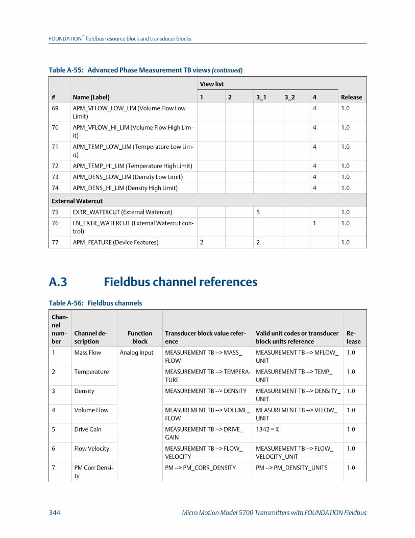
Advanced Phase Measurement TB views (continued)Table A-55:
# Name (Label)
View list
Release1 2 3_1 3_2 4
69 APM_VFLOW_LOW_LIM (Volume Flow LowLimit)
4 1.0
70 APM_VFLOW_HI_LIM (Volume Flow High Lim-it)
4 1.0
71 APM_TEMP_LOW_LIM (Temperature Low Lim-it)
4 1.0
72 APM_TEMP_HI_LIM (Temperature High Limit) 4 1.0
73 APM_DENS_LOW_LIM (Density Low Limit) 4 1.0
74 APM_DENS_HI_LIM (Density High Limit) 4 1.0
External Watercut
75 EXTR_WATERCUT (External Watercut) 5 1.0
76 EN_EXTR_WATERCUT (External Watercut con-trol)
1 1.0
77 APM_FEATURE (Device Features) 2 2 1.0
A.3 Fieldbus channel references
Fieldbus channelsTable A-56:
Chan-nelnum-ber
Channel de-scription
Functionblock
Transducer block value refer-ence
Valid unit codes or transducerblock units reference
Re-lease
1 Mass Flow Analog Input MEASUREMENT TB --> MASS_FLOW
MEASUREMENT TB --> MFLOW_UNIT
1.0
2 Temperature MEASUREMENT TB --> TEMPERA-TURE
MEASUREMENT TB --> TEMP_UNIT
1.0
3 Density MEASUREMENT TB --> DENSITY MEASUREMENT TB --> DENSITY_UNIT
1.0
4 Volume Flow MEASUREMENT TB --> VOLUME_FLOW
MEASUREMENT TB --> VFLOW_UNIT
1.0
5 Drive Gain MEASUREMENT TB --> DRIVE_GAIN
1342 = % 1.0
6 Flow Velocity MEASUREMENT TB --> FLOW_VELOCITY
MEASUREMENT TB --> FLOW_VELOCITY_UNIT
1.0
7 PM Corr Densi-ty
PM --> PM_CORR_DENSITY PM --> PM_DENSITY_UNITS 1.0
FOUNDATION™
fieldbus resource block and transducer blocks
344 Micro Motion Model 5700 Transmitters with FOUNDATION Fieldbus
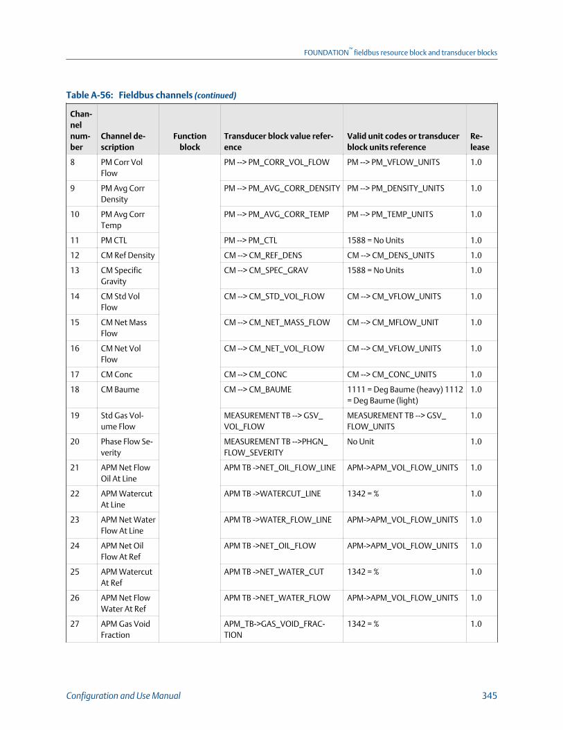
Fieldbus channels (continued)Table A-56:
Chan-nelnum-ber
Channel de-scription
Functionblock
Transducer block value refer-ence
Valid unit codes or transducerblock units reference
Re-lease
8 PM Corr VolFlow
PM --> PM_CORR_VOL_FLOW PM --> PM_VFLOW_UNITS 1.0
9 PM Avg CorrDensity
PM --> PM_AVG_CORR_DENSITY PM --> PM_DENSITY_UNITS 1.0
10 PM Avg CorrTemp
PM --> PM_AVG_CORR_TEMP PM --> PM_TEMP_UNITS 1.0
11 PM CTL PM --> PM_CTL 1588 = No Units 1.0
12 CM Ref Density CM --> CM_REF_DENS CM --> CM_DENS_UNITS 1.0
13 CM SpecificGravity
CM --> CM_SPEC_GRAV 1588 = No Units 1.0
14 CM Std VolFlow
CM --> CM_STD_VOL_FLOW CM --> CM_VFLOW_UNITS 1.0
15 CM Net MassFlow
CM --> CM_NET_MASS_FLOW CM --> CM_MFLOW_UNIT 1.0
16 CM Net VolFlow
CM --> CM_NET_VOL_FLOW CM --> CM_VFLOW_UNITS 1.0
17 CM Conc CM --> CM_CONC CM --> CM_CONC_UNITS 1.0
18 CM Baume CM --> CM_BAUME 1111 = Deg Baume (heavy) 1112= Deg Baume (light)
1.0
19 Std Gas Vol-ume Flow
MEASUREMENT TB --> GSV_VOL_FLOW
MEASUREMENT TB --> GSV_FLOW_UNITS
1.0
20 Phase Flow Se-verity
MEASUREMENT TB -->PHGN_FLOW_SEVERITY
No Unit 1.0
21 APM Net FlowOil At Line
APM TB ->NET_OIL_FLOW_LINE APM->APM_VOL_FLOW_UNITS 1.0
22 APM WatercutAt Line
APM TB ->WATERCUT_LINE 1342 = % 1.0
23 APM Net WaterFlow At Line
APM TB ->WATER_FLOW_LINE APM->APM_VOL_FLOW_UNITS 1.0
24 APM Net OilFlow At Ref
APM TB ->NET_OIL_FLOW APM->APM_VOL_FLOW_UNITS 1.0
25 APM WatercutAt Ref
APM TB ->NET_WATER_CUT 1342 = % 1.0
26 APM Net FlowWater At Ref
APM TB ->NET_WATER_FLOW APM->APM_VOL_FLOW_UNITS 1.0
27 APM Gas VoidFraction
APM_TB->GAS_VOID_FRAC-TION
1342 = % 1.0
FOUNDATION™
fieldbus resource block and transducer blocks
Configuration and Use Manual 345
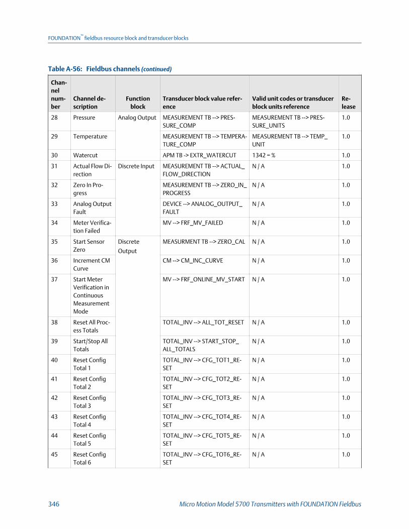
Fieldbus channels (continued)Table A-56:
Chan-nelnum-ber
Channel de-scription
Functionblock
Transducer block value refer-ence
Valid unit codes or transducerblock units reference
Re-lease
28 Pressure Analog Output MEASUREMENT TB --> PRES-SURE_COMP
MEASUREMENT TB --> PRES-SURE_UNITS
1.0
29 Temperature MEASUREMENT TB --> TEMPERA-TURE_COMP
MEASUREMENT TB --> TEMP_UNIT
1.0
30 Watercut APM TB -> EXTR_WATERCUT 1342 = % 1.0
31 Actual Flow Di-rection
Discrete Input MEASUREMENT TB --> ACTUAL_FLOW_DIRECTION
N / A 1.0
32 Zero In Pro-gress
MEASUREMENT TB --> ZERO_IN_PROGRESS
N / A 1.0
33 Analog OutputFault
DEVICE --> ANALOG_OUTPUT_FAULT
N / A 1.0
34 Meter Verifica-tion Failed
MV --> FRF_MV_FAILED N / A 1.0
35 Start SensorZero
Discrete
Output
MEASURMENT TB --> ZERO_CAL N / A 1.0
36 Increment CMCurve
CM --> CM_INC_CURVE N / A 1.0
37 Start MeterVerification inContinuousMeasurementMode
MV --> FRF_ONLINE_MV_START N / A 1.0
38 Reset All Proc-ess Totals
TOTAL_INV --> ALL_TOT_RESET N / A 1.0
39 Start/Stop AllTotals
TOTAL_INV --> START_STOP_ALL_TOTALS
N / A 1.0
40 Reset ConfigTotal 1
TOTAL_INV --> CFG_TOT1_RE-SET
N / A 1.0
41 Reset ConfigTotal 2
TOTAL_INV --> CFG_TOT2_RE-SET
N / A 1.0
42 Reset ConfigTotal 3
TOTAL_INV --> CFG_TOT3_RE-SET
N / A 1.0
43 Reset ConfigTotal 4
TOTAL_INV --> CFG_TOT4_RE-SET
N / A 1.0
44 Reset ConfigTotal 5
TOTAL_INV --> CFG_TOT5_RE-SET
N / A 1.0
45 Reset ConfigTotal 6
TOTAL_INV --> CFG_TOT6_RE-SET
N / A 1.0
FOUNDATION™
fieldbus resource block and transducer blocks
346 Micro Motion Model 5700 Transmitters with FOUNDATION Fieldbus
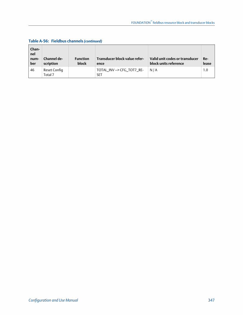
Fieldbus channels (continued)Table A-56:
Chan-nelnum-ber
Channel de-scription
Functionblock
Transducer block value refer-ence
Valid unit codes or transducerblock units reference
Re-lease
46 Reset ConfigTotal 7
TOTAL_INV --> CFG_TOT7_RE-SET
N / A 1.0
FOUNDATION™
fieldbus resource block and transducer blocks
Configuration and Use Manual 347

FOUNDATION™
fieldbus resource block and transducer blocks
348 Micro Motion Model 5700 Transmitters with FOUNDATION Fieldbus

Appendix BFOUNDATION™ fieldbus function blocks
Topics covered in this appendix:
• Analog Input (AI) function block
• Analog Output (AO) function block
• Integrator (INT) Function Block
• Discrete Input (DI) function block
• Discrete Output (DO) function block
B.1 Analog Input (AI) function block
The Analog Input (AI) Function Block processes the measurement from the TransducerBlock and makes it available to other function blocks. The output value from the AI block isin engineering units and contains a status indicating the quality of the measurement. TheAI block supports alarming, signal scaling, signal filtering, signal status calculation, modecontrol, and simulation. In Automatic mode, the block’s output parameter (OUT) reflectsthe process variable (PV) value and status. In Manual mode, OUT may be set manually. TheManual mode is reflected on the output status. A discrete output (OUT_D) is provided toindicate whether a selected alarm condition is active. Alarm detection is based on the OUTvalue and user specified alarm limits.
B.1.1 AI block configuration parameters• CHANNEL: The CHANNEL value is used to select the measurement value. Configure
the CHANNEL parameter before configuring the XD_SCALE parameter.
• L_TYPE: Linearization type. Determines whether the field value is used directly(Direct), is converted linearly (Indirect), or is converted with the square root(Indirect Square Root).
• XD_SCALE: The high and low scale values, engineering units code, and number ofdigits to the right of the decimal point associated with the channel input value. TheXD_SCALE units code must match the units code of the measurement channel in thetransducer block. If the units do not match, the block will not transition to MAN orAUTO.
FOUNDATION™
fieldbus function blocks
Configuration and Use Manual 349

• OUT_SCALE: The high and low scale values, engineering units code, and number ofdigits to the right of the decimal point associated with OUT when L_TYPE is notdirect.
• SIMULATE: A group of data that contains the current transducer value and status,the simulated transducer value and status, and the enable/disable bit.
• PV_FTIME: The time constant of the first-order PV filter. It is the time required for a63% change in the IN value.
• LOW_CUT: If percentage value of transducer input fails below this, PV = 0.
• LOW_LIM: The setting for the alarm limit used to detect the LO alarm condition forprocess variable in EU of PV_SCALE.
• LO_PRI: The priority of the LO alarm.
• HI_LIM: The setting for the alarm limit used to detect the HI alarm condition forprocess variable in EU of PV_SCALE.
• HI_PRI: The priority of the HI alarm.
• ALARM_HYS: The percent amount the alarm value must return within the alarmlimit before the associated active alarm condition clears.
B.1.2 AI block modesThe AI Function Block supports three modes of operation as defined by the MODE_BLKparameter:
• Manual (Man): The block output (OUT) may be set manually.
• Automatic (Auto): OUT reflects the analog input measurement or the simulatedvalue when simulation is enabled.
• Out of Service (O/S): The block is not processed. FIELD_VAL and PV are not updatedand the OUT status is set to Bad: Out of Service. The BLOCK_ERR parameter showsOut of Service. In this mode, you can make changes to all configured parameters.The target mode of a block may be restricted to one or more of the supportedmodes.
B.1.3 AI block simulationTo support testing, either change the mode of the block to manual and adjust the outputvalue, or enable simulation through the configuration tool and manually enter a value forthe measurement value and its status. To enable simulation, the Simulation switch has tobe ON. With simulation enabled, the actual measurement value has no impact on the OUTvalue or the status.
NoteThe transmitter has a simulation switch on the display. As a safety measure, the switch has to bereset every time there is a power interruption. This measure is to prevent devices that went throughsimulation in the staging process from being installed with simulation enabled.
FOUNDATION™
fieldbus function blocks
350 Micro Motion Model 5700 Transmitters with FOUNDATION Fieldbus

B.1.4 AI block configurationA minimum of four parameters are required to configure the AI Block: CHANNEL, L_TYPE,XD_SCALE, and OUT_SCALE.
CHANNEL
Select the channel that corresponds to the desired sensor measurement.
AI block channel definitionsTable B-1:
Channel Description
1 Mass flow
2 Temperature
3 Density
4 Volume flow
5 Drive gain
6 Flow velocity
7 PM corrected density
8 PM corrected volume flow
9 PM average corrected density
10 PM average corrected temperature
11 PM CTL
12 CM reference density
13 CM specific gravity
14 CM standard volume flow
15 CM net mass flow
16 CM net volume flow
17 CM concentration
18 CM baume
19 Gas standard volume flow
20 Phase flow severity
21 APM net oil flow at line
22 APM watercut at line
23 APM net water flow at line
24 Net oil flow at reference
25 Watercut at reference
26 Net water flow at reference
27 Gas void fraction
FOUNDATION™
fieldbus function blocks
Configuration and Use Manual 351
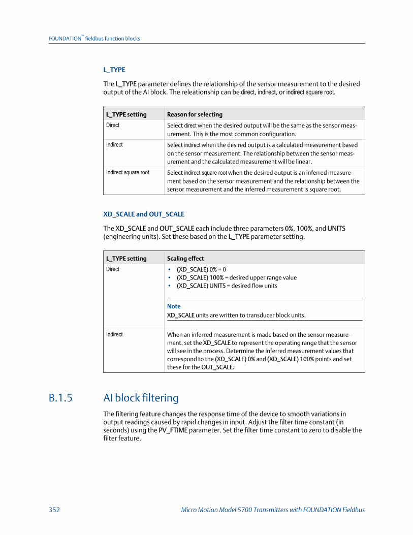
L_TYPE
The L_TYPE parameter defines the relationship of the sensor measurement to the desiredoutput of the AI block. The releationship can be direct, indirect, or indirect square root.
L_TYPE setting Reason for selecting
Direct Select direct when the desired output will be the same as the sensor meas-urement. This is the most common configuration.
Indirect Select indirect when the desired output is a calculated measurement basedon the sensor measurement. The relationship between the sensor meas-urement and the calculated measurement will be linear.
Indirect square root Select indirect square root when the desired output is an inferred measure-ment based on the sensor measurement and the relationship between thesensor measurement and the inferred measurement is square root.
XD_SCALE and OUT_SCALE
The XD_SCALE and OUT_SCALE each include three parameters 0%, 100%, and UNITS(engineering units). Set these based on the L_TYPE parameter setting.
L_TYPE setting Scaling effect
Direct • (XD_SCALE) 0% = 0• (XD_SCALE) 100% = desired upper range value• (XD_SCALE) UNITS = desired flow units
NoteXD_SCALE units are written to transducer block units.
Indirect When an inferred measurement is made based on the sensor measure-ment, set the XD_SCALE to represent the operating range that the sensorwill see in the process. Determine the inferred measurement values thatcorrespond to the (XD_SCALE) 0% and (XD_SCALE) 100% points and setthese for the OUT_SCALE.
B.1.5 AI block filteringThe filtering feature changes the response time of the device to smooth variations inoutput readings caused by rapid changes in input. Adjust the filter time constant (inseconds) using the PV_FTIME parameter. Set the filter time constant to zero to disable thefilter feature.
FOUNDATION™
fieldbus function blocks
352 Micro Motion Model 5700 Transmitters with FOUNDATION Fieldbus
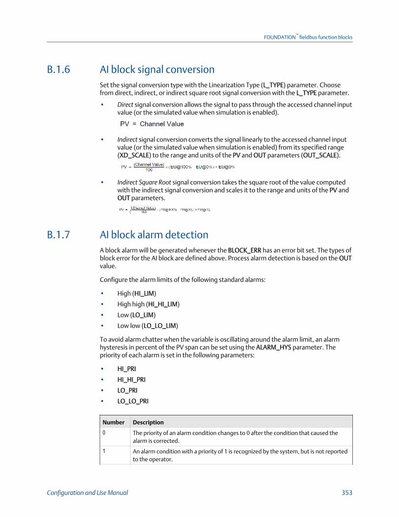
B.1.6 AI block signal conversionSet the signal conversion type with the Linearization Type (L_TYPE) parameter. Choosefrom direct, indirect, or indirect square root signal conversion with the L_TYPE parameter.
• Direct signal conversion allows the signal to pass through the accessed channel inputvalue (or the simulated value when simulation is enabled).
• Indirect signal conversion converts the signal linearly to the accessed channel inputvalue (or the simulated value when simulation is enabled) from its specified range(XD_SCALE) to the range and units of the PV and OUT parameters (OUT_SCALE).
• Indirect Square Root signal conversion takes the square root of the value computedwith the indirect signal conversion and scales it to the range and units of the PV andOUT parameters.
B.1.7 AI block alarm detectionA block alarm will be generated whenever the BLOCK_ERR has an error bit set. The types ofblock error for the AI block are defined above. Process alarm detection is based on the OUTvalue.
Configure the alarm limits of the following standard alarms:
• High (HI_LIM)
• High high (HI_HI_LIM)
• Low (LO_LIM)
• Low low (LO_LO_LIM)
To avoid alarm chatter when the variable is oscillating around the alarm limit, an alarmhysteresis in percent of the PV span can be set using the ALARM_HYS parameter. Thepriority of each alarm is set in the following parameters:
• HI_PRI
• HI_HI_PRI
• LO_PRI
• LO_LO_PRI
Number Description
0 The priority of an alarm condition changes to 0 after the condition that caused thealarm is corrected.
1 An alarm condition with a priority of 1 is recognized by the system, but is not reportedto the operator.
FOUNDATION™
fieldbus function blocks
Configuration and Use Manual 353
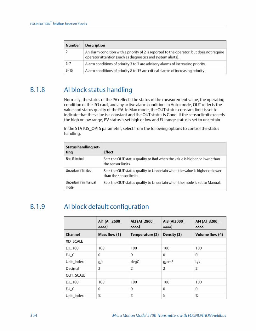
Number Description
2 An alarm condition with a priority of 2 is reported to the operator, but does not requireoperator attention (such as diagnostics and system alerts).
3–7 Alarm conditions of priority 3 to 7 are advisory alarms of increasing priority.
8–15 Alarm conditions of priority 8 to 15 are critical alarms of increasing priority.
B.1.8 AI block status handlingNormally, the status of the PV reflects the status of the measurement value, the operatingcondition of the I/O card, and any active alarm condition. In Auto mode, OUT reflects thevalue and status quality of the PV. In Man mode, the OUT status constant limit is set toindicate that the value is a constant and the OUT status is Good. If the sensor limit exceedsthe high or low range, PV status is set high or low and EU range status is set to uncertain.
In the STATUS_OPTS parameter, select from the following options to control the statushandling.
Status handling set-ting Effect
Bad if limited Sets the OUT status quality to Bad when the value is higher or lower thanthe sensor limits.
Uncertain if limited Sets the OUT status quality to Uncertain when the value is higher or lowerthan the sensor limits.
Uncertain if in manualmode
Sets the OUT status quality to Uncertain when the mode is set to Manual.
B.1.9 AI block default configuration
AI1 (AI_2600_xxxx)
AI2 (AI_2800_xxxx)
AI3 (AI3000_xxxx)
AI4 (AI_3200_xxxx
Channel Mass flow (1) Temperature (2) Density (3) Volume flow (4)
XD_SCALE
EU_100 100 100 100 100
EU_0 0 0 0 0
Unit_Index g/s degC g/cm³ L/s
Decimal 2 2 2 2
OUT_SCALE
EU_100 100 100 100 100
EU_0 0 0 0 0
Unit_Index % % % %
FOUNDATION™
fieldbus function blocks
354 Micro Motion Model 5700 Transmitters with FOUNDATION Fieldbus
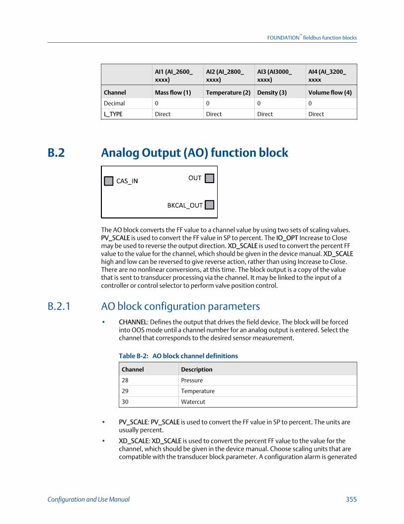
AI1 (AI_2600_xxxx)
AI2 (AI_2800_xxxx)
AI3 (AI3000_xxxx)
AI4 (AI_3200_xxxx
Channel Mass flow (1) Temperature (2) Density (3) Volume flow (4)
Decimal 0 0 0 0
L_TYPE Direct Direct Direct Direct
B.2 Analog Output (AO) function block
The AO block converts the FF value to a channel value by using two sets of scaling values.PV_SCALE is used to convert the FF value in SP to percent. The IO_OPT Increase to Closemay be used to reverse the output direction. XD_SCALE is used to convert the percent FFvalue to the value for the channel, which should be given in the device manual. XD_SCALEhigh and low can be reversed to give reverse action, rather than using Increase to Close.There are no nonlinear conversions, at this time. The block output is a copy of the valuethat is sent to transducer processing via the channel. It may be linked to the input of acontroller or control selector to perform valve position control.
B.2.1 AO block configuration parameters• CHANNEL: Defines the output that drives the field device. The block will be forced
into OOS mode until a channel number for an analog output is entered. Select thechannel that corresponds to the desired sensor measurement.
AO block channel definitionsTable B-2:
Channel Description
28 Pressure
29 Temperature
30 Watercut
• PV_SCALE: PV_SCALE is used to convert the FF value in SP to percent. The units areusually percent.
• XD_SCALE: XD_SCALE is used to convert the percent FF value to the value for thechannel, which should be given in the device manual. Choose scaling units that arecompatible with the transducer block parameter. A configuration alarm is generated
FOUNDATION™
fieldbus function blocks
Configuration and Use Manual 355

if the channel is not an analog output or the scaling limits or units of XD_SCALE arenot available from the transducer. The block will be forced into OOS mode until thecorrect entries are made.
B.2.2 AO block modesThe AO function block supports following modes of operation defined by MODE_BLKparameter:
• Out of Service (O/S): The AO algorithm of the block is not executed. The last value isissued at OUT or the determined value when the Fault State is activated.
• Manual (MAN): The user can directly enter the output value of the AO Block.
• Automatic (AUTO): The set point entered by the user is used over the SP parameteron implementation of the AO Block.
• Cascade (CAS): The AO Function Block receives the set point directly from anupstream function block over the CAS_IN parameter to calculate the output valueinternally. The AO Block is implemented.
• RemoteCascade (RCAS): The AO Function Block receives the set point directly fromthe host system over the RCAS_IN parameter to calculate the output valueinternally. The AO Block is implemented.
B.2.3 AO block errorsThe following conditions are reported in the BLOCK_ERR attribute:
• Block Configuration Error: The selected channel is incompatible with the engineeringunits selected in XD_SCALE or the CHANNEL is zero.
• Link Configuration Error
• Simulate Active: Simulation is enabled and the block is using a simulated value in itsexecution.
• Local Override: The output of the block is not responding to OUT because theresource block has been placed into LO mode or fault state action is active.
• Device Fault State set:
• Output Failure: May be propagated backward as BAD, Device Failure
• Readback Check Failed: May be propagated backward as BAD, Sensor Failure
• Out‐of‐Service: The actual mode is out of service (OOS)
B.2.4 AO block simulationWhen simulation is enabled, the last value of OUT is maintained and reflected in the fieldvalue of the SIMULATE attribute. In this case, the PV and READBACK values and statusesare based on the SIMULATE value and the status that you enter.
FOUNDATION™
fieldbus function blocks
356 Micro Motion Model 5700 Transmitters with FOUNDATION Fieldbus
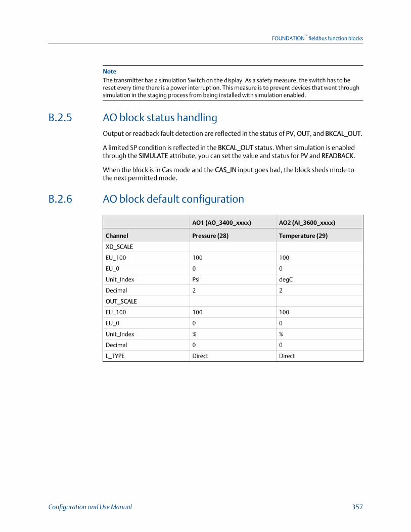
NoteThe transmitter has a simulation Switch on the display. As a safety measure, the switch has to bereset every time there is a power interruption. This measure is to prevent devices that went throughsimulation in the staging process from being installed with simulation enabled.
B.2.5 AO block status handlingOutput or readback fault detection are reflected in the status of PV, OUT, and BKCAL_OUT.
A limited SP condition is reflected in the BKCAL_OUT status. When simulation is enabledthrough the SIMULATE attribute, you can set the value and status for PV and READBACK.
When the block is in Cas mode and the CAS_IN input goes bad, the block sheds mode tothe next permitted mode.
B.2.6 AO block default configuration
AO1 (AO_3400_xxxx) AO2 (AI_3600_xxxx)
Channel Pressure (28) Temperature (29)
XD_SCALE
EU_100 100 100
EU_0 0 0
Unit_Index Psi degC
Decimal 2 2
OUT_SCALE
EU_100 100 100
EU_0 0 0
Unit_Index % %
Decimal 0 0
L_TYPE Direct Direct
FOUNDATION™
fieldbus function blocks
Configuration and Use Manual 357
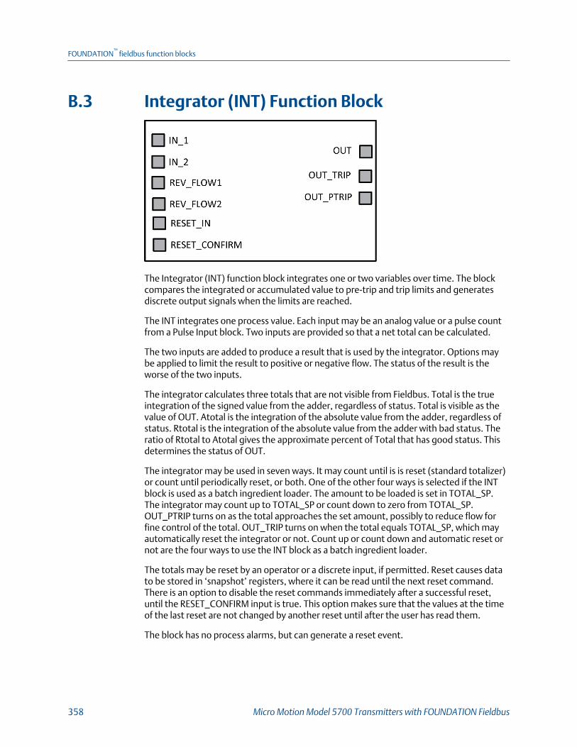
B.3 Integrator (INT) Function Block
The Integrator (INT) function block integrates one or two variables over time. The blockcompares the integrated or accumulated value to pre-trip and trip limits and generatesdiscrete output signals when the limits are reached.
The INT integrates one process value. Each input may be an analog value or a pulse countfrom a Pulse Input block. Two inputs are provided so that a net total can be calculated.
The two inputs are added to produce a result that is used by the integrator. Options maybe applied to limit the result to positive or negative flow. The status of the result is theworse of the two inputs.
The integrator calculates three totals that are not visible from Fieldbus. Total is the trueintegration of the signed value from the adder, regardless of status. Total is visible as thevalue of OUT. Atotal is the integration of the absolute value from the adder, regardless ofstatus. Rtotal is the integration of the absolute value from the adder with bad status. Theratio of Rtotal to Atotal gives the approximate percent of Total that has good status. Thisdetermines the status of OUT.
The integrator may be used in seven ways. It may count until is is reset (standard totalizer)or count until periodically reset, or both. One of the other four ways is selected if the INTblock is used as a batch ingredient loader. The amount to be loaded is set in TOTAL_SP.The integrator may count up to TOTAL_SP or count down to zero from TOTAL_SP.OUT_PTRIP turns on as the total approaches the set amount, possibly to reduce flow forfine control of the total. OUT_TRIP turns on when the total equals TOTAL_SP, which mayautomatically reset the integrator or not. Count up or count down and automatic reset ornot are the four ways to use the INT block as a batch ingredient loader.
The totals may be reset by an operator or a discrete input, if permitted. Reset causes datato be stored in ‘snapshot’ registers, where it can be read until the next reset command.There is an option to disable the reset commands immediately after a successful reset,until the RESET_CONFIRM input is true. This option makes sure that the values at the timeof the last reset are not changed by another reset until after the user has read them.
The block has no process alarms, but can generate a reset event.
FOUNDATION™
fieldbus function blocks
358 Micro Motion Model 5700 Transmitters with FOUNDATION Fieldbus
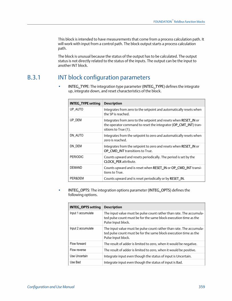
This block is intended to have measurements that come from a process calculation path. Itwill work with input from a control path. The block output starts a process calculationpath.
The block is unusual because the status of the output has to be calculated. The outputstatus is not directly related to the status of the inputs. The output can be the input toanother INT block.
B.3.1 INT block configuration parameters• INTEG_TYPE: The integration type parameter (INTEG_TYPE) defines the integrate
up, integrate down, and reset characteristics of the block.
INTEG_TYPE setting Description
UP_AUTO Integrates from zero to the setpoint and automatically resets whenthe SP is reached.
UP_DEM Integrates from zero to the setpoint and resets when RESET_IN orthe operator command to reset the integrator (OP_CMT_INT) tran-sitions to True (1).
DN_AUTO Integrates from the setpoint to zero and automatically resets whenzero is reached.
DN_DEM Integrates from the setpoint to zero and resets when RESET_IN orOP_CMD_INT transitions to True.
PERIODIC Counts upward and resets periodically. The period is set by theCLOCK_PER attribute.
DEMAND Counts upward and is reset when RESET_IN or OP_CMD_INT transi-tions to True.
PER&DEM Counts upward and is reset periodically or by RESET_IN.
• INTEG_OPTS: The integration options parameter (INTEG_OPTS) defines thefollowing options.
INTEG_OPTS setting Description
Input 1 accumulate The input value must be pulse count rather than rate. The accumula-ted pulse count must be for the same block execution time as thePulse Input block.
Input 2 accumulate The input value must be pulse count rather than rate. The accumula-ted pulse count must be for the same block execution time as thePulse Input block.
Flow forward The result of adder is limited to zero, when it would be negative.
Flow reverse The result of adder is limited to zero, when it would be positive.
Use Uncertain Integrate input even though the status of input is Uncertain.
Use Bad Integrate input even though the status of input is Bad.
FOUNDATION™
fieldbus function blocks
Configuration and Use Manual 359
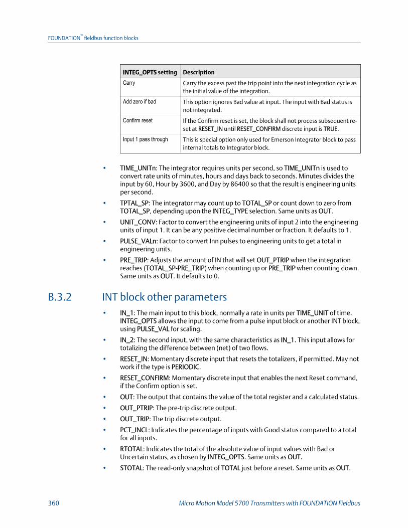
INTEG_OPTS setting Description
Carry Carry the excess past the trip point into the next integration cycle asthe initial value of the integration.
Add zero if bad This option ignores Bad value at input. The input with Bad status isnot integrated.
Confirm reset If the Confirm reset is set, the block shall not process subsequent re-set at RESET_IN until RESET_CONFIRM discrete input is TRUE.
Input 1 pass through This is special option only used for Emerson Integrator block to passinternal totals to Integrator block.
• TIME_UNITn: The integrator requires units per second, so TIME_UNITn is used toconvert rate units of minutes, hours and days back to seconds. Minutes divides theinput by 60, Hour by 3600, and Day by 86400 so that the result is engineering unitsper second.
• TPTAL_SP: The integrator may count up to TOTAL_SP or count down to zero fromTOTAL_SP, depending upon the INTEG_TYPE selection. Same units as OUT.
• UNIT_CONV: Factor to convert the engineering units of input 2 into the engineeringunits of input 1. It can be any positive decimal number or fraction. It defaults to 1.
• PULSE_VALn: Factor to convert Inn pulses to engineering units to get a total inengineering units.
• PRE_TRIP: Adjusts the amount of IN that will set OUT_PTRIP when the integrationreaches (TOTAL_SP-PRE_TRIP) when counting up or PRE_TRIP when counting down.Same units as OUT. It defaults to 0.
B.3.2 INT block other parameters• IN_1: The main input to this block, normally a rate in units per TIME_UNIT of time.
INTEG_OPTS allows the input to come from a pulse input block or another INT block,using PULSE_VAL for scaling.
• IN_2: The second input, with the same characteristics as IN_1. This input allows fortotalizing the difference between (net) of two flows.
• RESET_IN: Momentary discrete input that resets the totalizers, if permitted. May notwork if the type is PERIODIC.
• RESET_CONFIRM: Momentary discrete input that enables the next Reset command,if the Confirm option is set.
• OUT: The output that contains the value of the total register and a calculated status.
• OUT_PTRIP: The pre-trip discrete output.
• OUT_TRIP: The trip discrete output.
• PCT_INCL: Indicates the percentage of inputs with Good status compared to a totalfor all inputs.
• RTOTAL: Indicates the total of the absolute value of input values with Bad orUncertain status, as chosen by INTEG_OPTS. Same units as OUT.
• STOTAL: The read-only snapshot of TOTAL just before a reset. Same units as OUT.
FOUNDATION™
fieldbus function blocks
360 Micro Motion Model 5700 Transmitters with FOUNDATION Fieldbus

• SRTOTAL: The read-only snapshot of RTOTAL just before a reset. Same units as OUT.
• N_RESET: Counts the number of resets. It can not be written or reset.
B.3.3 INT block modesThe Integrator function block supports the following modes:
• Manual (Man) – The integration calculations are not performed. OUT, OUT_TRIP,and OUT_PTRIP may be set manually.
• Automatic (Auto) – The integration algorithm is performed and the result is writtento OUT. Reset actions depend on the integration type attribute (INTEG_TYPE) andthe inputs.
• Out of Service (O/S) – The block does not execute. OUT status is set to Bad: Out ofService. The BLOCK_ERR attribute shows Out of service.
The integrator initializes with the value in OUT when the mode changes from Manual toAutomatic. The Manual, Automatic, and Out of Service modes may be configured aspermitted modes for operator entry.
B.3.4 INT block errorsThe following conditions are reported in the BLOCK_ERR parameter:
• Block Configuration Error: INTEG_TYPE is still zero, TIME_UNITn is still zero.
• Out-of-Service: The actual mode is out of service (OOS).
B.3.5 INT block status handlingThe output status calculation is based on the accumulation of input statuses. Thecalculation includes the accumulations for both input channels when IN_2 is enabled.
Each time the function block executes, the input status is accumulated as Good or Bad asper the input status. The input as uncertain is considered as Bad input.
The output status is determined with the following logic:
• When less than 25% of the input status accumulation is Good, OUT status is set toBad.
• When 25% to less than 50% of the input status accumulation is Good, OUT status isset to Uncertain.
• When 50% or more of the input status accumulation is Good, OUT status is set toGood.
The input status accumulation is reset when the integrator is reset.
FOUNDATION™
fieldbus function blocks
Configuration and Use Manual 361

B.3.6 INT block special mode
Enhanced FF host Overview > Totalizer Control > Configure Integrator Block
Basic FF host Total Inventory TB > Integrator1 Configuration (OD Index 14)
Total Inventory TB > Integrator2 Configuration (OD Index 15)
Along with standard operation of integrating the process value at INn, the Micro MotionIntegrator function block has one special mode of operation: Input 1 pass through. In thisspecial mode of operation, the device internal totals/inventories are controlled throughthe Integrator block. The Integrator block passes through the device total/inventory tooutput and the device total/inventory is reset by the RESET_IN input. To control theintegrator block mode there is one additional parameter in the Total-Inventory TB for eachINT block. By default the integrator function block operates in standard mode.
Fieldbuscode Label Description
0 Standard Block is working as per configuration of function block parame-ters.
1 Total 1 Block outputs Total 1 value and RESET_IN resets Total 1
2 Total 2 Block outputs Total 2 value and RESET_IN resets Total 2
3 Inventory 1 Block outputs Inventory 1 value and RESET_IN resets Inventory 1
4 Inventory 2 Block outputs Inventory 2 value and RESET_IN resets Inventory 2
5 Total 4 Block outputs Total 4 value and RESET_IN resets Total 4
6 Inventory 3 Block outputs Inventory 3 value and RESET_IN resets Inventory 3and Inventory 4
7 Total 3 Block outputs Total 3 value and RESET_IN resets Total 3
8 Inventory 4 Block outputs Inventory 4 value and RESET_IN resets Inventory 3and Inventory 4
9 Total 5 Block outputs Total 5 value and RESET_IN resets Total 5
10 Inventory 5 Block outputs Inventory 5 value and RESET_IN resets Inventory 5
11 Total 6 Block outputs Total 6 value and RESET_IN resets Total 6
12 Inventory 6 Block outputs Inventory 6 value and RESET_IN resets Inventory 6
13 Total 7 Block outputs Total 7 value and RESET_IN resets Total 7
14 Inventory 7 Block outputs Inventory 7 value and RESET_IN resets Inventory 7
B.3.7 INT block default configuration
ITB1 (INTEG_4000_6830) ITB2 (INTEG_4200_6830)
INTEG_TYPE Uninitialized Uninitialized
FOUNDATION™
fieldbus function blocks
362 Micro Motion Model 5700 Transmitters with FOUNDATION Fieldbus
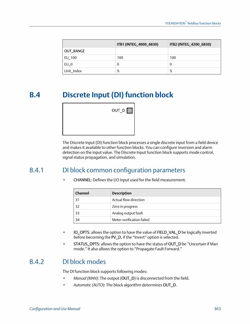
ITB1 (INTEG_4000_6830) ITB2 (INTEG_4200_6830)
OUT_RANGE
EU_100 100 100
EU_0 0 0
Unit_Index % %
B.4 Discrete Input (DI) function block
The Discrete Input (DI) function block processes a single discrete input from a field deviceand makes it available to other function blocks. You can configure inversion and alarmdetection on the input value. The Discrete Input function block supports mode control,signal status propagation, and simulation.
B.4.1 DI block common configuration parameters• CHANNEL: Defines the I/O input used for the field measurement.
Channel Description
31 Actual flow direction
32 Zero in progress
33 Analog output fault
34 Meter verification failed
• IO_OPTS: allows the option to have the value of FIELD_VAL_D be logically invertedbefore becoming the PV_D, if the “Invert” option is selected.
• STATUS_OPTS: allows the option to have the status of OUT_D be “Uncertain if Manmode.” It also allows the option to “Propagate Fault Forward.”
B.4.2 DI block modesThe DI function block supports following modes:
• Manual (MAN): The output (OUT_D) is disconnected from the field.
• Automatic (AUTO): The block algorithm determines OUT_D.
FOUNDATION™
fieldbus function blocks
Configuration and Use Manual 363

• Out of Service (O/S): The block is not processed. The output status is set to Bad: Outof Service. The BLOCK_ERR attribute shows Out of Service.
B.4.3 DI block errorsThe following conditions are reported in the BLOCK_ERR attribute:
• Simulate Active: Simulation is enabled and the block is using a simulated value in itsexecution.
• Input failure/process variable has Bad status: The hardware is bad, the configuredchannel is invalid, or a Bad status is being simulated.
• Out‐of‐Service: The actual mode is out of service (OOS)
B.4.4 DI block simulationWhen simulation is enabled, the value of SIMULATE is reflected in the field value of theOUT_D. With simulation enabled, the actual measurement value has no impact on theOUT_D value or the status.
NoteThe transmitter has a simulation switch on the display. As a safety measure, the switch has to bereset every time there is a power interruption. This measure is to prevent devices that went throughsimulation in the staging process from being installed with simulation enabled.
B.4.5 DI block status handlingUnder normal conditions, a Good: Non-cascade status is passed through to OUT_D. Theblock also supports Status Action on Failure and Block Error indications.
B.4.6 DI block default configuration
DI1 (DI_4400_xxxx)
CHANNEL Analog Output Fault (33)
IO_OPTS 0x0000
STATUS_OPTS 0x0000
FOUNDATION™
fieldbus function blocks
364 Micro Motion Model 5700 Transmitters with FOUNDATION Fieldbus
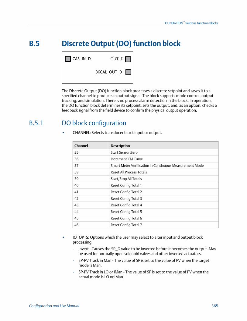
B.5 Discrete Output (DO) function block
The Discrete Output (DO) function block processes a discrete setpoint and saves it to aspecified channel to produce an output signal. The block supports mode control, outputtracking, and simulation. There is no process alarm detection in the block. In operation,the DO function block determines its setpoint, sets the output, and, as an option, checks afeedback signal from the field device to confirm the physical output operation.
B.5.1 DO block configuration• CHANNEL: Selects transducer block input or output.
Channel Description
35 Start Sensor Zero
36 Increment CM Curve
37 Smart Meter Verification in Continuous Measurement Mode
38 Reset All Process Totals
39 Start/Stop All Totals
40 Reset Config Total 1
41 Reset Config Total 2
42 Reset Config Total 3
43 Reset Config Total 4
44 Reset Config Total 5
45 Reset Config Total 6
46 Reset Config Total 7
• IO_OPTS: Options which the user may select to alter input and output blockprocessing.
- Invert - Causes the SP_D value to be inverted before it becomes the output. Maybe used for normally open solenoid valves and other inverted actuators.
- SP-PV Track in Man - The value of SP is set to the value of PV when the targetmode is Man.
- SP-PV Track in LO or IMan - The value of SP is set to the value of PV when theactual mode is LO or IMan.
FOUNDATION™
fieldbus function blocks
Configuration and Use Manual 365
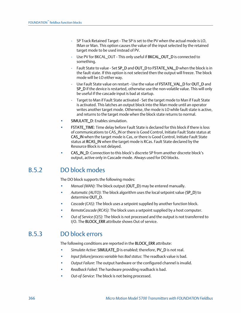
- SP Track Retained Target - The SP is set to the PV when the actual mode is LO,IMan or Man. This option causes the value of the input selected by the retainedtarget mode to be used instead of PV.
- Use PV for BKCAL_OUT - This only useful if BKCAL_OUT_D is connected tosomething.
- Fault State to value - Set SP_D and OUT_D to FSTATE_VAL_D when the block is inthe fault state. If this option is not selected then the output will freeze. The blockmode will be LO either way.
- Use Fault State value on restart - Use the value of FSTATE_VAL_D for OUT_D andSP_D if the device is restarted, otherwise use the non-volatile value. This will onlybe useful if the cascade input is bad at startup.
- Target to Man if Fault State activated - Set the target mode to Man if Fault Stateis activated. This latches an output block into the Man mode until an operatorwrites another target mode. Otherwise, the mode is LO while fault state is active,and returns to the target mode when the block state returns to normal.
• SIMULATE_D: Enables simulation.
• FSTATE_TIME: Time delay before Fault State is declared for this block if there is lossof communications to CAS_IN or there is Good Control, Initiate Fault State status atCAS_IN when the target mode is Cas, or there is Good Control, Initiate Fault Statestatus at RCAS_IN when the target mode is RCas. Fault State declared by theResource Block is not delayed.
• CAS_IN_D: Connection to this block’s discrete SP from another discrete block’soutput, active only in Cascade mode. Always used for DO blocks.
B.5.2 DO block modesThe DO block supports the following modes:
• Manual (MAN): The block output (OUT_D) may be entered manually.
• Automatic (AUTO): The block algorithm uses the local setpoint value (SP_D) todetermine OUT_D.
• Cascade (CAS): The block uses a setpoint supplied by another function block.
• RemoteCascade (RCAS): The block uses a setpoint supplied by a host computer.
• Out of Service (O/S): The block is not processed and the output is not transferred toI/O. The BLOCK_ERR attribute shows Out of service.
B.5.3 DO block errorsThe following conditions are reported in the BLOCK_ERR attribute:
• Simulate Active: SIMULATE_D is enabled; therefore, PV_D is not real.
• Input failure/process variable has Bad status: The readback value is bad.
• Output Failure: The output hardware or the configured channel is invalid.
• Readback Failed: The hardware providing readback is bad.
• Out‐of‐Service: The block is not being processed.
FOUNDATION™
fieldbus function blocks
366 Micro Motion Model 5700 Transmitters with FOUNDATION Fieldbus

B.5.4 DO block simulationWith SIMULATE_D enabled, the specified value and status is reflected in READBACK_D. IfSIMULATE_D is not enabled, and the mode is not Out of Service, the value of OUT_D is sentto the hardware
NoteThe transmitter has a simulation Switch on the display. As a safety measure, the switch has to bereset every time there is a power interruption. This measure is to prevent devices that went throughsimulation in the staging process from being installed with simulation enabled.
B.5.5 DO block status handlingUnder normal operating conditions, the output statuses (OUT_D and BKCAL_OUT_D) areGood: Cascade. If the output hardware fails, the status of BKCAL_OUT_D is set to Bad:DeviceFail, and the BLOCK_ERR attribute shows Output Failure. If the hardware used foroutput feedback fails, the status of READBACK_D and PV_D is set to Bad: DeviceFail, andthe BLOCK_ERR attribute shows Bad PV and Readback Failed.
B.5.6 DO block default configuration
DO1 (DO_4600_xxxx)
CHANNEL Start Sensor Zero (35)
IO_OPTS 0x0000
FOUNDATION™
fieldbus function blocks
Configuration and Use Manual 367

FOUNDATION™
fieldbus function blocks
368 Micro Motion Model 5700 Transmitters with FOUNDATION Fieldbus

Appendix CUsing the transmitter display
Topics covered in this appendix:
• Components of the transmitter display
• Access and use the display menus
C.1 Components of the transmitter displayThe transmitter display includes a status LED, a multi-line LCD panel, two securityswitches, and four optical switches.
Model 5700 transmitter displayFigure C-1:
Status LED
The status LED indicates the current state of the transmitter.
Using the transmitter display
Configuration and Use Manual 369

Model 5700 transmitter status LEDFigure C-2:
Status LED and device statusTable C-1:
Status LED condition Device status
Solid green No alerts are active.
Solid yellow One or more alerts are active with Alert Severity = Out of Specifica-tion, Maintenance Required, or Function Check.
Solid red One or more alerts are active with Alert Severity = Failure.
Flashing yellow (1 Hz) The Function Check in Progress alert is active.
LCD panel
In normal operation, the LCD panel shows the current value of the display variables, andtheir measurement units.
Using the transmitter display
370 Micro Motion Model 5700 Transmitters with FOUNDATION Fieldbus

Model 5700 transmitter LCD panelFigure C-3:
The LCD panel also provides access to the display menus and alert information. From thedisplay menus, you can:
• View the current configuration and make configuration changes.
• Perform procedures such as loop testing and zero verification.
• Run batches.
The alert information allows you to see which alerts are active, acknowledge the alertsindividually or as a group, and to see more detailed information for individual alerts.
C.2 Access and use the display menusThe display menus allow you to perform most configuration, administration, andmaintenance tasks.
The four optical switches, ⇦⇧⇩⇨, are used to navigate the menus, make selections, andenter data. To activate an optical switch, hold your thumb or finger over it to block thelight.
Using the transmitter display
Configuration and Use Manual 371

Optical switchesFigure C-4:
Procedure
1. Observe the action bar at the bottom of the LCD panel.
The action bar displays Menu⇨.
2. Place your thumb or finger over the ⇨ optical switch to activate it.
The top-level menu is displayed.
3. Navigate the menus using the four optical switches:
• Activate ⇧ or ⇩ to scroll to the previous or next item in the menu.
• Activate and hold ⇧ or ⇩ (approximately 1 second to scroll rapidly throughnumbers or menu options, or to move to the previous screen or next screen in amulti-screen display.
• Activate ⇨ to drill down to a lower menu or to select an option.
• Activate and hold ⇨ to save and apply your action.
• Activate ⇦ to return to the previous menu.
• Activate and hold ⇦ to cancel your action.
The action bar is updated with context-sensitive information. The ⇨ and ⇦ symbolsindicate the associated optical switch.
If the menu or the topic is too large for a single display screen, the ⇩ and ⇧ symbolsat the bottom and top of the LCD panel are used to indicate that you must scrolldown or up to see more information.
Using the transmitter display
372 Micro Motion Model 5700 Transmitters with FOUNDATION Fieldbus

Navigation arrowsFigure C-5:
4. If you make a menu choice that leads to a possible configuration change, or tocertain procedures such as zero calibration:
• If display security is not enabled, the display prompts you to activate ⇦⇧⇩⇨, inthat order. This feature protects against accidental changes to configuration, butdoes not provide any security.
Security promptsFigure C-6:
• If display security is enabled, the display prompts you to enter the displaypassword.
5. If you make a menu choice that requires entering a numeric value or characterstring, the display provides a screen similar to the following:
Numeric values and character stringsFigure C-7:
Using the transmitter display
Configuration and Use Manual 373

• Activate ⇦ or ⇨ to position the cursor.
• Activate ⇧ and ⇩ to scroll through the values that are valid for that position.
• Repeat until all characters are set.
• Activate and hold ⇨ to save the value.
6. To exit the display menu system, use either of the following methods:
• Wait until the menu times out and returns to the display variables.
• Exit each menu separately, working your way back to the top of the menusystem.
Using the transmitter display
374 Micro Motion Model 5700 Transmitters with FOUNDATION Fieldbus

Appendix DUsing ProLink III with the transmitter
D.1 Connect with ProLink IIIA connection from ProLink III to your transmitter allows you to read process data,configure the transmitter, and perform maintenance and troubleshooting tasks.
D.1.1 ProLink III Connection typesYou can connect a ProLink III PC to the transmitter with a USB connection to the ServicePort.
D.1.2 Make a service port connection from ProLink III to thetransmitter
CAUTION!
If the transmitter is in a hazardous area, do not open the wiring compartment while thetransmitter is powered up. Opening the wiring compartment while the transmitter is poweredup could cause an explosion. To connect to the transmitter in a hazardous environment, use aconnection method that does not require opening the wiring compartment.
Prerequisites
• Ensure the transmitter service port is enabled.
• Obtain a USB type A to type A cable.
ImportantThe USB cable should be no greater than 1 meter in length.
Procedure
1. Insert one end of the USB cable into the USB port on your PC.
Using ProLink III with the transmitter
Configuration and Use Manual 375

2. Open the wiring compartment on the transmitter, and insert the other end of theUSB cable into the service port on the transmitter.
Service port inside transmitter wiring compartmentFigure D-1:
3. Start ProLink III.
4. Choose Connect to Physical Device.
5. Set parameters as shown here.
Parameter Setting
Protocol Service Port
PC Port The number assigned to the USB port on your PC
6. Click Connect.
Need help? If an error message appears:
• Ensure that you have specified the correct port on your PC.
• Ensure the transmitter service port is enabled at Menu > Configuration > Security > ServicePort
Using ProLink III with the transmitter
376 Micro Motion Model 5700 Transmitters with FOUNDATION Fieldbus

Appendix EUsing a Field Communicator with thetransmitter
Topics covered in this appendix:
• Basic information about the Field Communicator
• Connect with a Field Communicator
E.1 Basic information about the FieldCommunicatorThe Field Communicator is a handheld configuration and management tool that can beused with a variety of devices, including Micro Motion transmitters. It provides completeaccess to transmitter functions and data.
Field Communicator documentation
Most of the instructions in this manual assume that you are already familiar with the andcan perform the following tasks:
• Turn on the Field Communicator
• Navigate the Field Communicator menus
• Send configuration data to the device
• Use the alpha keys to enter information
If you are unable to perform these tasks, consult the Field Communicator manual beforeattempting to use the Field Communicator. The Field Communicator manual is availableon the documentation CD or at www.emerson.com.
Device descriptions (DDs)
To view the device descriptions that are installed on your :
1. At the Fieldbus application menu, press Utility > Available Device Descriptions.
2. Scroll the list of manufacturers and select Micro Motion, then scroll the list ofinstalled device descriptions.
If Micro Motion is not listed, or you do not see the required device description, use theField Communicator Easy Upgrade Utility to install the device description, or contactcustomer support.
Field Communicator menus and messages
Many of the menus in this manual start with the On-Line menu. Ensure that you are able tonavigate to the On-Line menu.
Using a Field Communicator with the transmitter
Configuration and Use Manual 377
As you use the Field Communicator with a Micro Motion transmitter, you will see a numberof messages and notes. This manual does not document all of these messages and notes.
ImportantThe user is responsible for responding to messages and notes and complying with all safetymessages.
E.2 Connect with a Field CommunicatorA connection from the Field Communicator to your transmitter allows you to read processdata, configure the transmitter, and perform maintenance and troubleshooting tasks.The Field Communicator must be connected directly to a fieldbus segment. It can beconnected at any point between segment terminators, including directly on the fieldbusterminals on the transmitter.
NoteThe Field Communicator will not be able to communicate with the transmitter if it is simplyconnected to the wiring terminals on the bench. At minimum, you must have a power supply, powerconditioner, and terminators.
Prerequisites
The following device description (DD) must be installed on theField Communicator: 5700 FF Dev v1, DD v2, or later.
Procedure
Use the provided examples as a reference to determine the best way to connect the FieldCommunicator to your fieldbus segment.
Using a Field Communicator with the transmitter
378 Micro Motion Model 5700 Transmitters with FOUNDATION Fieldbus

Bench connection example (no fieldbus host)Figure E-1:
A. TransmitterB. Field CommunicatorC. TerminatorsD. Power conditionerE. Power supplyF. Connection block
Using a Field Communicator with the transmitter
Configuration and Use Manual 379

Field connection example (with fieldbus host and multiple devices)Figure E-2:
A. Transmitters (or other devices)B. Field CommunicatorC. TerminatorsD. Power conditionerE. Power supplyF. Fieldbus junction boxG. Fieldbus host
Using a Field Communicator with the transmitter
380 Micro Motion Model 5700 Transmitters with FOUNDATION Fieldbus

Appendix FConcentration measurement matrices,derived variables, and process variables
Topics covered in this appendix:
• Standard matrices for the concentration measurement application
• Derived variables and calculated process variables
F.1 Standard matrices for the concentrationmeasurement applicationThe standard concentration matrices available from Micro Motion are applicable for avariety of process fluids. These matrices are included in the ProLink III installation.
TipIf the standard matrices are not appropriate for your application, you can build a custom matrix orpurchase a custom matrix from Micro Motion.
Matrix name Description Density unitTemperatureunit Derived variable
Deg Balling Matrix represents percent extract, bymass, in solution, based on °Balling.For example, if a wort is 10 °Ballingand the extract in solution is 100% su-crose, the extract is 10% of the totalmass.
g/cm3 °F Mass Concentration(Density)
Deg Brix Matrix represents a hydrometer scalefor sucrose solutions that indicates thepercent by mass of sucrose in solutionat a given temperature. For example,40 kg of sucrose mixed with 60 kg ofwater results in a 40 °Brix solution.
g/cm3 °C Mass Concentration(Density)
Deg Plato Matrix represents percent extract, bymass, in solution, based on °Plato. Forexample, if a wort is 10 °Plato and theextract in solution is 100% sucrose, theextract is 10% of the total mass.
g/cm3 °F Mass Concentration(Density)
Concentration measurement matrices, derived variables, and process variables
Configuration and Use Manual 381
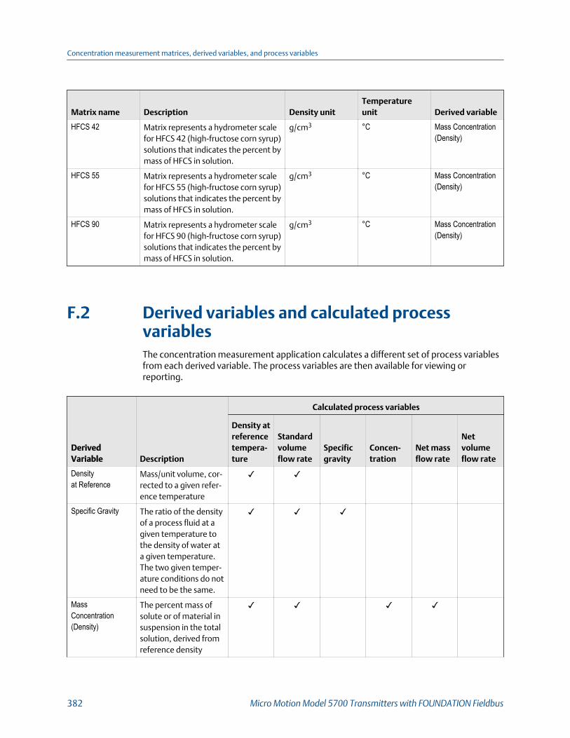
Matrix name Description Density unitTemperatureunit Derived variable
HFCS 42 Matrix represents a hydrometer scalefor HFCS 42 (high-fructose corn syrup)solutions that indicates the percent bymass of HFCS in solution.
g/cm3 °C Mass Concentration(Density)
HFCS 55 Matrix represents a hydrometer scalefor HFCS 55 (high-fructose corn syrup)solutions that indicates the percent bymass of HFCS in solution.
g/cm3 °C Mass Concentration(Density)
HFCS 90 Matrix represents a hydrometer scalefor HFCS 90 (high-fructose corn syrup)solutions that indicates the percent bymass of HFCS in solution.
g/cm3 °C Mass Concentration(Density)
F.2 Derived variables and calculated processvariablesThe concentration measurement application calculates a different set of process variablesfrom each derived variable. The process variables are then available for viewing orreporting.
DerivedVariable Description
Calculated process variables
Density atreferencetempera-ture
Standardvolumeflow rate
Specificgravity
Concen-tration
Net massflow rate
Netvolumeflow rate
Densityat Reference
Mass/unit volume, cor-rected to a given refer-ence temperature
✓ ✓
Specific Gravity The ratio of the densityof a process fluid at agiven temperature tothe density of water ata given temperature.The two given temper-ature conditions do notneed to be the same.
✓ ✓ ✓
MassConcentration(Density)
The percent mass ofsolute or of material insuspension in the totalsolution, derived fromreference density
✓ ✓ ✓ ✓
Concentration measurement matrices, derived variables, and process variables
382 Micro Motion Model 5700 Transmitters with FOUNDATION Fieldbus

DerivedVariable Description
Calculated process variables
Density atreferencetempera-ture
Standardvolumeflow rate
Specificgravity
Concen-tration
Net massflow rate
Netvolumeflow rate
MassConcentration(Specific Gravity)
The percent mass ofsolute or of material insuspension in the totalsolution, derived fromspecific gravity
✓ ✓ ✓ ✓ ✓
VolumeConcentration(Density)
The percent volume ofsolute or of material insuspension in the totalsolution, derived fromreference density
✓ ✓ ✓ ✓
VolumeConcentration(Specific Gravity)
The percent volume ofsolute or of material insuspension in the totalsolution, derived fromspecific gravity
✓ ✓ ✓ ✓ ✓
Concentration(Density)
The mass, volume,weight, or number ofmoles of solute or ofmaterial in suspensionin proportion to the to-tal solution, derivedfrom reference density
✓ ✓ ✓
Concentration(Specific Gravity)
The mass, volume,weight, or number ofmoles of solute or ofmaterial in suspensionin proportion to the to-tal solution, derivedfrom specific gravity
✓ ✓ ✓ ✓
Concentration measurement matrices, derived variables, and process variables
Configuration and Use Manual 383

Concentration measurement matrices, derived variables, and process variables
384 Micro Motion Model 5700 Transmitters with FOUNDATION Fieldbus

Appendix GEnvironmental compliance
G.1 RoHS and WEEEIn compliance with the RoHS directive (Restriction of Hazardous Substances) and the WEEEdirective (Waste Electrical and Electronic Equipment), the battery in the Model 5700transmitter cannot be serviced or replaced by users. If the battery requires replacement,contact customer service for replacement and disposal.
Environmental compliance
Configuration and Use Manual 385

Environmental compliance
386 Micro Motion Model 5700 Transmitters with FOUNDATION Fieldbus
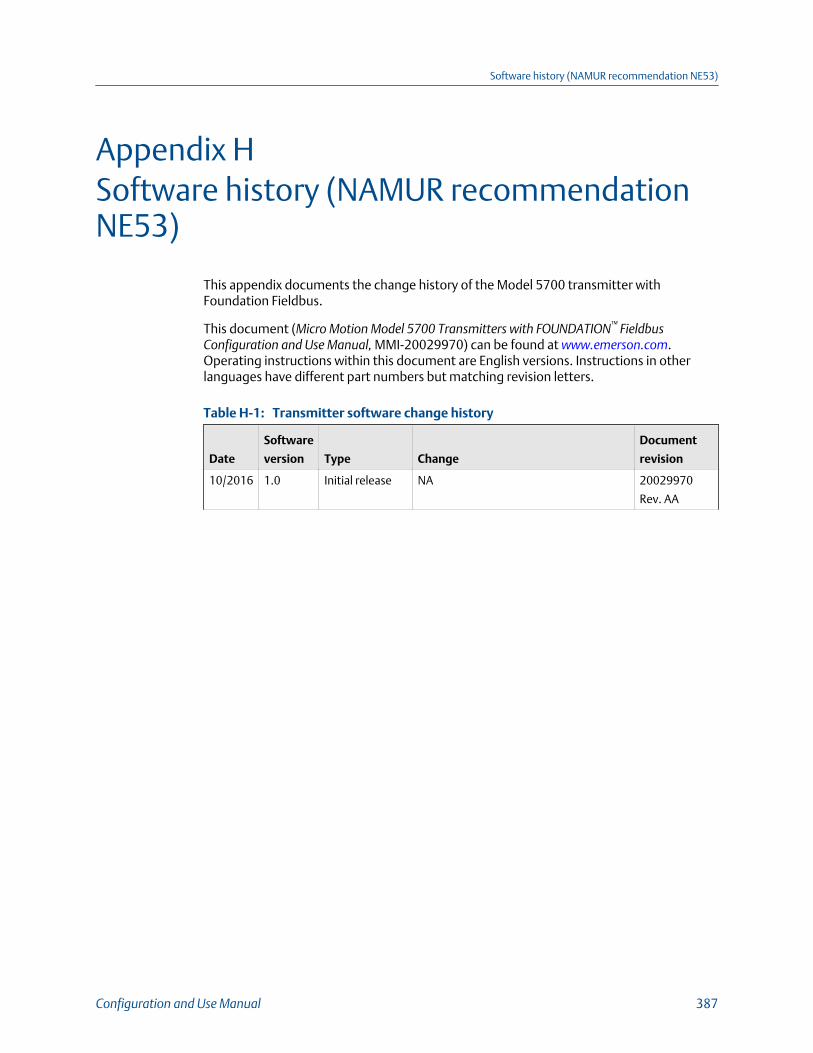
Appendix HSoftware history (NAMUR recommendationNE53)
This appendix documents the change history of the Model 5700 transmitter withFoundation Fieldbus.
This document (Micro Motion Model 5700 Transmitters with FOUNDATION™ FieldbusConfiguration and Use Manual, MMI-20029970) can be found at www.emerson.com.Operating instructions within this document are English versions. Instructions in otherlanguages have different part numbers but matching revision letters.
Transmitter software change historyTable H-1:
Date
Software
version Type Change
Document
revision
10/2016 1.0 Initial release NA 20029970
Rev. AA
Software history (NAMUR recommendation NE53)
Configuration and Use Manual 387

Transmitter software change history (continued)Table H-1:
Date
Software
version Type Change
Document
revision
10/2017 1.10 Software
improvements
• Corrected both Russian and Japanesestrings on the local display
• Enhanced the transmitter to correctlycalculate daylight savings time
• Enhanced both API Referral and Con-centration Measurement applicationsso that if either one is licensed, theapplication is now activated in thetransmitter immediately without theuser having to enable it
• Enhanced local display to show theHardware revision level
• Support added for turning the localdisplay either on or off from the localdisplay
• Corrected the velocity calculation touse actual density rather than stand-ard gas density when the transmitteris in Gas Standard Volume mode
• Support added to the local display soalert conditions can be set to detect(enabled)
• Enhanced Historian so that when anHistorian transfer is aborted either bythe user or as the result of an internalerror, files are properly closed so thatthe Historian no longer quits loggingdata approximately 5 months later.
20029970
Rev. AB
Software history (NAMUR recommendation NE53)
388 Micro Motion Model 5700 Transmitters with FOUNDATION Fieldbus
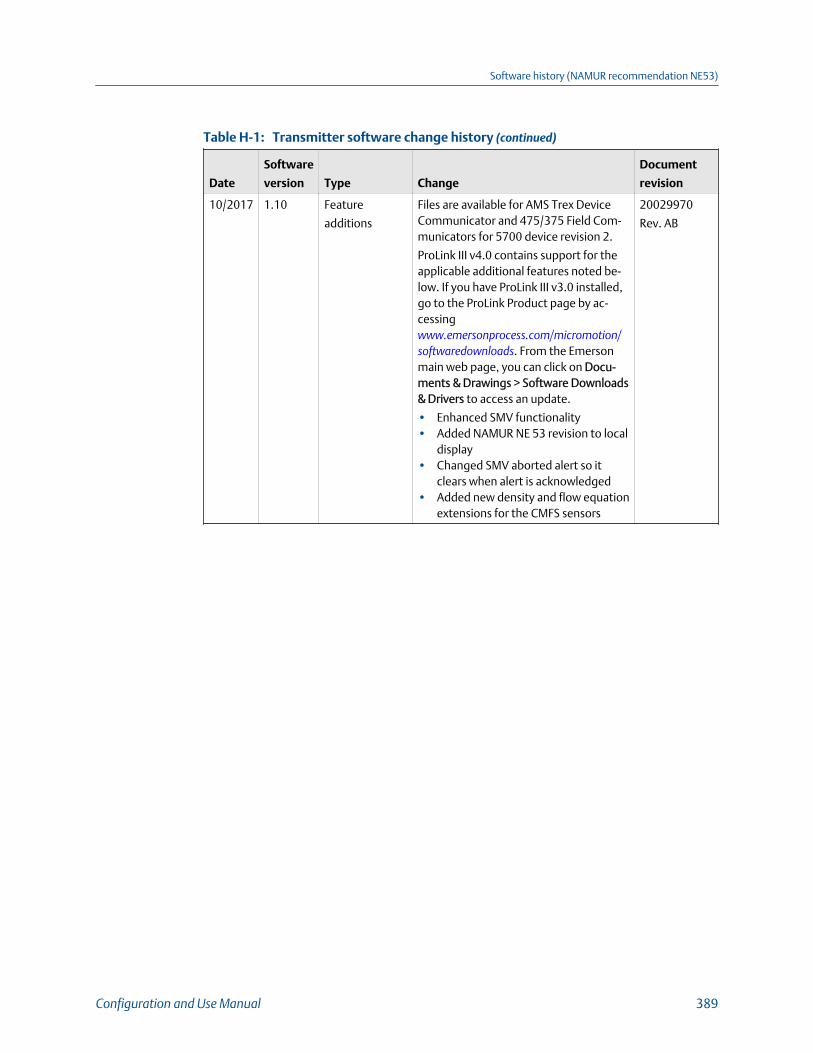
Transmitter software change history (continued)Table H-1:
Date
Software
version Type Change
Document
revision
10/2017 1.10 Feature
additions
Files are available for AMS Trex DeviceCommunicator and 475/375 Field Com-municators for 5700 device revision 2.
ProLink III v4.0 contains support for theapplicable additional features noted be-low. If you have ProLink III v3.0 installed,go to the ProLink Product page by ac-cessing www.emersonprocess.com/micromotion/softwaredownloads. From the Emersonmain web page, you can click on Docu-ments & Drawings > Software Downloads& Drivers to access an update.
• Enhanced SMV functionality• Added NAMUR NE 53 revision to local
display• Changed SMV aborted alert so it
clears when alert is acknowledged• Added new density and flow equation
extensions for the CMFS sensors
20029970
Rev. AB
Software history (NAMUR recommendation NE53)
Configuration and Use Manual 389

Software history (NAMUR recommendation NE53)
390 Micro Motion Model 5700 Transmitters with FOUNDATION Fieldbus

Software history (NAMUR recommendation NE53)
Configuration and Use Manual 391

* MMI-20029970*MMI-20029970
Rev AB
2018
Micro Motion Inc. USAWorldwide Headquarters7070 Winchester CircleBoulder, Colorado USA 80301T +1 303-527-5200T +1 800-522-6277F +1 303-530-8459www.emerson.com
Micro Motion EuropeEmerson Automation SolutionsNeonstraat 16718 WX EdeThe NetherlandsT +31 (0) 70 413 6666F +31 (0) 318 495 556www.micromotion.nl
Micro Motion AsiaEmerson Automation Solutions1 Pandan CrescentSingapore 128461Republic of SingaporeT +65 6777-8211F +65 6770-8003
Micro Motion United KingdomEmerson Automation SolutionsEmerson Process Management LimitedHorsfield WayBredbury Industrial EstateStockport SK6 2SU U.K.T +44 0870 240 1978F +44 0800 966 181
Micro Motion JapanEmerson Automation Solutions1-2-5, Higashi ShinagawaShinagawa-kuTokyo 140-0002 JapanT +81 3 5769-6803F +81 3 5769-6844
©2018 Micro Motion, Inc. All rights reserved.
The Emerson logo is a trademark and service mark of Emerson Electric Co. Micro Motion, ELITE,ProLink, MVD and MVD Direct Connect marks are marks of one of the Emerson AutomationSolutions family of companies. All other marks are property of their respective owners.