configuration aerodynamics of the asw 22 bl sailplane
TRANSCRIPT
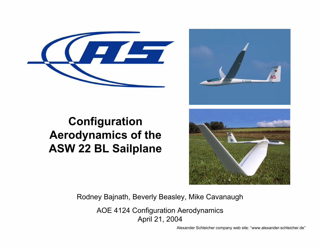
ConfigurationAerodynamics of theASW 22 BL Sailplane
Rodney Bajnath, Beverly Beasley, Mike Cavanaugh
AOE 4124 Configuration AerodynamicsApril 21, 2004
Alexander Schleicher company web site: “www.alexander-schleicher.de”

ASW 22 BL Specifications
Wing Span: 86.6 ftWing Area: 179.4 ft2
Aspect Ratio: 41.8
Mean chord: 2.07 ft
Airfoils: HQ17/14.38 (root)DU84-132/V3 (tip)
BLC: 860 blow holes lwr surface 75%c, flap root to tip
Max T-O Weight: 1654 lbs.
Payload: 198 lbs.
Water Ballast: 452 lbs.
W/SMAX = 9.22 lbs./ft2
Conventional controls: ailerons (inner & outer), elevator, rudder
Double panel air brake (upper surface only)
Two wheel retractable main landing gear, fixed tail wheel
Cruise flaps (flap + inner aileron): +9.2° (thermaling), -0.5°, -7.7°, -10.7°
Landing flaps: flap +40°, inner aileron +14°, outer aileron -8°
Alexander Schleicher company web site: www.alexander-schleicher.deFred Thomas, Fundamentals of Sailplane Design, 1999.Dick Johnson, “A Flight Test Evaluation of the AS-W22”, Soaring, April 1983.

Three Types of Soaring
• Thermal – circle in rising currentof warm air
• Ridge – fly in updraft onwindward side of ridge
• Wave – fly in updraft portion ofwave on lee side of mountain
Soaring Flight Manual, Soaring Society of America, 1992.
Photos, World Championships, Uvalde, Texas, 1991.
Goal: sink less than the air rises
Result: climb & fly to next thermal!

ASW 22 BL Factory Speed Polar
-700
-600
-500
-400
-300
-200
-100
0
0 20 40 60 80 100 120 140
knots
sin
k (f
t/m
in)
540 kg (1191 lbs)
750 kg (1654 lbs)
Min. sink: 79 fpm @ 43.2 KCAS (1191 lbs. / CL = 1.05)
Best glide: 64.85 @ 59.4 KCAS (1654 lbs. / CL = 0.77)
Max Speed: 151 KCAS
Stall Speed: 35.3 KCAS (light A/C) 41.5 KCAS (heavy A/C) (Flaps 9° / CLmax = 1.58)
!
!tan
1/ =DL
Alexander Schleicher company web site: www.alexander-schleicher.deDick Johnson, “A Flight Test Evaluation of the AS-W22”, Soaring, April 1983.

Quest for Low Drag Drives AerodynamicConfiguration of Open Class Sailplanes
• Large span – low span loading (minimize induced drag) for a fixed weight
• Minimum fuselage size to accommodate pilot - reduce wetted area
• Laminar flow airfoils on wing, vertical tail & horizontal tail – low skin friction
• Laminar flow on fuselage - low skin friction
• Smooth composite construction – reduce drag of surface imperfections
• Boundary layer control on wing - fix transition and eliminate laminar bubbles
• Cruise flaps – adjust span & chord loading for a range of flight conditions
• Retractable landing gear – reduce pressure drag from gear and open doors
• Winglets - minimize induced drag in climbs
• Long tail moment arm – reduce horizontal tail area, min downwash at tail
• Aft center of gravity placement – reduce trim drag
• Water ballast – adjust speed for maximum L/D, improve penetration
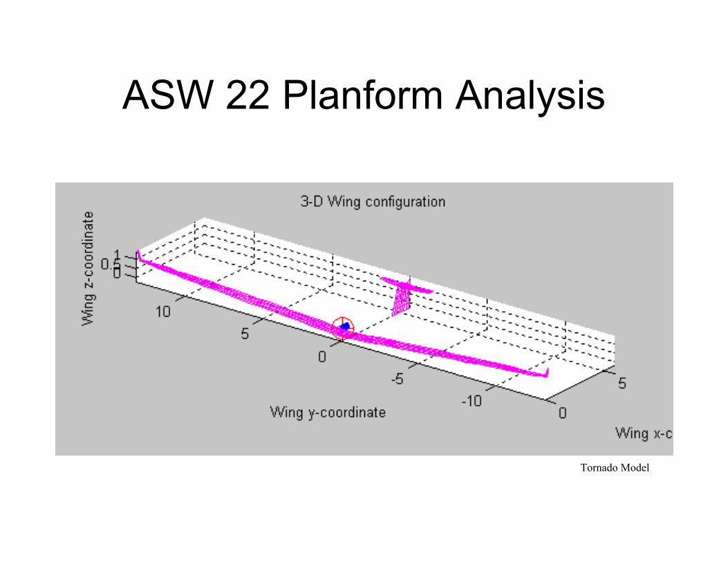
ASW 22 Planform Analysis
Tornado Model

ASW 22 Planform Analysis
• Without Winglets– AR = 38.3
– b = 25.0 m
– e = 0.95
– L/Dmax = 60
– W/Smax = 9.42 lb/ft2
• With Winglets– AR = 41.8
– b = 26.58 m
– e = 0.99
– L/Dmax = 62
– W/Smax = 9.21 lb/ft2
– Improved stall
– Better roll rate
– Lower induced drag

ASW 22BL Trim Analysis
0.00.00.0Cmo
-0.368-0.203-0.410dCm/dCL
VLMpcJKayTornado
ASW 22BL Elevator Effectiveness
-2
-1.5
-1
-0.5
0
0.5
1
-0.5 0 0.5 1 1.5 2 2.5
CL
Cm

ASW 22BL Stability and Control
Lateral-DirectionalLongitudinal
The ASW 22BL is stable for all major flight conditions.
-0.004
0.011
JKay
-1.47
7.22
JKay
-1.80
4.89
VLMpc DATCOMTornadoDATCOMTornado
-0.02
0.79
-1.70
-1.48
6.30
-1.96Cm_e
-0.21Cl_-2.36Cm_
0.039Cn_6.34CL_

XFOIL Wing Airfoil Analysis• Favorable pressure gradient to promote laminar flow• Airfoil analysis at CL for best L/D (59.4 KCAS @ 1654 lbs.)
Mark Drela, “XFOIL 6.9 User Guide,” 2001.

XFOIL Wing Airfoil Analysis
• Skin friction plot shows presenceof laminar separation bubbles onthe upper and lower surfacewhere cf goes to zero
• Shape factor (_*/_) increasesdramatically due to transition and thepresence of the laminar bubbles

XFOIL Wing Airfoil Analysis
• Boundary layer profiles show reverse flow in the bubble region
• Blowing used to fix transition and eliminate bubble
– 430 holes (0.0225” diameter) located on bottom of each wing
– 73%~71% chord just in front of flap and aileron hinge lines
– 20 mm spacing running from flap root to tip of aileron
– Four inlet pitot tubes supply pressurized air to blowing holes
Lower wing surface
laminar profile
turbulent profile
reverse flow in bubble

XFOIL Wing Airfoil Analysis
• Polar with upper and lower surface laminar separation bubbles present
• At max L/D speed (CL=0.773), trips at 0.65c on the upper surface and 0.77con the lower surface reduce airfoil Cd by 4.9 counts

Drag Polar “Extracted” from Company Speed Polar
• CD extracted from company speed polar using L/D = 1/tan!• Data for the heavy aircraft (1654 lbs.) at 5,000 ft.
0.00
0.20
0.40
0.60
0.80
1.00
1.20
1.40
1.60
1.80
0.0000 0.0050 0.0100 0.0150 0.0200 0.0250 0.0300 0.0350 0.0400 0.0450
CD
CL
!tan
1/ =DL

Drag Breakdown
• Attempt to match polar derived from Schleicher company data
0.00
0.20
0.40
0.60
0.80
1.00
1.20
0.0000 0.0050 0.0100 0.0150 0.0200 0.0250
CD
CL
Schleicher
Cd fuselage
Cdf wing
Cdp wing
Cd HT
Cd VT
Cd induced

Independent Flight Test Verification of Performance
• Flight test of the original ASW 22by Dick Johnson and David Jonesin 1983
• Appeared in the April 1983 issueof Soaring Magazine
• Plot shows amount of scatter inperformance flight test data
• Plot shows flap schedulingsuggested by Schleicher
• Performance of later 22B and22BL models improved withincreased span and winglets
Dick Johnson, “A Flight Test Evaluation of the AS-W22”, Soaring, April 1983.

ASW 22 BL Stability & Control Analysis
Phys(#) Reference units
1 weight 1653.75 lbs2 Ixx 10780 slug-ft^23 Iyy 626 slug-ft^24 Izz 11396 slug-ft^25 Ixz 0 slug-ft^26 Area 179.37 ft^27 Span 86.62 ft8 Chord 2.067 ft9 Thrust Angle 0 rad
Ref(#) Condition units
1 density 0.002048 slugs/ft^32 TAS 107.94 ft/s3 Mach 0.0984 CL 0.773 trim5 CD 0.01191 trim6 gamma -0.01542 radians
Stability derivatives and referenceconditions for analysis
c.g. @ 42.5%c
Jan Roskam, “Airplane Design Book VI”, 1990.
Stability D(#) Derivatives /rad /deg /rad /deg
1 CLAlpha 6.3259 0.110400 6.2964 0.1098852 CDAlpha 0.0979 0.001709 0.0882 0.0015393 CmAlpha -1.2551 -0.021903 -1.4740 -0.0257244 CLAlphadot 0.5129 0.008951 - -5 CmAlphadot -3.9800 -0.069459 - -6 CLq 5.7499 0.100347 14.3943 0.2512097 Cmq -44.6196 -0.778702 -46.1854 -0.8060288 CLM 0.0 0.0 - -9 CDM 0.0 0.0 - -10 CmM 0.0 0.0 - -11 CLDeltaM 0.2528 0.004412 0.2412 0.00421012 CDDeltaM 0.0056 0.000097 0.0093 0.00016313 CMDeltaM -1.9618 -0.034237 -1.7300 -0.03019214 CTV 0.0 0.0 - -15 CTDeltaT 0.0 0.0 - -16 CyBeta -0.2824 -0.004928 4.2181 0.07361417 ClBeta -0.2064 -0.003602 0.0198 0.00034618 CnBeta 0.0392 0.000685 0.8100 0.014136
19 Clp -0.9658 -0.016854 -0.7335 -0.012801
20 Cnp 0.1174 0.002048 -0.1912 -0.00333621 Cyp -0.0082 -0.000143 -0.1434 -0.00250222 Clr 0.1676 0.002926 0.1364 0.00238023 Cnr -0.0277 -0.000484 0.3344 0.00583624 Cyr 0.0840 0.001466 1.7479 0.03050425 ClDeltaL 0.6251 0.010909 0.2731 0.00476626 CnDeltaL -0.0194 -0.000338 0.0102 0.00017927 ClDeltaN 0.0019 0.000033 -0.0424 -0.00073928 CnDeltaN -0.0194 -0.000338 0.4437 0.00774329 CyDeltaN 0.1099 0.001918 2.4083 0.042030
DATCOM Tornado

ASW 22 BL Stability & Control Summary• Longitudinal static stability positive
– Stick-fixed neutral point location: 0.66c Tornado / 0.62c DATCOM
– C.G. location calculated to be 42.5%c at maximum take-off weight
• Static lateral/directional stability positive
– CN_> 0: Tornado (sign change needed) & DATCOM
– CL_< 0 dihedral effect: Tornado (sign change needed) & DATCOM
• Lateral/directional control
– Rudder power: _ degree of sideslip per degree of rudder deflection
– Steady state roll rate 17.02 deg/sec at 45 knots (Johnson flight test value 11.25 deg/sec)
– Dick Johnson flight test reports “moderately strong adverse yaw”
• Longitudinal Dynamic Stability
• Lateral/Directional Dynamic Stability
Mode ! "d (rad/s) "n (rad/s) f (Hz) T (sec)
phugoid -0.00033 0.3127 0.3127 0.0498 20.0933short period 0.71326 2.8114 4.0111 0.4474 2.2349
Mode ! "d (rad/s) "n (rad/s) f (Hz) T (sec) T2 (sec) T1/2 (sec)
dutch roll 0.16144 0.6143 0.6225 0.0978 10.23spiral 84.47
roll 0.1025
Dick Johnson, “A Flight Test Evaluation of the AS-W22”, Soaring, April 1983.

Conclusions
• Pro– Performance, low min sink (79 fpm) and high glide ratio (L/D 64.85)– Variable wing loading with jettisonable water ballast. Good penetration
on strong days and low minimum sink on weak days– Wing extensions and winglet add-ons provide versatility– ASW 22BL an improvement over ASW 22 and ASW 22B because of
higher L/D and span efficiency (as evidenced by flight testing)– Stable configuration– Winner of 6 World Championships!
• Con– Ground handling difficult due to large span (TEU aileron deflection)– Flight test report of moderately strong adverse yaw– Complexity (boundary layer control)– Technology is 10 years old, current max L/D now in low to mid 70’s– Price: $144,339 US / Eastern Sailplanes, Waynesville, OH

References
• Alexander Schleicher company web site, www.alexander-schleicher.de
• Fred Thomas, Fundamentals of Sailplane Design, College Park Press, College Park Maryland, 1999.
• Richard H. Johnson, “A Flight Test Evaluation of the AS-W22,” Soaring Magazine, April 1983.
• Soaring Flight Manual, Private and Commercial, Soaring Society of America, Jeppesen Sanderson, Inc., 1992.
• Mark Drela, “XFOIL 6.9 User Guide,” MIT Aero & Astro, 2001.
• Jan Roskam, Airplane Design Part VI: Preliminary Calculation of Aerodynamic, Thrust and Power Characteristics,Roskam Aviation and Engineering Corporation, Ottawa Kansas, 1990.