config guide vpns vpls
TRANSCRIPT

8/21/2019 Config Guide Vpns Vpls
http://slidepdf.com/reader/full/config-guide-vpns-vpls 1/485
Junos®OS
VPLS Feature Guide for Routing Devices
Release
13.2
Published: 2013-07-31
Copyright © 2013, Juniper Networks, Inc.

8/21/2019 Config Guide Vpns Vpls
http://slidepdf.com/reader/full/config-guide-vpns-vpls 2/485
Juniper Networks, Inc.1194North Mathilda AvenueSunnyvale, California 94089USA408-745-2000www.juniper.net
Thisproduct includesthe Envoy SNMPEngine, developed by EpilogueTechnology,an IntegratedSystems Company.Copyright© 1986-1997,
Epilogue Technology Corporation.All rights reserved. This program and its documentation were developed at privateexpense, and no part
of them is in thepublic domain.
This product includes memory allocation software developed by Mark Moraes,copyright © 1988, 1989, 1993, University of Toronto.
This product includes FreeBSD software developed by the University of California, Berkeley, and its contributors. All of the documentation
and software included in the 4.4BSD and 4.4BSD-Lite Releases is copyrighted by the Regents of the University of California. Copyright ©
1979, 1980, 1983, 1986, 1988, 1989, 1991, 1992, 1993, 1994. The Regents of the University of California. All rights reserved.
GateD software copyright © 1995, the Regents of the University. All rights reserved. Gate Daemon was originated and developed through
release 3.0 by Cornell University and its collaborators. Gated is based on Kirton’s EGP, UC Berkeley’s routing daemon (routed), and DCN’s
HELLO routing protocol. Development of Gated has beensupported in part by the National Science Foundation. Portions of the GateD
software copyright © 1988, Regentsof theUniversityof California.All rights reserved. Portionsof theGateD software copyright © 1991, D.
L. S. Associates.
This product includes software developed by Maker Communications, Inc., copyright © 1996, 1997, Maker Communications, Inc.
Juniper Networks, Junos, Steel-Belted Radius, NetScreen, and ScreenOS are registered trademarks of Juniper Networks, Inc.in the United
States and other countries. The Juniper Networks Logo, the Junos logo, and JunosE are trademarks of Juniper Networks, Inc.All other
trademarks, service marks, registered trademarks, or registered service marks are the property of theirrespective owners.
Juniper Networks assumes no responsibility for any inaccuracies in this document. Juniper Networks reserves the right to change, modify,
transfer, or otherwise revise this publication without notice.
Products made or sold byJuniper Networks or components thereof might be covered by oneor more of thefollowingpatents that are
owned by or licensed to Juniper Networks: U.S. Patent Nos. 5,473,599, 5,905,725, 5,909,440,6,192,051, 6,333,650, 6,359,479, 6,406,312,
6,429,706, 6,459,579, 6,493,347, 6,538,518, 6,538,899, 6,552,918, 6,567,902, 6,578,186, and 6,590,785.
Junos®
OSVPLS FeatureGuide forRoutingDevices13.2
Copyright © 2013, Juniper Networks, Inc.
All rights reserved.
The informationin this document is currentas of thedateon thetitlepage.
YEAR 2000 NOTICE
Juniper Networks hardware and software products are Year 2000 compliant. Junos OS has no known time-related limitations through the
year 2038. However,the NTPapplicationis known to have some difficulty in theyear2036.
END USER LICENSE AGREEMENT
The Juniper Networks product that is thesubject of this technical documentationconsists of (or is intended for usewith)Juniper Networks
software. Useof such software is subject to theterms and conditions of theEnd User License Agreement (“EULA”) posted athttp://www.juniper.net/support/eula.html. By downloading, installing or using such software, you agree to theterms and conditions of
that EULA.
Copyright © 2013, Juniper Networks, Inc.ii

8/21/2019 Config Guide Vpns Vpls
http://slidepdf.com/reader/full/config-guide-vpns-vpls 3/485
Table of Contents
About the Documentation . . . . . . . . . . . . . . . . . . . . . . . . . . . . . . . . . . . . . . . . . . . . xiii
Documentation and Release Notes . . . . . . . . . . . . . . . . . . . . . . . . . . . . . . . . . xiii
Supported Platforms . . . . . . . . . . . . . . . . . . . . . . . . . . . . . . . . . . . . . . . . . . . . xiii
Using the Examples in This Manual . . . . . . . . . . . . . . . . . . . . . . . . . . . . . . . . . xiii
Merging a Full Example . . . . . . . . . . . . . . . . . . . . . . . . . . . . . . . . . . . . . . . xiv
Merging a Snippet . . . . . . . . . . . . . . . . . . . . . . . . . . . . . . . . . . . . . . . . . . . xiv
Documentation Conventions . . . . . . . . . . . . . . . . . . . . . . . . . . . . . . . . . . . . . . xv
Documentation Feedback . . . . . . . . . . . . . . . . . . . . . . . . . . . . . . . . . . . . . . . . xvii
Requesting Technical Support . . . . . . . . . . . . . . . . . . . . . . . . . . . . . . . . . . . . xvii
Self-Help Online Tools and Resources . . . . . . . . . . . . . . . . . . . . . . . . . . xvii
Opening a Case with JTAC . . . . . . . . . . . . . . . . . . . . . . . . . . . . . . . . . . . . xviii
Part 1 Overview
Chapter 1 Introduction to VPLS . . . . . . . . . . . . . . . . . . . . . . . . . . . . . . . . . . . . . . . . . . . . . . . 3
Introduction to VPLS . . . . . . . . . . . . . . . . . . . . . . . . . . . . . . . . . . . . . . . . . . . . . . . . . 3
VPLS Routing and Virtual Ports . . . . . . . . . . . . . . . . . . . . . . . . . . . . . . . . . . . . . . . . . 4
VPLS and Aggregated Ethernet Interfaces . . . . . . . . . . . . . . . . . . . . . . . . . . . . . . . . 6
BGP Signaling for VPLS PE Routers Overview . . . . . . . . . . . . . . . . . . . . . . . . . . . . . 7
BGP Route Reflectors for VPLS . . . . . . . . . . . . . . . . . . . . . . . . . . . . . . . . . . . . . . . . . 7
VPLS Multihoming Overview . . . . . . . . . . . . . . . . . . . . . . . . . . . . . . . . . . . . . . . . . . . 8Enabling BGP Path Selection for Layer 2 VPNs and VPLS . . . . . . . . . . . . . . . . . . . 10
VPLS Path Selection Process for PE Routers . . . . . . . . . . . . . . . . . . . . . . . . . . . . . . 12
BGP and VPLS Path Selection for Multihomed PE Routers . . . . . . . . . . . . . . . . . . 14
VPLS Multihoming Reactions to Network Failures . . . . . . . . . . . . . . . . . . . . . . . . . 16
Interoperability between BGP Signaling and LDP Signaling in VPLS . . . . . . . . . . . 17
LDP-Signaled and BGP-Signaled PE Router Topology . . . . . . . . . . . . . . . . . . 18
Flooding Unknown Packets Across Mesh Groups . . . . . . . . . . . . . . . . . . . . . . 19
Unicast Packet Forwarding . . . . . . . . . . . . . . . . . . . . . . . . . . . . . . . . . . . . . . . . 19
VPLS Label Blocks Operation . . . . . . . . . . . . . . . . . . . . . . . . . . . . . . . . . . . . . . . . . 19
Elements of Network Layer Reachability Information . . . . . . . . . . . . . . . . . . . 20
Requirements for NLRI Elements . . . . . . . . . . . . . . . . . . . . . . . . . . . . . . . . . . . 20
How Labels are Used in Label Blocks . . . . . . . . . . . . . . . . . . . . . . . . . . . . . . . . 21Label Block Composition . . . . . . . . . . . . . . . . . . . . . . . . . . . . . . . . . . . . . . . . . . 21
Label Blocks in Junos OS . . . . . . . . . . . . . . . . . . . . . . . . . . . . . . . . . . . . . . . . . . 21
VPLS Label Block Structure . . . . . . . . . . . . . . . . . . . . . . . . . . . . . . . . . . . . . . . 21
PE Router Mesh Groups for VPLS Routing Instances . . . . . . . . . . . . . . . . . . . . . . . 23
Understanding PIM Snooping for VPLS . . . . . . . . . . . . . . . . . . . . . . . . . . . . . . . . . 24
Chapter 2 Introduction to Configuring VPLS . . . . . . . . . . . . . . . . . . . . . . . . . . . . . . . . . . . 27
Configuring an Ethernet Switch as the CE Device . . . . . . . . . . . . . . . . . . . . . . . . . . 27
iiiCopyright © 2013, Juniper Networks, Inc.

8/21/2019 Config Guide Vpns Vpls
http://slidepdf.com/reader/full/config-guide-vpns-vpls 4/485
Part 2 Configuration
Chapter 3 Configuring VPLS . . . . . . . . . . . . . . . . . . . . . . . . . . . . . . . . . . . . . . . . . . . . . . . . . . 31
Introduction to Configuring VPLS . . . . . . . . . . . . . . . . . . . . . . . . . . . . . . . . . . . . . . 32
Configuring VPLS Routing Instances . . . . . . . . . . . . . . . . . . . . . . . . . . . . . . . . . . . . 32Configuring BGP Signaling for VPLS . . . . . . . . . . . . . . . . . . . . . . . . . . . . . . . . 34
Configuring the VPLS Site Name and Site Identifier . . . . . . . . . . . . . . . . 34
Configuring Automatic Site Identifiers for VPLS . . . . . . . . . . . . . . . . . . . . 35
Configuring the Site Range . . . . . . . . . . . . . . . . . . . . . . . . . . . . . . . . . . . . 36
Configuring the VPLS Site Interfaces . . . . . . . . . . . . . . . . . . . . . . . . . . . . 37
Configuring the VPLS Site Preference . . . . . . . . . . . . . . . . . . . . . . . . . . . 38
Configuring LDP Signaling for VPLS . . . . . . . . . . . . . . . . . . . . . . . . . . . . . . . . . 38
Configuring LDP Signaling for the VPLS Routing Instance . . . . . . . . . . . 40
Configuring LDP Signaling on the Router . . . . . . . . . . . . . . . . . . . . . . . . . 41
Configuring VPLS Routing Instance and VPLS Interface Connectivity . . . . . . 41
Configuring the VPLS Encapsulation Type . . . . . . . . . . . . . . . . . . . . . . . . . . . 42
Configuring the VPLS MAC Table Timeout Interval . . . . . . . . . . . . . . . . . . . . . 42Configuring the Size of the VPLS MAC Address Table . . . . . . . . . . . . . . . . . . . 43
Limiting the Number of MAC Addresses Learned from an Interface . . . . . . . 44
Removing Addresses from the MAC Address Database . . . . . . . . . . . . . . . . . 45
Configuring Interfaces for VPLS Routing . . . . . . . . . . . . . . . . . . . . . . . . . . . . . . . . . 45
Configuring the VPLS Interface Name . . . . . . . . . . . . . . . . . . . . . . . . . . . . . . . 46
Configuring VPLS Interface Encapsulation . . . . . . . . . . . . . . . . . . . . . . . . . . . 47
Enabling VLAN Tagging . . . . . . . . . . . . . . . . . . . . . . . . . . . . . . . . . . . . . . . . . . 49
Configuring VLAN IDs for Logical Interfaces . . . . . . . . . . . . . . . . . . . . . . . . . . 49
Enabling VLANs for Hub and Spoke VPLS Networks . . . . . . . . . . . . . . . . . . . 50
Configuring Aggregated Ethernet Interfaces for VPLS . . . . . . . . . . . . . . . . . . 50
Configuring the MTU for Layer 2 Interfaces . . . . . . . . . . . . . . . . . . . . . . . . . . . . . . . 52
Configuring Static Pseudowires for VPLS . . . . . . . . . . . . . . . . . . . . . . . . . . . . . . . . 53
Configuring VPLS Multihoming (FEC 128) . . . . . . . . . . . . . . . . . . . . . . . . . . . . . . . 54
VPLS Multihomed Site Configuration . . . . . . . . . . . . . . . . . . . . . . . . . . . . . . . 54
Specifying an Interface as the Active Interface . . . . . . . . . . . . . . . . . . . . 55
Configuring Multihoming on the PE Router . . . . . . . . . . . . . . . . . . . . . . . 56
VPLS Single-Homed Site Configuration . . . . . . . . . . . . . . . . . . . . . . . . . . . . . 56
Enabling BGP Path Selection for Layer 2 VPNs and VPLS . . . . . . . . . . . . . . . . . . . 57
Configuring EXP-Based Traffic Classification for VPLS . . . . . . . . . . . . . . . . . . . . . 59
Configuring VPLS Load Balancing . . . . . . . . . . . . . . . . . . . . . . . . . . . . . . . . . . . . . . 59
Configuring VPLS Load Balancing Based on IP and MPLS Information . . . . . . . . . 61
Configuring VPLS Load Balancing on MX Series 3D Universal Edge Routers . . . . 62
Configuring VPLS Fast Reroute Priority . . . . . . . . . . . . . . . . . . . . . . . . . . . . . . . . . . 63
Configuring VPLS Without a Tunnel Services PIC . . . . . . . . . . . . . . . . . . . . . . . . . 65
Mapping VPLS Traffic to Specific LSPs . . . . . . . . . . . . . . . . . . . . . . . . . . . . . . . . . 66
Configuring Firewall Filters and Policers for VPLS . . . . . . . . . . . . . . . . . . . . . . . . . 67
Configuring a VPLS Filter . . . . . . . . . . . . . . . . . . . . . . . . . . . . . . . . . . . . . . . . . 67
Configuring an Interface-Specific Counter for VPLS . . . . . . . . . . . . . . . . 68
Configuring an Action for the VPLS Filter . . . . . . . . . . . . . . . . . . . . . . . . . 68
Configuring VPLS FTFs . . . . . . . . . . . . . . . . . . . . . . . . . . . . . . . . . . . . . . . 68
Changing Precedence for Spanning-Tree BPDU Packets . . . . . . . . . . . . 69
Applying a VPLS Filter to an Interface . . . . . . . . . . . . . . . . . . . . . . . . . . . 69
Copyright © 2013, Juniper Networks, Inc.iv
VPLS Feature Guide for Routing Devices

8/21/2019 Config Guide Vpns Vpls
http://slidepdf.com/reader/full/config-guide-vpns-vpls 5/485
Applying a VPLS Filter to a VPLS Routing Instance . . . . . . . . . . . . . . . . . 69
Configuring a Filter for Flooded Traffic . . . . . . . . . . . . . . . . . . . . . . . . . . . 70
Configuring a VPLS Policer . . . . . . . . . . . . . . . . . . . . . . . . . . . . . . . . . . . . . . . . 70
Firewall Filter Match Conditions for VPLS Traffic . . . . . . . . . . . . . . . . . . . . . . . . . . . 71
Specifying the VT Interfaces Used by VPLS Routing Instances . . . . . . . . . . . . . . . 78
Flooding Unknown Traffic Using Point-to-Multipoint LSPs . . . . . . . . . . . . . . . . . . 79
Configuring Static Point-to-Multipoint Flooding LSPs . . . . . . . . . . . . . . . . . . . 81
Configuring Dynamic Point-to-Multipoint Flooding LSPs . . . . . . . . . . . . . . . . 81
ConfiguringDynamicPoint-to-MultipointFloodingLSPswith the Default
Template . . . . . . . . . . . . . . . . . . . . . . . . . . . . . . . . . . . . . . . . . . . . . . . 82
Configuring Dynamic Point-to-Multipoint Flooding LSPs with a
Preconfigured Template . . . . . . . . . . . . . . . . . . . . . . . . . . . . . . . . . . . 82
Configuring VPLS and Integrated Routing and Bridging . . . . . . . . . . . . . . . . . . . . . 83
Configuring MAC Address Flooding and Learning for VPLS . . . . . . . . . . . . . . 83
Configuring MSTP for VPLS . . . . . . . . . . . . . . . . . . . . . . . . . . . . . . . . . . . . . . . 84
Configuring Interoperability Between BGP Signaling and LDP Signaling in
VPLS . . . . . . . . . . . . . . . . . . . . . . . . . . . . . . . . . . . . . . . . . . . . . . . . . . . . . . . . . 84LDP BGP Interworking Platform Support . . . . . . . . . . . . . . . . . . . . . . . . . . . . 85
Configuring FEC 128 VPLS Mesh Groups for LDP BGP Interworking . . . . . . . . 85
Configuring FEC 129 VPLS Mesh Groups for LDP BGP Interworking . . . . . . . . 85
Configuring Switching Between Pseudowires Using VPLS Mesh Groups . . . 86
Configuring Integrated Routing and Bridging Support for LDP BGP
Interworking with VPLS . . . . . . . . . . . . . . . . . . . . . . . . . . . . . . . . . . . . . . . 87
Configuring Inter-AS VPLS with MAC Processing at the ASBR . . . . . . . . . . . . 87
Inter-AS VPLS with MAC Operations Configuration Summary . . . . . . . . 87
Configuring the ASBRs for Inter-AS VPLS . . . . . . . . . . . . . . . . . . . . . . . . 88
Example: Configuring Ingress Replication for IP Multicast Using MBGP
MVPNs . . . . . . . . . . . . . . . . . . . . . . . . . . . . . . . . . . . . . . . . . . . . . . . . . . . . . . . 89
Tracing VPLS Traffic and Operations . . . . . . . . . . . . . . . . . . . . . . . . . . . . . . . . . . . 102Configuring the Label Block Size . . . . . . . . . . . . . . . . . . . . . . . . . . . . . . . . . . . . . . 103
Configuring Y.1731 Functionality for VPLS to Support Delay and Delay
Variation . . . . . . . . . . . . . . . . . . . . . . . . . . . . . . . . . . . . . . . . . . . . . . . . . . . . . . 103
Configuring Improved VPLSMAC Address Learningon T4000Routers with Type
5 FPCs . . . . . . . . . . . . . . . . . . . . . . . . . . . . . . . . . . . . . . . . . . . . . . . . . . . . . . . 105
Configuring BFD for Layer 2 VPN and VPLS . . . . . . . . . . . . . . . . . . . . . . . . . . . . . . 107
Chapter 4 VPLS Examples . . . . . . . . . . . . . . . . . . . . . . . . . . . . . . . . . . . . . . . . . . . . . . . . . . 109
Example: Building a VPLS From Router 1 to Router 3 to Validate Label Blocks . . 109
Example: Configuring PIM Snooping for VPLS . . . . . . . . . . . . . . . . . . . . . . . . . . . . 115
Example: Configuring BGP Autodiscovery for LDP VPLS . . . . . . . . . . . . . . . . . . . 126
Example:Configuring BGP Autodiscovery forLDP VPLSwithUser-Defined Mesh
Groups . . . . . . . . . . . . . . . . . . . . . . . . . . . . . . . . . . . . . . . . . . . . . . . . . . . . . . . 143
Example: VPLS Multihoming, Improved Convergence Time . . . . . . . . . . . . . . . . . 152
Example: Configuring VPLS Multihoming (FEC 129) . . . . . . . . . . . . . . . . . . . . . . . 164
VPLS Multihoming Overview . . . . . . . . . . . . . . . . . . . . . . . . . . . . . . . . . . . . . 164
Example: Configuring VPLS Multihoming (FEC 129) . . . . . . . . . . . . . . . . . . . 166
Example: Configuring Inter-AS VPLS with MAC Processing at the ASBR . . . . . . . 178
vCopyright © 2013, Juniper Networks, Inc.
Table of Contents

8/21/2019 Config Guide Vpns Vpls
http://slidepdf.com/reader/full/config-guide-vpns-vpls 6/485
Example: Building a VPLS From Router 1 to Router 3 to Validate Label Blocks . . 203
Example: Configuring FEC 129 BGP Autodiscovery for VPWS . . . . . . . . . . . . . . . 209
Understanding VPWS . . . . . . . . . . . . . . . . . . . . . . . . . . . . . . . . . . . . . . . . . . 209
Supported and Unsupported Features . . . . . . . . . . . . . . . . . . . . . . . . . . . 211
Understanding FEC 129 BGP Autodiscovery for VPWS . . . . . . . . . . . . . . . . . 212
Supported Standards in FEC 129 BGP Autodiscovery for VPWS . . . . . . 212
Routes and Routing Table Interaction in FEC 129 BGP Autodiscovery
for VPWS . . . . . . . . . . . . . . . . . . . . . . . . . . . . . . . . . . . . . . . . . . . . . . 212
Layer 2 VPN Behavior in FEC 129 BGP Autodiscovery for VPWS . . . . . . 213
BGP Autodiscovery Behavior in FEC 129 BGP Autodiscovery for
VPWS . . . . . . . . . . . . . . . . . . . . . . . . . . . . . . . . . . . . . . . . . . . . . . . . . 213
LDP Signaling Behavior in VPWS in FEC 129 BGP Autodiscovery for
VPWS . . . . . . . . . . . . . . . . . . . . . . . . . . . . . . . . . . . . . . . . . . . . . . . . . 213
Example: Configuring FEC 129 BGP Autodiscovery for VPWS . . . . . . . . . . . . 214
Chapter 5 Next Generation VPLS Examples . . . . . . . . . . . . . . . . . . . . . . . . . . . . . . . . . . . 227
Next-Generation VPLS Point-to-Multipoint Forwarding Overview . . . . . . . . . . . 227Next-Generation VPLS Point-to-Multipoint Forwarding Applications . . . . . 228
Implementation . . . . . . . . . . . . . . . . . . . . . . . . . . . . . . . . . . . . . . . . . . . . . . . . 232
Example: NG-VPLS Using Point-to-Multipoint LSPs . . . . . . . . . . . . . . . . . . . . . . 233
Next-Generation VPLS for Multicast with Multihoming Overview . . . . . . . . . . . . 265
Operation of Next-Generation VPLS for Multicast with Multihoming Using
BGP . . . . . . . . . . . . . . . . . . . . . . . . . . . . . . . . . . . . . . . . . . . . . . . . . . . . . . 267
Implementation of Redundancy UsingVPLSMultihomed LinksBetween PE
and CE Devices . . . . . . . . . . . . . . . . . . . . . . . . . . . . . . . . . . . . . . . . . . . . 270
Example: Next-Generation VPLS for Multicast with Multihoming . . . . . . . . . . . . 271
Example: Configuring H-VPLS Without VLANs . . . . . . . . . . . . . . . . . . . . . . . . . . . 291
Example: Configuring H-VPLS With VLANs . . . . . . . . . . . . . . . . . . . . . . . . . . . . . 303
Example: Configuring H-VPLS BGP-Based and LDP-Based VPLS
Interoperation . . . . . . . . . . . . . . . . . . . . . . . . . . . . . . . . . . . . . . . . . . . . . . . . . 315
Example:Configuring BGP-BasedH-VPLS UsingDifferent MeshGroupsforEach
Spoke Router . . . . . . . . . . . . . . . . . . . . . . . . . . . . . . . . . . . . . . . . . . . . . . . . . 336
Example: Configuring LDP-Based H-VPLS Using a Single Mesh Group to
Terminate the Layer 2 Circuits . . . . . . . . . . . . . . . . . . . . . . . . . . . . . . . . . . . . 359
Chapter 6 VPLS Configuration Statements . . . . . . . . . . . . . . . . . . . . . . . . . . . . . . . . . . . 365
active-interface (VPLS Multihoming) . . . . . . . . . . . . . . . . . . . . . . . . . . . . . . . . . . 365
any (VPLS Multihoming) . . . . . . . . . . . . . . . . . . . . . . . . . . . . . . . . . . . . . . . . . . . . 366
automatic-site-id . . . . . . . . . . . . . . . . . . . . . . . . . . . . . . . . . . . . . . . . . . . . . . . . . . 367
best-site . . . . . . . . . . . . . . . . . . . . . . . . . . . . . . . . . . . . . . . . . . . . . . . . . . . . . . . . . 368
bfd-liveness-detection (Layer 2 VPN and VPLS) . . . . . . . . . . . . . . . . . . . . . . . . . 369
connectivity-type . . . . . . . . . . . . . . . . . . . . . . . . . . . . . . . . . . . . . . . . . . . . . . . . . . 370detection-time (BFD Liveness Detection) . . . . . . . . . . . . . . . . . . . . . . . . . . . . . . . 371
encapsulation (Physical Interface) . . . . . . . . . . . . . . . . . . . . . . . . . . . . . . . . . . . . 373
encapsulation-type (Layer 2 VPNs) . . . . . . . . . . . . . . . . . . . . . . . . . . . . . . . . . . . 378
family multiservice . . . . . . . . . . . . . . . . . . . . . . . . . . . . . . . . . . . . . . . . . . . . . . . . . 380
fast-reroute-priority . . . . . . . . . . . . . . . . . . . . . . . . . . . . . . . . . . . . . . . . . . . . . . . . 383
identifier (VPLS Multihoming for FEC 129) . . . . . . . . . . . . . . . . . . . . . . . . . . . . . . 384
ignore-encapsulation-mismatch . . . . . . . . . . . . . . . . . . . . . . . . . . . . . . . . . . . . . 385
ignore-mtu-mismatch . . . . . . . . . . . . . . . . . . . . . . . . . . . . . . . . . . . . . . . . . . . . . . 386
Copyright © 2013, Juniper Networks, Inc.vi
VPLS Feature Guide for Routing Devices

8/21/2019 Config Guide Vpns Vpls
http://slidepdf.com/reader/full/config-guide-vpns-vpls 7/485
interface (Routing Instances) . . . . . . . . . . . . . . . . . . . . . . . . . . . . . . . . . . . . . . . . 387
interface (VPLS Multihoming for FEC 129) . . . . . . . . . . . . . . . . . . . . . . . . . . . . . . 388
interface (VPLS Routing Instances) . . . . . . . . . . . . . . . . . . . . . . . . . . . . . . . . . . . 389
interface-mac-limit . . . . . . . . . . . . . . . . . . . . . . . . . . . . . . . . . . . . . . . . . . . . . . . . 390
l2vpn-id . . . . . . . . . . . . . . . . . . . . . . . . . . . . . . . . . . . . . . . . . . . . . . . . . . . . . . . . . . 391
label-block-size . . . . . . . . . . . . . . . . . . . . . . . . . . . . . . . . . . . . . . . . . . . . . . . . . . . 392
label-switched-path-template . . . . . . . . . . . . . . . . . . . . . . . . . . . . . . . . . . . . . . . 393
local-switching (VPLS) . . . . . . . . . . . . . . . . . . . . . . . . . . . . . . . . . . . . . . . . . . . . . 394
mac-flush . . . . . . . . . . . . . . . . . . . . . . . . . . . . . . . . . . . . . . . . . . . . . . . . . . . . . . . . 395
mac-table-aging-time . . . . . . . . . . . . . . . . . . . . . . . . . . . . . . . . . . . . . . . . . . . . . . 397
mac-table-size . . . . . . . . . . . . . . . . . . . . . . . . . . . . . . . . . . . . . . . . . . . . . . . . . . . 398
mesh-group (Protocols VPLS) . . . . . . . . . . . . . . . . . . . . . . . . . . . . . . . . . . . . . . . 399
minimum-interval (BFD Liveness Detection) . . . . . . . . . . . . . . . . . . . . . . . . . . . . 401
minimum-interval (transmit-interval) . . . . . . . . . . . . . . . . . . . . . . . . . . . . . . . . . 403
minimum-receive-interval (BFD Liveness Detection) . . . . . . . . . . . . . . . . . . . . . 405
mtu . . . . . . . . . . . . . . . . . . . . . . . . . . . . . . . . . . . . . . . . . . . . . . . . . . . . . . . . . . . . . 407
multi-homing (VPLS Multihoming for FEC 128) . . . . . . . . . . . . . . . . . . . . . . . . . . 409multi-homing (VPLS Multihoming for FEC 129) . . . . . . . . . . . . . . . . . . . . . . . . . . 410
multiplier (BFD Liveness Detection) . . . . . . . . . . . . . . . . . . . . . . . . . . . . . . . . . . . . 411
neighbor (Protocols VPLS) . . . . . . . . . . . . . . . . . . . . . . . . . . . . . . . . . . . . . . . . . . 413
no-adaptation (BFD Liveness Detection) . . . . . . . . . . . . . . . . . . . . . . . . . . . . . . . 415
no-local-switching (VPLS) . . . . . . . . . . . . . . . . . . . . . . . . . . . . . . . . . . . . . . . . . . 416
no-tunnel-services . . . . . . . . . . . . . . . . . . . . . . . . . . . . . . . . . . . . . . . . . . . . . . . . . 417
peer-active (VPLS Multihoming for FEC 129) . . . . . . . . . . . . . . . . . . . . . . . . . . . . 418
peer-as (VPLS) . . . . . . . . . . . . . . . . . . . . . . . . . . . . . . . . . . . . . . . . . . . . . . . . . . . . 419
ping-interval . . . . . . . . . . . . . . . . . . . . . . . . . . . . . . . . . . . . . . . . . . . . . . . . . . . . . . 420
preference (Interface-Level Preference for VPLS Multihoming for FEC 129) . . . . 421
preference (Site-Level Preference for VPLS Multihoming for FEC 129) . . . . . . . . 422
primary (VPLS Multihoming) . . . . . . . . . . . . . . . . . . . . . . . . . . . . . . . . . . . . . . . . . 423route-distinguisher . . . . . . . . . . . . . . . . . . . . . . . . . . . . . . . . . . . . . . . . . . . . . . . . . 424
rsvp-te (Routing Instances Provider Tunnel) . . . . . . . . . . . . . . . . . . . . . . . . . . . . 426
site (VPLS Multihoming for FEC 128) . . . . . . . . . . . . . . . . . . . . . . . . . . . . . . . . . . 427
site (VPLS Multihoming for FEC 129) . . . . . . . . . . . . . . . . . . . . . . . . . . . . . . . . . . 428
site-identifier (VPLS) . . . . . . . . . . . . . . . . . . . . . . . . . . . . . . . . . . . . . . . . . . . . . . . 429
site-preference . . . . . . . . . . . . . . . . . . . . . . . . . . . . . . . . . . . . . . . . . . . . . . . . . . . 430
site-range . . . . . . . . . . . . . . . . . . . . . . . . . . . . . . . . . . . . . . . . . . . . . . . . . . . . . . . . 431
source-attachment-identifier (Protocols VPWS) . . . . . . . . . . . . . . . . . . . . . . . . 432
static (Protocols VPLS) . . . . . . . . . . . . . . . . . . . . . . . . . . . . . . . . . . . . . . . . . . . . . 433
target-attachment-identifier (Protocols VPWS) . . . . . . . . . . . . . . . . . . . . . . . . . 434
template . . . . . . . . . . . . . . . . . . . . . . . . . . . . . . . . . . . . . . . . . . . . . . . . . . . . . . . . . 435
threshold (detection-time) . . . . . . . . . . . . . . . . . . . . . . . . . . . . . . . . . . . . . . . . . . 436
threshold (transmit-interval) . . . . . . . . . . . . . . . . . . . . . . . . . . . . . . . . . . . . . . . . 438
traceoptions (Protocols VPLS) . . . . . . . . . . . . . . . . . . . . . . . . . . . . . . . . . . . . . . . 440
transmit-interval (BFD Liveness Detection) . . . . . . . . . . . . . . . . . . . . . . . . . . . . . 442
tunnel-services (Routing Instances VPLS) . . . . . . . . . . . . . . . . . . . . . . . . . . . . . . 444
version (BFD Liveness Detection) . . . . . . . . . . . . . . . . . . . . . . . . . . . . . . . . . . . . . 445
vlan-id . . . . . . . . . . . . . . . . . . . . . . . . . . . . . . . . . . . . . . . . . . . . . . . . . . . . . . . . . . 446
vlan-id-list (Interface in VPLS) . . . . . . . . . . . . . . . . . . . . . . . . . . . . . . . . . . . . . . . 447
vrf-export . . . . . . . . . . . . . . . . . . . . . . . . . . . . . . . . . . . . . . . . . . . . . . . . . . . . . . . . 448
viiCopyright © 2013, Juniper Networks, Inc.
Table of Contents

8/21/2019 Config Guide Vpns Vpls
http://slidepdf.com/reader/full/config-guide-vpns-vpls 8/485
vrf-import . . . . . . . . . . . . . . . . . . . . . . . . . . . . . . . . . . . . . . . . . . . . . . . . . . . . . . . . 449
vrf-target . . . . . . . . . . . . . . . . . . . . . . . . . . . . . . . . . . . . . . . . . . . . . . . . . . . . . . . . 450
vlan-tagging . . . . . . . . . . . . . . . . . . . . . . . . . . . . . . . . . . . . . . . . . . . . . . . . . . . . . . 451
vpls (Interfaces) . . . . . . . . . . . . . . . . . . . . . . . . . . . . . . . . . . . . . . . . . . . . . . . . . . . 451
vpls (Routing Instance) . . . . . . . . . . . . . . . . . . . . . . . . . . . . . . . . . . . . . . . . . . . . . 452
vpls-id . . . . . . . . . . . . . . . . . . . . . . . . . . . . . . . . . . . . . . . . . . . . . . . . . . . . . . . . . . 454
Part 3 Administration
Chapter 7 VPLS Reference . . . . . . . . . . . . . . . . . . . . . . . . . . . . . . . . . . . . . . . . . . . . . . . . . 457
Supported Platforms and PICs . . . . . . . . . . . . . . . . . . . . . . . . . . . . . . . . . . . . . . . 457
Supported VPLS Standards . . . . . . . . . . . . . . . . . . . . . . . . . . . . . . . . . . . . . . . . . 458
Chapter 8 Configuring VPLS Reference . . . . . . . . . . . . . . . . . . . . . . . . . . . . . . . . . . . . . . 459
Configuring Port Mirroring for VPLS Traffic . . . . . . . . . . . . . . . . . . . . . . . . . . . . . . 459
Part 4 Index
Index . . . . . . . . . . . . . . . . . . . . . . . . . . . . . . . . . . . . . . . . . . . . . . . . . . . . . . . . 463
Copyright © 2013, Juniper Networks, Inc.viii
VPLS Feature Guide for Routing Devices
8/21/2019 Config Guide Vpns Vpls
http://slidepdf.com/reader/full/config-guide-vpns-vpls 9/485
List of Figures
Part 1 Overview
Chapter 1 Introduction to VPLS . . . . . . . . . . . . . . . . . . . . . . . . . . . . . . . . . . . . . . . . . . . . . . . 3
Figure 1: Flooding a Packet with an Unknown Destination to All PE Routers in
the VPLS Instance . . . . . . . . . . . . . . . . . . . . . . . . . . . . . . . . . . . . . . . . . . . . . . . . 5
Figure 2: CE Device Multihomed to Two PE Routers . . . . . . . . . . . . . . . . . . . . . . . . . 9
Figure 3: BGP and LDP Signaling for a VPLS Routing Instance . . . . . . . . . . . . . . . . 18
Figure 4: VPLS Label Block Structure . . . . . . . . . . . . . . . . . . . . . . . . . . . . . . . . . . . 22
Figure 5: Label Mapping Example . . . . . . . . . . . . . . . . . . . . . . . . . . . . . . . . . . . . . . 23
Part 2 Configuration
Chapter 3 Configuring VPLS . . . . . . . . . . . . . . . . . . . . . . . . . . . . . . . . . . . . . . . . . . . . . . . . . . 31
Figure 6: Flooding Unknown VPLS Traffic Using Ingress Replication . . . . . . . . . . . 79
Figure 7: Flooding Unknown VPLS Traffic Using a Point-to-Multipoint LSP . . . . . 80
Figure 8: Internet Multicast Topology . . . . . . . . . . . . . . . . . . . . . . . . . . . . . . . . . . . 90
Chapter 4 VPLS Examples . . . . . . . . . . . . . . . . . . . . . . . . . . . . . . . . . . . . . . . . . . . . . . . . . . 109
Figure 9: Router 1 to Router 3 Topology . . . . . . . . . . . . . . . . . . . . . . . . . . . . . . . . . 110
Figure 10: PIM Snooping for VPLS . . . . . . . . . . . . . . . . . . . . . . . . . . . . . . . . . . . . . . 116
Figure 11: BGP Autodiscovery for LDP VPLS . . . . . . . . . . . . . . . . . . . . . . . . . . . . . . 128
Figure 12: BGP Autodiscovery for LDP VPLS with a User-Defined Mesh Group . . 144
Figure 13: VPLS Multihoming Topology with Router PE2 Configured as the Best
Site . . . . . . . . . . . . . . . . . . . . . . . . . . . . . . . . . . . . . . . . . . . . . . . . . . . . . . . . . . 154
Figure 14: CE Device Multihomed to Two PE Routers . . . . . . . . . . . . . . . . . . . . . . 165
Figure 15: Topology for FEC 129 Multihoming . . . . . . . . . . . . . . . . . . . . . . . . . . . . 168
Figure 16: Inter-AS VPLS with MAC Operations Example Topology . . . . . . . . . . . 179
Figure 17: Router 1 to Router 3 Topology . . . . . . . . . . . . . . . . . . . . . . . . . . . . . . . . 204
Figure 18: VPWS Sample Topology . . . . . . . . . . . . . . . . . . . . . . . . . . . . . . . . . . . . 210
Figure 19: Simple VPWS Topology . . . . . . . . . . . . . . . . . . . . . . . . . . . . . . . . . . . . . 218
Chapter 5 Next Generation VPLS Examples . . . . . . . . . . . . . . . . . . . . . . . . . . . . . . . . . . . 227
Figure 20: Ingress Replication . . . . . . . . . . . . . . . . . . . . . . . . . . . . . . . . . . . . . . . . 232
Figure 21: Point-to-Multipoint Replication . . . . . . . . . . . . . . . . . . . . . . . . . . . . . . . 232
Figure 22: Logical Topology of NG-VPLS Using Point-to-Multipoint LSPs . . . . . 234
Figure 23: Physical Topology of NG-VPLS Using Point-to-Multipoint LSPs . . . . 235
Figure 24: Single CE Site Multihomed with Two PE Routers . . . . . . . . . . . . . . . . 268
Figure 25: Two CE Sites Multihomed to a Single PE Router on Different Line
Cards . . . . . . . . . . . . . . . . . . . . . . . . . . . . . . . . . . . . . . . . . . . . . . . . . . . . . . . . 269
Figure 26: Physical Topology of Next-Generation VPLS for Multicast with
Multihoming . . . . . . . . . . . . . . . . . . . . . . . . . . . . . . . . . . . . . . . . . . . . . . . . . . . 272
ixCopyright © 2013, Juniper Networks, Inc.

8/21/2019 Config Guide Vpns Vpls
http://slidepdf.com/reader/full/config-guide-vpns-vpls 10/485
Figure 27: Logical Topology of Next-Generation VPLS for Multicast with
Multihoming . . . . . . . . . . . . . . . . . . . . . . . . . . . . . . . . . . . . . . . . . . . . . . . . . . . 272
Figure 28: Basic H-VPLS With One MTU and Two PE-r Devices . . . . . . . . . . . . . 293
Figure 29: Basic H-VPLS With One MTU and Two PE-r Devices . . . . . . . . . . . . . 304
Figure 30: H-VPLS with LDP-Based and BGP-Based VPLS Interoperation . . . . . 316
Figure 31: Physical Topology of H-VPLS . . . . . . . . . . . . . . . . . . . . . . . . . . . . . . . . 337
Figure 32: Logical Topology of H-VPLS . . . . . . . . . . . . . . . . . . . . . . . . . . . . . . . . . 338
Figure 33: Physical Topology of H-VPLS using a Single Mesh Group . . . . . . . . . 360
Copyright © 2013, Juniper Networks, Inc.x
VPLS Feature Guide for Routing Devices

8/21/2019 Config Guide Vpns Vpls
http://slidepdf.com/reader/full/config-guide-vpns-vpls 11/485
List of Tables
About the Documentation . . . . . . . . . . . . . . . . . . . . . . . . . . . . . . . . . . . . . . . . . xiii
Table 1: Notice Icons . . . . . . . . . . . . . . . . . . . . . . . . . . . . . . . . . . . . . . . . . . . . . . . . . xv
Table 2: Text and Syntax Conventions . . . . . . . . . . . . . . . . . . . . . . . . . . . . . . . . . . . xv
Part 1 Overview
Chapter 1 Introduction to VPLS . . . . . . . . . . . . . . . . . . . . . . . . . . . . . . . . . . . . . . . . . . . . . . . 3
Table 3: NLRI Elements . . . . . . . . . . . . . . . . . . . . . . . . . . . . . . . . . . . . . . . . . . . . . . 20
Part 2 Configuration
Chapter 3 Configuring VPLS . . . . . . . . . . . . . . . . . . . . . . . . . . . . . . . . . . . . . . . . . . . . . . . . . . 31
Table 4: VLAN ID Range by Interface Type . . . . . . . . . . . . . . . . . . . . . . . . . . . . . . . 49
Table 5: Firewall Filter Match Conditions for VPLS Traffic . . . . . . . . . . . . . . . . . . . 72
Chapter 4 VPLS Examples . . . . . . . . . . . . . . . . . . . . . . . . . . . . . . . . . . . . . . . . . . . . . . . . . . 109
Table 6: NLRI Exchange Between for Router 1 and Router 3 . . . . . . . . . . . . . . . . . 110
Table 7: NLRI Exchange Between for Router 1 and Router 3 . . . . . . . . . . . . . . . . . 204
Table 8: Autodiscovery Route Format . . . . . . . . . . . . . . . . . . . . . . . . . . . . . . . . . . 212
Table 9: Pseudowire Route Format . . . . . . . . . . . . . . . . . . . . . . . . . . . . . . . . . . . . 213
Chapter 5 Next Generation VPLS Examples . . . . . . . . . . . . . . . . . . . . . . . . . . . . . . . . . . . 227Table 10: Hardware and Software Used . . . . . . . . . . . . . . . . . . . . . . . . . . . . . . . . 233
Table 11: Hardware and Software Used . . . . . . . . . . . . . . . . . . . . . . . . . . . . . . . . . 271
xiCopyright © 2013, Juniper Networks, Inc.

8/21/2019 Config Guide Vpns Vpls
http://slidepdf.com/reader/full/config-guide-vpns-vpls 12/485
Copyright © 2013, Juniper Networks, Inc.xii
VPLS Feature Guide for Routing Devices
8/21/2019 Config Guide Vpns Vpls
http://slidepdf.com/reader/full/config-guide-vpns-vpls 13/485
About the Documentation
• Documentation and Release Notes on page xiii
• Supported Platforms on page xiii
• Using the Examples in This Manual on page xiii
• Documentation Conventions on page xv
• Documentation Feedback on page xvii
• Requesting Technical Support on page xvii
Documentation and Release Notes
To obtain the most current version of all Juniper Networks®
technical documentation,
see the product documentation page on the Juniper Networks website at
http://www.juniper.net/techpubs/.
If the information in the latest release notes differs from the information in the
documentation, follow the product Release Notes.
Juniper Networks Books publishes books by Juniper Networks engineers and subject
matter experts. These books go beyond the technical documentation to explore thenuances of network architecture, deployment, and administration. The current list can
be viewed at http://www.juniper.net/books.
Supported Platforms
For the features described in this document, the following platforms are supported:
• M Series
• T Series
• MX Series
Using the Examples in This Manual
If you want touse the examples in this manual, you can use the load merge or the load
merge relative command. These commands cause the software to merge the incoming
configuration into the current candidate configuration. The example does not become
active until you commit the candidate configuration.
xiiiCopyright © 2013, Juniper Networks, Inc.

8/21/2019 Config Guide Vpns Vpls
http://slidepdf.com/reader/full/config-guide-vpns-vpls 14/485
If the example configuration contains the top level of the hierarchy (or multiple
hierarchies), the example is a full example. In this case, use the load merge command.
If the example configuration does not start at the top level of the hierarchy, the example
is a snippet. In this case, use the load merge relative command. These procedures aredescribed in the following sections.
Merging a Full Example
To merge a full example, follow these steps:
1. From the HTML or PDF version of the manual, copy a configuration example into a
text file, save the file with a name, and copy the file to a directory on your routing
platform.
Forexample, copy thefollowingconfiguration toa file andname thefile ex-script.conf.
Copy the ex-script.conf file to the /var/tmp directory on your routing platform.
system {scripts {
commit {
file ex-script.xsl;
}
}
}
interfaces {
fxp0 {
disable;
unit 0 {
family inet {
address 10.0.0.1/24;
}
}}
}
2. Merge the contents of the file into your routing platform configuration by issuing the
load merge configuration mode command:
[edit]
user@host# load merge /var/tmp/ex-script.conf
load complete
Merging a Snippet
To merge a snippet, follow these steps:
1. From the HTML or PDF version of the manual, copya configuration snippet into a text
file, savethe filewith a name, and copythe fileto a directory on your routing platform.
For example, copy the following snippet to a file and name the file
ex-script-snippet.conf . Copy the ex-script-snippet.conf file to the /var/tmp directory
on your routing platform.
commit {
file ex-script-snippet.xsl; }
Copyright © 2013, Juniper Networks, Inc.xiv
VPLS Feature Guide for Routing Devices

8/21/2019 Config Guide Vpns Vpls
http://slidepdf.com/reader/full/config-guide-vpns-vpls 15/485
2. Move to the hierarchy level that is relevant for this snippet by issuing the following
configuration mode command:
[edit]
user@host# edit system scripts
[edit system scripts]
3. Merge the contents of the file into your routing platform configuration by issuing the
load merge relative configuration mode command:
[edit system scripts]
user@host# load merge relative /var/tmp/ex-script-snippet.conf
load complete
For more information about the load command, see theCLI UserGuide.
Documentation Conventions
Table 1 on page xv defines notice icons used in this guide.
Table 1: Notice Icons
DescriptionMeaningIcon
Indicates important features or instructions.Informational note
Indicates a situation that might result in loss of data or hardware damage.Caution
Alerts you tothe risk of personal injury or death.Warning
Alerts you tothe risk of personal injury from a laser.Laser warning
Table 2 on page xv defines the text and syntax conventions used in this guide.
Table 2: Text and Syntax Conventions
ExamplesDescriptionConvention
To enter configuration mode, typetheconfigure command:
user@host> configure
Represents text that you type.Bold text like this
user@host> show chassis alarms
No alarms currently active
Represents output that appears on the
terminal screen.
Fixed-width text like this
xvCopyright © 2013, Juniper Networks, Inc.
About the Documentation

8/21/2019 Config Guide Vpns Vpls
http://slidepdf.com/reader/full/config-guide-vpns-vpls 16/485
Table 2: Text and Syntax Conventions (continued)
ExamplesDescriptionConvention
• A policy term is a named structurethat defines match conditions and
actions.
• JunosOS SystemBasicsConfiguration
Guide
• RFC 1997,BGPCommunities Attribute
• Introduces or emphasizes importantnew terms.
• Identifies book names.
• Identifies RFC and Internet draft titles.
Italic text like this
Configure the machine’s domain name:
[edit]
root@# set system domain-name
domain-name
Represents variables (options for which
you substitute a value) in commands or
configuration statements.
Italic text like this
• To configure a stub area, include the
stub statement at the[edit protocols
ospf areaarea-id] hierarchy level.
• Theconsole portis labeledCONSOLE.
Represents names of configuration
statements, commands, files, and
directories;configuration hierarchylevels;
or labels on routing platform
components.
Text like this
stub <default-metric metric>;Enclose optional keywords or variables.< > (angle brackets)
broadcast | multicast
( string1 | string2 | string3)
Indicates a choicebetween the mutually
exclusive keywordsor variables on either
side of the symbol. The set of choices is
often enclosed in parentheses for clarity.
| (pipe symbol)
rsvp { # Required fordynamic MPLS onlyIndicates a comment specified on the
sameline asthe configuration statement
to which it applies.
# (pound sign)
communityname members[
community-ids ]
Enclose a variable for which you can
substitute one or more values.
[ ] (square brackets)
[edit]
routing-options {
static {
route default {
nexthop address;
retain;
}
}
}
Identify a level in the configuration
hierarchy.
Indention and braces( { } )
Identifies a leaf statement at a
configuration hierarchy level.
; (semicolon)
GUI Conventions
• In the Logical Interfaces box, select
All Interfaces.
• To cancel the configuration, click
Cancel.
Representsgraphical user interface(GUI)
items you click or select.
Bold text like this
In the configuration editor hierarchy,
select Protocols>Ospf.
Separates levels in a hierarchy of menu
selections.
> (bold right angle bracket)
Copyright © 2013, Juniper Networks, Inc.xvi
VPLS Feature Guide for Routing Devices

8/21/2019 Config Guide Vpns Vpls
http://slidepdf.com/reader/full/config-guide-vpns-vpls 17/485
Documentation Feedback
We encourage you to provide feedback, comments, and suggestions so that we can
improve the documentation. You can send your comments to
[email protected], or fill out the documentation feedback form at
https://www.juniper.net/cgi-bin/docbugreport/ . If you are using e-mail, be sure to include
the following information with your comments:
• Document or topic name
• URL or page number
• Software release version (if applicable)
Requesting Technical Support
Technical productsupport is availablethrough the Juniper Networks TechnicalAssistance
Center (JTAC). If you are a customer with an active J-Care or JNASC support contract,
or are covered under warranty, and need post-sales technical support, you can access
our tools and resources online or open a case with JTAC.
• JTAC policies—For a complete understanding of our JTAC procedures and policies,
review the JTACUser Guide located at
http://www.juniper.net/us/en/local/pdf/resource-guides/7100059-en.pdf.
• Product warranties—For product warranty information, visit
http://www.juniper.net/support/warranty/.
• JTAC hours of operation—The JTAC centers have resources available 24 hours a day,
7 daysa week, 365 days a year.
Self-Help Online Tools and Resources
For quick and easy problem resolution, Juniper Networks has designed an online
self-service portal called the Customer Support Center (CSC) that provides you with the
following features:
• Find CSC offerings: http://www.juniper.net/customers/support/
• Search for known bugs: http://www2.juniper.net/kb/
• Find product documentation: http://www.juniper.net/techpubs/
• Find solutions and answer questions using our Knowledge Base: http://kb.juniper.net/
• Download the latest versions of software and review release notes:
http://www.juniper.net/customers/csc/software/
• Search technical bulletins for relevant hardware and software notifications:
https://www.juniper.net/alerts/
xviiCopyright © 2013, Juniper Networks, Inc.
About the Documentation

8/21/2019 Config Guide Vpns Vpls
http://slidepdf.com/reader/full/config-guide-vpns-vpls 18/485
• Join and participate in the Juniper Networks Community Forum:
http://www.juniper.net/company/communities/
• Open a case online in the CSC Case Management tool: http://www.juniper.net/cm/
To verify service entitlementby productserial number, use our Serial NumberEntitlement
(SNE) Tool: https://tools.juniper.net/SerialNumberEntitlementSearch/
Opening a Case with JTAC
You can open a case with JTAC on the Web or by telephone.
• Use the Case Management tool in the CSC at http://www.juniper.net/cm/.
• Call 1-888-314-JTAC (1-888-314-5822 toll-free in the USA, Canada, and Mexico).
For international or direct-dial options in countries without toll-free numbers, see
http://www.juniper.net/support/requesting-support.html .
Copyright © 2013, Juniper Networks, Inc.xviii
VPLS Feature Guide for Routing Devices

8/21/2019 Config Guide Vpns Vpls
http://slidepdf.com/reader/full/config-guide-vpns-vpls 19/485
PART 1
Overview
• Introduction to VPLS on page 3
• Introduction to Configuring VPLS on page 27
1Copyright © 2013, Juniper Networks, Inc.

8/21/2019 Config Guide Vpns Vpls
http://slidepdf.com/reader/full/config-guide-vpns-vpls 20/485
Copyright © 2013, Juniper Networks, Inc.2
VPLS Feature Guide for Routing Devices
8/21/2019 Config Guide Vpns Vpls
http://slidepdf.com/reader/full/config-guide-vpns-vpls 21/485
CHAPTER 1
Introduction to VPLS
• Introduction to VPLS on page 3
• VPLS Routing and Virtual Ports on page 4
• VPLS and Aggregated Ethernet Interfaces on page 6
• BGP Signaling for VPLS PE Routers Overview on page 7
• BGP Route Reflectors for VPLS on page 7
• VPLS Multihoming Overview on page 8
• Enabling BGP Path Selection for Layer 2 VPNs and VPLS on page 10
• VPLS Path Selection Process for PE Routers on page 12
• BGP and VPLS Path Selection for Multihomed PE Routers on page 14
• VPLS Multihoming Reactions to Network Failures on page 16
• Interoperability between BGP Signaling and LDP Signaling in VPLS on page 17
• VPLS Label Blocks Operation on page 19
• PE Router Mesh Groups for VPLS Routing Instances on page 23
• Understanding PIM Snooping for VPLS on page 24
Introduction to VPLS
VPLS is an Ethernet-based point-to-multipoint Layer 2 VPN. It allows you to connect
geographically dispersed Ethernet local area networks (LAN) sites to each other across
an MPLS backbone. For customers who implement VPLS, all sites appear to be in the
same Ethernet LAN even though traffic travels across the service provider's network.
VPLS, in its implementation andconfiguration,has much in common with a Layer2 VPN.
In VPLS, a packet originating within a service provider customer’s network is sent first to
a customer edge (CE) device (for example, a router or Ethernet switch). It is then sentto a provider edge (PE) router within the service provider’snetwork.The packet traverses
the service provider’s network over a MPLS label-switched path (LSP). It arrives at the
egress PE router, which then forwards the traffic to the CE device at the destination
customer site.
NOTE: Inthe VPLS documentation,the word router intermssuchasPErouter
is used to refer to any device that provides routing functions.
3Copyright © 2013, Juniper Networks, Inc.

8/21/2019 Config Guide Vpns Vpls
http://slidepdf.com/reader/full/config-guide-vpns-vpls 22/485
The difference is that for VPLS, packets can traverse the service provider’s network in
point-to-multipoint fashion, meaning that a packet originating from a CE device can be
broadcast to all the PE routers participating in a VPLS routing instance. In contrast, a
Layer 2 VPN forwards packets in point-to-point fashion only.
Thepaths carryingVPLStrafficbetweeneach PE router participatingin a routing instance
are called pseudowires. The pseudowires are signaled using either BGP or LDP.
VPLS Routing and Virtual Ports
Because VPLS carries Ethernet traffic across a service provider network, it must mimic
an Ethernet network in some ways. When a PE router configured with a VPLS routing
instance receives a packet from a CE device, it first determines whether it has the
destination of the VPLS packet in the appropriate routing table. If it does, it forwards the
packet to the appropriate PE router or CE device. If it does not, it broadcasts the packet
to all other PE routers and CE devices that are members of that VPLS routing instance.
In both cases, the CE device receiving thepacket must be different from theone sendingthe packet.
NOTE: In the VPLS documentation, the term router is usedto refer toany
device that provides routing functions.
When a PE router receives a packet from another PE router, it first determines whether
it has the destination of the VPLS packet in the appropriate routing table. If it does, the
PE router either forwards the packet or drops it depending on whether the destination is
a local or remote CE device:
• If the destination is a local CE device, the PE router forwards the packet to it.
• If the destination is a remote CE device(connectedto another PE router),the PE router
discards the packet.
If thePE router cannotdetermine the destination of the VPLS packet, it floodsthe packet
to all attached CE devices.
This process is illustrated in Figure 1 on page 5.
Copyright © 2013, Juniper Networks, Inc.4
VPLS Feature Guide for Routing Devices

8/21/2019 Config Guide Vpns Vpls
http://slidepdf.com/reader/full/config-guide-vpns-vpls 23/485
Figure1: Floodinga Packet with an Unknown Destinationto AllPE Routersin the VPLS Instance
VPLS can be directly connected to an Ethernet switch. Layer 2 information gathered by
an Ethernet switch (for example, media access control [MAC] addresses and interface
ports) is included in the VPLS routing instance table. However, instead of all VPLS
interfacesbeing physical switch ports, the router allows remote trafficfora VPLSinstance
to be delivered acrossan MPLS LSPand arrive on a virtualport.The virtualport emulates
a local, physical port. Traffic can be learned, forwarded, or flooded to the virtual port in
almost the same way as traffic is sent to a local port.
The VPLS routing table learns MAC address and interface information for both physical
and virtual ports. The main difference between a physical port and a virtual port is that
the router captures additional information from the virtual port, an outgoing MPLS label
used to reach the remote site and an incoming MPLS label for VPLS traffic received fromthe remote site. The virtual port is generated dynamically on a Tunnel Services Physical
Interface Card (PIC) when you configure VPLS on the router.
You can also configure VPLS without a Tunnel Services PIC. To do so, you use a
label-switched interface (LSI) to provide VPLS functionality. An LSI MPLS label is used
asthe inner label for VPLS. This label maps to a VPLS routing instance. On the PE router,
the LSI label is stripped and then mapped to a logical LSI interface. The Layer 2 Ethernet
frame is then forwarded using the LSI interface to the correct VPLS routing instance.
One restrictionon flooding behaviorin VPLS is thattraffic received from remote PE routers
is never forwarded to other PE routers. This restriction helps prevent loops in the core
network. However, if a CE Ethernet switch has two or more connections to the same PE
router, you must enable the Spanning Tree Protocol (STP) on the CE switch to preventloops. STP is supported on MX Series routers and EX Series switches only.
TheJunos OS allows standard BridgeProtocol Data Unit (BPDU) frames to pass through
emulated Layer 2 connections, such as those configured with Layer 2 VPNs, Layer 2
circuits, and VPLS routing instances. However, CE Ethernet switches that generate
proprietary BPDU frames might not be able to run STP across Juniper Networks routing
platforms configured for these emulated Layer 2 connections.
5Copyright © 2013, Juniper Networks, Inc.
Chapter1: Introduction to VPLS

8/21/2019 Config Guide Vpns Vpls
http://slidepdf.com/reader/full/config-guide-vpns-vpls 24/485
NOTE: Under certain circumstances, VPLS provider routers might duplicate
an Internet Control Message Protocol (ICMP) reply from a CE router when a
PE router hasto floodan ICMPrequest because the destination MACaddress
has not yet been learned. The duplicate ICMP reply can be triggered when a
CE router with promiscuous mode enabled is connected to a PE router. The
PE router automatically floods the promiscuous mode–enabled CE router,
which then returns the ICMP request to the VPLS provider routers. The VPLS
provider routers consider the ICMP request to be new and flood the request
again, creating a duplicate ping reply.
VPLS and Aggregated Ethernet Interfaces
You can configure aggregated Ethernet interfaces between CE devices and PE routers
forVPLS routinginstances.Trafficis load-balanced acrossall of the links in theaggregated
interface. If one or more links in the aggregated interface fails, the traffic is switched to
the remaining links.
Forwarding is based on a lookup of the DA MAC address. For the remote site, if a packet
needs to be forwarded over an LSP, the packet is encapsulated and forwarded through
the LSP. If the packet destination is a local site, it is forwarded over appropriate local site
interface. For an aggregated Ethernet interface on the local site, packets are sent out of
the load-balanced child interface. The Packet Forwarding Engine acquires the child link
to transmit the data.
NOTE: Inthe VPLS documentation,the word router intermssuchasPErouter
is used to refer to any device that provides routing functions.
When a received packet does not have a match to a MAC address in the forwarding
database, the packet is forwarded over a set of interfaces determined from a lookup in
the flooding database based on the incoming interface. This is denoted by a flood next
hop. The flood next hop can include the aggregated Ethernet interface as the set of
interfaces to flood the packet.
Each VPLS routing instance configured on a PE router has its own forwarding database
entries that associate all of the MAC addresses the VPLS routing instance acquires with
each corresponding port. A route is added to the kernel with a MAC address as the prefix
andthe next hopused to reachthe destination.The routeis an interfaceif the destination
is local. For a remote destination, the route is a next hop for the remote site.
For local aggregated Ethernet interfaces on M Series and T Series routers, learning is
based on the parent aggregated Ethernet logical interface. To age out MAC addresses
foraggregatedEthernet interfaces, eachPacket ForwardingEngineis queriedto determine
where the individual child interfaces are located. MAC addresses are aged out based on
the age of the original interface.
For MX Series routers and EX Series switches, when a Dense Port Concentrator (DPC)
learns a MAC address it causes the Routing Engine to age out the entry. This behavior
Copyright © 2013, Juniper Networks, Inc.6
VPLS Feature Guide for Routing Devices
8/21/2019 Config Guide Vpns Vpls
http://slidepdf.com/reader/full/config-guide-vpns-vpls 25/485
applies to all logical interfaces. For an aggregated Ethernet logical interface, once all the
member DPCs have aged out the entry, the entry is deleted from the Routing Engine.
Related
Documentation
Configuring Interfaces for VPLS Routing on page 45•
• Configuring Aggregated Ethernet Interfaces for VPLS on page 50
BGP Signaling for VPLS PE Routers Overview
BGP can autonomously signal pseudowires between the PE routers participating in the
samevirtualprivate LANservice(VPLS) network.As PE routers areadded to andremoved
from the VPLS network, BGP can signal pseudowires to new PE routers and tear down
old pseudowires to old PE routers. Each PE router only needs to be configured with the
identity of the VPLS routing instance.Each PE router does notneed to be configured with
theidentities of allof thePE routersthat are or might becomea part of theVPLS network.
NOTE: Inthe VPLS documentation,the word router intermssuchasPErouter
is used to refer to any device that provides routing functions.
When you configure BGP for signaling in a VPLS network, customer sites can be either
single-homedto a singlePE router ormultihomed totwo or more PE routers.Multihoming
provides redundancy for the connection between the customer site and the service
provider’s network.
You can either configure all of the PE routersin the VPLS network as a full mesh or you
can use BGP route reflectors. For full mesh configurations, each PE router needs to be
able to create a bidirectional pseudowire to each of the other PE routers participating in
the VPLS network.
Related
Documentation
VPLS Multihoming Overview on page 8•
• VPLS Path Selection Process for PE Routers on page 12
BGP Route Reflectors for VPLS
In large networks, it might be necessary to configure BGP route reflectors to reduce the
control plane workload for the routers participating in the VPLS network. BGP route
reflectors can help to reduce the workload of the network control plane in the following
ways.
• Making it unnecessary to configure all of the VPLS PE routers in a full mesh.
• Limiting the total volume of BGP VPLS messages exchanged within the network by
transmitting messages to interested routers only (instead of all of the BGP routers in
the network)
• Reducing the network signaling load whenever another BGP router is added to or
removed from the network
7Copyright © 2013, Juniper Networks, Inc.
Chapter1: Introduction to VPLS

8/21/2019 Config Guide Vpns Vpls
http://slidepdf.com/reader/full/config-guide-vpns-vpls 26/485
The basic solution to these problems is to deploy a small group of BGP route reflectors
that are in a full mesh with one another. Each of the VPLS PE routers is configured to
have a BGP session with one or more of the route reflectors, making it unnecessary to
maintain a full mesh of BGP sessions between all of the PE routers.
NOTE: Inthe VPLS documentation,the word router intermssuchasPErouter
is used to refer to any device that provides routing functions.
Thistype of configuration only affectsthe controlplane of the VPLSnetwork (how routers
signal andtear down pseudowires to one another in the network). Theactual data plane
state and forwarding paths for the VPLS traffic are not modified by the route reflectors.
Effectively,the VPLS pseudowires shouldtakethe same pathsacross thenetwork whether
or not you have configured route reflectors. For a description of how VPLS selects the
best path to a PE router, see “VPLS Path Selection Process for PE Routers” on page 12.
The MAC addresses themselves are not exchanged or processed in any way by BGP.Each VPLS PE router performs all MAC address learning and aging individually. BGP's
only function relative to VPLS is to exchange messages related to automatic discovery
of PE routers being added to and removed from the VPLS network and the MPLS label
exchange needed to signal a pseudowire from one PE router to another.
Related
Documentation
VPLS Path Selection Process for PE Routers on page 12•
• Example: Configuring a Route Reflector
• Example: NG-VPLS Using Point-to-Multipoint LSPs on page 233
• Example: Next-Generation VPLS for Multicast with Multihoming on page 271
VPLS Multihoming Overview
Virtual private LAN service (VPLS) multihoming enables you to connect a customer site
to two or more PE routers to provide redundant connectivity. A redundant PE router can
provide network service to the customer site as soon as a failure is detected. VPLS
multihoming helps to maintain VPLS service and traffic forwarding to and from the
multihomed site in the event of the following types of network failures:
• PE router to CE device link failure
• PE router failure
• MPLS-reachability failure between the local PE router and a remote PE router
Copyright © 2013, Juniper Networks, Inc.8
VPLS Feature Guide for Routing Devices

8/21/2019 Config Guide Vpns Vpls
http://slidepdf.com/reader/full/config-guide-vpns-vpls 27/485
Figure 2: CE Device Multihomed to Two PE Routers
PE1
PE2
P1
P2
PE3
g 0 4 0 8 7 9
CE2CE1
NOTE: Inthe VPLS documentation,the word router intermssuchasPErouter
is used to refer to any device that provides routing functions.
Figure 2 on page 9 illustrates how a CE device could be multihomed to two PE routers.
Device CE1 is multihomed to Routers PE1 and PE2. Device CE2 has two potential paths
toreach Device CE1, but only one path is active at any one time. If Router PE1 were the
designated VPLS edge (VE) device (also called a designated forwarder), BGP would
signal a pseudowire from Router PE3 to Router PE1. If a failure occurred over this path,
Router PE2 would be made the designated VE device, and BGP would re-signal the
pseudowire from Router PE3 to Router PE2.
Multihomed PE routers advertise network layer reachability information (NLRI) for the
multihomed site to the other PE routers in the VPLS network. The NLRI includes the site
ID for the multihomed PE routers. For all of the PE routers multihomed to the same CE
device, you need to configure the same site ID. The remote VPLS PE routers use the site
ID to determine where to forward traffic addressed to the customer site. To avoid route
collisions, the site ID shared by the multihomed PE routers must be different than the
site IDs configured on the remote PE routers in the VPLS network.
Although you configure the same site ID for each of the PE routers multihomed to the
same CE device, you can configure unique values for other parameters, such as the route
distinguisher. These values help to determine which multihomed PE router is selected
as the designated VE device to be used to reach the customer site.
BEST PRACTICE: We recommend that you configure unique route
distinguishers for each multihomed PE router. Configuring unique routedistinguishers helpswith fasterconvergencewhen the connectionto a primary
multihomedPE routergoes down. If youconfigure uniqueroutedistinguishers,
the other PE routers in the VPLS network must maintain additional state for
the multihomed PE routers.
Remote PE routers in the VPLS network need to determine which of the multihomed PE
routers shouldforwardtraffic to reachthe CE device. To make thisdetermination, remote
9Copyright © 2013, Juniper Networks, Inc.
Chapter1: Introduction to VPLS

8/21/2019 Config Guide Vpns Vpls
http://slidepdf.com/reader/full/config-guide-vpns-vpls 28/485
PE routers use the VPLS path-selection process to select one of the multihomed PE
routers based on its NLRI advertisement. Because remote PE routers pick only one of the
NLRI advertisements, it establishes a pseudowire to only one of the multihomed PE
routers, the PE router that originated the winning advertisement. This prevents multiple
paths from being created between sites in the network, preventing the formation of
Layer 2 loops. If the selected PE router fails, all PE routers in the network automatically
switch to the backup PE router and establish new pseudowires to it.
BEST PRACTICE: To prevent the formation of Layer 2 loops between the CE
devices andthe multihomed PE routers,we recommendthatyou employ the
Spanning Tree Protocol (STP) on your CE devices. Layer 2 loops can form
dueto incorrect configuration. Temporary Layer 2 loops can also form during
convergence after a change in the network topology.
The PE routers run the BGP path selection procedure on locally originated and received
Layer 2 route advertisements to establish that the routes are suitable for advertisement
to other peers, such as BGP route reflectors. If a PE router in a VPLS network is also a
route reflector, the path selection process for the multihomed site has no effect on the
path selection process performed by this PE router for the purpose of reflecting Layer 2
routes. Layer 2 prefixes that have different route distinguishers are considered to have
different NLRIs for route reflection. The VPLS path selection process enables the route
reflector to reflect all routes that have different route distinguishers to the route reflector
clients, even though only one of these routes is used to create the VPLS pseudowire to
the multihomed site.
Related
Documentation
Configuring VPLS Multihoming (FEC 128) on page 54•
Enabling BGP Path Selection for Layer 2 VPNs and VPLS
Layer 2 VPNs and VPLS share the same path selection process for determining the
optimal path to reach all of the destinations shared within a single routing instance. For
Layer 2 VPN and VPLS topologies that do not include multihomed PE routers, the path
selection process is straightforward since there is just a single path from each PE router
toeachCE device.However, if multihoming is configuredfor oneor more of theCE devices,
the path selection process becomes more complex, since there can be two or more valid
paths to reach each multihomed CE device.
NOTE: Inthe VPLS documentation,the word router intermssuchasPErouter
is used to refer to any device that provides routing functions.
The Layer 2 VPN and VPLS path selection process uses the following path selection
algorithms:
• On the Provider routers within the service providers network, the standard BGP path
selection algorithm is used. Using the standard BGP path selection for Layer 2 VPN
and VPLSroutesallowsservice providers to leverage theirexistingLayer 3 VPN network
Copyright © 2013, Juniper Networks, Inc.10
VPLS Feature Guide for Routing Devices

8/21/2019 Config Guide Vpns Vpls
http://slidepdf.com/reader/full/config-guide-vpns-vpls 29/485
infrastructureto also supportLayer2 VPNsand VPLS. TheBGP path selection algorithm
alsohelps to ensure thatthe serviceprovider’snetworkbehavespredictably withregard
to Layer 2 VPN and VPLS path selection. This is particularly important in networks
employing route reflectors and multihoming.
When a Provider router receives multiple paths for the same destination prefix (for
example, a multihomed CE device), one path is selected based on the BGP path
selection algorithm and placed in the bgp.l2vpn.0 routing table and the appropriate
instance.l2vpn.0routing table. However, all of the availablepaths (includingthe backup
paths for multihomed CE devices) are advertised to the intermediate BGP routers and
the PE routers in the Layer 2 VPN or VPLS routing instances.
For more information about the BGP path selection process, seeUnderstanding BGP
Path Selection.
• Once a PE router receives all of the available paths to each CE device, it runs the
designated forwarder path selection algorithm to select the preferred path to reach
eachCE device, independentlyof the resultsof the earlier BGP pathselection algorithm
run on the Provider router. The VPLS designated forwarder algorithm uses the D-bit,
preference, and PE router identifier to determine which of the valid paths to each CE
device to use. The PE router might select a path to reach a CE device whichis different
from the path selected by theBGP-based Provider routers. In thisscenario,the following
is the expected behavior for traffic sent to the multihomed CE device:
1. If the path selected by the remote PE router is available, traffic will traverse the
network to the multihomed CE device using the remote PE router’s preferred path
(again, ignoring the path selected by the BGP-based Provider routers).
2. If the path selected by the remote PE router fails, the Provider routers switch the
traffic destinedfor themultihomedCE deviceto thealternatepathas soon asfailure
is detected. They then notify the remote PE router of the path failure. The remote
PE router updates its routing table accordingly.
For more information about the VPLS designated forwarder path selection algorithm,
see “VPLS Path Selection Process for PE Routers” on page 12. This algorithm is also
described in the Internet draft draft-ietf-l2vpn-vpls-multihoming-03.txt,BGPbased
Multi-homing in Virtual Private LANService.
Related
Documentation
Understanding BGP Path Selection•
• VPLS Path Selection Process for PE Routers on page 12
11Copyright © 2013, Juniper Networks, Inc.
Chapter1: Introduction to VPLS

8/21/2019 Config Guide Vpns Vpls
http://slidepdf.com/reader/full/config-guide-vpns-vpls 30/485
VPLS Path Selection Process for PE Routers
The VPLS path selection process is used to select the best path between a remote PE
router and a local PE router in a VPLS network. This path selection process is applied to
routes received from both single-homed and multi-homed PE routers.
NOTE: Inthe VPLS documentation,the word router intermssuchasPErouter
is used to refer to any device that provides routing functions.
When the VPLS path selection process is complete, a PE router is made the designated
VPLS edge (VE) device. The designated VE device effectively acts as the endpoint for
the VPLS pseudowire that is signaled from the remote PE router. Once a PE router is
made the designated VE device, a pseudowire can be signaled between the remote PE
router and the local PE router and then VPLS packets can begin to flow between the PE
routers.
Routes from multihomed PE routers connected to the same customer site share the
same site ID, but can have different route distinguishers and block offsets. You can alter
the configurations of the route distinguishers and block offsets to make a router more
likely or less likely to be selected as the designated VE device.
On each PE router in the VPLS network, the best path to the CE device is determined by
completing the following VPLS path selection process on each route advertisement
received:
1. If the advertisement has the down bit set to 0, the advertisement is discarded.
2. Select the path with a higher preference. The preference attribute is obtained fromthe site-preference configured using the site-preference statement at the [edit
routing-instances routing-instance-name protocols vpls site site-name] hierarchy level.
If the site preferenceis 0,the preferenceattribute is obtainedfrom the local preference.
3. If the preference values are the same, select the path with the lower router ID.
4. If the router IDs are the same, the routes are from the same PE router and the
advertisement is considered to be an update. The router ID corresponds to the value
of the originator ID for the BGP attribute (if present). Otherwise, the IP address for the
remote BGP peer is used.
5. If the block offset values are the same, the advertisement is considered to be an
update.
Once theVPLS path selectionprocess has been completed andthe designated VE device
has been selected, a pseudowire is signaled between the remote PE router and the local
PE router.
NOTE: The VPLS path selection process works the same whether or not the
route has been received from another PE router, a route reflector, or an
autonomous system border router (ASBR).
Copyright © 2013, Juniper Networks, Inc.12
VPLS Feature Guide for Routing Devices

8/21/2019 Config Guide Vpns Vpls
http://slidepdf.com/reader/full/config-guide-vpns-vpls 31/485
When the remote PE router establishes or refreshes a pseudowire to the local PE router,
it verifies that the prefix is in the range required for the site ID based on the block offset
and label range advertised by the designated VE device. If the prefix is out of range, the
pseudowire status is set to out of range.
Thefollowing cases outline the potential decisions that could be made when a PE router
completes the VPLS path selection process for a Layer 2 advertisement in the VPLS
network:
• ThePE router originated oneof the advertisements and selectedits ownadvertisement
as the best path.
This PE router has been selected as the designated VE device. Selection as the
designated VE device triggers the creation of pseudowires to and from the other PE
routersin theVPLS network.If theremote customersite is multihomed,the designated
VE device triggers the creation of pseudowires to and from only the designated VE
device for the remote site.
• The PE router originated one of the advertisements but did not select its own
advertisement as the best path.
This PE router is a redundant PE router for a multihomed site, but it was not selected
as the designated VE device. However, if this PE router has just transitionedfrom being
the designated VE device (meaning it was receiving traffic from the remote PE routers
addressed to the mulithomed customer site), the PE router tears down all the
pseudowires that it had to and from the other PE routers in the VPLS network.
• The PE router received the route advertisements and selected a best path. It did not
originate any of these advertisements because it was not connected to the customer
site.
If the best path to the customer site (the designated VE device) has not changed,nothing happens. If the best path has changed, this PE router brings up pseudowires
to and from the newly designated VE device and tears down the pseudowires to and
from the previously designated VE device.
If this PE router does not select a best path after running the VPLS path selection
process, then the local PE router does not consider the remote site to exist.
When a VE device receives an advertisement for a Layer 2 NLRI that matches its own
site ID but the site is not multihomed, the pseudowire between the VE device and the
transmitting PE router transitions to a site collision state and is not considered to be up.
Related
Documentation
BGP Route Reflectors for VPLS on page 7•
13Copyright © 2013, Juniper Networks, Inc.
Chapter1: Introduction to VPLS

8/21/2019 Config Guide Vpns Vpls
http://slidepdf.com/reader/full/config-guide-vpns-vpls 32/485
BGP and VPLS Path Selection for Multihomed PE Routers
The BGP and VPLS path selection procedures are used to select the best path between
the remote PE router and one of the multihomed PE routers. As part of these path
selection procedures, one of the multihomed PE routers is made the designated VE
device. ThedesignatedVE device effectively actsas theendpointfor the VPLS pseudowire
from the remote PE router. Once a multihomed PE router is made the designated VE
device, a pseudowire can be created between the remote PE router and the multihomed
PE router.
NOTE: Inthe VPLS documentation,the word router intermssuchasPErouter
is used to refer to any device that provides routing functions.
Routes from multihomed PE routers connected to the same customer site share the
same site ID, but can have different route distinguishers and block offsets. On each PE
router in the VPLS network, the best path to the multihomed PE router is determined by
completing the following VE device-selection procedures on each route advertisement
received from a multihomed PE router:
1. BGP designated VE device-selection procedure—Runs before the VPLS designated
VE device-selection procedure. However, the BGP designated VE device-selection
procedure is used only when the route distinguishers for the multihomed PE routers
are identical. If the route distinguishers are unique, only the VPLS designated VE
device-selection procedure is run.
2. VPLS designated VE device-selection procedure—Runs after the BGP designated VE
device-selection procedure. However, if the route distinguishers for each multihomed
PE router are unique, the advertisements are not considered relevant to the BGP
designated VE device-selection procedure. As a consequence, only the VPLS
designated VE device-selection procedure is used.
The BGP designated VE device-selection procedure is as follows:
1. If the advertisement has the down bit set to 0, the advertisement is discarded.
2. Select the path with a higher preference. The preference attribute is obtained from
the site-preference configured using the site-preference statement at the [edit
routing-instances routing-instance-nameprotocols vpls site site-name] hierarchy
level. If the site-preference is 0, the preference attribute is obtained from the
local-preference.
3. If the preference values are the same, select the path with the lower router-id.
4. If the router-ids are the same, the routes are from the same PE router and the
advertisement is considered to be an update.
Copyright © 2013, Juniper Networks, Inc.14
VPLS Feature Guide for Routing Devices

8/21/2019 Config Guide Vpns Vpls
http://slidepdf.com/reader/full/config-guide-vpns-vpls 33/485
Once the BGP designated VE device-selection procedure is complete, the VPLS
designated VE device-selectionprocedurebegins. Thisprocedureis carried out regardless
of the outcome of the BGP designated VE device-selection procedure:
1. If the advertisement has the down bit set to 0, the advertisement is discarded.
2. Select the path with a higher preference. The preference attribute is obtained from
the site-preference configured using the site-preference statement at the [edit
routing-instances routing-instance-nameprotocols vpls site site-name] hierarchy
level. If the site-preference is 0, the preference attribute is obtained from the
local-preference.
3. If the preference values are the same, select the path with the lower router-id.
4. If the router-ids are the same, select the path with a lower route distinguisher.
5. If the route distinguishers are the same, select the path with the lower block offset
value.
6. If the block offset values are the same, the advertisement is considered to be an
update.
Once the BGP and VPLS path selection procedures have been completed and the
designated VE devices have been selected, a pseudowire can be created between the
remote PE router and the multihomed PE router.
When the remote PE router establishes or refreshes a pseudowire to the local PE router,
it verifies that the prefix is in the range required for the site ID based on the block offset
and label range advertised by the designated VE device. If the prefix is out of range, the
pseudowire status is set to out of range.
Thefollowing cases outline the potential decisions that could be made when a PE router
completes the BGP and VPLS path selection procedures for a Layer 2 advertisement in
the VPLS network:
• The PE router originated one of the multihomed advertisements and selected its own
advertisement as the best path.
This PE router has been selected as the designated VE device. Selection as the
designated VE device triggers the creation of pseudowires to and from the other PE
routers in the VPLS network. When the remote customer site is also multihomed, the
designated VE device triggers the creation of pseudowires to and from only the
designated VE device for the remote site.
• The PE router originated one of the multihomed advertisements but did not select its
own advertisement as the best path.
This PE router is one of the redundant PE routers for the multihomed site; it was not
selected as the designated VE device. However, if this PE router has just transitioned
from being the designated VE device (meaning it was receiving traffic from the remote
PE routers addressed to the mulithomed customer site), the PE router tears down all
the pseudowires that it had to and from the other PE routers in the VPLS network.
15Copyright © 2013, Juniper Networks, Inc.
Chapter1: Introduction to VPLS

8/21/2019 Config Guide Vpns Vpls
http://slidepdf.com/reader/full/config-guide-vpns-vpls 34/485
• ThePE router receivesthe multihomed advertisements andselects a best path; it does
notoriginate anyof these advertisementsbecause it isnotconnected tothe multihomed
customer site.
If the preferred path to the customer site (the designated VE device) has not changed,nothinghappens. Ifthepreferredpathhas changed, thisPE routerbrings up pseudowires
to and from the newly designated VE device and tears down the pseudowires to and
from the previously designated VE device.
If this PE router does not select a best path after running the BGP and VPLS path
selection process, the local PE router does not consider the remote site to exist.
When a VE device receives an advertisement for a Layer 2 NLRI which matches its own
site ID but the site is not multihomed, the pseudowire between it and the transmitting
PE router transitions to a site collision state and is not considered to be up.
VPLS Multihoming Reactions to Network Failures
VPLS multihoming is designed to protect customer sites from a loss of network
connectivity in the event of the following types of network failures:
• Link failure between the CE device and the PE router—BGP on the PE router is notified
when the link goes down. BGP sets the circuit status vectorbit in the MP_REACH_NLRI
to indicate that the circuit is down.
If all of the VPLS local attachment circuits are down, then BGP modifies the down bit
in the VPLSadvertisementLayer2-Extended-Community to indicatethat the customer
site is down. When the bit is modified, BGP advertises the route to all of the remote
PE routers to notify them that the circuit (and site) is down. Each of the remote PE
routers run the BGP and VPLS path selection procedures again and reroute the VPLS
pseudowires as needed.
• MPLS connectivity failure to the remote PE router—On the multihomed PE router, BGP
discovers that MPLS cannot connect to the BGP next hop in the service provider’s
network. BGP modifies the circuit status vector bit in the MP_REACH_NLRI to indicate
that the LSP is down. Once the bit is modified, BGP readvertises the route to all of the
remote PE routers to notify them that connectivity from the local site to the remote
site is down.
The remote PE routers each run the BGP and VPLS path selection procedures again.
With the LSP to the original multihomed PE router down, the remote PE routers
designate the backup multihomed PE router as the VE device for the multihomed
customer site. The pseudowires to and from the remote PE routers are then rerouted
to the backup multihomed PE router.
• PE router failure—When either the multihomed PE router or the BGP process running
on it fails, the remote PE routers detect the expiration of the holdtimer, bring down
their peering sessions, and delete the Layer 2 advertisements from that multihomed
PE router. TheremotePE routerseachrun theBGP andVPLSpathselectionprocedures
again and reroute their pseudowires to the backup multihomed PE router.
Alternatively, the remote PE routers could discoverthat the BGP next hop, represented
by the failed multihomed PE router, is unreachable. Forthis case,the remote PE routers
Copyright © 2013, Juniper Networks, Inc.16
VPLS Feature Guide for Routing Devices

8/21/2019 Config Guide Vpns Vpls
http://slidepdf.com/reader/full/config-guide-vpns-vpls 35/485
mark the Layer 2 routes advertised by the multihomed PE router as unreachable. The
remote PE routers each run the BGP and VPLS path selection procedures again and
reroute their pseudowires to the backup multihomed PE router.
The remote PE routers behave in the same manner if you reconfigure the localpreference attribute of the primary multihomed PE router (effectively performing an
administrative failover to the backup multihomed PE router). On the primary
multihomed PE router, BGP advertises a Layer 2 update with the new local preference
attribute to all of the remote PE routers. The remote PE routers each run the BGP and
VPLS path selection procedures again and reroute their pseudowires to the backup
multihomed PE router.
NOTE: Inthe VPLS documentation,the word router intermssuchasPErouter
is used to refer to any device that provides routing functions.
Interoperability between BGP Signaling and LDP Signaling in VPLS
You can configure a VPLS routing instance where some of the PE routers use BGP for
signaling and some use LDP for signaling.
NOTE: Inthe VPLS documentation,the word router intermssuchasPErouter
is used to refer to any device that provides routing functions.
The following concepts form the basis of the configuration needed to include both
BGP-signaled and LDP-signaled PE routers in a VPLS routing instance:
• PE router mesh group—Consists of a set of routers participating in a VPLS routing
instance that share the same signaling protocol, either BGP or LDP, and are also fully
meshed. Each VPLS routing instance can have just one BGP mesh group. However,
you can configure multiple LDP mesh groups for each routing instance.
• Border router—A PE router that must be reachable by all of the other PE routers
participating in a VPLSrouting instance,whetherthey areLDP-signaledor BGP-signaled.
Bidirectional pseudowires are created between the border router and all of these PE
routers. Theborder routeris awareof thecomposition ofeach PE meshgroupconfigured
as a part of the VPLS routing instance. It can also have direct connections to local CE
routers, allowing it to act as a typical PE router in a VPLS routing instance.
The following sections describe how the LDP-signaled and BGP-signaled PE routers
function when configured to interoperate within a VPLS routing instance:
• LDP-Signaled and BGP-Signaled PE Router Topology on page 18
• Flooding Unknown Packets Across Mesh Groups on page 19
• Unicast Packet Forwarding on page 19
17Copyright © 2013, Juniper Networks, Inc.
Chapter1: Introduction to VPLS

8/21/2019 Config Guide Vpns Vpls
http://slidepdf.com/reader/full/config-guide-vpns-vpls 36/485
LDP-Signaled and BGP-Signaled PE Router Topology
Figure 3 on page 18 illustrates a topology for a VPLS routing instance configured to
support both BGP and LDP signaling. Router B is the border router. Routers PE1 and PE2are in the LDP-signaled mesh group LDP-1. Routers PE3, PE4, and PE5 are in the
LDP-signaled mesh group LDP-2. RoutersPE6, PE7, PE8, androuter B (the borderrouter)
are in the BGP-signaled mesh group. The border router also acts as a standard VPLS PE
router (having local connections to CE routers). All of the PE routers shown are within
the same VPLS routing instance.
Figure 3: BGP and LDP Signaling for a VPLS Routing Instance
Two-way pseudowires are established between the PE routers in each mesh group and
between each PE router in the VPLS routing instance and the border router. In
Figure 3 onpage 18, two-way pseudowires are established between routers PE1 and PE2
in mesh group LDP-1, routers PE3, PE4, and PE5 in mesh group LDP-2, and routers PE6,
PE7, and PE8 in the BGP mesh group. Routers PE1 through PE8 also all have two-way
pseudowires to the Border router. Based on this topology, the LDP-signaled routers are
able to interoperate with the BGP-signaled routers. Both the LDP-signaled and
BGP-signaled PE routers can logically function within a single VPLS routing instance.
Copyright © 2013, Juniper Networks, Inc.18
VPLS Feature Guide for Routing Devices

8/21/2019 Config Guide Vpns Vpls
http://slidepdf.com/reader/full/config-guide-vpns-vpls 37/485
NOTE: The following features are not supported for VPLS routing instances
configured with both BGP and LDP signaling:
• Point-to-multipoint LSPs
• Integrated routing and bridging
• IGMP snooping
Flooding Unknown Packets Across Mesh Groups
Broadcast, multicast, and unicast packets of unknown origin received from a PE router
are flooded to all local CE routers. They are also flooded to all of the PE routers in the
VPLS routing instance except the PE routers that are a part of the originating PE router
mesh group.
For example, if a multicast packet is received by the border router in Figure 3 on page 18,it is flooded to the two local CE routers. It is also flooded toroutersPE1 and PE2 in the
LDP-1 mesh group and to routers PE3, PE4, and PE5 in the LDP-2 mesh group. However,
the packet is not flooded to routers PE6, PE7, and PE8 in the BGP mesh group.
Unicast Packet Forwarding
The PE border router is made aware of the composition of each PE router mesh group.
From the data plane, each PE router mesh group is viewed as a virtual pseudowire LAN.
Theborderrouter isconfiguredto interconnect allof thePE router mesh groupsbelonging
to a single VPLS routing instance. To interconnect the mesh groups, a common MAC
table is created on the border router.
Unicast packets originating withina mesh group are dropped if the destinationis anotherPE router within the same mesh group. However, if the destination MAC address of the
unicast packet is a PE router located in a different mesh group, the packet is forwarded
to that PE router.
VPLS Label Blocks Operation
A virtual private LAN service (VPLS) is a Layer 2 (L2) service that emulates a local area
network (LAN) across a wide area network (WAN). VPLS labels are defined and
exchanged in the Border Gateway Protocol (BGP) control plane. In the Junos OS
implementation, label blocks are allocated and used in the VPLS control plane for two
primary functions: autodiscovery and signaling.
• Autodiscovery—A method forautomatically recognizing eachprovider edge(PE) router
in a particular VPLS domain, using BGP update messages.
• Signaling—Each pair of PE routers in a VPLS domain sends and withdraws VPN labels
to each other. The labels are used to establish and dismantle pseudowires between
the routers. Signaling is also used to transmit certain characteristics of a pseudowire.
19Copyright © 2013, Juniper Networks, Inc.
Chapter1: Introduction to VPLS
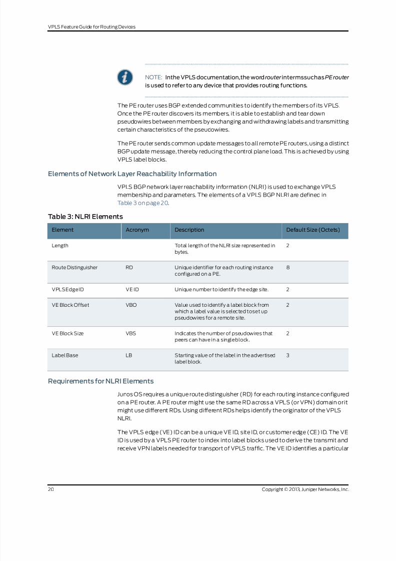
8/21/2019 Config Guide Vpns Vpls
http://slidepdf.com/reader/full/config-guide-vpns-vpls 38/485
NOTE: Inthe VPLS documentation,the word router intermssuchasPErouter
is used to refer to any device that provides routing functions.
The PE router uses BGP extended communities to identify the members of its VPLS.
Once the PE router discovers its members, it is able to establish and tear down
pseudowires between members by exchanging and withdrawing labels and transmitting
certain characteristics of the pseudowires.
The PE router sends common update messages to all remote PE routers, using a distinct
BGP update message, thereby reducing the control plane load. This is achieved by using
VPLS label blocks.
Elements of Network Layer Reachability Information
VPLS BGP network layer reachability information (NLRI) is used to exchange VPLS
membership and parameters. The elements of a VPLS BGP NLRI are defined inTable 3 on page 20.
Table 3: NLRI Elements
Default Size (Octets)DescriptionAcronymElement
2Total length of the NLRI size represented in
bytes.
Length
8Unique identifier for each routing instance
configured on a PE.
RDRoute Distinguisher
2Unique number to identify the edge site.VE IDVPLSEdgeID
2Value used to identify a label block from
which a label value is selected toset up
pseudowires for a remote site.
VBOVE Block Offset
2Indicates the number of pseudowires that
peers can have in a singleblock.
VBSVE Block Size
3Starting value of the label in the advertised
label block.
LBLabel Base
Requirements for NLRI Elements
Junos OS requires a unique route distinguisher (RD) for each routing instance configured
on a PE router. A PE router might use the same RD across a VPLS (or VPN) domain orit
might use different RDs. Using different RDs helps identify the originator of the VPLS
NLRI.
The VPLS edge (VE) ID can be a unique VE ID, site ID, or customer edge (CE) ID. The VE
ID is used by a VPLS PE router to index into label blocks used to derive the transmit and
receive VPN labels needed for transport of VPLS traffic. The VE ID identifies a particular
Copyright © 2013, Juniper Networks, Inc.20
VPLS Feature Guide for Routing Devices

8/21/2019 Config Guide Vpns Vpls
http://slidepdf.com/reader/full/config-guide-vpns-vpls 39/485
site, so it needs to be unique within the VPLS domain, except for some scenarios such
as multihoming.
All PE routers have full mesh connectivity with each other to exchange labels and set up
pseudowires.The VE block size (VBS) is a configurable value that represents the numberof label blocks required to cover all the pseudowires for the remote peer.
A single label block contains 8 labels (1 octet) by default. The default VBS in Junos OS
is 2 blocks (2 octets) for a total of 16 labels.
How Labels are Used in Label Blocks
Each PE router creates a mapping of the labels in the label block tothe sites in a VPLS
domain. A PE router advertising a label block with a block offset indicates which sites
can use the labels to reach it. When a PE router is ready to advertise its membership to
a VPLS domain, it allocatesa label block andadvertises the VPLS NLRI. In this way,other
PE routers in the same VPLS domain can learn of the existence of the VPLS and set up
pseudowires to it if needed. The VPLS NLRI advertised for this purpose is referred to asthe default VPLS NLRI. The label block in the default VPLS NLRI is referred to as the
default labelblock.
Label Block Composition
A label block (set of labels) is used to reach a given site ID. A single label block contains
8 labels (1 octet) by default. The VBS is 2 octets by default in Junos OS.
The label block advertised is defined as a label base (LB) and a VE block size (VBS). It
is a contiguous set of labels (LB, LB+1,...LB+VBS-1). For example, when Router PE-A
sends a VPLS update, it sends the same label block information to all other PE routers.
Each PE router that receives the LB advertisement infers the label intended for Router
PE-A by adding its own site ID tothe label base.
In this manner, each receiving PE gets a unique label for PE-A for that VPLS. This simple
method is enhanced by using a VE block offset (VBO).
A labelblock is defined as: <Label Base (LB), VE blockoffset (VBO), VE blocksize(VBS)>
is the set {LB+VBO, LB+VBO+1,...,LB+VBO+VBS-1}.
Label Blocks in Junos OS
Instead of a single large label block tocover all VE IDs in a VPLS, the Junos OS
implementation contains several label blocks, each with a different label base. This
makes label block management easier, and also allows Router PE-A to seemlessly
integrate a PE router joining a VPLS with a site ID not covered by the set of label blocks
that Router PE-A has already advertised.
VPLS Label Block Structure
This section illustrates how a label block is uniquely identified.
21Copyright © 2013, Juniper Networks, Inc.
Chapter1: Introduction to VPLS

8/21/2019 Config Guide Vpns Vpls
http://slidepdf.com/reader/full/config-guide-vpns-vpls 40/485
A VPLS BGP NLRI with site ID V, VE block offset VBO,VE block size VBS, and label base
LB communicates the following to its peers:
• Label block for V: Labels from LB to(LB + VBS -1).
• Remote VE set for V: from VBO to (VBO + VBS -1).
The label block advertised is a set of labels used to reach a given site ID. If there are
several label blocks, the remote VE set helps to identify which label block to use. The
example in Figure 4 on page 22 illustrates label blocks. There are two blocks and each
block has eight labels. In this example, the label values are 64 to 71 and 80 to 87.
Figure 4: VPLS Label Block Structure
64 65 66 67 68 69 70 71 80 81 82 83 84 85 86 87
1 2 3 4 5 6 7 8 9 10 11 12 13 14 15 16
VE Block Size = 8 VE Block Size = 8
Label base
VE Block Offset (1, 9)
For site range 9 through 16
Labels
Site IDs
g 0 4 0 5 0 3
To create a one-to-one mapping of these 16 labels to 16 sites, assume the site IDs are
the numbers 1 to 16, as shown in the illustration. The site block indicates which site ID
can use which label in the label block. So, in the first block, site ID 1 uses 64, site ID 2 uses
65, and so forth. Finally, site ID 8 uses 71.The 9thsite ID will use the secondblock instead
of the first block.
Thelabels are calculatedby comparingthe valuesof VBO<= Localsite ID < (VBO +VBS).
Consequently, site ID 9 uses 80, site ID 10 uses 81, and soon.
To furtherillustrate the one-to-one mapping of labels to sites, assume a label block with
site offset of 1 and a label base of 10. The combination of label base and block offset
contained in the VPLS NLRI provides the mapping of labels to site IDs. The block offset
is the starting site ID that can use the label block as advertised in the VPLS NLRI.
To advertise the default VPLS NLRI, a PE router picks a starting block offset that fits its
own site ID and is such that the end block offset is a multiple of a single label block. In
Junos OS a single label block is eight labels by default.
The end block offset is the last site ID that maps to the last label in the label block. The
end offset for the first block is 8 which mapsto label 17 and the second block is 16. For
example, a site with ID 3 picks a block offset of 1 and advertises a label block of size 8 to
cover sites with IDs 1 to8. A sitewith ID10 picks a block offset of9 tocover sites with IDs
9 to 16.
Copyright © 2013, Juniper Networks, Inc.22
VPLS Feature Guide for Routing Devices

8/21/2019 Config Guide Vpns Vpls
http://slidepdf.com/reader/full/config-guide-vpns-vpls 41/485
The VPLS NLRI shown in Figure 5 on page 23 is for site ID 18. The label base contains
value 262145. The block offset contains value 17. The illustration shows which site IDs
correspond to which labels.
Figure 5: Label Mapping Example
Site Offset = 17 Site IDs
Label Block
17 18 19 20 21 22 23 24
Length
RD
VE ID - 18
VE Block Offset - 17
VE Block Size - 8
Label Base - 262145
VPLS NLRI for Site ID 18
Label Mapping for Site ID 18
Label Base = 262145
262145 262146 262147 262148 262149 262150 262151 262152Label
Site ID
g 0 4 0 5 0 4
If a PE router configured with site ID 17 is in the same VPLS domain as a PE router
configured with site ID 18, it receives the VPLS NLRI as shown in Figure 3. So it uses label
262145to send traffic to site 18.Similarly, a PE router configured withsite ID 19 uses label
262147 to send traffic to a PE router configured with site ID 18. However, only PE routers
configured with site IDs 17 to 24 can use the label block shown to set up pseudowires.
Related
Documentation
Example: Building a VPLSFromRouter 1 to Router3 to Validate Label Blockson page 109•
PE Router Mesh Groups for VPLS Routing Instances
A PE router mesh groupconsists of a set ofrouters participating ina VPLS routing instance
that share the same signaling protocol, either BGP or LDP. Each VPLS routing instance
can have just one BGP mesh group. However, you can configure multiple LDP mesh
groups for each routing instance.
The Junos OS can support up to 16 mesh groups on MX Series routers and up to128 on
M Series and T Series routers. However, two mesh groups are created by default, one for
theCE routers andone for thePE routers. Therefore, themaximumnumberof user-defined
mesh groups is 14 for MX Series routers and 126 for M Series and T Series routers. PE
router mesh groups are not supported on J Series routers.
NOTE: Inthe VPLS documentation,the word router intermssuchasPErouter
is used to refer to any device that provides routing functions.
The Junos OS supports both forwarding equivalency class (FEC) 128 and FEC 129. FEC
129 uses VPLS autodiscovery to convey endpoint information.FEC 128 requires manually
configured pseudowires.
23Copyright © 2013, Juniper Networks, Inc.
Chapter1: Introduction to VPLS

8/21/2019 Config Guide Vpns Vpls
http://slidepdf.com/reader/full/config-guide-vpns-vpls 42/485
The following describes the behavior of mesh groups in regards to BGP-signaled PE
routers and LDP-signaled PE routers:
• BGP-signaled PE routers—Automatically discovered PE routers that use BGP for
signaling are associated with the default VE mesh group. You cannot configure theJunos OS to associate these routers with a user-defined VE mesh group.
• LDP-signaled PE routers (FEC 128)—PE routers statically configured using FEC-128
LDP signaling are placed in a default mesh group. However, you can configure a VE
mesh group and associate each LDP FEC-128 neighbor with it. Each configured VE
mesh group contains a set of VEs that are in the same interior gateway protocol (IGP)
routing instance and are fully meshed with each other in the control and data planes.
• LDP-signaledPE routers (FEC 129)—Configuration for a mesh group for FEC 129 is very
similiar to the configuration for FEC 128.
Note the following differences for FEC 129:
• Each user-defined mesh group must have a unique route distinguisher. Do not usethe route distinguisher that is defined for the default mesh group at the [edit
routing-intances] hierarchy level.
• Each user-defined mesh group must have its own import and export route target.
• Each user-defined mesh group can have a unique Layer 2 VPN ID. By default, all the
mesh groupsthat are configured for the a VPLS routing-instance usethe same Layer
2 VPN ID, the one that you configure at the [edit routing-instances] hierarchy level.
Related
Documentation
Example: Configuring BGP Autodiscovery for LDP VPLS on page 126•
Understanding PIM Snooping for VPLS
There are two ways to direct PIM control packets:
• By the use of PIM snooping
• By the use of PIM proxying
PIMsnoopingconfigures a device to examineand operate only on PIMhello andjoin/prune
packets. A PIMsnooping device snoopsPIM hello andjoin/prune packetson eachinterface
to find interested multicast receivers and populates the multicast forwarding tree with
this information. PIM snooping differs from PIM proxying in that both PIM hello and
join/prune packets are transparently flooded in the VPLS as opposed to the flooding of
only hello packets in the case of PIM proxying. PIM snooping is configured on PE routersconnected through pseudowires. PIM snooping ensures that no new PIM packets are
generated in the VPLS, with the exception of PIM messages sent through LDP on
pseudowires.
NOTE: Inthe VPLS documentation,the word router intermssuchasPErouter
is used to refer to any device that provides routing functions.
Copyright © 2013, Juniper Networks, Inc.24
VPLS Feature Guide for Routing Devices

8/21/2019 Config Guide Vpns Vpls
http://slidepdf.com/reader/full/config-guide-vpns-vpls 43/485
A device that supports PIM snooping snoops hello packets received on attachment
circuits. It does not introduce latency in the VPLS core when it forwards PIM join/prune
packets.
To configure PIM snooping on a PE router, use the pim-snooping statement at the [editrouting-instances instance-name protocols] hierarchy level:
routing-instances {
customer {
instance-type vpls;
...
protocols {
pim-snooping{
traceoptions {
file pim.logsize 10m;
flag all;
flag timer disable;
}
}}
}
}
“Example: Configuring PIM Snooping for VPLS” on page 115 explains the PIM snooping
method. The use of the PIM proxying method is not discussed here and is outside the
scope of this document. Formoreinformationabout PIM proxying, see PIM Snooping over
VPLS.
Related
Documentation
• Example: Configuring PIM Snooping for VPLS on page 115
25Copyright © 2013, Juniper Networks, Inc.
Chapter1: Introduction to VPLS

8/21/2019 Config Guide Vpns Vpls
http://slidepdf.com/reader/full/config-guide-vpns-vpls 44/485
Copyright © 2013, Juniper Networks, Inc.26
VPLS Feature Guide for Routing Devices

8/21/2019 Config Guide Vpns Vpls
http://slidepdf.com/reader/full/config-guide-vpns-vpls 45/485
CHAPTER 2
Introduction to Configuring VPLS
• Configuring an Ethernet Switch as the CE Device on page 27
Configuring an Ethernet Switch as the CE Device
For VPLS configurations, the CE device does not necessarily need to be a router. You can
link the PE routers directly to Ethernet switches. However, there are a few configuration
issues to be aware of:
• When you configure VPLS routing instances and establish two or more connections
between a CE Ethernet switch and a PE router, you must enable the Spanning Tree
Protocol (STP) on the switch to prevent loops.
• The Junos OS allows standard Bridge Protocol Data Unit (BPDU) frames to pass
through emulated Layer 2 connections, such as those configured with Layer 2 VPNs,
Layer 2 circuits, and VPLS instances. However, CE Ethernet switches that generate
proprietaryBPDU frames might notbe able torun STP acrossJuniper Networks routing
platforms configured for these emulated Layer 2 connections.
NOTE: Inthe VPLS documentation,the word router intermssuchasPErouter
is used to refer to any device that provides routing functions.
27Copyright © 2013, Juniper Networks, Inc.

8/21/2019 Config Guide Vpns Vpls
http://slidepdf.com/reader/full/config-guide-vpns-vpls 46/485
Copyright © 2013, Juniper Networks, Inc.28
VPLS Feature Guide for Routing Devices

8/21/2019 Config Guide Vpns Vpls
http://slidepdf.com/reader/full/config-guide-vpns-vpls 47/485
PART 2
Configuration
• Configuring VPLS on page 31
• VPLS Examples on page 109
• Next Generation VPLS Examples on page 227
• VPLS Configuration Statements on page 365
29Copyright © 2013, Juniper Networks, Inc.

8/21/2019 Config Guide Vpns Vpls
http://slidepdf.com/reader/full/config-guide-vpns-vpls 48/485
Copyright © 2013, Juniper Networks, Inc.30
VPLS Feature Guide for Routing Devices

8/21/2019 Config Guide Vpns Vpls
http://slidepdf.com/reader/full/config-guide-vpns-vpls 49/485
CHAPTER 3
Configuring VPLS
• Introduction to Configuring VPLS on page 32
• Configuring VPLS Routing Instances on page 32
• Configuring Interfaces for VPLS Routing on page 45
• Configuring the MTU for Layer 2 Interfaces on page 52
• Configuring Static Pseudowires for VPLS on page 53
• Configuring VPLS Multihoming (FEC 128) on page 54
• Enabling BGP Path Selection for Layer 2 VPNs and VPLS on page 57
• Configuring EXP-Based Traffic Classification for VPLS on page 59
• Configuring VPLS Load Balancing on page 59
• Configuring VPLS Load Balancing Based on IP and MPLS Information on page 61
• Configuring VPLS Load Balancing on MX Series 3D Universal Edge Routers on page 62
• Configuring VPLS Fast Reroute Priority on page 63
• Configuring VPLS Without a Tunnel Services PIC on page 65
• Mapping VPLS Traffic to Specific LSPs on page 66
• Configuring Firewall Filters and Policers for VPLS on page 67
• Firewall Filter Match Conditions for VPLS Traffic on page 71
• Specifying the VT Interfaces Used by VPLS Routing Instances on page 78
• Flooding Unknown Traffic Using Point-to-Multipoint LSPs on page 79
• Configuring VPLS and Integrated Routing and Bridging on page 83
• Configuring Interoperability Between BGP Signaling and LDP Signaling in
VPLS on page 84
• Example: Configuring Ingress Replication for IP Multicast Using MBGP
MVPNs on page 89
• Tracing VPLS Traffic and Operations on page 102
• Configuring the Label Block Size on page 103
• Configuring Y.1731 Functionality for VPLS to Support Delay and Delay
Variation on page 103
31Copyright © 2013, Juniper Networks, Inc.

8/21/2019 Config Guide Vpns Vpls
http://slidepdf.com/reader/full/config-guide-vpns-vpls 50/485
• Configuring Improved VPLS MAC Address Learning on T4000 Routers with Type 5
FPCs on page 105
• Configuring BFD for Layer 2 VPN and VPLS on page 107
Introduction to Configuring VPLS
Virtual private LAN service (VPLS) allows you to provide a point-to-multipoint LAN
between a set of sites in a virtual private network (VPN).
To configure VPLS functionality, you must enable VPLS support on the provider edge
(PE) router. You must also configure PE routers to distribute routing information to the
other PE routers in the VPLS and configure the circuits between the PE routers and the
customer edge (CE) routers.
NOTE: Inthe VPLS documentation,the word router intermssuchasPErouter
is used to refer to any device that provides routing functions.
Each VPLS is configured under a routing instance of type vpls. A vpls routing instance
can transparently carry Ethernet traffic across the service provider’s network. As with
other routing instances, all logical interfaces belonging to a VPLS routing instance are
listed under that instance.
In addition to VPLS routing instance configuration, you must configure MPLS
label-switched paths (LSPs) between the PE routers, IBGP sessions between the PE
routers, and an interior gateway protocol (IGP) on the PE and provider (P) routers.
By default, VPLS is disabled.
Many configuration procedures for VPLS areidentical to the procedures for Layer2 VPNs
and Layer 3 VPNs.
Configuring VPLS Routing Instances
To configure a VPLS routing instance, include the vpls statement:
vpls {
active-interface {
any;
primary interface-name;
}
connectivity-type (ce | irb | permanent);
encapsulation-type encapsulation-type ;interface-mac-limit limit;
label-block-size size;
mac-table-aging-time time;
mac-table-size size;
neighbor neighbor-id ;
no-tunnel-services;
site site-name{
active-interface {
any;
Copyright © 2013, Juniper Networks, Inc.32
VPLS Feature Guide for Routing Devices

8/21/2019 Config Guide Vpns Vpls
http://slidepdf.com/reader/full/config-guide-vpns-vpls 51/485
primary interface-name;
}
interface interface-name {
interface-mac-limit limit;
}mesh-group mesh-group-name;
multi-homing;
site-identifier identifier ;
site-preference preference-value {
backup;
primary;
}
}
site-range number ;
traceoptions {
file filename <files number > <size size> <world-readable | no-world-readable>;
flag flag <flag-modifier > <disable>;
}
tunnel-services {devices device-names;
primary primary-device-name;
}
vpls-id vpls-id ;
}
You can include this statement at the following hierarchy levels:
• [edit routing-instances routing-instance-name protocols]
• [edit logical-systems logical-system-namerouting-instances routing-instance-name
protocols]
NOTE: You cannot configure a routing protocol (OSPF, RIP, IS-IS or BGP)
inside a VPLS routing instance (instance-type vpls). The Junos CLI disallows
this configuration.
The configuration for the VPLS routing instance statements is explained in the following
sections:
• Configuring BGP Signaling for VPLS on page 34
• Configuring LDP Signaling for VPLS on page 38
• Configuring VPLS Routing Instance and VPLS Interface Connectivity on page 41
•
Configuring the VPLS Encapsulation Type on page 42• Configuring the VPLS MAC Table Timeout Interval on page 42
• Configuring the Size of the VPLS MAC Address Table on page 43
• Limiting the Number of MAC Addresses Learned from an Interface on page 44
• Removing Addresses from the MAC Address Database on page 45
33Copyright © 2013, Juniper Networks, Inc.
Chapter3: Configuring VPLS

8/21/2019 Config Guide Vpns Vpls
http://slidepdf.com/reader/full/config-guide-vpns-vpls 52/485
Configuring BGP Signaling for VPLS
You can configure BGP signaling for the VPLS routing instance. BGP is used to signal the
pseudowires linking each of the PE routers participating in the VPLS routing instance.The pseudowires carry VPLS traffic across the service provider's network between the
VPLS sites.
NOTE: You cannot configure both BGP signaling and LDP signaling for the
same VPLS routing instance. If you attempt to configure the statements that
enable BGP signaling for the VPLS routing instance (the site, site-identifier,
and site-range statements) and the statements that enable LDP signaling
for the same instance (the neighbor and vpls-id statements), the commit
operation fails.
NOTE: Inthe VPLS documentation,the word router intermssuchasPErouter
is used to refer to any device that provides routing functions.
Configure BGP signaling for the VPLS routing instance by completing the steps in the
following sections:
• Configuring the VPLS Site Name and Site Identifier on page 34
• Configuring Automatic Site Identifiers for VPLS on page 35
• Configuring the Site Range on page 36
• Configuring the VPLS Site Interfaces on page 37
• Configuring the VPLS Site Preference on page 38
Configuring the VPLS Site Name and Site Identifier
When you configure BGP signaling for the VPLS routing instance, on each PE router you
must configure each VPLS site that has a connection to the PE router. All the Layer 2
circuits provisioned for a VPLS site are listed as the set of logical interfaces (using the
interface statement) within the site statement.
You must configure a site name and site identifier for each VPLS site.
To configure the site name and the site identifier, include the site and the site-identifier
statements:
site site-name{
interface interface-name {
interface-mac-limit limit;
}
site-identifier identifier ;
}
Thenumerical identifiercan beany number from 1 through 65,534thatuniquelyidentifies
the local VPLS site.
Copyright © 2013, Juniper Networks, Inc.34
VPLS Feature Guide for Routing Devices

8/21/2019 Config Guide Vpns Vpls
http://slidepdf.com/reader/full/config-guide-vpns-vpls 53/485
You can include these statements at the following hierarchy levels:
• [edit routing-instances routing-instance-name protocols vpls]
• [edit logical-systems logical-system-namerouting-instances routing-instance-name
protocols vpls]
Configuring Automatic Site Identifiers for VPLS
When you enable automatic site identifiers, the Junos OS automatically assigns site
identifiersto VPLS sites.To configureautomatic site identifiersfor a VPLS routinginstance,
include the automatic-site-id statement:
automatic-site-id {
collision-detect-time seconds;
new-site-wait-time seconds;
reclaim-wait-time minimum seconds maximum seconds;
startup-wait-time seconds;
}
You can include this statement at the following hierarchy levels:
• [edit routing-instances routing-instance-name protocols vpls site site-name]
• [edit logical-systems logical-system-namerouting-instances routing-instance-name
protocols vpls site site-name]
The automatic-site-id statement includes a number of options that control different
delays in network layer reachability information (NLRI) advertisements. All of these
options are configured with default values. See the statement summary for the
automatic-site-id statement for more information.
The automatic-site-id statement includes the following options:
• collision-detect-time—The time in seconds to wait after a claim advertisement is sent
tothe otherrouters ina VPLS instance beforea PE router canbegin using a site identifier.
If the PE router receives a competing claim advertisement for the same site identifier
during this time period, it initiates the collision resolution procedure for site identifiers.
• new-site-wait-time—The time in seconds to wait to receive VPLS information for a
newly configured routing instance or a new site. This time interval is also applied
whenever the automatic site identifier feature is activated on a VPLS routing instance
otherthan at startup.Effectively, thistimer indicates howlong to wait beforean attempt
is made toallocate a site identifier. This timer is also triggered whenever a VPLS routing
instance is enabled.
• reclaim-wait-time—The time to wait before attempting to claim a site identifier after
a collision. A collision occurs whenever an attempt is made to claim a site identifier by
two separate VPLS sites.
• startup-wait-time—The time in seconds to wait at startup to receive all the VPLS
information for the route targets configured on the other PE routers included in the
VPLS routing instance.
35Copyright © 2013, Juniper Networks, Inc.
Chapter3: Configuring VPLS

8/21/2019 Config Guide Vpns Vpls
http://slidepdf.com/reader/full/config-guide-vpns-vpls 54/485
Configuring the Site Range
When you enable BGP signaling for each VPLS routing instance, you can optionally
configure the site range. The site range specifies an upper limit on the maximum site
identifier that canbe accepted to allow a pseudowire to be brought up.You must specify
a value from 1 through 65,534. The default value is 65,534. We recommend using the
default. Pseudowires cannot be established to sites with site identifiers greater than the
configured site range. If you issue the show vpls connections command, such sites are
displayed as OR (out of range).
To configure the site range, include the site-range statement:
site-range number ;
You can include this statement at the following hierarchy levels:
• [edit routing-instances routing-instance-name protocols vpls]
• [edit logical-systems logical-system-namerouting-instances routing-instance-name
protocols vpls]
There are networks that require that the site range be configured using a value smaller
than the local site identifier, for example, a hub-and-spoke VPLS with multihomed sites.
For this type of network, you need to allow pseudowires to be established between the
spoke routers and the hub router. However, you also need to prevent pseudowires from
being established between spoke routers directly. Due to the multihoming requirement
of spoke sites, Layer2 VPN NRLIs need to be accepted from other spoke routers (at least
from spokes with the same site identifier as the locally configured sites) to determine
the status of local spoke routers (active or not active) based on the local preference
included in the NRLIs received from the other spoke routers.
This type of VPLS network can be implemented by, for example, numbering hub sites
with identifiers 1 through 8 and spoke sites with identifiers 9 and larger. You can then
configure a site range of 8 on each of the spoke sites. Although the spoke sites accept
NRLIs and install them in the Layer 2 VPN routing tables (allowing the multihomed sites
to determine the status of the local site), the spoke sites cannot establish pseudowires
directly to the other spoke sites due to the configured site range.
The following configurations illustrate this concept. The configurations are for the VPLS
routing instances on three routers, two spoke routers and one hub router:
Router 1—spoke:
routing-instance hub-and-spoke {
no-local-switching;
protocols {
vpls {
site-range 8;
no-tunnel-services;
site spoke-9 {
site-identifier 9 {
multi-homing;
site-preference primary;
Copyright © 2013, Juniper Networks, Inc.36
VPLS Feature Guide for Routing Devices

8/21/2019 Config Guide Vpns Vpls
http://slidepdf.com/reader/full/config-guide-vpns-vpls 55/485
}
}
site spoke-10 {
site-identifier 10 {
multi-homing;site-preference backup;
}
}
}
}
}
Router 2—spoke:
routing-instance hub-and-spoke {
no-local-switching;
protocols {
vpls {
site-range 8;
no-tunnel-services;site spoke-9 {
site-identifier 9 {
multi-homing;
site-preference backup;
}
}
site spoke-10 {
site-identifier 10 {
multi-homing;
site-preference primary;
}
}
}
}
}
Hub—router 3:
routing-instance hub-and-spoke {
no-local-switching;
protocols {
vpls {
no-tunnel-services;
site hub {
site-identifier 1;
}
}
}}
Configuring the VPLS Site Interfaces
You must configure an interface for each of the pseudowires you specify for the VPLS
site.
To configure an interface for the VPLS site, include the interface statement:
37Copyright © 2013, Juniper Networks, Inc.
Chapter3: Configuring VPLS
8/21/2019 Config Guide Vpns Vpls
http://slidepdf.com/reader/full/config-guide-vpns-vpls 56/485
interface interface-name {
interface-mac-limit limit;
}
You can include these statements at the following hierarchy levels:
• [edit routing-instances routing-instance-name protocols vpls site site-name]
• [edit logical-systems logical-system-namerouting-instances routing-instance-name
protocols vpls]
You can also configure a limit on thenumber of MAC addresses that can be learned from
the specified interface.Formore information,see “Limitingthe Number of MACAddresses
Learned from an Interface” on page 44.
Configuring the VPLS Site Preference
You can specify the local preference value advertised for a particular VPLS site. The site
preference value is specified using the site-preference statement configured at the [edit
routing-instances routing-instance-name protocols vpls site site-name] hierarchy level. By
configuring the site-preference statement, a value configured for the local-preference
statement at the [edit protocols bgp] hierarchy level is ignored by the VPLS routing
instance. However, you can change the site preference value for VPLS routes exported
to other routers by configuring an export policy. When a PE router receives multiple
advertisements with the same VPLS edge (VE) device identifier, the advertisement with
the highest local preference value is preferred.
To configure the VPLS site preference, include the site-preference statement:
site-preference preference-value {
backup;
primary;
}
You canalso specify either the backup optionor the primary optionfor the site-preference
statement. The backup option specifies the preference value as 1, the lowest possible
value, ensuring that the VPLS site is the least likely to be selected. The primary option
specifies the preference value as 65,535, the highest possible value, ensuring that the
VPLS site is the most likely to be selected.
For a list of hierarchy levels at which you can include the site-preference statement, see
the statement summary section for this statement.
Configuring LDP Signaling for VPLS
You can configure LDP as the signaling protocol for a VPLS routing instance. Thisfunctionality is described in RFC 4762,Virtual Private LANService (VPLS) Using Label
DistributionProtocol (LDP)Signaling.
Copyright © 2013, Juniper Networks, Inc.38
VPLS Feature Guide for Routing Devices

8/21/2019 Config Guide Vpns Vpls
http://slidepdf.com/reader/full/config-guide-vpns-vpls 57/485
The Junos OS software does not support all of RFC 4762. When enabling LDP signaling
for a VPLS routing instance, network engineers should be aware that only the following
values are supported:
• FEC—128 or 129
• Control bit—0
• Ethernet pseudowire type—0x0005
• Ethernet tagged mode pseudowire type—0x0004
LDP signaled VPLS supports the Virtual Circuit Connectivity Verification (VCCV) Type
Length Value (TLV) for pseudowire label mapping, label database display, and LDP
trace. When you enable LDP signaling for a pseudowire, LDP advertises the VCCV
capabilities to the neighboring routers.VCCV providesa controlchannel for a pseudowire
and includes both operations and management functions (for example, connectivity
verification). This control channel is established between the pseudowire's ingress and
egress devices. Once established, connectivity verification messages can be sent overthe VCCV control channel.
The Junos OS software supports the following VCCV capabilities for LDP signaled VPLS
(defined in RFC 5085 Section 8.1):
• VCCV connectivity check types:
• Router Alert Label
• MPLS pseudowire label with TTL=1
• VCCV connectivity verification type:
• LSP ping
If the peer device also advertises VCCV parameters during pseudowire setup, the Junos
OS software selects the set of common advertised parameters to use as the method for
performing VCCV OAM on the pseudowire.
The locally advertised and peer advertised VCCV parameters can be viewed using the
show ldp database command as show here:
user@host> show ldp database l2circuit extensive
Input label database, 10.255.245.198:0--10.255.245.194:0
Label Prefix
299872 L2CKT CtrlWord PPP VC 100
MTU: 4470
VCCV Control Channel types:
MPLS router alert label
MPLS PW label with TTL=1
VCCV Control Verification types:
LSP ping
Label Prefix
State: Active
Age: 19:23:08
39Copyright © 2013, Juniper Networks, Inc.
Chapter3: Configuring VPLS

8/21/2019 Config Guide Vpns Vpls
http://slidepdf.com/reader/full/config-guide-vpns-vpls 58/485
Be aware of the following behavior with regard to TLVs when configuring LDP-signaled
VPLS in a network with equipment from other vendors:
• When a Juniper Network’s device receives a TLV with an empty address, LDP accepts
the TLV.
• When a MAC address is withdrawn, LDP specifies a zero address (0.0.0.0) for the
AddressList.
To enable LDP signaling for the set of PE routers participating in the same VPLS routing
instance, you need to use the vpls-id statement configured at the [edit routing-instances
routing-instance-nameprotocolsvpls] hierarchy level to configure the sameVPLS identifier
on each of the PE routers. The VPLS identifier must be globally unique. When each VPLS
routing instance(domain)hasa uniqueVPLS identifier, it is possibleto configuremultiple
VPLS routing instances between a given pair of PE routers.
LDP signaling requiresthat youconfigurea full-mesh LDPsession between the PE routers
in the same VPLS routing instance. Neighboring PE routers are statically configured.Tunnels are created between the neighboring PE routers to aggregate traffic from one
PE router to another. Pseudowires are then signaled to demultiplex traffic between VPLS
routing instances. These PE routers exchange the pseudowire label, the MPLS label that
acts as the VPLS pseudowire demultiplexer field, by using LDP forwarding equivalence
classes (FECs). Tunnels based on both MPLS and generic routing encapsulation (GRE)
are supported.
NOTE: You cannot configure both BGP signaling and LDP signaling for the
same VPLS routing instance. If you attempt to configure the statements that
enable BGP signaling for the VPLS routing instance (the site, site-identifier,
and site-range statements), and the statements that enable LDP signaling
for the same instance, neighbor and vpls-id, the commit operation fails.
To enable LDP signalingforthe VPLSroutinginstance, complete the steps in the following
sections:
• Configuring LDP Signaling for the VPLS Routing Instance on page 40
• Configuring LDP Signaling on the Router on page 41
Configuring LDP Signaling for the VPLS Routing Instance
To configure the VPLS routing instance to use LDP signaling, you must configure the
same VPLS identifier on each PE router participating in the instance. Specify the VPLS
identifier with the vpls-id statement:
vpls-id vpls-id ;
You can include this statement at the following hierarchy levels:
• [edit routing-instances routing-instance-name protocols vpls]
• [edit logical-systems logical-system-namerouting-instances routing-instance-name
protocols vpls]
Copyright © 2013, Juniper Networks, Inc.40
VPLS Feature Guide for Routing Devices

8/21/2019 Config Guide Vpns Vpls
http://slidepdf.com/reader/full/config-guide-vpns-vpls 59/485
To configure the VPLS routing instance to use LDP signaling, you also must include the
neighbor statement to specify each of the neighboring PE routers that are a part of this
VPLS domain:
neighbor neighbor-id ;
You can include this statement at the following hierarchy levels:
• [edit routing-instances routing-instance-name protocols vpls]
• [edit logical-systems logical-system-namerouting-instances routing-instance-name
protocols vpls]
Configuring LDP Signaling on the Router
To enable LDP signaling, you need to configure LDP on each PE router participating in
the VPLS routing instance. A minimal configuration is to enable LDP on the loopback
interface, which includes the router identifier (router-id), on the PE router using the
interface statement:
interface interface-name;
You can include this statement at the following hierarchy levels:
• [edit protocols ldp]
• [edit logical-systems logical-system-nameprotocols ldp]
You can enable LDPon allthe interfaces onthe router using theall option forthe interfaces
statement. For more information about how to configure LDP, see the Junos OSMPLS
Applications Library for Routing Devices.
Configuring VPLS Routing Instance and VPLS Interface Connectivity
You can configure the VPLS routing instance to take down or maintain its VPLS
connections depending on the status of the interfaces configured for the VPLS routing
instance. By default, the VPLS connection is taken down whenever a customer-facing
interface configured for the VPLS routing instance fails. This behavior can be explicitly
configured by specifying the ce option for the connectivity-type statement:
connectivity-type ce;
You canalternatively specify thatthe VPLSconnection remain up so longas an Integrated
Routing and Bridging (IRB) interface is configured for the VPLS routing instance by
specifying the irb option for the connectivity-type statement:
connectivity-type irb;
To ensure that the VPLS connection remain up until explicitly taken down, specify thepermanent option for the connectivity-type statement:
connectivity-type permanent;
This option is reserved for use in configuring Layer 2 Wholesale subscriber networks. See
the BroadbandSubscriberManagementSolutionsGuide for details about configuring a
Layer 2 Wholesale network.
41Copyright © 2013, Juniper Networks, Inc.
Chapter3: Configuring VPLS
8/21/2019 Config Guide Vpns Vpls
http://slidepdf.com/reader/full/config-guide-vpns-vpls 60/485
You can include this statement at the following hierarchy levels:
• [edit routing-instances routing-instance-name protocols vpls]
• [edit logical-systems logical-system-namerouting-instances routing-instance-name
protocols vpls]
Configuring the VPLS Encapsulation Type
You can specify a VPLS encapsulation type for the pseudowires established between
VPLS neighbors. The encapsulation type is carried in the LDP-signaling messages
exchanged between VPLS neighbors when pseudowires are created. You might need to
alter the encapsulation type depending on what other vendors’ equipment is deployed
within your network.
VPLS effectively provides a bridge between Ethernet networks. As a consequence, only
two encapsulation types are available:
• ethernet—Ethernet
• ethernet-vlan—Ethernet virtual LAN (VLAN)
If you do not specify an encapsulation type for the VPLS routing instance or the VPLS
neighbor, ethernet is used.
To specify an encapsulation type for the VPLS routing instance, include the
encapsulation-type statement:
encapsulation-type (ethernet | ethernet-vlan);
You can include this statement at the following hierarchy levels:
• [edit routing-instances routing-instance-name protocols vpls]
• [edit logical-systems logical-system-namerouting-instances routing-instance-name
protocols vpls]
You can also specify an encapsulation type for a specific VPLS neighbor by including the
encapsulation-type statement at the following hierarchy levels:
• [edit routing-instances routing-instance-name protocols vpls neighbor address]
• [edit logical-systems logical-system-namerouting-instances routing-instance-name
protocols vpls neighbor address]
Configuring the VPLS MAC Table Timeout Interval
You canmodify the timeout interval forthe VPLStable. Werecommendyou that configure
longer values for small, stable VPLS networks andshortervalues forlarge, dynamic VPLS
networks. If the VPLS table does not receive any updates during the timeout interval, the
router waits one additional interval beforeautomaticallyclearing the MACaddress entries
from the VPLS table.
Copyright © 2013, Juniper Networks, Inc.42
VPLS Feature Guide for Routing Devices

8/21/2019 Config Guide Vpns Vpls
http://slidepdf.com/reader/full/config-guide-vpns-vpls 61/485
To modify the timeout interval for the VPLS table, include the mac-table-aging-time
statement:
mac-table-aging-time seconds;
You can include this statement at the following hierarchy levels:
• [edit routing-instances routing-instance-name protocols vpls]
• [edit logical-systems logical-system-namerouting-instances routing-instance-name
protocols vpls]
NOTE: The mac-table-aging-time statement is not available on MX Series
routers.
Configuring the Size of the VPLS MAC Address Table
You can modify the size of the VPLS media access control (MAC) address table. The
default table size is 512 MACaddresses,the minimumis 16 addresses, andthe maximum
is 65,536 addresses.
NOTE: T4000 routers withType 5 FPCs supportup to 262,143MAC addresses
per VPLS routing instance. To enable the improved VPLS MAC address
learning limit (that is, 262,143 MAC addresses), you must Include the
enhanced-mode statement at the [edit chassis network-services] hierarchy
level, reboot the router, and then modify the size of the VPLS MAC address
table.
If the MAC table limit is reached, new MAC addresses can no longer be added to the
table. Eventually the oldest MAC addresses are removed from the MAC address table
automatically. This frees space in the table, allowing new entries to be added. However,
as long as the table is full, new MAC addresses are dropped.
To change the VPLS MAC table size for each VPLS or VPN routing instance, include the
mac-table-size statement:
mac-table-size size;
You can include this statement at the following hierarchy levels:
• [edit routing-instances routing-instance-name protocols vpls]
• [edit logical-systems logical-system-namerouting-instances routing-instance-name
protocols vpls]
When you include the mac-table-size statement, the affected interfaces include all
interfaces within the VPLS routing instance, including the local interfaces, the LSI
interfaces, and the VT interfaces.
43Copyright © 2013, Juniper Networks, Inc.
Chapter3: Configuring VPLS
8/21/2019 Config Guide Vpns Vpls
http://slidepdf.com/reader/full/config-guide-vpns-vpls 62/485
Limiting the Number of MAC Addresses Learned from an Interface
You can configure a limit on the number of MAC addresses learned by a VPLS routing
instance using the mac-table-size statement. If the MAC table limit is reached, new MACaddresses can no longer be added to the table. Eventually the oldest MAC addresses are
removedfrom the MACaddress table automatically. Thisfreesspacein thetable, allowing
new entries to be added. However, as long as the table is full, new MAC addresses are
dropped.
Because this limit applies to each VPLS routing instance, the MAC addresses of a single
interface can consume all the available space in the table, preventing the routing instance
from acquiring addresses from other interfaces.
You can limit the number of MAC addresses learned from each interface configured for
a VPLS routing instance. To do so, include the interface-mac-limit statement:
interface-mac-limit limit;
You can include this statement at the following hierarchy levels:
• [edit routing-instances routing-instance-name protocols vpls]
• [edit logical-systems logical-system-namerouting-instances routing-instance-name
protocols vpls]
The interface-mac-limit statement affects the local interfaces only(the interfaces facing
CE devices).
Configuring the interface-mac-limit statement at the [edit routing-instances
routing-instance-nameprotocols vpls] hierarchy level causes the same limit to be applied
to all of the interfaces configured for that specific routing instance.
You canalsolimit the number of MACaddresseslearned by a specific interface configured
for a VPLS routing instance. This gives you the ability to limit particular interfaces that
you expect might generate a lot of MAC addresses.
To limit the number of MAC addresses learned by a specific interface, include the
interface-mac-limit statement at the following hierarchy levels:
• [edit routing-instances routing-instance-name protocols vpls site site-name interfaces
interface-name]
• [edit logical-systems logical-system-namerouting-instances routing-instance-name
protocols vpls site site-name interfaces interface-name]
The MAC limit configured for an individual interface at this hierarchy level overrides any
value configured at the [edit routing-instances routing-instance-name protocols vpls]
hierarchy level. Also, the MAC limit configured using the mac-table-size statement can
override the limit configured using the interface-mac-limit statement.
The MAC address limit applies to customer-facing interfaces only.
Copyright © 2013, Juniper Networks, Inc.44
VPLS Feature Guide for Routing Devices

8/21/2019 Config Guide Vpns Vpls
http://slidepdf.com/reader/full/config-guide-vpns-vpls 63/485
Removing Addresses from the MAC Address Database
You canenable MACflushprocessingfor the VPLS routing instance or for themesh group
under a VPLS routing instance. MAC flush processing removes MAC addresses from theMACaddress database that have beenlearned dynamically. With the dynamicallylearned
MAC addresses removed, MAC address convergence requires less time to complete.
You can clear dynamically learned MAC addresses from the MAC address database by
including the mac-flush statement:
mac-flush [ explicit-mac-flush-message-options ];
To clear dynamically learned MAC addresses globally across all devices participating in
the routing instance, you can include the statement at the following hierarchy levels:
• [edit logical-systems logical-system-namerouting-instances routing-instance-name
protocols vpls]
• [edit routing-instances routing-instance-name protocols vpls]
To clear the MAC addresses on the routers in a specific mesh group, you can include the
statement at the following hierarchy levels:
• [edit logical-systems logical-system-namerouting-instances routing-instance-name
protocols vpls mesh-group mesh-group-name]
• [edit routing-instances routing-instance-name protocols vpls
mesh-group mesh-group-name]
For certain cases where MAC flush processing is not initiated by default, you can also
specify explicit-mac-flush-message-optionsto additionally configure the router to send
explicit MAC flush messagesunder specific conditions. Fora list of the explicit MAC flushmessage options you can include with this statement, see the summary section for this
statement.
Related
Documentation
Configuring Improved VPLS MAC Address Learning on T4000 Routers with Type 5
FPCs on page 105
•
• enhanced-mode
• show ldpdatabase
Configuring Interfaces for VPLS Routing
On each PE router and for each VPLS routing instance, specify which interfaces are
intendedfor the VPLStraffictravelingbetween PE and CE routers.Tospecifythe interface
for VPLS traffic, include the interface statement in the routing instance configuration:
interface interface-name;
You can include this statement at the following hierarchy levels:
• [edit routing-instances routing-instance-name]
45Copyright © 2013, Juniper Networks, Inc.
Chapter3: Configuring VPLS

8/21/2019 Config Guide Vpns Vpls
http://slidepdf.com/reader/full/config-guide-vpns-vpls 64/485
• [edit logical-systems logical-system-namerouting-instances routing-instance-name]
You must also define each interface by including the following statements:
vlan-taggingvlan-tagging;encapsulation encapsulation-type ;
unit logical-unit-number {
family vpls;
vlan-id vlan-id-number ;
}
You can include these statements at the following hierarchy levels:
• [edit interfaces interface-name]
• [edit logical-systems logical-system-nameinterfaces interface-name]
NOTE: Inthe VPLS documentation,the word router intermssuchasPErouter is used to refer to any device that provides routing functions.
The following sections provide enough information to enable you to configure interfaces
for VPLS routing.
• Configuring the VPLS Interface Name on page 46
• Configuring VPLS Interface Encapsulation on page 47
• Enabling VLAN Tagging on page 49
• Configuring VLAN IDs for Logical Interfaces on page 49
• Enabling VLANs for Hub and Spoke VPLS Networks on page 50
• Configuring Aggregated Ethernet Interfaces for VPLS on page 50
Configuring the VPLS Interface Name
Specify both the physical and logical portions of the interface name, in the following
format:
physical.logical
For example, in ge-1/2/1.2, ge-1/2/1 is the physical portion of the interface name and 2 is
the logical portion. If you do not specify the logical portion of the interface name, 0 is set
by default.
A logical interface can be associated with only one routing instance.
If you enable a routing protocol on all instances by specifying interfaces all when
configuring the master instance of the protocol at the [edit protocols] hierarchy level,
and you configure a specific interface for VPLS routing at the [edit routing-instances
routing-instance-name] hierarchy level, the latter interface statement takes precedence
and the interface is used exclusively for VPLS.
Copyright © 2013, Juniper Networks, Inc.46
VPLS Feature Guide for Routing Devices

8/21/2019 Config Guide Vpns Vpls
http://slidepdf.com/reader/full/config-guide-vpns-vpls 65/485
If you explicitly configure the same interface name at both the [edit protocols] and [edit
routing-instances routing-instance-name] hierarchy levels and then attempt to commit
the configuration, the commit operation fails.
Configuring VPLS Interface Encapsulation
You need to specify an encapsulation type for each PE-router-to-CE-router interface
configured for VPLS. This section describes the encapsulation statement configuration
options available for VPLS.
Tvo configurethe encapsulation type on the physical interface, include the encapsulation
statement:
encapsulation (ethernet-vpls | ether-vpls-over-atm-llc |extended-vlan-vpls | vlan-vpls);
You can include the encapsulation statement for physical interfaces at the following
hierarchy levels:
• [edit interfaces interface-name]
• [edit logical-systems logical-system-nameinterfaces interface-name]
You can configure the following physical interface encapsulations for VPLS routing
instances:
• ethernet-vpls—Use Ethernet VPLS encapsulation on Ethernet interfaces that have
VLAN 802.1Q tagging and VPLS enabled. The PE router expects to receive Ethernet
frames with VLAN tags that are not service-delimiting. The Ethernet frames are not
meaningful to the PE router and cannot be used by the service provider to separate
customer traffic.
On M Series routers (except the M320 router), the 4-port Fast Ethernet TX PIC and
the 1-port, 2-port, and 4-port, 4-slot Gigabit Ethernet PICs can use the Ethernet VPLS
encapsulation type.
• ether-vpls-over-atm-llc—For ATM intelligent queuing (IQ) interfaces only, use the
Ethernet virtual private LAN service (VPLS) over ATM LLC encapsulation to bridge
Ethernet interfaces and ATM interfaces over a VPLS routing instance (as described in
RFC 2684,Multiprotocol Encapsulation overATM Adaptation Layer 5). Packets from
the ATM interfaces are converted to standard ENET2/802.3 encapsulated Ethernet
frames with the frame check sequence (FCS) field removed.
• extended-vlan-vpls—Use extended virtualLAN(VLAN)VPLS encapsulationon Ethernet
interfaces that have VLAN 802.1Q tagging and VPLS enabled and that must accept
packets carrying TPIDs 0x8100, 0x9100, and 0x9901. On M Series routers (except the
M320router), the 4-portFastEthernetTX PICand the1-port, 2-port, and4-port, 4-slotGigabit Ethernet PICs can use the Ethernet VPLS encapsulation type.
47Copyright © 2013, Juniper Networks, Inc.
Chapter3: Configuring VPLS

8/21/2019 Config Guide Vpns Vpls
http://slidepdf.com/reader/full/config-guide-vpns-vpls 66/485
NOTE: The built-in Gigabit Ethernet PICon an M7irouter does not support
extended VLAN VPLS encapsulation.
• vlan-vpls—Use VLAN VPLS encapsulation on Ethernet interfaces with VLAN 802.1Q
tagging and VPLS enabled. The PE router expects to receive Ethernet frames with
VLAN tags that are service-delimiting. These VLAN tags can be used by the service
provider to separate customertraffic. For example, LANtrafficfrom different customers
can flow through the same service provider switch, which can then apply VLAN tags
to distinguish one customer’s traffic from the others. Thetraffic canthen be forwarded
to the PE router.
Interfaces with VLAN VPLS encapsulation accept packets carrying standard TPID
values only. On M Series routers (except the M320 router), the 4-port Fast Ethernet
TX PIC and the 1-port, 2-port, and 4-port, 4-slot Gigabit Ethernet PICs can use the
Ethernet VPLS encapsulation type.
To configure the encapsulation type for logical interfaces, include the encapsulation
statement:
encapsulation (ether-vpls-over-atm-llc | vlan-vpls);
You can include the encapsulation statement for logical interfaces at the following
hierarchy levels:
• [edit interfaces interface-name unit number ]
• [edit logical-systems logical-system-nameinterfaces interface-name unit number ]
You can configure the following logical interface encapsulations for VPLS routing
instances:
• ether-vpls-over-atm-llc—Use Ethernet VPLS over Asynchronous Transfer Mode (ATM)
logicallink control (LLC) encapsulation to bridgeEthernet interfaces and ATM interfaces
over a VPLS routing instance (as described in RFC 2684,MultiprotocolEncapsulation
over ATMAdaptationLayer5). Packets from the ATM interfaces are converted to
standardENET2/802.3-encapsulated Ethernet frames withthe frame checksequence
(FCS) field removed. This encapsulation type is supported on ATM intelligent queuing
(IQ) interfaces only.
• vlan-vpls—Use VLAN VPLS encapsulation on Ethernet interfaces with VLAN 802.1Q
tagging and VPLS enabled. The PE router expects to receive Ethernet frames with
VLAN tags that are service-delimiting. These VLAN tags can be used by the service
provider to separate customertraffic. For example, LANtrafficfrom different customerscan flow through the same service provider switch, which can then apply VLAN tags
to distinguish onecustomer's traffic from the others. Thetraffic canthen be forwarded
to the PE router.
Interfaces with VLAN VPLS encapsulation accept packets carrying standard TPID
values only. On M Series routers (except the M320 router), the 4-port Fast Ethernet
TX PIC and the 1-port, 2-port, and 4-port, 4-slot Gigabit Ethernet PICs can use the
Ethernet VPLS encapsulation type.
Copyright © 2013, Juniper Networks, Inc.48
VPLS Feature Guide for Routing Devices

8/21/2019 Config Guide Vpns Vpls
http://slidepdf.com/reader/full/config-guide-vpns-vpls 67/485
NOTE: Label-switched interfaces (LSIs) do not support VLAN VPLS
encapsulation. Therefore, you can only use VLAN VPLS encapsulation on
a PE-router-to-CE-router interface and not a core-facing interface.
When you configure the physical interface encapsulation as vlan-vpls, you also need to
configure the sameinterfaceencapsulation forthe logical interface.Youneed to configure
the vlan-vpls encapsulation on the logical interface because the vlan-vpls encapsulation
allows you to configure a mixed mode, where some of the logical interfaces use regular
Ethernet encapsulation (the default for logical interfaces) and some use vlan-vpls. For
more information, seeConfiguring VLANEncapsulation.
Enabling VLAN Tagging
Junos OS supports receiving and forwarding routed Ethernet frames with 802.1Q virtual
local area network (VLAN) tags and running the Virtual Router Redundancy Protocol
(VRRP) over 802.1Q-tagged interfaces. For VPLS to function properly, configure the
router toreceive andforward frames with 802.1Q VLAN tags byincluding the vlan-tagging
statement at the [edit interfaces interface-name] hierarchy level:
[edit interfaces interface-name]
vlan-tagging;
Gigabit Ethernet interfaces canbe partitioned. You canassign up to 4095different logical
interfaces, one for each VLAN, but you are limited to a maximum of 1024 VLANs on any
single Gigabit Ethernet or 10-Gigabit Ethernet port. Fast Ethernet interfaces can also be
partitioned, with a maximum of:
• 1024 logical interfaces for the 4-port FE PIC
• 1024 logical interfaces for the 2-port Fixed Interface Card (FIC) on an M7i router
• 16 logical interfaces for the M40e router
Table 4 on page 49 lists VLAN ID ranges by interface type.
Table 4: VLAN ID Range by Interface Type
VLAN ID RangeInterface Type
512 through 1023Fast Ethernet
512 through 4094Gigabit Ethernet
Configuring VLAN IDs for Logical Interfaces
You can bind a VLAN identifier to a logical interface by including the vlan-id statement:
vlan-id number ;
You can include this statement at the following hierarchy levels:
• [edit interfaces interface-name unit logical-unit-number ]
49Copyright © 2013, Juniper Networks, Inc.
Chapter3: Configuring VPLS

8/21/2019 Config Guide Vpns Vpls
http://slidepdf.com/reader/full/config-guide-vpns-vpls 68/485
• [edit logical-systems logical-system-nameinterfaces interface-name unit
logical-unit-number ]
You can also configure a logical interface to forward packets and learn MAC addresses
within each VPLS routing instance configured with a VLAN ID that matches a VLAN IDspecified in a list using the vlan-id-list statement. VLAN IDs can be entered individually
using a space to separate each ID, entered as an inclusive list separating the starting
VLAN ID and ending VLAN ID with a hyphen, or a combination of both.
For example, to configure the VLAN IDs 20 and 45 and the range of VLAN IDs between
30 and 40, issue the following command from the CLI:
set interfaces ge-1/0/1 unit 1 vlan-id-list [20 30-40 45];
To configure a list of VLAN IDs for a logical interface, include the vlan-id-list statement:
vlan-id-list list-of-vlan-ids;
You can include this statement at the following hierarchy levels:
• [edit interfaces interface-name unit logical-unit-number ]
• [edit logical-systems logical-system-nameinterfaces interface-name unit
logical-unit-number ]
Enabling VLANs for Hub and Spoke VPLS Networks
For hub and spoke VPLS networks, you need to configure the swap option for the
output-vlan-map statement on the hub facing interface of each spoke PE router. The
output-vlan-map statement ensures that thevlanID of thespoke PE router matches the
VLAN ID of the hub PE router in the VPLS network. The following configuration example
illustrates an interface configuration with the output-vlan-map statement included:
[edit interfaces xe-4/0/0]
vlan-tagging;
encapsulation flexible-ethernet-services;
unit610 {
encapsulation vlan-ccc;
vlan-id 610;
output-vlan-map swap;
}
Configuring Aggregated Ethernet Interfaces for VPLS
You can configure aggregated Ethernet interfaces between CE devices and PE routers
forVPLS routinginstances.Trafficis load-balanced acrossall of the links in theaggregated
interface. If one or more links in the aggregated interface fails, the traffic is switched to
the remaining links.
For more information about how aggregated Ethernet interfaces function in the context
of VPLS, see “VPLS and Aggregated Ethernet Interfaces” on page 6.
To configure aggregated Ethernet interfaces for VPLS, configure the interface for the
VPLS routing instance as follows:
interfaces ae x {
Copyright © 2013, Juniper Networks, Inc.50
VPLS Feature Guide for Routing Devices

8/21/2019 Config Guide Vpns Vpls
http://slidepdf.com/reader/full/config-guide-vpns-vpls 69/485
vlan-tagging;
encapsulationencapsulation-type ;
unit logical-unit-number {
vlan-id number ;
}}
You can configure the following physical link-layer encapsulation types for the VPLS
aggregated Ethernet interface:
• ethernet-vpls
• extended-vlan-vpls
• flexible-ethernet-services
• vlan-vpls
For the interface configuration statement, in ae x , the x represents the interface instance
number to complete the link association; x can be from 0 through 127, for a total of128 aggregated interfaces.
For more information about how to configure aggregated Ethernet interfaces, see the
AggregatedEthernet Interfaces Feature Guide for Routing Devices.
TheaggregatedEthernetinterface must also be configured for the VPLS routing instance
as shown in the following example:
[edit]
routing-instances {
green {
instance-type vpls;
interface ae0.0;
route-distinguisher 10.255.234.34:1;vrf-target target:11111:1;
protocols {
vpls {
site-range 10;
site green3 {
site-identifier 3;
}
}
}
}
}
Interface ae0.0 represents the aggregated Ethernet interface in the routing instance
configuration. The VPLS routing instance configuration is otherwise standard.
51Copyright © 2013, Juniper Networks, Inc.
Chapter3: Configuring VPLS

8/21/2019 Config Guide Vpns Vpls
http://slidepdf.com/reader/full/config-guide-vpns-vpls 70/485
Configuring the MTU for Layer 2 Interfaces
By default, the MTU used to advertise a Layer 2 pseudowire is determined by taking the
interface MTU for the associated physical interface and subtracting the encapsulation
overhead for sending IP packets based on the encapsulation. However, encapsulations
that support multiple logical interfaces (and multiple Layer 2 pseudowires) rely on the
same interface MTU (since they are all associated with the same physical interface).
This can prove to be a limitation for VLAN Layer 2 pseudowires using the same Ethernet
interface or for Layer 2 pseudowire DLCIs using the same Frame Relay interface.
This canalso affect multivendor environments. Forexample, if you have three PE devices
supplied by different vendors andone of the devices only supports an MTU of 1500, even
if the other devices support larger MTUs you must configure the MTU as 1500 (the
smallest MTU of the three PE devices).
You can explicitly configure which MTU is advertised for a Layer 2 pseudowire, even if
the Layer 2 pseudowire is sharing a physical interface with other Layer pseudowires.
When youexplicitlyconfigure an MTUfor a Layer2 pseudowire, be aware of thefollowing:
• An explicitly configured MTU is signaled to the remote PE device. The configured MTU
is also compared to the MTU received from the remote PE device. If there is a conflict,
the Layer 2 pseudowire is taken down.
• If you configure an MTU for an ATM cell relay interface on an ATM II PIC, the configured
MTU is used to compute the cell bundle size advertised for that Layer 2 pseudowire,
instead of the default interface MTU.
• A configured MTU is used only in the control plane. It is not enforced in the data plane.
You need to ensure that the CE device for a given Layer 2 pseudowire uses the correct
MTU for data transmission.
The following procedure describe how to configure the MTU for the Layer 2 interface.
This information applies to the following Layer 2 technologies:
• Layer 2 VPNs
• Layer 2 Circuits
• VPLS
1. To configure the MTU for a Layer 2 circuit, include the mtu statement:
mtu mtu-number ;
Fora list of hierarchy levels atwhichyou canincludethis statement, seethe statementsummary section for this statement.
2. To allow a Layer 2 pseudowire to be established even though the MTU configured on
the local PE router does not match the MTU configured on the remote PE router,
include the ignore-mtu-mismatch statement:
ignore-mtu-mismatch ;
Copyright © 2013, Juniper Networks, Inc.52
VPLS Feature Guide for Routing Devices

8/21/2019 Config Guide Vpns Vpls
http://slidepdf.com/reader/full/config-guide-vpns-vpls 71/485
Fora list of hierarchy levels atwhichyou canincludethis statement, seethe statement
summary section for this statement.
Related
Documentation
ignore-mtu-mismatch on page 386•
• mtu on page407
Configuring Static Pseudowires for VPLS
You can configure a VPLS domain using static pseudowires. A VPLS domain consists of
a set of PE routers that act as a single virtual Ethernet bridge for the customer sites
connected to these routers. By configuring static pseudowires for the VPLS domain, you
do not need to configure the LDP or BGP protocols that would normally be used for
signaling. However, if you configurestatic pseudowires, any changes to the VPLSnetwork
topology have to be managed manually.
NOTE: Inthe VPLS documentation,the word router intermssuchasPErouter
is used to refer to any device that provides routing functions.
Static pseudowires require that you configure a set of in and out labels for each
pseudowire configured for the VPLS domain. You still need to configure a VPLS identifier
and neighbor identifiers for a static VPLS domain. You can configure both static and
dynamic neighbors within the same VPLS routing instance.
To configure a static pseudowire for a VPLS neighbor, include the static statement:
static (Protocols VPLS) {
incoming-label label;outgoing-label label;
}
You must configure an incoming and outgoing label for the static pseudowire using the
incoming-label and outgoing-label statements. These statements identify the static
pseudowire’s incoming traffic and destination.
To configure a static pseudowire for a VPLS neighbor, include the static statement at
the [editrouting-instances routing-instance-nameprotocols vplsneighbor address] hierarchy
level.
You can also configure the static statement for a backup neighbor (if you configure the
neighbor as static the backup must also be static) by including it at the [edit
routing-instances routing-instance-nameprotocolsvplsneighbor address backup-neighbor
address] hierarchy leveland for a mesh group by including it at the [edit routing-instances
routing-instance-name protocols vpls mesh-group mesh-group-name neighbor address]
hierarchy level.
For a list of hierarchy levels at which you can include the static statement, see the
statement summary section for this statement.
53Copyright © 2013, Juniper Networks, Inc.
Chapter3: Configuring VPLS

8/21/2019 Config Guide Vpns Vpls
http://slidepdf.com/reader/full/config-guide-vpns-vpls 72/485
To enable static VPLS on a router, you need to either configure a virtual tunnel interface
(requires the router to have a tunnel services PIC) or you can configure a label switching
interface (LSI). To configure an LSI, include the no-tunnel-servicesstatement at the [edit
protocols vpls static-vpls] hierarchy level. For more information, see “Configuring VPLS
Without a Tunnel Services PIC” on page 65.
NOTE: Static pseudowires for VPLS using an LSI is supported on MX series
routersand EXSeries switchesonly. ForM seriesandT seriesrouters, a tunnel
services PIC is required.
If you issue a show vpls connections command, static neighbors are displayed with "SN"
next to their addresses in the command output.
Related
Documentation
Configuring VPLS Without a Tunnel Services PIC on page 65•
Configuring VPLS Multihoming (FEC 128)
VPLSmultihoming allows youto connect a customersite to multiplePE routersto provide
redundant connectivity while preventing the formation of Layer 2 loops in the service
provider’snetwork.A VPLS site multihomed to twoor more PE routersprovides redundant
connectivity in the event of a PE router-to-CE device link failure or the failure of a PE
router. For more informationabout VPLSmultihoming,see “VPLS Multihoming Overview”
on page 8.
NOTE: If you want to enable multihoming for a VPLS routing instance, you
cannot also enable LDP signaling. You can only enable BGP signaling.
NOTE: Inthe VPLS documentation,the word router intermssuchasPErouter
is used to refer to any device that provides routing functions.
The following sections describe how to configure VPLS multihoming. Some information
is alsoprovided on single-homed siteconfiguration versus multihomedsite configuration.
• VPLS Multihomed Site Configuration on page 54
• VPLS Single-Homed Site Configuration on page 56
VPLS Multihomed Site Configuration
The following describes the requirements for a VPLS multihomed site configuration:
• Assign the same site ID on all PE routers connected to the same CE devices.
• Assign the sameroutedistinguisheron all PE routers connected to the sameCE devices.
• Reference all interfaces assigned to the multihomed VPLS site on each PE router. Only
one of these interfaces is used to send and receive traffic for this site at a time.
Copyright © 2013, Juniper Networks, Inc.54
VPLS Feature Guide for Routing Devices

8/21/2019 Config Guide Vpns Vpls
http://slidepdf.com/reader/full/config-guide-vpns-vpls 73/485
• Either designate a primary interface or allow the router to select the interface to be
used as the primary interface.
If the router selects the interface, the interface used to connect the PE router to the
site depends on the order in which interfaces are listed in the PE router’sconfiguration.The first operational interface in the set of configured interfaces is chosen to be the
designated interface. If this interface fails, the next interface in the list is selected to
send and receive traffic for the site.
• Configure multihoming for the site.
Thefollowing configuration shows the statements you need to configure to enable VPLS
multihoming:
[edit routing-instances routing-instance-name]
instance-type vpls;
interface interface-name;
interface interface-name;
protocols vpls {site site-name{
active-interface {
any;
primary interface-name;
}
interface interface-name;
interface interface-name;
multi-homing;
site-identifier number ;
}
}
route-distinguisher ( as-number : id | ip-address: id );
NOTE: If youadda directconnectionbetweenCE devices that aremultihomed
to the same VPLS site on different PE routers, the traffic can loop and a loss
of connectivity might occur. We do not recommend this topology.
Most of these statements are explained in more detail in the rest of this chapter. The
following sections explain how to configure the statements that are specific to VPLS
multihoming:
• Specifying an Interface as the Active Interface on page 55
• Configuring Multihoming on the PE Router on page 56
Specifying an Interface as the Active Interface
You need tospecify oneof theinterfacesfor themultihomed site asthe primary interface.
If there are multiple interfaces, the remaining interfaces are activated only when the
primary interface goes down. If no active interfaces are configured at the site level, all
traffic for a VPLS site travels through a single, non-multihomed PE router.
55Copyright © 2013, Juniper Networks, Inc.
Chapter3: Configuring VPLS

8/21/2019 Config Guide Vpns Vpls
http://slidepdf.com/reader/full/config-guide-vpns-vpls 74/485
You must configure one of the following options for the active-interface statement:
• any—One configured interface is randomly designated as the active interface for the
VPLS site.
• primary—Specify the name of the multihomed interface to be used as the primary
interface by the VPLS site.
To specify a multihomed interface as the primary interface for the VPLS site, include the
active-interface statement:
active-interface {
any;
primary interface-name;
}
You can include this statement at the following hierarchy levels:
• [edit routing-instances routing-instance-name protocols vpls site site-name]
• [edit logical-systems logical-system-namerouting-instances routing-instance-name
protocols vpls site site-name]
Configuring Multihoming on the PE Router
When a CE deviceis connected tothe same VPLS site onmorethan onePE router, include
the multi-homing statementon all associated PE routers.Configuration of this statement
tracks BGP peers. If no BGP peer is available, VPLS deactivates all active interfaces for
a site. To specify that the PE router is part of a multihomed VPLS site, include the
multi-homing statement:
multi-homing;
You can include this statement at the following hierarchy levels:
• [edit routing-instances routing-instance-name protocols vpls site site-name]
• [edit logical-systems logical-system-namerouting-instances routing-instance-name
protocols vpls site site-name]
Include the multi-homing statement on all PE routers associated with a particular VPLS
site.
VPLS Single-Homed Site Configuration
All VPLS single-homed sites are connected to the same default VE device. All interfaces
in a VPLS routing instance that are not configured as part of a multihomed site areassumed to be single-homed to the default VE device.
Copyright © 2013, Juniper Networks, Inc.56
VPLS Feature Guide for Routing Devices

8/21/2019 Config Guide Vpns Vpls
http://slidepdf.com/reader/full/config-guide-vpns-vpls 75/485
Enabling BGP Path Selection for Layer 2 VPNs and VPLS
Layer 2 VPNs and VPLS share the same path selection process for determining the
optimal path to reach all of the destinations shared within a single routing instance. For
Layer 2 VPN and VPLS topologies, the path selection process is straightforward if there
is just a single path from each PE router to each CE device. However, the path selection
processbecomesmore complex if thePE routersreceivetwo or more valid pathsto reach
a specific CE device.
NOTE: Inthe VPLS documentation,the word router intermssuchasPErouter
is used to refer to any device that provides routing functions.
The following network scenarios provide examples of what might cause a PE router to
receive more than one valid path to reach a specific CE device:
• Multihoming—One or more CE devices within a routing instance are multihomed to
two or more PE routers. Each multihomed CE device has at least two valid paths.
• Route reflectors—There aremultipleroute reflectorsdeployed withinthe samenetwork
andtheyare supporting PE routerswithin thesame routing instance. Dueto time delays
in large complex networks, the route reflectors can separately receive a different valid
path to reach a CE device at different times. When they readvertise these valid paths,
a PE router could receive two or more separate but apparently valid paths to the same
CE device.
By default, Juniper Networks routers use just the designated forwarder path selection
algorithm to select the best path to reach each Layer 2 VPN or VPLS routing instance
destination (for more information, see “VPLS Path Selection Process for PE Routers” onpage 12). However, you can also configure the routers in your network to use both the
BGP path selection algorithm and the designated forwarder path selection algorithm as
follows:
• On the Provider routers within the service providers network, the standard BGP path
selection algorithm is used (for more information, seeUnderstanding BGPPath
Selection). Using the standard BGP path selection for Layer 2 VPN and VPLS routes
allows a service provider to leverage the existing Layer 3 VPN network infrastructure
to also support Layer 2 VPNs and VPLS. The BGP path selection algorithm also helps
to ensure that the service provider’s network behaves predictably with regard to Layer
2 VPN and VPLS path selection. This is particularly important in networks employing
route reflectors and multihoming.
When a Provider router receives multiple paths for the same destination prefix (for
example, a multihomed CE device), one path is selected based on the BGP path
selection algorithm and placed in the bgp.l2vpn.0 routing table and the appropriate
instance.l2vpn.0 routing table.
57Copyright © 2013, Juniper Networks, Inc.
Chapter3: Configuring VPLS

8/21/2019 Config Guide Vpns Vpls
http://slidepdf.com/reader/full/config-guide-vpns-vpls 76/485
• When a PE router receives all of the available paths to each CE device, it runs the
designated forwarder path selection algorithm to select the preferred path to reach
eachCE device, independentlyof the resultsof the earlier BGP pathselection algorithm
run on the Provider router. The VPLS designated forwarder algorithm uses the D-bit,
preference, and PE router identifier to determine which of the valid paths to each CE
device to use. The PE router might select a path to reach a CE device whichis different
from the path selected by theBGP-based Provider routers. In thisscenario,the following
is the expected behavior for traffic sent to the multihomed CE device:
• If the path selected by the remote PE router is available, traffic will traverse the
network to the multihomed CE device using the remote PE router’s preferred path
(again, ignoring the path selected by the BGP-based Provider routers).
• If the path selected by the remote PE router fails:
1. The Provider routers switch the traffic destined for the multihomed CE device to
the alternate path as soon as failure is detected.
2. The Provider routers notify the remote PE routers of the path failure.
3. The remote PE routers update their routing tables accordingly.
For more information about the VPLS designated forwarder path selection algorithm,
see “VPLS Path Selection Process for PE Routers” on page 12. This algorithm is also
described in the Internet draft draft-kompella-l2vpn-vpls-multihoming-03.txt,
Multi-homing in BGP-basedVirtual Private LANService.
To enable the BGP path selection algorithm for Layer2 VPN and VPLS routing instances,
complete the following steps:
1. Run Junos OS Release 12.3 or later on all of the PE and Provider routers participating
in Layer 2 VPN or VPLS routing instances.
Attempting to enable this functionality on a network with a mix of routers that both
do and do not support this feature can result in anomalous behavior.
2. Specify a unique route distinguisher on each PE router participating in a Layer 2 VPN
or VPLS routing instance.
3. Configure the l2vpn-use-bgp-rules statement on all of the PE and Provider routers
participating in Layer 2 VPN or VPLS routing instances.
You can configure this statement at the [edit protocols bgp path-selection] hierarchy
level to apply this behavior to all of the routing instances on the router or at the [edit
routing-instances routing-instance-name protocols bgp path-selection] hierarchy level
to apply this behavior to a specific routing instance.
Related
Documentation
Understanding BGP Path Selection•
• VPLS Path Selection Process for PE Routers on page 12
• l2vpn-use-bgp-rules
• route-distinguisher on page 424
Copyright © 2013, Juniper Networks, Inc.58
VPLS Feature Guide for Routing Devices

8/21/2019 Config Guide Vpns Vpls
http://slidepdf.com/reader/full/config-guide-vpns-vpls 77/485
Configuring EXP-Based Traffic Classification for VPLS
You can enable EXP classification on traffic entering core facing VPLS LSI interfaces on
a VPLS routing instance by configuring either a logical tunnel interface (lt-) or the
no-tunnel-servicesstatement. By configuring either of these, a default EXP classifier is
enabled on every core facing interface that includes family mpls in its configuration. This
feature works on MX Series routers and EX Series switches only. You can configure an
EXP classifierexplicitly at the [edit class-of-service]hierarchy level. For moreinformation
about EXP classifiers, see the Junos OS Class of Service Library for Routing Devices.
To enable EXP classification on traffic entering core facing VPLS LSI interfaces on a VPLS
routing instance, include the no-tunnel-services statement:
no-tunnel-services;
You can include this statement at the following hierarchy levels:
• [edit routing-instances routing-instance-name protocols vpls]
• [edit logical-systems logical-system-namerouting-instances routing-instance-name
protocols vpls]
Configuring VPLS Load Balancing
By default, when there are multiple equal-cost paths to the same destination for the
activeroute, the Junos OS uses a hash algorithm to select one of the next-hop addresses
toinstall in theforwardingtable. Wheneverthe setof next hops for a destinationchanges,
the next-hop address is reselected using the hash algorithm.
You can configure the Junos OS so that, for the active route, all next-hop addresses fora destination are installed in the forwarding table. This feature is called per-packet load
balancing. You can use load balancing to spread traffic across multiple paths between
routers. You can also configure per-packet load balancing to optimize VPLS traffic flows
across multiple paths.
NOTE: Inthe VPLS documentation,the word router intermssuchasPErouter
is used to refer to any device that provides routing functions.
You can load-balance VPLS traffic based on Layer 2 media access control (MAC)
information, IP information and MPLS labels, or MPLS labels only.
NOTE: For platform support information, see family multiservice.
To optimize VPLS traffic flows across multiple paths, include the family multiservice
statement at the [edit forwarding-options hash-key] hierarchy level:
family multiservice {
destination-mac;
59Copyright © 2013, Juniper Networks, Inc.
Chapter3: Configuring VPLS

8/21/2019 Config Guide Vpns Vpls
http://slidepdf.com/reader/full/config-guide-vpns-vpls 78/485
label-1;
label-2;
payload {
ip {
layer-3 {(destination-ip-only | source-ip-only);
}
layer-3-only;
layer-4;
}
}
source-mac;
symetric-hash {
complement;
}
}
You canconfigureoneor more of thefollowingoptionsto load-balance using thespecified
packet information:
• destination-mac—Include the destination-address MAC information in the hash key
for Layer 2 load balancing.
• source-mac—Include the source-address MAC information in the hash key.
• label-1—Include the first MPLS label in the hash key. Used for including a one-label
packet for per-flow load balancing of IPv4 VPLS traffic based on IP information and
MPLS labels.
• label-2 —Include the second MPLS label in the hash key. If both label-1 and label-2 are
specified, the entire first label and the first 16 bits of the second label are hashed.
• payload—Include the packet’s IP payload in the hash key.
• ip—Include the IP address of the IPv4 or IPv6 payload in the hash key.
• layer-3-only—Include only the Layer 3 information from the packet’s IP payload in the
hash key.
• layer-3—Include Layer 3 information from the packet’s IP payload in the hash key.
• destination-address-only—Include only the destination IP address in the payload in the
hash key.
NOTE: You can include either the source-address-only or the
destination-address-only statement, not both.They are mutually exclusive.
• source-address-only—Include only the source IP address in the payload in the hash
key.
NOTE: You can include either the source-address-only or the
destination-address-only statement, not both.They are mutually exclusive.
Copyright © 2013, Juniper Networks, Inc.60
VPLS Feature Guide for Routing Devices

8/21/2019 Config Guide Vpns Vpls
http://slidepdf.com/reader/full/config-guide-vpns-vpls 79/485
• layer-4—Include Layer 4 information from the packet’s IP payload in the hash key.
• symmetric-hash—Configure the symmetric hash or symmetric hash complement for
configuring symmetrical load balancing on an 802.3ad Link Aggregation Group.
• complement—Include the complement of the symmetric hash in the hash key.
Formore information about how to configure per-packet load balancing, see theRouting
PolicyFeature Guide for Routing Devices.
Related
Documentation
Configuring VPLS Load Balancing Based on IP and MPLS Information on page 61•
• Configuring VPLS Load Balancing on MX Series 3D Universal Edge Routers on page 62
Configuring VPLS Load Balancing Based on IP and MPLS Information
In Junos OS Release 9.4 and later, you can configure load balancing for VPLS traffic to
have the hash key include IP information andMPLS labelson the M120 andM320 routersonly. In earlierJunosOS Releases,you canconfigure load balancing basedonly on Layer2
information.In Junos OS Release 9.5 andlater, youcan configure load balancingfor VPLS
traffic based on Layer 3 IP and Layer 4 information on MX Series routers only. For more
information, see “Configuring VPLS Load Balancing on MX Series 3D Universal Edge
Routers” on page 62.
For IPv4 traffic, only the IP source and destination addresses are included in the hash
key. For MPLS and IPv4 traffic, one or two MPLS labels and IPv4 source and destination
addresses are included. For MPLS Ethernet pseudowires, only one or two MPLS labels
are included in the hash key.
NOTE: VPLS load balancing based on MPLS labels and IP information is
supported only on the M120 and M320 routers. In Junos OS Release 9.5 and
later, on MX Series routers only,you canconfigure VPLS load balancing based
on IP and Layer 4 information.
To optimize VPLSflowsacross multiple paths based on IP and MPLSinformation,include
the family multiservice statement at the [edit forwarding-options hash-key] hierarchy
level:
[edit forwarding-options hash-key]
family multiservice {
label-1;
label-2;payload {
ip {
layer-3-only;
}
}
}
To use the first MPLS label in the hash key, include the label-1 statement:
61Copyright © 2013, Juniper Networks, Inc.
Chapter3: Configuring VPLS
8/21/2019 Config Guide Vpns Vpls
http://slidepdf.com/reader/full/config-guide-vpns-vpls 80/485
[edit forwarding-options hash-key family multiservice]
label-1;
To use the second MPLS label, include both the label-1 and label-2 statements:
[edit forwarding-options hash-key family multiservice]
label-1;
label-2;
To use the packet’s IPv4 payload in the hash key, include the payload and ip statements:
[edit forwarding-options hash-key family multiservice]
payload {
ip;
}
NOTE: Only IPv4 is supported.
To include only Layer3 informationfrom the IPv4 payload, specify the layer-3-only option
tothe payload ip statement:
[edit forwarding-options hash-key family multiservice]
payload {
ip {
layer-3-only;
}
}
To use the first and second MPLS labels and the packet’s IP payload in the hash key,
include the label-1, label-2, and payload ip statements:
[edit forwarding-options hash-key family multiservice]
label-1;
label-2;
payload {
ip;
}
Configuring VPLS Load Balancing on MX Series 3D Universal Edge Routers
In Junos OS Release 9.5 and later, on MX Series routers, you can configure the load
balancing hash key for Layer 2 traffic to use fields in the Layer 3 and Layer 4 headers
inside the frame payload. You can also configure VPLS load balancing based on IP and
MPLSinformationon M120and M320routers only.For more information, see“Configuring
VPLS Load Balancing Based on IP and MPLS Information” on page 61.
You can configure load balancing on MX Series routers based on Layer 3 or Layer 4
information or both.
To configure VPLS load balancing on the MX Series router to include either Layer 3 IP
information or Layer 4 headers or both:
1. Include the payload statement at the [edit forwarding-options hash-key family
multiservice] hierarchy level.
Copyright © 2013, Juniper Networks, Inc.62
VPLS Feature Guide for Routing Devices

8/21/2019 Config Guide Vpns Vpls
http://slidepdf.com/reader/full/config-guide-vpns-vpls 81/485
2. Include the ip statement at the [edit forwarding-options hash-key family multiservice
payload] hierarchy level.
To configure VPLS load balancing to include the Layer 3 information:
1. Include the layer-3 statement at the [edit forwarding-options hash-key family
multiservice payload ip] hierarchy level.
2. Include the source-ip-only statement at the [edit forwarding-options hash-key family
multiservice payload ip layer-3] hierarchy level to include information about the IP
source address only in the hash key.
3. Include destination-ip-only statement at the [edit forwarding-options hash-key family
multiservice payload ip layer-3] hierarchy level to include information about the IP
destination address only in the hash key.
NOTE: You canconfigureeitherthe source-ip-onlyorthe destination-ip-only
statements at a time, not both. They are mutually exclusive.
To configure VPLS load balancing to include Layer 4 information:
• Include the layer-4 statement at the [edit forwarding-options hash-key family
multiservice payload ip] hierarchy level.
The following example shows load balancing configured to use the source Layer 3 IP
address option and Layer 4 header fields as well as the source and destination MAC
addresses:
[edit forwarding-options hash-key]
family multiservice {source-mac;
destination-mac;
payload {
ip {
layer-3 {
source-ip-only;
}
layer-4;
}
}
}
Related
Documentation
family multiservice on page 380•
• hash-key
Configuring VPLS Fast Reroute Priority
When a path is rerouted after a link failure by using the MPLS fast reroute feature, the
router repairs the affected next hops by switching them from the active label switched
path (LSP) to the standby LSP. To specify the order in which the router repairs next hops
and restores traffic convergence for VPLS routing instances after a fast reroute event,
63Copyright © 2013, Juniper Networks, Inc.
Chapter3: Configuring VPLS

8/21/2019 Config Guide Vpns Vpls
http://slidepdf.com/reader/full/config-guide-vpns-vpls 82/485
you can use the fast-reroute-priority statement to configure high, medium, or low fast
reroute priority for a VPLS routing instance. By default, the fast reroute priority for a VPLS
routing instance is low.
The router repairs next hops and restores known unicast, unknown unicast, broadcast,and multicast traffic for VPLS routing instances in the following order, based on the fast
reroute priority configuration:
1. The router repairs next hops for high-priority VPLS routing instances.
2. The router repairs next hops for medium-priority VPLS routing instances.
3. The router repairs next hops for low-priority VPLS routing instances.
Because the router repairs next hops for VPLS routing instances configured with high
fast reroute priority first, the traffic traversing high-priority VPLS instances is restored
faster than the traffic for VPLS instances configured with medium or low fast reroute
priority. The ability to prioritize specific VPLS routing instances for faster convergence
and traffic restoration enables service providers to offer differentiated service levels to
their customers.
Within a particular fast reroute priority level (high, medium, or low), the router follows no
particular order for traffic restoration of VPLS routing instances.
NOTE: VPLS fast reroute priority is not supported on EX Series switches or
J Series routers.
To configure high, medium, or lowfast reroute priority for a VPLS routing instance, include
the fast-reroute-priority statement:
fast-reroute-priority (high | medium | low);
You can include this statement at the following hierarchy levels:
• [edit logical-systems logical-system-namerouting-instances routing-instance-name
forwarding-options]
• [edit routing-instances routing-instance-name forwarding-options]
You can configure fast reroute priority only for routing instances with the instance-type
set to vpls. If you attempt to configure fast reroute priority for a routing instance with an
instance-type other thanvpls, therouterdisplays a warningmessage andthe configuration
fails.
The following example snippet shows configuration of high fast reroute priority for a
VPLS routing instance named test-vpls:
test-vpls {
instance-type vpls;
forwarding-options {
fast-reroute-priority high;
}
}
Copyright © 2013, Juniper Networks, Inc.64
VPLS Feature Guide for Routing Devices

8/21/2019 Config Guide Vpns Vpls
http://slidepdf.com/reader/full/config-guide-vpns-vpls 83/485
To display the fast reroute priority setting configured for a VPLS routing instance, use
the show route instance detail operational command. For information about using this
command, see the Junos OSOperationalMode Commands.
Configuring VPLS Without a Tunnel Services PIC
VPLS normally uses a dynamic virtual tunnel logical interface on a Tunnel Services PIC
tomodeltrafficfroma remotesite(a site on a remote PE router that is in a VPLS domain).
All traffic coming from a remote site is treated as coming in over the virtual port
representing this remote site, for the purposes of Ethernet flooding, forwarding, and
learning. An MPLS lookup based on the inner VPN label is done on a PE router. The label
is stripped and the Layer 2 Ethernet frame contained within is forwarded to a Tunnel
Services PIC. The PIC loops back the packet and then a lookup based on Ethernet MAC
addresses is completed. This approach requires that the router have a Tunnel Services
PIC and that the PE router complete two protocol lookups.
NOTE: Inthe VPLS documentation,the word router intermssuchasPErouter
is used to refer to any device that provides routing functions.
You can configure VPLS without a Tunnel Services PIC by configuring the
no-tunnel-servicesstatement. This statement creates a label-switched interface (LSI)
to provide VPLS functionality. An LSI MPLS label is used as the inner label for VPLS. This
label maps to a VPLS routing instance. On the PE router, the LSI label is stripped and
then mapped to a logical LSI interface. The Layer 2 Ethernet frame is then forwarded
using the LSI interface to the correct VPLS routing instance.
By default, VPLS requires a Tunnel Services PIC. To configure VPLS on a router without
a Tunnel Services PIC and create an LSI, include the no-tunnel-servicesstatement:
no-tunnel-services;
Fora list of the hierarchy levels at which youcan include this statement,see thesummary
section for this statement.
To configure a VPLS routing instance on a router without a tunnel services PIC, include
the no-tunnel-servicesstatement at the [edit routing-instances routing-instance-name
protocols vpls] hierarchy level. To configure static VPLS on a router without a tunnel
services PIC, include the no-tunnel-services statement at the [edit protocols vpls
static-vpls] hierarchy level.
When you configure VPLS without a Tunnel Services PIC by including the
no-tunnel-servicesstatement, the following limitations apply:
• An Enhanced FPC is required.
• ATM1 interfaces are not supported.
• Aggregated SONET/SDH interfaces are not supported as core-facing interfaces.
• Channelized interfaces are not supported as core-facing interfaces.
• GRE-encapsulated interfaces are not supported as core-facing interfaces.
65Copyright © 2013, Juniper Networks, Inc.
Chapter3: Configuring VPLS

8/21/2019 Config Guide Vpns Vpls
http://slidepdf.com/reader/full/config-guide-vpns-vpls 84/485
Related
Documentation
Configuring Static Pseudowires for VPLS on page 53•
Mapping VPLS Traffic to Specific LSPs
You can map VPLS traffic to specific LSPs by configuring forwarding table policies. This
procedure is optional but can be useful. The following example illustrates how you can
map lower priority VPLS routing instances to slower LSPs while mapping other higher
priority VPLS routing instances to faster LSPs. In this example configuration, a-to-b1 and
a-to-c1 are high-priority LSPs between the PE routers, while a-to-b2 and a-to-c2 are
low-priority LSPs between the PE routers.
NOTE: Inthe VPLS documentation,the word router intermssuchasPErouter
is used to refer to any device that provides routing functions.
To map VPLS traffic, include the policy-statement vpls-priority statement:
policy-statement vpls-priority {
term a {
from {
rib mpls.0;
community company-1;
}
then {
install-nexthop lsp [ a-to-b1 a-to-c1 ];
accept;
}
}
term b {from {
rib mpls.0;
community company-2;
}
then {
install-nexthop lsp-regex [ "^a-to-b2$" "^a-to-c2$" ];
accept;
}
}
}
community company-1 members target:11111:1;
community company-2 members target:11111:2;
You can include the policy-statement vpls-priority statement at the following hierarchy
levels:
• [edit policy-options]
• [edit logical-systems logical-system-namepolicy-options]
Include the export statement to apply the vpls-priority policy to the forwarding table:
export vpls-priority;
Copyright © 2013, Juniper Networks, Inc.66
VPLS Feature Guide for Routing Devices

8/21/2019 Config Guide Vpns Vpls
http://slidepdf.com/reader/full/config-guide-vpns-vpls 85/485
You can include this statement at the following hierarchy levels:
• [edit routing-options forwarding-table]
• [edit logical-systems logical-system-namerouting-options forwarding-table]
For more information about how to configure routing policies, see theRouting Policy
Feature Guide forRouting Devices.
Configuring Firewall Filters and Policers for VPLS
You can configure both firewall filters and policers for VPLS. Firewall filters allow you to
filterpacketsbased ontheircomponentsand toperforman actionon packetsthat match
the filter. Policers allow you to limit the amount of traffic that passes into or out of an
interface.
VPLS filters and policers act on a Layer 2 frame that includes the media access control
(MAC) header (after any VLAN rewrite or other rules are applied), but does not includethe cyclical redundancy check (CRC) field.
You can apply VPLS filters and policers on the PE router to customer-facing interfaces
only.
NOTE: Inthe VPLS documentation,the word router intermssuchasPErouter
is used to refer to any device that provides routing functions.
The following sections explain how to configure filters and policers for VPLS:
• Configuring a VPLS Filter on page 67
• Configuring a VPLS Policer on page 70
Configuring a VPLS Filter
To configure a filter for VPLS, include the filter statement at the [edit firewall family vpls]
hierarchy level:
[edit firewall family vpls]
filter filter-name {
interface-specific;
term term-name {
from {
match-conditions;
}then {
actions;
}
}
}
Formore informationabout howto configure firewall filters, seetheFirewallFiltersFeature
Guide for Routing Devices. For information on how to configure a VPLS filter match
condition, see “Firewall Filter Match Conditions for VPLS Traffic” on page 71.
67Copyright © 2013, Juniper Networks, Inc.
Chapter3: Configuring VPLS

8/21/2019 Config Guide Vpns Vpls
http://slidepdf.com/reader/full/config-guide-vpns-vpls 86/485
To configure a filter for VPLS traffic, complete the following tasks:
• Configuring an Interface-Specific Counter for VPLS on page 68
• Configuring an Action for the VPLS Filter on page 68
• Configuring VPLS FTFs on page 68
• Changing Precedence for Spanning-Tree BPDU Packets on page 69
• Applying a VPLS Filter to an Interface on page 69
• Applying a VPLS Filter to a VPLS Routing Instance on page 69
• Configuring a Filter for Flooded Traffic on page 70
Configuring an Interface-Specific Counter for VPLS
When you configure a firewall filter for VPLS and apply it to multiple interfaces, you can
specify individual counters specific to each interface. This allows you to collect separate
statistics on the traffic transiting each interface.
To generate an interface-specific counter for VPLS, you configure the interface-specific
statement. A separate instantiation of the filter is generated. This filter instance has a
different name (based on the interface name) and collects statistics on the interface
specified only.
To configure interface-specific counters, include the interface-specific statement at the
[edit firewall family vpls filter filter-name] hierarchy level:
[edit firewall family vpls filter filter-name]
interface-specific;
NOTE: The counter name is restricted to 24 bytes. If the renamed counter
exceeds this maximum length, it might be rejected.
Configuring an Action for the VPLS Filter
You can configure the following actions for a VPLS filter at the [edit firewall family vpls
filter filter-name term term-name then] hierarchy level: accept, count, discard,
forwarding-class, loss-priority, next, policer.
Configuring VPLS FTFs
Forwarding table filters (FTFs) are filters configured for forwarding tables. For VPLS,they
are attached to the destination MAC (DMAC) forwarding table of the VPLS routing
instance. You define VPLS FTFs in the same manner as any other type of FTF. You canonly apply a VPLS FTF as an input filter.
To specify a VPLS FTF, include the filter input statement at the [edit routing-instance
routing-instance-name forwarding-options family vpls] hierarchy level:
[edit routing-instance routing-instance-name forwarding-options family vpls]
filter input filter-name;
Copyright © 2013, Juniper Networks, Inc.68
VPLS Feature Guide for Routing Devices

8/21/2019 Config Guide Vpns Vpls
http://slidepdf.com/reader/full/config-guide-vpns-vpls 87/485
Changing Precedence for Spanning-Tree BPDU Packets
Spanning tree BPDU packets are automatically set to a high precedence. The queue
number on these packets is set to 3. On M Series routers (except the M320 router) by
default, a queue value of 3 indicates high precedence. To enable this higher precedence
on BPDUpackets,an instance-specificBPDU precedencefilternamed default_bpdu_filter
is automatically attached to the VPLS DMAC table. This filter places a high precedence
on all packets sent to 01:80:c2:00:00:00/24 .
You can overwrite this filter by configuring a VPLS FTF filter and applying it to the VPLS
routing instance. For more information, see “Configuring VPLS FTFs” on page 68 and
“Applying a VPLS Filter to a VPLS Routing Instance” on page 69.
Applying a VPLS Filter to an Interface
To apply a VPLS filter to an interface, include the filter statement:
filter {group index ;
input input-filter-name;
output output-filter-name ;
}
You can include this statement at the following hierarchy levels:
• [edit interfaces interface-name unit number family vpls]
• [edit logical-systems logical-system-nameinterfaces interface-name unit number
family vpls]
In the input statement, list the name of the VPLS filter to be evaluated when packets are
received on the interface. In the output statement, list the name of the VPLS filter to beevaluated when packets are transmitted on the interface.
NOTE: For output interface filters, MAC addresses arelearnedafter the filter
action is completed. When an output interface filter’s action is discard, the
packet is dropped before the MAC address is learned. However, an input
interface filter learns the MAC address before discarding the packet.
Applying a VPLS Filter to a VPLS Routing Instance
You can apply a VPLS filter to a VPLS routing instance. The filter checks traffic passing
through the specified routing instance.
Input routing instance filters learn the MAC address before the filter action is completed,
so if the filter action is discard, the MAC address is learned before the packet is dropped.
To apply a VPLS filterto packets arriving at a VPLS routing instance and specify the filter,
include the filter input statement at the [edit routing-instances routing-instance-name
forwarding-options family vpls] hierarchy level:
[edit routing-instances routing-instance-name forwarding-options family vpls]
69Copyright © 2013, Juniper Networks, Inc.
Chapter3: Configuring VPLS

8/21/2019 Config Guide Vpns Vpls
http://slidepdf.com/reader/full/config-guide-vpns-vpls 88/485
filter input input-filter-name;
Configuring a Filter for Flooded Traffic
You can configure a VPLS filter to filter flooded packets. CE routers typically flood the
following types of packets to PE routers in VPLS routing instances:
• Layer 2 broadcast packets
• Layer 2 multicast packets
• Layer 2 unicast packets with an unknown destination MAC address
• Layer 2 packets with a MAC entry in the DMAC routing table
You can configure filters to manage how these flooded packets are distributed to the
other PE routers in the VPLS routing instance.
To apply a flooding filter to packets arriving at the PE router in the VPLS routing instance,
and specify the filter, include the flood input statement:
flood input filter-name;
You can include this statement at the following hierarchy levels:
• [edit routing-instances routing-instance-name forwarding-options family vpls]
• [edit logical-systems logical-system-namerouting-instances routing-instance-name
forwarding-options family vpls]
Configuring a VPLS Policer
You can configure a policer for VPLS traffic. The VPLS policer configuration is similar to
the configuration of any other type of policer.
VPLS policers have the following characteristics:
• You cannot police the default VPLS routes stored in the flood table from PE
router–sourced flood traffic.
• When specifying policing bandwidth, the VPLS policer considers all Layer 2 bytes in a
packet to determine the packet length.
To configure a VPLS policer, include the policer statement at the [edit firewall] hierarchy
level:
[edit firewall]
policer policer-name {bandwidth-limit limit;
burst-size-limit limit;
then action;
}
To apply a VPLS policer to an interface, include the policer statement:
policer {
input input-policer-name;
Copyright © 2013, Juniper Networks, Inc.70
VPLS Feature Guide for Routing Devices

8/21/2019 Config Guide Vpns Vpls
http://slidepdf.com/reader/full/config-guide-vpns-vpls 89/485
output output-policer-name;
}
You can include this statement at the following hierarchy levels:
• [edit interfaces interface-name unit number family vpls]
• [edit logical-systems logical-system-nameinterfaces interface-name unit number
family vpls
In the input statement, list the name of the VPLS policer to be evaluated when packets
are received on the interface. In the output statement, list the name of the VPLS policer
to be evaluatedwhen packets are transmittedon the interface. This type of VPLS policer
can only apply to unicast packets. For information about how to filter flood packets, see
“Configuring a Filter for Flooded Traffic” on page 70.
Related
Documentation
Firewall Filters Feature Guide for Routing Devices•
•
Firewall Filter Match Conditions for VPLS Traffic on page 71
Firewall Filter Match Conditions for VPLS Traffic
Inthe from statementin the VPLS filterterm, youspecify conditions that the packet must
match for the action in the then statement to be taken. All conditions in the from
statement must match for the action to be taken. The order in which you specify match
conditions is not important, because a packet must match all the conditions in a term
for a match to occur.
If you specify no match conditions in a term, that term matches all packets.
An individual condition in afrom
statement can contain a list of values. For example, you
canspecify numeric ranges.You canalsospecifymultiple source addresses or destination
addresses. When a condition defines a list of values, a match occurs if one of the values
in the list matches the packet.
Individual conditions in a from statement can be negated. When you negate a condition,
you are defining an explicit mismatch. For example, the negated match condition for
forwarding-class is forwarding-class-except. If a packet matches a negated condition, it
is immediately considered not to match the from statement, and the next term in the
filter is evaluated, if there is one. If there are no more terms, the packet is discarded.
You can configure a firewall filter with match conditions for Virtual Private LAN Service
(VPLS) traffic (family vpls). Table 5 on page 72 describes the match-conditions you can
configure at the [edit firewall familyvpls filter filter-name term term-name from] hierarchylevel.
71Copyright © 2013, Juniper Networks, Inc.
Chapter3: Configuring VPLS

8/21/2019 Config Guide Vpns Vpls
http://slidepdf.com/reader/full/config-guide-vpns-vpls 90/485
NOTE: Not all match conditions for VPLS traffic aresupported on all routing
platforms or switching platforms. A number of match conditions for VPLS
traffic are supported only on MX Series 3D Universal Edge Routers.
In the VPLS documentation,the word router in termssuchasPErouter is used
to refer to any device that provides routing functions.
Table 5: Firewall Filter Match Conditions for VPLS Traffic
DescriptionMatch Condition
Match the destination media access control (MAC) address of a VPLS packet.destination-mac-address
address
(MX Series routers and EX Series switches only) Match the UDP or TCP destination port field.
You cannot specify both the port and destination-port match conditions in the same term.
In place of the numeric value, you can specifyone of the followingtext synonyms (the port
numbers arealso listed): afs (1483), bgp (179), biff (512), bootpc (68), bootps (67), cmd (514),
cvspserver (2401), dhcp (67), domain (53), eklogin (2105), ekshell (2106), exec (512), finger (79),
ftp (21), ftp-data (20), http (80), https (443), ident (113), imap (143), kerberos-sec (88),
klogin (543), kpasswd (761), krb-prop (754), krbupdate (760), kshell (544), ldap (389), ldp (646),
login (513), mobileip-agent (434), mobilip-mn (435), msdp (639), netbios-dgm (138),
netbios-ns (137), netbios-ssn (139), nfsd (2049), nntp (119), ntalk (518), ntp (123), pop3 (110),
pptp (1723), printer (515), radacct (1813), radius (1812), rip (520), rkinit (2108), smtp (25),
snmp (161), snmptrap (162), snpp (444), socks (1080), ssh (22), sunrpc (111), syslog (514),
tacacs (49), tacacs-ds (65), talk (517), telnet (23), tftp (69), timed (525), who (513), or xdmcp (177).
destination-port number
(MX Series routers and EX Series switches only) Do not match on the TCP or UDP destination
port field. You cannot specify both the port and destination-port match conditions in the same
term.
destination-port-except
number
(MX Series routers and EX Series switches only) Match destination prefixes in the specified list.
Specifythe name of a prefix list defined atthe [edit policy-options prefix-list prefix-list-name]
hierarchy level.
NOTE: VPLSprefix lists support only IPv4 addresses. IPv6 addresses included in a VPLS prefix
list will be discarded.
destination-prefix-list name
(MX Series routersand EX Series switchesonly) Do not match destination prefixes in the specified
list. For more information, seethe destination-prefix-list match condition.
destination-prefix-list name
except
Copyright © 2013, Juniper Networks, Inc.72
VPLS Feature Guide for Routing Devices

8/21/2019 Config Guide Vpns Vpls
http://slidepdf.com/reader/full/config-guide-vpns-vpls 91/485
Table 5: Firewall Filter Match Conditions for VPLS Traffic (continued)
DescriptionMatch Condition
(MX Series routers and EX Series switches only) Match the Differentiated Services code point(DSCP). The DiffServ protocol uses the type-of-service (ToS) byte in the IP header. The most
significant 6 bits of this byte form theDSCP. Formore information,see theBAClassifier Overview .
You can specify a numeric value from 0 through 63. To specify the value in hexadecimal form,
include 0x as a prefix. To specify the value in binary form, include b asa prefix.
In placeof thenumeric value,you canspecify oneof thefollowingtext synonyms (the fieldvalues
are also listed):
• RFC 3246, An ExpeditedForwardingPHB (Per-Hop Behavior), defines one code point: ef (46).
• RFC 2597, Assured Forwarding PHB Group, defines 4 classes, with 3 drop precedences in each
class, for a total of 12 code points:
af11 (10), af12 (12), af13 (14),
af21 (18), af22 (20), af23 (22),
af31 (26), af32 (28), af33 (30),
af41 (34), af42 (36), af43 (38)
dscp number
(MX Series routers and EX Series switches only) Do not match on the DSCP. For details, see the
dscp match condition.
dscp-except number
Match the 2-octet IEEE 802.3 Length/EtherType field to the specified value or list of values.
You can specify decimal or hexadecimal values from 0 through 65535 (0xFFFF). A value from
0 through 1500 (0x05DC) specifies the length of an Ethernet Version 1 frame. A value from 1536
(0x0600) through 65535 specifies the EtherType (nature of the MAC client protocol) of an
Ethernet Version 2 frame.
In place of thenumericvalue, youcan specifyone of thefollowingtextsynonyms (thehexadecimal
values arealso listed): aarp (0x80F3), appletalk (0x809B), arp (0x0806), ipv4 (0x0800),
ipv6 (0x86DD), mpls-multicast (0x8848), mpls-unicast (0x8847), oam (0x8902), ppp (0x880B),
pppoe-discovery (0x8863), pppoe-session (0x8864), or sna (0x80D5).
ether-type values
Do not match the 2-octet Length/EtherType field to the specified value or list of values.
For details about specifying the values, see the ether-type match condition.
ether-type-except values
Match the forwarding class. Specify assured-forwarding, best-effort, expedited-forwarding, or
network-control.
forwarding-class class
Do not match the forwarding class. For details, see the forwarding-class match condition.forwarding-class-except
class
73Copyright © 2013, Juniper Networks, Inc.
Chapter3: Configuring VPLS

8/21/2019 Config Guide Vpns Vpls
http://slidepdf.com/reader/full/config-guide-vpns-vpls 92/485
Table 5: Firewall Filter Match Conditions for VPLS Traffic (continued)
DescriptionMatch Condition
Match the ICMP message code field.
If you configurethis match condition, we recommend that you also configurethe next-header
icmp or next-headericmp6 match condition in the same term.
If youconfigure this match condition, youmustalso configure the icmp-type message-typematch
condition in the same term. An ICMP message code provides more specific information than an
ICMP message type, butthe meaningof an ICMP message code is dependent on the associated
ICMP message type.
In placeof thenumeric value,you canspecify oneof thefollowingtext synonyms (the fieldvalues
are also listed). The keywords are grouped by the ICMP type with which they are associated:
• parameter-problem: ip6-header-bad (0), unrecognized-next-header (1), unrecognized-option
(2)
• time-exceeded: ttl-eq-zero-during-reassembly (1), ttl-eq-zero-during-transit (0)
• destination-unreachable: address-unreachable (3), administratively-prohibited(1),
no-route-to-destination (0), port-unreachable (4)
icmp-code message-code
Do notmatch the ICMP message code field. For details, see the icmp-code match condition.icmp-code-except
message-code
(MX Series routers and EX Series switches only) Match the ICMP message code field.
If youconfigure this match condition, werecommend that youalsoconfigurethe ip-protocol icmp
or ip-protocol icmp6 match condition in the same term.
If youconfigure this match condition, youmustalso configure the icmp-type message-typematch
condition in the same term. An ICMP message code provides more specific information than an
ICMP message type, butthe meaningof an ICMP message code is dependent on the associated
ICMP message type.
In placeof thenumeric value,you canspecify oneof thefollowingtext synonyms (the fieldvalues
are also listed). The keywords are grouped by the ICMP type with which they are associated:
• parameter-problem: ip6-header-bad (0), unrecognized-next-header (1), unrecognized-option
(2)
• time-exceeded: ttl-eq-zero-during-reassembly (1), ttl-eq-zero-during-transit (0)
• destination-unreachable: address-unreachable (3), administratively-prohibited(1),
no-route-to-destination (0), port-unreachable (4)
icmp-code number
(MXSeries routers andEX Seriesswitches only) Do notmatch on theICMPcode field. Fordetails,
see the icmp-code match condition.
icmp-code-except number
(MX Series routers and EX Series switches only) Match the ICMP message type field.
If you configurethis match condition, we recommend that you also configurethe ip-protocol
icmp, ip-protocol icmp6, or ip-protocol icmpv6 match condition in the same term.
In placeof thenumeric value,you canspecify oneof thefollowingtext synonyms (the fieldvalues
are also listed): destination-unreachable (1), echo-reply (129), echo-request (128),
membership-query (130), membership-report (131), membership-termination (132),
neighbor-advertisement (136), neighbor-solicit (135), node-information-reply (140),
node-information-request (139), packet-too-big (2), parameter-problem (4), redirect (137),
router-advertisement (134), router-renumbering (138), router-solicit (133), or time-exceeded (3).
icmp-type number
Copyright © 2013, Juniper Networks, Inc.74
VPLS Feature Guide for Routing Devices

8/21/2019 Config Guide Vpns Vpls
http://slidepdf.com/reader/full/config-guide-vpns-vpls 93/485
Table 5: Firewall Filter Match Conditions for VPLS Traffic (continued)
DescriptionMatch Condition
(MX Series routers and EX Series switches only) Do not match the ICMP message type field. Fordetails, see the icmp-type match condition.
icmp-type-except number
Interface on which the packet was received. You can configurea match condition that matches
packets based on the interface on which they were received.
NOTE: If you configure this match condition with an interface that does not exist, the term
does not match any packet.
interface interface-name
Match the logical interface on which the packet was receivedto the specified interfacegroup or
setof interface groups.For group-number , specify a single valueor a rangeof values from 0 through
255.
To assign a logical interface to an interface group group-number , specify the group-number atthe
[interfaces interface-name unit number family family filter group] hierarchy level.
For more information, seeFiltering Packets Received on a Set of InterfaceGroupsOverview .
NOTE: This match condition is not supported on T4000 Type 5 FPCs.
interface-group
group-number
Do not match the logical interface on which the packet was received to the specified interface
group or setof interface groups. For details, see the interface-group match condition.
NOTE: This match condition is not supported on T4000 Type 5 FPCs.
interface-group-except
group-name
Match the interface on which the packet was received to the specified interface set.
To definean interface set,include the interface-set statementat the [editfirewall] hierarchy level.
For more information, seeFilteringPacketsReceived on an InterfaceSetOverview .
interface-set
interface-set-name
(MX Series routersand EX Series switchesonly) 32-bit addressthat supportsthe standardsyntax
for IPv4 addresses.
ip-address address
(MX Series routers and EX Seriesswitches only) 32-bitaddress that is thefinal destination node
address for the packet.
ip-destination-address
address
(MX Series routersand EX Seriesswitches only) IP precedence field. In placeof thenumeric field
value, you can specify one of the following text synonyms (the field values are also listed):
critical-ecp (0xa0), flash (0x60), flash-override (0x80), immediate (0x40), internet-control (0xc0),
net-control (0xe0), priority (0x20), or routine (0x00).
ip-precedence
ip-precedence-field
(MX Series routers and EX Series switches only) Do not match on the IP precedence field.ip-precedence-except
ip-precedence-field
(MX Series routers and EX Series switches only) IP protocol field.ip-protocol number
(MX Series routers and EX Series switches only) Do not match on the IP protocol field.ip-protocol-except number
(MX Series routersand EX Series switchesonly) IP addressof thesourcenode sending thepacket.ip-source-address address
75Copyright © 2013, Juniper Networks, Inc.
Chapter3: Configuring VPLS

8/21/2019 Config Guide Vpns Vpls
http://slidepdf.com/reader/full/config-guide-vpns-vpls 94/485
Table 5: Firewall Filter Match Conditions for VPLS Traffic (continued)
DescriptionMatch Condition
(MX Series routers and EX Series switches only) Match on the IEEE 802.1p learned VLAN prioritybits in the provider VLAN tag (the only tag in a single-tag frame with 802.1Q VLAN tags or the
outer tag in a dual-tag frame with 802.1Q VLAN tags). Specify a single value or multiple values
from 0 through 7.
Compare with the user-vlan-1p-priority match condition.
learn-vlan-1p-priority number
(MX Series routers and EX Series switches only) Do not match on the IEEE 802.1p learned VLAN
priority bits. For details, see the learn-vlan-1p-priority match condition.
learn-vlan-1p-priority-except
number
(MXSeries routers andEX Seriesswitches only) Matchthe user VLAN ID drop eligability indicator
(DEI) bit.
learn-vlan-dei
(MX Series routers and EX Series switches only) Do not match the user VLAN ID DEI bit.learn-vlan-dei-except
(MX Series routers and EX Series switches only) VLAN identifier used for MAC learning.learn-vlan-id number
(MX Series routers and EX Series switches only) Do not match on the VLAN identifier used for
MAC learning.
learn-vlan-id-except number
Packet loss priority (PLP) level. Specify a single level or multiple levels: low, medium-low,
medium-high, or high.
Supported on M120 and M320 routers; M7i and M10i routers with the Enhanced CFEB (CFEB-E);
and MX Series routers.
ForIP traffic onM320, MXSeries, andT Series routerswithEnhancedII FlexiblePIC Concentrators
(FPCs) and EX Series switches, you must include the tri-color statement at the [edit
class-of-service] hierarchy level tocommita PLPconfiguration with anyof thefour levelsspecified.
If the tri-color statement is not enabled, you can only configure the high and low levels. This
applies to all protocol families.
For information aboutthe tri-color statement and aboutusing behavior aggregate(BA) classifiers
toset the PLP level of incoming packets, seeOverviewof Forwarding Classes.
loss-priority level
Do not match on the packet loss priority level. Specify a single level or multiple levels: low,
medium-low, medium-high, or high.
For information about using behavior aggregate (BA) classifiers to setthe PLP level of incoming
packets, seeBAClassifier Overview .
loss-priority-except level
(MX Series routers and EX Series switches only) TCP or UDP source or destination port. You
cannot specify boththe port match conditionand either the destination-port or source-port match
condition in the same term.
port number
(MX Series routers and EX Series switches only) Do not match on the TCP or UDP source or
destination port.You cannotspecifyboth the port match conditionand either the destination-port
or source-port match condition in the same term.
port-except number
Copyright © 2013, Juniper Networks, Inc.76
VPLS Feature Guide for Routing Devices

8/21/2019 Config Guide Vpns Vpls
http://slidepdf.com/reader/full/config-guide-vpns-vpls 95/485
Table 5: Firewall Filter Match Conditions for VPLS Traffic (continued)
DescriptionMatch Condition
(MX Series routers and EX Series switches only) Match the destination or source prefixes in thespecified list. Specify the name of a prefix list defined atthe [edit policy-options prefix-list
prefix-list-name] hierarchy level.
NOTE: VPLS prefix lists support only IPV4 addresses. IPV6 addresses included in a VPLS prefix
list will be discarded.
prefix-list name
(MX Series routers and EX Series switches only) Do not match the destination or source prefixes
in the specified list. For more information, see the destination-prefix-list match condition.
prefix-list name except
Source MAC address of a VPLS packet.source-mac-address address
(MXSeries routersand EX Seriesswitches only) TCP or UDPsource port field. You cannotspecify
the port and source-port match conditions in the same term.
source-port number
(MX Series routers and EX Series switches only) Do not match on the TCP or UDP source port
field. You cannot specify the port and source-port match conditionsin the same term.
source-port-except number
(MX Series routers and EX Seriesswitches only) Match thesource prefixes in the specified prefix
list. Specifya prefixlist namedefinedat the[editpolicy-optionsprefix-list prefix-list-name] hierarchy
level.
NOTE: VPLS prefix lists support only IPV4 addresses. IPV6 addresses included in a VPLS prefix
list will be discarded.
source-prefix-list name
(MXSeries routersand EX Series switchesonly) Donot match thesourceprefixes in thespecified
prefix list. For more information, see the source-prefix-list match condition.
source-prefix-list name
except
Match one or more of the low-order 6 bits in the 8-bit TCP flags field in the TCP header.
To specify individualbit fields, youcan specify thefollowing text synonyms or hexadecimal values:
• fin (0x01)
• syn (0x02)
• rst (0x04)
• push (0x08)
• ack (0x10)
• urgent (0x20)
In a TCP session, the SYN flag is set only in the initial packetsent, while the ACK flag is set in all
packets sent after the initial packet.
You can string together multiple flags using the bit-field logical operators.
If you configurethis match condition for IPv6 traffic, we recommend that you also configurethe
next-header tcp match condition in the same term to specify that the TCP protocolis being used
on the port.
tcp-flags flags
(MX Series routers and EX Series switches only) Traffic type. Specify broadcast, multicast,
unknown-unicast, or known-unicast.
traffic-type type-name
77Copyright © 2013, Juniper Networks, Inc.
Chapter3: Configuring VPLS

8/21/2019 Config Guide Vpns Vpls
http://slidepdf.com/reader/full/config-guide-vpns-vpls 96/485
Table 5: Firewall Filter Match Conditions for VPLS Traffic (continued)
DescriptionMatch Condition
(MX Series routers and EX Series switches only) Do not match on the traffic type. Specifybroadcast, multicast, unknown-unicast, or known-unicast.
traffic-type-excepttype-name
(MX Series routers and EX Series switches only) Matchon the IEEE 802.1p user priority bits in the
customer VLAN tag (the inner tag in a dual-tag frame with 802.1Q VLAN tags). Specify a single
value or multiple values from 0 through 7.
Compare with the learn-vlan-1p-priority match condition.
user-vlan-1p-priority number
(MX Series routers and EX Series switches only) Do not match on the IEEE 802.1p user priority
bits. For details, see the user-vlan-1p-priority match condition.
user-vlan-1p-priority-except
number
(MX Series routers and EX Seriesswitches only) Match thefirstVLAN identifierthat is part of the
payload.
user-vlan-id number
(MX Series routers and EX Series switches only) Do not match on the first VLAN identifier that
is part of the payload.
user-vlan-id-except number
VLAN Ethernet type field of a VPLS packet.vlan-ether-type value
Do notmatch on the VLAN Ethernet type fieldof a VPLSpacket.vlan-ether-type-except value
Related
Documentation
Guidelines forConfiguring Firewall Filters•
• Firewall Filter Terminating Actions
• Firewall Filter NonterminatingActions
Specifying the VT Interfaces Used by VPLS Routing Instances
By default, the Junos OS automatically selects one of the virtual tunnel (VT) interfaces
available to the router for de-encapsulating traffic from a remote site. The Junos OS
cycles through the currently available VT interfaces,regularlyupdatingthe listof available
VT interfaces as new remote sites are discovered and new connections are brought up.
However, you can also explicitly configure which VT interfaces will receive the VPLS
traffic.
By including the tunnel-services statement at the [edit routing-instances
routing-instance-name protocols vpls] hierarchy level, you can specify that traffic for
particularVPLS routing instancesbe forwarded to specific VT interfaces. Doingso allowsyou to load-balance VPLS traffic among all the available VT interfaces on the router.
The tunnel-services statement includes the following options:
• devices—Specifies the VT interfaces acceptable for use by the VPLS routing instance.
If you do not configure this option, all VT interfaces available to the router can be used
for de-encapsulating traffic for this instance.
Copyright © 2013, Juniper Networks, Inc.78
VPLS Feature Guide for Routing Devices
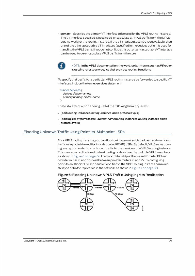
8/21/2019 Config Guide Vpns Vpls
http://slidepdf.com/reader/full/config-guide-vpns-vpls 97/485
• primary—Specifies the primary VT interface to be used by the VPLS routing instance.
The VT interface specified is used to de-encapsulate all VPLS traffic from the MPLS
core network for this routing instance. If the VT interface specified is unavailable, then
one of the other acceptable VT interfaces (specified in the devices option) is used for
handlingthe VPLS traffic. If youdo notconfigurethis option,any acceptableVT interface
can be used to de-encapsulate VPLS traffic from the core.
NOTE: Inthe VPLS documentation,the word router intermssuchasPErouter
is used to refer to any device that provides routing functions.
To specify that traffic for a particular VPLS routing instance be forwarded to specific VT
interfaces, include the tunnel-services statement:
tunnel-services {
devices device-names;
primary primary-device-name;}
These statements can be configured at the following hierarchy levels:
• [edit routing-instances routing-instance-name protocols vpls]
• [edit logical-systems logical-system-namerouting-instances routing-instance-name
protocols vpls]
Flooding Unknown Traffic Using Point-to-Multipoint LSPs
For a VPLS routing instance, you can flood unknown unicast, broadcast, and multicast
traffic using point-to-multipoint (also called P2MP) LSPs. By default, VPLS relies uponingress replication to flood unknown traffic to the members of a VPLS routing instance.
This can cause replication of data at routing nodes shared by multiple VPLS members,
as shown in Figure 6 on page 79. The flood data is tripled between PE router PE1 and
provider router P1 and doubled between provider routers P1 and P2. By configuring
point-to-multipoint LSPs to handle flood traffic, the VPLS routing instance can avoid
this type of traffic replication in the network, as shown in Figure 7 on page 80.
Figure 6: Flooding Unknown VPLS Traffic Using Ingress Replication
79Copyright © 2013, Juniper Networks, Inc.
Chapter3: Configuring VPLS

8/21/2019 Config Guide Vpns Vpls
http://slidepdf.com/reader/full/config-guide-vpns-vpls 98/485
Figure 7: Flooding Unknown VPLSTrafficUsing a Point-to-Multipoint LSP
NOTE: Inthe VPLS documentation,the word router intermssuchasPErouter
is used to refer to any device that provides routing functions.
The point-to-multipoint LSP used for VPLS flooding can be either static or dynamic. In
either case, for each VPLS routing instance, the PE router creates a dedicatedpoint-to-multipoint LSP. All of the neighbors of the VPLS routing instance are added to
the point-to-multipoint LSP when the feature is enabled. If there are n PE routers in the
VPLSrouting instance, npoint-to-multipoint LSPsare created in the network where each
PE router is the root of the point-to-multipoint tree and includes the rest of the n – 1 PE
routers as leaf nodes. If you configured static point-to-multipoint LSPs for flooding, any
additional VPLS neighbors added to the routing instance later are not automatically
added to the point-to-multipoint LSP. You will need to manually add the new VPLS
neighbors to the static point-to-multipoint flooding LSP. If you configure dynamic
point-to-multipoint LSPs, whenever VPLS discovers a new neighbor through BGP, a
sub-LSP forthis neighbor is added to the point-to-multipoint LSPforthe routinginstance.
This featurecan be enabled incrementally on anyPE router that is part of a specific VPLS
routing instance. The PE routers can then use point-to-multipoint LSPs to flood traffic,
whereas other PE routers in thesame VPLS routing instance canstill useingressreplication
to flood traffic. However, when this feature is enabled on any PE router, you must ensure
that all PE routers in the VPLS routing instance that participate in the flooding of traffic
over point-to-multipoint LSPs are upgraded to Junos OS Release 8.3 or later to support
this feature.
To flood unknown unicast, broadcast, and multicast traffic using point-to-multipoint
LSPs, configure the rsvp-te statement as follows:
rsvp-te {
label-switched-path-template {
(default-template | lsp-template-name);
}
static-lsp lsp-name;
}
You can include this statement at the following hierarchy levels:
• [edit routing-instance routing-instance-name provider-tunnel]
• [edit logical-systems logical-system-namerouting-instances routing-instance-name
provider-tunnel]
Copyright © 2013, Juniper Networks, Inc.80
VPLS Feature Guide for Routing Devices

8/21/2019 Config Guide Vpns Vpls
http://slidepdf.com/reader/full/config-guide-vpns-vpls 99/485
You can configure either a static point-to-multipoint LSP for VPLS flooding or a dynamic
point-to-multipoint LSP.
NOTE: You cannot specify both the static and label-switched-path-template
statements at the same time.
The following sections describe howto configurestatic and dynamic point-to-multipoint
LSPs for flooding unknown traffic in a VPLS routing instance:
• Configuring Static Point-to-Multipoint Flooding LSPs on page 81
• Configuring Dynamic Point-to-Multipoint Flooding LSPs on page 81
Configuring Static Point-to-Multipoint Flooding LSPs
The static-lsp option creates a static flooding point-to-multipoint LSP that includes all
of the neighbors in the VPLS routing instance. Flood traffic is sent to all of the VPLSneighbors using the generated point-to-multipoint LSP. VPLS neighbors added to the
routing instance later are not automatically added to the point-to-multipoint LSP. You
will need to manually add the new VPLS neighbors to the static point-to-multipoint
flooding LSP. By configuring static point-to-multipoint LSPs for flooding, you have more
control over which path each sub-LSP follows.
To configure a static flooding point-to-multipoint LSP, specify the name of the static
flooding point-to-multipoint LSP by including the static-lsp statement:
static-lsp lsp-name;
You can include this statement at the following hierarchy levels:
• [edit routing-instances routing-instance-name provider-tunnel rsvp-te]
• [edit logical-systems logical-system-namerouting-instances routing-instance-name
provider-tunnel rsvp-te]
Configuring Dynamic Point-to-Multipoint Flooding LSPs
To configure a dynamic point-to-multipoint flooding LSP, include the
label-switched-path-template statement option at the [edit routing-instances
routing-instance-name provider-tunnel rsvp-te] hierarchy level:
[edit routing-instances routing-instance-name provider-tunnel rsvp-te]
label-switched-path-template {
(default-template | lsp-template-name);}
81Copyright © 2013, Juniper Networks, Inc.
Chapter3: Configuring VPLS

8/21/2019 Config Guide Vpns Vpls
http://slidepdf.com/reader/full/config-guide-vpns-vpls 100/485
You can automatically generate the point-to-multipoint LSP to be used for flooding
unknown traffic or you can manually configure the point-to-multipoint LSP:
• Configuring Dynamic Point-to-Multipoint Flooding LSPs with the Default
Template on page 82
• Configuring Dynamic Point-to-Multipoint Flooding LSPs with a Preconfigured
Template on page 82
Configuring Dynamic Point-to-MultipointFloodingLSPs withtheDefaultTemplate
The default-template option,specifiedat the [edit routing-instances routing-instance-name
provider-tunnel rsvp-te label-switched-path-template] hierarchy level, causes the
point-to-multipoint LSPsto be created with default parameters. The default parameters
are for a minimally configured point-to-multipoint LSP. The name of this
point-to-multipoint LSP is also generated automatically and is based on the following
model:
id :vpls: router-id : routing-instance-name
The following show command output for show mpls lspp2mp illustrates how a
point-to-multipoint flood LSP name could appear if you configure the
label-switched-path-template statement with the default-template option:
user@host> show mpls lsp p2mp ingress
Ingress LSP: 2 sessions P2MP name: static, P2MP branch count: 3
To From State Rt ActivePath P LSPname
10.255.14.181 10.255.14.172 Up 0 * vpn02-vpn11
10.255.14.177 10.255.14.172 Up 0 path2 * vpn02-vpn07
10.255.14.174 10.255.14.172 Up 0 path3 * vpn02-vpn04
P2MP name: 9:vpls:10.255.14.172:green, P2MP branch count: 2
To From State Rt ActivePath P LSPname
10.255.14.177 10.255.14.172 Up 0 *
11:vpls:10.255.14.172:green
10.255.14.174 10.255.14.172 Up 0 *
10:vpls:10.255.14.172:green
Total 5 displayed, Up 5, Down 0
The dynamically generated point-to-multipoint LSP name is 9:vpls:10.255.14.172:green.
Configuring Dynamic Point-to-Multipoint Flooding LSPs with a Preconfigured
Template
You can configure a point-to-multipoint flooding LSP template for the VPLS routing
instance. The template allows you to specify the properties of the dynamic
point-to-multipoint LSPs that are used to flood traffic for the VPLS routing instance. You
canspecify all of the standard options available for a point-to-multipoint LSPwithinthis
template. These properties are inherited by the dynamic point-to-multipoint flood LSPs.
To configure a point-to-multipoint LSP template for flooding VPLS traffic, specify all of
the properties you want to include in a point-to-multipoint LSP configuration. To specify
this LSP as a point-to-multipoint flooding template, include the p2mp and template
statements:
p2mp;
template;
Copyright © 2013, Juniper Networks, Inc.82
VPLS Feature Guide for Routing Devices

8/21/2019 Config Guide Vpns Vpls
http://slidepdf.com/reader/full/config-guide-vpns-vpls 101/485
You can include these statements at the following hierarchy levels:
• [edit protocols mpls label-switched-path p2mp-lsp-template-name]
• [edit logical-systems logical-system-nameprotocols mpls label-switched-path
p2mp-lsp-template-name]
Formoreinformationabout howto configurethe p2mp statement and point-to-multipoint
LSPs, see the Junos OSMPLS Applications Library for Routing Devices.
Once you have configured the point-to-multipoint LSP template, specify the name of
the point-to-multipoint LSPtemplatewith the label-switched-path-template statement:
label-switched-path-template p2mp-lsp-template-name;
You can include this statement at the following hierarchy levels:
• [edit routing-instances routing-instance-name provider-tunnel rsvp-te]
• [edit logical-systems logical-system-namerouting-instances routing-instance-name
provider-tunnel rsvp-te]
Configuring VPLS and Integrated Routing and Bridging
Traditional Layer2 switching environments consist of Layer2 devices (such as switches)
that partition data into broadcast domains. The broadcast domains can be created
through physical topologies or logically through virtual local area networks (VLANs). For
MX Series routers, you can logically configure broadcast domains within virtual switch
routing instances, VPLS routing instances, or bridging domains. The individual routing
instances or bridging domains are differentiated through VLAN identifiers and these
instances or domains function much like traditional VLANs.
Fordetailed informationand configuration instructionson bridgingdomainsand spanning
tree protocol, see the Junos OS Network Interfaces Library for Routing Devices, the Junos
OSRouting Protocols Library forRouting Devices, and the Junos OS FeatureGuides.
The following sections provide configuration information specific to VPLS in regards to
integrated routing and bridging:
• Configuring MAC Address Flooding and Learning for VPLS on page 83
• Configuring MSTP for VPLS on page 84
Configuring MAC Address Flooding and Learning for VPLS
In a VPLS routing instance orbridge domain, when a frameis received from a CE interface,it is flooded to the other CE interfaces and all of the VE interfaces if the destination MAC
address is not learned or if the frame is either broadcast or multicast. If the destination
MAC addressis learnedon another CE device, such a frameis unicastedto theCE interface
on which the MAC address is learned. This might not be desirable if the service provider
does not want CE devices to communicate with each other directly.
To prevent CE devices from communicating directly include the no-local-switching
statement at the [edit bridge-domains bridge-domain-name] hierarchy level:
83Copyright © 2013, Juniper Networks, Inc.
Chapter3: Configuring VPLS

8/21/2019 Config Guide Vpns Vpls
http://slidepdf.com/reader/full/config-guide-vpns-vpls 102/485
[edit bridge-domains bridge-domain-name]
no-local-switching;
The no-local-switching statement is available only on MX Series routers. If you include
it, frames arriving on a CE interface are sent to VE or core-facing interfaces only.
Configuring MSTP for VPLS
When you configure integrated routing and bridging, you might also need to configure
the Multiple Spanning Tree Protocol (MSTP). When you configure MSTP on a provider
edge (PE) router running VPLS, you must also configure ethernet-vpls encapsulation on
the customer-facing interfaces. VLAN-based VPLS interface encapsulations are not
supported with MSTP.
Configuring Interoperability Between BGP Signaling and LDP Signaling in VPLS
A single VPLS routing instance can encompass one set of PE routers that use BGP for
signaling and another set of PE routers that use LDP for signaling. Within each set, all ofthe PE routers are fully meshed in both the control and data planes and have a
bidirectionalpseudowire toeach of the other routers in theset.However, the BGP-signaled
routers cannot be directly connected to the LDP-signaled routers. To be able to manage
the two separate sets of PE routers in a single VPLS routing instance, a border PE router
must be configured to interconnect the two sets of routers.
The VPLS RFCs and Internet drafts require that all of the PE routers participating in a
singleVPLS routing instance mustbe fully meshedin the data plane. In the control plane,
each fully meshed set of PE routers in a VPLS routing instance is called a PE router mesh
group. The border PE router must be reachable by and have bidirectional pseudowires
toall of thePE routersthat are a part of theVPLS routing instance, both theLDP-signaled
and BGP-signaled routers.
NOTE: Inthe VPLS documentation,the word router intermssuchasPErouter
is used to refer to any device that provides routing functions.
For LDP BGP interworking to function, LDP-signaled routers can be configured with
forwarding equivalence class (FEC) 128 or FEC 129.
The following sections describe how to configure BGP LDP interworking for VPLS:
• LDP BGP Interworking Platform Support on page 85
• Configuring FEC 128 VPLS Mesh Groups for LDP BGP Interworking on page 85
• Configuring FEC 129 VPLS Mesh Groups for LDP BGP Interworking on page 85
• Configuring Switching Between Pseudowires Using VPLS Mesh Groups on page 86
• Configuring Integrated Routing and Bridging Support for LDP BGP Interworking with
VPLS on page 87
• Configuring Inter-AS VPLS with MAC Processing at the ASBR on page 87
Copyright © 2013, Juniper Networks, Inc.84
VPLS Feature Guide for Routing Devices

8/21/2019 Config Guide Vpns Vpls
http://slidepdf.com/reader/full/config-guide-vpns-vpls 103/485
LDP BGP Interworking Platform Support
LDP BGP interworking is supportedon the following Juniper Networksroutersand routing
platforms:
• M7i
• M10i
• M40e
• M120
• M320
• MX Series routers
• T Series routers
• TX Matrix routers
• EX Series switches
Configuring FEC 128 VPLS Mesh Groups for LDP BGP Interworking
To configure FEC128 LDP BGP interworking for VPLS, include the mesh-group statement
in the VPLS routing instance configuration of the PE border router:
mesh-group mesh-group-name {
local-switching;
mac-flush [ explicit-mac-flush-message-options ];
neighbor address;
peer-as all;
vpls-id number ;}
You can include this statement at the following hierarchy levels:
• [edit routing-instances routing-instance-name protocols vpls]
• [edit logical-systems logical-system-namerouting-instances routing-instance-name
protocols vpls]
Using the neighbor statement, configure each PE router that is a part of the mesh group.
You must separate the LDP-signaled routers and the BGP-signaled routers into their own
respective mesh groups. The LDP-signaled routers can be divided into multiple mesh
groups. The BGP-signaled routers must be configured within a single mesh group for
each routing instance.
Configuring FEC 129 VPLS Mesh Groups for LDP BGP Interworking
Configuration for a mesh group for FEC 129 is very similiar to the configuration for FEC
128.
85Copyright © 2013, Juniper Networks, Inc.
Chapter3: Configuring VPLS

8/21/2019 Config Guide Vpns Vpls
http://slidepdf.com/reader/full/config-guide-vpns-vpls 104/485
Note the following differences for FEC 129:
• Each user-defined mesh group must have a unique route distinguisher. Do not use the
route distinguisher that is defined for the default mesh group at the [edit
routing-intances] hierarchy level.
• Each user-defined mesh group must have its own import and export route target.
• Each user-defined mesh group can have a unique Layer 2 VPN ID. By default, all the
mesh groups that are configured for the a VPLS routing-instance use the same Layer
2 VPN ID, the one that you configure at the [edit routing-instances] hierarchy level.
Configuring Switching Between Pseudowires Using VPLS Mesh Groups
To configure switching between Layer 2 circuit pseudowires using VPLS mesh groups,
you can do either of the following:
• Configure a mesh group for each Layer 2 circuit pseudowire terminating at a VPLS
routing instance.The Junos OS cansupport up to 16 mesh groups on MX Series routers
and up to 128 on M Series and T Series routers. However, two mesh groups are created
by default, one for the CE routers and one for the PE routers. Therefore, the maximum
number of user-defined mesh groups is 14 for MX Series routers and 126 for M Series
and T Series routers. PE router mesh groups are not supported on J Series routers.
• Configure a single mesh group,terminate all the Layer2 circuitpseudowires into it, and
enable local switching between the pseudowires by including the local-switching
statement at the [edit routing-instances routing-instance-name protocols vpls
mesh-group mesh-group-name] hierarchy level. By default, you cannot configure local
switching for mesh groups (except for theCE mesh group)because all of the VPLS PE
routers must be configured in a full mesh. However, local switching is useful if you are
terminating Layer2 circuit pseudowires in a mesh group configured for an LDPsignaledVPLS routing instance.
NOTE: Donotincludethe local-switching statement on PE routersconfigured
in a full mesh VPLS network.
To terminate multiple pseudowires at a single VPLS mesh group, include the
local-switching statement:
local-switching;
You can include this statement at the following hierarchy levels:
• [edit routing-instances routing-instance-name protocols vpls mesh-group
mesh-group-name]
• [edit logical-systems logical-system-namerouting-instances routing-instance-name
protocols vpls mesh-group mesh-group-name]
Copyright © 2013, Juniper Networks, Inc.86
VPLS Feature Guide for Routing Devices

8/21/2019 Config Guide Vpns Vpls
http://slidepdf.com/reader/full/config-guide-vpns-vpls 105/485
Configuring Integrated Routing and Bridging Support for LDP BGP Interworking with VPLS
Beginningwith JunosOS Release 9.4, youcanconfigure an integratedroutingand bridging
(IRB)interfaceon a router thatfunctionsas an autonomous system border router (ASBR)in an inter-AS VPLS environment between BGP-signaled VPLS and LDP-signaled VPLS.
Previously, IRB interfaces were supported only on Provider Edge (PE) routers.
To configure a IRB support for LDP BGP Interworking with VPLS, include the
routing-interface interface-name statement.
You can include this statement at the following hierarchy levels:
• [edit routing-instances routing-instance-name]
• [edit logical-routers logical-router-name routing-instances routing-instance-name]
Configuring Inter-AS VPLS with MAC Processing at the ASBR
Inter-AS VPLS with MAC processing at the ASBR enables you to interconnect customer
sites that arelocatedin different ASs. In addition,you canconfigurethe ASswith different
signaling protocols. You can configure one of the ASs with BGP-signaled VPLS and the
other withLDP-signaled VPLS. Formoreinformation about howto configureLDP-signaled
and BGP signaled VPLS, see “Configuring Interoperability Between BGP Signaling and
LDP Signaling in VPLS” on page 84.
For inter-AS VPLS to function properly, you need to configure IBGP peering between the
PE routers, includingthe ASBRsin each AS,justas you dofor a typical VPLS configuration.
You also need to configure EBGP peering between the ASBRs in the separate ASs. The
EBGP peering is needed between the ASBRs only. The link between the ASBR routers
does not have to be Ethernet. You can also connect a CE router directly to one of the
ASBRs, meaning you do not have tohave a PE router between the ASBR and the CE
router.
The configuration for the connection between the ASBRs makes inter-AS VPLS with
MAC operations unique. The other elements of the configuration are described in other
sections of this manual.An extensive configuration example for inter-AS VPLS with MAC
operations is provided in the Junos OS FeatureGuides.
The following sections describe how to configure inter-AS VPLS with MAC operations:
• Inter-AS VPLS with MAC Operations Configuration Summary on page 87
• Configuring the ASBRs for Inter-AS VPLS on page 88
Inter-AS VPLS with MAC Operations Configuration Summary
This section provides a summary of all of the elements which must be configured to
enable inter-AS VPLS with MAC operations. These procedures are described in detail
later in this chapter and in other parts of the Junos OS VPNs Library for Routing Devices.
87Copyright © 2013, Juniper Networks, Inc.
Chapter3: Configuring VPLS

8/21/2019 Config Guide Vpns Vpls
http://slidepdf.com/reader/full/config-guide-vpns-vpls 106/485
The following lists all of major elements of an inter-AS VPLS with MAC operations
configuration:
• Configure IBGP between all of the routers within each AS, including the ASBRs.
• Configure EBGP between the ASBRs in the separated ASs. The EBGP configuration
includes the configuration that interconnects the ASs.
• Configure a full mesh of LSPs between the ASBRs.
• Configure a VPLS routing instance encompassing the ASBR routers. The ASBRs are
VPLS peers and are linked by a single pseudowire. Multihoming between ASs is not
supported. A full mesh of pseudowires is needed between the ASBR routers in all of
the interconnected ASs.
• Configure the VPLS routing instances using either BGP signaling or LDP signaling. LDP
BGP interworking is supportedfor inter-AS VPLS withMAC operations, so it is possible
to interconnect the BGP-signaled VPLS routing instanceswith the LDP-signaled VPLS
routing instances.
• Configurea singleVPLS mesh group for all of the ASBRsinterconnected using inter-AS
VPLS.
Configuring the ASBRs for Inter-AS VPLS
This section describes the configuration on the ASBRs needed to enable inter-AS VPLS
with MAC operations.
On eachASBR,you needto configurea VPLS meshgroupwithinthe VPLS routinginstance
which needs to include all of the PE routers within the AS, in addition to the ASBR. You
need to configure the same mesh group for each of the ASs you want to interconnect
using inter-AS VPLS. The mesh group name should be identical on each AS. You also
must include the peer-as all statement. This statement enables the router to establisha single pseudowire to each of the other ASBRs.
To configure the mesh group on each ASBR, include the mesh-group and peer-as all
statements:
mesh-group mesh-group-name {
peer-as all;
}
You can include these statements at the following hierarchy levels:
• [edit routing-instances routing-instance-name protocols vpls]
• [edit logical-systems logical-system-namerouting-instances routing-instance-name
protocols vpls]
Related
Documentation
Example: Configuring BGP Autodiscovery for LDP VPLS on page 126•
• Example: ConfiguringBGPAutodiscovery forLDP VPLSwith User-DefinedMesh Groups
on page 143
Copyright © 2013, Juniper Networks, Inc.88
VPLS Feature Guide for Routing Devices

8/21/2019 Config Guide Vpns Vpls
http://slidepdf.com/reader/full/config-guide-vpns-vpls 107/485
Example: Configuring Ingress Replication for IP Multicast Using MBGP MVPNs
• Requirements on page 89
• Overview on page 89
• Configuration on page 90
• Verification on page 94
Requirements
Theroutersused in thisexample areJuniper Networks M Series Multiservice EdgeRouters,
T Series Core Routers, or MX Series 3D Universal Edge Routers running Junos OS Release
10.4 or later. When using ingress replication for IP multicast, each participating router
must be configured with BGP for control plane procedures and with ingress replication
for the data provider tunnel, which forms a full mesh of MPLS point-to-point LSPs. The
ingress replication tunnel can be selective or inclusive, depending on the configuration
of the provider tunnel in the routing instance.
Overview
The ingress-replication provider tunnel type uses unicast tunnels between routers to
create a multicast distribution tree.
The mpls-internet-multicastroutinginstancetypeuses ingressreplication provider tunnels
to carry IP multicast data between routers through an MPLS cloud, using MBGP (or Next
Gen) MVPN. Ingress replicationcanalso beconfiguredwhenusing MVPNto carrymulticast
data between PE routers.
The mpls-internet-multicast routing instance is a non-forwarding instance used only for
control plane procedures. It does not support any interface configurations. Only onempls-internet-multicast routing instancecan be defined for a logical system. Allmulticast
and unicast routes used for IP multicast are associated only with the default routing
instance (inet.0), not with a configured routing instance. The mpls-internet-multicast
routing instance type is configured for the default master instance on each router, and
is also included at the [edit protocols pim] hierarchy level in the default instance.
For each mpls-internet-multicast routing instance, the ingress-replication statement is
required under the provider-tunnel statement and also under the [edit routing-instances
routing-instance-name provider-tunnel selective group source] hierarchy level.
When a new destination needs to be added to the ingress replication provider tunnel,
the resulting behavior differs depending on how the ingress replication provider tunnel
is configured:
• create-new-ucast-tunnel—When this statement is configured, a new unicast tunnel to
the destination is created, and is deleted when the destination is no longer needed.
Use this mode for RSVP LSPs using ingress replication.
• label-switched-path-template—When this statement is configured, an LSP template
is used for the for the point-to-multipoint LSP for ingress replication.
89Copyright © 2013, Juniper Networks, Inc.
Chapter3: Configuring VPLS

8/21/2019 Config Guide Vpns Vpls
http://slidepdf.com/reader/full/config-guide-vpns-vpls 108/485
The IP topology consists of routers on the edge of the IP multicast domain. Each router
has a set of IP interfaces configured toward the MPLS cloud and a set of interfaces
configured toward the IP routers. See Figure 8 on page 90. Internet multicast traffic is
carried between the IP routers, through the MPLS cloud,using ingress replication tunnels
for the data plane and a full-mesh IBGP session for the control plane.
Figure 8: Internet Multicast Topology
Border Router B
Border Router D
IP Router B
IP Router D
IP Router A
IP Router C
Border Router A
Border Router C
MPLS Core
IPInterface
IP
Interface
MPLS
Interface
MPLS
Interface
Multicast IP Traffic 1 Multicast IP Traffic 2
Multicast IP Traffic 1 Multicast IP Traffic 2
g 0 4 0 6 3 2
Configuration
CLI Quick
Configuration
To quickly configure this example, copy the following commands, paste them into a text
file, remove any line breaks, change any details necessary to match your network
configuration, andthen copy andpaste the commands into theCLI at the [edit] hierarchy
level.
Border Router C set protocols mpls ipv6-tunneling
set protocols mpls interface all
set protocols bgp groupibgp type internal
set protocols bgp group ibgp local-address 10.255.10.61
set protocols bgp groupibgp family inet unicast
set protocols bgp groupibgp family inet-vpn any
set protocols bgp group ibgp family inet6 unicast
set protocols bgp group ibgp family inet6-vpn any
Copyright © 2013, Juniper Networks, Inc.90
VPLS Feature Guide for Routing Devices

8/21/2019 Config Guide Vpns Vpls
http://slidepdf.com/reader/full/config-guide-vpns-vpls 109/485
set protocols bgp group ibgp family inet-mvpn signaling
set protocols bgp group ibgp family inet6-mvpn signaling
set protocols bgp group ibgp export to-bgp
set protocols bgp group ibgp neighbor 10.255.10.97
set protocols bgp group ibgp neighbor 10.255.10.55set protocols bgp group ibgp neighbor 10.255.10.57
set protocols bgp group ibgp neighbor 10.255.10.59
set protocols ospf traffic-engineering
set protocols ospf area 0.0.0.0 interface fxp0.0 disable
set protocols ospf area 0.0.0.0 interface lo0.0
set protocols ospf area 0.0.0.0 interface so-1/3/1.0
set protocols ospf area 0.0.0.0 interface so-0/3/0.0
set protocols ospf3 area 0.0.0.0 interface lo0.0
set protocols ospf3 area 0.0.0.0 interface so-1/3/1.0
set protocols ospf3 area 0.0.0.0 interface so-0/3/0.0
set protocols ldp interface all
set protocols pim rp static address 15.10.10.2
set protocols pim rp static address 2::15:10:10:2
set protocols pim interface fe-0/1/0.0set protocols pim mpls-internet-multicast
set routing-instances test instance-type mpls-internet-multicast
set routing-instances test provider-tunnel ingress-replication label-switched-path
set routing-instances test protocols mvpn
Step-by-Step
Procedure
The following example requires you to navigate various levels in the configuration
hierarchy. Forinformation about navigatingthe CLI,seeUsing theCLI Editor inConfiguration
Mode in the CLI UserGuide.
The following example shows how to configure ingress replication on an IP multicast
instancewith the routinginstance typempls-internet-multicast. Additionally, this example
shows how to configure a selective provider tunnel that selects a new unicast tunnel
each time a new destination needs to be added to the multicast distribution tree.
This example shows the configuration of the link between Border Router C and edge IP
Router C, from which Border Router C receives PIM join messages.
1. Enable MPLS.
[edit protocols mpls]
user@Border_Router_C#set ipv6-tunneling
user@Border_Router_C#set interface all
2. Configure a signaling protocol, such as RSVP or LDP.
[edit protocols ldp]
user@Border_Router_C#set interface all
3. Configure a full-mesh of IBGP peering sessions.
[edit protocols bgp group ibgp]
user@Border_Router_C#set type internal
user@Border_Router_C#set local-address 10.255.10.61
user@Border_Router_C#set neighbor 10.255.10.97
user@Border_Router_C#set neighbor 10.255.10.55
user@Border_Router_C#set neighbor 10.255.10.57
user@Border_Router_C#set neighbor 10.255.10.59
user@Border_Router_C#set export to-bgp
91Copyright © 2013, Juniper Networks, Inc.
Chapter3: Configuring VPLS

8/21/2019 Config Guide Vpns Vpls
http://slidepdf.com/reader/full/config-guide-vpns-vpls 110/485
4. Configure the multiprotocol BGP-related settings so that the BGP sessions carry
the necessary NLRI.
[edit protocols bgp group ibgp]
user@Border_Router_C#set family inet unicast
user@Border_Router_C#set family inet-vpn any
user@Border_Router_C#set family inet6 unicast
user@Border_Router_C#set family inet6-vpn any
user@Border_Router_C#set family inet-mvpn signaling
user@Border_Router_C#set family inet6-mvpn signaling
5. Configure an interior gateway protocol (IGP).
This example shows a dual stacking configuration with OSPF and OSPF version 3
configured on the interfaces.
[edit protocols ospf3]
user@Border_Router_C#set area 0.0.0.0 interface lo0.0
user@Border_Router_C#set area 0.0.0.0 interface so-1/3/1.0
user@Border_Router_C#set area 0.0.0.0 interface so-0/3/0.0
[edit protocols ospf]
user@Border_Router_C#set traffic-engineering
user@Border_Router_C#set area 0.0.0.0 interface fxp0.0 disable
user@Border_Router_C#set area 0.0.0.0 interface lo0.0
user@Border_Router_C#set area 0.0.0.0 interface so-1/3/1.0
user@Border_Router_C#set area 0.0.0.0 interface so-0/3/0.0
6. Configure a global PIM instance on the interface facing the edge device.
PIM is not configured in the core.
[edit protocols pim]
user@Border_Router_C#set rp static address 15.10.10.2
user@Border_Router_C#set rp static address 2::15:10:10:2user@Border_Router_C#set interface fe-0/1/0.0
user@Border_Router_C#set mpls-internet-multicast
7. Configure the ingress replication provider tunnel to create a new unicast tunnel
each time a destination needs to be added to the multicast distribution tree.
[edit routing-instances test]
user@Border_Router_C#set instance-type mpls-internet-multicast
user@Border_Router_C# set provider-tunnelingress-replicationlabel-switched-path
user@Border_Router_C#set protocols mvpn
NOTE: Alternatively, use the label-switched-path-templatestatement
to configure a point-to-point LSP for the ingress tunnel.
Configure the point-to-point LSP to use the default template settings
(this is needed only when using RSVP tunnels). For example:
[edit routing-instances test provider-tunnel]
user@Border_Router_C#set ingress-replication label-switched-path
label-switched-path-template default-template
user@Border_Router_C#set selective group 232.1.1.1/32 source
192.168.195.145/32 ingress-replication label-switched-path
Copyright © 2013, Juniper Networks, Inc.92
VPLS Feature Guide for Routing Devices

8/21/2019 Config Guide Vpns Vpls
http://slidepdf.com/reader/full/config-guide-vpns-vpls 111/485
8. Commit the configuration.
user@Border_Router_C#commit
Results From configuration mode, confirm your configuration by issuing the show protocols andshow routing-instances command. If the output does not display the intended
configuration, repeat the instructions in this example to correct the configuration.
user@Border_Router_C#show protocols
mpls {
ipv6-tunneling;
interface all;
}
bgp {
group ibgp {
type internal;
local-address 10.255.10.61;
family inet {
unicast;}
family inet-vpn {
any;
}
family inet6 {
unicast;
}
family inet6-vpn {
any;
}
family inet-mvpn {
signaling;
}
family inet6-mvpn {
signaling;
}
export to-bgp; ## 'to-bgp' is not defined
neighbor 10.255.10.97;
neighbor 10.255.10.55;
neighbor 10.255.10.57;
neighbor 10.255.10.59;
}
}
ospf {
traffic-engineering;
area 0.0.0.0 {
interface fxp0.0 {
disable;
}
interface lo0.0;
interface so-1/3/1.0;
interface so-0/3/0.0;
}
}
ospf3 {
area 0.0.0.0 {
93Copyright © 2013, Juniper Networks, Inc.
Chapter3: Configuring VPLS

8/21/2019 Config Guide Vpns Vpls
http://slidepdf.com/reader/full/config-guide-vpns-vpls 112/485
interface lo0.0;
interface so-1/3/1.0;
interface so-0/3/0.0;
}
}ldp{
interface all;
}
pim {
rp {
static {
address 15.10.10.2;
address 2::15:10:10:2;
}
}
interface fe-0/1/0.0;
mpls-internet-multicast;
}
user@Border_Router_C#show routing-instances
test {
instance-type mpls-internet-multicast;
provider-tunnel {
ingress-replication {
label-switched-path;
}
}
protocols {
mvpn;
}
}
Verification
Confirm that the configuration is working properly. The following operational output is
for LDP ingress replication SPT-only mode. Themulticast source behindIP Router B. The
multicast receiver is behind IP Router C.
• Checking the Ingress Replication Status on Border Router C on page 95
• Checking the Routing Table for the MVPN Routing Instance on Border Router
C onpage 95
• Checking the MVPN Neighbors on Border Router C on page 96
• Checking the PIM Join Status on Border Router C on page 97
• Checking the Multicast Route Status on Border Router C on page 98
• Checking the Ingress Replication Status on Border Router B on page 99
• Checking the Routing Table for the MVPN Routing Instance on Border Router
B onpage 99
• Checking the MVPN Neighbors on Border Router B on page 100
• Checking the PIM Join Status on Border Router B on page 101
• Checking the Multicast Route Status on Border Router B on page 101
Copyright © 2013, Juniper Networks, Inc.94
VPLS Feature Guide for Routing Devices

8/21/2019 Config Guide Vpns Vpls
http://slidepdf.com/reader/full/config-guide-vpns-vpls 113/485
Checking the Ingress Replication Status on Border Router C
Purpose Use the show ingress-replication mvpn command to check the ingress replication status.
Action user@Border_Router_C> show ingress-replication mvpn
Ingress Tunnel: mvpn:1
Application: MVPN
Unicast tunnels
Leaf Address Tunnel-type Mode State
10.255.10.61 P2P LSP Existing Up
Meaning The ingress replication is using a point-to-point LSP, and is in the Up state.
Checking the Routing Table for the MVPN Routing Instance on Border Router C
Purpose Use the show route table command to check the route status.
95Copyright © 2013, Juniper Networks, Inc.
Chapter3: Configuring VPLS

8/21/2019 Config Guide Vpns Vpls
http://slidepdf.com/reader/full/config-guide-vpns-vpls 114/485
Action user@Border_Router_C> show route table test.mvpn
test.mvpn.0: 5 destinations, 7 routes (5 active, 1 holddown, 0 hidden)
+ = Active Route, - = Last Active, * = Both
1:0:0:10.255.10.61/240
*[BGP/170] 00:45:55, localpref 100, from 10.255.10.61
AS path: I, validation-state: unverified
> via so-2/0/1.0
1:0:0:10.255.10.97/240
*[MVPN/70] 00:47:19, metric2 1
Indirect
5:0:0:32:192.168.195.106:32:224.1.1.1/240
*[PIM/105] 00:06:35
Multicast (IPv4) Composite
[BGP/170] 00:06:35, localpref 100, from 10.255.10.61
AS path: I, validation-state: unverified
> via so-2/0/1.0
6:0:0:1000:32:15.10.10.2:32:224.1.1.1/240
*[PIM/105] 00:07:03 Multicast (IPv4) Composite
7:0:0:1000:32:192.168.195.106:32:224.1.1.1/240
*[MVPN/70] 00:06:35, metric2 1
Multicast (IPv4) Composite
[PIM/105] 00:05:35
Multicast (IPv4) Composite
test.mvpn-inet6.0: 2 destinations, 2 routes (2 active, 0 holddown, 0 hidden)
+ = Active Route, - = Last Active, * = Both
1:0:0:10.255.10.61/432
*[BGP/170] 00:45:55, localpref 100, from 10.255.10.61
AS path: I, validation-state: unverified
> via so-2/0/1.0
1:0:0:10.255.10.97/432
*[MVPN/70] 00:47:19, metric2 1
Indirect
Meaning The expected routes are populating the test.mvpn routing table.
Checking the MVPN Neighbors on Border Router C
Purpose Use the show mvpn neighbor command to check the neighbor status.
Copyright © 2013, Juniper Networks, Inc.96
VPLS Feature Guide for Routing Devices

8/21/2019 Config Guide Vpns Vpls
http://slidepdf.com/reader/full/config-guide-vpns-vpls 115/485
Action user@Border_Router_C> show mvpn neighbor
MVPN instance:
Legend for provider tunnel
S- Selective provider tunnel
Legend for c-multicast routes properties (Pr)
DS -- derived from (*, c-g) RM -- remote VPN route
Family : INET
Instance : test
MVPN Mode : SPT-ONLY
Neighbor Inclusive Provider Tunnel
10.255.10.61 INGRESS-REPLICATION:MPLS Label
16:10.255.10.61
MVPN instance:
Legend for provider tunnel
S- Selective provider tunnel
Legend for c-multicast routes properties (Pr)
DS -- derived from (*, c-g) RM -- remote VPN route
Family : INET6
Instance : test
MVPN Mode : SPT-ONLY
Neighbor Inclusive Provider Tunnel
10.255.10.61 INGRESS-REPLICATION:MPLS Label
16:10.255.10.61
Checking the PIM Join Status on Border Router C
Purpose Use the show pim join extensive command to check the PIM join status.
97Copyright © 2013, Juniper Networks, Inc.
Chapter3: Configuring VPLS

8/21/2019 Config Guide Vpns Vpls
http://slidepdf.com/reader/full/config-guide-vpns-vpls 116/485
Action user@Border_Router_C> show pim join extensive
Instance: PIM.master Family: INET
R = Rendezvous Point Tree, S = Sparse, W = Wildcard
Group: 224.1.1.1 Source: *
RP: 15.10.10.2
Flags: sparse,rptree,wildcard
Upstream interface: Local
Upstream neighbor: Local
Upstream state: Local RP
Uptime: 00:07:49
Downstream neighbors:
Interface: ge-3/0/6.0
15.10.10.2 State: Join Flags: SRW Timeout: Infinity
Uptime: 00:07:49 Time since last Join: 00:07:49
Number of downstream interfaces: 1
Group: 224.1.1.1
Source: 192.168.195.106 Flags: sparse
Upstream protocol: BGP
Upstream interface: Through BGP
Upstream neighbor: Through MVPN
Upstream state: Local RP, Join to Source, No Prune to RP
Keepalive timeout: 69
Uptime: 00:06:21
Number of downstream interfaces: 0
Instance: PIM.master Family: INET6
R = Rendezvous Point Tree, S = Sparse, W = Wildcard
Checking the Multicast Route Status on Border Router C
Purpose Use the show multicast route extensive command to check the multicast route status.
Copyright © 2013, Juniper Networks, Inc.98
VPLS Feature Guide for Routing Devices

8/21/2019 Config Guide Vpns Vpls
http://slidepdf.com/reader/full/config-guide-vpns-vpls 117/485
Action user@Border_Router_C> show multicast route extensive
Instance: master Family: INET
Group: 224.1.1.1
Source: 192.168.195.106/32 Upstream interface: lsi.0
Downstream interface list:
ge-3/0/6.0
Number of outgoing interfaces: 1
Session description: NOB Cross media facilities
Statistics: 18 kBps, 200 pps, 88907 packets
Next-hop ID: 1048577
Upstream protocol: MVPN
Route state: Active
Forwarding state: Forwarding
Cache lifetime/timeout: forever
Wrong incoming interface notifications: 0
Uptime: 00:07:25
Instance: master Family: INET6
Checking the Ingress Replication Status on Border Router B
Purpose Use the show ingress-replication mvpn command to check the ingress replication status.
Action user@Border_Router_B> show ingress-replication mvpn
Ingress Tunnel: mvpn:1
Application: MVPN
Unicast tunnels
Leaf Address Tunnel-type Mode State
10.255.10.97 P2P LSP Existing Up
Meaning The ingress replication is using a point-to-point LSP, and is in the Up state.
Checking the Routing Table for the MVPN Routing Instance on Border Router B
Purpose Use the show route table command to check the route status.
99Copyright © 2013, Juniper Networks, Inc.
Chapter3: Configuring VPLS

8/21/2019 Config Guide Vpns Vpls
http://slidepdf.com/reader/full/config-guide-vpns-vpls 118/485
Action user@Border_Router_B> show route table test.mvpn
test.mvpn.0: 5 destinations, 7 routes (5 active, 0 holddown, 0 hidden)
+ = Active Route, - = Last Active, * = Both
1:0:0:10.255.10.61/240
*[MVPN/70] 00:49:26, metric2 1
Indirect
1:0:0:10.255.10.97/240
*[BGP/170] 00:48:22, localpref 100, from 10.255.10.97
AS path: I, validation-state: unverified
> via so-1/3/1.0
5:0:0:32:192.168.195.106:32:224.1.1.1/240
*[PIM/105] 00:09:02
Multicast (IPv4) Composite
[BGP/170] 00:09:02, localpref 100, from 10.255.10.97
AS path: I, validation-state: unverified
> via so-1/3/1.0
7:0:0:1000:32:192.168.195.106:32:224.1.1.1/240
*[PIM/105] 00:09:02 Multicast (IPv4) Composite
[BGP/170] 00:09:02, localpref 100, from 10.255.10.97
AS path: I, validation-state: unverified
> via so-1/3/1.0
test.mvpn-inet6.0: 2 destinations, 2 routes (2 active, 0 holddown, 0 hidden)
+ = Active Route, - = Last Active, * = Both
1:0:0:10.255.10.61/432
*[MVPN/70] 00:49:26, metric2 1
Indirect
1:0:0:10.255.10.97/432
*[BGP/170] 00:48:22, localpref 100, from 10.255.10.97
AS path: I, validation-state: unverified
> via so-1/3/1.0
Meaning The expected routes are populating the test.mvpn routing table.
Checking the MVPN Neighbors on Border Router B
Purpose Use the show mvpn neighbor command to check the neighbor status.
Copyright © 2013, Juniper Networks, Inc.100
VPLS Feature Guide for Routing Devices

8/21/2019 Config Guide Vpns Vpls
http://slidepdf.com/reader/full/config-guide-vpns-vpls 119/485
Action user@Border_Router_B> show mvpn neighbor
MVPN instance:
Legend for provider tunnel
S- Selective provider tunnel
Legend for c-multicast routes properties (Pr)
DS -- derived from (*, c-g) RM -- remote VPN route
Family : INET
Instance : test
MVPN Mode : SPT-ONLY
Neighbor Inclusive Provider Tunnel
10.255.10.97 INGRESS-REPLICATION:MPLS Label
16:10.255.10.97
MVPN instance:
Legend for provider tunnel
S- Selective provider tunnel
Legend for c-multicast routes properties (Pr)
DS -- derived from (*, c-g) RM -- remote VPN route
Family : INET6
Instance : test
MVPN Mode : SPT-ONLY
Neighbor Inclusive Provider Tunnel
10.255.10.97 INGRESS-REPLICATION:MPLS Label
16:10.255.10.97
Checking the PIM Join Status on Border Router B
Purpose Use the show pim join extensive command to check the PIM join status.
Action user@Border_Router_B> show pim join extensive
Instance: PIM.master Family: INET
R = Rendezvous Point Tree, S = Sparse, W = Wildcard
Group: 224.1.1.1
Source: 192.168.195.106
Flags: sparse,spt
Upstream interface: fe-0/1/0.0
Upstream neighbor: Direct
Upstream state: Local Source
Keepalive timeout: 0
Uptime: 00:09:39
Downstream neighbors:
Interface: Pseudo-MVPN
Uptime: 00:09:39 Time since last Join: 00:09:39
Number of downstream interfaces: 1
Instance: PIM.master Family: INET6
R = Rendezvous Point Tree, S = Sparse, W = Wildcard
Checking the Multicast Route Status on Border Router B
Purpose Use the show multicast route extensive command to check the multicast route status.
101Copyright © 2013, Juniper Networks, Inc.
Chapter3: Configuring VPLS

8/21/2019 Config Guide Vpns Vpls
http://slidepdf.com/reader/full/config-guide-vpns-vpls 120/485
Action user@Border_Router_B> show multicast route extensive
Instance: master Family: INET
Group: 224.1.1.1
Source: 192.168.195.106/32 Upstream interface: fe-0/1/0.0
Downstream interface list:
so-1/3/1.0
Number of outgoing interfaces: 1
Session description: NOB Cross media facilities
Statistics: 18 kBps, 200 pps, 116531 packets
Next-hop ID: 1048580
Upstream protocol: MVPN
Route state: Active
Forwarding state: Forwarding
Cache lifetime/timeout: forever
Wrong incoming interface notifications: 0
Uptime: 00:09:43
Related
Documentation
Configuring Routing Instances foranMBGPMVPN•
• mpls-internet-multicast
• ingress-replication
• create-new-ucast-tunnel
• label-switched-path-template on page 393
• show ingress-replicationmvpn
Tracing VPLS Traffic and Operations
To trace VPLS traffic, include the traceoptions statement:
traceoptions {
file filename <files number > <size size> <world-readable | no-world-readable>;
flag flag <flag-modifier > <disable>;
}
You can include this statement at the following hierarchy levels:
• [edit logical-systems logical-system-namerouting-instances routing-instance-name
protocols vpls]
• [edit routing-instances routing-instance-name protocols vpls]
The following trace flags display the operations associated with VPLS:
• all—All VPLS tracing options
• connections—VPLS connections (events and state changes)
• error—Error conditions
• nlri—VPLS advertisements received or sent using BGP
Copyright © 2013, Juniper Networks, Inc.102
VPLS Feature Guide for Routing Devices

8/21/2019 Config Guide Vpns Vpls
http://slidepdf.com/reader/full/config-guide-vpns-vpls 121/485
• route—Trace-routing information
• topology—VPLS topology changes caused by reconsideration or advertisements
received from other PE routers using BGP
Configuring the Label Block Size
VPLS MPLS packets have a two-label stack. The outer label is used for normal MPLS
forwarding in the service provider’s network. If BGP is used to establish VPLS, the inner
label is allocated by a PE router as part of a label block. One inner label is needed for
each remote VPLS site. Four sizes are supported. We recommend using the default size
of 8, unless the network design requires a different size for optimal label usage, to allow
the router to support a larger number of VPLS instances.
NOTE: Inthe VPLS documentation,the word router intermssuchasPErouter
is used to refer to any device that provides routing functions.
If youallocate a large number of small label blocksto increase efficiency,you alsoincrease
the number of routes in the VPLS domain. This has an impact on the control plane
overhead.
Changing the configured label block size causes all existing pseudowires to be deleted.
For example, if you configure the label block size tobe 4 and then change the size to8,
all existing label blocks of size 4 are deleted, which means that all existing pseudowires
aredeleted.The newlabel block of size8 is created,and newpseudowires areestablished.
Four label block sizes are supported: 2, 4, 8, and 16. Consider the following scenarios:
• 2—Allocate the label blocks in increments of 2. For a VPLS domain that has only two
sites with no future expansion plans.
• 4—Allocate the label blocks in increments of 4.
• 8 (default)—Allocate the label blocks in increments of 8.
• 16—Allocate the label blocks in increments of 16. A label block size of 16 enables you
tominimize thenumberof routes inthe VPLS domain.Use this setting onlyif thenumber
of routes is the most important concern.
Configure the label block size:
[edit routing-instances instance-name protocols vpls]
user@router# set label-block-size 2
Related
Documentation
Configuring VPLS Routing Instances on page 32•
Configuring Y.1731 Functionality for VPLS to Support Delay and Delay Variation
For VPLS, you can configure the Ethernet frame delay measurement (ETH-DM)
functionality to trigger two-way ETH-DM and allow concurrent ETH-DM CLI sessions
103Copyright © 2013, Juniper Networks, Inc.
Chapter3: Configuring VPLS
8/21/2019 Config Guide Vpns Vpls
http://slidepdf.com/reader/full/config-guide-vpns-vpls 122/485
fromthe samelocal maintenance associationend point(MEP). Thefeaturealso provides
the option to perform ETH-DM for a given 802.1q priority, to set the size of the data type,
length,and value (TLV), to disable the session-id-tlv option, andto generate XML output.
This feature complements the ITU-T Y.1731 Ethernet service OAM feature. On-demanddelay measurement for VPLS is supported on MX Series routers installed with Rev-B
DPCs. Only the two-way delay measurement feature is supportedfor VPLS connections.
MX Series routers with modular port concentrators (MPCs) and 10-Gigabit Ethernet
MPCs with SFP+ support ITU-T Y.1731 functionality on VPLS for frame-delay and
delay-variation.
This feature is currently supported only for up MEPs. Set the MEP direction to up by
configuring the up option for the direction statement at the [edit protocols oam ethernet
connectivity-fault-management maintenance-domain md-namemaintenance-association
ma-name mep mep-id ] hierarchy level.
This feature also provides support for an optional configuration where you can delegatethe server-side processing (for two-way delay measurement) to the Packet Forwarding
Engine (PFE) to preventoverloading on the Routing Engine. To enable thisfeature, include
the delegate-server-processing statement at the [edit protocols oam ethernet
connectivity-fault-management performance-monitoring] hierarchy level. By default, the
server-side processing is done by the Routing Engine.
Thefollowing commandsenable youto monitor and maintain the Y.1731feature forVPLS:
• To display the delay measurement values across a VPLS connection, use the monitor
ethernet delay-measurement two-way ( remote-mac-address | mep mep-id )
maintenance-domain name maintenance-association name count count wait time priority
802.1p-value size no-session-id-tlv xml command.
• The feature also provides support for enhanced continuity measurement by using an
existing continuity check protocol. The continuity for every remote MEP is measured
as the percentage of time that a remote MEP was operationally up over the total
administratively enabled time.
To display the continuity measurement information, use the show oam ethernet
connectivity-fault-management mep-database maintenance-domain name
maintenance-association name local-mep identifier remote-mep identifier command.
• You can restart the continuity measurement by clearing the currently measured
operational uptime and administrative enabled time. To clear the existing continuity
measurement and restart counting the operational uptime, use the clear oam ethernet
connectivity-fault-management continuity-measurement maintenance-domain name
maintenance-association name local-mep identifier remote-mep identifier command.
• To clear the delay statistics, issue a clear oam ethernet connectivity-fault-management
statistics command or a clear oam ethernet connectivity-fault-management
delay-statistics two-way maintenance-domain md-name maintenance-association
ma-name command.
Copyright © 2013, Juniper Networks, Inc.104
VPLS Feature Guide for Routing Devices

8/21/2019 Config Guide Vpns Vpls
http://slidepdf.com/reader/full/config-guide-vpns-vpls 123/485
Related
Documentation
ITU-T Y.1731 Ethernet ServiceOAM Feature Guide forRoutingDevices•
• Configuring MEP Interfaces to SupportEthernet FrameDelayMeasurements
• Example:ConfiguringTwo-WayEthernetFrameDelayMeasurementswithSingle-Tagged
Interfaces
Configuring Improved VPLS MAC Address Learning on T4000 Routers with Type 5FPCs
Junos OS Release 12.3 enables improvedvirtual private LANservice (VPLS) MAC address
learning on T4000 routers with Type 5 FPCs by supporting up to 262,143 MAC addresses
per VPLS routing instance. In Junos OS releases before Release 12.3, T4000 routers with
Type 5 FPCs support only 65,535 MAC addresses per VPLS routing instance.
Before you begin, configure VPLS. See “Configuring VPLS Routing Instances” on page 32.
To enable improved VPLS MAC address learning on T4000 routers with Type 5 FPCs:
1. Enable the network services mode by including the enhanced-mode statement at the
[edit chassis network-services] hierarchy level.
[edit chassis network-services]
user@host# set enhanced-mode
NOTE: After you configure the enhanced-mode statement and commit
your configuration, a warning message prompts you to reboot the router.
2. Perform a system reboot in operational mode.
user@host> request system-reboot
After the router reboots, only the T4000 Type 5 FPCs are online while the remaining
FPCs are offline. You can verify the status of the FPCs by using the show chassis fpc
operational mode command.
3. Modify the size of the VPLS MAC address table at the [edit routing-instance
instance-name protocols vpls] hierarchy level.
[edit routing-instance instance-name protocols vpls]
user@host# set mac-table-size size
For example, to set the MAC address learning limit to 262,143 addresses for each vpls
routing instance:
[edit routing-instance vpls protocols vpls]
user@host# set mac-table-size 262143
NOTE: The enhanced-mode statement supports up to 262,143 MAC
addresses per VPLS routing instance. However, the MAC address learning
limitfor eachinterfaceremainsthe same(thatis, 65,535 MACaddresses).
105Copyright © 2013, Juniper Networks, Inc.
Chapter3: Configuring VPLS

8/21/2019 Config Guide Vpns Vpls
http://slidepdf.com/reader/full/config-guide-vpns-vpls 124/485
4. In configuration mode, verify the configuration.
user@host# show routing-instances instance-name
vpls {
instance-type vpls;
protocols {
vpls {
mac-table-size {
262143;
}
}
}
}
To disable the improved VPLS MACaddresslearning feature on T4000 routers with Type
5 FPCs, include the delete chassis network-services enhanced-mode statement at the
[edit] hierarchy level.
NOTE: After you disable network services mode and commit your
configuration, a warningmessage promptsyou to reboot the router. You must
reboot the router. Continuing without a reboot might result in unexpected
system behavior.
Related
Documentation
enhanced-mode•
• Network ServicesModeOverview
• Configuring VPLS Routing Instances on page 32
• show chassis fpc
Copyright © 2013, Juniper Networks, Inc.106
VPLS Feature Guide for Routing Devices

8/21/2019 Config Guide Vpns Vpls
http://slidepdf.com/reader/full/config-guide-vpns-vpls 125/485
Configuring BFD for Layer 2 VPN and VPLS
The following procedure describes how to configure Bidirectional Forwarding Detection
(BFD) for Layer 2 VPN and VPLS. For VPNs, you configure the BFD sessions on the
interfaces carrying traffic from the PE routers to the CE routers.
The BFD protocol is a simple hello mechanism that detects failures in a network. Hello
packets are sent at a specified, regular interval. A neighbor failure is detected when the
routing device stops receiving a reply after a specified interval. BFD works with a wide
variety of network environments and topologies. The failure detection timers for BFD
have shorter time limits than default failure detection mechanisms for BGP, so they
provide faster detection.
The BFD failure detection timers are adaptive and can be adjusted to be faster or slower.
The lower the BFD failure detection timer value, the faster the failure detection and vice
versa. For example, the timers can adapt to a higher value if the adjacency fails (that is,
the timer detects failures more slowly). Or a neighbor can negotiate a higher value for a
timer than the configured value. The timers adapt to a higher value when a BFD session
flap occursmorethan three times in a span of 15 seconds. A back-off algorithm increases
the receive interval by two if the local BFD instance is the reason for the session flap. The
transmission interval is increased by two if the remote BFD instance is the reason for the
session flap. You canuse the clear bfd adaptation command to return BFDintervaltimers
to their configured values. The [Unresolved xref] command is hitless, meaning that the
command does not affect traffic flow on the routing device.
1. You can enable BFD failure detection. The BFD failure detection timers are adaptive
and can be adjusted to be faster or slower. The lower the BFD failure detection timer
value, the faster the failure detection and vice versa. For example, the timers can
adapt to a higher value if the adjacency fails (that is, the timer detects failures moreslowly). Or a neighbor can negotiate a higher value for a timer than the configured
value. The timers adapt to a higher value when a BFD session flap occurs more than
three times in a span of 15 seconds. A back-off algorithm increases the receive (Rx)
interval by two if the local BFD instance is the reason for the session flap. The
transmission (Tx) interval is increased by two if the remoteBFD instance is the reason
for the session flap.
To enable BFD failure detection and specify the threshold for the adaptation of the
BFD session detection time, specify a time in milliseconds using the threshold
statement. When the detection time adapts to a value equal to or greater than the
threshold, a single trap and a single system log message are sent.
NOTE: The threshold time must be equal to or greater than the value
specified in the minimum-interval or the minimum-receive-interval
statement.
You can use the clear bfd adaptation command to return BFD interval timers to their
configured values. The clear bfd adaptation command is hitless, meaning that the
command does not affect traffic flow on the routing device.
107Copyright © 2013, Juniper Networks, Inc.
Chapter3: Configuring VPLS
8/21/2019 Config Guide Vpns Vpls
http://slidepdf.com/reader/full/config-guide-vpns-vpls 126/485
2. You can specify the minimum interval after which the local routing device transmits
hello packets and then expects to receive a reply from a neighbor with which it has
established a BFD session. You specify the interval in milliseconds using the
minimum-interval statement.
Optionally, instead of using this statement, you can specify the minimum transmit
and receive intervals separately using the minimum-interval (specified under the
transmit-interval statement) and minimum-receive-interval statements.
3. You can configure the minimum interval after which the local routing device must
receive a reply from a neighbor with which it has established a BFD session. Specify
the number of milliseconds using the minimum-receive-interval statement.
4. You can specify that an interface be declared down when a certain number of hello
packets have not been received from a neighboring router through that interface.
Specify the number of hello packets by including the multiplier statement.
5. You can configure BFD sessions not to adapt to changing network conditions by
including the no-adaptation statement. We recommend that youdonot disable BFDadaptation unless it is preferable to have BFD adaptation disabled in your network.
6. Specify the transmit intervaloptions forbfd-liveness-detection statement by including
the transmit-interval statement. The negotiated transmit interval for a peer is the
interval between the sending of BFD packets to peers. The receive interval for a peer
is the minimum time that it requires between packets sent from its peer; the receive
interval is not negotiated between peers. To determine the transmit interval, each
peer compares its configured minimum transmit interval with its peer's minimum
receive interval. The larger of the two numbers is accepted as the transmit interval
for that peer.
The transmit-interval statement specifies how often BFD statements are transmitted
and includes the following options:
• minimum-interval milliseconds—Specify the minimum interval in milliseconds at
which the local routing device transmits hello packets to a neighbor with which it
has established a BFD session.
• threshold milliseconds—Specify the threshold for the adaptation of the BFD session
transmit interval. When the transmit interval adapts to a value greater than the
threshold, a single trap and a single system message are sent.
NOTE: The threshold value specified in the threshold statement must
be greater than the value specified in the minimum-interval statement
for the transmit-interval statement.
7. Specifythe BFDversionby includingthe version statement. You canset BFD to version
0, 1, or allow BFD to determine what version it needs to be by including the automatic
option.
Related
Documentation
• bfd-liveness-detection on page 369
• clear bfdadaptation
Copyright © 2013, Juniper Networks, Inc.108
VPLS Feature Guide for Routing Devices

8/21/2019 Config Guide Vpns Vpls
http://slidepdf.com/reader/full/config-guide-vpns-vpls 127/485
CHAPTER 4
VPLS Examples
• Example: Building a VPLSFromRouter 1 to Router3 to Validate Label Blockson page 109
• Example: Configuring PIM Snooping for VPLS on page 115
• Example: Configuring BGP Autodiscovery for LDP VPLS on page 126
• Example: Configuring BGP Autodiscovery for LDP VPLS with User-Defined Mesh
Groups on page 143
• Example: VPLS Multihoming, Improved Convergence Time on page 152
• Example: Configuring VPLS Multihoming (FEC 129) on page 164
• Example: Configuring Inter-AS VPLS with MAC Processing at the ASBR on page 178
• Example: Building a VPLS From Router1 to Router3 to Validate Label Blockson page 203
• Example: Configuring FEC 129 BGP Autodiscovery for VPWS on page 209
Example: Building a VPLS From Router 1 to Router 3 to Validate Label Blocks
This example illustrates how VPLS label blocks are allocated for a specific configuration.
It is organized in the following sections:
• Requirements on page 109
• Overview and Topology on page 109
• Configuration on page 111
Requirements
This configuration example requires three Juniper Networks routers.
Overview and Topology
In the network shown in Figure 9 on page 110 Router 1 is establishing a pseudowire to
Router 3
109Copyright © 2013, Juniper Networks, Inc.

8/21/2019 Config Guide Vpns Vpls
http://slidepdf.com/reader/full/config-guide-vpns-vpls 128/485
Figure 9: Router 1 to Router 3 Topology
ge-5/0/2
Site A Site B
ge-5/3/2 ge-2/0/1 ge-4/0/2
ge-0/3/0 ge-0/2/0R2 R3R1
g 0 4 0 5 0 5
Each PE filters the VPLS NLRI contained in the BGP update messages based on route
target communities. Those VPLS NLRI instancesthat matchthe route target(in this case
8717:2000:2:1) are imported for further processing. The NLRI for Router 1 and Router 3 is
shown in Table 6 on page 110.
Table 6: NLRI Exchange Between for Router 1 and Router 3
Router 3 NLRI Advertisement to Router 1Router 1 NLRI Advertisement to Router 3
RD - 8717:1000RD - 8717:1000
V E I D - 2V E I D - 1
VEBlockOffset - 1VE Block Offset- 1
VEBlockSize - 8VE Block Size- 8
Label Base - 262153Label Base - 262161
To set up a pseudowire toRouter 3, Router 1 must select a label touse tosend traffic to
Router 3 and also select a label that it expects Router 3 to use to send traffic to itself.The site ID contained in the VPLS NLRI from Router 3 is 2.
Router 1 learns of theexistence of site ID 2 in the same VPLS domain. Using the equation
VBO <= Local Site ID < (VBO +VBS), Router 1 checks if the route advertised by site ID 2
fits in the label block and block offset that it previously advertised to Router 3. In this
example it does fit, sothe site ID 2 is mapped by the VPLS NLRI advertised by Router 1,
and Router 1 is ready toset up a pseudowire toRouter 3.
To select the label to reach Router 3, Router 1 looks at the label block advertised by
Router 3 and performs a calculation. The calculation a PE router uses to check if its site
ID is mapped in the label block from the remote peer is VBO <= Local Site ID < (VBO
+VBS). So, Router 1 selects label (262153 + (1 -1)) = 262153 to send traffic to Router 3.
Using the same equation, Router 1 looks at its own label block that it advertised andselects label(262161 + (2 - 1))= 262162to receivetrafficfrom Router 3. Router 1 programs
its forwarding state such that any traffic destined to Router 3 carries the pseudowire
label 262153 and any traffic coming from Router 3 is expected to have the pseudowire
label 262162. This completes the operations on the VPLS NLRI received from Router 3.
Router 1 now has a pseudowire set up to Router 3.
Router 3 operation is very similar to the Router 1 operation. Since the Router 3 site ID of
2 fits in the label block and block offset advertised by Router 1, Router 3 selects label
Copyright © 2013, Juniper Networks, Inc.110
VPLS Feature Guide for Routing Devices

8/21/2019 Config Guide Vpns Vpls
http://slidepdf.com/reader/full/config-guide-vpns-vpls 129/485
(262161+ (2- 1))= 262162 tosendtraffic toRouter 1. Router 3 looks atits own label block
that it advertised and selects label (262153 + (1 - 1)) = 262153 to receive traffic from
Router 1. This completes the creation of a pseudowire to Router 1.
By default, for VPLS operation Junos OS uses a virtual tunnel (VT) loopback interfaceto represent a pseudowire. This example uses a label-switched interface (LSI) instead
of a VT interface because there is no change in the VPLS control plane operation. Thus,
for an MX platform, if there is a tunnel physical interface card (PIC) configured, it is
mandatory to include the no-tunnel-servicesstatement at the
[edit routing-instances routing-instance-name protocols vpls] hierarchy level.
Configuration
The following sections present the steps to configure and verify the example in
Figure 9 on page 110.
• Configuring Router 1 on page 111
• Configuring Router 3 on page 111
• Verifying the VPLS Label Allocations on page 112
Configuring Router 1
Step-by-Step
Procedure
Configure Router 1. Create the edut routing instance. Specify the vpls instance type.
Configure the route distinguisher and specify the value 8717:1000. Configure the
1.
route target and specify the value 8717:100 Configure the VPLS protocol. Specify
10 asthe siterange. Specify 1 asthe site ID. Include theno-tunnel-services statement.
[edit routing-instances]
edut {
instance-type vpls;
interface ge-5/0/2.0;route-distinguisher 8717:1000;
vrf-target target:8717:100;
protocols {
vpls {
site-range 10;
no-tunnel-services;
site router-1 {
site-identifier 1;
}
}
}
}
Configuring Router 3
Step-by-Step
Procedure
Configure Router 3. Create the edut routing instance. Specify the vpls instance type.
Configure the route distinguisher and specify the value 8717:2000. Configure the
1.
route target and specify the value 8717:200 Configure the VPLS protocol. Specify
10 asthe siterange. Specify 2 asthe site ID. Include theno-tunnel-services statement.
[edit routing-instances]
edut {
111Copyright © 2013, Juniper Networks, Inc.
Chapter4: VPLS Examples
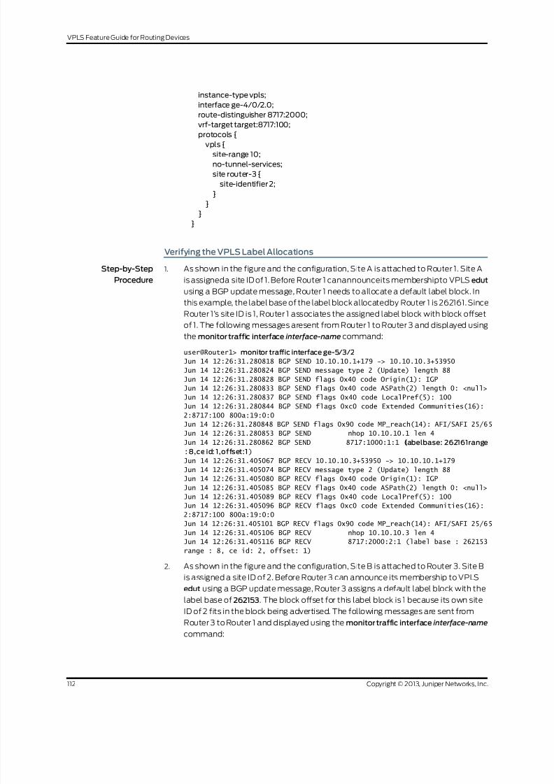
8/21/2019 Config Guide Vpns Vpls
http://slidepdf.com/reader/full/config-guide-vpns-vpls 130/485
instance-type vpls;
interface ge-4/0/2.0;
route-distinguisher 8717:2000;
vrf-target target:8717:100;
protocols {vpls {
site-range 10;
no-tunnel-services;
site router-3 {
site-identifier 2;
}
}
}
}
Verifying the VPLS Label Allocations
Step-by-Step
Procedure
1. As shown in the figure and the configuration, Site A is attached to Router 1. Site A
is assigneda site ID of 1. Before Router 1 canannounceits membershipto VPLS edut
using a BGP update message, Router 1 needs to allocate a default label block. In
this example, the label base of the label block allocatedby Router 1 is 262161. Since
Router 1’s site ID is 1, Router 1 associates the assigned label block with block offset
of 1. The following messages aresent from Router 1 to Router 3 and displayed using
the monitor traffic interface interface-name command:
user@Router1> monitor traffic interface ge-5/3/2
Jun 14 12:26:31.280818 BGP SEND 10.10.10.1+179 -> 10.10.10.3+53950
Jun 14 12:26:31.280824 BGP SEND message type 2 (Update) length 88
Jun 14 12:26:31.280828 BGP SEND flags 0x40 code Origin(1): IGP
Jun 14 12:26:31.280833 BGP SEND flags 0x40 code ASPath(2) length 0: <null>
Jun 14 12:26:31.280837 BGP SEND flags 0x40 code LocalPref(5): 100
Jun 14 12:26:31.280844 BGP SEND flags 0xc0 code Extended Communities(16):
2:8717:100 800a:19:0:0
Jun 14 12:26:31.280848 BGP SEND flags 0x90 code MP_reach(14): AFI/SAFI 25/65
Jun 14 12:26:31.280853 BGP SEND nhop 10.10.10.1 len 4
Jun 14 12:26:31.280862 BGP SEND 8717:1000:1:1 (labelbase: 262161range
: 8,ce id: 1,offset:1)
Jun 14 12:26:31.405067 BGP RECV 10.10.10.3+53950 -> 10.10.10.1+179
Jun 14 12:26:31.405074 BGP RECV message type 2 (Update) length 88
Jun 14 12:26:31.405080 BGP RECV flags 0x40 code Origin(1): IGP
Jun 14 12:26:31.405085 BGP RECV flags 0x40 code ASPath(2) length 0: <null>
Jun 14 12:26:31.405089 BGP RECV flags 0x40 code LocalPref(5): 100
Jun 14 12:26:31.405096 BGP RECV flags 0xc0 code Extended Communities(16):
2:8717:100 800a:19:0:0
Jun 14 12:26:31.405101 BGP RECV flags 0x90 code MP_reach(14): AFI/SAFI 25/65
Jun 14 12:26:31.405106 BGP RECV nhop 10.10.10.3 len 4
Jun 14 12:26:31.405116 BGP RECV 8717:2000:2:1 (label base : 262153
range : 8, ce id: 2, offset: 1)
2. As shown in the figure and the configuration, Site B is attached to Router 3. Site B
is assigned a site ID of 2. Before Router 3 can announce its membership to VPLS
edut using a BGP update message, Router 3 assigns a default label block with the
label base of 262153. The block offset for this label block is 1 because its own site
ID of 2 fits in the block being advertised. The following messages are sent from
Router 3 to Router 1 and displayed using the monitor traffic interface interface-name
command:
Copyright © 2013, Juniper Networks, Inc.112
VPLS Feature Guide for Routing Devices
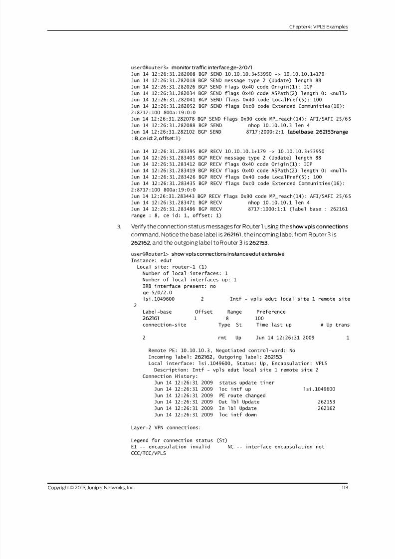
8/21/2019 Config Guide Vpns Vpls
http://slidepdf.com/reader/full/config-guide-vpns-vpls 131/485
user@Router3> monitor traffic interface ge-2/0/1
Jun 14 12:26:31.282008 BGP SEND 10.10.10.3+53950 -> 10.10.10.1+179
Jun 14 12:26:31.282018 BGP SEND message type 2 (Update) length 88
Jun 14 12:26:31.282026 BGP SEND flags 0x40 code Origin(1): IGP
Jun 14 12:26:31.282034 BGP SEND flags 0x40 code ASPath(2) length 0: <null>
Jun 14 12:26:31.282041 BGP SEND flags 0x40 code LocalPref(5): 100
Jun 14 12:26:31.282052 BGP SEND flags 0xc0 code Extended Communities(16):
2:8717:100 800a:19:0:0
Jun 14 12:26:31.282078 BGP SEND flags 0x90 code MP_reach(14): AFI/SAFI 25/65
Jun 14 12:26:31.282088 BGP SEND nhop 10.10.10.3 len 4
Jun 14 12:26:31.282102 BGP SEND 8717:2000:2:1 (labelbase: 262153range
: 8,ce id: 2,offset:1)
Jun 14 12:26:31.283395 BGP RECV 10.10.10.1+179 -> 10.10.10.3+53950
Jun 14 12:26:31.283405 BGP RECV message type 2 (Update) length 88
Jun 14 12:26:31.283412 BGP RECV flags 0x40 code Origin(1): IGP
Jun 14 12:26:31.283419 BGP RECV flags 0x40 code ASPath(2) length 0: <null>
Jun 14 12:26:31.283426 BGP RECV flags 0x40 code LocalPref(5): 100
Jun 14 12:26:31.283435 BGP RECV flags 0xc0 code Extended Communities(16):
2:8717:100 800a:19:0:0
Jun 14 12:26:31.283443 BGP RECV flags 0x90 code MP_reach(14): AFI/SAFI 25/65Jun 14 12:26:31.283471 BGP RECV nhop 10.10.10.1 len 4
Jun 14 12:26:31.283486 BGP RECV 8717:1000:1:1 (label base : 262161
range : 8, ce id: 1, offset: 1)
3. Verify the connection status messages for Router 1 using the show vpls connections
command. Notice the base label is 262161, the incoming label from Router 3 is
262162, and the outgoing label toRouter 3 is 262153.
user@Router1> show vpls connections instance edut extensive
Instance: edut
Local site: router-1 (1)
Number of local interfaces: 1
Number of local interfaces up: 1
IRB interface present: no
ge-5/0/2.0lsi.1049600 2 Intf - vpls edut local site 1 remote site
2
Label-base Offset Range Preference
262161 1 8 100
connection-site Type St Time last up # Up trans
2 rmt Up Jun 14 12:26:31 2009 1
Remote PE: 10.10.10.3, Negotiated control-word: No
Incoming label: 262162, Outgoing label: 262153
Local interface: lsi.1049600, Status: Up, Encapsulation: VPLS
Description: Intf - vpls edut local site 1 remote site 2
Connection History:
Jun 14 12:26:31 2009 status update timer
Jun 14 12:26:31 2009 loc intf up lsi.1049600
Jun 14 12:26:31 2009 PE route changed
Jun 14 12:26:31 2009 Out lbl Update 262153
Jun 14 12:26:31 2009 In lbl Update 262162
Jun 14 12:26:31 2009 loc intf down
Layer-2 VPN connections:
Legend for connection status (St)
EI -- encapsulation invalid NC -- interface encapsulation not
CCC/TCC/VPLS
113Copyright © 2013, Juniper Networks, Inc.
Chapter4: VPLS Examples

8/21/2019 Config Guide Vpns Vpls
http://slidepdf.com/reader/full/config-guide-vpns-vpls 132/485
EM -- encapsulation mismatch WE -- interface and instance encaps not
same
VC-Dn -- Virtual circuit down NP -- interface hardware not present
CM -- control-word mismatch -< -- only outbound connection is up
CN -- circuit not provisioned >- -- only inbound connection is up
OR -- out of range Up -- operationalOL -- no outgoing label Dn -- down
LD -- local site signaled down CF -- call admission control failure
RD -- remote site signaled down SC -- local and remote site ID collision
LN -- local site not designated LM -- local site ID not minimum designated
RN -- remote site not designated RM -- remote site ID not minimum designated
XX -- unknown connection status IL -- no incoming label
MM -- MTU mismatch MI -- Mesh-Group ID not availble
BK -- Backup connection ST -- Standby connection
PF -- Profile parse failure PB -- Profile busy
Legend for interface status
Up -- operational
Dn -- down
4. Verify the connection status messages for Router 3 using the show vpls connectionscommand. Notice the base label is 262153, the incoming label from Router 1 is
262153, and the outgoing label to Router 1 is 262162.
user@Router3> show vpls connections instance edut extensive
Instance: edut
Local site: router-3 (2)
Number of local interfaces: 1
Number of local interfaces up: 1
IRB interface present: no
ge-4/0/2.0
lsi.1050368 1 Intf - vpls edut local site 2 remote site
1
Label-base Offset Range Preference
262153 1 8 100
connection-site Type St Time last up # Up trans
1 rmt Up Jun 14 12:26:31 2009 1
Remote PE: 10.10.10.1, Negotiated control-word: No
Incoming label: 262153, Outgoing label: 262162
Local interface: lsi.1050368, Status: Up, Encapsulation: VPLS
Description: Intf - vpls edut local site 2 remote site 1
Connection History:
Jun 14 12:26:31 2009 status update timer
Jun 14 12:26:31 2009 loc intf up lsi.1050368
Jun 14 12:26:31 2009 PE route changed
Jun 14 12:26:31 2009 Out lbl Update 262162
Jun 14 12:26:31 2009 In lbl Update 262153
Jun 14 12:26:31 2009 loc intf down
Layer-2 VPN connections:
Legend for connection status (St)
EI -- encapsulation invalid NC -- interface encapsulation not
CCC/TCC/VPLS
EM -- encapsulation mismatch WE -- interface and instance encaps not
same
VC-Dn -- Virtual circuit down NP -- interface hardware not present
CM -- control-word mismatch -< -- only outbound connection is up
CN -- circuit not provisioned >- -- only inbound connection is up
Copyright © 2013, Juniper Networks, Inc.114
VPLS Feature Guide for Routing Devices

8/21/2019 Config Guide Vpns Vpls
http://slidepdf.com/reader/full/config-guide-vpns-vpls 133/485
OR -- out of range Up -- operational
OL -- no outgoing label Dn -- down
LD -- local site signaled down CF -- call admission control failure
RD -- remote site signaled down SC -- local and remote site ID collision
LN -- local site not designated LM -- local site ID not minimum designated
RN -- remote site not designated RM -- remote site ID not minimum designatedXX -- unknown connection status IL -- no incoming label
MM -- MTU mismatch MI -- Mesh-Group ID not availble
BK -- Backup connection ST -- Standby connection
PF -- Profile parse failure PB -- Profile busy
Legend for interface status
Up -- operational
Dn -- down
Related
Documentation
VPLS Label Blocks Operation on page 19•
Example: Configuring PIM Snooping for VPLS
This example showshowto configurePIM snoopingin a virtual private LANservice(VPLS)
to restrict multicast traffic to interested devices.
• Requirements on page 115
• Overview on page 115
• Configuration on page 116
• Verification on page 122
Requirements
This example uses the following hardware and software components:
• M Series Multiservice Edge Routers (M7i and M10i with Enhanced CFEB, M120, and
M320 with E3 FPCs) or MX Series 3D Universal Edge Routers (MX80, MX240, MX480,
and MX960)
• Junos OS Release 13.2 or later
Overview
The following example shows how to configure PIM snooping to restrict multicast traffic
to interested devices in a VPLS.
NOTE: This example demonstratesPIMsnoopingby theuse of a PIMsnooping
device to restrict multicast traffic. The use of the PIM proxying method to
achieve PIM snooping is out of the scope of this document and is yet to be
implemented in Junos OS.
115Copyright © 2013, Juniper Networks, Inc.
Chapter4: VPLS Examples
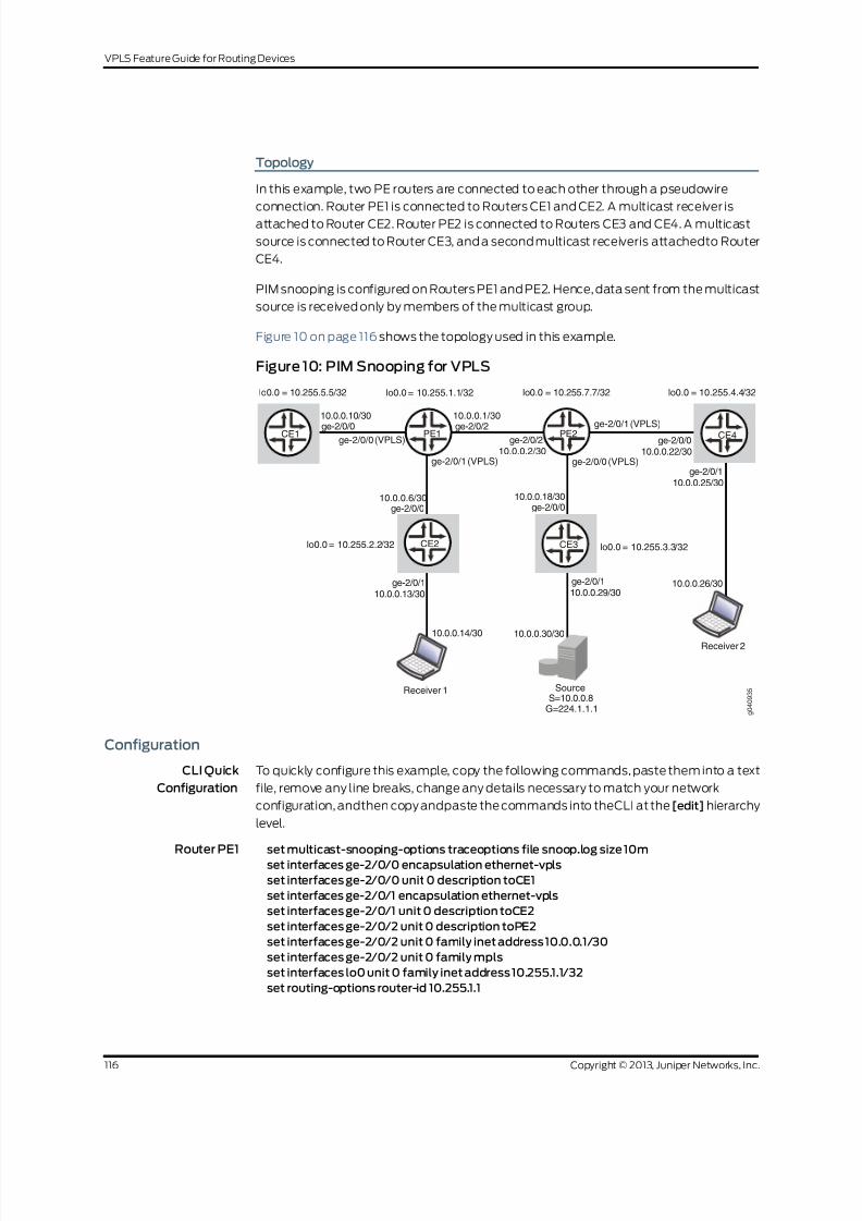
8/21/2019 Config Guide Vpns Vpls
http://slidepdf.com/reader/full/config-guide-vpns-vpls 134/485
Topology
In this example, two PE routers are connected to each other through a pseudowire
connection. Router PE1 is connected to Routers CE1 and CE2. A multicast receiver is
attached to Router CE2. Router PE2 is connected to Routers CE3 and CE4. A multicast
source is connected to Router CE3, and a second multicast receiveris attachedto Router
CE4.
PIM snooping is configured on Routers PE1 and PE2. Hence, data sent from the multicast
source is received only by members of the multicast group.
Figure 10 on page 116 shows the topology used in this example.
Figure 10: PIM Snooping for VPLS
lo0.0 = 10.255.5.5/32 lo0.0 = 10.255.7.7/32lo0.0 = 10.255.1.1/32 lo0.0 = 10.255.4.4/32
lo0.0 = 10.255.2.2/32 lo0.0 = 10.255.3.3/32
10.0.0.10/30
ge-2/0/0
10.0.0.6/30ge-2/0/0
10.0.0.18/30ge-2/0/0
10.0.0.1/30
10.0.0.2/30
ge-2/0/2ge-2/0/2
10.0.0.22/30ge-2/0/0
10.0.0.25/30
10.0.0.26/30
ge-2/0/1
10.0.0.13/30
10.0.0.14/30 10.0.0.30/30
ge-2/0/110.0.0.29/30ge-2/0/1
ge-2/0/0 (VPLS)
ge-2/0/0 (VPLS)ge-2/0/1 (VPLS)
ge-2/0/1 (VPLS)CE1
CE2 CE3
CE4
Receiver 2
Receiver 1S=10.0.0.8
G=224.1.1.1
Source
PE1 PE2
g 0 4 0 9 3 5
Configuration
CLI Quick
Configuration
To quickly configure this example, copy the following commands, paste them into a text
file, remove any line breaks, change any details necessary to match your network
configuration, andthen copy andpaste the commands into theCLI at the [edit] hierarchy
level.
Router PE1 set multicast-snooping-options traceoptions file snoop.log size 10m
set interfaces ge-2/0/0 encapsulation ethernet-vpls
set interfaces ge-2/0/0 unit 0 description toCE1
set interfaces ge-2/0/1 encapsulation ethernet-vpls
set interfaces ge-2/0/1 unit 0 description toCE2
set interfaces ge-2/0/2 unit 0 description toPE2
set interfaces ge-2/0/2 unit 0 family inet address 10.0.0.1/30
set interfaces ge-2/0/2 unit 0 family mpls
set interfaces lo0 unit 0 family inet address 10.255.1.1/32
set routing-options router-id 10.255.1.1
Copyright © 2013, Juniper Networks, Inc.116
VPLS Feature Guide for Routing Devices

8/21/2019 Config Guide Vpns Vpls
http://slidepdf.com/reader/full/config-guide-vpns-vpls 135/485
set protocols mpls interface ge-2/0/1.0
set protocols bgp group toPE2 type internal
set protocols bgp group toPE2 local-address 10.255.1.1
set protocols bgp group toPE2 family l2vpn signaling
set protocols bgp group toPE2 neighbor 10.255.7.7set protocols ospf area 0.0.0.0 interface ge-2/0/2.0
set protocols ospf area 0.0.0.0 interface lo0.0 passive
set protocols ldp interface ge-2/0/2.0
set protocols ldp interface lo0.0
set routing-instances titanium instance-type vpls
set routing-instances titanium vlan-id none
set routing-instances titanium interface ge-2/0/0.0
set routing-instances titanium interface ge-2/0/1.0
set routing-instances titanium route-distinguisher 101:101
set routing-instances titanium vrf-target target:201:201
set routing-instances titanium protocols vpls vpls-id 15
set routing-instances titanium protocols vpls site pe1 site-identifier 1
set routing-instances titanium protocols pim-snooping
Router CE1 set interfaces ge-2/0/0 unit 0 description toPE1
set interfaces ge-2/0/0 unit 0 family inet address 10.0.0.10/30
set interfaces lo0 unit 0 family inet address 10.255.2.2./32
set routing-options router-id 10.255.2.2
set protocols ospf area 0.0.0.0 interface all
set protocols ospf area 0.0.0.0 interface lo0.0 passive
set protocols pim rp static address 10.255.3.3
set protocols pim interface all
Router CE2 set interfaces ge-2/0/0 unit 0 description toPE1
set interfaces ge-2/0/0 unit 0 family inet address 10.0.0.6/30
set interfaces ge-2/0/1 unit 0 description toReceiver1
set interfaces ge-2/0/1 unit 0 family inet address 10.0.0.13/30
set interfaces lo0 unit 0 family inet address 10.255.2.2
set routing-options router-id 10.255.2.2
set protocols ospf area 0.0.0.0 interface all
set protocols ospf area 0.0.0.0 interface lo0.0 passive
set protocols pim rp static address 10.255.3.3
set protocols pim interface all
Router PE2 set multicast-snooping-options traceoptions file snoop.log size 10m
set interfaces ge-2/0/0 encapsulation ethernet-vpls
set interfaces ge-2/0/0 unit 0 description toCE3
set interfaces ge-2/0/1 encapsulation ethernet-vpls
set interfaces ge-2/0/1 unit 0 description toCE4
set interfaces ge-2/0/2 unit 0 description toPE1
set interfaces ge-2/0/2 unit 0 family inet address 10.0.0.2/30
set interfaces ge-2/0/2 unit 0 family mpls
set interfaces lo0 unit 0 family inet address 10.255.7.7/32
set routing-options router-id 10.255.7.7
set protocols mpls interface ge-2/0/2.0
set protocols bgp group toPE1 type internal
set protocols bgp group toPE1 local-address 10.255.7.7
set protocols bgp group toPE1 family l2vpn signaling
set protocols bgp group toPE1 neighbor 10.255.1.1
set protocols ospf area 0.0.0.0 interface ge-2/0/2.0
117Copyright © 2013, Juniper Networks, Inc.
Chapter4: VPLS Examples

8/21/2019 Config Guide Vpns Vpls
http://slidepdf.com/reader/full/config-guide-vpns-vpls 136/485
set protocols ospf area 0.0.0.0 interface lo0.0
set protocols ldp interface ge-2/0/2.0
set protocols ldp interface lo0.0
set routing-instances titanium instance-type vpls
set routing-instances titanium vlan-id noneset routing-instances titanium interface ge-2/0/0.0
set routing-instances titanium interface ge-2/0/1.0
set routing-instances titanium route-distinguisher 101:101
set routing-instances titanium vrf-target target:201:201
set routing-instances titanium protocols vpls vpls-id 15
set routing-instances titanium protocols vpls site pe2 site-identifier 2
set routing-instances titanium protocols pim-snooping
Router CE3 (RP) set interfaces ge-2/0/0 unit 0 description toPE2
set interfaces ge-2/0/0 unit 0 family inet address 10.0.0.18/30
set interfaces ge-2/0/1 unit 0 description toSource
set interfaces ge-2/0/1 unit 0 family inet address 10.0.0.29/30
set interfaces lo0 unit 0 family inet address 10.255.3.3/32
set routing-options router-id 10.255.3.3set protocols ospf area 0.0.0.0 interface all
set protocols ospf area 0.0.0.0 interface lo0.0 passive
set protocols pim rp local address 10.255.3.3
set protocols pim interface all
Router CE4 set interfaces ge-2/0/0 unit 0 description toPE2
set interfaces ge-2/0/0 unit 0 family inet address 10.0.0.22/30
set interfaces ge-2/0/1 unit 0 description toReceiver2
set interfaces ge-2/0/1 unit 0 family inet address 10.0.0.25/30
set interfaces lo0 unit 0 family inet address 10.255.4.4/32
set routing-options router-id 10.255.4.4
set protocols ospf area 0.0.0.0 interface all
set protocols ospf area 0.0.0.0 interface lo0.0 passive
set protocols pim rp static address 10.255.3.3
set protocols pim interface all
Configuring PIM Snooping for VPLS
Step-by-Step
Procedure
The following example requires that you navigate various levels in the configuration
hierarchy. Forinformation about navigatingthe CLI,seeUsing theCLI Editor inConfiguration
Mode in the CLI UserGuide.
NOTE: This section includes a step-by-step configuration procedure for one
or more routers in the topology. For comprehensive configurations for all
routers, see “CLI Quick Configuration” on page 116.
To configure PIM snooping for VPLS:
1. Configure the router interfaces forming the links between the routers.
Router PE2
[edit interfaces]
user@PE2# set ge-2/0/0 encapsulation ethernet-vpls
Copyright © 2013, Juniper Networks, Inc.118
VPLS Feature Guide for Routing Devices

8/21/2019 Config Guide Vpns Vpls
http://slidepdf.com/reader/full/config-guide-vpns-vpls 137/485
user@PE2# set ge-2/0/0 unit 0 description toCE3
user@PE2# set ge-2/0/1 encapsulation ethernet-vpls
user@PE2# set ge-2/0/1 unit 0 description toCE4
user@PE2# set ge-2/0/2 unit 0 description toPE1
user@PE2# set ge-2/0/2 unit 0 family mplsuser@PE2# set ge-2/0/2 unit 0 family inet address 10.0.0.2/30
user@PE2# set lo0 unit 0 family inet address 10.255.7.7/32
NOTE: ge-2/0/0.0 and ge-2/0/1.0 are configured as VPLS interfaces
and connect to Routers CE3 and CE4. See Virtual Private LANService
FeatureGuide for more details.
Router CE3
[edit interfaces]
user@CE3# set ge-2/0/0 unit 0 description toPE2
user@CE3# set ge-2/0/0 unit 0 family inet address 10.0.0.18/30user@CE3# set ge-2/0/1 unit 0 description toSource
user@CE3# set ge-2/0/1 unit 0 family inet address 10.0.0.29/30
user@CE3# setlo0 unit 0 family inet address 10.255.3.3/32
NOTE: The ge-2/0/1.0 interfaceon RouterCE3 connects to the multicast
source.
Router CE4
[edit interfaces]
user@CE4# set ge-2/0/0 unit 0 description toPE2
user@CE4# set ge-2/0/0 unit 0 family inet address 10.0.0.22/30
user@CE4# set ge-2/0/1 unit 0 description toReceiver2
user@CE4# set ge-2/0/1 unit 0 family inet address 10.0.0.25/30
user@CE4# set lo0 unit 0 family inet address 10.255.4.4/32
NOTE: The ge-2/0/1.0 interface on Router CE4 connects to a multicast
receiver.
Similarly, configure Routers PE1, CE1, and CE2.
2. Configure the router IDs of all routers.
Router PE2[edit routing-options]
user@PE2# set router-id 10.255.7.7
Similarly, configure other routers.
3. Configure an IGP on interfaces of all routers.
Router PE2
[edit protocols ospf area 0.0.0.0]
user@PE2# set interface ge-2/0/2.0
119Copyright © 2013, Juniper Networks, Inc.
Chapter4: VPLS Examples

8/21/2019 Config Guide Vpns Vpls
http://slidepdf.com/reader/full/config-guide-vpns-vpls 138/485
user@PE2# set interface lo0.0
Similarly, configure other routers.
4. Configure the LDP, MPLS, and BGP protocols on the PE routers.
Router PE2
[edit protocols]
user@PE2# set ldp interface lo0.0
user@PE2# set mpls interface ge-2/0/2.0
user@PE2# set bgpgroup toPE1 type internal
user@PE2# set bgp group toPE1 local-address 10.255.7.7
user@PE2# set bgpgroup toPE1 family l2vpn signaling
user@PE2# set bgp group toPE1 neighbor 10.255.1.1
user@PE2# set ldp interface ge-2/0/2.0
TheBGP group is required forinterfacing withthe otherPE router. Similarly,configure
Router PE1.
5. Configure PIM on all CE routers.
Ensure that Router CE3 is configured as the rendezvous point (RP) and that the RP
address is configured on other CE routers.
Router CE3
[edit protocols pim]
user@CE3# set rp local address 10.255.3.3
user@CE3# set interface all
Router CE4
[edit protocols pim]
user@CE4# set rp static address 10.255.3.3
user@CE4# set interface all
Similarly, configure Routers CE1 and CE2.
6. Configure multicast snooping options on the PE routers.
Router PE2
[edit multicast-snooping-options traceoptions]
user@PE2# set file snoop.log size 10m
Similarly, configure Router PE1.
7. Create a routing instance (titanium), and configure the VPLS on the PE routers.
Router PE2
[edit routing-instances titanium]
user@PE2# set instance-type vpls
user@PE2# set vlan-id none
user@PE2# set interface ge-2/0/0.0
user@PE2# set interface ge-2/0/1.0user@PE2# set route-distinguisher 101:101
user@PE2# set vrf-target target:201:201
user@PE2# set protocols vpls vpls-id 15
user@PE2# set protocols vpls site pe2 site-identifier 2
Similarly, configure Router PE1.
8. Configure PIM snooping on the PE routers.
Router PE2
Copyright © 2013, Juniper Networks, Inc.120
VPLS Feature Guide for Routing Devices

8/21/2019 Config Guide Vpns Vpls
http://slidepdf.com/reader/full/config-guide-vpns-vpls 139/485
[edit routing-instances titanium]
user@PE2# set protocols pim-snooping
Similarly, configure Router PE1.
Results
From configuration mode, confirm your configuration by entering the show interfaces,
show routing-options, show protocols, show multicast-snooping-options, and show
routing-instances commands.
If the output does not display the intended configuration, repeat the instructions in this
example to correct the configuration.
user@PE2# show interfaces
ge-2/0/2 {
unit 0 {
description toPE1
family inet { address 10.0.0.2/30;
}
family mpls;
}
}
ge-2/0/0 {
encapsulation ethernet-vpls;
unit 0 {
description toCE3;
}
}
ge-2/0/1 {
encapsulation ethernet-vpls;
unit 0 {
description toCE4;
}
}
lo0 {
unit 0 {
family inet {
address 10.255.7.7/32;
}
}
}
user@PE2# show routing-options
router-id 10.255.7.7;
user@PE2# show protocols
mpls {
interface ge-2/0/2.0;
}
ospf {
area 0.0.0.0 {
interface ge-2/0/2.0;
interface lo0.0;
}
}
ldp {
interface ge-2/0/2.0;
121Copyright © 2013, Juniper Networks, Inc.
Chapter4: VPLS Examples

8/21/2019 Config Guide Vpns Vpls
http://slidepdf.com/reader/full/config-guide-vpns-vpls 140/485
interface lo0.0;
}
bgp {
group toPE1 {
type internal;
local-address 10.255.7.7; family l2vpn {
signaling;
}
neighbor 10.255.1.1;
}
user@PE2# show multicast-snooping-options
traceoptions {
file snoop.log size 10m;
}
user@PE2# show routing-instances
titanium {
instance-type vpls;
vlan-id none;
interface ge-2/0/0.0;
interface ge-2/0/1.0;
route-distinguisher 101:101;
vrf-target target:201:201;
protocols {
vpls {
site pe2 {
site-identifier 2;
}
vpls-id 15;
}
pim-snooping;
}
}
Similarly, confirm the configuration on all other routers. If you are done configuring the
routers, enter commit from configuration mode.
NOTE: Use the show protocols command on the CE routers to verify the
configuration for the PIM RP .
Verification
Confirm that the configuration is working properly.
• Verifying PIM Snooping for VPLS on page 122
Verifying PIM Snooping for VPLS
Purpose Verify that PIM Snooping is operational in the network.
Action To verify that PIM snooping is working as desired, use the following commands:
Copyright © 2013, Juniper Networks, Inc.122
VPLS Feature Guide for Routing Devices

8/21/2019 Config Guide Vpns Vpls
http://slidepdf.com/reader/full/config-guide-vpns-vpls 141/485
• show pim snooping interfaces
• show pim snooping neighbors detail
• show pim snooping statistics
• show pim snooping join
• show pim snooping join extensive
• show multicast snooping route extensive instance <instance-name> group
<group-name>
1. From operational mode on Router PE2, run the show pim snooping interfaces
command.
user@PE2> show pim snooping interfaces
Instance: titanium
Learning-Domain: default
Name State IP NbrCnt
ge-2/0/0.0 Up 4 1
ge-2/0/1.0 Up 4 1
DR address: 10.0.0.22
DR flooding is ON
The output verifies that PIM snooping is configured on the two interfaces connecting
Router PE2 to Routers CE3 and CE4.
Similarly, check the PIM snooping interfaces on Router PE1.
2. From operational mode on Router PE2, run the show pim snooping neighbors detail
command.
user@PE2> show pim snooping neighbors detail
Instance: titanium
Learning-Domain: default
Interface: ge-2/0/0.0
Address: 10.0.0.18
Uptime: 00:17:06
Hello Option Holdtime: 105 seconds 99 remaining
Hello Option DR Priority: 1
Hello Option Generation ID: 552495559
Hello Option LAN Prune Delay: delay 500 ms override 2000 ms
Tracking is supported
Interface: ge-2/0/1.0
Address: 10.0.0.22
Uptime: 00:15:16
Hello Option Holdtime: 105 seconds 103 remaining
Hello Option DR Priority: 1
Hello Option Generation ID: 1131703485
123Copyright © 2013, Juniper Networks, Inc.
Chapter4: VPLS Examples

8/21/2019 Config Guide Vpns Vpls
http://slidepdf.com/reader/full/config-guide-vpns-vpls 142/485
Hello Option LAN Prune Delay: delay 500 ms override 2000 ms
Tracking is supported
The output verifies that Router PE2 can detect the IP addresses of its PIM snooping
neighbors (10.0.0.18 on CE3 and 10.0.0.22 on CE4).
Similarly, check the PIM snooping neighbors on Router PE1.
3. From operational mode on Router PE2, run the show pim snooping statistics
command.
user@PE2> show pim snooping statistics
Instance: titanium
Learning-Domain: default
Tx J/P messages 0
RX J/P messages 246
Rx J/P messages -- seen 0
Rx J/P messages -- received 246
Rx Hello messages 1036Rx Version Unknown 0
Rx Neighbor Unknown 0
Rx Upstream Neighbor Unknown 0
Rx J/P Busy Drop 0
Rx J/P Group Aggregate 0
Rx Malformed Packet 0
Rx No PIM Interface 0
Rx Bad Length 0
Rx Unknown Hello Option 0
Rx Unknown Packet Type 0
Rx Bad TTL 0
Rx Bad Destination Address 0
Rx Bad Checksum 0
Rx Unknown Version 0
The output shows the number of hello and join/prune messages received by Router
PE2. This verifies that PIM sparse mode is operational in the network.
4. Send multicast traffic from the source terminal attached to Router CE3, for the
multicast group 224.1.1.1.
5. From operational mode on Router PE2, run the show pim snooping join, show pim
snooping join extensive, and show multicast snooping route extensive instance
<instance-name> group <group-name> commands to verify PIM snooping.
user@PE2> show pim snooping join
Instance: titanium
Learning-Domain: default
Group: 224.1.1.1
Source: *
Flags: sparse,rptree,wildcard
Upstream neighbor: 10.0.0.18, Port: ge-2/0/0.0
Group: 224.1.1.1
Source: 10.0.0.30
Copyright © 2013, Juniper Networks, Inc.124
VPLS Feature Guide for Routing Devices

8/21/2019 Config Guide Vpns Vpls
http://slidepdf.com/reader/full/config-guide-vpns-vpls 143/485
Flags: sparse
Upstream neighbor: 10.0.0.18, Port: ge-2/0/0.0
user@PE2> show pim snooping join extensive
Instance: titanium
Learning-Domain: default
Group: 224.1.1.1
Source: *
Flags: sparse,rptree,wildcard
Upstream neighbor: 10.0.0.18, Port: ge-2/0/0.0
Downstream port: ge-2/0/1.0
Downstream neighbors:
10.0.0.22 State: Join Flags: SRW Timeout: 180
Group: 224.1.1.1
Source: 10.0.0.30
Flags: sparse
Upstream neighbor: 10.0.0.18, Port: ge-2/0/0.0
Downstream port: ge-2/0/1.0
Downstream neighbors:10.0.0.22 State: Join Flags: S Timeout: 180
The outputs show that multicast traffic sent for the group 224.1.1.1 is sent to Receiver
2 throughRouter CE4andalso displaythe upstream anddownstream neighbordetails.
user@PE2> show multicast snooping route extensive instance titanium group 224.1.1.1
Nexthop Bulking: OFF
Family: INET
Group: 224.1.1.1/32
Bridge-domain: titanium
Mesh-group: __all_ces__
Downstream interface list:
ge-2/0/1.0-(1072) Statistics: 0 kBps, 0 pps, 0 packets
Next-hop ID: 1048577
Route state: Active
Forwarding state: Forwarding
Group: 224.1.1.1/32
Source: 10.0.0.8
Bridge-domain: titanium
Mesh-group: __all_ces__
Downstream interface list:
ge-2/0/1.0 -(1072)
Statistics: 0 kBps, 0 pps, 0 packets
Next-hop ID: 1048577
Route state: Active
Forwarding state: Forwarding
Meaning PIM snooping is operational in the network.
Related
Documentation
Understanding PIM Snooping for VPLS on page 24•
125Copyright © 2013, Juniper Networks, Inc.
Chapter4: VPLS Examples

8/21/2019 Config Guide Vpns Vpls
http://slidepdf.com/reader/full/config-guide-vpns-vpls 144/485
Example: Configuring BGP Autodiscovery for LDP VPLS
This example describes how to configure BGP autodiscovery for LDP VPLS, as specified
in forwarding equivalency class (FEC) 129. FEC 129 uses BGP autodiscovery to convey
endpoint information, so you do not need to manually configure pseudowires.
• Requirements on page 126
• Overview on page 126
• Configuration on page 128
• Verification on page 142
Requirements
This example uses the following hardware and software components:
•
Four MX Series 3D Universal Edge Routers
• Junos OS Release 10.4R2 or later
If you are using M Series or T Series routers, the PE routers must have either virtual
loopback tunnel (vt) interfaces or label-switched interfaces (LSIs). On M Series and T
Series routers, VPLS uses tunnel-based PICs to create virtual ports on vt interfaces. If
you do not have a tunnel-based PIC installed on your M Series or T Series router, you can
still configure VPLS by using LSIs to support the virtual ports. Use of LSIs requires
Ethernet-based PICs installed in an Enhanced Flexible PIC Concentrator (FPC).
You do not need to use routers for the CE devices. For example, the CE devices can be
EX Series Ethernet Switches.
Overview
All PE routers in a VPLS network operate like a large, distributed Ethernet switch to
provide Layer 2 services to attached devices. This example shows a minimum
configuration for PE routers and CE devices to create an autodiscovered VPLS network.
The topology consists of five routers: two PE routers, two CE routers, and an optional
route reflector (RR). ThePE routers use BGPto autodiscover twodifferent VPLSinstances
that are configured on both PE routers. Then the PE routers use LDP to automatically
signal two pseudowires between the discovered end points. Finally, the PE routers bring
up both VPLS instances for forwarding traffic. Each CE device is configured with two
VLANs, with each VLAN belonging to different VPLS instances in the PE routers.
Copyright © 2013, Juniper Networks, Inc.126
VPLS Feature Guide for Routing Devices

8/21/2019 Config Guide Vpns Vpls
http://slidepdf.com/reader/full/config-guide-vpns-vpls 145/485
This example includes the following settings:
• auto-discovery-only—Allowsthe router to processonlythe autodiscovery network layer
reachability information (NLRI) update messages for LDP-based Layer 2 VPN and
VPLS update messages (BGP_L2VPN_AD_NLRI) (FEC 129). Specifically, theauto-discovery-only statement notifies the routing process (rpd) to expect
autodiscovery-related NLRImessagesso thatinformation can be deciphered and used
by LDP and VPLS. You can configure this statement at the global, group, and neighbor
levels for BGP. The auto-discovery-only statement must be configured on allPE routers
in the VPLS. If you configure route reflection, the auto-discovery-only statement is also
required on P routers that act as the route reflector in supporting FEC 129-related
updates.
The signaling statement is not included in this example but is discussed here for
completeness. The signaling statement allows the router to process only the
BGP_L2VPN_NLRIs used for BGP-based Layer 2 VPNs (FEC 128).
Forinteroperation scenarios in which a PE router mustsupport both types of NLRI (FEC128 and FEC 129), you can configure both the signaling statement and the
auto-discovery-only statement. For example, a single PE router might need to process
a combination of BGP-signaled virtual private wire service (VPWS) and LDP-signaled
VPLS assisted by BGP autodiscovery. Configuring both the signaling statement and
the auto-discovery-only statement together allows both types of signaling to run
independently. The signaling statement is supported at the same hierarchy levels as
the auto-discovery-only statement.
• cluster—Configuring a route reflector is optional for FEC 129 autodiscovered PE routers.
In this example, the cluster statement configures Router RR to be a route reflector in
the IBGP group. For inbound updates,BGP autodiscoveryNLRImessages are accepted
if therouter is configured to be a routereflector or if the keep all statementis configured
in the IBGP group.
• l2vpn-id—Specifies a globallyunique Layer 2 VPN communityidentifier forthe instance.
This statement is configurable for routing instances of type vpls.
You can configure the following formats for the community identifier:
• Autonomous system (AS) number format—l2vpn-id: as-number : 2-byte-number . For
example: l2vpn-id:100:200. The ASnumber can bein therangefrom1 through 65,535.
• IPv4 format—l2vpn-id: ip-address: 2-byte-number . For example: l2vpn-id:10.1.1.1:2.
• vrf-target—Defines the import and export route targets for the NLRI. You must either
configure the vrf-target statement or the vrf-import and vrf-export statements to define
the instance import and export policy or the import and export route targets for theNLRI. This example uses the vrf-target statement.
• route-distinguisher—Forms part of the BGP autodiscovery NLRI and distinguishes to
which VPN or VPLS routing instance each route belongs. Each route distinguisher is a
6-byte value. You mustconfigurea uniqueroute distinguisher foreach routing instance.
You can configure the following formats for the route distinguisher:
• AS number format— as-number : 2-byte-number
127Copyright © 2013, Juniper Networks, Inc.
Chapter4: VPLS Examples

8/21/2019 Config Guide Vpns Vpls
http://slidepdf.com/reader/full/config-guide-vpns-vpls 146/485
• IPv4 format— ip-address: 2-byte-number
Two notable statements are included in this example. These statements are important
for interoperability with other vendors’ equipment. The interoperability statements are
not necessary for the topology that is used in this example, but they are included for
completeness.
The interoperability statements are as follows:
• input-vlan-map pop—Removes an outer VLAN tag from the top of the VLAN tag stack.
• output-vlan-map push—Adds an outer VLAN tag in front of the existing VLAN tag.
Topology Diagram
Figure 11 on page 128 shows the topology used in this example.
Figure 11: BGP Autodiscovery for LDP VPLS
Route Reflector
PE1
PE2
CE1
g 0 4 0 7 0 3
CE2
Configuration
CLI Quick
Configuration
To quickly configure BGP autodiscovery for LDP VPLS, copy the following commands,
remove any line breaks, and then paste the commands into the CLI of each device.
On Router PE1:
[edit]
set interfaces ge-0/1/0 vlan-tagging
set interfaces ge-0/1/0 encapsulation flexible-ethernet-services
set interfaces ge-0/1/0 unit 100 encapsulation vlan-vpls
set interfaces ge-0/1/0 unit 100 vlan-id 100
set interfaces ge-0/1/0 unit 100 input-vlan-map popset interfaces ge-0/1/0 unit 100 output-vlan-map push
set interfaces ge-0/1/0 unit 100 family vpls
set interfaces ge-0/1/0 unit 200 encapsulation vlan-vpls
set interfaces ge-0/1/0 unit 200 vlan-id 200
set interfaces ge-0/1/0 unit 200 family vpls
set interfaces ge-0/1/1 unit 0 description "PE1 to PE2"
set interfaces ge-0/1/1 unit 0 family inet address 8.0.40.100/24
set interfaces ge-0/1/1 unit 0 family iso
set interfaces ge-0/1/1 unit 0 family mpls
Copyright © 2013, Juniper Networks, Inc.128
VPLS Feature Guide for Routing Devices
8/21/2019 Config Guide Vpns Vpls
http://slidepdf.com/reader/full/config-guide-vpns-vpls 147/485
set interfaces ge-0/3/0 unit 0 description "PE1 to RR"
set interfaces ge-0/3/0 unit 0 family inet address 8.0.70.100/24
set interfaces ge-0/3/0 unit 0 family iso
set interfaces ge-0/3/0 unit 0 family mpls
set interfaces lo0 unit 0 family inet address 8.0.0.100/32set routing-options router-id 8.0.0.100
set routing-options autonomous-system 100
set protocols mpls interface lo0.0
set protocols mpls interface all
set protocols mpls interface fxp0.0 disable
set protocols bgp groupint type internal
set protocols bgp group int local-address 8.0.0.100
set protocols bgp group int family l2vpn auto-discovery-only
set protocols bgp group int neighbor 8.0.0.107
set protocols isis level 1 disable
set protocols isis interface all
set protocols isis interface fxp0.0 disable
set protocols isis interface lo0.0
set protocols ldp interface allset protocols ldp interface fxp0.0 disable
set protocols ldp interface lo0.0
set routing-instances vpls100 instance-type vpls
set routing-instances vpls100 interface ge-0/1/0.100
set routing-instances vpls100 route-distinguisher 8.0.0.100:100
set routing-instances vpls100 l2vpn-id l2vpn-id:100:100
set routing-instances vpls100 vrf-target target:100:100
set routing-instances vpls100 protocols vpls no-tunnel-services
set routing-instances vpls200 instance-type vpls
set routing-instances vpls200 interface ge-0/1/0.200
set routing-instances vpls200 route-distinguisher 8.0.0.100:200
set routing-instances vpls200 l2vpn-id l2vpn-id:100:200
set routing-instances vpls200 vrf-target target:100:208
set routing-instances vpls200 protocols vpls no-tunnel-services
On Device CE1:
[edit]
set interfaces ge-1/2/1 vlan-tagging
set interfaces ge-1/2/1 mtu 1400
set interfaces ge-1/2/1 unit 100vlan-id 100
set interfaces ge-1/2/1 unit 100 family inet address 3.0.100.103/24
set interfaces ge-1/2/1 unit 200vlan-id 200
set interfaces ge-1/2/1 unit 200 family inet address 3.0.200.103/24
set protocols ospf area 0.0.0.0 interface ge-1/2/1.100
set protocols ospf area 0.0.0.0 interface ge-1/2/1.200
On Router PE2:
[edit]
set interfaces ge-1/1/0 vlan-tagging
set interfaces ge-1/1/0 encapsulation flexible-ethernet-services
set interfaces ge-1/1/0 unit 100 encapsulation vlan-vpls
set interfaces ge-1/1/0 unit 100 vlan-id 100
set interfaces ge-1/1/0 unit 100 input-vlan-map pop
set interfaces ge-1/1/0 unit 100 output-vlan-map push
set interfaces ge-1/1/0 unit 100 family vpls
set interfaces ge-1/1/0 unit 200 encapsulation vlan-vpls
129Copyright © 2013, Juniper Networks, Inc.
Chapter4: VPLS Examples

8/21/2019 Config Guide Vpns Vpls
http://slidepdf.com/reader/full/config-guide-vpns-vpls 148/485
set interfaces ge-1/1/0 unit 200 vlan-id 200
set interfaces ge-1/1/0 unit 200 family vpls
set interfaces ge-1/2/1 unit 0 description "PE2 to PE1"
set interfaces ge-1/2/1 unit 0 family inet address 8.0.40.104/24
set interfaces ge-1/2/1 unit 0 family isoset interfaces ge-1/2/1 unit 0 family mpls
set interfaces lo0 unit 0 family inet address 8.0.0.104/32
set routing-options router-id 8.0.0.104
set routing-options autonomous-system 100
set protocols mpls interface lo0.0
set protocols mpls interface all
set protocols mpls interface fxp0.0 disable
set protocols bgp groupint type internal
set protocols bgp group int local-address 8.0.0.104
set protocols bgp group int family l2vpn auto-discovery-only
set protocols bgp group int neighbor 8.0.0.107
set protocols isis level 1 disable
set protocols isis interface ge-1/2/1.0
set protocols isis interface lo0.0set protocols ldp interface all
set protocols ldp interface fxp0.0 disable
set protocols ldp interface lo0.0
set routing-instances vpls100 instance-type vpls
set routing-instances vpls100 interface ge-1/1/0.100
set routing-instances vpls100 route-distinguisher 8.0.0.104:100
set routing-instances vpls100 l2vpn-id l2vpn-id:100:100
set routing-instances vpls100 vrf-target target:100:100
set routing-instances vpls100 protocols vpls no-tunnel-services
set routing-instances vpls200 instance-type vpls
set routing-instances vpls200 interface ge-1/1/0.200
set routing-instances vpls200 route-distinguisher 8.0.0.104:200
set routing-instances vpls200 l2vpn-id l2vpn-id:100:200
set routing-instances vpls200 vrf-target target:100:208set routing-instances vpls200 protocols vpls no-tunnel-services
On Device CE2:
[edit]
set interfaces ge-1/1/0 vlan-tagging
set interfaces ge-1/1/0 mtu 1400
set interfaces ge-1/1/0 unit 100 vlan-id 100
set interfaces ge-1/1/0 unit 100 family inet address 3.0.100.105/24
set interfaces ge-1/1/0 unit 200 vlan-id 200
set interfaces ge-1/1/0 unit 200 family inet address 3.0.200.105/24
set protocols ospf area 0.0.0.0 interface ge-1/1/0.100
set protocols ospf area 0.0.0.0 interface ge-1/1/0.200
On Router RR:
[edit]
set interfaces ge-1/3/2 unit 0 description "RR to PE1"
set interfaces ge-1/3/2 unit 0 family inet address 8.0.70.107/24
set interfaces ge-1/3/2 unit 0 family iso
set interfaces ge-1/3/2 unit 0 family mpls
set interfaces lo0 unit 0 family inet address 8.0.0.107/32
set routing-options router-id 8.0.0.107
set routing-options autonomous-system 100
Copyright © 2013, Juniper Networks, Inc.130
VPLS Feature Guide for Routing Devices

8/21/2019 Config Guide Vpns Vpls
http://slidepdf.com/reader/full/config-guide-vpns-vpls 149/485
set protocols bgp groupint type internal
set protocols bgp group int local-address 8.0.0.107
set protocols bgp group int family l2vpn auto-discovery-only
set protocols bgp group int cluster 107.107.107.107
set protocols bgp group int neighbor 8.0.0.100set protocols bgp group int neighbor 8.0.0.104
set protocols isis level 1 disable
set protocols isis interface all
set protocols isis interface fxp0.0 disable
set protocols isis interface lo0.0
set protocols ldp interface all
set protocols ldp interface fxp0.0 disable
set protocols ldp interface lo0.0
Router PE1
Step-by-Step
Procedure
To configure Router PE1:
Configure the interfaces, the interface encapsulation, and the protocol families.
[edit]
1.
user@PE1# edit interfaces
[edit interfaces]
user@PE1# set ge-0/1/0 encapsulation flexible-ethernet-services
user@PE1# set ge-0/1/0 unit 100 encapsulation vlan-vpls
user@PE1# set ge-0/1/0 unit 100 family vpls
user@PE1# set ge-0/1/0 unit 200 encapsulation vlan-vpls
user@PE1# set ge-0/1/0 unit 200family vpls
user@PE1# set ge-0/1/1 unit 0 description "PE1 to PE2"
user@PE1# set ge-0/1/1 unit 0 family inet address 8.0.40.100/24
user@PE1# set ge-0/1/1 unit 0 family iso
user@PE1# set ge-0/1/1 unit 0 family mpls
user@PE1# set ge-0/3/0 unit 0 description "PE1 to RR"user@PE1# set ge-0/3/0 unit 0 family inet address 8.0.70.100/24
user@PE1# set ge-0/3/0 unit 0 family iso
user@PE1# set ge-0/3/0 unit 0 family mpls
user@PE1# set lo0 unit 0 family inet address 8.0.0.100/32
2. Configure the VLANs.
[edit interfaces]
user@PE1# set ge-0/1/0 vlan-tagging
user@PE1# set ge-0/1/0 unit 100 vlan-id 100
user@PE1# set ge-0/1/0 unit 100 input-vlan-map pop
user@PE1# set ge-0/1/0 unit 100 output-vlan-map push
user@PE1# set ge-0/1/0 unit 200vlan-id 200
user@PE1# exit
3. Configure the protocol-independent properties.
We recommend that the router ID be the same as the local address. (See the
local-address statement in Step 4.)
[edit]
user@PE1# edit routing-options
[edit routing-options]
user@PE1# set router-id 8.0.0.100
131Copyright © 2013, Juniper Networks, Inc.
Chapter4: VPLS Examples

8/21/2019 Config Guide Vpns Vpls
http://slidepdf.com/reader/full/config-guide-vpns-vpls 150/485
user@PE1# set autonomous-system 100
user@PE1# exit
4. Configure IBGP, including the auto-discovery-only statement.
[edit]user@PE1# edit protocols
[edit protocols]
user@PE1# set bgpgroup int type internal
user@PE1# set bgp group int local-address 8.0.0.100
user@PE1# set bgp group int family l2vpn auto-discovery-only
user@PE1# set bgp group int neighbor 8.0.0.107
5. Configure MPLS, LDP, and an IGP.
[edit protocols]
user@PE1# set mpls interface lo0.0
user@PE1# set mpls interface all
user@PE1# set mpls interface fxp0.0 disable
user@PE1# set isis level 1 disableuser@PE1# set isis interface all
user@PE1# set isis interface fxp0.0 disable
user@PE1# set isis interface lo0.0
user@PE1# set ldp interface all
user@PE1# set ldp interface fxp0.0 disable
user@PE1# set ldp interface lo0.0
user@PE1# exit
6. Configure the routing instances.
The no-tunnel-servicesstatement is required if youare using LSIinterfacesfor VPLS
instead of vt interfaces.
[edit]
user@PE1# edit routing-instances[edit routing-instances]
user@PE1# set vpls100 instance-type vpls
user@PE1# set vpls100 interface ge-0/1/0.100
user@PE1# set vpls100 route-distinguisher 8.0.0.100:100
user@PE1# set vpls100 l2vpn-id l2vpn-id:100:100
user@PE1# set vpls100 vrf-target target:100:100
user@PE1# set vpls100 protocols vpls no-tunnel-services
user@PE1# set vpls200 instance-type vpls
user@PE1# set vpls200 interface ge-0/1/0.200
user@PE1# set vpls200 route-distinguisher 8.0.0.100:200
user@PE1# set vpls200 l2vpn-id l2vpn-id:100:200
user@PE1# set vpls200 vrf-target target:100:208
user@PE1# set vpls200 protocols vpls no-tunnel-services
7. If you are done configuring the device, commit the configuration.
[edit]
user@PE1# commit
Results From configuration mode, confirm your configuration by entering the show interfaces,
show protocols, show routing-options, and show routing-instances commands. If the
Copyright © 2013, Juniper Networks, Inc.132
VPLS Feature Guide for Routing Devices

8/21/2019 Config Guide Vpns Vpls
http://slidepdf.com/reader/full/config-guide-vpns-vpls 151/485
output doesnot display the intended configuration, repeatthe instructionsin thisexample
to correct the configuration.
user@PE1# show interfaces
ge-0/1/0 {vlan-tagging;
encapsulation flexible-ethernet-services;
unit100 {
encapsulation vlan-vpls;
vlan-id 100;
input-vlan-map pop;
output-vlan-map push;
family vpls;
}
unit200 {
encapsulation vlan-vpls;
vlan-id 200;
family vpls;
}}
ge-0/1/1 {
unit0 {
description "PE1 to PE2";
family inet {
address 8.0.40.100/24;
}
family iso;
family mpls;
}
}
ge-0/3/0 {
unit0 {
description "PE1 to RR";family inet {
address 8.0.70.100/24;
}
family iso;
family mpls;
}
}
lo0{
unit0 {
family inet {
address 8.0.0.100/32;
}
}
}
user@PE1# show protocols
mpls {
interface lo0.0;
interface all;
interface fxp0 disable;
}
bgp {
group int {
133Copyright © 2013, Juniper Networks, Inc.
Chapter4: VPLS Examples

8/21/2019 Config Guide Vpns Vpls
http://slidepdf.com/reader/full/config-guide-vpns-vpls 152/485
type internal;
local-address 8.0.0.100;
family l2vpn {
auto-discovery-only;
}neighbor 8.0.0.107;
}
}
isis {
level 1 disable;
interface all;
interface lo0.0;
interface fxp0 disable;
}
ldp{
interface lo0.0;
interface all;
interface fxp0 disable;
}
user@PE1# show routing-options
router-id 8.0.0.100;
autonomous-system 100;
user@PE1# show routing-instances
vpls100 {
instance-type vpls;
interface ge-0/1/0.100;
route-distinguisher 8.0.0.100:100;
l2vpn-id l2vpn-id:100:100;
vrf-target target:100:100;
protocols {
vpls {
no-tunnel-services;}
}
}
vpls200 {
instance-type vpls;
interface ge-0/1/0.200;
route-distinguisher 8.0.0.100:200;
l2vpn-id l2vpn-id:100:200;
vrf-target target:100:208;
protocols {
vpls {
no-tunnel-services;
}
}}
Device CE1
Step-by-Step
Procedure
To configure Device CE1:
Configure interface addresses and the interface maximum transmissionunit (MTU).
[edit]
1.
Copyright © 2013, Juniper Networks, Inc.134
VPLS Feature Guide for Routing Devices
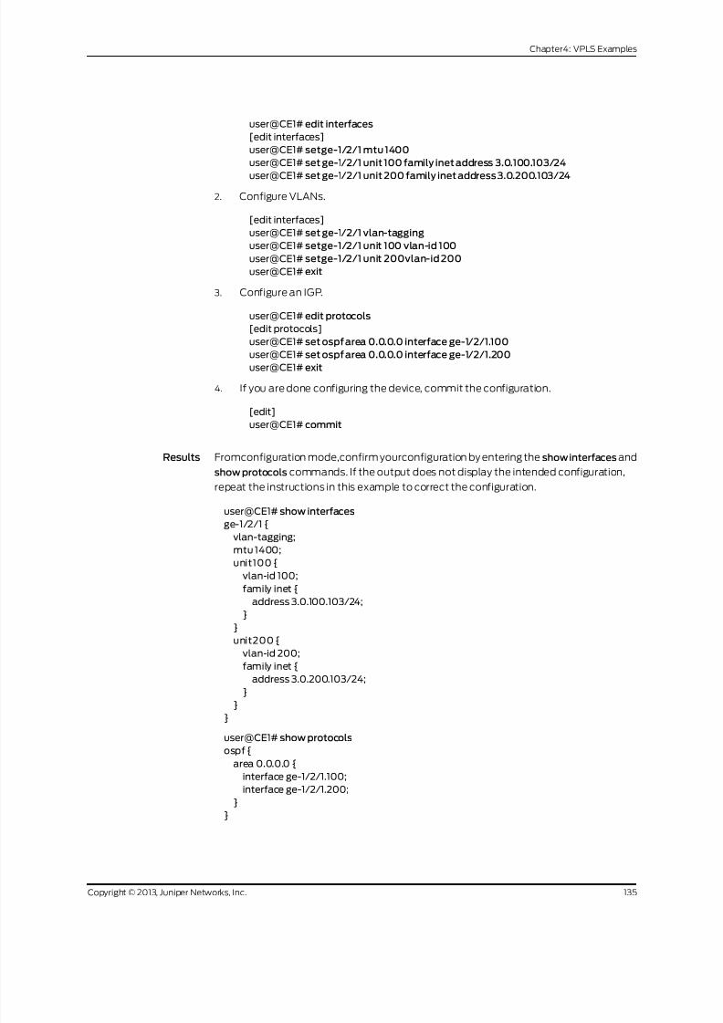
8/21/2019 Config Guide Vpns Vpls
http://slidepdf.com/reader/full/config-guide-vpns-vpls 153/485
user@CE1# edit interfaces
[edit interfaces]
user@CE1# setge-1/2/1 mtu 1400
user@CE1# set ge-1/2/1 unit 100 family inet address 3.0.100.103/24
user@CE1# set ge-1/2/1 unit 200 family inet address 3.0.200.103/24
2. Configure VLANs.
[edit interfaces]
user@CE1# set ge-1/2/1 vlan-tagging
user@CE1# setge-1/2/1 unit 100 vlan-id 100
user@CE1# setge-1/2/1 unit 200vlan-id 200
user@CE1# exit
3. Configure an IGP.
user@CE1# edit protocols
[edit protocols]
user@CE1# set ospf area 0.0.0.0 interface ge-1/2/1.100
user@CE1# set ospf area 0.0.0.0 interface ge-1/2/1.200user@CE1# exit
4. If you are done configuring the device, commit the configuration.
[edit]
user@CE1# commit
Results Fromconfiguration mode,confirm yourconfiguration by entering the show interfaces and
show protocols commands. If the output does not display the intended configuration,
repeat the instructions in this example to correct the configuration.
user@CE1# show interfaces
ge-1/2/1 {
vlan-tagging;mtu 1400;
unit100 {
vlan-id 100;
family inet {
address 3.0.100.103/24;
}
}
unit200 {
vlan-id 200;
family inet {
address 3.0.200.103/24;
}
}
}
user@CE1# show protocols
ospf {
area 0.0.0.0 {
interface ge-1/2/1.100;
interface ge-1/2/1.200;
}
}
135Copyright © 2013, Juniper Networks, Inc.
Chapter4: VPLS Examples

8/21/2019 Config Guide Vpns Vpls
http://slidepdf.com/reader/full/config-guide-vpns-vpls 154/485
Router PE2
Step-by-Step
Procedure
To configure Router PE2:
Configure the interfaces, the interface encapsulation, and the protocol families.
[edit]
1.
user@PE2# edit interfaces
[edit interfaces]
user@PE2# set ge-1/1/0 encapsulation flexible-ethernet-services
user@PE2# set ge-1/1/0 unit 100 encapsulation vlan-vpls
user@PE2# set ge-1/1/0 unit 100 family vpls
user@PE2# set ge-1/1/0 unit 200 encapsulation vlan-vpls
user@PE2# set ge-1/1/0 unit 200family vpls
user@PE2# set ge-1/2/1 unit 0 description "PE2 to PE1"
user@PE2# set ge-1/2/1 unit 0 family inet address 8.0.40.104/24
user@PE2# set ge-1/2/1 unit 0 family iso
user@PE2# set ge-1/2/1 unit 0 family mpls
user@PE2# set lo0 unit 0 family inet address 8.0.0.104/32
2. Configure the VLANs.
[edit interfaces]
user@PE2# set ge-1/1/0 vlan-tagging
user@PE2# set ge-1/1/0 unit 100 vlan-id 100
user@PE2# set ge-1/1/0 unit 100 input-vlan-map pop
user@PE2# set ge-1/1/0 unit 100 output-vlan-map push
user@PE2# set ge-1/1/0 unit 200vlan-id 200
user@PE2# exit
3. Configure the protocols-independent properties.
We recommend that the router ID be the same as the local address. (See the
local-address statement in Step 4.)
[edit]
user@PE2# edit routing-options
[edit routing-options]
user@PE2# set router-id 8.0.0.104
user@PE2# set autonomous-system 100
4. Configure IBGP, including the auto-discovery-only statement.
[edit]
user@PE2# edit protocols
[edit protocols]
user@PE2# set bgpgroup int type internal
user@PE2# set bgp group int local-address 8.0.0.104
user@PE2# set bgp group int family l2vpn auto-discovery-only
user@PE2# set bgp group int neighbor 8.0.0.107
5. Configure MPLS, LDP, and an IGP.
[edit protocols]
user@PE2# set mpls interface lo0.0
user@PE2# set mpls interface all
user@PE2# set mpls interface fxp0.0 disable
user@PE2# set isis level 1 disable
Copyright © 2013, Juniper Networks, Inc.136
VPLS Feature Guide for Routing Devices
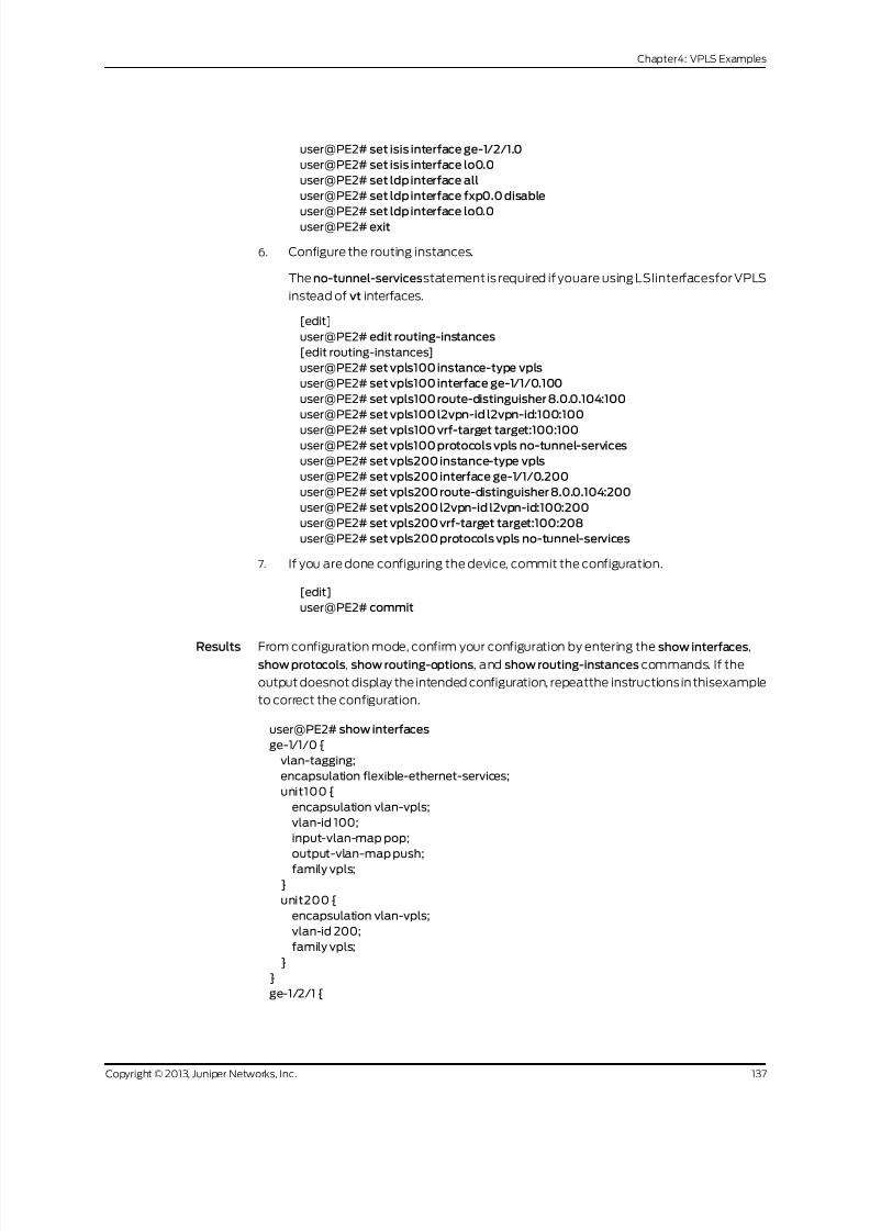
8/21/2019 Config Guide Vpns Vpls
http://slidepdf.com/reader/full/config-guide-vpns-vpls 155/485
user@PE2# set isis interface ge-1/2/1.0
user@PE2# set isis interface lo0.0
user@PE2# set ldp interface all
user@PE2# set ldp interface fxp0.0 disable
user@PE2# set ldp interface lo0.0user@PE2# exit
6. Configure the routing instances.
The no-tunnel-servicesstatement is required if youare using LSIinterfacesfor VPLS
instead of vt interfaces.
[edit]
user@PE2# edit routing-instances
[edit routing-instances]
user@PE2# set vpls100 instance-type vpls
user@PE2# set vpls100 interface ge-1/1/0.100
user@PE2# set vpls100 route-distinguisher 8.0.0.104:100
user@PE2# set vpls100 l2vpn-id l2vpn-id:100:100
user@PE2# set vpls100 vrf-target target:100:100user@PE2# set vpls100 protocols vpls no-tunnel-services
user@PE2# set vpls200 instance-type vpls
user@PE2# set vpls200 interface ge-1/1/0.200
user@PE2# set vpls200 route-distinguisher 8.0.0.104:200
user@PE2# set vpls200 l2vpn-id l2vpn-id:100:200
user@PE2# set vpls200 vrf-target target:100:208
user@PE2# set vpls200 protocols vpls no-tunnel-services
7. If you are done configuring the device, commit the configuration.
[edit]
user@PE2# commit
Results From configuration mode, confirm your configuration by entering the show interfaces,show protocols, show routing-options, and show routing-instances commands. If the
output doesnot display the intended configuration, repeatthe instructionsin thisexample
to correct the configuration.
user@PE2# show interfaces
ge-1/1/0 {
vlan-tagging;
encapsulation flexible-ethernet-services;
unit100 {
encapsulation vlan-vpls;
vlan-id 100;
input-vlan-map pop;
output-vlan-map push;
family vpls;
}
unit200 {
encapsulation vlan-vpls;
vlan-id 200;
family vpls;
}
}
ge-1/2/1 {
137Copyright © 2013, Juniper Networks, Inc.
Chapter4: VPLS Examples

8/21/2019 Config Guide Vpns Vpls
http://slidepdf.com/reader/full/config-guide-vpns-vpls 156/485
unit0 {
description "PE2 to PE1";
family inet {
address 8.0.40.104/24;
}family iso;
family mpls;
}
}
lo0{
unit0 {
family inet {
address 8.0.0.104/32;
}
}
}
user@PE2# show protocols
mpls {
interface lo0.0;
interface all;
interface fxp0 disable;
}
bgp {
group int {
type internal;
local-address 8.0.0.104;
family l2vpn {
auto-discovery-only;
}
neighbor 8.0.0.107;
}
}
isis {
level 1 disable;
interface ge-1/2/1.0;
interface lo0.0;
}
ldp{
interface lo0.0;
interface all;
interface fxp0 disable;
}
user@PE2# show routing-options
router-id 8.0.0.104;
autonomous-system 100;
user@PE2# show routing-instances
vpls100 {
instance-type vpls;
interface ge-1/1/0.100;
route-distinguisher 8.0.0.104:100;
l2vpn-id l2vpn-id:100:100;
vrf-target target:100:100;
protocols {
vpls {
Copyright © 2013, Juniper Networks, Inc.138
VPLS Feature Guide for Routing Devices

8/21/2019 Config Guide Vpns Vpls
http://slidepdf.com/reader/full/config-guide-vpns-vpls 157/485
no-tunnel-services;
}
}
}
vpls200 {instance-type vpls;
interface ge-1/1/0.200;
route-distinguisher 8.0.0.104:200;
l2vpn-id l2vpn-id:100:200;
vrf-target target:100:208;
protocols {
vpls {
no-tunnel-services;
}
}
}
Device CE2
Step-by-Step
Procedure
To configure Device CE2:
Configure VLAN interfaces.
[edit]
1.
user@CE2# edit interfaces ge-1/1/0
[edit interfaces ge-1/1/0]
user@CE2# set vlan-tagging
user@CE2# setmtu 1400
user@CE2# setunit 100 vlan-id 100
user@CE2# set unit 100 family inet address 3.0.100.105/24
user@CE2# setunit 200 vlan-id 200
user@CE2# set unit 200 family inet address 3.0.200.105/24
user@CE2# exit
2. Configure OSPF on the interfaces.
[edit]
user@CE2# edit protocols ospf area 0.0.0.0
[edit protocols ospf area 0.0.0.0]
user@CE2# set interface ge-1/1/0.100
user@CE2# set interface ge-1/1/0.200
user@CE2# exit
3. If you are done configuring the device, commit the configuration.
[edit]
user@CE2# commit
Results Fromconfiguration mode,confirm yourconfiguration by entering the show interfaces and
show protocols commands. If the output does not display the intended configuration,
repeat the instructions in this example to correct the configuration.
user@CE2# show interfaces
ge-1/1/0 {
vlan-tagging;
mtu 1400;
139Copyright © 2013, Juniper Networks, Inc.
Chapter4: VPLS Examples

8/21/2019 Config Guide Vpns Vpls
http://slidepdf.com/reader/full/config-guide-vpns-vpls 158/485
unit100 {
vlan-id 100;
family inet {
address 3.0.100.105/24;
}}
unit200 {
vlan-id 200;
family inet {
address 3.0.200.105/24;
}
}
}
user@CE2# show protocols
ospf {
area 0.0.0.0 {
interface ge-1/1/0.100;
interface ge-1/1/0.200;
}
}
Router RR
Step-by-Step
Procedure
To configure Router RR:
Configure interface addresses and the protocol families.
[edit]
1.
user@RR# edit interfaces
[edit interfaces]
user@RR# set ge-1/3/2 unit 0 description "RR to PE1"
user@RR# set ge-1/3/2 unit 0 family inet address 8.0.70.107/24
user@RR# set ge-1/3/2 unit 0 family iso
user@RR# set ge-1/3/2 unit 0 family mpls
user@RR# set lo0 unit 0 family inet address 8.0.0.107/32
user@RR# exit
2. Configure the autonomous systems and the router ID.
[edit]
user@RR# edit routing-options
[edit routing-options]
user@RR# set autonomous-system 100
user@RR# set router-id 8.0.0.107
user@RR# exit
3. ConfigureBGPandset thisrouter to be the routereflector. Routereflectionis optionalfor FEC 129.
[edit]
user@RR# edit protocols bgp group int
[edit protocols bgp group int]
user@RR# set type internal
user@RR# set local-address 8.0.0.107
user@RR# set family l2vpn auto-discovery-only
user@RR# set cluster 107.107.107.107
Copyright © 2013, Juniper Networks, Inc.140
VPLS Feature Guide for Routing Devices
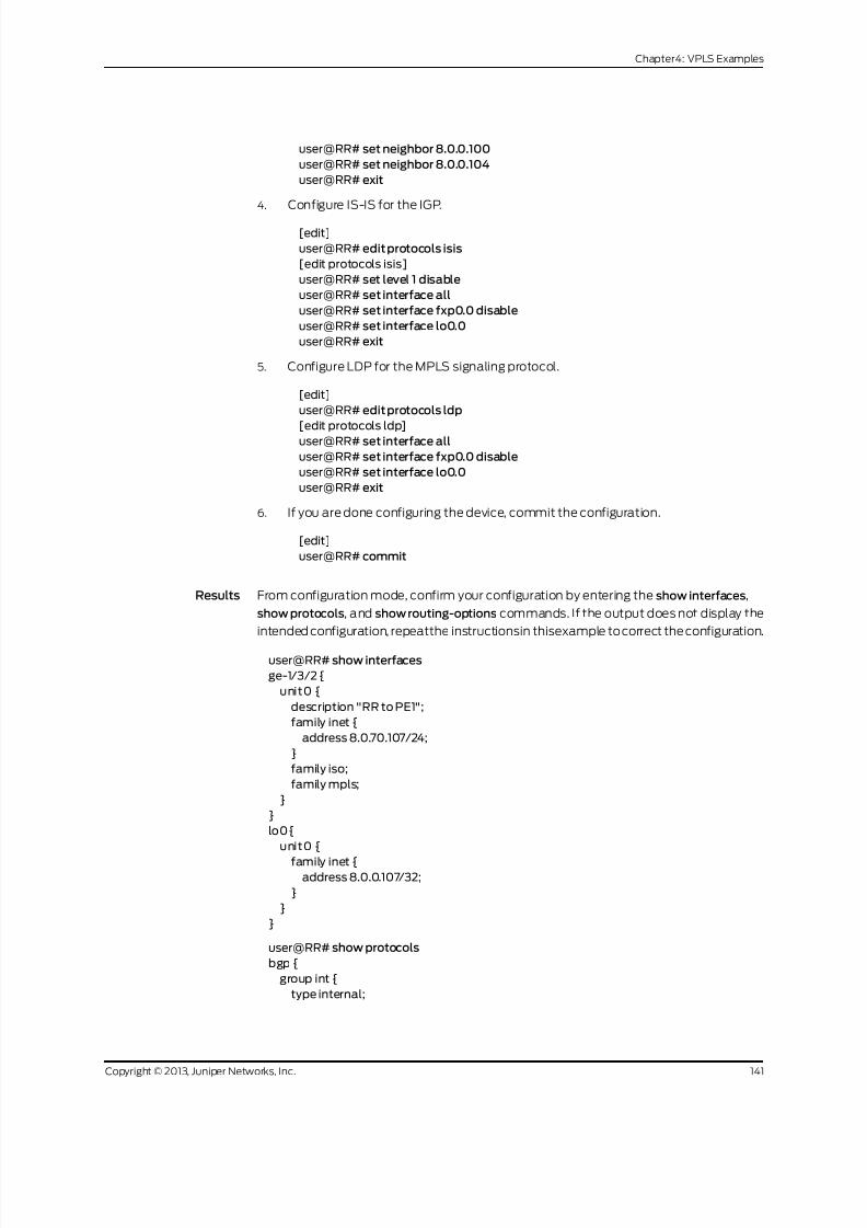
8/21/2019 Config Guide Vpns Vpls
http://slidepdf.com/reader/full/config-guide-vpns-vpls 159/485
user@RR# set neighbor 8.0.0.100
user@RR# set neighbor 8.0.0.104
user@RR# exit
4. Configure IS-IS for the IGP.
[edit]
user@RR# edit protocols isis
[edit protocols isis]
user@RR# set level 1 disable
user@RR# set interface all
user@RR# set interface fxp0.0 disable
user@RR# set interface lo0.0
user@RR# exit
5. Configure LDP for the MPLS signaling protocol.
[edit]
user@RR# edit protocols ldp
[edit protocols ldp]user@RR# set interface all
user@RR# set interface fxp0.0 disable
user@RR# set interface lo0.0
user@RR# exit
6. If you are done configuring the device, commit the configuration.
[edit]
user@RR# commit
Results From configuration mode, confirm your configuration by entering the show interfaces,
show protocols, and show routing-options commands. If the output does not display the
intended configuration, repeatthe instructionsin thisexample to correct the configuration.
user@RR# show interfaces
ge-1/3/2 {
unit0 {
description "RR to PE1";
family inet {
address 8.0.70.107/24;
}
family iso;
family mpls;
}
}
lo0{
unit0 {
family inet {address 8.0.0.107/32;
}
}
}
user@RR# show protocols
bgp {
group int {
type internal;
141Copyright © 2013, Juniper Networks, Inc.
Chapter4: VPLS Examples

8/21/2019 Config Guide Vpns Vpls
http://slidepdf.com/reader/full/config-guide-vpns-vpls 160/485
local-address 8.0.0.107;
family l2vpn {
auto-discovery-only;
}
cluster 107.107.107.107;neighbor 8.0.0.100;
neighbor 8.0.0.104;
}
}
isis {
level 1 disable;
interface lo0.0;
interface all;
interface fxp0 disable;
}
ldp{
interface lo0.0;
interface all;
interface fxp0 disable;}
user@RR# show routing-options
router-id 8.0.0.107;
autonomous-system 100;
Verification
To verify the operation, use the following commands:
• show route extensive
• show route advertising-protocol bgp neighbor
• show route receive-protocol bgp neighbor
• show route table bgp.l2vpn.0
• show route table vpls100.l2vpn.0
• show route table vpls200.l2vpn.0
• show vpls connections extensive
• show vpls mac-table detail
• show vpls statistics
AD in the routing table output indicates autodiscovery NLRI.
Related
Documentation
Example: ConfiguringBGPAutodiscovery forLDP VPLSwith User-DefinedMesh Groups
on page 143
•
• Configuring Interoperability Between BGP Signaling and LDP Signaling in VPLS on
page 84
Copyright © 2013, Juniper Networks, Inc.142
VPLS Feature Guide for Routing Devices
8/21/2019 Config Guide Vpns Vpls
http://slidepdf.com/reader/full/config-guide-vpns-vpls 161/485
Example: Configuring BGPAutodiscovery forLDPVPLS withUser-Defined MeshGroups
This example describeshow to configureuser-definedmeshgroupsfor BGPautodiscovery
for LDP VPLS, as specified in forwarding equivalency class (FEC) 129. FEC 129 uses BGP
autodiscovery to convey endpoint information,so you do not need to manually configure
pseudowires. You configure mesh groups on the border router to group the sets of PE
routers that are automatically fully meshed and that share the same signaling protocol,
either BGP or LDP. You can configure multiple mesh groups to map each fully meshed
LDP-signaled or BGP-signaled VPLS domain to a mesh group.
• Requirements on page 143
• Overview on page 143
• Configuration on page 144
• Verification on page 149
Requirements
Before you begin, configure BGP autodiscovery for LDP VPLS. See “Example: Configuring
BGP Autodiscovery for LDP VPLS” on page 126.
The hardware and software requirements for this example are the same as the
requirements forthe Example:ConfiguringBGPAutodiscoveryforLDPVPLS. You will need
to adapt the example configuration to the topology used in this example.
Overview
Configuration fora meshgroup forFEC 129 is verysimiliar to the mesh-group configuration
for FEC 128.
Note the following differences for FEC 129:
• Each user-defined mesh group must have a unique route distinguisher. Do not use the
route distinguisher that is defined for the default mesh group at the [edit
routing-intances] hierarchy level.
• Each user-defined mesh group must have its own import and export route target.
• Each user-defined mesh group can have a unique Layer 2 VPN ID. By default, all the
mesh groups that are configured for a VPLS routing instance use the same Layer 2
VPN ID as the one that you configure at the [edit routing-instances] hierarchy level.
Topology Diagram
Figure 12 on page 144 shows a topology that includes a user-defined mesh group.
143Copyright © 2013, Juniper Networks, Inc.
Chapter4: VPLS Examples

8/21/2019 Config Guide Vpns Vpls
http://slidepdf.com/reader/full/config-guide-vpns-vpls 162/485
Figure 12: BGP Autodiscovery for LDP VPLS with a User-Defined MeshGroup
R3
R4
CE2
CE3
R2CE1ge-2/0/8
ge-2/0/5
ge-2/1/3
ge-2/0/9
ge-2/1/7
ge-2/1/6
g 0 1 5 3 1 8 5
172.16.0.1/24
172.16.0.3/24
172.16.0.4/24
lo0:
CE1 10.255.14.214
CE3 10.255.14.218CE4 10.255.14.219
R2 2.2.2.2
R3 3.3.3.3
R4 4.4.4.4
“CLI Quick Configuration” on page 144 shows the configuration for all of the devices in
Figure 12 on page 144. The section “Step-by-Step Procedure” on page 146 describes the
steps on Device R2.
Configuration
CLI Quick
Configuration
To quicklyconfigure a meshgroup,copy the following commands, remove anylinebreaks,
and then paste the commands into the CLI of each device.
Device CE1 set interfaces ge-2/0/8 unit 0
set interfaces lo0 unit 0 family inet address 10.255.14.214/32
set protocols ospf area 0.0.0.0 interface lo0.0 passive
set protocols ospf area 0.0.0.0 interface ge-2/0/8.0
Device CE3 set interfaces ge-2/0/9 unit 0
set interfaces lo0 unit 0 family inet address 10.255.14.218/32set protocols ospf area 0.0.0.0 interface lo0.0 passive
set protocols ospf area 0.0.0.0 interface ge-2/0/9.0
Device CE4 set interfaces ge-2/1/6 unit 0
set interfaces lo0 unit 0 family inet address 10.255.14.219/32
set protocols ospf area 0.0.0.0 interface lo0.0 passive
set protocols ospf area 0.0.0.0 interface ge-2/1/6.0
Device R2 set interfaces ge-2/0/5 encapsulation ethernet-vpls
set interfaces ge-2/0/5 unit 0 description to_CE1
set interfaces ge-2/0/5 unit 0 family vpls
set interfaces ge-2/0/10 unit 0 description to_R3
set interfaces ge-2/0/10 unit 0 family inet address 10.10.4.2/30set interfaces ge-2/0/10 unit 0 family mpls
set interfaces ge-2/0/11 unit 0 description to_R4
set interfaces ge-2/0/11 unit 0 family inet address 10.10.5.1/30
set interfaces ge-2/0/11 unit 0 family mpls
set interfaces lo0 unit 0 family inet address 2.2.2.2/32
set protocols mpls interface ge-2/0/10.0
set protocols mpls interface ge-2/0/11.0
set protocols bgp local-address 2.2.2.2
set protocols bgp group pe-pe type internal
Copyright © 2013, Juniper Networks, Inc.144
VPLS Feature Guide for Routing Devices

8/21/2019 Config Guide Vpns Vpls
http://slidepdf.com/reader/full/config-guide-vpns-vpls 163/485
set protocols bgp group pe-pe connect-retry-interval 1
set protocols bgp group pe-pe family l2vpn auto-discovery-only
set protocols bgp group pe-pe family l2vpn signaling
set protocols bgp group pe-pe neighbor 3.3.3.3
set protocols bgp group pe-pe neighbor 4.4.4.4set protocols ospf traffic-engineering
set protocols ospf area 0.0.0.0 interface lo0.0 passive
set protocols ospf area 0.0.0.0 interface ge-2/0/10.0
set protocols ospf area 0.0.0.0 interface ge-2/0/11.0
set protocols ldp interface ge-2/0/10.0
set protocols ldp interface ge-2/0/11.0
set protocols ldp interface lo0.0
set routing-instances inst512 instance-type vpls
set routing-instances inst512 interface ge-2/0/5.0
set routing-instances inst512 route-distinguisher 100:100
set routing-instances inst512 l2vpn-id l2vpn-id:1:2
set routing-instances inst512 vrf-target target:1:1
set routing-instances inst512 protocols vpls mesh-group metro1 vrf-target target:2:1
set routing-instances inst512 protocols vpls mesh-group metro1 route-distinguisher100:200
set routing-options autonomous-system 64510
Device R3 set interfaces ge-2/0/10 unit 0 description to_R2
set interfaces ge-2/0/10 unit 0 family inet address 10.10.4.1/30
set interfaces ge-2/0/10 unit 0 family mpls
set interfaces ge-2/1/3 encapsulation ethernet-vpls
set interfaces ge-2/1/3 unit 0 description to_CE3
set interfaces ge-2/1/3 unit 0 family vpls
set interfaces lo0 unit 0 family inet address 3.3.3.3/32
set protocols mpls interface ge-2/0/10.0
set protocols bgp local-address 3.3.3.3
set protocols bgp group pe-pe type internal
set protocols bgp group pe-pe connect-retry-interval 1set protocols bgp group pe-pe family l2vpn auto-discovery-only
set protocols bgp group pe-pe family l2vpn signaling
set protocols bgp group pe-pe neighbor 2.2.2.2
set protocols bgp group pe-pe neighbor 4.4.4.4
set protocols ospf traffic-engineering
set protocols ospf area 0.0.0.0 interface ge-2/0/10.0
set protocols ospf area 0.0.0.0 interface lo0.0 passive
set protocols ldp interface ge-2/0/10.0
set protocols ldp interface lo0.0
set routing-instances inst512 instance-type vpls
set routing-instances inst512 interface ge-2/1/3.0
set routing-instances inst512 route-distinguisher 100:100
set routing-instances inst512 l2vpn-id l2vpn-id:1:2
set routing-instances inst512 vrf-target target:1:1
set routing-instances inst512 protocols vpls
set routing-options autonomous-system 64510
Device R4 set interfaces ge-2/0/10 unit 0 description to_R2
set interfaces ge-2/0/10 unit 0 family inet address 10.10.5.2/30
set interfaces ge-2/0/10 unit 0 family mpls
set interfaces ge-2/1/7 encapsulation ethernet-vpls
set interfaces ge-2/1/7 unit 0 description to_CE4
145Copyright © 2013, Juniper Networks, Inc.
Chapter4: VPLS Examples

8/21/2019 Config Guide Vpns Vpls
http://slidepdf.com/reader/full/config-guide-vpns-vpls 164/485
set interfaces ge-2/1/7 unit 0 family vpls
set interfaces lo0 unit 0 family inet address 4.4.4.4/32
set protocols mpls interface ge-2/0/10.0
set protocols bgp local-address 4.4.4.4
set protocols bgp group pe-pe type internalset protocols bgp group pe-pe connect-retry-interval 1
set protocols bgp group pe-pe family l2vpn auto-discovery-only
set protocols bgp group pe-pe family l2vpn signaling
set protocols bgp group pe-pe neighbor 2.2.2.2
set protocols bgp group pe-pe neighbor 3.3.3.3
set protocols ospf traffic-engineering
set protocols ospf area 0.0.0.0 interface ge-2/0/10.0
set protocols ospf area 0.0.0.0 interface lo0.0 passive
set protocols ldp interface ge-2/0/10.0
set protocols ldp interface lo0.0
set routing-instances inst512 instance-type vpls
set routing-instances inst512 interface ge-2/1/7.0
set routing-instances inst512 route-distinguisher 100:100
set routing-instances inst512 l2vpn-id l2vpn-id:1:2set routing-instances inst512 vrf-target target:1:1
set routing-instances inst512 protocols vpls
set routing-options autonomous-system 64510
Step-by-Step
Procedure
To configure a mesh group:
Configure the interfaces.
[edit interfaces]
1.
user@R2# set ge-2/0/5 encapsulation ethernet-vpls
user@R2# set ge-2/0/5 unit 0 description to_CE1
user@R2# set ge-2/0/5 unit 0 family vpls
user@R2# set ge-2/0/10 unit 0 description to_R3
user@R2# set ge-2/0/10 unit 0 family inet address 10.10.4.2/30
user@R2# set ge-2/0/10 unit 0 family mpls
user@R2# set ge-2/0/11 unit 0 description to_R4
user@R2# set ge-2/0/11 unit 0 family inet address 10.10.5.1/30
user@R2# set ge-2/0/11 unit 0 family mpls
user@R2# set lo0 unit 0 family inet address 2.2.2.2/32
2. Configure MPLS on the interfaces.
[edit protocols mpls]
user@R2# set interface ge-2/0/10.0
user@R2# set interface ge-2/0/11.0
3. Configure BGP.
[edit protocols bgp]
user@R2# set local-address 2.2.2.2
[edit protocols bgp group pe-pe]
user@R2# set type internal
Copyright © 2013, Juniper Networks, Inc.146
VPLS Feature Guide for Routing Devices

8/21/2019 Config Guide Vpns Vpls
http://slidepdf.com/reader/full/config-guide-vpns-vpls 165/485
user@R2# set connect-retry-interval 1
user@R2# set family l2vpn auto-discovery-only
user@R2# set family l2vpn signaling
user@R2# set neighbor 3.3.3.3
user@R2# set neighbor 4.4.4.4
4. Set the import and export route target for the default mesh group.
[edit protocols ospf]
user@R2# set traffic-engineering
user@R2# set area 0.0.0.0 interface lo0.0 passive
user@R2# set area 0.0.0.0 interface ge-2/0/10.0
user@R2# set area 0.0.0.0 interface ge-2/0/11.0
5. Configure LDP on the core-facing interfaces and on the loopback interface.
[edit protocols ldp]
user@R2# set interface ge-2/0/10.0
user@R2# set interface ge-2/0/11.0
user@R2# set interface lo0.0
6. Configure the VPLS routing instance.
Make sure that the route distinguisher in the mesh group is unique.
[edit routing-instances inst512]
user@R2# set instance-type vpls
user@R2# set interface ge-2/0/5.0
user@R2# set route-distinguisher 100:100
user@R2# set l2vpn-id l2vpn-id:1:2
user@R2# set vrf-target target:1:1
user@R2# set protocols vpls mesh-group metro1 vrf-target target:2:1
user@R2# set protocols vpls mesh-group metro1 route-distinguisher 100:200
7. Configure the autonomous system (AS) number.
[edit routing-options]
user@R2# set autonomous-system 64510
8. If you are done configuring the device, commit the configuration.
[edit]
user@R2# commit
Results From configuration mode, confirm your configuration by entering the show
routing-instances command. If the output does not display the intended configuration,
repeat the instructions in this example to correct the configuration.
user@R2# show interfacesge-2/0/5 {
encapsulation ethernet-vpls;
unit0 {
description PE1_to_CE1;
family vpls;
}
}
ge-2/0/10 {
unit 0{
147Copyright © 2013, Juniper Networks, Inc.
Chapter4: VPLS Examples

8/21/2019 Config Guide Vpns Vpls
http://slidepdf.com/reader/full/config-guide-vpns-vpls 166/485
description to_R3;
family inet {
address 10.10.4.2/30;
}
family mpls;}
}
ge-2/0/11 {
unit0 {
description to_R4;
family inet {
address 10.10.5.1/30;
}
family mpls;
}
}
lo0{
unit 0{
family inet {address 2.2.2.2/32;
}
}
}
user@R2# show protocols
mpls {
interface ge-2/0/10.0;
interface ge-2/0/11.0;
}
bgp {
local-address 2.2.2.2;
group pe-pe {
type internal;
connect-retry-interval 1;
family l2vpn {
auto-discovery-only;
signaling;
}
neighbor 3.3.3.3;
neighbor 4.4.4.4;
}
}
ospf {
traffic-engineering;
area 0.0.0.0 {
interface lo0.0 {
passive;
}
interface ge-2/0/10.0;
interface ge-2/0/11.0;
}
}
ldp{
interface ge-2/0/10.0;
interface ge-2/0/11.0;
interface lo0.0;
Copyright © 2013, Juniper Networks, Inc.148
VPLS Feature Guide for Routing Devices

8/21/2019 Config Guide Vpns Vpls
http://slidepdf.com/reader/full/config-guide-vpns-vpls 167/485
}
user@R2# show routing-instances
inst512 {
instance-type vpls;
interface ge-2/0/5.0;
route-distinguisher 100:100;
l2vpn-id l2vpn-id:1:2;
vrf-target target:1:1;
protocols {
vpls {
mesh-group metro1 {
vrf-target target:2:1;
route-distinguisher 100:200;
}
}
}
}
user@R2# show routing-optionsautonomous-system 64510;
Verification
Confirm that the configuration is working properly.
• Verifying the Routes on page 149
• Checking Connectivity on page 151
• Checking the VPLS Connections on page 152
• Display Learned VPLS MAC Address Information on page 152
Verifying the Routes
Purpose Verify that the expected routes are learned.
Action From operational mode, enter the show route command.
user@R2> show route
inet.0: 9 destinations, 9 routes (9 active, 0 holddown, 0 hidden)
+ = Active Route, - = Last Active, * = Both
2.2.2.2/32 *[Direct/0] 4d 02:42:47
> via lo0.0
3.3.3.3/32 *[OSPF/10] 4d 02:41:56, metric 1
> to 10.10.4.1 via ge-2/0/10.0
4.4.4.4/32 *[OSPF/10] 4d 02:42:01, metric 1
> to 10.10.5.2 via ge-2/0/11.010.10.3.2/32 *[Local/0] 4d 02:42:47
Reject
10.10.4.0/30 *[Direct/0] 4d 02:42:46
> via ge-2/0/10.0
10.10.4.2/32 *[Local/0] 4d 02:42:47
Local via ge-2/0/10.0
10.10.5.0/30 *[Direct/0] 4d 02:42:46
> via ge-2/0/11.0
10.10.5.1/32 *[Local/0] 4d 02:42:47
Local via ge-2/0/11.0
149Copyright © 2013, Juniper Networks, Inc.
Chapter4: VPLS Examples
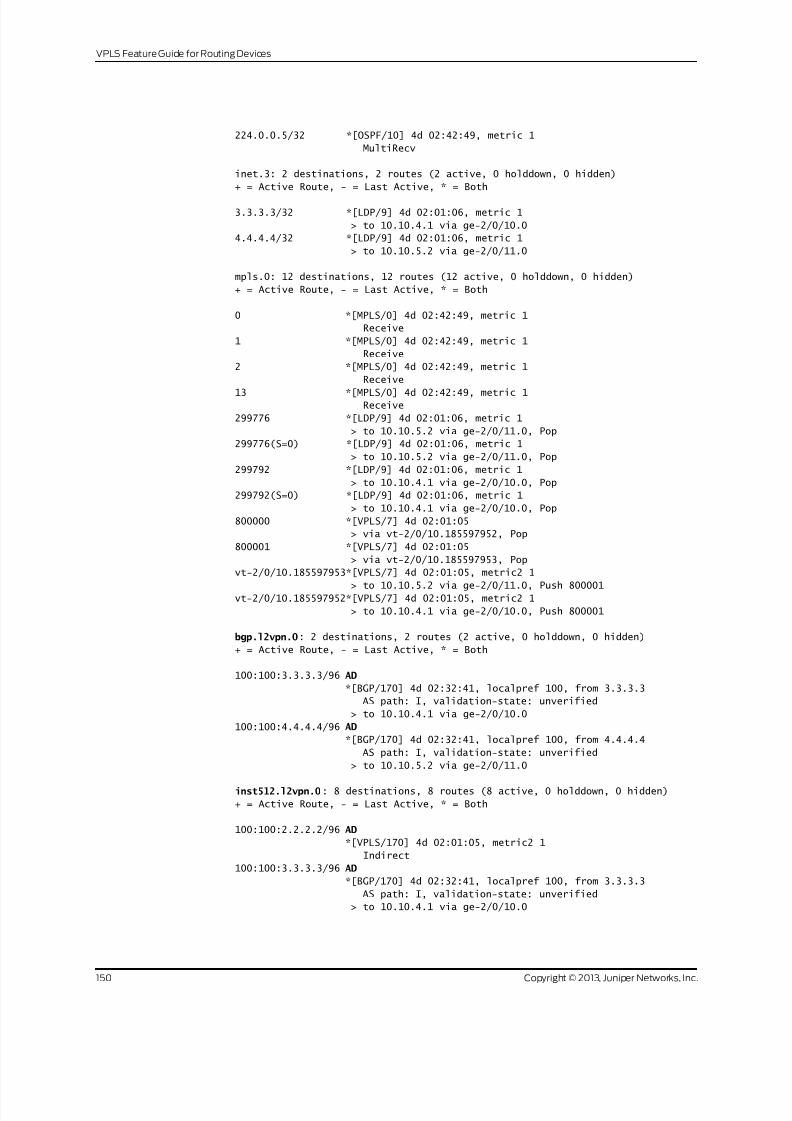
8/21/2019 Config Guide Vpns Vpls
http://slidepdf.com/reader/full/config-guide-vpns-vpls 168/485
224.0.0.5/32 *[OSPF/10] 4d 02:42:49, metric 1
MultiRecv
inet.3: 2 destinations, 2 routes (2 active, 0 holddown, 0 hidden)
+ = Active Route, - = Last Active, * = Both
3.3.3.3/32 *[LDP/9] 4d 02:01:06, metric 1
> to 10.10.4.1 via ge-2/0/10.0
4.4.4.4/32 *[LDP/9] 4d 02:01:06, metric 1
> to 10.10.5.2 via ge-2/0/11.0
mpls.0: 12 destinations, 12 routes (12 active, 0 holddown, 0 hidden)
+ = Active Route, - = Last Active, * = Both
0 *[MPLS/0] 4d 02:42:49, metric 1
Receive
1 *[MPLS/0] 4d 02:42:49, metric 1
Receive
2 *[MPLS/0] 4d 02:42:49, metric 1
Receive
13 *[MPLS/0] 4d 02:42:49, metric 1 Receive
299776 *[LDP/9] 4d 02:01:06, metric 1
> to 10.10.5.2 via ge-2/0/11.0, Pop
299776(S=0) *[LDP/9] 4d 02:01:06, metric 1
> to 10.10.5.2 via ge-2/0/11.0, Pop
299792 *[LDP/9] 4d 02:01:06, metric 1
> to 10.10.4.1 via ge-2/0/10.0, Pop
299792(S=0) *[LDP/9] 4d 02:01:06, metric 1
> to 10.10.4.1 via ge-2/0/10.0, Pop
800000 *[VPLS/7] 4d 02:01:05
> via vt-2/0/10.185597952, Pop
800001 *[VPLS/7] 4d 02:01:05
> via vt-2/0/10.185597953, Pop
vt-2/0/10.185597953*[VPLS/7] 4d 02:01:05, metric2 1
> to 10.10.5.2 via ge-2/0/11.0, Push 800001vt-2/0/10.185597952*[VPLS/7] 4d 02:01:05, metric2 1
> to 10.10.4.1 via ge-2/0/10.0, Push 800001
bgp.l2vpn.0: 2 destinations, 2 routes (2 active, 0 holddown, 0 hidden)
+ = Active Route, - = Last Active, * = Both
100:100:3.3.3.3/96 AD
*[BGP/170] 4d 02:32:41, localpref 100, from 3.3.3.3
AS path: I, validation-state: unverified
> to 10.10.4.1 via ge-2/0/10.0
100:100:4.4.4.4/96 AD
*[BGP/170] 4d 02:32:41, localpref 100, from 4.4.4.4
AS path: I, validation-state: unverified
> to 10.10.5.2 via ge-2/0/11.0
inst512.l2vpn.0: 8 destinations, 8 routes (8 active, 0 holddown, 0 hidden)
+ = Active Route, - = Last Active, * = Both
100:100:2.2.2.2/96 AD
*[VPLS/170] 4d 02:01:05, metric2 1
Indirect
100:100:3.3.3.3/96 AD
*[BGP/170] 4d 02:32:41, localpref 100, from 3.3.3.3
AS path: I, validation-state: unverified
> to 10.10.4.1 via ge-2/0/10.0
Copyright © 2013, Juniper Networks, Inc.150
VPLS Feature Guide for Routing Devices

8/21/2019 Config Guide Vpns Vpls
http://slidepdf.com/reader/full/config-guide-vpns-vpls 169/485
100:100:4.4.4.4/96 AD
*[BGP/170] 4d 02:32:41, localpref 100, from 4.4.4.4
AS path: I, validation-state: unverified
> to 10.10.5.2 via ge-2/0/11.0
100:200:2.2.2.2/96 AD
*[VPLS/170] 4d 02:01:05, metric2 1 Indirect
3.3.3.3:NoCtrlWord:5:1:2:2.2.2.2:3.3.3.3/176
*[VPLS/7] 4d 02:01:05, metric2 1
> to 10.10.4.1 via ge-2/0/10.0
3.3.3.3:NoCtrlWord:5:1:2:3.3.3.3:2.2.2.2/176
*[LDP/9] 4d 02:01:05
Discard
4.4.4.4:NoCtrlWord:5:1:2:2.2.2.2:4.4.4.4/176
*[VPLS/7] 4d 02:01:05, metric2 1
> to 10.10.5.2 via ge-2/0/11.0
4.4.4.4:NoCtrlWord:5:1:2:4.4.4.4:2.2.2.2/176
*[LDP/9] 4d 02:01:05
Discard
ldp.l2vpn.0: 2 destinations, 2 routes (2 active, 0 holddown, 0 hidden)+ = Active Route, - = Last Active, * = Both
3.3.3.3:NoCtrlWord:5:1:2:3.3.3.3:2.2.2.2/176
*[LDP/9] 4d 02:01:05
Discard
4.4.4.4:NoCtrlWord:5:1:2:4.4.4.4:2.2.2.2/176
*[LDP/9] 4d 02:01:05
Discard
Meaning The output shows all the learned routes, including the autodiscovered (AD) routes.
Checking Connectivity
Purpose Verify that Device CE1 can ping Device CE3 and Device CE4.
Action user@CE1> ping 10.255.14.218
PING 10.255.14.218 (10.255.14.218): 56 data bytes
64 bytes from 10.255.14.218: icmp_seq=0 ttl=64 time=0.787 ms
64 bytes from 10.255.14.218: icmp_seq=1 ttl=64 time=0.651 ms
^C
--- 10.255.14.218 ping statistics ---
2 packets transmitted, 2 packets received, 0% packet loss
round-trip min/avg/max/stddev = 0.651/0.719/0.787/0.068 ms
user@CE1> ping 10.255.14.219
PING 10.255.14.219 (10.255.14.219): 56 data bytes
64 bytes from 10.255.14.219: icmp_seq=0 ttl=64 time=1.054 ms
64 bytes from 10.255.14.219: icmp_seq=1 ttl=64 time=0.669 ms
^C
--- 10.255.14.219 ping statistics ---
2 packets transmitted, 2 packets received, 0% packet loss
round-trip min/avg/max/stddev = 0.669/0.862/1.054/0.193 ms
Meaning The output shows that VPLS is operational.
151Copyright © 2013, Juniper Networks, Inc.
Chapter4: VPLS Examples

8/21/2019 Config Guide Vpns Vpls
http://slidepdf.com/reader/full/config-guide-vpns-vpls 170/485
Checking the VPLS Connections
Purpose Make sure that all of the FEC 129 VPLS connections come up correctly.
Action user@R2> show vpls connections
Instance: inst512
L2vpn-id: 1:2
Local-id: 2.2.2.2
Mesh-group connections: __ves__
Remote-id Type St Time last up # Up trans
4.4.4.4 rmt Up Oct 26 15:11:56 2012 1
Remote PE: 4.4.4.4, Negotiated control-word: No
Incoming label: 800001, Outgoing label: 800001
Local interface: vt-2/0/10.185597953, Status: Up, Encapsulation: ETHERNET
Description: Intf - vpls inst512 local-id 2.2.2.2 remote-id 4.4.4.4
neighbor 4.4.4.4
3.3.3.3 rmt Up Oct 26 15:11:56 2012 1
Remote PE: 3.3.3.3, Negotiated control-word: No
Incoming label: 800000, Outgoing label: 800001
Local interface: vt-2/0/10.185597952, Status: Up, Encapsulation: ETHERNET
Description: Intf - vpls inst512 local-id 2.2.2.2 remote-id 3.3.3.3
neighbor 3.3.3.3
Meaning As expected, the connections are up.
Display Learned VPLS MAC Address Information
Purpose Verify that all CE devices’ MAC addresses are learned and installed.
Action user@R2> show vpls mac-table
MAC flags (S -static MAC, D -dynamic MAC, L -locally learned, C -Control MAC
SE -Statistics enabled, NM -Non configured MAC, R -Remote PE MAC)
Logical system : R2
Routing instance : inst512
Bridging domain : __inst512__, VLAN : NA
MAC MAC Logical NH RTR
address flags interface Index ID
00:21:59:0f:35:32 D ge-2/0/5.0
00:21:59:0f:35:33 D vt-2/0/10.185597952
00:21:59:0f:35:d5 D vt-2/0/10.185597953
Related
Documentation
Example: Configuring BGP Autodiscovery for LDP VPLS on page 126•
• Configuring Interoperability Between BGP Signaling and LDP Signaling in VPLS on
page 84
Example: VPLS Multihoming, Improved Convergence Time
This example shows how to configure a virtual private LAN service (VPLS) employing
multihoming to a customer site. This particular VPLS multihoming example shows how
Copyright © 2013, Juniper Networks, Inc.152
VPLS Feature Guide for Routing Devices
8/21/2019 Config Guide Vpns Vpls
http://slidepdf.com/reader/full/config-guide-vpns-vpls 171/485
to configure a feature that improves the network convergence time in the event a
multihomed site needs to switch traffic to its alternate PE router.
• Requirements on page 153
• Overview on page 153
• Configuration on page 154
Requirements
This example uses the following hardware and software components:
• Three M Series, MX Series, or T Series routers
• Junos OS Release 12.2 or later
If you are using M Series or T Series routers, the PE routers must have either virtual
loopback tunnel (vt) interfaces or label-switched interfaces (LSIs). On M Series and T
Series routers, VPLS uses tunnel-based PICs to create virtual ports on vt interfaces. Ifyou do not have a tunnel-based PIC installed on your M Series or T Series router, you can
still configure VPLS by using LSIs to support the virtual ports. Use of LSIs requires
Ethernet-based PICs installed in an Enhanced Flexible PIC Concentrator (FPC).
You do not need to use routers for the CE devices. For example, the CE devices can be
EX Series Ethernet Switches.
Overview
All PE routers in a VPLS network operate like a large, distributed Ethernet switch to
provide Layer 2 services to attached devices. This example illustrates a network of PE
routers and CE devices configured to use VPLS multihoming.. The topology consists of
six routers: four PE routers and two CE devices. Device CE1 is multihomed to Routers PE1and PE2. The PE routers are configured with the best-site and mac-flush statements to
improve the convergence time in the event the connection between Device CE1 and one
of its multihomed PE routers fails.
This example includes the following settings:
• best-site—Uses the B-bit of the control flags bit vector (the thirdbit counting from the
most significant bit) within the Layer 2 information extended community to indicate
that thesiteis preferred. Each VPLS site configured with thebest-site statementsignals
to the other PE routers that it is the preferred site. The Layer 2 information extended
community includes the following information:
•
Extended community type (2 octets)
• Encapsulation type (1 octet)
• Control flags (1 octet)
• Layer 2 MTU (2 octets)
• Reserved (2 octets)
153Copyright © 2013, Juniper Networks, Inc.
Chapter4: VPLS Examples

8/21/2019 Config Guide Vpns Vpls
http://slidepdf.com/reader/full/config-guide-vpns-vpls 172/485
When a neighboring PE router withinthe VPLS routing instance receives thelabelblock
advertisement, it knows that the corresponding PE router is the most preferable router
of those remote PE routers multihomed to that site. If a neighboring PE router does
not support the best site feature, the standard local site selection process is used. For
example, if Router PE1 does not receive a B-bit from any of the label blocks
advertisements receivedfrom Router PE3, Router PE1 proceeds to assumethat Router
PE3 does not support the best site feature. It creates a virtual circuit based on its
minimum-designatedsite. Forthe otherPE routers that do supportthe bestsite feature,
Router PE1 builds virtual circuits using the locally tagged best site.
• mac-flush—Enablesmedia access control (MAC)flush processing forthe VPLSrouting
instance or for the mesh group under a VPLS routing instance. MAC flush processing
removes MAC addresses from the MAC address database that have been learned
dynamically. With the dynamically learned MAC addresses removed, MAC address
convergence requires less time to complete.
Topology
Figure 13 on page 154 shows the topology used in this example. Router PE2 is configured
with the best-site statement and acts as the preferred gateway for traffic from Device
CE1.
Figure 13: VPLS Multihoming Topology with Router PE2 Configured asthe Best Site
PE1
Service
ProviderNetwork
PE2
PE3
PE4
CE1
CE2
CE3 g
0 4 1 2 7 7
Configuration
CLI Quick
Configuration
To quickly configure this example, copy the following commands, paste them into a text
file, remove any line breaks, change any details necessary to match your network
configuration, andthen copy andpaste the commands into theCLI at the [edit] hierarchy
level.
Router PE1:
set interfaces fe-0/1/0 encapsulation ethernet-vpls
set interfaces fe-0/1/0 unit 0 family vpls
set interfaces fe-0/1/2 unit 0 family inet address 10.0.59.14/32
set interfaces fe-0/1/2 unit 0 family iso
set interfaces fe-0/1/2 unit 0 family mpls
set interfaces fe-0/1/3 unit 0 family inet address 10.0.89.14/30
Copyright © 2013, Juniper Networks, Inc.154
VPLS Feature Guide for Routing Devices

8/21/2019 Config Guide Vpns Vpls
http://slidepdf.com/reader/full/config-guide-vpns-vpls 173/485
set interfaces fe-0/1/3 unit 0 family iso set interfaces fe-0/1/3 unit 0 family mpls
set interfaces lo0 unit 0 family inet address 192.168.9.1/32
set interfaces lo0 unit 0 family iso address 47.0005.8083.0000.1921.6800.5003.00
set routing-options router-id 192.168.9.1
set protocols mpls interface allset protocols bgp groupint type internal
set protocols bgp group int local-address 8.0.0.104
set protocols bgp group int family l2vpn signaling
set protocols isis level 1 disable
set protocols isis interface fe-0/1/2.0
set protocols isis interface fe-0/1/3.0
set protocols isis interface lo0.0
set protocols ldp interface all
set protocols ldp interface fxp0.0 disable
set protocols ldp interface lo0.0
set routing-instances vpls_1 instance-type vpls
set routing-instances vpls_1 interface fe-0/1/0.0
set routing-instances vpls_1 route-distinguisher 10.255.107.74:1
set routing-instances vpls_1 vrf-target target:65056:1set routing-instances vpls_1 protocols vpls no-tunnel-services
set routing-instances vpls_1 protocols vpls site site_3 site-identifier 3
set routing-instances vpls_1 protocols vpls site site_3 multi-homing
set routing-instances vpls_1 protocols vpls site site_3 site-preference primary
set routing-instances vpls_1 protocols vpls site site_3 interface fe-0/1/0.0
set routing-instances vpls_1 protocols vpls site site_994 site-identifier 994
set routing-instances vpls_1 protocols vpls mac-flush
155Copyright © 2013, Juniper Networks, Inc.
Chapter4: VPLS Examples

8/21/2019 Config Guide Vpns Vpls
http://slidepdf.com/reader/full/config-guide-vpns-vpls 174/485
Router PE2:
set interfaces fe-0/1/1 encapsulation ethernet-vpls
set interfaces fe-0/1/1 unit 0 family vpls
set interfaces fe-0/1/2 unit 0 family inet address 10.0.59.13/32
set interfaces fe-0/1/2 unit 0 family iso
set interfaces fe-0/1/2 unit 0 family mpls
set interfaces lo0 unit 0 family inet address 192.168.5.1/32
set interfaces lo0 unit 0 family iso address 47.0005.8083.0000.1921.6800.5005.00
set routing-options router-id 192.168.5.1
set protocols mpls interface all
set protocols isis level 1 disable
set protocols isis interface fe-0/1/2.0
set protocols isis interface lo0.0
set protocols ldp interface all
set protocols ldp interface fxp0.0 disable
set protocols ldp interface lo0.0
set routing-instances vpls_1 instance-type vpls
set routing-instances vpls_1 interface fe-0/1/1.0set routing-instances vpls_1 route-distinguisher 10.255.107.76:1
set routing-instances vpls_1 vrf-target target:65056:1
set routing-instances vpls_1 protocols vpls no-tunnel-services
set routing-instances vpls_1 protocols vpls site site_3 site-identifier 3
set routing-instances vpls_1 protocols vpls site site_3 multi-homing
set routing-instances vpls_1 protocols vpls site site_3 site-preference backup
set routing-instances vpls_1 protocols vpls site site_3 interface fe-0/1/1.0
set routing-instances vpls_1 protocols vpls site site_995 site-identifier 995
set routing-instances vpls_1 protocols vpls site site_995 best-site
set routing-instances vpls_1 protocols vpls mac-flush
Router PE3:
set interfaces fe-1/3/0 unit 0 description "PE3 to PE1"
set interfaces fe-1/3/0 unit 0 family inet address 10.0.89.13/30set interfaces fe-1/3/0 unit 0 family iso
set interfaces fe-1/3/0 unit 0 family mpls
set interfaces fe-1/3/1 encapsulation ethernet-vpls
set interfaces fe-1/3/1 unit 0 family vpls
set interfaces lo0 unit 0 family inet address 192.168.8.1/32
set interfaces lo0 unit 0 family iso address 47.0005.8083.0000.1921.6800.5002.00
set routing-options router-id 192.168.8.1
set protocols isis level 1 disable
set protocols isis interface fe-1/3/0.0
set protocols isis interface lo0.0
set protocols ldp interface all
set protocols ldp interface fxp0.0 disable
set protocols ldp interface lo0.0
set protocols mpls interface all
set routing-instances vpls_1 instance-type vpls
set routing-instances vpls_1 interface fe-1/3/1.0
set routing-instances vpls_1 route-distinguisher 10.255.107.72:1
set routing-instances vpls_1 vrf-target target:65056:1
set routing-instances vpls_1 protocols vpls no-tunnel-services
set routing-instances vpls_1 protocols vpls site site_2 site-identifier 2
set routing-instances vpls_1 protocols vpls site site_2 interface fe-0/1/0.100
set routing-instances vpls_1 protocols vpls site site_993 site-identifier 993
Copyright © 2013, Juniper Networks, Inc.156
VPLS Feature Guide for Routing Devices

8/21/2019 Config Guide Vpns Vpls
http://slidepdf.com/reader/full/config-guide-vpns-vpls 175/485
set routing-instances vpls_1 protocols vpls mac-flush
Router PE1
Step-by-StepProcedure
To configure Router PE1:
Configure the interfaces, interface encapsulation, and the protocol families.1.
[edit interfaces]
user@PE1# set interfaces fe-0/1/0 encapsulation ethernet-vpls
user@PE1# set interfaces fe-0/1/0 unit 0 family vpls
user@PE1# set interfaces fe-0/1/2 unit 0 family inet address 10.0.59.14/32
user@PE1# set interfaces fe-0/1/2 unit 0 family iso
user@PE1# set interfaces fe-0/1/2 unit 0 family mpls
user@PE1# set interfaces fe-0/1/3 unit 0 family inet address 10.0.89.14/30
user@PE1# set interfaces fe-0/1/3 unit 0 family isoset interfaces fe-0/1/3unit 0
family mpls
user@PE1# set lo0 unit 0 family inet address 192.168.9.1/32
user@PE1# set lo0 unit 0 family isoaddress47.0005.8083.0000.1921.6800.5003.00
2. Configure the protocol-independent properties.
[edit routing-options]
user@PE1# set router-id 192.168.9.1
3. Configure MPLS on the router’s interfaces.
[edit protocols mpls]
user@PE1# set interface all
4. Configure BGP.
[edit protocols bgp]
user@PE1# set groupint type internal
user@PE1# set group int local-address 8.0.0.104
user@PE1# set groupint family l2vpn signaling
5. Configure IS-IS as the IGP between the PE routers.
[edit protocols isis]
user@PE1# set level 1 disable
user@PE1# set interface fe-0/1/3.0
user@PE1# set interface lo0.0
6. Configure LDP as the signaling protocol for MPLS.
[edit protocols ldp]
user@PE1# set interface all
user@PE1# set interface fxp0.0 disable
user@PE1# set interface lo0.0
7. Configure the VPLS routing instance.
Include the mac-flush statement to ensure that stale routes are removed from
Router PE1 promptly.
[edit routing-instances vpls_1]
user@PE1# set instance-type vpls
user@PE1# set interface fe-0/1/0.0
user@PE1# set route-distinguisher 10.255.107.74:1
157Copyright © 2013, Juniper Networks, Inc.
Chapter4: VPLS Examples
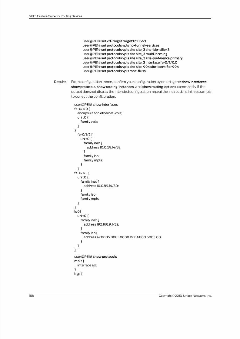
8/21/2019 Config Guide Vpns Vpls
http://slidepdf.com/reader/full/config-guide-vpns-vpls 176/485
user@PE1# set vrf-target target:65056:1
user@PE1# set protocols vpls no-tunnel-services
user@PE1# set protocols vpls site site_3 site-identifier 3
user@PE1# set protocols vpls site site_3 multi-homing
user@PE1# set protocols vpls site site_3 site-preference primaryuser@PE1# set protocols vpls site site_3 interface fe-0/1/0.0
user@PE1# set protocols vpls site site_994 site-identifier 994
user@PE1# set protocols vpls mac-flush
Results From configuration mode, confirm your configuration by entering the show interfaces,
show protocols, show routing-instances, and show routing-options commands. If the
output doesnot display the intended configuration, repeatthe instructionsin thisexample
to correct the configuration.
user@PE1# show interfaces
fe-0/1/0 {
encapsulation ethernet-vpls;
unit0 {family vpls;
}
}
fe-0/1/2 {
unit0 {
family inet {
address 10.0.59.14/32;
}
family iso;
family mpls;
}
}
fe-0/1/3 {
unit0 {family inet {
address 10.0.89.14/30;
}
family iso;
family mpls;
}
}
lo0{
unit0 {
family inet {
address 192.168.9.1/32;
}
family iso {
address 47.0005.8083.0000.1921.6800.5003.00;}
}
}
user@PE1# show protocols
mpls {
interface all;
}
bgp {
Copyright © 2013, Juniper Networks, Inc.158
VPLS Feature Guide for Routing Devices

8/21/2019 Config Guide Vpns Vpls
http://slidepdf.com/reader/full/config-guide-vpns-vpls 177/485
group int {
type internal;
local-address 8.0.0.104;
family l2vpn {
signaling;}
}
}
isis {
level 1 disable;
interface fe-0/1/2.0;
interface fe-0/1/3.0;
interface lo0.0;
}
ldp{
interface all;
interface fxp0.0 {
disable;
}interface lo0.0;
}
user@PE1# show routing-instances
vpls_1 {
instance-type vpls;
interface fe-0/1/0.0;
route-distinguisher 10.255.107.74:1;
vrf-target target:65056:1;
protocols {
vpls {
no-tunnel-services;
site site_3 {
site-identifier 3;
multi-homing;
site-preference primary;
interface fe-0/1/0.0;
}
site site_994 {
site-identifier 994;
}
mac-flush;
}
}
}
user@PE1# show routing-options
router-id 192.168.9.1;
Router PE2
Step-by-Step
Procedure
To configure Router PE2:
Configure the interfaces, interface encapsulation, and the protocol families.1.
[edit interfaces]
user@PE2# set fe-0/1/1 encapsulation ethernet-vpls
user@PE2# set fe-0/1/1 unit 0 family vpls
159Copyright © 2013, Juniper Networks, Inc.
Chapter4: VPLS Examples

8/21/2019 Config Guide Vpns Vpls
http://slidepdf.com/reader/full/config-guide-vpns-vpls 178/485
user@PE2# set fe-0/1/2 unit 0 family inet address 10.0.59.13/32
user@PE2# set fe-0/1/2 unit 0 family iso
user@PE2# set fe-0/1/2 unit 0 family mpls
user@PE2# set lo0 unit 0 family inet address 192.168.5.1/32
user@PE2# set lo0 unit 0 family isoaddress47.0005.8083.0000.1921.6800.5005.00
2. Configure the protocol-independent properties.
[edit routing-options]
user@PE2# set router-id 192.168.5.1
3. Configure MPLS on the Router PE2 interfaces.
[edit protocols]
user@PE2# set mpls interface all
4. Configure the LDP as the signaling protocol for MPLS on the PE router facing
interface.
[edit protocols ldp]user@PE2# set interface all
user@PE2# set interface fxp0.0 disable
user@PE2# set interface lo0.0
5. Configure IS-IS as the IGP between the PE routers.
[edit protocols isis]
user@PE2# set level 1 disable
user@PE2# set interface fe-0/1/2.0
user@PE2# set interface lo0.0
6. Configure the VPLS routing instance vpls_1.
Include the best-site statement to ensure that Router PE2 acts as the preferred
path for the CE router. Include the mac-flush statement to ensure that stale routes
are removed from Router PE2 promptly.
[edit routing-instances vpls_1]
user@PE2# set instance-type vpls
user@PE2# set interface fe-0/1/1.0
user@PE2# set route-distinguisher 10.255.107.76:1
user@PE2# set vrf-target target:65056:1
user@PE2# set protocols vpls no-tunnel-services
user@PE2# set protocols vpls site site_3 site-identifier 3
user@PE2# set protocols vpls site site_3 multi-homing
user@PE2# set protocols vpls site site_3 site-preference backup
user@PE2# set protocols vpls site site_3 interface fe-0/1/1.0
user@PE2# set protocols vpls site site_995 site-identifier 995
user@PE2# set protocols vpls site site_995 best-site
user@PE2# set protocols vpls mac-flush
Results From configuration mode, confirm your configuration by entering the show interfaces,
show protocols, show routing-instances, and show routing-options commands. If the
output doesnot display the intended configuration, repeatthe instructionsin thisexample
to correct the configuration.
user@PE2# show interfaces
Copyright © 2013, Juniper Networks, Inc.160
VPLS Feature Guide for Routing Devices

8/21/2019 Config Guide Vpns Vpls
http://slidepdf.com/reader/full/config-guide-vpns-vpls 179/485
fe-0/1/1 {
encapsulation ethernet-vpls;
unit0 {
family vpls;
}}
fe-0/1/2 {
unit0 {
family inet {
address 10.0.59.13/32;
}
family iso;
family mpls;
}
}
lo0{
unit0 {
family inet {
address 192.168.5.1/32;}
family iso {
address 47.0005.8083.0000.1921.6800.5005.00;
}
}
}
user@PE2# show protocols
mpls {
interface all;
}
isis {
level 1 disable;
interface fe-0/1/2.0;
interface lo0.0;
}
ldp{
interface all;
interface fxp0.0 {
disable;
}
interface lo0.0;
}
user@PE2# show routing-instances
vpls_1 {
instance-type vpls;
interface fe-0/1/1.0;
route-distinguisher 10.255.107.76:1;vrf-target target:65056:1;
protocols {
vpls {
no-tunnel-services;
site site_3 {
site-identifier 3;
multi-homing;
site-preference backup;
interface fe-0/1/1.0;
161Copyright © 2013, Juniper Networks, Inc.
Chapter4: VPLS Examples

8/21/2019 Config Guide Vpns Vpls
http://slidepdf.com/reader/full/config-guide-vpns-vpls 180/485
}
site site_995 {
site-identifier 995;
best-site;
}mac-flush;
}
}
}
user@pe2# show routing-options
router-id 192.168.5.1;
Router PE3
Step-by-Step
Procedure
To configure Router PE3:
Configure the interfaces, interface encapsulation, and the protocol families.1.
[edit interfaces]user@PE3# set fe-1/3/0 unit 0 description "PE3 to PE1"
user@PE3# set fe-1/3/0 unit 0 family inet address 10.0.89.13/30
user@PE3# set fe-1/3/0 unit 0 family iso
user@PE3# set fe-1/3/0 unit 0 family mpls
user@PE3# set fe-1/3/1 encapsulation ethernet-vpls
user@PE3# set fe-1/3/1 unit 0 family vpls
user@PE3# set lo0 unit 0 family inet address 192.168.8.1/32
user@PE3# set lo0 unit 0 family isoaddress
47.0005.8083.0000.1921.6800.5002.00
2. Configure the protocol-independent properties.
[edit routing-options]
user@PE3# set router-id 192.168.8.1
3. Configure IS-IS as the IGP between the PE routers.
[edit protocols isis]
user@PE3# set level 1 disable
user@PE3# set interface fe-0/1/3.0
user@PE3# set interface lo0.0
4. Configure LDP as the signaling protocol for MPLS.
[edit protocols ldp]
user@PE3# set interface all
user@PE3# set interface fxp0.0 disable
user@PE3# set interface lo0.0
5. Configure the VPLS routing instance.
Include the mac-flush statement here to ensure that stale routes are removed from
Router PE1 promptly.
[edit routing-instances vpls_1]
user@PE3# set instance-type vpls
user@PE3# set interface fe-1/3/1.0
user@PE3# set route-distinguisher 10.255.107.72:1
user@PE3# set vrf-target target:65056:1
user@PE3# set protocols vpls no-tunnel-services
Copyright © 2013, Juniper Networks, Inc.162
VPLS Feature Guide for Routing Devices

8/21/2019 Config Guide Vpns Vpls
http://slidepdf.com/reader/full/config-guide-vpns-vpls 181/485
user@PE3# set protocols vpls site site_2 site-identifier 2
user@PE3# set protocols vpls site site_2 interface fe-0/1/0.100
user@PE3# set protocols vpls site site_993 site-identifier 993
user@PE3# set protocols vpls mac-flush
Results From configuration mode, confirm your configuration by entering the show interfaces,
showprotocolsshow routing-instances,and show routing-optionscommands. If theoutput
does not display the intended configuration, repeat the instructions in this example to
correct the configuration.
user@PE3# show interfaces
fe-1/3/0 {
unit0 {
description "PE3 to PE1";
family inet {
address 10.0.89.13/30;
}
family iso;family mpls;
}
}
fe-1/3/1 {
encapsulation ethernet-vpls;
unit0 {
family vpls;
}
}
lo0{
unit0 {
family inet {
address 192.168.8.1/32;
}family iso {
address 47.0005.8083.0000.1921.6800.5002.00;
}
}
}
user@PE3# show protocols
mpls {
interface all;
}
bgp {
group int {
type internal;
local-address 8.0.0.100;
family l2vpn {
signaling;
}
}
}
isis {
level 1 disable;
interface fe-1/3/0.0;
interface lo0.0;
163Copyright © 2013, Juniper Networks, Inc.
Chapter4: VPLS Examples

8/21/2019 Config Guide Vpns Vpls
http://slidepdf.com/reader/full/config-guide-vpns-vpls 182/485
}
ldp{
interface all;
interface fxp0.0 {
disable;}
interface lo0.0;
}
user@PE3# show routing-instances
vpls_1 {
instance-type vpls;
interface fe-0/1/0.100; ## 'fe-0/1/0.100' is not defined
route-distinguisher 10.255.107.72:1;
vrf-target target:65056:1;
protocols {
vpls {
no-tunnel-services;
site site_2 {
site-identifier 2;
interface fe-1/3/1.0;
}
site site_993 {
site-identifier 993;
}
mac-flush;
}
}
}
user@pe3# show routing-options
router-id 192.168.8.1;
Example: Configuring VPLS Multihoming (FEC 129)
• VPLS Multihoming Overview on page 164
• Example: Configuring VPLS Multihoming (FEC 129) on page 166
VPLS Multihoming Overview
Virtual private LAN service (VPLS) multihoming enables you to connect a customer site
to two or more PE routers to provide redundant connectivity. A redundant PE router can
provide network service to the customer site as soon as a failure is detected. VPLS
multihoming helps to maintain VPLS service and traffic forwarding to and from the
multihomed site in the event of the following types of network failures:
• PE router to CE device link failure
• PE router failure
• MPLS-reachability failure between the local PE router and a remote PE router
Copyright © 2013, Juniper Networks, Inc.164
VPLS Feature Guide for Routing Devices

8/21/2019 Config Guide Vpns Vpls
http://slidepdf.com/reader/full/config-guide-vpns-vpls 183/485
Figure 14: CE Device Multihomed to Two PE Routers
PE1
PE2
P1
P2
PE3
g 0 4 0 8 7 9
CE2CE1
NOTE: Inthe VPLS documentation,the word router intermssuchasPErouter
is used to refer to any device that provides routing functions.
Figure 2 on page 9 illustrates how a CE device could be multihomed to two PE routers.
Device CE1 is multihomed to Routers PE1 and PE2. Device CE2 has two potential paths
toreach Device CE1, but only one path is active at any one time. If Router PE1 were the
designated VPLS edge (VE) device (also called a designated forwarder), BGP would
signal a pseudowire from Router PE3 to Router PE1. If a failure occurred over this path,
Router PE2 would be made the designated VE device, and BGP would re-signal the
pseudowire from Router PE3 to Router PE2.
Multihomed PE routers advertise network layer reachability information (NLRI) for the
multihomed site to the other PE routers in the VPLS network. The NLRI includes the site
ID for the multihomed PE routers. For all of the PE routers multihomed to the same CE
device, you need to configure the same site ID. The remote VPLS PE routers use the site
ID to determine where to forward traffic addressed to the customer site. To avoid route
collisions, the site ID shared by the multihomed PE routers must be different than the
site IDs configured on the remote PE routers in the VPLS network.
Although you configure the same site ID for each of the PE routers multihomed to the
same CE device, you can configure unique values for other parameters, such as the route
distinguisher. These values help to determine which multihomed PE router is selected
as the designated VE device to be used to reach the customer site.
BEST PRACTICE: We recommend that you configure unique route
distinguishers for each multihomed PE router. Configuring unique routedistinguishers helpswith fasterconvergencewhen the connectionto a primary
multihomedPE routergoes down. If youconfigure uniqueroutedistinguishers,
the other PE routers in the VPLS network must maintain additional state for
the multihomed PE routers.
Remote PE routers in the VPLS network need to determine which of the multihomed PE
routers shouldforwardtraffic to reachthe CE device. To make thisdetermination, remote
165Copyright © 2013, Juniper Networks, Inc.
Chapter4: VPLS Examples
8/21/2019 Config Guide Vpns Vpls
http://slidepdf.com/reader/full/config-guide-vpns-vpls 184/485
PE routers use the VPLS path-selection process to select one of the multihomed PE
routers based on its NLRI advertisement. Because remote PE routers pick only one of the
NLRI advertisements, it establishes a pseudowire to only one of the multihomed PE
routers, the PE router that originated the winning advertisement. This prevents multiple
paths from being created between sites in the network, preventing the formation of
Layer 2 loops. If the selected PE router fails, all PE routers in the network automatically
switch to the backup PE router and establish new pseudowires to it.
BEST PRACTICE: To prevent the formation of Layer 2 loops between the CE
devices andthe multihomed PE routers,we recommendthatyou employ the
Spanning Tree Protocol (STP) on your CE devices. Layer 2 loops can form
dueto incorrect configuration. Temporary Layer 2 loops can also form during
convergence after a change in the network topology.
The PE routers run the BGP path selection procedure on locally originated and received
Layer 2 route advertisements to establish that the routes are suitable for advertisement
to other peers, such as BGP route reflectors. If a PE router in a VPLS network is also a
route reflector, the path selection process for the multihomed site has no effect on the
path selection process performed by this PE router for the purpose of reflecting Layer 2
routes. Layer 2 prefixes that have different route distinguishers are considered to have
different NLRIs for route reflection. The VPLS path selection process enables the route
reflector to reflect all routes that have different route distinguishers to the route reflector
clients, even though only one of these routes is used to create the VPLS pseudowire to
the multihomed site.
Example: Configuring VPLS Multihoming (FEC 129)
This example shows how to configure virtual private LAN service (VPLS) multihoming.
Multihoming allows a customer site to connect to multiple provider edge (PE) routers.
A VPLS site multihomed to two or more PE routers provides redundant connectivity in
the event of a PE router-to-CE devicelink failure or the failure of a PE router. Theexample
demonstrates BGP-based multihoming support for FEC 129 VPLS (also known as LDP
VPLS with BGP-based autodiscovery).
• Requirements on page 166
• Overview on page 167
• Configuration on page 168
• Verification on page 175
Requirements
This example has the following hardware and software requirements:
• One or more CE devices to represent a VPLS site.
• Two or more PE devices.
• Junos OS Release 12.3 or later running on the PE devices that are connected to the
multihomed VPLS site.
Copyright © 2013, Juniper Networks, Inc.166
VPLS Feature Guide for Routing Devices

8/21/2019 Config Guide Vpns Vpls
http://slidepdf.com/reader/full/config-guide-vpns-vpls 185/485
Overview
BGP-based VPLS autodiscovery (FEC 129) enables each VPLS PE router to discover the
other PE routers that are in the same VPLS domain. VPLS autodiscovery also
automatically detects when PE routers are added or removed from the VPLS domain.
You do not need to manually configure the VPLS and maintain the configuration when
a PE router is added or deleted. VPLS autodiscovery uses BGP to discover the VPLS
members and to set up and tear down pseudowires in the VPLS.
BGP multihoming enables you to connect a customer site to two or more PE routers to
provide redundant connectivity while preventing the formation of Layer 2 loops in the
service provider’s network. The redundant connectivity maintains the VPLS service and
traffic forwarding to and from the multihomed site in the event of a PE router-to-CE
device link failure, the failure of a PE router, or an MPLS reachability failure between the
localPE router anda remotePE router. A redundant PE router canbeginproviding service
to the customer site as soon as the failure is detected.
When a CE device connects to multiple PE routers, each of these routers advertises
reachability for the multihomed site—routes that have the same site ID in the Layer 2
network layer reachability information (NLRI). The other PE routers in the network use
a BGP path selection process to select only one of the advertising routers to which they
send traffic destined for the CE device. This path selection process eliminates Layer 2
loops in the VPLS network.
Autodiscovery is not specifically related to multihoming. Autodiscovery is not required
for multihoming to work. They are two separate features. That said, the meaning of FEC
129 is that VPLS does autodiscovery. So when you configure multihoming for FEC 129,
you must also, by definition, configure autodiscovery (with the auto-discovery-only
statement).
There are two places in the configuration where you can configure VPLS multihoming.
One is for FEC 128,and the other is for FEC 129:
• For FEC128—routing-instances instance-name protocols vplssite site-namemulti-homing
• For FEC 129—routing-instances instance-name protocols vpls multi-homing
The following statements are used for configuring multihoming for FEC 129:
[edit routing-instances instance-name protocols vpls]
multi-homing {
peer-active;
site site-name{
active-interface interface-name {any;
primary interface-name;
}
identifier identifier ;
interface interface-name {
preference preference-value;
}
peer-active;
preference ( preference-value | backup | primary);
167Copyright © 2013, Juniper Networks, Inc.
Chapter4: VPLS Examples

8/21/2019 Config Guide Vpns Vpls
http://slidepdf.com/reader/full/config-guide-vpns-vpls 186/485
}
}
This example shows Device CE1 multihomed to Router PE1 and Router PE2. In addition,
DeviceCE2 is single-homedto Router PE1.Device PE3 is the remotePE router, connected
to Device CE3. Multihoming is not enabled on Device PE3. “CLI Quick Configuration” on
page 168 showstheconfigurationfor allof thedevices in Figure 15on page168. Thesection
“Configuring DevicePE1” on page 171 has step-by-step instructions for configuring Device
PE1.
Figure 15: Topology for FEC 129 Multihoming
PE1CE1
CE2
ge-0/3/0.0 ge-0/3/3.0
ge-0/3/1.0
P
PE2fe-0/1/3.0
ge-0/3/2.0
g 0 4 1 2 0 5
fe-0/1/2.0
PE3
ge-0/3/3.0
CE3
ge-0/3/2.0
Configuration
CLI Quick
Configuration
To quickly configure this example, copy the following commands, paste them into a text
file, remove any line breaks, change any details necessary to match your network
configuration, andthen copy andpaste the commands into theCLI at the [edit] hierarchy
level.
Device PE1 set interfaces ge-0/3/3 encapsulation ethernet-vplsset interfaces ge-0/3/3 unit 0 description PE1-to-CE2
set interfaces ge-0/3/3 unit 0 family vpls
set interfaces ge-0/3/1 encapsulation ethernet-vpls
set interfaces ge-0/3/1 unit 0 description PE1-to-CE1
set interfaces ge-0/3/1 unit 0 family vpls
set interfaces ge-1/2/0 unit 1 description PE1-to-P
set interfaces ge-1/2/0 unit 1 family inet address 10.1.1.1/30
set interfaces ge-1/2/0 unit 1 family mpls
set interfaces ge-1/2/1 unit 5 description PE1-to-PE2
set interfaces ge-1/2/1 unit 5 family inet address 10.1.1.5/30
set interfaces ge-1/2/1 unit 5 family mpls
set interfaces lo0 unit 2 family inet address 1.1.1.2/32
set protocols mpls interface ge-1/2/0.1
set protocols mpls interface ge-1/2/1.5set protocols bgp local-address 1.1.1.2
set protocols bgp group pe-pe type internal
set protocols bgp group pe-pe family l2vpn auto-discovery-only
set protocols bgp group pe-pe family l2vpn signaling
set protocols bgp group pe-pe neighbor 1.1.1.3
set protocols bgp group pe-pe neighbor 1.1.1.4
set protocols bgp group pe-pe neighbor 1.1.1.5
set protocols ospf traffic-engineering
set protocols ospf area 0.0.0.0 interface ge-1/2/0.1
Copyright © 2013, Juniper Networks, Inc.168
VPLS Feature Guide for Routing Devices

8/21/2019 Config Guide Vpns Vpls
http://slidepdf.com/reader/full/config-guide-vpns-vpls 187/485
set protocols ospf area 0.0.0.0 interface ge-1/2/1.5
set protocols ospf area 0.0.0.0 interface lo0.2 passive
set protocols ldp interface ge-1/2/0.1
set protocols ldp interface ge-1/2/1.5
set protocols ldp interface lo0.2set routing-instances green instance-type vpls
set routing-instances green interface ge-0/3/1.0
set routing-instances green interface ge-0/3/3.0
set routing-instances green route-distinguisher 1.1.1.2:1
set routing-instances green l2vpn-id l2vpn-id:100:100
set routing-instances green vrf-target target:100:100
set routing-instances green protocols vpls no-tunnel-services
set routing-instances green protocols vpls oam ping-interval 600
set routing-instances greenprotocolsvpls oam bfd-liveness-detectionminimum-interval
200
set routing-instances green protocols vpls multi-homing site test identifier 1
set routing-instances green protocols vpls multi-homing site test interface ge-0/3/1.0
set routing-options router-id 1.1.1.2
set routing-options autonomous-system 100
Device PE2 set interfaces fe-0/1/3 encapsulation ethernet-vpls
set interfaces fe-0/1/3 unit 0 description PE2-to-CE1
set interfaces fe-0/1/3 unit 0 family vpls
set interfaces ge-1/2/0 unit 6 description PE2-to-PE1
set interfaces ge-1/2/0 unit 6 family inet address 10.1.1.6/30
set interfaces ge-1/2/0 unit 6 family mpls
set interfaces ge-1/2/2 unit 10 description PE2-to-P
set interfaces ge-1/2/2 unit 10 family inet address 10.1.1.10/30
set interfaces ge-1/2/2 unit 10 family mpls
set interfaces lo0 unit 4 family inet address 1.1.1.4/32
set protocols mpls interface ge-1/2/0.6
set protocols mpls interface ge-1/2/2.10
set protocols bgp local-address 1.1.1.4set protocols bgp group pe-pe type internal
set protocols bgp group pe-pe family l2vpn auto-discovery-only
set protocols bgp group pe-pe family l2vpn signaling
set protocols bgp group pe-pe neighbor 1.1.1.2
set protocols bgp group pe-pe neighbor 1.1.1.3
set protocols bgp group pe-pe neighbor 1.1.1.5
set protocols ospf traffic-engineering
set protocols ospf area 0.0.0.0 interface ge-1/2/0.6
set protocols ospf area 0.0.0.0 interface ge-1/2/2.10
set protocols ospf area 0.0.0.0 interface lo0.4 passive
set protocols ldp interface ge-1/2/0.6
set protocols ldp interface ge-1/2/2.10
set protocols ldp interface lo0.4
set routing-instances green instance-type vplsset routing-instances green interface fe-0/1/3.0
set routing-instances green route-distinguisher 1.1.1.4:1
set routing-instances green l2vpn-id l2vpn-id:100:100
set routing-instances green vrf-target target:100:100
set routing-instances green protocols vpls no-tunnel-services
set routing-instances green protocols vpls oam ping-interval 600
set routing-instances greenprotocolsvpls oam bfd-liveness-detectionminimum-interval
200
set routing-instances green protocols vpls multi-homing site test identifier 1
169Copyright © 2013, Juniper Networks, Inc.
Chapter4: VPLS Examples

8/21/2019 Config Guide Vpns Vpls
http://slidepdf.com/reader/full/config-guide-vpns-vpls 188/485
set routing-instances green protocols vpls multi-homing site test interface fe-0/1/3.0
set routing-options router-id 1.1.1.4
set routing-options autonomous-system 100
Device PE3 set interfaces ge-0/3/3 unit 0set interfaces ge-1/2/0 unit 14 description PE3-to-P
set interfaces ge-1/2/0 unit 14 family inet address 10.1.1.14/30
set interfaces ge-1/2/0 unit 14 family mpls
set interfaces lo0 unit 5 family inet address 1.1.1.5/32
set protocols rsvp interface ge-1/2/0.14
set protocols mpls interface ge-1/2/0.14
set protocols bgp local-address 1.1.1.5
set protocols bgp group pe-pe type internal
set protocols bgp group pe-pe family l2vpn auto-discovery-only
set protocols bgp group pe-pe family l2vpn signaling
set protocols bgp group pe-pe neighbor 1.1.1.2
set protocols bgp group pe-pe neighbor 1.1.1.3
set protocols bgp group pe-pe neighbor 1.1.1.4
set protocols ospf traffic-engineeringset protocols ospf area 0.0.0.0 interface ge-1/2/0.14
set protocols ospf area 0.0.0.0 interface lo0.5 passive
set protocols ldp interface ge-1/2/0.14
set protocols ldp interface lo0.5
set routing-instances green instance-type vpls
set routing-instances green interface ge-0/3/3.0
set routing-instances green route-distinguisher 1.1.1.5:100
set routing-instances green l2vpn-id l2vpn-id:100:100
set routing-instances green vrf-target target:100:100
set routing-instances green protocols vpls no-tunnel-services
set routing-instances green protocols vpls oam ping-interval 600
set routing-instances greenprotocolsvpls oam bfd-liveness-detectionminimum-interval
200
set routing-instances green protocols vpls oam ping-interval 600set routing-instances greenprotocolsvpls oam bfd-liveness-detectionminimum-interval
200
set routing-options router-id 1.1.1.5
set routing-options autonomous-system 100
Device CE1 set interfaces ge-0/3/0 unit 0 description CE1-to-PE1
set interfaces ge-0/3/0 unit 0 family inet address 20.1.1.5/24
set interfaces fe-0/1/2 unit 0 description CE1-to-PE2
set interfaces fe-0/1/2 unit 0 family inet address 20.1.1.1/24
Device CE2 set interfaces ge-0/3/2 unit 0 description CE2-to-PE1
set interfaces ge-0/3/2 unit 0 family inet address 20.1.1.6/24
Device CE3 set interfaces ge-0/3/2 unit 0 description CE3-to-PE3
set interfaces ge-0/3/2 unit 0 family inet address 20.1.1.7/24
Device P set interfaces ge-1/2/0 unit 2 description P-to-PE1
set interfaces ge-1/2/0 unit 2 family inet address 10.1.1.2/30
set interfaces ge-1/2/0 unit 2 family mpls
set interfaces ge-3/2/0 unit 9 description P-to-PE2
set interfaces ge-3/2/0 unit 9 family inet address 10.1.1.9/30
set interfaces ge-3/2/0 unit 9 family mpls
Copyright © 2013, Juniper Networks, Inc.170
VPLS Feature Guide for Routing Devices

8/21/2019 Config Guide Vpns Vpls
http://slidepdf.com/reader/full/config-guide-vpns-vpls 189/485
set interfaces ge-4/2/0 unit 13 description P-to-PE3
set interfaces ge-4/2/0 unit 13 encapsulation ethernet
set interfaces ge-4/2/0 unit 13 peer-unit 14
set interfaces ge-4/2/0 unit 13 family inet address 10.1.1.13/30
set interfaces ge-4/2/0 unit 13 family mplsset interfaces lo0 unit 3 family inet address 1.1.1.3/32
set protocols mpls interface ge-1/2/0.2
set protocols mpls interface ge-3/2/0.9
set protocols mpls interface ge-4/2/0.13
set protocols bgp local-address 1.1.1.3
set protocols bgp group pe-pe type internal
set protocols bgp group pe-pe family l2vpn signaling
set protocols bgp group pe-pe neighbor 1.1.1.2
set protocols bgp group pe-pe neighbor 1.1.1.4
set protocols bgp group pe-pe neighbor 1.1.1.5
set protocols ospf traffic-engineering
set protocols ospf area 0.0.0.0 interface ge-1/2/0.2
set protocols ospf area 0.0.0.0 interface ge-3/2/0.9
set protocols ospf area 0.0.0.0 interface ge-4/2/0.13set protocols ospf area 0.0.0.0 interface lo0.3 passive
set protocols ldp interface ge-1/2/0.2
set protocols ldp interface ge-3/2/0.9
set protocols ldp interface ge-4/2/0.13
set protocols ldp interface lo0.3
set routing-options router-id 1.1.1.3
set routing-options autonomous-system 100
Configuring Device PE1
Step-by-Step
Procedure
The following example requires you to navigate various levels in the configuration
hierarchy. Forinformation about navigatingthe CLI,seeUsing theCLI Editor inConfiguration
Mode in the CLI UserGuide.
To configure Device PE1:
1. Configure the interfaces.
Configure family mpls on the provider-facing interfaces. Configure family vpls on
the customer-facing interfaces.
[edit interfaces]
user@PE1# set ge-0/3/3 encapsulation ethernet-vpls
user@PE1# set ge-0/3/3 unit 0 description PE1-to-CE2
user@PE1# set ge-0/3/3 unit 0 family vpls
user@PE1# set ge-0/3/1 encapsulation ethernet-vpls
user@PE1# set ge-0/3/1 unit 0 description PE1-to-CE1user@PE1# set ge-0/3/1unit 0 family vpls
user@PE1# set ge-1/2/0 unit 1 description PE1-to-P
user@PE1# set ge-1/2/0 unit 1 family inet address 10.1.1.1/30
user@PE1# set ge-1/2/0 unit 1 family mpls
user@PE1# set ge-1/2/1 unit 5 description PE1-to-PE2
user@PE1# set ge-1/2/1 unit 5 family inet address 10.1.1.5/30
171Copyright © 2013, Juniper Networks, Inc.
Chapter4: VPLS Examples

8/21/2019 Config Guide Vpns Vpls
http://slidepdf.com/reader/full/config-guide-vpns-vpls 190/485
user@PE1# set ge-1/2/1 unit 5 family mpls
user@PE1# set lo0 unit 2 family inet address1.1.1.2/32
2. Configure the interior gateway protocol (IGP) and signaling protocols on theprovider-facing interfaces.
The traffic-engineering statement enables OSPF to advertise the label-switched
path (LSP) metric in summary link-state advertisements (LSAs).
[edit protocols]
user@PE1# set ldp interface ge-1/2/0.1
user@PE1# set ldp interface ge-1/2/1.5
user@PE1# set ldp interface lo0.2
user@PE1# set mpls interface ge-1/2/0.1
user@PE1# set mpls interface ge-1/2/1.5
user@PE1# set ospf traffic-engineeringuser@PE1# set ospf area 0.0.0.0 interface ge-1/2/0.1
user@PE1# set ospf area 0.0.0.0 interface ge-1/2/1.5
user@PE1# set ospf area 0.0.0.0 interface lo0.2 passive
3. Configure BGP.
The auto-discovery-only statement notifies the routing process (rpd) to expect
autodiscovery-related NLRI messages so that information can be deciphered and
used by LDP and VPLS. The auto-discovery-only statement must be configured on
all PE routers in a VPLS. If you configure route reflection, the auto-discovery-only
statement is also required on provider (P) routers that act as the route reflector in
supporting FEC 129-related updates.
For interoperation scenarios in which a PE router must support both types of NLRI(FEC 128 and FEC 129), this example also includes the signaling statement.
[edit protocols bgp]
user@PE1# set local-address 1.1.1.2
user@PE1# set grouppe-pe type internal
user@PE1# set group pe-pe family l2vpn auto-discovery-only
user@PE1# set group pe-pe family l2vpn signaling
user@PE1# set group pe-pe neighbor 1.1.1.3
user@PE1# set group pe-pe neighbor 1.1.1.4
user@PE1# set group pe-pe neighbor 1.1.1.5
4. Configure the routing instance.
Both CE-facing interfaces are included in the routing instance.Only the multihomed
interface is included in the multihoming site.
As a convention, the route distinguisher is composed of Device PE1’s loopback
interface address and the multihoming site identifier.
[edit routing-instances green]
user@PE1# set instance-type vpls
user@PE1# set interface ge-0/3/1.0
user@PE1# set interface ge-0/3/3.0
user@PE1# set route-distinguisher 1.1.1.2:1
Copyright © 2013, Juniper Networks, Inc.172
VPLS Feature Guide for Routing Devices
8/21/2019 Config Guide Vpns Vpls
http://slidepdf.com/reader/full/config-guide-vpns-vpls 191/485
user@PE1# set l2vpn-id l2vpn-id:100:100
user@PE1# set vrf-target target:100:100
user@PE1# set protocols vpls no-tunnel-services
user@PE1# set protocols vpls multi-homing site test identifier 1
user@PE1# set protocols vpls multi-homing site test interface ge-0/3/1.0
5. (Optional) Configure bidirectional forwarding detection (BFD) for FEC 129 VPLS.
[edit routing-instances green]
user@PE1# set protocols vpls oam ping-interval 600
user@PE1# set protocols vpls oam bfd-liveness-detection minimum-interval 200
6. Configure the autonomous system (AS) number and router ID.
[edit routing-options]
user@PE1# set router-id 1.1.1.2
user@PE1# set autonomous-system 100
Results From configuration mode, confirm your configuration by entering the show interfaces,
show protocols, show routing-instances, and show routing-options commands. If theoutput doesnot display the intended configuration, repeatthe instructionsin thisexample
to correct the configuration.
user@PE1# show interfaces
ge-0/3/1 {
encapsulation ethernet-vpls;
unit0 {
description PE1-to-CE1;
family vpls;
}
}
ge-0/3/3 {
encapsulation ethernet-vpls;
unit0 {
description PE1-to-CE2;
family vpls;
}
}
ge-1/2/0 {
unit1 {
description PE1-to-P;
family inet {
address 10.1.1.1/30;
}
family mpls;
}
}
ge-1/2/1 {
unit5 {
description PE1-to-PE2;
family inet {
address 10.1.1.5/30;
}
family mpls;
}
}
173Copyright © 2013, Juniper Networks, Inc.
Chapter4: VPLS Examples
8/21/2019 Config Guide Vpns Vpls
http://slidepdf.com/reader/full/config-guide-vpns-vpls 192/485
lo0{
unit2 {
family inet {
address 1.1.1.2/32;
}}
}
user@PE1# show protocols
mpls {
interface ge-1/2/0.1;
interface ge-1/2/1.5;
}
bgp {
local-address 1.1.1.2;
group pe-pe {
type internal;
family l2vpn {
auto-discovery-only;
signaling;
}
neighbor 1.1.1.3;
neighbor 1.1.1.4;
neighbor 1.1.1.5;
}
}
ospf {
traffic-engineering;
area 0.0.0.0 {
interface ge-1/2/0.1;
interface ge-1/2/1.5;
interface lo0.2 {
passive;
}
}
}
ldp{
interface ge-1/2/0.1;
interface ge-1/2/1.5;
interface lo0.2;
}
user@PE1# show routing-instances
green {
instance-type vpls;
interface ge-0/3/1.0;
interface ge-0/3/3.0;
route-distinguisher 1.1.1.2:100;l2vpn-id l2vpn-id:100:100;
vrf-target target:100:100;
protocols {
vpls {
no-tunnel-services;
oam {
ping-interval 600;
bfd-liveness-detection {
minimum-interval 200;
Copyright © 2013, Juniper Networks, Inc.174
VPLS Feature Guide for Routing Devices
8/21/2019 Config Guide Vpns Vpls
http://slidepdf.com/reader/full/config-guide-vpns-vpls 193/485
}
}
multi-homing {
site test {
identifier 1;interface ge-0/3/1.0;
}
}
}
}
}
user@PE1# show routing-options
router-id 1.1.1.2;
autonomous-system 100;
If you are done configuring the device, enter commit from configuration mode.
Verification
Confirm that the configuration is working properly.
• Verifying That Multihoming Is Operational on page 175
• Checking the Multihoming Routes on page 176
• Checking the BFD Sessions on page 177
• Pinging the Remote PE Router in the VPLS Domain on page 177
Verifying That Multihoming Is Operational
Purpose Verify that multihoming is operational.
Action From operational mode, enter the show vpls connections extensive command.
user@PE1> show vpls connections extensive
Layer-2 VPN connections:
Legend for connection status (St)
EI -- encapsulation invalid NC -- interface encapsulation not CCC/TCC/VPLS
EM -- encapsulation mismatch WE -- interface and instance encaps not same
VC-Dn -- Virtual circuit down NP -- interface hardware not present
CM -- control-word mismatch -> -- only outbound connection is up
CN -- circuit not provisioned <- -- only inbound connection is up
OR -- out of range Up -- operational
OL -- no outgoing label Dn -- down
LD -- local site signaled down CF -- call admission control failure
RD -- remote site signaled down SC -- local and remote site ID collision
LN -- local site not designated LM -- local site ID not minimum designated
RN -- remote site not designated RM -- remote site ID not minimum designated
XX -- unknown connection status IL -- no incoming label
MM -- MTU mismatch MI -- Mesh-Group ID not available
BK -- Backup connection ST -- Standby connection
PF -- Profile parse failure PB -- Profile busy
RS -- remote site standby SN -- Static Neighbor
LB -- Local site not best-site RB -- Remote site not best-site
VM -- VLAN ID mismatch
Legend for interface status
175Copyright © 2013, Juniper Networks, Inc.
Chapter4: VPLS Examples

8/21/2019 Config Guide Vpns Vpls
http://slidepdf.com/reader/full/config-guide-vpns-vpls 194/485
Up -- operational
Dn -- down
Instance: green
L2vpn-id: 100:100
Local-id: 1.1.1.2 Number of local interfaces: 2
Number of local interfaces up: 2
ge-0/3/1.0
ge-0/3/3.0
lsi.101711873 Intf - vpls green local-id 1.1.1.2 remote-id
1.1.1.4 neighbor 1.1.1.4
Remote-id Type St Time last up # Up trans
1.1.1.4 rmt Up Jan 31 13:49:52 2012 1
Remote PE: 1.1.1.4, Negotiated control-word: No
Incoming label: 262146, Outgoing label: 262146
Local interface: lsi.101711873, Status: Up, Encapsulation: ETHERNET
Description: Intf - vpls green local-id 1.1.1.2 remote-id 1.1.1.4 neighbor
1.1.1.4
Connection History:
Jan 31 13:49:52 2012 status update timerJan 31 13:49:52 2012 PE route changed
Jan 31 13:49:52 2012 Out lbl Update 262146
Jan 31 13:49:52 2012 In lbl Update 262146
Jan 31 13:49:52 2012 loc intf up lsi.101711873
Multi-home:
Local-site Id Pref State
test 1 100 Up
Number of interfaces: 1
Number of interfaces up: 1
ge-0/3/1.0
Received multi-homing advertisements:
Remote-PE Pref flag Description
1.1.1.4 100 0x0
Meaning The output shows the status of multihoming for routing instance green.
Checking the Multihoming Routes
Purpose Verify that the expected routes are identified as multihoming.
Action From operational mode, enter the show route table bgp.l2vpn.0 and show route table
green.l2vpn.0 commands.
user@PE1> show route table bgp.l2vpn.0
bgp.l2vpn.0: 2 destinations, 2 routes (2 active, 0 holddown, 0 hidden)
+ = Active Route, - = Last Active, * = Both
1.1.1.4:100:1.1.1.4/96 AD
*[BGP/170] 1d 03:10:45, localpref 100, from 1.1.1.4 AS path: I, validation-state: unverified
> via ge-1/2/1.5
1.1.1.4:100:1:0/96 MH
*[BGP/170] 1d 03:10:45, localpref 100, from 1.1.1.4
AS path: I, validation-state: unverified
> via ge-1/2/1.5
user@PE1> show route table green.l2vpn.0
Copyright © 2013, Juniper Networks, Inc.176
VPLS Feature Guide for Routing Devices

8/21/2019 Config Guide Vpns Vpls
http://slidepdf.com/reader/full/config-guide-vpns-vpls 195/485
green.l2vpn.0: 6 destinations, 6 routes (6 active, 0 holddown, 0 hidden)
+ = Active Route, - = Last Active, * = Both
1.1.1.2:100:1.1.1.2/96 AD
*[VPLS/170] 1d 03:11:03, metric2 1
Indirect1.1.1.4:100:1.1.1.4/96 AD
*[BGP/170] 1d 03:11:02, localpref 100, from 1.1.1.4
AS path: I, validation-state: unverified
> via ge-1/2/1.5
1.1.1.2:100:1:0/96 MH
*[VPLS/170] 1d 03:11:03, metric2 1
Indirect
1.1.1.4:100:1:0/96 MH
*[BGP/170] 1d 03:11:02, localpref 100, from 1.1.1.4
AS path: I, validation-state: unverified
> via ge-1/2/1.5
1.1.1.4:NoCtrlWord:5:100:100:1.1.1.2:1.1.1.4/176
*[VPLS/7] 1d 03:11:02, metric2 1
> via ge-1/2/1.5
1.1.1.4:NoCtrlWord:5:100:100:1.1.1.4:1.1.1.2/176*[LDP/9] 1d 03:11:02
Discard
Meaning MH in the output indicates a multihoming route. AD indicates autodiscovery.
Checking the BFD Sessions
Purpose Verify that the BFD session status is operational.
Action From operational mode, enter the show bfd session command.
user@PE1> show bfd session
Detect Transmit
Address State Interface Time Interval Multiplier127.0.0.1 Up ge-1/2/1.5 0.600 0.200 3
127.0.0.1 Up ge-1/2/0.1 0.600 0.200 3
2 sessions, 2 clients
Cumulative transmit rate 10.0 pps, cumulative receive rate 10.0 pps
Meaning Up in the State field indicates that BFD is working.
Pinging theRemote PE Router in the VPLS Domain
Purpose Check the operability of the MPLS Layer 2 virtual private network (VPN) connection.
Action From operational mode, enter the ping mpls l2vpn command with the fec129 option.user@PE1> ping mpls l2vpn fec129 instance green remote-id 1.1.1.5 remote-pe-address 1.1.1.5
!!!!!
--- lsping statistics ---
5 packets transmitted, 5 packets received, 0% packet loss
Meaning The output shows that the ping operation is successful, meaning that the LSP for a FEC
129 Layer 2 VPN connection is reachable.
177Copyright © 2013, Juniper Networks, Inc.
Chapter4: VPLS Examples
8/21/2019 Config Guide Vpns Vpls
http://slidepdf.com/reader/full/config-guide-vpns-vpls 196/485
Related
Documentation
Example: Configuring BGP Autodiscovery for LDP VPLS on page 126•
• Example: ConfiguringBGPAutodiscovery forLDP VPLSwith User-DefinedMesh Groups
on page 143
Example: Configuring Inter-AS VPLS with MAC Processing at the ASBR
This example describes how to configure inter-AS Virtual Private LAN Service (VPLS)
with MAC processing between BGP-signaled VPLS and LDP-signaled VPLS. This feature
is described in RFC 4761 as multi-AS VPLS option E or method E.
This example is organized in the following sections:
• Requirements on page 178
• Overview and Topology on page 178
•
Configuration on page 179
Requirements
To support inter-AS VPLS between BGP-signaled VPLS and LDP-signaled VPLS, your
network must meet the following hardware and software requirements:
• MX Series or M320 routers for the ASBRs.
• Junos OS Release 9.3 or higher.
• Gigabit Ethernet or 10-Gigabit Ethernet interfaces.
Overview and Topology
VPLS is a key enabler for delivering multipoint Ethernet service. Major service providers
have implemented IP and MPLS backbones and offer VPLS services to large enterprises.
Growing demand requires the VPLS network to scale to support many VPLS customers
with multiple sites spread across geographically dispersed regions. BGP-signaled VPLS
signaling offersscaling advantages over LDP-signaled VPLS. In someenvironmentsthere
is a need for BGP-signaled VPLS to interoperate with existing LDP-signaled VPLS.
This example shows one way to configure BGP-signaled VPLS interworking with an
existing LDP-signaled VPLS network.
The advantages of the configuration are:
• You can interconnect customer sites that are spread across different autonomous
systems (ASs).
• LDP-signaled VPLS and BGP-signaled VPLS interworking is supported.
• Because the ASBRsupportsMAC operations, customer sitescan be connected directly
to the ASBR.
• The inter-AS link is not restricted to Ethernet interfaces.
• Additional configuration for multihoming is relatively straightforward.
Copyright © 2013, Juniper Networks, Inc.178
VPLS Feature Guide for Routing Devices

8/21/2019 Config Guide Vpns Vpls
http://slidepdf.com/reader/full/config-guide-vpns-vpls 197/485
Traffic from the interworking virtual private LAN services is switched at the ASBR. The
ASBR does all the data plane operations: flooding, MAC learning, aging, and MAC
forwarding for each AS to switch traffic among any customer facing interfaces and
between thefullymeshed pseudowiresin theAS. A singlepseudowire is created between
the ASBRs across the inter-AS link and the ASBRs forward traffic from the pseudowires
in each AS tothe peer ASBR.
Each ASBR performs VPLS operations within its own AS and performs VPLS operations
with the ASBR in the other AS. The ASBR treats the other AS as a BGP-signaled VPLS
site. To establish VPLS pseudowires, VPLS NLRI messages are exchanged across the
EBGP sessions on the inter-AS links between the ASBRs.
The sample metro network is configured for LDP-signaled VPLS. The core network is
configured for BGP-signaled VPLS.
The first part of the example shows the basic configuration steps to configure the logical
interfaces, OSPF, internal BGP, LDP, and MPLS. This part of the configuration is the same
as other VPLS configurations for LDP-signaled VPLS and BGP-signaled VPLS.
Theunique part of the example is configured in theVPLS routing instances, externalBGP,
and the policy that populates the BGP route table with routes learned from direct routes
and OSPF routes. Additional details about the configuration statements are included in
the step-by-step procedure.
Figure 16 on page 179 shows the topology used in this example.
Figure 16: Inter-AS VPLS with MAC Operations Example Topology
g 0 1 6 9 5 3
ASBR1 ASBR2 PE2PE1
AS65010LDP-basedVPLS Metro
AS65020BGP-basedVPLS Core
lo0.0 192.168.1.1
10.10.11.1ge-0/3/0
ge-1/3/0
lo0.0 192.168.2.1
10.0.23.9ge-1/3/1
ge-0/3/110.0.23.10
lo0.0 192.168.11.1
ge-0/1/1
lo0.0 192.168.12.1
lo0.0 192.168.3.1 lo0.0 192.168.10.1
ge-3/1/010.0.78.2
10.0.78.1ge-0/3/0
10.0.90.13ge-3/1/1
ge-0/1/010.0.90.14
10.10.11.2ge-0/1/1
Inter-AS link
CE2CE1
Configuration
To configureinter-AS VPLSbetween BGP-signaledVPLS and LDP-signaledVPLS, perform
these tasks.
179Copyright © 2013, Juniper Networks, Inc.
Chapter4: VPLS Examples

8/21/2019 Config Guide Vpns Vpls
http://slidepdf.com/reader/full/config-guide-vpns-vpls 198/485
NOTE: In any configuration session it is a good practice to periodically use
the commit checkcommand to verifythat the configuration canbe committed.
• Configuring Interfaces on page 180
• Configuring OSPF on page 182
• Configuring the Internal BGP Peer Group on page 183
• Configuring LDP on page 184
• Configuring MPLS on page 185
• Configuring the External BGPPeer Group Betweenthe Loopback Interfaces on page 185
• Configuring the External BGP Peer Group Between the Inter-AS Link
Interfaces on page 186
• Configuring the VPLS Routing Instances on page 190
• Results on page 194
Configuring Interfaces
Step-by-Step
Procedure
To configure interfaces:
On each router, configure an IP address on the loopback logical interface 0 (lo0.0):1.
user@CE1# set interfaces lo0 unit 0 family inet address 192.168.1.1/32 primary
user@PE1# set interfaces lo0 unit 0 family inet address 192.168.2.1/32 primary
user@ASBR1# set interfaces lo0 unit 0 family inet address 192.168.3.1/32 primary
user@ASBR2# set interfaces lo0 unit 0 family inet address 192.168.10.1/32 primary
user@PE2# set interfaces lo0 unit 0 family inet address 192.168.11.1/32 primary
user@CE2# set interfaces lo0 unit 0 family inet address 192.168.12.1/32 primary
2. On each router, commit the configuration:
user@host> commit check
configuration check succeeds
user@host> commit
commit complete
3. On each router, display the interface information for lo0 and verify that the correct
IP address is configured:
user@host> show interfaces lo0
Physical interface: lo0, Enabled, Physical link is Up
Interface index: 6, SNMP ifIndex: 6
Type: Loopback, MTU: Unlimited
Device flags : Present Running Loopback
Interface flags: SNMP-Traps
Link flags : None
Last flapped : Never
Copyright © 2013, Juniper Networks, Inc.180
VPLS Feature Guide for Routing Devices

8/21/2019 Config Guide Vpns Vpls
http://slidepdf.com/reader/full/config-guide-vpns-vpls 199/485
Input packets : 0
Output packets: 0
Logical interface lo0.0 (Index 75) (SNMP ifIndex 16)
Flags: SNMP-Traps Encapsulation: Unspecified
Input packets : 0Output packets: 0
Protocol inet, MTU: Unlimited
Flags: None
Addresses
Local: 127.0.0.1
Addresses, Flags: Primary Is-Default Is-Primary
Local: 192.168.3.1
Logical interface lo0.16384 (Index 64) (SNMP ifIndex 21)
Flags: SNMP-Traps Encapsulation: Unspecified
Input packets : 0
Output packets: 0
Protocol inet, MTU: Unlimited
Flags: None
Addresses
Local: 127.0.0.1
Logical interface lo0.16385 (Index 65) (SNMP ifIndex 22)
Flags: SNMP-Traps Encapsulation: Unspecified
Input packets : 0
Output packets: 0
Protocol inet, MTU: Unlimited
Flags: None
In the example above notice that the primary lo0 local address for the inet protocol
family on Router ASBR1 is 192:168:3:1.
4. On each router, configure an IP address and protocol family on the Gigabit Ethernet
interfaces. Specify the inet protocol family.
user@CE1# set interfaces ge-0/3/0 unit 0 family inet address 10.10.11.1/24
user@PE1# set interfaces ge-1/3/1 unit 0 family inet address 10.0.23.9/30
user@ASBR1# set interfaces ge-0/3/1 unit 0 family inet address 10.0.23.10/30
user@ASBR1# set interfaces ge-0/3/0 unit 0 family inet address 10.0.78.1/30
user@ASBR2# set interfaces ge-3/1/0 unit 0 family inet address 10.0.78.2/30
user@ASBR2# set interfaces ge-3/1/1 unit 0 family inet address 10.0.90.13/30
user@PE2# set interfaces ge-0/1/0 unit 0 family inet address 10.0.90.14/30
user@CE2# set interfaces ge-0/1/1 unit 0 family inet address 10.10.11.2/24
5. On each router, commit the configuration:
user@host> commit check
configuration check succeeds
user@host> commit
commit complete
6. Display information for Gigabit Ethernet interfaces and verify that the IP address
and protocol family are configured correctly.
181Copyright © 2013, Juniper Networks, Inc.
Chapter4: VPLS Examples
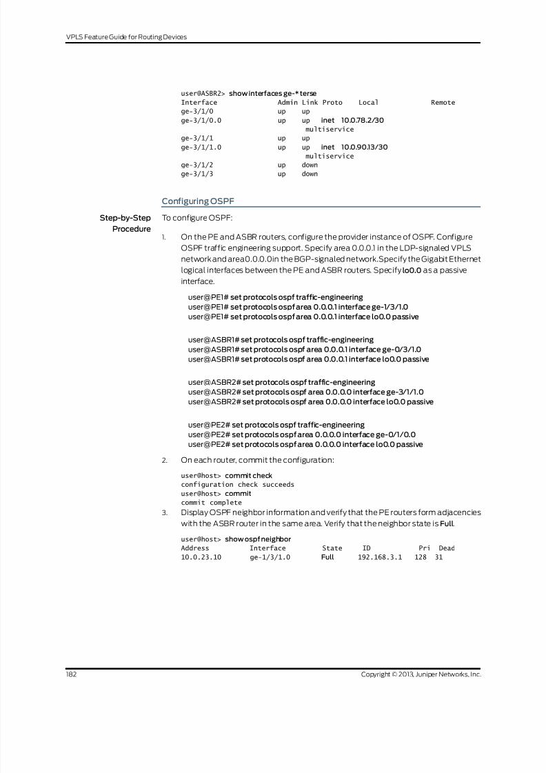
8/21/2019 Config Guide Vpns Vpls
http://slidepdf.com/reader/full/config-guide-vpns-vpls 200/485
user@ASBR2> show interfaces ge-* terse
Interface Admin Link Proto Local Remote
ge-3/1/0 up up
ge-3/1/0.0 up up inet 10.0.78.2/30
multiservice
ge-3/1/1 up up
ge-3/1/1.0 up up inet 10.0.90.13/30
multiservice
ge-3/1/2 up down
ge-3/1/3 up down
Configuring OSPF
Step-by-Step
Procedure
To configure OSPF:
On the PE and ASBR routers, configure the provider instance of OSPF. Configure
OSPF traffic engineering support. Specify area 0.0.0.1 in the LDP-signaled VPLS
1.
networkand area0.0.0.0in the BGP-signaled network.Specify the Gigabit Ethernet
logical interfaces between the PE and ASBR routers. Specify lo0.0 as a passiveinterface.
user@PE1# set protocols ospf traffic-engineering
user@PE1# set protocols ospf area 0.0.0.1 interface ge-1/3/1.0
user@PE1# set protocols ospf area 0.0.0.1 interface lo0.0 passive
user@ASBR1# set protocols ospf traffic-engineering
user@ASBR1# set protocols ospf area 0.0.0.1 interface ge-0/3/1.0
user@ASBR1# set protocols ospf area 0.0.0.1 interface lo0.0 passive
user@ASBR2# set protocols ospf traffic-engineering
user@ASBR2# set protocols ospf area 0.0.0.0 interface ge-3/1/1.0
user@ASBR2# set protocols ospf area 0.0.0.0 interface lo0.0 passive
user@PE2# set protocols ospf traffic-engineering
user@PE2# set protocols ospf area 0.0.0.0 interface ge-0/1/0.0
user@PE2# set protocols ospf area 0.0.0.0 interface lo0.0 passive
2. On each router, commit the configuration:
user@host> commit check
configuration check succeeds
user@host> commit
commit complete
3. Display OSPF neighbor information and verify that the PE routers form adjacencies
with the ASBR router in the same area. Verify that the neighbor state is Full.
user@host> show ospf neighborAddress Interface State ID Pri Dead
10.0.23.10 ge-1/3/1.0 Full 192.168.3.1 128 31
Copyright © 2013, Juniper Networks, Inc.182
VPLS Feature Guide for Routing Devices

8/21/2019 Config Guide Vpns Vpls
http://slidepdf.com/reader/full/config-guide-vpns-vpls 201/485
Configuring the Internal BGP Peer Group
Step-by-Step
Procedure
The purpose of configuring an internal BGP peer group is to create a full mesh of BGP
LSPs among the PE routers in the BGP-signaled AS, including the ASBR routers.
To configure the internal BGP peer group:
1. The purpose of this step is tocreate a full mesh of IBGP peers between the PE
routers, including the ASBR routers, within the BGP-signaled AS.
On Router ASBR2, configure internal BGP. Specify the BGP type as internal. Specify
the local address as the local lo0 IP address.
Specify the inet protocol family. Specify the labeled-unicast statement and the
resolve-vpn option. The labeled-unicast statement causes the router to advertise
labeled routes out of the IPv4 inet.0 route table and places labeled routes into the
inet.0 route table. The resolve-vpn option puts labeled routes in the MPLS inet.3
route table The inet.3 route table is used to resolve routes for the PE router locatedin the other AS.
Specify the l2vpn family to indicate to the router that this is a VPLS. Specify the
signaling option to configure BGP as the signaling protocol. This enables BGP to
carry Layer 2 VPLS NLRI messages for this peer group.
Specify the lo0 interface IP address of the PE as the neighbor. Configure an
autonomous system identifier.
user@ASBR2# set protocols bgp group core-ibgp type internal
user@ASBR2# set protocols bgp group core-ibgp local-address 192.168.10.1
user@ASBR2# set protocols bgp group core-ibgp family inet labeled-unicast
resolve-vpn
user@ASBR2# set protocols bgp group core-ibgp family l2vpn signaling
user@ASBR2# set protocols bgp group core-ibgp neighbor 192.168.11.1
user@ASBR2# set routing-options autonomous-system 0.65020
2. On Router PE2, configure internal BGP. Specify the BGP type as internal. Specify
the local address as the local lo0 IP address.
Specify the l2vpn family to indicate this is a VPLS. Specify the signaling option to
configure BGP as the signaling protocol. This enables BGP to carry Layer 2 VPLS
NLRI messages.
Specify the lo0 interface IP address of Router ASBR2 as the neighbor. Configure an
autonomous system identifier.
user@PE2# set protocols bgp group core-ibgp type internal
user@PE2# set protocols bgp group core-ibgp local-address 192.168.11.1user@PE2# set protocols bgp group core-ibgp family l2vpn signaling
user@PE2# set protocols bgp group core-ibgp neighbor 192.168.10.1
user@PE2# set routing-options autonomous-system 0.65020
3. On each router, commit the configuration:
user@host> commit check
configuration check succeeds
user@host> commit
183Copyright © 2013, Juniper Networks, Inc.
Chapter4: VPLS Examples

8/21/2019 Config Guide Vpns Vpls
http://slidepdf.com/reader/full/config-guide-vpns-vpls 202/485
commit complete
4. On Router PE2and Router ASBR2, display BGPneighbor information andverify that
the peer connection state is Established.
user@ASBR2> show bgp neighbor
Peer: 192.168.11.1+49443 AS 65020 Local: 192.168.10.1+179 AS 65020
Type: Internal State: Established Flags: ImportEval Sync
Last State: OpenConfirm Last Event: RecvKeepAlive
Last Error: None
Options: Preference LocalAddress AddressFamily Rib-group Refresh
Address families configured: l2vpn-signaling inet-labeled-unicast
Local Address: 192.168.10.1 Holdtime: 90 Preference: 170
Number of flaps: 0
Peer ID: 192.168.11.1 Local ID: 192.168.10.1 Active Holdtime: 90
Keepalive Interval: 30 Peer index: 0
...
Configuring LDP
Step-by-Step
Procedure
To configure LDP:
On the PE and ASBR routers, configure LDP with the Gigabit Ethernet interfaces
between the PE and ASBR routers, and between the two ASBR routers. To support
1.
LDP-signaled VPLS, additionally configure LDP with the lo0.0 interface on Router
PE1 and Router ASBR1:
user@PE1# set protocols ldp interface ge-1/3/1.0
user@PE1# set protocols ldp interface lo0.0
user@ASBR1# set protocols ldp interface ge-0/3/1.0
user@ASBR1# set protocols ldp interface ge-0/3/0.0
user@ASBR1# set protocols ldp interface lo0.0
user@ASBR2# set protocols ldp interface ge-3/1/0.0
user@ASBR2# set protocols ldp interface ge-3/1/1.0
user@PE2# set protocols ldp interface ge-0/1/0.0
NOTE: The configuration of LDP signaling between the ASBR routers
is not required for Inter-AS VPLS. It is included here for reference only
and might be used in LDP environments.
2. On each router, commit the configuration:
user@host> commit check
configuration check succeeds
user@host> commit
commit complete
3. Display LDP configuration information and verify that the correct interfaces are
configured. LDP operation can be verified after MPLS is configured.
user@ASBR1> show configuration protocols ldp
Copyright © 2013, Juniper Networks, Inc.184
VPLS Feature Guide for Routing Devices

8/21/2019 Config Guide Vpns Vpls
http://slidepdf.com/reader/full/config-guide-vpns-vpls 203/485
interface ge-0/3/0.0;
interface ge-0/3/1.0;
interface lo0.0;
The preceding example is from ASBR1.
Configuring MPLS
Step-by-Step
Procedure
To configure MPLS:
On thePE andASBRrouters, configure MPLS.Enable MPLS on thelogicalinterfaces.
Add the Gigabit Ethernet interfaces to the MPLS protocol. This adds entries to the
MPLS forwarding table.
1.
user@pe1# set protocols mpls interface ge-1/3/1.0
user@pe1# set interfaces ge-1/3/1 unit 0 family mpls
user@ASBR1# set protocols mpls interface ge-0/3/1.0
user@ASBR1# set protocols mpls interface ge-0/3/0.0user@ASBR1# setinterfaces ge-0/3/1 unit 0 family mpls
user@ASBR1# set interfaces ge-0/3/0 unit 0 family mpls
user@ASBR2# set protocols mpls interface ge-3/1/0.0
user@ASBR2# set protocols mpls interface ge-3/1/1.0
user@ASBR2# setinterfaces ge-3/1/0 unit 0 family mpls
user@ASBR2# setinterfaces ge-3/1/1 unit 0 family mpls
user@pe2# set protocols mpls interface ge-0/1/0.0
user@pe2# set interfaces ge-0/1/0 unit 0 family mpls
2. On each router, commit the configuration:
user@host> commit checkconfiguration check succeeds
user@host> commit
commit complete
3. On the PE and ASBR routers, display LDP neighbor information and verify that the
directly connected LDP neighbors are listed:
user@ASBR1> show ldp neighbor
Address Interface Label space ID Hold time
192.168.2.1 lo0.0 192.168.2.1:0 44
10.0.78.2 ge-0/3/0.0 192.168.10.1:0 13
10.0.23.9 ge-0/3/1.0 192.168.2.1:0 11
The preceding example is from ASBR1.
Configuring the External BGP Peer Group Between the Loopback Interfaces
Step-by-Step
Procedure
To configure the external BGP (EBGP) peer group between the loopback interfaces:
On Router ASBR1 and Router PE1, configure an autonomous system identifier:1.
user@PE1# set routing-options autonomous-system 0.65010
user@ASBR1# set routing-options autonomous-system 0.65010
185Copyright © 2013, Juniper Networks, Inc.
Chapter4: VPLS Examples
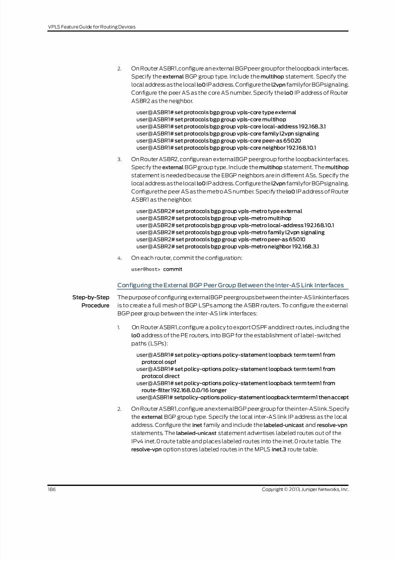
8/21/2019 Config Guide Vpns Vpls
http://slidepdf.com/reader/full/config-guide-vpns-vpls 204/485
2. On Router ASBR1,configure an external BGPpeer groupfor theloopback interfaces.
Specify the external BGP group type. Include the multihop statement. Specify the
local address asthelocal lo0 IP address. Configurethe l2vpn familyfor BGPsignaling.
Configure the peer AS as the core AS number. Specify the lo0 IP address of Router
ASBR2 as the neighbor.
user@ASBR1# set protocols bgp group vpls-core type external
user@ASBR1# set protocols bgp group vpls-core multihop
user@ASBR1# set protocols bgp group vpls-core local-address 192.168.3.1
user@ASBR1# set protocols bgp group vpls-core family l2vpn signaling
user@ASBR1# set protocols bgp group vpls-core peer-as 65020
user@ASBR1# set protocols bgp group vpls-core neighbor 192.168.10.1
3. On Router ASBR2, configurean externalBGP peergroup forthe loopbackinterfaces.
Specify the external BGP group type. Include the multihop statement. The multihop
statement is needed because the EBGP neighbors are in different ASs. Specify the
local address asthelocal lo0 IP address. Configurethe l2vpn familyfor BGPsignaling.
Configurethe peer AS as the metro AS number. Specify the lo0 IP address of Router
ASBR1 as the neighbor.
user@ASBR2# set protocols bgp group vpls-metro type external
user@ASBR2# set protocols bgp group vpls-metro multihop
user@ASBR2# set protocols bgp group vpls-metro local-address 192.168.10.1
user@ASBR2# set protocols bgp group vpls-metro family l2vpn signaling
user@ASBR2# set protocols bgp group vpls-metro peer-as 65010
user@ASBR2# set protocols bgp group vpls-metro neighbor 192.168.3.1
4. On each router, commit the configuration:
user@host> commit
Configuring the External BGP Peer Group Between the Inter-AS Link Interfaces
Step-by-Step
Procedure
Thepurpose of configuring externalBGP peergroupsbetweenthe inter-ASlinkinterfaces
is to create a full mesh of BGP LSPs among the ASBR routers. To configure the external
BGP peer group between the inter-AS link interfaces:
1. On Router ASBR1,configure a policy to export OSPF anddirect routes, including the
lo0 address of the PE routers, into BGP for the establishment of label-switched
paths (LSPs):
user@ASBR1# set policy-options policy-statement loopback term term1 from
protocol ospf
user@ASBR1# set policy-options policy-statement loopback term term1 from
protocol direct
user@ASBR1# set policy-options policy-statement loopback term term1 from
route-filter 192.168.0.0/16 longer
user@ASBR1# setpolicy-options policy-statement loopbacktermterm1 then accept
2. On Router ASBR1,configure anexternalBGP peer group for theinter-ASlink.Specify
the external BGP group type. Specify the local inter-AS link IP address as the local
address. Configure the inet family and include the labeled-unicast and resolve-vpn
statements. The labeled-unicast statement advertises labeled routes out of the
IPv4 inet.0 route table and places labeled routes into the inet.0 route table. The
resolve-vpn option stores labeled routes in the MPLS inet.3 route table.
Copyright © 2013, Juniper Networks, Inc.186
VPLS Feature Guide for Routing Devices

8/21/2019 Config Guide Vpns Vpls
http://slidepdf.com/reader/full/config-guide-vpns-vpls 205/485
Include the export statement and specifythe policy you created. Configure the peer
AS as the core AS number. Specify the inter-AS link IP address of Router ASBR2 as
the neighbor.
user@ASBR1# set protocols bgp group metro-core type externaluser@ASBR1# set protocols bgp group metro-core local-address 10.0.78.1
user@ASBR1# set protocols bgp group metro-core family inet labeled-unicast
resolve-vpn
user@ASBR1# set protocols bgp group metro-core export loopback
user@ASBR1# set protocols bgp group metro-core peer-as 65020
user@ASBR1# set protocols bgp group metro-core neighbor 10.0.78.2
3. On Router ASBR2, configure a policy to export OSPF and direct routes, including
the lo0 address, into BGP for the establishment of LSPs:
user@ASBR2# set policy-options policy-statement loopback term term1 from
protocol ospf
user@ASBR2# set policy-options policy-statement loopback term term1 from
protocol direct
user@ASBR2# set policy-options policy-statement loopback term term1 fromroute-filter 192.168.0.0/16 longer
user@ASBR2# setpolicy-optionspolicy-statementloopbacktermterm1 thenaccept
4. On Router ASBR2, configure an external BGPpeergroup forthe inter-ASlink. Specify
the external BGP group type. Specify the local inter-AS link IP address as the local
address. Configure the inet family and include the labeled-unicast and resolve-vpn
statements. Include the export statement and specify the policy you created.
Configure the peer AS as the core AS number. Specify the inter-AS link IP address
of Router ASBR1 as the neighbor.
user@ASBR2# set protocols bgp group core-metro type external
user@ASBR2# set protocols bgp group core-metro local-address 10.0.78.2
user@ASBR2# set protocols bgp group core-metro family inet labeled-unicast
resolve-vpn
user@ASBR2# set protocols bgp group core-metro export loopback
user@ASBR2# set protocols bgp group core-metro peer-as 65010
user@ASBR2# set protocols bgp group core-metro neighbor 10.0.78.1
5. On each router, commit the configuration:
user@host> commit check
configuration check succeeds
user@host> commit
commit complete
6. On Router ASBR1, display the BGP neighbors. Verify that the first peer is the IP
address of the Gigabit Ethernet interface of Router ASBR2. Verify that the second
peer isthe IP address of the lo0 interfaceof Router ASBR2. Also verify that the state
of each peer is Established. Notice that on Router ASBR1 the NLRI advertised byRouter ASBR2 the inter-AS link peer is inet-labeled-unicast and the NLRI advertised
by Router ASBR2 the loopback interface peer is l2vpn-signaling.
user@ASBR1> show bgp neighbor
Peer: 10.0.78.2+65473 AS 65020 Local: 10.0.78.1+179 AS 65010
Type: External State: Established Flags: Sync
Last State: OpenConfirm Last Event: RecvKeepAlive
Last Error: Cease
Export: [ loopback ]
Options: Preference LocalAddress AddressFamily PeerAS Rib-group Refresh
187Copyright © 2013, Juniper Networks, Inc.
Chapter4: VPLS Examples

8/21/2019 Config Guide Vpns Vpls
http://slidepdf.com/reader/full/config-guide-vpns-vpls 206/485
Address families configured: inet-labeled-unicast
Local Address: 10.0.78.1 Holdtime: 90 Preference: 170
Number of flaps: 3
Last flap event: Stop
Error: 'Cease' Sent: 1 Recv: 2
Peer ID: 192.168.10.1 Local ID: 192.168.3.1 Active Holdtime: 90 Keepalive Interval: 30 Peer index: 0
BFD: disabled, down
Local Interface: ge-0/3/0.0
NLRI for restart configured on peer: inet-labeled-unicast
NLRI advertised by peer: inet-labeled-unicast
NLRI for this session: inet-labeled-unicast
Peer supports Refresh capability (2)
Restart time configured on the peer: 120
Stale routes from peer are kept for: 300
Restart time requested by this peer: 120
NLRI that peer supports restart for: inet-labeled-unicast
NLRI that restart is negotiated for: inet-labeled-unicast
NLRI of received end-of-rib markers: inet-labeled-unicast
NLRI of all end-of-rib markers sent: inet-labeled-unicast
Peer supports 4 byte AS extension (peer-as 65020) Table inet.0 Bit: 10000
RIB State: BGP restart is complete
Send state: in sync
Active prefixes: 2
Received prefixes: 3
Accepted prefixes: 3
Suppressed due to damping: 0
Advertised prefixes: 3
Last traffic (seconds): Received 8 Sent 3 Checked 60
Input messages: Total 8713 Updates 3 Refreshes 0 Octets 165688
Output messages: Total 8745 Updates 2 Refreshes 0 Octets 166315
Output Queue[0]: 0
Peer: 192.168.10.1+51234 AS 65020 Local: 192.168.3.1+179 AS 65010
Type: External State: Established Flags: Sync
Last State: OpenConfirm Last Event: RecvKeepAlive
Last Error: Cease
Options: Multihop Preference LocalAddress AddressFamily PeerAS Rib-group
Refresh
Address families configured: l2vpn-signaling
Local Address: 192.168.3.1 Holdtime: 90 Preference: 170
Number of flaps: 3
Last flap event: Stop
Error: 'Cease' Sent: 1 Recv: 2
Peer ID: 192.168.10.1 Local ID: 192.168.3.1 Active Holdtime: 90
Keepalive Interval: 30 Peer index: 0
BFD: disabled, down
NLRI for restart configured on peer: l2vpn-signaling
NLRI advertised by peer: l2vpn-signaling
NLRI for this session: l2vpn-signaling
Peer supports Refresh capability (2)
Restart time configured on the peer: 120
Stale routes from peer are kept for: 300
Restart time requested by this peer: 120
NLRI that peer supports restart for: l2vpn-signaling
NLRI that restart is negotiated for: l2vpn-signaling
NLRI of received end-of-rib markers: l2vpn-signaling
NLRI of all end-of-rib markers sent: l2vpn-signaling
Copyright © 2013, Juniper Networks, Inc.188
VPLS Feature Guide for Routing Devices

8/21/2019 Config Guide Vpns Vpls
http://slidepdf.com/reader/full/config-guide-vpns-vpls 207/485
Peer supports 4 byte AS extension (peer-as 65020)
Table bgp.l2vpn.0 Bit: 20000
RIB State: BGP restart is complete
RIB State: VPN restart is complete
Send state: in sync
Active prefixes: 1 Received prefixes: 1
Accepted prefixes: 1
Suppressed due to damping: 0
Advertised prefixes: 1
Table inter-as.l2vpn.0
RIB State: BGP restart is complete
RIB State: VPN restart is complete
Send state: not advertising
Active prefixes: 1
Received prefixes: 1
Accepted prefixes: 1
Suppressed due to damping: 0
Last traffic (seconds): Received 19 Sent 18 Checked 42
Input messages: Total 8712 Updates 3 Refreshes 0 Octets 165715
Output messages: Total 8744 Updates 2 Refreshes 0 Octets 166342
Output Queue[1]: 0
Output Queue[2]: 0
7. On Router ASBR2, display the BGP summary. Notice that the first peer is the IP
address of the Gigabit Ethernet interface of Router ASBR1, the second peer is the
IP addressof the lo0 interface of Router ASBR1, andthe thirdpeer is the lo0 interface
of Router PE2. Verify that the state of each peer is Established.
user@ASBR2> show bgpsummary
Groups: 3 Peers: 3 Down peers: 0
Table Tot Paths Act Paths Suppressed History Damp State
Pending
inet.0 3 2 0 0 00
bgp.l2vpn.0 2 2 0 0 0
0
Peer AS InPkt OutPkt OutQ Flaps Last Up/Dwn
State|#Active/Received/Accepted/Damped...
10.0.78.1 65010 8781 8748 0 2 2d 17:54:56
Establ
inet.0: 2/3/3/0
192.168.3.1 65010 8780 8747 0 2 2d 17:54:54
Establ
bgp.l2vpn.0: 1/1/1/0
inter-as.l2vpn.0: 1/1/1/0
192.168.11.1 65020 8809 8763 0 1 2d 17:59:22
Establ
bgp.l2vpn.0: 1/1/1/0 inter-as.l2vpn.0: 1/1/1/0
8. On Router PE2, display the BGP group. Verify that the peer is the IP address of the
lo0 interface of Router ASBR2. Verify that the number of established peer sessions
is1.
user@PE1> show bgp group
Group Type: Internal AS: 65020 Local AS: 65020
Name: core-ibgp Index: 1 Flags: Export Eval
189Copyright © 2013, Juniper Networks, Inc.
Chapter4: VPLS Examples

8/21/2019 Config Guide Vpns Vpls
http://slidepdf.com/reader/full/config-guide-vpns-vpls 208/485
Holdtime: 0
Total peers: 1 Established: 1
192.168.10.1+179
bgp.l2vpn.0: 1/1/1/0
inter-as.l2vpn.0: 1/1/1/0
Groups: 1 Peers: 1 External: 0 Internal: 1 Down peers: 0 Flaps:
7
Table Tot Paths Act Paths Suppressed History Damp State
Pending
bgp.l2vpn.0 1 1 0 0 0
0
inte.l2vpn.0 1 1 0 0 0
0
Configuring the VPLS Routing Instances
Step-by-Step
Procedure
To configure the VPLS routing instances:
On Router PE1, configure the VPLS routing instance. To enable a VPLS instance,specify the vpls instance type. Configure VPLS on the CE-facing Gigabit Ethernet
interface. Configure the CE-facing interface to use ethernet-vpls encapsulation.
1.
user@PE1# set routing-instances metro instance-type vpls
user@PE1# set routing-instances metro interface ge-1/3/0.0
2. On Router PE1,configure the VPLS protocol within the routing instance. To uniquely
identify the virtual circuit, configurethe VPLSidentifier. TheVPLSidentifier uniquely
identifies each VPLS in the router. Configure the same VPLS ID on all the routers
for a given VPLS.
Specify the IP address of the lo0 interface on Router ASBR2 as the neighbor.
Configure the CE-facing interface to use ethernet-vpls encapsulation and the vpls
protocol family.
user@PE1# set routing-instances metro protocols vpls vpls-id 101
user@PE1# set routing-instances metro protocols vpls neighbor 192.168.3.1
user@PE1# set interfaces ge-1/3/0 encapsulation ethernet-vpls
user@PE1# set interfaces ge-1/3/0 unit 0 family vpls
3. On Router ASBR1, configure the VPLS routing instance. To enable a VPLS instance,
specify the vpls instance type. Configurea route distinguisher anda VRF target. The
vrf-target statementcauses default VRFimport andexport policies to be generated
that accept and tag routes with the specified target community.
NOTE: A route distinguisher allows the router to distinguish between
two identical IP prefixes usedas VPN routes. Configure a different route
distinguisher on each ASBR router.
NOTE: You must configure the same VRF target on both ASBR routers.
Copyright © 2013, Juniper Networks, Inc.190
VPLS Feature Guide for Routing Devices

8/21/2019 Config Guide Vpns Vpls
http://slidepdf.com/reader/full/config-guide-vpns-vpls 209/485
user@ASBR1# set routing-instances inter-as instance-type vpls
user@ASBR1# set routing-instances inter-as route-distinguisher 65010:1
user@ASBR1# set routing-instances inter-as vrf-target target:2:1
4. On Router ASBR1, configure the VPLS protocol within the routing instance.
Configure the VPLS identifier. Specify the IP address of the lo0 interface on Router
PE1 as the neighbor.
user@ASBR1# set routing-instances inter-as protocols vpls vpls-id 101
user@ASBR1# set routing-instances inter-as protocols vpls neighbor 192.168.2.1
NOTE: The VPLS identifier uniquely identifies eachLDP-signaled VPLS
in the router. Configure the same VPLS ID on Router PE1 and Router
ASBR1.
5. On Router ASBR1, configure the VPLS site within the routing instance. Configurethe site identifier as required by the protocol to establish the EBGP pseudowire. As
a best practice for more complex topologies involving multihoming, configure a site
preference.
user@ASBR1# set routing-instances inter-as protocols vpls site ASBR-metro
site-identifier 1
user@ASBR1# set routing-instances inter-as protocols vpls site ASBR-metro
site-preference 10000
6. On Router ASBR1, configure the VPLS mesh group peer-as statement within the
routing instance to specify which ASs belong to this AS mesh group. Configure the
peer AS for the mesh group as all.
This statement enables the router to establish a single pseudowire between the
ASBR routers. VPLS NLRI messages are exchanged across the EBGP sessions on
the inter-AS links between the ASBR routers. All autonomous systems are in one
mesh group.
user@ASBR1# set routing-instances inter-as protocols vpls mesh-group metro
peer-as all
7. On ASBR2, configurethe VPLS routing instance. To enable a VPLS instance, specify
the vpls instance type. Configurea routedistinguisher anda VRFtarget. Thevrf-target
statement causes default VRF import and export policies to be generated that
accept and tag routes with the specified target community.
NOTE: A route distinguisher allows the router to distinguish between
two identical IP prefixes usedas VPN routes. Configure a different route
distinguisher on each ASBR router.
NOTE: You must configure the same VRF target community on both
ASBR routers.
191Copyright © 2013, Juniper Networks, Inc.
Chapter4: VPLS Examples

8/21/2019 Config Guide Vpns Vpls
http://slidepdf.com/reader/full/config-guide-vpns-vpls 210/485
user@ASBR2# set routing-instances inter-as instance-type vpls
user@ASBR2# set routing-instances inter-as route-distinguisher 65020:1
user@ASBR2# set routing-instances inter-as vrf-target target:2:1
8. On Router ASBR2, configure the VPLS site within the routing instance. Configure
the site identifier as required by the protocol.
user@ASBR2# set routing-instances inter-as protocols vpls site ASBR-core
site-identifier 2
9. On Router ASBR2, configure the VPLS mesh group within the routing instance to
specify which VPLS PEs belong to this AS mesh group. Configure the peer AS for
the mesh group as all.
This statement enables the router to establish a single pseudowire between the
ASBR routers. VPLS NLRI messages are exchanged across the EBGP sessions on
the inter-AS links between the ASBR routers. All autonomous systems are in one
mesh group.
user@ASBR1# setrouting-instances inter-as protocols vplsmesh-group corepeer-asall
10. On Router PE2, configure the VPLS routing instance. To enable a VPLS instance,
specify the vpls instance type. Configure VPLS on the CE-facing Gigabit Ethernet
interface. Configure a route distinguisher and a VRF target.
user@PE2# set routing-instances inter-as instance-type vpls
user@PE2# set routing-instances inter-as interface ge-0/1/1.0
user@PE2# set routing-instances inter-as route-distinguisher 65020:1
user@PE2# set routing-instances inter-as vrf-target target:2:1
11. On Router PE2, configure the VPLS site within the routing instance. Configure the
site identifier as required by the protocol.
Configure the CE-facing interface to use ethernet-vpls encapsulation and the vplsprotocol family.
user@PE2# set routing-instances inter-as protocols vpls site PE2 site-identifier 3
user@PE2# set interfaces ge-0/1/1 encapsulation ethernet-vpls
user@PE2# set interfaces ge-0/1/1 unit 0 family vpls
12. On each router, commit the configuration:
user@host> commit check
configuration check succeeds
user@host> commit
commit complete
13. On the PE routers, display the CE-facing Gigabit Ethernet interface information and
verify that the encapsulation is configured correctly:
user@host> show interfaces ge-1/3/0
Address Interface Label space ID Hold time
10.0.23.10 ge-1/3/1.0 192.168.3.1:0 11
Physical interface: ge-1/3/0, Enabled, Physical link is Up
Interface index: 147, SNMP ifIndex: 145
Link-level type: Ethernet, MTU: 1514, Speed: 1000mbps, MAC-REWRITE Error:
None,
Loopback: Disabled, Source filtering: Disabled, Flow control: Enabled,
Auto-negotiation: Enabled, Remote fault: Online
Copyright © 2013, Juniper Networks, Inc.192
VPLS Feature Guide for Routing Devices

8/21/2019 Config Guide Vpns Vpls
http://slidepdf.com/reader/full/config-guide-vpns-vpls 211/485
Device flags : Present Running
Interface flags: SNMP-Traps Internal: 0x4000
Link flags : None
CoS queues : 4 supported, 4 maximum usable queues
Schedulers : 256
Current address: 00:12:1e:ee:34:db, Hardware address: 00:12:1e:ee:34:db Last flapped : 2008-08-27 19:02:52 PDT (5d 22:32 ago)
Input rate : 0 bps (0 pps)
Output rate : 0 bps (0 pps)
Ingress rate at Packet Forwarding Engine : 0 bps (0 pps)
Ingress drop rate at Packet Forwarding Engine : 0 bps (0 pps)
Active alarms : None
Active defects : None
Logical interface ge-1/3/0.0 (Index 84) (SNMP ifIndex 146)
Flags: SNMP-Traps Encapsulation: ENET2
Input packets : 0
Output packets: 1
Protocol inet, MTU: 1500
Flags: None
Addresses, Flags: Is-Preferred Is-Primary Destination: 10.10.11/24, Local: 10.10.11.11, Broadcast: 10.10.11.255
193Copyright © 2013, Juniper Networks, Inc.
Chapter4: VPLS Examples

8/21/2019 Config Guide Vpns Vpls
http://slidepdf.com/reader/full/config-guide-vpns-vpls 212/485
Results
This section describes commands you can use to test the operation of the VPLS.
1. To verify the VPLS connectionshave beenestablished, enter the showvpls connections
command on Router PE 1.
user@PE1> show vpls connections
Layer-2 VPN connections:
Legend for connection status (St)
EI -- encapsulation invalid NC -- interface encapsulation not CCC/TCC/VPLS
EM -- encapsulation mismatch WE -- interface and instance encaps not same
VC-Dn -- Virtual circuit down NP -- interface hardware not present
CM -- control-word mismatch -> -- only outbound connection is up
CN -- circuit not provisioned <- -- only inbound connection is up
OR -- out of range Up -- operational
OL -- no outgoing label Dn -- down
LD -- local site signaled down CF -- call admission control failure
RD -- remote site signaled down SC -- local and remote site ID collisionLN -- local site not designated LM -- local site ID not minimum designated
RN -- remote site not designated RM -- remote site ID not minimum designated
XX -- unknown connection status IL -- no incoming label
MM -- MTU mismatch MI -- Mesh-Group ID not availble
BK -- Backup connection ST -- Standby connection
Legend for interface status
Up -- operational
Dn -- down
Instance: metro
VPLS-id: 101
Neighbor Type St Time last up # Up trans
192.168.3.1(vpls-id 101) rmt Up Sep 9 14:05:18 2008 1
Remote PE: 192.168.3.1, Negotiated control-word: No Incoming label: 800001, Outgoing label: 800000
Local interface: vt-1/2/0.1048576, Status: Up, Encapsulation: ETHERNET
Description: Intf - vpls metro neighbor 192.168.3.1 vpls-id 101
In the display from Router PE1, verify that the neighbor is the lo0 address of Router
ASBR1 and that the status is Up.
2. To verify the VPLS connectionshave beenestablished, enter the showvpls connections
command on Router ASBR 1.
user@ASBR1> show vpls connections
...
Instance: inter-as
BGP-VPLS State
Mesh-group connections: metro
Neighbor Local-site Remote-site St Time last up
192.168.10.1 1 2 Up Sep 8 20:16:28 2008
Incoming label: 800257, Outgoing label: 800000
Local interface: vt-1/2/0.1049088, Status: Up, Encapsulation: VPLS
LDP-VPLS State
VPLS-id: 101
Mesh-group connections: __ves__
Neighbor Type St Time last up # Up trans
192.168.2.1(vpls-id 101) rmt Up Sep 9 14:05:22 2008 1
Copyright © 2013, Juniper Networks, Inc.194
VPLS Feature Guide for Routing Devices
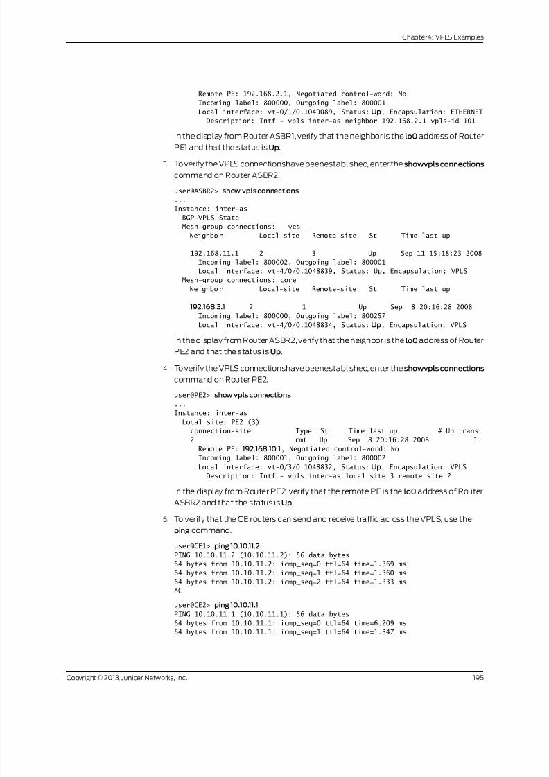
8/21/2019 Config Guide Vpns Vpls
http://slidepdf.com/reader/full/config-guide-vpns-vpls 213/485
Remote PE: 192.168.2.1, Negotiated control-word: No
Incoming label: 800000, Outgoing label: 800001
Local interface: vt-0/1/0.1049089, Status: Up, Encapsulation: ETHERNET
Description: Intf - vpls inter-as neighbor 192.168.2.1 vpls-id 101
In the display from Router ASBR1, verify that the neighbor is the lo0 address of RouterPE1 and that the status is Up.
3. To verify the VPLS connectionshave beenestablished, enter the showvpls connections
command on Router ASBR2.
user@ASBR2> show vpls connections
...
Instance: inter-as
BGP-VPLS State
Mesh-group connections: __ves__
Neighbor Local-site Remote-site St Time last up
192.168.11.1 2 3 Up Sep 11 15:18:23 2008
Incoming label: 800002, Outgoing label: 800001
Local interface: vt-4/0/0.1048839, Status: Up, Encapsulation: VPLS Mesh-group connections: core
Neighbor Local-site Remote-site St Time last up
192.168.3.1 2 1 Up Sep 8 20:16:28 2008
Incoming label: 800000, Outgoing label: 800257
Local interface: vt-4/0/0.1048834, Status: Up, Encapsulation: VPLS
In the display from Router ASBR2, verify that the neighbor is the lo0 address of Router
PE2 and that the status is Up.
4. To verify the VPLS connectionshave beenestablished, enter the showvpls connections
command on Router PE2.
user@PE2> show vpls connections
...
Instance: inter-as
Local site: PE2 (3)
connection-site Type St Time last up # Up trans
2 rmt Up Sep 8 20:16:28 2008 1
Remote PE: 192.168.10.1, Negotiated control-word: No
Incoming label: 800001, Outgoing label: 800002
Local interface: vt-0/3/0.1048832, Status: Up, Encapsulation: VPLS
Description: Intf - vpls inter-as local site 3 remote site 2
In the display from Router PE2, verify that the remote PE is the lo0 address of Router
ASBR2 and that the status is Up.
5. To verify that the CE routers can send and receive traffic across the VPLS, use the
ping command.
user@CE1> ping 10.10.11.2PING 10.10.11.2 (10.10.11.2): 56 data bytes
64 bytes from 10.10.11.2: icmp_seq=0 ttl=64 time=1.369 ms
64 bytes from 10.10.11.2: icmp_seq=1 ttl=64 time=1.360 ms
64 bytes from 10.10.11.2: icmp_seq=2 ttl=64 time=1.333 ms
^C
user@CE2> ping 10.10.11.1
PING 10.10.11.1 (10.10.11.1): 56 data bytes
64 bytes from 10.10.11.1: icmp_seq=0 ttl=64 time=6.209 ms
64 bytes from 10.10.11.1: icmp_seq=1 ttl=64 time=1.347 ms
195Copyright © 2013, Juniper Networks, Inc.
Chapter4: VPLS Examples

8/21/2019 Config Guide Vpns Vpls
http://slidepdf.com/reader/full/config-guide-vpns-vpls 214/485
64 bytes from 10.10.11.1: icmp_seq=2 ttl=64 time=1.324 ms
^C
If Router CE1 can send traffic to and receive traffic from Router CE2 and Router CE2
cansendtraffic to and receivetraffic fromRouterCE1, the VPLSis performing correctly.
6. To display the configuration for Router CE1, use the show configuration command.
For your reference, the relevant sample configuration for Router CE1 follows.
interfaces {
lo0{
unit0 {
family inet {
address 192.168.1.1/32 {
primary;
}
address 127.0.0.1/32;
}
}
}
ge-0/3/0 {
unit0 {
family inet {
address 10.10.11.1/24;
}
}
}
}
7. To display the configuration for Router PE1, use the show configuration command.
For your reference, the relevant sample configuration for Router PE1 follows.
interfaces {
lo0{
unit0 {
family inet {
address 192.168.2.1/32 {
primary;
}
address 127.0.0.1/32;
}
}
}
ge-1/3/0 {
encapsulation ethernet-vpls;
unit0 {
family vpls;
}
}
ge-1/3/1 {
unit0 {
family inet {
address 10.0.23.9/30;
}
family mpls;
}
Copyright © 2013, Juniper Networks, Inc.196
VPLS Feature Guide for Routing Devices

8/21/2019 Config Guide Vpns Vpls
http://slidepdf.com/reader/full/config-guide-vpns-vpls 215/485
}
}
routing-options {
autonomous-system 0.65010;
}protocols {
mpls {
interface ge-1/3/1.0;
}
ospf {
traffic-engineering;
area 0.0.0.1 {
interface ge-1/3/1.0;
interface lo0.0 {
passive;
}
}
}
ldp{interface ge-1/3/1.0;
interface lo0.0;
}
}
routing-instances {
metro {
instance-type vpls;
interface ge-1/3/0.0;
protocols {
vpls {
vpls-id 101;
neighbor 192.168.3.1;
}
}}
}
8. To display the configuration for Router ASBR1, use the show configuration command.
For your reference, the relevant sample configuration for Router ASBR1 follows.
interfaces {
lo0{
unit0 {
family inet {
address 192.168.3.1/32 {
primary;
}
address 127.0.0.1/32;}
}
}
ge-0/3/0 {
unit0 {
family inet {
address 10.0.78.1/30;
}
family mpls;
197Copyright © 2013, Juniper Networks, Inc.
Chapter4: VPLS Examples

8/21/2019 Config Guide Vpns Vpls
http://slidepdf.com/reader/full/config-guide-vpns-vpls 216/485
}
}
ge-0/3/1 {
unit0 {
family inet {address 10.0.23.10/30;
}
family mpls;
}
}
}
routing-options {
autonomous-system 0.65010;
}
protocols {
mpls {
interface ge-0/3/1.0;
interface ge-0/3/0.0;
}bgp {
group vpls-core {
type external;
multihop;
local-address 192.168.3.1;
family l2vpn {
signaling;
}
peer-as 65020;
neighbor 192.168.10.1;
}
group metro-core {
type external;
local-address 10.0.78.1;family inet {
labeled-unicast {
resolve-vpn;
}
}
export loopback;
peer-as 65020;
neighbor 10.0.78.2;
}
}
ospf {
traffic-engineering;
area 0.0.0.1 {
interface ge-0/3/1.0;interface lo0.0 {
passive;
}
}
}
ldp{
interface ge-0/3/0.0;
interface ge-0/3/1.0;
interface lo0.0;
Copyright © 2013, Juniper Networks, Inc.198
VPLS Feature Guide for Routing Devices

8/21/2019 Config Guide Vpns Vpls
http://slidepdf.com/reader/full/config-guide-vpns-vpls 217/485
}
}
policy-options {
policy-statement loopback {
term term1 {from {
protocol [ ospf direct ];
route-filter 192.168.0.0/16 longer;
}
then accept;
}
}
}
routing-instances {
inter-as {
instance-type vpls;
route-distinguisher 65010:1;
vrf-target target:2:1;
protocols {vpls {
site ASBR-metro {
site-identifier 1;
site-preference 10000;
}
vpls-id 101;
neighbor 192.168.2.1;
mesh-group metro {
peer-as {
all;
}
}
}
}}
}
9. To display the configuration for Router ASBR2, use the show configuration command.
For your reference, the relevant sample configuration for Router ASBR2 follows.
interfaces {
lo0{
unit0 {
family inet {
address 192.168.10.1/32 {
primary;
}
address 127.0.0.1/32;}
}
}
ge-3/1/0 {
unit0 {
family inet {
address 10.0.78.2/30;
}
family mpls;
199Copyright © 2013, Juniper Networks, Inc.
Chapter4: VPLS Examples
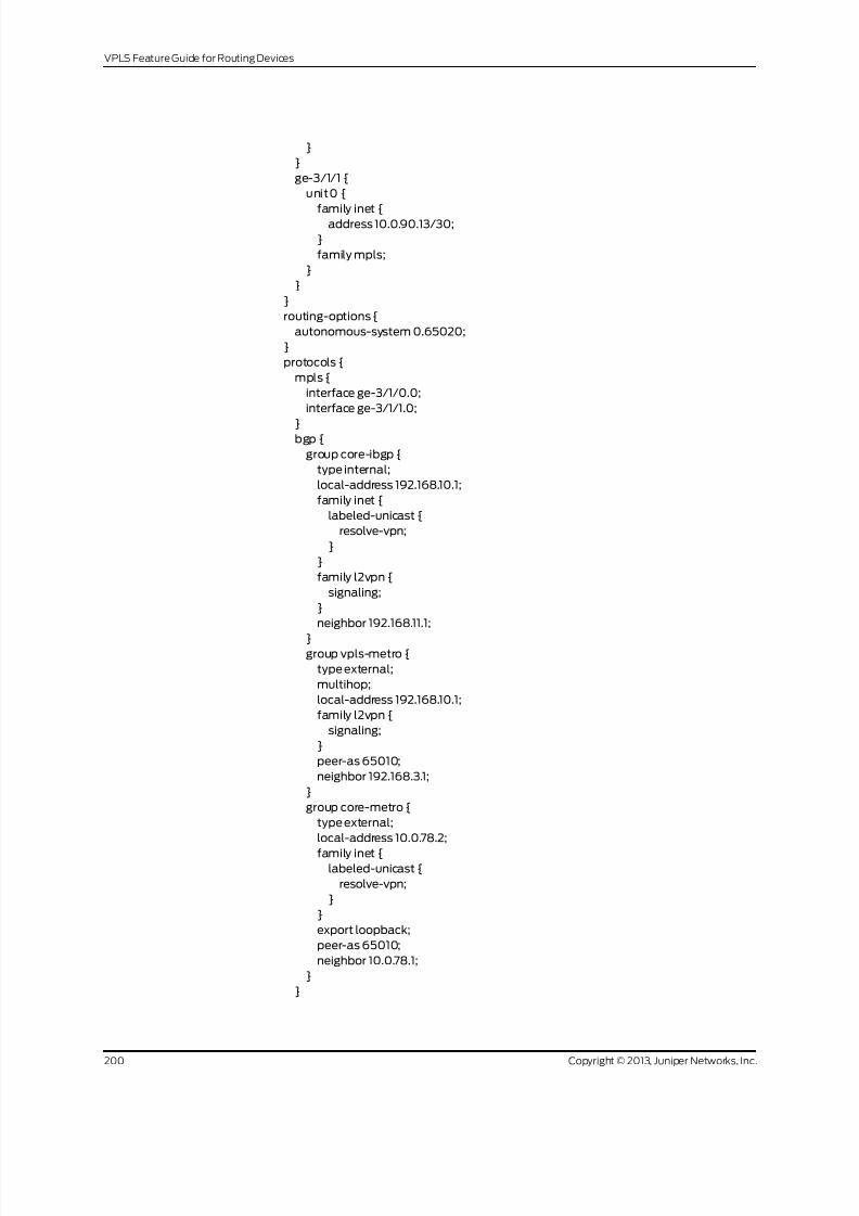
8/21/2019 Config Guide Vpns Vpls
http://slidepdf.com/reader/full/config-guide-vpns-vpls 218/485
}
}
ge-3/1/1 {
unit0 {
family inet {address 10.0.90.13/30;
}
family mpls;
}
}
}
routing-options {
autonomous-system 0.65020;
}
protocols {
mpls {
interface ge-3/1/0.0;
interface ge-3/1/1.0;
}bgp {
group core-ibgp {
type internal;
local-address 192.168.10.1;
family inet {
labeled-unicast {
resolve-vpn;
}
}
family l2vpn {
signaling;
}
neighbor 192.168.11.1;
}group vpls-metro {
type external;
multihop;
local-address 192.168.10.1;
family l2vpn {
signaling;
}
peer-as 65010;
neighbor 192.168.3.1;
}
group core-metro {
type external;
local-address 10.0.78.2;
family inet {labeled-unicast {
resolve-vpn;
}
}
export loopback;
peer-as 65010;
neighbor 10.0.78.1;
}
}
Copyright © 2013, Juniper Networks, Inc.200
VPLS Feature Guide for Routing Devices

8/21/2019 Config Guide Vpns Vpls
http://slidepdf.com/reader/full/config-guide-vpns-vpls 219/485
ospf {
traffic-engineering;
area 0.0.0.0 {
interface ge-3/1/1.0;
interface lo0.0 {passive;
}
}
}
ldp{
interface ge-3/1/0.0;
interface ge-3/1/1.0;
}
}
policy-options {
policy-statement loopback {
term term1 {
from {
protocol [ ospf direct ];route-filter 192.168.0.0/16 longer;
}
then accept;
}
}
}
routing-instances {
inter-as {
instance-type vpls;
route-distinguisher 65020:1;
vrf-target target:2:1;
protocols {
vpls {
site ASBR-core {site-identifier 2;
}
mesh-group core {
peer-as {
all;
}
}
}
}
}
}
10. To display the configuration for Router PE2, use the show configuration command.
For your reference, the relevant sample configuration for Router PE2 follows.
interfaces {
lo0{
unit0 {
family inet {
address 192.168.11.1/32 {
primary;
}
address 127.0.0.1/32;
201Copyright © 2013, Juniper Networks, Inc.
Chapter4: VPLS Examples

8/21/2019 Config Guide Vpns Vpls
http://slidepdf.com/reader/full/config-guide-vpns-vpls 220/485
}
}
}
ge-0/1/0 {
unit0 {family inet {
address 10.0.90.14/30;
}
family mpls;
}
}
ge-0/1/1 {
encapsulation ethernet-vpls;
unit0 {
family vpls;
}
}
}
routing-options {autonomous-system 0.65020;
}
protocols {
mpls {
interface ge-0/1/0.0;
}
bgp {
group core-ibgp {
type internal;
local-address 192.168.11.1;
family l2vpn {
signaling;
}
neighbor 192.168.10.1;}
}
ospf {
traffic-engineering;
area 0.0.0.0 {
interface ge-0/1/0.0;
interface lo0.0 {
passive;
}
}
}
ldp{
interface ge-0/1/0.0;
}}
routing-instances {
inter-as {
instance-type vpls;
interface ge-0/1/1.0;
route-distinguisher 65020:1;
vrf-target target:2:1;
protocols {
vpls {
Copyright © 2013, Juniper Networks, Inc.202
VPLS Feature Guide for Routing Devices

8/21/2019 Config Guide Vpns Vpls
http://slidepdf.com/reader/full/config-guide-vpns-vpls 221/485
sitePE2 {
site-identifier 3;
}
}
}}
}
11. To display the configuration for Router CE2, use the show configuration command.
For your reference, the relevant sample configuration for Router CE2 follows.
interfaces {
lo0{
unit0 {
family inet {
address 192.168.12.1/32 {
primary;
}
address 127.0.0.1/32;}
}
}
ge-0/1/1 {
unit0 {
family inet {
address 10.10.11.2/24;
}
}
}
}
RelatedDocumentation
Example: Building a VPLS From Router 1 to Router 3 to Validate Label Blocks
This example illustrates how VPLS label blocks are allocated for a specific configuration.
It is organized in the following sections:
• Requirements on page 203
• Overview and Topology on page 203
• Configuration on page 205
RequirementsThis configuration example requires three Juniper Networks routers.
Overview and Topology
In the network shown in Figure 9 on page 110 Router 1 is establishing a pseudowire to
Router 3
203Copyright © 2013, Juniper Networks, Inc.
Chapter4: VPLS Examples

8/21/2019 Config Guide Vpns Vpls
http://slidepdf.com/reader/full/config-guide-vpns-vpls 222/485
Figure 17: Router 1 to Router 3 Topology
ge-5/0/2
Site A Site B
ge-5/3/2 ge-2/0/1 ge-4/0/2
ge-0/3/0 ge-0/2/0R2 R3R1
g 0 4 0 5 0 5
Each PE filters the VPLS NLRI contained in the BGP update messages based on route
target communities. Those VPLS NLRI instancesthat matchthe route target(in this case
8717:2000:2:1) are imported for further processing. The NLRI for Router 1 and Router 3 is
shown in Table 6 on page 110.
Table 7: NLRI Exchange Between for Router 1 and Router 3
Router 3 NLRI Advertisement to Router 1Router 1 NLRI Advertisement to Router 3
RD - 8717:1000RD - 8717:1000
V E I D - 2V E I D - 1
VEBlockOffset - 1VE Block Offset- 1
VEBlockSize - 8VE Block Size- 8
Label Base - 262153Label Base - 262161
To set up a pseudowire toRouter 3, Router 1 must select a label touse tosend traffic to
Router 3 and also select a label that it expects Router 3 to use to send traffic to itself.The site ID contained in the VPLS NLRI from Router 3 is 2.
Router 1 learns of theexistence of site ID 2 in the same VPLS domain. Using the equation
VBO <= Local Site ID < (VBO +VBS), Router 1 checks if the route advertised by site ID 2
fits in the label block and block offset that it previously advertised to Router 3. In this
example it does fit, sothe site ID 2 is mapped by the VPLS NLRI advertised by Router 1,
and Router 1 is ready toset up a pseudowire toRouter 3.
To select the label to reach Router 3, Router 1 looks at the label block advertised by
Router 3 and performs a calculation. The calculation a PE router uses to check if its site
ID is mapped in the label block from the remote peer is VBO <= Local Site ID < (VBO
+VBS). So, Router 1 selects label (262153 + (1 -1)) = 262153 to send traffic to Router 3.
Using the same equation, Router 1 looks at its own label block that it advertised andselects label(262161 + (2 - 1))= 262162to receivetrafficfrom Router 3. Router 1 programs
its forwarding state such that any traffic destined to Router 3 carries the pseudowire
label 262153 and any traffic coming from Router 3 is expected to have the pseudowire
label 262162. This completes the operations on the VPLS NLRI received from Router 3.
Router 1 now has a pseudowire set up to Router 3.
Router 3 operation is very similar to the Router 1 operation. Since the Router 3 site ID of
2 fits in the label block and block offset advertised by Router 1, Router 3 selects label
Copyright © 2013, Juniper Networks, Inc.204
VPLS Feature Guide for Routing Devices

8/21/2019 Config Guide Vpns Vpls
http://slidepdf.com/reader/full/config-guide-vpns-vpls 223/485
(262161+ (2- 1))= 262162 tosendtraffic toRouter 1. Router 3 looks atits own label block
that it advertised and selects label (262153 + (1 - 1)) = 262153 to receive traffic from
Router 1. This completes the creation of a pseudowire to Router 1.
By default, for VPLS operation Junos OS uses a virtual tunnel (VT) loopback interfaceto represent a pseudowire. This example uses a label-switched interface (LSI) instead
of a VT interface because there is no change in the VPLS control plane operation. Thus,
for an MX platform, if there is a tunnel physical interface card (PIC) configured, it is
mandatory to include the no-tunnel-servicesstatement at the
[edit routing-instances routing-instance-name protocols vpls] hierarchy level.
Configuration
The following sections present the steps to configure and verify the example in
Figure 9 on page 110.
• Configuring Router 1 on page 205
• Configuring Router 3 on page 205
• Verifying the VPLS Label Allocations on page 206
Configuring Router 1
Step-by-Step
Procedure
Configure Router 1. Create the edut routing instance. Specify the vpls instance type.
Configure the route distinguisher and specify the value 8717:1000. Configure the
1.
route target and specify the value 8717:100 Configure the VPLS protocol. Specify
10 asthe siterange. Specify 1 asthe site ID. Include theno-tunnel-services statement.
[edit routing-instances]
edut {
instance-type vpls;
interface ge-5/0/2.0;route-distinguisher 8717:1000;
vrf-target target:8717:100;
protocols {
vpls {
site-range 10;
no-tunnel-services;
site router-1 {
site-identifier 1;
}
}
}
}
Configuring Router 3
Step-by-Step
Procedure
Configure Router 3. Create the edut routing instance. Specify the vpls instance type.
Configure the route distinguisher and specify the value 8717:2000. Configure the
1.
route target and specify the value 8717:200 Configure the VPLS protocol. Specify
10 asthe siterange. Specify 2 asthe site ID. Include theno-tunnel-services statement.
[edit routing-instances]
edut {
205Copyright © 2013, Juniper Networks, Inc.
Chapter4: VPLS Examples

8/21/2019 Config Guide Vpns Vpls
http://slidepdf.com/reader/full/config-guide-vpns-vpls 224/485
instance-type vpls;
interface ge-4/0/2.0;
route-distinguisher 8717:2000;
vrf-target target:8717:100;
protocols {vpls {
site-range 10;
no-tunnel-services;
site router-3 {
site-identifier 2;
}
}
}
}
Verifying the VPLS Label Allocations
Step-by-Step
Procedure
1. As shown in the figure and the configuration, Site A is attached to Router 1. Site A
is assigneda site ID of 1. Before Router 1 canannounceits membershipto VPLS edut
using a BGP update message, Router 1 needs to allocate a default label block. In
this example, the label base of the label block allocatedby Router 1 is 262161. Since
Router 1’s site ID is 1, Router 1 associates the assigned label block with block offset
of 1. The following messages aresent from Router 1 to Router 3 and displayed using
the monitor traffic interface interface-name command:
user@Router1> monitor traffic interface ge-5/3/2
Jun 14 12:26:31.280818 BGP SEND 10.10.10.1+179 -> 10.10.10.3+53950
Jun 14 12:26:31.280824 BGP SEND message type 2 (Update) length 88
Jun 14 12:26:31.280828 BGP SEND flags 0x40 code Origin(1): IGP
Jun 14 12:26:31.280833 BGP SEND flags 0x40 code ASPath(2) length 0: <null>
Jun 14 12:26:31.280837 BGP SEND flags 0x40 code LocalPref(5): 100
Jun 14 12:26:31.280844 BGP SEND flags 0xc0 code Extended Communities(16):
2:8717:100 800a:19:0:0
Jun 14 12:26:31.280848 BGP SEND flags 0x90 code MP_reach(14): AFI/SAFI 25/65
Jun 14 12:26:31.280853 BGP SEND nhop 10.10.10.1 len 4
Jun 14 12:26:31.280862 BGP SEND 8717:1000:1:1 (labelbase: 262161range
: 8,ce id: 1,offset:1)
Jun 14 12:26:31.405067 BGP RECV 10.10.10.3+53950 -> 10.10.10.1+179
Jun 14 12:26:31.405074 BGP RECV message type 2 (Update) length 88
Jun 14 12:26:31.405080 BGP RECV flags 0x40 code Origin(1): IGP
Jun 14 12:26:31.405085 BGP RECV flags 0x40 code ASPath(2) length 0: <null>
Jun 14 12:26:31.405089 BGP RECV flags 0x40 code LocalPref(5): 100
Jun 14 12:26:31.405096 BGP RECV flags 0xc0 code Extended Communities(16):
2:8717:100 800a:19:0:0
Jun 14 12:26:31.405101 BGP RECV flags 0x90 code MP_reach(14): AFI/SAFI 25/65
Jun 14 12:26:31.405106 BGP RECV nhop 10.10.10.3 len 4
Jun 14 12:26:31.405116 BGP RECV 8717:2000:2:1 (label base : 262153
range : 8, ce id: 2, offset: 1)
2. As shown in the figure and the configuration, Site B is attached to Router 3. Site B
is assigned a site ID of 2. Before Router 3 can announce its membership to VPLS
edut using a BGP update message, Router 3 assigns a default label block with the
label base of 262153. The block offset for this label block is 1 because its own site
ID of 2 fits in the block being advertised. The following messages are sent from
Router 3 to Router 1 and displayed using the monitor traffic interface interface-name
command:
Copyright © 2013, Juniper Networks, Inc.206
VPLS Feature Guide for Routing Devices

8/21/2019 Config Guide Vpns Vpls
http://slidepdf.com/reader/full/config-guide-vpns-vpls 225/485
user@Router3> monitor traffic interface ge-2/0/1
Jun 14 12:26:31.282008 BGP SEND 10.10.10.3+53950 -> 10.10.10.1+179
Jun 14 12:26:31.282018 BGP SEND message type 2 (Update) length 88
Jun 14 12:26:31.282026 BGP SEND flags 0x40 code Origin(1): IGP
Jun 14 12:26:31.282034 BGP SEND flags 0x40 code ASPath(2) length 0: <null>
Jun 14 12:26:31.282041 BGP SEND flags 0x40 code LocalPref(5): 100
Jun 14 12:26:31.282052 BGP SEND flags 0xc0 code Extended Communities(16):
2:8717:100 800a:19:0:0
Jun 14 12:26:31.282078 BGP SEND flags 0x90 code MP_reach(14): AFI/SAFI 25/65
Jun 14 12:26:31.282088 BGP SEND nhop 10.10.10.3 len 4
Jun 14 12:26:31.282102 BGP SEND 8717:2000:2:1 (labelbase: 262153range
: 8,ce id: 2,offset:1)
Jun 14 12:26:31.283395 BGP RECV 10.10.10.1+179 -> 10.10.10.3+53950
Jun 14 12:26:31.283405 BGP RECV message type 2 (Update) length 88
Jun 14 12:26:31.283412 BGP RECV flags 0x40 code Origin(1): IGP
Jun 14 12:26:31.283419 BGP RECV flags 0x40 code ASPath(2) length 0: <null>
Jun 14 12:26:31.283426 BGP RECV flags 0x40 code LocalPref(5): 100
Jun 14 12:26:31.283435 BGP RECV flags 0xc0 code Extended Communities(16):
2:8717:100 800a:19:0:0
Jun 14 12:26:31.283443 BGP RECV flags 0x90 code MP_reach(14): AFI/SAFI 25/65Jun 14 12:26:31.283471 BGP RECV nhop 10.10.10.1 len 4
Jun 14 12:26:31.283486 BGP RECV 8717:1000:1:1 (label base : 262161
range : 8, ce id: 1, offset: 1)
3. Verify the connection status messages for Router 1 using the show vpls connections
command. Notice the base label is 262161, the incoming label from Router 3 is
262162, and the outgoing label toRouter 3 is 262153.
user@Router1> show vpls connections instance edut extensive
Instance: edut
Local site: router-1 (1)
Number of local interfaces: 1
Number of local interfaces up: 1
IRB interface present: no
ge-5/0/2.0lsi.1049600 2 Intf - vpls edut local site 1 remote site
2
Label-base Offset Range Preference
262161 1 8 100
connection-site Type St Time last up # Up trans
2 rmt Up Jun 14 12:26:31 2009 1
Remote PE: 10.10.10.3, Negotiated control-word: No
Incoming label: 262162, Outgoing label: 262153
Local interface: lsi.1049600, Status: Up, Encapsulation: VPLS
Description: Intf - vpls edut local site 1 remote site 2
Connection History:
Jun 14 12:26:31 2009 status update timer
Jun 14 12:26:31 2009 loc intf up lsi.1049600
Jun 14 12:26:31 2009 PE route changed
Jun 14 12:26:31 2009 Out lbl Update 262153
Jun 14 12:26:31 2009 In lbl Update 262162
Jun 14 12:26:31 2009 loc intf down
Layer-2 VPN connections:
Legend for connection status (St)
EI -- encapsulation invalid NC -- interface encapsulation not
CCC/TCC/VPLS
207Copyright © 2013, Juniper Networks, Inc.
Chapter4: VPLS Examples
8/21/2019 Config Guide Vpns Vpls
http://slidepdf.com/reader/full/config-guide-vpns-vpls 226/485
EM -- encapsulation mismatch WE -- interface and instance encaps not
same
VC-Dn -- Virtual circuit down NP -- interface hardware not present
CM -- control-word mismatch -< -- only outbound connection is up
CN -- circuit not provisioned >- -- only inbound connection is up
OR -- out of range Up -- operationalOL -- no outgoing label Dn -- down
LD -- local site signaled down CF -- call admission control failure
RD -- remote site signaled down SC -- local and remote site ID collision
LN -- local site not designated LM -- local site ID not minimum designated
RN -- remote site not designated RM -- remote site ID not minimum designated
XX -- unknown connection status IL -- no incoming label
MM -- MTU mismatch MI -- Mesh-Group ID not availble
BK -- Backup connection ST -- Standby connection
PF -- Profile parse failure PB -- Profile busy
Legend for interface status
Up -- operational
Dn -- down
4. Verify the connection status messages for Router 3 using the show vpls connectionscommand. Notice the base label is 262153, the incoming label from Router 1 is
262153, and the outgoing label to Router 1 is 262162.
user@Router3> show vpls connections instance edut extensive
Instance: edut
Local site: router-3 (2)
Number of local interfaces: 1
Number of local interfaces up: 1
IRB interface present: no
ge-4/0/2.0
lsi.1050368 1 Intf - vpls edut local site 2 remote site
1
Label-base Offset Range Preference
262153 1 8 100
connection-site Type St Time last up # Up trans
1 rmt Up Jun 14 12:26:31 2009 1
Remote PE: 10.10.10.1, Negotiated control-word: No
Incoming label: 262153, Outgoing label: 262162
Local interface: lsi.1050368, Status: Up, Encapsulation: VPLS
Description: Intf - vpls edut local site 2 remote site 1
Connection History:
Jun 14 12:26:31 2009 status update timer
Jun 14 12:26:31 2009 loc intf up lsi.1050368
Jun 14 12:26:31 2009 PE route changed
Jun 14 12:26:31 2009 Out lbl Update 262162
Jun 14 12:26:31 2009 In lbl Update 262153
Jun 14 12:26:31 2009 loc intf down
Layer-2 VPN connections:
Legend for connection status (St)
EI -- encapsulation invalid NC -- interface encapsulation not
CCC/TCC/VPLS
EM -- encapsulation mismatch WE -- interface and instance encaps not
same
VC-Dn -- Virtual circuit down NP -- interface hardware not present
CM -- control-word mismatch -< -- only outbound connection is up
CN -- circuit not provisioned >- -- only inbound connection is up
Copyright © 2013, Juniper Networks, Inc.208
VPLS Feature Guide for Routing Devices

8/21/2019 Config Guide Vpns Vpls
http://slidepdf.com/reader/full/config-guide-vpns-vpls 227/485
OR -- out of range Up -- operational
OL -- no outgoing label Dn -- down
LD -- local site signaled down CF -- call admission control failure
RD -- remote site signaled down SC -- local and remote site ID collision
LN -- local site not designated LM -- local site ID not minimum designated
RN -- remote site not designated RM -- remote site ID not minimum designatedXX -- unknown connection status IL -- no incoming label
MM -- MTU mismatch MI -- Mesh-Group ID not availble
BK -- Backup connection ST -- Standby connection
PF -- Profile parse failure PB -- Profile busy
Legend for interface status
Up -- operational
Dn -- down
Related
Documentation
VPLS Label Blocks Operation on page 19•
Example: Configuring FEC 129 BGP Autodiscovery for VPWS
• Understanding VPWS on page 209
• Understanding FEC 129 BGP Autodiscovery for VPWS on page 212
• Example: Configuring FEC 129 BGP Autodiscovery for VPWS on page 214
Understanding VPWS
Virtual private wire service (VPWS) Layer 2 VPNs employ Layer 2 services over MPLS to
builda topologyof point-to-point connections that connect endcustomersitesin a VPN.
These Layer 2 VPNsprovidean alternativeto privatenetworks thathave beenprovisioned
by means of dedicated leased lines or by means of Layer 2 virtual circuits that employ
ATM or Frame Relay.The service provisioned with these Layer2 VPNsis known as VPWS.
You configure a VPWS instance on each associated edge device for each VPWS Layer 2
VPN.
Traditional VPNs over Layer 2 circuits require the provisioning and maintenance of
separate networks for IP and for VPN services. In contrast, VPWS enables the sharing of
a provider’s core network infrastructure between IP and Layer 2 VPN services, reducing
the cost of providing those services.
Junos OS supports two types of VPWS Layer 2 VPNs:
• Kompella Layer 2 VPNs, which use BGP for autodiscovery and signaling.
• FEC 129 BGP autodiscovery for VPWS, which uses BGP for autodiscovery and LDP as
the signaling protocol.
FEC129 BGP autodiscoveryfor VPWSrequires the l2vpn-id, source-attachment-identifier ,
and target-attachment-identifier statements. Kompella Layer 2 VPNs require the
site-identifier and remote-site-id statements.
209Copyright © 2013, Juniper Networks, Inc.
Chapter4: VPLS Examples

8/21/2019 Config Guide Vpns Vpls
http://slidepdf.com/reader/full/config-guide-vpns-vpls 228/485
NOTE: VPWS creates pseudowires that emulate Layer 2 circuits. A virtual
private LAN service (VPLS) network is similar to VPWS, but provides
point-to-multipoint traffic forwarding in contrast to the VPWS Layer 2 VPN’s
point-to-point traffic forwarding. If you need point-to-multipoint service
instead of point-to-point service, consider using VPLS instead of VPWS.
A VPWS Layer 2 VPN can have either a full-mesh or a hub-and-spoke topology. The
tunneling mechanism in the core network typically is MPLS. However, VPWS can also
use other tunneling protocols, such as GRE. VPWS is similar to Martini Layer 2 services
over MPLS, and employs a similar encapsulation scheme for forwarding traffic.
Figure 18 on page 210 illustrates an example of a simple VPWS Layer 2 VPN topology.
Figure 18: VPWS Sample Topology
In this example, the service provider offers VPWS services to Customer A and Customer
B. Customer A wants to create a full mesh of point-to-point links between Westford and
Bangalore. Customer B needs only a single point-to-point link between Westford and
Sunnyvale. The service provider uses BGP and MPLS signaling in the core, and creates a
set of unidirectional pseudowires at each provider edge (PE) device to separatelycross-connect each customer’s Layer 2 circuits.
In order to provision this service, the provider configures two VPWS Layer 2 VPNs, Layer
2 VPN A and Layer 2 VPN B. The circuit cross-connect (CCC) encapsulation type
(ethernet-ccc or vlan-ccc) is configured for each VPWS Layer 2 VPN. All interfaces in a
given VPWS Layer2 VPNmust beconfiguredwith theVPWSLayer 2 VPN’sencapsulation
type.
Copyright © 2013, Juniper Networks, Inc.210
VPLS Feature Guide for Routing Devices

8/21/2019 Config Guide Vpns Vpls
http://slidepdf.com/reader/full/config-guide-vpns-vpls 229/485
Local and remote site information for the interfaces identifies the cross-connect. Local
cross-connects are supported when the interfaces that are connected belong to two
different sites configured in the same VPWS instance and on the same PE device.
BGP advertises reachability for the VPNs. The BGP configuration is similar to that usedfor other VPN services, such as Layer 3 VPNs and VPLS. MPLS is configured to set up
base LSPs to the remote PE devices similarly to the other VPN services.
Junos OS provides VPWS support the following configuration methods:
• Pseudowires are manually configured using Forwarding Equivalence Class (FEC) 128.
• Pseudowires are signaled by LDP using FEC 129. This arrangement reduces the
configuration burden that is associated with statically configured Layer 2 circuits while
still using LDP as the underlying signaling protocol.
Supported and Unsupported Features
Junos OS supports the following features with VPWS :
• intra-AS VPWS functionality using BGP for autodiscovery and FEC 129 LDP for
pseudowire signaling.
• Graceful Routing Engine switchover.
• Operation,administration,and maintenance(OAM)mechanisms,including Bidirectional
Forwarding Detection and MPLS ping.
• FEC 128 LDP signaling with static configuration (in Junos OS this is configured within
protocols l2circuit). With this option, there is no BGP autodiscovery.
Junos OS does not support the following VPWS functionality:
• Multihoming of customer sites to multiple PE devices using the BGP site model of
multihoming.
• Terminating FEC 129 VPWS into a mesh group of an FEC 129 VPLS instance.
• intra-AS VPWS functionality using BGP for autodiscovery and FEC 128 LDP for
pseudowire signaling.
• FEC 129 VPWS without BGP autodiscovery.
• Static configuration of VPWS with FEC 129 signaling.
• Nonstop active routing.
• Multi-segment pseudowires.
• Interworking of FEC 128 and FEC 129 VPWS.
• Statically configured Layer 2 circuit-style pseudowire redundancy.
• Inter-AS deployments.
211Copyright © 2013, Juniper Networks, Inc.
Chapter4: VPLS Examples

8/21/2019 Config Guide Vpns Vpls
http://slidepdf.com/reader/full/config-guide-vpns-vpls 230/485
Understanding FEC 129 BGP Autodiscovery for VPWS
The major functional components in a VPWS with FEC 129 are BGP, LDP, and the Layer
2 VPN module of Junos OS. BGP is responsible for distributing the local autodiscoveryroutes created on each PE device to all other PE devices. LDP is responsible for using the
autodiscovery information provided by BGP to set up targeted LDP sessions over which
to signal the pseudowires. The Layer 2 VPN is the glue that binds the BGP and LDP
functionalities together.
Supported Standards in FEC 129 BGP Autodiscovery for VPWS
The relevant RFCs for this feature are as follows:
• RFC 4447, Pseudowire SetupandMaintenanceUsing theLabel DistributionProtocol
(LDP)
• RFC 6074,Provisioning,Auto-Discovery,andSignaling in Layer 2 VirtualPrivate Networks
(L2VPNs)
Routes and Routing Table Interaction in FEC 129 BGP Autodiscovery for VPWS
BGP, LDP, and Layer 2 VPNs interact through different types of routes installed in the
instance.l2vpn.0 table. Theroutes that are present in the table are autodiscovery routes
and pseudowire routes.
• Autodiscovery routes are used by BGP to allow autodiscovery of remote source access
individual identifiers (SAIIs) (the sources of the point-to-point pseudowires) and PE
device addresses. Autodiscovery routes are advertised when you configure the l2vpn
auto-discovery-only address family.
The format of the autodiscovery routes is a combination of the route distinguisher andthe SAII. For example: 10.255.0.1:100:0.0.0.1/96 AD.
Table 8 on page 212 lists the route elements and the number of associated bytes
allocated to each element.
Table 8: Autodiscovery Route Format
BytesRoute Element
8 bytesRD
4 bytesSAII
The l2vpn-id of the FEC 129 VPWSinstance is attached to the route in a BGP extended
community.One autodiscoveryroute is advertisedfor each source attachment identifier
(SAI) in the instance.
• Pseudowire routes are installed by the Layer 2 VPN (local) and LDP (remote) to
represent the bidirectional components of the pseudowire. For example:
NoCtrlWord:5:100:200:2:0.0.0.1/176. The format of the routes is described in
Table 9 on page 213.
Copyright © 2013, Juniper Networks, Inc.212
VPLS Feature Guide for Routing Devices

8/21/2019 Config Guide Vpns Vpls
http://slidepdf.com/reader/full/config-guide-vpns-vpls 231/485
Table 9: Pseudowire Route Format
Field DescriptionField Name
2 bytesPseudowire type + control word bit
4 bytesRemote PE address
8 bytesAttachment group identifier (AGI)
The AGI field of the pseudowire route is always set tothe l2vpn-id of the instance.
4 bytesSAII
4 bytesTarget attachment individual identifier (TAII)
Layer 2 VPN Behavior in FEC 129 BGP Autodiscovery for VPWS
A Layer 2 VPN installs a locally generated autodiscovery route into the instance.l2vpn.0
table for every SAII configured in an FEC 129 VPWS instance. The extended community
containing the l2vpn-id is attachedwhen therouteis addedto the instance.l2vpn.0 table.
For each autodiscovered SAII from a remote neighbor where the l2vpn-id matches the
local l2vpn-id and the received SAII matches a locally configured TAII, the Layer 2 VPN
obtains an MPLS label and generates a pseudowire route and adds it to the
instance.l2vpn.0 table. The remote PE address is copiedfrom the BGP protocol next hop
for the autodiscovery route.
The Layer 2 VPN module of Junos OS is responsible for installing the forwarding routes
into the mpls.0 table as usual.
BGP Autodiscovery Behavior in FEC 129 BGP Autodiscovery for VPWS
Local autodiscovery routes installed by the Layer 2 VPN in the instance.l2vpn.0 table are
advertised by BGP to remote PE devices sl2vpn auto-discovery-only address family
according to the instance and BGP export policies.
On the receiving side, BGP accepts autodiscovery routes from remote peers and installs
them in the local bgp.l2vpn.0 table, if they are allowed by inbound policy. The route is
installed, and a secondary route is imported into the instance.l2vpn.0 table when an
import route target match between the route and instance is found.
LDP Signaling Behavior in VPWS in FEC 129 BGP Autodiscovery for VPWS
LDP listens for routes from instance.l2vpn.0 for any instance configured for FEC 129
VPWS. These routes are identified by the instance-type l2vpn statement in the routing
instance and the presence of the l2vpn-id statement.
When a BGP autodiscovery route is installed, LDP sets up a targeted session with the
remote peer, where the peer address is identified as the protocol next hop of the BGP
autodiscovery route.
213Copyright © 2013, Juniper Networks, Inc.
Chapter4: VPLS Examples

8/21/2019 Config Guide Vpns Vpls
http://slidepdf.com/reader/full/config-guide-vpns-vpls 232/485
When a pseudowire route is installed is the instance.l2vpn.0 table, LDP uses the
parameters associated with the route to signal the creation of the pseudowire using FEC
129. Upon receiving an FEC 129 label mapping message from a remote peer, LDP installs
the pseudowire route in the ldp.l2vpn.0 table.
Upona successfull2vpn-idmatchwitha configuredFEC 129VPWSinstance, a secondary
pseudowire route is imported to the instance.l2vpn.0 table. If an outgoing pseudowire
has not already been set up when the incoming pseudowire signaling is received, LDP
initiates the outgoing pseudowire creation as well.
Example: Configuring FEC 129 BGP Autodiscovery for VPWS
This example shows how to configure the virtual private wire service (VPWS), where
remote provider edge (PE) devices are automatically discovered dynamically by BGP,
and pseudowires are signaled by LDP using FEC 129. This arrangement reduces the
configuration burden that is associated with statically configured Layer 2 circuits while
still using LDP as the underlying signaling protocol.
• Requirements on page 214
• Overview on page 214
• Configuration on page 218
• Verification on page 222
Requirements
This example requires Junos OS Release 13.2 or later on the PE devices.
Overview
BecauseVPWS isa point-to-point service, FEC129 VPWS routinginstancesare configured
as instance-type l2vpn. AswithFEC129VPLS,FEC129VPWS usesthe l2vpn-idstatement
to define the Layer 2 VPN of which the routing instance is a member. The presence of
the l2vpn-id statement designates that FEC 129 LDP signaling is used for the routing
instance. The absence of l2vpn-id indicates that BGP signaling is used instead.
The point-to-pointnature of VPWSrequires thatyou specify the source access individual
identifier (SAII) and the targetaccess individual identifier (TAII). ThisSAII-TAII pairdefines
a unique pseudowire between two PE devices.
The SAII is specified with the source-attachment-identifier statement within the FEC 129
VPWS routing instance.Youconfigure the source attachment identifierand the interfaces
to associate with that source attachment identifier. Under each interface, you can
configure the TAII with the target-attachment-identifier statement. If the configured
target identifier matches a source identifier advertised by a remote PE device by way of
a BGP autodiscovery message, the pseudowirebetween thatsource-target pair is signaled.
If there is no match between an advertised source identifier and the configured target
identifier, the pseudowire is not established.
Sample: VPWS
Configuration with
routing-instances {
FEC129-VPWS {
instance-type l2vpn;Multiple Interfacesand
Sites interface ge-0/0/1.0;
Copyright © 2013, Juniper Networks, Inc.214
VPLS Feature Guide for Routing Devices

8/21/2019 Config Guide Vpns Vpls
http://slidepdf.com/reader/full/config-guide-vpns-vpls 233/485
interface ge-0/0/2.0;
interface ge-0/0/3.0;
route-distinguisher 10.255.0.1:200;
l2vpn-id l2vpn-id:100:200;
vrf-target target:100:200;protocols l2vpn {
site CUSTOMER-1 {
source-attachment-identifier 1;
interface ge-0/0/1.0 {
target-attachment-identifier 2;
}
interface ge-0/0/2.0 {
target-attachment-identifier 3;
}
}
}
}
}
You can configure multiple interfaces within a site, because each SAII-TAII pair defines
a uniquepseudowire, asshownwith pseudowires 1-2 and1-3 in thesample configuration.
Both the source and target access identifiers are 4-byte numbers and can only be
configured in FEC 129 VPWS instances where the instance-type is l2vpn and the l2vpn-id
configuration statement is present.
You can specify the source and target identifiers as plain unsigned integers in the range
1 through 4,292,967,295.
The Layer 2 circuit and Layer 2 VPN services allow many optional parameters to be
included on a per-pseudowire basis. FEC 129 VPWS allows such parameters as MTU
settings, community tagging, and inclusion of a control word, as shown in this sample
configuration:
Sample: VPWS
Configuration with
routing-instances {
FEC129-VPWS {
instance-type l2vpn;Optional Configuration
Parameters interface ge-0/0/1.0;
interface ge-0/0/2.0;
interface ge-0/0/3.0;
route-distinguisher 10.255.0.1:200;
l2vpn-id l2vpn-id:100:200;
vrf-target target:100:200;
protocols l2vpn {
site CUSTOMER-1 {
source-attachment-identifier 1;
community COMM;
control-word ;
encapsulation-type ethernet;
ignore-encapsulation-mismatch ;
ignore-mtu-mismatch ;
mtu 1500;
no-control-word;
interface ge-0/0/1.0 {
target-attachment-identifier 2;
}
215Copyright © 2013, Juniper Networks, Inc.
Chapter4: VPLS Examples

8/21/2019 Config Guide Vpns Vpls
http://slidepdf.com/reader/full/config-guide-vpns-vpls 234/485
interface ge-0/0/2.0 {
target-attachment-identifier 3;
community COMM;
control-word;
encapsulation-type ethernet;ignore-encapsulation-mismatch;
ignore-mtu-mismatch;
mtu 1500;
no-control-word;
}
}
}
}
}
Whenconfigured within thesite, thedefinedparameters affectanypseudowire originating
from that site. When configured under an interface, the defined parameters affect that
single specific pseudowire. This allows you to manipulate the parameters across all
pseudowires associated with a particular local site in one place in the configuration.
Like other point-to-point services, the interfaces configured as members of the FEC 129
VPWS instance must be configured for CCC encapsulation and the CCC address family,
as shown here:
interfaces {
ge-0/0/1 {
encapsulation ethernet-ccc;
unit0 {
family ccc;
}
}
ge-0/0/2 {
encapsulation ethernet-ccc;
unit0 {
family ccc;
}
}
ge-0/0/3 {
encapsulation ethernet-ccc;
unit0 {
family ccc;
}
}
}
You can use vlan-ccc instead of ethernet-ccc.
To support the basic FEC 129 VPWS functionality, the BGP sessions on the PE devices
also need to be configured with the BGP auto-discovery-only address family to allow
exchange of the autodiscovery routes. If traditional BGP VPLS or Layer 2 VPN service is
also provisioned on the PE devices, the address family l2vpn signaling is also required,
as shown here:
bgp {
group pe {
Copyright © 2013, Juniper Networks, Inc.216
VPLS Feature Guide for Routing Devices

8/21/2019 Config Guide Vpns Vpls
http://slidepdf.com/reader/full/config-guide-vpns-vpls 235/485
type internal;
local-address 10.255.0.1;
family l2vpn {
auto-discovery-only;
signaling;}
neighbor 10.255.0.2;
neighbor 10.255.0.3;
}
}
The following configuration sample shows an FEC 129 VPWS routing instance with the
operation, administration,and maintenance (OAM)(ping and BFD)configurationoptions:
Sample: VPWS
Configuration with
OAM
routing-instances {
FEC129-VPWS {
instance-type l2vpn;
interface ge-0/0/1.0;
route-distinguisher 10.255.0.1:200;
l2vpn-id l2vpn-id:100:200;
vrf-target target:100:200;
protocols l2vpn {
oam {
ping-interval 600;
bfd-liveness-detection {
minimum-interval 200;
}
}
site CUSTOMER {
source-attachment-identifier 1;
oam {
ping-interval 600;
bfd-liveness-detection {
minimum-interval 200;
}
}
interface ge-0/0/1.0 {
oam {
ping-interval 600;
bfd-liveness-detection {
minimum-interval 200;
}
}
target-attachment-identifier 2;
}
}
}
}
}
OAM options configured under protocols l2vpn apply to all sites and pseudowires in the
routing instance. OAMoptions configured undera particular siteapply to the pseudowires
configured under that site. OAM options configured under a particular interface apply to
the pseudowire configured under that interface.
217Copyright © 2013, Juniper Networks, Inc.
Chapter4: VPLS Examples

8/21/2019 Config Guide Vpns Vpls
http://slidepdf.com/reader/full/config-guide-vpns-vpls 236/485
Topology Diagram
Figure 19 on page 218 shows the topology used in this example.
This example uses a simple topology with two PE devices and two customer edge (CE)devices.
Figure 19: Simple VPWS Topology
CE1ge-2/0/8
PE1ge-2/0/5 fe-2/0/10
PE2fe-2/0/10 ge-2/1/7
CE2ge-2/1/6
loO:
PE1 1.1.1.1PE2 2.2.2.2
CE1 5.5.5.5
CE2 6.6.6.6 g 0 4 1 3 7 3
“CLI Quick Configuration” on page 218 shows the configuration for all of the devices in
Figure 19 on page 218. The section “Step-by-Step Procedure” on page 219 describes the
steps on Device PE1.
Configuration
CLI Quick
Configuration
To quickly configure this example, copy the following commands, paste them into a text
file, remove any line breaks, change any details necessary to match your network
configuration, andthen copy andpaste the commands into theCLI at the [edit] hierarchy
level.
Device CE1 set interfaces ge-2/0/8 unit 0 description CE1_to_PE1
set interfaces ge-2/0/8 unit 0 family inet address 172.16.0.1/24
set interfaces lo0 unit 0 family inet address5.5.5.5/32
set protocols ospf area 0.0.0.0 interface lo0.0 passiveset protocols ospf area 0.0.0.0 interface ge-2/0/8.0
Device CE2 set interfaces ge-2/1/6 unit 0 description CE2_to_PE2
set interfaces ge-2/1/6 unit 0 family inet address 172.16.0.4/24
set interfaces lo0 unit 0 family inet address 6.6.6.6/32
set protocols ospf area 0.0.0.0 interface lo0.0 passive
set protocols ospf area 0.0.0.0 interface ge-2/1/6.0
Device PE1 set interfaces ge-2/0/5 encapsulation ethernet-ccc
set interfaces ge-2/0/5 unit 0 description PE1_to_CE1
set interfaces ge-2/0/5 unit 0 family ccc
set interfaces fe-2/0/10 unit 0 description to_PE2
set interfaces fe-2/0/10 unit 0 family inet address 10.0.0.1/30
set interfaces fe-2/0/10 unit 0 family mplsset interfaces lo0 unit 0 family inet address 1.1.1.1/32
set protocols mpls interface fe-2/0/10.0
set protocols bgp local-address 1.1.1.1
set protocols bgp group pe-pe type internal
set protocols bgp group pe-pe family l2vpn auto-discovery-only
set protocols bgp group pe-pe family l2vpn signaling
set protocols bgp group pe-pe neighbor 2.2.2.2
set protocols ospf traffic-engineering
set protocols ospf area 0.0.0.0 interface lo0.0 passive
Copyright © 2013, Juniper Networks, Inc.218
VPLS Feature Guide for Routing Devices

8/21/2019 Config Guide Vpns Vpls
http://slidepdf.com/reader/full/config-guide-vpns-vpls 237/485
set protocols ospf area 0.0.0.0 interface fe-2/0/10.0
set protocols ldp interface fe-2/0/10.0
set protocols ldp interface lo0.0
set routing-instances FEC129-VPWS instance-type l2vpn
set routing-instances FEC129-VPWS interface ge-2/0/5.0set routing-instances FEC129-VPWS route-distinguisher 1.1.1.1:100
set routing-instances FEC129-VPWS l2vpn-id l2vpn-id:100:100
set routing-instances FEC129-VPWS vrf-target target:100:100
set routing-instances FEC129-VPWS protocols l2vpn site ONE
source-attachment-identifier 1
set routing-instances FEC129-VPWS protocols l2vpn site ONE interface ge-2/0/5.0
target-attachment-identifier 2
set routing-options autonomous-system 64510
Device PE2 set interfaces ge-2/1/7 encapsulation ethernet-ccc
set interfaces ge-2/1/7 unit 0 description PE2_to_CE2
set interfaces ge-2/1/7 unit 0 family ccc
set interfaces fe-2/0/10 unit 0 description to_PE1
set interfaces fe-2/0/10 unit 0 family inet address 10.0.0.2/30set interfaces fe-2/0/10 unit 0 family mpls
set interfaces lo0 unit 0 family inet address 2.2.2.2/32
set protocols mpls interface fe-2/0/10.0
set protocols bgp local-address 2.2.2.2
set protocols bgp group pe-pe type internal
set protocols bgp group pe-pe family l2vpn auto-discovery-only
set protocols bgp group pe-pe family l2vpn signaling
set protocols bgp group pe-pe neighbor 1.1.1.1
set protocols ospf traffic-engineering
set protocols ospf area 0.0.0.0 interface fe-2/0/10.0
set protocols ospf area 0.0.0.0 interface lo0.0 passive
set protocols ldp interface fe-2/0/10.0
set protocols ldp interface lo0.0
set routing-instances FEC129-VPWS instance-type l2vpnset routing-instances FEC129-VPWS interface ge-2/1/7.0
set routing-instances FEC129-VPWS route-distinguisher 2.2.2.2:100
set routing-instances FEC129-VPWS l2vpn-id l2vpn-id:100:100
set routing-instances FEC129-VPWS vrf-target target:100:100
set routing-instances FEC129-VPWS protocols l2vpn site TWO
source-attachment-identifier 2
set routing-instances FEC129-VPWS protocols l2vpn site TWO interface ge-2/1/7.0
target-attachment-identifier 1
set routing-options autonomous-system 64510
Step-by-Step
Procedure
To configure a FEC 129 VPWS:
Configure the interfaces.
[edit interfaces]
1.
user@PE1# set ge-2/0/5 encapsulation ethernet-ccc
user@PE1# set ge-2/0/5 unit 0 description PE1_to_CE1
user@PE1# set ge-2/0/5 unit 0 family ccc
user@PE1# set fe-2/0/10 unit 0 description to_PE2
user@PE1# set fe-2/0/10 unit 0 family inet address 10.0.0.1/30
user@PE1# set fe-2/0/10 unit 0 family mpls
219Copyright © 2013, Juniper Networks, Inc.
Chapter4: VPLS Examples

8/21/2019 Config Guide Vpns Vpls
http://slidepdf.com/reader/full/config-guide-vpns-vpls 238/485
user@PE1# set lo0 unit 0 family inet address1.1.1.1/32
2. Configure MPLS on the core-facing interface.
[edit protocols mpls]
user@PE1# set interface fe-2/0/10.0
3. Configure BGP.
[edit protocols bgp]
user@PE1# set local-address 1.1.1.1
user@PE1# set grouppe-pe type internal
user@PE1# set group pe-pe family l2vpn auto-discovery-only
user@PE1# set group pe-pe family l2vpn signaling
user@PE1# set group pe-pe neighbor 2.2.2.2
4. Configure an interior gateway protocol, such as IS-IS or OSPF.
If you use OSPF, enabletraffic engineering. Traffic engineering is supportedby IS-IS
by default.
[edit protocols ospf]
user@PE1# set traffic-engineering
user@PE1# set area 0.0.0.0 interface lo0.0 passive
user@PE1# set area 0.0.0.0 interface fe-2/0/10.0
5. Configure LDP on the core-facing interface and on the loopback interface.
[edit protocols ldp]
user@PE1# set interface fe-2/0/10.0
user@PE1# set interface lo0.0
6. Configure the VPWS routing instance.
LDP listens for routes from instance.l2vpn.0 for any instance configured for FEC 129
VPWS. These routes are identified by the instance-type l2vpn statement in therouting instance and the presence of the l2vpn-id statement.
Make sure that the target-attachment-identifier matches the
source-attachment-identifier in the remote PE device’s corresponding site. In this
example,the pseudowire is established between Device PE1 and Device PE2.Device
PE1 uses SAI 1 and TAI 2, while DevicePE2 uses the opposite, SAI 2 and TAI 1.
[edit routing-instances FEC129-VPWS]
user@PE1# set instance-type l2vpn
user@PE1# set interface ge-2/0/5.0
user@PE1# set route-distinguisher 1.1.1.1:100
user@PE1# set l2vpn-id l2vpn-id:100:100
user@PE1# set vrf-target target:100:100
user@PE1# set protocols l2vpn site ONE source-attachment-identifier 1user@PE1# set protocols l2vpn site ONE interface ge-2/0/5.0
target-attachment-identifier 2
7. Configure the autonomous system (AS) number.
[edit routing-options]
user@PE1# set autonomous-system 64510
Copyright © 2013, Juniper Networks, Inc.220
VPLS Feature Guide for Routing Devices

8/21/2019 Config Guide Vpns Vpls
http://slidepdf.com/reader/full/config-guide-vpns-vpls 239/485
8. If you are done configuring the device, commit the configuration.
[edit]
user@PE1# commit
Results From configuration mode, confirm your configuration by entering the show interfaces,
show protocols, show routing-instances,and show routing-options command. If the output
does not display the intended configuration, repeat the instructions in this example to
correct the configuration.
user@PE1# show interfaces
ge-2/0/5 {
encapsulation ethernet-ccc;
unit0 {
description PE1_to_CE1;
family ccc;
}
}
fe-2/0/10 {
unit1 {
description to_PE2;
family inet {
address 10.0.0.1/30;
}
family mpls;
}
}
lo0{
unit0 {
family inet {
address 1.1.1.1/32;
}}
}
user@PE1# show protocols
mpls {
interface fe-2/0/10.0;
}
bgp {
local-address 1.1.1.1;
group pe-pe {
type internal;
family l2vpn {
auto-discovery-only;
inactive: signaling;
}
neighbor 2.2.2.2;
}
}
ospf {
traffic-engineering;
area 0.0.0.0 {
interface lo0.0 {
passive;
221Copyright © 2013, Juniper Networks, Inc.
Chapter4: VPLS Examples

8/21/2019 Config Guide Vpns Vpls
http://slidepdf.com/reader/full/config-guide-vpns-vpls 240/485
}
interface fe-2/0/10.0;
}
}
ldp{interface fe-2/0/10.0;
interface lo0.0;
}
user@PE1# show routing-instances
FEC129-VPWS {
instance-type l2vpn;
interface ge-2/0/5.0;
route-distinguisher 1.1.1.1:100;
l2vpn-id l2vpn-id:100:100;
vrf-target target:100:100;
protocols {
l2vpn {
site ONE {
source-attachment-identifier 1;
interface ge-2/0/5.0 {
target-attachment-identifier 2;
}
}
}
}
}
user@PE1# show routing-options
autonomous-system 64510;
Verification
Confirm that the configuration is working properly.
• Verifying the Routes on page 222
• Checking Connectivity Between the CE Devices on page 224
• Checking the VPWS Connections on page 224
• Checking Connectivity Between the PE Devices on page 225
Verifying the Routes
Purpose Verify that the expected routes are learned.
Action From operational mode, enter the show route command.
user@PE1> show route
inet.0: 5 destinations, 5 routes (5 active, 0 holddown, 0 hidden)
+ = Active Route, - = Last Active, * = Both
1.1.1.1/32 *[Direct/0] 6d 21:16:32
> via lo0.0
2.2.2.2/32 *[OSPF/10] 6d 21:15:31, metric 1
> to 10.0.0.2 via fe-2/0/10.0
10.0.0.0/30 *[Direct/0] 6d 21:16:31
> via fe-2/0/10.0
Copyright © 2013, Juniper Networks, Inc.222
VPLS Feature Guide for Routing Devices

8/21/2019 Config Guide Vpns Vpls
http://slidepdf.com/reader/full/config-guide-vpns-vpls 241/485
10.0.0.1/32 *[Local/0] 6d 21:16:32
Local via fe-2/0/10.0
224.0.0.5/32 *[OSPF/10] 6d 21:16:34, metric 1
MultiRecv
inet.3: 1 destinations, 1 routes (1 active, 0 holddown, 0 hidden)+ = Active Route, - = Last Active, * = Both
2.2.2.2/32 *[LDP/9] 5d 22:25:19, metric 1
> to 10.0.0.2 via fe-2/0/10.0
mpls.0: 8 destinations, 8 routes (8 active, 0 holddown, 0 hidden)
+ = Active Route, - = Last Active, * = Both
0 *[MPLS/0] 6d 21:16:33, metric 1
Receive
1 *[MPLS/0] 6d 21:16:33, metric 1
Receive
2 *[MPLS/0] 6d 21:16:33, metric 1
Receive
13 *[MPLS/0] 6d 21:16:33, metric 1 Receive
299808 *[LDP/9] 5d 22:25:19, metric 1
> to 10.0.0.2 via fe-2/0/10.0, Pop
299808(S=0) *[LDP/9] 5d 22:25:19, metric 1
> to 10.0.0.2 via fe-2/0/10.0, Pop
299824 *[L2VPN/7] 5d 22:25:18
> via ge-2/0/5.0, Pop
ge-2/0/5.0 *[L2VPN/7] 5d 22:13:02, metric2 1
> to 10.0.0.2 via fe-2/0/10.0, Push 299872
bgp.l2vpn.0: 1 destinations, 1 routes (1 active, 0 holddown, 0 hidden)
+ = Active Route, - = Last Active, * = Both
2.2.2.2:100:0.0.0.2/96 AD
*[BGP/170] 6d 20:51:23, localpref 100, from 2.2.2.2 AS path: I, validation-state: unverified
> to 10.0.0.2 via fe-2/0/10.0
ldp.l2vpn.0: 1 destinations, 1 routes (1 active, 0 holddown, 0 hidden)
+ = Active Route, - = Last Active, * = Both
2.2.2.2:NoCtrlWord:5:100:100:0.0.0.2:0.0.0.1/176
*[LDP/9] 5d 22:13:02
Discard
FEC129-VPWS.l2vpn.0: 4 destinations, 4 routes (4 active, 0 holddown, 0 hidden)
+ = Active Route, - = Last Active, * = Both
1.1.1.1:100:0.0.0.1/96 AD
*[L2VPN/170] 6d 20:53:26, metric2 1
Indirect
2.2.2.2:100:0.0.0.2/96 AD
*[BGP/170] 6d 20:51:23, localpref 100, from 2.2.2.2
AS path: I, validation-state: unverified
> to 10.0.0.2 via fe-2/0/10.0
2.2.2.2:NoCtrlWord:5:100:100:0.0.0.1:0.0.0.2/176
*[L2VPN/7] 6d 20:51:23, metric2 1
> to 10.0.0.2 via fe-2/0/10.0
2.2.2.2:NoCtrlWord:5:100:100:0.0.0.2:0.0.0.1/176
223Copyright © 2013, Juniper Networks, Inc.
Chapter4: VPLS Examples

8/21/2019 Config Guide Vpns Vpls
http://slidepdf.com/reader/full/config-guide-vpns-vpls 242/485
*[LDP/9] 5d 22:13:02
Discard
Meaning The output shows all the learned routes, including the autodiscovery (AD) routes.
Checking Connectivity Between the CE Devices
Purpose Verify that Device CE1 can ping Device CE2.
Action user@CE1> ping 6.6.6.6
PING 6.6.6.6 (6.6.6.6): 56 data bytes
64 bytes from 6.6.6.6: icmp_seq=0 ttl=64 time=0.679 ms
64 bytes from 6.6.6.6: icmp_seq=1 ttl=64 time=0.524 ms
^C
--- 6.6.6.6 ping statistics ---
2 packets transmitted, 2 packets received, 0% packet loss
round-trip min/avg/max/stddev = 0.524/0.602/0.679/0.078 ms
Meaning The output shows that the VPWS is operational.
Checking the VPWS Connections
Purpose Make sure that all of the FEC 129 VPWS connections come up correctly.
Copyright © 2013, Juniper Networks, Inc.224
VPLS Feature Guide for Routing Devices

8/21/2019 Config Guide Vpns Vpls
http://slidepdf.com/reader/full/config-guide-vpns-vpls 243/485
Action user@PE1> show l2vpn connections
Layer-2 VPN connections:
Legend for connection status (St)
EI -- encapsulation invalid NC -- interface encapsulation not CCC/TCC/VPLSEM -- encapsulation mismatch WE -- interface and instance encaps not same
VC-Dn -- Virtual circuit down NP -- interface hardware not present
CM -- control-word mismatch -> -- only outbound connection is up
CN -- circuit not provisioned <- -- only inbound connection is up
OR -- out of range Up -- operational
OL -- no outgoing label Dn -- down
LD -- local site signaled down CF -- call admission control failure
RD -- remote site signaled down SC -- local and remote site ID collision
LN -- local site not designated LM -- local site ID not minimum designated
RN -- remote site not designated RM -- remote site ID not minimum designated
XX -- unknown connection status IL -- no incoming label
MM -- MTU mismatch MI -- Mesh-Group ID not available
BK -- Backup connection ST -- Standby connection
PF -- Profile parse failure PB -- Profile busy
RS -- remote site standby SN -- Static NeighborLB -- Local site not best-site RB -- Remote site not best-site
VM -- VLAN ID mismatch
Legend for interface status
Up -- operational
Dn -- down
Instance: FEC129-VPWS
L2vpn-id: 100:100
Local source-attachment-id: 1 (ONE)
Target-attachment-id Type St Time last up # Up trans
2 rmt Up Nov 28 16:16:14 2012 1
Remote PE: 2.2.2.2, Negotiated control-word: No
Incoming label: 299792, Outgoing label: 299792
Local interface: ge-2/0/5.0, Status: Up, Encapsulation: ETHERNET
Meaning As expected, the connection is up. The output includes the source attachment ID and
the target attachment ID.
Checking Connectivity Between the PE Devices
Purpose Verify that DevicePE1 canping DevicePE2. The pingmpls l2vpn fec129 command accepts
SAIs and TAIs as integers or IP addresses and also allows you to use the CE-facing
interface instead of the other parameters (instance, local-id, remote-id,
remote-pe-address).
225Copyright © 2013, Juniper Networks, Inc.
Chapter4: VPLS Examples

8/21/2019 Config Guide Vpns Vpls
http://slidepdf.com/reader/full/config-guide-vpns-vpls 244/485
Action user@PE1> pingmpls l2vpnfec129 instance FEC129-VPWSremote-id2 remote-pe-address 2.2.2.2
local-id 1
!!!!!
--- lsping statistics ---
5 packets transmitted, 5 packets received, 0% packet loss
user@PE1> ping mpls l2vpn fec129 interface ge-2/0/5.0
!!!!!
--- lsping statistics ---
5 packets transmitted, 5 packets received, 0% packet loss
Meaning The output shows that the VPWS is operational.
Related
Documentation
• Example: Configuring BGP Autodiscovery for LDP VPLS on page 126
• Example: ConfiguringBGPAutodiscovery forLDP VPLSwith User-DefinedMesh Groups
on page 143
• Example: Configuring VPLS Multihoming (FEC 129) on page 164
• Introduction to Configuring Layer 2 VPNs
• Configuring the Local Siteon PERouters in Layer 2 VPNs
Copyright © 2013, Juniper Networks, Inc.226
VPLS Feature Guide for Routing Devices
8/21/2019 Config Guide Vpns Vpls
http://slidepdf.com/reader/full/config-guide-vpns-vpls 245/485
CHAPTER 5
Next Generation VPLS Examples
• Next-Generation VPLS Point-to-Multipoint Forwarding Overview on page 227
• Example: NG-VPLS Using Point-to-Multipoint LSPs on page 233
• Next-Generation VPLS for Multicast with Multihoming Overview on page 265
• Example: Next-Generation VPLS for Multicast with Multihoming on page 271
• Example: Configuring H-VPLS Without VLANs on page 291
• Example: Configuring H-VPLS With VLANs on page 303
• Example: Configuring H-VPLS BGP-Based and LDP-Based VPLS
Interoperation on page 315
• Example: Configuring BGP-Based H-VPLS UsingDifferent MeshGroupsforEach Spoke
Router on page 336
• Example: Configuring LDP-Based H-VPLS Using a Single Mesh Group to Terminate
the Layer 2 Circuits on page 359
Next-Generation VPLS Point-to-Multipoint Forwarding Overview
VPLS is a Layer 2 solution for efficiently sending multicast traffic over a multiprotocol
label switching (MPLS) core.
VPLSemulatesthe broadcastdomainof a LANacrossan MPLS networkcloud.Traditional
MPLS implementations of VPLS require that all participating ingress provider edge (PE)
routers make separate copies of each broadcast or multicast packet to send to all other
PE routers that are part of the VPLS site for the same extended LAN. In a large virtual
private network (VPN), replication overhead can be significant for each ingress router
and its attached core-facing links.
Juniper Networks has several important VPLS enhancements that provide a solution for
the replication overhead issue:
• Point-to-multipointLSP support providesefficientdistribution of multicasttrafficsuch
as IP-based television (IPTV).
• Multihoming support integrates the path selection capability of BGP with VPLS to
allowa customer edge (CE) Ethernet switch tohavea backup path acrossthe network.
This document explains the use of point-to-multipoint LSPs in the MPLS core as an
alternativeto ingress replication.Point-to-multipoint LSPs enable ingress routers to send
227Copyright © 2013, Juniper Networks, Inc.

8/21/2019 Config Guide Vpns Vpls
http://slidepdf.com/reader/full/config-guide-vpns-vpls 246/485
only one copy of each packet into the MPLS cloud. Each PE router maintains a
point-to-multipoint tree so traffic can be efficiently sent to all VPN sites. This process
requires the fewest possible replications of the packets and does the replication at the
most optimal points in the network.
The benefits of this approach are:
• Conservation of bandwidth
• Increased PE router efficiency
• Improved traffic engineering for flows of flooded traffic
• Manual control or several levels of automatic operation
• Simplified multicast optimization, which is ideal for IPTV or network access wholesale
The Internet Engineering Task Force (IETF) supports two standardized VPLS
implementations:RFC4761: Virtual Private LANService (VPLS) Using BGPfor
Auto-Discovery andSignalingandRFC4762: VirtualPrivateLANService(VPLS)UsingLDP
Signaling.
Juniper Networks has implemented VPLS solutions based on both RFCs. BGP-based
VPLS is thesuperior solution, butLDP-based VPLS is supported forthoseserviceproviders
that have already deployed this alternative.
For a detailed technology overview of LDP-BGP VPLS interworking seeLDP-BGP VPLS
Interworking at http://www.juniper.net/us/en/local/pdf/whitepapers/2000282-en.pdf.
Next-Generation VPLS Point-to-Multipoint Forwarding Applications
VPLS provides a multipoint-to-multipoint Ethernet service that can span one or more
metro areas and provides connectivity between multiple sites as if these sites wereattached to the same Ethernet LAN.
VPLS uses an IP andMPLS service providerinfrastructure. From a service provider’spoint
of view, use of IP and MPLS routing protocols and procedures instead of the Spanning
Tree Protocol (STP), and MPLS labels instead of VLAN IDs, significantly improves the
scalability of the VPLS service.
VPLS Protocol Operation
VPLS carries Ethernet traffic across a service provider network, so it must mimic an
Ethernetnetwork in someways.When a PE routerconfiguredwith a VPLSrouting instance
receives a packet from a CE device, it first determines whether it knows the destination
of the VPLS packet. If it does, it forwards the packet to the appropriate PE router or CEdevice. If it does not, it broadcasts the packet to all the other PE routers and CE devices
that are members of that VPLS routing instance. In both cases, the CE device receiving
the packet must be different from the one sending the packet.
Copyright © 2013, Juniper Networks, Inc.228
VPLS Feature Guide for Routing Devices

8/21/2019 Config Guide Vpns Vpls
http://slidepdf.com/reader/full/config-guide-vpns-vpls 247/485
When a PE router receives a packet from another PE router, it first determines whether
it knows the destination of the VPLS packet. If the destination is known, the PE router
either forwards the packet or drops it, depending on whether the destination is a local
or remote CE device. The PE router has three options (scenarios):
• If the destination is a local CE device, the PE router forwards the packet to it.
• If the destination is a remote CE device (connected to another PE router), it discards
the packet.
• If it cannot determine the destination of the VPLS packet, the PE router floods it to its
attached CE devices.
A VPLS can be directly connected to an Ethernet switch. Layer 2 information gathered
by an Ethernet switch, such as media access control (MAC) addresses and interface
ports, is included in the VPLS routing instance table. However, instead of all VPLS
interfacesbeing physical switch ports, the router allows remote trafficfora VPLSinstance
to be delivered acrossan MPLS LSPand arrive on a virtualport.The virtualport emulates
a local, physical port. Traffic can be learned, forwarded, or flooded to the virtual port in
almost the same way as traffic sent to a local port.
The VPLS routing table is populated with MAC addresses and interface information for
both physical and virtual ports. One difference between a physical port and a virtual port
is that on a virtual port, the router captures the outgoing MPLS label used to reach the
remote site and an incoming MPLS label for VPLS traffic received from the remote site.
The virtual port is generated dynamically on a Tunnel Services PIC when you configure
VPLS on a Juniper Networks M Series Multiservice Edge Router or T Series Core Router.
A Tunnel Services PIC is required on each M Series or T Series VPLS router.
If your router has an Enhanced FPC installed, you can configure VPLS without a Tunnel
Services PIC. To do so, you use a label-switched interface (LSI) to provide VPLSfunctionality. An LSI MPLS label is used as the inner label for VPLS. This label maps to
a VPLS routing instance. On the PE router, the LSI label is stripped and then mapped to
a logicalLSIinterface. TheLayer 2 Ethernetframe is thenforwarded using the LSIinterface
to the correct VPLS routing instance. To configure VPLS on a router without a Tunnel
Services PIC, include the no-tunnel-servicesstatement.
One restrictionon flooding behaviorin VPLS is thattraffic received from remote PE routers
is never forwarded to other PE routers. This restriction helps prevent loops in the core
network. This also means that the core network of PE routers must be fully meshed.
Additionally, if a CE Ethernet switch has two or more connections to the same PE router,
you must enable the Spanning Tree Protocol (STP) on the CE switch to prevent loops.
Point-to-Multipoint Implementation
In next-generationVPLS, point-to-multipoint LSPs areused to flood broadcast, multicast,
and unknown unicast traffic across a VPLS core network to all the PE routers. This is
more efficient in terms of bandwidth utilization between the PE router and provider (P)
router.
If point-to-multipoint LSPs are not being used, the PE router needs to forward multiple
copies of broadcast, multicast, and unknown unicast packets to all PE routers. If
229Copyright © 2013, Juniper Networks, Inc.
Chapter 5: Next Generation VPLS Examples

8/21/2019 Config Guide Vpns Vpls
http://slidepdf.com/reader/full/config-guide-vpns-vpls 248/485
point-to-multipoint LSPs are used, the PE router floods one copy of each packet to the
P router, where it is replicated close to the egress router.
NOTE: For next-generation VPLS, both point-to-point LSPs andpoint-to-multipoint LSPs are needed between the PE routers.
In VPLS, point-to-multipoint LSPsare onlyused to transport broadcast frames, multicast
frames, and unicast frames with an unknown destination MAC address. All other frames
are still transported using point to-point LSPs. This structure is much more efficient for
bandwidth use, particularly near the source of the broadcast, multicast, and unknown
frames. However, it also results in more state in the network because each PE router is
the ingress of one point-to-multipoint LSP that touches all other PE routers and one
point-to-point LSP going to each of the other PE routers.
Enabling point-to-multipoint LSPs for any VPLS instance starts the flooding of
unknown-unicast, broadcast, and multicast traffic using point-to-multipoint LSPs.
For each VPLS instance, a PE router creates a dedicated point-to-multipoint LSP.
Whenever VPLS discovers a new neighbor through BGP, a source-to-leaf sub-LSP is
added for this neighbor in the point-to-multipoint LSP instance.
If thereare nPE routersin theVPLSinstance, then thediscoveryof a new neighborthrough
BGP creates n point-to-multipoint LSPs in the network, where each PE router is the root
ofthe treeandthe rest ofthe n-1 PE routers are leaf nodes (or source-to-leaf sub-LSPs).
Each point-to-multipoint LSPcreatedby PE routers canbe identified using an RSVP-traffic
engineering point-to-multipoint session object, which is passed as a provider multicast
service interface (PMSI) tunnel attribute by BGP while advertising VPLS routes. Using
this tunnel attribute, incoming source-to-leafsub-LSPadd request messages (RSVP-pathmessage) can be associated with the right VPLS instance and originator PE router. As a
result, label allocation is done in such a way that when traffic arrives on the LSP, it is not
only terminated on the right VPLS instance, but the originator PE router is also identified
so that source MAC addresses can be learned.
Point-to-multipoint LSPs can be enabled incrementally on any PE router that is part of
a specific VPLS instance. This means a PE router that has this feature uses
point-to-multipoint LSPs to flood traffic, whereas other PE routers in the same VPLS
instance canuse ingress replicationto floodthe traffic. However, when point-to-multipoint
LSPs are enabled on any PE router, make sure that all the PE routers that are part of the
same VPLS instance also support this feature.
NOTE: Penultimate-hop popping (PHP) is disabled for point-to-multipoint
LSPs terminating in a VPLS instance.
Limitations of Point-to-Multipoint LSPs
Copyright © 2013, Juniper Networks, Inc.230
VPLS Feature Guide for Routing Devices

8/21/2019 Config Guide Vpns Vpls
http://slidepdf.com/reader/full/config-guide-vpns-vpls 249/485
When implementing point-to-multipoint LSPs remember the following limitations:
• There is no mechanism to allow onlymulticast trafficto go over the point-to-multipoint
LSP.
• Point-to-multipoint LSPs do not support inter-AS traffic. Only intra-AS traffic is
supported.
• Point-to-multipoint LSPs do not support graceful restart for ingress LSPs. This also
affects VPLS when flooding is done using point-to-multipoint LSPs.
• The same point-to-multipoint LSP cannot be shared across multiple VPLS instances.
• When this feature is enabled, ingress PE routers use only point-to-multipoint LSPs for
flooding.Therouter initiatesthe creation of source-to-leaf sub-LSPs for eachPE router
that is part of the same VPLS instance. Any PE router for which this source-to-leaf
sub-LSP fails to come up does not receive any flooded traffic from the ingress PE
router.
• It is possible that flooding of unknown unicast traffic over point-to-multipoint LSPs
may lead to packet reordering, because as soon as learning is done, unicast traffic is
sent out using point-to-point pseudowire LSPs.
• Static LSPs and LSPs configured using the label-switched-path-template statement
cannot be configured at the same time.
• When an LSP is configured using the static-lsp statement, a point-to-multipoint LSP
is created statically to include all neighbors in the VPLS instance.
Before enabling the point-to-multipoint LSP feature on any PE router, make sure that
all the other PE routers that are part of thesame VPLS instance are upgraded to a Junos
OS Release that supports it. If a router in the VPLS instance does not support
point-to-multipoint LSPs, it may lose all the traffic sent on the point-to-multipoint LSP.Therefore, do not enable this feature if there is a single router in a VPLS instance that is
not capable of supporting this feature, either because it is not running the appropriate
Junos OS Release or because it is a router from a vendor that does not support this
feature.
Simultaneous Transit and Egress Router Operation
A PE router that plays the role of both an MPLS transit router and an MPLS egress router
can do so by receiving either one or two copies of a packet to fulfill each of its roles.
To fulfill both roles while using only a single copy of a packet, Juniper Networks M Series
and T Series routers require a Tunnel Services PIC configured with virtual tunnel (vt)
interfaces and ultimate-hop popping must be enabled. With a virtual tunnel interfaceand ultimate-hop popping, a single copy of the received packet is forwarded beyond the
PE router to fulfill the transit router role and is also consumed internally by the virtual
tunnel interface to fulfill the egress router role.
If a label-switched interface (LSI) logical interface is used, thentwocopiesof eachpacket
must be received on the point-to-multipoint LSP, one to fulfill the transit router role and
one to fulfill the egress router role.
231Copyright © 2013, Juniper Networks, Inc.
Chapter 5: Next Generation VPLS Examples
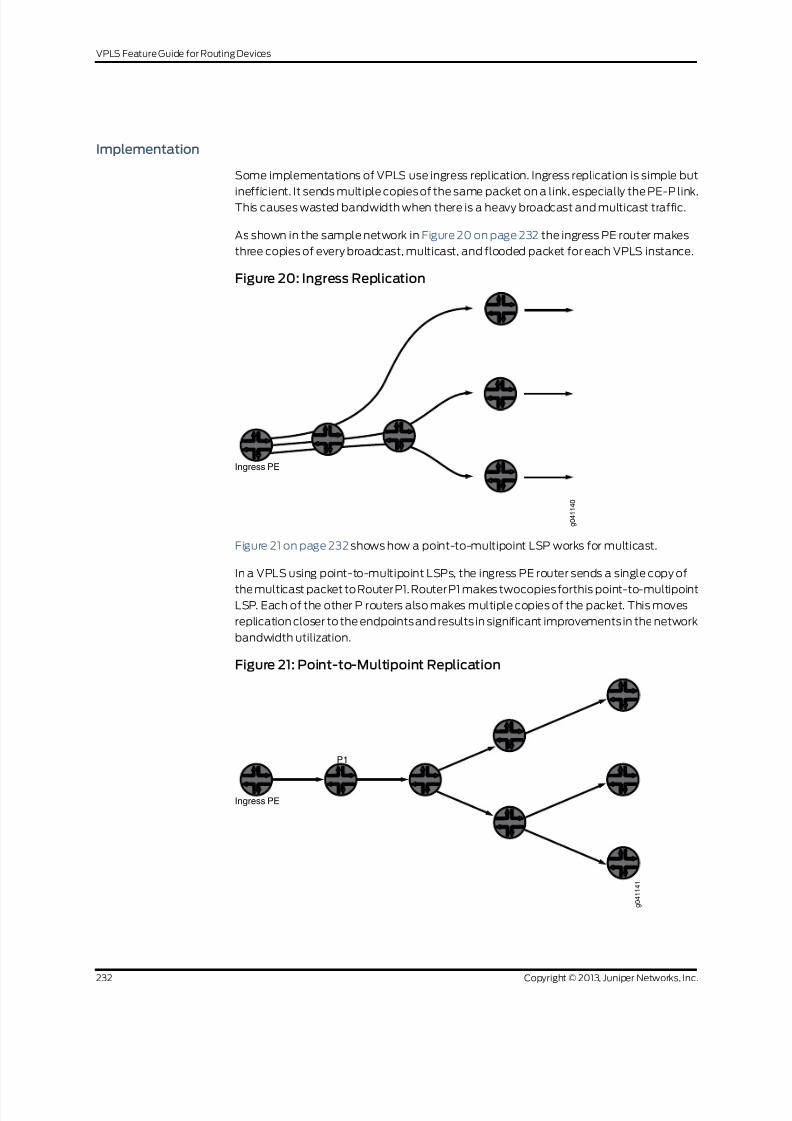
8/21/2019 Config Guide Vpns Vpls
http://slidepdf.com/reader/full/config-guide-vpns-vpls 250/485
Implementation
Some implementations of VPLS use ingress replication. Ingress replication is simple but
inefficient. It sends multiple copies of the same packet on a link, especially the PE-P link.This causes wasted bandwidth when there is a heavy broadcast and multicast traffic.
As shown in the sample network in Figure 20 on page 232 the ingress PE router makes
three copies of every broadcast, multicast, and flooded packet for each VPLS instance.
Figure 20: Ingress Replication
Ingress PE
g 0 4 1 1 4 0
Figure 21 on page 232 shows how a point-to-multipoint LSP works for multicast.
In a VPLS using point-to-multipoint LSPs, the ingress PE router sends a single copy of
the multicast packet to Router P1. Router P1 makes twocopiesforthis point-to-multipointLSP. Each of the other P routers also makes multiple copies of the packet. This moves
replication closer to the endpointsand results in significant improvements in the network
bandwidth utilization.
Figure 21: Point-to-Multipoint Replication
Ingress PE
P1
g 0 4 1 1 4 1
Copyright © 2013, Juniper Networks, Inc.232
VPLS Feature Guide for Routing Devices

8/21/2019 Config Guide Vpns Vpls
http://slidepdf.com/reader/full/config-guide-vpns-vpls 251/485
Related
Documentation
Example: NG-VPLS Using Point-to-Multipoint LSPs on page 233•
Example: NG-VPLS Using Point-to-Multipoint LSPs
This example shows how to configure next-generation VPLS (NG_VPLS) using
point-to-multipoint LSPs. The topology is shown in Figure 22 on page 234 and
Figure 23 on page 235. This example is organized in the following sections:
• Requirements on page 233
• Overview and Topology on page 233
• Configuration on page 236
Requirements
Table 10 on page 233 lists thehardware that is used and thesoftware that is required for
this example:
Table 10: Hardware and Software Used
SoftwareComponentsEquipment
Junos OS Release 9.3R4 or laterDPC-4 10GE-X, DPC-40 1GE-XSix MX Series 3D Universal Edge Routers
Junos OS Release 9.3R4 or laterFPC3, 10GE-XenpakOne T Series Core Router
Junos OS Release 9.3R4 or laterEX4200 virtual switchesEight EX4200 Ethernet Switches
Junos OS Release 9.3R4 or laterGigabit Ethernet interfacesOne M7i Multiservice Edge Router
Overview and Topology
The logical topology of the NG-VPLS example is shown in Figure 22 on page 234.
233Copyright © 2013, Juniper Networks, Inc.
Chapter 5: Next Generation VPLS Examples

8/21/2019 Config Guide Vpns Vpls
http://slidepdf.com/reader/full/config-guide-vpns-vpls 252/485
Figure 22: Logical Topology of NG-VPLS Using Point-to-Multipoint LSPs
Route Reflector
Site ID 5
Layer 2
Layer 2
Source
Source
Receiver
Receiver
Receiver
Receiver
PE3 CE3
PE4
P2
PE2
PE1 P1CE1
C-RP
Site ID 1Site ID 2
Site ID 3
Site ID 4
S = 192.4.1.2
G = 234.1.1.1 - 100
S = 40.40.40.4
G = 235.1.1.1 - 100
Site ID 6
CE2
g 0 4 1 1 4 3
The routers in this example are preconfigured with the following:
• OSPF area 0 is configured on all the PE routers and P routers with traffic engineering
enabled.
• All of the core-facing interfaces are configured with the mpls protocol address family.
• The RSVP and MPLS protocols are enabled for all the core-facing interfaces.
• Allthe MX Seriesroutershave theirnetworkservices mode setto Ethernet.The network
servicesmode is configured by including the network-services statement and specifying
the ethernet option.
• All the PE routers are configured for autonomous system 65000.
The physical topology of the NG-VPLS example is shown in Figure 23 on page 235. The
topology consists of six MX Series routers connected with redundant links in the core.
Four MX Series routers are acting as PE routers and two are core routers.
Copyright © 2013, Juniper Networks, Inc.234
VPLS Feature Guide for Routing Devices

8/21/2019 Config Guide Vpns Vpls
http://slidepdf.com/reader/full/config-guide-vpns-vpls 253/485
Figure 23: Physical Topology of NG-VPLS Using Point-to-Multipoint LSPs
Route Reflector
Layer 2
Receiver Receiver Receiver
PE4
PE2
PE1
Site ID 1 Site ID 2 Site ID 3 Site ID 4
Source
S = 192.4.1.2G = 234.1.1.1 - 100
Source
S = 40.40.40.4G = 235.1.1.1 - 100
Site ID 6
CE3
PE3
203/1 201/1 203/4 201/2 202/2
Site ID 5
Receiver
203/2
ge-1/0/0
Layer 2 CE1
C-RPge-1/1/2
g e - 1 / 1 / 0
g e - 0 / 1 / 0
g e - 1 / 0 / 2
ge-0/1/2
g e - 0 / 1 / 1
g e - 1 / 0 / 1
g e - 1 / 1 / 0
ge-0/0/0
x e - 0 / 1 / 0
xe-0/3/0xe-0/0/0
P2
P1
x e - 0 / 1 / 0
xe-0/0/0xe-0/3/0
ge-1/3/0
x e - 0 / 1 / 0
x e - 0 / 2 / 0
x e - 0 / 2 / 0
g
e - 0 / 2 / 0
g e - 1 / 1 / 0
CE2
ge-1/0/0
g 0 4 1 1 4 2
Note the following topology details:
• A route reflector is configured in the topology to reflect the family l2-vpn routes to all
the PE routers for BPG-VPLS.
• The GOLD VPLS routing instance is configured with two sites in each of the PE routers.
• One GOLD site is connected to the CE router and the other one is directly connected
to the test equipment on each PE router.
• The no-tunnel-services statement is included in the GOLD VPLS instance to enable
the use of LSI interfaces for VPLS tunnel services.
• Router CE1 and Router CE2 areEX Series Virtual Chassis switches acting as CE routers.
• Router CE3 is an M7i router acting as a CE router.
• Two multicast sources are configured. One is connected to Router CE1 (Site 1) and the
other to Router PE2 (Site 4) to simulate different scenarios.
• Router CE1 is configured as the rendezvous point (RP).
• Unicast traffic is enabled on all the test equipment ports and is sent to all the sites in
the GOLD VPLS instance.
235Copyright © 2013, Juniper Networks, Inc.
Chapter 5: Next Generation VPLS Examples

8/21/2019 Config Guide Vpns Vpls
http://slidepdf.com/reader/full/config-guide-vpns-vpls 254/485
Configuration
This example shows how to configure next-generation VPLS using point-to-multipoint
LSPs. It is organized in the following sections:
• Configuring the PE Router Interfaces on page 236
• Configuring a Route Reflector for all PE Routers for BGP-Based VPLS on page 238
• Establishing BGP-Based VPLS with a Route Reflector on page 239
• Configuring Point-to-Point LSPs Between PE Routers on page 240
• Configuring Dynamic and Static Point-to-Multipoint LSPs Between PE
Routers on page 240
• Configuring Point-to-Multipoint Link Protection on page 241
• Configuring a BGP-Based VPLS Routing Instance for NG-VPLS on page 243
• Configuring Tunnel Services for VPLS on page 246
• Verifying the Control Plane on page 247
• Verifying the Data Plane on page 255
• Results on page 259
Configuring the PE Router Interfaces
Step-by-Step
Procedure
On the customer-facingPE interfaces, enable VLAN tagging, configurethe encapsulation
type, andenablethe VPLS address family.There arefour possibleinterfaceencapsulations
for VPLS routing instances that you can choose depending on your needs.
1. If your network requires that each logical interface on the PE router-to-CE router
linkbe configuredto only acceptpackets withVLAN ID 1000, include thevlan-tagging
statement, include the encapsulation statement, and specify vlan-vpls as the
encapsulation type. Also include the vlan-id statement and specify 1000 as the
VLAN ID.
[edit interfaces]
ge-1/1/0 {
vlan-tagging;
encapsulation vlan-vpls;
unit1 {
encapsulation vlan-vpls;
vlan-id 1000;
family vpls;
}
}
With this configuration, you can configure multiple logical interfaces with different
VLAN IDs and associate each logical interface with a different routing instance.
2. If your network requires each physical interface on the PE router to CE router link
to be configured to use the entire Ethernet port as part of a single VPLS instance,
includethe encapsulation statement, andspecify ethernet-vpls asthe encapsulation
type.
[edit interfaces]
Copyright © 2013, Juniper Networks, Inc.236
VPLS Feature Guide for Routing Devices

8/21/2019 Config Guide Vpns Vpls
http://slidepdf.com/reader/full/config-guide-vpns-vpls 255/485
ge-1/2/0 {
encapsulation ethernet-vpls;
unit0 {
family vpls;
}}
With this encapsulation mode, you cannot create multiple logical units (VLANs).
3. If your network requires that each logical interface of the single physical interface
on the PE router toCE router link be configured to use a mix of different
encapsulations, include the encapsulation statement, and specify
flexible-ethernet-services as the encapsulation type at the [edit interfaces
interface-name] hierarchy level. Also include the encapsulation statement, and
specify vlan-vpls or vlan-ccc as the encapsulation type at the [edit interfaces
interface-name unit logical-unit-number ] hierarchy level.
[edit interfaces]
ge-1/2/0 {vlan-tagging;
encapsulation flexible-ethernet-services;
unit1 {
encapsulation vlan-vpls;
}
unit2 {
encapsulation vlan-ccc;
}
}
4. If your network requires support for using a mix of single and dual tagged VLANs
configured in different logical interfaces on a single physical interface, include the
encapsulation statement, and specify flexible-vlan-tagging as the encapsulation
type.
5. Configure the core-facing CE router interfaces. The CE router and PE router logical
interface configuration must match encapsulation types and VLAN IDs. Typically
the IP address is configured on the core-facing CE router interfaces if the CE device
is a router and terminates the Layer 2 domain into the Layer 3 network. In this
example, the interface is configured for single tagging with a VLAN ID of 1000.
[edit interfaces]
ge-1/1/0 {
vlan-tagging;
unit1 {
vlan-id 1000;
family inet {
address 40.40.40.1/24;}
}
}
237Copyright © 2013, Juniper Networks, Inc.
Chapter 5: Next Generation VPLS Examples

8/21/2019 Config Guide Vpns Vpls
http://slidepdf.com/reader/full/config-guide-vpns-vpls 256/485
Configuring a Route Reflector for all PE Routers for BGP-Based VPLS
Step-by-Step
Procedure
Configuring a route reflector is the preferred method to enable any BGP-based service
offerings. Configuring a routereflector avoids the requirement for a fullmesh of BGPpeer
sessions, and it scales well. BGP redundancy can be achieved using multiple route
reflectors in a single cluster.
1. To enable BGP to carry Layer 2 VPN and VPLS NLRI messages, create a peer group,
include the family statement, specify the l2vpn option, and include the signaling
statement. To configure the route reflector cluster and complete the BGP peer
sessions, include the cluster statement and specify the IP address for the cluster
ID. Then include the neighbor statementand specify theIP address of thePE routers
that are BGP client peers in the cluster.
[edit protocols]
bgp {
group RR {
type internal;local-address 7.7.7.7;
family l2vpn {
signaling;
}
cluster 7.7.7.7;
neighbor 1.1.1.1; # To PE1
neighbor 2.2.2.2; # To PE2
neighbor 3.3.3.3; # To PE3
neighbor 4.4.4.4; # To PE4
}
}
2. Configure OSPF and enable traffic engineering on the route reflector to create the
Constrained Shortest Path First (CSPF) database for the egress LSPs terminatingfrom the PE routers.
[edit protocols]
ospf {
traffic-engineering;
area 0.0.0.0 {
interface all;
interface fxp0.0 {
disable;
}
}
}
3. Enable the MPLS andRSVP protocols on all interfaces connectedto the MPLS core.
This terminates the RSVP egress LSPs from the PE routers.
[edit protocols]
rsvp {
interface all;
interface fxp0.0 {
disable;
}
}
Copyright © 2013, Juniper Networks, Inc.238
VPLS Feature Guide for Routing Devices

8/21/2019 Config Guide Vpns Vpls
http://slidepdf.com/reader/full/config-guide-vpns-vpls 257/485
mpls {
interface all;
interface fxp0.0 {
disable;
}}
Establishing BGP-Based VPLS with a Route Reflector
Step-by-Step
Procedure
For BGP-based VPLS, all PE routers need to have a full mesh of BGP peer sessions with
each other or have a single peer with the route reflector. The route reflector reflects the
routes received from the other PE routers. In this example, the PE router is configured to
establish a peer relationship with the route reflector.
1. To haveall thePE routersestablish a BGPclient peer session with theroute reflector,
create an internal peer group, include the local-address statement, and specify the
IP address of the PE router. Also include the neighbor statement, and specify the IP
address of the route reflector. To enable BGP to carry Layer 2 VPN and VPLS NLRI
messages, include the family statement, specify the l2vpn option, and include the
signaling statement.
[edit protocols]
bgp {
group to-RR {
type internal;
local-address 1.1.1.1;
family l2vpn {
signaling;
}
neighbor 7.7.7.7; # To the route reflector
}
}
2. Configure a point-to-point RSVP LSP from the PE routers to the route reflector. To
create theLSP, includethe label-switched-pathstatement,give theLSP a meaningful
name, include the to statement and specify the IP address of the route reflector as
the LSP end point. This LSP is needed to resolve the BGP next hops in the inet.3
routing table for the routes received from the route-reflector.
[edit protocols]
mpls {
label-switched-path to-RR {
to 7.7.7.7;
}
interface all;
interface fxp0.0 {disable;
}
}
239Copyright © 2013, Juniper Networks, Inc.
Chapter 5: Next Generation VPLS Examples

8/21/2019 Config Guide Vpns Vpls
http://slidepdf.com/reader/full/config-guide-vpns-vpls 258/485
Configuring Point-to-Point LSPs Between PE Routers
Step-by-Step
Procedure
In next-generation VPLS, point-to-multipoint LSPsare only used to transport broadcast,
multicast, and unknown unicast frames. All other frames are still transported using
point-to-point RSVP LSPs. This is a more efficient use of bandwidth, particularly near
the source of the unknown, broadcast, and multicast frames. The trade-off is more state
in the network, because each PE router is the ingress of one point-to-multipoint LSPthat
touches all other PE routers, and n point-to-point LSPs are needed, one going to each
of the other PE routers.
1. To create a point-to-point LSP, include the label-switched-path statement, give
the LSP a meaningful name, include the to statement, and specify the IP address
of the other PE router as the LSP endpoint. The example shows the configuration
of LSPs from Router PE1 to Routers PE2, PE3, and PE4.
[edit protocols]
mpls {
label-switched-path to-PE2 {
to 2.2.2.2;
}
label-switched-path to-PE3 {
to 3.3.3.3;
}
label-switched-path to-PE4 {
to 4.4.4.4;
}
}
Configuring Dynamic and Static Point-to-Multipoint LSPs Between PE Routers
Step-by-StepProcedure
This procedure describes how to enable the creation of dynamic point-to-multipointLSPs and how to configure static point-to-multipoint LSPs. On a router configured with
static point-to-multipoint LSPs, the LSPs come up immediately. On a router configured
with dynamic point-to-multipoint LSPs, the LSP comes up only after receiving BGP
neighbor information from the route reflector or from the other PE routers participating
in the VPLS domain.
For each VPLS instance, a PE router with dynamic point-to-multipoint LSPs enabled
creates a dedicated point-to-multipoint LSP based on the point-to-multipoint template.
Whenever VPLS discovers a new neighbor through BGP, a sub-LSP for this neighbor is
added to the point-to-multipoint LSP.
If thereare nPE routersin theVPLSinstancethen theroutercreates npoint-to-multipoint
LSPs in the network where each PE router is the root of the tree and includes the rest of
the n-1 PE routers as leaf nodes connected through a source-to-leaf sub-LSP.
1. In this step, you configure Router PE1 and Router PE2 to use a dynamic
point-to-multipoint LSP template for LSP creation. When these routers receive a
new BGP route advertised from the route reflector for a new neighbor, they create
a point-to-multipoint sub-LSP to that neighbor. To create the dynamic
point-to-multipoint LSP template, include the label-switched-path statement, give
the LSP template a meaningful name, include the template statement and include
Copyright © 2013, Juniper Networks, Inc.240
VPLS Feature Guide for Routing Devices

8/21/2019 Config Guide Vpns Vpls
http://slidepdf.com/reader/full/config-guide-vpns-vpls 259/485
the p2mp statement. Also enable link protection and configure the optimize timer
to periodically reoptimize the LSP path.
[edit protocols]
mpls {
label-switched-path vpls-GOLD-p2mp-template {
template; # identify as a template
optimize-timer 50;
link-protection; # link protection is enabled on point-to-multipoint LSPs
p2mp;
}
}
2. In this step, you configure static point-to-multipoint LSPs. Creating static
point-to-multipoint LSPs is similar to creating point-to-point LSPs, except you can
also configure other RSVP parameters under each point-to-multipoint LSP.
To create static point-to-multipointLSPs, includethe label-switched-path statement,
givethe LSPa meaningful name, includethe tostatement,andspecifythe IP address
of the PE router that is the endpoint of the LSP. Also include the p2mp statement
and specify a pathname.
[edit protocols]
mpls {
label-switched-path to-pe2 {
to 2.2.2.2;
p2mp vpls-GOLD;
}
label-switched-path to-pe3 {
to 3.3.3.3;
p2mp vpls-GOLD;
}
label-switched-path to-pe1 {
to 1.1.1.1;
p2mp vpls-GOLD;
}
}
Configuring Point-to-Multipoint Link Protection
Step-by-Step
Procedure
Point-to-multipoint LSPs only support RSVP link protection for traffic engineering. Node
protection is not supported. Link protection is optional, but it is the recommended
configuration for most networks.
1. To enable link protection on the core-facing interfaces, include the link-protection
statement at the [edit protocols rsvp interface interface-name] hierarchy level.
[edit protocols]
rsvp {
interface all;
interface fxp0.0 {
disable;
}
interface xe-0/3/0.0 {
link-protection;
}
241Copyright © 2013, Juniper Networks, Inc.
Chapter 5: Next Generation VPLS Examples

8/21/2019 Config Guide Vpns Vpls
http://slidepdf.com/reader/full/config-guide-vpns-vpls 260/485
interface xe-0/2/0.0 {
link-protection;
}
interface xe-0/1/0.0 {
link-protection;}
}
2. Enable the point-to-multipoint LSP to use the RSVP link protection feature.
Link-protection can be configured for both static point-to-multipoint and dynamic
point-to-multipoint LSPs that use a template.
For static point-to-multipoint LSPs, configure each branch sub-LSP. To enable link
protection, include the link-protection statement at the [edit protocols mpls
label-switched-path label-switched-path-name] hierarchy level.
[edit protocols mpls label-switched-path]
label-switched-path to-pe2 {
to 2.2.2.2;
link-protection;
p2mp vpls-GOLD;
}
label-switched-path to-pe3 {
to 3.3.3.3;
link-protection;
p2mp vpls-GOLD;
}
label-switched-path to-pe1 {
to 1.1.1.1;
link-protection;
p2mp vpls-GOLD;
}
3. For dynamic point-to-multipoint LSPs using a template, only the template needsto have link protection configured. All the point-to-multipoint branch LSPs that use
the template inherit this configuration.
To enable link protection for dynamic point-to-multipoint LSPs, include the
link-protection statement at the [edit protocols mpls label-switched-path
label-switched-path-name] hierarchy level.
[edit protocols mpls label-switched-path]
label-switched-path vpls-GOLD-p2mp-template {
template;
optimize-timer 50;
link-protection;
p2mp;
}
Copyright © 2013, Juniper Networks, Inc.242
VPLS Feature Guide for Routing Devices

8/21/2019 Config Guide Vpns Vpls
http://slidepdf.com/reader/full/config-guide-vpns-vpls 261/485
Configuring a BGP-Based VPLS Routing Instance for NG-VPLS
Step-by-Step
Procedure
For NG-VPLS, the routing-instance configuration is similar to that for a regular VPLS
routing instance. The routing instance defines the VPLS site and creates the VPLS
connection. The following parameters are configured.
• Instance Type – VPLS.
• Interface – The interface connecting to the CE router.
• Route Distinguisher – Each routing instance you configure on a PE router must have a
unique routedistinguisher. Theroutedistinguisher is usedby BGPto distinguishbetween
potentially identical network reachability information (NLRI) messages received from
different VPNs. If you usea uniqueroutedistinguisher for each routing instanceon each
PE, you can determine which PE originated the route.
• VRF Target – Configuring a VRF target community using the vrf-target statement
causes default VRF import and export policies to be generated that accept imported
routes and tag exported routes with the specified target community.
• Protocols – Configure the VPLS protocol as described in the following procedure.
1. To configure the NG-VPLS routing instance,includethe routing-instances statement
andspecifythe instance name. Alsoinclude the instance-type statement and specify
vpls as the type. Include the route-distinguisher statement and specify a route
distinguisher that is unique throughout all VPNsconfigured on the router. Configure
a VRFroute target byincluding the vrf-target statementand specify the route target.
The route target exported by one router must match the route target imported by
another router for the same VPLS.
[edit]
routing-instances {GOLD {
instance-type vpls;
interface ge-1/0/0.1;
interface ge-1/1/0.1;
route-distinguisher 1.1.1.1:1;
vrf-target target:65000:1;
}
}
2. To use a point-to-multipoint LSP for VPLS flooding, configure an LSP under the
VPLS routing instance.
To configure the point-to-multipoint LSP for VPLS flooding, include the
label-switched-path-template statementand specify thename ofthe LSPtemplateat the [edit routing-instances routing-instances-name provider-tunnel rsvp-te]
hierarchy level.
[edit]
routing-instances {
GOLD {
instance-type vpls;
interface ge-1/0/0.1;
interface ge-1/1/0.1;
243Copyright © 2013, Juniper Networks, Inc.
Chapter 5: Next Generation VPLS Examples

8/21/2019 Config Guide Vpns Vpls
http://slidepdf.com/reader/full/config-guide-vpns-vpls 262/485
route-distinguisher 1.1.1.1:1;
provider-tunnel {
rsvp-te {
label-switched-path-template {
vpls-GOLD-p2mp-template;}
}
}
vrf-target target:65000:1;
}
}
3. Configuring the VPLS protocol enables the VPLS between different sites in the
VPLSdomain. Multiplesites canbe configuredunder a single VPLSrouting instance,
but note that the lowest site ID is used to build the VPLS pseudowire to the other
PE routers, and the label block associated with the lowest site ID is advertised. The
following parameters are configured for the VPLS protocol:
•
Site – Name of the VPLS site.
• Site Range – Maximum site ID allowed in the VPLS. The site range specifies the
highest-value site ID allowedwithin theVPLS, notthe numberof sitesin theVPLS.
• Site Identifier – Any number between 1 and 65,534 that uniquely identifies the
VPLS site. This is also referred as the VE-ID in the relevant RFC.
• PE-CE Interface – The interface participating in this site.
• Tunnel services for VPLS – If youdo not configure anytunnel interfaceat the [edit
protocol vpls tunnel-services] hierarchy, the router uses any tunnel interface
available on the router for VPLS.
• No-tunnel-services – If you include the no-tunnel-servicesstatement, the router
usesa label-switchedinterface (LSI) forthe tunnel services forthat VPLS instance.
• Mac Table Size – The size of the VPLS media access control (MAC) address table.
The default is 512 addresses and the maximum is 65,536. When the table is full,
new MAC addresses are no longer added to the table.
To configure the VPLS protocol, include the vpls statement at the [edit
routing-instances routing-instance-name protocols] hierarchy level. To configure the
site range, include the site-range statement and specify the highest-value site ID
allowed within the VPLS. To cause the router to use an LSI interface, include the
no-tunnel-servicesstatement.Tocreate a VPLS site, include the site statement and
specify a site name. Also include the site-identifier statement and specify the site
ID. Then include the interface statement and specify the interface name for the
interface connected to the CE device.
[edit]
routing-instances {
GOLD {
instance-type vpls;
interface ge-1/0/0.1;
interface ge-1/1/0.1;
route-distinguisher 1.1.1.1:1;
provider-tunnel {
Copyright © 2013, Juniper Networks, Inc.244
VPLS Feature Guide for Routing Devices

8/21/2019 Config Guide Vpns Vpls
http://slidepdf.com/reader/full/config-guide-vpns-vpls 263/485
rsvp-te {
label-switched-path-template {
vpls-GOLD-p2mp-template;
}
}}
vrf-target target:65000:1;
protocols {
vpls {
site-range 8;
no-tunnel-services;
site CE1 {
site-identifier 1;
interface ge-1/0/0.1;
}
site Direct {
site-identifier 2;
interface ge-1/1/0.1;
}}
}
}
}
245Copyright © 2013, Juniper Networks, Inc.
Chapter 5: Next Generation VPLS Examples

8/21/2019 Config Guide Vpns Vpls
http://slidepdf.com/reader/full/config-guide-vpns-vpls 264/485
Configuring Tunnel Services for VPLS
Step-by-Step
Procedure
A tunnel interfaceis neededfor VPLS configuration to encapsulate the originating traffic,
and to de-encapsulate the traffic coming from a remote site. If the tunnel interface is
not configured, the router selects one of the available tunnel interfaces on the router by
default. There are three methods available in Junos OS to configure this tunnel interface.
• To specify a virtual tunnel interface to be used as the primary device for tunneling,
include the primary statement, and specify the virtual tunnel interface to be used at
the [edit routing-instances routing-instance-name protocols vpls tunnel-services]
hierarchy level.
[edit routing-instances routing-instance-name]
protocols {
vpls {
site-range 8;
tunnel-services {
primary vt-1/2/10;}
}
}
• To configure the router to use an LSI interface for tunnel services rather than a virtual
tunnel interface,includethe no-tunnel-services statement at the [editrouting-instances
routing-instance-name protocols vpls] hierarchy level.
[edit routing-instances routing-instance-name]
protocols {
vpls {
site-range 8;
no-tunnel-services;
}
}
• In an MX Series router you must create the tunnel services interface to be used for
tunnelservices. To create the tunnelserviceinterface,include the bandwidth statement
and specify the amount of bandwidth to reserve for tunnel services in gigabits per
second at the [edit chassis fpc slot-number pic slot-number tunnel-services] hierarchy
level.
[edit chassis]
f p c 1 {
p i c 3 {
tunnel-services {
bandwidth 1g;
}
}
}
Copyright © 2013, Juniper Networks, Inc.246
VPLS Feature Guide for Routing Devices

8/21/2019 Config Guide Vpns Vpls
http://slidepdf.com/reader/full/config-guide-vpns-vpls 265/485
Verifying the Control Plane
Step-by-Step
Procedure
Thissection describes show command outputs youcan use to validate the control plane.
It also provides methodologies for troubleshooting. Note the following:
• In this example there are six sites. Router PE1 and Router PE2 have two sites each.
Router PE3and Router PE4haveone site each.All sites arein the GOLD VPLS instance.
• In VPLS if you have multiple sites configured under a single VPLS routing instance, the
label block from the site with the lowest site ID is used to establish pseudowires
between remote PEs. Note that the data traffic is still sent tothose PE router interfaces
connected to CE devices that are in one of the following states:
• LM – Local site ID is not the minimum designated. The local site ID is not the lowest.
Therefore the local site ID is not being used to establish pseudowires or distribute
VPLS label blocks.
• RM – Remote site ID is not the minimum designated. The remote site ID is not the
lowest. Therefore, the remote site ID is not being used to establish pseudowires or
distribute VPLS label blocks.
• For more information about how VPLS label blocks are allocated and used, see
UnderstandingVPLSLabelBlocks Operation.
247Copyright © 2013, Juniper Networks, Inc.
Chapter 5: Next Generation VPLS Examples

8/21/2019 Config Guide Vpns Vpls
http://slidepdf.com/reader/full/config-guide-vpns-vpls 266/485
1. After the entire configuration is done, you can verify the VPLS connections state.
In the following output, the VPLS connections show the Up state for certain sites,
and the remaining sites show either the RM or LM state. This is the expected state
in a VPLS implementation on multihoming sites.
In this example, Router PE1 has site CE1 configured with site ID 1 and site Direct
configured with site ID 2. The label block for site CE1 is advertised to the remote PE
routers and used for receiving the data packets from the remote PE routers. In the
show command output, notice the following:
• Router PE1 uses its lowest site ID, which is site ID 1. SiteID 1 is usedforDevice CE1.
• Router PE2 uses its lowest site ID, which is site ID 3. SiteID 3 is used for Device
CE2.
• Router PE3 and Router PE4 each have a single site configured.
For site CE1, connection site 3 isin the Up state and connection site 4 isin the RM
state.
• For site Direct, all the connections are in the LM state.
• Site Direct has a higher site ID than site 1 on this router.
On Router PE1, use the show vpls connections command to verify the VPLS
connections state .
user@PE1> show vpls connections
Layer-2 VPN connections:
Legend for connection status (St)
EI -- encapsulation invalid NC -- interface encapsulation not
CCC/TCC/VPLS
EM -- encapsulation mismatch WE -- interface and instance encaps not
same
VC-Dn -- Virtual circuit down NP -- interface hardware not present
CM -- control-word mismatch -> -- only outbound connection is up
CN -- circuit not provisioned <- -- only inbound connection is up
OR -- out of range Up -- operational
OL -- no outgoing label Dn -- down
LD -- local site signaled down CF -- call admission control failure
RD -- remote site signaled down SC -- local and remote site ID collision
LN -- local site not designated LM -- local site ID not minimum designated
RN -- remote site not designated RM -- remote site ID not minimum designated
XX -- unknown connection status IL -- no incoming label
MM -- MTU mismatch MI -- Mesh-Group ID not availble
BK -- Backup connection ST -- Standby connection
Legend for interface statusUp -- operational
Dn -- down
Instance: GOLD
Local site: CE1 (1)
connection-site Type St Time last up # Up trans
3 rmt Up Oct 6 16:27:23 2009 1
Remote PE: 2.2.2.2, Negotiated control-word: No
Incoming label: 262171, Outgoing label: 262145
Copyright © 2013, Juniper Networks, Inc.248
VPLS Feature Guide for Routing Devices

8/21/2019 Config Guide Vpns Vpls
http://slidepdf.com/reader/full/config-guide-vpns-vpls 267/485
Local interface: lsi.1049353, Status: Up, Encapsulation: VPLS
Description: Intf - vpls GOLD local site 1 remote site 3
4 rmt RM
5 rmt Up Oct 6 16:27:27 2009 1
Remote PE: 3.3.3.3, Negotiated control-word: No
Incoming label: 262173, Outgoing label: 262145
Local interface: lsi.1049354, Status: Up, Encapsulation: VPLS
Description: Intf - vpls GOLD local site 1 remote site 5
6 rmt Up Oct 6 16:27:31 2009 1
Remote PE: 4.4.4.4, Negotiated control-word: No
Incoming label: 262174, Outgoing label: 800000
Local interface: lsi.1049355, Status: Up, Encapsulation: VPLS
Description: Intf - vpls GOLD local site 1 remote site 6
Local site: Direct (2)
connection-site Type St Time last up # Up trans
3 rmt LM
4 rmt LM
5 rmt LM
6 rmt LM
2. On Router PE4, use the show vpls connections command to verify the VPLSconnections state.
Verify that site 2 and site 4 are in the RM state. This state tells you that the sites are
configured with the highest site ID on Router PE1 and Router PE2. Because Router
PE4 has only one site configured, it does not have any sites in the LM states.
user@PE4> show vpls connections
...
Instance: GOLD
Local site: Direct (6)
connection-site Type St Time last up # Up trans
1 rmt Up Oct 6 16:28:35 2009 1
Remote PE: 1.1.1.1, Negotiated control-word: No
Incoming label: 800000, Outgoing label: 262174
Local interface: vt-1/2/10.1048576, Status: Up, Encapsulation: VPLS Description: Intf - vpls GOLD local site 6 remote site 1
2 rmt RM
3 rmt Up Oct 6 16:28:35 2009 1
Remote PE: 2.2.2.2, Negotiated control-word: No
Incoming label: 800002, Outgoing label: 262150
Local interface: vt-1/2/10.1048577, Status: Up, Encapsulation: VPLS
Description: Intf - vpls GOLD local site 6 remote site 3
4 rmt RM
5 rmt Up Oct 6 16:28:35 2009 1
Remote PE: 3.3.3.3, Negotiated control-word: No
Incoming label: 800004, Outgoing label: 262150
Local interface: vt-1/2/10.1048578, Status: Up, Encapsulation: VPLS
Description: Intf - vpls GOLD local site 6 remote site 5
3. On each PE router, use the show bgp summary command to verify that the IBGP
sessions between the PE routers or between the PE router and the route reflector
have been established. Thesessionsmust be operational before the PE routers can
exchangeany Layer2 VPN routes. In the example below, also noticethat the output
from Router PE1 shows that the bgp.l2vpn.0 and GOLD.l2vpn.0 routing tables have
been created.
user@PE1> show bgp summary
Groups: 1 Peers: 1 Down peers: 0
Table Tot Paths Act Paths Suppressed History Damp State Pending
249Copyright © 2013, Juniper Networks, Inc.
Chapter 5: Next Generation VPLS Examples

8/21/2019 Config Guide Vpns Vpls
http://slidepdf.com/reader/full/config-guide-vpns-vpls 268/485
bgp.l2vpn.0 4 4 0 0 0 0
Peer AS InPkt OutPkt OutQ Flaps Last Up/Dwn State
7.7.7.7 65000 40 39 0 1 15:45 Establ
bgp.l2vpn.0: 4/4/4/0
GOLD.l2vpn.0: 4/4/4/0
admin@PE2# run show bgp summary
Groups: 1 Peers: 1 Down peers: 0
Table Tot Paths Act Paths Suppressed History Damp State Pending
bgp.l2vpn.0 4 4 0 0 0 0
inet6.0 0 0 0 0 0 0
inet.0 0 0 0 0 0 0
Peer AS InPkt OutPkt OutQ Flaps Last Up/Dwn State
7.7.7.7 65000 43 42 0 0 17:25 Establ
bgp.l2vpn.0: 4/4/4/0
GOLD.l2vpn.0: 4/4/4/0
4. On Router PE4, use the show route table command to verify that there is one Layer
2 VPN route to each of the other PE routers. Router PE3 should have a similar show
command output.
user@PE4> show route table bgp.l2vpn.0
bgp.l2vpn.0: 5 destinations, 5 routes (5 active, 0 holddown, 0 hidden)
+ = Active Route, - = Last Active, * = Both
1.1.1.1:1:1:1/96
*[BGP/170] 00:23:18, localpref 100, from 7.7.7.7
AS path: I
> to 10.10.9.1 via xe-0/0/0.0, label-switched-path to-PE1
1.1.1.1:1:2:1/96
*[BGP/170] 00:23:18, localpref 100, from 7.7.7.7
AS path: I
> to 10.10.9.1 via xe-0/0/0.0, label-switched-path to-PE1
2.2.2.2:10:3:1/96
*[BGP/170] 00:23:18, localpref 100, from 7.7.7.7 AS path: I
> to 10.10.9.1 via xe-0/0/0.0, label-switched-path to-PE2
2.2.2.2:10:4:1/96
*[BGP/170] 00:23:18, localpref 100, from 7.7.7.7
AS path: I
> to 10.10.9.1 via xe-0/0/0.0, label-switched-path to-PE2
3.3.3.3:10:5:1/96
*[BGP/170] 00:23:18, localpref 100, from 7.7.7.7
AS path: I
> to 10.10.8.1 via xe-0/1/0.0, label-switched-path to-PE3
5. On the routereflector, usethe show bgpsummarycommand to verifythat the router
has an IBGP peer session with each of the PE routers.
user@RR> show bgp summary
Groups: 2 Peers: 5 Down peers: 1Table Tot Paths Act Paths Suppressed History Damp State Pending
bgp.l2vpn.0 6 6 0 0 0 0
inet.0 0 0 0 0 0 0
Peer AS InPkt OutPkt OutQ Flaps Last Up/Dwn State
1.1.1.1 65000 44 46 0 0 18:27 Establ
bgp.l2vpn.0: 2/2/2/0
2.2.2.2 65000 43 45 0 0 18:22 Establ
bgp.l2vpn.0: 2/2/2/0
3.3.3.3 65000 42 45 0 0 18:19 Establ
Copyright © 2013, Juniper Networks, Inc.250
VPLS Feature Guide for Routing Devices

8/21/2019 Config Guide Vpns Vpls
http://slidepdf.com/reader/full/config-guide-vpns-vpls 269/485
bgp.l2vpn.0: 1/1/1/0
4.4.4.4 65000 43 45 0 0 18:15 Establ
bgp.l2vpn.0: 1/1/1/0
6. In NG-VPLS, point-to-multipoint LSPs carry only unknown unicast, broadcast, and
multicast packets. A full mesh of point-to-point LSPs is needed between the PE
routers for NG-VPLS. The point-to-point LSPs create routes in the inet.3 routing
table. These entries are used to resolve the Layer 2 VPN routes received from the
BGP peers. All other data traffic is sent over point-to-point LSPs.
A point-to-point LSP is also created for the route reflector. This LSP creates a route
in the inet.3 routing table for BGP next-hop resolution.
On Router PE1, use the show mpls lsp command to verify that the to-PE2, to-PE3,
to-PE4, and to-RR LSPsare in the Up state.
user@PE1> show mpls lsp ingress unidirectional
Ingress LSP: 7 sessions
To From State Rt P ActivePath LSPname
2.2.2.2 1.1.1.1 Up 0 * to-PE23.3.3.3 1.1.1.1 Up 0 * to-PE3
4.4.4.4 1.1.1.1 Up 0 * to-PE4
7.7.7.7 1.1.1.1 Up 0 * to-RR
Total 4 displayed, Up 4, Down 0
admin@PE2# run show mpls lsp ingress unidirectional
Ingress LSP: 7 sessions
To From State Rt P ActivePath LSPname
1.1.1.1 2.2.2.2 Up 0 * to-PE1
3.3.3.3 2.2.2.2 Up 0 * to-PE3
4.4.4.4 2.2.2.2 Up 0 * to-PE4
7.7.7.7 2.2.2.2 Up 0 * to-RR
Total 4 displayed, Up 4, Down 0
admin@PE3# run show mpls lsp ingress unidirectional
Ingress LSP: 7 sessions
To From State Rt P ActivePath LSPname
1.1.1.1 3.3.3.3 Up 0 * to-PE1
2.2.2.2 3.3.3.3 Up 0 * to-PE2
4.4.4.4 3.3.3.3 Up 0 * to-PE4
7.7.7.7 3.3.3.3 Up 0 * to-RR
Total 4 displayed, Up 4, Down 0
admin@PE4# run show mpls lsp ingress unidirectional
Ingress LSP: 7 sessions
To From State Rt P ActivePath LSPname
1.1.1.1 4.4.4.4 Up 0 * to-PE1
2.2.2.2 4.4.4.4 Up 0 * to-PE2
3.3.3.3 4.4.4.4 Up 0 * to-PE3
7.7.7.7 4.4.4.4 Up 0 * to-RR
Total 4 displayed, Up 4, Down 0
7. For each VPLS instance, a PE router creates a dedicated point-to-multipoint LSP.
In this example, Router PE1 and Router PE2 are configured to use apoint-to-multipoint dynamic template.
For dynamic point-to-multipoint LSPs, whenever VPLS discovers a new Layer 2
VPNneighbor through BGP, a source-to-leaf sub-LSP is added in theVPLS instance
for this neighbor PE router.
On Router PE1, use the show mpls lsp command to verify that three source-to-leaf
sub-LSPs are created.
251Copyright © 2013, Juniper Networks, Inc.
Chapter 5: Next Generation VPLS Examples

8/21/2019 Config Guide Vpns Vpls
http://slidepdf.com/reader/full/config-guide-vpns-vpls 270/485
user@PE1> show mpls lsp ingress p2mp
Ingress LSP: 1 sessions
P2MP name: 1.1.1.1:1:vpls:GOLD, P2MP branch count: 3
To From State Rt P ActivePath LSPname
4.4.4.4 1.1.1.1 Up 0 * 4.4.4.4:1.1.1.1:1:vpls:GOLD
3.3.3.3 1.1.1.1 Up 0 * 3.3.3.3:1.1.1.1:1:vpls:GOLD
2.2.2.2 1.1.1.1 Up 0 * 2.2.2.2:1.1.1.1:1:vpls:GOLD
Total 3 displayed, Up 3, Down 0
8. On Router PE2, use the show mpls lsp command to verify that three source-to-leaf
sub-LSPs are created.
user@PE2> show mpls lsp p2mp ingress
Ingress LSP: 1 sessions
P2MP name: 2.2.2.2:10:vpls:GOLD, P2MP branch count: 3
To From State Rt P ActivePath LSPname
4.4.4.4 2.2.2.2 Up 0 * 4.4.4.4:2.2.2.2:10:vpls:GOLD
3.3.3.3 2.2.2.2 Up 0 * 3.3.3.3:2.2.2.2:10:vpls:GOLD
1.1.1.1 2.2.2.2 Up 0 * 1.1.1.1:2.2.2.2:10:vpls:GOLD
Total 3 displayed, Up 3, Down 0
9. In this step, Router PE3 and Router PE4 are using static point-to-multipoint LSPs.
Forstaticpoint-to-multipointLSPs,the source-to-leafsub-LSPsto allthe PE routers
are manually configured.
On Router PE3, use the show mpls lsp command to verify that three source-to-leaf
sub-LSPs have been configured.
user@PE3> show mpls lsp p2mp ingress
Ingress LSP: 1 sessions
P2MP name: vpls-GOLD, P2MP branch count: 3
To From State Rt P ActivePath LSPname
1.1.1.1 3.3.3.3 Up 0 * to-pe1
4.4.4.4 3.3.3.3 Up 0 * to-pe4
2.2.2.2 3.3.3.3 Up 0 * to-pe2
Total 3 displayed, Up 3, Down 0
10. On Router PE4, use the show mpls lsp command to verify that three source-to-leaf
sub-LSPs are configured.
user@PE4> show mpls lsp ingress p2mp
Ingress LSP: 1 sessions
P2MP name: vpls-GOLD, P2MP branch count: 3
To From State Rt P ActivePath LSPname
1.1.1.1 4.4.4.4 Up 0 * to-pe1
3.3.3.3 4.4.4.4 Up 0 * to-pe3
2.2.2.2 4.4.4.4 Up 0 * to-pe2
Total 3 displayed, Up 3, Down 0
11. Each point-to-multipoint LSP created by the PE router can be identified using an
RSVP-TEpoint-to-multipoint sessionobject. Thesessionobject is passed asa PMSI
tunnel attribute by BGP when it advertises VPLS routes. Using this tunnel attribute,
an incoming source-to-leaf sub LSP add request (RSVP-Path message) supports
label allocationin sucha waythat whentraffic arriveson thissource-to-leafsub-LSP
the router terminates the message in the right VPLS instance and also identifies
the originating PE. This supports source MAC address learning.
On Router PE1, use the show rsvp session command to verify that the RSVP session
for the dynamic point-to-multipoint LSP is Up andthat link protection is configured
Copyright © 2013, Juniper Networks, Inc.252
VPLS Feature Guide for Routing Devices

8/21/2019 Config Guide Vpns Vpls
http://slidepdf.com/reader/full/config-guide-vpns-vpls 271/485
as desired. Notice that the point-to-multipoint session object to be sent in BGP is
54337.
user@PE1> show rsvp session detail p2mp ingress
Ingress RSVP: 7 sessions
P2MP name: 1.1.1.1:1:vpls:GOLD, P2MP branch count: 3
2.2.2.2
From: 1.1.1.1, LSPstate: Up, ActiveRoute: 0
LSPname: 2.2.2.2:1.1.1.1:1:vpls:GOLD, LSPpath: Primary
P2MP LSPname: 1.1.1.1:1:vpls:GOLD
Suggested label received: -, Suggested label sent: -
Recovery label received: -, Recovery label sent: 262145
Resv style: 1 SE, Label in: -, Label out: 262145
Time left: -, Since: Tue Oct 6 16:27:23 2009
Tspec: rate 0bps size 0bps peak Infbps m 20 M 1500
Port number: sender 2 receiver 54337 protocol 0
Link protection desired
Type: Protection down
PATH rcvfrom: localclient
Adspec: sent MTU 1500 Path MTU: received 1500
PATH sentto: 10.10.2.2 (xe-0/1/0.0) 371 pkts
RESV rcvfrom: 10.10.2.2 (xe-0/1/0.0) 370 pkts
Explct route: 10.10.2.2
Record route: <self> 10.10.2.2
12. Router PE4 is configured for static point-to-multipoint LSPs. Link protection is not
configured for these LSPs. Use the show rsvp session command to verify that the
point-to-multipoint session object to be sent in BGP is 42873.
user@PE4> show rsvp session detail p2mp ingress
Ingress RSVP: 7 sessions
P2MP name: vpls-GOLD, P2MP branch count: 3
1.1.1.1 From: 4.4.4.4, LSPstate: Up, ActiveRoute: 0
LSPname: to-pe1, LSPpath: Primary
P2MP LSPname: vpls-GOLD
Suggested label received: -, Suggested label sent: -
Recovery label received: -, Recovery label sent: 390416
Resv style: 1 SE, Label in: -, Label out: 390416
Time left: -, Since: Tue Oct 6 15:28:33 2009
Tspec: rate 0bps size 0bps peak Infbps m 20 M 1500
Port number: sender 10 receiver 42873 protocol 0
PATH rcvfrom: localclient
Adspec: sent MTU 1500
Path MTU: received 1500
PATH sentto: 10.10.9.1 (xe-0/0/0.0) 524 pkts
RESV rcvfrom: 10.10.9.1 (xe-0/0/0.0) 447 pkts
Explct route: 10.10.9.1 10.10.3.1Record route: <self> 10.10.9.1 10.10.3.1
13. On Router PE1, use the show route table command to verifythat Router PE1 received
a Layer 2 VPN route to Router PE2 from the router reflector and the route includes
a PMSI object that contains the point-to-multipoint tunnel identifier of 20361.
user@PE1> show route table GOLD.l2vpn.0 detail
GOLD.l2vpn.0: 6 destinations, 6 routes (6 active, 0 holddown, 0 hidden)
!
!
253Copyright © 2013, Juniper Networks, Inc.
Chapter 5: Next Generation VPLS Examples

8/21/2019 Config Guide Vpns Vpls
http://slidepdf.com/reader/full/config-guide-vpns-vpls 272/485
2.2.2.2:10:3:1/96 (1 entry, 1 announced)
*BGP Preference: 170/-101
Route Distinguisher: 2.2.2.2:10
PMSI: Flags
0:RSVP-TE:label[0:0:0]:Session_13[2.2.2.2:0: 20361:2.2.2.2]
Next hop type: Indirect
Next-hop reference count: 7
Source: 7.7.7.7
Protocol next hop: 2.2.2.2
Indirect next hop: 2 no-forward
State: <Secondary Active Int Ext>
Local AS: 65000 Peer AS: 65000
Age: 4:25:25 Metric2: 1
Task: BGP_65000.7.7.7.7+63544
Announcement bits (1): 0-GOLD-l2vpn
AS path: I (Originator) Cluster list: 7.7.7.7
AS path: Originator ID: 2.2.2.2
Communities: target:65000:1 Layer2-info: encaps:VPLS, control
flags:, mtu: 0, site preference: 100
Import Accepted
Label-base: 262145, range: 8 Localpref: 100
Router ID: 7.7.7.7
Primary Routing Table bgp.l2vpn.0
PMSI: Flags 0:RSVP-TE:label[0:0:0]:Session_13[2.2.2.2:0:20361:2.2.2.2]
14. On Router PE2, use the show rsvp session command to verify that the PMSI tunnel
identifier object of 20361 matches the PMSI tunnel identifier object displayed on
Router PE1.
user@PE2> show rsvp session p2mp detail
Ingress RSVP: 7 sessions
P2MP name: 2.2.2.2:10:vpls:GOLD, P2MP branch count: 3
1.1.1.1
From: 2.2.2.2, LSPstate: Up, ActiveRoute: 0 LSPname: 1.1.1.1:2.2.2.2:10:vpls:GOLD, LSPpath: Primary
P2MP LSPname: 2.2.2.2:10:vpls:GOLD
Suggested label received: -, Suggested label sent: -
Recovery label received: -, Recovery label sent: 262171
Resv style: 1 SE, Label in: -, Label out: 262171
Time left: -, Since: Tue Oct 6 16:31:47 2009
Tspec: rate 0bps size 0bps peak Infbps m 20 M 1500
Port number: sender 1 receiver 20361 protocol 0
Link protection desired
Type: Protection down
PATH rcvfrom: localclient
Adspec: sent MTU 1500
Path MTU: received 1500
PATH sentto: 10.10.2.1 (xe-0/1/0.0) 379 pkts
RESV rcvfrom: 10.10.2.1 (xe-0/1/0.0) 379 pkts
Explct route: 10.10.2.1
Record route: <self> 10.10.2.1
Copyright © 2013, Juniper Networks, Inc.254
VPLS Feature Guide for Routing Devices

8/21/2019 Config Guide Vpns Vpls
http://slidepdf.com/reader/full/config-guide-vpns-vpls 273/485
Verifying the Data Plane
Step-by-Step
Procedure
After the control plane is verified using the previous steps, you can verify the data plane.
This section describes show command outputs you can use to validate the data plane.
1. On Router PE1, use the show vpls connections extensive | match Flood command to
verify the point-to-multipoint LSPname and status of all the sites. Notice the flood
next-hop identifier of 600 for the 1.1.1.1:1:vpls:GOLD LSP.
user@PE1> show vpls connections extensive | match Flood
Ingress RSVP-TE P2MP LSP: 1.1.1.1:1:vpls:GOLD, Flood next-hop ID: 600
2. On Router PE1, use the show vpls connections extensive command to verify the
point-to-multipoint LSP name and status of all the sites.
user@PE1> show vpls connections extensive
Instance: GOLD
Local site: CE1 (1)
Number of local interfaces: 1
Number of local interfaces up: 1
IRB interface present: no
ge-1/0/0.1
lsi.1049353 3 Intf - vpls GOLD local site 1 remote site 3
lsi.1049346 4 Intf - vpls GOLD local site 1 remote site 4
Interface flags: VC-Down
lsi.1049354 5 Intf - vpls GOLD local site 1 remote site 5
lsi.1049355 6 Intf - vpls GOLD local site 1 remote site 6
Label-base Offset Range Preference
262169 1 8 100
connection-site Type St Time last up # Up trans
3 rmt Up Oct 6 16:27:23 2009 1
Remote PE: 2.2.2.2, Negotiated control-word: No
Incoming label: 262171, Outgoing label: 262145
Local interface: lsi.1049353, Status: Up, Encapsulation: VPLS
Description: Intf - vpls GOLD local site 1 remote site 3 RSVP-TE P2MP lsp:
Ingress branch LSP: 2.2.2.2:1.1.1.1:1:vpls:GOLD, State: Up
Egress branch LSP: 1.1.1.1:2.2.2.2:10:vpls:GOLD, State: Up
Connection History:
Oct 6 16:27:23 2009 status update timer
Oct 6 16:27:23 2009 PE route changed
Oct 6 16:27:23 2009 Out lbl Update 262145
Oct 6 16:27:23 2009 In lbl Update 262171
Oct 6 16:27:23 2009 loc intf up lsi.1049353
4 rmt RM
RSVP-TE P2MP lsp:
Ingress branch LSP: 2.2.2.2:1.1.1.1:1:vpls:GOLD, State: Up
5 rmt Up Oct 6 16:27:27 2009 1
Remote PE: 3.3.3.3, Negotiated control-word: No
Incoming label: 262173, Outgoing label: 262145 Local interface: lsi.1049354, Status: Up, Encapsulation: VPLS
Description: Intf - vpls GOLD local site 1 remote site 5
RSVP-TE P2MP lsp:
Ingress branch LSP: 3.3.3.3:1.1.1.1:1:vpls:GOLD, State: Up
Egress branch LSP: to-pe1, State: Up
Connection History:
Oct 6 16:27:27 2009 status update timer
Oct 6 16:27:27 2009 PE route changed
Oct 6 16:27:27 2009 Out lbl Update 262145
Oct 6 16:27:27 2009 In lbl Update 262173
255Copyright © 2013, Juniper Networks, Inc.
Chapter 5: Next Generation VPLS Examples

8/21/2019 Config Guide Vpns Vpls
http://slidepdf.com/reader/full/config-guide-vpns-vpls 274/485
Oct 6 16:27:27 2009 loc intf up lsi.1049354
6 rmt Up Oct 6 16:27:31 2009 1
Remote PE: 4.4.4.4, Negotiated control-word: No
Incoming label: 262174, Outgoing label: 800000
Local interface: lsi.1049355, Status: Up, Encapsulation: VPLS
Description: Intf - vpls GOLD local site 1 remote site 6 RSVP-TE P2MP lsp:
Ingress branch LSP: 4.4.4.4:1.1.1.1:1:vpls:GOLD, State: Up
Egress branch LSP: to-pe1, State: Up
Connection History:
Oct 6 16:27:31 2009 status update timer
Oct 6 16:27:31 2009 PE route changed
Oct 6 16:27:31 2009 Out lbl Update 800000
Oct 6 16:27:31 2009 In lbl Update 262174
Oct 6 16:27:31 2009 loc intf up lsi.1049355
Local site: Direct (2)
Number of local interfaces: 1
Number of local interfaces up: 1
IRB interface present: no
Interface name Remote site ID Description
ge-1/1/0.1lsi.1049347 3 Intf - vpls GOLD local site 2 remote site 3
Interface flags: VC-Down
lsi.1049348 4 Intf - vpls GOLD local site 2 remote site 4
Interface flags: VC-Down
lsi.1049350 5 Intf - vpls GOLD local site 2 remote site 5
Interface flags: VC-Down
lsi.1049352 6 Intf - vpls GOLD local site 2 remote site 6
Interface flags: VC-Down
Label-base Offset Range Preference
262177 1 8 100
connection-site Type St Time last up
3 rmt LM
RSVP-TE P2MP lsp:
Ingress branch LSP: 2.2.2.2:1.1.1.1:1:vpls:GOLD, State: Up
4 rmt LMRSVP-TE P2MP lsp:
Ingress branch LSP: 2.2.2.2:1.1.1.1:1:vpls:GOLD, State: Up
5 rmt LM
RSVP-TE P2MP lsp:
Ingress branch LSP: 3.3.3.3:1.1.1.1:1:vpls:GOLD, State: Up
6 rmt LM
RSVP-TE P2MP lsp:
Ingress branch LSP: 4.4.4.4:1.1.1.1:1:vpls:GOLD, State: Up
Ingress RSVP-TE P2MP LSP: 1.1.1.1:1:vpls:GOLD, Flood next-hop ID: 600
3. Junos OS Release 9.0 and later identifies the flood next-hop route as a composite
next hop. On Router PE1, use the show route forwarding-table family vpls vpn GOLD
detail command to verify that three composite flood next-hop routes are installed
in the Packet Forwarding Engine.
user@PE1> show route forwarding-table family vpls vpn GOLD detail
Routing table: GOLD.vpls
VPLS:
Destination Type RtRef Next hop Type Index NhRef Netif
default perm 0 dscd 518 1
00:00:28:28:28:02/48
user 0 ucst 617 4 ge-1/1/0.1
00:00:28:28:28:06/48
user 0 indr 1048576 4
10.10.3.2 Push 800000, Push 390384(top)
Copyright © 2013, Juniper Networks, Inc.256
VPLS Feature Guide for Routing Devices

8/21/2019 Config Guide Vpns Vpls
http://slidepdf.com/reader/full/config-guide-vpns-vpls 275/485
621 2 xe-0/2/0.0
lsi.1049353 intf 0 indr 1048574 3
10.10.2.2 Push 262145 598 2 xe-0/1/0.0
lsi.1049354 intf 0 indr 1048575 4
10.10.1.2 Push 262145, Push 302272(top)
602 2 xe-0/3/0.0lsi.1049355 intf 0 indr 1048576 4
10.10.3.2 Push 800000, Push 390384(top)
621 2 xe-0/2/0.0
00:14:f6:75:78:00/48
user 0 indr 1048575 4
10.10.1.2 Push 262145, Push 302272(top)
602 2 xe-0/3/0.0
00:19:e2:57:e7:c0/48
user 0 ucst 604 4 ge-1/0/0.1
0x30003/51 user 0 comp 613 2
0x30002/51 user 0 comp 615 2
0x30001/51 user 0 comp 582 2
ge-1/0/0.1 intf 0 ucst 604 4 ge-1/0/0.1
ge-1/1/0.1 intf 0 ucst 617 4 ge-1/1/0.1
You can also use the use the show route forwarding-table family vpls extensive
command to match the flood identifier andnote the flood label. To match the label
out corresponding to the point-to-multipoint LSP, use the show rsvp session ingress
p2mp command.
4. On Router PE1, use the show route forwarding-table family vpls vpn GOLD extensive
| find 0x30003/51 command to get more details about the composite next-hop
route and the associated point-to-multipoint LSP labels.
user@PE1> showrouteforwarding-table family vplsvpn GOLDextensive | find0x30003/51
Destination: 0x30003/51
Route type: user
Route reference: 0 Route interface-index: 0
Flags: sent to PFE
Nexthop:
Next-hop type: composite Index: 613 Reference: 2
Nexthop:
Next-hop type: composite Index: 556 Reference: 4
Next-hop type: unicast Index: 604 Reference: 4
Next-hop interface: ge-1/0/0.1
Next-hop type: unicast Index: 617 Reference: 4
Next-hop interface: ge-1/1/0.1
Destination: 0x30002/51
Route type: user
Route reference: 0 Route interface-index: 0
Flags: sent to PFE
Nexthop:
Next-hop type: composite Index: 615 Reference: 2
Nexthop:Next-hop type: composite Index: 556 Reference: 4
Next-hop type: unicast Index: 604 Reference: 4
Next-hop interface: ge-1/0/0.1
Next-hop type: unicast Index: 617 Reference: 4
Next-hop interface: ge-1/1/0.1
Nexthop:
Next-hop type: composite Index: 603 Reference: 3
Next-hop type: flood Index: 600 Reference: 2
Nexthop: 10.10.2.2
257Copyright © 2013, Juniper Networks, Inc.
Chapter 5: Next Generation VPLS Examples

8/21/2019 Config Guide Vpns Vpls
http://slidepdf.com/reader/full/config-guide-vpns-vpls 276/485
Next-hop type: Push 262145 Index: 599 Reference: 1
Next-hop interface: xe-0/1/0.0
Nexthop: 10.10.3.2
Next-hop type: Push 390496 Index: 622 Reference: 1
Next-hop interface: xe-0/2/0.0
Nexthop: 10.10.1.2
Next-hop type: Push 302416 Index: 618 Reference: 1
Next-hop interface: xe-0/3/0.0
Destination: 0x30001/51
Route type: user
Route reference: 0 Route interface-index: 0
Flags: sent to PFE
Nexthop:
Next-hop type: composite Index: 582 Reference: 2
Nexthop:
Next-hop type: composite Index: 556 Reference: 4
Next-hop type: unicast Index: 604 Reference: 4
Next-hop interface: ge-1/0/0.1
Next-hop type: unicast Index: 617 Reference: 4
Next-hop interface: ge-1/1/0.1Nexthop:
Next-hop type: composite Index: 603 Reference: 3
Next-hop type: flood Index: 600 Reference: 2
Nexthop: 10.10.2.2
Next-hop type: Push 262145 Index: 599 Reference: 1
Next-hop interface: xe-0/1/0.0
Nexthop: 10.10.3.2
Next-hop type: Push 390496 Index: 622 Reference: 1
Next-hop interface: xe-0/2/0.0
Nexthop: 10.10.1.2
Next-hop type: Push 302416 Index: 618 Reference: 1
Next-hop interface: xe-0/3/0.0
Destination: ge-1/0/0.1
Route type: interfaceRoute reference: 0 Route interface-index: 84
Flags: sent to PFE
Next-hop type: unicast Index: 604 Reference: 4
Next-hop interface: ge-1/0/0.1
Destination: ge-1/1/0.1
Route type: interface
Route reference: 0 Route interface-index: 86
Flags: sent to PFE
Next-hop type: unicast Index: 617 Reference: 4
Next-hop interface: ge-1/1/0.1
5. On Router PE1, use the show vpls mac-table instance GOLD command to verify the
learned MAC addresses of CE routers connected to the VPLS domain.
user@PE1> show vpls mac-table instance GOLDMAC flags (S -static MAC, D -dynamic MAC,
SE -Statistics enabled, NM -Non configured MAC)
Routing instance : GOLD
Bridging domain : __GOLD__, VLAN : NA
MAC MAC Logical
address flags interface
00:00:28:28:28:02 D ge-1/1/0.1
00:00:28:28:28:04 D lsi.1049353
Copyright © 2013, Juniper Networks, Inc.258
VPLS Feature Guide for Routing Devices

8/21/2019 Config Guide Vpns Vpls
http://slidepdf.com/reader/full/config-guide-vpns-vpls 277/485
00:14:f6:75:78:00 D lsi.1049354
00:19:e2:51:7f:c0 D lsi.1049353
00:19:e2:57:e7:c0 D ge-1/0/0.1
6. On Router PE1, use the show vpls statistics command to verify the broadcast,
multicast, and unicast traffic flow using the packet statistics for the VPLS instance.
user@PE1> show vpls statistics
VPLS statistics:
Instance: GOLD
Local interface: lsi.1049347, Index: 72
Current MAC count: 0
Local interface: lsi.1049348, Index: 73
Current MAC count: 0
Local interface: lsi.1049346, Index: 82
Current MAC count: 0
Local interface: lsi.1049353, Index: 83
Remote PE: 2.2.2.2
Current MAC count: 2
Local interface: ge-1/0/0.1, Index: 84 Broadcast packets: 421
Broadcast bytes : 26944
Multicast packets: 3520
Multicast bytes : 261906
Flooded packets : 509043345
Flooded bytes : 130315095486
Unicast packets : 393836428
Unicast bytes : 100822118854
Current MAC count: 1 (Limit 1024)
Local interface: ge-1/1/0.1, Index: 86
Broadcast packets: 0
Broadcast bytes : 0
Multicast packets: 0
Multicast bytes : 0
Flooded packets : 22889544
Flooded bytes : 5859702144
Unicast packets : 472
Unicast bytes : 30838
Current MAC count: 1 (Limit 1024)
Local interface: lsi.1049354, Index: 88
Remote PE: 3.3.3.3
Current MAC count: 1
Local interface: lsi.1049350, Index: 89
Current MAC count: 0
Local interface: lsi.1049355, Index: 90
Remote PE: 4.4.4.4
Current MAC count: 0
Local interface: lsi.1049352, Index: 91
Current MAC count: 0
Results
Theconfiguration, verification, and testing part of this example has been completed. The
following section is for your reference.
The relevant sample configuration for Router PE1 follows.
PE1 Configuration chassis {
dump-on-panic;
259Copyright © 2013, Juniper Networks, Inc.
Chapter 5: Next Generation VPLS Examples

8/21/2019 Config Guide Vpns Vpls
http://slidepdf.com/reader/full/config-guide-vpns-vpls 278/485
f p c 1 {
pic 3 {
tunnel-services {
bandwidth 1g;
}}
}
network-services ethernet;
}
interfaces {
xe-0/1/0 {
unit0 {
family inet {
address 10.10.2.1/30;
}
family mpls;
}
}
xe-0/2/0 {unit0 {
family inet {
address 10.10.3.1/30;
}
family mpls;
}
}
xe-0/3/0 {
unit0 {
family inet {
address 10.10.1.1/30;
}
family mpls;
}}
ge-1/0/0 {
vlan-tagging;
encapsulation vlan-vpls;
unit1 {
encapsulation vlan-vpls;
vlan-id 1000;
family vpls;
}
}
ge-1/1/0 {
vlan-tagging;
encapsulation vlan-vpls;
unit1 {encapsulation vlan-vpls;
vlan-id 1000;
family vpls;
}
}
lo0{
unit0 {
family inet {
address 1.1.1.1/32;
Copyright © 2013, Juniper Networks, Inc.260
VPLS Feature Guide for Routing Devices
8/21/2019 Config Guide Vpns Vpls
http://slidepdf.com/reader/full/config-guide-vpns-vpls 279/485
}
}
}
}
routing-options {static {
route 172.0.0.0/8 next-hop 172.19.59.1;
}
autonomous-system 65000;
}
protocols {
rsvp {
interface all;
interface fxp0.0 {
disable;
}
}
mpls {
label-switched-path to-RR {to 7.7.7.7;
}
label-switched-path vpls-GOLD-p2mp-template {
template;
optimize-timer 50;
link-protection;
p2mp;
}
label-switched-path to-PE2 {
to 2.2.2.2;
}
label-switched-path to-PE3 {
to 3.3.3.3;
}label-switched-path to-PE4 {
to 4.4.4.4;
}
interface all;
interface fxp0.0 {
disable;
}
}
bgp {
group to-RR {
type internal;
local-address 1.1.1.1;
family l2vpn {
signaling;}
neighbor 7.7.7.7;
}
}
ospf {
traffic-engineering;
area 0.0.0.0 {
interface all;
interface fxp0.0 {
261Copyright © 2013, Juniper Networks, Inc.
Chapter 5: Next Generation VPLS Examples
8/21/2019 Config Guide Vpns Vpls
http://slidepdf.com/reader/full/config-guide-vpns-vpls 280/485
disable;
}
}
}
}routing-instances {
GOLD {
instance-type vpls;
interface ge-1/0/0.1;
interface ge-1/1/0.1;
route-distinguisher 1.1.1.1:1;
provider-tunnel {
rsvp-te {
label-switched-path-template {
vpls-GOLD-p2mp-template;
}
}
}
vrf-target target:65000:1;protocols {
vpls {
site-range 8;
no-tunnel-services;
site CE1 {
site-identifier 1;
interface ge-1/0/0.1;
}
site Direct {
site-identifier 2;
interface ge-1/1/0.1;
}
}
}}
}
The relevant sample configuration for Router PE2 follows.
PE2 Configuration chassis {
dump-on-panic;
aggregated-devices {
ethernet {
device-count 1;
}
}
f p c 1 {
pic 3 {
tunnel-services {
bandwidth 1g;
}
}
}
}
interfaces {
xe-0/1/0 {
unit0 {
Copyright © 2013, Juniper Networks, Inc.262
VPLS Feature Guide for Routing Devices

8/21/2019 Config Guide Vpns Vpls
http://slidepdf.com/reader/full/config-guide-vpns-vpls 281/485
family inet {
address 10.10.2.2/30;
}
family mpls;
}}
xe-0/2/0 {
unit0 {
family inet {
address 10.10.5.1/30;
}
family mpls;
}
}
xe-0/3/0 {
unit0 {
family inet {
address 10.10.4.1/30;
}family mpls;
}
}
ge-1/0/1 {
gigether-options {
802.3ad ae0;
}
}
ge-1/0/2 {
gigether-options {
802.3ad ae0;
}
}
ge-1/1/0 {vlan-tagging;
encapsulation vlan-vpls;
unit1 {
encapsulation vlan-vpls;
vlan-id 1000;
family vpls;
}
}
ae0 {
vlan-tagging;
encapsulation vlan-vpls;
unit1 {
encapsulation vlan-vpls;
vlan-id 1000;family vpls;
}
}
fxp0 {
apply-groups [ re0 re1 ];
}
lo0{
unit0 {
family inet {
263Copyright © 2013, Juniper Networks, Inc.
Chapter 5: Next Generation VPLS Examples

8/21/2019 Config Guide Vpns Vpls
http://slidepdf.com/reader/full/config-guide-vpns-vpls 282/485
address 2.2.2.2/32;
}
}
}
}routing-options {
static {
route 172.0.0.0/8 next-hop 172.19.59.1;
}
autonomous-system 65000;
}
protocols {
rsvp {
interface all;
interface fxp0.0 {
disable;
}
}
mpls {label-switched-path to-RR {
to 7.7.7.7;
}
label-switched-path vpls-GOLD-p2mp-template {
template;
optimize-timer 50;
link-protection;
p2mp;
}
label-switched-path to-PE1 {
to 1.1.1.1;
}
label-switched-path to-PE3 {
to 3.3.3.3;}
label-switched-path to-PE4 {
to 4.4.4.4;
}
interface all;
interface fxp0.0 {
disable;
}
}
bgp {
group to-RR {
type internal;
local-address 2.2.2.2;
family l2vpn {signaling;
}
neighbor 7.7.7.7;
}
}
ospf {
traffic-engineering;
area 0.0.0.0 {
interface all;
Copyright © 2013, Juniper Networks, Inc.264
VPLS Feature Guide for Routing Devices

8/21/2019 Config Guide Vpns Vpls
http://slidepdf.com/reader/full/config-guide-vpns-vpls 283/485
interface fxp0.0 {
disable;
}
}
}}
routing-instances {
GOLD {
instance-type vpls;
interface ge-1/1/0.1;
interface ae0.1;
route-distinguisher 2.2.2.2:10;
provider-tunnel {
rsvp-te {
label-switched-path-template {
vpls-GOLD-p2mp-template;
}
}
}vrf-target target:65000:1;
protocols {
vpls {
site-range 8;
site CE1 {
site-identifier 3;
interface ae0.1;
}
site Direct {
site-identifier 4;
interface ge-1/1/0.1;
}
}
}}
}
Related
Documentation
Next-Generation VPLS Point-to-Multipoint Forwarding Overview on page 227•
Next-Generation VPLS for Multicast with Multihoming Overview
VPLSemulatesthe broadcastdomainof a LANacrossan MPLS networkcloud.Traditional
MPLS implementations of VPLS require that all participating ingress PE routers make
separate copies of each broadcast or multicast packet to send to all other PE routers
that are part of theVPLS site for thesame extendedLAN.In a large virtual privatenetwork(VPN), replication overhead can be significant for each ingress router and its attached
core-facing links.
265Copyright © 2013, Juniper Networks, Inc.
Chapter 5: Next Generation VPLS Examples

8/21/2019 Config Guide Vpns Vpls
http://slidepdf.com/reader/full/config-guide-vpns-vpls 284/485
Junos OS offers the following VPLS enhancements which provide redundancy for VPLS
between PE and CE routers:
• Redundancy using BGP for multihomed links between PE and CE devices— Juniper
Networks integrates the local preference and path selection capability of BGP withVPLS to allow a CE Ethernet switch to have a backup path across the network.
• Redundancy using the Spanning Tree Protocol (STP) for multihomed links between
PE and CE devices— Various versions of STP can be used in the CE network to avoid
loops in a multihoming environment. The provider does not have any control over this
customer network configuration. The provider can also implement BGP-based loop
avoidance as an additional measure to avoid loops.
The following standardized VPLS implementations are supported by the Internet
Engineering Task Force (IETF):
• RFC 4761,VirtualPrivate LANService(VPLS)UsingBGP forAuto-DiscoveryandSignaling
• RFC 4762,Virtual Private LANService (VPLS) Using LDPSignaling
For more information about the basic configuration of next-generation VPLS, see the
Technology OverviewNext-Generation VPLSUsingPoint-to-Multipoint LSPs forUnicast
andMulticast Forwarding.
Fora detailed technology overviewof VPLS, you can refer toLDP-BGPVPLSInterworking
at the following location:
http://www.juniper.net/us/en/local/pdf/whitepapers/2000282-en.pdf .
Redundancy Using BGP for Multihomed Links between PE and CE Routers
Juniper Networksimplements a BGP-based multihomingsolution to provide redundancy
for VPLS between PE and CE routers.
In this implementation:
• VPLS-enabled PE routers (also called VPLS PE routers) collectively elect one of the
VPLS PE routers, to which a site is multihomed, as the designated forwarder of traffic
between this site and all other sites.
• All the other VPLS PE routers, to which the same site is connected, do not forward
traffic to or from the site.
• Essentially all VPLS PE routers behave as if the site is singlehomed to the VPLS PE
router that is the designated forwarder.
•
Service providers are able to prevent well-known Layer 2 loops without relying on thecustomer’s STP configuration.
• Customers can still run STP as a fallback strategy to prevent loops that are formed
without the service provider's knowledge.
Copyright © 2013, Juniper Networks, Inc.266
VPLS Feature Guide for Routing Devices
8/21/2019 Config Guide Vpns Vpls
http://slidepdf.com/reader/full/config-guide-vpns-vpls 285/485
The benefits of multihoming include:
• Redundancy of the link connecting the PE router and the CE device.
• Redundancy of the directly connected PE routers.
• Faster convergence when there is a link failure between a PE router and CE device.
• The same BGP attributes are used to configure primary and backup links.
Operation of Next-Generation VPLS for Multicast with Multihoming Using BGP
VPLS provides a multipoint-to-multipoint Ethernet service that can span one or more
metro areas and multiple sites. VPLS provides connectivity as if these sites are attached
to the same Ethernet LAN.
VPLS uses an IP and MPLS service provider infrastructure. From the service provider’s
point of view, using IP and MPLS routing protocols and procedures instead of STP, and
using MPLS labels instead of VLAN identifiers(IDs), significantly improves the scalabilityof the VPLS service.
Single CE Site Connected to Multiple VPLS PE Routers
This section describes the process used to elect a single designated forwarder for a
multihomed site.
Fora multihomed site, all the PE routers in the VPLS instance elect the same designated
forwarder PE router usingthe BGP VPLSmultihoming procedure.Only electeddesignated
forwarders forward traffic to and receive traffic from the multihomed site. All other PE
routers where this multihomed site is present do not participate in forwarding for that
site.
All remote PE routers are aware of the designated forwarder PE router for each
multihomed site and do not create a pseudowire to the PE routers that are not the
designated forwarder for the multihomed site.
In Figure 24 on page 268:
• The same site ID (sometimes known as a VPLS edge identifier or VE ID) is configured
on all VPLS PE routers to which a site is multihomed.
• All PE routers are aware of which sites are multihomed since they see multiple
advertisements with the same site ID.
• One of the VPLS PE routers is selected as the designated forwarder for this site by all
PE routers based on a deterministic algorithm.• The algorithm selects the VPLS PE router that originates the best advertisement with
a particular site ID as the designated forwarder. There are two possible selection
methods:
• BGP path selection on the route reflector and the PE routers
• VPLS site selection on the PE router only
267Copyright © 2013, Juniper Networks, Inc.
Chapter 5: Next Generation VPLS Examples

8/21/2019 Config Guide Vpns Vpls
http://slidepdf.com/reader/full/config-guide-vpns-vpls 286/485
• If multiplenetwork layer reachabilityinformation (NLRI) advertisements have the same
route distinguisher and site ID, the router uses BGP path selection rules to select the
best path. The BGP rules are:
• Always prefer advertisements that do not have the down bit set over ones that dohave this bit set.
• Prefer the advertisement with the higher local preference.
• Use the configurable per-site site preference to set the BGP local preference in the
advertisement and influence the choice of the designated forwarder.
• Ignore the interior gateway protocol(IGP) metric while doingpath selectionbecause
the choice of designated forwarder must be the same on all PE routers.
• Among advertisements with the same route distinguisher, apply VPLS site selection
rules (a subset of BGP path selection rules) to pick the select advertisement.
Figure24 on page 268 illustratesthe following four-stepprocess to select the designatedforwarder and create the pseudowire:
1. Router PE1 and Router PE2 both have the same site ID (Site 1) for Router CE1.
Router PE1 has a better local preference of 65535 and is configured as the primary
router.
2. Router PE3 receives the BGP NLRI advertisement from Router PE1 and Router PE2
with the local preferences of 65535 and 1, respectively.
3. Router PE3 runs the BGP path selection algorithm and selects Router PE1 as the
designated forwarder VPLS edge PE router for Site 1.
4. Router PE3creates the pseudowire only to Router PE1,whichhelps to save bandwidth
in the network core.
Figure 24: Single CE Site Multihomed with Two PE Routers
PE1 P2
PE3 CE3
Site 3Site 1
CE1
PE2 P1
Primary Link
Backup Link
Pseudo-wire only built to the Designated Forwarder
PE (PE1) for the Multihomed Site-1
4
3
1
2
g 0 4 0 5 3 0
The resulting VPLS PE router roles for Site 1 are:
• Router PE1 is the designated forwarder VPLS edge PE router.
• Router PE2 is the non-designated forwarder VPLS edge PE router.
Copyright © 2013, Juniper Networks, Inc.268
VPLS Feature Guide for Routing Devices

8/21/2019 Config Guide Vpns Vpls
http://slidepdf.com/reader/full/config-guide-vpns-vpls 287/485
• Router PE3 is the remote VPLS edge PE router.
All the interfaces linking the CE and PE devices that are connected to the designated
forwarder VPLS PE router, are marked Up and forwarding in show command output.
All the interfaces linking the CE and PE devices on the non-designated forwarder VPLS
PE router, aremarked vc-down in show command output.The router does notsend traffic
or forward received traffic on these interfaces.
Remote VPLS PE routers establish pseudowires only to the designated PE router, and
tear down any pseudowires to the non-designated PE router.
Multiple CE Sites Connected to a Single VPLS PE Router for Link Redundancy
This section describe some of the operational details of multiple CE sites connected to
a single VPLS PE router.
In Figure 25 on page 269:
• Router CE2 is multihomed to Router PE1 and Router PE2.
• Router CE1 is singlehomed to Router PE1.
Figure 25: Two CE Sites Multihomed to a Single PE Router on DifferentLine Cards
Primary Link
Backup Link
CE1
CE2
CE5
PE1PE5 P2
PE3
PE2 P1 PE4
CE3
Route Reflector
g 0 4 0 5 3 1
The scenario shown in Figure 2 is common. Your network might have a single PE router
in a remote area, but you would like to multihome a Layer 2 network to different Flexible
PIC Concentrators (FPCs) on the same PE router. This configuration provides link
redundancy on the CE devices and link redundancy on the links between the CE and PE
devices, but limited link redundancy on PE devices. In this case, you need the ability to
configure a site to use a single active interface for forwarding.
In this scenario:
• Path selection is done per site to determine if a PE router is the designated forwarder
for that site or not.
• Only a single pseudowire is established between any two PE routers, even if one or
both of them have multiple designated PE routers.
269Copyright © 2013, Juniper Networks, Inc.
Chapter 5: Next Generation VPLS Examples

8/21/2019 Config Guide Vpns Vpls
http://slidepdf.com/reader/full/config-guide-vpns-vpls 288/485
NOTE: A pseudowire between two PE routers is always established
between the designated sites with the minimum site IDs on the two PE
routers.
• Establishing a single pseudowire avoids the need to maintain multiple flooding and
media access control (MAC) address tables per instance (one per site) on each PE
router.
• The local interfaces are marked vc-down in the show command output where a site is
connected to the non-designated forwarder router.
• When a designated site on a PE router fails, all MAC addresses from this remote PE
router have to be learned again, since the router does not know the exact site where
the MAC addresses were originally learned from.
Implementation of Redundancy Using VPLS Multihomed Links Between PE and CE Devices
You might need to multihome a CE device to multiple PE routers without causing a Layer
2 forwarding loop. This is not a problem if theCE device is a router, since no Layer 2 loops
can form when using a router. However, if the CE device is a Layer 2 device, like a hub or
switch, multihoming it to two PE routers can cause a Layer 2 loop.
You can use one of the following methods to prevent the Layer 2 loop:
• BGP-based primary and backup link selection.
• Spanning tree protocol (STP) to prune links to the CE router. However, this method
requires the service provider to trust its customer to not cause any Layer 2 loops by
misconfiguration.
• Active and standby up link functionality, such as the redundant trunk groups that are
supported on Juniper Networks EX Series Ethernet Switches.
The limitations of using STP on the CE site are:
• Backbone and access network bandwidth is not used efficiently.
• PE routers using STP to prevent loops with dual-homed sites receive broadcast traffic
unnecessarily because the pseudowire to the standby PE router still exists.
• When the direct link between the CE andPE router fails, multihoming works fine. When
a link connected downstream from the CE router fails, multihoming does not work.
The benefits and properties of the BGP-based solution are:
• BGP path selection does not have the limitations of STP.
• A CE device that is multihomed to multiple PE routers is given the same site ID on all
the PE routers it is multihomed to.
• The BGP path selection algorithm selects the router that originates the best
advertisement as the VPLS PE designated forwarder.
Copyright © 2013, Juniper Networks, Inc.270
VPLS Feature Guide for Routing Devices
8/21/2019 Config Guide Vpns Vpls
http://slidepdf.com/reader/full/config-guide-vpns-vpls 289/485
• If desired, you can set the local preference on the PE routers to control BGP path
selection.
• BGP path selection occurs on the route reflector and the PE router.
• An IGP metric is not part of the selection process.
• If the route distinguisher is the same on both PE routers,the route reflector selects one
PE router as the designated forwarder. If the route distinguishers are different on the
PE routers, the route reflector forwards both copies of the route to the remote PE
routers.
Related
Documentation
Example: Next-Generation VPLS for Multicast with Multihoming on page 271•
• Example: NG-VPLS Using Point-to-Multipoint LSPs on page 233
• Next-Generation VPLS Point-to-Multipoint Forwarding Overview on page 227
Example: Next-Generation VPLS for Multicast with Multihoming
This example shows how to configure next-generation VPLS for multicast with
multihoming. It is organized in the following sections:
• Requirements on page 271
• Overview and Topology on page 271
• Configuration on page 274
Requirements
The following table lists the hardware and software requirements for this configuration.
Table 11: Hardware and Software Used
SoftwareComponentsEquipment
Junos OS Release 9.3 or laterDPC40X-1GE -X, DPC 4X-10GE-X,
DPC40x-1GE-R, DPC 4X-10GE-R
Four MX Series 3D Universal Edge Routers
Junos OS Release 9.3 or laterFPC 3, 10GE XenpakTwo M320 Multiservice Edge Routers and T
Series Core Routers
Junos OS Release 9.4 or laterEX4200, EX3200Five EX Series Ethernet Switches
Overview and Topology
Figure 26 on page 272 shows the physical topology used in this next-generation VPLS
multihoming example.
271Copyright © 2013, Juniper Networks, Inc.
Chapter 5: Next Generation VPLS Examples

8/21/2019 Config Guide Vpns Vpls
http://slidepdf.com/reader/full/config-guide-vpns-vpls 290/485
Figure 26: Physical Topology of Next-Generation VPLS for Multicast withMultihoming
Route Reflector
Source203/2
Receiver
PE2
PE1 PE5 P2 PE3
CE3CE1
P1 PE4
203/1
Receiver
203/3
CE5
ge-1/3/0
g e - 0 / 0 / 0
g e- 0 / 1 / 2
g e - 0 / 1 / 0
g
e - 0 / 1 / 3
ge-1/0/0
ge-1/0/3
x e - 0 / 1 / 0
xe-0/3/0
xe-0/3/0
x e - 0 / 1 / 0
x e - 0 / 2 / 0
x e - 0 / 2 / 0
xe-1/1/0
g e - 0 / 0 / 0
ge-0/0/0
ge-0/0/0
ge-0/0/1
ge-0/0/0
ge-0/2/0
x e - 0 / 0 / 0
ge-1/0/0
xe -0 /0/ 0 g e-1 /0 /0
g e-1 / 1 / 0
g e- 0 / 1 / 0
x e-1 / 3 / 0
xe-0/1/0
xe-1/2/0
ge-1/0/0
g
e - 0 / 1 / 2
g e - 0 / 1 / 1
g e - 0 / 1 / 0
g e- 0 / 0 / 0
ge-1/3/0
g 0 4 0 5 3 2
Figure 27 onpage272 show the logicaltopologyof the next-generationVPLS multihoming
example.
Figure 27: Logical Topology of Next-Generation VPLS for Multicast withMultihoming
Primary Link
Backup Link
CE5
P2 PE3
P1 PE4
CE3
Route Reflector
Source
203/2
Receiver
203/1
BGP NLRI Advertisement sent From PE1 and PE2 to PE5 .
PE2
PE1PE5
g 0 4 0 5 3 3
CE1
1.1.1.1
2.2.2.2
5.5.5.5
7.7.7.7
4.4.4.4
Copyright © 2013, Juniper Networks, Inc.272
VPLS Feature Guide for Routing Devices

8/21/2019 Config Guide Vpns Vpls
http://slidepdf.com/reader/full/config-guide-vpns-vpls 291/485
The network state and configuration before the implementation is as follows:
• Five PE routers participating in the next-generation VPLS domain named GOLD.
• OSPF, BGP, and RSVP are configured on the MPLS core interfaces.
• The no-tunnel-services statement is included in the VPLS routing instance. This
statement supports the use of label-switched interface (LSI) tunnel interfaces for
VPLS.
• Router PE1 and Router PE2 are configured with a dynamic point-to-multipoint LSP
using the vpls-GOLD-p2mp-template template.
• Router PE3 and Router PE4 are configured to use static point-to-multipoint LSPs.
NOTE: Single-hop point-to-multipoint LSPs are not supported, so
single-hop point-to-multipoint LSPs are down.
• Router CE1 is multihomed to Router PE1 and Router PE2 through an EX4200 Layer 2
switch.
• Router CE3 is multihomed to Router PE3 and Router PE4 through an EX4200 Layer 2
switch.
• Router CE5 is singlehomed to Router PE5.
• The off-path route reflector is configured for BGP. The family l2vpn statement is
included in the route reflector configuration.
• Router CE3 is connected to test equipment through port 203/2. The test equipment
generatesmulticast trafficto groups230.1.1.1through230.1.1.10at the rate of 10,000pps.
• Router CE1 and Router CE5 are configured with static Internet Group ManagementProtocol (IGMP) joins so they can receive the multicast traffic from Router CE3.
• TheLayer 2 switches are configured with truck ports to the PE routers andaccess ports
to the test equipment.
Here is a summary of the steps necessary to complete the configuration successfully:
1. Configure a unique route distinguisher for the VPLS routing instance named GOLD on
Router PE1, Router PE2, Router PE3, and Router PE4.
2. Configure the same site ID for the multihomed PE routers. Configure both Router PE1
and Router PE2 with a site ID value of 1. Configure both Router PE3 and Router PE4
with a site ID value of 3.
3. Configure multihoming under the CE1 site configuration.
4. Configure the site-preference Primary on Router PE1 and configurethe site-preference
Backup on Router PE2. In this case, Router PE1 has the primary link to Router CE1 and
Router PE2 has the backup link to Router CE1.
5. Configure the site preference on Router PE3 and Router PE4. Configure Router PE3
as the primary and Router PE4 as the backup.
273Copyright © 2013, Juniper Networks, Inc.
Chapter 5: Next Generation VPLS Examples

8/21/2019 Config Guide Vpns Vpls
http://slidepdf.com/reader/full/config-guide-vpns-vpls 292/485
Configuration
This section provides a step-by-step procedure to configure next-generation VPLS for
multicast with multihoming.
NOTE: In any configuration session, it is good practice to verify periodically
that the configuration can be committed using the commit check command.
This example is organized in the following sections:
• Configuring Next-Generation VPLS Multihoming on page 274
• Validating the VPLS Control Plane on page 276
• Verifying the VPLS Data Plane on page 282
• Results on page 286
Configuring Next-Generation VPLS Multihoming
Step-by-Step
Procedure
In BGP-based VPLS multihoming, it is recommended that you configure distinct
route distinguishers for each multihomed router. Configuring distinct route
1.
distinguishers helps with faster convergence when the connection to a primary
router goesdown. It alsorequires the otherbackup PE routersto maintain additional
state information for faster convergence.
There are two levels of path selection:
• The first is BGP: BGP uses a combination of route distinguisher, site ID, and VE
block offset for BGP path selection.
• The second is in VPLS: VPLS uses the site ID for VPLS path selection.
By configuring unique route distinguishers, the prefixes for BGP path selection are
all unique. Therefore, BGP path selection is skipped and VPLS path selection is
used, which only looks at the site ID.
On Router PE1, Router PE2, Router PE3, and Router PE4 configure a unique router
distinguisher for the GOLD routing instance.
user@PE1# set routing-instance GOLD route-distinguisher 1.1.1.1:1
user@PE2# set routing-instance GOLD route-distinguisher 2.2.2.2:10
user@PE3# set routing-instance GOLD route-distinguisher 3.3.3.3:1
user@PE4# set routing-instance GOLD route-distinguisher 4.4.4.4:10
2. Configure site ID 1 on Routers PE1 and PE2 for Router CE1. Configure site ID 3 on
Routers PE3 and PE4 for Router CE3.
user@PE1# set routing-instance GOLD protocols vpls site CE1 site-identifier 1
user@PE2# set routing-instance GOLD protocols vpls site CE1 site-identifier 1
Copyright © 2013, Juniper Networks, Inc.274
VPLS Feature Guide for Routing Devices

8/21/2019 Config Guide Vpns Vpls
http://slidepdf.com/reader/full/config-guide-vpns-vpls 293/485
user@PE3# set routing-instance GOLD protocols vpls site CE3 site-identifier 3
user@PE4# set routing-instance GOLD protocols vpls site CE3 site-identifier 3
3. Enablemultihoming byincluding the multi-homing statement under themultihomed
site configuration on Router PE1, Router PE2, Router PE3, and Router PE4.
user@PE1# set routing-instance GOLD protocols vpls site CE1 multi-homing
user@PE2# set routing-instance GOLD protocols vpls site CE1 multi-homing
user@PE3# set routing-instance GOLD protocols vpls site CE3 multi-homing
user@PE4# set routing-instance GOLD protocols vpls site CE3 multi-homing
4. Include the site-preference primary statement on Router PE1 and Router PE3, and
include the site-preference backup statement on Router PE2 and Router PE4. Thesite-preference primary statement sets the local preference to the highest value
(65535) and the site-preference backup statement sets the BGP local preference
to 1. Since the site ID is the same, the routers select the highest local preference
value as the designated forwarder.
user@PE1# setrouting-instanceGOLDprotocolsvpls siteCE1 site-preference primary
user@PE2# setrouting-instanceGOLD protocols vplssiteCE1site-preferencebackup
user@PE3# set routing-instance GOLD protocols vpls site CE3 site-preference
primary
user@PE4# set routing-instance GOLD protocols vpls site CE3 site-preference
backup
275Copyright © 2013, Juniper Networks, Inc.
Chapter 5: Next Generation VPLS Examples

8/21/2019 Config Guide Vpns Vpls
http://slidepdf.com/reader/full/config-guide-vpns-vpls 294/485
Validating the VPLS Control Plane
Step-by-Step
Procedure
This section presents show commands that you can use to verify the operation of the
example configuration.
In this example the traffic patterns are:
• The source is connected to Router CE3 and sends 10,000 pps for the groups 230.1.1.1
to 230.1.1.10. Router CE3 is configured as a rendezvous point.
• Multicast receivers are connected to both Router CE1 and Router CE5. Protocol
Independent Multicast (PIM) join messages are generated by the test equipment.
• The link between Router PE3 and Router CE3 and the link between Router PE1 and
Router CE1 are configured as primaries for VPLS multihoming.
• All PE routers have a BGP session with the route reflector.
•
All PE routers have a label-switched path (LSP) that is created to the route reflectorso that the PE routers have a route to the route reflector in the inet.3 table for route
resolution.
Copyright © 2013, Juniper Networks, Inc.276
VPLS Feature Guide for Routing Devices

8/21/2019 Config Guide Vpns Vpls
http://slidepdf.com/reader/full/config-guide-vpns-vpls 295/485
1. On Router PE1, use the show vpls connections command to verify that the VPLS
connections are Up between Router PE1 and Router PE3 and between Router PE1
and PE5. Router PE1 is the primary link selected by the VPLS multihoming
configuration.
user@PE1# show vpls connections
Layer-2 VPN connections:
Legend for connection status (St)
EI -- encapsulation invalid NC -- interface encapsulation not
CCC/TCC/VPLS
EM -- encapsulation mismatch WE -- interface and instance encaps not
same
VC-Dn -- Virtual circuit down NP -- interface hardware not present
CM -- control-word mismatch -> -- only outbound connection is up
CN -- circuit not provisioned <- -- only inbound connection is up
OR -- out of range Up -- operational
OL -- no outgoing label Dn -- down
LD -- local site signaled down CF -- call admission control failure
RD -- remote site signaled down SC -- local and remote site ID collisionLN -- local site not designated LM -- local site ID not minimum designated
RN -- remote site not designated RM -- remote site ID not minimum designated
XX -- unknown connection status IL -- no incoming label
MM -- MTU mismatch MI -- Mesh-Group ID not availble
BK -- Backup connection ST -- Standby connection
Legend for interface status
Up -- operational
Dn -- down
Instance: GOLD
Local site: CE1 (1)
connection-site Type St Time last up # Up trans
1 rmt RN
3 rmt Up Nov 16 11:22:44 2009 1
Remote PE: 3.3.3.3, Negotiated control-word: No
Incoming label: 262147, Outgoing label: 262145
Local interface: lsi.1048835, Status: Up, Encapsulation: VPLS
Description: Intf - vpls GOLD localsite 1 remote site 3
5 rmt Up Nov 16 11:22:46 2009 1
Remote PE: 5.5.5.5, Negotiated control-word: No
Incoming label: 262149, Outgoing label: 262161
Local interface: lsi.1048836, Status: Up, Encapsulation: VPLS
Description: Intf - vpls GOLD localsite 1 remote site 5
2. On Router PE2, use the show vpls connections command to verify that the VPLS
connections to Router PE3 and Router PE5 are in the LN state, meaning the local
router is not the designated forwarder. Router PE2 is configured to be the backup
link for Router CE1.
user@PE2# show vpls connections
...
Instance: GOLD
Local site: CE1 (1)
connection-site Type St Time last up # Up trans
277Copyright © 2013, Juniper Networks, Inc.
Chapter 5: Next Generation VPLS Examples

8/21/2019 Config Guide Vpns Vpls
http://slidepdf.com/reader/full/config-guide-vpns-vpls 296/485
1 rmt LN
3 rmt LN
5 rmt LN
3. On Router PE3, use the show vpls connections command to verify that the VPLSconnections to Router PE1 and Router PE5 are Up. Router PE3 is configured to be
the primary link for Router CE3.
user@PE3# show vpls connections
...
Instance: GOLD
Local site: CE3 (3)
connection-site Type St Time last up # Up trans
1 rmt Up Nov 16 11:22:01 2009 1
Remote PE: 1.1.1.1, Negotiated control-word: No
Incoming label: 262145, Outgoing label: 262147
Local interface: lsi.1048832, Status: Up, Encapsulation: VPLS Description: Intf - vpls GOLD local site 3 remote site 1
3 rmt RN
5 rmt Up Nov 16 11:22:56 2009 1
Remote PE: 5.5.5.5, Negotiated control-word: No
Incoming label: 262149, Outgoing label: 262163
Local interface: lsi.1048834, Status: Up, Encapsulation: VPLS
Description: Intf - vpls GOLD local site 3 remote site 5
4. On Router PE4, use the show vpls connections command to verify that the VPLS
connections are in the LN state, meaning the local site is not designated. Router
PE4 is configured to be the backup link for Router CE3.
user@PE4# show vpls connections
...
Instance: GOLD
Local site: CE3 (3)
connection-site Type St Time last up # Up trans
1 rmt LN
3 rmt SC
5 rmt LN
5. On Router PE1, use the show route advertising-protocol command to verify that
Router PE1 (the multihoming primary router) is sending the BGP Layer 2 VPN route
advertisement to the route reflector with the local preference value of 65535. The
local preference is used by Router PE3 to select Router PE1 as the designated
forwarder, rather than selecting Router PE2 that has a local preference of 1.
user@PE1# show route advertising-protocol bgp 7.7.7.7 extensive
GOLD.l2vpn.0: 5 destinations, 5 routes (5 active, 0 holddown, 0 hidden)
* 1.1.1.1:1:1:1/96 (1 entry, 1 announced)
BGP group to-RR type Internal
Route Distinguisher: 1.1.1.1:1
Label-base: 262145, range: 8
Nexthop: Self
Flags: Nexthop Change
Localpref: 65535
AS path: [65000] I
Copyright © 2013, Juniper Networks, Inc.278
VPLS Feature Guide for Routing Devices

8/21/2019 Config Guide Vpns Vpls
http://slidepdf.com/reader/full/config-guide-vpns-vpls 297/485
Communities: target:65000:1 Layer2-info: encaps:VPLS, control flags:,
mtu: 0, site preference: 65535
PMSI: Flags 0:RSVP-TE:label[0:0:0]:Session_13[1.1.1.1:0:9519:1.1.1.1]
6. On Router PE2, use the show route advertising-protocol command to verify that
Router PE2 is configured as the multihoming backup with a local preference of 1.
user@PE2# show route advertising-protocol bgp 7.7.7.7 extensive
GOLD.l2vpn.0: 5 destinations, 5 routes (5 active, 0 holddown, 0 hidden)
* 2.2.2.2:10:1:1/96 (1 entry, 1 announced)
BGP group to-RR type Internal
Route Distinguisher: 2.2.2.2:10
Label-base: 262145, range: 8
Nexthop: Self
Flags: Nexthop Change
Localpref: 1
AS path: [65000] I
Communities: target:65000:1 Layer2-info: encaps:VPLS, control flags:,
mtu: 0, site preference: 1
7. On Router PE3, use the show route receive-protocol command to verify that Router
PE3 receives the Layer 2 VPN route from the route reflector for Router PE1 and
Router PE2 with different local preference values.
BGP route selection is based on the received l2vpn routes for the VPLS site
connected to multihomed PE routers. Since the route distinguishers are different
on Router PE1 and Router PE2, Router PE3 and Router PE4 consider the received
routes from Router PE1 and Router PE2 as different routes. Router PE3 and Router
PE4 run the BGP path selection algorithm and select Router PE1, the router
advertising the route with the higher local preference value, as the designated
forwarder.
user@PE3# show route receive-protocol bgp 7.7.7.7
bgp.l2vpn.0: 4 destinations, 4 routes (4 active, 0 holddown, 0 hidden) Prefix Nexthop MED Lclpref AS path
1.1.1.1:1:1:1/96
* 1.1.1.1 65535 I
2.2.2.2:10:1:1/96
* 2.2.2.2 1 I
4.4.4.4:10:3:1/96
* 4.4.4.4 1 I
5.5.5.5:10:5:1/96
* 5.5.5.5 100 I
GOLD.l2vpn.0: 5 destinations, 5 routes (5 active, 0 holddown, 0 hidden)
Prefix Nexthop MED Lclpref AS path
1.1.1.1:1:1:1/96
* 1.1.1.1 65535 I
2.2.2.2:10:1:1/96
* 2.2.2.2 1 I
4.4.4.4:10:3:1/96
* 4.4.4.4 1 I
5.5.5.5:10:5:1/96
* 5.5.5.5 100 I
8. On Router PE3, use the show route table command to verify that Router PE3 has
selected the static point-to-multipoint LSP from Router PE3 to Router PE1 for
forwarding.
279Copyright © 2013, Juniper Networks, Inc.
Chapter 5: Next Generation VPLS Examples

8/21/2019 Config Guide Vpns Vpls
http://slidepdf.com/reader/full/config-guide-vpns-vpls 298/485
Notice that RouterPE2 doesnot have anyprovider multicast serviceinterface(PMSI)
flags because PMSI attributes are not attached.
user@PE3# show route table GOLD.l2vpn.0 extensive
GOLD.l2vpn.0: 5 destinations, 5 routes (5 active, 0 holddown, 0 hidden)
1.1.1.1:1:1:1/96 (1 entry, 1 announced)
*BGP Preference: 170/-65536
Route Distinguisher: 1.1.1.1:1
PMSI: Flags 0:RSVP-TE:label[0:0:0]:Session_13[1.1.1.1:0:9519:1.1.1.1]
Next hop type: Indirect
Next-hop reference count: 4
Source: 7.7.7.7
Protocol next hop: 1.1.1.1
Indirect next hop: 2 no-forward
State: <Secondary Active Int Ext>
Local AS: 65000 Peer AS: 65000
Age: 2:30:44 Metric2: 1
Task: BGP_65000.7.7.7.7+179
Announcement bits (1): 0-GOLD-l2vpn
AS path: I (Originator) Cluster list: 7.7.7.7
AS path: Originator ID: 1.1.1.1 Communities: target:65000:1 Layer2-info: encaps:VPLS, control
flags:, mtu: 0, site preference: 65535
Import Accepted
Label-base: 262145, range: 8
Localpref: 65535
Router ID: 7.7.7.7
Primary Routing Table bgp.l2vpn.0
Indirect next hops: 1
Protocol next hop: 1.1.1.1 Metric: 3
Indirect next hop: 2 no-forward
Indirect path forwarding next hops: 1
Next hop type: Router
Next hop: 10.10.8.2 via xe-0/1/0.0 weight
0x1
1.1.1.1/32 Originating RIB: inet.3 Metric: 3 Node path count:
1
Forwarding nexthops: 1
Nexthop: 10.10.8.2 via xe-0/1/0.0
2.2.2.2:10:1:1/96 (1 entry, 1 announced)
*BGP Preference: 170/-2
Route Distinguisher: 2.2.2.2:10
Next hop type: Indirect
Next-hop reference count: 3
Source: 7.7.7.7
Protocol next hop: 2.2.2.2
Indirect next hop: 2 no-forward
State: <Secondary Active Int Ext>
Local AS: 65000 Peer AS: 65000
Age: 2:30:44 Metric2: 1
Task: BGP_65000.7.7.7.7+179
Announcement bits (1): 0-GOLD-l2vpn
AS path: I (Originator) Cluster list: 7.7.7.7
AS path: Originator ID: 2.2.2.2
Communities: target:65000:1 Layer2-info: encaps:VPLS, control
flags:, mtu: 0, site preference: 1
Import Accepted
Label-base: 262145, range: 8
Localpref: 1
Copyright © 2013, Juniper Networks, Inc.280
VPLS Feature Guide for Routing Devices

8/21/2019 Config Guide Vpns Vpls
http://slidepdf.com/reader/full/config-guide-vpns-vpls 299/485
Router ID: 7.7.7.7
Primary Routing Table bgp.l2vpn.0
Indirect next hops: 1
Protocol next hop: 2.2.2.2 Metric: 3
Indirect next hop: 2 no-forward
Indirect path forwarding next hops: 1 Next hop type: Router
Next hop: 10.10.8.2 via xe-0/1/0.0 weight
0x1
2.2.2.2/32 Originating RIB: inet.3
Metric: 3 Node path count:
1
Forwarding nexthops: 1
Nexthop: 10.10.8.2 via xe-0/1/0.0
9. On Router PE3, use the show vpls connections command to verify that the VPLS
connection is in the Up state.
Notice the display also shows the local interface and the incoming and outgoing
label values used.
user@PE3# show vpls connections extensive
...
Instance: GOLD
Local site: CE3 (3)
Number of local interfaces: 1
Number of local interfaces up: 1
IRB interface present: no
ge-1/0/0.1
lsi.1048832 1 Intf - vpls GOLD local site 3 remote site
1
lsi.1048833 2 Intf - vpls GOLD local site 3 remote site
2
Interface flags: VC-Down
lsi.1048834 5 Intf - vpls GOLD local site 3 remote site
5
Interface flags: VC-Down
Label-base Offset Range Preference
262145 1 8 65535
connection-site Type St Time last up # Up trans
1 rmt Up Nov 16 11:22:01 2009 1
Remote PE: 1.1.1.1, Negotiated control-word: No
Incoming label: 262145, Outgoing label: 262147
Local interface: lsi.1048832, Status: Up, Encapsulation: VPLS
Description: Intf - vpls GOLD local site 3 remote site 1
RSVP-TE P2MP lsp:
Egress branch LSP: 3.3.3.3:1.1.1.1:1:vpls:GOLD, State: Up
Connection History:
Nov 16 11:22:54 2009 PE route changed
Nov 16 11:22:01 2009 status update timer
Nov 16 11:22:01 2009 PE route changed
Nov 16 11:22:01 2009 Out lbl Update 262147
Nov 16 11:22:01 2009 In lbl Update 262145
Nov 16 11:22:01 2009 loc intf up lsi.1048832
3 rmt RN
5 rmt RD
Ingress RSVP-TE P2MP LSP: vpls-GOLD, Flood next-hop ID: 616
281Copyright © 2013, Juniper Networks, Inc.
Chapter 5: Next Generation VPLS Examples

8/21/2019 Config Guide Vpns Vpls
http://slidepdf.com/reader/full/config-guide-vpns-vpls 300/485
Verifying the VPLS Data Plane
Step-by-Step
Procedure
After the control plane is verified using the previous steps, you can verify the data plane.
The data plane operation in the VPLS multihoming scenario is the same as the regular
next-generation VPLS operation. This section describes the show command outputs
that you can use to validate the data plane.
1. On Router PE3, use the show mpls lsp command to verify the state of the static
LSPs and sub-LSPs.
Router PE2 is configured with static point-to-multipoint LSPs and sub-LSPs with
link protection. Point to multipoint LSPs are not supported for single-hop LSPs. In
the followingoutput notice thatthe single-hop point-to-multipoint LSPfrom Router
PE3 to Router PE4 is down.
user@PE3# show mpls lsp p2mp ingress
Ingress LSP: 1 sessions
P2MP name: vpls-GOLD, P2MP branch count: 4
To From State Rt P ActivePath LSPname
5.5.5.5 3.3.3.3 Up 0 * to-pe5
1.1.1.1 3.3.3.3 Up 0 * to-pe1
4.4.4.4 3.3.3.3 Dn 0 * to-pe4
2.2.2.2 3.3.3.3 Up 0 * to-pe2
Total 4 displayed, Up 3, Down 1
2. On Router PE1, use the show mpls lsp command to verify the state of the dynamic
LSPs.
Router PE1 is using a dynamic point-to-multipoint LSP template configured with
link protection. Notice that the LSP state is Up and that link protection is desired.
user@PE1# show mpls lsp p2mp ingress extensive
Ingress LSP: 1 sessions
P2MP name: 1.1.1.1:1:vpls:GOLD, P2MP branch count: 1
3.3.3.3
From: 1.1.1.1, State: Up, ActiveRoute: 0, LSPname:
3.3.3.3:1.1.1.1:1:vpls:GOLD
ActivePath: (primary)
P2MP name: 1.1.1.1:1:vpls:GOLD
Link protection desired
LoadBalance: Random
Encoding type: Packet, Switching type: Packet, GPID: IPv4
*Primary State: Up
Priorities: 7 0
OptimizeTimer: 50
SmartOptimizeTimer: 180
Reoptimization in 45 second(s).
Computed ERO (S [L] denotes strict [loose] hops): (CSPF metric: 3) 10.10.3.2 S 10.10.9.2 S 10.10.8.1 S
Received RRO (ProtectionFlag 1=Available 2=InUse 4=B/W 8=Node
10=SoftPreempt):
10.10.3.2(Label=488645) 4.4.4.4(flag=0x21) 10.10.9.2(flag=1
Label=299936) 10.10.8.1(Label=262145)
12 Nov 16 15:38:08.116 CSPF: computation result ignored[314 times]
11 Nov 16 11:23:44.856 Link-protection Up
10 Nov 16 11:23:32.696 CSPF: computation result ignored[3 times]
9 Nov 16 11:22:47.859 Record Route: 10.10.3.2(Label=488645)
4.4.4.4(flag=0x21) 10.10.9.2(flag=1 Label=299936) 10.10.8.1(Label=262145)
Copyright © 2013, Juniper Networks, Inc.282
VPLS Feature Guide for Routing Devices
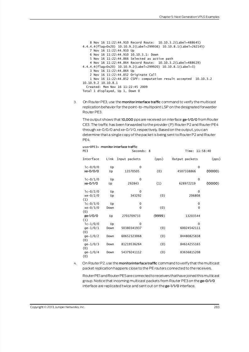
8/21/2019 Config Guide Vpns Vpls
http://slidepdf.com/reader/full/config-guide-vpns-vpls 301/485
8 Nov 16 11:22:44.910 Record Route: 10.10.3.2(Label=488645)
4.4.4.4(flag=0x20) 10.10.9.2(Label=299936) 10.10.8.1(Label=262145)
7 Nov 16 11:22:44.910 Up
6 Nov 16 11:22:44.910 10.10.3.1: Down
5 Nov 16 11:22:44.866 Selected as active path
4 Nov 16 11:22:44.864 Record Route: 10.10.3.2(Label=488629)4.4.4.4(flag=0x20) 10.10.9.2(Label=299920) 10.10.8.1(Label=3)
3 Nov 16 11:22:44.864 Up
2 Nov 16 11:22:44.852 Originate Call
1 Nov 16 11:22:44.852 CSPF: computation result accepted 10.10.3.2
10.10.9.2 10.10.8.1
Created: Mon Nov 16 11:22:45 2009
Total 1 displayed, Up 1, Down 0
3. On Router PE3, use the monitor interface traffic command to verify the multicast
replication behavior for the point-to-multipoint LSP on the designated forwarder
Router PE3.
The output shows that 10,000 pps are received on interface ge-1/0/0 from Router
CE3. The traffic has been forwarded to the provider (P) Router P2 and Router PE4
through xe-0/0/0 and xe-0/1/0, respectively. Based on the output, you can
determine that a single copy of the packet is being sent to Router P2 and Router
PE4.
user@PE3> monitor interface traffic
PE3 Seconds: 8 Time: 11:58:40
Interface Link Input packets (pps) Output packets (pps)
lc-0/0/0 Up 0 0
xe-0/0/0 Up 13570505 (0) 4507338866 (10000)
lc-0/1/0 Up 0 0
xe-0/1/0 Up 292843 (1) 628972219 (10000)
lc-0/2/0 Up 0 0
xe-0/2/0 Up 343292 (0) 206808
(1)
lc-0/3/0 Up 0 0
xe-0/3/0 Down 0 (0) 0
(0)
ge-1/0/0 Up 2703709733 (9999) 13203544
(1)
lc-1/0/0 Up 0 0
ge-1/0/1 Down 50380341937 (0) 60024542111
(0)
ge-1/0/2 Down 60652323068 (0) 84480825838
(0)
ge-1/0/3 Down 81219536264 (0) 84614255165
(0)
ge-1/0/4 Down 54379241112 (0) 83656815208
(0)
4. On Router P2, use the monitorinterface traffic command to verify that the multicast
packet replication happens close to the PE routers connected to the receivers.
Router PE1 and Router PE5 areconnected to receiversthathave joined thismulticast
group. Notice that incoming multicast packets from Router PE3 on the ge-0/1/0
interface are replicated twice and sent out on the ge-1/1/0 interface.
283Copyright © 2013, Juniper Networks, Inc.
Chapter 5: Next Generation VPLS Examples

8/21/2019 Config Guide Vpns Vpls
http://slidepdf.com/reader/full/config-guide-vpns-vpls 302/485
user@P2> monitor interface traffic
P2 Seconds: 6 Time: 12:07:58
Interface Link Input packets (pps) Output packets (pps)
ge-0/1/0 Up 661459806 (10000) 116236
(0)
ge-1/1/0 Up 115956 (0) 1322690473 (20000)
gr-2/1/0 Up 0 (0) 0
(0)
ip-2/1/0 Up 0 (0) 0
(0)
5. On Router PE3, use the show vpls flood command to verify information about the
flood next-hop route.
Junos OS Release 9.0 and later identifies the flood next-hop route as a composite
next hop. Notice that the interface is ge-1/0/0.1, the next-hop type is composite,
and that the flood composition is flood-to-all. This means the traffic is flooded to
all the PE routers.
user@PE3# show vpls flood extensive
Name: GOLD
CEs: 1
VEs: 1
Flood route prefix: 0x30002/51
Flood route type: FLOOD_GRP_COMP_NH
Flood route owner: __ves__
Flood group name: __ves__
Flood group index: 0
Nexthop type: comp
Nexthop index: 606
Flooding to:
Name Type NhType Index
__all_ces__ Group comp 603Composition: split-horizon
Flooding to:
Name Type NhType Index
ge-1/0/0.1 CE ucst 578
Flood route prefix: 0x30003/51
Flood route type: FLOOD_GRP_COMP_NH
Flood route owner: __all_ces__
Flood group name: __all_ces__
Flood group index: 1
Nexthop type: comp
Nexthop index: 611
Flooding to:
Name Type NhType Index
__ves__ Group comp 594Composition: flood-to-all
Component p2mp NH (for all core facing interfaces):
Index
616
Flooding to:
Name Type NhType Index
__all_ces__ Group comp 603
Composition: split-horizon
Flooding to:
Name Type NhType Index
Copyright © 2013, Juniper Networks, Inc.284
VPLS Feature Guide for Routing Devices

8/21/2019 Config Guide Vpns Vpls
http://slidepdf.com/reader/full/config-guide-vpns-vpls 303/485
ge-1/0/0.1 CE ucst 578
Flood route prefix: 0x30001/51
Flood route type: FLOOD_GRP_COMP_NH
Flood route owner: __re_flood__
Flood group name: __re_flood__ Flood group index: 65534
Nexthop type: comp
Nexthop index: 598
Flooding to:
Name Type NhType Index
__ves__ Group comp 594
Composition: flood-to-all
Component p2mp NH (for all core facing interfaces):
Index
616
Flooding to:
Name Type NhType Index
__all_ces__ Group comp 603
Composition: split-horizon
Flooding to: Name Type NhType Index
ge-1/0/0.1 CE ucst 578
Name: __juniper_private1__
CEs: 0
VEs: 0
6. On Router PE3, use the show vpls mac-table command to verify that the MAC
address of thePE router at theremote endof theVPLS has been learned andadded
to the MAC address table.
Notice that the MAC address is learned on the ge-1/0/0.1 interface.
user@PE3# show vpls mac-table
MAC flags (S -static MAC, D -dynamic MAC,
SE -Statistics enabled, NM -Non configured MAC)
Routing instance : GOLD
Bridging domain : __GOLD__, VLAN : NA
MAC MAC Logical
address flags interface
00:14:f6:75:78:00 D ge-1/0/0.1
7. On Router PE3, use the show route forwarding-table command to verify that the
forwarding table has the required entries with two labels: one for the VPLS service
and the other for the next-hop interface.
user@PE3> show route forwarding-table family vpls vpn GOLD
Routing table: GOLD.vpls
VPLS:
Destination Type RtRef Next hop Type Index NhRef Netif
default perm 0 dscd 574 1
lsi.1048832 intf 0 indr 1048575 4
10.10.7.1 Push 262147, Push 309680(top)
596 2 xe-0/0/0.0
lsi.1048836 intf 0 indr 1048574 4
10.10.7.1 Push 262179, Push 299856(top)
589 2 xe-0/0/0.0
00:10:db:e9:4e:b6/48
user 0 indr 1048574 4
10.10.7.1 Push 262179, Push 299856(top)
285Copyright © 2013, Juniper Networks, Inc.
Chapter 5: Next Generation VPLS Examples

8/21/2019 Config Guide Vpns Vpls
http://slidepdf.com/reader/full/config-guide-vpns-vpls 304/485
589 2 xe-0/0/0.0
00:12:1e:c6:98:00/48
user 0 indr 1048575 4
10.10.7.1 Push 262147, Push 309680(top)
596 2 xe-0/0/0.0
00:14:f6:75:78:00/48 user 0 ucst 578 4 ge-1/0/0.1
0x30002/51 user 0 comp 606 2
ge-1/0/0.1 intf 0 ucst 578 4 ge-1/0/0.1
0x30003/51 user 0 comp 611 2
0x30001/51 user 0 comp 598 2
Results
The configuration and verification parts of this example have been completed. The
following section is for your reference.
The relevant sample configuration for Router PE1 follows:
Router PE1 chassis {dump-on-panic;
f p c 1 {
pic 3 {
tunnel-services {
bandwidth 1g;
}
}
}
network-services ethernet;
}
interfaces {
xe-0/1/0 {
unit0 {
family inet {
address 10.10.2.1/30;
}
family mpls;
}
}
xe-0/2/0 {
unit0 {
family inet {
address 10.10.3.1/30;
}
family mpls;
}
}
xe-0/3/0 {
unit0 {
family inet {
address 10.10.1.1/30;
}
family mpls;
}
}
ge-1/0/0 {
Copyright © 2013, Juniper Networks, Inc.286
VPLS Feature Guide for Routing Devices

8/21/2019 Config Guide Vpns Vpls
http://slidepdf.com/reader/full/config-guide-vpns-vpls 305/485
vlan-tagging;
encapsulation vlan-vpls;
unit1 {
encapsulation vlan-vpls;
vlan-id 1000;family vpls;
}
}
lo0{
unit0 {
family inet {
address 1.1.1.1/32;
}
}
}
}
routing-options {
static {
route 172.0.0.0/8 next-hop 172.19.59.1;}
autonomous-system 65000;
}
protocols {
rsvp {
interface all;
interface fxp0.0 {
disable;
}
interface xe-0/3/0.0 {
link-protection;
}
interface xe-0/2/0.0 {
link-protection;}
interface xe-0/1/0.0 {
link-protection;
}
}
mpls {
label-switched-path to-RR {
to 7.7.7.7;
}
label-switched-path vpls-GOLD-p2mp-template {
template;
optimize-timer 50;
link-protection;
p2mp;}
label-switched-path to-PE2 {
to 2.2.2.2;
}
label-switched-path to-PE3 {
to 3.3.3.3;
}
label-switched-path to-PE4 {
to 4.4.4.4;
287Copyright © 2013, Juniper Networks, Inc.
Chapter 5: Next Generation VPLS Examples

8/21/2019 Config Guide Vpns Vpls
http://slidepdf.com/reader/full/config-guide-vpns-vpls 306/485
}
label-switched-path to-PE5 {
to 5.5.5.5;
}
interface all;interface fxp0.0 {
disable;
}
}
bgp {
group to-RR {
type internal;
local-address 1.1.1.1;
family l2vpn {
signaling;
}
neighbor 7.7.7.7;
}
}ospf {
traffic-engineering;
area 0.0.0.0 {
interface all;
interface fxp0.0 {
disable;
}
}
}
}
routing-instances {
GOLD {
instance-type vpls;
interface ge-1/0/0.1;route-distinguisher 1.1.1.1:1;
provider-tunnel {
rsvp-te {
label-switched-path-template {
vpls-GOLD-p2mp-template;
}
}
}
vrf-target target:65000:1;
protocols {
vpls {
site-range 8;
no-tunnel-services;
site CE1 {site-identifier 1;
multi-homing;
site-preference primary;
interface ge-1/0/0.1;
}
}
}
}
}
Copyright © 2013, Juniper Networks, Inc.288
VPLS Feature Guide for Routing Devices

8/21/2019 Config Guide Vpns Vpls
http://slidepdf.com/reader/full/config-guide-vpns-vpls 307/485
The relevant sample configuration for Router PE2 follows.
PE2 Router chassis {
dump-on-panic;
f p c 1 {
pic 3 {
tunnel-services {
bandwidth 1g;
}
}
}
network-services ethernet;
}
interfaces {
xe-0/1/0 {
unit0 {
family inet {
address 10.10.2.2/30;
}
family mpls;
}
}
xe-0/2/0 {
unit0 {
family inet {
address 10.10.5.1/30;
}
family mpls;
}
}
xe-0/3/0 {
unit0 {
family inet {address 10.10.4.1/30;
}
family mpls;
}
}
ge-1/0/1 {
vlan-tagging;
encapsulation vlan-vpls;
}
ge-1/0/3 {
vlan-tagging;
encapsulation vlan-vpls;
unit1 {
encapsulation vlan-vpls;vlan-id 1000;
family vpls;
}
}
fxp0 {
apply-groups [ re0 re1 ];
}
lo0{
unit0 {
289Copyright © 2013, Juniper Networks, Inc.
Chapter 5: Next Generation VPLS Examples

8/21/2019 Config Guide Vpns Vpls
http://slidepdf.com/reader/full/config-guide-vpns-vpls 308/485
family inet {
address 2.2.2.2/32;
}
}
}}
routing-options {
static {
route 172.0.0.0/8 next-hop 172.19.59.1;
}
autonomous-system 65000;
}
protocols {
rsvp {
interface all;
interface fxp0.0 {
disable;
}
}mpls {
label-switched-path to-RR {
to 7.7.7.7;
}
label-switched-path vpls-GOLD-p2mp-template {
template;
optimize-timer 50;
link-protection;
p2mp;
}
label-switched-path to-PE1 {
to 1.1.1.1;
}
label-switched-path to-PE3 {to 3.3.3.3;
}
label-switched-path to-PE4 {
to 4.4.4.4;
}
label-switched-path to-PE5 {
to 5.5.5.5;
}
interface all;
interface fxp0.0 {
disable;
}
}
bgp {group to-RR {
type internal;
local-address 2.2.2.2;
family l2vpn {
signaling;
}
neighbor 7.7.7.7;
}
}
Copyright © 2013, Juniper Networks, Inc.290
VPLS Feature Guide for Routing Devices

8/21/2019 Config Guide Vpns Vpls
http://slidepdf.com/reader/full/config-guide-vpns-vpls 309/485
ospf {
traffic-engineering;
area 0.0.0.0 {
interface all;
interface fxp0.0 {disable;
}
}
}
}
routing-instances {
GOLD {
instance-type vpls;
interface ge-1/0/3.1;
route-distinguisher 2.2.2.2:10;
provider-tunnel {
rsvp-te {
label-switched-path-template {
vpls-GOLD-p2mp-template;}
}
}
vrf-target target:65000:1;
protocols {
vpls {
site-range 8;
no-tunnel-services;
site CE1 {
site-identifier 1;
multi-homing;
site-preference backup;
interface ge-1/0/3.1;
}}
}
}
Related
Documentation
Example: NG-VPLS Using Point-to-Multipoint LSPs on page 233•
• Next-Generation VPLS Point-to-Multipoint Forwarding Overview on page 227
• Next-Generation VPLS for Multicast with Multihoming Overview on page 265
Example: Configuring H-VPLS Without VLANs
This example shows how to configure the hierarchical virtual private LAN service
(H-VPLS). No VLANs are configured in this example.
• Requirements on page 292
• Overview on page 292
• Configuration on page 293
• Verification on page 299
291Copyright © 2013, Juniper Networks, Inc.
Chapter 5: Next Generation VPLS Examples

8/21/2019 Config Guide Vpns Vpls
http://slidepdf.com/reader/full/config-guide-vpns-vpls 310/485
Requirements
No special configuration beyond device initialization is required before configuring this
example.
Overview
H-VPLS uses LDP-based VPLS to signal and establish pseudowires. LDP-based VPLS
is defined in RFC4762,VirtualPrivate LANService(VPLS)UsingLabelDistributionProtocol
(LDP)Signaling. RFC 4762 also defines a hierarchical mode of operation for LDP VPLS
called H-VPLS.
VPLS and H-VPLS are different with respect to scaling. VPLS requires a full mesh of
tunnel label-switched paths (LSPs) among all of the provider edge (PE) routers that
participate in the VPLS service. For each VPLS service, n*(n-1)/2 pseudowires must be
set up between the PE routers. In contrast, H-VPLS partitions the network into several
edge domains that are interconnected using an MPLS core. Each edge device only needs
to learn of one local PE device and therefore needs less routing table support. This has
the potential to allow service providers to use relatively less costly devices (such as EX
Series switches) at the customer edge.
NOTE: As alternatives to H-VPLS, Juniper Networks offers other ways to
address VPLS scalability. For more information, see Application Note:
Demystifying H-VPLS.
H-VPLS defines two roles or functionalities:
• PE-r—PEdevicethat runsVPLS withother PE-rdevices, butwhich alsohas pseudowires
(itcan be basedon QinQ access) withanotherdevicecalled a multi-tenant unit (MTU),
which provides the access layer.
• MTU—PE device that represents the access layer on the H-VPLS architecture and
establishes pseudowires to one or more PE-r devices through which VPLS traffic is
forwarded.
Figure 28 on page 293 shows the topology used in this example.
Copyright © 2013, Juniper Networks, Inc.292
VPLS Feature Guide for Routing Devices
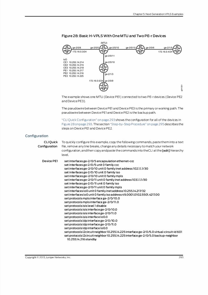
8/21/2019 Config Guide Vpns Vpls
http://slidepdf.com/reader/full/config-guide-vpns-vpls 311/485
Figure 28: Basic H-VPLS With One MTU and Two PE-r Devices
CE1ge-2/0/8
PE1ge-2/0/5
172.16.0.3/24
(MTU)
ge-2/0/10
ge-2/0/11
PE2ge-2/0/10 ge-2/0/6
CE2ge-2/1/5
172.16.0.4/24
PE3
ge-2/0/10
ge-2/1/3
CE3
ge-2/0/9172.16.0.5/24
loO:
CE1 10.255.14.214
CE2 10.255.14.215CE3 10.255.14.218
PE1 10.255.14.217
PE2 10.255.14.216
PE3 10.255.14.225
g 0 4 1 3 5 1
The example shows one MTU (Device PE1) connected to two PE-r devices (Device PE2
and Device PE3).
The pseudowire between Device PE1 and Device PE3 is the primary or working path. The
pseudowire between Device PE1 and Device PE2 is the backup path.
“CLI Quick Configuration” on page 293 shows the configuration for all of the devices in
Figure 28 onpage 293. The section “Step-by-Step Procedure” on page 295 describes the
steps on Device PE1 and Device PE2.
Configuration
CLI Quick
Configuration
To quickly configure this example, copy the following commands, paste them into a text
file, remove any line breaks, change any details necessary to match your network
configuration, andthen copy andpaste the commands into theCLI at the [edit] hierarchy
level.
Device PE1 set interfaces ge-2/0/5 encapsulation ethernet-ccc
set interfaces ge-2/0/5 unit 0 family ccc
set interfaces ge-2/0/10 unit 0 family inet address 102.1.1.1/30
set interfaces ge-2/0/10 unit 0 family iso
set interfaces ge-2/0/10 unit 0 family mpls
set interfaces ge-2/0/11 unit 0 family inet address 103.1.1.1/30
set interfaces ge-2/0/11 unit 0 family iso
set interfaces ge-2/0/11 unit 0 family mpls
set interfaces lo0 unit 0 family inet address 10.255.14.217/32
set interfaces lo0 unit 0 family iso address 49.0001.0102.5501.4217.00
set protocols mpls interface ge-2/0/10.0
set protocols mpls interface ge-2/0/11.0
set protocols isis level 1 disableset protocols isis interface ge-2/0/10.0
set protocols isis interface ge-2/0/11.0
set protocols isis interface lo0.0
set protocols ldp interface ge-2/0/10.0
set protocols ldp interface ge-2/0/11.0
set protocols ldp interface lo0.0
set protocols l2circuit neighbor 10.255.14.225 interface ge-2/0/5.0 virtual-circuit-id 601
set protocols l2circuit neighbor 10.255.14.225 interface ge-2/0/5.0 backup-neighbor
10.255.14.216 standby
293Copyright © 2013, Juniper Networks, Inc.
Chapter 5: Next Generation VPLS Examples

8/21/2019 Config Guide Vpns Vpls
http://slidepdf.com/reader/full/config-guide-vpns-vpls 312/485
set routing-options router-id 10.255.14.217
Device PE2 set interfaces ge-2/0/6 encapsulation ethernet-vpls
set interfaces ge-2/0/6 unit 0 family vpls
set interfaces ge-2/0/10 unit 0 family inet address 102.1.1.2/30set interfaces ge-2/0/10 unit 0 family iso
set interfaces ge-2/0/10 unit 0 family mpls
set interfaces lo0 unit 0 family inet address 10.255.14.216/32
set interfaces lo0 unit 0 family iso address 49.0001.0102.5501.4216.00
set protocols mpls interface ge-2/0/10.0
set protocols isis level 1 disable
set protocols isis interface ge-2/0/10.0
set protocols isis interface lo0.0
set protocols ldp interface ge-2/0/10.0
set protocols ldp interface lo0.0
set routing-instances customer instance-type vpls
set routing-instances customer interface ge-2/0/6.0
set routing-instances customer protocols vpls vpls-id 601
set routing-instances customer protocols vpls neighbor 10.255.14.217set routing-options router-id 10.255.14.216
Device PE3 set interfaces ge-2/1/3 encapsulation ethernet-vpls
set interfaces ge-2/1/3 unit 0 family vpls
set interfaces ge-2/0/10 unit 0 family inet address 103.1.1.2/30
set interfaces ge-2/0/10 unit 0 family iso
set interfaces ge-2/0/10 unit 0 family mpls
set interfaces lo0 unit 0 family inet address 10.255.14.225/32
set interfaces lo0 unit 0 family iso address 49.0001.0102.5501.4225.00
set protocols mpls interface ge-2/0/10.0
set protocols isis level 1 disable
set protocols isis interface ge-2/0/10.0
set protocols isis interface lo0.0
set protocols ldp interface ge-2/0/10.0
set protocols ldp interface lo0.0
set routing-instances customer instance-type vpls
set routing-instances customer interface ge-2/1/3.0
set routing-instances customer protocols vpls vpls-id 601
set routing-instances customer protocols vpls neighbor 10.255.14.217
set routing-options router-id 10.255.14.225
Device CE1 set interfaces ge-2/0/8 unit 0 family inet address 172.16.0.3/24
set interfaces lo0 unit 0 family inet address 10.255.14.214/32
set protocols ospf area 0.0.0.0 interface lo0.0 passive
set protocols ospf area 0.0.0.0 interface ge-2/0/8.0
Device CE2 set interfaces ge-2/1/5 unit 0 family inet address 172.16.0.4/24set interfaces lo0 unit 0 family inet address 10.255.14.215/32
set protocols ospf area 0.0.0.0 interface lo0.0 passive
set protocols ospf area 0.0.0.0 interface ge-2/1/5.0
Device CE3 set interfaces ge-2/0/9 unit 0 family inet address 172.16.0.5/24
set interfaces lo0 unit 0 family inet address 10.255.14.218/32
set protocols ospf area 0.0.0.0 interface lo0.0 passive
set protocols ospf area 0.0.0.0 interface ge-2/0/9.0
Copyright © 2013, Juniper Networks, Inc.294
VPLS Feature Guide for Routing Devices
8/21/2019 Config Guide Vpns Vpls
http://slidepdf.com/reader/full/config-guide-vpns-vpls 313/485
Step-by-Step
Procedure
The following example requires you to navigate various levels in the configuration
hierarchy. Forinformation about navigatingthe CLI,seeUsing theCLI Editor inConfiguration
Mode in the CLI UserGuide.
To configure H-VPLS on the MTU device:
1. Configure the interfaces.
On the MTU device interface that connects to the customer edge, configure one of
the circuit cross-connect (CCC) encapsulation types and the CCC address family.
This enables Layer 2 circuits.
On the core-facing interfaces, enable MPLS labels. The ISO address is needed as
well on the core-facing interfaces because IS-IS is used in the core.
[edit interfaces]
user@PE1# set ge-2/0/5 encapsulation ethernet-ccc
user@PE1# set ge-2/0/5 unit 0 family ccc
user@PE1# set ge-2/0/10 unit 0 family inet address 102.1.1.1/30
user@PE1# set ge-2/0/10 unit 0 family iso
user@PE1# set ge-2/0/10 unit 0 family mpls
user@PE1# set ge-2/0/11 unit 0 family inet address 103.1.1.1/30
user@PE1# set ge-2/0/11 unit 0 family iso
user@PE1# set ge-2/0/11 unit 0 family mpls
user@PE1# set lo0 unit 0 family inet address 10.255.14.217/32
user@PE1# set lo0 unit 0 family iso address 49.0001.0102.5501.4217.00
2. Enable MPLS and LDP on the interfaces.
On the MTU device interfaces that connect to other PE devices, configure MPLSand LDP.
[edit protocols mpls]
user@PE1# set interface ge-2/0/10.0
user@PE1# set interface ge-2/0/11.0
[edit protocols ldp ]
user@PE1# set interface ge-2/0/10.0
user@PE1# set interface ge-2/0/11.0
user@PE1# set interface lo0.0
3. Enable routing on the interfaces.
On the MTUdevice interfaces that connect to other PE devices, configurean interior
gateway protocol (IGP), such as OSPF or IS-IS.
[edit protocols isis]
user@PE1# set level 1 disable
user@PE1# set interface ge-2/0/10.0
user@PE1# set interface ge-2/0/11.0
user@PE1# set interface lo0.0
4. Configure the Layer 2 circuit.
295Copyright © 2013, Juniper Networks, Inc.
Chapter 5: Next Generation VPLS Examples

8/21/2019 Config Guide Vpns Vpls
http://slidepdf.com/reader/full/config-guide-vpns-vpls 314/485
The neighbor 10.255.14.225 is Device PE3’s loopback interface address. This sets
up the working path.
The neighbor 10.255.14.216 is Device PE2’s loopback interface address. This sets up
the backup path.
The virtual circuit ID must match the VPLS ID that is configured on Device PE2 and
Device PE3.
[edit protocols l2circuit neighbor 10.255.14.225 interface ge-2/0/5.0]
user@PE1# set virtual-circuit-id 601
user@PE1# set backup-neighbor 10.255.14.216 standby
5. Configure the router ID.
[edit routing-options]
user@PE1# set router-id 10.255.14.217
Step-by-Step
Procedure
The following example requires you to navigate various levels in the configuration
hierarchy. Forinformation about navigatingthe CLI,seeUsing theCLI Editor inConfiguration
Mode in the CLI UserGuide.
To configure H-VPLS on the MTU device:
1. Configure the interfaces.
On the PE-r device interface that connects to the customer edge, configure one of
the VPLS encapsulation types and the VPLS address family. This enables VPLS.
On the core-facing interfaces, enable MPLS labels. The ISO address is needed as
well on the core-facing interfaces because IS-IS is used in the core.
[edit interfaces]
user@PE2# set ge-2/0/6 encapsulation ethernet-vpls
user@PE2# set ge-2/0/6 unit 0 family vpls
user@PE2# set ge-2/0/10 unit 0 family inet address 102.1.1.2/30
user@PE2# set ge-2/0/10 unit 0 family iso
user@PE2# set ge-2/0/10 unit 0 family mpls
user@PE2# set lo0 unit 0 family inet address 10.255.14.216/32
user@PE2# set lo0 unit 0 family iso address 49.0001.0102.5501.4216.00
2. Enable MPLS and LDP on the interfaces.
On the MTU device interfaces that connect to other PE devices, configure MPLS
and LDP.
[edit protocols mpls]
user@PE2# set interface ge-2/0/10.0
[edit protocols ldp ]
user@PE2# set interface ge-2/0/10.0
user@PE2# set interface lo0.0
3. Enable routing on the interfaces.
Copyright © 2013, Juniper Networks, Inc.296
VPLS Feature Guide for Routing Devices

8/21/2019 Config Guide Vpns Vpls
http://slidepdf.com/reader/full/config-guide-vpns-vpls 315/485
On the MTUdevice interfaces that connect to other PE devices, configurean interior
gateway protocol (IGP), such as OSPF or IS-IS.
[edit protocols isis]
user@PE2# set level 1 disable
user@PE2# set interface ge-2/0/10.0
user@PE2# set interface lo0.0
4. Configure VPLS.
The neighbor 10.255.14.217 statement points to Device PE1’s loopback interface
address.
The VPLS ID must match the virtual circuit ID thatis configuredon the MTU(Device
PE1).
[edit routing-instances customer]
user@PE2# set instance-type vpls
user@PE2# set interface ge-2/0/6.0
user@PE2# set protocols vpls vpls-id 601
user@PE2# set protocols vpls neighbor 10.255.14.217
5. Configure the router ID.
[edit routing-options]
user@PE2# set router-id 10.255.14.216
Results From configuration mode, confirm your configuration by entering the show interfaces,
show protocols, show routing-instances, and show routing-options commands. If the
output doesnot display the intended configuration, repeatthe instructionsin thisexample
to correct the configuration.
Device PE1 user@PE1# show interfaces
ge-2/0/5 {
encapsulation ethernet-ccc;
unit0 {
family ccc;
}
}
ge-2/0/10 {
unit0 {
family inet {
address 102.1.1.1/30;
}
family iso;
family mpls;
}
}ge-2/0/11 {
unit0 {
family inet {
address 103.1.1.1/30;
}
family iso;
family mpls;
}
}
297Copyright © 2013, Juniper Networks, Inc.
Chapter 5: Next Generation VPLS Examples

8/21/2019 Config Guide Vpns Vpls
http://slidepdf.com/reader/full/config-guide-vpns-vpls 316/485
lo0{
unit0 {
family inet {
address 10.255.14.217/32;
}family iso {
address 49.0001.0102.5501.4217.00;
}
}
}
user@PE1# show protocols
mpls {
interface ge-2/0/10.0;
interface ge-2/0/11.0;
}
isis {
level 1 disable;
interface ge-2/0/10.0;interface ge-2/0/11.0;
interface lo0.0;
}
ldp{
interface ge-2/0/10.0;
interface ge-2/0/11.0;
interface lo0.0;
}
l2circuit {
neighbor 10.255.14.225 {
interface ge-2/0/5.0 {
virtual-circuit-id 601;
backup-neighbor 10.255.14.216 {
standby;}
}
}
}
user@PE1# show routing-options
router-id 10.255.14.217;
Device PE2 user@PE2# show interfaces
ge-2/0/6 {
encapsulation ethernet-vpls;
unit0 {
family vpls;
}
}
ge-2/0/10 {
unit0 {
family inet {
address 102.1.1.2/30;
}
family iso;
family mpls;
}
Copyright © 2013, Juniper Networks, Inc.298
VPLS Feature Guide for Routing Devices

8/21/2019 Config Guide Vpns Vpls
http://slidepdf.com/reader/full/config-guide-vpns-vpls 317/485
}
lo0{
unit0 {
family inet {
address 10.255.14.216/32;}
family iso {
address 49.0001.0102.5501.4216.00;
}
}
}
user@PE2# show protocols
mpls {
interface ge-2/0/10.0;
}
isis {
level 1 disable;
interface ge-2/0/10.0;interface lo0.0;
}
ldp{
interface ge-2/0/10.0;
interface lo0.0;
}
user@PE2# show routing-instances
customer {
instance-type vpls;
interface ge-2/0/6.0;
protocols {
vpls {
vpls-id 601;
neighbor 10.255.14.217;
}
}
}
user@PE2# show routing-options
router-id 10.255.14.216;
If you are done configuring the devices, enter commit from configuration mode.
Verification
Confirm that the configuration is working properly.
• Verifying the Layer 2 Circuit on page 300
• Checking the VPLS Connections on page 300
• Checking Connectivity on page 302
• Manually Triggering a Switch from the Active Pseudowire to the Redundant
Pseudowire on page 302
299Copyright © 2013, Juniper Networks, Inc.
Chapter 5: Next Generation VPLS Examples

8/21/2019 Config Guide Vpns Vpls
http://slidepdf.com/reader/full/config-guide-vpns-vpls 318/485
Verifying the Layer 2 Circuit
Purpose Verify that the Layer 2 circuit is operational on the MTU device.
Action From operational mode, enter the show l2circuit connections command.
user@PE1> show l2circuit connections
Layer-2 Circuit Connections:
Legend for connection status (St)
EI -- encapsulation invalid NP -- interface h/w not present
MM -- mtu mismatch Dn -- down
EM -- encapsulation mismatch VC-Dn -- Virtual circuit Down
CM -- control-word mismatch Up -- operational
VM -- vlan id mismatch CF -- Call admission control failure
OL -- no outgoing label IB -- TDM incompatible bitrate
NC -- intf encaps not CCC/TCC TM -- TDM misconfiguration
BK -- Backup Connection ST -- Standby Connection
CB -- rcvd cell-bundle size bad SP -- Static Pseudowire
LD -- local site signaled down RS -- remote site standby
RD -- remote site signaled down XX -- unknown
Legend for interface status
Up -- operational
Dn -- down
Neighbor: 10.255.14.216
Interface Type St Time last up # Up trans
ge-2/0/5.0(vc 601) rmt ST
Neighbor: 10.255.14.225
Interface Type St Time last up # Up trans
ge-2/0/5.0(vc 601) rmt Up Oct 5 19:38:15 2012 1
Remote PE: 10.255.14.225, Negotiated control-word: No
Incoming label: 299872, Outgoing label: 800001
Negotiated PW status TLV: No
Local interface: ge-2/0/5.0, Status: Up, Encapsulation: ETHERNET
Meaning As expected, the Layer 2 circuit connection to Device PE3 is operational, and the
connection to Device PE2 is in standby mode.
Checking the VPLS Connections
Purpose Verify that the VPLS connections are operational on the PE-r devices.
Action From operational mode, enter the show vpls connections command.
user@PE2> show vpls connections
Layer-2 VPN connections:
Legend for connection status (St)
EI -- encapsulation invalid NC -- interface encapsulation not CCC/TCC/VPLS
EM -- encapsulation mismatch WE -- interface and instance encaps not same
VC-Dn -- Virtual circuit down NP -- interface hardware not present
CM -- control-word mismatch -> -- only outbound connection is up
CN -- circuit not provisioned <- -- only inbound connection is up
OR -- out of range Up -- operational
OL -- no outgoing label Dn -- down
LD -- local site signaled down CF -- call admission control failure
Copyright © 2013, Juniper Networks, Inc.300
VPLS Feature Guide for Routing Devices

8/21/2019 Config Guide Vpns Vpls
http://slidepdf.com/reader/full/config-guide-vpns-vpls 319/485
RD -- remote site signaled down SC -- local and remote site ID collision
LN -- local site not designated LM -- local site ID not minimum designated
RN -- remote site not designated RM -- remote site ID not minimum designated
XX -- unknown connection status IL -- no incoming label
MM -- MTU mismatch MI -- Mesh-Group ID not available
BK -- Backup connection ST -- Standby connectionPF -- Profile parse failure PB -- Profile busy
RS -- remote site standby SN -- Static Neighbor
LB -- Local site not best-site RB -- Remote site not best-site
VM -- VLAN ID mismatch
Legend for interface status
Up -- operational
Dn -- down
Instance: customer
VPLS-id: 601
Neighbor Type St Time last up # Up trans
10.255.14.217(vpls-id 601) rmt Up Oct 8 14:46:54 2012 1
Remote PE: 10.255.14.217, Negotiated control-word: No
Incoming label: 800001, Outgoing label: 299856 Negotiated PW status TLV: No
Local interface: vt-2/0/10.84934913, Status: Up, Encapsulation: ETHERNET
Description: Intf - vpls customer neighbor 10.255.14.217 vpls-id 601
user@PE3> show vpls connections
Layer-2 VPN connections:
Legend for connection status (St)
EI -- encapsulation invalid NC -- interface encapsulation not CCC/TCC/VPLS
EM -- encapsulation mismatch WE -- interface and instance encaps not same
VC-Dn -- Virtual circuit down NP -- interface hardware not present
CM -- control-word mismatch -> -- only outbound connection is up
CN -- circuit not provisioned <- -- only inbound connection is up
OR -- out of range Up -- operational
OL -- no outgoing label Dn -- downLD -- local site signaled down CF -- call admission control failure
RD -- remote site signaled down SC -- local and remote site ID collision
LN -- local site not designated LM -- local site ID not minimum designated
RN -- remote site not designated RM -- remote site ID not minimum designated
XX -- unknown connection status IL -- no incoming label
MM -- MTU mismatch MI -- Mesh-Group ID not available
BK -- Backup connection ST -- Standby connection
PF -- Profile parse failure PB -- Profile busy
RS -- remote site standby SN -- Static Neighbor
LB -- Local site not best-site RB -- Remote site not best-site
VM -- VLAN ID mismatch
Legend for interface status
Up -- operational
Dn -- down
Instance: customer
VPLS-id: 601
Neighbor Type St Time last up # Up trans
10.255.14.217(vpls-id 601) rmt Up Oct 8 14:46:54 2012 1
Remote PE: 10.255.14.217, Negotiated control-word: No
Incoming label: 800001, Outgoing label: 299872
Negotiated PW status TLV: No
Local interface: vt-2/0/10.68157697, Status: Up, Encapsulation: ETHERNET
Description: Intf - vpls customer neighbor 10.255.14.217 vpls-id 601
301Copyright © 2013, Juniper Networks, Inc.
Chapter 5: Next Generation VPLS Examples

8/21/2019 Config Guide Vpns Vpls
http://slidepdf.com/reader/full/config-guide-vpns-vpls 320/485
Meaning As expected, the VPLS connections are operational on both PE-r devices.
Checking Connectivity
Purpose Verify that Device CE1 can ping Device CE3.
Action user@CE1> ping 10.255.14.218
PING 10.255.14.218 (10.255.14.218): 56 data bytes
64 bytes from 10.255.14.218: icmp_seq=0 ttl=64 time=0.858 ms
64 bytes from 10.255.14.218: icmp_seq=1 ttl=64 time=0.527 ms
64 bytes from 10.255.14.218: icmp_seq=2 ttl=64 time=0.670 ms
^C
--- 10.255.14.218 ping statistics ---
3 packets transmitted, 3 packets received, 0% packet loss
round-trip min/avg/max/stddev = 0.527/0.685/0.858/0.136 ms
Meaning The output shows that H-VPLS is operational.
Manually Triggering a Switch from the Active Pseudowire to the Redundant
Pseudowire
Purpose Makesure that the pseudowirebetween Device PE1 and Device PE2 becomesoperational.
Action user@CE1> request l2circuit-switchover virtual-circuit-id 601 neighbor 10.255.14.225
user@CE1> ping 10.255.14.215
PING 10.255.14.215 (10.255.14.215): 56 data bytes
64 bytes from 10.255.14.215: icmp_seq=0 ttl=64 time=0.738 ms
64 bytes from 10.255.14.215: icmp_seq=1 ttl=64 time=0.627 ms
64 bytes from 10.255.14.215: icmp_seq=2 ttl=64 time=0.629 ms
^C--- 10.255.14.215 ping statistics ---
3 packets transmitted, 3 packets received, 0% packet loss
round-trip min/avg/max/stddev = 0.627/0.665/0.738/0.052 ms
Meaning The successful ping from Device CE1 to Device CE2 shows that the pseudowire between
Device PE1 and PE2 is operational. Now, if you ping Device CE3 from Device CE1, the ping
should fail.
Related
Documentation
Application Note: Demystifying H-VPLS•
• Example: Configuring H-VPLS With VLANs on page 303
• Redundant Pseudowires for Layer 2 Circuits andVPLS
• Configuring Redundant Pseudowires for Layer 2 Circuits andVPLS
Copyright © 2013, Juniper Networks, Inc.302
VPLS Feature Guide for Routing Devices

8/21/2019 Config Guide Vpns Vpls
http://slidepdf.com/reader/full/config-guide-vpns-vpls 321/485
Example: Configuring H-VPLS With VLANs
This example shows how to configure the hierarchical virtual private LAN service
(H-VPLS). VLANs are configured in this example.
• Requirements on page 303
• Overview on page 303
• Configuration on page 305
• Verification on page 312
Requirements
No special configuration beyond device initialization is required before configuring this
example.
Overview
H-VPLS uses LDP-based VPLS to signal and establish pseudowires. LDP-based VPLS
is defined in RFC4762,VirtualPrivate LANService(VPLS)UsingLabelDistributionProtocol
(LDP)Signaling. RFC 4762 also defines a hierarchical mode of operation for LDP VPLS
called H-VPLS.
VPLS and H-VPLS are different with respect to scaling. VPLS requires a full mesh of
tunnel label-switched paths (LSPs) among all of the provider edge (PE) routers that
participate in the VPLS service. For each VPLS service, n*(n-1)/2 pseudowires must be
set up between the PE routers. In contrast, H-VPLS partitions the network into several
edge domains that are interconnected using an MPLS core. Each edge device only needs
to learn of one local PE device and therefore needs less routing table support. This has
the potential to allow service providers to use relatively less costly devices (such as EXSeries switches) at the customer edge.
NOTE: As alternatives to H-VPLS, Juniper Networks offers other ways to
address VPLS scalability. For more information, see Application Note:
Demystifying H-VPLS.
H-VPLS defines two roles or functionalities:
• PE-r—PEdevicethat runsVPLS withother PE-rdevices, butwhich alsohas pseudowires
(itcan be basedon QinQ access) withanotherdevicecalled a multi-tenant unit (MTU),
which provides the access layer.
• MTU—PE device that represents the access layer on the H-VPLS architecture and
establishes pseudowires to one or more PE-r devices through which VPLS traffic is
forwarded.
Figure 29 on page 304 shows the topology used in this example.
303Copyright © 2013, Juniper Networks, Inc.
Chapter 5: Next Generation VPLS Examples

8/21/2019 Config Guide Vpns Vpls
http://slidepdf.com/reader/full/config-guide-vpns-vpls 322/485
Figure 29: Basic H-VPLS With One MTU and Two PE-r Devices
CE1ge-2/0/8
PE1ge-2/0/5
172.16.0.3/24
(MTU)
ge-2/0/10
ge-2/0/11
PE2ge-2/0/10 ge-2/0/6
CE2ge-2/1/5
172.16.0.4/24
PE3
ge-2/0/10
ge-2/1/3
CE3
ge-2/0/9172.16.0.5/24
loO:
CE1 10.255.14.214
CE2 10.255.14.215CE3 10.255.14.218
PE1 10.255.14.217
PE2 10.255.14.216
PE3 10.255.14.225
g 0 4 1 3 5 1
The example shows one MTU (Device PE1) connected to two PE-r devices (Device PE2
and Device PE3).
The pseudowire between Device PE1 and Device PE3 is the primary or working path. The
pseudowire between Device PE1 and Device PE2 is the backup path.
To support VLANs with H-VPLS, you must include the output-vlan-map swap statement
in the configuration of the MTU device as a workaround to prevent a VLAN ID mismatch.
Otherwise, the PE-r devices report a VLAN ID mismatch, as shown here:
user@PE2> show vpls connections
Layer-2 VPN connections:
Legend for connection status (St)
EI -- encapsulation invalid NC -- interface encapsulation not CCC/TCC/VPLS
EM -- encapsulation mismatch WE -- interface and instance encaps not same
VC-Dn -- Virtual circuit down NP -- interface hardware not presentCM -- control-word mismatch -> -- only outbound connection is up
CN -- circuit not provisioned <- -- only inbound connection is up
OR -- out of range Up -- operational
OL -- no outgoing label Dn -- down
LD -- local site signaled down CF -- call admission control failure
RD -- remote site signaled down SC -- local and remote site ID collision
LN -- local site not designated LM -- local site ID not minimum designated
RN -- remote site not designated RM -- remote site ID not minimum designated
XX -- unknown connection status IL -- no incoming label
MM -- MTU mismatch MI -- Mesh-Group ID not available
BK -- Backup connection ST -- Standby connection
PF -- Profile parse failure PB -- Profile busy
RS -- remote site standby SN -- Static Neighbor
LB -- Local site not best-site RB -- Remote site not best-site
VM -- VLAN ID mismatch
Legend for interface status
Up -- operational
Dn -- down
Instance: customer
VPLS-id: 601
Neighbor Type St Time last up # Up trans
10.255.14.217(vpls-id 601) rmt VM
Copyright © 2013, Juniper Networks, Inc.304
VPLS Feature Guide for Routing Devices
8/21/2019 Config Guide Vpns Vpls
http://slidepdf.com/reader/full/config-guide-vpns-vpls 323/485
“CLI Quick Configuration” on page 305 shows the configuration for all of the devices in
Figure 29on page304. Thesection “Step-by-StepProcedure” on page307 describes the
steps on Device PE1 and Device PE2.
Configuration
CLI Quick
Configuration
To quickly configure this example, copy the following commands, paste them into a text
file, remove any line breaks, change any details necessary to match your network
configuration, andthen copy andpaste the commands into theCLI at the [edit] hierarchy
level.
Device PE1 set interfaces ge-2/0/5 vlan-tagging
set interfaces ge-2/0/5 encapsulation vlan-ccc
set interfaces ge-2/0/5 unit 601 encapsulation vlan-ccc
set interfaces ge-2/0/5 unit 601 vlan-id 601
set interfaces ge-2/0/5 unit 601 output-vlan-map swap
set interfaces ge-2/0/5 unit 601 family ccc
set interfaces ge-2/0/10 unit 0 family inet address 102.1.1.1/30
set interfaces ge-2/0/10 unit 0 family isoset interfaces ge-2/0/10 unit 0 family mpls
set interfaces ge-2/0/11 unit 0 family inet address 103.1.1.1/30
set interfaces ge-2/0/11 unit 0 family iso
set interfaces ge-2/0/11 unit 0 family mpls
set interfaces lo0 unit 0 family inet address 10.255.14.217/32
set interfaces lo0 unit 0 family iso address 49.0001.0102.5501.4217.00
set protocols mpls interface ge-2/0/10.0
set protocols mpls interface ge-2/0/11.0
set protocols isis level 1 disable
set protocols isis interface ge-2/0/10.0
set protocols isis interface ge-2/0/11.0
set protocols isis interface lo0.0
set protocols ldp interface ge-2/0/10.0
set protocols ldp interface ge-2/0/11.0
set protocols ldp interface lo0.0
set protocols l2circuit neighbor 10.255.14.225 interface ge-2/0/5.601 virtual-circuit-id
601
set protocols l2circuitneighbor 10.255.14.225 interface ge-2/0/5.601 encapsulation-type
ethernet-vlan
set protocols l2circuit neighbor 10.255.14.225 interface ge-2/0/5.601 backup-neighbor
10.255.14.216 standby
set routing-options router-id 10.255.14.217
Device PE2 set interfaces ge-2/0/6 vlan-tagging
set interfaces ge-2/0/6 encapsulation vlan-vpls
set interfaces ge-2/0/6 unit 601 encapsulation vlan-vpls
set interfaces ge-2/0/6 unit 601 vlan-id 601
set interfaces ge-2/0/6 unit 601 family vpls
set interfaces ge-2/0/10 unit 0 family inet address 102.1.1.2/30
set interfaces ge-2/0/10 unit 0 family iso
set interfaces ge-2/0/10 unit 0 family mpls
set interfaces lo0 unit 0 family inet address 10.255.14.216/32
set interfaces lo0 unit 0 family iso address 49.0001.0102.5501.4216.00
set protocols mpls interface ge-2/0/10.0
set protocols isis level 1 disable
set protocols isis interface ge-2/0/10.0
305Copyright © 2013, Juniper Networks, Inc.
Chapter 5: Next Generation VPLS Examples

8/21/2019 Config Guide Vpns Vpls
http://slidepdf.com/reader/full/config-guide-vpns-vpls 324/485
set protocols isis interface lo0.0
set protocols ldp interface ge-2/0/10.0
set protocols ldp interface lo0.0
set routing-instances customer instance-type vpls
set routing-instances customer interface ge-2/0/6.601set routing-instances customer protocols vpls vpls-id 601
set routing-instancescustomer protocols vplsneighbor 10.255.14.217encapsulation-type
ethernet-vlan
set routing-options router-id 10.255.14.216
Device PE3 set interfaces ge-2/0/10 unit 0 family inet address 103.1.1.2/30
set interfaces ge-2/0/10 unit 0 family iso
set interfaces ge-2/0/10 unit 0 family mpls
set interfaces ge-2/1/3 vlan-tagging
set interfaces ge-2/1/3 encapsulation vlan-vpls
set interfaces ge-2/1/3 unit 601 encapsulation vlan-vpls
set interfaces ge-2/1/3 unit 601vlan-id 601
set interfaces ge-2/1/3 unit 601 family vpls
set interfaces lo0 unit 0 family inet address 10.255.14.225/32set interfaces lo0 unit 0 family iso address 49.0001.0102.5501.4225.00
set protocols mpls interface ge-2/0/10.0
set protocols isis level 1 disable
set protocols isis interface ge-2/0/10.0
set protocols isis interface lo0.0
set protocols ldp interface ge-2/0/10.0
set protocols ldp interface lo0.0
set routing-instances customer instance-type vpls
set routing-instances customer interface ge-2/1/3.601
set routing-instances customer protocols vpls vpls-id 601
set routing-instancescustomer protocols vplsneighbor 10.255.14.217encapsulation-type
ethernet-vlan
set routing-options router-id 10.255.14.225
Device CE1 set interfaces ge-2/0/8 vlan-tagging
set interfaces ge-2/0/8 unit 601 vlan-id 601
set interfaces ge-2/0/8 unit 601 family inet address 172.16.0.3/24
set interfaces lo0 unit 0 family inet address 10.255.14.214/32
set protocols ospf area 0.0.0.0 interface lo0.0 passive
set protocols ospf area 0.0.0.0 interface ge-2/0/8.601
Device CE2 set interfaces ge-2/1/5 vlan-tagging
set interfaces ge-2/1/5 unit 601 vlan-id 601
set interfaces ge-2/1/5 unit 601 family inet address 172.16.0.4/24
set interfaces lo0 unit 0 family inet address 10.255.14.215/32
set protocols ospf area 0.0.0.0 interface lo0.0 passive
set protocols ospf area 0.0.0.0 interface ge-2/1/5.601
Device CE3 set interfaces ge-2/0/9 vlan-tagging
set interfaces ge-2/0/9 unit 601 vlan-id 601
set interfaces ge-2/0/9 unit 601 family inet address 172.16.0.5/24
set interfaces lo0 unit 0 family inet address 10.255.14.218/32
set protocols ospf area 0.0.0.0 interface lo0.0 passive
set protocols ospf area 0.0.0.0 interface ge-2/0/9.601
Copyright © 2013, Juniper Networks, Inc.306
VPLS Feature Guide for Routing Devices
8/21/2019 Config Guide Vpns Vpls
http://slidepdf.com/reader/full/config-guide-vpns-vpls 325/485
Step-by-Step
Procedure
The following example requires you to navigate various levels in the configuration
hierarchy. Forinformation about navigatingthe CLI,seeUsing theCLI Editor inConfiguration
Mode in the CLI UserGuide.
To configure H-VPLS on the MTU device:
1. Configure the interfaces.
On the MTU device interface that connects to the customer edge, configure one of
the circuit cross-connect (CCC) encapsulation types and the CCC address family.
This enables Layer 2 circuits.
On the core-facing interfaces, enable MPLS labels. The ISO address is needed as
well on the core-facing interfaces because IS-IS is used in the core.
[edit interfaces]
user@PE1# set ge-2/0/5 vlan-tagging
user@PE1# set ge-2/0/5 encapsulation vlan-ccc
user@PE1# set ge-2/0/5 unit 601 family ccc
user@PE1# set ge-2/0/5 unit 601 encapsulation vlan-ccc
user@PE1# set ge-2/0/5 unit 601 vlan-id 601
user@PE1# set ge-2/0/5 unit 601 output-vlan-map swap
user@PE1# set ge-2/0/10 unit 0 family inet address 102.1.1.1/30
user@PE1# set ge-2/0/10 unit 0 family iso
user@PE1# set ge-2/0/10 unit 0 family mpls
user@PE1# set ge-2/0/11 unit 0 family inet address 103.1.1.1/30
user@PE1# set ge-2/0/11 unit 0 family iso
user@PE1# set ge-2/0/11 unit 0 family mpls
user@PE1# set lo0 unit 0 family inet address 10.255.14.217/32user@PE1# set lo0 unit 0 family iso address 49.0001.0102.5501.4217.00
2. Enable MPLS and LDP on the interfaces.
On the MTU device interfaces that connect to other PE devices, configure MPLS
and LDP.
[edit protocols mpls]
user@PE1# set interface ge-2/0/10.0
user@PE1# set interface ge-2/0/11.0
[edit protocols ldp ]
user@PE1# set interface ge-2/0/10.0
user@PE1# set interface ge-2/0/11.0
user@PE1# set interface lo0.0
3. Enable routing on the interfaces.
On the MTUdevice interfaces that connect to other PE devices, configurean interior
gateway protocol (IGP), such as OSPF or IS-IS.
[edit protocols isis]
user@PE1# set level 1 disable
user@PE1# set interface ge-2/0/10.0
307Copyright © 2013, Juniper Networks, Inc.
Chapter 5: Next Generation VPLS Examples

8/21/2019 Config Guide Vpns Vpls
http://slidepdf.com/reader/full/config-guide-vpns-vpls 326/485
user@PE1# set interface ge-2/0/11.0
user@PE1# set interface lo0.0
4. Configure the Layer 2 circuit.
The neighbor 10.255.14.225 is Device PE3’s loopback interface address. This setsup the working path.
The neighbor 10.255.14.216 is Device PE2’s loopback interface address. This sets up
the backup path.
The virtual circuit ID must match the VPLS ID that is configured on Device PE2 and
Device PE3.
[edit protocols l2circuit neighbor 10.255.14.225 interface ge-2/0/5.601]
user@PE1# set virtual-circuit-id 601
user@PE1# set encapsulation-type ethernet-vlan
user@PE1# set backup-neighbor 10.255.14.216 standby
5. Configure the router ID.
[edit routing-options]
user@PE1# set router-id 10.255.14.217
Step-by-Step
Procedure
The following example requires you to navigate various levels in the configuration
hierarchy. Forinformation about navigatingthe CLI,seeUsing theCLI Editor inConfiguration
Mode in the CLI UserGuide.
To configure H-VPLS on the MTU device:
1. Configure the interfaces.
On the PE-r device interface that connects to the customer edge, configure one of
the VPLS encapsulation types and the VPLS address family. This enables VPLS.
On the core-facing interfaces, enable MPLS labels. The ISO address is needed as
well on the core-facing interfaces because IS-IS is used in the core.
[edit interfaces]
user@PE2# set ge-2/0/6 vlan-tagging
user@PE2# set ge-2/0/6 encapsulation vlan-vpls
user@PE2# set ge-2/0/6 unit 601 encapsulation vlan-vpls
user@PE2# set ge-2/0/6 unit 601vlan-id 601
user@PE2# set ge-2/0/6 unit 601family vpls
user@PE2# set ge-2/0/10 unit 0 family inet address 102.1.1.2/30
user@PE2# set ge-2/0/10 unit 0 family iso
user@PE2# set ge-2/0/10 unit 0 family mpls
user@PE2# set lo0 unit 0 family inet address 10.255.14.216/32
user@PE2# set lo0 unit 0 family iso address 49.0001.0102.5501.4216.00
2. Enable MPLS and LDP on the interfaces.
On the MTU device interfaces that connect to other PE devices, configure MPLS
and LDP.
[edit protocols mpls]
Copyright © 2013, Juniper Networks, Inc.308
VPLS Feature Guide for Routing Devices

8/21/2019 Config Guide Vpns Vpls
http://slidepdf.com/reader/full/config-guide-vpns-vpls 327/485
user@PE2# set interface ge-2/0/10.0
[edit protocols ldp ]
user@PE2# set interface ge-2/0/10.0
user@PE2# set interface lo0.0
3. Enable routing on the interfaces.
On the MTUdevice interfaces that connect to other PE devices, configurean interior
gateway protocol (IGP), such as OSPF or IS-IS.
[edit protocols isis]
user@PE2# set level 1 disable
user@PE2# set interface ge-2/0/10.0
user@PE2# set interface lo0.0
4. Configure VPLS.
The neighbor 10.255.14.217 statement points to Device PE1’s loopback interface
address.
The VPLS ID must match the virtual circuit ID thatis configuredon the MTU(Device
PE1).
[edit routing-instances customer]
user@PE2# set instance-type vpls
user@PE2# set interface ge-2/0/6.601
user@PE2# set protocols vpls vpls-id 601
user@PE2# set protocols vpls neighbor 10.255.14.217 encapsulation-type
ethernet-vlan
5. Configure the router ID.
[edit routing-options]
user@PE2# set router-id 10.255.14.216
Results From configuration mode, confirm your configuration by entering the show interfaces,
show protocols, show routing-instances, and show routing-options commands. If the
output doesnot display the intended configuration, repeatthe instructionsin thisexample
to correct the configuration.
Device PE1 user@PE1# show interfaces
ge-2/0/5 {
vlan-tagging;
encapsulation vlan-ccc;
unit601 {
encapsulation vlan-ccc;
vlan-id 601;
output-vlan-map swap;family ccc;
}
}
ge-2/0/10 {
unit0 {
family inet {
address 102.1.1.1/30;
}
family iso;
309Copyright © 2013, Juniper Networks, Inc.
Chapter 5: Next Generation VPLS Examples

8/21/2019 Config Guide Vpns Vpls
http://slidepdf.com/reader/full/config-guide-vpns-vpls 328/485
family mpls;
}
}
ge-2/0/11 {
unit0 {family inet {
address 103.1.1.1/30;
}
family iso;
family mpls;
}
}
lo0{
unit0 {
family inet {
address 10.255.14.217/32;
}
family iso {
address 49.0001.0102.5501.4217.00;}
}
}
user@PE1# show protocols
mpls {
interface ge-2/0/10.0;
interface ge-2/0/11.0;
}
isis {
level 1 disable;
interface ge-2/0/10.0;
interface ge-2/0/11.0;
interface lo0.0;}
ldp{
interface ge-2/0/10.0;
interface ge-2/0/11.0;
interface lo0.0;
}
l2circuit {
neighbor 10.255.14.225 {
interface ge-2/0/5.601 {
virtual-circuit-id 601;
encapsulation-type ethernet-vlan;
backup-neighbor 10.255.14.216 {
standby;
}}
}
}
user@PE1# show routing-options
router-id 10.255.14.217;
Device PE2 user@PE2# show interfaces
ge-2/0/6 {
Copyright © 2013, Juniper Networks, Inc.310
VPLS Feature Guide for Routing Devices

8/21/2019 Config Guide Vpns Vpls
http://slidepdf.com/reader/full/config-guide-vpns-vpls 329/485
vlan-tagging;
encapsulation vlan-vpls;
unit601 {
encapsulation vlan-vpls;
vlan-id 601;family vpls;
}
}
ge-2/0/10 {
unit0 {
family inet {
address 102.1.1.2/30;
}
family iso;
family mpls;
}
}
lo0{
unit0 {family inet {
address 10.255.14.216/32;
}
family iso {
address 49.0001.0102.5501.4216.00;
}
}
}
user@PE2# show protocols
mpls {
interface ge-2/0/10.0;
}
isis {level 1 disable;
interface ge-2/0/10.0;
interface lo0.0;
}
ldp{
interface ge-2/0/10.0;
interface lo0.0;
}
user@PE2# show routing-instances
customer {
instance-type vpls;
interface ge-2/0/6.601;
protocols {vpls {
vpls-id 601;
neighbor 10.255.14.217 {
encapsulation-type ethernet-vlan;
}
}
}
}
311Copyright © 2013, Juniper Networks, Inc.
Chapter 5: Next Generation VPLS Examples
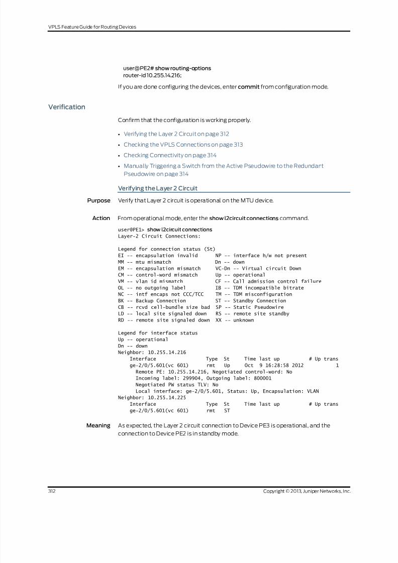
8/21/2019 Config Guide Vpns Vpls
http://slidepdf.com/reader/full/config-guide-vpns-vpls 330/485
user@PE2# show routing-options
router-id 10.255.14.216;
If you are done configuring the devices, enter commit from configuration mode.
Verification
Confirm that the configuration is working properly.
• Verifying the Layer 2 Circuit on page 312
• Checking the VPLS Connections on page 313
• Checking Connectivity on page 314
• Manually Triggering a Switch from the Active Pseudowire to the Redundant
Pseudowire on page 314
Verifying the Layer 2 Circuit
Purpose Verify that Layer 2 circuit is operational on the MTU device.
Action From operational mode, enter the show l2circuit connections command.
user@PE1> show l2circuit connections
Layer-2 Circuit Connections:
Legend for connection status (St)
EI -- encapsulation invalid NP -- interface h/w not present
MM -- mtu mismatch Dn -- down
EM -- encapsulation mismatch VC-Dn -- Virtual circuit Down
CM -- control-word mismatch Up -- operational
VM -- vlan id mismatch CF -- Call admission control failure
OL -- no outgoing label IB -- TDM incompatible bitrate
NC -- intf encaps not CCC/TCC TM -- TDM misconfigurationBK -- Backup Connection ST -- Standby Connection
CB -- rcvd cell-bundle size bad SP -- Static Pseudowire
LD -- local site signaled down RS -- remote site standby
RD -- remote site signaled down XX -- unknown
Legend for interface status
Up -- operational
Dn -- down
Neighbor: 10.255.14.216
Interface Type St Time last up # Up trans
ge-2/0/5.601(vc 601) rmt Up Oct 9 16:28:58 2012 1
Remote PE: 10.255.14.216, Negotiated control-word: No
Incoming label: 299904, Outgoing label: 800001
Negotiated PW status TLV: No
Local interface: ge-2/0/5.601, Status: Up, Encapsulation: VLAN
Neighbor: 10.255.14.225
Interface Type St Time last up # Up trans
ge-2/0/5.601(vc 601) rmt ST
Meaning As expected, the Layer 2 circuit connection to Device PE3 is operational, and the
connection to Device PE2 is in standby mode.
Copyright © 2013, Juniper Networks, Inc.312
VPLS Feature Guide for Routing Devices

8/21/2019 Config Guide Vpns Vpls
http://slidepdf.com/reader/full/config-guide-vpns-vpls 331/485
Checking the VPLS Connections
Purpose Verify that the VPLS connections are operational on the PE-r devices.
Action From operational mode, enter the show vpls connections command.
user@PE2> show vpls connections
Layer-2 VPN connections:
Legend for connection status (St)
EI -- encapsulation invalid NC -- interface encapsulation not CCC/TCC/VPLS
EM -- encapsulation mismatch WE -- interface and instance encaps not same
VC-Dn -- Virtual circuit down NP -- interface hardware not present
CM -- control-word mismatch -> -- only outbound connection is up
CN -- circuit not provisioned <- -- only inbound connection is up
OR -- out of range Up -- operational
OL -- no outgoing label Dn -- down
LD -- local site signaled down CF -- call admission control failure
RD -- remote site signaled down SC -- local and remote site ID collision
LN -- local site not designated LM -- local site ID not minimum designated
RN -- remote site not designated RM -- remote site ID not minimum designated
XX -- unknown connection status IL -- no incoming label
MM -- MTU mismatch MI -- Mesh-Group ID not available
BK -- Backup connection ST -- Standby connection
PF -- Profile parse failure PB -- Profile busy
RS -- remote site standby SN -- Static Neighbor
LB -- Local site not best-site RB -- Remote site not best-site
VM -- VLAN ID mismatch
Legend for interface status
Up -- operational
Dn -- down
Instance: customer VPLS-id: 601
Neighbor Type St Time last up # Up trans
10.255.14.217(vpls-id 601) rmt Up Oct 9 16:29:02 2012 1
Remote PE: 10.255.14.217, Negotiated control-word: No
Incoming label: 800001, Outgoing label: 299904
Negotiated PW status TLV: No
Local interface: vt-2/0/10.84934914, Status: Up, Encapsulation: VLAN
Description: Intf - vpls customer neighbor 10.255.14.217 vpls-id 601
user@PE3> show vpls connections
Layer-2 VPN connections:
Legend for connection status (St)
EI -- encapsulation invalid NC -- interface encapsulation not CCC/TCC/VPLS
EM -- encapsulation mismatch WE -- interface and instance encaps not sameVC-Dn -- Virtual circuit down NP -- interface hardware not present
CM -- control-word mismatch -> -- only outbound connection is up
CN -- circuit not provisioned <- -- only inbound connection is up
OR -- out of range Up -- operational
OL -- no outgoing label Dn -- down
LD -- local site signaled down CF -- call admission control failure
RD -- remote site signaled down SC -- local and remote site ID collision
LN -- local site not designated LM -- local site ID not minimum designated
RN -- remote site not designated RM -- remote site ID not minimum designated
313Copyright © 2013, Juniper Networks, Inc.
Chapter 5: Next Generation VPLS Examples
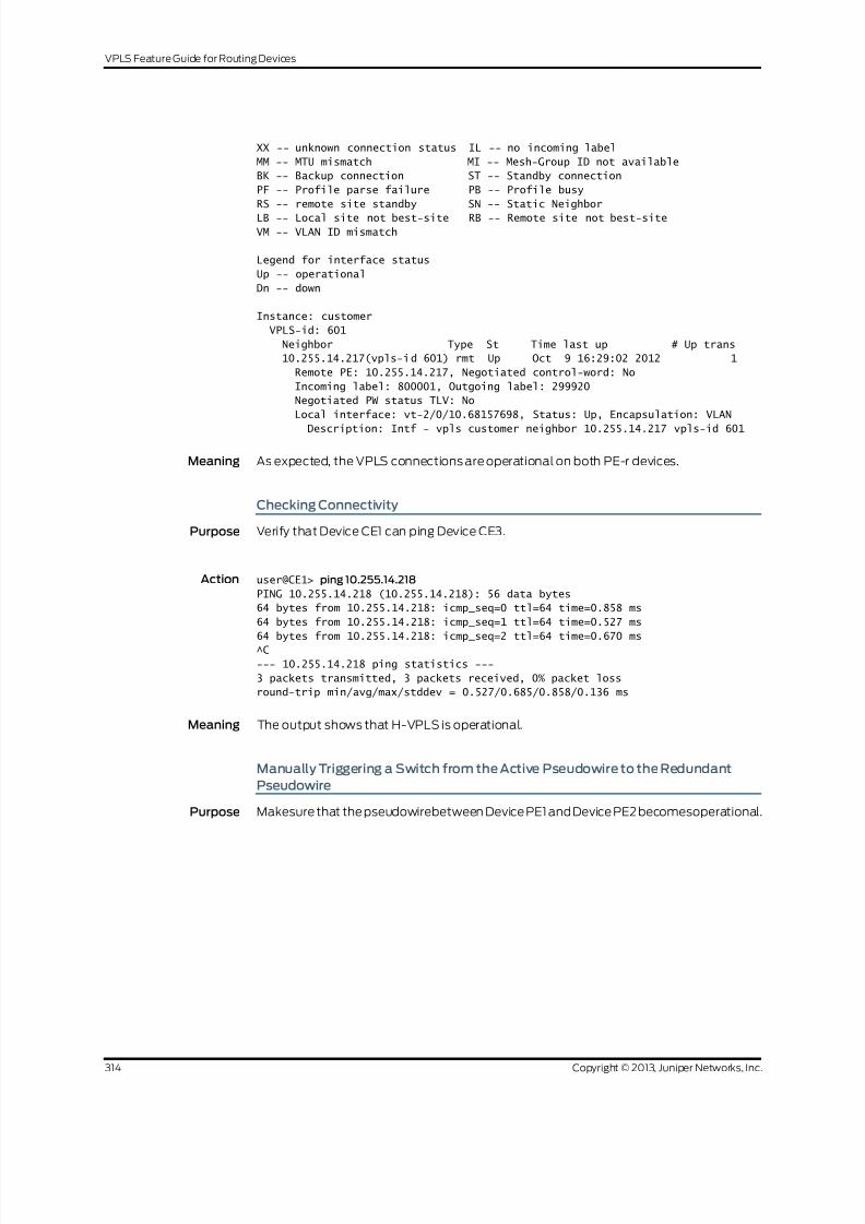
8/21/2019 Config Guide Vpns Vpls
http://slidepdf.com/reader/full/config-guide-vpns-vpls 332/485
XX -- unknown connection status IL -- no incoming label
MM -- MTU mismatch MI -- Mesh-Group ID not available
BK -- Backup connection ST -- Standby connection
PF -- Profile parse failure PB -- Profile busy
RS -- remote site standby SN -- Static Neighbor
LB -- Local site not best-site RB -- Remote site not best-siteVM -- VLAN ID mismatch
Legend for interface status
Up -- operational
Dn -- down
Instance: customer
VPLS-id: 601
Neighbor Type St Time last up # Up trans
10.255.14.217(vpls-id 601) rmt Up Oct 9 16:29:02 2012 1
Remote PE: 10.255.14.217, Negotiated control-word: No
Incoming label: 800001, Outgoing label: 299920
Negotiated PW status TLV: No
Local interface: vt-2/0/10.68157698, Status: Up, Encapsulation: VLAN
Description: Intf - vpls customer neighbor 10.255.14.217 vpls-id 601
Meaning As expected, the VPLS connections are operational on both PE-r devices.
Checking Connectivity
Purpose Verify that Device CE1 can ping Device CE3.
Action user@CE1> ping 10.255.14.218
PING 10.255.14.218 (10.255.14.218): 56 data bytes
64 bytes from 10.255.14.218: icmp_seq=0 ttl=64 time=0.858 ms
64 bytes from 10.255.14.218: icmp_seq=1 ttl=64 time=0.527 ms
64 bytes from 10.255.14.218: icmp_seq=2 ttl=64 time=0.670 ms
^C
--- 10.255.14.218 ping statistics ---
3 packets transmitted, 3 packets received, 0% packet loss
round-trip min/avg/max/stddev = 0.527/0.685/0.858/0.136 ms
Meaning The output shows that H-VPLS is operational.
Manually Triggering a Switch from the Active Pseudowire to the Redundant
Pseudowire
Purpose Makesure that the pseudowirebetween Device PE1 and Device PE2 becomesoperational.
Copyright © 2013, Juniper Networks, Inc.314
VPLS Feature Guide for Routing Devices

8/21/2019 Config Guide Vpns Vpls
http://slidepdf.com/reader/full/config-guide-vpns-vpls 333/485
Action user@CE1> request l2circuit-switchover virtual-circuit-id 601 neighbor 10.255.14.225
user@CE1> ping 10.255.14.215
PING 10.255.14.215 (10.255.14.215): 56 data bytes
64 bytes from 10.255.14.215: icmp_seq=0 ttl=64 time=0.738 ms
64 bytes from 10.255.14.215: icmp_seq=1 ttl=64 time=0.627 ms64 bytes from 10.255.14.215: icmp_seq=2 ttl=64 time=0.629 ms
^C
--- 10.255.14.215 ping statistics ---
3 packets transmitted, 3 packets received, 0% packet loss
round-trip min/avg/max/stddev = 0.627/0.665/0.738/0.052 ms
Meaning The successful ping from Device CE1 to Device CE2 shows that the pseudowire between
Device PE1 and PE2 is operational. Now, if you ping Device CE3 from Device CE1, the ping
should fail.
Related
Documentation
Application Note: Demystifying H-VPLS•
•
Example: Configuring H-VPLS Without VLANs on page 291
• Redundant Pseudowires for Layer 2 Circuits andVPLS
• Configuring Redundant Pseudowires for Layer 2 Circuits andVPLS
Example: Configuring H-VPLS BGP-Based and LDP-Based VPLS Interoperation
This example showshowto configurethe hierarchical virtualprivateLANservice (H-VPLS)
in a scenario that uses both LDP-based VPLS and BGP-based VPLS interoperating in a
multihoming deployment. This scenario is useful when a customer deployment has the
two different types of VPLS in use, and you need to integrate them. Another example is
when ISP-A is running BGP-based VPLS and ISP-B is running the LDP-based VPLS, and
the two ISPs are merging their networks.
Requirements
No special configuration beyond device initialization is required before configuring this
example.
Overview
In this example, Device PE2 and Device PE3 are acting as internetworking provider edge
(PE) routers with BGP-based as well as LDP-based VPLS termination.
The devices in this example have the following roles:
• BGP VPLS only PE—Device PE1
• LDP VPLS only PE—Device PE4
• BGP-LDP VPLS PE—Device PE2 and Device PE3
Figure 30 on page 316 shows the topology used in this example.
315Copyright © 2013, Juniper Networks, Inc.
Chapter 5: Next Generation VPLS Examples

8/21/2019 Config Guide Vpns Vpls
http://slidepdf.com/reader/full/config-guide-vpns-vpls 334/485
Figure 30: H-VPLS with LDP-Based and BGP-Based VPLS Interoperation
PE3
PE2
PE4PE1 CE4CE1
BGP VPLS LDP VPLS
CE3
CE2
Mesh Group PE3
VPLS Site ID1
Mesh Group PE2VPLS Site ID1
BG P VPLS Pseudowire Pr imar y Pseudowire
Backup Pseudowire
g 0 4 1 3 5 2
From Device PE4, the pseudowire to Device PE3 is the primary or working path. The
pseudowire Device PE2 is the backup path.
“CLI Quick Configuration” on page 316 shows the configuration for all of the devices inFigure 30 on page 316. The section “Step-by-Step Procedure” on page 319 describes the
steps on Device PE1, Device PE2, and Device PE4.
Configuration
CLI Quick
Configuration
To quickly configure this example, copy the following commands, paste them into a text
file, remove any line breaks, change any details necessary to match your network
configuration, andthen copy andpaste the commands into theCLI at the [edit] hierarchy
level.
Device PE1 set interfaces ge-2/0/5 encapsulation ethernet-vpls
set interfaces ge-2/0/5 unit 0 description to_CE1
set interfaces ge-2/0/5 unit 0 family vpls
set interfaces fe-2/0/9 unit 0 description to_PE2
set interfaces fe-2/0/9 unit 0 family inet address 10.10.3.1/30
set interfaces fe-2/0/9 unit 0 family mpls
set interfaces fe-2/0/10 unit 0 description to_PE3
set interfaces fe-2/0/10 unit 0 family inet address 10.10.1.1/30
set interfaces fe-2/0/10 unit 0 family mpls
set interfaces lo0 unit 0 family inet address 1.1.1.1/32
set protocols mpls interface fe-2/0/10.0
set protocols mpls interface fe-2/0/9.0
set protocols ldp interface fe-2/0/10.0
set protocols ldp interface fe-2/0/9.0
set protocols ldp interface lo0.0
set protocols bgp group internal-peers type internal
set protocols bgp group internal-peers local-address 1.1.1.1
set protocols bgp group internal-peers family l2vpn signaling
set protocols bgp group internal-peers neighbor 2.2.2.2
set protocols bgp group internal-peers neighbor 3.3.3.3
set protocols ospf area 0.0.0.0 interface lo0.0 passive
set protocols ospf area 0.0.0.0 interface fe-2/0/10.0
set protocols ospf area 0.0.0.0 interface fe-2/0/9.0
set routing-instances h-vpls-PE1 instance-type vpls
set routing-instances h-vpls-PE1 interface ge-2/0/5.0
set routing-instances h-vpls-PE1 route-distinguisher 1:1
Copyright © 2013, Juniper Networks, Inc.316
VPLS Feature Guide for Routing Devices

8/21/2019 Config Guide Vpns Vpls
http://slidepdf.com/reader/full/config-guide-vpns-vpls 335/485
set routing-instances h-vpls-PE1 vrf-target target:1:1
set routing-instances h-vpls-PE1 protocols vpls interface ge-2/0/5.0
set routing-instances h-vpls-PE1 protocols vpls site PE1-vpls site-identifier 2
set routing-options autonomous-system 64510
Device PE2 set interfaces ge-2/0/6 encapsulation ethernet-vpls
set interfaces ge-2/0/6 unit 0 description to_CE2
set interfaces ge-2/0/6 unit 0 family vpls
set interfaces fe-2/0/8 unit 0 description to_PE3
set interfaces fe-2/0/8 unit 0 family inet address 10.10.4.2/30
set interfaces fe-2/0/8 unit 0 family mpls
set interfaces fe-2/0/9 unit 0 description to_PE4
set interfaces fe-2/0/9 unit 0 family inet address 10.10.5.1/30
set interfaces fe-2/0/9 unit 0 family mpls
set interfaces fe-2/0/10 unit 0 description to_PE1
set interfaces fe-2/0/10 unit 0 family inet address 10.10.3.2/30
set interfaces fe-2/0/10 unit 0 family mpls
set interfaces lo0 unit 0 family inet address 2.2.2.2/32
set protocols mpls interface fe-2/0/10.0set protocols mpls interface fe-2/0/9.0
set protocols mpls interface fe-2/0/8.0
set protocols ldp interface fe-2/0/10.0
set protocols ldp interface fe-2/0/9.0
set protocols ldp interface fe-2/0/8.0
set protocols ldp interface lo0.0
set protocols bgp groupibgp type internal
set protocols bgp group ibgp local-address 2.2.2.2
set protocols bgp group ibgp family l2vpn signaling
set protocols bgp group ibgp neighbor 3.3.3.3
set protocols bgp group ibgp neighbor 1.1.1.1
set protocols ospf area 0.0.0.0 interface lo0.0 passive
set protocols ospf area 0.0.0.0 interface fe-2/0/10.0
set protocols ospf area 0.0.0.0 interface fe-2/0/9.0set protocols ospf area 0.0.0.0 interface fe-2/0/8.0
set routing-instances h-vpls-PE2 instance-type vpls
set routing-instances h-vpls-PE2 interface ge-2/0/6.0
set routing-instances h-vpls-PE2 route-distinguisher 1:2
set routing-instances h-vpls-PE2 vrf-target target:1:1
set routing-instances h-vpls-PE2 protocols vpls interface ge-2/0/6.0
set routing-instances h-vpls-PE2 protocols vpls site PE2-vpls site-identifier 1
set routing-instances h-vpls-PE2 protocols vpls site PE2-vpls multi-homing
set routing-instances h-vpls-PE2 protocols vpls site PE2-vpls mesh-group h-vpls-PE2
set routing-instances h-vpls-PE2 protocols vpls vpls-id 100
set routing-instances h-vpls-PE2 protocols vpls mesh-group h-vpls-PE2 vpls-id 100
set routing-instances h-vpls-PE2 protocols vpls mesh-group h-vpls-PE2 local-switching
set routing-instances h-vpls-PE2 protocols vpls mesh-grouph-vpls-PE2 neighbor 4.4.4.4
set routing-options autonomous-system 64510
Device PE3 set interfaces fe-2/0/8 unit 0 description to_PE2
set interfaces fe-2/0/8 unit 0 family inet address 10.10.4.1/30
set interfaces fe-2/0/8 unit 0 family mpls
set interfaces fe-2/0/9 unit 0 description to_PE4
set interfaces fe-2/0/9 unit 0 family inet address 10.10.6.1/30
set interfaces fe-2/0/9 unit 0 family mpls
set interfaces fe-2/0/10 unit 0 description to_PE1
317Copyright © 2013, Juniper Networks, Inc.
Chapter 5: Next Generation VPLS Examples

8/21/2019 Config Guide Vpns Vpls
http://slidepdf.com/reader/full/config-guide-vpns-vpls 336/485
set interfaces fe-2/0/10 unit 0 family inet address 10.10.1.2/30
set interfaces fe-2/0/10 unit 0 family mpls
set interfaces ge-2/1/3 encapsulation ethernet-vpls
set interfaces ge-2/1/3 unit 0 description to_CE3
set interfaces ge-2/1/3 unit 0 family vplsset interfaces lo0 unit 0 family inet address 3.3.3.3/32
set protocols mpls interface fe-2/0/10.0
set protocols mpls interface fe-2/0/8.0
set protocols mpls interface fe-2/0/9.0
set protocols ldp interface fe-2/0/10.0
set protocols ldp interface fe-2/0/9.0
set protocols ldp interface fe-2/0/8.0
set protocols ldp interface lo0.0
set protocols bgp group internal-peers type internal
set protocols bgp group internal-peers local-address 3.3.3.3
set protocols bgp group internal-peers family l2vpn signaling
set protocols bgp group internal-peers neighbor 2.2.2.2
set protocols bgp group internal-peers neighbor 1.1.1.1
set protocols ospf traffic-engineeringset protocols ospf area 0.0.0.0 interface lo0.0 passive
set protocols ospf area 0.0.0.0 interface fe-2/0/10.0
set protocols ospf area 0.0.0.0 interface fe-2/0/8.0
set protocols ospf area 0.0.0.0 interface fe-2/0/9.0
set routing-instances h-vpls-PE3 instance-type vpls
set routing-instances h-vpls-PE3 interface ge-2/1/3.0
set routing-instances h-vpls-PE3 route-distinguisher 1:3
set routing-instances h-vpls-PE3 vrf-target target:1:1
set routing-instances h-vpls-PE3 protocols vpls interface ge-2/1/3.0
set routing-instances h-vpls-PE3 protocols vpls site PE3-vpls site-identifier 1
set routing-instances h-vpls-PE3 protocols vpls site PE3-vpls multi-homing
set routing-instances h-vpls-PE3 protocols vpls site PE3-vpls mesh-group h-vpls-PE3
set routing-instances h-vpls-PE3 protocols vpls vpls-id 100
set routing-instances h-vpls-PE3 protocols vpls mesh-group h-vpls-PE3 vpls-id 100set routing-instances h-vpls-PE3 protocols vpls mesh-group h-vpls-PE3 local-switching
set routing-instancesh-vpls-PE3 protocols vpls mesh-grouph-vpls-PE3 neighbor 4.4.4.4
set routing-options autonomous-system 64510
Device PE4 set interfaces fe-2/0/9 unit 0 description to_PE3
set interfaces fe-2/0/9 unit 0 family inet address 10.10.6.2/30
set interfaces fe-2/0/9 unit 0 family mpls
set interfaces fe-2/0/10 unit 0 description to_PE2
set interfaces fe-2/0/10 unit 0 family inet address 10.10.5.2/30
set interfaces fe-2/0/10 unit 0 family mpls
set interfaces ge-2/1/7 encapsulation ethernet-vpls
set interfaces ge-2/1/7 unit 0 description to_CE4
set interfaces ge-2/1/7 unit 0 family vpls
set interfaces lo0 unit 0 family inet address 4.4.4.4/32set protocols mpls interface fe-2/0/10.0
set protocols mpls interface fe-2/0/9.0
set protocols ldp interface fe-2/0/10.0
set protocols ldp interface fe-2/0/9.0
set protocols ldp interface lo0.0
set protocols ospf area 0.0.0.0 interface lo0.0 passive
set protocols ospf area 0.0.0.0 interface fe-2/0/10.0
set protocols ospf area 0.0.0.0 interface fe-2/0/9.0
set routing-instances ldp-vpls instance-type vpls
Copyright © 2013, Juniper Networks, Inc.318
VPLS Feature Guide for Routing Devices

8/21/2019 Config Guide Vpns Vpls
http://slidepdf.com/reader/full/config-guide-vpns-vpls 337/485
set routing-instances ldp-vpls interface ge-2/1/7.0
set routing-instances ldp-vpls protocols vpls vpls-id 100
set routing-instances ldp-vpls protocols vpls neighbor 3.3.3.3
set routing-instances ldp-vpls protocols vpls neighbor 2.2.2.2
Device CE1 set interfaces ge-2/0/8 unit 0 description to_PE1
set interfaces ge-2/0/8 unit 0 family inet address 172.16.0.1/24
set interfaces lo0 unit 0 family inet address 10.255.14.214/32
set protocols ospf area 0.0.0.0 interface lo0.0 passive
set protocols ospf area 0.0.0.0 interface ge-2/0/8.0
Device CE2 set interfaces ge-2/1/5 unit 0 description to_PE2
set interfaces ge-2/1/5 unit 0 family inet address 172.16.0.2/24
set interfaces lo0 unit 0 family inet address 10.255.14.215/32
set protocols ospf area 0.0.0.0 interface lo0.0 passive
set protocols ospf area 0.0.0.0 interface ge-2/1/5.0
Device CE3 set interfaces ge-2/0/9 unit 0 description to_PE3
set interfaces ge-2/0/9 unit 0 family inet address 172.16.0.3/24
set interfaces lo0 unit 0 family inet address 10.255.14.218/32
set protocols ospf area 0.0.0.0 interface lo0.0 passive
set protocols ospf area 0.0.0.0 interface ge-2/0/9.0
Device CE4 set interfaces ge-2/1/6 unit 0 description to_PE4
set interfaces ge-2/1/6 unit 0 family inet address 172.16.0.4/24
set interfaces lo0 unit 0 family inet address 10.255.14.219/32
set protocols ospf area 0.0.0.0 interface lo0.0 passive
set protocols ospf area 0.0.0.0 interface ge-2/1/6.0
Step-by-Step
Procedure
The following example requires you to navigate various levels in the configuration
hierarchy. Forinformation about navigatingthe CLI,seeUsing theCLI Editor inConfiguration
Mode in the CLI UserGuide.
To configure the BGP-based VPLS PE device:
1. Configure the interfaces.
On the device interface that connects to the customer edge, enable VPLS
encapsulation and the VPLS address family.
On the core-facing interfaces, enable MPLS labels.
[edit interfaces]
user@PE1# set ge-2/0/5 encapsulation ethernet-vpls
user@PE1# set ge-2/0/5 unit 0 description to_CE1
user@PE1# set ge-2/0/5 unit 0 family vpls
user@PE1# set fe-2/0/10 unit 0 description to_PE3
user@PE1# set fe-2/0/10 unit 0 family inet address 10.10.1.1/30
user@PE1# set fe-2/0/10 unit 0 family mpls
user@PE1# set fe-2/0/9 unit 0 description to_PE2
user@PE1# set fe-2/0/9 unit 0 family inet address 10.10.3.1/30
user@PE1# set fe-2/0/9 unit 0 family mpls
319Copyright © 2013, Juniper Networks, Inc.
Chapter 5: Next Generation VPLS Examples
8/21/2019 Config Guide Vpns Vpls
http://slidepdf.com/reader/full/config-guide-vpns-vpls 338/485
user@PE1# set lo0 unit 0 family inet address1.1.1.1/32
2. Enable MPLS and LDP on the interfaces.
On the MTU device interfaces that connect to other PE devices, configure MPLS
and LDP.
[edit protocols mpls]
user@PE1# set interface fe-2/0/10.0
user@PE1# set interface fe-2/0/9.0
[edit protocols ldp ]
user@PE1# set interface fe-2/0/10.0
user@PE1# set interface fe-2/0/9.0
user@PE1# set interface lo0.0
3. Enable routing on the interfaces.
On the MTUdevice interfaces that connect to other PE devices, configurean interior
gateway protocol (IGP), such as OSPF or IS-IS.
[edit protocols ospf area 0.0.0.0]
user@PE1# set interface lo0.0 passive
user@PE1# set interface fe-2/0/10.0
user@PE1# set interface fe-2/0/9.0
4. Configure BGP with Layer 2 VPN signaling.
The l2vpn signaling statement enables support for both VPLS and Layer 2 VPN
advertisement under the same network layer reachability information (NLRI).
The internal IBGP (IBGP) full mesh includes Device PE1, Device PE2, and Device
PE3. Device PE4 is not included.
[edit protocols bgp group internal-peers]
user@PE1# set type internal
user@PE1# set local-address 1.1.1.1
user@PE1# set family l2vpn signaling
user@PE1# set neighbor 2.2.2.2
user@PE1# set neighbor 3.3.3.3
5. Configure the VPLS routing instance.
Because this is BGP-based VPLS, include a route distinguisher, a VRF target, and a
site name and ID.
[edit routing-instances h-vpls-PE1]
user@PE1# set instance-type vpls
user@PE1# set interface ge-2/0/5.0
user@PE1# set route-distinguisher 1:1
user@PE1# set vrf-target target:1:1
[edit routing-instances h-vpls-PE1 protocols vpls]
user@PE1# set interface ge-2/0/5.0
user@PE1# set site PE1-vpls site-identifier2
6. Configure the autonomous system (AS) number.
[edit routing-options]
user@PE1# set autonomous-system 64510
Copyright © 2013, Juniper Networks, Inc.320
VPLS Feature Guide for Routing Devices

8/21/2019 Config Guide Vpns Vpls
http://slidepdf.com/reader/full/config-guide-vpns-vpls 339/485
Step-by-Step
Procedure
The following example requires you to navigate various levels in the configuration
hierarchy. Forinformation about navigatingthe CLI,seeUsing theCLI Editor inConfiguration
Mode in the CLI UserGuide.
To configure the BGP-LDP-based VPLS PE device:
1. Configure the interfaces.
On the PE-r device interface that connects to the customer edge, configure one of
the VPLS encapsulation types and the VPLS address family. This enables VPLS.
On the core-facing interfaces, enable MPLS labels.
[edit interfaces]
user@PE2# set ge-2/0/6 encapsulation ethernet-vpls
user@PE2# set ge-2/0/6 unit 0 description to_CE2
user@PE2# set ge-2/0/6 unit 0 family vpls
user@PE2# set fe-2/0/10 unit 0 description to_PE1
user@PE2# set fe-2/0/10 unit 0 family inet address 10.10.3.2/30
user@PE2# set fe-2/0/10 unit 0 family mpls
user@PE2# set fe-2/0/9 unit 0 description to_PE4
user@PE2# set fe-2/0/9 unit 0 family inet address 10.10.5.1/30
user@PE2# set fe-2/0/9 unit 0 family mpls
user@PE2# set fe-2/0/8 unit 0 description to_PE3
user@PE2# set fe-2/0/8 unit 0 family inet address 10.10.4.2/30
user@PE2# set fe-2/0/8 unit 0 family mpls
user@PE2# set lo0 unit 0 family inet address2.2.2.2/32
2. Enable MPLS and LDP on the interfaces.
On the MTU device interfaces that connect to other PE devices, configure MPLS
and LDP.
[edit protocols mpls]
user@PE2# set interface fe-2/0/10.0
user@PE2# set interface fe-2/0/9.0
user@PE2# set interface fe-2/0/8.0
[edit protocols ldp]
user@PE2# set interface fe-2/0/10.0
user@PE2# set interface fe-2/0/9.0
user@PE2# set interface fe-2/0/8.0
user@PE2# set interface lo0.0
3. Enable routing on the interfaces.
On the MTUdevice interfaces that connect to other PE devices, configurean interior
gateway protocol (IGP), such as OSPF or IS-IS.
[edit protocols ospf area 0.0.0.0]
user@PE2# set interface lo0.0 passive
user@PE2# set interface fe-2/0/10.0
321Copyright © 2013, Juniper Networks, Inc.
Chapter 5: Next Generation VPLS Examples
8/21/2019 Config Guide Vpns Vpls
http://slidepdf.com/reader/full/config-guide-vpns-vpls 340/485
user@PE2# set interface fe-2/0/9.0
user@PE2# set interface fe-2/0/8.0
4. [edit protocols bgp group ibgp]
user@PE2# set type internaluser@PE2# set local-address 2.2.2.2
user@PE2# set family l2vpn signaling
user@PE2# set neighbor 3.3.3.3
user@PE2# set neighbor 1.1.1.1
5. Configure VPLS.
The vpls-id statement enables LDP signaling for the VPLS instance.
[edit routing-instances h-vpls-PE2]
user@PE2# set instance-type vpls
user@PE2# set interface ge-2/0/6.0
user@PE2# set route-distinguisher 1:2
user@PE2# set vrf-target target:1:1
[edit routing-instances h-vpls-PE2 protocols vpls]
user@PE2# set interface ge-2/0/6.0
user@PE2# set site PE2-vpls site-identifier 1
user@PE2# set site PE2-vpls multi-homing
user@PE2# set site PE2-vpls mesh-group h-vpls-PE2
user@PE2# set vpls-id 100
user@PE2# set mesh-group h-vpls-PE2 vpls-id 100
user@PE2# set mesh-group h-vpls-PE2 local-switching
user@PE2# set mesh-group h-vpls-PE2 neighbor 4.4.4.4
6. [edit routing-options]
user@PE2# set autonomous-system 64510
Step-by-Step
Procedure
The following example requires you to navigate various levels in the configuration
hierarchy. Forinformation about navigatingthe CLI,seeUsing theCLI Editor inConfiguration
Mode in the CLI UserGuide.
To configure LDP-based VPLS PE device:
1. Configure the interfaces.
On the PE-r device interface that connects to the customer edge, configure one of
the VPLS encapsulation types and the VPLS address family. This enables VPLS.
On the core-facing interfaces, enable MPLS labels.
[edit interfaces]
user@PE4# set fe-2/0/10 unit 0 description to_PE2
user@PE4# set fe-2/0/10 unit 0 family inet address 10.10.5.2/30
user@PE4# set fe-2/0/10 unit 0 family mpls
user@PE4# set fe-2/0/9 unit 0 description to_PE3
user@PE4# set fe-2/0/9 unit 0 family inet address 10.10.6.2/30
user@PE4# set fe-2/0/9 unit 0 family mpls
user@PE4# set ge-2/1/7 encapsulation ethernet-vpls
Copyright © 2013, Juniper Networks, Inc.322
VPLS Feature Guide for Routing Devices

8/21/2019 Config Guide Vpns Vpls
http://slidepdf.com/reader/full/config-guide-vpns-vpls 341/485
user@PE4# set ge-2/1/7 unit 0 description to_CE4
user@PE4# set ge-2/1/7 unit 0 family vpls
user@PE4# set lo0 unit 0 family inet address 4.4.4.4/32
2. Enable MPLS and LDP on the interfaces.
On the MTU device interfaces that connect to other PE devices, configure MPLS
and LDP.
[edit protocols mpls]
user@PE4# set interface fe-2/0/10.0
user@PE4# set interface fe-2/0/9.0
[edit protocols ldp]
user@PE4# set interface fe-2/0/10.0
user@PE4# set interface fe-2/0/9.0
user@PE4# set interface lo0.0
3. Enable routing on the interfaces.
On the MTUdevice interfaces that connect to other PE devices, configurean interior
gateway protocol (IGP), such as OSPF or IS-IS.
[edit protocols ospf area 0.0.0.0]
user@PE4# set interface lo0.0 passive
user@PE4# set interface fe-2/0/10.0
user@PE4# set interface fe-2/0/9.0
4. Configure VPLS.
The vpls-id statement enables LDP signaling for the VPLS instance.
[edit routing-instances ldp-vpls]
user@PE4# set instance-type vplsuser@PE4# set interface ge-2/1/7.0
user@PE4# set protocols vpls vpls-id 100
[edit routing-instances ldp-vpls protocols vpls]
user@PE4# set neighbor 3.3.3.3
user@PE4# set neighbor 2.2.2.2
Results From configuration mode, confirm your configuration by entering the show interfaces,
show protocols, show routing-instances, and show routing-options commands. If the
output doesnot display the intended configuration, repeatthe instructionsin thisexample
to correct the configuration.
Device PE1 user@PE1# show interfacesge-2/0/5 {
encapsulation ethernet-vpls;
unit0 {
description to_CE1;
family vpls;
}
}
fe-2/0/9 {
}
323Copyright © 2013, Juniper Networks, Inc.
Chapter 5: Next Generation VPLS Examples

8/21/2019 Config Guide Vpns Vpls
http://slidepdf.com/reader/full/config-guide-vpns-vpls 342/485
unit0 {
description to_PE2;
family inet {
address 10.10.3.1/30;
}family mpls;
}
}
fe-2/0/10 {
unit0 {
description to_PE3;
family inet {
address 10.10.1.1/30;
}
family mpls;
}
}
lo0{
unit0 {family inet {
address 1.1.1.1/32;
}
}
}
user@PE1# show protocols
mpls {
interface fe-2/0/10.0;
interface fe-2/0/9.0;
}
bgp {
group internal-peers {
type internal;local-address 1.1.1.1;
family l2vpn {
signaling;
}
neighbor 2.2.2.2;
neighbor 3.3.3.3;
}
}
ospf {
area 0.0.0.0 {
interface lo0.0 {
passive;
}
interface fe-2/0/10.0;interface fe-2/0/9.0;
}
}
ldp{
interface fe-2/0/10.0;
interface fe-2/0/9.0;
interface lo0.0;
}
Copyright © 2013, Juniper Networks, Inc.324
VPLS Feature Guide for Routing Devices

8/21/2019 Config Guide Vpns Vpls
http://slidepdf.com/reader/full/config-guide-vpns-vpls 343/485
user@PE1# show routing-instances
h-vpls-PE1 {
instance-type vpls;
interface ge-2/0/5.0;
route-distinguisher 1:1;vrf-target target:1:1;
protocols {
vpls {
interface ge-2/0/5.0;
site PE1-vpls {
site-identifier 2;
}
}
}
}
user@PE1# show routing-options
autonomous-system 64510;
Device PE2 user@PE2# show interfacesge-2/0/6 {
encapsulation ethernet-vpls;
unit0 {
description to_CE2;
family vpls;
}
}
fe-2/0/8 {
unit0 {
description to_PE3;
family inet {
address 10.10.4.2/30;
}
family mpls;}
}
fe-2/0/9 {
unit 0{
description to_PE4;
family inet {
address 10.10.5.1/30;
}
family mpls;
}
}
fe-2/0/10 {
unit0 {
description to_PE1;family inet {
address 10.10.3.2/30;
}
family mpls;
}
}
lo0{
unit0 {
family inet {
325Copyright © 2013, Juniper Networks, Inc.
Chapter 5: Next Generation VPLS Examples

8/21/2019 Config Guide Vpns Vpls
http://slidepdf.com/reader/full/config-guide-vpns-vpls 344/485
address 2.2.2.2/32;
}
}
}
user@PE2# show protocols
mpls {
interface fe-2/0/10.0;
interface fe-2/0/9.0;
interface fe-2/0/8.0;
}
bgp {
group ibgp {
type internal;
local-address 2.2.2.2;
family l2vpn {
signaling;
}
neighbor 3.3.3.3;neighbor 1.1.1.1;
}
}
ospf {
area 0.0.0.0 {
interface lo0.0 {
passive;
}
interface fe-2/0/10.0;
interface fe-2/0/9.0;
interface fe-2/0/8.0;
}
}
ldp{interface fe-2/0/10.0;
interface fe-2/0/9.0;
interface fe-2/0/8.0;
interface lo0.0;
}
user@PE2# show routing-instances
h-vpls-PE2 {
instance-type vpls;
interface ge-2/0/6.0;
route-distinguisher 1:2;
vrf-target target:1:1;
protocols {
vpls {interface ge-2/0/6.0;
site PE2-vpls {
site-identifier 1;
multi-homing;
mesh-group h-vpls-PE2;
}
vpls-id 100;
mesh-group h-vpls-PE2 {
vpls-id 100;
Copyright © 2013, Juniper Networks, Inc.326
VPLS Feature Guide for Routing Devices

8/21/2019 Config Guide Vpns Vpls
http://slidepdf.com/reader/full/config-guide-vpns-vpls 345/485
local-switching;
neighbor 4.4.4.4;
}
}
}}
user@PE2# show routing-options
autonomous-system 64510;
Device PE4 user@PE4# show interfaces
ge-2/1/7 {
encapsulation ethernet-vpls;
unit0 {
description to_CE4;
family vpls;
}
}
fe-2/0/9 {
unit0 {description to_PE3;
family inet {
address 10.10.6.2/30;
}
family mpls;
}
}
fe-2/0/10 {
unit0 {
description to_PE2;
family inet {
address 10.10.5.2/30;
}
family mpls;}
}
lo0{
unit0 {
family inet {
address 4.4.4.4/32;
}
}
}
user@PE4# show protocols
mpls {
interface fe-2/0/9.0;
interface fe-2/0/10.0;
}
ospf {
area 0.0.0.0 {
interface lo0.0 {
passive;
}
interface fe-2/0/9.0;
interface fe-2/0/10.0;
327Copyright © 2013, Juniper Networks, Inc.
Chapter 5: Next Generation VPLS Examples

8/21/2019 Config Guide Vpns Vpls
http://slidepdf.com/reader/full/config-guide-vpns-vpls 346/485
}
}
ldp{
interface fe-2/0/10.0;
interface fe-2/0/9.0;interface lo0.0;
}
user@PE4# show routing-instances
ldp-vpls {
instance-type vpls;
interface ge-2/1/7.0;
protocols {
vpls {
vpls-id 100;
neighbor 3.3.3.3;
neighbor 2.2.2.2;
}
}
}
If you are done configuring the devices, enter commit from configuration mode.
Verification
Confirm that the configuration is working properly. In a multihoming scenario with
BGP-LDP VPLS, the LDP pseudowires are in the down state for the backup PE (Device
PE2). Whereas on the LDP-only VPLS PE (Device PE4), the pseudowires to the primary
and backup BGP-LDP PE devices are in the up state.
• Verifying the VPLS Connections on page 328
•
Manually Triggering a Switch from the Active Pseudowire to the BackupPseudowire on page 331
• Checking Connectivity on page 334
• Checking the BGP Layer 2 VPN Routing Tables on page 335
• Checking the Layer 2 Circuit Routing Tables on page 335
Verifying the VPLS Connections
Purpose Verify that the VPLS connections are working as expected.
Action From operational mode, enter the show vpls connections command.
user@PE1> show vpls connections
Layer-2 VPN connections:
Legend for connection status (St)
EI -- encapsulation invalid NC -- interface encapsulation not CCC/TCC/VPLS
EM -- encapsulation mismatch WE -- interface and instance encaps not same
VC-Dn -- Virtual circuit down NP -- interface hardware not present
CM -- control-word mismatch -> -- only outbound connection is up
CN -- circuit not provisioned <- -- only inbound connection is up
OR -- out of range Up -- operational
OL -- no outgoing label Dn -- down
Copyright © 2013, Juniper Networks, Inc.328
VPLS Feature Guide for Routing Devices

8/21/2019 Config Guide Vpns Vpls
http://slidepdf.com/reader/full/config-guide-vpns-vpls 347/485
LD -- local site signaled down CF -- call admission control failure
RD -- remote site signaled down SC -- local and remote site ID collision
LN -- local site not designated LM -- local site ID not minimum designated
RN -- remote site not designated RM -- remote site ID not minimum designated
XX -- unknown connection status IL -- no incoming label
MM -- MTU mismatch MI -- Mesh-Group ID not availableBK -- Backup connection ST -- Standby connection
PF -- Profile parse failure PB -- Profile busy
RS -- remote site standby SN -- Static Neighbor
LB -- Local site not best-site RB -- Remote site not best-site
VM -- VLAN ID mismatch
Legend for interface status
Up -- operational
Dn -- down
Instance: h-vpls-PE1
Local site: PE1-vpls (2)
connection-site Type St Time last up # Up trans
1 rmt Up Oct 16 16:52:27 2012 1
Remote PE: 2.2.2.2, Negotiated control-word: No Incoming label: 800016, Outgoing label: 800009
Local interface: vt-2/0/10.51380738, Status: Up, Encapsulation: VPLS
Description: Intf - vpls h-vpls-PE1 local site 2 remote site 1
user@PE2> show vpls connections
Layer-2 VPN connections:
Legend for connection status (St)
EI -- encapsulation invalid NC -- interface encapsulation not CCC/TCC/VPLS
EM -- encapsulation mismatch WE -- interface and instance encaps not same
VC-Dn -- Virtual circuit down NP -- interface hardware not present
CM -- control-word mismatch -> -- only outbound connection is up
CN -- circuit not provisioned <- -- only inbound connection is up
OR -- out of range Up -- operational
OL -- no outgoing label Dn -- downLD -- local site signaled down CF -- call admission control failure
RD -- remote site signaled down SC -- local and remote site ID collision
LN -- local site not designated LM -- local site ID not minimum designated
RN -- remote site not designated RM -- remote site ID not minimum designated
XX -- unknown connection status IL -- no incoming label
MM -- MTU mismatch MI -- Mesh-Group ID not available
BK -- Backup connection ST -- Standby connection
PF -- Profile parse failure PB -- Profile busy
RS -- remote site standby SN -- Static Neighbor
LB -- Local site not best-site RB -- Remote site not best-site
VM -- VLAN ID mismatch
Legend for interface status
Up -- operational
Dn -- down
Instance: h-vpls-PE2
BGP-VPLS State
Local site: PE2-vpls (1)
connection-site Type St Time last up # Up trans
1 rmt RN
2 rmt Up Oct 16 17:12:31 2012 1
Remote PE: 1.1.1.1, Negotiated control-word: No
Incoming label: 800257, Outgoing label: 800000
Local interface: vt-2/0/10.118489089, Status: Up, Encapsulation: VPLS
329Copyright © 2013, Juniper Networks, Inc.
Chapter 5: Next Generation VPLS Examples

8/21/2019 Config Guide Vpns Vpls
http://slidepdf.com/reader/full/config-guide-vpns-vpls 348/485
Description: Intf - vpls h-vpls-PE2 local site 1 remote site 2
LDP-VPLS State
VPLS-id: 100
Mesh-group connections: h-vpls-PE2
Neighbor Type St Time last up # Up trans
4.4.4.4(vpls-id 100) rmt Up Oct 16 17:12:30 2012 1 Remote PE: 4.4.4.4, Negotiated control-word: No
Incoming label: 800000, Outgoing label: 800001
Negotiated PW status TLV: No
Local interface: vt-2/0/10.118489088, Status: Up, Encapsulation: ETHERNET
Description: Intf - vpls h-vpls-PE2 neighbor 4.4.4.4 vpls-id 100
user@PE3> show vpls connections
Layer-2 VPN connections:
Legend for connection status (St)
EI -- encapsulation invalid NC -- interface encapsulation not CCC/TCC/VPLS
EM -- encapsulation mismatch WE -- interface and instance encaps not same
VC-Dn -- Virtual circuit down NP -- interface hardware not present
CM -- control-word mismatch -> -- only outbound connection is up
CN -- circuit not provisioned <- -- only inbound connection is upOR -- out of range Up -- operational
OL -- no outgoing label Dn -- down
LD -- local site signaled down CF -- call admission control failure
RD -- remote site signaled down SC -- local and remote site ID collision
LN -- local site not designated LM -- local site ID not minimum designated
RN -- remote site not designated RM -- remote site ID not minimum designated
XX -- unknown connection status IL -- no incoming label
MM -- MTU mismatch MI -- Mesh-Group ID not available
BK -- Backup connection ST -- Standby connection
PF -- Profile parse failure PB -- Profile busy
RS -- remote site standby SN -- Static Neighbor
LB -- Local site not best-site RB -- Remote site not best-site
VM -- VLAN ID mismatch
Legend for interface statusUp -- operational
Dn -- down
Instance: h-vpls-PE3
BGP-VPLS State
Local site: PE3-vpls (1)
connection-site Type St Time last up # Up trans
1 rmt LN
2 rmt LN
LDP-VPLS State
VPLS-id: 100
Mesh-group connections: h-vpls-PE3
Neighbor Type St Time last up # Up trans
4.4.4.4(vpls-id 100) rmt LN
user@PE4> show vpls connections
Layer-2 VPN connections:
Legend for connection status (St)
EI -- encapsulation invalid NC -- interface encapsulation not CCC/TCC/VPLS
EM -- encapsulation mismatch WE -- interface and instance encaps not same
VC-Dn -- Virtual circuit down NP -- interface hardware not present
CM -- control-word mismatch -> -- only outbound connection is up
CN -- circuit not provisioned <- -- only inbound connection is up
OR -- out of range Up -- operational
Copyright © 2013, Juniper Networks, Inc.330
VPLS Feature Guide for Routing Devices

8/21/2019 Config Guide Vpns Vpls
http://slidepdf.com/reader/full/config-guide-vpns-vpls 349/485
OL -- no outgoing label Dn -- down
LD -- local site signaled down CF -- call admission control failure
RD -- remote site signaled down SC -- local and remote site ID collision
LN -- local site not designated LM -- local site ID not minimum designated
RN -- remote site not designated RM -- remote site ID not minimum designated
XX -- unknown connection status IL -- no incoming labelMM -- MTU mismatch MI -- Mesh-Group ID not available
BK -- Backup connection ST -- Standby connection
PF -- Profile parse failure PB -- Profile busy
RS -- remote site standby SN -- Static Neighbor
LB -- Local site not best-site RB -- Remote site not best-site
VM -- VLAN ID mismatch
Legend for interface status
Up -- operational
Dn -- down
Instance: ldp-vpls
VPLS-id: 100
Neighbor Type St Time last up # Up trans
2.2.2.2(vpls-id 100) rmt Up Oct 16 17:12:23 2012 1 Remote PE: 2.2.2.2, Negotiated control-word: No
Incoming label: 800001, Outgoing label: 800000
Negotiated PW status TLV: No
Local interface: vt-2/0/10.17825793, Status: Up, Encapsulation: ETHERNET
Description: Intf - vpls ldp-vpls neighbor 2.2.2.2 vpls-id 100
3.3.3.3(vpls-id 100) rmt Up Oct 16 17:12:20 2012 1
Remote PE: 3.3.3.3, Negotiated control-word: No
Incoming label: 800000, Outgoing label: 800000
Negotiated PW status TLV: No
Local interface: vt-2/0/10.17825792, Status: Up, Encapsulation: ETHERNET
Description: Intf - vpls ldp-vpls neighbor 3.3.3.3 vpls-id 100
Meaning On DevicePE1, theBGP-VPLSconnectionto DevicePE2 is up.In a steady-state condition,
Device PE2 is the primary router and has all pseudowires terminating on it. Traffic flows
fromCE1to PE1 to PE2 to PE4 to CE4.
On Device PE2, the BGP-VPLS connection to Device PE1 is up. The connection to Device
PE3 is in the RN state. The LDP-VPLS connection to Device PE4 is up.
On DevicePE3, all VPLS connections are in the LN state.This is expected because Device
PE3 is the backup.
On Device PE4, the LDP-only VPLS router, the primary pseudowire to Device PE2 and
the backup pseudowire to Device PE3 are in the up state.
Manually Triggering a Switch from the Active Pseudowire to the Backup
Pseudowire
Purpose Verify that when Device PE2 becomes unavailable, the traffic flow shifts to Device PE3.
Action On Device PE2, deactivate the interfaces.1.
user@PE2# deactivate interfaces
user@PE2# commit
2. Rerun the show vpls connections command on all of the PE devices.
331Copyright © 2013, Juniper Networks, Inc.
Chapter 5: Next Generation VPLS Examples

8/21/2019 Config Guide Vpns Vpls
http://slidepdf.com/reader/full/config-guide-vpns-vpls 350/485
user@PE1> show vpls connections
Layer-2 VPN connections:
Legend for connection status (St)
EI -- encapsulation invalid NC -- interface encapsulation not CCC/TCC/VPLS
EM -- encapsulation mismatch WE -- interface and instance encaps not same
VC-Dn -- Virtual circuit down NP -- interface hardware not present
CM -- control-word mismatch -> -- only outbound connection is up
CN -- circuit not provisioned <- -- only inbound connection is up
OR -- out of range Up -- operational
OL -- no outgoing label Dn -- down
LD -- local site signaled down CF -- call admission control failure
RD -- remote site signaled down SC -- local and remote site ID collision
LN -- local site not designated LM -- local site ID not minimum designated
RN -- remote site not designated RM -- remote site ID not minimum designated
XX -- unknown connection status IL -- no incoming label
MM -- MTU mismatch MI -- Mesh-Group ID not available
BK -- Backup connection ST -- Standby connection
PF -- Profile parse failure PB -- Profile busy
RS -- remote site standby SN -- Static Neighbor
LB -- Local site not best-site RB -- Remote site not best-siteVM -- VLAN ID mismatch
Legend for interface status
Up -- operational
Dn -- down
Instance: h-vpls-PE1
Local site: PE1-vpls (2)
connection-site Type St Time last up # Up trans
1 rmt Up Oct 17 12:24:01 2012 2
Remote PE: 3.3.3.3, Negotiated control-word: No
Incoming label: 800000, Outgoing label: 800257
Local interface: vt-2/0/10.84934656, Status: Up, Encapsulation: VPLS
Description: Intf - vpls h-vpls-PE1 local site 2 remote site 1
user@PE2> show vpls connections
Layer-2 VPN connections:
Legend for connection status (St)
EI -- encapsulation invalid NC -- interface encapsulation not CCC/TCC/VPLS
EM -- encapsulation mismatch WE -- interface and instance encaps not same
VC-Dn -- Virtual circuit down NP -- interface hardware not present
CM -- control-word mismatch -> -- only outbound connection is up
CN -- circuit not provisioned <- -- only inbound connection is up
OR -- out of range Up -- operational
OL -- no outgoing label Dn -- down
LD -- local site signaled down CF -- call admission control failure
RD -- remote site signaled down SC -- local and remote site ID collision
LN -- local site not designated LM -- local site ID not minimum designated
RN -- remote site not designated RM -- remote site ID not minimum designated
XX -- unknown connection status IL -- no incoming labelMM -- MTU mismatch MI -- Mesh-Group ID not available
BK -- Backup connection ST -- Standby connection
PF -- Profile parse failure PB -- Profile busy
RS -- remote site standby SN -- Static Neighbor
LB -- Local site not best-site RB -- Remote site not best-site
VM -- VLAN ID mismatch
Legend for interface status
Up -- operational
Dn -- down
Copyright © 2013, Juniper Networks, Inc.332
VPLS Feature Guide for Routing Devices

8/21/2019 Config Guide Vpns Vpls
http://slidepdf.com/reader/full/config-guide-vpns-vpls 351/485
Instance: h-vpls-PE2
BGP-VPLS State
Local site: PE2-vpls (1)
LDP-VPLS State
VPLS-id: 100 Mesh-group connections: h-vpls-PE2
Neighbor Type St Time last up # Up trans
4.4.4.4(vpls-id 100) rmt OL
user@PE3> show vpls connections
Layer-2 VPN connections:
Legend for connection status (St)
EI -- encapsulation invalid NC -- interface encapsulation not CCC/TCC/VPLS
EM -- encapsulation mismatch WE -- interface and instance encaps not same
VC-Dn -- Virtual circuit down NP -- interface hardware not present
CM -- control-word mismatch -> -- only outbound connection is up
CN -- circuit not provisioned <- -- only inbound connection is up
OR -- out of range Up -- operational
OL -- no outgoing label Dn -- downLD -- local site signaled down CF -- call admission control failure
RD -- remote site signaled down SC -- local and remote site ID collision
LN -- local site not designated LM -- local site ID not minimum designated
RN -- remote site not designated RM -- remote site ID not minimum designated
XX -- unknown connection status IL -- no incoming label
MM -- MTU mismatch MI -- Mesh-Group ID not available
BK -- Backup connection ST -- Standby connection
PF -- Profile parse failure PB -- Profile busy
RS -- remote site standby SN -- Static Neighbor
LB -- Local site not best-site RB -- Remote site not best-site
VM -- VLAN ID mismatch
Legend for interface status
Up -- operational
Dn -- down
Instance: h-vpls-PE3
BGP-VPLS State
Local site: PE3-vpls (1)
connection-site Type St Time last up # Up trans
2 rmt Up Oct 17 12:24:01 2012 1
Remote PE: 1.1.1.1, Negotiated control-word: No
Incoming label: 800257, Outgoing label: 800000
Local interface: vt-2/0/10.135266304, Status: Up, Encapsulation: VPLS
Description: Intf - vpls h-vpls-PE3 local site 1 remote site 2
LDP-VPLS State
VPLS-id: 100
Mesh-group connections: h-vpls-PE3
Neighbor Type St Time last up # Up trans
4.4.4.4(vpls-id 100) rmt Up Oct 17 12:24:02 2012 1
Remote PE: 4.4.4.4, Negotiated control-word: No Incoming label: 800000, Outgoing label: 800000
Negotiated PW status TLV: No
Local interface: vt-2/0/10.135266305, Status: Up, Encapsulation: ETHERNET
Description: Intf - vpls h-vpls-PE3 neighbor 4.4.4.4 vpls-id 100
user@PE4> show vpls connections
Layer-2 VPN connections:
Legend for connection status (St)
333Copyright © 2013, Juniper Networks, Inc.
Chapter 5: Next Generation VPLS Examples
8/21/2019 Config Guide Vpns Vpls
http://slidepdf.com/reader/full/config-guide-vpns-vpls 352/485
EI -- encapsulation invalid NC -- interface encapsulation not CCC/TCC/VPLS
EM -- encapsulation mismatch WE -- interface and instance encaps not same
VC-Dn -- Virtual circuit down NP -- interface hardware not present
CM -- control-word mismatch -> -- only outbound connection is up
CN -- circuit not provisioned <- -- only inbound connection is up
OR -- out of range Up -- operationalOL -- no outgoing label Dn -- down
LD -- local site signaled down CF -- call admission control failure
RD -- remote site signaled down SC -- local and remote site ID collision
LN -- local site not designated LM -- local site ID not minimum designated
RN -- remote site not designated RM -- remote site ID not minimum designated
XX -- unknown connection status IL -- no incoming label
MM -- MTU mismatch MI -- Mesh-Group ID not available
BK -- Backup connection ST -- Standby connection
PF -- Profile parse failure PB -- Profile busy
RS -- remote site standby SN -- Static Neighbor
LB -- Local site not best-site RB -- Remote site not best-site
VM -- VLAN ID mismatch
Legend for interface status
Up -- operationalDn -- down
Instance: ldp-vpls
VPLS-id: 100
Neighbor Type St Time last up # Up trans
2.2.2.2(vpls-id 100) rmt OL
3.3.3.3(vpls-id 100) rmt Up Oct 16 17:12:20 2012 1
Remote PE: 3.3.3.3, Negotiated control-word: No
Incoming label: 800000, Outgoing label: 800000
Negotiated PW status TLV: No
Local interface: vt-2/0/10.17825792, Status: Up, Encapsulation: ETHERNET
Description: Intf - vpls ldp-vpls neighbor 3.3.3.3 vpls-id 100
Meaning On Device PE1, the BGP-VPLS connection to Device PE3 is up. Traffic flows from CE1 to
PE1 to PE3 to PE4 to CE4.
On Device PE2, the BGP-VPLS connection to Device PE1 is in the OL state.
On Device PE3, all VPLS connections are up.
OnDevice PE4, theVPLSconnectionto Device PE2is inthe OLstate.The VPLS connection
toDevice PE3 is up.
If you reactivate the interfaces on Device PE2, the connections revert to their previous
state and traffic flow.
Checking Connectivity
Purpose Verify that Device CE1 can ping Device CE4.
Copyright © 2013, Juniper Networks, Inc.334
VPLS Feature Guide for Routing Devices
8/21/2019 Config Guide Vpns Vpls
http://slidepdf.com/reader/full/config-guide-vpns-vpls 353/485
Action user@CE1> ping 10.255.14.219
PING 10.255.14.219 (10.255.14.219): 56 data bytes
64 bytes from 10.255.14.219: icmp_seq=0 ttl=64 time=1.149 ms
64 bytes from 10.255.14.219: icmp_seq=1 ttl=64 time=0.779 ms^C
--- 10.255.14.219 ping statistics ---
2 packets transmitted, 2 packets received, 0% packet loss
round-trip min/avg/max/stddev = 0.779/0.964/1.149/0.185 ms
Meaning The output shows that VPLS is operational.
Checking the BGP Layer 2 VPN Routing Tables
Purpose Verify that the VPLS routes are learned from BGP.
Action user@PE1> show route table bgp.l2vpn.0
bgp.l2vpn.0: 1 destinations, 1 routes (1 active, 0 holddown, 0 hidden)
+ = Active Route, - = Last Active, * = Both
1:3:1:1/96
*[BGP/170] 20:00:11, localpref 100, from 3.3.3.3
AS path: I, validation-state: unverified
> to 10.10.1.2 via fe-2/0/10.0
user@PE3> show route table bgp.l2vpn.0
bgp.l2vpn.0: 1 destinations, 1 routes (1 active, 0 holddown, 0 hidden)
+ = Active Route, - = Last Active, * = Both
1:1:2:1/96
*[BGP/170] 20:00:11, localpref 100, from 1.1.1.1
AS path: I, validation-state: unverified
> to 10.10.1.1 via fe-2/0/10.0
Checking the Layer 2 Circuit Routing Tables
Purpose Verify that the VPLS routes are learned from LDP.
335Copyright © 2013, Juniper Networks, Inc.
Chapter 5: Next Generation VPLS Examples

8/21/2019 Config Guide Vpns Vpls
http://slidepdf.com/reader/full/config-guide-vpns-vpls 354/485
Action user@PE3> show route table l2circuit.0
l2circuit.0: 2 destinations, 2 routes (2 active, 0 holddown, 0 hidden)
+ = Active Route, - = Last Active, * = Both
4.4.4.4:NoCtrlWord:5:100:Local/96*[VPLS/7] 01:30:11, metric2 1
> to 10.10.6.2 via fe-2/0/9.0
4.4.4.4:NoCtrlWord:5:100:Remote/96
*[LDP/9] 20:41:57
Discard
user@PE4> show route table bgp.l2vpn.0
l2circuit.0: 3 destinations, 3 routes (2 active, 0 holddown, 1 hidden)
+ = Active Route, - = Last Active, * = Both
3.3.3.3:NoCtrlWord:5:100:Local/96
*[VPLS/7] 20:42:51, metric2 1
> to 10.10.6.1 via fe-2/0/9.0
3.3.3.3:NoCtrlWord:5:100:Remote/96
*[LDP/9] 20:41:57
Discard
Related
Documentation
Application Note: Demystifying H-VPLS•
• Example: Configuring H-VPLS Without VLANs on page 291
• Example: Configuring H-VPLS With VLANs on page 303
• Redundant Pseudowires for Layer 2 Circuits andVPLS
• Configuring Redundant Pseudowires for Layer 2 Circuits andVPLS
Example: Configuring BGP-BasedH-VPLS UsingDifferent MeshGroups for EachSpoke
Router
This example showshowto configurethe hierarchical virtualprivateLANservice (H-VPLS)
using different mesh groups to provide H-VPLS functionality and provides steps for
verifying the configuration.Thisis one typeof H-VPLS configuration possible in the Juniper
Networks implementation. For information about the alternate type of configuration see
“Example: Configuring LDP-Based H-VPLS Using a Single Mesh Group to Terminate the
Layer 2 Circuits” on page 359.
Using mesh groups improves LDP-based VPLS control plane scalability and avoids the
requirement for a full mesh of LDP sessions. This example uses BGP-based VPLS.
This example is organized into the following sections:
• Requirements on page 337
• Overview and Topology on page 337
• Configuration on page 338
Copyright © 2013, Juniper Networks, Inc.336
VPLS Feature Guide for Routing Devices

8/21/2019 Config Guide Vpns Vpls
http://slidepdf.com/reader/full/config-guide-vpns-vpls 355/485
Requirements
This example uses the following hardware components:
• Four MX Series 3D Universal Edge Routers for Router PE1, Router PE2, Router PE3, and
Router PE4
• One M Series Multiservice Edge Router for Router CE4
• Two EX Series Ethernet Switches for Device CE1 and Device CE2
• One J Series Services Router for Router CE3
Overview and Topology
Figure 31 on page 337 shows the physical topology used in this example.
Figure 31: Physical Topology of H-VPLS
g e - 2 / 0 / 8
g e - 2 / 1 / 5
g e - 2 / 0 / 5
g e - 2 / 0 / 6
g e - 2 / 0 / 9
ge-2/0/9
ge-2/0/10
g e - 2 / 0 / 9
ge-2/1/3
ge-2/0/9
ge-2/1/7
ge-2/1/6
PE1
PE2
PE3
PE4
CE4
CE3
EX Series
M Series
J Series
EX Series
g 0 1 5 3 1 8 3
CE1
CE2 g e - 2 / 0 / 1 0
ge-2/0/10
MX Series
g e - 2 / 0 / 8
MX Series
MX Series
MX Series
g e - 2 / 0 / 8
g e - 2 / 0 / 8
g e - 2 / 0 / 9
ge-2/0/10
g e - 2 / 0 / 8
The following describes the base configuration used in this example:
• Router PE1 and Router PE2 are configured as MTU devices.
• Router PE3 and Router PE4 are configured as PE-r routers, each using an LDP-based
VPLS routing instance.
• TheLDP andOSPFprotocols are configured onall of theMTU devices andPE-r routers.
• Core-facing interfaces are enabled with the MPLS address family.
• Optionally, the VPLS routing instances can be configured on PE-r routers with the
no-tunnel-interface statement. This allowsthe routersto use a label-switched interface
(LSI),whichis usefulif your routersdo nothaveTunnelServicesPICsor built-in support
for tunnel services.
337Copyright © 2013, Juniper Networks, Inc.
Chapter 5: Next Generation VPLS Examples

8/21/2019 Config Guide Vpns Vpls
http://slidepdf.com/reader/full/config-guide-vpns-vpls 356/485
• All of the routers are configured with loopback IP addresses.
• BGP is configured on the PE-r routers. Optionally, you can configure route reflection.
This is useful for scaling internal BGP (IBGP). The BGP configuration includes the
signaling statementat the [editprotocolsbgp group group-name familyl2vpn] hierarchylevel to support Layer 2 VPN signaling using BGP.
Figure 32 on page 338 shows the logical topology used in this example.
Figure 32: Logical Topology of H-VPLS
PE1
MTU1
1.1.1.1
PE2
MTU2
2.2.2.2
EX Series
EX Series
MX Series
MX Series
g 0 1 5 3 1 8 4
CE1
CE2
PE4
Primary-PE-r
4.4.4.4
MX Series
MX Series
MX Series
M Series
Primary LDP Pseudowires from MTU to PE
Backup LDP Pseudowires from MTU to PE
PE3
Backup-PE-r3.3.3.3
In Figure 32 on page 338:
• The MTU devices (Router PE1 and Router PE2) have Layer 2 circuit connections to the
PE-r routers (Router PE3 and Router PE4). For redundancy, a backup neighbor is
configured for the Layer 2 circuit connections to the PE-r routers.
• The l2circuitstatementin the [edit protocols] hierarchy is included on the MTUdevices.
• A VPLS routing instance is configured on the PE-r routers.
• In the VPLS routing instance on the PE-rrouters, mesh groupsare createdto terminate
the Layer 2 circuit pseudowires that originate at the MTU devices.
• Each MTU device is configured with a different virtual circuit ID.
• Each PE-r router’s mesh groups configuration includes VPLS ID values that match the
virtual circuit IDs used on the MTU devices.
Configuration
To configure H-VPLS with different mesh groups for each spoke PE-r router using
BGP-based VPLS, perform the following tasks:
• Configuring the Spoke MTU PE Routers on page 339
• Configuring the Hub PE (PE-r) on page 340
• Verifying the H-VPLS Operation on page 343
Copyright © 2013, Juniper Networks, Inc.338
VPLS Feature Guide for Routing Devices

8/21/2019 Config Guide Vpns Vpls
http://slidepdf.com/reader/full/config-guide-vpns-vpls 357/485
Configuring the Spoke MTU PE Routers
Step-by-Step
Procedure
On Router PE1, configure the Gigabit Ethernet interface connected to Router CE1.
Include the encapsulation statement and specify the ethernet-ccc option. Also
1.
configure the logical interface by including the family statement and specifying the
ccc option.
[edit interfaces]
ge-2/0/5 {
encapsulation ethernet-ccc;
unit0 {
family ccc;
}
}
2. On Router PE1, configurethe Layer2 circuit by including the neighbor statementand
specifying the IP address of Router PE3 as the neighbor. Configure the Gigabit
Ethernet logical interface by includingthe virtual-circuit-id statement and specifying
100 as the ID. Also configure a backup neighbor for the Layer 2 circuit by including
the backup-neighbor statement, specifying the loopback interface IP address of
Router PE4 as the backup neighbor, and including the standby statement.
[edit protocols]
l2circuit {
neighbor 3.3.3.3 {
interface ge-2/0/5.0 {
virtual-circuit-id 100;
backup-neighbor 4.4.4.4 { # Backup H-VPLS PE router
standby;
}
}
}
3. On Router PE2, configure the Gigabit Ethernet interface connected to Router CE2.
Include the encapsulation statement and specify the ethernet-ccc option. Also
configure the logical interface by including the family statement and specifying the
ccc option.
[edit interfaces]
ge-2/0/6 {
encapsulation ethernet-ccc;
unit0 {
family ccc;
}
}
4. On Router PE2, configure the Layer 2 circuit by including the neighbor statementand specifying the IP address of Router PE3 as the neighbor. Configure the Gigabit
Ethernet logical interface by includingthe virtual-circuit-id statement and specifying
200 as the ID. Configure the encapsulation by including the encapsulation-type
statement and specifying the ethernet option. Also configure a backup neighbor for
the Layer 2 circuit by including the backup-neighbor statement, specifying the
loopback interface IP address of Router PE4 as the backup neighbor, and including
the standby statement.
339Copyright © 2013, Juniper Networks, Inc.
Chapter 5: Next Generation VPLS Examples
8/21/2019 Config Guide Vpns Vpls
http://slidepdf.com/reader/full/config-guide-vpns-vpls 358/485
[edit protocols]
l2circuit {
neighbor 3.3.3.3 {
interface ge-1/0/2.0 {
virtual-circuit-id 200; # different VC-IDencapsulation-type ethernet; # default encapsulation
backup-neighbor 4.4.4.4 {
standby;
}
}
}
}
Configuring the Hub PE (PE-r)
Step-by-Step
Procedure
On RouterPE3 (theprimaryhub),configure theGigabitEthernetinterface connected
to Router CE3. Include the encapsulation statement and specify the ethernet-vpls
option. Also configure the logical interface by including the family vpls statement.
1.
[edit interfaces]
ge-2/0/0 {
encapsulation ethernet-vpls;
unit0 {
family vpls;
}
}
lo0{
unit0 {
family inet {
address 3.3.3.3/32;
}
}
}
2. On RouterPE4 (thebackup hub), configure the Gigabit Ethernetinterface connected
to Router CE4. Include the encapsulation statement and specify the ethernet-vpls
option. Also configure the logical interface by including the family vpls statement.
[edit interfaces]
ge-2/1/7 {
encapsulation ethernet-vpls;
unit0 {
description to_CE4;
family vpls;
}
}
lo0{
unit0 {
family inet {
address 4.4.4.4/32;
}
}
}
Copyright © 2013, Juniper Networks, Inc.340
VPLS Feature Guide for Routing Devices

8/21/2019 Config Guide Vpns Vpls
http://slidepdf.com/reader/full/config-guide-vpns-vpls 359/485
3. On PE-r Router PE3, configure the BGP-based VPLS routing instance by including
the instance-type statement at the [edit routing-instances H-VPLS] hierarchy level
and specifying the vpls option. Include the interface statement and specify the
Gigabit Ethernet interface connected to Router CE3. Configure a route distinguisher
to ensurethat theroute advertisement is unique byincluding the route-distinguisher
statement and specifying 3.3.3.3:33 as the value. Also configure the VPN routing
and forwarding (VRF) route target to be included in the route advertisements to
the other routersparticipating in the VPLS. To configure the VRF route target,include
the vrf-target statement and specify target:64510:2 as the value. Optionally, include
the no-tunnel-servicesstatement toenable theuse of LSI interfaces,which is useful
if the device does not have tunnel services. The no-tunnel-services statement is
omitted in this example. Optionally, you can include the site-range statement to
specify an upper limit on the maximum site identifier that can be accepted to allow
a pseudowire to be brought up.The site-range statement is omitted in this example.
We recommend using the default of 65,534.
Configure the VPLS protocol and the mesh groups for each MTU PE device.
To configure the VPLS protocol, include the vpls statement at the [edit
routing-instances H-VPLS protocols] hierarchy level. Include the site statement and
specify a name for the site. Include the interface statement and specify the Gigabit
Ethernet interface connected to Device CE3.
Configuring mesh groups under the VPLS instance terminates the Layer 2 circuit
into the VPLS instance. To configure each mesh group, include the mesh-group
statementand specify themeshgroupname.In this example, themeshgroupname
is thename of the MTUdevice associatedwith each mesh group. Include the vpls-id
statement and specify the ID that matches the virtual circuit ID configured in
“Configuring the Spoke MTU PE Routers” on page 339. Also include the neighbor
statement and specify the IP address of the spoke PE router associated with each
mesh group. Optionally, include the local-switching statement if you are not using
a full mesh of VPLS connections. The local-switching statement is useful if you are
configuring a single meshgroup and terminatingmultiple Layer 2 circuitpseudowires
into it. The local-switching statement is omitted in this example.
routing-instances {
H-VPLS {
instance-type vpls;
interface ge-2/1/3.0;
route-distinguisher 3.3.3.3:33;
vrf-target target:64510:2;
protocols {
vpls {
site pe3 {site-identifier 3;
interface ge-2/1/3.0;
}
mesh-group pe1 {
vpls-id 100;
neighbor 1.1.1.1;
}
mesh-group pe2 {
vpls-id 200;
341Copyright © 2013, Juniper Networks, Inc.
Chapter 5: Next Generation VPLS Examples
8/21/2019 Config Guide Vpns Vpls
http://slidepdf.com/reader/full/config-guide-vpns-vpls 360/485
neighbor 2.2.2.2;
}
}
}
}}
4. On PE-r Router PE4, configure a routing instance like the one on Router PE3.
routing-instances {
H-VPLS {
instance-type vpls;
interface ge-2/1/7.0;
route-distinguisher 4.4.4.4:44;
vrf-target target:64510:2;
protocols {
vpls {
site pe4 {
site-identifier 4;
interface ge-2/1/7.0;}
mesh-group pe1 {
vpls-id 100;
neighbor 1.1.1.1;
}
mesh-group pe2 {
vpls-id 200;
neighbor 2.2.2.2;
}
}
}
}
}
Copyright © 2013, Juniper Networks, Inc.342
VPLS Feature Guide for Routing Devices

8/21/2019 Config Guide Vpns Vpls
http://slidepdf.com/reader/full/config-guide-vpns-vpls 361/485
Verifying the H-VPLS Operation
Step-by-Step
Procedure
This section describes the operational commands that you can use to validate that the
H-VPLS is working as expected.
343Copyright © 2013, Juniper Networks, Inc.
Chapter 5: Next Generation VPLS Examples
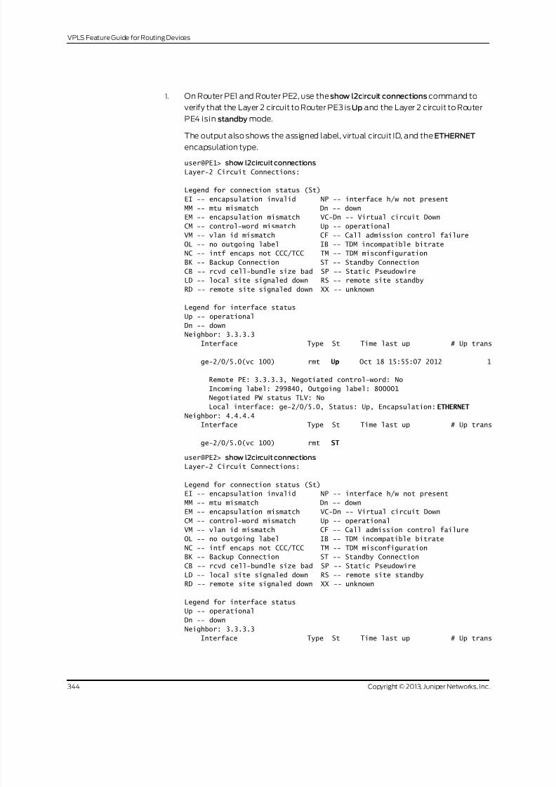
8/21/2019 Config Guide Vpns Vpls
http://slidepdf.com/reader/full/config-guide-vpns-vpls 362/485
1. On Router PE1 and Router PE2, use the show l2circuit connections command to
verify that the Layer 2 circuit to Router PE3 is Up and the Layer 2 circuit to Router
PE4 isin standby mode.
The output also shows the assigned label, virtual circuit ID, and the ETHERNETencapsulation type.
user@PE1> show l2circuit connections
Layer-2 Circuit Connections:
Legend for connection status (St)
EI -- encapsulation invalid NP -- interface h/w not present
MM -- mtu mismatch Dn -- down
EM -- encapsulation mismatch VC-Dn -- Virtual circuit Down
CM -- control-word mismatch Up -- operational
VM -- vlan id mismatch CF -- Call admission control failure
OL -- no outgoing label IB -- TDM incompatible bitrate
NC -- intf encaps not CCC/TCC TM -- TDM misconfiguration
BK -- Backup Connection ST -- Standby Connection
CB -- rcvd cell-bundle size bad SP -- Static Pseudowire
LD -- local site signaled down RS -- remote site standby
RD -- remote site signaled down XX -- unknown
Legend for interface status
Up -- operational
Dn -- down
Neighbor: 3.3.3.3
Interface Type St Time last up # Up trans
ge-2/0/5.0(vc 100) rmt Up Oct 18 15:55:07 2012 1
Remote PE: 3.3.3.3, Negotiated control-word: No
Incoming label: 299840, Outgoing label: 800001
Negotiated PW status TLV: No
Local interface: ge-2/0/5.0, Status: Up, Encapsulation: ETHERNET
Neighbor: 4.4.4.4Interface Type St Time last up # Up trans
ge-2/0/5.0(vc 100) rmt ST
user@PE2> show l2circuit connections
Layer-2 Circuit Connections:
Legend for connection status (St)
EI -- encapsulation invalid NP -- interface h/w not present
MM -- mtu mismatch Dn -- down
EM -- encapsulation mismatch VC-Dn -- Virtual circuit Down
CM -- control-word mismatch Up -- operational
VM -- vlan id mismatch CF -- Call admission control failure
OL -- no outgoing label IB -- TDM incompatible bitrate
NC -- intf encaps not CCC/TCC TM -- TDM misconfiguration
BK -- Backup Connection ST -- Standby Connection
CB -- rcvd cell-bundle size bad SP -- Static Pseudowire
LD -- local site signaled down RS -- remote site standby
RD -- remote site signaled down XX -- unknown
Legend for interface status
Up -- operational
Dn -- down
Neighbor: 3.3.3.3
Interface Type St Time last up # Up trans
Copyright © 2013, Juniper Networks, Inc.344
VPLS Feature Guide for Routing Devices

8/21/2019 Config Guide Vpns Vpls
http://slidepdf.com/reader/full/config-guide-vpns-vpls 363/485
ge-2/0/6.0(vc 200) rmt Up Oct 18 15:55:07 2012 1
Remote PE: 3.3.3.3, Negotiated control-word: No
Incoming label: 299872, Outgoing label: 800002
Negotiated PW status TLV: No Local interface: ge-2/0/6.0, Status: Up, Encapsulation: ETHERNET
Neighbor: 4.4.4.4
Interface Type St Time last up # Up trans
ge-2/0/6.0(vc 200) rmt ST
2. On Router PE1 and Router PE2, use the show ldp neighbor command to verify that
the targeted LDP sessions have been created between the loopback interface to
the primary and backup H-VPLS hub neighbors.
user@PE1> show ldp neighbor
Address Interface Label space ID Hold time
10.10.3.2 ge-2/0/9.0 2.2.2.2:0 13
10.10.1.2 ge-2/0/10.0 3.3.3.3:0 103.3.3.3 lo0.0 3.3.3.3:0 36
4.4.4.4 lo0.0 4.4.4.4:0 39
10.10.9.2 ge-2/0/8.0 4.4.4.4:0 14
user@PE2> show ldp neighbor
Address Interface Label space ID Hold time
10.10.3.1 ge-2/0/10.0 1.1.1.1:0 12
10.10.5.2 ge-2/0/9.0 4.4.4.4:0 11
10.10.4.1 ge-2/0/8.0 3.3.3.3:0 11
3.3.3.3 lo0.0 3.3.3.3:0 39
4.4.4.4 lo0.0 4.4.4.4:0 38
3. On Router PE3 and Router PE4, use the show vpls connections command to verify
that the VPLS connection status is Up for both the LDP-based VPLS and the
BGP-based VPLS Layer 2 circuits that are terminated.user@PE3> show vpls connections
Layer-2 VPN connections:
Legend for connection status (St)
EI -- encapsulation invalid NC -- interface encapsulation not
CCC/TCC/VPLS
EM -- encapsulation mismatch WE -- interface and instance encaps not
same
VC-Dn -- Virtual circuit down NP -- interface hardware not present
CM -- control-word mismatch -> -- only outbound connection is up
CN -- circuit not provisioned <- -- only inbound connection is up
OR -- out of range Up -- operational
OL -- no outgoing label Dn -- down
LD -- local site signaled down CF -- call admission control failureRD -- remote site signaled down SC -- local and remote site ID collision
LN -- local site not designated LM -- local site ID not minimum designated
RN -- remote site not designated RM -- remote site ID not minimum designated
XX -- unknown connection status IL -- no incoming label
MM -- MTU mismatch MI -- Mesh-Group ID not available
BK -- Backup connection ST -- Standby connection
PF -- Profile parse failure PB -- Profile busy
RS -- remote site standby SN -- Static Neighbor
LB -- Local site not best-site RB -- Remote site not best-site
VM -- VLAN ID mismatch
345Copyright © 2013, Juniper Networks, Inc.
Chapter 5: Next Generation VPLS Examples

8/21/2019 Config Guide Vpns Vpls
http://slidepdf.com/reader/full/config-guide-vpns-vpls 364/485
Legend for interface status
Up -- operational
Dn -- down
Instance: H-VPLSBGP-VPLS State
Local site: pe3 (3)
connection-site Type St Time last up # Up trans
4 rmt Up Oct 18 15:58:39 2012 1
Remote PE: 4.4.4.4, Negotiated control-word: No
Incoming label: 800267, Outgoing label: 800266
Local interface: vt-2/0/9.135266562, Status: Up, Encapsulation: VPLS
Description: Intf - vpls H-VPLS local site 3 remote site 4
LDP-VPLS State
Mesh-group connections: pe1
Neighbor Type St Time last up # Up trans
1.1.1.1(vpls-id 100) rmt Up Oct 18 15:55:07 2012 1
Remote PE: 1.1.1.1, Negotiated control-word: No
Incoming label: 800001, Outgoing label: 299840
Negotiated PW status TLV: No
Local interface: vt-2/0/10.135266560, Status: Up, Encapsulation:
ETHERNET
Description: Intf - vpls H-VPLS neighbor 1.1.1.1 vpls-id 100
Mesh-group connections: pe2
Neighbor Type St Time last up # Up trans
2.2.2.2(vpls-id 200) rmt Up Oct 18 15:55:07 2012 1
Remote PE: 2.2.2.2, Negotiated control-word: No
Incoming label: 800002, Outgoing label: 299872
Negotiated PW status TLV: No Local interface: vt-2/0/8.135266561, Status: Up, Encapsulation: ETHERNET
Description: Intf - vpls H-VPLS neighbor 2.2.2.2 vpls-id 200
user@PE4> show vpls connections
Layer-2 VPN connections:
Legend for connection status (St)
EI -- encapsulation invalid NC -- interface encapsulation not
CCC/TCC/VPLS
EM -- encapsulation mismatch WE -- interface and instance encaps not
same
VC-Dn -- Virtual circuit down NP -- interface hardware not present
CM -- control-word mismatch -> -- only outbound connection is up
CN -- circuit not provisioned <- -- only inbound connection is upOR -- out of range Up -- operational
OL -- no outgoing label Dn -- down
LD -- local site signaled down CF -- call admission control failure
RD -- remote site signaled down SC -- local and remote site ID collision
LN -- local site not designated LM -- local site ID not minimum designated
RN -- remote site not designated RM -- remote site ID not minimum designated
XX -- unknown connection status IL -- no incoming label
MM -- MTU mismatch MI -- Mesh-Group ID not available
BK -- Backup connection ST -- Standby connection
PF -- Profile parse failure PB -- Profile busy
Copyright © 2013, Juniper Networks, Inc.346
VPLS Feature Guide for Routing Devices

8/21/2019 Config Guide Vpns Vpls
http://slidepdf.com/reader/full/config-guide-vpns-vpls 365/485
RS -- remote site standby SN -- Static Neighbor
LB -- Local site not best-site RB -- Remote site not best-site
VM -- VLAN ID mismatch
Legend for interface status
Up -- operationalDn -- down
Instance: H-VPLS
BGP-VPLS State
Local site: pe4 (4)
connection-site Type St Time last up # Up trans
3 rmt Up Oct 18 15:58:39 2012 1
Remote PE: 3.3.3.3, Negotiated control-word: No
Incoming label: 800266, Outgoing label: 800267
Local interface: vt-2/0/8.17826050, Status: Up, Encapsulation: VPLS
Description: Intf - vpls H-VPLS local site 4 remote site 3
LDP-VPLS State
Mesh-group connections: pe1 Neighbor Type St Time last up # Up trans
1.1.1.1(vpls-id 100) rmt Up Oct 18 15:58:39 2012 1
Remote PE: 1.1.1.1, Negotiated control-word: No
Incoming label: 800002, Outgoing label: 299856
Negotiated PW status TLV: No
Local interface: vt-2/0/9.17826048, Status: Up, Encapsulation: ETHERNET
Description: Intf - vpls H-VPLS neighbor 1.1.1.1 vpls-id 100
Mesh-group connections: pe2
Neighbor Type St Time last up # Up trans
2.2.2.2(vpls-id 200) rmt Up Oct 18 15:58:39 2012 1
Remote PE: 2.2.2.2, Negotiated control-word: No
Incoming label: 800003, Outgoing label: 299888
Negotiated PW status TLV: No
Local interface: vt-2/0/10.17826049, Status: Up, Encapsulation: ETHERNET
Description: Intf - vpls H-VPLS neighbor 2.2.2.2 vpls-id 200
4. On Router PE3 and Router PE4, use the show vpls flood command to verify that the
H-VPLS PE router created a flood group for each spoke PE site.
user@PE3> show vpls flood
Name: H-VPLS
CEs: 1
VEs: 3
Flood Routes:
Prefix Type Owner NhType NhIndex 0x300cc/51 FLOOD_GRP_COMP_NH __ves__ comp 1376
0x300cf/51 FLOOD_GRP_COMP_NH __all_ces__ comp 744
0x300d5/51 FLOOD_GRP_COMP_NH pe1 comp 1702
0x300d3/51 FLOOD_GRP_COMP_NH pe2 comp 1544
0x30001/51 FLOOD_GRP_COMP_NH __re_flood__ comp 740
user@PE4> show vpls flood
Name: H-VPLS
CEs: 1
VEs: 3
347Copyright © 2013, Juniper Networks, Inc.
Chapter 5: Next Generation VPLS Examples

8/21/2019 Config Guide Vpns Vpls
http://slidepdf.com/reader/full/config-guide-vpns-vpls 366/485
Flood Routes:
Prefix Type Owner NhType NhIndex
0x300d1/51 FLOOD_GRP_COMP_NH __ves__ comp 1534
0x300d0/51 FLOOD_GRP_COMP_NH __all_ces__ comp 753
0x300d6/51 FLOOD_GRP_COMP_NH pe1 comp 1378
0x300d4/51 FLOOD_GRP_COMP_NH pe2 comp 16950x30002/51 FLOOD_GRP_COMP_NH __re_flood__ comp 750
5. On Router PE3 and Router PE4, use the show vpls mac-table command to verify
that MAC addresses of the CE devices have been learned.
user@PE3> show vpls mac-table
MAC flags (S -static MAC, D -dynamic MAC, L -locally learned, C -Control MAC
SE -Statistics enabled, NM -Non configured MAC, R -Remote PE MAC)
Routing instance : H-VPLS
Bridging domain : __H-VPLS__, VLAN : NA
MAC MAC Logical NH RTR
address flags interface Index ID
00:21:59:0f:35:32 D vt-2/0/8.135266560 00:21:59:0f:35:33 D ge-2/1/3.0
00:21:59:0f:35:d4 D vt-2/0/9.135266561
00:21:59:0f:35:d5 D vt-2/0/10.135266562
user@PE4> show vpls mac-table
MAC flags (S -static MAC, D -dynamic MAC, L -locally learned, C -Control MAC
SE -Statistics enabled, NM -Non configured MAC, R -Remote PE MAC)
Logical system : PE4
Routing instance : H-VPLS
Bridging domain : __H-VPLS__, VLAN : NA
MAC MAC Logical NH RTR
address flags interface Index ID
00:21:59:0f:35:32 D vt-2/0/8.17826050 00:21:59:0f:35:33 D vt-2/0/9.17826050
00:21:59:0f:35:d4 D vt-2/0/10.17826050
00:21:59:0f:35:d5 D ge-2/1/7.0
6. Make sure that the CE devices can ping each other.
user@CE1> ping 10.255.14.219 # ping sent from CE1 CE4
PING 10.255.14.219 (10.255.14.219): 56 data bytes
64 bytes from 10.255.14.219: icmp_seq=0 ttl=64 time=10.617 ms
64 bytes from 10.255.14.219: icmp_seq=1 ttl=64 time=9.224 ms
^C
--- 10.255.14.219 ping statistics ---
2 packets transmitted, 2 packets received, 0% packet loss
round-trip min/avg/max/stddev = 9.224/9.921/10.617/0.697 ms
user@CE2> ping 10.255.14.218 # ping sent from CE2 to CE3
PING 10.255.14.218 (10.255.14.218): 56 data bytes
64 bytes from 10.255.14.218: icmp_seq=0 ttl=64 time=1.151 ms
64 bytes from 10.255.14.218: icmp_seq=1 ttl=64 time=0.674 ms
^C
--- 10.255.14.218 ping statistics ---
2 packets transmitted, 2 packets received, 0% packet loss
round-trip min/avg/max/stddev = 0.674/0.913/1.151/0.238 ms
7. Check the relevant routing tables.
Copyright © 2013, Juniper Networks, Inc.348
VPLS Feature Guide for Routing Devices

8/21/2019 Config Guide Vpns Vpls
http://slidepdf.com/reader/full/config-guide-vpns-vpls 367/485
user@PE1> show route table l2circuit.0
l2circuit.0: 4 destinations, 4 routes (4 active, 0 holddown, 0 hidden)
+ = Active Route, - = Last Active, * = Both
3.3.3.3:NoCtrlWord:5:100:Local/96
*[L2CKT/7] 00:12:16, metric2 1
> to 10.10.1.2 via ge-2/0/10.0
3.3.3.3:NoCtrlWord:5:100:Remote/96
*[LDP/9] 00:12:16
Discard
4.4.4.4:NoCtrlWord:5:100:Local/96
*[L2CKT/7] 00:12:10, metric2 1
> to 10.10.9.2 via ge-2/0/8.0
4.4.4.4:NoCtrlWord:5:100:Remote/96
*[LDP/9] 00:12:15
Discard
user@PE2> show route table l2circuit.0
l2circuit.0: 4 destinations, 4 routes (4 active, 0 holddown, 0 hidden)
+ = Active Route, - = Last Active, * = Both
3.3.3.3:NoCtrlWord:5:200:Local/96
*[L2CKT/7] 00:13:13, metric2 1
> to 10.10.4.1 via ge-2/0/8.0
3.3.3.3:NoCtrlWord:5:200:Remote/96
*[LDP/9] 00:13:13
Discard
4.4.4.4:NoCtrlWord:5:200:Local/96
*[L2CKT/7] 00:13:13, metric2 1
> to 10.10.5.2 via ge-2/0/9.0
4.4.4.4:NoCtrlWord:5:200:Remote/96
*[LDP/9] 00:13:13
Discard
user@PE3> show route table H-VPLS.l2vpn.0
H-VPLS.l2vpn.0: 2 destinations, 2 routes (2 active, 0 holddown, 0 hidden)+ = Active Route, - = Last Active, * = Both
3.3.3.3:33:3:1/96
*[L2VPN/170/-101] 03:19:26, metric2 1
Indirect
4.4.4.4:44:4:1/96
*[BGP/170] 03:15:45, localpref 100, from 4.4.4.4
AS path: I, validation-state: unverified
> to 10.10.6.2 via ge-2/0/9.0
user@PE4> show route table H-VPLS.l2vpn.0
H-VPLS.l2vpn.0: 2 destinations, 2 routes (2 active, 0 holddown, 0 hidden)
+ = Active Route, - = Last Active, * = Both
3.3.3.3:33:3:1/96
*[BGP/170] 03:21:17, localpref 100, from 3.3.3.3
AS path: I, validation-state: unverified
> to 10.10.6.1 via ge-2/0/9.0
4.4.4.4:44:4:1/96
*[L2VPN/170/-101] 03:17:47, metric2 1
Indirect
349Copyright © 2013, Juniper Networks, Inc.
Chapter 5: Next Generation VPLS Examples

8/21/2019 Config Guide Vpns Vpls
http://slidepdf.com/reader/full/config-guide-vpns-vpls 368/485
Results The configuration and verification parts of this example have been completed. The
following section is for your reference.
The relevant sample configuration for Router PE1 follows.
Router PE1 interfaces {
ge-2/0/5 {
encapsulation ethernet-ccc;
unit0 {
description to_CE1;
family ccc;
}
}
ge-2/0/8 {
unit0 {
description to_PE4;
family inet {
address 10.10.9.1/30;
}family mpls;
}
}
ge-2/0/9 {
unit0 {
description to_PE2;
family inet {
address 10.10.3.1/30;
}
family mpls;
}
}
ge-2/0/10 {
unit0 {description to_PE3;
family inet {
address 10.10.1.1/30;
}
family mpls;
}
}
lo0{
unit0 {
family inet {
address 1.1.1.1/32;
}
}
}}
protocols {
mpls {
interface ge-2/0/8.0;
interface ge-2/0/9.0;
interface ge-2/0/10.0;
}
ospf {
traffic-engineering;
Copyright © 2013, Juniper Networks, Inc.350
VPLS Feature Guide for Routing Devices

8/21/2019 Config Guide Vpns Vpls
http://slidepdf.com/reader/full/config-guide-vpns-vpls 369/485
area 0.0.0.0 {
interface lo0.0 {
passive;
}
interface ge-2/0/8.0;interface ge-2/0/9.0;
interface ge-2/0/10.0;
}
}
ldp{
interface ge-2/0/8.0;
interface ge-2/0/9.0;
interface ge-2/0/10.0;
interface lo0.0;
}
l2circuit {
neighbor 3.3.3.3 {
interface ge-2/0/5.0 {
virtual-circuit-id 100;backup-neighbor 4.4.4.4 {
standby;
}
}
}
}
}
The relevant sample configuration for Router PE2 follows.
Router PE2 interfaces {
ge-2/0/6 {
encapsulation ethernet-ccc;
unit0 {
description to_CE2;
family ccc;
}
}
ge-2/0/8 {
unit0 {
description to_PE3;
family inet {
address 10.10.4.2/30;
}
family mpls;
}
}
ge-2/0/9 {
unit0 {
description to_PE4;
family inet {
address 10.10.5.1/30;
}
family mpls;
}
}
ge-2/0/10 {
351Copyright © 2013, Juniper Networks, Inc.
Chapter 5: Next Generation VPLS Examples

8/21/2019 Config Guide Vpns Vpls
http://slidepdf.com/reader/full/config-guide-vpns-vpls 370/485
unit0 {
description to_PE1;
family inet {
address 10.10.3.2/30;
}family mpls;
}
}
lo0{
unit0 {
family inet {
address 2.2.2.2/32;
}
}
}
}
protocols {
mpls {
interface ge-2/0/8.0;interface ge-2/0/9.0;
interface ge-2/0/10.0;
}
ospf {
traffic-engineering;
area 0.0.0.0 {
interface lo0.0 {
passive;
}
interface ge-2/0/8.0;
interface ge-2/0/9.0;
interface ge-2/0/10.0;
}
}ldp{
interface ge-2/0/8.0;
interface ge-2/0/9.0;
interface ge-2/0/10.0;
interface lo0.0;
}
l2circuit {
neighbor 3.3.3.3 {
interface ge-2/0/6.0 {
virtual-circuit-id 200;
backup-neighbor 4.4.4.4 {
standby;
}
}}
}
}
The relevant sample configuration for Router PE3 follows.
Router PE3 interfaces {
ge-2/0/8 {
unit0 {
Copyright © 2013, Juniper Networks, Inc.352
VPLS Feature Guide for Routing Devices

8/21/2019 Config Guide Vpns Vpls
http://slidepdf.com/reader/full/config-guide-vpns-vpls 371/485
description to_PE2;
family inet {
address 10.10.4.1/30;
}
family mpls;}
}
ge-2/0/9 {
unit0 {
description to_PE4;
family inet {
address 10.10.6.1/30;
}
family mpls;
}
}
ge-2/0/10 {
unit0 {
description to_PE1;family inet {
address 10.10.1.2/30;
}
family mpls;
}
}
ge-2/1/3 {
encapsulation ethernet-vpls;
unit0 {
description to_CE3;
family vpls;
}
}
lo0{unit 0{
family inet {
address 3.3.3.3/32;
}
}
}
}
protocols {
mpls {
interface ge-2/0/8.0;
interface ge-2/0/9.0;
interface ge-2/0/10.0;
}
bgp {group internal-peers {
type internal;
local-address 3.3.3.3;
family l2vpn {
signaling;
}
neighbor 4.4.4.4;
}
}
353Copyright © 2013, Juniper Networks, Inc.
Chapter 5: Next Generation VPLS Examples

8/21/2019 Config Guide Vpns Vpls
http://slidepdf.com/reader/full/config-guide-vpns-vpls 372/485
ospf {
traffic-engineering;
area 0.0.0.0 {
interface lo0.0 {
passive;}
interface ge-2/0/8.0;
interface ge-2/0/9.0;
interface ge-2/0/10.0;
}
}
ldp{
interface ge-2/0/8.0;
interface ge-2/0/9.0;
interface ge-2/0/10.0;
interface lo0.0;
}
}
routing-instances {H-VPLS {
instance-type vpls;
interface ge-2/1/3.0;
route-distinguisher 3.3.3.3:33;
vrf-target target:64510:2;
protocols {
vpls {
site pe3 {
site-identifier 3;
interface ge-2/1/3.0;
}
mesh-group pe1 {
vpls-id 100;
neighbor 1.1.1.1;}
mesh-group pe2 {
vpls-id 200;
neighbor 2.2.2.2;
}
}
}
}
}
routing-options {
autonomous-system 64510;
}
The relevant sample configuration for Router PE4 follows.
Router PE4 interfaces {
ge-2/0/8 {
unit0 {
description to_PE3;
family inet {
address 10.10.6.2/30;
}
family mpls;
Copyright © 2013, Juniper Networks, Inc.354
VPLS Feature Guide for Routing Devices

8/21/2019 Config Guide Vpns Vpls
http://slidepdf.com/reader/full/config-guide-vpns-vpls 373/485
}
}
ge-2/0/9 {
unit0 {
description to_PE1;family inet {
address 10.10.9.2/30;
}
family mpls;
}
}
ge-2/0/10 {
unit0 {
description to_PE2;
family inet {
address 10.10.5.2/30;
}
family mpls;
}}
ge-2/1/7 {
encapsulation ethernet-vpls;
unit0 {
description to_CE4;
family vpls;
}
}
lo0{
unit0 {
family inet {
address 4.4.4.4/32;
}
}}
}
protocols {
mpls {
interface ge-2/0/8.0;
interface ge-2/0/9.0;
interface ge-2/0/10.0;
}
bgp {
group internal-peers {
type internal;
local-address 4.4.4.4;
family l2vpn {
signaling;}
neighbor 3.3.3.3;
}
}
ospf {
traffic-engineering;
area 0.0.0.0 {
interface lo0.0 {
passive;
355Copyright © 2013, Juniper Networks, Inc.
Chapter 5: Next Generation VPLS Examples

8/21/2019 Config Guide Vpns Vpls
http://slidepdf.com/reader/full/config-guide-vpns-vpls 374/485
}
interface ge-2/0/8.0;
interface ge-2/0/9.0;
interface ge-2/0/10.0;
}}
ldp{
interface ge-2/0/8.0;
interface ge-2/0/9.0;
interface ge-2/0/10.0;
interface lo0.0;
}
}
routing-instances {
H-VPLS {
instance-type vpls;
interface ge-2/1/7.0;
route-distinguisher 4.4.4.4:44;
vrf-target target:64510:2;protocols {
vpls {
site pe4 {
site-identifier 4;
interface ge-2/1/7.0;
}
mesh-group pe1 {
vpls-id 100;
neighbor 1.1.1.1;
}
mesh-group pe2 {
vpls-id 200;
neighbor 2.2.2.2;
}}
}
}
}
routing-options {
autonomous-system 64510;
}
The relevant sample configuration for Device CE1 follows.
Router CE1 interfaces {
ge-2/0/8 {
unit0 {
description to_PE1;
family inet {
address 172.16.0.1/24;
}
}
}
lo0{
unit 0{
family inet {
address 10.255.14.214/32;
Copyright © 2013, Juniper Networks, Inc.356
VPLS Feature Guide for Routing Devices

8/21/2019 Config Guide Vpns Vpls
http://slidepdf.com/reader/full/config-guide-vpns-vpls 375/485
}
}
}
}
protocols {ospf {
area 0.0.0.0 {
interface lo0.0 {
passive;
}
interface ge-2/0/8.0;
}
}
}
The relevant sample configuration for Device CE2 follows.
Router CE2 interfaces {
ge-2/1/5 {
unit0 {
description to_PE2;
family inet {
address 172.16.0.2/24;
}
}
}
lo0{
unit 0{
family inet {
address 10.255.14.215/32;
}
}
}
}
protocols {
ospf {
area 0.0.0.0 {
interface lo0.0 {
passive;
}
interface ge-2/1/5.0;
}
}
}
The relevant sample configuration for Device CE3 follows.
Router CE3 interfaces {ge-2/0/9 {
unit0 {
description to_PE3;
family inet {
address 172.16.0.3/24;
}
}
}
lo0{
357Copyright © 2013, Juniper Networks, Inc.
Chapter 5: Next Generation VPLS Examples

8/21/2019 Config Guide Vpns Vpls
http://slidepdf.com/reader/full/config-guide-vpns-vpls 376/485
unit0 {
family inet {
address 10.255.14.218/32;
}
}}
}
protocols {
ospf {
area 0.0.0.0 {
interface lo0.0 {
passive;
}
interface ge-2/0/9.0;
}
}
}
The relevant sample configuration for Device CE4 follows.
Router CE4 interfaces {
ge-2/1/6 {
unit0 {
description to_PE4;
family inet {
address 172.16.0.4/24;
}
}
}
lo0{
unit 0{
family inet {
address 10.255.14.219/32;
}
}
}
}
protocols {
ospf {
area 0.0.0.0 {
interface lo0.0 {
passive;
}
interface ge-2/1/6.0;
}
}
}
Related
Documentation
Example: Configuring LDP-Based H-VPLS Using a Single Mesh Group to Terminate
the Layer 2 Circuits on page 359
•
Copyright © 2013, Juniper Networks, Inc.358
VPLS Feature Guide for Routing Devices

8/21/2019 Config Guide Vpns Vpls
http://slidepdf.com/reader/full/config-guide-vpns-vpls 377/485
Example: Configuring LDP-Based H-VPLS Using a Single Mesh Group to Terminatethe Layer 2 Circuits
This example shows how to configure a single mesh group to terminate the Layer 2
circuits into an LDP-based VPLS. Thisis onetypeof hierarchical virtual privateLAN service
(H-VPLS)configurationpossiblein the Juniper Networks implementation.Forinformation
about the alternate type of configuration see“Example: Configuring BGP-Based H-VPLS
Using Different Mesh Groups for Each Spoke Router” on page 336.
This example provides step-by-step configuration instructions and also provides steps
for verifying and troubleshooting the configuration.
This example is organized into the following sections:
• Requirements on page 359
• Overview and Topology on page 359
• Configuration on page 360
Requirements
This example uses the following hardware components:
• Four MX Series 3D Universal Edge Routers for Routers PE1, PE2, PE3, and PE4
• Two M Series Multiservice Edge Routers for Routers CE4 and PE5
• Two EX Series Ethernet Switches for Devices CE1 and CE2
• Two T Series Core Routers for Routers P1 and the route reflector
• One J Series Services Router for Router CE3
Overview and Topology
Figure 33 on page 360 shows the physical topology used in this example.
359Copyright © 2013, Juniper Networks, Inc.
Chapter 5: Next Generation VPLS Examples

8/21/2019 Config Guide Vpns Vpls
http://slidepdf.com/reader/full/config-guide-vpns-vpls 378/485
Figure 33: Physical Topology of H-VPLS using a Single Mesh Group
Route Reflector
g e - 0 / 1 / 0
g e - 0 / 1 / 2
g e - 1 / 0 / 0
g e - 1 / 0 / 2
x e - 0 / 1 / 0
xe-0/3/0
xe-0/3/0
x e - 0 / 1 / 0
ge-1/0/1
ge-3/0/0
ge-0/0/0
ge-0/2/0
x e - 0 / 0 / 0
ge-2/0/0
g e - 1 / 1 / 0
g e - 0 / 1 / 0
ge-0/2/0
PE1
x e - 1 / 3 / 0
x e - 0 / 0 / 0
PE2
ge-1/2/0
g e - 0 / 1 / 0PE3
PE5
P1 PE4 CE4
CE5
CE3
EX Series
T Series
MX Series
M Series
J Series
EX Series
MX Series MX Series
MX Series T Series
MX Series M Series
g 0 4 0 5 4 6
CE1
CE2
xe-0/2/0
xe-0/2/0
In Figure 33 on page 360:
• Local switching is used to switch traffic between Layer 2 circuit pseudowires from the
different spoke PE routers.
• The spoke PE routers are configured with the same virtual circuit ID and VPLS ID pair
in a mesh group.
• The spoke PE routers are configured in an LDP-signaled VPLS routing instance.
•
The layer 2 circuits are terminated into the LDP-based VPLS.
Configuration
To configure a single mesh group to terminate the Layer 2 circuits into an LDP-based
VPLS, perform the following tasks:
• Configuring the Spoke PE Routers on page 360
• Configuring the Hub PE Router on page 362
• Verification on page 363
Configuring the Spoke PE Routers
Step-by-StepProcedure
Configure a singlemesh group toterminate allthe Layer2 circuitpseudowires andenablelocal switching between the pseudowires.
1. On Router PE1, configure the Layer 2 circuit by including the l2circuit statement at
the [edit protocols] hierarchy level. Include the neighbor statement and specify the
IPv4 address of the hub PE router. Also configure the logical interface by including
the interface statement and specify the interface connected to Router CE1.
Copyright © 2013, Juniper Networks, Inc.360
VPLS Feature Guide for Routing Devices

8/21/2019 Config Guide Vpns Vpls
http://slidepdf.com/reader/full/config-guide-vpns-vpls 379/485
Configure the virtual circuit ID by including the virtual-circuit-id statement and
specifying 100 astheID value atthe [editprotocols l2circuit neighbor5.5.5.5 interface
ge-1/0/0.0] hierarchy level.
Configure the backup neighbor by including the backup-neighbor statement andspecifying the IPv4 address of the backup hub PE router. Router PE3 is the backup
neighbor in this example. Also include the standby statement at the [edit protocols
l2circuit neighbor 5.5.5.5 interface ge-1/0/0.0 backup-neighbor 3.3.3.3] hierarchy
level.
[edit protocols]
l2circuit {
neighbor 5.5.5.5 {
interface ge-1/0/0.0 {
virtual-circuit-id 100;
backup-neighbor 3.3.3.3 {
standby;
}
}}
}
2. On Router PE2, configure the Layer 2 circuit by including the l2circuit statement at
the [edit protocols] hierarchy level. Include the neighbor statement and specify the
IPv4 address of the hub PE router. Configure the logical interface by including the
interface statement and specifying the interface connected to Router CE2.
Configure the virtual circuit ID by including the virtual-circuit-id statement and
specifying 100 astheID value atthe [editprotocols l2circuit neighbor5.5.5.5 interface
ge-1/0/2.0] hierarchy level. Includethe encapsulationstatement and specifyethernet
as the type.
Configure the backup neighbor by including the backup-neighbor statement andspecifying the IPv4 address of the backup hub PE router. Router PE3 is the backup
neighbor in this example. Also include the standby statement at the [edit protocols
l2circuit neighbor 5.5.5.5 interface ge-1/0/0.0 backup-neighbor 3.3.3.3] hierarchy
level.
[edit protocols]
l2circuit {
neighbor 5.5.5.5 {
interface ge-1/0/2.0 {
virtual-circuit-id 100;
encapsulation-type ethernet;
backup-neighbor 3.3.3.3 {
standby;
}
}
}
}
3. On Router PE4, configure the Layer 2 circuit by including the l2circuit statement at
the [edit protocols] hierarchy level. Include the neighbor statement and specify the
IPv4 address of the hub PE router. Configure the logical interface by including the
interface statement and specify the interface connected to Router CE4.
361Copyright © 2013, Juniper Networks, Inc.
Chapter 5: Next Generation VPLS Examples

8/21/2019 Config Guide Vpns Vpls
http://slidepdf.com/reader/full/config-guide-vpns-vpls 380/485
Configure the virtual circuit ID by including the virtual-circuit-id statement and
specifying 100 astheID value atthe [editprotocols l2circuit neighbor5.5.5.5 interface
ge-1/2/0.0] hierarchy level.
Configure the backup neighbor by including the backup-neighbor statement andspecifying the IPv4 address of the backup hub PE router. Router PE3 is the backup
neighbor in this example. Also include the standby statement at the [edit protocols
l2circuit neighbor 5.5.5.5 interface ge-1/2/0.0 backup-neighbor 3.3.3.3] hierarchy
level.
[edit protocols]
l2circuit {
neighbor 5.5.5.5 {
interface ge-1/2/0.0 {
virtual-circuit-id 100;
backup-neighbor 3.3.3.3 {
standby;
}
}}
}
Configuring the Hub PE Router
Step-by-Step
Procedure
Configure a singlemesh group toterminate allthe Layer2 circuitpseudowires andenable
local switching between the pseudowires.
1. On Router PE3, configure the Gigabit Ethernet interface connected to Router CE3
by including the encapsulation statement and specifying the ethernet-vpls option.
Also configurethe logical interface by including the family statementand specifying
the vpls option.
[edit interfaces]
ge-1/0/1 {
encapsulation ethernet-vpls;
unit0 {
family vpls;
}
}
2. On Router PE3, configure the logical loopback interface by including the family
statement and specifyingthe inet option. Include the address statement and specify
the IPv4 address for the interface.
[edit interfaces]
lo0{
unit0 {
family inet {
address 3.3.3.3/32;
}
}
}
3. On Router PE3, configure the LDP-based VPLS routing instance by including the
instance-type statement at the [edit routing-instances H-VPLS] hierarchy level and
Copyright © 2013, Juniper Networks, Inc.362
VPLS Feature Guide for Routing Devices

8/21/2019 Config Guide Vpns Vpls
http://slidepdf.com/reader/full/config-guide-vpns-vpls 381/485
specifying the vpls option. Include the interface statement and specify the Gigabit
Ethernet interface connected to Router CE3.
Configure the VPLS protocol by including the vpls statement at the [edit
routing-instances H-VPLS protocols] hierarchy level. Include the no-tunnel-servicesstatement to enable the router to use an LSI interface.
[edit routing-instances]
H-VPLS {
instance-type vpls;
interface ge-1/0/1.0;
protocols {
vpls {
no-tunnel-services;
}
}
}
4. On Router PE3, configure the mesh group by including the mesh-group statement
at the [edit routing-instances H-VPLS protocols vpls] hierarchy level and specifying
L2-Circuits asthe name of the group. Include the vpls-id statement and specify 100
asthe ID value. Include the local-switching statement to enable the router to switch
traffic between the pseudowires.
For each neighbor in the mesh group, include the neighbor statement and specify
the IPv4 address of the spoke PE router.
[edit routing-instances H-VPLS protocols vpls]
mesh-group L2-Circuits {
vpls-id 100; <<<Same VPLS ID on all MTUs
local-switching; << Local-switching enabled
neighbor 1.1.1.1; <<MTU IP addresses
neighbor 2.2.2.2;
neighbor 4.4.4.4;
}
Verification
Step-by-Step
Procedure
On Router PE5, use the show ldp neighbor command to verify that LDP sessions
have been created to each of the spoke PE routers.
1.
user@PE5# show ldp neighbor
Address Interface Label space ID Hold time
1.1.1.1 lo0.0 1.1.1.1:0 33
2.2.2.2 lo0.0 2.2.2.2:0 37
4.4.4.4 lo0.0 4.4.4.4:0 39
2. On Router PE5, use the show vpls connections extensive command to verify thatthe mesh group neighbor session is Up, that inbound and outbound labels have
been assigned, that the VPLS ID is correct, and that the virtual tunnel interface is
being used.
user@PE5# show vpls connections extensive
...
Instance: H-VPLS
Number of local interfaces: 1
Number of local interfaces up: 1
363Copyright © 2013, Juniper Networks, Inc.
Chapter 5: Next Generation VPLS Examples

8/21/2019 Config Guide Vpns Vpls
http://slidepdf.com/reader/full/config-guide-vpns-vpls 382/485
Number of VE mesh-groups: 2
Number of VE mesh-groups up: 1
ge-2/0/0.0
Mesh-group interfaces: L2-Circuits
State: Up ID: 2
vt-2/1/0.1048848 Intf - vpls H-VPLS neighbor 4.4.4.4 vpls-id 100 vt-2/1/0.1048849 Intf - vpls H-VPLS neighbor 2.2.2.2 vpls-id 100
vt-2/1/0.1048850 Intf - vpls H-VPLS neighbor 1.1.1.1 vpls-id 100
Mesh-group interfaces: __ves__
State: Dn ID: 0
Mesh-group connections: L2-Circuits
Neighbor Type St Time last up # Up trans
4.4.4.4(vpls-id 100) rmt Up Jan 3 16:46:26 2010 1
Remote PE: 4.4.4.4, Negotiated control-word: No
Incoming label: 800011, Outgoing label: 301088
Local interface: vt-2/1/0.1048848, Status: Up, Encapsulation: ETHERNET
Description: Intf - vpls H-VPLS neighbor 4.4.4.4 vpls-id 100
Connection History: Jan 3 16:46:26 2010 status update timer
Jan 3 16:46:26 2010 PE route changed
Jan 3 16:46:26 2010 In lbl Update 800011
Jan 3 16:46:26 2010 Out lbl Update 301088
Jan 3 16:46:26 2010 In lbl Update 800011
Jan 3 16:46:26 2010 loc intf up vt-2/1/0.1048848
2.2.2.2(vpls-id 100) rmt Up Jan 3 16:46:26 2010 1
Remote PE: 2.2.2.2, Negotiated control-word: No
Incoming label: 800010, Outgoing label: 301488
Local interface: vt-2/1/0.1048849, Status: Up, Encapsulation: ETHERNET
Description: Intf - vpls H-VPLS neighbor 2.2.2.2 vpls-id 100
Connection History:
Jan 3 16:46:26 2010 status update timerJan 3 16:46:26 2010 PE route changed
Jan 3 16:46:26 2010 In lbl Update 800010
Jan 3 16:46:26 2010 Out lbl Update 301488
Jan 3 16:46:26 2010 In lbl Update 800010
Jan 3 16:46:26 2010 loc intf up vt-2/1/0.1048849
1.1.1.1(vpls-id 100) rmt Up Jan 3 16:46:26 2010 1
Remote PE: 1.1.1.1, Negotiated control-word: No
Incoming label: 800009, Outgoing label: 301296
Local interface: vt-2/1/0.1048850, Status: Up, Encapsulation: ETHERNET
Description: Intf - vpls H-VPLS neighbor 1.1.1.1 vpls-id 100
Connection History:
Jan 3 16:46:26 2010 status update timer
Jan 3 16:46:26 2010 PE route changed
Jan 3 16:46:26 2010 In lbl Update 800009
Jan 3 16:46:26 2010 Out lbl Update 301296
Jan 3 16:46:26 2010 In lbl Update 800009
Jan 3 16:46:26 2010 loc intf up vt-2/1/0.1048850
Related
Documentation
• Example: Configuring BGP-Based H-VPLS UsingDifferent MeshGroupsforEach Spoke
Router on page 336
Copyright © 2013, Juniper Networks, Inc.364
VPLS Feature Guide for Routing Devices

8/21/2019 Config Guide Vpns Vpls
http://slidepdf.com/reader/full/config-guide-vpns-vpls 383/485
CHAPTER 6
VPLS Configuration Statements
active-interface (VPLS Multihoming)
Syntax active-interface {
any;
primary interface-name;}
Hierarchy Level [edit logical-systems logical-system-name routing-instances instance-nameprotocols vpls
multi-homing],
[edit logical-systems logical-system-name routing-instances instance-nameprotocols vpls
multi-homing site site-name],
[edit routing-instances instance-nameprotocols vpls multi-homing],
[edit routing-instances instance-nameprotocols vpls multi-homing site site-name]
Release Information Statement introduced in Junos OS Release 7.5.
Description Specify a multihomed interface as the primary interface for the VPLS site. If there are
multiple interfaces, the remaining interfacesare activated only whenthe primary interface
goes down. If no active interfaces are configured at the site level, it is assumed that all
traffic for a VPLS site travels through a single, nonmultihomed PE router.
NOTE: Inthe VPLS documentation,the word router intermssuchasPErouter
is used to refer to any device that provides routing functions.
The remaining statements are explained separately.
For FEC 128, use the [edit routing-instances instance-name protocols vpls multi-homing]
hierarchy level.
Required Privilege
Level
routing—To view this statement in the configuration.
routing-control—To add this statement to the configuration.
Related
Documentation
• Specifying an Interface as the Active Interface on page 55
365Copyright © 2013, Juniper Networks, Inc.

8/21/2019 Config Guide Vpns Vpls
http://slidepdf.com/reader/full/config-guide-vpns-vpls 384/485
any (VPLS Multihoming)
Syntax any;
Hierarchy Level [edit logical-systems logical-system-name routing-instances instance-nameprotocols vpls
multi-homing active-interface],
[edit logical-systems logical-system-name routing-instances instance-nameprotocols vpls
multi-homing site site-nameactive-interface],
[edit routing-instances instance-nameprotocols vpls multi-homing active-interface],
[edit routing-instances instance-nameprotocols vpls multi-homing site site-name
active-interface]
Release Information Statement introduced in Junos OS Release 7.5.
Description Specify that any multihomed interface can be used as the primary interface by the VPLS
site. Depending on the orderin which interfaces are listedin the PE router’sconfiguration,
the first operational interfacein thesetof configuredinterfaces is chosen to be the primary
interface.
NOTE: Inthe VPLS documentation,the word router intermssuchasPErouter
is used to refer to any device that provides routing functions.
For FEC 128, use the [edit routing-instances instance-name protocols vpls multi-homing
active-interface] hierarchy level.
Default This is the default behavior.
Required Privilege
Level
routing—To view this statement in the configuration.
routing-control—To add this statement to the configuration.
Related
Documentation
• Specifying an Interface as the Active Interface on page 55
• primary on page 423
Copyright © 2013, Juniper Networks, Inc.366
VPLS Feature Guide for Routing Devices

8/21/2019 Config Guide Vpns Vpls
http://slidepdf.com/reader/full/config-guide-vpns-vpls 385/485
automatic-site-id
Syntax automatic-site-id {
collision-detect-time seconds;new-site-wait-time seconds;
reclaim-wait-time minimum seconds maximum seconds;
startup-wait-time seconds;
}
Hierarchy Level [edit logical-systemslogical-system-namerouting-instances routing-instance-nameprotocols
vpls site site-name],
[edit routing-instances routing-instance-name protocols vpls site site-name]
Release Information Statement introduced in Junos OS Release 9.1.
Description Enable automatic site identifiers for VPLS routing instances.
When you configure automatic-site-id for the first time, you must deactivate and then
activate protocol vpls. However, if you already have automatic-site-id configured, you do
not need to deactivate and then activate protocol vpls.
Options collision-detect-time—The time in seconds to wait after a claim advertisement is sent to
theother routersin a VPLS instancebeforea PE router can beginusinga site identifier.
If the PE router receives a competingclaimadvertisement for the same site identifier
during thistimeperiod,it initiates the collision resolutionprocedure forsite identifiers.
NOTE: Inthe VPLS documentation,the word router intermssuchasPErouter
is used to refer to any device that provides routing functions.
new-site-wait-time—The time in seconds to wait to receive VPLS information for a newly
configured routing instance or a new site. This time interval is also applied whenever
the automatic site identifier feature is activated on a VPLS routing instance other
than at startup. Effectively, this timer indicates how long to wait before an attempt
is made to allocate a site identifier. This timer is also triggered whenever a VPLS
routing instance is enabled.
reclaim-wait-time—The time in seconds to wait to receive VPLS information for a newly
configured routing instance or a new site. This time interval is also applied whenever
the automatic site identifier feature is activated on a VPLS routing instance other
than at startup. Effectively, this timer indicates how long to wait before an attemptis made to allocate a site identifier. This timer is also triggered whenever a VPLS
routinginstance is enabled. You canconfigure twovaluesfor thisoption:the minimum
wait time and the maximum wait time.
startup-wait-time—The time in seconds to wait at startup to receive all the VPLS
information for the route targets configured on the other PE routers included in the
VPLS routing instance.
367Copyright © 2013, Juniper Networks, Inc.
Chapter 6: VPLS Configuration Statements

8/21/2019 Config Guide Vpns Vpls
http://slidepdf.com/reader/full/config-guide-vpns-vpls 386/485
Required Privilege
Level
routing—To view this statement in the configuration.
routing-control—To add this statement to the configuration.
Related
Documentation
• Configuring Automatic Site Identifiers for VPLS on page 35
best-site
Syntax best-site;
Hierarchy Level [edit logical-systemslogical-system-namerouting-instances routing-instance-nameprotocols
vpls site site-name],
[edit routing-instances routing-instance-name protocols vpls site site-name]
Release Information Statement introduced in Junos OS Release 12.2.
Description Enables the VPLS multihoming best site functionality, allowing the site on which it has
beenenabled to be the preferredsite forthis PE router. Thisstatementmustbe configuredon all PE routers within the optimized VPLS routing instance.
NOTE: Inthe VPLS documentation,the word router intermssuchasPErouter
is used to refer to any device that provides routing functions.
Required Privilege
Level
routing—To view this statement in the configuration.
routing-control—To add this statement to the configuration.
Related
Documentation
• Example: VPLS Multihoming, Improved Convergence Time on page 152
Copyright © 2013, Juniper Networks, Inc.368
VPLS Feature Guide for Routing Devices

8/21/2019 Config Guide Vpns Vpls
http://slidepdf.com/reader/full/config-guide-vpns-vpls 387/485
bfd-liveness-detection (Layer 2 VPN and VPLS)
Syntax bfd-liveness-detection {
detection-time {threshold milliseconds;
}
minimum-interval milliseconds;
minimum-receive-interval milliseconds;
multiplier number ;
no-adaptation;
transmit-interval {
minimum-interval milliseconds;
threshold milliseconds;
}
version (1 | automatic);
}
Hierarchy Level [editlogical-system logical-system-name routing-instances routing-instance-nameprotocols
l2vpn oam],
[editlogical-system logical-system-name routing-instances routing-instance-nameprotocols
vpls neighbor neighbor-id oam],
[editlogical-system logical-system-name routing-instances routing-instance-nameprotocols
vpls mesh-group mesh-group-nameneighbor neighbor-id oam],
[editlogical-system logical-system-name routing-instances routing-instance-nameprotocols
vpls oam],
[edit routing-instances routing-instance-name protocols l2vpn oam],
[edit routing-instances routing-instance-name protocols vpls neighbor neighbor-id oam],
[edit routing-instances routing-instance-nameprotocols vpls mesh-group mesh-group-name
neighbor neighbor-id oam],
[edit routing-instances routing-instance-name protocols vpls oam]
Release Information Statement introduced in Junos OS Release 10.0.
Statement introduced in Junos OS Release 13.2 for Layer 2 VPNs and VPLS.
Description Configure bidirectional failure detection timers.
The BFD failure detection timers are adaptive and can be adjusted to be more or less
aggressive. For example, the timers can adapt to a higher value if the adjacency fails, or
a neighbor can negotiate a higher value for a timer than the configured value. The timers
adapt to a higher value when a BFD session flap occurs more than three times in a span
of 15 seconds. A back-off algorithm increases the receive (Rx) interval by two if the local
BFDinstanceis thereason for the session flap.The transmission(Tx) interval is increased
bytwo if the remoteBFD instance is thereason for the session flap. You can use the clear
bfd adaptation command to return BFD interval timers to their configured values. The
clear bfd adaptation command is hitless, meaning that the command does not affect
traffic flow on the routing device.
The remaining statements are explained separately.
Required Privilege
Level
routing—To view this statement in the configuration.
routing-control—To add this statement to the configuration.
369Copyright © 2013, Juniper Networks, Inc.
Chapter 6: VPLS Configuration Statements

8/21/2019 Config Guide Vpns Vpls
http://slidepdf.com/reader/full/config-guide-vpns-vpls 388/485
Related
Documentation
• Configuring BFD for Layer 2 VPN and VPLS on page 107
• Example: Configuring BFD for Static Routes
connectivity-type
Syntax connectivity-type (ce | irb | permanent);
Hierarchy Level [edit logical-systemslogical-system-namerouting-instances routing-instance-nameprotocols
vpls],
[edit routing-instances routing-instance-name protocols vpls]
Release Information Statement introduced in Junos OS Release 9.1.
irb option introduced in Junos OS Release 9.3.
permanent option introduced in Junos OS Release 10.4.
Description Specifywhena VPLSconnectionis taken down depending on whether or notthe interface
for the VPLSrouting instance is customer-facingor integrated routing and bridging (IRB).
Default ce
Options ce—Require that for the VPLS connection to be up, the customer-facing interface for the
VPLS routing instance must also be up. If the customer-facing interface fails, the
VPLS connection is taken down.
irb—Allow a VPLS connection to remain up so long as an IRB interface is configured for
the VPLS routing instance.
permanent—Allow a VPLS connection to remain up until specifically taken down. This
option is reserved for use in configuring Layer 2 Wholesale subscriber networks. See
theBroadbandSubscriberManagementSolutionsGuidefor details aboutconfiguring
a Layer 2 Wholesale network.
NOTE: To specifically take down a VPLS routing instance that is using the
permanent option, all associated static logical interfaces must also be down.
Required Privilege
Level
routing—To view this statement in the configuration.
routing-control—To add this statement to the configuration.
Related
Documentation
• Configuring VPLS Routing Instance and VPLS Interface Connectivity on page 41
• Configuring SeparateNNIRouting Instances for Layer 2Wholesale Service Retailers
Copyright © 2013, Juniper Networks, Inc.370
VPLS Feature Guide for Routing Devices

8/21/2019 Config Guide Vpns Vpls
http://slidepdf.com/reader/full/config-guide-vpns-vpls 389/485
detection-time (BFD Liveness Detection)
Syntax detection-time {
threshold milliseconds;}
Hierarchy Level [edit logical-systems logical-system-name protocols bgp bfd-liveness-detection],
[edit logical-systems logical-system-name protocols bgp group group-name
bfd-liveness-detection],
[editlogical-systems logical-system-nameprotocols bgp group group-nameneighbor address
bfd-liveness-detection],
[edit logical-systemslogical-system-namerouting-instances routing-instance-nameprotocols
bgp bfd-liveness-detection],
[edit logical-systemslogical-system-namerouting-instances routing-instance-nameprotocols
bgp group group-name bfd-liveness-detection],
[edit logical-systemslogical-system-namerouting-instances routing-instance-nameprotocols
bgp group group-name neighbor addressbfd-liveness-detection],
[editlogical-system logical-system-name routing-instances routing-instance-nameprotocols
l2vpn oam bfd-liveness-detection],
[editlogical-system logical-system-name routing-instances routing-instance-nameprotocols
vpls neighbor neighbor-id oam bfd-liveness-detection],
[editlogical-system logical-system-name routing-instances routing-instance-nameprotocols
vpls mesh-group mesh-group-nameneighbor neighbor-id oam bfd-liveness-detection],
[editlogical-system logical-system-name routing-instances routing-instance-nameprotocols
vpls oam bfd-liveness-detection],
[edit protocols bgp bfd-liveness-detection],
[edit protocols bgp group group-namebfd-liveness-detection],
[edit protocols bgp group group-nameneighbor addressbgp bfd-liveness-detection],
[edit routing-instances routing-instance-name protocols bgp bfd-liveness-detection],
[edit routing-instances routing-instance-name protocols bgp group group-name
bfd-liveness-detection],
[edit routing-instances routing-instance-name protocols bgp group group-name neighbor
addressbfd-liveness-detection]
[edit routing-instances routing-instance-nameprotocols l2vpn oam bfd-liveness-detection],
[edit routing-instances routing-instance-name protocols vpls neighbor neighbor-id oam
bfd-liveness-detection],
[edit routing-instances routing-instance-nameprotocols vpls mesh-group mesh-group-name
neighbor neighbor-id oam bfd-liveness-detection],
[edit routing-instances routing-instance-name protocols vpls oam bfd-liveness-detection]
Release Information Statement introduced in Junos OS Release 8.2.
Statement introduced in Junos OS Release 9.0 for EX Series switches.
Support for BFD authentication introduced in Junos OS Release 9.6.
Statement introduced in Junos OS Release 12.1 for the QFX Series.
Statement introduced in Junos OS Release 13.2 for Layer 2 VPNs and VPLS.
Description Enable BFD failure detection. The BFD failure detection timers are adaptive and can be
adjusted to be faster or slower. Thelower the BFDfailuredetection timer value, the faster
the failure detection and vice versa. For example, the timers can adapt to a higher value
if the adjacency fails (that is, the timer detects failures more slowly). Or a neighbor can
negotiate a higher value for a timer than the configured value. The timers adapt to a
highervalue when a BFD sessionflapoccurs more than threetimesin a spanof 15seconds.
A back-off algorithm increases the receive (Rx) interval by two if the local BFD instance
371Copyright © 2013, Juniper Networks, Inc.
Chapter 6: VPLS Configuration Statements

8/21/2019 Config Guide Vpns Vpls
http://slidepdf.com/reader/full/config-guide-vpns-vpls 390/485
is the reason for the session flap. The transmission (Tx) interval is increased by two if
the remote BFD instance is the reason for the session flap. You can use the clear bfd
adaptation command to return BFD interval timers to their configured values. The clear
bfd adaptation command is hitless, meaning that the command does not affect traffic
flow on the routing device.
The remaining statement is explained separately.
Required Privilege
Level
routing—To view this statement in the configuration.
routing-control—To add this statement to the configuration.
Related
Documentation
• Configuring BFD for Layer 2 VPN and VPLS on page 107
• Example: Configuring BFD for BGP
• bfd-liveness-detection
• threshold on page 436
Copyright © 2013, Juniper Networks, Inc.372
VPLS Feature Guide for Routing Devices

8/21/2019 Config Guide Vpns Vpls
http://slidepdf.com/reader/full/config-guide-vpns-vpls 391/485
encapsulation (Physical Interface)
Syntax encapsulation (atm-ccc-cell-relay | atm-pvc | cisco-hdlc | cisco-hdlc-ccc | cisco-hdlc-tcc |
ethernet-bridge | ethernet-ccc | ethernet-over-atm | ethernet-tcc | ethernet-vpls |ethernet-vpls-fr | ether-vpls-over-atm-llc | ethernet-vpls-ppp |extended-frame-relay-ccc
| extended-frame-relay-ether-type-tcc | extended-frame-relay-tcc | extended-vlan-bridge
| extended-vlan-ccc | extended-vlan-tcc | extended-vlan-vpls | flexible-ethernet-services
| flexible-frame-relay | frame-relay | frame-relay-ccc | frame-relay-ether-type |
frame-relay-ether-type-tcc | frame-relay-port-ccc | frame-relay-tcc | generic-services |
multilink-frame-relay-uni-nni| ppp | ppp-ccc | ppp-tcc | vlan-ccc| vlan-vci-ccc | vlan-vpls);
Hierarchy Level [edit interfaces interface-name],
[edit interfaces rlsq number : number ]
Release Information Statement introduced before Junos OS Release 7.4.
Statement introduced in Junos OS Release 11.1 for EX Series switches.
Statement introduced in Junos OS Release 12.1X48 for PTX Series Packet TransportRouters (flexible-ethernet-services , ethernet-ccc, and ethernet-tcc options only).
Description Specify the physical link-layer encapsulation type. Not all encapsulation types are
supported on the switches. See the switch CLI.
Default ppp—Use serial PPP encapsulation.
Options atm-ccc-cell-relay—Use ATM cell-relay encapsulation.
atm-pvc—Use ATM PVC encapsulation.
cisco-hdlc—Use Cisco-compatible High-Level Data Link Control (HDLC) framing.
cisco-hdlc-ccc—Use Cisco-compatible HDLC framing on CCC circuits.
cisco-hdlc-tcc—Use Cisco-compatible HDLC framing on TCC circuits for connecting
different media.
ethernet-bridge—Use Ethernet bridge encapsulation on Ethernet interfaces that have
bridging enabled and that must accept all packets.
ethernet-ccc—Use Ethernet CCC encapsulation on Ethernet interfaces that must accept
packets carrying standard Tag Protocol ID (TPID) values. For 8-port, 12-port, and
48-port Fast Ethernet PICs, CCC is not supported.
ethernet-over-atm—For interfaces that carry IPv4 traffic, use Ethernet over ATM
encapsulation.Whenyouuse thisencapsulation type,youcannot configuremultipoint
interfaces. As defined in RFC2684,MultiprotocolEncapsulationoverATMAdaptation
Layer5, this encapsulation type allows ATM interfaces to connect to devices that
support only bridge protocol data units (BPDUs). Junos OS does not completely
support bridging, but accepts BPDU packets as a default gateway. If you use the
router as an edge device, then the router acts as a default gateway. It accepts
Ethernet LLC/SNAP frames with IP or ARP in the payload, and drops the rest. For
packets destined to the Ethernet LAN, a route lookup is done using the destination
373Copyright © 2013, Juniper Networks, Inc.
Chapter 6: VPLS Configuration Statements

8/21/2019 Config Guide Vpns Vpls
http://slidepdf.com/reader/full/config-guide-vpns-vpls 392/485
IP address.If theroutelookup yields a fulladdressmatch, thepacket is encapsulated
withan LLC/SNAPandMAC header, andthe packet is forwardedto theATM interface.
ethernet-tcc—For interfaces that carry IPv4 traffic, use Ethernet TCC encapsulation on
interfaces that must accept packets carrying standard TPID values. For 8-port,12-port, and 48-port Fast Ethernet PICs, TCC is not supported.
ethernet-vpls—Use Ethernet VPLS encapsulation on Ethernet interfaces that have VPLS
enabled and that must accept packets carrying standard TPID values. On M Series
routers, except the M320 router, the 4-port Fast Ethernet TX PIC and the 1-port,
2-port, and 4-port, 4-slot Gigabit Ethernet PICs can use the Ethernet VPLS
encapsulation type.
ethernet-vpls-fr—Use in a VPLS setupwhena CE device is connected to a PE deviceover
a time division multiplexing (TDM) link. This encapsulation type enables the PE
device to terminate the outer layer 2 Frame Relay connection, use the 802.1p bits
inside the inner Ethernet header to classify the packets, look at the MAC address
from the Ethernet header, and use the MAC address to forward the packet into a
given VPLS instance.
ethernet-vpls-ppp—Use in a VPLS setup when a CE device is connected toa PE device
over a time division multiplexing (TDM) link. This encapsulation type enables the PE
device to terminate the outer layer 2 PPP connection, use the 802.1p bits inside the
inner Ethernet header to classify the packets, look at the MAC address from the
Ethernet header, and use it to forward the packet into a given VPLS instance.
ether-vpls-over-atm-llc—For ATM intelligentqueuing (IQ) interfacesonly, use theEthernet
virtual private LAN service (VPLS) over ATM LLC encapsulation to bridge Ethernet
interfaces and ATM interfaces over a VPLS routing instance (as described in
RFC 2684,Multiprotocol Encapsulation over ATMAdaptation Layer 5). Packets from
the ATM interfaces are converted to standard ENET2/802.3 encapsulated Ethernet
frames with the frame check sequence (FCS) field removed.
extended-frame-relay-ccc—Use Frame Relay encapsulation on CCC circuits. This
encapsulation type allows you to dedicate DLCIs 1 through 1022 to CCC.
extended-frame-relay-ether-type-tcc —Use extended Frame Relay ether type TCC for
Cisco-compatible Frame Relay for DLCIs 1 through 1022. This encapsulation type is
used for circuits with different media on either side of the connection.
extended-frame-relay-tcc—Use Frame Relay encapsulation on TCC circuits to connect
different media.This encapsulation type allows you to dedicate DLCIs1 through 1022
to TCC.
extended-vlan-bridge—Use extended VLAN bridge encapsulation on Ethernet interfaces
that have IEEE 802.1Q VLAN tagging and bridging enabled and that must accept
packets carrying TPID 0x8100 or a user-defined TPID.
Copyright © 2013, Juniper Networks, Inc.374
VPLS Feature Guide for Routing Devices

8/21/2019 Config Guide Vpns Vpls
http://slidepdf.com/reader/full/config-guide-vpns-vpls 393/485
extended-vlan-ccc—Use extended VLAN encapsulation on CCC circuits with Gigabit
Ethernet and 4-port Fast Ethernet interfaces that must accept packets carrying
802.1Q values. For 8-port, 12-port, and 48-port Fast Ethernet PICs, extended VLAN
CCC is not supported. For 4-port Gigabit Ethernet PICs, extended VLAN CCC is not
supported.
extended-vlan-tcc—Forinterfaces thatcarryIPv4 traffic,use extendedVLANencapsulation
on TCC circuits with Gigabit Ethernet interfaces on which you want to use 802.1Q
tagging. For 4-port Gigabit Ethernet PICs, extended VLAN TCC is not supported.
extended-vlan-vpls—Use extended VLAN VPLS encapsulation on Ethernet interfaces
that have VLAN 802.1Q tagging and VPLS enabled and that must accept packets
carrying TPIDs 0x8100, 0x9100, and 0x9901. On M Series routers, except the M320
router, the 4-port Fast Ethernet TX PIC and the 1-port, 2-port, and 4-port, 4-slot
Gigabit Ethernet PICs can use the Ethernet VPLS encapsulation type.
NOTE: The built-in Gigabit Ethernet PIC on an M7i router does not support
extended VLAN VPLS encapsulation.
flexible-ethernet-services —For Gigabit Ethernet IQ interfaces and Gigabit Ethernet PICs
with small form-factor pluggable transceivers (SFPs) (except the 10-port Gigabit
Ethernet PIC and the built-in Gigabit Ethernet port on the M7i router), use flexible
Ethernet services encapsulation when you want to configure multiple per-unit
Ethernet encapsulations. Aggregated Ethernet bundles can use this encapsulation
type. This encapsulation type allows you to configureany combination of route, TCC,
CCC, Layer 2 virtual private networks (VPNs), and VPLS encapsulations on a single
physical port. If youconfigure flexible Ethernet servicesencapsulationon the physical
interface, VLAN IDs from 1 through 511 are no longer reserved for normal VLANs.
flexible-frame-relay—For IQ interfaces only, use flexible Frame Relay encapsulation when
you want to configure multiple per-unit Frame Relay encapsulations. This
encapsulation type allows you to configure any combination of TCC, CCC, and
standard Frame Relay encapsulations on a single physical port. Also, each logical
interface can have any DLCI value from 1 through 1022.
frame-relay—Use Frame Relay encapsulation.
frame-relay-ccc—Use Frame Relay encapsulation on CCC circuits.
frame-relay-ether-type—UseFrame Relay ethertype encapsulationfor compatibilitywith
the Cisco Frame Relay.
frame-relay-ether-type-tcc—UseFrameRelayethertype TCC forCisco-compatible Frame
Relay on TCC circuits to connect different media.
frame-relay-port-ccc—Use Frame Relay port CCC encapsulation to transparently carry
all the DLCIs between two customer edge (CE) routers without explicitly configuring
each DLCI on the two provider edge (PE) routers with Frame Relay transport. When
you use this encapsulation type, you can configure the ccc family only.
375Copyright © 2013, Juniper Networks, Inc.
Chapter 6: VPLS Configuration Statements

8/21/2019 Config Guide Vpns Vpls
http://slidepdf.com/reader/full/config-guide-vpns-vpls 394/485
frame-relay-tcc—Use Frame Relay encapsulation on TCC circuits to connect different
media.
generic-services—Use generic services encapsulation for services with a hierarchical
scheduler.
multilink-frame-relay-uni-nni —Use MLFR UNI NNI encapsulation. This encapsulation is
used on link services, voice services interfaces functioning as FRF.16 bundles, and
their constituent T1 or E1 interfaces, and is supported on LSQ and redundant LSQ
interfaces.
ppp—Use serial PPP encapsulation.
ppp-ccc—Useserial PPP encapsulationon CCCcircuits.When you use this encapsulation
type, you can configure the ccc family only.
ppp-tcc—Use serial PPP encapsulation on TCC circuits for connecting different media.
When you use this encapsulation type, you can configure the tcc family only.
vlan-ccc—Use Ethernet VLAN encapsulation on CCC circuits.
vlan-vci-ccc—Use ATM-to-Ethernet interworking encapsulation on CCC circuits. When
you use this encapsulation type, you can configure the ccc family only. All logical
interfaces configured on the Ethernet interface must also have the encapsulation
type set to vlan-vci-ccc.
vlan-vpls—Use VLANVPLS encapsulation on Ethernet interfaces with VLAN tagging and
VPLS enabled. Interfaces with VLAN VPLS encapsulation accept packets carrying
standard TPID values only. On M Series routers, except the M320 router, the 4-port
Fast Ethernet TX PIC and the 1-port, 2-port, and 4-port, 4-slot Gigabit Ethernet PICs
can use the Ethernet VPLS encapsulation type.
NOTE: Label-switched interfaces (LSIs) do not support VLAN VPLS
encapsulation. Therefore, you can only use VLAN VPLS encapsulation on a
PE-router-to-CE-router interface and not a core-facing interface.
Required Privilege
Level
interface—To view this statement in the configuration.
interface-control—To add this statement to the configuration.
Copyright © 2013, Juniper Networks, Inc.376
VPLS Feature Guide for Routing Devices

8/21/2019 Config Guide Vpns Vpls
http://slidepdf.com/reader/full/config-guide-vpns-vpls 395/485
Related
Documentation
• Configuring Interface Encapsulation on Physical Interfaces
• Configuring CCC Encapsulation for Layer 2 VPNs
• Configuring Layer 2 SwitchingCross-ConnectsUsing CCC
• Configuring TCC Encapsulation for Layer 2 VPNs andLayer 2 Circuits
• ConfiguringATM Interface Encapsulation
• Configuring ATM-to-Ethernet Interworking
• Configuring VLANEncapsulation
• ConfiguringExtendedVLANEncapsulation
• ConfiguringEncapsulation for Layer 2 Wholesale VLAN Interfaces
• Configuring Interfaces for Layer 2 Circuits
• Configuring Interface Encapsulation on PTXSeries Packet Transport Routers
• Configuring anMPLS-BasedLayer 2 VPN(CLI Procedure)
• Configuring MPLS LSP Tunnel Cross-Connects UsingCCC
• Configuring TCC
• Configuring VPLS Interface Encapsulation on page 47
• Configuring Interfaces for VPLS Routing on page 45
• Defining the Encapsulation for Switching Cross-Connects
• Understanding Encapsulation on an Interface
377Copyright © 2013, Juniper Networks, Inc.
Chapter 6: VPLS Configuration Statements
8/21/2019 Config Guide Vpns Vpls
http://slidepdf.com/reader/full/config-guide-vpns-vpls 396/485
encapsulation-type (Layer 2 VPNs)
Syntax encapsulation-type (atm-aal5 | atm-cell | atm-cell-port-mode | atm-cell-vc-mode |
atm-cell-vp-mode | cesop | cisco-hdlc | ethernet | ethernet-vlan | frame-relay |frame-relay-port-mode | interworking | ppp | satop-e1 | satop-e3 | satop-t1 | satop-t3);
Hierarchy Level [edit logical-systems logical-system-name protocols l2circuit neighbor address interface
interface-name],
[edit logical-systemslogical-system-namerouting-instances routing-instance-nameprotocols
l2vpn],
[edit logical-systemslogical-system-namerouting-instances routing-instance-nameprotocols
l2vpn neighbor address],
[edit logical-systemslogical-system-namerouting-instances routing-instance-nameprotocols
vpls],
[edit protocols l2circuit neighbor address interface interface-name],
[edit routing-instances routing-instance-name protocols l2vpn],
[edit routing-instances routing-instance-name protocols l2vpn neighbor address],
[edit routing-instances routing-instance-name protocols vpls],
[edit routing-instances routing-instance-name protocols vpls neighbor address]
Release Information Statement introduced in Junos OS Release 9.2.
Statement introduced in Junos OS Release 11.1 for EX Series switches.
Description Specify the type of Layer 2 traffic originating from the CE device. Only the ethernet and
ethernet-vlan encapsulation types are supported for VPLS. Not all encapsulation types
are supported on the switches. See the switch CLI.
Options atm-aal5—ATM Adaptation Layer (AAL/5)
atm-cell—ATM cell relay
atm-cell-port-mode—ATM cell relay port promiscuous mode
atm-cell-vc-mode—ATM VC cell relay nonpromiscuous mode
atm-cell-vp-mode—ATM virtual path (VP) cell relay promiscuous mode
cesop—CESOP-based Layer 2 VPN
cisco-hdlc—Cisco Systems–compatible HDLC
ethernet—Ethernet
ethernet-vlan—Ethernet VLAN
frame-relay—Frame Relay
frame-relay-port-mode—Frame Relay port mode
interworking—Layer 2.5 interworking VPN
ppp—PPP
satsop-e1—SATSOP-E1–based Layer 2 VPN
Copyright © 2013, Juniper Networks, Inc.378
VPLS Feature Guide for Routing Devices

8/21/2019 Config Guide Vpns Vpls
http://slidepdf.com/reader/full/config-guide-vpns-vpls 397/485
satsop-e3—SATSOP-E3–based Layer 2 VPN
satsop-t1—SATSOP-T1–based Layer 2 VPN
satsop-t3—SATSOP-T3–based Layer 2 VPNDefault: For VPLS networks, the default encapsulation type is ethernet.
Required Privilege
Level
routing—To view this statement in the configuration.
routing-control—To add this statement to the configuration.
Related
Documentation
• Configuring the Local Siteon PERouters in Layer 2 VPNs
• Configuring VPLS Routing Instances on page 32
• Configuring Interfaces for Layer 2 Circuits
• Configuring anMPLS-BasedLayer 2 VPN(CLI Procedure)
379Copyright © 2013, Juniper Networks, Inc.
Chapter 6: VPLS Configuration Statements

8/21/2019 Config Guide Vpns Vpls
http://slidepdf.com/reader/full/config-guide-vpns-vpls 398/485
family multiservice
Syntax family multiservice {
destination-mac;label-1;
label-2;
payload {
ip {
layer-3 {
(source-ip-only | destination-ip-only);
}
layer-3-only;
layer-4;
}
}
source-mac;
symmetric-hash {
complement;}
}
Hierarchy Level [edit forwarding-options hash-key]
Release Information Statement introduced in Junos OS Release 8.0.
ip, label-1, label-2, layer-3-only, and payload options introduced in Junos OS Release 9.4.
layer-3, layer-. source-ip-only, and destination-ip-only options introduced in Junos OS
Release 9.5.
symmetric-hash and complement options introduced in Junos OS Release 9.6.
Description Configure load balancing based on Layer 2 media access control information. On MX
Seriesrouters, configure VPLS load balancing. On M120 andM320 routers only, configureVPLS load balancing based on MPLS labels and IP information. For IPv4 traffic, only the
IP source and destination addresses are included in the hash key. For MPLS and IPv4
traffic, one or two MPLS labels and IPv4 source and destination addresses are included.
For MPLS Ethernet pseudowires, only one or two MPLS labels are included in the hash
key.
Options You can configure one or more options to load-balance using the packet information
that you specify.
destination-mac—Include the destination-address MAC information in the hash key for
Layer 2 load balancing.
label-1 (M120 and M320 routers only)—Include the first MPLS label in the hash key. Used
for including a one-label packet for per-flow load balancing of IPv4 VPLS traffic
based on IP information and MPLS labels.
label-2 (M120 and M320 routers only)—Include the second MPLS label in the hash key.
If both label-1 and label-2 are specified, the entire first label and the first 16 bits of
the second label are hashed.
Copyright © 2013, Juniper Networks, Inc.380
VPLS Feature Guide for Routing Devices

8/21/2019 Config Guide Vpns Vpls
http://slidepdf.com/reader/full/config-guide-vpns-vpls 399/485
payload (MX Series, M120, and M320 routers only)—Include the packet’s IP payload in
the hash key.
• ip (MX Series, M120, andM320 routersonly)—Include the IP address of theIPv4 or IPv6
payload in the hash key.
• layer-3 (MX Series routers only)—Use this to include Layer 3 information from the
packet’s IP payload in the hash key.
• destination-ip-only (MXSeriesroutersonly)—Usethisto include only thedestination
IP address in the payload in the hash key.
• source-ip-only (MX Series routers only)—Use this to include only the source IP
address in the payload in the hash key.
NOTE: You caninclude either the source-ip-only orthe destination-ip-only
statement, not both. They are mutually exclusive.
• layer-3-only (M120, and M320 routers only)—Include only the Layer 3 information
from the packet’s IP payload in the hash key.
• layer-4 (MX Series routers only)—Include Layer 4 information from the packet’s IP
payload in the hash key.
NOTE: On MX Series routers only, youcan configure either Layer 3 or Layer
4 load balancing, or both at the same time.
NOTE: On I chip platforms, an unknown Layer 4 header is excluded from
load-balance hashing to avoid undesired packet reordering.
source-mac—Include the source-address MAC information in the hash key.
symmetric-hash (MX Series routers only)—Configure the symmetric hash or symmetric
hash complement for configuring symmetrical load balancing on an 802.3ad Link
Aggregation Group.
• complement —Include the complement of the symmetric hash in the hash key.
Required Privilege
Level
interface—To view this statement in the configuration.
interface-control—To add this statement to the configuration.
381Copyright © 2013, Juniper Networks, Inc.
Chapter 6: VPLS Configuration Statements

8/21/2019 Config Guide Vpns Vpls
http://slidepdf.com/reader/full/config-guide-vpns-vpls 400/485
Related
Documentation
• Configuring LoadBalancingBasedonMAC Addresses
• Configuring VPLS Load Balancing Based on IP and MPLS Information on page 61
• Configuring VPLS Load Balancing on MX Series 3D Universal Edge Routers on page 62
• Configuring VPLS Load Balancing on page 59
Copyright © 2013, Juniper Networks, Inc.382
VPLS Feature Guide for Routing Devices

8/21/2019 Config Guide Vpns Vpls
http://slidepdf.com/reader/full/config-guide-vpns-vpls 401/485
fast-reroute-priority
Syntax fast-reroute-priority (high | low | medium);
Hierarchy Level [edit forwarding-options]
[edit logical-systems logical-system-name routing-instances routing-instance-name
forwarding-options],
[edit routing-instances routing-instance-name forwarding-options]
Release Information Statement introduced in Junos OS Release 9.5.
Statement introduced in Junos OS Release 12.3R2 for EX Series switches.
Description Specify the fast reroute priority for a VPLS routing instance. You can configure high,
medium, or low fast reroute priority to prioritize specific VPLS routing instances for faster
convergence and traffic restoration. Because the router repairs nexthopsfor high-priority
VPLS routing instances first, the traffic traversing a VPLS routing instance configured
with high fast reroute priority is restored faster than the traffic for VPLS routing instancesconfigured with medium or low fast reroute priority.
NOTE: Inthe VPLS documentation,the word router intermssuchasPErouter
is used to refer to any device that provides routing functions.
Default low
Options high—Set thefastreroutepriority for a VPLS routing instance tohigh. Duringa fast reroute
event, the router repairs next hops for high-priority VPLS routing instances first.
low—Set the fast reroute priority for a VPLS routing instance to low, which is the default.
During a fast reroute event, the router repairs next hops for low-priority VPLS routing
instances last.
medium—Set the fast reroute priority for a VPLS routing instance to medium. During a
fast reroute event, the router repairs next hops for medium-priority VPLS instances
after high-priority VPLS routing instances but before low-priority VPLS routing
instances.
Required Privilege
Level
routing—To view this statement in the configuration.
routing-control—To add this statement to the configuration.
Related
Documentation
• Configuring VPLS Fast Reroute Priority on page 63
383Copyright © 2013, Juniper Networks, Inc.
Chapter 6: VPLS Configuration Statements

8/21/2019 Config Guide Vpns Vpls
http://slidepdf.com/reader/full/config-guide-vpns-vpls 402/485
identifier (VPLS Multihoming for FEC 129)
Syntax identifier identifier ;
Hierarchy Level [edit logical-systems logical-system-name routing-instances instance-nameprotocols vpls
multi-homing site site-name],
[edit routing-instances instance-nameprotocols vpls multi-homing site site-name]
Release Information Statement introduced in Junos OS Release 12.3.
Description Configure a Layer 2 VPN or VPLS multihoming identifier (MHID). An identifier needs to
be configured for each multihomed site. Multihoming site identifiers are specific to a
VPLS domain. They need not be unique on a provider edge (PE) router when multiple
VPLS instances are present. The network layer reachability information (NLRI)
advertisements sent to a CE device are identified as candidates for designated forwarder
selection because the advertisements have the same multihoming identifier. Thus, you
shouldassignthe same identifier onall VPLS PE routersthat are multihomed tothe samecustomer site.
NOTE: Theroutedistinguisher mustbe unique amongPE routers participating
in a multihomed site, so that the RD:MHID combination is unique across
multiple VPLS domains. For example, one PE router might have a route
distinguisher of 1.1.1.4:1, and another PE router in the same site might have a
route distinguisher of 1.1.1.2:1. The first number can be, for example, the
loopback interface address that identifies the PE router. The second number
is the multihoming identifier.
NOTE: Inthe VPLS documentation,the word router intermssuchasPErouter
is used to refer to any device that provides routing functions.
Options identifier —Number that identifies the multihomed site.
Range: 1 through 65535
Required Privilege
Level
routing—To view this statement in the configuration.
routing-control—To add this statement to the configuration.
Related
Documentation
• Example: Configuring VPLS Multihoming (FEC 129) on page 164
Copyright © 2013, Juniper Networks, Inc.384
VPLS Feature Guide for Routing Devices

8/21/2019 Config Guide Vpns Vpls
http://slidepdf.com/reader/full/config-guide-vpns-vpls 403/485
ignore-encapsulation-mismatch
Syntax ignore-encapsulation-mismatch;
Hierarchy Level [edit logical-systems logical-system-name protocols l2circuit local-switching interface
interface-name],
[edit logical-systems logical-system-name protocols l2circuit neighbor address interface
interface-name],
[edit logical-systemslogical-system-namerouting-instances routing-instance-nameprotocols
vpls mesh-group mesh-group-nameneighbor neighbor-id ],
[edit logical-systemslogical-system-namerouting-instances routing-instance-nameprotocols
vpls neighbor neighbor-id ],
[edit protocols l2circuit local-switching interface interface-name],
[edit protocols l2circuit neighbor address interface interface-name],
[edit routing-instances routing-instance-name protocols evpn interface interface-name],
[edit routing-instances routing-instance-nameprotocols vpls mesh-group mesh-group-name
neighbor neighbor-id ],
[edit routing-instances routing-instance-name protocols vpls neighbor neighbor-id ]
Release Information Statement introduced in Junos OS Release 9.2.
Statement extended to support local switching in Junos OS Release 10.4.
Statement introduced for EVPNs in Junos OS Release 13.2 for MX 3D Series.
Description Allow a Layer 2 circuit, VPLS, or EVPN to be established even though the encapsulation
configured on the CE device interface does not match the encapsulation configured on
the Layer 2 circuit, VPLS, or EVPN interface.
Required Privilege
Level
routing—To view this statement in the configuration.
routing-control—To add this statement to the configuration
Related
Documentation
• ConfiguringEVPNRouting Instances
• Configuring Interfaces for Layer 2 Circuits
385Copyright © 2013, Juniper Networks, Inc.
Chapter 6: VPLS Configuration Statements

8/21/2019 Config Guide Vpns Vpls
http://slidepdf.com/reader/full/config-guide-vpns-vpls 404/485
ignore-mtu-mismatch
Syntax ignore-mtu-mismatch;
Hierarchy Level [edit logical-systems logical-system-name protocols l2circuit local-switching interface
interface-name],
[edit logical-systems logical-system-name protocols l2circuit neighbor address interface
interface-name],
[edit logical-systemslogical-system-namerouting-instances routing-instance-nameprotocols
l2vpn interface interface-name],
[edit logical-systemslogical-system-namerouting-instances routing-instance-nameprotocols
vpls],
[edit protocols l2circuit local-switching interface interface-name],
[edit protocols l2circuit neighbor address interface interface-name],
[edit routing-instances routing-instance-name protocols l2vpn interface interface-name],
[edit routing-instances routing-instance-name protocols vpls]
Release Information Statement introduced in Junos OS Release 8.5.
Support for remote PE routers added in Junos OS Release 9.2.
Support for Layer 2 VPNs and VPLS added in Junos OS Release 10.4.
Description Ignore the MTU configuration set for the physical interface associated with the local
switching interface or with the remote PE router. This allows a pseudowire to be brought
up between two logical interfaces that are defined on physical interfaces with different
MTU values.
Required Privilege
Level
routing—To view this statement in the configuration.
routing-control—To add this statement to the configuration
RelatedDocumentation
•
Configuring Local Interface Switching in Layer 2 Circuits
• Configuring the MTU for Layer 2 Interfaces on page 52
Copyright © 2013, Juniper Networks, Inc.386
VPLS Feature Guide for Routing Devices
8/21/2019 Config Guide Vpns Vpls
http://slidepdf.com/reader/full/config-guide-vpns-vpls 405/485
interface (Routing Instances)
Syntax interface interface-name {
description text;}
Hierarchy Level [edit logical-systems logical-system-name routing-instances routing-instance-name],
[edit routing-instances routing-instance-name]
Release Information Statement introduced before Junos OS Release 7.4.
Statement introduced in Junos OS Release 9.2 for EX Series switches.
Statement introduced in Junos OS Release 12.3 for ACX Series routers.
Statement introduced in Junos OS Release 13.2 for MX 3D Series routers.
Description Interface over which the VPN traffic travels between the PE device and CE device. You
configure the interface on the PE device. If the value vrf is specified for the instance-type
statement included in the routing instance configuration, this statement is required.
Options interface-name—Name of the interface.
Required Privilege
Level
routing—To view this statement in the configuration.
routing-control—To add this statement to the configuration.
Related
Documentation
• Configuring Routing Instances on PERouters in VPNs
• ConfiguringEVPNRouting Instances
• Example: Configuring MPLS-BasedLayer3 VPNs on EX Series Switches
• interface (VPLS Routing Instances) on page 389
387Copyright © 2013, Juniper Networks, Inc.
Chapter 6: VPLS Configuration Statements

8/21/2019 Config Guide Vpns Vpls
http://slidepdf.com/reader/full/config-guide-vpns-vpls 406/485
interface (VPLS Multihoming for FEC 129)
Syntax interface interface-name {
preference preference-value;}
Hierarchy Level [edit logical-systems logical-system-name routing-instances instance-nameprotocols vpls
multi-homing site site-name],
[edit routing-instances instance-nameprotocols vpls multi-homing site site-name]
Release Information Statement introduced in Junos OS Release 12.3.
Description Configure the interface that connects this site to the VPN.
The remaining statement is explained separately.
Options interface-name—Name of the interface (for example, ge-0/1/0.1).
Required Privilege
Level
routing—To view this statement in the configuration.
routing-control—To add this statement to the configuration.
Related
Documentation
• Example: Configuring VPLS Multihoming (FEC 129) on page 164
Copyright © 2013, Juniper Networks, Inc.388
VPLS Feature Guide for Routing Devices

8/21/2019 Config Guide Vpns Vpls
http://slidepdf.com/reader/full/config-guide-vpns-vpls 407/485
interface (VPLS Routing Instances)
Syntax interface interface-name {
interface-mac-limit limit;}
Hierarchy Level [edit logical-systemslogical-system-namerouting-instances routing-instance-nameprotocols
vpls],
[edit logical-systemslogical-system-namerouting-instances routing-instance-nameprotocols
vpls site site-name],
[edit routing-instances routing-instance-name protocols vpls],
[edit routing-instances routing-instance-name protocols vpls site site-name]
Release Information Statement introduced before Junos OS Release 7.4.
Description Configure the interface for a pseudowire to the VPLS customer site. To complete the
configuration of interfaces for a VPLS routing instance, you must also configure the
interfaces specified for a VPLS site at the [edit routing-instances routing-instance-name]
hierarchy level as described inConfiguring Routing Instances on PERouters in VPNs.
Options interface-name—Specify the name of the interface used by the VPLS site.
The remaining statement is explained separately.
Required Privilege
Level
routing—To view this statement in the configuration.
routing-control—To add this statement to the configuration.
Related
Documentation
• Configuring the VPLS Site Interfaces on page 37
• Configuring Routing Instances on PERouters in VPNs
• interface (Routing Instances) on page 387
389Copyright © 2013, Juniper Networks, Inc.
Chapter 6: VPLS Configuration Statements

8/21/2019 Config Guide Vpns Vpls
http://slidepdf.com/reader/full/config-guide-vpns-vpls 408/485
interface-mac-limit
Syntax interface-mac-limit limit {
packet-action drop;}
Hierarchy Level [edit logical-systemslogical-system-namerouting-instances routing-instance-nameprotocols
vpls site site-name interfaces interface-name],
[edit routing-instances routing-instance-name protocols evpn],
[edit routing-instances routing-instance-name protocols evpn interface interface-name],
[edit routing-instances routing-instance-name protocols vpls site site-name interfaces
interface-name]
Release Information Statement introduced before Junos OS Release 7.4.
Support for EVPNs introduced in Junos OS Release 13.2 on MX 3D Series routers.
Description Specify the maximum number of media access control (MAC) addresses that can be
learned by the EVPN or VPLS routing instance. You can configure the same limit for all
interfaces configured for a routing instance. You can also configure a limit for a specific
interface.
Options limit—Specify the number of MAC addresses that can be learned from each interface.
Range: 16 through 65,536 MAC addresses
Default: 512 addresses
The remaining statement is explained separately.
Required Privilege
Level
routing—To view this statement in the configuration.
routing-control—To add this statement to the configuration.
Related
Documentation
• ConfiguringEVPNRouting Instances
• Limiting the Number of MAC Addresses Learned from an Interface on page 44
• interface
• mac-table-size on page 398
Copyright © 2013, Juniper Networks, Inc.390
VPLS Feature Guide for Routing Devices

8/21/2019 Config Guide Vpns Vpls
http://slidepdf.com/reader/full/config-guide-vpns-vpls 409/485
l2vpn-id
Syntax l2vpn-id ( as-number : id | ip-address: id );
Hierarchy Level [edit logical-systems logical-system-name routing-instances instance-name],
[edit routing-instances instance-name]
Release Information Statement introduced in Junos OS Release 10.4R2.
Description Specify a globally unique Layer 2 VPN community identifier for the instance.
Options as-number : id —Autonomous system number (l2vpn-id: as-number : 2-byte-number . For
example: l2vpn-id l2vpn-id:100:200. The ASnumbercan bein therangefrom1 through
65,535.
ip-address: id —IP address (l2vpn-id: ip-address: 2-byte-number . For example: l2vpn-id
l2vpn-id:10.1.1.1:2. The IP address can be any globally unique unicast address.
Required Privilege
Level
routing—To view this statement in the configuration.
routing-control—To add this statement to the configuration.
Related
Documentation
• Example: Configuring BGP Autodiscovery for LDP VPLS on page 126
• Example: ConfiguringBGPAutodiscovery forLDP VPLSwith User-DefinedMesh Groups
on page 143
• Example: Configuring FEC 129 BGP Autodiscovery for VPWS on page 209
391Copyright © 2013, Juniper Networks, Inc.
Chapter 6: VPLS Configuration Statements

8/21/2019 Config Guide Vpns Vpls
http://slidepdf.com/reader/full/config-guide-vpns-vpls 410/485
label-block-size
Syntax label-block-size size;
Hierarchy Level [edit logical-systems profile-name routing-instances instance-nameprotocols vpls],
[edit routing-instances instance-nameprotocols vpls]
Release Information Statement introduced in Junos OS Release 10.0.
Description Configure the label block size for VPLS labels.
Default 8
Options • 2—Allocate the label blocks in increments of 2. For a VPLS domain that has only two
sites with no future expansion plans.
• 4—Allocate the label blocks in increments of 4.
• 8 (default)—Allocate the label blocks in increments of 8.
• 16—Allocate the label blocks in increments of 16. A label block size of 16 enables you
tominimize thenumberof routes inthe VPLS domain.Use this setting onlyif thenumber
of routes is the most important concern.
Required Privilege
Level
routing—To view this statement in the configuration.
routing-control—To add this statement to the configuration.
Related
Documentation
• Configuring the Label Block Size on page 103
Copyright © 2013, Juniper Networks, Inc.392
VPLS Feature Guide for Routing Devices

8/21/2019 Config Guide Vpns Vpls
http://slidepdf.com/reader/full/config-guide-vpns-vpls 411/485
label-switched-path-template
Syntax label-switched-path-template {
(default-template | lsp-template-name);}
Hierarchy Level [edit logical-systems logical-system-name routing-instances routing-instance-name
provider-tunnel rsvp-te],
[edit logical-systems logical-system-name routing-instances routing-instance-name
provider-tunnel ingress-replication label-switched-path],
[edit logical-systems logical-system-name routing-instances routing-instance-name
provider-tunnel selective group addresssource source-address rsvp-te],
[edit logical-systems logical-system-name routing-options dynamic-tunnels tunnel-name
rsvp-te entry-name],
[edit routing-instances routing-instance-name provider-tunnel ingress-replication
label-switched-path],
[edit routing-instances routing-instance-name provider-tunnel rsvp-te],
[editrouting-instances routing-instance-nameprovider-tunnelselectivegroup addresssource
source-address rsvp-te],
[edit routing-options dynamic-tunnels tunnel-name rsvp-te entry-name]
Release Information Statement introduced in Junos OS Release 8.5.
Description Specify the LSP template. An LSP template is used as the basis for other dynamically
generated LSPs. This feature can be used for a number of applications, including
point-to-multipoint LSPs, flooding VPLS traffic, configuring ingress replication for IP
multicast using MBGP MVPNs, and to enable RSVP automatic mesh. There is no default
setting for the label-switched-path-template statement, so you must configure either
the default-template using the default-template option, or you must specify the name
of your preconfigured LSP template.
Options default-template—Specify that the default LSP template be used for the dynamically
generated LSPs.
lsp-template-name—Specify the name of an LSP tobe used as a template for the
dynamically generated LSPs.
Required Privilege
Level
routing—To view this statement in the configuration.
routing-control—To add this statement to the configuration.
Related
Documentation
• Example: Configuring Ingress Replication for IP Multicast Using MBGP MVPNs on
page 89
• Configuring Point-to-Multipoint LSPs foranMBGPMVPN
• Configuring Dynamic Point-to-Multipoint Flooding LSPs on page 81
• ConfiguringRSVP Automatic Mesh
393Copyright © 2013, Juniper Networks, Inc.
Chapter 6: VPLS Configuration Statements

8/21/2019 Config Guide Vpns Vpls
http://slidepdf.com/reader/full/config-guide-vpns-vpls 412/485
local-switching (VPLS)
Syntax local-switching;
Hierarchy Level [edit logical-systemslogical-system-namerouting-instances routing-instance-nameprotocols
vpls mesh-group mesh-group-name],
[editrouting-instances routing-instance-nameprotocolsvpls mesh-group mesh-group-name]
Release Information Statement introduced in Junos OS Release 9.3.
Description Allows youto terminate multiple Layer 2 circuit pseudowires at a single VPLSmesh group.
Required Privilege
Level
routing—To view this statement in the configuration.
routing-control—To add this statement to the configuration.
Related
Documentation
• Configuring Switching Between Pseudowires Using VPLS Mesh Groups on page 86
Copyright © 2013, Juniper Networks, Inc.394
VPLS Feature Guide for Routing Devices

8/21/2019 Config Guide Vpns Vpls
http://slidepdf.com/reader/full/config-guide-vpns-vpls 413/485
mac-flush
Syntax mac-flush [ explicit-mac-flush-message-options ];
Hierarchy Level [edit logical-systemslogical-system-namerouting-instances routing-instance-nameprotocols
vpls],
[edit logical-systemslogical-system-namerouting-instances routing-instance-nameprotocols
vpls mesh-group mesh-group-name],
[edit routing-instances routing-instance-name protocols vpls],
[editrouting-instances routing-instance-nameprotocolsvpls mesh-group mesh-group-name]
Release Information Statement introduced in Junos OS Release 10.0.
Description Enable media access control (MAC) flush processing for the virtual private LAN service
(VPLS) routing instance or for the mesh group under a VPLS routing instance. MAC flush
processing removes MAC addresses from the MAC address database that have been
learned dynamically. Withthe dynamically learned MAC addressesremoved,MACaddressconvergence requires less time to complete.
For certain cases where MAC flush processing is not initiated by default, you can also
specify explicit-mac-flush-message-optionsthat additionally configure the router to send
explicit MACflushmessages. To configurethe router to sendexplicit MACflushmessages
underspecific conditions, include explicit-mac-flush-message-options withthe statement.
NOTE: Inthe VPLS documentation,the word router intermssuchasPErouter
is used to refer to any device that provides routing functions.
In certain cases, BGP updates sent by the provider edge (PE) device are delayed for 1 to
5 seconds.
This happens when all of the following condtions are true:
• BGP-based VPLS multihoming sites are configured.
• The mac-flush statement is included in the configuration.
• a non-minimum designated-forwarder site (site-x, for example) transitions to
non-designated-forwarder status
TheBGP update beingdelayed corresponds to the explicit-MACflushnotificationmessage
sent by site-x's PE device (PE2, for example). This BGP update message is not deferred
if the designated-forwarder status is lost due to a locally-triggered event (for example,
a local attachment-circuit interface going down). In other words, BGP update messages
are deferred (in Device PE2) only when the designated-forwarder state is lost due to
external events taking place in remote PE devices that also hold site-x (for example, in
PE1). Suppose, for example, that Device PE1 is the default designated-forwarder with
site-x's local interface in the DOWN state. Device PE2 defers BGP update message after
Device PE1's local interface comes back to the UP state.
395Copyright © 2013, Juniper Networks, Inc.
Chapter 6: VPLS Configuration Statements

8/21/2019 Config Guide Vpns Vpls
http://slidepdf.com/reader/full/config-guide-vpns-vpls 414/485
Options explicit-mac-flush-message-options—(Optional) You can specify one or more of the
following explicit MAC flush message options:
• any-interface—(Optional) Send a MAC flush message when any customer-facing
attachment circuit interface goes down.
• any-spoke—(Optional) Send a MAC FLUSH-FROM-ME flush message to all provider
edge (PE) routers in the core when one of the spoke pseudowires between the
multitenant unit switch andthe other network-facing provideredge (NPE) router goes
down, causing the multitenant unit switch to switch to this NPE router.
NOTE: Thisoption hasa similar effect in a VPLS multihoming environment
with multiple multitenant unit switches connected to NPE routers, where
both multitenant unit switcheshave pseudowires that terminate in a mesh
group with local-switching configured. If the any-spoke option is enabled,
then both PE routers send MAC FLUSH-FROM-ME flush messages to allPEs in the core.
• propagate—(Optional) Propagate MAC flush to the core.
Required Privilege
Level
routing—To view this statement in the configuration.
routing-control—To add this statement to the configuration.
Related
Documentation
• Configuring VPLS Routing Instances on page 32
• Configuring Interoperability Between BGP Signaling and LDP Signaling in VPLS on
page 84
Copyright © 2013, Juniper Networks, Inc.396
VPLS Feature Guide for Routing Devices

8/21/2019 Config Guide Vpns Vpls
http://slidepdf.com/reader/full/config-guide-vpns-vpls 415/485
mac-table-aging-time
Syntax mac-table-aging-time time;
Hierarchy Level [edit logical-systemslogical-system-namerouting-instances routing-instance-nameprotocols
vpls],
[edit routing-instances routing-instance-name protocols vpls]
Release Information Statement introduced in Junos OS Release 7.4.
Description Modify the timeout interval for the MAC table.
Options time—Specify the number of seconds to wait between MAC table clearings.
Range: 10 through 1,000,000 seconds
Default: 300 seconds
Required Privilege
Level
routing—To view this statement in the configuration.
routing-control—To add this statement to the configuration.
Related
Documentation
• Configuring the VPLS MAC Table Timeout Interval on page 42
397Copyright © 2013, Juniper Networks, Inc.
Chapter 6: VPLS Configuration Statements

8/21/2019 Config Guide Vpns Vpls
http://slidepdf.com/reader/full/config-guide-vpns-vpls 416/485
mac-table-size
Syntax mac-table-size size {
packet-action drop;}
Hierarchy Level [edit logical-systemslogical-system-namerouting-instances routing-instance-nameprotocols
vpls],
[edit routing-instances routing-instance-name protocols evpn],
[edit routing-instances routing-instance-name protocols vpls]
Release Information Statement introduced before Junos OS Release 7.4.
Statement introduced in Junos OS Release 13.2 for EVPNs on MX 3D Series routers.
Description Specify the size of the MAC address table.
Options size—Specify the size of the MAC address table.Range:
• (M Series and T Series routers only) 16 through 65,536 MAC addresses
• (MX Series routers only) 16 through 1,048,575 MAC addresses
• (T4000 routers with Type 5 FPCs only) 16 through 262,143 MAC addresses
NOTE: Before modifying the size of the MAC address table (to 262,143
addresses), you must enable network services mode by including the
enhanced-mode statement at the [edit chassis network-services]
hierarchy level and then reboot the router.
Default: 512 MAC addresses
The remaining statement is explained separately.
Required Privilege
Level
routing—To view this statement in the configuration.
routing-control—To add this statement to the configuration.
Related
Documentation
• ConfiguringEVPNRouting Instances
• Configuring the Size of the VPLS MAC Address Table on page 43
• Configuring Improved VPLS MAC Address Learning on T4000 Routers with Type 5
FPCs on page 105
• enhanced-mode
• evpn
Copyright © 2013, Juniper Networks, Inc.398
VPLS Feature Guide for Routing Devices

8/21/2019 Config Guide Vpns Vpls
http://slidepdf.com/reader/full/config-guide-vpns-vpls 417/485
mesh-group (Protocols VPLS)
Syntax mesh-group mesh-group-name {
l2vpn-id ( as-number : id | ip-address: id );local-switching;
mac-flush [ explicit-mac-flush-message-options ];
neighbor address {...}
peer-as all;
pseudowire-status-tlv;
route-distinguisher ( as-number : id | ip-address: id );
vpls-id number ;
vrf-export [ policy-names ];
vrf-import [ policy-names ];
vrf-target {
community ;
import community-name;
export community-name;
}}
}
Hierarchy Level [edit logical-systemslogical-system-namerouting-instances routing-instance-nameprotocols
vpls],
[edit logical-systemslogical-system-namerouting-instances routing-instance-nameprotocols
vpls site site-name],
[edit routing-instances routing-instance-name protocols vpls],
[edit routing-instances routing-instance-name protocols vpls site site-name]
Release Information Statement introduced in Junos OS Release 9.0.
local-switching, mac-tlv-receive, mac-tlv-send, and peer-as options introduced in Junos
OS Release 9.3.pseudowire-status-tlv and mac-flush options introduced in Junos OS Release 10.0.
route-distinguisher option introduced in Junos OS Release 11.2.
Description Specify the virtual private LAN service (VPLS)mesh group.The statement options allow
you to specify each provider edge (PE) router that is a member of the mesh group. This
statement is also used in the configuration of inter-autonomous system (AS) VPLS with
media access control (MAC) operations.
NOTE: Inthe VPLS documentation,the word router intermssuchasPErouter
is used to refer to any device that provides routing functions.
Options mesh-group-name—Name of the VPLS mesh group.
The remaining statements are explained separately.
Required Privilege
Level
routing—To view this statement in the configuration.
routing-control—To add this statement to the configuration.
399Copyright © 2013, Juniper Networks, Inc.
Chapter 6: VPLS Configuration Statements

8/21/2019 Config Guide Vpns Vpls
http://slidepdf.com/reader/full/config-guide-vpns-vpls 418/485
Related
Documentation
• Configuring VPLS Routing Instances on page 32
• Configuring Interoperability Between BGP Signaling and LDP Signaling in VPLS on
page 84
Copyright © 2013, Juniper Networks, Inc.400
VPLS Feature Guide for Routing Devices

8/21/2019 Config Guide Vpns Vpls
http://slidepdf.com/reader/full/config-guide-vpns-vpls 419/485
minimum-interval (BFD Liveness Detection)
Syntax minimum-interval milliseconds;
Hierarchy Level [edit logical-systems logical-system-name protocols bgp bfd-liveness-detection],
[edit logical-systems logical-system-name protocols bgp group group-name
bfd-liveness-detection],
[editlogical-systems logical-system-nameprotocols bgp group group-nameneighbor address
bfd-liveness-detection],
[edit logical-systemslogical-system-namerouting-instances routing-instance-nameprotocols
bgp bfd-liveness-detection],
[edit logical-systemslogical-system-namerouting-instances routing-instance-nameprotocols
bgp group group-name bfd-liveness-detection],
[edit logical-systemslogical-system-namerouting-instances routing-instance-nameprotocols
bgp group group-name neighbor addressbfd-liveness-detection],
[editlogical-system logical-system-name routing-instances routing-instance-nameprotocols
l2vpn oam bfd-liveness-detection],
[editlogical-system logical-system-name routing-instances routing-instance-nameprotocols
vpls neighbor neighbor-id oam bfd-liveness-detection],
[editlogical-system logical-system-name routing-instances routing-instance-nameprotocols
vpls mesh-group mesh-group-nameneighbor neighbor-id oam bfd-liveness-detection],
[editlogical-system logical-system-name routing-instances routing-instance-nameprotocols
vpls oam bfd-liveness-detection],
[edit protocols bgp bfd-liveness-detection],
[edit protocols bgp group group-namebfd-liveness-detection],
[edit protocols bgp group group-nameneighbor addressbgp bfd-liveness-detection],
[edit routing-instances routing-instance-name protocols bgp bfd-liveness-detection],
[edit routing-instances routing-instance-name protocols bgp group group-name
bfd-liveness-detection],
[edit routing-instances routing-instance-name protocols bgp group group-name neighbor
addressbfd-liveness-detection]
[edit routing-instances routing-instance-nameprotocols l2vpn oam bfd-liveness-detection],
[edit routing-instances routing-instance-name protocols vpls neighbor neighbor-id oam
bfd-liveness-detection],
[edit routing-instances routing-instance-nameprotocols vpls mesh-group mesh-group-name
neighbor neighbor-id oam bfd-liveness-detection],
[edit routing-instances routing-instance-name protocols vpls oam bfd-liveness-detection]
Release Information Statement introduced in Junos OS Release 8.5.
Statement introduced in Junos OS Release 9.0 for EX Series switches.
Statement introduced in Junos OS Release 12.1 for the QFX Series.
Statement introduced in Junos OS Release 13.2 for Layer 2 VPN and VPLS.
Description Configure the minimum interval after which the local routing device transmits hello
packets andthen expects to receive a reply from a neighbor with which it has establisheda BFD session. Optionally, instead of using this statement, you can specify the minimum
transmit and receive intervals separately using the minimum-interval (specified under
the transmit-interval statement) and minimum-receive-interval statements.
Options milliseconds—Specify the minimum interval value for BFD liveliness detection.
Range: 1 through 255,000
401Copyright © 2013, Juniper Networks, Inc.
Chapter 6: VPLS Configuration Statements

8/21/2019 Config Guide Vpns Vpls
http://slidepdf.com/reader/full/config-guide-vpns-vpls 420/485
Required Privilege
Level
routing—To view this statement in the configuration.
routing-control—To add this statement to the configuration.
Related
Documentation
• Configuring BFD for Layer 2 VPN and VPLS on page 107
• Example: Configuring BFD for Static Routes
• bfd-liveness-detection
• minimum-receive-interval on page 405
• transmit-interval on page 442
Copyright © 2013, Juniper Networks, Inc.402
VPLS Feature Guide for Routing Devices

8/21/2019 Config Guide Vpns Vpls
http://slidepdf.com/reader/full/config-guide-vpns-vpls 421/485
minimum-interval (transmit-interval)
Syntax minimum-interval milliseconds;
Hierarchy Level [edit logical-systems logical-system-name protocols bgp bfd-liveness-detection
transmit-interval],
[edit logical-systems logical-system-name protocols bgp group group-name
bfd-liveness-detection transmit-interval],
[editlogical-systems logical-system-nameprotocols bgp group group-nameneighbor address
bfd-liveness-detection transmit-interval],
[edit logical-systemslogical-system-namerouting-instances routing-instance-nameprotocols
bgp bfd-liveness-detection transmit-interval],
[edit logical-systemslogical-system-namerouting-instances routing-instance-nameprotocols
bgp group group-name bfd-liveness-detection transmit-interval],
[edit logical-systemslogical-system-namerouting-instances routing-instance-nameprotocols
bgp group group-name neighbor addressbfd-liveness-detection transmit-interval],
[editlogical-system logical-system-name routing-instances routing-instance-nameprotocols
l2vpn oam bfd-liveness-detection transmit-interval],
[editlogical-system logical-system-name routing-instances routing-instance-nameprotocols
vpls neighbor neighbor-id oam bfd-liveness-detection transmit-interval],
[editlogical-system logical-system-name routing-instances routing-instance-nameprotocols
vpls mesh-group mesh-group-nameneighbor neighbor-id oam bfd-liveness-detection
transmit-interval],
[editlogical-system logical-system-name routing-instances routing-instance-nameprotocols
vpls oam bfd-liveness-detection transmit-interval],
[edit protocols bgp bfd-liveness-detection transmit-interval],
[edit protocols bgp group group-namebfd-liveness-detection transmit-interval],
[edit protocols bgp group group-nameneighbor addressbgp bfd-liveness-detection
transmit-interval],
[edit routing-instances routing-instance-name protocols bgp bfd-liveness-detection
transmit-interval],
[edit routing-instances routing-instance-name protocols bgp group group-name
bfd-liveness-detection transmit-interval],
[edit routing-instances routing-instance-name protocols bgp group group-name neighbor
addressbfd-liveness-detection transmit-interval]
[edit routing-instances routing-instance-name protocols l2vpn oam bfd-liveness-detection
transmit-interval],
[edit routing-instances routing-instance-name protocols vpls neighbor neighbor-id oam
bfd-liveness-detection transmit-interval],
[edit routing-instances routing-instance-nameprotocols vpls mesh-group mesh-group-name
neighbor neighbor-id oam bfd-liveness-detection transmit-interval],
[edit routing-instances routing-instance-name protocols vpls oam bfd-liveness-detection
transmit-interval]
Release Information Statement introduced in Junos OS Release 8.2.Statement introduced in Junos OS Release 9.0 for EX Series switches.
Support for BFD authentication introduced in Junos OS Release 9.6.
Statement introduced in Junos OS Release 12.1 for the QFX Series.
Statement introduced in Junos OS Release 13.2 for Layer 2 VPN and VPLS.
Description Configure the minimum interval at which the local routing devicetransmits hello packets
to a neighbor with which it has established a BFD session. Optionally, instead of using
403Copyright © 2013, Juniper Networks, Inc.
Chapter 6: VPLS Configuration Statements

8/21/2019 Config Guide Vpns Vpls
http://slidepdf.com/reader/full/config-guide-vpns-vpls 422/485
this statement at this hierarchy level, you can configure the minimum transmit interval
using the minimum-interval statement at the bfd-liveness-detection hierarchy level.
Options milliseconds—Minimum transmit interval value.
Range: 1 through 255,000
NOTE: The threshold value specified in the threshold statement must be
greater than the value specified in the minimum-interval statement for the
transmit-interval statement.
Required Privilege
Level
routing—To view this statement in the configuration.
routing-control—To add this statement to the configuration.
RelatedDocumentation
• Configuring BFD for Layer 2 VPN and VPLS on page 107
• Example: Configuring BFD for Static Routes
• bfd-liveness-detection
• minimum-interval on page 401
• threshold on page 438
Copyright © 2013, Juniper Networks, Inc.404
VPLS Feature Guide for Routing Devices

8/21/2019 Config Guide Vpns Vpls
http://slidepdf.com/reader/full/config-guide-vpns-vpls 423/485
minimum-receive-interval (BFD Liveness Detection)
Syntax minimum-receive-interval milliseconds;
Hierarchy Level [edit logical-systems logical-system-name protocols bgp bfd-liveness-detection],
[edit logical-systems logical-system-name protocols bgp group group-name
bfd-liveness-detection],
[editlogical-systems logical-system-nameprotocols bgp group group-nameneighbor address
bfd-liveness-detection],
[edit logical-systemslogical-system-namerouting-instances routing-instance-nameprotocols
bgp bfd-liveness-detection],
[edit logical-systemslogical-system-namerouting-instances routing-instance-nameprotocols
bgp group group-name bfd-liveness-detection],
[edit logical-systemslogical-system-namerouting-instances routing-instance-nameprotocols
bgp group group-name neighbor addressbfd-liveness-detection],
[editlogical-system logical-system-name routing-instances routing-instance-nameprotocols
l2vpn oam bfd-liveness-detection],
[editlogical-system logical-system-name routing-instances routing-instance-nameprotocols
vpls neighbor neighbor-id oam bfd-liveness-detection],
[editlogical-system logical-system-name routing-instances routing-instance-nameprotocols
vpls mesh-group mesh-group-nameneighbor neighbor-id oam bfd-liveness-detection],
[editlogical-system logical-system-name routing-instances routing-instance-nameprotocols
vpls oam bfd-liveness-detection],
[edit protocols bgp bfd-liveness-detection],
[edit protocols bgp group group-namebfd-liveness-detection],
[edit protocols bgp group group-nameneighbor addressbgp bfd-liveness-detection],
[edit routing-instances routing-instance-name protocols bgp bfd-liveness-detection],
[edit routing-instances routing-instance-name protocols bgp group group-name
bfd-liveness-detection],
[edit routing-instances routing-instance-name protocols bgp group group-name neighbor
addressbfd-liveness-detection]
[edit routing-instances routing-instance-nameprotocols l2vpn oam bfd-liveness-detection],
[edit routing-instances routing-instance-name protocols vpls neighbor neighbor-id oam
bfd-liveness-detection],
[edit routing-instances routing-instance-nameprotocols vpls mesh-group mesh-group-name
neighbor neighbor-id oam bfd-liveness-detection],
[edit routing-instances routing-instance-name protocols vpls oam bfd-liveness-detection]
Release Information Statement introduced in Junos OS Release 8.5.
Statement introduced in Junos OS Release 9.0 for EX Series switches.
Support for BFD authentication introduced in Junos OS Release 9.6.
Statement introduced in Junos OS Release 12.1 for the QFX Series.
Statement introduced in Junos OS Release 13.2 for Layer 2 VPN and VPLS.
Description Configure the minimum interval after which the local routing device must receive a replyfrom a neighbor with which it has established a BFD session. Optionally, instead of using
thisstatement, youcan configurethe minimumreceive interval using theminimum-interval
statement.
Options milliseconds—Specify the minimum receive interval value.
Range: 1 through 255,000
405Copyright © 2013, Juniper Networks, Inc.
Chapter 6: VPLS Configuration Statements

8/21/2019 Config Guide Vpns Vpls
http://slidepdf.com/reader/full/config-guide-vpns-vpls 424/485
Required Privilege
Level
routing—To view this statement in the configuration.
routing-control—To add this statement to the configuration.
Related
Documentation
• Configuring BFD for Layer 2 VPN and VPLS on page 107
• Example: Configuring BFD for Static Routes
• bfd-liveness-detection
• minimum-interval on page 401
• transmit-interval on page 442
Copyright © 2013, Juniper Networks, Inc.406
VPLS Feature Guide for Routing Devices
8/21/2019 Config Guide Vpns Vpls
http://slidepdf.com/reader/full/config-guide-vpns-vpls 425/485
mtu
Syntax mtu bytes;
Hierarchy Level [edit interfaces interface-name],
[edit interfaces interface-nameunit logical-unit-number family family ],
[edit interfaces interface-range name],
[editlogical-systems logical-system-name interfaces interface-nameunit logical-unit-number
family family ],
[edit logical-systems logical-system-name protocols l2circuit local-switching interface
interface-namebackup-neighbor address],
[edit logical-systems logical-system-name protocols l2circuit neighbor address interface
interface-name],
[edit logical-systems logical-system-name protocols l2circuit neighbor address interface
interface-namebackup-neighbor address],
[edit logical-systemslogical-system-namerouting-instances routing-instance-nameprotocols
l2vpn interface interface-name],
[edit logical-systemslogical-system-namerouting-instances routing-instance-nameprotocols
vpls],
[edit protocols l2circuit local-switching interface interface-namebackup-neighbor address],
[edit protocols l2circuit neighbor address interface interface-name]
[editprotocolsl2circuit neighbor address interface interface-namebackup-neighbor address],
[edit routing-instances routing-instance-name protocols l2vpn interface interface-name],
[edit routing-instances routing-instance-name protocols vpls]
Release Information Statement introduced before Junos OS Release 7.4.
Statement introduced in Junos OS Release 9.0 for EX Series switches.
Support for Layer 2 VPNs and VPLS introduced in Junos OS Release 10.4.
Statement introduced in Junos OS Release 12.1X48 for PTX Series Packet Transport
Routers.
Statement introduced in Junos OS Release 12.2 for ACX Series Universal Access Routers.
Supportat the[setinterfaces interface-name unit logical-unit-numberfamilyccc] hierarchy
level introduced in Junos OS Release 12.3R3 for MX Series routers.
Description Specify the maximum transmissionunit (MTU)size forthe mediaor protocol. Thedefault
MTU size depends on the device type. Changing the media MTU or protocol MTU causes
an interface to be deleted and added again.
To route jumbo data packets on the routed VLAN interface (RVI) on EX Series switches,
you must configure the jumbo MTU size on the member physical interfaces and also on
the RVI itself (the vlan interface).
CAUTION: For EX Series switches, setting or deleting the jumbo MTUsize on
the RVI (the vlan interface) while the switch is transmitting packets might
cause packets to be dropped.
NOTE: If a packetwhosesize is largerthan theconfigured MTUsize is received
on the receiving interface, the packet is eventually dropped. The value
407Copyright © 2013, Juniper Networks, Inc.
Chapter 6: VPLS Configuration Statements

8/21/2019 Config Guide Vpns Vpls
http://slidepdf.com/reader/full/config-guide-vpns-vpls 426/485
considered forMRU (maximumreceive unit) size isalso thesameas theMTU
size configured on that interface.
NOTE: Notall devices allow you to set an MTUvalue, andsomedevices have
restrictions on the range of allowable MTU values. You cannot configure an
MTU for management Ethernet interfaces (fxp0, em0, or me0) or for
loopback, multilink, and multicast tunnel devices.
For more information about configuring MTU for specific interfaces and router or switch
combinations, seeConfiguring theMediaMTU.
Options bytes—MTU size.
Range: 256 through 9192 bytes, 256 through 9500 bytes (Junos OS 12.1X48R2 for PTX
Series routers)
Default: 1500 bytes (INET, INET6, and ISO families), 1448 bytes (MPLS), 1514 bytes (EX
Series switch interfaces)
Required Privilege
Level
interface—To view this statement in the configuration.
interface-control—To add this statement to the configuration.
Related
Documentation
• ConfiguringGigabit Ethernet Interfaces (CLIProcedure)
• Configuring theMediaMTU
• Configuring the MTU for Layer 2 Interfaces on page 52
• ConfiguringRouted VLAN Interfaces (CLIProcedure)
• Setting theProtocol MTU
Copyright © 2013, Juniper Networks, Inc.408
VPLS Feature Guide for Routing Devices

8/21/2019 Config Guide Vpns Vpls
http://slidepdf.com/reader/full/config-guide-vpns-vpls 427/485
multi-homing (VPLS Multihoming for FEC 128)
Syntax multi-homing;
Hierarchy Level [edit logical-systemslogical-system-namerouting-instances routing-instance-nameprotocols
vpls site site-name],
[edit routing-instances routing-instance-name protocols vpls site site-name]
Release Information Statement introduced in Junos OS Release 7.5.
Description Specify the PE router as being a part of a multihomed site. Include this statement on all
PE routers associated with a particular site. Configuration of this statement tracks BGP
peers. If no BGP peer is available, all active interfaces for a site are deactivated.
NOTE: Inthe VPLS documentation,the word router intermssuchasPErouter is used to refer to any device that provides routing functions.
Required Privilege
Level
routing—To view this statement in the configuration.
routing-control—To add this statement to the configuration.
Related
Documentation
• Configuring Multihoming on the PE Router on page 56
409Copyright © 2013, Juniper Networks, Inc.
Chapter 6: VPLS Configuration Statements
8/21/2019 Config Guide Vpns Vpls
http://slidepdf.com/reader/full/config-guide-vpns-vpls 428/485
multi-homing (VPLS Multihoming for FEC 129)
Syntax multi-homing {
peer-active;site site-name{
active-interface interface-name {
any;
primary interface-name;
}
identifier identifier ;
interface interface-name {
preference preference-value;
}
peer-active;
preference ( preference-value | backup | primary);
}
}
Hierarchy Level [edit logical-systems logical-system-name routing-instances instance-nameprotocols vpls],
[edit routing-instances instance-nameprotocols vpls]
Release Information Statement introduced in Junos OS Release 12.3.
Description For VPLS autodiscovery (FEC 129), specify the parameters for multihoming to two or
more provider edge (PE) routers.
NOTE: Inthe VPLS documentation,the word router intermssuchasPErouter
is used to refer to any device that provides routing functions.
The remaining statements are explained separately.
Required Privilege
Level
routing—To view this statement in the configuration.
routing-control—To add this statement to the configuration.
Related
Documentation
• Example: Configuring VPLS Multihoming (FEC 129) on page 164
Copyright © 2013, Juniper Networks, Inc.410
VPLS Feature Guide for Routing Devices

8/21/2019 Config Guide Vpns Vpls
http://slidepdf.com/reader/full/config-guide-vpns-vpls 429/485
multiplier (BFD Liveness Detection)
Syntax multiplier number ;
Hierarchy Level [edit logical-systems logical-system-name protocols bgp bfd-liveness-detection],
[edit logical-systems logical-system-name protocols bgp group group-name
bfd-liveness-detection],
[editlogical-systems logical-system-nameprotocols bgp group group-nameneighbor address
bfd-liveness-detection],
[edit logical-systemslogical-system-namerouting-instances routing-instance-nameprotocols
bgp bfd-liveness-detection],
[edit logical-systemslogical-system-namerouting-instances routing-instance-nameprotocols
bgp group group-name bfd-liveness-detection],
[edit logical-systemslogical-system-namerouting-instances routing-instance-nameprotocols
bgp group group-name neighbor addressbfd-liveness-detection],
[editlogical-system logical-system-name routing-instances routing-instance-nameprotocols
l2vpn oam bfd-liveness-detection],
[editlogical-system logical-system-name routing-instances routing-instance-nameprotocols
vpls neighbor neighbor-id oam bfd-liveness-detection],
[editlogical-system logical-system-name routing-instances routing-instance-nameprotocols
vpls mesh-group mesh-group-nameneighbor neighbor-id oam bfd-liveness-detection],
[editlogical-system logical-system-name routing-instances routing-instance-nameprotocols
vpls oam bfd-liveness-detection],
[edit protocols bgp bfd-liveness-detection],
[edit protocols bgp group group-namebfd-liveness-detection],
[edit protocols bgp group group-nameneighbor addressbgp bfd-liveness-detection],
[edit routing-instances routing-instance-name protocols bgp bfd-liveness-detection],
[edit routing-instances routing-instance-name protocols bgp group group-name
bfd-liveness-detection],
[edit routing-instances routing-instance-name protocols bgp group group-name neighbor
addressbfd-liveness-detection]
[edit routing-instances routing-instance-nameprotocols l2vpn oam bfd-liveness-detection],
[edit routing-instances routing-instance-name protocols vpls neighbor neighbor-id oam
bfd-liveness-detection],
[edit routing-instances routing-instance-nameprotocols vpls mesh-group mesh-group-name
neighbor neighbor-id oam bfd-liveness-detection],
[edit routing-instances routing-instance-name protocols vpls oam bfd-liveness-detection]
Release Information Statement introduced in Junos OS Release 8.5.
Statement introduced in Junos OS Release 9.0 for EX Series switches.
Support for BFD authentication introduced in Junos OS Release 9.6.
Statement introduced in Junos OS Release 12.1 for the QFX Series.
Statement introduced in Junos OS Release 13.2 for Layer 2 VPN and VPLS.
Description Configure the number of hello packets not received by a neighbor that causes theoriginating interface to be declared down.
Options number —Number of hello packets.
Range: 1 through 255
Default: 3
411Copyright © 2013, Juniper Networks, Inc.
Chapter 6: VPLS Configuration Statements

8/21/2019 Config Guide Vpns Vpls
http://slidepdf.com/reader/full/config-guide-vpns-vpls 430/485
Required Privilege
Level
routing—To view this statement in the configuration.
routing-control—To add this statement to the configuration.
Related
Documentation
• Configuring BFD for Layer 2 VPN and VPLS on page 107
• Example: Configuring BFD for Static Routes
• bfd-liveness-detection
Copyright © 2013, Juniper Networks, Inc.412
VPLS Feature Guide for Routing Devices
8/21/2019 Config Guide Vpns Vpls
http://slidepdf.com/reader/full/config-guide-vpns-vpls 431/485
neighbor (Protocols VPLS)
Syntax neighbor neighbor-id {
associate-profile{dynamic-profile-name ;
profile-variable-set profile-variable-set-name;
}
backup-neighbor {...}
community community-name;
connection-protection;
encapsulation-typetype;
ignore-encapsulation-mismatch ;
oam {
bfd-liveness-detection {
detection-time {
threshold milliseconds;
}
minimum-interval milliseconds;minimum-receive-interval milliseconds;
multiplier number ;
no-adaptation;
transmit-interval {
minimum-interval milliseconds;
threshold milliseconds;
}
version (1 | automatic);
}
ping-interval;
}
pseudowire-status-tlv;
psn-tunnel-endpoint address;
revert-time seconds;
static {
incoming-label label;
outgoing-label label;
}
switchover-delay milliseconds;
}
Hierarchy Level [edit logical-systemslogical-system-namerouting-instances routing-instance-nameprotocols
vpls],
[edit logical-systems logical-system-name routing-instances instance-nameprotocols vpls
mesh-group mesh-group-name],
[edit routing-instances routing-instance-name protocols vpls],
[edit routing-instances instance-nameprotocols vpls mesh-group mesh-group-name]
Release Information Statement introduced in Junos OS Release 8.4. The pseudowire-status-tlv option was
added in Junos OS Release 10.0.
Description Specify each of the PE routers participating in the VPLS domain. Configuring this
statement enables LDP for signaling VPLS.
413Copyright © 2013, Juniper Networks, Inc.
Chapter 6: VPLS Configuration Statements

8/21/2019 Config Guide Vpns Vpls
http://slidepdf.com/reader/full/config-guide-vpns-vpls 432/485
NOTE: Inthe VPLS documentation,the word router intermssuchasPErouter
is used to refer to any device that provides routing functions.
Options neighbor-id —Specify the neighbor identifier for each PE router participating in the VPLS
domain.
The remaining statements are explained separately.
Required Privilege
Level
routing—To view this statement in the configuration.
routing-control—To add this statement to the configuration.
Related
Documentation
• Configuring LDP Signaling for VPLS on page 38
Copyright © 2013, Juniper Networks, Inc.414
VPLS Feature Guide for Routing Devices

8/21/2019 Config Guide Vpns Vpls
http://slidepdf.com/reader/full/config-guide-vpns-vpls 433/485
no-adaptation (BFD Liveness Detection)
Syntax no-adaptation;
Hierarchy Level [edit logical-systems logical-system-name protocols bgp bfd-liveness-detection],
[edit logical-systems logical-system-name protocols bgp group group-name
bfd-liveness-detection],
[editlogical-systems logical-system-nameprotocols bgp group group-nameneighbor address
bfd-liveness-detection],
[edit logical-systemslogical-system-namerouting-instances routing-instance-nameprotocols
bgp bfd-liveness-detection],
[edit logical-systemslogical-system-namerouting-instances routing-instance-nameprotocols
bgp group group-name bfd-liveness-detection],
[edit logical-systemslogical-system-namerouting-instances routing-instance-nameprotocols
bgp group group-name neighbor addressbfd-liveness-detection],
[editlogical-system logical-system-name routing-instances routing-instance-nameprotocols
l2vpn oam bfd-liveness-detection],
[editlogical-system logical-system-name routing-instances routing-instance-nameprotocols
vpls neighbor neighbor-id oam bfd-liveness-detection],
[editlogical-system logical-system-name routing-instances routing-instance-nameprotocols
vpls mesh-group mesh-group-nameneighbor neighbor-id oam bfd-liveness-detection],
[editlogical-system logical-system-name routing-instances routing-instance-nameprotocols
vpls oam bfd-liveness-detection],
[edit protocols bgp bfd-liveness-detection],
[edit protocols bgp group group-namebfd-liveness-detection],
[edit protocols bgp group group-nameneighbor addressbgp bfd-liveness-detection],
[edit routing-instances routing-instance-name protocols bgp bfd-liveness-detection],
[edit routing-instances routing-instance-name protocols bgp group group-name
bfd-liveness-detection],
[edit routing-instances routing-instance-name protocols bgp group group-name neighbor
addressbfd-liveness-detection]
[edit routing-instances routing-instance-nameprotocols l2vpn oam bfd-liveness-detection],
[edit routing-instances routing-instance-name protocols vpls neighbor neighbor-id oam
bfd-liveness-detection],
[edit routing-instances routing-instance-nameprotocols vpls mesh-group mesh-group-name
neighbor neighbor-id oam bfd-liveness-detection],
[edit routing-instances routing-instance-name protocols vpls oam bfd-liveness-detection]
Release Information Statement introduced in Junos OS Release 9.0
Statement introduced in Junos OS Release 9.0 for EX Series switches.
Support for BFD authentication introduced in Junos OS Release 9.6.
Statement introduced in Junos OS Release 12.1 for the QFX Series.
Statement introduced in Junos OS Release 13.2 for Layer 2 VPN and VPLS.
Description Configure BFD sessions not to adapt to changing network conditions. We recommendthat you do not disable BFD adaptation unless it is preferable to have BFD adaptation
disabled in your network.
Required Privilege
Level
routing—To view this statement in the configuration.
routing-control—To add this statement to the configuration.
Related
Documentation
Configuring BFD for Layer 2 VPN and VPLS on page 107•
415Copyright © 2013, Juniper Networks, Inc.
Chapter 6: VPLS Configuration Statements
8/21/2019 Config Guide Vpns Vpls
http://slidepdf.com/reader/full/config-guide-vpns-vpls 434/485
• Example: Configuring BFD for Static Routes
• bfd-liveness-detection
no-local-switching (VPLS)
Syntax no-local-switching;
Hierarchy Level [edit bridge-domains bridge-domain-name]
Release Information Statement introduced in Junos OS Release 8.5.
Description PreventCE devicesfrom communicatingdirectly witheach other. If the no-local-switching
statement is configured, frames arriving on a CE interface are sent to a VPLS edge (VE)
device or core-facing interfaces only.
Required PrivilegeLevel
routing—To view this statement in the configuration.routing-control—To add this statement to the configuration.
Related
Documentation
• Configuring VPLS and Integrated Routing and Bridging on page 83
Copyright © 2013, Juniper Networks, Inc.416
VPLS Feature Guide for Routing Devices
8/21/2019 Config Guide Vpns Vpls
http://slidepdf.com/reader/full/config-guide-vpns-vpls 435/485
no-tunnel-services
Syntax no-tunnel-services;
Hierarchy Level [edit logical-systems logical-system-name protocols vpls static-vpls],
[edit logical-systemslogical-system-namerouting-instances routing-instance-nameprotocols
vpls],
[edit protocols vpls static-vpls],
[edit routing-instances routing-instance-name protocols vpls]
Release Information Statement introduced in Junos OS Release 7.6.
Support for static VPLS added in Junos OS Release 10.2.
Description Configure VPLS on a router without a Tunnel Services PIC. Configuring the
no-tunnel-servicesstatement creates a label-switched interface (LSI) to provide VPLS
functionality. An LSI MPLS label is used as the inner label for VPLS. This label maps to
a VPLS routing instance. On the PE router, the LSI label is stripped and then mapped toa logicalLSIinterface. TheLayer 2 Ethernetframe is thenforwarded using the LSIinterface
to the correct VPLS routing instance.
NOTE: In VPLS documentation, the word Router in terms such asPRRouter
is used to refer to any device that provides routing functions.
Label-switched interfaces configured with the no-tunnel-servicesstatement are not
supported with GRE tunnels.
NOTE: Although visible in the CLI, the no-tunnel-services statement is not
supported at the [edit logical-systems logical-system-nameprotocols vpls
static-vpls]andthe [edit logical-systems logical-system-namerouting-instances
routing-instance-name protocols vpls] hierarchy levels.
Required Privilege
Level
routing—To view this statement in the configuration.
routing-control—To add this statement to the configuration.
Related
Documentation
• Configuring VPLS Without a Tunnel Services PIC on page 65
• Configuring Static Pseudowires for VPLS on page 53
• Configuring EXP-Based Traffic Classification for VPLS on page 59
417Copyright © 2013, Juniper Networks, Inc.
Chapter 6: VPLS Configuration Statements

8/21/2019 Config Guide Vpns Vpls
http://slidepdf.com/reader/full/config-guide-vpns-vpls 436/485
peer-active (VPLS Multihoming for FEC 129)
Syntax peer-active;
Hierarchy Level [edit logical-systems logical-system-name routing-instances instance-nameprotocols vpls
multi-homing],
[edit logical-systems logical-system-name routing-instances instance-nameprotocols vpls
multi-homing site site-name],
[edit routing-instances instance-nameprotocols vpls multi-homing],
[edit routing-instances instance-nameprotocols vpls multi-homing site site-name]
Release Information Statement introduced in Junos OS Release 12.3.
Description Keep customer edge (CE) interfaces in the up state when all BGP peers go down.
NOTE: Inthe VPLS documentation,the word router intermssuchasPErouter
is used to refer to any device that provides routing functions.
Considera scenario in which twoprovider edge (PE) routers are sharing twomultihomed
sites under one routing instance, with two CE devices, CE1 and CE2.
PE1
PE2
PE3
CE1
CE3Service Provider
g 0 4 1 2 0 7
CE2
If the BGP peering session drops between Router PE1 and Router PE2, each one would
consider itself to be the designated forwarder (DF) for Device CE1 and Device CE2. This
creates a loop through the two CE devices, in which traffic loops from one CE device to
the other then back to the first.
Junos OS overcomes this scenario by dropping all multihomed CE interface traffic on all
multihoming PE routers when the BGP session drops between the PE routers. This
functionality is enabled by default for all sites in a routing instance.
The peer-active statement disables the default functionality, so that PE routers keep
their multihomed CE interfaces in the up state, even though the BGP peering session is
down.
If you configure this statement in the multi-homing hierarchy, the default functionality is
disabled for all sites. If you configure this statement for a site, the default functionality
is disabled only for that particular site.
Copyright © 2013, Juniper Networks, Inc.418
VPLS Feature Guide for Routing Devices

8/21/2019 Config Guide Vpns Vpls
http://slidepdf.com/reader/full/config-guide-vpns-vpls 437/485
Default If you omit this statement, Junos OS drops all multihomed CE interface traffic on all
multihoming PE routers when the BGP session drops between the PE routers.
Required Privilege
Level
routing—To view this statement in the configuration.
routing-control—To add this statement to the configuration.
Related
Documentation
• Example: Configuring VPLS Multihoming (FEC 129) on page 164
peer-as (VPLS)
Syntax peer-as {
all;
}
Hierarchy Level [edit logical-systemslogical-system-namerouting-instances routing-instance-nameprotocols
vpls mesh-group mesh-group-name],
[editrouting-instances routing-instance-nameprotocolsvpls mesh-group mesh-group-name]
Release Information Statement introduced in Junos OS Release 9.3.
Description Enable the autonomous system border router (ASBR) to establish a single pseudowire
to each of the other ASBRs interconnected using inter-AS VPLS with MAC processing at
the ASBR.
NOTE: Inthe VPLS documentation,the word router intermssuchasPErouter
is used to refer to any device that provides routing functions.
Options all—This option is required. All peer routers, the ASBRs, are placedwithinthe same VPLS
mesh group.
Required Privilege
Level
routing—To view this statement in the configuration.
routing-control—To add this statement to the configuration.
Related
Documentation
• Configuring Inter-AS VPLS with MAC Processing at the ASBR on page 87
419Copyright © 2013, Juniper Networks, Inc.
Chapter 6: VPLS Configuration Statements
8/21/2019 Config Guide Vpns Vpls
http://slidepdf.com/reader/full/config-guide-vpns-vpls 438/485
ping-interval
Syntax ping-interval seconds;
Hierarchy Level [edit logical-systems logical-system-name protocols l2circuit neighbor address interface
interface-nameoam],
[edit logical-systems logical-system-name routing-instances instance-nameprotocols l2vpn
oam],
[edit logical-systems logical-system-name routing-instances instance-nameprotocols vpls
neighbor addressoam],
[edit logical-systems logical-system-name routing-instances instance-nameprotocols vpls
mesh-group mesh-group-nameneighbor addressoam],
[edit logical-systems logical-system-name routing-instances instance-nameprotocols vpls
oam],
[edit protocols l2circuit neighbor address interface interface-nameoam],
[edit routing-instances instance-nameprotocols l2vpn oam],
[edit routing-instances instance-nameprotocols vpls neighbor addressoam],
[edit routing-instances instance-nameprotocolsvpls mesh-group mesh-group-nameneighbor
addressoam],
[edit routing-instances instance-nameprotocols vpls oam]
Release Information Statement introduced in Junos OS Release 10.0.
Support for FEC 129 VPLS added in Junos OS Release 12.2.
Description Configurethe timeintervalbetweenpingmessagesfor bidirectional forwardingdetection
(BFD) sessions enabled over pseudowires inside a VPN.
Options seconds—Time interval between ping messages.
Range: 30 through 3600
Required Privilege
Level
routing—To view this statement in the configuration.
routing-control—To add this statement to the configuration.
Related
Documentation
• ConfiguringBFDfor VCCVfor Layer 2 VPNs, Layer 2 Circuits, and VPLS in the Junos OS
VPNs Library forRouting Devices
Copyright © 2013, Juniper Networks, Inc.420
VPLS Feature Guide for Routing Devices

8/21/2019 Config Guide Vpns Vpls
http://slidepdf.com/reader/full/config-guide-vpns-vpls 439/485
preference (Interface-Level Preference for VPLS Multihoming for FEC 129)
Syntax preference preference-value;
Hierarchy Level [edit logical-systems logical-system-name routing-instances instance-nameprotocols vpls
multi-homing site site-name interface interface-name],
[edit routing-instances instance-nameprotocols vpls multi-homing site site-name interface
interface-name]
Release Information Statement introduced in Junos OS Release 12.3.
Description Specify a preference for the interface to become the designated forwarder (DF) for a
multihomed VPLS site. This preference statement can be useful when you want the
interface preference for a site to change dynamically so that the DF election can be
influenced depending on the interface state. Among the list of interface preferences,
JunosOS advertises the bestpreferenceas the VPLSsite’spreferencevalue. Forexample,
if the sitehas three interfaces configured with preferencevalues 12, 10,and 9,respectively,12 is advertised as the site preference. If that interface goes down, 10 is advertised as the
site preference.
If you configure interface-level preference, you cannot configure site-level preference.
Options preference-value—Preference value for the interface.
Range: 1 through 65535
Required Privilege
Level
routing—To view this statement in the configuration.
routing-control—To add this statement to the configuration.
RelatedDocumentation
•
Example: Configuring VPLS Multihoming (FEC 129) on page 164
421Copyright © 2013, Juniper Networks, Inc.
Chapter 6: VPLS Configuration Statements

8/21/2019 Config Guide Vpns Vpls
http://slidepdf.com/reader/full/config-guide-vpns-vpls 440/485
preference (Site-Level Preference for VPLS Multihoming for FEC 129)
Syntax preference ( preference-value | backup | primary);
Hierarchy Level [edit logical-systems logical-system-name routing-instances instance-nameprotocols vpls
multi-homing site site-name],
[edit routing-instances instance-nameprotocols vpls multi-homing site site-name]
Release Information Statement introduced in Junos OS Release 12.3.
Description Influence the designated forwarder (DF) selectionfora multihomed VPLSsite.Configure
the preference in terms of keywords primary and backup, or configure the preference
value explicitly.
Default If this statement is omitted, the default preference value for the site is 100.
Options preference-value—Preference value for the DF.
Range: 1 through 65535
backup—Less likely to become the DF.
primary—Most likely to become the DF.
Required Privilege
Level
routing—To view this statement in the configuration.
routing-control—To add this statement to the configuration.
Related
Documentation
• Example: Configuring VPLS Multihoming (FEC 129) on page 164
Copyright © 2013, Juniper Networks, Inc.422
VPLS Feature Guide for Routing Devices

8/21/2019 Config Guide Vpns Vpls
http://slidepdf.com/reader/full/config-guide-vpns-vpls 441/485
primary (VPLS Multihoming)
Syntax primary interface-name;
Hierarchy Level [edit logical-systems logical-system-name routing-instances instance-nameprotocols vpls
multi-homing active-interface],
[edit logical-systems logical-system-name routing-instances instance-nameprotocols vpls
multi-homing site site-nameactive-interface],
[edit routing-instances instance-nameprotocols vpls multi-homing active-interface],
[edit routing-instances instance-nameprotocols vpls multi-homing site site-name
active-interface]
Release Information Statement introduced in Junos OS Release 7.5.
Description Specify the name of the multihomed interface tobe used asthe primary interface by the
VPLS site.
For FEC 128, use the [edit routing-instances instance-name protocols vpls multi-homing
active-interface] hierarchy level.
Default If you omit this statement, depending on the order in which interfaces are listed in the
PE router’s configuration, the first operational interface in the set of configured interfaces
is chosen to be the primary interface.
NOTE: Inthe VPLS documentation,the word router intermssuchasPErouter
is used to refer to any device that provides routing functions.
Options interface-name—Name of the interface (for example, ge-0/1/0.1).
Required Privilege
Level
routing—To view this statement in the configuration.
routing-control—To add this statement to the configuration.
Related
Documentation
• Specifying an Interface as the Active Interface on page 55
• any on page 366
423Copyright © 2013, Juniper Networks, Inc.
Chapter 6: VPLS Configuration Statements

8/21/2019 Config Guide Vpns Vpls
http://slidepdf.com/reader/full/config-guide-vpns-vpls 442/485
route-distinguisher
Syntax route-distinguisher ( as-number : id | ip-address: id );
Hierarchy Level [edit logical-systems logical-system-name routing-instances routing-instance-name],
[edit logical-systemslogical-system-namerouting-instances routing-instance-nameprotocols
l2vpn mesh-group mesh-group-name],
[edit logical-systemslogical-system-namerouting-instances routing-instance-nameprotocols
vpls mesh-group mesh-group-name],
[edit routing-instances routing-instance-name],
[edit routing-instances routing-instance-name protocols l2vpn mesh-group
mesh-group-name],
[editrouting-instances routing-instance-nameprotocolsvpls mesh-group mesh-group-name]
Release Information Statement introduced before Junos OS Release 7.4.
Statement introduced in Junos OS Release 11.1 for EX Series switches.
Support at [edit routing-instances routing-instance-name protocols vpls mesh-group mesh-group-name] hierarchy level introduced in Junos OS Release 11.2.
Statement introduced in Junos OS Release 12.3 for ACX Series routers.
Support at [edit routing-instances routing-instance-name protocols l2vpn mesh-group
mesh-group-name] hierarchy level introduced in Junos OS Release 13.2.
Description Specify an identifier attached to a route, enabling you to distinguish to which VPN or
VPLS the route belongs. Each routing instance must have a unique route distinguisher
associated with it. The route distinguisher is used to place bounds around a VPN so that
the same IP address prefixes canbe used in different VPNs without having them overlap.
If the instance type is vrf, the route-distinguisher statement is required.
ForLayer 2 VPNsand VPLS,if youconfigurethe l2vpn-use-bgp-rules statement, youmust
configure a unique route distinguisher for each PE router participating in the routinginstance.
For other types of VPNs, we recommend that you use a unique route distinguisher for
each PE router participating in specific routing instance. Although you can use the same
routedistinguisheron allPE routersfor thesame VPNrouting instance, if youuse a unique
route distinguisher, you candetermine the CE router from which a route originated within
the VPN.
For Layer2 VPNs and VPLS, if you configure mesh groups, the route distinguisher in each
mesh group must be unique.
CAUTION: We strongly recommend that if you change a route distinguisher
that has already been configured, make the change during a maintenance
window, as follows:
1. Deactivate the routing instance.
2. Change the route distinguisher.
3. Activate the routing instance.
Copyright © 2013, Juniper Networks, Inc.424
VPLS Feature Guide for Routing Devices

8/21/2019 Config Guide Vpns Vpls
http://slidepdf.com/reader/full/config-guide-vpns-vpls 443/485
This is not required if you are configuring the route distinguisher for the first
time.
Options as-number : number — as-number is an assigned AS number, and number is any 2-byte or
4-byte value. TheAS number canbe from 1 through 4,294,967,295. If the AS number
is a 2-byte value, the administrative number is a 4-byte value. If the AS number is
4-byte value, the administrative number is a 2-byte value. A route distinguisher
consisting of a 4-byte AS number and a 2-byte administrative number is defined as
a type 2 route distinguisherin RFC 4364BGP/MPLSIPVirtualPrivateNetworks(VPNs).
NOTE: In Junos OS Release 9.1 and later, the numeric range for AS numbers
is extended to provide BGP support for 4-byte AS numbers, as defined in
RFC4893,BGPSupport forFour-octetASNumberSpace.AllreleasesofJunosOS support 2-byte AS numbers. To configure a route distinguisher that
includes a 4-byte AS number, append the letter “L” to the end of the AS
number. For example, a route distinguisher with the 4-byte AS number
7,765,000 and an administrative number of 1,000 is represented as
77765000L:1000.
In Junos OS Release 9.2 andlater, youcan also configure a 4-byteAS number
using the AS dot notation format of two integer values joined by a period:
<16-bithigh-order value in decimal>.<16-bit low-order value in decimal>. For
example, the 4-byte AS number of 65,546 in the plain-number format is
represented as 1.10 in AS dot notation format.
ip-address: id —IP address ( ip-address is a 4-byte value) within your assigned prefix range
and a 2-byte value for the id . The IP address can be any globally unique unicast
address.
Range: 0 through 4,294,967,295 (232
– 1). If the router you are configuring is a BGP peer
of a router that does not support 4-byte AS numbers, you need to configure a local
AS number. For more information, seeUsing 4-Byte AutonomousSystemNumbers
in BGPNetworks TechnologyOverview .
Required Privilege
Level
routing—To view this statement in the configuration.
routing-control—To add this statement to the configuration.
425Copyright © 2013, Juniper Networks, Inc.
Chapter 6: VPLS Configuration Statements

8/21/2019 Config Guide Vpns Vpls
http://slidepdf.com/reader/full/config-guide-vpns-vpls 444/485
Related
Documentation
• Example: Configuring BGPRouteTarget Filtering forVPNs
• Example: Configuring FEC 129 BGP Autodiscovery for VPWS on page 209
• ConfiguringEVPNRouting Instances
• Configuring Routing Instances on PERouters in VPNs
• Configuring anMPLS-BasedLayer 2 VPN(CLI Procedure)
• Configuring anMPLS-BasedLayer3 VPN (CLI Procedure)
• l2vpn-use-bgp-rules
rsvp-te (Routing Instances Provider Tunnel)
Syntax rsvp-te {
label-switched-path-template {
(default-template | lsp-template-name);}
static-lsp lsp-name;
}
Hierarchy Level [edit logical-systems logical-system-name routing-instances routing-instance-name
provider-tunnel],
[edit routing-instances routing-instance-name provider-tunnel]
Release Information Statement introduced in Junos OS Release 8.3.
Description Configure VPLS unknown unicast, broadcast, and multicast traffic flooding using
point-to-multipoint LSPs.
Options static-lsp lsp-name—Create a static point-to-multipoint LSP and automatically include
all of the neighbors in the VPLS routing instance.
The remaining option is explained separately.
Required Privilege
Level
routing—To view this statement in the configuration.
routing-control—To add this statement to the configuration.
Related
Documentation
• Flooding Unknown Traffic Using Point-to-Multipoint LSPs on page 79
Copyright © 2013, Juniper Networks, Inc.426
VPLS Feature Guide for Routing Devices

8/21/2019 Config Guide Vpns Vpls
http://slidepdf.com/reader/full/config-guide-vpns-vpls 445/485
site (VPLS Multihoming for FEC 128)
Syntax site site-name{
active-interface (any | primary interface-name);best-site;
interface interface-name {
interface-mac-limit limit;
}
mesh-group mesh-group-name;
multi-homing;
site-identifier identifier ;
site-preference preference-value;
}
Hierarchy Level [edit logical-systemslogical-system-namerouting-instances routing-instance-nameprotocols
vpls],
[edit routing-instances routing-instance-name protocols vpls]
Release Information Statement introduced before Junos OS Release 7.4.
Description Specify the site name and site identifier for a site. Allows you to configure a remote site
ID for remote sites.
Options site-name—Name of the site.
The remaining statements are explained separately.
Required Privilege
Level
routing—To view this statement in the configuration.
routing-control—To add this statement to the configuration.
Related
Documentation
• Configuring the VPLS Site Name and Site Identifier on page 34
427Copyright © 2013, Juniper Networks, Inc.
Chapter 6: VPLS Configuration Statements
8/21/2019 Config Guide Vpns Vpls
http://slidepdf.com/reader/full/config-guide-vpns-vpls 446/485
site (VPLS Multihoming for FEC 129)
Syntax site site-name{
active-interface interface-name {any;
primary interface-name;
}
identifier identifier ;
interface interface-name {
preference preference-value;
}
peer-active;
preference ( preference-value | backup | primary);
}
Hierarchy Level [edit logical-systems logical-system-name routing-instances instance-nameprotocols vpls
multi-homing],
[edit routing-instances instance-nameprotocols vpls multi-homing]
Release Information Statement introduced in Junos OS Release 12.3.
Description For VPLS autodiscovery (FEC 129), specify the parameters for a VPLS site that is
multihomed to two or more provider edge (PE) routers.
NOTE: Inthe VPLS documentation,the word router intermssuchasPErouter
is used to refer to any device that provides routing functions.
Options site-name—Name of the site.
The remaining statements are explained separately.
Required Privilege
Level
routing—To view this statement in the configuration.
routing-control—To add this statement to the configuration.
Related
Documentation
• Example: Configuring VPLS Multihoming (FEC 129) on page 164
Copyright © 2013, Juniper Networks, Inc.428
VPLS Feature Guide for Routing Devices

8/21/2019 Config Guide Vpns Vpls
http://slidepdf.com/reader/full/config-guide-vpns-vpls 447/485
site-identifier (VPLS)
Syntax site-identifier identifier ;
Hierarchy Level [edit logical-systemslogical-system-namerouting-instances routing-instance-nameprotocols
vpls site site-name],
[edit routing-instances routing-instance-name protocols vpls site site-name]
Release Information Statement introduced before Junos OS Release 7.4.
Description Specify the numerical identifier for the local VPLS site.
Options identifier —Specify the numerical identifier for the local VPLS site. The identifier must be
an unsigned 16-bit number greater than zero.
Required Privilege
Level
routing—To view this statement in the configuration.
routing-control—To add this statement to the configuration.
Related
Documentation
• Configuring the VPLS Site Name and Site Identifier on page 34
429Copyright © 2013, Juniper Networks, Inc.
Chapter 6: VPLS Configuration Statements

8/21/2019 Config Guide Vpns Vpls
http://slidepdf.com/reader/full/config-guide-vpns-vpls 448/485
site-preference
Syntax site-preference preference-value {
backup;primary;
}
Hierarchy Level [edit logical-systemslogical-system-namerouting-instances routing-instance-nameprotocols
l2vpn site site-name],
[edit logical-systemslogical-system-namerouting-instances routing-instance-nameprotocols
vpls site site-name],
[edit routing-instances routing-instance-name protocols l2vpn site site-name],
[edit routing-instances routing-instance-name protocols vpls site site-name]
Release Information Statement introduced before Junos OS Release 7.4.
Statement introduced for Layer 2 VPNs in Junos OS Release 9.1.
Description Specify the preference value advertised for a particular Layer 2 VPN or VPLS site. The
site preference value is encoded in the BGP local preference attribute. When a PE router
receives multiple advertisements with the same VE identifier, the advertisement with
the highest local preference value is preferred. You can use this statement to enable
multihoming for Layer 2 VPNs and VPLS.
Options preference-value—Specify the preferencevalueadvertised for a Layer2 VPN or VPLS site.
Range: 1 through 65,535
backup—Set the preference value to 1.
primary—Set the preference value to 65,535.
Required Privilege
Level
routing—To view this statement in the configuration.
routing-control—To add this statement to the configuration.
Related
Documentation
• Configuring the Local Siteon PERouters in Layer 2 VPNs
• Configuring the VPLS Site Preference on page 38
Copyright © 2013, Juniper Networks, Inc.430
VPLS Feature Guide for Routing Devices

8/21/2019 Config Guide Vpns Vpls
http://slidepdf.com/reader/full/config-guide-vpns-vpls 449/485
site-range
Syntax site-range number ;
Hierarchy Level [edit logical-systemslogical-system-namerouting-instances routing-instance-nameprotocols
vpls],
[edit routing-instances routing-instance-name protocols vpls]
Release Information Statement introduced before Junos OS Release 7.4.
Description Specify an upper limit on the maximum site identifier that can be accepted to allow a
pseudowire to be brought up. Pseudowires cannot be established to sites with site
identifiers greater than the configured site range. If you issue the show vpls connections
command, such sites are displayed as OR (out of range). You must specify a value from
1 through 65,534. We recommend using the default.
Default 65,534
Required Privilege
Level
routing—To view this statement in the configuration.
routing-control—To add this statement to the configuration.
Related
Documentation
• Configuring the Site Range on page 36
431Copyright © 2013, Juniper Networks, Inc.
Chapter 6: VPLS Configuration Statements

8/21/2019 Config Guide Vpns Vpls
http://slidepdf.com/reader/full/config-guide-vpns-vpls 450/485
source-attachment-identifier (Protocols VPWS)
Syntax source-attachment-identifier identifier ;
Hierarchy Level [edit logical-systemslogical-system-namerouting-instances routing-instance-nameprotocols
l2vpn site site-name],
[edit routing-instances routing-instance-name protocols l2vpn site site-name]
Release Information Statement introduced in Junos OS Release 13.2.
Description For FEC 129, specify the VPWS source attachment identifier. The point-to-point nature
of VPWS requires that you specify the source access individual identifier (SAII) and the
target access individual identifier (TAII). This SAII-TAII pair defines a unique pseudowire
between two PE devices.
Auto-discovery routes are used by BGP to allow auto-discovery of remote source access
individual identifiers (SAIIs) (the sources of the point-to-point pseudowires). Oneauto-discovery route is advertised for each source attachment identifier (SAI) in the
instance or mesh group.
The SAII is specified with the source-attachment-identifier statement within the FEC 129
VPWS routing instance.Youconfigure the source attachment identifierand the interfaces
to associate with that source attachment identifier. Under each interface, you can
configure the TAII with the target-attachment-identifier statement. If the configured
target identifier matches a source identifier advertised by a remote PE device by way of
a BGP auto-discovery message, the pseudowire between that source-target pair is
signaled. If there is no match between an advertised source identifier and the configured
target identifier, the pseudowire is not established.
Options identifier —The numerical identifier for the Layer 2 VPN site.
Range: 1 through 4,292,967,295
Required Privilege
Level
routing—To view this statement in the configuration.
routing-control—To add this statement to the configuration.
Related
Documentation
• Example: Configuring FEC 129 BGP Autodiscovery for VPWS on page 209
• target-attachment-identifier on page 434
Copyright © 2013, Juniper Networks, Inc.432
VPLS Feature Guide for Routing Devices

8/21/2019 Config Guide Vpns Vpls
http://slidepdf.com/reader/full/config-guide-vpns-vpls 451/485
static (Protocols VPLS)
Syntax static {
incoming-label label;outgoing-label label;
}
Hierarchy Level [edit logical-systemslogical-system-namerouting-instances routing-instance-nameprotocols
vpls mesh-group mesh-group-nameneighbor address],
[edit logical-systemslogical-system-namerouting-instances routing-instance-nameprotocols
vpls neighbor address],
[edit logical-systemslogical-system-namerouting-instances routing-instance-nameprotocols
vpls neighbor addressbackup-neighbor address],
[edit routing-instances routing-instance-nameprotocols vpls mesh-group mesh-group-name
neighbor address],
[edit routing-instances routing-instance-name protocols vpls neighbor address],
[edit routing-instances routing-instance-name protocols vpls neighbor address
backup-neighbor address]
Release Information Statement introduced in Junos OS Release 10.2.
Description Specifies a static pseudowire for a VPLS domain. By configuring static pseudowires for
the VPLS domain, you do not need to configure the LDP or BGP protocols that would
normally be used for signaling. Static pseudowires require that you configure a set of in
and out labels for each pseudowire configured for the VPLS domain. You can configure
both static and dynamic neighbors within the same VPLS routing instance. You can also
configure a static pseudowire for a backup neighbor (if you configure the neighbor as
static the backup must also be static) and for a mesh group.
Options incoming-label label—You must configure an incoming label for the static pseudowire.Range: 29,696 through 41,983 and 1,000,000 through 1,048,575
outgoing-label label—You must configure an outgoing label for the static pseudowire.
Range: 16 through 1,048,575
Required Privilege
Level
routing—To view this statement in the configuration.
routing-control—To add this statement to the configuration.
Related
Documentation
• See Configuring Static Pseudowires for VPLS on page 53.
433Copyright © 2013, Juniper Networks, Inc.
Chapter 6: VPLS Configuration Statements

8/21/2019 Config Guide Vpns Vpls
http://slidepdf.com/reader/full/config-guide-vpns-vpls 452/485
target-attachment-identifier (Protocols VPWS)
Syntax target-attachment-identifier identifier ;
Hierarchy Level [edit logical-systems logical-system-name routing-instances instance-nameprotocols l2vpn
site site-name interface interface-name],
[edit routing-instances instance-nameprotocols l2vpnsite site-nameinterface interface-name]
Release Information Statement introduced in Junos OS Release 13.2.
Description For FEC 129, specify the VPWS target attachment identifier. The point-to-point nature
of VPWS requires that you specify the source access individual identifier (SAII) and the
target access individual identifier (TAII). This SAII-TAII pair defines a unique pseudowire
between two PE devices.
Auto-discovery routes are used by BGP to allow auto-discovery of SAIIs (the sources of
the point-to-point pseudowires). One auto-discovery route is advertised for each sourceattachment identifier (SAI) in the instance or mesh group.
The SAII is specified with the source-attachment-identifier statement within the FEC 129
VPWS routing instance.Youconfigure the source attachment identifierand the interfaces
to associate with that source attachment identifier. Under each interface, you can
configure the TAII with the target-attachment-identifier statement. If the configured
target identifier matches a source identifier advertised by a remote PE device by way of
a BGP auto-discovery message, the pseudowire between that source-target pair is
signaled. If there is no match between an advertised source identifier and the configured
target identifier, the pseudowire is not established.
Options identifier —The numerical identifier for the Layer 2 VPN site.
Range: 1 through 4,292,967,295
Required Privilege
Level
routing—To view this statement in the configuration.
routing-control—To add this statement to the configuration.
Related
Documentation
• Example: Configuring FEC 129 BGP Autodiscovery for VPWS on page 209
• source-attachment-identifier on page 432
Copyright © 2013, Juniper Networks, Inc.434
VPLS Feature Guide for Routing Devices

8/21/2019 Config Guide Vpns Vpls
http://slidepdf.com/reader/full/config-guide-vpns-vpls 453/485
template
Syntax template;
Hierarchy Level [edit logical-systems logical-system-name protocols mpls label-switched-path
p2mp-lsp-template-name],
[edit protocols mpls label-switched-path p2mp-lsp-template-name]
Release Information Statement introduced in Junos OS Release 8.3.
Description Specify a template for the dynamically generated point-to-multipoint LSPs used for
VPLS flooding.
Required Privilege
Level
routing—To view this statement in the configuration.
routing-control—To add this statement to the configuration.
RelatedDocumentation
• ConfiguringDynamic Point-to-MultipointFloodingLSPs with a PreconfiguredTemplateon page 82
435Copyright © 2013, Juniper Networks, Inc.
Chapter 6: VPLS Configuration Statements

8/21/2019 Config Guide Vpns Vpls
http://slidepdf.com/reader/full/config-guide-vpns-vpls 454/485
threshold (detection-time)
Syntax threshold milliseconds;
Hierarchy Level [edit logical-systems logical-system-name protocols bgp bfd-liveness-detection
detection-time],
[edit logical-systems logical-system-name protocols bgp group group-name
bfd-liveness-detection detection-time],
[editlogical-systems logical-system-nameprotocols bgp group group-nameneighbor address
bfd-liveness-detection detection-time],
[edit logical-systemslogical-system-namerouting-instances routing-instance-nameprotocols
bgp bfd-liveness-detection detection-time],
[edit logical-systemslogical-system-namerouting-instances routing-instance-nameprotocols
bgp group group-name bfd-liveness-detection detection-time],
[edit logical-systemslogical-system-namerouting-instances routing-instance-nameprotocols
bgp group group-name neighbor addressbfd-liveness-detection detection-time],
[editlogical-system logical-system-name routing-instances routing-instance-nameprotocols
l2vpn oam bfd-liveness-detection detection-time],
[editlogical-system logical-system-name routing-instances routing-instance-nameprotocols
vpls neighbor neighbor-id oam bfd-liveness-detection detection-time],
[editlogical-system logical-system-name routing-instances routing-instance-nameprotocols
vpls mesh-group mesh-group-nameneighbor neighbor-id oam bfd-liveness-detection
detection-time],
[editlogical-system logical-system-name routing-instances routing-instance-nameprotocols
vpls oam bfd-liveness-detection detection-time],
[edit protocols bgp bfd-liveness-detection detection-time],
[edit protocols bgp group group-namebfd-liveness-detection detection-time],
[edit protocols bgp group group-nameneighbor addressbgp bfd-liveness-detection
detection-time],
[edit routing-instances routing-instance-name protocols bgp bfd-liveness-detection
detection-time],
[edit routing-instances routing-instance-name protocols bgp group group-name
bfd-liveness-detection detection-time],
[edit routing-instances routing-instance-name protocols bgp group group-name neighbor
addressbfd-liveness-detection detection-time]
[edit routing-instances routing-instance-name protocols l2vpn oam bfd-liveness-detection
detection-time],
[edit routing-instances routing-instance-name protocols vpls neighbor neighbor-id oam
bfd-liveness-detection detection-time],
[edit routing-instances routing-instance-nameprotocols vpls mesh-group mesh-group-name
neighbor neighbor-id oam bfd-liveness-detection detection-time],
[edit routing-instances routing-instance-name protocols vpls oam bfd-liveness-detection
detection-time]
Release Information Statement introduced in Junos OS Release 8.2.Statement introduced in Junos OS Release 9.0 for EX Series switches.
Support for BFD authentication introduced in Junos OS Release 9.6.
Statement introduced in Junos OS Release 12.1 for the QFX Series.
Statement introduced in Junos OS Release 13.2 for Layer 2 VPNs and VPLS.
Description Specify the threshold for the adaptation of the BFD session detection time. When the
detection time adapts to a value equal to or greater than the threshold, a single trap and
a single system log message are sent.
Copyright © 2013, Juniper Networks, Inc.436
VPLS Feature Guide for Routing Devices

8/21/2019 Config Guide Vpns Vpls
http://slidepdf.com/reader/full/config-guide-vpns-vpls 455/485
NOTE: The threshold value must be equal to or greater than the transmit
interval.
The threshold time must be equal to or greater than the value specified in
the minimum-interval or the minimum-receive-interval statement.
Options milliseconds—Value for the detection time adaptation threshold.
Range: 1 through 255,000
Required Privilege
Level
routing—To view this statement in the configuration.
routing-control—To add this statement to the configuration.
Related
Documentation
• Configuring BFD for Layer 2 VPN and VPLS on page 107
• Example: Configuring BFD for Static Routes
437Copyright © 2013, Juniper Networks, Inc.
Chapter 6: VPLS Configuration Statements

8/21/2019 Config Guide Vpns Vpls
http://slidepdf.com/reader/full/config-guide-vpns-vpls 456/485
threshold (transmit-interval)
Syntax threshold milliseconds;
Hierarchy Level [edit logical-systems logical-system-name protocols bgp bfd-liveness-detection
transmit-interval],
[edit logical-systems logical-system-name protocols bgp group group-name
bfd-liveness-detection transmit-interval],
[editlogical-systems logical-system-nameprotocols bgp group group-nameneighbor address
bfd-liveness-detection transmit-interval],
[edit logical-systemslogical-system-namerouting-instances routing-instance-nameprotocols
bgp bfd-liveness-detection transmit-interval],
[edit logical-systemslogical-system-namerouting-instances routing-instance-nameprotocols
bgp group group-name bfd-liveness-detection transmit-interval],
[edit logical-systemslogical-system-namerouting-instances routing-instance-nameprotocols
bgp group group-name neighbor addressbfd-liveness-detection transmit-interval],
[editlogical-system logical-system-name routing-instances routing-instance-nameprotocols
l2vpn oam bfd-liveness-detection transmit-interval],
[editlogical-system logical-system-name routing-instances routing-instance-nameprotocols
vpls neighbor neighbor-id oam bfd-liveness-detection transmit-interval],
[editlogical-system logical-system-name routing-instances routing-instance-nameprotocols
vpls mesh-group mesh-group-nameneighbor neighbor-id oam bfd-liveness-detection
transmit-interval],
[editlogical-system logical-system-name routing-instances routing-instance-nameprotocols
vpls oam bfd-liveness-detection transmit-interval],
[edit protocols bgp bfd-liveness-detection transmit-interval],
[edit protocols bgp group group-namebfd-liveness-detection transmit-interval],
[edit protocols bgp group group-nameneighbor addressbgp bfd-liveness-detection
transmit-interval],
[edit routing-instances routing-instance-name protocols bgp bfd-liveness-detection
transmit-interval],
[edit routing-instances routing-instance-name protocols bgp group group-name
bfd-liveness-detection transmit-interval],
[edit routing-instances routing-instance-name protocols bgp group group-name neighbor
addressbfd-liveness-detection transmit-interval]
[edit routing-instances routing-instance-name protocols l2vpn oam bfd-liveness-detection
transmit-interval],
[edit routing-instances routing-instance-name protocols vpls neighbor neighbor-id oam
bfd-liveness-detection transmit-interval],
[edit routing-instances routing-instance-nameprotocols vpls mesh-group mesh-group-name
neighbor neighbor-id oam bfd-liveness-detection transmit-interval],
[edit routing-instances routing-instance-name protocols vpls oam bfd-liveness-detection
transmit-interval]
Release Information Statement introduced in Junos OS Release 8.2.Statement introduced in Junos OS Release 9.0 for EX Series switches.
Statement introduced in Junos OS Release 12.1 for QFX Series.
Statement introduced in Junos OS Release 13.2 for Layer 2 VPN and VPLS.
Description Specify the threshold for the adaptation of the BFD session transmit interval. When the
transmit interval adapts to a value greater than the threshold, a single trap and a single
system message are sent.
Copyright © 2013, Juniper Networks, Inc.438
VPLS Feature Guide for Routing Devices

8/21/2019 Config Guide Vpns Vpls
http://slidepdf.com/reader/full/config-guide-vpns-vpls 457/485
Options milliseconds—Value for the transmit interval adaptation threshold.
Range: 0 through 4,294,967,295 (232
– 1)
NOTE: The threshold value specified in the threshold statement must be
greater than the value specified in the minimum-interval statement for
the transmit-interval statement.
Required Privilege
Level
routing—To view this statement in the configuration.
routing-control—To add this statement to the configuration.
Related
Documentation
• Configuring BFD for Layer 2 VPN and VPLS on page 107
• Example: Configuring BFD for Static Routes
•
bfd-liveness-detection
439Copyright © 2013, Juniper Networks, Inc.
Chapter 6: VPLS Configuration Statements

8/21/2019 Config Guide Vpns Vpls
http://slidepdf.com/reader/full/config-guide-vpns-vpls 458/485
traceoptions (Protocols VPLS)
Syntax traceoptions {
file filename <files number > <size size> <world-readable | no-world-readable>;flag flag <flag-modifier > <disable>;
}
Hierarchy Level [edit logical-systemslogical-system-namerouting-instances routing-instance-nameprotocols
vpls],
[edit routing-instances routing-instance-name protocols vpls]
Release Information Statement introduced before Junos OS Release 7.4.
Description Trace traffic flowing through a VPLS routing instance.
Options disable—(Optional) Disable the tracing operation. You can use this option to disable a
single operation when you have defined a broad group of tracing operations, suchas all.
file filename—Name of the file to receive the output of the tracing operation. Enclose the
name in quotation marks (" ").
files number —(Optional) Maximum number of trace files. When a trace file named
trace-file reaches this size, it is renamed trace-file.0. When trace-file again reaches
its maximum size, trace-file.0 is renamed trace-file.1 and trace-file is renamed
trace-file.0. This renaming scheme continues until the maximum number of trace
files is reached. Then the oldest trace file is overwritten.
If youspecify a maximumnumberof files,you also mustspecify a maximum file size with
the size option.Range: 2 through 1000 files
Default: 2 files
flag flag—Tracing operation to perform. To specify more than one tracing operation,
include multiple flag statements. You can specify the following tracing flags:
• all—All VPLS tracing options
• connections—VPLS connections (events and state changes)
• error—Error conditions
• nlri—VPLS advertisements received or sent by means of the BGP
• route—Routing information
• topology—VPLStopologychanges causedby reconfigurationor advertisements received
from other provider edge (PE) routers using BGP
flag-modifier —(Optional) Modifier for the tracing flag. You can specify the following
modifiers:
• detail—Provide detailed trace information.
Copyright © 2013, Juniper Networks, Inc.440
VPLS Feature Guide for Routing Devices

8/21/2019 Config Guide Vpns Vpls
http://slidepdf.com/reader/full/config-guide-vpns-vpls 459/485
• disable—Disable the tracing flag.
• receive—Trace received packets.
• send—Trace sent packets.
no-world-readable—Do not allowany user toread the log file.
size size—(Optional) Maximum size of each trace file, in kilobytes (KB), megabytes (MB),
or gigabytes (GB). When a trace file named trace-file reaches this size, it is renamed
trace-file.0. When trace-file again reaches its maximum size, trace-file.0 is renamed
trace-file.1 and trace-file is renamed trace-file.0. This renaming scheme continues
until the maximum number of trace files is reached. Then the oldest trace file is
overwritten.
If you specify a maximum file size, you also must specify a maximum number of trace
files with the files option.
Syntax: x k to specify kilobytes, x m to specify megabytes, or x g to specify gigabytes
Range: 10 KB through the maximum file size supported on your system
Default: 1 MB
world-readable—Allow any user to read the log file.
Required Privilege
Level
routing—To view this statement in the configuration.
routing-control—To add this statement to the configuration.
Related
Documentation
• Tracing VPLS Traffic and Operations on page 102
441Copyright © 2013, Juniper Networks, Inc.
Chapter 6: VPLS Configuration Statements

8/21/2019 Config Guide Vpns Vpls
http://slidepdf.com/reader/full/config-guide-vpns-vpls 460/485
transmit-interval (BFD Liveness Detection)
Syntax transmit-interval {
minimum-interval milliseconds;threshold milliseconds;
}
Hierarchy Level [edit logical-systems logical-system-name protocols bgp bfd-liveness-detection],
[edit logical-systems logical-system-name protocols bgp group group-name
bfd-liveness-detection],
[editlogical-systems logical-system-nameprotocols bgp group group-nameneighbor address
bfd-liveness-detection],
[edit logical-systemslogical-system-namerouting-instances routing-instance-nameprotocols
bgp bfd-liveness-detection],
[edit logical-systemslogical-system-namerouting-instances routing-instance-nameprotocols
bgp group group-name bfd-liveness-detection],
[edit logical-systemslogical-system-namerouting-instances routing-instance-nameprotocols
bgp group group-name neighbor addressbfd-liveness-detection],
[editlogical-system logical-system-name routing-instances routing-instance-nameprotocols
l2vpn oam bfd-liveness-detection],
[editlogical-system logical-system-name routing-instances routing-instance-nameprotocols
vpls neighbor neighbor-id oam bfd-liveness-detection],
[editlogical-system logical-system-name routing-instances routing-instance-nameprotocols
vpls mesh-group mesh-group-nameneighbor neighbor-id oam bfd-liveness-detection],
[editlogical-system logical-system-name routing-instances routing-instance-nameprotocols
vpls oam bfd-liveness-detection],
[edit protocols bgp bfd-liveness-detection],
[edit protocols bgp group group-namebfd-liveness-detection],
[edit protocols bgp group group-nameneighbor addressbgp bfd-liveness-detection],
[edit routing-instances routing-instance-name protocols bgp bfd-liveness-detection],
[edit routing-instances routing-instance-name protocols bgp group group-name
bfd-liveness-detection],
[edit routing-instances routing-instance-name protocols bgp group group-name neighbor
addressbfd-liveness-detection]
[edit routing-instances routing-instance-nameprotocols l2vpn oam bfd-liveness-detection],
[edit routing-instances routing-instance-name protocols vpls neighbor neighbor-id oam
bfd-liveness-detection],
[edit routing-instances routing-instance-nameprotocols vpls mesh-group mesh-group-name
neighbor neighbor-id oam bfd-liveness-detection],
[edit routing-instances routing-instance-name protocols vpls oam bfd-liveness-detection]
Release Information Statement introduced in Junos OS Release 8.2.
Statement introduced in Junos OS Release 9.0 for EX Series switches.
Support for BFD authentication introduced in Junos OS Release 9.6.
Statement introduced in Junos OS Release 12.1 for the QFX Series.Statement introduced in Junos OS Release 13.2 for Layer 2 VPN and VPLS.
Description Specify the transmit interval for the bfd-liveness-detection statement. The negotiated
transmit interval for a peer is the interval between the sending of BFD packets to peers.
The receive interval for a peer is the minimum time that it requires between packets sent
from its peer; the receive interval is not negotiated between peers. To determine the
transmit interval, each peer compares its configured minimum transmit interval with its
Copyright © 2013, Juniper Networks, Inc.442
VPLS Feature Guide for Routing Devices

8/21/2019 Config Guide Vpns Vpls
http://slidepdf.com/reader/full/config-guide-vpns-vpls 461/485
peer's minimum receive interval.Thelarger of thetwonumbers is accepted asthe transmit
interval for that peer.
The remaining statements are explained separately.
Required Privilege
Level
routing—To view this statement in the configuration.
routing-control—To add this statement to the configuration.
Related
Documentation
• Configuring BFD for Layer 2 VPN and VPLS on page 107
• Example: Configuring BFD for Static Routes
• bfd-liveness-detection
• threshold on page 438
• minimum-interval on page 403
• minimum-receive-interval on page 405
443Copyright © 2013, Juniper Networks, Inc.
Chapter 6: VPLS Configuration Statements

8/21/2019 Config Guide Vpns Vpls
http://slidepdf.com/reader/full/config-guide-vpns-vpls 462/485
tunnel-services (Routing Instances VPLS)
Syntax tunnel-services {
devices device-names;primary primary-device-name;
}
Hierarchy Level [edit logical-systemslogical-system-namerouting-instances routing-instance-nameprotocols
vpls],
[edit routing-instances routing-instance-name protocols vpls]
Release Information Statement introduced before Junos OS Release 7.4.
Description Specify that traffic for particular VPLS routing instances be forwarded to specific virtual
tunnel(VT) interfaces, allowing you to load-balanceVPLStraffic amongall the available
VT interfaces on the router.
NOTE: Inthe VPLS documentation,the word router intermssuchasPErouter
is used to refer to any device that provides routing functions.
Options devices device-names—Specify the VT interfaces acceptable for use by the VPLS routing
instance. If you do not configure this option, all VT interfaces available to the router
can be used for de-encapsulating traffic for this instance.
primary primary-device-name—Specify the primary VT interface to be used by the VPLS
routing instance. TheVT interface specified is used to de-encapsulate all VPLStraffic
from the MPLS core network for this routing instance. If the VT interface specifiedis unavailable, then one of the other acceptable VT interfaces is used for handling
the VPLS traffic. If you do not configure this option, any acceptable VT interface can
be used to de-encapsulate VPLS traffic from the core.
Required Privilege
Level
routing—To view this statement in the configuration.
routing-control—To add this statement to the configuration.
Related
Documentation
• Specifying the VT Interfaces Used by VPLS Routing Instances on page 78
Copyright © 2013, Juniper Networks, Inc.444
VPLS Feature Guide for Routing Devices

8/21/2019 Config Guide Vpns Vpls
http://slidepdf.com/reader/full/config-guide-vpns-vpls 463/485
version (BFD Liveness Detection)
Syntax version (0 | 1 | automatic);
Hierarchy Level [edit logical-systems logical-system-name protocols bgp bfd-liveness-detection],
[edit logical-systems logical-system-name protocols bgp group group-name
bfd-liveness-detection],
[editlogical-systems logical-system-nameprotocols bgp group group-nameneighbor address
bfd-liveness-detection],
[edit logical-systemslogical-system-namerouting-instances routing-instance-nameprotocols
bgp bfd-liveness-detection],
[edit logical-systemslogical-system-namerouting-instances routing-instance-nameprotocols
bgp group group-name bfd-liveness-detection],
[edit logical-systemslogical-system-namerouting-instances routing-instance-nameprotocols
bgp group group-name neighbor addressbfd-liveness-detection],
[editlogical-system logical-system-name routing-instances routing-instance-nameprotocols
l2vpn oam bfd-liveness-detection],
[editlogical-system logical-system-name routing-instances routing-instance-nameprotocols
vpls neighbor neighbor-id oam bfd-liveness-detection],
[editlogical-system logical-system-name routing-instances routing-instance-nameprotocols
vpls mesh-group mesh-group-nameneighbor neighbor-id oam bfd-liveness-detection],
[editlogical-system logical-system-name routing-instances routing-instance-nameprotocols
vpls oam bfd-liveness-detection],
[edit protocols bgp bfd-liveness-detection],
[edit protocols bgp group group-namebfd-liveness-detection],
[edit protocols bgp group group-nameneighbor addressbgp bfd-liveness-detection],
[edit routing-instances routing-instance-name protocols bgp bfd-liveness-detection],
[edit routing-instances routing-instance-name protocols bgp group group-name
bfd-liveness-detection],
[edit routing-instances routing-instance-name protocols bgp group group-name neighbor
addressbfd-liveness-detection]
[edit routing-instances routing-instance-nameprotocols l2vpn oam bfd-liveness-detection],
[edit routing-instances routing-instance-name protocols vpls neighbor neighbor-id oam
bfd-liveness-detection],
[edit routing-instances routing-instance-nameprotocols vpls mesh-group mesh-group-name
neighbor neighbor-id oam bfd-liveness-detection],
[edit routing-instances routing-instance-name protocols vpls oam bfd-liveness-detection]
Release Information Statement introduced in Junos OS Release 8.1
Statement introduced in Junos OS Release 12.1 for the QFX Series.
Statement introduced in Junos OS Release 13.2 for Layer 2 VPN and VPLS.
Description Specify the BFD version for detection. You can explicitly configure BFD version 0, version
1, or the routing device can automatically detect the BFD version. By default, the routing
device automatically detects the BFD version, which is either 0 or 1.
Options Configure the BFD version to detect: 0 (BFD version 0), 1 (BFD version 1), or automatic
(autodetect the BFD version)
Default: automatic
Required Privilege
Level
routing—To view this statement in the configuration.
routing-control—To add this statement to the configuration.
445Copyright © 2013, Juniper Networks, Inc.
Chapter 6: VPLS Configuration Statements

8/21/2019 Config Guide Vpns Vpls
http://slidepdf.com/reader/full/config-guide-vpns-vpls 464/485
Related
Documentation
• Configuring BFD for Layer 2 VPN and VPLS on page 107
• Example: Configuring BFDAuthentication for BGP
• Example: Configuring BFDon Internal BGPPeer Sessions
• Example: Configuring BFDAuthentication for BGP
• Understanding BFD Authentication for BGP
vlan-id
Syntax vlan-id number ;
Hierarchy Level [edit interfaces interface-nameunit logical-unit-number ],
[edit logical-systemslogical-system-nameinterfaces interface-nameunit logical-unit-number ]
Release Information Statement introduced before Junos OS Release 7.4.
Description For Fast Ethernet and Gigabit Ethernet interfaces only, bind an 802.1Q VLAN tag ID to a
logical interface.
Options number —A valid VLAN identifier.
Range: For4-port Fast Ethernet PICsconfigured to handle VPLStraffic, 512 through 1023.
For 1-port and 10-port Gigabit Ethernet PICs configured to handle VPLS traffic, 512
through 4094.
Required Privilege
Level
interface—To view this statement in the configuration.
interface-control—To add this statement to the configuration.
Related
Documentation
• Configuring Interfaces for VPLS Routing on page 45
Copyright © 2013, Juniper Networks, Inc.446
VPLS Feature Guide for Routing Devices

8/21/2019 Config Guide Vpns Vpls
http://slidepdf.com/reader/full/config-guide-vpns-vpls 465/485
vlan-id-list (Interface in VPLS)
Syntax vlan-id-list [ numbersnumber–number ];
Hierarchy Level [edit interfaces interface-nameunit logical-unit-number ],
[edit logical-systemslogical-system-nameinterfaces interface-nameunit logical-unit-number ]
Release Information Statement introduced for VPLS in Junos OS Release 10.2.
Description Configure a logical interface to forward packets and learn MAC addresses within each
VPLS routing instance configured with a VLAN ID that matches a VLAN ID specified in
the list. VLAN IDs can be entered individually using a space to separate each ID, entered
as an inclusive list separating the starting VLAN ID and ending VLAN ID with a hyphen,
or a combination of both.
Options number number —Individual VLAN IDs separated by a space.
number-number —Starting VLAN ID and ending VLAN ID in an inclusive range.
Range: 1 through 4095
Required Privilege
Level
interface—To view this statement in the configuration.
interface-control—To add this statement to the configuration.
Related
Documentation
• Configuring Interfaces for VPLS Routing on page 45
• Configuring VLAN IDs for Logical Interfaces on page 49
447Copyright © 2013, Juniper Networks, Inc.
Chapter 6: VPLS Configuration Statements

8/21/2019 Config Guide Vpns Vpls
http://slidepdf.com/reader/full/config-guide-vpns-vpls 466/485
vrf-export
Syntax vrf-export [ policy-names ];
Hierarchy Level [edit logical-systems logical-system-name routing-instances routing-instance-name],
[edit logical-systemslogical-system-namerouting-instances routing-instance-nameprotocols
vpls mesh-group mesh-group-name]
[edit routing-instances routing-instance-name]
[editrouting-instances routing-instance-nameprotocolsvpls mesh-group mesh-group-name]
Release Information Statement introduced before Junos OS Release 7.4.
Statement introduced in Junos OS Release 11.1 for EX Series switches.
Statement introduced in Junos OS Release 12.3 for ACX Series routers.
Description Specify how routes are exported from the local PE router’s VRF table
( routing-instance-name.inet.0) to the remote PE router. If the value vrf is specified for
the instance-type statement includedin the routinginstance configuration, thisstatementis required.
You can configure multiple export policies on the PE router or PE switch (EX8200 switch
only).
Default If the instance-type is vrf, vrf-export is a required statement. The default action is to
reject.
Options policy-names—Names for the export policies.
Required Privilege
Level
routing—To view this statement in the configuration.
routing-control—To add this statement to the configuration.
Related
Documentation
• instance-type
• ConfiguringPolicies for the VRF TableonPERouters in VPNs
Copyright © 2013, Juniper Networks, Inc.448
VPLS Feature Guide for Routing Devices

8/21/2019 Config Guide Vpns Vpls
http://slidepdf.com/reader/full/config-guide-vpns-vpls 467/485
vrf-import
Syntax vrf-import [ policy-names ];
Hierarchy Level [edit logical-systems logical-system-name routing-instances routing-instance-name],
[edit logical-systemslogical-system-namerouting-instances routing-instance-nameprotocols
vpls mesh-group mesh-group-name]
[edit routing-instances routing-instance-name]
[editrouting-instances routing-instance-nameprotocolsvpls mesh-group mesh-group-name]
Release Information Statement introduced before Junos OS Release 7.4.
Statement introduced in Junos OS Release 11.1 for EX Series switches.
Description Specifyhow routes are imported into the VRF table ( routing-instance-name.inet.0) of the
local provider edge (PE) router or switch (EX8200 only) from the remote PE. If the value
vrf is specified for the instance-type statement included in the routing instance
configuration, this statement is required.
You can configure multiple import policies on the PE router or PE switch (EX8200 switch
only).
Default If the instance-type is vrf, vrf-import is a required statement. The default action is to
accept.
Options policy-names—Names for the import policies.
Required Privilege
Level
routing—To view this statement in the configuration.
routing-control—To add this statement to the configuration.
Related
Documentation
• instance-type
• ConfiguringPolicies for the VRF TableonPERouters in VPNs
449Copyright © 2013, Juniper Networks, Inc.
Chapter 6: VPLS Configuration Statements

8/21/2019 Config Guide Vpns Vpls
http://slidepdf.com/reader/full/config-guide-vpns-vpls 468/485
vrf-target
Syntax vrf-target {
community ;import community-name;
export community-name;
}
Hierarchy Level [edit logical-systems logical-system-name routing-instances routing-instance-name],
[edit logical-systemslogical-system-namerouting-instances routing-instance-nameprotocols
l2vpn mesh-group mesh-group-name]
[edit logical-systemslogical-system-namerouting-instances routing-instance-nameprotocols
vpls mesh-group mesh-group-name]
[edit routing-instances routing-instance-name],
[editrouting-instances routing-instance-nameprotocols l2vpn mesh-group mesh-group-name]
[editrouting-instances routing-instance-nameprotocolsvpls mesh-group mesh-group-name]
Release Information Statement introduced before Junos OS Release 7.4.
Statement introduced in Junos OS Release 11.1 for EX Series switches.
Statement introduced in Junos OS Release 12.3 for ACX Series routers.
Description Specify a VRF target community. If you configure the community option only, default VRF
import and export policies are generated that accept and tag routes with the specified
targetcommunity. Thepurposeof the vrf-target statement is to simplify the configuration
by allowing you to configure most statements at the [edit routing-instances] hierarchy
level. In effect, this statement configures a single policy for import and a single policy for
export to replace the per-VRF policies for every community.
You canstill createmorecomplex policies by explicitly configuringVRF import and export
policies using the import and export options.
Options community —Community name.
import community-name—Allowed communities accepted from neighbors.
export community-name—Allowed communities sent to neighbors.
Required Privilege
Level
routing—To view this statement in the configuration.
routing-control—To add this statement to the configuration.
Related
Documentation
• ConfiguringPolicies for the VRF TableonPERouters in VPNs
• Example: Configuring FEC 129 BGP Autodiscovery for VPWS on page 209
Copyright © 2013, Juniper Networks, Inc.450
VPLS Feature Guide for Routing Devices

8/21/2019 Config Guide Vpns Vpls
http://slidepdf.com/reader/full/config-guide-vpns-vpls 469/485
vlan-tagging
Syntax vlan-tagging;
Hierarchy Level [edit interfaces interface-name],
[edit logical-systems logical-system-name interfaces interface-name]
Release Information Statement introduced before Junos OS Release 7.4.
Statement introduced in Junos OS Release 9.0 for EX Series switches.
Statement introduced in Junos OS Release 12.2 for ACX Series Universal Access Routers.
Statement introduced in Junos OS Release 13.2 for PTX Series Routers.
Description For Fast Ethernet and Gigabit Ethernet interfaces, aggregated Ethernet interfaces
configured for VPLS, and pseudowire subscriber interfaces, enable the reception and
transmission of 802.1Q VLAN-tagged frames on the interface.
Required Privilege
Level
interface—To view this statement in the configuration.
interface-control—To add this statement to the configuration.
Related
Documentation
• Example: Configuring Layer3 Subinterfaces fora DistributionSwitch andan Access
Switch
• Example: Configuring BGP Autodiscovery for LDP VPLS on page 126
• Configuring a Layer3 Subinterface (CLI Procedure)
• ConfiguringTaggedAggregated Ethernet Interfaces
• Configuring Interfaces for VPLS Routing on page 45
• Enabling VLAN Tagging on page 49
• 802.1Q VLANsOverview
• vlan-id
vpls (Interfaces)
Syntax vpls;
Hierarchy Level [edit interfaces interface-nameunit logical-unit-number family],
[editlogical-systems logical-system-name interfaces interface-nameunit logical-unit-number
family]
Release Information Statement introduced before Junos OS Release 7.4.
Description Specify the VPLS protocol family information for the logical interface.
Required Privilege
Level
routing—To view this statement in the configuration.
routing-control—To add this statement to the configuration.
Related
Documentation
• Configuring Interfaces for VPLS Routing on page 45
451Copyright © 2013, Juniper Networks, Inc.
Chapter 6: VPLS Configuration Statements

8/21/2019 Config Guide Vpns Vpls
http://slidepdf.com/reader/full/config-guide-vpns-vpls 470/485
vpls (Routing Instance)
Syntax vpls {
active-interface {any;
primary interface-name;
}
community COMM;
connectivity-type (ce | irb);
encapsulation-type ethernet;
ignore-encapsulation-mismatch ;
ignore-mtu-mismatch ;
interface interface-name;
interface-mac-limit limit;
label-block-size size;
mac-flush [ explicit-mac-flush-message-options ];
mac-table-aging-time time;
mac-table-size size;mesh-group mesh-group-name {
l2vpn-id ( as-number : id | ip-address: id );
local-switching;
mac-flush [ explicit-mac-flush-message-options ];
neighbor address {...}
peer-as all;
pseudowire-status-tlv;
route-distinguisher ( as-number : id | ip-address: id );
vpls-id number ;
vrf-export [ policy-names ];
vrf-import [ policy-names ];
vrf-target {
community ;
import community-name;
export community-name;
}
}
mtu mtu;
no-tunnel-services;
site site-name{
active-interface interface-name {
any;
primary preference-value;
}
best-site;
interface interface-name {
interface-mac-limit limit;
}
mesh-group mesh-group-name;
multi-homing;
site-identifier identifier ;
site-preference preference-value {
backup;
primary;
}
}
Copyright © 2013, Juniper Networks, Inc.452
VPLS Feature Guide for Routing Devices

8/21/2019 Config Guide Vpns Vpls
http://slidepdf.com/reader/full/config-guide-vpns-vpls 471/485
site-range number ;
traceoptions {
file filename <files number > <size size> <world-readable | no-world-readable>;
flag flag <flag-modifier > <disable>;
}tunnel-services {
devices device-names;
primary primary-device-name;
}
}
Hierarchy Level [edit logical-systems logical-system-name routing-instances routing-instance-name
protocols],
[edit routing-instances routing-instance-name protocols]
Release Information Statement introduced before Junos OS Release 7.4. The mac-flush option was added in
Junos OS Release 10.0.
Description Configure a virtual private LAN service (VPLS) routing instance.
The remaining statements are explained separately.
Required Privilege
Level
routing—To view this statement in the configuration.
routing-control—To add this statement to the configuration.
Related
Documentation
• Configuring VPLS Routing Instances on page 32
453Copyright © 2013, Juniper Networks, Inc.
Chapter 6: VPLS Configuration Statements

8/21/2019 Config Guide Vpns Vpls
http://slidepdf.com/reader/full/config-guide-vpns-vpls 472/485
vpls-id
Syntax vpls-id vpls-id ;
Hierarchy Level [edit logical-systems logical-system-namerouting-instances instance-nameprotocolsl2vpn],
[edit logical-systems logical-system-name routing-instances instance-nameprotocols l2vpn
mesh-group mesh-group-name],
[edit logical-systems logical-system-name routing-instances instance-nameprotocols vpls],
[edit logical-systems logical-system-name routing-instances instance-nameprotocols vpls
mesh-group mesh-group-name],
[edit routing-instances instance-nameprotocols l2vpn],
[edit routing-instances instance-nameprotocols l2vpn mesh-group mesh-group-name],
[edit routing-instances instance-nameprotocols vpls],
[edit routing-instances instance-nameprotocols vpls mesh-group mesh-group-name]
Release Information Statement introduced in Junos OS Release 8.4.
Description Identify the virtual circuit identifier used for the VPLS routing instance or mesh group.
This statement is a part of the configuration to enable LDP signaling for VPLS.
Options vpls-id —Specify a valid identifier for the VPLS routing instance.
Required Privilege
Level
routing—To view this statement in the configuration.
routing-control—To add this statement to the configuration.
Related
Documentation
• Configuring LDP Signaling for VPLS on page 38
Copyright © 2013, Juniper Networks, Inc.454
VPLS Feature Guide for Routing Devices

8/21/2019 Config Guide Vpns Vpls
http://slidepdf.com/reader/full/config-guide-vpns-vpls 473/485
PART 3
Administration
• VPLS Reference on page 457
• Configuring VPLS Reference on page 459
455Copyright © 2013, Juniper Networks, Inc.

8/21/2019 Config Guide Vpns Vpls
http://slidepdf.com/reader/full/config-guide-vpns-vpls 474/485
Copyright © 2013, Juniper Networks, Inc.456
VPLS Feature Guide for Routing Devices

8/21/2019 Config Guide Vpns Vpls
http://slidepdf.com/reader/full/config-guide-vpns-vpls 475/485
CHAPTER 7
VPLS Reference
• Supported Platforms and PICs on page 457
• Supported VPLS Standards on page 458
Supported Platforms and PICs
Virtual private LAN service (VPLS) is supported on all M Series routers except the M160.
VPLS is supported on all J Series, MX Series, and T Series routers.
VPLS is supported on the following SRX Services Gateways for the branch:
• SRX100
• SRX210
• SRX240
• SRX650
VPLS is supported on the following PICs:
• All ATM2 IQ PICs
• 4-port Fast Ethernet PIC with 10/100 Base-TX interfaces PIC
• 1-port, 2-port, and 10-port Gigabit Ethernet PICs
• 1-port, 2-port, and 4-port Gigabit Ethernet PICs with SFP
• 1-port 10-Gigabit Ethernet PIC
• 1-port and 2-port Gigabit Ethernet Intelligent Queuing (IQ) PICs
• 4-port and 8-port Gigabit Ethernet IQ2 PICs with SFP
• 1-port 10-Gigabit Ethernet IQ2 PIC with XFP
• 4-port, quad-wide Gigabit Ethernet PIC
• 10-port 10-Gigabit OSE PIC
457Copyright © 2013, Juniper Networks, Inc.

8/21/2019 Config Guide Vpns Vpls
http://slidepdf.com/reader/full/config-guide-vpns-vpls 476/485
Supported VPLS Standards
Junos OS substantially supports the following Internet RFCs and draft, which define
standards for virtual private LAN service (VPLS).
• RFC 4761,VirtualPrivate LANService(VPLS)UsingBGP forAuto-DiscoveryandSignaling
• RFC 4762,Virtual Private LANService (VPLS) Using Label DistributionProtocol (LDP)
Signaling
FEC128,FEC 129, control bit0, the Ethernet pseudowire type 0x0005, andthe Ethernet
tagged mode pseudowire type 0x0004 are supported.
• Internet draft draft-kompella-l2vpn-vpls-multihoming,Multi-homing in BGP-based
Virtual Private LANService
Related
Documentation
• Supported Carrier-of-Carriers and InterproviderVPNStandards
• Supported Layer 2 Circuit Standards
• Supported Layer 2 VPNStandard
• Supported Layer3 VPNStandards
• SupportedMulticast VPNStandards
• Accessing Standards Documentson the Internet
Copyright © 2013, Juniper Networks, Inc.458
VPLS Feature Guide for Routing Devices

8/21/2019 Config Guide Vpns Vpls
http://slidepdf.com/reader/full/config-guide-vpns-vpls 477/485
CHAPTER 8
Configuring VPLS Reference
• Configuring Port Mirroring for VPLS Traffic on page 459
Configuring Port Mirroring for VPLS Traffic
You can configure port mirroring for VPLS traffic on the M7, M10i, M120, M320, and the
MX Series routers. VPLS port mirroring is supported only M7i and M0i routers with the
Enhanced Compact Forwarding Engine Board (CFEB-E). In addition, on M320 routers,
VPLS port mirroring is supported only on Enhanced IIIFlexible PIC Concentrators(FPCs).
To configure port mirroring for VPLS include the port-mirroring statement at the [edit
forwarding-options] hierarchy level. Formore informationabout configuring portmirroring
for VPLS for all platforms supported, see theRouting PolicyFeature Guide for Routing
Devices. For information about configuring port mirroring for VPLS for MX Series routers,
see the JUNOSMX Series Ethernet Services Routers Layer 2 ConfigurationGuide.
459Copyright © 2013, Juniper Networks, Inc.

8/21/2019 Config Guide Vpns Vpls
http://slidepdf.com/reader/full/config-guide-vpns-vpls 478/485
Copyright © 2013, Juniper Networks, Inc.460
VPLS Feature Guide for Routing Devices

8/21/2019 Config Guide Vpns Vpls
http://slidepdf.com/reader/full/config-guide-vpns-vpls 479/485
PART 4
Index
• Index on page 463
461Copyright © 2013, Juniper Networks, Inc.

8/21/2019 Config Guide Vpns Vpls
http://slidepdf.com/reader/full/config-guide-vpns-vpls 480/485
Copyright © 2013, Juniper Networks, Inc.462
VPLS Feature Guide for Routing Devices

8/21/2019 Config Guide Vpns Vpls
http://slidepdf.com/reader/full/config-guide-vpns-vpls 481/485
Index
Symbols#, comments in configuration statements...................xvi
( ), in syntax descriptions....................................................xvi
802.1Q VLANs
VLAN tagging.................................................................451
< >, in syntax descriptions...................................................xvi
[ ], in configuration statements.........................................xvi
{ }, in configuration statements........................................xvi
| (pipe), in syntax descriptions..........................................xvi
Aactive-interface statement..............................................365
usage guidelines.............................................................55
address prefix, source or destination
firewall filter match conditions
VPLS traffic...............................................................71
address, source or destination
firewall filter match conditions
VPLS traffic...............................................................71
aggregated Ethernet interfaces
VPLS, configuring..........................................................50VPLS, overview..................................................................6
any statement.......................................................................366
autodiscovery statement
BGP for LDP VPLS
usage guidelines..........................................126, 143
VPWS................................................................................214
automatic-site-id statement...........................................367
usage guidelines.............................................................35
Bbest-site statement............................................................368
bfd-liveness-detection statement................................369BFD
threshold...............................................................438
transmit-interval.................................................442
usage guidelines...........................................................107
BGP and LDP signaling, VPLS.............................................17
BGP autodiscovery
for LDP VPLS.........................................................126, 143
for VPWS.........................................................................214
BGP route reflectors
VPLS...................................................................................... 7
BGP signaling
VPLS...................................................................................... 7
BPDU packets, spanning tree............................................69
braces, in configuration statements................................xvi
brackets
angle, in syntax descriptions.....................................xvi
square, in configuration statements.......................xvi
bridging domains....................................................................83
Ccomments, in configuration statements.......................xvi
connectivity-type statement...........................................370
usage guidelines..............................................................41
conventions
text and syntax................................................................xvcurly braces, in configuration statements.....................xvi
customer support..................................................................xvii
contacting JTAC.............................................................xvii
Ddestination MAC address
firewall filter match conditions
VPLS traffic...............................................................71
detection-time statement................................................369
BGP....................................................................................371
usage guidelines...........................................................107
documentationcomments on.................................................................xvii
DSCP code point
firewall filter match condition
VPLS traffic...............................................................71
Eencapsulation statement
physical interface.........................................................373
VPLS
usage guidelines....................................................47
encapsulation-type statement.......................................378
VPLS
usage guidelines....................................................42
Ethernet interfaces
VLAN tagging.................................................................451
463Copyright © 2013, Juniper Networks, Inc.

8/21/2019 Config Guide Vpns Vpls
http://slidepdf.com/reader/full/config-guide-vpns-vpls 482/485
Ffamily multiservice statement........................................380
MX Series routers
usage guidelines....................................................62
usage guidelines.............................................................59
VPLS load balancing
usage guidelines.....................................................61
Fast Ethernet interfaces
VLAN tagging.................................................................451
fast reroute priority
VPLS...................................................................................63
fast-reroute-priority statement......................................383
usage guidelines.............................................................63
FEC 129 Seemultihoming
VPWS................................................................................214
filters, VPLS...............................................................................67
firewall filtersVPLS....................................................................................67
font conventions......................................................................xv
forwarding class
firewall filter match conditions
VPLS traffic...............................................................71
GGigabit Ethernet interfaces
VLAN tagging.................................................................451
H
H-VPLSexample........................................................291, 303, 315
Hub and spoke VPLS
VLANS, enabling............................................................50
IICMP replies, VPLS...................................................................6
identifier statement............................................................384
ignore-encapsulation-mismatch statement............385
ignore-mtu-mismatch statement.................................386
usage guidelines.............................................................52
instances, Layer 2 VPN
overview.........................................................................209
integrated routing and bridging.........................................83
inter-AS
VPLS....................................................................................87
Inter-AS VPLS with MAC operations...............................87
interface statement............................................................388
IS-IS..................................................................................387
OSPF................................................................................387
VPLS................................................................................389
usage guidelines.....................................................37
VPNs.................................................................................387
interface-mac-limit statement......................................390
usage guidelines.............................................................44
Internet draft
draft-kompella-l2vpn-vpls-multihoming-03.txt,
Multi-homing in BGP-based Virtual Private LAN
Service.................................................................................458
IRB
VPLS, interface connectivity.......................................41
Ll2circuit
H-VPLS
usage guidelines................................291, 303, 315
l2vpn-id statement...............................................................391usage guidelines..................................................126, 143
VPWS................................................................................214
label blocks example, VPLS...................................109, 203
label blocks operation...........................................................19
label switching interfaces
VPLS...................................................................................65
label-block-size statement..............................................392
label-switched-path-template statement................393
usage guidelines.............................................................79
Layer 2 VPNs
path selection............................................................10, 57
Layer 2 VPNs, multihoming...........................................10, 57layer-3 statement
load balancing
usage guidelines....................................................62
layer-3-only statement
usage guidelines..............................................................61
layer-4 statement
load balancing
usage guidelines....................................................62
Layer 2
MTU.....................................................................................52
Layer 2 VPNs
multihoming.................................................................409
LDP BGP interworking
configuration guidelines..............................................84
platform support............................................................85
systems supported.......................................................84
LDP signaling
VPLS...................................................................................38
LDP VPLS
with BGP autodiscovery....................................126, 143
Copyright © 2013, Juniper Networks, Inc.464
VPLS Feature Guide for Routing Devices

8/21/2019 Config Guide Vpns Vpls
http://slidepdf.com/reader/full/config-guide-vpns-vpls 483/485
load balancing
VPLS...................................................................................59
M120 and M320 routers.......................................61
MX Series routers..................................................62
local-switching statement
VPLS................................................................................394
usage guidelines....................................................86
loss priority
firewall filter match conditions
VPLS traffic...............................................................71
LSI
VPLS...................................................................................65
MMAC address
VPLS limits.......................................................................44
mac-flush statement.........................................................395usage guidelines.............................................................45
mac-table-aging-time statement.................................397
usage guidelines.............................................................42
mac-table-size statement...............................................398
usage guidelines.............................................................43
manuals
comments on.................................................................xvii
match conditions for firewall filters
VPLS traffic........................................................................71
mesh-group statement.....................................................399
configuration guidelines..............................................84
usage guidelines...........................................................143minimum-interval.................................................................401
BFD, transmit-interval...............................................403
minimum-interval statement..........................................369
usage guidelines...........................................................107
minimum-receive-interval
BFD...................................................................................405
minimum-receive-interval statement.........................369
usage guidelines...........................................................108
MPLS
Layer 2 VPN connections
operability, checking............................................177
MSTP, VPLS..............................................................................84
MTU
Layer 2................................................................................52
mtu statement......................................................................407
usage guidelines.............................................................52
multi-homing statement.........................................409, 410
FEC 129
usage guidelines..................................................166
usage guidelines.............................................................56
multihomed PE routers............................................................7
multihoming
configuration, VPLS......................................................54
path selection............................................................10, 57
VPLS................................................................................409
VPLS, overview.........................................................8, 164
multiplier
BFD.....................................................................................411
multiplier statement...........................................................369
usage guidelines...........................................................108
Nneighbor statement
usage guidelines.............................................................38
VPLS..................................................................................413
no-adaptation
BFD....................................................................................415no-adaptation statement................................................369
usage guidelines...........................................................108
no-local-switching statement.........................................416
configuration guidelines..............................................83
no-tunnel-services statement.........................................417
usage guidelines.............................................................65
Ooam statement
usage guidelines...........................................................107
OSPF
enabling...........................................................................387
Pparentheses, in syntax descriptions................................xvi
path selection, Layer 2 VPNs and VPLS..................10, 57
payload statement
usage guidelines..............................................................61
peer-active statement........................................................418
peer-as statement................................................................419
usage guidelines
VPLS..........................................................................88
physical interfaces
VLAN tagging.................................................................451
ping-interval statement....................................................420
policers
VPLS....................................................................................67
port number (TCP or UDP), source or destination
firewall filter match conditions
VPLS traffic...............................................................71
preference statement................................................421, 422
primary statement...............................................................423
465Copyright © 2013, Juniper Networks, Inc.
Index

8/21/2019 Config Guide Vpns Vpls
http://slidepdf.com/reader/full/config-guide-vpns-vpls 484/485
pseudowires
VPLS mesh groups........................................................86
R
route-distinguisher statement........................................424
rsvp-te statement................................................................426
usage guidelines.............................................................79
Ssingle-homed PE routers........................................................7
site configuration
VPLS...................................................................................34
site statement..............................................................427, 428
VPLS
usage guidelines....................................................34
site-identifier statement...................................................429
VPLSusage guidelines....................................................34
site-preference statement...............................................430
VPLS
usage guidelines....................................................38
site-range statement...........................................................431
source-attachment-identifier statement...................432
static pseudowires, configuring.........................................53
static statement
usage guidelines.............................................................53
VPLS.................................................................................433
support, technical See technical support
syntax conventions.................................................................xv
Ttarget-attachment-identifier statement....................434
technical support
contacting JTAC.............................................................xvii
template statement............................................................435
usage guidelines.............................................................79
threshold
BFD...................................................................................438
BGP...................................................................................436
threshold statement...........................................................369
usage guidelines...........................................................107
traceoptions statement
VPLS................................................................................440
transmit-interval
BFD...................................................................................442
transmit-interval statement............................................369
usage guidelines...........................................................108
tunnel services PIC
VPLS...................................................................................65
tunnel-services statement...............................................444
usage guidelines.............................................................78
V
verification
IS-IS policy.......................................................................94
version
BFD...................................................................................445
version statement................................................................369
usage guidelines...........................................................108
Virtual Private Wire Service. See VPWS (virtual
private wire service Layer 2 VPNs)
virtual-circuit-id
H-VPLS
usage guidelines................................291, 303, 315
VLAN tagging..........................................................................451
vlan-id statement................................................................446vlan-id-list statement.........................................................447
vlan-tagging statement......................................................451
VPLS
autodiscovery................................................................166
BGP and LDP signaling..................................................17
BGP route reflectors.........................................................7
BGP signaling.....................................................................7
bridging domains...........................................................83
duplicate ICMP replies....................................................6
encapusulation type, configuring.............................42
fast reroute priority........................................................63
filters....................................................................................67actions......................................................................68
flood traffic..............................................................70
FTFs...........................................................................68
interface-specific counters...............................68
interfaces.................................................................69
routing instances..................................................69
flood filters........................................................................70
inter-AS..............................................................................87
interface connectivity....................................................41
IRB.........................................................................................41
label blocks example.......................................109, 203
label blocks operation...................................................19
LDP BGP interworking..........................................84, 87
LDP signaling...................................................................38
load balancing................................................................59
MAC address limits.......................................................44
MAC address table........................................................43
MAC table timeout interval........................................42
mesh groups....................................................................86
MSTP..................................................................................84
Copyright © 2013, Juniper Networks, Inc.466
VPLS Feature Guide for Routing Devices

8/21/2019 Config Guide Vpns Vpls
http://slidepdf.com/reader/full/config-guide-vpns-vpls 485/485
multihomed site configuration.................................54
multihoming................................................7, 10, 57, 409
configuration...........................................................54
overview.............................................................8, 164
path selection............................................................10, 57
policers........................................................................67, 70
single-homed site configuration..............................56
single-homing.....................................................................7
site configuration...........................................................34
static pseudowires, configuring................................53
supported software standards..............................458
tunnel services PIC, configuring without..............65
VLANs for hub and spoke networks.......................50
VT interfaces, specifying.............................................78
with LDP and BGP autodiscovery.................126, 143
Y.1731 delay and delay variation..............................103
VPLS label block size..........................................................392VPLS load balancing
M120 and M320 routers................................................61
MX Series routers...........................................................62
VPLS traffic
match conditions
firewall filters............................................................71
Index