conference paper: random access preamble format for systems with many antennas
TRANSCRIPT

Random Access Preamble Format
for Systems with Many Antennas Henrik Sahlin*, Stefan Parkvall*, Mattias Frenne**, Peter Nauclér**
*Ericsson Research, **Ericsson System and Technologies
Ericsson AB
Sweden
Abstract— The computational complexity of FFT
(Fast Fourier Transform) processing in an OFDM
(Orthogonal Frequency Division Multiplex) based receiver
is large with a large amount of receiver antennas. In LTE
(Long Term Evolution) release 8, FFTs of different size
are used for user data and random-access preambles [1]
requiring additional FFTs to be implemented for random-
access reception. Within the current paper, a 5G random-
access preamble format is proposed based on a short
sequence of the same length as the length of the OFDM
symbols that are used for other uplink physical channels,
such as user data, control signaling, and reference
signals. The preamble sequence is constructed by
repeating the short sequence multiple times. A
corresponding preamble detector in which FFTs of the
same size as for other uplink channels and signals are
used is also described. In this way, the amount of special
random-access related processing and hardware support is
significantly reduced for multi-antenna systems with
frequency-domain beamforming. This preamble detector
is also robust against inter-carrier interference from other
uplink channels and signals. Furthermore, the proposed
preamble detector scheme can be used in 5G scenarios
with a high amount of phase noise and frequency errors.
For time-domain beamforming, the beamforming weights
can be changed during preamble reception such that the
number of spatial directions is increased for which
preamble detection is done. Simulation results are used to
compare preamble formats for different lengths of the
sequences.
Keywords—Random Access, preamble, PRACH, LTE,
Massive MIMO, receiver imperfections, 5G
I. INTRODUCTION
With the emerging 5G technologies, the use of a
large number of elements is of great interest, especially in conjunction with higher carrier frequencies. At the same time, the cell radius at very high frequencies is most likely smaller than for a lower-frequency deployment due to the differences in propagation conditions.
Random access is used for initial access for a UE (User Equipment) including timing-offset estimation at the base station, e.g. as in LTE (Long Term Evolution) Release 8 [1]. A description of this procedure is given in [2]. The random-access preamble should be detected with high probability and low false-alarm rate by the base station while at the same time providing accurate timing estimates.
An illustration of the random-access preamble, as specified for LTE Release 8 [1][3], is given in Fig. 1. A sub-frame consists of 30720 samples and a random-access preamble is constructed from a long sequence of length 24576 samples, a cyclic prefix of length 3168 samples and a guard of 2976 samples. Several additional formats are specified in LTE [1], with one or two repetitions of the 24576 samples long sequence and several different sizes of the cyclic prefix. In the following, this format is referred to as the preamble format with a long sequence.
An illustration of the PUSCH (Physical Uplink Shared Channel) structure, used for data transmission, is included in Fig. 1. Data transmissions are based on DFTS-OFDM (Discrete Fourier Transform Spread Orthogonal Frequency Division Multiplex) where each DFTS-OFDM symbol has a length of 2048 samples and a cyclic prefix of 144 or 160 samples.
Several detectors have been proposed for detecting
Fig. 1. User data and preamble with long sequence, with corresponding time windows (in red) and FFTs
random-access preambles, see e.g. [4], including frequency-domain and hybrid time-frequency-domain approaches. In the frequency-domain approach, the received signal is processed with an FFT (Fast Fourier Transform) corresponding to the length of the preamble. Hence, an FFT of length 24 576 is thus required for each receive antenna, see illustration in Fig. 1. Dedicated hardware might be needed for the sole purpose of random-access preamble detection. After this large FFT, the preamble bandwidth is extracted, which is an output from this large FFT. Alternatively, a hybrid time-frequency approach can be used where a low-pass filter is first used in the time domain in order to extract the preamble bandwidth. This low-pass filter is followed by an FFT of a size much smaller than 24 576. One such low-pass filter has to be applied to receive each antenna signal.
The random-access preamble as illustrated in Fig. 1 covers a time interval which is much longer than the length of OFDM symbols used for other transmissions such as user data. The preamble receiver is thus designed with the assumptions of propagation conditions not varying over time during the length of the preamble.
This paper is organized as follows. A random-access preamble format suitable for 5G systems with smaller cell sizes and extensive use of beamforming is proposed and described in section IIA with a corresponding detector described in section IIB. Section IIC provides a statistical analysis to be used for designing preamble detection thresholds. A discussion of frequency-domain and time-domain beamforming is found in Sections IIIA and IIIB, respectively. The paper is concluded with simulations results in section IV, a discussion in section V and conclusions in section VI.
II. PREAMBLE FORMAT
A. Transmitter
A short random-access preamble sequence can be constructed by using Zadoff-Chu sequences. The u
root Zadoff-Chu sequence is defined [1] as
10, ZC
)1(
ZC
NnenxN
nunj
u
(1)
where the length ZCN of the Zadoff-Chu sequence is
a prime number. The use of a Zadoff-Chu sequence is beneficial due to its constant amplitude properties leading to low PAPR (Peak to Average Power Ratio). Also, Zadoff-Chu sequences have good cyclic auto- and cross-correlation properties [4].
The preamble sequence depends on the frequency allocation, such that the number of sub-carriers,
denoted by seqN , allocated for preamble transmission
equals the maximum number of symbols. For example, with LTE nomenclature, 6 resource blocks are allocated to random access, which correspond to 72 sub-carriers. For an allocation of 72 sub-carriers,
the sequence length ZCN can be set to 71.
A time-continuous short random-access signal can be formulated as
1
0
21
0
2
short
seq
0
seq
seq)(
N
k
tfkkjN
n
N
nkj
u eenxts
(2)
where short0 Tt , 71ZCseq NN , is an
amplitude-scaling factor in order to conform to the
transmit power of preamble, f is the sub-carrier
spacing and 0k is used to control the position of
preamble in the frequency domain, see [1] for a similar notation. A short sequence of the same length as the
OFDM symbol is achieved by fT /1short .
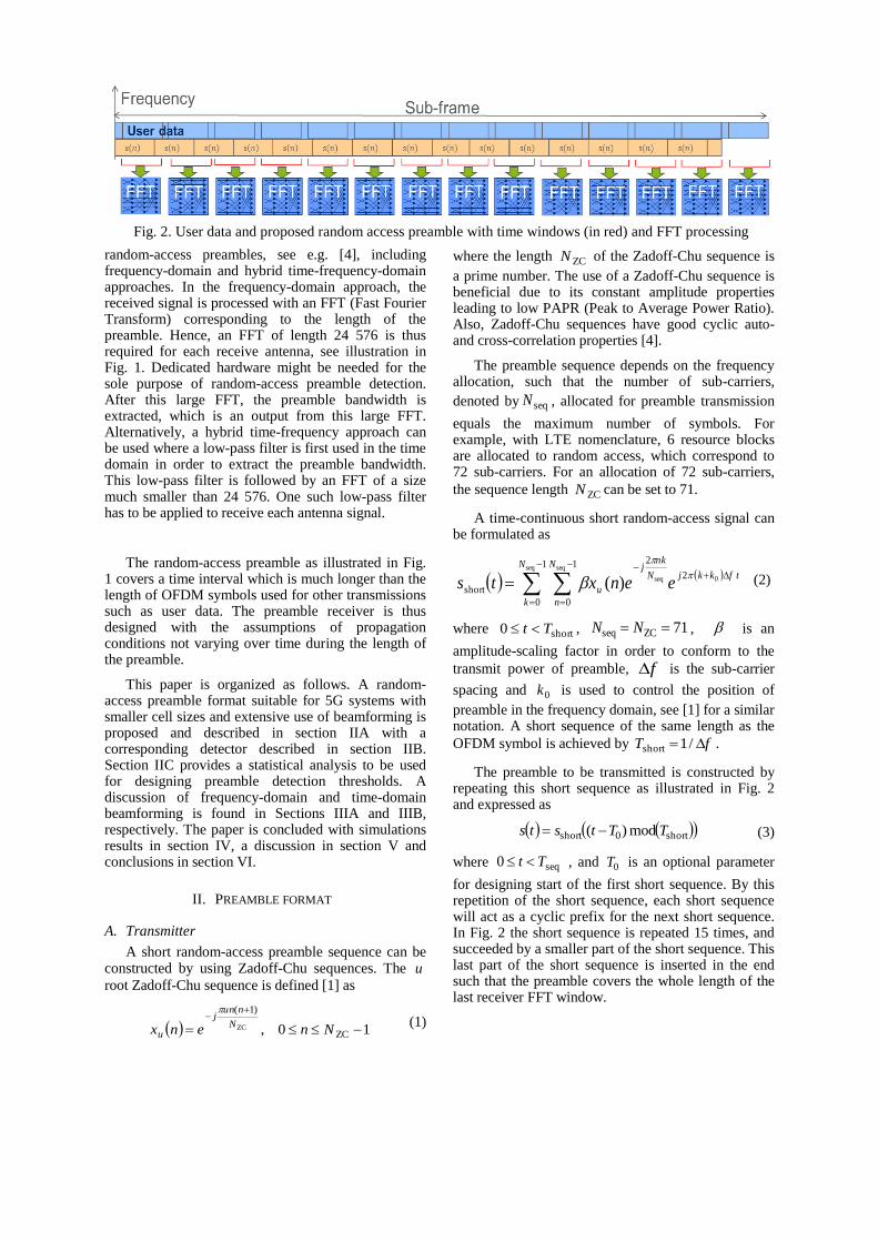
The preamble to be transmitted is constructed by repeating this short sequence as illustrated in Fig. 2 and expressed as
short0short mod)( TTtsts (3)
where seq0 Tt , and 0T is an optional parameter
for designing start of the first short sequence. By this repetition of the short sequence, each short sequence will act as a cyclic prefix for the next short sequence. In Fig. 2 the short sequence is repeated 15 times, and succeeded by a smaller part of the short sequence. This last part of the short sequence is inserted in the end such that the preamble covers the whole length of the last receiver FFT window.
Fig. 2. User data and proposed random access preamble with time windows (in red) and FFT processing
B. Preamble detector
The radio transmission from mobile to base-station, for receiver antenna a , is modelled as the
output from an L tap FIR filter
1
0
),()(),(),(
L
m
anwdmnxamhanr
(4)
where )(nx is transmitted sequence, ),( anw is
interference and additive white Gaussian noise with
variance )(2 aw , and d corresponds to a round-trip
delay for the current UE. This round-trip delay is
limited by the cell radius, i.e. 10 Dd where
cFRD scell2 , cellR is the cell radius in meters,
sF is the sampling rate, c is the speed of light, and
x denotes rounding towards nearest lower integer.
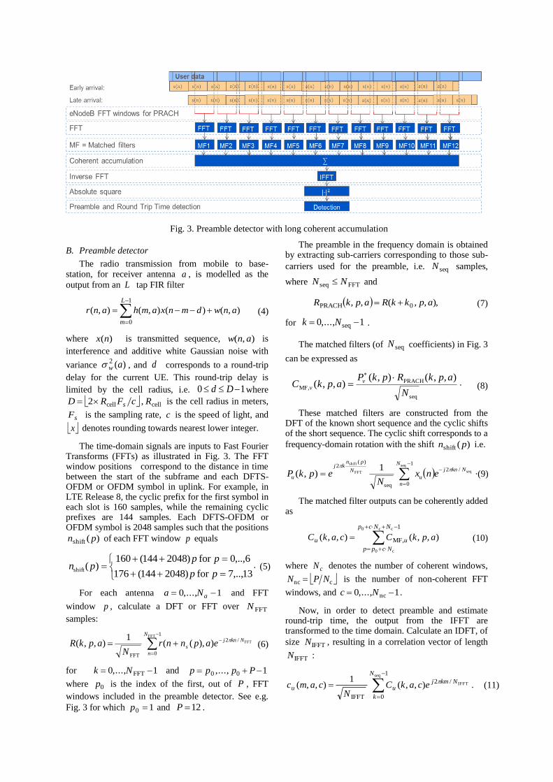
The time-domain signals are inputs to Fast Fourier Transforms (FFTs) as illustrated in Fig. 3. The FFT window positions correspond to the distance in time between the start of the subframe and each DFTS-OFDM or OFDM symbol in uplink. For example, in LTE Release 8, the cyclic prefix for the first symbol in each slot is 160 samples, while the remaining cyclic prefixes are 144 samples. Each DFTS-OFDM or OFDM symbol is 2048 samples such that the positions
)(shift pn of each FFT window p equals
13,..,7for )2048144(176
6,..,0for )2048144(160)(shift
pp
pppn . (5)
For each antenna 1,...,0 aNa and FFT
window p , calculate a DFT or FFT over FFTN
samples:
1
0
/2
FFT
FFT
FFT)),((1
),,(N
n
Nknj
s eapnnrN
apkR (6)
for 1,...,0 FFT Nk and ,...,0pp 10 Pp
where 0p is the index of the first, out of P , FFT
windows included in the preamble detector. See e.g.
Fig. 3 for which 10 p and 12P .
The preamble in the frequency domain is obtained by extracting sub-carriers corresponding to those sub-
carriers used for the preamble, i.e. seqN samples,
where FFTseq NN and
),,,(,, 0PRACH apkkRapkR (7)
for 1,...,0 seq Nk .
The matched filters (of seqN coefficients) in Fig. 3
can be expressed as
seq
PRACH,MF
),,(),(),,(
N
apkRpkPapkC v
v
. (8)
These matched filters are constructed from the DFT of the known short sequence and the cyclic shifts of the short sequence. The cyclic shift corresponds to a
frequency-domain rotation with the shift )(shift pn i.e.
1
0
/2
seq
)(2 seq
seqFFT
shift
1),(
N
n
Nknj
u
N
pnkj
u enxN
epkP
. (9)
The matched filter outputs can be coherently added as
1
,MF
cc0
c0
),,(),,(
NNcp
Ncpp
uu apkCcakC (10)
where cN denotes the number of coherent windows,
cnc NPN is the number of non-coherent FFT
windows, and 1,...,0 nc Nc .
Now, in order to detect preamble and estimate round-trip time, the output from the IFFT are transformed to the time domain. Calculate an IDFT, of
size IFFTN , resulting in a correlation vector of length
IFFTN :
1
0
/2
IFFT
seq
IFFT),,(1
),,(
N
k
Nkmjuu ecakC
Ncamc
. (11)
Fig. 3. Preamble detector with long coherent accumulation

Selecting seqIFFT NN corresponds to an
interpolation, which can be done in order to increase the resolution of the timing estimation.
A Neyman-Pearson criterion [5] is used as decision variable, which for deterministic signals in additive white Gaussian noise equals the normalized absolute square of the matched filter output, formulated as
1
0
1
02
2
ncc
nc
)(ˆ
),,(1)(
N
c
N
a w
u
au
a
a
camc
NNNm
(12)
where a simple estimator of the noise variance can be formulated as
1 1
0
2
,MFseq
20
0
seq
),,(1
)(ˆ
Pp
pp
N
k
uw apkCNP
a . (13)
Preamble number u is detected if the absolute
squared value of this autocorrelation exceeds a threshold
Th)( mu (14)
for at least one value of m , within the search window
of size D . A preamble detector and round-trip time estimator can now be formulated as searching for the maximum value in this vector of decision variables and comparing this maximum value with a threshold. In other words, the preamble with index u is detected
if there is an 1,0 Dm such that Th)( mu .
This preamble detector threshold Th should be
selected with care such that the false detection rate is low without causing a too low detection rate, see section IIC.
A timing estimate follows as the value of m which
corresponds to the maximum value of )(mu , i.e.
)(maxargˆ mm um (15)
such that a timing error estimate in seconds equals
)/(ˆˆIFFTerr NfmT . (16)
C. Detection threshold design
Denote the preamble false detection rate, for each
value of m , as fdP such that the false alarm rate FAP
equals
fd1)1(1 fdFADPD ePP
. (17)
Modelling the received signal ),( anr as noise
only, then the decision variable )(mu is a chi-square
distributed random variable with unity mean and
nc2 NNa degrees of freedom. The false detection
probability can thus be formulated as
)2,2(1 ncThncχfd 2 NNNNFP aa . (18)
where the chi-square Cumulative Density Function equals
12
0χ
1),(2
r
k
kz zerzF (19)
if 2r is an integer. The threshold can now be
calculated as the value of Th in (18) resulting in a
specified false alarm rate FAP according to (17) which
can be formulated as
)2),1ln(1
1(2
1ncFA
1
χnc
Th 2 NNPD
FNN
aa
. (20)
III. BEAMFORMING
A. Frequency domain beamforming
A frequency domain beamforming before preamble detection is illustrated in Fig 4a. Here, the antenna signals are first received in a Radio Unit (RU), and then sampled and quantized in an Analog-to-Digital Converter (ADC). A transformation from time to frequency domain is done using an FFT, after which the preamble detector is applied. Here, an FFT is typically calculated for each antenna or subset of antennas, such that different users and channels in different sub-bands of the received signal can be extracted before further signal processing.
The beamforming (BF) is used in order to increase received signal strength before the preamble detector. Beamforming aims at combining received signals from several antennas such that more signal energy is received in specific spatial directions.
When beamforming is done in the frequency domain one or several specific beamformers can be applied to those sub-carriers which are used for random access. By these beamformers, the preamble detector is sensitive in several spatial directions.
Fig. 4. Frequency domain and time domain beamforming before preamble detectors.
B. Time-domain beam-forming
For time-domain beamforming, the beamforming scaling and phase shifts are applied before the FFT, see illustration in Fig. 4b. Time-domain signals from many antennas are thus combined in the beamforming. In this way, the beamforming is the same for all sub-carriers. This time domain beamforming might be done on an analog signal (i.e., before ADC) as in Fig. 4b, or on a digital signal (i.e., after the analog-to-digital converter, ADC) but before the FFT (no illustration included for brevity).
At initial access, the base station has limited knowledge of the position of the UE. The preamble receiver must therefore evaluate several beamformers in order to be able to detect the preamble. With time-domain beamforming, this requires one sequence of processing from FFT to preamble detector per beamformer. An illustration is given in Fig. 5 of an approach in which the beamforming is changed between each FFT window. Here the outputs from each beamforming, followed by an FFT, are individually processed in a matched filter, an IFFT, an absolute square calculation, and finally a preamble detector. If the hardware supports several simultaneous beamformers in the same time-window, then several spatial directions can be processed in parallel. Each such beamformer is referred to as one receiver baseband (BB) port.
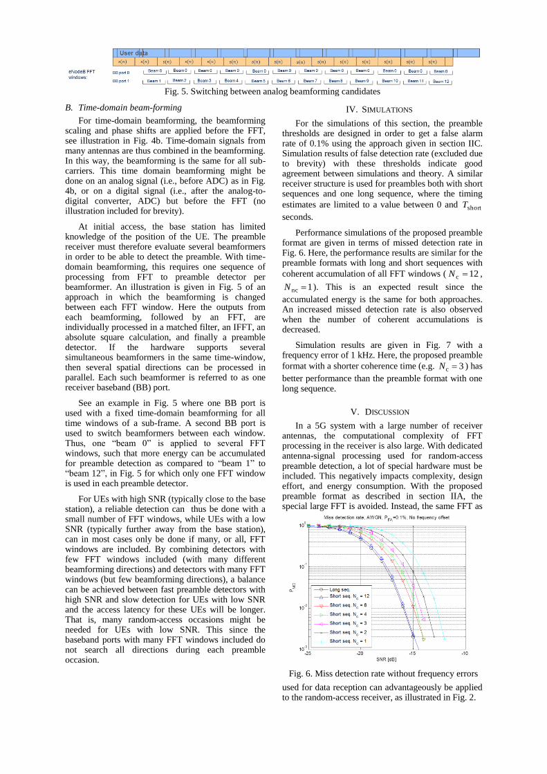
See an example in Fig. 5 where one BB port is used with a fixed time-domain beamforming for all time windows of a sub-frame. A second BB port is used to switch beamformers between each window. Thus, one “beam 0” is applied to several FFT windows, such that more energy can be accumulated for preamble detection as compared to “beam 1” to “beam 12”, in Fig. 5 for which only one FFT window is used in each preamble detector.
For UEs with high SNR (typically close to the base station), a reliable detection can thus be done with a small number of FFT windows, while UEs with a low SNR (typically further away from the base station), can in most cases only be done if many, or all, FFT windows are included. By combining detectors with few FFT windows included (with many different beamforming directions) and detectors with many FFT windows (but few beamforming directions), a balance can be achieved between fast preamble detectors with high SNR and slow detection for UEs with low SNR and the access latency for these UEs will be longer. That is, many random-access occasions might be needed for UEs with low SNR. This since the baseband ports with many FFT windows included do not search all directions during each preamble occasion.
IV. SIMULATIONS
For the simulations of this section, the preamble thresholds are designed in order to get a false alarm rate of 0.1% using the approach given in section IIC. Simulation results of false detection rate (excluded due to brevity) with these thresholds indicate good agreement between simulations and theory. A similar receiver structure is used for preambles both with short sequences and one long sequence, where the timing
estimates are limited to a value between 0 and shortT
seconds.
Performance simulations of the proposed preamble format are given in terms of missed detection rate in Fig. 6. Here, the performance results are similar for the preamble formats with long and short sequences with
coherent accumulation of all FFT windows ( 12c N ,
1nc N ). This is an expected result since the
accumulated energy is the same for both approaches. An increased missed detection rate is also observed when the number of coherent accumulations is decreased.
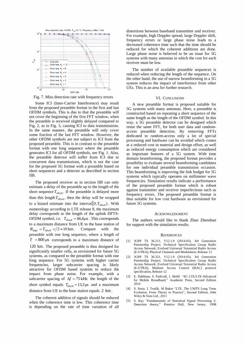
Simulation results are given in Fig. 7 with a frequency error of 1 kHz. Here, the proposed preamble
format with a shorter coherence time (e.g. 3c N ) has
better performance than the preamble format with one long sequence.
V. DISCUSSION
In a 5G system with a large number of receiver antennas, the computational complexity of FFT processing in the receiver is also large. With dedicated antenna-signal processing used for random-access preamble detection, a lot of special hardware must be included. This negatively impacts complexity, design effort, and energy consumption. With the proposed preamble format as described in section IIA, the special large FFT is avoided. Instead, the same FFT as
used for data reception can advantageously be applied to the random-access receiver, as illustrated in Fig. 2.
Fig. 5. Switching between analog beamforming candidates
Fig. 6. Miss detection rate without frequency errors
Some ICI (Inter-Carrier Interference) may result from the proposed preamble format in the first and last OFDM symbols. This is due to that the preamble will not cover the beginning of the first FFT window, when the preamble is received slightly delayed compared to Fig. 2, as in Fig. 3, causing ICI to data transmissions. In the same manner, the preamble will only cover some fraction of the last FFT window. However, the other OFDM symbols are not subject to ICI from the proposed preamble. This is in contrast to the preamble format with one long sequence where the preamble generates ICI for all OFDM symbols, see Fig. 1. Also, the preamble detector will suffer from ICI due to concurrent data transmissions, which is not the case for the proposed 5G format with a preamble based on short sequences and a detector as described in section IIB.
The proposed receiver as in section IIB can only estimate a delay of the preamble up to the length of the
short sequence shortT . If the preamble is delayed more
than this length shortT , then the delay will be wrapped
to a biased estimate into the interval ),0 shortT . With
numerology according to LTE release 8, the maximum delay corresponds to the length of the uplink DFTS-
OFDM symbol, i.e. sT 6,66short . This corresponds
to a maximum distance from UE to the base station of
km 10 2shortmax cTR . Compare with the
preamble with one long sequence, where a length of
s 800 T corresponds to a maximum distance of
km 120 . The proposed preamble is thus designed for
significantly smaller cells, as envisioned for future 5G systems, as compared to the preamble format with one long sequence. For 5G systems with higher carrier frequencies, larger subcarrier spacing is likely attractive for OFDM based systems to reduce the impact from phase noise. For example, with a
subcarrier spacing of kHz 75f the length of the
short symbol equals μs 3,13short T and a maximum
distance from UE to the base station equals km 2 .
The coherent addition of signals should be reduced when the coherence time is low. This coherence time is depending on the rate of time variation of all
distortions between baseband transmitter and receiver. For example, high Doppler spread, large Doppler shift, frequency errors or large phase noise leads to a decreased coherence time such that the time should be reduced for which the coherent additions are done. Large phase noise is believed to be an issue for 5G systems with many antennas in which the cost for each receiver must be low.
The number of available preamble sequences is reduced when reducing the length of the sequence. On the other hand, the use of narrow beamforming in a 5G system reduces the impact of interference from other UEs. This is an area for further research.
VI. CONLUSIONS
A new preamble format is proposed suitable for 5G systems with many antennas. Here, a preamble is constructed based on repeating a short sequence of the same length as the length of the OFDM symbol. In this way, a 5G preamble detector can be designed which reuse the same FFT, for both user data and random-access preamble detection. By removing FFTs dedicated to random-access only a lot of special processing and hardware can be avoided which comes at a reduced cost in material and design effort, as well as reduced energy consumption which are considered as important features of a 5G system. With time domain beamforming, the proposed format provides a possibility to evaluate several beamforming candidates for one individual preamble transmission occasion. This beamforming is improving the link budget for 5G systems which typically operates on millimeter wave frequencies. Simulation results indicate a performance of the proposed preamble format which is robust against transmitter and receiver imperfections such as frequency errors. The proposed preamble format is thus suitable for low cost hardware as envisioned for future 5G systems.
ACKNOWLEDGMENT
The authors would like to thank Zhao Zhenshan for support with the simulation results.
REFERENCES
[1] 3GPP TS 36.211, V12.1.0 (2014-03), 3rd Generation Partnership Project; Technical Specification Group Radio Access Network; Evolved Universal Terrestrial Radio Access (E-UTRA); Physical Channels and Modulation, Release 12
[2] 3GPP TS 36.321, V12.1.0 (2014-03), 3rd Generation Partnership Project; Technical Specification Group Radio Access Network; Evolved Universal Terrestrial Radio Access (E-UTRA); Medium Access Control (MAC) protocol specification, Release 12
[3] E. Dahlman, S. Parkvall, J. Sköld “4G LTE/LTE-Advanced for Mobile Broadband,” Academic Press, Second Edition 2014
[4] S. Sesia. I. Toufik. M Baker “LTE, The UMTS Long Term Evolution, From Theory to Practice”, Second Edition, John Wiley & Sons Ltd., 2011
[5] S. Kay “Fundamentals of Statistical Signal Processing 2: Detection theory,” Prentice Hall, New Jersey, 1998
Fig. 7. Miss detection rate with frequency errors