conesys hermetic eur - benchmark connector
TRANSCRIPT
51www.conesys.com [email protected]
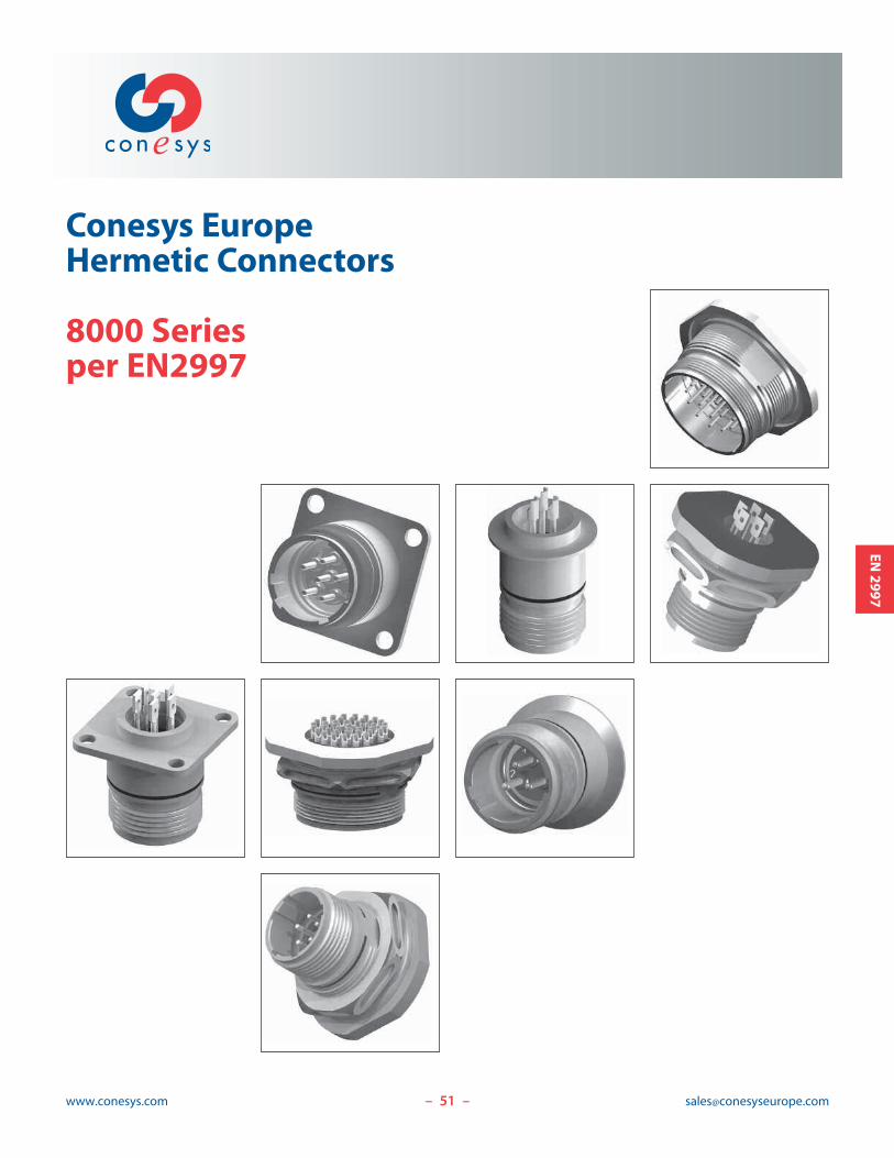
Conesys EuropeHermetic Connectors
8000 Seriesper EN2997
– –
EN2997

52www.conesys.com [email protected]
8000 Series
Hermetic Connectors
per EN2997
– –
EN2997
Features and Application
8000 Series hermetic connector receptacles are manufacturedto Conesys Europe standards and meet all the requirementsof EN2997.
8000 Series is a threaded cylindrical connector designed forhighest performance capabilities, used in severe-environmentapplications, i.e., aircraft engines.
These connectors are fully interchangeable and intermateablewith MIL-C-83723 Series III Threaded and Rolls-RoyceESC10 connectors.
Square flange, jam nut, and solder mount receptacles areavailable in 10 shell sizes and insert arrangements utilizingsizes 20, 16, and 12 contacts.
Customer specific design can be proposed for special applications – Consult factory for details.
These 8000 Series hermetic connectors are available in passivated stainless steel material. Other materials can beproposed for special applications with commercial P/N –Please consult factory.
Insert Arrangement – 8000 Series hermetic connectors useEN2997 insert arrangements.
Customer Specific Insert Arrangement – 8000 Series hermetic connectors can be proposed with special insertarrangement issued from MIL-STD-1554 (insert arrangementsfor MIL-C-83723 series III connectors) – Please consult factory.
Shell polarization – Alternate key/keyway positions preventcross mating of adjacent connectors having same insertarrangement.
Interfacial Pin Insert Seal – Raised moisture barriersaround each receptacle pin, which mate into lead-in chamfersof the plug hard face socket insert, provide individual contactsealing.
Glass Insulator – These hermetic connectors are designedwith sintered compression glass as insulator.
Special Contacts – These hermetic connectors are availablewith special contact, i.e., thermo couple (chromel, alumel,etc.). Commercial P/N only.
53www.conesys.com [email protected]
8000 Series
Hermetic Connectors
per EN2997
– –
EN2997
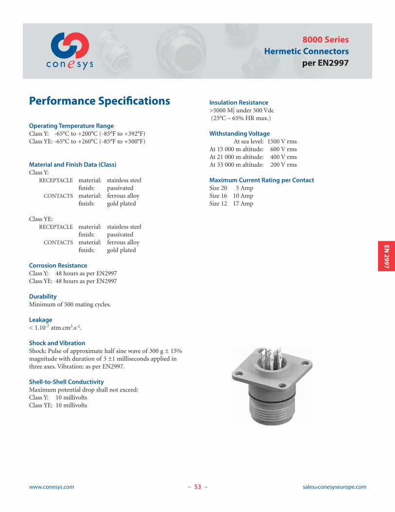
Performance Specifications
Operating Temperature Range
Class Y: -65°C to +200°C (-85°F to +392°F)Class YE: -65°C to +260°C (-85°F to +500°F)
Material and Finish Data (Class)
Class Y:RECEPTACLE material: stainless steel
finish: passivatedCONTACTS material: ferrous alloy
finish: gold plated
Class YE:RECEPTACLE material: stainless steel
finish: passivatedCONTACTS material: ferrous alloy
finish: gold plated
Corrosion Resistance
Class Y: 48 hours as per EN2997Class YE: 48 hours as per EN2997
Durability
Minimum of 500 mating cycles.
Leakage
< 1.10-7 atm.cm3.s-1.
Shock and Vibration
Shock: Pulse of approximate half sine wave of 300 g ± 15%magnitude with duration of 3 ±1 milliseconds applied inthree axes. Vibration: as per EN2997.
Shell-to-Shell Conductivity
Maximum potential drop shall not exceed:Class Y: 10 millivoltsClass YE: 10 millivolts
Insulation Resistance
>5000 M| under 500 Vdc(25°C – 65% HR max.)
Withstanding Voltage
At sea level: 1500 V rmsAt 15 000 m altitude: 600 V rmsAt 21 000 m altitude: 400 V rmsAt 33 000 m altitude: 200 V rms
Maximum Current Rating per Contact
Size 20 5 AmpSize 16 10 AmpSize 12 17 Amp

8000 Series
Hermetic Connectors
per EN2997
www.conesys.com [email protected]– –
EN2997
EN and Conesys Part Number Development
EN Prefix EN2997 Y 0 10 06 M N
Conesys Prefix 8000 Y 0 10 06 P N -XXX
Class (Material and Finish)
Y = Shell – stainless steel, passivated (200 C°)
= Terminals – ferrous alloy, gold plated
YE = Shell – stainless steel, passivated (260 C°)
= Terminals – ferrous alloy, gold plated
Shell Type (specification sheet number)
0 = Square flange receptacle
7 = Jam nut receptacle
1 = Solder mount receptacle
Shell Size
8 thru 24 (Size 28 – Consult factory)
Insert Arrangement
See pages 62–64
Contact Style (pin only)
M = Pin with solder cup – EN P/N only
P = Pin with solder cup – Conesys P/N only
X = Pin with eyelet – Conesys P/N only
C = Pin tail (for PCB) – Conesys P/N only
Polarization (keying)
N = Normal
6, 7, 8, 9, or Y (Alternate keyed positions; Y is not available in SS 8)
Modification or Particularities (applies to Conesys part numbers only)
XXX= Modification
Consult factory for details
EN2997
55www.conesys.com [email protected]
8000 Series
Hermetic Connectors
per EN2997
– –
EN2997
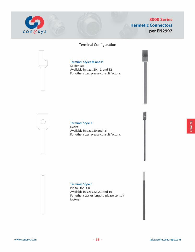
Terminal Configuration
Terminal Styles M and P
Solder cup
Available in sizes 20, 16, and 12
For other sizes, please consult factory.
Terminal Style X
Eyelet
Available in sizes 20 and 16
For other sizes, please consult factory.
Terminal Style C
Pin tail for PCB
Available in sizes 22, 20, and 16
For other sizes or lengths, please consult
factory.
56www.conesys.com [email protected]
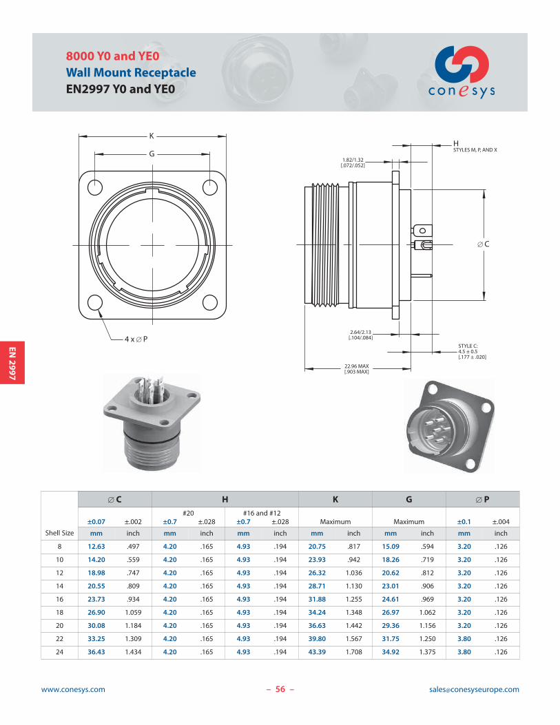
8000 Y0 and YE0
Wall Mount Receptacle
EN2997 Y0 and YE0
– –
EN2997
22.96 MAX[.903 MAX]
� C
STYLE C:4.5 ± 0.5[.177 ± .020]
HSTYLES M, P, AND X
2.64/2.13[.104/.084]
1.82/1.32[.072/.052]
K
G
4 x � P
Shell Size
� C H K G � P
#20 #16 and #12±0.07 ±.002 ±0.7 ±.028 ±0.7 ±.028 Maximum Maximum ±0.1 ±.004
mm inch mm inch mm inch mm inch mm inch mm inch
8 12.63 .497 4.20 .165 4.93 .194 20.75 .817 15.09 .594 3.20 .126
10 14.20 .559 4.20 .165 4.93 .194 23.93 .942 18.26 .719 3.20 .126
12 18.98 .747 4.20 .165 4.93 .194 26.32 1.036 20.62 .812 3.20 .126
14 20.55 .809 4.20 .165 4.93 .194 28.71 1.130 23.01 .906 3.20 .126
16 23.73 .934 4.20 .165 4.93 .194 31.88 1.255 24.61 .969 3.20 .126
18 26.90 1.059 4.20 .165 4.93 .194 34.24 1.348 26.97 1.062 3.20 .126
20 30.08 1.184 4.20 .165 4.93 .194 36.63 1.442 29.36 1.156 3.20 .126
22 33.25 1.309 4.20 .165 4.93 .194 39.80 1.567 31.75 1.250 3.80 .126
24 36.43 1.434 4.20 .165 4.93 .194 43.39 1.708 34.92 1.375 3.80 .126
57www.conesys.com [email protected]
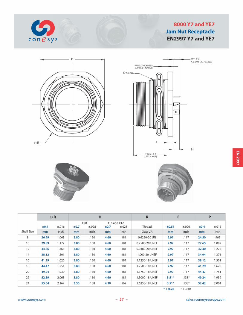
8000 Y7 and YE7
Jam Nut Receptacle
EN2997 Y7 and YE7
– –
EN2997
F
19.63 ± 0.3[.773 ± .012]
STYLE X :4.5 ± 0.5 [.177 ± .020]
H
PANEL THICKNESS:3.2/1.6 [.126/.063]
K THREAD
P
� R
Shell Size
� R H K F P
#20 #16 and #12±0.4 ±.016 ±0.7 ±.028 ±0.7 ±.028 Thread ±0.51 ±.020 ±0.4 ±.016
mm inch mm inch mm inch Class 2A mm inch mm inch
8 26.99 1.063 3.80 .150 4.60 .181 0.6250-20 UN 2.97 .117 24.50 .965
10 29.89 1.177 3.80 .150 4.60 .181 0.7500-20 UNEF 2.97 .117 27.65 1.089
12 34.66 1.365 3.80 .150 4.60 .181 0.9380-20 UNEF 2.97 .117 32.40 1.276
14 38.12 1.501 3.80 .150 4.60 .181 1.000-20 UNEF 2.97 .117 34.94 1.376
16 41.29 1.626 3.80 .150 4.60 .181 1.1250-18 UNEF 2.97 .117 38.12 1.501
18 44.47 1.751 3.80 .150 4.60 .181 1.2500-18 UNEF 2.97 .117 41.29 1.626
20 49.24 1.939 3.80 .150 4.60 .181 1.3750-18 UNEF 2.97 .117 44.47 1.751
22 52.39 2.063 3.80 .150 4.60 .181 1.5000-18 UNEF 3.51* .138* 49.24 1.939
24 55.04 2.167 3.50 .138 4.30 .169 1.6250-18 UNEF 3.51* .138* 52.42 2.064
* ± 0.26 * ± .010
58www.conesys.com [email protected]
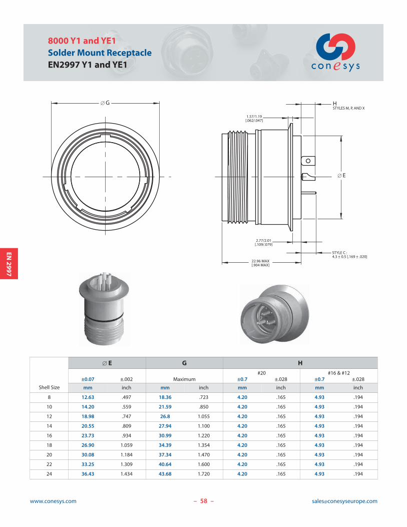
8000 Y1 and YE1
Solder Mount Receptacle
EN2997 Y1 and YE1
– –
EN2997
� E
22.96 MAX[.904 MAX]
STYLE C :4.3 ± 0.5 [.169 ± .020]
2.77/2.01[.109/.079]
1.57/1.19[.062/.047]
HSTYLES M, P, AND X
� G
Shell Size
� E G H
#20 #16 & #12±0.07 ±.002 Maximum ±0.7 ±.028 ±0.7 ±.028
mm inch mm inch mm inch mm inch
8 12.63 .497 18.36 .723 4.20 .165 4.93 .194
10 14.20 .559 21.59 .850 4.20 .165 4.93 .194
12 18.98 .747 26.8 1.055 4.20 .165 4.93 .194
14 20.55 .809 27.94 1.100 4.20 .165 4.93 .194
16 23.73 .934 30.99 1.220 4.20 .165 4.93 .194
18 26.90 1.059 34.39 1.354 4.20 .165 4.93 .194
20 30.08 1.184 37.34 1.470 4.20 .165 4.93 .194
22 33.25 1.309 40.64 1.600 4.20 .165 4.93 .194
24 36.43 1.434 43.68 1.720 4.20 .165 4.93 .194
59www.conesys.com [email protected]
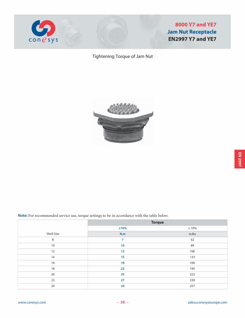
8000 Y7 and YE7
Jam Nut Receptacle
EN2997 Y7 and YE7
– –
EN2997
Tightening Torque of Jam Nut
Note: For recommended service use, torque settings to be in accordance with the table below.
Shell Size
Torque
±10% ±.10%
N.m in.lbs
8 7 62
10 10 89
12 12 106
14 15 133
16 18 160
18 22 195
20 25 222
22 27 239
24 29 257

60www.conesys.com [email protected]
8000 Series
Hermetic Connectors
per EN2997
– –
EN2997
Keying Positions
C°
B°
D°
A°
MASTER KEYWAY NORMAL
Notes:
1. Mating face of receptacle shown.2. All minor keyways (keys) are rotated to provide shell
polarization while master keyway (key) remains fixed as shown.
3. Insert arrangement does not rotate relative to the masterkeyway (key).
Position
Shell Size
08 10 12 to 24
A B C D A B C D A B C D
N 105 140 215 265 105 140 215 265 105 140 215 265
6 102 132 248 320 102 132 248 320 18 149 192 259
7 80 118 230 312 80 118 230 312 92 152 222 342
8 35 140 205 275 35 140 205 275 84 152 204 334
9 64 155 234 304 64 155 234 304 24 135 199 240
Y — — — — 25 115 220 270 98 152 268 338
61www.conesys.com [email protected]
8000 Series
Hermetic Connectors
per EN2997
– –
EN2997
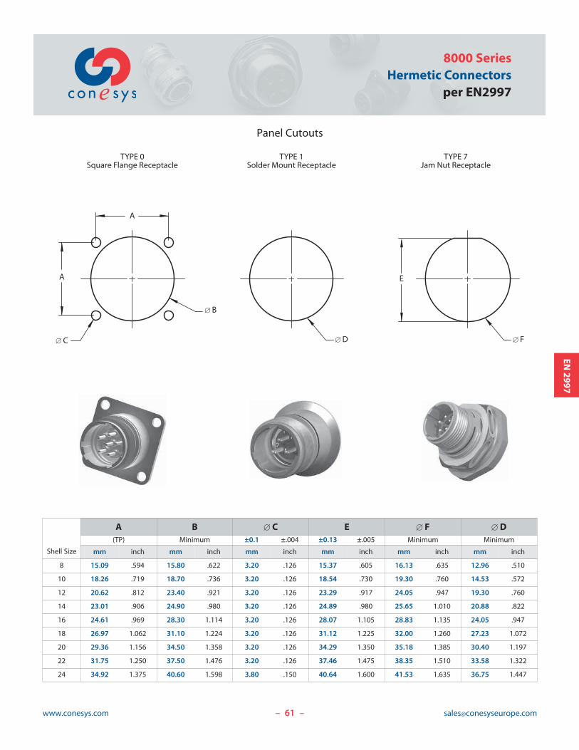
Panel Cutouts
Shell Size
A B � C E � F � D
(TP) Minimum ±0.1 ±.004 ±0.13 ±.005 Minimum Minimum
mm inch mm inch mm inch mm inch mm inch mm inch
8 15.09 .594 15.80 .622 3.20 .126 15.37 .605 16.13 .635 12.96 .510
10 18.26 .719 18.70 .736 3.20 .126 18.54 .730 19.30 .760 14.53 .572
12 20.62 .812 23.40 .921 3.20 .126 23.29 .917 24.05 .947 19.30 .760
14 23.01 .906 24.90 .980 3.20 .126 24.89 .980 25.65 1.010 20.88 .822
16 24.61 .969 28.30 1.114 3.20 .126 28.07 1.105 28.83 1.135 24.05 .947
18 26.97 1.062 31.10 1.224 3.20 .126 31.12 1.225 32.00 1.260 27.23 1.072
20 29.36 1.156 34.50 1.358 3.20 .126 34.29 1.350 35.18 1.385 30.40 1.197
22 31.75 1.250 37.50 1.476 3.20 .126 37.46 1.475 38.35 1.510 33.58 1.322
24 34.92 1.375 40.60 1.598 3.80 .150 40.64 1.600 41.53 1.635 36.75 1.447
A
� B
A
� C
TYPE 0Square Flange Receptacle
�D � F
TYPE 1Solder Mount Receptacle
TYPE 7Jam Nut Receptacle
E

62www.conesys.com [email protected]– –
EN2997
8000 Series
Insert Arrangement and Contact Information
per EN2997
Insert Arrangement and Contact Information
Insert Arrangement
Total Quantity of Contacts
No. of By size
Contacts 20 16 12
08-03 3 3
08-98 3 3
10-05 5 5
10-06 6 6
10-20* 2 2
12-03 3 3
12-12 12 12
14-04 4 4
14-07 7 7
14-12 12 9 3
14-15 15 15
16-10 10 10
16-24 24 24
18-08 8 8
18-14 14 14
18-31 31 31
20-16 16 16
20-25 25 19 6
20-28 28 24 4
20-39 39 37 2
20-41 41 41
22-12 12 12
22-19 19 19
22-32 32 26 6
22-39 39 27 12
22-55 55 55
24-30 30 30
24-43 43 23 20
24-57 57 55 2
24-61 61 61
* This layout is not to EN2997, and has to be ordered with Conesys P/N only.
Please consult factory for hermetic insert arrangement availability.
3
2
1
12
34
5
6
2 1
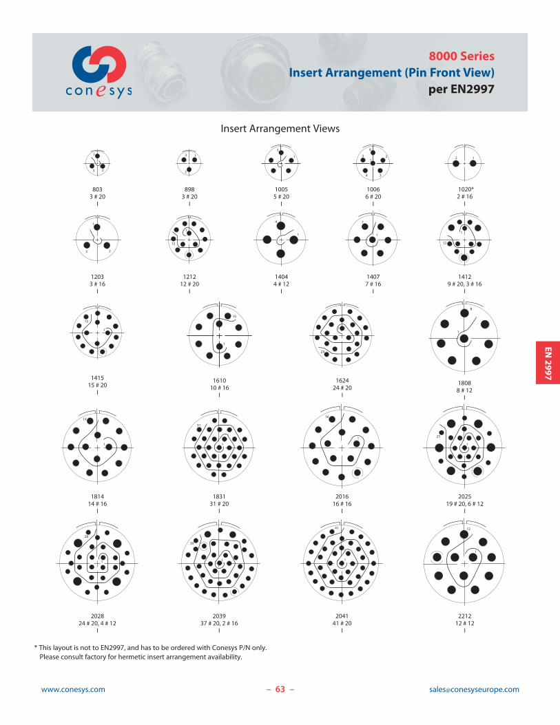
803
3 # 20
I
898
3 # 20
I
1005
5 # 20
I
1006
6 # 20
I
1020*
2 # 16
I
1203
3 # 16
I
1212
12 # 20
I
1404
4 # 12
I
1407
7 # 16
I
1412
9 # 20, 3 # 16
I
1814
14 # 16
I
1831
31 # 20
I
2016
16 # 16
I
2025
19 # 20, 6 # 12
I
2028
24 # 20, 4 # 12
I
2039
37 # 20, 2 # 16
I
2041
41 # 20
I
2212
12 # 12
I
1
31
1
25
1
3 2
1
5
1
23
1
4
1
7
1808
8 # 12
I
1
8
1
12
1
12
1415
15 # 20
I
1
15
1610
10 # 16
I
1
10
1
14
1
12
1
39
1624
24 # 20
I
1
24
1
16
1
28
1
41
Insert Arrangement Views
63www.conesys.com [email protected]
8000 Series
Insert Arrangement (Pin Front View)
per EN2997
– –
EN2997
* This layout is not to EN2997, and has to be ordered with Conesys P/N only.
Please consult factory for hermetic insert arrangement availability.