conductive, convective, and radiative heat performance ......nfpa 1961, and a test with a second...
TRANSCRIPT

Conductive, Convective, and Radiative Heat Performance Testing of Fire
Attack Hoses
Sponsored by
The Last Call Foundation
Major Qualifying Project Report:
Submitted to the Faculty of
WORCESTER POLYTECHNIC INSTITUTE
In partial fulfillment of the requirements for the
Degree of Bachelor of Science
By:
Rebecca Barolli
Jaclyn Bouvier
Emily Brecher
Benjamin Gaudet
Connor Gillespie
Date:
April 20, 2016
Approved:
Kathy Notarianni, Advisor
Raymond Ranellone, Co-Advisor

ii
Abstract
A fire attack hose is an essential tool to control and extinguish fires and a lifeline for the
firefighters manning it. In order for a firefighter to execute his or her duties in relative safety,
their hoses must withstand the harsh environments of the modern day fire ground. Fire attack
hoses, while rigorously tested for mechanical integrity, are not tested at a level of heat stress
representative of a municipal fire ground. This study developed test methods using conductive,
radiative, and flame impingement heat stresses to begin to address this issue. A selection of
representative fire attack hoses used for municipal firefighting and candidate high thermal
performance materials were subjected to these tests to provide groundwork for the development
of a next generation fire attack hose.
iii
Executive Summary
An incident of hose failure at a fire in Boston on March 26, 2014 resulted in the deaths of
two firefighters when the hose they were relying on failed to deliver water due to a burn-through.
This and several other similar occurrences around the country suggest that currently
manufactured fire attack hoses may not sufficiently withstand the levels of heat stress necessary
to reliably control and extinguish fires and protect firefighter’s lives on the modern day fire
ground. The Last Call Foundation was founded in the wake of the Boston fire and the lives lost
that day in the line of duty. Through their sponsorship, this study aimed to assess the
performance of currently manufactured fire attack hoses as well as higher performing materials
not presently used in fire hoses, such as those used in firefighter personal protective gear, when
exposed to heat insults more representative of the environments of municipal firefighting.
This research study was conducted in two distinct parts. The first part was conducted
with the goal of determining and documenting the performance of currently manufactured fire
attack hoses when exposed to a higher level of conductive heat stress than they are currently
tested at and when exposed to a European standard hose test involving flame-to-hose
impingement. The results of this research are presented in Chapter One of this document. The
second part of this study involved testing of current and potential hose materials subjected to a
radiative heat stress. A comparison of the performance of jacketing materials used in the
manufacture of modern fire attack hoses to the performance of “high heat resistance” materials
presently used in firefighter personal protective gear via radiative heat insults is presented in
Chapter Two.
Chapter One: Heat Performance Testing of Currently Available Fire Attack Hose
A market analysis was conducted which identified the materials and construction of the
bulk of commercially available fire attack hose models meeting the requirements of NFPA 1961:
Standard on Fire Hoses. A study of these hoses aided in the identification of a range of physical
characteristics that may influence the performance of these hoses. These characteristics then
combine to compose the “structure” of the fire attack hose. The market analysis provided an
understanding of the municipal fire attack hose structure that is most common in the fire service
and therefore of interest to this study.
iv
All hose models tested were double-jacketed, lay-flat attack hoses with a 1 3/4 inch flow
diameter. This is the description of the most common hose structure identified by the market
analysis for use in municipal firefighting. Within this category of fire attack hose, the
majority can be described by four structural components: jacket material, liner material, weight
per unit length, and jacket coating. These components were set as our study variables for the first
part of this research. An array of ten fire attack hose models was created based on these four
study variables. In order to isolate these variables, each hose in the test matrix was chosen with
at least one other hose that differed by only one variable such that performance comparisons
could be made as a function of each individual study variable. Each of the ten hose models
chosen for analysis is NFPA compliant and is available for purchase in the United States.
Once the array of fire attack hoses to be tested was finalized, a set of specifications for
the performance tests were established. Overarching specifications included: the test hoses being
pressurized to an operational pressure, automatic collection of real-time pressure data within a
hose, a test with conduction-based heat transfer and higher temperatures than are required by
NFPA 1961, and a test with a second form of heat insult beyond the simple conduction-based
heat transfer present in NFPA 1961. A rigorous conduction test, hereby known as the "Hot Plate"
test, was developed which utilized a controlled hot surface to impart a conductive heat flux on a
hose. To incorporate a second form of heat insult, which involved flame impingement, a
replication of the German DIN 14811 Flame Resistance Test was built in the WPI fire lab.
A total of three iterations of apparatus design were carried out for the Hot Plate test.
These iterations were aimed at advancing the rigor, repeatability, and realism of the test while
attempting to debug data inconsistencies caused by water-damage and hose placement. A failure
analysis of the trial designs is intended to provide a stepping stone for the future continuation of
fire attack hose research and development of fire attack hose performance tests. Data collected
from the comparative analysis of the test matrix using the hot plate test was largely inconclusive.
However, a clear correlation between the severity of hose failure and the liner material was
discovered. Additionally, this portion of the study established a set of criteria with which to
quantify the majority of municipal fire attack hoses and demonstrated the challenge to be faced
with performance test design.
The set of hoses selected for study were then subjected to the German DIN test involving
direct flame impingement. Three of the ten test hoses, e.g. 30%, failed a single trial of this test.
While a minority, this failure rate indicates that the U.S. standard is less rigorous than the

v
German standard and that the level of rigor of the U.S. conductive heat test may not be high
enough to serve as an indicator of how the hose would perform on an actual fire ground.
Recommendations for future work are focused on design of the test apparatus,
improvements in the experimental procedure, and future research on fire attack hoses. The
following recommendations are offered for the continuation of research initiated by this study in
an effort to produce conclusive data on currently manufactured fire hose performance.
In order to advance the third iteration hot plate test design, it is recommended that the
following design changes are made. These alterations are intended to reduce sources of
error and data inconsistency present in the first three Hot Plate design iterations.
1. A water guard added to the sides of the frame or some other water-proofing
method is suggested to prevent pre-wetting of test segments.
2. A heat source without integrated electronic components should be utilized of
remove the possibility of water-damage to the heat element.
If future research were to redesign the frame apparatus, a form of water guard such as
acrylic siding would be beneficial to prevent pre-wetting of hose sections. In addition, if the hot
plate is kept in a reversed orientation, then the use of a different heat source is recommended, as
it would eliminate the potentially damaging effects of water condensation. Specifically, a
resistance heater with internal thermocouples would produce a constant surface temperature with
a constant input voltage. This would negate the difficult task of shielding electrical components
from steam condensation. However, a custom device would require calibration before use to
ensure temperature readings of the hot surface are accurate.
If a new design for a hose-to-hot surface apparatus is required, a cantilever mechanism is
recommended over a translating rode mechanism in order to improve design simplicity.
A cantilever mechanism would rest the hot plate onto the hose without the tight design
tolerances required when utilizing translating rods and linear bearings. While rods and bearings
are very precise when custom manufactured, a cantilever mechanism is more simplistic and
offers comparable accuracy at a lower cost and without custom manufacturing. In the case of this
study, the translating rode mechanism created for the third hot plate design iteration offered
sufficient precision and repeatability when built with aluminum extrusion framing; however,
custom manufacturing would have been required for optimal precision and repeatability. A

vi
cantilever mechanism could also be built with aluminum framing and, if properly designed,
could offer improved precision over a translating rode mechanism build with the same
components.
It is recommended that the number of trials in the DIN 14811: Flame Resistance Replica
Test is increased to mirror the German standard exactly.
In the DIN standard, five trials are required for each hose with a mandatory pass rate of
4/5 hoses. The replication conducted in this study included a single trial on each hose. Mirroring
the number of trials specified in the DIN 14811 test would increase both the validity and insight
provided in regard to hose failures and performance.
Further Research Recommendations on the Thermal Performance of Currently Available
Fire Attack Hose:
Testing of the full matrix of representative hoses using a waterproofed test platform with the
cantilevered apparatus is recommended. Investigation should include determining the impact of
each study variable with intent to further verify the effects of coatings, weight per unit length,
liner failure methods, and outer jacket performance. An additional recommendation is to expand
testing past the original ten hose matrix to account for hose structures separate from the structure
focused on in this study. This will allow a broader understanding of attack fire hose heat
resistance performance in all accounts.
Chapter Two: Radiative Heat Performance Testing of Materials for Application in Fire Attack
Hose
Initial research focused on materials currently being used in fire attack hose jackets.
Polyester and nylon 6.6 are the two most common jacket materials in modern fire attack hoses
due to their ability to withstand mold and rot. These materials were not chosen for their heat
performance ability nor are they expected to withstand a significant heat stress. NFPA
1961: Standard on Fire Hose only calls for conduction resistance testing on currently
manufactured fire attack hoses. In contrast, NFPA codes for personal protective equipment (PPE)
that firefighters wear during their daily duties do contain extensive heat performance criteria. For
instance, NFPA 1971: Standard on Protective Ensembles for Structural Fire Fighting and

vii
Proximity Fire Fighting specifies a thermal performance test for assessing the abilities of PPE
materials to resist a radiative heat flux. Given this fact, it was determined that testing of materials
for potential application in fire attack hose jackets would begin with materials currently used in
the design and manufacture of firefighter personal protective ensembles.
The four main goals of this area of research were to select candidate materials for testing,
create a test methodology for conducting a radiative heat performance test of each material,
perform testing on current and candidate materials, and establish performance criteria to compare
materials to one another. Five candidate materials were selected based on their PPE applications:
Nomex®, Kevlar®, PBI Max®, PBI Kombat Flex® and Pyrovatex® fr Cotton. Pyrovatex® fr
Cotton is the only material tested that is not used in firefighter PPE but is used in PPE commonly
worn in the chemical and welding industries. The cone calorimeter, a widely studied and utilized
industry standard apparatus was selected as the test platform for this research. A test
methodology was created that allowed the collection of data for two performance criteria: time to
decomposition and time to ignition. Test procedures included multiple trials to ensure accurate
data resolution.
The testing procedure specified that materials are initially subjected to a low heat flux
which is progressively increased and the times at which the materials begin to thermally
decompose (and in some cases ignite) are recorded. Current fire attack hose jacket materials
were tested first to create a baseline against which to compare the selected candidate materials.
Polyester and nylon 6.6 both reached decomposition temperatures under a heat flux exposure of
11.9 kW/m2 and ignited under an exposure of 18 kW/m2. Of the two current materials, polyester
performed better, decomposing and igniting at a later time than nylon 6.6 when exposed to the
same heat flux. However, it is important to note that both current hose materials ignited at heat
fluxes lower than a value widely accepted as an indicator of flashover (approximately 20
kW/m2). Both polyester and nylon 6.6 reached decomposition temperature at a heat flux value
just slightly greater than half of the same value widely accepted as an indicator of flashover.
All candidate materials surpassed the baseline performance of the current materials. None
of the candidate materials decomposed or ignited during testing at 11.9 kW/m2 and only two
candidate materials, 50% Kevlar®-50% Nomex® and Pyrovatex® fr Cotton, reached
decomposition at 18.0 kW/m2. At a heat flux of 24.2 kW/m2, 20% higher than that indicative of
flashover, PBI Max® and Kombat Flex® still did not show signs of decomposition. Testing was
viii
continued on PBI Max® until ignition was reached at 48.4 kW/m2, a heat flux more than double
that which occurs at flashover.
Given the results of radiative testing the following was concluded: current hose jacket
materials do not withstand pre-flashover conditions, there are candidate materials currently being
manufactured that perform better in high heat environments that current materials do, and certain
candidate materials do not ignite until heat fluxes higher than those indicative of flashover. In
light of these findings, it was determined that there are other materials currently being
manufactured that are better suited for the high heat environment of the fire ground than the
current materials being used in fire hose jackets today.
Recommendations for future work are focused on further testing of the materials selected
for this research, along with searching for other materials that are suitable for this type of
application.
Continued testing on selected materials would provide a more complete set of results.
Continued testing of these candidate materials at the desired heat fluxes of 10, 15, and 20
kW/m2 is recommended. Materials used in this testing that did not ignite near these heat flux
values (Kevlar®, Nomex®, PBI® Fiber and Pyrovatex® fr Cotton) should continue to be tested
on the cone calorimeter by increasing the heat flux until ignition occurs. It is also important to
know the decomposition point of those materials to determine what their limits are as to what
heat fluxes they can withstand. As of now, it is difficult to determine which of those materials is
considered to be the best candidate.
Additional high heat performance materials should be tested following the same
methodology.
This study focused mainly on PPE materials meaning that there are other possible
candidate materials that were left out. For example, this project did not look into intumescent
materials or other hose configurations. Additionally, some hose models intended for wild-fires
have the ability to “weep” meaning that small perforations in the hose allow water to leak out in
a controlled manner and pre-wet the jacket material. This keeps the jacket material at a cooler
temperature and could potentially prolong its decomposition time. A material that is highly
reflective could also be an effective candidate material. If the material can reflect portions of
incident heat energy instead of absorbing it, the service life of the hose can be extended.

ix
High heat performance materials should be tested in combinations.
Each candidate material in this study was tested individually. The thermal resistance
offered by combinations or layers of these and/or similar materials could produce enhanced
performance results. Specifying different layer thicknesses or amounts of separate materials
could offer greater heat resistance at a lower cost.
A similar radiative heat insult study should be conducted on liner materials.
Further investigation into potential “high thermal performance” materials for fire attack
hose liners is recommended since this project only focused on jacket materials of municipal fire
attack hoses. Current hose liners made of EPDM rubber and thermoplastic polyurethane (TPU)
have never been tested under radiative heat fluxes similar to those in this study. In this light,
other material may offer better performance against heat insult.
A prototype hose made of candidate materials should be tested via a rigorous heat
performance test for analysis in a large-scale scenario.
Once the aforementioned testing is completed, and if the material passes non-heat
performance testing, the creation of a prototype hose constructed from candidate materials is
suggested. This prototype should then be tested according to a procedure similar to those
discussed in Chapter One to analyze its applicability in a high heat environment. The results
from that testing can then be compared to the results from this research to determine if the
prototype displays significant improvements in performance.
Concluding Statements
This study provided the first methodologies and data sets for assessing the performance
of fire attack hoses and candidate fire attack hose materials against conductive, radiative and
flame impingement heat stresses on the scale of those found on the fire ground. It is intended that
this study will raise awareness of fire attack hose thermal performance and provide a stepping
stone for the continued development of fire attack hoses and the testing methodologies used to
inform their design. In this light, recommendations were provided for further testing and
improved procedures in order to advance the development of a fire attack hose with higher
thermal performance.
x
Introduction
Project Sponsor: The Last Call Foundation
On March 26, 2014 a nine-alarm fire broke out in a four-story brick home in the Back
Bay of Boston, Massachusetts. Strong winds drove an intense fire that continued to grow, tearing
through the brownstone and resulting in unpredictable conditions. In the basement of the
building were two Boston Fire Department officials, Lieutenant Edward Walsh and Firefighter
Michael Kennedy. They entered the building with the intent of rescuing a possible victim from
the basement. Upon reaching the bottom of the stairs, Lieutenant Walsh was recorded calling
Command to request water. At this point, the Engine 33 pump operator charged the line.
However, “the hose line lost its water due to the rapidly deteriorating fire conditions which
compromised the hose” [1]. Tragically, neither firefighter survived the incident.
The Issue
In the weeks and months following this tragedy, there were many questions asked as to
why this happened. Initially, many believed that the hose failure was a fluke accident or solely
the result of tactical operations. The story of a hose burning through and leaving firefighters
trapped inside of a burning building was not one that many had heard before. However, as word
about this incident spread, phone calls and emails from fire departments across the country were
received saying that they have experienced burn-throughs of fire attack hoses. It became
apparent that this was not an isolated incident. It was also revealed that neither the extent nor
frequency of burn-throughs in the U.S. was documented or even known. In fact, an in-depth
literature review found no research done on the heat performance of the currently available fire
attack hoses. In parallel with this study, another research team at WPI created a database where
the fire service could report and document fire attack hose burn-throughs [2]. Finally, a major
issue that arose was that no test methods are currently in place in the United States for thermal
performance testing of fire attack hoses at conditions representative of the municipal fire ground.

xi
Project Scope
This study was conducted in two parts, each with the high-level goal of contributing
scientific data useful for the design and production of a next generation fire attack hose with high
thermal performance. The focus of the first part was on understanding and documenting the
performance of currently manufactured fire attack hoses when subjected to both a conductive
heat insult and flame impingement. The focus of the second part was on testing new materials
which are known to have high thermal resistance but are not currently used in the manufacturing
of fire attack hoses. These new materials, referred to as “candidate materials”, were tested to
document their performance when exposed to a range of radiation heat fluxes. The performance
of these candidate materials was then compared to the performance of current jacket materials
when exposed to identical radiative heat exposures.
To understand the performance of currently manufactured fire attack hoses when exposed
to conductive heat insult and flame impingement, a conduction-based heat insult test and a
replication of a German flame impingement test were developed. These tests allowed for the
comparison of an array of ten fire attack hose models that conform to the most common design
and structure of municipal fire attack hoses today. The four principle study variables that were
investigated as the main distinguishing factors in the structure and performance of a fire attack
hose include the liner material, jacket material, weight per unit length, and jacket coatings. The
initial design of a conduction-based test focused on subjecting hose specimens to higher steady-
state heat fluxes than are present in current U.S. fire attack hose standards. With this goal in
mind, an iterative process of design and testing was carried out to refine the test accuracy and
repeatability. Ultimately, three design iterations were carried out and a set of recommendations
was given for further development of the test design and the direction of future research.
Although a final satisfactory design was not reached, another research team at WPI has begun to
build off of the recommendations provided.
This research also focuses on identifying candidate materials for application in a fire
attack hose jacket which were then compared to the baseline radiative heat performance of
materials currently used for fire attack hose jackets. Referencing the standard ASTM E1354
(which deals with test methods for measuring heat release rates) and using a widely accepted test
apparatus, a methodology was created that allowed a quantitative data comparison between
materials. The radiative testing was performed on a cone calorimeter at varying heat flux
xii
exposures to accurately compare the thermal performance of these materials. Criteria were
identified in order to rank the materials based on their performance during testing. From this,
recommendations were made to continue testing on selected materials and to perform additional
investigations into other high heat performance materials.
Chapter 1
Heat Performance Testing of Currently Available Fire
Attack Hose
Authors:
Jaclyn Bouvier
Benjamin Gaudet
Connor Gillespie

1-2
Table of Contents
1. Goal Statement ............................................................................................................................... 1-4
2. Background .................................................................................................................................... 1-5 2.1 Modern Municipal Fire Attack Hoses ......................................................................................... 1-5
2.1.1 An Overview of Hose Structure ................................................................................................................ 1-5 2.1.2 Jacket Materials ............................................................................................................................................. 1-6 2.1.3 Coatings ........................................................................................................................................................... 1-7 2.1.4 Liner Material ................................................................................................................................................. 1-7
2.2 Double Jacketed Fire Attack Hose Manufacturing Process ............................................... 1-7 2.3 Current Fire Attack Hose Performance Standards ................................................................ 1-8
2.3.1. NFPA 1961 ..................................................................................................................................................... 1-8 2.3.2 The DIN 14811 Flame Resistance Test ................................................................................................... 1-9
3. Methodology ................................................................................................................................... 1-10 3.1 Market Analysis of Currently Available Fire Attack Hoses .............................................. 1-10 3.2 Establishment of Study Variables .............................................................................................. 1-10 3.3 Development of a Parametric Fire Attack Hose Test Matrix ........................................... 1-11 3.4 Performance Test Specifications .................................................................................................... 1-12 3.5 The Hot Plate Test ............................................................................................................................. 1-12 3.6 The DIN Flame Test Replication .................................................................................................... 1-14 3.7 An Overview of Data Acquisition and Hose Pressurization ............................................. 1-15 3.8 Third Party Quality Assurance ...................................................................................................... 1-16 3.9 Testing of Fire Attack Hoses ........................................................................................................... 1-16
4. Results and Discussion ................................................................................................................. 1-17 4.1 Test Results of the First Hot Plate Design .............................................................................. 1-17 4.2 The Second Hot Plate Design Iteration .................................................................................... 1-20
4.2.1 Second Iteration Results and Discussion...............................................................................................1-22 4.3 The Third Hot Plate Design ............................................................................................................. 1-24
4.3.1 Results of Third Hot Plate Design Test .................................................................................................1-26 4.4 Hose Performance when Subjected to an International Flame Impingement Thermal
Assault Test .............................................................................................................................................. 1-28 4.4.1 A Closer Look at the Effect of Coatings on Flame Resistance ......................................................1-30
5. Conclusion ...................................................................................................................................... 1-33
6. Future Work and Recommendations ....................................................................................... 1-34
7. Appendices ...................................................................................................................................... 1-36 Appendix A –German DIN: 14811 Replication Procedure ....................................................... 1-36 Appendix B - Flame Chamber Procedure ....................................................................................... 1-37 Appendix C – Hot Plate – First Iteration Procedure ................................................................... 1-38 Appendix D – Hot Plate – Second Iteration Procedure .............................................................. 1-39 Appendix E – Hot Plate – Third Iteration Procedure ................................................................. 1-41
8. Bibliography ................................................................................................................................. 1-42
1-3
Table of Figures
Figure 1: First Hot Plate Iteration Design ................................................................................................ 1-13
Figure 2: First Iteration Pressure Rig ....................................................................................................... 1-13
Figure 3: Flame Chamber Test Set-Up .................................................................................................... 1-14
Figure 4: DAQ System ............................................................................................................................. 1-15
Figure 5: WFD Quality Assurance Testing .............................................................................................. 1-16
Figure 6: Example Pressure Loss in EPDM Lined Hose Trial ................................................................ 1-17
Figure 7: Example Pressure Loss in TPU Lined Hose Trial .................................................................... 1-18
Figure 8: EPDM Hose Failure Example .................................................................................................. 1-18
Figure 9: TPU Hose Failure Example ...................................................................................................... 1-19
Figure 10: Second Iteration Hot Plate Design ......................................................................................... 1-21
Figure 11: Second Iteration Hose Pressure Set Up .................................................................................. 1-21
Figure 12: Second Iteration Hot Plate Initial Pressure Loss Results ....................................................... 1-22
Figure 13: Third Iteration Hot Plate Design Test Set-Up ........................................................................ 1-24
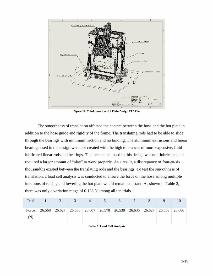
Figure 14: Third Iteration Hot Plate Design CAD File ............................................................................ 1-25
Figure 15: Third Iteration Hot Plate Test - Hose 4 Results ...................................................................... 1-26
Figure 16: Third Iteration Hot Plate Test - Hose 3 Results ...................................................................... 1-27
Table of Tables
Table 1: Hose Test Matrix ....................................................................................................................... 1-11
Table 2: Load Cell Analysis .................................................................................................................... 1-25
Table 3: DIN Replica Test and Flame Chamber Test Results ................................................................. 1-29
Table 4: Hose 5 vs. Hose 6 Coating Comparison .................................................................................... 1-31
Table 5: Hose 7 vs. Hose 8 Coating Comparison .................................................................................... 1-31
Table 6: Hose 1 vs. Hose 10 Coating Comparison .................................................................................. 1-32
1-4
1. Goal Statement The main goals of this study were as follows:
1. Design a rigorous performance test to accurately and repeatably assess the
performance of a variety of commercially available fire attack hose models
subjected to a range of conduction-based heat fluxes.
2. Replicate the essential aspects of the German DIN 14811 flame resistance test to
assess the performance of the same set of commercially available fire attack hoses
when subjected to direct flame impingement.
3. Investigate the impact of each of the four principle structural components of a
municipal fire attack hoses as it relates to a hose’s overall resistance to a heat stress.
1-5
2. Background
2.1 Modern Municipal Fire Attack Hoses
Today’s fire service plays an essential role in our public safety, as it has for hundreds of
years. The firefighters who risk their lives for the safety of others depend on their equipment to
be functioning properly to keep them out of harm’s way. One of the most crucial pieces of
equipment to a firefighter is the fire hose which provides a critical line of defense second only to
the fire fighter’s personal protective ensemble (PPE). Next to the PPE, “a fire hose surely is the
firefighter’s next lifeline” [2].
There are multiple types of fire hoses in the industry today that perform different
functions on the fire ground, including water supply and fire attack, however, it is the fire attack
hose that is the subject of this study. The purpose of a fire attack hose is to transport water from
the fire pump to the firefighter, allowing him or her to extinguish flames at strategic locations
anywhere on the fire ground. These hoses must be durable and reliable against the harsh
conditions present on the fire ground and be able to withstand multiple years of service.
2.1.1 An Overview of Hose Structure
The two main areas of structural firefighting are industrial and municipal. This study
focuses on the fire attack hoses used for municipal firefighting, which involves residencies and
most non-industrial occupancies. These hoses are typically “lay-flat” and non-rigid, making them
easily maneuverable while empty and efficiently storable on fire engine hose beds. The majority
of municipal fire attack hoses are purchased with nominal flow diameters of 1 ¾ or 2 ½ inches to
optimize the volumetric flow rate of water onto the fire and the nozzle back pressure experienced
by firefighters. Most models offer a range of diameters between 1 and 3 inches although the
extremes are less commonly used by fire departments. The hoses are manufactured in lengths of
50 feet, can be coupled together to create a longer line if necessary, and are service tested to
operate under pressures up to 400 psi [3]. In terms of weight, a 50ft length of 1-¾ inch diameter
municipal fire attack hoses typically ranges from 12-23 lbs. A 2-½ inch line of the same length
would be proportionally heavier. However, a lighter hose is preferred by firefighters as it is
easier to maneuver in and out of burning buildings, especially those with multiple stories. The
differences in weight between hose models are due to differences in material density and
quantity.

1-6
There are the three principal lay-flat hose structures: single jacket, double jacket, and
thru-the-weave extrusion. Double-jacketed hoses are the norm when fighting a municipal fire
while single-jacketed hoses are common in industrial applications. Thru-the-weave extrusion
hoses are seen in both fire attack and water supply applications, although they are less common
in fire attack. A single layer of woven fabric bonded to an inner elastomer liner forms the
modern single jacket attack hose. These hoses have lower durability and are intended for less
frequent use and less severe environments. Single jacket hoses are also convenient in situations
where a lighter weight hose is preferred, such as high-rise firefighting. The modern double-
jacketed fire attack hose consists of two layers of woven fabric, one of which is bonded to an
inner liner. These hoses are used in situations where particularly harsh conditions and frequent
use are expected [3]. Thru-the-weave extrusion hoses may be single or double jacketed, however,
they differ from traditional single and double-jacketed hoses in how their inner jacket and liner
are pressed into each other to form an interlocking weave. This type of construction is less
common but is seen in supply lines and specially manufactured fire attack lines.
2.1.2 Jacket Materials
The outer jacket of a fire attack hose is designed and tested to withstand pressures
ranging from 300 psi to the manufacturer specification, and the outer jacket is what protects the
watertight liner and/or inner jacket from heat, abrasion, and puncturing [8]. Current fire hose
jackets are manufactured almost exclusively with synthetic materials. Either nylon 6.6 or
polyester fibers constitute the jackets of nearly all fire attack hoses manufactured today based on
the current market. This being said, cotton jacketed fire attack hoses are still in use at fire
stations all over the country, and though no longer manufactured, make up a significant part of
the fire service’s attack lines.
Polyester is crease-resistant, has the ability to retain its shape even when affected by
moisture, dries quickly, and is resistant to light and weather [6, 11]. Polyester fibers have a
melting point temperature of approximately 250℃. In comparison, nylon 6.6 is known for its
strong abrasion resistance and overall toughness. In general, this means that nylon 6.6 has a
relatively long service life. The melting temperature of nylon 6.6 is slightly higher than that of
polyester at 255℃ [7, 11]. For both materials, their melting points allow them to survive most
ambient conditions, however contact with hot gas flows, flames or hot surfaces sufficient in
1-7
duration to heat the hoses at or above these temperatures would cause material degradation /
melting.
2.1.3 Coatings
A majority of fire attack hoses are sold with their jackets treated with a coating meant to
enhance the hose performance on the fireground, as well as increase the overall lifespan by
preventing unnecessary wear and tear. The exact composition of the jacket coatings vary with
each manufacturer and in many cases the exact composition of the coating material is considered
a trade secret, limiting the information available about them. However their intended purposes
can be categorized. The coatings were designated by manufacturers to provide either abrasion
resistance or abrasion and heat resistance to the hose jackets they are applied to.
2.1.4 Liner Material
The inner liner maintains the hose’s form and allows water to flow through
without leaking or corroding the outer jacket material over time. Fire attack hoses are most
commonly lined with thermosetting synthetic rubber, such as ethylene propylene (EPDM
rubber), or thermoplastic material, such as thermoplastic polyurethane (TPU). Some fire attack
hoses models have liners made of nitrile, although this is less common.
On one hand, EPDM has the appearance of regular black rubber and is the most
commonly manufactured synthetic rubber in municipal fire hose liners. It has a minimum
service temperature of -60℃ and a maximum service temperature of 300℃.This material is used
in fire attack hoses due to its high elasticity and strong resistance to heat, ozone, and weather
[4]. On the other hand, TPU is the most commonly utilized thermoplastic elastomer. TPU is very
versatile and has a high elongation and tensile strength, as well as the ability to resist oil,
solvents, chemicals, and abrasion [5]. This material has a mildly transparent appearance when
used as a fire attack hose liner.
2.2 Double Jacketed Fire Attack Hose Manufacturing Process
While there are several types of fire attack hoses, most share a similar manufacturing
process. In the case of a double-jacketed hose, the general process includes the following steps.
First, each of these two jackets are woven separately, one slightly smaller than the other. They
are then woven using two different types of yarn, a filler yarn and a warp yarn. The warp yarn
1-8
runs the length of the hose and is usually made out of a polyester or nylon material. The filler
yarn runs a tight spiral around the circumference of the hose, crisscrossing between the warp
yarns. In some cases, the jackets are then dipped in a tank of elastomeric coating, which
increases abrasion and heat resistance [3].
Next, the rubber material goes through an extruding process to form the liner. During
this process a mass of uncured rubber is inserted into an extruder. At this point it is warmed
before being shaped into a tubular liner by a cylindrical press. The liner is soon vulcanized,
which makes the rubber strong and elastic. The vulcanized liner is then passed through a rubber
calendar, which wraps another thin layer of uncured rubber around it. The jackets and liners are
then sent for assembly.
In the assembly process, the outer jacket is first laid out flat. The inner jacket and
consecutively the liner are then pulled through, creating a loose hose. One end of the hose
assembly is clamped shut and a steam nozzle is attached to the other end. This pressurizes the
hose and presses the three layers against each other. The high pressure and heat cause the rubber
of the lining to bond with the inner jacket. Couplings are added to the hoses through the use of an
expansion mandrel, which seals the jacket between a brass ring and the coupling. The hoses are
then pressurized to between 600-800 psi to test for leaks [3].
2.3 Current Fire Attack Hose Performance Standards
2.3.1. NFPA 1961
NFPA 1961: Standard on Fire Hoses, states the design, construction, inspection and
testing requirements for all newly manufactured fire hoses. The code is not required; however,
most manufacturers comply with it for safety purposes and buyer satisfaction. This standard
includes kink tests, burst tests, and proof tests. NFPA 1961 does not explicitly define the testing
method for the heat resistance test, but rather states that fire attack hoses must comply with heat
resistance tests from UL 19, FM 2111 or an equivalent test. FM Approvals and Underwriters
Laboratories (UL) are large scientific corporations that release standards for the quality
assessment of various products [8].
The heat resistance test set forth by UL 19 and FM 2111 is conductive and involves
heating a 2.5 x 1.5 x 8 inch steel block to 260℃ (500℉) before stamping it on a water filled hose
for 60 seconds. Upon completion of the trial, the hose is allowed to cool and is then pressurized
1-9
to three times service test pressure. If there is no observable leakage or critical damage,
the hose is considered to have passed the test [9]. This test, however, is only specific to one type
of heat transfer, when all three are present in a fire environment.
2.3.2 The DIN 14811 Flame Resistance Test
The German Institute for Standardization has developed a fire hose performance standard
that is referred to as DIN 14811: Fire-fighting hoses – Non-percolating lay flat delivery hoses
and hose assemblies for pumps and vehicles. The standard includes a “flame resistance test” that
requires a test hose to be able to perform against flame impingement and be able to self-
extinguish. This test requires five trials of pressurizing a fire hose with water to 70 psi and
securing a portion of it perpendicular to an open flame such that the flame impinges the hose for
ten seconds. If the test hose can withstand the ten-second impingement without bursting and if
the after-flame or after-glow time is no more than three seconds, the hose is considered to have
passed the trial [10]. The hose must pass four out of five trials to pass the test. In comparison to
the heat resistance performance test specified in NFPA 1961, the DIN 14811 test introduces a
whole other form of heat insult as well as higher level of rigor. Although the trials times are 1/6
as long, the insult temperatures are at least 6 to 9 times as high.

1-10
3. Methodology
3.1 Market Analysis of Currently Available Fire Attack Hoses
To understand the range of fire attack hose models and characteristics available for
purchase in the U.S., a search of multiple manufacturer websites was carried out during the early
stages of this study. At the onset of the search, the only parameters that had been specified for
the fire hoses to be tested were that they were:
● Intended for municipal firefighting
● Lay-flat construction
● Specified as fire attack hose
● Not specified as “large diameter”
This study is focused on municipal firefighting, which involves lay-flat hose construction
as the norm since lay-flat construction allows for more efficient storage on the fire trucks. Fire
hose specified and used as fire attack hose is laid out from the fire truck to the source of the fire.
In contrast, large diameter hoses are laid out from the nearest hydrant to the truck and are used to
supply water to the operation. Large diameter fire hoses are also impractical for most municipal
fire attack operations even if the manufacturer specifies them for “fire attack”. The outcome of
the search was a list of fifty-eight hose models available from eleven different hose
manufacturers. All fifty-eight fire attack hoses met the four criteria stated above. An assessment
of the hose list confirmed that most municipal fire attack hoses are double jacketed and have the
option for nominal flow diameters of 1 ¾ and 2 ½ inches.
3.2 Establishment of Study Variables
Based on background research and the market analysis, the hose structure of interest was
determined to be a lay-flat double-jacketed hose with a 1-¾ inch flow diameter, which is most
representative of a generic fire attack hose that would likely be used by a firefighter, neglecting
any specifications for couplings or nozzles. The array of lay-flat double-jacketed hose available
in 1-3/4” flow diameter differed in four key variables. These included liner material, jacket
material weight per unit length, and whether or not the hose was coated for abrasion and/or
heat. In terms of weight, the majority of double-jacketed 1-¾ inch attack hoses ranged from 14-
19 lbs per 50 feet of linear hose length with outliers as light as 12 lbs per 50ft and as heavy as 23
lbs per 50ft. All hose models from the market analysis had either polyester or nylon jackets and
1-11
the large majority had either EPDM or TPU liners. Based on these findings, the following four
study variables were selected:
● Weight per 50 feet (14 -19 lbs. per 50ft)
● Jacket Material (Nylon or Polyester)
● Liner Material (EPDM Rubber or TPU)
● Jacket Coating (None, Abrasion Resistance Only, Abrasion & Heat Resistance)
3.3 Development of a Parametric Fire Attack Hose Test Matrix
With a set of study variables established, the next step was to develop an array of
representative fire attack hose models (i.e. a “test matrix”) to analyze. The chosen models had to
represent the fire attack hose structure and materials identified as commonplace in municipal
firefighting. Additionally, each model was NFPA 1961 compliant in all aspects of its design and
performance.
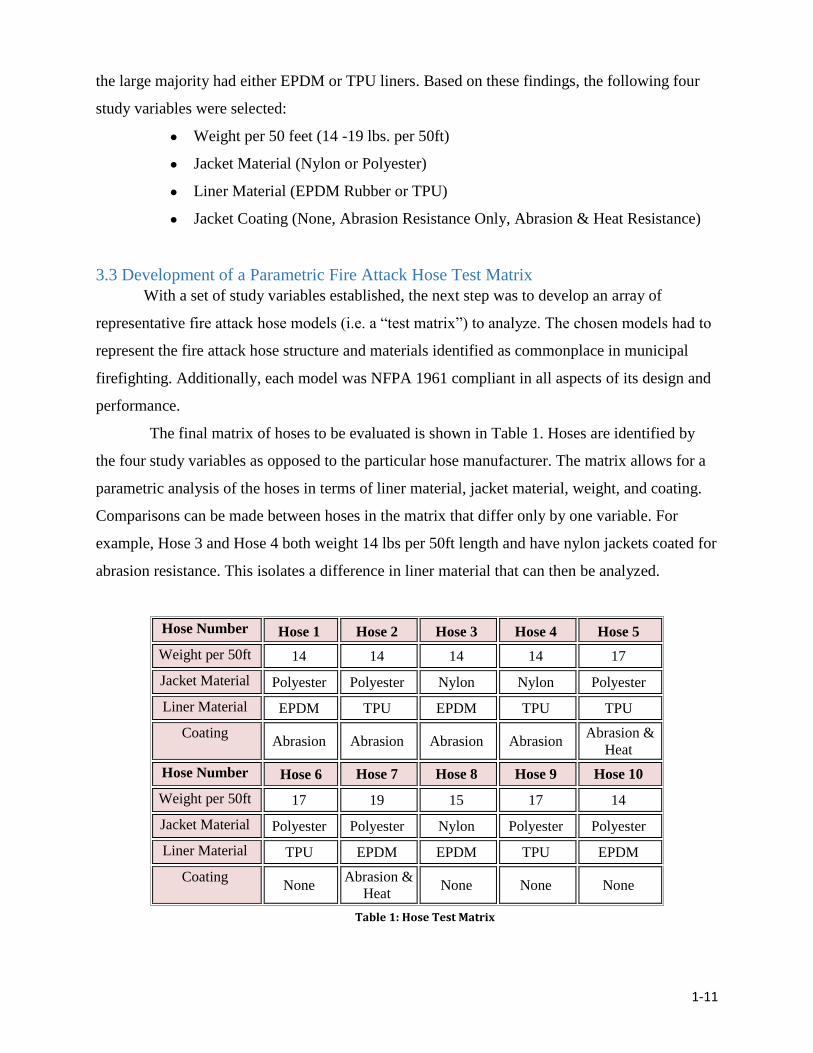
The final matrix of hoses to be evaluated is shown in Table 1. Hoses are identified by
the four study variables as opposed to the particular hose manufacturer. The matrix allows for a
parametric analysis of the hoses in terms of liner material, jacket material, weight, and coating.
Comparisons can be made between hoses in the matrix that differ only by one variable. For
example, Hose 3 and Hose 4 both weight 14 lbs per 50ft length and have nylon jackets coated for
abrasion resistance. This isolates a difference in liner material that can then be analyzed.
Hose Number Hose 1 Hose 2 Hose 3 Hose 4 Hose 5
Weight per 50ft 14 14 14 14 17
Jacket Material Polyester Polyester Nylon Nylon Polyester
Liner Material EPDM TPU EPDM TPU TPU
Coating Abrasion Abrasion Abrasion Abrasion
Abrasion &
Heat
Hose Number Hose 6 Hose 7 Hose 8 Hose 9 Hose 10
Weight per 50ft 17 19 15 17 14
Jacket Material Polyester Polyester Nylon Polyester Polyester
Liner Material TPU EPDM EPDM TPU EPDM
Coating None
Abrasion &
Heat None None None
TABLE : HOSE TEST MATRIX
Table 1: Hose Test Matrix

1-12
3.4 Performance Test Specifications
With an array of test hoses compiled, the next step was to determine the specifications
that would inform the choice of an international fire hose performance test and the design of a
rigorous conduction test to be used in the parametric analysis. The two primary specifications for
both tests were that they be repeatable, rigorous and realistic and that the hose specimens be
uniformly pressurized during all trials. Repeatability reduces random error and helps improve
data accuracy. Rigor ensures that performance in terms of time to failure can be observed.
Realism governs the heat insult magnitude and modes of heat transfer such that they are
comparable to what a hose would experience on the fire ground. Realism also dictates that the
hose is pressurized to simulate a fire-fighting situation. A consequence of pressurizing the hoses
was to define “failure” as the initial loss of constant pressure. A hose was considered to have
failed during a testing trial if any loss of pressure was recorded and the failure itself could be
physically observed. Other specifications for the individual tests are given below.
For the international performance test:
● The mode of heat transfer to the hose must be convection and/or radiation.
● The test must be designed for the equivalent of a municipal fire attack hose.
For the conduction test:
● The conductive heat source must be steady state and adjustable.
● Heat insult temperatures must match or exceed 260℃ while remaining realistic.
3.5 The Hot Plate Test
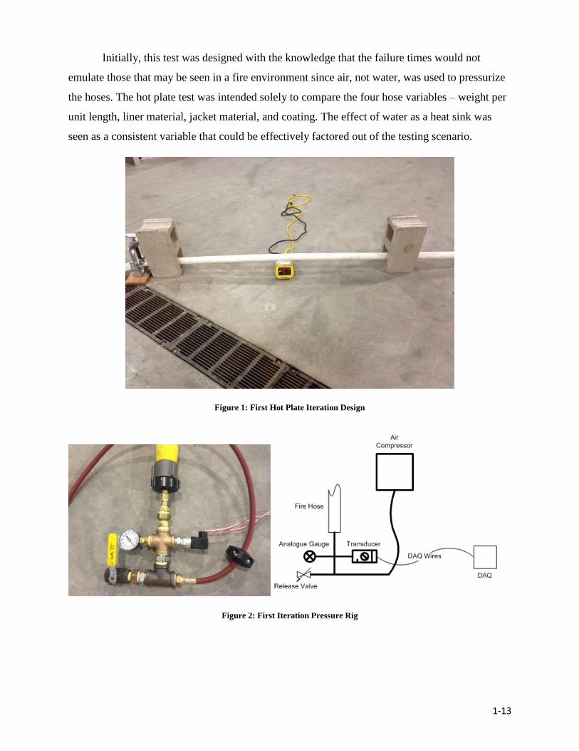
The original conduction test, which was dubbed the “Hot Plate Test”, involved draping a
hose pressurized with air over a digital laboratory hot plate, supporting both ends of the hose,
and recording time to initial pressure loss (See Figure 2). The hot plate was set to four successive
temperatures: 350℃, 400℃, 450℃, and 500℃. There were four trials run at each temperature for
each hose in the matrix. Air was the chosen medium, as it would not cause water damage to the
electronic hot plate in the event of a failure. The hoses were pressurized to 110 +/- 7 psi, a
realistic operational pressure for fire attack hoses. The set up for the first iteration of this design
can be seen below in Figure 3. The entire procedure can be seen in Appendix C.
1-13
Initially, this test was designed with the knowledge that the failure times would not
emulate those that may be seen in a fire environment since air, not water, was used to pressurize
the hoses. The hot plate test was intended solely to compare the four hose variables – weight per
unit length, liner material, jacket material, and coating. The effect of water as a heat sink was
seen as a consistent variable that could be effectively factored out of the testing scenario.
Figure 1: First Hot Plate Iteration Design
Figure 2: First Iteration Pressure Rig
1-14
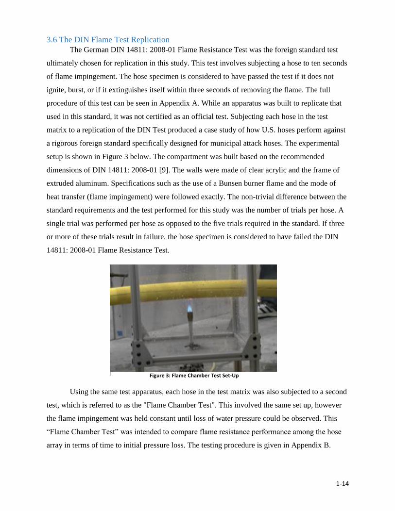
3.6 The DIN Flame Test Replication
The German DIN 14811: 2008-01 Flame Resistance Test was the foreign standard test
ultimately chosen for replication in this study. This test involves subjecting a hose to ten seconds
of flame impingement. The hose specimen is considered to have passed the test if it does not
ignite, burst, or if it extinguishes itself within three seconds of removing the flame. The full
procedure of this test can be seen in Appendix A. While an apparatus was built to replicate that
used in this standard, it was not certified as an official test. Subjecting each hose in the test
matrix to a replication of the DIN Test produced a case study of how U.S. hoses perform against
a rigorous foreign standard specifically designed for municipal attack hoses. The experimental
setup is shown in Figure 3 below. The compartment was built based on the recommended
dimensions of DIN 14811: 2008-01 [9]. The walls were made of clear acrylic and the frame of
extruded aluminum. Specifications such as the use of a Bunsen burner flame and the mode of
heat transfer (flame impingement) were followed exactly. The non-trivial difference between the
standard requirements and the test performed for this study was the number of trials per hose. A
single trial was performed per hose as opposed to the five trials required in the standard. If three
or more of these trials result in failure, the hose specimen is considered to have failed the DIN
14811: 2008-01 Flame Resistance Test.
Using the same test apparatus, each hose in the test matrix was also subjected to a second
test, which is referred to as the "Flame Chamber Test". This involved the same set up, however
the flame impingement was held constant until loss of water pressure could be observed. This
“Flame Chamber Test” was intended to compare flame resistance performance among the hose
array in terms of time to initial pressure loss. The testing procedure is given in Appendix B.
Figure 3: Flame Chamber Test Set-Up
1-15
3.7 An Overview of Data Acquisition and Hose Pressurization
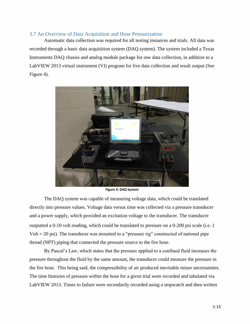
Automatic data collection was required for all testing instances and trials. All data was
recorded through a basic data acquisition system (DAQ system). The system included a Texas
Instruments DAQ chassis and analog module package for raw data collection, in addition to a
LabVIEW 2013 virtual instrument (VI) program for live data collection and result output (See
Figure 4).
The DAQ system was capable of measuring voltage data, which could be translated
directly into pressure values. Voltage data versus time was collected via a pressure transducer
and a power supply, which provided an excitation voltage to the transducer. The transducer
outputted a 0-10 volt reading, which could be translated to pressure on a 0-200 psi scale (i.e. 1
Volt = 20 psi). The transducer was mounted to a “pressure rig” constructed of national pipe
thread (NPT) piping that connected the pressure source to the fire hose.
By Pascal’s Law, which states that the pressure applied to a confined fluid increases the
pressure throughout the fluid by the same amount, the transducer could measure the pressure in
the fire hose. This being said, the compressibility of air produced inevitable minor uncertainties.
The time histories of pressure within the hose for a given trial were recorded and tabulated via
LabVIEW 2013. Times to failure were secondarily recorded using a stopwatch and then written
FIGURE : DATA ACQUISITION
SYSTEM
Figure 4: DAQ System
1-16
down manually. An analog gauge mounted to the pressure rig also secondarily measured
pressure in the hose.
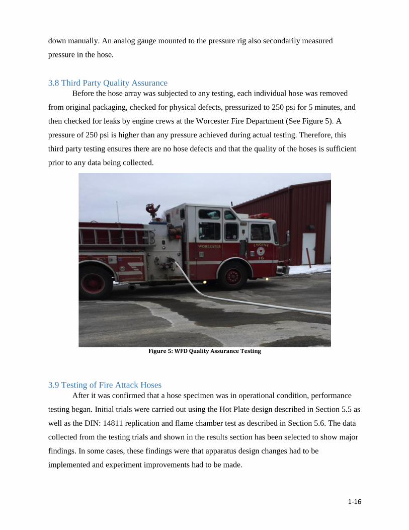
3.8 Third Party Quality Assurance
Before the hose array was subjected to any testing, each individual hose was removed
from original packaging, checked for physical defects, pressurized to 250 psi for 5 minutes, and
then checked for leaks by engine crews at the Worcester Fire Department (See Figure 5). A
pressure of 250 psi is higher than any pressure achieved during actual testing. Therefore, this
third party testing ensures there are no hose defects and that the quality of the hoses is sufficient
prior to any data being collected.
3.9 Testing of Fire Attack Hoses
After it was confirmed that a hose specimen was in operational condition, performance
testing began. Initial trials were carried out using the Hot Plate design described in Section 5.5 as
well as the DIN: 14811 replication and flame chamber test as described in Section 5.6. The data
collected from the testing trials and shown in the results section has been selected to show major
findings. In some cases, these findings were that apparatus design changes had to be
implemented and experiment improvements had to be made.
FIGURE : THIRD PARTY TESTING, WORCESTER
MA
Figure 5: WFD Quality Assurance Testing
1-17
4. Results and Discussion
4.1 Test Results of the First Hot Plate Design
The first hot plate test design ultimately served as an initial step in designing a more
rigorous conduction test. A full parametric analysis was not completed using this design since a
series of design changes were decided upon before all hose models could be shipped to the
testing site. However, enough trials were performed to reveal a connection between liner
material and hose performance and to identify other potential design improvements.
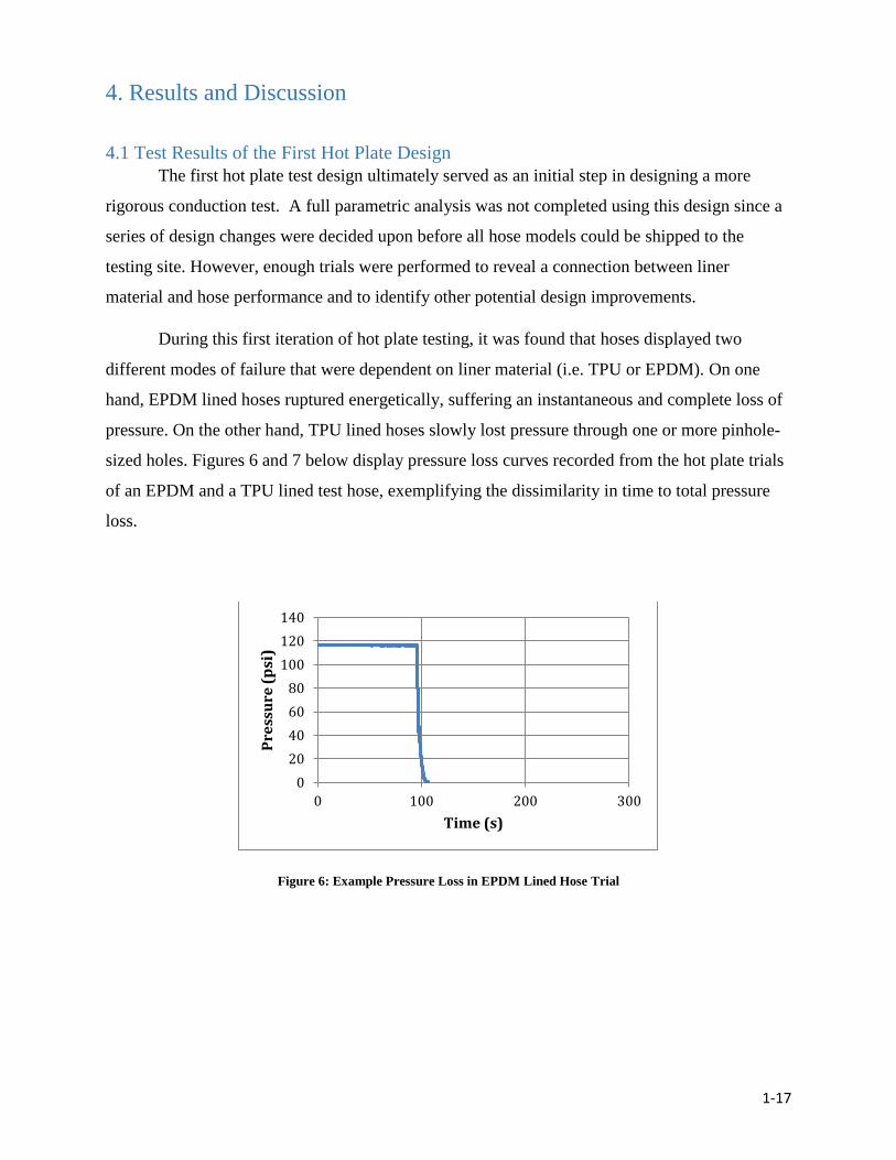
During this first iteration of hot plate testing, it was found that hoses displayed two
different modes of failure that were dependent on liner material (i.e. TPU or EPDM). On one
hand, EPDM lined hoses ruptured energetically, suffering an instantaneous and complete loss of
pressure. On the other hand, TPU lined hoses slowly lost pressure through one or more pinhole-
sized holes. Figures 6 and 7 below display pressure loss curves recorded from the hot plate trials
of an EPDM and a TPU lined test hose, exemplifying the dissimilarity in time to total pressure
loss.
Figure 6: Example Pressure Loss in EPDM Lined Hose Trial
0
20
40
60
80
100
120
140
0 100 200 300
Pre
ssu
re (
psi
)
Time (s)

1-18
Figure 7: Example Pressure Loss in TPU Lined Hose Trial
These failure modes held true through all three hot plate testing iterations. Data was
inconclusive as to whether EPDM or TPU hoses lasted longer until initial pressure drop;
however, TPU lined hoses consistently took a longer time to reach a point of half-pressure when
compared with EPDM lined hoses. The difference in failure modes is based on the thermo
mechanical properties of the liner material. More specifically, EPDM is thermosetting while
TPU is thermoplastic. When a heat flux is applied to the EPDM lined hoses, the outer jacket and
coating are first melted away leaving the liner exposed. The application of heat caused the liner
to build up interior thermal stresses until it eventually ruptures as seen in Figure 8 below. If these
holes are large enough, they could render the hose incapable of delivering water to the nozzle at
an adequate pressure to fight a fire.
Figure 8: EPDM Hose Failure Example
0
20
40
60
80
100
120
140
0 50 100 150 200 250 300P
ress
ure
(p
si)
Time (s)
1-19
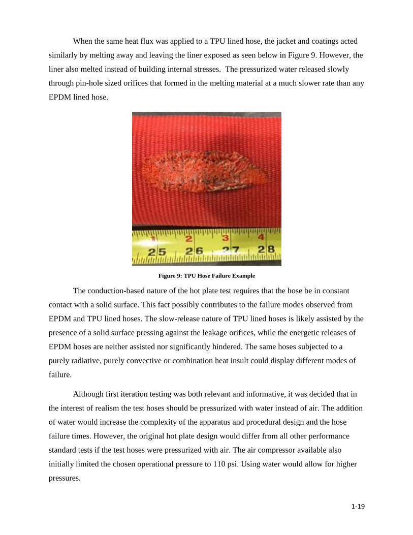
When the same heat flux was applied to a TPU lined hose, the jacket and coatings acted
similarly by melting away and leaving the liner exposed as seen below in Figure 9. However, the
liner also melted instead of building internal stresses. The pressurized water released slowly
through pin-hole sized orifices that formed in the melting material at a much slower rate than any
EPDM lined hose.
Figure 9: TPU Hose Failure Example
The conduction-based nature of the hot plate test requires that the hose be in constant
contact with a solid surface. This fact possibly contributes to the failure modes observed from
EPDM and TPU lined hoses. The slow-release nature of TPU lined hoses is likely assisted by the
presence of a solid surface pressing against the leakage orifices, while the energetic releases of
EPDM hoses are neither assisted nor significantly hindered. The same hoses subjected to a
purely radiative, purely convective or combination heat insult could display different modes of
failure.
Although first iteration testing was both relevant and informative, it was decided that in
the interest of realism the test hoses should be pressurized with water instead of air. The addition
of water would increase the complexity of the apparatus and procedural design and the hose
failure times. However, the original hot plate design would differ from all other performance
standard tests if the test hoses were pressurized with air. The air compressor available also
initially limited the chosen operational pressure to 110 psi. Using water would allow for higher
pressures.
1-20
4.2 The Second Hot Plate Design Iteration
A second hot plate design iteration was developed based on the findings and
troubleshooting of the first iteration. Most changes were made in order to account for the heat
transfer effects of static water within a fire attack hose and to streamline the testing procedure. A
hose pressurized with water is more difficult to contain upon rupture; however, it is more
realistic and more common among standard fire hose performance tests including those
referenced in DIN 14811 and NFPA 1961. To increase rigor, the test pressure for the second
iteration was increased to 150 psi, which is a high-end value of fire attack hose operational
pressure. Additionally the range of temperatures the hoses were tested at (i.e. 350℃, 400℃,
450℃, 500℃) was reduced to include only 500℃. This procedure can be seen in Appendix D.
Ceramic or metallic building components involved in a structural fire can reach similar
temperatures and utilizing only one rigorous temperature value for conduction testing allows for
a simpler parametric analysis. The added dimension that would result from varying temperature
was deemed unnecessary.
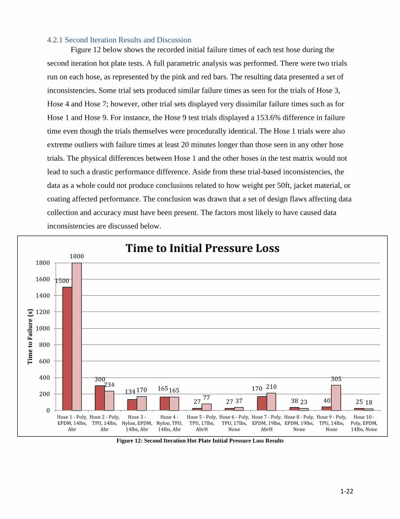
The new apparatus utilized the chamber built for the DIN replication to contain water
spray, which drained out a hole in the bottom of the compartment (seen in Figure 10). The hot
plate was raised off the bottom of the chamber to prevent water pooling into its electrical
components and to align it with the hose inlets. The hose itself was arced through the chamber
such that the apex of the arc rested on the hot plate, but was smooth enough for complete contact.
Both ends of the arc were supported by cinder blocks.
The pressure rig, originally intended for air, had to be redesigned to accommodate for
water and a higher pressure. As shown in Figures 10 and 11, the rig consisted of a direct
standpipe connection with two waterways: a pump (pressure washer) and a bypass. The bypass
allowed the pressure rig and the fire hose to be quickly filled with water at a standpipe pressure
of about 55 psi before the pump increased the pressure of the system to 150 psi.
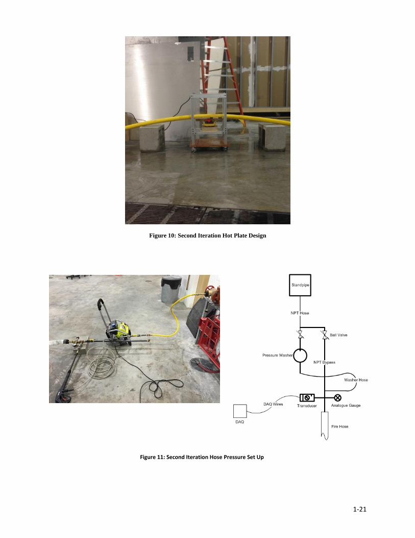
1-21
Figure 10: Second Iteration Hot Plate Design
Figure 11: Second Iteration Hose Pressure Set Up
1-22
4.2.1 Second Iteration Results and Discussion
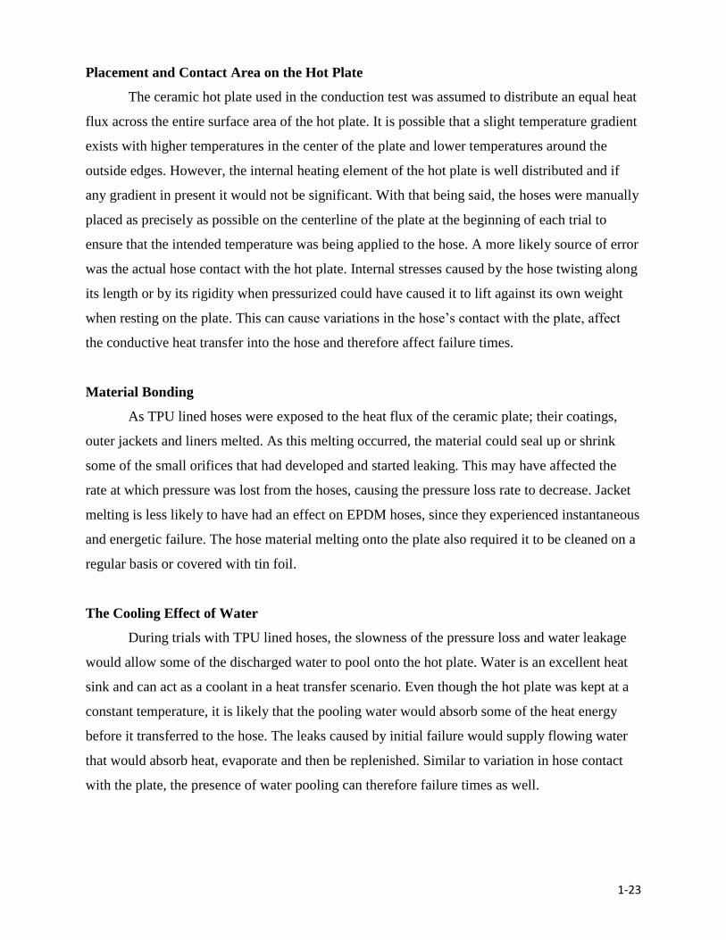
Figure 12 below shows the recorded initial failure times of each test hose during the
second iteration hot plate tests. A full parametric analysis was performed. There were two trials
run on each hose, as represented by the pink and red bars. The resulting data presented a set of
inconsistencies. Some trial sets produced similar failure times as seen for the trials of Hose 3,
Hose 4 and Hose 7; however, other trial sets displayed very dissimilar failure times such as for
Hose 1 and Hose 9. For instance, the Hose 9 test trials displayed a 153.6% difference in failure
time even though the trials themselves were procedurally identical. The Hose 1 trials were also
extreme outliers with failure times at least 20 minutes longer than those seen in any other hose
trials. The physical differences between Hose 1 and the other hoses in the test matrix would not
lead to such a drastic performance difference. Aside from these trial-based inconsistencies, the
data as a whole could not produce conclusions related to how weight per 50ft, jacket material, or
coating affected performance. The conclusion was drawn that a set of design flaws affecting data
collection and accuracy must have been present. The factors most likely to have caused data
inconsistencies are discussed below.
Figure 12: Second Iteration Hot Plate Initial Pressure Loss Results
1500
300
134 165
27 27
170
38 40 25
1800
234170 165
7737
210
23
305
180
200
400
600
800
1000
1200
1400
1600
1800
Hose 1 - Poly,EPDM, 14lbs,
Abr
Hose 2 - Poly,TPU, 14lbs,
Abr
Hose 3 -Nylon, EPDM,
14lbs, Abr
Hose 4 -Nylon, TPU,14lbs, Abr
Hose 5 - Poly,TPU, 17lbs,
AbrH
Hose 6 - Poly,TPU, 17lbs,
None
Hose 7 - Poly,EPDM, 19lbs,
AbrH
Hose 8 - Poly,EPDM, 19lbs,
None
Hose 9 - Poly,TPU, 14lbs,
None
Hose 10 -Poly, EPDM,14lbs, None
Tim
e t
o F
ail
ure
(s)
Time to Initial Pressure Loss
1-23
Placement and Contact Area on the Hot Plate
The ceramic hot plate used in the conduction test was assumed to distribute an equal heat
flux across the entire surface area of the hot plate. It is possible that a slight temperature gradient
exists with higher temperatures in the center of the plate and lower temperatures around the
outside edges. However, the internal heating element of the hot plate is well distributed and if
any gradient in present it would not be significant. With that being said, the hoses were manually
placed as precisely as possible on the centerline of the plate at the beginning of each trial to
ensure that the intended temperature was being applied to the hose. A more likely source of error
was the actual hose contact with the hot plate. Internal stresses caused by the hose twisting along
its length or by its rigidity when pressurized could have caused it to lift against its own weight
when resting on the plate. This can cause variations in the hose’s contact with the plate, affect
the conductive heat transfer into the hose and therefore affect failure times.
Material Bonding
As TPU lined hoses were exposed to the heat flux of the ceramic plate; their coatings,
outer jackets and liners melted. As this melting occurred, the material could seal up or shrink
some of the small orifices that had developed and started leaking. This may have affected the
rate at which pressure was lost from the hoses, causing the pressure loss rate to decrease. Jacket
melting is less likely to have had an effect on EPDM hoses, since they experienced instantaneous
and energetic failure. The hose material melting onto the plate also required it to be cleaned on a
regular basis or covered with tin foil.
The Cooling Effect of Water
During trials with TPU lined hoses, the slowness of the pressure loss and water leakage
would allow some of the discharged water to pool onto the hot plate. Water is an excellent heat
sink and can act as a coolant in a heat transfer scenario. Even though the hot plate was kept at a
constant temperature, it is likely that the pooling water would absorb some of the heat energy
before it transferred to the hose. The leaks caused by initial failure would supply flowing water
that would absorb heat, evaporate and then be replenished. Similar to variation in hose contact
with the plate, the presence of water pooling can therefore failure times as well.
1-24
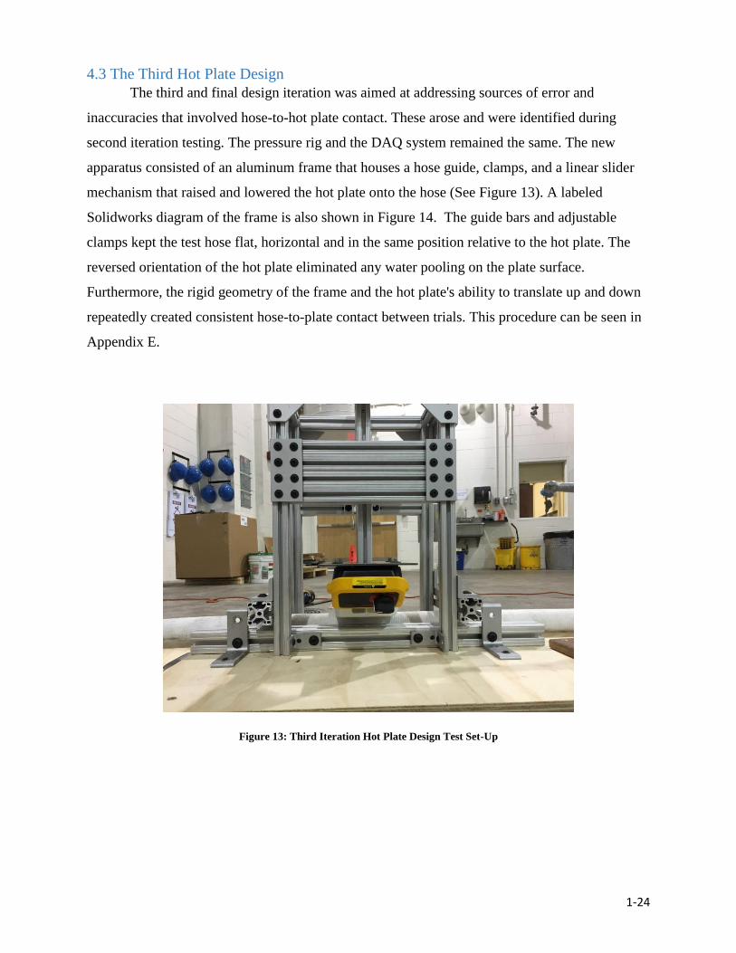
4.3 The Third Hot Plate Design
The third and final design iteration was aimed at addressing sources of error and
inaccuracies that involved hose-to-hot plate contact. These arose and were identified during
second iteration testing. The pressure rig and the DAQ system remained the same. The new
apparatus consisted of an aluminum frame that houses a hose guide, clamps, and a linear slider
mechanism that raised and lowered the hot plate onto the hose (See Figure 13). A labeled
Solidworks diagram of the frame is also shown in Figure 14. The guide bars and adjustable
clamps kept the test hose flat, horizontal and in the same position relative to the hot plate. The
reversed orientation of the hot plate eliminated any water pooling on the plate surface.
Furthermore, the rigid geometry of the frame and the hot plate's ability to translate up and down
repeatedly created consistent hose-to-plate contact between trials. This procedure can be seen in
Appendix E.
Figure 13: Third Iteration Hot Plate Design Test Set-Up
FIGURE 14 THIRD ITERATION DESIGN CAD DRAWING
1-25
The smoothness of translation affected the contact between the hose and the hot plate in
addition to the hose guide and rigidity of the frame. The translating rods had to be able to slide
through the bearings with minimum friction and no binding. The aluminum extrusions and linear
bearings used in the design were not created with the high tolerances of more expensive, fluid
lubricated linear rods and bearings. The mechanism used in this design was non-lubricated and
required a larger amount of “play” to work properly. As a result, a discrepancy of four-to-six
thousandths existed between the translating rods and the bearings. To test the smoothness of
translation, a load cell analysis was conducted to ensure the force on the hose among multiple
iterations of raising and lowering the hot plate would remain constant. As shown in Table 2,
there was only a variation range of 0.128 N among all ten trials.
Trial 1 2 3 4 5 6 7 8 9 10
Force
(N)
26.568 26.627 26.656 26.607 26.578 26.538 26.636 26.627 26.568 26.666
Table 2: Load Cell Analysis
Figure 14: Third Iteration Hot Plate Design CAD File
1-26
The bearing ratio of the slider mechanism as a whole was calculated as shown:
𝐵𝑅 =𝐿𝑒𝑓
𝐷𝑒𝑓
**where Lef is the effective length and Def is the effective diameter.
A bearing ratio of 1 or higher is required for smooth translation and a value of 1.5 is
recommended as optimal. The slider mechanism ratio is approximately 1.31. This value is less
than ideal, although the data shown in Table 2 supports the claim that a ratio of 1.31 is sufficient
for this application of providing consistent contact force.
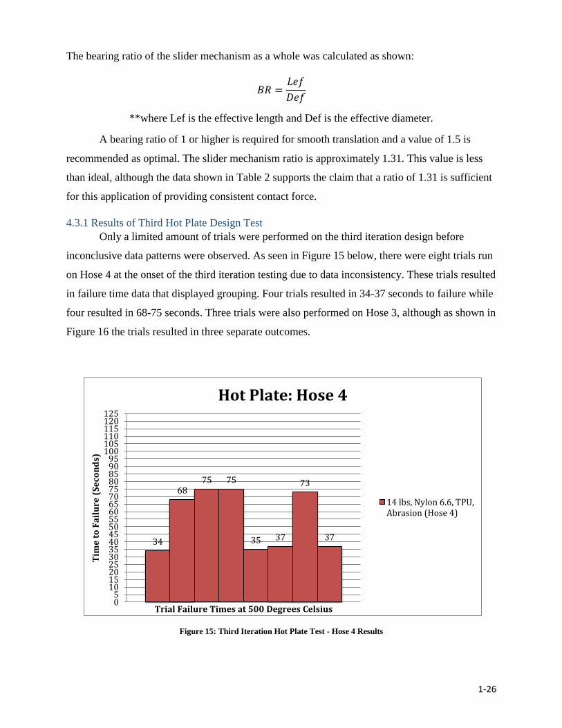
4.3.1 Results of Third Hot Plate Design Test
Only a limited amount of trials were performed on the third iteration design before
inconclusive data patterns were observed. As seen in Figure 15 below, there were eight trials run
on Hose 4 at the onset of the third iteration testing due to data inconsistency. These trials resulted
in failure time data that displayed grouping. Four trials resulted in 34-37 seconds to failure while
four resulted in 68-75 seconds. Three trials were also performed on Hose 3, although as shown in
Figure 16 the trials resulted in three separate outcomes.
Figure 15: Third Iteration Hot Plate Test - Hose 4 Results
34
6875 75
35 37
73
37
05
101520253035404550556065707580859095
100105110115120125
Tim
e t
o F
ail
ure
(S
eco
nd
s)
Trial Failure Times at 500 Degrees Celsius
Hot Plate: Hose 4
14 lbs, Nylon 6.6, TPU,Abrasion (Hose 4)

1-27
Figure 16: Third Iteration Hot Plate Test - Hose 3 Results
In spite of the issues addressed by the third design iteration, the new apparatus also
developed its own unique set of problems. Primarily, the new orientation of the hot plate allowed
water to spray inside the hot plate itself as opposed to on its surface after a test hose ruptured.
The water was then evaporated by the internal heating element and condensed onto electrical
components, causing short-circuits. Efforts were made to prevent water condensation from
reaching these components after the phenomenon was first observed in initial trials; however,
they were not successful. The involvement of potentially faulty circuitry led to uncertainties as to
how much heat the plate was actually producing compared to the numerical value that was
shown on the digital display. This uncertainty was present across all trials. Secondarily, water
that sprayed from the hose due to failure from each trial would pre-wet consecutive segments of
the hose to be used in later trials, requiring a long intermission between trials. If the hoses were
not completely dry before the next trial, the water could slow the rate at which the hose surface
was heated.
57
80
115
05
101520253035404550556065707580859095
100105110115120125
Tim
e t
o F
ail
ure
(S
eco
nd
s)
Trial Failure Times at 500 Degrees Celsius
Hot Plate: Hose 3
14 lbs, Nylon 6.6, EPDM,Abrasion (Hose 3)
1-28
4.4 Hose Performance when Subjected to an International Flame Impingement Thermal
Assault Test
The apparatus and the procedures of both the DIN: 14811 flame resistance test replication
and the flame chamber test were kept constant throughout the course of all testing. There were
no alterations made and a complete parametric analysis was performed. It should be noted that
only one trial was completed per hose. In the DIN 14811 test, a hose length is subjected to flame
impingement for a ten second-time period. The flame is then extinguished and hose performance
is analyzed. A trial is considered to be successful if the hose does not ignite, rupture or is able to
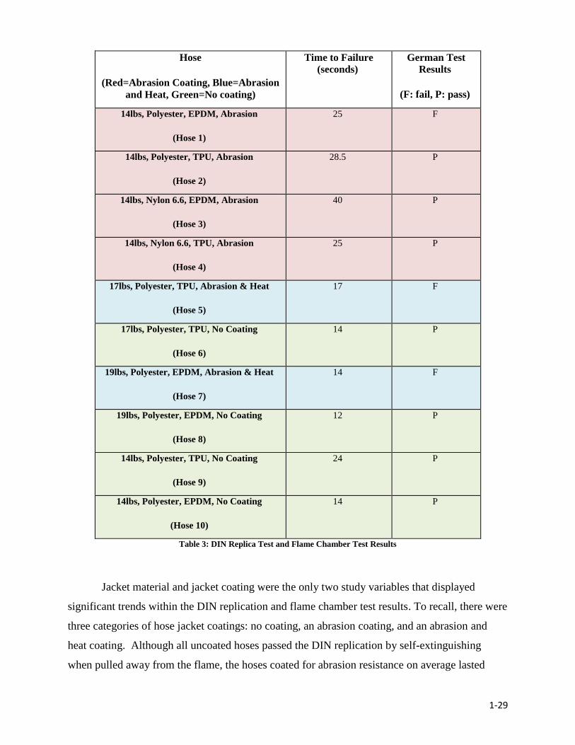
self-extinguish within three seconds. Ultimately, three of the ten hoses in the test matrix failed
the DIN 14811 replication. This result suggests that the level of rigor and heat insult that the
actual DIN standard requires fire attack hoses to withstand is higher than that of U.S standards
on fire hoses. Table 3 shows which of hoses passed the DIN 14811 replication as well as the
times to initial pressure loss during the flame chamber test.
1-29
Hose
(Red=Abrasion Coating, Blue=Abrasion
and Heat, Green=No coating)
Time to Failure
(seconds) German Test
Results
(F: fail, P: pass)
14lbs, Polyester, EPDM, Abrasion
(Hose 1)
25 F
14lbs, Polyester, TPU, Abrasion
(Hose 2)
28.5 P
14lbs, Nylon 6.6, EPDM, Abrasion
(Hose 3)
40 P
14lbs, Nylon 6.6, TPU, Abrasion
(Hose 4)
25 P
17lbs, Polyester, TPU, Abrasion & Heat
(Hose 5)
17 F
17lbs, Polyester, TPU, No Coating
(Hose 6)
14 P
19lbs, Polyester, EPDM, Abrasion & Heat
(Hose 7)
14 F
19lbs, Polyester, EPDM, No Coating
(Hose 8)
12 P
14lbs, Polyester, TPU, No Coating
(Hose 9)
24 P
14lbs, Polyester, EPDM, No Coating
(Hose 10)
14 P
Table 3: DIN Replica Test and Flame Chamber Test Results
Jacket material and jacket coating were the only two study variables that displayed
significant trends within the DIN replication and flame chamber test results. To recall, there were
three categories of hose jacket coatings: no coating, an abrasion coating, and an abrasion and
heat coating. Although all uncoated hoses passed the DIN replication by self-extinguishing
when pulled away from the flame, the hoses coated for abrasion resistance on average lasted

1-30
about 15 seconds longer than either abrasion and heat coated hoses or completely uncoated hoses
when constantly subjected to flame impingement during the flame chamber test. This result can
be seen in Table 3 with hoses one through four having only an abrasion coating (red shading),
hoses five and seven having an abrasion and heat coating (blue shading), and hoses six, eight,
nine, and ten having no coating (green shading). Also shown in Table 3, all three hoses that
failed the DIN replication were polyester jacketed hoses that were also coated for either abrasion
or abrasion and heat. Therefore, there are two principle findings from these results that the
authors feel merit further investigation and research:
1. It appears that the outer jacket material is a factor in flame resistance as all three
hoses that failed the German Standard Test had polyester outer jackets. Since the
melting point temperature of nylon 6.6 is slightly higher, this might be expected, but
other thermal and even structural components of the nylon jacket may also play a role
in its ability to self-extinguish.
2. Uncoated hoses were more likely to self-extinguish after being moved away from
direct flame impingement; however, they did not last as long as their coated
counterparts during instances of constant flame impingement. This contradicted an
initial hypothesis that coated hoses offered all-around superior performance against
heat insult. Once flame impingement was halted, all four uncoated hoses were all
able to self-extinguish while only three of the six coated hoses were able to. While
this finding requires further testing in order to be confirmed, it appears that the
presence of coatings does not benefit the ability of the fire attack hose to self-
extinguish.
The best performing hose in this study was the nylon 6.6, EPDM lined hose with the
abrasion coating (Hose 3). Note that only two hoses in this study had nylon 6.6 outer jackets,
this one having a weight per unit length of 14 lbs per 50 ft. This hose lasted 40 seconds before
failure in the direct flame impingement test. Based on this finding, it would be informative to test
a nylon 6.6, EPDM lined hose with the abrasion coating in a heavier weight per unit length.
4.4.1 A Closer Look at the Effect of Coatings on Flame Resistance
The hose comparisons made from the flame chamber test data showed that, when the
other three study variables were held constant, a coated hose outperformed a counterpart hose
with no coating. Coating comparisons were made between the following pairs: Hose 5 vs. Hose
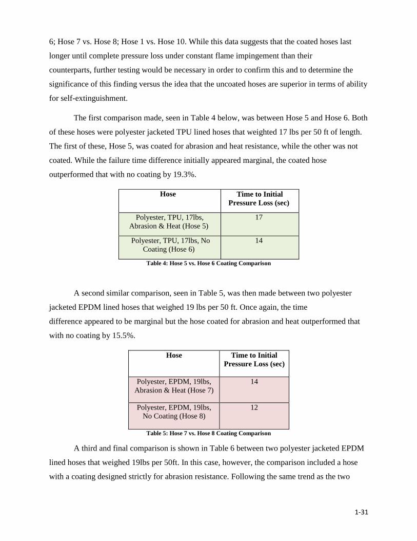
1-31
6; Hose 7 vs. Hose 8; Hose 1 vs. Hose 10. While this data suggests that the coated hoses last
longer until complete pressure loss under constant flame impingement than their
counterparts, further testing would be necessary in order to confirm this and to determine the
significance of this finding versus the idea that the uncoated hoses are superior in terms of ability
for self-extinguishment.
The first comparison made, seen in Table 4 below, was between Hose 5 and Hose 6. Both
of these hoses were polyester jacketed TPU lined hoses that weighted 17 lbs per 50 ft of length.
The first of these, Hose 5, was coated for abrasion and heat resistance, while the other was not
coated. While the failure time difference initially appeared marginal, the coated hose
outperformed that with no coating by 19.3%.
Hose Time to Initial
Pressure Loss (sec)
Polyester, TPU, 17lbs,
Abrasion & Heat (Hose 5)
17
Polyester, TPU, 17lbs, No
Coating (Hose 6)
14
Table 4: Hose 5 vs. Hose 6 Coating Comparison
A second similar comparison, seen in Table 5, was then made between two polyester
jacketed EPDM lined hoses that weighed 19 lbs per 50 ft. Once again, the time
difference appeared to be marginal but the hose coated for abrasion and heat outperformed that
with no coating by 15.5%.
Hose Time to Initial
Pressure Loss (sec)
Polyester, EPDM, 19lbs,
Abrasion & Heat (Hose 7)
14
Polyester, EPDM, 19lbs,
No Coating (Hose 8)
12
Table 5: Hose 7 vs. Hose 8 Coating Comparison
A third and final comparison is shown in Table 6 between two polyester jacketed EPDM
lined hoses that weighed 19lbs per 50ft. In this case, however, the comparison included a hose
with a coating designed strictly for abrasion resistance. Following the same trend as the two
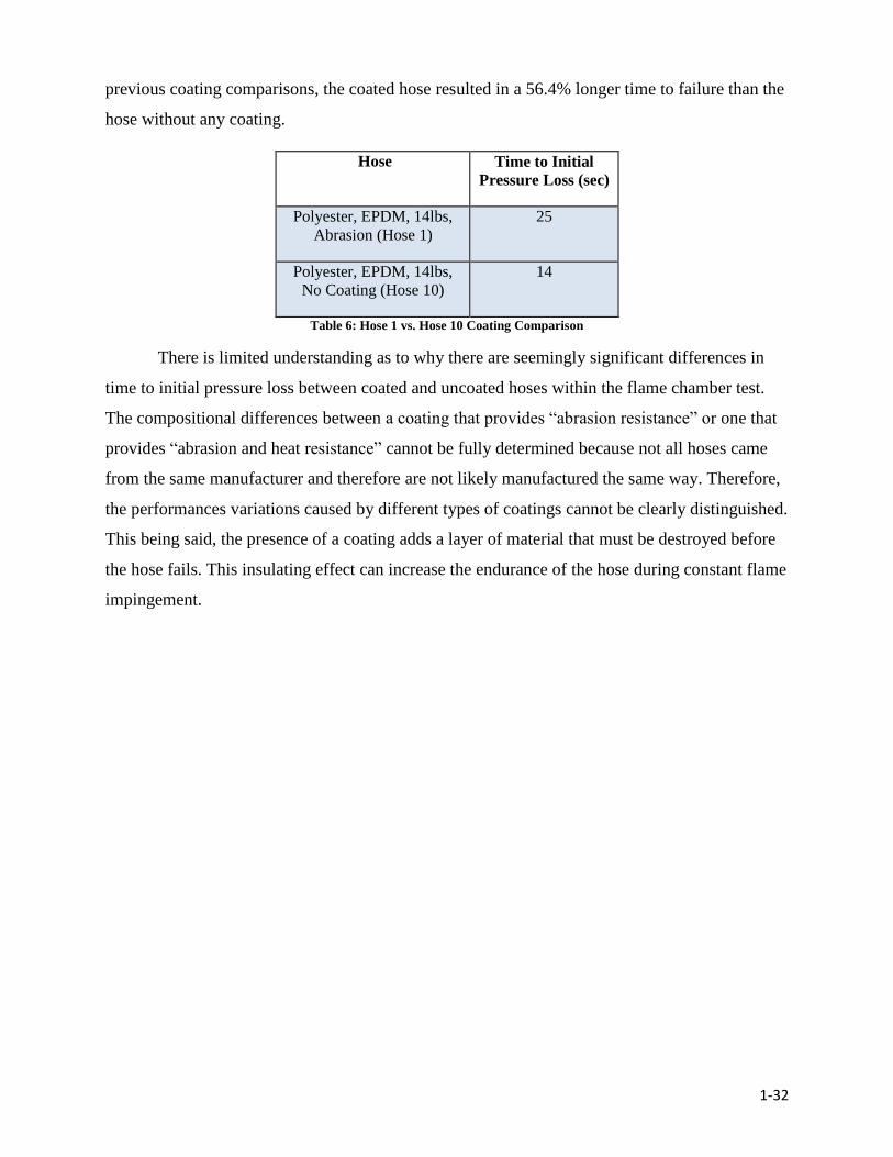
1-32
previous coating comparisons, the coated hose resulted in a 56.4% longer time to failure than the
hose without any coating.
Hose Time to Initial
Pressure Loss (sec)
Polyester, EPDM, 14lbs,
Abrasion (Hose 1)
25
Polyester, EPDM, 14lbs,
No Coating (Hose 10)
14
Table 6: Hose 1 vs. Hose 10 Coating Comparison
There is limited understanding as to why there are seemingly significant differences in
time to initial pressure loss between coated and uncoated hoses within the flame chamber test.
The compositional differences between a coating that provides “abrasion resistance” or one that
provides “abrasion and heat resistance” cannot be fully determined because not all hoses came
from the same manufacturer and therefore are not likely manufactured the same way. Therefore,
the performances variations caused by different types of coatings cannot be clearly distinguished.
This being said, the presence of a coating adds a layer of material that must be destroyed before
the hose fails. This insulating effect can increase the endurance of the hose during constant flame
impingement.
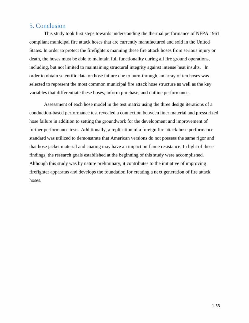
1-33
5. Conclusion This study took first steps towards understanding the thermal performance of NFPA 1961
compliant municipal fire attack hoses that are currently manufactured and sold in the United
States. In order to protect the firefighters manning these fire attack hoses from serious injury or
death, the hoses must be able to maintain full functionality during all fire ground operations,
including, but not limited to maintaining structural integrity against intense heat insults. In
order to obtain scientific data on hose failure due to burn-through, an array of ten hoses was
selected to represent the most common municipal fire attack hose structure as well as the key
variables that differentiate these hoses, inform purchase, and outline performance.
Assessment of each hose model in the test matrix using the three design iterations of a
conduction-based performance test revealed a connection between liner material and pressurized
hose failure in addition to setting the groundwork for the development and improvement of
further performance tests. Additionally, a replication of a foreign fire attack hose performance
standard was utilized to demonstrate that American versions do not possess the same rigor and
that hose jacket material and coating may have an impact on flame resistance. In light of these
findings, the research goals established at the beginning of this study were accomplished.
Although this study was by nature preliminary, it contributes to the initiative of improving
firefighter apparatus and develops the foundation for creating a next generation of fire attack
hoses.

1-34
6. Future Work and Recommendations
Recommendations for future work are focused on design of the test apparatus,
improvements in the experimental procedure, and future research on fire attack hoses. The
following recommendations are offered for the continuation of research initiated by this study in
an effort to produce conclusive data on currently manufactured fire hose performance.
In order to advance the third iteration hot plate test design, it is recommended that the
following design changes are made. These alterations are intended to reduce sources of
error and data inconsistency present in the first three Hot Plate design iterations.
1. A water guard added to the sides of the frame or some other water-proofing
method is suggested to prevent pre-wetting of test segments.
2. A heat source without integrated electronic components should be utilized of
remove the possibility of water-damage to the heat element.
If future research were to redesign the frame apparatus, a form of water guard such as
acrylic siding would be beneficial to prevent pre-wetting of hose sections. In addition, if the hot
plate is kept in a reversed orientation, then the use of a different heat source is recommended, as
it would eliminate the potentially damaging effects of water condensation. Specifically, a
resistance heater with internal thermocouples would produce a constant surface temperature with
a constant input voltage. This would negate the difficult task of shielding electrical components
from steam condensation. However, a custom device would require calibration before use to
ensure temperature readings of the hot surface are accurate.
If a new design for a hose-to-hot surface apparatus is required, a cantilever mechanism is
recommended over a translating rode mechanism in order to improve design simplicity.
A cantilever mechanism would rest the hot plate onto the hose without the tight design
tolerances required when utilizing translating rods and linear bearings. While rods and bearings
are very precise when custom manufactured, a cantilever mechanism is more simplistic and
offers comparable accuracy at a lower cost and without custom manufacturing. In the case of this
study, the translating rode mechanism created for the third hot plate design iteration offered
sufficient precision and repeatability when built with aluminum extrusion framing; however,
1-35
custom manufacturing would have been required for optimal precision and repeatability. A
cantilever mechanism could also be built with aluminum framing and, if properly designed,
could offer improved precision over a translating rode mechanism build with the same
components.
It is recommended that the number of trials in the DIN 14811: Flame Resistance Replica
Test is increased to mirror the German standard exactly.
In the original DIN standard, five trials are required for each hose. The replication
conducted in this study included a single trial on each hose. Mirroring the number of trials
specified in the DIN 14811 test would increase both the validity and insight provided in regard to
hose failures and performance.
Further Research Recommendations on the Thermal Performance of Currently Available
Fire Attack Hose:
Testing of the full matrix of representative hoses using a waterproofed test platform with the
cantilevered apparatus is recommended. Investigation should include determining the impact of
each study variable with intent to further verify the effects of coatings, weight per unit length,
liner failure methods, and outer jacket performance. An additional recommendation is to expand
testing past the original ten hose matrix to account for hose structures separate from the structure
focused on in this study. This will allow a broader understanding of attack fire hose heat
resistance performance in all accounts.
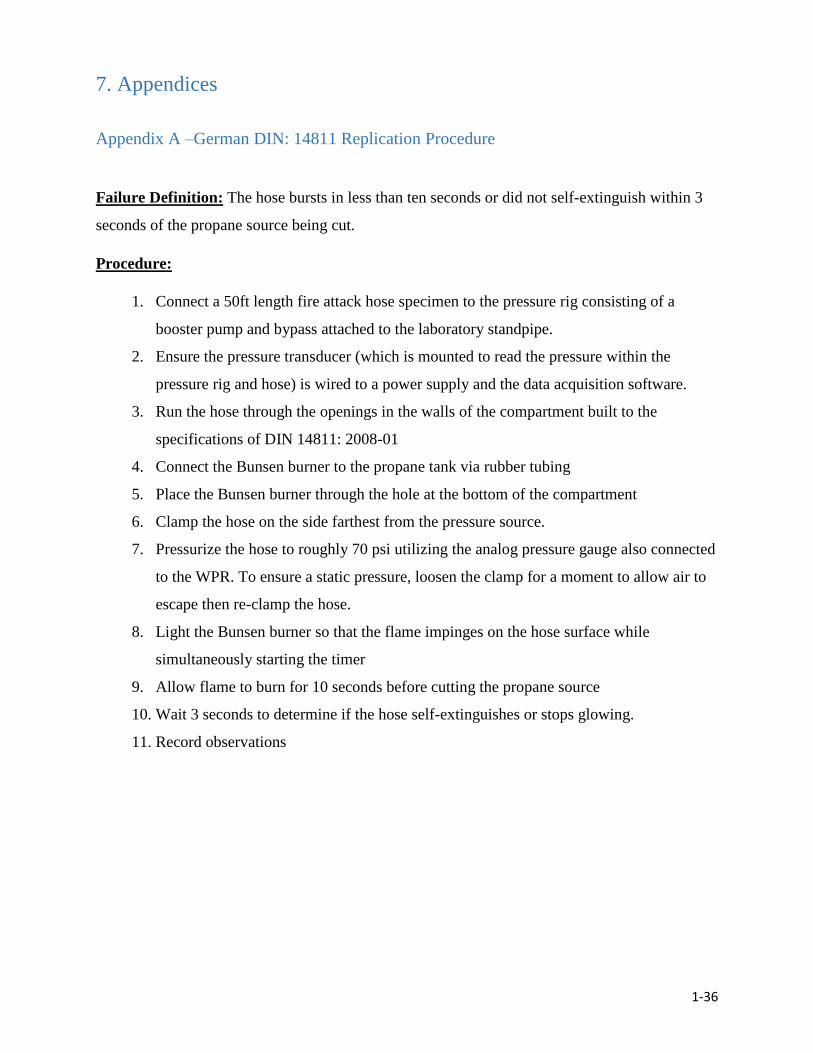
1-36
7. Appendices
Appendix A –German DIN: 14811 Replication Procedure
Failure Definition: The hose bursts in less than ten seconds or did not self-extinguish within 3
seconds of the propane source being cut.
Procedure:
1. Connect a 50ft length fire attack hose specimen to the pressure rig consisting of a
booster pump and bypass attached to the laboratory standpipe.
2. Ensure the pressure transducer (which is mounted to read the pressure within the
pressure rig and hose) is wired to a power supply and the data acquisition software.
3. Run the hose through the openings in the walls of the compartment built to the
specifications of DIN 14811: 2008-01
4. Connect the Bunsen burner to the propane tank via rubber tubing
5. Place the Bunsen burner through the hole at the bottom of the compartment
6. Clamp the hose on the side farthest from the pressure source.
7. Pressurize the hose to roughly 70 psi utilizing the analog pressure gauge also connected
to the WPR. To ensure a static pressure, loosen the clamp for a moment to allow air to
escape then re-clamp the hose.
8. Light the Bunsen burner so that the flame impinges on the hose surface while
simultaneously starting the timer
9. Allow flame to burn for 10 seconds before cutting the propane source
10. Wait 3 seconds to determine if the hose self-extinguishes or stops glowing.
11. Record observations
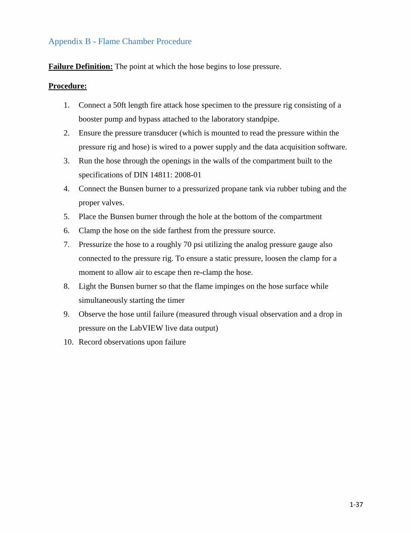
1-37
Appendix B - Flame Chamber Procedure
Failure Definition: The point at which the hose begins to lose pressure.
Procedure:
1. Connect a 50ft length fire attack hose specimen to the pressure rig consisting of a
booster pump and bypass attached to the laboratory standpipe.
2. Ensure the pressure transducer (which is mounted to read the pressure within the
pressure rig and hose) is wired to a power supply and the data acquisition software.
3. Run the hose through the openings in the walls of the compartment built to the
specifications of DIN 14811: 2008-01
4. Connect the Bunsen burner to a pressurized propane tank via rubber tubing and the
proper valves.
5. Place the Bunsen burner through the hole at the bottom of the compartment
6. Clamp the hose on the side farthest from the pressure source.
7. Pressurize the hose to a roughly 70 psi utilizing the analog pressure gauge also
connected to the pressure rig. To ensure a static pressure, loosen the clamp for a
moment to allow air to escape then re-clamp the hose.
8. Light the Bunsen burner so that the flame impinges on the hose surface while
simultaneously starting the timer
9. Observe the hose until failure (measured through visual observation and a drop in
pressure on the LabVIEW live data output)
10. Record observations upon failure
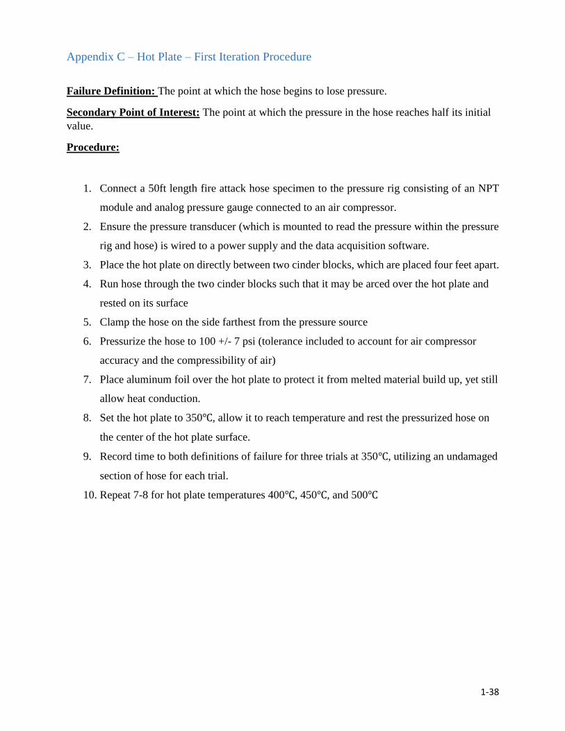
1-38
Appendix C – Hot Plate – First Iteration Procedure
Failure Definition: The point at which the hose begins to lose pressure.
Secondary Point of Interest: The point at which the pressure in the hose reaches half its initial
value.
Procedure:
1. Connect a 50ft length fire attack hose specimen to the pressure rig consisting of an NPT
module and analog pressure gauge connected to an air compressor.
2. Ensure the pressure transducer (which is mounted to read the pressure within the pressure
rig and hose) is wired to a power supply and the data acquisition software.
3. Place the hot plate on directly between two cinder blocks, which are placed four feet apart.
4. Run hose through the two cinder blocks such that it may be arced over the hot plate and
rested on its surface
5. Clamp the hose on the side farthest from the pressure source
6. Pressurize the hose to 100 +/- 7 psi (tolerance included to account for air compressor
accuracy and the compressibility of air)
7. Place aluminum foil over the hot plate to protect it from melted material build up, yet still
allow heat conduction.
8. Set the hot plate to 350℃, allow it to reach temperature and rest the pressurized hose on
the center of the hot plate surface.
9. Record time to both definitions of failure for three trials at 350℃, utilizing an undamaged
section of hose for each trial.
10. Repeat 7-8 for hot plate temperatures 400℃, 450℃, and 500℃
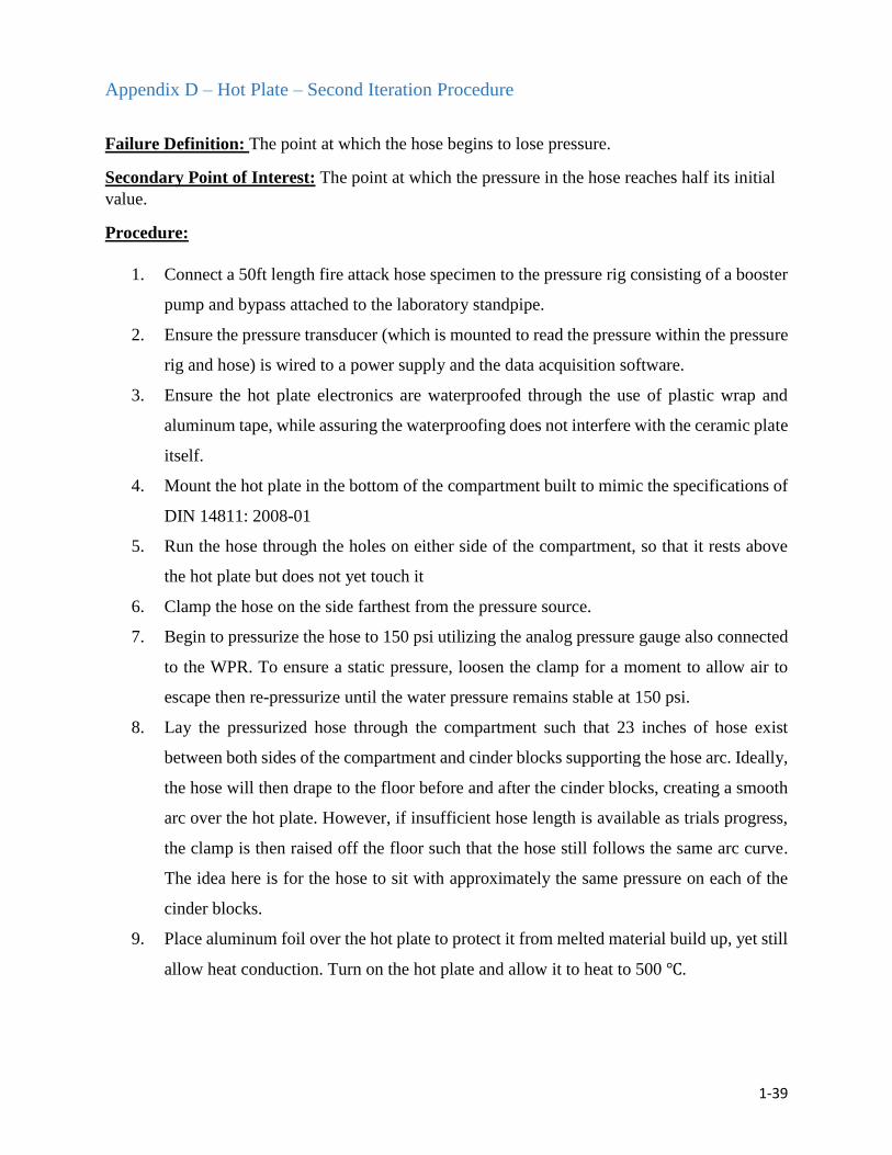
1-39
Appendix D – Hot Plate – Second Iteration Procedure
Failure Definition: The point at which the hose begins to lose pressure.
Secondary Point of Interest: The point at which the pressure in the hose reaches half its initial
value.
Procedure:
1. Connect a 50ft length fire attack hose specimen to the pressure rig consisting of a booster
pump and bypass attached to the laboratory standpipe.
2. Ensure the pressure transducer (which is mounted to read the pressure within the pressure
rig and hose) is wired to a power supply and the data acquisition software.
3. Ensure the hot plate electronics are waterproofed through the use of plastic wrap and
aluminum tape, while assuring the waterproofing does not interfere with the ceramic plate
itself.
4. Mount the hot plate in the bottom of the compartment built to mimic the specifications of
DIN 14811: 2008-01
5. Run the hose through the holes on either side of the compartment, so that it rests above
the hot plate but does not yet touch it
6. Clamp the hose on the side farthest from the pressure source.
7. Begin to pressurize the hose to 150 psi utilizing the analog pressure gauge also connected
to the WPR. To ensure a static pressure, loosen the clamp for a moment to allow air to
escape then re-pressurize until the water pressure remains stable at 150 psi.
8. Lay the pressurized hose through the compartment such that 23 inches of hose exist
between both sides of the compartment and cinder blocks supporting the hose arc. Ideally,
the hose will then drape to the floor before and after the cinder blocks, creating a smooth
arc over the hot plate. However, if insufficient hose length is available as trials progress,
the clamp is then raised off the floor such that the hose still follows the same arc curve.
The idea here is for the hose to sit with approximately the same pressure on each of the
cinder blocks.
9. Place aluminum foil over the hot plate to protect it from melted material build up, yet still
allow heat conduction. Turn on the hot plate and allow it to heat to 500 ℃.
1-40
10. Place the hose on the center of the hot plate, ensuring that the hose is not resting on a fold
crease. Then close the sliding walls of the compartment and simultaneously start the trial
timer
11. The hose should press up against the top of the holes in the sliding walls, which in turn
press the hose to the hot plate.
12. Continue monitoring pressure – record the time at which the pressure is initially lost, and
the time at which it reaches half of its initial pressure
13. At half pressure, stop the timer and remove the hose from the compartment
14. Slide down the hose to a new location and repeat
15. Repeat this procedure 3 times at 500 ℃

1-41
Appendix E – Hot Plate – Third Iteration Procedure
Failure Definition: The point at which the hose begins to lose pressure.
Secondary Point of Interest: The point at which the pressure in the hose reaches half its initial
value.
Procedure:
1. Connect a 50ft length of coupled fire attack hose to the pressure rig, i.e. a pump and
bypass attached to the laboratory standpipe.
2. Ensure the pressure transducer (which is mounted to read the pressure within the
pressure rig and hose) is wired to a power supply and the data acquisition software.
3. Run the deflated hose through either side of the precision frame, so that it rests within
the hose guide.
4. Clamp the free end of the hose at a distance such that maximum hose length is saved for
later tests.
5. Begin to pressurize the hose to 150 psi utilizing the analog pressure gauge also
connected to the pressure rig. To ensure a static pressure, loosen the clamp for a moment
to allow air to escape then re-pressurize until the water pressure remains stable at 150
psi
6. Lower and lock the hose clamp bars such that the hose is resting flat and true between
the hose guide with minimal bowing
7. Turn on the hot plate and allow it to reach 500℃
8. Release the mechanism holding the hot plate off of the hose and allow it to be lowered
onto the hose
9. Once the hose and hot plate contact each other, begin the timer for the trial.
10. Continue monitoring pressure – record the time at which the pressure is initially lost,
and the time at which it reaches half of its initial pressure
11. At half pressure, stop the timer, stop the DAQ, and raise the hot plate off of the hose
12. Slide the hose through the hose guide to a new location, clamp off the damaged section
from the previous test (if applicable)
13. Perform five iterations (trials) of this procedure for each of the ten hose specimens.
1-42
8. Bibliography
[1] "Lieutenant and Fire Fighter Die and 13 Fire Fighters Injured in a Wind-driven Fire in a
Brownstone - Massachusetts." NIOSH Fire Fighter Fatality Investigation and Prevention
Program (2016): n. pag. Web. 4 Apr. 2016.
[2] Donovan, J., Gates, P., Murphy, J., Scangas, C., Ranellone, R. and Notarianni, R. A. An
Analysis of Modern Day Fire Attack Hose. Worcester Polytechnic Institute, Worcester
MA. 2016.
[3] "Fire Hose." How Fire Hose Is Made. N.p., n.d. Web. 29 Oct. 2015.
[4] "Material Selection Guide." Pressure Vessel Design Manual (2004): 464. Web. 26 Oct.
2015.
[5] "Microbial Resistance of Thermoplastic Polyurethanes." Additives for Polymers 17.10
(1987): 2. Web. 26 Oct. 2015.
[6] "Polyester Fibres." Polyester Fibres. N.p., n.d. Web. 26 Oct. 2015.
[7] "GEHR Plastics PA 6.6 Nylon 6.6, Dry." GEHR Plastics PA 6.6 Nylon 6.6,
Dry. N.p., n.d. Web. 26 Oct. 2015.
[8] National Fire Protection Association, "NFPA 1961: Standard on Fire Hose, 2013
Edition," ed. Quincy, MA: National Fire Protection Association, 2012.
[9] Underwriters Laboratories, "ANSI/UL 19: Lined Fire Hose and Hose Assemblies," ed.
Northbrook, IL, 2013.
[10] German Institute for Standardization, "DIN 14811 Fire-fighting hoses- Non -percolating
lay flat delivery hoses and hose assemblies for pumps and vehicles," ed. Berlin,
Germany: German Institute for Standardization, 2008.
[11] J. E. McIntyre, Synthetic Fibres: Nylon, Polyester, Acrylic, Polyolefin: Taylor &
Francis, 2005.
2-1
Chapter 2
Radiative Heat Performance Testing of Materials for
Application in a Fire Attack Hose
Authors: Rebecca Barolli Emily Brecher

2-2
Table of Contents
Table of Tables ..................................................................................................................................... 2-3
1. Introduction ..................................................................................................................................... 2-4
2. Literature Review ........................................................................................................................... 2-5 2.1 Current Hose Materials .................................................................................................................. 2-5
2.2 Personal Protection Equipment Materials ................................................................................. 2-6
3. Methodology .................................................................................................................................... 2-8 3.1 Objective #1: Select Candidate Materials for Testing ............................................................ 2-8
3.2 Objective #2: Create Test Methodology for Radiative Heat.................................................. 2-9 3.2.1 The Cone Calorimeter ............................................................................................................................. 2-9
3.2.2 Data Collection .......................................................................................................................................... 2-9
3.2.3 Test Procedure .........................................................................................................................................2-10
3.3 Objective #3: Perform Testing on Materials ........................................................................... 2-11 3.3.1 Heater Thermocouple Calibration .....................................................................................................2-12
3.4 Objective #4: Establish Baseline Performance Criteria ....................................................... 2-13
4. Results ............................................................................................................................................. 2-14 4.1 Current Materials .......................................................................................................................... 2-14
4.2 Candidate Materials ...................................................................................................................... 2-15
4.3 Comparison of Current and Candidate Materials ................................................................. 2-18
5. Conclusions .................................................................................................................................... 2-21
6. Recommendations and Future Work ...................................................................................... 2-22
7. References ...................................................................................................................................... 2-24
Glossary ............................................................................................................................................... 2-26
2-3
Table of Tables Table 1 - Characteristics of Current Fire Hose Materials ............................................................ 2-6
Table 2 - Characteristics of Potential Candidate Materials ......................................................... 2-8
Table 3 - Calibration Conversion Table..................................................................................... 2-13
Table 4 –Testing Results for Current Materials at 11.9 kW/m2 ................................................ 2-14
Table 5 - Testing Results for Current Materials at 18.0 kW/m2 ................................................ 2-15
Table 6 - Testing Results for Candidate Materials at 18.0 kW/m2 ............................................ 2-16
Table 7 - Testing Results for Candidate Materials at 24.2 kW/m2 ............................................ 2-17
Table 8 - Testing Results for PBI Max® at 36.7 and 48.4 kW/m2 ............................................ 2-17
Table 9 - Before and After Photo Comparison of Samples at 18.0 kW/m2 ............................... 2-19
Table 10 - Current Material Comparison ................................................................................... 2-20
Table 11 - Candidate Material Comparison ............................................................................... 2-20
2-4
1. Introduction
A fire attack hose is an essential tool used by firefighters to combat and suppress fires
and to provide a line of safety. However, the hoses are not always recognized for their other
important role on the fire ground: serving as an additional line of defense for firefighters. From
this, one would assume that these hoses would be able to withstand the harsh conditions of the
fire ground. There are multiple documented accounts of firefights being left stranded inside
burning buildings without an adequate water supply due to fire attack hose burn throughs.
According to the National Institute of Occupational Health and Safety, “in 2008, two firefighters
in North Carolina and one firefighter in Alabama died when an attack hose burned through and
in 2010, an Illinois firefighter was killed when a hose failed” [1]. More recently in Boston’s
Back Bay, two firefighters lost their lives “when they lost their water supply after their hose
burned through” [1].
It seems that the materials being used in fire hoses today are cannot reliably withstand the
exposure levels at the scene of a fire creating a demand for the discovery of new materials that
can. This research will identify materials used in PPE that could be applied to the jackets of a fire
hose in order to: create a test method that will test current and candidate materials in a radiative
heat environment, perform this testing on the selected materials, and quantify the time to
decomposition and ignition of these materials as compared to current fire hose materials. This
research serves to test the hypothesis that there are materials being manufactured that are better
suited for the high heat environment of the fire scene than the current materials being used in fire
hose jackets today.
2-5
2. Literature Review
During the earliest recorded firefighting operations in the United States, buckets of water
were carried from a water source to the fire in an attempt to extinguish it. This method was
inefficient, unreliable and labor intensive. With the invention of the hand pump, water was more
efficiently directed towards a burning structure; however, the firefighting was still carried out
with buckets. It was not until 1807 when two Philadelphia firefighters fashioned leather and
metal rivets into a long tube shaped object that the idea of a fire hose was created. At the time,
“one hundred feet of hose was the equivalent of sixty men with buckets” [2].
The idea was incredibly successful, however the leather was not. It would dry out, crack
and burst when exposed to high pressure and heat. While the metal rivets solved some of these
problems, hoses were still required to be regularly oiled and maintained to keep them in working
order. In 1821, a rubber-lined hose made of cotton webbing was introduced to the fire service
along with an entire industry invested in creating different sizes and shapes of fire hose. For
many years afterword, cotton was the standard material for the fabrication of fire hoses as it was
stronger, lighter, and easier to roll and handle than leather [2].
2.1 Current Hose Materials
The introduction of polyester, nylon, and reinforced plastic to the fire hose industry
occurred in the late 1900’s. These materials became the new standard for jacket materials while
rubber continuing to be used as a liner material. These jacket materials were seen to be superior
over cotton solely for their ability to withstand mold and rot [3]. These materials had not been
chosen for application in the jacket of a fire hose primarily for their performance characteristics
against heat insult. This is alarming since the fire attack hose is considered to be the second line
of defense for a firefighter behind only their personal protective equipment.
Most fire attack hoses being used by fire departments today have jackets weaved from
polyester or nylon 6.6. These materials are typically found in household applications, especially
in clothing and furniture. They do not have high heat applications besides use in fire attack
hoses. Table 1 below compares the characteristics of polyester and nylon 6.6 [4].
2-6
Material Burns? Melts? Drips? Decomposition
Temperature
Polyester Yes Yes Yes 265°C
Nylon 6.6 Yes Yes Yes 250-260°C
Table 1: Characteristics of Current Fire Hose Materials
Today, the National Fire Protection Association (NFPA) codes outline the specifications
and performance capabilities required for fire hoses. More specifically, NFPA 1961: Standard on
Fire Hose defines all performance tests that current fire hoses must meet [5]. These tests for
hose certification involve an elongation test, a burst test, a tensile strength test, and a flexibility
and compressibility test among others. The only heat resistance test required is a conduction-
based heat resistance test. This test requires a 2 ½” x 1 ½” x 8” steel block to be heated to 260 ˚C
and stamped on a fire hose for 60 seconds. The hose is then hydrostatically pressurized to three
times the service test pressure to identify any leaks. NFPA 1961 currently contains no radiative
heat performance test.
2.2 Personal Protection Equipment Material
NFPA codes do contain radiative heat performance testing criteria for the personal
protective equipment (PPE) that firefighters wear during their daily duties. NFPA 1971 Section
8.10 specifies that PPE must be tested in accordance with ISO 17492 for its thermal protective
performance through a series of tests where the material is exposed to a heat flux of 84 kW/m2
+/- 2 kW/m2 [6]. A thermal protective performance (TPP) will be calculated and a value of 35
must be achieved for the material to pass the test. The firefighters’ personal protective equipment
is made of material that is expected to withstand the hottest temperatures of the fire scene and
could potentially be well suited for application in a fire attack hose jacket.
High-heat performance materials are typically classified by the type of characteristics they
possess. The two terms that classify these materials are fire resistant and fire retardant. Fire
resistant materials are those that will not ignite upon exposure to flames and do not melt or drip
under high radiant heat exposures upwards of 600 ˚C. Fire retardant materials may catch fire and
could suffer a burn through; however, they will self-extinguish when removed from direct flame

2-7
contact [7]. Both of these types of materials are used in the fire service for firefighter’s personal
protection against high heat conditions.
A selection of fire resistant and fire retardant materials, all of which are utilized in
firefighter PPE and could potentially have application in fire attack hoses were selected for
testing. However, this selection is by no means an exhaustive set of all fire resistant and fire
retardant materials. DuPont manufactures two of the materials: Nomex®, known for its flame-
resistance is used in turnout gear and accessories and Kevlar®, known for its thermal protection,
durability, and strength is used in turnout gear as outer shells and thermal liners [8]. PBI® fiber
is manufactured by PBI, Inc. and is known for its strength and thermal protection that is woven
into a fabric used to create the outer shell of turnout gear [9]. PBI was first synthesized in 1961
and began being used by the New York City Fire Department and other areas within the U.S. fire
service industry in 1994. Two specific weaves of the PBI® fiber were selected: PBI® Max and
PBI® Kombat Flex. PBI Max is 70% PBI fiber and 30% Kevlar® filaments while PBI® Kombat
Flex is 36% PBI fiber and 64% Kevlar® filaments [10][11].
While not tested to the same standard that firefighter turnout gear is tested, the chemical
industry also has personal protective equipment. Pyrovatex® fr Cotton was selected for testing to
represent materials used in this industry. Pyrovatex® fr Cotton is actually a coating applied to
pure cotton material, used as protective apparel in both the chemical and welding industries for
its fire resistive properties [12].
Previous test data on the performance of current fire hose jacket materials when exposed to
a known radiative heat flux could not be found. Therefore, this research will serve to create a test
methodology and to document the performance of current fire attack hose and PPE materials
2-8
3. Methodology
The overall goal of this portion of the study was to identify candidate materials to be
compared to current materials for application in a fire attack hose. This research:
1. Selected candidate materials for testing
2. Created a test methodology for quantifying the radiative heat performance of each
material
3. Performed testing on current and candidate materials
4. Established performance criteria to compare materials
Before the test procedure was created and the testing occurred, candidate materials were
identified based on their application in industry as personal protection equipment. The heat
related characteristics of the current and candidate materials were documented and compared.
3.1 Objective #1: Select Candidate Materials for Testing
Five materials were selected as candidate materials to test the hypothesis that there are other
materials that exist that perform better in a high heat environment than the current fire hose
jacket materials. The burning, melting, and dripping properties as well as decomposition
temperatures of the materials can be found in Table 2 [13][14][15].
Material Burn? Melt? Drip? Decomposition
Temperature
Nomex® Yes No No 425°C
Kevlar® No No 450-480°C
PBI Max® No No No 676°C
PBI Kombat Flex® No No No 676°C
Pyrovatex® fr Cotton No No 250°C
Table 2: Characteristics of Potential Candidate Materials
Based on the properties identified above, these materials were selected for testing. As all of these
materials have high heat applications, they were expected to perform better than the current
materials.
2-9
3.2 Objective #2: Create Test Methodology for Radiative Heat
To test the performance of current hose jacket materials and the candidate materials, a test
methodology needed to be created. The test needed to include a means of quantifying heat
resistance under a controlled, uniform radiative heat source in a repeatable and concise fashion
as well as allow comparison between materials. A testing apparatus called the cone calorimeter
fit these criteria and was chosen as the principle apparatus of this portion of the study.
3.2.1 The Cone Calorimeter
The cone calorimeter has a radiant cone-shaped heater that provides a constant irradiance
to the surface of the sample being tested. The heat flux from this heater ranges from 0-110
kW/m2 [16]. This apparatus is used to determine “the ignitability, heat release rates, mass loss
rates, effective heat of combustion and visible smoke development of materials and products”
[17]. It also allows an effective means to calculate the time to ignition. While the cone
calorimeter can provide information on toxic gas production and heat release rate calculations,
these capabilities were not required for this research. This study utilized the cone heater as a
radiative heat source and the built-in thermocouples to record the temperature time histories of
the top and bottom surfaces of the samples during each test.
3.2.2 Data Collection
The temperature data recorded by the calorimeter thermocouples allowed the
determination of the time required for the material samples to reach their listed decomposition
temperature. This time data was used as a comparison to determine which materials could
withstand radiative heat the longest. The time to ignition and flame extinction, if applicable, was
also used in this manner. The time to ignition or ignitability under a constant heat flux was
defined as the “measurement of time from initial exposure to time of sustained flaming” [17].
Overall, materials that could withstand a specified heat source for a longer time were favored.
The time to decomposition, or time to failure, was defined as the time when the top
thermocouple on the sample reaches the decomposition temperature of the material. Current
jacket hose materials were tested first in order to create a baseline against which to compare the
performance of the candidate materials. In order to prove the initial hypothesis, candidate
materials needed to surpass the performance baseline set by the current host materials.
2-10
3.2.3 Test Procedure
A procedure for testing all of the selected materials needed to be created so that test
results were consistent and repeatable. While this type of testing had not been done on hose
materials, a general cone calorimeter sample testing procedure has. Section 6 of the User’s Guide
for the Cone Calorimeter created by the National Institute of Standards and Technology (NIST)
lists preparative procedures for sample testing that should be applied “as needed to assure
adequate preparation for actual testing” [18].
Before any experiments could be performed, test materials were cut into 100mm x
100mm samples, then labeled and measured for thickness and weight. Shears, razor blades and a
band saw were used to cut the materials to size. Extraneous threads were removed to prevent
inconsistent results. After being cut, each sample was wrapped with aluminum foil and fitted
with an edge frame to prevent edge burning, a phenomenon that can lead to two-dimensional
burning and alter results. A wire grid was also used to prevent two-dimensional burning which is
common with thin materials like those being tested. To record the results of each test,
thermocouples were placed above and below the test sample, between the wire grid and the top
surface of the sample and between the bottom surface of the sample and the aluminum foil.
Thermally insulated cement was coated onto the aluminum foil in the area where the
thermocouple was placed to prevent the thermocouple from misreading. This cement forced the
thermocouple to read the surface temperature of the material and not of the aluminum foil.
The testing apparatus was prepared by placing a ceramic fiber blanket into the specimen
holder. The sample, wrapped in aluminum foil with the thermocouples, was placed on top of the
ceramic fiber blanket. The wire grid was then situated on top of the sample and finally the edge
frame was positioned on top to hold everything in place. This entire apparatus was subjected to
heat fluxes from the cone heater. Insulated gloves were used to handle the apparatus and samples
at the end of each test.
The cone heater was positioned in the horizontal orientation as this is the most common
arrangement according to ASTM E1354 Section 1.4, “independent of whether the end-use
application involves a horizontal or vertical orientation” [17]. This orientation also ensures that
materials that may melt or drip are held in the same location and therefore are accurately tested
[16]. Before each test was run, the distance from the top surface of the sample to the cone heater
was measured and adjusted so that there was a gap of approximately one inch or twenty-five
millimeters.

2-11
Once the sample was properly prepared, testing was ready to begin. Each test was run
identically and following the subsequent procedure:
1. Clean air was run through the cone calorimeter for three minutes (180 seconds)
2. The testing apparatus was placed on the sample mount assembly
3. The spark igniter was moved into place and the shutters were opened
4. The testing apparatus was exposed to the predetermined heat flux for 15 minutes (900
seconds) or until ignition and self-extinguishment of the sample
5. The testing apparatus was removed, the spark igniter moved out of place and the shutter
closed
6. Three minutes (180 seconds) of clean air was run through the cone calorimeter once more
During each test, the length of clean air before and after the test was recorded along with the
time to ignition and flame self-extinguishment if applicable. The time to failure was calculated
after the test was complete. Failure was defined as the time when the thermocouple on the top of
the sample reached the decomposition temperature of the material. If the sample did not ignite, it
was exposed for fifteen minutes as this allows enough time for the material to reach the
maximum temperature possible from the heat flux given. When ignition does not occur, this
means that the temperature of ignition of the material was higher than the maximum temperature
reached.
3.3 Objective #3: Perform Testing on Materials
Each test (material and heat flux combination) was run twice to remove any potential
inconsistencies. If the time to ignition or time to decomposition had a percent error of higher
than 20%, the test was repeated. Trials were repeated as well if there was a thermocouple failure
during testing.
Materials were tested at heat fluxes intended to start at 10 kW/m2 and then increasing by 5
kW/m2 until the material showed signs of decomposition. It is important to note that the heat flux
of 20 kW/m2 closely represents the heat flux at the floor during a compartment fire at flashover
[19]. The heat flux of 10 kW/m2 was chosen as it represents pre-flashover conditions.
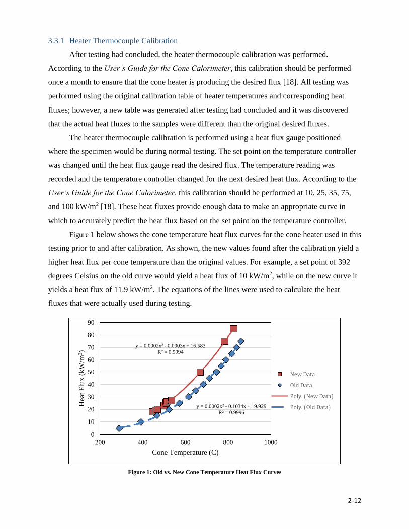
2-12
3.3.1 Heater Thermocouple Calibration
After testing had concluded, the heater thermocouple calibration was performed.
According to the User’s Guide for the Cone Calorimeter, this calibration should be performed
once a month to ensure that the cone heater is producing the desired flux [18]. All testing was
performed using the original calibration table of heater temperatures and corresponding heat
fluxes; however, a new table was generated after testing had concluded and it was discovered
that the actual heat fluxes to the samples were different than the original desired fluxes.
The heater thermocouple calibration is performed using a heat flux gauge positioned
where the specimen would be during normal testing. The set point on the temperature controller
was changed until the heat flux gauge read the desired flux. The temperature reading was
recorded and the temperature controller changed for the next desired heat flux. According to the
User’s Guide for the Cone Calorimeter, this calibration should be performed at 10, 25, 35, 75,
and 100 kW/m2 [18]. These heat fluxes provide enough data to make an appropriate curve in
which to accurately predict the heat flux based on the set point on the temperature controller.
Figure 1 below shows the cone temperature heat flux curves for the cone heater used in this
testing prior to and after calibration. As shown, the new values found after the calibration yield a
higher heat flux per cone temperature than the original values. For example, a set point of 392
degrees Celsius on the old curve would yield a heat flux of 10 kW/m2, while on the new curve it
yields a heat flux of 11.9 kW/m2. The equations of the lines were used to calculate the heat
fluxes that were actually used during testing.
Figure 1: Old vs. New Cone Temperature Heat Flux Curves
y = 0.0002x2 - 0.1034x + 19.929
R² = 0.9996
y = 0.0002x2 - 0.0903x + 16.583
R² = 0.9994
0
10
20
30
40
50
60
70
80
90
200 400 600 800 1000
Hea
t F
lux
(kW
/m2)
Cone Temperature (C)
New Data
Old Data
Poly. (New Data)
Poly. (Old Data)
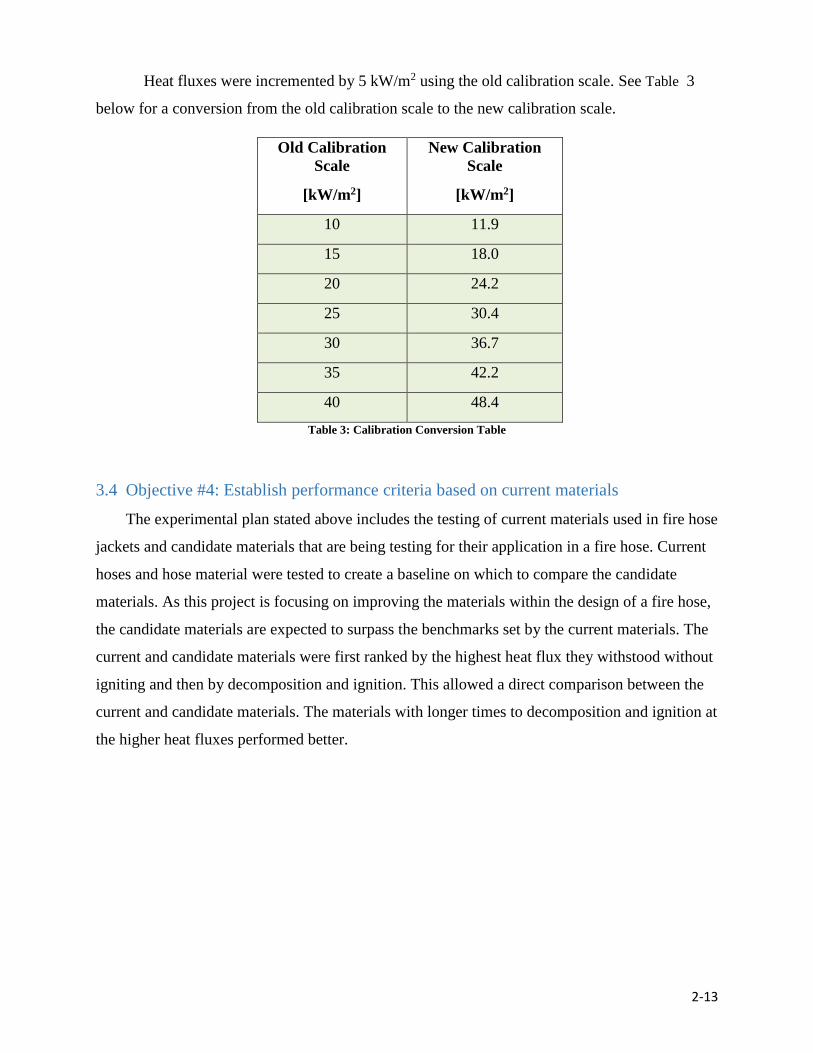
2-13
Heat fluxes were incremented by 5 kW/m2 using the old calibration scale. See Table 3
below for a conversion from the old calibration scale to the new calibration scale.
Old Calibration
Scale
[kW/m2]
New Calibration
Scale
[kW/m2]
10 11.9
15 18.0
20 24.2
25 30.4
30 36.7
35 42.2
40 48.4
Table 3: Calibration Conversion Table
3.4 Objective #4: Establish performance criteria based on current materials
The experimental plan stated above includes the testing of current materials used in fire hose
jackets and candidate materials that are being testing for their application in a fire hose. Current
hoses and hose material were tested to create a baseline on which to compare the candidate
materials. As this project is focusing on improving the materials within the design of a fire hose,
the candidate materials are expected to surpass the benchmarks set by the current materials. The
current and candidate materials were first ranked by the highest heat flux they withstood without
igniting and then by decomposition and ignition. This allowed a direct comparison between the
current and candidate materials. The materials with longer times to decomposition and ignition at
the higher heat fluxes performed better.

2-14
4. Results
Time to decomposition and time to ignition were selected as the properties to evaluate each
material’s performance. These characteristics (if applicable) allow for a comparison of each
material’s properties against a variety of high radiative heat fluxes. Materials that can withstand
higher heat fluxes are better suited for the fire ground. The time to failure is defined as the time
when the top surface of the test sample reaches the decomposition temperature of the material.
This was chosen as it is an estimate of the beginning of degradation of the material. Materials
with longer times to decomposition and ignition are desired.
4.1 Current Materials
Initial research focused on current materials used in fire attack hose jackets to identify a
baseline on which to compare candidate materials. The following two metrics, time to
decomposition and time to ignition, were chosen as the criteria for documentation and
comparison of the performance of each material. Polyester and nylon 6.6 both withstood a heat
flux of 11.9 kW/m2 without ignition over the fifteen minute duration of each test. The time to
decomposition for both polyester and nylon 6.6 subjected to a heat flux of 11.9 kW/m2 are
presented in Table 4. To reiterate, the time to decomposition is defined as the time when the top
surface of the test sample reached the decomposition temperature of the material.
Material Decomposition
Trial 1
[seconds]
Decomposition
Trial 2
[seconds]
Polyester 132 129
Nylon 6.6 22 172
Table 4: Testing Results for Current Materials at 11.9 kW/m2
While further testing would be needed to reduce the uncertainty in the time to
decomposition of nylon 6.6, it is clear that both materials reach the decomposition temperature at
less than three minutes, even when subjected to a very moderate heat flux. Because neither
material ignited at 11.9 kW/m2, the heat flux was increased to 18.0 kW/m2. Both current jacket
materials ignited at this heat flux and the results from this testing are presented in Table 5.

2-15
Material Decomposition
Trial 1
[seconds]
Decomposition
Trial 2
[seconds]
Ignition
Trial 1
[seconds]
Ignition
Trial 2
[seconds]
Polyester 45 46 256 260
Nylon
6.6
22 16 214 223
Table 5: Testing Results for Current Materials at 18.0 kW/m2
The polyester and nylon 6.6 samples both decomposed and ignited at a heat flux of 18.0
kW/m2. It is important to note that this heat flux is indicative of pre-flashover conditions [19].
Both samples decomposed around one minute and ignited around four minutes of exposure to
this heat flux. The nylon 6.6 sample ignited after 214-223 seconds of exposure to these
conditions (18 kW/m^2, 467˚C), where the polyester sample did not ignite until 256-260 seconds
of exposure to the same conditions. Both samples ignited after approximately four minutes of
exposure to a heat flux that is approaching but below flashover conditions. This is alarming as
these materials are currently being used every day by the fire service. In the meantime, it appears
that hoses made of polyester material may last longer when exposed to heat fluxes on the fire
scene.
From this information, the following conclusions can be made: the current fire hose jacket
materials are not suitable for high heat environments as they decompose in under a minute and
ignite in about four minutes when exposed to pre-flashover conditions, and polyester may be the
better performing material in terms of time to decomposition and time to ignition.
4.2 Candidate Materials
There were five candidate materials tested for application in a fire hose jacket: 50%
Kevlar®-50% Nomex®, 90% Nomex®, PBI Max®, PBI Kombat Flex®, and Pyrovatex® fr
Cotton. None of the candidate materials reached decomposition or ignition temperatures when
exposed to 11.9 kW/m2 as compared to both current materials tested, which both reached their
decomposition temperatures under exposure to this heat flux.
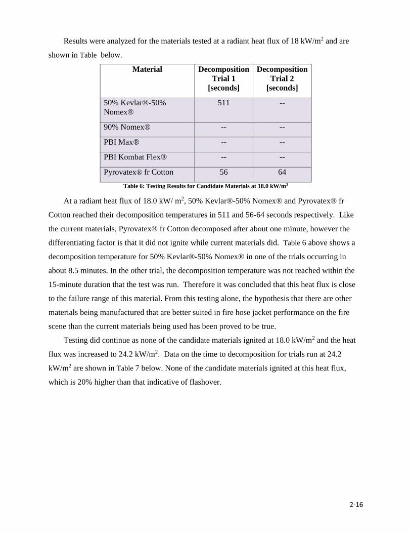
2-16
Results were analyzed for the materials tested at a radiant heat flux of 18 kW/m2 and are
shown in Table below.
Material Decomposition
Trial 1
[seconds]
Decomposition
Trial 2
[seconds]
50% Kevlar®-50%
Nomex®
511 --
90% Nomex® -- --
PBI Max® -- --
PBI Kombat Flex® -- --
Pyrovatex® fr Cotton 56 64
Table 6: Testing Results for Candidate Materials at 18.0 kW/m2
At a radiant heat flux of 18.0 kW/ m2, 50% Kevlar®-50% Nomex® and Pyrovatex® fr
Cotton reached their decomposition temperatures in 511 and 56-64 seconds respectively. Like
the current materials, Pyrovatex® fr Cotton decomposed after about one minute, however the
differentiating factor is that it did not ignite while current materials did. Table 6 above shows a
decomposition temperature for 50% Kevlar®-50% Nomex® in one of the trials occurring in
about 8.5 minutes. In the other trial, the decomposition temperature was not reached within the
15-minute duration that the test was run. Therefore it was concluded that this heat flux is close
to the failure range of this material. From this testing alone, the hypothesis that there are other
materials being manufactured that are better suited in fire hose jacket performance on the fire
scene than the current materials being used has been proved to be true.
Testing did continue as none of the candidate materials ignited at 18.0 kW/m2 and the heat
flux was increased to 24.2 kW/m2. Data on the time to decomposition for trials run at 24.2
kW/m2 are shown in Table 7 below. None of the candidate materials ignited at this heat flux,
which is 20% higher than that indicative of flashover.

2-17
Material Decomposition
Trial 1
[seconds]
Decomposition
Trial 2
[seconds]
50% Kevlar®-50%
Nomex®
54 166
90% Nomex® 145 117
PBI Max® -- --
PBI Kombat Flex® -- --
Pyrovatex® fr Cotton 50 50
Table 7: Testing Results for Candidate Materials at 24.2 kW/m2
The 50% Kevlar®-50% Nomex® and Pyrovatex® fr Cotton once again reached their
decomposition temperatures and more quickly under this heat flux. The 90% Nomex® also
reached its decomposition temperature. While it is clear that further testing would be needed to
reduce the uncertainties in the decomposition times, it is also apparent that the 50% Kevlar®-
50% Nomex®, 90% Nomex®, and Pyrovatex® fr Cotton begin to decompose in less than three
minutes under exposure to a heat flux of 24.2 kW/m2 . This compares to the current materials
tested which also reached decomposition in less than three minutes but under exposure to a heat
flux 25% less than the candidate materials. Pyrovatex® fr Cotton is used for PPE in the chemical
and welding industry but not for PPE in the firefighting industry. Both PBI Max® and PBI
Kombat Flex® withstood exposure to 24.2 kW/m2 radiant flux for a duration of 15 minutes
without reaching their thermal decomposition temperatures. From this, PBI Max® was selected
for testing at higher heat fluxes of 36.7 kW/m2 and 48.4 kW/m2. The results from this testing are
shown below in Table 8.
Material Heat Flux
[kW/m2]
Decomposition
Trial 1
[seconds]
Decomposition
Trial 2
[seconds]
Ignition
Trial 1
[seconds]
Ignition
Trial 2
[seconds]
PBI Max® 36.7 --- 414 -- --
48.4 83 106 85 110
Table 8: Testing Results for PBI Max® at 36.7 and 48.4 kW/m2
It was not until a heat flux of 36.7 kW/m2 did the material decompose and 48.4 kW/m2 that
PBI Max® began to ignite. However, it can be said that both materials made of PBI fiber
withstood heat flux the best of the materials tested during this research.
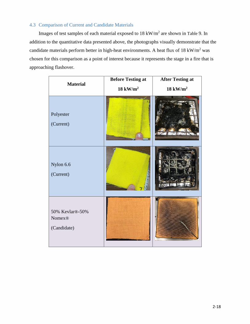
2-18
4.3 Comparison of Current and Candidate Materials
Images of test samples of each material exposed to 18 kW/m2 are shown in Table 9. In
addition to the quantitative data presented above, the photographs visually demonstrate that the
candidate materials perform better in high-heat environments. A heat flux of 18 kW/m2 was
chosen for this comparison as a point of interest because it represents the stage in a fire that is
approaching flashover.
Material Before Testing at
18 kW/m2
After Testing at
18 kW/m2
Polyester
(Current)
Nylon 6.6
(Current)
50% Kevlar®-50%
Nomex®
(Candidate)
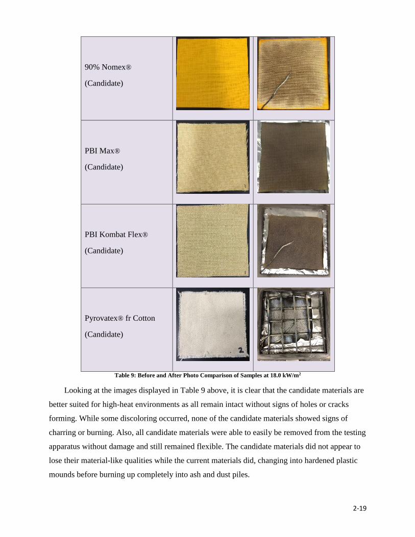
2-19
90% Nomex®
(Candidate)
PBI Max®
(Candidate)
PBI Kombat Flex®
(Candidate)
Pyrovatex® fr Cotton
(Candidate)
Table 9: Before and After Photo Comparison of Samples at 18.0 kW/m2
Looking at the images displayed in Table 9 above, it is clear that the candidate materials are
better suited for high-heat environments as all remain intact without signs of holes or cracks
forming. While some discoloring occurred, none of the candidate materials showed signs of
charring or burning. Also, all candidate materials were able to easily be removed from the testing
apparatus without damage and still remained flexible. The candidate materials did not appear to
lose their material-like qualities while the current materials did, changing into hardened plastic
mounds before burning up completely into ash and dust piles.
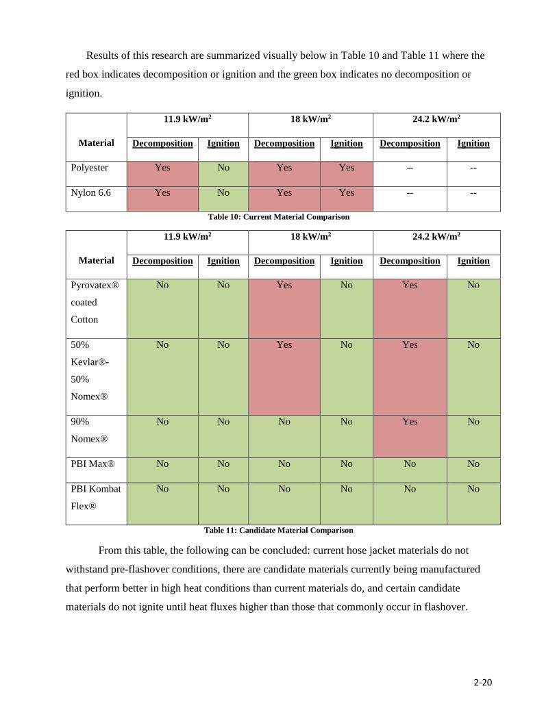
2-20
Results of this research are summarized visually below in Table 10 and Table 11 where the
red box indicates decomposition or ignition and the green box indicates no decomposition or
ignition.
Material
11.9 kW/m2 18 kW/m2 24.2 kW/m2
Decomposition Ignition Decomposition Ignition Decomposition Ignition
Polyester Yes No Yes Yes -- --
Nylon 6.6 Yes No Yes Yes -- --
Table 10: Current Material Comparison
Material
11.9 kW/m2 18 kW/m2 24.2 kW/m2
Decomposition Ignition Decomposition Ignition Decomposition Ignition
Pyrovatex®
coated
Cotton
No No Yes No Yes No
50%
Kevlar®-
50%
Nomex®
No No Yes No Yes No
90%
Nomex®
No No No No Yes No
PBI Max® No No No No No No
PBI Kombat
Flex®
No No No No No No
Table 11: Candidate Material Comparison
From this table, the following can be concluded: current hose jacket materials do not
withstand pre-flashover conditions, there are candidate materials currently being manufactured
that perform better in high heat conditions than current materials do, and certain candidate
materials do not ignite until heat fluxes higher than those that commonly occur in flashover.
2-21
5. Conclusions
This research accomplished four things: identified candidate materials used in PPE for
application for the jacket of a fire hose, created a test method useful for testing current and
candidate materials in a radiative heat environment, performed the aforementioned test
methodology using the cone calorimeter and quantified the time to decomposition and ignition of
current and candidate materials under a range of heat fluxes. This research proved the hypothesis
to be true that there are other materials being manufactured that are better suited in fire hose
jacket performance on the fire scene than the current materials being used.
The project tested the two main materials currently being used in fire attack hose jackets,
polyester and nylon 6.6, to create a baseline on which to compare candidate materials. Five
different materials currently used in PPE were identified as being suitable for application in a fire
attack hose jacket: 50% Kevlar®-50% Nomex®, 90% Nomex®, PBI Max®, PBI Kombat Flex®
and Pyrovatex® fr Cotton. A test method was created using a cone calorimeter to provide a
radiant heat flux that was reliable, consistent and repeatable. This method allowed the following
information to be gathered about each sample if applicable: time to decomposition and time to
ignition.
Based on the data collected, it is evident that there are candidate materials that perform better
than the current materials when exposed to the same radiative conditions. The current materials
both reached decomposition temperature when exposed to a radiant heat of 11.9 kW/m2, a heat
flux comparable to pre-flashover conditions. As testing continued, it was found that current
jacket materials began to ignite at 18.0 kW/m2 (still pre-flashover conditions), while a majority
of the candidate materials were not even close to reaching their decomposition temperatures.
Testing was continued on PBI Max® until it reached ignition. It was not until the material
was exposed to a radiant heat flux of 36.7 kW/m2 and 48.4 kW/m2, which is double the heat flux
indicative of flashover, that it began to burn. This evidence proves the research hypothesis that
there are materials currently used in firefighter PPE that perform better when exposed to a
radiant heat source than the current materials being used in fire attack hoses. PBI Max® and PBI
Kombat Flex® both withstood a heat flux higher than that considered to be indicative of
flashover.
2-22
6. Recommendations and Future Work
Recommendations for future work are focused on further testing of the materials selected
for this research, along with searching for other materials that are suitable for this type of
application.
Continued testing on selected materials would provide a more complete set of results.
Continued testing of these candidate materials at the desired heat fluxes of 10, 15, and 20
kW/m2 is recommended. Materials used in this testing that did not ignite near these heat flux
values (Kevlar®, Nomex®, PBI® Fiber and Pyrovatex® fr Cotton) should continue to be tested
on the cone calorimeter by increasing the heat flux until ignition occurs. It is also important to
know the decomposition point of those materials to determine what their limits are as to what
heat fluxes they can withstand. As of now, it is difficult to determine which of those materials is
considered to be the best candidate.
Additional high heat performance materials should be tested following the same
methodology.
This study focused mainly on PPE materials meaning that there are other possible
candidate materials that were left out. For example, this project did not look into intumescent
materials or other hose configurations. Additionally, some hose models intended for wild-fires
have the ability to “weep” meaning that small perforations in the hose allow water to leak out in
a controlled manner and pre-wet the jacket material. This keeps the jacket material at a cooler
temperature and could potentially prolong its decomposition time. A material that is highly
reflective could also be an effective candidate material. If the material can reflect portions of
incident heat energy instead of absorbing it, the service life of the hose can be extended.
High heat performance materials should be tested in combinations.
Each candidate material in this study was tested individually. The thermal resistance
offered by combinations or layers of these and/or similar materials could produce enhanced
performance results. Specifying different layer thicknesses or amounts of separate materials
could offer greater heat resistance at a lower cost.
2-23
A similar radiative heat insult study should be conducted on liner materials.
Further investigation into potential “high thermal performance” materials for fire attack
hose liners is recommended since this project only focused on jacket materials of municipal fire
attack hoses. Current hose liners made of EPDM rubber and thermoplastic polyurethane (TPU)
have never been tested under radiative heat fluxes similar to those in this study. In this light,
other material may offer better performance against heat insult.
A prototype hose made of candidate materials should be tested via a rigorous heat
performance test for analysis in a large-scale scenario.
Once the aforementioned testing is completed, and if the material passes non-heat
performance testing, the creation of a prototype hose constructed from candidate materials is
suggested. This prototype should then be tested according to a procedure similar to those
discussed in Chapter One to analyze its applicability in a high heat environment. The results
from that testing can then be compared to the results from this research to determine if the
prototype displays significant improvements in performance.
2-24
7. References
[1] Hose Failure in Fatal Boston Fire Raises Concerns. (2014, November 15). Retrieved
February 13, 2016, from http://www.fireengineering.com/articles/2014/11/hose-
failure-in-fatal-boston-fire-raises-concerns.html.
[2] Hashagen, P. (n.d.). The Development of Fire Hose. Retrieved February 13, 2016, from
http://lacountyfirefighters.org/items/Development of Fire Hose.pdf.
[3] Gilbert, D. (n.d.). History of Fire Hose. Retrieved February 13, 2016, from
http://www.crownshoptalk.com/History of Fire Hose.pdf.
[4] Bourbigot, S., & Flambard, X. (n.d.). Heat resistance and flammability of high
performance fibres: A review. Fire Mater. Fire and Materials, pp. 155-168.
[5] National Fire Protection Association, "NFPA 1961: Standard on Fire Hose” 2013 ed.
Quincy, MA: National Fire Protection Association, 2012.
[6] National Fire Protection Association, “NFPA 1971: Standard on Protective Ensembles
for Structural Fire Fighting and Proximity Fire Fighting,” 2013 ed. Quincy, MA:
National Fire Protection Association, 2012.
[7] Flame Resistant vs. Fire Retardant. (2013, April 15). Retrieved October 30, 2015.
[8] Firefighter Gear - The First Line of Defense. (2016). Retrieved February 13, 2016, from
http://www.dupont.com/products-and-services/personal-protective-equipment/thermal-
protective/uses-and-applications/firefigher-turnout-gear.html.
[9] PBI Protection Through and Through for Structural & Proximity Firefighting. (n.d.).
Retrieved February 13, 2016, from http://pbiproducts.com/fabrics/en/markets/fire-
service.
[10] PBI Max. (n.d.). Retrieved February 13, 2016, from
http://globeturnoutgear.com/education/materials/turnout-gear/outer-shells/pbi-max.
[11] Kombat Flex. (n.d.). Retrieved February 13, 2016, from
http://globeturnoutgear.com/education/materials/turnout-gear/outer-shells/kombat-flex.
[12] Flame retardant workwear - CE certified Safe-Pyrovatex® Flame retardant protective
(n.d.). Retrieved October 30, 2015.
[13] http://www.dupont.com/content/dam/dupont/products-and-services/fabrics-fibers-and-
nonwovens/fibers/documents/Kevlar_Technical_Guide.pdf (n.d.). Retrieved October 30,
2015.
[14] Nomex® Fibers for Heat- and Flame-Resistant Protection. (n.d.). Retrieved October 30,
2015.
[15] PBI Properties. (n.d.). Retrieved October 30, 2015.

2-25
[16] National Fire Protection Association & Society of Fire Protection Engineers. (2002).
SFPE Handbook of Fire Protection Engineering (Section 3 Chapter 3). Quincy, MA:
National Fire Protection Association.
[17] ASTM International. (2011). Standard Test Method for Heat and Visible Smoke Release
Rates for Materials and Products Using an Oxygen Consumption Calorimeter (E1354-
11b). West Conshohocken, PA: ASTM International.
[18] National Institute of Standards and Technology. (2001). User’s Guide for the Cone
Calorimeter. West Sussex, United Kingdom: Fire Testing Technology Limited.
[19] Poon, L.S. (1988). Predicting Time of Flashover. Fire Safety Science. AOFST (3), pp.
283-294.
[20] Avameg, Inc. (2015). Fire Hose. How Products Are Made (Volume 4), pp. 1-5.

2-26
Glossary
Candidate Material – refers to a material that is currently used in Personal Protective
Equipment and being tested in this research for application in a fire attack hose jacket
Current Material – refers to a material that is already being used to manufacture fire attack
hose jackets
Fire Resistant - will not ignite upon exposure to flames and do not melt or drip under high
radiant heat exposure upwards of 600 degrees Celsius
Fire Retardant – chemically treated to self-extinguish after flame exposure
Time to Decomposition – the length of time from when the sample was first introduced to a heat
flux to the moment when the surface of the sample reached its temperature of decomposition
Time to Ignition – the length of time from when the sample was first introduced to a heat flux to
the moment flaming combustion occurred