conductive concrete made from recycled carbon fibres for
TRANSCRIPT

Materiales de ConstruCCión
Vol. 70, Issue 339, July–September 2020, e223ISSN-L: 0465-2746
https://doi.org/10.3989/mc.2020.17019
Conductive concrete made from recycled carbon fibres for self-heating and de-icing applications in urban furniture
G. Fanecaa, T. Ikumib,d*, J. M. Torrentsc, A. Aguadob, I. Segurab,d
a. Escofet 1886 Ltd, (Spain)b. Department of Civil and Environmental Engineering, Barcelona Tech, Polytechnic University of Catalonia, UPC,
(Barcelona, Spain)c. Department of Electronics Engineering, Universitat Politècnica de Catalunya - Barcelona Tech, C4, (Barcelona, Spain)
d. Smart Engineering Ltd, (Barcelona, Spain)* [email protected]
Received 12 December 2019 Accepted 10 March 2020
Available on line 13 July 2020
ABSTRACT: This paper presents a broad experimental study performed at laboratory and industrial facilities to develop conductive concrete for self-heating and de-icing applications in urban furniture. Self-heating capacity is achieved by the application of electric current through a highly dense matrix containing recycled carbon fibers and graphite flakes. Prisms and slabs were fabricated with two different conductive concretes and electrode con-figurations to characterize the electrical properties and heating performance. Finally, 3 benches with different electrode disposals were fabricated to assess the heating capacity in real-scale applications. The results presented indicate promising results about the use of recycled carbon fibers for electrothermal concrete applications and identify the electrode configuration that allows the most efficient heat transfer and reduction of temperature gradients within the heated element. Real-scale tests show that the current technology developed is potentially applicable at de-icing applications in climates where temperatures remain within the range of -3 or -5 ºC.
KEYWORDS: Thermal analysis; Electrical properties; Temperature; High performance concrete; Fibre reinforcement.
Citation/Citar como: Faneca, G.; Ikumi, T.; Torrents, J. M.; Aguado, A.; Segura, I. (2020) Conductive concrete made from recycled carbon fibres for self-heating and de-icing applications in urban furniture. Mater. Construcc. 70 [339], e223 https://doi.org/10.3989/mc.2020.17019
RESUMEN: Hormigón conductor con fibras de carbono recicladas para aplicaciones calefactables en mobiliario urbano. Este artículo presenta un extenso trabajo experimental a escala laboratorio e industrial para desarrollar mobiliario urbano con hormigones conductores calefactables. La capacidad calefactable se alcanza mediante la aplicación de corriente eléctrica por una matriz de hormigón con fibras de carbono recicladas y escamas de grafito. Se fabricaron prismas y losas con dos hormigones conductores y distintas configuraciones de electrodos para caracterizar sus propiedades eléctricas y capacidad calefactora. Finalmente, se fabricaron 3 bancos para evaluar la capacidad de calentamiento en aplicaciones a escala real. Los resultados muestran el potencial de las fibras de carbono recicladas para su uso en aplicaciones electrotérmicas e identifican las configuraciones de elec-trodos más adecuadas para reducir los gradientes de temperatura dentro del elemento calefactado. Por último, los ensayos a escala real muestran que la tecnología desarrollada es potencialmente válida para aplicaciones de des-hielo en climas donde la temperatura varía entorno los -3 y -5 ºC.
PALABRAS CLAVE: Análisis térmico; Propiedades eléctricas; Temperatura; Hormigón de altas prestaciones; Refuerzo de fibras.
Orcid ID: G. Faneca (https://orcid.org/0000-0001-5161-8597); T. Ikumi (https://orcid.org/0000-0001-9547-5241); J. M. Torrents (https://orcid.org/0000-0002-8289-6706); A. Aguado (https://orcid.org/0000-0001-5542-6365); I. Segura(https://orcid.org/0000-0001-6519-9899)
Copyright: © 2020 CSIC. This is an open-access article distributed under the terms of the Creative Commons Attribution 4.0 International (CC BY 4.0) License

2 • G. Faneca et al.
Materiales de Construcción 70 (339), July–September 2020, e223. ISSN-L: 0465-2746. https://doi.org/10.3989/mc.2020.17019
1. INTRODUCTION
The concept of smart cities have emerged from the opportunities created by the digital era to face the challenges associated with the new urban con-text. Digital innovation opens up the possibility to be more efficient and more effective, better combat-ing challenges in individual infrastructures, across infrastructure systems, and throughout society as a whole (1-3). As “smart solutions”, or digital tech-nologies, become more commonplace in our cit-ies, the so-called “smart materials” have received increasing attention within the scientific community (4). Their potential is perceived as a key element to bring value to our urban areas and translate it into a profitable commercial practice.
Research on cementitious materials used for civil and building construction has been traditionally focused on mechanical performance and durability characteristics to cover its main functionality, which is structural. However, nowadays there is a demand of multifunctional materials which are not only able to cover the structural requirements but also incor-porate additional features that provide the resulting material with an increased range of applications. Most current functional properties in smart con-crete are based on the incorporation of functional fillers or aggregates to generate conductive proper-ties in the material. Conductive concrete has been used as anode for electrochemical chloride extrac-tion (5-8), electromagnetic wave shielding (9, 10), self-sensing concrete (11-14), cathodic protection (15), energy harvesting (16, 17) and electrothermal control (18-31), among others.
Electrothermal concrete refers to the material achieving electrical resistance heating based on the Joule effect. Research on electrothermal concrete has been mainly focused on deicing and snow melting applications in roadways (19-22, 25-27), and indoor electrical floor heating (24, 28). Since conventional concrete behaves as a dielectric material, electrically conductive fillers such as carbon fibers, steel fibers, steel shaving, nickel powders and graphite are incor-porated to reduce the resistivity of concrete (32).
The use of steel fibers presents a high potential to develop conductive cementitious materials since these are already been widely adopted in a broad range of structural and non-structural concrete applications (33). However, the flow of electric charges through steel fiber reinforced concrete promotes fiber cor-rosion and thus, the degradation of both the struc-tural and thermal functionality of the material. Nowadays, carbonaceous products are mainly used instead of steel fibers or shavings in the conductive cementitious materials mixture design (34) since these present high thermal conductivity, low thermal expansion and are highly resistant to corrosion.
However, the world-wide demand for virgin car-bon fibers often surpasses supply capacity (35, 36),
which causes an increase of cost both in terms of energy consumed during manufacturing (up to 165 kWh/kg) and material price (up to 40 £/kg) (37, 38). Additionally, the increasing amount of car-bon fiber composites produced raises concern on waste disposal and consumption of non-renewable resources, with the associated negative environ-mental impact. In this context, the introduction of recycled carbon fibers (RCF) in conductive cementi-tious materials could potentially convert an expen-sive product and waste disposal into a profitable reusable material with high retention of mechanical properties (38) and a 30 to 40% cost savings versus virgin carbon fibers.
So far, research published on the use of RCF in conductive cementitious materials is limited to the characterization of the mechanical and electri-cal properties of the resulting composite (33). This paper presents the first broad experimental study that explores the heating capacity of conductive concrete with recycled carbon fibers for de-icing and self-heating applications at laboratory and industrial scale. Prisms of 40×40×160 mm were fabricated to characterize the electrical properties of two differ-ent conductive concretes. Slabs of 300×600×40 mm with two electrode configurations were submitted to different heating test scenarios varying the dura-tion of the heating cycles and the voltage applied. Finally, 3 full-scale benches (700×2000×150 mm) with different electrode disposals were fabricated at Escofet 1886 industrial facilities and tested to assess the current heating capacity of the material in real-scale urban furniture applications.
2. EXPERIMENTAL PROGRAM
2.1. Materials
Ultra high performance concrete mixtures con-tained CEM I 52.5R cement and siliceous aggre-gates with particle size distribution ranging from 0 to 5 mm. A high purity calcium carbonate filler (d50 < 3 µm) was used to contribute to higher com-pactness and workability of the mixture. A super-plasticizer based on a polycarboxylate solution (MasterGlenium ACE 425) and a viscosity modu-lator based on siliceous nano-particles (Meyco ms 685) were employed.
Recycled carbon fibers (Carbiso CT6/CT12) and micronized carbon fibers were used to improve the electrical and thermal conductivity of the concrete matrix. The carbon fiber is produced from a primary recycling process of trimmings, defective pieces or deteriorated carbon fiber reinforced composite materials. The main origin of these residues are com-panies dedicated to the manufacture of compounds for the aerospace, automotive and similar industries. The carbon fiber is obtained by shredding and sub-sequent pyrolysis to eliminate the polymeric resins

Conductive concrete made from recycled carbon fibres for self-heating and de-icing applications in urban furniture • 3
Materiales de Construcción 70 (339), July–September 2020, e223. ISSN-L: 0465-2746. https://doi.org/10.3989/mc.2020.17019
impregnated to the fiber. The micronized carbon fibers present particle sizes of d90-d70 = 0.425 and d20 = 0.300 mm. The properties of the carbonaceous materials used are included in Table 1.
2.2. Composition and preparation of concretes
In total, 2 concrete compositions were designed with different carbonaceous addition contents. Table 2 describes the composition of the concretes used. The first mixture consists of an ultra-high per-formance concrete (UHPC) with 9 kg of recycled carbon fibers per m3 of concrete (0.407 % vol.) to increase the electrical and thermal conductivity of the material (referred to as RCF). The plain con-crete dosage adopted corresponds to mixes typically used by the company Escofet 1886 in the manufac-turing process of urban furniture and architectonic façades. The second mixture additionally incor-porates 36 kg of micronized carbon fibers per m3 of concrete (1.65 % vol.) to further increase the electrical and thermal conductivity of the material (referred to as R+MCF). The proportions of the carbonaceous additions were set from previous tests on conductive concretes (33, 39).
The mixing process was performed in a planetary mixer at the industrial facilities of the company Escofet 1886 to reproduce the typical fabrication practices adopted in the precast industry. Aggregates, limestone filler and cement were first mixed for 60 s. Then, water was added and mixed for 180 s. Nano-silica and superplasticizer were then incorporated to the mix and homogenized for additional 180 s, each. The carbonaceous additions were added to the mix after incorporating the water and additives, with no previous dispersion of the fibers. Previous research has proved that this procedure provides a good dispersion of the fibers into the cementitious matrix (33). Unfortunately, no data about the com-bined effects of fibers and the micronized addition is available.
Prismatic specimens with dimensions 40×40×160 mm were fabricated from the mixes indicated in Table 2 according to UNE-EN 196–1 (40) to charac-terize the electrical properties of the concretes. These specimens incorporate 6 stainless steel threaded shanks of 6 mm diameter and 30 mm length to act as electrodes. The placing of these electrodes was carried out after compacting the fresh concrete in the molds. Figure 1a shows a scheme of the elec-trodes positioning on the specimens.
Slabs (S) of 300×600×40 mm were fabricated from the mixes indicated in Table 2 to characterize Table 1. Properties of the recycled carbon fibers and
micronized carbon fibers.
Properties Values
Recycled Carbon fiber
Carbon fiber content (%) 100
Density (kg/m3) 1800
Nominal length (mm) 6/12
Diameter (µm) 7
Tensile strength (MPa) 4150
Young modulus (GPa) 252
Electrical conductivity (S·cm-1) 100-1000
Micronized carbon fiber
Carbon content (min %) 95
Ash content (max %) 6
Moisture (max %) 0.5
Density (g/ml) 0.65-0.85
Table 2. Composition of the concretes.
Material RCF R+MCF
Cement [kg/m3] 800 800
Sand [kg/m3] 1161 1161
Limestone filler [kg/m3] 200 200
Water [kg/m3] 110 110
Superplasticizer [% bcwa] 3.7 3.7
Nano silica [% bcw] 7.1 7.1
Recycled carbon fiber [kg/m3] 9 9
Micronized carbon fiber [kg/m3] - 36a: by cement weight
Figure 1. Scheme of the electrodes positioning on the specimens. All dimensions in mm.
4 • G. Faneca et al.
Materiales de Construcción 70 (339), July–September 2020, e223. ISSN-L: 0465-2746. https://doi.org/10.3989/mc.2020.17019
the thermal behavior of larger specimens. In this case, two different electrode disposals were incorpo-rated to create the electric flux. Figure 1b shows a scheme of the electrodes positioning on the slabs. The first configuration (TDS) consisted in two steel deployé sheets with rhomboidal grid of 30×13 mm placed 20 mm from the transverse edges of the ele-ment (section A-A’ in Figure 1b). The latter con-figuration replaced the deployé sheets by a wider squared steel grid (TSG) of 40×40 mm. Grids on both configurations were connected to the exter-nal part of the element by stainless steel threaded shanks of 6 mm diameter and 30 mm length. The placing of these electrodes was carried out after compacting the fresh concrete in the molds. All specimens remained in the molds for 24h with liquid curing agents and afterwards were kept under con-trolled temperature (20° ± 5 °C) and humidity (70 ± 10 %) conditions until testing.
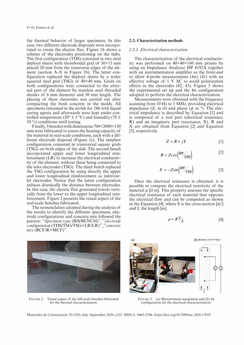
Finally, 3 benches with dimensions 700×2000×150 mm were fabricated to assess the heating capacity of the material in real-scale conditions, each with a dif-ferent electrode disposal (Figure 1c). The simplest configuration consisted in transversal square grids (TSG) on both edges of the slab. The second bench incorporated upper and lower longitudinal rein-forcement (LR) to increase the electrical conductiv-ity of the element, without these being connected to the inlet electrodes (TSG). The third bench replaced the TSG configuration by using directly the upper and lower longitudinal reinforcement as inlet/out-let electrodes. Notice that the latest configuration reduces drastically the distance between electrodes. In this case, the electric flux generated travels verti-cally from the lower to the upper longitudinal rein-forcement. Figure 2 presents the visual aspect of the real-scale benches fabricated.
The nomenclature adopted during the analysis of the results to identify the different specimens, elec-trode configurations and concrete mix followed the pattern: “Specimen type (B/S/BENCH)”_”electrode configuration (TDS/TSG/TSG+LR/LR)”_”concrete mix (RCF/R+MCF)”.
2.3. Characterization methods
2.3.1. Electrical characterization
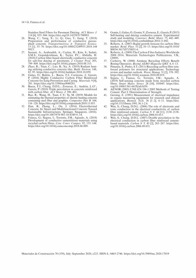
The characterization of the electrical conductiv-ity was performed on 40×40×160 mm prisms by using an Impedance Analyzer HP 4192A together with an instrumentation amplifier as the front-end to allow 4-probe measurements (4w) (41) with an effective voltage of 1 V AC to avoid polarization effects in the electrodes (42, 43). Figure 3 shows the experimental set up and the 4w configuration adopted to perform the electrical characterization.
Measurements were obtained with the frequency scanning from 10 Hz to 1 MHz, providing electrical impedance (Z, in Ω) and phase (f, in °). The elec-trical impedance is described by Equation [1] and is composed of a real part (electrical resistance, R) and an imaginary part (reactance, X). R and X are obtained from Equation [2] and Equation [3], respectively.
= +Z R jX [1]
φπ )(=R Zcos 180 [2]
φπ )(= −X Zsin 180 [3]
Once the electrical resistance is obtained, it is possible to compute the electrical resistivity of the material ρ [Ω·m]. This property assesses the specific electrical resistance of each material that opposes the electrical flow and can be computed as shown in the Equation [4], where S is the cross-section [m2] and L the length [m].
RSLρ = [4]
Figure 2. Visual aspect of the full-scale benches fabricated for the thermal characterization.
Figure 3. (a) Measurement equipment and (b) 4w configuration for the electrical characterization.

Conductive concrete made from recycled carbon fibres for self-heating and de-icing applications in urban furniture • 5
Materiales de Construcción 70 (339), July–September 2020, e223. ISSN-L: 0465-2746. https://doi.org/10.3989/mc.2020.17019
2.3.2. Thermal characterization
The heating behavior of the conductive cement-based materials casted was characterized on two dif-ferent stages. The first stage evaluated the heating capacity of the 300×600×40 mm slabs by modifying the duration of the heating cycles and the voltage applied. The duration of the heating cycles evaluated were 3 h and 48 h. For the 3 h test, a constant voltage was applied throughout the heating cycle to the speci-mens via the different electrode configurations incor-porated. The 48 h test was comprised by 2 cycles of 8 h heating period followed by a 16 h cooling period. Different voltages were adopted during the tests to evaluate different heating kinetics (11/18/25 V in the 3 h heating and 25/33 V in the 48 h cycles).
The thermal characterization of the different config-urations is evaluated in terms of the increase of temper-ature in the center of the slab, the temperature gradient between the center of the element and the inlet electrode and the electrical resistance of the material throughout the test. The electrical resistance is estimated based on the effective voltage (Veff) and current (Ieff) monitored during the tests. Since the voltage and current are in phase, the electrical resistance (R) can be computed by the Ohm’s law as indicated in Equation [5].
=R /V Ieff eff [5]
Such characterization covers important aspects required in concrete mixtures for self-heating appli-cations, which are the achievement of certain heating rates, the uniformity of the temperature distribution within the element and the capacity of the mate-rial to sustain different voltages during long peri-ods of time without affecting its heating properties. Additionally, the power consumption computed by Equation [6] is reported in each test.
=P V Ieff eff eff [6]
The second stage evaluated the heating capacity of the 3 full-scale benches fabricated. In this case, the duration of the heating cycles was set at 3 h and the voltages applied varied from 2 to 21 V. The different voltages applied were not adopted to perform com-parative analyses between the different electrode con-figurations incorporated in the benches. Instead, these values correspond to the maximum voltage (and thus, maximum heating capacity) sustained by the material prior to degradation of the conductive and thermal properties. In other words, the full –scale trials were designed to show the full potential of the material in real-scale applications. Table 3 summarizes the distri-bution of the heating tests performed and the voltages evaluated over the different specimens evaluated. All tests were performed at the frequency of 50 Hz.
Figure 4a presents the experimental set up adopted during these tests. Temperature variations are registered by type K thermocouples embedded in the material. Figure 4b shows the exact location of the thermocouples placed in the slabs and benches. For the 300×600×40 mm slabs, these were located in the middle section 1 cm away from the inlet elec-trode and at the center of all specimens. On the other hand, full-scale benches incorporated 12 thermo-couples arranged all over the slab. A virtual square grid is depicted in dotted red lines on the plant view of Figure 4b to facilitate the identification of the sensors and the analysis of the results. A can be seen, those near the longitudinal edges (rows A and C) were placed at the middle section of the bench while those located in the central region (row B) were arranged closer to the upper external surface to char-acterize the temperature perceived by the user.
3. RESULTS AND DISCUSSION
3.1. Electrical characterization of the carbonaceous materials
Figure 5 shows the variation of the electrical resistivity within the range of frequencies evalu-ated for both concrete mixtures used in this study (RCF and R+MCF). Results for the specimens with recycled and micronized carbon fibers are depicted in the main vertical axis while samples with only recycled carbon fibers are represented in the sec-ondary axis. The error bars included correspond to +1/-1 standard deviation associated with the 3 speci-mens tested for each material. An additional dotted blue line is added at 50 Hz to locate the standard frequency of electrical mains.
RCF specimens present a constant electrical resistivity of 0.055 Ωm, regardless of the frequency applied. On the other hand, R+MCF samples obtained electrical resistivities ranging from 0.27-0.44 Ωm. The behaviour of the mixture R+MCF presents some similitudes with the behaviour of the reference mixes with no conductive addition (see Faneca et al (33)) and might be caused by polarization effects. The
Table 3. Tests performed for the thermal characterization.
Specimens 3h heating
2 cycles: 8h heating/16h cooling
S_TDS_RCF 11/18/25 V 25 V
S_TSG_RCF 11/18/25 V 25 V
S_TDS_R+MCF 11/18/25 V -
S_TSG_R+MCF 11/18/25 V -
BENCH_TSG_RCF 21 V -
BENCH_TSG+LR_RCF 11 V -
BENCH_LR_RCF 2 V -

6 • G. Faneca et al.
Materiales de Construcción 70 (339), July–September 2020, e223. ISSN-L: 0465-2746. https://doi.org/10.3989/mc.2020.17019
reduction of resistivity with the increase of frequency is commonly associated with insulator materials and may be caused by polarization effects. Some authors have suggested that polarization effects are not elimi-nated by the use of AC but are rather manifested in the form of introduction of a capacitance in paral-lel with the electrical resistance. As the frequency of the applied current is increased, the effect of the capacitance is reduced (33). In this case, the behav-iour of the R+MCF mix exhibits polarization effects although the incorporation of MCF allows to sig-nificantly reduce the resistivity considering the values provided for the reference material by Faneca et al. (33) (ranging from 278 to 235 Ωm). These results evi-dence a difference in the electrical conductive mecha-nism between R+MCF and R+CF.
At the frequency of 50 Hz, which is the one applied during the heating tests, R+MCF material obtained a
resistivity of 0.42 Ωm. This value is 7.6 times higher than the one obtained for RCF material, indicating that the addition of micronized carbon fibers causes a very significant increase of resistivity. This trend was not initially expected as micronized carbon fiber is a highly conductive material. However, the results obtained seem consistent both statistically and with the out-comes of the heating tests performed in 300×600×40 mm slabs (presented in section 3.2.1). Therefore, these should not be attributed to possible malfunctions of the measurement equipment or singular fabrication flaws. Instead, results suggest that the addition of MCF hinders the homogeneous distribution of carbo-naceous products within the concrete matrix and dis-rupts the electrical continuity of the material.
3.2. Thermal characterization in slabs
3.2.1. 3h heating cycle in slabs
The first test series involved the application of three different effective voltages (11, 18 and 25 V) during 3 h on rectangular concrete slabs with both types of elec-trode disposals (TSG and TDS) and carbonaceous additions (RCF and R+MCF). Figure 6 presents the heating curves obtained for all specimens tested based on the electrode configuration adopted. Figure 6a depicts the specimens with TDS electrode configura-tion while Figure 6b presents the samples with TSG configuration. The temperature variations presented correspond to the values registered at the center of the specimen, as this region is more representative of the real heating potential of the material. Figure 6 includes average power consumption values registered in each test. These values are maintained constant throughout the heating test duration, with a maximum +1 stan-dard deviation of 0.9 W. Room temperature during the tests ranged between 19 - 21 ºC.
Figure 4. (a) Experimental set up for the thermal characterization tests and (b) Thermocouples placement in slabs and benches.
Figure 5. Electrical resistivity variation with the frequency.

Conductive concrete made from recycled carbon fibres for self-heating and de-icing applications in urban furniture • 7
Materiales de Construcción 70 (339), July–September 2020, e223. ISSN-L: 0465-2746. https://doi.org/10.3989/mc.2020.17019
The positive values registered at the beginning of the test indicates that the inner region of the concrete element was at a higher initial tempera-ture than the ambient. The heating curves describe a linear increase of temperature over time followed by a second stage characterized by a decrease on the heating rate. The duration of the first stage decreases with the intensity of the voltage applied while the heating rate reduction during the second stage is more evident for high voltages. As expected, results show increasing heating rates with the volt-age applied. Temperature variations registered at the end of the test range from 7 - 17, 4 - 8.5 and 2 - 3 ºC for 25, 18 and 11 V, respectively. These values reflect that the heating performance (increment of temperature per volt applied) is not constant for the different potentials adopted in this study. For the high voltage configuration, the heating per-formance ranges between 0.28-0.68 ºC/V while for the low voltage configuration, the heating perfor-mance decreases to 0.17-0.28 ºC/V.
The arrangement of the results adopted allows a direct comparison between the heating capacity asso-ciated with the two carbonaceous additions intro-duced in the concrete mix. On average, temperatures reached at the end of the test by the material with recycled carbon fibers and graphite flakes are 25 and 50 % lower than the ones achieved by the material with only carbon fibers for TDS and TSG electrode configurations, respectively. These results suggest that the additional incorporation of graphite flakes into the mix significantly worsen the performance of the material for heating applications, especially if the TSG electrode configuration is adopted.
Figure 7 rearranges the same set of results to allow a clear assessment of the influence of the electrode dis-posal (TDS or TSG) on the heating capacity of RCF (Figure 7a) and R+MCF slabs (Figure 7b). Figure 7a shows similar heating curves for both electrode
configurations in specimens with only reinforced carbon fiber, indicating that the electrode disposal plays a minor role on the heating performance of material RCF. However, this trend is not maintained in R+MCF (Figure 7b). In this case, specimens with TDS electrode configuration display higher heat-ing curves than specimens with TSG disposal for all voltages evaluated. These results suggest that in low conductive materials, the increment of steel surface allows a more efficient transfer of the electric charges between the electrode and the conductive concrete.
Even though temperature gradients are inherent to the heating mechanism induced by the Joule effect, if not limited, these might compromise the service-ability of the structure and generate high internal stresses that might affect the structural performance of the element. Therefore, the development of self-heating concrete mixes not only comprises the assess-ment of the heating rates but also the evaluation of the temperature distribution within the element.
Figure 8a and Figure 8b depict the influence of the voltage and the carbonaceous addition on the tem-perature drop registered between the center of the slab (ΔTc) and near the inlet electrode (ΔTi) for TDS and TSG configuration, respectively. Independently of the electrode disposal, temperature gradients are charac-terized by a rapid increase followed by a second stage where the temperature lost tend to a constant value, especially for medium and high voltages. As expected, results show increasing temperature drops with the voltage applied, suggesting that temperature gradients increase proportionally with the heating rate.
Temperature drops registered at the end of the test range from 1 - 6 and 1 - 14 ºC for TDS and TSG configuration, respectively. These results suggest that the TDS electrode disposal limits the magnitude of heat peaks nearby the electrode location, allow-ing a more efficient heat transfer to the conductive concrete. Figure 8a shows a minor influence of the
Figure 6. Heating curves based on material (RCF and R+MCF) for electrode configuration (a) TDS and (b) TSG.

8 • G. Faneca et al.
Materiales de Construcción 70 (339), July–September 2020, e223. ISSN-L: 0465-2746. https://doi.org/10.3989/mc.2020.17019
type of carbonaceous addition on the temperature gradients registered throughout the test. Therefore, the temperature drops registered in specimens with TDS electrode disposal is mainly attributed to the intensity of the voltage applied. On the other hand, Figure 8b depicts much larger temperature drops in RCF specimens than in R+MCF slabs. These results seems to be related to the small heat transmission surface of the electrode configuration TSG, when compared to the TDS. The small contact area of the TSG configuration demands a highly conduc-tive cementitious material to distribute efficiently the electrical charges throughout the specimen. Otherwise, high local temperature peaks are gener-ated nearby the electrode location and the tempera-ture drop increase significantly, specially for high voltage configurations.
Finally, Figure 9 presents the evolution of elec-trical resistance displayed by the specimens tested. The shaded domains represented correspond to the envelops covered by the electrical resistance curves measured in each specimen for all voltages (11, 18 and 25 V). Results show constant values throughout the test duration, regardless of the voltage applied. In other words, the variations of voltage and inten-sity were proportional within the range considered in the tests. This suggests that the material is able to sustain all testing conditions without deteriorat-ing its conductive properties. Values obtained range from 6 to 15.7 Ω, for TSG_RCF and TSG_R+MCF material configuration, respectively. As expected, electrical resistance values are inversely propor-tional to the heating capacity of the material at the center of the slab.
Figure 7. Heating curves based on electrode configuration (TDS and TSG) for (a) RCF and (b) R+MCF.
Figure 8. Temperature drops registered between the inlet electrode and the center of the slab in (a) TDS and (b) TSG electrode configurations.

Conductive concrete made from recycled carbon fibres for self-heating and de-icing applications in urban furniture • 9
Materiales de Construcción 70 (339), July–September 2020, e223. ISSN-L: 0465-2746. https://doi.org/10.3989/mc.2020.17019
3.2.2. 2 cycles of 8h heating/16h cooling in slabs
The second test series involves the application of the high voltage configuration (25 V) on concrete slabs with recycled carbon fiber addition (RCF) and both types of electrode disposals (TSG and TDS) during 2 continuous cycles of 8 h heating/16 h cooling. This testing configuration allows the study of the performance of the different specimens under repetitive long heating cycles with high heat-ing rates, which might be representative of the real
field conditions. Room temperature during the tests ranged between 24 - 28 ºC.
Figure 10a shows the temperature evolution reg-istered at the center of the specimen with respect to room temperature over the test duration. The first heating cycle presents the same trends as described for 3 h tests in both electrode configurations, with a rapid temperature increase followed by a plateau. Notice that specimens TSG_RCF do not follow a natural heating profile near the first plateau region. Instead, these experience a sudden halt, indicating a possible deterioration of the material. The incre-ments of temperature registered reached 18 ºC at the end of the 8 h heating period, which is a similar value than the one obtained during the 3 h tests at the same voltage. During the disconnected period, the material experiences a rapid decrease of tem-perature followed by a plateau at 1 - 2 ºC over room temperature.
The second heating sequence, 24 h after test start, shows different behaviors for TDS and TSG elec-trode configurations. Concrete slabs with TDS elec-trodes display the same heating and cooling rates than the ones described for the first cycle, suggesting no degradation of the conductive and self-heating properties of the material after 8 h of high volt-age application. However, slabs with TSG electrode configuration are not able to induce any significant heating during the whole cycle. This behavior indi-cates that the conductive properties of the material might be completely deteriorated, possibly since the plateau region of the first heating cycle, as com-mented previously. The average power consumption measurements registered during the heating cycles also reflects this deterioration of the conductive properties of the specimens with TSG electrode dis-posal (Figure 10a). While during the first cycle both specimens were able to transfer similar average rates of electrical energy per unit time, during the second Figure 9. Electrical resistance evolution.
Figure 10. (a) Temperature evolution at the center of the slab and (b) Temperature drop.

10 • G. Faneca et al.
Materiales de Construcción 70 (339), July–September 2020, e223. ISSN-L: 0465-2746. https://doi.org/10.3989/mc.2020.17019
cycle a dramatic loss of power consumption is regis-tered for the TSG specimen.
Figure 10b depicts the temperature drop regis-tered between the center of the slab (ΔTc) and near the inlet electrode (ΔTi) for TDS and TSG configura-tion. In general, temperature gradients increase rap-idly during the first hours of the heating stages, start to decrease slightly during the plateau stage of the heating cycles and decrease rapidly during the cool-ing phases. Maximum temperature gradients regis-tered for TDS and TSG disposal during the first cycle are 7 and 17 ºC, respectively. Notice that even though both electrode configurations reached similar heating rates (Figure 10a), the temperature drops for TSG disposal are 2.4 times higher than for TDS configura-tion. These results are consistent with the outcomes presented in section 3.2.1 and confirm the better performance of the TDS disposal when it comes to minimize temperature gradients within the specimen.
Under a steady energy supply and material prop-erties, once the material reaches its highest heating potential, temperature gradients tend to decrease over time until constant temperature distribution across the specimen. TDS_RCF samples reflect this normal behavior with the decrease of temperature gradients during the plateau region of the heating cycles. However, the slight increase of temperature variation depicted by the TSG_RCF specimen dur-ing this period can only be explained by a degrada-tion of the conductive properties of the material, as the energy supplied remained constant.
The degradation of the conductive properties in the specimens TSG_RCF is confirmed during the second heating stage. Figure 10a shows that this mix-ture does not register any relevant increase of tem-perature at the center of the slab during this period. On the other hand, the temperature drop depicted in Figure 10b indicates that the thermocouple located nearby the inlet electrode did register an increase of temperature during the second heating stage. In other words, the concrete near the inlet electrode was heated, but the conductive properties of the mate-rial were not sufficient to heat the center of the slab, indicating severe degradation of the matrix.
Finally, Figure 11 shows the electrical resistance during the first heating cycle for TSG_RCF and TDS_RCF specimens. Specimens with TDS electrode configuration describe a constant resistance over the two heating cycles, indicating that the specimens were able to sustain the maximum temperature consistently over long periods of time without any degradation. On the other hand, samples with TSG electrode dis-posal depict an increase of electrical resistance from the second hour of the heating cycle. This suggests an increasing reduction of the material conductive prop-erties over time, which coincides with the unnatural heating profile described during the plateau region of the first heating cycle and the following incapacity of generating heat at the center of the specimen.
3.3. Thermal characterization in real-scale benches
Figure 12-Figure 15 present the results associ-ated with the thermal characterization of real-scale benches with TSG, TSG+LR and LR electrode con-figurations, respectively. All tests were performed at room temperature between 26 - 29 ºC. The full temperature profile for each of the 12 thermocou-ples arranged is only displayed for the first bench configuration (BENCH_TSG_RCF) to show the typical temperature evolution profiles registered (Figure 12). As can be seen, the large amount of thermocouples incorporated hinder the interpreta-tion of the graphs. Therefore, results are presented instead in Figure 13-Figure 15 as heating snapshot maps after 30 min/1 h/2 h/3 h of test onset. Figure 12 includes vertical dotted red lines at the times cap-tured in the heat maps for the first bench configu-ration. The temperature depicted is the difference between the temperature registered by the sensor and the room temperature. Each thermocouple incorporated is representative of the heating capac-ity of the rectangular region defined by the virtual grid included in each figure, as described in Figure 4b. The range of the color limits adopted in all fig-ures is maintained to allow color-based comparison between the different benches evaluated.
The bench with the TSG electrode configuration and no steel reinforcement reaches increments of temperature between 2.1-3.1 ºC after 30 min at 21 V (Figure 13). The thermocouple located at A4 grid was not working thus no temperature is available there.
Figure 11. Electrical resistance R evolution during the heating cycles.

Conductive concrete made from recycled carbon fibres for self-heating and de-icing applications in urban furniture • 11
Materiales de Construcción 70 (339), July–September 2020, e223. ISSN-L: 0465-2746. https://doi.org/10.3989/mc.2020.17019
The largest temperature value is obtained near the inlet electrode (1A) while the lowest temperature is registered at the thermocouples situated near the out-let electrode (4B, 4C). The temperature drops between these locations is limited to less than 1 ºC, which is a very low temperature variation considering the dis-tance between electrodes (almost 2 m). During the 1 h – 2h heating period, temperature variations increase more slowly, reaching temperatures between 3.4-4.2 ºC. After 2 h of heating, the bench seems to have arrived to its maximum heating potential at this voltage, as tem-perature are maintained. The average power consump-tion registered during this test was 25.9 W, with a +1 standard deviation of only 0.08 W.
The bench with an additional longitudinal rein-forcement (TSG+LR, Figure 14) reaches tempera-ture increments of 3.1-4.5 ºC after only 30 min of 11 V application. Then, temperature profiles increase slightly until the end of the test, where the increase
in temperature ranges from 3.5-5.4 ºC. The tempera-ture drops registered between the hottest and cool-est locations increase from 1.3 (at 30 min) to 1.9 ºC (at 3 h). which are still a low temperature gradient given the dimensions of the element. The average power consumption registered during this test was 26.1 W, with a +1 standard deviation of only 0.08 W.
Finally, the bench that uses the longitudinal rein-forcement itself as inlet and outlet electrodes shows increases in temperature from 1.9-2.9 ºC after 30 min at 2 V (Figure 15). Temperature continue to increase slightly until 2.4-3.4 ºC after 1 h of voltage applica-tion. At this point, the temperature reached is main-tained until the end of the heating period. Even though the temperature increase showed by this elec-trode configuration is lower than the temperatures reached in previous benches, the heating performance of this bench is significantly superior if the voltage applied is considered. The temperature increase per volt applied (ºC/V) of this configuration is 7.5 and 3 times larger than the BENCH_TSG_RCF and BENCH_TSG+LR_RCF, respectively. In terms of electrical consumption, this configuration registered an average power consumption during the test of only 7.7 W, with a +1 standard deviation of 0.06 W.
Similarly to all other real-scale benches evalu-ated, temperature drops registered in BENCH_LR_RCF between the hottest and coolest locations are limited to values around 1 ºC throughout the test duration. Unlike some of the values obtained in the laboratory-scale slabs presented in section 3.2.1, the temperature drops registered in benches neither com-promise the comfort nor the structural performance due to thermal-induced stresses. These results indi-cate that with the current set of technology, tempera-ture drops can be maintained at acceptable ranges if the increase of temperature is limited to 3-4 ºC over
Figure 12. Complete temperature evolution on BENCH_TSG_RCF with 21 V.
Figure 13. Heating maps at 30min/1h/2h/3h on BENCH_TSG_RCF with 21 V.

12 • G. Faneca et al.
Materiales de Construcción 70 (339), July–September 2020, e223. ISSN-L: 0465-2746. https://doi.org/10.3989/mc.2020.17019
room temperature. Therefore, the technology devel-oped seems to be potentially applicable at de-icing applications in urban furniture in climates where the lowest temperatures remain within the range of -3 or -4 ºC. However, heating tests should be validated at room temperatures of such ranges.
4. CONCLUSIONS
This paper presents a broad experimental study that explores the current capacity of conductive concrete for de-icing and self-heating applications in urban furniture, from small-scale laboratory speci-mens to full real-scale benches. The following spe-cific findings may be derived from this study.
• RCF material (concrete with recycled car-bon fibers) is about 7.5 times more conductive than the R+MCF (concrete with recycled and micronized carbon fibers). This indicates that the addition of micronized carbon fibers lower significantly the conductive properties of the composite.
• Temperature variations reached at the end of the 3h heating test range from 7 - 17, 4 - 8.5 and 2 - 3 ºC for 25, 18 and 11 V, respectively. R+MCF slabs attain 25-50 % lower temperatures than RCF slabs. These results suggest that the addi-tional incorporation of graphite flakes into the mix also worsen the heating performance of the material.
Figure 14. Heating maps at 30min/1h/2h/3h on BENCH_TSG+LR_RCF with 11 V.
Figure 15. Heating maps at 30min/1h/2h/3h on BENCH_LR_RCF with 2 V.

Conductive concrete made from recycled carbon fibres for self-heating and de-icing applications in urban furniture • 13
Materiales de Construcción 70 (339), July–September 2020, e223. ISSN-L: 0465-2746. https://doi.org/10.3989/mc.2020.17019
• Results on the 3h and 24 heating tests indicate that the TDS (transversal deployé sheets) elec-trode disposal limits the magnitude of heat peaks nearby the electrode location, allowing a more efficient heat transfer to the conductive concrete and reducing the temperature gra-dients within the elements and the possibility to deteriorate the conductive properties of the material.
• Real-scale tests show that benches are able to heat uniformly 2-4 ºC over room temperature after 30 minutes of voltage application. After 3 h, increments in temperature reach 3-5 ºC. Such performance places the current technology developed as potentially applicable at de-icing applications in climates where the lowest tem-peratures remain within the range of -3 or -5 ºC. Slightly lower temperature values might be obtained at the external surface of the benches, as the thermocouples were embedded 2.6 cm. Further tests should be performed at room tem-peratures of this range to confirm the results obtained.
ACKNOWLEDGMENTS
The authors acknowledge the financial support provided by the Spanish Ministry of Economy and Competitiveness through Project BIA2016-78742-C2-1-R, and the Torres Quevedo Program (postdoctoral fellowships PTQ-14-07072 and PTQ-15-07562), as well as the support from the Catalan Government through the Industrial Doctorate program DI-2015-013. Furthermore, the authors wish to thank the company Escofet 1886 for their collaboration and support throughout the project.
REFERENCES
1. National Infrastructure Commission, ARUP and University College London (2017) Briefing Note: Infrastructure and Digital Systems Resilience, London, (2017).
2. ICE, Institution of Civil Engineers (2017) State of the Nation 2017: Digital Transformation, London, (2017).
3. World Economic Forum (2016) Shaping the Future of Construction: A Breakthrough in Mindset and Technology, (2016).
4. D’Alessandro, A.; Ubertini, F.; Laflamme, S. (2015) Towards smart concrete for smart cities: Recent results and future application of strain-sensing nanocomposites. J. Smart Cities. 1 [1], 3–14.
5. Pérez, A.; Climent, M.A.; Garcés, P. (2010) Electromechanical Extraction of chlorides from reinforced concrete using a conductive cement paste as an anode. Corros. Sci. 52 [5], 1576–1581. https://doi.org/10.1016/j.corsci.2010.01.016.
6. Del Moral, B.; Galao, Ó.; Antón, C.; Climent, M.A.; Garcés, P. (2013) Usability of cement paste containing nanofibres as an anode in electrochemical chloride extrac-tion from concrete. Mater. Construcc. 63 [309], 39–48. https://doi.org/10.3989/mc.2012.03111.
7. Xu, J.; Yao, W. (2009) Current distribution in reinforced concrete cathodic protection system with conductive mortar
overlay anode. Const. Build. Mater. 23 [6], 2220–2226. https://doi.org/10.1016/j.conbuildmat.2008.12.002.
8. Westhof, L. (2006) Field experience with a conductive cement-based composite as anode for the cathodic protec-tion of reinforced concrete structures. In: Proceedings of the 2nd International Conference on Concrete Solutions, Watford.
9. Singh, A.P.; Mishra, M.; Chandra, A.; Dhawan, S.K. (2011) Graphene oxide/ferrofluid/cement composites for electro-magnetic interference shielding application. Nanotech. 22 [46], 465701. https://doi.org/10.1088/0957-4484/22/46/465701.
10. Han, B.; Zhang, L.; Ou, J. (2017) Electromagnetic Wave Shielding/Absorbing Concrete. In: Smart and Multi-functional Concrete Toward Sustainable Infrastructures. Springer, Singapore, (2017). https://doi.org/10.1007/978-981-10-4349-9_18.
11. Chen, P.W.; Chung, D.D.L. (1993) Carbon fiber reinforced concrete for smart structures capable of non-destructive flaw detection. Smart Mater. Struct. 2 [1], 22–30. https://doi.org/10.1088/0964-1726/2/1/004.
12. Park, S.; Ahmad, S.; Yun, C.B.; Roh, Y. (2006) Multiple crack detection of concrete structures using impedance-based structural health monitoring techniques. Exp. Mech. 46, 609–618. https://doi.org/10.1007/s11340-006-8734-0.
13. Han, B.G.; Yu, X.; Ou, J.P. (2014) Self-sensing Concrete in Smart Structures, Elsevier, Amsterdam, (2014). https://doi.org/10.1016/C2013-0-14456-X.
14. Han, B.G.; Ding, S.Q.; Yu, X. (2015) Intrinsic self-sens-ing concrete and structures: A review. Measurement. 59, 110–128. https://doi.org/10.1016/j.measurement.2014.09.048.
15. Carmona, J.; Garcés, P.; Climent, M.A. (2015) Efficiency of a conductive cement-based anodic system for the appli-cation of cathodic protection, cathodic prevention and electrochemical chloride extraction to control corrosion in reinforced concrete structures. Corros. Sci. 96 ,102–111. https://doi.org/10.1016/j.corsci.2015.04.012.
16. Lee, J.J.; Kim, D.H.; Lee, S.T.; Lim, J.K. (2014) Fundamental study of energy harvesting using thermo-electric effect on concrete structure in road. Adv. Mater. Res. 1044–1045, 332–337. https://doi.org/10.4028/www.scientific.net/AMR.1044–1045.332.
17. Wei, J.; Nie, Z.B.; He, G.P.; Hao, L.; Zhao, L.L.; Zhang, Q. (2014) Energy harvesting from solar irradiation in cities using the thermoelectric behavior of carbon fiber reinforced cement composites. RSC Adv. 4, 48128–48134. https://doi.org/10.1039/C4RA07864K.
18. Chung, D.D.L. (2004) Electrically conductive cement-based materials. Adv. Cem. Res. 16 [4], 167–176. https://doi.org/10.1680/adcr.2004.16.4.167.
19. Zhao, H.; Wu, Z.; Wang, S.; Zheng, J.; Che, G. (2011) Concrete pavement deicing with carbon fiber heating wires. Cold Reg. Sci. Technol. 65 [3], 413–420. https://doi.org/10.1016/j.coldregions.2010.10.010.
20. Lai, Y.; Liu, Y.; Ma, D. (2014) Automatically melting snow on airport cement concrete pavement with carbon fiber grille. Cold Reg. Sci. Technol. 103, 57–62. https://doi.org/10.1016/j.coldregions.2014.03.008.
21. Wu, J.; Liu, J.; Yang, F. (2015) Three-phase composite conductive concrete for pavement deicing. Construct. Build. Mater. 75, 129–135. https://doi.org/10.1016/j.conbuildmat.2014.11.004.
22. Zhang, Q.; Yu, Y.; Chen, W.; Zhou, Y.; Li, H. (2016) Outdoor experiment of flexible sandwiched graphite-PET sheets based self-snow-thawing pavement. Cold Reg. Sci. Technol. 122, 10–17. https://doi.org/10.1016/j.coldregions.2015.10.016.
23. Kim, G.M.; Naeem, F.; Kim, H.K.; Lee, H.K. (2016) Heating and heat-dependent mechanical characteristics of CNT-embedded cementitious composites. Compos. Struct. 136, 162–170. https://doi.org/10.1016/j.compstruct.2015.10.010.
24. Hambach, M.; Möller, H.; Neumann, T.; Volkmer, D. (2016) Carbon fibre reinforced cement-based composites as smart floor heating materials. Composites part B. 90, 465–470. https://doi.org/10.1016/j.compositesb.2016.01.043.
25. Bai, W.Y.; Chen, W.; Chen, B.; Tu, R. (2017) Research on Electrically Conductive Concrete with Double-Layered
14 • G. Faneca et al.
Materiales de Construcción 70 (339), July–September 2020, e223. ISSN-L: 0465-2746. https://doi.org/10.3989/mc.2020.17019
Stainless Steel Fibers for Pavement Deicing. ACI Mater. J. 114 [6], 935–944. https://doi.org/10.14359/51700993.
26. Wang, C.; Yang, X.; Li, Q.; Guo, T.; Jiang, T. (2018) Preparation and performance of conductive gussas-phalt concrete. Transportmetrica A: Transport Science. 15 [1], 55–70. https://doi.org/10.1080/23249935.2018.1449913.
27. Sassani, A.; Arabzadeh, A.; Ceylan, H.; Kim, S.; Sadati, S.M.S.; Gopalakrishnan, K.; Taylor, P.C.; Abdulla, H. (2018) Carbon fiber-based electrically conductive concrete for salt-free deicing of pavements. J. Cleaner Prod. 203, 799–809. https://doi.org/10.1016/j.jclepro.2018.08.315.
28. Zhao, R.; Tuan, C.; Luo, B.; Xu, A. (2019) Radiant heat-ing utilizing conductive concrete tiles. Build. Environ. 148, 82–95. https://doi.org/10.1016/j.buildenv.2018.10.059.
29. Galao, O.; Bañón, L.; Baeza, F.J.; Carmona, J.; Garcés, P. (2016) Highly Conductive Carbon Fiber Reinforced Concrete for Icing Prevention and Curing. Materials, 9 [4], 281. https://doi.org/10.3390/ma9040281.
30. Baeza, F.J.; Chung, D.D.L.; Zornoza, E.; Andión, L.Gª.; Garcés, P. (2010) Triple percolation in concrete reinforced with carbon fiber. ACI Mater. J. 396–402.
31. Rao, R.; Wang, H.; Tuan, C.Y.; Ye, M. (2019) Models for estimating the thermal properties of electric heating concrete containing steel fiber and graphite. Composites Part B. 164, 116–120. https://doi.org/10.1016/j.compositesb.2018.11.053.
32. Han, B.; Zhang, L.; Ou, J. (2016) Electrothermal Concrete. In: Smart and Multifunctional Concrete Toward Sustainable Infrastructures. Springer, Singapore, (2016). https://doi.org/10.1007/978-981-10-4349-9_14.
33. Faneca, G.; Segura, I.; Torrents, J.M.; Aguado, A. (2018) Development of conductive cementitious materials using recycled carbon fibres. Cem. Concr. Compos. 92, 135–144. https://doi.org/10.1016/j.cemconcomp.2018.06.009.
34. Gomis, J.; Galao, O.; Gomis, V.; Zornoza, E.; Garcés, P. (2015) Self-heating and deicing conductive cement. Experimental study and modeling. Construct. Build. Mater. 75, 442–449. https://doi.org/10.1016/j.conbuildmat.2014.11.042.
35. Roberts, A. (2007) Rapid growth forecast for carbon fibre market. Reinf. Plast. 51 [2], 10–13. https://doi.org/10.1016/S0034-3617(07)70051-6.
36. Roberts, A. (2009) The Carbon Fibre Industry Worldwide 2008–2014, Materials Technologies Publications, UK, (2009).
37. Carberry, W. (2008) Airplane Recycling Efforts Benefit Boeing Operators. Boeing AERO Magazine QRT. 4, 6–13.
38. Pimenta, S.; Pinho, S.T. (2011) Recycling carbon fibre rein-forced polymers for structural applications: Technology review and market outlook. Waste Manag. 31 [2], 378–392. https://doi.org/10.1016/j.wasman.2010.09.019.
39. Segura, I.; Faneca, G.; Torrents, J.M.; Aguado, A. (2019) Self-sensing concrete made from recycled carbon fibres. Smart Mater. Struct. 28 [10], 105045. https://doi.org/10.1088/1361-665X/ab3d59.
40. AENOR (2005) UNE-EN 196-1:2005 Methods of Testing Cement. Part I: Determination of Strength.
41. Gersing, E. (1991) Measurement of electrical impedance in organs measuring equipment for research and clinical applications. Biomed. Tech. 36 [1–2], 6–11. https://doi.org/10.1515/bmte.1991.36.1-2.6.
42. Wen, S.; Chung, D.D.L. (2006) The role of electronic and ionic conduction in the electrical conductivity of carbon fiber reinforced cement. Carbon N Y. 44 [11], 2130–2138. https://doi.org/10.1016/j.carbon.2006.03.013.
43. Wen, S.; Chung, D.D.L. (2007) Double percolation in the electrical conduction in carbon fiber reinforced cement-based materials. Carbon N Y. 45 [2], 263–267. https://doi.org/10.1016/j.carbon.2006.09.031.