conduction - rgcetpdy.ac.in year/heat and mass transfe… · the general heat conduction equation...
TRANSCRIPT

CONDUCTION
Fourier Law of Conduction
Rate of heat conduction is proportional to the area measured normal to the direction of
heat flow and to the temperature gradient in that direction.
dx
dTkAQ
dx
dTAQ
Where
A – Area in m2
dx
dTTemperature gradient in k/m
k – Thermal conductivity in W/mK
Thermal conductivity is defined as the ability of a substance to conduct heat.
[The negative sign indicates that the heat flows in a direction along which there is a
decrease in temperature]
GENERAL HEAT CONDUCTION EQUATION IN CARTESIAN COORDINATES
Consider a small rectangular element of sides dx, dy and dz as shown in Fig. 1.1.
The energy balance of this rectangular element is obtained from first law of
thermodynamics.
Net heat conducted into Heat generated Heat stored
element form all the + within the = stored in the ..(1.1)
coordinate directions element element

Net heat conducted into element from all the coordinate directions
Let q x be the heat flux in a direction of face ABCD and q x + d x be the heat flux in a
direction of face EFGH.
The rate of heat flow into the element in x direction through the face ABCD is
….. (1.2)
Where k – Thermal conductivity, W/mK
x
TTemperature gradient
The rate of heat flow out of the element in x direction through the face EFGH is
dxdydzx
Tk
xdydz
x
Tk
dxQx
QdQ
xx
xxxx
dydzx
TkdydzqQ xxx
dxdydzx
Tk
xdydz
x
TkdQ xxxx

Subtracting (1.2) – (1.3)
dxdydz
x
Tk
axdydz
x
Tkdydz
x
TkdQ xxxdxxx
x
Tk
xdydz
x
Tkdydz
x
Tk xxx dx dy dz
dxdydzx
Tk
xQQ xdxxx
…. (1.4)
Similarly
dxdydzy
Tk
ydQ ydyyy
…. (1.5)
dxdydzy
Tk
yqQZ ydyy
…. (1.6)
ADDING (1.4) + (1.5) + (1.6)
Net heat conducted
z
Tk
zdxdydz
y
Tk
ydxdydz
x
Tk
xzyx dx dy dz
z
Tk
zy
Tk
yx
Tk
xzyx dx dy dz
Heat Stored in the element
We know that,
Heat stored in the Mass of the Specific heat of Rise in
element = element Heat of the temperature
element of element
Net heat conducted into element from all the coordinate directions
z
Tk
zy
Tk
yx
Tk
xzyx dx dy dz
t
TCpm
dx dy dz t
TC p
[ Mass = Density Volume ]
….. (1.9)
Heat Stored within the element
Heat generated within the element is given by
Q = q dx dy dz ….. (1.9)
Substituting equation (1.7), (1.8) and (1.9) in equation (1.1)
(1.1) ==>
z
Tk
zy
Tk
yx
Tk
xzyx dx dy dz + q dx dy dz
t
TC p
dx dy dz
==> t
TCq
zkz
zy
Tky
yx
Tkx
xp
Considering the material is isotropic. So,
kx = ky = kz = k = constant.
==>
2
2
2
2
2
2
z
T
y
T
x
Tk + q
t
TC p
Divided by k,
t
T
k
C
k
q
z
T
y
T
x
T p
2
2
2
2
2
2
t
T
k
q
z
T
y
T
x
T
12
2
2
2
2
2
….. (1.10)
Heat stored in the element t
TC p
dx dy dz
It is a general three dimensional heat conduction equation in Cartesian coordinates
Where, Thermal diffusivity smC
k
p
/2
Thermal diffusivity is nothing but how fast heat is diffused through a material during
changes of temperature with time.
Case (i): No heat sources
In the absence of internal heat generation, equation (1.10) reduces to
t
T
z
T
y
T
x
T
12
2
2
2
2
2
….. (1.11)
This equation is known as diffusion equation (or) Fourier‟s equation.
Case (ii): Steady state conditions
In steady state condition, the temperature does not change with time. So, 0
t
T. The
heat conduction equation (1.10) reduces to
02
2
2
2
2
2
k
q
z
T
y
T
x
T ….. (1.12)
(or)
02
k
qTV
This equation is known as known as Poisson‟s equation.
In the absence of internal heat generation, equation (1.12) becomes:
02
2
2
2
2
2
z
T
y
T
x
T …… (1.13)
(or)
02
TV
This equation is known as Laplace equation.

Case (iii): One dimensional steady state heat conduction
If the temperature varies only in the x direction, the equation (1.10) reduces to
02
2
k
q
x
T …… (1.14)
In the absence of internal heat generation, equation (1.14) becomes:
02
2
x
T …… (1.15)
Case (iv): Two dimensional steady state heat conduction
If the temperature varies only in the x and y direction, the equation (1.10) becomes:
02
2
2
2
k
q
y
T
x
T ….. (1.16)
In the absence of internal heat generation, equation (1.16) reduces to
02
2
2
2
y
T
x
T … .(1.17)
Case (v): Unsteady state, one dimensional, without internal heat generation
In unsteady state, the temperature changes with time, i.e., 0
t
T. So, the general conduction
equation (1.10) reduces to
t
T
x
T
12
2
…… (1.18)
GENERAL HEAT CONDUCTION EQUATION IN CYLINDRICAL CO-ORDINATES
The general heat conduction equation in Cartesian coordinates derived in the previous
section is used for solids with rectangular boundaries like squares, cubes, slabs etc. But, the
Cartesian coordinate system is not applicable for the solids like cylinders, cones, spheres etc. for
cylindrical solids, a cylindrical coordinate system is used.
Consider a small cylindrical element of sides dr, d and dz as shown in fig. 1.2.
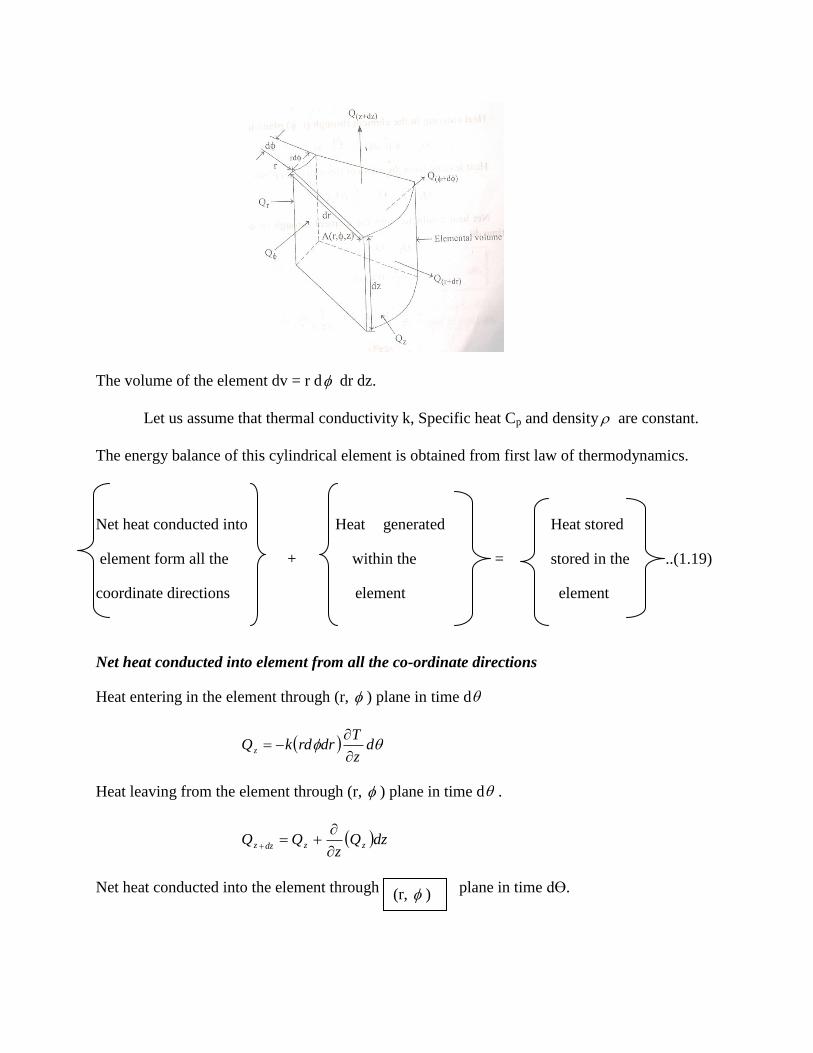
The volume of the element dv = r d dr dz.
Let us assume that thermal conductivity k, Specific heat Cp and density are constant.
The energy balance of this cylindrical element is obtained from first law of thermodynamics.
Net heat conducted into Heat generated Heat stored
element form all the + within the = stored in the ..(1.19)
coordinate directions element element
Net heat conducted into element from all the co-ordinate directions
Heat entering in the element through (r, ) plane in time d
dz
TdrrdkQ z
Heat leaving from the element through (r, ) plane in time d .
dzQz
QQ zzdzz
Net heat conducted into the element through plane in time dӨ.
(r, )

ddzrddrz
Tk
dzdz
Tdrrdk
z
dzQz
z
dzzz
..2
2
..
….. (1.20)
Heat entering in the element through ( , z) plane in time d .
dr
T
rr
Tdzrddrk
dr
Tr
rdzdrdk
drdr
Tdzrdk
r
drQr
r
drrr
1..
...
..
2
2
Heat entering in the element through (z, r) plane in time d .
d
r
TdzdrkQ
.
Heat leaving from the element through (z, r) plane in time d .
rdQr
QdQ
Net heat conducted through (r, ) plane = ddzrddrz
T..
2
2
Net heat conducted through ( , z) plane dr
T
rr
Tdzrddrk
1..
2
2

Net heat conducted into the element through (z, r) plane in time d .
ddzdrrdT
rk
ddzdrdT
rk
rddr
Tdrdzk
r
rdQr
dQd
2
2
2
1
1
.
Net heat conducted into element from all the co-ordinate directions
2
2
z
Tk
(dr rd dz) d
+
ddzdrrdT
rk
dr
T
rr
Tdzdrrdk
2
2
2
2
2
1
1
[Adding equation 1.20, 1.21 and 1.22]
2
2
2
2
22
2
2
2
22
2
2
2
11
11
z
TT
rr
T
rr
Tddzdrrdk
T
rr
T
rr
T
z
Tddzdrrdk
….. (1.23)
Net heat conducted into element from all the co-ordinate directions
2
2
2
2
22
211
z
TT
rr
T
rr
Tddzdrrdk
Heat generated within the element
Total heat generated within the element is given by
Q =q (dr rd dz) d …… (1.24)
Heat stored in the element
The increase in internal energy of the element is equal to the net heat stored in the
element.
Increase in internal energy
= Net heat stored in the element
= ( dr rd dz)
dT
C p
……. (1.25)
Substituting equation (1.23). (1.24) and (1.25) in (1.19)
k19.1 (dr rd dz)d qz
TT
rr
T
rr
T
2
2
2
2
22
211
(dr rd dz)
d
TC p
= (dr rd dz)
dT
C p
Divided by (dr rd dz) d
TCq
z
TT
rr
T
rr
Tk p.
112
2
2
2
22
2
==> …… (1.26)
It is a general three dimensional heat conduction equation in cylindrical co-ordinates.
==>
pC
kT
k
q
z
TT
rr
T
rr
T
1112
2
2
2
22
2
If the flow is steady, one dimensional and no heat generation, equation (1.26) becomes:
T
k
C
k
q
z
TT
rr
T
rr
T p
2
2
2
2
22
211

01
2
2
r
T
rr
T ……. (1.27)
(or)
==> 0.1
r
Tr
dr
d
r …….. (1.28)
CONDUCTION OF HEAT THROUGH A SLAB OR PLANE WALL
Consider a slab of uniform thermal conductivity k, thickness L, with inner temperature
T1, and outer temperature T2.
Let us consider a small elemental area of thickness „d x ‟.
From Fourier law of conduction, we know that,
kAdTdxQ
dx
dTkAQ
.
Integrating the above equation between the limits of 0 to L and T1 to T2.
21
12
0
0
0
0
2
1
2
1
2
1
TTkALQ
TTkALQ
AkAxQ
dTkAdxQ
kAdTQdx
T
T
L
L T
T
L T
T
21 TTL
kAQ ….. (1.29)

R
TQ
kA
L
TTQ
overall
21
……. (1.30)
Where
21 TTT
kA
LR Thermal resistance of slab.
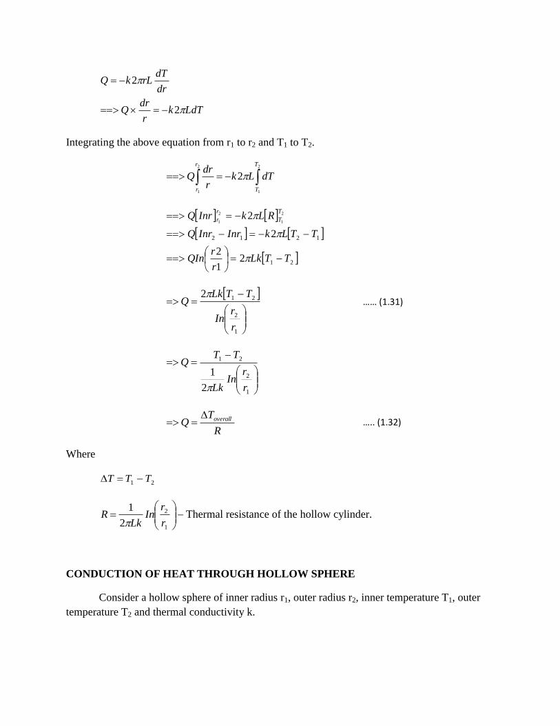
CONDUCTION OF HEAT THROUGH HOLLOW CYLINDER
Consider a hollow cylinder inner radius r1, outer radius r2, inner temperature T1, outer
temperature T2 and thermal conductivity k.
Let us consider a small elemental area of thickness “dr”
From Fourier law of conduction, we know that,
dr
dTkAQ
Area of a cylinder is rL2
rLA 2
So,
LdTkr
drQ
dr
dTrLkQ
2
2
Integrating the above equation from r1 to r2 and T1 to T2.
2
1
2
1
2
r
r
T
T
dTLkr
drQ
21
1212
21
2
2
2 2
1
2
1
TTLkr
rQIn
TTLkInrInrQ
RLkInrQT
T
r
r
1
2
212
r
rIn
TTLkQ
…… (1.31)
1
2
21
2
1
r
rIn
Lk
TTQ
R
TQ overall ….. (1.32)
Where
21 TTT
1
2
2
1
r
rIn
LkR
Thermal resistance of the hollow cylinder.
CONDUCTION OF HEAT THROUGH HOLLOW SPHERE
Consider a hollow sphere of inner radius r1, outer radius r2, inner temperature T1, outer
temperature T2 and thermal conductivity k.
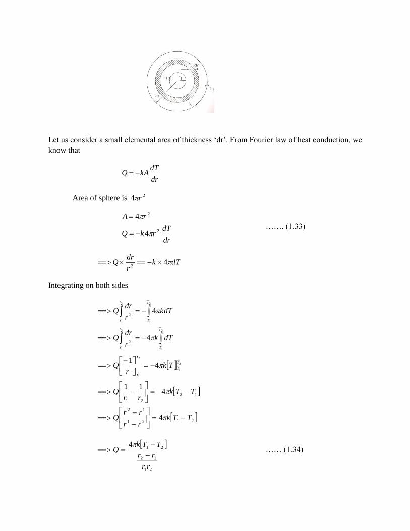
Let us consider a small elemental area of thickness „dr‟. From Fourier law of heat conduction, we
know that
dr
dTkAQ
Area of sphere is 24 r
dr
dTrkQ
rA
2
2
4
4
……. (1.33)
dTkr
drQ 4
2
Integrating on both sides
2121
12
12
21
2
2
4
411
41
4
4
2
1
2
1
2
1
2
1
2
1
2
1
TTkrr
rrQ
TTkrr
Q
Tkr
Q
dTkr
drQ
kdTr
drQ
T
T
r
r
T
T
r
r
T
T
r
r
21
12
214
rr
rr
TTkQ
…… (1.34)

21
12
21
4 rrk
rr
TTQ
R
TQ loveral …….. (1.35)
Where
21 TTT
21
12
4 rrk
rrR
Thermal resistance of hollow sphere.
Newton’s Law of Cooling
Heat transfer by convection is given by Newton law of cooling
TThAQ s ……. (1.36)
Where
A - Area exposed to heat transfer in m2
h – Heat transfer co-efficient in W/m2K
Ts – Temperature of the surface in K
T - Temperature of the fluid in K.
6. Heat Transfer Through a Composite Plane Wall with Inside and Outside Convection
Consider a composite wall of thickness L1, L2 and L3 having thermal conductivity k1, k2
and k3 respectively. It is assumed that the interior and exterior surface of the system are
subjected to convection at mean temperatures Ta and Tb with heat transfer co-efficient ha and hb
respectively. Within the composite wall, the slabs are subjected to conduction.
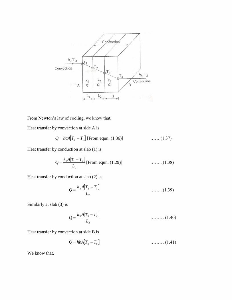
From Newton‟s law of cooling, we know that,
Heat transfer by convection at side A is
1TThaAQ a [From equn. (1.36)] …… (1.37)
Heat transfer by conduction at slab (1) is
1
211
L
TTAkQ
[From equn. (1.29)] …….. (1.38)
Heat transfer by conduction at slab (2) is
2
122
L
TTAkQ
…….. (1.39)
Similarly at slab (3) is
3
433
L
TTAkQ
……… (1.40)
Heat transfer by convection at side B is
bTThbAQ 4 ……… (1.41)
We know that,

AhQTT
a
a
11 [From equn. (1.37)]
Ak
LQTT
1
1
21 [ From equn. (1.38)]
Ak
LQTT
2
2
32 [From equn. (1.39)]
Ak
LQTT
3
3
43 [From equn. (1.40)]
AhQTT
b
b
14 [From equn. (1.410]
Adding both sides of the above equations
AhAk
L
Ak
L
Ak
L
Ah
TTQ
AhAk
L
Ak
L
Ak
L
AhQTT
ba
ba
ba
ba
11
11
3
3
2
2
1
1
3
3
2
2
1
1
R
TQ overall …….. (1.42)
Where
ba TTT
Thermal resistance, ba RRRRRR 321
=AhAk
L
Ak
L
Ak
L
Ah ba
11
3
3
2
2
1
1
We know that,

UA
TTQ
UAR
ba
1
1
ba TTUAQ …… (1.43)
Where
„U‟ is the overall heat transfer co-efficient (W/m2K).
HEAT TRANSFER THROUGH COMPOSITE PIPES OR CYLINDERS WITH INSIDE
AND OUTSIDE CONVECTION
A hot fluid at a temperature Ta, with heat transfer co-efficient ha, flowing through a pipe is
separated by two layers from atmosphere as shown in fig. 1.7. Let the thermal conductivities be
k1 and k2. On the outside surface heat is being transferred to a cold fluid at a temperature Tb with
heat transfer co-efficient hb.
Heat transfer by convection at side A is
1TTAhQ aa [From equn. No. (1.36)]
Here Area, A = Lr12
So,
112 TTLhrQ aa …….. (1.44)

Heat transfer by conduction at section 1 is
1
2
2112
r
rIn
TTLkQ
……… (1.45)
[From equn. (1.310]
Similarly
At section 2
2
3
3222
r
rIn
TTLkQ
……….. (1.46)
Heat transfer by convection at side B is
b
b
TTLhbrQ
TThbAQ
3
3
32 ………… (1.47)
We know that,
a
ahLr
QTT
1
12
[From equn. (1.440]
1
2
1
212 r
rIn
Lk
QTT
[From equn. (1.45)]
2
3
2
322 r
rIn
Lk
QTT
[From equn. (1.46)]
hbLr
QTT b
3
32
[From equn. (1.47)]
Adding both sides of the above equations

32
23
1
12
1
32
23
1
12
1
32
23
1
12
1
1//1
2
1
1//1
2
1//1
21
rhk
rrIn
k
rrIn
rhL
TTQ
rhk
rrIn
k
rrIn
rh
TTLQ
rhk
rrIn
k
rrIn
rhL
QTTa
ba
ba
ba
ba
ba
R
TQ overall
Where
32
23
1
12
1
1//1
2
1
rhk
rrIn
k
rrIn
rhLR
ba
baoverall TTT
We know that,
UA
TTQ
UAR
ba
1
1
ba TTUAQ ……… (1.49)
Where
U = Overall heat transfer co-efficient, W/m2K
A = Area = Lr32
CRITICAL RADIUS OF INSULATION
Addition of insulating material on a surface does not reduce the amount of heat transfer
rate always. In fact under certain circumstances it actually increases the heat loss up to certain
thickness of insulation. The radius of insulation for which the heat transfer is maximum is called
critical radius of insulation and the corresponding thickness is called critical thickness. If the
thickness is further increased, the heat loss will be reduced.

Critical Radius of Insulation For A Cylinder
Consider a cylinder having thermal conductivity k. Let r1 and r0 inner and outer radii of
insulation.
Heat transfer, Q =
kL
r
rIn
TTi
2
1
0
[From equn. No. (1.31)]
Considering h be the outside heat transfer co-efficient.
hAkL
r
r
rIn
TTQ i
0
1
1
0
1
2
Here A0 = Lr02
LhkL
r
rIn
TTQ i
0
1
0
2
1
2
To find the critical radius of insulation, differentiate Q with respect to r0 and equate it to
zero.
01
0
2
00
0
2
1
2
1
2
1
2
10
hLrr
rIn
kL
hLrkLrTT
dr
dQi
Since 0 TTi
02
1
2
12
00
hLrkLr
……. (1.50)
HEAT CONDUCTION WITH HEAT GENERATION
In many practical cases, there is a heat generation within the system. Typical examples
are
Electric coils
Resistance heater
Nuclear reactor
Combustion of fuel in the fuel bed of boiler furnaces.
PLANE WALL WITH INTERNAL HEAT GENERATION
Consider a slab of thickness L, thermal conductivity k, as shown in fig. 1.10.
Consider a small elemental area of thickness d x .
crh
kr 0
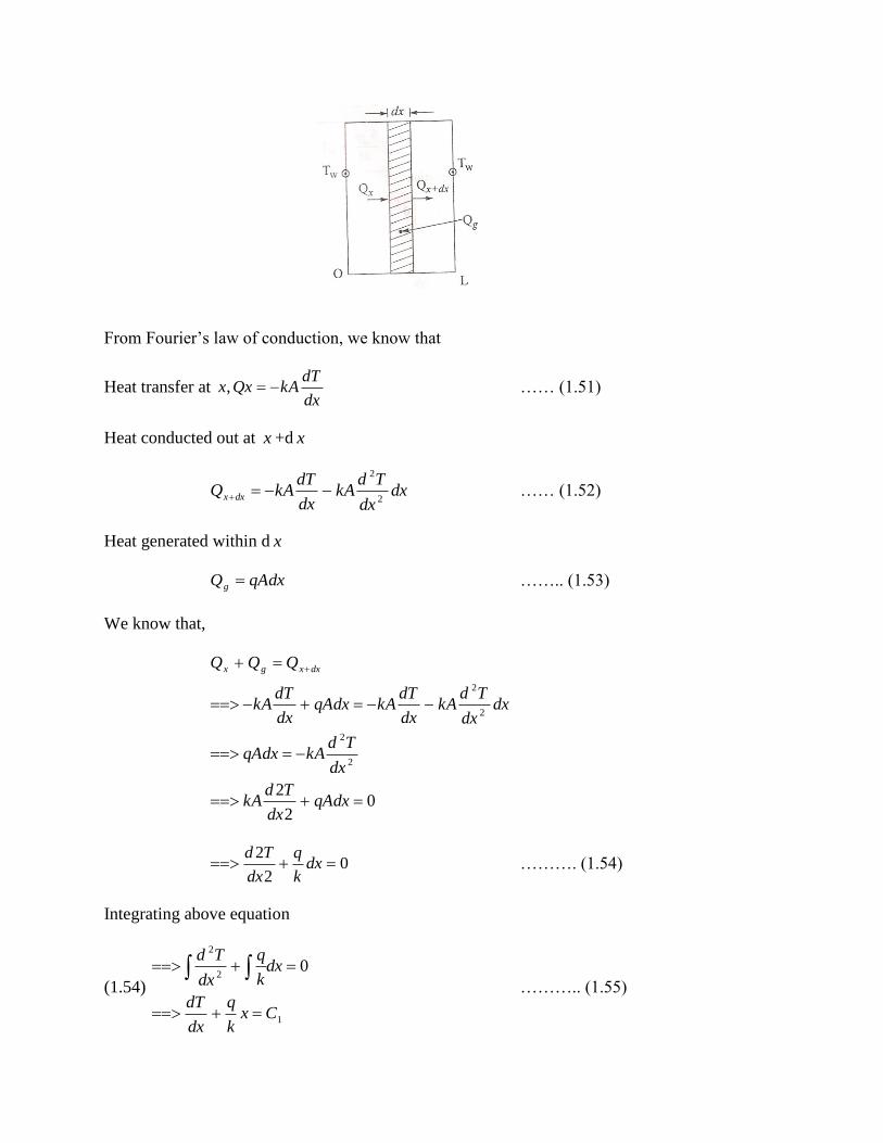
From Fourier‟s law of conduction, we know that
Heat transfer at dx
dTkAQxx , …… (1.51)
Heat conducted out at x +d x
dxdx
TdkA
dx
dTkAQ dxx 2
2
…… (1.52)
Heat generated within d x
qAdxQg …….. (1.53)
We know that,
02
2
2
2
2
2
qAdxdx
TdkA
dx
TdkAqAdx
dxdx
TdkA
dx
dTkAqAdx
dx
dTkA
QQQ dxxgx
02
2 dx
k
q
dx
Td ………. (1.54)
Integrating above equation
(1.54)
1
2
2
0
Cxk
q
dx
dT
dxk
q
dx
Td
……….. (1.55)

Integrating
(1.55)
21
2
1
2CxC
x
k
qT
Cxk
q
dx
dT
……… (1.56)
The temperature on the two faces of the slab (Tw) is the same because it loses it loses the
same amount of heat by convection on two sides.
Apply boundary conditions; C1 = 0
(1.56) 2
2
2
1Cx
k
qT
Apply T 2
,L
xTw
2
2
2
2
22
1
22
1
L
k
qTC
CL
k
qT
w
w
Substituting C1 and C2 value in equation (1.56)
k
qLTx
k
qT w
80
2
12
2
224
8xL
k
qTT w ……. (1.57)
The maximum temperature Tmax (at the centre) is obtained by putting 0x in Equation
(1.57).
21
2
2
1CxCx
k
qT
k
qLTC w
8
2
2

…….. (1.58)
Heat flow rate
qALQ2
1
Heat transfer by convection
h
qLTTw
qALhAThAT
hAThATqAL
TThAqALQ
TThAQ
w
W
w
w
2
2
1
2
1
2
1
Surface or Wall temperature
…….. (1.59)
CYLINDER WITH INTERNAL HEAT GENERATION
Consider a cylinder of radius r and thermal conductivity k. Heat is generated (Qg) in the
cylinder due to passage of an electric current.
From Fourier‟s law of conduction, we know that,
02
2
k
q
dr
Tdr r
………. (1.60)
Integrating
k
qLTT w
8
2
max
h
qLTTw
2

r
C
k
qr
dr
dT
Cr
k
q
dr
dTr
k
q
dr
Tdr r
1
1
2
2
2
2
2
0
Integrating
r
Cr
k
q
dr
dT 1
2
2122
2CInrC
k
qrT
……. (1.61)
212
2CInrC
k
qrT
Apply boundary conditions
C1 = 0
(1.61) 2
2
0
2C
k
qrTw [Put T = Tw, r = r0]
k
qrTC w
2
2
0
2
Apply C1 and C2 value in Equation (1.61)
22
04
rrk
qTT w
At centre
r = 0, T = Tmax
==> 2
0max4
rk
qTT w
k
qrTw
k
qrT
40
4
2
0
2

……. (1.62)
We know that,
Heat generated
LqrQ2
0 ……….. (1.63)
Heat transfer due to convection
TAhAQ w
TTLrhQ w02 ………. (1.64)
Equation (1.63) and (1.64)
h
qrTT
hTqrhT
hThTqr
TThqr
TTLrhLqr
w
w
w
w
w
2
22
22
2
2
0
0
0
0
0
2
0
……. (1.65)
Similarly,
For sphere, temperature at the centre
…… (1.66)
Maximum Temperature, 2
0max4
rk
qTT w
Surface temperature, h
qrTTw
2
0
k
qrTT wc
6
2
0
3
2
32
050.03/4
050.04250
3/4
250
4
q
rr
q
Temperature at the centre of the sphere
k
qrTT wc
6
2
[From Equn no. (1.66)]
18.06
050.01555281
2
Result:
Heat generated, q = 15,000 W/m3
Center temperature, Tc = 315.7 K
FINS
It is possible to increase the heat transfer rate by increasing the surface of heat transfer.
The surfaces used for increasing heat transfer are called extended surfaces of fins.
Types of fins
Some common types of fin configuration are shown in fig. 1.11.
3/000,15 mWq
KTc 7.315
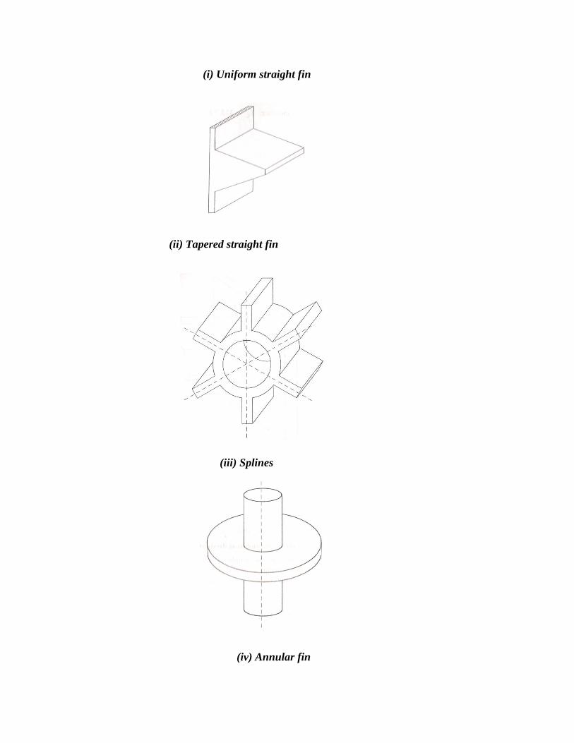
(i) Uniform straight fin
(ii) Tapered straight fin
(iii) Splines
(iv) Annular fin
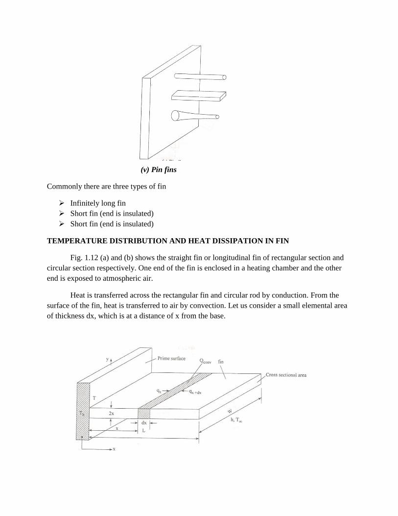
(v) Pin fins
Commonly there are three types of fin
Infinitely long fin
Short fin (end is insulated)
Short fin (end is insulated)
TEMPERATURE DISTRIBUTION AND HEAT DISSIPATION IN FIN
Fig. 1.12 (a) and (b) shows the straight fin or longitudinal fin of rectangular section and
circular section respectively. One end of the fin is enclosed in a heating chamber and the other
end is exposed to atmospheric air.
Heat is transferred across the rectangular fin and circular rod by conduction. From the
surface of the fin, heat is transferred to air by convection. Let us consider a small elemental area
of thickness dx, which is at a distance of x from the base.

A steady state conditions, heat balance equation for that element is as follows.
Heat conducted into the element = Heat conducted out of the element + heat convected to the
surrounding air.
convdxxx QQQ ……. (1.67)
Where,
TTpdxh
TThAQconv
dx
AdkA
dx
dTkAdxQx
dx
dTkAQx
dx
2
2
Substituting Q x , Q dxx and Qconv values in equation (1.67)
(1.67)
0
0
2
2
2
2
2
2
2
2
2
2
2
TTmdx
Td
TTkP
hP
dx
Td
TTkA
hP
dx
Td
TThpdx
TdkA
TTpdxhdxdx
TdkA
dx
dTkA
dx
dTkA
Where, kA
hPm
2
02
2
2
mdx
Td
kA
hPm
……. (1.68)
TT
Equation (1.68) shows that the temperature is a function of x and m. It is a second order,
linear differential equation. Its general solution is,
mxmxeCeC 21
……… (1.69)
The temperature distribution and heat dissipation depends upon the following fin
conditions.
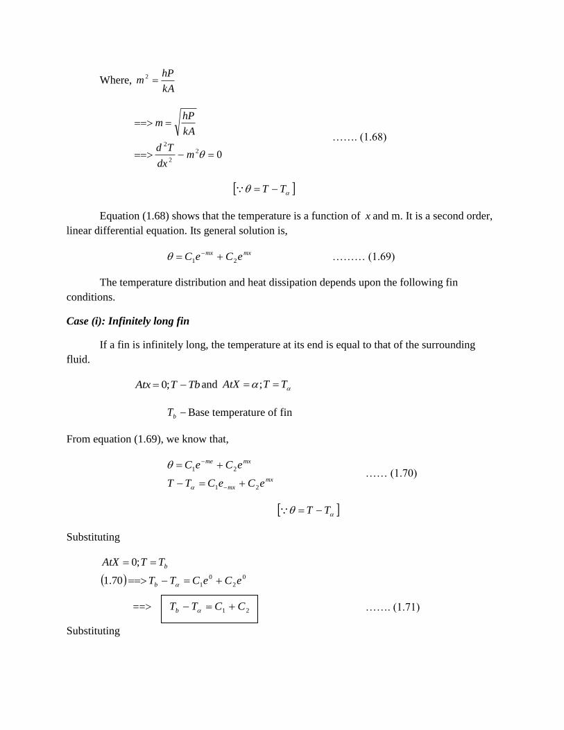
Case (i): Infinitely long fin
If a fin is infinitely long, the temperature at its end is equal to that of the surrounding
fluid.
TbTAtx ;0 and TTAtX ;
bT Base temperature of fin
From equation (1.69), we know that,
mx
mx
mxme
eCeCTT
eCeC
21
21
…… (1.70)
TT
Substituting
0
2
0
170.1
;0
eCeCTT
TTAtX
b
b
==> ……. (1.71)
Substituting
21 CCTTb
TTAtX ; in equation (1.70)
0
0
2
21
21
m
mm
mmx
eC
eCeC
eCeCTT
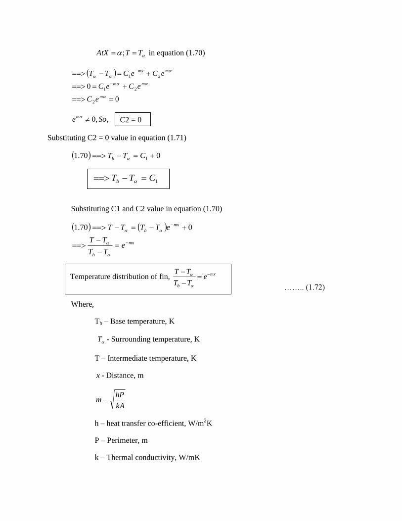
,,0 Soem
Substituting C2 = 0 value in equation (1.71)
070.1 1 CTTb
Substituting C1 and C2 value in equation (1.70)
mx
b
mx
b
eTT
TT
eTTTT
070.1
…….. (1.72)
Where,
Tb – Base temperature, K
T - Surrounding temperature, K
T – Intermediate temperature, K
x - Distance, m
kA
hPm
h – heat transfer co-efficient, W/m2K
P – Perimeter, m
k – Thermal conductivity, W/mK
C2 = 0
1CTTb
Temperature distribution of fin, mx
b
eTT
TT

A – Area, m2
Heat dissipation through the fin is obtained by integrating the heat lost by convection
over the entire fin surface.
We know that,
Heat lost by convection, TThAQconv
mx
b
mx
b
b
mx
eTTTTeTT
TT
dxTTehPQ
dxTThPQ
TThPdxQ
0
0
TThPkAQ
kA
hPmTThP
kA
hP
TThPm
mTThP
mTThP
mxem
TThP
dxeTTbhPQ
b
b
b
b
b
b
mx
1
1
1
11
10
0
…. ( 1.73)
Case (ii): Fin with insulated end (Short fin)
The fin has a finite length and the tip of fin is insulated.
Heat transferred, TThPkAQ b
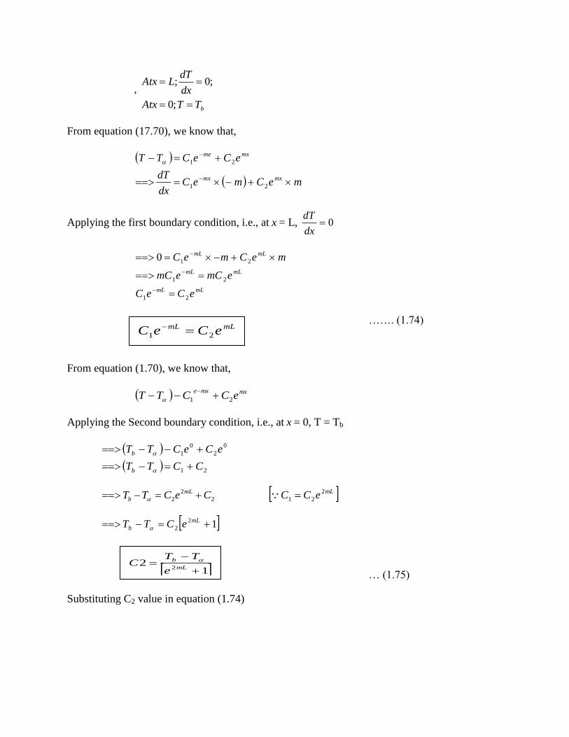
,
bTTAtx
dx
dTLAtx
;0
;0;
From equation (17.70), we know that,
meCmeCdx
dT
eCeCTT
mxmx
mxme
21
21
Applying the first boundary condition, i.e., at x = L, 0dx
dT
mLmL
mLmL
mLmL
eCeC
emCemC
meCmeC
21
21
210
……. (1.74)
From equation (1.70), we know that,
mxmxeeCCTT 21
Applying the Second boundary condition, i.e., at x = 0, T = Tb
21
0
2
0
1
CCTT
eCeCTT
b
b
2
2
2 CeCTTmL
b mLeCC
2
21
12
2 mL
b eCTT
… (1.75)
Substituting C2 value in equation (1.74)
mLmLeCeC 21
12
2
mL
b
e
TTC

mLmLmL
mL
b
mL
mL
b
eee
TTbC
emLe
TTC
ee
TTC
222
21
2
21
1
1
12
1
==> …. (1.76)
Substituting C1 and C2 value in equation (1.70)
mL
mx
mL
mx
b
mL
mx
mL
mx
b
mx
mL
bmx
mL
b
e
e
e
e
TT
TT
e
e
e
eTTTT
ee
TTe
e
TTTT
22
22
22
11
11
11
Multiplying the numerator and denominator by emL
and e-mL
mLmL
xLm
mLmL
Lxm
mL
mL
mL
mx
mL
mL
mL
mx
b
ee
e
ee
e
e
e
e
e
e
e
e
e
TT
TT
2211
mLmL
xLmxLm
b ee
ee
TT
TT
…… (1.77)
In terms of hyperbolic function it can be written as,
mL
xLm
TT
TT
b cosh
cosh
Temperature distribution of fin with insulated end
……… (1.78)
mL
b
e
TTC
21
1
mL
xLm
TT
TT
b cosh
cosh

mL
xLmmTTb
dx
dT
mL
xLmTTTT b
cosh
sinh
cosh
cosh
We know that,
Heat transferred, dx
dTkAQ
mLTTkA
hPkA
mLTTbkAm
mL
mLTTkAmQ
atx
mL
xLmTTkAmQ
mL
xLmmTTkA
b
b
b
b
tanh
tanh
cosh
sinh
0
cosh
sinh
cosh
sinh
kA
hPm
mLTThPkA b tanh
…..(1.79)
Applications
The main application of fins are
Cooling of electronic components
Cooling of motor cycle engines.
Cooling of small capacity compressors
Cooling of transformers
Cooling of radiators and refrigerators etc.
Heat transferred for insulated fin mLTThPkAQ b tanh

Fin efficiency
The efficiency of a fin is defined as the ratio of actual heat transferred fin to the
maximum possible heat transferred by the fin
maxQ
Q fin
fin
For insulated end
mL
mLfin
tanh
Fin effectiveness
It is defined as the ratio of heat transfer with fin to heat transfer without fin
Fin effectiveness, withoutfin
withfin
Q
QE
For insulated end
Fin effectiveness,
kP
hA
mLE
tanh
TRANSIENT HEAT CONDUCTION (OR) UNSTEADY STATE CONDUCTION
If the temperature of a body does not vary with time, it is said to be in a steady state. But
if there is an abrupt change in its surface temperature, it attains a steady state after some period.
During this period the temperature varies with time and the body is said to be in an unsteady or
transient state.
Transient heat conduction occur in cooling of IC engines, automobile engines, boiler
tubes, heating and cooling of metal billets, rocket nozzles, electric irons etc.
Transient heat conduction can be divided in to periodic heat flow and non periodic heat
flow.
(i) Periodic heat flow
In periodic heat flow, the temperature varies on a regular basis.
Examples: Cylinder of an IC engine,
Surface of earth during a period of 24 hours.

(ii) Non periodic heat flow:
In non periodic heat flow, the temperature at any point within the system varies non-
linearly with time.
Examples: heating of an ingot in a furnace, cooling of bars.
Biot Number
The ratio of internal conduction resistance to the surface convection resistance is known
as Biot number.
Biot Number ceisvectionresSurfacecon
cesisnductionreInternalco
tan
tan
k
hLcBi
Where
K – Thermal conductivity, W/mK
H – Heat transfer co-efficient, W/m2K
Lc – Characteristic length or significant length
Characteristic length, A
V
aSurfaceAre
VolumeLc
For slab:
Characteristic length, A
LA
A
VLc
2
Where
L – Thickness of the slab
2
LLc
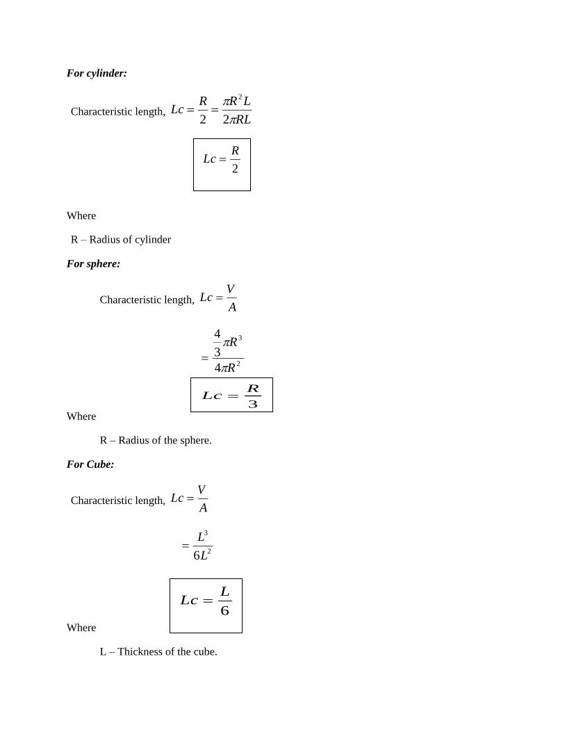
For cylinder:
Characteristic length, RL
LRRLc
22
2
Where
R – Radius of cylinder
For sphere:
Characteristic length, A
VLc
2
3
4
3
4
R
R
Where
R – Radius of the sphere.
For Cube:
Characteristic length, A
VLc
2
3
6L
L
Where
L – Thickness of the cube.
2
RLc
3
RLc
6
LLc
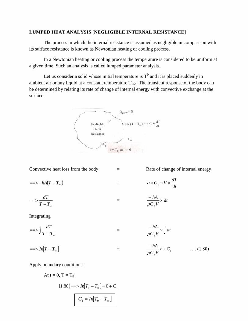
LUMPED HEAT ANALYSIS [NEGLIGIBLE INTERNAL RESISTANCE]
The process in which the internal resistance is assumed as negligible in comparison with
its surface resistance is known as Newtonian heating or cooling process.
In a Newtonian heating or cooling process the temperature is considered to be uniform at
a given time. Such an analysis is called lumped parameter analysis.
Let us consider a solid whose initial temperature is T0 and it is placed suddenly in
ambient air or any liquid at a constant temperature T . The transient response of the body can
be determined by relating its rate of change of internal energy with convective exchange at the
surface.
Convective heat loss from the body = Rate of change of internal energy
TThA = dt
dTVC p
TT
dT = dt
VC
hA
p
Integrating
TT
dT =
dt
VC
hA
p
TTIn = 1CtVC
hA
p
…. (1.80)
Apply boundary conditions.
At t = 0, T = T0
10 080.1 CTTIn
TTInC 01

Substituting C1 value in equation (1.80)
tVC
hA
TT
TTIn
tVC
hATTInTTIn
TTIntVC
hATTIn
p
p
p
0
0
0
…… (1.81)
Where
T0 – Initial temperature of the solid, K
T – Intermediate temperature of the solid, K
T
- Surface temperature of the solid (or) Finial temperature of the solid, K
h – Heat transfer co-efficient, W/m2K
A – Surface area of body, m2
P – Density of the body, kg/m3
V – Volume of the body, m3
Cp – Specific heat of the body, J/kg K.
t – Time, s.
Note
1. In lumped parameter system, Biot number value is less than 0.1.
i.e., 1.01.0 k
hLB c
i
VC
hAt
pe
TT
TT
0

2. T0 – Initial temperature, K
T – Intermediate temperature, K
T
- Surface temperature or Final temperature, K
HEAT FLOW IN SEMI-INFINITE SOLIDS
A solid which extends itself infinitely in all directions of space is known as infinite solid.
If an infinite solid is split in the middle by a plane, each half is known as semi infinite solid.
In a semi infinite solid, at any instant of time, there is always a point where the effect of
heating (or cooling) at one of its boundaries is not felt at all. At this point the temperature
remains unchanged.
Semi Infinite Plate
Consider a semi infinite body and it extends to infinity in the +ve x direction. The entire body is
initially at uniform temperature Ti including the surface at x = 0 is suddenly raised to T0.
The governing equation is
dt
dT
dx
Td
12
2
The boundary conditions are
T iTx 0,
T 0,0 0 fortTt
T 0, fortTt i
The analytical solution for this case is given by

t
xerf
TT
TT
i
x
20
0 ….. (1.82)
Where erf indicates “error function of” and the definition of error function is generally
available in mathematical texts. Usually tabulation of error values are available in data books.
- Thermal diffusivity, m2/s
t – Time, s
X – Distance, m
Ti – Initial temperature, K
T0 – Surface temperature (or) Final temperature, K
T x - Intermediate temperature, K
Note
1. In semi infinite solid, head transfer co-efficient or biot number value is .
i.e., h
or
iB
2. Ti – Initial temperature, K
T0 – Surface temperature (or) Final temperature, K
T x - Intermediate temperature, K
TRANSIENT HEAT FLOW IN AN INFINITE PLATE
A solid which extends itself infinitely in all directions of space is known as infinite solid.
Consider an infinite flat plate of uniform thickness 2L as shown in fig. 1.15, which is initially at
a uniform temperature of Ti. It is suddenly exposed to a large mass of fluid having a temperature
T . This temperature is assumed to be constant throughout the process of cooling or heating.
The plate is extended to infinity in the y and z directions.
The heat transfer co-efficient between the surface of the plate and the fluid on both sides
is assumed to be constant. The center of the plate is selected as the orgin.
The governing differential equation is
dx
dT
dx
Td
12
2

The boundary conditions are
Tt t = 0, T0 = Ti
Tt x = 0, 0dx
dT
Tt x = L, kA TThAdx
dT0
The solution of the above differential equation with this boundary condition is given by
2
0 ,,L
t
L
hL
L
xf
TT
TT
i
From this equation, we know that conduction resistance is not negligible. The
temperature history becomes a function of biot number ,
k
hLcFourier number
2L
tand the
dimension less parameter
L
xwhich indicates the location of point within the plate where
temperature is to be obtained. The dimensionless parameter
L
x is replaced by
R
rin case of
cylinders and spheres.
Heisler has prepared charts for graphical solutions of the unsteady state conduction
problems. These charts have been constructed in non-dimensional parameters. The charts are
suitable for problems with a finite surface and internal resistance. For such case the biot number
lies between 0 and 100.
These heiler charts were further extended and improved by grobe.
The heiler and grober charts are used to solve the problems of sudden immersion of plate,
cylinder or sphere into a fluid.
Note: For infinite solids,
Take Ti – Initial temperature – K
T - Final temperature – K
T0 - Center line temperature – K
T x - Intermediate temperature – K
The infinite solids, biot number value is in between 0.1 and 100 i.e., 0.1 < Bi < 100.
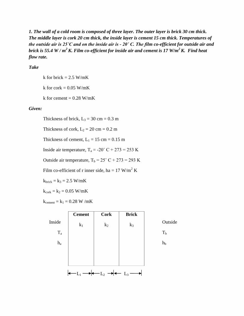
1. The wall of a cold room is composed of three layer. The outer layer is brick 30 cm thick.
The middle layer is cork 20 cm thick, the inside layer is cement 15 cm thick. Temperatures of
the outside air is 25˚C and on the inside air is - 20˚ C. The film co-efficient for outside air and
brick is 55.4 W / m2 K. Film co-efficient for inside air and cement is 17 W/m
2 K. Find heat
flow rate.
Take
k for brick = 2.5 W/mK
k for cork = 0.05 W/mK
k for cement = 0.28 W/mK
Given:
Thickness of brick, L3 = 30 cm = 0.3 m
Thickness of cork, L2 = 20 cm = 0.2 m
Thickness of cement, L1 = 15 cm = 0.15 m
Inside air temperature, Ta = -20˚ C + 273 = 253 K
Outside air temperature, Tb = 25˚ C + 273 = 293 K
Film co-efficient of r inner side, ha = 17 W/m2 K
kbrick = k3 = 2.5 W/mK
kcork = k2 = 0.05 W/mK
kcement = k1 = 0.28 W /mK
Inside Outside
Ta Tb
ha hb
L1 L2 L3
Cement
k1
Cork
k2
Brick
k3

To find:
Heat flow rate (Q/A)
Solution:
Heat flow through composite wall is given by
R
Q Toverall [From Equn no. 1.42 or HMT Date book page No. 43 and 44]
Where
4.55
1
5.2
3.0
05.0
2.0
28.0
15.0
17
1
298253/
11/
11
11
3
3
2
2
1
1
3
3
2
2
1
1
3
3
2
2
1
1
AQ
hk
L
k
L
k
L
h
TTAQ
AhAk
L
Ak
L
Ak
L
Ah
TTQ
AhAk
L
Ak
L
Ak
L
AhR
TTT
ba
ba
ba
ba
ba
ba
The negative sign indicates that the heat flows from the outside into the cold room.
Result:
Heat flow rate, Q/A = -9.5 W/m2
2. A wall of a cold room is composed of three layer. The outer layer is brick 20 cm thick, the
middle layer is cork 10 cm thick, the inside layer is cement 5 cm thick. The temperature of the
outside air is 25˚ C and that on the inside air is -20˚ C. The film co-efficient for outside air and
brick is 45.4 W/m2K and for inside air and cement is 17 W/m
2K.
Q/A = -9.5 W/m2
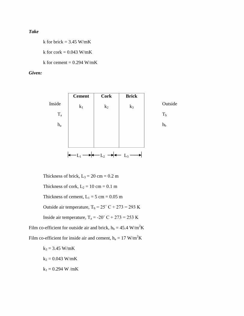
Take
k for brick = 3.45 W/mK
k for cork = 0.043 W/mK
k for cement = 0.294 W/mK
Given:
Inside Outside
Ta Tb
ha hb
L1 L2 L3
Thickness of brick, L3 = 20 cm = 0.2 m
Thickness of cork, L2 = 10 cm = 0.1 m
Thickness of cement, L1 = 5 cm = 0.05 m
Outside air temperature, Tb = 25˚ C + 273 = 293 K
Inside air temperature, Ta = -20˚ C + 273 = 253 K
Film co-efficient for outside air and brick, hb = 45.4 W/m2K
Film co-efficient for inside air and cement, ha = 17 W/m2K
k3 = 3.45 W/mK
k2 = 0.043 W/mK
k1 = 0.294 W /mK
Cement
k1
Cork
k2
Brick
k3

To find:
1. Heat flow rate
2. Thermal resistance of the wall
Solution:
Heat flow through composite wall is given by
RQ Toverall [From Equn no. (1.42) (or) HMT Date book page No. 43 and 44]
Where
4.45
1
45.3
2.0
043.0
1.0
294.0
05.0
17
1
298253/
11/
11
11
3
3
2
2
1
1
3
3
2
2
1
1
3
3
2
2
1
1
AQ
hk
L
k
L
k
L
h
TTAQ
AhAk
L
Ak
L
Ak
L
Ah
TTQ
AhAk
L
Ak
L
Ak
L
AhR
TTT
ba
ba
ba
ba
ba
ba
The negative sign indicates that the heat flows from the outside into the cold room.
Thermal Resistance
AhAk
L
Ak
L
Ak
L
AhR
ba
11
3
3
2
2
1
1
For Unit Area
ba hk
L
k
L
k
L
hR
11
3
3
2
2
1
1
Q/A = -17.081W/m2
W/m2
4.45
1
45.3
2.0
043.0
1.0
294.0
05.0
17
1 R
Result:
1. Heat flow rate, Q/A = -17.081 W/m2
2. Thermal resistance, R = 2.634 K/W
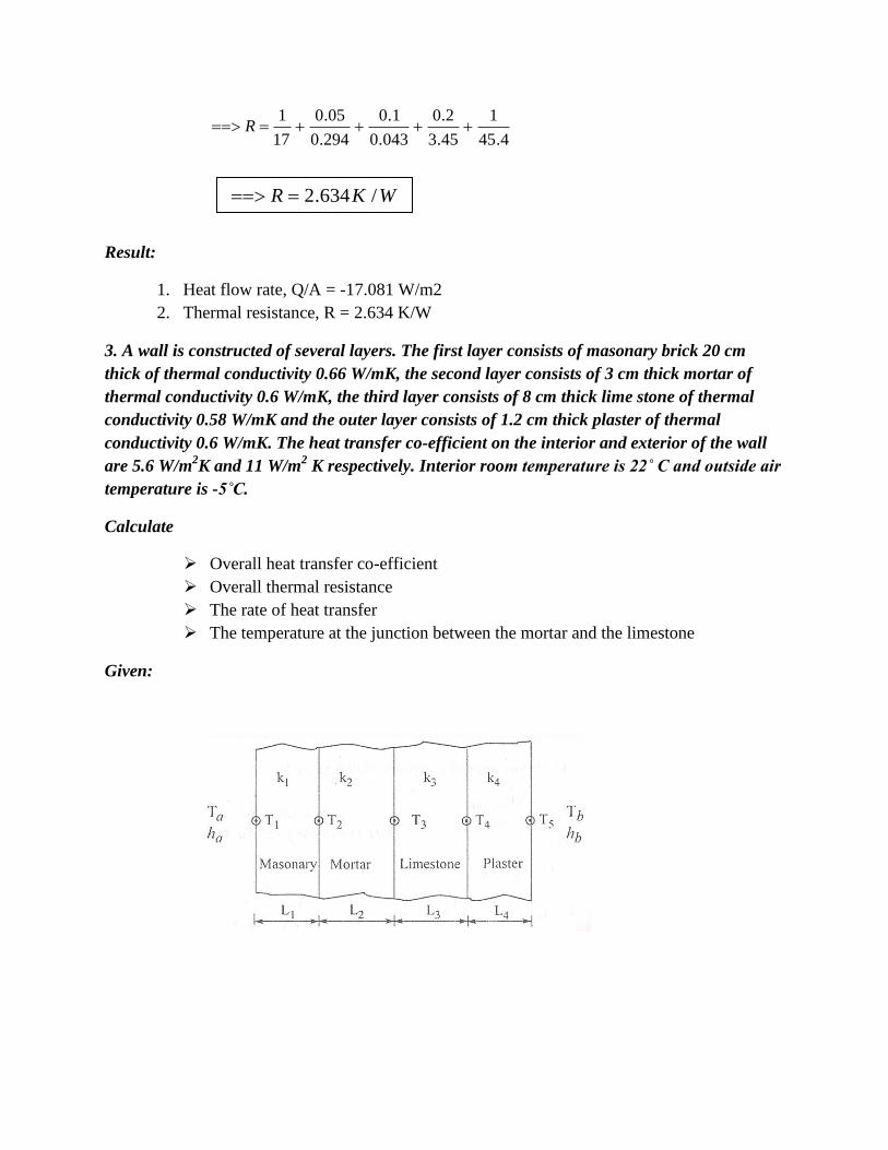
3. A wall is constructed of several layers. The first layer consists of masonary brick 20 cm
thick of thermal conductivity 0.66 W/mK, the second layer consists of 3 cm thick mortar of
thermal conductivity 0.6 W/mK, the third layer consists of 8 cm thick lime stone of thermal
conductivity 0.58 W/mK and the outer layer consists of 1.2 cm thick plaster of thermal
conductivity 0.6 W/mK. The heat transfer co-efficient on the interior and exterior of the wall
are 5.6 W/m2K and 11 W/m
2 K respectively. Interior room temperature is 22˚ C and outside air
temperature is -5˚C.
Calculate
Overall heat transfer co-efficient
Overall thermal resistance
The rate of heat transfer
The temperature at the junction between the mortar and the limestone
Given:
WKR /634.2

Thickness of masonary, L1 = 20 cm = 0.20 m
Thermal conductivity, k1 = 0.66 W/mK
Thickness of mortar, L2 = 3 cm = 0.03 m
Thermal conductivity of mortrar, k2 = 0.6 W/mK
Thickness of limestone, L3 = 8 cm = 0.08m
Thermal conductivity, k3 = 0.58 W/mK
Thickness or Plaster, L4 = 1.2 cm = 0.012 m
Thermal conductivity, k4 = 0.6 W/mK
Interior heat transfer, co-efficient ha = 5.6 W/m2K
Exterior heat transfer co-efficient hb = 11 W/m2K
Inside air temperature, Ta = 22˚C + 273 = 295 K
Outside air temperature, Tb = -5˚C + 273 = 268 K.
To fine:
a) Overall heat transfer co-efficient, U
b) Overall thermal resistance, (R)
c) Heat transfer/m2, (Q/A)
d) The temperature at the junction between the Mortar and the limestone, (T3)
Solution:
Heat flow through composite wall is given by
RQ Toverall [From Equn no. (1.42) or HMT Date book page No. 43 & 44]
Where
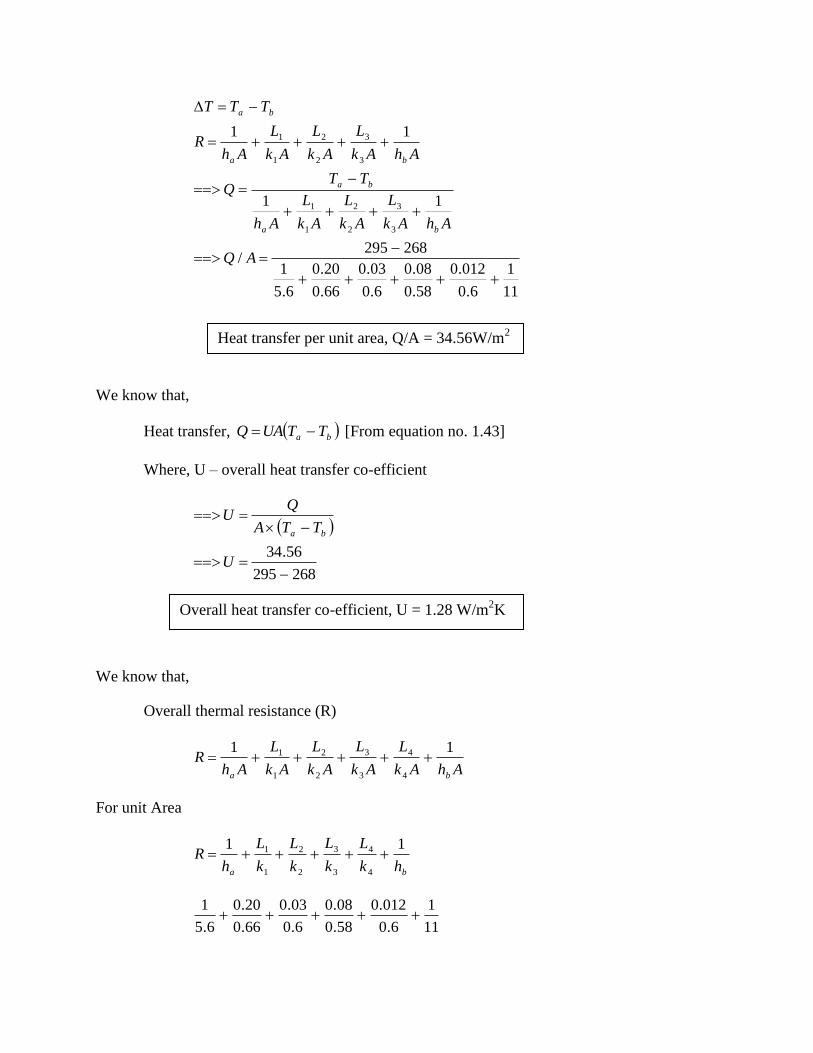
11
1
6.0
012.0
58.0
08.0
6.0
03.0
66.0
20.0
6.5
1
268295/
11
11
3
3
2
2
1
1
3
3
2
2
1
1
AQ
AhAk
L
Ak
L
Ak
L
Ah
TTQ
AhAk
L
Ak
L
Ak
L
AhR
TTT
ba
ba
ba
ba
We know that,
Heat transfer, ba TTUAQ [From equation no. 1.43]
Where, U – overall heat transfer co-efficient
268295
56.34
U
TTA
QU
ba
We know that,
Overall thermal resistance (R)
AhAk
L
Ak
L
Ak
L
Ak
L
AhR
ba
11
4
4
3
3
2
2
1
1
For unit Area
ba hk
L
k
L
k
L
k
L
hR
11
4
4
3
3
2
2
1
1
11
1
6.0
012.0
58.0
08.0
6.0
03.0
66.0
20.0
6.5
1
Heat transfer per unit area, Q/A = 34.56W/m2
Overall heat transfer co-efficient, U = 1.28 W/m2K
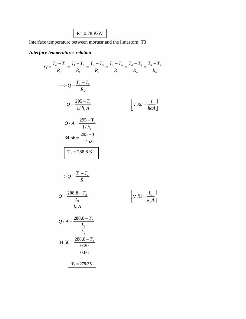
Interface temperature between mortasr and the limestorn, T3
Interface temperatures relation
b
b
a
a
R
TT
R
TT
R
TT
R
TT
R
TT
R
TTQ
5
4
54
3
43
2
32
1
211
a
a
R
TTQ 1
Ah
TQ
a/1
295 1
haARa
1
6.5/1
29556.34
/1
295/
1
1
T
h
TAQ
a
1
21
R
TTQ
Ak
L
TQ
1
1
28.288
Ak
LR
1
11
66.0
20.0
8.28856.34
8.288/
2
1
1
2
T
k
L
TAQ
R= 0.78 K/W
T1 = 288.8 K
KT 3.2782
2
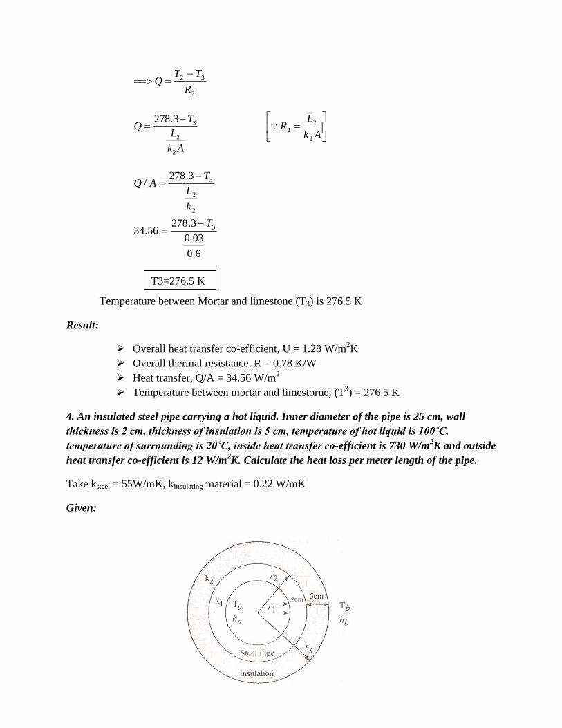
32
R
TTQ
Ak
L
TQ
2
2
33.278
Ak
LR
2
2
2
6.0
03.0
3.27856.34
3.278/
3
2
2
3
T
k
L
TAQ
Temperature between Mortar and limestone (T3) is 276.5 K
Result:
Overall heat transfer co-efficient, U = 1.28 W/m2K
Overall thermal resistance, R = 0.78 K/W
Heat transfer, Q/A = 34.56 W/m2
Temperature between mortar and limestorne, (T3) = 276.5 K
4. An insulated steel pipe carrying a hot liquid. Inner diameter of the pipe is 25 cm, wall
thickness is 2 cm, thickness of insulation is 5 cm, temperature of hot liquid is 100˚C,
temperature of surrounding is 20˚C, inside heat transfer co-efficient is 730 W/m2K and outside
heat transfer co-efficient is 12 W/m2K. Calculate the heat loss per meter length of the pipe.
Take ksteel = 55W/mK, kinsulating material = 0.22 W/mK
Given:
T3=276.5 K
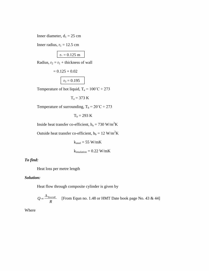
Inner diameter, d1 = 25 cm
Inner radius, r1 = 12.5 cm
Radius, r2 = r1 + thickness of wall
= 0.125 + 0.02
Temperature of hot liquid, Ta = 100˚C + 273
Ta = 373 K
Temperature of surrounding, Tb = 20˚C + 273
Tb = 293 K
Inside heat transfer co-efficient, ha = 730 W/m2K
Outside heat transfer co-efficient, hb = 12 W/m2K
ksteel = 55 W/mK
kinsulation = 0.22 W/mK
To find:
Heat loss per metre length
Solution:
Heat flow through composite cylinder is given by
RQ Toverall [From Equn no. 1.48 or HMT Date book page No. 43 & 44]
Where
r1 = 0.125 m
r3 = 0.195
m

195.12
1
22.0
145.
195.
55
125.
145.
125.730
1
2
1
293373
11
2
1
11
2
1
32
2
3
1
1
2
1
32
2
3
1
1
2
1
InInL
Q
rhk
r
rIn
k
r
rIn
rhL
TTQ
rhk
r
rIn
k
r
rIn
rhLR
TTT
ba
ba
ba
ba
Result:
Heat transfer per metre length, Q/L = 281. 178 W/m.
5. Air at 90˚C flows in a copper tube of 5 cm inner diameter with thermal conductivity 380
W/mK and with 0.7 cm thick wall which is heated from the outside by water at 120˚C. a scale
of 0.4 cm thick is deposited on the outer surface of the tube whose thermal conductivity is 1.82
W/mK. The air and water side unit surface conductance are 220 W/m2 K and 3650 W/m
2 K
respectively. Calculate
Overall water to air transmittance
Water to air heat exchange
Temperature drop across the scale deposit.
Given:
Q/L = 281. 178W/m

Inner air temperature, Ta = 90˚ + 273
Inner diameter of the copper, d1 = 5 cm
Radius, r1 = 2.5 cm
Thermal conductivity, k1 = 380 W/mK
Outer radius of the copper, r2 = inner radius + thickness of wall
r2 = 0.025 + 0.007 m
r3 = r2 + thickness of scale
= 0.032 + 0.004
Outside temperature of water, Tb = 120˚C + 273
= 393 K
Thermal conductivity, k2 = 1.82 W/mK
Surface conductance of air, ha = 220 W/m2K
Surface conductance of water, hb = 3650 W/m2K
To find:
1. Overall heat transfer co-efficient, U
2. Water to air heat transfer, Q
3. Temperature drop across the scale deposit, (T3 - T2)
Solution:
Heat flow through composite cylinder is given by
Ta = 363 K
r1 = 0.025 m
r2 = 0.032 m
r3 = 0.036 m

R
Q Toverall [From Equn no. (1.48) or HMT Date book page No. 43 & 45]
Where
036.3650
1
82.1
032.
036.
380
025.
032.
025.220
1
2
1
393363
11
2
1
11
2
1
32
2
3
1
1
2
1
32
2
3
1
1
2
1
InInL
Q
rhk
r
rIn
k
r
rIn
rhL
TTQ
rhk
r
rIn
k
r
rIn
rhLR
TTT
ba
ba
ba
ba
[Negative sign indicates that heat flows from outside to inner side]
We know that,
Heat transfer, Q = UA T
Where
U – Overall heat transfer co-efficient
A – Area = 2 Lr3
T = Ta - Tb
Q/L = -739.79 W/m

393363036.0279.739
2
2
3
3
U
TTrUL
Q
TTLrUQ
ba
ba
==>
Interface temperatures
b
b
a
aba
R
TT
R
TT
R
TT
R
TT
R
TT
R
TQ
3
2
32
1
211 …….. (1)
(1) 2
32
R
TTQ
Where
82.1
032.0
036.0
2
1
3279.739
2
1
2
1
2
12
2
2
3
32
2
2
3
32
2
2
3
In
TT
k
r
rIn
TT
L
Q
k
r
rIn
L
TTQ
k
r
rIn
LR
U = 109.01 W/m2K
Overall heat transfer co-efficient, U = 109.01 W/m2K.

==> T2 – T3 = -7.6 K
==>
Result:
1. Overall heat transfer co-efficient, U = 109.01 W/m2K
2. Heat exchange, Q/L = -739.79 W/m
[Negative sign indicates that heat flows from outside to inner side]
3. Temperature drop across the scale deposit,
T3 – T2 = 7.6 K
6. An electrical wire of 10 m length and 1 mm diameter dissipates 200W in air at 25˚C. The
convection heat transfer co-efficient between the wire surface and air is 15W/m2K. The
thermal conductivity of wire is 0.582 W/mK. Calculate the critical radius of insulation and
also determine the temperature of the wire if it is insulated to the critical thickness of
insulation.
Given:
Length of the wire, L = 10 mm
Diameter of the wire, d = 1 mm
Radius of the wire, r = 0.5 mm = 0.510-3
m
Heat transfer, Q = 200 W
Surrounding temperature, Tb = 25˚C + 273 = 298 K
Convection heat transfer co-efficient between the wire surface and air, hb = 15 Wm2K.
Thermal conductivity of wire, k = 0.582 W/mk
T3 – T2 = 7.6 K
Temperature across the scale deposit, T3 – T2 = 7.6 K

To find:
1. Critical radius of insulation, rc
2. Temperature of wire, Ta
Solution:
We know that,
Critical radius of insulation, n
krc
15
582.0
Heat transfer through an insulated wire when critical radius is used is given by
146.0
298200
0388.015
1
582.0
0005.0
0388.0
102
1
298200
1
2
1
1
1
Ta
In
T
rhk
r
rIn
L
TTQ
a
cb
c
ba
==>
Result:
1. Critical radius of insulation, rc = 0.0388mm
2. Temperature of the wire, Ta = 327.28 K (or) 54.2˚C.
rc = 0.0388 m
Ta = 327.28 K

7. A wire of 6 mm diameter with 2 mm thick insulation (K = 0.11 W/mK). If the convective
heat transfer co-efficient between the insulating surface heat transfer co-efficient between the
insulating surface and air is 25 W/m2K, find the critical thickness of insulation and also find
the percentage of change in the heat transfer rate if the critical radius is used.
Given:
d1 = 6 mm
r1 = 3 mm
r2 = r1+2 = 3+2 = 5 mm = 0.005 m
k = 0.11W / mK
hb = 25 W/m2K
Solution:
1. Critical radius, h
krc [From. No. (1.50)]
mrc
3104.4
25
11.0
Critical thickness, tc = rc – r1
= 4.4 10-3
m
2. Heat transfer through an insulated wire is given by
mrc
3104.4
Critical thickness, tc = 1.4 10-3
m (or) 1.4 mm
64.12
2
005.025
1
11.0
003.0
005.0
2
1
2
1
1
21
1
2
1
ba
ba
b
ba
TTLQ
In
TT
rhk
r
rIn
L
TTQ
[From HMT data book page no. 43 & 45]
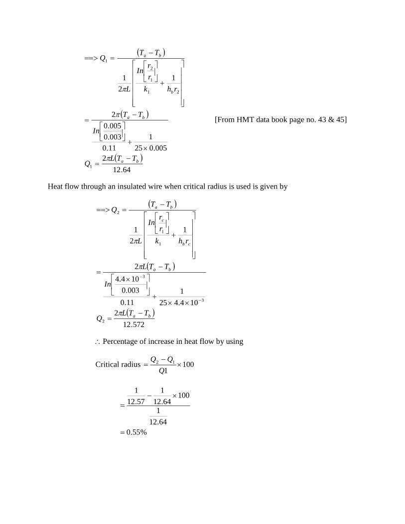
Heat flow through an insulated wire when critical radius is used is given by
572.12
2
104.425
1
11.0
003.0
104.4
2
1
2
1
2
3
3
1
1
2
ba
ba
cb
c
ba
TTLQ
In
TTL
rhk
r
rIn
L
TTQ
Percentage of increase in heat flow by using
Critical radius 1001
12
Q
%55.0
64.12
1
10064.12
1
57.12
1
Result:
1. Critical thickness, tc = 1.410-3
2. Percentage of increase in heat transfer by using critical radius = 0.55%
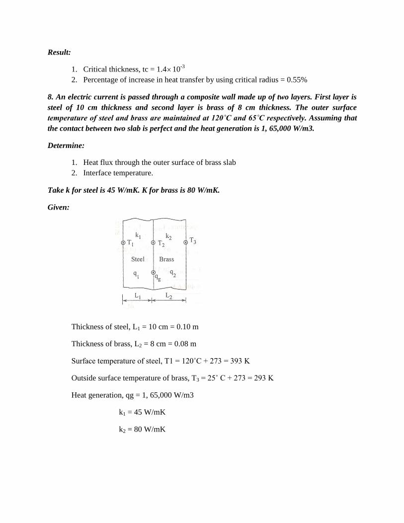
8. An electric current is passed through a composite wall made up of two layers. First layer is
steel of 10 cm thickness and second layer is brass of 8 cm thickness. The outer surface
temperature of steel and brass are maintained at 120˚C and 65˚C respectively. Assuming that
the contact between two slab is perfect and the heat generation is 1, 65,000 W/m3.
Determine:
1. Heat flux through the outer surface of brass slab
2. Interface temperature.
Take k for steel is 45 W/mK. K for brass is 80 W/mK.
Given:
Thickness of steel, L1 = 10 cm = 0.10 m
Thickness of brass, L2 = 8 cm = 0.08 m
Surface temperature of steel, T1 = 120˚C + 273 = 393 K
Outside surface temperature of brass, T3 = 25˚ C + 273 = 293 K
Heat generation, qg = 1, 65,000 W/m3
k1 = 45 W/mK
k2 = 80 W/mK
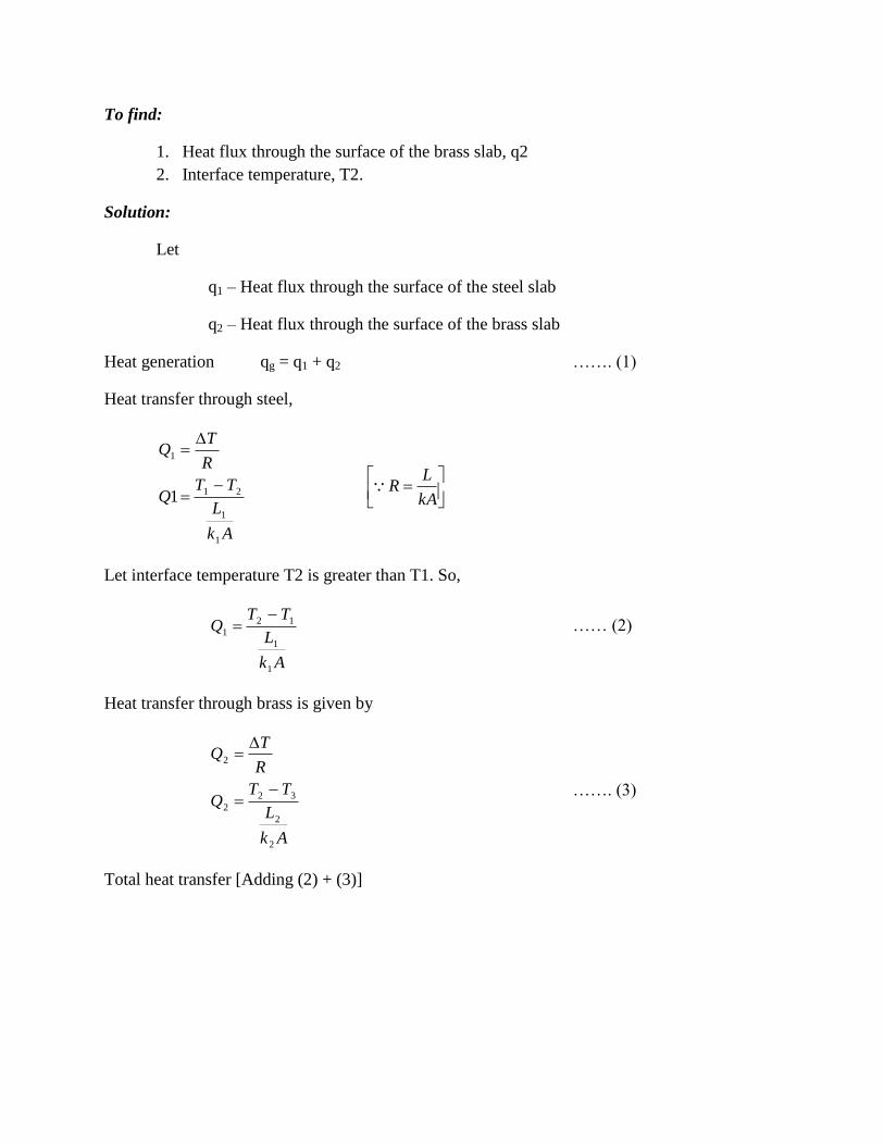
To find:
1. Heat flux through the surface of the brass slab, q2
2. Interface temperature, T2.
Solution:
Let
q1 – Heat flux through the surface of the steel slab
q2 – Heat flux through the surface of the brass slab
Heat generation qg = q1 + q2 ……. (1)
Heat transfer through steel,
Ak
L
TTQ
R
TQ
1
1
21
1
1
kA
LR
Let interface temperature T2 is greater than T1. So,
Ak
L
TTQ
1
1
12
1
…… (2)
Heat transfer through brass is given by
Ak
L
TTQ
R
TQ
2
2
32
2
2
……. (3)
Total heat transfer [Adding (2) + (3)]

2
2
32
1
1
12
2
2
32
1
1
12
211
/
1
k
L
TT
k
L
TTAQ
Ak
L
TT
Ak
L
TTQ
QQQ
Heat flux (or) Heat generation
KT
T
T
T
TT
TT
TTq
k
L
TT
k
L
TTAQqg
g
6.468
5.1454636,16,5000,65,1
636,16,554.1454
3380003.636,78,1100054.454
101
338
101102.2
393
102.2
101
338
102.2
393000,65,1
80
08.0
338
45
10.0
393
/
2
2
2
2
33
2
33
2
3
2
3
2
22
2
2
32
1
1
12
Heat transfer through steel, is given by
Interface temperature, T2 = 468.6K

45
10.0
3936.468
/
1
1
1
12
1
1
1
12
1
q
k
L
TTAQ
Ak
L
TTQ
From equation (1)
Heat generation, qg = q1+ q2
==> 1, 65,000 =34.020 +q2
==> q2 = 1, 65,000 – 34.020
q2 = 1, 30,980 W/m2
Heat flux through the
Surface of the brass slab, q2 = 1, 30,980 W/m2
Result:
(i) q2 = 1, 30,980 W/m2
(ii) T2 = 468.6 K.
9. A copper wire of 40 mm diameter carries 250 A and has a resistance of 0.25 10-4
cm/length surface temperature of copper wire is 250˚C and the ambient air temperature is
10˚C. If the thermal conductivity of the copper wire is 175 W/mK, calculate
1. Heat transfer co-efficient between wire surface and ambient air.
2. Maximum temperature in the wire.
Given:
Diameter, d = 40 mm = 0.040 m
Radius, r = 20 mm = 0.020 m
Current, I = 250A.
q1=34020 W/m2

Resistance, R = 0.2510-4 cm/length
Surface temperature, Tw = 205˚C + 273 = 523 K
Ambient air temperature, T
= 10˚C + 273 = 283 K
Thermal conductivity, k = 175 W/mK
To find:
1. Heat transfer co-efficient, h
2. Maximum temperature, Tmax.
Solution:
Heat transfer, Q = I2R
= (250)2 (0.2510-4
)
= 1.562 W/cm
= 1.56102 W/m
= 156W/m
We know that,
Heat generated, LrV
2
156
1020.0
1562
q
We know that,
Maximum temperature
k
qtTT w
4
2
max [From Equn no. (1.62)]
.07.523
1754
020.0124140523
2
K
q = 124140W/m3
Tmax = 523.07 K.

We know that,
Surface temperature, h
rqTTw
2 [From Equn no.(1.65)]
h
2
124140020.0283523
==>
Result:
1. Heat transfer co-efficient, h = 5.17W/m2K
2. Maximum temperature, Tmax = 523.07 K.
10. An aluminum alloy fin of 7 mm thick and 50 mm long protrudes from a wall, which is
maintained at 120˚C. The heat transfer coefficient and conductivity of the fin material are
140W/m2K and 55 W/mK respectively. Determine
1. Temperature at the end of the fin.
2. Temperature at the middle of the fin.
3. Total heat dissipated by the fin.
Given:
Thickness, t = 7 mm = 0.007 m
Length, L = 50 mm = 0.050 m
Base temperature, Tb = 120˚C + 273 = 393 K
Ambient temperature, T
= 22˚ + 273 = 295 K
Heat transfer co-efficient, h = 140 W/m2K
Thermal conductivity, k = 55 W/mK.
To find:
1. Temperature at the end of the fin.
2. Temperature at the middle of the fin
3. Total heat dissipated by the fin.
h = 5017 W/m2K.

Solution:
Since the length of the fin is 50 mm, it is treated as short fin. Assume end is insulated.
We known that,
Temperature distribution [Short fin, end insulated]
mL
xLm
TT
TT
b cosh
cosh
……. (1)
[From HMT data book page no. 49]
i) Temperature at the end of the fin, Put Lx
mLTT
TT
mL
LLm
TT
TT
b
b
cosh
1
cosh
cosh)1(
…… (2)
Where
kA
hPm
P = Perimeter = 2L (Approx)
= 2 0.050
A – Area = Length thickness = 0.0500.007
4105.355
1.0140
kA
hPm
P = 0.1 m
A = 3.5 10-4
m2
m = 26.96 m-1

8.47295
05.2
1
295393
295
05.2
1
050.09.26cosh
1)2(
T
T
TT
TT
TT
TT
b
b
==>
ii) Temperature at the middle of the fin.
Put Lx /2 in Equation (1)
6025.0295393
295
049.2
234.1
295393
295
050.09.26cosh
2
050.0050.09.26cosh
cosh
2/cosh)1(
T
T
TT
TT
mL
LLm
TT
TT
b
b
Temperature at the middle of the fin
iii) Total heat dissipated
[From HMT data book page no. 49]
050.09.26tanh295393105.3551.0140
tanh
21
4
21
mLTThPkAQ b
T = 342.8 K
Temperature at the end of the fin, T Lx = 342.8 K
T = 354.04 K
KTLx 04.354
2/
Q = 44.4 W

Result:
1. Temperature at the end of the fin, KT Lx 8.342
2. Temperature at the middle of the fin, KT Lx 04.3542/
3. Total heat dissipated, Q = 44.4 W
11. Ten thin brass fins (k=100 W/mK), 0.75 mm thick are placed axially on a 1 m long and 60
mm diameter engine cylinder which is surrounded by 27˚C. The fins are extended 1.5 m from
the cylinder surface and the heat transfer co-efficient between cylinder and atmospheric air is
15 W/m2K. Calculate the rate of heat transfer and the temperature at the end of fins when the
cylinder surface is at 160˚C.
Given:
Number of fins = 10
Thermal conductivity, k = 100 W/mK
Thickness of the fin, t = 0.75 10-3
m
Length of engine cylinder, Lcy = 1 m
Diameter of the cylinder, d = 60 mm = 0.060 m
Atmosphere temperature, T
= 27˚C + 273 = 300 K
Length of the fin, Lf = 1.5 cm = 1.510-2
m
Heat transfer co-efficient, h = 15 W/m2K
Cylinder surface temperature
Or
base temperature, Tb = 160˚C + 273 = 433 K
To find:
1. Rate of heat transfer Q
2. Temperature at the end of the fin
Solution:
Length of the fin is 1.5 cm. So, this is short fin. Assuming that the fin end is insulated

We know that,
Heat transferred, fb mLTThPkAQ tanh2
1
……… (1)
[From HMT data book page no.49]
Where
P – Perimeter = 2Length of the cylinder
= 21
A – Area = length of the cylinder thickness
= 10.7510-3
m
31075.0100
215
kA
hPm
P = 2 m
A = 10.7510-3
m
20 = m-1

WQ
Q
mLTThPkAQ fb
1.58
29.01335.1
105.120tanh3004331075.0100215
tanh)1(
1
1
221
3
21
1
Heat transferred per fin = 58.1 W
Heat transferred for 10 fins = 58.1 10 = 581 W
…….. (2)
Heat transfer from un finned surface due to convection is
TTLftdLh
ThAQ
bcy 10
2
[Area of unfinned surface = Area of cylinder – Area of fin]
300433105.11075.0101060.01523
……. (3)
So, total heat transfer, Q = Q1 + Q2
Q = 581 + 375.8
We known that,
Temperature distribution [short fin, end insulated]
f
f
b mL
xLm
TT
TT
cosh
cosh
[From HMT data book page no.49]
We need temperature at the end of fin, so, put Lx
Q1 = 581 W
Q2 = 375.8 W
Total heat transfer, Q = 956.8 W
95.0
300433300
95.0
95.0
95.0
1
105.120cosh
1
cosh
cosh
2
TTTT
TTTT
TT
TT
mL
LLm
TT
TT
b
b
b
fb
Result:
1. Heat transfer, Q = 956.8 W
2. Temperature at the end of the fin, T = 440K.
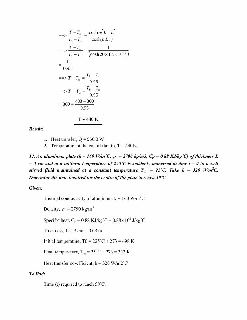
12. An aluminum plate (k = 160 W/m˚C, = 2790 kg/m3, Cp = 0.88 KJ/kg˚C) of thickness L
= 3 cm and at a uniform temperature of 225˚C is suddenly immersed at time t = 0 in a well
stirred fluid maintained at a constant temperature T
= 25˚C. Take h = 320 W/m2C.
Determine the time required for the centre of the plate to reach 50˚C.
Given:
Thermal conductivity of aluminum, k = 160 W/m˚C
Density, = 2790 kg/m3
Specific heat, Cp = 0.88 KJ/kg˚C = 0.88103 J/kg˚C
Thickness, L = 3 cm = 0.03 m
Initial temperature, T0 = 225˚C + 273 = 498 K
Final temperature, T
= 25˚C + 273 = 323 K
Heat transfer co-efficient, h = 320 W/m2˚C
To find:
Time (t) required to reach 50˚C.
T = 440 K
Solution:
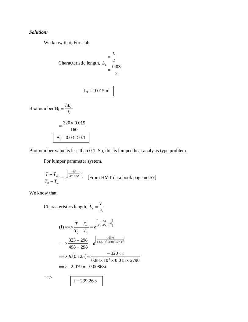
We know that, For slab,
Characteristic length, cL
2
03.0
2
L
Biot number Bi k
hLe
160
015.0320
Biot number value is less than 0.1. So, this is lumped heat analysis type problem.
For lumper parameter system.
tVCp
hA
eTT
TT
0
[From HMT data book page no.57]
We know that,
Characteristics length, A
VLc
t
tIn
e
eTT
TT
t
tVCp
hA
00868.0079.2
2790015.01088.0
320125.0
298498
298323
)1(
3
2790015.01088.0
320
0
3
==>
Lc = 0.015 m
Bi = 0.03 < 0.1
t = 239.26 s
Result:
Time required to reach 50˚C is 239.26 s.
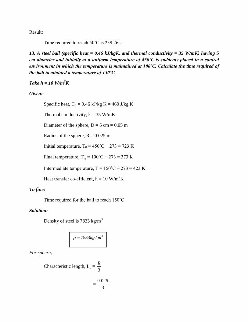
13. A steel ball (specific heat = 0.46 kJ/kgK. and thermal conductivity = 35 W/mK) having 5
cm diameter and initially at a uniform temperature of 450˚C is suddenly placed in a control
environment in which the temperature is maintained at 100˚C. Calculate the time required of
the ball to attained a temperature of 150˚C.
Take h = 10 W/m2K
Given:
Specific heat, Cp = 0.46 kJ/kg K = 460 J/kg K
Thermal conductivity, k = 35 W/mK
Diameter of the sphere, D = 5 cm = 0.05 m
Radius of the sphere, R = 0.025 m
Initial temperature, T0 = 450˚C + 273 = 723 K
Final temperature, T
= 100˚C + 273 = 373 K
Intermediate temperature, T = 150˚C + 273 = 423 K
Heat transfer co-efficient, h = 10 W/m2K
To fine:
Time required for the ball to reach 150˚C
Solution:
Density of steel is 7833 kg/m3
For sphere,
Characteristic length, Lc = 3
R
3
025.0
3/7833 mkg

We know that,
Biot number, Bi = k
hLe
1.01038.2
35
103.810
3
3
iB
Biot number value is less than 0.1. So, this is lumped heat analysis type problem.
For lumped parameter system,
tVCp
hA
eTT
TT
0 …… (1)
[From HMT data book page no.57]
We know that,
Characteristics length, A
VLc
tIn
e
eTT
TT
t
tVCp
h
78331033.8460
10
373723
373423
373723
373423
)1(
3
78331033.8460
10
0
3
==>
Result:
Time required for the ball to reach 150˚C is 5840.54s.
14. A large wall 2 cm thick has uniform temperature 30˚C initially and the wall temperature is
suddenly raised and maintained at 400˚C. Find
1. The temperature at a depth of 0.8 cm from the surface of the wall after 10 s.
Lc = 8.33 10-3
m
t = 5840.54 s

2. Instantaneous heat flow rate through that surface per m2 per hour.
Take = 0.008 m2/hr, k = W/m˚C.
Given:
Thickness, L = 2 cm = 0.02 m
Initial temperature, Ti = 30˚C + 273 = 303 K
Surface temperature, T0 = 400˚C + 273 = 673 K
Thermal diffusivity, = 0.008 m2/h
= 2.2210-6
m2/s
Thermal conductivity, k = 6 W/m˚C.
Case (i)
Depth, x = 0.8 cm = 0.8 10-2 m
= 0.008 m
Time, t = 10 s
Case (ii)
Time, t = 1 h = 3600 s
To find:
1. Temperature (Tx) at a depth of 0.8 cm from the surface of the wall after 10s.
2. Instantaneous heat flow rate (q x ) through that surface per hour.
Solution:
In this problem heat transfer co-efficient h is not given. So take it as . i.e., h .
We know that,
Biot number, Bi = k
hLe
h
h
==>
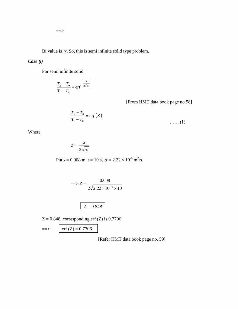
Bi value is . So, this is semi infinite solid type problem.
Case (i)
For semi infinite solid,
t
x
i
x erfTT
TT 2
0
0
[From HMT data book page no.58]
ZerfTT
TT
i
x
0
0
……. (1)
Where,
t
xZ
2
Put x = 0.008 m, t = 10 s, = 2.22 10-6
m2/s.
101022.22
008.0
6
Z
Z = 0.848, corresponding erf (Z) is 0.7706
==>
[Refer HMT data book page no. 59]
Z = 0.848
erf (Z) = 0.7706
7706.0370
673
7706.0673303
673
7706.0)1(0
0
x
x
i
x
T
T
TT
TT
Case (ii)
Instantaneous heat flow
t
x
i
x et
TTkq
40
2
[From HMT data book page no. 58]
t = 36000 s (Given)
36001022.24
008.0
36001022.2
30367366
2
6eq x
Result:
Intermediate temperature, T x = 387.85 K
Heat flux, q x = 13982.37 W/m2
15. A semi infinite slab of aluminum is exposed to a constant heat flux at the surface of 0.25
MW/m2. Initial temperature of the slab is 25˚C. Calculate the surface temperature after 10
minutes and also find the temperature at a distance of 30 cm from the surface after 10
minutes.
Given:
Heat flux, q0 = 0.25 MW/m2
q0 = 0.25106 W/m
2
KTx 85.387
2/37.13982 mWq x

Initial temperature, Ti = 25˚C + 273 = 298 K
Distance, x = 30 cm = 0.30 m
Time, t = 10 minutes = 600 s
To find:
1. Surface temperature (T0) after 10 minutes.
2. Temperature (T x ) at a distance of 30 cm from the surface
Solution:
Heat flux,
t
TTkq i
0
0 ……. (1)
[From HMT data book page no. 58]
[HMT data book page no. 1]
Properties of aluminum
Thermal diffusivity, = 84.1810-6
m2/s
Thermal conductivity, k = 204.2 W/mK.
6001018.84
2982.2041025.0)1(
6
06
T
(ii) For semi infinite solid,
t
xerf
TT
TT
i
x
20
0
[From HMT data book page no. 58]
ZerfTT
TT
i
x
0
0
……. (2)
Where
T0 = 785.68 K

6001018.842
30.0
2
6
0
Z
t
xZ
Z = 0.667, corresponding erf (Z) is 0.65663
[From HMT data book page no. 59]
65663.068.785298
68.785
65663.0)2(0
0
x
i
x
T
TT
TT
==>
Temperature at a distance at 30 cm is 465.45 K
Result:
1. Surface temperature, T0 = 785.65 K
2. Temperature at a distance of 30 cm, T x = 465.45 K
Z = 0.667
erf (Z) = 0.65663
T x = 465. 45 K