condition monitoring and fault diagnosis of...
TRANSCRIPT

Condition Monitoring and Fault Diagnosis ofGenerators in Power Networks
Bowen Yang, Fangyu Li, Jin Ye, Wenzhan SongCenter for Cyber-Physical Systems
University of GeorgiaAthens, Georgia USA
Email: bowen.yang, fangyu.li, jin.ye, wsong @ uga.edu
Abstract—In this paper, a novel hierarchical signal processingmethodology is proposed for generator condition monitoringand fault diagnosis based on raw electrical waveform data inpower networks, which can often be measured by strategically-located waveform sensors. The impact of generator short circuitfaults on strategically located electrical waveform sensors inpower networks are firstly investigated and validated in MatlabSimulink. Based on the large set of electrical waveform dataproduced by Matlab Simulink, a hierarchical algorithm is thendesigned to locate fault site location and monitor the condition ofgenerators in power networks. Finally, the proposed methodologyis validated in 14-bus IEEE standard power network underdifferent scenarios (e.g, one generator fault, two-generator-fault,various aging levels, etc). Our results show that we can locatefault site location and monitor the aging condition of generatorsin power networks. Compared to traditional condition monitoringand fault diagnosis based on generator sensors, our proposedmethodology can monitor a large number of generators basedon a limited number of waveform sensors, which promises toreduce the cost of the maintenance and improve the reliabilityof the power grid.
Index Terms—Synchronous Generators, Power Networks, Con-dition Monitoring, Fault Diagnosis, Short Circuit Faults, Ad-vanced Signal Processing
I. INTRODUCTION
Generators are playing a vital role in electrical powergeneration. Synchronous generators have been major meansto generate electric power over a century. In recent years,due to the increased penetration of wind energy, the numberof asynchronous generators have risen rapidly. Conditionmonitoring and fault diagnosis of large generators in powernetworks are gaining more interest since generator faults canlead to a catastrophic failure and then outages if not detectedin the early stage. Due to aging or severe operating conditions,generators are subject to many different types of faults includingstator faults, rotor electrical faults and rotor mechanical faults.Among these faults, stator winding inter-turn short fault due tothe aging of winding insulation is the most dominant, whichaccount for over 25% of faults in generators. When the inter-turn short fault is progressing, the condition of stator windingsdeteriorates and it can lead to catastrophic failures (e.g., phase-to-ground short circuit).
Our research is partially support by NSF-1725636, NSF-CNS-1066391,NSF-CNS-0914371, NSF-CPS-1135814, NSF-CDI-1125165, and SouthernCompany.
In the past decade, many condition monitoring and faultdiagnosis methods for generators, including signal-based,model-based and data-driven, have been investigated [1]–[4]. Motor current signature analysis (MCSA) based on thefrequency analysis of the stator currents has been one of themost popular noninvasive condition monitoring and diagnosismethods. MCSA technique is mostly used to identify both rotorfaults (e.g., bearing damage, broken rotor bar, eccentricity,end ring breakage, etc) and stator faults (e.g., short circuitfault, etc) based on slots related harmonics [5], [6], thirdharmonic [7], the sideband frequency components [8], andthe other [9]. The frequency analysis of stator voltages isalso used to detect stator winding inter-turn short faults insome operating conditions [10], [11]. Symmetrical componentanalysis, which decomposes stator current or voltage to positive-sequence, negative-sequence, and zero-sequence components, isone of the alternative condition monitoring and fault diagnosismethods due to symmetry of stator windings under the healthycondition [12], [13]. Therefore, condition monitoring and faultdiagnosis techniques based on generator sensors (e.g, voltage,current, vibration, etc) have been widely used and promise toreduce unscheduled downtime, and maintenance costs.
When generators are connected in power networks, cur-rent/voltage signature signals of faulty electric machines willpropagate through the power networks [14]. The raw electricalwaveform and signals (e.g., voltage, current, harmonics, powerfactor, etc) in power networks will likely change, which containrich information about condition of generators. In [15], [16],some waveform information (magnitude or phase) were usedto identify parameters of generators, however, they were notyet used to monitor the aging condition of the generators forscheduled maintenance. In addition, for condition monitoringand fault diagnosis of generators, raw electrical waveforms athigher sampling rate besides magnitude and phase mentionedabove might be needed as fault/deteriorating condition ofgenerators will produce unusual harmonics.
To the best of our knowledge, there are no existing works incondition monitoring/fault diagnosis of generators by analyzingraw electrical waveforms in power networks, which can bemeasured by strategically located electrical waveform sensors.
In this paper, we propose to develop advanced signalprocessing methodology for generator condition monitoring
1

and fault diagnosis based on strategically located waveformsenors in power networks with the goal to reduce the costof the maintenance and improve the reliability of the powergrid. Firstly, we build the the equivalent model of synchronousgenerators under short circuit faults. Secondly, we analyzethe impact of generator short circuit faults on strategicallylocated electric waveform sensors in power networks. Thirdly,we build 14-bus IEEE standard power network model in MatlabSimulink and different scenarios (e.g, one generator fault, two-generator-fault, various aging levels, etc) to produce a large setof electric waveform data for condition monitoring and faultdiagnosis. Finally, based on the electrical waveform data inpower networks, we will develop data-driven signal analysisapproach to locate fault sources and estimate the aging levelsof generators in power networks.
II. ANALYSIS OF THREE-PHASE SHORT FAULT
When the short circuit faults happens in synchronous gener-ators, the current could be multiple times of the rating currentof the generator, which could bring catastrophic damages to thepower grid. In this section, the short-circuit fault of synchronousgenerators is analyzed.
Assume the generator operates at speed ω, then the fluxlinkage will be: ψ = Ψ0 cos(α0 + ωt). And the fault happensat t = 0, the induced current will produce ∆ψ to maintain theinitial flux linkage ψ0, so ∆ψ = ψ0 −Ψ0 cos(α0 + ωt).
According to the flux linkage analysis above, stator currentincludes two parts: one is the DC component iap generatingthe initial flux linkage ψ0; the other one is the AC componenti′at the synchronous frequency (f = ω
2π ), which generates therotating field to offset the rotor exciting field.
For the salient pole machine, to compensate the differencein magnetic resistance of d- and q- axis, there will be oneadditional AC component, the frequency of which is twice thesynchronous frequency of the stator current. Therefore, threetypes of magnetic field will be induced by the stator. And thesethree magnetic fields will then change the flux linkage in therotor winding. Therefore, to maintain its flux linkage in therotor, the rotor will have similar armature reaction and inducethree types of currents. Since the rotor is rotating at angularspeed ω, frequencies of these currents will be: ω, 0 and −ω. Itshould be noted that −ω means the field rotates in the oppositedirection.
The current components which will attenuate are refereedto as free current ∆i, while others are refereed to as forcedcurrent i∞. The classification is shown in Table I.
TABLE I: Short Current Classification.forced current i∞ free current ∆i
stator i∞ ∆i′ = i′ − i∞ iap, i2ωrotor if [0] ∆ifa ∆ifω
According to the synchronous generator model and constant-linkage theorem, the short circuit current of generators withdamping windings could be deducted by:
ia = −Eq[0]xd
cos(ωt+ α0)
− (E′′q0
x′′d−Eq[0]xd
) exp(− t
T ′′d
) cos(ωt+ α0)
− (E′q[0]
x′d−Eq[0]xd
) exp(− t
T ′d
) cos(ωt+ α0)
− E′′d0
x′′qexp(− t
T ′′q
) sin(ωt+ α0)
+U[0]
2(
1
x′′d+
1
x′′q) exp(− t
Ta) cos(α0 − δ0)
+U[0]
2(
1
x′′d− 1
x′′q) exp(− t
Ta) cos(2ωt+ α0 + δ0)
(1)
Similarly, the rotor current can be obtained by:if = if [0]
+ [xadxσDU[0] cos δ0
(xfxD − x2ad)x′′d
−(xd − x′d)U[0] cos δ0
xadx′d] exp(− t
T ′′d
)
+(xd − x′d)U[0] cos δ0
xadx′dexp(− t
T ′d
)
−xadxσDU[0]
(xfxD − x2ad)x′′d
exp(− t
Ta) cos(ωt+ δ0)
(2)
III. IMPACT OF GENERATOR FAULTS ON ELECTRICWAVEFORMS IN POWER NETWORKS
To simplify the analysis of short circuit fault, the method ofsymmetrical components is used in this section to analyzethe impact of generator short circuit faults on the powernetworks. A according to symmetrical components, any types ofasymmetrical three-phase phasor could be decomposed to threesymmetrical three-phase phasors. Take current for example, (3)shows the relationship between currents in two coordinates.Phase b and phase c currents could be derived by similarequations. Ia(1)
Ia(2)Ia(0)
=1
3
1 a a2
1 a2 a1 1 1
IaIbIc
(3)
where a = ej120, a2 = ej240
; Ia(1), Ia(2), Ia(0) are the pos-
itive, negative and zero sequence of phase currents, respectively.Then sequence impedance is introduced to describe relationshipbetween voltage and current in symmetrical components coor-dinate. Thevenin’s equivalent circuit for sequence impedanceis shown in figure1. It should be noted that the asymmetricalcomponents in sequence impedance are eliminated by adoptingthe asymmetrical voltage source and the transmission linereactances are modeled in Zff . For generality, the equivalentcircuit equation could be derived by:
Eeq − Zff(1)Ifa(1) = Ufa(1)
0 − Zff(2)Ifa(2) = Ufa(2)
0 − Zff(0)Ifa(0) = Ufa(0)
(4)
Three more equations are needed to solve the equationswith 6 unknown variables, which are derived from the faultconditions. And common faults in power system include twophase short fault, two phase grounded short fault, etc. Therelated fault conditions are listed in Table II.
2

Fig. 1: Equivalent circuit of each phase sequence
TABLE II: Common Fault Condition in Power System.
fault category fault conditionsingle phase short Ufa = 0 Ifb = 0 Ifc = 0
two phases short Ifa = 0 Ifb + Ifc = 0 Ufb = Ufctwo phases grounded Ifa = 0 Ufb = 0 Ufc = 0
Therefore, common asymmetric short faults could be solvedby (4) and the related fault equations listed in Table II. Otherbus voltage and branch current in the normal condition couldalso be solved similarly. However, this method requires thedetailed grid topology information and the accurate faultlocation, which may not be easy to acquire. In addition,to simulate multiple fault cases, this method is based on astrong assumption that the whole system is linear, which ishardly applicable in the real power system. Therefore, in thefollowing section, an advanced signal processing technique willbe proposed to locate the fault source for condition monitoringand fault diagnosis.
IV. FAULT IDENTIFICATION AND LOCATIONIn this section, we use the measured waveform data to
identify and locate generator faults. Algorithm 1 shows howthe whole process works. The waveforms of voltage andcurrent signals V = [V1, V2, . . . , VN ]T , I = [I1, I2, . . . , IN ]T
are measured from a network with size N the nodal, wheredepending on the number of phases at node i, Vi and Ii canbe row vectors of size 1, 2 or 3. In order to characterize thewaveform properties, we adopt instantaneous properties from:
sc(t) = s(t) + jHs(t) = A(t)ejψ(t), (5)where s(t) is the real signal, sc(t) is the complex expression,A(t) is the instantaneous amplitude (IA) (envelope), ψ(t) isthe instantaneous phase(IP), H is the Hilbert transform as:
Hs(t) =1
π
∞∫−∞
s(τ)
t− τdτ. (6)
Thus, for a three phase current In = [InA, InB , InC ]T ,where InA = AInA
ejψInA(t). (Vn can be expressed in the
same way.)
Algorithm 1 Waveform based Generator Fault Identification andLocation Algorithm
1: Input: Waveforms of voltage and current.2: Output: Fault properties and location.3: Event detection based on time series anomaly detection tech-
niques;4: Unbalance detection to distinguish single phase, double phase or
three phase fault;5: Event source region determination based on measurement changes;
A. Event Detection
Before identifying the location of an event, we must firstbecome aware of the occurrence of such event. Thanks tothe data-driven time series anomaly detection techniques, thepresence of the event can be detected continuously. The changesof the nodal voltages and branch currents can be expressed as:
∆Vn = Vn(t) − Vn(t− w), ∆Inp = Inp(t) − Inp(t− w), (7)
where, w is the analysis window size, n and p denote twoarbitrary neighboring nodes. If abnormal changes happen to∆Vn and ∆Inp, which indicate the difference between the pre-and post-event, an event can be detected. Once the occurrenceof an event is detected, the next step is to identify the typesof the event and location of the root cause of the event.
B. Phase Unbalance Characterization
Simulating the generator aging faults, we could meet single,two or even three phase issues, which means the short circuit asshown in Figure 2. The waveforms of Phases A,B, and C allowa relatively straightforward phase unbalance characterizationbased on direct comparisons of phase signal attributes.
Based on the IA, we define the current unbalance character-ization functions Iα, Iβ , and Iγ as:
Inα =1
3
i,j∈A,B,C∑i 6=j
(AIni−AInj
)2. (8)
Inβ =Imax − Imin
Imax× 100%, (9)
Inγ =
i,j∈A,B,C∑i 6=j
Γ(AIni, AInj
), (10)
where, In,max = maxAInA, AInB
, AInC and In,min =
minAInA, AInB
, AInC, Γ denotes a thresholding function
to measure the difference. Similarly, we can also get Vα, Vβand Vγ . If Iβ and Vβ is not zero, there exists unbalance amongthe three phases. Then we use Iγ and Vγ to determine the howmany phases are affected. In addition, Iα and Vα are used tomeasure the absolute changes.
C. Identifying the Event Source Region
Assuming there are two waveform sets from two nodes, ifit happens, an event may occur in three regions: upstream ofnode n, downstream of node p, and between nodes n and p.The measurements can be expressed as Mn and Mp. Since wenot only have the voltage and current, but also the unbalancemeasurements, Mn can be defined as
Mn = [InA, InB , InC , VnA, VnB , VnC , Iα, Iβ , Iγ , Vα, Vβ , Vγ ]T .(11)
Then, event location can determined by the comparisonbetween ∆Mn and ∆Mp. For example, if the change patternsof ∆Mn and ∆Mp are the same, the event happens either onthe upstream or downstream, but if those are different, theevent happens between nodes n and p.
3

Fig. 2: IEEE 14 Bus Power Network
V. SIMULATION AND EVALUATION
For evaluation, a 14-bus IEEE standard power network(Figure 2) is built to investigate the impact of the generatorfaults on electrical waveforms in power networks, which isalso used to generate a large set of waveform data needed inthe proposed algorithms. In the simulation model, generatorsare simplified as non-ideal three-phase voltage sources, andthe loads are modeled as constant power loads. Meanwhile,the transmission line reactances are modeled by Simulinkblock ’Three-Phase PI Section Line’. And the parameters arecalculated from the IEEE standard 14-bus testbed datasheet.Specifically, the level of the short fault or the aging degree ismodeled as a short circuit resistance, Rf , as shown in figure 2(only depict the single phase grounded short fault for example).Rf is modeled as Rf = 10(5−10∗κaging), where κaging denotesthe generator condition aging level.
When two generators highlighted in Figure 2 have agingstator windings both at 50% level, their voltage and currentsignature will change and will likely impact raw electricalwaveforms and signals (e.g.,voltage, current, harmonics, powerfactor) in power networks (e.g, voltage, current, etc) due towaveform and signal propagation. As a result, the voltage andcurrent waveforms in bus 6 generator and bus from 6 to 11 aresignificantly impacted as shown in Figure 3. The traditionalapproaches based on machine sensors, for instance, sensors inbus 6 generator, cannot distinguish whether bus 6 generatoris faulty or not. To address this challenges, we developed anadvanced signal processing approach based on strategicallylocated waveform senors. The proposed data-driven approachutilizes waveforms as well as derived signal attributes tocharacterize the dynamic relationships among limited sensors todeduce the actual fault locations, which may not be monitored.
Based on the model shown in Figure 2, two generator faultsare simulated, which are located at G1 and G8 with 50% aging.There are 14 nodes in the grid, and typically all generators(5) and transformers (3) should have built-in sensors, so there
Fig. 3: Single Phase Short Fault Simulation Results.
could be 8 sensors in the traditional power networks. In ourexperiment, we only use 4 sensors from Nodes 1, 6, 7, and 14,to simulate the limited sensor situation.
Figure 4 shows the voltages and IAs from the 4 sensors.Based on the Vγ function, we can know only Phase A hasthe short circuit event. Although observations from Nodes 7and 14 indicate differences between Phases B and C, the smalldeviations should be caused be the unbalanced Phase A currentrather than more than one phase short circuit.
Fig. 4: Voltage waveforms and corresponding instantaneousamplitudes at Nodes 1, 6, 7 and 14.
Next, let us locate the root source region. Figure 5 showsthe current waveforms measured at Node 6. From Table III,Iβ is the largest for IG6, which means the major unbalancesource for Node 6 is from the Node 5 direction. (If Node 6is the fault source, the current unbalance metrics between 6and 11, 12, 13 would be similar.) So the fault source could beNodes 1, 2 or 3. However, if Node 2 or 3 is the fault source,the current measured at Node 7 about Bus 4 would displaymore obvious unbalances. While, Node 1 could be the source,as both its voltage and current are not balanced.
4
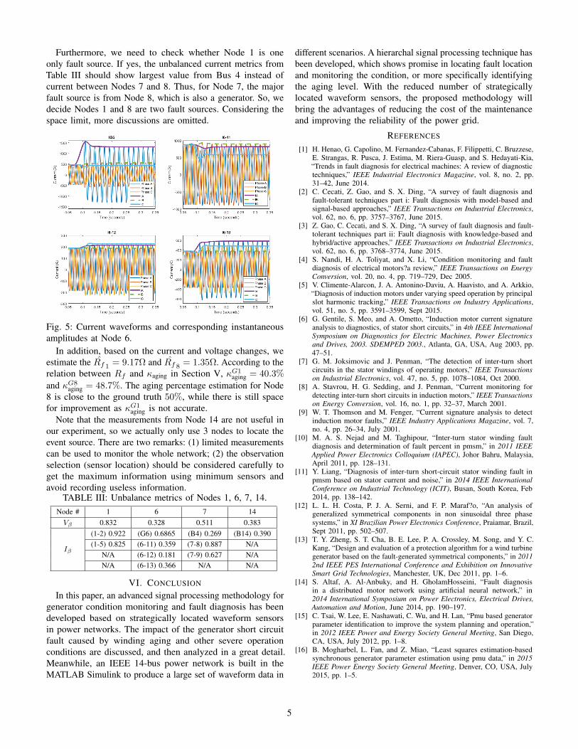
Furthermore, we need to check whether Node 1 is oneonly fault source. If yes, the unbalanced current metrics fromTable III should show largest value from Bus 4 instead ofcurrent between Nodes 7 and 8. Thus, for Node 7, the majorfault source is from Node 8, which is also a generator. So, wedecide Nodes 1 and 8 are two fault sources. Considering thespace limit, more discussions are omitted.
Fig. 5: Current waveforms and corresponding instantaneousamplitudes at Node 6.
In addition, based on the current and voltage changes, weestimate the Rf 1 = 9.17Ω and Rf 8 = 1.35Ω. According to therelation between Rf and κaging in Section V, κG1
aging = 40.3%
and κG8aging = 48.7%. The aging percentage estimation for Node
8 is close to the ground truth 50%, while there is still spacefor improvement as κG1
aging is not accurate.Note that the measurements from Node 14 are not useful in
our experiment, so we actually only use 3 nodes to locate theevent source. There are two remarks: (1) limited measurementscan be used to monitor the whole network; (2) the observationselection (sensor location) should be considered carefully toget the maximum information using minimum sensors andavoid recording useless information.
TABLE III: Unbalance metrics of Nodes 1, 6, 7, 14.Node # 1 6 7 14Vβ 0.832 0.328 0.511 0.383
Iβ
(1-2) 0.922 (G6) 0.6865 (B4) 0.269 (B14) 0.390(1-5) 0.825 (6-11) 0.359 (7-8) 0.887 N/A
N/A (6-12) 0.181 (7-9) 0.627 N/AN/A (6-13) 0.366 N/A N/A
VI. CONCLUSION
In this paper, an advanced signal processing methodology forgenerator condition monitoring and fault diagnosis has beendeveloped based on strategically located waveform sensorsin power networks. The impact of the generator short circuitfault caused by winding aging and other severe operationconditions are discussed, and then analyzed in a great detail.Meanwhile, an IEEE 14-bus power network is built in theMATLAB Simulink to produce a large set of waveform data in
different scenarios. A hierarchal signal processing technique hasbeen developed, which shows promise in locating fault locationand monitoring the condition, or more specifically identifyingthe aging level. With the reduced number of strategicallylocated waveform sensors, the proposed methodology willbring the advantages of reducing the cost of the maintenanceand improving the reliability of the power grid.
REFERENCES
[1] H. Henao, G. Capolino, M. Fernandez-Cabanas, F. Filippetti, C. Bruzzese,E. Strangas, R. Pusca, J. Estima, M. Riera-Guasp, and S. Hedayati-Kia,“Trends in fault diagnosis for electrical machines: A review of diagnostictechniques,” IEEE Industrial Electronics Magazine, vol. 8, no. 2, pp.31–42, June 2014.
[2] C. Cecati, Z. Gao, and S. X. Ding, “A survey of fault diagnosis andfault-tolerant techniques part i: Fault diagnosis with model-based andsignal-based approaches,” IEEE Transactions on Industrial Electronics,vol. 62, no. 6, pp. 3757–3767, June 2015.
[3] Z. Gao, C. Cecati, and S. X. Ding, “A survey of fault diagnosis and fault-tolerant techniques part ii: Fault diagnosis with knowledge-based andhybrid/active approaches,” IEEE Transactions on Industrial Electronics,vol. 62, no. 6, pp. 3768–3774, June 2015.
[4] S. Nandi, H. A. Toliyat, and X. Li, “Condition monitoring and faultdiagnosis of electrical motors?a review,” IEEE Transactions on EnergyConversion, vol. 20, no. 4, pp. 719–729, Dec 2005.
[5] V. Climente-Alarcon, J. A. Antonino-Daviu, A. Haavisto, and A. Arkkio,“Diagnosis of induction motors under varying speed operation by principalslot harmonic tracking,” IEEE Transactions on Industry Applications,vol. 51, no. 5, pp. 3591–3599, Sept 2015.
[6] G. Gentile, S. Meo, and A. Ometto, “Induction motor current signatureanalysis to diagnostics, of stator short circuits,” in 4th IEEE InternationalSymposium on Diagnostics for Electric Machines, Power Electronicsand Drives, 2003. SDEMPED 2003., Atlanta, GA, USA, Aug 2003, pp.47–51.
[7] G. M. Joksimovic and J. Penman, “The detection of inter-turn shortcircuits in the stator windings of operating motors,” IEEE Transactionson Industrial Electronics, vol. 47, no. 5, pp. 1078–1084, Oct 2000.
[8] A. Stavrou, H. G. Sedding, and J. Penman, “Current monitoring fordetecting inter-turn short circuits in induction motors,” IEEE Transactionson Energy Conversion, vol. 16, no. 1, pp. 32–37, March 2001.
[9] W. T. Thomson and M. Fenger, “Current signature analysis to detectinduction motor faults,” IEEE Industry Applications Magazine, vol. 7,no. 4, pp. 26–34, July 2001.
[10] M. A. S. Nejad and M. Taghipour, “Inter-turn stator winding faultdiagnosis and determination of fault percent in pmsm,” in 2011 IEEEApplied Power Electronics Colloquium (IAPEC), Johor Bahru, Malaysia,April 2011, pp. 128–131.
[11] Y. Liang, “Diagnosis of inter-turn short-circuit stator winding fault inpmsm based on stator current and noise,” in 2014 IEEE InternationalConference on Industrial Technology (ICIT), Busan, South Korea, Feb2014, pp. 138–142.
[12] L. L. H. Costa, P. J. A. Serni, and F. P. Maraf?o, “An analysis ofgeneralized symmetrical components in non sinusoidal three phasesystems,” in XI Brazilian Power Electronics Conference, Praiamar, Brazil,Sept 2011, pp. 502–507.
[13] T. Y. Zheng, S. T. Cha, B. E. Lee, P. A. Crossley, M. Song, and Y. C.Kang, “Design and evaluation of a protection algorithm for a wind turbinegenerator based on the fault-generated symmetrical components,” in 20112nd IEEE PES International Conference and Exhibition on InnovativeSmart Grid Technologies, Manchester, UK, Dec 2011, pp. 1–6.
[14] S. Altaf, A. Al-Anbuky, and H. GholamHosseini, “Fault diagnosisin a distributed motor network using artificial neural network,” in2014 International Symposium on Power Electronics, Electrical Drives,Automation and Motion, June 2014, pp. 190–197.
[15] C. Tsai, W. Lee, E. Nashawati, C. Wu, and H. Lan, “Pmu based generatorparameter identification to improve the system planning and operation,”in 2012 IEEE Power and Energy Society General Meeting, San Diego,CA, USA, July 2012, pp. 1–8.
[16] B. Mogharbel, L. Fan, and Z. Miao, “Least squares estimation-basedsynchronous generator parameter estimation using pmu data,” in 2015IEEE Power Energy Society General Meeting, Denver, CO, USA, July2015, pp. 1–5.
5