condair cp3 - umidificatoare · if it is suspected that safe operation is no longer possible, then...
TRANSCRIPT
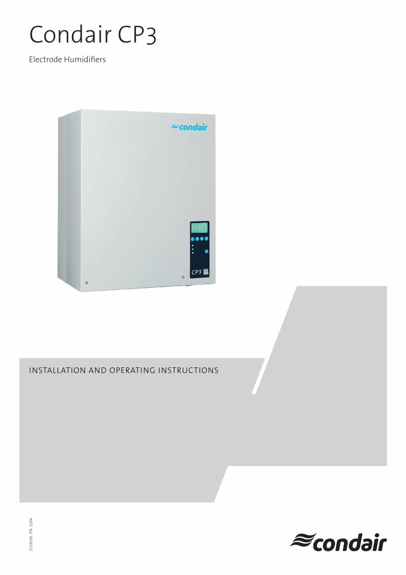
InstallatIon and operatIng InstructIons
electrode Humidifiers
2529
291
en
120
4
condair cp3

3
1 Introduction 41.1 To the very beginning 41.2 Notes on the installation and operating instructions 4
2 For your safety 6
3 Product Overview 83.1 Models overview 83.2 Identificationoftheunit 93.3 Steamhumidifierconstruction 103.4 Functional description 113.5 Humidificationsystemoverview 123.6 Overview unit interconnection 133.7 Options 143.7.1 Options overview 143.7.2 Option details 153.8 Accessories 163.8.1 Accessories overview 163.8.2 Accessory details 173.9 Standarddelivery 183.10 Storing/Transportation/Packaging 18
4 Notes for the planning engineer 194.1 Selectingtheunitversion 194.1.1 Calculatingthemaximumrequiredsteamcapacity 194.1.2 Selectingtheunit 204.2 Selectingtheoptionsanaccessories 204.3 Selecting the control system 21
5 Mounting and installation work 245.1 Importantnotesformountingandinstallationwork 245.2 Mounting the unit 255.2.1 Notes on locating the unit 255.2.2 Mountingthehumidifier 275.2.3 Inspecting the installed unit 285.3 Steaminstallation 295.3.1 Overviewsteaminstallation 295.3.2 Positioningandmountingofthe
steamdistributionpipes 305.3.3 Installing the steam distributors 335.3.4 Positioningandmountingofthefanunit 345.3.5 Installing the steam hose 355.3.6 Installing the condensate hose 365.3.7 Inspecting the steam installation 375.4 Water installation 385.4.1 Overview water installation 385.4.2 Notesonwaterinstallation 395.4.3 Inspectingthewaterinstallation 405.5 Electric installation 415.5.1 WiringdiagramCondairCP3Basic/Pro 415.5.2 Wiring diagram CP3ProLinkUpsystems 425.5.3 Fuses F4forheatingvoltagesupply 435.5.4 InsertingtheCP3Card 445.5.5 Notes on electric installation 445.5.6 Inspecting the electrical installation 44
6 Operation 456.1 Functionofthedisplayandoperatingelements 456.2 Commissioning 456.3 Notes on operation 46
6.3.1 Remoteoperatingandfaultindication 466.3.2 Notes on the operation at ambient
temperatures≤0°C 466.3.3 Inspections during operation 476.3.4 Carrying out manual draining 476.4 Takingtheunitoutofoperation 476.5 Overviewandoperatingofthemenu 486.6 Interrogationfunctions 496.6.1 Interrogationoftheoperatinginformationin
theindicationlevel 496.6.2 Interrogationofunitinformation 506.6.3 Interrogationofthemalfunctionlist 516.7 Unitsettings 526.7.1 Launching the unit settings menu 526.7.2 Selecting the dialogue language 526.7.3 Control settings 526.7.4 Cylinder settings 546.7.5 Setting the capacity limitation 556.7.6 ConfiguringtheOn/Offtimer 566.7.7 Activating/Deactivatingfaultcurrentrelayoperation 566.7.8 Settingtheoperationmodeformultipleunits 576.7.9 Water management settings 576.7.10 Performingremoterelaytests 586.7.11 Setting the date 586.7.12 Setting the time 586.7.13 Settingthedisplaycontrast 596.8 Modbussettings 59
7 Maintenance 607.1 Importantnotesonmaintenance 607.2 Maintenance list 617.3 Removingandinstallingpartsformaintenance 627.3.1 Removalandinstallationofthesteamcylinder 627.3.2 Disassemblyandassemblyofthe
cleanablesteamcylindertypeD... 647.3.3 Removalandinstallationofthewatercupand
the water hoses 657.3.4 Removalandinstallationofthedrainpump 667.3.5 Removalandinstallationoftheinletvalve 667.4 Notes on cleaning the unit components 677.5 Notesoncleaningagents 697.6 Resettingthemaintenanceindication 69
8 Troubleshooting 708.1 Malfunctionlist 708.1.1 Systemfaults 708.1.2 Unitfaults 718.2 Resettingtheerrorindication(redLEDlights) 738.3 Notesonfaultelimination 738.4 Replacingthebackupbatteryonthe
control boardoftheCondairCP3Pro 74
9 Taking out of service/Disposal 759.1 Takingoutofservice 759.2 Disposal/Recycling 75
10 Productspecifications 7610.1 Technicaldata 7610.2 Unitdimensions 77
Contents
4
Limitation
The subject of these installation and operating instructions arethesteamhumidifierCondairCP3 in its versions “Basic” and “Pro”. The various accessories (e.g. steam distributor, steam distributionsystem,etc.)areonlydescribedinsofarasthisisnecessaryforproperoperationoftheequipment.Furtherinformationonaccessoriescanbeobtainedintherespectiveinstructions.
These installation and operating instructions are restricted to the installation, commissioning, operation, servicing and trouble shootingofthesteamhumidifierCondairCP3andismeantforwelltrainedpersonnelbeingsufficientlyqualifiedfortheirrespectivework.
These installation and operating instructions aresupplementedbyvariousseparateitemsofdocumen-tation(sparepartslist,manualsforaccessories,etc.).Wherenecessary,appropriatecross-referencesare made to these publications in these installation and operating instructions.
1 Introduction
WethankyouforhavingpurchasedthesteamhumidifierCondairCP3.
ThesteamhumidifierCondairCP3incorporatesthelatesttechnicaladvancesandmeetsallrecog-nizedsafetystandards.Nevertheless,improperuseoftheCondairCP3mayresultindangertotheuserorthirdpartiesand/orimpairmentofmaterialassets.
Toensureasafe,proper,andeconomicaloperationofthesteamhumidifierCondairCP3,pleaseobserveandcomplywithallinformationandsafetyinstructionscontainedinthe present installation and operating instructionsaswellastheinstructionsgiveninthemanualsforthecomponentsusedinthehumidificationsystem.
Ifyouhavequestions,whicharenotorinsufficientlyansweredinthisdocumentation,pleasecontactyour Condair supplier. They will be glad to assist you.
1.2 Notes on the installation and operating instructions
1.1 To the very beginning
5
Symbols used in this manual
CAUTION!Thecatchword“CAUTION”designatesnotesinthisdocumentationthat,ifneglected,maycausedamage and/or malfunction of the unit or other material assets.
WARNING!Thecatchword“WARNING”usedinconjunctionwiththegeneralcautionsymboldesignatessafetyanddangernotesinthisdocumentationthat,ifneglected,maycausetoinjury to persons.
DANGER!Thecatchword“DANGER”usedinconjunctionwiththegeneralcautionsymboldesignatessafetyanddangernotes in thisdocumentation that, ifneglected,may lead tosevere injury or even death of persons.
SafekeepingPleasesafeguardthese installation and operating instructionsinasafeplace,whereitcanbeim-mediatelyaccessed.Iftheequipmentchangeshands,thedocumentationshouldbepassedontothe new operator.
Ifthedocumentationgetsmislaid,pleasecontactyourCondairsupplier.
Language versionsThe present installation and operating instructions areavailableinvariouslanguages.PleasecontactyourCondairsupplierforinformation.
Copyright protectionThe present installation and operating instructions areprotectedundertheCopyrightAct.Passing-onandreproductionofthemanual(orpartthereof)aswellasexploitationandcommunicationofthecontentsareprohibitedwithoutwrittenpermissionbythemanufacturer.Violationofcopyrighttermsissubjecttolegalprosecutionandarisesliabilityforindemnification.
Themanufacturerreservestherighttofullyexploitcommercialpatentrights.

6
2 For your safety
GeneralEverypersonworkingwiththeCondairCP3musthavereadandunderstoodthepresent installation and operating instructionsbeforecarryingoutanywork.Knowingandunderstandingthecontentsofthepresent installation and operating instructions is a basicrequirementforprotectingthepersonnelagainstanykindofdanger,topreventfaultyopera-tion,andtooperatetheunitsafelyandcorrectly.
Allideograms,signsandmarkingsappliedtotheunitmustbeobservedandkeptinreadablestate.
QualificationofpersonnelAll actions described in the present installation and operating instructions (installation, operation, maintenance,etc.)mustbecarriedoutonlybywelltrainedandsufficientlyqualifiedpersonnelauthorised by the owner.Forsafetyandwarrantyreasonsanyactionbeyondthescopeofthismanualsmustbecarriedoutonlybyqualifiedpersonnelauthorisedbythemanufacturer.
ItisassumedthatallpersonsworkingwiththeCondairCP3arefamiliarandcomplywiththeap-propriateregulationsonworksafetyandthepreventionofaccidents.
Intended useThesteamhumidifierCondairCP3isintendedexclusivelyforairhumidificationviaasteamdis-tributororaventilationunitapprovedbythemanufacturerwithinthespecifiedoperatingcon-ditions(seechapter10“Productspecifications”).AnyothertypeofapplicationwithouttheexpresswrittenconsentofthemanufacturerisconsideredasnotconformingwiththeintendedpurposeandmayleadtotheCondairCP3becomingdangerous.Operationoftheequipmentintheintendedmannerrequiresthat all the information in these instal-lation and operating instructions is observed (in particular the safety instructions).
7
Danger that may arise from the unit
DANGER! Danger of electrical shock!The Condair CP3 is mains powered. One may get in touch with live parts when the unit is open. Touching live parts may cause severe injury or danger to life.Prevention:BeforecarryingoutanyworksettheCondairCP3outofoperationasdescribedinchapter6.4(switchofftheunit,disconnectitfromthemainsandstopthewatersupply)andsecurethe unit against inadvertent power-up.
WARNING! Danger of burning!The Condair CP3 produces steam. When producing steam, the steam cylinder inside the humidifiergetsveryhot(upto100°C).Iftheunitisopenedimmediatelyafterhavingpro-duced steam there is danger of burning when touching the steam cylinder.Prevention: Beforecarryingoutanyworkset theCondairCP3outofoperationasdescribedinchapter6.4,thenwaituntiltheevaporationunithascooleddownsufficientlythuspreventingdangerofburning.
Behaviour in case of dangerIfitissuspectedthatsafe operation is no longer possible,thentheCondairCP3shouldimmedi-ately be shut down and secured against accidental power-up according to chapter 6.4. This canbethecaseunderthefollowingcircumstances:– iftheCondairCP3oritsmainscableisdamaged– iftheCondairCP3isnolongeroperatingcorrectly– ifconnectionsand/orpipingarenotsealed
AllpersonsworkingwiththeCondairCP3mustreportanyalterationstotheunit thatmayaffectsafetytotheownerwithoutdelay.
ProhibitedmodificationstotheunitNomodificationsmustbeundertakenontheCondairCP3withouttheexpresswrittenconsentofthemanufacturer.
Forthereplacementofdefectivecomponentsuseexclusivelyoriginal accessories and spare parts availablefromyourCondairsupplier.

8
3 Product Overview
3.1 Models overview
SteamairhumidifiersCondairCP3areavailableintheversions“Basic" and “Pro”withdifferent heating voltages and steam capacities ranging from 5 kg/h up to a max. of 180 kg/h.
Heating voltage * Max. steamcapacity in kg/h
Graduation in kg/h
Model Condair CP3 Unit size / Number of units
Basic... Pro... Single unitsmall
Single unitlarge
Double unit large
400V3(400V/3~/50...60Hz)
5...15 1 5...15 5...15 116...45 1 16...45 16...45 1
52 -- 52 52 160 -- 60 60 170 -- 70 70 180 -- 80 80 190 -- 90 90 1
105 ** -- -- 105 1 1120 ** -- -- 120 1 1135 ** -- -- 135 1 1152 ** -- -- 152 2160 ** -- -- 160 2180 ** -- -- 180 2
230V3(230V/3~/50...60Hz)
5...15 1 5...15 5...15 116...30 1 16...30 16...30 1
44 -- 44 44 150 -- 50 50 160 -- 60 60 1
75 ** -- -- 75 1 190 ** -- -- 90 1 1
100 ** -- -- 100 2120 ** -- -- 120 2
230V1(230V/1~/50...60Hz) 5...8 1 5...8 5...8 1
* Other heating voltages on request** Link Up systems
Key model designation
Example:Condair CP3 Pro 45 400V3
UnitVersion:Pro Basic
Maximumsteamcapacityinkg/h:
Heatingvoltage:400V/3~/50...60Hz:400V3230V/3~/50...60Hz:230V3230V/1~/50...60Hz:230V1

9
3.2 Identificationoftheunit
Theidentificationoftheunitisfoundonthetypeplate(forthelocationofthetypeplateseeunitoverview):
Condair AG, CH-8808 PfäffikonType: CP3 Pro 45 Ser.Nr.: XXXXXXX 11.06Heating Voltage: 400V / 3~ / 50...60Hz Power: 33.8 kWSteam Capacity: 45.0 kg/h Ctrl.Voltage: 230V / 1~ / 50...60HzWater Pressure: 1...10 bar Model: Main Unit / Modul A
Made in Switzerland
Type designation Serialnumber(7digits) Month/Year
Heating voltage
Maximum steam capacity per unit
Admissible water supply pressure
Powerconsumption
Model
Control voltage
Fieldwithcertificationsymbols

10
3.3 Steamhumidifierconstruction
1 Housing(small,large) 2 Cable openings, top side 3 Main contactor 4 Powerboard 5 ControlboardwithCP3Card 6 Displayandcontrolunit 7 Remoteoperatingandfaultindicationboard 8 Operation status indicators 9 Cableopenings,bottomside10 Drainkey11 Unitswitch 12 Steam outlet 13 Water cup
14 Filling hose 15 Water supply hose 16 Inlet valve17 Overflowhose18 Drainconnection(notvisible)19 Watersupplypipe20 Drainpump 21 Type plate22 DataplateCP3Card 23 Steam cylinder 24 Level sensor 25 Auxiliary drain hose 26 Electrode plug
The illustration above shows the large unit
1
12
13
15
14
17
16
1918
20
23
25
26
24
2
3
7
4
56
8
11109
21
22
11
3.4 Functional description
ThesteamhumidifierCondairCP3 is apressureless steamgenerator that utilizesanelectrodeheating. ThesteamhumidifierCondairCP3isdesignedforairhumidificationviaasteamdistributor(steamdistributionpipe,ventilationunitorsteamdistributionsystemOptiSorp).
Steam generationAny time steam is requested, the electrodes are supplied with voltage via main contactor. Simultane-ously,theinletvalveopensandwaterentersthesteamcylinderfromthebottomviawatercupandsupplyline.Assoonastheelectrodescomeincontactwiththewater,currentbeginstoflowbetweentheelectrodes,eventuallyheatingandevaporating thewater.Themore theelectrodesurface isexposed to water, the higher is the current consumption and thus the steam capacity.Uponreaching therequestedsteamcapacity, the inletvalvecloses. If thesteamgenerationde-creasesbelowacertainpercentageoftherequiredcapacity,duetoloweringofthewaterlevel(e.g.becauseoftheevaporationprocessordrainage),theinletvalveopensuntiltherequiredcapacityis available again.Iftherequiredsteamcapacityislowerthantheactualoutput,theinletvalveiscloseduntilthedesiredcapacityisachievedbyloweringofthewaterlevel(evaporationprocess).
Level monitoringA sensor provided in the steam cylinder cover detects when the water level gets too high. The mo-ment the sensor comes in contact with water, the inlet valve closes.
DrainageAsaresultoftheevaporationprocess,theconductivityofthewaterincreasesduetoanescalatingmineralconcentration.Eventually,aninadmissiblyhighcurrentconsumptionwouldtakeplaceifthisconcentrationprocesswerepermittedtocontinue.Topreventthisconcentrationfromreachingavalue,unsuitablyhighfortheoperation,acertainamountofwaterisperiodicallydrainedfromthecylinderandreplacedbyfreshwater.
ControlThe steam production can be controlled steplessly via the internal or an external continuous controller orwithanOn/Offcontrolviaanexternalhumidistat.
12
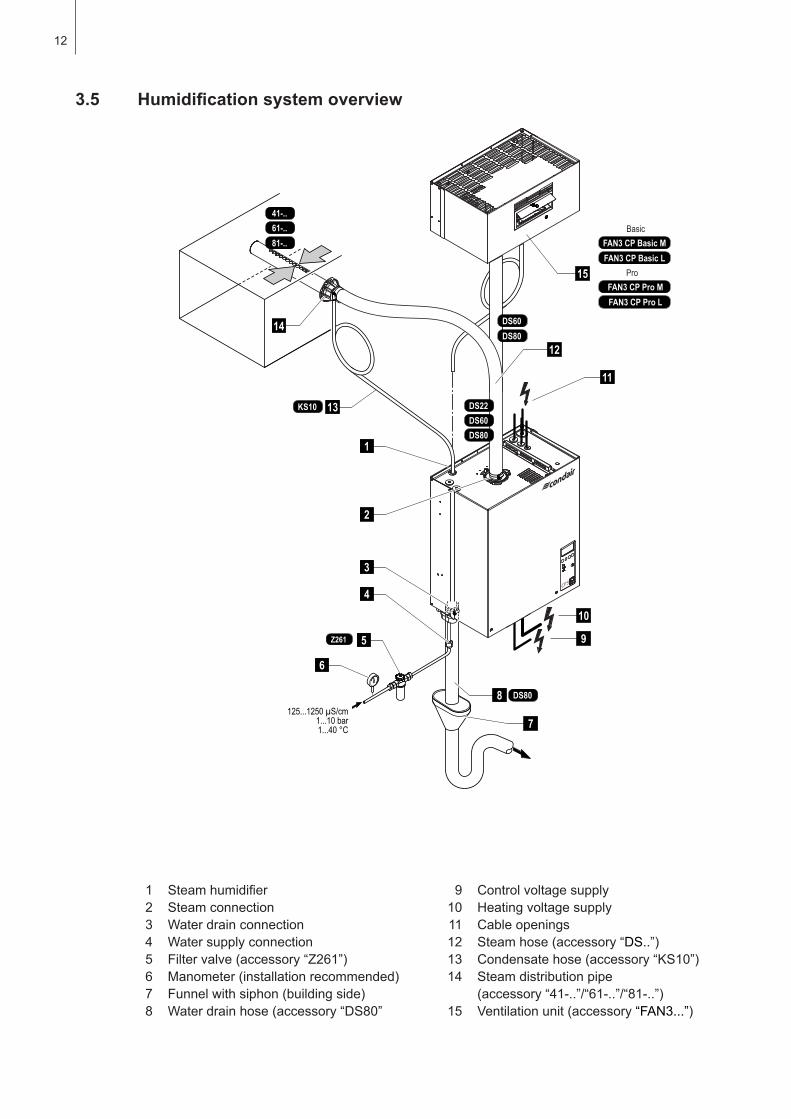
3.5 Humidificationsystemoverview
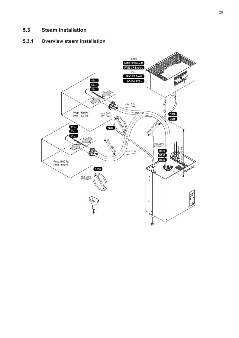
1 Steamhumidifier 2 Steam connection 3 Water drain connection 4 Water supply connection 5 Filtervalve(accessory“Z261”) 6 Manometer(installationrecommended) 7 Funnelwithsiphon(buildingside) 8 Waterdrainhose(accessory“DS80”
9 Controlvoltagesupply10 Heatingvoltagesupply 11 Cable openings 12 Steam hose (accessory “DS..”)13 Condensatehose(accessory“KS10”) 14 Steam distribution pipe (accessory“41-..”/“61-..”/“81-..”)15 Ventilationunit(accessory“FAN3...”)
DS60DS80
15
FAN3 CP Basic MFAN3 CP Basic L
FAN3 CP Pro MFAN3 CP Pro L
Basic
Pro
DS808
7
9
10
125...1250 µS/cm1...10 bar1...40 °C
1
2
3
4
5
6
Z261
14
11
KS10
61-..41-..
81-..
13DS60DS22
DS80
12
13
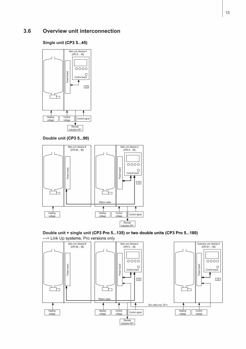
3.6 Overview unit interconnection
Single unit (CP3 5...45)
I/O
I/O I/O
I/O
Main unit, Module A(CP3 5 ... 45)
Powe
r boa
rd
Control board
Heating voltage
Control voltage Control signal
Remote indication RFI
Main unit, Module B(CP3 46 ... 90)
Powe
r boa
rd
Heating voltage
Main unit, Module A(CP3 5 ... 45)
Control board
Powe
r boa
rd
Ribbon cable
Heating voltage
Control voltage Control signal
Remote indication RFI
Main unit, Module B(CP3 46 ... 90)
Powe
r boa
rd
Heating voltage
Main unit, Module A(CP3 5 ... 45)
Control board
Powe
r boa
rd
Ribbon cable
Heating voltage
Control voltage Control signal
Remote indication RFI
Extension unit, Module A(CP3 91... 135)
Control board
Powe
r boa
rd
Bus cable max. 50 m
Heating voltage
Control voltage
Double unit (CP3 5...90)
Double unit + single unit (CP3 Pro 5...135) or two double units (CP3 Pro 5...180) --->LinkUpsystems,Proversions only
14
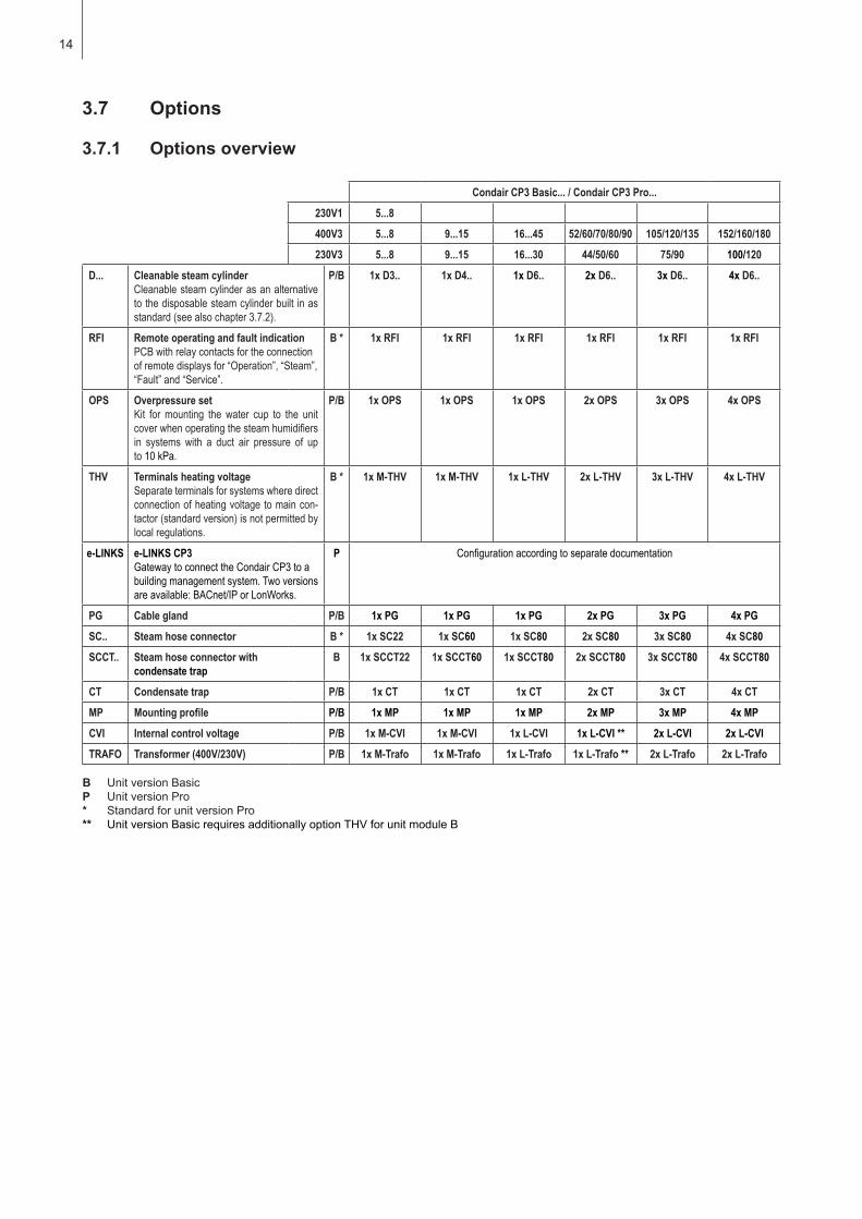
3.7 Options
3.7.1 Options overview
Condair CP3 Basic... / Condair CP3 Pro...
230V1 5...8
400V3 5...8 9...15 16...45 52/60/70/80/90 105/120/135 152/160/180
230V3 5...8 9...15 16...30 44/50/60 75/90 100/120
D... Cleanable steam cylinderCleanable steam cylinder as an alternative to the disposable steam cylinder built in as standard (see also chapter 3.7.2).
P/B 1x D3.. 1x D4.. 1x D6.. 2x D6.. 3x D6.. 4x D6..
RFI Remote operating and fault indicationPCB with relay contacts for the connection of remote displays for “Operation”, “Steam”, “Fault” and “Service”.
B * 1x RFI 1x RFI 1x RFI 1x RFI 1x RFI 1x RFI
OPS Overpressure setKit for mounting the water cup to the unit cover when operating the steam humidi fiers in systems with a duct air pressure of up to 10 kPa.
P/B 1x OPS 1x OPS 1x OPS 2x OPS 3x OPS 4x OPS
THV Terminals heating voltageSeparate terminals for systems where direct connection of heating voltage to main con-tactor (standard version) is not permitted by local regulations.
B * 1x M-THV 1x M-THV 1x L-THV 2x L-THV 3x L-THV 4x L-THV
e-LINKS e-LINKS CP3Gateway to connect the Condair CP3 to a building management system. Two versions are available: BACnet/IP or LonWorks.
P Configuration according to separate documentation
PG Cable gland P/B 1x PG 1x PG 1x PG 2x PG 3x PG 4x PG
SC.. Steam hose connector B * 1x SC22 1x SC60 1x SC80 2x SC80 3x SC80 4x SC80
SCCT.. Steam hose connector with condensate trap
B 1x SCCT22 1x SCCT60 1x SCCT80 2x SCCT80 3x SCCT80 4x SCCT80
CT Condensate trap P/B 1x CT 1x CT 1x CT 2x CT 3x CT 4x CT
MP Mounting profile P/B 1x MP 1x MP 1x MP 2x MP 3x MP 4x MP
CVI Internal control voltage P/B 1x M-CVI 1x M-CVI 1x L-CVI 1x L-CVI ** 2x L-CVI 2x L-CVI
TRAFO Transformer (400V/230V) P/B 1x M-Trafo 1x M-Trafo 1x L-Trafo 1x L-Trafo ** 2x L-Trafo 2x L-Trafo
B UnitversionBasicP UnitversionPro* StandardforunitversionPro** UnitversionBasicrequiresadditionallyoptionTHVforunitmoduleB
15
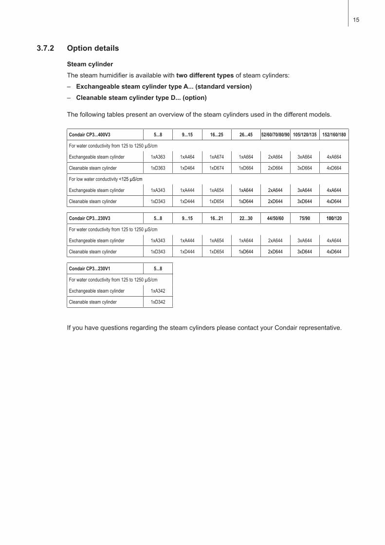
3.7.2 Option details
Steam cylinderThesteamhumidifierisavailablewithtwo different typesofsteamcylinders:– Exchangeable steam cylinder type A... (standard version)– Cleanable steam cylinder type D... (option)
Thefollowingtablespresentanoverviewofthesteamcylindersusedinthedifferentmodels.
Condair CP3...400V3 5...8 9...15 16...25 26...45 52/60/70/80/90 105/120/135 152/160/180
For water conductivity from 125 to 1250 µS/cm
Exchangeable steam cylinder 1xA363 1xA464 1xA674 1xA664 2xA664 3xA664 4xA664
Cleanable steam cylinder 1xD363 1xD464 1xD674 1xD664 2xD664 3xD664 4xD664
For low water conductivity <125 µS/cm
Exchangeable steam cylinder 1xA343 1xA444 1xA654 1xA644 2xA644 3xA644 4xA644
Cleanable steam cylinder 1xD343 1xD444 1xD654 1xD644 2xD644 3xD644 4xD644
Condair CP3...230V3 5...8 9...15 16...21 22...30 44/50/60 75/90 100/120
For water conductivity from 125 to 1250 µS/cm
Exchangeable steam cylinder 1xA343 1xA444 1xA654 1xA644 2xA644 3xA644 4xA644
Cleanable steam cylinder 1xD343 1xD444 1xD654 1xD644 2xD644 3xD644 4xD644
Condair CP3...230V1 5...8
For water conductivity from 125 to 1250 µS/cm
Exchangeable steam cylinder 1xA342
Cleanable steam cylinder 1xD342
IfyouhavequestionsregardingthesteamcylinderspleasecontactyourCondairrepresentative.
16
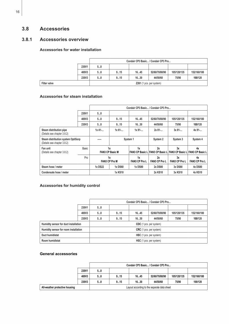
3.8 Accessories
3.8.1 Accessories overview
Accessories for water installation
Condair CP3 Basic... / Condair CP3 Pro...
230V1 5...8
400V3 5...8 9...15 16...45 52/60/70/80/90 105/120/135 152/160/180
230V3 5...8 9...15 16...30 44/50/60 75/90 100/120
Filter valve Z261 (1 pcs. per system)
Accessories for steam installation
Condair CP3 Basic... / Condair CP3 Pro...
230V1 5...8
400V3 5...8 9...15 16...45 52/60/70/80/90 105/120/135 152/160/180
230V3 5...8 9...15 16...30 44/50/60 75/90 100/120
Steam distribution pipe(Details see chapter 3.8.2)
1x 41-... 1x 61-... 1x 81-... 2x 81-... 3x 81-... 4x 81-...
Steam distribution system OptiSorp(Details see chapter 3.8.2)
––– System 1 System 2 System 3 System 4
Fan unit(Details see chapter 3.8.2)
Basic 1x FAN3 CP Basic M
1x FAN3 CP Basic L
2x FAN3 CP Basic L
3x FAN3 CP Basic L
4x FAN3 CP Basic L
Pro 1x FAN3 CP Pro M
1x FAN3 CP Pro L
2x FAN3 CP Pro L
3x FAN3 CP Pro L
4x FAN3 CP Pro L
Steam hose / meter 1x DS22 1x DS60 1x DS80 2x DS80 3x DS80 4x DS80
Condensate hose / meter 1x KS10 2x KS10 3x KS10 4x KS10
Accessories for humidity control
Condair CP3 Basic... / Condair CP3 Pro...
230V1 5...8
400V3 5...8 9...15 16...45 52/60/70/80/90 105/120/135 152/160/180
230V3 5...8 9...15 16...30 44/50/60 75/90 100/120
Humidity sensor for duct installation CDC (1 pcs. per system)
Humidity sensor for room installation CRC (1 pcs. per system)
Duct humidistat HBC (1 pcs. per system)
Room humidistat HSC (1 pcs. per system)
General accessories
Condair CP3 Basic... / Condair CP3 Pro...
230V1 5...8
400V3 5...8 9...15 16...45 52/60/70/80/90 105/120/135 152/160/180
230V3 5...8 9...15 16...30 44/50/60 75/90 100/120
All-weather protective housing Layout according to the separate data sheet
17
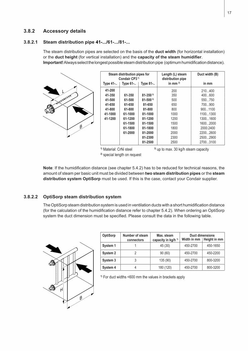
Thesteamdistributionpipesareselectedonthebasisoftheduct width(forhorizontalinstallation)or the duct height(forverticalinstallation)andthecapacityofthesteamhumidifier.Important! Alwaysselectthelongestpossiblesteamdistributionpipe(optimumhumidificationdistance).
3.8.2 Accessory details
3.8.2.1 Steam distribution pipe 41-.../61-.../81-...
3.8.2.2 OptiSorp steam distribution system
TheOptiSorpsteamdistributionsystemisusedinventilationductswithashorthumidificationdistance(forthecalculationofthehumidificationdistancerefertochapter5.4.2).WhenorderinganOptiSorpsystemtheductdimensionmustbespecified.Pleaseconsultthedatainthefollowingtable.
Steam distribution pipes for Condair CP3 1)
Length (L) steam distribution pipe
Duct width (B)
Type 41-.. Type 61-.. Type 81-.. in mm 2) in mm
41-200 200 210...40041-350 61-350 81-350 3) 350 400...60041-500 61-500 81-500 3) 500 550...75041-650 61-650 81-650 650 700...90041-800 61-800 81-800 800 900...1100
41-1000 61-1000 81-1000 1000 1100...130041-1200 61-1200 81-1200 1200 1300...1600
61-1500 81-1500 1500 1600...2000 61-1800 81-1800 1800 2000.2400 61-2000 81-2000 2000 2200...2600 81-2300 2300 2500...2900 81-2500 2500 2700...3100
1) Material: CrNi steel 3) up to max. 30 kg/h steam capacity2) special length on request
Note:Ifthehumidificationdistance(seechapter5.4.2)hastobereducedfortechnicalreasons,theamountofsteamperbasicunitmustbedividedbetweentwo steam distribution pipes or the steam distribution system OptiSorpmustbeused.Ifthisisthecase,contactyourCondairsupplier.
OptiSorp Number of steam connectors
Max. steam capacity in kg/h 1)
Duct dimensionsWidth in mm Height in mm
System 1 1 45 (30) 450-2700 450-1650
System 2 2 90 (60) 450-2700 450-2200
System 3 3 135 (90) 450-2700 800-3200
System 4 4 180 (120) 450-2700 800-3200
1) For duct widths <600 mm the values in brackets apply
18
3.9 Standard delivery
Thestandarddeliveryincludes:
– SteamhumidifierCondairCP3equippedwiththeoptionsorderedaccordingtochapter3.7,fixingset and installation and operating instructions(thisdocument),packagedincardboardbox– Unitsmall(WxHxD):456 mmx620mmx280mm,shippingweight:26kg– Unitlarge(WxHxD):559mmx667mmx350mm,shippingweight:31kg
– Orderedaccessorieswithoperatinginstructionsaccordingchapter3.8,packedseparately
– Spare parts list
3.10 Storing/Transportation/Packaging
StoringStoretheunitinaprotectedareameetingthefollowingrequirements:
– Roomtemperature:1...40°C– Roomhumidity:10...75%rh
TransportationForoptimumprotectionalwaystransporttheunitintheoriginalpackaging.
Theweightofthesmallandthelargeunitismorethan20kg(weightwithoutpackaging:smallunit23kg,largeunit28kg).Therefore,alwaystransporttheunitwiththehelpofanotherpersonoruseaforkliftoracrane.Alwaysplacetheunitonitsbackside.
PackagingKeeptheoriginalpackagingoftheCondairCP3forlateruse.
Incaseyouwishtodisposeofthepackaging,observethelocalregulationsonwastedisposal.Neverdisposeofthepackagingtotheenvironment.
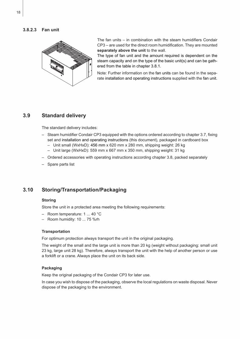
3.8.2.3 Fan unit
Thefanunits–incombinationwiththesteamhumidifiersCondairCP3–areusedforthedirectroomhumidification.Theyaremountedseparately above the unit to the wall.Thetypeoffanunitandtheamountrequiredisdependentonthesteamcapacityandonthetypeofthebasicunit(s)andcanbegath-eredfromthetableinchapter3.8.1.
Note:Furtherinformationonthefanunitscanbefoundinthesepa-rate installation and operating instructions supplied with the fanunit.
19
4.1 Selecting the unit version
Themaximumrequiredsteamcapacitymustbecalculatedbasedononeofthefollowingformulas:
V•ρ mD= •(x2 - x1) 1000
or V mD= •(x2 - x1) 1000•ε
mD: maximumsteamdemandinkg/hV: volumeofsupplyairportionperhourinm3/h(forindirectroomhumidification)orroomvolume
tobehumidifiedperhourinm3/h(fordirectroomhumidification)ρ: specificgravityofairinkg/m3
ε: specificvolumeofairinm3/kgx2: desiredabsoluteroomairhumiditying/kgx1: minimumabsolutesupplyairhumidityin g/kgThevaluesforρ,ε, x2 and x1canbegatheredfromtheh,x-diagram or the Carrier-Diagramformoist air respectively.
Important notes:– Therequiredmaximumsteamcapacitydependsonthespecificapplicationandtheinstallation.
Thecalculatedsteamcapacitybasedontheaboveformulas,theh,xdiagramandtheconditionoftheairtobehumidifieddoesnotconsideranysteamloss(e.g.duetocondensationinthesteamhosesandthesteamdistributors),anyheatlossoftheunitaswellasanyabsorptionorreleaseofhumidityofmaterialslocatedintheroombeinghumidified.In addition, the calculated steam capacity does not consider any losses caused by the draining ratedependingonthewaterqualityaswellasanylossesoccurifthesteamhumidifierisoperatedonamainscircuitwithagroundfaultcircuitinterrupter.
Thetotalamountoflossesdependsontheentiresystemandmustbetakenintoconsiderationwhencalculatingtherequiredsteamcapacity.IfyouhaveanyquestionsregardingthecalculationofthesteamcapacitypleasecontactyourCondairsupplier.
– Forsystemswherethemax.requiredsteamcapacityvariesextensively(e.g.fortestfacilitiesorforsystemswithvariableairvolumeflow,etc.),pleasecontactyourCondairsupplier.
4 Notes for the planning engineer
Toselecttheunitversionthefollowingplanningstepsarerequired:
1. Calculating the required maximum steam capacity according chapter 4.1.1
2. Selectingtheunitversionfromthetableinchapter4.1.2
4.1.1 Calculatingthemaximumrequiredsteamcapacity
20
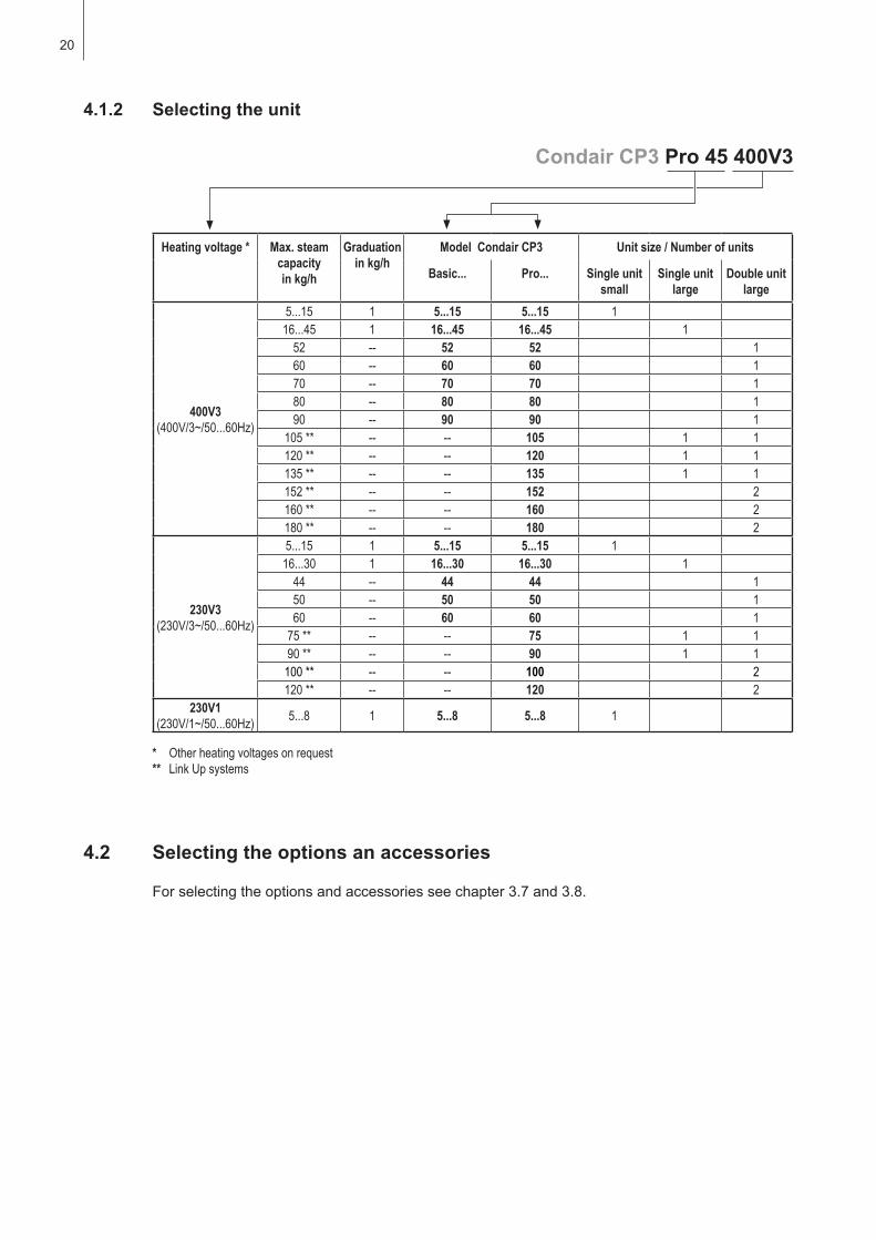
Condair CP3 Pro 45 400V3
4.1.2 Selecting the unit
Heating voltage * Max. steamcapacity in kg/h
Graduation in kg/h
Model Condair CP3 Unit size / Number of units
Basic... Pro... Single unitsmall
Single unitlarge
Double unit large
400V3(400V/3~/50...60Hz)
5...15 1 5...15 5...15 116...45 1 16...45 16...45 1
52 -- 52 52 160 -- 60 60 170 -- 70 70 180 -- 80 80 190 -- 90 90 1
105 ** -- -- 105 1 1120 ** -- -- 120 1 1135 ** -- -- 135 1 1152 ** -- -- 152 2160 ** -- -- 160 2180 ** -- -- 180 2
230V3(230V/3~/50...60Hz)
5...15 1 5...15 5...15 116...30 1 16...30 16...30 1
44 -- 44 44 150 -- 50 50 160 -- 60 60 1
75 ** -- -- 75 1 190 ** -- -- 90 1 1
100 ** -- -- 100 2120 ** -- -- 120 2
230V1(230V/1~/50...60Hz) 5...8 1 5...8 5...8 1
* Other heating voltages on request** Link Up systems
4.2 Selecting the options an accessories
For selecting the options and accessories see chapter 3.7 and 3.8.
21
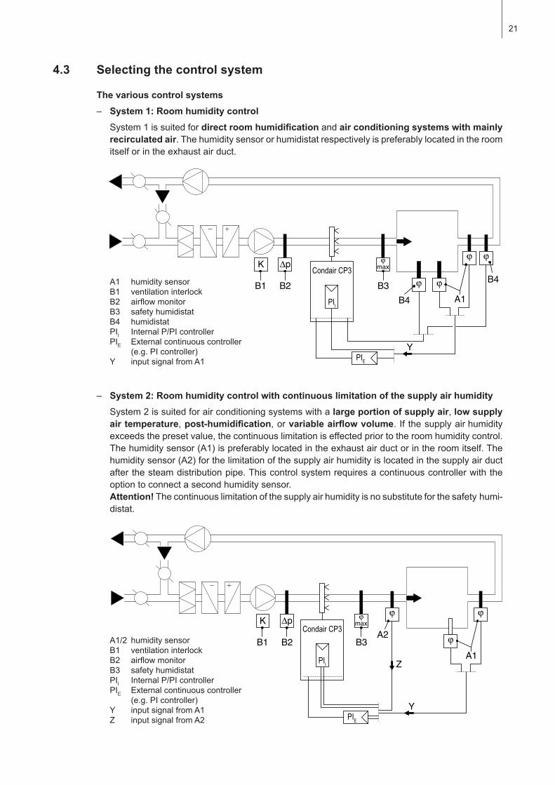
4.3 Selecting the control system
The various control systems– System 1: Room humidity control
System1issuitedfordirectroomhumidification and air conditioning systems with mainly recirculated air.Thehumiditysensororhumidistatrespectivelyispreferablylocatedintheroomitselforintheexhaustairduct.
A1 humidity sensorB1 ventilationinterlockB2 airflowmonitorB3 safetyhumidistatB4 humidistatPII InternalP/PIcontrollerPIE External continuous controller (e.g.PIcontroller)Y inputsignalfromA1
– System 2: Room humidity control with continuous limitation of the supply air humiditySystem2issuitedforairconditioningsystemswithalarge portion of supply air, low supply air temperature, post-humidification, or variableairflowvolume. If thesupplyairhumidityexceedsthepresetvalue,thecontinuouslimitationiseffectedpriortotheroomhumiditycontrol.Thehumiditysensor(A1)ispreferablylocatedintheexhaustairductorintheroomitself.Thehumiditysensor(A2)forthelimitationofthesupplyairhumidityislocatedinthesupplyairductafterthesteamdistributionpipe.Thiscontrolsystemrequiresacontinuouscontrollerwiththeoption to connect a second humidity sensor.Attention! Thecontinuouslimitationofthesupplyairhumidityisnosubstituteforthesafetyhumi-distat.
A1/2 humiditysensorB1 ventilationinterlockB2 airflowmonitorB3 safetyhumidistatPII InternalP/PIcontrollerPIE External continuous controller (e.g.PIcontroller)Y inputsignalfromA1Z inputsignalfromA2
22
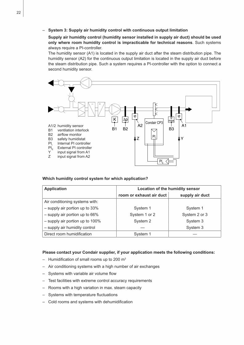
– System 3: Supply air humidity control with continuous output limitationSupply air humidity control (humidity sensor installed in supply air duct) should be used only where room humidity control is impracticable for technical reasons. Such systems alwaysrequireaPI-controller.Thehumiditysensor(A1)islocatedinthesupplyairductafterthesteamdistributionpipe.Thehumiditysensor(A2)forthecontinuousoutputlimitationislocatedinthesupplyairductbeforethesteamdistributionpipe.SuchasystemrequiresaPI-controllerwiththeoptiontoconnectasecond humidity sensor.
A1/2 humiditysensorB1 ventilationinterlockB2 airflowmonitorB3 safetyhumidistatPII InternalPIcontrollerPIE ExternalPIcontrollerY inputsignalfromA1Z inputsignalfromA2
Which humidity control system for which application?
Application Location of the humidity sensorroom or exhaust air duct supply air duct
Airconditioningsystemswith:–supplyairportionupto33% System 1 System 1–supplyairportionupto66% System 1 or 2 System 2 or 3–supplyairportionupto100% System 2 System 3– supply air humidity control — System 3Directroomhumidification System 1 —
Please contact your Condair supplier, if your application meets the following conditions:– Humidificationofsmallroomsupto200m3
– Airconditioningsystemswithahighnumberofairexchanges
– Systemswithvariableairvolumeflow
– Testfacilitieswithextremecontrolaccuracyrequirements
– Rooms with a high variation in max. steam capacity
– Systemswithtemperaturefluctuations
– Coldroomsandsystemswithdehumidification
23
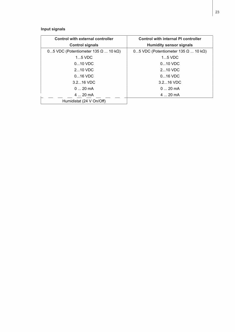
Input signals
Control with external controller Control with internal PI controllerControl signals Humidity sensor signals
0...5VDC(Potentiometer135Ω...10kΩ) 0...5VDC(Potentiometer135Ω...10kΩ)1...5VDC 1...5VDC0...10VDC 0...10VDC2...10VDC 2...10VDC0...16VDC 0...16VDC3.2...16VDC 3.2...16VDC0...20mA 0...20mA4...20mA 4...20mA
Humidistat(24VOn/Off)

24
5 Mounting and installation work
QualificationofpersonnelAllmountingandinstallationworkmustbecarriedoutonlybywellqualifiedpersonnelauthorisedby the owner.Itistheowner’sresponsibilitytoverifyproperqualificationofthepersonnel.
General note Strictlyobserveandcomplywithallinformationgiveninthe present installation and operating instruc-tionsregardingthelocationoftheunitandtheinstallationofwater,steamandelectricity.
Observe and comply with all local regulations dealing with water, steam and electrical installations.
SafetySomeinstallationworkrequiresremovaloftheunitcover.Pleasenotethefollowing:
DANGER! Danger of electrical shock!Youmaygetintouchwithlivepartswhentheunitisopen.Thesteamhumidifiermustbeconnectedtothemainsonlyafterallmountingandinstallationworkhasbeencompletedandthecoverhasbeen relocated properly.
CAUTION!The electronic componentsinsidethehumidifierarevery sensitive to electrostatic discharge. Whentheunitisopenforinstallationwork,appropriatemeasuresmustbetakentoprotectthesecomponentsagainstdamagecausedbyelectrostaticdischarge(ESDprotection).
5.1 Important notes for mounting and installation work
25
min
. 400
mm
B
min. 600 mm
Hmin. 250 mm
min. 400 mm
min
. 600
mm
50 mm
60...70 °C
1 ... 40 °Cmax. 75 %rhIP20
T
5.2 Mounting the unit
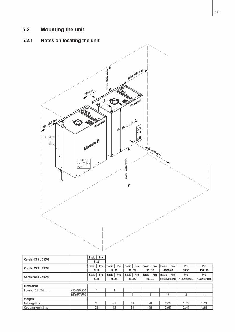
5.2.1 Notes on locating the unit
Condair CP3 ... 230V1 Basic Pro5...8
Condair CP3 ... 230V3 Basic Pro Basic Pro Basic Pro Basic Pro Basic Pro Pro Pro5...8 9...15 16...21 22...30 44/50/60 75/90 100/120
Condair CP3 ... 400V3 Basic Pro Basic Pro Basic Pro Basic Pro Basic Pro Pro Pro5...8 9...15 16...25 26...45 52/60/70/80/90 105/120/135 152/160/180
DimensionsHousing (BxHxT) in mm 456x620x280 1 1
559x667x350 1 1 2 3 4WeightsNet weight in kg 21 21 28 28 2x 28 3x 28 4x 28Operating weight in kg 26 32 65 65 2x 65 3x 65 4x 65
Module A
Module B

26
Theinstallationsiteofthesteamhumidifierdependslargelyonthelocationofthesteamdistributor(see chapter 5.3).Toensure proper functioningofthesteamhumidifierandtoobtain an optimal efficiency,thefollowingpointsmustbeconsideredandobservedwhenchoosingthelocationforthesteamhumidifier:
– Installthesteamhumidifiersothatthelength of the steamhoseiskeptasshortaspossible(max. 4 m)andthattheminimum bend radius (R= 300 mm) and up-slope (20 %) or down-slope (5 %)ofthesteamhoseisobserved(seechapter5.3.5).
– ThesteamhumidifiersCondairCP3aredesignedforwall-mounting.Makesurethattheconstruc-tion(wall,pillar,floor-mountedconsole,etc.)towhichthehumidifiersaretobemounted,offersa sufficientlyhighload-bearingcapacity(takenoticeoftheweightinformationfoundinthedimensionsandweightstableabove),andissuitablefortheinstallation.
CAUTION!Donotmountthesteamhumidifierdirectlytotheventilationduct(insufficientstability).
– ThebackpaneloftheCondairCP3isretainingheatduringoperation(max.surfacetemperatureofthemetalhousingapprox.60-70°C).Makesure,therefore,thattheconstruction(wall,pillar,etc.)towhichtheunitsaretobemounted,doesnotconsistofheat-sensitivematerial.
– Installthesteamhumidifierinsuchamannerthatitisfreely accessiblewithsufficientspaceavailableformaintenancepurposes(refertotheaboveillustrationforminimumdistances).
– TheCondairCP3isprotectedaccordingtoIP20.Makesuretheunitsareinstalledinadrip-prooflocation and the admissible ambient conditions are complied with.
– ThesteamhumidifierCondairCP3mayonlybeinstalledinroomswithafloordrain.
CAUTION!If forsomereason theCondairCP3mustbe installed ina locationwithoutfloordrain, it ismandatorytoprovidealeakagemonitoringdevicetosafelyinterruptthewatersupplyincaseofleakage.
– WhenfixingtheCondairCP3useonlythefixingmaterialssuppliedwiththeunit.Iffixingwiththematerialssuppliedisnotpossibleinyourparticularcase,selectamethodoffixingthatisofsimilar stability.
– TheCondairCP3 isdesigned for installationandoperationwithinbuildings (admissible tem-peraturerangeseechapter10.1).ForoutdooroperationtheCondairCP3mustbeplacedinaweatherprotectivehousing.Ifambienttemperaturesnearorbelowthefreezingpointhavetobeexpected,theprotectivehousingmustequippedwithathermostatcontrolledheatingofsufficientcapacity. The water supply pipe must be equipped with a trace-heating and must be insulated up to the protective housing. Furthermore the special notes regarding the operation at ambient temperatures≤0°Cmustbeobserved(seechapter6.3.2).
27
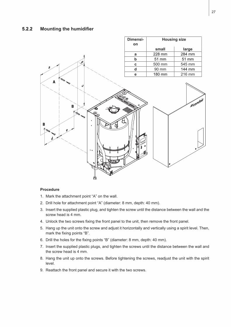
5.2.2 Mountingthehumidifier
Procedure1. Marktheattachmentpoint“A”onthewall.
2. Drillholeforattachmentpoint“A”(diameter:8mm,depth:40mm).
3. Insert the supplied plastic plug, and tighten the screw until the distance between the wall and the screw head is 4 mm.
4. Unlockthetwoscrewsfixingthefrontpaneltotheunit,thenremovethefrontpanel.
5. Hanguptheunitontothescrewandadjustithorizontallyandverticallyusingaspiritlevel.Then,markthefixingpoints“B”.
6. Drilltheholesforthefixingpoints“B”(diameter:8mm,depth:40mm).
7. Insert the supplied plastic plugs, and tighten the screws until the distance between the wall and the screw head is 4 mm.
8. Hangtheunitupontothescrews.Beforetighteningthescrews,readjusttheunitwiththespiritlevel.
9. Reattachthefrontpanelandsecureitwiththetwoscrews.
d
e
bc
a
A
B
B
Dimensi-on
Housing size
small largea 228 mm 284 mmb 51 mm 51 mmc 500mm 545 mmd 90mm 144 mme 180mm 216 mm

28
5.2.3 Inspecting the installed unit
Checkthefollowingpoints:
Is the unit installed in the correct place (see chapter 5.2.1)?
Isthesupportingsurfacestableenough?
Istheunitcorrectlyaligned,verticallyandhorizontally?
Is the unit properly secured (see chapter 5.2.2)?
Hasthefrontpaneloftheunitbeenrelocatedandcorrectlyfixedwiththetwoscrews?
29
5.3 Steam installation
5.3.1 Overview steam installation
FAN3 CP Basic MFAN3 CP Basic L
FAN3 CP Pro MFAN3 CP Pro L
Basic
Pro
DS60DS80
Rmin. 300
mmØmin. 200 mm
max. 4 m
DS60DS22
DS80
61-...81-...
61-...
41-...
41-...
81-...
max.
4 m
min. 5 %–
min.
300 m
m
KS10Rmin. 300 mm min. 5 %
–
min. 20 %+
min. 20 %–
min. 20 %–
Pmin1500 Pa-800 Pa
Pmax
Pmin1500 Pa-800 Pa
Pmax
Ømin. 200 mm
KS10

30
Thecalculationof thehumidificationdistance “BN” isdependentonseveral factors.Fora roughestimationofthehumidificationdistance“BN”,thefollowingtableisuseful.Recommendedstandardvalueslistedinthistablearebasedonasupply-airtemperaturerangeof15°Cto30°C.Thevaluesgiven in bold type only apply to steam distribution pipes 41-..., 61-... and 81-..., the values in brackets apply to the OptiSorp steam distribution system.
Humidity at inletφ1in%rh
LengthofhumidificationdistanceBN in m Humidityatoutletφ2in%rh
40 50 60 70 80 905 0,9(0,22) 1,1(0,28) 1,4(0,36) 1,8(0,48) 2,3(0,66) 3,5(1,08)10 0,8(0,20) 1,0(0,26) 1,3(0,34) 1,7(0,45) 2,2(0,64) 3,4(1,04)20 0,7(0,16) 0,9(0,22) 1,2(0,30) 1,5(0,41) 2,1(0,58) 3,2(0,96)30 0,5(0,10) 0,8(0,17) 1,0(0,25) 1,4(0,36) 1,9(0,52) 2,9(0,88)40 – 0,5(0,11) 0,8(0,20) 1,2(0,30) 1,7(0,45) 2,7(0,79)50 – – 0,5(0,13) 1,0(0,24) 1,5(0,38) 2,4(0,69)60 – – – 0,7(0,16) 1,2(0,30) 2,1(0,58)70 – – – – 0,8(0,20) 1,7(0,45)
Forductwidths<600mmthehumidificationdistancefortheOptiSorpsystemincreasesbyapprox.50%
φ1in%rh: Relativesupplyairhumiditypriortohumidificationatthelowestsupplyairtemperatureφ2in%rh: Relativesupplyairhumidityafterthesteamdistributionpipeatmaximumcapacity
Example
given: φ1=30%rh,φ2=70%rh
humidificationdistanceBN: 1,4m(0.36mforsteamdistributionsystemOptiSorp)
Note:Ifthehumidificationdistancehastobereducedfortechnicalreasons,theamountofsteamper basic unit must be divided between two steam distribution pipes or the steam distribution system OptiSorpmustbeused.Ifthisisthecase,contactyourCondairsupplier.
5.3.2 Positioning and mounting of the steam distribution pipes
Thelocationforthesteamdistributionpipesshouldbedeterminedatthetimeofdimensioningtheairconditioningsystem.Pleasenotethefollowinginstructionstoensureproperhumidificationoftheduct air.
CalculatingthehumidificationdistanceThewater vapour, emitting from the steam distribution pipes, requires a certain distance to beabsorbedbytheambientairsothatitisnolongervisibleassteam.Thisdistanceisreferredtoashumidificationdistance“BN”andservesasabasisforthedeterminationoftheminimumdistancesfromtheupstreamcomponentsinthesystem.
HumidificationdistanceBN Expansion and mixing zone
φ1:Supplyairhumiditybeforehumidificationφ2:Supplyairhumidityafterhumidification
31
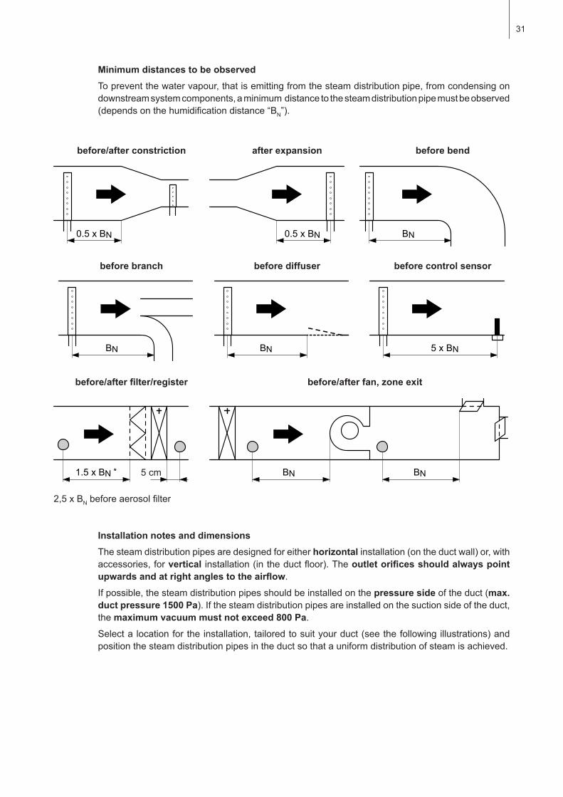
Minimum distances to be observedTopreventthewatervapour,thatisemittingfromthesteamdistributionpipe,fromcondensingondownstream system components, a minimum distance to the steam distribution pipe must be observed (dependsonthehumidificationdistance“BN”).
before/after constriction after expansion before bend
before branch before diffuser before control sensor
before/afterfilter/register before/afterfan,zoneexit
2,5xBNbeforeaerosolfilter
Installation notes and dimensionsThesteamdistributionpipesaredesignedforeitherhorizontalinstallation(ontheductwall)or,withaccessories,forvertical installation(intheductfloor).Theoutletorificesshouldalwayspointupwardsandatrightanglestotheairflow.
Ifpossible,thesteamdistributionpipesshouldbeinstalledonthepressure sideoftheduct(max. duct pressure 1500 Pa).Ifthesteamdistributionpipesareinstalledonthesuctionsideoftheduct,the maximum vacuum must not exceed 800 Pa.
Selectalocationfortheinstallation,tailoredtosuityourduct(seethefollowingillustrations)andpositionthesteamdistributionpipesintheductsothatauniformdistributionofsteamisachieved.
1.5 x BN * BN BN5 cm

32
Inpositioningthesteamdistributionpipes,thefollowingdimensionsshouldbeobserved:
Note:When locating theOptiSorp steamdistribution systempleasenote the instructions in theseparatedocumentationforthisproduct.
hmin
hminhmin
hmin
hminhmin
1/2 H1/2
H
H
1/3
2/3H
1/5
1/5
2/51/5
H2/72/73/7
1/51/5 H
2/51/5
1/4 H1/41/41/4
1/3 H1/31/3
2/7
2/7
3/7
H
1/21/2
1/5H
1/51/51/51/5
H
1/61/6
2/6
1/61/6
H
1/61/6
2/61/61/6
hmin
gmin gmin
gmin
gmin gmin
gmin
gmin.=100mmhmin.=85mm
Hmin.=250mm H≥400mm Hmin.=200mm
Hmin.=400mm Hmin.=350mm Hmin.=300mm
Hmin.=600mm Hmin.=500mm Hmin.=400mm
Hmin.=720mm Hmin.=600mm Hmin.=500mm
33
5.3.3 Installing the steam distributors
Detailedinformationontheinstallationofsteamdistributionpipes41-..,61-.../81-...andOptiSorpsteamdistributionsystemcanbefoundintheseparate“MountingInstructions”forthisproducts.
Guidelines for dimensioning the ventilation ducts– Tofacilitatetheinstallationofthesteamdistributionpipesandforcontrolpurposes,asufficiently
sized control opening should be planned.
– Withintherangeofthehumidificationdistance,theventilationductshouldbewaterproofed.
– Airductspassingthroughcoldroomsshouldbeinsulatedtopreventthehumidifiedairfromcon-densing along the duct wall.
– Poorairflowconditionswithintheairduct(e.g.causedbyobstacles,tightbends,etc.)canleadtocondensationofthehumidifiedair.
– Steam distribution pipes must not be mounted to round ducts.
IfyouhavequestionsrelatingtothedimensioningofventilationductsincombinationwithsteamhumidifiersCondairCP3,contactyourCondairsupplier.
34
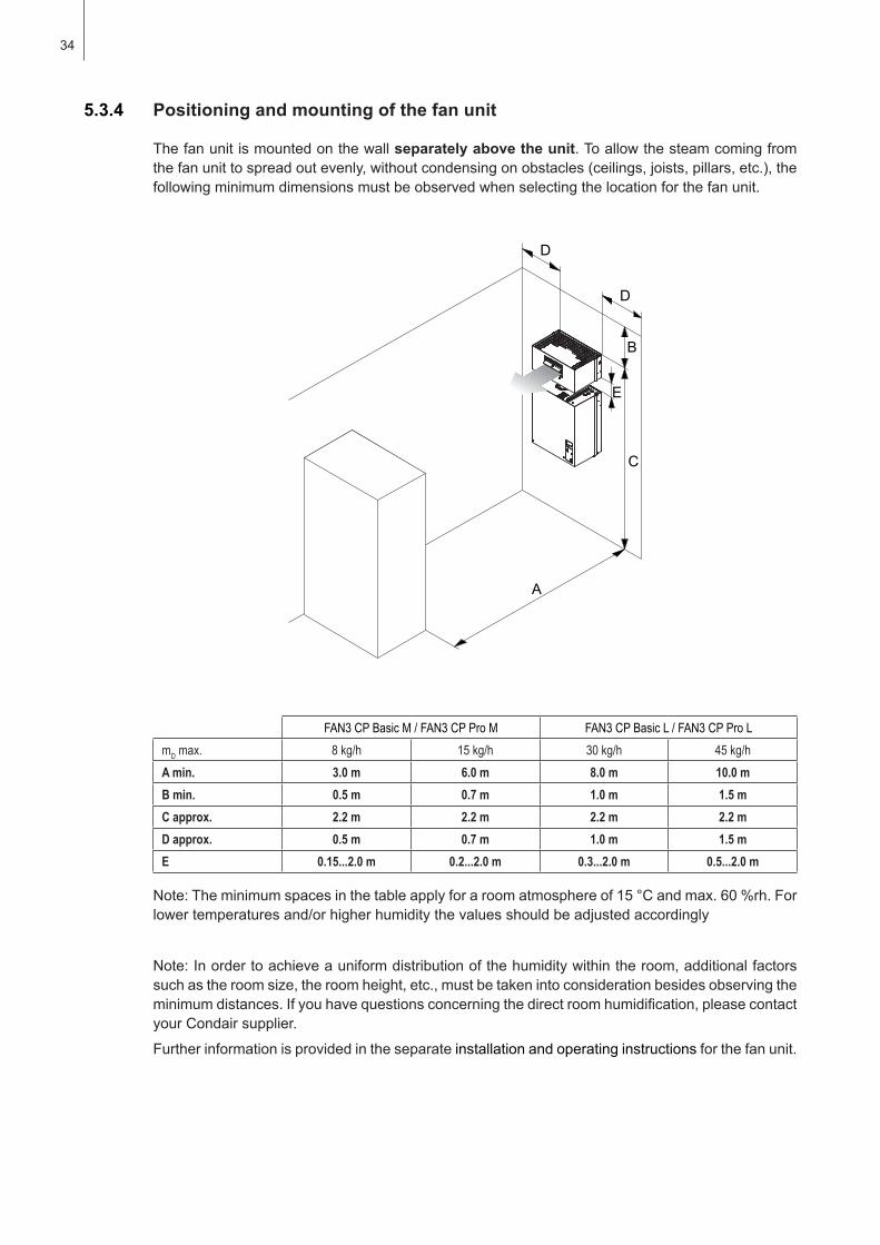
5.3.4 Positioning and mounting of the fan unit
FAN3 CP Basic M / FAN3 CP Pro M FAN3 CP Basic L / FAN3 CP Pro LmD max. 8 kg/h 15 kg/h 30 kg/h 45 kg/hA min. 3.0 m 6.0 m 8.0 m 10.0 mB min. 0.5 m 0.7 m 1.0 m 1.5 mC approx. 2.2 m 2.2 m 2.2 m 2.2 mD approx. 0.5 m 0.7 m 1.0 m 1.5 mE 0.15...2.0 m 0.2...2.0 m 0.3...2.0 m 0.5...2.0 m
Note:Theminimumspacesinthetableapplyforaroomatmosphereof15°Candmax.60%rh.Forlowertemperaturesand/orhigherhumiditythevaluesshouldbeadjustedaccordingly
Note:Inordertoachieveauniformdistributionofthehumiditywithintheroom,additionalfactorssuchastheroomsize,theroomheight,etc.,mustbetakenintoconsiderationbesidesobservingtheminimumdistances.Ifyouhavequestionsconcerningthedirectroomhumidification,pleasecontactyour Condair supplier.
Furtherinformationisprovidedintheseparateinstallation and operating instructionsforthefanunit.
Thefanunitismountedonthewallseparately above the unit.Toallowthesteamcomingfromthefanunittospreadoutevenly,withoutcondensingonobstacles(ceilings,joists,pillars,etc.),thefollowingminimumdimensionsmustbeobservedwhenselectingthelocationforthefanunit.
A
C
B
D
D
E

35
5.3.5 Installing the steam hose
Important! UseoriginalCondairsteamhoseexclusively.Othertypesofsteamhosescancauseundesiredoperationalmalfunctions.
Instructions for the hose layoutThehoselayoutdependsonthepositionofthesteamdistributionpipe:
– Steam distribution pipe is mounted morethan300mmabovethetopedgeofthehumidifier:
Initially, lead the steam hose with an upslope of at least 20% over a minimum height of 300 mm, then lead the hose with a minimum upslope of 20%and/oraminimum downslope of 5% to the steam distribution pipe.
– Steam distribution pipe is mounted lessthan300mmabovethetopedgeofthehumidifier:
Initially, the steam hose is led with an upslope of at least 20 % over a minimum height of 300 mmabovethetopedgeofthehumidifierandthendowntothesteamdistributionpipewithaminimum slope of 5 %.
– Thesteamhoseshouldbekeptasshortaspossible(max. 4 m)whileobservingtheminimum bend radius of 300 mm. Important!Allowancemustbemadeforapressure loss of 10 mm water column (approx. 100 Pa) per meter steam hose.Note:Ifyourparticularinstallationexceedsthemaximumsteamhoselengthof4mcontactyourCondair representative. In any case, steam hoses longer than 4 m must be insulated in their entire length.
– Reductionsinthecrosssectionsuchaskinksshouldbeavoidedthroughouttheentirelengthofthehose.Theinstallationofastopcockinthesteamhoseisnotpermissible.
min.
300 m
m
Rmin.
300 m
m
min. 5 % min. 20 %
max.
4 m
min.
300 m
mRmin.
300 mm
min. 20 %
max.
4 m
max.
4 m
min. 5 %
Rmin.
300 m
m
max.
4 m
min.
300 m
m
min. 20 %
min.
300 m
m
min. 20 %min. 5 %
Rmin. 300 m
mmin. 20%
36
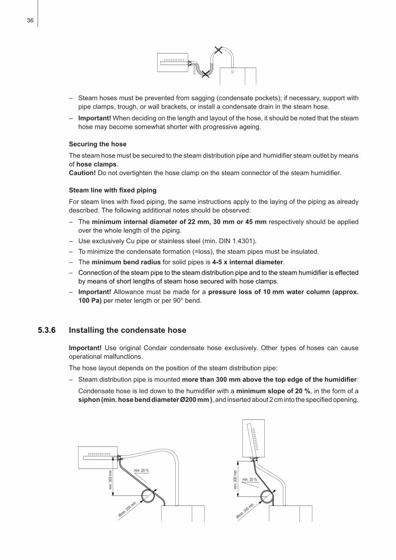
– Steamhosesmustbepreventedfromsagging(condensatepockets);ifnecessary,supportwithpipeclamps,trough,orwallbrackets,orinstallacondensatedraininthesteamhose.
– Important!Whendecidingonthelengthandlayoutofthehose,itshouldbenotedthatthesteamhose may become somewhat shorter with progressive ageing.
Securing the hoseThesteamhosemustbesecuredtothesteamdistributionpipeandhumidifiersteamoutletbymeansofhose clamps. Caution!Donotovertightenthehoseclamponthesteamconnectorofthesteamhumidifier.
SteamlinewithfixedpipingForsteamlineswithfixedpiping,thesameinstructionsapplytothelayingofthepipingasalreadydescribed.Thefollowingadditionalnotesshouldbeobserved:
– The minimum internal diameter of 22 mm, 30 mm or 45 mm respectively should be applied overthewholelengthofthepiping.
– UseexclusivelyCupipeorstainlesssteel(min.DIN1.4301).– Tominimizethecondensateformation(=loss),thesteampipesmustbeinsulated.– The minimum bend radiusforsolidpipesis4-5 x internal diameter.– Connectionofthesteampipetothesteamdistributionpipeandtothesteamhumidifieriseffected
bymeansofshortlengthsofsteamhosesecuredwithhoseclamps.– Important! Allowancemustbemadeforapressure loss of 10 mm water column (approx.
100 Pa)permeterlengthorper90°bend.
5.3.6 Installing the condensate hose
Important! Use originalCondair condensate hose exclusively.Other types ofhoses can causeoperationalmalfunctions.
Thehoselayoutdependsonthepositionofthesteamdistributionpipe:
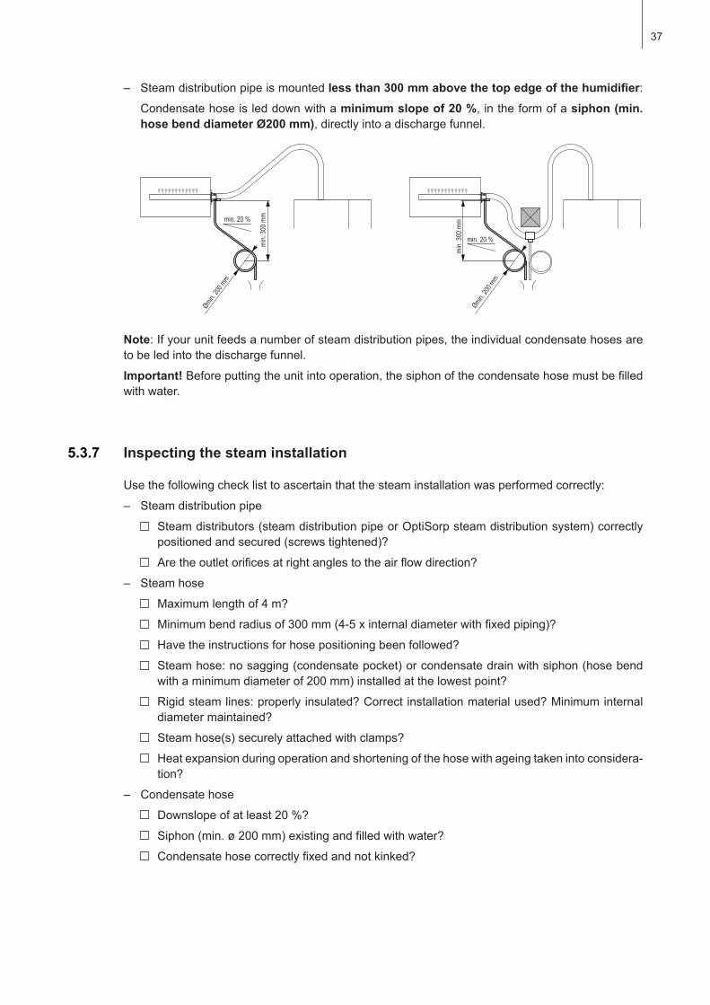
– Steam distribution pipe is mounted morethan300mmabovethetopedgeofthehumidifier:Condensatehoseisleddowntothehumidifierwithaminimum slope of 20 %,intheformofa siphon (min. hose bend diameter Ø200 mm ),andinsertedabout2cmintothespecifiedopening.
min.
300 m
m min. 20 %
Ømin. 200 mm
min.
300 m
m
min. 20 %
Ømin. 200 mm
37
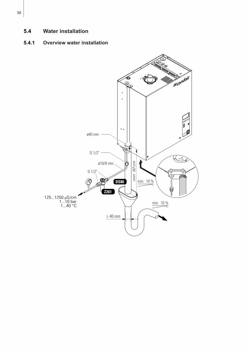
– Steam distribution pipe is mounted lessthan300mmabovethetopedgeofthehumidifier:Condensate hose is led down with a minimum slope of 20 %,intheformofasiphon (min. hose bend diameter Ø200 mm),directlyintoadischargefunnel.
Note:Ifyourunitfeedsanumberofsteamdistributionpipes,theindividualcondensatehosesaretobeledintothedischargefunnel.
Important! Beforeputtingtheunitintooperation,thesiphonofthecondensatehosemustbefilledwith water.
5.3.7 Inspecting the steam installation
Usethefollowingchecklisttoascertainthatthesteaminstallationwasperformedcorrectly:
– Steam distribution pipe
Steamdistributors(steamdistributionpipeorOptiSorpsteamdistributionsystem)correctlypositionedandsecured(screwstightened)?
Aretheoutletorificesatrightanglestotheairflowdirection?
– Steam hose
Maximumlengthof4m?
Minimumbendradiusof300mm(4-5xinternaldiameterwithfixedpiping)?
Havetheinstructionsforhosepositioningbeenfollowed?
Steamhose:nosagging(condensatepocket)orcondensatedrainwithsiphon(hosebendwithaminimumdiameterof200mm)installedatthelowestpoint?
Rigidsteamlines:properlyinsulated?Correctinstallationmaterialused?Minimuminternaldiametermaintained?
Steamhose(s)securelyattachedwithclamps?
Heatexpansionduringoperationandshorteningofthehosewithageingtakenintoconsidera-tion?
– Condensate hose
Downslopeofatleast20%?
Siphon(min.ø200mm)existingandfilledwithwater?
Condensatehosecorrectlyfixedandnotkinked?
min.
300 m
mmin. 20 %
Ømin. 20
0 mm
min.
300 m
m
min. 20 %
Ømin. 20
0 mm
38
DS80
125...1250 µS/cm1...10 bar1...40 °C
ø40 mm
ø10/8 mm
G 1/2"
Z261
≥ 40 mm
G 1/2"
min
. 50
cm
min. 10 %–
min. 10 %–
5.4 Water installation
5.4.1 Overview water installation
39
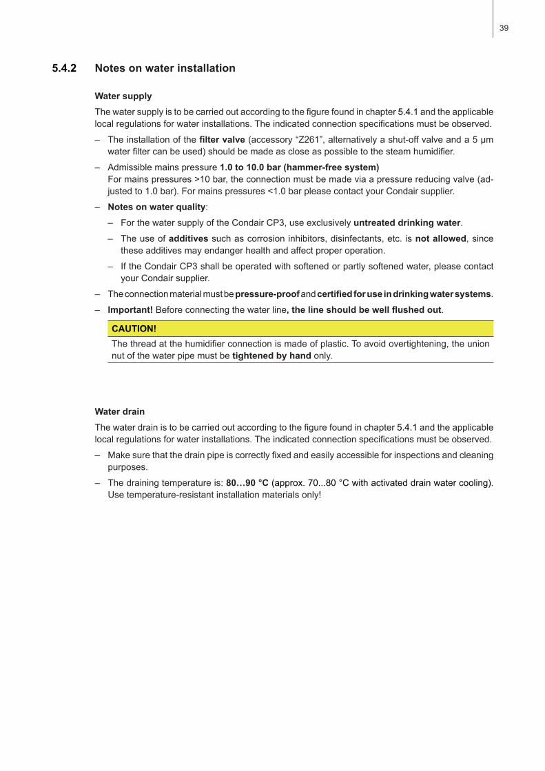
Water supplyThewatersupplyistobecarriedoutaccordingtothefigurefoundinchapter5.4.1 and the applicable localregulationsforwaterinstallations.Theindicatedconnectionspecificationsmustbeobserved.
– Theinstallationofthefiltervalve(accessory“Z261”,alternativelyashut-offvalveanda5µmwaterfiltercanbeused)shouldbemadeascloseaspossibletothesteamhumidifier.
– Admissible mains pressure 1.0 to 10.0 bar (hammer-free system)Formainspressures>10bar,theconnectionmustbemadeviaapressurereducingvalve(ad-justedto1.0bar).Formainspressures<1.0barpleasecontactyourCondairsupplier.
– Notesonwaterquality:– ForthewatersupplyoftheCondairCP3,useexclusivelyuntreated drinking water.– Theuseofadditivessuchascorrosioninhibitors,disinfectants,etc.is not allowed, since
theseadditivesmayendangerhealthandaffectproperoperation.
– IftheCondairCP3shallbeoperatedwithsoftenedorpartlysoftenedwater,pleasecontactyour Condair supplier.
– The connection material must be pressure-proof and certifiedforuseindrinkingwatersystems.
– Important!Beforeconnectingthewaterline,thelineshouldbewellflushedout.
CAUTION! Thethreadatthehumidifierconnectionismadeofplastic.Toavoidovertightening,theunionnutofthewaterpipemustbetightened by hand only.
Water drainThewaterdrainistobecarriedoutaccordingtothefigurefoundinchapter5.4.1 and the applicable localregulationsforwaterinstallations.Theindicatedconnectionspecificationsmustbeobserved.
– Makesurethatthedrainpipeiscorrectlyfixedandeasilyaccessibleforinspectionsandcleaningpurposes.
– Thedrainingtemperatureis:80…90°C (approx.70...80°Cwithactivateddrainwatercooling). Usetemperature-resistantinstallationmaterialsonly!
5.4.2 Notes on water installation
40
5.4.3 Inspecting the water installation
Checkthefollowingtopics:
– Water supply
Hasfiltervalve(accessory“Z261”)orshut-offvalveand5µmwaterfilterrespectivelybeeninstalledinsupplyline?
Haveadmissiblewaterpressure(1–10bar)andadmissibletemperature(1–40°C)beenobserved?
Doesthesupplycapacitymatchthehumidifierandistheminimuminsidediameterofthesup-plypipemaintainedthroughouttheentirelength?
Are all components and pipes properly secured and are all threaded connections securely tightened?
Isthewatersystemproperlysealed?
Doesthewatersupplyinstallationmeettherequirementsofthelocalregulationsforwaterinstallations?
– Water drain
Istheminimuminsidediameterofthedrainpipeof40mmmaintainedthroughouttheentirelength?
Hasdrainpipebeeninstalledwithadownslopeofatleast10%?
Hastheheatresistanceofthematerialusedbeenverifiedtobeatleast100°C?
Isthedrainhoseproperlysecured(hoseclampsatunitconnectiontightened)?
Does thewaterdrain installationmeet the requirementsof the local regulations forwaterinstallations?

41
5.5 Electric installation
5.5.1 Wiring diagram Condair CP3 Basic/Pro
A1
Contr
oller
(acti
ve) o
r hum
idity
sens
orA2
Co
ntroll
er (p
assiv
e), s
et JP
3 to p
ositio
n 5V
A3
On/O
ff con
trolle
r, set
JP3 t
o pos
ition 2
4VA4
Lim
itatio
n sign
alBA
T Ba
ckup
batte
ry CP
3 Pro
(CR2
032,
Lithiu
m 3V
)B1
Ve
ntilat
ion in
terloc
kB2
Sa
fety h
umidi
stat
B3
Airflo
w mo
nitor
F1
Inter
nal fu
se “P
ower
boar
d” (6
.3 A,
slow
actin
g)
F2
Inter
nal fu
se “P
ower
boar
d” co
ntrol
signa
l (200
mA,
fast
actin
g)F3
Int
erna
l fuse
“Pow
er bo
ard”
24 V
DC su
pply
(V+)
(200
mA,
fast
actin
g)F4
Ex
terna
l fuse
heati
ng vo
ltage
supp
lyF5
Ex
terna
l fuse
contr
ol vo
ltage
supp
lyH1
Re
mote
oper
ating
and f
ault i
ndica
tion
J Sh
ort c
ircuit
ed, if
no ex
terna
l mon
itorin
g dev
ices a
re co
nnec
tedJ2
Lin
k Up s
ystem
“Pow
er bo
ard”
JP1
Term
inatio
n Link
Up s
ystem
JP3
Jump
er co
ntrol
signa
l
K Ex
terna
l safe
ty ch
ain (2
30V/
5A)
K1
Main
conta
ctor (
for co
nnec
ting t
he he
ating
volta
ge su
pply
to the
unit)
M Ve
ntilat
ion un
itQ 4
Ex
terna
l ser
vice s
witch
heati
ng vo
ltage
supp
lyQ5
Ex
terna
l ser
vice s
witch
contr
ol vo
ltage
supp
lySW
1 Se
lector
switc
h con
trol v
oltag
e 230
V/20
0VX0
Co
nnec
tion t
ermi
nal h
eatin
g volt
age (
unit v
ersio
n Pro
)X1
Co
nnec
tion t
ermi
nal c
ontro
l volt
age
X6
Conn
ectio
n to m
odule
B
4 3 2 1 2 1
Analog Out
F1
100m
A
Sensor Supply Max. 60mA
Unit
ONSt
eam
Serv
ice
Erro
r
Faul
t Rem
ote
Boar
d
12
34
56
78
910
H1
Q5
J
F5
L1∆p
N
230
V/1N
~/50
..60
HzB
3
B2
B1
M
K
V+IN
On/O
ffSe
t JP3
OUT
to
24
V
Set J
P3 O
UT
to 5
V
GND
V+IN+
–
P / P
I
+–
P / P
I
GND
140Ω
...10
kΩ
A1
A4
A2
A3
L1
Q4 K1 X0 F4
L1L2
L3
L1L2
L3PE
L1L2
L3
Heat
ing
Mod
ule
B
400
V/3~
/50.
.60
Hz23
0 V/
3~/5
0..6
0 Hz
Q4 F4
L1N
PE
230
V/1~
/50.
.60
Hz
L1
Q4K1 X0 F4
L1L2
L3
L1L2
L3PE
L1L2
L3
Heat
ing
Mod
ule
A
400
V/3~
/50.
.60
Hz23
0 V/
3~/5
0..6
0 Hz
Q4 F4
L1N
PE
230
V/1~
/50.
.60
Hz
Mod
ule
BM
odul
e A
L1N
ϕ max
.
Supp
ly c
able
* (1
.5 m
)
CPU
cab
le *
(1.5
m)
CON
TROL
BOA
RD
J3 DRIV
ER B
J2 FAUL
T RE
MOT
E
J1 D
RIVE
R A
J4(R
S485
)
CP3
Card
Mai
n un
it
CR20
32B
AT
F2
200m
AF
F3
200m
AF
X2X7X4X3INLET V.DRAIN V.CONTACTOR
X5
PN
P1M
odul
B23
0V
200V
V+IN
GND
CON
T.SIG
N
POW
ER B
OARD
J1 CPU
BOAR
D
J4 EXTE
RNAL
CON
.
J2 LIN
K UP
INGN
DLI
M. S
IGN
V+IN
BLOW
ERX6
PEL1
NSC
1M
AIN
SUP
PLY
X1
SC2
LEV.
SEN
SOR
F1 6
.3 A
T
VTX SUPPLY SWITCH
OUT
24V
OUT
5V
JP3
Link
Up
Term
inat
ionJP
1
SW1
* su
pplie
d with
do
uble
units
42
CON
TROL
BOA
RD
J3 DRIV
ER B
J2 FAUL
T RE
MOT
E
J1 D
RIVE
R A
J4(R
S485
)
CP3
Card
Mai
n un
it
CON
TROL
BOA
RD
J3 DRIV
ER B
POW
ER B
OARD
EXT
ENSI
ON M
ODUL
E B
(if e
xist
ing)
J2 FAUL
T RE
MOT
E
J1 D
RIVE
R A
J4
CP3
Card
Exte
ns. u
nit
4 3 2 1 2 1
Analog Out
F1
100m
A
Sensor Supply Max. 60mA
Unit
ONSt
eam
Serv
ice
Erro
r
Faul
t Rem
ote
Boar
d
12
34
56
78
910
H1
Safety ChainLoop
for s
afet
y ch
ain
78
Q5
J
F5
L1∆p
N
230
V/1N
~/50
..60
Hzϕ max
.
B3
B2
B1
K
V+IN
On/O
ffSe
t JP3
OUT
to
24
V
Set J
P3 O
UT
to 5
V
GND
V+IN+
–
P / P
I
+–
P / P
I
GND
140Ω
...10
kΩ
A1
A4
A2
A3
L1
Q4 K1 X0 F4
L1L2
L3
L1L2
L3PE
L1L2
L3
Heat
ing
Mod
ule
B
400
V/3~
/50.
.60
Hz23
0 V/
3~/5
0..6
0 Hz
Q4 F4
L1N
PE23
0 V/
1~/5
0..6
0 Hz
L1
Q4 K1 X0 F4
L1L2
L3
L1L2
L3PE
L1L2
L3
Heat
ing
Mod
ule
A
400
V/3~
/50.
.60
Hz23
0 V/
3~/5
0..6
0 Hz
Q4 F4
L1N
PE23
0 V/
1~/5
0..6
0 Hz
L1
Q4 K1 X0 F4
L1L2
L3
L1L2
L3PE
L1L2
L3
Heat
ing
Mod
ule
A
400
V/3~
/50.
.60
Hz23
0 V/
3~/5
0..6
0 Hz
Q4 F4
L1N
PE23
0 V/
1~/5
0..6
0 Hz
POW
ER B
OARD
MA
IN U
NIT
MO
DU
LE A
EXTE
NSI
ON
UN
IT M
OD
ULE
AM
AIN
UN
IT M
OD
ULE
B
Q5 F5
L1N
230
V/1N
~/50
..60
Hz
Exte
nsio
nM
odul
e B
(if e
xist
ing)
Safe
ty c
hain
for E
xten
sion
uni
t (by
clie
nt)
POW
ER B
OARD
POW
ER B
OARD
Set J
umpe
r on
JP1
Link
Up
cabl
e **
(10
m)
Supp
ly c
able
* (1
.5 m
)
CPU
cab
le *
(1.5
m)
CR20
32B
ATCR
2032
BAT
F2
200m
AF
X2X7X4X3INLET V.DRAIN V.CONTACTOR
X5
PN
P1M
odul
B23
0V
200V
V+IN
GND
CON
T.SIG
N
J1 CPU
BOAR
D
J4 EXTE
RNAL
CON
.
J2 LIN
K UP IN
GND
LIM
. SIG
NV+
INBL
OWER
X6
SW1
PEL1
NSC
1M
AIN
SUP
PLY
X1
SC2
LEV.
SEN
SOR
F1 6
.3 A
T
VTX SUPPLY SWITCH
Link
Up
Term
inat
ionJP
1
F3
200m
AF
OUT
24V
OUT
5V
JP3
5.5.2 Wiring diagram CP3 Pro Link Up systems
A1
Contr
oller
(acti
ve) o
r hum
idity
sens
orA2
Co
ntroll
er (p
assiv
e), s
et JP
3 to p
ositio
n 5V
A3
On/O
ff con
trolle
r, set
JP3 t
o pos
ition 2
4VA4
Lim
itatio
n sign
alBA
T Ba
ckup
batte
ry CP
3 Pro
(CR2
032,
Lithiu
m 3V
)B1
Ve
ntilat
ion in
terloc
kB2
Sa
fety h
umidi
stat
B3
Airflo
w mo
nitor
F1
Inter
nal fu
se “P
ower
boar
d” (6
.3 A,
slow
actin
g)
F2
Inter
nal fu
se “P
ower
boar
d” co
ntrol
signa
l (200
mA,
fast
actin
g)F3
Int
erna
l fuse
“Pow
er bo
ard”
24 V
DC su
pply
(V+)
(200
mA,
fast
actin
g)F4
Ex
terna
l fuse
heati
ng vo
ltage
supp
lyF 5
Ex
terna
l fuse
contr
ol vo
ltage
supp
lyH1
Re
mote
oper
ating
and f
ault i
ndica
tion
J Sh
ort c
ircuit
ed, if
no ex
terna
l mon
itorin
g dev
ices a
re co
nnec
tedJ2
Lin
k Up s
ystem
“Pow
er bo
ard”
JP1
Term
inatio
n Link
Up s
ystem
JP3
Jump
er co
ntrol
signa
l
K Ex
terna
l safe
ty ch
ain (2
30V/
5A)
K1
Main
conta
ctor (
for co
nnec
ting t
he he
ating
volta
ge su
pply
to the
unit)
M Ve
ntilat
ion un
itQ 4
Ex
terna
l ser
vice s
witch
heati
ng vo
ltage
supp
lyQ5
Ex
terna
l ser
vice s
witch
contr
ol vo
ltage
supp
lySW
1 Se
lector
switc
h con
trol v
oltag
e 230
V/20
0VX0
Co
nnec
tion t
ermi
nal h
eatin
g volt
age (
unit v
ersio
n Pro
)X1
Co
nnec
tion t
ermi
nal c
ontro
l volt
age
X6
Conn
ectio
n to m
odule
B
* su
pplie
d with
doub
le un
its**
supp
lied w
ith Li
nk U
p sys
tems

43
5.5.3 Fuses F4 for heating voltage supply
Heating voltage Max. steamcapacity
[kg/h]
Model Condair CP3 Unit design
**
Nominal power[kW]
Nominal cur-rent[A]
Main fuses F4[A]
Basic... Pro...
400V3(400V/3~/50...60Hz)
5...8 5...8 5...8 EK 6.0 8.7 3x 10⁹...12 9...12 9...12 EK 9.0 13.0 3x 16
13...15 13...15 13...15 EK 11.3 16.3 3x 2016...20 16...20 16...20 EG 15.0 21.7 3x 2521...25 21...25 21...25 EG 18.8 27.1 3x 3526...30 26...30 26...30 EG 22.5 32.5 3x 4031...42 31...42 31...42 EG 31.5 45.5 3x 5043...45 43...45 43...45 EG 33.8 48.8 3x 63
52 52 52 DG 2x 19.5 2x 28.1 2x (3x 40)60 60 60 DG 2x 22.5 2x 32.5 2x (3x 40)70 70 70 DG 2x 26.3 2x 37.9 2x (3x 50)80 80 80 DG 2x 30.0 2x 43.3 2x (3x 50)90 90 90 DG 2x 33.8 2x 48.8 2x (3x 63)105 -- 105 DG + EG 3x 26.3 3x 37.9 3x (3x 50)120 -- 120 DG + EG 3x 30.0 3x 43.3 3x (3x 50)135 -- 135 DG + EG 3x 33.8 3x 48.8 3x (3x 63)152 -- 152 2x DG 4x 28.5 4x 41.1 4x (3x 50)160 -- 160 2x DG 4x 30.0 4x 43.3 4x (3x 50)180 -- 180 2x DG 4x 33.8 4x 48.8 4x (3x 63)
230V3(230V/3~/50...60Hz)
5...8 5...8 5...8 EK 6.0 15.8 3x 209...15 9...15 9...15 EK 11.3 29.6 3x 40
16...21 16...21 16...21 EG 15.8 41.4 3x 5022...30 22...30 22...30 EG 22.5 59.1 3x 63
44 44 44 DG 2x 16.5 2x 43.4 2x (3x 63)50 50 50 DG 2x 18.8 2x 49.3 2x (3x 63)60 60 60 DG 2x 22.5 2x 59.1 2x (3x 63)75 -- 75 DG + EG 3x 18.8 3x 49.3 3x (3x 63)90 -- 90 DG + EG 3x 22.5 3x 59.1 3x (3x 63)100 -- 100 2x DG 4x 22.5 4x 59.1 4x (3x 63)120 -- 120 2x DG 4x 22.5 4x 59.1 4x (3x 63)
230V1(230V/1~/50...60Hz)
5 5 5 EK 3.8 16.3 206...8 6...8 6...8 EK 6.0 26.1 35
** EK= Single unit small EG= Single unit large DG= Double unit large
Note:Theminimumcrosssectionofthesupplycablemustcomplywiththelocalregulations.
44
5.5.4 Inserting the CP3 Card
All important operating parameters such as the maximum steam capacity, the heating voltage, the numberofbaseunitsaswellasthedifferentiationbetweenmainandextensionunitarepermanentlystoredontheCP3Card.Beforeyoustarttheelectricalinstallation,check whether the CP3 Card is installed.If it isnot,check whether the type designation on the CP3 Card supplied corresponds with the type designation on the data plate of the unit (the data plate is located above the type plate of the unit).Ifthedesignationsmatch,placetheCP3Cardinthecardholderoncontrolprint.Then cover thedataplateabovethetypeplatewiththedataplatesupplied(self-adhesive).IfthetypedesignationontheCP3Cardandthedataplatedonotmatch,theCP3Cardmustnotbeinstalled.Ifthisisthecase,contactyourCondairsupplier.
5.5.5 Notes on electric installation
– The electric installation must be carried out according to the wiring diagram in chapter 5.5.1 or 5.5.2andtheapplicablelocalregulations.Allinformationgiveninthecorresponding wiring diagram mustbefollowedandobserved.
– All cables must be lead into the unit via the cable openings equipped with cable glands (e.g. op-tion“PG-cablegland”).Thecablefortheheatingvoltagesupplymustbeleadintotheunitfromthe bottom via the cable opening equipped with the clamp strap. Fix the cable with the clamp strap.
– Makesurethecablesdonotscrubonanycomponents.
– Maximum cable length and required cross section per wire must be observed.
– Thesupplyvoltagesforheatingandcontrolmustmatchtherespectivevoltagesstatedinthewiring diagram.
5.5.6 Inspecting the electrical installation
Checkthefollowingpoints:
Dothesupplyvoltagesforheatingandcontrolcomplywiththerelevantvoltagesgiveninthewiringdiagram?
IsthecorrectCP3Cardinserted?
Arethevoltagesupplies(heatingandcontrolvoltage)correctlyfused?
Istheserviceswitch“Q..”installedinthesupplylinefortotheheatingandcontrolvoltage?
Areallcomponentscorrectlyconnectedaccordingtothewiringdiagram?
Areallconnectingcablesfastened?
Aretheconnectingcablesfreeoftension(passedthroughcableglands?)
Doestheelectricinstallationmeettheapplicablelocalregulationsforelectricinstallations?
Isthefrontpanelmountedandcorrectlyfixedwiththetwoscrews?
45
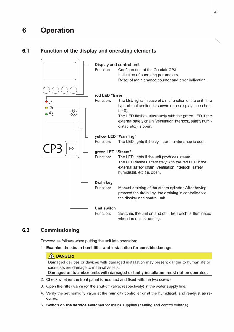
6 Operation
Display and control unitFunction: ConfigurationoftheCondairCP3. Indicationofoperatingparameters. Resetofmaintenancecounteranderrorindication.
red LED “Error”Function: TheLEDlightsincaseofamalfunctionoftheunit.The
typeofmalfunctionisshowninthedisplay,seechap-ter8).
TheLEDflashesalternatelywiththegreenLEDiftheexternalsafetychain(ventilationinterlock,safetyhumi-distat,etc.)isopen.
yellow LED “Warning”Function: TheLEDlightsifthecylindermaintenanceisdue.
green LED “Steam”Function: TheLEDlightsiftheunitproducessteam. TheLEDflashesalternatelywiththeredLEDifthe
externalsafetychain(ventilationinterlock,safetyhumidistat,etc.)isopen.
Drain keyFunction: Manualdrainingofthesteamcylinder.Afterhaving
pressedthedrainkey,thedrainingiscontrolledviathe display and control unit.
Unit switchFunction: Switchestheunitonandoff.Theswitchisilluminated
when the unit is running.
6.1 Function of the display and operating elements
6.2 Commissioning
Proceedasfollowswhenputtingtheunitintooperation:
1. Examinethesteamhumidifierandinstallationforpossibledamage.
DANGER!Damageddevicesordeviceswithdamagedinstallationmaypresentdangertohumanlifeorcause severe damage to material assets. Damaged units and/or units with damaged or faulty installation must not be operated.
2. Checkwhetherthefrontpanelismountedandfixedwiththetwoscrews.
3. Open the filtervalve(ortheshut-offvalve,respectively)inthewatersupplyline.4. Verifythesethumidityvalueatthehumiditycontrolleroratthehumidistat,andreadjustasre-
quired.
5. Switch on the service switchesformainssupplies(heatingandcontrolvoltage).
46
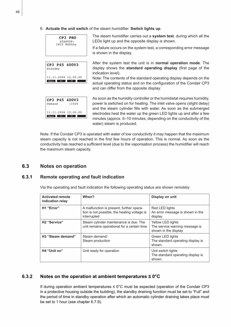
STARTUP: CP3 PRO
INIT MODULeXXXXXXXXXXXXXXXXXXXX
Menu Set
Thesteamhumidifiercarriesoutasystem test, during which all the LEDslightupandtheoppositedisplayisshown.
Ifafailureoccursonthesystemtest,acorrespondingerrormessageis shown in the display.
After the system test the unit is innormal operation mode. The display shows the standard operating display (first page of theindicationlevel).Note:ThecontentsofthestandardoperatingdisplaydependsontheactualoperatingstatusandontheconfigurationoftheCondairCP3andcandifferfromtheoppositedisplay.
As soon as the humidity controller or the humidistat requires humidity, powerisswitchedonforheating.Theinletvalveopens(slightdelay)and thesteamcylinderfillswithwater.Assoonas thesubmergedelectrodesheatthewaterupthegreenLEDlightsupandafterafewminutes(approx.5–10minutes,dependingontheconductivityofthewater)steamisproduced.
StandbyCP3 P45 400V3
XXXXXXXXXXXXXXXXXXXXXXXXXXXXXXXXXXXXXXXX11.11.2006 12.00.00Menu Set
Demand :100%CP3 P45 400V3
XXXXXXXXXXXXXXXXXXXXXXXXXXXXXXXXXXXXXXXX11.11.2006 12.00.00Menu Set
Note:IftheCondairCP3isoperatedwithwateroflowconductivityitmayhappenthatthemaximumsteamcapacity isnotreachedinthefirst fewhoursofoperation.This isnormal.Assoonastheconductivityhasreachedasufficientlevel(duetothevaporisationprocess)thehumidifierwillreachthe maximum steam capacity.
6. Actuate the unit switchofthesteamhumidifier.Switch lights up.
6.3 Notes on operation
6.3.1 Remote operating and fault indication
Viatheoperatingandfaultindicationthefollowingoperatingstatusareshownremotely:
Activated remote indication relay
When? Display on unit
H1 “Error” Amalfunctionispresent,furtheropera-tion is not possible, the heating voltage is interrupted
RedLEDlightsAn error message is shown in the display
H2 “Service” Steam cylinder maintenance is due. The unitremainsoperationalforacertaintime
YellowLEDlightsThe service warning message is shown in the display
H3 “Steam demand” Steamdemand/Steam production
GreenLEDlightsThe standard operating display is shown.
H4 “Unit on” Unitreadyforoperation UnitswitchlightsThe standard operating display is shown.
6.3.2 Notesontheoperationatambienttemperatures≤0°C
Ifduringoperationambienttemperatures≤0°Cmustbeexpected(operationoftheCondairCP3inaprotectivehousingoutsidethebuilding),thestandbydrainingfunctionmustbesetto“Full”andtheperiodoftimeinstandbyoperationafterwhichanautomaticcylinderdrainingtakesplacemustbesetto1hour(seechapter6.7.9).

47
6.3.3 Inspections during operation
DuringoperationtheCondairCP3andthehumidificationsystemhavetobeinspectedweekly.Onthisoccasioncheckthefollowing:
• thewaterandsteaminstallationforanyleakage.
• thesteamhumidifierandtheothersystemcomponentsforcorrectfixingandanydamage.
• theelectricinstallationforanydamage.
Iftheinspectionrevealsanyirregularities(e.g.leakage,errorindication)oranydamagedcompo-nentstaketheCondairCP3outofoperationasdescribedinchapter6.4. Then, contact your Condair representative.
6.3.4 Carrying out manual draining
Proceedasfollowstodraintheunitmanually:
Manual Drain
Modul A
Press START or STOP
Esc SetStart
6.4 Taking the unit out of operation
Inordertotakethesteamhumidifieroutofoperation,performthefollowingsteps:
1. Iftheunithastobeswitchedoffbecauseofamalfunction,pleasenotetheerrorcodeoftheactualerror message shown in the display.
2. Closetheshut-offvalveinthewatersupplyline
3. Start manual draining (see chapter 6.3.4)andwaituntilthesteamcylinderisempty.
4. Actuate the unit switch5. Disconnectsteamhumidifierfromthemains:Switchoffallserviceswitchestomainssup-
plies(heatingandcontrolvoltage)andsecureswitchesin“off”positionagainstaccidentallybeingswitchedon,orclearlymarktheswitches.
6. Ifambient temperatures ≤0°Cmustbeexpectedwhentheunitisoutofoperation (operation oftheCondairCP3inaprotectivehousingoutsidethebuilding):drainthewatersupplypipeandthewaterfilter(filtervalve).
WARNING! Danger of burning!Ifsteamwasproducedjustbeforetheunitistakenoutofoperation,waitbeforeopeningtheunitandletthesteamcylindercooldowntopreventdangerofburning.
1. Brieflypressthedrainkey. The drain dialogue appears in the display.
2. Pressthe<Start>key.Theheatingvoltageisinterruptedandthedrain pump starts. The yellowLEDflashes. To stop the drain cycle press the <Stop>key.Note:Bypressingthe<Esc>keytheunitreturnstotheindicationlevel. A drain cycle in progress will be stopped automatically.
48
Demand :50%CP3 P90 400V3
XXXXXXXXXXXXXXXXXXXXXXXXXXXXXXXXXXXXXXXX11.11.2006 12.00.00Menu Set
Software :1.00LA00CP3 P90 400V3
Controlsign.:0-10VLimitsignal :0-10VModbus Addr.:1Menu Set
Power Limit :100%CP3 P90 400V3
Request A :50%Request B :50%∑ Steam :45kg/hMenu Set
Cylindertype:A644CP3 P90 400V3
Operating HoursCylinder A :22hCylinder B :21hMenu Mdl B
Main menu
User :SetWerksebene :Set
Info :Set
Esc Set
Info
ErrorHistory:Set
Unit Status :Set
Esc Set
Main menu
User :Set
Info :Set
Esc Set
User CodeUser Code
88088808 Enter Number Enter Number Confirm with Set Confirm with SetEsc Set
UserUser
Settings :SetSettings :SetModbus :SetModbus :Set
Maintenance :SetMaintenance :Set
EscEsc Set
Drain Factor:1.0CP3 P90 400V3
Conductivity:>125µSStandbyDrain:PartialForce Drain :OnMenu Mdl B
TimerCP3 P90 400V3
On/Off Timer:OffPower Limit :OffHum.Setpoint:OffMenu Set
6.5 Overview and operating of the menu
Theoperatinganddisplayunitisoperatedviathefourkeyslocatedjustbelowthedisplay.The4statusfieldsatthebottomofthedisplayshowtheactivekeysthefunctionsassignedtothem.
Menu overview
actualkeysetting
keys
Indication level
Menu level
Operating
Menu Info– Interrogationofunitinformation– Interrogationofthemalfunctionlist
Menu User– Resetting the maintenance counter– Unitsettings– Modbus settings
StandbyCP3 P45 400V3
XXXXXXXXXXXXXXXXXXXXXXXXXXXXXXXXXXXXXXXX11.11.2006 12.00.00Menu Set
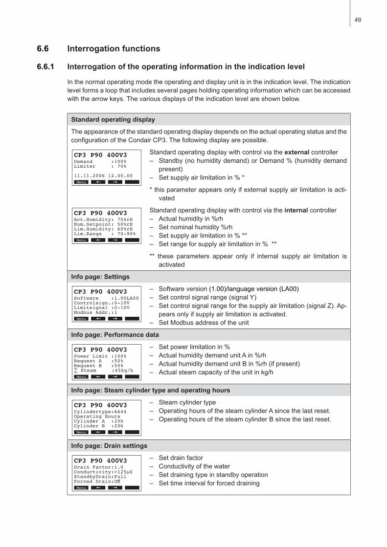
49
6.6 Interrogation functions
6.6.1 Interrogation of the operating information in the indication level
In the normal operating mode the operating and display unit is in the indication level. The indication levelformsaloopthatincludesseveralpagesholdingoperatinginformationwhichcanbeaccessedwiththearrowkeys.Thevariousdisplaysoftheindicationlevelareshownbelow.
Standard operating display
TheappearanceofthestandardoperatingdisplaydependsontheactualoperatingstatusandtheconfigurationoftheCondairCP3.Thefollowingdisplayarepossible.
Demand :100%CP3 P90 400V3
Limiter : 70% 11.11.2006 12.00.00Menu Set
Standard operating display with control via the external controller– Standby(nohumiditydemand)orDemand%(humiditydemand
present)– Setsupplyairlimitationin%*
*thisparameterappearsonlyifexternalsupplyairlimitationisacti-vated
Act.Humidity: 75%rHCP3 P90 400V3
Hum.Setpoint: 50%rHLim.Humidity: 60%rHLim.Range : 70-90%Menu Set
Standard operating display with control via the internal controller– Actualhumidityin%rh– Setnominalhumidity%rh– Setsupplyairlimitationin%**– Setrangeforsupplyairlimitationin%**
** these parameters appear only if internal supply air limitation isactivated
Info page: Settings
Software :1.00LA00CP3 P90 400V3
Controlsign.:0-10VLimitsignal :0-10VModbus Addr.:1Menu Set
– Softwareversion(1.00)/languageversion(LA00)– Setcontrolsignalrange(signalY)– Setcontrolsignalrangeforthesupplyairlimitation(signalZ).Ap-
pearsonlyifsupplyairlimitationisactivated.– SetModbusaddressoftheunit
Info page: Performance data
Power Limit :100%CP3 P90 400V3
Request A :50%Request B :50%∑ Steam :45kg/hMenu Set
– Setpowerlimitationin%– ActualhumiditydemandunitAin%rh– ActualhumiditydemandunitBin%rh(ifpresent)– Actualsteamcapacityoftheunitinkg/h
Info page: Steam cylinder type and operating hours
Cylindertype:A644CP3 P90 400V3
Operating HoursCylinder A :20hCylinder B :20hMenu Set
– Steam cylinder type– OperatinghoursofthesteamcylinderAsincethelastreset.– OperatinghoursofthesteamcylinderBsincethelastreset.
Info page: Drain settings
Drain Factor:1.0CP3 P90 400V3
Conductivity:>125µSStandbyDrain:FullForced Drain:OffMenu Set
– Setdrainfactor– Conductivityofthewater– Set draining type in standby operation– Settimeintervalforforceddraining

50
6.6.2 Interrogation of unit information
Selectthelistwiththeunitinformation:Path:Main menu > Info > Unit Status
Press< > and < >keys,inordertoselecttheunitinformationavailableinthelist:
1 Total operating hours since the initial commissioning.
2 Actualstatusoftheremoteindicationrelay“Steam”
3 Actualstatusoftheremoteindicationrelay“Service”
4 Actualstatusoftheremoteindicationrelay“Error”
5 Actualstatusoftheremoteindicationrelay“Uniton”
6 Actual signal value at analog output 1 (corresponds to the actual steamcapacityconvertedtothesignalrangeof0...10V)
7 Actual signal value at analog output 2(0...10V)
8 CalculatedmeandraintimeinsecondsofunitA(andB)
9 CurrentaveragerequestofunitA(andB)
10 ActualstatusofthemaximumlevelsensorinthesteamcylinderA(andB)
11 Countershowing thenumberof times themaximum level in thesteamcylinderA(andB)hasbeenexceeded
12 ActualstatusoftheinletvalveofunitA(andB)
13 ActualstatusofthedrainpumpofunitA(andB)
14 ActualstatusofthemaincontactorofunitA(andB)
Pressthe<Esc>keyseveraltimestoquittheunitinformationlistandtoreturn to the standard operating display.
Info Page: Timer settings
TimerCP3 P90 400V3
On/Off Timer :OffPower Limit :OffHum.Setpoint:OffMenu Set
– ActualstatusofOn/Offtimer– Actualstatusofpowerlimittimer– Actualstatusofhumiditysetpointtimer(appearsonlyifinternalP/PI
controllerisactivated)
Unit Status
0hRemote SteamOff
System Operating Hour
11.11.2006 12.00.00
Esc Set
Remote ServiceOffRemote ErrorOffRemote Unit OnOnRemote Analog Out-10.0 VRemote Analog Out-20.0 VAverage Drain TimeA 0.0 s B 0.0 s
Max. Level SensorA Off B OffMax. Level CounterA 0 B 0Inlet ValveA Off B OffOutlet PumpA Off B OffMain ContactorA Off B Off
Average RequestA 100% B 0 %
1
2
3
4
5
6
7
8
9
10
111213
14
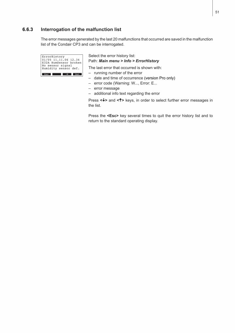
51
6.6.3 Interrogation of the malfunction list
Selecttheerrorhistorylist:Path:Main menu > Info > ErrorHistory
Thelasterrorthatoccurredisshownwith:– runningnumberoftheerror– dateandtimeofoccurrence(versionProonly)– errorcode(Warning:W...,Error:E...– error message– additionalinfotextregardingtheerror
Press< > and < >keys,inordertoselectfurthererrormessagesinthe list.
Pressthe<Esc>keyseveral timestoquit theerrorhistory listandtoreturn to the standard operating display.
Theerrormessagesgeneratedbythelast20malfunctionsthatoccurredaresavedinthemalfunctionlistoftheCondairCP3andcanbeinterrogated.
ErrorHistory
E32A HumSensor brokenNo sensor signalHumidity sensor def.
01/05 11.11.06 12.34
11.11.2006 12.00.00Esc Set
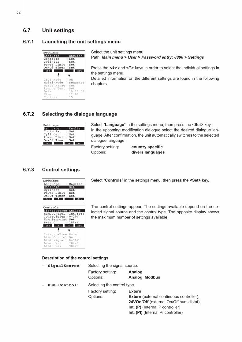
52
6.7 Unit settings
6.7.1 Launching the unit settings menu
Selecttheunitsettingsmenu:Path:Main menu > User > Password entry: 8808 > Settings
Pressthe< > and < >keysinordertoselecttheindividualsettingsinthe settings menu. Detailedinformationonthedifferentsettingsarefoundinthefollowingchapters.
6.7.2 Selecting the dialogue language
Settings
Controls :SetCylinder :SetPower Limit :Set
Language :English
On/Off Timer :SetEsc Set
Select “Language”inthesettingsmenu,thenpressthe<Set>key.Intheupcomingmodificationdialogueselectthedesireddialoguelan-guage.Afterconfirmation,theunitautomaticallyswitchestotheselecteddialogue language.Factorysetting: countryspecificOptions: divers languages
6.7.3 Control settings
Select “Controls”inthesettingsmenu,thenpressthe<Set>key.
The control settings appear. The settings available depend on the se-lected signal source and the control type. The opposite display shows themaximumnumberofsettingsavailable.
Settings
Controls :SetCylinder :SetPower Limit :Set
Language :English
On/Off Timer :SetEsc Set
Description of the control settings
– SignalSource: Selectingthesignalsource.Factorysetting: AnalogOptions: Analog, Modbus
– Hum.Control: Selectingthecontroltype.Factorysetting: ExternOptions: Extern(externalcontinuouscontroller), 24VOn/Off(externalOn/Offhumidistat), Int. (P)(InternalPcontroller) Int. (PI)(InternalPIcontroller)
Lim. Control:OnLimitsignal :0-10VLimit Min :70%rH
Integr.-Time:8min
Limit Max :90%rH
Controls
Hum.Control :Int.(PI)Controlsign.:0-10VHum.Setpoint:Set
SignalSource:Analog
P-Band :18%rHEsc Set
Remote Test :SetDate :19.10.07Time :12:00
Water Manag.:Set
Contrast :15
Settings
Controls :SetCylinder :SetPower Limit :Set
Language :English
On/Off Timer :SetEsc Set
GFCI-Mode :OnMulti-Mode :Sequence
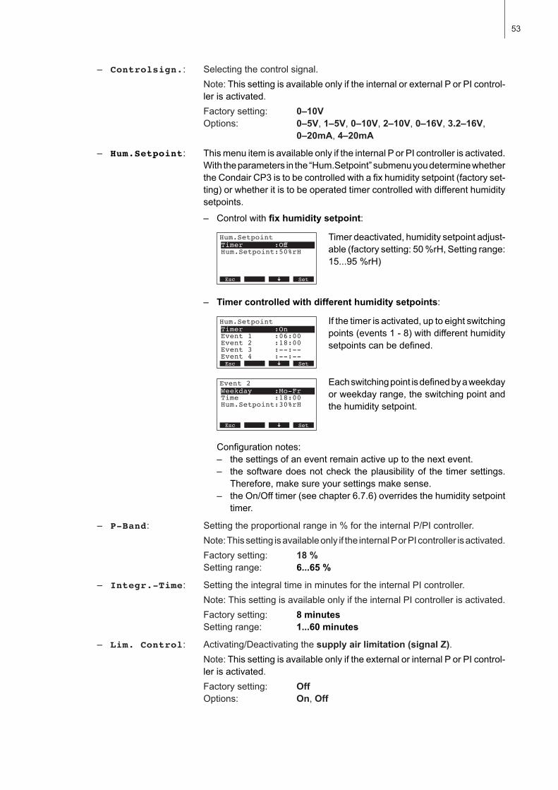
53
– Controlsign.: Selectingthecontrolsignal.Note:ThissettingisavailableonlyiftheinternalorexternalPorPIcontrol-ler is activated.Factorysetting: 0–10VOptions: 0–5V, 1–5V, 0–10V, 2–10V, 0–16V, 3.2–16V,
0–20mA, 4–20mA
– Hum.Setpoint: ThismenuitemisavailableonlyiftheinternalPorPIcontrollerisactivated.Withtheparametersinthe“Hum.Setpoint”submenuyoudeterminewhethertheCondairCP3istobecontrolledwithafixhumiditysetpoint(factoryset-ting)orwhetheritistobeoperatedtimercontrolledwithdifferenthumiditysetpoints.
– Control with fixhumiditysetpoint:
Timerdeactivated,humiditysetpointadjust-able(factorysetting:50%rH,Settingrange:15...95%rH)
– Timer controlled with different humidity setpoints:
Ifthetimerisactivated,uptoeightswitchingpoints(events1-8)withdifferenthumiditysetpointscanbedefined.
Eachswitchingpointisdefinedbyaweekdayorweekdayrange,theswitchingpointandthe humidity setpoint.
Configurationnotes:– thesettingsofaneventremainactiveuptothenextevent.– thesoftwaredoesnotcheck theplausibilityof the timersettings.
Therefore,makesureyoursettingsmakesense.– theOn/Offtimer(seechapter6.7.6)overridesthehumiditysetpoint
timer.
– P-Band: Settingtheproportionalrangein%fortheinternalP/PIcontroller.Note:ThissettingisavailableonlyiftheinternalPorPIcontrollerisactivated.Factorysetting: 18 %Settingrange: 6...65 %
– Integr.-Time: SettingtheintegraltimeinminutesfortheinternalPIcontroller.Note:ThissettingisavailableonlyiftheinternalPIcontrollerisactivated.Factorysetting: 8 minutesSettingrange: 1...60 minutes
– Lim. Control: Activating/Deactivatingthesupply air limitation (signal Z). Note:ThissettingisavailableonlyiftheexternalorinternalPorPIcontrol-ler is activated.Factorysetting: OffOptions: On, Off
Hum.Setpoint
Hum.Setpoint:50%rH
Timer :Off
Esc Set
Hum.Setpoint
Event 1 :06:00Event 2 :18:00Event 3 :--:--
Timer :On
Event 4 :--:--Esc Set
Event 2
Time :18:00Hum.Setpoint:30%rH
Weekday :Mo-Fr
Esc Set
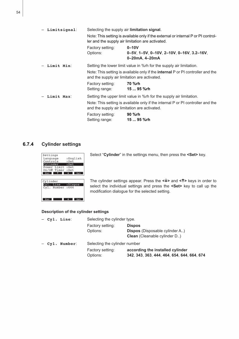
54
6.7.4 Cylinder settings
Settings
Controls :SetCylinder :SetPower Limit :Set
Language :English
On/Off Timer :SetEsc Set
Cylinder
Cyl. Number :644Cyl. Line :Dispos
Esc Set
Select “Cylinder”inthesettingsmenu,thenpressthe<Set>key.
Thecylindersettingsappear.Pressthe< > and < >keysinordertoselect the individual settings and press the <Set> key to call up themodificationdialoguefortheselectedsetting.
Description of the cylinder settings
– Cyl. Line: Selectingthecylindertype.Factorysetting: DisposOptions: Dispos(DisposablecylinderA..) Clean (CleanablecylinderD..)
– Cyl. Number: SelectingthecylindernumberFactorysetting: according the installed cylinderOptions: 342, 343, 363, 444, 464, 654, 644, 664, 674
– Limitsignal: Selectingthesupplyairlimitation signal. Note:ThissettingisavailableonlyiftheexternalorinternalPorPIcontrol-ler and the supply air limitation are activated.Factorysetting: 0–10VOptions: 0–5V, 1–5V, 0–10V, 2–10V, 0–16V, 3.2–16V,
0–20mA, 4–20mA
– Limit Min: Settingthelowerlimitvaluein%rhforthesupplyairlimitation.Note:ThissettingisavailableonlyiftheinternalPorPIcontrollerandtheand the supply air limitation are activated.Factorysetting: 70 %rhSettingrange: 15 ... 95 %rh
– Limit Max: Settingtheupperlimitvaluein%rhforthesupplyairlimitation.Note:ThissettingisavailableonlyiftheinternalPorPIcontrollerandtheand the supply air limitation are activated.Factorysetting: 90 %rhSettingrange: 15 ... 95 %rh
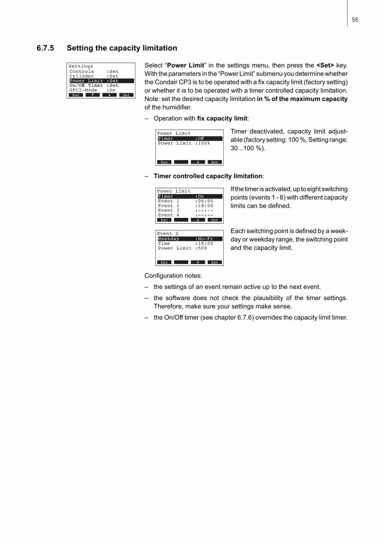
55
Settings
Cylinder :SetPower Limit :SetOn/Off Timer :Set
Controls :Set
GFCI-Mode :OnEsc Set
6.7.5 Setting the capacity limitation
Select “Power Limit” inthesettingsmenu,thenpressthe<Set>key.Withtheparametersinthe“PowerLimit”submenuyoudeterminewhethertheCondairCP3istobeoperatedwithafixcapacitylimit(factorysetting)or whether it is to be operated with a timer controlled capacity limitation. Note:setthedesiredcapacitylimitationin % of the maximum capacity ofthehumidifier.
– Operation with fixcapacitylimit:
Timer deactivated, capacity limit adjust-able(factorysetting:100%,Settingrange:30...100%).
– Timer controlled capacity limitation:
Ifthetimerisactivated,uptoeightswitchingpoints(events1-8)withdifferentcapacitylimitscanbedefined.
Eachswitchingpointisdefinedbyaweek-dayorweekdayrange,theswitchingpointand the capacity limit.
Configurationnotes:
– thesettingsofaneventremainactiveuptothenextevent.
– the software does not check the plausibility of the timer settings.Therefore,makesureyoursettingsmakesense.
– theOn/Offtimer(seechapter6.7.6)overridesthecapacitylimittimer.
Power Limit
Power Limit :100%
Timer :Off
Esc Set
Power Limit
Event 1 :06:00Event 2 :18:00Event 3 :--:--
Timer :On
Event 4 :--:--Esc Set
Event 2
Time :18:00Power Limit :50%
Weekday :Mo-Fr
Esc Set
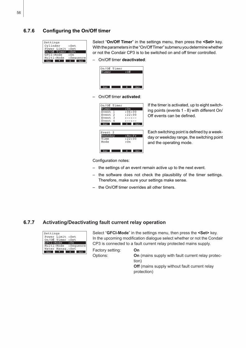
56
6.7.7 Activating/Deactivating fault current relay operation
Settings
On/Off Timer :SetGFCI-Mode :OnMulti-Mode :Sequence
Power Limit :Set
Water Manag.:SetEsc Set
Select “GFCI-Mode”inthesettingsmenu,thenpressthe<Set>key.IntheupcomingmodificationdialogueselectwhetherornottheCondairCP3isconnectedtoafaultcurrentrelayprotectedmainssupply.Factorysetting: OnOptions: On (mainssupplywithfaultcurrentrelayprotec-
tion) Off (mainssupplywithoutfaultcurrentrelay
protection)
Settings
Power Limit :SetOn/Off Timer :SetGFCI-Mode :On
Cylinder :Set
Multi-Mode :SequenceEsc Set
6.7.6 ConfiguringtheOn/Offtimer
Select “On/Off Timer”inthesettingsmenu,thenpressthe<Set>key.Withtheparametersinthe“On/OffTimer”submenuyoudeterminewhetherornottheCondairCP3istobeswitchedonandofftimercontrolled.
– On/Offtimerdeactivated:
– On/Offtimeractivated:
Ifthetimerisactivated,uptoeightswitch-ingpoints(events1-8)withdifferentOn/Offeventscanbedefined.
Eachswitchingpointisdefinedbyaweek-dayorweekdayrange,theswitchingpointand the operating mode.
Configurationnotes:
– thesettingsofaneventremainactiveuptothenextevent.
– the software does not check the plausibility of the timer settings.Therefore,makesureyoursettingsmakesense.
– theOn/Offtimeroverridesallothertimers.
On/Off Timer
Timer :Off
Esc Set
On/Off Timer
Event 1 :06:00Event 2 :22:00Event 3 :--:--
Timer :On
Event 4 :--:--Esc Set
Event 2
Time :22:00Mode :On
Weekday :Mo-Fr
Esc Set
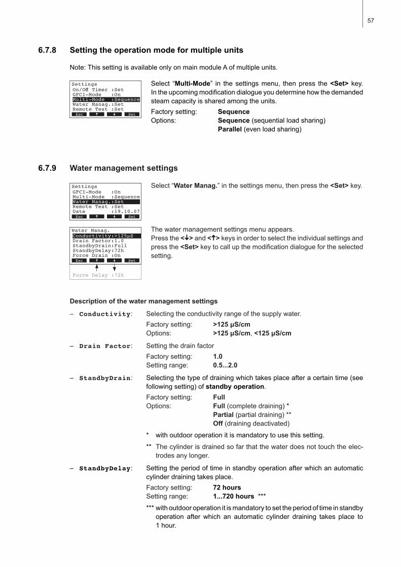
57
6.7.9 Water management settings
Select “Water Manag.”inthesettingsmenu,thenpressthe<Set>key.
The water management settings menu appears. Pressthe< > and < >keysinordertoselecttheindividualsettingsandpress the <Set>keytocallupthemodificationdialoguefortheselectedsetting.
Settings
Multi-Mode :SequenceWater Manag.:SetRemote Test :Set
GFCI-Mode :On
Date :19.10.07Esc Set
Description of the water management settings
– Conductivity: Selectingtheconductivityrangeofthesupplywater.Factorysetting: >125μS/cmOptions: >125μS/cm, <125μS/cm
– Drain Factor: SettingthedrainfactorFactorysetting: 1.0Settingrange: 0.5...2.0
– StandbyDrain: Selectingthetypeofdrainingwhichtakesplaceafteracertaintime(seefollowingsetting)ofstandby operation.Factorysetting: FullOptions: Full (completedraining)* Partial(partialdraining)** Off(drainingdeactivated)* withoutdooroperationitismandatorytousethissetting.
** Thecylinderisdrainedsofarthatthewaterdoesnottouchtheelec-trodes any longer.
– StandbyDelay: Settingtheperiodoftimeinstandbyoperationafterwhichanautomaticcylinderdrainingtakesplace.Factory setting: 72 hoursSetting range: 1...720 hours ******withoutdooroperationitismandatorytosettheperiodoftimeinstandby
operation after which an automatic cylinder draining takes place to1 hour.
6.7.8 Setting the operation mode for multiple units
Settings
GFCI-Mode :OnMulti-Mode :SequenceWater Manag.:Set
On/Off Timer :Set
Remote Test :SetEsc Set
Select “Multi-Mode” in thesettingsmenu, thenpress the<Set> key.Intheupcomingmodificationdialogueyoudeterminehowthedemandedsteam capacity is shared among the units.Factorysetting: SequenceOptions: Sequence(sequentialloadsharing) Parallel (evenloadsharing)
Note:ThissettingisavailableonlyonmainmoduleAofmultipleunits.
Force Delay :72h
Water Manag.
Drain Factor:1.0StandbyDrain:FullStandbyDelay:72h
Conductivity:>125µS
Force Drain :OnEsc Set
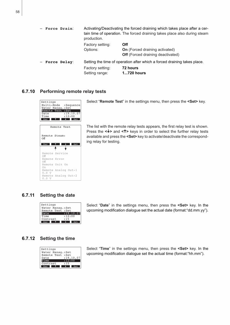
58
6.7.10 Performing remote relay tests
Settings
Water Manag.:SetRemote Test :SetDate :19.10.07
Multi-Mode :Sequence
Time :12:00Esc Set
Select “Remote Test”inthesettingsmenu,thenpressthe<Set>key.
Thelistwiththeremoterelaytestsappears,thefirstrelaytestisshown.Press the< > and < >keys inorder toselect the further relay testsavailable and press the <Set>keytoactivate/deactivatethecorrespond-ingrelayfortesting.
Remote Test
Remote Steam:Off
Esc Set
Remote ServiceOff 12.00.00Remote ErrorOffRemote Unit OnOn.11.2006 12.00.00Remote Analog Out-10.0 VRemote Analog Out-20.0 V
6.7.11 Setting the date
Select “Date” in the settingsmenu, thenpress the<Set> key. In the upcomingmodificationdialoguesettheactualdate(format:“dd.mm.yy”).
Settings
Remote Test :SetDate :19.10.07Time :12:00
Water Manag.:Set
Contrast :15Esc Set
Settings
Remote Test :SetDate :19.10.07Time :12:00
Water Manag.:Set
Contrast :15Esc Set
6.7.12 Setting the time
Select “Time” in thesettingsmenu, thenpress the<Set> key. In the upcomingmodificationdialoguesettheactualtime(format:“hh.mm”).
– Force Drain: Activating/Deactivatingtheforceddrainingwhichtakesplaceafteracer-taintimeofoperation.Theforceddrainingtakesplacealsoduringsteamproduction.Factorysetting: OffOptions: On (Forceddrainingactivated) Off(Forceddrainingdeactivated)
– Force Delay: Settingthetimeofoperationafterwhichaforceddrainingtakesplace.Factory setting: 72 hoursSetting range: 1...720 hours
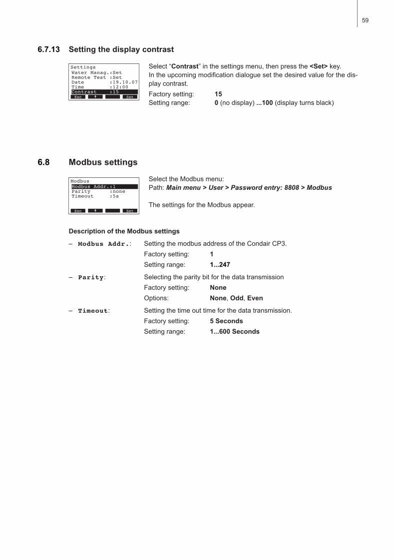
59
6.7.13 Setting the display contrast
Select “Contrast”inthesettingsmenu,thenpressthe<Set>key.Intheupcomingmodificationdialoguesetthedesiredvalueforthedis-play contrast.Factorysetting: 15Settingrange: 0(nodisplay)...100(displayturnsblack)
Settings
Remote Test :SetDate :19.10.07Time :12:00
Water Manag.:Set
Contrast :15Esc Set
6.8 Modbus settings
SelecttheModbusmenu:Path:Main menu > User > Password entry: 8808 > Modbus
ThesettingsfortheModbusappear.
Modbus
Parity :noneTimeout :5sXXXXXXXXXXXXXXXXXXXX
Modbus Addr.:1
11.11.2006 12.00.00Esc Set
Description of the Modbus settings
– Modbus Addr.: SettingthemodbusaddressoftheCondairCP3.Factorysetting: 1Settingrange: 1...247
– Parity: SelectingtheparitybitforthedatatransmissionFactorysetting: NoneOptions: None, Odd, Even
– Timeout: Settingthetimeouttimeforthedatatransmission.Factorysetting: 5 SecondsSettingrange: 1...600 Seconds
60
7 Maintenance
QualificationofpersonnelAllmaintenanceworkmustbecarriedoutonlybywellqualifiedandtrainedpersonnelauthorisedby the owner.Itistheowner’sresponsibilitytoverifyproperqualificationofthepersonnel.
General note Theinstructionsanddetailsformaintenanceworkmustbefollowedandupheld.
Onlythemaintenanceworkdescribedinthisdocumentationmaybecarriedout.
OnlyuseoriginalCondairsparepartstoreplacefaultyparts.
SafetySomemaintenanceworkrequiresremovaloftheunitcover.Pleasenotethefollowing:
DANGER! Danger of electrical chockYoumaygetintouchwithlivepartswhentheunitisopen.Touchinglivepartsmaycausesevereinjuryorevenlethalviolation.
Prevention: BeforecarryingoutanymaintenanceworksettheCondairCP3outofoperationasdescribed in chapter 6.4(switchofftheunit,disconnectitfromthemainsandstopthewatersup-ply)andsecuretheunitagainstinadvertentpower-up.
CAUTION!The electronic components inside the humidifier are very sensitive to electrostatic dis-charge.Prevention: Beforecarryingoutanymaintenanceworktotheelectricalorelectronicequipmentofthehumidifier,appropriatemeasures must be taken to protect the respective components against damage caused by electrostatic discharge (ESD protection).
7.1 Important notes on maintenance

61
7.2 Maintenance list
TomaintainoperationalsafetytheCondairCP3steamhumidifiermustbemaintainedatregularin-tervals.Thisisdifferentiatedbetweenthefirst maintenance after approx. 500 operating hours (I), steam cylinder maintenance after the yellow LED lights (II) and annual maintenance (III). Belowyouwillfindasummaryoftheworktobecarriedoutforeachofthethreemaintenancestages.
Components Interval Work to be done
I II III
Cleanable steam cylinder Type D..
X X X Clean steam cylinder and electrodes and checkfordamage,replaceifnecessary.Note:Thesteamcylindermustbereplacedafteramaximumoperat-ingtimeof5,000h.
Electrode plug X X X Checktoseefirmlypositioned(removecoverandtighten fixing screw with hexagonal head socketwrench).Warning!Thisworkshouldonlybecarriedoutbyan electrician.
Replacement steam cyl. type A.. X Remove and replace.
Drainpump X Remove,disassembleandclean,replaceifneces-sary.
Steam cylinder receptacle X Inspect,cleanifnecessary.
Inlet valve X Remove and clean filter insert, replace if neces-sary.
Drainpipeandsiphon X Inspect, clean if necessary (decalcify and rinseout).
Steam installation X X Inspect steam and condensate hoses for cracksand to see that they are correctly attached, replace faultyhoses.
Water installation X X Inspectwaterhoses in theunit forcracksand toseethattheyarecorrectlyattached,replacefaultyhosesChecksupplypipeistight,maketightifnecessary.Cleanwaterfilter,ifavailable.
Electrical installation X X Checkallcablesintheunitarefirmlypositionedandexaminestatusofinsulation.
62
7.3 Removing and installing parts for maintenance
7.3.1 Removal and installation of the steam cylinder
1. Useascrewdrivertoundothetwoscrewsfixingthefrontpaneltotheunit,thenremovethefrontpanel.
2. Units with steam hose connector in housing top:releasethetwohoseclampsontherubbersleeveusingascrewdriver,thendetachtherubbersleevefromtheconnectionintheunitcoverandfromthesteamoutletconnectionofthesteamcylinder.
Units without steam hose connector in housing top (not shown): release the hose clamp onthesteamhoseusingascrewdriver,thendetachthesteamhosefromthesteamoutletcon-nectionofthesteamcylinder.
1 2
3 4
3. Removeallplugsfromtheelectrodesandfromthelevelsensor.
4. Loosenthetwoscrewsofthesteamcylinderfixingdevicebyafewturns,thenpushthefixingdevice upwards until it comes loose and remove it.

63
5. Carefullyliftsteamcylinderawayfromthecylinderreceptacle,thenremoveittothefront.
CAUTION!Putsteamcylinderdowncarefullytoavoiddamagetothelowerconnectionpiece!
Installationofthesteamcylinderfollowsthereversesequence.Observe the following:– Beforeinstallingthesteamcylinderintheunit,checktheO-ringofthecylinderreceptaclefor
damageandreplaceifnecessary.
– MoistentheO-ringofthecylinderreceptaclewithwater(donotusegreaseoroil),theninsertsteam cylinder into the receptacle and push it down to the stop.
– Attach the electrode plugs and the level sensor plug to the respective electrode and sensor con-nectionsaccordingtothefollowingtable.
Steam cylinder typeA363 / D363A464 / D464
A664 / D664A674 / D674
Cableconfiguration
5
Sensor white
brown
red
blackSensor white
brown
red
blackbrown
red
black
– Fastensteamhoseontheconnectorintheunitcoverandonsteamconnectorofthecylinderwith hose clamps.
CAUTION!Aleakysteamhosecancausedamageduetomoistureinsidetheunit.
CAUTION!Theoutletconnectorofthesteamcylinderismadeofplastic.Do not overtighten the hose clamponthesteamconnectorofthesteamcylinder.

64
7.3.2 Disassembly and assembly of the cleanable steam cylinder type D...
1. Fastenelectrodesnapfasteningsandpushelectrodesapprox.2cmdownwardsintothesteamcylinder.
2. Releaseclampclipsofthecylindercoverandraisecover.
3. Removecarefullyelectrodesbyliftingupwards.
4. RemoveO-ringsfromtheelectrodes.Note:IntactO-ringscanbereused.
The assemblyofthecleanablesteamcylinderfollowsthereversesequence.Observe the follow ing:– Beforeassemblingthesteamcylinder,checktheO-ringinthesteamcylindercoverandtheO-rings
ontheelectrodesfordamage,andreplaceifnecessary.MakesuretorelocateO-ringscorrectly.
– Insertelectrodesintosteamcylindercoverandpushthemupwardsuntilthesnapfastenersengage.
– Placethecylindercover(withmountedO-ring)inthecorrectposition(alignthetwocamsonthesteamcylinderbodywiththecorrespondinggroovesinthecylindercover)onthecylinderbodyandsecurecoverwiththefasteningclips.
1 3
2
4
65
7.3.3 Removal and installation of the water cup and the water hoses
Toimproveaccessibilityforremovingthewatercupandthewaterhoseswerecommendtoremovethesteamcylinderfirst(seechapter7.3.1).
1. Releasehoseclampsusingpliers,thendisconnectallhosesfromthecorrespondingconnectorsand remove the hoses.Note:Thehosesconnectedtothewatercupmayalsoberemovedtogetherwiththewatercup(seeillustration)andthendisconnectedfromtheconnectorsofthewatercupoutsidetheunit.
2. Carefullypullfixingclipofthewatercuptothefront,thenpushwatercupdownfromtheholdingdeviceandremoveittothefront.
The installationofthewatercupandthewaterhosesfollowsthereversesequence.Beforefixingthe water hoses to the connector using the hose clamps, align the hoses in a way that they are not twisted.
66
7.3.4 Removal and installation of the drain pump
The steam cylinder does not need to be removed when removing the drain pump.
1. Detachelectriccables(polarityofthecablesmustnotbeobserved).
2. Releasehoseclampsandremovethehosesfromtheconnectors.
3. Pullthedrainpumpofftheholdingdevice.
4. Separatetheelectricmotorfromthepumpbody:releasethelockonthebayonetcatch,thencounter-rotate the electric motor and the pump body.
The assembly and the installationof thedrainpumpfollowsthereversesequence.Beforeas-semblingthepump,checkO-ringfordamageandreplaceifnecessary.Then,placetheO-ringonthe centering collar and moisten the O-ring with water.
7.3.5 Removal and installation of the inlet valve
The steam cylinder does not need to be removed when removing the inlet valve.
1. Detachelectriccables(polarityofthecablesmustnotbeobserved).
2. Releasehoseclampandremovethehosefromtheconnector.
3. Unlockunionnutofthewaterpipeandremovewaterpipe.
4. Pulltheinletvalveofftheholdingdevice.
The installationoftheinletvalvefollowsthereversesequence.Theunionnutofthewaterpipemust be tightened by hand only.
1
2
2
3
4
2
3
3
1
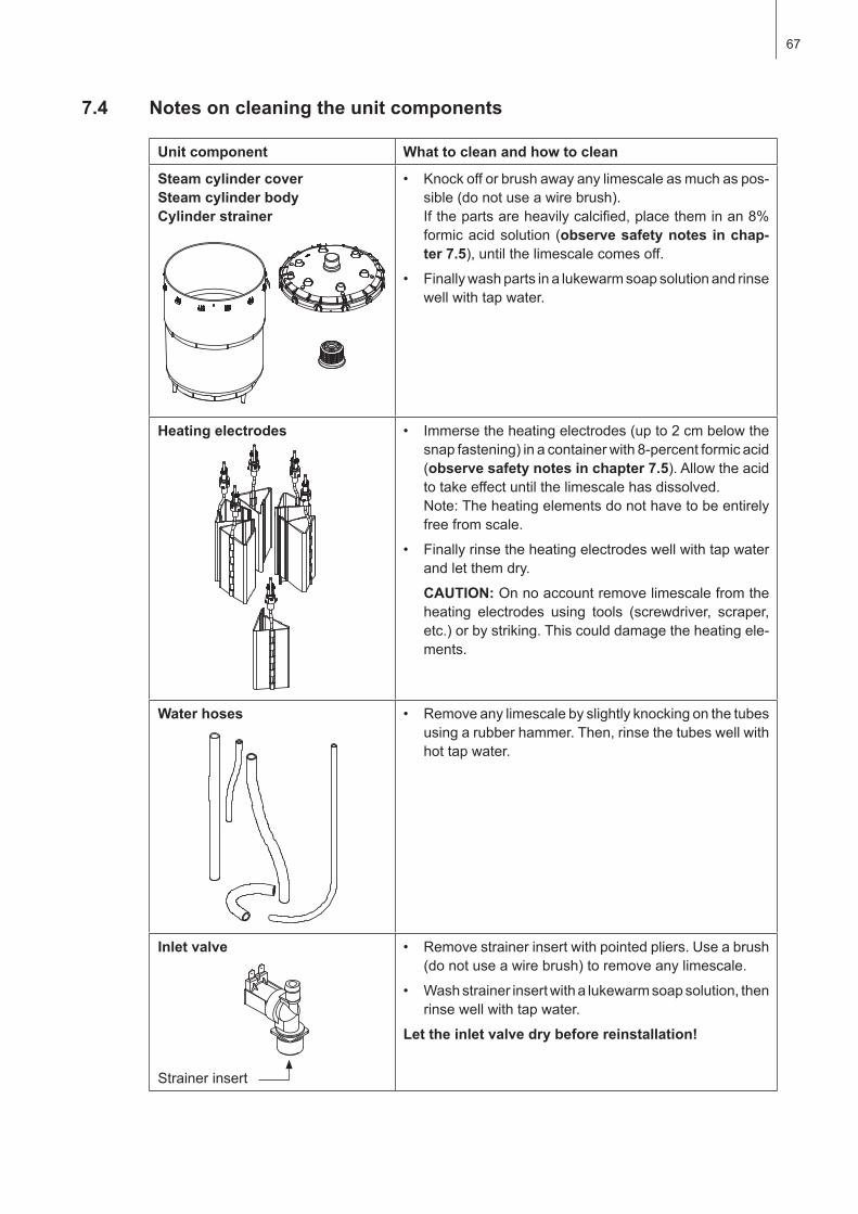
67
7.4 Notes on cleaning the unit components
Unit component What to clean and how to clean
Steam cylinder cover Steam cylinder bodyCylinder strainer
• Knockofforbrushawayanylimescaleasmuchaspos-sible(donotuseawirebrush).Ifthepartsareheavilycalcified,placetheminan8%formicacidsolution(observe safety notes in chap-ter 7.5),untilthelimescalecomesoff.
• Finallywashpartsinalukewarmsoapsolutionandrinsewell with tap water.
Heating electrodes • Immersetheheatingelectrodes(upto2cmbelowthesnapfastening)inacontainerwith8-percentformicacid(observe safety notes in chapter 7.5).Allowtheacidtotakeeffectuntilthelimescalehasdissolved.Note:Theheatingelementsdonothavetobeentirelyfreefromscale.
• Finallyrinsetheheatingelectrodeswellwithtapwaterand let them dry.
CAUTION: Onnoaccountremovelimescalefromtheheating electrodes using tools (screw driver, scraper, etc.)orbystriking.Thiscoulddamagetheheatingele-ments.
Water hoses • Removeanylimescalebyslightlyknockingonthetubesusing a rubber hammer. Then, rinse the tubes well with hot tap water.
Inlet valve
Strainer insert
• Removestrainerinsertwithpointedpliers.Useabrush(donotuseawirebrush)toremoveanylimescale.
• Washstrainerinsertwithalukewarmsoapsolution,thenrinse well with tap water.
Let the inlet valve dry before reinstallation!
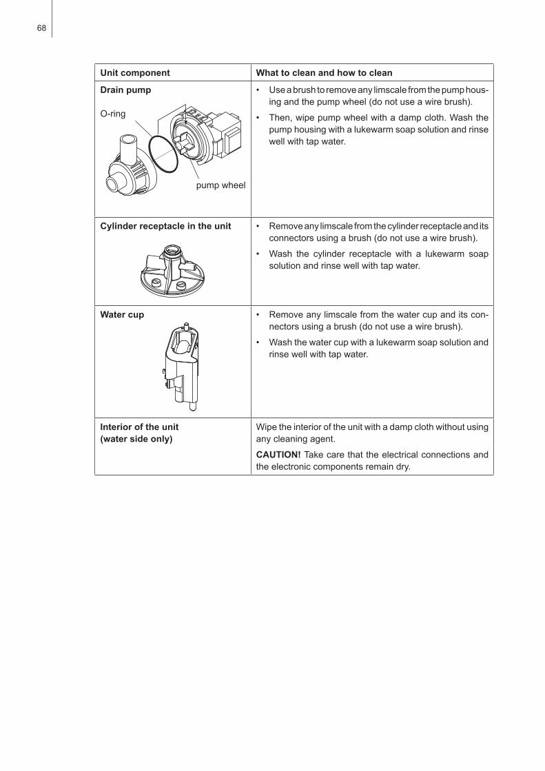
68
Unit component What to clean and how to clean
Drain pump
O-ring
pump wheel
• Useabrushtoremoveanylimscalefromthepumphous-ingandthepumpwheel(donotuseawirebrush).
• Then,wipepumpwheelwithadampcloth.Washthepumphousingwithalukewarmsoapsolutionandrinsewell with tap water.
Cylinder receptacle in the unit • Removeanylimscalefromthecylinderreceptacleanditsconnectorsusingabrush(donotuseawirebrush).
• Wash the cylinder receptacle with a lukewarm soapsolution and rinse well with tap water.
Water cup • Removeanylimscalefromthewatercupanditscon-nectorsusingabrush(donotuseawirebrush).
• Washthewatercupwithalukewarmsoapsolutionandrinse well with tap water.
Interior of the unit (water side only)
Wipetheinterioroftheunitwithadampclothwithoutusingany cleaning agent.
CAUTION! Takecarethattheelectricalconnectionsandthe electronic components remain dry.
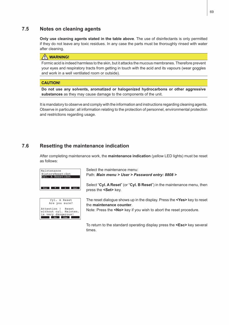
69
7.5 Notes on cleaning agents
Only use cleaning agents stated in the table above.Theuseofdisinfectantsisonlypermittediftheydonotleaveanytoxicresidues.Inanycasethepartsmustbethoroughlyrinsedwithwateraftercleaning.
WARNING!Formicacidisindeedharmlesstotheskin,butitattacksthemucousmembranes.Thereforepreventyoureyesandrespiratorytractsfromgettingintouchwiththeacidanditsvapours(weargogglesandworkinawellventilatedroomoroutside).
CAUTION!Do not use any solvents, aromatized or halogenized hydrocarbons or other aggressive substancesastheymaycausedamagetothecomponentsoftheunit.
Itismandatorytoobserveandcomplywiththeinformationandinstructionsregardingcleaningagents.Observeinparticular:allinformationrelatingtotheprotectionofpersonnel,environmentalprotectionand restrictions regarding usage.
7.6 Resetting the maintenance indication
Aftercompletingmaintenancework,themaintenance indication(yellowLEDlights)mustberesetasfollows:
Selectthemaintenancemenu:Path:Main menu > User > Password entry: 8808 >
Select “Cyl. A Reset”(or“Cyl. B Reset”)inthemaintenancemenu,thenpress the <Set>key.
Theresetdialogueshowsupinthedisplay.Pressthe<Yes>keytoresetthe maintenance counter.Note:Pressthe<No>keyifyouwishtoaborttheresetprocedure.
To return to the standard operating display press the <Esc>keyseveraltimes.
Maintenance
Cyl. A Reset:Set
XXXXXXXXXXXXXXXXXXXX
HistoryReset:Set
11.11.2006 12.00.00Esc Set
Cyl. A Reset
Attention ! Resetwithout cyl. Mainten.
Are you sure?
is very dangerous!Esc SetNo Yes

70
8 Troubleshooting
Important! Mostoperationalmalfunctionsarenotcausedbyfaultyequipmentbutratherbyimproperinstallationordisregardingofplanningguidelines.Therefore,acompletefaultdiagnosisalwaysin-volvesathoroughexaminationoftheentiresystem.Often,thesteamhoseconnectionhasnotbeenproperlyexecuted,orthefaultlieswiththehumiditycontrolsystem.
8.1 Malfunction list
8.1.1 System faults
Warning Error Cause Remedy
LED Display LED Display
CP3 Card missing (Test run possible)
CP3 Card missing
––– WarningW1: CP3-Card Missing
redlights Error
E1: CP-Card Missing
No CP3 Card installed on the control board.
Install CP3 Card or start test run.
CP3 Card is empty
––– ––– redlights Error
E2: CP-Card Empty
No data stored on the CP3 Card. Install new CP3 Card.
CP3 Card is defective
––– ––– redlights Error
E3: CP-Card Invalid
Invalid data stored on the CP3 Card. Install new CP3 Card.
CP3 Card is incompatible
––– ––– redlights Error
E4: CP-Card incompat
The installed CP3 Card is not compatible with the hardware of the unit or with the basic settings of the control electronics.
Install correct CP3 Card. Let your Condair service technician adjust the basic settings.
Module B missing
––– ––– redlights Error
E5: Modul B Missing
Module B not correctly connected or de-fective.
Check module B and both connecting cables.
Extension unit missing Main unit missing
––– WarningW6: Extended Missing
redlights Error
E6: Main Missing
No communication between main unit and extension unit.
Check/connect bus cable.
Main or extension unit not switched on. Switch on main unit and/or extension unit.
Extension unit is in error status
––– ––– redlights Error
E7: Extended Error
The display of the main unit indicates that the extension unit is in error status.The type of error is shown on the display of the extension unit.
Take corresponding measures according to the indicated error type.
Extension unit is not compatible
––– ––– redlights Error
E8: Extend.Incompat.
The CP3 Card of the main unit is not compat-ible with the one of the extension unit.
Install correct CP3 Cards into the units.
Wrong hardware settings
––– ––– redlights Error
E9: Illegal Settings
False test run parameters. Let your Condair service technician adjust the test run parameters (heating voltage, Cylinder-No.).
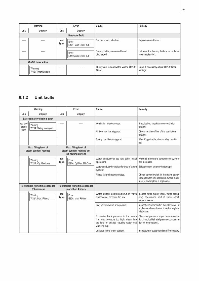
71
Warning Error Cause Remedy
LED Display LED Display
Hardware fault
––– ––– redlights Error
E10: Flash R/W Fault
Control board defective. Replace control board.
––– ––– ErrorE11: Clock R/W Fault
Backup battery on control board discharged.
Let have the backup battery be replaced (see chapter 8.4).
On/Off timer active
––– WarningW12: Timer Disable
––– ––– The system is deactivated via the On/Off-Timer.
None. If necessary adjust On/Off timer settings.
8.1.2 Unit faults
Warning Error Cause Remedy
LED Display LED Display
External safety chain is open
red and green flash
WarningW20A: Safety loop open
––– ––– Ventilation interlock open. If applicable, check/turn on ventilation system.
Air flow monitor triggered. Check ventilator/filter of the ventilation system.
Safety humidistat triggered. Wait. If applicable, check safety humidi-stat
Max. filling level of steam cylinder reached
Max. filling level of steam cylinder reached but
no heating current
––– WarningW21A: Cyl.Max.Level
redlights Error
E21A: Cyl.Max.&NoCurr
Water conductivity too low (after initial operation).
Wait until the mineral content of the cylinder has increased
Water conductivity too low for type of steam cylinder.
Select correct steam cylinder type.
Phase failure heating voltage. Check service switch in the mains supply line and switch on if applicable. Check mains fuse(s) and replace if applicable.
Permissible filling time exceeded (20 minutes)
Permissible filling time exceeded (more than 4 hours)
––– WarningW22A: Max. Filltime
redlights Error
E22A: Max. Filltime
Water supply obstructed/shut-off valve closed/water pressure too low.
Inspect water supply (filter, water piping, etc.), check/open shut-off valve, check water pressure.
Inlet valve blocked or defective. Inspect strainer insert in the inlet valve, if applicable clean strainer insert or replace inlet valve.
Excessive back pressure in the steam line (duct pressure too high, steam line too long or kinked), causing water loss via filling cup.
Check duct pressure, inspect steam installa-tion. If applicable install pressure compensa-tion kit (see options).
Leakage in the water system. Inspect water system and seal if necessary.
72
Warning Error Cause Remedy
LED Display LED Display
No electrode current for more than 20 minutes
No electrode current for more than 4 hours
––– WarningW23A: No Current
redlights Error
E23A: No Current
Phase failure heating voltage. Inspect/turn on service switch of the mains supply line. Inspect the fuses of the mains supply, replace if necessary.
Water supply obstructed/shut-off valve closed/water pressure too low.
Inspect water supply (filter, water piping, etc.), check/open shut-off valve, check water pressure.
Inlet valve blocked or defective. Inspect strainer insert of the inlet valve, if applicable clean strainer insert or replace inlet valve.
Excessive back pressure in the steam line (duct pressure too high, steam line too long or kinked), causing water loss via filling cup.
Check duct pressure, inspect steam installa-tion. If applicable install pressure compensa-tion kit (see options).
Leakage in the water system. Inspect water system and seal if necessary.
Electrode current in relation to the steam demand too high
Electrode current in relation to the steam demand too high
––– WarningW24A: Over Current
redlights Error
E24A: Over Current
Humidity demand has decreased too fast. Automatic adaptation of the operating point.
Drain pump defective. Inspect drain pump, replace if necessary.
Drain in steam cylinder blocked. Clean/replace steam cylinder.
Water conductivity too high for this type of steam cylinder.
Select correct steam cylinder type.
Max. admissible electrode current exceeded
Max. admissible electrode current exceeded
––– WarningW25A: Excess Current
redlights Error
E25A: Excess Current
Drain pump defective. Inspect drain pump, replace if necessary.
Drain in steam cylinder blocked. Clean/replace steam cylinder.
Water conductivity too high for this type of steam cylinder.
Select correct steam cylinder type.
Main contactor jammed
––– ––– redlights Error
E26A: Req.Off Current
Main contactor jammed in activated posi-tion.
Inspect main contactor, replace if necessary.
Foam detection Foam detection (4 automatic drainings within 24 hours)
––– WarningW27A: Foam
redlights Error
E27A: Foam
Foaming in steam cylinder. Drain steam cylinder via drain key (sev-eral times, if necessary). Check quality of the supply water.
Steam cylinder needs service Service interval for steam cylinder exceeded
yellowlights Warning
W28A: Cyl. Maintenance
red and yellowflash
ErrorE28A: Cyl. Maintenance
Mineral deposits and/or electrodes spent. Steam cylinder Type A: replaceSteam cylinder Type D: clean
Important: After replacement or cleaning of the steam cylinder, reset the maintenance counter (see chapter 7.6).
Steam cylinder needs service Max. operating hours of the steam cylinder reached
yellowlights Warning
W29A: Cyl. Maintenance
red and yellowflash
ErrorE29A: Cyl. Maintenance
Maximum operating hours of the steam cylinder reached.
Steam cylinder Type A: replaceSteam cylinder Type D: clean
Important: After replacement or cleaning of the steam cylinder, reset the maintenance counter (see chapter 7.6).
73
8.2 Resetting the error indication (red LED lights)
Toresettheerrorindication:
Disconnectthesteamairhumidifierfromthemains.Waitapprox.5seconds,thenreconnectthe unit to the mains.
Note:Ifthefaulthasnotbeeneliminated,theerrorindicationreappearsafterashortwhile.
8.3 Notes on fault elimination
DANGER!Fortheeliminationoffaultssetthesteamhumidifieroutofoperation as described in chapter 6.4, separate the unit from the mains and secure it against inadvertent power-up.
Theeliminationoffaultsmustbecarriedoutbyqualifiedandwelltrainedprofessionalsonly.Malfunctionsrelatingtotheelectricalinstallation(e.g.replacementofthebackupbatterie,replace-mentoffuses,etc.)mustberepairedbyauthorizedpersonnelorbyyourCondairrepresentative’sservice technician only.
RepairworkandthereplacementoffaultycomponentsmustbecarriedoutbyyourCondairrepre-sentative’sservicetechnicianonly!
Warning Error Cause Remedy
LED Display LED Display
Humidity sensor signal (signal Y)missing
Humidity sensor signal (signal Y) missing for more than 1 minute
––– WarningW32A: Ctrl.Sens.Broken
redlights Error
E32A: Ctrl.Sens.Broken
No sensor signal present at signal input (Signal Y).
Check humidity sensor (signal Y) , replace if necessary. Inspect wiring.
Signal of humidity limitation sen-sor (signal Z) missing
Signal of humidity limitation sensor (signal Z) missing for more
than 1 minute
––– WarningW33A: Lim.-Sens.def.
redlights Error
E33A: Lim.Sens.Broken
No sensor signal present at signal input (signal Y).
Check humidity sensor (signal Y) , replace if necessary. Inspect wiring.
Module A (B) locked via Modbus
––– WarningW34A: Modbus disable
––– Module A (B) locked because the corre-sponding Modbus register is deactivated.
Activate the corresponding Modbus register.
Modbus Timeout (5 s)
––– ––– redlights Error
E35A: Modbus Timeout
No actual demand or humidity signal received via Modbus.
Send actual demand or humidity signal.
Standby draining of steam cylinder active
––– WarningW36A: Standby Drain
––– ––– Automatic standby draining of steam cylinder active.
No measures must be taken.
Forced draining of steam cylinder active
––– WarningE37A: Forced Drain
––– ––– Forced draining of steam cylinder active. No measures must be taken.
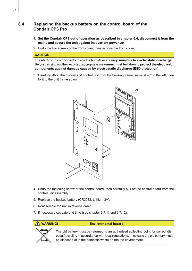
74
8.4 Replacing the backup battery on the control board of the Condair CP3 Pro
1. Set the Condair CP3 out of operation as described in chapter 6.4, disconnect it from the mains and secure the unit against inadvertent power-up.
2. Undothetwoscrewsofthefrontcover,thenremovethefrontcover.
CAUTION!The electronic componentsinsidethehumidifierarevery sensitive to electrostatic discharge.Beforecarryingoutthenextstep,appropriatemeasures must be taken to protect the electronic components against damage caused by electrostatic discharge (ESD protection).
3. Carefullylift-offthedisplayandcontrolunitfromthehousingframe,swivelit90°totheleft,thenfixittotheunitframeagain.
4. Undothefasteningscrewofthecontrolboard,thencarefullypull-offthecontrolboardfromthecontrol unit assembly.
5. Replacethebackupbattery(CR2032,Lithium3V).
6. Reassemble the unit in reverse order.
7. Ifnecessarysetdateandtime(seechapter6.7.11and6.7.12).
WARNING! Environmental hazard!
Theoldbatterymustbereturnedtoanauthorisedcollectingpointforcorrectdis-posal/recyclinginaccordancewithlocalregulations.Innocasetheoldbatterymustbedisposedofinthedomesticwasteorintotheenvironment.
75
9 Taking out of service/Disposal
9.1 Taking out of service
IftheCondairCP3mustbereplacedorifthehumidificationsystemisnotneededanymore,proceedasfollows:
1. Taketheunitoutofoperationasdescribedinchapter6.4.
2. Havetheunit(andallothersystemcomponents,ifnecessary)unmountedbyaqualifiedservicetechnician.
9.2 Disposal/Recycling
Componentsnotusedanymoremustnotbedisposedofinthedomesticwaste.Pleasedisposeoftheunitortheindividualcomponentsinaccordancewithlocalregulationsat the authorised collecting point.
If you have any questions, please contact the responsible authority or your localCondair representative.
Thankyouforyourcontributiontoenvironmentalprotection.
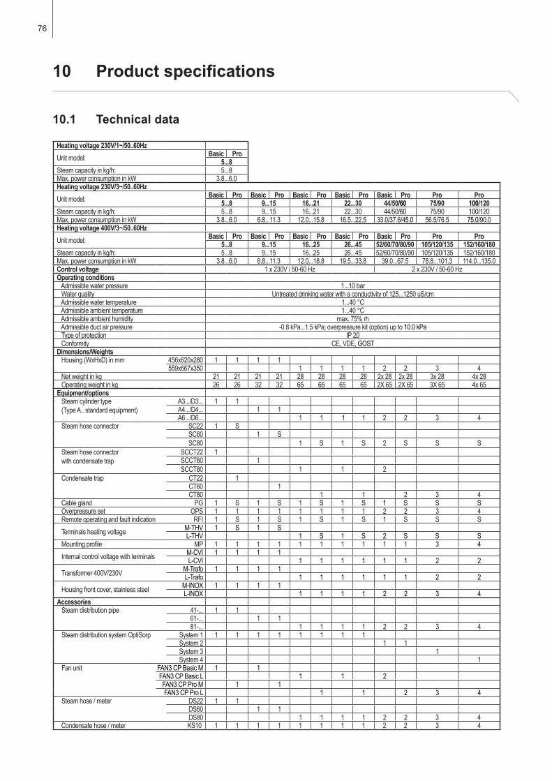
76
10 Productspecifications
10.1 Technical data
Heating voltage 230V/1~/50..60HzUnit model: Basic Pro
5...8Steam capacity in kg/h: 5...8Max. power consumption in kW 3.8...6.0Heating voltage 230V/3~/50..60HzUnit model: Basic Pro Basic Pro Basic Pro Basic Pro Basic Pro Pro Pro
5...8 9...15 16...21 22...30 44/50/60 75/90 100/120Steam capacity in kg/h: 5...8 9...15 16...21 22...30 44/50/60 75/90 100/120Max. power consumption in kW 3.8...6.0 6.8...11.3 12.0...15.8 16.5...22.5 33.0/37.6/45.0 56.5/76.5 75.0/90.0Heating voltage 400V/3~/50..60HzUnit model: Basic Pro Basic Pro Basic Pro Basic Pro Basic Pro Pro Pro
5...8 9...15 16...25 26...45 52/60/70/80/90 105/120/135 152/160/180Steam capacity in kg/h: 5...8 9...15 16...25 26...45 52/60/70/80/90 105/120/135 152/160/180Max. power consumption in kW 3.8...6.0 6.8...11.3 12.0...18.8 19.5...33.8 39.0...67.5 78.8...101.3 114.0...135.0Control voltage 1 x 230V / 50-60 Hz 2 x 230V / 50-60 HzOperating conditions Admissible water pressure 1...10 bar Water quality Untreated drinking water with a conductivity of 125...1250 uS/cm Admissible water temperature 1...40 °C Admissible ambient temperature 1...40 °C Admissible ambient humidity max. 75% rh Admissible duct air pressure -0.8 kPa...1.5 kPa; overpressure kit (option) up to 10.0 kPa Type of protection IP 20 Conformity CE, VDE, GOSTDimensions/Weights Housing (WxHxD) in mm 456x620x280 1 1 1 1
559x667x350 1 1 1 1 2 2 3 4 Net weight in kg 21 21 21 21 28 28 28 28 2x 28 2x 28 3x 28 4x 28 Operating weight in kg 26 26 32 32 65 65 65 65 2X 65 2X 65 3X 65 4x 65Equipment/options Steam cylinder type (Type A.. standard equipment)
A3.../D3... 1 1A4.../D4... 1 1A6.../D6... 1 1 1 1 2 2 3 4
Steam hose connector
SC22 1 SSC60 1 SSC80 1 S 1 S 2 S S S
Steam hose connector with condensate trap
SCCT22 1 SCCT60 1 SCCT80 1 1 2
Condensate trap CT22 1CT60 1CT80 1 1 2 3 4
Cable gland PG 1 S 1 S 1 S 1 S 1 S S S Overpressure set OPS 1 1 1 1 1 1 1 1 2 2 3 4 Remote operating and fault indication RFI 1 S 1 S 1 S 1 S 1 S S S Terminals heating voltage M-THV 1 S 1 S
L-THV 1 S 1 S 2 S S S Mounting profile MP 1 1 1 1 1 1 1 1 1 1 3 4 Internal control voltage with terminals M-CVI 1 1 1 1
L-CVI 1 1 1 1 1 1 2 2 Transformer 400V/230V M-Trafo 1 1 1 1
L-Trafo 1 1 1 1 1 1 2 2 Housing front cover, stainless steel M-INOX 1 1 1 1
L-INOX 1 1 1 1 2 2 3 4Accessories Steam distribution pipe 41-... 1 1
61-... 1 181-... 1 1 1 1 2 2 3 4
Steam distribution system OptiSorp System 1 1 1 1 1 1 1 1 1System 2 1 1System 3 1System 4 1
Fan unit FAN3 CP Basic M 1 1FAN3 CP Basic L 1 1 2FAN3 CP Pro M 1 1FAN3 CP Pro L 1 1 2 3 4
Steam hose / meter DS22 1 1DS60 1 1DS80 1 1 1 1 2 2 3 4
Condensate hose / meter KS10 1 1 1 1 1 1 1 1 2 2 3 4
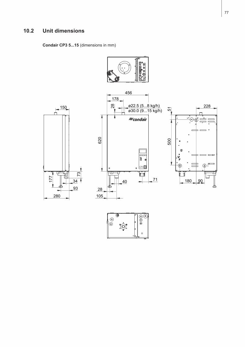
77
10.2 Unit dimensions
Condair CP3 5...15(dimensionsinmm)
456178
177 73
28105
71
93
34 40
280
150 228
51
180 90
500
620
28 ø22.5(5...8kg/h)ø30.0(9...15kg/h)
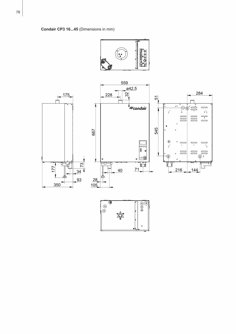
78
Condair CP3 16...45(Dimensionsinmm)
559
228ø42.5
667
40
28105
71
175
34
93350
73
177
284
51
216 144
545
32

© condair ltd., printed in switzerlandtechnical modifications reserved

consultIng, sales and servIce:
Manufacturer:condair ltd.Member of the Walter Meier grouptalstrasse 35-37, 8808 pfäffikon, switzerlandph. +41 55 416 61 11, Fax +41 55 416 62 [email protected], www.condair.com
reg.no. 40002-2