concrete structures using fabric formwork - university...
TRANSCRIPT

20 The Structural Engineer 89 (8) 19 April 2011
Introduction
A prismatic concrete beam, with uniform transverse andlongitudinal reinforcement percentages, has a constant momentand shear force capacity at every point along its length. In all but afew locations, such a member is by definition under utilised. Theubiquitous use of orthogonal moulds as formwork for suchstructures has resulted in a well-established vocabulary ofprismatic forms for concrete structures, yet rigid formwork systemsmust resist considerable fluid pressures, may consume significantamounts of material and can be expensive to construct. Moreover,the resulting member requires more material and has a greaterdeadweight than one cast with a variable cross-section.
Simple optimisation routines, described in this paper, may beundertaken to design a variable cross section member in which theflexural and transverse force capacity at any point on the elementreflects the requirements of the loading envelope applied to it. Theconstruction of structures with complex non-orthogonalgeometries is often perceived to be both difficult and expensive,yet this paper demonstrates that by casting concrete into a flexiblefabric membrane, architecturally interesting, optimised structuresthat reduce material use and take real advantage of the fluidity ofconcrete can be produced.
Fabric formwork
Fabric formwork has been used in offshore and geotechnicalengineering since the early 1900s, but it was not until the 1960sthat its widespread use began to grow, precipitated by the newavailability of high strength, low cost fabrics1. Initial interest in thearchitectural possibilities of fabric formwork can be attributed tothe Spanish architect Miguel Fisac, whose work in this fieldculminated in a patented method for the construction ofprefabricated fabric formed wall panels2.
Since then, multiple design and construction methods for fabricformwork have evolved. In Japan, Kenzo Unno’s ‘zero-waste’system for casting fabric formed walls3 has been successful, whilein North America significant savings in both material and labourcosts have been recorded as a result of using fabric formwork in
Synopsis
Using fabric formwork, it is possible to cast architecturallyinteresting, optimised structures that use up to 40% less concretethan an equivalent strength prismatic section, thereby offering thepotential for significant embodied energy savings in new concretestructures. This paper reports on the philosophy of andbackground to fabric formwork before techniques for the design,optimisation and shape prediction of fabric formed concretebeams are presented.
The practicality of construction with non-orthogonal elements isdiscussed before the results of new structural test data,undertaken at the University of Bath on 4m span ‘T’ beamelements formed in reusable fabric moulds, are presented.Potential areas of future development for fabric formwork,including the use of woven advanced composite fabrics aspermanent participating formwork and the feasibility of uniformstrength prestressed beams, are then discussed.
Paper
Concrete structures using fabric formwork
J. J. Orr, MEng (Hons)Department of Architecture and Civil Engineering, University of Bath
A. P. Darby, BSc, PhD, CEng, MIStructESenior Lecturer in Structural Engineering, Dept of Architecture and Civil Engineering, University of Bath
T. J. Ibell, CEng, BSc(Eng), PhD, FIStructE, MICE, FHEAProfessor of Civil Engineering, Department of Architecture and Civil Engineering, University of Bath
M. C. Evernden, MEng, PhDLecturer in Structural Engineering, Department of Architecture and Civil Engineering, University of Bath
M. Otlet, BSc(Hons), CEng, FIStructE, FSFEDirector, Atkins Engineering and Major Projects, Atkins UK Ltd
Keywords: Formwork, Fabric, Concrete, Beams, Design, Construction work, Testing, Loads
Received: 06/10: Modified: 09/10; Accepted: 10/10
© J. J. Orr, A. P. Darby, T. J. Ibell, M. C. Evernden & M. Otlet
1 Research undertaken (courtesty C.A.S.T)
SE8 paper - Concrete structures from fabric formwork_Layout 3 14/04/2011 14:41 Page 20
The Structural Engineer 89 (8) 19 April 2011 21
the construction of columns and footings4. Additional and ongoingresearch5, led by Professor Mark West at the University ofManitoba’s Centre for Architectural Structures and Technology(C.A.S.T), has further considered the architectural possibilities offabric formwork for beams and trusses, in addition to its use forshells, panels, columns and walls (Fig 1).
Although it has a low embodied energy (of approximately0.90MJ/kg)6 concrete is used in vast quantities. In 2008 worldproduction of cement amounted to approximately 2.8 x 10⁹t7, withits manufacture estimated to account for some 3% of all globalCO2 emissions8, providing further impetus for the design ofoptimised structures. Concrete volume savings in fabric formedbeams, when compared to an equivalent strength prismaticmember, of 40% have already been achieved9,10, illustrating thepotential for fabric formwork to reduce the embodied energy ofnew building structures.
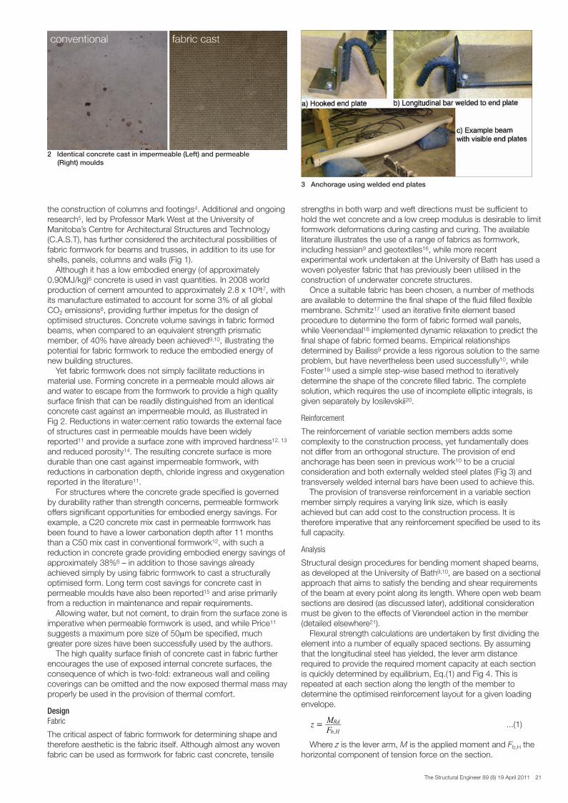
Yet fabric formwork does not simply facilitate reductions inmaterial use. Forming concrete in a permeable mould allows airand water to escape from the formwork to provide a high qualitysurface finish that can be readily distinguished from an identicalconcrete cast against an impermeable mould, as illustrated in Fig 2. Reductions in water:cement ratio towards the external faceof structures cast in permeable moulds have been widelyreported11 and provide a surface zone with improved hardness12, 13
and reduced porosity14. The resulting concrete surface is moredurable than one cast against impermeable formwork, withreductions in carbonation depth, chloride ingress and oxygenationreported in the literature11.
For structures where the concrete grade specified is governedby durability rather than strength concerns, permeable formworkoffers significant opportunities for embodied energy savings. Forexample, a C20 concrete mix cast in permeable formwork hasbeen found to have a lower carbonation depth after 11 monthsthan a C50 mix cast in conventional formwork12, with such areduction in concrete grade providing embodied energy savings ofapproximately 38%6 – in addition to those savings alreadyachieved simply by using fabric formwork to cast a structurallyoptimised form. Long term cost savings for concrete cast inpermeable moulds have also been reported15 and arise primarilyfrom a reduction in maintenance and repair requirements.
Allowing water, but not cement, to drain from the surface zone isimperative when permeable formwork is used, and while Price11
suggests a maximum pore size of 50μm be specified, muchgreater pore sizes have been successfully used by the authors.
The high quality surface finish of concrete cast in fabric furtherencourages the use of exposed internal concrete surfaces, theconsequence of which is two-fold: extraneous wall and ceilingcoverings can be omitted and the now exposed thermal mass mayproperly be used in the provision of thermal comfort.
DesignFabric
The critical aspect of fabric formwork for determining shape andtherefore aesthetic is the fabric itself. Although almost any wovenfabric can be used as formwork for fabric cast concrete, tensile
strengths in both warp and weft directions must be sufficient tohold the wet concrete and a low creep modulus is desirable to limitformwork deformations during casting and curing. The availableliterature illustrates the use of a range of fabrics as formwork,including hessian9 and geotextiles16, while more recentexperimental work undertaken at the University of Bath has used awoven polyester fabric that has previously been utilised in theconstruction of underwater concrete structures.
Once a suitable fabric has been chosen, a number of methodsare available to determine the final shape of the fluid filled flexiblemembrane. Schmitz17 used an iterative finite element basedprocedure to determine the form of fabric formed wall panels,while Veenendaal18 implemented dynamic relaxation to predict thefinal shape of fabric formed beams. Empirical relationshipsdetermined by Bailiss9 provide a less rigorous solution to the sameproblem, but have nevertheless been used successfully10, whileFoster19 used a simple step-wise based method to iterativelydetermine the shape of the concrete filled fabric. The completesolution, which requires the use of incomplete elliptic integrals, isgiven separately by Iosilevskii20.
Reinforcement
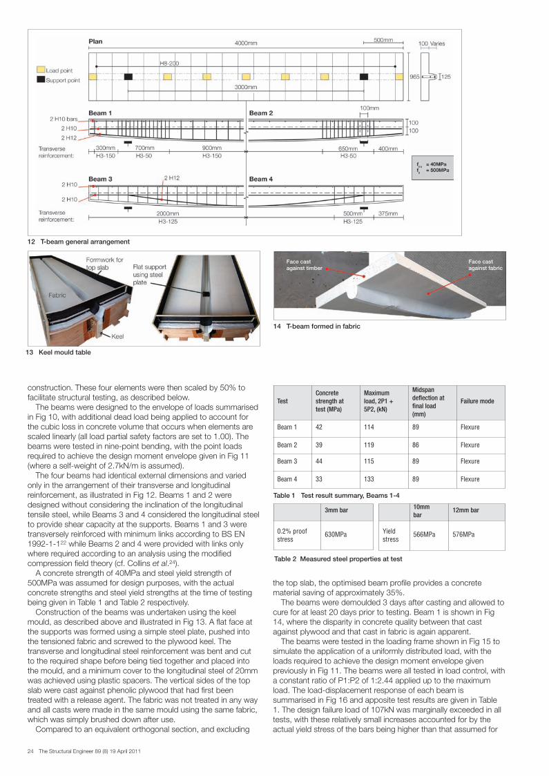
The reinforcement of variable section members adds somecomplexity to the construction process, yet fundamentally doesnot differ from an orthogonal structure. The provision of endanchorage has been seen in previous work10 to be a crucialconsideration and both externally welded steel plates (Fig 3) andtransversely welded internal bars have been used to achieve this.
The provision of transverse reinforcement in a variable sectionmember simply requires a varying link size, which is easilyachieved but can add cost to the construction process. It istherefore imperative that any reinforcement specified be used to itsfull capacity.
Analysis
Structural design procedures for bending moment shaped beams,as developed at the University of Bath9,10, are based on a sectionalapproach that aims to satisfy the bending and shear requirementsof the beam at every point along its length. Where open web beamsections are desired (as discussed later), additional considerationmust be given to the effects of Vierendeel action in the member(detailed elsewhere21).
Flexural strength calculations are undertaken by first dividing theelement into a number of equally spaced sections. By assumingthat the longitudinal steel has yielded, the lever arm distancerequired to provide the required moment capacity at each sectionis quickly determined by equilibrium, Eq.(1) and Fig 4. This isrepeated at each section along the length of the member todetermine the optimised reinforcement layout for a given loadingenvelope.
...(1)
Where z is the lever arm, M is the applied moment and Fb,H thehorizontal component of tension force on the section.
zFM
,b H
Rd=
2 Identical concrete cast in impermeable (Left) and permeable (Right) moulds
3 Anchorage using welded end plates
SE8 paper - Concrete structures from fabric formwork_Layout 3 14/04/2011 14:42 Page 21

22 The Structural Engineer 89 (8) 19 April 2011
For a beam with just one layer of reinforcement, the resultingeffective depth is then proportional to the bending moment on thesection. In such a situation, the vertical component of force in thebar will be equal to the applied shear force according to Eq.(2).This suggests that the inclined longitudinal bar may be used toprovide both flexural and shear force capacity to the section.
...(2)
Where V is the shear force, M is the applied moment, x is theposition along the beam.
However, utilising a longitudinal bar to provide vertical forcecapacity close to the supports in a simply supported beamrequires the bar to be fully anchored at its ends. The use ofexternal steel plates to provide such anchorage is anunsatisfactory solution as it introduces the potential for brittlefailure, exposes the internal reinforcement to corrosion andincreases construction complexity.
Furthermore, for a structure subject to an envelope of loads thelongitudinal reinforcement position will be determined by themaximum moment on each section. Where a structure is subjectto both point and uniformly distributed loads, it is feasible that themaximum moment and maximum shear forces on a section willnot originate from the same load case. In such a situation, a barplaced for moment capacity will then be incorrectly inclined toprovide the desired vertical force, and thus transversereinforcement will be required. However, an inclined bar still
VdxdM F ,b v= =
provides some value of vertical force, which in design may beadded to the shear resistance of the section to reduce itstransverse reinforcement requirements (c.f. BS EN 1992-1-122
(cl.6.2.1)).The assessment of shear capacity in fabric formed beams has
previously been undertaken to BS 8110-123, yet the empirical‘concrete contribution’ of this method is not necessarily applicableto the design of variable section beams. This assertion issupported by the available test data9, 10, where shear has beenseen to be the predominant failure mode.
The variable angle truss model, as adopted by BS EN 1992-1-122 for sections with transverse reinforcement, considers only thecapacity provided to the member by the reinforcement and thusavoids a reliance on empirical relationships to determine shearstrength. A yet more attractive approach is found in compressionfield theory24, which allows the detailed analysis of any crosssection shape to be undertaken. However, this approach is yet tobe taken up by European code writing committees.
Construction
Fabric formwork provides a fundamentally simple constructionmethod and an optimised beam can be formed using only a sheetof fabric and modest supporting frame, as illustrated in Fig 5. Thefabric, as discussed above, is completely reusable, either for arepeat element or in an entirely new beam geometry.
More stringent construction control is achieved through the useof the ‘keel mould’ for the production of pre-cast beams (Fig 6).
6 Construction using the keel mould
4 Steel reinforced section flexural design basis
5 Construction using fabric
7 Construction using the pinch mould
SE8 paper - Concrete structures from fabric formwork_Layout 3 14/04/2011 14:42 Page 22

The Structural Engineer 89 (8) 19 April 2011 23
Here, the fabric is held vertically and secured to a ‘keel’ that hasbeen pre-cut to the desired longitudinal beam profile. The fabric isthen prestressed in two directions before being fixed in position.Prestressing the fabric prevents wrinkling during construction andminimises the volume of concrete in the tension zone.
The ‘pinch mould’ (Fig 7) may alternatively be used to createpre-cast beams and trusses with more complex geometries. Using‘pinch points’ the sheets of fabric can be held together duringcasting, creating an opening in the resulting element. This is apotentially important consideration for the provision of buildingservices, but requires more careful analysis in design, as previouslydiscussed.
Building services
The aesthetic appeal of variable section members, coupled with ahigh quality surface finish and the additional advantages ofexposed thermal mass make fabric formwork an ideal means bywhich architectural, structural and building service requirementscan be integrated.
Using the ‘pinch mould’ construction method, pre-cast variablesection fabric formed beams can easily be created with voids intheir mid-span zones (Fig 8). Such sections are rarely used inconventional reinforced concrete design, yet provide a simplemethod for the routing of service ductwork. However, such anarrangement may detract from the aesthetic appeal of exposed,fabric formed soffits and the provision of services through a raisedfloor may be more appropriate (Fig 9). Such an approach holdsadditional advantages for the circulation of air exposed to theconcrete slab and allows the building to be easily adapted forfuture changes in use.
Costs
Whilst cost savings have been recorded in projects that made useof fabric formwork for the construction of columns and footings4,there is limited data available for the construction of more complexvariable section elements. However, Pallet15 suggests that labourcost savings may be achieved as formwork stripping and workcycle times are improved when concrete is cast in fabric. Coupledwith the aforementioned material use reductions, the economicadvantage of fabric formwork is increasingly apparent.
The construction of complex doubly curved concrete elementsremains entirely feasible using well established computednumerically controlled (CNC) manufacturing processes to producesteel moulds for use as formwork. However, such an approach isboth expensive and time consuming, and is suitable only wheremultiple identical elements are desired. Using fabric formwork, thecreation of multiple ‘one-offs’ from a single sheet of fabric isentirely feasible, and can be undertaken anywhere in the worldusing simple construction techniques.
Construction examples
Whilst fabric formwork is increasingly used in North America in theconstruction of concrete columns and footings, there are far fewerexamples of beam and slab construction. D’Aponte et al.25 providedetails of a number of small houses built using fabric formwork,and construction techniques for such structures are being refinedin ongoing work at the Yestermorrow Design School, Vermont26.
T-beams
Using the sectional analysis method described above, four 8mspan fabric formed beams were recently designed at the Universityof Bath for use as precast elements in reinforced concrete frame
9 Integration of building services8 Pre-cast beam element
11 Test loads
10 Load cases and resulting shear and moment envelopes
SE8 paper - Concrete structures from fabric formwork_Layout 3 14/04/2011 14:42 Page 23
24 The Structural Engineer 89 (8) 19 April 2011
construction. These four elements were then scaled by 50% tofacilitate structural testing, as described below.
The beams were designed to the envelope of loads summarisedin Fig 10, with additional dead load being applied to account forthe cubic loss in concrete volume that occurs when elements arescaled linearly (all load partial safety factors are set to 1.00). Thebeams were tested in nine-point bending, with the point loadsrequired to achieve the design moment envelope given in Fig 11(where a self-weight of 2.7kN/m is assumed).
The four beams had identical external dimensions and variedonly in the arrangement of their transverse and longitudinalreinforcement, as illustrated in Fig 12. Beams 1 and 2 weredesigned without considering the inclination of the longitudinaltensile steel, while Beams 3 and 4 considered the longitudinal steelto provide shear capacity at the supports. Beams 1 and 3 weretransversely reinforced with minimum links according to BS EN1992-1-122 while Beams 2 and 4 were provided with links onlywhere required according to an analysis using the modifiedcompression field theory (cf. Collins et al.24).
A concrete strength of 40MPa and steel yield strength of500MPa was assumed for design purposes, with the actualconcrete strengths and steel yield strengths at the time of testingbeing given in Table 1 and Table 2 respectively.
Construction of the beams was undertaken using the keelmould, as described above and illustrated in Fig 13. A flat face atthe supports was formed using a simple steel plate, pushed intothe tensioned fabric and screwed to the plywood keel. Thetransverse and longitudinal steel reinforcement was bent and cutto the required shape before being tied together and placed intothe mould, and a minimum cover to the longitudinal steel of 20mmwas achieved using plastic spacers. The vertical sides of the topslab were cast against phenolic plywood that had first beentreated with a release agent. The fabric was not treated in any wayand all casts were made in the same mould using the same fabric,which was simply brushed down after use.
Compared to an equivalent orthogonal section, and excluding
the top slab, the optimised beam profile provides a concretematerial saving of approximately 35%.
The beams were demoulded 3 days after casting and allowed tocure for at least 20 days prior to testing. Beam 1 is shown in Fig14, where the disparity in concrete quality between that castagainst plywood and that cast in fabric is again apparent.
The beams were tested in the loading frame shown in Fig 15 tosimulate the application of a uniformly distributed load, with theloads required to achieve the design moment envelope givenpreviously in Fig 11. The beams were all tested in load control, witha constant ratio of P1:P2 of 1:2.44 applied up to the maximumload. The load-displacement response of each beam issummarised in Fig 16 and apposite test results are given in Table1. The design failure load of 107kN was marginally exceeded in alltests, with these relatively small increases accounted for by theactual yield stress of the bars being higher than that assumed for
12 T-beam general arrangement
Table 1 Test result summary, Beams 1-4
TestConcretestrength attest (MPa)
Maximumload, 2P1 +5P2, (kN)
Midspandeflection atfinal load(mm)
Failure mode
Beam 1 42 114 89 Flexure
Beam 2 39 119 86 Flexure
Beam 3 44 115 89 Flexure
Beam 4 33 133 89 Flexure
Table 2 Measured steel properties at test
10mmbar
12mm bar
Yieldstress
566MPa 576MPa
3mm bar
0.2% proofstress
630MPa
13 Keel mould table
14 T-beam formed in fabric
Face cast against timber
Face cast against fabric
SE8 paper - Concrete structures from fabric formwork_Layout 3 14/04/2011 14:42 Page 24

The Structural Engineer 89 (8) 19 April 2011 25
design (Table 2) and the potential for small errors in the position ofthe longitudinal bars. In general the sectional method provides anaccurate technique for determining the moment capacity of thevariable section element.
Beam 1 reached a maximum load of 114kN and after displayingsome ductility the cantilever loads P1 were removed. Beam 1 wasthen loaded by the five central point loads at a constant load ofapproximately 86kN up to a midspan deflection of 85mm.Subsequently, load was applied at the mid-span only, with aconstant load of 54kN carried by the section up to its maximumdisplacement of 90mm, as shown in Fig 16.
Beams 2, 3 and 4 were tested in a similar manner, but afterachieving ductility at their maximum load capacities (Fig 16) wereloaded by the central point load only. Beam 4 achieved a slightlyhigher maximum load than the first three tests, but this increase isnot considered to be significant.
All beams displayed a ductile response, with yielding of thelongitudinal steel leading eventually to compression failures in thetop slab. Cracking of the sections was well distributed (Fig 17) andno shear failures were recorded, in contrast to tests previouslyundertaken at the University of Bath9,10 in which shear was thepredominant failure mode.
The four beams described above displayed similar load-deflection responses, with almost identical cracked and uncrackedstiffnesses recorded. This demonstrates that the two shear designmethods have relatively little effect on the overall memberresponse, and the sectional design approach may thus be usedwith confidence in the design of optimised beam structures. Inaddition, the keel mould has now been successfully demonstratedas a feasible construction method for fabric formed concretestructures.
The similar load capacities recorded between Beams 1-4 furthersuggests that transverse reinforcement design may besatisfactorily undertaken using either BS EN 1992-1-122 or themodified compression field theory. Whilst the beams describedabove were designed to fail in flexure, future work will be requiredto comprehensively assess the shear behaviour of variable section
members. This will then allow more detailed design guidance to beprovided.
Serviceability
The advantage of a prismatic beam is its constant stiffness prior tocracking. The variable section beam is inherently more flexible thanits prismatic counterpart and thus the serviceability limit state maybecome a concern. For example, in the beams described above,applying a deflection limit of span/250 reduces the permissibleload capacity by around 30%, as highlighted in Fig 16.
Yet stringent deflection requirements can do little except adddeadweight. Designing a structure to follow the loads applied to it,without adding unnecessary material is a more sensible -moreover, sustainable – approach to structural design. For thosesituations where stringent deflection criteria are truly important, theuse of prestressed reinforcement provides an ideal solution. Withfabric formwork, uniform strength prestressed beams (asdescribed by Guyon27, where the extreme fibres at every point onthe beam are at their compressive or tensile stress limit, Fig18) areentirely feasible and display excellent behaviour at the serviceabilitylimit state. With fabric formwork, optimised, materially efficient,aesthetically pleasing structures that minimise embodied energyand encourage the appropriate use of thermal mass are possible.The construction of such structures can now be undertaken usinga simple, reusable formwork system.
The future
The provision of reinforcement to a continually varying crosssection has the potential to add significantly to construction time.A participating fabric system in which a composite fabricincorporating carbon fibres acts as both formwork andreinforcement may therefore be advantageous in some situations.Improvements in three-dimensional weaving capabilities may allowdesigners to specify carbon fibre weave directions and densities atvarious points along the length of a beam based on the appliedloads. The resulting formwork could then simply be filled withconcrete to provide an optimised, composite reinforced structure
16 Load-displacement test results, Beams 1-4
15 Test set up
SE8 paper - Concrete structures from fabric formwork_Layout 3 14/04/2011 14:42 Page 25

26 The Structural Engineer 89 (8) 19 April 2011
that minimises material use.There are, however, a number of technical hurdles to clear
before such a method could be used in general construction. Inaddition to vandalism and fire protection, an adequate bondbetween concrete and reinforcement must be provided for the lifeof the structure and the existing architectural merit of fabric formedconcrete structures must be maintained.
Flexural elements are fundamentally inefficient and it is in thedesign of shell structures that real material savings may be found.Using a combination of inexpensive fabric as formwork andlightweight, durable, high strength carbon fibre sheets asreinforcement, medium span shell elements such as those alreadyproduced at C.A.S.T may become a realistic alternative to existingfloor and roof systems, as illustrated in Fig 18.
Conclusions
The design of fabric formed concrete structures has, to date, beenled primarily by architectural concerns. Work to provide morecomplete design guidance for these remarkable structures is nowwell underway. Fabric formed concrete beams offer significantadvantages for designers, including reductions in material use,ease of construction and aesthetic appeal. Further advantagesmay be gained through the use of prestressed reinforcement,either steel or fibre reinforced polymers, where improvements inboth serviceability and ultimate limit state behaviour can beobtained. Additional work is required to investigate the use offlexible fibre reinforced polymer fabrics and grids as both externalparticipating reinforcement in beam structures and as internalreinforcement in thin-shell elements.
By designing optimised concrete structures, significant savingsin material use can be achieved, with concomitant reductions inboth embodied carbon and construction cost. Fabric formwork notonly provides a simple means by which such structures can becast, but by allowing excess pore water to bleed from the surfaceof the concrete the resulting element is both durable and beautiful.Fabric formwork thus offers exciting opportunities for engineersand architects in the move towards a more sustainableconstruction industry.
References1 Lamberton, B.A.: ‘Fabric forms for concrete’, Conc. int., December, 1989, p
58-672 Orr, J. J., Darby, A. P., Ibell, T. J.: ‘Innovative concrete structures using fabric
formwork’, SEMC 2010, Cape Town, South Africa, 4-8 September, 20103 West, M.: ‘Kenzo Unno, Fabric Formed Walls’, Winnipeg, University of
Manitoba, Available fromhttp://www.umanitoba.ca/cast_building/assets/downloads/PDFS/Fabric_Formwork/Kenzo_Unno _Article.pdf.
4 FabFormIndustries. Fastfoot Commercial Edging Video (online), 2010 [cited2010 27/05]; Available from: http://www.fabform.com/products/fastfoot/fastfoot_commercial_edging_video.html
5 West, M., Araya, R.: ‘Fabric formwork for concrete structures andarchitecture’, Int. Conf. Textile Composites and Inflatable Structures,Barcelona, Spain, 5-7 October, 2009
6 Hammond, G. P., Jones, C. I.: ‘Embodied energy and carbon in constructionmaterials’, Proc. Instn Civil Engrs: Energy, 161 (2) p 87-98
7 Van Oss, H. G.: ‘Mineral Commodity Summaries: Cement’, USGS, 20068 CDIAC.: Fossil-Fuel CO2 emissions (online), 2005 [cited 2010 30/03];
Available from: http://cdiac.esd.ornl.gov/trends/emis/meth_reg.html9 Bailiss, J.: ‘Fabric-formed concrete beams: Design and analysis’, MEng
Thesis, Department of Architecture and Civil Engineering, Bath, University ofBath, 2006
10 Garbett, J.: ‘Bone growth analogy for optimising flexibly fomed concretebeams’, MEng Thesis, Dept for Architecture and Civil Engineering, Bath,University of Bath, 2008
11 Price, W. F.: ‘Controlled permeability formwork’. London, 200012 Price, W .F. and Widdows, S. J.: ‘The effect of permeable formwork on the
surface properties of concrete’, Magazine of Conc. Res., 43/155, 1991, p93-104
13 Serafini, F. L.: ‘Corrosion protection of concrete using a controlledpermeability formwork (CPF) system’, Corrosion and Corrosion Protection ofSteel in Concrete, Sheffield, 1994
14 Kasai, K., et al.: ‘Study on the evaluation of concrete quality prepared withpermeable forms and plywood forms’, Trans. Jpn Conc. Inst, 10/1989, p59-66
15 Pallet, P.: ‘Introduction to the formworks scene’, Concrete Magazine. 1994,p 11-12
16 West, M., Abdelgar, H. S., Gorski, J.: ‘State of the art report on fabricformwork’, Concrete: Construction’s sustainable option, Sept 4-6, 2007
17 Schmitz, R. P.: ‘Fabric formed concrete’, 17th Analysis and Computationspeciality conference, 2006 Structures Congress, St. Louis, MO, May 18-20,2006
18 Veenendaal, D.: ‘Evolutionary optimisation of fabric formed structuralelements’, Thesis, Civil Engineering and Geosciences, Delft, University ofDelft, 2008
19 Foster, R.: ‘Form finding and analysis of fabric formed concrete beams’,MEng Thesis, Architecture and Civil Engineering, Bath, University of Bath,2010
20 Iosilevskii, G.: ‘Shape of a soft container under hydrostatic load’, J. App.Mech., 77/1, 2010, p 3
21 Vierendeel, A.: Longerons en treillis et longerons à arcades. Louvain, TroisRois, 1897
22 BS EN 1992-1-1, Eurocode 2: Design of concrete structures - Part 1-1:General rules and rules for buildings. 2004
23 BS 8110-1, Structural use of concrete - Part 1: Code of practice for designand construction. 1997
24 Collins, M. P., Mitchell, D., Bentz, E. C.: ‘Shear Design of ConcreteStructures’, The Structural Engineer, 86/10, 2008, p 32-39
25 D’Aponte, E., Lawton, A. and Johnson, R. M.: ‘Fabric Formwork forArchitectural Concrete Structures’, 1st Int. Conf. Conc. Techn., Tabriz, Iran,6-7 November, 2009
26 Yestermorrow Design Build School (accessed, 01/08/10); Available from:http://www.yestermorrow.org/
27 Guyon, Y.: Prestressed Concrete. London, Contractors Record andMunicipal Engineering, 1953
Acknowledgments
The authors gratefully acknowledge the ongoing support of theEngineering and Physical Sciences Research Council (EPSRC) andAtkins UK Ltd, and wish to thank the technical staff in theDepartment of Architecture and Civil Engineering at the Universityof Bath for their assistance in preparing the tests described in thispaper.
19 Fabric cast columns supporting fabric formed shells (courtesy C.A.S.T)
17 Typical failure mode
18 Uniform strength prestressed beams
SE8 paper - Concrete structures from fabric formwork_Layout 3 14/04/2011 14:42 Page 26