concrete laboratary - sjce.ac.insjce.ac.in/wp-content/uploads/2018/01/concrete-lab-manual.pdf ·...
TRANSCRIPT

CONCRETE LABORATARY
INSTRUCTION MANUAL
for
IV Semester B.E. Civil Engineering
Compiled and Edited
by
Dr. Satish R. Associate Professor
H.L. Girish Raje Urs
Associate Professor
H.M. Mahendra Kumar
Assistant Professor
Department of Civil Engineering Sri Jayachamarajendra College of Engineering, Mysuru – 570006.

ii

iii
Department of Civil Engineering Sri Jayachamarajendra College of Engineering, Mysuru- 570 006
Vision and Mission of the Department of Civil Engineering
VISION
“To produce engineers having professional and leadership qualities with capacity to take up research and professional assignments in Civil Engineering and allied fields with focus on interdisciplinary and innovative approach and to compete in civil engineering profession at the global level”.
MISSION
To impart quality and real time education to contribute to the field of Civil Engineering.
To impart soft skills, leadership qualities and professional ethics among the graduates to handle projects independently.
To develop graduates to compete at the global level.
To deal with the contemporary issues and to cater to the societal needs.
Programme Educational Objectives (PEOs)
PEO1 To impart quality education and knowledge in contemporary science and technology to meet the challenges in the field of Civil Engineering and to serve the society.
PEO2 To impart the knowledge of analysis and design using the codes of practice and software packages.
PEO3 To inculcate the sense of ethics, morality, creativity, leadership, professionalism, self-confidence and independent thinking.
PEO4 To motivate the students to take up higher studies and innovative research projects.
Programme Specific Outcomes (PSOs)
PSO1 The student has the ability to apply the knowledge of Physics, Chemistry, Mathematics, Programming Skills and Soft Skills to solve Civil Engineering problems.
PSO2 The student has the proficiency in streams of Civil Engineering to visualise and execute the systems for sustainable living.
PSO3 The student has the practical knowledge and experimental skills to tackle Civil Engineering problems using technical and management skills, exhibiting professional ethics to meet the societal needs.
PSO4
The programme enables the faculty to develop academic proficiency by involving in research & innovation, interaction with industry and professional bodies through technical advice and Continuing Education Programs (CEP) to meet the needs of the user system.

iv
Department of Civil Engineering Sri Jayachamarajendra College of Engineering, Mysuru- 570 006
PROGRAMME OUTCOMES (POs)
Engineering Graduates will be able to:
P01
Apply the knowledge of mathematics, science, engineering fundamentals, and an
engineering specialization to the solution of complex engineering problems – (Engineering
knowledge)
P02
Identify, formulate, review research literature, and analyze complex engineering
problems reaching substantiated conclusions using first principles of mathematics,
natural sciences, and engineering sciences – (Problem analysis)
P03
Design solutions for complex engineering problems and design system components
or processes that meet the specified needs with appropriate consideration for the
public health and safety, and the cultural, societal, and environmental considerations –
(Design/development of solutions)
P04
Use research-based knowledge and research methods including design of experiments,
analysis and interpretation of data, and synthesis of the information to provide valid
conclusions – (Conduct investigations of complex problems)
P05
Create, select, and apply appropriate techniques, resources, and modern engineering and IT
tools including prediction and modeling to complex engineering activities with an
understanding of the limitations – (Modern tool usage)
P06
Apply reasoning informed by the contextual knowledge to assess societal, health, safety,
legal and cultural issues and the consequent responsibilities relevant to the professional
engineering practice – (The engineer and society)
P07
Understand the impact of the professional engineering solutions in societal and
environmental contexts, and demonstrate the knowledge of, and need for
sustainable development – (Environment and sustainability)
P08 Apply ethical principles and commit to professional ethics and responsibilities and norms
of the engineering practice – (Ethics)
P09 Function effectively as an individual, and as a member or leader in diverse teams, and in
multidisciplinary settings – (Individual and team work)
P10
Communicate effectively on complex engineering activities with the engineering community
and with society at large, such as, being able to comprehend and write effective reports
and design documentation, make effective presentations, and give and receive clear
instructions – (Communication)
P11
Demonstrate knowledge and understanding of the engineering and management
principles and apply these to one’s own work, as a member and leader in a team, to
manage projects and in multidisciplinary environments – (Project management and
finance)
P12
Recognize the need for, and have the preparation and ability to engage in
independent and life-long learning in the broadest context of technological change – (Life-
long learning)

v
FOREWORD
The concrete laboratory intends to train the students in the field of testing
the ingredients of concrete and to study the behavior of fresh concrete, its
workability and strength in hardened state, which are used directly or indirectly in
the design of structural elements.
This instruction manual guides the students to conduct the test as per
standard codal procedures. The student shall follow the guidelines indicated for
conducting the tests more effectively and for better understanding and for logical
interpreting the test results as per IS code.
Before conducting any test, student shall come prepared with theoretical
background of the corresponding test, specification as per code.
Student must familiarize with the scope and purpose of the test.
Student shall make sure to have the knowledge of measuring instruments
like slide calipers and other gauges.
Students shall acquaint themselves with the safe and correct usage of
instruments/ equipments under the guidance of teaching or supporting staff
of the laboratory.
Students shall give importance to accuracy and precision while conducting
the test and interpreting the test results.
It is hoped that this instruction manual will serve to orient the students in
performing the test and preparing the report as per the Codal provision. The
authors thank our Head of the department Dr. K. Prakash for his guidance and
support. Also thank Mr. Naveen Kumar H.V. for his excellent efforts in bringing
out this instruction manual in the present format.
Dr. Satish R.
H.L. Girish Raje Urs
H.M. Mahendra Kumar

vi
CONTENTS
Page No.
Foreword v
Contents vii
CEMENT
1. Normal Consistency of Cement 1
2. Setting Time of Cement 2
3. Specific Gravity of Cement 6
4. Fineness Test of Cement by Sieve Analysis 8
5. Compression Strength Test 9
6. Soundness by Le-Chatelier’s Method 13
FRESH CONCRETE
7. Slump Test 15
8. Compaction Factor Test 17
9. Vee- Bee Test 19
HARDENED CONCRETE
10. Compression Strength of Concrete 21
11. Split Tensile Test 24
AGGREGATES
12. Determination of Specific Gravity of Fine Aggregate 27
13. Shape Tests (Flaky, Elongation, and Angularity Number) 29
14. Impact Test 34
15. Crushing Test 37
16. Abrasion Test 39
NON-DESTRUCTIVE TESTING OF CONCRETE
REBOUND HAMMER TEST
17. Non Destructive Testing of Concrete
1. Rebound hammer test
42

Concrete Lab Manual
Dept. of Civil Engg., SJCE, Mysuru Page 1
NORMAL CONSISTENCY OF CEMENT
Exp. No.: 1
AIM: To determine the quantity of water required to produce a cement paste of standard
consistency.
APPARATUS:
Vicat’s apparatus conforming to IS: 5513-1976
Weighing Balance
Gauging Trowel
Stop Watch.
REFERENCE CODE:
IS: 4031 (Pat 4) – 1988 methods of physical test for hydraulic cement
IS : 5513-1996 for specification for Vicat’s apparatus.
THEORY:
The standard consistency of a cement paste is defined as that consistency which will
permit the vicat plunger to penetrate to a point 5 to 7 mm from the bottom of the
vicatmould. For finding out initial setting time, final setting time, soundness of cement
and compressive strength of cement, it is necessary to fix the quantity of water to be
mixed in cement in each case.
PROCEDURE:
1. Prepare a paste of weighed quantity of cement (300 grams) with a weighed quantity
of potable or distilled water, starting with 26% water of 300g of cement.
2. Take care that the time of gauging is not less than 3 minutes, not more than 5 minutes
and the gauging shall be completed before setting occurs.
3. The gauging time shall be counted from the time of adding the water to the dry
cement until commencing to fill the mould.
4. Fill the vicatmould with this paste, the mould resting upon a non porous plate.
5. After completely filling the mould, trim off the surface of the paste, making it in
level with the top of the mould. The mould may slightly be shaken to expel the air.
6. Place the test block with the mould, together with the non-porous resting plate, under
the rod bearing the plunger (10mm diameter), lower the plunger gently to touch the
surface of the test block and quickly release, allowing it to penetrate into the paste.
7. This operation shall be carried out immediately after filling the mould.
8. Prepare trial pastes with varying percentages of water and test as described above
until the amount of water necessary for making the standard consistency as defined
above is obtained.

Concrete Lab Manual
Dept. of Civil Engg., SJCE, Mysuru Page 2
9. Express the amount of water as a percentage by weight of the dry cement.
Repetition of the experiment fresh cement is to be taken.
OBSERVATION AND CALCULATION:
1. Type of cement…………………….
2. Brand of cement…………………..
3. Time of Test……………………….
4. Room Temperature…………………
Trail
No.
Weight of
cement
(gms)
Percentage by water of
dry Cement
(%)
Amount of
water added
(ml)
Penetration
(mm)
1
2
3
4
Fig.: Vicat Apparatus
RESULT: Normal consistency for the given sample of cement is…………………..%

Concrete Lab Manual
Dept. of Civil Engg., SJCE, Mysuru Page 3
DETERMINATION OF SETTING TIME OF STANDARD
CEMENT PASTE Exp. No.: 2
AIM: To determine the initial and final setting time of a given sample of cement.
APPARATUS:
Vicat apparatus conforming to IS : 5513-1976
Weighing Balance
Glass plate
Gauging Trowel
Stop Watch
REFERENCE CODE:
IS: 4031 (Pat 4) – 1988 methods of physical test for hydraulic cement
IS : 5513-1996 for specification for Vicat’s apparatus.
THEORY:
Initial setting time is regarded as the time elapsed between the moments that the water
is added to the cement to the time that the paste starts losing its plasticity. The final
setting time is the time elapsed between the moment the water is added to the cement
and the time when the paste has completely lost its plasticity and has attained sufficient
firmness to resist certain definite pressure.
PROCEDURE:
1. Preparation of Test Block: - Prepare a neat 300 gms cement paste by gauging the
cement with 0.85 times the water required to give a paste of standard consistency.
Potable or distilled water shall be used in preparing the paste.
2. Start a stop-watch at the instant when water is added to the cement. Fill the Vicat
mould with a cement paste gauged as above and the mould resting on a nonporous
plate. Fill the mould completely and smooth off the surface of the paste making it
level with the top of the mould.
3. Immediately after moulding, place the test block in the moist closet or moist room
and allow it to remain there except when determinations of time of setting are being
made.
4. Determination of Initial Setting Time: - Place the test block confined in the mould
and resting on the non-porous plate, under the rod bearing the needle lower the
needle gently until it comes in contact with the surface of the test block and quickly
release, allowing it to penetrate into the test block
5. Repeat this procedure until the needle, when brought in contact with the test block
and released as described above, fails to pierce the block beyond 5.0 ± 0.5 mm
measured from the bottom of the mould shall be the initial setting time.

Concrete Lab Manual
Dept. of Civil Engg., SJCE, Mysuru Page 4
6. Determination of Final Setting Time: - Replace the needle of the Vicat apparatus
by the needle with an annular attachment.
7. The cement shall be considered as finally set when, upon applying the needle gently
to the surface of the test block, the needle makes an impression there on, while the
attachment fails to do so.
8. The period elapsing between the time when water is added to the cement and the
time at which the needle makes an impression on the surface of test block while
the attachment fails to do so shall be the final setting time.
OBSERVATION:
1. Type of cement=…………………….
2. Brand of cement=t…………………..
3. Weight of given sample of cement is=…………… ….gms
4. The normal consistency of a given sample of cement is=………………….%
5. Volume of water addend for preparation of test block=…………………ml
Sl.
No.
Setting Time
(min)
Penetration
(mm)
1
2
3
4
5
6

Concrete Lab Manual
Dept. of Civil Engg., SJCE, Mysuru Page 5
Fig.: Vicat Apparatus
RESULT:
1. The initial setting time of the cement sample is found to be..............minutes
2. The final setting time of the cement sample is found to be …........... minutes

Concrete Lab Manual
Dept. of Civil Engg., SJCE, Mysuru Page 6
SPECIFIC GRAVITY OF CEMENT
Exp. No.: 3
AIM: To determine the specific gravity of given sample of cement.
APPARATUS:
Weighing balance
specific gravity bottle (50ml capacity)
kerosene
funnel
INTRODUCTION:
Specific gravity is defined as the ratio between weight of a given volume of material
and weight of an equal volume of water. To determine the specific gravity of cement,
kerosene is used which does not react with cement.
PROCEDURE:
1. Clean and dry the specific gravity bottle and weigh it with the stopper (W1).
2. Fill the specific gravity bottle with cement sample at least half of the bottle and
weigh with stopper (W2).
3. Fill the specific gravity bottle containing the cement, with kerosene (free of water)
placing the stopper and weigh it (W3) ,While doing this do not allow any air bubbles
to remain in the specific gravity bottle.
4. After weighing the bottle, the bottle shall be cleaned and dried again.
5. Then fill it with fresh kerosene and weigh it with stopper (W4).
6. Remove the kerosene from the bottle and fill it with full of water and weigh it with
stopper (W5).
OBSERVATIONS:
Description of item Trial 1 Trial 2
Weight of empty bottle(W1 g)
Weight of bottle + Cement ( W2 g)
Weight of bottle + Cement + Kerosene( W3 g)
Weight of bottle + Full Kerosene( W4 g)
Weight of bottle + Full Water( W5 g)
(W2 - W1)* (W4 - W1)
Specific gravity of Cement =--------------------------------------------------
((W4 - W1)-(W3-W2))*(W5 - W1)

Concrete Lab Manual
Dept. of Civil Engg., SJCE, Mysuru Page 7
Fig.: Specific Gravity Bottle
RESULTS: Specific gravity of given Cement =---------------------------------------

Concrete Lab Manual
Dept. of Civil Engg., SJCE, Mysuru Page 8
FINENESS TEST OF CEMENT BY SIEVE ANALYSIS
Exp. No.: 4
AIM: To determine the fineness of the cement of the given sample by sieve analysis.
APPARATUS:
IS: 90μ test sieve
bottom pan
weighing balance,
brush
REFERENCE CODE: IS 4031 (PART1): 1988, IS460 (PART1): 1985
THEORY: The degree of fineness of cement is a measure of the mean size of the
grains. The finer cement has quicker action with water and gains early strength without
change in the ultimate strength. Finer cement is susceptible to shrinkage and cracking.
PROCEDURE:
1. Accurately weigh 100 gms of cement sample and place it over the test sieve. Gently
breakdown the air set lumps if any with fingers.
2. Hold the sieve with pan in both hands and sieve with gentle wrist motion, in circular
and vertical motion for a period of 10 to 15 minutes without any spilling of cement.
3. Place the cover on the sieve and remove the pan. Now tap the other side of the sieve
with the handle of brush and clean the outer side of the sieve.
4. Empty the pan and fix it below the sieve and continue sieving as mentioned in the
steps 2 and 3. Totally sieve for 15 minutes and weigh the residue (Left over the sieve).
OBSERVATIONS:
1. Weight of cement taken =...................................
2. Weight of cement retained after sieving =................................
3. Type of cement =.............................
4. Brand of cement=.....................................
5. Room temperature=............................
Percentage weight of Residue = Weight of sample left on the sieve
Total weight of sample
RESULT: Fineness of the given sample is=……………………………………%

Concrete Lab Manual
Dept. of Civil Engg., SJCE, Mysuru Page 9
COMPRESSIVE STRENGTH TEST OF HYDRULIC CEMENT
Exp. No.: 5
AIM: To determine the compressive strength of standard cement mortar cubes
THEORY: The compressive strength of cement mortars is determined in order to
verify whether the cement conforms to IS specifications and whether it will be able to
develop the required compressive strength of concrete. The average compressive
strength of at least three mortar cubes (area of the face 50 cm2 ) composed of one part
of cement and three parts of standard stand should satisfy IS code specifications.
REFERENCE: IS: 4031 ( Pat 6 ) – 1988.
APPARATUS:
Vibration Machine
Poking Rod
Cube Mould size conforming to IS : 10080-1982
Weighing Balance
Trowel
Stop Watch
Graduated Glass Cylinders
INTRODUCTION:
The compressive strength of cement mortars is determined in order to verify whether
the cement conforms to IS specifications and whether it will be able to develop the
required compressive strength of concrete. The average compressive strength of at least
three mortar cubes (area of the face 50 cm2 ) composed of one part of cement and three
parts of standard stand should satisfy IS code specifications.
PROCEDURE:
1. Preparation of test specimens:- Clean appliances shall be used for mixing and the
temperature of water and that of the test room at the time when the above operations
are being performed shall be 27 ± 2°C.distilled water shall be used in preparing the
cubes.
2. The material for each cube shall be mixed separately and the quantity of cement,
standard sand and water shall be as follows: Cement 200 g and Standard Sand 600
g
1. Water (P/4+0.3) percent of combined mass of cement and sand, where P is the
percentage of water required to produce a paste of standard consistency.

Concrete Lab Manual
Dept. of Civil Engg., SJCE, Mysuru Page 10
2. Place on a nonporous plate, a mixture of cement and standard sand. Mix it dry with
a trowel for one Minute and then with water until the mixture is of uniform colour.
The quantity of water to be used shall be as specified in step 2. The time of mixing
shall in any event be not less than 3 min and should the time taken to obtain a
uniform colour exceed 4 min, the mixture shall be rejected and the operation
repeated with a fresh quantity of cement, sand and water.
3. Moulding Specimens: - In assembling the moulds ready for use, treat the interior
faces of the mould with a thin coating of mould oil.
4. Place the assembled mould on the table of the vibration machine and hold it firmly
in position by means of a suitable clamp. Attach a hopper of suitable size and shape
securely at the top of the mould to facilitate filling and this hopper shall not be
removed until the completion of the vibration period.
5. Immediately after mixing the mortar in accordance with step 1 & 2, place the mortar
in the cube mould and prod with the rod. Place the mortar in the hopper of the cube
mould and prod again as specified for the first layer and then compact the mortar
by vibration.
6. The period of vibration shall be two minutes at the specified speed of 12 000 ± 400
vibration per minute.
7. At the end of vibration, remove the mould together with the base plate from the
machine and finish the top surface of the cube in the mould by smoothing the
surface with the blade of a trowel.
8. Curing Specimens:- keep the filled moulds in moist closet or moist room for 24 ± 1
hour after completion of vibration. At the end of that period, remove them from the
moulds and immediately submerge in clean fresh water and keep there until taken
out just prior to breaking.
9. The water in which the cubes are submerged shall be renewed every 7 days and
shall be maintained at a temperature of 27 ± 2°C. After they have been taken out
and until they are broken, the cubes shall not be allowed to become dry.
10. Test three cubes for compressive strength for each period of curing mentioned under
the relevant Specifications (i.e. 3 days, 7 days, 28 days)
11. The cubes shall be tested on their sides without any packing between the cube and
the steel plattens of the testing machine. One of the plattens shall be carried on a
base and shall be self-adjusting, and the load shall be steadily and uniformly
applied, starting from zero at a rate of 35 N/mm2/min.
OBSETRVATION:
Type of cement=...........................
Brand of cement=........................
Date of casting=..............................

Concrete Lab Manual
Dept. of Civil Engg., SJCE, Mysuru Page 11
Trail
No
Age
of
Cube
Dimensions
Of the specimen
(mm)
Weight of
Cement
Cube
(gms)
Cross-
Sectional
area
(mm2)
Crushing
Load (N)
Average
Compressive
strength
(MPa) L
mm
B
mm
H
mm
1
2
3
4
Compressive Strength = Crushing load
Cross section area
Fig.: Universal Testing Machine

Concrete Lab Manual
Dept. of Civil Engg., SJCE, Mysuru Page 12
Fig.: Vibrator
RESULT: The average compressive strength of the given cement
1) 3 days ………………………. N/mm2
2) 7 days……………………….. N/mm2
3) 28 days……………………… N/mm2

Concrete Lab Manual
Dept. of Civil Engg., SJCE, Mysuru Page 13
SOUNDNESS OF CEMENT
Exp. No.: 6
AIM: To determine the soundness of the given sample of cement by: Le-chatlier’s
Method.
APPARATUS:
Le-chatlier’s apparatus
Weighing Balance
Water bath
Measuring cylinder
REFERENCE CODE:
IS : 4031 ( Pat 3 ) – 1988 methods of physical test of hydraulic cement
Part-3 determination of soundness
THEORY:
Once of the most important properties of cement is its soundness. Unsoundness in
cement is caused by expansion of some of the constituents like free lime produced in
the manufacturing process of cement. Another possible case of unsoundness is the
presence of too high a magnesia content in the cement and presence of excess of lime
than that could be combined with acidic oxide at kiln.
PROCEDURE:
1. Prepare a cement paste formed by gauging cement with 0.78 times water rag to give
a paste of standard consistency. The gauging time should not be less than 3 minutes
nor greater than 5 min.
2. On the inner surface of mould. Place the mould on glass sheet & fill it with cement
paste taking care to keep the edges of the mould gently together cover the mould
with another piece of glass sheet & place a small weight on this Covering glass
sheet & immediately sulnnerage the whole assembly in water at a temp of 27 oc
& keep it for 24 hrs.
3. Take out the assembly from water after 24 hrs measure the distance flow the
indicator points & record its.
4. Submerge the mould again in water in 25 to 30 minutes.
5. Remove the mould from the water. Allow it to cool & measure the distance the
indicator points & record it. The difference b/w two measurements represent the
same expansion of cement.
6. The sample should be tested & average of the results should be reported.

Concrete Lab Manual
Dept. of Civil Engg., SJCE, Mysuru Page 14
OBSERVATION:
Type of Cement Tested
Initial Length Of The Specimen L1
Final Length Of The Specimen L2
Expansion Of The Specimen (L1- L2 )
Fig.: Soundness Testing Apparatus
RESULT: Soundness of cement =…………………………………………..

Concrete Lab Manual
Dept. of Civil Engg., SJCE, Mysuru Page 15
SLUMP TEST
Exp. No.: 7
AIM: To determine the workability or consistency of concrete mix of given proportion
by slump test.
APPARATUS:
pan to mix concrete
weighing balance
trowel
cone
steel scale
tamping rod
mixing tray
REFERENCE CODE:
IS: 456-2000, code for plain and reinforced concrete
IS: 1199-1959 methods of sampling and analysis of concrete
THEORY:
This is the test extensively used in site work all over the world. Fresh unsupported
concrete will flow to the sides and the vertical sinking of concrete is known as slump.
The slump cone is a hollow frustum made of thin steel sheet with internal dimensions,
as the top diameter 10 cms. The bottom diameter 20 cms, and height 30cms.
PROCEDURE
1. Mix the dry constituents thoroughly to get a uniform colour and then add water.
2. The internal surface of the mould is to be thoroughly cleaned and placed on a
smooth, horizontal and non-absorbent surface.
3. Place the mixed concrete in the cleaned slump cone in 4 layers each approximately
1/4 in height of the mould. Tamp each layer 25 times with tamping rod.Using the
tampering rod or a trowel strike of the excess concrete above the concrete cone.
Measure the vertical height of cone (h1).
4. Slowly and carefully remove in the vertical direction. As soon as the cone is
removed the concrete settles in vertical direction. Place the steel scale above top of
settled concrete in horizontal position and measure the height of cone(h2).
5. Complete the experiment in two minutes after sampling.
6. The difference of two heights (h1-h2) gives the value of slump

Concrete Lab Manual
Dept. of Civil Engg., SJCE, Mysuru Page 16
OBSERVATIONS:
1) Type of cement=……………….
2) Brand of cement=……………….
3) Density of concrete=...............
Trail
No
Proportion SLUMP
In
MM
Remarks w/c W
litre
C
kg
FA
kg
CA
kg
1
2
3
4
Fig. Different Types of Slump
Result: The slump of concrete=……………………………….mm (indicate Low/
Medium/ High Degree of workability)

Concrete Lab Manual
Dept. of Civil Engg., SJCE, Mysuru Page 17
COMPACTION FACTOR TEST
Exp. No.: 8
AIM: To determine the workability of freshly mixed concrete by the of Compacting
Factor Test.
APPARATUS:
Compaction factor apparatus
Weighing balance
tamping rod Trowel
Scoop about 150 mm long
Tamper( 16 mm in diameter and 600 mm length)
Ruler
Tools and containers for mixing or concrete mixer etc.
REFERENCE CODE:
IS; 1199-1959 methods of sampling and analysis of concrete
IS:5515-1983 Specification for compressive factor apparatus
THEORY:
The compaction factor is defined as the ratio of the weight of partially compacted
concrete to the weight of fully compacted concrete. The compacting factor test is
designed primarily for use in the laboratory but it can also be used in the field. It is more
precise and sensitive than the slump test and is particularly useful for concrete mixes of
very low workability as are normally used when concrete is to be compacted by
vibration.
PROCEDURE:
1. Grease the inner surface of the hoppers and the cylinder and Fasten the hopper
doors.
2. \Weigh the empty cylinder accurately (W1. Kgs) an Fix the cylinder on the base
with nuts and bolts.
3. Mix coarse and fine aggregates and cement dry until the mixture is uniform in
colour and then with water until concrete appears to be homogeneous.
4. Fill the freshly mixed concrete in upper hopper gently with trowel without
compacting.
5. Release the trap door of the upper hopper and allow the concrete of fall into the
lower hopper bringing the concrete into standard compaction.
6. Immediately after the concrete comes to rest, open the trap door of the lower hopper
and allow the concrete to fall into the cylinder, bringing the concrete into standard
compaction.

Concrete Lab Manual
Dept. of Civil Engg., SJCE, Mysuru Page 18
7. Remove the excess concrete above the top of the cylinder by a trowel.
8. Find the weight of cylinder i.e cylinder filled with partially compacted
concrete(W2kgs)
9. Refill the cylinder with same sample of concrete in approx. 4 layers, tamping each
layer with tamping for 25 times in order to obtain full compaction of concrete.
10. Level the mix and weigh the cylinder filled with fully compacted concrete (W3 Kg).
11. Repeat the procedure for different for different a trowel.
OBSERVATIONS AND CALCULATIONS:
Weight of cylinder W1 =…………………………. Kgs
Trail
no
Quantity of material Mass of
cylinder With
partially
compaction
W2 (Kgs)
Mass of cylinder
with
fully compaction
W3 (Kgs)
Compaction
Factor
(𝐖𝟏 − 𝐖𝟐)
(𝐖𝟑 − 𝐖𝟏)
w/c W
litre
C
kg
FA
kg
CA
kg
1
2
3
𝐂𝐨𝐦𝐩𝐚𝐜𝐭𝐢𝐨𝐧 𝐟𝐚𝐜𝐭𝐨𝐫 =𝑾𝟐−𝑾𝟏
𝑾𝟑−𝑾𝟏
RESULTS: Compaction factor IS =…………………………………..

Concrete Lab Manual
Dept. of Civil Engg., SJCE, Mysuru Page 19
VEE-BEE CONSISTOMETER
Exp. No.: 9
AIM: To measure the workability of concrete by vee-bee consistometer test
APPARATUS:
Vee-Bee consistometer test apparatus
Stopwatch
Standard iron rod
Weighing device
Tamper( 16 mm in diameter and 600 mm length)
Tools and containers for mixing
REFERENCE CODE:
IS: 1199-1959 method of sampling and analysis of concrete
IS: 456-2000 code of practice for plain and reinforced concrete
IS: 10510:1983 specification for vee-bee consistometer
THEORY:
The Vee-bee consistometer (measures the remoulding ability of concrete under
vibration. The test results reflect the amount of energy required to remould a quantity
of concrete under given vibration conditions. The Veebee consistometer is applicable
to concrete with slumps less than 5cm.
PROCEDURE:
1. Slump test as described earlier is performed, placing the slump cone inside the sheet
metal cylindrical pot of the consistometer.
2. The glass disc attached to the swivel arm is turned and placed on the top of the
concrete in the pot. The electrical vibrator is then switched on and simultaneously
a stop watch started.
3. The vibration is continued till such a time as the conical shape of the concrete
disappears and the concrete assumes a cylindrical shape. This can be judged by
observing the glass disc from the top for disappearance of transparency.
4. Immediately when the concrete fully assumes a cylindrical shape, the stop watch is
switched off. The time required for the shape of concrete to change from slump
cone shape to cylindrical shape in seconds is known as Vee Bee Degree.
5. This method is very suitable for very dry concrete whose slump value cannot be
measured by Slump Test, but the vibration is too vigorous for concrete with a slump
greater than about 50 mm.

Concrete Lab Manual
Dept. of Civil Engg., SJCE, Mysuru Page 20
OBSERVATIONS:
1) Type of cement=……………….
2) Brand of cement=……………….
Trail
no
Quantity of material Slump
mm
The Vee Bee
Degree of
concrete
in sec
Remark W/c
W
litre
C
kg
FA
kg
CA
kg
1
2
3 `
Fig. Veebee Consistometer
RESULTS: The VEE-BEE Degree for 0.5 W/C =………Sec

Concrete Lab Manual
Dept. of Civil Engg., SJCE, Mysuru Page 21
COMPRESSIVE STRENGTH OF CONCRETE CUBES
Exp. No.: 10
AIM: To determine the compressive strength of given concrete mixes.
APPARATUS:
Testing Machine
Specimen mould
tamping rod
weighing device
Tools and containers for mixing.
REFERENCE CODE:
IS : 1199-1959 method of sampling and analysis of concrete
IS:516 – 1959 method of test for strength of concrete
THEORY:
Concrete is very strong in compression. It is assumed that whole of the compression
will be taken up by the concrete while designing any RCC structure. The most important
strength test for concrete is the compression test.
PROCEDURE:
1. Sampling of Materials - Samples of aggregates for each batch of concrete shall be
of the desired grading and shall be in an air-dried condition. The cement samples
on arrival at the laboratory shall be thoroughly mixed dry either by hand or in a
suitable mixer in such a manner as to ensure the greatest possible blending and
uniformity in the material.
2. Proportioning - The proportions of the materials, including water in concrete mixes
used for determining the suitability of the materials available, shall be similar in all
respects to those to be employed in the work.
3. Weighing - The quantities of cement, each size of aggregate, and water for each
batch shall be determined by weight to an accuracy of 0.1 percent of the total weight
of the batch.
4. Mixing Concrete - The concrete shall be mixed by hand or preferably in a laboratory
batch mixer in such a manner as to avoid loss of water or other materials. Each batch
of concrete shall be of such a size as to leave about 10 percent excess after moulding
the desired number of test specimens.

Concrete Lab Manual
Dept. of Civil Engg., SJCE, Mysuru Page 22
5. Mould - Test specimens cubical in shape shall be 15 × 15 × 15 cm.
6. Compacting - The test specimens shall be made as soon as practicable after
mixing and in such a way as to produce full compaction of the concrete with neither
segregation nor excessive laitance.
6. Curing - The test specimens shall be stored in a place free from vibration in moist
air of at least 90 percent relative humidity and at a temperature of 27° ± 2°C for 24
hours ± ½ hour from the time of addition of water to the dry ingredients.
7. Placing the Specimen in the Testing Machine - The bearing surfaces of the testing
machine shall be wiped clean and any loose sand or other material removed from
the surfaces of the specimen which are to be in contact with the compression
platens.
8. In the case of cubes the specimen shall be placed in the machine in such a manner
that the load shall be applied to opposite sides of the cubes as cast that is not to the
top and bottom.
9. The axis of the specimen shall be carefully aligned with the centre of thrust of the
spherically seated platen. No packing shall be used between the faces of the test
specimen and the steel platen of the testing machine.
10. The load shall be applied without shock and increased continuously at a rate of
approximately 140 kg/sq cm/min until the resistance of the specimen to the
increasing load breaks down and no greater load can be sustained.
11. The maximum load applied to the specimen shall then be recorded and the
appearance of the concrete and any unusual features in the type of failure shall be
noted
OBSERVATION:
1) Mix proportion =………………………………..
2) Date of casting=………………………………….
3) Date of Testing=………………………………….
4) Age of concrete=………………………………….
5) Curing history=...........................................
Trail
No.
Wt. of
specimen
kg
Dimensions of the
specimen
Cross
sectional
area
mm2
Crushing
load
KN
Compressiv
e strength
N/mm2 L
mm
B
mm
H
mm
1
2
3

Concrete Lab Manual
Dept. of Civil Engg., SJCE, Mysuru Page 23
Compressive strength =Crushing load
Cross sectional area
Fig.: Universal Testing Machine
RESULT: Compressive strength of Concrete --------------N/mm2

Concrete Lab Manual
Dept. of Civil Engg., SJCE, Mysuru Page 24
SPLIT TENSILE STRENGTH OF CONCRETE
Exp. No.: 11
AIM: To determine the split tensile strength of concrete of given mix proportions.
APPARATUS:
Compression testing machine
tamping rods
weighing device
Tools and containers for mixing
Tamper
REFERENCE CODE:
IS:456:2000 code of practice for plain and reinforced concrete
IS:5816:1999 Method of test for split tensile strength of concrete
THEORY:
The tensile strength is one of the basic and important properties of the concrete. The
concrete is not usually expected to resist the direct tension because of its low tensile
strength and brittle nature. However the determination of tensile strength of concrete is
necessary to determine the load at which the concrete members may crack.
PROCEDURE:
1. Sampling of Materials - Samples of aggregates for each batch of concrete shall be of the
desired grading and shall be in an air-dried condition. The cement samples, on arrival at the
laboratory, shall be thoroughly mixed dry either by hand or in a suitable mixer in such a
manner as to ensure the greatest possible blending and uniformity in the material.
2. Proportioning - The proportions of the materials, including water, in concrete mixes used
for determining the suitability of the materials available, shall be similar in all respects to
those to be employed in the work.
3. Weighing - The quantities of cement, each size of aggregate, and water for each batch shall
be determined by weight, to an accuracy of 0.1 percent of the total weight of the batch.
4. Mixing Concrete - The concrete shall be mixed by hand, or preferably, in a laboratory batch
mixer, in such a manner as to avoid loss of water or other materials. Each batch of concrete
shall be of such a size as to leave about 10 percent excess after moulding the desired number
of test specimens.
5. Mould - The cylindrical mould shall be of 150 mm diameter and 300 mm height conforming
to IS: 10086-1982.
6. Compacting - The test specimens shall be made as soon as practicable after mixing, and in
such a way as to produce full compaction of the concrete with neither segregation nor
excessive laitance.

Concrete Lab Manual
Dept. of Civil Engg., SJCE, Mysuru Page 25
7. Curing - The test specimens shall be stored in a place, free from vibration, in moist air of
at least 90 percent relative humidity and at a temperature of 27° ± 2°C for 24 hours ± ½
hour from the time of addition of water to the dry ingredients.
8. Placing the Specimen in the Testing Machine - The bearing surfaces of the supporting and
loading rollers shall be wiped clean, and any loose sand or other material removed from the
surfaces of the specimen where they are to make contact with the rollers.
9. Two bearings strips of nominal (1/8 in i.e 3.175mm) thick plywood free of imperfections
approximately (25mm) wide and of length equal to or slightly longer than that of the
specimen should be provided for each specimen.
10. The bearing strips are placed between the specimen and both upper and lower bearing
blocks of the testing machine or between the specimen and the supplemental bars or plates.
11. Draw diametric lines an each end of the specimen using a suitable device that will ensure
that they are in the same axial plane. Centre one of the plywood strips along the centre of
the lower bearing block.
12. Place the specimen on the plywood strip and align so that the lines marked on the ends of
the specimen are vertical and cantered over the plywood strip.
13. Place a second plywood strip lengthwise on the cylinder, cantered on the lines marked on
the ends of the cylinder. Apply the load continuously and without shock, at a constant rate
within, the range of 689 to 1380 kPa/min splitting tensile stress until failure of the specimen
14. Record the maximum applied load indicated by the testing machine at failure. Note the type
of failure and appearance of fracture
OBSERVATION AND CALCULATION:
1) Mix proportion =………………………………..
2) Date of casting=………………………………….
3) Date of Testing=………………………………….
4) Age of concrete=………………………………….
Trail
No
Wt. of
specimen
kg
Diameter of
specimen
mm
Length of
Specimen
mm
Failure
load P
mm
Split tensile
strength
1
2
Calculate the splitting tensile strength of the specimen as follows:
T = 2P
ΠDL

Concrete Lab Manual
Dept. of Civil Engg., SJCE, Mysuru Page 26
where
D: diameter
L : Length, m
P : maximum applied load indicated by testing machine, kN
T : splitting tensile strength,
Fig.: Loading Arrangement for Determining Split Tensile Strength
RESULT:
i) The average 7 Days Tensile Strength of concrete sample is found to be …..…..
ii) The average 28 Days Tensile Strength of concrete sample is found to be …..…..

Concrete Lab Manual
Dept. of Civil Engg., SJCE, Mysuru Page 27
DETERMINATION OF SPECIFIC GRAVITY OF FINE
AGGREGATE
Exp. No.: 12
AIM: To determine specific gravity of a given sample of fine aggregate.
APPARATUS:
Pycnometer bottle
Taping rod
Funnel
PROCEDURE:
1. Take the empty pycnometer (w1) gms.
2. Take a sample of fine aggregate for which specific gravity is to be find out and
transfer that to the pycnometer and weight (w2).
3. Pour distilled water into pycnometer.
4. Eliminate the entrapped air by rotating the pycnometer.
5. Wipe out the outer surface of pycnometer and weight it (w3).
6. Transfer the aggregate of the pycnometer into a try care being taken to ensure that
all the aggregate is transferred.
7. Refill the pycnometer with distilled water upto the mark and it shoukd be
completely dry from outside and take the weight w4.
CALUCULATIONS:
Trail
No
Weight of
empty bottle
(W1) gms
Weight of empty
bottle + Fine
aggregate
(W2) gms
Weight of empty
bottle + water +
Fine aggregate
(W3) Gms
Weight of
empty bottle +
water
(W4) gms
1
2
Specific Gravity of Fine Aggregate =(𝑊2 − 𝑊1)
(𝑊2 − 𝑊1) (𝑊3 − 𝑊4)

Concrete Lab Manual
Dept. of Civil Engg., SJCE, Mysuru Page 28
Fig.: Pycnometer
RESULT: The Specific Gravity of a given sample of fine aggregate is = __________

Concrete Lab Manual
Dept. of Civil Engg., SJCE, Mysuru Page 29
SHAPE TEST
FLAKINESS INDEX:
Exp. No.: 13
AIM: To determining the flakiness index of the coarse aggregate.
APPARATUS:
metal gauge
Weighing Balance
Gauging Trowel
Sieves.
REFERENCE:
IS : 2386 ( Part I) – 1963 Method of tst for aggregates for concrete
IS: 383-1970 specification for coarse and fine aggregate from natural source
for concrete
THEORY:
The flakiness index of an aggregate is the percentage by weight of particles in it whose
least dimension (thickness) is less than three-fifths of their mean dimension. Particle
shape and surface texture influence the properties of freshly mixed concrete more than
the properties of hardened concrete. Rough-textured, angular, and elongated particles
require more water to produce workable concrete than smooth, rounded compact
aggregate. Consequently, the cement content must also be increased to maintain the
water-cement ratio. Generally, flat and elongated particles are avoided or are limited to
about 15 % by weight of the total aggregate.
PROCEDURE
1. A quantity of aggregate shall be taken sufficient to provide the minimum number
of 200 pieces of any fraction to be tested.
2. The sample shall be sieved with sieves specified in Table.
3. Then each fraction shall be gauged in turn for thickness on a metal gauge of the
pattern shown in Fig or in bulk on sieves having elongated slots. The width of the
slot used in the gauge or sieve shall be of the dimensions specified in column 3 of
Table for the appropriate size of material.
4. The total amount passing the gauge shall be weighed to an accuracy of at least 0.1
percent of the weight of the test sample.

Concrete Lab Manual
Dept. of Civil Engg., SJCE, Mysuru Page 30
CALUCULATIONS:
Flakiness Index = 100 x∑ 𝑤
∑ 𝑊
Where, w is the weights of material passing the various thickness gauges and W is the
total weights of aggregate passing and retained on the specified sieves.
Dimensions of Thickness:
Size of Aggregate
(mm) Weight
Retained on
Thickness
Gauge
Thickness
Gauge
(mm)
Weight
Of flaky particles
W
g
Passing
through
IS sieve
Retained
on
IS sieve
63 50 33.90
50 40 27.00
40 31.5 21.50
31.5 25 16.95
25 20 13.50
20 16 10.80
16 12.5 8.55
12.5 10 6.75
10 6.3 4.89
Fig.: Thickness Gauge
Results: Flakiness index=........................................

Concrete Lab Manual
Dept. of Civil Engg., SJCE, Mysuru Page 31
ELONGATION INDEX
AIM: To determining the elongation index of the coarse aggregate.
APPARATUS:
metal gauge
weighing Balance
Gauging Trowel
Sieves.
REFERENCE CODE:
IS : 2386 ( Part I) – 1963 Method of tst for aggregates for concrete
IS: 383-1970 specification for coarse and fine aggregate from natural source
for concrete
THEORY:
The elongation index of an aggregate is the percentage by weight of particles in it
whose greatest dimension (thickness) is greater than one and four-fifths of their mean
dimension. The test is not applicable to sizes smaller than 6.3mm.
PROCEDURE:
1. A quantity of aggregate shall be taken sufficient to provide the minimum number
of 200 pieces of any fraction to be tested.
2. The sample shall be sieved with sieves specified in Table.
3. Each fraction shall be gauged in turn for length on a metal gauge of the pattern
shown in Fig. The gauge length used shall be of the dimensions specified in column
4 of Table for the appropriate size of material.
4. The total amount of aggregate retained by the length gauge shall be weighed to an
accuracy of at least 0.1 percent of the weight of the test sample.
CALUCULATIONS:
Elongation index=100 x (x/W) %
Where, x is the weight of materials retained on specified gauges and W is the total
weights of aggregate passing and retained on the specified sieves.

Concrete Lab Manual
Dept. of Civil Engg., SJCE, Mysuru Page 32
Fig.: Length Gauge
Dimensions of Length gauge
Size of Aggregate
(mm) Weight
Retained on
Length
Gauge
Length
Gauge
(mm)
Weight
of elongation
particles
X
g
Passing
through IS
sieve
Retained on
IS sieve
63 50 -
50 40 81.0
40 31.5 58.5
31.5 25 -
25 20 40.5
20 16 32.4
16 12.5 25.5
12.5 10 20.2
10 6.3 14.7
RESULTS: Elongation Particles=……………………………………….%

Concrete Lab Manual
Dept. of Civil Engg., SJCE, Mysuru Page 33
ANGULARITY NUMBER TEST
AIM: To determine the angularity number of coarse aggregate.
REFERENCECODE:
IS : 2386 ( Part I) – 1963 Method of test for aggregates for concrete
IS: 383-1970 specification for coarse and fine aggregate from natural source for
concrete
THEORY: Angularity test helps us to determine the angularity of the coarse aggregate.
Higher the angularity number better is the interlocking of the aggregate.
APPARATUS REQUIRED: Metal cylinder, Tamping rod, balance, metal scoop.
TEST DESCRIPTION:
First the metal mould calibrated by filling it with water and determining the weight of
water in it. Then the mould is filled with clean dried aggregates in three layers. The
weight of aggregate in the mould is recorded. determine the specific gravity of the
aggregate. Finally the angularity number of aggregate is calculated.
PROCEDURE:
1. The aggregate is compacted in three layers, each layer being given 100 blows using
the standard tamping rod at a rate of 2 blows/second by lifting the rod 5 cm above
the surface of the aggregate and then allowing it to fall freely.
2. The blows are uniformly distributed over the surface of the aggregate.
3. After compacting the third layer, the cylinder is filled to overflowing and excess
material is removed off with temping rod as a straight edge.
4. The aggregate (water) with cylinder is then weighed. Three separate determinations
are made and mean weight of the aggregate in the cylinder is calculated.
OBSERVATION AND CALCULATION:
Trail
No
Volume of metal
measures
V1(ml)
Volume of water required to
fill the metal measures
containing aggregate
V2 (ml)
Percentage of
voids (V2/ V1)x100
1
2
Percentage of voids = 𝑉2
𝑉1𝑥10 = _______________
Angularity number = V-33=...................
RESULT: Aggregate angularity number=…………………………………..
Concrete Lab Manual
Dept. of Civil Engg., SJCE, Mysuru Page 34
AGGREGATE IMPACT VALUE TEST
Exp. No.: 14
AIM: To determine the aggregate impact value of given aggregates
APPARATUS REQUIRED:
Impact testing machine
cylinder, tamping rod
IS Sieve
Weighing balance.
REFERENCE CODE:
IS : 2386 ( Part IV) – 1963 methods of test for aggregate for concrete
IS:383:1970- specification for coarse and fine aggregate from natural sourse
for concrete
IS:9377:1979-specification for apparatus for aggregate impact value test
THEORY:
The aggregate impact value gives a relative measure of the resistance of an aggregate
to sudden shock or impact, which in some aggregates differs from its resistance to a
slow compressive load.
PROCEDURE:
1. The test sample consists of aggregates passing 12.5mm sieve and retained on
10mmsieve and dried in an oven for 4 hours at a temperature of 100oC to 110oC
2. The aggregates are filled up to about 1/3 full in the cylindrical measure and tamped
25 times with rounded end of the tamping rod
3. The rest of the cylindrical measure is filled by two layers and each layer being
tamped 25 times.
4. The overflow of aggregates in cylindrically measure is cut off by tamping rod using
it has a straight edge.
5. Then the entire aggregate sample in a measuring cylinder is weighed nearing to
0.01gm
6. The aggregates from the cylindrical measure are carefully transferred into the cup
7. Which is firmly fixed in position on the base plate of machine. Then it is tamped
25 times.

Concrete Lab Manual
Dept. of Civil Engg., SJCE, Mysuru Page 35
8. The hammer is raised until its lower face is 38cm above the upper surface of
aggregate in the cup and allowed to fall freely on the aggregates. The test sample is
subjected to a total of 15 such blows each being delivered at an interval of not less
than one second. The crushed aggregate is than removed from the cup and the whole
of it is sieved on 2.366mm sieve until no significant amount passes. The fraction
passing the sieve is weighed accurate to 0.1gm. Repeat the above steps with other
fresh sample.
9. Let the original weight of the oven dry sample be W1gm and the weight of fraction
passing 2.36mm IS sieve be W2gm. Then aggregate impact value is expressed as
the % of fines formed in terms of the total weight of the sample.
OBSERVATION AND CALCULATION:
Aggregate impact value = 𝑊2
𝑊1 𝑋 100 = ______________________________%
Trail 1 Trail 2
Total weight of the aggregate filling the
cylindrical metal measures
W1gms
Weight of aggregate passing through
2.36 mm sieve
W2gms
Aggregate impact = (W2/W1) X 100 %
Concrete Lab Manual
Dept. of Civil Engg., SJCE, Mysuru Page 36
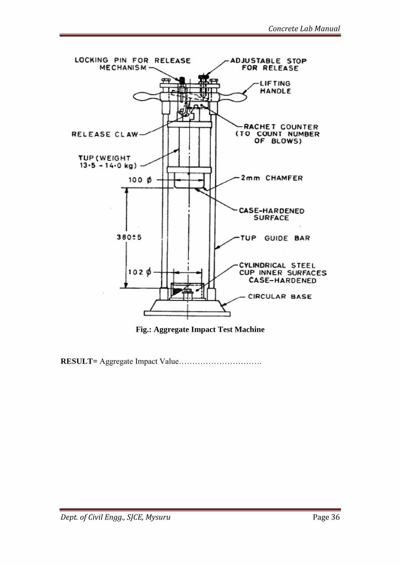
Fig.: Aggregate Impact Test Machine
RESULT= Aggregate Impact Value………………………….

Concrete Lab Manual
Dept. of Civil Engg., SJCE, Mysuru Page 37
AGGREGATE CRUSHING VALUE TEST
Exp. No.: 15
AIM: To determine the crushing value of the road aggregates
APPARATUS:
The apparatus of the aggregate crushing value test as per IS: 2386 (Part IV) –
1963consists of:
A 15cm diameter open ended steel cylinder with plunger and base plate, of the
general form.
A straight metal tamping rod of circular cross-section 16mm diameter and 45 to
60 cm long, rounded at one end.
A balance of capacity 3k
IS Sieves.
A compression testing machine capable of applying load up to 40tonnes.
Cylindrical measure having internal dia. of 11.5cm & height 18 cm for
measuring the sample.
REFERENCE CODE:
IS : 2386 ( Part IV) – 1963 method of test for aggregates for concrete
IS:383:1970 specification for coarse and fine aggregate from natural source for
concrete
IS: 9376:1979 Specification for apparatus for measuring aggregate crushing
value
THEORY:
The aggregate crushing value gives a relative measure of the resistance of an aggregate
to crushing under a gradually applied compressive load. Crushing value is a measure of
the strength of the aggregate. The aggregates should therefore have minimum crushing
value.
PROCEDURE: The test sample: It consists of aggregates sized 12.5 mm - 10.0 mm
(minimum3kg). The aggregates should be dried by heating at 1000-1100 C for a period
of 4 hours and cooled.
1. Sieve the material through 12.5 mm and 10.0 mm IS sieve. The aggregates passing
through 12.5 mm sieve and retained on 10.0 mm sieve comprises the test material.
2. The cylinder of the test shall be put in position on the base-plate and the test sample
added in thirds, each third being subjected to 25 strokes with the tamping rod.
3. The surface of the aggregate shall be carefully leveled.

Concrete Lab Manual
Dept. of Civil Engg., SJCE, Mysuru Page 38
4. The plunger is inserted so that it rests horizontally on this surface, care being taken
to ensure that the plunger does not jam in the cylinder
5. The apparatus, with the test sample and plunger in position, shall then be placed
between the plates of the testing machine.
6. The load is applied at a uniform rate as possible so that the total load is reached in
10 minutes. The total load shall be 40 tones.
7. The load shall be released and the whole of the material is removed from the
cylinder and sieved on 2.36mm IS Sieve.
8. The fraction passing the sieve shall be weighed and recorded
OBSERVATION AND CALCULATION:
Trail 1 Trail 2
Total weight of dry sample
taken= W1 gms
Weight of aggregate passing
through 2.36 mm sieve
W2gms
Aggregate crushing =
(W2/W1)*100 (%)
Aggregate impact value = 100 X 𝑊2
𝑊1
Fig.: Aggregate Crushing Test Apparatus
RESULT: Aggregate Crushing Value=………………………………

Concrete Lab Manual
Dept. of Civil Engg., SJCE, Mysuru Page 39
AGGREGATE ABRASION VALUE TEST
Exp. No.: 16
AIM: To determining the abrasion value of coarse aggregate by the use of Los Angeles
machine.
APPARATUS:
Los Angeles Machine: It consists of a hollow steel cylinder, closed at both the
ends with an internal diameter of 700 mm and length 500 mm and capable of
rotating about its horizontal axis.
Cast iron or steel balls, approximately 48 mm in diameter and each weighing
between 390 to 445 g; 6 to 12 balls are required.
IS sieve.
Balance.
REFERENCE CODE: IS: 2386 (Part IV) – 1963, IS: 383-1970.
THEORY:
The abrasion value of the aggregates is determined in order to determine their
Resistance against wearing. In this the aggregate sample is mixed with abrasive charge
consisting standard balls & rotated in closed inclined cylinders for specific number of
revolutions.
PROCEDURE:
1. The test sample shall consist of clean aggregate which has been dried in an oven at
105 to 110°C to substantially constant weight and shall conform to one of the
grading shown in Table 3.22. The grading or grading used shall be those most nearly
representing the aggregate furnished for the work.
2. The test sample and the abrasive charge shall be placed in the Los Angeles abrasion
testing machine and the machine rotated at a speed of 20 to 33 rev/min. For grading
A, B, C and D, the machine shall be rotated for 500 revolutions; for grading E, F
and G, it shall be rotated for 1 000 revolutions.
3. The machine shall be so driven and so counter-balanced as to maintain a
substantially uniform peripheral speed. If an angle is used as the shelf, the machine
shall be rotated in such a direction that the charge is caught on the outside surface
of the angle.
4. At the completion of the test, the material shall be discharged from the machine and
a preliminary separation of the sample made on a sieve coarser than the l.70 mm IS
Sieve.

Concrete Lab Manual
Dept. of Civil Engg., SJCE, Mysuru Page 40
5. The material coarser than the 1.70 mm IS Sieve shall be washed dried in an oven at
105 to 110°C to a substantially constant weight, and accurately weighed to the
nearest gram
TABULAR COLUMN:
Specified Abrasive Charge
Gradings of Test Samples
OBSERVATIONS:
Trail 1 Trail 2
Total weight of dry sample
taken= W1 gm
Weight of portion passing 1.7
mm sieve= W2 gm
Aggregate abrasion value =
(W2/W1)*100 Value (%)

Concrete Lab Manual
Dept. of Civil Engg., SJCE, Mysuru Page 41
Fig.: Los Angeles Abrasion Testing Machine
RESULT: Mean Los Angeles Abrasion value =…………………………..%

Concrete Lab Manual
Dept. of Civil Engg., SJCE, Mysuru Page 42
NON-DESTRUCTIVE TESTING OF CONCRETE
REBOUND HAMMER TEST
Exp. No.: 17
AIM: To determine the compressive strength of concrete by using the rebound
hammer.
APPARATUS:
Rebound Hammer instrument.
Abrasive Stone
PROCEDURE:
Hold the instrument firmly so that the plunger is perpendicular to the test surface.
Gradually push the instrument toward the test surface until the hammer impacts. After
impact, maintain pressure on the instrument and if necessary depress the button on the
side of the instrument to lock the plunger in its retracted position. Read the rebound
number on the scale to the nearest whole number and record the rebound number. Take
ten readings from each test area. No two impact tests shall be closer together than 25
mm (1 in). Examine the impression made on the surface after impact, and if the impact
crushes or breaks through a near-surface air void, disregard the reading and take another
reading.
Fig.: Rebound Hammer

Concrete Lab Manual
Dept. of Civil Engg., SJCE, Mysuru Page 43
READING YOUR RESULTS:
Make at least ten readings from a concrete surface and discard the highest and lowest
rebound numbers. Average the remaining eight numbers. If desired, take a few test
readings before you complete your series of ten regular tests. Use the average rebound
number to estimate the strength of the concrete. Compare your average rebound number
to the chart shown on your Concrete Rebound Hammer.
Average Rebound Number Quality of Concrete
˃40 Very good hard layer
30 to 40 Good layer
20 to 30 Fair
˂20 Poor concrete