concrete intersections - american concrete pavement ... · road intersections perhaps more than any...
TRANSCRIPT

1
IntroductionTraffic causes damage to pavement of at-grade street androad intersections perhaps more than any other location.Heavy vehicle stopping and turning can stress the pave-ment surface severely along the approaches to an inter-section. The pave ment within the junction (physical area)of an intersection also may receive nearly twice the trafficas the pavement on the approaching roadways.
At busy intersections, the added load and stress fromheavy vehicles often cause asphalt pavements to dete -riorate quickly. Asphalt surfaces tend to rut and shoveunder the stress or load of busses and trucks stopping andturning. These deformed surfaces become a safety con -cern for drivers and costly maintenance problems forroadway agencies.
Concrete pavements better withstand the loading andturning movements of heavy vehicles. As a result, city,county and state roadway agencies have begun rebuildingdeteriorated asphalt intersections with concrete pave-ment. These agencies are extending road and streetsystem maintenance funds by eliminating the expense ofintersections that require frequent maintenance.
At-grade intersections along business, industrial, and arte-rial corridor routes are some of the busiest and most vitalpavements in an urban roadway network. Closing theseroads and intersections for pavement repair creates costlytraffic delays and disruption to local businesses. Con cretepavements provide a long service life for these major corri-dors and intersections.
Concrete pavements also offer other advantages for inter-sections, including:
1. A long-term pavement solution.
2. Low maintenance costs.
3. No softening or deterioration caused by oil and/orfuel drippings.
4. Better light reflectivity than asphalt, enhancingpedes trian and vehicle safety at night and in incle -ment weather.
5. A durable and skid resistant surface.
Concrete IntersectionsA Guide for Design and Construction
©2007 American Concrete Pavement Association
An intersection reconstructed with concrete.

Successful construction of concrete intersections is chal-lenging, especially in urban areas, where accommodatingtraffic and adjacent business needs often must supersedeother engineering or construction factors. However,modern technology, including fast-track construction,simplifies these challenges.
Design ConsiderationsWhen building or rebuilding an intersection, the newconcrete pavement should cover at least the entire func-tional area of the intersection. The functional area includesthe longitudinal limits of any auxiliary lanes (Figure 1).(1,2)
Normally, the distress caused by heavy vehicles brakingand turning will occur within an intersection’s functionalboundaries.
As a rule, it is important to evaluate the existing pavementcondition before choosing limits for the new concretepavement. On busy routes, it may be desirable to extendthe limits for the new concrete pavement beyond the inter-section’s functional boundaries. Traffic congestion at a busyintersection may extend the distance where vehicles startand stop, which may extend the length of distressed pave-ment. The length that pavement distress extends beyondthe intersection’s functional boundaries will depend uponthe number, speed, and type of vehicles that use the inter-secting roadways. A similar extension of distress is possiblewhere trucks cause damage while accelerating slowly up asteep grade away from an intersection.
Physical Area
Functional Area
Figure 1. Physical and functional areas of an intersection.
If significant changes to an intersection are re quired, it is idealto extend the new pavement to the boundaries of the inter-section’s new functional area. Traffic patterns change withmodi fications to an intersection’s through-lanes, aux il iarylanes, and acceleration and deceleration tapers. Therefore, thelocation where vehicles cause damage also may change fromthe location in the existing intersection configuration.
As a standard, some agencies extend the new concretepavement 100 to 200 ft (30 to 60 m) beyond the intersec-tion’s physical area on each leg of the intersection for alltraffic lanes. Others extend the new pavement ap -proaching the intersection farther than the new pavementleaving the intersection. In the latter cases, the concretelanes approaching the intersection may begin 200 to 400ft (60 to 120 m) from the intersection’s physical area, whilelanes leaving the intersection terminate about 50 ft (15 m)beyond the physical area. For intersections carryingmoderate traffic volumes and a low percentage of heavyvehicles, 50 to 100 ft (15 to 30 m) of new pavement isusually sufficient to replace the distressed pavement.
2
Figure 2. These before (top) and after images show a concreteinlay extending well beyond the physical area of an intersectionin Western Michigan.
Before
After

■ Concrete Slab ThicknessBecause an intersection’s physical area carries traffic fromboth roadways, the concrete slab thickness in the physicalarea of the intersection may need to be greater than thethickness on any approaching roadway. The need for extrathickness will depend on the roadway or street classifica-tion and the average daily truck traffic (ADTT) that eachroute carries.
Table 1 defines six roadway (street) classifications. Theseclassifications depend on traffic volume, vehicle type(s)and maximum axle load ing.
Designers should consider increasing the slab thicknessfor at-grade intersections of industrial and arterial road-ways. The physical area will likely require 0.5 to 1.0 in.(12 to 25 mm) of additional thickness (see Table 2).
When traffic warrants extra concrete thickness in the inter-section’s physical area, it is generally easier to change thethickness at a location before the radii for the intersection.The slabs near the intersection’s radii are built using fixedforms and separate hand-pours in most cases. A transitionlength of about 3 to 6 ft (1 to 2 m) for changing the thick-ness is usually adequate. The decision on precisely whereto change thickness should be left to the contractor.Requiring the transition to be at a specific location may
3
Table 1. Street classifications(3)
Street class Description
Two-wayaverage daily
traffic(ADT)
Two-wayaverage dailytruck traffic
(ADTT)Typical range ofslab thickness
Light residential
Short streets in subdivisions and similarresidential areas – often not through-streets.
Less than 200 2 – 4 4.0 – 5.0 in.(100 – 125 mm)
Residential Through-streets in subdivisions andsimilar residential areas that occasion-ally carry a heavy vehicle (truck or bus).
200 – 1,000 10 – 50 5.0 – 6.0 in.(125 – 150 mm)
Collector Streets that collect traffic from severalresidential subdivisions, and that mayserve buses and trucks.
1,000 – 8,000 50 – 500 5.5 – 8.0 in.(135 – 200 mm)
Business Streets that provide access to shoppingand urban central business districts.
11,000 – 17,000 400 – 700 6.0 – 8.0 in.(150 – 200 mm)
Industrial Streets that provide access to industrialareas or parks, and typically carryheavier trucks than the business class.
2,000 – 4,000 300 – 800 6.5 – 9.5 in.(165 – 240 mm)
Arterial Streets that serve traffic from majorexpressways and carry traffic throughmetropolitan areas. Truck and bus routesare primarily on these roads.
4,000 – 15,000(minor)
4,000 – 30,000(major)
300 – 600
700 – 1,500
6.5 – 9.5 in.(165 – 240 mm)7.0 – 10.0 in.
(175 – 250 mm)
Table 2. Slab thickness considerations for the physical area of at-grade intersections. Note that in this table, thickness T3 is greaterthan T2, and T2 is greater than T1.
Intersecting roadway 1 Intersecting roadway 2 Physical area thickness*
Low ADTT (T1) Low ADTT (T2) T2
Low ADTT (T1) High ADTT (T3) T3
High ADTT (T3) High ADTT (T3) T3 + 0.5 – 1.0 in. (12 – 25 mm)**
* Assumes thickness (T1, T2 or T3) for intersecting roadways based on anticipated traffic and calculated in a rational design procedure suchas that of AASHTO,(4) StreetPave Software,(3,5) or MEPD.
** The AASHTO thickness design procedure(4) shows that doubling the traffic loading requires about an additional 1 in. (25 mm) of concretepavement thickness. The ACPA design procedure(3,5) shows that an extra 0.5 in. (12 mm) of slab thickness is required when doubling traffic.

com plicate construction and conflict with other job sitefactors, such as providing access to adjacent businesses.
At-grade intersections of light residential, residential,collector, and business roadways should not require anyextra concrete thickness in the physical area. The intersec-tion thickness should be the same as the thicker of the twoap proaching roadways.
■ JointingJoint design is arguably the most important design aspectfor concrete pavement intersections. At-grade intersec-tions often introduce jointing challenges that do not existalong tangent sections of concrete roadway or streetpavements. However, these complications can be over-come by applying simple jointing fundamentals.
Joints are necessary primarily to control the location ofcracks that occur from natural actions on concrete pave-ment. When designed correctly, joints accommodate theexpansion and contraction of concrete slabs caused bytemperature fluctuations, and account for stresses thatdevelop from slab curling and warping.(6) During construc-tion, joints also divide the pavement into suitable place-ment increments or elements for the contractor. Certainjoints also accommodate slab movement against fixedstructures.
For at-grade intersections, a designer should considerthree major joint design elements: joint spacing, jointtype, and joint layout. Each factor can influence the long-term performance of the pavement. In addition, otherfactors to consider include: dowel bars for load transfer,tiebars for tying lanes, and sealing joints.*
Joint Spacing – For unreinforced concrete pavement,joint spacing or slab length depends on slab thickness,concrete aggregate, subbase/subgrade, and climate.(6,7)
In most areas, the typical maximum transverse jointspacing for unreinforced (plain) pavement is about 15 ft(4.5 m). Longitudinal joints on two-lane and multilane
street pavements are typically about 10 to 13 ft (3.0 to4.2 m) apart, and serve the dual purpose of crack controland lane delineation.
Equation 1 determines the maximum allowable jointspacing based on slab thickness and subbase type. Slabskept to dimensions shorter than the equation determineswill have curling and warping stresses within safe limits toensure minimal risk of random cracking.
ML = T x CS (Eq. 1)
where:
ML = Maximum length between joints(See Notes 1 and 2).
T = Slab thickness(Either English or metric units).
CS = Support constant.
Use 24 for subgrades or unstabilized (granular)subbases.
Use 21 for stabilized subbases, or existing concrete orasphalt pavement (for conventional overlays).
Use 12 to 15 for ultra-thin overlays of asphalt(See Note 3).
Notes:
1. The spacing of transverse joints in plain (unreinforced)concrete pavement should not exceed 15 ft (5 m) forslabs less than 10 in. (250 mm) thick.
2. A general rule-of-thumb requires that the transversejoint spacing should not exceed 150% of the longitu-dinal joint spacing. This ratio is difficult to maintainwithin intersections due to islands, medians, auxiliarylanes, and curved areas, and can be disregarded in favorof common-sense jointing patterns to accommodatethese elements within the intersection.
3. The spacing of transverse and longitudinal joints inultrathin and thin overlays range from 4 to 6 ft (1.33 to2.0 m) depending upon overlay thickness, supportconditions, and lane width.
The climate and concrete aggregate common to somegeographic regions may allow transverse joints to befurther apart, or require them to be closer together thanEquation 1 determines. For example, concrete made fromgranite and limestone coarse aggregate is much less sensi-tive to temperature change than concrete made fromsiliceous gravel, chert, or slag aggregate. A less tempera-ture-sensitive concrete does not expand or contract muchwith temperature change, which allows a longer spacingbetween pavement contraction joints without any greaterchance of random cracking. However, unless experience
4
* Joints should be sealed to minimize infiltration of water andincompressible particles if local experience indicates it is neces-sary. The effectiveness of joint sealing depends upon thesealant type, installation technique, maintenance, concreteproperties and joint configuration. For pavements with jointsspaced less than 15 ft (4.5 m), the impact of the sealant onpavement performance is not as critical as it is for longerspacing. The impact of joint sealing on pavement performancealso may be more noticeable in urban areas and Northernclimates if pavements carry heavy traffic and receive sand orsalt applications for snow and ice control. See Reference 8, inthe sources listed at the end of this document, for more detailson joint sealing techniques and materials.

with local conditions and concrete aggregates indicatesotherwise, use Equation 1 to determine the maximumallowable transverse joint spacing for unreinforced pavements.
A transverse joint spacing up to 30 ft (9 m) is allowable forpavements reinforced with distributed steel reinforce-ment. The purpose of distributed steel is to hold togetherany intermediate (mid-panel) cracks that will develop inthe long panels between transverse joints.** Distributedsteel neither adds to the load-carrying capacity of thepavement nor compensates for poor subgrade conditions.
Joint Types – There are three basic joint types for con -crete pavements: contraction, construction ,and isolation.Specific design requirements for each type depend onorientation to the direction of the roadway (transverse orlongitudinal). Most concrete intersections will require eachof the three joint types in both longitudinal and transverseorientations. Figure 3 pro vides cross-sections detailingeach type.
Transverse Joints – Transverse contraction joints run trans-verse to the pavement centerline and are essential tocontrol cracking from stresses caused by shrinkage,
5
thermal contraction, and moisture or thermal gradients.Typically these joints are at a right angle to the pavementcenterline and edges. However, some agencies skew trans-verse contraction joints to decrease the dynamic loadingacross the joints by eliminating the simultaneous crossingof each wheel on a vehicle’s.(6,7) Right-angle transversecontraction joints are preferable to skewed joints for con -crete intersections because they do not create complexjointing patterns within the intersection’s physical area.Skewing joints is not a substitute for the load transferprovided by dowels, (smooth round bars).
The need for dowels in transverse contraction jointsdepends upon the roadway or street classification. Undow-eled contraction joints (Type A-1, Figure 3) are usually suffi-cient for light residential, residential, or collectorpavements. Industrial and arterial streets that will carryheavy truck traffic for long periods require doweledcontraction joints (Type A-2, Figure 3).(7) Doweled contrac-tion joints are also necessary in pavements with distrib-uted steel reinforcement, and should be considered forslabs longer than 20 ft (6 m). Table 3 provides recom-mended dowel sizes.
** Pavements with distributed steel are often called jointed reinforced concrete pavements (JRCP). In JRCP, the joint spacing ispurposely increased and reinforcing steel is used to hold together intermediate cracks. If there is enough distributed steel withinthe pavement (0.10 to 0.25% per cross-sectional area), the mid-panel (sometimes called “mesh”) cracks do not detract from the pave-ment’s performance.(9) However, if there is not enough steel, the steel can corrode or rupture and the cracks can start to open anddeteriorate.
Slab thicknessin. (mm)
Dowel diameterin. (mm)
Minimum dowel lengthin. (mm)
Plain (unreinforced) pavements†
<7 (<180) not necessary not necessary
7 – 7.9 (180 – 195) 1.00 (25) 14 (360)
8 – 9.9 (200 – 249) 1.25 (32) 14 (360)
≥ 10 (≥ 250) 1.50 (38) 14 (360)
Distributed steel reinforced pavements
6 (150) 0.75 (19) 14 (360)
6.5 (165) 0.875 (22) 14 (360)
7 (180) 1.00 (25) 14 (360)
7.5 (190) 1.125 (28) 14 (360)
8 – 9.9 (200 – 249) 1.25 (32) 14 (360)
≥ 10 (≥ 250) 1.50 (38) 14 (360)
Table 3. Dowel sizes for plain pavements and pavements reinforced with distributed steel.
† Assumes thickness is based on anticipated traffic and is calculated in a rational design procedure such as that of AASHTO,(4) ACPA(3,5) orMEPDG.

6
T
Construction:
Contraction:
Smooth dowelExpansion cap
Isolation:
T
T
T
T
T
Undoweled – Transverse (Type A-1)
Doweled – Transverse (Type A-2)
Untied – Longitudinal (Type A-3)
Tied – Longitudinal (Type A-4)
T/4–T/31 in. (25 mm) max.
T
Fixture orStructure
1/8 – 1/4 in.(3 – 6 mm) typ.
1/8 – 3/8 in.(3 – 9 mm) typ.
1/8 – 3/8 in.(3 – 9 mm) typ.
T/3
T/2
Smooth dowel
Doweled butt – Transverse (Type B-1)
T/2
T/2
T
T T
Tied butt – Longitudinal (Type B-2)
T/2
Deformed tie bar
Tied – Transverse (Type C-1)(Keyway optional)
T/2
Keyed – Longitudinal (Type C-2)(Deformed tie bar optional)
T/2
Deformed tie bar Deformed tie bar
4.5 ft.
1in. (25 mm)max.
1/2 – 1 in.(12 – 25 mm) max.
1.2TFiller
T/2
Thickened edge – Transverse (Type D-1)
Doweled – Transverse (Type D-2)
Undoweled – Longitudinal (Type D-4)
T T
8 in.(200 mm)
Sleeper slab – Transverse (Type D-3)
Bond breaker
6 ft (2 m) typ.
Smooth dowel Deformed tie bar
Figure 3. Cross sections of different joint types.

Transverse construction joints (Type B-1, C-1, Figure 3) arenecessary at the end of a paving segment, or at a place-ment interruption for a driveway or cross road. A doweledbutt joint (Type B-1) is preferable. It should be used when-ever the construction joint will correspond to the locationof a contraction joint or construction joint in an adjacentlane. Sometimes it is not feasible to match the location ofa transverse joint in the adjacent lane, which necessitatesuse of a tied construction joint (Type C-1). The deformedtiebars in a Type C-1 joint prevent the joint from openingand causing sympathy cracking in adjacent lane(s).
Longitudinal Joints – Longitudinal contraction joints(Type A-3, A-4, Figure 3) also are necessary to controlcracking from stresses caused by concrete volumechanges and moisture or thermal gradients. These jointsrun parallel to the pavement centerline and usually corre-spond to the edge of a driving lane. On two-lane andmultilane pavements, a spacing of 10 to 13 ft (3.0 to 4.0m) serves the dual purpose of crack control and lanedelineation.
For unusual or special locations, such as ramps and turningareas between median islands, the maximum recom-mended slab width (distance between longitudinal con -traction joints) is 15 ft (4.5 m). However, this may beexcessive for thinner slabs, in which case Equation 1should be used to determine the maximum allowablelongitudinal joint spacing.
The need to tie longitudinal contraction joints will dependon the degree of lateral restraint available to prevent thejoints from opening permanently. Most longitudinalcontraction joints on roadway tangent sections containNo. 4 or No. 5 (#13M or #16M) deformed reinforcing bars.†
The deformed bars are usually about 24 to 30 in. (600 to750 mm) long and are spaced at 30 to 40 in. (750 to 1000mm) intervals. Where there are curbs on both sides of thepavement, it may not be necessary to tie the joints unlesslocal experience indicates otherwise.
Longitudinal construction joints (Type B-2, C-2, Figure 3)join pavement lanes that are paved at different times.Concrete intersections require these joints because of thenumerous pours necessary to place pavement aroundislands and medians, and between the curves connectingthe two roadways.
The optional keyway for a tied longitudinal constructionjoint can be difficult to construct correctly in thin pave-ments. Therefore, some agencies avoid placing keyways inslabs less than 10 in. (250 mm) thick.(7) Keyway shear fail-ures can occur in thin slabs when keyways are too large ortoo close to the slab surface. Some contractors report thathalf-round keyways are easier to construct and less proneto problems than trapezoidal keyways. Where a keyway isdeemed necessary, the dimensions indicated in Figure 4will afford the optimum load-transfer performance.
7
† For very wide roadways, there is a limit to width of pavementthat can be tied together without concern for cracking.Current recommendations(7) limit the tied width of highwaypavement to about 48 ft (14.5 m) based on the subgrade dragtheory. However, there has been good field performance ofcertain intersections with up to 70 ft (21 m) of tied pavement.If local-experience records are not available for intersectiondesign, consider using an untied contraction joint (Type A-3) orconstruction joint (Type C-2) near the centerline of roadwaysections that exceed 48 ft (14.5 m).
0.2 T 0.2 T
0.5 T
T
1:4 Slope
0.1 T
Trapezoidal Half-Round
Figure 4. Keyway standard dimensions.
Isolation Joints – Isolation joints (Type D-1, D-2, D-3, D-4,Figure 3) are essential at asymmetrical and T-intersectionsto isolate the side road from the through street (Figure 5,page 8). Isolation joints also are needed where the pave-ment abuts certain manholes, drainage fixtures, sidewalks,aprons, and structures. Certain agencies and contractorsalso prefer to use isolation joints at crossroad intersec-tions. Where used, the isolation joint will allow inde-pendent movement of the pavement and the structurewithout any connection that could cause damage. To beeffective, the pre formed compressible filler should meetthe requirements of ASTM†† D1751, D1752, or D994, andmust cover the entire depth of the concrete slab.
†† ASTM is now the official name of the organization originallycalled the American Society for Testing and Materials. Equiv-alent Canadian standards for all ASTM standards addressed inthis publication, as well as the Canadian equivalent, are listedon page 28.

At asymmetrical or T-intersections, undoweled, thickened-edge or sleeper-slab isolation joints (Type D-1 or D-3,Figure 3) are preferable to doweled isolation joints,because they each permit independent lateral movementof the through-street concrete slabs. The sleeper slab andthickened edge designs each provide improved supportto compensate for the absence of dowel bars. For a thick-ened edge joint, the abutting edges of the concrete slabsshould be 20% thicker at the joint and taper back to thenominal thickness over at least 4.5 ft (1.5 m).
At locations inaccessible to heavy vehicle loads, such asthose between a pavement and a structure, a thickened-edge joint is not necessary. A butt joint with a non-extruding, preformed compressible material is adequate.
For utility fixtures such as manholes, catch basins, anddrainage inlets, the need for isolation will depend uponthe casting design and potential for differential move-ment. Non-telescoping manholes with ribbed cylinderwalls usually require a boxout with a perimeter isolationjoint to allow independent vertical and horizontal slab
movement. Common square boxouts sometimes causecracks to form at the corners of the boxout. To avoid crack-inducing corners, consider using rounded boxouts orplacing fillets on the corners of square boxouts. It is advan-tageous to place welded-wire fabric or small-diameterreinforcing bars in the concrete pavement around anyinterior corners at square boxouts to hold cracks tightlyshould they develop. Figure 6, page 9 shows details forboxing out in-pavement fixtures.
In some circumstances, boxing out fixtures may be unde-sirable. For instance, boxouts can impede fast-trackconstruction because more time is needed to placeconcrete around the casting after the pavement gainsstrength. It is also very difficult to maintain a uniform jointpattern if there are too many manholes randomly posi-tioned in an intersection. In these cases it may be best tocast the fixtures into the concrete.
To isolate a fixture without a boxout, some contractors andagencies wrap the casting with pliable expansion jointfiller or a suitable bond breaker. If no differential move-ment is expected, the manhole can be cast directly into theconcrete. Telescoping manhole fixtures have a two-piececasting, which allows vertical movement.
Concrete pavement performance suffers if the pavementcontains too many transverse expansion (isolation-type)joints. Outdated specifications sometimes require expan-sion joints spaced uniformly along tangent sections. Thesejoints create maintenance problems because nearby trans-verse contraction joints open excessively as the expansionjoint closes gradually over time. The open contractionjoints then lose load transfer and develop distresses likefaulting. Transverse expansion joints at regular intervalsmay be needed when:
1. The pavement is divided into long panels [60 ft (18 m)or more] without contraction joints in-between.
2. The pavement is constructed while ambient temper-atures are below 40°F (4°C).
3. The contraction joints are allowed to be infiltrated bylarge incompressible materials.
4. The pavement is constructed of materials that, in thepast, have shown high expansion characteristics.
In most situations, these criteria do not apply. Therefore,transverse expansion joints should not normally be used.
8
90° T
90° T/Apron Divided highway(non-concrte median)
Skewed T
90° Skew Skew/Skew
Figure 5. Asymmetrical and T-intersections that require isolationjoints.

Joint Layout – A well-designed joint layout contributesto good long-term performance of at-grade intersections.A good jointing plan will ease construction by providingclear guidance to the contractor. It is common practice forsome designers to leave intersection joint layout to thefield engineer and contractor. These designers often justifythis practice by citing the many field adjustments thatoccur during construction, which they contend negatesthe usefulness of a jointing plan. However, it is not desir-able to eliminate the jointing plan entirely, except for verysimple intersections. A jointing plan and appropriate fieldadjustments are both important for more complex inter-sections, because islands, medians, and auxiliary turninglanes complicate joint layout and require some fore-thought before construction. A plan also enables contrac-tors to bid new projects more accurately.
During construction, it is likely that location changes willbe necessary for some joints within an intersection. Theprimary reason is to ensure that joints pass throughembedded fixtures such as manholes or drainage inlets. Itis common for the actual location of manholes or drainageinlets to vary from the location shown on the plans. It willbe necessary for the construction crew to adjust the loca-tion of some joints during construction so that they coin-cide with the actual location of a nearby manhole or inlet.The designer should consider placing a note on the plan togive the field engineer and contractor the latitude to makeappropriate adjustments. Reference 10 provides a ten-stepmethod for laying out joints for concrete intersections.
Another important aspect of laying out intersection jointsis determining where to use dowel bars or tiebars near theintersection’s physical area. Figure 7, page 10 shows exam-ples of dowel and tiebar use in intersections.
9
Square Manhole Boxout Diagonal Manhole Boxout Circular Manhole Boxout
Square Inlet (no Boxout)
Telescoping ManholeManhole (no Boxout)Square Boxout with Fillets
Isolation Joint Isolationjoint
Isolationjoint
Isolationjoint
Isolationjoint
Round Inlet Boxout
Isolation Joint
Isolationjoint /bond breakeraroundperimeter
No boxout orisolation jointnecessary
Figure 6. Details for boxing out fixtures.
Notes: 1. Isolation joints should be at least 1⁄2 in. (12 mm) wide and filled with a compressible material.2. Boxouts should be large enough to provide at least 1 ft (0.3 m) clearance between the fixture and the
surrounding isolation joint.

10
90-degree T-intersection(both roadways doweled)
Skewed T-intersection(both roadways doweled)
Typical Auxiliary Lane Island
Isolation jointalong island perimeter
Skewed T-intersection(neither roadway doweled)
Standard Intersection(doweled or undoweled cross roads)
Isolation joint(see Note 2)
Isolation joint(see Note 2)
Isolation joint(see Note 2)
Isolation joint(see Note 2)
Construction joint(see Note 1)
Construction joint (see Note 1)
SeeNote 3
SeeNote 3
SeeNote 3
Omit tiebarsif curb paved
integrallywith pavement
Island
Contraction Joint (Undoweled – Type A-1)*
Contraction Joint (Untied – Type A-3 )*
Contraction Joint (Tied – Type A-4)*
Construction Joint (Tied – Type B)*
Isolation Joint [Thickened edge (Type D-1)* or Sleeper slab (Type D-3)*]
Contraction Joint (Doweled – Type A-2 )*
Notes:1. Use and location of construction joint depends on staging used by contractor. Shown at this location for illustration only.2. Specific site and staging conditions will dictate where a contractor positions the isolation joint precisely.3. Centerline joint may be untied if pavement width exceeds 48 ft (14.5 m) per footnote on page 7.
* Joints are illustrated in Figure 3, page 6.
Figure 7. Use of dowel bars and tiebars in intersections.

Phasing Construction – Phasing is almost always a keyelement of intersection construction plans. The need for arefined phasing plan depends upon the need to maintaintraffic flow through the intersection during construction.There are four basic construction staging options: com -plete closure with detours, partial closure with detours,complete closure during time-windows, and con structionunder traffic.
Intersections of rural or other low-traffic roadways do notusually require the same level of consideration necessaryfor intersections that carry high volumes of traffic. Closinglow-traffic intersections for the duration of construction isoften the optimal solution and should always be consid-ered. In some cases, the availability of convenient alternateroutes (e.g., frontage roads) may even permit closing anintersection that carries a high traffic volume withoutsignificant concern for traffic flow or business disruption.
For the contractor, complete closure is ideal. Completeclosure eliminates complex work-zone lane configura-tions, which increases the safety of the construction workzone. Complete closure also allows the contractor to placemore pavement in a continuous operation, generallyincreasing pavement smoothness, improving quality, andreducing construction time.
Completely closing an intersection for constructionrequires developing a detour plan. Clear and understand-able signing along the detour route will make the detourmore acceptable to motorists. A sign indicating the datewhen the intersection will re-open also can improve publicrelations.
Unfortunately, closing intersections for the entireconstruction period is often not viable along urban arterialor corridor routes. For example, the lack of traffic over anextended period might cause businesses near the closureto lose customers. In these circumstances, one option is tolimit complete intersection closure to non-business hours.If it is feasible to divert traffic around the intersection, evenfor a few hours, the contractor can complete criticalconstruction phases quickly and expedite the entireproject.
Some agencies develop phasing plans that allowcomplete intersection closure during specific periods(windows). Usually the window will begin at about 6 p.m.and last until about 6 a.m. the following morning. Thestarting and ending time depends upon the local rush-
hour traffic pattern. Within the window the contractormay close and occupy the entire intersection. At the endof the window, public traffic must be able to use the intersection. In this manner, the closure will not hindermorning, evening, or daytime traffic flow. Undertime-window phasing plans, contractors perform eachsequential construction operation during successive time -windows. For example, if the project includes removal ofan existing pavement, the contractor may place a tem -porary pavement after removing the existing materialduring one 12-hour window. The temporary pavementcarries traffic until the contractor removes it to pave thenew concrete roadway in a subsequent time window.
Another option to avoid closing an entire intersection is toclose one leg of the intersection at a time. This is oftenfeasible for intersections between residential and collectorstreets. Detours along the closed residential street areusually short and not a burden to local residents.
On some roadways, it may be unacceptable to close theentire intersection at any time. Many agencies have hadgood success replacing busy intersections with concretepavement while maintaining normal traffic volumes.Figure 8 (page 12) shows possible options for phasingconstruction under traffic.
These options may reduce the number of availablethrough-lanes and may somewhat limit turning move-ments during construction. However, the degree of theserestrictions depends upon the number of lanes on theapproaching roadways. None may be necessary if theapproaching roadways have at least three through lanes ineach direction. A detour for one leg of the intersection orspecial alternating traffic signals will be necessary if one orboth of the approaching streets has just one lane in eachdirection.
Construction under traffic can generally start on any leg ofan intersection. However, if an intersection includes amajor road and a minor cross road, the driving lanes of themajor roadway usually are built before the cross road.Concentrating on the major roadway pavement generallyproduces a smoother-riding intersection. After the majorroadway pavement lanes are finished, other pavementareas are built without affecting the smoothness throughthe intersection. Typically, this method is more productivebecause the contractor can place more pavement in acontinuous operation without gaps or changes in thepavement width.
11

■ Quality Concrete Mixtures
A suitable concrete mixture is necessary to ensure thesuccess of the construction phasing plan. Whether thecontractor or agency determines the concrete mixtureproportions, the concrete must be capable of meetingstrength requirements reliably within any specified timewindows for construction, and must have adequate long-term durability. The contractor should have some latitudeto adjust the mixture proportions during construction ifthe mixture does not work properly for the requiredconstruction phasing plan. Before construction, contrac-tors also may offer valuable suggestions or value-engi-neering options to expedite construction.
Strength – Compressive strength testing (ASTM C39) isthe most common and easiest way to evaluate concretestrength. Concrete with a 28-day compressive strengthaveraging 3000 to 4000 psi (20 to 30 MPa) is adequate formost intersections. During construction, the pavementmay be opened to traffic at a strength somewhat less thanthe 28-day target value (see table 7, page 23).
Some highway agencies use flexural strength (ASTM C78)as the structural strength criterion to evaluate loadcapacity. Flexural strength provides an assessment of the
tensile strength at the bottom of the slab, more appropri-ately modeling the stresses due to wheel loads. However,challenges associated with casting and testing beam spec-imens properly, discourage many engineers and contrac-tors from using this test method in the field.
Durability – Strength is not a reliable measure of con -crete’s durability. In frost-affected areas, a concrete pave-ment must be able to withstand many cycles of freezingand thawing and the effects of deicing salts. This requiresquality aggregate, a low water-cementitious material ratio,an adequate cement factor, and a sufficient quantity ofentrained air bubbles. The percentages of total air contentnecessary for weather-resistant concrete are shown inTable 4 (page 13). These recommendations varydepending on the exposure condition of the concrete.Adequate curing measures also are necessary for devel-oping durable con crete pavement.
In addition to making the hardened concrete pavementweather resistant, entrained air bubbles improve theconcrete while it is still in a plastic state by:
1. Reducing water required for satisfactory workability.
2. Preventing segregation.
3. Reducing bleeding.
12
Construction by Lane:
Construction by Quadrant:
Phase 1 Phase 2 Phase 3 Phase 4
Phase 1 Phase 2 Phase 3 Phase 4
Figure 8. Possible options for phasing construction under traffic.

Because of these beneficial and essential effects in bothplastic and hardened concrete, it is wise to consider usingentrained air even in mild exposure conditions.
The quantity of water in the mixture also has a criticalinfluence on the durability and weather resistance of hard-ened concrete.(11) For a given quantity of cementitiousmaterials, a lower quantity of water will produce a moredurable mixture in most cases. However, an adequatequantity of water is necessary to produce a workableconcrete. Satisfactory pavement durability is generallyachieved with:
1. A water-cementitious material ratio not exceeding0.53 with a minimum cementitious material contentof 520 lb/yd3 (310 kg/m3) for mild exposure condi-tions.
2. A water-cementitious material ratio not exceeding0.49 with a minimum cementitious material contentof 560 lb/yd3 (330 kg/m3) for moderate-to-severeexposure conditions (frequent freezing and thawing,and application of deicing agents).
Careful aggregate selection is important to avoid futureproblems with alkali aggregate reactions or D-cracking.Coarse or fine aggregates that are susceptible to alkali-silica or alkali-carbonate reactivity require special mixtureproportions to produce durable concrete. Many agenciesspecify special mixtures when using locally availableaggregates known to have reactivity potential. It is alsopossible to test a proposed concrete mixture to determineif there is reactivity potential. For more information, referto References 12 and 13.
Fast-track Concrete Mixtures – Fast-track con cretemixtures develop strength rapidly and are beneficial whenearly opening of the pavement is necessary. For intersec-tions, there are several practical options available toproduce concrete that gains strength rapidly. The mixturecomponents can be selected or proportioned for rapidstrength gain, and the mixture water can be heated socement hydration begins quickly.
Although proprietary cements are available, fast-trackmixtures do not necessarily require these special mate-rials. Rapid strength development is possible by usinggreater-than-normal quantities of ordinary ASTM C150Type I and Type II cements, but high-early-strength ASTMC150 Type III cement may be used. Most aggregates andadmixtures available locally also can be used in fast-trackmixtures if combined in the proper proportions.(14,15)
Table 5 shows example proportions of a fast-track mixture.
13
Table 4. Recommended* total air contents.(11)
Nominal maximumaggregate sizein. (mm)
Target** percentageair content for exposure
Severe† Moderate† Mild†
2 (50) 5 4 2
11⁄2 (37.5) 5.5 4.5 2.5
1 (25) 6 4.5 3
3⁄4 (19) 6 5 3.5
1⁄2 (12.5) 7 5.5 4
3⁄8 (9.5) 7.5 6 4.5
* Canadian standards differ; refer to CSA Standard A23.1. ** A tolerance of -1% to +2% is typical for paving concrete.
† Severe exposure is an environment where concrete pavement isexposed to wet freeze-thaw conditions or deicers. Moderateexposure is an environment where concrete pavement isexposed to freezing but will not be continually moist, exposed towater for long periods before freezing, or in contact with deicers.Mild exposure is an environment where concrete pavement isnot exposed to freezing conditions or deicers.
Table 5. Typical fast-track mixture proportions.(14)
Material Type Quantity*
Cement ASTM C150Type I
ASTM C150Type II
ASTM C150Type III
700 – 800 lb/yd3
(415 – 475 kg/m3)700 – 800 lb/yd3
(415 – 475 kg/m3)600 – 750 lb/yd3
(360 – 450 kg/m3)
Fly ash ASTM C618 10 – 20% byweight of cement
Water ASTM C94 See note below
Air-entrainingadmixture
ASTM C260 As necessary
Acceleratingadmixture
ASTM C494 As necessary
Water-reducingadmixture
ASTM C494 As necessary
* Use quantity of water appropriate to produce sufficient work-ability and maintain desired strength gain. Water-cementi-tious material ratio should not exceed 0.37 – 0.43 under mostcircumstances.

The sooner the concrete temperature rises, the faster it willdevelop strength. One way to raise the temperature ofplastic concrete is to heat the mix water. This may be prac-tical for intersection projects that do not require a largequantity of concrete.
Several factors influence the water temperature needed toproduce a desirable mixture temperature at placement.The critical factors are: ambient air temperature, aggregatetemperatures, aggregate free-moisture content, and port-land cement type. When necessary, ready-mix concreteproducers heat water to 140 to 150°F (60 to 66°C) toelevate mixture temperature sufficiently for cool-weathercon struction. The same practice will accelerate strengthdevelopment in warmer ambient temperatures. However,to avoid a flash set using this method, combine the hotwater and aggregates before adding the cement to theconcrete mixer.(14)
Though hot water does facilitate early cement hydration,its benefits may be short-lived. Several hours of heatcontainment with insulating blankets may be necessary toachieve the desirable strength gain, particularly when coolweather conditions prevail.
Mixtures for Thin Overlays – The concrete mix ture forthin overlays is often selected based on requirements foropening to traffic. A normal thin-overlay mixture includes:cement, coarse, and fine aggregate; air-entraining agent;admixtures (water-reducers or plasticizers); fibers (as spe -cified); and a low water-cementitious materials ratio.Compared to aggregate used for thicker concrete pave-ments, the top-size of coarse aggregate for thin bonded orunbonded concrete overlays(16,27) is reduced appropriatelyto account for the smaller thickness. When fibers are usedin such a mixture, the fiber contents are usually in the rangeappropriate for the specific fiber type, although on someprojects higher-than-normal dosages have been used.
ConstructionVarious methods and machines are used to build concretepavement intersections, including slipform and fixed-formconstruction equipment. Unlike mainline roadway paving,intersection construction work usually necessitates someuse of fixed-form placement. Contractors may elect to useslipform equipment in an intersection if the paving area islarge enough to warrant its use, or if staging allows thecontractor to build the driving lanes of the major roadwaythrough the physical area of the intersection.
Despite the variety of possible equipment, the followingconstruction steps are typical for nearly all types ofconcrete pavement.
1. Removing or planing an existing pavement (wherenecessary).
2. Preparing the grade.
3. Setting forms (where used).
4. Placing in-pavement objects (dowels, tiebars, andboxouts, where used).
5. Placing and finishing the concrete.
6. Texturing the pavement surface.
7. Curing the concrete.
8. Jointing the pavement.
■ Removing or Planing ExistingPavement
The first step in the complete reconstruction of an inter-section is to remove the existing pavement.
The options for removing existing asphalt include: coldmilling, scarifying, and excavating the material with equip-ment such as a front-end loader or bulldozer. Cold millingoffers productivity and suitable grade control. Cold millingequipment uses carbide teeth mounted on a rotary drum.The teeth chip away existing asphalt as the drum rotates.The size of the broken material depends upon the toothconfiguration, drum rotation speed, forward machinespeed, and removal depth. Particle size also varies with thetemperature, condition, and asphalt content of the oldhot-mix asphalt. The ability to control particle size ishelpful when the asphalt millings are reused on theproject for fill or subbase.
Attaining the desired removal depth may require severalmilling passes. Commonly available machines can remove6 in. (150 mm) of asphalt material in one pass.
Scarifying or ripping is also common for removing thinlayers of existing asphalt. This method uses motor-gradersor bulldozers equipped with scarifying equipment. Whilescarifying is less expensive than cold milling, there is alsoless ability to control removal depth or grade. Neverthe-less, scarifying equipment is adequate when the removalgoes below the depth of all asphalt layers.
There also are three methods for removing existingconcrete or composite pavements:
14

1. Break the concrete into small fragments for removalby backhoe and hand tools.
2. Lift the concrete out of place in large segments.
3. Scarify the concrete with large milling machines.
At urban intersections, the optimal method depends uponthe size of the intersection, the allowable time for removal,the land use in the surrounding area, and concerns aboutnoise and dust generation. The presence of sensitive utilitypipes, conduits, or cables beneath the pavement also maydiscourage use of equipment that imparts impact vibra-tions. In general, the selection of the most productiveremoval method should be left to the contractor based onexperience and available equipment.
If an existing asphalt intersection will receive a concretepavement overlay, removal of the existing asphalt shouldstop short of the subbase or subgrade. Because coldmilling offers excellent grade control, it is the best choicefor removing controlled layers of existing asphalt pave-ments. The rough surface from milling also provides anexcellent bonding surface for the overlay.(16,17,27) Forbonded concrete overlays less than 4 in. (100 mm) thick,current recommendations(16,27) suggest that at least 3 in.(75 mm) of asphalt thickness remain after mill ing topromote composite action.
■ Preparing the GradeA reasonably uniform sub grade or subbase, with no abruptchanges in support, is ideal for any concrete pavement.Achieving this condition after pavement removal opera-tions will require some effort even in the relativelyconfined work area of an intersection. The first step is toensure as much as is practicable, so that the subgrade soilsare of uniform material and density.
Compacting the subgrade surface adequately requires acompactor heavy enough to achieve 95 percent of max i -mum density determined through ASTM D698. However, itmay be difficult to maneuver large compactors in a trenchcreated by removing an older pavement for an intersec-tion. A more effective strategy in a confined area may be toapply more compaction effort using smaller equipment.
The soil moisture content should be reasonably uniformduring compaction; excessively wet or dry spots requirecorrection to produce reasonable uniformity. For mostsoils, compaction should be accomplished at moisturecontents at or slightly above optimum.
Soft spots in the subgrade often become visible afterremoving an old pavement. It is not acceptable to merelyplace a granular layer over these soft areas; excavation and
removal is necessary. Ideally, the replacement soil shouldbe of the same type as in the surrounding subgrade todevelop uniform support.
Contractors must pay particular attention to sections ofthe subgrade overlying any utility installations such assewers, telephone and power conduits, and water lines.Careless compaction of fill materials in these trenchesoften causes soft spots in the subgrade. Controlled low-strength fill (flowable-fill) materials are an economicalalternative for these areas.
Flowable-fill materials do not need compaction and floweasily to fill a trench. The mixtures contain portlandcement, sand, fly ash, and water and typically develop 28-day compressive strengths of about 50 – 100 psi (0.35 – 0.70MPa). Flowable-fill materials provide enough strength toprevent settlement, but are easy to remove using a bucketon a backhoe or front-end loader if future excavation isnecessary.
Subbase – A subbase is a thin layer of engineered mate-rial placed on top of the prepared sub grade. Subbasesprovide uniform support to the pavement and a stableplatform for construction equipment. Subbases also helpprevent mud-pumping of fine-grained subgrade soils attransverse pavement joints in roads subject to a largevolume of unidirectional truck traffic. Intersections at resi-dential streets and even some streets that may carryheavier vehicles usually do not require a subbase.
Where used, unstabilized subbase thicknesses should notexceed 4 to 6 in. (100 to 150 mm). A thicker subbase is notnecessary or economical under most conditions. Gooddense-graded, granular-subbase materials have a plasticityindex of 6 or less, and contain a maximum of 15 percentfine particles that pass the No. 200 (75 µm) sieve. Forstability, the subbase requires compaction to 100 percentmaximum density as determined by ASTM D698 (Figure 9).
15
Figure 9. Compacting subbase.

Trimming – The method for trimming or shaping thegrade varies by project and may depend upon intersectionsize. Typical specifications(18) require:
1. A subgrade surface that does not vary from thedesign elevation by more than 0.5 in. (12 mm).
2. An unstabilized subbase surface with deviations thatdo not exceed 0.5 in. (12 mm), longitudinal or trans-verse, by a 10 ft (3 m) straightedge.
On large intersections, contractors may use automatictrimming equipment to shape the subbase or subgradeand deposit any excess material outside the paving area.For fixed-form paving, the automatic trimming machinerides on the forms after they are fastened into place. Forslipform paving, the trimming machine references thestringline(s) for the slipform paving machine.
On small projects and in confined work zones, it may notbe practical to use automatic trimming equipment, andthe contractor will probably trim the grade with a motorgrader or small loader.
Because final trimming disturbs the subgrade or subbasesurface slightly, additional compaction rolling is usuallynecessary (Figure 9).
■ Placing FormsFixed-form paving is almost always necessary for the shortpaving segments, varying paving widths, and curvedpaving areas common to intersections.
Form placement at intersections does not vary much fromform placement along straight pavement sections.Straight sections require standard 10-ft (3-m) steel formsthat fasten to the subgrade with three pins or stakes(Figure 10). A stringline set to the top elevation of thepavement determines the location and height for theforms. A stake spacing for the stringline of about 25 ft(7.5 m) will produce good results for straight sections.(19)
Each straight metal form must be clean and unmarred toproduce a smooth pavement. Contractors should examineforms with a straightedge or stringline before using theforms on a project. Straight form sections that deviate bymore than 0.125 in. (3 mm) along the top, or 0.25 in. (6 mm)along the inside edge should be replaced.
The quality of the support beneath the form dependsupon the trueness of the subgrade or subbase surface. Thebase of the form should bear against the subbase orsubgrade surface completely and not lie on any clumps ofdirt or large rocks. After setting the forms, the form crewshould visually check to ensure the forms are aligned andfully supported, as well as to be sure the form ends arelocked together securely. Adequately securing forms is acrucial step because the forms must support equipmentand remain in place until the concrete has hardened. Forease of removal and cleaning, forms require a thin applica-tion of form-release oil before paving.
Standard 10-ft (3-m) straight forms are acceptable forforming compound-radius curves and curve radiiexceeding 100 ft (30 m), but smaller radii require curvedsteel or flexible wooden forms.(19) Short, 5-ft (1.5-m),straight forms also produce acceptable results on curvesless than 100 ft (30 m).(20)
Curved sections require a tighter stringline staking intervalthan straight sections. To ensure the forms meet thedesign location and surface elevation, a stringline stakinginterval of 5 ft (1.5 m) is ideal for curve radii less than 50 ft(15 m). Additional bracing is also sometimes necessary tosecure forms around smaller curves; where necessary abracing interval of 2 ft (0.6 m) is usually sufficient.
16
Figure 10. Forms should rest on a level surface, and should befastened securely and pinned in place.
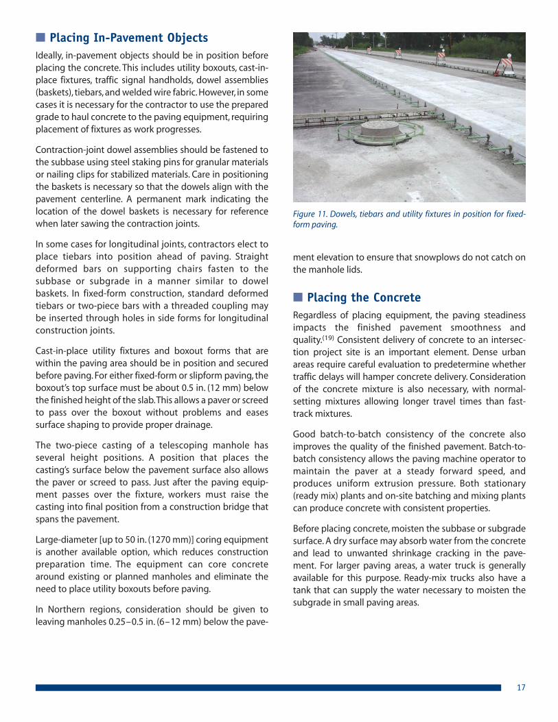
■ Placing In-Pavement ObjectsIdeally, in-pavement objects should be in position beforeplacing the concrete. This includes utility boxouts, cast-in-place fixtures, traffic signal handholds, dowel assemblies(baskets), tiebars, and welded wire fabric. However, in somecases it is necessary for the contractor to use the preparedgrade to haul concrete to the paving equipment, requiringplacement of fixtures as work progresses.
Contraction-joint dowel assemblies should be fastened tothe subbase using steel staking pins for granular materialsor nailing clips for stabilized materials. Care in positioningthe baskets is necessary so that the dowels align with thepavement centerline. A permanent mark indicating thelocation of the dowel baskets is necessary for referencewhen later sawing the contraction joints.
In some cases for longitudinal joints, contractors elect toplace tiebars into position ahead of paving. Straightdeformed bars on supporting chairs fasten to thesubbase or subgrade in a manner similar to dowelbaskets. In fixed-form construction, standard deformedtiebars or two-piece bars with a threaded coupling maybe inserted through holes in side forms for longitudinalconstruction joints.
Cast-in-place utility fixtures and boxout forms that arewithin the paving area should be in position and securedbefore paving. For either fixed-form or slipform paving, theboxout’s top surface must be about 0.5 in. (12 mm) belowthe finished height of the slab. This allows a paver or screedto pass over the boxout without problems and easessurface shaping to provide proper drainage.
The two-piece casting of a telescoping manhole hasseveral height positions. A position that places thecasting’s surface below the pavement surface also allowsthe paver or screed to pass. Just after the paving equip-ment passes over the fixture, workers must raise thecasting into final position from a construction bridge thatspans the pavement.
Large-diameter [up to 50 in. (1270 mm)] coring equipmentis another available option, which reduces constructionpreparation time. The equipment can core concretearound existing or planned manholes and eliminate theneed to place utility boxouts before paving.
In Northern regions, consideration should be given toleaving manholes 0.25 – 0.5 in. (6 – 12 mm) below the pave-
ment elevation to ensure that snowplows do not catch onthe manhole lids.
■ Placing the ConcreteRegardless of placing equipment, the paving steadinessimpacts the finished pavement smoothness andquality.(19) Consistent delivery of concrete to an intersec-tion project site is an important element. Dense urbanareas require careful evaluation to predetermine whethertraffic delays will hamper concrete delivery. Considerationof the concrete mixture is also necessary, with normal-setting mixtures allowing longer travel times than fast-track mixtures.
Good batch-to-batch consistency of the concrete alsoimproves the quality of the finished pavement. Batch-to-batch consistency allows the paving machine operator tomaintain the paver at a steady forward speed, andproduces uniform extrusion pressure. Both stationary(ready mix) plants and on-site batching and mixing plantscan produce concrete with consistent properties.
Before placing concrete, moisten the subbase or sub gradesurface. A dry surface may absorb water from the concreteand lead to unwanted shrinkage cracking in the pave-ment. For larger paving areas, a water truck is generallyavailable for this purpose. Ready-mix trucks also have atank that can supply the water necessary to moisten thesubgrade in small paving areas.
17
Figure 11. Dowels, tiebars and utility fixtures in position for fixed-form paving.

When placing a concrete overlay on a milled asphaltsurface, no moistening is normally necessary. Concreteoverlays less than 4 in. (100 mm) thick, which rely onbonding to the asphalt, require a dry surface. However,thicker overlays, which do not rely on bond, may requirewhitewashing to cool a dark asphalt surface. The need for whitewash depends upon the ambient and asphalt-surface temperature. More information on whitewash isavailable in Reference 17.
Fixed-Form – There are a variety of fixed-form pavingmachines. The less complex equipment such as hand-operated and self-propelled vibratory screeds, single-tubefinishers, and revolving triple tubes, are useful for almostall complex paving areas. The external (surface) vibrationthat this equipment produces is adequate to consolidatemost pavement slabs. However, supplementary internalvibration with hand-operated spud vibrators is usuallynecessary for adequate consolidation of non-reinforcedconcrete slabs thicker than 10 in. (250 mm). A combina-tion of internal and surface-vibration is preferable for rein-forced slabs of any thickness.(11) Because surface vibrationof concrete is least effective near the forms, it is beneficialto consolidate concrete along the forms with a spudvibrator.
Larger, form-riding machines can place and consolidatethe concrete between forms in one pass. These machineseither ride on the forms or pipes laid outside the forms.Since form-riding paving equipment cannot produceacceptable results riding on wooden forms, most of thecurved areas joining intersecting pavements require use ofhand-placement equipment, such as vibratory or rollerscreeds.
Evenly depositing concrete onto the grade in front of thefixed-form placement machine eases paving. Piling toomuch concrete in front of the machine leads to strikeoffdifficulty. The concrete should not overly exceed theheight of the forms. However, piling too little concrete infront of the machine may produce low spots in the pave-ment surface. Although it is ideal to distribute the concreteevenly with the chute from the ready mix or otherconcrete hauling truck, some distribution of the concretewith hand tools is usually necessary. Shovels are preferableto other hand tools for this purpose because they are lesslikely to cause concrete segregation.
When necessary, supplemental vibration with handheldspud vibrators should precede the placement screed. Stan-dard practice for thicker slabs calls for vertical plunges ofthe vibrator head. For thin slabs, it is preferable to insertthe vibrator head at an angle or horizontally to keep it
completely immersed in the concrete. Operators shouldneither drag spud vibrators through the concrete norattempt to move the concrete laterally, as either will segre-gate the mixture.
In general, proper consolidation of air-entrained concretetakes less time than consolidation of non air-entrainedconcrete, even when both mixtures are prepared with thesame consistency (slump). The vibration time necessary toachieve adequate consolidation also depends upon thesize and type of vibrator. For most equipment, leaving the
18
Figure 12. (A) Vibrating screed, (B) Roller screed, (C) Form-ridingpaver.
A ➤
B ➤
C ➤

vibrator head inserted for 5 to 15 seconds is usuallyadequate.(11,19)
Slipform – Use of slipform paving equipment for intersec-tion reconstruction is not very common. However, acontractor may elect to use slipform equipment in anintersection if the paving area is large enough to warrantits use. Paving the curb and gutter is another common useof a slipform machine for intersection construction.
There are many sizes of slipform paving machines, withmany smaller models available for urban paving. Slipformpaving machines spread, consolidate, screed, and float-finish the concrete in one pass without the need for fixedside forms. Generally, contractors preset stringlines toestablish the line and grade control for the paver.
Like fixed-form paving, depositing concrete in front of thepaver evenly will improve the resulting pavement. A slip-form paver must further spread and consolidate theconcrete as it moves forward and cannot produceadequate results if it must push a large pile of concrete.When operating properly, a well-consolidated and prop-erly-shaped slab emerges behind the slipform paver as itmoves steadily forward.
Certain slipform paving equipment can pave curbs andgutters and easily pave around curves between inter-secting roadways. Some slipform paving machines canplace curbs integrally with the driving lanes (Figure 13). Insuch cases, the contractor must attach a curb mule to thepaver so that the curb section will extrude out as the pavermoves forward. Integral curbs eliminate a separateforming or placing operation that is otherwise necessaryfor most urban roadways.
More detailed information on properly setting up andoperating slipform equipment is available in Reference 19.
■ Finishing the SurfaceAfter the paving equipment passes, it may be necessary tofurther finish the concrete surface to remove small imper-fections and smooth any bumps. There are a number ofdifferent automatic and hand-operated finishing toolsavailable for this purpose. In the tight work zones typical ofintersection construction, most contractors will opt forhand finishing tools.
Finishing is necessary earlier with air-entrained concretethan non-air-entrained concrete because air-entrainedconcrete develops much less bleed water. It is customaryto wait until all bleed water leaves the concrete slabsurface before finishing non-air-entrained concrete.
Checking the surface behind the paving equipment with a10 to 16 ft (3 to 4.8 m) hand-operated straightedge is arecommended pro ce dure.(19) Successive straightedgingshould overlap by one-half the length of the straightedgeto ensure that the tool removes high spots and fills lowspots in the surface. Experienced finishers can use thestraightedge to remove noticeable bumps by employing ascraping motion. Otherwise, they use a long-handled floatto smooth bumps and disturbed places in the surface.
Edging is necessary for any concrete placed against fixedforms. The small edging tool effectively smoothes the slabcorner and separates the concrete from the form. Withoutseparation, the concrete may adhere to the top of theform, and tear or spall upon form removal.
Particular attention also may be necessary for finishingaround boxed-out fixtures and cast-in-place fixtures.Ideally, the height adjustment and supplemental vibrationaround the object are complete before workers need tofinish the pavement surface. If properly positioned, theobject should easily blend into the surrounding pavement.Some surface warping may be necessary if the object istoo high or too low.
Smoothness Requirements – Smoothness or rideabilityrequirements can be applied to intersection projects.However, less stringent requirements are necessary than
19
Figure 13. Slipform pavement with integral curb.

are normally required for high-speed highways. Warping ofslabs to meet fixtures (manholes, drainage inlets, etc.),existing curb and gutter, and cross- or side-road connec-tions make meeting highway-standard smoothness re -quire ments very difficult in most cases.
For California profilograph testing of intersection projects,the acceptable rideability index should be relaxed, andcertain areas should be excluded from measurement.Those areas at intersections which should be excludedfrom testing include: acceleration and deceleration tapers,auxiliary (right and left turn) lanes, sections less than 50 ft(15 m), and locations that require surface warping thatmake profile testing irrelevant. For more information, seeReference 21.
For small projects, excluded areas, and odd-shaped areas,surface testing with a 10-ft (3-m) straightedge [ 1⁄8 to 3⁄16
in. (3 to 5 mm) allowable deviation] will produce accept-able smoothness.
■ Texturing the SurfaceThe surface texture necessary for intersection pavementsdepends upon the speed limit of the approach roadways.For low-speed residential, municipal collector, or urbanbusiness streets, a burlap, turf-drag, or coarse broomsurface texture is usually sufficient to provide the micro-texture necessary for wet weather stopping.(22) High-speed [i.e., +50 mph (+80 km/h)] arterial roadways alsorequire a good macrotexture to reduce the water filmthickness enough to prevent hydroplaning.‡
The texture chosen for the intersection must be appliedafter finishing and before curing the concrete. Eithermechanical or hand-operated equipment can adequatelyapply the texture; however, confined intersection workzones may limit the practical use of mechanical equip-ment.
■ Curing the ConcreteCuring is the treatment or protection given concreteduring the hardening period. Curing measures are neces-sary to maintain a satisfactory moisture and temperaturecondition in the concrete because internal temperatureand moisture directly influence both early and ultimateconcrete properties.(11,14) Proper curing measures preventrapid water loss from the mixture and allow more thor-ough cement hydration. Therefore, to maximize concretequality, it is necessary to apply curing measures as early aspossible after placing concrete.(11,14) Curing is also criticalto providing a durable pavement surface that will retainsurface texture.
A variety of curing methods and materials are available forconcrete pavement, including: water spray or fog, wetburlap sheets, plastic sheets, insulating blankets, andliquid-membrane-forming compounds.
The application of a liquid-membrane-forming compoundto seal the concrete surface is the most common curingmethod for concrete pavement. A liquid-membrane-forming compound that meets ASTM C309 materialrequirements is adequate for most situations whenapplied at the following rates:
1. 200 ft2/gal (5.0 m2/L) for normal paving applications.
2. 150 ft2/gal (3.75 m2/L) for fast-track concrete.
3. 100 ft2/gal (2.5 m2/L) for thin overlays.
White-pigmentation in the compound is preferable to aclear compound so coverage is easily seen. The pigmentalso reflects solar radiation that may otherwise heat theconcrete surface excessively.
The first few hours after paving — when the concreteremains plastic — are the most critical for good curing. Assuch, the contractor should apply a curing compound as
20
‡ For concrete pavement, macrotexture refers to texture added to the surface of slabs by mechanical means. All state agency specifi-cations require concrete pavement to have a surface texture that aids stopping in wet weather. The specific texture varies greatlyamong agencies, but the state-specified texture is usually meant for high speed highways and is commonly either transverse or longi-tudinal tining. Uniform spaced transverse tining typically produces a tire whine at high speeds but can produce acceptable noiselevels on lower speed roads. The characteristic whine can also be used as an acoustical warning of an approaching intersection if thatis desirable. For noise sensitive areas, drag textures such as astro turf or burlap drag or tined textures such as longitudinal tining ornarrow spaced transverse tining 3⁄8 to 1⁄2 in. (9 to 12 mm) can be used. When selecting a texture, safety needs to be balanced with thenoise issues to ensure proper frictional properties are achieved. For tining operations, typical requirements are a tine depth of 1⁄8 to1⁄4 in. (3 to 6 mm) and a tine width of 1⁄8 in. (3 mm). Longitudinal tining is typically placed on 3⁄4 in. (19 mm) center-to-center spacing.(22)

soon as possible after the water sheen has left the surfaceand texturing is complete. A variety of spraying equipmentis available, but on most intersection projects, simple handsprayers are the likely choice.
The initial application of curing compound should coatboth the top and edges of slipformed concrete. For fixed-form paving, the curing compound should initially coat theexposed concrete surface. If removing forms early, asecond coat should be applied to any exposed verticaledges of the slab to provide a complete seal.
Insulating blankets are sometimes also necessary forcuring fast-track concrete in intersection work. Thepurpose of insulating fast-track concrete with blankets isto aid early strength gain in cool weather conditions. Theblankets reduce heat loss and lessen the influence of bothair temperature and solar radiation on the pavementtemperature. The blankets are not a substitute for curingcompound, which is still needed to contain moisture forthorough hydration. Table 6 indicates when insulation isrecommended for fast-track concrete.(14,15)
Normal curing measures without insulation are acceptablewhere rapid strength gain is not required. However, specialprecautions are necessary when the intersection is beingconstructed either in very cold or hot weather. More infor-mation on curing, including wet curing, blanket insulation,and cold-weather and hot-weather construction tech-niques, is available in References 11, 14 and 15.
■ Jointing the PavementAt-grade concrete inter sections usually require every jointtype. The design details and specific purpose of each typeare defined in “Jointing” on page 4. Typical constructionmethods are described below.
Construction Joints – At intersections, transverseconstruction joints typically are built by hand at predeter-mined locations. This requires a form (header board) thatcan contain the concrete, and secure dowels or tiebarspositioned and aligned properly (Figure 11). Vibration ofconcrete near the construction joint is important to ensuregood encapsulation of the steel bars. If the constructionjoint provides a transition from concrete to asphalt pave-ment, special transition forming may be necessary (seepage 25, “Concrete-to-Asphalt Transition”).
For either fixed side forms or slipform construction, theslab edge provides the longitudinal construction joint. Thecontractor will pre-position tiebars and keyways for fixed-form construction. While most fixed forms come with pre-drilled holes for the tiebars, the contractor will probablyhave to attach a board to the side forms to make a keyway.A contractor can equip a slipform paver with a tool to forma keyway along the slab edge as the paver progressesforward. Where required, tiebars are inserted into the slip-formed edge while the concrete is plastic, or after hard-ening they can be anchored into holes drilled in thepavement edge.
21
Table 6. Recommended conditions requiring insulating blankets.(14,15)
Minimum air temperatureduring time period
Opening time, hr
8 16 24 36 48
<50°F (<10°C) Yes Yes Yes Yes No
50 – 65°F (10 – 18°C) Yes Yes Yes No No
65 – 80°F (18 – 27°C) Yes No No No No
>80°F (>27°C) No No No No No
Figure 14. Curing blankets moved aside for sawing fast-trackconcrete.

Isolation Joints – T- and asymmetrical intersections mayrequire a thickened edge or sleeper-slab isolation joint.The thickened edge isolation joint is usually preferable toa sleeper-slab isolation joint to avoid the additional timenecessary to build and cure the sleeper. Specific site andstaging conditions will dictate where a contractor posi-tions the isolation joint. The joint filler material must standvertically, extend completely through the entire slab thick-ness, and be held firmly in position (usually by stakesdriven into the subgrade.) The isolation joint materialis usually a non-absorbent foam board or bitumen-treated fiberboard. A width from 0.5 to 1.0 in. (12 to 25mm) is adequate.
A longitudinal isolation joint is necessary wherever thepavement abuts sidewalks, driveways, or aprons. The jointwill permit differential movement that might otherwisedamage the pavement or curb. Against aprons and olderdriveway pavements, the isolation joint eliminates “sym-
pathy” cracking where it is not possible to match the jointsin the other pavement. The contractor must position asection of joint filler against the back of the curb beforeplacing the concrete for new aprons, driveways or walks. Ifthe new concrete pavement will directly abut an olderconcrete pavement, the filler must rest against the olderpavement before starting construction. A wider isolationfiller is recommended between the roadway pavement
A
B
B A
A
Sidewalk
A. 1.0 in. (25 mm) fiberboardB. 0.5 in. (12 mm) fiberboard
Apron / Driveway
Figure 15. Location of isolation joint for curb and gutter, apronsand driveways near concrete intersections.
and an abutting sidewalk or apron than is recommendedbetween sidewalks and apron or driveway pavement(Figure 15).
Contraction Joints – After paving and curing theconcrete, the final step is to place the longitudinal andtransverse contraction joints. Although there are severalmethods to form these joints in the plastic concrete,sawing the concrete after hardening is by far the mostcommon method. Contractors have successfully cutcontraction joints using wet-, dry-, and early-age-sawingequipment.(14,23)
The saw cut provides a plane of weakness where crackingwill begin. Using conventional saws, a cut depth of at leastone-fourth the slab thickness (T/4) and 1⁄8 in. (3 mm) widegenerally controls crack formation for transverse contrac-tion joints. However, for pavement on stabilized subbases,an increase in the initial saw cut to a depth equivalent toone-third the slab thickness (T/3) is required for transversecontraction joints. The extra cut depth accentuates theplane of weakness to overcome additional frictionalrestraint and higher curling stresses in the concretecaused by the stabilized subbase. Longitudinal contractionjoints require a cut depth equivalent to one-third of theslab thickness (T/3) regardless of the subbase.
The time of sawing is critical for proper contraction jointformation. Sawing too soon results in spalling and ravelingalong the joint face. Sawing too late results in randomcracking elsewhere in the slab. Joint sawing with conven-tional saws should begin whenever the concrete strengthis adequate and the saw blades will not excessively ravelthe concrete surface. This occurs sometime between 4 to24 hours after paving, but usually within the first 12 hours.Weather (temperature, wind, humidity, and direct sunlight)has a large influence on concrete strength gain and theoptimal time to begin sawing.
The concrete mixture itself also affects the optimal time tobegin sawing. Mixtures made with softer limestone aggre-gates require less strength before sawing than do mixtureswith harder coarse aggregates.(24) Fast-track mixtures thatgain strength quickly also require sawing to begin muchsooner than normal-setting mixtures.
Early-age saws allow cutting after compressive strengthsreach about 150 psi (1.0 MPa), usually about an hour or twoafter paving. Most currently available early-age saws pro -vide a shallow cut at about 1 to 11⁄4 in. (25 to 33 mm) deep.The shallow cut has been shown to control cracking effec-tively at transverse joints when made early, before the finalset of the concrete.(23)
22

The time of sawing is usually not quite as critical for longi-tudinal contraction joints as it is for transverse contractionjoints. However, longitudinal contraction joint sawingshould follow closely behind sawing of transverse contrac-tion joints whenever practicable. This will reduce the possi-bility of uncontrolled longitudinal cracking.
If the transverse contraction joints contain dowels, the sawoperator should reference the markers on either side ofthe slab to determine where the baskets are and where toposition the saw cut. For typical dowel-jointed pavementswith 15-ft (4.5-m) panels, there is usually 2 to 3 in. (50 to75 mm) tolerance on either side of the true center of thedowels, depending upon dowel length. Saw cuts that arewithin the tolerance provide the typical minimum 6 in.(150 mm) of dowel embedment necessary for effectiveload transfer.
The presence of tiebars along the longitudinal contractionjoint necessitates similar care by the saw operator tocenter the cut over the steel tiebars.
Soon after wet-sawing, the crew should flush sawed jointswith water to remove saw slurry. If left in place, the slurrywill eventually harden and become more difficult toremove. In some conditions, the hardened slurry may evenimpede joint closure during warm periods.
■ Opening to TrafficThe basis for deciding when to open a concrete intersec-tion to construction or public traffic should be theconcrete’s strength and not an arbitrary time from place-ment.(14,15) Strength directly relates to the pavement’sload bearing capacity.
As slab support or pavement thickness increases, stress inthe concrete will decrease for a given load. This relation-ship allows different opening strength criteria for differentpavement designs and early traffic loads.(14,15,24)
Table 7 provides traffic opening criteria for public vehicleson concrete pavement. The table assumes a 2.0-ft (0.6-m)offset of traffic from the lane or pavement edge. Wide trucklanes, tied concrete shoulders, and curbs and gutters canall serve to reduce load stresses to levels equivalent to a2.0 ft (0.6 m) traffic offset. If the pavement design does notinclude these features, the contractor can place barricadesto prevent edge loads. After the concrete compressivestrength reaches 2500 psi (17 MPa), or flexural strengthreaches 450 psi (3.0 MPa), the contractor generally mayremove the barricades. However, it may be necessary towait for concrete to gain full design strength on thinmunicipal pavements.
A correlation between compressive strength and flexuralstrength can be made in the laboratory for each unique
23
Slab thicknessFoundationsupport*
Opening strength**
Compressive***psi (MPa)
Flexural (3rd-point)psi (MPa)
6.0 in. (150 mm)Unstabilized 3600 (24.8) 540 (3.7)
Stabilized 1690 (11.7) 370 (2.6)
8.0 in. (200 mm)Unstabilized 1350 (9.3) 330 (2.3)
Stabilized 1100 (7.6) 300 (2.1)
10.0 in. (250 mm)Unstabilized 1100 (7.6) 300 (2.1)
Stabilized 1100 (7.6) 300 (2.1)
Table 7. Strength necessary to open concrete pavement to public traffic (based on References 14 and 15).
* Unstabilized (granular) foundation assumes a Modulus of Subgrade Reaction, k = 100 psi/in. (27 MPa/m). Stabilized foundationassumes k = 500 psi/in. (135 MPa/m).
** Assumes there will be 500 one-way equivalent single axle load (ESAL) repetitions between time of opening and time concretereaches design strength (28-day strength).
*** There was no compressive strength criteria in the original research (Reference 14). The values shown here were developed usingthe correlation equation described in this section with C = 9.0. It is strongly recommended to develop a unique correlation betweenflexural and compressive strength for new mixtures.

concrete mixture. Equation 2 is an example of a relationshipbetween compressive strength and third-point flexuralstrength. This relationship was developed from a finite set ofmixtures, and may not be valid for your particularmixture.(25)
f r = C • (f ’cr)0.5 (Eq. 2)
where:
f r = flexural strength (modulus of rupture) in third-point loading, psi (MPa).
f ’cr = required average compressive strength, psi (MPa).
C = A constant between 8 and 10 psi (for normalmixtures) [for high-strength concrete C rangesfrom 7.5 to 12 psi (11.7 recommended)].
Non-destructive Testing – Some agencies, con sultants,and contractors use non-destructive strength testing toevaluate concrete pavement at early ages. Maturity andpulse velocity testing methods are common on fast-trackconcrete pavement projects.(14,15)
Maturity testing provides strength evaluation throughmonitoring of internal concrete temperature in the field.The basis of maturity is that each concrete mixture has aunique strength-time/temperature relationship. Therefore,a mixture will have the same strength at a given maturityno matter what conditions (time or temperature) occurbefore measurement.(14,15) To implement maturity on aproject, technicians must develop a calibration curve inthe laboratory or in the field prior to start of paving. Thecalibration curve is used to estimate strength values fromfield temperature measurements.
Pulse-velocity is another non-destructive test available fordetermining concrete strength at early ages. It is a truenon-destructive test that measures the time required foran ultrasonic wave to pass through concrete from onetransducer to another. The velocity of the wave correlatesto concrete strength or stiffness.(14,15) Like maturity testing,pulse-velocity testing requires laboratory calibration toproduce meaningful field information. In the laboratory,technicians make pulse-velocity measurements through arepresentative number of cast concrete specimens, testthe specimens for strength, and plot the results against thepulse-velocity readings to create a calibration curve.
Non-destructive test methods may be better suited toevaluate opening strength of concrete intersections andother pavement because there is no delay betweensampling and testing the concrete. With standard cylin-
ders or flexural beams, specimens must be prepared andsometimes transported to a testing laboratory. Further-more, unlike conventional strength tests that measure thepotential strength under standard conditions, non-destructive test methods give an indication of the in-placestrength. References 14 and 15 provide more informationon non-destructive test methods.
■ Vehicle Detector Loop InstallationTraffic signal design is based largely on the traffic volumesand the geometrics of the intersection. Most heavily-trav-eled intersections require traffic control signals withtraffic-sensing detectors. Presently, the most commonvehicle detector is the inductive loop detector.(26) Thesedetectors can be installed into saw cuts in the pavementsurface, cast into the concrete, or fastened to the grade inpreformed loops.
Vehicle-detector loops that install into saw cuts can last formany years after proper installation. A 0.25-in. (6-mm)wide saw cut to a depth of 2 in. (50 mm) is necessary torecess the detector below the pavement surface. Figure16A shows three common configurations. After sawing,detector system manufacturers recommend flushing thesaw cuts with water to remove saw slurry, then usingcompressed air to remove debris that may puncture thewire insulation. Rounding the corners of diagonal orrectangular loops with additional saw cuts or 0.75-in.(18-mm) diameter core holes will ease insertion of thedetector wire and allow the wire to remain more flexible,preventing rupture.
24
(A) Loop Configurations (not to scale)
(B) Typical Location of 3/4 in. (18 mm)Core Hole and Conduit (not to scale)
CircularSquare Diagonal
Lead through 2 in. (50 mm) deepsaw cut to handhold or conduit
Lead to signalcontroller cabinet
8 in. (200 mm) min.Curb
Saw cut 2 in.(50 mm) min.depth
Conduit
Figure 16. Vehicle detector loop configurations.

Detector system manufacturers(26) recommend installing16 AWG stranded wire with a coating suitable for thesealant. An outer jacket of 0.050 in. (1.25 mm) polyesterwire insulation with an additional
A polyester coating of 0.032 in. (0.8 mm) provides protec-tion from melting to 400°F (204°C) and is suitable for hot-applied sealants. Cold-applied sealants and epoxies thatare specifically formulated for installing loop detectorsalso are readily available.
The detector wire should be flexible enough to give withpavement movement but provide enough tension toremain in the bottom of the saw cut. A backer rod placedabove the wires is recommended by detector systemmanufacturers to ensure the wires remain in place.
Preformed loops can be cast into concrete and do notrequire sawing. In a preformed loop, PVC pipe encapsu-lates the detector wires for protection and providesrigidity to the loop during installation. The loops must befastened securely into position before paving at aminimum of 2 in. (50 mm) above any reinforcing steel. Ifthe slab contains welded wire fabric or bar mats, the pipesshould not align with the reinforcement grid (Figure 17).Any reinforcing steel that aligns with the pipes will inter-fere with the inductive loop.
The detector wires often break near the conduit thatbrings them to a signal handhold or the signal controllercabinet. To avoid breakage, it is advantageous to core drillthis location to provide a larger recess (Figure 16B).
Offset
Offset
Preformed loop
Reinforcement or wire fabric grid
Lead to handhold orsignal controller
Figure 17. Aligning preformed vehicle loop detectors above rein-forcing steel.
■ Concrete-to-Asphalt TransitionThe transition between a concrete pavement intersectionand an asphalt pavement can be troublesome if poorlydesigned. Figure 18 shows four transition details fordifferent concrete pavements. Details A, B and C accountfor impact loads on the transition slab with extra thickness(Details A and B are for concrete overlays of existingasphalt pavement).
25
AC SURFACE
AC BASET
15 ft. (4.5 m) min.
5 ft. (1.5 m) min.
1.2 T[6 in. (150 mm) min.]
AC SURFACE
AC BASET
6 ft.(2 m)max.
6 ft.(2 m)max.
T + 3 in.(75 mm)
T
Saw cut face
Saw cut face
Saw cut face
AC SURFACE
AC BASE
GRANULAR
AC SURFACE
AC BASE
GRANULAR
1.2 T
5 ft.(1.5 m) min.
12 in.(300 mm)
min.
15 ft.(4.5 m)
min.
11.5 – 15 ft.(3.5 – 4.5 m) min.
T > 7 in.(175 mm)
11/2 in.40 mm2 in.
(50 mm)
Dowel bars optional
Concrete to Asphalt Transition Details
Detail BThickened edge for bonded concrete overlay < 4 in. (100 mm)
Detail CThickened edge for new pavement
Detail DImpact slab for new pavement
Detail AThickened edge for normal unbonded overlay T > 4 in.(100 mm unbonded concrete overlays)
Figure 18. Transition details for concrete pavement to asphalt pavement.

1. “Driveway and Street Intersection Spacing,” Trans-portation Research Circular, No. 456, TransportationResearch Board, National Research Council, Wash-ington, DC, March 1996.
2. A Policy on Geometric Design of Highways and Streets,American Association of State Highway and Trans-portation Officials, Washington, DC, 1994.
3. Design of Concrete Pavements for City Streets, IS184P,American Concrete Pavement Association, Skokie, IL,2005.
4. Guide for the Design of Pavement Structures, Amer icanAssociation of State High way and TransportationOfficials, Wash ing ton, DC, 1993.
5. Thickness Design for Concrete Highway and Street Pave-ments, EB109P, Portland Cement Association, Skokie,IL, 1984.
6. Design and Construction of Joints for Con crete High-ways, TB010P, American Concrete Pavement Associa-tion, Skokie, IL, 1991.
7. Design and Construction of Joints in Concrete Streets,IS061P, American Concrete Pavement Association,Skokie, IL, 1992.
8. Joint and Crack Sealing and Repair for Concrete Pave-ments, TB012P, American Concrete Pavement Associa-tion, Skokie, IL, 1993.
9. Smith, K.D., and others, “Performance of ConcretePavements, Evaluation of In-Service Concrete Pave-ments,” Volume 1 – Final Report, DTFH-61-91-C-00053,Federal Highway Administration, Washington, DC,April 1995.
10. Intersection Joint Layout, IS006P, American ConcretePavement Association, Skokie, IL, 2007.
11. Kosmatka, S.; Kerkhoff, B.; and Panarese, W., “Designand Control of Concrete Mixtures,” 14th Edition,EB001, Portland Cement Association, Skokie, IL, 2002.
12. Guide Specification for Concrete Subject to Alkali-SilicaReactions, IS415TC, Portland Cement Association andAmerican Concrete Pavement Association, Skokie, IL,1995.
Detail D shows an impact slab, meant for pavements thatfrequently carry heavy trucks and are thicker than 7 in.(175 mm). The impact slab protects the asphalt pavementfrom deformation by providing additional support at thetransition. Contractors can easily create the lip in theimpact slab using a false form header.
One way to keep the slabs near the transition frommigrating on unstabilized subbases is to place deformedtiebars in the first three transverse contraction joints. Thetiebars will hold the slabs tightly together. Slab migrationis not an issue with concrete overlays on asphalt becausethe concrete established sufficient bond to the asphaltsurface.
■ Adding Lanes to Existing ConcretePavement
Some intersection improvements require additionalconcrete lanes next to existing concrete pavement or curband gutter. For these improvements it is essential to placetransverse contraction joints (Type A-1 or A-2, Figure 3 onpage 6) to match any existing joints or cracks in theexisting pavement (Figure 19). Without a contraction joint,
movement of the old concrete pavement may cause asympathy crack in the new lanes.
An alternative method to avoid sympathy cracking is toplace an isolation joint with a separating medium (Type D-4, Figure 3 on page 6) between the edge of the existingpavement, or curb and gutter, and the new lane.
Existingcontraction
joint
Existingtransversecrack
Existingisolation jointExisting
ReinforcedPavement
New TurningLane
Place new jointsmatching location and type
Figure 19. Aligning joints for adding auxiliary turn lanes to existingJRCP concrete pavements.
26
References

27
13. Diagnosis and Control of Alkali-Aggregate Reactions inConcrete, 1st Edition, IS413TC, Portland Cement Asso-ciation and American Concrete Pavement Associationand Na tion al Ready Mixed Concrete Association andNational Aggregates Association, Skokie, IL 1997.
14. Fast-Track Concrete Pavements, TB004.02P, AmericanConcrete Pavement Association, Skokie, IL, 1994.
15. Accelerated Rigid Paving Techniques: State-of-the-ArtReport (Special Project 201), FHWA-SA-94 -080, FederalHighway Administration, Washington, DC, December1994.
16. Whitetopping – State of the Practice, EB210P, AmericanConcrete Pavement Association, Skokie, IL, 1997.
17. Grove, J., and others, “Bond Contribution to White -topping Performance on Low Volume Roads,” Trans-portation Research Record 1382, TransportationRe search Board, Na tion al Research Council, Wash-ington, DC, 1993, pp. 104 -110.
18. Guide Specifications for Highway Construction, Amer-ican Association of State Highway and TransportationOfficials, Washington, DC, 1993.
19. Construction of Portland Cement Concrete PavementsParticipant’s Manual, FHWA HI-96-027, NationalHighway Institute, Federal Highway Administration,Washington, DC, 1996.
20. “The 1996 Public Works Manual,” Public Works, Vol.127. No. 5, Public Works Journal Corporation, Ridge-wood, NJ, April 15, 1996.
21. Constructing Smooth Concrete Pavements, TB006P,American Concrete Pavement Association, Skokie, IL,1990.
22. Snyder, M., Pavement Surface Characteristics: A Syn -thesis and Guide, EB235P, American Concrete Pave-ment Association, Skokie, IL, 2006.
23. Zollinger, D., and others, “Sawcut Depth Considera-tions for Jointed Concrete Pavement Based on Frac-ture Mechanics Anal ysis,” Transportation ResearchRecord 1449, Transportation Research Board, NationalResearch Council, Washington, DC, 1995, pp. 91-100.
24. Okamoto, P., and others, “Guidelines for Timing JointSawing and Earliest Loading for Concrete Pavement,”Volume 1 – Final Re port, FHWA-RD-91-079, FederalHighway Administration, Washington, DC, February1994.
25. “High Strength Concrete,” ACI Manual of ConcretePractice, Part 1, Materials and General Properties ofConcrete, ACI 363R-84, American Concrete Institute,Farmington Hills, MI, 1990.
26. “Loop Installation,” Detector Systems Technical Notes,Detector Systems, Inc., Stanton, CA, 1990.
27. “Guide to Concrete Overlay Solutions,” ACPA Publica-tion TB021P, National Concrete Technology Center,Ames, IA, 2007.

American Concrete Pavement Association5420 Old Orchard Rd., Suite A100Skokie, IL 60077-1059(847) 966-ACPAwww.pavement.com TB019P
ASTMDesignation ASTM Title
CSA/CAN Equivalentor Specified Test
ASTM C33 Standard Specification for Concrete Aggregate A23.1
ASTM C39 Test Method for Compressive Strength of Cylindrical Concrete Specimens A23.2-9C
ASTM C78 Test Method for Flexural Strength of Concrete (Using Simple Beam withThird-Point Loading)
A23.2-8C
ASTM C109 Test Method for Compressive Strength of Hydraulic Cement Mortar A5
ASTM C150 Standard Specification for Portland Cement A5
ASTM C260 Standard Specification for Air-Entraining Admixtures for Concrete ASTM C260
ASTM C309 Standard Specification for Liquid Membrane-Forming Compounds forCuring Concrete
ASTM C309
ASTM C494 Standard Specification for Chemical Admixtures for Concrete ASTM C494
ASTM C597 Test Method for Pulse Velocity through Concrete A23.2-24C
ASTM C618 Standard Specification for Fly Ash and Raw or Calcined Natural Pozzolanfor use as a Mineral Admixture in Portland Cement Concrete
A23.5
ASTM D698 Laboratory Compaction Characteristics of Soil Using Standard Effort ASTM D698
ASTM C803 Test Method for Penetration Resistance of Hardened Concrete ASTM C803
ASTM C805 Test Method for Rebound Number of Hardened Concrete ASTM C805
ASTM C900 Test Method for Pullout Strength of Hardened Concrete ASTM C900
ASTM C1017 Standard Specification for Chemical Admixtures for Producing FlowingConcrete
ASTM C1017
ASTM C1074 Practice for Estimating Concrete Strength by the Maturity Number ASTM C1074
ASTM C1150 Standard Test Method for the Break-Off Number of Hardened Concrete ASTM C1150
ASTM D994 Standard Specification for Preformed Expansion Joint Filler for Concrete ASTM D994
ASTM D1751 Specification for Preformed Expansion Joint for Concrete Paving andStructural Construction
ASTM D1751
ASTM D1752 Specification for Preformed Sponge and Cork Expansion Joint Fillers forConcrete Paving and Structural Construction
ASTM D1752
ASTM D4791 Test for Flat or Elongated Particles in Coarse Aggregate CRD-C119
ASTM References and Canadian Equivalents
This publication is based on the facts, tests, and authorities stated herein. It is intended for the use of professional personnel competent to evaluate the significance and limitations of the reported findings and who will accept responsibility for the application of the material it contains.Obviously, the American Concrete Pavement Association disclaims any and all responsibility for application of the stated principles or for the accuracy of any of the sources other than work performed or information developed by the Association.