concrete flag pavements design and ... - island block & paving
TRANSCRIPT
PA 05 Concrete Flag Pavements - Design and Construction Guide

Concrete Flag Pavements Design and Construction Guide
CONCRETE MASONRY ASSOCIATION OF AUSTRALIA
CONCRETE FLAG PAVEMENTS – DESIGN AND CONSTRUCTION GUIDE
Associate Professor Brian Shackel
School of Civil and Environmental Engineering, University of New South Wales.
Alan Pearson
Concrete Masonry Association of Australia
CONTENTS
1 Introduction 2
2 Background and Scope 2
3 Definitions 3
4 Choice of Concrete Flag 4
5 Design of Flag Pavement 5
6 Materials 10
7 Construction and Detailing 11
8 References 14
Disclaimer: The Concrete Masonry Association of Australia Limited is a non-profit organisation sponsored by the concrete masonry industry in Australia to provide information on the many uses of concrete masonry products. Since the information provided is intended for general guidance only and in no way replaces the service of professional consultants on particular projects, no liability can be accepted by the Association for its use.
Industry Support. Most of the manufacturers of quality concrete masonry products in Australia are members of the Concrete Masonry Association of Australia (CMAA). It is recommended that advice be obtained from local CMAA members to adapt or supplement information contained in this Guide.
Remember, when working with cement and concrete/mortar or manufactured or prefabricated concrete products, ALWAYS follow the manufacturer's instructions and seek advice about working safely with the products from the manufacturer, your nearest WorkCover Authority or Worksafe Australia.
1
Concrete Flag Pavements Design and Construction Guide
2
1 Introduction
Large format pavers (ie typically 300 mm x 300 mm and greater in plan) or “flags” have long been accepted as one of the most attractive and durable methods of pavement surfacing. Recently in Australia, flag pedestrian surfacing has been rediscovered by landscape architects and specifiers.
The diversity of colours and surface textures enables architects, engineers and specifiers to design sympathetic demarcation large-format flag pavements embracing scale and aesthetics, particularly in pedestrian areas.
Flags in many pavement situations need to be able to withstand commercial vehicle axle loads.
Hitherto, in Australia, there has been no industry or national code of practice for the specification, design and detailing of flag pavements. This Guide seeks to fulfill this role.
2
Background and Scope
This design guide is for flexible pavements surfaced with concrete flags which may carry occasional traffic eg pedestrian malls, etc. Concrete flag pavements are not suitable for roads or streets carrying high traffic volumes. Here, conventional segmental concrete pavements are the recommended solution. This guide is restricted to the specific flag sizes, thicknesses, strengths and traffic intensities detailed therein and should not be extrapolated to other conditions. For concrete pavers having a gross plan area of less than0.08 m2, design should be according to the Design Guide for Residential Accessways and Roads, PA02 199713
For trafficked pavements the design recommendations set out herein apply only for square concrete flags having the plan dimensions and minimum thicknesses given in Table 1.This
guide is for concrete flags laid on bedding sand only and does not apply to natural stone, brick or ceramic pavers, tiles or concrete flags which are adhered to rigid substrates. The design curves for vehicle traffic given herein are appropriate for concrete flags laid on bedding sand.
Concrete Flag Pavements Design and Construction Guide
Concrete Flag Pavements Design and Construction Guide
3
3 Definitions
Flags
Large format concrete pavers with a gross plan area greater than 0.08 m2, used in combination with a bedding course to form a surfacing layer.
Pedestrian Pavements
Pavements subject only to foot traffic. These include footpaths not subject to vehicle over-run or parking, pedestrian precincts which are completely closed to vehicle access, residential paths and patios and hard landscaping.
Low Volume Residential paths, paths in public gardens, pavements at schools or campuses, hard landscape areas, common outdoor areas of residential buildings. Suburban shopping area pavements, pedestrian areas around institutional buildings, sporting or recreational areas. Pavements with less than 3000 passes per day.
Medium Volume Pavements with greater than 3000 and less than 30,000 passes per day.
High Volume Pavements with high-volume pedestrian traffic exceeding 30,000 passes per day – typically inner-city and major suburban pedestrian malls and paths.
Pedestrian and Light Vehicle Pavements
Pavements carrying pedestrians and light vehicles (LV) only. This includes residential driveways.
Pedestrian and Commercial Vehicles Pavements
Areas carrying both pedestrian and mixed vehicular traffic. Normally mall traffic will comprise a mix of light vehicles such as delivery vans with a gross weight less than 3 tonnes and commercial vehicles such as trucks, emergency and service vehicles having gross weights of 3 tonnes or more. This category includes commercial vehicle crossovers, driveways carrying occasional truck traffic, footpaths subject to truck overrun or parking, pedestrian malls accepting service vehicles and commercial vehicles, pedestrian crossings and lightly trafficked streets.
Light Vehicles
Light vehicles (LV) are vehicles which when fully-loaded have a gross weight less than 3 tonnes. This category includes cars, utilities, delivery vans and some light 2-axle trucks.
Commercial Vehicles
Commercial vehicles (CV) are vehicles having a gross weight of 3 tonnes or more and which comply with state or commonwealth legislation for the axle loads, tyre pressures and dimensions of normal on-road vehicles. Off-road, industrial, oversize, abnormally loaded or overloaded vehicles are specifically excluded from this guide. This vehicle category principally comprises 2 and 3 axle trucks. Trucks having 5 axles or more should not comprise more than 5% of the commercial vehicles. If data on the gross weights of the vehicles to be carried on the pavement are not available then all vehicles fitted with dual tyres and all trucks shall be classed as commercial vehicles.
Concrete Flag Pavements Design and Construction Guide
Concrete Flag Pavements Design and Construction Guide
4
4
Choice of Concrete Flag
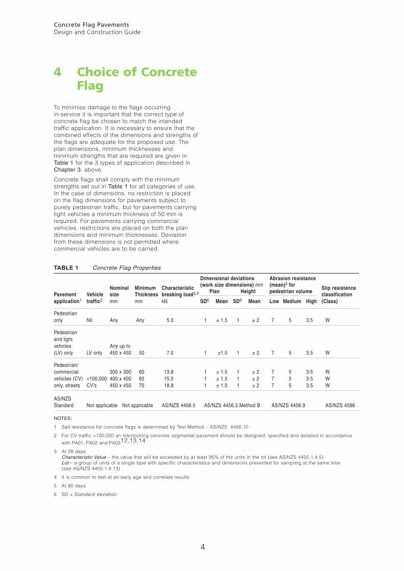
To minimise damage to the flags occurring in-service it is important that the correct type of concrete flag be chosen to match the intended traffic application. It is necessary to ensure that the combined effects of the dimensions and strengths of the flags are adequate for the proposed use. The plan dimensions, minimum thicknesses and minimum strengths that are required are given in Table 1 for the 3 types of application described in Chapter 3. above.
Concrete flags shall comply with the minimum strengths set out in Table 1 for all categories of use. In the case of dimensions, no restriction is placed on the flag dimensions for pavements subject to purely pedestrian traffic, but for pavements carrying light vehicles a minimum thickness of 50 mm is required. For pavements carrying commercial vehicles, restrictions are placed on both the plan dimensions and minimum thicknesses. Deviation from these dimensions is not permitted where commercial vehicles are to be carried.
TABLE 1 Concrete Flag Properties
Dimensional deviations Abrasion resistance (work size dimensions) mm (mean)5 for Nominal Minimum Characteristic
Plan Height pedestrian volume Slip resistance
Pavement Vehicle size Thickness breaking load3,4 classification
application1 traffic2 mm mm kN SD6 Mean SD6 Mean Low Medium High (Class)
Pedestrian only Nil Any Any 5.0 1 ± 1.5 1 ± 2 7 5 3.5 W
Pedestrian and light vehicles Any up to(LV) only LV only 450 x 450 50 7.0 1 ±1.5 1 ± 2 7 5 3.5 W
Pedestrian/ commercial 300 x 300 60 13.8 1 ± 1.5 1 ± 2 7 5 3.5 W vehicles (CV) <100,000 400 x 400 65 15.5 1 ± 1.5 1 ± 2 7 5 3.5 W only, streets CV’s 450 x 450 70 18.8 1 ± 1.5 1 ± 2 7 5 3.5 W
AS/NZS Standard Not applicable Not applicable AS/NZS 4456.5 AS/NZS 4456.3 Method B AS/NZS 4456.9 AS/NZS 4586
NOTES:
1 Salt resistance for concrete flags is determined by Test Method – AS/NZS 4456.10
2 For CV traffic >100,000 an interlocking concrete segmental pavement should be designed, specified and detailed in accordance
with PA01, PA02 and PA0312,13,14
3 At 28 days Characteristic Value – the value that will be exceeded by at least 95% of the units in the lot (see AS/NZS 4455.1.4.5) Lot – a group of units of a single type with specific characteristics and dimensions presented for sampling at the same time (see AS/NZS 4455.1.4.13)
4 It is common to test at an early age and correlate results
5 At 90 days
6 SD = Standard deviation
Concrete Flag Pavements Design and Construction Guide
5
5
Design of flag Pavement
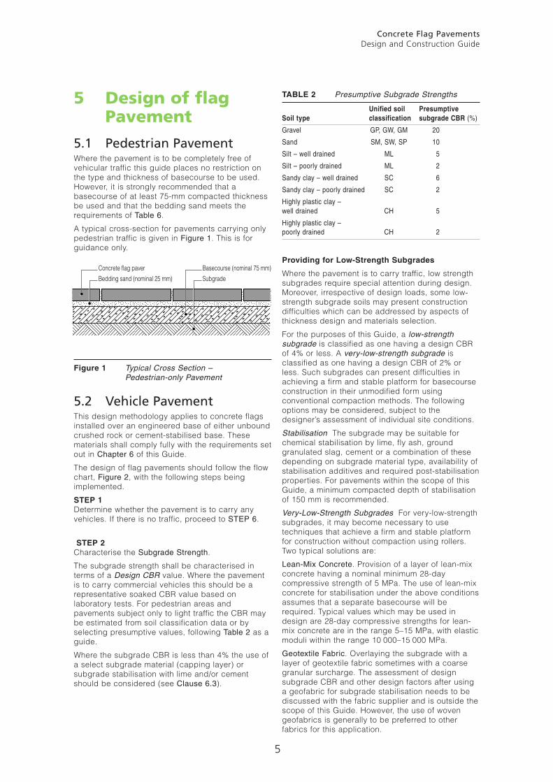
5.1 Pedestrian PavementWhere the pavement is to be completely free of vehicular traffic this guide places no restriction on the type and thickness of basecourse to be used. However, it is strongly recommended that a basecourse of at least 75-mm compacted thickness be used and that the bedding sand meets the requirements of Table 6.
A typical cross-section for pavements carrying only pedestrian traffic is given in Figure 1. This is for guidance only.
Figure 1 Typical Cross Section – Pedestrian-only Pavement
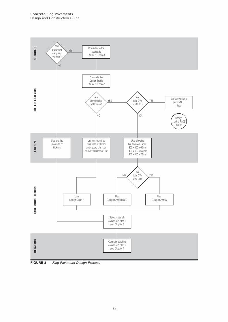
5.2 Vehicle PavementThis design methodology applies to concrete flags installed over an engineered base of either unbound crushed rock or cement-stabilised base. These materials shall comply fully with the requirements set out in Chapter 6 of this Guide.
The design of flag pavements should follow the flow chart, Figure 2, with the following steps being implemented.
STEP 1 Determine whether the pavement is to carry any vehicles. If there is no traffic, proceed to STEP 6.
STEP 2 Characterise the Subgrade Strength.
The subgrade strength shall be characterised in terms of a Design CBR value. Where the pavement is to carry commercial vehicles this should be a representative soaked CBR value based on laboratory tests. For pedestrian areas and pavements subject only to light traffic the CBR may be estimated from soil classification data or by selecting presumptive values, following Table 2 as a guide.
Where the subgrade CBR is less than 4% the use of a select subgrade material (capping layer) or subgrade stabilisation with lime and/or cement should be considered (see Clause 6.3).
Providing for Low-Strength Subgrades
Where the pavement is to carry traffic, low strength subgrades require special attention during design. Moreover, irrespective of design loads, some low-strength subgrade soils may present construction difficulties which can be addressed by aspects of thickness design and materials selection.
For the purposes of this Guide, a low-strength subgrade is classified as one having a design CBR of 4% or less. A very-low-strength subgrade is classified as one having a design CBR of 2% or less. Such subgrades can present difficulties in achieving a firm and stable platform for basecourse construction in their unmodified form using conventional compaction methods. The following options may be considered, subject to the designer’s assessment of individual site conditions.
Stabilisation The subgrade may be suitable for chemical stabilisation by lime, fly ash, ground granulated slag, cement or a combination of these depending on subgrade material type, availability of stabilisation additives and required post-stabilisation properties. For pavements within the scope of this Guide, a minimum compacted depth of stabilisation of 150 mm is recommended.
Very-Low-Strength Subgrades For very-low-strength subgrades, it may become necessary to use techniques that achieve a firm and stable platform for construction without compaction using rollers. Two typical solutions are:
Lean-Mix Concrete. Provision of a layer of lean-mix concrete having a nominal minimum 28-day compressive strength of 5 MPa. The use of lean-mix concrete for stabilisation under the above conditions assumes that a separate basecourse will be required. Typical values which may be used in design are 28-day compressive strengths for lean-mix concrete are in the range 5–15 MPa, with elastic moduli within the range 10 000–15 000 MPa.
Geotextile Fabric. Overlaying the subgrade with a layer of geotextile fabric sometimes with a coarse granular surcharge. The assessment of design subgrade CBR and other design factors after using a geofabric for subgrade stabilisation needs to be discussed with the fabric supplier and is outside the scope of this Guide. However, the use of woven geofabrics is generally to be preferred to other fabrics for this application.
Concrete flag paverBedding sand (nominal 25 mm)
Basecourse (nominal 75 mm)Subgrade
TABLE 2 Presumptive Subgrade Strengths
Unified soil PresumptiveSoil type classification subgrade CBR (%)
Gravel GP, GW, GM 20
Sand SM, SW, SP 10
Silt – well drained ML 5
Silt – poorly drained ML 2
Sandy clay – well drained SC 6
Sandy clay – poorly drained SC 2
Highly plastic clay – well drained CH 5
Highly plastic clay –poorly drained CH 2
Concrete Flag Pavements Design and Construction Guide
6
Willpavementcarry anyvehicles?
YES
NO
Areany vehicles> 3 tonnes?
YES
NO
Aretotal CV's
> 100 000?YES
Aretotal CV's> 50 000?
YESNO
NO
Characterise thesubgrade
Clause 5.2, Step 2
Use minimum flagthickness of 50 mm
and square plan sizeof 450 x 450 mm or less
Use any flagplan size orthickness
Use following,but also see Table 1300 x 300 x 60 mm400 x 400 x 65 mm450 x 450 x 70 mm
Calculate theDesign Traffic
Clause 5.2, Step 5
UseDesign Chart C
UseDesign Charts B or C
Select materialsClause 5.2, Step 8
and Chapter 6
Consider detailingClause 5.2, Step 9
and Chapter 7
UseDesign Chart A
Use conventional pavers NOT flags
Design using PA02 (Ref 13)
SUBG
RADE
FLAG
SIZ
EDE
TAIL
ING
BASE
COUR
SE D
ESIG
NTR
AFFI
C AN
ALYS
IS
FIGURE 2 Flag Pavement Design Process
Concrete Flag Pavements Design and Construction Guide
7
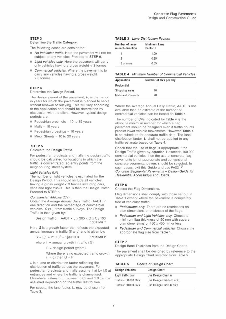
STEP 3 Determine the Traffic Category.
The following cases are considered:■ No Vehicular traffic. Here the pavement will not be
subject to any vehicles. Proceed to STEP 6.■ Light vehicles only. Here the pavement will carry
only vehicles having a gross weight < 3 tonnes.■ Commercial vehicles. Where the pavement is to
carry any vehicles having a gross weight ≥ 3 tonnes.
STEP 4 Determine the Design Period.
The design period of the pavement, P, is the period in years for which the pavement is planned to serve without renewal or relaying. This will vary according to the application and should be determined by discussion with the client. However, typical design periods are:■ Pedestrian precincts – 10 to 15 years■ Malls – 10 years■ Pedestrian crossings – 10 years■ Minor Streets – 10 to 20 years
STEP 5 Calculate the Design Traffic.
For pedestrian precincts and malls the design traffic should be calculated for locations in which the traffic is concentrated, eg entry points from the neighbouring street system.
Light Vehicles (LV) The number of light vehicles is estimated for the Design Period. This should include all vehicles having a gross weight < 3 tonnes including cars, vans and light trucks. This is then the Design Traffic. Proceed to STEP 6.
Commercial Vehicles (CV) Obtain the Average Annual Daily Traffic (AADT) in one direction and the percentage of commercial vehicles, C (%), from traffic surveys. The Design Traffic is then given by:
Design Traffic = AADT x L x 365 x G x C / 100 Equation 1
Here G is a growth factor that reflects the expected annual increase in traffic (if any) and is given by:
G = [(1 + i/100)P – 1]/(i/100) Equation 2
where i = annual growth in traffic (%)
P = design period (years)
Where there is no expected traffic growth (i = 0) then G = P
L is a lane or distribution factor reflecting the distribution of traffic across the pavement. For pedestrian precincts and malls assume that L=1.0 at entrances and where the traffic is channelised. Elsewhere, values of L between 0.65 and 1.0 can be assumed depending on the traffic distribution.
For streets, the lane factor, L, may be chosen from Table 3.
TABLE 3 Lane Distribution Factors
Number of lanes Minimum Lanein each direction Factor, L
1 1.00
2 0.85
3 or more 0.65
TABLE 4 Minimum Number of Commercial Vehicles
Application Number of CVs per day
Residential 1
Shopping areas 10
Malls and Precincts 20
Where the Average Annual Daily Traffic, AADT, is not available then an estimate of the number of commercial vehicles can be based on Table 4.
The number of CVs indicated by Table 4 is the absolute minimum number for which a flag pavement should be designed even if traffic counts predict lower vehicle movements. However, Table 4 is no substitute for accurate traffic data. The lane distribution factor, L, shall not be applied to any traffic estimate based on Table 4.
Check that the use of flags is appropriate If the Design Traffic given by equation 1 exceeds 100 000 commercial vehicles then the use of concrete flag pavements is not appropriate and conventional concrete segmental pavers should be selected. In such cases, exit this Guide and use PA0213 Concrete Segmental Pavements – Design Guide for Residential Accessways and Roads.
STEP 6 Choose the Flag Dimensions.
Flag dimensions shall comply with those set out in Table 1 except where the pavement is completely free of vehicular traffic.
■ Pedestrians only There are no restrictions on plan dimensions or thickness of the flags.
■ Pedestrian and Light Vehicles only Choose a minimum flag thickness of 50 mm with square plan dimensions of 450 x 450mm or less .
■ Pedestrian and Commercial vehicles Choose the appropriate flag size from Table 1.
STEP 7 Design Base Thickness from the Design Charts.
The pavement shall be designed by reference to the appropriate Design Chart selected from Table 5.
TABLE 5 Choice of Design Chart
Design Vehicles Design Chart
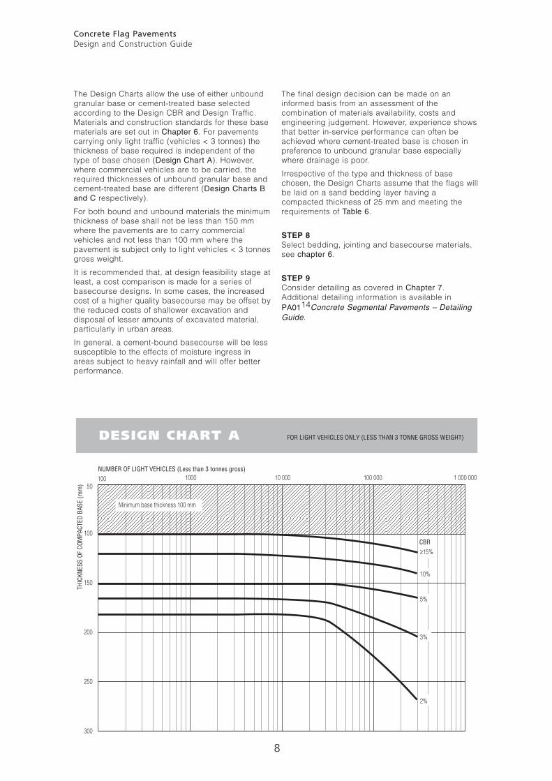
Light traffic only Use Design Chart A
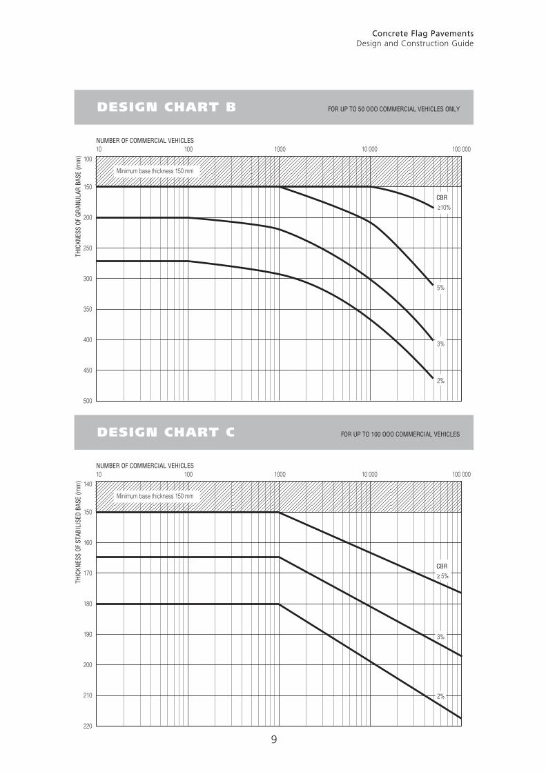
Traffic < 50 000 CVs Use Design Charts B or C
Traffic ≥ 50 000 CVs Use Design Chart C only
Concrete Flag Pavements Design and Construction Guide
8
The Design Charts allow the use of either unbound granular base or cement-treated base selected according to the Design CBR and Design Traffic. Materials and construction standards for these base materials are set out in Chapter 6. For pavements carrying only light traffic (vehicles < 3 tonnes) the thickness of base required is independent of the type of base chosen (Design Chart A). However, where commercial vehicles are to be carried, the required thicknesses of unbound granular base and cement-treated base are different (Design Charts B and C respectively).
For both bound and unbound materials the minimum thickness of base shall not be less than 150 mm where the pavements are to carry commercial vehicles and not less than 100 mm where the pavement is subject only to light vehicles < 3 tonnes gross weight.
It is recommended that, at design feasibility stage at least, a cost comparison is made for a series of basecourse designs. In some cases, the increased cost of a higher quality basecourse may be offset by the reduced costs of shallower excavation and disposal of lesser amounts of excavated material, particularly in urban areas.
In general, a cement-bound basecourse will be less susceptible to the effects of moisture ingress in areas subject to heavy rainfall and will offer better performance.
The final design decision can be made on an informed basis from an assessment of the combination of materials availability, costs and engineering judgement. However, experience shows that better in-service performance can often be achieved where cement-treated base is chosen in preference to unbound granular base especially where drainage is poor.
Irrespective of the type and thickness of base chosen, the Design Charts assume that the flags will be laid on a sand bedding layer having a compacted thickness of 25 mm and meeting the requirements of Table 6.
STEP 8 Select bedding, jointing and basecourse materials, see chapter 6.
STEP 9 Consider detailing as covered in Chapter 7. Additional detailing information is available in PA0114 Concrete Segmental Pavements – Detailing Guide.
≥15%
10%
5%
3%
2%
1000100 10 000 100 000 1 000 00050
100
150
200
250
300
NUMBER OF LIGHT VEHICLES (Less than 3 tonnes gross)
CBR
THIC
KNES
S OF
COM
PACT
ED B
ASE
(mm
)
Minimum base thickness 100 mm
DESIGN CHART A FOR LIGHT VEHICLES ONLY (LESS THAN 3 TONNE GROSS WEIGHT)
Concrete Flag Pavements Design and Construction Guide
9
5%
3%
2%
100 1000 10 000 100 000100
150
250
350
200
300
400
450
500
NUMBER OF COMMERCIAL VEHICLES
CBR
THIC
KNES
S OF
GRA
NULA
R BA
SE (m
m)
Minimum base thickness 150 mm
DESIGN CHART B FOR UP TO 50 OOO COMMERCIAL VEHICLES ONLY
10
≥10%
≥ 5%
3%
2%
100 1000 10 000 100 000140
150
170
190
160
180
200
210
220
NUMBER OF COMMERCIAL VEHICLES
CBR
THIC
KNES
S OF
STA
BILI
SED
BASE
(mm
)
Minimum base thickness 150 mm
DESIGN CHART C FOR UP TO 100 OOO COMMERCIAL VEHICLES
10
Concrete Flag Pavements Design and Construction Guide
10
6.3 Basecourse Materials6.3.1 Granular BaseGranular base shall comply fully with the requirements of a Class A material as set out in Table 8.
To maximise the use of economically-available materials and as specifications vary among State and Municipal Authorities, the following information should be used as a guide to preferred minimum requirements only. Designers should take into account local specifications, materials availability and experience.
Granular materials should comply with local requirements for basecourse for an asphalt-surfaced pavement. The material may be either a crushed quarry material or a natural gravel.
The information in Table 8 is representative of specifications issued by Australian road authorities.
6.3.2 Cement-Stabilised MaterialsThese materials are designed to have sufficient strength and therefore elastic modulus for this property to be taken into account in thickness design.
In areas of high rainfall or where the water table is high, these materials offer improved performance compared with unbound materials. They are less susceptible to the effects of moisture ingress.
Cement-treated materials shall meet the grading requirements of Table 8 for Class A or B materials and, after the addition of cement, shall achieve a 7-day unconfined compression strength of not less than 2.0 MPa and not more than 5.0 MPa. Cementitious material meeting the requirements of a GP or GB cement in accordance with AS 2972 will usually be suitable as a binder. Where aggressive ground water may be present, the use of a sulphate-resistant binder should be considered.
6 Materials
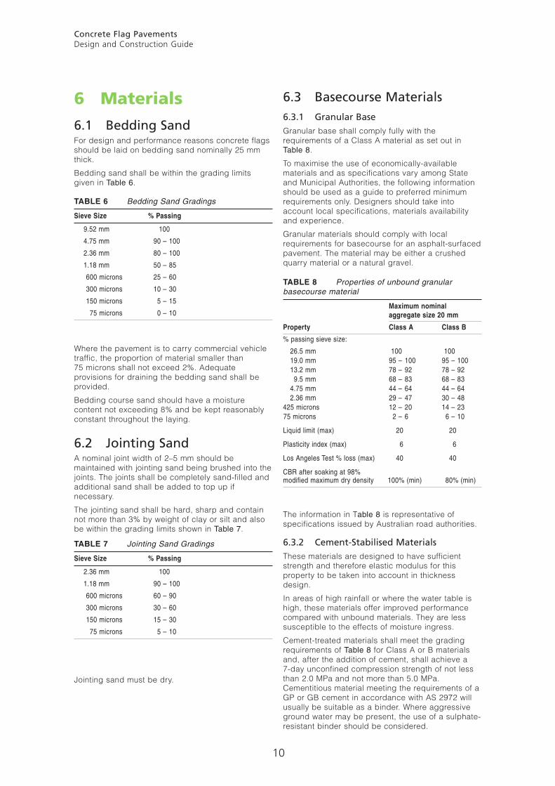
6.1 Bedding Sand For design and performance reasons concrete flags should be laid on bedding sand nominally 25 mm thick.
Bedding sand shall be within the grading limits given in Table 6.
TABLE 6 Bedding Sand Gradings
Sieve Size % Passing
9.52 mm 100
4.75 mm 90 – 100
2.36 mm 80 – 100
1.18 mm 50 – 85
600 microns 25 – 60
300 microns 10 – 30
150 microns 5 – 15
75 microns 0 – 10
Where the pavement is to carry commercial vehicle traffic, the proportion of material smaller than 75 microns shall not exceed 2%. Adequate provisions for draining the bedding sand shall be provided.
Bedding course sand should have a moisture content not exceeding 8% and be kept reasonably constant throughout the laying.
6.2 Jointing Sand A nominal joint width of 2–5 mm should be maintained with jointing sand being brushed into the joints. The joints shall be completely sand-filled and additional sand shall be added to top up if necessary.
The jointing sand shall be hard, sharp and contain not more than 3% by weight of clay or silt and also be within the grading limits shown in Table 7.
TABLE 7 Jointing Sand Gradings
Sieve Size % Passing
2.36 mm 100
1.18 mm 90 – 100
600 microns 60 – 90
300 microns 30 – 60
150 microns 15 – 30
75 microns 5 – 10
Jointing sand must be dry.
TABLE 8 Properties of unbound granular basecourse material
Maximum nominal aggregate size 20 mm
Property Class A Class B
% passing sieve size:
26.5 mm 100 100 19.0 mm 95 – 100 95 – 100 13.2 mm 78 – 92 78 – 92 9.5 mm 68 – 83 68 – 83 4.75 mm 44 – 64 44 – 64 2.36 mm 29 – 47 30 – 48 425 microns 12 – 20 14 – 23 75 microns 2 – 6 6 – 10
Liquid limit (max) 20 20
Plasticity index (max) 6 6
Los Angeles Test % loss (max) 40 40
CBR after soaking at 98%modified maximum dry density 100% (min) 80% (min)
Concrete Flag Pavements Design and Construction Guide
11
In the absence of local experience, the required binder content should be determined by laboratory testing. As a guide, a cement content in the range 3–5% by weight of untreated material will often be suitable. The moisture content should not exceed that required for field compaction.
6.3.3 Basecourse CompactionThe base shall be compacted to not less than 98% of modified maximum dry density to AS 1289 for Class A granular base and to not less than 96% of modified maximum dry density for cement-stabilised base.
7
Construction and Detailing
7.1 GeneralFor design and performance reasons, concrete flags should be laid on bedding sand nominally 25 mm thick (see Clause 6.1).
A nominal joint width of 2–5 mm should be maintained with jointing sand being brushed into the joints (see Clause 6.2).
Where concrete flags are laid abutting kerbs or drainage channels, the surface of the flags shall be at least 5 mm above the kerb or channel.
The difference in level between two adjacent flags shall not exceed 3 mm.
7.2 Cutting and LayingConcrete flags shall be cut where necessary using a saw or disc cutter.
Where square pavers are to be cut, eg to permit installation in stretcher bond, the cut pavers shall be placed in areas away from traffic. The minimum plan area of the cut pavers shall not be less than 50% of the normal (uncut) plan area.
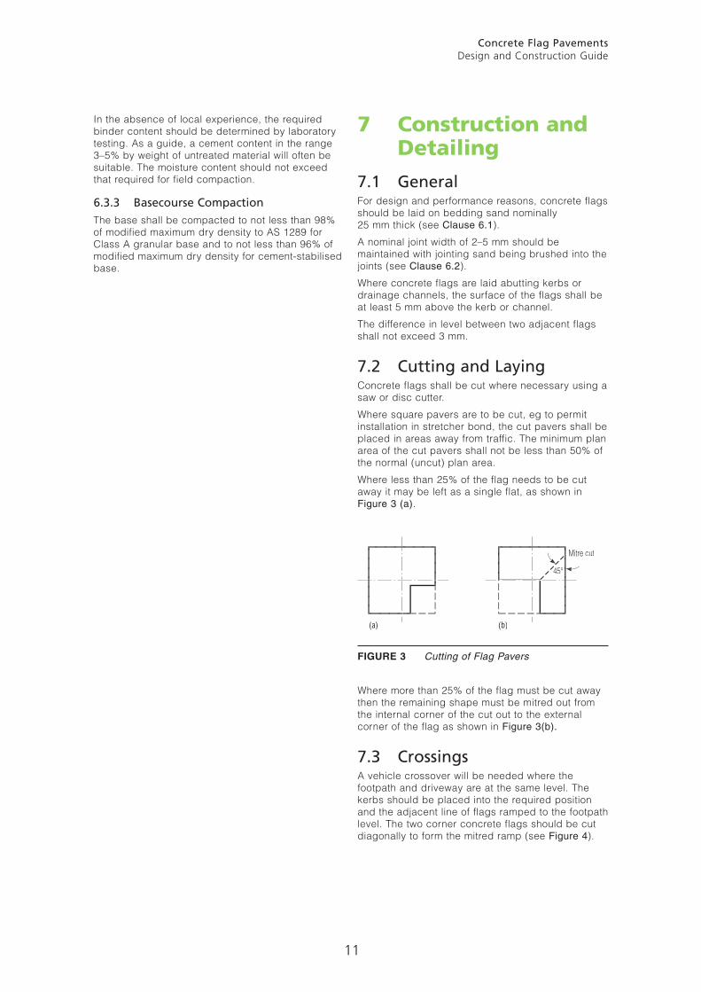
Where less than 25% of the flag needs to be cut away it may be left as a single flat, as shown in Figure 3 (a).
FIGURE 3 Cutting of Flag Pavers
Where more than 25% of the flag must be cut away then the remaining shape must be mitred out from the internal corner of the cut out to the external corner of the flag as shown in Figure 3(b).
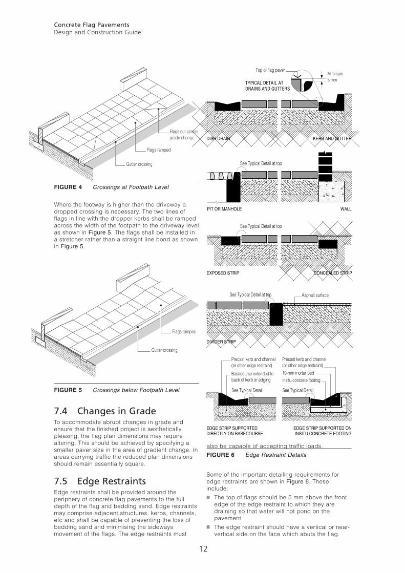
7.3 CrossingsA vehicle crossover will be needed where the footpath and driveway are at the same level. The kerbs should be placed into the required position and the adjacent line of flags ramped to the footpath level. The two corner concrete flags should be cut diagonally to form the mitred ramp (see Figure 4).
45°
Mitre cut
(a) (b)
Concrete Flag Pavements Design and Construction Guide
12
FIGURE 4 Crossings at Footpath Level
Where the footway is higher than the driveway a dropped crossing is necessary. The two lines of flags in line with the dropper kerbs shall be ramped across the width of the footpath to the driveway level as shown in Figure 5. The flags shall be installed in a stretcher rather than a straight line bond as shown in Figure 5.
FIGURE 5 Crossings below Footpath Level
7.4 Changes in GradeTo accommodate abrupt changes in grade and ensure that the finished project is aesthetically pleasing, the flag plan dimensions may require altering. This should be achieved by specifying a smaller paver size in the area of gradient change. In areas carrying traffic the reduced plan dimensions should remain essentially square.
7.5 Edge RestraintsEdge restraints shall be provided around the periphery of concrete flag pavements to the full depth of the flag and bedding sand. Edge restraints may comprise adjacent structures, kerbs, channels, etc and shall be capable of preventing the loss of bedding sand and minimising the sideways movement of the flags. The edge restraints must
also be capable of accepting traffic loads.FIGURE 6 Edge Restraint Details
Some of the important detailing requirements for edge restraints are shown in Figure 6. These include:■ The top of flags should be 5 mm above the front
edge of the edge restraint to which they are draining so that water will not pond on the pavement.
■ The edge restraint should have a vertical or near-vertical side on the face which abuts the flag.
Flags cut acrossgrade change
Flags ramped
Gutter crossing
Flags ramped
Gutter crossing
Minimum5 mm
Top of flag paver
See Typical Detail at top
See Typical Detail See Typical Detail
See Typical Detail at top
See Typical Detail at top
TYPICAL DETAIL ATDRAINS AND GUTTERS
DISH DRAIN KERB AND GUTTER
PIT OR MANHOLE WALL
EXPOSED STRIP CONCEALED STRIP
DIVIDER STRIP
EDGE STRIP SUPPORTEDDIRECTLY ON BASECOURSE
Precast kerb and channel(or other edge restraint)
Precast kerb and channel(or other edge restraint)
Basecourse extended toback of kerb or edging
Asphalt surface
EDGE STRIP SUPPORTED ONINSITU CONCRETE FOOTING
10-mm mortar bedInsitu concrete footing
Concrete Flag Pavements Design and Construction Guide
13
■ The basecourse should extend below the edge restraint for its full width (to minimise the likelihood of the edge restraint itself being disturbed) except at situations such as walls or pits.
■ Where the edge restraint is in the form of a standard road-authority kerb, gutter/channel or dish drain, the requirement of that authority in relation to concrete quality should be followed. Elsewhere the use of a Grade N32 concrete is recommended.
See also Figure 9 for surface drainage and Figure 10 for bedding sand drainage details.
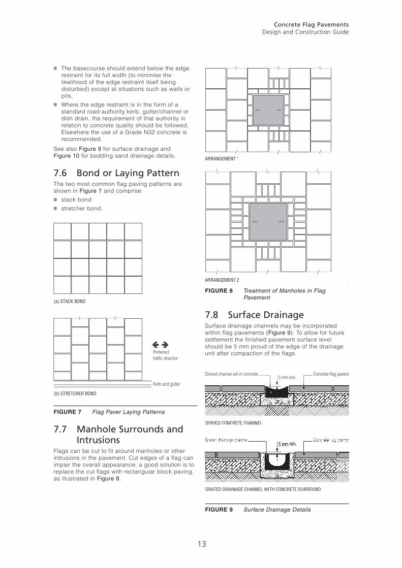
7.6 Bond or Laying PatternThe two most common flag paving patterns are shown in Figure 7 and comprise:■ stack bond■ stretcher bond.
FIGURE 7 Flag Paver Laying Patterns
7.7 Manhole Surrounds and IntrusionsFlags can be cut to fit around manholes or other intrusions in the pavement. Cut edges of a flag can impair the overall appearance; a good solution is to replace the cut flags with rectangular block paving, as illustrated in Figure 8.
FIGURE 8 Treatment of Manholes in Flag Pavement
7.8 Surface DrainageSurface drainage channels may be incorporated within flag pavements (Figure 9). To allow for future settlement the finished pavement surface level should be 5 mm proud of the edge of the drainage unit after compaction of the flags.
FIGURE 9 Surface Drainage Details
Preferredtraffic direction
Kerb and gutter
(a) STACK BOND
(b) STRETCHER BOND
ARRANGEMENT 1
ARRANGEMENT 2
Dished channel set in concrete5 mm min.
Concrete flag pavers
DISHED CONCRETE CHANNEL
GRATED DRAINAGE CHANNEL WITH CONCRETE SURROUND
Concrete Flag Pavements Design and Construction Guide
14
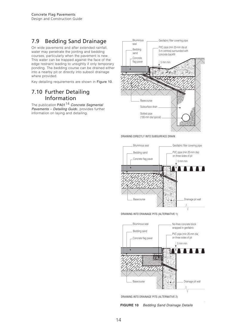
7.9 Bedding Sand Drainage On wide pavements and after extended rainfall, water may penetrate the jointing and bedding courses, particularly when the pavement is new. This water can be trapped against the face of the edge restraint leading to unsightly if only temporary ponding. The bedding course can be drained either into a nearby pit or directly into subsoil drainage where provided.
Key detailing requirements are shown in Figure 10.
7.10 Further Detailing Information
The publication PA0114 Concrete Segmental Pavements – Detailing Guide, provides further information on laying and detailing.
FIGURE 10 Bedding Sand Drainage Details
Geofabric filter covering pipe
5 mm min.
Bituminousseal
Beddingsand
Basecourse
DRAINING DIRECTLY INTO SUBSURFACE DRAIN
Subsurface drain
Slotted pipe(100-mm dia typical)
PVC pipe (min 20-mm dia at5-m centres) surrounded withconcrete backfill
DRAINING INTO DRAINAGE PITS (ALTERNATIVE 2)
DRAINING INTO DRAINAGE PITS (ALTERNATIVE 1)
Geofabric filter covering pipeBituminous seal
Bedding sand
Basecourse Drainage pit wall
PVC pipe (min 20-mm dia)on three sides of pit
No-fines concrete blockwrapped in geofabric
Bituminous seal
Bedding sand
Basecourse Drainage pit wall
PVC pipe (min 20-mm dia)on three sides of pit
Concreteflag paver
Concrete flag paver
Concrete flag paver
5 mm min.
5 mm min.
Concrete Flag Pavements Design and Construction Guide
15
8 REFERENCES
1 BS 7263 Precast Concrete Flags, Kerbs, Channels, Edgings and Quadrants, Part 1: Specification
2 Interpave UK Precast Concrete Paving – a Design Handbook. UniClass E1 p225, 1999
3 TRL Application Guide 26 – 1997 Footways – Design and Maintenance Guide, Transport Research Laboratory, UK
4 Shackel B Design and Construction of Interlocking Concrete Block Pavements, Elsevier Science Publishers Ltd, 1990
5 Lilley A A Handbook of Segmental Paving, Chapman & Hall Publishers, 1991
6 Shackel B Safety and Environmental Aspects of Concrete Segmental Paving, Proceedings of Biennial Conference, Concrete Masonry Association of Australia, 1986
7 Pearson AR and Hodgkinson JR A Performance Review of Concrete Segmental Pavements in Urban Redevelopment Projects, Proceedings of Seventh National Local Government Engineering Conference, Adelaide, 1993
8 Shackel B An Experimental Investigation of Factors Influencing the Design of Interlocking Concrete Block Pavements in Roads, Proceedings of Australian Road Research Board Conference, 1982
9 Pearson AR and Hodgkinson JR Some Factors Affecting Success and Distress in Concrete Segmental Pavements in Australia, Proceedings of 4th International Conference – Concrete Block, New Zealand, 1992
10 Shackel B A Pilot Study of the Performance of Block Paving Under Traffic Using a Heavy Vehicle Simulator, Proceedings of Symposium on Precast Concrete Paving, Johannesburg, 1979
11 Shackel B An Experimental Investigation of the Roles of Bedding and Jointing Sands in the Performance of Interlocking Concrete Block Pavements, Concrete Beton No. 19, 1980
12 CMAA Concrete Segmental Pavements – Guide to Specifying (PA03)
13 CMAA Concrete Segmental Pavements – Design Guide for Residential Accessways and Roads (PA02)
14 CMAA Concrete Segmental Pavements – Detailing Guide (PA01)
15 AS/NZS 4455 Masonry Units and Segmental Pavers
16 AS/NZS 4456 Masonry Units and Segmental Pavers – Methods of Test
17 AS/NZS 4586 Slip Resistance Classifications of New Pedestrian Surface Materials.

12 / Industrial Pavements
PO Box 370, Artarmon NSW 1570 AustraliaSuite 3.02, Level 3, 44 Hampden Road Artarmon NSW 2064 AustraliaTelephone +61 2 8448 5500 Fax +61 2 9411 3801 ABN 30003873309
www.cmaa.com.au